

Sony SDT-S9000, SDT-S7200, SDT-S5200, SDT-S7000, SDT-S5000 Operators Manual
...
3-798-026-33(1)
SDT-S9000/S7000/S7200/S5000/S5200/S4000E/S2000E
DDS Drive Unit
Operator’s Guide
Mode d’emploi
––––––––––––– page 2
–––––––––––––––– page 29
Bedienungsanleitung
Guía del usuario
–––––––––––––– página 81
–––––––– Seite 55

SDT-S9000/S7000/S7200/S5000/S5200/S4000E/S2000E
DDS Drive Unit
User's Guide
Mode d'emploi
Benutzerhandbuch
Guía del usuario
Sony Corporation Printed in Japan 1996

Safety Regulations
Owner's Record
The model and serial numbers are located on the bottom. Record the serial
number in the space provided below.
Refer to them whenever you call upon your Sony dealer regarding this
product.
Model No. Serial No.
Information
WARNING
To prevent fire or shock hazard, do not expose the
unit to rain or moisture.
To avoid electrical shock, do not open the cabinet.
Refer servicing to qualified personnel only.
For the customers in the U.S.A.
You are cautioned that any changes or modifications not expressly approved
in this manual could void your authority to operate this equipment.
WARNING
Note: This equipment has been tested and found to comply with the limits
for a Class B digital device, pursuant to Part 15 of the FCC Rules. These
limits are designed to provide reasonable protection against harmful
interference in a residential installation. This equipment generates, uses and
can radiate radio frequency energy and, if not installed and used in
accordance with the instructions, may cause harmful interference to radio
communications. However, there is no guarantee that interference will not
occur in a particular installation. If this equipment does cause harmful
interference to radio or television reception, which can be determined by
turning the equipment off and on, the user is encouraged to try to correct the
interference by one or more of the following measures:
• Reorient or relocate the receiving antenna
• Increase the separation between the equipment and receiver.
• Connect the equipment into an outlet on a circuit different from that
to which the receiver is connected.
• Consult the dealer or an experienced radio/TV technician for help.
2

NOTICE
THIS NOTICE IS APPLICABLE FOR USA AND CANADA ONLY.
If shipped to USA, use the UL LISTED power cord specified below for
220-240 V operation.
If shipped to CANADA, use the CSA CERTIFIED power cord specified
below for 220-240 V operation.
DO NOT USE ANY OTHER POWER CORD
Plug Cap Tandem blade with ground pin.
(NEMA 6-15P Configuration)
Cord Type SVT or SJT, three 16 or 18 AWG wires.
Length Maximum 14.7 feet (4.5m)
Rating Minimum 10A, 250 V
NOTICE
This notice is applicable for countries other than USA and Canada.
In the countries other than USA and Canada, use the power cord set
approved by the appropriate testing organization for the specific countries
where this unit is to be used.
English
English
3

Table of Contents
How to Use this Guide 6
Part 1. Introduction 7
About DDS Drives 7
Features...........................................................................................................7
Useable Cartridges ..........................................................................................9
System Components........................................................................................9
Part Names and Functions 10
Front panel.....................................................................................................10
Rear Panel .....................................................................................................12
Part 2. Preparation 13
Supplied Items 13
Interconnections 13
SCSI ID Setting 14
English
Configuration Switches Setting 14
Part 3. Operation 16
How to use the DDS Drive 16
Cartridge Removal .........................................................................................17
Part 4. Care and Maintenance 18
Taking Care of the Drive 18
Safety Considerations....................................................................................18
Avoiding Damage...........................................................................................18
Taking Care of Cartridges 20
Use Precautions.............................................................................................20
Storage Precautions ......................................................................................20
Head Cleaning 21
How to Clean .................................................................................................21
4

Appendix 22
Specifications (SDT-S9000) 22
Specifications (SDT-S7000) 23
Specifications (SDT-S7200) 24
Specifications (SDT-S5000) 25
Specifications (SDT-S5200) 26
Specifications (SDT-S4000E) 27
Specifications (SDT-S2000E) 28
5

How to Use this Guide
This Guide describes the DDS Drive Unit SDT-S9000/S7000/S7200/S5000/
S5200/S4000E/S2000E , and how to take care of it. Please read it carefully
before using the unit, and keep it handy for future reference.
The Guide consists of four parts, plus the specifications. Refer to the parts
that relate to your use of the drive.
Part 1 describes the features of the drive, its system components, and the
name and function of each part.
Part 2 describes the necessary connections between the drive and the host
computer. If other SCSI devices are being used, you may need to change the
SCSI ID setting. Read this part if you are installing the drive.
Part 3 describes how to use the drive, including how to turn it on, and how to
insert and remove cartridges. Read this part if you are going to operate the
drive.
Part 4 describes how to take care of the drive and cartridges, and how to
clean the drive heads. Read this part before using the drive.
The Specifications appendix provides the major specifications of the SDT-
S9000/S7000/S7200/S5000/S5200/S4000E/S2000E.
6

Part 1. Introduction
About DDS Drives
The SDT-S9000 is an external DDS drive unit that uses data cartridges
conforming to the DDS-3 format. The SDT-S7000, SDT-S7200, SDT-S5000
and SDT-S5200 are external DDS drive units that use data cartridges
conforming to the DDS-2 format. The SDT-S4000E and SDT-S2000E are
external DDS drive units that use data cartridges conforming to the DDS-1
format. The SDT-S9000 supports DDS-1, DDS-2 and DDS-3 formats.The
SDT-S7000, SDT-S7200, SDT-S5000 and SDT-S5200 support both DDS-1
and DDS-2 formats. The SDT-S4000E and SDT-S2000E support only DDS1 format.
Features
The DDS Drive Unit SDT-S9000 has the following features:
• The Digital Data Storage format provides a huge data storage capacity on
DDS-1/DDS-2/DDS-3 data cartridges.
• Read After Write Function and third-level error correction code guarantee
high data reliability.
• Data compression provides 24 gigabytes of storage on 125 m tape-length
cartridge.
The native capacity is 12 gigabytes of storage on 125 m tape-length
cartridge.
• Stored data are automatically checked for compression.
• The SCSI-2 (ANSI SCSI-2 X3T9.2/86-109 REV.10C) interface is fully
supported for host computer access.
• Read/Write operation is available with both DDS-1, DDS-2 and DDS-3
format.
*1
*1
This is assuming 2 : 1 compression ratio.
The degree of data compression attained while recording data varies according to system
environment and data type.
Part 1. Introduction
7

The DDS Drive Unit SDT-S7000/S7200/S5000/S5200 has the following
features:
• The Digital Data Storage format provides a huge data storage capacity on
DDS-1/DDS-2 data cartridges.
• Read After Write Function and third-level error correction code guarantee
high data reliability.
• Data compression*1 provides 8 gigabytes of storage on 120 m tape-length
cartridge.
*2
The native capacity is 4 gigabytes of storage on 120 m tape-length
cartridge.
• Stored data are automatically checked for compression.*3 The SDT-S5000
can read uncompressed data written by earlier-model drives.
• The SCSI-2 (ANSI SCSI-2 X3T9.2/86-109 REV.10C) interface is fully
supported for host computer access.
• Read/Write operation is available with both DDS-1 and DDS-2 format.
*1
The SDT-S7200/S5200 is not equipped with data compression.
*2
This is assuming 2 : 1 compression ratio.
The degree of data compression attained while recording data varies according to system
environment and data type.
*3
With the SDT-S7000 and SDT-S5000.
The DDS Drive Unit SDT-S4000E/S2000E has the following features:
• The Digital Data Storage format provides a huge data storage capacity on
DDS-1 data cartridges.
• Read After Write Function and third-level error correction code guarantee
high data reliability.
• Data compression*1 provides 4 gigabytes of storage on 90 m tape-length
cartridge.
*2
The native capacity is 2 gigabytes of storage on 90 m tape-length cartridge.
• Stored data are automatically checked for compression.*3 The SDT-S4000E
can read uncompressed data written by earlier-model drives.
• The SCSI-2 (ANSI SCSI-2 X3T9.2/86-109 REV.10C) interface is fully
supported for host computer access.
Part 1. Introduction
8
*1
The SDT-S2000E is not equipped with data compression.
*2
This is assuming 2 : 1 compression ratio.
The degree of data compression attained while recording data varies according to system
environment and data type.
*3
With the SDT-S4000E only.

Useable Cartridges
Data cartridges used with the SDT-S9000 must be marked with the DDS-1,
DDS-2 or DDS-3 logo. The SDT-S7000/S7200/S5000/S5200 can only be
used with data catridges marked with the DDS-1 or DDS-2 logo and the
SDT-S4000E/S2000E can only be used with data cartridges marked with the
DDS-1 logo.
CAUTION:
Be sure to use only the cartridges designed specifically for DDS (do not use
DAT cartridges for music).
System Components
The SDT-S9000/S7000/S7200/S5000/S5200/S4000E/S2000E connects to the
host computer via a SCSI-2 interface.
DDS-3 Logo DDS-2 Logo DDS-1 logo
Host Computer
SDT-S9000/S7000/S7200/S5000/
S5200/S4000E/S2000E
(This Device)
Figure 1-1. Example of System Components
Peripheral Devices
Part 1. Introduction
9
Part Names and Functions
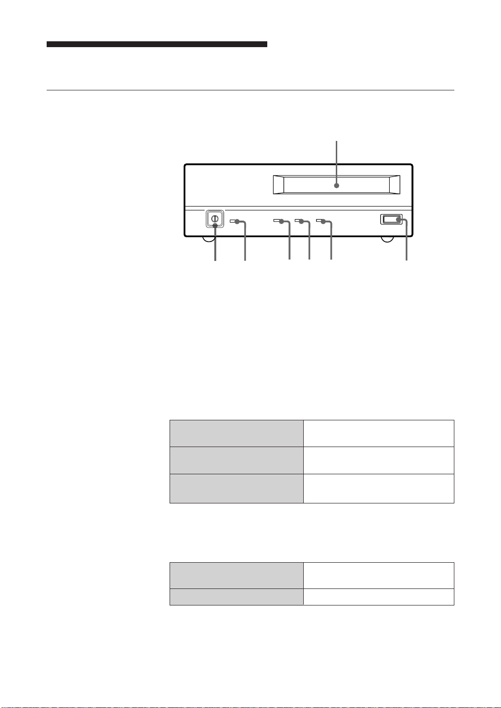
Front panel
1
POWER BUSY TAPE STATUS
7
6
Figure 1-2. Front panel
345
EJECT
2
1 DDS Data Cartridge Receptacle
See page 17 for information on inserting and removing a DDS data
cartridge.
2 EJECT Button
Push to remove a data cartridge from the drive.
3 STATUS Indicator
Lights when an inserted cartridge is write-protected. This indicator also
lights under the following conditions:
Drive needs cleaning: repeating long-on, short-off
blinking.
End of Tape during cleaning: repeating blinking (same on-off
interval).
Drive Malfunctioning: repeating short-on (once or twice),
long-off blinking.
Part 1. Introduction
10
4 TAPE Indicator
When a DDS cartridge is installed, this indicator lights. This also lights
under the following conditions:
Inserting and removing repeated blinking (same on-off
a cartridge: interval).
Cartridge deteriorated: alternating long-short blinking.

5 BUSY Indicator
Lights when data is being transferred through the SCSI interface. This
indicator also lights under the following conditions:
Drive is reading or writing repeated blinking (same on-off
normally: interval).
High Humidity: *
1
alternating long-short blinking
(cartridge cannot be inserted).
6 POWER Indicator
Lights while the drive is on.
7 POWER Switch
Press to turn the drive on or off.
*1
With the SDT-S5000/S5200/S4000E/S2000E
Part 1. Introduction
11
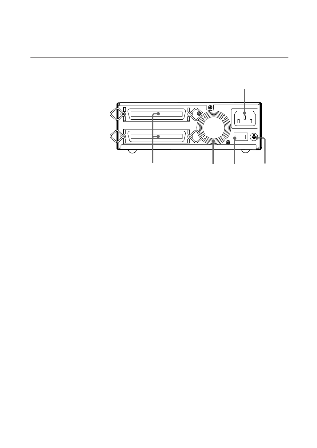
Rear Panel
1
SCSI CONNECTOR
AC IN
SCSI ID
5
Figure 1-3. Rear Panel
1 AC IN Connector
Connect the supplied power cable here.
2 GND (Ground) Terminal
Connect the ground terminals of other devices to the unit's frame
ground.
3 Rotary Selector Switch
SCSI ID selector.
4 Cooling Fan
5 SCSI Connector
Connects to the SCSI bus connector of the host computer or another
SCSI peripheral.
GND
234
Part 1. Introduction
12

Part 2. Preparation
After you confirm that you have all of the required accessories for your
installation, connect the drive to the host computer, and select the SCSI ID
with the rotary switch on the rear panel.
Supplied Items
When you first open the box, make sure it contains the following items.
Contact your supplier if anything is missing or broken.
• DDS Drive Unit
• Power Cable
• This Guide
Interconnections
The SCSI bus allows connection of up to seven peripherals to the host
computer. Use a SCSI cable with a full-pitch connector.
Precautions
• Switch off the host computer and peripherals before connecting the SCSI
cable.
• Make sure the SCSI connectors are pressed tightly together.
• If this unit is the last (or only) device on the SCSI bus, make sure to connect
a SCSI bus terminator to the open connector.
• The total length of the SCSI cable(s) between the host computer and the last
device should be less than 6 meters.
Figure 2-1 Interconnections
*1
When using high-speed data transfer with the SDT-S9000/S7000/S7200, it is recommended
that total length of the SCSI cable not exceed 3m.
*1
SCSI CONNECTOR
AC IN
SCSI ID
GND
AC power
Part 2. Preparation
13

SCSI ID Setting
The SCSI ID is set by the rotary switch on the rear panel. Press the + or buttons to move the number up or down, respectively.
As shipped from the factory, the SCSI ID is set to 0. Press the switch buttons,
if necessary, to select the SCSI ID number you require.
Precautions
• The SCSI ID must be different from IDs of the other peripherals on the
SCSI bus.
• As shipped from the factory, SCSI parity is enabled and Term power is ON.
Since the terminating resistor inside the drive is disabled, a SCSI bus
terminator must be connected to the SCSI bus before use.
• Before changing the SCSI ID setting, be sure to turn off the power with the
POWER switch on the front panel.
Configuration Switches Setting
Sony SDT-S9000/S7000/S7200 has a set of configuration switches located
on its bottom side (Fig 2-2). These drives can be made ready to run in major
workstations by setting the configuration switches as shown in the following
table.
*1
Part 2. Preparation
14
*1
with the SDT-S9000/S7000/S7200
Fig2-2 SDT-S9000/S7000/S7200 Configuration swiches

SDT-S9000/S7000/S7200 Configuration Switch Settings for Unix
System Configuration
Host Unix SW Setting
PC-based WS SCO Unix
Xenix
Digital WS
Sun WS Solaris 2.X
Sun WS Sun OS 4.1.X
IBM RS/6000 WS AIX
IBM RS/6000 WS AIX
HP WS HP-UX
SGI WS IRIX
Part 2. Preparation
15
Part 3. Operation
This section describes how to use the DDS drive, and how to handle data
cartridges.
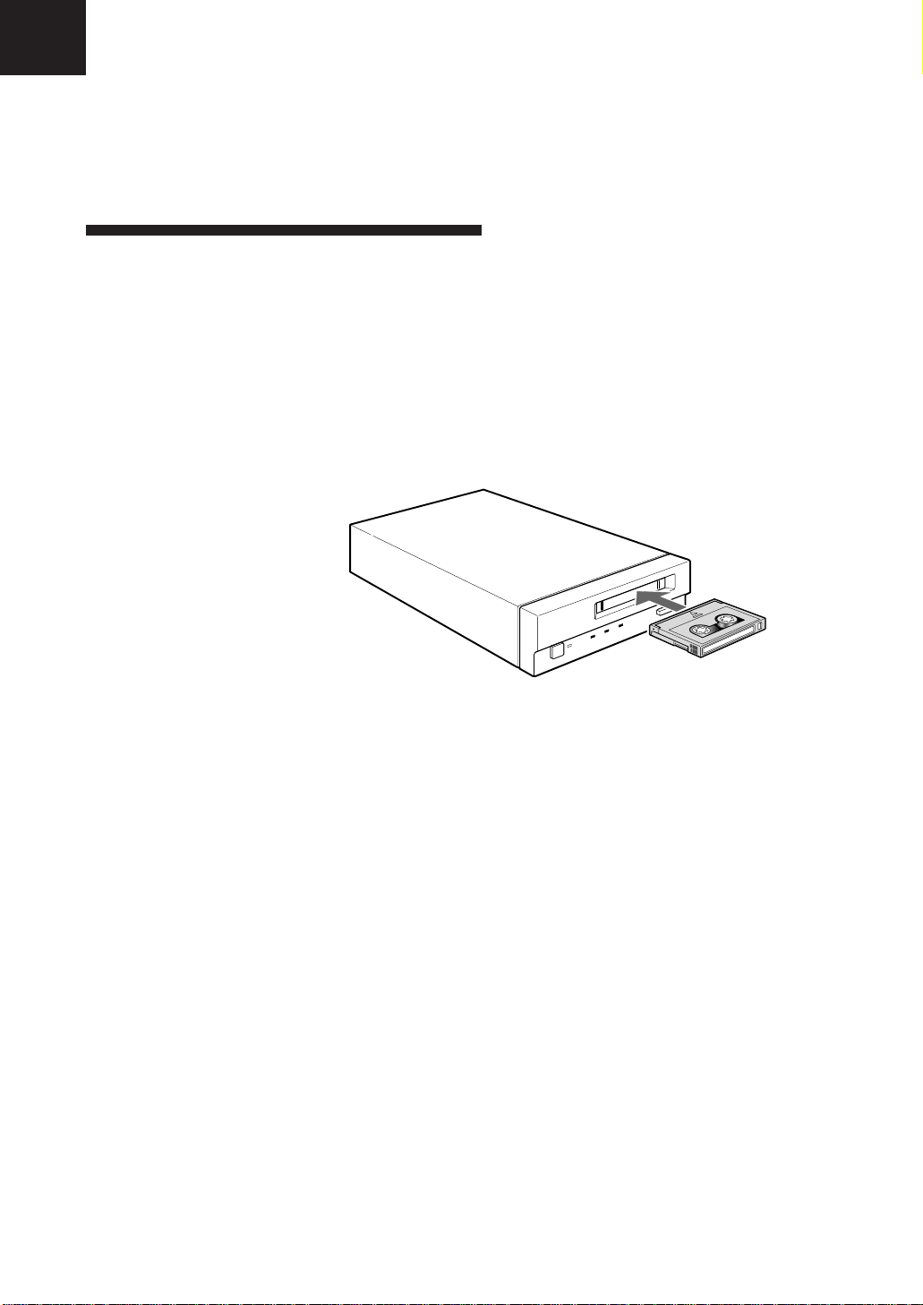
How to use the DDS Drive
1 Press the POWER switch on the front panel.
The POWER indicator should light, and the STATUS, BUSY and TAPE
indicators should blink as the self-test is performed.
2 When the three indicators stop blinking, you can insert a data cartridge as
shown below. The TAPE indicator will blink, and if the cartridge is
write-protected, the STATUS indicator will light.
Figure 3-1. Inserting a data cartridge
3 Computer software controls the reading and writing of tapes. While
reading or writing, the BUSY indicator blinks.
Part 3. Operation
16
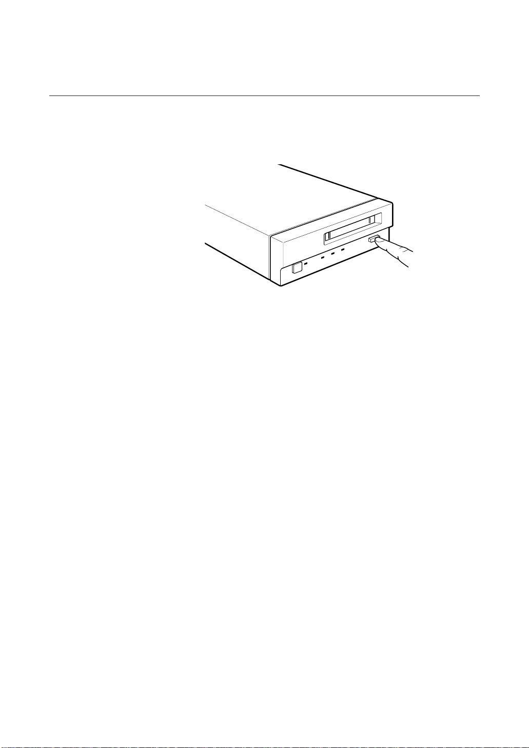
Cartridge Removal
Press the EJECT button.
The cartridge ejects automatically.
Figure 3-2. Press the EJECT button
Caution
Do not push the EJECT button while the BUSY indicator is blinking: to do so
may destroy data on the tape.
Part 3. Operation
17

Part 4. Care and Maintenance
Taking Care of the Drive
Safety Considerations
■ Power
• Be sure to use only 100-240 V AC.
• Avoid plugging into the same outlet as high-current equipment like copiers
or shredders.
■ Power Cable Precautions
• Do not crush the cable or place heavy items on it. If the cable insulation
appears worn or broken, do not use the cable.
• Always unplug the cable by holding the plug: never pull the cable itself, as
it will break.
• If the drive is not being used for a long time, unplug the cable from the
outlet.
Avoiding Damage
■ Avoid shock and vibration
Intense shock, such as from dropping the drive, will damage it.
■ Environmental considerations
Do not store or use the drive in locations subject to:
• high humidity • excessive dust
• high temperature • intense vibration
• direct sunlight • sudden changes in temperature
■ Proper ventilation
To avoid overheating, install the drive where it will have free air circulation
around the case, and do not cover it during operation. The drive can
malfunction if the internal temperature rises too high.
■ Avoid sudden changes in temperature
If the drive is moved from a cool place to a warm place, or if the room
temperature suddenly rises, moisture may condense inside the case. After a
sudden change in temperature, wait at least one hour before turning the drive
on. If the drive is turned on with condensation inside, and a cartridge is
installed, the drive or the tape can be damaged.
Part 4. Care and Maintenance
18

■ When the Humidity sensor indicator is on
The drive contains a humidity sensor, which causes the BUSY indicator to
blink when the humidity inside the case is too high (see page 10). If this
occurs, reduce the humidity in the room with a dehumidifier or air
conditioner, or by other means.
■ Abnormal occurrences
If the drive behaves abnormally, or if it begins to smell or smoke,
immediately unplug it from the wall outlet and contact your supplier for
assistance.
■ Cabinet cleaning
Wipe the cabinet with a soft dry cloth. For heavy dirt, wipe with a soft cloth
moistened with a gentle liquid soap, then wipe again with a soft dry cloth. Do
not use alcohol, paint thinner, bug sprays or other volatile solvents, as they
can damage the finish.
*1
With the SDT-S5000/S5200/S4000E/S2000E.
*1
Part 4. Care and Maintenance
19
Taking Care of Cartridges
Use Precautions
• Avoid heavy vibration and dropping.
• The shutter on the face of the cartridge is opened automatically when it is
inserted into the drive. Do not open the shutter by hand, as touching the tape
may damage it.
• The cartridge was carefully aligned during assembly at the factory. Please
do not try to open it or take it apart.
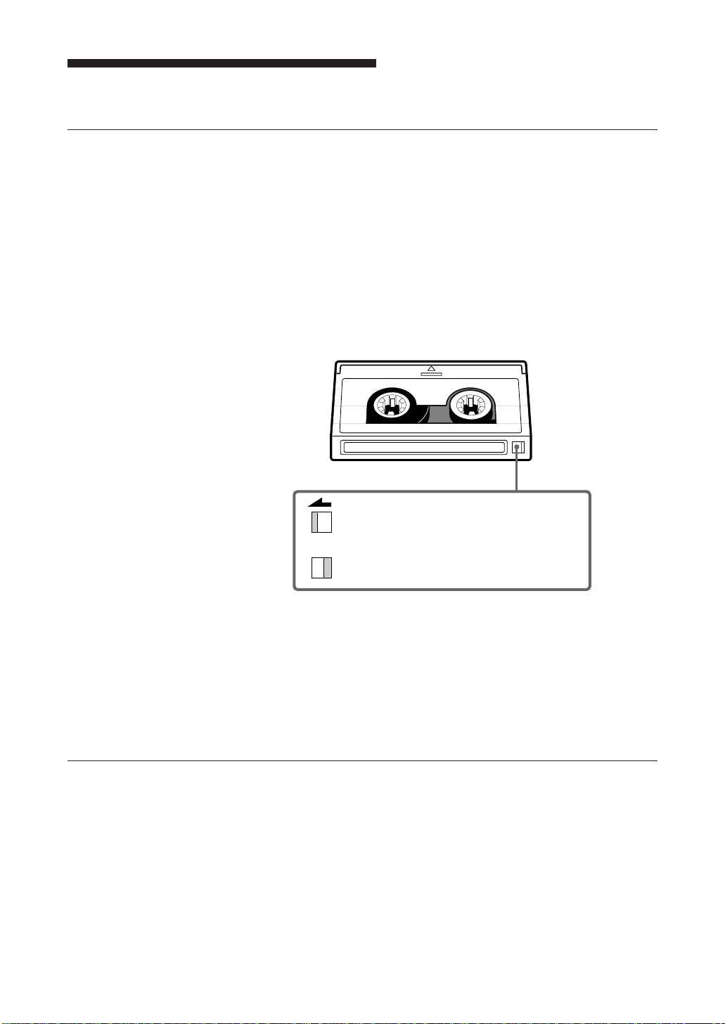
• The write-protect switch on the face of the cartridge prevents the tape from
being written to or accidentally erased. If you do not need to write to the
tape, move this switch to the write-protect position (in the direction of the
arrow).
• In case of a sudden change in temperature, condensation may interfere with
• Avoid unnecessary insertion and removal of cartridges if you do not need to
• When finished using the drive, remove the cartridge.
Storage Precautions
• Keep cartridges in their cases when not in the drive.
• Avoid storing cartridges in dusty places, in direct sunlight, near heaters or
• Do not place cartridges on the dashboard or in a storage tray in a car.
Using your fingernail, push the switch in the
direction of the arrow to protect the tape from
writing or accidental erasure.
Return the switch to its original position to
re-enable writing.
Figure 4-1. Write-protect switch
reading and writing to a tape.
write or read a tape.
air conditioners, or in humid locations.
Part 4. Care and Maintenance
20

Head Cleaning
To keep the DDS drive in top condition, clean the head as needed, using the
proper head cleaning cartridge (sold separately). When the head needs
cleaning, the STATUS indicator will blink.
How to Clean
1 Insert the head cleaning cartridge (DGD15CL) into the DDS Data
2 After about 10 seconds, cleaning will stop and the cartridge will eject
Notice:
Do not rewind the cleaning cartridge and reuse it. When you reach the end of
the cartridge, dispose of it and buy a new one.
cartridge receptacle. Cleaning starts automatically.
automatically.
One head cleaning cartridge can be used about 90 times.
Part 4. Care and Maintenance
21

Appendix
Specifications (SDT-S9000)
■ Performance
Storage Capacity 24 GB compressed
Bit Error Rate less than 10
Data Transfer Rate 1.18 MB/s uncompressed
(TAPE) 2.36 to 4.72 MB/s compressed
Burst Data Transfer Rate 5 MB/s maximum, asynchronous
(SCSI) 10 MB/s maximum, synchronous
Initialize Time less than 3 seconds
Load Time less than 24 seconds
Unload Time less than 20 seconds
Rewind Time less than 80 seconds (with 125 m tape)
■ Operating Environment
Operating Temperature: 10 to 35 °C
Non-Operating Temperature: -40 to +70 °C
(with 125 m DDS-3 tape)
12 GB uncompressed
(with 125 m DDS-3 tape)
-15
Humidity: 30 to 80%
(no condensation)
Maximum wet bulb temperature: 26 °C
Humidity: 10 to 90%
*1
■ Power Supply & Miscellaneous
Power Supply 100 to 240 V AC, 50/60 Hz
Case Dimensions 160 × 52.4 × 300 mm (W × H × D)
Weight 2.2 kg
Accessories Power Cable (1)
Specifications may be subject to change, in the interest of technological
improvement, without notice or obligation.
*1
This is assuming 2 : 1 compression ratio.
The degree of data compression attained while recording data varies according to system
environment and data type.
Appendix
22
0.5 to 0.3 A
(excluding protruding parts)
User's Guide (1)

Specifications (SDT-S7000)
■ Performance
Storage Capacity 8 GB compressed
Bit Error Rate less than 10
Data Transfer Rate 778 kB/s uncompressed
Burst Data Transfer Rate 5 MB/s maximum, asynchronous
Initialize Time less than 3 seconds
Load Time less than 16 seconds
Unload Time less than 20 seconds
Rewind Time less than 80 seconds (with 120 m tape)
■ Operating Environment
Operating Temperature: 10 to 35 °C
Non-Operating Temperature: -40 to +70 °C
(with 120 m DDS-2 tape)
4 GB uncompressed
(with 120 m DDS-2 tape)
-15
1556 to 3112 kB/s compressed
10 MB/s maximum, synchronous
Humidity: 30 to 80%
(no condensation)
Maximum wet bulb temperature: 26 °C
Humidity: 10 to 90%
■ Power Supply & Miscellaneous
Power Supply 100 to 240 V AC, 50/60 Hz
Case Dimensions 160 × 52.4 × 300 mm (W × H × D)
Weight 2.2 kg
Accessories Power Cable (1)
Specifications may be subject to change, in the interest of technological
improvement, without notice or obligation.
*1
This is assuming 2 : 1 compression ratio.
The degree of data compression attained while recording data varies according to system
environment and data type.
0.5 to 0.3 A
(excluding protruding parts)
User's Guide (1)
Appendix
23

Specifications (SDT-S7200)
■ Performance
Storage Capacity 4 GB uncompressed
Bit Error Rate less than 10
Data Transfer Rate 778 kB/s uncompressed
Burst Data Transfer Rate 5 MB/s maximum, asynchronous
Initialize Time less than 3 seconds
Load Time less than 16 seconds
Unload Time less than 20 seconds
Rewind Time less than 80 seconds (with 120 m tape)
■ Operating Environment
Operating Temperature: 10 to 35 °C
Non-Operating Temperature: -40 to +70 °C
■ Power Supply & Miscellaneous
Power Supply 100 to 240 V AC, 50/60 Hz
Case Dimensions 160 × 52.4 × 300 mm (W × H × D)
Weight 2.2 kg
Accessories Power Cable (1)
(with 120 m DDS-2 tape)
-15
10 MB/s maximum, synchronous
Humidity: 30 to 80%
(no condensation)
Maximum wet bulb temperature: 26 °C
Humidity: 10 to 90%
0.5 to 0.3 A
(excluding protruding parts)
User's Guide (1)
24
Specifications may be subject to change, in the interest of technological
improvement, without notice or obligation.
Appendix

Specifications (SDT-S5000)
■ Performance
Storage Capacity 8 GB compressed
Bit Error Rate less than 10
Data Transfer Rate 366 kB/s uncompressed
Burst Data Transfer Rate 3 MB/s maximum, asynchronous
Initialize Time less than 5 seconds
Load Time less than 16 seconds
Unload Time less than 20 seconds
Rewind Time less than 70 seconds (with 120 m tape)
■ Operating Environment
Operating Temperature: 10 to 35 °C
Non-Operating Temperature: -40 to +70 °C
(with 120 m DDS-2 tape)
*1
4 GB uncompressed
(with 120 m DDS-2 tape)
-15
732 to 1464 kB/s compressed
5 MB/s maximum, synchronous
Humidity: 30 to 80%
(no condensation)
Maximum wet bulb temperature: 26 °C
Humidity: 10 to 90%
■ Power Supply & Miscellaneous
Power Supply 100 to 240 V AC, 50/60 Hz
Case Dimensions 160 × 52.4 × 300 mm (W × H × D)
Weight 2.2 kg
Accessories Power Cable (1)
Specifications may be subject to change, in the interest of technological
improvement, without notice or obligation.
*1
This is assuming 2 : 1 compression ratio.
The degree of data compression attained while recording data varies according to system
environment and data type.
0.5 to 0.3 A
(excluding protruding parts)
User's Guide (1)
Appendix
25

Specifications (SDT-S5200)
■ Performance
Storage Capacity 4 GB uncompressed
Bit Error Rate less than 10
Data Transfer Rate 366 kB/s uncompressed
Burst Data Transfer Rate 3 MB/s maximum, asynchronous
Initialize Time less than 5 seconds
Load Time less than 16 seconds
Unload Time less than 20 seconds
Rewind Time less than 70 seconds (with 120 m tape)
■ Operating Environment
Operating Temperature: 10 to 35 °C
Non-Operating Temperature: -40 to +70 °C
■ Power Supply & Miscellaneous
Power Supply 100 to 240 V AC, 50/60 Hz
Case Dimensions 160 × 52.4 × 300 mm (W × H × D)
Weight 2.2 kg
Accessories Power Cable (1)
(with 120 m DDS-2 tape)
-15
5 MB/s maximum, synchronous
Humidity: 30 to 80%
(no condensation)
Maximum wet bulb temperature: 26 °C
Humidity: 10 to 90%
0.5 to 0.3 A
(excluding protruding parts)
User's Guide (1)
26
Specifications may be subject to change, in the interest of technological
improvement, without notice or obligation.
Appendix

Specifications (SDT-S4000E)
■ Performance
Storage Capacity 4 GB compressed
Bit Error Rate less than 10
Data Transfer Rate 366 kB/s uncompressed
Burst Data Transfer Rate 3 MB/s maximum, asynchronous
Initialize Time less than 5 seconds
Load Time less than 16 seconds
Unload Time less than 20 seconds
Rewind Time less than 70 seconds (with 90 m tape)
■ Operating Environment
Operating Temperature: 10 to 35 °C
Non-Operating Temperature: -40 to +70 °C
(with 90 m DDS-1 tape)
*1
2 GB uncompressed
(with 90 m DDS-1 tape)
-15
732 to 1464 kB/s compressed
5 MB/s maximum, synchronous
Humidity: 30 to 80%
(no condensation)
Maximum wet bulb temperature: 26 °C
Humidity: 10 to 90%
■ Power Supply & Miscellaneous
Power Supply 100 to 240 V AC, 50/60 Hz
Case Dimensions 160 × 52.4 × 300 mm (W × H × D)
Weight 2.2 kg
Accessories Power Cable (1)
Specifications may be subject to change, in the interest of technological
improvement, without notice or obligation.
*1
This is assuming 2 : 1 compression ratio.
The degree of data compression attained while recording data varies according to system
environment and data type.
0.5 to 0.3 A
(excluding protruding parts)
User's Guide (1)
Appendix
27

Specifications (SDT-S2000E)
■ Performance
Storage Capacity 2 GB uncompressed
Bit Error Rate less than 10
Data Transfer Rate 366 kB/s
Burst Data Transfer Rate 3 MB/s maximum, asynchronous
Initialize Time less than 5 seconds
Load Time less than 16 seconds
Unload Time less than 20 seconds
Rewind Time less than 70 seconds (with 90 m tape)
■ Operating Environment
Operating Temperature: 10 to 35 °C
Non-Operating Temperature: -40 to +70 °C
■ Power Supply & Miscellaneous
Power Supply 100 to 240 V AC, 50/60 Hz
Case Dimensions 160 × 52.4 × 300 mm (W × H × D)
Weight 2.2 kg
Accessories Power Cable (1)
(with 90 m DDS-1 tape)
-15
5 MB/s maximum, synchronous
Humidity: 30 to 80%
(no condensation)
Maximum wet bulb temperature: 26 °C
Humidity: 10 to 90%
0.5 to 0.3 A
(excluding protruding parts)
User's Guide (1)
28
Specifications may be subject to change, in the interest of technological
improvement, without notice or obligation.
Appendix

Régles de sécurité
AVERTISSEMENT
Afin d'eviter tout risque d'incendie ou d'électrocution,
ne pas exposer cet appareil à la pluie ou à l'humidité.
Afin d'écarter tout risque d'électrocution, garder le
coffret fermé. Ne confier l'entretien de l'appareil qu'à
un personnel qualifié.
REMARQUE
CETTE REMARQUE NE CONCERNE QUE LES ETATS-UNIS ET
CANADA.
En cas d'envoi aux Etats-Unis, n'utiliser que le cordon d'alimentation
Inscrit sur LIST UL et spécifié ci-dessous pour utilisation sur 220-240 V.
En cas d'envol au CANADA, n'utiliser que le cordon d'alimentation
CERTIFIE par CSA et spécifié ci-dessous pour utlilsation sur 220-240 V.
N'UTILISER AUCUN AUTRE CORDON D'ALIMENTATION
Fiche Lame tandem avec une broche de mise à la terre.
(Configuration NEMA 6-15P)
Cordon Type SVT ou SJT, trois fils 16 ou 18 AWG.
Longeur Maximum 14.7 pieds (4.5m)
Capacité Minimum 10A, 250 V
Français
Français
29
 Loading...