

Page 1
3-810-850-12(1)
Digital Surr ound
Processor
Operating instructions
Mode d’emploi
Manual de Instrucciones
Manual de Instruçõnes
GB
F
E
P
SDP-E300
© 1996 by Sony Corporation
GB
1
Page 2

WARNING
To prevent fire or shock
hazard, do not expose
the unit to rain or
moisture.
To avoid electrical shock, do not open
the cabinet. Refer servicing to qualified
personnel only.
Precautions
On safety
• Should any solid object or liquid fall
into the cabinet, unplug the processor
and have it checked by qualified
personnel before operating it any
further.
On power sources
• Before operating the processor, check
that the operating voltage is identical
with your local power supply. The
operating voltage is indicated on the
nameplate at the rear of the
processor.
• The processor is not disconnected
from the AC power source (mains) as
long as it is connected to the wall
outlet, even if the processor itself has
been turned off.
• If you are not going to use the
processor for a long time, be sure to
disconnect the processor from the
wall outlet. To disconnect the mains
lead, grasp the plug itself; never pull
the cord.
• The AC power cord (mains lead)
must be changed, at a qualified
service shop only.
• The mains switch is located on the
front exterior.
On operation
• Before connecting other components,
be sure to turn off and unplug the
processor.
On cleaning
• Clean the cabinet, panel and controls
with a soft cloth slightly moistened
with a mild detergent solution. Do
not use any type of abrasive pad,
scouring powder or solvent such as
alcohol or benzine.
If you have any question or problem
concerning your processor, please
consult your nearest Sony dealer.
On placement
• Do not install the appliance in a
confined space, such as a bookcase or
built in cabinet.
• Place the processor in a location with
adequate ventilation to prevent heat
buildup and prolong the life of the
processor.
• Do not place the processor near heat
sources, or in a place subject to direct
sunlight, excessive dust or
mechanical shock.
• Do not place anything on top of the
cabinet that might block the
ventilation holes and cause
malfunctions.
GB
2
Page 3

About This Manual
TABLE OF CONTENTS
Conventions
• The instructions in this manual
describe the controls on the
processor. You can also use the
controls on the remote if they have
the same or similar names as those on
the processor.
• The “Remote Button Descriptions”
section on page 18 provides an
overview of the remote buttons.
• The following icons are used in this
manual:
Indicates that you can use only
the remote to do the task.
Indicates hints and tips for
making the task easier.
This processor has the Dolby Surround
system.
Manufactured under license from Dolby
Laboratories Licensing Corporation.
DOLBY, the double-D symbol a and
PRO LOGIC are trademarks of Dolby
Laboratories Licensing Corporation.
Getting Started
Unpacking 4
Hookup Overview 4
TV/VCR Hookups 5
Audio Component Hookups 5
Speaker System Hookups 6
AC Hookups 7
Processor Operations
Selecting a Component 8
Recording 11
Using Surround Sound
Choosing a Surround Mode 12
Getting the Most Out of Dolby Pro Logic Surround Sound 12
GB
Additional Information
Troubleshooting 14
Specifications 15
Glossary 16
Index 17
Rear Panel Descriptions 17
Remote Button Descriptions 18
GB
3
Page 4
Getting Started
Unpacking
Check that you received the following items with your
processor:
• Remote controller (remote) (1)
• Size AA (R6) batteries (2)
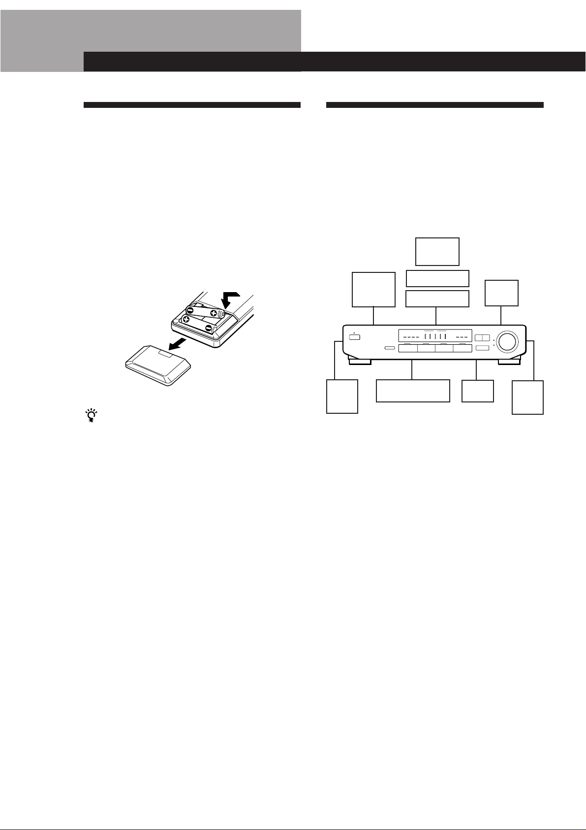
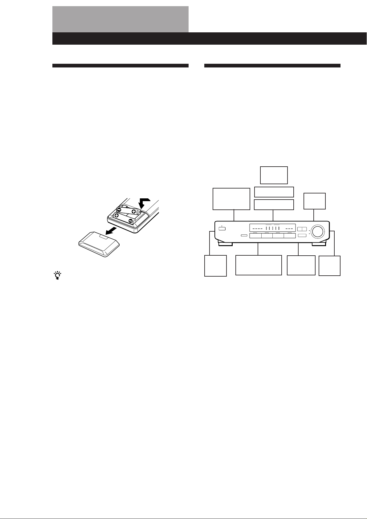
Inserting batteries into the remote
Insert two size AA (R6) batteries with the + and – on
the battery compartment. When using the remote,
point it at the remote sensor g on the processor.
When to replace batteries
Under normal use, the batteries should last for about 6
months. When the remote no longer operates the
processor, replace both batteries with new ones.
Notes
• Do not leave the remote in an extremely hot or humid
place.
• Do not use a new battery with an old one.
• Do not expose the remote sensor to direct sunlight or
lighting apparatuses. Doing so may cause a malfunction.
• If you don’t use the remote for an extended period of time,
remove the batteries to avoid possible damage from
battery leakage and corrosion.
Hookup Overview
The processor allows you to connect and control the
following audio/video components. Follow the
hookup procedures for the components that you want
to connect to the processor on the pages specified. To
learn the locations and names of each jack, see “Rear
Panel Descriptions” on page 17.
TV/VCR Hookups (5)
Speaker System
Hookups (6)
Amplifier
for front
speakers
Rear
speaker
(L)
Control Amplifier,
CD player, etc...
Audio Component
Hookups (5)
Before you get started
• Turn off the power to all components before making
any connections.
• Do not connect the mains lead until all of the
connections are completed.
• Be sure to make connections firmly to avoid hum
and noise.
• When connecting an audio/video cable, be sure to
match the colour-coded pins to the appropriate jacks
on the components: Yellow (video) to Yellow; White
(left, audio) to White; and Red (right, audio) to Red.
TV
VCR
LD player
Active
woofer
Centre
speaker
Rear
speaker
(R)
GB
4
Page 5

Getting Started
VIDEO 2
AUDIO
IN
VIDEO
IN
L
R
OUTPUT
VIDEO
AUDIO
L
R
TV/VCR Hookups
Overview
This section describes how to connect video
components to the processor. For specific locations of
the jacks, see the illustration below.
VIDEO 1
What cables will I need?
• Audio/video cable (not supplied) (2 for the VCR, and 1
for an additional VCR or LD player)
Yellow
White (L)
Red (R)
• Audio cable (not supplied) (1 for the TV)
• Video cable (not supplied) (1 for the MONITOR or TV)
Yellow
Hookups
The arrow ç indicates signal flow.
Monitor (TV)
MONITOR OUT
TV INVIDEO 2
Yellow
White (L)
Red (R)
White (L)White (L)
Red (R)Red (R)
Yellow
VCR
Processor
VIDEO
IN
OUT
L
R
AUDIO
IN
OUT
VIDEO 1
VCR
OUTPUT
VIDEO
AUDIO
INPUT
VIDEO
AUDIO
L
R
VCR or LD player
Processor VCR or LD player
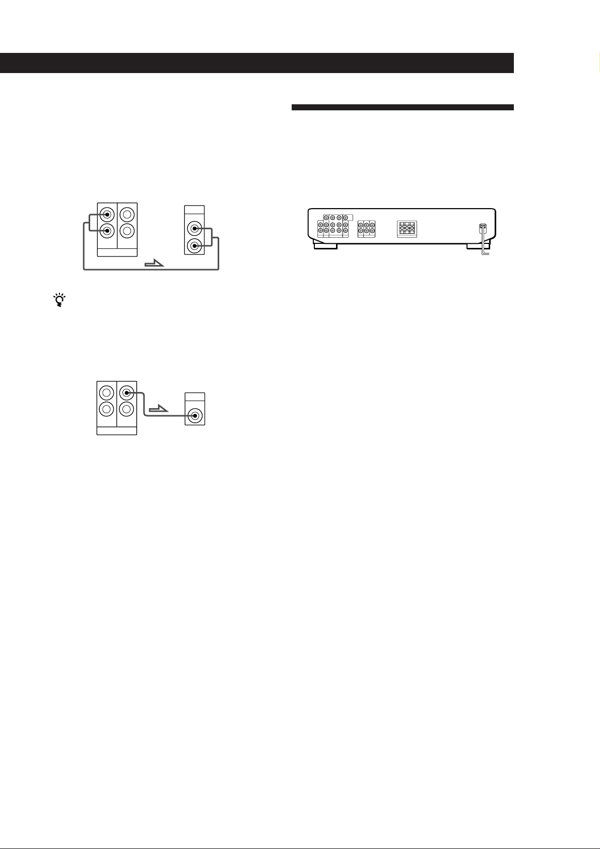
Audio Component Hookups
Overview
This section describes how to connect either an entire
audio system or an individual audio component to the
processor so you can listen to stereo sources in
surround sound.
For specific locations of the jacks, see the illustration
below.
TV
Processor
MONITOR
OUT
Processor
L
R
AUDIO
IN
TV
Monitor (TV)
INPUT
VIDEO
TV
OUTPUT
AUDIO
LINE IN
What cords will I need?
Audio cord (not supplied) (1)
White (L)White (L)
Red (R)Red (R)
L
R
(continued)
GB
5
Page 6

Getting Started
SPEAKERS
REARLRCENTER
L
R
FRONT
OUT
AUX
INPUT
L
R
Hookups
The arrow ç indicates signal flow.
Audio system
Connect the PRE OUT, ADAPTER OUT, or TAPE REC jacks
on your control amplifier to the LINE IN jacks on the
processor.
Processor
L
R
AUDIO
IN
LINE
CD player (etc.)
Connect the LINE OUT jacks on your CD player (etc.) to the
LINE IN jacks on the processor.
Processor
L
R
AUDIO
IN
LINE
Control Amplifier
PRE OUT
L
R
CD Player (etc.)
LINE OUT
L
R
What cords will I need?
Audio cord (not supplied) (1) (for the amplifier powering
the front speakers)
White (L)White (L)
Red (R)Red (R)
What cords will I need?
Speaker cord (not supplied) (1 for each rear speaker and one
for the centre speaker)
(+)
(–)
(+)
(–)
Twist the stripped ends of the cord about 2/3 inch (15 mm).
Be sure to match the speaker cord to the appropriate
terminal on the components: + to + and – to –. If the cords
are reversed, the sound will be distorted and will lack bass.
Hookups
Front speakers
Processor
Amplifier
(for front speakers)
Speaker System Hookups
Overview
This section describes how to connect your speakers to
the processor. Although you can connect rear and
centre speakers directly to the processor, front speakers
must be connected through a separate amplifier (as
shown below). Connecting an active woofer will
increase bass response.
For specific locations of the terminals, see the
illustration below.
FRONT OUT
REAR/CENTER out
For optimum surround sound effect, place your
speakers as shown below.
REAR SPEAKERS
SURROUND
MIX out
CENTER SPEAKERSSURROUND
Rear
Rear and centre speakers
Rear speaker
(R)
Processor
} ]
Active woofer
Processor
CENTER
REAR
MIX
SURROUND
Centre speaker
} ]
Active woofer
INPUT
Rear speaker
(L)
} ]
45°
GB
6
Front
60 - 90 cm
Page 7
• If you need an even more powerful sound
You can connect the rear and centre speakers through
additional amplifiers using the SURROUND REAR out
and SURROUND CENTER out pin jacks.
Rear speakers
Processor
L
R
REAR
SURROUND
CENTER
MIX
Amplifier
(for rear speakers)
AUX
INPUT
L
R
Getting Started
AC Hookups
Connecting the mains lead
Connect the mains lead from this processor and from
your audio/video components to a wall outlet.
/
to a wall
outlet
If you want to use a wireless rear speaker system
Use the SURROUND REAR out pin jacks.
Centre speaker
Processor
CENTER
REAR
MIX
SURROUND
Amplifier
(for centre speaker)
INPUT
Before You Use Your Processor
Make sure that you have turned MASTER VOLUME to
the leftmost position (0).
GB
7
Page 8
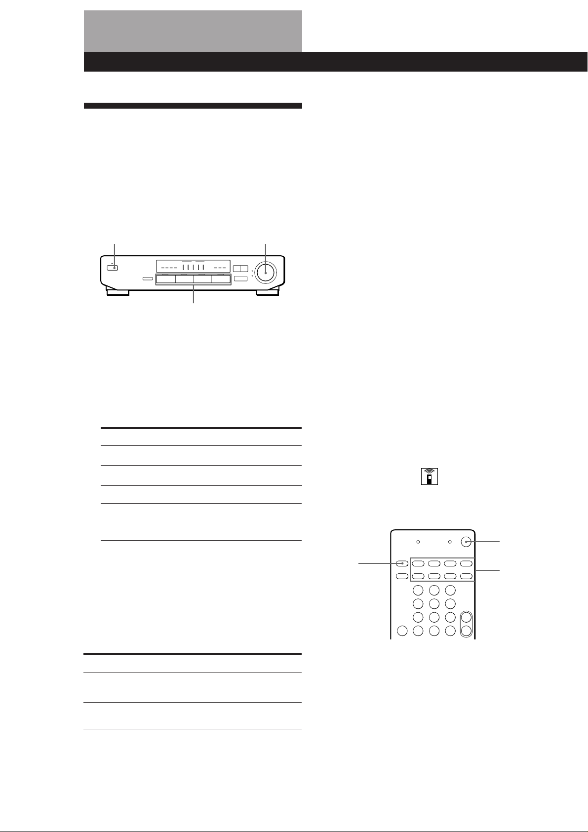
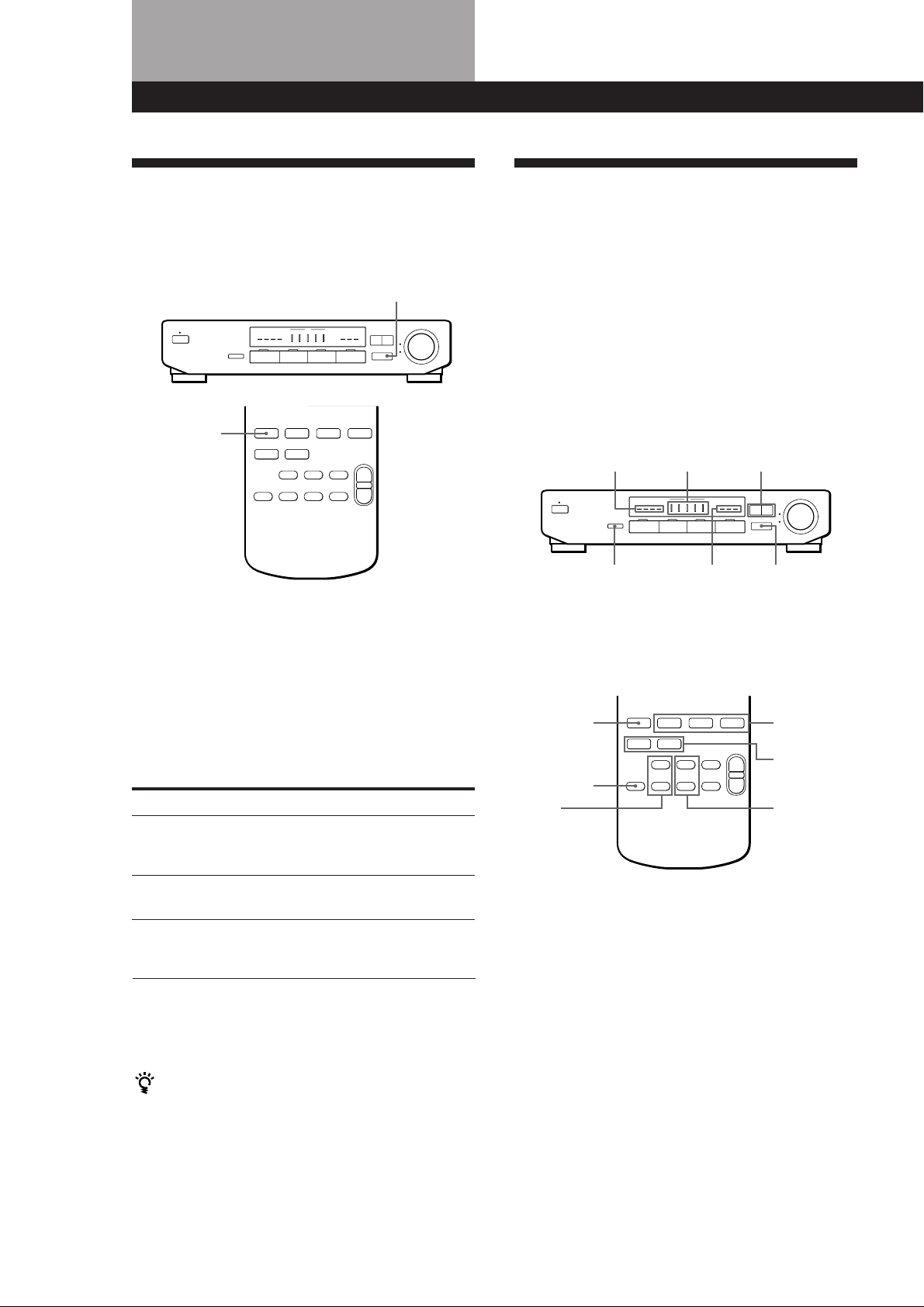
Processor Operations
Selecting a Component
To listen to or watch a connected component, first
select the function on the processor or with the remote.
Before you begin, make sure you have:
• Connected all components securely and correctly as
indicated on pages 5 to 7.
• Turned MASTER VOLUME to the leftmost position
(0) to avoid damaging your speakers.
POWER MASTER VOLUME
Watching video programmes
To take full advantage of the processor’s surround
sound effects, like Dolby Surround, turn off the
speakers on your TV before you start. This also lets you
use the processor’s remote to control the audio.
To watch TV programmes, do the following:
1 Turn on your TV.
2 Turn on the processor and press TV.
3 Turn on the amplifier for the front speakers and
set it’s function selector to AUX.
(If you connected the FRONT OUT jacks to the
amplifier’s AUX IN jacks).
Function buttons
1 Press POWER to turn on the processor.
Using SYSTEM OFF on the remote puts the
processor in STANDBY mode. Press one of the
Function buttons to turn on the power, using the
processor, when it is in STANDBY mode.
2 Press a function button to select the component
you want to use:
To listen to or watch
Video tapes
TV programmes
Laser discs (or video tapes)
Records, Radio programmes,
Compact discs (CD),
Audio tapes, or MiniDiscs (MD)
* If you connected your audio amplifier to the LINE
IN jacks on the processor as shown on page 6, use
the function selector on the amplifier to select the
component you want to listen to (“CD” for example).
Press
VIDEO 1
TV
VIDEO 2
LINE*
3 Turn on the component, the VCR for example,
and start playback.
To watch videos or laser discs, do the following:
1 Turn on your VCR or LD player.
2 Turn on the processor and press VIDEO 1 (to
watch a video).
3 Turn on the amplifier connecting the front
speakers and set it’s function selector to AUX.
(If you connected the FRONT OUT jacks to the
amplifier’s AUX IN jacks).
Using the remote
The remote lets you operate the processor and the Sony
components that are connected to it.
SYSTEM
OFF
VISUAL
POWER
SYSTEM
CONTROL/
FUNCTION
4 Turn MASTER VOLUME to adjust the volume.
To
Mute the sound
Reinforce the bass
GB
8
Do this
Press MUTING. Press again to
restore the sound
Press BASS BOOST to turn on
the BASS BOOST indicator.
1 Press one of the SYSTEM CONTROL/
FUNCTION buttons to select the component you
want to use. When the processor is in STANDBY
mode, the power turns on and the input switches
to the component you selected.
Page 9
Processor Operations
The SYSTEM CONTROL/FUNCTION buttons on
the remote are factory-set as follows:
To listen to Press
Records PHONO*
Radio programmes TUNER*
Compact discs (CD) CD*
Audio tapes (Tape deck B) TAPE*
VHS Video tapes VIDEO 1
(Remote control mode VTR 3)
Laserdiscs VIDEO 2
TV programmes TV
Other components LINE**
* The input selector switches to LINE IN. If you
connect a Sony amplifier (that can be controlled by
infrared wireless remote) to the LINE IN jacks of
the processor, the amplifier’s input selector
automatically switches to the selected component.
** If you connected an additional audio component to
the LINE jacks as shown on page 6.
If you want to change the factory setting of a
button, see page 10.
If the component does not turn on
Press the power switch on the component.
2 Start playing.
Refer to “Remote Button Descriptions” on page 18
for details.
Operating one component while using
another (Background Operation)
You can temporality operate other components while
listening to or watching a programme.
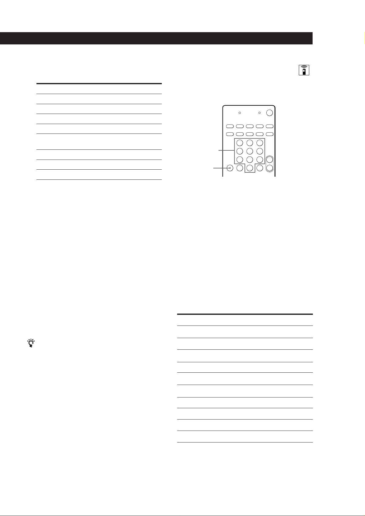
Numeric buttons
BACKGROUND
1 Hold down BACKGROUND.
2 Press both the corresponding numeric button of
the component you’re going to use (see the table
below) and one of the following buttons at the
same time; VISUAL POWER, TV/VIDEO, CH
PRESET +/–, ANT TV/VTR, D.SKIP, (, 9, p,
0 / ) , = / + , P , r .
Example:To start recording on the VCR while
watching TV.
While holding down BACKGROUND,
press 9 (or 8) and press r at the same
time.
The numeric buttons are assigned to select the
functions as follows:
To turn off the components
Press SYSTEM OFF.
If you use a Sony TV
When you press TV to watch a TV programme, the TV
turns on and switches to the TV input. The TV also
turns on when you press VIDEO 1 or VIDEO 2 and
switches to the appropriate video input.
If the TV does not switch to the appropriate input
automatically, press TV/VIDEO on the remote.
Numeric button
1
2
3
4
5
6
7
8
9
0
* Sony VCRs are operated with a VTR 1, 2 or 3 setting.
These correspond to Beta, 8mm and VHS respectively.
Operates
CD player
DAT deck
MD deck
Tape deck A
Tape deck B
LD player
VCR (remote control mode VTR 1*)
VCR (remote control mode VTR 2*)
VCR (remote control mode VTR 3*)
TV
(continued)
GB
9
Page 10
Processor Operations
Changing the factory setting of a
function button
If the factory settings of the FUNCTION buttons don’t
match your system components, you can change them.
For example, if you have a VHS VTR and a 8mm VTR,
you can assign the VIDEO 2 button to operate you
8mm VTR. Note that the settings of the LINE, TUNER
and PHONO buttons cannot be changed.
SYSTEM
CONTROL/
FUNCTION
Numeric buttons
1 Hold down the SYSTEM CONTROL/FUNCTION
button whose function you want to change
(VIDEO 2, for example).
2 Press the corresponding numeric button of the
component you want to assign to the SYSTEM
CONTROL/FUNCTION button (8 = 8mm VTR,
for example).
For the numeric buttons, see the table in
“Operating one component while using another”
on page 9.
Now you can use the VIDEO 2 button to control a
8mm VTR.
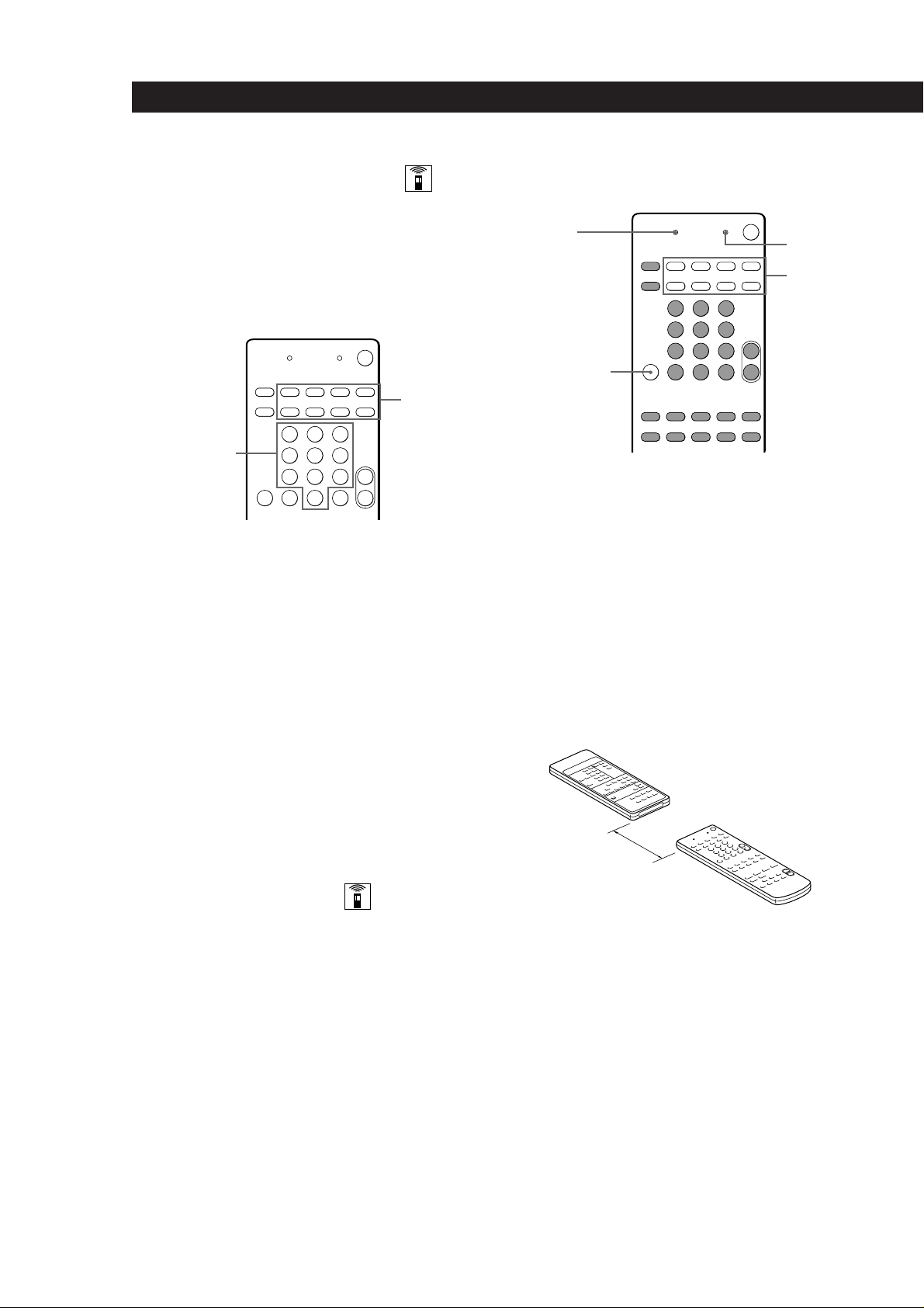
You can programme signals from other remote controls
to the shadded buttons shown below.
LEARN
indicator
BACKGROUND
LEARN
SYSTEM
CONTROL/
FUNCTION
1 Press the SYSTEM CONTROL/FUNCTION
button of the component you want to programme.
For example, if you want to programme a CD
player’s remote, press CD.
2 Press LEARN to turn on the LEARN indicator.
3 Press the button on this unit’s remote that is to
“learn” the signal from the other remote.
The LEARN indicator flashes slowly.
Be sure to use only the shadded buttons shown
above (see “Remote Button Descriptions” on page
18 for the buttons you can use to operate each
component).
Other remote
10
GB
To reset the setting to the factory setting
Repeat the above procedure.
Programming the Remote
The RM-PE300 remote included with the SDP-E300 can
control non-Sony components by “learning” the
control signals from their remotes. Once this remote
learns the other components signals, you can use these
components as part of your system. Additionally, if
you have any Sony components that fail to operate
with this remote, use this programming function. This
remote can “learn” signals only from other infrared
wireless remotes. Before you programme signals, make
sure that the two remotes:
• Face straight at each other (see Step 3 below)
• Are placed at a distance of about 2 inches (5 cm)
• Are not moved during programming
Processor remote
About 2 inches
(5 cm)
If the LEARN indicator flashes rapidly
You cannot use the button you’ve pressed.
4 On the other remote, select the function that the
processor’s remote is to “learn” and hold down its
button until the LEARN indicator lights steadily.
5 Repeat Steps 3 and 4 to programme other buttons.
Note that each button can only “learn” one signal
from another remote.
6 Press LEARN.
After the LEARN indicator turns off, you can
control the other component with the
programmed buttons.
Page 11

When you programme the recording signal
While holding down the r button on the processor’s
remote and press the record button on the other remote.
If you cannot successfully programme signals, check
the following:
• If the LEARN indicator does not light up at all, the
batteries are weak. Replace both batteries.
• If the LEARN indicator does not flash or light up in
Step 3 or 4, there is interference. Clear the signal as
described in “Clearing the programmed signal”
below and programme again from the beginning.
• The two remotes are placed too far apart. Make sure
they are only 2 inches apart.
• If you don’t proceed to the following steps within
about 1 minute during Steps 2 and 3, the remote
automatically exits learning mode. Start again from
Step 2.
• If the memory in the remote has become full, (If you
programme signals of Sony components, you can
store about 30 signals.) You can programme a new
signal on a previously programmed button, but the
new signal will replace the previously programmed
one.
Notes
• You cannot turn on programmed components by pressing
a SYSTEM CONTROL/FUNCTION button. You have to
turn on the component’s power switch.
• Do not programme remote signals of air conditioners or
other household appliances.
Clearing the programmed signal
To clear the programmed signals, do the following.
The button’s functions are reset to the factory-preset.
1 Press LEARN to turn on the LEARN indicator.
Processor Operations
Recording
This processor makes it easy to record to and from the
components connected to the processor. You don’t
have to connect playback and recording components
directly: once you select a programme source on the
processor, you can record and edit as you normally
would using the controls on each component.
Before you begin, make sure you’ve connected all
components properly.
Function buttons
c
ç
c
ç
Playback component
(programme source)
ç: Audio signal flow
c: Video signal flow
Recording on a video tape
You can record from a LD player using the processor.
You can also add audio from a variety of audio sources
when editing a video tape.* See your VCR or LD
player’s instruction manual if you need help.
* If you connect a stereo system, or an individual audio
component, to the LINE IN jacks as shown on page 6.
1 Press VIDEO 2 (if an LD player is connected to the
VIDEO 2 jacks) to select the programme source.
Recording
component
(VCR)
2 While holding down BACKGROUND, hold down
the button to be cleared until the LEARN
indicator turns off.
2 Set the component to be ready for playing.
For example, insert the laser disc you want to
record from into the LD player.
3 Insert a blank video tape into the VCR for
recording.
4 Start recording on the VCR and then start playing
the laser disc you want to record.
You can replace audio while copying a laser disc
At the point you want to start adding different sound,
press LINE (if an audio component system is connected
to the LINE IN jacks, be sure to select the proper source
beforehand) and start playback. The sound from the
selected component will be recorded over the original
audio.
To resume recording the sound of the laser disc, press
the VIDEO 2 function button.
11
GB
Page 12
Using Surround Sound
Choosing a Surround Mode
You can take advantage of surround sound simply by
selecting one of the three pre-programmed surround
modes according to the type of programme you wish
to play.
SURROUND MODE
SURROUND
ON/OFF
1 Press SURROUND MODE to turn on the
surround sound.
One of the SURROUND indicators lights up in the
display.
Getting the Most Out of Dolby
Pro Logic Surround Sound
To obtain the best possible Dolby Pro Logic Surround
sound, first select the centre mode according to the
speaker system you have. Then, adjust the volume of
each speaker.
Note that you must connect the rear speakers and/or
one centre speaker to do the following adjustments.
CENTER MODE
Indicators
CENTER MODE
LEVEL
Indicators
SURROUND
Indicators
EFFECT –/+
SURROUND MODE
2 Press SURROUND MODE repeatedly until the
indicator for the surround mode you want lights
up.
Select the appropriate surround mode as follows:
Select
PRO LOGIC
THEATER
SIMULATED
To turn off surround sound
Press SURROUND ON/OFF on the remote.
You can find Dolby Surround-encoded software by
looking at the packaging
However, some videos and laser discs may use Dolby
Surround sound even if it’s not indicated on the
package.
To
Decode programmes processed with Dolby
Surround and create the atmosphere of a
movie theatre.
Reproduce the acoustics of a movie
theatre. Ideal for soft, acoustic sounds.
Create a simulated surround sound from
monaural sources such as old movies or
TV programmes.
SURROUND
ON/OFF
TEST TONE
REAR
LEVEL +/–
SURROUND
Modes
EFFECT –/+
CENTER
LEVEL +/–
12
GB
Page 13

Using Surround Sound
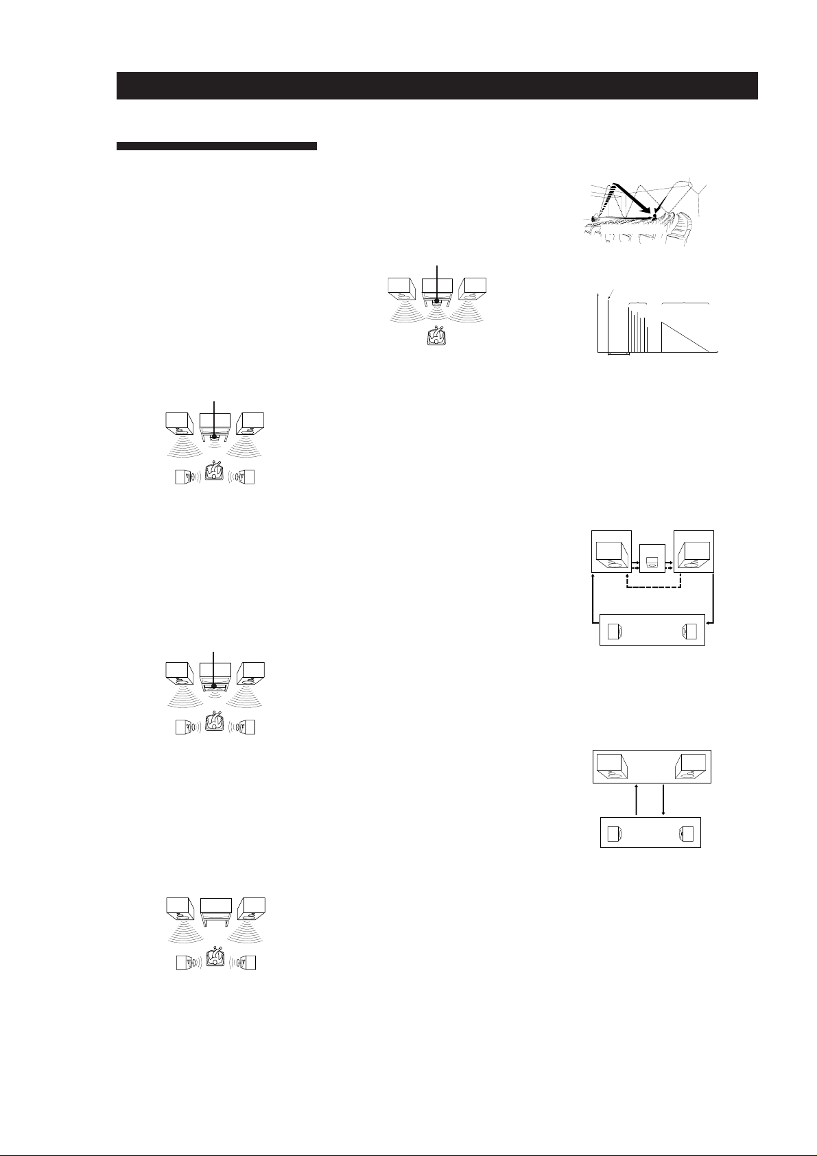
Selecting the centre mode
The processor offers you four centre modes: Phantom,
Normal, Wide, and 3 Channel Logic. Each mode is
designed for a different speaker configuration. Select
the mode that best suits your speaker’s system
configuration:
1 Press SURROUND MODE repeatedly to select the
PRO LOGIC sound field.
2 Press CENTER MODE repeatedly until the
indicator for the centre mode you want lights in
the display.
* The CENTER MODE indicator may not light
immediately when using SURROUND MODE on the
amplifier to selecting the surround mode.
If you have
Front and rear
speakers, no
centre speaker
Front and rear
speakers, and a
small centre
speaker
Front and rear
speakers, and a
large centre
speaker
* Select the centre mode as follows:
Select
PHANTOM
NORMAL
WIDE
So that
The sound of the
centre channel is
output from the front
speakers.
The bass sound of the
centre channel is
output from the front
speakers (because a
small speaker cannot
produce enough
bass).
For “complete”
Dolby Pro Logic
Surround sound.
Adjusting the speaker volume
The test tone feature lets you set the volume of your
speakers to the same level.
You can only use the test tone when the surround
mode is set to Pro Logic.
Using the controls on the remote lets you adjust the
volume level from your listening position.
1 Press TEST TONE on the remote.
You will hear the test tone from each speaker
sequentially.
2 Adjust the volume level so that the test tone from
each speaker is at the same level from your
listening position.
• To adjust the level of centre speaker, press
CENTER LEVEL + or – on the remote.
• To adjust the level of rear speakers, press
REAR LEVEL + or – on the remote.
3 Press TEST TONE on the remote to turn off the
test tone.
You can adjust all speakers at one time
Adjust MASTER VOLUME on the processor or remote.
Note
The centre and rear levels are indicated on the LEVEL meter
in the centre of the display during adjustment.
Front and centre
speakers, no rear
speaker
3 CH LOGIC
(3 Channel
Logic)
The sound of the rear
channel is output
from the front
speakers.
Adjusting the Effect Level
(for THEATER and SIMULATED only)
You can make the surround sound more prominent by
increasing the EFFECT level. This control lets you
adjust the “presence” of the surround effect in five
steps (1-5).
1 Start playing a programme source.
2 Use EFFECT (–/+) to select the level you prefer.
The effect level is indicated on the LEVEL meter
in the centre of the display.
Note
Changing the effect level may not produce major variations
in the surround effect when used with certain playback
sources.
13
GB
Page 14

Additional Information
Troubleshooting
If you experience any of the following difficulties while
using the processor, use this troubleshooting guide to
help you remedy the problem. Should any problem
persist, consult your nearest Sony dealer.
There’s no sound or only a very low-level sound is heard.
/ Check that the speakers and components are
connected securely.
/ Press MUTING if the MUTING indicator
turns on.
/ Make sure you select the correct component
on the processor.
/ Make sure you select the correct component
on the amplifer for the front speakers.
The left and right sounds are unbalanced or reversed.
/ Check that the speakers and components are
connected correctly and securely.
Recording cannot be made.
/ Check that the components are connected
correctly.
The remote does not function.
/ Point the remote at the remote sensor g on
the processor.
/ Remove the obstacles in the path of the
remote and the processor.
/ Replace both batteries in the remote with new
ones if they are weak.
/ Make sure you select the correct function on
the remote.
The CENTER MODE indicator does not light immediately.
/ The CENTER MODE indicator may not light
immediately when using SURROUND MODE
on the amplifier to selecting the surround
mode.
Severe hum or noise is heard.
/ Check that the speakers and components are
connected securely.
/ Check that the connecting cords are away
from a transformer or motor, and at least 10
feet (3 meters) away from a TV set or
fluorescent light.
/ Place your TV away from the audio
components.
/ The plugs and jacks are dirty. Wipe them
with a cloth slightly moistened with alcohol.
No sound or only a very low-level sound is heard from
the rear speakers.
/ Select the appropriate centre mode (see page
13).
/ Adjust the speaker volume appropriately (see
page 13).
/ Make sure you turned on the surround mode.
No sound is heard from the centre speaker.
/ Select the appropriate centre mode (see page
13).
/ Adjust the speaker volume appropriately (see
page 13).
14
Surround effect cannot be obtained.
/ Make sure you turn on the surround mode.
No picture or an unclear picture is seen on the TV screen.
/ Select the appropriate function on the
processor.
/ Place your TV away from the audio
components.
GB
Page 15

Specifications
Amplifier section
Power output
Additional Information
Surround mode
Frequency
response
Audio section
Inputs
Sensitivity
VIDEO 1,
VIDEO 2,
TV, LINE
Outputs
(DIN 1 kHz)
Centre:
40 W/8 ohms
(only in the PRO LOGIC
and THEATER modes)
Rear:
20 W + 20 W/8 ohms
VIDEO 1 + 2, TV, LINE:
20 Hz - 20 kHz ±2 dB
Impedance
150 mV
kilohms
VIDEO 1 REC:
Voltage 150 mV,
Impedance 470 ohms
FRONT, CENTER, REAR,
MIX:
Voltage: 1 V
Impedance: 1 kilohms
50
BASS BOOST
Video section
Inputs
Outputs
General
Power
requirements
Power
consumption
Dimensions
Mass (Approx.)
Supplied
accessories
+7 dB at 60 Hz
VIDEO 1, VIDEO 2,
TV, LINE:
1 Vp-p 75 ohms
VIDEO 1 REC,
VIDEO MONITOR:
1 Vp-p 75 ohms
220 - 230 V AC, 50/60 Hz
90 W
430 x 95 x 280 mm
3
/4 x 11 1/8 in)
(17 x 3
4.6 kg
(10 lb 2 oz)
Remote controller
(remote) (1)
Size AA (R6) batteries (2)
Design and specifications are subject to
change without notice.
15
GB
Page 16
Additional Information
Glossary
Centre mode
Setting of speakers to enhance Dolby Pro
Logic Surround mode. To obtain the best
possible surround sound, select one of the
following four centre modes according to
your speaker system.
• NORMAL mode
Select NORMAL mode if you have front
and rear speakers and a small centre
speaker. Since a small speaker cannot
produce enough bass, the bass sound of
the centre channel is output from the front
speakers.
Front
speaker (L)
speaker (L)
Centre
speaker
Rear
• WIDE mode
Select WIDE mode if you have front and
rear speakers and a large centre speaker.
With the WIDE mode, you can take full
advantage of Dolby Surround sound.
Front
speaker (L)
Centre
speaker
Rear
speaker (L)
• PHANTOM mode
Select PHANTOM mode if you have front
and rear speakers but no centre speaker.
The sound of the centre channel is output
from the front speakers.
Front
speaker (L)
Front
speaker (R)
Rear
speaker (R)
Front
speaker (R)
Rear
speaker (R)
Front
speaker (R)
• 3 CH LOGIC mode
Select 3 CH LOGIC mode if you have front
and centre speakers but no rear speaker.
The sound of the rear channel is output
from the front speakers to let you
experience some of the surround sound
without using rear speakers.
Front
speaker (L)
Centre
speaker
Front
speaker (R)
Dolby Pro Logic Surround
Decoding system of Dolby Surround sound
standardized in TV programmes and movies.
Compared with the former Dolby Surround
system, Dolby Pro Logic Surround improves
sound image by using four separate channels:
off-screen audio effects, on-screen dialog,
left-to-right panning, and music. These
channels manipulate the sound to be heard
and enhance the action as it happens on the
screen. To take advantage of Dolby Pro Logic,
you should have at least one pair of rear
speakers and/or one centre speaker. You also
need to select the appropriate centre mode to
enjoy a full effect.
Dolby Surround
Encoding and decoding system of Dolby
Surround sound for consumer use. Dolby
Surround decodes the extra channels on the
Dolby Surround-encoded sound tracks of
movie videos and TV programmes and
produces sound effects and echoes that make
the action seem to envelop you.
The processor offers Dolby Surround as one
of the pre-programmed sound fields. If you
have rear or centre speaker(s), we
recommend that you customize the Dolby
Surround sound field by selecting the
appropriate centre mode to take advantage of
Dolby Pro Logic Surround sound.
Surround sound
Sound that consists of three elements: direct
sound, early reflected sound (early
reflections) and reverberative sound
(reverberation). The acoustics where you hear
the sound affect the way these three sound
elements are heard. These sound elements are
combined in such a way that you can actually
feel the size and the type of a concert hall.
• Types of sound
Early reflections
Direct sound
Reverberation
• Transition of sound from rear speakers
Direct sound
Level
Early reflection time
Early
reflections Reverberation
Time
Test tone
Signal given out by the processor for
adjusting the speaker volume. The test tone
will come out as follows:
• In a system with a centre speaker
(NORMAL/WIDE/3 CH LOGIC modes)
The test tone is output from the front L
(left), centre, front R (right), and rear
speakers in succession.
Front (L)
3 CH LOGIC
Rear (L, R)
NORMAL/WIDE
Front (R)
Centre
• In a system without a centre speaker
(PHANTOM mode)
The test tone is output from the front and
the rear speakers alternately.
Front (L, R)
PHANTOM
Rear (L, R)
16
GB
Rear
speaker (L)
Rear
speaker (R)
Page 17

Index
Index
A
Adjusting
effect level 13
speaker volume 13
volume 8
Audio component hookups 5
B
Background operation 9
C
Centre mode 13, 16
NORMAL mode 13, 16
PHANTOM mode 13, 16
3 CH LOGIC mode 13, 16
WIDE mode 13, 16
Connecting. See Hookups
D
Dolby Pro Logic
Surround 16
getting the most out of 12
Dolby Surround sound 12, 16
centre mode 13, 16
Dubbing. See Recording
E, F, G
Editing. See Recording
H, I, J, K, L, M
Hookups
audio components 5
mains lead 7
overview 4
speakers 6
TV/VCRs 5
N, O
NORMAL mode 13, 16
P, Q
PHANTOM mode 13, 16
Programme source
selecting 8, 9
Programming the remote 10
R
Rear panel 5, 6, 7, 17
Recording
on a video tape 11
Remote buttons 8, 9, 10, 12, 18
background operation 9
S
Selecting a programme source
8
using the remote 8
Speakers
connection 6
impedance 15
placement 6
Surround sound 12, 13, 16
T
Test tone 13, 16
3 CH LOGIC mode 13, 16
Troubleshooting 14
TV/VCR hookups 5
U, V
Unpacking 4
W, X, Y, Z
Watching video programmes
8
WIDE mode 13, 16
Rear Panel Descriptions
1 LINE (AUDIO) IN
2 VIDEO 2 IN
3 VIDEO 1 IN/OUT
4 MONITOR OUT
0!¡54623 7891
5 TV (AUDIO) IN
6 FRONT OUT
7 SURROUND REAR out
8 SURROUND CENTER out
!™
9 SURROUND MIX out
0 SPEAKERS (REAR)
!¡SPEAKER (CENTER)
!™ mains lead
17
GB
Page 18

Remote Button Descriptions
Remote Button Descriptions
For buttons not described on previous pages and buttons with names different from the buttons on the main unit.
Remote
Button
0-9
>10
CH/PRESET
+/–
D. SKIP
0 / )
Operates
Receiver
CD player/MD
recorder/LD
player
TV/VCR
CD player/
Tape deck/
LD player/
MD recorder
Receiver
TV/VCR
CD player
CD player
Tape deck/MD
recorder/VCR/
LD player
Function
Selects preset numbers.
Selects track numbers.
0 selects track 10.
Selects channel numbers.
Selects track numbers
over 10.
Scans and selects preset
stations.
Selects preset channels.
Skips discs (CD player
with multi-disc changer
only.)
Searches tracks (forward
or backward).
Fastforwards or rewinds.
Remote
Button
RMS
DIRECTION
RMS CLEAR
RMS/START
ENTER
TV/VIDEO
VISUAL
POWER
-/- -
Operates
Tape deck
Tape deck
Tape deck
TV/VCR
TV/VCR
TV/VCR/LD
player
TV
Function
Selects tape direction (for
tape decks with the RMS*
function.)
Clears RMS* programme
(for tape decks with the
RMS function.)
Programmes tracks (tape
deck with the RMS*
function only).
Changes channels when
used with 0-9.
Selects input signal: TV
input or video input.
Press this button followed
by the SYSTEM
CONTROL/FUNCTION
button of the visual
component you want to
turn off.
Selects the channel entry
mode, either one or two
digit.
= / +
P
(
p
9
r
r + (
CD player/
MD recorder/
LD player
VCR
CD player/
Tape deck/MD
recorder/LD
player/VCR
CD player/
Tape deck/MD
recorder/LD
player/VCR
CD player/
Tape deck/MD
recorder/LD
player/VCR
Tape deck
Tape deck/
MD recorder
Tape deck/
VCR
Skips tracks.
Index search
Pauses play or record.
(Also starts recording
with components in
record standby.)
Starts play.
Stops play.
Starts play on the reverse
side (for auto-reverse
decks).
Sets tape decks to the
record standby mode.
Starts recording when
pressed with ( (or 9
on tape deck).
SUB CH +/–
POSI
SWAP
P IN P
ANT TV/VTR
* RMS: Random Music Sensor
** Only for Sony TVs with the picture-in-picture function
TV
TV
TV
TV
VCR
Selects preset channels for
the small picture.**
Changes the position of
the small picture.**
Swaps the small and the
large picture.**
Activates the picture-inpicture function.**
Selects output signal from
the aerial terminal: TV
signal or VCR
programme.
18
GB
Page 19

A VERTISSEMENT
Afin d’éviter tout risque
d’incendie ou
d’électrocution, éviter
d’exposer l’appareil à la
pluie ou à l’humidité.
Afin d’écarter tout risque
d’électrocution, garder le coffret fermé.
Ne confier l’entretien de l’appareil qu’à
un personnel qualifié.
Précautions
Sécurité
• Si un solide ou un liquide tombait
dans le coffret, débranchez le
processeur et faites-le vérifier par un
technicien qualifié avant de le
remettre en service.
Sources d’alimentation
• Avant de mettre le processeur en
service, vérifiez que la tension de
fonctionnement correspond à celle du
courant secteur local. La tension de
fonctionnement est indiquée sur la
plaque signalétique à l’arrière du
processeur.
• Le processeur n’est pas déconnecté de
la source d’alimentation tant qu’il est
branché sur une prise murale, même
si vous le mettez hors tension.
• Si vous ne comptez pas utiliser le
processeur pendant un certain temps,
débranchez-le de la prise murale.
Pour débrancher le cordon, tirez sur
la fiche et jamais sur le cordon
proprement dit.
• Si le cordon d’alimentation secteur
doit être remplacé, faites appel à un
professionnel uniquement.
• L’interrupteur d’alimentation se
trouve sur le panneau avant.
Nettoyage
• Nettoyez le coffret, le panneau et les
commandes avec un chiffon doux
légèrement imprégné d’une solution
détergente neutre. N’utilisez pas de
tampon abrasif, poudre à récurer ou
solvant, comme de l’alcool ou de la
benzine.
En cas de question ou de problème
concernant le processeur, consultez le
revendeur Sony le plus proche.
Installation
• N’installez pas le processeur dans un
espace confiné comme dans une
bibliothèque ou un meuble encastré.
• Installez le processeur dans un
endroit bien ventilé pour éviter tout
risque de surchauffe interne et
prolonger la durée de vie des
composants.
• N’installez pas le processeur près
d’une source de chaleur, dans un
endroit en plein soleil, poussiéreux
ou exposé à des chocs mécaniques.
• Ne posez rien sur le coffret qui puisse
bloquer les orifices de ventilation et
provoquer un mauvais
fonctionnement.
Fonctionnement
• Avant de raccorder d’autres
appareils, mettez le processeur hors
tension et débranchez-le.
F
2
Page 20
Au sujet de ce
manuel
Conventions
• Ce mode d’emploi décrit les
commandes du processeur. Vous
pouvez également utiliser les
commandes de la télécommande qui
ont un nom identique ou similaire à
celles du processeur.
• Le paragraphe “Description de la
télécommande” à la page 18 fournit
une description des commandes de la
télécommande.
• Les icônes suivants sont utilisés dans
ce manuel:
Indique que vous ne pouvez
utiliser que la télécommande
pour effectuer cette opération.
Donne des conseils
supplémentaires pour faciliter
l’utilisation.
Ce processeur utilise le système
surround Dolby.
Fabriqué sous licence de Dolby
Laboratories Licensing Corporation.
DOLBY, le symbole double-D aet PRO
LOGIC sont des marques de Dolby
Laboratories Licensing Corporation.
TABLE DES MATIÈRES
Préparatifs
Déballage 4
Description des raccordements 4
Raccordement d’un téléviseur/magnétoscope 5
Raccordement de composants audio 5
Raccordement d’enceintes 6
Raccordement au courant secteur 7
Fonctionnement du processeur
Sélection d’un composant 8
Enregistrement 11
Ecoute du son surround
Choix d’un mode surround 12
Utilisation optimale du son surround Dolby Pro Logic 12
Informations supplémentaires
Guide de dépannage 14
Spécifications 15
Glossaire 16
Index 17
Nomenclature du panneau arrière 17
F
Description de la télécommande 18
F
3
Page 21
Préparatifs
Déballage
Vérifiez si les accessoires suivants se trouvent dans
l’emballage:
• Télécommande (1)
• Piles de format AA (R6) (2)
Mise en place des piles dans la
télécommande
Insérez deux piles de format AA (R6) en faisant
correspondre les bornes + et – avec le schéma dans le
logement. Pour utiliser la télécommande, dirigez-la
vers le détecteur infrarouge g sur le processeur.
Description des raccor dements
Vous pouvez raccorder au processeur les composants
audio/vidéo suivants. Selon les composants que vous
voulez raccorder au processeur, reportez-vous aux
pages indiquées pour les connexions. Pour plus de
détails sur les différentes prises du processeur,
reportez-vous à “Description du panneau arrière” page
17.
Raccordement d’un
téléviseur/
magnétoscope (5)
Raccordement
d’enceintes (6)
Amplificateur
pour enceintes
avant
Téléviseur
Magnétoscope
Lecteur LD
Enceinte
centrale
Quand remplacer les piles
Dans des conditions d’utilisation normales, les piles
durent environ six mois. Quand vous ne pouvez plus
contrôler le processeur avec la télécommande,
remplacez les piles par des neuves.
Remarques
• Ne laissez pas la télécommande dans un endroit
extrêmement chaud ou humide.
• N’utilisez pas une pile neuve avec une vieille pile.
• Ne pas exposer le détecteur infrarouge aux rayons directs
du soleil ou à un éclairage pour éviter tout mauvais
fonctionnement.
• Si vous prévoyez de ne pas utiliser la télécommande
pendant longtemps, enlevez les piles pour éviter tout
dommage dû à une fuite d’électrolyte et à la corrosion.
Enceinte
arrière
(gauche)
Amplificateur de
control, lecteur
CD, etc.
Raccordement de
composants audio (5)
Caisson de
grave
amplifié
Enceinte
arrière
(droite)
Avant de commencer
• Mettez tous les composants hors tension avant
d’effectuer les connexions.
• Effectuez toutes les connexions avant de brancher le
cordon d’alimentation secteur.
• Enfoncez les fiches correctement pour éviter un
bourdonnement et du bruit.
• Lors du raccordement d’un câble audio/vidéo, faites
correspondre les fiches codées par couleur aux prises
des composants: jaune (vidéo) à jaune, blanc (audio,
gauche) à blanc et rouge (audio, droit) à rouge.
F
4
Page 22

Raccordement d’un téléviseur/
VIDEO 2
AUDIO
IN
VIDEO
IN
L
R
OUTPUT
VIDEO
AUDIO
L
R
magnétoscope
Aperçu
Ce paragraphe explique comment raccorder des
composants vidéo au processeur. L’illustration cidessous indique l’emplacement des prises.
Magnétoscope
Processeur Magnétoscope
OUT
L
R
OUT
VIDEO
IN
AUDIO
IN
VIDEO 1
Préparatifs
OUTPUT
INPUT
VIDEO
VIDEO
AUDIO
AUDIO
L
R
VIDEO 1
MONITOR OUT
TV INVIDEO 2
De quels cordons avez-vous besoin?
• Vous avez besoin de câbles audio/vidéo (non fournis) (2
pour le magnétoscope et 1 pour un second magnétoscope
ou un lecteur LD)
Jaune
Blanc (gauche)
Rouge (droit)
Jaune
Blanc (gauche)
Rouge (droit)
• Câble audio (non fourni) (1 pour le téléviseur)
Blanc (gauche)
Rouge (droit)
Blanc (gauche)
Rouge (droit)
• Câble vidéo (non fourni) (1 pour le moniteur ou le
téléviseur)
Jaune Jaune
Raccordements
La flèche ç indique le sens du signal.
Magnétoscope ou lecteur LD
Processeur
Magnétoscope ou
lecteur LD
Raccordement de composants
audio
Aperçu
Ce paragraphe explique comment raccorder toute une
chaîne ou un élément seulement au processeur pour
écouter des sources stéréo en surround.
L’illustration ci-dessous indique l’emplacement des
prises.
Moniteur (Téléviseur)
Processeur
Téléviseur
Processeur
L
R
AUDIO
IN
TV
MONITOR
OUT
Moniteur (Téléviseur)
INPUT
VIDEO
Téléviseur
OUTPUT
AUDIO
L
R
LINE IN
De quels cordons avez-vous besoin?
Câble audio (non fourni) (1)
Blanc (gauche)
Rouge (droit)
(continuer page suivante)
Blanc (gauche)
Rouge (droit)
F
5
Page 23

Préparatifs
L
R
FRONT
OUT
AUX
INPUT
L
R
SPEAKERS
REARLRCENTER
Raccordements
La flèche ç indique le sens du signal.
Chaîne audio
Raccorder les prises PRE OUT, ADAPTER OUT, ou TAPE
REC de l’amplificateur de contrôle aux prises LINE IN du
processeur.
Processeur
L
R
AUDIO
IN
LINE
Amplificateur de
contrôle
PRE OUT
L
R
Lecteur CD (ou autre)
Raccordez les prises LINE OUT de votre lecteur CD (ou
autre appareil) aux prises LINE IN du processeur.
Processeur
L
R
AUDIO
IN
LINE
Lecteur CD
LINE OUT
L
R
Raccordement d’enceintes
Pour obtenir un effet surround optimum, positionnez
les enceintes comme illustré ci-dessous.
Arrière
60 - 90 cm
45°
Avant
De quels cordons avez-vous besoin?
Câble audio (non fourni) (1) (pour l’amplificateur entraînant
les enceintes avant)
Blanc (gauche)
Rouge (droit)
Blanc (gauche)
Rouge (droit)
De quels cordons avez-vous besoin?
Vous avez besoin de cordons d’enceintes (non fournis) (1
pour chaque enceinte arrière et un pour l’enceinte centrale)
(+)
(–)
Dénudez environ 15 mm de gaine à chaque extrémité du
cordon. Veillez à faire correspondre les bornes des cordons
d’enceintes aux bornes des composants: + à + et – à –. Si les
cordons sont inversés, le son sera déformé et les graves
feront défaut.
(+)
(–)
Aperçu
Ce paragraphe décrit la liaison des enceintes au
processeur. Bien qu’il soit possible de raccorder des
enceintes arrière et centrale directement au processeur,
les enceintes avant doivent être raccordées à un
amplificateur séparé, comme indiqué ci-dessous. Le
raccordement d’un caisson de grave amplifié
améliorera la réponse des graves.
L’illustration ci-dessous indique l’emplacement des
bornes du processeur.
FRONT OUT REAR SPEAKERS
Sortie SURROUND
REAR/CENTER
Sortie
SURROUND
MIX
CENTER SPEAKERS
Raccordements
Enceintes avant
Processeur
Enceintes centrale et arrière
Enceinte
arrière (droite) Processeur
} ]
Amplificateur (pour
enceintes avant)
Enceinte
centrale
} ]
Enceinte
arrière
(gauche)
} ]
F
6
Page 24

Caisson de grave amplifié
Processeur
CENTER
Caisson de grave
INPUT
Préparatifs
Raccordement au courant
secteur
REAR
MIX
SURROUND
• Pour obtenir un son plus puissant
Vous pouvez raccorder les enceintes arrière et centrale à
des amplificateurs auxiliaires par les prises de sortie
SURROUND REAR et SURROUND CENTER.
Enceintes arrière
Processeur
CENTER
L
R
REAR
MIX
SURROUND
Amplificateur (pour
enceintes arrière)
AUX
INPUT
L
R
Si vous voulez utiliser un système d’enceintes
arrière infrarouge
Utilisez les prises de sortie SURROUND REAR.
Enceinte centrale
Branchement du cordon d’alimentation
secteur
Branchez le cordon d’alimentation secteur du
processeur et des composants audio/vidéo sur une
prise murale.
/
à une prise murale
Avant d’utiliser le processeur
Assurez-vous que la commande MASTER VOLUME
est tournée complètement vers la gauche (0).
Processeur Amplificateur (pour
l’enceinte centrale)
INPUT
REAR
SURROUND
CENTER
MIX
F
7
Page 25

Fonctionnement du processeur
Sélection d’un composant
Pour écouter ou regarder un composant raccordé, vous
devez d’abord sélectionner la fonction sur le
processeur ou avec la télécommande.
Avant tout, vérifiez que:
• Vous avez raccordé tous les composants
correctement comme indiqué aux pages 5 à 7.
• Vous avez tourné la commande MASTER VOLUME
complètement à gauche (position 0) pour éviter
d’endommager les enceintes.
POWER MASTER VOLUME
Touches de fonction
1 Appuyez sur POWER pour mettre le processeur
sous tension.
La touche SYSTEM OFF sur la télécommande met
le processeur en mode STANDBY. Appuyez sur
une des touches de fonction pour mettre
l’appareil sous tension par le processeur quand il
est en mode STANDBY.
2 Appuyez sur une touche de fonction pour
sélectionner un composant:
Pour
Couper le son
Renforcer les graves
Vous devez
Appuyer sur MUTING.
Appuyez de nouveau pour
rétablir le son.
Appuyer sur BASS BOOST
pour allumer l’indicateur
BASS BOOST.
Pour regarder des programmes vidéo
Pour tirer le meilleur parti des effets surround du
processeur, tel le Dolby Surround, désactivez les hautparleurs du téléviseur. Vous pourrez ainsi utiliser la
télécommande pour contrôler le son.
Pour regarder des émissions de télévision, procédez
comme suit:
1 Allumez le téléviseur.
2 Allumez le processeur et appuyez sur TV.
3 Allumez l’amplificateur pour les enceintes avant
et réglez le sélecteur de fonction sur AUX.
(Si vous avez raccordé les prises FRONT OUT aux
prises AUX IN de l’amplificateur).
Pour regarder des vidéos ou des disques laser, procédez
comme suit:
1 Allumez le magnétoscope ou le lecteur LD.
Pour écouter ou regarder
Cassettes vidéo
Programmes de télévision
Disques laser (ou cassettes vidéo)
Disques analogiques, programmes
radio, disques compacts (CD),
cassettes audio ou minidisques (MD)
* Si vous raccordez votre amplificateur audio aux
prises LINE IN du processeur, comme indiqué à la
page 6, utilisez le sélecteur de fonction sur
l’amplificateur pour sélectionner le composant que
vous voulez écouter, par exemple CD.
Appuyer sur
VIDEO 1
TV
VIDEO 2
LINE*
3 Mettez le composant, par exemple le
magnétoscope, sous tension et commencez la
lecture.
4 Tournez la commande MASTER VOLUME pour
régler le volume.
2 Allumez le processeur et appuyez sur VIDEO 1
(pour regarder une vidéo).
3 Allumez l’amplificateur relié aux enceintes avant
et réglez le sélecteur de fonction sur AUX.
(Si vous avez raccordé les prises FRONT OUT aux
prises AUX IN de l’amplificateur).
Utilisation de la télécommande
La télécommande vous permet de contrôler le
processeur et les composants Sony raccordés.
SYSTEM
OFF
VISUAL
POWER
SYSTEM
CONTROL/
FUNCTION
F
8
Page 26

Fonctionnement du processeur
1 Appuyez sur une des touches SYSTEM
CONTROL/FUNCTION pour sélectionner le
composant à utiliser. Quand le processeur est en
mode STANDBY, il se met sous tension et se règle
sur l’entrée du composant sélectionné.
Le tableau suivant indique le réglage usine des
touches SYSTEM CONTROL/FUNCTION de la
télécommande.
Pour reproduire Appuyez sur
Des disques analogiques PHONO*
Des émissions de radio TUNER*
Des disques compacts (CD) CD*
Cassettes audio TAPE*
(Platine à cassette B)
Cassettes vidéo VHS VIDEO 1
(mode de télécommande VTR 3)
Disques laser VIDEO 2
Des programmes TV TV
Autres comoposants LINE**
* Le sélecteur d’entrée se règle sur LINE IN. Si vous
raccordez un amplificateur Sony (pouvant être
piloté par une télécommande infrarouge) aux
prises LINE IN du processeur, le sélecteur d’entrée
de l’amplificateur se règle automatiquement sur le
composant sélectionné.
** Si vous raccordez un composant audio
supplémentaire aux prises LINE, comme indiqué à
la page 6.
Pour changer le réglage usine d’une touche, voir
page 10.
Utilisation simultanée de plusieurs
composants (Fonctionnement simultané)
Vous pouvez passer momentanément à un autre
composant pendant que vous écoutez ou regardez un
programme.
Touches
numériques
BACKGROUND
1 Tenez la touche BACKGROUND enfoncée.
2 Appuyez simultanément sur la touche numérique
correspondant au composant (voir le tableau cidessous) et sur une des touches suivantes:
VISUAL POWER, TV/VIDEO, CH PRESET +/–,
ANT TV/VTR, D.SKIP, (, 9, p, 0/),
= / +, P , r .
Exemple:Pour commencer un enregistrement sur
le magnétoscope tout en regardant la
télévision.
Tout en tenant la touche
BACKGROUND enfoncée, appuyez
simultanément sur 9 (ou 8) et sur r.
Les touches numériques sélectionnent les fonctions
comme suit:
Touche numérique
Pour sélectionner
Si le composant ne se met pas sous tension
Appuyez sur l’interrupteur d’alimentation sur le
composant.
2 Démarrez la lecture.
Pour plus de détails, voir “Description de la
télécommande” page 18.
Pour mettre les composants hors tension
Appuyez sur SYSTEM OFF.
Si vous avez un téléviseur Sony
Quand vous appuyez sur TV pour regarder un
programme TV, le téléviseur se met automatiquement
sous tension et se règle sur l’entrée TV. Le téléviseur se
met également sous tension et se règle sur l’entrée
appropriée quand vous appuyez sur la touche VIDEO 1
ou VIDEO 2. Si le téléviseur ne se règle pas
automatiquement sur l’entrée appropriée, appuyez sur
la touche TV/VIDEO de la télécommande.
1
2
3
4
5
6
7
8
9
0
* Les magnétoscopes Sony utilisent les modes de
télécommande VTR 1, 2 et 3 qui correspondent aux
systèmes Beta, 8 mm et VHS.
Le lecteur CD
La platine DAT
L’enregistreur MD
La platine à cassette A
La platine à cassette B
Le lecteur LD
Le magnétoscope (mode de
télécommande VTR 1*)
Le magnétoscope (mode de
télécommande VTR 2*)
Le magnétoscope (mode de
télécommande VTR 3*)
Le téléviseur
(continuer page suivante)
F
9
Page 27

Fonctionnement du processeur
Changement des réglages usine des
touches de fonction
Si les réglages usine des touches de FUNCTION ne
correspondent pas aux composants que vous utilisez,
vous pouvez les changer. Par exemple, si vous avez un
magnétoscope VHS et un magnétoscope 8 mm, vous
pouvez assigner la touche VIDEO 2 pour le contrôle du
magnétoscope 8 mm. Toutefois, vous ne pouvez pas
changer les réglages des touches LINE, TUNER et
PHONO.
SYSTEM
CONTROL/
Touches
numériques
FUNCTION
1 Tenez enfoncée la touche SYSTEM CONTROL/
FUNCTION dont vous voulez changer la fonction
(par exemple, VIDEO 2).
2 Appuyez sur la touche numérique correspondant
au composant auquel vous voulez assigner la
touche SYSTEM CONTROL/FUNCTION (par
exemple, 8 = magnétoscope 8 mm).
Pour plus de détails sur les touches numériques,
voir le tableau dans “Utilisation simultanée de
plusieurs composants” page 9.
Maintenant, vous pouvez utiliser la touche
VIDEO 2 pour contrôler le magnétoscope 8 mm.
Pour revenir au réglage usine
Refaites les opérations précédentes.
Vous pouvez programmer des signaux d’autres
télécommandes sur les touches grises ci-dessous.
Indicateur
LEARN
BACKGROUND
LEARN
SYSTEM
CONTROL/
FUNCTION
1 Appuyez sur la touche SYSTEM CONTROL/
FUNCTION de l’appareil à programmer. Par
exemple, si vous voulez programmer la
télécommande d’un lecteur CD, appuyez sur CD.
2 Appuyez sur LEARN pour que l’indicateur
LEARN s’allume.
3 Appuyez sur la touche de la télécommande du
processeur qui doit “apprendre” le signal de
l’autre télécommande. L’indicateur LEARN
clignote lentement.
Veillez à utiliser les touches grises indiquées cidessus (voir “Description de la télécommande” à
la page 18 pour savoir quelles touches vous
pouvez utiliser pour chaque composant).
Autre télécommande
Télécommande du
processeur
Environ 5 cm
(2 pouces)
10
Programmation de la télécommande
La télécommande RM-PE300 fournie avec le processeur
SDP-E300 peut piloter des appareils d’une autre
marque si vous programmez les signaux de contrôle de
leurs télécommandes. Une fois que la télécommande a
“appris” les signaux des autres appareils, vous pouvez
les utiliser comme composants de la chaîne. De même,
si vous avez des appareils Sony qui ne répondent pas
aux signaux de la télécommande, utilisez cette fonction
de programmation. Cette télécommande peut
“apprendre” uniquement les signaux d’une
télécommande infrarouge. Avant la programmation,
vérifiez que les deux télécommandes:
• se trouvent face à face (voir l’étape 3 ci-dessous).
• se trouvent à une distance de 5 cm l’une de l’autre.
F
• ne sont pas déplacées pendant la programmation.
Si l’indicateur LEARN clignote rapidement
Vous ne pouvez pas utiliser la touche que vous avez
enclenchée.
4 Sur l’autre télécommande, sélectionnez la fonction
que la télécommande du processeur doit
“apprendre” et tenez la touche correspondante
enfoncée jusqu’à ce que l’indicateur LEARN
s’allume.
5 Refaites les opérations 3 et 4 pour programmer
d’autres touches. Chaque touche ne peut
“apprendre” qu’un seul signal d’une autre
télécommande.
Page 28

6 Appuyez sur LEARN.
Une fois que l’indicateur LEARN est éteint, vous
pouvez piloter l’appareil avec les touches
programmées.
Pour programmer un signal d’enregistrement
Tenez enfoncée la touche r sur la télécommande du
processeur et appuyez sur la touche d’enregistrement
de l’autre télécommande.
Si vous ne parvenez pas à programmer des signaux,
vérifiez les points suivants:
• Si l’indicateur LEARN ne s’allume pas, les piles sont
faibles. Remplacez-les.
• Si l’indicateur LEARN ne clignote pas ou ne s’allume
pas à l’étape 3 ou 4, il y a des interférences.
Supprimez le signal comme indiqué dans le
paragraphe “Suppression d’un signal programmé” cidessous et recommencez la programmation depuis le
début.
• Les deux télécommandes sont trop loin l’une de
l’autre. Ne laissez pas plus de 5 cm entre les
télécommandes.
• Effectuez les étapes 2 et 3 en moins d’une minute
sinon la télécommande annule automatiquement le
mode d’apprentissage. Dans ce cas, recommencez à
partir de l’étape 2.
• Si la mémoire de la télécommande est pleine (vous
pouvez programmer jusqu’à 30 signaux d’appareils
Sony), vous pouvez programmer un nouveau signal
mais il remplacera un signal déjà programmé.
Remarques
• Vous ne pouvez pas mettre un appareil programmé sous
tension en appuyant sur la touche SYSTEM CONTROL/
FUNCTION. Vous devez utiliser l’interrupteur
d’alimentation sur l’appareil.
• N’essayez pas de programmer les signaux d’un
climatiseur ou autre appareil domestique.
Suppression d’un signal programmé
Pour supprimer des signaux programmés, effectuez les
étapes suivantes. Les touches seront réinitialisées au
réglage usine.
1 Appuyez sur LEARN pour que l’indicateur
LEARN s’allume.
2 Tout en tenant la touche BACKGROUND
enfoncée, appuyez sur la touche dont le
programme doit être supprimé jusqu’à ce que
l’indicateur LEARN s’éteigne.
Fonctionnement du processeur
Enregistrement
Vous pouvez réaliser facilement des enregistrements
entre les différents composants raccordés au processeur.
Il n’est pas nécessaire de raccorder directement les
composants de lecture et d’enregistrement car une fois
que vous avez sélectionné la source de programme sur le
processeur, vous pouvez procéder à l’enregistrement ou
au montage comme si vous utilisiez les commandes de
chaque composant.
Avant de commencer, vérifiez que vous avez raccordé
correctement tous les composants.
Touches de fonction
c
ç
c
ç
Appareil de lecture
(source de programme)
ç: Sens du signal audio
c: Sens du signal vidéo
Enregistrement sur une cassette vidéo
Vous pouvez enregistrer un disque laser avec le
processeur. Vous pouvez également ajouter le son de
diverses sources sonores lors du montage d’une
cassette vidéo.* Consultez le mode d’emploi du
magnétoscope ou du lecteur LD si nécessaire.
* Si vous raccordez une chaîne stéréo ou un composant
audio séparé aux prises LINE IN, comme indiqué à la
page 6.
1 Appuyez sur VIDEO 2 (si un lecteur LD est
raccordé aux prises VIDEO 2) pour sélectionner la
source de programme.
2 Réglez le composant pour la lecture.
Par exemple, insérez un disque laser dans le cas
du lecteur LD.
3 Insérez une cassette vierge dans le magnétoscope.
4 Démarrez l’enregistrement sur le magnétoscope,
puis la lecture du disque laser que vous voulez
enregistrer.
Vous pouvez changer le son pendant
l’enregistrement d’un disque laser
A l’endroit où vous voulez ajouter une autre bande son,
appuyez sur LINE (si une chaîne audio est raccordée
aux prises LINE IN, veillez à sélectionner auparavant la
source) et commencez la lecture. Le son du composant
sélectionné est enregistré à la place du son original.
Pour enregistrer de nouveau le son du disque laser,
appuyez sur la touche de fonction VIDEO 2.
Appareil
d’enregistrement
(magnétoscope)
11
F
Page 29

Ecoute du son surround
Choix d’un mode surround
Vous pouvez choisir un des trois modes surround
préréglés selon le type de musique que vous écoutez.
SURROUND MODE
SURROUND
ON/OFF
1 Appuyez sur SURROUND MODE pour activer le
son surround.
Un des indicateurs SURROUND s’allume sur
l’affichage.
2 Appuyez plusieurs fois sur SURROUND MODE
jusqu’à ce que l’indicateur correspondant au
mode souhaité s’allume.
Sélectionnez le mode surround approprié en
fonction des indications du tableau suivant:
Sélectionnez
Pour
Utilisation optimale du son
surround Dolby Pro Logic
Afin d’obtenir le meilleur effet surround Dolby Pro
Logic possible, sélectionnez d’abord le mode de canal
central en fonction des enceintes utilisées. Ajustez
ensuite le volume de chaque enceinte.
Vous devez raccorder les enceintes arrière et/ou une
enceinte centrale pour pouvoir effectuer les réglages
suivants.
Indicateurs
CENTER MODE
CENTER MODE
SURROUND
ON/OFF
TEST TONE
REAR
LEVEL +/–
Indicateurs
LEVEL
Indicateurs
SURROUND
EFFECT –/+
SURROUND
MODE
Modes
SURROUND
EFFECT –/+
CENTER
LEVEL +/–
12
PRO LOGIC
THEATER
SIMULATED
Décoder des programmes enregistrés en
Dolby surround et recréer l’atmosphère
d’une salle de cinéma.
Recréer l’acoustique d’un cinéma. Idéal pour
les sons acoustiques doux.
Simuler un son surround à partir de sources
monophoniques, comme les films anciens ou
certaines émissions de télévision.
Pour désactiver le son surround
Appuyez sur SURROUND ON/OFF de la télécommande.
Vous pouvez reconnaître un programme enregistré
en Dolby surround grâce à l’indication sur
l’emballage
Cependant, certains disques vidéo et laser sont
enregistrés en Dolby surround même si ce n’est pas
indiqué sur l’emballage.
F
Page 30

Ecoute du son surround
Sélection du mode de canal central
Le processeur offre quatre modes avec canal central:
PHANTOM, NORMAL, WIDE et 3 CH LOGIC.
Chaque mode correspond à une configuration
d’enceintes différente. Sélectionnez le mode le mieux
adapté à la disposition de vos enceintes.
1 Appuyez plusieurs fois sur SURROUND MODE
pour sélectionner le champ sonore PRO LOGIC.
2 Appuyez plusieurs fois sur CENTER MODE
jusqu’à ce que l’indicateur pour le mode souhaité
apparaisse sur l’affichage.
vous référant au tableau suivant.
* L’indicateur CENTER MODE peut ne pas s’allumer
immédiatement quand vous utilisez la touche
SURROUND MODE de l’amplificateur pour
sélectionner le mode surround.
Si vous avez
Des enceintes
avant et arrière
mais pas
d’enceinte centrale
Sélectionnez
PHANTOM
* Choisissez un mode en
Pour que
Le son du canal
central soit fourni par
les enceintes avant.
Réglage du volume des enceintes
La tonalité d’essai permet de régler le volume de toutes
les enceintes au même niveau.
Vous ne pouvez utiliser la tonalité d’essai que lorsque
le mode surround est réglé sur PRO LOGIC.
Utilisez la télécommande pour régler le volume depuis
votre position d’écoute.
1 Appuyez sur la touche TEST TONE de la
télécommande.
La tonalité d’essai est fournie successivement par
chaque enceinte.
2 Réglez le volume de sorte que la tonalité d’essai
de chaque enceinte soit perçue au même niveau
depuis la position d’écoute.
• Pour régler le niveau de l’enceinte centrale,
appuyez sur la touche CENTER LEVEL + ou –
sur la télécommande.
• Pour régler le niveau des enceintes arrière,
appuyez sur la touche REAR LEVEL + ou – sur
la télécommande.
Des enceintes
avant et arrière et
une petite enceinte
centrale
Des enceintes
avant et arrière et
une grande
enceinte centrale
Des enceintes
avant et centrale
mais pas
d’enceintes arrière
NORMAL
WIDE
3 CH LOGIC
(Logic 3 canaux)
Le son des graves du
canal central soit
fourni par les
enceintes avant (car
une petite enceinte ne
peut pas produire
assez de graves).
Le son surround
Dolby Pro Logic soit
“complet”.
Le son du canal
arrière soit fourni par
les enceintes avant.
3 Appuyez sur la touche TEST TONE de la
télécommande pour arrêter la tonalité d’essai.
Vous pouvez régler toutes les enceintes
simultanément
Réglez la commande MASTER VOLUME sur le
processeur ou la télécommande.
Remarque
Les niveaux des canaux arrière et central apparaissent sur
l’indicateur LEVEL au centre de l’affichage pendant le
réglage.
Réglage du niveau de l’effet
(pour THEATER et SIMULATED seulement)
Vous pouvez rendre le surround plus évident en
augmentant le niveau de l’effet. La commande EFFECT
LEVEL vous permet d’ajuster l’effet sur cinq niveaux
différents (1-5).
1 Reproduisez une source de programme.
2 Avec EFFECT (–/+), sélectionnez le niveau selon
vos préférences. Le niveau de l’effet apparaît au
centre de l’affichage sur l’indicateur LEVEL.
Remarque
Avec certaines sources de lecture, le changement du niveau
d’effet n’est pas toujours accompagné d’un changement
important de l’effet surround.
13
F
Page 31

Informations supplémentaires
Guide de dépannage
Si vous rencontrez des difficultés lors de l’utilisation de
le processeur, consultez ce guide de dépannage pour
essayer de résoudre le problème. Toutefois, si le
problème persiste, consultez un revendeur Sony.
Pas de son ou son extrêmement faible.
/ Vérifiez si les enceintes et les composants sont
correctement raccordés.
/ Appuyez sur la touche MUTING si
l’indicateur MUTING est allumé.
/ Veillez à sélectionner le composant approprié
sur le processeur.
/ Veillez à sélectionner le composant approprié
sur l’amplificateur pour les enceintes avant.
Les sons des canaux gauche et droit sont déséquilibrés
ou inversés.
/ Vérifiez si les enceintes et les composants sont
correctement raccordés.
Impossible d’enregistrer.
/ Vérifiez si les composants sont correctement
raccordés.
La télécommande ne fonctionne pas.
/ Dirigez la télécommande vers le détecteur
infrarouge g du processeur.
/ Enlevez tout obstacle éventuel entre la
télécommande et le processeur.
/ Si les piles de la télécommande sont faibles,
remplacez-les par des neuves.
/ Vérifiez que vous avez sélectionné la fonction
appropriée sur la télécommande.
L’indicateur CENTER MODE ne s’allume pas
immédiatement.
/ L’indicateur CENTER MODE peut ne pas
s’allumer immédiatement quand vous utilisez
la touche SURROUND MODE de
l’amplificateur pour sélectionner le mode de
surround.
Bourdonnement ou parasites importants.
/ Vérifiez si les enceintes et les composants sont
correctement raccordés.
/ Assurez-vous que les cordons de
raccordement ne sont pas à proximité d’un
transformateur ou d’un moteur et qu’ils se
trouvent à au moins 3 mètres d’un téléviseur
ou d’une lampe fluorescente.
/ Eloignez le téléviseur des composants audio.
/ Les fiches et les prises sont sales. Essuyez-les
avec un chiffon légèrement imprégné
d’alcool.
Pas de son ou son très faible en provenance des
enceintes arrière.
/ Sélectionnez le mode de canal central
approprié (voir page 13).
/ Réglez le volume des enceintes correctement
(voir page 13).
/ Vérifiez si le mode surround est en service.
Aucun son ne sort de l’enceinte centrale.
/ Sélectionnez le mode de canal central
approprié (voir page 13).
/ Réglez le volume des enceintes correctement
(voir page 13).
14
Impossible d’obtenir l’effet surround.
/ Vérifiez si le mode surround est en service.
Pas d’image ou image de mauvaise qualité sur l’écran du
téléviseur.
/ Sélectionnez la fonction appropriée sur le
processeur.
/ Eloignez le téléviseur des composants audio.
F
Page 32

Spécifications
Section amplificateur
Puissance de sortie
Mode surround
(DIN 1 kHz)
Centre:
40 W/8 ohms
(seulement modes PRO
LOGIC et THEATER)
Arrière:
20 W + 20 W/8 ohms
Informations supplémentaires
Réponse en
fréquence
Section audio
Entrées
Sensibilité
VIDEO 1,
VIDEO 2,
TV, LINE
Sorties
BASS BOOST
Section vidéo
Entrées
Sorties
VIDEO 1 + 2, TV, LINE:
20 Hz - 20 kHz ±2 dB
Impédance
150 mV
50
kilohms
VIDEO 1 REC:
Tension 150 mV,
Impédance 470 ohms
FRONT, CENTER, REAR,
MIX:
Tension: 1 V
Impédance: 1 kilohms
+7 dB à 60 Hz
VIDEO 1, VIDEO 2,
TV, LINE:
1 Vc-c 75 ohms
VIDEO 1 REC,
VIDEO MONITOR:
1 Vc-c 75 ohms
Généralités
Alimentation
Consommation
électrique
Dimensions
Poids (approx.)
Accessoires
fournis
La conception et les spécifications sont
modifiables sans préavis.
CA 220 - 230 V, 50/60 Hz
90 W
430 x 95 x 280 mm
4,6 kg
Télécommande (1)
Piles de format AA (R6) (2)
3
(17 x 3
/4 x 11 1/8
pouces)
(10 li. 2 on.)
15
F
Page 33

Informations supplémentaires
Glossaire
Mode de canal central
Ce réglage des enceintes accentue l’effet
surround Dolby Pro Logic. Pour obtenir le
meilleur effet surround possible, choisissez
un des quatres modes suivants selon la
disposition des enceintes.
• Mode NORMAL
Choisissez le mode NORMAL si vous
utilisez des enceintes avant et arrière avec
une petite enceinte centrale. Etant donné
qu’une petite enceinte ne peut pas
reproduire suffisamment de graves, le son
des graves du canal central est fourni par
les enceintes avant.
arrière
arrière
Enceinte
centrale
Enceinte
centrale
Enceinte
avant
(droite)
Enceinte
arrière
(droite)
Enceinte
avant
(droite)
Enceinte
arrière
(droite)
Enceinte
avant
(gauche)
Enceinte
(gauche)
• Mode WIDE
Choisissez le mode WIDE si vous utilisez
des enceintes avant et arrière avec une
grande enceinte centrale. Le mode WIDE
permet de profiter pleinement du son
surround Dolby.
Enceinte
avant
(gauche)
Enceinte
(gauche)
• Mode 3 CH LOGIC
Choisissez le mode 3 CH LOGIC si vous
avez des enceintes avant et centrale mais
pas d’enceintes arrière. Le son du canal
arrière est fourni par les enceintes avant, ce
qui permet de profiter un peu du son
surround même sans enceintes arrière.
Enceinte
avant
(gauche)
Enceinte
centrale
Enceinte
avant
(droite)
Surround Dolby Pro Logic
C’est un système de décodage du son
surround Dolby utilisé pour les programmes
TV et les films. Comparé au système
surround Dolby précédent, le nouveau
système surround Dolby Pro Logic améliore
l’image sonore grâce à l’utilisation de quatre
canaux séparés: les effets sonores hors-écran
(off-screen), les dialogues sur écran (onscreen), le panorama gauche-droite et la
musique. Ces canaux manipulent le son afin
d’accentuer l’action en temps réel. Pour
pouvoir profiter pleinement de l’effet Dolby
Pro Logic, vous devez avoir au moins deux
enceintes arrière et/ou une enceinte centrale.
Vous devez également régler le mode de
canal central approprié.
Surround Dolby
C’est un système de codage et de décodage
du son surround Dolby pour usage grand
public. Le système surround Dolby décode
les canaux supplémentaires des pistes
sonores codées en surround Dolby des films
vidéo et des programmes TV pour produire
des effets sonores et des échos qui donnent
l’impression de se trouver au coeur de
l’action.
Le processeur propose le surround Dolby
comme champ sonore préréglé. Si vous avez
des enceintes arrière ou centrale, nous vous
conseillons de personnaliser le champ sonore
surround Dolby en sélectionnant le mode de
canal central approprié pour pouvoir profiter
pleinement du son surround Dolby Pro
Logic.
• Types de son
Premières réflexions
Son direct
Réverbération
• Evolution du son des enceintes arrière
Son direct
Niveau
Temps des premières
réflexions
Premières
réflexions
Réverbération
Temps
Tonalité d’essai
Ce signal émis par le processeur permet de
régler le volume des enceintes. La tonalité
d’essai fonctionne comme suit:
• Dans un système avec une enceinte
centrale (modes NORMAL/WIDE/3 CH
LOGIC)
La tonalité sort par l’enceinte avant
gauche, l’enceinte centrale, l’enceinte avant
droite, puis les enceintes arrière.
Enceinte
avant gauche
NORMAL/WIDE
Enceinte
centrale
3 CH LOGIC
Enceintes arrière
(gauche et
droite)
Enceinte
avant droite
• Dans un système sans enceinte centrale
(mode PHANTOM)
La tonalité d’essai sort par les enceintes
avant et arrière alternativement.
Enceintes avant (gauche et droite)
16
• Mode PHANTOM
Choisissez le mode PHANTOM si vous
avez des enceintes avant et arrière mais
pas d’enceinte centrale. Le son du canal
central est fourni par les enceintes avant.
Enceinte
avant
(gauche)
Enceinte
arrière
(gauche)
F
Enceinte
avant
(droite)
Enceinte
arrière
(droite)
Son surround
Le son surround comprend trois éléments: le
son direct, le son immédiatement réfléchi
(premières réflexions) et le son réverbéré
(réverbération). Ces trois éléments sont
affectés par l’acoustique de la pièce. La
combinaison de ces trois éléments permet de
recréer l’environnement sonore d’une salle de
concert.
PHANTOM
Enceintes arrière
(gauche et
droite)
Page 34

Index
Index
A, B, C
Connexions Voir
Raccordements
Copie Voir enregistrement
D
Déballage 4
Dolby Pro Logic
surround 16
utilisation optimale 12
E, F
Enceintes
impédance 15
positionnement 6
raccordement 6
Enregistrement
sur une cassette vidéo 11
G, H, I, J, K, L
Guide de dépannage 14
M, N, O
Mode de canal central 13, 16
mode NORMAL 13, 16
mode PHANTOM 13, 16
mode 3 CH LOGIC 13, 16
mode WIDE 13, 16
Montage Voir Enregistrement
P, Q
Panneau arrière 5, 6, 7, 17
Pour regarder des programmes
vidéo 8
Programmation de la
télécommande 10
R
Raccordement d’un téléviseur/
magnétoscope 5
Raccordement de composants
audio 5,
Raccordements
description 4
composants audio 5
cordon d’alimentation
secteur 7
enceintes 6
téléviseur/magnétoscope 5
Réglage
du niveau de l’effet 13
du volume 8
du volume des enceintes 13
S
Sélection d’une source de
programme 8, 9
avec la télécommande 9
Son surround 12, 13, 16
Son surround Dolby 12, 16
mode de canal central 13,
16
Source de programme sélection
8, 9
T
Tonalité d’essai 13, 16
Touches de la
télécommande 8, 9, 10, 12,
18
utilisation simultanée de
plusieurs composants 9
U, V, W, X, Y, Z
Utilisation simultanée de
plusieurs composants 8
Description du panneau arrière
13 0
1 Entrée de ligne (son)
(LINE (AUDIO) IN)
2 Entrée vidéo 2 (VIDEO 2 IN)
3 Entrée/sortie vidéo 1
(VIDEO 1 IN/OUT)
4 Sortie moniteur
(MONITOR OUT)
546
5 Entrée TV (son)
(TV (AUDIO) IN)
6 Sortie avant (FRONT OUT)
7 Sortie surround arrière
(Sortie SURROUND REAR)
8 Sortie surround centre
(Sortie SURROUND CENTER)
9287
!¡
!™
9 Sortie mixage surround
(Sortie SURROUND MIX)
0 Enceintes arrière
(SPEAKERS (REAR))
!¡Enceinte centrale
(SPEAKER (CENTER))
!™ Cordon d’alimentation secteur
17
F
Page 35

Description de la télécommande
Description de la télécommande
Commandes qui ne sont pas expliquées auparavant et dont les noms ne correspondent pas à ceux des commandes
du processeur.
Commande
0-9
>10
CH/
PRESET
+/–
D. SKIP
0 / )
= / +
P
(
p
9
r
r + (
Contrôle
Le processeur
Le lecteur CD/
enregistreur MD/
lecteur LD
Le téléviseur/
magnétoscope
Le lecteur CD/
lecteur de cassette/
lecteur LD/
enregistreur MD
Le processeur
Le téléviseur/
magnétoscope
Le lecteur CD
Le lecteur CD
Le lecteur de
cassette/enregistreur
MD/magnétoscope/
lecteur LD
Le lecteur CD/
enregistreur MD/
lecteur LD
Magnétoscope
Le lecteur CD/
lecteur de cassette/
enregistreur MD/
lecteur LD/
magnétoscope
Le lecteur CD/
lecteur de cassette/
enregistreur MD/
lecteur LD/
magnétoscope
Le lecteur CD/
lecteur de cassette/
enregistreur MD/
lecteur LD/
magnétoscope
Le lecteur de cassette
Le lecteur de
cassette/enregistreur
MD
Le lecteur de
cassette/
magnétoscope
Fonction
Sélection des numéros de
préréglage.
Sélection des numéros de
plage. 0 sert pour 10.
Sélection des numéros de
canal.
Sélection des numéros de
plage supérieurs à 10.
Balayage et sélection des
stations préréglées.
Sélection des canaux
préréglés.
Saut de disques (lecteur
CD avec changeur multidisques uniquement).
Recherche de plages (avant
ou arrière).
Avance rapide ou
rebobinage.
Saut de plages.
Recherche d’index
Pause de lecture ou
d’enregistrement.
(Egalement pour démarrer
l’enregistrement sur les
composants en attente
d’enregistrement.)
Commencement de la
lecture.
Arrêt de la lecture.
Commencement de la
lecture sur la face arrière
(platines autoreverse).
Réglage des platines à
cassette en mode d’attente
d’enregistrement.
Commencement de
l’enregistrement quand elle
est enclenchée
simultanément avec la
touche ( (ou 9 sur la
platine à cassette).
Commande
RMS
DIRECTION
RMS CLEAR
RMS/START
ENTER
TV/VIDEO
VISUAL
POWER
-/- -
SUB CH +/–
POSI
SWAP
P IN P
ANT TV/VTR
* RMS: Random Music Sensor (Recherche aléatoire)
** Uniquement pour les téléviseurs Sony équipés de la
fonction image dans l’image
Contrôle
Le lecteur de
cassette
Le lecteur de
cassette
Le lecteur de
cassette
Le
téléviseur/
magnétoscope
Le
téléviseur/
magnétoscope
Le
téléviseur/
magnétoscope/
lecteur LD
Le téléviseur
Le téléviseur
Le téléviseur
Le téléviseur
Le téléviseur
Le
magnétoscope
Fonction
Sélection du sens de
défilement (platines à cassette
équipées de la fonction RMS
uniquement).
Annulation du programme
RMS* (platines à cassette
équipées de la fonction RMS*
uniquement).
Programmation de plages
(platines à cassette équipées
de la fonction RMS*
uniquement).
Changement des canaux avec
les touches 0-9.
Sélection du signal d’entrée:
entrée TV ou entrée vidéo.
Appuyez sur cette touche puis
sur la touche SYSTEM
CONTROL/FUNCTION de
l’appareil vidéo que vous
voulez arrêter.
Sélection du mode d’entrée de
canal, soit un ou deux chiffres.
Sélection des canaux préréglés
pour l’image incrustée.**
Changement de position de
l’image incrustée.**
Inversion de l’image incrustée
et de l’image principale.**
Activation de la fonction
image dans l’image.**
Sélection du signal de sortie
de la borne d’antenne: signal
du téléviseur ou du
magnétoscope.
18
F
Page 36

ADVERTENCIA
Para evitar incendios y el
riesgo de electrocución, no
exponga la unidad a la
lluvia ni a la humedad.
Para evitar descargas eléctricas, no abra
la unidad. En caso de avería, solicite los
servicios de personal cualificado.
Precauciones
Seguridad
• Si dentro del procesador cae algún
objeto sólido o líquido, desenchúfelo
y haga que sea revisado por personal
cualificado.
Fuentes de alimentación
• Antes de utilizar el procesador,
compruebe si su tensión de
alimentación es idéntica a la de la red
local. La tensión de alimentación está
indicada en la placa de características
de la parte posterior del procesador.
• El procesador no se desconectará de
la fuente de alimentación de CA (red)
mientras permanezca enchufado a
una toma de la misma, incluso
aunque ponga en OFF su interruptor
de alimentación.
• Cuando no vaya a utilizar el
procesador durante mucho tiempo,
desenchúfelo de la red. Para
desconectar el cable de alimentación,
tire del enchufe. No tire nunca del
propio cable.
• El cable de alimentación de CA
solamente deberá ser cambiado en un
taller de reparaciones cualificado.
• El interruptor de alimentación
principal se encuentra en la parte
frontal exterior.
Limpieza
• Limpie la caja, los paneles, y los
controles con un paño suave
ligeramente humedecido en una
solución poco concentrada de
detergente. No utilice ningún tipo de
estropajos, polvos abrasivos, ni
disolventes como alcohol o bencina.
Si tiene cualquier pregunta o
problema en relación con su
procesador, consulte a su proveedor
Sony más cercano.
Ubicación
• No instale el procesador en un
espacio cerrado, como una estantería
para libros o un armario empotrado.
• Coloque el procesador en un lugar
adecuadamente ventilado para evitar
el recalentamiento interior y
prolongar su duración útil.
• No coloque el receptor cerca de
fuentes térmicas, ni sometido a la luz
solar directa, polvo excesivo, ni a los
golpes.
• No coloque nada sobre el procesador,
ya que podría bloquear los orificios
de ventilación y provocar su mal
funcionamiento.
Operación
• Antes de conectar otros componentes,
cerciórese de poner en OFF el
interruptor de alimentación de este
procesador y de desconectarlo de la
toma de la red.
E
2
Page 37

Descripción de este
manual
Convencionalismos
• En este manual de instrucciones se
describen los controles del
procesador. Usted también podrá
utilizar los controles del telemando si
poseen nombres iguales o similares a
los del procesador.
• En la sección “Descripción de las
teclas del telemando” de la página 19
se ofrece un resumen de las teclas de
dicho telemando.
• En este manual se utilizan los iconos
siguientes:
Indica que usted solamente podrá
utilizar el telemando para realizar
la tarea.
Indica consejos y sugerencias
para facilitar las tareas.
Este procesador posee el sistema Dolby
Surround.
Fabricado bajo licencia de Dolby
Laboratories Licensing Corporation.
DOLBY, el símbolo de la doble D a y
PRO LOGIC son marcas de Dolby
Laboratories Licensing Corporation.
ÍNDICE
Preparativos
Desembalaje 4
Descripción general de las conexiones 4
Conexión de un televisor/videograbadoras 5
Conexión de componentes de audio 5
Conexión de sistemas de altavoces 6
Conexión de CA 7
Operaciones del procesador
Selección de un componente 8
Grabación 12
Utilización de sonido perimétrico
Elección de un modo perimétrico 13
Disfrute al máximo de sonido Dolby Pro Logic Surround 13
Información adicional
Solución de problemas 15
Especificaciones 16
Glosario 17
Índice alfabético 18
Descripción del panel posterior 18
E
Descripción de las teclas del telemando 19
E
3
Page 38

Preparativos
Desembalaje
Compruebe si ha recibido los accesorios siguientes con
el procesador:
• Telemando (1)
• Pilas de tamaño AA (R6) (2)
Colocación de las pilas en el telemando
Inserte dos pilas de tamaño AA (R6) de acuerdo con +
y – del compartimiento de las mismas. Cuando utilice
el telemando, apunte con él hacia el sensor de control
remoto g del procesador.
Descripción general de las
conexiones
El procesador le permitirá conectar y controlar los
componentes de audio/vídeo siguientes. Para conectar
al procesador los componentes deseados, siga los
procedimientos de las páginas especificadas. Para
aprender la ubicación y el nombre de cada toma,
consulte “Descripción del panel posterior” de la página
18.
Conexión de un televisor/
Conexión de un
sistema de
altavoces (6)
Amplificador
para los
altavoces
delanteros
videograbadora (5)
Televisor
Videograbadora
Reproductor de
discos láser
Altavoz
central
Cuándo reemplazar las pilas
En utilización normal, las pilas durarán unos 6 meses.
Cuando el telemando no pueda controlar el procesador,
reemplace ambas pilas por otras nuevas.
Notas
• No deje el telemando en un lugar extremadamente cálido
ni húmedo.
• No utilice una pila nueva con otra vieja.
• No exponga el sensor de control remoto a la luz solar
directa ni a la de aparatos de iluminación. Si lo hiciese,
podría causar un mal funcionamiento.
• Cuando no vaya a utilizar el telemando durante mucho
tiempo, extráigale las pilas a fin de evitar el daño que
podría causar el electrólito de las mismas.
Altavoz
trasero
(izquierdo)
Amplificador de
control, reproductor de
discos compactos, etc.
Conexión de
componentes de
audio (5)
Altavoz
de
graves
activo
Altavoz
trasero
(derecho)
Antes de comenzar
• Antes de realizar cualquier conexión, desconecte la
alimentación de todos los componentes.
• No conecte el cable de alimentación de CA antes de
haber realizado todas las conexiones.
• Cerciórese de realizar conexiones firmes para evitar
zumbidos y ruidos.
• Cuando conecte un cable de audio/vídeo, cerciórese
de hacer coincidir las clavijas codificadas en color
con las tomas apropiadas de los componentes.
Amarilla (vídeo) a amarilla, blanca (canal izquierdo
de audio) a blanca, y roja (canal derecho de audio) a
roja.
E
4
Page 39

Conexión de un televisor/
VIDEO 2
AUDIO
IN
VIDEO
IN
L
R
OUTPUT
VIDEO
AUDIO
L
R
videograbadoras
Descripción general
En esta sección se describe cómo conectar componentes
de vídeo al procesador.
Con respecto a la ubicación específica de los
terminales, consulte la ilustración siguiente.
VIDEO 1
¿Qué cables se necesitan?
• Cable de audio/vídeo (no suministrado) (2 para la
videograbadora, y 1 para una videograbadora adicional o
un reproductor de discos láser)
Amarilla
Blanca (canal
izquierdo)
Roja (canal
derecho)
• Cable de audio (no suministrado) (1 para monitor o
televisor)
Blanca (canal
izquierdo)
Roja (canal
derecho)
• Cable de vídeo (no suministrado) (1 para el monitor o
televisor)
Amarilla Amarilla
Conexiones
MONITOR OUT
TV INVIDEO 2
Amarilla
Blanca (canal
izquierdo)
Roja (canal
derecho)
Blanca (canal
izquierdo)
Roja (canal
derecho)
Preparativos
Videograbadora
Procesador Videograbadora
OUTPUT
INPUT
VIDEO
AUDIO
VIDEO
AUDIO
L
R
VIDEO
IN
OUT
L
R
AUDIO
IN
OUT
VIDEO 1
Videograbadora o reproductor de discos láser
Videograbadora o
Procesador
reproductor de discos láser
Conexión de componentes de
audio
Descripción general
En esta sección se describe cómo conectar todo un
sistema de audio o un componente de audio individual
al procesador a fin de poder escuchar fuentes estéreo
con sonido perimétrico.
Con respecto a la ubicación específica de los
terminales, consulte la ilustración siguiente.
La flecha ç indica el flujo de la señal.
Monitor (televisor)
Procesador
MONITOR
Monitor (televisor)
OUT
INPUT
VIDEO
Televisor
Procesador
L
R
AUDIO
IN
TV
Televisor
OUTPUT
AUDIO
LINE IN
¿Qué cables se necesitan?
Cable de audio (no suministrado) (1)
Blanca (canal
izquierdo)
Roja (canal
derecho)
L
R
Blanca (canal
izquierdo)
Roja (canal
derecho)
(Continúa)
E
5
Page 40

Preparativos
L
R
FRONT
OUT
AUX
INPUT
L
R
SPEAKERS
REARLRCENTER
Conexiones
La flecha ç indica el flujo de la señal.
Sistema de audio
Conecte las tomas PRE OUT, ADAPTER OUT, o TAPE REC
de su amplificador de control a las tomas LINE IN del
procesador.
Procesador
L
R
AUDIO
IN
LINE
Amplificador de control
PRE OUT
L
R
Reproductor de discos compactos (etc.)
Conecte las tomas LINE OUT de su reproductor de discos
compactos (etc.) a las tomas LINE IN del procesador.
Procesador
L
R
AUDIO
IN
LINE
Reproductor de discos
compactos (etc.)
LINE OUT
L
R
Conexión de sistemas de
altavoces
Para obtener el óptimo sonido perimétrico, coloque los
altavoces como se muestra en la ilustración siguiente.
Altavoz trasero
60 - 90 cm
45° Altavoz
delantero
¿Qué cables se necesitan?
Cable de audio (no suministrado) (1) (para el amplificador
de los altavoces delanteros)
Blanca (canal
izquierdo)
Roja (canal
derecho)
Blanca (canal
izquierdo)
Roja (canal
derecho)
¿Qué cables se necesitan?
Cables de altavoces (no suministrado) (1 para cada altavoz
trasero y otro para el altavoz central)
(+)
(–)
Retuerza unos 15 mm de los extremos pelados del cable.
Cerciórese de hacer coincidir el conductor del cable de
altavoz con el terminal apropiado del componente: + a + y –
a –. Si invirtiese los conductores, el sonido se oiría
distorsionado, y habría carencia de graves.
(+)
(–)
Descripción general
En esta sección se describe cómo conectar sus altavoces
al procesador. Aunque usted podrá conectar altavoces
traseros y uno central directamente al procesador, los
altavoces delanteros deberá conectarlos a través de un
amplificador separado (como se muestra a
continuación). La conexión de un altavoz de graves
activo incrementará la respuesta en graves.
Con respecto a la ubicación específica de los
terminales, consulte la ilustración siguiente.
FRONT OUT
Salida SURROUND
REAR/CENTER
SURROUND
REAR SPEAKERS
Salida
MIX
CENTER SPEAKERS
Conexiones
Altavoces delanteros
Procesador
Altavoces traseros y central
Altavoz
trasero
(derecho)
} ]
Procesador
Amplificador (para los
altavoces delanteros)
Altavoz
central
(izquierdo)
} ]
Altavoz
trasero
} ]
E
6
Page 41

Altavoz de graves activo
Procesador
CENTER
Altavoz de
graves activo
INPUT
Preparativos
Conexión de CA
Conexión de los cables de alimentación
REAR
MIX
SURROUND
• Si necesita un sonido todavía más potente
Usted podrá conectar altavoces traseros y central a través
de amplificadores adicionales utilizando las tomas de
salida SURROUND REAR y SURROUND CENTER.
Altavoces traseros
Procesador
CENTER
L
R
REAR
SURROUND
Amplificador (para los
altavoces traseros)
MIX
AUX
INPUT
L
R
Si desea utilizar un sistema de altavoces traseros
inalámbrico
Utilice las tomas fono SURROUND REAR.
Altavoz central
Conecte el cable de alimentación de este procesador y
de los componentes de audio/vídeo a una toma de la
red.
/
a una toma de
la red
Antes de utilizar su procesador
Cerciórese de girar MASTER VOLUME completamente
hasta la posición izquierda (0).
Procesador
CENTER
REAR
MIX
SURROUND
Amplificador (para el
altavoz central)
INPUT
E
7
Page 42

Operaciones del procesador
Selección de un componente
Para escuchar o contemplar un componente conectado,
seleccione en primer lugar la función en el procesador
o con el telemando.
Antes de comenzar, cerciórese de haber:
• Conectado todos los componentes con seguridad y
correctamente como se indica en las páginas 5 a 7.
• Girado MASTER VOLUME hacia la posición extrema
izquierda (0) para evitar dañar sus altavoces.
POWER MASTER VOLUME
Teclas de función
1 Presione el botón POWER para conectar la
alimentación del procesador.
Utilizando SYSTEM OFF del telemando podrá
poner el receptor en el modo de espera
(STANDBY). Presione una de las teclas de función
para conectar la alimentación, utilizando el
procesador, cuando se encuentre en el modo de
espera.
2 Presione una tecla de función para seleccionar el
componente que desee utilizar:
Para escuchar o contemplar
videocintas
programas de televisión
discos láser (o videocintas)
discos analógicos, programas de
radiodifusión, discos compactos,
cintas de audio, o minidiscos
* Si ha conectado su amplificador de audio a las tomas
LINE IN del procesador como se muestra en la
página 6, utilice el selector de función del
amplificador para seleccionar el componente que
desee escuchar (“CD” por ejemplo).
presione
VIDEO 1
TV
VIDEO 2
LINE*
Para
silenciar el sonido
reforzar los graves
Haga lo siguiente
Presione MUTING. Para restablecer el
sonido, vuelva a presionarla.
Presione BASS BOOST para que se
encienda el indicador BASS BOOST.
Contemplación de programas de vídeo
Para aprovechar plenamente las ventajas de los efectos
de sonido perimétrico del procesador, como Dolby
Surround, desconecte los altavoces de su televisor
antes de comenzar. Esto le permitirá también utilizar
el telemando del procesador para controlar la parte de
audio.
Para contemplar programas de televisión, haga lo
siguiente:
1 Conecte la alimentación de su televisor.
2 Conecte la alimentación del procesador y presione
TV.
3 Conecte la alimentación para los altavoces
delanteros y ponga su selector de función en
AUX.
(Si ha conectado las tomas FRONT OUT a las
tomas AUX IN del amplificador.)
Para contemplar videocintas o discos láser, realice lo
siguiente:
1 Conecte la alimentación de su videograbadora o
reproductor de discos láser.
2 Conecte la alimentación del procesador y presione
VIDEO 1 (para contemplar vídeo).
3 Conecte la alimentación del amplificador
conectando los altavoces delanteros y ponga su
selector de función en AUX. (Si ha conectado las
tomas FRONT OUT a las tomas AUX IN del
amplificador.)
3 Conecte la alimentación del componente, la
videograbadora, por ejemplo, e inicie la
reproducción.
4 Gire MASTER VOLUME para ajustar el volumen.
E
8
Page 43

Operaciones del procesador
Utilización del telemando
El telemando le permitirá controlar el procesador y los
componentes Sony a él conectados.
SYSTEM
OFF
VISUAL
POWER
SYSTEM
CONTROL/
FUNCTION
1 Presione una de las teclas SYSTEM CONTROL/
FUNCTION para seleccionar el componente que
desee utilizar. Cuando el procesador esté en el
modo de espera (STANDBY), la alimentación se
conectará y la entrada cambiará al componente
que haya seleccionado.
Las teclas SYSTEM CONTROL/FUNCTION del
telemando han sido ajustadas en fábrica de la
forma siguiente:
Para escuchar presione
discos analógicos PHONO*
programas de radiodifusión TUNER*
discos compactos CD*
cintas de audio TAPE*
(Deck de cassettes B)
cintas de vídeo VHS VIDEO 1
(Modo de control remoto VTR 3)
discos láser VIDEO 2
programas de teledifusión TV
otros componentes LINE**
* El selector de entrada cambiará a LINE IN. Si ha
conectado un amplificador Sony (que pueda
controlarse con telemando inalámbrico de rayos
infrarrojos) a las tomas LINE IN del procesador, el
selector de entrada del amplificador cambiará
automáticamente al componente seleccionado.
** Si ha conectado un componente de audio adicional
a las tomas LINE de la página 6.
Para desconectar la alimentación de los componentes
Presione SYSTEM OFF.
Si está utilizando un televisor Sony
Cuando presione TV para contemplar un programa de
teledifusión, la alimentación del televisor se conectará y
se cambiará a la entrada de televisión.
Si el televisor no cambia automáticamente a la entrada
de vídeo apropiada, presione VIDEO 1/VIDEO 2 del
telemando.
Control de un componente durante la
utilización de otro (Operación de fondo)
Usted podrá controlar temporalmente otro
componente durante la escucha o la contemplación de
un programa.
Teclas numéricas
BACKGROUND
1 Mantenga pulsada BACKGROUND.
2 Presione simultáneamente la tecla numérica
correspondiente al componente que vaya a
utilizar (consulte la tabla de abajo) y una de las
teclas siguientes: VISUAL POWER, TV/VIDEO,
CH PRESET +/–, ANT TV/VTR, D.SKIP, (, 9,
p , 0 / ) , = / +, P , r .
Ejemplo: Para iniciar la grabación en la
videograbadora durante la
contemplación de televisión.
Manteniendo pulsada BACKGROUND,
presione simultáneamente 9 (u 8) y r.
(Continúa)
Si desea cambiar el ajuste de fábrica de una tecla,
consulte la página 10.
Si no se conecta la alimentación del componente
Presione el interruptor de alimentación del componente
seleccionado.
2 Inicie la reproducción.
Con respecto a los detalles, consulte “Descripción
de las teclas del telemando” de la página 19.
E
9
Page 44

Operaciones del procesador
Las teclas numéricas están asignadas para seleccionar
las funciones de la forma siguiente:
Tecla numérica
1
2
3
4
5
6
7
8
9
0
* Las videograbadoras Sony se controlan con el ajuste
VTR 1, 2, o 3. Estos ajustes corresponden a Beta, 8 mm,
y VHS, respectivamente.
Controla
Reproductor de discos compactos
Deck de cinta audiodigital
Deck de minidiscos
Deck de cassettes A
Deck de cassettes B
Reproductor de discos láser
Videograbadora (modo VTR 1* del
telemando)
Videograbadora (modo VTR 2* del
telemando)
Videograbadora (modo VTR 3* del
telemando)
Televisor
Cambio del ajuste de fábrica de una
tecla de función
Si los ajustes de fábrica de las teclas FUNCTION no
concuerdan con los componentes de su sistema, podrá
cambiarlos. Por ejemplo, si posee una videograbadora
VHS y otra de 8 mm, podrá asignar la tecla VIDEO 2
para controlar su videograbadora de 8 mm. Tenga en
cuenta que los ajustes de las teclas LINE, TUNER y
PHONO no pueden cambiarse.
2 Presione la tecla numérica correspondiente al
componente que desee asignar a la tecla SYSTEM
CONTROL/FUNCTION (8 = videograbadora de
8 mm, por ejemplo).
Con respecto a las teclas numéricas, consulte la
tabla de “Control de un componente durante la
utilización de otro” de la página 9.
Ahora podrá utilizar la tecla VIDEO 2 para
controlar una videograbadora de 8 mm.
Para reponer el ajuste al valor de fábrica
Repita el procedimiento mencionado arriba.
Programación del telemando
El telemando RM-PE300 incluido con el SDP-E300
puede controlar componentes que no sean Sony
“aprendiendo” las señales de control de sus
telemandos. Después de que este telemando haya
aprendido las señales de otros componentes, podrá
utilizar estos componentes como parte de su sistema.
Además, si posee cualquier componente que no
funcione con este telemando, utilice la función de
programación. Este telemando puede “aprender”
señales solamente de telemandos de rayos infrarrojos.
Antes de programar las señales, cerciórese de que los
dos telemandos:
• Estén encarados entre sí (consulte el paso 3 siguiente)
• Estén colocados a una distancia de unos 5 cm
• No se muevan durante la programación
Usted podrá programar señales de otros telemandos en
las teclas sombreadas mostradas a continuación.
Indicador
LEARN
LEARN
10
SYSTEM
CONTROL/
FUNCTION
SYSTEM
CONTROL/
FUNCTION
Teclas numéricas
1 Mantenga pulsada la tecla SYSTEM CONTROL/
FUNCTION cuya función dese cambiar (VIDEO 2,
por ejemplo).
BACKGROUND
1 Presione la tecla SYSTEM CONTROL/
FUNCTION del componente que desee
programar. Por ejemplo, si desea programar el
telemando de un reproductor de discos
compactos, presione CD.
E
Page 45

Operaciones del procesador
Presione LEARN para que se encienda el
2
indicador LEARN.
3 Presione la tecla del telemando del receptor que
desee que “aprenda” la señal procedente del otro
telemando.
El indicador LEARN parpadeará lentamente.
Cerciórese de utilizar las teclas sombreadas
mostradas arriba (con respecto a las teclas que
podrá utilizar para controlar cada componente,
consulte “Descripción de las teclas del
telemando” de la página 19).
Otro telemando
Telemando del
procesador
Unos 5 cm
Si el indicador LEARN parpadea rápidamente
Usted no podrá utilizar la tecla presionada.
4 En el otro telemando, seleccione la función que
desee que “aprenda” el telemando del procesador
y manténgala pulsada hasta que el indicador
LEARN permanezca encendido.
Si no puede programar satisfactoriamente señales,
compruebe lo siguiente:
• Si el indicador LEARN no se enciende en absoluto, las
pilas estarán débiles. Reemplace ambas pilas.
• Si el indicador LEARN no parpadea o no se enciende
en el paso 3 o 4, existirán interferencias. Borre la
señal como se describe más adelante en “Borrado de
señales programadas”, y prográmela de nuevo desde
el comienzo.
• Los dos telemandos están demasiado separados.
Cerciórese de que se encuentren a una distancia de
5 cm como máximo.
• Si no realiza los pasos siguientes antes de
aproximadamente 1 minuto durante los pasos 2 y 3, el
telemando saldrá automáticamente del modo de
aprendizaje. Comience de nuevo desde el paso 2.
• Cuando la memoria del telemando se haya llenado (Si
usted programa señales de componentes Sony, podrá
almacenar aproximadamente 30 señales.), podrá
programar una nueva señal en una tecla previamente
programada, pero la nueva señal reemplazará a la
anterior.
Notas
• Usted no podrá conectar la alimentación de componentes
programados presionando una tecla SYSTEM CONTROL/
FUNCTION. Usted tendrá que conectarla con el
interruptor de alimentación del componente.
• No programe las señales de control remoto de
acondicionadores de aire ni de otros electrodomésticos.
5 Repita los pasos 3 y 4 para programar otras teclas.
Tenga en cuenta que cada tecla solamente podrá
“aprender” una señal de otro telemando.
6 Presione LEARN.
Después de que se haya apagado el indicador
LEARN, podrá controlar el otro componente con
las teclas programadas.
Para programar la señal de grabación
Manteniendo pulsada la tecla r del telemando del
receptor, presione la tecla de grabación del otro
telemando.
Borrado de señales programadas
Para borrar las señales programadas, realice lo
siguiente.
La funciones de las teclas se repondrán a los ajustes
realizados en fábrica.
1 Presione LEARN para que se encienda el
indicador LEARN.
2 Manteniendo pulsada BACKGROUND, mantenga
presionada la tecla cuya señal desee borrar hasta
que se apague el indicador LEARN.
11
E
Page 46

Operaciones del procesador
Gr abación
Este procesador facilita la grabación en y desde los
componentes conectados al mismo. Usted no tendrá
que conectar directamente componentes de
reproducción y grabación: una vez seleccionada una
fuente de programas en el procesador, podrá grabar y
editar como lo haría normalmente utilizando los
controles de cada componente.
Antes de comenzar, cerciórese de haber conectado
adecuadamente todos los componentes.
Teclas de función
c
cçç
Componente para
reproducción (fuente
de programas)
ç: Flujo de la señal de audio
c: Flujo de la señal de vídeo
Componente para
grabación
(videograbadora)
Usted podrá reemplazar el sonido durante la copia
de un disco láser
En el punto en el que desee iniciar la adición de sonido,
presione LINE (si ha conectado un sistema de
componentes de audio a las tomas LINE IN, cerciórese
de seleccionar con antelación la fuente apropiada) e
inicie la reproducción. El sonido del componente
seleccionado se grabará sobre la parte de audio original.
Para reanudar la grabación del sonido del disco láser,
presione la tecla de función VIDEO 2.
Grabación en un cassette de vídeo
Usted podrá grabar de un reproductor de discos láser
utilizando el procesador. También podrá añadir audio
desde gran variedad de fuentes de audio cuando edite
una cinta de vídeo.* Si necesita ayuda, consulte el
manual de instrucciones de su videograbadora o de su
reproductor de discos láser.
* Si ha conectado un sistema estéreo, o un componente
individual de audio, a las tomas LINE IN como se muestra
en la página 6.
1 Presione VIDEO 2 (si ha conectado un
reproductor de discos láser a las tomas VIDEO 2)
para seleccionar la fuente de programas.
2 Prepare el componente y déjelo listo para
reproducir.
Por ejemplo, inserte el disco láser que desee
grabar en el reproductor de discos láser.
3 Inserte un cassette de vídeo en blanco en la
videograbadora para grabación.
4 Inicie la grabación en la videograbadora y
después ponga en reproducción el disco láser que
desee grabar.
12
E
Page 47

Utilización de sonido perimétrico
Utilización de sonido perimétrico
Elección de un modo
perimétrico
Usted podrá aprovechar las ventajas del sonido
perimétrico seleccionando simplemente uno de los tres
modos perimétricos preprogramados de acuerdo con el
tipo de música que desee reproducir.
SURROUND MODE
SURROUND
ON/OFF
1 Presione SURROUND MODE para activar el
sonido perimétrico.
En el visualizador se encenderá uno de los
indicadores SURROUND (modo perimétrico).
2 Presione repetidamente SURROUND MODE
hasta que se encienda el indicador del modo
perimétrico deseado.
Seleccione el modo perimétrico apropiado de la
forma siguiente:
Disfrute al máximo de sonido
Dolby Pro Logic Surround
Para obtener el mejor sonido Dolby Pro Logic
Surround posible, seleccione en primer lugar el modo
central de acuerdo con el sistema de altavoces que haya
conectado. Después ajuste el volumen de cada altavoz.
Tenga en cuenta que, para realizar los ajustes
siguientes, tendrá que conectar altavoces traseros y/o
uno central.
Indicadores
CENTER MODE
CENTER MODE
SURROUND
ON/OFF
TEST TONE
REAR
LEVEL +/–
Indicadores
LEVEL
Indicadores
SURROUND
EFFECT –/+
SURROUND MODE
Modos
SURROUND
EFFECT –/+
CENTER
LEVEL +/–
Seleccione
PRO LOGIC
THEATER
SIMULATED
Para desactivar el sonido perimétrico
Presione SURROUND ON/OFF del telemando.
Usted podrá encontrar software codificado con
Dolby Surround observando el paquete
Sin embargo, algunos videocassettes y discos láser
pueden utilizar sonido Dolby Surround aunque no esté
indicado en el paquete.
para
decodificar programas procesados con
Dolby Surround y crear la atmósfera de
una sala de cine.
reproducir la acústica de una sala de cine.
Ideal para sonidos suaves y acústicos.
crear un sonido perimétrico simulado
utilizando fuentes monoaurales tales como
películas antiguas o programas de
televisión.
13
E
Page 48

Utilización de sonido perimétrico
Selección del modo central
El procesador ofrece cuatro modos centrales: fantasma,
normal, amplio, y lógico de 3 canales. Cada modo ha
sido diseñado para una configuración diferente de
altavoces. Seleccione el modo que más se adecúe a su
configuración de altavoces.
1 Presione repetidamente SURROUND MODE para
seleccionar el campo acústico PRO LOGIC.
2 Presione repetidamente CENTER MODE hasta
que en el visualizador aparezca el indicador del
modo central deseado.
central de la forma siguiente:
* El indicador CENTER MODE es posible que no se
encienda inmediatamente cuando utilice
SURROUND MODE del amplificador para
seleccionar el modo de sonido perimétrico.
Si posee
altavoces delanteros
y traseros, pero no
tiene altavoz central
altavoces delanteros
y traseros, y un
altavoz central
pequeño
altavoces delanteros
y traseros, y un
altavoz central
grande
altavoces delanteros
y central, pero no
tiene altavoces
traseros
* Seleccione el modo
seleccione
PHANTOM
NORMAL
WIDE
3 CH LOGIC
(lógico de 3
canales)
para que
el sonido del canal
central salga a través de
los altavoces delanteros.
el sonido de graves del
canal central salga a
través de los altavoces
delanteros (porque un
altavoz pequeño no
puede producir
suficientes graves).
obtener sonido Dolby
Pro Logic Surround
“completo”.
el sonido del canal
trasero salga a través de
los altavoces delanteros.
Ajuste del volumen de los altavoces
La función de tono de prueba le permitirá ajustar el
volumen de sus altavoces al mismo nivel.
Usted solamente podrá utilizar el tono de prueba
cuando el modo perimétrico esté ajustado a “Pro
Logic”.
La utilización de los controles del telemando le
permitirá ajustar el nivel del volumen desde su
posición de escucha.
1 Presione TEST TONE del telemando.
Usted oirá secuencialmente el tono de prueba a
través de cada altavoz.
2 Ajuste el nivel del volumen de forma que el tono
de prueba de cada altavoz se oiga con el mismo
nivel desde su posición de escucha.
• Para ajustar el nivel del altavoz central,
presione CENTER LEVEL + o – del telemando.
• Para ajustar el nivel de los altavoces traseros,
presione REAR LEVEL + o – del telemando.
3 Presione TEST TONE del telemando para
desactivar el tono de prueba.
Usted podrá ajustar todos los altavoces a la vez
Ajuste MASTER VOLUME del receptor o del
telemando.
Nota
Los niveles central y trasero se indicarán en el medidor
LEVEL del centro del visualizador durante el ajuste.
Ajuste del nivel del efecto (para THEATER y
SIMULATED solamente)
14
Usted hacer que el sonido perimétrico resulte más
prominente aumentando el nivel de EFFECT. Este
control le permitirá ajustar la “presencia” del efecto
perimétrico en cinco pasos (1-5).
1 Ponga en reproducción la fuente de programas.
2 Utilice EFFECT (–/+) para seleccionar el nivel
deseado. El nivel del efecto se indicará en el
medidor del centro del visualizador.
Nota
El cambio del nivel de efecto puede que no produzca
variaciones importantes en el efecto perimétrico cuando
utilice ciertas fuentes de reproducción.
E
Page 49

Información adicional
Solución de pr oblemas
Si experimenta cualquiera de las dificultades siguientes
cuando utilice el procesador, use esta guía de solución
de problemas para tratar de resolver el problema. Si el
problema persiste, consulte a su proveedor Sony más
cercano.
No hay sonido, o solamente se oye sonido de nivel muy
bajo.
/ Compruebe si los altavoces y los
componentes están conectados con seguridad.
/ Si el indicador MUTING está encendido,
presione MUTING.
/ Compruebe si ha seleccionado el componente
correcto en el procesador.
/ Compruebe si ha seleccionado el componente
correcto en el amplificador para los altavoces
delanteros.
Información adicional
No aparecen imágenes o éstas no se ven claramente en
la pantalla del televisor.
/ Seleccione la función apropiada en el
procesador.
/ Coloque el televisor alejado de los
componentes de audio.
No es posible grabar.
/ Compruebe si los componentes están
correctamente conectados.
El telemando no funciona.
/ Apunte con el telemando hacia el sensor de
control remoto g del procesador.
/ Elimine los obstáculos entre el telemando y el
procesador.
/ Si las pilas del telemando están débiles,
reemplace ambas por otras nuevas.
/ Cerciórese de seleccionar la función correcta
en el telemando.
El sonido de los altavoces izquierdo y derecho está
desequilibrado o invertido.
/ Compruebe si los altavoces y los
componentes están conectados correctamente
y con seguridad.
Se oye zumbido o ruido considerable.
/ Compruebe si los altavoces y los
componentes están conectados con seguridad.
/ Compruebe si los cables conectores están
alejados de un transformador o motor, y a 3
metros por lo menos de un televisor o una
lámpara fluorescente.
/ Aleje su televisor de los componentes de
audio.
/ Las clavijas y las tomas están sucias. Frótelas
con un paño ligeramente humedecido en
alcohol.
No hay sonido o solamente se oye sonido de nivel muy
bajo a través de los altavoces traseros.
/ Seleccione el modo central apropiado
(consulte la página 14).
/ Ajuste apropiadamente el volumen de los
altavoces (consulte la página 14).
/ Compruebe si ha activado el modo
perimétrico.
El indicador CENTER MODE no se enciende
inmediatamente.
/ El indicador CENTER MODE es posible que
no se encienda inmediatamente cuando
utilice SURROUND MODE del amplificador
para seleccionar el modo de sonido
perimétrico.
No se oye sonido a través del altavoz central.
/ Seleccione el modo central apropiado
(consulte la página 14).
/ Ajuste apropiadamente el volumen de los
altavoces (consulte la página 14).
No puede obtenerse el efecto perimétrico.
/ Compruebe si ha activado el modo
perimétrico.
15
E
Page 50

Información adicional
Especificaciones
Sección del amplificador
Salida de
potencia
Modo
perimétrico
Respuesta en
frecuencia
(DIN, 1 kHz)
Central:
40 W/8 ohmios
(solamente en los modos
PRO LOGIC y THEATER)
Traseros:
20 W + 20 W/8 ohmios
VIDEO 1 + 2, TV, LINE:
20 Hz - 20 kHz ±2 dB
Sección de audio
Entradas
Sensi-bilidad
VIDEO 1,
VIDEO 2,
TV, LINE
Salidas
BASS BOOST
150 mV
VIDEO 1 REC:
Tensión: 150 mV
Impedancia: 470 ohmios
FRONT, CENTER, REAR,
MIX:
Tensión: 1 V
Impedancia: 1 kiloohmios
+7 dB a 60 Hz
Impedancia
50
kiloohmios
16
Sección de vídeo
Entradas
Salidas
VIDEO 1, VIDEO 2,
TV, LINE: 1 Vp-p, 75 ohmios
VIDEO 1 REC,
VIDEO MONITOR:
1 Vp-p, 75 ohmios
Sección general
Alimentación
Consumo
Dimensiones
Masa (aprox.)
Accesorios
suministrados
Diseño y especificaciones sujetos a cambio
sin previo aviso.
E
220-230 V CA, 50/60 Hz
90 W
430 x 95 x 280 mm
(an/al/prf)
4,6 kg
Telemando (1)
Pilas de tamaño AA (R6) (2)
Page 51

Información adicional
Información adicional
Glosario
Modo central
Ajuste de los altavoces para realzar el modo
Dolby Pro Logic Surround. Para obtener el
mejor sonido perimétrico posible, seleccione
uno de los cuatro modos centrales siguientes
de acuerdo con su sistema de altavoces.
• Modo NORMAL
Seleccione el modo NORMAL si posee
altavoces delanteros y traseros, y un
altavoz central pequeño. Como un altavoz
pequeño no puede producir suficientes
graves, el sonido de graves del canal
central sale a través de los altavoces
delanteros.
Altavoz
delantero
izquierdo
Altavoz trasero
izquierdo
Altavoz
central
• Modo WIDE
Seleccione el modo WIDE si posee
altavoces delanteros y traseros, y un
altavoz central grande. Con el modo
WIDE, podrá aprovechar plenamente las
ventajas del sonido Dolby Surround.
Altavoz
delantero
izquierdo
Altavoz trasero
izquierdo
Altavoz
central
• Modo PHANTOM
Seleccione el modo PHANTOM si posee
altavoces delanteros y traseros, pero carece
de altavoz central. El sonido del canal
central saldrá a través de los altavoces
delanteros.
Altavoz
delantero
izquierdo
Altavoz
delantero
derecho
Altavoz trasero
derecho
Altavoz
delantero
derecho
Altavoz trasero
derecho
Altavoz
delantero
derecho
• Modo 3 CH LOGIC
Seleccione el modo 3 CH LOGIC si posee
altavoces delanteros y central, pero carece
de altavoces traseros. El sonido del canal
trasero saldrá a través de los altavoces
delanteros para permitirle experimentar
cierto sonido perimétrico sin utilizar
altavoces traseros.
Altavoz
delantero
izquierdo
Altavoz
central
Altavoz
delantero
derecho
Dolby Pro Logic Surround
Sistema decodificador de sonido Dolby
Surround normalizado en programas y
películas de televisión. En comparación con
el anterior sistema Dolby Surround, Dolby
Pro Logic Surround mejora la imagen del
sonido utilizando cuatro canales separados,
efectos acústicos fuera de pantalla, diálogo en
pantalla, panoramización de izquierda a
derecha, y música. Estos canales manipulan
el sonido escuchado y realzan la acción a
medida que se produce en la pantalla. Para
aprovechar las ventajas de Dolby Pro Logic
Surround, deberá poseer por lo menos un par
de altavoces traseros y/o un altavoz central.
También tendrá que seleccionar el modo
central apropiado para disfrutar de un efecto
pleno.
Dolby Surround
Sistema codificador y decodificador del
sonido Dolby Surround para usuarios en
general. Dolby Surround decodifica los
canales extra de las pistas de sonido
codificadas con Dolby Surround de
videocintas de películas y programas de
televisión, y produce efectos acústicos y ecos
que hacen que la acción parezca envolverle.
El procesador ofrece Dolby Surround como
uno de los campos acústicos
preprogramados. Si posee altavoces traseros
o central(es), le recomendamos que adapte el
campo acústico Dolby Surround
seleccionando el modo central apropiado
para aprovechar las ventajas del sonido
Dolby Pro Logic Surround.
Sonido perimétrico
Sonido que se compone de tres elementos:
sonido directo, sonido reflejado cerca
(reflexiones cercanas), y sonido reverberativo
(reverberación). Las condiciones acústicas de
escucha del sonido afectarán la forma en la
que se oirán estos tres elementos del sonido.
Estos elementos del sonido se combinan de
forma tal que usted podrá sentir realmente el
tamaño y el tipo de una sala de conciertos.
• Tipos de sonido
Reflexiones cercanas
Sonido directo
Reverberación
• Transición del sonido desde los
altavoces
Sonido
Reflexiones
directo
Nivel
Tiempo de reflexión
cercana
cercanas Reverberación
Tiempo
Tono de prueba
Señal ofrecida por el procesador para ajustar
el volumen de los altavoces. El tono de
prueba saldrá de la forma siguiente:
• En un sistema con un altavoz central
(modos NORMAL/WIDE/3 CH LOGIC)
El tono de prueba saldrá sucesivamente a
través del altavoz delantero izquierdo, del
central, del delantero derecho, y de los
traseros.
Delantero
izquierdo
NORMAL/WIDE
3 CH LOGIC
Traseros
(izquierdo y
derecho)
Delantero
derecho
Central
• En un sistema sin altavoz central (modo
PHANTOM)
El tono de prueba saldrá alternativamente
a través de los altavoces delanteros y
traseros.
Delanteros (izquierdo y derecho)
PHANTOM
Traseros
(izquierdo y
derecho)
Altavoz trasero
izquierdo
Altavoz trasero
derecho
17
E
Page 52

Índice alfabético
Índice alfabético
A, B
Ajuste
nivel del efecto 14
volumen 8
volumen de los altavoces 14
Altavoces
conexión 6, 7
impedancia 16
ubicación 6
C
Conexión de componentes de
audio 5, 6
Conexión de televisor/
videograbadora 7
Conexiones
altavoces 6, 7
componentes de audio 5, 6
cables de alimentación de
CA 7
televisor/videograbadoras 5
D
Desembalaje 4
Dolby Pro Logic
disfrute al máximo 13
Surround 17
Duplicación. Consulte
Grabación
E
Edición. Consulte Grabación
F
Fuente de programas
selección 9, 10
G, H, I, J, K, L
Grabación
en un cassette de vídeo 12
M, N
Modo central 13, 17
modo NORMAL 13, 17
modo PHANTOM 13, 17
modo 3 CH LOGIC 13,17
modo WIDE 13, 17
O
Operación de fondo 9
P, Q, R
Panel posterior 5, 6, 7, 18
S
Selección de una fuente de
programas 8
utilizando el telemando 9
Solución de problemas 15
Sonido Dolby Surround 12, 17
modo central 13, 17
Sonido perimétrico 12, 13, 17
T, U,V, W, X, Y, Z
Teclas del telemando 9, 10, 12,
19
operación de fondo 9
Tono de prueba 14, 17
Descripción del panel posterior
30!¡56 97812 4
1 Entrada de línea
(LINE (AUDIO) IN)
2 Entrada de vídeo 2 (VIDEO 2 IN)
3 Entrada/salida 1 de vídeo
(VIDEO 1 IN/OUT)
4 Salida para monitor
(MONITOR OUT)
5 Entrada para televisor (audio)
(TV (AUDIO) IN)
6 Salida de línea para altavoces
delanteros (FRONT OUT)
7 Salida para altavoces
perimétricos traseros
(Salida SURROUND REAR)
8 Salida para altavoz perimétrico
central (Salida SURROUND
CENTER)
!™
9 Salida para mezcla
(Salida SURROUND MIX)
0 Altavoces (traseros)
(SPEAKERS (REAR))
!¡Altavoces (centrales)
(SPEAKER (CENTER))
!™ Cable de alimentación de CA
18
E
Page 53

Descripción de las teclas del telemando
Descripción de las teclas del telemando
Para las teclas no descritas en las páginas anteriores, y para las que tienen nombres diferentes a los de las teclas de la
unidad principal.
Tecla del
telemando
0-9
>10
CH/
PRESET
+/–
D. SKIP
0 / )
= / +
P
(
p
Controla
Receptor
Reproductor de discos
compactos/grabador de
minidiscos/reproductor
de discos láser
Televisor/
videograbadora
Reproductor de discos
compactos/deck de
cassettes/reproductor
de discos láser/
grabador de minidiscos
Receptor
Televisor/
videograbadora
Reproductor de discos
compactos
Reproductor de discos
compactos
Deck de cassettes/
grabador de
minidiscos/
videograbadora/
reproductor de discos
láser
Reproductor de discos
compactos/grabador de
minidiscos/reproductor
de discos láser
Videograbadora
Reproductor de discos
compactos/deck de
cassettes/grabador de
minidiscos/reproductor
de discos láser/
videograbadora
Reproductor de discos
compactos/deck de
cassettes/grabador de
minidiscos/reproductor
de discos láser/
videograbadora
Reproductor de discos
compactos/deck de
cassettes/grabador de
minidiscos/reproductor
de discos láser/
videograbadora
Función
Selecciona números de
memorización.
Selecciona números de
canciones (pistas).
0 selecciona la canción (pista)
10.
Selecciona números de
canales.
Selecciona números de
canciones (pistas) superiores
a 10.
Explora y selecciona
emisoras memorizadas.
Selecciona canales
memorizados.
Salta discos (reproductor de
discos compactos con
cargador multidisco
solamente).
Busca canciones (progresiva
o regresivamente).
Hace que la cinta avance
rápidamente o que se
rebobine.
Salta canciones (pistas).
Busca señales de índice.
Realiza una pausa en la
reproducción o en la
grabación. (También inicia
la grabación con
componentes en el modo de
grabación en espera.)
Inicia la reproducción.
Para la reproducción.
Tecla del
telemando
9
r
r + (
RMS
DIRECTION
RMS
CLEAR
RMS/
START
ENTER
TV/VIDEO
VISUAL
POWER
-/- -
SUB CH
+/–
POSI
SWAP
P IN P
ANT TV/
VTR
Controla
Deck de cassettes
Deck de cassettes/
grabador de
minidiscos
Deck de cassettes/
videograbadora
Deck de cassettes
Deck de cassettes
Deck de cassettes
Televisor/
videograbadora
Televisor/
videograbadora
Televisor/
videograbadora/
reproductor de discos
láser
Televisor
Televisor
Televisor
Televisor
Televisor
Videograbadora
Función
Inicia la reproducción de la
cara posterior(para decks con
inversión automática).
Pone los decks de cassettes en
el modo de grabación en
espera.
inicia la grabación cuando se
presiona con ( (o 9 del
deck).
Selecciona el sentido de la
cinta (para decks de cassettes
con función de RMS*).
Borra el programa del RMS*
(para decks de cassettes con
función de RMS*).
Programa canciones (para
decks de cassettes con
función de RMS* solamente).
Cambia canales cuando se
utiliza con 0-9.
Selecciona la señal de
entrada: Entrada de televisor
o de componente de vídeo.
Presione esta tecla seguida
por la tecla SYSTEM
CONTROL/FUNCTION del
componente de vídeo cuya
alimentación desee
desconectar.
Selecciona el modo de
introducción de canales, uno
o dos dígitos.
Selecciona canales
memorizados para la imagen
pequeña**.
Cambia la posición de la
imagen pequeña**.
Intercambia la imagen
pequeña y la grande**.
Activa la función de imagen
en imagen**.
Selecciona la señal de salida
de los terminales de antena:
Señal de televisión o
programa de la
videograbadora.
* RMS: Random Music Sensor = Sensor aleatorio de
canciones
** Solamente para televisores Sony con función de imagen en
imagen
19
E
Page 54

ADVERTÊNCIA
Para evitar o risco de
incêndio ou de choque
eléctrico, não exponha o
aparelho à chuva nem à
humidade.
Para evitar descargas eléctricas, não
abra o aparelho. Solicite assistência
somente a técnicos especializados.
Precauções
Acerca da segurança
• Se algum objecto sólido ou líquido
cair dentro do processador, este deve
ser desligado da rede eléctrica e
submetido a uma averiguação técnica
por pessoal qualificado antes de
voltar a ser utilizado.
Acerca das fontes de alimentação
• Antes de utilizar este processador,
certifique-se de que a voltagem de
funcionamento do mesmo é idêntica à
tensão da rede eléctrica local. A
voltagem de funcionamento está
indicada na placa de identificação
situada na parte posterior do
processador.
• Mesmo com o interruptor de
alimentação desactivado, o
processador não estará desligado da
fonte de tensão CA enquanto
permanecer ligado a uma tomada da
rede.
• Quando este processador não for ser
utilizado por um período prolongado,
desligue-o da tomada da rede. Para
desligar o cabo, puxe-o pela ficha;
nunca pelo fio.
• Se o cabo de alimentação CA precisar
ser alterado, solicite a alteração
somente a serviços técnicos
qualificados.
• O interruptor de alimentação está
localizado na parte frontal externa do
aparelho.
Acerca da limpeza da parte externa
do aparelho
• Limpe a parte externa, os paineis e os
controlos com um pano macio
levemente humedecido com uma
solução de detergente suave. Não
utilize nenhum tipo de escova
abrasiva, pó saponáceo ou solvente,
tal como álcool ou benzina.
Caso surjam quaisquer dúvidas ou
problemas concernentes ao seu
processador, consulte o seu agente
Sony mais próximo.
Acerca da instalação
• Não instale o aparelho num espaço
fechado, como por exemplo, uma
estante ou um armário.
• Instale o processador num local com
ventilação adequada, a fim de evitar o
seu sobreaquecimento interno e
prolongar a vida útil dos seus
componentes.
• Não instale este processador nas
cercanias de fontes de calor, nem em
locais sujeitos à luz solar directa,
muito pó, ou choques mecânicos.
• Não coloque sobre a superfície
superior do aparelho nada que possa
bloquear os orifícios de ventilação e
causar algum mau funcionamento.
Acerca do funcionamento
• Antes de ligar outros equipamentos,
certifique-se de desligar e ligar
P
2
novamente o processador.
Page 55

Acerca deste manual
ÍNDICE
Convenções
• As instruções neste manual
descrevem os controlos no
processador. Podem-se, ainda,
utilizar os controlos no telecomando,
caso tenham o mesmo nome ou
similar aos correspondentes no
processador.
• A secção «Descrição das Teclas do
Telecomando» na página Contracapa
provê um sumário das teclas do
telecomando.
• Os símbolos a seguir são utilizados
neste manual:
Indica que se pode utilizar
somente o telecomando para
executar a operação.
Indica informações e conselhos
para tornar a sua tarefa mais
fácil.
Este processador possui o sistema
perimétrico Dolby Surround.
Fabricado sob licença de Dolby
Laboratories Licencing Corporation.
DOLBY, o símbolo dos dois D a e PRO
LOGIC são marcas registadas de Dolby
Laboratories Licencing Corporation.
Preparativos
Desempacotamento 4
Descrição das Ligações 4
Ligações do Televisor/Videogravador 5
Ligações de Componentes de Áudio 5
Ligações do Sistema de Altifalantes 6
Ligações CA 7
Operações do processador
Selecção de um Componente 8
Gravação 11
Utilização do som de efeitos perimétricos
Selecção de Efeitos Perimétricos 12
Obtenção do Máximo em Efeitos Perimétricos Dolby Pro Logic
Surround 12
Informações Adicionais
Verificação de Problemas 14
Especificações 15
Glossário 16
P
Índice Remissivo 17
Descrição do Painel Posterior 17
Descrição das Teclas do Telecomando Contracapa
P
3
Page 56

Preparativos
Desempacotamento
Certifique-se de ter recebido os itens a seguir junto com
o seu processador:
• Telecomando (1)
• Pilhas R6 (tamanho AA) (2)
Inserção de pilhas no telecomando
Insira duas pilhas R6 (tamanho AA), observando a
correspondência dos pólos + e – com as marcas no
compartimento. Na utilização do telecomando, aponteo ao sensor remoto g no processador.
Quando substituir as pilhas
Sob condições normais de utilização, as pilhas devem
durar cerca de 6 meses. Quando o telecomando não
mais controlar o processador, substitua ambas as pilhas
por outras novas.
Notas
• Não deixe o telecomando em locais extremamente quentes
ou húmidos.
• Não utilize pilhas novas com velhas.
• Não exponha o sensor remoto à luz solar directa ou a
aparatos de iluminação. Do contrário, poderá causar
algum mau funcionamento.
• Caso não utilize o telecomando por um período
prolongado, remova as pilhas para evitar possíveis avarias
decorrentes da fuga do electrólito e posterior corrosão das
pilhas.
Descrição das Ligações
O processador possibilita-lhe ligar e controlar os
seguintes equipamentos de áudio/vídeo. Siga o
procedimento de ligação para os equipamentos que
deseja ligar ao processador nas páginas especificadas.
Para aprender os locais e nomes de cada tomada,
consulte «Descrição do Painel Posterior» na página 17.
Ligações do Televisor/
Videogravador (5)
Ligações do
Sistema de
Altifalantes (6)
Amplificador
para colunas
frontais
Coluna
posterior
esquerda (L)
Amplificador de
controlo, leitor
Ligações de
Componentes de Áudio (5)
Medidas preliminares
• Desligue a alimentação de todos os componentes
antes de efectuar qualquer ligação.
• Não ligue o cabo de alimentação CA até que todas as
ligações estejam completadas.
• Certifique-se de efectuar as ligações firmemente para
evitar a captação de zumbidos ou interferências.
• Na ligação de um cabo de áudio/vídeo, certifique-se
de combinar as fichas codificadas por cores com as
tomadas correspondentes nos componentes: amarelo
(vídeo) com amarelo; branco (esquerda, áudio) com
branco; vermelho (direita, áudio) com vermelho.
Televisor
Videogravador
Leitor LD
CD, etc...
Coluna
central
Altifalante
de graves
activo
Coluna
posterior
direita (R)
P
4
Page 57

Ligações do Televisor/
VIDEO 2
AUDIO
IN
VIDEO
IN
L
R
OUTPUT
VIDEO
AUDIO
L
R
Videogravador
Descrição geral
Esta secção descreve como ligar os equipamentos de
vídeo ao processador. Quanto à localização específica
das tomadas, consulte a ilustração abaixo.
Videogravador
Processador
VIDEO
IN
OUT
L
R
IN
OUT
VIDEO 1
AUDIO
Preparativos
Videogravador
OUTPUT
INPUT
VIDEO
VIDEO
AUDIO
AUDIO
L
R
VIDEO 1
MONITOR OUT
TV INVIDEO 2
Quais os cabos necessários?
• Cabo de áudio/vídeo (venda avulsa) (2 para o
videogravador e 1 para um videogravador adicional ou
leitor LD)
Amarelo
Branco (L)
Vermelho (R)
Amarelo
Branco (L)
Vermelho (R)
• Cabo de ligação de áudio (venda avulsa) (1 para o
televisor)
Branco (L)
Vermelho (R)
Branco (L)
Vermelho (R)
• Cabo de ligação de vídeo (venda avulsa) (1 para o
MONITOR ou televisor)
Amarelo Amarelo
Ligações
A seta ç indica o fluxo do sinal.
Monitor (TV)
Processador
MONITOR
OUT
Monitor (TV)
INPUT
VIDEO
Videogravador ou leitor LD
Processador
Videogravador
ou leitor LD
Ligações de Componentes de
Áudio
Descrição geral
Esta secção descreve como efectuar a ligação de um
sistema de áudio completo ou um componente de
áudio individual ao processador, de modo que se
possam escutar fontes estéreo em som perimétrico.
Quanto às localizações específicas das tomadas,
consulte a ilustração abaixo.
Televisor
Processador
L
R
AUDIO
IN
TV
Televisor
OUTPUT
AUDIO
LINE IN
Quais os cabos necessários?
Cabo de ligação de áudio (venda avulsa) (1)
Branco (L)
L
R
Vermelho (R)
Branco (L)
Vermelho (R)
(continua...)
P
5
Page 58

Preparativos
L
R
FRONT
OUT
AUX
INPUT
L
R
SPEAKERS
REARLRCENTER
Ligações
A seta ç indica o fluxo do sinal.
Sistema de áudio
Ligue as tomadas PRE OUT, ADAPTER OUT ou TAPE REC
do seu amplificador de controlo às tomadas LINE IN do
processador.
Processador
L
R
AUDIO
IN
LINE
Amplificador de
controlo
PRE OUT
L
R
Leitor de discos compactos (etc.)
Ligue as tomadas LINE OUT do seu leitor de discos
compactos (etc.) às tomadas LINE IN deste processador.
Processador
L
R
AUDIO
IN
LINE
Leitor CD (etc.)
LINE OUT
L
R
Ligações do Sistema de
Altifalantes
Para o efeito sonoro perimétrico óptimo, posicione as
colunas de altifalantes tal como ilustrado abaixo.
Coluna posterior
60 - 90 cm
45°
Coluna frontal
Quais os cabos necessários?
Cabo de ligação de áudio (venda avulsa) (1) (para o
amplificador a accionar as colunas frontais)
Branco (L)
Vermelho (R)
Branco (L)
Vermelho (R)
Quais os cabos necessários?
Cabo de altifalante (venda avulsa) (1 para cada coluna
posterior e um para a coluna central)
(+)
(–)
Torça as extremidades descascadas do cabo cerca de 15 mm.
Certifique-se de combinar o cabo de altifalante com o
terminal apropriado nos componentes: + com + e – com –.
Caso os cabos sejam invertidos, o som será distorcido e
haverá perda de graves.
(+)
(–)
Descrição geral
Esta secção descreve como efectuar a ligação dos seus
altifalantes a este processador. Embora seja possível
ligar as colunas posteriores e central directamente ao
processador, as colunas frontais devem ser ligadas
através de um amplificador separado (como ilustrado
abaixo). A ligação de um altifalante de graves activo
incrementará a resposta dos graves.
Quanto às localizações específicas dos terminais,
consulte a ilustração abaixo.
FRONT OUT
Saída SURROUND
REAR/CENTER
SURROUND
REAR SPEAKERS
Saída
MIX
CENTER SPEAKERS
Ligações
Colunas de altifalantes frontais
Processador
Colunas posteriores e central
Coluna
posterior
direita (R)
} ]
Processador
Amplificador (para
colunas frontais)
Coluna
central
} ]
Coluna
posterior
esquerda (L)
} ]
P
6
Page 59

Altifalante de graves activo
Processador
CENTER
Altifalante de
graves activo
INPUT
Preparativos
Ligações CA
Ligação do cabo de alimentação CA
REAR
MIX
SURROUND
• Caso nessecite de um som ainda mais potente
As colunas de altifalante posteriores e central podem ser
ligadas através de amplificadores adicionais mediante a
utilização das tomadas de terminal de saída SURROUND
REAR e SURROUND CENTER.
Colunas posteriores
Processador
CENTER
L
R
REAR
MIX
SURROUND
Amplificador (para
colunas posteriores)
AUX
INPUT
L
R
Caso queira utilizar um sistema de altifalantes
posteriores sem fio
Utilize as tomadas de terminal de saída SURROUND
REAR.
Ligue o cabo de alimentação CA deste processador e
dos componentes de áudio/vídeo a uma tomada da
rede.
/
a uma tomada
da rede
Antes de utilizar o seu processador
Certifique-se de ter girado MASTER VOLUME até a
sua posição extremo-esquerda (0).
Coluna central
Processador
REAR
SURROUND
CENTER
MIX
Amplificador (para
coluna central)
INPUT
P
7
Page 60

Operações do processador
Selecção de um Componente
Para escutar ou assistir a um componente conjugado,
primeiro seleccione a função no processador ou com o
telecomando. Antes de começar, certifique-se de ter:
• ligado todos os componentes firme e correctamente
tal como indicado nas páginas de 5 a 7;
• girado MASTER VOLUME à posição extremoesquerda (0) para evitar avarias dos altifalantes.
POWER MASTER VOLUME
Teclas de função
1 Pressione POWER para ligar o processador.
A utilização de SYSTEM OFF no telecomando põe
o processador no modo de espera STANDBY.
Pressione uma das teclas de função para ligar a
alimentação, utilizando o processador durante o
modo STANDBY.
2 Pressione uma tecla de função para seleccionar o
componente que deseja utilizar:
Para escutar ou assistir a
Pressione
Assistência de programas de vídeo
Para obter a máxima vantagem dos efeitos sonoros
perimétricos deste processador, tal como o Dolby
Surround, desligue os altifalantes do seu televisor
antes de iniciar. Isto também possibilitar-lhe-á utilizar
o telecomando do processador para controlar o áudio.
Para assistir a programas de TV, execute o seguinte
processamento:
1 Ligue a alimentação do seu televisor.
2 Ligue a alimentação do processador e pressione
TV.
3 Ligue a alimentação do amplificador para as
colunas de altifalante frontais e ajuste o seu
selector de função a AUX.
(Caso tenha ligado as tomadas FRONT OUT às
tomadas AUX IN do amplificador.)
Para assistir a vídeos ou discos laser, execute o seguinte
procedimento:
1 Ligue a alimentação do seu videogravador ou
leitor LD.
2 Ligue a alimentação do processador e pressione
VIDEO 1 (para assistir a um vídeo).
Cassetes de vídeo
Programas de TV
Discos laser (ou cassetes de vídeo)
Discos analógicos, programas de
rádio, discos compactos (CD),
cassetes de áudio ou minidiscos (MD)
* Caso tenha ligado o seu amplificador de áudio às
tomadas LINE IN do processador tal como ilustrado
na página 6, utilize o selector de função no
amplificador para seleccionar o componente que
deseja escutar (por exemplo, «CD»).
VIDEO 1
TV
VIDEO 2
LINE*
3 Ligue a alimentação do componente, por exemplo
o videogravador, e inicie a reprodução.
4 Gire MASTER VOLUME para ajustar o volume.
Para
silenciar o som
reforçar os graves
Procedimento
Pressione MUTING. Pressione-a
novamente para retomar o som.
Pressione BASS BOOST para
ligar o indicador BASS BOOST.
3 Ligue a alimentação do amplificador ligando as
colunas frontais e ajuste o seu selector de função a
AUX.
(Caso tenha ligado as tomadas FRONT OUT às
tomadas AUX IN do amplificador.)
Utilização do telecomando
O telecomando permite-lhe operar o processador e os
equipamentos componentes Sony ligados ao
processador.
SYSTEM
OFF
VISUAL
POWER
SYSTEM
CONTROL/
FUNCTION
P
8
Page 61

Operações do processador
1 Pressione uma das teclas SYSTEM CONTROL/
FUNCTION para seleccionar o equipamento
componente que deseja utilizar. Quando o
processador está no modo STANDBY, a
alimentação liga-se e a entrada comuta para o
componente seleccionado.
As teclas SYSTEM CONTROL/FUNCTION no
telecomando vêm pré-ajustadas da fábrica como
segue:
Para escutar Pressione
Discos analógicos PHONO*
Programas de rádio TUNER*
Discos compactos (CD) CD*
Cassetes de áudio TAPE*
(deck de cassetes B)
Cassetes de vídeo VHS VIDEO 1
(modo de comando VTR 3)
Discos laser VIDEO 2
Programas de TV TV
Outros componentes LINE**
* O selector de entrada comuta a LINE IN. Caso ligue
um amplificador Sony (que pode ser controlado
por telecomando sem fio infravermelho) às
tomadas LINE IN do processador, o selector de
entrada do amplificador comuta automaticamente
ao componente seleccionado.
** Caso tenha ligado um componente de áudio
adicional às tomadas LINE conforme ilustrado na
página 6.
Operação de um componente durante
a utilização de um outro (operação de
fundo)
Podem-se operar temporariamente outros
componentes durante a audição ou a assistência de um
programa.
Teclas numéricas
BACKGROUND
1 Mantenha pressionada BACKGROUND.
2 Pressione a tecla numérica correspondente ao
componente a ser utilizado (consulte a tabela
abaixo) e uma das teclas a seguir
simultaneamente; VISUAL POWER, TV/VIDEO,
CH PRESET +/–, ANT TV/VTR, D.SKIP, (, 9,
p , 0 / ) , = / +, P , r .
Exemplo:Para iniciar a gravação no
videogravador enquanto assiste à TV.
Enquanto mantém pressionada
BACKGROUND, carregue em 9 (ou 8) e
pressione r simultaneamente.
Caso deseje alterar o ajuste de fábrica de uma
tecla, consulte a página 10.
Caso o equipamento componente não se ligue
Pressione o interruptor de alimentação no componente.
2 Inicie a reprodução.
Consulte «Descrição das Teclas do Telecomando»
na contracapa quanto aos detalhes.
Para desligar os componentes
Pressione SYSTEM OFF.
Caso utilize um televisor Sony
Quando se pressiona TV para assistir a um programa de
TV, o televisor liga-se e comuta à entrada de TV. O
televisor também é ligado com o pressionar de VIDEO 1
ou VIDEO 2 e comuta à entrada de vídeo apropriada.
Caso o televisor não comute à entrada apropriada
automaticamente, carregue em TV/VIDEO no
telecomando.
As teclas numéricas são designadas para seleccionar as
funções como segue:
Tecla numérica
1
2
3
4
5
6
7
8
9
0
* Videogravadores Sony são operados com um ajuste
VTR1, 2 ou 3. Estes correspondem a Beta, 8 mm e VHS
respectivamente.
Opera
Leitor CD
Deck DAT
Deck MD
Deck de cassetes A
Deck de cassetes B
Leitor LD
Videogravador (modo de comando VTR1*)
Videogravador (modo de comando VTR2*)
Videogravador (modo de comando VTR3*)
Televisor
(continua...)
P
9
Page 62

Operações do processador
Alteração do ajuste de fábrica de uma
tecla de função
Caso os ajustes de fábrica das teclas FUNCTION não
correspondam aos componentes do seu sistema,
poderá alterá-los. Por exemplo, caso possua um
videogravador VHS e um videogravador 8 mm, poderá
designar a tecla VIDEO 2 para operar o seu
videogravador 8 mm. Note que os ajustes das teclas
LINE, TUNER e PHONO não podem ser alterados.
SYSTEM
CONTROL/
FUNCTION
Teclas numéricas
1 Mantenha pressionada a tecla SYSTEM
CONTROL/FUNCTION cuja função deseja
alterar (VIDEO 2, por exemplo).
2 Carregue na tecla numérica correspondente ao
componente que deseja designar à tecla SYSTEM
CONTROL/FUNCTION (8 = videogravador
8 mm, por exemplo).
Para as teclas numéricas, consulte a tabela em
«Operação de um componente durante a
utilização de um outro» na página 9.
Agora, pode-se utilizar a tecla VIDEO 2 para
controlar um videogravador 8 mm.
Para retornar ao ajuste de fábrica
Repita o procedimento acima.
Os sinais de outros telecomandos podem ser
programados para as teclas sombreadas mostradas
abaixo.
Indicador
LEARN
BACKGROUND
LEARN
SYSTEM
CONTROL/
FUNCTION
1 Pressione a tecla SYSTEM CONTROL/
FUNCTION do componente que deseja
programar.
Por exemplo, caso deseje programar o
telecomando de um leitor de discos compactos,
carregue em CD.
2 Carregue em LEARN para ligar o indicador
LEARN.
3 Pressione a tecla no telecomando deste aparelho
que irá «aprender» o sinal do outro telecomando.
O indicador LEARN pisca lentamente.
Certifique-se de utilizar somente as teclas
sombreadas na ilustração acima (consulte
«Descrição das teclas do telecomando» na
contracapa quanto às teclas que podem ser
utilizadas para operar cada componente).
Outro telecomando
10
Telecomando do
Programação do telecomando
O telecomando RM-PE300 incluso com o SDP-E300
pode controlar componentes não-Sony mediante o
«aprendizado» dos sinais de controlo dos seus
telecomandos. Uma vez que este telecomando aprenda
os sinais dos outros componentes, poderá utilizar tais
componentes como parte do seu sistema.
Adicionalmente, caso possua algum componente Sony
que não funcione com este telecomando, utilize esta
função de programação. Este telecomando pode
«aprender» os sinais somente de outros telecomandos
infravermelhos sem fio. Antes de programar sinais,
certifique-se de que os dois telecomandos:
• estejam voltados face a face (consulte o passo 3
abaixo);
• estejam colocados a uma distância de cerca de 5 cm;
P
• não sejam movidos durante a programação.
Cerca de 5 cm
Caso o indicador LEARN pisque rapidamente
Não é possível utilizar a tecla pressionada.
4 No outro telecomando, seleccione a função que o
telecomando deste processador deve «aprender»,
e mantenha pressionada a sua tecla até que o
indicador LEARN se acenda estavelmente.
5 Repita os passos 3 e 4 para programar outras
teclas.
Note que cada tecla pode «aprender» somente um
sinal de outro telecomando.
processador
Page 63

6 Carregue em LEARN.
Após o indicador LEARN desligar-se, poder-se-á
controlar o outro equipamento com as teclas
programadas.
Na programação do sinal de gravação
Enquanto mantém pressionada a tecla r no
telecomando do processador, carregue na tecla de
gravação do outro telecomando.
Operações do processador
Gravação
Este processador torna fácil gravar materiais em ou de
equipamentos conjugados ao mesmo. Não é necessário
ligar os componentes de reprodução e de gravação
directamente: uma vez seleccionada uma fonte de
programa no processador, pode-se gravar e editar com
o procedimento normal através dos controlos de cada
componente.
Caso não seja possível programar sinais
satisfatoriamente, verifique o seguinte:
• Caso o indicador LEARN não se acenda, as pilhas
estão fracas. Substitua ambas as pilhas.
• Caso o indicador LEARN não pisque ou se acenda no
passo 3 ou 4, existem interferências. Apague o sinal
como descrito em «Apagamento do sinal
programado» abaixo e programe novamente a partir
do início.
• Os dois telecomandos estão demasiadamente
afastados um do outro. Certifique-se de que estejam
somente a 5 cm de distância.
• Caso não prossiga com a sequência de passos dentro
de cerca de 1 minuto durante os passos 2 e 3, o
telecomando automaticamente sai do modo de
aprendizado. Inicie novamente, então, a partir do
passo 2.
• Caso a memória do telecomando esteja cheia (caso
programe sinais de componentes Sony, poderá
armazenar cerca de 30 sinais), poderá programar um
novo sinal numa tecla previamente programada,
porém o novo sinal substituirá o prévio.
Notas
• Não é possível ligar os equipamentos programados
mediante o pressionar da tecla SYSTEM CONTROL/
FUNCTION. É necessário ligar o interruptor de
alimentação do componente.
• Não programe sinais remotos de condicionadores de ar ou
outros aparatos electrodomésticos.
Apagamento do sinal programado
Para apagar os sinais programados, execute o
procedimento a seguir.
As teclas de funções são retornadas ao pré-ajuste de
fábrica.
1 Carregue em LEARN para ligar o indicador
LEARN.
2 Enquanto mantém pressionada BACKGROUND,
mantenha pressionada também a tecla a ser
apagada, até que o indicador LEARN se apague.
Antes de iniciar, certifique-se de ter ligado todos os
componentes apropriadamente.
Teclas de função
c
cçç
Componente de reprodução
(fonte de programa)
ç: Fluxo do sinal de áudio
c: Fluxo do sinal de vídeo
Componente de
gravação
(videogravador)
Gravação de cassetes de vídeo
Podem-se gravar um leitor de discos laser mediante a
utilização deste processador. Pode-se, ainda, adicionar
o áudio de uma variedade de fontes sonoras quando se
for montar uma fita de vídeo.* Consulte o manual de
instruções do seu videogravador ou leitor de discos
laser, caso necessite de auxílio.
* Caso ligue um sistema estéreo ou um componente de
áudio individual às tomadas LINE IN conforme ilustrado
na página 6.
1 Carregue em VIDEO 2 (caso um leitor de LDs seja
ligado às tomadas VIDEO 2) para seleccionar a
fonte de programas.
2 Prepare o componente para reprodução.
Por exemplo, insira o disco laser que deseja
gravar no leitor LD.
3 Insira uma fita de vídeo em branco no
videogravador para gravação.
4 Inicie a gravação no videogravador e então inicie
a reprodução do disco laser que deseja gravar.
Pode-se substituir o áudio durante a cópia de um
disco laser
No ponto em que deseja iniciar a adição de um som
diferente, pressione LINE (caso um sistema de
componente de áudio esteja ligado às tomadas LINE IN,
certifique-se de seleccionar a fonte apropriada de
antemão) e inicie a reprodução. O som do componente
seleccionado será gravado sobre o áudio original.
Para retomar a gravação do som do disco laser,
pressione a tecla de função VIDEO 2.
11
P
Page 64

Utilização do som de efeitos perimétricos
Selecção de Efeitos
Perimétricos
Pode-se tirar vantagem do som perimétrico através da
simples selecção de um dos três efeitos perimétricos
preprogramados, de acordo com o tipo de música que
se deseja reproduzir.
SURROUND MODE
SURROUND
ON/OFF
1 Pressione SURROUND MODE para ligar o som
perimétrico.
Um dos indicadores SURROUND acende-se no
mostrador.
2 Pressione SURROUND MODE repetidamente, até
que o indicador para o efeito perimétrico desejado
se acenda no mostrador.
Seleccione o efeito perimétrico apropriado,
conforme a seguir:
Obtenção do Máximo em
Efeitos Perimétricos Dolby Pr o
Logic Surround
Para obter o máximo possível do som perimétrico
Dolby Pro Logic Surround, primeiro seleccione o modo
central de acordo com o seu sistema de altifalantes. A
seguir, ajuste o volume de cada altifalante.
Note que as colunas de altifalante posteriores e/ou
central devem ser ligadas para se executar o
procedimento a seguir.
Indicadores
CENTER MODE
CENTER MODE
SURROUND
ON/OFF
TEST TONE
REAR
LEVEL +/–
Indicadores
LEVEL
Indicadores
SURROUND
EFFECT –/+
SURROUND MODE
Efeitos
perimétricos
SURROUND
EFFECT –/+
CENTER
LEVEL +/–
12
Seleccione
PRO LOGIC
THEATER
SIMULATED
Para desactivar o som perimétrico
Pressione SURROUND ON/OFF no telecomando.
Podem-se identificar materiais software codificados
com Dolby Surround mediante a verificação da
embalagem
Entretanto, alguns vídeos e discos laser podem utilizar
som com Dolby Surround, mesmo sem indicação na
embalagem.
P
Para
Descodificar programas processados com o
efeito perimétrico Dolby Surround e criar a
atmosfera de uma sala de teatro.
Reproduzir a acústica de uma sala de
teatro. Ideal para acústicas suaves.
Criar um som perimétrico simulado de
fontes monofónicas tais como antigos
filmes ou programas de TV.
Page 65

Utilização do som de efeitos perimétricos
Selecção do modo central
O processador oferece-lhe quatro modos centrais:
Phantom, Normal, Wide e 3 Channel Logic. Cada
modo é designado para uma diferente configuração de
altifalantes. Seleccione o modo que melhor se adeque à
configuração do seu sistema de altifalantes:
1 Carregue em SURROUND MODE repetidamente
para seleccionar o campo acústico PRO LOGIC.
2 Carregue em CENTER MODE repetidamente, até
que o indicador para o modo central desejado se
acenda no mostrador.
tal como segue:
* O indicador CENTER MODE pode não se acender
imediatamente quando se utiliza SURROUND MODE
no amplificador para seleccionar o modo perimétrico.
Caso possua
Colunas de
altifalantes frontais
e posteriores, sem
coluna central
Colunas frontais e
posteriores, e uma
pequena coluna
central
Colunas frontais e
posteriores, e uma
coluna central de
grande porte
Colunas frontais e
central, sem coluna
posterior
* Seleccione o modo central
Seleccione
PHANTOM
NORMAL
WIDE
3 CH LOGIC
(3 Canais
Logic)
Para que
O som do canal central
seja emanado pelas
colunas frontais.
Os sons graves do canal
central sejam emanados
pelas colunas frontais
(porque uma coluna
pequena não pode
produzir suficientes
graves).
Obtenha o som
perimétrico Dolby Pro
Logic «completo.»
O som do canal
posterior seja emanado
pelas colunas frontais.
Ajuste do volume dos altifalantes
A função de sinal de teste possibilita-lhe ajustar o
volume das suas colunas de altifalantes ao mesmo
nível.
O sinal de teste pode ser utilizado somente quando o
modo de efeito perimétrico está ajustado em Pro Logic.
Com os controlos do telecomando, pode-se ajustar o
nível de volume sem se deslocar da posição de
audição.
1 Carregue em TEST TONE no telecomando.
Será ouvido o sinal de teste de cada altifalante
sequencialmente.
2 Ajuste o nível de volume de modo que o sinal de
teste de cada altifalante esteja no mesmo nível
quando ouvido a partir da sua posição de
audição.
• Para ajustar o nível da coluna central, pressione
CENTER LEVEL + ou – no telecomando.
• Para ajustar o nível das colunas posteriores,
pressione REAR LEVEL + ou – no telecomando.
3 Pressione TEST TONE no telecomando para
desligar o sinal de teste.
Podem-se ajustar todos os altifalantes de uma só
vez
Ajuste MASTER VOLUME no processador ou no
telecomando.
Nota
Os níveis central e posteriores são indicados no medidor
LEVEL no centro do mostrador durante o ajustamento.
Ajuste do nível de efeito (somente para
THEATER e SIMULATED)
Pode-se criar o som perimétrico mais proeminente
mediante o aumento do nível EFFECT. Este controlo
permite o ajuste da «presença» do efeito perimétrico
em cinco etapas (1-5).
1 Inicie a reprodução de uma fonte sonora.
2 Utilize EFFECT (–/+) para seleccionar o nível
preferido. O nível de efeito é indicado no
medidor LEVEL no centro do mostrador.
Nota
Alterações no nível do efeito podem não produzir maiores
variações no efeito perimétrico quando utilizadas com
determinadas fontes de reprodução.
13
P
Page 66

Informações Adicionais
V erificação de Problemas
Caso alguma das dificuldades a seguir surja durante a
operação deste processador, utilize o guia de
verificação de problemas a seguir para solucionar o
problema. Caso algum problema persista, consulte o
seu agente Sony mais próximo.
Nível sonoro muito reduzido ou ausência total de som.
/ Verifique se as ligações dos altifalantes e dos
componentes estão firmemente efectuadas.
/ Carregue em MUTING, se o indicador
MUTING estiver aceso.
/ Certifique-se de seleccionar o componente
correcto no processador.
/ Certifique-se de seleccionar o componente
correcto no amplificador para as colunas de
altifalantes frontais.
Imagem ausente ou imprecisa no écran do televisor.
/ Seleccione a função apropriada no
processador.
/ Aumente a distância entre o televisor e os
componentes de áudio.
Não é possível realizar gravações.
/ Verifique se os componentes estão
correctamente ligados.
O telecomando não funciona.
/ Aponte o telecomando ao sensor remoto g no
processador.
/ Remova obstáculos no trajecto do
telecomando e do processador.
/ Substitua ambas as pilhas do telecomando
por outras novas, caso estejam fracas.
/ Certifique-se de seleccionar a função correcta
no telecomando.
Os sons dos canais esquerdo e direito estão
desequilibrados ou invertidos.
/ Verifique se os altifalantes e os componentes
estão ligados correcta e firmemente.
Ocorrência de zumbidos ou interferências intensas.
/ Verifique se os altifalantes e os componentes
estão ligados firmemente.
/ Verifique se os cabos de ligação estão
afastados de transformadores e motores, e a
um mínimo de 3 metros de distância de
televisores ou lâmpadas fluorescentes.
/ Afaste o televisor dos componentes de áudio.
/ As fichas e tomadas estão contaminadas.
Limpe-as com um pano levemente
humedecido com álcool.
Nível sonoro muito reduzido ou completamente ausente
nas colunas posteriores.
/ Seleccione o modo central apropriado
(consulte a a página 13).
/ Ajuste o volume dos altifalantes
apropriadamente (consulte a página 13).
/ Certifique-se de ter ligado a função de efeitos
perimétricos.
O indicador CENTER MODE não se acende
imediatamente.
/ O indicador CENTER MODE pode não se
acender imediatamente quando s utiliza
SURROUND MODE no amplificador para
seleccionar o modo perimétrico.
14
Ausência de som da coluna de altifalantes central.
/ Seleccione o modo central apropriado
(consulte a página 13).
/ Ajuste o volume dos altifalantes
apropriadamente (consulte a página 13).
Não é possível obter o efeito perimétrico.
/ Certifique-se de ligar a função de efeitos
perimétricos.
P
Page 67

Especificações
Secção do amplificador
Saída de
potência
Informações Adicionais
Efeito
perimétrico
Resposta em
frequência
Secção do áudio
Entradas
Sensibilidade
VIDEO 1,
VIDEO 2,
TV, LINE
Saídas
150 mV
VIDEO 1 REC:
FRONT, CENTER, REAR,
MIX:
(DIN 1 kHz)
Central:
40 W/8 ohms
(somente nos modos
PRO LOGIC e
THEATER)
Posterior:
20 W + 20 W/8 ohms
VIDEO 1 + 2, TV, LINE:
20 Hz - 20 kHz ±2 dB
Impedância
50
kohms
Tensão de 150 mV
Impedância de 470 ohms
Tensão de 1 V
Impedância de 1 kohms
BASS BOOST
+7 dB a 60 Hz
Secção de vídeo
Entradas
Saídas
VIDEO 1, VIDEO 2,
TV, LINE: 1 Vp-p 75 ohms
VIDEO 1 REC,
VIDEO MONITOR:
1 Vp-p 75 ohms
Generalidades
Alimentação
Consumo
Dimensões
Peso (aprox.)
Acessórios
fornecidos
Design e especificações sujeitos a alterações
sem aviso prévio.
220-230 V CA, 50/60 Hz
90 W
430 x 95 x 280 mm
4,6 kg
Telecomando (1)
Pilhas R6 (tamanho AA) (2)
15
P
Page 68

Informações Adicionais
Glossário
Modo central
Ajuste dos altifalantes para aprimorar o
modo de efeito perimétrico Dolby Pro Logic
Surround. Para obter o máximo possível do
som perimétrico, seleccione um dos quatro
modos centrais a seguir, de acordo com o seu
sistema de altifalantes.
• Modo NORMAL
Seleccione o modo NORMAL, caso possua
colunas de altifalantes frontais e
posteriores e uma pequena coluna central.
Visto que uma coluna de pequeno porte
não é capaz de produzir graves suficientes,
os sons graves do canal central são
emanados pelas colunas frontais.
Coluna
frontal
esquerda (L)
Coluna
posterior
esquerda (L)
Coluna
central
• Modo WIDE
Seleccione o modo WIDE, caso possua
colunas frontais e posteriores, e uma
coluna central de grande porte. Com o
modo WIDE, poderá obter o efeito máximo
do som Dolby Surround.
Coluna
frontal
esquerda (L)
Coluna
posterior
esquerda (L)
Coluna
central
Coluna
frontal
direita (R)
Coluna
posterior
direita (R)
Coluna
frontal
direita (R)
Coluna
posterior
direita (R)
• Modo 3 CH LOGIC
Seleccione o modo 3 CH LOGIC, caso
possua colunas frontais e central, porém
nenhuma coluna posterior. O som do canal
posterior é emanado pelas colunas
frontais, proporcionando-lhe alguns dos
efeitos perimétricos sem a utilização de
colunas posteriores.
Coluna
frontal
esquerda (L)
Coluna
central
Coluna
frontal
direita (R)
Efeito perimétrico Dolby Pro Logic
Surround
Sistema de descodificação de som Dolby
Surround padronizado nos programas de TV
e filmes.
Comparado com o sistema Dolby Surround
anterior, o Dolby Pro Logic Surround
aprimora a imagem virtual do som mediante
a utilização de quatro canais independentes:
para efeito de áudio fora do écran, para
diálogos no écran, para efeitos panorâmicos
esquerda-direita e para músicas. Tais canais
manipulam o som a ser escutado e
intensificam a acção desenrolada na cena.
Para tirar vantagem de Dolby Pro Logic,
requer-se ao menos um par de colunas
posteriores e/ou uma coluna central. É
necessário, ainda, seleccionar o modo central
apropriado para desfrutar do efeito total.
Dolby Surround
Sistema de codificação e descodificação do som
Dolby Surround para uso do consumidor.
Dolby Surround descodifica os canais extra das
pistas de áudio codificadas com Dolby
Surround nos filmes de vídeo e programas de
TV, produzindo efeitos sonoros e ecos que
tornam a acção no écran mais envolventes.
O processador oferece Dolby Surround como
um dos campos acústicos preprogramados.
Caso possua coluna(s) posteriores ou central,
recomenda-se a personalização do campo
acústico Dolby Surround mediante a selecção
do modo central apropriado. Assim, poderá
desfrutar ao máximo o som perimétrico
Dolby Pro Logic Surround.
• Tipos de som
Reflexões primárias
Som directo
Reverberação
• Transição do som das colunas
posteriores
Som directo
Nível
Tempo de reflexão
Reflexões
primárias Reverberação
Tempo
primária
Sinal de teste
Sinal emanado pelo processador para o ajuste
do nível de volume. O sinal de teste será
emanado como segue:
• Num sistema com uma coluna central
(modos NORMAL/WIDE/3 CH LOGIC)
O sinal de teste é emanado pelas colunas
frontal esquerda (L), central, frontal direita
(R) e posteriores sucessivamente.
Frontal
esquerda (L)
direita (L, R)
NORMAL/WIDE
Central
3 CH LOGIC
Posteriores
esquerda,
Frontal
direita (R)
• Num sistema sem uma coluna central
(modo PHANTOM)
O sinal de teste é emanado pelas colunas
frontais e posteriores alternadamente.
Frontal esquerda, direita (L, R)
PHANTOM
16
• Modo PHANTOM
Seleccione o modo PHANTOM, caso
possua colunas frontais e posteriores,
porém nenhuma coluna central. O som do
canal central é emanado pelas colunas
frontais.
Coluna
frontal
esquerda (L)
Coluna
posterior
esquerda (L)
P
Coluna
frontal
direita (R)
Coluna
posterior
direita (R)
Som perimétrico
Som composto de três elementos: som
directo, som primariamente reflectido
(reflexão primária) e som reverberante
(reverberação). A acústica do recinto afecta a
forma de audição destes três elementos do
som. Tais elementos do som são combinados
de tal maneira que se pode obter a sensação
exacta produzida pelo porte e tipo de uma
sala de concertos.
Posteriores esquerda, direita (L, R)
Page 69

Índice Remissivo
Índice Remissivo
A, B, C
Ajuste
nível de efeito 13
volume, do 8
volume dos altifalantes, do 13
Altifalantes
impedância 15
instalação 6
ligação 6
Assistência de programas de
vídeo 8
D
Desempacotamento 4
Dolby Pro Logic
Obtenção do máximo em
efeitos perimétricos 12
Surround 16
Duplicação. Consulte Gravação
E, F
Edição. Consulte Gravação
G, H, I, J, K
Gravação
cassetes de vídeo, de 11
L
Ligação. Consulte Ligações
Ligações
altifalantes, dos 6
cabo de alimentação CA, do 7
componentes de áudio, dos 5
descrição 4
televisor/videogravador, do
5
Ligações dos componentes de
áudio 5
Ligações do televisor/
videogravador 5
M, N
Modo central 13, 16
Modo 3 CH LOGIC 13, 16
Modo NORMAL 13, 16
Modo PHANTOM 13, 16
Modo WIDE 13, 16
Modo 3 CH LOGIC 13, 16
Modo NORMAL 13, 16
Modo PHANTOM 13, 16
Modo WIDE 13, 16
Mostrador 14
O
Operação de fundo 9
P, Q, R
Painel posterior 5, 6, 7, 17
Programação do telecomando
10
PTY 16
S
Selecção da fonte sonora 8
com o telecomando 8
Selecção da fonte sonora 8, 9
Sinal de teste 13, 16
Som Dolby Surround 12, 16
Modo central do 13, 16
Som perimétrico 12, 13, 16
T, U
Teclas do telecomando 8, 9,
10, 12, 18
operação de fundo 9
V, W, X, Y, Z
Verificação de problemas 14
Descrição do Painel Posterior
3546
1 LINE (AUDIO) IN de linha de
entrada
2 VIDEO 2 IN de entrada de
vídeo 2
3 VIDEO 1 IN/OUT de entrada/
saída de vídeo 1
4 MONITOR OUT de saída de
monitor
5 TV (AUDIO) IN de entrada de
6 FRONT OUT de saída da coluna
7 Saída SURROUND REAR do
8 Saída SURROUND CENTER d
0
912 7 8 !¡
TV (áudio)
frontal
altifalante perimétrico posterior
altifalante perimétrico central
!™
9 Saída SURROUND MIX de
mistura do som perimétrico
0 SPEAKERS (REAR) das colunas
de altifalantes (posteriores)
!¡SPEAKER (CENTER) da coluna
de altifalantes central
!™ Cado de alimentação CA
17
P
Page 70

Descrição das Teclas do Telecomando
Descrição das Teclas do Telecomando
Para as teclas não-descritas nas páginas anteriores e teclas com nomes diferentes das teclas do aparelho principal.
Tecla no
telecomando
0-9
>10
CH/
PRESET
+/–
D. SKIP
0 / )
= / +
P
(
p
9
Opera
Receptor
Leitor CD/
gravador MD/
leitor LD
Televisor/
videogravador
Leitor CD/deck
de cassetes/leitor
LD/gravador
MD
Receptor
Televisor/
videogravador
Leitor CD
Leitor CD
Deck de cassetes/
gravador MD/
videogravador/
leitor LD
Leitor CD/
gravador MD/
leitor LD
Videogravador
Leitor CD/deck
de cassetes/
gravador MD/
leitor LD/
videogravador
Leitor CD/deck
de cassetes/
gravador MD/
leitor LD/
videogravador
Leitor CD/deck
de cassetes/
gravador MD/
leitor LD/
videogravador
Deck de cassetes
Função
Selecciona números de
memória.
Selecciona números de
faixa. 0 selecciona a faixa
10.
Selecciona números de
canais.
Selecciona números de faixa
superiores a 10.
Pesquisa e selecciona
estações programadas.
Selecciona canais
programados.
Salta discos (somente no
leitor CD com
multipermutador de discos).
Busca faixas (progressiva e
regressivamente).
Avança rapidamente ou
rebobina.
Salta faixas.
Busca índexes.
Pausa a reprodução ou a
gravação. (Também inicia a
gravação com componentes
no modo de gravação em
pausa.)
Inicia a reprodução.
Cessa a reprodução.
Inicia a reprodução do lado
inverso (para decks de autoreversão).
Tecla no
Opera
Função
telecomando
r + (
RMS
DIRECTION
RMS CLEAR
RMS/START
ENTER
TV/VIDEO
VISUAL
POWER
-/- -
SUB CH +/–
POSI
SWAP
P IN P
ANT TV/VTR
* RMS: Sensor aleatório de músicas
** Somente para televisores Sony com a função de imagem-
na-imagem
Deck de
cassetes/
videogravador
Deck de
cassetes
Deck de
cassetes
Deck de
cassetes
Televisor/
videogravador
Televisor/
videogravador
Televisor/
videogravador/
leitor LD
Televisor
Televisor
Televisor
Televisor
Televisor
Videogravador
Inicia a gravação quando
pressionada com ( (ou 9
no deck de cassetes).
Selecciona o sentido de
movimento da fita (para
decks de cassetes com a
função RMS*).
Apaga programas RMS*
(para decks de cassetes com
a função RMS).
Programa faixas (somente no
deck de cassetes com a
função RMS*).
Altera canais quando
utilizado com 0-9.
Selecciona o sinal de entrada:
entrada de TV ou entrada de
vídeo.
Pressione esta tecla seguida
pela tecla SYSTEM
CONTROL/FUNCTION do
componente visual que
deseja desligar.
Selecciona o modo de
entrada de canais, com um
ou dois dígitos.
Selecciona canais
programados para a imagem
pequena**.
Altera a posição da imagem
pequena**.
Permuta as imagens pequena
e grande**.
Activa a função de imagemna-imagem**.
Selecciona o sinal de saída do
terminal de antena: sinal do
televisor ou programa do
videogravador.
r
Sony Corporation Printed in Japan
Deck de cassetes/
gravador MD
Ajusta os decks de cassetes
ao modo de gravação em
pausa.
18
P
 Loading...