

Page 1
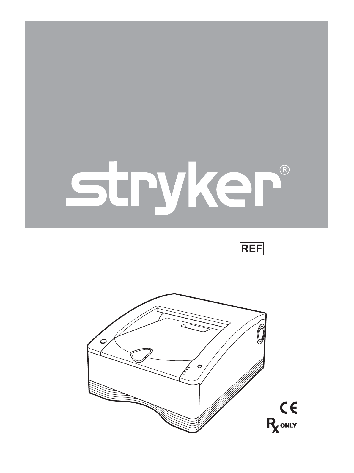
SDP1000
Digital Color Printer
User Guide
0240080230
4-196-299-06 (1)
EN
Page 2

Table of Contents
Warnings and Cautions ...................................................................................... 3
Product Description/Intended Use .................................................................... 5
Indications/Contraindications ................................................................................................................ 5
System Configuration ........................................................................................................................... 5
Location and Function of Parts and Controls .................................................. 5
Front ..................................................................................................................................................... 5
Rear ...................................................................................................................................................... 6
Carrying the printer ............................................................................................. 7
Connections ........................................................................................................ 7
USB Port Connection ........................................................................................................................... 7
Before Printing .................................................................................................... 9
Notes on Handling the Ink Ribbon and Paper ...................................................................................... 9
Loading the Ink Ribbon and Paper .....................................................................................................10
Replacing the Ink Ribbon and Paper .................................................................................................. 13
Printing ............................................................................................................... 14
Precautions ........................................................................................................ 16
Safety ................................................................................................................................................. 16
Installation .......................................................................................................................................... 16
Transportation ..................................................................................................................................... 16
Cleaning ............................................................................................................................................. 16
Cleaning the Internals of the Printer ................................................................................................... 17
Ink Ribbon and Paper ....................................................................................... 19
Technical Specifications .................................................................................. 20
About the Self-Laminating Color Printing Pack (SEPC-100/SEPC-110) ............................................ 20
Troubleshooting ................................................................................................ 21
Explanation of Indicators ................................................................................. 22
If a Paper Jam Occurs ....................................................................................... 23
Warranty and Return Plolicy ............................................................................ 29
2
EN
Page 3
Warnings and Cautions
WARNING
1. Federal law (United States of America) restricts this
device to use by, or on order of, a physician.
2. Carefully unpack the device and check if any damage
occurred during shipment. If damage is detected, refer
to the standard warranty.
3. Read this manual thoroughly and be familiar with its
contents prior to using this equipment.
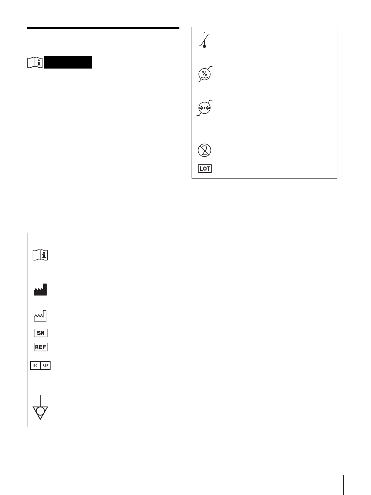
Storage and transport temperature
This symbol indicates the acceptable
temperature range for storage and transport
environments.
Storage and transport humidity
This symbol indicates the acceptable
humidity range for storage and transport
environments.
Storage and transport pressure
This symbol indicates the acceptable
atmospheric pressure range for storage and
transport environments.
To reduce the risk of fire or electric shock, do not
expose this apparatus to rain or moisture.
To avoid electrical shock, do not open the
cabinet. Refer servicing to qualified personnel
only.
To avoid the risk of electric shock, this equipment
must only be connected to a supply mains with
protective earth.
No modification of this equipment is allowed.
Symbols on the products
Consult the instructions for use
Follow the directions in the instructions for
use for parts of the unit on which this symbol
appears.
This symbol indicates the manufacturer, and
appears next to the manufacturer’s name and
address.
This symbol indicates the date of
manufacture.
This symbol indicates the serial number.
This symbol indicates the version of the
accompanying document.
This symbol indicates the European
Community representative, and appears next
to the European Community representative's
name and address.
For accessories
This symbol indicates the do not reuse.
This symbol indicates the batch code.
This unit has no power switch.
To disconnect the main power, unplug the power plug.
When installing the unit, incorporate a readily accessible
disconnect device in the fixed wiring, or connect the power
plug to an easily accessible socket-outlet near the unit.
Do not position the ME equipment where it is difficult to
unplug the power plug.
If a fault should occur during operation of the unit, operate
the disconnect device to switch the power supply off, or
unplug the power plug.
The Stryker Standard Warranty and Return Policy is void
if any of these warnings are disregarded.
For the customers in the U.S.A.
This equipment has been tested and found to comply with
the limits for a Class A digital device, pursuant to part 15
of the FCC Rules. These limits are designed to provide
reasonable protection against harmful interference when
the equipment is operated in a commercial environment.
This equipment generates, uses and can radiate radio
frequency energy and, if not installed and used in
accordance with the instruction manual, may cause
harmful interference to radio communications. Operation
of this equipment in a residential area is likely to cause
harmful interference in which case the user will be
required to correct the interference at his own expense.
This symbol indicates the equipotential
terminal which brings the various parts of a
system to the same potential.
You are cautioned that any changes or modifications not
expressly approved in this manual could void your
authority to operate this equipment.
All interface cables used to connect peripherals must be
shielded in order to comply with the limits for a digital
device pursuant to Subpart B of part 15 of FCC Rules.
Warnings and Cautions
EN
3
Page 4
For the customers in Canada
This unit has been certified according to Standard CAN/
CSA-C22.2 No.60601-1.
For the customers in the U.S.A and Canada
When you use this product connected to 240 V single
phase, be sure to connect this product to a center tapped
circuit.
Important safeguards/notices for use in the
medical environments
1. All the equipments connected to this unit shall be
certified according to Standard IEC 60601-1,
IEC 60950-1, IEC 60065 or other IEC/ISO Standards
applicable to the equipments.
2. Furthermore all configurations shall comply with the
system standard IEC 60601-1. Everybody who
connects additional equipment to the signal input part
or signal output part configures a medical system, and
is therefore, responsible that the system complies with
the requirements of the system standard IEC 60601-1.
If in doubt, consult your local Stryker service
technician.
3. The leakage current could increase when connected to
other equipment.
4. For this particular equipment, all accessory equipment
connected as noted above, must be connected to mains
via an additional isolation transformer conforming with
the construction requirements of IEC 60601-1 and
providing at least Basic Insulation.
5. This equipment generates, uses, and can radiate radio
frequency energy. If it is not installed and used in
accordance with the instruction manual, it may cause
interference to other equipment. If this unit causes
interference (which can be determined by unplugging
the power cord from the unit), try these measures:
Relocate the unit with respect to the susceptible
equipment. Plug this unit and the susceptible
equipment into different branch circuit.
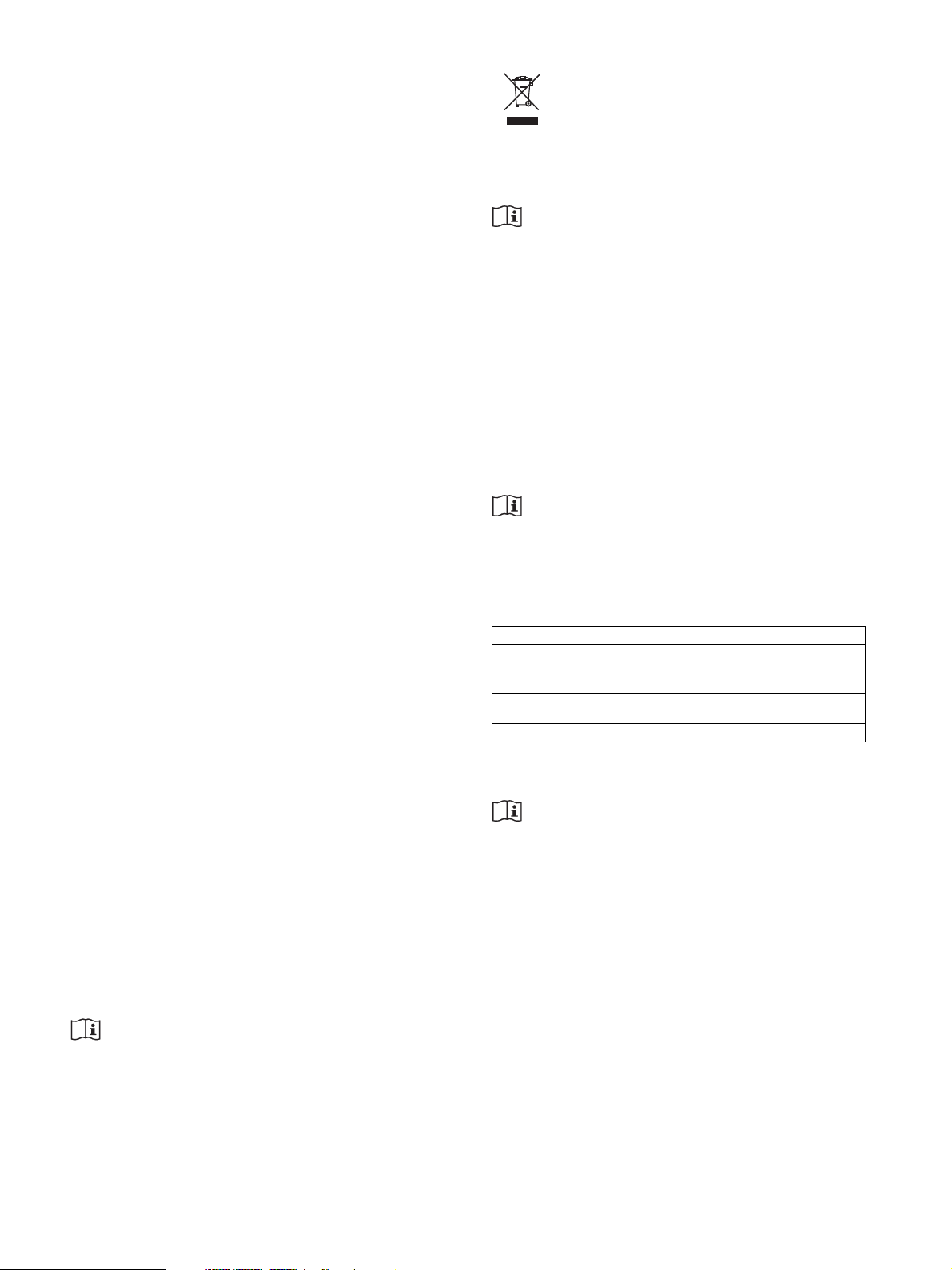
This product contains waste electrical or electronic
equipment. It must not be disposed of as unsorted
municipal waste and must be collected separately.
Warning on power connection
Use a proper power cord for your local power supply.
1. Use the approved Power Cord (3-core mains lead) /
Appliance Connector / Plug with earthing-contacts that
conforms to the safety regulations of each country if
applicable.
2. Use the Power Cord (3-core mains lead) / Appliance
Connector / Plug conforming to the proper ratings
(Voltage, Ampere).
If you have questions on the use of the above Power Cord
/ Appliance Connector / Plug, please consult a Stryker
service technician.
Warning on power connection for
medical use
Please use the following power supply cord.
With connectors (plug or female) and cord types other than
those indicated in this table, use the power supply cord that
is approved for use in your area.
United States and Canada
Plug Type HOSPITAL GRADE*
Cord Type Min.Type SJT
Minimum Rating for Plug
and Appliance Couplers
Safety Approval UL Listed and CSA
*Note: Grounding reliability can only be achieved when the equipment is
connected to an equivalent receptacle marked ‘Hospital Only’ or ‘Hospital Grade’.
Caution
Do not use the device in a MR (Magnetic Resonance)
environment.
It may cause a malfunction, fire, and unwanted movement.
Min.18 AWG
10A/125V
Warning
The printer must be properly connected to the isolation
transformer prior to use. Failure to do so may result in a
higher leakage current for the printer.
Caution
When you dispose of the unit or accessories, you must
obey the laws in the relative area or country and the
regulations in the relative hospital regarding
environmental pollution.
4
Warnings and Cautions
EN
Page 5
Introduction
Location and Function of Parts and Controls
Product Description/ Intended Use
The SDP1000 Stryker Digital Color Printer, REF
0240080230, is a dye sublimation thermal transfer printer
providing high quality and high resolution printing of
Stryker Digital Capture Device image data on A4 or letter
size paper in full color (256 gradations process and 16.7
million colors).
It prints images by pressing a thermal head, heated
according to the input image data, against a dedicated ink
ribbon coated with sublimation ink, transferring the ink
onto special thermal printing paper.
This device is intended for use in medical environments,
such as clinics, examination rooms, and operating rooms.
Indications/Contraindications
The Stryker Printer is a medical accessory, that when used
with the SDC systems, is intended to be used to record
operative procedures.
There are no known contraindications.
Introduction
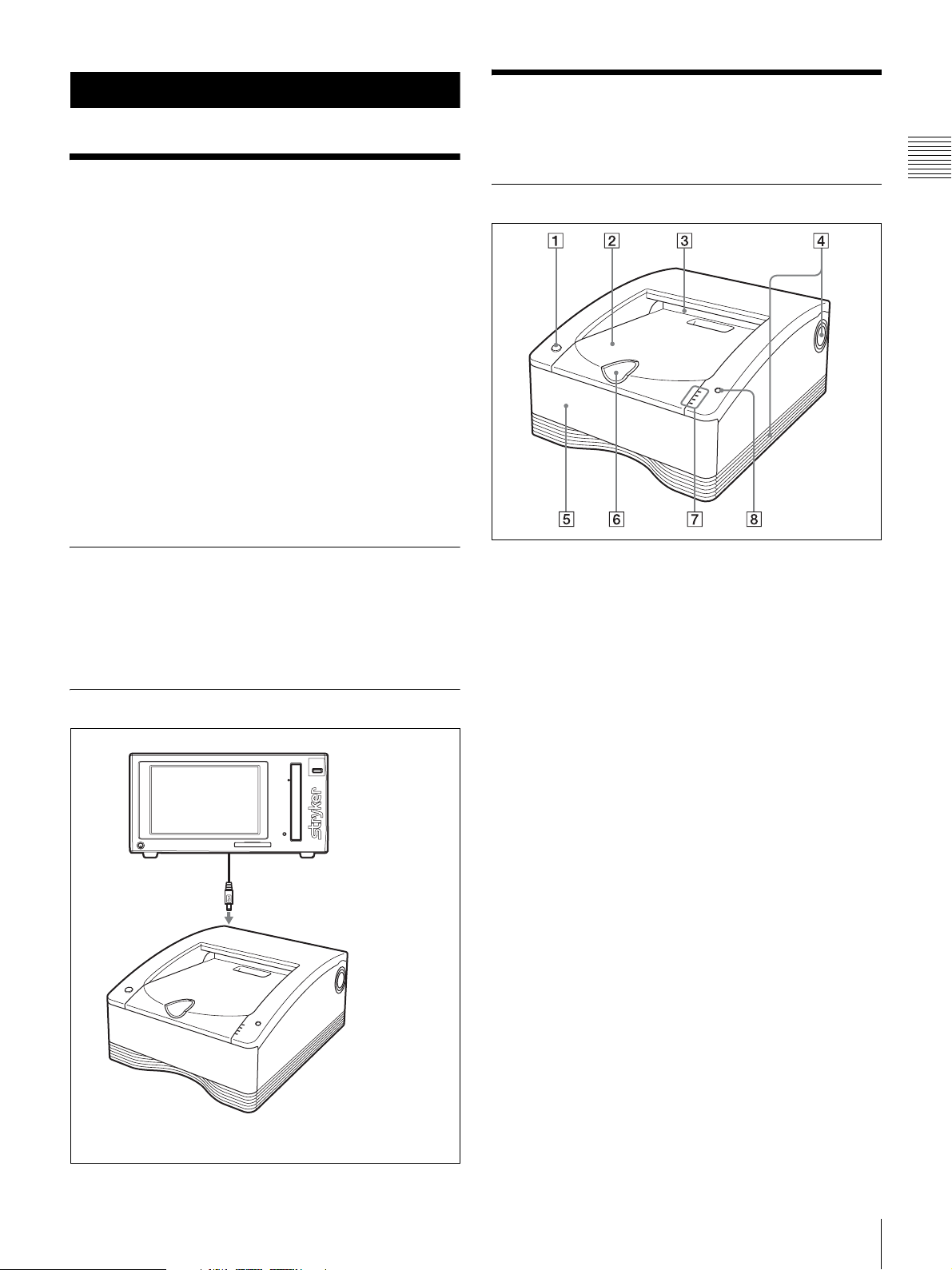
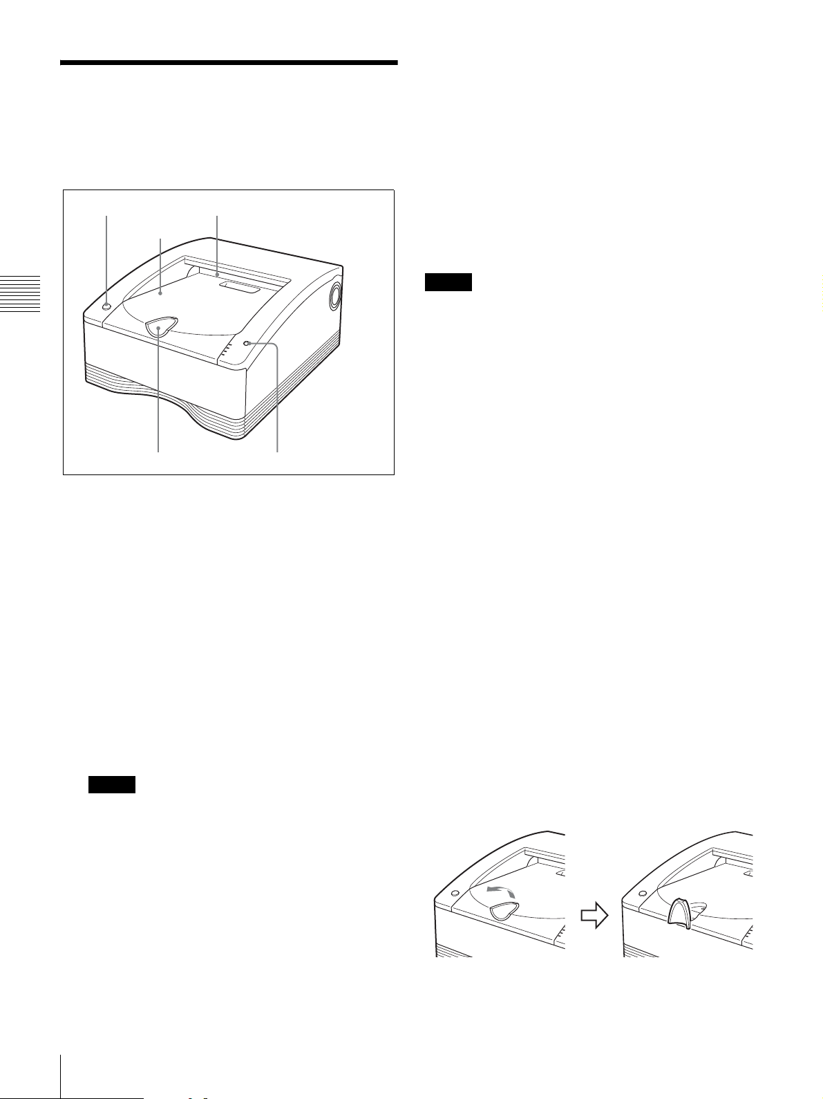
Front
A 1 On/standby switch/indicator
When this switch is pressed, the indicator lights, and
the printer enters the ready state. When it is pressed
again, the indicator flashes and then goes out, and the
printer enters the standby state.
System Configuration
USB cable
SDP1000 Stryker Digital Color Printer
Stryker Digital
Capture Device
B Paper cover
Printouts stack here.
C Paper outlet
Printouts are ejected here.
D Vent openings
E Media tray (page 10)
The ink ribbon and paper are loaded here.
F Stopper (page 14)
Flip this stopper up in order to prevent the ejected
printouts from falling.
Product Description/Intended Use / Location and Function of Parts and Controls
EN
5
Page 6
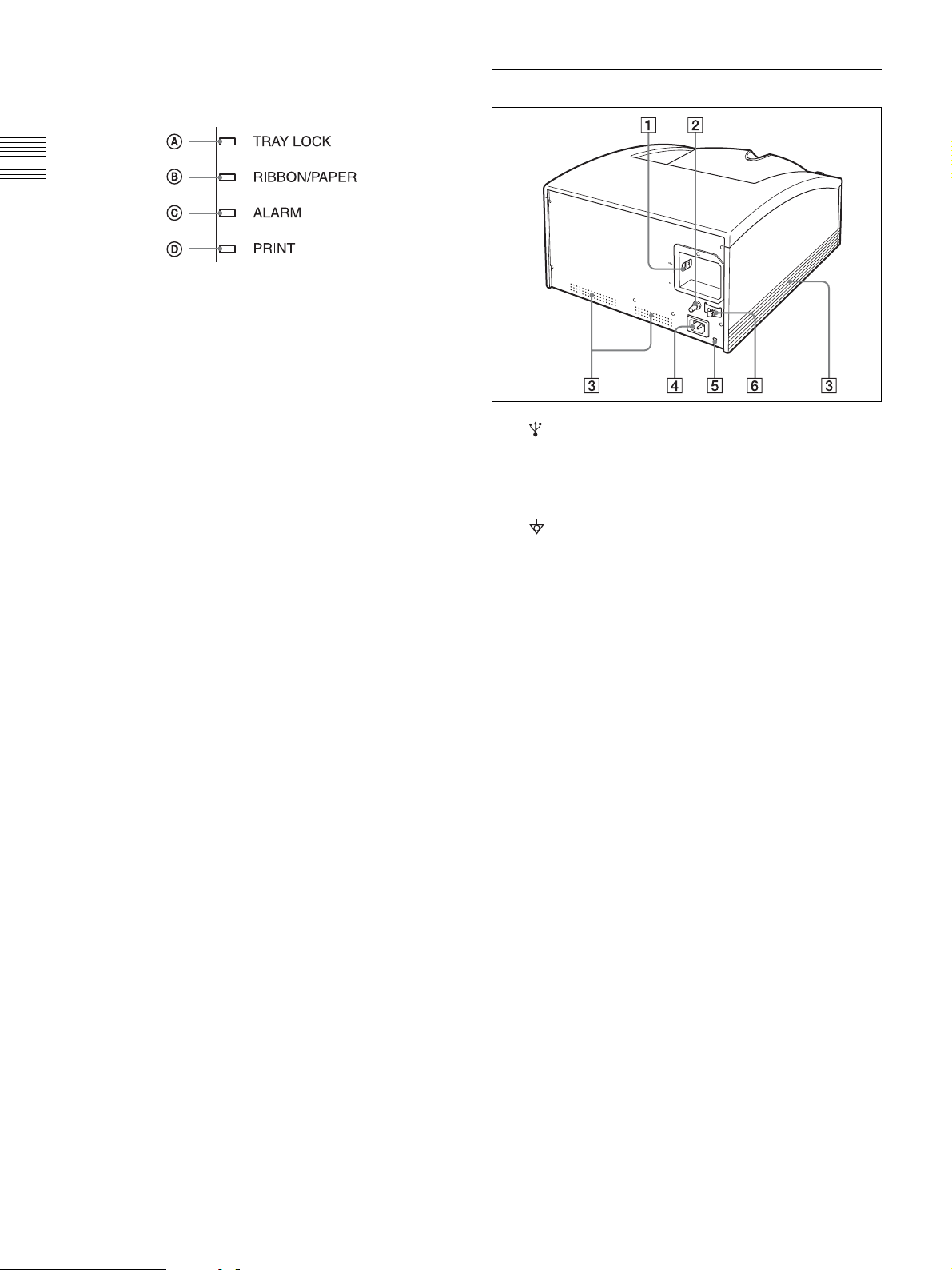
G Indicators
Introduction
The indicators are as shown below:
A TRAY LOCK indicator
Lights when the media tray cannot be pulled out.
B RIBBON/PAPER indicator
Lights when an error involving the ink ribbon or
paper occurs.
Also, flashes while cleaning is in progress.
C ALARM indicator
Lights when an error such as a paper jam occurs.
D PRINT indicator
Lights while printing is in progress.
Do not pull out the media tray while the TRAY LOCK
indicator is lit. It may cause damage.
The location and cause of an error can be determined
according to which of the indicators (PRINT,
ALARM, RIBBON/PAPER and TRAY LOCK) are
on or flashing. For details, refer to “Explanation of
Indicators” on page 22.
Rear
A USB connector
Connects to a computer equipped with a USB
interface (which conforms to USB 2.0), etc., using a
USB cable (supplied).
B Equipotential ground terminal connector
Used to connect to a ground (equipotential) plug to
bring the various parts of the system to the same
potential.
C Vent openings
Use the hospital grade power cord provided.
D ~AC IN connector (page 7)
H STOP button (page 14)
Press this button to stop a continuous printing
operation.
When this button is pressed, the printer returns to
ready state after the current page is printed and
ejected.
E Security slot
Used to attach a security cable.
F USB cable stopper (page 8)
Fixes the USB cable to prevent it from being
disconnected.
6
Location and Function of Parts and Controls
EN
Page 7
Preparation
Carrying the printer
Connections
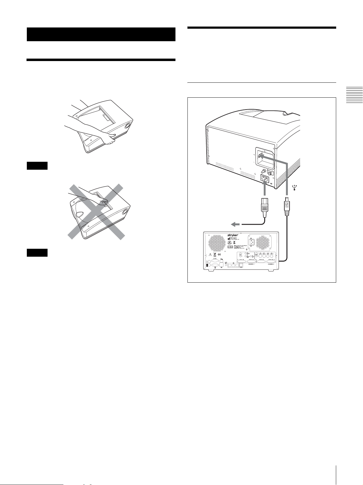
After connecting a USB connecting cable to the printer and
the Stryker Digital Capture Device, connect the power
cord.
Hold both sides of the printer as shown below when
carrying the printer.
Note
NEVER handle or lift the printer as shown.
Note
Retain the original carton and packing materials in case
you have to transport this unit in the future.
USB Port Connection
SDP1000
to ~AC IN connector
Powe r cord
to cart or wall
outlet
Stryker Digital Capture Device
Preparation
to (USB)
connector
USB connecting
cable
WAR NING
Using this unit for medical purposes
This equipment's connectors are not isolated.
Do not connect any device other than one which conforms
to IEC 60601-1.
When an information technology device or AV device that
uses an alternating current is connected, current leakage
may result in an electric shock to the patient or operator.
If use of such a device is unavoidable, isolate its power
supply by connecting an isolation transformer, or by
connecting an isolator between the connecting cables.
After implementing these measures, confirm that the
reduced risk now conforms to IEC 60601-1.
Carrying the printer / Connections
EN
7
Page 8
Securing the USB cable
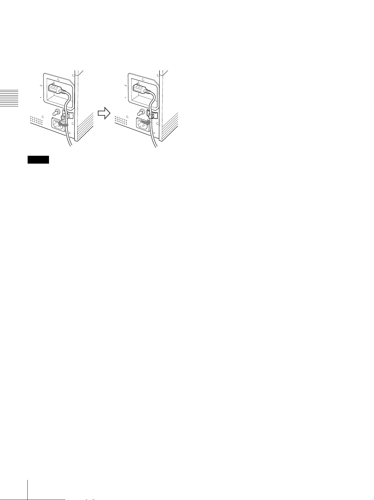
After you connect the USB cable to the printer, it is
recommended that you use the cable stopper to secure the
USB cable to prevent it from being accidentally
disconnected.
Preparation
Notes
• Make sure that the USB cable is connected securely at
both ends.
• Operation of the printer is not guaranteed for connection
to a USB hub.
8
Connections
EN
Page 9
Operation
Before Printing
Once the printer is connected to the Stryker Digital
Capture Device (page 7) and before initiating printing, the
paper and ink ribbon need to be loaded as described below.
Notes on Handling the Ink Ribbon and Paper
Do not re-use
Doing so may result in malfunction and negatively
affect printing results.
Compatible ink ribbon and paper
• Be sure to use only ink ribbon and paper that is intended
specifically for use with this printer.
• Always use the ink ribbon and paper provided in the
same package together. Each printing pack contains two
ink ribbons rolls and two paper rolls.
• For details on the ink ribbon and paper that can be used
in this printer, see “Ink Ribbon and Paper” on page 19.
• Since, like other color dyes, the dyes used in this ink
ribbon may discolor over time, the product will neither
be replaced nor be warranted against any color change.
Handling paper rolls
• Place the paper roll vertically on the stable place, when
opening the wrapping. If you open the wrapping holding
it with hands or placing it horizontally, you may drop it.
Dropping may result in an injury.
• Be sure not to open the wrapping with a knife such as a
cutter. This may damage a paper roll and ink ribbon and
you may not be able to use them for printing.
• Whenever you set down a paper roll, place it standing on
its end as show in the figure below. If you place it on its
side, it could roll of the surface and fall, possibly causing
personal injury.
• Always hold a paper roll securely with two hands.
Dropping a paper roll could cause personal injury. Any
dust on the printing surface will result in poor printout
quality.
Operation
Handling the ink ribbon
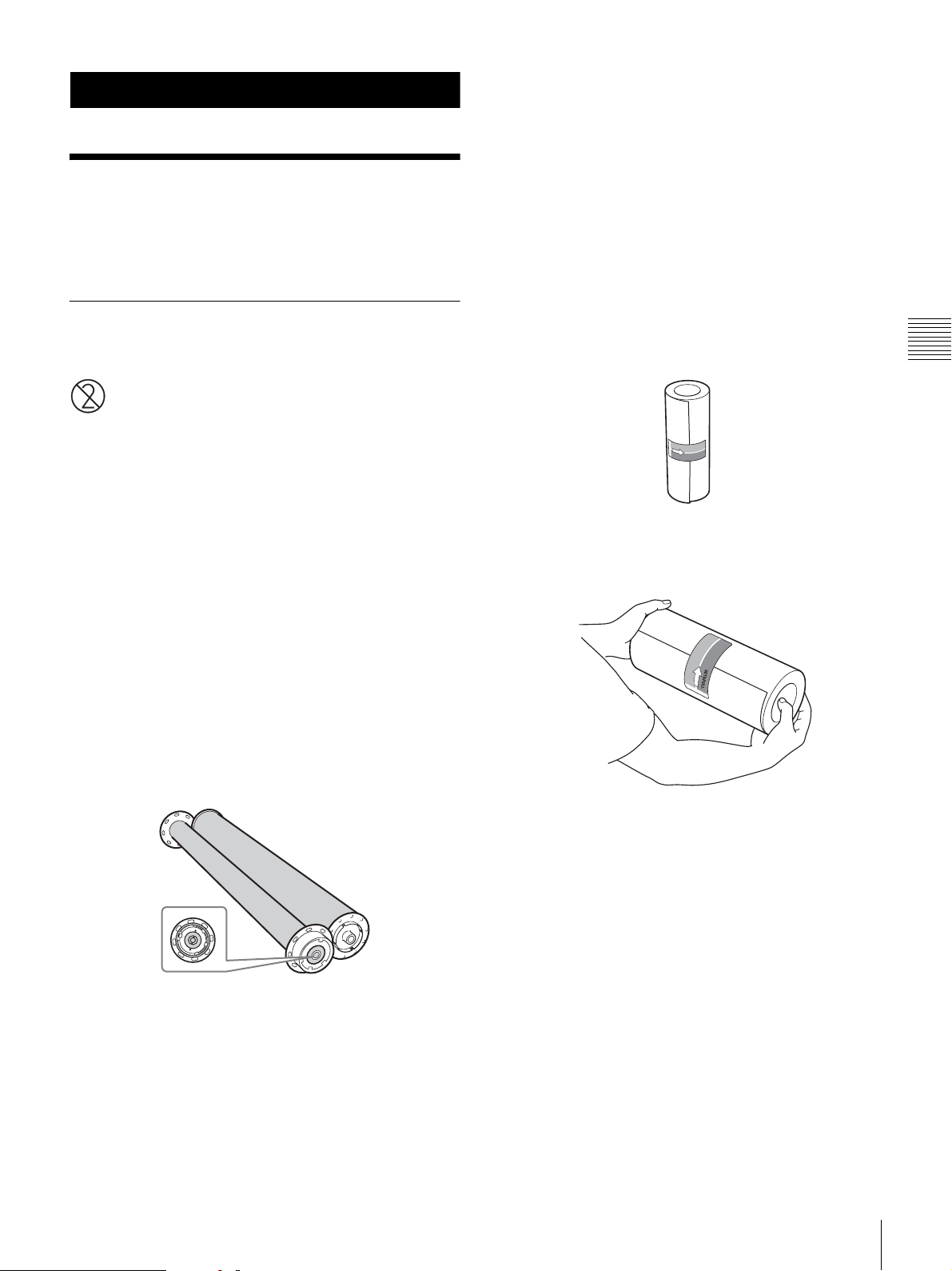
• Do not separate the two spools of the ink ribbon before
loading it in the printer.
• An IC board is built into one of the spools. Do not touch
the terminals of the IC board, and do not allow them to
come into contact with metal objects, etc. Furthermore,
do not strike, bend or drop the ink ribbon; doing so could
make the ink ribbon unusable.
IC board
• Do not attempt to re-use a used ink ribbon.
• Do not rewind the ink ribbon.
• Do not touch the surface of the ink ribbon, and do not
leave it exposed in a dusty location. Fingerprints and
dust on the surface of the ink ribbon can cause smudges
in printed output, and can damage the thermal head.
Hold securely with two hands
Notes on storing ink ribbons and paper
• Do not store ink ribbons and paper in locations exposed
to high temperatures, high humidity, dust, or direct
sunlight.
• Do not open the ink ribbon and paper packages until you
are ready to use them.
• If it is necessary to store a partially used ink ribbon or
paper roll for an extended period of time, it is
recommended that they be stored in their original bags.
Before Printing
EN
9
Page 10
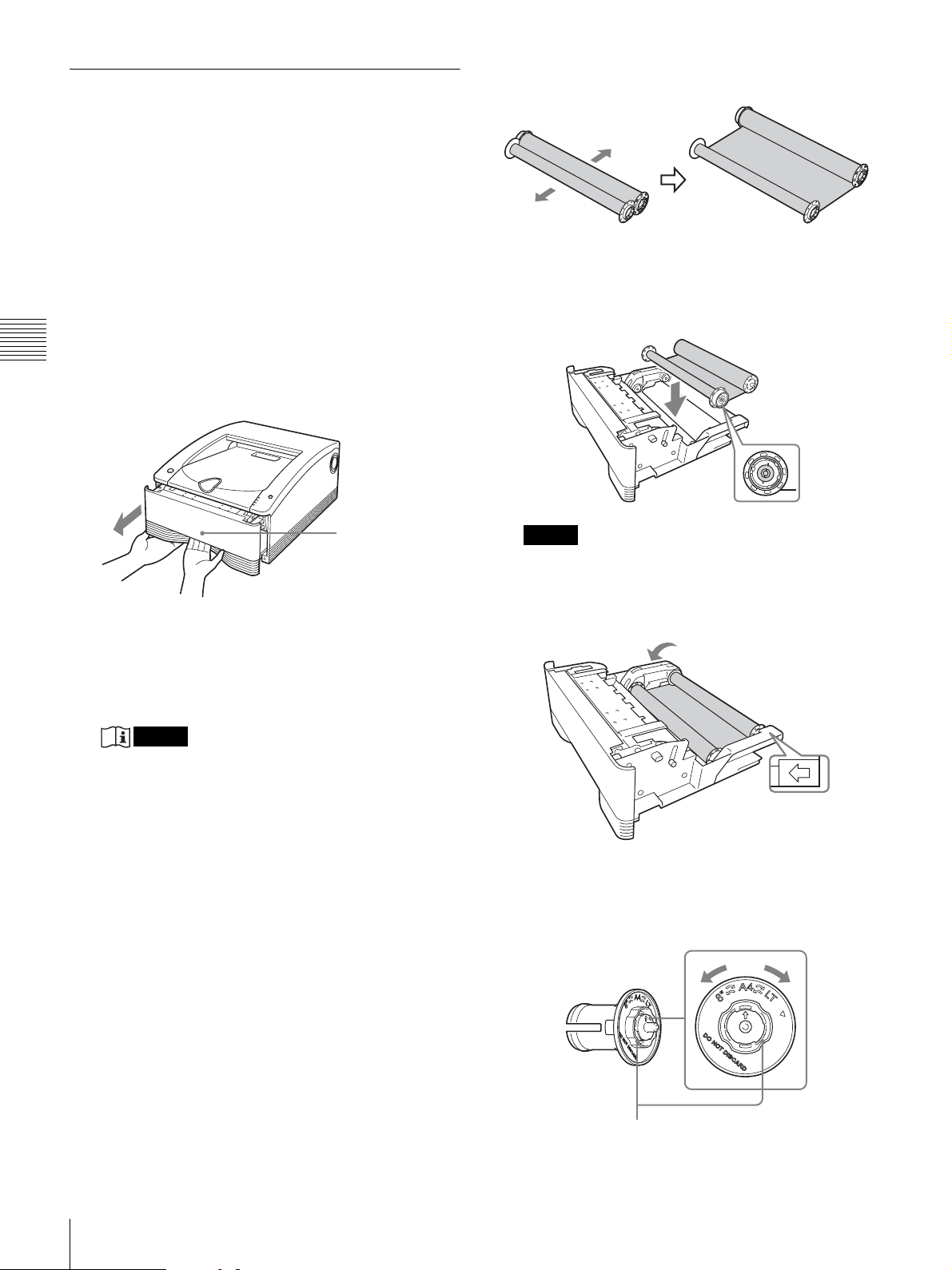
Loading the Ink Ribbon and Paper
When using the printer for the first time, it is necessary to
first load the paper and ink ribbon.
CAUTION
Do not touch any unit circuitry and the patient at the same
time.
If the unit malfunctions, it may generate voltage that could
be harmful to the patient.
1
Make sure that the printer is not performing an
operation, and then pull out the media tray.
As shown in the figure below, hook your fingers under
Operation
the bottom edge of the media tray and pull the tray
out, using your other hand to support the media tray
from the bottom.
2
Separate the two spools of the ink ribbon.
3
Load the ink ribbon in the media tray.
Place the ink ribbon in the media tray so that the IC
board of the ink ribbon is positioned as shown in the
figure below.
IC board
Lock released
The media tray is normally locked in place when it is
in the printer. The lever that releases the media tray is
located behind the bottom edge of the tray. To unlock
the tray, simply pull the lever with your fingers.
Notes
• Do not pull out the media tray while the TRAY
LOCK indicator is lit. It may cause damage.
• Be careful not to drop the media tray when pulling
it out. Dropping the media tray may result in an
injury. When pulling out and inserting the media
tray, hold the handle part with one hand and support
the media tray from the bottom with the other hand,
while making sure both of your hands are securely
holding the media tray.
• Do not leave the media tray partially opened. When
performing work on the media tray, pull it out of the
printer completely.
• Perform the work while the removed tray is placed
on a stable surface.
• Do not set the media tray down in a dusty location.
Dust can cause smudges in printed output, and can
damage the thermal head.
Note
If there is any slack in the cleaning ribbon after it is
placed in the tray, take up the slack by turning the
spool in the direction indicated by the arrow in the
following figure.
Direction to
turn spool
4
Set the selector for the paper holder (blue).
Turn the knob on the paper holder (blue) selector to
match the size of the paper roll.
Selector
10
Knob
Before Printing
EN
Page 11
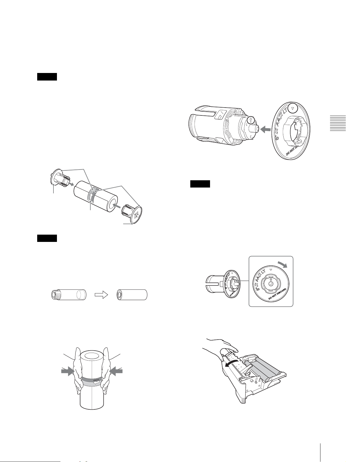
The selector settings and paper rolls correspond as
follows.
• LT (letter size): SEPC-110
• A4 (A4 size): SEPC-100
Page length on SDC HD and SDC Classic will be
11 inches for both settings.
Note
Do not turn the selector beyond the range of the paper
size marks when setting it. Doing so may result in
damage.
5
Insert the paper holders into the paper roll.
A pink paper holder and a blue paper holder are
provided with the printer. Insert these paper holders
into the ends of the paper roll as shown in the figure
below, with the pink paper holder in the end closer to
the pink adhesive label and the blue paper holder in
the end closer to the blue label.
Blue
If the paper holder selector comes off
The selector could come off if you drop the blue paper
holder. Follow the procedure described below to
reattach the selector to the paper holder.
1 As shown in the figure below, put the selector in
the bobbin, line up the V mark on the selector
with the arrow on the bobbin, and then push the
selector into place.
The hook on the selector snaps into the notch on
the bobbin marked by the arrow.
Operation
Bobbin
Selector
Pink
Paper
holder
Label
Paper holder
Notes
• If the edges of the paper on the ends of the paper roll
are not even, it is necessary to make the edges even
(being careful not to crumple the edges while doing
so) before placing the paper roll in the media tray.
Using a paper roll with uneven edges can cause a
malfunction.
• Do not strike or squeeze the paper roll. Doing so
could break or bend the paper roll, and could result
in poor printing quality.
• If inserting the paper holder into the paper roll is
difficult when loading the paper roll, squeeze the
roll from both sides to restore its shape.
Note
There are two hooks on the selector: one indicated by
the V mark and the other on the opposite side of the
selector. Do not install the selector so that the hook on
the side opposite of the V mark is in the notch on the
bobbin marked by the arrow, as doing so could result
in damage to the paper holder.
2 Turn the selector in the direction indicated by the
arrow in the figure below until it clicks into place.
6
Load the paper roll in the media tray.
1 Open the media tray cover.
• Correctly insert the paper holders all the way.
Before Printing
11
EN
Page 12
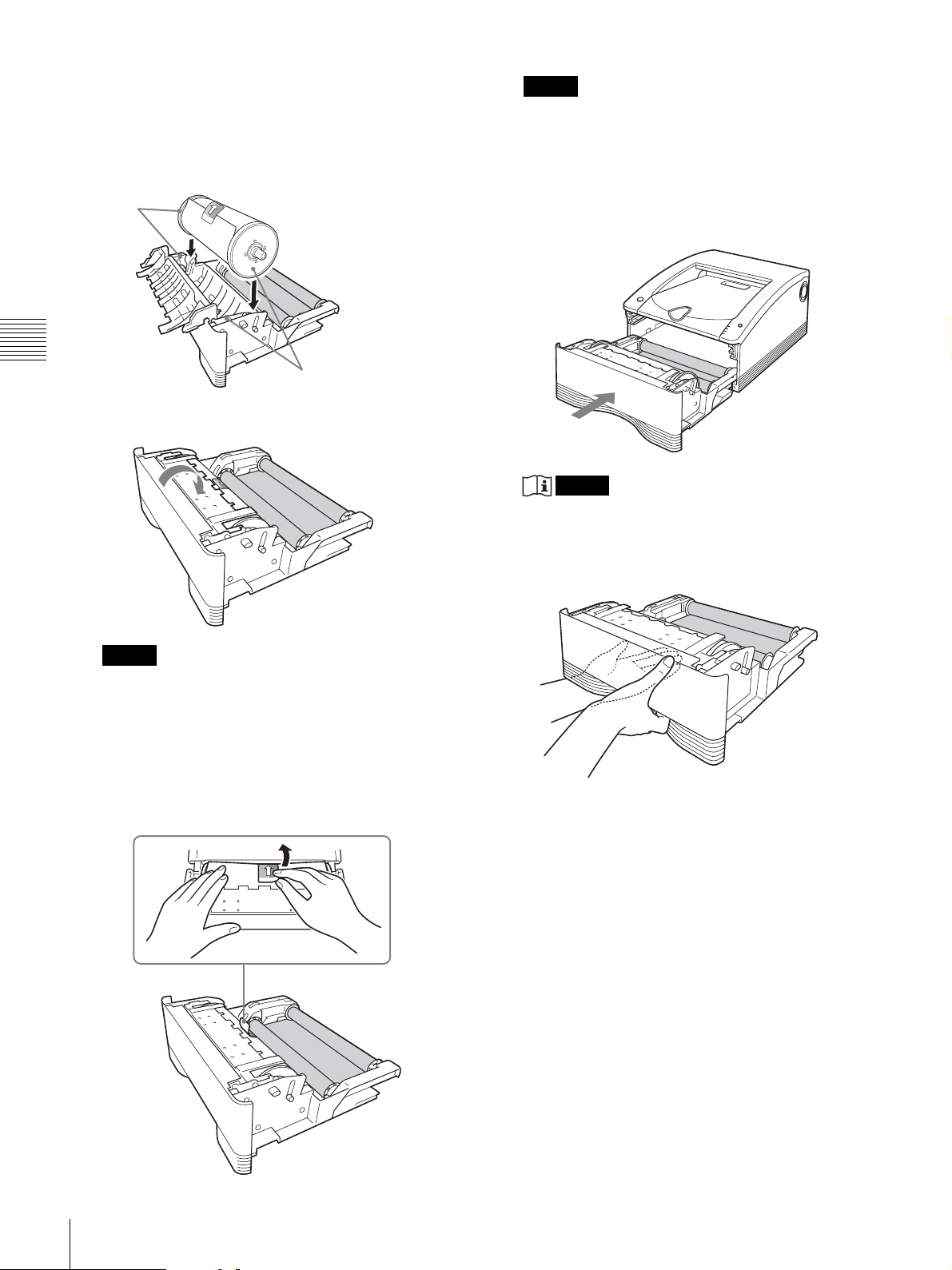
2 Place the paper roll in the media tray so that the
arrow on the label points toward the ink ribbon
side. You can load the paper roll in the correct
direction by matching the colors of the paper
holders inserted into the paper roll with the colors
on the media tray.
Blue
Note
Be certain to remove the labels completely. If the
labels are not peeled off carefully, they can leave
adhesive on the paper. Leaving any of the label in the
printer can cause a malfunction.
8
Insert the media tray into the printer.
Push the media tray in until it clicks into place.
Operation
Pink
3 Close the media tray cover so that it clicks into
place.
Notes
• Dropping the media tray while it is loaded with
paper and ink ribbon could cause personal injury.
Always use two hands when carrying the media
tray, supporting the media tray from the bottom.
Note
Once the paper roll has been loaded, do not touch the
printing surface (the inner surface of the paper roll).
Fingerprints or sweat on the surface of the paper, or
even creases in the paper, could result in poor printing
quality.
7
Carefully peel off the adhesive labels from the paper
roll in the direction indicated by the arrow.
• Removing the adhesive labels before closing the
cover can cause a malfunction.
• Wind the paper roll if the leading edge of the paper
is touching the ink ribbon. If the leading edge of the
paper is left resting on the ink ribbon, malfunctions
may occur.
12
Before Printing
EN
Page 13
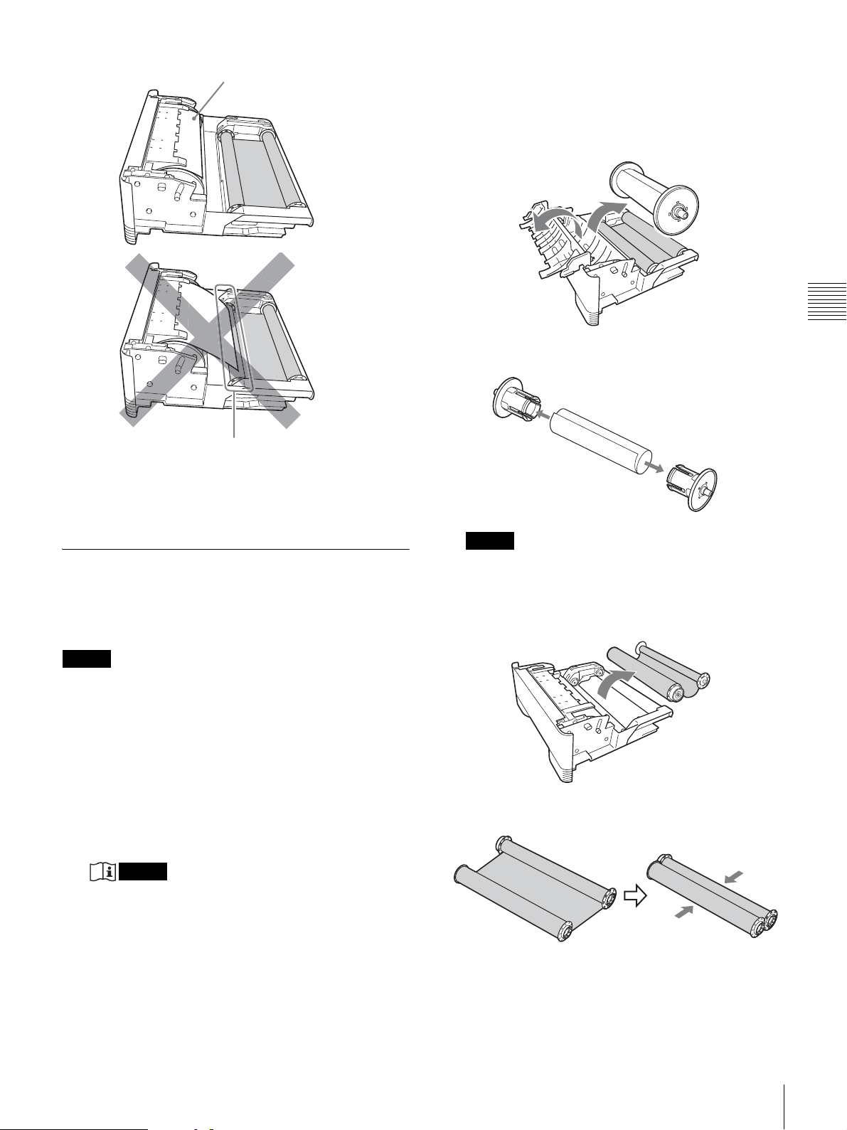
Leading edge of paper
Leading edge of paper
the thermal head could result in a burn. Also, be
careful not to scratch the thermal head.
2
Open the cover of the media tray and remove the
paper roll.
3
Remove the paper holders from the paper roll.
Operation
If the ink ribbon becomes torn while still in use
Cellophane tape, etc., can be used to repair a torn ink
ribbon so that the remainder of the ribbon can be used.
Replacing the Ink Ribbon and Paper
Once the ink ribbon or paper have been used to print the
specified number of sheets, follow the procedure described
below to replace the ink ribbon and paper.
Notes
• Be sure to replace the ink ribbon and the paper roll at the
same time.
• The ink ribbon and paper roll both contain excess
material. Even if there appears to be some excess ink
ribbon or paper remaining, replace both with a new ink
ribbon and paper roll. Attempting to use the remaining
excess ink ribbon or paper can cause a malfunction.
1
Make sure that the TRAY LOCK indicator is
extinguished then pull out the media tray.
Notes
• If the media tray does not pull out, do not force it
out. Press the 1 On/standby switch to enter the
standby state, and then press the switch again to turn
the printer ON. Try pulling the media tray again
after the printer finishes initializing.
• After a printing operation is completed, the thermal
head is very hot. When pulling out the media tray,
be careful not to touch the thermal head. Touching
Note
Be sure to retain the paper holders for use with the
next paper roll. Do not discard the paper holders.
4
Remove the ink ribbon.
Roll together the two spools of the ink ribbon that you
just removed.
5
Load the new ink ribbon and paper.
For details on how to load ink ribbon and paper, refer
to step 2 onward for “Loading the Ink Ribbon and
Paper” on page 10.
Before Printing
EN
13
Page 14
Printing
Before printing
• Is the printer connected to a Stryker Digital Capture
Device? (page 7)
• Has the media tray been properly loaded? (page 10)
1 On/standby switch
Paper cover
Paper outlet
• Do not open the media tray while printing is in
progress.
If the media tray is opened, printing stops and the
PRINT, ALARM, RIBBON/PAPER, and TRAY
LOCK indicators all light simultaneously. In such
an event, press the 1 On/standby switch once to
enter the standby state and then press the switch
again to turn the printer ON, and check that there is
no paper jam or the ink ribbon is not broken. Also,
if printing was partway through, cut off the used
part of the paper roll with a pair of scissors or the
like before using the printer.
Notes
Operation
1
Press the printer 1 On/standby switch to turn on the
power of the printer.
The 1 On/standby indicator lights and initialization
of the printer begins.
The PRINT, ALARM, RIBBON/PAPER, and TRAY
LOCK indicators light simultaneously during
initialization of the printer, and go out when
initialization is complete.
2
Turn the Stryker Digital Capture Device on.
3
Using the Stryker Digital Capture Device, initiate a
printing operation.
The PRINT indicator flashes while the image data is
being received, and then remains steadily lit while
printing is in progress.
Notes
• Do not place objects on the paper cover that will
obstruct printing. Doing so may result in damage.
• Although the paper being printed may come into
view in the paper outlet while printing is in
progress, do not touch the paper until printing is
completed. Doing so could result in misoperation.
• Do not allow more than 10 printouts to accumulate
on the paper cover. Leaving too many printouts on
the paper cover could cause a paper jam.
• Do not press the 1 On/standby switch to enter the
standby state while printing is in progress. Doing so
may cause a paper jam or the ink ribbon to break.
STOP buttonStopper
Storing printed images
• Avoid storing printouts in a location subject to high
temperatures, high humidity, excessive dust or direct
sunlight. Such conditions could result in fading.
• Do not stick tape on a printout. Also, do not let printouts
come into contact with materials which contain
plasticizers, such as erasers or desk mats.
• Do not allow volatile organic solvents, such as alcohol,
to come into contact with printouts.
Cancelling continuous printing
Press the STOP button. Printing of the current item
finishes, and then the printer enters the ready state once the
printout is ejected.
When printing is disabled
The printer will not operate if the ALARM, RIBBON/
PAPER or TRAY LOCK indicator is on. For details, see
“Explanation of Indicators” on page 22.
If the ink ribbon runs out while continuous
printing
The printer terminates the printing operation. Once the
new ink ribbon is loaded, the printing operation
automatically resumes and the remaining images are
printed.
Using the stopper
To prevent ejected printouts from falling off of the paper
cover, insert your finger in the depression on the edge of
the stopper and then flip the stopper up in the direction
indicated by the arrow in the diagram below.
14
Printing
EN
Page 15

When removing and then reloading a partially
used paper roll
If the paper roll is not tightly rolled, roll it up more tightly
before reloading it.
Note
When removing a partially used paper roll, be sure to place
the media tray on a stable surface before beginning.
If you drop the media tray while it contains a paper roll, it
could cause personal injury.
When removing and inserting the media tray, be sure
to use both hands, with one hand holding the handle
and the other hand supporting the media tray from the
bottom.
Operation
Printing
EN
15
Page 16

Miscellaneous
Precautions
Safety
• Operate the printer using the power source specified in
“Technical Specifications” (page 20).
• Be careful not to damage the power cable by placing or
dropping heavy objects on it; it is dangerous to use the
unit with a damaged power cable.
• If you do not intend to use the printer for a long time,
press the 1 On/standby switch on the printer to enter the
standby state and then remove the power plug.
• Unplug the power cable by grasping the plug, not the
Miscellaneous
cable itself.
• Do not disassemble the unit. There is a danger of electric
shock from the internal parts.
• Be careful not to spill water or other liquids on the unit, or
to allow combustible or metallic material to enter the
cabinet. If used with foreign matter in the cabinet, the unit
is liable to fail, or present a risk of fire or electric shock.
• If the unit malfunctions or if a foreign body falls into the
cabinet, disconnect the power immediately and consult
your local Stryker representative.
condensation forms, turn off the power and leave the
printer standing for at least one hour.
• If the printing pack is subjected to wide and sudden
changes in temperature, condensation may form on the
ink ribbon or paper inside. This will cause the printer to
malfunction. Also, if the printing pack is used in this
state, spots are likely to appear on the printout.
• To store a half-used printing pack, replace it in its
original packing and reseal the package. If possible, keep
the sealed printing pack in a cool, dark location. To
subsequently use the printing pack, place it, in its sealed
package, in a warm room for several hours. Doing so
prevents condensation from forming when the printing
pack is removed from its package.
Transportation
When transporting the printer, be certain to first
remove all accessories, including the ink ribbon and
paper. Carrying the printer with accessories installed can
later cause the printer to malfunction. It is recommended
that the ink ribbon and paper roll be stored in their original
bags.
Warning
To avoid electric shock and potentially fatal injury,
unplug the console from the electrical outlet before
cleaning.
Do not sterilize the printer or immerse it in any liquid.
Doing so will damage the unit.
Installation
• Avoid placing the unit in a location subject to:
– mechanical vibration
– high humidity
– excessive dust
– direct or excessive sunlight
– extremely high or low temperatures
• Ventilation holes are provided on the back of the unit to
prevent the unit from overheating. Be careful not to
obstruct them with other objects or by covering the unit
with a cloth etc.
• To prevent internal heat built-up, leave enough room
around the printer for air to circulate through the
ventilation holes (intake) on the left and right hand side
and the ventilation holes (exhaust) on the rear of the
cabinet (at least more than 10 cm).
On condensation
• If the printer is subjected to wide and sudden changes in
temperature, such as when it is moved from a cold room
to a warm room or when it is left in a room with a heater
that tends to produce quantities of moisture,
condensation may form inside the printer. In such cases
the printer will probably not work properly, and may
even develop a fault if you persist in using it. If moisture
Cleaning
Note
Before you clean the printer, be sure to press the 1 On/
standby switch to enter the standby state and then remove
the power plug.
When the cabinet becomes dirty
When solvents such as benzene or thinner, or acid, alkaline
or abrasive detergent, or chemical cleaning cloths are used
on the printer surface, the surface finish may be damaged.
Take care with respect to the following:
• Clean the printer surface with a 50 to 70 v/v%
concentration of isopropyl alcohol or a 76.9 to 81.4 v/v%
concentration of ethanol.
• Stubborn stains may be removed with a soft cloth such
as a cleaning cloth lightly dampened with mild detergent
solution and then cleaned using the above chemical.
• Do not use unnecessary force to rub the printer surface
with a stained cloth. The printer surface may be scratched.
• Do not keep the printer surface in contact with a rubber
or vinyl resin product for a long period of time.
The surface finish may deteriorate or the coating may
come off.
16
Precautions
EN
Page 17
Cleaning the Internals of the Printer
Perform thermal head cleaning if lines and marks appear
on printouts, and perform roller cleaning if scratches
appear at regular intervals.
Thermal head cleaning
To maintain print quality, we recommend that you perform
regular thermal head cleaning once a month or once after
every 10 printing packs used.
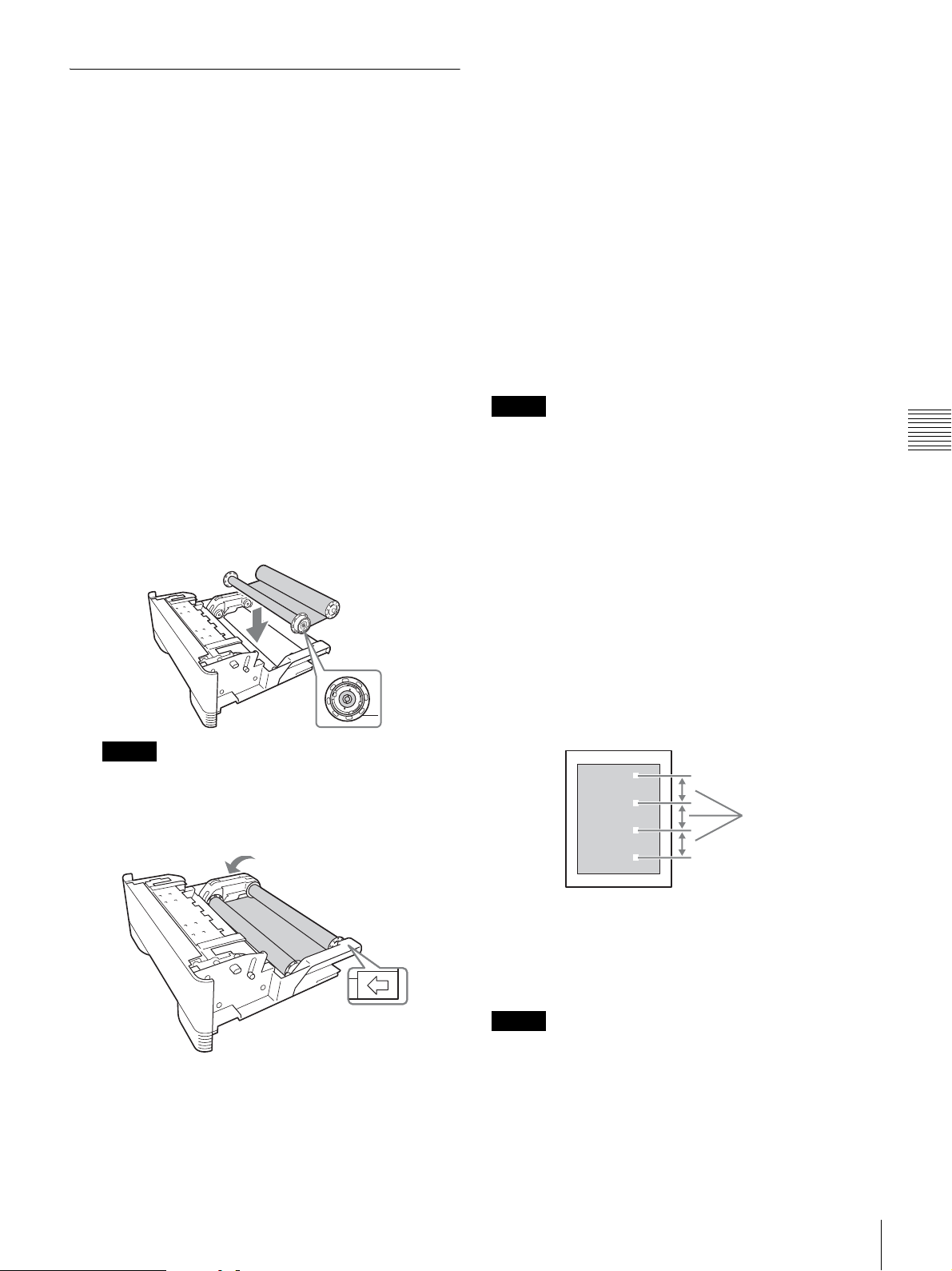
1
Make sure that the printer is not performing an
operation, and then pull out the media tray.
2
Confirm whether there is paper inside.
3
Remove the ink ribbon.
For details on how to remove the ink ribbon, see step
4 of “Replacing the Ink Ribbon and Paper” on
page 13.
4
Load the cleaning ribbon.
For details on how to load the cleaning ribbon, see
steps 2 and 3 of “Loading the Ink Ribbon and Paper”
on page 10.
When cleaning is completed, the paper that was used
for cleaning is ejected and the TRAY LOCK indicator
is extinguished.
If you want to clean the rollers, proceed to “Roller
cleaning” on page 17.
If you are not cleaning the rollers, continue with the
steps below.
6
Make sure that the TRAY LOCK indicator is
extinguished then pull out the media tray.
7
Remove the cleaning ribbon.
8
Load the ink ribbon.
9
Insert the media tray into the printer.
Notes
• Store the cleaning ribbon in a location without dust (such
as in a bag).
• Place the removed media tray on a stable surface when
loading and removing the cleaning ribbon.
• Dropping the media tray while paper is loaded may
result in an injury. When pulling out and inserting the
media tray, hold the handle part with one hand and
support the media tray from the bottom with the other
hand, while making sure both of your hands are securely
holding the media tray.
Miscellaneous
IC board
Note
If there is any slack in the cleaning ribbon after it is
placed in the tray, take up the slack by turning the
spool in the direction indicated by the arrow in the
following figure.
Direction to
turn spool
5
Insert the media tray into the printer.
When the TRAY LOCK indicator is lit and the printer
finishes initializing, the RIBBON/PAPER indicator
flashes and cleaning starts automatically.
Roller cleaning
On rare occasion, scratches may appear at regular intervals
on printouts as shown in the following. These scratches
appear when the rollers inside the printer are dirty and
indicate that cleaning is necessary.
Regular intervals
You can remove dust and other particles attached to the
rollers by using a cleaning sheet, which may be purchased
separately.
The following describes the cleaning procedure.
Notes
• Perform roller cleaning while the cleaning ribbon is still
inside the printer after thermal head cleaning.
• Keep a scratched printout and remember the direction it
was facing when ejected. You will need it later to
confirm the position of the scratches.
Precautions
EN
17
Page 18
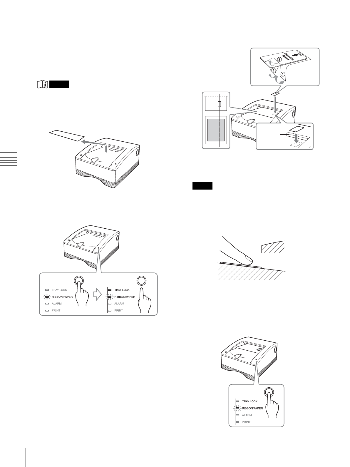
• Be sure to use only one cleaning sheet per cleaning
procedure. Using more than one sheet for a single roller
cleaning procedure may result in malfunction.
1
If thermal head cleaning has not been performed,
perform steps 1 to 5 of “Thermal head cleaning” on
page 17.
Note
When performing roller cleaning, do not pull out the
media tray after thermal head cleaning is performed.
2
Remove the paper that is ejected after thermal head
cleaning is performed.
4
Remove the backing paper 1 from the cleaning sheet
and attach the cleaning sheet to the partially ejected
paper, then remove the backing paper 2.
Paper
outlet
Attach the cleaning
sheet vertically in the
Miscellaneous
3
Keep the STOP button pressed and take your finger
off the button when the TRAY LOCK indicator is lit.
About 20 cm of paper is fed out of the printer from the
paper outlet.
position where the
scratches appeared.
Notes
• Orient the scratched printout that you kept in the
direction it was facing when ejected, and use it to
align the position of the cleaning sheet with the
position of the scratches.
• Press the cleaning sheet with your finger to make
When attaching the cleaning
sheet, align its edge with the
edge of the paper outlet.
sure that it is firmly affixed.
Paper outlet
• Make sure there is no air trapped under the cleaning
sheet and the corners of the sheet are not curling up.
Such cases will result in paper jams.
• If air is trapped under the cleaning sheet, be sure to
press it out.
5
Press the STOP button.
Roller cleaning with the cleaning sheet starts.
18
Precautions
EN
Page 19
When cleaning is completed, the paper is ejected and
the TRAY LOCK indicator is extinguished.
Ink Ribbon and Paper
Notes
• The cleaning sheet is ejected with the paper.
Discard the paper and do not reuse it.
• To perform roller cleaning again, repeat the
procedure from step 3.
• If an error occurs, restart the procedure from step 1.
6
Make sure that the TRAY LOCK indicator is
extinguished then pull out the media tray.
7
Remove the cleaning ribbon.
8
Load the ink ribbon.
9
Insert the media tray into the printer.
This completes the cleaning procedure.
Notes
• As paper is used during cleaning procedures, the
specified number of prints possible with a paper roll may
be reduced if the same roll is used for multiple cleaning
procedures.
• If there is not enough paper, the paper on which the
cleaning sheet is attached may remain on the paper
holder after cleaning is performed. In such cases, be sure
to replace the paper roll.
• If the cleaning sheet is not ejected despite sufficient
paper, cut off the paper on which the cleaning sheet is
attached from the paper holder, and repeat the procedure
from step 2.
Self-Laminate Color Printing Pack SEPC-100
Contains two color ink ribbons and two rolls of paper (A4size width).
Self-Laminate Color Printing Pack SEPC-110
Contains two color ink ribbons and two rolls of paper
(Letter size width).
Printable quantity
The number of printouts that can be made with a single set
of ink ribbon and paper is shown below.
Printing pack SEPC-100 SEPC-110
Number of sheets 50 sheets 50 sheets
Print size A4 Letter
For symbols on the accessories, see page 3.
Miscellaneous
Notes
• Do not change the ink ribbon and paper roll when they
are only partially used. Doing so can cause problems.
The number of printouts indicated above is not
quarantined.
• When the ink ribbon is used up, replace both the ink
ribbon and the paper roll.
• Destroy and discard ink ribbon per NIST Media
Sanitization Standards. (For customers in the U.S.A.)
Ink Ribbon and Paper
EN
19
Page 20

Technical Specifications
Design and specifications are subject to change without
notice.
Power requirements
100 — 240 V AC, 50/60 Hz
Input current 3.4 — 1.4 A
Operating temperatures
5°C — 35°C (41°F — 95°F)
Operating humidity
20% — 80% (no condensation)
Operating pressure
700 hPa — 1,060 hPa
Storage and transport temperature
–20°C — +60°C (–4°F — +140°F)
Storage and transport humidity
20% — 80% (no condensation)
Storage and transport pressure
700 hPa — 1,060 hPa
Dimensions Approx. 317 × 425 × 207 mm (w × d × h)
Weight Approx. 11.5 kg
Miscellaneous
Printing system Dye transfer sublimation thermal printing
Thermal head 11.83 dot/mm, 2,560 dots (301 dpi)
Gradations 8-bit (256-level) processing each for
yellow, magenta, and cyan
Maximum print size
A4 size: 202 × 287 mm
Letter size: 208 × 269 mm
Picture elements
A4 size: 2,392 dots × 3,400 dots
Letter size: 2,464 dots × 3,192 dots
Printing time Approximately 76 seconds (A4 size)
Approximately 72 seconds (Letter size)
Interface Hi-Speed USB (USB 2.0)
Component supplied
Paper holder:
1 Paper holder (pink) (1): P12811
2 Paper holder (Blue) (1): P12812
Cleaning Ribbon (1)
P12814
Media Tray (1)
P12813
Hospital Grade Power Cord (118 in) (1)
(For US/CANADA use only)
PN 12760
CD-ROM (1)
P12744
Optional accessories
Ink ribbon/paper roll
(2 rolls of paper; 2 rolls of ribbon)
Self-Laminating Color Printing Pack
Letter size (SEPC-110)
0240080231
Self-Laminating Color Printing Pack
A4 size (SEPC-100)
0240080232
Cleaning Sheet Pack
0240080233
Medical Specifications
Protection against electric shock:
Class I
Protection against harmful ingress of
water:
Ordinary
Degree of safety in the presence of a
flammable anesthetic mixture with air
or with oxygen or nitrous oxide:
Not suitable for use in the presence of
a flammable anesthetic mixture with
air or with oxygen or nitrous oxide
Mode of operation:
Continuous
About the Self-Laminating Color Printing Pack (SEPC-100/SEPC-110)
Caution
When you dispose of the unit or accessories, you must
obey the laws in the relative area or country and the
regulations in the relative hospital regarding
environmental pollution.
Precautions
• Store unopened paper rolls in a cool dark place.
• Open paper rolls only when ready to use.
• Please refer to the printer’s instruction manual about
how to load the paper roll.
• Promptly load the paper roll into the tray and place into
the printer.
• This paper roll is specifically designed for the SDP1000
Stryker Digital Color Printer. Do not use with printers
from other manufacturers.
20
Technical Specifications
EN
Page 21

Troubleshooting
If a problem appears, check the following troubleshooting
guide first and perform whatever action is necessary to
solve the problem. If the problem persists, turn off the
printer and consult with your local Stryker representative.
Symptom Possible causes and remedies
The printer does not
print even though
images are being sent
from the computer.
The printer does not
print.
The paper roll cannot
be loaded in the
media tray.
The paper does not
feed.
The print area is
printed offset.
There are marks and
stripes on the print
side.
Scratches appear at
regular intervals.
• The printer is in the standby state (the
1 On/standby indicator is not lit).
t Press the 1 On/standby switch.
• The printer is not connected properly.
t Check the connections (page 7).
• An indicator on the printer is
displaying an error status.
tRefer to “Explanation of Indicators”
on page 22 and take the appropriate
action.
• The paper roll is being loaded with the
colors of the paper holders and the
colors on the media tray incorrectly
matched.
t Load the paper roll so that the
colors of the paper holders and the
colors on the media tray match
(page 12).
• The paper roll is loaded with the colors
of the paper holders and the colors of
the labels affixed to the paper roll
incorrectly matched.
t Load the paper roll so that the
colors of the paper holders and
colors of the labels affixed to the
paper roll match (page 11).
• The paper roll is loaded with the left
and right reversed (when the paper roll
has been reloaded).
t Load the paper roll in the proper
direction (page 12).
• The paper holder selector does not
match the size of the paper roll.
t Set the selector properly (page 10).
• The label affixed to the paper roll has
not been peeled off.
t Peel the label off properly
(page 12).
• The paper roll is wound to loosely.
t Rewind the paper roll and then load
it (page 15).
• The leading edge of the paper roll is
folded.
t Cut off the folded part so that the
paper becomes straight (page 24).
• The paper holder selector does not
match the size of the paper roll.
tSet the selector properly (page 10).
• The thermal head is dirty.
t Perform thermal head cleaning
(page 17).
• The rollers inside the printer are dirty.
t Perform roller cleaning (page 17).
Symptom Possible causes and remedies
The media tray
cannot be opened.
The fan turns when
the printer is in the
ready state.
• The power may have been turned off
during the printing operation.
tPress the 1 On/standby switch to
turn on the power of the printer and
initialize the printer.
• The printer may not have been able to
recover from an error.
tPress the 1 On/standby switch to
enter the standby state and then
press the 1 On/standby switch
again to turn on the power. If the
media tray still cannot be opened,
press the 1 On/standby switch to
enter the standby state and then
disconnect the power cord and
contact your dealer.
• The printer is performing temperature
control. This is not a malfunction.
Miscellaneous
Troubleshooting
EN
21
Page 22

Explanation of Indicators
The meanings of the indicators on the printer when they
are on or flashing are described below.
Indicator Status Possible causes and remedies
1 On/
standby
(green)
TRAY
LOCK
(orange)
RIBBON/
PA PE R
(orange)
Miscellaneous
ALARM
(orange)
On The printer is turned on.
Flashing The printer is entering the standby
On The media tray cannot be pulled out
On One of the following causes.
1)
Flashing • LED will flash slowly when there
1)
On One of the following causes.
state.
because the mechanical action is going,
eg. printer initializing, tray recently
closed, printer cleaning cycle in
process.
It lights up with other LED.
• A paper roll has not been loaded.
t Load a paper roll (page 11).
• An ink ribbon has not been loaded.
tLoad an ink ribbon (page 10).
• The ink ribbon has been used up.
tLoad a new ink ribbon and paper
roll (page 13).
• A ribbon error has occurred.
tCheck that an ink ribbon has
been loaded properly.
are 6 to 15 sheets of media
remaining.
• LED will flash rapidly when there
are 5 or fewer sheets of media
remaining.
• LED will flash three consecutive
times at once when:
• Thermal head or roller cleaning
is in progress.
• The printer is waiting to begin
roller cleaning.
tPress the STOP button to
begin.
• The cleaning ribbon is loaded.
tRemove the cleaning ribbon.
• The media tray is not closed.
tClose the media tray properly.
• A paper jam has occurred in the
printer.
tRemove the jammed paper
(page 23).
• The paper outlet is full of printouts.
tRemove the printouts that are
blocking the paper outlet.
Indicator Status Possible causes and remedies
RIBBON/
PA PE R,
ALARM
PRINT
(green)
All of TRAY
LOCK,
RIBBON/
PA PE R,
ALARM,
and PRINT
On One of the following causes.
1)
Flashing 2)
On Printing is in progress.
Flashing Image data is being received.
Flashing
slowly
On • The printer is initializing.
• The paper roll has run out.
tLoad a new ink ribbon and paper
roll (page 13).
• A paper feed error has occurred.
tCheck the ink ribbon and paper
roll.
• A paper eject error has occurred.
tCheck the ink ribbon and paper
roll.
One of the following causes.
• A ribbon error occurred while
cleaning was in progress.
tCheck that the cleaning ribbon
has been loaded properly.
• A paper jam occurred inside the
printer while cleaning was in
progress.
tRemove the jammed paper
(page 23).
• The paper roll ran out while
cleaning was in progress.
tLoad a new paper roll.
• A feed error occurred while
cleaning was in progress.
tCheck the cleaning ribbon and
paper roll.
• An eject error occurred while
cleaning was in progress.
tCheck the cleaning ribbon and
paper roll.
The printer is waiting until the thermal
head reaches a temperature at which
printing is possible. Once that
temperature is reached, the PRINT
indicator will light.
tAfter pressing the 1 On/standby
switch to turn on the printer, this
indicator remains lit while the
printer is initializing. Wait until
initialization is complete.
• The media tray was opened during
printing.
tPress the 1 On/standby switch
to enter the standby state, press
the 1 On/standby switch again
to turn on the power, and then
check the ink ribbon and paper
roll.
• A serious failure has occurred.
tPress the 1 On/standby switch
to enter the standby state, and
then press the 1 On/standby
switch again to turn on the
power. If the printer is still
unable to recover from the
failure, press the 1 On/standby
switch to enter the standby state
and then disconnect the power
cord and contact your dealer.
22
Explanation of Indicators
EN
Page 23
Footnotes for the previous chart:
1)
During continuous printing, the PRINT indicator lights at the
same time if there are still images remaining.
2)
Only the RIBBON/PAPER indicator flashes. The ALARM
indicator is lit.
If a Paper Jam Occurs
While the printer is printing, if the ALARM indicator
lights and any of the following messages appears on the
computer monitor, it is possible that a paper jam has
occurred in the printer:
“A paper jam has occurred. Remove the jammed paper.”
“A paper jam has occurred. Printing has stopped. Remove
the jammed paper and then resume printing.”
“There is a problem with a motor or a sensor. Printing has
stopped. Turn the printer off and then back on again, and
then resume printing.”
If a paper jam has occurred, follow the procedure
described below to check the status of the paper roll.
1
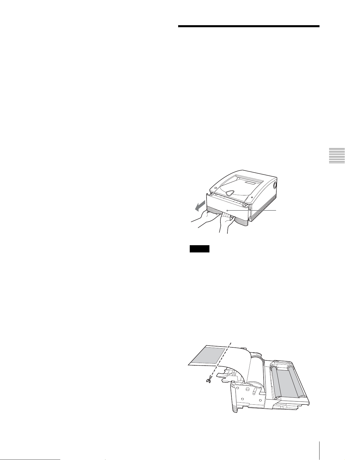
Make sure that the printer is not performing an
operation, and then pull out the media tray.
Miscellaneous
Lock released
Note
If the media tray does not pull out, do not force it out.
Press the 1 On/standby switch to enter the standby
state, and then press the switch again to turn the
printer ON. Try pulling the media tray again after the
printer finishes initializing.
2
Open the media tray cover, check whether there is
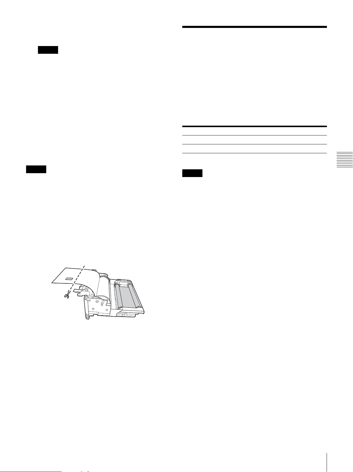
printing on the paper, and cut the paper.
Cut the paper as follows.
If there is printing on the paper
Cut off the printed portion with a pair of scissors.
If a Paper Jam Occurs
EN
23
Page 24
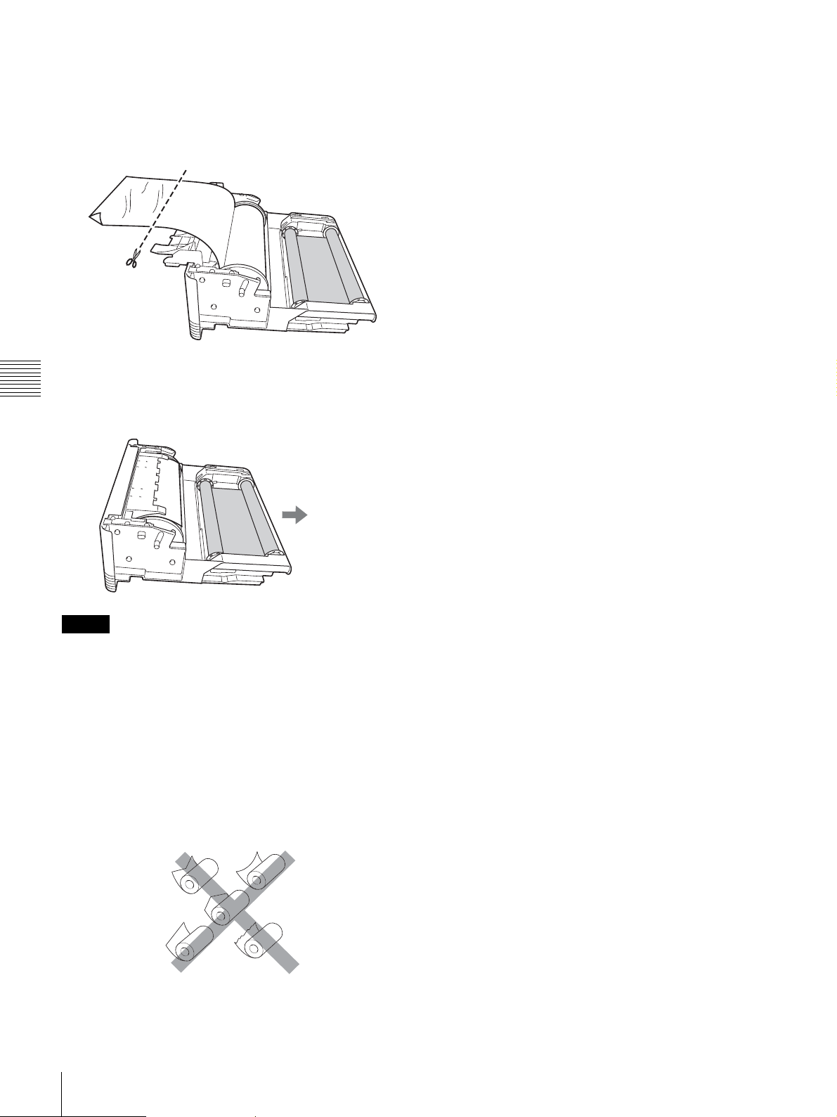
If there is no printing on the paper
Make sure that the leading edge of the paper is not
creased or wrinkled.
If the leading edge is creased or the paper is wrinkled,
cut off the leading edge or wrinkled portion with a
pair of scissors or the like.
3
Tighten any looseness in the paper roll (page 15), and
close the media tray cover until it snaps into place.
Miscellaneous
4
Insert the media tray into the printer.
To the printer
Notes
• When removing the paper roll, be sure to place the media
tray on a stable surface before beginning.
• If you drop the media tray while it contains a paper roll,
it could cause personal injury. When removing and
inserting the media tray, be sure to use both hands, with
one hand holding the handle and the other hand
supporting the media tray from the bottom.
• When cutting the paper roll, be sure to cut so that the
leading edge of the paper is straight. Loading the paper
into the printer with the leading edge cut as follows may
result in damage to the printer.
24
If a Paper Jam Occurs
EN
Page 25
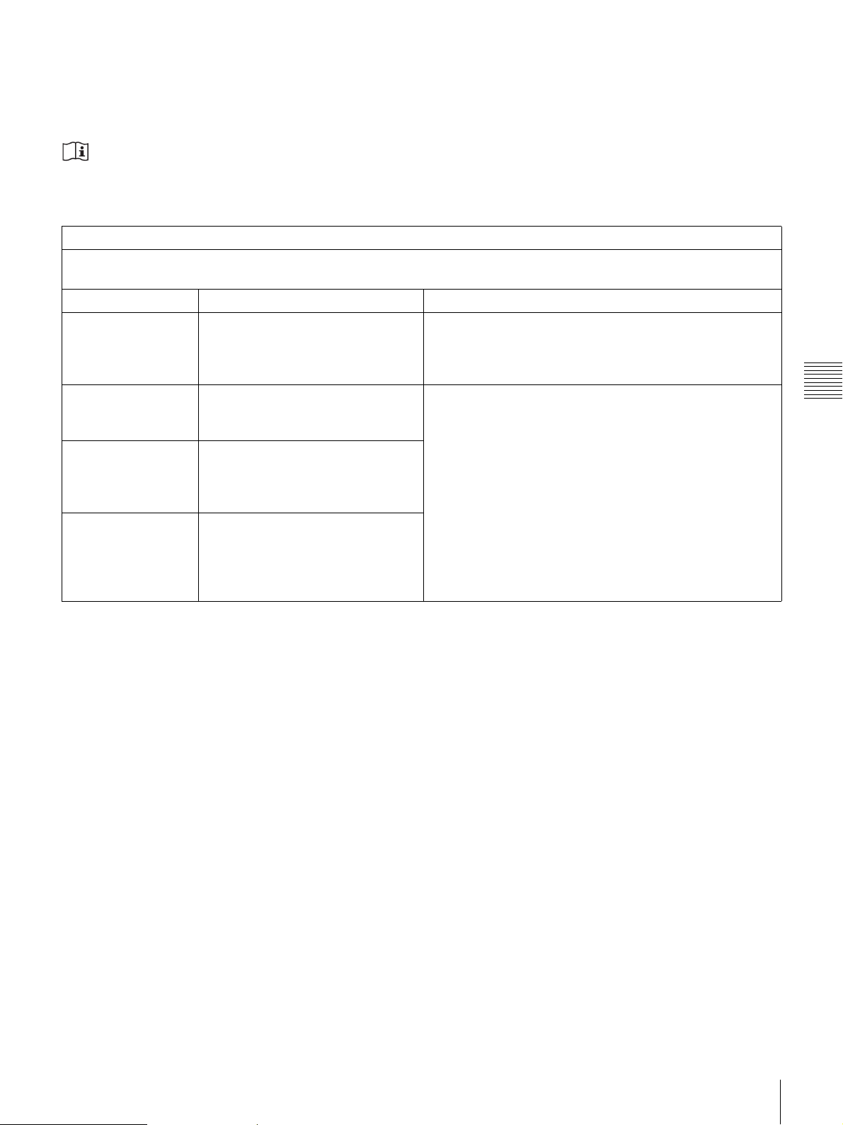
Important EMC notices for use in the medical environments
• The SDP1000 needs special precautions regarding EMC and needs to be installed and put into service according to the
EMC information provided in the instructions for use.
• The portable and mobile RF communications equipment such as cellular phones can affect the SDP1000.
Warning
The use of accessories and cables other than those specified, with the exception of replacement parts sold by Stryker , may
result in increased emissions or decreased immunity of the SDP1000.
Guidance and manufacturer’s declaration - electromagnetic emissions
The SDP1000 is intended for use in the electromagnetic environment specified below.
The customer or the user of the SDP1000 should assure that it is used in such an environment.
Emission test Compliance Electromagnetic environment - guidance
RF emissions
CISPR 11
RF emissions
CISPR 11
Harmonic
emissions
Group 1
Class B
Class A
The SDP1000 uses RF energy only for its internal
function. Therefore, its RF emissions are very low
and are not likely to cause any interference in nearby
electronic equipment.
The SDP1000 is suitable for use in all
establishments, including domestic establishments
and those directly connected to the public lowvoltage power supply network that supplies buildings
used for domestic purposes.
Miscellaneous
IEC 61000-3-2
Voltage
fluctuations/flicker
emissions
Complies
IEC 61000-3-3
Warning
If the SDP1000 should be used adjacent to or stacked with other equipment, it should be observed to verify normal
operation in the configuration in which it will be used.
If a Paper Jam Occurs
EN
25
Page 26
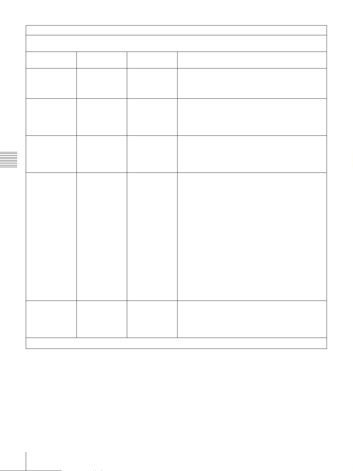
Guidance and manufacturer’s declaration - electromagnetic immunity
The SDP1000 is intended for use in the electromagnetic environment specified below. The customer or the
user of the SDP1000 should assure that it is used in such an environment.
Immunity test
Electrostatic
discharge (ESD)
IEC 60601
test level
±6 kV contact
Compliance
level
±6 kV contact
Electromagnetic environment - guidance
Floors should be wood, concrete or ceramic tile. If
floors are covered with synthetic material, the relative
humidity should be at least 30%.
IEC 61000-4-2
Electrical fast
transient/burst
±8 kV air
±2 kV for power
supply lines
±8 kV air
±2 kV for power
supply lines
Mains power quality should be that of a typical
commercial or hospital environment.
IEC 61000-4-4
Surge
IEC 61000-4-5
Miscellaneous
Voltage dips,
short
interruptions and
voltage
variations on
power supply
input lines
IEC 61000-4-11
Power frequency
(50/60 Hz)
magnetic field
±1 kV for input/
output lines
±1 kV line(s) to
line(s)
±2 kV line(s) to
earth
< 5% U
T
(> 95% dip in
U
)
T
for 0.5 cycle
40% U
T
(60% dip in U
for 5 cycles
70% U
T
(30% dip in U
for 25 cycles
< 5% U
T
(> 95% dip in
U
)
T
for 5 sec
±1 kV for input/
output lines
±1 kV differential
mode
±2 kV common
mode
< 5% U
(> 95% dip in
)
U
T
for 0.5 cycle
40% U
)
(60% dip in UT)
T
for 5 cycles
70% U
)
(30% dip in UT)
T
for 25 cycles
< 5% U
(> 95% dip in
U
)
T
for 5 sec
Mains power quality should be that of a typical
commercial or hospital environment.
T
Mains power quality should be that of a typical
commercial or hospital environment. If the user of the
SDP1000 requires continued operation during power
mains interruptions, it is recommended that the
SDP1000 be powered from an uninterruptible power
T
T
T
supply or a battery.
3 A/m 3 A/m Power frequency magnetic fields should be at levels
characteristic of a typical location in a typical
commercial or hospital environment.
IEC 61000-4-8
NOTE: U
26
If a Paper Jam Occurs
EN
is the a.c. mains voltage prior to application of the test level.
T
Page 27
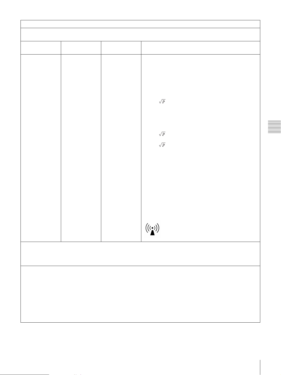
Guidance and manufacturer’s declaration - electromagnetic immunity
The SDP1000 is intended for use in the electromagnetic environment specified below. The customer or the
user of the SDP1000 should assure that it is used in such an environment.
Immunity test
IEC 60601
test level
Compliance
level
Electromagnetic environment - guidance
Portable and mobile RF communications equipment
should be used no closer to any part of the SDP1000,
including cables, than the recommended separation
distance calculated from the equation appliance to
the frequency of the transmitter.
Recommended separation distance
Conducted RF
IEC 61000-4-6
Radiated RF
IEC 61000-4-3
3 Vrms
150 kHz to
80 MHz
3 V/m
80 MHz to
2.5 GHz
3 Vrms
3 V/m
d = 1.2
d = 1.2 80 MHz to 800 MHz
d = 2.3 800 MHz to 2.5 GHz
Where P is the maximum output power rating of the
transmitter in watts (W) according to the transmitter
manufacturer and d is the recommended separation
distance in meters (m).
Field strengths from fixed RF transmitters, as
determined by an electromagnetic site survey,
a
should be less than the compliance level in each
frequency range.
b
Interference may occur in the vicinity of equipment
marked with following symbol:
Miscellaneous
NOTE 1: At 80 MHz and 800 MHz, the higher frequency range applies.
NOTE 2: These guidelines may not apply in all situations. Electromagnetic propagation is affected by
absorption and reflection from structures, objects and people.
a Field strengths from fixed transmitters, such as base stations for radio (cellular/cordless) telephones and
land mobile radios, amateur radio, AM and FM radio broadcast and TV broadcast cannot be predicted
theoretically with accuracy.
To assess the electromagnetic environment due to fixed RF transmitters, an electromagnetic site survey
should be considered. If the measured field strength in the location in which the SDP1000 is used exceeds
the applicable RF compliance level above, the SDP1000 should be observed to verify normal operation. If
abnormal performance is observed, additional measures may be necessary, such as reorienting or
relocating the SDP1000.
b Over the frequency range 150 kHz to 80 MHz, field strengths should be less than 3 V/m.
If a Paper Jam Occurs
EN
27
Page 28
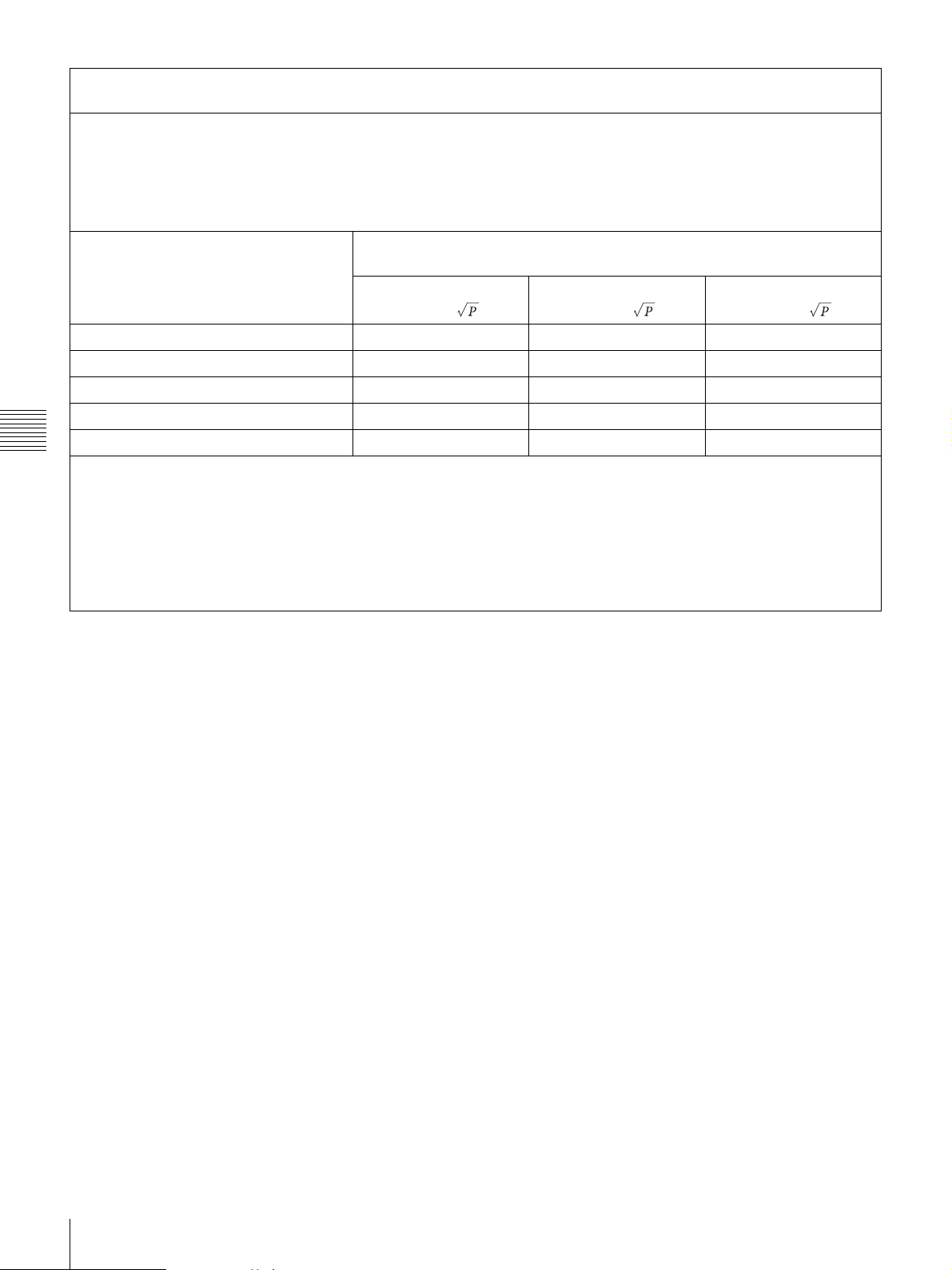
Recommended separation distances between portable and mobile RF communications equipment
and the SDP1000
The SDP1000 is intended for use in an electromagnetic environment in which radiated RF disturbances are
controlled.
The customer or the user of the SDP1000 can help prevent electromagnetic interference by maintaining a
minimum distance between portable and mobile RF communications equipment (transmitters) and the
SDP1000 as recommended below, according to the maximum output power of the communications
equipment.
Separation distance according to frequency of transmitter
Rated maximum output power of
transmitter
W
150 kHz to 80 MHz
d = 1.2
80 MHz to 800 MHz
m
d = 1.2
800 MHz to 2.5 GHz
d = 2.3
0.01 0.12 0.12 0.23
0.1 0.380.380.73
1 1.2 1.2 2.3
10 3.8 3.8 7.3
Miscellaneous
100 12 12 23
For transmitters rated a maximum output power not listed above, the recommended separation distance d in
meters (m) can be estimated using the equation applicable to the frequency of the transmitter, where P is the
maximum output power rating of the transmitter in watts (W) according to the transmitter manufacturer.
NOTE 1: At 80 MHz and 800 MHz, the separation distance for the higher frequency range applies.
NOTE 2: These guidelines may not apply in all situations. Electromagnetic propagation is affected by
absorption and reflection from structures, objects and people.
28
If a Paper Jam Occurs
EN
Page 29

Warranty and Return Plolicy
Product Warranty
Stryker Endoscopy warrants all products, subject to the exceptions provided herein, to be free from defects in design, materials and workmanship and to substantially
conform to the product specifications contained in the documentation provided by Stryker Endoscopy with the products for a period of one year from the date of purchase
(the “Warranty Period”). This warranty shall apply only to the original end-user purchaser of products directly from Stryker Endoscopy or a Stryker Endoscopy authorized
distributor. This warranty may not be transferred or assigned without the express written consent of Stryker Endoscopy.
If a valid warranty claim is received within the Warranty Period, Stryker will, in its sole discretion: (1) repair the product at no charge, (2) replace the product at no charge
with a product that is at least functionally equivalent to the original product, or (3) refund the purchase price of the product. In any event, Stryker’s liability for breach of
warranty shall be limited to the replacement value of the defective or non-conforming part or component.
This warranty does not app ly to: (1) products that have been misused, neglected, modi fied, altered, adjusted, ta mpered with, improperly installed or re furbished; (2) products
that have been repaired by any person other than Stryker Endoscopy personnel without the prior written consent of Stryker Endoscopy; (3) products that have been subjected
to unusual stress or have not been maintained in accordance with the instructions in the user manual or as demonstrated by a Stryker Endoscopy representative; (4) products
on which any original serial numbers or other identification marks have been removed or destroyed; or (5) products that have been repaired with any unauthorized or nonStryker components, including replacement lamps.
If Stryker determines in its reasonable discretion that the claimed defect or non-conformance in the product is excluded from warranty coverage as described hereunder, it
will notify the customer of such determination and will provide an estimate of the cost of repair of the product. In such an event, any repair would be performed at Stryker’s
standard rates.
Products and product components repaired or replaced under this warranty continue to be warranted as described herein during the initial Warranty Period or, if the initial
Warranty Period has expired by the time the product is repaired or replaced, for thirty (30) days after delivery of the repaired or replaced product. When a product or
component is replaced, the item provided in replacement will be the customer’s property and the replaced item will be Stryker’s property. If a refund is provided by Stryker,
the product for which the refund is provided must be returned to Stryker and will become Stryker’s property.
The inspection, testing, acceptance or use of the products and services furnished hereunder shall not affect Stryker’s obligation under this warranty, and such warranty shall
survive inspection, test, acceptance and use.
Notwithstanding the above, (i) the following products are warranted for a period of ninety (90) days from the date of purchase: Scopes, Associated Scope Hardware, Fiber
Optic Cables, Laparoscopic Instruments, VCRs, Monitors, and Ink Jet Printers; (ii) SDP1000 Stryker Digital Color Printers are warranted for three (3) years from the date
of purchase; and (iii) replacement light bulbs are warranted for a period of sixty (60) days from the date of purchase.
TO THE FULLEST EXTENT PERMITTED BY LAW, THE EXPRESS WARRANTY SET FORTH HEREIN IS THE ONLY WARRANTY APPLICABLE TO
THE PRODUCTS AND IS EXPRESSLY IN LIEU OF ANY OTHER WARRANTY BY STRYKER, EXPRESSED OR IMPLIED, INCLUDING, BUT NOT
LIMITED TO, ANY IMPLIED WARRANTY OF MERCHANTABILITY OR FITNESS FOR A PARTICULAR PURPOSE. STRYKER SHALL NOT HAVE
ANY TORT LIABILITY TO CUSTOMER WITH RESPECT TO THE PRODUCTS AND SHALL NOT BE LIABLE FOR INDIRECT, SPECIAL,
INCIDENTAL OR CONSEQUENTIAL DAMAGES RESULTING FROM ANY BREACH OF WARRANTY OR UNDER ANY OTHER LEGAL THEORY.
Return Policy
Stryker Endoscopy values customer relationships and strives for satisfaction in purchases made by our customers. Therefore, we offer a return policy for most products.
Under this policy, customers may return purchased products to Stryker Endoscopy, within 90 days of customer’s receipt of the product, for a credit or a refund of the
purchase price paid, less shipping and handling and applicable restocking fees. Products that fail after the first 90 days may be covered by and are subject to the terms of
applicable product warranty. Sterile products may not be returned for credit or refund unless they are in their original, unopened packaging or if they are in breach of the
applicable warranty.
Restocking Fees: Unless the product is defective or the return is the direct result of a Stryker Endoscopy error, a restocking fee of 10% may be charged on all returned
products.
A Returned Merchandise Authorization (RMA) number must be obtained from Stryker Endoscopy before returning product. To obtain an RMA number, please contact
Stryker Endoscopy Customer Service at 1.800.624.4422.
Please send any returned products to:
Stryker Endoscopy
Attn: Returns
5900 Optical Court
San Jose, CA 95138, USA
With the return, please include the following:
1. RMA number
2. Purchase order number
3. Original invoice number
4. Name, address, and account number (of the organization returning the product)
5. Itemized list of the items being returned
6. Reason for the return
7. Product Experience Report/Complaint number, if applicable
Please carefully package the product being returned. Credit will not be given for items that are damaged in return shipment due to inadequate packaging.
Stryker Endoscopy does not accept any COD returns. Return shipping costs are borne by the customer unless Stryker Endoscopy specifically agrees otherwise.
Please clean and sterilize all potentially contaminated products prior to returning them to Stryker Endoscopy. It is unlawful to transport bio-contaminated products through
interstate commerc e, unless they are pr operly packaged and labeled as such. Stryker Endoscopy reserves the right to destroy contaminated product at the customer’s expense
and charge the customer for a replacement unit.
Please remove any “Protected Health Information” as defined in the Health Insurance Portability and Accountability Act of 1996 from products prior to returning them to
Stryker Endoscopy.
If a return does not comply with these terms, Stryker Endoscopy reserves the right to destroy the product at the customer’s expense. Any replacement would be at the
customer’s expense.
Miscellaneous
Warranty and Return Plolicy
EN
29
Page 30

Page 31

Page 32

Produced for:
Stryker Endoscopy
5900 Optical Cour t
San Jose, CA 95138 USA
1-800-624-4422
U.S. Patents: www.stryker.com/patents
P12706 F
2017/09
Printed in Japan
 Loading...