

Sony SDM-X52 Service Manual

SERVICE MANUAL
SPECIFICATIONS
SDM-X52
US Model
Canadian Model
AEP Model
LCD panel Panel type: a-Si TFT Active Matrix
Picture size: 15.0 inch
Input signal format RGB operating frequency*
Horizontal: 28 – 61 kHz
Vertical: 56 – 75 Hz
Resolution Horizontal: Max.1024 dots
Vertical: Max.768 lines
Input signal levels Analog RGB video signal
0.7 Vp-p, 75 Ω, positive
SYNC signal
TTL level, 2.2 kΩ ,
positive or negative
(Separate horizontal and vertical,
or composite sync)
0.3 Vp-p, 75Ω, negative
(Sync on green)
Digital RGB (DVI) signal: TMDS
(Single link)
Power requirements 100 – 240 V, 50 – 60 Hz,
Max. 0.7A
Power consumption Max. 28 W
°
Operating tempe rature 5 – 35
C
Dimensions (width/height/depth)
Display (upright):
Approx. 392 × 358 × 199 mm
1
/2 × 14 1/8 × 7 7/8 inches)
(15
(with stand)
Approx. 392 × 299 × 73 mm
1
/2 × 11 7/8 ×2 7/8 inches)
(15
(without stand)
Mass Approx. 4.8 kg (10 lb 9 oz) (with
stand)
Approx. 3.5 kg (7 lb 11 oz)
(without stand)
Plug & Play DDC2B
* Recommended horizontal and vertical timing condition
• Horizontal sync width dut y should be more than 4. 8% of total
horizontal time or 0.8 µs, whichever is larger.
• Horizontal blanking wi dth should be more than 2.5 µsec.
• Vertical blanking width sh ould be more than 450 µsec.
Design and specification s are subject to change without notice.
TFT LCD Color Computer Display
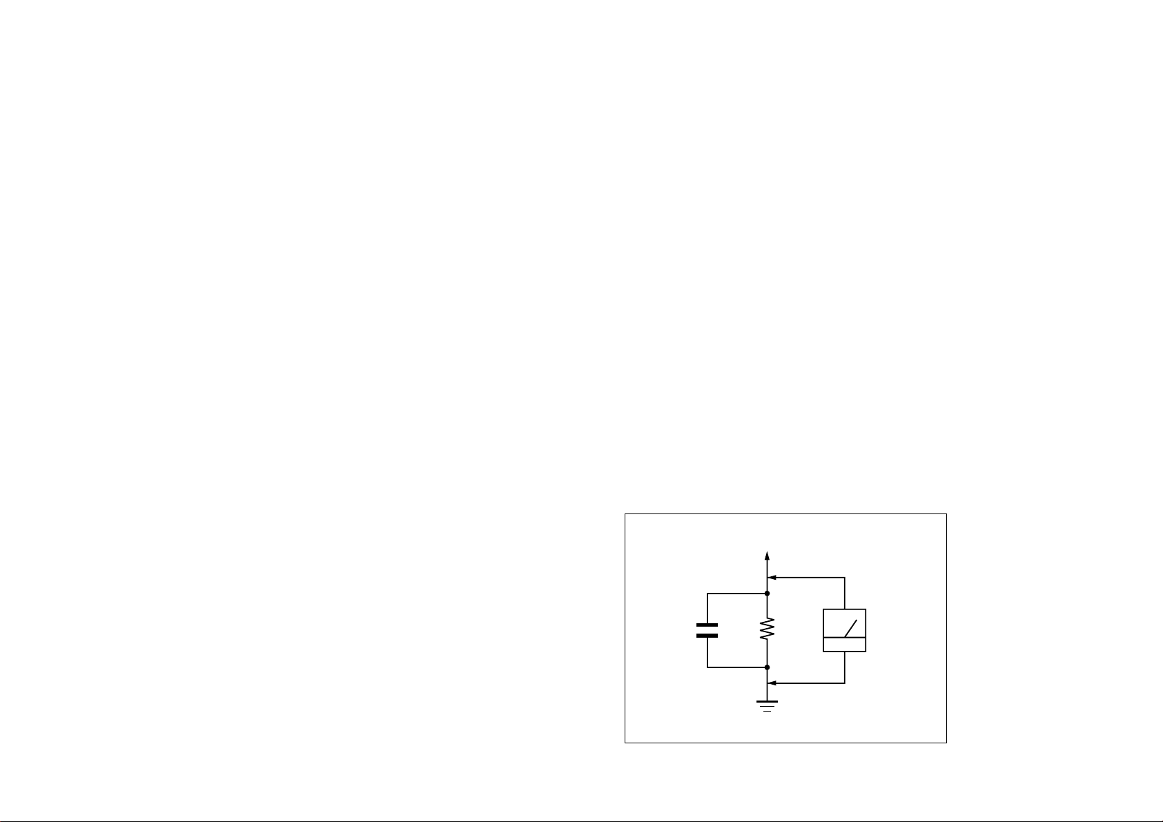
1.5 k
Ω
0.15 µF
AC
Voltmeter
(0.75 V)
To Exposed Metal
Parts on Set
Earth Ground
SAFETY CHECK-OUT
After correcting the original service problem, perform the following safety
checks before releasing the set to the customer:
1. Check the area of your repair for unsoldered or poorly-soldered
connections. Check the entire board surface for solder splashes and
bridges.
2. Check the interboard wiring to ensure that no wires are “pinched” or
contact high-wattage resistors.
3. Check that all control knobs, shields, covers, ground straps, and
mounting hardware have been replaced. Be absolutely certain that you
have replaced all the insulators.
4. Look for unauthorized replacement parts, particularly transistors, that
were installed during a previous repair. Point them out to the customer
and recommend their replacement.
5. Look for parts which, though functioning, show obvious signs of
deterioration. Point them out to the customer and recommend their
replacement.
6. Check the line cords for cracks and abrasion. Recommend the
replacement of any such line cord to the customer.
7. Check the connector shell, metal trim, “metallized” knobs, screws, and
all other exposed metal parts for AC Leakage. Check leakage as described right.
LEAKAGE TEST
The AC leakage from any exposed metal part to earth ground and from all
exposed metal parts to any exposed metal part having a return to chassis,
must not exceed 0.5 mA (500 microamperes).
Leakage current can be measured by any one of three methods.
1. A commercial leakage tester, such as the Simpson 229 or RCA WT540A. Follow the manufacturers’ instructions to use these instruments.
2. A battery-operated AC milliammeter. The Data Precision 245 digital
multimeter is suitable for this job.
3. Measuring the voltage drop across a resistor by means of a VOM or
battery-operated AC voltmeter. The “limit” indication is 0.75 V, so
analog meters must have an accurate low-voltage scale. The Simpson 250
and Sanwa SH-63Trd are examples of a passive VOMs that are suitable.
Nearly all battery operated digital multimeters that have a 2 V AC range
are suitable. (See Fig. A)
Fig. A. Using an AC voltmeter to check AC leakage.
SDM-X52(E) 2

WARNING!!
AVERTISSEMENT!!
SAFETY-RELATED COMPONENT WARNING!!
COMPONENTS IDENTIFIED BY SHADING AND MARK ! ON THE
SCHEMATIC DIAGRAMS, EXPLODED VIEWS AND IN THE
PARTS LIST ARE CRITICAL FOR SAFE OPERATION. REPLACE
THESE COMPONENTS WITH SONY PARTS WHOSE PART
NUMBERS APPEAR AS SHOWN IN THIS MANUAL OR IN
SUPPLEMENTS PUBLISHED BY SONY. CIRCUIT ADJUSTMENTS THAT ARE CRITICAL FOR SAFE OPERATION ARE
IDENTIFIED IN THIS MANUAL. FOLLOW THESE PROCEDURES
WHENEVER CRITICAL COMPONENTS ARE REPLACED OR IMPROPER OPERATION IS SUSPECTED.
ATTENTION AUX COMPOSANTS RELATIFS À LA SÉCURITÉ!!
LES COMPOSANTS IDENTIFIÉS PAR UNE TRAME ET UNE
MARQUE ! SONT CRITIQUES POUR LA SÉCURITÉ. NE LES
REMPLACER QUE PAR UNE PIÈCE PORTANT LE NUMÉRO
SPECIFIÉ. LES RÉGLAGES DE CIRCUIT DONT L’IMPORTANCE EST
CRITIQUE POUR LA SÉCURITÉ DU FONCTIONNEMENT SONT
IDENTIFIÉS DANS LE PRÉSENT MANUEL. SUIVRE CES
PROCÉDURES LORS DE CHAQUE REMPLACEMENT DE
COMPOSANTS CRITIQUES, OU LORSQU’UN MAUVAIS
FONCTIONNEMENT EST SUSPECTÉ.
SDM-X52(E) 3
POWER SAVING FUNCTION
AUTOMATIC PICTURE QUALITY ADJUSTMENT
FUNCTION
(ANALOG RGB)
This monitor meets the power-saving guidelines set by VESA,
E
NERGY STAR, and NUTEK. If the monitor is connected to a
computer or video graphics board that is DPMS (Display Power
Management Signaling) compliant, the monitor will
automatically reduce power consumption as shown below.
Power mode Power consumption1 (power)
indicator
normal
28 W (max.) green
operation
active off*
3 W (max.) orange
(deep sleep)**
1 (power) off 1 W red
main power of f 0 W off
* When your computer enters the “active off” mode, the input signal is
cut and NO INPUT SI GNAL appears on the screen . After 10 s econds,
the monitor enters the po w er sa ving mode.
** “Deep sleep” is a power saving mode defined by the Environmental
Protection Agency.
Note
ZZ...
If the (POWER SAVE) is set to OFF (page 16), the monito r does not
enter the power saving mode.
When the monitor receives an input signal, it
automatically adjusts the picture’s position and
sharpness ( phase/ pitch) , and e nsures that a clear
picture appears on the screen.
The factory preset mode
When the monitor receives an input signal, it automatically
matches the signal to one of the factory preset modes stored in the
monitor’s memory to provide a high quality picture at the center
of the screen. If th e in put sign al m atc hes th e fac tory pres et mo de,
the picture is appears on the screen automatically with the
appropriate default adjustment.
If input signals do not match one of the factory
preset modes
When the monitor receives an input signal, the automatic picture
quality adjustment function of this monitor is activated and
ensures that a clear picture always appears on the screen (within
the following monitor frequency ranges):
Horizontal frequency: 28 – 61 kHz
Vertical frequency: 56 – 75 Hz
Consequently, the first time the monitor receives input signals
that do not match one of the factory preset modes, the monitor
may take a longer time th an normal for displaying the picture on
the screen. This adjustment data is automatically stored in
memory so that next time, the monitor will function in the same
way as when the monitor receives the signals that match one of
the factory preset modes.
If you adjust the phase, pitch, and pictures
position manually
For some input signals, the automatic picture quality adjustment
function of this monitor may not completely adjust the picture
position, phase, and pitch. In this case, yo u can manually set these
adjustments (page 13). If you manually set these adjustments,
they are stored in memory as user modes and automatically
recalled whenever the monitor receives the same input signals.
SDM-X52(E) 4

TABLE OF CONTENTS
Section Title Page Section Title Page
1. DISASSEMBLY
1-1. Rear Cover and Cabinet Assy Removal ............... 1-1
1-2. H andI Boards Removal ....................................... 1-2
1-3. A Board Removal ................................................ 1-3
1-4. G Board Removal ................................................ 1-4
1-5. U Board Removal ................................................. 1-5
1-6. Speaker Box and LCD Unit Removal .................. 1-6
1-7. LCD Panel Removal ............................................. 1-7
2. ADJUSTMENTS
2-1. Service Functions of Buttons in Front Panel ........ 2-1
2-2. Usea of Service Mode .......................................... 2-2
2-3. Functions of Service Mode .................................. 2-3
3. DIAGRAMS
3-1. Block Diagrams .................................................... 3-1
3-2. Circuit Boards Location........................................ 3-2
3-3. Schematic Diagrams and Printed Wiring Boards.. 3-2
(1)Schematic Diagram
of A(a,b,c,d,e) Board.......................... 3-4
(2)Schematic Diagram of H Board. ...................... 3-10
(3)Schematic Diagram of I Board......................... 3-12
(4)Schematic Diagram of U Board. ...................... 3-14
(5)Schematic Diagram of G Board. ...................... 3-16
4. EXPLODED VIEWS
4-1. Chassis ................................................................. 4-2
2-4. White Balance Adjustment .................................. 2-3
2-5. Action after Replacing
the LCD Panel and Board ..................................... 2-5
4-2. Packing Materials ................................................. 4-4
5. ELECTRICAL PARTS LIST ............................... 5-1
SDM-X52(E) 5
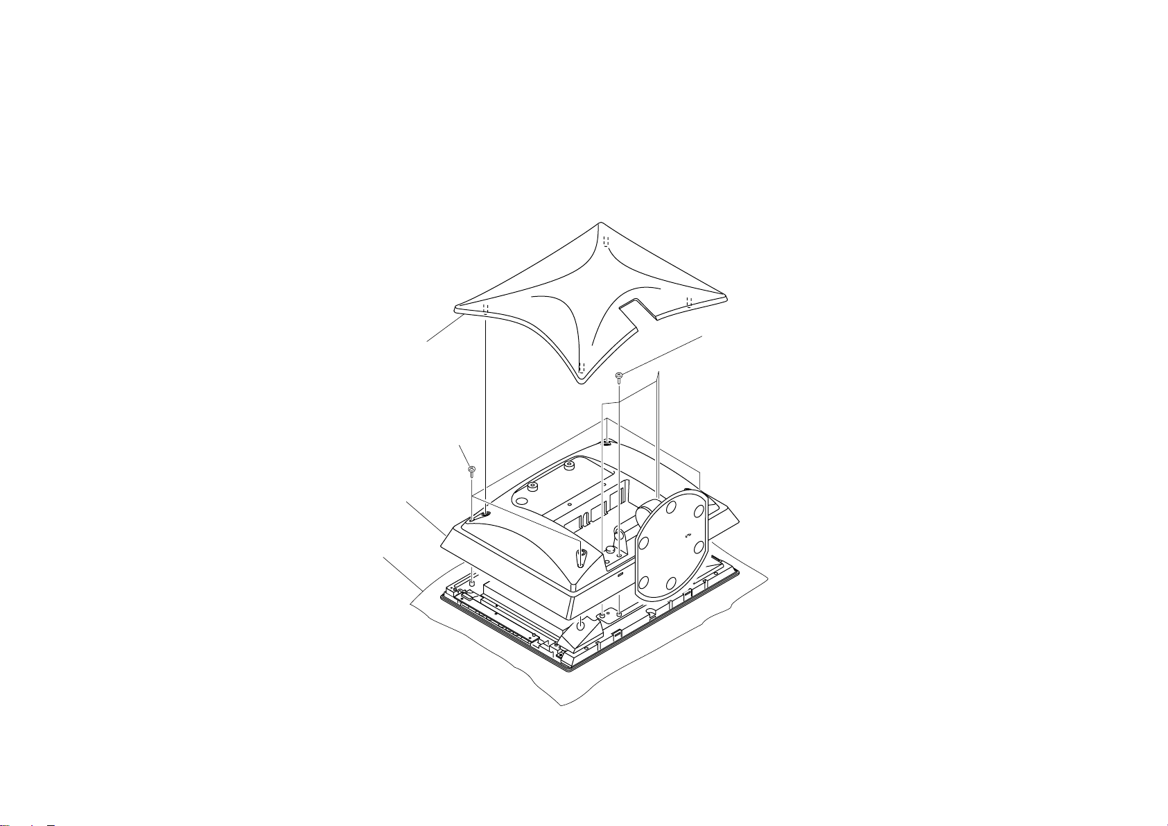
1-1. REAR COVER AND CABINET ASSY REMOVAL
1 Rear Cover
3 Four Screws
(+PWH 3X12)
SECTION 1
DISASSEMBLY
2 Four Screws
(+PSW 4X10)
4 Cabinet assy
Protection sheet
SDM-X52(E) 1-1
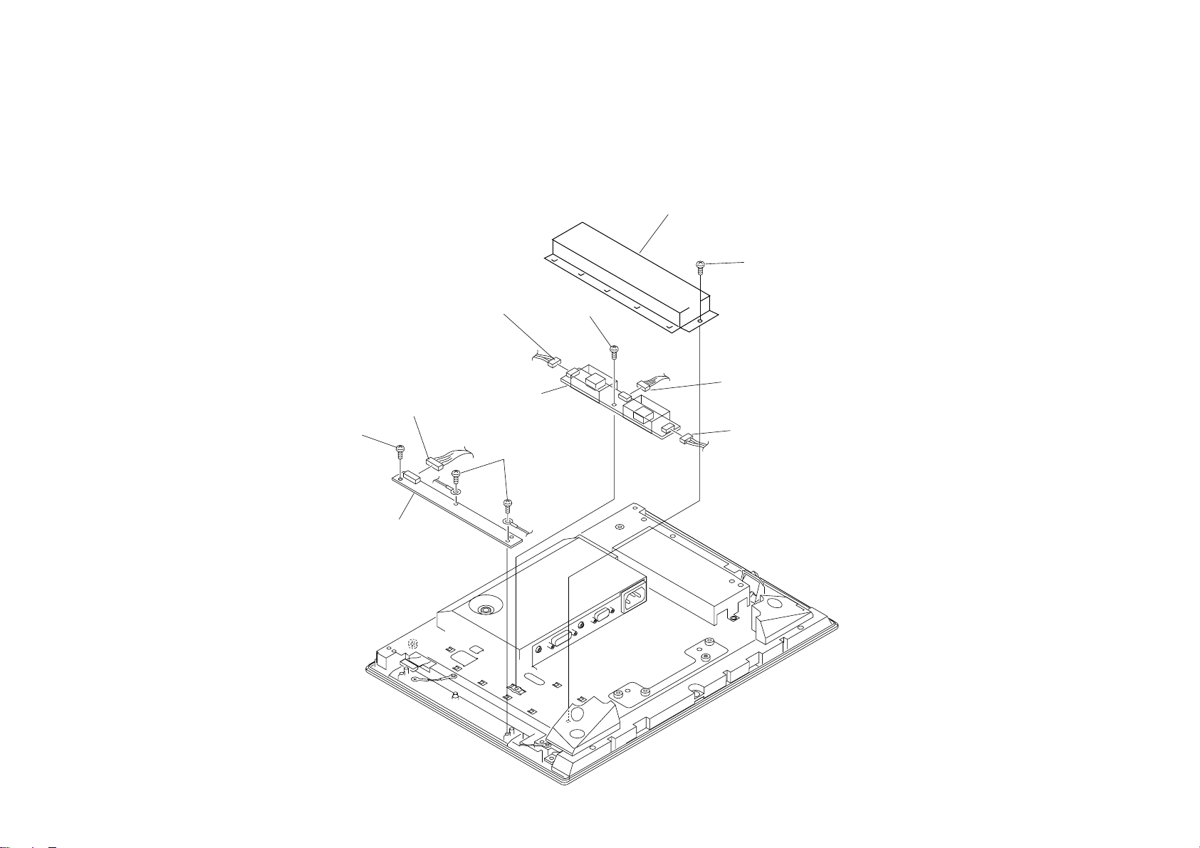
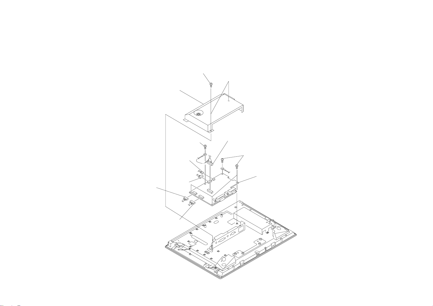
1-2. H AND I BOARDS REMOVAL
6 Connector
CN3
7 Screw
(+PTw 3X6)
5 Inverter shield
4 Screw
(+PTw 3X6)
2 Screw
(+PTP 3X8)
3 H board
1 Connector
CN904
8 I board
2 Two screws
(+PTP 3X8)
6 Connector
CN1
6 Connector
CN2
SDM-X52(E) 1-2
1-3. A BOARD REMOVAL
1 Screw
(+PTW 3X6)
2 Interface shield
1 Connector
CN202
4 Screw
(+PTW 3X6)
1 Connector
CN801
1 Connector
CN201
3 Connector
CN303
3 Connector
CN501
4 Four screws
(+PTW 3X6)
5 A board
SDM-X52(E) 1-3
1-4. G BOARD REMOVAL
3 connector
CN271
1 Tree screws
(+PTW 3x6)
2 Power shield
4 G board
3 connector
CN102
3 connector
CN101
SDM-X52(E) 1-4

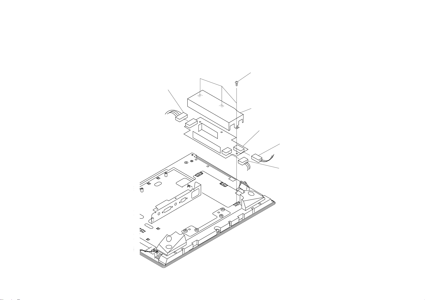
1-5. U BOARD REMOVAL
2 Screw
(+PTP 3X8)
3 Spacer
4 U board
1 Connector
CN852
1 Connector
CN851
SDM-X52(E) 1-5
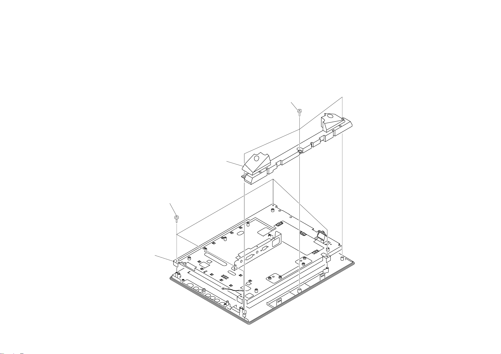
1-6. SPEAKER BOX AND LCD UNIT REMOVAL
2 Speaker box
3 Four screws
(+P 4X10)
1 Tree screws
(+BVWHTP 3X8)
4 LCD unit
SDM-X52(E) 1-6

1-7. LCD PANEL REMOVAL
2 LCD panel
1 Four screws
(+P 2.4X5)
1 Four screws
(+P 2.4X5)
SDM-X52(E) 1-7

SECTION 2
ADJUSTMENTS
2-1. Service Functions of Buttons in Front Panel
The following functions are available for servicing the set.
1. To display the model information
Press the MENU button for five seconds or more in the ordinary power-on state,
and the following information is displayed on the screen:
- Model name
- Serial number
- Manufactured year and week
This function is described in the instruction manual also.
2. To display ETI (Elapsed Time Indicator)
Press the OK button for five seconds or more in the ordinary power-on state, and
the cumulative power-on time excluding the power-off and power saving state is
displayed on the screen.
3. All mode recall
Press the POWER button with pressing the OK button in the power-off state, and
the user memory is completely cleared and the system is reset to the factory setting.
This reset is similar to RESET in the OSD menu, but differs from it in the
following:
- The NO SYNC AGING flag is cleared.
- LANGUAGE is set to ENGLIDH.
- INPUT is set to INPUT1: DVI-D.
5. To enter the service mode
Press the POWER button with pressing the UP (↑) and DOWN (↓)
buttons in the power-off state, and the system is set to the service mode. The service
mode will be explained later.
To exit from the service mode, turn off the power.
6. To copy EDID to the EEPROM and to clear ETI
Press the POWER button with pressing the UP (↑) and OK buttons in the
power-off state, and the data for the model information are copied to the EEPROM
for the internal microcontroller from EDID of INPUT2: HD15, and the model
information display is made correct.
When replacing the A board, this operation is required after writing EDID and at
the same time ETI is reset to 0.
7. To enter the ISP mode
Turn on the MAIN POWER switch with pressing the DOWN (↓) button in the
main-power-off state, and the system enters the ISP mode. The POWER LED goes
off, and both input LED's 1 and 2 light on, and the picture disappears, and any
button becomes invalid.
In the ISP mode, the internal software can be updated with an external personal
computer using a special fixture.
To cancel the ISP mode, turn off the MAIN POWER switch.
4. To set the NO SYNC AGING flag
Press the POWER button with pressing the UP (↑) button in the power-off
state, and the NO SYNC AGING flag is set. In this setting, when the input with no
input signal is selected, the system goes into the AGING MODE.
The NO SYNC AGING flag is held until it is cleared. To clear the NO SYNC
AGING flag, go into the service mode and then set the AGING MODE to OFF, or
execute the all mode recall.
SDM-X52(E) 2-1
 Loading...