

Page 1
4-089-157-23(1)
TFT LCD Color
Computer Display
Operating Instructions
Mode d’emploi
Bedienungsanleitung
Manual de instrucciones
Istruzioni per l’uso
Инструкция по эксплуатации
Bruksanvisning
Gebruiksaanwijzing
GB
FR
DE
ES
IT
RU
SE
NL
SDM-X52
SDM-X72
SDM-X82
© 2002 Sony Corporation
Page 2
Owner’s Record
The model and serial numbers are located at the rear of the unit.
Record these numbers in the spaces provided below. Refer to them
whenever you call upon your dealer regarding this product.
Model No.
Serial No.
WARNING
To prevent fire or shock hazard, do not expos e the
unit to rain or moisture.
Dangerously high voltages are present inside the
unit. Do not open the cabinet. Refer servicing to
qualified personnel only.
FCC Notice
This equipment has been tested and found to comply with the limits
for a Class B digital device, pursuant to Part 15 of the FCC Rules.
These limits are designed to provide reasonable protection against
harmful interference in a residential installation. This equipment
generates, uses, and can radiate radio frequency energy and, if not
installed and used in accordance with the instructions, may cause
harmful interference to radio communications. However, there is no
guarantee that interference will not occur in a particular installation.
If this equipment does cause harmful interference to radio or
television reception, which can be determined by turning the
equipment off and on, the user is encouraged to try to correct the
interference by one or more of the following measures:
– Reorient or relocate the receiving antenna.
– Increase the separation between the equipment and receiver.
– Connect the equipment into an outlet on a circuit different from
that to which the receiver is connected.
– Consult the dea ler or an ex perienced r adio/TV te chnician f or help.
You are cautioned that any changes or modifications not expressly
approved in this manual could void your authority to operate this
equipment.
If you have any questions about this product, you may call:
Sony Customer Informati on Ce nt e r
1-800-222-SONY (7669)
or write to:
Sony Customer Informati on Ce nt e r
1 Sony Drive, Mail Drop #T1-11, Park Ridge, NJ 07656
NOTICE
This notice is applicable for USA/Canada only.
If shipped to USA/Canada, install only a UL LISTED/CSA
LABELLED power supply cord meeting the following
specifications:
SPECIFICATIONS
Plug Type Nema-Plug 5-15p
Cord Type SVT or SJT, minimum 3 × 18 AWG
Length Maximum 15 feet
Rating Minimum 7 A, 125 V
NOTICE
Cette notice s’applique aux Etats-Unis et au Canada
uniquement.
Si cet appareil est exporté aux Etats-Unis ou au Canada, utiliser
le cordon d’alimentation portant la mention UL LISTED/CSA
LABELLED et remplissant les conditions suivantes:
SPECIFICATIONS
Type de fiche Fiche Nema 5-15 broches
Cordon Type SVT ou SJT, minimum 3 × 18 AWG
Longueur Maximum 15 pieds
Tension Minimum 7 A, 125 V
ENERGY STAR Partner, Sony
As an
Corporation has determined that this
product meets the
guidelines for energy efficiency.
This monitor complies with the
TCO’99 guidelines.
ENERGY STAR
(for the grey model)
Declaration of Conformity
Trade Name: SONY
Model No.: SDM-X52/X72/X82
Responsible Party: Sony Electronics Inc.
Address: 680 Kinderkamack Road,Oradell,NJ 07649
USA
Telephone No.: 201-930-6972
This device complies with Part 15 of the FCC Rules. Operation is
subject to the following two conditions: (1) This device may not
cause harmful interference, and (2) this device must accept any
interference received, including interference that may cause
undesired operation.
2
This monitor complies with the
TCO’95 guidelines.
(for the black model)
Page 3
Table of Contents
Precautions. . . . . . . . . . . . . . . . . . . . . . . . . . . . . . . . . . . . . . . . . . . . 4
Identifying parts and controls . . . . . . . . . . . . . . . . . . . . . . . . . . . . . . 5
Setup. . . . . . . . . . . . . . . . . . . . . . . . . . . . . . . . . . . . . . . . . .7
Setup 1: Connect a computer equipped with the DVI output connector
(digital RGB) . . . . . . . . . . . . . . . . . . . . . . . . . . . . . . . . . . . 7
Setup 2: Connect a computer equipped with the HD15 output
connector (analog RGB) . . . . . . . . . . . . . . . . . . . . . . . . . . 7
Setup 3: Connect the audio cord . . . . . . . . . . . . . . . . . . . . . . . . . . . 8
Setup 4: Connect the power cord . . . . . . . . . . . . . . . . . . . . . . . . . . 8
Setup 5: Bundle the cords and cables. . . . . . . . . . . . . . . . . . . . . . . 9
Setup 6: Turn on the monitor and computer . . . . . . . . . . . . . . . . . . 9
Setup 7: Adjusting the tilt and height . . . . . . . . . . . . . . . . . . . . . . . 10
Selecting the input signal (INPUT button). . . . . . . . . . . . . . . . . . . . 11
Customizing Your Monitor . . . . . . . . . . . . . . . . . . . . . . .12
• Macintosh is a trad emark licensed to
Apple Computer, Inc., registered in the
U.S.A. and other countries.
• Windows
Microsoft Corporation in the Uni te d
States and other countries.
• IBM PC/AT and VGA are registered
trademarks of IBM Corporation of the
U.S.A.
• VESA and DDC
Video Electronics Stan da rds
Association.
ENERGY STAR is a U.S. registered
•
mark.
• All other product names ment i one d
herein may be the trademarks or
registered trad emarks of their r espective
companies.
•Furthermore, “” and “” are not
mentioned in each case in this manu al .
is registered trademark of
are trademarks of the
Navigating the menu. . . . . . . . . . . . . . . . . . . . . . . . . . . . . . . . . . . . 12
BACKLIGHT. . . . . . . . . . . . . . . . . . . . . . . . . . . . . . . . . . . . . . 12
CONTRAST . . . . . . . . . . . . . . . . . . . . . . . . . . . . . . . . . . . . . . . 12
BRIGHTNESS . . . . . . . . . . . . . . . . . . . . . . . . . . . . . . . . . . . . . 12
SCREEN (analog RGB signal only) . . . . . . . . . . . . . . . . . . . . . 13
COLOR. . . . . . . . . . . . . . . . . . . . . . . . . . . . . . . . . . . . . . . . . . . 14
GAMMA . . . . . . . . . . . . . . . . . . . . . . . . . . . . . . . . . . . . . . . . . . . 15
ZOOM (SDM-X72/X82 only). . . . . . . . . . . . . . . . . . . . . . . . . . 15
SMOOTHING. . . . . . . . . . . . . . . . . . . . . . . . . . . . . . . . . . . 15
Additional settings. . . . . . . . . . . . . . . . . . . . . . . . . . . . . . . . . . . . . . 16
Technical Features . . . . . . . . . . . . . . . . . . . . . . . . . . . . .17
Controlling the volume . . . . . . . . . . . . . . . . . . . . . . . . . . . . . . . . . . 17
Power saving function. . . . . . . . . . . . . . . . . . . . . . . . . . . . . . . . . . . 17
Reducing the power consumption (ECO mode) . . . . . . . . . . . . . . . 18
Automatic picture quality adjustment function
(analog RGB signal only) . . . . . . . . . . . . . . . . . . . . . . . . . . . . . . . . 18
Troubleshooting. . . . . . . . . . . . . . . . . . . . . . . . . . . . . . . .19
On-screen messages . . . . . . . . . . . . . . . . . . . . . . . . . . . . . . . . . . . 19
Trouble symptoms and remedies . . . . . . . . . . . . . . . . . . . . . . . . . . 20
Self-diagnosis function . . . . . . . . . . . . . . . . . . . . . . . . . . . . . . . . . . 22
Specifications. . . . . . . . . . . . . . . . . . . . . . . . . . . . . . . . . .23
TCO’99 Eco-document (for the grey model). . . . . . . . . . . . . . . . . . . .i
TCO’95 Eco-document (for the black model) . . . . . . . . . .Back Cover
GB
3
Page 4

Precautions
Warning on power connections
• Use the supplied power cord. If you use a different power cord,
be sure that it is compatible with your local power supply.
For the customers in the U.S.A.
If you do not use the appropriate cord, this monitor will not
conform to mandatory FCC standards.
For the customers in the UK
If you use the monitor in the UK, be sure to use the appropriate
UK power cord.
Example of plug types
for 100 to 120 V AC for 200 to 240 V AC for 240 V AC only
The equipment should be installed near an easily accessible outlet.
Installation
Do not install or leave the monitor:
• In places subject to extreme temperatures, for example near a
radiator, heating ve nt, or in direc t su nlight. Subjecting the
monitor to extreme temperatures, such as in an automobile
parked in direct sunlight or near a heating vent, could cause
deformations of the casing or malfunctions.
• In places subject to mechanical vibration or shock.
• Near any equipment that generates a strong magnetic field,
such as a TV or various other household appliances.
• In places subject to inordinate amounts of dust, dirt, or sand, for
example near an open window or an outdoor exit. If setting up
temporarily in an outdoor environ me n t, be sur e to take
adequate precautions against airborne dust and dirt. Otherwise
irreparable malfu nctions could occur.
Handling the LCD screen
• Do not leave the LCD screen facing the sun as it can damage
the LCD screen. Take care when you place the monitor by a
window.
• Do not push on or scratch the LCD screen. Do not place a heavy
object on the LCD screen. This may cause th e screen to lose
uniformity or cause LCD panel malfunctions.
• If the monitor is used in a cold place, a residual image may
appear on the screen. This is not a malfunction. The screen
returns to normal as the temperature rises to a normal operating
level.
• If a still picture is displayed for a long time, a residu al image
may appear for a while. The residual image will eventually
disappear.
• The LCD panel becomes warm dur ing operation. This is not a
malfunction.
About the built-in stereo speakers
Be sure to keep magnetic rec ording eq uipmen t, tape s, and flo ppy
discs away from the speaker’s opening as the speakers generate a
magnetic field. This magnetic field may affect data stored on
magnetic tapes and discs.
Note on the LCD (Liquid Crystal Display)
Please note that the LCD screen is made with high-precision
technology. However, black points or bright points of light (red,
blue, or green) may appear constantly on the LCD screen, and
irregular color ed stripes or brightness may appear on the LCD
screen. This is not malfunction.
(Effective dots: more than 99.99%)
Maintenance
• Be sure to unplug the power cord from the power outlet before
cleaning your mon itor.
• Clean the LCD screen with a soft cloth. If you use a glass
cleaning liquid, do not use any type of cleaner containing an
anti-static solution or similar additive as this may scratch the
LCD screen’s coating.
• Clean the cabinet, panel, and controls with a so ft cloth lightly
moistened with a mil d detergent solut ion. Do not use any type
of abrasive pad, scouring powder, or solvent, such as alcohol or
benzine.
• Do not rub, touch, or tap the surface of the screen with sharp or
abrasive items such as a ballpoint pen or screwdriver. This type
of contact may result in a scratched picture tube.
• Note that material deterioration or LCD screen coating
degradation may occur if the monitor is exposed to volatile
solvents such as insecticide, or if prolonged co ntact is
maintained with rubber or vinyl materials.
Transportation
• Disconnect all cables from the monitor and grasp the support
and base sections of the display stand firmly with both hands
when transporti ng. If you d rop the mo nitor, yo u may be in jured
or the monitor m a y be damaged.
• When you transport this monitor for repair or shipment, use the
original carton and packing materials.
Disposal of the monitor
• Do not dispose of this monitor with general
household waste.
• The fluorescent tube used in this monitor contains
mercury. Disposal of this mon itor must be carried out
in accordance to the regulations of your local
sanitation authority.
4
Page 5
Identifying parts and controls
See the pages in parentheses for further details.
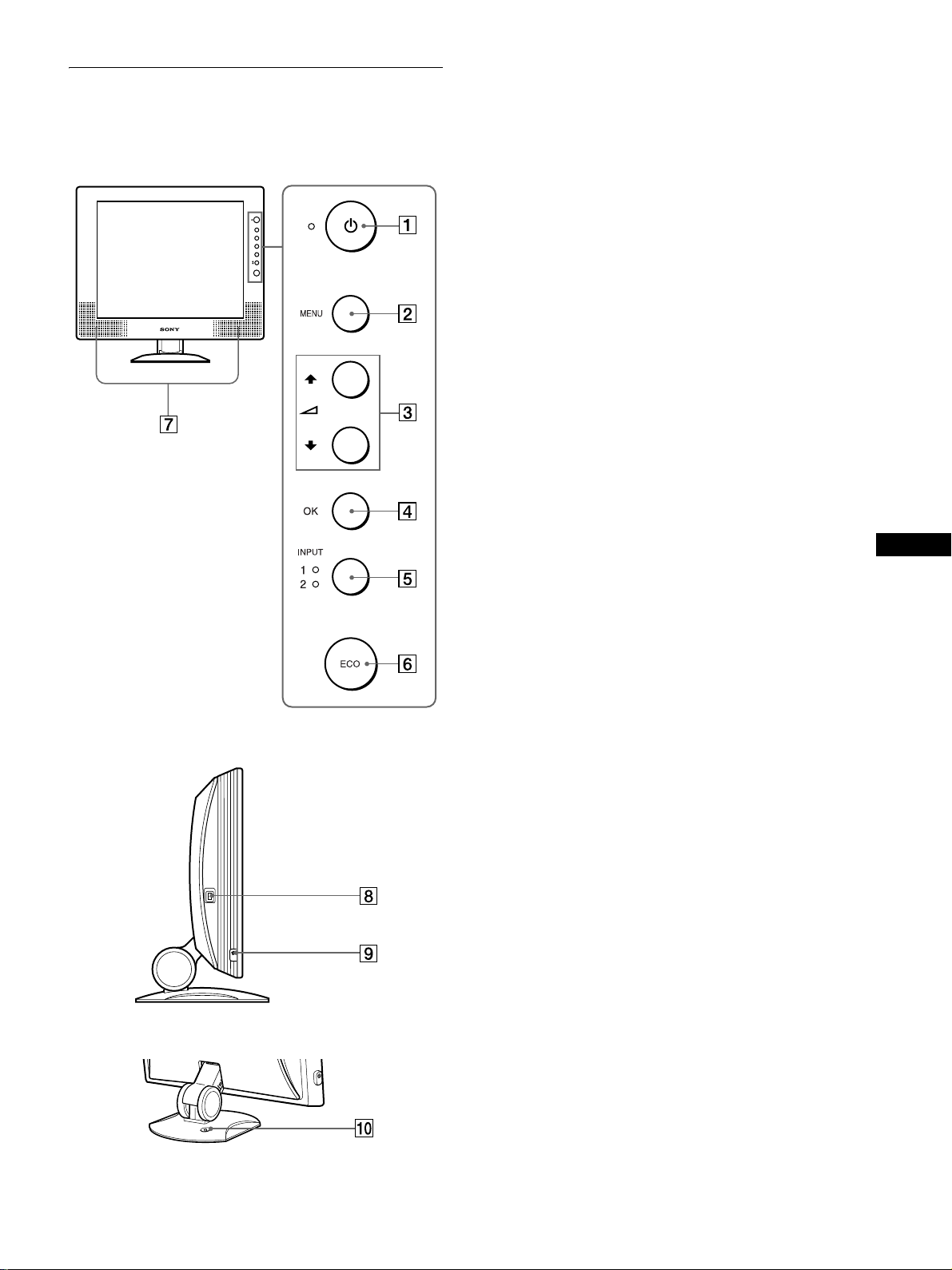
Front of the LCD display
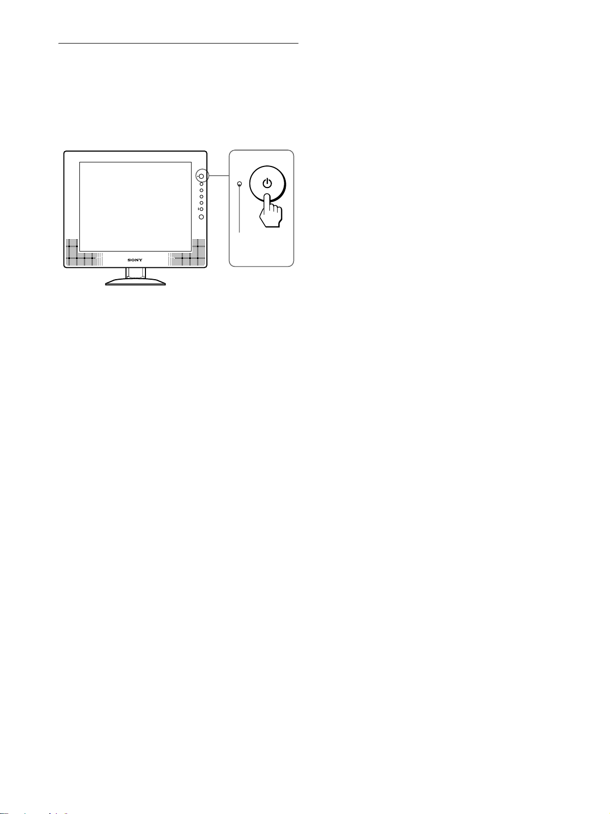
1 1 (Power) switch and 1 (power) indicator
(pages 9, 17, 22)
This switch turns the monitor on when the 1 (power)
indicator lights up in red. To turn the monitor off, press this
switch again.
If the 1 (power) indicator does not light up , press the MAIN
POWER switch (8).
2 MENU button (page 12)
This button turns the menu screen on and off.
3 M/m and 2 (volume) buttons (page 12, 17)
These buttons are used to select th e menu items and make
adjustments, and also display the VOLUM E m enu to c ontro l
the volume.
4 OK button (page 12)
This button activates the selected menu item and adjustments
using with M/m buttons (3).
5 INPUT button and INPUT1/INPUT2 indicator
(page 11)
This button selects the connected computer for switching the
video input sig nals, and the corresponding indicator,
(INPUT1 or INPUT2) lights up.
6 ECO button (page 18)
This button is used to reduce the power consumption.
GB
Side view of the LCD display
Rear of the display stand
7 Stereo speakers (page 17)
These output the audio signals as sound.
8 MAIN POWER switch (page 9)
This switch turns the monitor’s main power on and off.
9 Headphones jack (page 17)
This jack outputs audio signals to the headphones.
0 Security Lock Hole
The security lock hole should be app lied with t he Kensingt on
Micro Saver Security System.
Micro Saver Security System is a tra demark of Kensington.
(continued)
5
Page 6

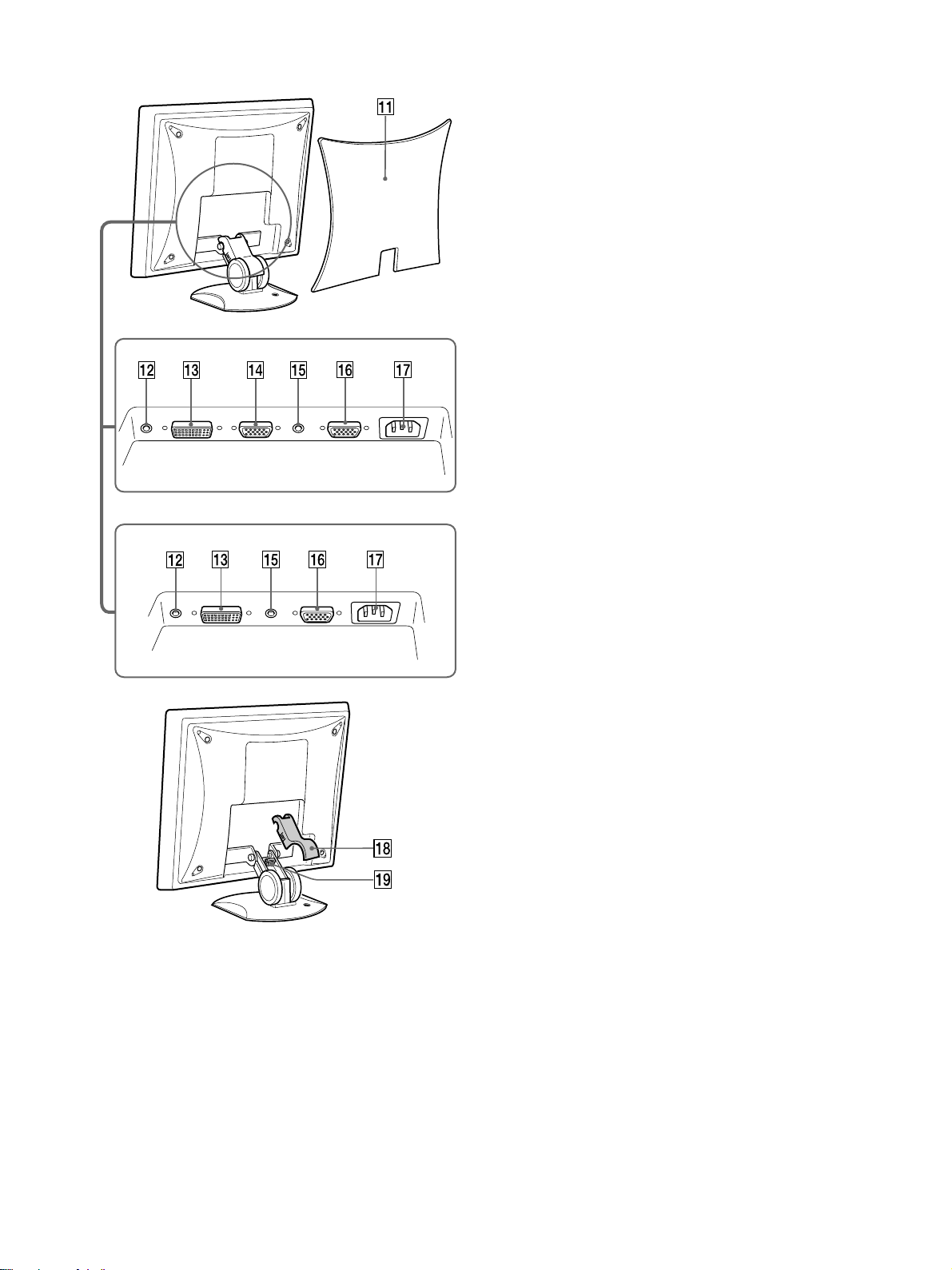
Rear of the LCD display
SDM-X72/X82
qa Back cover (page 7)
Remove this cover when you connect cables or cords.
qs Audio input jack for INPUT1 (page 8)
This jack inputs audi o signals when connected to the audio
output jack of a comput er or other audio equipment.
qd DVI-D input connector (digital RGB) for INPUT1
(page 7)
This connector inputs digit al RGB vid eo signa ls that com ply
with DVI Rev. 1.0.
qf HD15 input connector (analog RGB) for INPUT1
(page 7) (SDM-X72/X82 only)
This connect or inputs an alog RGB video si gnals (0. 700 Vp-p,
positive) and SYNC signals.
qg Audio input jack for INPUT2 (page 8)
This jack inputs audi o signals when connected to the audio
output jack of a comput er or other audio equipment.
qh HD15 input connector (analog RGB) for INPUT2
(page 8)
This connect or inputs an alog RGB video si gnals (0. 700 Vp-p,
positive) and SYNC signals.
SDM-X52
qj AC IN connector (page 8)
Connect the power cord (supplied ).
qk Arm cover (page 9)
Remove this cover to bundle connecting cords and cables.
ql Cable holder (page 9)
This part secures cables and cords to the monitor.
6
Page 7

Setup
Before using your monitor, check that the following items are
included in your carton:
•LCD display
• Power cord
• HD15-HD15 video signal cable (an alog RGB)
• DVI-D video signal cable (digital RGB)
• Audio cord (stereo miniplug)
• Windows Utility/Macintosh Utility Disk
• Warranty card
• This instruction manua l
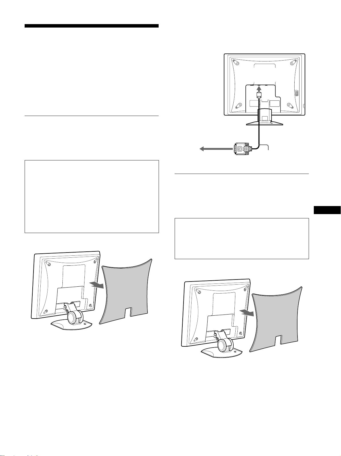
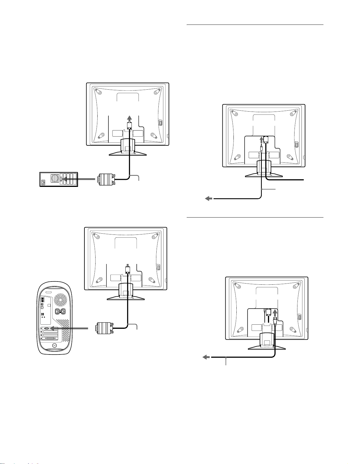
2 Using the supplied DVI-D video signal cable (di gital
RGB), connect the compute r to the m onit or’s DVI -D
input connector (digital RGB) for INPUT1.
to the DVI-D input
connector (digital RGB)
for INPUT1
Setup 1:Connect a computer
equipped with the DVI
output connector (digital
RGB)
• Turn off the monitor and computer before connecting.
• When connecting the computer to the monitor’s HD15
input connector (analog RGB), refer to “Setup 2:
Connect a computer equipped with the HD15 ou tput
connector (analog RGB).”
Note
Do not touch the pins of the video signal cable connector as this might
bend the pins.
1 Remove the back cover.
to the computer’s DVI output
connector (digital RGB)
DVI-D video signal
cable (digital RGB)
(supplied)
Setup 2:Connect a computer
equipped with the HD15
output connector (analog
RGB)
Turn off the monitor and computer before con necting.
Note
Do not touch the pins of the video signal cable connector as this might
bend the pins.
1 Remove the back cover.
GB
(continued)
7
Page 8
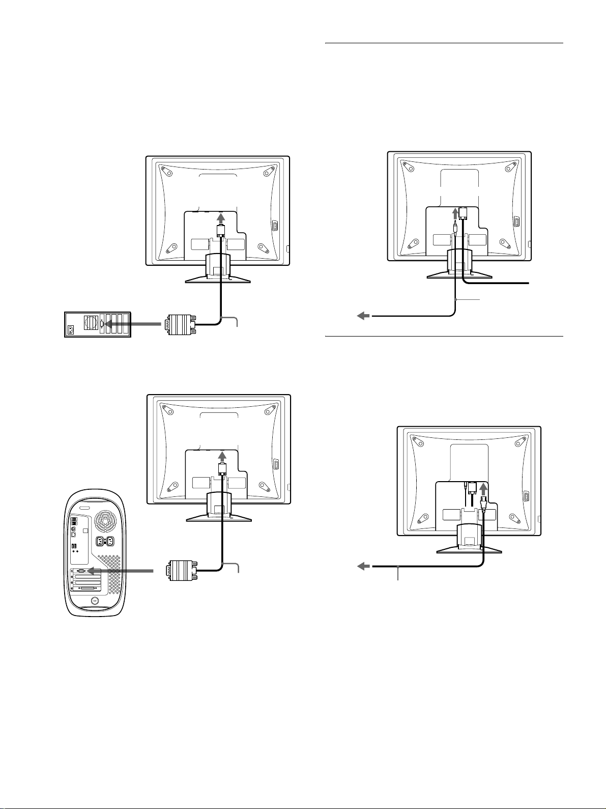
2 Using the supplied HD15-HD15 video signal cable
(analog RGB), connect the computer to the
monitor’s HD 15 input connector (analog RGB) for
INPUT 1 or INPUT2.
Connect the computer according to the following
illustrations.
x Connecting to an IBM PC/AT or
compatible co m p u ter
Setup 3:Connect the audio cord
Connect the supplied audio cord to th e co rre spo nding
monitor’s audio input jack.
Using the monitor’s speakers or headpho nes, you can listen to
sound from your computer or other audio equipment connected to
the monitor’s audio input jacks.
For more information, see “Controlling the volume” on page 17.
to the HD 15 input
connector (analog RGB)
for INPUT 1 or IN PUT2
to the computer’s HD15 output
connector (analog RGB)
IBM PC/AT or
compatible computer
x Connecting to a Macintosh
to the HD 15 input
connector (analog RGB)
for INPUT 1 or IN PUT2
HD15-HD15 video signal
cable (analog RGB)
(supplied)
to audio input
to audio output of the
computer or other audio
equipment
audio cord (supplied)
Setup 4:Connect the power cord
1 Connect the supplied power cord to the monitor’s
AC IN connector.
2 Connect it to a power outlet.
to AC IN
1
to the computer’s output
connector
HD15-HD15 video signal
cable (analog RGB)
(supplied)
Macintosh
When connecting a Macint osh co mputer , use an adapte r (not supplie d)
if necessary. C onnect the ad apter to th e computer befo re connect ing the
video signal cable.
8
to power outlet
power cord (supplied)
2
Page 9
Setup 5:Bundle the cords and
cables
Setup 6:Turn on the monitor and
computer
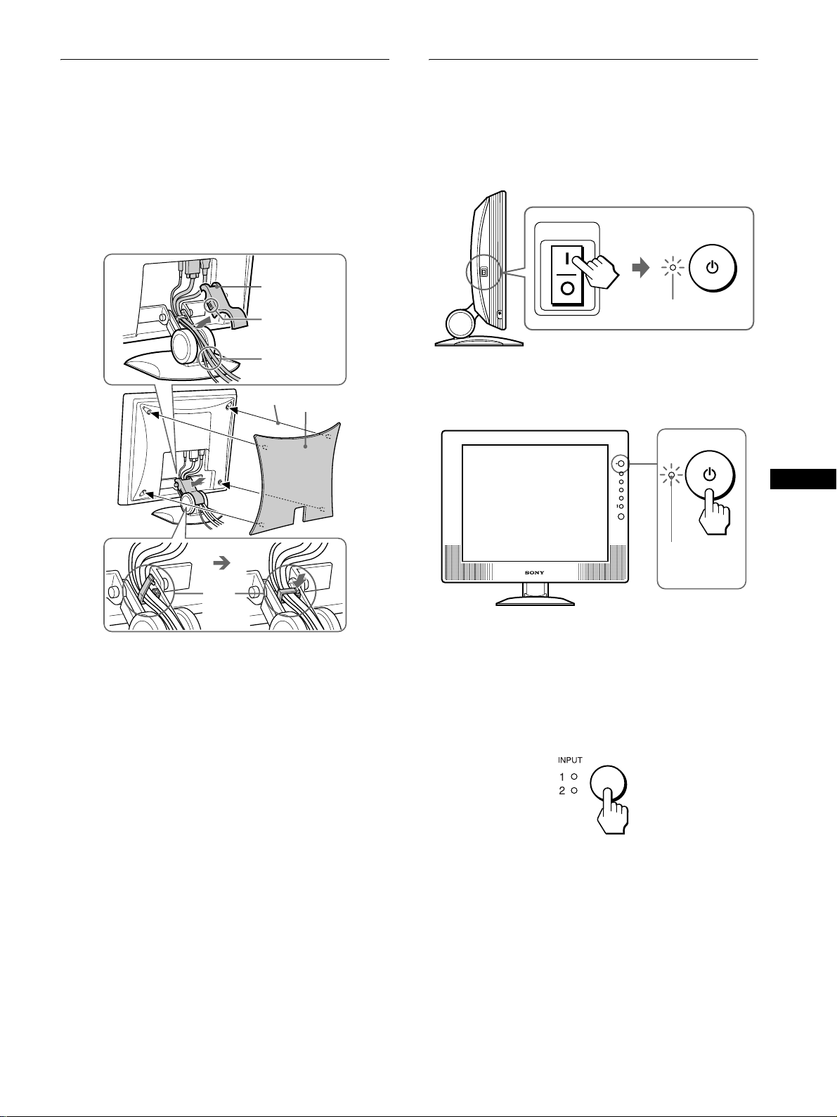
1 Remove the arm cover.
2 Bundle the cords and cables inside of the stand.
3 Secure the cables and cords with the cable holder.
4 Replace the arm cover and b ack cover.
1
arm cover
Hold at this
point.
2
4
back cover
1 Press the MAIN POWER switch on the left side of the
monitor in the direction of [.
The 1 (power) indicator lights up in red.
MAIN POWER
lights in red
2 Press the 1 (power) switch on the front right of the
monitor.
The 1 (power) indicator lights up in gr een.
GB
3
Note
If you cannot bundle all of the cords and cables inside the stand, le ave
them hanging down outside the stand.
lights in green
3 Turn on the computer.
4 Press the INPUT button repeatedly and select the
desired input signal.
The selected input signal indicator lights up and the pictu re
appears on the screen.
For more information, see “Selecting the input signal (INPUT
button)” on page 11.
The installation of your monitor is compl ete. If necessary, use the
monitor’s controls to adjust the picture (page 12).
(continued)
9
Page 10

If no picture appears on your screen
• Check that the power cord and the video signal cable are
properly connected.
Setup 7:Adjusting the tilt and
height
• If NO INPUT SIGNAL appears on the screen:
– The computer is in the power saving mode. Try pressing any
key on the keyboard or moving the mouse.
– Check that the input signal setting is correct by pressing the
INPUT button repeatedly (page 11).
• If CABLE DISCONNECTED appears on the screen:
– Check that the video signal cable is properly connected.
– Check that the input signal setting is correct by pressing the
INPUT button repeatedly (page 11).
• If OUT OF SCAN RANGE appears on the screen, reconnect
the old monitor. Then adjust the computer’s graphics board in
the following ranges.
SDM-X52 SDM-X72/X82
Horizontal frequency
28 – 61 kHz 28 – 92 kHz
Vertical frequency 56 – 75 Hz 56 – 85 Hz
Resolution 1024 × 768 or less 1280 × 1024 or less
For more information about on-screen messages, see “Trouble
symptoms and remedi es” on page 20.
No need for specific drivers
The monitor complies with the “DDC” Plug & Play standard and
automatically detects all the monitor’s infor mation. No specific driver
needs to be installed to the computer.
The first time you turn on your computer after connecting the monitor, the
setup Wizard may appear on the screen. In this case, follow the on-screen
instructions. The Plug & Play monitor is automatically selected so that
you can use this monitor.
This monitor c an be ad justed within t he angle s and he ights s hown
below.
30°
approx. 50°
approx. 80°
The vertical frequency turns to 60 Hz.
Since flickers are unobtrusive on the monitor, you can use it as it is. You
do not need to set the vertical frequency to any particular hi gh value.
approx. 45°
approx. 45°
(SDM-X82 only)
To use the monitor comfortably
Adjust the viewing angle of your monitor according to the height
of your desk and chair, and so that light is not reflected from the
screen to your eyes.
Note
When adjusting the screen til t an d height, proceed slowly and carefu lly,
being sure not to hit the moni tor against the desk or the base o f the display
stand.
10
Page 11
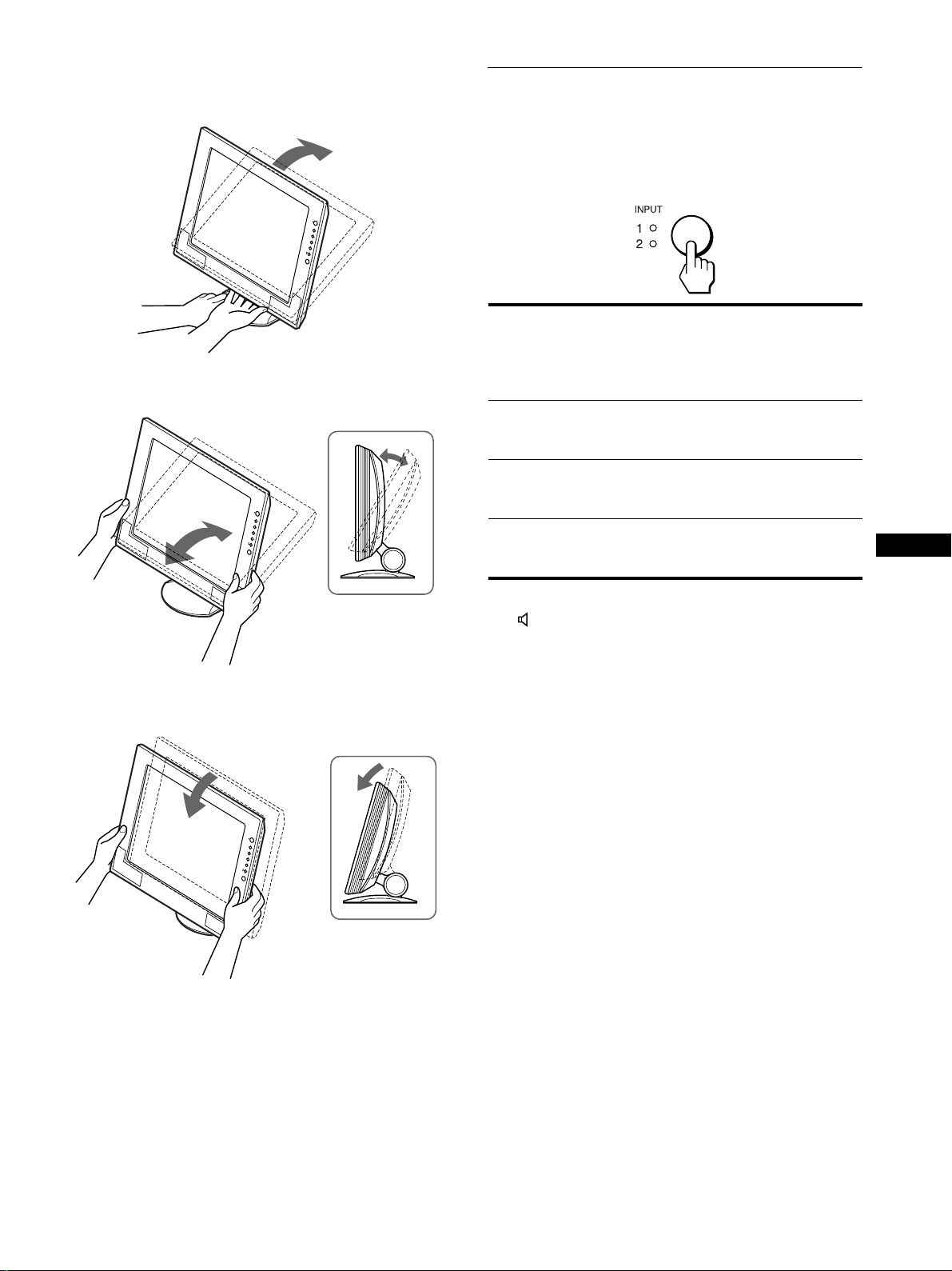
1 Grasp the lower middle part of the LCD panel while
holding the display stand, then, tilt the LCD panel
adequately backward.
Selecting the input signal
(INPUT button)
Press the INPUT button.
The input signal change each time you press this button as
follows.
2 Grasp the lower sides of the LCD panel, then adjust
screen tilt.
3 Grasp the lower sides of the LCD panel, then adjust
screen height.
On-screen
message
(Appears about
5 seconds on
the upper left
corner.)
INPUT1: DVI-D INPUT1 DVI-D input
INPUT1: HD15
(SDM-X72/X82
only)
INPUT2: HD15 INPUT2 HD15 input
Selecting the input signal for the audio input jack
See “ (AUDIO SELECT)” on page 16.
Input indicator
lights up
INPUT1 HD15 input
Input signal
configuration
connector (digital
RGB) for INPUT1
connector (analog
RGB) for INPUT1
connector (analog
RGB) for INPUT2
GB
11
Page 12
Customizing Your Monitor
Before making adjustments
Connect the monitor and the com puter, and turn them on.
Wait for at least 30 minutes before making adjustm ents for the
best results.
You can make numerous adj ustments to your monitor using the
on-screen menu.
The menu screen illustrations show the SDM-X72/X82 model.
The same operations apply for the SDM-X52 model.
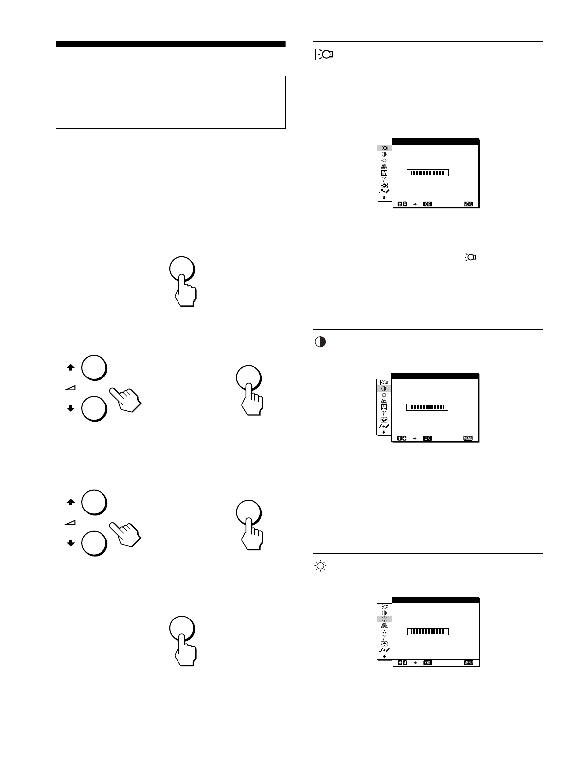
BACKLIGHT
If the screen is too bright, adjust the back light and make the screen
easier to see.
Note
The backlight cannot be adjusted when the ECO mode is set to “ON”
(page 18)
.
BACKL GHTI
100
Navigating the menu
1 Display the main menu.
Press the MENU button to display the main menu on your
screen.
MENU
2 Select the menu you want to adjust.
Press the M/m buttons to display the desired menu. Press the
OK button to select the menu item.
OK
,
3 Adjust the menu.
Press the M/m buttons to make the adjustmen t, then pr ess the
OK button.
When you press the OK button, the setting is stored, then the
display returns to the previous menu.
OK
,
1280 1024 60Hzx/
EX I T
1 Press the MENU button.
The main menu appears on th e screen.
2 Press the M/m buttons to select (BACKLIGHT)
and press the OK button.
The BACKLIGHT menu appears on the screen.
3 Press the M/m buttons to adjust the desired light
level.
CONTRAST
Adjust the picture contrast.
CONTRAST
100
1280 1024 60Hzx/
1 Press the MENU button.
The main menu appears on th e screen.
2 Press the M/m buttons to select 6 (CONTRAST) and
press the OK button.
The CONTRAST menu appears on the screen.
3 Press the M/m buttons to adjust the contrast.
EX I T
4 Close the menu.
Press the MENU button once to return to normal viewing. If
no buttons are pressed, the menu closes automatically after
about 45 seconds .
MENU
x
Resetting the adjustments to the default settings
You can reset the adjustments using the RESET m enu . Fo r m ore
information about resetting the adjustments, see “0 (RESET)”
on page 16.
12
BRIGHTNESS
Adjust the picture brightness (black level).
BR GHTNESSI
100
1280 1024 60Hzx/
1 Press the MENU button.
The main menu appears on th e screen.
EX I T
Page 13

2 Press the M/m buttons to select 8 (BRIGHTNESS)
and press the OK button.
The BRIGHTNESS menu appears on the screen.
3 Press the M/m buttons to adjust the brightness.
SCREEN (analog RGB signal only)
Note
When receiving digital R GB signals from the DVI-D input co nnector
for INPUT1, adjustment is unnece ssary.
x Automatic picture qual ity adju st me nt
function
3 Press the M/m buttons to select AUTO and pres s the
OK button.
Make the appropriate adjustments of the screen’s phase, pitch
and horizontal/vertical position for the current input signal
and store them.
4 Press the M/m buttons to select and press the OK
button.
Return to the menu screen.
x Adjust the picture’s sharpness manually
(PHASE/PITCH)
You can adjust the picture’s sharpness as follows. This
adjustment is effective when the computer is connected to the
monitor’s HD15 input connector (analog RGB).
When the monitor receives an input signal, it
automatically adjusts the picture’s position and
sharpness (phase/pitch), and ensures that a clear
picture appears on the screen (page 18).
Note
While the automatic picture quality adjustment function is activated, only
the 1 (power) switch will operate.
If the automatic picture quality adjustment function of
this monitor seems to not completely adjust the
picture.
You can make further automatic ad justment of t he pictur e quality
for the current input signal. (See AUTO below.)
If you still need to make further adjustments to the
picture quality
You can manually adjust the picture’s sharpness (phase/pitch) and
position (horizontal/vertical position).
These adjustments are stored in memory and automatically
recalled when the display receives the same input signal.
SCREEN
AUTO
PHASE
I
P TCH
H CENTER
V CENTER
1280 1024 60Hzx/
EX I T
1 Set the resolution to 1024 × 768 (SDM-X52)
1280 × 1024 (SDM-X72/X82) on the computer.
2 Load the Utility Disk.
3 Start the Utility Disk and display the test pattern.
For Windows
Click [Utility]
For Macintosh
Click [Utility] t [Mac]/[Mac Utility].
t [Windows]/[Win Utility.exe].
4 Press the MENU button.
The main menu appears on th e screen.
5 Press the M/m buttons to select (SCREEN) and
press the OK button.
The SCREEN menu appears on the screen.
6 Press the M/m buttons to select PHASE and press
the OK button.
The PHASE menu appears on the screen.
7 Press the M/m buttons until the horizontal stripes
are at a minimum.
Adjust so that the horizontal stripes are at a minimum.
GB
x Make further automatic adjustments to the
picture quali ty for the cur rent input signal
(AUTO)
1 Press the MENU button.
The main menu appears on the screen.
2 Press the M/m buttons to select (SCREEN) and
press the OK button.
The SCREEN me nu appears on t he sc r e en.
8 Press the OK button.
The main menu appears on th e screen.
If vertical stripes are observed over the en tire screen, adjust
pitch by the following steps.
9 Press the M/m buttons to select (SCREEN) and
press the OK button.
The SCREEN menu appears on the screen.
10 Press the M/m buttons to select PITCH an d press the
OK button.
The PITCH menu appears on the screen.
(continued)
13
Page 14
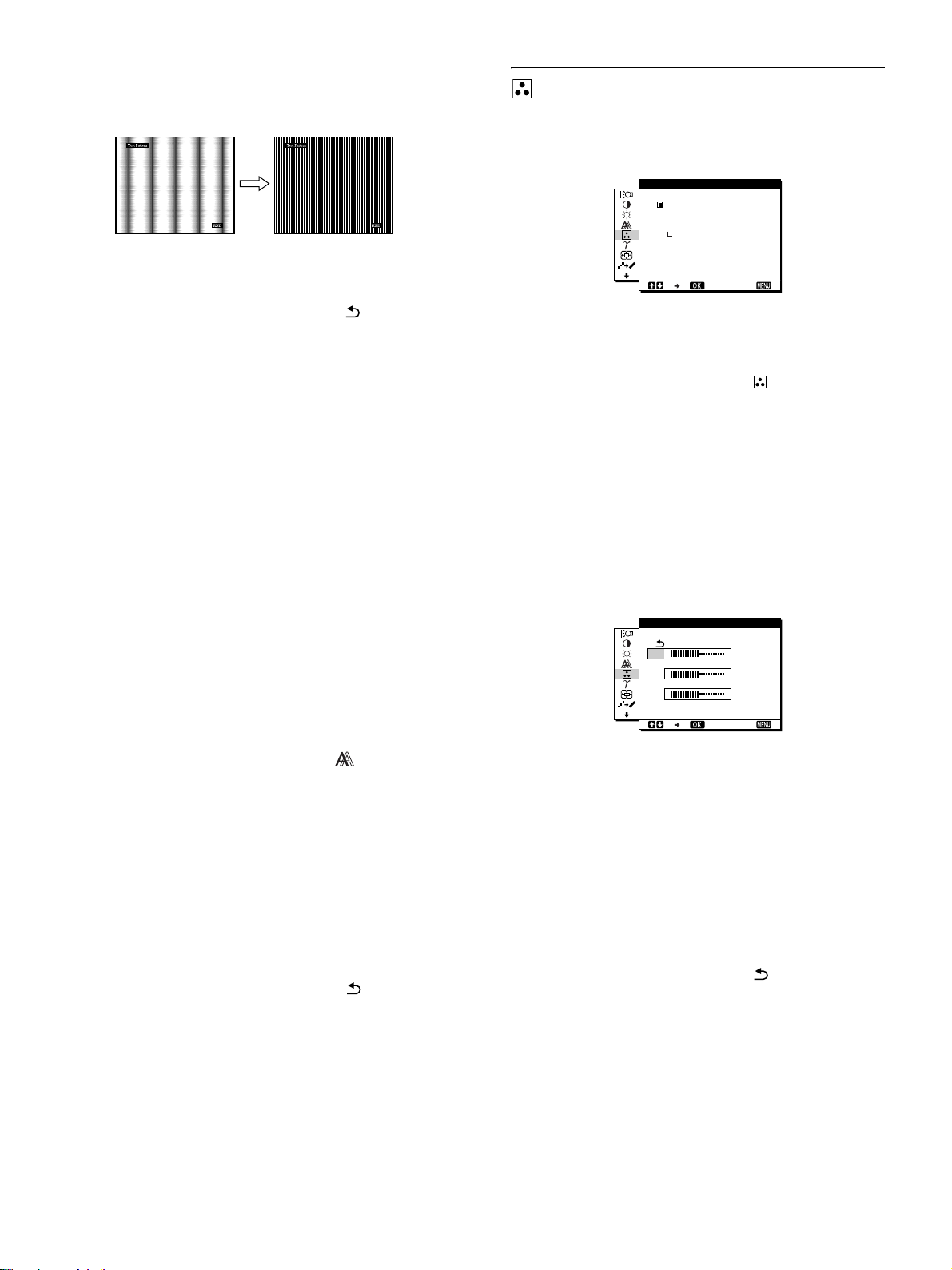
11 Press the M/m buttons until the vertical stripes
disappear.
Adjust so that the vertical stripes disappear.
COLOR
You can select the picture’s color level of the white color field
from the default color temperature settings.
Also, if necessary, you can fine tune the color temperature.
COLOR
9300K
6500K
USER
ADJUST
12 Click [END] on the screen to turn off the test pattern.
13 Press the M/m buttons and select and press the
OK button.
Return to the menu screen.
x Adjust the picture’s position manually
(H CEN TER /V CENT ER)
If the picture is not in the center of the screen, adjust the picture’s
centering as follows.
1 Set the resolution to 1280 × 1024 on the computer
when using the SDM-X72/X82 model.
When using the SDM-X52 model, it is not necessary to set the
resolution.
2 Load the Utility Disk.
3 Start the Utility Disk and display the test pattern.
For Windows
Click [Utility] t [Windows]/[Win Utility.exe].
For Macintosh
Click [Utility] t [Mac]/[Mac Utility].
4 Press the MENU button.
The main menu appears on th e screen.
1280 1024 60Hzx/
EX I T
1 Press the MENU button.
The main menu appears on th e screen.
2 Press the M/m buttons to select (COLOR) and
press the OK button.
The COLOR menu appears on the screen.
3 Press the M/m buttons to select the desired color
temperature and press the OK button.
Whites will change from a bluish hue to reddish hue as the
temperature is lowered from 9300K (default setting) to
6500K.
Fine tuning the color temperature
(USER ADJUSTMENT)
INPUT1 and INPUT2 can be set independently.
USER ADJUSTMENT
R
G
B
1280 1024 60Hzx/
50
50
50
EX I T
5 Press the M/m buttons to select (SCREEN) and
press the OK button.
The SCREEN menu appears on the screen.
6 Press the M/m buttons to select H CENTER or
V CENTER and press the OK button.
The H CENTER or V CENTER menu appears on the screen.
7 Press the M/m buttons to center the test pattern in
the screen.
8 Click [END] on the screen to turn off the test pattern.
9 Press the M/m buttons and select and press the
OK button.
Return to the menu screen.
1 Press the M/m buttons to select ADJUST and press
the OK button.
The USER ADJUSTMENT menu appears on the scre en.
2 Press the M/m buttons to select R (Red) or B (Blue)
and press the OK button. Then press the M/m
buttons to adjust the color temperature and press
the OK button.
Since this adjustment ch anges the color temperature by
increasing or decreasing the R and B components with respect
to G (green), the G component is fixed.
3 Press the M/m buttons to select , then press the
OK button.
The new color setting is stored in memory for USER
ADJUSTMENT and automatically recalled whenever USER
is selected.
The COLOR menu appears on the screen.
14
Page 15
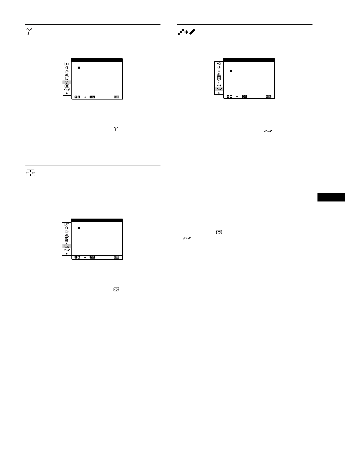
GAMMA
SMOOTHING
You can associate the picture’s color shade on the screen with the
picture’s original color shade.
GAMMA
GAMMA 1
GAMMA 2
GAMMA 3
1280 1024 60Hzx/
EX I T
1 Press the MENU button.
The main menu appears on the screen.
2 Press the M/m buttons to select (GAMMA) and
press the OK button.
The GAMMA menu appears on the screen.
3 Press the M/m buttons to select the desired mode.
ZOOM (SDM-X72/X82 only)
The monitor is set to display the picture on the screen in full,
irrespective of the picture’s mode or resolution in the default
setting (FULL2).
You can also view the picture in its actual aspect ratio or
resolution.
ZOOM
FULL2
FULL1
REAL
1280 1024 60Hzx/
EX I T
If the picture displayed at the FULL2 or FULL1 mode of ZOOM
is not smooth, use the picture smoothing function.
SMOOTH NGI
TEXT
STANDARD
GRAPH CS
I
1280 1024 60Hzx/
EX I T
1 Press the MENU button.
The main menu appears on th e screen.
2 Press the M/m buttons to select (SMOOTHING),
and press the OK button.
The SMOOTHING menu appears on the screen.
3 Press the M/m buttons to select the desired mode.
The smoothing effect becomes strong er in the order of
TEXTtSTANDARDtGRAPHICS.
• TEXT: To make the characters appear clear. (This mode is
suited for text-based applicat ions.)
• STANDARD (The default setting): Stan dard smoothing
effect.
• GRAPHICS: To make the pictures appear clean. (This
mode is suited for CD-ROM software such as
photo images or illustrations.)
Note
• When you set the (ZOOM) menu to REAL, the
(SMOOTHING) menu is not available.
• 1024 × 768 (SDM-X52), 1280 × 1024 (SDM-X72/X82) reso lut io n
signals are shown only in REAL mode and SMOOTHING is not
possible.
GB
1 Press the MENU button.
The main menu appears on the screen.
2 Press the M/m buttons to select (ZOOM) and
press the OK button.
The ZOOM menu appears on the screen.
3 Press the M/m buttons to select the desired mode.
• FULL2 (The default setting): The input signal is
displayed on the screen in full, irrespe ctive of the
picture’ s mo de or re s o lution.
• FULL1: The input signal is displayed on the screen at its
actual aspect ratio. Therefore, bl ack bands may
appear at the top and bottom of the picture
depending on the signal.
• REAL: The input signal is displayed on the screen at its
actual resolution. Sub-1280 × 1024 signal is
displayed at the ce nter of the screen surrounded
by a black frame.
Note
• When using the SDM-X72/ X82 m odel with 1280
signals, the ab ov e mentioned settings are not available. The picture is
displayed on the screen in full.
• SDM-X52 can only di s p lay the picture on th e s creen in full.
× 1024 resolution
15
Page 16

Additional settings
The following menus appear on the screen when you keep
pressing the m button.
• MENU POSITION
• AUDIO SELECT
• POWER SAVE
• LANGUAGE
• RESET 0
•MENU LOCK
ZZ...
1 Press the MENU button.
The main menu appears on th e screen.
2 Keep pressing the m button until the desired menu’s
item you want to adjust appears on the screen.
MENU POS T ONII
ZZ...
1280 1024 60Hzx/
EX I T
x LANGUA GE
1 Press the M/m buttons to select (LANGUAGE)
and press the OK button.
The LANGUAGE menu appears on the screen.
2 Press the M/m buttons to select a language.
• ENGLISH
• FRANÇAIS: French
• DEUTSCH: German
• ESPAÑOL: Spanish
• ITALIANO: Italian
• NEDERLANDS: Dutch
• SVENSKA: Swedish
•: Russian
• : Japanese
3 Press the M/m buttons to select the desired menu
and press the OK button.
Adjust the selected menu according to the following
instructions.
x MENU POSITION
You can change the menu position if it is blocking an image on
the screen.
1 Press the M/m buttons to select (MENU
POSITION) and press the OK button.
The MENU POSITION menu appears on t he screen.
2 Press the M/m buttons to select the desired position
and press the OK button.
You can choose one of 9 positions where the menu will
appear.
x AUDIO SELECT
Select the audio input when connectin g to bo th of the mo nit or’s
audio input jacks for INPUT1 and INPUT2.
1 Press the M/m buttons to select (AUDIO SELECT)
and press the OK button.
The AUDIO SELECT menu appears on the screen.
2 Press the M/m buttons to select the desired mode.
• AUTO: To select either audio input by switching with t he
INPUT button.
• INPUT1: To select audio input via the AUDIO1 jack.
• INPUT2: To select audio input via the AUDIO2 jack.
x 0 RESET
Reset the adjustments to the default settings.
1 Press the M/m buttons to select 0 (RESET) and
press the OK button.
The RESET menu appears on the screen.
2 Press the M/m buttons to select the desired mode.
• OK: To reset all of the adjustment data to the default
setting. Note that the (LANGUAGE) setting
is not reset by this method.
• CANCEL: To cancel resetting and return to the menu
screen.
x MENU LOCK
Lock the control of buttons to prevent accidental adjustment s or
resetting.
1 Press the M/m buttons to select (MENU LOCK)
and press the OK button.
The MENU LOCK menu appears on the screen.
2 Press the M/m buttons to select ON or OFF.
• ON: Only the 1 (power) switch and INPUT button will
operate. If you att empt any other operation, the
(MENU LOCK) appears on the screen.
• OFF: Set (MENU LOCK) to OFF. If you set the
(MENU LOCK) to ON, only this menu item
can be selected.
ZZ...
x POWER SAVE
Set the power saving mode (page 17).
1 Press the M/m buttons to select (POWER SAVE)
and press the OK button.
The POWER SAVE menu appears on the screen.
ZZ...
2 Press the M/m buttons to select either ON or OFF.
• ON: Enters the power saving mode automatically when
no input signal is being input via currently selected
computer.
• OFF: Not enter the power saving mode.
16
Page 17

Technical Features
Controlling the volume
Using the monitor’s sp eakers or headphones, you can listen to
sound from your c omputer or o ther audio equ ipment conn ected to
the monitor’s audio input jacks.
You can control the volume by using a separate VOLUME menu
from the main menu.
1 Press the M/m (2) buttons when no menu appears
on the scr een.
VOLUME
,
2 Press the M/m (2) buttons to control the volume.
The menu automatically disappears after about 5 seconds.
Using the headphones
By connecting your headphones to the monitor’s headphone jack,
you can listen to sou nd from your computer or other audio
equipment connected to the monitor’s audio input jack.
30
Power saving function
This monitor meets the power-saving guidelines set by VESA,
ENERGY STAR, and NUTEK. If the monitor is connected to a
computer or video graphics board that is DPMS (Display Power
Management Signaling) compliant, the monitor will
automatically reduce power consumption as shown below.
SDM-X52
Power mode Power consumption 1 (power)
normal
operation
active off*
(deep sleep)**
1 (power) off 1 W red
main power off 0 W off
28 W (max.) green
3 W (max.) orange
SDM-X72
Power mode Power consumption
normal
operation
active off*
(deep sleep)**
1 (power) off 1 W red
main power off 0 W off
40 W (max.) green
3 W (max.) orange
indicator
1 (power)
indicator
GB
Notes
• You cannot adjust the vol um e w hen displaying the main menu on the
screen.
• When your monitor is in power saving mode, no sound comes from the
speakers or the headphones.
SDM-X82
Power mode Power consumption 1 (power)
normal
operation
active off*
(deep sleep)**
1 (power) off 1 W red
main power off 0 W off
* When your computer enters the “active off” mode, the input signal is
cut and NO INPUT SI GNAL appears on the screen. After 10 seco nds,
the monitor enters the power savin g m ode.
** “ Deep sleep” is a power saving mo de defi ned by the Environmental
Protection Agency.
Note
ZZ...
If the (POWER SAVE) i s set to OFF (page 16), the monitor does not
enter the power saving mode.
58 W (max.) green
3 W (max.) orange
indicator
17
Page 18

Reducing the power consumption
(ECO mode)
If you press the ECO button on the front of the monitor, the
backlight level reduces and the power consumption is reduced.
Press the ECO button
,
The ECO: ON menu appears on the screen and the backlight level
is reduced. The menu automatical ly disappears after about 5
seconds.
To cancel the ECO mode
Press the ECO button again.
Press the ECO button
,
The ECO: OFF menu appears on the screen and normal backlight
lebel is set. The menu automatically disappears after about 5
seconds.
:
ECO ON
:
ECO OFF
Automatic picture quality
adjustment function
signal only)
When the monitor receives an input signal, it
automatically adjusts the picture’s position and
sharpness (phase/p itch), an d ensure s that a clea r
picture appears on the screen.
The factory preset mode
When the monitor receives an input signal, it automatically
matches the signal to one of the factory preset modes stored in the
monitor’s memory to provide a high quality picture at the center
of the screen. If the in put sign al matc hes the fac tory pre set mode ,
the picture is appears on the screen automatically with the
appropriate default adjustmen t.
If input signals do not match one of the factory
preset modes
When the monitor receives an input signal, the automatic picture
quality adjustment function of this monitor is activated and
ensures that a clear picture always appears on the screen (within
the following monitor frequency ranges):
Horizontal frequency: 28 – 61 kH z (SDM-X52)
28 – 92 kHz (SDM-X72/X 82)
Vertical frequency: 56 – 75 Hz (SDM-X52)
56 – 85 Hz (SDM-X72/X82)
Consequently, the first time the monitor receives input signals
that do not match one of the factory preset modes, the monitor
may take a longer tim e than normal for displaying the picture on
the screen. This adjustment data is automatically stored in
memory so that next time, the monitor will function in the same
way as when the monitor receives the signals that match one of
the factory preset modes.
(analog RGB
If you adjust the phase, pitch, and pictures
position manually
For some input signals, the automatic picture quality adjustment
function of this monitor may not completely adjust the picture
position, phase, and pitch. In this case, you can manually set the se
adjustments (page 13). If you manually set these adjustments,
they are stored in memory as user mo des and automatically
recalled whenever the monitor receives the same input signals.
18
Page 19
Troubleshooting
Before contacting technical support, refer to this section.
On-screen messages
If there is something wrong with the input signal, one of the
following messages appears on the screen. To solv e the pr oblem,
see “Trouble symptoms and remedies” on page 20.
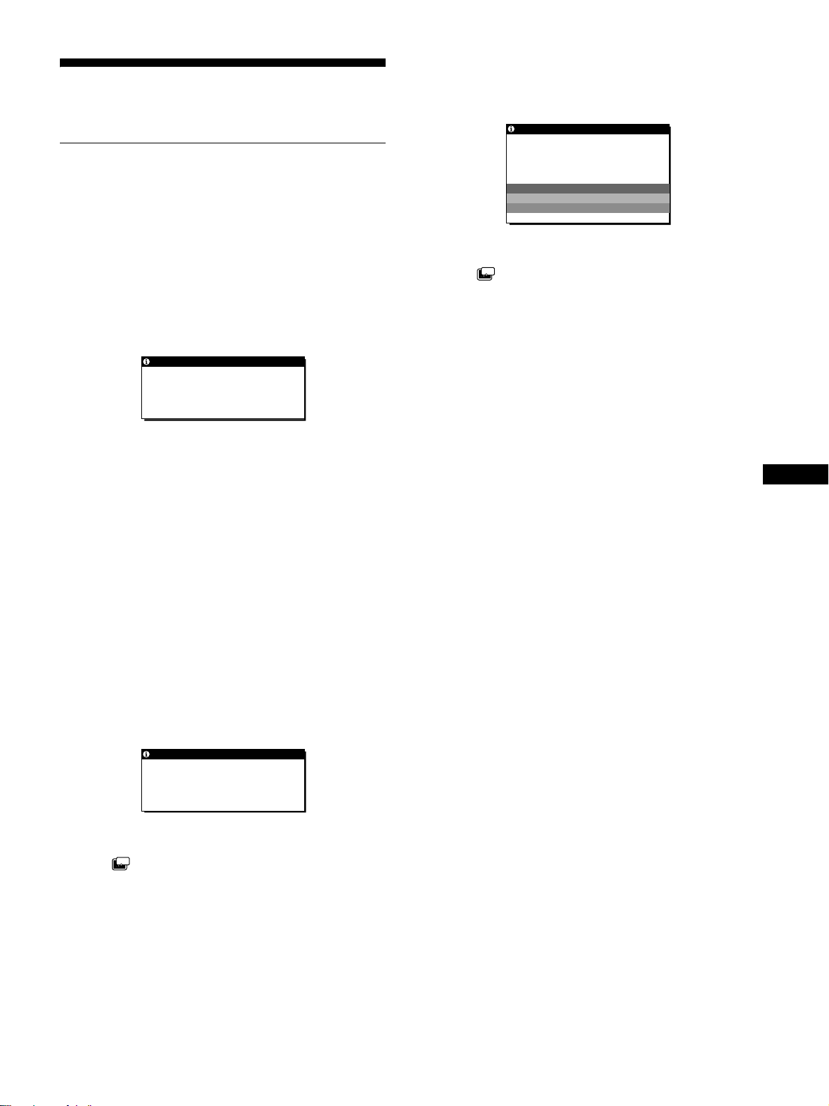
If CABLE DISCONNECTED appears on the screen
This indicates that the video signal cable has been di sconnected
from the currently selected conne ct or.
INFORMATION
CAB L E D I SCONNECTED
INPUT1:DVI -D
GO TO POWER SAVE
If OUT OF SCAN RANGE appears on the screen
This indicates that the input signal is not supported by the
monitor’s specifications. Check the following items
For more information about on-screen messages, see “Trouble
symptoms and remedies” on page 20
INFORMATION
OUT OF SCAN RANGE
INPU T 1 :DV I - D
xxx.xkHz/ xxx.xHz
If “xxx.x kHz/xxx Hz” is displayed
This indicates that either the horizontal or vertical frequency
is not supported by the monitor’s specification s.
The figures indicate the horizontal and vertical frequencies of
the current input signal.
If “RESOLUTION > 1024 × 768” is displayed
(SDM-X52)
This indicates that the resolution is not supported by the
monitor’s specifications (1024 × 768 or less).
If “RESOLUTION > 1280 × 1024” is displayed
(SDM-X72/X82)
This indicates that the resolution is not supported by the
monitor’s specifications (1280 × 1024 or less).
GO TO POWER SAVE
ZZ...
If the (POWER SAVE) is set to “ON,” the monitor will
enter the power saving mode after about 5 seconds from the
time the message is displayed.
GB
If NO INPUT SIGNAL appears on the screen
This indicates that no signal is being input via the currently
selected connector.
INFORMATION
NO I NPUT S IGNAL
INPU T 1 :DV I - D
GO TO POWER SAVE
GO TO POWER SAVE
ZZ...
If the (POWER SAVE) is set to “ON,” the monitor will
enter the power saving mode after about 5 seconds from the
time the message is displayed.
19
Page 20

Trouble symptoms and remedies
If a problem occurs as a result of a connected computer or other equipment, refer to the connected computer/equipment’s instruction manual.
Use the self-diagnosis function (page 22) if the following recommendations do not resolve the problem.
Symptom Check these items
No picture
If the 1 (power) indicator is not lit,
or if the 1 (power) indicator will not
light up when the 1 (power) switch
is pressed,
The 1 (power ) ind ica tor tu rns on re d.
If the 1 (power) indicator is green, • Use the s e lf-diagnosis function (page 22).
If CABLE DISCONNECTED
appears on the screen,
If NO INPUT SIGNAL appears on
the screen, or the 1 (power)
indicator is orange,
If OUT OF SCAN RANGE appears
on the screen (page 19),
If using Windows,
If using a Macintosh system, • When connecting a Macintosh computer, use an adapter (not supplied) if necessary.
Picture flickers, bounces,
oscillates, or is scrambled.
• Check that the power cord is properly connected.
• Check that the monitor’s MAIN POWER switch is “on” (page 9).
• Check that the 1 (power) switch is on.
• Check that the video signal cable is prop erly connected and all plugs are firmly seated in
their sockets (page 7).
• Check that the video input connector’s pins are not bent or pushed in.
• Check that the input select setting is correct (page 11).
• A non- supplied video signal cable is connected. If you connect a non-supplied video
signal cable, CABLE DISCONNECTED may appear on the screen before entering the
power saving mode. This is not a malfunction.
• Check that the video signal cable is prop erly connected and all plugs are firmly seated in
their sockets (page 7).
• Check that the video input connector’s pins are not bent or pushed in.
• Check that the input select setting is correct (page 11).
xProblem caused by a connected computer or other equipment, and not
caused by the monitor
• The computer is in the power saving mode. Try pressing any key on the keyboard or
moving the mouse.
• Check that your graphics board is attached to the comput er properly.
• Check that the computer’s power is “on.”
xProblem caused by a connected computer or other equipment, and not
caused by the monitor
• Check that the video frequency range is within that specified for the monitor. If you
replaced an old monitor with this monitor, reconnect the old monitor and then adjust the
computer’s graphics board in the following ranges.
Horizontal frequency: 28 – 61 kHz (SDM-X52) 28 – 92 kHz (SDM-X72/X82)
Vertical frequency: 56 – 75 Hz (SDM-X52) 56 – 85 Hz (SDM-X72/X82)
Resolution: 1024 × 768 or less (SDM-X52) 1280 × 1024 or less (SDM-X72/X82)
• If you replaced an old monitor with this monitor, reconnect the old monitor and do the
following. Select “SONY” from the “Manufacturers” list and select “SDM-X52” or “SDMX72” or “SDM -X82 ” from the “M ode ls” list in th e Windows device sele ction s creen. If “S DM X52” or “SDM-X72” or “SDM-X82” does not appear in the “Models” list, try “Plug & Play”
or install the information file for this monitor using the Windows Monitor Information Disk.
Connect the adapter to the computer before connecting the video signal cable.
• Adju s t the pitch and phase (anal og RGB signal only) (page 13).
• Isolate and eliminate any potential sources of electric or ma gnetic fields such as other
monitors, laser printers, electric fans, fluorescent lighting, or televisions.
• Move the monitor away from power lines or place a magnetic shield near the monitor.
• Try plugging the monitor in to a different AC outlet, preferably on a different circuit.
• Cha nge the orientat ion of the monitor.
xProblem caused by a connected computer or other equipment, and not
caused by the monitor
• Check your graphics board manual for the proper monitor setting.
• Confirm that the graphics mode (VESA, Macintosh 19'' Color, etc.) and the frequency of the
input signal are supported by t his monito r. Even if the frequency is within the proper range, som e
graphics boards may have a sync pulse that is too narrow for the monitor to sync correctly.
• This monitor does not process the interlace signals. Set for progressive signals.
• Adjust the computer’s refresh rate (vertical frequency) to obtain the best possible picture
(60 Hz is recommended).
20
Page 21
Symptom Check these items
Picture is fuzzy. • Adjus t the brightness and contrast ( page 12).
• Adjus t the pitch and phase (analog RGB signal only) (page 13).
xProblem caused by a connected computer or other equipment, and not
caused by the monitor
• Set the resolution to 1024 × 768 (SDM-X52), 1280 × 1024 (SDM-X72/X 82) on your
computer.
Picture is ghosting. • Eliminate the use of video cable extensions and/or video switch boxes.
• Check that all plugs are firmly seated in their sockets.
Picture is not centered or sized
properly (ana log RGB signal onl y).
• Adju s t the pitch and phase (page 13).
• Adjust the picture position (page 14). Note that some video modes do not fill the screen to
the edges.
Picture is too small. • Set the zoom setting to FULL2 (page 15).
xProblem caused by a connected computer or other equipment, and not
caused by the monitor
• Set the resolution to 102 4 × 768 (SDM-X5 2), 1280 × 1024 (SDM-X72/X82) on your computer.
Picture is dark. • Adjus t the brightness (page 12).
• Adjust the backlight (page 12).
• It takes a few minutes for the display to become bright after turning on the monitor.
• Adjust (GAMMA) (page 15).
• If you press the ECO button, the screen turns darker.
Wavy or elliptical pattern (moire)
• Adjus t the pitch and phase (analog RGB signal only) (page 13).
is visible.
Color is not uniform. • Adjus t the pitch and phase (analog RGB signal only) (page 13).
White does not look white. • Adjust the color temperature (page 14).
Monitor buttons do not operate
• If the menu lock is set to ON, set it to OFF (page 16).
( appears on the screen) .
The monitor turns off after a while. • Set th e power saving fu nction to OFF (page 16).
xProblem caused by a connected computer or other equipment, and not
caused by the monitor
• Set the computer’s power saving setting to off.
GB
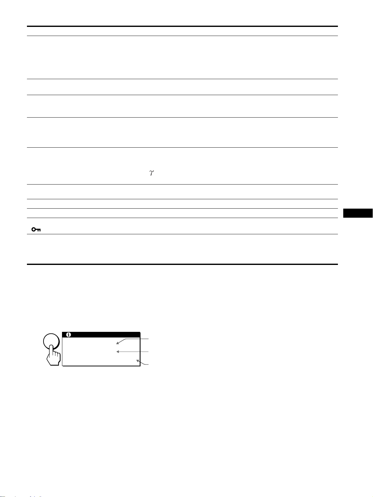
Displaying this monitor’s name, serial number,
and date of manufacture.
While the monitor is rece iving a video signal , press and
hold the MENU button for more than 5 seconds.
The monitor’s information box appears. Press the MENU button
again to make the box disapp ear.
Example
Model
name
Serial
number
Week and
year of manufacture
MENU
INFORMATION
MODEL : SDM-X82
SER. NO : 1234567
MANUFACTURED : 2002-40
If any problem persists, ca ll your authorized Sony de aler and giv e
the following information:
• Mod el name: SDM-X52, SDM-X72, SDM-X82
• Seri al number
• Name and specifications of your computer and graphics board.
• Typ e of input signals (analog RGB/digit al RGB)
21
Page 22
Self-diagnosis function
This monitor is equipped with a self-diagnosis func tion. If there is
a problem with your monitor or computer(s), the screen will go
blank and the 1 (power) indicator will either light up green or
flash orange. If the 1 (power) indicator is lit in orange, the
computer is in power saving mode. Try pressing any key on the
keyboard or movi ng the mouse.
1 (power)
indicator
If the picture disappears from the screen and the
1 (power) indicator is green
Turn off the 1 (power) switch and disconnect the
1
video signal cables from the monitor.
2 Turn the monitor on by pressing the 1 (power)
switch.
If all four color bars appear (white, red, green, blue), the monitor
is working properly. Reconnect the video input cables and check
the condition of your co m pu t e r( s ) .
If the color bars do not appear, ther e is a potential monito r failure.
Inform your authorized Sony dealer of the monitor’s condition.
If the 1 (power) indicator lights up in orange
Try pressing any key on the keyboard or moving the
mouse.
The computer’s power saving mode is awaked and the 1 (power)
indicator lights up in green, and the picture appears on the screen.
22
Page 23

Specifications
SDM-X52
LCD panel Panel type: a-Si TFT Active Matrix
Picture size: 15.0 inch
Input signal format RGB operating frequency*
Horizontal: 28 – 61 k H z
Vertical: 56 – 75 Hz
Resolution Horizontal: Max.1024 dots
Vertical: Max.768 lines
Input signal levels Analog RGB vi deo signal
0.7 Vp-p, 75 Ω, positive
SYNC signal
TTL level, 2.2 kΩ,
positive or negative
(Separate horizontal and vertical,
or composite sync)
0.3 Vp-p, 75Ω, negative
(Sync on green)
Digital RGB (DVI) signal: TMDS
(Single link)
Power requirements 100 – 240 V, 50 – 60 Hz,
Max. 0.7A
Power consumption Max. 28 W
Operating tempe rature 5 – 35
Dimensions (width/height/depth)
Mass Approx. 4.8 kg (1 0 lb 9 oz) (with
Plug & Play DDC2B
Accessories See page 7.
°C
Display (upright):
Approx. 392 × 358 × 199 mm
1
/2 × 14 1/8 × 7 7/8 inches)
(15
(with stand)
Approx. 392 × 299 × 73 mm
1
/2 × 11 7/8 × 2 7/8 inches)
(15
(without stand)
stand)
Approx. 3.5 kg (7 lb 11 oz)
(without stand)
SDM-X72/X82
LCD panel Panel type: a-Si TFT Active Matrix
Picture size: 17.0 inch (SDM-X72)
Picture size: 18.1 inch (SDM-X82)
Input signal format RGB operating frequency*
Horizontal: 28 – 92 kHz
Vertical: 56 – 85 Hz
Resolution Horizontal: Max.1280 dots
Vertical: Max.1024 lines
Input signal levels Analog RGB video signal
0.7 Vp-p, 75 Ω, positive
SYNC signal
TTL level, 2.2 kΩ,
positive or negative
(Separate horizontal and vertical,
or composite sync)
0.3 Vp-p, 75Ω, negative
(Sync on green)
Digital RGB (DVI) signal: TMDS
(Single link)
Power requireme nts 100 – 240 V, 50 – 60 Hz,
Max. 0.9 A (SDM-X72)
Max. 1.2 A (SDM-X82)
Power consumption Max. 40 W (SDM-X72)
Max. 58 W (SDM-X82)
Operating temperature 5 – 35
Dimensions (width/height/depth)
Mass Approx. 7.1 kg (15 l b 10 oz) (with
Plug & Play DD C2B
Accessories See page 7.
°C
Display (upright):
Approx. 438 × 410 × 227 mm
1
/4 × 16 1/4 × 9 inches)
(17
(with stand) (SDM-X72)
Approx. 450 × 424 × 241 mm
3
/4 × 16 3/4 × 9 1/2 inches)
(17
(with stand) (SDM-X82)
Approx. 438 × 356 × 84 mm
1
/4 × 14 1/8 × 3 3/8 inches)
(17
(without stand) (SDM-X72)
Approx. 450 × 368 × 90 mm
3
/4 × 14 1/2 × 3 5/8 inches)
(17
(without stand) (SDM-X82)
stand) (SDM-X72)
Approx. 8.6 kg (18 lb 15 oz) (with
stand) (SDM-X82)
Approx. 5.3 kg (11 lb 11 oz)
(without stand) (SDM-X72)
Approx. 6.5 kg (14 lb 5 oz)
(without stand) (SDM-X82)
GB
* Recommended horizont al and vertical timing condition
• Horizontal sync width duty should be more than 4.8% of total
horizontal time or 0.8 µs , whic he ver is larger.
• Horizontal blanking widt h should be more than 2.5 µsec.
• Verti cal blanking width should be more than 450 µsec .
Design and specifications are subject to change without notice.
23
Page 24

Page 25
Table des matières
• Macintosh est une marque commerciale
sous licence d’Apple Computer, Inc.,
déposée aux Etats-Unis et dans d’autres
pays.
•Windows
déposée de Microsoft Corporation aux
Etats-Unis et dans d’autres pays.
• IBM PC/AT et VGA sont des marques
commerciales déposées d’IBM
Corporati on of the U.S.A.
• VESA et DDC
commerciales de Video Electronics
Standards Association.
ENERGY STAR est une marque
•
déposée aux Etats-Un is.
• Tous les autres noms de produit
mentionnés dans le présent mode
d’emploi peuvent être des marques
commerciales ou des marques
commerciales déposées de leurs
entreprises respectives.
• De plus, les symboles “” et “” ne
sont pas systématiquement mentionnés
dans ce mode d’emploi.
est une marque commercia le
sont des marques
Précautions. . . . . . . . . . . . . . . . . . . . . . . . . . . . . . . . . . . . . . . . . . . . 4
Identification des composants et des commandes. . . . . . . . . . . . . . 5
Installation . . . . . . . . . . . . . . . . . . . . . . . . . . . . . . . . . . . . .7
Réglage 1 : Raccordez un ordinateur équipé d’un connecteur de
sortie DVI (RVB numérique). . . . . . . . . . . . . . . . . . . . . 7
Réglage 2 : Raccordez un ordinateur équipé d’un connecteur de
sortie HD15 (RVB analogique). . . . . . . . . . . . . . . . . . . 7
Réglage 3 : Raccordez le cordon audio. . . . . . . . . . . . . . . . . . . . . . 8
Réglage 4 : Branchez le câble d’alimentation . . . . . . . . . . . . . . . . . 8
Réglage 5 : Regroupez les cordons et les câbles . . . . . . . . . . . . . . 9
Réglage 6 : Mettez le moniteur et l’ordinateur sous tension . . . . . . 9
Réglage 7 : Réglage de l’inclinaison et de la hauteur . . . . . . . . . . 10
Sélection du signal d’entrée (touche INPUT) . . . . . . . . . . . . . . . . . 11
Personnalisation de votre moniteur. . . . . . . . . . . . . . . .12
Pilotage par menu. . . . . . . . . . . . . . . . . . . . . . . . . . . . . . . . . . . . . . 12
RETROÉCLAIRAGE . . . . . . . . . . . . . . . . . . . . . . . . . . . . . . . 12
CONTRASTE . . . . . . . . . . . . . . . . . . . . . . . . . . . . . . . . . . . . . . 12
LUMINOSITÉ . . . . . . . . . . . . . . . . . . . . . . . . . . . . . . . . . . . . . . 13
ECRAN (signal RVB analogique uniquement) . . . . . . . . . . . . . 13
COULEUR. . . . . . . . . . . . . . . . . . . . . . . . . . . . . . . . . . . . . . . . . 14
GAMMA . . . . . . . . . . . . . . . . . . . . . . . . . . . . . . . . . . . . . . . . . . . 15
ZOOM (SDM-X72/X82 uniquement) . . . . . . . . . . . . . . . . . . . . 15
SMOOTHING . . . . . . . . . . . . . . . . . . . . . . . . . . . . . . . . . . . 15
Réglages additionnels . . . . . . . . . . . . . . . . . . . . . . . . . . . . . . . . . . 16
Spécifications techniques. . . . . . . . . . . . . . . . . . . . . . . .17
Contrôle du volume. . . . . . . . . . . . . . . . . . . . . . . . . . . . . . . . . . . . . 17
Fonction d’économie d’énergie. . . . . . . . . . . . . . . . . . . . . . . . . . . . 17
Réduction de la consommation électrique (mode ECO). . . . . . . . . 18
Fonction de réglage automatique de la qualité de l’image
(signal RVB analogique uniquement) . . . . . . . . . . . . . . . . . . . . . . . 18
Dépannage . . . . . . . . . . . . . . . . . . . . . . . . . . . . . . . . . . . .19
Messages affichés . . . . . . . . . . . . . . . . . . . . . . . . . . . . . . . . . . . . . 19
Symptômes de défaillance et remèdes. . . . . . . . . . . . . . . . . . . . . . 20
Fonction d’autodiagnostic. . . . . . . . . . . . . . . . . . . . . . . . . . . . . . . . 22
Spécifications. . . . . . . . . . . . . . . . . . . . . . . . . . . . . . . . . .23
TCO’99 Eco-document (for the grey model) . . . . . . . . . . . . . . . . . . .i
TCO’95 Eco-document (for the black model) . . . . . . .Couverture dos
FR
3
Page 26

Précautions
Avertissement sur les connexions d’alimentation
• Utilisez le câble d’alimentation fourni. Si vous utilisez un câble
d’alimentation différent, assurez-vous qu’il est compatible
avec la tension secteur locale.
Pour les clients aux Etats-Unis
Si vous n’utilisez pas le câble approprié, ce moniteur ne sera
pas conforme aux normes FCC obliga to ir e s .
Pour les clients au Royaume-Uni
Si vous utilisez le moniteur au Royaume-Uni, veuillez utiliser
le câble d’alimentation adapté au Royaume-Uni.
Exemples de types de fiches
pour 100 à 120 V CA pour 200 à 240 V CA pour 240 V CA
uniquement
L’appareil doit être installé à proximité d ’une prise de c ourant
aisément accessible.
Installation
N’installez pas et ne laissez pas le moniteur :
• A des endroits expo s é s à de s te m p é r a t u r es ex t r ê m es, par
exemple à proximité d’un radiateur, d’un conduit de chauffage
ou exposé directement au soleil. L’exposition du moniteur à des
températures extrêmes, comme dans l’habitacle d’une vo iture
garée en plein soleil ou à proximité d’un conduit de chauffage,
risque d’entraîner de s déf ormations du châssis ou de s
dysfonctionnements.
• A des endroits soumis à des vibrations mécaniques ou à des
chocs.
• A pro ximité d’appareils générant de puissants champs
magnétiques, comme un téléviseur ou d’autres appar eils
électroménagers.
• A des endroit soumis à des quantités inhabituelles de poussière,
de saletés ou de sable, par e xe mple à c ôté d’ une fenê tr e ou ve rte
ou d’une porte donnant sur l’ e xtéri e ur. En ca s d’ins tallation
temporaire à l’extérieur , ve illez à pre ndr e le s préc autions
requises contre la poussière et les saletés en suspension dans l’air.
Faute de quoi des domma ges irréparabl es risquent de se produire.
Manipulation de l’écran LCD
• Ne laisse z pas l ’ écran LCD face au soleil, car vous risquez
sinon de l’endommager. F a ites do nc a ttention si vous installez
le moniteur à côté d’une fenêtre.
• N’appuyez pas sur la surface de l’écran LCD et veillez à ne pas
l’érafler. Ne posez pas d’objets lourd s sur l’écran LCD. Vous
risquez sinon d’altérer l’uniformité de l’écran ou de provoquer
un dysfonctionnement de l ’ écran LCD.
• Lorsque le moniteur est utilisé dans un environnement froi d, il
est possible qu’une image rémanente apparaisse sur l’écran. Il
ne s’agit pas d’un dysfonctionnemen t. L ’ écran recouvre sa
condition normale dès que la température est revenue à un
niveau normal.
• Si une image fixe reste affichée pendant une longue durée, il se
peut qu’une image rémanente apparaisse pendant un certain
temps. Cette image rémanente finira par disparaître.
• Le panneau LCD s’échauffe en cours d’utilisation. Il ne s’agit
pas d’un dysfonctionnement.
A propos des haut-parleurs stéréo intégrés
Assurez-vous de tenir vos équipements d’enre gistrement
magnétique, vos cassettes et vos disquettes à l’écart des
ouvertures des haut-parleurs qui génèrent des champs
magnétiques. Ces champs magnétiques sont susceptibles
d’effacer ou d’endommager les données stocké es sur vos
cassettes ou disquettes.
Remarque sur l’écran à cristaux liquides (LCD Liquid Crystal Display)
Veuillez noter que l’écran LCD est issu d’une technologie de
haute précision. Toutefois, il est possible que des points noirs ou
des points brillants de lumière (rouge, bleu ou vert) apparaissent
constamment sur l’écran LCD, ainsi que des bandes de couleurs
irrégulières ou une certaine luminosité. Il ne s’agit pas d’un
dysfonctionnement.
(Points effectifs : supérieurs à 99,99%)
Entretien
• Débranchez le câble d’alimentation de la prise secteur avant de
procéder au netto ya g e de vot r e mo niteur.
• Nettoyez l’écran LCD avec un chiffon doux. Si vous utilisez un
liquide de nettoyage pour le verre, n’utilisez pas de nettoyant
contenant une solution antistatique ou tout autre additif
similaire, car vous risquez sinon de griffer le revêtement de
l’écran LCD.
• Nettoyez le châss is, le pa nne au et le s comm andes à l’ai de d’u n
chiffon doux légèrement imprégné d’une solution détergente
neutre. N’utilisez aucun type de tampon abrasif, de poudre à
récurer ou de solvant tel que de l’alcool ou de la benzine.
• Ne frottez pas, ne touchez pas et ne tapotez pas la surfa ce de
l’écran avec des objets point us ou abrasifs comme un stylo à
bille ou un tournevis. Ce type de contact risque de rayer le tube
image.
• Sachez qu’une détérioration des matériaux ou du revêtement de
l’écran LCD risque de se produire si le moniteur est exposé à
des solvants volatiles comme des insecticides ou en cas de
contact prolongé avec des objets en caout chouc ou en vinyle.
Transport
• Débranchez tous les câbles du moniteur et saisissez le moniteur
fermement des deux mains par son support et sa base. Si vous
laissez tomber le moniteur, vous risquez de vous blesser ou
d’endommager le mon ite ur.
• Pour transporter ce monit eur en vue de réparations ou de son
expédition, utilisez le carton et les matériaux de
conditionnement originaux.
Elimination du moniteur
• N’éliminez pas ce moniteur avec les ordures
ménagères.
• Le tube fluorescent utilisé dans ce moniteur con tient
du mercure. L’élimination de ce moniteur doit être
effectuée conformément aux réglementations des
autorités locales compétentes en matière de propreté
publique.
4
Page 27

Identification des composants et des commandes
Pour plus de détails, reportez-vous aux pag e s entre parenthèses.
Avant de l’écran à cristaux liquides
1 1 Commutateur (alimentation) et 1 indicateur
(alimentation) (pages 9, 17, 22)
Ce commutateur met le moniteur sous tension lorsque
l’indicateur d’alimentation 1 s’allume en rouge. Appuyez de
nouveau sur ce commu ta t e ur po ur me ttre le moniteur hors
tension.
Si le voyant 1 (alimentation) ne s’allume pas, appuyez sur le
commutateur MAIN POWER (8).
2 Touche MENU (menu) (page 12)
Cette touche permet d’activer et de désactiver l’écran de
menus.
3 Touches M/m et 2 (volume) (pages 12, 17)
Ces touches permettent de sélectionner les options de menu et
d’effectuer des réglages. Elles permettent également
d’afficher le menu V OL UM E po ur co ntrôler le volume.
4 Touche OK (page 13)
Cette touche active les réglages et les options de menu
sélectionnés à l’aide des tou ches M/m (3).
5 Touche INPUT et indicateur INPUT1/INPUT2
(page 11)
Cette touche sélectionne l’ordi nateur raccordé pour la
commutation des signaux d’entrée vidéo et l’indicateur
correspondant (INPUT1 ou INPUT2) s’allume.
Vue latérale de l’écran à cristaux liquides
6 Touche ECO (page 18)
Cette touche permet de réduire la consommation él ectrique.
FR
7 Haut-parleurs stéréo (page 17)
Ce haut-parleurs diffusent les signaux audio sous forme de
sons.
8 Commutateur MAIN POWER (page 9)
Ce commutateur d’alimentation principal met le moniteur
sous et hors tension.
9 Prise pour casque d’écoute (page 17)
Cette prise transmet les signaux audio vers un casque
d’écoute.
q; Orifice de verrouillage de sécurité
L’orifice de verrouillage de sécurité doit être utilisé avec le
système Kensington Micro Saver Security System.
Micro Saver Security System est une marque commerciale de
Kensington.
Arrière du support d’écran
(suite page suivante)
5
Page 28
Arrière de l’écran à cristaux liquides
SDM-X72/X82
SDM-X52
qa Capot arrière (page 7)
Retirez ce capot pour raccorder des câbles ou des cordons.
qs Prise d’entrée audio pour INPUT1 (page 8)
Cette prise tr ansmet des signaux vidéo lorsqu’elle est
raccordée sur la prise de sortie audio d’un ordinateur ou d’un
autre appareil audio.
qd Connecteur d’entrée DVI-D (RVB numérique) pour
INPUT1 (page 7)
Ce connecteur transmet des signaux vidéo RVB numériques
conformes à la DVI Rév. 1.0.
qf Connecteur d’entrée HD15 (RVB analogique) pour
INPUT1 (page 7) (SDM-X72/X82 uniquement)
Ce connecteur transmet des signaux vidéo RVB analogiques
(0,700 Vp-p, posi tifs) et des signaux SYNC.
qg Prise d’entrée audio pour INPUT2 (page 8)
Cette prise tr ansmet des signaux vidéo lorsqu’elle est
raccordée sur la prise de sortie audio d’un ordinateur ou d’un
autre appareil audio.
qh Connecteur d’entrée HD15 (RVB analogique) pour
INPUT2 (page 8)
Ce connecteur transmet des signaux vidéo RVB analogiques
(0,700 Vp-p, posi tifs) et des signaux SYNC.
qj Connecteur AC IN (page 8)
Raccordez le cordon d’alimentation (fourni).
qk Cache (page 9)
Retirez ce couv ercle po ur reg rouper les câbl es ou les c ordons
à raccorder.
ql Support de câbles (page 9)
Cette piéce permet de maintenir les câbles et les cordons
contre le moniteur.
6
Page 29
Installation
Avant d’utiliser votre moniteur, véri fiez si les accessoires
suivants se trouvent bien dans le carton d’emballage :
• Ecran LCD
• Câble d’alimentation
• Câble de signal vidéo HD15-HD15 (RVB analogique)
• Câble de signal vidéo DVI-D (RVB numérique)
• Câble audio (minifiche stéréo)
• Windows Utility/Macintosh Utility Disk
• Carte de garantie
• Ce mode d’ emploi
Réglage 1 : Raccordez un
ordinateur équipé d’un
connecteur de sortie
DVI (RVB numériqu e)
• Eteignez le moniteur et l’ordinateur avant d’effectuer le
raccordement.
• Lorsque vous raccordez l’ordinateur sur le connecteur
d’entrée HD15 (RVB analogique) du moniteur,
reportez-vous à “Réglage 2 : Raccordez un ordinateur
équipé d’un connecteur de sort ie HD 15 (RVB
analogique)”.
Remarque
Ne touchez pas les broches du connecteur du câble de signal vidéo, car
vous risquez sinon de plier les broches.
2 Raccordez l’ordinateur sur le connecteur d’entrée
DVI-D (RVB numérique) pour INPUT1 du m oniteur à
l’aide du câble de signal vidéo DVI-D (RVB
numérique) fourni.
vers le connecteur d’entrée
DVI-D (RVB numérique)
pour INPUT1
vers le connecteur d’entrée
DVI (RVB numérique) de
l’ordinateur
Câble de signal vidéo
DVI-D (RVB numérique)
(fourni)
Réglage 2 : Raccordez un
ordinateur équipé d’un
connecteur de sortie
HD15 (RVB analogique)
Eteignez le moniteur et l’ordinateur avant d’effectuer le
raccordement.
FR
1 Retirez le capot arrière.
Remarque
Ne touchez pas les broches du connecteur du câble de signal vidéo, car
vous risquez sinon de plier les broches.
1 Retirez le capot arrière.
(suite page suivante)
7
Page 30
2 Raccordez l’ordinateur sur le connecteur d’entrée
HD15 (RVB analogique) pour INPUT1 ou INPUT2 du
moniteur à l’aide du câble de signal vidéo HD15HD15 (RVB analogique) fourni.
Raccordez l’ordinateur comme ill ustré ci-après.
x Raccordement à un ordinateu r IBM PC/
AT ou compatible
vers le connecteur d’entrée
HD15 (RVB analogique)
pour INPUT1 ou INPUT2
vers le connecteur d’entrée
HD15 (RVB analogique) de
l’ordinateur
Réglage 3 : Raccordez le cordon
audio
Raccordez le cordon audio fourni sur la prise d’entrée
audio correspondante du moniteur.
Avec les haut-p arleurs ou les écou teurs du moniteur , vous po uvez
écouter le son à partir de l’ordinateur ou d’un autre appareil audio
raccordé sur les prises d’entrée aud io du moniteur.
Pour plus d’info r m at ions, reportez -vo us à “C o ntrôle du volume”
page 17.
vers l’entrée audio
Câble de signal vidéo
Ordinateur IBM PC/AT
ou compatible
HD15-HD15 (RVB
analogique) (fourni)
xRaccordement à un Macintosh
vers le connecteur d’entrée
HD15 (RVB analogique)
pour INPUT1 ou INPUT2
vers le connecteur de
sortie de l’ordinateur
Câble de signal vidéo
HD15-HD15 (RVB
analogique) (fourni)
Vers les prises de sortie de
l’ordinateur ou tout autre
équipement audio
Câble audio (fourni)
Réglage 4 : Branchez le câble
d’alimentation
1 Raccordez le cordon d’alimentation fourni sur le
connecteur AC IN du moniteur.
2 Raccordez-le à une prise secteur.
vers AC IN
1
vers une prise secteur
Ordinateur Macintosh
En cas de raccordement d’un ordinateur Macintosh, utilisez si
nécessaire un adaptateur (n on fourni). Raccordez l’adaptateur sur
l’ordinat eur avant de raccorder le câble du signal vi déo.
8
Câble d’alimentation (fourni)
2
Page 31

Réglage 5 : Regroupez les cordons
et les câbles
Réglage 6 : Mettez le moniteur et
l’ordinateur sous
1 Retirez le cache.
2 Regroupez les cordons et les câbles dans le
support.
3 Fixez les câbles et les cordons à l’aide du support
de câbles.
4 Replacez le cache et le capot arrière.
1
cache
Tenez ici.
2
4
capot arrière
tension
1 Appuyez sur le commutateur MAIN POWER situé
sur le côté gauche du moniteur en direction de [.
L’indicateur d’alimentation 1 s’allume en rouge.
MAIN POWER
il s’allume en rouge
2 Appuyez sur le commutateur d’alimentation 1 situé
à droite, à l’avant du moniteur.
L’indicateur d’alimentation 1 s’allume en vert.
FR
3
Remarque
Si vous ne parvenez pas à regrouper tous le s cord ons e t tous le s câble s
dans le support, faites-les pendre e n de hors de celui-ci.
il s’allume en
vert
3 Mettez l’ordinateur sous tension.
4 Appuyez plusieurs fois sur la touche INPUT et
sélectionnez le signal d’entrée souhaité.
L’indicateur du signal d’entré e sél ectionné s’allume et
l’image apparaît sur l’écran.
Pour plus d’inf ormations, report ez-vous à “Sélection du
signal d’entrée (touche INPUT)” page 11.
L’installation de votre moniteur est à présent terminée. Si
nécessaire, utilisez le s commandes du moniteur pour régler
l’image. (page 12)
(suite page suivante)
9
Page 32

Si aucune image n’apparaît sur l’écran
• Vérifiez que le câble d’alimentation et le câble du signal vidéo
sont correctement raccordés.
Réglage 7 : Réglage de
l’inclinaison et de la
• Si l’indication PAS ENTREE VIDEO apparaît sur l’écran :
– L’ordinateur est en mode d’économie d’énergie. Appuyez
sur n’importe quelle touche du clavier ou déplacez la souris.
– Vérifiez que le réglage du signa l d ’entrée est correct en
appuyant plusieurs fois sur la touche INPUT (page 11).
• Si CABLE PAS CONNECTÉ apparaît sur l’écran :
– Vérifiez que le câble d’entrée vidéo est branché
correctement ;
– Vérifiez que le réglage du signa l d ’entrée est correct en
appuyant plusieurs fois sur la touche INPUT (page 11).
• Si l’indication HORS PLAGE DE BALAYAGE apparaît sur
l’écran, reconnectez l’ancien moniteur. Réglez ensuite la carte
graphique de l’ordinateur dans les plages suivantes.
SDM-X52 SDM-X72/X82
Fréquence horizontale 28 – 61 kHz 28 – 92 kHz
Fréquence verticale 56 – 75 Hz 56 – 85 Hz
Résolution 1024 × 768 ou
moins
1280 × 1024 ou
moins
Pour des informations plus détaillées sur les messages à l’écran,
voir “Symptômes de défaillance et remèdes” à la page 20.
hauteur
Ce moniteur peut être ajus té selo n les an gles et les hauteurs
indiqués ci-dessous .
30°
environ 50°
environ 80°
Vous n’avez besoin d’aucun pilote pour ce moniteur
Le moniteur prend en cha rge la fonction Plug & Play “DDC” e t dé te ct e
automatiquement toutes les autres informations relatives au moniteur. Il
n’est pas nécessaire d’installer de pilote pour cet ordinateur.
La première fois que vous mettez sous tension votre ordinateur après avoir
raccordé le moniteur, l’assistant de réglage peut s’afficher sur l’écran.
Dans ce cas, suivez les instructions indiquées sur l’écran. Le moniteur
Plug & Play est automatiquement sélectionné afin que vous puissiez
l’utiliser.
La fréquence verticale devient 60 Hz.
Etant donné que les scintilleme nt s sur le mon iteu r sont discrets, vous
pouvez l’utiliser tel quel. Vous n’avez pas besoin de régler la fréquence
verticale sur une valeur particuliè rement élevée.
environ 45°
environ 45°
(SDM-X82
uniquement)
Pour une utilisation confortable du moniteur
Ajustez l’angle de v is ualis a tio n de v o t re m on iteur e n fo n ction de
la hauteur de votre bureau et de votre chaise, pour que l’écran ne
réfléchisse pas la lumière dans les yeux.
Remarque
Lors du réglage de l’inclina iso n et de la hauteur de l’écran, procédez
lentement et dél icatement en veill ant à ne pas cogner le panne au LCD
contre le bureau ou la base du support d’écran.
10
Page 33

1 Saisissez la partie médiane inférieure de l’écran à
cristaux liquides tout en maintenant le support
d’écran puis inclinez l’écr an à cristaux liquides ve rs
l’arrière de façon appropriée.
Sélection du signal d’entrée
(touche INPUT)
Appuyez sur la touche INPUT.
Le signal d’entrée change à chaque fois que vous appuyez sur
cette touche comme suit :
2 Saisissez les côtés inférieurs de l’écran à cristaux
liquides, puis ajustez l’inclinaison de l’écran.
3 Saisissez les côtés inférieurs de l’écran à cristaux
liquides, puis ajustez la hauteur de l’écran.
Message à
l’écran (apparaît
dans les
5 secondes dans
le coin supérieur
gauche).
ENTRÉE1
(INPUT1): DVI-D
ENTRÉE1
(INPUT1): HD15
(SDM-X72/X82
uniquement)
ENTRÉE2
(INPUT2): HD15
Sélection du signal d’entrée pour la prise d’entrée audio
Voir “ (ENTRÉE AUDIO)” page16.
L’indicateur
d’entrée
s’allume
INPUT1 Connecteur d’entr ee
INPUT1 Connecteur d’entr ee
INPUT2 Connecteur d’entr ee
Configuration du
signal d’entrée
DVI-D (R VB numérique)
pour INPUT1
HD15 (RVB analogique)
pour INPUT1
HD15 (RVB analogique)
pour INPUT2
FR
11
Page 34

Personnalisation de votre moniteur
Avant de procéder aux réglages
Raccordez le moniteur et l’ordi nateur et mettez-les sous tension .
Pour obtenir les meilleurs résultats, attendez au moins
30 minutes avant d’effectuer les rég lages.
Vous pouvez effectuer de nombreux réglages l’aide des menus
d’affichage.
Les illustrations des écrans de menu correspondent au modèle
SDM-X72/X82. Le s mêmes opérations s’appliquent au modèle
SDM-X52.
x Réinitialisation des réglages aux réglages
par défaut
Vous pouvez réinitialiser les réglages à l’aide du menu
RESTAUR. Pour plus d’informations sur la réinitialisation des
réglages, reportez-vous à “0 (RESTAUR)” page 16.
RETROÉCLAIRAGE
Si l’écran est trop lumineux, ajustez le rétroéclairage pour rendre
l’écran plus facile à regard er.
Remarque
Il est impossible d’ajuster le rétroéclairage lorsque le mode ECO est réglé
sur “ACTIF” (page 18).
RETROÉCLA RAGEI
Pilotage par menu
1 Affichez le menu principal.
Appuyez sur la touche MENU pour afficher le menu principal
sur votre écran.
MENU
2 Sélectionnez le menu que vous voulez régler.
Appuyez sur les touches M/m pour afficher le menu de votre
choix. Appuyez sur la touche OK pour sélectionner un
élément de ce menu.
OK
,
3 Réglez le menu.
Appuyez sur les touches M/m pour effectuer votre réglage
puis appuyez sur la touche OK.
Lorsque vous appuyez sur OK, le réglag e est mémorisé et
l’appareil revient au menu précédent.
100
1280 1024 60Hzx/
EX I T
1 Appuyez sur la touche MENU.
Le menu principal apparaît sur l’écran.
2 Appuyez sur les touches M/m pour sélectionner
(RETROÉCLAIRAGE) puis appuyez sur la
touche OK.
Le menu RETROÉCLAIRAGE apparaît sur l’écran.
3 Appuyez sur les touches M/m pour ajuster le niveau
de luminosité souhaité.
CONTRASTE
Ajustez le contraste de l’imag e.
CONTRAST E
100
1280 1024 60Hzx/
EX I T
OK
,
4 Quittez le menu.
Appuyez une fois sur la touche MENU pour revenir en mode
de visualisation normale. Si vous n’actionnez aucune touche,
le menu se referme automatiquement au bout d’environ
45 secondes.
MENU
12
1 Appuyez sur la touche MENU.
Le menu principal apparaît sur l’écran.
2 Appuyez sur les touches M/m pour sélectionner
6 (CONTRASTE) puis appuyez sur la touche OK.
Le menu CONTRASTE apparaît sur l’écran.
3 Appuyez sur les touches M/m pour régler le
contraste.
Page 35

LUMINOSITÉ
Ajustez la luminosité de l’image (niveau du noir).
LUM NOS T ÉII
100
1280 1024 60Hzx/
EX I T
x Effectuer d’autre s rég lages automatique s
de la qualité de l’imag e pou r le si gna l
d’entrée courant (AUTOMATIQUE)
1 Appuyez sur la touche MENU.
Le menu principal apparaît sur l’écran.
2 Appuyez sur les touches M/m pour sélectionner
(ECRAN) et appuyez ensuite sur la touche OK.
Le menu ECRAN apparaît sur l’écran.
1 Appuyez sur la touche MENU.
Le menu principal apparaît sur l’écran.
2 Appuyez sur les touches M/m pour sélectionner
8 (LUMINOSITÉ) puis appuyez sur la touche OK.
Le menu LUMINOSITÉ apparaît sur l’écran.
3
Appuyez sur les touches M/m pour régler la luminosité.
ECRAN (signal RVB analogique
uniquement)
Remarque
Lorsque vous recevez des signaux RVB numériques depuis le connecteur
d’entrée DVI-D pour INPUT1, aucun réglage n’est nécessaire.
x Fonction de réglage automatique de la
qualité de l’imag e
Lorsque le moniteur reçoit un signal d’entrée, il
ajuste automatiquement la position et la netteté
de l’image (phase/horloge) et garantit la qualité de
l’image qui apparaît sur l’écran (page 18).
Remarque
Lorsque la fonction de réglage automatique de la qualité de l’image est
activée, seul le commutateur d’alimentation 1 fonctionne.
3 Appuyez sur les touches M/m pour sélectionner
AUTOMATIQUE puis appuyez sur la touche OK.
Procédez aux réglages appropriés de la phase, de l’horloge et
de la position horizontale/verticale de l’écran pour le signal
d’entrée courant et enregist rez-les.
4 Appuyez sur les touches M/m pour sélectionner
puis appuyez sur la touche OK.
L’écran des menus s’affiche à nouveau.
x Réglage manuel de la netteté de l’image
(PHASE/PITCH)
Vous pouvez ajuster la netteté de l’image c omme suit. Ce réglage
est effectif lorsque l’ordinateur est raccordé sur le connecteur
d’entrée HD15 (RVB analogique) du moniteur.
1 Réglez la résolution de l’ordinateur sur 1024 × 768
(SDM-X52), 1280 × 1024 (SDM-X72/X82).
2 Chargez la disquette d’utilitaire.
3 Démarrez la disquette d’utilitaire et affichez la mire
de test.
Pour Windows
Cliquez sur [Utility]
Pour Macintosh
Cliquez sur [Utility] t [Mac]/[Mac Utility].
t [Windows]/[Win Utility.exe].
4 Appuyez sur la touche MENU.
Le menu principal apparaît sur l’écran.
FR
Si la fonction de réglage automatique de la qualité de
l’image de ce moniteur semble ne pas régler
complètement l’image.
Vous pouvez effe ct uer un aut re r ég lage au to ma tiq ue de la qu ali té d e
l’image pour le signal d’entrée courant. (Voir AUTOMATIQUE cidessous.)
Si vous souhaitez effectuer d’autres réglages de la
qualité de l’image
Vous pouvez régler manu ellement la ne tteté (phase /horloge) e t la
position (horizontale/verticale) de l’image.
Ces réglages sont mémorisés et au t omatiquement rappelés
lorsque le même signal d’entrée est reçu.
ECRAN
AUTOMAT QUE
PHASE
P I TCH
CENTRAGE H
CENTRAGE V
1280 1024 60Hzx/
I
EX I T
5 Appuyez sur les touches M/m pour sélectionner
(ECRAN) puis appuyez sur la touche OK.
Le menu ECRAN apparaît sur l’écran.
6 Appuyez sur les touches M/m pour sélectionner
PHASE puis appuyez sur la touche OK.
Le menu PHASE appara ît sur l’écran.
7 Appuyez sur les touches M/m jusqu’à ce que les
bandes horizontales soient réduites au minimum.
Réglez la valeur de façon à ce que les rayures horizontales
soient réduites au minimum.
(suite page suivante)
13
Page 36

8 Appuyez sur la touche OK.
Le menu principal apparaît sur l’écran.
Si vous observez des bandes verticales sur tout l’écran,
ajustez le pas en suivant les étapes suivantes.
9 Appuyez sur les touches M/m pour sélectionner
(ECRAN) puis appuyez sur la touche OK.
Le menu ECRAN apparaît sur l’écran.
10 Appuyez sur les touches M/m pour sélectionner
PITCH puis appuyez sur la touche OK.
Le menu PITCH apparaît sur l’écran.
11 Appuyez sur les touches M/m jusqu’à ce que les
bandes verticales disparaissent.
Ajustez la valeur jusqu’à ce que les rayures verticales aient
disparu.
8 Cliquez sur [END] à l’écran pour désactiver la mire
de test.
9 Appuyez sur les touches M/m pour sélectionner
puis appuyez sur la touche OK.
L’écran des menus s’affiche à nouveau.
COULEUR
Vous pouvez sélecti onner le niveau de couleur des zones de
couleur blanche de l’im age à l’aide des réglages de température
des couleurs par défaut.
Vous pouvez également régler av ec précision la température des
couleurs, si nécessaire.
COULEUR
9300K
6500K
UT I L I SATEUR
RÉGLER
12 Cliquez sur [END] à l’écran pour désactiver la mire
de test.
13 Appuyez sur les touches M/m pour sélectionner
puis appuyez sur la touche OK.
L’écran des menus s’affiche à nouveau.
x Réglage manuel de la position de l’image
(CENTRAGE H/CENTRAGE V)
Si l’image n’est pas centrée sur l’écran, ajustez le centrage de
l’image en procédant comme suit :
1 Réglez la résolution sur 1280 × 1024 sur l’ordina teur
si vous utilisez le modèle SDM-X72/X82.
Il n’est pas nécessaire de régler la résolu t io n avec le modèle
SDM-X52.
2 Chargez la disquette d’utilitaire.
3 Démarrez la disquette d’utilitaire et affichez la mire
de test.
Pour Windows
Cliquez sur [Utility]
t [Windows]/[Win Utility.exe].
Pour Macintosh
Cliquez sur [Utility] t [Mac]/[Mac Utility].
4 Appuyez sur la touche MENU.
Le menu principal apparaît sur l’écran.
1280 1024 60Hzx/
EX I T
1 Appuyez sur la touche MENU.
Le menu principal apparaît sur l’écran.
2 Appuyez sur les touches M/m pour sélectionner
(COULEUR) puis appuyez sur la touche OK.
Le menu COULEUR apparaît à l’écran.
3 Appuyez sur les touches M/m pour sélectionner la
température des coul eurs de votre choix et appuyez
ensuite sur la touche OK.
Les blancs passent d’une teinte bleuâtre à une teinte rougeâtre
lorsque la température passe de 9300K (réglage par défaut) à
6500K.
Réglage précis de la température des couleurs
(RÉGLER UTILISA)
Il est impossible de régler INPUT1 et INPUT2 séparément.
RÉGLER U TILISA
R
G
B
1280 1024 60Hzx/
50
50
50
EX I T
1 Appuyez sur les touches M/m pour sélectionner
RÉGLER puis appuyez sur la touche OK.
Le menu RÉGLER UTILISA apparaît à l’écran.
5 Appuyez sur les touches M/m pour sélectionner
(ECRAN) puis appuyez sur la touche OK.
Le menu ECRAN apparaît sur l’écran.
6 Appuyez sur les touches M/m pour sélectionner
CENTRAGE H ou CENTRAGE V puis appuyez sur la
touche OK.
Le menu CENTRAGE H ou CENT RAGE V ap paraît sur l’é cran.
7 Appuyez sur la touche M/m pour centrer la mire de
test sur l’écran.
14
Page 37

2 Appuyez sur les touches M/m pour sélectionner R
(rouge) ou B (bleu) puis appuyez sur la touche OK.
Appuyez ensuite sur les touch es M/m pour ajuster la
température des couleurs, puis appuyez sur la
touche OK.
Etant donné que ce réglage modifie la température des
couleurs en augmentant ou en diminuant les composantes R et
B par rapport à V (vert), la composante V est fixe.
3 Appuyez sur les touches M/m pour sélectionner ,
puis appuyez sur la touche OK.
Le nouveau réglage des couleu rs de RÉ GLER UTILISA est
enregistré dans la mémoire et automatiquement rappelé
lorsque UTILISATEUR est sélectionné.
Le menu COULEUR apparaît sur l’écran.
GAMMA
Vous pouvez associer les nuances foncées des couleurs de l’image
affichée à l’écran à celles des couleurs originales de l’image.
GAMMA
GAMMA 1
GAMMA 2
GAMMA 3
1280 1024 60Hzx/
1 Appuyez sur la touche MENU.
Le menu principal apparaît à l’ écran.
2 Appuyez sur les touches M/m pour sélectionner
(GAMMA) puis appuyez sur OK.
Le menu GAMMA apparaît à l’écran.
EX I T
3 Appuyez sur les touches M/m pour sélectionner le
mode souhaité.
• FULL2 (réglage par défaut) : Le signal d’entrée
s’affiche en plein écran, quel que soit le mode ou
la résolution de l’image.
• FULL1 : Le signal d’entrée s’affiche sur l’écran en
fonction du rapport hauteur/largeur en cours. Par
conséquent, des bandes noires peuvent
apparaître en haut et en bas de l’image, selon le
signal.
• ORIGINAL : Le signal d’entrée s’affiche sur l’écran en
fonction de la résolution en cours. Le signal
sous-1280 × 1024 est affiché au centre de
l’écran, entouré d’un cadre noir.
Remarques
• Lorsque vous utilisez le modè le SDM-X 72/X82 avec des signaux de
résolution 1280
disponibles. L’image s’affiche en plein écran.
• Le SDM-X52 peut unique ment afficher l’image en ple in écr an .
× 1024, les réglages mentionnés ci-dessus ne sont pas
SMOOTHING
Si l’image affichée en mode FULL2 ou FULL1 de la fonction
ZOOM n’est pas lisse, utilisez la fonction de lissage de l’image.
SMOOTH NGI
TEXTE
STANDARD
I
GRAPH QUE
1280 1024 60Hzx/
1 Appuyez sur la touche MENU.
Le menu principal apparaît sur l’écran.
EX I T
FR
3 Appuyez sur les touches M/m pour sélectionner le
mode souhaité.
ZOOM (SDM-X72/X82 uniquement)
Le moniteur est réglé pour afficher l’imag e en plein écran, quel
que soit le mode ou la résolution de l’image dans le réglage par
défaut (FULL2).
Vous pouvez également visualiser l’image dans son format ou sa
résolution réels.
ZOOM
FULL2
FULL1
ORIGI NAL
1280 1024 60Hzx/
1 Appuyez sur la touche MENU.
Le menu principal apparaît sur l’écran.
2 Appuyez sur les touches M/m pour sélectionner
(ZOOM), puis appuyez sur OK.
Le menu ZOOM apparaît sur l’écran.
EX I T
2 Appuyez sur les touches M/m pour sélectionner
(SMOOTHING), puis sur OK.
Le menu SMOOTHING apparaît sur l’écran.
3 Appuyez sur les touches M/m pour sélectionner le
mode souhaité.
L’effet de lissage est plus visible dans ce sens :
TEXTEtSTANDARDtGRAPHIQUE.
• TEXTE : Caractère en clair. (Ce mo de convient aux
applications de traitement de texte.)
• STANDARD (réglage par défaut) : Effet de liss age
standard.
• GRAPHIQUE : Images nettes. (Ce mode convient aux
CD-ROM contenant des p hotos ou des
illustrations.)
Remarques
• Lorsque vous réglez le men u (ZOOM) sur ORIG INA L , le m en u
(SMOOTHING) n’est pas disponible.
• Les signaux de résolution 1024 × 768 (SDM-X52) et 1280 × 1024
(SDM-X72/X82) sont unique ment affichés en mode ORIGIN A L et la
fonction SMOOTHING est in active.
15
Page 38

Réglages additionnels
Les menus suivants apparaissent sur l’écran lorsque vous
maintenez la touche m enfoncée.
• POSITION MENU
• ENTRÉE AUDIO
• MODE ÉCO
• LANGUAGE
• RESTAURE 0
• VERROU RÉGLAGES
ZZ...
1 Appuyez sur la touche MENU.
Le menu principal apparaît sur l’écran.
2 Maintenez la touche m enfoncée jusqu’à ce que
l’option de menu que vous souhaitez régler
apparaisse sur l’écran.
3
Appuyez sur les touches M/m pour sélectionner
l’option de menu de votre choix, puis appuyez sur OK.
Réglez l’option de menu sélectionnée en appliquant les
instructions suivantes.
x POSITION MENU
Vous pouvez changer la position du menu s’il masque une image
à l’écran.
POS T ON MENUII
ZZ...
1280 1024 60Hzx/
EX I T
2 Appuyez sur les touches M/m pour sélectionner
ACTIF ou INACTIF.
• ACTIF : passe automatiquement en mode d’économie
d’énergie lorsqu’aucun signal d’e ntrée n’est reçu
via l’ordinateur sélectionné.
• INACTIF : ne passe pas en mode d’économie d’énergie.
x LANGUA GE
1 Appuyez sur les touches M/m pour sélectionner
(LANGUAGE) puis appuyez sur la touche OK.
Le menu LANGUAGE apparaît sur l’écran.
2 Appuyez sur les touches M/m pour sélectionner une
langue.
• ENGLISH : Anglais
• FRANÇAIS
• DEUTSCH : Allemand
• ESPAÑOL : Esp a gnol
• ITALIANO : Italien
• NEDERLANDS : Néerlandais
• SVENSKA : Suédois
•: Russe
• : Japonais
x 0 RESTAURE
Réinitialisation des réglages aux valeurs par défaut.
1 Appuyez sur les touches M/m pour sélectionner
(POSITION MENU) puis appuyez sur la touche
OK.
Le menu POSITION M ENU apparaît sur l’écran.
2 Appuyez sur les touches M/m pour sélectionner la
position souhaitée puis appuyez sur la touche OK.
Vous pouvez choisir l’une des 9 positions pour l’affichage du menu.
x ENTRÉE AUDIO
Sélectionnez l’entrée audio lorsque vous utilisez les deux prises
d’entrée audio pour IN PUT1 et INPUT2 du moniteur.
1 Appuyez sur les touches M/m pour sélectionner
(ENTRÉE AUDIO) puis appuyez sur la touche OK.
Le menu ENTRÉE AUDIO apparaît sur l’écran.
2 Appuyez sur les touches M/m pour sélectionner le
mode souhaité.
• AUTOMATIQUE : permet d’activer l’entrée audio en
commutant la touche INPUT.
• ENTRÉE1 (INPUT1) : permet d’activer l’entrée audio via
la prise AUDIO1.
• ENTRÉE2 (INPUT2) : permet d’activer l’entrée audio via
la prise AUDIO2.
ZZ...
x MODE ÉCO
Réglez le mode d’économie d’énergie (page17).
1 Appuyez sur les touches M/m pour sélectionner
ZZ...
(MODE ÉCO), puis appuyez sur la touche OK.
Le menu MODE ÉCO apparaît sur l’écran.
1 Appuyez sur les touches M/m pour sélectionner
0 (RESTAURE) puis appuyez sur la touche OK.
Le menu RESTAURE apparaît sur l’écran.
2 Appuyez sur les touches M/m pour sélectionner le
mode souhaité.
• OK : Réinit ialise toutes les données de régl age à la
configuration par défaut. Notez que le réglage
(LANGUAGE) n’est pas réinitialisé par cette
méthode.
• ANNULER : Annule la réinitialisation et retourn e à l’écran
du menu.
x VERROU RÉGLAGES
Verrouillez la commande d es touches afin d’éviter tout régl age ou
toute réinitialisation accidentels.
1 Appuyez sur les touches M/m pour sélectionner
(VERROU RÉGLAGES) puis appuyez sur la
touche OK.
Le menu VERROU RÉGLAGES apparaît sur l’écran.
2 Appuyez sur les touches M/m pour sélectionner
ACTIF ou INACTIF.
• ACTIF : seuls le commutateur d’alimentation 1 et la
touche INPUT sont ac tifs. Si vous essayez
d’activer une autre touche, (VERROU
RÉGLAGES) apparaît sur l’écran.
• INACTIF : (VERROU RÉGLAGES) est désactivé. Si
vous réglez le (VERROU RÉGLAGES) sur
ACTIF, seul ce paramèt re de menu peut être
sélectionné.
16
Page 39

Spécifications techniques
Contrôle du volume
Avec les haut-par leurs ou les éco uteurs du moni teur, vous pou vez
écouter le son à partir de l’ordinateur ou d’un autre appareil audio
raccordé sur les prises d’entrée audio du moniteur.
Vous pouvez régler le volume à l’aide d’un menu VOLUME
distinct dans le men u prin c i pa l.
1 Appuyez sur les touches M/m (2) lorsqu’aucun
menu n’apparaît sur l’écran.
VOLUME
,
30
Fonction d’économie d’énergie
Ce moniteur satisfait aux crit ères d’économie d’énergie VESA,
ENERGY STAR et NUTEK. Lorsque le moniteur est raccordé à
un ordinateur ou une carte graphique vidéo compatible DPMS
(Display Power Management Signaling), le moniteur réduit
automatiquement sa consommation d’énergie comme indiqué cidessous.
SDM-X52
Mode
d’alimentation
fonctionnement
normal
inactif*
(sommeil profond)**
1 (alimentation)
inactif
Alimentation
principale inactive
Consommation
d’énergie
28 W (max.) vert
3 W (max.) orange
1 W rouge
0 W désactivé
L’indicateur 1
(alimentation)
2 Appuyez sur les touches M/m (2) pour contrôler le
volume.
Le menu disparaît automatiquement au bout d’environ
5 secondes.
Utilisation des écouteurs
Lorsque vous branchez vos écouteurs sur la prise écouteurs du
moniteur, vous pouvez écouter le so n à partir de l’ordinateur ou
d’un autre appareil audio raccordé sur la prise d’entrée audio du
moniteur.
Remarques
• Vous ne pouvez pas régler le volu m e lo rsque le menu principal est
affiché sur l’écran.
• Lorsque votre moniteur est en mode économie d’éne r gi e, auc un son
n’est émis par les haut-parleurs ou le casque d’écoute.
SDM-X72
Mode
d’alimentation
fonctionnement
normal
inactif*
(sommeil profond)**
1 (alimentation)
inactif
Alimentation
principale inactive
SDM-X82
Mode
d’alimentation
fonctionnement
normal
inactif*
(sommeil profond)**
1 (alimentation)
inactif
Alimentation
principale inactive
Consommation
d’énergie
40 W (max.) vert
3 W (max.) orange
1 W rouge
0 W désactivé
Consommation
d’énergie
58 W (max.) vert
3 W (max.) orange
1 W rouge
0 W désactivé
L’indicateur 1
(alimentation)
L’indicateur 1
(alimentation)
FR
* Lorsque votre ordinateur passe en mode “inactif”, le signal d’entrée
est coupé et l’i ndication PAS ENTREE VIDEO apparaît à l’écran . Au
bout de 10 secondes, le moniteur passe en mode d’économie
d’énergie.
** “Sommeil profond” est un mode d’économie d’énergie défini par
l’Environmental Protection Agency.
Remarque
ZZ...
Si (MODE ÉCO) est réglé sur INACTIF (page 16), le moniteur ne
passe pas en mode d’économie d’ énergie.
17
Page 40

Réduction de la consommation
électrique
Si vous appuyez sur la touche ECO située à l’avant du moniteur,
le niveau du rétroéclairage est réduit, ainsi que la consommation
électrique.
Appuyez sur la touche ECO.
(mode ECO)
Fonction de réglage automatique
de la qualité de l’im age
analogique uniquement)
Lorsque le moniteur reçoit un signal d’entrée, il
ajuste automatiquement la position et la netteté
de l’image (phase/horloge) et garantit la qualité de
l’image qui apparaît sur l’écran.
(signal RVB
,
Le menu ECO: ACTIF s’affiche et le niveau du rétroéclairage est
réduit. Le menu disparaît automatiquement après environ 5
secondes.
Pour annuler le mode ECO
Appuyez de nouveau sur la touche ECO.
Appuyez sur la touche ECO.
,
Le menu ECO: INACTIF s’affiche et le niveau normal du
rétroéclairage est réglé. Le menu disparaît automatiquement après
environ 5 secondes.
:
ECO A CT I F
:
ECO I NACT I F
Le mode préréglé en usine
Lorsque le moniteur reçoit un signal d’entrée, il fait
automatiquemen t correspondre le signal à l’un des modes
présélectionnés par défaut enregistrés dans la mémoire du
moniteur afin de produire une image de ha ute qualité au cent re de
l’écran. Si le signal d’entrée correspond au mode préréglé d’usine,
l’image apparaît automatiquement sur l’écran, avec le réglage par
défaut appropri é .
Si certains signaux d’entrée ne correspondent à
aucun mode préréglé d’usine
Lorsque le moniteur reçoit un signal d’entrée, la fonction de
réglage automatique de la qualité de l’image de ce moniteur est
activée et garantit l’affichage permanent d’une image claire sur
l’écran (dans les plages de fréquences suivantes du moniteur ) :
Fréquence horizontale : 28 – 61 kHz (SDM-X52)
28 – 92 kHz (SDM-X72/X82)
Fréquence verticale : 56 – 75 Hz (SDM-X52)
56 – 85 Hz (SDM-X72/X82)
En conséquence, la première fois que le moniteur reçoit des
signaux d’entrée qui ne correspondent pas à l’un des modes
présélectionnés par défaut, il se peut que le moniteur prenne un
peu plus de temps que d’habitude pour afficher l’image à l’écran.
Ces données de réglages sont automatiquement enregistrées dans
la mémoire de sorte que le moniteur fonctionnera de la même
manière la prochaine fois qu’il recevra des signaux correspondant
à l’un des modes présé lectionnés par défaut.
18
Si vous ajustez la phase, le pas et la position des
images manuellement
Pour certains signaux d’entr ée, la fonction de réglage
automatique de la qualité de l’image de ce moniteur peut ne pas
ajuster totalement la position, la pha se et le p as de l’im age . Dans
ce cas, vous pouvez effectuer ces réglages manuellement
(page 13). Si vous effectuez ces réglages manuellement, ils sont
mémorisés comme des modes utilisateurs et sont
automatiquement rappelés lorsque le moniteur reçoit les mêmes
signaux d’entrée.
Page 41

Dépannage
Avant de prendre contact avec l’assistance technique, consultez
les informations présentées dans cette section.
Messages affichés
S’il se produit une anomalie au niveau du signal d’entrée, l’un des
messages suivants apparaît sur l’écran. Pour résoudre le
problème, voir “Symptômes de défaillance et remèdes” à la
page 20.
Si l’indication CABLE PAS CONNECTÉ apparaît
sur l’écran
Cela signifie que le câble de signal vidéo a été déconnecté du
connecteur actuellement sélectionné.
INFORMATI
CAB L E P AS CONNECTÉ
ENTRÉE1 : D
PASSER EN M DOEÉCO
ON
S
VI-D
Si l’indication HORS PLAGE DE BALAYAGE
apparaît sur l’écran
Cela signifie que le signal d’entr ée n’est pas pris en c harge par les
spécifications du moniteur. Vérifiez les éléments suivants.
Pour des informations plus détaillées sur les messages à l’écran,
voir “Symptômes de défaillance et remèdes” à la page20.
INFORMATI
HORS PLAGE DE
BAL AYAGE
ENTRÉE1 : DV I - D
xxx.xkHz/ xxxHz
Si “xxx.x kHz/xxx Hz” est affiché
Cela signifie que la fréquence horizo ntale ou verticale n’est
pas prise en charge par les spécification s du moniteur.
Les chiffres indiquent les fréquences horizontales et
verticales du signal d’entrée en cours.
Si “RESOLUTION > 1024 × 768” est affiché
(SDM-X52)
Cela signifie que la résolution n’est pas prise en charge pa r les
spécifications du m oniteur (1024 × 768 ou moi ns).
Si “RESOLUTION > 1280 × 1024” est affiché
(SDM-X72/X82)
Cela signifie que la résolution n’est pas prise en charge pa r les
spécifications du m oniteur (1280 × 1024 ou moins).
ONS
PASSER EN MODE ÉCO
ZZ...
Si (MODE ÉCO) est réglé sur “ACTIF”, le moniteur
passe en mode d’économie d’énergie environ 5 secondes
après l’affichage du message.
FR
Si l’indication PAS ENTREE VIDEO apparaît sur
l’écran
Cela signifie qu’aucun signal n’est détecté en entrée via le
connecteur actuellement sélectionné.
INFORMATION
PAS ENTREE V I DEO
ENTRÉE1 : DV I - D
PASSER EN MODE ÉCO
PASSER EN MODE ÉCO
ZZ...
Si (MODE ÉCO) est réglé sur “ACTIF”, le moniteur
passe en mode d’économie d’énergie environ 5 secondes
après l’affichage du message.
S
19
Page 42

Symptômes de défaillance et remèdes
Si un problème est causé par un or dinateu r ou un a utre appar eil raccord é, repor tez-vous aux mode s d’emp loi de l’ap pareil ou de l’ordinateur
concerné.
Utilisez la fonction d’autodiagnostic (page 22) si les recommandations suivantes ne permettent pas de résoudre le problème.
Symptôme Vérifiez ces éléments
Pas d’image
Si l’indicateur 1(alimentation) n’est pas
allumé ou si l’indicateur
ne s’allume pas lorsque vous appuyez sur
le commutateur
L’indicateur d’alimentation 1
devient rouge.
Si le voyant 1 (alimentation) est v ert,
Si CABLE PAS CONNECTÉ
apparaît sur l’écran,
Si l’indication PAS ENTREE
VIDEO s’affiche à l’écran ou si le
voyant 1 (alimentation) est orange,
Si l’indication HORS PLAGE DE
BALAYAGE apparaît sur l’écran
(page 19),
Si vous utilisez Windows, • Si vous avez remplacé votre ancien moniteur par ce moniteur, rebranchez l’ancien
Si vous utilisez un système
Macintosh,
L’image scintille, sautille, oscille
ou est brouillée.
1
1
(alimentation),
(alimentation)
• Vérifiez si le câble d’alimentation est correctement raccord é.
• Vérifiez que le commutateur MAIN POWER est réglé sur “ON” (page9).
• Vérifiez que le commutateur 1 (alimentation) est activé.
• Utilisez la fonction d’autodiagnostic (page 22).
• Vérifiez si le câble de signal vidéo est correctement raccordé et si toutes les fiches sont
correctement branchées sur leur prise (page 7).
• Vérifie z si les broches du connecteur d’entrée vidéo ne sont pas pliées ou enfoncées.
• Vérifiez si le réglage de sél ection d’entrée est correct (page 11).
• Un câble de signal vidéo non fourni est connecté. Si vous raccordez un câble de vidéo non
fourni, l’indication CABLE PAS CONNECTÉ apparaît sur l’écran avant le passage au
mode d’économi e d’ é ne rgie. Il ne s’agit pas d’un dysfonctionneme n t.
• Vérifiez si le câble de signal vidéo est correctement raccordé et si toutes les fiches sont
correctement branchées sur leur prise (page 7).
• Vérifie z si les broches du connecteur d’entrée vidéo ne sont pas pliées ou enfoncées.
• Vérifiez si le réglage de sél ection d’entrée est correct (page 11).
Problème causé par un ordinateur ou un autre appareil raccordé et non par le moniteur
x
• L’ordinateur se trouve en mode d’économie d’énergie. Appuyez sur une touche
quelconque du clavier ou déplacez la souris.
• Vérifiez que votre carte graphique est correctement connectée à votre ordi nateur.
• Vérifiez si l’alimentation de l’ordinateur est réglée sur “ON”.
Problème causé par un ordinateur ou un autre appareil raccordé et non par le moniteur
x
• Vérifie z si la plage de fréquence vidéo est comprise dans l a plage spécifiée pour le
moniteur. Si vous avez remplacé un ancien moniteur par ce moniteur, rebranchez l’ancien
puis ajustez la carte gra p hique de l’ordinateur da n s le s plages suivantes.
Fréquence horizontale : 28 – 61 kHz (SDM-X52), 28 – 92 kHz (SDM-X72/X82)
Fréquence verticale : 56 – 75 Hz (SDM-X52), 56 – 85 Hz (SDM-X72/X82)
Résolution : 1024 × 768 ou moins (SDM-X52), 1280 × 1024 ou moins (SDM-X72/X82)
moniteur et suivez la procédure suivante. Sélectionnez “SONY” dans la liste “Fabricants”
et sélectionnez “SDM-X52” o u “SDM-X72” ou “SDM-X82” depuis la list e “Modèles”
dans l’écran de sélection de péri phérique Windows. Si “SDM-X52” ou “SDM-X72” ou
“SDM-X82” n’apparaît pas dans la liste des modèles, essayez “Plug & Play” ou installez
le fichier d’informations de ce moniteur à l’aide de Windows Monitor Information Disk.
• En cas de raccordement d’un ordinateur Macintosh, utilisez si nécessaire un adaptateur
(non fourni). Raccordez l’adaptateur sur l’ordinateur avant de raccorder le câble du signal
vidéo.
• Réglez l ’h orl oge et la phase (signal RVB analogique uniquement) (page 13).
• Isolez et supprimez les sources potentielles de champs électriques ou magnétiques telles
que d’autres moniteurs, des imprimantes laser, des ventilateurs électriques, des éclairages
fluorescents ou des tél éviseurs.
• Eloi gnez le moniteur des lignes à haute tension ou placez un blindage magnétique à
proximité du moniteur.
• Branchez le moniteur sur une autre prise secteur, de préférence reliée à un autre circuit.
• Changez l’orientation de l’écran.
Problème causé par un ordinateur ou un autre appareil raccordé et non par le moniteur
x
• Consultez le mode d’emploi de votre carte graphique pour le r églage approprié du m oniteur.
• Assurez-vous que le mode gr ap hi que (VESA, Macintosh 19 " C ol or, etc.) et la fréquence du
signal d’entrée s ont supportés par ce monit eur. Même si la fréquence est com pr i se dans la
plage appropriée, il se peut que certaine s c ar te s vidéo offrent une impulsion de
synchronisation tro p ét r oi t e po ur que l e moniteur se synchron ise correctement.
• Ce moniteur ne traite pas les signaux entrelacés. Utilisez des signaux progressifs.
• Ajustez le taux de régénération de l’ordinateur (fréquence verticale) de manière à obtenir
la meilleure image possible (60 Hz est recommandé).
20
Page 43

Symptôme Vérifiez ces éléments
L’image est floue. • Réglez la lu minosité et le contraste (page 12).
• Réglez le pas et la phase (signal RVB analogique uniquement) (page 13).
Problèm e caus é par un or d inateu r ou un au tre ap pareil r accor dé et non par le m oniteur
x
• Réglez la résolution de votre ordinateu r sur 1024 × 768 (SDM-X52), 1280 × 1024
(SDM-X72/X82).
Apparition d’images fantômes. • N’utilisez pas de prolongateurs de câble vidéo et/ou de boîtiers de commutation vidéo.
• Vérifiez si toutes les fiches sont correctement branchées sur leur prise.
L’image n’est pas centrée
correctement, ni du bon f orm a t
(signal RV B an alog ique un ique m en t).
• Réglez le pas et la phase (page 13).
• Ajustez la position de l’image (page 14). Notez que certains modes vidéo ne remplissent
pas l’écran jusqu’aux bords.
L’image est trop petite. • R églez le paramètre zoom sur FULL2 (page 15).
Problèm e caus é par un or d inateu r ou un au tre ap pareil r accor dé et non par le m oniteur
x
• Réglez la résolution de votre ordinateu r sur 1024 × 768 (SDM-X52), 1280 × 1024
(SDM-X72/X82).
L’image est sombre. • Réglez la luminosité (page 13).
• Réglez le rétro écl airage (page 12).
• Plusieurs minutes sont nécessaires avant que l’écran ne devienne lumineux après sa mise
sous tension.
• Réglez (GAMMA) (page 15).
• L’écran devient plus sombre lorsque vous appuyez sur la touche ECO.
Apparition d’un motif ondulatoire
• Ajustez l’horloge et la phase (signal RVB analogique uniquement) (page 13).
ou elliptique (moiré).
Les couleurs ne sont pas
• Ajustez l’horloge et la phase (signal RVB analogique uniquement) (page 13).
uniformes.
Le blanc ne semble pas blanc. • Réglez la température des couleurs (page 14).
Les touches du moniteur sont
• Si le verrouillage des réglages est réglé sur ACTIF, réglez-le sur INACTIF (page 16).
inopérantes
( apparaît sur l’écran).
Le moniteur se met hors tension
au bout d’un moment.
• Réglez la fonction d’économie d’énergie sur INACTIF (page 16).
Problèm e caus é par un or d inateu r ou un au tre ap pareil r accor dé et non par le m oniteur
x
• Désactivez le mode d’économie d’énergie de l’ordinateur.
FR
Affichage de la désignation, du numéro de sé rie et
de la date de fabrication de ce moniteur.
Pendant que l’écran reçoit un signal vidéo, maintenez
la touche MENU enfoncée pendant plus de cinq
secondes.
La zone d’informations de l’écran apparaît. Appuyez de nouveau
sur la touche MENU pour faire disparaître la boîte de dialogue.
Exemple
MENU
INFORMATIONS
MODEL : SDM-X82
SER. NO : 1234567
MANUFACTURED : 2002-40
Désignation
Numéro de
série
Semaine et
année de
fabrication
Si le problème persiste , ap pelez votre revendeur Sony agréé et
fournissez-lui les informations suivantes :
• Désignation: SDM-X52, SDM-X72, SDM-X82
• Numéro de série
• Nom et spécifications de votre ordinat eur et de votre carte
graphique.
• Type de si gnaux d’entrée (RVB analo gique/RVB numérique)
21
Page 44

Fonction d’autodiagnostic
Ce moniteur est équipé d’une fonction d’autodiagnostic. En cas
de problème avec votre moniteur ou votre (vos) ordinateur(s),
l’écran se vide et l’indicateu r 1 (alimentation) s’allume en vert
ou clignote en ora nge. Si l’in dicateur 1 ( alimentation ) est allumé
en orange, cela signifie que l’ordinate ur se trouve en mode
d’économie d’énergie. Appuyez sur une touche quelcon que du
clavier ou déplacez la souris.
Indicateur
1 (alimentation)
Si l’image disparaît de l’écran et que l’indicateur
1 (alimentation) est vert.
1
Coupez le commutateur 1 (alimentation) et
débranchez les câbles de s igna l vidéo de l’appareil.
2 Mettez le moniteur sous tension en appuyant sur le
commutateur
Si les quatre barre s de couleu r apparais sent (blanc he, rouge , verte
et bleue), c’est que le moniteur fonctionne correctement.
Rebranchez les câbles d’entrée vidéo et contrôlez le statut de
votre (vos) ordinateur(s).
Si les barres de coul eu r n’a pp ar a is se nt pas, c’est peut- être en
raison d’une défaillance du moniteur. Informez votre revendeur
Sony agréé de la condition du moniteur.
1 (alimentation).
Si l’indicateur 1 (alimentation) s’allume en
orange.
Essayez d’appuyer sur une touche quelconque du
clavier ou de déplacer la souris.
Le mode d’économ ie d’énergie de l’or dinateur est désactivé, le
voyant 1 (alimentation) s’allume en vert et l’image apparaît sur
l’écran.
22
Page 45

Spécifications
SDM-X52
Panneau LCD Type de panneau : a-Si TFT à matrice
active
Taille de l’image : 15,0 pouces
Format du signal d’entrée Fréquence opérationnelle RVB*
Horizontale : 28 – 61 kH z
Verticale : 56 – 75 Hz
Résolution Horizontale : Max.1024 points
Verticale : Max.768 lignes
Niveaux des signaux d’e ntrée
Signal vidéo RVB analogique
0,7 Vp-p, 75 ohms, positif
Signal SYNC
Niveau TTL, 2,2 kohm s,
positif ou négatif
(Horizontal et vertical séparément,
ou synchro composite)
0,3 Vp-p, 75ohms, négatif
(synchro sur le vert)
Signal RVB numérique (DVI) :
TMDS (lien simple)
Puissance de raccordement 100 – 240 V, 50 – 60 Hz,
Max. 0,7 A
Consommation électr ique Max. 28 W
Température de fo nc tio nn e me n t
°C
5 – 35
Dimensions (largeur/hauteur/profondeur)
Ecran (verticalement) :
Approx. 392 × 358 × 199 mm
1
/2 × 14 1/8 × 7 7/8 pouces)
(15
(avec support)
Approx. 392 × 299 × 73 mm
1
/2 × 11 7/8 × 2 7/8 pouces)
(15
(sans support)
Masse Approx. 4,8 kg (10 lb 9 oz)
(avec support)
Approx. 3,5 kg (7 lb 11 oz)
(sans support)
Plug & Play DDC2B
Accessoires Voir page 7.
SDM-X72/X82
Panneau LCD Type de panneau : a-Si TFT à matrice
active
Taille de l’image : 17,0 pouces
(SDM-X72)
Taille de l’image : 18,1 pouces
Format du signal d’entrée Fréquence opérationnelle RVB*
Résolution Horizontale : Max.1280 point s
Niveaux des signaux d’entrée
Puissance de raccordement 100 – 240 V, 50 – 60 Hz,
Consommation électrique Max. 40 W (SDM-X72)
Température de fonctionnement
Dimensions (largeur/hauteur/profondeur)
Masse Approx. 7,1 kg (15 lb 10 oz) (avec
Plug & Play DD C2B
Accessoires Voir page 7.
* Condition de synchronisation horizontale et verticale recommandée
• La lar geur de synchronisation horizontale doit être
supérieure de plus de 4,8% à la durée horiz ontale totale ou
0,8 µs, suivant la plus grand e vale ur .
• La largeur de suppression horizontale doit être supérieure à
2,5 µs.
• La largeur de suppression verticale doit être supérieure à
450 µs.
La conception et les spécifications sont sujettes à modifications
sans préavis.
(SDM-X82)
Horizontale : 28 – 92 kHz
Verticale : 56 – 85 Hz
Verticale : Max.1024 lignes
Signal vidéo RVB analogique
0,7 Vp-p, 75 ohms, positif
Signal SYNC
Niveau TTL, 2,2 kohms,
positif ou négatif
(Horizontal et vertical séparément,
ou synchro composite)
0,3 Vp-p, 75ohms, négatif
(synchro sur le vert)
Signal RVB numérique (DVI) :
TMDS (lie n simple)
Max. 0,9 A (SDM-X72)
Max. 1,2 A (SDM-X82)
Max. 58 W (SDM-X82)
°C
5 – 35
Ecran (verticalement) :
Approx. 438 × 410 × 227 mm
1
/4 × 16 1/4 × 9 pouces)
(17
(avec support) (SDM-X72)
Approx. 450 × 424 × 241 mm
3
/4 × 16 3/4 × 9 1/2 pouces)
(17
(avec support) (SDM-X82)
Approx. 438 × 356 × 84 mm
1
/4 × 14 1/8 × 3 3/8 pouces)
(17
(sans support) (SDM-X72)
Approx. 450 × 368 × 90 mm
3
/4 × 14 1/2 × 3 5/8 pouces)
(17
(sans support) (SDM-X82)
support) (SDM-X72)
Approx. 8,6 kg (18 lb 15 oz) (avec
support) (SDM-X82)
Approx. 5,3 kg (11 lb 11 oz)
(sans support) (SDM-X72)
Approx. 6,5 kg (14 lb 5 oz)
(sans support) (SDM-X82)
FR
23
Page 46

Page 47

Inhalt
• Macintosh ist ein Warenzeichen der
Apple Computer, Inc. , i n den USA und
anderen Ländern.
•Windows
Warenzeichen der Microsoft
Corporation in den USA und ande re n
Ländern.
• IBM PC/AT und VGA sind
eingetragene W are nzeichen der IBM
Corporation in den USA.
• VESA und DDC
der Video Electronics Standards
Association.
ENERGY STAR ist ein eing etragenes
•
Warenzeichen in den USA.
• Alle anderen in diesem Hand buc h
erwähnten Produktnamen können
Warenzeichen oder eingetragene
Warenzeichen der jeweiligen
Eigentümer sein.
• Im Handbuch sind die Warenz ei chen
und eingetragenen Warenzeichen nicht
überall ausdrücklich durch „“ und „“
gekennzeichnet.
ist ein eingetragenes
sind Warenzeichen
Sicherheitsmaßnahmen . . . . . . . . . . . . . . . . . . . . . . . . . . . . . . . . . . 4
Lage und Funktion der Teile und Bedienelemente. . . . . . . . . . . . . . 5
Installation . . . . . . . . . . . . . . . . . . . . . . . . . . . . . . . . . . . . .7
Schritt 1: Anschließen eines Computers mit
DVI-Ausgangsanschluß (digitales RGB) . . . . . . . . . . . . . 7
Schritt 2: Anschließen eines Computers mit
HD15-Ausgangsanschluß (analoges RGB) . . . . . . . . . . . 7
Schritt 3: Anschließen des Audiokabels . . . . . . . . . . . . . . . . . . . . . 8
Schritt 4: Anschließen des Netzkabels . . . . . . . . . . . . . . . . . . . . . . 8
Schritt 5: Bündeln der Kabel . . . . . . . . . . . . . . . . . . . . . . . . . . . . . . 9
Schritt 6: Einschalten von Monitor und Computer . . . . . . . . . . . . . . 9
Schritt 7: Einstellen von Neigung und Höhe . . . . . . . . . . . . . . . . . 10
Auswählen des Eingangssignals (Taste INPUT) . . . . . . . . . . . . . . 11
Einstellen des Monitors. . . . . . . . . . . . . . . . . . . . . . . . . .12
Navigieren in den Menüs . . . . . . . . . . . . . . . . . . . . . . . . . . . . . . . . 12
HINTERGRUNDBEL . . . . . . . . . . . . . . . . . . . . . . . . . . . . . . . 12
KONTRAST . . . . . . . . . . . . . . . . . . . . . . . . . . . . . . . . . . . . . . . 12
HELLIGKEIT. . . . . . . . . . . . . . . . . . . . . . . . . . . . . . . . . . . . . . . 12
BILDSCHIRM (nur analoges RGB-Signal). . . . . . . . . . . . . . . . 13
FARBE . . . . . . . . . . . . . . . . . . . . . . . . . . . . . . . . . . . . . . . . . . . 14
GAMMA . . . . . . . . . . . . . . . . . . . . . . . . . . . . . . . . . . . . . . . . . . . 15
ZOOM (nur SDM-X72/X82). . . . . . . . . . . . . . . . . . . . . . . . . . . 15
SMOOTHING. . . . . . . . . . . . . . . . . . . . . . . . . . . . . . . . . . . 15
Weitere Einstellungen. . . . . . . . . . . . . . . . . . . . . . . . . . . . . . . . . . . 16
Technische Merkmale . . . . . . . . . . . . . . . . . . . . . . . . . . .17
Einstellen der Lautstärke . . . . . . . . . . . . . . . . . . . . . . . . . . . . . . . . 17
Die Energiesparfunktion . . . . . . . . . . . . . . . . . . . . . . . . . . . . . . . . . 17
Verringern der Leistungsaufnahme (ECO-Modus) . . . . . . . . . . . . . 18
Automatische Einstellung der Bildqualität
(nur analoges RGB-Signal). . . . . . . . . . . . . . . . . . . . . . . . . . . . . . . 18
Störungsbehebung . . . . . . . . . . . . . . . . . . . . . . . . . . . . .19
Bildschirmmeldungen . . . . . . . . . . . . . . . . . . . . . . . . . . . . . . . . . . . 19
Fehlersymptome und Abhilfemaßnahmen . . . . . . . . . . . . . . . . . . . 20
Selbstdiagnosefunktion. . . . . . . . . . . . . . . . . . . . . . . . . . . . . . . . . . 22
Technische Daten . . . . . . . . . . . . . . . . . . . . . . . . . . . . . .23
TCO’99 Eco-document (for the grey model) . . . . . . . . . . . . . . . . . . .i
TCO’95 Eco-document
(for the black model) . . . . . . . . . . . . . . . . . . . . Hintere Umschlagseite
DE
3
Page 48

Sicherheitsmaßnahmen
Warnhinweis zum Netzanschluß
• Verwenden Sie ausschließlich das mitgelieferte Netzkabel.
Wenn Sie ein anderes Netzkabel verwenden, achten Sie darauf,
daß es für die Stromversorgung in Ihrem Land geeignet ist.
Für Kunden in den USA
Wenn Sie kein geeignetes Netzkabel verwenden, entspricht
dieser Monitor nicht den obligatorischen FCC-Standards.
Für Kunden in Großbritann i en
Wenn Sie den Moni tor in Großbr itannien ver wenden, benu tzen Sie
bitte das Kabel mit dem für Großbritannien geeigneten Stecker
Beispiele für Steckertypen
Hinweis zum integrierten Stereolautsprecher
Der Lautsprecher erzeugt ein Magnetfeld. Halt en Sie Bänder/
Disketten und ander e magnetische Datenträger von den
Öffnungen des Lautsprechers fern. Das Magnetfeld des
Lautsprechers kann ma gnetische Datenträger wie Magnetbänder
oder Disketten beschä digen.
Hinweis zum LCD-Display
(Flüssigkristallbildschirm)
Bitte beachten Sie, daß der LCD-Bildschirm in einer
Hochpräzisionstechnologie herge stellt wird. S chwarze oder he lle
.
Lichtpunkte (r ot, blau oder grün) k önnen jedoch permanent auf
dem LCD-Bildschirm zu sehen sein, und unregelmäßige
Farbstreifen oder helle Bereiche können auf dem LCDBildschirm erscheinen. Dies ist keine Fehlfunktion.
(Effektive B il dpunkte: über 99,99 %)
für 100 bis 120 V
Wechselstrom
Die Netzsteckdose sollte sich in der Nähe des Geräts be finden
und leicht zugänglich sein.
für 200 bis 240 V
Wechselstrom
nur für 240 V
Wechselstrom
Aufstellort
Achten Sie darauf, daß der Monitor am Aufstell- oder Lagerort
vor folgenden Bedingungen geschützt ist:
• Vor extremen Temperaturen, wie sie zum Beispiel in der Nähe
eines Heizkörpers, eines Warmluftauslasses oder in direktem
Sonnenlicht auftreten. Extreme Temperaturen, zum Beispiel in
einem in der Sonne geparkten Auto oder in der Nähe eines
Warmluftauslasses, können bei dem Monitor zu einer
Verformung des Gehäuses oder zu Fehlfunktionen führen.
• Vor mechanischen Vibrationen oder Stößen.
• Vor starken Magnetfelder n. Stellen Sie den Monitor daher
nicht in der Nähe vo n Ger ä ten auf, die solche M a gnetfelder
erzeugen, zum Beispiel Fernsehgeräten oder Haushaltsgeräten.
• Vor übermäßig viel Staub, Sc hm utz oder Sand, wie sie zum
Beispiel an einem offenen Fenste r oder einer Tür ins Freie
auftreten könn en. Wenn Sie den Monitor vorübergehend im
Freien benutzen müssen, treffen Sie geeignete
Vorsorgemaßnahmen gegen Staub- und Schmutzpartikel in der
Luft. Andernfalls kann es zu irreparablen Schäden am Gerät
kommen.
Hinweise zum LCD-Bildschirm
• Stellen Sie das Gerät nicht so auf, daß der LCD-Bildschirm auf
die Sonne gerichtet ist. Andernfalls könnte der LCDBildschirm beschädigt werden. Achten Sie darauf besonders,
wenn Sie den Monitor in der Nähe eines Fensters aufstellen.
• Stoßen Sie nicht gegen den LCD-Bilds c hir m , un d ze rk r at ze n
Sie ihn nicht. Stellen Sie keine schweren Gegenstände auf den
LCD-Bildschirm. Dadurch könnte di e Gleichmäßigkeit des
Bildes beeinträchtigt werden, oder am LCD-Bildschirm
könnten Fehlfunktionen auftr e ten.
• Wenn Sie den Monitor in einer kalten Umgebung benutzen,
kann ein Nachbild auf dem LCD-Bildschirm zu sehen sein.
Dies ist keine Fehlfunktion. Das Phänomen verschwindet,
sobald wieder eine normale Umgebungstemperatur erreicht ist.
• Wenn Sie über längere Zeit ein Standbild anzeigen lassen, kann
eine Zeit lang ein Nachbild zu sehen sein. Dieses Nachbild
verschwindet nach einer Weile wieder.
• Der Bildschirm erwärmt sich bei Betrieb. Dies ist keine
Fehlfunktion.
Wartung
• Trennen Sie unbedingt das Netzkabel von der Netzsteckdose, bevor
Sie den Monitor reinigen.
• Reinigen Sie den LCD-Bildschirm mit einem weichen Tuch. Wenn
Sie ein Glasreinigungsm ittel verwenden, achten S ie darauf, daß es
keine Antistatik-Lösung oder ähnliche Zusätze enthält, da diese zu
Kratzern auf der Beschichtung des LCD-Bildschirms führen könnten.
• Reinigen Sie Gehäuse, Bedienfeld und Bedienelemente mit einem
weichen Tuch, das Sie leicht mit einem milden Reinigungsmittel
angefeuchtet haben. Verwenden Sie keine Scheue rmit tel,
Scheuerschwämme oder Lösungsmittel wie Alkohol oder Benzin.
• Berühren Sie die LCD-Bildschirmoberfläche nicht mit scharfen,
rauhen oder spitzen Gegenständen wie zum Beispiel Kugelschre ibern
oder Schraubenziehern. Andernfalls könnte die LCDBildschirmoberfläche zerkratzt werden.
• Beachten Sie bitte, daß es zu Materialschäden oder zu Schäden an der
LCD-Bildschirmbeschichtung kommen kann, wenn der Monitor
flüchtigen Lösungsmitteln wie zum Beispiel Inse ktiziden ausgesetzt
ist oder wenn er längere Zeit mit Gummi- oder Vinylmaterialien in
Berühung kommt.
Transport
• Wenn Sie den Monitor transportieren wollen, lösen Sie alle
Kabel vom Monitor, und fassen Sie den Fuß und den Arm des
Bildschirmständers fest mit beiden Händen. Wenn Sie den
Monitor fallenla s sen , kö nn te n Sie sic h ve r le tz e n, un d de r
Monitor könnte beschädigt werden.
• Wenn Sie den Monitor zur Reparatur oder bei eine m Umzug
transportieren müssen, verpacken Sie ihn mit Hilfe der
Originalverpackungsmaterialien wieder im Originalkarton.
Entsorgen des Monitors
• Entsorgen Sie den Monitor nicht im normalen
Hausmüll.
• Die Leuchtstoffröhre in diesem Monitor enthält
Quecksilber. Der Monitor muß in Übereinstimmung
mit den Vorschriften der lokalen Umwelt- und
Entsorgungsbehörden entsorgt werden.
4
Page 49

Lage und Funktion der Teile und Bedienelemente
Weitere Informationen finden Sie auf den in Klammern
angegebenen Se iten.
Vorderseite des LCD-Bildschirms
1 Netzschalter 1 und Netzanzeige 1 (Seite 9, 17, 22)
Wenn die Netzanzeige 1 rot leuchtet, dient dieser Schalter
zum Einschalten des Monitors. Drücken Sie diesen Schalter
erneut, um den Monitor wieder auszuschalten.
Wenn die Netzanzeige 1 nicht leuchtet, drücken Sie den
Hauptnetzschalter MAIN POWER (8).
2 Menütaste MENU (Seite 12)
Diese Taste dient zum Ein- bzw. Ausblenden des Menüs.
3 Tasten M/m und 2 (Lautstärke) (Seite12, 17)
Diese Tasten dienen zum Auswählen der Menüoptionen bzw.
zum Vornehmen der Einstellung en. Außerdem lä ßt sich damit
das Menü LAUTSTÄRKE zum Einstellen der Lautstärke
aufrufen.
4 Taste OK (Seite 12)
Diese Taste dient zum Aktivieren der Menüoptionen bzw.
Einstellu ngen, die mit den Ta sten M/m (3) ausgewählt
wurden.
5 Taste INPUT und Anzeige INPUT1/INPUT2 (Sei te 11)
Diese Taste dient zum Auswählen des Videoeingangssignals
von den angeschl ossenen C omputer n. Die dem aus gewählten
Eingang entsprechende Anzeige (INPUT1 oder INPUT2)
leuchtet auf.
Seitenansicht des LCD-Bildschirms
6 Taste ECO (Seite 18)
Diese Taste dient zum Reduzieren der Leistungsaufnahme.
7 Stereolautsprecher (Seite 17)
Dieser Lautspre cher gibt Tonsignale aus.
8 Hauptnetzschalter MAIN POWER (Seite 9)
Mit diesem Schalter schalten Sie die Hauptstromversorgung
des Monitors ein bzw. aus.
9 Kopfhörerbuchse (Seite 17)
Hier werden Tonsignale an den Kopfhörer au sgegeben.
0 Aussparung für die Sicherheitssperre
Die Aussparung für die Sicherheitssperre ist für ein Micro
Saver Security Syste m vo n K en s ing to n ge da c ht.
Micro Saver Security System ist ein Warenzeichen von
Kensington.
DE
Rückseite des Bildschirmständers
(Fortsetzung)
5
Page 50

Rückseite des LCD-Bildschirms
SDM-X72/X82
qa Hintere Abdeckung (Seite 7)
Nehmen Sie diese Abdeckung ab, wenn Sie Kabel
anschließen wollen.
qs Audioeingangsbuchse für INPUT1 (Seite8)
Über diese Buchse werden Tonsignale eingespeist, wenn das
Gerät an den Audioausgang eines Compute rs oder eines
anderen Audiogeräts angeschlossen ist.
qd DVI-D-Eingangsanschluß (digitales RGB) für
INPUT1 (Seite 7)
An diesem Anschluß wer den digitale RGB-Videosi gnale
eingespeist, die DVI Rev. 1.0 entspreche n.
qf HD15-Eingangseinschluß (analoges RGB) für
INPUT1 (Seite 7) (nur SDM-X72/X82)
Dieser Anschluß dient zum Einspeisen von analogen RGBVideosignalen (0,700 Vp-p, positiv) und
Synchronisationssignalen.
qg Audioeingangsbuchse für INPUT2 (Seite8)
Über diese Buchse werden Tonsignale eingespeist, wenn das
Gerät an den Audioausgang eines Compute rs oder eines
anderen Audiogeräts angeschlossen ist.
SDM-X52
qh HD15-Eingangseinschluß (analoges RGB) für
INPUT2 (Seite 8)
Dieser Anschluß dient zum Einspeisen von analogen RGBVideosignalen (0,700 Vp-p, positiv) und
Synchronisationssignalen.
qj Netzeingang AC IN (Seite 8)
Schließen Sie hier das Netzkabel (mitgeliefert) an.
qk Abdeckung des Ständerarms (Seite 9)
Entfernen Sie diese Abdeckung, wenn Sie die Kabel bündeln
wollen.
ql Kabelhalter (Seite 9)
Mit diesem Halter können Sie Kabel sicher am Monitor
befestigen.
6
Page 51

Installation
Bevor Sie mit de m Monitor arbeiten, überprüfen S ie bitte, ob
folgende Teile mitgeliefert wurden:
• LCD-Bildschirm
• Netzkabel
• HD15-HD15-Videosignalkabel (analoges RGB)
• DVI-D-Videosignalkabel (digitales RGB)
• Audiokabel (Stereoministecker)
• Windows Utility/Macintosh Utility Disk
• Garantiekarte
• Diese Bedienungsanleitung
Schritt 1:Anschließen eines
Computers mit DVIAusgangsanschluß
2 Schließen Sie den Computer mit dem mitgelieferten
DVI-D-Videosignalkabel (digitales RGB) an den DVID-Eingangsanschluß (digitales RGB) für INPUT1 am
Monitor an.
an den DVI-DEingangsanschluß
(digitales RGB) für INPUT1
an den DVIAusgangsanschluß (digitales
RGB) des Computers
(digitales RGB)
• Schalten Sie vor dem Anschließen den Mo nitor und den
Computer aus.
• Wenn Sie den Computer an den HD15Eingangsanschluß (analoges RGB) des Monitors
anschließen, schlagen Sie bitte unter „Schritt 2:
Anschließen eines Computers mit HD15Ausgangsanschluß (analoges RGB)“ nach.
Hinweis
Berühren Sie die Stifte des Videosignalkabelansc hl usses nicht. Sie
könnten die Stifte sonst möglich erweise verbiegen.
1 Nehmen Sie die hintere Abdeckung ab.
DVI-D-Videosignalkabel
(digitales RGB)
(mitgeliefert)
Schritt 2:Anschließen eines
Computers mit HD15Ausgangsanschluß
(analoges RGB)
Schalten Sie vor dem Anschließen den Monitor und den
Computer aus.
Hinweis
Berühren Sie die Stifte des Videosignalk abelanschlusses nicht. Sie
könnten die Stifte sonst möglicher weise verbiegen.
1 Nehmen Sie die hintere Abdeckung ab.
DE
(Fortsetzung)
7
Page 52

2 Schließen Sie den Computer mit dem mitgelieferten
HD15-HD15-Videosignalkabel (analoges RGB) an
den HD15-Eingangsanschluß (analoges RGB) für
INPUT1 oder INPUT2 am Monitor an.
Schließen Sie den C omputer wie in den folgenden
Abbildungen dargestellt an.
x Anschließen an einen IBM PC/AT oder
kompatiblen Computer
an den HD15Eingangsanschluß
(analoges RGB) für
INPUT1 oder INPUT2
an den HD15-Ausgangsanschluß
(analoges RGB) des Computers
HD15-HD15-
IBM PC/AT oder
kompatibler Computer
Videosignalkabel
(analoges RGB)
(mitgeliefert)
Schritt 3:Anschließen des
Audiokabels
Schließen Sie das mitgelieferte Audiokabel an die
entsprechende Audioeingangsbuchse des Monitors
an.
Über die Lautsprecher des Monitors oder über Kopfhörer können
Sie Ton vom Computer ode r an deren Audiogeräten, die an di e
Audioeingangsbu chsen des Monitors angeschlossen sind,
wiedergeben lassen.
Weitere Informationen dazu finden Sie unter „Einstel l en der
Lautstärk e “ auf Seite 17.
an Audioeingang
an den Audioausgang des
Computers oder eines
anderen Audiogeräts
Audiokabel
(mitgeliefert)
x Anschließe n an einen Macintosh
an den HD15Eingangsanschluß
(analoges RGB) für
INPUT1 oder INPUT2
an den
Ausgangsanschluß des
Computers
HD15-HD15Videosignalkabel
(analoges RGB)
(mitgeliefert)
Macintosh
Wenn Sie einen Macintos h anschließen wollen, verw enden Sie
gegebenenfalls einen Adapter (nicht mitgeliefert). Schließen Sie den
Adapter an den Computer a n, bevo r Sie das Vi deosignalkabel
anschließen.
Schritt 4:Anschließen des
Netzkabels
1 Schließen Sie das mitgelieferte Netzkabel an den
Netzeingang AC IN des Monitors an.
2 Schließen Sie das Netzkabel an eine Netzste ckdose
an.
an AC IN
1
an Netzsteckdose
Netzkabel (mitgeliefert)
2
8
Page 53

Schritt 5:Bündeln der Kabel
1 Nehmen Sie die Abdeckung des Ständerarms ab.
Schritt 6:Einschalten von Monitor
und Computer
2 Bündeln Sie die Kabel im Inneren des Ständers.
3 Befestigen Sie alle Kabel mit dem Kabelhalter.
4 Bringen Sie die Abdeckung des Ständerarms und
die hintere Abdekkung wieder an.
1
Abdeckung des
Ständerarms
An dieser
Stelle halten
2
hintere
4
Abdeckung
1 Drücken Sie den Hauptnetzschalter MAIN POWER
an der linken Seite des Monitors auf der Seite [.
Die Netzanzeige 1 leuchtet rot auf.
MAIN POWER
leuchtet rot
2 Drücken Sie den Netzschalter 1 vorne rechts am
Monitor.
Die Netzanzeige 1 leuchtet grün auf.
3
Hinweis
Wenn Sie nicht alle Kabel im Stän der bündeln können, lassen Sie eini ge
an der Außenseite des Ständers hängen.
leuchtet grün
3 Schalten Sie den Computer ein.
4 Drücken Sie die Taste INPUT so oft, bis das
gewünschte Eingangssignal ausgewählt ist.
Die Anzeige des ausgewählten Eingangssignals leuchtet auf,
und das Bild erscheint auf dem Bildschirm.
Weitere Informationen finden Sie unter „Auswählen des
Eingangssignals (Taste INPUT)“ auf Seite 11.
Die Installation des Monitors ist damit abgeschlossen. St ellen Sie
gegebenenfalls das Bild mit den Bedienelementen des Monitors
nach Ihren Wünschen ein (Seite 12).
DE
(Fortsetzung)
9
Page 54

Wenn auf dem Bildschirm kein Bild erscheint
• Das Netzkabel und das Videosignalkabel müssen richt ig
angeschlossen sein.
Schritt 7:Einstellen von Neigung
und Höhe
• Die Meldung KEIN EING SIGNAL erscheint auf dem
Bildschirm:
– Der Computer befindet sich im Stromsparmodus. Drücken
Sie eine beliebige Taste auf der Computer-Tastatur, oder
bewegen Sie die Maus.
– Vergewissern Sie sich, ob das Eingangssignal korrekt
eingestellt ist, indem Sie d ie Taste INPUT mehrmals drücke n
(Seite 1 1).
• Die Meldung KABEL NICHT VERBUNDEN erscheint auf
dem Bildschirm:
– Das Videosignalkabel muß richtig angeschlossen sein.
– Vergewissern Sie sich, ob das Eingangssignal korrekt
eingestellt ist, indem Sie d ie Taste INPUT mehrmals drücke n
(Seite 1 1).
• Wenn die Meldung NICHT IM ABTASTBEREICH erscheint,
schließen Sie wieder Ihren alten Bild schirm an. Stellen Sie
dann die Grafikkarte des Computers auf folg ende Werte ein.
SDM-X52 SDM-X72/X82
Horizontal fr e quenz 28 – 61 kHz 28 – 92 kHz
Vertikalfrequenz 56 – 75 Hz 56 – 85 Hz
Auflösung
max. 1024
× 768 max. 1280 × 1024
Mit dem Ständer können Sie den Monitor innerhalb der unt en
abgebildeten Wi nkel und Höhen nach Bedarf einstellen.
30°
ca. 50°
ca. 80°
Schlagen Sie bitte unter den weiteren Informationen über
Bildschirmmeldungen nach (siehe „Fehlersympto m e und
Abhilfemaßnahmen“ auf Seite 20).
Spezielle Treiber werden nicht benötigt
Dieser Monitor entspricht dem Plu g-a nd-Play-Standard „DDC“, so daß
alle Daten des Monitors automa ti sch e rkannt werden. Daher muß kein
spezifischer Treiber auf dem Computer installiert werden.
Wenn Sie den Monitor an den Com put er anschließen und diesen dann
zum ersten Mal starten, wird möglicherweise der Hardware-Assistent auf
dem Bildschirm angezeigt. Gehe n Sie in diese m Fall nach den
Anweisungen auf dem Bildschirm vor. Der Plug-and-Play-Monitor ist
automatisch ausgewählt, so daß Sie ohne weitere Vorbereitungen mit
diesem Monitor arbeite n können.
Die Vertikalfrequenz wechselt zu 60 Hz.
Da das Flimmern auf dem Monitor fast nicht sichtbar ist, können Sie die
Einstellung unverändert lassen. Sie brauchen die Vertikalfrequenz nicht
auf einen besonders hohen Wert einzustellen.
ca. 45°
ca. 45°
(nur SDM-X82)
So können Sie ergonomisch mit dem Monitor
arbeiten
Berücksichtigen Sie beim Einstellen des Monitorwinkels die
Höhe von Schreibtisch und Stuhl, und achten Sie darauf, daß auf
dem Bildschirm keine Lichtreflexe auftreten.
10
Hinweis
Wenn Sie Neigung und Höhe de s Bil dschirms einstellen, gehen Sie
langsam und vorsichtig vor. Ac hten Sie darauf, den
LCD-Bildschirm nicht gegen die Schreibtischplatte ode r de n Fuß des
Bildschirmständers zu stoßen.
Page 55

1 Halten Sie den Bildschirmständer fest, und fassen
Sie den LCD-Bildschirm unten in der Mitte. Neigen
Sie dann den LCD-Bildschirm weit genug nach
hinten.
Auswähl en des Eingangssi gnal s
(Taste INPUT)
Drücken Sie die Taste INPUT.
Das Eingangssignal wechselt mit jedem Tastendruck wie folgt.
2 Fassen Sie den LCD-Bildschirm unten an den
Seiten, und stellen Sie die Neigung des Bildschirms
wie gewünscht ein.
3 Fassen Sie den LCD-Bildschirm unten an den
Seiten, und stellen Sie die Höhe des Bildschirms
wie gewünscht ein.
Bildschirmmeldung
(erscheint ca. 5
Sekunden lang
oben links)
EINGANG1
(INPUT1): DVI-D
EINGANG1
(INPUT1): HD15
(nur SDM-X72/
X82)
EINGANG2
(INPUT2): HD15
Auswählen des Eingangssignals für die
Audioeingangsbuchse
Schlagen Sie dazu unter „ (AUDIO-EINGANG)“ auf Seite 16 nach.
Eingangsanzeige
leuchtet auf
INPUT1 DVI-D-
INPUT1 HD15-
INPUT2 HD15-
Konfiguration
des
Eingangssignals
Eingangsanschluß
(digitales RGB) für
INPUT1
Eingangsanschluß
(analoges RGB) für
INPUT1
Eingangsanschluß
(analoges RGB) für
INPUT2
DE
11
Page 56

Einstellen des Monitors
Vor dem Einstellen
Verbinden Sie den Monitor mit dem Computer, und schalten
Sie beide Geräte ein.
Die besten Ergebnisse erzielen Sie, wenn Sie mindestens
30 Minuten warten, bevor Sie Einstellungen vornehmen.
Mit den Bildschirmmenüs können Sie eine Vielzahl von
Einstellungen vornehmen.
Die Abbildungen zeigen d en Menü bildschirm des Modells S DMX72/X82. Dieselben Vorgehensweisen gelten auch beim Modell
SDM-X52.
HINTERGRUNDBEL
Wenn der Bildschirm zu hell ist, stellen Sie die
Hintergrundbeleuchtung ein, so daß die Anzeigen auf dem
Bildschirm besser zu erkennen sind.
Hinweis
Die Hintergrundbeleuchtung kann nicht eingestellt werden, wenn der
ECO-Mod us auf „EIN“ ges etzt ist (Seite 18).
H NTERGRUNDBELI
100
Navigieren in den Menüs
1 Rufen Sie das Hauptmenü auf.
Drücken Sie die Tast e MENU, um das Hauptmenü auf de m
Bildschirm aufzurufen.
MENU
2 Wählen Sie das Menü aus, in dem Sie Einstellunge n
vornehmen wollen.
Wählen Sie mit den Tasten M/m das gewünschte Menü aus.
Wählen Sie mit der Taste OK die gewünschte Menüoption
aus.
OK
,
3 Nehmen Sie im Menü die gewünschten
Einstellungen vor.
Nehmen Sie die Einst ell un g mit den Tasten M/m vor, und
drücken Sie dann di e Ta s te O K .
Sobald Sie die Taste OK drücken, wird die Einstellung
gespeichert, und das vorh erige Menü wird wieder angezeigt.
1280 1024 60Hzx/
EX I T
1 Drücken Sie die Taste MENU.
Das Hauptmenü erscheint auf dem Bildschirm.
2 Wählen Sie mit den Tasten M/m die Option
(HINTERGRUNDBEL), und drücken Sie OK.
Das Menü HINTERGRUNDBEL erscheint auf dem
Bildschirm.
3 Stellen Sie mit den Tasten M/m die gewünschte
Helligkeit ein.
KONTRAST
Zum Einstellen des Bildkontrasts.
KONTRAST
100
1280 1024 60Hzx/
1 Drücken Sie die Taste MENU.
Das Hauptmenü erscheint auf dem Bildschirm.
EX I T
OK
,
4 Schließen Sie das Menü.
Wenn Sie die Taste MENU einmal drücken, erscheint wieder
die normale Anze ige. We nn Sie kein e weite re Tast e drück en,
wird das Bildschirmmenü nach etwa 45 Sekunden
automatisch ausgeblendet.
MENU
x Zurücksetzen der Werte auf die
Standardeinstellungen
Sie können die Einstellungen im Menü ZURÜCKSETZEN
zurücksetzen. Weitere Informationen zum Zurücksetzen der
Einstellungen finden Sie unter „0 (ZURÜCKSETZEN)“ auf
Seite 16.
12
2 Wählen Sie mit den Tasten M/m die Option
6 (KONTRAST), und drücken Sie OK.
Das Menü KONTRAST erscheint auf dem Bildschirm.
3 Stellen Sie den Kontrast mit den Tasten M/m ein.
HELLIGKEIT
Zum Einstellen der Bildhelligkeit (Schwarzwert).
HELL GKE TII
100
1280 1024 60Hzx/
1 Drücken Sie die Taste MENU.
Das Hauptmenü erscheint auf dem Bildschirm.
EX I T
Page 57

2 Wählen Sie mit den Tasten M/m die Option
8 (HELLIGKEIT), und drücken Sie OK.
Das Menü HELLIGKEIT erscheint auf dem Bildschirm.
3 Stellen Sie die Helligkeit mit den Tasten M/m ein.
3 Wählen Sie mit den Tasten M/m die Option
AUTOMATISCH, und drücken Sie OK.
Nehmen Sie die gewünschten Einstellungen von Phase und
Pitch des Bildschirms s owi e horizontaler bzw. vertikaler
Position für das akt uelle Eingangssignal vor , und speichern
Sie die Einstellungen.
BILDSCHIRM (nur analoges RGB-
Signal)
Hinweis
Wenn digitale RGB-Signa le vom D VI-D -E ingangsanschluß für
INPUT1 eingehen, ist diese Einstellung nicht erforderlich.
x Automatische Einstellung der Bildqualität
Wenn am Monitor ein Eingangssignal eingeht,
wird automatisch die Bildposition und d ie Schärfe
(Phase/Pitch) eingestellt, so daß ein klares Bild
auf dem Bildschirm erscheint (Seite 18).
Hinweis
Wenn die automatische Einstellung der Bildqualität aktiviert ist,
funktioniert nur noch der Netzschalter 1.
Wenn das Bild mit der automatischen Einstellung der
Bildqualität dieses Monitors nicht ausreichend
eingestellt wird
Sie können eine weitere automatische Einstellung der Bildqualität
für das aktuelle Eingangssignal vornehmen. Näheres dazu finden
Sie unter AUTOMATISCH weiter unten.
Wenn Sie darüber hinaus weitere Einstellungen der
Bildqualität vornehmen müssen
Sie können die Schärfe (Phase/Pitch) und Position (horizontal/
vertikal) des Bildes auch manuell einstellen.
4 Wählen Sie mit den Tasten M/m die Option , und
drücken Sie OK.
Der Menübildschirm erscheint wieder.
x Manuelles Einstellen der Bildschärfe
(PHASE/PITCH)
Sie können die Bildschärfe folgenderma ßen einstellen. Diese
Einstellung gilt , wenn der Computer an den HD15Eingangsanschluß ( a naloges RGB) am Monitor angeschlossen
ist.
1 Stellen Sie die Auflösung am Computer auf 1024 ×
768 (SDM-X52) 1280 × 1024 (SDM-X72/X82) ein.
2 Legen Sie die Dienstprogrammdiskette (Utility Disk)
ein.
3 Starten Sie die Dienstprogrammdiskette, und rufen
Sie das Testmuster auf.
Für Windows
Klicken Sie auf [Utility]
Für Macintosh
Klicken Sie auf [Utility] t [Mac]/[Mac Utility].
t [Windows]/[Win Utility.exe].
4 Drücken Sie die Taste MENU.
Das Hauptmenü erscheint auf dem Bildschirm.
5 Wählen Sie mit den Tasten M/m die Option
(BILDSCHIRM), und drücken Sie OK.
Das Menü BILDSCHIRM erscheint auf dem Bildschirm.
DE
Diese Einstellungen werden im Gerät gespeichert und
automatisch abgerufen, wenn am Monitor wieder die gleichen
Eingangssignale eingehen.
B I L DSCH I R M
AUTOMAT I SCH
PHASE
P I TCH
H CENTER
V CENTER
1280 1024 60Hzx/
EX I T
x Vornehmen einer weiteren automatischen
Einstellung der Bildqualität für das aktuelle
Eingangssignal (AUTOMATISCH)
1 Drücken Sie die Taste MENU.
Das Hauptmenü erscheint auf dem Bildschirm.
2 Wählen Sie mit den Tasten M/m die Option
(BILDSCHIRM), und drücken Sie OK.
Das Menü BILDSCHIRM erscheint auf dem Bildschirm.
6 Wählen Sie mit den Tasten M/m die Option PHASE,
und drücken Sie dann OK.
Das Menü PHASE erscheint auf dem Bildschirm.
7 Reduzieren Sie mit den Tasten M/m die horizontalen
Streifen auf ein Minimum.
Stellen Sie das Bild so ein, daß d ie horizontalen Streifen auf
ein Minimum reduziert werden.
8 Drücken Sie die Taste OK.
Das Hauptmenü erscheint auf dem Bildschirm.
Wenn auf dem gesamten Bildschirm vertikale Streifen zu
sehen sind, stellen Sie mit den folgenden Schritten den Pitch
ein.
9 Wählen Sie mit den Tasten M/m die Option
(BILDSCHIRM), und drücken Sie dann OK.
Das Menü BILDSCHIRM erscheint auf dem Bildschirm.
(Fortsetzung)
13
Page 58

10 Wählen Sie mit den Tasten M/m die Option PITCH,
und drücken Sie dann OK.
Das Menü PITCH erscheint auf dem Bildschirm.
11 Korrigieren Sie mit den T asten M/m die ver tikalen
Streifen.
Stellen Sie das Bild so ein, daß die vertikalen Streifen
verschwinden.
FARBE
Sie können die Farbstufe de s w eißen Farbfeldes im Bild aus den
Standardeinstellungen für die Farbtemperatur auswählen.
Sie können die Farbtemper atur, falls erforderlich, auch
feineinstellen.
FAR B E
9300K
6500K
BENUTZER
E I NST E L L UNG
12 Klicken Sie abschließend auf dem Bildschirm auf
[END].
13 Wählen Sie mit den Tasten M/m die Option , und
drücken Sie OK.
Der Menübildschirm erscheint wieder.
x Manuelles Einstellen der Bildpositi on
(H CENTER/V CENTER)
Wenn sich das Bild nicht in der Bildschirmmitte befindet, stellen
Sie die Bildposition folgendermaßen ein.
1 Stellen Sie die Auflösung am Computer auf 1280 ×
1024 ein, wenn Sie mit dem Modell SDM-X72/X82
arbeiten.
Beim Modell SDM-X52 br a u ch e n Sie di e Auf lö s un g nic h t
einzustellen.
2 Legen Sie die Dienstprogrammdiskette (Utility Disk)
ein.
3 Starten Sie die Dienstprogrammdiskette, und rufen
Sie das Testmuster auf.
Für Windows
Klicken Sie auf [Utility]
t [Windows]/[Win Utility.exe].
Für Macintosh
Klicken Sie auf [Utility] t [Mac]/[Mac Utility].
4 Drücken Sie die Taste MENU.
Das Hauptmenü erscheint auf dem Bildschirm.
1280 1024 60Hzx/
EX I T
1 Drücken Sie die Taste MENU.
Das Hauptmenü erscheint auf dem Bildschirm.
2 Wählen Sie mit den Tasten M/m die Option
(FARBE), und drücken Sie dann OK.
Das Menü FARBE ers c heint auf dem Bilds c hirm.
3 Wählen Sie mit den Tasten M/m die gewünschte
Farbtemperatur aus, und drücken Sie dann OK.
Wenn Sie die Farbtemperatur von 9300K
(Standardeinst e llu ng ) auf 65 00 K senk en, erscheinen weiß e
Flächen nicht mehr bläulich, sondern rötlic h.
Feineinstellen der Farbtemperatur
(BENUTZEREINST)
INPUT1 und INPUT 2 können unabhängig voneinander
eingestellt werden.
BENUTZERE I NST
R
G
B
1280 1024 60Hzx/
50
50
50
EX I T
1 Wählen Sie mit den Tasten M/m die Option
EINSTELLUNG, und drücken Sie dann OK.
Das Menü BENUTZEREINST erscheint auf dem Bildsch irm.
5 Wählen Sie mit den Tasten M/m die Option
(BILDSCHIRM), und drücken Sie dann OK.
Das Menü BILDSCHIRM erscheint auf dem Bildschirm.
6 Wählen Sie mit den Tasten M/m die Option
H CENTER oder V CENTER, und drücken Sie dann
OK.
Das Menü H CENTER oder V CENTER erscheint auf dem
Bildschirm.
7 Zentrieren Sie das Testmuster mit den Tasten M/m
auf dem Bildschirm.
8 Klicken Sie abschließend auf dem Bildschirm auf
[END]. Damit wird das Testmuster ausgeschaltet.
9 Wählen Sie mit den Tasten M/m die Option , und
drücken Sie OK.
Der Menübildschirm erscheint wieder.
14
2 Wählen Sie mit den Tasten M/m die Option R (Rot)
oder B (Blau), und drücken Sie OK. Stellen Sie dann
mit den Tasten M/m die Farbtemperatur ein, und
drücken Sie OK.
Bei dieser Einstellung wird die Farbtemperatur verändert,
indem die Rot- oder die Blaukomponente im Vergleich zur
Grünkomponen te verstärkt oder abgeschwächt wird. Die
Grünkomponente bleibt dabei unverändert.
3 Wählen Sie mit den Tasten M/m die Option , und
drücken Sie OK.
Die neue Farbeinstellung für BENUTZEREINST wird
gespeichert und automatisch abgerufen, wenn Sie
BENUTZER auswählen.
Das Menü FARBE ers c heint auf dem Bilds c hirm.
Page 59

GAMMA
Sie können die Farben des Bildes auf dem Bildschirm mit den
Originalf arben des B il des abgleic h en.
GAMMA
GAMMA 1
GAMMA 2
GAMMA 3
Hinweise
• Wenn Sie beim Modell SDM-X72/X 82 Si gna le mi t ein er Auf lösu ng
von 1280
× 1024 einspeisen, stehen die oben genannten Einstellungen
nicht zur Verfügung. Das Bild wird auf dem Bildsc hirm als Vollbild
angezeigt.
• Beim SDM-X52 kann das Bild nur in voller Größe auf dem Bildschirm
angezeigt werden.
SMOOTHING
1280 1024 60Hzx/
EX I T
1 Drücken Sie die Taste MENU.
Das Hauptmenü erscheint auf dem Bildschirm.
2 Wählen Sie mit den Tasten M/m die Option
(GAMMA), und drücken Sie dann OK.
Das Menü GAMMA erscheint auf dem Bildschirm.
3 Wählen Sie mit den Tasten M/m den gewünschten
Modus aus.
ZOOM (nur SDM-X72/X82)
Standardmäßig ist der Monitor so eingestellt, daß das Bild in
voller Größe auf dem Bildschirm angezeigt wird, un abhängig von
dem Modus oder der Auf lösung des Bildes (F ULL2).
Sie können das Bild aber auch im tatsächlichen
Bildseitenverhältnis oder in der ta tsächlichen Auflösung anzeigen
lassen.
ZOOM
FULL2
FULL1
ORIGINAL
1280 1024 60Hzx/
1 Drücken Sie die Taste MENU.
Das Hauptmenü erscheint auf dem Bildschirm.
2 Wählen Sie mit den Tasten M/m die Option
(ZOOM), und drücken Sie OK.
Das Menü ZOOM erscheint auf dem Bildschirm.
3 Wählen Sie mit den Tasten M/m den gewünschten
Modus aus.
• FULL2 (Standardeinstellung): D as Eing angssign al wird
in voller Größe auf dem Bildschirm angezeig t ,
unabhängig von dem Modus oder der Auflösung
des Bildes.
• FULL1: Das Eingangssignal wird im tatsächlichen
Bildseitenverhältnis auf dem Bildschirm
angezeigt. Daher können je nach Signal schwarze
Streifen oben und unten am Bildrand erscheinen.
• ORIGINAL: Das Eingangssignal wird mit der
tatsächlichen Auflösung auf dem Bildschirm
angezeigt. Ein Signal mit einer niedrigeren
Auflösung als 12 80 × 1024 wird in der
Bildschirmmitte und umgeben von einem
schwarzen Rahmen angezeigt.
EX I T
Wenn das im Modus FULL2 oder FULL1 der Option ZOOM
angezeigte Bild nicht störungsfrei i s t, verwenden Sie die
Bildglättungsfunktion.
SMOOTH NGI
TEXT
STANDARD
I
GRAF K
1280 1024 60Hzx/
EX I T
1 Drücken Sie die Taste MENU.
Das Hauptmenü erscheint auf dem Bildschirm.
2 Wählen Sie mit den Tasten M/m die Option
(SMOOTHING), und drücken Sie OK.
Das Menü SMOOTHING wird auf dem Bildschirm
angezeigt.
3 Wählen Sie mit den Tasten M/m den gewünschten
Modus aus.
Der Glättungseffekt wird in der Reihenfolge
TEXTtSTANDARDtGRAFIK stärker.
• TEXT: Damit werden Zei c hen mit scharfen Konturen
angezeigt. Dieser Modus ist für textorientierte
Anwendungen geeignet.
• STANDARD (Standardeinstellung):
Standardglättungseffekt.
• GRAFIK: Damit werden Bilder sch arf angezeigt. Dieser
Modus eignet sich für CD-ROM-Software wie
Fotos oder Abbildun ge n .
Hinweise
• Wenn Sie (ZOOM) auf ORIGINAL setzen, steht das Menü
(SMOOTHING) nicht zur Verfügung.
• Signale mit einer Auflösung von 1024 × 768 (SDM-X52) bzw. 1280 ×
1024 (SDM-X72/X82) werden nur im Modus ORIGINAL angezeigt,
und SMOOTHING ist nicht mö gl ich.
DE
15
Page 60

Weitere Einstellungen
Die folgenden Menüs erscheinen auf dem Bildschirm, wenn Sie
die Taste m gedrückt halten.
• POSITION MENÜ
• AUDIO-EINGANG
• STROMSPARMODUS
• LANGUAGE
• ZURÜCKSETZEN 0
•MENÜ-SPERRE
ZZ...
1 Drücken Sie die Taste MENU.
Das Hauptmenü erscheint auf dem Bildschirm.
2 Halten Sie die Taste m gedrückt, bis das
gewünschte Menü, in dem Sie Einstellungen
vornehmen wollen, auf dem Bildschirm erscheint.
3 Wählen Sie mit den Tasten M/m die gewünschte
Menüoption aus, und drücken Sie OK.
Stellen Sie die ausgewählte Menüoption dann anhand der
folgenden Anweisungen ein.
x POSITION MENÜ
Sie können das Menü verschieben, wenn es das Bild auf dem
Bildschirm verdeckt.
1 Wählen Sie mit den Tasten M/m die Option
(POSITION MENÜ), und drücken Sie OK.
Das Menü POSITION MENÜ wird auf dem Bildschirm
angezeigt.
POS T ON MENÜII
ZZ...
1280 1024 60Hzx/
EX I T
2 Wählen Sie mit den Tasten M/m die Einstellung EIN
oder AUS.
• EIN: Der Stromsparmodus wird automatisch aktiviert,
wenn kein Eingangssignal über den gerade
ausgewählten Computer eingespei st wird.
• AUS: Der Stromsparmodus wird nicht aktiviert.
x LANGUA GE
1 Wählen Sie mit den Tasten M/m die Option
(LANGUAGE), und drücken Sie OK.
Das Menü LANGUAGE erscheint auf dem Bildschirm.
2 Wählen Sie mit den Tasten M/m eine Sprache aus.
• ENGLISH: Englisch
• FRANÇAIS: Französisch
•DEUTSCH
• ESPAÑOL: Spanisch
• ITALIANO: Italienisch
• NEDERLANDS: Niederländisch
• SVENSKA: Schwedisch
• : Russisch
• : Japanisch
x 0 ZURÜCKSETZEN
Zum Zurücksetzen der Werte auf die Standardeinstellungen.
1 Wählen Sie mit den Tasten M/m die Option
0 (ZURÜCKSETZEN), und drücken Sie OK.
Das Menü ZURÜCKSETZEN erscheint auf dem Bildsc h irm.
2 Wählen Sie mit den Tasten M/m die gewünschte
Position aus, und drücken Sie OK.
Sie können eine von 9 Positionen für das Menü auswählen.
x AUDIO-EINGANG
Wählen Sie den Audioeingang aus, wenn Geräte an beiden
Audioeingangsbuchsen für INPUT1 und INPUT2 des Monitors
angeschlossen sind.
1 Wählen Sie mit den Tasten M/m die Option
(AUDIO-EINGANG), und drücken Sie OK.
Das Menü AUDIO-EINGANG erscheint auf dem Bildschirm.
2 Wählen Sie mit den Tasten M/m den gewünschten
Modus aus.
• AUTOMATISCH: Beide Audioeingänge können mit der
• EINGANG1: Die Audioeingangsbuchse AUDIO1 wird
• EINGANG2: Die Audioeingangsbuchse AUDIO2 wird
ZZ...
x STROMSPARMODUS
Stellen Sie den Str omsparmodus ein (Sei te 17).
1 Wählen Sie mit den Tasten M/m die Option
ZZ...
OK.
Das Menü STROMSPARMODUS erscheint auf dem
Bildschirm.
Taste INPUT aktiviert werden.
ausgewählt.
ausgewählt.
(STROMSPARMODUS) aus, und drücken Sie
2 Wählen Sie mit den Tasten M/m den gewünschten
Modus aus.
• OK: Zum Z urücksetzen aller Einstellungen auf die
werkseitigen Werte. Beachten S ie, daß die
Einstellung für (LANGUAGE) bei diesem
Verfahren nicht zurückgesetzt wird.
• ABBRECHEN: Zum Abbrechen des Zurücksetzens und
zum Zurückschalten zum Menübildschirm.
x MENÜ-SPERRE
Zum Sperren der Bedienelemente, u m ein versehentliches Ändern
der Einstellungen oder das Zurücksetzen zu verhindern.
1 Wählen Sie mit den Tasten M/m die Option
(MENÜ-SPERRE), und drücken Sie OK.
Das Menü MENÜ-SPERRE erscheint auf dem Bildschirm.
2 Wählen Sie mit den Tasten M/m die Einstellung EIN
oder AUS.
• EIN: Sie können nur noch den Netzschalter 1 und die
Taste INPUT benutzen. Wenn Sie versuchen, eine
andere Funktion auszuführen, erscheint
(MENÜ-SPERRE) auf dem Bildschirm.
• AUS: Setzen Sie (MENÜ-SPERRE) auf AUS. Wenn
Sie (MENÜ-SPERRE) auf EIN setzen, läß t
sich nur diese Option auswählen.
16
Page 61

Technische Merkmale
Einstellen der Lautstärke
Über die Lautsprecher des Monitors oder über Kopfhörer können
Sie Ton vom Computer oder anderen Audiogeräten, die an die
Audioeingangsbuchsen des Monito r s angeschlossen sind,
wiedergeben lassen.
Die Lautstärke läßt sich über ein separates Menü
LAUTSTÄRKE einstellen, das Sie nicht über das Hauptmenü
aufrufen können.
1 Drücken Sie die Tasten M/m (2), wenn kein Menü
auf dem Bildschirm angezeigt wird.
LAUTSTÄRKE
Die Energiesparfunktion
Dieser Monitor erfüllt die Energiesparrichtli nien der VESA, des
ENERGY STAR-Programms und des NUTEK-Standards. Wenn
der Monitor an einen Computer oder eine Grafikkarte
angeschlossen ist, der bzw. die DPMS (Display Power
Management Signaling) unterstützt, wird der Stromverbrauch des
Geräts wie unten erläutert reduziert.
SDM-X52
Betriebsmodus
Normalbetrieb bis zu 28 W grün
Deaktiviert*
(Tiefschlaf)**
Netzschalter 1 aus 1 W rot
Hauptstromversorgung
ausgeschaltet
Leistungsaufnahme
bis zu 3 W orange
0 W aus
Netzanzeige 1
,
30
2 Stellen Sie mit den Tasten M/m (2) die Lautstärke
ein.
Nach etwa 5 Sekunden wird das Menü automatisch ausgeblendet.
Wiedergabe über Kopfhörer
Wenn Sie Kopfhörer an die Kopfhörerbuchse des Monitors
anschließen, können Sie Ton vom Computer oder anderen
Audiogeräten, die an die Audioeingangsbuchse des Monitors
angeschlossen sind, wiedergeben lassen.
Hinweise
• Wenn das Hauptmenü auf dem Bildschirm angezeigt wird, läßt sich die
Lautstärke nicht einstellen.
• Wenn sich der Monitor im Stromsparmodus befindet, wird über den
Lautsprecher oder die Kopfhörer kein Ton ausgegeben.
SDM-X72
Betriebsmodus
Normalbetrieb bis zu 40 W grün
Deaktiviert*
(Tiefschlaf)**
Netzschalter 1 aus 1 W rot
Hauptstromversorgung
ausgeschaltet
Leistungsaufnahme
bis zu 3 W orange
0 W aus
Netzanzeige 1
SDM-X82
Betriebsmodus
Normalbetrieb bis zu 58 W grün
Deaktiviert*
(Tiefschlaf)**
Netzschalter 1 aus 1 W rot
Hauptstromversorgung
ausgeschaltet
* Wenn der Computer in den Modus „Deaktiviert“ wechselt, geht kein
Eingangssignal mehr ein, und KEIN EING SIGNAL erscheint auf
dem Bildschirm. Nach 10 Sekunden schaltet der Monitor in den
Energiesparmodus.
** „Tiefschlaf“ ist ein Energiesparm odus, der von der
EPA (Environmental Protection Agency - Umweltbehörde der USA)
definiert wurde.
Leistungsaufnahme
bis zu 3 W orange
0 W aus
Netzanzeige 1
DE
Hinweis
ZZ...
Wenn (STROMSPARMODUS) auf AUS gesetzt ist (Seite 16),
schaltet der Monitor nicht in den Stromsparmodus.
17
Page 62

Verringern der Leistungsaufnahme
(ECO-Modus)
Automatische Einstellung der
Bildqualität
(nur analoges RGB-Signal)
Wenn Sie die Taste ECO an der Vo rde rs e ite des Mo nito r s
drücken, wird die Hintergrundbeleuchtung dunkler, und die
Leistungsaufnahme wird reduziert.
Drücken Sie die Taste ECO.
,
Das Menü ECO: EIN wird auf dem Bildschirm angezeigt. Die
Helligkeit der Hin tergrundbe leuchtung wird reduzi ert. Nach etwa
5 Sekunden wird das Menü automatisch ausgeblendet.
So deaktivieren Sie den ECO-Modus
Drücken Sie nochm a ls di e Ta st e ECO .
Drücken Sie die Taste ECO.
,
Das Menü ECO: AUS wird auf dem Bildschirm angezeigt. Für die
Hintergrundbeleuchtung wird wieder die normale Helligkeit
eingestellt. Nach etwa 5 Sekunden wird das Menü automat isch
ausgeblendet.
:
ECO E I N
:
ECO AUS
Wenn am Monitor ein Eingangssignal eingeht,
wird automatisch die Bildposition und die Schärfe
(Phase/Pitch) eingestellt, so daß ein klares Bild
auf dem Bildschirm erscheint.
Werkseitig vordefinierter Modus
Wenn ein Eingangssi gnal in den Monitor eingespeist wird,
vergleicht der Monitor dieses Signal mit den werkseitig
vordefinierten Modi im Speicher des Monitors und wählt
automatisch den Modus aus, be i dem sich in der Bild schirmmitte
eine hohe Bildqualität erzielen läßt. Wenn das Eingangssignal
dem werkseitig vordefinierten Modus entspricht, wird das Bild
automatisch mit der entsprechenden Standardeinstellung
angezeigt.
Wenn die Eingangssignale keinem der werkseitig
vordefinierten Modi entsprechen
Wenn am Monitor ein Eingangssignal eingeht, wird an diesem
Monitor die automatische Einstellungsfunktion für die
Bildqualität aktiviert und sorgt dafür, daß das Bild immer scharf
und in guter Qualität auf dem Bildschirm angezeigt wird
(innerhalb der folgenden Monitorfrequenzbereiche):
Horizontalfrequenz: 28 – 6 1 kHz (SDM-X52)
28 – 92 kHz (SDM-X72/X82)
Vertikalfrequenz: 56 – 75 Hz (SDM-X52)
56 – 85 Hz (SDM-X72/X82)
Wenn der Monitor zum ersten Mal Eingangssignale empfängt, die
nicht einem der werkseitig voreingestellten Modi entsprechen,
dauert es daher in der Regel länger als im Norma lfall, bis ein Bild
auf dem Bildschirm erscheint. Die bei diesem Prozeß
eingestellten Daten werden autom atisch im Ge rät gespeiche rt, so
daß der Monitor beim nächsten Mal, wenn das entsprechende
Signal eingeht, genauso schn ell reagiert wie bei einem werkseitig
voreingestellten Signal.
18
Wenn Sie Phase, Pitch und Bildposition manuell
einstellen
Bei einigen Eingangssignalen werden mit der automatischen
Einstellung der Bildqualität dieses Monitors Bildposition, Phase
und Pitch mögliche rweise nicht ausreichend eingestellt. In diesem
Fall können Sie die Ei nstellung en manuell vornehmen (S eite 13).
Wenn Sie diese Einstellungen manuell vornehmen, werden sie als
Benutzermodi im Gerät gespeichert und automatisch abgerufen,
wenn am Monitor wieder die gleichen Eingangssignale eingehen.
Page 63

Störungsbehebung
Lesen Sie bitte im folgend en Abschnitt nach, bevor Si e sich an
den Kundendienst wenden.
Bildschirmmeldungen
Wenn am Eingangssignal ein Fehler vorliegt, erscheint eine der
folgenden Warnm e ld un ge n au f de m Bildschirm. Schla ge n Sie
bitte die zugehö rige Abhilfemaßnah m e nach (siehe
„Fehlersymptome und Abhilfemaßnahmen“ auf Seite 20).
Wenn KABEL NICHT VERBUNDEN auf dem
Bildschirm erscheint
Diese Meldung gibt an, daß das Videosignalkabel nicht mehr an
den zur Zeit ausgewählten Eingang angeschlossen ist.
INFORMATI
KABEL N I CHT VERBUND NE
EINGANG1:DVI -D
I N STROMSPARMODUS
ON
Wenn NICHT IM ABTASTBEREICH auf dem
Bildschirm erscheint
Diese Meldung gibt an, daß das Eingangssignal nicht den
technischen Daten des Monitors entspricht. Überprüfen Si e
folgendes.
Schlagen Sie bitte unter den weiteren Informationen über
Bildschirmmeldungen nach (siehe „ Fehlersymptome und
Abhilfemaßnahmen“ auf Seit e 20).
INFORMATI
NICHT IM
ABTASTBERE
EINGANG1:DVI -D
xxx.xkHz/ xxxHz
Wenn „xxx. x kHz/xxx Hz“ auf dem Bildschirm
erscheint
Diese Meldung gibt an, daß der Monitor die Horizontal- oder
Vertikalfrequenz nicht unterstützt.
Die Zahlen geben die Horizontal- und Vertikalfrequenz des
aktuellen Eingangssignals an.
Wenn „AUFLÖSUNG > 1024 × 768“ auf dem
Bildschirm erscheint (SDM-X52)
Diese Meldung gibt an, daß der Monitor die Auflösung nicht
unterstü tzt (max. 1024 × 768).
Wenn „AUFLÖSUNG > 1280 × 1024“ auf dem
Bildschirm erscheint (SDM-X72/X82)
Diese Meldung gibt an, daß der Monitor die Auflösung nicht
unterstü tzt (max. 1280 × 1024).
ON
I CH
IN STROMSPARMODUS
ZZ...
Wenn (STROMSPARMODUS) auf „EIN“ gesetzt ist,
schaltet der Monitor etwa 5 Sekunden nach Erscheinen der
Meldung in den St romsparmodus.
DE
Wenn KEIN EING SIGNAL auf dem Bildschirm
erscheint
Diese Meldung gibt an, daß am zur Zeit ausgewählten Eingang
kein Eingangssi gnal eingeht.
INFORMATION
KEIN EING SIGNAL
EINGANG1:DVI -D
I N STROMSPARMODUS
IN STROMSPARMODUS
ZZ...
Wenn (STROMSPARMODUS) auf „EIN“ gesetzt ist,
schaltet der Monitor etwa 5 Sekunden nach Erscheinen der
Meldung in den Stromsp a rm od us .
19
Page 64

Fehlersymptome und Abhilfemaßnahmen
Wenn ein Problem auf den angeschloss enen Computer oder andere Geräte zurückzuführen ist, schlagen Sie bitte in der Bedie nungsanleitung zu
dem angeschlossenen Computer bzw. Gerät nach.
Führen Sie die Sel bs tdiagnosefunktio n (Seite 22) aus, wenn sich ei n Problem mit den im fol genden empfohlenen Maßnahmen nicht beheben läßt.
Symptom
Es wird kein Bild angezeigt
Die Netzanzeige 1 leuchtet ni cht,
oder die Netzanzeige 1 leuchtet
nicht auf, wenn der Netzschalter 1
gedrückt wird.
Die Netzanzeige 1 leuchtet rot. • Der Monitor muß am Netzschalter
Die 1 Netzanzeige leuchtet grün. • Verwenden Sie die Selbstdiagnosefunktion (Seite22).
KABEL NICHT VERBUNDEN
erscheint auf dem Bildschirm.
Die Meldung KEIN EING SIGNAL
erscheint auf dem Bildschirm, oder
die Netzanzeige 1 leucht et orange.
NICHT IM ABT AS TBERE ICH
erscheint auf dem Bildschirm
(Seite 1 9).
Sie arbeiten mit eine m WindowsSystem.
Sie arbeiten mit einem MacintoshSystem.
Überprüfen Sie bitt e folgendes:
• Das Netzkabel muß korrekt angeschlossen sein.
• Überprüfen Sie, ob der Hauptnetzschalter MAIN POWER des Monitors auf „ein“ steht
(Seite 9).
1
eingeschaltet sein.
• Überprüfen Sie, ob das Videosignalkabel ko rrekt ang esch lossen is t und alle Ste cke r fest in
den Buchsen sitzen (Seite 7).
• Achten Sie darauf, daß am Videoeingangsanschluß keine Stifte verbogen oder eingedrückt
sind.
• Überprüfen Sie, ob das Eingangssignal korrekt ausgewählt ist (Seite 11).
• Ein ni cht mitgeliefert es Videosignalkabel ist angesc hlossen. Wenn Sie ein nicht
mitgeliefertes Videosignalkabel anschließen, erscheint KABEL NICHT VERBUNDEN
auf dem Bildschirm, und dann schaltet das Gerät in den Stromsparmodus. Dies ist keine
Fehlfunktion.
• Überprüfen Sie, ob das Videosignalkabel ko rrekt ang esch lossen is t und alle Ste cke r fest in
den Buchsen sitzen (Seite 7).
• Achten Sie darauf, daß am Videoeingangsanschluß keine Stifte verbogen oder eingedrückt
sind.
• Überprüfen Sie, ob das Eingangssignal korrekt ausgewählt ist (Seite 11).
xDurch den angeschlossenen Computer oder andere Geräte, aber nicht
durch den Monitor verursachte Probleme
• Der Computer befindet sich im Stromsparmodus. Drücken Sie eine beliebige T aste auf der
Computer-Tastatur, oder bewegen Sie die Maus.
• Über pr üfen Sie, ob die Grafikka r te korrekt in den Computer eingebaut ist.
• Überprüfen Sie, ob der Computer eingeschaltet ist.
xDurch den angeschlossenen Computer oder andere Geräte, aber nicht
durch den Monitor verursachte Probleme
• Ste llen Sie sicher, daß die Videofrequenz im für den Monitor angegebenen Ber e ich liegt.
Wenn Sie einen älteren Monitor durch diesen Monitor ersetzt haben, schließen Sie den
alten Monitor wieder an, und stellen Sie dann die Grafikkarte des Computers auf folgende
Werte ein:
Horizontalfrequenz: 28 – 61 kHz (SDM-X52) 28 – 92 kHz (SDM-X72/X82)
Vertikalfrequenz: 56 – 75 Hz (SDM-X52) 56 – 85 Hz (SDM-X72/X82)
Auflösung: max. 1024 × 768 (SDM-X52), max. 1280 × 1024 (SDM-X72/X82)
• Wenn Sie einen älteren Moni tor durch diesen Monit or ersetzt haben, schließen Sie den
alten Monitor wieder an und gehen folgendermaßen vor: Wählen Sie in der Liste
„Hersteller“ die Option „SONY“, und wählen Sie dann in der Liste „Modelle“ im
Geräteauswahlbildschi r m von Windows die Option „SDM -X52“ oder „SDM-X72“ oder
„SDM-X82“. Wenn „SDM-X52“ oder „SDM-X72“ oder „SDM-X82“ in der Liste
„Modelle“ nicht angezeigt wird, probieren Sie es mit „Plug & Play“, oder installieren Sie
die Informationsdatei zu diesem Monitor von der „Windows Monitor Information Disk“.
• Wenn Sie einen Macintosh anschließen wollen, verwenden Sie gegebenenfalls einen
Adapter (nicht mitgeliefert). Schließe n Sie den Adapter an den Computer an, bevor Sie
das Videosignalkabel anschließen.
20
Page 65

Symptom
Das Bild flimmert, springt,
oszilliert oder ist gestört.
Überprüfen Sie bitte folgendes:
• Stellen Sie Pitch und Phase ein (nur bei analogem RGB-Signal) (Seite 13).
• Entfernen Sie alle möglichen Quellen elektrischer oder magneti scher Felder wie andere Monitore,
Laserdrucker , Ventilatoren, Leuchtstoffröhren oder Fernsehgerä te aus der Nähe des Monitors.
• Halten Sie den Monitor von Stromleitungen fern, oder schützen Sie den Monitor durch
eine Magnetabschirmung.
• Schließen Sie das Netzkabel des Monitors an eine andere Netzsteckdose, möglichst an
einem anderen Stromkreis, an.
• Ändern Sie die Ausrichtung des Bildschirms.
xDurch den angeschlossenen Computer oder andere Geräte, aber nicht
durch den Monitor verursachte Probleme
• Schla gen Sie in der Anleit ung zur Grafikkarte die korrekte Monitoreinstellung nach.
• Überprüfen Sie, ob der Grafikmodus (VESA, Macintosh 19 Zoll Farbe usw.) und die Frequenz
des Eingangssignals von diesem M onito r unters tützt werd en. Auch w enn die Frequenz
innerhalb des unterstützten Bereichs lie gt, ar beiten ei nige Gr afikkarten möglicherweise mit
einem Synchronisationsimpuls, der für eine korrekte Synchronisation des Monit ors zu kurz ist.
• Dieser Monitor kann Signale im Zeilensprungmodus nicht ve rarbeiten. Stellen Sie
progressive Signale ein.
• Stellen Sie d ie Auffrischungsrat e am Computer (Vert ikalfrequenz) auf den Wert ein, mit
dem Sie die besten Bilder erzielen (60 Hz ist der empfohlene Wert).
Das Bild ist verschwommen. • Stellen Sie Helligkeit und Kontrast ein (Seite 12).
• Stellen Sie Pitch und Phase ein (nur bei analogem RGB-Signal) (Seite 13).
xDurch den angeschlossenen Computer oder andere Geräte, aber nicht
durch den Monitor verursachte Probleme
• Stellen Sie die Auflösung am Computer auf 1024 × 768 (SDM-X52), 1280 × 1024 (SDMX72/X82) ein.
Doppelbilder sind zu sehen. • Verwenden Sie keine Bildschirmverlängerungsk abel und/oder Videoschaltboxen, wenn
dieses Phänomen auftritt.
• Überprüfen Sie, ob alle Stecker fest in den jeweiligen Buchsen sitzen.
Das Bild ist nicht zentriert, oder
die Bildgröße ist nicht k orrekt (nur
bei analogem RGB-Signal).
• Ste llen Sie Pitch und Phase ein (Seite 13).
• Stellen Sie die Bildposition ein (Seite 14). Beachten Sie, daß bei bestimmten Videomodi
die Anzeige nicht den gesamten Bildschirm füllt.
Das Bild ist zu klein. • Setzen Sie di e Option ZOOM auf FULL2 (Seite 15).
xDurch den angeschlossenen Computer oder andere Geräte, aber nicht
durch den Monitor verursachte Probleme
• Stellen Sie die Auflösung am Computer auf 1024 × 768 (SDM-X52), 1280 × 1024 (SDMX72/X82) ein.
Das Bild ist dunkel. • Stellen Sie die Helligkeit ein (Seite 12).
• Stellen Sie die Hintergrundbeleuchtung ein (Seite 12).
• Nach dem Einschalten des Geräts dauert es einige Minuten, bis der Bildschirm hell wird.
• Stellen Sie (GAMMA) ein (Seite 15).
• Wenn Sie die Taste ECO drücken, wird der Bildschirm dunkler.
Wellenförmige oder elliptische
• Stellen Sie Pitch und Phase ein (nur bei analogem RGB-Signal) (Seite 13).
Moiré-Effekte sind sichtbar.
Die Farbe ist nicht glei chmäßig. • Stellen Sie Pitch und Phase ein (nur bei analogem RGB-Signal) (Seite 13).
Weiß sieht nicht weiß aus. • Stellen Sie die Farbtemperatur ein (Seite 14).
Die Bedienelemente am Monitor
• Wenn die Menüsperre auf EIN gesetzt ist, setzen Sie sie au f AUS (Seite 16).
funktionieren nicht ( erscheint
auf dem Bildschirm).
Der Monitor schaltet sich nach
einer Weile aus.
• Setzen Sie die Stromsparfunktion auf AUS (Seite 16).
xDurch den angeschlossenen Computer oder andere Geräte, aber nicht
durch den Monitor verursachte Probleme
• Deakt ivieren Sie die Stromsparfunktion des Computers.
Anzeigen des Namens, der Seriennummer und
des Herstellungsdatums des Monitors.
Während Videosignale am Monitor eingeh en, halten Sie
die Taste MENU mehr als fünf Sekunden lang gedrüc kt.
Ein Feld mit Informationen zum Monito r wird angezeigt.
Drücken Sie erneut die Taste MENU, um das Feld auszublenden.
Beispiel
MENU
INFORMATION
MODEL : SDM-X82
SER. NO : 1234567
MANUFACTURED : 2002-40
Modellname
Seriennummer
Woche und
Jahr der
Herstellung
Läßt sich ein Problem mit den oben angegebenen Maßnahmen
nicht beheben, wenden Sie si ch an einen autorisierten SonyHändler. Halten Sie die folgenden Informationen bereit:
• Mod ellname: SDM-X52, SDM-X72, SDM-X82
• Seriennummer
• Modellbezeichnung un d technische Daten des Comput ers und
der Grafikkarte
• Typ der eingespeisten Signale (analoge RGB-Signale/digitale
RGB-Signale)
DE
21
Page 66

Selbstdiagnosefunktion
Dieser Monitor verfü gt über eine Selbstdiagnosefunktion. Wenn
an dem Monitor oder am Computer (an den Computern) ein
Problem auftritt, erscheint ein leerer Bildschirm, und die
Netzanzeige 1 leucht et grün auf oder blinkt orange. Wenn die
Netzanzeige 1 orange leuchtet, befindet sich der Computer im
Stromsparmodus. Drücken Sie eine beliebige Taste auf der
Computer-Tastatur, oder bewegen Sie die Maus.
Netzanzeige 1
Wenn das Bild auf dem Bildschirm ausgeblendet
wird und die Netzanzeige 1 grün leuchtet
1
Schalten Sie das Gerät am Netzs chalter 1 aus, un d
lösen Sie die Videosignalkabel vom Gerät.
2 Schalten Sie den Monitor mit dem Netzschalter 1
ein.
Wenn alle vier Farbbalken (weiß, rot, grün, blau) angezeigt
werden, funktioniert der Monitor ordnungsgemäß. Schließen Sie
die Videoeingangskabel wie d er an , und überprüfen Sie den
Zustand des/der Computer(s).
Wenn die Farbbalken nicht erschein en, liegt möglicherweise ein
Fehler am Monitor vor. Wenden Sie sich mit der Beschreibung
des Problems an einen autorisi erten Sony-Händler.
Wenn die Netzanzeige 1 orange leuchtet
Drücken Sie eine beliebige Taste auf der ComputerTastatur, oder bewegen Sie die Maus.
Der Stromsparmodus des Computers wird deaktiviert, die
Netzanzeige 1 leuchtet grün, und das Bild erscheint auf dem
Bildschirm.
22
Page 67

Technische Daten
SDM-X52
LCD-Bildschirm Bildschirmtyp: a-Si-TFT-
Aktivmatrix
Bildgröße: 38 cm
Eingangssignalformat RGB-Betriebsfrequenz*
Horizontal: 28 – 61 k H z
Vertikal: 56 – 75 Hz
Auflösung Horizontal: bis zu 1024 P unkte
Vertikal: bis zu 768 Zeilen
Eingangssignalpegel Analoges RGB-Videosignal
0,7 Vp-p, 75 Ohm, positiv
Synchronisationssignal
TTL-Pegel, 2,2 kOhm,
positiv oder negativ
(separates horizontales und
vertikales Signal oder
zusammengesetztes
Synchronisationssignal)
0,3 Vp-p, 75 Ohm, negativ
(Grünsignal mit Synchronisation)
Digitales RGB-Signal (DVI):
TMDS (einfache Verbindung)
Betriebsspannung 100 bis 2 40 V, 50 – 60 Hz,
bis zu 0,7 A
Leistungsaufnahme bis zu 28 W
Betriebstemperatur 5 – 35 °C
Abmessungen (B/H/T) Bildschirm (aufrecht stehend):
ca. 392 × 358 × 199 mm
(mit Ständer)
ca. 392 × 299 × 73 mm
(ohne Ständer)
Gewicht ca. 4,8 kg (mit Ständer)
ca. 3,5 kg (ohne Ständer)
Plug & Play DDC2B
Zubehör Erläuterungen dazu finden Sie auf
Seite 7.
SDM-X72/X82
LCD-Bildschirm Bildschirmtyp: a-Si-TFT-
Aktivmatrix
Bildgröße: 43 cm (SDM-X72)
Bildgröße: 46 cm (SDM-X82)
Eingangssignalformat RGB-Betriebsfrequenz*
Horizontal: 28 – 92 kHz
Vertikal: 56 – 85 Hz
Auflösung Horizontal: bis zu 1280 Punkte
Vertikal: bis zu 1024 Zeilen
Eingangssignalpegel Analoges RGB-Videosignal
0,7 Vp-p, 75 Ohm , p os itiv
Synchronisationssignal
TTL-Pegel, 2,2 kOhm,
positiv oder negativ
(separates horizontales und
vertikales Signal oder
zusammengesetztes
Synchronisationssignal)
0,3 Vp-p, 75 Ohm, ne ga tiv
(Grünsignal mit Synchronisation)
Digitales RGB-Signal (DVI):
TMDS (einfache Verbindung)
Betriebsspannung 100 bis 240 V, 50 – 60 Hz,
bis zu 0,9 A (SDM-X72)
bis zu 1,2 A (SDM-X82)
Leistungsaufnahme bis zu 40 W (SDM-X 72)
bis zu 58 W (SDM-X82)
Betriebstemperatur 5 – 35 °C
Abmessungen (B/H/T) Bildschirm (aufrecht stehend):
ca. 438 × 410 × 227 mm
(mit Ständer) (SDM-X72)
ca. 450 × 424 × 241 mm
(mit Ständer) (SDM-X82)
ca. 438 × 356 × 84 mm
(ohne Ständer) (SDM-X72)
ca. 450 × 368 × 90 mm
(ohne Ständer) (SDM-X82)
Gewicht ca. 7,1 kg (mit Ständer) (SDM-X72)
ca. 8,6 kg (mit Ständer) (SDM-X82)
ca. 5,3 kg
(ohne Ständer) (SDM-X72)
ca. 6,5 kg
(ohne Ständer) (SDM-X82)
Plug & Play DD C2B
Zubehör Erläuterungen dazu finden Sie auf
Seite 7.
DE
* Empfohlene Werte für das horizontale und vertikale Timing
• Das horizontale Synchron breitenverhältni s sollte bei mehr
als 4,8 % des horiz ontalen Gesamt- Timing oder bei 0,8 µSek.
liegen, je nachdem, welcher Wert höher ist.
• Die horizontale Austastbreite sollte über 2,5 µSek. liegen.
• Die vertikale Austastbreite sollte über 450 µSek. liegen.
Änderungen, die dem t echnischen Fortschritt dienen, bleiben
vorbehalten.
23
Page 68

Page 69

Índice
Precauciones . . . . . . . . . . . . . . . . . . . . . . . . . . . . . . . . . . . . . . . . . . 4
Identificación de componentes y controles. . . . . . . . . . . . . . . . . . . . 5
Configuración. . . . . . . . . . . . . . . . . . . . . . . . . . . . . . . . . . .7
Paso 1: Conexión de un ordenador equipado con conector
de salida DVI (RGB digital). . . . . . . . . . . . . . . . . . . . . . . . . 7
Paso 2: Conexión de un ordenador equipado con conector
de salida HD15 (RGB analógica) . . . . . . . . . . . . . . . . . . . . 7
Paso 3: Conexión del cable de audio. . . . . . . . . . . . . . . . . . . . . . . . 8
Paso 4: Conexión del cable de alimentación . . . . . . . . . . . . . . . . . . 8
Paso 5: Agrupación de los cables . . . . . . . . . . . . . . . . . . . . . . . . . . 9
Paso 6: Encendido del monitor y el ordenador . . . . . . . . . . . . . . . . 9
Paso 7: Ajuste de la inclinación y la altura. . . . . . . . . . . . . . . . . . . 10
Selección de la señal de entrada (botón INPUT) . . . . . . . . . . . . . . 11
Personalización del monitor. . . . . . . . . . . . . . . . . . . . . .12
Navegación por el menú. . . . . . . . . . . . . . . . . . . . . . . . . . . . . . . . . 12
RETROILUMIN . . . . . . . . . . . . . . . . . . . . . . . . . . . . . . . . . . . 12
CONTRASTE . . . . . . . . . . . . . . . . . . . . . . . . . . . . . . . . . . . . . . 12
BRILLO. . . . . . . . . . . . . . . . . . . . . . . . . . . . . . . . . . . . . . . . . . . 12
PANTALLA (sólo para la señal RGB analógica) . . . . . . . . . . . 13
COLOR. . . . . . . . . . . . . . . . . . . . . . . . . . . . . . . . . . . . . . . . . . . 14
GAMMA . . . . . . . . . . . . . . . . . . . . . . . . . . . . . . . . . . . . . . . . . . . 15
ZOOM (sólo SDM-X72/X82) . . . . . . . . . . . . . . . . . . . . . . . . . . 15
SUAVIZADO . . . . . . . . . . . . . . . . . . . . . . . . . . . . . . . . . . . 15
Ajustes adicionales . . . . . . . . . . . . . . . . . . . . . . . . . . . . . . . . . . . . . 16
ES
• Macintosh es una marca comercial con
licencia de Apple Computer, Inc.,
registrada en EE.UU. y en otros pa íses.
•Windows
registrada de Microsoft Corporation en
Estados Unidos y en otros países.
• IBM PC/AT y VGA son marcas
comerciales registradas de IBM
Corporati on de EE.UU.
• VESA y DDC
de Video Electronic s Standards
Association.
ENERGY STAR es una marca
•
registrada de EE.UU.
• El resto de nombres de productos
mencionados pueden ser marc as
comerciales o marcas comerci ale s
registradas de sus respectivas
compañías.
• Además, “” y “” no se mencionan en
cada caso en este manual .
es una marca comercial
son marcas comerciales
Características técnicas . . . . . . . . . . . . . . . . . . . . . . . . .17
Control del volumen . . . . . . . . . . . . . . . . . . . . . . . . . . . . . . . . . . . . 17
Función de ahorro de energía . . . . . . . . . . . . . . . . . . . . . . . . . . . . 17
Reducción del consumo de energía (modo ECO) . . . . . . . . . . . . . 18
Función de ajuste automático de la calidad de imagen
(sólo para la señal RGB analógica) . . . . . . . . . . . . . . . . . . . . . . . . 18
Solución de problemas . . . . . . . . . . . . . . . . . . . . . . . . . .19
Mensajes en pantalla . . . . . . . . . . . . . . . . . . . . . . . . . . . . . . . . . . . 19
Problemas y soluciones . . . . . . . . . . . . . . . . . . . . . . . . . . . . . . . . . 20
Función de autodiagnóstico . . . . . . . . . . . . . . . . . . . . . . . . . . . . . . 22
Especificaciones . . . . . . . . . . . . . . . . . . . . . . . . . . . . . . .23
TCO’99 Eco-document (for the grey model) . . . . . . . . . . . . . . . . . . .i
TCO’95 Eco-document (for the black model) . . . . .Cubierta posterior
3
Page 70

Precauciones
Advertencia sobre las conexiones de la
alimentación
• Utilice el cable de alimentación suministrado. Si utiliza un
cable de alimentación diferente, asegúrese de que es
compatible con el suministro eléctrico local.
Para los usuarios en EE.UU.
Si no utiliza el cable adecuado, este monitor no cumplirá las
normas obligatorias de la FCC.
Para los usuarios en el Reino Unido
Si emplea el monitor en el Reino Unido, utilice el cable de
alimentación apropiado para dicho país.
Ejemplo de tipos de enchufe
para 100 a 120 V CA para 200 a 240 V CA para 240 V CA
solamente
El equipo debe instalarse cerca de una toma de corriente de
fácil acceso.
Instalación
No instale ni deje el monitor:
• En lugares sujetos a temperaturas extremas, por ejemplo cerca
de un radiador, o una salida de aire caliente o bajo la luz solar
directa. Expuesto a temperat uras extremas, como en un
automóvil aparcado bajo la luz solar directa o cerca de una
salida de aire caliente, ya que podrían producirse
deformaciones del exterior o fallos de funcionamiento.
• En lugares su je tos a vibraciones mecánicas o golpes.
• Cerca de equipos que generan campos magnéticos intensos,
como un TV o demás electrodomést icos.
• En lugares expuestos a grandes cantidades de polvo, suciedad o
arena, por ejemplo cerca de una ventana abierta o de una salida
al exterior. Si lo instala temporalmente en un lugar exterior,
asegúrese de tomar las precauciones adecuadas contra polvo y
suciedad. En caso contrario, podrían producirse fallos de
funcionamiento irreparables.
Manejo de la pantalla LCD
• No deje la pantalla LC D orientad a al sol, ya que puede dañ arse.
Tenga cuidado cuando coloque el monitor cerca de una
ventana.
• No presione ni raye la pantalla LCD. No sitúe objetos pesad os
sobre la pantalla LCD. Si lo hace, la pantalla puede perder
uniformidad o podrían producirse fallos de funcionamiento en
el panel LCD.
• Si utiliza el monitor en un lugar frío, es posible que aparezca
una imagen residual en la pantalla. Esto no es un fallo de
funcionamiento. La pantalla recuperará el nivel de
funcionamiento normal al aumentar la temperatura.
• Si una imagen fija permanece en pantalla durante mucho
tiempo, es posible que aparezca una imagen residual durante un
tiempo. Dicha imagen residual desaparecerá eventualmente.
• El panel LCD se calienta durante el funcionamiento. Esto n o es
un fallo de funcionamiento.
Acerca del altavoz estéreo incorporado
Asegúrese de mantener alej ados disquetes, cintas y equipos
magnéticos de grabación de la abertura del altavoz alejados, ya
que los altavoces generan un campo magnético. Dicho campo
puede afectar a los datos almacenados en discos y cintas
magnéticas.
Nota sobre la pantalla LCD (Pantalla de cristal
líquido)
Tenga en cuenta que la pantalla LCD está fabricada con
tecnología de alta precisi ón. No obstante, pueden apar ecer de
forma constante en la misma puntos negros o brillantes de luz
(rojos, azules o verdes) y oca sio na lm ente b r illos o ra ya s de c o lor
irregular. Esto no es un fallo de funcionamiento.
(Puntos efectivos: más del 99,99%)
Mantenimiento
• Asegú rese de desenchufar el cable de alimentaci ón de la toma
de corriente antes de limpiar el monitor.
• Limpie la pantalla LCD con un paño suave. Si utiliza un
producto líqui do de limpieza de cris tales, no emplee ningún
producto que contenga soluciones antiestáticas ni aditivos
similares, ya que puede dañar el revestimiento de la pantalla.
• Limpie el exterior, el panel y los controles con un paño suave
ligeramente humedecido con una solución detergente poco
concentrada. No utilice estropajos abrasivos, detergente en
polvo ni disolventes, como alcohol o bencina.
• No frote, toque ni golpee la superficie de la pantalla LCD con
objetos afilados o abrasivos, como un bolígrafo o un
destornillador. Este tipo de contacto puede rayar el tubo de
imagen.
• Tenga en cuenta que el material podría deteri orarse o el
revestimiento de la pantalla LCD degradarse si expone el
monitor a disolventes volátiles, como insecticidas, o si está en
contacto durante mucho tiempo con materiales de caucho o de
vinilo.
Transporte
• Desconecte todos los cables del monitor y agarre firmemente
las secciones de apoyo y base del soporte de pantalla con ambas
manos cuando lo transporte. Si deja caer el monitor, pueden
producirse daños físi cos o podría dañar dicho monitor.
• Cuando transporte este monitor para su reparación o
desplazamiento, utilice la caja de cartón y los materiales de
embalaje originales.
Desecho del monitor
• No deseche este monitor en basuras domésticas
ordinarias.
• El tubo fluorescente utilizado en este monitor
contiene mercurio. El desecho de este monitor debe
realizarse de acuerdo con las normas de las
autoridades sanitarias locales.
4
Page 71

Identificación de componentes y controles
Consulte las página s que aparecen entre parént esis para obtener
información detallada.
Parte frontal de la pantalla LCD
1 Interruptor e indicador 1 (alimentación)
(páginas 9, 17, 22)
Este interruptor enciende el monitor cuando el indicador
1 (alimentación) se ilumina en rojo. Vuelva a pulsarlo para
apagar el monitor.
Si el indicador 1 (alimentación) no se ilumina, pulse el
interruptor MAIN POWER (8).
2 Botón MENU (menú) (página 12)
Este botón activa y desactiva la pantalla del menú.
3 Botones M/m y 2 (volumen) (páginas 12, 17)
Estos botones se utilizan para sele cci onar los elementos de
menú y realizar ajustes. Además muestran el menú
VOLUMEN para controlar el volumen.
4 Botón OK (página 12)
Este botón activa el elemento y los ajustes de menú
seleccionados con los boton es M/m (3).
5 Botón INPUT e indicador INPUT1/INPUT2
(página 11)
Este botón selecciona el ordenador conectado para el
intercambio de señales de entrada de vídeo, y se ilumina el
indicador correspondiente (INPUT1 o INPUT2).
6 Botón ECO (página 18)
Este botón se utiliza para reducir el consumo de energía.
Vista lateral de la pantalla LCD
7 Altavoces estéreo (página 17)
Emite las señales de audio como sonido.
8 Interruptor MAIN POWER (alimentacion principal)
(página 9)
Este interruptor cambia la alimentación del monitor de
conectado a desconectado.
9 Toma de auriculares (página 17)
Esta toma envía las señales de au dio a los auriculares.
0 Orificio de bloqueo de seguridad
El orificio de bl oqueo de seguridad debe aplicarse con el
sistema de seguridad Kensington Micro Save r Security
System.
Micro Saver Security System es una marca comercial de
Kensington.
ES
Parte posterior del soporte de pantalla
(continúa)
5
Page 72

Parte posterior de la pantalla LCD
SDM-X72/X82
SDM-X52
qa Cubierta posterior (página 7)
Extraiga esta cubierta cuando conecte cables.
qs Toma de entrada de audio para INPUT1 (página 8)
Esta toma introduce las señales de audio al conectarse a la
toma de salida de audio de un ordenador o de otro equipo de
audio.
qd Conector de entrada DVI-D (RGB digital) para
INPUT1 (página 7)
Este conector intr oduce señales de vídeo RGB digitales que
cumplen con DVI Rev. 1.0.
qf Conector de entrada HD15 (RGB analógica) para
INPUT1 (página 7) (sólo SDM-X72/X82)
Este conector introduce las señales de vídeo RGB analógicas
(0,700 Vp-p, positivas) y las de sincroni zación.
qg Toma de entrada de audio para INPUT2 (página 8)
Esta toma introduce las señales de audio al conectarse a la
toma de salida de audio de un ordenador o de otro equipo de
audio.
qh Conector de entrada HD15 (RGB analógica) para
INPUT2 (página 8)
Este conector introduce las señales de vídeo RGB analógicas
(0,700 Vp-p, positivas) y las de sincroni zación.
qj Conector AC IN (entrada CA) (página 8)
Conecte el cable de alimentación (suministrado).
qk Cubierta del soporte (página 9)
Extraiga esta cubierta p ara agrupar los cables de conexió n.
ql Portacab les (págin a 9)
Esta pieza sujeta los cables al monitor.
6
Page 73

Configuración
Antes de utilizar el monitor, compruebe que los siguientes
artículos se incluyen en la caja:
• Pantalla LCD
• Cable de alimentación
• Cable de señal de vídeo HD15-HD15 (RGB analógica)
• Cable de señal de vídeo DVI-D (RGB digital)
• Cable de audio (minienchufe estéreo)
• Windows Utility/Macintosh Utility Disk
• Tarjeta de garantía
• Este manual de instrucciones
Paso 1: Conexión de un ordenador
equipado con conector de
salida DVI (RGB digital)
2 Utilice el cable de señal de vídeo DVI-D (RGB digita l)
suministrado para conectar el ordenador al
conector de entrada DVI-D (RGB digital) del mon itor
para INPUT1.
al conector de entrada
DVI-D (RGB digital)
para INPUT1
al conector de salida DVI del
ordenador (RGB digital)
• Apague el monitor y el ordenador antes de conectarlos.
• Al conecta r el ordenador al conector de entrada HD15
(RGB analógica) del monitor, cons ulte el “Paso 2:
Conexión de un ordenador equipado con conector de
salida HD15 (RGB analógica)”.
Nota
No toque los terminales del conector del cable de seña l de ví deo, ya
que podrían doblarse.
1 Extraiga la cubierta posterior.
cable de señal de vídeo
DVI-D (RGB digital)
(suministrado)
Paso 2: Conexión de un ordenador
equipado con conector de
salida HD15 (RGB
analógica)
Apague el monitor y el ordenador antes de conectarlos.
Nota
No toque los terminales de l co nector del cable de señal de víde o, ya
que podrían doblar se .
1 Extraiga la cubierta posterior.
ES
(continúa)(continúa)
7
Page 74

2 Utilice el cable de señal de vídeo HD15-HD15 (RGB
analógica) suministrado para conectar el orden ador
al conector de entrada HD 15 (RGB analógica) del
monitor para INPUT1 o INPUT2.
Conecte el ord enador según las ilustraciones que apa r e cen a
continuación.
x Conexión a un ordenador IBM PC/AT o
compatible
al conector de entrada
HD 15 (RGB analógica)
para INPUT1 o INPUT2
al conector de salida HD15 del
ordenador (RGB analógica)
cable de señal de vídeo
Ordenador IBM PC/AT o
compatible
HD15-HD15 (RGB
analógica) (suministrada)
Paso 3: Conexión del cable de
audio
Conecte al cable de audio suministrado a la toma de
entrada de audio correspondiente del monitor.
Puede utilizar los altavoces del monitor o unos auriculares para
escuchar el sonido del ordenador o de otr o equipo de audio
conectado a las tomas de entrada de audio del monitor.
Para obtener más inform ación, consulte “Control d el volumen” en
la página 17.
a la entrada de audio
a la salida de audio del
ordenador o de otro
equipo de audio
Cable de audio
(suministrado)
x Conexión a un Macintosh
al conector de entrada
HD 15 (RGB analógica)
para INPUT1 o INPUT2
al conector de salida del
ordenador
cable de señal de vídeo
HD15-HD15 (RGB
analógica) (suministrada)
Ordenador Macintosh
Si conecta un ordenador Maci ntosh, utilice un adaptador (no
suministrado) si es necesario. Conecte el adaptador al ordenador
antes de conectar el cable de señal de vídeo.
Paso 4: Conexión del cable de
alimentación
1 Conecte el cable de alimentación suministrado al
conector AC IN del monitor
2 Conéctelo a una toma de corriente.
a AC IN
1
a una toma de corriente
Cable de alimentación (suministrado)
2
8
Page 75

Paso 5: Agrupación de los cables
1 Retire la cubierta del soporte.
Paso 6: Encendido del monitor y el
ordenador
2 Agrupe los cables dentro del soporte.
3 Sujete los cables con el portacables.
4 Vuelva a colocar la cubierta del soport e y la cubierta
posterior.
1
cubierta del
soporte
Fíjelo en este
punto.
2
cubierta
4
posterior
1 Pulse el interruptor MAIN POWER situado en el
lateral izquierdo del monitor hacia [.
El indicador 1 (alimentación) se ilumina en rojo.
MAIN POWER
se ilumina en rojo
2 Pulse el interruptor 1 (alimentación) situado en la
parte frontal derecha del monitor.
El indicador 1 (alimentación) se ilumina en verde.
3
Nota
Si no es posible agrupar todos los cables de ntr o de l sopo rte, déj elos
colgando fuera del soporte.
se ilumina en
verde
ES
3 Encienda el ordenador.
4 Pulse el botón INPUT varias veces y seleccione la
señal de entrada deseada.
El indicador de la señal de entrada se leccio na d a se ilu mina y
la imagen aparece en la pant alla.
Para obtener más información, consulte “Selección de la señal
de entrada (botón INPUT)” en la página 11.
La instalación del monitor ha final izado. Si es necesario, utilice
los controles del monitor para ajustar la imagen (página12).
(continúa)
9
Page 76

Si no aparece ninguna imagen en pantalla
• Verifique que el cable de alimentación y el cable de señal de
vídeo están conectados correctamente.
Paso 7: Ajuste de la inclinación y
la altura
• Si NO SEÑAL aparece en pantalla:
– El ordenador está en el modo de ahorro de energía. Pulse
cualquier tecla del teclado o mueva el ratón.
– Pulse el botón INPUT varias veces pa ra comprobar que el
ajuste de la señal de entrada es correcto (página 11).
• Si CABLE DESCONECTADO aparece en pantalla:
– Compruebe que el cable de señal de vídeo está correctamente
conectado.
– Pulse el botón INPUT varias veces pa ra comprobar que el
ajuste de la señal de entrada es correcto (página 11).
• Si FUERA ALCANCE EXPLOR. aparece en pantalla, vuelva
a conectar el monitor antiguo. A continuación, ajuste la tarjeta
gráfica del ordenador en los siguientes rangos.
SDM-X52 SDM-X72/X82
Frecuencia horizontal 28 – 61 kHz 28 – 92 kHz
Frecuencia vertical 56 – 75 Hz 56 – 85 Hz
Resolución 1024 × 768 o
inferior
1280 × 1024 o
inferior
Para obtener más información sob r e lo s mensajes en pantalla,
consulte “Problemas y soluciones” en la página 20.
Este monitor puede ajustarse dentro de los ángulos y las alturas
que se indican a continuación.
30°
aprox. 50°
aprox. 80°
No es necesario instalar controladores específicos
El monitor cum ple con el estándar Plug & Play “DDC” y de tecta
automáticamente toda la información de dicho monitor. No es preciso
instalar ningún control ado r específico en el ordenador.
La primera v ez que en cienda e l ord enador despué s de cone ctar el monitor ,
es posible que aparezca el asistente de instalación en pantalla. En este
caso, siga las instrucciones en pantalla. El monitor Plug & Play se
selecciona automáticamente, por lo que puede utilizar este monitor.
La frecuencia vertical se a just a en 60 H z.
Puesto que apenas se aprecian parpadeos en el monitor, puede utilizarlo
tal cual. No es necesario ajustar la frecuencia vertical en ningún valor alto
específico.
aprox. 45°
aprox. 45°
(Sólo SDM-X82)
Para utilizar el monitor cómodamente
Ajuste el ángulo de visualización del monitor según la altura del
escritorio y de la silla, y de forma que la luz no se refleje de la
pantalla hacia los ojos.
Nota
Cuando ajuste la altura y la inc li na ci ón de la pantalla, realícelo le nta y
cuidadosamente, asegurándose de no golpear el panel LCD contra la mesa
o la base de soporte de la pantal la .
10
Page 77

1 Agarre la mitad inferior del panel LCD mientras
sujeta el soporte de pantalla y, a continuación,
incline el panel LCD de forma adecu ada ha cia atrás .
Selección de la señal de entrada
(botón INPUT)
Pulse el botón INPUT.
La señal de entrada cambia cada vez que se pulsa este bot ón,
como se muestra a continuación.
2 Agarre los laterales inferiores del panel LCD y
ajuste la inclinación de la pantalla.
3 Agarre los laterales inferiores del panel LCD y
ajuste la altura de la pantalla.
Mensaje en
pantalla (aparece
durante unos
5 segundos en la
esquina superior
izquierda).
ENTRADA1
(INPUT1): DVI-D
ENTRADA1
(INPUT1): HD15
(sólo SDM-X72/
X82)
ENTRADA2
(INPUT2): HD15
Selección de la señal de entrada para la toma de entrada de
audio
Consulte “ (SELECCIÓN AUDIO)” en la página 16.
El indicador de
entrada se
ilumina
INPUT1 Conector de entrada
INPUT1 Conector de entrada
INPUT2 Conector de entrada
Configuración
de la señal de
entrada
DVI-D (RGB
digital) para
INPUT1
HD15 (RGB
analógica) para
INPUT1
HD15 (RGB
analógica) para
INPUT2
ES
11
Page 78

Personalización del monitor
Antes de realizar ajustes
Conecte el moni tor y el ordenador, y enci éndalos.
Espere al menos 30 minutos antes de re alizar los aj ustes co n el
fin de obtener los mejores resultados posibles.
Es posible realizar diversos aj ust es en el monitor mediante el
menú en pantalla.
Las ilustraciones de la pantalla de menú muestran el modelo
SDM-X72/X82. Se aplican las mismas operaciones para el
modelo SDM-X52.
x Restauración de los ajustes a los v alores
predeterminados
Es posible restaurar los ajustes mediante el menú REST. Para
obtener más información sobre la restauración de los ajustes,
consulte “0 (REST)” en la página 16.
RETROILUMIN
Si la pantalla brilla demasiado, a juste la luz de fondo para fa cilitar
su visualización.
Nota
No es posible ajustar la luz de f ondo cuando el modo ECO está a just a do
en “SI” (página 18).
RETRO LUM NII
Navegación por el menú
1 Muestre el menú principal.
Pulse el botón MENU para que el menú principal aparezca en
pantalla.
MENU
2 Seleccione el menú que desee ajustar.
Pulse los botones M/m para que aparezca el menú deseado.
Pulse el botón OK para seleccionar el elemento de menú.
OK
,
3 Ajuste el menú.
Pulse los botones M/m para reali za r el ajuste y, a
continuación, pulse el botón OK.
Al pulsar el botón OK, el ajuste se almacena y, a
continuación, la unidad vue lve al men ú ante rio r .
100
1280 1024 60Hzx/
EX I T
1 Pulse el botón MENU.
El menú principal aparecerá en l a pantalla.
2 Pulse los botones M/m para seleccionar
(RETROILUMIN) y pulse el botón OK.
El menú RETROILUMIN aparece en la pantall a.
3 Pulse los botones M/m para ajustar el nivel de luz
deseado.
CONTRASTE
Ajuste el contraste de la imagen.
CONTRAST E
100
1280 1024 60Hzx/
1 Pulse el botón MENU.
El menú principal aparecerá en l a pantalla.
EX I T
OK
,
4 Cierre el menú.
Pulse el botón MENU una vez para recuperar la visualización
normal. Si no pulsa ningún bot ón, el menú se cerr a rá
automáticament e después de unos 45 segun dos.
MENU
12
2 Pulse los botones M/m para seleccionar
6 (CONTRASTE) y pulse el botón OK.
El menú CONTRASTE aparecerá en la pantal la .
3 Pulse los botones M/m para ajustar el contraste.
BRILLO
Ajuste el brillo de la imagen (nivel de negro).
BRI LLO
100
1280 1024 60Hzx/
EX I T
Page 79

1 Pulse el botón MENU.
El menú principal aparecerá en la pantalla.
2 Pulse los botones M/m para seleccionar
8 (BRILLO) y pulse el botón OK.
El menú BRILLO aparecerá en la pantalla.
3 Pulse los botones M/m para ajustar el brillo.
3 Pulse los botones M/m para seleccionar
AUTOMÁTICA y pulse el botón OK.
Realice los ajustes necesarios de la fase, el paso y la po sici ón
horizontal o vertical de la pantalla para la señal de entrada
actual y almacénelos.
4 Pulse los botones M/m para seleccionar y pulse
el botón OK.
Vuelva a la pantalla del menú.
PANTALLA (sólo para la señal RGB
analógica)
Nota
No es necesario realizar ningún ajuste cuando se reciben señales RGB
del conector de entrada DVI-D p ara INPUT1.
x Función de ajuste automático de la calidad
de imagen
Cuando el monitor recibe una señal de entrada,
ajusta automáticamente la posición (fase y paso)
y nitidez de la imagen con el fin de garantizar la
visualización de una imagen nítida en la pantalla
(página 18).
Nota
Si la función de ajuste automático de la calidad de imagen está activada,
sólo funcionará el interruptor 1 (alimentación).
Si la función de ajuste automático de la calidad de
imagen de este monitor parece no ajustar la imagen
completamente.
Es posible realizar ajustes automáticos adicionales de la calidad
de imagen para la señal de entrada actual. (Consulte AUTO a
continuación.)
Si aún necesita realizar ajuste s adicionales a la c alidad
de imagen
Es posible ajustar manualmente la nitidez (fase y paso) y la
posición (horizontal o vertical) de l a imagen.
Dichos ajustes se almacenan en la me m ori a y se vue lve n a activ ar
automáticamente cuando la pantalla recibe la misma señal de entrada.
PANTALLA
x Ajuste manual de la nitidez de la imagen
(FASE/ANCHO)
La nitidez de la imagen puede ajustarse según se indica a
continuación. Este ajust e es válido cuando el ordenador está
conectado al conector de ent rada HD15 (RGB analógica) del
monitor.
1 Ajuste la resolución en 1024 × 768 (SDM-X52)
1280 × 1024 (SDM-X72/X82) en el ordenador.
2 Cargue el disco de utilidades (Utility Disk).
3 Inicie el disco de utilidades y muestre el patrón de
prueba.
Para Windows
Haga clic en [Utility]
Para Macintosh
Haga clic en [Utility] t [Mac]/[Mac Utility].
t [Windows]/[Win Utility.exe].
4 Pulse el botón MENU.
El menú principal aparecerá en la pantalla.
5 Pulse los botones M/m para seleccionar
(PANTALLA) y pulse el botón OK.
El menú PANTALLA aparecerá en la pantalla.
6 Pulse los botones M/m para seleccionar FASE y
pulse el botón OK.
El menú FASE aparecerá en la pantalla.
7 Pulse los botones M/m hasta que las rayas
horizontales sean mínimas.
Realice el ajuste de forma que las rayas horizontales sean
mínimas.
ES
AUTOMÁT CA
FASE
ANCHO
CENTRADO H
CENTRADO V
1280 1024 60Hzx/
I
EX I T
x Realización de ajustes automáticos
adicionales a la calidad de imagen para la
señal de entrada ac tual (AUTOMÁTICA)
1 Pulse el botón MENU.
El menú principal aparecerá en la pantalla.
2 Pulse los botones M/m para seleccionar
(PANTALLA) y pulse el botón OK.
El menú PANTALLA aparecerá en la pantalla.
8 Pulse el botón OK.
El menú principal aparecerá en la pantalla.
Si hay rayas vertic ales en toda la pantalla, a juste el paso
siguiendo los siguientes pasos.
9 Pulse los botones M/m para seleccionar
(PANTALLA) y pulse el botón OK.
El menú PANTALLA aparecerá en la pantalla.
(continúa)
13
Page 80

10 Pulse los botones M/m para seleccionar ANCHO y
pulse el botón OK.
El menú ANCHO aparecerá en la pantalla.
11 Pulse los botones M/m hasta que las rayas
verticales desaparezcan.
Realice el ajuste de forma que las rayas verticales
desaparezcan.
COLOR
Es posible seleccionar el nivel de color de la imagen del campo de
color blanco mediante los ajustes de temperatura de color por
omisión.
Además, en el caso que fuese necesario , es posible realizar un
ajuste más preciso de la tempera t ura de color.
COLOR
9300K
6500K
USUAR O
I
AJU STAR
12 Haga clic en [END] en la pantalla para desactivar el
patrón de prueba.
13 Pulse los botones M/m para seleccionar y pulse
el botón OK.
Vuelva a la pantalla del menú.
x Ajuste manual de la posición de la imagen
(CENTRADO H/CENTRADO V)
Si la imagen no aparece en el centro de la pantalla, ajuste el
centrado de la imagen de la siguiente forma.
1 Con el modelo SDM-X72/X82, ajuste la resolución
del ordenador en 1280 × 1024.
Si utiliza el modelo SDM-X52, no es necesario ajustar la
resolución.
2 Cargue el disco de utilidades (Utility Disk).
3 Inicie el disco de utilidades y muestre el patrón de
prueba.
Para Windows
Haga clic en [Utility]
Para Macintosh
Haga clic en [Utility]
t [Windows]/[Win Utility.exe].
t [Mac]/[Mac Utility].
1280 1024 60Hzx/
EX I T
1 Pulse el botón MENU.
El menú principal aparecerá en l a pantalla.
2 Pulse los botones M/m para selecc ionar (COLOR)
y pulse el botón OK.
El menú COLOR aparece en la pantalla.
3 Pulse los botones M/m para seleccionar la
temperatura del color deseada y pulse el botón OK.
Los colores blancos cambiarán de un tono azulado a un tono
rojizo cuando se reduzca la tempera tura de 9300 K (ajuste
predeterminado) a 6500 K.
Ajuste más preciso de la temperatura de color
(AJUSTE USUARIO)
INPUT1 y INPUT2 pu eden ajustarse por separado.
AJUSTE USUAR O
R
V
A
1280 1024 60Hzx/
I
50
50
50
EX I T
4 Pulse el botón MENU.
El menú principal aparecerá en la pantalla.
5 Pulse los botones M/m para seleccionar
(PANTALLA) y pulse el botón OK.
El menú PANTALLA aparecerá en la pantalla.
6 Pulse los botones M/m para seleccionar
CENTRADO H o CENTRADO V y pulse el botón OK.
El menú CENTRADO H o CENTRADO V aparecerá en la
pantalla.
7 Pulse el botón M/m para centrar la image n de prueba
en la pantalla.
8 Haga clic en [END] en pantalla para desactivar el
patrón de prueba.
9 Pulse los botones M/m para seleccionar y pulse
el botón OK.
Vuelva a la pantalla del menú.
14
1 Pulse los botones M/m para seleccionar AJUSTAR y
pulse el botón OK.
El menú AJUSTE USUARIO aparecerá en pantalla.
2 Pulse los botones M/m para seleccionar R (Rojo) o
A (Azul) y pulse el botón OK. A continuación, pulse
los botones M/m para ajustar la temperatura de
color y pulse el botón OK.
Puesto que este ajuste cambi a la temperatura de color
aumentando o disminuyendo los componentes R y A con
respecto a V (Verde), el componente V será fijo.
3 Pulse los botones M/m para seleccionar y, a
continuación, pulse el botón OK.
El nuevo ajuste de color se alm acena para AJUSTE
USUARIO y se recuperará automáticamente siempre que se
seleccione USUARIO.
El menú COLOR aparece en la pantalla.
Page 81

GAMMA
SUAVIZADO
Es posible asociar el to no de colo r en panta lla de la imagen con el
tono de color original de la imagen.
GAMMA
GAMMA 1
GAMMA 2
GAMMA 3
1280 1024 60Hzx/
EX I T
1 Pulse el botón MENU.
El menú principal apar ece en la pantalla.
2 Pulse los botones M/m para seleccionar
(GAMMA) y pulse el botón OK.
El menú GAMMA aparece en la pantalla.
3 Pulse los botones M/m para seleccionar el modo
deseado.
ZOOM (sólo SDM-X72/X82)
El monitor está ajustado para mostrar la imagen en pantalla
completa, independientemente del modo o de la resolución de la
imagen en el ajuste por omisión (COMPLETA2).
También se puede ver la imagen co n su relación de aspecto o
resolución real.
ZOOM
COMPLETA2
COMPLETA1
REAL
1280 1024 60Hzx/
1 Pulse el botón MENU.
El menú principal apar ece en la pantalla.
EX I T
Si la imagen mostrada en el modo COMP LETA2 o
COMPLETA1 de ZOOM no es uniforme, utilice la función de
suavizado.
SUAV ZADOI
TEXTO
ES TÁNDAR
I
GRÁF COS
1280 1024 60Hzx/
EX I T
1 Pulse el botón MENU.
El menú principal aparece en la pantalla.
2 Pulse los botones M/m para seleccionar
(SUAVIZADO), y pulse el botón OK.
El menú SUAVIZADO aparece en la pa nt alla.
3 Pulse los botones M/m para seleccionar el modo
deseado.
El efecto de uniformidad se potencia según el orden de
TEXTOtESTÁNDARtGRÁFICOS.
• TEXTO: Para que los caracteres aparezcan con nitidez.
(Este modo es adecuado para aplicaciones basadas
en texto.)
• ESTÁNDAR (ajuste por omisión): Efecto de
uniformidad está ndar.
• GRÁFICOS: Para que las imágenes aparezcan con
nitidez. (Este modo es adecuado para software de
CD-ROM como imágenes fotográficas o
ilustraciones.)
Notas
• Si ajusta el menú (ZOOM) en REAL, el menú
(SUAVIZADO) no estará disponible.
• Las señales de resolución 1024 × 76 8 (SD M -X52) y 1280 × 1024
(SDM-X72/X82) aparecen solamente en el modo REAL y no es posible
emplear SUAVIZADO.
ES
2 Pulse los botones M/m para seleccionar (ZOOM)
y pulse el botón OK.
El menú ZOOM aparecerá en la pantalla.
3 Pulse los botones M/m para seleccionar el modo
deseado.
• COMPLET A2 (ajuste po r omisi ón): La se ñal de entrad a
se muestra en pantalla completa, sin tener en
cuenta la resolución o modo de la imagen.
• COMPLETA1: La señal de en trada se muestr a en pant alla
con su relación de aspecto real. Por tanto, pueden
aparecer bandas negras en las part es superior e
inferior de la imagen en función de la señal.
• REAL: La señal de entrada se muestra en pantalla con su
resolución real. L a señal Sub-1280 × 1024 se
muestra en el centro de la pan talla con un marco
negro alrededor.
Notas
• Si utiliza el modelo SDM-X72/X82 c on señales de resolución 1280
1024, los valores mencionados ant er ior me nt e no estarán disponibles.
La imagen aparecerá en la pantalla en tamaño completo.
• El modelo SDM-X52 sólo puede mostrar la imagen en pantalla completa.
×
15
Page 82

Ajustes adicionales
Si sigue pulsand o el botó n m, aparecerán los siguientes menús.
• POSICIÓN MENÚ
• SELECCIÓN AUDIO
• AHORRO ENERGÍA
• LANGUAGE
• REST 0
• BLOQ DE AJUSTES
ZZ...
1 Pulse el botón MENU.
El menú principal aparecerá en la pantalla.
2 Siga pulsando el botón m hasta que el elemento del
menú que desee ajustar aparezca en la pantalla.
3 Pulse los botones M/m para seleccionar el menú
deseado y pulse el botón OK.
Ajuste el menú seleccionado según las siguientes
instrucciones.
x POSICIÓN MENÚ
Es posible cambiar la posición del menú si bloquea alguna imagen
en pantalla.
1 Pulse los botones M/m para seleccionar
(POSICIÓN MENÚ) y pulse el botón OK.
El menú POSICIÓN MENÚ aparece en la pantal la.
2 Pulse los botones M/m para selecciona r la posi ción
deseada y pulse el botón OK.
Es posible seleccionar una de las nueve posiciones en l a que
aparecerá el menú.
x SELECCIÓN AUDIO
Seleccione la entrada de audio al realizar una conex ión a ambas
tomas de entrada de audio del monitor para INPUT1 e INPUT2.
1 Pulse los botones M/m para seleccionar
(SELECCIÓN AUDIO) y pulse el botón OK.
Aparecerá el menú SELECCIÓN AUDIO en la pantalla.
2 Pulse los botones M/m para seleccionar el modo
deseado.
• AUTOMÁTICA: Para seleccionar cualqu ier entrada de audio
cambiándola con el botón INPUT.
• ENTRADA1 (INPUT1): Para seleccionar la entrada de audio
mediante la toma AUDIO1.
• ENTRADA2 (INPUT2): Para seleccionar la entrada de audio
mediante la toma AUDIO2.
POS C N MENÚIIÓ
ZZ...
1280 1024 60Hzx/
EX I T
x LANGUA GE
1 Pulse los botones M/m para seleccionar
(LANGUAGE) y pulse el botón OK.
Aparecerá el menú LANGUAGE en la pantalla.
2 Pulse los botones M/m para seleccionar un idioma.
• ENGLISH: Inglés
• FRANÇAIS: Francés
• DEUTSCH: Alemán
• ESPAÑOL
• ITALIANO: Italiano
• NEDERLANDS: Holandés
• SVENSKA: Sueco
•: Ruso
• : Japonés
x 0 REST
Restaure los ajustes a los valores por omisión.
1 Pulse los botones M/m para seleccionar 0 (REST)
y pulse el botón OK.
Aparecerá el menú REST en la pantal la.
2 Pulse los botones M/m para seleccionar el modo
deseado.
• ACEPTAR: Para ajustar de nuevo todos los datos de ajuste a
los valores por omisión. Tenga en cuenta que el
ajuste (LANGUAGE) no volverá a ajustarse
mediante este método.
• CANCELAR: Para cancelar la restauración y volver a la
pantalla de menú.
x BLOQ DE AJUSTES
Bloquee los botone s de control para evitar realizar o restaurar
ajustes accidentalmente.
1 Pulse los botones M/m para seleccionar (BLOQ
DE AJUSTES) y pulse el botón OK.
Aparecerá el menú BLOQ DE AJUSTES en la pantal la.
2 Pulse los botones M/m para seleccionar SI o NO.
• SI: Sólo funcionará n el interrup tor 1 (alimentación) y el
botón INPUT. Si intenta cualquier otra operación,
(BLOQ DE AJUSTES) aparecerá en la pantalla.
• NO: Ajuste (BLOQ DE AJUSTES) en NO. Si ajusta
la opción (BLOQ DE AJUSTES) en SI, sólo se
puede seleccionar este element o de menú.
ZZ...
x AHORRO ENERGÍA
Ajuste el modo de ahor ro de energía (página 17).
1 Pulse los botones M/m para seleccionar
ZZ...
(AHORRO ENERGÍA) y pulse el botón OK.
Aparecerá el menú AHORRO ENERGÍA en la pantalla.
2 Pulse los botones M/m para seleccionar SI o NO.
• SI: Pasa automáticamente al modo de ahorro de energía
cuando no se introduce ninguna señal de entrada a
través del ordenador seleccionado actualmente.
• NO: No pasa al modo de ahorro de energía.
16
Page 83

Características técnicas
Control del volumen
Puede utilizar los altavoces del monitor o unos auriculares para
escuchar el sonido del ordenador o de otro equipo de audio
conectado a las tomas de entrada de audio del monitor.
El volumen se puede cont ro la r media nte otro menú VOLUMEN
del menú principal.
1 Pulse los botones M/m (2) cuando no aparezca
ningún menú en la pantalla.
VOLUMEN
,
30
Función de ahorro de energía
Este monitor cumple las directrices de ahorro de energía
establecidas por VESA,
monitor está conectado a un ordenador o tarjeta gráfica de vídeo
compatible con DPMS (Display Power Management Signaling),
dicho monitor r e du cirá automáticam ente el consumo de ene r gía
como se muestra a continuación.
SDM-X52
Modo de
alimentación
funcionamiento normal 28 W (máx.) verde
activo-inactivo*
(deep sleep)**
1 (alimentación)
desactivada
alimentación principal
desactivada
ENERGY STAR y NUTEK. Si el
Consumo de
energía
3 W (máx.) naranja
1 W rojo
0 W apagado
Indicador 1
(alimentación)
2 Pulse los botones M/m (2) para controlar el
volumen.
El menú desaparece automáti camente transcurridos unos
5 segundos.
Uso de aur i cu l a r e s
Al conectar unos auriculares a la toma de auriculares del monitor,
es posible escuchar el sonido del ordenador o de otro equipo de
audio conectado a las tomas de entrada de audio del moni to r.
Notas
• No es posible ajustar el volu m en mientras s e visualiza el menú
principal en pantalla .
• Cuando el monitor se encuentra en el modo de ahorro de energía, el
sonido no se oye por el altavoz o los auric ulares.
SDM-X72
Modo de
alimentación
funcionamiento normal 40 W (máx.) verde
activo-inactivo*
(deep sleep)**
1 (alimentación)
desactivada
alimentación principal
desactivada
Consumo de
energía
3 W (máx.) naranja
1 W rojo
0 W apagado
Indicador 1
(alimentación)
SDM-X82
Modo de
alimentación
funcionamiento normal 58 W (máx.) verde
activo-inactivo*
(deep sleep)**
1 (alimentación)
desactivada
alimentación principal
desactivada
* Cuando el ordenador entra en el modo “activo-inact ivo”, la señal de
entrada se interrumpe y la pantalla muestra NO SEÑAL.
Transcurridos 10 segundos, el monitor entra en el modo de ahorro de
energía.
** “ Deep sleep” es un modo de ahorro de e nergía definido por la
Agencia de prote cc ión del medio ambiente (E nvironmental
Protection Agency).
Consumo de
energía
3 W (máx.) naranja
1 W rojo
0 W apagado
Indicador 1
(alimentación)
ES
Nota
Si la opción (AHORRO ENERGÍA) está ajustada en NO
(página 16), el monitor no pasa al modo de ahorro de energía.
ZZ...
17
Page 84

Reducción del consumo de energía
(modo ECO)
Si pulsa el botón ECO situado en la parte frontal del monitor, se
reducirá el nivel de la luz de fondo además del consumo de
energía.
Pulse el botón ECO.
Función de ajuste automático de la
calidad de imagen
RGB analógica)
Cuando el monitor recibe una señal de entrada,
ajusta automáticamente la posición (fase y paso)
y nitidez de la imagen con el fin de garantizar la
visualización de una imagen nítida en la pantalla.
(sólo para la señal
,
El menú ECO: SI aparece en la pa ntalla y se reduce el nivel de
retroiluminación. El menú desapare ce au tomá tic amen te
transcurridos aproximadamente 5 segundos.
Para cancelar el modo ECO
Vuelva a pulsar el botón ECO.
Pulse el botón ECO.
,
El menú ECO: NO aparece en la pantalla y el valor del nivel de
retroiluminación es normal. El menú desaparece
automáticamente transcurridos aproximadamente 5 segundos.
:
ECO S I
:
ECO NO
Modo predefinido en fábrica
Cuando el monitor recibe una señal de entrada, hace coincidir
automáticamente la señal con uno de los modos predefinidos en
fábrica almacenados en la memoria del monitor para mostrar una
imagen de alta calidad en el centro de la pantalla. Si la señal de
entrada coincide con el modo predefinido en fábrica, la imagen
aparecerá automáticamente en l a pantalla con el ajuste por
omisión adecuado .
Si las señales no coinciden con uno de los modos
predefinidos en fábrica
Cuando el monitor recibe una señal de entrada, su función de
ajuste automático de la calidad de imagen se activa con el fin de
garantizar la visualización constante de una imagen nítida en la
pantalla (dentro de los sigu ientes intervalos de frecuencia del
monitor):
Frecuencia horizontal: 28 – 61 kHz (SDM-X 52)
28 – 92 kHz (SDM-X72/X82)
Frecuencia vertical: 56 – 75 Hz (SDM-X52)
56 – 85 Hz (SDM-X72/X82)
Como consecuencia, la primera vez que el monitor reciba señales
de entrada que no coincidan con ninguno de los modos
predefinidos en fábrica, dicho mo nitor podrá tardar más tie mp o
del normal en mostrar la imagen en pan talla. Estos datos de ajus te
se almacenan automáticamente en la memoria, para que la
próxima vez el monitor funci one de la misma forma que cuando
recibe señales que coinciden con uno de los modos predefinidos
en fábrica.
18
Si ajusta la fase, el paso y la posición de la
imagen manualmente
Para algunas señales de entrada, es posible que la función de
ajuste automático de la calidad de imagen de este monitor no
ajuste la posición, la fase y el paso de la imagen completam ente .
En este caso, estos valores pueden ajustarse manualmente
(página 13). Si estos valores se ajusta n manualmente, se
almacenarán en memoria como modos de usuario y se
recuperarán automáticament e cada vez que el monitor reciba las
mismas señales de entrada.
Page 85

Solución de problemas
Antes de ponerse en contacto con el soporte técnico, consulte esta
sección.
Mensajes en pantalla
Si la señal de entrada presenta algún problema, la pantalla
mostrará uno de los siguientes men sajes. Para solucionar el
problema, consulte “Problemas y soluciones” en la página 20.
Si FUERA ALCANCE EXPLOR. aparece en
pantalla
Esto indica que la señal de entrada no cumple las especificaciones
del monitor. Compruebe lo siguiente.
Para obtener más información sob re lo s mensajes en pantalla,
consulte “Problemas y soluciones” en la página 20.
Si CABLE DESCONECTADO aparece en pantalla
Esto indica que el cable de señal de vídeo se ha desconectado del
conector actualmente s eleccionado.
IN FORMAC I
CAB L E DESCONECTADO
ENTRADA 1 :
IR A AHORRO ENERGÍ A
IR A AHORRO ENERGÍA
Si la opción (AHORRO ENERGÍA) está ajustada en
ZZ...
“SI”, el monitor pasa al modo de ahorro de energía
transcurridos aproximadamente 5 segundos a partir del
momento en qu e se muestra el mensaje.
ÓN
DV I - D
IN FORMAC I
FUERA ALCANCE EXPLOR .
ENTRADA 1 :DV I - D
xxx.xkHz/ xxxHz
ÓN
Si aparece “xxx.x kHz/xxx Hz”
Esto indica que la frec uencia horizontal o la vertical no
cumple las especificaciones del monitor.
Las cifras indican las frecuencias horizon t al y vertical de la
señal de ent rada actua l.
Si aparece “RESOLUCIÓN > 1024 × 768” (SDM-X52)
Esto indica que la resolución no cumple las especificaciones
del monitor (1024 × 768 o inferior).
Si aparece “RESOLUCIÓN > 1280 × 1024” (SDM-X72/
X82)
Esto indica que la resolución no cumple las especificaciones
del monitor (1280 × 1024 o inferior).
Si NO SEÑAL aparece en pantalla
Esto indica que no se recibe nin guna señal mediante el conector
actualmente seleccionado.
IN FORMAC I ÓN
NO SEÑA L
ENTRADA 1 :DV I - D
IR A AHORRO ENERGÍ A
ES
IR A AHORRO ENERGÍA
Si la opción (AHORRO ENERGÍA) está ajustada en
ZZ...
“SI”, el monitor pasa al modo de ahorro de energía
transcurridos aproximadamente 5 segundos a partir del
momento en que se muestra el mensaje.
19
Page 86

Problemas y soluciones
Si se produce algún problema debido a l a conexión de un orden ador u otro equipo, consulte el manual de instrucciones de dicho equipo.
Utilice la función de autodiagnóstico (página 22) si el problema no se soluciona mediante las siguientes recomendaciones.
Problema Compruebe lo siguiente
No aparece la imagen
Si el indicador 1 (alimentación) no
se ilumina, o si el indicador
1 (alimentación) no se ilumina al
pulsar el interruptor
1 (alimentación),
El indicador 1 (alimentación) se
ilumina en rojo.
Si el indicador 1 (a limentación) está
en verde,
Si CABLE DESCONECTADO
aparece en la pantalla,
Si NO SEÑAL aparece en la
pantalla, o el indi cador
1 (alimentación) está en naranja,
• Compruebe que el cable de alimentaci ón está correctamente conectado.
• Compruebe que el interruptor MAIN POWER del monitor esté en “on” (página 9).
1
• Compruebe que el interru ptor
• Utilice la función de autodiagnóstico (página 22).
• Compruebe que el cable de señal de vídeo está correc tamente conectado y qu e todos los
enchufes están perfectamente insertados en sus receptáculos (página 7).
• Compruebe que los terminal es del conector de entr ada de vídeo no están doblados ni
aplastados.
• Compruebe que el ajuste de selecci ón de entrada es correcto (página 11).
• Ha conectado un cable de señal de vídeo no suministrado. Si conecta un cable de señal de
vídeo no suministrado, CABLE DESCONECTADO aparecerá en pantalla antes de entrar
en el modo de ahorro de energía. Esto no es un fallo de funci onamiento.
• Compruebe que el cable de señal de vídeo está correc tamente conectado y qu e todos los
enchufes están perfectamente insertados en sus receptáculos (página 7).
• Compruebe que los terminal es del conector de entr ada de vídeo no están doblados ni
aplastados.
• Compruebe que el ajuste de selecci ón de entrada es correcto (página 11).
(alimentación) esté activado.
xProblema causado por un ordenador u otro equipo conectado y no por el
monitor
• El orden ador está en el modo de ahorro de energía. Pul se cualquier tecla del teclado o
mueva el ratón.
• Compr uebe que la tarjeta gráfi c a está correctamente instalada en el ordenador.
• Compruebe que la alimentación del ordenador está activada.
Si FUERA ALCANCE EXPLOR.
aparece en pantalla (página 19),
Si utiliza Windows, • Si ha sustituido un monitor antiguo por éste, vuelva a conectar el antiguo y realice lo
Si utiliza un sistema Macintosh, • Si conecta un ordenador Macin tosh, utili ce un adaptad or (no sumin istrado) si es n ecesario.
xProblema causado por un ordenador u otro equipo conectado y no por el
monitor
• Compruebe que el rango de frecuencia de vídeo se encuentra dentro del especificado para
el monitor. Si ha sustituido un monitor antiguo por este monitor, vuelva a conectar el
monitor antiguo y ajuste la tarjeta gráfica del ordenador en los siguientes rangos.
Frecuencia horizontal: 28 – 61 kHz (SDM-X52), 28 – 92 kHz (SDM-X72/X82)
Frecuencia vertical: 56 – 75 Hz (SDM-X52), 56 – 85 Hz (SDM-X72/X82)
Resolución: 1024 × 768 o inferior (SDM-X52 ), 1280 × 1024 o inferior (SDM-X72/X82)
siguiente. Seleccione “SONY” en la lista “Manufacturers” y elija “SDM-X52”, o “SDMX72”, o “SDM-X82” en la lista “Models” de la pantalla de selecci ón de dispositivos de
Windows. Si “SDM-X52”, o “SDM-X72”, o “SDM-X82” no aparece en la lista
“Models”, intente con “Plug & Play” o instale el archivo de información para este monitor
utilizando el disco Windows Monitor Information Disk.
Conecte el adaptador al ordenador antes de conectar el cable d e señal de vídeo.
20
Page 87

Problema Compruebe lo siguiente
La imagen parpadea, se ondula,
oscila o aparece codificada.
• Ajuste el paso y la fase (sólo señal RGB a nal ógica) (página 13).
• Aísle y elimine las fuentes potenciales de campos eléctricos o magnéticos, como otros
monitores, impresoras láser, ventiladores eléctricos, luces fluorescentes o televisores.
• Aleje el monitor de líneas eléctricas o instale una protección magnética cerca del monitor.
• Enchufe el monitor en una toma de CA diferente, preferiblemente de un circuito diferente.
• Cambie la orientación de la pantalla.
xProblema causado por un ordenador u otro equipo conectado y no por el
monitor
• Consulte el manual de la tarjeta gráfica para obtener información sobre el ajuste adecuado
para el monitor.
"
• Compruebe que este monitor admite el modo gráfico (VESA, Macintosh 19
Color, etc.) y
la frecuencia de la señal de entrada. Aunque l a frecuencia se encuentre dentro del margen
adecuado, algunas tarjetas de vídeo pueden tener un impulso de sincronización demasiado
estrecho para que el monitor se sincro nice correctamente.
• Este moni to r no p rocesa las señales de entrelazado. Ajústelo para señales progresivas.
• Ajuste la frecuencia de barrido (frecuencia vertical) del ordena dor para obtener la mejor
imagen posible (se recomienda 60 Hz).
La imagen es borrosa. • Ajuste el brillo y el contraste (página12).
• Ajuste el paso y la fase (Sólo señal RGB analógica) (página 13).
xProblema causado por un ordenador u otro equipo conectado y no por el
monitor
• Ajuste la resolución en 1024 × 768 (SDM-X52), 1280 × 1024 (SDM-X72/X82) en el ordenador.
Aparecen imágenes fantasma. • Deje de utilizar cables prolongadores de vídeo y/o dispositivos de conmutación de vídeo.
• Compruebe que todos los enchufes están firmemente insertados en sus receptáculos.
La imagen no está centrada o su
tamaño no es correcto (sólo señal
RGB analógica).
• Ajuste el paso y la fase (página 13).
• Ajuste la posición de la imagen (página 14). Tenga en cuenta que algunos modos de vídeo
no llenan la pantalla hasta los bordes.
La imagen es demasia do peque ña. • Establezca el valor del zoom en COMPLETA2 (página 15).
xProblema causado por un ordenador u otro equipo conectado y no por el
monitor
• Ajuste la resolución en 1024 × 768 (SDM-X52), 1280 × 1024 (SDM-X72/X82) en el ordenador.
La imagen es oscura. • Ajuste el brillo (página 12).
• Ajuste la retroiluminación (página 12).
• La pant alla tarda unos minutos en iluminarse tras encender la unidad.
• Ajuste (GAMMA) (página 15).
• Si pul s a el botón ECO, la pantal la se oscurece.
Aparece un patrón ondulado o
• Ajuste el paso y la fase (sólo señal RGB a nal ógica) (página 13).
elíptico (muaré).
El color no es uniforme. • Ajuste el paso y la fase (sólo señal RGB analógica) ( página 13).
El blanco no parece blanco. • Ajuste la temperatura del color (página 14).
Los botones del monitor no
• Si el bloqueo del menú e s tá ajustado en SI, a jústelo en NO (página 16).
funcionan
( aparece en pantalla).
El monitor se apaga tras un
tiempo.
• Ajuste la función de ahorro de energía en NO (página 16).
xProblema causado por un ordenador u otro equipo conectado y no por el
monitor
• Desact ive el ajuste de ahorro de energía del ordenador.
ES
Visualización del nombre, número de serie y
fecha de fabricación de este monitor.
Mientras el monitor recibe una señal de vídeo, pulse y
mantenga pulsado el botón MENU durante más de 5
segundos.
Aparece el cuadro de información del mo nitor. Para que
desaparezca el cuadro, vuelva a pulsar el botón MENU.
Ejemplo
MENU
INFORMACIÓN
MODEL : SDM-X82
SER. NO : 1234567
MANUFACTURED : 2002-40
Nombre del
modelo
Número
de serie
Semana y
año de
fabricación
Si algún problema no se solu ciona, póngase en contacto con un
proveedor Sony a utorizado y proporciónele la siguiente
información:
• Nombre del modelo: SDM-X52, SDM-X72, SDM-X82
• Número de serie
• Nombr e y especificaciones del ordenador y tarjeta gráfica.
• Tipo de señales de entrada (RGB analógica/RGB digital)
21
Page 88

Función de autodiagnóstico
Este monitor dispone de una func ión de autodiagnó stico. Si existe
algún problema con el monitor o el ordenador, la pantalla
aparecerá en blanco y el indicador 1 (alimentación) se iluminará
en verde o parpadeará en naranja. Si el indicador
1 (alimentación) se ilumina en naranja, significa que el
ordenador está en el modo de aho rro de energía. Pulse cualquier
tecla del teclado o mueva el ratón.
Indicador
1 (alimentación)
Si la imagen desaparece de la pantalla y el
indicador 1 (alimentación) está en verde
1
Desactive el interruptor 1 (alim enta ción) y
desconecte los cables de señal de vídeo de la
unidad.
2 Encienda el monitor pulsando el interruptor
1 (alimentación).
Si aparecen cuatro barras de color (blanco , rojo, verde, azul),
significa que el monitor func io na correctamente. Vuelva a
conectar los cables de entrada de vídeo y compruebe el estado del
ordenador.
Si las barras de color no aparecen, signif ica que existe un fallo
potencial del monitor. Informe a un prov eed or Sony autoriz a do
sobre el estado del monitor.
Si el indicador 1 (alimentación) se ilumina en
naranja.
Intente pulsar cualquier te cla del teclado o desplazar el
ratón.
Se desactiva el modo de ahorro de energía del ordenador, el
indicador 1 (alimentación) se ilumina en verde y la imagen
aparece en la pantalla.
22
Page 89

Especificaciones
SDM-X52
Panel LCD Tipo de panel: Matriz activa
a-Si TFT
Tamaño de imagen: 15,0 pulgadas
Formato de la señal de entrada
Frecuencia de funcionamiento RVA*
Horizontal: 28 – 61 k H z
Vertical: 56 – 75 Hz
Resolución Horizontal: Máx. 102 4 puntos
Vertical: Máx. 768 líneas
Niveles de señal de entrada
Señal de vídeo R GB analógica
0,7 Vp-p, 75 Ω, positiva
Señal SYNC
Nivel TTL, 2,2 kΩ,
positiva o negativa
(Horizontal y vertical
independiente, o sincronización
compuesta)
0,3 Vp-p, 75Ω, negativa
(Sincronización en verde)
Señal RGB (DVI) digital: TMDS
(enlace único)
Requisitos de alimentación 100 – 240 V, 50 – 60 Hz,
Máx. 0,7 A
Consumo de energía Máx. 28 W
Temperatura de fu nc io na m ie nto
°C
5 – 35
Dimensiones (ancho/ alto/profundidad)
Pantalla (vertical):
Aprox. 392 × 358 × 199 mm
1
/2 × 14 1/8 × 7 7/8 pulgadas)
(15
(con soporte)
Aprox. 392 × 299 × 73 mm
1
/2 × 11 7/8 × 2 7/8 pulgadas)
(15
(sin soporte)
Peso Aprox. 4,8 kg (10 lb 9 oz) (con
soporte)
Aprox. 3,5 kg (7 lb 11 oz)
(sin soporte)
Plug & Play DDC2B
Accesorios Consulte la página 7.
SDM-X72/X82
Panel LCD Tipo de panel: Matriz activa
Formato de la señal de ent rada
Resolución Horizontal: Máx. 1280 puntos
Niveles de señal de entrada
Requisitos de alimentación100 – 240 V, 50 – 60 Hz,
Consumo de energía Máx. 40 W (SDM-X72)
Temperatura de funcionamien to
Dimensiones (ancho/alto/profundidad)
Peso Aprox. 7, 1 kg (15 lb 10 oz) (con
Plug & Play DD C2B
Accesorios Consulte la página 7.
* Condición de sincronización horizontal y vertical recomendada
• La anchura de sincronización horizontal de empleo debe ser
superior al 4,8% del tiempo total horizontal o 0,8 µs, según el
que sea mayor.
• La anchura de supresión horizontal debe ser superior a
2,5 µseg.
• La anchura de supresión vertical debe ser superior a
450 µseg.
Diseño y especificacion es sujetos a cambios sin previo aviso.
a-Si TFT
Tamaño de imagen: 17,0 pulgadas
(SDM-X72)
Tamaño de imagen: 18,1 pulgadas
(SDM-X82)
Frecuencia de funcionamiento RVA*
Horizontal: 28 – 92 kHz
Vertical: 56 – 85 Hz
Vertical: Máx. 1024 líneas
Señal de vídeo RGB analógica
0,7 Vp-p, 75 Ω, positiva
Señal SYNC
Nivel TTL, 2,2 kΩ,
positiva o negativa
(Horizontal y vertical
independiente, o sincronización
compuesta)
0,3 Vp-p, 75Ω, negativa
(Sincronización en verde)
Señal RGB (DVI) digital: TMDS
(enlace único)
Máx. 0,9 A (SDM-X72)
Máx. 1,2 A (SDM-X82)
Máx. 58 W (SDM-X82)
°C
5 – 35
Pantalla (vertical):
Aprox. 438 × 410 × 227 mm
1
/4 × 16 1/4 × 9 pulgadas)
(17
(con soporte) (SDM-X72)
Aprox. 450 × 424 × 241 mm
3
/4 × 16 3/4 × 9 1/2 pulgadas)
(17
(con soporte) (SDM-X82)
Aprox. 438 × 356 × 84 mm
1
/4 × 14 1/8 × 3 3/8 pulgadas)
(17
(sin soporte) (SDM-X72)
Aprox. 450 × 368 × 90 mm
3
/4 × 14 1/2 × 3 5/8 pulgadas)
(17
(sin soporte) (SDM-X82)
soporte) (SDM-X72)
Aprox. 8,6 kg (18 lb 15 oz) (con
soporte) (SDM-X82)
Aprox. 5,3 kg (11 lb 11 oz)
(sin soporte) (SDM-X72)
Aprox. 6,5 kg (14 lb 5 oz)
(sin soporte) (SDM-X82)
ES
23
Page 90

Page 91

Indice
Precauzioni. . . . . . . . . . . . . . . . . . . . . . . . . . . . . . . . . . . . . . . . . . . . 4
Identificazione delle parti e dei comandi. . . . . . . . . . . . . . . . . . . . . . 5
Installazione . . . . . . . . . . . . . . . . . . . . . . . . . . . . . . . . . . . .7
Punto 1: Collegamento ad un computer dotato di connettore
di uscita DVI (RGB digitale). . . . . . . . . . . . . . . . . . . . . . . . 7
Punto 2: Collegamento ad un computer dotato del connettore
di uscita HD15 (RGB analogico) . . . . . . . . . . . . . . . . . . . . 7
Punto 3: Collegamento del cavo audio . . . . . . . . . . . . . . . . . . . . . . 8
Punto 4: Collegamento del cavo di alimentazione. . . . . . . . . . . . . . 8
Punto 5: Raggruppamento di cavi e fili . . . . . . . . . . . . . . . . . . . . . . 9
Punto 6: Accensione del monitor e del computer . . . . . . . . . . . . . . 9
Punto 7: Regolazione dell’inclinazione e dell’altezza . . . . . . . . . . 10
Selezione del segnale di ingresso (tasto INPUT) . . . . . . . . . . . . . . 11
Personalizzazione del monitor . . . . . . . . . . . . . . . . . . . .12
Come spostarsi all’interno del menu. . . . . . . . . . . . . . . . . . . . . . . . 12
RETROILLUMINAZ . . . . . . . . . . . . . . . . . . . . . . . . . . . . . . . . 12
CONTRASTO . . . . . . . . . . . . . . . . . . . . . . . . . . . . . . . . . . . . . . 12
LUMINOSITÀ . . . . . . . . . . . . . . . . . . . . . . . . . . . . . . . . . . . . . . 12
SCHERMO (solo segnale RGB analogico) . . . . . . . . . . . . . . . 13
COLORE. . . . . . . . . . . . . . . . . . . . . . . . . . . . . . . . . . . . . . . . . . 14
GAMMA . . . . . . . . . . . . . . . . . . . . . . . . . . . . . . . . . . . . . . . . . . . 15
ZOOM (solo SDM-X72/X82) . . . . . . . . . . . . . . . . . . . . . . . . . . 15
SMOOTHING. . . . . . . . . . . . . . . . . . . . . . . . . . . . . . . . . . . 15
Impostazioni aggiuntive . . . . . . . . . . . . . . . . . . . . . . . . . . . . . . . . . 16
IT
• Macintosh è un marchio di fabbrica
concesso in licenza a Apple Computer,
Inc., registrat o negl i Stati Un iti e in altri
paesi.
•Windows
Microsoft Corporation negli Stati Uniti
e in altri paesi.
• IBM PC/AT e VGA sono marchi di
fabbrica registrati di IBM C orporation
degli Stati Uniti.
• VESA e DDC
della Video Electronics Standards
Association.
ENERGY STAR è un marchio
•
registrato degli Stati Uniti.
• Tutti gli altri nomi di prodotti citati nel
presente manuale potrebbero essere i
marchi di fabbrica o i marchi di fabbrica
registrati delle rispettive società.
• Inoltre, “” e “” non sempre vengono
citati nel presente manuale.
è un marchio di fabbrica di
sono marchi di fabbrica
Funzioni . . . . . . . . . . . . . . . . . . . . . . . . . . . . . . . . . . . . . .17
Controllo del volume. . . . . . . . . . . . . . . . . . . . . . . . . . . . . . . . . . . . 17
Funzione di risparmio energetico . . . . . . . . . . . . . . . . . . . . . . . . . . 17
Riduzione del consumo energetico (modo ECO) . . . . . . . . . . . . . . 18
Funzione di regolazione automatica della qualità
dell’immagine (solo segnale RGB analogico) . . . . . . . . . . . . . . . . . 18
Guida alla soluzione dei problemi . . . . . . . . . . . . . . . . .19
Messaggi a schermo. . . . . . . . . . . . . . . . . . . . . . . . . . . . . . . . . . . . 19
Sintomi e soluzioni dei problemi . . . . . . . . . . . . . . . . . . . . . . . . . . . 20
Funzione di autodiagnostica. . . . . . . . . . . . . . . . . . . . . . . . . . . . . . 22
Caratteristiche tecniche . . . . . . . . . . . . . . . . . . . . . . . . .23
TCO’99 Eco-document (for the grey model). . . . . . . . . . . . . . . . . . . .i
TCO’95 Eco-document (for the black model) . . . . Pannello anteriore
3
Page 92

Precauzioni
Avvertimento sui collegamenti dell’alimentazione
• Utilizzare il cavo di alimentazione in dotazione. In caso
contrario, assicurarsi che il cavo utilizzato sia compatibile con
la tensione operativa lo cale.
Per gli utenti negli Stati Uniti
Se non viene utilizzato il cavo adeguato, il monitor non sarà
conforme agli standard FCC.
Per gli utenti nel Regno Unito
Se il monitor viene utilizzato nel Regno Unito, utilizzare il cavo
di alimentazione appropriato per il Regno Unito.
Esempio di tipi di spine
da 100 a 120 V CA da 200 a 240 V CA solo 240 V CA
L’apparecchio deve essere installato vicino ad una presa
facilmente accessibile.
Installazione
Non installare né lasciare il monitor:
• in luoghi soggetti a temperature ecce ssivamente elevate, ad
esempio in prossimità di radiato r i, cond ot ti d’a r ia cal da o alla
luce solare diretta. L’esposizione del monitor a temperature
elevate, come in prossimità di c ondotti d’aria calda o all’inte rno
di un’auto parcheggiata al sole, potrebbe causare la
deformazione del rivestimento del monitor o problemi di
funzionamento.
• in luoghi soggetti a scosse o vi brazioni meccaniche.
• in pro ssimità di apparecchiature che generano f or ti campi
magnetici, qu ali televisori o alt ri apparecchi ad uso domestico.
• in luoghi soggetti a sporco, polvere o sabbia eccessivi, ad
esempio in prossimità di finestre ap erte o di uscite. Se il
monitor viene installato temporaneamente in un luogo aperto,
assicurarsi di prendere le adeguate precauzioni contro sporco e
polvere. Diversamente, è possibile che si verifi chin o pro blemi
di funzionamento irreparabili.
Informazioni sui diffusori incorporati
Assicurarsi di tenere le apparecc hi ature di registrazione
magnetiche, i nastri e i dische tti flop py lonta no d alle ape rture d ei
diffusori, in quanto i diffusori generano un campo magnetico che
potrebbe danneggiare i dat i memorizzati su dischi e nastri
magnetici.
Nota sullo schermo LCD (display a cristalli liquidi)
Nonostante lo schermo LC D sia stato costruito seguendo una
tecnologia ad alta precisione, è possibile che presenti
costantemente piccoli punti neri o lumi nosi (rossi, blu o verdi)
oppure strisce colorate irregolari o fenomeni di luminosità . Non si
tratta di un problema di funzionamento.
Punti effettivi: oltre 99,99%.
Manutenzione
• Prima di pulire il monitor, assicurarsi di scollegare il cavo di
alimentazione dalla presa di rete.
• Per pulire lo schermo LCD, utilizzare un panno morbido. Se
viene utilizzata una soluzione detergente per vetri, assicurarsi
che non contenga soluzioni antistatiche o additivi simili onde
evitare di graffiare il rivestimento dello schermo LCD.
• Per pulire il rivestimento, il pannello e i co mandi, ut ilizz are un
panno morbido leggermente inumidito con una soluzione
detergente neutra. Non utilizzar e alcun tipo di polvere o
spugnetta abrasiva né solventi come alcool o benzen e.
• Non strofinare, toccare o tamburellare sulla superficie dello
schermo LCD con ogge tti abra sivi o appun titi co me un a penn a
a sfera o un cacciavite onde evitare di graffi are il cinescopio a
colori.
• Si noti che i materiali impiegati e il rivestimento dello schermo
LCD potrebbero deteriorarsi se il monitor viene esposto a
solventi volatili quali gli insetticidi o se rimane in contatto a
lungo con gomma o materiali in vinile.
Trasporto
• Durante il trasporto, scollegare tutti i cavi dal monitor e
afferrare saldamente il supporto e la base del display con
entrambe le mani. Se il moni to r viene fatto cadere, si
potrebbero causare danni alle persone o al monitor stesso.
• Per trasportare il monitor o inviarlo in riparazione, utilizzar e il
materiale di imballaggio originale.
Manutenzione dello schermo LCD
• Non lasciare lo schermo LCD rivolto verso il sole poiché
potrebbe venire danneggiato. Prendere le dovute precauzioni se
il monitor viene pos i z ion a t o in prossimità di una fin est ra.
• Non esercitare alcuna pressione sullo schermo LCD né
graffiarlo. Non appoggiare ogg etti pesanti sullo schermo LCD,
onde evitare che perda uniformità o che si verifichino problemi
di funzionamento.
• Se il monitor viene utilizzato in un luogo freddo, è possibile che
sullo schermo ap paia un’immagine residua. Ciò non indica un
problema di funzionamento; lo schermo torna alle condizioni
normali non appena la temperatura raggiunge un livello di
utilizzo normale.
• Se un fermo immagine viene visualizzato per un periodo
prolungato, potrebbe apparire momentaneamente un’immagine
residua che sparirà in poco tempo .
• Dur ante il funzionamento, il pannello LCD si s calda. Ciò non
indica un problema di funzionamento.
4
Smaltimento del monitor
• Non smaltire il monitor insieme ai normali rifiuti
domestici.
• Il tubo a fluorescenza utilizzato per questo monitor
contiene mercurio. Lo sma ltim ento del mon itor de ve
quindi essere effettuato in conformità alle norme
sanitarie locali.
Page 93

Identificazione del le parti e dei comandi
Per ulteriori informazioni, consultare le pagine indicate tra
parentesi.
Parte anteriore del display LCD
1 Interruttore 1 (alimentazione) e indicatore
1 (alimentazione) (pagine 9, 17, 22)
Utilizzare questo interruttore per accendere il monitor quando
l’indicatore 1 (alimentazione) si illumina in rosso. Per
spegnere il monitor, premere nuovamente l’interruttore.
Se l’indicatore 1 (alimentazione ) no n si illumi na, pre m er e
l’interruttore MAIN POWER (8).
2 Tasto MENU (menu) (pagina 12)
Questo tasto consente di attivare e disattivare la schermata del
menu.
3 Tasti M/m e 2 (volume) (pagina 12, 17)
Utilizzare questi tasti per selezionare le voci di menu ed
effettuare le regolazioni, oltre che per visualizzare il menu
VOLUME per il controllo del volume.
4 Tasto OK (pagina 12)
Utilizzare questo tasto per attivare la voce di menu e le
regolazioni selezionate mediante i tasti
5 Tasto INPUT e indicatore INPUT1/INPUT2
(pagina 11)
Utilizzare questo tasto per selezionare il computer collegato e
per impostare i segnali di ingresso video. L’indicatore
corrispondente (INPUT1 o INPUT2) si illumina.
M/m (3).
Vista laterale del display LCD
6 Tasto ECO (pagina 18)
Utilizzare questo tasto per ridurre il consumo energetico.
7 Diffusori stereo (pagina 17)
Tramite questa uscita vengono emessi i segnali audio, come il
suono.
8 Interruttore MAIN POWER (pagina 9)
Utilizzare questo interruttore per attivare o disattivare
l’alimentazione principa le del mo ni tor.
9 Presa per le cuffie (pagina 17)
Tramite questa presa ve ngono trasmessi i segnali audio alle
cuffie.
0 Foro di protezione
Utilizzare il foro di protezione con il sistema di sicurezza
Micro Saver Kensington.
Il sistema di sicurezza Micro Saver è un marchio di fabbrica
di Kensington.
IT
Parte posteriore del supporto del display
(continua)
5
Page 94

Parte posteriore del display LCD
SDM-X72/X82
SDM-X52
qa Coperchio posteriore (pagina 7)
Rimuovere questo coperchio quando vengono collegati cavi o
fili.
qs Presa di ingresso audio per INPUT1 (pagina 8)
Tramite questa presa vengono immessi i segnali audio quando
si effettua il collegamento alla presa di uscita audio di un
computer o di altri apparecchi audio.
qd Connettore di ingresso DVI-D (RGB digitale) per
INPUT1 (pagina 7)
Questo connettore trasmette i segnali video RGB digitali
conformi a DVI Rev. 1.0.
qf Connettore di ingresso HD15 (RGB analogico) per
INPUT1 (pagina 7) (solo SDM-X72/X82)
Questo connettore trasmette i segnali video RGB analogici
(0,700 Vp-p, positivo) e i segnali SYNC.
qg Presa di ingresso audio per INPUT2 (pagina 8)
Tramite questa presa vengono immessi i segnali audio quando
si effettua il collegamento alla presa di uscita audio di un
computer o di altri apparecchi audio.
qh Connettore di ingresso HD15 (RGB analogico) per
INPUT2 (pagina 8)
Questo connettore trasmette i segnali video RGB analogici
(0,700 Vp-p, positivo) e i segnali SYNC.
qj Connettore AC IN (pagina 8)
Collegare il cavo di alimentazione (in dotazione).
qk Coperchio del braccio (pagina 9)
Rimuovere questo coperchio per raggruppare i cavi e i fili di
collegamento.
ql Fermacavo (pagina 9)
Questo elemento consente di fissare i cavi e i fili al monitor.
6
Page 95

Installazione
Prima di utilizzare il monitor, controllare che nella confezione
siano contenuti i seguenti articoli:
•Display LCD
• Cavo di alimentazione
• Cavo del segnale video HD15-HD15 (RGB analogico)
• Cavo del segnale video DVI-D (RGB digitale)
• Cavo au dio (minipresa stereo)
• Windows Utility /Macintosh Utility Disk
• Garanzia
• Il presente manuale delle istruzioni
Punto 1:Collegamento ad un
computer dotato di
connettore di uscita DVI
2 Collegare il computer al connettore di ingresso
DVI-D del monitor (RGB digitale) per INPUT1
utilizzando il cavo del segnale video DVI-D (RGB
digitale) in dotazione.
al connettore di
ingresso DVI-D (RGB
digitale) per INPUT1
al connettore di uscita DVI
(RGB digitale) del computer
(RGB digitale)
• Prima di effettuare i collegamenti, spegnere il monitor e
il computer.
• Se il comp uter viene collegato al connettore d i in gresso
HD15 del monitor (RGB analogico), fare riferi mento a
“Punto 2: Collegamento ad un com pute r dotato de l
connettore di uscita HD15 (RGB analogico)”.
Nota
Non toccare i piedini del connettore del cavo del segnale vid eo onde
evitare di piegarli.
1 Rimuovere il coperchio posteriore.
cavo del segnale video
DVI-D (RGB digitale) (in
dotazione)
Punto 2:Collegamento ad un
computer dotato del
connettore di uscita HD15
(RGB analogico)
Prima di effettuare i collegamenti, spegnere il monitor e il
computer.
Nota
Non toccare i piedini del connettore del cavo del segna le vi deo onde
evitare di piegar li.
1 Rimuovere il coperchio posteriore.
IT
(continua)
7
Page 96

2 Collegare il computer al connettore di ingresso HD
15 (RGB analogico) del monitor per INPUT1 o
INPUT2 utilizzando il cavo del segnale video HD15HD15 (RGB analogico) in dotazione.
Collegare il computer facendo riferimento alle illustrazioni
riportate di seguito.
x Collegamento ad un computer IBM PC/AT
o compatibile
al connettore di ingresso
HD 15 (RGB analogico)
per INPUT1 o INPUT2
al connettore di uscita HD15
(RGB analogico) del computer
Punto 3:Collegamento del cavo
audio
Collegare il cavo audio in dotazione alla presa di
ingresso audio del monitor corrispondente.
Utilizzando i diffusori o le cuffie del monitor, è possibile ascoltare
l’audio emesso dal computer o da un altro apparecchi o audio
collegato alle prese di ingresso audio del monitor.
Per ulteriori informazioni, vedere “Controllo del volume” a
pagina 17.
all’ingresso audio
cavo del segnale video
Computer IBM PC/AT o
compatibile
HD15-HD15 (RGB
analogico) (in dotazione)
x Collegamento ad un Macintosh
al connettore di ingresso
HD 15 (RGB analogico)
per INPUT1 o INPUT2
al connettore di uscita
del computer
cavo del segnale video
HD15-HD15 (RGB
analogico) (in dotazione)
all’uscita audio del
computer o ad altro
apparecchio audio
Cavo audio
(in dotazione)
Punto 4:Collegamento del cavo di
alimentazione
1 Collegare il cavo di alimentazione in dotazione al
connettore AC IN del monitor.
2 Collegarlo quindi ad una presa di rete.
a AC IN
1
ad una presa di rete
Computer Macintosh
Se si collega un computer Macint osh, utilizzare un adattato re (non in
dotazione), se necessario. Collegare l’adattatore al computer prima di
collegare il cavo del segna le vi deo.
8
Cavo di alimentazione (in dotazione)
2
Page 97

Punto 5:Raggruppamento di cavi e
fili
Punto 6: Accensione del mon itor e
del computer
1 Rimuovere il coperchio del braccio.
2 Raggruppare i cavi e i fili all’interno del supporto.
3 Fissare i cavi e i fili utilizzando il fermacavo.
4 Reinstallare il coperchio del braccio e il coperchio
posteriore.
1
coperchio del
braccio
Afferrare in
questo punto.
2
coperchio
4
posteriore
1 Premere l’interruttore MAIN POWER sulla parte
sinistra del monitor in corrispondenza di [.
L’indicatore 1 (alimentazione) si illumina in rosso.
MAIN POWER
rosso
2 Premere l’interruttore 1 (alimentazione) sull a p art e
anteriore destra del monitor.
L’indicatore 1 (alimentazione) si illumina in verde.
3
Nota
Se non è possibil e r aggruppare tutti i cavi e i fili all’interno del su pporto,
lasciarli liberi fuori dal supporto.
verde
3 Accendere il computer.
4 Premere più volte il tasto INPUT, quindi selezionare
il segnale di ingresso desiderato.
L’indicatore del segnale di ingresso selezio nato si illum ina e
sullo schermo viene visualizzata l’immagine.
Per ulteriori informazioni, vede re “Selezione del segnale di
ingresso (tasto INPUT)” a pagina 11.
L’installazione del monitor è completa. Se necessario, utili zzare i
comandi del monitor per regolare l’immagine (pagina 12).
IT
(continua)
9
Page 98

Se sullo schermo non appare alcuna immagine
• Verificare che il cavo di alimentazione e il cavo del segnale
video siano collegati in modo corretto.
Punto 7:Regolazione
dell’inclinazione e
• Se sullo schermo appare il messaggio NO SEGNALE IN
INGRESSO:
– Il computer si trova nel modo di risparmio energetico.
Provare a premere un tasto qualsiasi della tastiera o a
spostare il mouse.
– Verificare che l’impostazione del segnale di ingresso sia
corretta premendo più volte il tasto INPUT (pagina 11).
• Se sullo schermo appare il messaggio CAVO SCOLLEGATO:
– Verificare che il cavo del segnale video sia collegato
correttamente.
– Verificare che l’impostazione del segnale di ingresso sia
corretta premendo più volte il tasto INPUT (pagina 11).
• Se sullo schermo appare il messaggio FUORI GAMMA
SCANSIONE, collegare di nuovo il vecchio monitor. Quindi ,
regolare la scheda grafica del computer come indicato di
seguito.
SDM-X52 SDM-X72/X82
Frequenza
orizzontale
Frequenza
verticale
Risoluzione
28 – 61 kHz 28 – 92 kHz
56 – 75 Hz 56 – 85 Hz
1024
× 768 o
inferiore
1280 × 1024 o
inferiore
dell’altezza
È possibile regolare questo monitor entro i valori di angolazione
e altezza indicati di seg uito.
30°
circa 50°
circa 80°
Per ulteriori informazioni sui messaggi a schermo, vedere
“Sintomi e soluzioni dei problemi” a pagina 20.
Non sono richiesti driver specifici
Il monitor supporta lo standard Plug & Play “DDC” e rileva
automaticamente tutte le informazioni video. Non è richiesta
l’installazione di driver specifici sul computer.
Alla prima accensi one del computer dopo il coll egamento del monito r, è
possibile che venga visu al iz zata la procedura guidata di c onfigurazione.
In tal caso, seguire le istruzioni a schermo. Viene selezionato
automaticamente il monitor Plug & Play in modo che sia possibile
utilizzarlo.
La frequenza verticale passa a 60 Hz.
Poiché un eventuale sfarf al li o de ll ’immagine non indica problemi di
funzionamento del moni tor, è possibile procedere all’utilizz o. Non è
necessario impostare la frequenza verticale su valori alti specifici.
circa 45°
circa 45°
(solo SDM-X82)
Utilizzo ottimale del monitor
Regolare l’angolazione visiva del monitor in base all’altezza della
scrivania e della sedia e in modo da non avere il riflesso della luce
direttamente negl i occhi.
Nota
Procedere alla regolazione dell’altezza e dell’inclinazione dello schermo
lentamente, assicurandosi di non urtare il pannello LCD sulla scrivania o
sulla base del supporto del display.
10
Page 99

1 Afferrare la parte centrale inferiore del pannello LCD
tenendo il supporto del display, quindi inclinare il
pannello LCD all’indietro in modo adeguato.
Selezione del segnale di ingresso
(tasto INPUT)
Premere il tasto INPUT.
Ad ogni pressione di questo tasto, il segnale di ingresso cambia
nel modo descrit to di se g uito.
2 Afferrare i lati inferiori del pannello LCD, quindi
regolare l’inclinazione dello schermo.
3 Afferrare i lati inferiori del pannello LCD, quindi
regolare l’altezza dello schermo.
Messaggio a
schermo (viene
visualizzato per
circa 5 secondi
nell’angolo
superiore
sinistro).
INGRESSO1
(INPUT1): DVI-D
INGRESSO1
(INPUT1): HD15
(solo SDM-X72/X82)
INGRESSO2
(INPUT2): HD15
Selezione del segnale di ingresso per la presa di ingresso
audio
Vedere “ (SELEZIONE AUDIO)” a pagi na16.
L’indicatore
relativo
all’ingresso
si illumina
INPUT1 Connettore di ingresso
INPUT1 Connettore di ingresso
INPUT2 Connettore di ingresso
Configurazione del
segnale di ingresso
DVI-D (RGB digitale)
per INPUT1
HD15 (RGB analogico)
per INPUT1
HD15 (RGB analogico)
per INPUT2
IT
11
Page 100

Personalizzazione del monitor
Prima di procedere alle regolazioni
Collegare il monitor e il computer, quindi accenderli.
Per ottenere i migliori risultati, attendere almeno 30 minuti
prima di effettuare le regolazioni.
Tramite il menu a schermo è possibile effettuare numerose
regolazioni.
Le illustrazioni delle schermate di menu che seguono si
riferiscono al modello SDM-X72/X82. Le operazioni descritte
sono inoltre valide per il modello SDM-X52.
RETROILLUMINAZ
Se lo schermo è eccessivamente luminoso, regolare la
retroilluminazione per renderne più chiara la visibilità.
Nota
Non è possibile regolare la retroilluminazione se il modo ECO è impostato
su “SÌ”(pagina 18).
RETRO LLUM NAZII
100
1280 1024 60Hzx/
EX I T
Come spostarsi all’int e rn o d el menu
1 Visualizzazione del menu principale.
Per visualizzare il menu principale, premere il tasto MENU.
MENU
2 Selezione del menu che si desidera regolare.
Per visualizzare il menu desiderat o, premere i tasti
M/m. Per selezionare la voce di menu, premere OK.
OK
,
3 Regolazione del menu.
Per effettuare le regolazioni, premere i tasti M/m, quindi
premere il tasto OK.
Quando viene premuto il tasto OK, l’impostazione viene
memorizzata, quindi l’apparecchio torna al menu precedente.
1 Premere il tasto MENU.
Sullo schermo appare il menu principale.
2 Premere i tast i M/m per selezionare
(RETROILLUMINAZ), quindi premere il tasto
OK.
Il menu RETROILLUMINAZ viene visualizzato sullo
schermo.
3 Premere i tast i M/m per regolare il livello di
luminosità desiderato.
CONTRASTO
Regolare il contra sto dell’immagine.
CONTRASTO
100
1280 1024 60Hzx/
1 Premere il tasto MENU.
Sullo schermo appare il menu principale.
EX I T
OK
,
4 Chiusura del menu.
Per tornare alla visualizzazione normale, premere una volta il
tasto MENU. Se non viene premuto alcun tasto, il menu si
chiude automaticamente dopo circa 45 secondi.
MENU
x Ripristino delle regol az io ni su i valori
predefiniti
Tramite il menu RIPRISTINO è possibile ripristinare le
regolazioni. Per ulteriori informazioni sul ripristino delle
regolazioni, vedere “0 (RIPRISTINO)” a pagina 16.
12
2 Premere i tast i M/m per selezionare
6 (CONTRASTO), quindi premere il tasto OK.
Il menu CONTRASTO viene visualizzato sullo schermo.
3 Premere i tast i M/m per regolare il contrasto.
LUMINOSITÀ
Regolare la luminosità dell’immagine (live llo di nero).
LUM NOS TÀII
100
1280 1024 60Hzx/
1 Premere il tasto MENU.
Sullo schermo appare il menu principale.
EX I T
 Loading...