

Page 1

SDM-S73/S93
SERVICE MANUAL
US Model
Canadian Model
AEP Model
Chinese Model
TFT LCD COLOR COMPUTER DISPLAY
Page 2
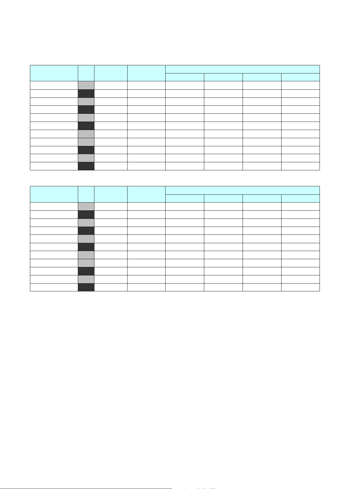
There are some different LCD panels are used in the model SDM-S73/S93.
Therefore the repair parts are also different.
Please confirm the serial number before repairing.
Model name Color
SDM-S73 (Korea) GRAY U/C SDM-S73/HK UC7 9,000,001-9,120,000 9,120,001- 9,200,000
SDM-S73 (Korea) BLACK U/C SDM-S73/BK UC7 9,200,001-9,260,000 9,260,001-9,300,000
SDM-S73(China) GRAY U/C SDM-S73/HC UC7 3,200,001~3,254,000 - 3,254,001~3,292,400 3,292,401~3,350,000
SDM-S73(China) BLACK U/C SDM-S73/BC UC7 3,500,001~3,572,000 - 3,572,001~3,623,200 3,623,201~3,700,000
SDM-S73 (Korea) GRAY AEP SDM-S73/HK EKZ 9,300,001-9,420,000 9,420,001-9,500,000
SDM-S73 (Korea) BLACK AEP SDM-S73/BK EKZ 9,500,001-9,560,000 9,560,001-9,600,000
SDM-S73(China)(TCO03) GRAY AEP SDM-S73/HC EKZ 3,350,001~3,416,000 - 3,416,001~3,450,600 3,450,601~3,500,000
SDM-S73(China)(TCO99) GRAY AEP SDM-S73/HC9 EKZ 9,923,001~9,928,000 - 9,928,001~9,934,000 9,934,001~9,940,000
SDM-S73(China) BLACK AEP SDM-S73/BC EKZ 3,700,001~3,772,000 - 3,772,001~3,823,200 3,823,201~3,900,000
SDM-S73(China) GRAY CHINA SDM-S73/HC CN6 6,630,001~6,641,000 - 6,641,001~6,649,000 6,649,001~6,660,000
SDM-S73(China) BLACK CHINA SDM-S73/BC CN6 6,850,001~6,857,000 - 6,857,001~6,862,200 6,862,201~6,870,000
Model name Color Main destination Description
SDM-S93 (Korea) GRAY U/C SDM-S93/HK UC7 9,000,001-9,200,000
SDM-S93 (Korea) BLACK U/C SDM-S93/BK UC7 9,200,001-9,300,000
SDM-S93(China) GRAY U/C SDM-S93/HC UC7 3,200,001~3,230,000 3,230,001~3,320,000 - 3,320,000-3,350,000
SDM-S93(China) BLACK U/C SDM-S93/BC UC7 3,500,001~3,540,000 3,540,001~3,670,000 - 3,670,001-3,700,000
SDM-S93 (Korea) GRAY AEP SDM-S93/HK EKZ 9,300,001-9,495,000 9,495,001-9,500,000
SDM-S93 (Korea) BLACK AEP SDM-S93/BK EKZ 9,500,001-9,595,000 9,595,001-9,600,000
SDM-S93(China)(TCO03) GRAY AEP SDM-S93/HC EKZ 3,350,001~3,455,000 - 3,485,001~3,500,000 3,455,001-3,485,000
SDM-S93(China) GRAY AEP SDM-S93/HC9 EKZ 9,931,501~9,940,000 - 9,923,001~9,931,500 1,550,001-1,580,000
SDM-S93(China) BLACK AEP SDM-S93/BC EKZ 3,700,001~3,720,000 - 3,720,001~3,870,000 3,870,001-3,900,000
SDM-S93(China) GRAY CHINA SDM-S93/HC CN6 6,630,001~6,660,000 - - 1,640,001-1,670,000
SDM-S93(China) BLACK CHINA SDM-S93/BC CN6 6,850,001~6,870,000 - - 1,670,001-1,700,000
Main destination Description
LPL CMO:L01 CMO:L05 AUO
FUJITSU LPL CMO AUO
Serial Number
Serial Number
- 2 SDM-S73 / S93 (E)
Page 3

CONTENTS
SPECIFICATIONS ................................................... 3
PRECAUTION ......................................................... 4
TIMING CHART ....................................................... 5
OPERATING INSTRUCTIONS ................................ 6
WIRING DIAGRAM ................................................. 7
SPECIFICATIONS
1. LCD CHARACTERISTICS
Type : TFT Color LCD Module
Size : 17 inch(SDM-S73)
19 inch(SDM-S93)
Pixel Pitch :
0.264 (H) x 0.264 (V)
:
0.294 (H) x 0.294 (V)
Color Depth : 16.2M colors
16.7M colors
Electrical Interface : LVDS
Surface Treatment : Haze 25%, Hard-coating(3H)
Operating Mode : Normally White
Backlight Unit : Top/Bottom edge side 4-CCFL
(Cold Cathode Fluorescent Lamp)
2. OPTICAL CHARACTERISTICS
2-1. Viewing Angle by Contrast Ratio ≥
(SDM-S73)
Left : -60° min., -70°(Typ) Right : +60° min., +70°(Typ)
Top :+45° min., +60°(Typ) Bottom : -45°min., -60°(Typ)
(SDM-S93)
Left : -85° min. Right : +85° min.
Top :+85° min. Bottom : -85°min.
2-2. Luminance : 200(min), 250(Typ) (SDM-S73)
: 240(min), 300(Typ) (SDM-S93)
2-3. Contrast Ratio : 300(min), 400(Typ) (SDM-S73)
: 400(min), 700(Typ) (SDM-S93)
3. SIGNAL (Refer to the Timing Chart)
3-1. Sync Signal
• Type : Separate Sync,
SOG (Sync On Green)
Composite Sync
3-2. Video Input Signal
1) Type : R, G, B Analog
2) Voltage Level : 0~0.71 V
a) Color 0, 0 : 0 Vp-p
b) Color 7, 0 : 0.467 Vp-p
c) Color 15, 0 : 0.714 Vp-p
:
:
:
3) Input Impedance : 75
3-3. Operating Frequency
Horizontal : 28 ~ 80kHz
Vertical : 48 ~ 75Hz
(SDM-S73)
(SDM-S93)
(SDM-S73)
(SDM-S93)
10
10
BLOCK DIAGRAM ....................................................9
ADJUSTMENT ...................................................... 11
EXPLODED VIEW.................................................. 12
EXPLODED VIEW PARTS LIST
............................ 13
TIONS
5. POWER SUPPLY
5-1. Power
5-2. Power Consumption
POWER ON (NORMAL)
POWER ON (NORMAL)
DPMS OFF
POWER S/W OFF
AC POWER S/W OFF
6. ENVIRONMENT
6-1. Operating Temperature: 5°C~35°C (41°F~95°F)
6-2. Relative Humidity : 10%~80%
6-3. MTBF : 50,000 Hours(Min)
7. DIMENSIONS (with TILT/SWIVEL)
(SDM-S73)
Width : 367 mm (14.45'')
Depth : 215 mm (8.46'')
Height : 410 mm (16.14'')
(SDM-S93)
Width : 412 mm (16.22'')
Depth : 234 mm (9.21'')
Height : 445 mm (17.52'')
8. WEIGHT (with TILT/SWIVEL)
(SDM-S73)
Net. Weight : 5.7kg (12.57 lbs)
Gross Weight : 8.3kg (18.30 lbs)
(SDM-S93)
Net. Weight : 7.1kg (16.65 lbs)
Gross Weight : 9.4 kg (20.73 lbs)
: AC 100~240V, 50/60Hz , 1.0A
H/V SYNC
MODE
MODE
H/V SYNC
ON/ON
ON/ON
OFF/OFF
VIDEO
ACTIVE
ACTIVE
OFF
-
-
-
-
-
-
-
-
POWER CONSUMPTION
POWER CONSUMPTION
less than 50 W (SDM-S93)
less than 45 W (SDM-S73)
less than 1W
less than 1W
(Non-condensing)
LED COLOR
LED COLORVIDEO
GREEN
GREEN
AMBER
RED
OFF
.
Max. Resolution
4
Analog : 1280 x 1024 / 75Hz
– 3 –
SDM-S73/S93 (E)
Page 4
WARNING FOR THE SAFETY-RELATED COMPONENT.
• There are some special components used in LCD
monitor that are important for safety.
These parts are
marked on the schematic diagram and the
replacement parts list.
It is essential that these critical
parts should be replaced with the manufacturer’s
specified parts to prevent electric shock, fire or other
hazard.
• Do not modify original design without obtaining written
permission from manufacturer or you will void the
original parts and labor guarantee.
TAKE CARE DURING HANDLING THE LCD MODULE
WITH BACKLIGHT UNIT.
• Must mount the module using mounting holes arranged
in four corners.
• Do not press on the panel, edge of the frame strongly
or electric shock as this will result in damage to the
screen.
• Do not scratch or press on the panel with any sharp
objects, such as pencil or pen as this may result in
damage to the panel.
• Protect the module from the ESD as it may damage the
electronic circuit (C-MOS).
• Make certain that treatment person’s body are
grounded through wrist band.
• Do not leave the module in high temperature and in
areas of high humidity for a long time.
• The module not be exposed to the direct sunlight.
•Avoid contact with water as it may a short circuit within
the module.
• If the surface of panel become dirty, please wipe it off
with a softmaterial. (Cleaning with a dirty or rough cloth
may damage the panel.)
WARNING
BE CAREFUL ELECTRIC SHOCK !
• If you want to replace with the new backlight (CCFL) or
inverter circuit, must disconnect the AC adapter
because high voltage appears at inverter circuit about
650Vrms.
• Handle with care wires or connectors of the inverter
circuit. If the wires are pressed cause short and may
burn or take fire.
PRECAUTION
CAUTION
Please use only a plastic screwdriver to protect yourself
from shock hazard during service operation.
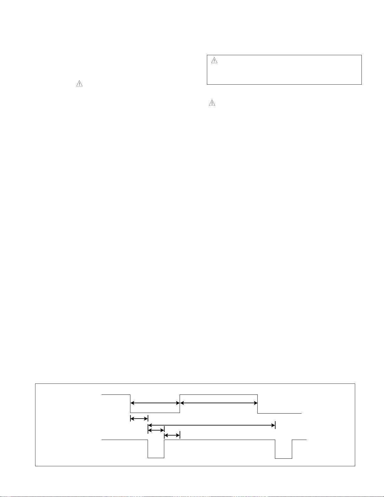
TIMING CHART
VIDEO
C
SYNC
B
A
E
F
D
– 4 –
SDM-S73/S93 (E)
Page 5

Mode
H/V
Sort
1
2
3
4
5
6
7
8
9
10
11
12
13
14
15
16
17
18
19
20
21
22
720x400
70Hz
H– 35.00 864 640 64 64 96 224
V– 66.667Hz 525 480 3 3 39 45
640x480
60Hz
H– 37.50 840 640 16 64 120 200
V– 75.0Hz 500 480 1 3 16 20
640x480
65Hz
H– 31.500 900 720 18 108 54 180
V+ 70.156Hz 449 400 12 3 34 49
640x480
75Hz
H– 35.162 896 720 34 40 102 176
V– 59.901Hz 587 480 12 2 93 107
720x480
60Hz
H+- 35.156 1024 800 24 72 128 224
V+ 56.250Hz 625 600 1 2 22 25
800x600
56Hz
H+ 37.879 1056 800 40 128 88 256
V+ 60.317Hz 628 600 1 4 23 28
800x600
60Hz
H+ 48.077 1040 800 56 120 64 240
V+ 72.188Hz 666 600 37 6 23 66
800x600
72Hz
H+ 46.875 1056 800 16 80 160 256
V+ 75.0Hz 625 600 1 3 21 25
800x600
75Hz
H– 49.727 1152 832 32 64 224 320
V– 74.553Hz 667 624 3 3 37 43
832x624
(MAC16”)
75Hz
H– 48.363 1344 1024 24 136 160 320
V– 60.004Hz 806 768 3 6 29 38
1024x768
60Hz
H– 56.476 1328 1024 24 136 144 304
V– 70.069Hz 806 768 3 6 29 38
1024x768
70Hz
H+ 60.023 1312 1024 16 96 176 288
V+ 75.029Hz 800 768 1 3 28 32
1024x768
75Hz
H– 60.241 1328 1024 32 96 176 304
V– 74.927Hz 804 768 3 3 30 36
1024x768
(MAC19)
75Hz
H+ 67.500 1600 1152 64 128 256 448
V+ 75.000Hz 900 864 1 3 32 36
1152x864
75Hz
H– 68.681 1456 1152 32 128 144 304
V– 75.062Hz 915 870 3 3 39 45
1152x870
(MAC21)
75Hz
H– 61.795 1504 1152 30 128 194 352
V– 65.950Hz 937 900 2 4 31 37
1152x900
66Hz
H– 71.732 1472 1152 16 96 208 320
V– 76.068Hz 943 900 2 8 33 43
1152x900
75Hz
H+ 31.216 1480 1170 37 129 144 310
V+ 50.026Hz 624 584 3 3 34 40
1170x584
50Hz
H+ 60.000 1800 1280 96 112 312 520
V+ 60.000Hz 1000 960 1 3 36 40
1280x960
60Hz
H+ 63.981 1688 1280 48 112 248 408
V+ 60.020Hz 1066 1024 1 3 38 42
1280x1024
60Hz
H+ 79.976 1688 1280 16 144 248 408
V+ 75.025Hz 1066 1024 1 3 38 42
1280x1024
75Hz
Sync
Polarity
Frequency
Dot
Clock
Back Porch
(F)
Blanking time
(B)
Resolution
28.350
25.175
30.240
31.500
31.505
36.000
40.000
50.000
49.500
57.285
65.000
75.000
78.750
80.000
108.000
100.000
92.940
105.590
46.200
108.000
108.000
135.000
<< Dot Clock (MHz), Horizontal Frequency (kHz), Vertical Frequency (Hz), Horizontal etc... (µs), Vertical etc... (ms) >>
H– 31.469 800 640 16 96 48 160
V– 59.940Hz 525 480 10 2 33 45
Sync Duration
(D)
Front Porch
(C)
Video Active Time
(A)
Total Period
(E)
– 5 –
SDM-S73/S93 (E)
Page 6

REAR VIEW(SDM-S73) REARVIEW(SDM-S93)
OPERATING INSTRUCTIONS
HD15(RGB) input
connector
AC IN connector
AC IN
connector
Main Power Switch
HD15(RGB) input
connector
Main Power Switch
MENU
OK
ECO
1
3
4
2
5
1. (Power) switch and (power) indicator
This switch turns the monitor on when the power
indicator lights up in red. To turn the monitor off, press
this switch again.
If the power indicator does not light up, press the MAIN
POWER switch.
2. MENU Button
This button turns the menu screen on and off.
3. Buttons
These buttons are used to select the menu items and
make adjustments.
4. OK Button
This button actives tge selected menu item and
adjustments made using the buttons(
3
).
5. ECO Button
This button is used to reduce the power consumption.
Front Control Panel
– 6 –
SDM-S73/S93 (E)
Page 7

WIRING DIAGRAM (SDM-S73)
Connector Ass'y P/N:
1-900-275-71
CN001
CN003
J702
J705
J706
AC Switch with
Connector P/N:
1-786-624-11
– 7 –
SDM-S73/S93 (E)
Page 8

WIRING DIAGRAM (SDM-S93)
Connector Ass'y P/N:
1-900-275-71
J705
J706
J702
AC Switch with
Connector P/N:
1-786-624-11
– 8 –
SDM-S73/S93 (E)
Page 9

– 9 –
EEPROMx2
Analog(R/G/B)
D-Subx2
(EDID)
3.3V
LIPS
2.5V
ADC
MST9111A
Scaling
OSD
Pre-Amp PLL
Regulator
LVDS
Tx
3.3V
LVDS
EEPROM
24C16
(System)
MTV412PLCC
3.3V
Panel
Vcc
BLOCK DIAGRAM
KEY
SDM-S73/S93 (E)
Filter
+
Inverter
Output
(4Lamp)
LAMP Connector
5V
12V
5V
Regulator
2.5V
Page 10

LIPS Board Block Diagram
EMI
COMPONENTS
LINE
100 ~ 240V
INPUT RECTIFIER
AND FILTER
ENERGY
TRANSFER
OUTPUT RECTIFIER
AND FILTER
12V
5V
GND
SIGNAL
COLLECTI
ON
PHOTO-
COUPLER
ISOLATION
PWM
CONTROL
CIRCUIT
HVDC
100KHz
PRIMARY SECONDARY
50 ~ 60Hz
– 10 –
SDM-S73/S93 (E)
Page 11

ADJUSTMENT
1. Procedures of how to go to service mode.
1) Enter the service mode of this unit by turning on
the power while pressing and holding the “r” key
simultaneously.
2) Press “MENU” key——MAINTAIN.
3) Press “OK” key to enter the service menu.
4) Select the desired function.
5) Press the “MENU” key to exit OSD.
6) Turn off the power and then turn on it again. The
monitor then enters the normal mode.
To enter the service again, repeat the procedure
described above.
Note
W/B readjustment is required after the panel, board
and microcomputer are replaced. However, be sure to
perform aging for more than 30 minutes for RGB reset
before W/B adjustment.
2. Setup
1) Prepare timing and pattern data for a signal
generator according to the Sony timing
specifications.
2) Connect a monitor video cable to the signal
generator.
3) Put Color Analyzer(ex. CA-110) 50cm away from
the monitor, specify it vertically in the center of
the display, and adjust the focus to the optimum
level using an eyepiece.
4) Put the monitor and Color Analyzer(ex. CA-110)
in a light-shielded room.
5) Set up [SERVICE MODE] of the monitor.
3. Operation
Data is manually set to improve the productivity. The
brightness, contrast, and backlight are set to 50, 70
and 100 respectively. After that, the default data of
the color temperature to be adjusted is set.
4. Warm up time
Warm up for 30 minutes before performing any
adjustment.
5. Adjustment for White Balance
a. Display SMPTE at SXGA/60Hz(Input level
0.73V).
b. Set up [SERVICE MODE].
c. Click “INITIAL EEPROM” and again setup Service
Mode.
d. Click “WHITE BALANCE” and then select “AUTO”.
6. 9300K color adjustment
a. Select “9300K” in “COLOR TEMP” and enter.
b. Use a 35%(89Gray) IRE white video field in the
primary mode.
c. Adjust “SUB CONTRAST “ to secure the color
temperature.
d. Press “MENU” key to exit adjust mode.
7. 6500K color adjustment
a. Select “6500K” in “COLOR TEMP” and enter.
b. Repeat the adjustment procedure as steps b to d
at 9300K.
– 11 –
SDM-S73/S93 (E)
Page 12

1
5
2
3
6
8
11
9
4
14
10
6
2
(SDM-S73)
(SDM-S73)
(SDM-S93)
(SDM
-S93)
7
8
EXPLODED VIEW
– 12 –
SDM-S73/S93 (E)
Page 13

SDM-S73 EXPLODED VIEW PARTS LIST
S
A
A
(
(
(
(
(
A
Ref. No.
ONY Part No.SONY name LG PART NO.
X40420601 BEZEL ASSY (Gray), S73 3091TKL077B
1
X40420631 BEZEL ASSY (Black), S73 3091TKL077A
180543711 LCD PANEL (LPL), S73 6304FLP082A
180543721 LCD PANEL (LPL)TCO'03, S73 6304FLP106A
2
180560011 LCD PANEL (CMO)(L01), S73 6304FCI003A
180560021 LCD PANEL (CMO)(L05), S73 6304FCI003A
180527711 LCD PANEL (AUO), S73 6304FAU009A
409737501 CABINET (Gray), S73 3809TKL056B
3
409737511 CABINET (Black), S73 3809TKL056A
X40420621 STAND ASSY (Gray), S73 3043TKK131B
4
X40420651 STAND ASSY (Black), S73 3043TKK131A
5 A1410269A H MOUNT 6871TST418A
409656901 COVER PIECE POWER SWITCH (Gray) 3550TKK344D
6
409656911 COVER PIECE POWER SWITCH (Black) 3550TKK344C
7 178662411 AC SWITCH with connector 6631T25005H
A1410270A G MOUNT (for LPL), S73 6871TPT243C
8
1415754
TBD
TBD
G MOUNT (for CMO-L01), S73 6871TPT243D
G MOUNT
G MOUNT
for CMO-L05), S73 6871TPT243F
for AU), S73 6871TPT241N
A1410268A A MOUNT (for LPL), S73 3313TL7021B
9
TBD A MOUNT (for LPL)(for TCO03), S73 3313TL7021Q
TBD A MOUNT (for CMO), S73 3313TL7021T
TBD A MOUNT (for AUO), S73 3313TL7021Y
10 190027571 CONNECTOR ASSY 6631T11016W
11
12
409739601 REAR COVER (Gray), S73 3550TKK388B
409739611 REAR COVER (Black), S73 3550TKK388A
409739901 ARM COVER (REAR) (Gray), S73 3550TKK391B
409739911 ARM COVER (REAR) (Black), S73 3550TKK391A
409738601 CABLE HOLDER 4930TKK059B
CCESSORIES & PACKING MATERIALS
182711811 POWER-SUPPLY CORD SET (U/C) 6410TUW004A
13
182712011 POWER-SUPPLY CORD SET (AEP) 6410TEW006A
182712211 POWER-SUPPLY CORD SET (CH) 6410TCW004A
14 182775711 D-SUB CABLE 6850TD9004G
15 410235604 CD-ROM 3170TZ1253B
409626521 QUICK SETUP GUIDE (U/C, CH), Korea 3828TUO207F
16
409626511 QUICK SETUP GUIDE (AEP), Korea 3828TUO207G
409626551 QUICK SETUP GUIDE
409626541 QUICK SETUP GUIDE
U/C, CH), China
AEP), China
3828TUO206K
3828TUO206J
17 409440101 PROTECTION BAG 3880TKZ009E
18 409740801 CUSHION, S73 3911TKK613E
19
409703801
410176401 INDIVIDUAL CARTON (Gray), China, S73
410132401 INDIVIDUAL CARTON (Gray), PC Recycle, Korea, S73
410176501 INDIVIDUAL CARTON (Gray), PC Recycle, China, S73
409703901 INDIVIDUAL CARTON (Black), Korea, S73
410176601 INDIVIDUAL CARTON (Black), China, S73
410132501 INDIVIDUAL CARTON (Black), PC Recycle, Korea, S73
410176701 INDIVIDUAL CARTON (Black), PC Recycle, China S73
INDIVIDUAL CARTON
Gray), Korea, S73
3890TSE450A
3890TSE541A
3890TSE450B
3890TSE541B
- 13 SDM-S73 / S93 (E)
Page 14

SDM-S93 EXPLODED VIEW PARTS LIST
A
(
(
(
(
(
(
A
Ref. No.
SONY Part No.SONY name LG PART NO.
X40420711 BEZEL ASSY (Gray), S93 3091TKL078B
1
X40420741 BEZEL ASSY (Black), S93 3091TKL078A
180534711 LCD PANEL (Fujitsu)TCO'03, S93 6304FFT002A
180534721 LCD PANEL (Fujitsu), S93 6304FFT002B
2
180560511 LCD PANEL (CMO), S93 6304FCI008A
1-805-655-11
1-805-644-11
409745101 CABINET (Gray), S93 3809TKL057B
3
409745111 CABINET (Black), S93 3809TKL057A
X40420731 STAND ASSY (Gray), S93 3043TKK131D
4
X40420761 STAND ASSY (Black), S93 3043TKK131C
LCD PANEL (LPL), S93 6304FLP075A
LCD PANEL (AUO), S93 6304FAU013A
5 A1410269A H MOUNT 6871TST418A
409656901 COVER PIECE POWER SWITCH (Gray) 3550TKK344D
6
409656911 COVER PIECE POWER SWITCH (Black) 3550TKK344C
7 178662411 AC SWITCH with connector 6631T25005H
A1410273A G MOUNT (for Fujitsu), S93 6871TPT249A
8
1415755A
TBD
TBD
G MOUNT
G MOUNT
G MOUNT
for CMO), S93 6871TPT249B
for LPL), S93 6871TPT249C
for AU), S93 6871TPT249H
9 A1410271A A MOUNT (for Fujitsu), S93 3313TL9007B
TBD A MOUNT (for CMO), S93 3313TL9008D
TBD A MOUNT (for LPL), S93 3313TL9007R
TBD A MOUNT (for AUO), S93 3313TL9007U
10 190027571 CONNECTOR ASSY 6631T11016W
TBD CONNECTOR ASSY (for AU) 6631T11016M
11
12
409745201 REAR COVER (Gray), S93 3550TKK392B
409745211 REAR COVER (Black), S93 3550TKK392A
409745401 ARM COVER (REAR) (Gray), S93 3550TKK407B
409745411 ARM COVER (REAR) (Black), S93 3550TKK407A
409738601 CABLE HOLDER 4930TKK059B
CCESSORIES & PACKING MATERIALS
182711811 POWER-SUPPLY CORD SET (U/C) 6410TUW004A
13
182712011 POWER-SUPPLY CORD SET (AEP) 6410TEW006A
182712211 POWER-SUPPLY CORD SET (CH) 6410TCW004A
14 182775711 D-SUB CABLE 6850TD9004G
15 410235604 CD-ROM 3170TZ1253B
409626521 QUICK SETUP GUIDE (U/C, CH), Korea 3828TUO207F
16
409626511 QUICK SETUP GUIDE (AEP), Korea 3828TUO207G
409626551 QUICK SETUP GUIDE
409626541 QUICK SETUP GUIDE
U/C, CH), China
AEP), China
3828TUO206K
3828TUO206J
17 409440101 PROTECTION BAG 3880TKZ009E
409746201 CUSHION, S93 3911TKK613F
409704001
INDIVIDUAL CARTON
410176901 INDIVIDUAL CARTON (Gray), China, S93
Gray), Korea, S93
3890TSE451A
410132601 INDIVIDUAL CARTON (Gray), PC Recycle, Korea, S93 3890TSE542A
409704101 INDIVIDUAL CARTON (Black), Korea, S93
410177201 INDIVIDUAL CARTON (Black), China, S93
3890TSE451B
410177001 INDIVIDUAL CARTON (Black), PC Recycle, Korea, S93 3890TSE542B
- 14 SDM-S73 / S93 (E)
Page 15

English
c
2004BR02-1
Made in Japan
9-878-219-01 Sony EMCS Corporation ©2004.3
Ichinomiya Te
SDM-S73/S93(E)
 Loading...