

Page 1

2-580-335-01(1)
TFT LCD Color
Computer Display
SDM-S204E
© 2004 Sony Corporation
Page 2
Owner’s Record
The model and serial numbers are located at the rear of the unit.
Record these numbers in the spaces provided below. Refer to them
whenever you call upon your dealer regarding this product.
Model No.
Serial No.
WARNING
To prevent fire or shock hazard, do not expos e the
unit to rain or moisture.
Dangerously high voltages are present inside the
unit. Do not open the cabinet. Refer servicing to
qualified personnel only.
FCC Notice
This equipment has been tested and found to comply with the limits
for a Class B digital device, pursuant to Part 15 of the FCC Rules.
These limits are designed to provide reasonable protection against
harmful interference in a residential installation. This equipment
generates, uses, and can radiate radio frequency energy and, if not
installed and used in accordance with the instructions, may cause
harmful interference to radio communications. However, there is no
guarantee that interference will not occur in a particular installation.
If this equipment does cause harmful interference to radio or
television reception, which can be determined by turning the
equipment off and on, the user is encouraged to try to correct the
interference by one or more of the following measures:
– Reorient or relocate the receiving antenna.
– Increase the separation between the equipment and receiver.
– Connect the equipment into an outlet on a circuit different from
that to which the receiver is connected.
– Consult the dea ler or an ex perienced r adio/TV te chnician f or help.
You are cautioned that any changes or modifications not expressly
approved in this manual could void your authority to operate this
equipment.
IMPORTANTE
Para prevenir cualquier mal funcionamiento y evitar daños, por
favor, lea detalladamente este manual de instrucciones antes
de conectar y operar este equipo.
NOTICE
This notice is applicable for USA/Canada only.
If shipped to USA/Canada, install only a UL LISTED/CSA
LABELLED power supply cord meeting the following
specifications:
SPECIFICATIONS
Plug Type Nema-Plug 5-15p
Cord Type SVT or SJT, minimum 3 × 18 AWG
Length Maximum 15 feet
Rating Minimum 7 A, 125 V
NOTICE
Cette notice s’applique aux Etats-Unis et au Canada
uniquement.
Si cet appareil est exporté aux Etats-Unis ou au Canada, utiliser
le cordon d’alimentation portant la mention UL LISTED/CSA
LABELLED et remplissant les conditions suivantes:
SPECIFICATIONS
Type de fiche Fiche Nema 5-15 broches
Cordon Type SVT ou SJT, minimum 3 × 18 AWG
Longueur Maximum 15 pieds
Tension Minimum 7 A, 125 V
ENERGY STAR Partner, Sony
As an
Corporation has determined that this
product meets the
guidelines for energy efficiency.
This monitor complies with the
TCO’03 guidelines.
ENERGY STAR
If you have any questions about this product, you may call;
Sony Customer Information Services Center
1-800-222-7669 or http://www.sony.com/
Declaration of Conformity
Trade Name: SONY
Model: SDM-S204E
Responsible Party: Sony Electronics Inc.
Address: 16450 W. Bernardo Dr,
Telephone Number: 8 58-942-2230
This device complies with part 15 of the FCC rules. Operation is
subject to the following two conditions: (1) This device may not
cause harmful interference, and (2) this device must accept any
interference received, including interference that may cause
undesired operation.
BZ
03
San Diego, CA 92127 U.S.A.
(for the gray model)
This monitor complies with the
TCO’99 guidelines.
(for the black model)
2
Page 3

Table of Contents
Precautions . . . . . . . . . . . . . . . . . . . . . . . . . . . . . . . . . . . . . . . . . . . 4
Identifying parts and controls . . . . . . . . . . . . . . . . . . . . . . . . . . . . . . 5
Setup . . . . . . . . . . . . . . . . . . . . . . . . . . . . . . . . . . . . . . . . .6
Setup 1: Connect the video signal cables . . . . . . . . . . . . . . . . . . . . 6
Setup 2: Connect the power cord . . . . . . . . . . . . . . . . . . . . . . . . . . 7
Setup 3: Bundle the cords and cables . . . . . . . . . . . . . . . . . . . . . . 8
Setup 4: Turn on the monitor and computer . . . . . . . . . . . . . . . . . . 8
Setup 5: Adjust the height and tilt . . . . . . . . . . . . . . . . . . . . . . . . . . 9
Selecting the input signal (INPUT button) . . . . . . . . . . . . . . . . . . . 10
Customizing Your Monitor . . . . . . . . . . . . . . . . . . . . . . .11
Navigating the menu . . . . . . . . . . . . . . . . . . . . . . . . . . . . . . . . . . . 11
PICTURE ADJUST menu . . . . . . . . . . . . . . . . . . . . . . . . . . . 12
SCREEN menu (analog RGB signal only) . . . . . . . . . . . . . . . 13
COLOR menu . . . . . . . . . . . . . . . . . . . . . . . . . . . . . . . . . . . . 14
GAMMA menu . . . . . . . . . . . . . . . . . . . . . . . . . . . . . . . . . . . . 15
ZOOM menu . . . . . . . . . . . . . . . . . . . . . . . . . . . . . . . . . . . . . 15
MENU POSITION menu . . . . . . . . . . . . . . . . . . . . . . . . . . . . 15
INPUT SENSING ON/OFF menu . . . . . . . . . . . . . . . . . . . . . 15
LANGUAGE menu . . . . . . . . . . . . . . . . . . . . . . . . . . . . . . . . . 16
0 RESET menu . . . . . . . . . . . . . . . . . . . . . . . . . . . . . . . . . . . . . 16
MENU LOCK menu . . . . . . . . . . . . . . . . . . . . . . . . . . . . . . . . 16
GB
• Macintosh is a trad emark licensed to
Apple Computer, Inc., registered in the
U.S.A. and other countries.
• Windows
Microsoft Corporation in the Uni te d
States and other countries.
• IBM PC/AT and VGA are registered
trademarks of IBM Corporation of the
U.S.A.
• VESA and DDC
Video Electronics Stan da rds
Association.
ENERGY STAR is a U.S. registered
•
mark.
• Adobe and Acrobat are trademarks of
Adobe Systems Incorporated.
• All other product names ment i one d
herein may be the trademarks or
registered trad emarks of their r espective
companies.
•Furthermore, “” and “” are not
mentioned in each case in this manu al .
is registered trademark of
are trademarks of the
Technical Features . . . . . . . . . . . . . . . . . . . . . . . . . . . . .17
Power saving function . . . . . . . . . . . . . . . . . . . . . . . . . . . . . . . . . . 17
Reducing the power consumption (ECO mode) . . . . . . . . . . . . . . 17
Automatic picture quality adjustment function
(analog RGB signal only) . . . . . . . . . . . . . . . . . . . . . . . . . . . . . . . . 18
Troubleshooting . . . . . . . . . . . . . . . . . . . . . . . . . . . . . . .19
On-screen messages . . . . . . . . . . . . . . . . . . . . . . . . . . . . . . . . . . . 19
Trouble symptoms and remedies . . . . . . . . . . . . . . . . . . . . . . . . . 20
Specifications . . . . . . . . . . . . . . . . . . . . . . . . . . . . . . . . .22
TCO’99 Eco-document (for the black model) . . . . . . . . . . . . . . . . . .i
TCO’03 Eco-document (for the gray model) . . . . . . . . . . . . . . . . . . ii
http://www.sony.net/
3
Page 4

Precautions
Warning on power connections
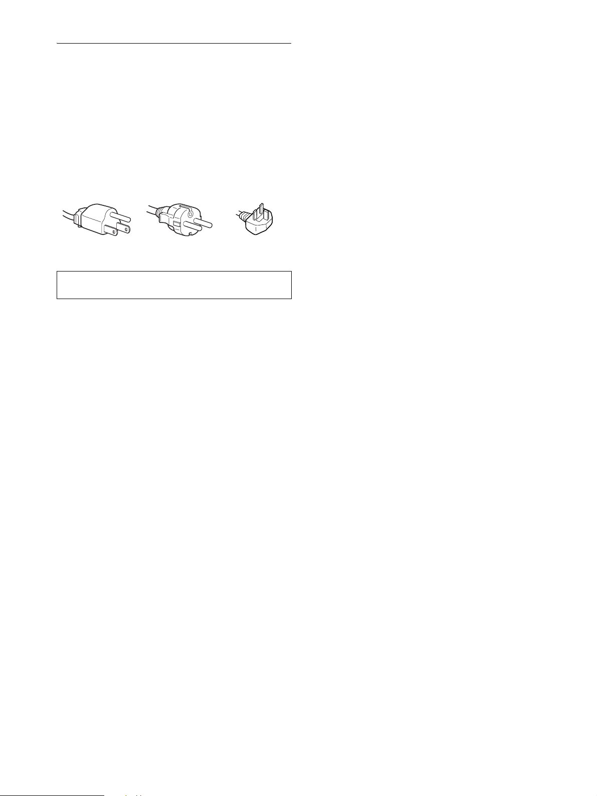
• Use the supplied power cord. If you use a different power cord,
be sure that it is compatible with your local power supply.
For the customers in the U.S.A.
If you do not use the appropriate cord, this monitor will not
conform to mandatory FCC standards.
For the customers in the UK
If you use the monitor in the UK, be sure to use the appropriate
UK power cord.
Example of plug types
for 100 to 120 V AC for 200 to 240 V AC for 240 V AC only
The equipment should be installed near an easily accessible outlet.
Installation
Do not install or leave the monitor:
• In places subject to extreme temperatures, for example near a
radiator, heating ve nt, or in direc t su nlight. Subjecting the
monitor to extreme temperatures, such as in an automobile
parked in direct sunlight or near a heatin g vent, could cause
deformations of the casing or malfunctions.
• In places subject to mechanical vibration or shock.
• Near any equipment that generates a strong magneti c fi eld,
such as a TV or various other household appliances.
• In places subject to inordinate amounts of dust, dirt, or sand, for
example near an open window or an outdoor exit. If setting up
temporarily in an outdoor environ me n t, be sur e to take
adequate precautions against airborne dust and dirt. Otherwise
irreparable malfu nctions could occur.
Handling the LCD screen
• Do not leave the LCD screen facing the sun as it can damage
the LCD screen. Take care when you place the monitor by a
window.
• Do not push on or scratch the LCD screen. Do not place a heavy
object on the LCD screen. This may cause th e screen to lose
uniformity or cause LCD panel malfunctions.
• If the monitor is used in a cold place, a residual image may
appear on the screen. This is not a malfunction. The screen
returns to normal as the temperature rises to a normal operating
level.
• If a still picture is displayed for a long time, a residual image
may appear for a while. The residual image will eventually
disappear.
• The LCD panel becomes warm during operation. This is no t a
malfunction.
Note on the LCD (Liquid Crystal Display)
Please note that the LCD screen is made with high-precision
technology. However, black points or bright points of light (red,
blue, or green) may appear constantly on the LCD screen, and
irregular color ed stripes or brightness may appear on the LCD
screen. This is not malfunction.
(Effective dots: more than 99.99%)
Maintenance
• Be sure to unplug the power cord from the power outlet before
cleaning your mon itor.
• Clean the LCD screen with a soft cloth. If you use a glass
cleaning liquid, do not use any type of cleaner containing an
anti-static solution or similar additive as this may scratch the
LCD screen’s coating.
• Clean the cabinet, panel, and controls with a so ft cloth lightly
moistened with a mil d detergent solution. Do not use any type
of abrasive pad, scouring powder, or solvent, such as alcohol or
benzine.
• Do not rub, touch, or tap the surface of the screen with sharp or
abrasive items such as a ballpoint pen or screwdriver. This type
of contact may result in a scratched picture tube.
• Note that material deterioration or LCD screen coating
degradation may occur if the monitor is exposed to volatile
solvents such as insecticide, or if prolonged co ntact is
maintained with rubber or vinyl materials.
Transportation
• Disconnect all cables from the monitor, and after fixing the
LCD display at its highest point, grasp both side of the LCD
display firmly taking care not to scratch the screen when
transporting. If yo u drop the monitor , you may be injured or the
monitor may be damaged.
• When you transport this monitor for repair or shipment, use the
original carton and packing materials.
Disposal of the monitor
• Do not dispose of this monitor with general
household waste.
• The fluorescent tube used in this monitor contains
mercury. Disposal of this mon itor must be carried out
in accordance to the regulations of your local
sanitation authority.
4
Page 5
Identifying parts and controls
See the pages in parentheses for further details.
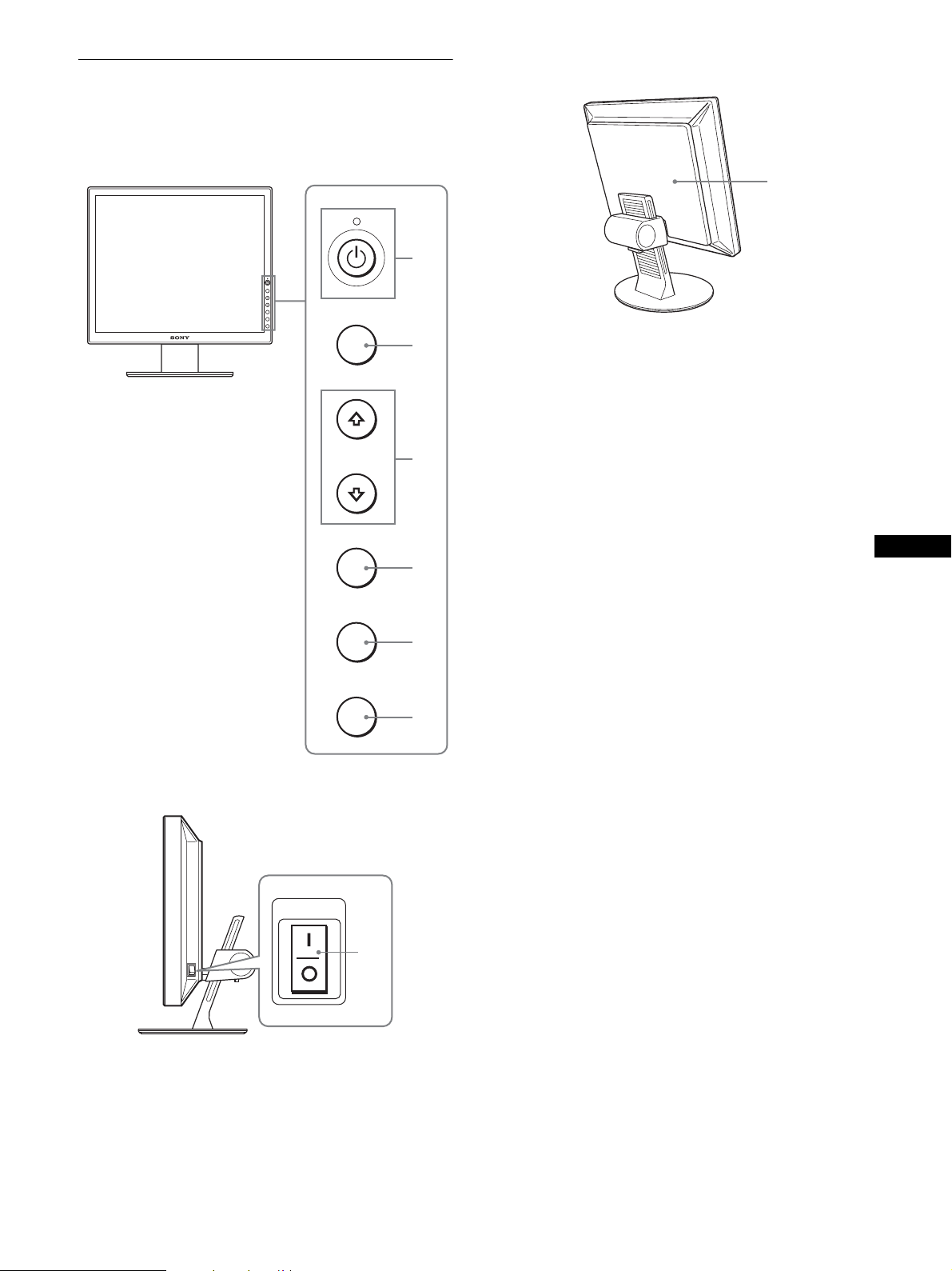
Front of the LCD display
MENU
OK
INPUT
ECO
MENU
1
2
3
Rear of the display stand
8
A 1 (Power) switch and 1 (power) indicator
(pages 8, 17)
This switch turns the monitor on when the 1 (power)
indicator lights up in red. To turn the monitor off, press this
switch again.
If the 1 (power) indicator does not li ght up , press the MAIN
POWER switch (7).
B MENU button (page 11)
This button turns the menu screen on and off.
Side view of the LCD display
MAIN POWER
OK
INPUT
ECO
7
4
5
6
C m/M buttons (page 11)
These buttons are used to se lect the menu items and make
adjustments.
D OK button (page 11)
This button activates the selected menu item and adjustments
made using the m/M buttons (3).
E INPUT button (page 10)
This button switches the video input signal between INPUT1,
INPUT2 and INPUT3 when two computers are connected to
the monitor.
F ECO button (page 17)
This button is used to reduce the power consumption.
G MAIN POWER switch (page 8)
This switch turns the monitor’s main power on and off.
H Back cover (page 6)
Remove this cover when you connect cables or cords.
GB
5
Page 6

Rear of the LCD display
Setup
q;
9
qa
qs
qd
I AC IN connector (page 7)
This connector connects the power cord (supplied).
J HD15 input connector (analog RGB) (page 7)
This connect or inputs an alog RGB v ideo signa ls (0.700 Vp -p,
positive) and sync signals.
K DVI-D input connector (digital RGB) (page 7)
This connector in pu ts d igital RGB video sig na ls th at comply
with DVI Rev.1.0.
L Cable holder (page 8)
This part secures cables and cords to the monitor.
Before using your monitor, check that the following items are
included in your carton:
•LCD display
• Power cord
• HD15-HD15 video signal cable (analog RGB)
• DVI-D video signal cable (digital RGB)
• CD-ROM (utility software for Windows/M acintosh, Operating
Instructi o ns , etc.)
• Warranty card
• Quick Setup Guide
Setup 1:Conn ect the video signal
cables
• Turn off the monitor and computer before connecting
them.
• When connecting the computer to the monitor’s HD15
input connector (analog RGB), refer to “Connect a
computer equipped with an HD15 output co nn ector
(analog RGB).”
Notes
• Do not touch the pins of th e vi deo signal cable connector a s thi s
might bend the pins.
• Check the alignment of the HD15 connector to prevent bending the
pins of the video signal cable c onnector.
M Security lock hole
The security lock hole should be used with the Kensington
Micro Saver Security System.
Micro Saver Security System is a trademark of Kensigton.
1 Slide up the back cover.
2 Tilt the display forward.
6
Page 7

Connect a computer equipped with a DVI output
connector (digital RGB)
Using the supplied DVI-D video signal cable (digital RG B), connect the
computer to the monitor’s DVI-D in put connector (digital RGB) .
to the DVI-D input
connector
(digital RGB)
to the computer’s DVI output
connector (digital RGB)
x Connecting to a Macintosh
to the HD 15 input
connector
(analog RGB)
to the computer’s
output connector
HD15-HD15 video signal
cable (analog RGB)
(supplied)
DVI-D video signal
cable (digital RGB)
(supplied)
Connect a computer equipped with an HD15
output connector (analog RGB)
Using the supplied HD15-HD15 video signal cable (analog RGB),
connect the computer to the monitor’s HD 15 input connector (analog
RGB).
Connect the computer according to the following illustrations.
x Connecting to an IBM PC/AT or
compatible computer
to the HD 15 input
connector
(analog RGB)
Macintosh
When connecti ng a Macin tosh c omputer, use an ad apter ( not su pplied) ,
if necessary. C onnect the a dapter to t he computer be fore conn ecting the
video signal cable.
Setup 2:Connect the power cord
1 Connect the supplied power cord securely to the
monitor’s AC IN connector.
2 Connect the other end securely to a power outlet.
1
to AC IN
GB
to the computer’s HD15 output
connector (analog RGB)
IBM PC/AT or compatible
computer
HD15-HD15 video signal
cable (analog RGB)
(supplied)
to power outlet
2
power cord (supplied)
7
Page 8

Setup 3:Bund le the cords and
Setup 4:Turn on the monitor and
cables
1 Slide up the back cover.
2 Secure the video signal cables using the cable
holder on the cabinet.
3 Slide down the back cover.
4 Bundle all the cords and cables through the cable
holder of the stand.
13
back cover
2
computer
1 Press the MAIN POWER switch located on the right
side of the monitor in the direction of the [ (on), if it
is not already pressed. Make sure the 1 (power)
indicator is lit in red.
Note
The monitor is factory shipped with the MAIN POWER switch set to [
(on).
lights in r e d
MAIN POWER
2 Press the 1 (power) switc h on the front rig ht o f the
monitor.
The 1 (power) indicator lights up in green.
4
Note
If you cannot bundle all the cords and cables through the cabl e holder of
the stand, leave them hanging down.
lights in green
3 Turn on the computer.
4 Press the INPUT button to select the desired input
signal.
The selected input’s picture appears on the screen.
For more information, see “Selecting the input signal (INPUT
button)” on page 10.
INPUT
The installation of your monitor is complete. If necessary, use the
monitor’s controls to adjust the picture (page 11).
8
Page 9
If no picture appears on your screen
• Check that the power cord and the video signal cable are
properly co nnected.
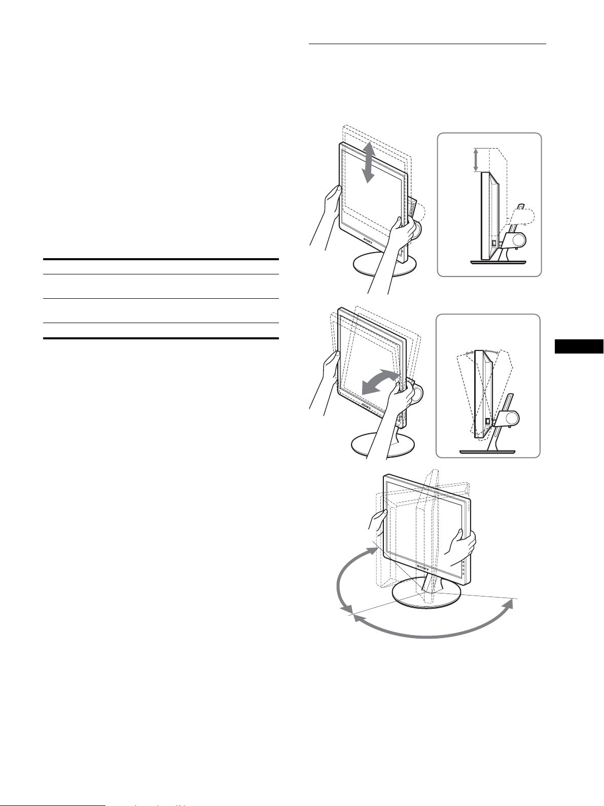
Setup 5:Adjust the height and tilt
This monitor can be adjusted within the angles shown below.
• If “NO INPUT SIGNAL” appears on the screen:
– The computer is in the power saving mode. Try pressing any
key on the keyboard or moving the mouse.
– Check that the input signal setting is correct by pressing the
INPUT button ( page 10).
• If “CABLE DISCONNECTED” appears on the screen:
– Check that the video s ignal cable is properly connected.
– Check that the input signal setting is correct by pressing the
INPUT button ( page 10).
• If “OUT OF RANGE” appears on the screen, reconnect the old
monitor. Then adjust the computer’s graphics board within the
following ranges.
Analog RGB Digital RGB
Horizontal
frequency
Vertical
frequency
28–92 kHz 28–75 kHz
48–85 Hz 60 Hz
Resolution 1600 × 1200 or less
For more information about on-screen messages, see “Trouble
symptoms and remedies” on page 20.
No need for specific drivers
The monitor complies with the “DDC” Plug & Play standard and
automatically detec ts all the monitor’s information. No spe ci fi c driver
needs to be installed on the computer.
The first time you turn on your computer after connecting the monitor, the
setup Wizard may appear on the screen. In this case, follow the on-screen
instructions. The Plug & Play monitor is automatically selected so that
you can use this monitor.
Grasp the sides of the LCD panel, then adjust screen
angles.
approx.
100 mm
(4 inches)
approx.
5°
approx.
20°
GB
The vertical frequency is set to 60 Hz.
Since flickers are unobtrusive on the monitor, you can use it as it is. You
do not need to set the vertical frequency to any particular hi gh va lu e.
approx.
175°
approx. 175°
To use the monitor comfortably
Adjust the viewing angle of your monitor according to the height
of your desk and chair , an d s o tha t l igh t is no t ref le c te d fr om the
screen to your eyes.
Note
When adjusting the screen ti lt and height, proceed slowly and carefully,
being sure not to hit the monit or against the desk.
9
Page 10

Selecting the input signal
(INPUT button)
Press the INPUT button.
The input signal change each time you press this button.
INPUT
On-screen message
(Appears about 5 seconds on
the upper left corner.)
INPUT1 : HD15 HD15 input connector
INPUT2 : HD15 HD15 input connector
INPUT3 : DVI-D DVI-D input connector
Input signal configurat ion
(analog RGB) for INPUT1
(analog RGB) for INPUT2
(digital RGB) for INPUT3
10
Page 11
Customizing Your Monitor
Before making adjustments
Connect the monitor and the computer, and turn them on.
For the best results, wait for at least 30 minutes before making
adjustments.
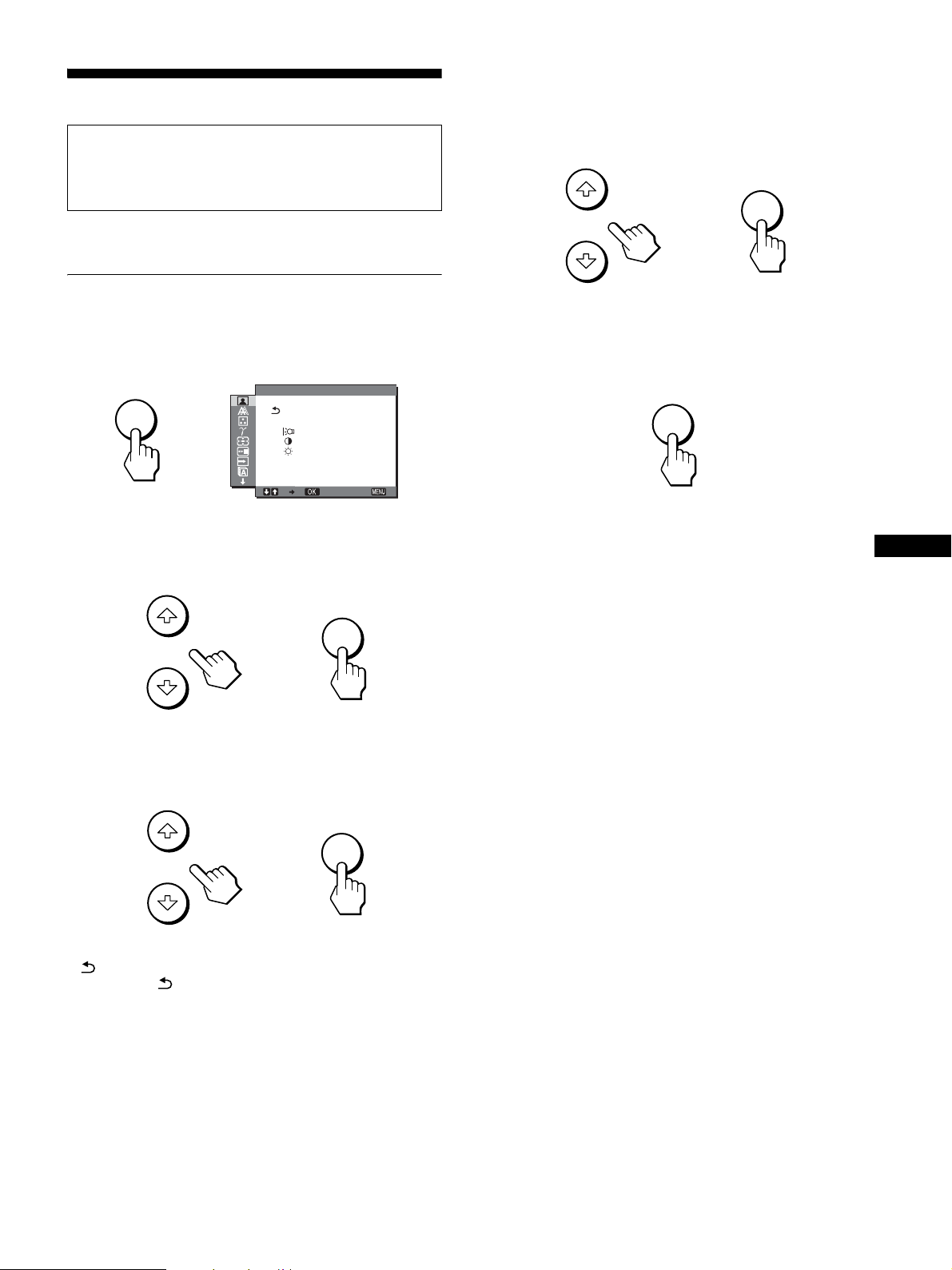
4 Adjust the item.
Press the m/M buttons to make the adjustment , the n press t he
OK button.
When you press the OK button, the setting is stored, then the
display returns to the previous menu.
OK
You can make numerous adjustments to your monitor using the
on-screen menu.
Navigating the menu
1 Display the main menu.
Press the MENU button to display the main menu on your
screen.
MENU
,
2 Select the menu.
Press the m/M buttons to display the de si re d m e nu . Pr e s s th e
OK button to move to the first menu item.
P CTURE ADJUSTI
HIGH
: 1 0 0
: 7 0
: 5 0
SMOOTHING
1600 1200 60Hzx/
EX I T
OK
,
,
5 Close the menu.
Press the MENU button once to return to normal viewing. If
no buttons are pressed, the menu closes automatically after
about 45 seconds .
MENU
x Resetting the adjustments to the default
settings
You can reset the adjustments using RESET menu. For more
information about resetting the adju stments, see 0 (RESET) on
page 16.
GB
3 Select the item you want to adjust.
Press the m/M buttons to select the item you want to adjust,
then press the OK butt on.
OK
,
If is one of the menu items.
When you select and press the OK button, the display returns to the
previous menu.
11
Page 12
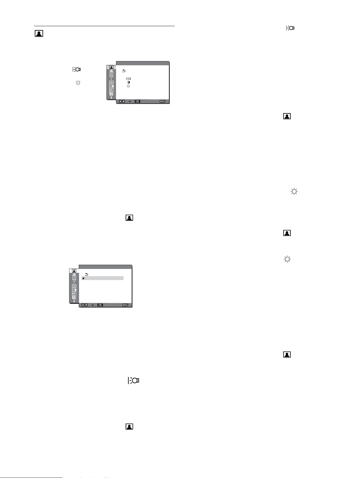
PICTURE ADJUST menu
You can adjust the following items using the PICTURE ADJUST
menu.
• MODE (ECO mode)
• BACKLIGHT
• CONTRAST 6
• BRIGHTNESS
• SMOOTHING
Notes
• You can adjust the backlight, contrast, and brightness for each ECO
mode.
• Settings in the PICTURE ADJUST menu can be made for the current
input. You can also adjust settings for oth er i nput s.
P CTURE ADJUSTI
HIGH
: 1 0 0
: 7 0
: 5 0
SMOOTHING
1600 1200 60Hzx/
EX I T
3Press the m/M buttons to select “ BACKLIGHT”
and press the OK button.
The “BACKLIGHT” menu appears on the screen.
4 Press the m/M buttons to adjust the light level and
press the OK button.
x Adjusting the CONTRAST 6
Adjust the picture contrast.
1 Press the MENU button.
The main menu appears on th e screen.
2 Press the m/M buttons to select (PICTURE
ADJUST) and press the OK button.
The PICTURE ADJUST menu appears on the screen.
x Selecting the MOD E (ECO mode)
You can select the picture mode to reduce the power
consumption.
Note
You can also select the pic ture mode with the ECO button (pages 5, 17)
on the front of the monitor.
1 Press the MENU button.
The main menu appears on th e screen.
2 Press the m/M buttons to select (PICTURE
ADJUST) and press the OK button.
The PICTURE ADJUST menu appears on the screen.
3 Press the m/M buttons to select “HIGH” and press
the OK button.
The “MODE” menu appears on the screen.
MODE
HIGH
MIDDLE
LOW
USER
1600 1200 60Hzx/
4 Press the m/M buttons to select the desired mode
and press the OK button.
The screen brightness is change d as th e m ode turns to HIGH
t MIDDLE t LOW, and the power consumption is
reduced. When you select “USER,” the screen brightness
turns to the level you adjusted with the ECO button on the
front of the monitor. For more information, see “ Reducing the
power consumption (ECO mode)” on page 17.
EX I T
3Press the m/M buttons to select “6 CONTRAST” and
press the OK button.
The “CONTRAST” menu appears on the screen.
4 Press the m/M buttons to adjust the contrast and
press the OK button.
x Adjusting the BRIGHTNESS
Adjust the picture brightness (black level).
1 Press the MENU button.
The main menu appears on th e screen.
2 Press the m/M buttons to select (PICTURE
ADJUST) and press the OK button.
The PICTURE ADJUST menu appears on the screen.
3 Press the m/M b uttons to select “ BRIGHTNESS”
and press the OK button.
The “BRIGHTNESS” menu appears on the screen.
4 Press the m/M buttons to adju st the bright ness and
press the OK button.
x Adjusting the SMOOTHING
If the picture di sp layed at the FU LL2 or F ULL1 mode of ZOO M
is not smooth, use the picture smoothing function.
1 Press the MENU button.
The main menu appears on th e screen.
2 Press the m/M buttons to select (PICTURE
ADJUST) and press the OK button.
The PICTURE ADJUST menu appears on the screen.
x Adjusting the BACKLIGHT
If the screen is too bright, adjust the ba cklight to make the screen
easier to see.
1 Press the MENU button.
The main menu appears on th e screen.
2 Press the m/M buttons to select (PICTURE
ADJUST) and press the OK button.
The PICTURE ADJUST menu appears on the screen.
12
Page 13

3 Press the m/M buttons to se lect “SMOOTHING” and
press the OK button.
The SMOOTHING menu appears on the screen.
x Make further automatic adjustments to the
picture quality for the current input signal
(AUTO)
4 Press the m/M buttons to select the desired mode.
The smoothing effect becomes stronger in the order of
TEXTtSTANDARDtGRAPHICS.
• TEXT: To make the characters appear clear. (This mode is
suited for text-based applications.)
• STANDARD (The default setting): Standard smoothing
effect.
• GRAPHICS: To make the pictures appear clean. (This
mode is suited for CD-ROM software such as
photo images or illustrations.)
Notes
• When you set the (ZOOM) menu to REAL, th e SMOO T H ING
menu is not available.
• 1600 × 1200 resoluti on signals are shown only in REAL mode and
SMOOTHING is no t possible.
SCREEN menu (analog RGB
signal only)
You can adjust the following items using the SCREEN menu.
• AUTO
• PHASE
•PITCH
•H CENTER
•V CENTER
SCREEN
AUTO
PHASE
I
P TCH
H CENTER
V CENTER
1600 1200 60Hzx/
EX I T
1 Press the MENU button.
The main menu appears on th e screen.
2 Press the m/M buttons to select (SCREEN) and
press the OK button.
The SCREEN menu appears on the screen.
3 Press the m/M buttons to select “AUTO” and press
the OK button.
Make the appropriate adjustments of the screen’s phase, pitch
and horizontal/vertical position for the current input signal
and store them.
x Adjust the picture’ s sharpness manually
(Phase/Pitch)
You can adjust the picture’s sharpness as follows. This
adjustment is effective when the computer is connected to the
monitor’s HD15 input connector (analog RGB).
1 Set the resolution to 1600 × 1200 on the computer.
2 Load the CD-ROM.
GB
3 Start the CD-ROM, select the area and model, and
display the test pattern.
For Windows
Click [Utility] t [Windows]/[Win Utility.exe].
For Macintosh
Click [Utility] t [Mac]/[Mac Utility].
Note
When receiving digital RGB signals from the DVI-D input connector,
adjustment is unnecessary.
x Automatic picture qu al ity adju stment
function
When the monitor receives an input signal, it automatically
adjusts the picture’s position and sharpness (phase/pitch), and
ensures that a clear picture appears on the screen (pa ge18).
Note
While the automatic picture quality adjustment function is activated, only
the 1 (power) switch will operate.
If the automatic picture quality adjustment function of this
monitor seems not to completely adjust the picture
You can make further automatic adjustment of the picture quality for the
current input signal (See “AUTO” below ).
If you still need to make further adjustments to the picture
quality
You can manually adjust the picture’s sharpness (phase/pitch) and
position (horizontal/v ertical position).
These adjustments are stored in memory and automatically
recalled when the monitor receives a previously input and
registered input signal.
4 Press the MENU button.
The main menu appears on th e screen.
5 Press the m/M buttons to select (SCREEN) and
press the OK button.
The SCREEN menu appears on the screen.
6 Press the m/M buttons to select “PHASE” and press
the OK button.
The “PHASE” adjustment menu appears on the screen.
7 Press the m/M buttons until the horizontal stripes
are at a minimum.
Adjust so that the horizontal stripes are at a minimum.
8 Press the OK button.
The main menu appears on th e screen.
If vertical stripes are observed over the en tire screen, adjust
the pitch using the following procedures.
13
Page 14
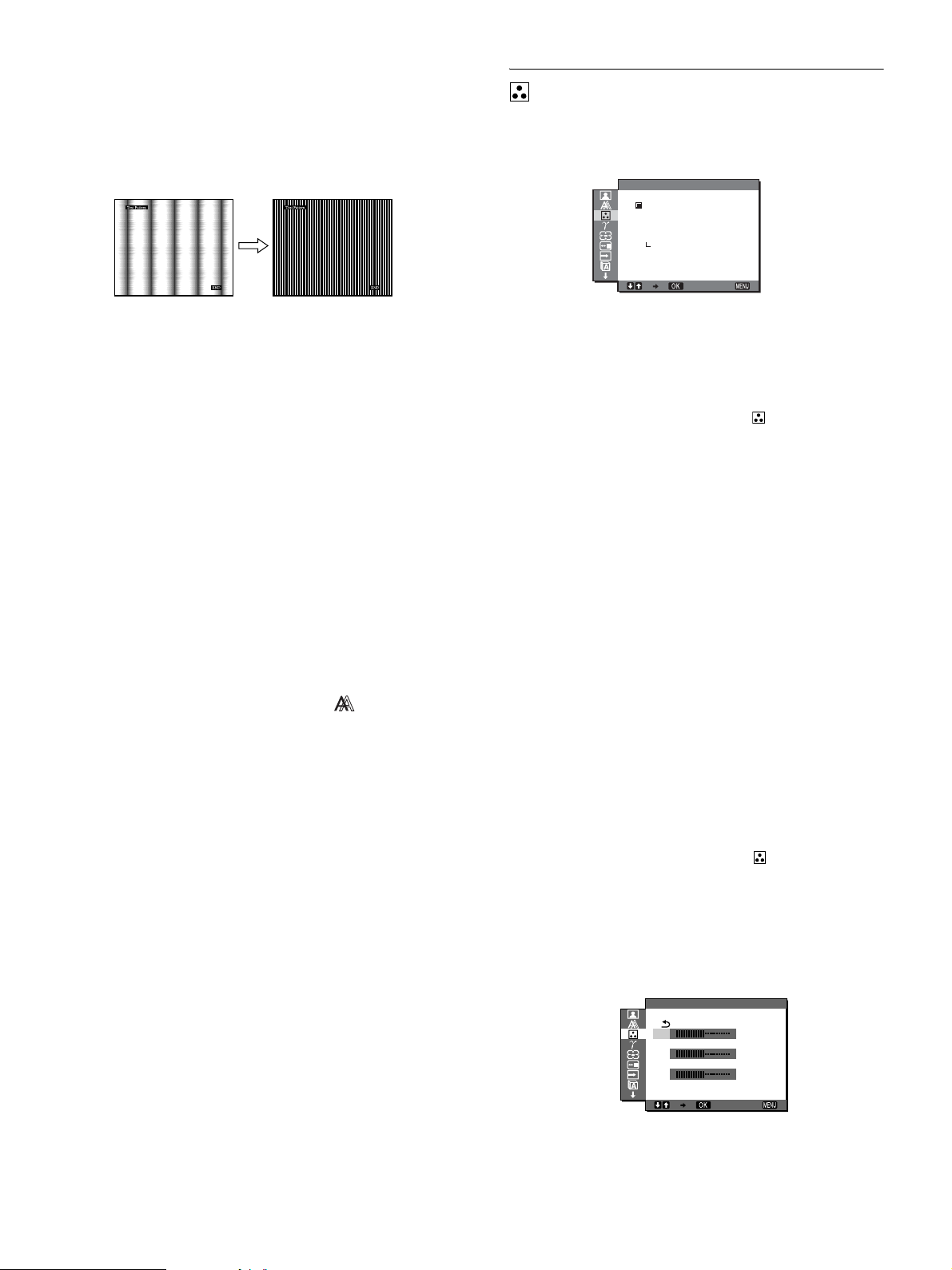
9 Press the m/M buttons to select “PITCH” and press
the OK button.
The “PITCH” adjustment menu appears o n t he screen.
10 Press the m/M buttons until the vertical stripes
disappear.
Adjust so that the vertical stripes disappear.
COLOR menu
You can select the picture’s color level for the white color field
from the default color temperature settings.
Also, if necessary, you can fine tune the color temperature.
COLOR
9300K
6500K
sRGB
USER
ADJUST
11 Click [END] on the screen to turn off th e test pattern .
x Adjust the picture’s position man ually
(H CENTER /V CENTER)
If the picture is not in the center of the screen, adjust the picture’s
centering as follows.
1 Set the resolution to 1600 × 1200 on the computer.
2 Load the CD-ROM.
3 Start the CD-ROM, select the area and model, and
display the test pattern.
For Windows
Click [Utility] t [Windows]/[Win Utility.exe].
For Macintosh
Click [Utility] t [Mac]/[Mac Utility].
4 Press the MENU button.
The main menu appears on th e screen.
5 Press the m/M buttons to select (SCREEN) and
press the OK button.
The SCREEN menu appears on the screen.
1600 1200 60Hzx/
Note
You can adjus t the color temperature for each ECO mode.
EX I T
1 Press the MENU button.
The main menu appears on th e screen.
2 Press the m/M buttons to select (COLOR) and
press the OK button.
The COLOR menu appears on the screen.
3 Press the m/M buttons to select the desired color
temperature and press the OK button.
Whites will change from a bluish hue to a reddish hue as the
temperature is lowered from 9300K to 6500K.
When you select “sRGB,” the colors adjust to the sRGB
profile. (The sRGB color setting is an in dustry-standard colo r
space protoc ol des igned fo r comp uter p roducts .) If yo u sele ct
“sRGB,” the color settings of your compute r must be set to the
sRGB profile.
Notes
• If a connected comp uter or other equip ment is not sRGB-compliant,
color cannot be adjust ed to the sRGB profile.
• If you select “sRGB,” you cannot adjust the contrast and brightness in
the PICTURE ADJUST menu. Also, you cannot adjust the GAMMA
menu.
6 Press the m/M buttons to select “H CENTER” or “V
CENTER” and press the OK button.
The “H CENTER” adjustment menu or “V CENTER”
adjustment menu appears on the screen.
7 Press the m/M buttons to center the test pattern on
the screen.
8 Click [END] on the screen to turn off th e test patte rn.
14
x Fine tuning the color temperature
1 Press the MENU button.
The main menu appears on th e screen.
2 Press the m/M buttons to select (COLOR) and
press the OK button.
The COLOR menu appears on the screen.
3 Press the m/M buttons to select “ADJUST” and
press the OK button.
The fine tuning menu for color temperature appears on the
screen.
USER ADJUSTMENT
R
G
B
1600 1200 60Hzx/
128
128
128
EX I T
Page 15

4 Press the m/M buttons to select R (Red) or B (Blue)
and press the OK button. Then press the m/M
buttons to adjust the color temperature and press
the OK button.
Since this adjustment cha nges the color temperature by
increasing or decreasing the R and B components with respect
to G (green), the G component is fixed.
5 Press the m/M buttons to select , then press the
OK button.
The new color setting is stored in memory and automatically
recalled whenever “USER” is selected.
The COLOR menu appears on the screen.
GAMMA menu
You can associate the picture’s color shade on the screen with the
picture’s original color shade.
GAMMA
GAMMA 1
GAMMA 2
GAMMA 3
1600 1200 60Hzx/
EX I T
The ZOOM menu appears on the screen.
3 Press the m/M buttons to select the desired mode.
• FULL2 (The default setting): The input signal is
displayed on the screen in fu ll, irrespective of the
picture’s mode or resolution.
• FULL1: The input signal is displayed on the screen at its
actual aspect ratio. Therefore, b la ck bands may
appear at the top and bottom of the picture,
depending on the signal.
• REAL: The input signal is displayed on the screen at its
actual resolut ion. Sub-1600 × 1200 signals are
displayed at the center of the screen surrounded
by a black frame.
Note
When you use 1600 × 1200 resolution signals, the ab ove me nt io ned
settings are not av ailable. The pict ur e is displayed on the sc reen in full.
MENU POSITION menu
You can change the menu position if it is blocking an image on
the screen.
MENU POS T ONII
Note
You can adjust the GAMMA for each ECO mode.
1 Press the MENU button.
The main menu appears on the screen.
2 Press the m/M buttons to select (GAMMA) and
press the OK button.
The GAMMA menu appears on the screen.
3 Press the m/M buttons to select the desired mode
and press the OK button.
ZOOM menu
The monitor is set to display the picture on the screen in full,
irrespective of the picture’s mode or resolution in the default
setting (FULL2).
You can also view the picture in its actual aspect ratio or
resolution.
ZOOM
FULL2
FULL1
REAL
1600 1200 60Hzx/
Note
Settings in the ZOOM men u can be made for the current input. You can
also adjust settings for other inputs.
1 Press the MENU button.
The main menu appears on the screen.
2 Press the m/M buttons to select (ZOOM) and
press the OK button.
EX I T
1600 1200 60Hzx/
EX I T
1 Press the MENU button.
The main menu appears on th e screen.
2 Press the m/M buttons to select (MENU
POSITION) and press the OK button.
The MENU POSITION menu appears on t he screen.
3 Press the m/M buttons to select the desired position
and press the OK button.
You can choose one of 9 positions where the menu will
appear.
INPUT SENSING ON/OFF menu
When you select AUTO ON in the INPUT SENSING ON/OFF
menu, the monitor automatically detects an input signal to an
input terminal, and changes the input automatically before the
monitor goes into the power saving mode.
I NPUT SENSING
AUTO ON
AUTO OFF
1600 1200 60Hzx/
1 Press the MENU button.
The main menu appears on th e screen.
EX I T
GB
15
Page 16
2 Press the m/M buttons to select (INPUT
SENSING ON/OFF) and press the OK button.
The INPUT SENSING menu appears on the screen.
3 Press the m/M buttons to select the desired mode
and press the OK button.
• ON: When the select ed input terminal has no input
signal, or when you select an input terminal by the
INPUT button on the monitor and the terminal has
no input signal, the on-screen message appears
(page 19) and the monitor checks the input signal to
another input terminal automatically to change the
input.
When the input is changed, the selected input
terminal is displayed on the left upper of the screen.
When there is no input sig nal, the monito r goes into
the power saving mode automatically.
• OFF: The input is not changed automatically. Press the
INPUT button to change the input.
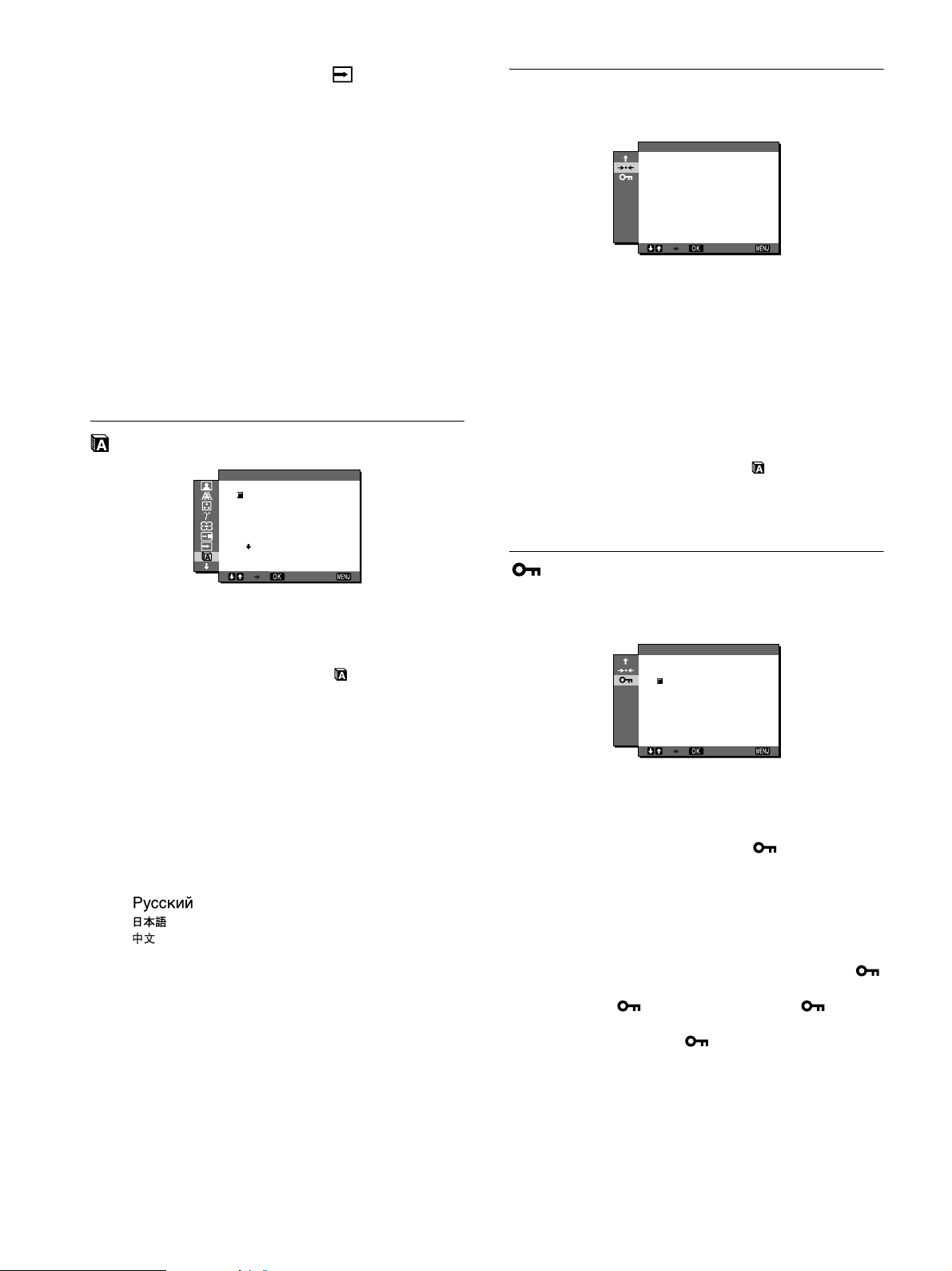
LANGUAGE menu
LANGUAGE
ENGL I SH
FRANÇA I S
DEUTSCH
ESPAÑOL
I TAL I ANO
0 RESET menu
Reset the adjustments to the default settings.
RESET
OK
CANCEL
1600 1200 60Hzx/
1 Press the MENU button.
The main menu appears on th e screen.
2 Press the m/M buttons to select 0 (RESET) and
press the OK button.
The RESET menu appears on the screen.
3 Press the m/M buttons to select the desired mode
and press the OK button.
• OK: To reset all of the adjustment data to the defau lt
settings. Note that the “ LANGUAGE”
setting is not reset by this method.
• CANCEL:To cancel resetting and return to the menu
screen.
EX I T
1600 1200 60Hzx/
EX I T
1 Press the MENU button.
The main menu appears on th e screen.
2 Press the m/M buttons to select (LANGUAGE)
and press the OK button.
The LANGUAGE menu appears on the screen.
3 Press the m/M buttons to select a language and
press the OK button.
• English
• Français: French
• Deutsch: German
• Español: Spanish
• Italiano: Italian
• Nederlands: Dutch
• Svenska: Swedish
•: Russian
• : Japanese
•: Chinese
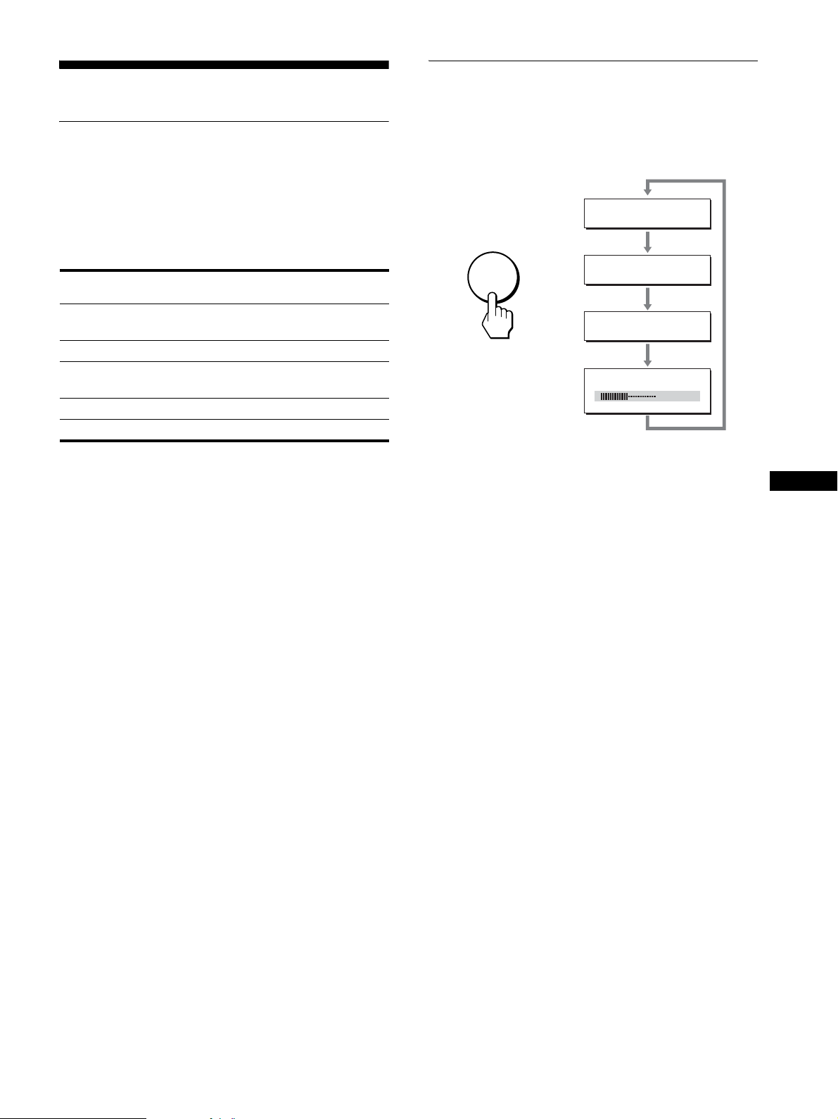
MENU LOCK menu
Lock the control of buttons to prevent accidental adjustments or
resetting.
MENU LOCK
ON
OFF
1600 1200 60Hzx/
1 Press the MENU button.
The main menu appears on th e screen.
2 Press the m/M buttons to select (MENU LOCK)
and press the OK button.
The MENU LOCK menu appears on the screen.
3 Press the m/M buttons to select either “ON” or
“OFF.”
• ON: Only the 1 (power) switch and INPUT button will
operate. If you attempt any other operation, the
(MENU LOCK) icon appears on the screen.
• OFF: Set “ MENU LOCK” to off. If “ MENU
LOCK” has been set to “ON,” when you press the
MENU button, “ MENU LOCK” is
automatically selected.
EX I T
16
Page 17
Technical Features
Reducing the power consumption
(ECO mode)
Po wer saving function
This monitor meets the power-saving guidelines set by VESA,
ENERGY STAR, and NUTEK. If the monitor is connected to a
computer or video graphics board that i s D PM (Display Power
Management) Standard comp liant, the monitor will automatically
reduce power con su m pti on as shown below.
Power mode Power consumption
normal
operation
ECO mode green
active off*
(deep sleep)
1 (power) off 2.7 W (max.) red
main power off 0 W off
* When your computer enters the “active off” mode, the input signal is
cut and “NO INPUT SIGNAL” appears on the screen. After 5
seconds, the monitor enters the po wer saving mode.
“Deep sleep” is a power sav ing mo de defined by the Environment al
Protection Agency.
** The maximum power consumption is 2.0 W in 100-120 V A C
areas.
58 W (max.) green
2.7 W (max.)** orange
1 (power)
indicator
If you press the ECO but ton on the front of the monitor
repeatedly, you can select th e screen brightness.
:
ECO HIGH
ECO
:
ECO MIDDLE
,
:
ECO LOW
:
ECO USER
Each mode appears on the screen and the screen brightness is
reduced according to the mode. The menu automatically
disappears after about 5 seconds.
Screen brightness and power consumption are reduced as the
mode changes from HIGH to MIDDLE to LOW.
The default setting of the screen brightness is set to “HIGH.”
If you select “USER,” you can adjust the backlight level by
pressing the m/M buttons as when you selec t BACKLIGHT usin g
the menu.
50
GB
17
Page 18

Automatic picture quality
adjustment function
(analog RGB
signal only)
When the monitor receives an input signal, it
automatically adjusts the picture’s position and
sharpness (phase/p itch), an d ensures that a clea r
picture appears on the screen.
The factory preset mode
When the monitor receives an inpu t signal, it automatically
matches the signal to one of the factory preset modes stored in the
monitor’s memory to provide a high quality picture at the center
of the screen. If the input signal matches the factory preset mode,
the picture appears on the screen automatically with the
appropriate default adjust ments.
If input signals do not match one of the factory
preset modes
When the monitor receives an input signal that does not match one
of the factory preset modes, the automati c pict u re quality
adjustment function of this monitor is activated to ensure that a
clear picture always appears on the screen (within the following
monitor frequency ranges):
Horizontal fre quency: 28–92 kHz (analog RGB)
28–75 kHz (digita l RG B)
Vertical frequency: 48–85 Hz (analog RGB)
60 Hz (digital RGB)
Consequently, the first time the monitor receives input signals
that do not match one of t he factory preset modes, the monitor
may take a longer time than normal to display the picture on the
screen. This adjustment data is automatically stored in memory so
that next time, the monitor will f unction in the same way as when
the monitor receives the signals that match one of the factory
preset modes.
If you adjust the phase, pitch, and picture position
manually
For some input signals, the automatic picture quality adjustment
function of this monitor may not completely adjust the picture
position, phase, and pitch. In this case, you can set these
adjustments manually (page 13). If you set these adjustments
manually, they are stored i n memory as user modes and
automatically recalled when ever the monitor receives the same
input signals.
18
Page 19

Troubleshooting
Before contacting technical support, refer to this section.
On-screen messages
If there is something wrong with the input signal, one of the
following messages appears on the screen. To solv e the pr oblem,
see “Trouble symptoms and remedies” on page 20.
If “OUT OF RANGE” appears on the screen
This indicates that the input signal is not supported by the
monitor’s specifications. Check the following items.
For more information about on-screen messages, see “Trouble
symptoms and remedies” on page 20.
If “xxx.x kHz / xxx Hz” is displayed
This indicates that either the horizontal or vertical frequency
is not supported by the monitor’s specification s.
The figures indicate the horizontal and vertical frequencies of
the current input signal.
INFORMATION
OUT OF RANGE
I NPUT # : XXXXX
XXX. XKHz / XXXHz
If “RESOLUTION i 1600 × 1200” is displayed
This indicates that the resolution is not supported by the
monitor’s specifications (1600 × 1200 or less).
INFORMATION
OUT OF RANGE
I NPUT # : XXXXX
RESOLU T I ON > 6100X1 002
If “NO INPUT SIGNAL” appears on the screen
This indicates that no signal is being input via the currently
selected connector.
When INPUT SENSING ON/OFF (page 15) is set to ON, the
monitor finds another input signal and changes the input
automatically.
INFORMATION
NO I NPUT S IGNA L
INPUT# :XXXX X
GO TO POWER SAVE
The monitor will enter the power saving mode after about 5
seconds from the time the message is displayed.
INFORMATION
NO I NPUT S IGNA L
INPUT# :XXXX X
GO TO POWER SAVE
If “CABLE DISCONNECTED” appears on the
screen
This indicates that the video signal cable has been di sconnected
from the currently selected conne ct or.
When INPUT SENSING ON/OFF (page 15) is set to ON, the
monitor finds another input signal and changes the input
automatically.
INFORMATION
CAB L E D I SCONNECTED
I NPUT # : XXXXX
GB
19
Page 20

Trouble symptoms and remedies
If a problem occurs as a result of a connected computer or other equipment, refer to the connected computer/equipment’s instruction manual.
For further information and troubleshooting assistance, please visit Sony support website at: http://www.sony.net/
Symptom Check these items
No picture
If the 1 (power) indicator is not lit,
or if the 1 (power) indicator will not
light up when the 1 (power) switch
is pressed,
If the 1 (power) indicator turns on
in red,
If “CABLE DISCONNECTED”
appears on the screen,
If “NO INPUT SIGNAL” appears on
the screen, or the 1 (power)
indicator is either orange or
alternating between green and
orange,
If “OUT OF RANGE” appears on
the screen (page 19),
If using Windows, • If you replaced an old monitor with this monitor, reconnect the old monitor and do the
If using a Macintosh system, • When connecting a Macintosh compu ter, use an adapter (not supplied) if necessary.
Picture flickers, bounces,
oscillates, or is scrambled.
• Check that the power cord is properly connected.
• Check that the monitor’s MAIN POWER switch is on (page 8).
• Check that the 1 (power) switch is on.
• Check that the video signal cable is properly connected and all plugs are firmly seated in
their sockets (page 6).
• Check that the video input connector’s pins are not bent or pushed in.
• Check that the input select setting is correct (page 10).
• A non- supplied video signal cable is connected. I f you connect a non-sup plied video
signal cable, “CABLE DISCONNECTED” may appear on the screen. This is not a
malfunction.
• Check that the video signal cable is properly connected and all plugs are firmly seated in
their sockets (page 6).
• Check that the video input connector’s pins are not bent or pushed in.
• Check that the input select setting is correct (page 10).
xProblem caused by a connected computer or other equipment, and not
caused by the monitor
• The computer is in the power saving mode. Try pressing any key on the keyboar d or
moving the mouse.
• Check that your graphics board is installed pr operly.
• Check that the computer’s power is on.
• Restart the computer.
xProblem caused by a connected computer or other equipment, and not
caused by the monitor
• Check that the video frequency range is within that specified for the monitor. If you
replaced an old monitor with this monitor, reconnect the old monitor and adjust the
computer’s graphics board within the following ranges:
Horizontal freq uency: 28–92 kHz (analog RGB) , 28–75 kHz (digit a l RGB)
Vert ical frequency: 48–85 Hz (analog RGB), 60 Hz (digital RGB)
Resolution: 1600 × 1200 or less
following. Select “SONY” from the “Manufacturers” list and select “SDM-S204E” from
the “Models” list in the Windows device selection screen. If “SDM-S204E” does not
appear in the “Models” list, try “Plug & Play.”
Connect the adapter to the computer before connecting the video signal cable.
• Adju s t the pitch and phase (anal og RGB signal only) (pa ge 13).
• Try plugging the monitor in to a different AC outlet, preferably on a different circuit.
• Cha nge the orientat ion of the monitor.
xProblem caused by a connected computer or other equipment, and not
caused by the monitor
• Check your graphics board manual for the proper monitor setting.
• Confirm that the graphics mode (VESA, Macintosh 19'' Color, etc.) and the frequency of
the input signal are supported by this monitor. Even if the frequency is within the proper
range, some graphics boards may have a sync pulse th at is too narrow for the monitor to
sync with correctly.
• This moni tor does not process interlace signals. Se t for pr ogressive signals.
• Adjust the computer’s refresh rate (vertical frequency) to obtain the best possible picture
(60 Hz is recommended).
20
Page 21

Symptom Check these items
Picture is fuzzy. • Adjus t the brightness and contrast (page 12).
• Adjus t the pitch and phase (analog RGB signal only) (page 13).
• Adjust the smoothing (page 12).
xProblem caused by a connected computer or other equipment, and not
caused by the monitor
• Set the resolution to 1600 × 1200 on your compute r.
Picture is ghosting. • Eliminate the use of video cable extensions and/or video switch boxes.
• Check that all plugs are firmly seated in their sockets.
Picture is not centered or sized
properly (analog RGB signal only).
Picture is too small. • Set the zoom setting to “FULL2” (page 15).
Picture is dark. • Adjus t the brightness (page 12).
Wavy or elliptical pattern (moire)
is visible.
Color is not uniform. • Adjus t the pitch and phase (analog RGB signal only) (page 13).
White does not look white. • Adjust the color temperature (page 14).
Monitor buttons do not operate
( appears on the screen).
Resolution display ed on the me nu
screen is incorrect.
After turning off the main power,
the 1 (power) indicator stays
bright for a while.
• Adju s t the pitch and phase (page 13).
• Adjust the picture position (page 14). Note that some video modes do not fill the screen to
the edges.
xProblem caused by a connected computer or other equipment, and not
caused by the monitor
• Set the resolution to 1600 × 1200 on your compute r.
• Adjust the backlight (page 12).
• It takes a few minutes for the display to become bright after turning on the monitor.
• Adjust the gamma on the GAMMA menu (page 15).
• The screen might turn darker, depends on ECO mode you selected.
• Adjus t the pitch and phase (analog RGB signal only) (page 13).
• If “MENU LOCK” is set to “ON,” set it to “OFF” (page 16).
• Depending on the graphics board setting, the resolution displayed on the menu screen may
not coincide with the one set on the computer.
• When the main power is on but the 1 (power) switch is not pressed, or when the monitor
is in the power saving mode, if you turn the MAIN POWER switch off, th e 1 (power)
indicator may not turn off right away. This is not a malfunction.
GB
21
Page 22

Displaying this monitor’s information
While the monitor is rece iving a video signal, press and
hold the MENU button for more than 5 secon ds until the
information box appears.
Press the MENU button again to make the box disappear.
Example
MENU
If any problem persists, call your authorized Sony de aler and give
the following information:
• Model name: SDM-S204E
• Serial number
• Detailed description of the problem
• Date of purchase
• Name and specifications of your computer and graphics board
• Type of i nput signals (analog RGB/digital R G B)
INFORMATION
MODEL : SDM-S204E
SER. NO : 1234567
MANUFACTURED : 2004-40
Model
name
Serial
number
Week and year
of manufacture
Specifications
LCD panel
Panel type: a-Si TFT Active Matrix
Picture size:20.1 inch (51 cm)
Input signal format
RGB operating frequency*
Horizontal: 28–92 kHz (analog RGB)
28–75 kHz (digital RGB)
Vertical:48–85 Hz (analog RGB)
60 Hz (digital RGB)
Resolution
Horizontal: Max.1600 dots
Vertical: Max.1200 lines
Input signal l e vels
Analog RGB video signal:
0.7 Vp-p, 75 Ω, positive
SYNC signal:
TTL level, 2.2 kΩ, positive or negative (Separate
horizontal and vertical, or composite sync)
0.3 Vp-p, 75 Ω, negative (Sync on green)
Digital RGB (DVI) signal: TMDS (Single link)
Power requirements
100–240 V, 50–60 Hz, Max. 1.2 A
Power consum ptio n
Max. 58 W
Operating temperature
°C
5–35
Dimensions
Display (upright):
With stand
Width: 440.5 mm (17
Height: 377.5 – 477.5 mm (14
Depth: 232.0 – 248.0 mm (9
Without stand
Width: 440.5 mm (17
Height: 354.5 mm (14 inc h es )
Depth: 72.5 mm (2 7/8 inches)
Mass
Approx. 8.2 kg (1 8 lb 1 1/4 oz) (with stand)
Approx. 6.2 kg (13 lb 11 oz) ( w itho u t sta nd )
Plug & Play
DDC2B
Accessories
See page 6.
3
/8 inches)
3
/8 inches)
1
/4 – 9 7/8 inches)
7
/8 – 18 7/8 inches)
22
* Recommended horizontal and vertical timing condition
• Horizontal sync w idth duty shou ld be more tha n 4.8% of tot al
horizontal time or 0.8 µs, whichever is larger.
• Horizontal blankin g width should be more than 2.5 µsec.
• Vertical bl anking width should be mo r e than 450 µsec.
Design and specifications are subject to change without notice.
Page 23

TCO’99 Eco-document (for the black
model)
x Congratulations!
You have just purchased a TCO’99 approved and labelled product! Your
choice has provided you with a product developed for professiona l use .
Your purchase has also contributed to reducing the burde n on the
environment and also to th e further development of envi ronmentally
adapted electronics products.
x Why do we have environmentally labelled com-
puters?
In many countries, environmental labelling has become an establi she d
method for encouraging t he adaptation of goods and services to t he
environment. The ma in problem , as far as comp uters and other electroni cs
equipment are concerned, is that environmentally harmful substances are
used both in the products and during their manufacture. Since it is not so
far possible to sa tisfactorily r ecycle the majo rity of elect ronics equipmen t,
most of these potentially damaging substances sooner or later enter nature.
There are also othe r characteristics of a computer, such as energy
consumption levels, that are im portant from the viewpoints of bot h th e
work (internal) and natural (external) environments. Since all methods of
electricity generation ha ve a negative effect on the environment (e.g.
acidic and climate-influencing emissions, radioactive waste), it is vital to
save energy. Electronics equipment in offices is often left running
continuously and thereby consumes a lot of energy.
x What does labelling involve?
This product meets the requirements for the TCO’99 scheme which
provides for international and e nvi ronmental labelling of persona l
computers. The labelling scheme was de ve lo ped as a joint effort by the
TCO (The Swedish Confede rat ion of Professional Employees), Svenska
Naturskyddsforeningen (The Swedish Society for Natu re Conservation)
and Statens Energim yndighet (The Swedish Nat ion al Energy
Administration).
Approval requirements cover a wide range of issues: envi ronment,
ergonomics, usabilit y, emissio n of electric and magnetic fields, energy
consumption and electrica l and fire safety.
The environmental demands impos e restrictions on the presence and us e
of heavy metals, brominated and chlorinated fla me retardants, CFCs
(freons) and chlorinate d sol vents, among other things. The product must
be prepared for recycling and the manufacturer is obliged to have an
environmental policy which must be adhered to in each country where the
company implements it s o perational policy.
Labelled products must meet strict environmental demands, for example,
in respect of the reduct io n of electric and magnetic fie ld s, physical and
visual ergonomics and good us ability.
Below you will find a brief summary of the environmental re qui rements
met by this product. The complete environment al criteria document ma y
be ordered from:
TCO Development
SE-114 94 Stockholm, Sweden
Fax: +46 8 782 92 07
Email (Internet): development@tco.se
Current information re ga rding TCO’99 approved and l abe l le d
products may also be obtained via the Internet, using the address:
http://www.tco-info.com/
x Environmental requirements
Flame retardants
Flame retardants are present in printed circuit boards, cables, wire s ,
casings and housings. Their purpose is to preve nt, or at least to del ay the
spread of fire. Up to 30% of the pla s ti c i n a computer casing can consist
of flame retardant substances. Most flame retardants cont ain bromine or
chloride, and those flame retard ants are chemica lly related to another
group of environmental toxins, PCBs. Both the flame retardants
containing bromine or chloride and the PCBs are suspected of giving rise
to severe health effect s, including reproductive da mage in fish-eating
birds and mammals, due to the bio-accumulative
retardants have bee n found in human blood and resear che r s fe ar t h at
disturbances in foetus development may occur.
The relevant TCO’99 demand requires that plastic components weighing
more than 25 grams must not contain flame retardants with organically
bound bromine or chlorine. Flame retardants are allowed in the printed
circuit boards since no substitutes are available.
* processes. Flame
Cadmium**
Cadmium is presen t in rec hargeable batteri es and in th e colour- generatin g
layers of certain computer displays. Cadmium da ma ge s the ne rvous
system and is toxic in high doses. The relevant TCO’99 requirement states
that batterie s , th e colour-generat ing layers of display sc reens and the
electrical or electronics components must not contain any cadmium.
Mercury**
Mercury is sometimes foun d in batt erie s, rel ays an d swit ches. It dama ges
the nervous system and is toxic in hi gh doses. The relevant TCO’99
requirement states that bat te rie s may not contain any mercury. It also
demands that mercury is not pr esen t in a ny of the e lectr i cal o r ele ctr onics
components associated w ith the labelled un it.
CFCs (freons)
The relevan t TCO’99 requirement states th at neither CFCs nor HCFCs
may be used during the manufa ct ure and assembly of the product. CF Cs
(freons) are sometimes used for washing printed circuit boards. CFCs
break down ozone and t hereby d amage the ozone la yer in t he strato sphere ,
causing increased reception on earth of ultraviolet light with e.g. increased
risks of skin cancer (malignant mela noma) as a consequence.
Lead**
Lead can be found in picture tubes, display screens, solders and
capacitors. Lead damages the nervous system and in higher doses, causes
lead poisoning. The relevant TCO’99 requirement permits the inclusion of
lead since no replacement has yet be en developed.
* Bio-accumulative is defined as substances which accumulate within
living organisms.
** Lead, Cadmi um and Mercury are heav y me ta ls which are Bio-
accumulative.
The energy requirements include a demand that the computer and/or
display, after a certain period of inactivity, shall reduce its power
consumption to a lower lev el in one or more sta ges. T he le ngth o f tim e to
reactivate the computer shall be reasonable for the user.
i
Page 24

TCO’03 Eco-document (for the gray
model)
x Congratulations!
The display you have just purchased carries the TCO’03
Displays label. This means that your display is designed,
manufactured and tested according to some o f the strictest
quality and environmental requirements in the world. This
makes for a high performance product, designed with the
user in focus that also minimizes the impact on our natural
environment.
x Ergonomics
• Good visual ergonomics and image quality in order to
improve the working environment for the user and to
reduce sight and strain problems. Important parameters
are luminance, contrast, resolution, reflectance, colour
rendition and image stability.
x Energy
• Energy-saving mode after a certain time – beneficial
both for the user and the environment
• Electrical safety
x Emissions
• Electromagnetic fields
• Noise emissions
x Ecology
• The product must be prepared for recycling and the
manufacturer must have a certified environmental
management system such as EMAS or ISO 14 001
• Restrictions on
- chlorinated and bromi nated flame retardants and
polymers
- heavy metals such as cadmium, mercury and lead.
involved in influencing the development of IT equipment
in a more user-friendly direction. Our labelling system
started with displays in 1992 and is now requested by user s
and IT-manufacturers all over the world.
For more information, please visit
www.tcodevelopment.com
Recycling Information
x Customer in Europe
The collection and recycling of this product has been planned
according to your co un tr y ’s rele va n t legi s lation. To ensure that
this product will be col lected a nd recycle d in way that mi nimize s
the impact on the environment, please do the following:
1. If you purchased this product for private use, contact yo ur
municipality or the waste collection system and bring the
product to this col le ction point / have the p ro duct be pick ed up
by the waste collection system. Alternatively, your retailer
might take back this if you purchase new equivalent equipment;
please check with your retailer whether he will take back this
product before bringing it. For information on your country’s
recycling arrangements, please contact the Sony representation
in your country (contact details at: www.sony-europ e.com).
Further detai ls on specifi c recycling s ystems can be found at the
following addresses:
- Belgium: www.recupel.be
- Netherlands: www.nvmp.nl (consumer electronics)
www.ictmilieu.nl (IT equipment)
- Norway: www.elretur.no
- Sweden: www.el-kretsen.se
- Switzerland: www.swico.ch
2. If you use this product professionally, check the product’s
delivery contract for take back / recycl in g arrangements and
follow the procedures described therein. Alternatively, follow
the procedures de sc ri b e d under point 1.
x Customer in USA
We Sony as a member of EIA recommends to visit URL below
http://www.eiae.org/
x Customer in Asia
http://www.sony.co.jp/SonyInfo/Environment/recycle/3R.html
The requirements included in this label have been
developed by TCO Development in co-operation with
scientists, experts, users as well as manufacturers all over
the world. Since the end of the 1980s TCO has been
ii
Page 25

2-580-335-01(1)
TFT LCD Color
Computer Display
SDM-S204E
© 2004 Sony Corporation
Page 26

Owner’s Record
The model and serial numbers are located at the rear of the unit.
Record these numbers in the spaces provided below. Refer to them
whenever you call upon your dealer regarding this product.
Model No.
Serial No.
WARNING
To prevent fire or shock hazard, do not expos e the
unit to rain or moisture.
Dangerously high voltages are present inside the
unit. Do not open the cabinet. Refer servicing to
qualified personnel only.
FCC Notice
This equipment has been tested and found to comply with the limits
for a Class B digital device, pursuant to Part 15 of the FCC Rules.
These limits are designed to provide reasonable protection against
harmful interference in a residential installation. This equipment
generates, uses, and can radiate radio frequency energy and, if not
installed and used in accordance with the instructions, may cause
harmful interference to radio communications. However, there is no
guarantee that interference will not occur in a particular installation.
If this equipment does cause harmful interference to radio or
television reception, which can be determined by turning the
equipment off and on, the user is encouraged to try to correct the
interference by one or more of the following measures:
– Reorient or relocate the receiving antenna.
– Increase the separation between the equipment and receiver.
– Connect the equipment into an outlet on a circuit different from
that to which the receiver is connected.
– Consult the dea ler or an ex perienced r adio/TV te chnician f or help.
You are cautioned that any changes or modifications not expressly
approved in this manual could void your authority to operate this
equipment.
IMPORTANTE
Para prevenir cualquier mal funcionamiento y evitar daños, por
favor, lea detalladamente este manual de instrucciones antes
de conectar y operar este equipo.
NOTICE
This notice is applicable for USA/Canada only.
If shipped to USA/Canada, install only a UL LISTED/CSA
LABELLED power supply cord meeting the following
specifications:
SPECIFICATIONS
Plug Type Nema-Plug 5-15p
Cord Type SVT or SJT, minimum 3 × 18 AWG
Length Maximum 15 feet
Rating Minimum 7 A, 125 V
NOTICE
Cette notice s’applique aux Etats-Unis et au Canada
uniquement.
Si cet appareil est exporté aux Etats-Unis ou au Canada, utiliser
le cordon d’alimentation portant la mention UL LISTED/CSA
LABELLED et remplissant les conditions suivantes:
SPECIFICATIONS
Type de fiche Fiche Nema 5-15 broches
Cordon Type SVT ou SJT, minimum 3 × 18 AWG
Longueur Maximum 15 pieds
Tension Minimum 7 A, 125 V
ENERGY STAR Partner, Sony
As an
Corporation has determined that this
product meets the
guidelines for energy efficiency.
This monitor complies with the
TCO’03 guidelines.
ENERGY STAR
If you have any questions about this product, you may call;
Sony Customer Information Services Center
1-800-222-7669 or http://www.sony.com/
Declaration of Conformity
Trade Name: SONY
Model: SDM-S204E
Responsible Party: Sony Electronics Inc.
Address: 16450 W. Bernardo Dr,
Telephone Number: 8 58-942-2230
This device complies with part 15 of the FCC rules. Operation is
subject to the following two conditions: (1) This device may not
cause harmful interference, and (2) this device must accept any
interference received, including interference that may cause
undesired operation.
BZ
03
San Diego, CA 92127 U.S.A.
(for the gray model)
This monitor complies with the
TCO’99 guidelines.
(for the black model)
2
Page 27
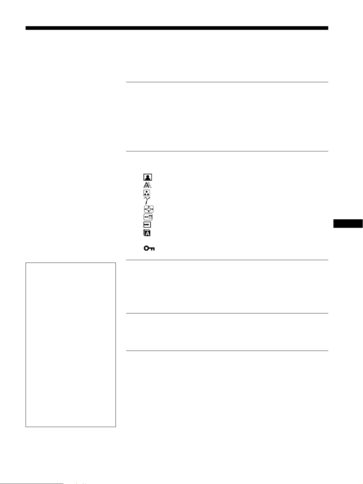
Table des matières
Précautions. . . . . . . . . . . . . . . . . . . . . . . . . . . . . . . . . . . . . . . . . . . . 4
Identification des composants et des commandes. . . . . . . . . . . . . . 5
Installation . . . . . . . . . . . . . . . . . . . . . . . . . . . . . . . . . . . . .6
Réglage 1 : Raccordez les câbles de signal vidéo . . . . . . . . . . . . . 6
Réglage 2 : Branchez le câble d’alimentation . . . . . . . . . . . . . . . . . 7
Réglage 3 : Regroupez les cordons et les câbles . . . . . . . . . . . . . . 8
Réglage 4 : Mettez le moniteur et l’ordinateur sous tension . . . . . . 8
Réglage 5 : Réglez la hauteur et le degré d’inclinaison. . . . . . . . . . 9
Sélection du signal d’entrée (Touche INPUT) . . . . . . . . . . . . . . . . 10
Personnalisation de votre moniteur. . . . . . . . . . . . . . . .11
Navigation dans le menu . . . . . . . . . . . . . . . . . . . . . . . . . . . . . . . . 11
Menu RÉGLAGE IMAGE . . . . . . . . . . . . . . . . . . . . . . . . . . . . 12
Menu ECRAN (signal RVB analogique uniquement) . . . . . . . 13
Menu COULEUR . . . . . . . . . . . . . . . . . . . . . . . . . . . . . . . . . . 14
Menu GAMMA . . . . . . . . . . . . . . . . . . . . . . . . . . . . . . . . . . . . 15
Menu ZOOM. . . . . . . . . . . . . . . . . . . . . . . . . . . . . . . . . . . . . . 15
Menu POSITION MENU. . . . . . . . . . . . . . . . . . . . . . . . . . . . . 15
Menu DÉTECTE ENTRÉE ACTIVÉE/DESACTIV . . . . . . . . . 16
Menu LANGUAGE . . . . . . . . . . . . . . . . . . . . . . . . . . . . . . . . . 16
0 Menu REINITIALISATIO. . . . . . . . . . . . . . . . . . . . . . . . . . . . . 16
Menu VERROU DU MENU . . . . . . . . . . . . . . . . . . . . . . . . . . 17
FR
• Macintosh est une marque commerciale
sous licence d’Apple Computer, Inc.,
déposée aux Etats-Unis et dans d’autres
pays.
• Windows
Microsoft Corporation aux Etats-Unis et
dans d’autres pays.
• IBM PC/AT et VGA sont des marques
déposées d’IBM Corporation aux EtatsUnis.
• VESA et DDC
commerciales de Video Electronics
Standards Association.
ENERGY STAR est une marque
•
déposée aux Etats - U nis.
• Adobe et Acrobat sont des marq ues
commerciales de Adobe Systems
Incorporated.
• Tous les autres noms de produit
mentionnés dans le présen t m ode
d’emploi peuvent être de s ma rque s
commerciales ou des marques déposé es
de leurs entreprises respectives.
• De plus, les symboles
pas systématiquement mentionnés dans
ce mode d’emploi.
est une marque déposée de
sont des marques
«»
«»
et
ne sont
Spécifications techniques. . . . . . . . . . . . . . . . . . . . . . . .17
Fonction d’économie d’énergie. . . . . . . . . . . . . . . . . . . . . . . . . . . . 17
Réduction de la consommation électrique (Mode ECO). . . . . . . . . 18
Fonction de réglage automatique de la qualité de l’image
(signal RVB analogique uniquement) . . . . . . . . . . . . . . . . . . . . . . . 18
Dépannage . . . . . . . . . . . . . . . . . . . . . . . . . . . . . . . . . . . .19
Messages affichés . . . . . . . . . . . . . . . . . . . . . . . . . . . . . . . . . . . . . 19
Symptômes de défaillance et remèdes. . . . . . . . . . . . . . . . . . . . . . 20
Spécifications. . . . . . . . . . . . . . . . . . . . . . . . . . . . . . . . . .22
TCO’99 Eco-document (for the black model) . . . . . . . . . . . . . . . . . . .i
TCO’03 Eco-document (for the gray model). . . . . . . . . . . . . . . . . . . ii
http://www.sony.net/
3
Page 28
Précautions
Avertissement sur les connexions d’alimentation
• Utilisez le câble d’alimentation four ni. Si vous utilisez un câ ble
d’alimentation différent, assurez-vous qu’il est compatible
avec la tension secteur locale.
Pour les clients aux Etats-Unis
Si vous n’utilisez pas le câble approprié, ce moniteur ne sera
pas conforme aux normes FCC obligatoires.
Pour les clients au Royaume-Uni
Si vous utilisez le moniteur au Royaume-Uni, veuillez utiliser
le câble d’alimentation adapté au Royaume-Uni.
Exemples de types de fiches
pour 100 à 120 V CA pour 200 à 240 V CA pour 240 V CA
uniquement
L’appareil doit être installé à proximité d ’une prise de c ourant
aisément accessible.
Installation
N’installez pas et ne laissez pas le moniteur :
• A des endroits ex po s é s à des températ u r es extrêmes, pa r
exemple à proximité d’un radiateur, d’un conduit de chauffage
ou exposé directement au soleil. L’exposition du moniteur à des
températures extrêmes, comme dans l’habitacle d’une vo iture
garée en plein soleil ou à proximité d’un conduit de chauffage,
risque d’entraîner de s déf ormations du châssis ou de s
dysfonctionnements.
• A des endroits soumis à des vibrations mécaniques ou à des chocs.
• A proximité d’appareils générant de puissants champs
magnétiques, comme un téléviseur ou d’autres appareils
électroménagers.
• A des endroit soumis à des quantités inhabituelles de poussière,
de saletés ou de sable, par exemple à côté d’une fenêtre ouverte
ou d’une porte donnant sur l’extérieur. En cas d’installation
temporaire à l’extérieur, veillez à prendre les précautions requises
contre la poussière et les saletés en suspension dans l’air. Faute
de quoi des dommages irréparables risquent de se produire.
Manipulation de l’écran LCD
• Ne laissez pas l’écran LCD face au soleil, car vous risquez
sinon de l’endommager. F a ites do nc a ttention si vous installez
le moniteur à côté d’une fenêtre.
• N’appuyez pas sur la surface de l’écran LCD et veillez à ne pas
l’érafler. Ne posez pas d’objets lourd s sur l’écran LCD. Vous
risquez sinon d’altérer l’uniformité de l’écran ou de provoquer
un dysfonctionnement de l ’ écran LCD.
• Lorsque le moniteur est utilisé dans un environnem ent froid, il
est possible qu’une image rémanente apparaisse sur l’écran. Il
ne s’agit pas d’un dysfonctionnemen t. L ’ écran recouvre sa
condition normale dès que la température est revenue à un
niveau normal.
• Si une image fixe reste affichée pendant une longue durée, il se
peut qu’une image rémanente apparaisse pendant un certain
temps. Cette image rémanente finira par disparaître.
• Le panneau LCD s’échauffe en cours d’utilisation. Il ne s’agit
pas d’un dysfonctionnement.
Remarque sur l’écran à cristaux liquides (LCD Liquid Crystal Display)
Veuillez noter que l’écran LCD est issu d’une technologie de
haute précision. Toutefois, il est possible que des points noirs ou
des points brillants de lumière (rouges, bleus ou verts)
apparaissent constamment sur l’écran LCD, ainsi que des bandes
de couleurs irrégulières ou une certaine luminosité. Il ne s’agit pas
d’un dysfonction n eme nt.
(Points effectifs : supérieurs à 99,99%)
Entretien
• Débranchez le câble d’alimentation de la prise secteur avant de
procéder au netto ya g e de vot r e mo niteur.
• Nettoyez l’écran LCD avec un chiffon doux. Si vous utilisez un
liquide de nettoyage pour le verre, n’utilisez pas de nettoyant
contenant une solution antistatique ou tout autre additif
similaire, car vous risquez sinon de griffer le revêt ement de
l’écran LCD.
• Nettoyez le châss is, le pa nne au et le s comm andes à l’ai de d’u n
chiffon doux légèrement imprégné d’une solution détergente
neutre. N’utilisez aucun type de tampon abrasif, de poudre à
récurer ou de solv ant tel que de l’alcool ou de l’essence.
• Ne frottez pas, ne touchez pas et ne tapotez pa s l a sur f ace de
l’écran avec des o bjets pointus ou abrasifs comm e un stylo à bille
ou un tournevis. C e type de c ontact risq ue de raye r le tube im age.
• Sachez qu’une détérioration des matériaux ou du revêtement de
l’écran LCD risque de se produire si le moniteur est exposé à
des solvants volatiles comme des insecticides ou en cas de
contact prolongé avec des objets en caoutchouc ou en vinyle.
Transport
• Débranchez tous les câbl es du moniteur, puis, après avoir
réglé l’écran LCD à son point le plus haut, saisissez
fermement les deux côtés de l’écran LCD en prena nt soin de ne
pas rayer ce dernier pe nd a nt le transport. En cas de chute du
moniteur, vous ris qu e z de l’en dommager ou de vous ble s s er.
• Pour transporter ce moniteur pour le faire réparer ou l’expédier,
utilisez le carton et les matériaux d e conditionneme nt d’origine.
Elimination du moniteur
• Ne jetez pas ce moniteur avec les ordures
ménagères.
• Le tube fluorescent utilisé dans ce moniteur con tient
du mercure. L’élimination de ce moniteur doit être
effectuée conformément aux réglementations des
autorités locales compétentes en matière de propreté
publique.
4
Page 29

Identification des composants et
des commandes
Pour plus de détail s , reportez-vous aux pages indiquées entre
parenthèses.
Avant de l’écran LCD
1
MENU
OK
INPUT
ECO
MENU
2
Arrière du support de l’écran
8
A Commutateur 1 (alimentation) et indicateur 1
(alimentation) (pages 8, 17)
Ce commutateur met le moniteur sous tension lorsque
l’indicateur d’alimentation 1 s’allume en rouge. Appuyez de
nouveau sur ce commu ta t e ur po ur me ttre le moniteur hors
tension.
Si l’indicateur 1 (alimentation) ne s’allume pas, appuyez sur
le commutateur MAIN POWER (7).
Vue latérale de l’écran LCD
INPUT
MAIN POWER
OK
ECO
3
4
5
6
B Touche MENU (page 11)
Cette touche permet d’activer et de désactiver l’écran de
menu.
C Touches m/M (page 11)
Ces touches servent à sélectionner les optio ns de menu et à
régler les paramètres.
D Touche OK (page 11)
Cette touche active les réglages et les options de menu
sélectionnés à l’aide des tou ches m/M (3).
E Touche INPUT (page 10)
Cette touche permet de commuter le sign al d’entrée vidéo
entre INPUT1, IN PU T2 et IN PUT3 lo rsqu e d eux ordi nate urs
sont raccordés au moni teur.
F Touche ECO (page 18)
Cette touche permet de réduire la consommation électrique.
G Commutateur MAIN POWER (page 8)
Ce commutateur d’alimentation principale met le moniteur
sous et hors tension.
H Panneau arrière (page 6)
Retirez ce capot pour raccorder des câbles ou des cordons.
FR
7
5
Page 30
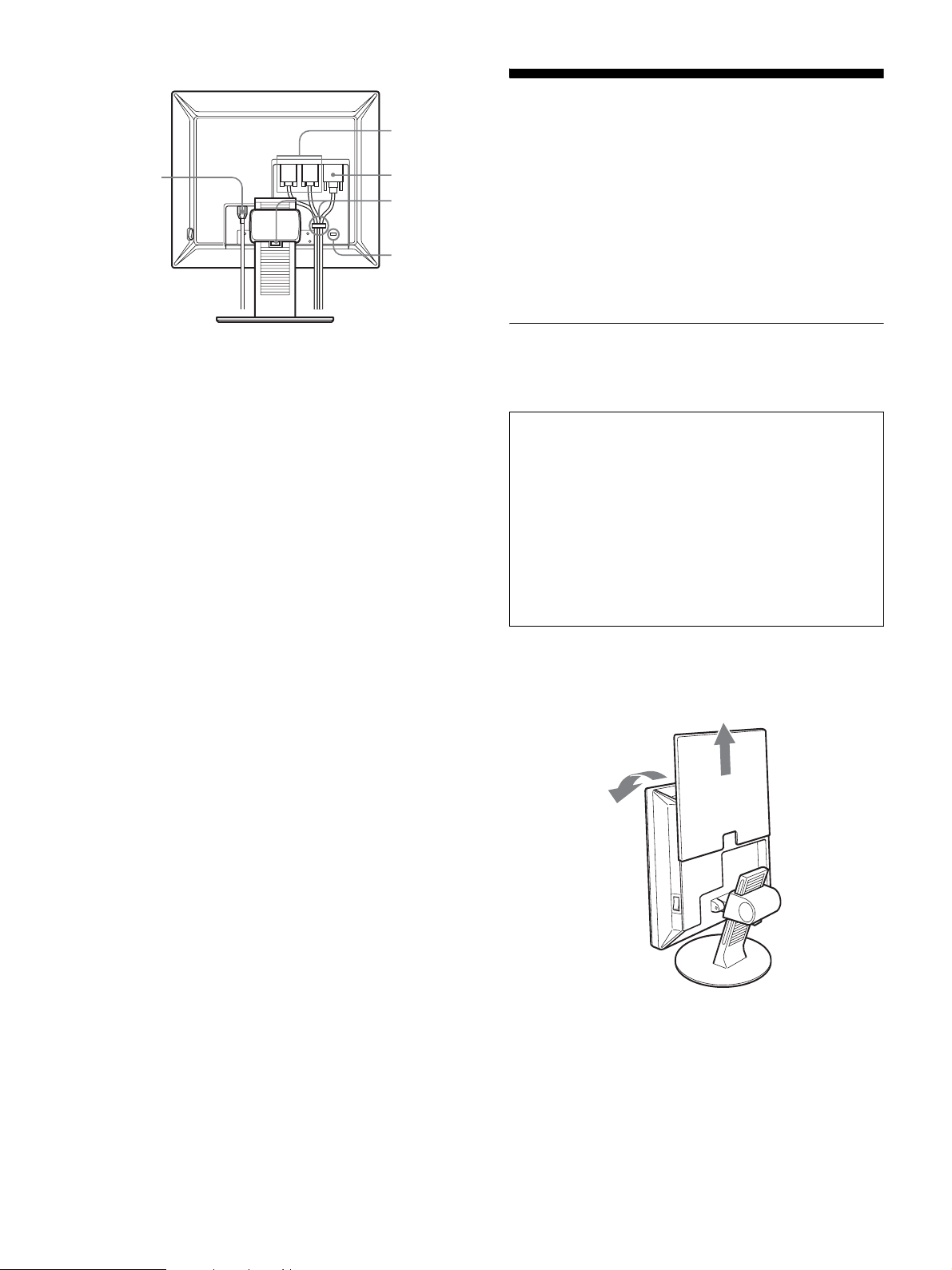
Arrière de l’écran LCD
Installation
q;
9
qa
qs
qd
I Connecteur AC IN (page 7)
Ce connecteur raccorde le cordon d’alimentation (fourni).
J Connecteur d’entrée HD15 (RVB analogique)
(page 7)
Ce connecteur transmet des signaux vidé o R V B analogiques
(0,700 Vc-c, positifs) et des signaux de sync hronisation.
K Connecteur d’entrée DVI-D (RVB numérique)
(page 7)
Ce connecteur transmet des signaux vidéo RVB numériques
conformes à la DVI Rév. 1.0.
L Support de câbles (page 8)
Cette pièce permet de maintenir l es câbles et les cordons
contre le moniteur.
Avant d’utiliser votre moniteur, vérifiez que les accessoires
suivants se trouvent bien dans le carton d’emballage :
• Ecran LCD
• Câble d’alimentation
• Câble de signal vidéo HD15-HD15 (RVB analogique)
• Câbl e de signal vidéo DVI-D (RVB numérique)
• CD-ROM (logiciel utilitaire pour Windows et Macintosh,
mode d’emploi, etc.)
• Carte de garantie
• Guide de configuration rapide
Réglage 1 : Raccordez les câbles
de signal vidéo
• Mettez le moniteur et l’ordinateur hors tension avant
d’effectuer le raccordement.
• Lorsque vous raccordez l’ordinateur au connecteur
d’entrée HD15 (RVB analogique) du moniteur,
reportez-vous à «Raccordez un ordina teur équi pé d ’un
connecteur de sortie HD15 (RVB analogique). »
Remarques
• Ne touchez pas les broches du connecteur du câble de signal vidéo,
car vous risquez sinon de plier les broches.
• Vérifiez l’aligne m ent du c onne cteur HD15 pour ne pas tordre les
broches du connecteur du câble de signal vidéo.
M Orifice de verrouillage de sécurité
L’orifice de verrouillage de sécurité doit être utilisé ave c le
système Kensington Micro Saver Security System.
Micro Saver Security System est une marque commerciale de
Kensington.
1 Faites coulisser le panneau arrière vers le haut.
2 Faites basculer l’écran vers l’avant.
6
Page 31

Raccordez un ordinateur équipé d’un connecteur
de sortie DVI (RVB numérique)
Raccordez l’ordinateur au con necteur d’entrée DVI-D du
moniteur (RVB nu mérique) à l’aide du câb le de signal vidéo DVID (RVB numérique) fourni .
vers le connecteur
d’entrée DVI-D
(RVB numérique)
vers le connecteur de sortie DVI
de l’ordinateur (RVB numérique)
câble de signal
vidéo DVI-D (RVB
numérique) (fourni)
x Raccordement à un Macintos h
vers le connecteur
d’entrée HD 15
(RVB analogique)
vers le connecteur de
sortie de l’ordinateur
câble de signal vidéo
HD15-HD15 (RVB
analogique) (fourni)
Macintosh
En cas de raccordement d’un ordinateur Macintosh, utilisez si nécessaire
un adaptateur (non fourni). Raccordez l’adaptateur à l’ordinateur avant de
raccorder le câble du signal vidéo.
Raccordez un ordinateur équipé d’un connecteur
de sortie HD15 (RVB analogique)
Raccordez l’ordin a teur au connecteur d’entrée HD 15 du
moniteur (RVB analogique) à l’aide du câble de signal vidéo
HD15-HD15 (RVB analogique) fourni.
Raccordez l’ordinateur comme illustré ci-après.
x Raccordement à un ordinateur IBM PC/AT
ou compatible
vers le connecteur
d’entrée HD 15
(RVB analogique)
vers le connecteur de sortie HD15
de l’ordinateur (RVB analogique)
câble de signal vidéo
ordinateur IBM PC/AT ou
compatible
HD15-HD15
(RVB analogique)
(fourni)
Réglage 2 : Branchez le câble
d’alimentation
1 Raccordez solidement le cordon d’alimentation
fourni au connecteur AC IN du moniteur.
2 Raccordez solidement l’autre extrémité du c ordon à
une prise secteur.
1
vers
AC IN
vers une prise secteur
2
câble d’alimentation (fourni)
FR
7
Page 32

Réglage 3 : Regroupez les cordons
Réglage 4 : Mettez le moniteur et
et les câbles
1 Faites coulisser le panneau arrière vers le haut.
2 Sécurisez les câbles de signal vidéo à l’aide du
support de câbles du boîtier.
3 Faites coulisser le panneau arrière vers le bas.
4 Regroupez tous les cordons et les câbles en les
passant dans le support de câbles du trépied du
moniteur.
13
panneau arrière
2
l’ordinateur sous
tension
1 Si vous n’avez pa s encore a ppuyé des sus, appuye z
sur le commutateur MAIN POWER situé sur le côté
droit du moniteur, vers [ (marche). Vérifiez que
l’indicateur d’alimentation 1 est allumé en rouge.
Remarque
Le commutateur MAIN POWER du moniteur est réglé par défaut
sur [ (marche).
L’indicateur
s’allume en rouge
MAIN POWER
2 Appuyez sur le comm utateur d’alimentation 1 situé
à droite à l’avant du moniteur.
L’indicateur d’alimentation 1 s’allume en vert.
4
Remarque
Si vous ne parvenez pas à regrouper tous les cordons et tous les câbles en
les passant dans le support de câbles du trépied du m oni teur, la issez-les
pendre.
L’indicateur
s’allume en vert
3 Mettez l’ordinateur sous tension.
4 Appuyez sur la touche INPUT et sélectionnez le
signal d’entrée souhaité.
L’image en entrée sélectionn ée s’affi che à l’écran.
Pour plus d’informations, voir «Sélection du signal d’entrée
(Touche INPUT) » à la page 10.
INPUT
L’installation de votre moniteur est à présent terminée. Si
nécessaire, utilisez les commandes du moniteur pour régler
l’image (page 11).
8
Page 33

Si aucune image n’apparaît sur l’écran
• Vérifiez que le cordon d’alimentation et le câble du signal
vidéo sont correctement racco rd és.
Réglage 5 : Réglez la hauteur et le
degré d’inclinaison
• Si l’indication « PAS D’ENTREE VIDEO » apparaît sur
l’écran :
– L’ordinateur est en mode d’économie d’énergie. Essayez
d’appuyer sur n’importe quelle touche du clavier ou déplacez
la souris.
– Vérifiez que le réglage du s ig nal d’entrée est correct en
appuyant sur la touche INPUT (page 10).
• Si l’indication « CABLE NON CONNECTÉ » apparaît sur
l’écran :
– Vérifiez que le câble de signal vidéo est raccordé
correctement.
– Vérifiez que le réglage du s ig nal d’entrée est correct en
appuyant sur la touche INPUT (page 10).
• Si l’indication « HORS PLAGE FRÉQUENCES » apparaît sur
l’écran, reconnectez l’ancien moniteur. Réglez ensuite la carte
graphique de l’ordinateur dans les plages suivantes.
RVB analogique RVB numérique
Fréquence
horizontale
Fréquence
verticale
28–92 kHz 28–75 kHz
48–85 Hz 60 Hz
Résolution 1600 × 1200 ou moins
Ce moniteur peut être ajusté selon les angles indiqués ci-dessous.
Tenez le panneau LCD par les côtés, puis ajustez
l’angle de vue de l’écran.
environ
100 mm
environ 5°
environ 20°
FR
Pour des informations détaillées sur les messages à l’écran, voir
« Symptômes de défaillance et remèdes » à la page 20.
Vous n’avez besoin d’aucun pilote spécifique
Ce moniteur est compatible avec la nor me Plug & Pl ay « DDC » et dé tecte
automatiquement to ut es les informations relativ es au mo ni teur. Il n’est
pas nécessaire d’installer de pil ot e sur l’ ordinateur.
La première fois que vous mettez sous tension votre ordinateur après avoir
raccordé le moniteur, l’ assist ant de réglage peut s’afficher sur l’é cran.
Dans ce cas, suivez les instructions indiquées sur l’écran. Le moniteur
Plug & Play est automatiquement sélectionné afin que vous puissiez
l’utiliser.
La fréquence verticale devi ent 60 Hz.
Etant donné que les scintillemen ts sur le mo ni te ur sont di scr e ts, vous
pouvez l’utiliser tel qu el. Vous n’avez pas besoin de régl er la fréquence
verticale sur une valeur particulièrement élevée.
environ
175°
environ 175°
Pour une utilisation confortable du moniteur
Ajustez l’angle de visualisation de votre moniteur en fonction de
la hauteur de votre bureau et de votre chaise pour que la lumière
de l’écran ne se réfléchisse pas dans vos yeux.
Remarque
Procédez lentement et avec précaution lors du réglage de l’inclinaison et
de la hauteur de l’écran, en veillant à ne pas cogner le moniteur contre le
bureau.
9
Page 34

Sélection du signal d’entrée
(Touche INPUT)
Appuyez sur la touche INPUT.
Le signal d
’entrée change à chaque pression sur cette touche.
INPUT
Message à l
pendant environ 5 secondes
dans le coin supérieur gauche).
INPUT1 : HD15 Connecteur d
INPUT2 : HD15 Connecteur d
INPUT3 : DVI-D Connecteur d
’écran (s’affiche
Configuration du signal en
entrée
(RVB analogique) pour
INPUT1
(RVB analogique) pour
INPUT2
(RVB numérique) pour
INPUT3
’entrée HD15
’entrée HD15
’entrée DVI-D
10
Page 35

Personnalisation de votre
moniteur
4 Réglez l’option.
Appuyez sur les touches m/M pour procéder au réglage,
appuyez ensuite sur la touche OK.
Lorsque vous appuyez sur la tou che OK, le réglage est
mémorisé et l’appareil revient au menu précédent.
Avant de procéder aux réglages
Raccordez le moniteur et l’ordinateur, puis mettez-les sous
tension.
Pour obtenir de s résultats optimaux, attendez au moins 30
minutes avant d’effec tuer les réglages.
Vous pouvez effectuer de nombreux réglages à l’aide des menus
d’affichage.
Navigation dans le menu
1 Affichez le menu principal.
Appuyez sur la touche MENU pour afficher le menu principal
sur votre écran.
MENU
,
2 Sélectionnez le menu.
Appuyez sur les touches m/M pour afficher le menu de votre
choix. Appuyez sur la to uche OK pour passer à la première
option de menu.
RÉGLAGE IMAGE
HAUT
: 1 0 0
: 7 0
: 5 0
LISSAGE
1600 1200 60Hzx/
EX I T
OK
,
5 Quittez le menu.
Appuyez une fois sur la touche MENU pour revenir en mode
de visualisation normale. Si vous n’actionnez aucune touche,
le menu se referme automatiquement au bout d’environ 45
secondes.
MENU
x Réinitialisation des réglages aux réglages
par défaut
Vous pouvez réinitialiser les réglages à l’aide du menu
REINITIALISATIO. Pour de plus amples informations sur la
réinitialisation des réglages, reportez-vous à la section 0
(REINITIALISATIO) à la page 16.
FR
OK
,
3 Sélectionnez l’option que vous souhaitez régler.
Appuyez sur les touches m/M pour sélectionner l’opti on que
vous souhaiter ajuster, puis appuyez sur la touche OK.
OK
,
Si est l’une des options de menu.
Lorsque vous sélectionnez et que vous appuyez sur la touch e OK ,
l’affichage revient au menu précédent.
11
Page 36

Menu RÉGLAGE IMAGE
Vous pouvez régler les éléments suivants à l’aide du menu
RÉGLAGE IMAGE.
• MODE
(mode d’économie ECO)
• RETROÉCLAIRAGE
• CONTRASTE 6
• LUMINOSITÉ
• LISSAGE
Remarques
• Vous pouvez régler le rétroéclairage, le contraste et la luminosité pour
chaque mode ÉCO.
• Les réglages du menu RÉGLAGE IMAGE peuvent être effectués pour
l’entrée en cours. Vous pou vez également ajuster le s régl ages pour
d’autres entrées .
x
Sélection du MODE (mode d’économie ECO)
Vous pouvez sélectionner le mode d’image pour réduire la
consommation électrique.
Remarque
Vous pouvez égalem ent sélectionner le mode d’im a g e ave c l a touche
ECO (pages 5 et 18) située à l’avant du moniteu r .
1 Appuyez sur la touche MENU.
Le menu principal apparaît à l’écran.
2 Appuyez sur les touches m/M pour sélectionne r
(RÉGLAGE IMAGE), puis appuyez sur la touch e OK.
Le menu RÉGLAGE IMAGE apparaît à l’écran.
3 Appuyez sur les touches m/M pour sélectionner
« HAUT », puis appuyez sur la touche OK.
Le menu « MODE » apparaît à l’écran.
MODE
HAUT
MOYEN
BAS
UTILISATEUR
1600 1200 60Hzx/
4 Appuyez sur les touches m/M pour sélectionner le
mode souhaité, puis appuyez sur la touche OK.
La luminosité de l’écran est modifiée lorsque le m ode passe à
HAUT t MOYEN t BAS, et la consommation électrique
est réduite. Lors de la sélection de « UTILISATEUR », la
luminosité de l’écran s’ajuste au niveau que vous avez défini
à l’aide de la touche ECO à l’avant du moniteur. Pour obtenir
davantage d’info rmations, reportez- vous à la section
« Réduction de la consommation électrique (Mode ECO) » à
la page 18.
RÉGLAGE IMAGE
HAUT
: 1 0 0
: 7 0
: 5 0
LISSAGE
1600 1200 60Hzx/
EX I T
EX I T
2 Appuyez sur les touches m/M pour sélectionner
(RÉGLAGE IMAGE), puis appuyez sur la
touche OK.
Le menu RÉGLAGE IMAGE apparaît à l’écran.
3 Appuyez sur les touches m/M pour sélectionner
« RETROÉCLAIRAGE », puis appuyez sur la
touche OK.
Le menu « RETROÉCLAIRAGE » apparaît à l’écran.
4 Appuyez sur les touches m/M pour aju ster le nive au
de luminosité, puis appuyez sur la touche OK.
x Réglage de CONTRASTE 6
Ajustez le contraste de l’imag e.
1 Appuyez sur la touche MENU.
Le menu principal apparaît à l’écran.
2 Appuyez sur les touches m/M pour sélectionner
(RÉGLAGE IMAGE), puis appuyez sur la touch e OK.
Le menu RÉGLAGE IMAGE apparaît à l’écran.
3 Appuyez sur les touches m/M pour sélectionner
« 6 CONTRASTE », puis appuyez sur la touche OK.
Le menu « CONTRASTE » appara ît à l’é cra n .
4 Appuyez sur les touches m/M pour régler le
contraste, puis appuyez sur la touche OK.
x Réglage de LUMINOSITÉ
Ajustez la luminosité de l’image (niveau du noir).
1 Appuyez sur la touche MENU.
Le menu principal apparaît à l’écran.
2 Appuyez sur les touches m/M pour sélectionne r
(RÉGLAGE IMAGE), puis appuyez sur la touch e OK.
Le menu RÉGLAGE IMAGE apparaît à l’écran.
3 Appuyez sur les touches m/M pour sélectionner
« LUMINOSITÉ », puis appuyez sur la touche
OK.
Le menu « LUMINOSITÉ » apparaît à l’écran.
4 Appuyez sur les touches m/M pour régler la
luminosité, puis appuyez sur la touche OK.
x Réglage de RETROÉCLAIRAGE
Si l’écran est trop lumineux, ajustez le rétroéclai rage pour re ndre
l’écran plus agréable à regarder.
1 Appuyez sur la touche MENU.
Le menu principal apparaît à l’écran.
12
Page 37

x Réglage du LISSAGE
Si l’image affichée en mode PLEIN2 ou PLEIN1 de la fonction
ZOOM n’est pas lisse, utilisez la fonction de lissage de l’image.
1 Appuyez sur la touche MENU.
Le menu principal apparaît sur l’écran.
x Fonction de réglage automatique de la
qualité de l’imag e
Lorsque le moniteur reçoit un signal d’entrée, il ajuste
automatiquement la position et la netteté de l’image (phase/
horloge) et garantit la qualité de l’image qui apparaît sur
l’écran (page 18).
2 Appuyez sur les touches m/M pour sélec tionner
(RÉGLAGE IMAGE), puis appuyez sur la touc he OK.
Le menu RÉGLAGE IMAGE apparaît à l’écran.
3 Appuyez sur les touches m/M pour sélectionner
« LISSAGE », puis sur OK.
Le menu « LISSAGE » apparaît sur l’écran.
4 Appuyez sur les touches m/M pour sélectionner le
mode souhaité.
L’effet de lissage est plus visible dans ce sens :
TEXTEtSTANDARDtGRAPHIQUE.
• TEXTE : Caractère en clair. (Ce mode convient aux
applications de traitement de texte.)
• STANDARD (réglage par défaut) : Effet de lissage
standard.
• GRAPHIQUE : Images nettes. (Ce mode convient aux
CD-ROM contenant des photos ou des
illustrations.)
Remarques
• Lorsque vous réglez le menu (ZOOM) sur RÉEL, le me nu
« LISSAGE » n’est pas disponible.
• Les signaux de résolution 1600 × 120 0 sont uniquement affichés en
mode RÉEL et la fonction L ISSA GE est inactive.
Remarque
Lorsque la fonction de réglage automatique de la qualité de l’image est
activée, seul le commutateur d’alimentation 1 fonctionne.
Si la fonction de régla ge automatique de la qualité de l’image
de ce moniteur semble ne pas régler complètement l’image
Vous pouvez effectu er un autre réglage autom at iqu e de la qualité de
l’image pour le signal d’entrée réglé (voir « AUTOMATIQUE »
ci-dessous).
Si vous souhaitez effectuer d’autres réglages de la qualité de
l’image
Vous pouvez régler manuellement la netteté (phase/horloge) et la position
(horizontale/verticale) de l’image.
Ces réglages sont mémorisés et automatiquement affichés lorsque
le moniteur capte un signal d’entrée mémorisé précédemment.
x Effectuez d’autres réglages automatiques
de la qualité de l’imag e pou r le si gna l
d’entrée régl é (AUTOMATIQUE)
1 Appuyez sur la touche MENU.
Le menu principal apparaît à l’écran.
FR
2 Appuyez sur les touches m/M pour sélectionne r
(ECRAN), puis appuyez sur la touche OK.
Le menu ECRAN apparaît à l’écran.
Menu ECRAN (signal RVB
analogique uniquement)
Vous pouvez régler les éléments suivants à l’aide du menu
ECRAN.
• AUTOMATIQUE
• PHASE
• HORLOGE
• CENTRAGE H
• CENTRAGE V
Remarque
Lors de la réception de signaux RVB numériques en provenance du
connecteur d’entrée D VI-D, aucun réglage n’est nécessaire.
ECRAN
AUTOMATIQUE
PHASE
HORLOGE
CENTRAGE H
CENTRAGE V
1600 1200 60Hzx/
EX I T
3 Appuyez sur les touches m/M pour sélectionner
« AUTOMATIQUE », puis appuyez sur la touc he OK.
Procédez aux réglages appropriés de la phase, du pas et de la
position horizontale/verticale de l’écran pour le signal
d’entrée réglé et enregistrez-l es.
x Réglage manuel de la netteté de l’image
(Phase/Horloge)
Vous pouvez ajuster la netteté de l’image c omme suit. Ce réglage
est effectif lorsque l’ordinateur est raccordé au connecteur
d’entrée HD15 (RVB analogique) du moniteur.
1 Réglez la résolution sur 1600 × 1200 sur
l’ordinateur.
2 Chargez le CD-ROM.
3 Lancez le CD-ROM, sélectionnez la zone et le
modèle, puis affichez la mire de test.
Pour Windows
Cliquez sur [Utility] t [Windows]/[Win Utility.exe].
Pour Macintosh
Cliquez sur [Utility] t [Mac]/[Mac Utility].
4 Appuyez sur la touche MENU.
Le menu principal apparaît à l’écran.
5 Appuyez sur les touches m/M pour sélectionne r
(ECRAN), puis appuyez sur la touche OK.
Le menu ECRAN apparaît à l’écran.
13
Page 38

6 Appuyez sur les touches m/M pour sélectionner
« PHASE », puis appuyez sur la touche OK.
Le menu de réglage « PHASE » apparaît à l’écran.
7 Appuyez sur les touches m/M jusqu’à ce que les
rayures horizontales soient réduites au minimum.
Réglez la valeur de f a çon que les rayures horizontales soient
réduites au minimum.
8 Appuyez sur la touche OK.
Le menu principal apparaît à l’écran.
Si vous observez des bandes verticales sur tout l’écran,
ajustez le pas en effectuant les étapes suivantes.
9 Appuyez sur les touches m/M pour sélectionner
« HORLOGE », puis appuyez sur la touche OK.
Le menu de réglage « HORLOGE » apparaît à l’écran.
10 Appuyez sur les touches m/M jusqu’à ce que les
bandes verticales disparaissent.
Ajustez la valeur jusqu’à ce que les rayures verticales aient
disparu.
7 Appuyez sur les touches m/M pour centrer la mire de
test sur l’écran.
8 Cliquez sur [END] sur l’écran pour désacti ver la mire
de test.
Menu COULEUR
Vous pouvez sélecti onner le niveau de coule ur des zones de
couleur blanche de l’im age à l’aide des réglages de température
des couleurs par défaut.
Vous pouvez également régler av ec précision la température des
couleurs, si nécessaire.
COULEUR
9300K
6500K
sRGB
UTILISATEUR
RÉGLAGE
1600 1200 60Hzx/
Remarque
Vous pouvez régler la tem pérature des couleurs pour chaque mode ÉCO.
1 Appuyez sur la touche MENU.
Le menu principal apparaît à l’écran.
EX I T
11 Cliquez sur [END] sur l’écran pour désactiver la mire
de test.
x Réglage manuel de la position de l’image
(CENTRAGE H /CENTRAGE V)
Si l’image n’est pas centrée sur l’écran, ajustez le centrage de
l’image en procédant comme suit.
1 Réglez la résolution sur 1600 × 1200 sur
l’ordinateur.
2 Chargez le CD-ROM.
3 Lancez le CD-ROM, sélectionnez la zone et le
modèle, puis affichez la mire de test.
Pour Windows
Cliquez sur [Utility] t [Windows]/[Win Utility.exe].
Pour Macintosh
Cliquez sur [Utility] t [Mac]/[Mac Utility].
4 Appuyez sur la touche MENU.
Le menu principal apparaît à l’écran.
5 Appuyez sur les touches m/M pour sélectionne r
(ECRAN), puis appuyez sur la touche OK.
Le menu ECRAN apparaît à l’écran.
6 Appuyez sur les touches m/M pour sélectionner
« CENTRAGE H » ou « CENTRAGE V », puis
appuyez sur la touche OK.
Le menu de réglage «CENTRAGE H » ou
« CENTRAGE V » apparaît sur l’écran.
2 Appuyez sur les touches m/M pour sélectionner
(COULEUR), puis appuyez sur la touche OK.
Le menu COULEUR apparaît à l’écran.
3 Appuyez sur les touches m/M pour sélectionner la
température de couleur souhaitée , puis appuyez sur
la touche OK.
Les blancs passent d’une teinte bleuâtre à une teinte rougeâtre
lorsque la température passe de 9300K à 6500K.
Si vous sélectionnez « sRGB », les couleurs s’adaptent au
profil sRGB. (Le réglage de couleur sRGB est un pr otocole
industriel standard d’espace de couleur conçu pour les
produits informatiques.) Si vous sélectionnez « sRGB », les
réglages de couleur de votre ordinateur doivent être définis
selon le profil sRGB.
Remarques
• Si un ordinateur ou un autre appareil raccordé n’est pas compatible
sRGB, il est impossible de régler la couleur au profil sRGB.
• Si vous sélectionnez « sRGB », il est impossible de régler le contraste
et la luminosité dans le menu RÉGLAGE IMAGE. Vous ne pouvez pas
non plus régler le menu GAMMA.
x Réglage précis de la température des
couleurs
1 Appuyez sur la touche MENU.
Le menu principal apparaît à l’écran.
2 Appuyez sur les touches m/M pour sélectionner
(COULEUR), puis appuyez sur la touche OK.
Le menu COULEUR apparaît à l’écran.
14
Page 39

3 Appuyez sur les touches m/M pour sélectionner
« RÉGLAGE », puis appuyez sur la touche OK.
Le menu de réglage fin de la températ ure des couleurs
apparaît à l’écran.
RÉGLAGE UTILISA
R
V
B
1600 1200 60Hzx/
128
128
128
EX I T
Menu ZOOM
Le moniteur est réglé pour afficher l’image en plein écran, quel
que soit le mode ou la résolution de l’image dans le réglage par
défaut (PLEIN2).
Vous pouvez également visualiser l’image dans son format ou sa
résolution réels.
ZOOM
PLEIN2
PLEIN1
RÉEL
4 Appuyez sur les touches m/M pour sélectionner R
(rouge) ou B (bleu), puis appuyez sur la touc he OK.
Appuyez ensuite sur les touch es m/M pour ajuster la
température des couleurs, puis appuyez sur la
touche OK.
Etant donné que ce réglage modifie la température des
couleurs en augmentant ou en diminuant les composantes R et
B par rapport à V (vert), la composante V reste fixe.
5 Appuyez sur les touches m/M pour séle ctionner ,
puis appuyez sur la touche OK.
Le nouveau réglage des couleurs est enregistré dans la
mémoire et automatiquement rappelé lorsque
« UTILISATEUR » est sélectionné.
Le menu COULEUR apparaît à l’écran.
Menu GAMMA
Vous pouvez associer les nuances foncées des couleurs de l’image
affichée à l’écran à celles des couleurs originales de l’image.
GAMMA
GAMMA 1
GAMMA 2
GAMMA 3
1600 1200 60Hzx/
EX I T
1600 1200 60Hzx/
Remarque
EX I T
Les réglages du menu ZOOM peuvent être effectués pour l’entrée
en cours. Vous pouvez également ajuster les réglages pour
d’autres entrées.
1 Appuyez sur la touche MENU.
Le menu principal apparaît sur l’écran.
2 Appuyez sur les touches m/M pour sélectionner
(ZOOM), puis appuyez sur OK.
Le menu ZOOM apparaît sur l’écran.
3 Appuyez sur les touches m/M pour sélectionner le
mode souhaité.
• PLEIN2 (réglage par défaut) : Le signal d’entrée
s’affiche en plein écran, quel que soit le mode ou
la résolution de l’image.
• PLEIN1 : Le signal d’entrée s’affiche sur l’écran en
fonction du rapport hauteur/largeur en cours. Par
conséquent, des bandes noires peuvent apparaître
en haut et en bas de l’image, selon le signal.
• RÉEL : Le signal d’entrée s’affiche sur l’écran en
fonction de la r éso lut ion e n cour s. Le sign al s ous 1600 × 1200 est affiché au centre de l’écran,
entouré d’un cadre noir.
FR
Remarque
Vous pouvez ajuster le GAMMA pour chaque mode ECO.
1 Appuyez sur la touche MENU.
Le menu principal apparaît à l’ écran.
2 Appuyez sur les touc hes m/M pour sélec tionner
(GAMMA), puis appuyez sur la touche OK.
Le menu GAMMA apparaît à l’écran.
3 Appuyez sur les touches m/M pour sélectionner le
mode souhaité, puis appuyez sur la touche OK.
Remarque
Si vous recevez des signaux de ré sol uti on 1600 × 1200, les réglages
mentionnés ci-dessus ne sont pas disponibles. L’image s’affiche en plein
écran.
Menu POSITION MENU
Vous pouvez changer la position du menu s’il masque une image
à l’écran.
POSITION MENU
1600 1200 60Hzx/
EX I T
1 Appuyez sur la touche MENU.
Le menu principal apparaît à l’écran.
2 Appuyez sur les touches m/M pour sélectionner
(POSITION MENU), puis appuyez sur la touche OK.
Le menu POSITION MENU apparaît à l’écr a n.
15
Page 40

3 Appuyez sur les touches m/M pour sélectionner la
position de votre choix, puis appuyez sur la touc he
OK.
Vous pouvez choisir l’une des 9 positions po ur l’affichage du
menu.
Menu DÉTECTE ENTRÉE
ACTIVÉE/DESACTIV
Menu LANGUAGE
LANGUAGE
ENGL I SH
FRANÇA I S
DEUTSCH
ESPAÑOL
I TAL I ANO
1600 1200 60Hzx/
EX I T
Si vous sélectionnez AUTO ACTIVÉE dans le menu DÉTECTE
ENTRÉE ACTIVÉE/DESACTIV, le moniteur détecte
automatiquement les sign aux en entrée captés par une borne
d’entrée et change automat iquement d’entrée avant de passer en
mode d’économie d’énergie.
DÉTECTE ENTRÉE
AUTO ACTIVÉE
AUTO DESACTIV
1600 1200 60Hzx/
EX I T
1 Appuyez sur la touche MENU.
Le menu principal apparaît à l’écran.
2 Appuyez sur les touches m/M pour s électio nner
(DÉTECTE ENTRÉE ACTIVÉE/DESACTIV), puis
appuyez sur la touche OK.
Le menu DÉTECTE ENTRÉE apparaît à l’écran.
3 Appuyez sur les touches m/M pour sélectionner le
mode souhaité, puis appuyez sur la touche OK.
• ACTIVÉE : Lorsque la borne d’entrée séle ctionnée ne
reçoit aucun signal ou lorsque vous u tilisez
la touche INPUT du moniteur pour
sélectionner une borne d’entrée et que cette
borne ne capte aucun signal , le message à
l’écran s’affiche (page 19) et le moniteur
vérifie automatiquement l es signaux
d’entrée captés par d’autres bornes d’entrée
afin de commuter l’entrée.
Lorsque l’entrée est commutée, la borne
d’entrée sélectionnée est affichée dans le
coin supérieur gauche de l’écra n. Lo rsque
aucun signal n’est capté, le moniteur passe
automatiquement en mode d’économie
d’énergie.
• DESACTIV : L’entrée n’est pas commutée
automatiquement. Appuyez sur la touche
INPUT pour commu ter la source d’en trée.
1 Appuyez sur la touche MENU.
Le menu principal apparaît à l’écran.
2 Appuyez sur les touches m/M p our sélection ner
(LANGUAGE), puis appuyez sur la touche OK.
Le menu LANGUAGE apparaît sur l’écran.
3 Appuyez sur les touches m/M pour sélectionner la
langue, puis appuyez sur la touche OK.
• English : Anglais
• Français
• Deutsch : Allemand
• Español : Espagnol
• Italiano : Italien
• Nederlands : Néerlandais
• Svenska : Suédois
• : Russe
• : Japonais
• : Chinois
0 Menu REINITIALISATIO
Réinitialisation des réglages aux réglages par défaut.
REINITIALISATIO
OK
ANNULER
1600 1200 60Hzx/
1 Appuyez sur la touche MENU.
Le menu principal apparaît à l’écran.
2 Appuyez sur les touches m/M pour sélectionner 0
(REINITIALISATIO), puis appuyez sur la touche OK.
Le menu REINITIALISATIO apparaît sur l’écran.
3 Appuyez sur les touches m/M pour sélectionner le
mode de votre choix, puis appuyez sur la touch e OK.
• OK : réinitialise tout es l es données de réglages à
la configuration par défaut. Notez que le
réglage « LANGUAGE » n’est pas
réinitialisé par cette action.
• ANNULER : annule la réinitialisation et revient à l’écran
de menu.
EX I T
16
Page 41

Menu VERROU DU MENU
Verrouillez la commande des touches afin d’éviter tout réglage ou
toute réinitialisation accidentels.
VERROU DU MENU
ACTIF
INACTIF
1600 1200 60Hzx/
EX I T
Spécifications techniques
Fonction d’économie d’énergie
Ce moniteur satisfait aux crit ères d’économie d’énergie VESA,
ENERGY STAR et NUTEK. Lorsque le moniteur est raccordé à
un ordinateur ou une carte graphique vidéo compatible DPM
(Display Power Ma nagement) Standa rd, le moniteur réduit
automatiquement sa consommation d’énergie comme indiqué cidessous.
1 Appuyez sur la touche MENU.
Le menu principal apparaît à l’ écran.
2 Appuyez sur les touches m/M pour sélec tionner
(VERROU DU MENU), puis appuyez sur la touche
OK.
Le menu VERROU DU MENU apparaît sur l’écran.
3 Appuyez sur les touches m/M pour sélectionner
« ACTIF » ou « INACTIF ».
• ACTIF : seuls le commutateur d’alimentation 1 et la
touche INPUT sont actifs. Si vous tentez de
lancer une autre opération, l’icône
(VERROU DU MENU) apparaît sur l’écran.
• INACTIF : Réglez « VERROU DU MENU » sur
« INACTIF ». Si « VERROU DU
MENU » est réglé sur « ACTIF », «
VERROU DU MENU » est automatiquement
sélectionné lorsque vous appuyez sur la touche
MENU.
Mode
d’alimentation
Fonctionnement
normal
Mode ECO vert
Inactif*
(sommeil profond)
1 (alimentation)
inactif
Alimentation
principale inactive
* Lorsque votre ordinateur passe en mode « inactif », le signal d’entrée
est coupé et l’indi cation « PAS D’ENTREE VIDEO » apparaît à
l’écran. Au bout de 5 secondes, le moniteur passe en mode
d’économie d’énergie.
« Sommeil profond » est un mode d’économie d’énergie défini par
l’Environmental Protection Agency.
** L a consommation d’énergie maxi male est de 2,0 W pour une
alimentation secteur à 100-120 V.
Consommation
d’énergie
58 W (max.) vert
2,7 W (max.)** orange
2,7 W (max.) rouge
0 W désactivé
Indicateur 1
(alimentation)
FR
17
Page 42

Réduction de la consommation
Fonction de réglage automatique
électrique
Si vous appuyez à plusieurs repr ises sur la touche ECO situé à
l’avant du moniteur, vous pouvez sélectionner la luminosité de
l’écran.
ECO
Chaque mode apparaît à l’écran et la luminosité de celui-ci est
réduite en fonction du mode . Le menu disp araît automatiq uement
dans les cinq secondes.
La luminosité de l’écran et la consommation électrique sont
réduites suivant le changement de mode, de HAUT à MOYEN et
à BAS.
La luminosité de l’écran est réglée par déf a ut sur « HAUT ».
Si vous sélectionnez « UTILISATEUR », vous pouvez régler le
niveau du rétr oéclaira ge en app uyant sur le s touche s m/M lorsque
vous sélectionnez RETROECLAIRAGE dans le menu.
(Mode ECO)
ECO HAUT
ECO MOYEN
,
ECO BAS
ECO
:
:
:
:
UTILISATEUR
50
de la qualité de l’im age
(signal RVB
analogique uniquement)
Lorsque le moniteur reçoit un signal d’entrée, il
ajuste automatiquement la position et la précision
de l’image (phase/horloge) et garantit la qualité de
l’image qui apparaît sur l’écran.
Le mode préréglé par défaut
Lorsque le moniteur reçoit un signal d’entrée, il fait
automatiquemen t correspondre le signal à l’un des modes
préréglés par défaut, enreg istrés dans l a mémoire du mo niteur afin
de produire une image de haute qualité au centre de l’écran. Si le
signal d’entrée correspond au mode préréglé par défaut, l’image
apparaît autom a tiquement sur l’écr a n, avec le réglage par dé faut
approprié.
Si certains signaux d’entrée ne correspondent à
aucun mode préréglé par défaut
Lorsque le moniteur reçoit un signal d’entrée qui ne correspond à
aucun mode préréglé par défaut, la fonction de réglage
automatique de la qualité de l’image de ce m oniteur est ac tivée et
garantit l’affichage permanent d’une image claire sur l’écran
(dans les plages de fréquences suivantes du moniteur) :
Fréquence horizontale : 28–92 kHz (RVB analogique)
28–75 kHz (RVB numérique)
Fréquence verticale : 48–85 Hz (RVB anal ogique)
60 Hz (RVB numérique)
En conséquence, la première fois que le moniteur reçoit des
signaux d’entrée qui ne correspondent pas à l’un des modes
préréglés par défaut, il se peut que l’affichage de l’image à l’écran
prenne plus de temps . C e s do nnées de réglage s son t
automatiquement enregistrées dans la mémoire de sorte que le
moniteur fonct ionnera d e la même m anière la p rochaine fois qu’il
recevra des signaux correspondants à l’un des modes préréglés
par défaut.
18
Si vous ajustez la phase, le pas et la position des
images manuellement
Pour certains signaux d’entr ée, la fonction de réglage
automatique de la qualité de l’image de ce moniteur peut ne pas
ajuster complètement la position, la phase et le pas de l’image.
Dans ce cas, vous pouvez effectuer ces réglages manuellement
(page 13). Si vous effectuez ces réglages manuellement, ils sont
mémorisés comme des modes utilisateurs et sont
automatiquement rappelés lorsque le moniteur reçoit les mêmes
signaux d’entrée.
Page 43

Dépannage
Avant de prendre contact avec l’assistance techniqu e, consultez
les informations présentées dans cette section.
Messages affichés
S’il se produit une anomalie au niveau du signal d’entrée, l’un des
messages suivants apparaît sur l’écran. Pour r ésoudre l e probl ème,
voir « Symptômes de défaillance et remèdes » à la page 20.
Si l’indication « HORS PLAGE FRÉQUENCES »
apparaît sur l’écran
Cela signifie que le signal d’entr ée n’est pas pris en c harge par les
spécifications du moniteur. Vérifiez les éléments suivants.
Pour des informations détaillées sur les messages à l’écran, voir
« Symptômes de défaillance et remèdes » à la page 20.
Si « xxx,x kHz / xxx Hz » est affiché
Cela signifie que la fréquence horizo ntale ou verticale n’est
pas prise en charge par les spécification s du moniteur.
Les chiffres indiquent les fréquences horizontales et
verticales du signal d’entrée en cours.
IN FORMA T I ONS
HORS PLAGE FRÉQUENCES
ENTRÉE# : XXXXX
XXX . XkHz / XXXHz
Si « RÉSOLUTION > 1600 × 1200 » est affiché
Cela indique que la résolution n’est pas prise en charge par le s
spécifications du m oniteur (1600 × 1200 ou mo ins).
IN FORMA T I ONS
HORS PLAGE FRÉQUENCES
ENTRÉE# : XXXXX
RÉSOLUTION > 1600X1200
Si l’indication « PAS D’ENTREE VIDEO » apparaît
sur l’écran
Cela signifie qu’aucun signal n’est détecté en entrée via le
connecteur actuellement sélectionné.
Lorsque DÉTECTE ENTRÉE ACTIVÉE/DESACTIV (page 16)
est réglé sur ACTIF, le moniteur détecte un autre signal d’entrée
et commute automatiquement la source d’entrée.
INFORMATIONS
,
PAS D
ENTREE VIDEO
ENTRÉE# : XXXXX
PASSE EN MODE ÉCO
Le moniteur passe en mode d’économie d’énergie environ 5
secondes après l’affichage du message.
INFORMATIONS
,
PAS D ENTREE VIDEO
ENTRÉE# : XXXXX
PASSE EN MODE ÉCO
Si l’indication « CABLE NON CONNECTÉ »
apparaît sur l’écran
Cela signifie que le câble de signal vidéo a été déconnecté du
connecteur actuellement sélectionné.
Lorsque DÉTECTE ENTRÉE ACTIVÉE/DESACTIV (page 16)
est réglé sur ACTIF, le moniteur détecte un autre signal d’entrée
et commute automatiquement la source d’entrée.
INFORMATION
CABLE NON CONNECTÉ
ENTRÉE# : XXXXX
FR
19
Page 44

Symptômes de défaillance et remèdes
Si un problème est causé par un or dinateu r ou un a utre appar eil raccord é, repor tez-vous aux mode s d’emp loi de l’ap pareil ou de l’ordinateur
concerné.
Pour obtenir de plus amples in fo rmations et accéder à l’assistance dépannage, visitez le site Internet de support clientèle Sony à l’adresse
suivante : http://www.sony.net/
Symptôme Vérifiez ces éléments
Pas d’image
Si l’indicateur 1 (alimentation)
n’est pas allumé ou si l’indi cateur 1
(alimentation) ne s’allume pas
lorsque vous appuyez sur le
commutateur 1 (alimentation),
Si l’indicateur 1 (alimentation)
devient rouge,
Si l’indication « CABLE NON
CONNECTÉ » apparaît sur l’écran,
Si l’indication PAS D’ENTREE
VIDEO apparaît sur l’écran ou si le
voyant d’alim e nt at i on 1 est orange
ou alterne entre le vert et le orange,
Si l’indication « HORS PLAGE
FRÉQUENCES » apparaît sur
l’écran (page 19),
Si vous utilisez Windows, • Si vous avez remplacé votre ancien moniteur par ce moniteur, rebranchez l’ancien
Si vous utilisez un système
Macintosh,
• Vérifiez que le câble d’alimentation est correctement raccordé.
• Vérifiez que le commutateur MAIN POWER est activé (page 8).
• Vérifiez que le commutateur 1 (alimentation) est activé.
• Vérifiez que le câble de signal vidéo est correctement raccordé et que toutes les fiches sont
correctement branchées dans leur pri se (page 6).
• Vérifie z que les broches du connecteur d’entrée vidéo ne sont pas pliées ou enfoncées.
• Vérifiez que le régl age de sélection d’entrée est corre ct (page 10).
• Un câble de signal vidéo non fourni est raccordé. Si vous raccordez un câble de si gnal
vidéo non fourni, « CABLE NON CONNECTÉ » peut s’afficher à l’écran. Il ne s’agit pas
d’un dysfonctionnement.
• Vérifiez que le câble de signal vidéo est correctement raccordé et que toutes les fiches sont
correctement branchées dans leur pri se (page 6).
• Vérifie z que les broches du connecteur d’entrée vidéo ne sont pas pliées ou enfoncées.
• Vérifiez que le régl age de sélection d’entrée est corre ct (page 10).
xProblème causé par un ordinateur ou un autre appareil raccordé et non par
le moniteur
• L’ordinateur est en mode d’économie d’énergie. Appuyez sur une touche quelconque du
clavier ou déplacez la souris.
• Vérifiez que votre carte graphique est correctement installée.
• Vérifiez que l’alimentation de l’ordinateur est activée.
• Redémarrez l’ordinateur.
xProblème causé par un ordinateur ou un autre appareil raccordé et non par
le moniteur
• Vérifiez que la plage de fréquence vidéo est comprise dans la plage spécifiée pour le
moniteur. Si vous avez remplacé un ancien moniteur par ce moniteur, rebranchez l’ancien,
puis ajustez la carte gra p hique de l’ordinateur da n s les pla g e s suivante s :
Fréquence horizontale : 28–92 kHz (RVB analogique), 28–75 kHz (RVB numérique)
Fréquence verticale : 48–85 Hz (RVB analogique), 60 Hz (RVB numérique)
Résolution : 1600 × 1200 ou moins
moniteur et suivez la procédure suivante. Sélectionnez « SONY » dans la liste
« Fabricants » et sélectionnez « SDM-S204E » dans la liste « Modèles » dans l’écran de
sélection de périphériques Windows. Si « SDM-S204E » n’apparaît pas dans la liste
« Models », essayez « Plug & Play ».
• En cas de raccordement d’un ordinateur Macintosh, utilisez si né cessaire un adaptateur
(non fourni). Raccordez l’adaptateur à l’ordinateur avant de raccorder le câble du signal
vidéo.
20
Page 45

Symptôme Vérifiez ces éléments
L’image scintille, sautille, oscille
ou est brouillée.
L’image est floue. • Réglez la lu minosité et le contraste (page 12).
Apparition d’images fantômes. • N’utilisez pas de prolongateurs de câble vidéo et/ou de boîtiers de commutation vidéo.
L’image n’est pas centrée
correctem ent ou le format est
incorrect (signal RVB analogique
uniquement).
L’image est trop petite. • Réglez le paramètre zoom sur PLEIN2 (page 15).
L’image est sombr e. • Réglez la luminosité (page 12).
Apparition d’un motif ondulatoire
ou elliptique (moiré).
Les couleurs ne sont pas
uniformes.
Le blanc ne semble pas blanc. • Réglez la température des couleurs (page 14).
Les touches du moniteur sont
inopérantes
( apparaît sur l’écran).
La résolution affichée d ans l’écran
de menu est incorrecte.
Après avoir mis le moniteur hors
tension, l’indicateur 1
(alimentation) reste allumé
pendant un moment.
• Réglez le pas et la phase (signal RVB analogique uniquement) (page 13).
• Branchez le moniteur sur une autre prise secteur, de préférence reliée à un autre circuit.
• Cha ngez l’orientati on du moniteur.
xProblème causé par un ordinateur ou un autre appareil raccordé et non par
le moniteur
• Consultez le mode d’emplo i de votre carte gra phi que pour le régla ge approprié du mo ni te ur.
• Assur ez-vous que le mode graphique (VESA, Macintosh 19'' Color, etc.) et la fréquenc e
du signal d’entrée sont supportés par ce moniteur. Même si la fréquence est comprise dans
la plage appropriée, il se peut que certai nes cartes vidéo offrent une impulsion de
synchronisation trop étroite pour que le moniteur se synchronise correctement.
• Ce moniteur ne traite pas les signaux entrelacés. Utilisez des signaux progressifs.
• Ajustez le taux de régénération de l’ordinateur (fréquence verticale) de manière à obtenir
la meilleure image possible (60 Hz est recommandé).
• Réglez le pas et la phase (signal RVB analogique uniquement) (page 13).
• Réglez le lissage (page 13).
xProblème causé par un ordinateur ou un autre appareil raccordé et non par
le moniteur
• Réglez la résolutio n de l’ordinateur s ur 1600 × 1200.
• Vérifiez que toutes les fiches sont correctement branchées sur leur prise.
• Ajustez le pas et la phase (page 13).
• Ajustez la position de l’image (page 14). Notez que certains modes vidéo ne remplissent
pas l’écran jusqu’aux bords.
xProblème causé par un ordinateur ou un autre appareil raccordé et non par
le moniteur
• Réglez la résolutio n de l’ordinateur s ur 1600 × 1200.
• Réglez le rétro écl airage (page 12).
• Plusieurs minutes sont nécessaires avant que l’écran ne devienne lum in eux après sa mise
sous tension.
• Réglez la valeur de gamma dans le menu GAMMA (page 15).
• L’écran peut s’assombrir en fonction du mode ECO sélectionné.
• Réglez le pas et la phase (signal RVB analogique uniquement) (page 13).
• Réglez le pas et la phase (signal RVB analogique uniquement) (page 13).
• Si « VERROU DU MENU » est réglé sur « ACTIF », réglez-le sur « INACTIF »
(page 17).
• Selon le paramétrage de la carte graphique, il est possible que la résol ution affichée dans
l’écran de menu ne corresponde pas à celle de l’ordinateur.
• Lorsque le moniteur est sous tension mais que le commutateu r 1 (alimen tatio n) n’e st pa s
enfoncé, ou lorsque le monit eur est en mode d’économie d’énergie, si vous désactivez le
commutateur MAIN POWER, il se peut que l’indicateur 1 (alimentation) ne s’éteigne
pas immédiatemen t. Il ne s’agit pas d’un dysfonctionne ment.
FR
21
Page 46

Affichage des informations du moniteur
Lorsque le moniteur reçoit un si gnal vidéo, appuyez sur
la touche MENU et maintenez-la enfoncée pendant plus
de 5 secondes jusqu’à ce que la boîte de dialogue
d’informations s’affiche.
Appuyez de nouveau sur la touche MENU pour faire disparaître
la boîte de dialogue.
Exemple
MENU
Si le problème persiste , ap pelez votre revendeur Sony agréé et
fournissez-lui les informations suivantes :
• Dés ignation : SDM-S204E
• Numéro de série
• Description détaillée du problème
• Date d’achat
• Nom et spécifica tions de votre ordinateur et de votre carte
graphique
• Types de signaux d’entrée (RVB analogique/RVB numérique)
INFORMATIONS
MODEL : SDM-S204E
SER. NO : 1234567
MANUFACTURED : 2004-40
Désignation
Numéro de
série
Semaine et
année de
fabrication
Spécifications
Panneau LCD
Type de panneau : a-Si TFT à matri ce active
Taille de l’image : 20,1 pouces (51 cm)
Format du signal d’entrée
Fréquence opérationnelle RVB*
Horizontale : 28–92 kHz (RVB analogique)
28–75 kHz (RVB numérique)
Verticale : 4 8–85 Hz (RVB analogique)
60 Hz (RVB numérique)
Résolution
Horizontale : Max. 1600 points
Verticale : Max. 1200 lignes
Niveaux des signaux d’ entrée
Signal vidéo RVB analogique :
0,7 Vc-c, 75 Ω
Signal SYNC :
Niveau TTL, 2,2 kΩ
vertical séparément, ou synchro composit e )
0,3 Vc-c, 75 Ω
Signal RVB numérique (DVI) : TMDS (lien simple)
Puissance de raccordement
100–240 V, 50–60 Hz, Max. 1,2 A
Consommation électrique
Max. 58 W
Température de fonctionnement
5–35
°C
Dimensions
Ecran (verticalement):
Avec support
Largeur: 440.5 mm
Hauteur: 377.5 – 477.5 mm
Profondeur: 232.0 – 248.0 mm
Sans support
Largeur: 440.5 mm
Hauteur: 354.5 mm
Profondeur: 72.5 mm
Poids
environ 8.2 kg (avec suppo rt)
environ 6.2 kg (sans support)
Plug & Play
DDC2B
Accessoires
Voir à la page 6.
, positif
, positif ou négatif (horizontal et
, négatif (synchro sur le vert)
22
* Condition de synchronisation horizontale et verticale
recommandée
• La large ur de synchronisation horizontale doit être
supérieure à 4,8% de l a durée horizontale to tale ou 0,8 µs,
suivant la plus grande valeur.
• La largeur de suppression horizontale doit être supérieure à
2,5 µsec.
• La largeur de suppression verticale doit être supérieure à 450
µsec.
La conception et les spécifications sont sujettes à modifications
sans préavis.
Page 47

TCO’99 Eco-document (for the black
model)
x Congratulations!
You have just purchased a TCO’99 approved and labelled product! Your
choice has provided you with a product developed for professiona l use .
Your purchase has also contributed to reducing the burde n on the
environment and also to th e further development of envi ronmentally
adapted electronics products.
x Why do we have environmentally labelled com-
puters?
In many countries, environmental labelling has become an establi she d
method for encouraging t he adaptation of goods and services to t he
environment. The ma in problem , as far as comp uters and other electroni cs
equipment are concerned, is that environmentally harmful substances are
used both in the products and during their manufacture. Since it is not so
far possible to sa tisfactorily r ecycle the majo rity of elect ronics equipmen t,
most of these potentially damaging substances sooner or later enter nature.
There are also othe r characteristics of a computer, such as energy
consumption levels, that are im portant from the viewpoints of bot h th e
work (internal) and natural (external) environments. Since all methods of
electricity generation ha ve a negative effect on the environment (e.g.
acidic and climate-influencing emissions, radioactive waste), it is vital to
save energy. Electronics equipment in offices is often left running
continuously and thereby consumes a lot of energy.
x What does labelling involve?
This product meets the requirements for the TCO’99 scheme which
provides for international and e nvi ronmental labelling of persona l
computers. The labelling scheme was de ve lo ped as a joint effort by the
TCO (The Swedish Confede rat ion of Professional Employees), Svenska
Naturskyddsforeningen (The Swedish Society for Natu re Conservation)
and Statens Energim yndighet (The Swedish Nat ion al Energy
Administration).
Approval requirements cover a wide range of issues: envi ronment,
ergonomics, usabilit y, emissio n of electric and magnetic fields, energy
consumption and electrica l and fire safety.
The environmental demands impos e restrictions on the presence and us e
of heavy metals, brominated and chlorinated fla me retardants, CFCs
(freons) and chlorinate d sol vents, among other things. The product must
be prepared for recycling and the manufacturer is obliged to have an
environmental policy which must be adhered to in each country where the
company implements it s o perational policy.
Labelled products must meet strict environmental demands, for example,
in respect of the reduct io n of electric and magnetic fie ld s, physical and
visual ergonomics and good us ability.
Below you will find a brief summary of the environmental re qui rements
met by this product. The complete environment al criteria document ma y
be ordered from:
TCO Development
SE-114 94 Stockholm, Sweden
Fax: +46 8 782 92 07
Email (Internet): development@tco.se
Current information re ga rding TCO’99 approved and l abe l le d
products may also be obtained via the Internet, using the address:
http://www.tco-info.com/
x Environmental requirements
Flame retardants
Flame retardants are present in printed circuit boards, cables, wire s ,
casings and housings. Their purpose is to preve nt, or at least to del ay the
spread of fire. Up to 30% of the pla s ti c i n a computer casing can consist
of flame retardant substances. Most flame retardants cont ain bromine or
chloride, and those flame retard ants are chemica lly related to another
group of environmental toxins, PCBs. Both the flame retardants
containing bromine or chloride and the PCBs are suspected of giving rise
to severe health effect s, including reproductive da mage in fish-eating
birds and mammals, due to the bio-accumulative
retardants have bee n found in human blood and resear che r s fe ar t h at
disturbances in foetus development may occur.
The relevant TCO’99 demand requires that plastic components weighing
more than 25 grams must not contain flame retardants with organically
bound bromine or chlorine. Flame retardants are allowed in the printed
circuit boards since no substitutes are available.
* processes. Flame
Cadmium**
Cadmium is presen t in rec hargeable batteri es and in th e colour- generatin g
layers of certain computer displays. Cadmium da ma ge s the ne rvous
system and is toxic in high doses. The relevant TCO’99 requirement states
that batterie s , th e colour-generat ing layers of display sc reens and the
electrical or electronics components must not contain any cadmium.
Mercury**
Mercury is sometimes foun d in batt erie s, rel ays an d swit ches. It dama ges
the nervous system and is toxic in hi gh doses. The relevant TCO’99
requirement states that bat te rie s may not contain any mercury. It also
demands that mercury is not pr esen t in a ny of the e lectr i cal o r ele ctr onics
components associated w ith the labelled un it.
CFCs (freons)
The relevan t TCO’99 requirement states th at neither CFCs nor HCFCs
may be used during the manufa ct ure and assembly of the product. CF Cs
(freons) are sometimes used for washing printed circuit boards. CFCs
break down ozone and t hereby d amage the ozone la yer in t he strato sphere ,
causing increased reception on earth of ultraviolet light with e.g. increased
risks of skin cancer (malignant mela noma) as a consequence.
Lead**
Lead can be found in picture tubes, display screens, solders and
capacitors. Lead damages the nervous system and in higher doses, causes
lead poisoning. The relevant TCO’99 requirement permits the inclusion of
lead since no replacement has yet be en developed.
* Bio-accumulative is defined as substances which accumulate within
living organisms.
** Lead, Cadmi um and Mercury are heav y me ta ls which are Bio-
accumulative.
The energy requirements include a demand that the computer and/or
display, after a certain period of inactivity, shall reduce its power
consumption to a lower lev el in one or more sta ges. T he le ngth o f tim e to
reactivate the computer shall be reasonable for the user.
i
Page 48

TCO’03 Eco-document (for the gray
model)
x Congratulations!
The display you have just purchased carries the TCO’03
Displays label. This means that your display is designed,
manufactured and tested according to some o f the strictest
quality and environmental requirements in the world. This
makes for a high performance product, designed with the
user in focus that also minimizes the impact on our natural
environment.
x Ergonomics
• Good visual ergonomics and image quality in order to
improve the working environment for the user and to
reduce sight and strain problems. Important parameters
are luminance, contrast, resolution, reflectance, colour
rendition and image stability.
x Energy
• Energy-saving mode after a certain time – beneficial
both for the user and the environment
• Electrical safety
x Emissions
• Electromagnetic fields
• Noise emissions
x Ecology
• The product must be prepared for recycling and the
manufacturer must have a certified environmental
management system such as EMAS or ISO 14 001
• Restrictions on
- chlorinated and bromi nated flame retardants and
polymers
- heavy metals such as cadmium, mercury and lead.
involved in influencing the development of IT equipment
in a more user-friendly direction. Our labelling system
started with displays in 1992 and is now requested by user s
and IT-manufacturers all over the world.
For more information, please visit
www.tcodevelopment.com
Recycling Information
x Customer in Europe
The collection and recycling of this product has been planned
according to your co un tr y ’s rele va n t legi s lation. To ensure that
this product will be col lected a nd recycle d in way that mi nimize s
the impact on the environment, please do the following:
1. If you purchased this product for private use, contact yo ur
municipality or the waste collection system and bring the
product to this col le ction point / have the p ro duct be pick ed up
by the waste collection system. Alternatively, your retailer
might take back this if you purchase new equivalent equipment;
please check with your retailer whether he will take back this
product before bringing it. For information on your country’s
recycling arrangements, please contact the Sony representation
in your country (contact details at: www.sony-europ e.com).
Further detai ls on specifi c recycling s ystems can be found at the
following addresses:
- Belgium: www.recupel.be
- Netherlands: www.nvmp.nl (consumer electronics)
www.ictmilieu.nl (IT equipment)
- Norway: www.elretur.no
- Sweden: www.el-kretsen.se
- Switzerland: www.swico.ch
2. If you use this product professionally, check the product’s
delivery contract for take back / recycl in g arrangements and
follow the procedures described therein. Alternatively, follow
the procedures de sc ri b e d under point 1.
x Customer in USA
We Sony as a member of EIA recommends to visit URL below
http://www.eiae.org/
x Customer in Asia
http://www.sony.co.jp/SonyInfo/Environment/recycle/3R.html
The requirements included in this label have been
developed by TCO Development in co-operation with
scientists, experts, users as well as manufacturers all over
the world. Since the end of the 1980s TCO has been
ii
Page 49

2-580-335-01(1)
TFT LCD Color
Computer Display
SDM-S204E
© 2004 Sony Corporation
Page 50

Owner’s Record
The model and serial numbers are located at the rear of the unit.
Record these numbers in the spaces provided below. Refer to them
whenever you call upon your dealer regarding this product.
Model No.
Serial No.
WARNING
To prevent fire or shock hazard, do not expos e the
unit to rain or moisture.
Dangerously high voltages are present inside the
unit. Do not open the cabinet. Refer servicing to
qualified personnel only.
FCC Notice
This equipment has been tested and found to comply with the limits
for a Class B digital device, pursuant to Part 15 of the FCC Rules.
These limits are designed to provide reasonable protection against
harmful interference in a residential installation. This equipment
generates, uses, and can radiate radio frequency energy and, if not
installed and used in accordance with the instructions, may cause
harmful interference to radio communications. However, there is no
guarantee that interference will not occur in a particular installation.
If this equipment does cause harmful interference to radio or
television reception, which can be determined by turning the
equipment off and on, the user is encouraged to try to correct the
interference by one or more of the following measures:
– Reorient or relocate the receiving antenna.
– Increase the separation between the equipment and receiver.
– Connect the equipment into an outlet on a circuit different from
that to which the receiver is connected.
– Consult the dea ler or an ex perienced r adio/TV te chnician f or help.
You are cautioned that any changes or modifications not expressly
approved in this manual could void your authority to operate this
equipment.
IMPORTANTE
Para prevenir cualquier mal funcionamiento y evitar daños, por
favor, lea detalladamente este manual de instrucciones antes
de conectar y operar este equipo.
NOTICE
This notice is applicable for USA/Canada only.
If shipped to USA/Canada, install only a UL LISTED/CSA
LABELLED power supply cord meeting the following
specifications:
SPECIFICATIONS
Plug Type Nema-Plug 5-15p
Cord Type SVT or SJT, minimum 3 × 18 AWG
Length Maximum 15 feet
Rating Minimum 7 A, 125 V
NOTICE
Cette notice s’applique aux Etats-Unis et au Canada
uniquement.
Si cet appareil est exporté aux Etats-Unis ou au Canada, utiliser
le cordon d’alimentation portant la mention UL LISTED/CSA
LABELLED et remplissant les conditions suivantes:
SPECIFICATIONS
Type de fiche Fiche Nema 5-15 broches
Cordon Type SVT ou SJT, minimum 3 × 18 AWG
Longueur Maximum 15 pieds
Tension Minimum 7 A, 125 V
ENERGY STAR Partner, Sony
As an
Corporation has determined that this
product meets the
guidelines for energy efficiency.
This monitor complies with the
TCO’03 guidelines.
ENERGY STAR
If you have any questions about this product, you may call;
Sony Customer Information Services Center
1-800-222-7669 or http://www.sony.com/
Declaration of Conformity
Trade Name: SONY
Model: SDM-S204E
Responsible Party: Sony Electronics Inc.
Address: 16450 W. Bernardo Dr,
Telephone Number: 8 58-942-2230
This device complies with part 15 of the FCC rules. Operation is
subject to the following two conditions: (1) This device may not
cause harmful interference, and (2) this device must accept any
interference received, including interference that may cause
undesired operation.
BZ
03
San Diego, CA 92127 U.S.A.
(for the gray model)
This monitor complies with the
TCO’99 guidelines.
(for the black model)
2
Page 51

Inhalt
• Macintosh ist ein Warenzeichen der
Apple Computer, Inc., in den U SA und
anderen Ländern.
• Windows
Warenzeichen der Mic rosoft
Corporation in den USA und a nderen
Ländern.
• IBM PC/AT und VGA sind
eingetragene Warenze ichen der IBM
Corporation in den USA.
• VESA und DDC
der Video Electronics Standards
Association.
ENERGY STAR ist ein eing etragenes
•
Warenzeichen in den USA.
• Adobe und Acrobat sind Warenzeichen
von Adobe Systems Incorporated.
• Alle anderen in die s e m H a ndbuch
erwähnten Produktnamen können
Warenzeichen oder eingetragene
Warenzeichen der je w ei ligen
Eigentümer sein.
• Im Handbuch sind die Wa renzeichen
und eingetragen en Warenzeichen ni cht
überall ausdrücklich durch „“ und „“
gekennzeichnet.
ist ein eingetragenes
sind Warenzeichen
Sicherheitsmaßnahmen . . . . . . . . . . . . . . . . . . . . . . . . . . . . . . . . . . 4
Lage und Funktion der Teile und Bedienelemente. . . . . . . . . . . . . . 5
Installation . . . . . . . . . . . . . . . . . . . . . . . . . . . . . . . . . . . . .6
Schritt 1: Anschließen der Videosignalkabel. . . . . . . . . . . . . . . . . . 6
Schritt 2: Anschließen des Netzkabels . . . . . . . . . . . . . . . . . . . . . . 7
Schritt 3: Bündeln der Kabel . . . . . . . . . . . . . . . . . . . . . . . . . . . . . . 8
Schritt 4: Einschalten von Monitor und Computer. . . . . . . . . . . . . . 8
Schritt 5: Einstellen von Höhe und Neigung . . . . . . . . . . . . . . . . . . 9
Auswählen des Eingangssignals (Taste INPUT) . . . . . . . . . . . . . . 10
Einstellen des Monitors. . . . . . . . . . . . . . . . . . . . . . . . . .11
Navigieren in den Menüs . . . . . . . . . . . . . . . . . . . . . . . . . . . . . . . . 11
Menü BILD EINSTELLEN . . . . . . . . . . . . . . . . . . . . . . . . . . . 12
Menü BILDSCHIRM (nur analoges RGB-Signal). . . . . . . . . . 13
Menü FARBE . . . . . . . . . . . . . . . . . . . . . . . . . . . . . . . . . . . . . 14
Menü GAMMA . . . . . . . . . . . . . . . . . . . . . . . . . . . . . . . . . . . . 15
Menü ZOOM. . . . . . . . . . . . . . . . . . . . . . . . . . . . . . . . . . . . . . 15
Menü POSITION MENÜ. . . . . . . . . . . . . . . . . . . . . . . . . . . . . 16
Menü EINGANGSERKENN EIN/AUS . . . . . . . . . . . . . . . . . . 16
Menü LANGUAGE . . . . . . . . . . . . . . . . . . . . . . . . . . . . . . . . . 16
Menü 0 ZURÜCKSETZEN . . . . . . . . . . . . . . . . . . . . . . . . . . . . 16
Menü MENÜ-SPERRE. . . . . . . . . . . . . . . . . . . . . . . . . . . . . . 17
Technische Merkmale . . . . . . . . . . . . . . . . . . . . . . . . . . .17
Die Energiesparfunktion . . . . . . . . . . . . . . . . . . . . . . . . . . . . . . . . . 17
Verringern der Leistungsaufnahme (ECO-Modus). . . . . . . . . . . . . 18
Automatische Einstellung der Bildqualität
(nur analoges RGB-Signal). . . . . . . . . . . . . . . . . . . . . . . . . . . . . . . 18
Störungsbehebung . . . . . . . . . . . . . . . . . . . . . . . . . . . . .19
Bildschirmmeldungen . . . . . . . . . . . . . . . . . . . . . . . . . . . . . . . . . . . 19
Fehlersymptome und Abhilfemaßnahmen . . . . . . . . . . . . . . . . . . . 20
Technische Daten . . . . . . . . . . . . . . . . . . . . . . . . . . . . . .22
TCO’99 Eco-document (for the black model) . . . . . . . . . . . . . . . . . . .i
TCO’03 Eco-document (for the gray model). . . . . . . . . . . . . . . . . . . ii
DE
Dieser Monitor ist für MultimediaAnwendungen gedac ht .
http://www.sony.net/
3
Page 52

Sicherheitsmaßnahmen
Warnhinweis zum Netzanschluss
• Verwenden Sie ausschließlich das mitgelieferte Netzkabel.
Wenn Sie ein anderes Netzkabel verwenden, achten Sie darauf,
dass es für die Stromversorgung in Ihrem Land geeignet ist.
Für Kunden in den USA
Wenn Sie kein geeignetes Netzkabel verwenden, entspricht
dieser Monitor nicht den obligatorischen FCC-Standards.
Für Kunden in Großbritann i en
Wenn Sie den M onitor in G roßbritannien v erwenden, be nutzen Sie
bitte das Kabel mit dem für Großbritannien geeigneten Stecker.
Beispiele für Steckertypen
für 100 bis 120 V
Wechselstrom
Die Netzsteckdose sollte sich in der Nähe des Geräts be finden
und leicht zugänglich sein.
Aufstellort
Achten Sie darauf, dass der Monitor am Aufste ll- oder Lagerort
vor folgenden Bedingungen geschützt ist:
• Vor extremen Temperaturen, wie sie zum Beispiel in der Nähe
eines Heizkörpers, eines Warmluftauslasses oder in direktem
Sonnenlicht auftreten. Extreme Temperaturen, zum Beispiel in
einem in der Sonne geparkten Auto oder in der Nähe eines
Warmluftauslasses, können bei dem Monitor zu einer
Verformung des Gehäuses oder zu Fehlfunktionen führen.
• Vor mechanischen Vibrationen oder Stößen.
• Vor stark en Magnetfeldern. St ellen Sie den Monitor daher
nicht in der Nähe vo n Ger ä ten auf, die solche M agnetfelder
erzeugen, zum Beispiel Fernsehgeräten oder Haushaltsgeräten.
• Vor übermäßig viel Staub , Sc hm utz oder Sand, wie sie zum
Beispiel an einem offenen Fenste r oder einer Tür ins Freie
auftreten könn en. Wenn Sie den Monitor vorübergehend im
Freien benutzen müssen, treffen Sie geeignete
Vorsorgemaßnahmen gegen Staub- und Schmutzpartikel in der
Luft. Andernfalls kann es zu irreparablen Schäden am Gerät
kommen.
Hinweise zum LCD-Bildschirm
• Stellen Sie das Gerät nicht so auf, dass der L CD-Bildschirm auf
die Sonne gerichtet ist. Andernfalls könnte der LCDBildschirm beschädigt werden. Achten Sie darauf besonders,
wenn Sie den Monitor in der Nähe eines Fensters aufstellen.
• Stoßen Sie nicht gegen den LCD-Bildschirm und zerkratzen
Sie ihn nicht. Stellen Sie keine schweren Gegenstände auf den
LCD-Bildschirm. Dadurch könnte die Gleichmäßigkeit des
Bildes beeinträchtigt werden oder am LC D-Bildschirm
könnten Fehlfunktionen auftre ten.
• Wenn Sie den Monitor in einer kalten Umgebung benutzen,
kann ein Nachbild auf dem LCD-Bildschirm zu sehen sein.
Dies ist keine Fehlfunktion. Das Phänomen verschwindet,
sobald wieder eine normale Umgebungstemperatur erreicht ist.
• Wenn Sie über längere Zeit ein Standbild anzeigen lassen, kann
eine Zeit lang ein Nachbild zu sehen sein. Dieses Nachbi ld
verschwindet nach einer Weile wieder.
• Der LCD-Bildschirm erwärmt sich bei Betrieb. Dies ist keine
Fehlfunktion.
für 200 bis 240 V
Wechselstrom
nur für 240 V
Wechselstrom
Hinweis zum LCD-Bildschirm
(Flüssigkristallbildschirm)
Bitte beachten Sie, dass der LCD-Bildschirm in einer
Hochpräzisionstechnologie herge stellt wird. S chwarze oder he lle
Lichtpunkte (r ot, blau oder grün) können jedoch permanent auf
dem LCD-Bildschirm zu sehen sein und unregelmäßige
Farbstreifen oder helle Bereiche könn en auf dem LCDBildschirm erscheinen. Dies ist keine Fehlfunktion.
(Effektive B il dpunkte: über 99,99%)
Wartung
• Trennen Sie unbedingt das Netzkabel von der Netzsteckdose,
bevor Sie den Mo nitor reinigen.
• Reinigen Sie den LCD-Bildschirm mit einem weichen Tuch. Wenn
Sie ein Glasreinigungsmittel verwenden, achten Sie darauf, dass es
keine Antistatik-Lösung oder ähnliche Zusätze enthält, da diese zu
Kratzern auf der Beschichtung des LCD-Bildschirms führen könnten.
• Reinigen Sie Gehäuse, Bedienfeld und Bedienelemente mit einem
weichen Tuch, das Sie leicht mit einer milden Reinigungslösung
angefeuchtet haben. Verwenden Sie keine Scheuermittel,
Scheuerschwämme oder Lösungsmittel wie Alkohol oder Benzin.
• Berühren Sie d ie LCD-Bildschirmoberfläche nicht mit
scharfen, rauhen oder spitzen Gegenständen wie zum Beispiel
Kugelschreibern oder Schraubenziehern. Andernfalls könnte
die LCD-Bildschirmoberfläche zerkratzt werden.
• Beachten Sie bitte, dass es zu Materialsc häden oder zu S chäden
an der LCD-Bildschirmbeschichtung kommen kann, wenn der
Monitor flüchtigen Lösungsmitteln wie zum Beispiel
Insektiziden ausgesetzt ist oder wenn er längere Zeit mit
Gummi- oder Vinylmaterialien in Berühung kommt.
Transport
• Lösen Sie alle Kabel vom Monitor. Fixieren Sie den LCDBildsch i rm an d e r höchsten Ste l l e und halten Sie den LCD-
Bildschirm fest an beiden Seiten. Achten Sie beim Transport
darauf, dass der Bildschirm nicht zerkratzt wird. Achten Sie
beim Transport darauf, dass der Bildschirm nicht zerkratzt
wird. Wenn Sie den Monitor fallen lassen, könnten Sie sich
verletzen und der Monitor könnte beschädigt werden.
• Wenn Sie den Monitor zur Reparatur oder bei einem Umzug
transportieren müssen, verpacken Sie ihn mit Hilfe der
Originalverpackungsmaterialien wieder im Originalkarton.
Entsorgen des Monitors
• Entsorgen Sie den Monitor nicht im normalen
Hausmüll.
• Die Leuchtstoffröhre in diesem Monitor enthält
Quecksilber. Der Monitor muss in Übereinstimmung
mit den Vorschriften der lokalen Umwelt- und
Entsorgungsbehörden entsorgt werden.
4
Page 53

Lage und Funktion der Teile und
Bedienelemente
Weitere Informationen finden Sie auf den in Klammern
angegebenen Se iten.
Vorderseite des LCD-Bildschirms
1
MENU
OK
INPUT
ECO
MENU
2
3
OK
4
INPUT
Rückseite des Bildschirmständers
8
A Netzschalter 1 und Netzanzeige 1 (Seite 8, 17)
Wenn die Netzanzeige 1 rot leuchtet, dient dieser Schalter
zum Einschalten des Monitors. Drücken Sie di esen Schalter
erneut, um den Monitor wieder auszuschalten.
Wenn die Netzanzeige 1 nicht leuchtet, drücken Sie den
Hauptnetzschalter MAIN POWER (7).
B Taste MENU (Seite 11)
Diese Taste dient zum Ein- bzw. Ausblenden des Menüs.
C Tasten m/M (Seite 11)
Diese Tasten dienen zum Auswählen von Menüoptionen und
Vornehmen von Einstellungen.
D Taste OK (Seite 11)
Diese Taste dient zum Aktivieren der Menü optionen bzw.
Einstellu ngen, die mit den Ta sten m/M (3) ausgewählt
wurden.
DE
Seitenansicht des LCD-Bildschirms
MAIN POWER
ECO
7
5
6
E Taste INPUT (Seite 10)
Diese Taste dient zum Auswählen des Videoeingangssignals
von INPUT1, INPUT2 bzw. INPUT3, wenn zwei Computer
an den Monitor angeschlossen sind.
F Taste ECO (Seite 18)
Diese Taste dient zum Reduzieren der Leistungsaufnahme.
G Hauptnetzschalter MAIN POWER (Seite 8)
Mit diesem Schalter schalten Sie die Hauptstromversorgung
des Monitors ein bzw. aus.
H Hintere Abdeckung (Seite 6)
Nehmen Sie diese Abdeckung ab, wenn Sie Kabel
anschließen wollen.
5
Page 54

Rückseite des LCD-Bildschirms
Installation
q;
9
qa
qs
qd
I Netzeingang AC IN (Seite 7)
Mit diesem Anschluss verbinden Sie das Netzkabel
(mitgeliefert).
J HD 15-Eingangsanschluss (analoge s RG B) (Se ite 7)
Dieser Anschluss dient zum Einspeisen von analogen RGBVideosignalen (0,700 Vp-p, positiv) und
Synchronisationssignalen.
K DVI-D-Eingangsanschluss (digitales RGB) (Seite 7)
An diesem Anschluss werden digitale RGB-Videosignale
eingespeist, die DVI Rev. 1.0 entsprechen.
L Kabelhalter (Seite 8)
Mit diesem Teil können Sie Kabel sicher am Monitor
befestigen.
M Aussparung für die Sicherheitssperre
Die Aussparung für die Sicherheitssperre ist für ein Micro
Saver Security-System von Kensington gedacht.
Micro Saver Security System ist ein Wa renzeichen von
Kensington.
Bevor Sie mit dem Monitor arbeiten, überprüfen Sie bitte, ob
folgende Teile mitgeliefert wurden:
• LCD-Bildschirm
• Netzkabel
• HD15-HD15-Vid eosignalkabel (analoges RGB)
• DVI-D-Videosignalkabel (digitales RGB)
• CD-ROM (Dienstprogra mm f ür Windows/Macintosh,
Bedienungsanleitung usw.)
• Garantiekarte
• Kurzreferenz
Schritt 1: Anschließen der
Videosignalkabel
• Schalten Sie vor dem Anschließen den Mon itor und den
Computer aus.
• Wenn Sie den Computer an den HD15Eingangsanschluss (a naloges RGB) des Monitors
anschließen, schlage n Sie b itte unter „Anschlie ßen eines
Computers mit einem HD15-Ausgangsanschluss
(analoges RGB)“ nach.
Hinweise
• Berühren Sie die Stifte des Videosignalkabelanschlusses nicht. Sie
könnten die Stifte sonst möglicher weise verbiegen.
• Achten Sie darauf, den Stecker des Videosignalkabels korrekt am
HD15-Anschluss auszuric ht en, damit die Stifte am Stecker des
Videosignalkabels nicht verbogen werden.
1 Schieben Sie die hintere Abdeckung nach oben.
2 Neigen Sie den Bildschirm nach vorn.
6
Page 55

Anschließen eines Computers mit einem
DVI-Ausgangsanschluss (digitales RGB)
Schließen Sie den Computer mit dem mitgelieferten DVI-DVideosignalkabel (digitales RGB) an den DVI-DEingangsanschluss (digitales RGB) am Monitor an.
an den DVI-DEingangsanschluss
(digitales RGB)
an den DVI-Ausgangsanschluss
(digitales RGB) des Computers
x Anschließen an einen Macintosh
an den HD15Eingangsanschluss
(analoges RGB)
an den
Ausgangsanschluss
des Computers
HD15-HD15Videosignalkabel
(analoges RGB)
(mitgeliefert)
Macintosh
DVI-D-Videosignalkabel
(digitales RGB)
(mitgeliefert)
Anschließen eines Computers mit einem HD15Ausgangsanschluss (analoges RGB)
Schließen Sie den Computer mit dem mitgelieferten HD15HD15-Videosignalkabel (analoges RGB) an den HD15 Eingangsanschluss (analoges RGB) am Monitor an.
Schließen Sie den Computer wie in den folgenden Abbildungen
dargestellt an.
x Anschließen an einen IBM PC/AT oder
kompatiblen Computer
an den HD15Eingangsanschluss
(analoges RGB)
Wenn Sie einen Macintosh anschließen wollen, verwenden Sie
gegebenenfalls einen A da pter (nicht mitgeliefert). Schließen Sie de n
Adapter an den Comput er a n, bev or Sie das V i de osignalkabel
anschließen.
Schritt 2: Anschließen des
Netzkabels
1 Schließen Sie das mitgelieferte Netzkabel fest an
den Netzeingang AC IN des Monitors an.
2 Schließen Sie das andere Ende fest an eine
Netzsteckdose an.
1
an AC IN
DE
an den HD15-Ausgangsanschluss
(analoges RGB) des Computers
IBM PC/AT oder kompatibler
Computer
HD15-HD15Videosignalkabel
(analoges RGB)
(mitgeliefert)
an Netzsteckdose
2
Netzkabel (mitgeliefert)
7
Page 56

Schritt 3: Bündeln der Kabel
Schritt 4: Einschalten von Monitor
1 Schieben Sie die hintere Abdeckung nach oben.
2 Befestigen Sie die Videosignalkabel mithilfe des
Kabelhalters am Gehäuse.
3 Schieben Sie die hintere Abdeckung nach unten.
4 Bündeln Sie alle Kabel im Kabelhalt er des Ständers.
13
hintere Abdeckung
2
und Computer
1 Drücken Sie gegebenenfalls den Hauptnetzs chalter
MAIN POWER an der rechten Seite des Monitors in
Richtung [ (ein). Achten Sie darauf, dass die
Netzanzeige 1 rot aufleuchtet.
Hinweis
Bei Lieferung ist der Hauptnetzschalter MAIN POWER eingeschaltet [
(ein).
leuchtet rot
MAIN POWER
2 Drücken Sie den Netzschalter 1 vorne rechts am
Monitor.
Die Netzanzeige 1 leuchtet grün auf.
4
Hinweis
Wenn Sie nicht alle Kab el im K abe l hal te r des Ständers bündeln können,
lassen Sie einige herunterhäng en.
leuchtet grün
3 Schalten Sie den Computer ein.
4 Drücken Sie die Taste INPUT, um das gewünschte
Eingangssignal auszuwählen.
Das Bild vom ausgewählten Eingang erscheint auf dem
Bildschirm.
Weitere Informationen finden Sie unter „Auswählen des
Eingangssignals (Taste INPUT)“ auf Seite 10.
INPUT
Die Installation des Monitors ist damit abgesc hlossen. Stellen Sie
gegebenenfalls das Bild mit den Bedienelementen des Monitors
nach Ihren Wünschen ein (Seite 11).
8
Page 57

Wenn auf dem Bildschirm kein Bild erscheint
• Das Netzkabel und das Videosignalkabel müssen richtig
angeschlossen sein.
Schritt 5: Einstellen von Höhe und
Neigung
• Wenn „KEIN EING SIGNAL“ auf dem Bildschirm erscheint:
– Der Computer befi ndet sich im Stromsparm odus. Drücken
Sie eine beliebige Ta ste auf der Computertas tatur oder
bewegen Sie die Maus.
– Vergewissern Sie sich, dass das Eingangssignal korrekt
eingestellt ist, indem Sie die Taste INPUT drücken
(Seite 10).
• Wenn „KABEL NICHT VERBUNDEN“ auf dem Bildschirm
erscheint:
– Das Videosignalkabel muss richtig angeschlos sen sein.
– Vergewissern Sie sich, dass das Eingangssignal korrekt
eingestellt ist, indem Sie die Taste INPUT drücken
(Seite 10).
• Wenn „UNZULÄSSIGER BEREICH“ erscheint, schließen Sie
wieder Ihren alten Monitor an. Stellen Sie dann die Grafikkarte
des Computers auf folgende Werte ein.
Analoges RGB Digitales RGB
Horizontalfrequenz
Vertikalfrequenz
28–92 kHz 28–75 kHz
48–85 Hz 60 Hz
Auflösung 1600 × 1200 oder weniger
Mit dem Ständer können Sie den Monitor innerhalb der unten
abgebildeten Winkel na ch Bedarf einstellen.
Fassen Sie den LCD-Bildschirm an den Seiten und
stellen Sie den Bildschirm wie gewünscht ein.
ca.
100 mm
ca. 20°
ca. 5°
Weitere Informat ionen zu den Bildschi rmmeldungen finden Sie
unter „Fehlersymptome und Abhilfemaßnahmen“ auf Seite 20.
Spezielle Treiber werden nicht benötigt
Dieser Monitor entspricht dem Plug -and-Play-Standard „DDC“, so da ss
alle Daten des Monitors automatisch erka nnt w erd en. Daher muss kein
spezifischer Treiber au f dem Computer installiert werden.
Wenn Sie den Monitor an den Com puter anschließen und diesen dann
zum ersten Mal st art en, wir d mö gli cherweise der Hardware-Assistent auf
dem Bildschirm angezeigt. Gehe n Sie in diesem Fall nach den
Anweisungen auf dem Bildschirm vor. Der Plug-and-Play-Monitor ist
automatisch ausgewäh lt , so da ss Sie oh ne weit ere Vorbereitungen mit
diesem Monitor arbeiten kö nnen.
Die Vertikalfrequenz ist auf 60 Hz eingestellt.
Da das Flimmern auf dem Monitor fast nicht sich t ba r ist, kö n ne n Sie die
Einstellung unverändert lassen. Sie brauchen die Vertikalfrequenz nicht
auf einen besonders hohen We rt einzustellen.
DE
ca. 175°
ca. 175°
So können Sie ergonomisch mit dem Monitor
arbeiten
Berücksichtigen Sie beim Einstellen des Monitorwinkels die
Höhe von Schreibtis ch un d Stuhl un d ach ten Si e dara uf, das s auf
dem Bildschirm keine Lichtreflexe auftreten.
9
Page 58

Hinweis
Wenn Sie die Neigung und H öhe des Bildschirms einstellen, gehen Sie
langsam und vorsichtig vor . Ac hte n Si e da rauf, den Monitor nicht gegen
die Schreibtischplatte zu stoßen.
Auswähl en des Eingangssi gnal s
(Taste INPUT)
Drücken Sie die Taste INPUT.
Das Eingangssignal wechselt mit jedem Tastendruck.
INPUT
Bildschirmmeldung (erscheint
ca. 5 Sekunden lang oben
links)
INPUT1 : HD15 HD15-Eingangsanschlus s
INPUT2 : HD15 HD15-Eingangsanschluss
INPUT3 : DVI-D DVI-D-Eingangsanschluss
Konfiguration des
Eingangssignals
(analoges RGB) für INPUT1
(analoges RGB) für INPUT2
(digitales RGB) für INPUT3
10
Page 59

Einstellen des Monitors
Vor dem Einstellen
Verbinden Sie den Moni tor mit dem Computer un d schalten
Sie beide Geräte ein.
Die besten Ergebnisse erzielen Sie, wenn Sie mindestens 30
Minuten warten, bevor Sie Einstellungen vornehmen.
Mit den Bildschirmmenüs können Sie eine Viel zahl von
Einstellungen vornehmen.
4 Wählen Sie einen Wert für die Option.
Nehmen Sie die Einstellung mit den Tasten m/M vor und
drücken Sie dann OK.
Sobald Sie die Taste OK drücken, wird die Einst ellung
gespeichert und das vorheri ge Menü wird wieder angezeigt.
OK
,
Navigieren in den Menüs
1 Rufen Sie das Hauptmenü auf.
Drücken Sie die Taste MENU, um das Hauptm enü auf dem
Bildschirm aufzurufen.
MENU
,
2 Wählen Sie das Menü aus.
Wählen Sie mit den Tasten m/M das gewünschte Menü aus.
Wechseln Sie mit der Taste OK zur ersten Menüoption .
BILD EINSTELLEN
HELL
: 1 0 0
: 7 0
: 5 0
SMOOTHING
1600 1200 60Hzx/
OK
EX I T
,
5 Schließen Sie das Menü.
Wenn Sie die Taste MENU einmal drücken, erscheint wieder
die normale Anze ige. We nn Sie kein e weite re Tast e drück en,
wird das Bildschirmmenü nach etwa 45 Sekunden
automatisch ausgeblendet.
MENU
x Zurücksetzen der Werte auf die
Standardeinstellungen
Sie können die E inste llun gen übe r das Me nü Z URÜ CKSETZ EN
zurücksetzen. Weitere Informationen zum Zurücksetzen der
Einstellungen finden Sie unter 0 (ZURÜCKSETZEN) auf
Seite 16.
DE
3 Wählen Sie die einzustellende Option aus.
Wählen Sie mit den Tasten m/M die gewünschte Option und
drücken Sie dann OK.
OK
,
Wenn eine der Menüoptionen ist
Wenn Sie auswählen und die Ta ste OK drüc ken, wird wieder das
vorhergehende Menü an ge zeigt.
11
Page 60

Menü BILD EINSTELLEN
1 Drücken Sie die Taste MENU.
Das Hauptmenü erscheint auf dem Bildschirm.
Über das Menü BILD EINSTELLEN können Sie folgende
Optionen einstellen.
• MODUS (ECO-Modus)
BILD EINSTELLEN
• HINTERGRUNDBEL
• KONTRAST 6
• HELLIGKEIT
• SMOOTHING
Hinweise
• Sie können die
Hintergrundbeleucht ung, den Kontrast und die Helligkeit für jeden
ECO-Modus getrennt einstellen.
• Die Einstellungen im Menü BILD EINSTELLEN gelten für den
aktuellen Eingang. Für die anderen Eingänge können Sie ebenfalls
Einstellungen vornehmen.
HELL
: 1 0 0
: 7 0
: 5 0
SMOOTHING
1600 1200 60Hzx/
EX I T
x Auswählen von MODUS (ECO-Modus)
Sie können den Bi ldmodus auswählen und damit den
Stromverbrauch reduzieren .
Hinweis
Sie können den Bildmodus auch mit der Taste ECO (Seite 5, 18)
an der Vorderseite des Monitors eins t ellen.
1 Drücken Sie die Taste MENU.
Das Hauptmenü erscheint auf dem Bildschirm.
2 Wählen Sie mit den Tasten m/M die Option
(BILD EINSTELLEN) und drücken Sie die Taste OK.
Das Menü BILD EINSTELLEN erscheint auf dem
Bildschirm.
3 Wählen Sie mit den Tasten m/M die Option „HELL“
und drücken Sie die Taste OK.
Auf dem Bildschirm wird das Menü „MODUS“ angezeigt.
MODUS
HELL
MITTEL
DUNKEL
BENUTZER
1600 1200 60Hzx/
EX I T
4 Wählen Sie mit den Tasten m/M den gewünschten
Modus aus und drücken Sie OK.
Die Helligkeit des Bildschirms ändert sich, wenn Sie HELL
t MITTEL t DUNKEL auswählen, und die
Leistungsaufnahme wird verringert. Wenn Sie
“BENUTZER” auswählen, wechselt die Helligkeit zu dem
Wert, den Sie mit der Taste ECO an der Vorderseite des
Monitors eingestellt haben. Weitere Informationen dazu
finden Sie unter “Verringern der Leistungsaufnahme (ECOModus)” auf Seite 18.
x Einstellen von HINTERGRUNDBEL
Wenn der Bildschirm zu hell ist, stellen Sie die
Hintergrundbeleuchtung ein, so dass die Anzeigen auf dem
Bildschirm besser zu erkennen sind.
2 Wählen Sie mit den Tasten m/M die Option
(BILD EINSTELLEN) und drücken Sie dann OK.
Das Menü BILD EINSTELLEN erscheint auf dem
Bildschirm.
3 Wählen Sie mit den Tasten m/M die Option „
HINTERGRUNDBEL“ und drücken Sie dann OK.
Auf dem Bildschirm wird das Menü „HINTERGRUNDBEL“
angezeigt.
4 Stellen Sie mit den Tasten m/M die
Hintergrundhelligkeit ein und drücken Sie OK.
x Einstellen von KONTRAST 6
Hiermit können Si e den Bildkontrast einstellen.
1 Drücken Sie die Taste MENU.
Das Hauptmenü erscheint auf dem Bildschirm.
2 Wählen Sie mit den Tasten m/M die Option
(BILD EINSTELLEN) und drücken Sie dann OK.
Das Menü BILD EINSTELLEN erscheint auf dem
Bildschirm.
3 Wählen Sie mit den Tasten m/M die Option
„6 KONTRAST“ und drücken Sie dann OK.
Auf dem Bildschirm wird das Menü „KONTRAST“
angezeigt.
4 Stellen Sie mit den Tas ten m/M den Kontrast ein und
drücken Sie OK.
x Einstellen von HELLIGKEIT
Hiermit können Sie die Bildhelligkeit (Schwarzwert) einstellen.
1 Drücken Sie die Taste MENU.
Das Hauptmenü erscheint auf dem Bildschirm.
2 Wählen Sie mit den Tasten m/M die O ption (BILD
EINSTELLEN) und drücken Sie dann OK.
Das Menü BILD EINSTELLEN erscheint auf dem
Bildschirm.
3 Wählen Sie mit den Tasten m/M die Option „
HELLIGKEIT“ und drücken Sie dann OK.
Auf dem Bildschirm wird das Menü „HELLIGKEIT“
angezeigt.
4 Stellen Sie mit den Tas ten m/M die Helligkeit ei n und
drücken Sie OK.
x Einstellen des SMOOTHING-Effekts
Wenn das im Modus FULL2 oder FULL1 der Option ZOOM
angezeigte Bild nicht störungsfrei ist, verwenden Sie die
Bildglättungsfunktion.
1 Drücken Sie die Taste MENU.
Das Hauptmenü erscheint auf dem Bildschirm.
12
Page 61

2 Wählen Sie mit den Tasten m/M die Option (BILD
EINSTELLEN) und drücken Sie dann OK.
Das Menü BILD EINSTELLEN erscheint auf dem
Bildschirm.
3 Wählen Sie mit den Tasten m/M die Option
„SMOOTHING“ und drücken Sie OK.
Das Menü SMOOTHING wird auf dem Bildschirm
angezeigt.
x Automatische Einstellung der Bildqualität
Wenn am Monitor ein Eingangssignal eingeht, werden
automatisch die Bildposition und die Schärfe (Phase/Pitch)
eingestellt, so dass ein klares Bild auf dem Bildschirm
erscheint (Seite 18).
Hinweis
Wenn die automatische Ei nste ll ung der Bildqualität aktivie rt ist,
funktioniert nur noch der N e tz schalter 1.
4 Wählen Sie mit den Tasten m/M den gewünschten
Modus aus.
Der Glättungseffekt wird in der Reihenfolge
TEXTtSTANDARDtGRAFIK stärker.
• TEXT: Damit werden Zeichen mit scharfen Kont uren
angezeigt. Dieser Modus ist für textorientierte
Anwendungen geeignet.
• STANDARD (Standardeinstellung):
Standardglättungseffekt.
• GRAFIK: Damit werden Bilder scharf angezeigt. Dieser
Modus eignet sich für CD-ROM-Software wie
Fotos oder Abbildungen.
Hinweise
• Wenn Sie (Z OOM) auf ORIGINAL setzen, steht das Menü
„SMOOTHING“ nicht zur Verfügung.
• Signale mit einer Auflösung von 1600 × 1200 werden nur im Modus
ORIGINAL angezeigt und SMOOTHING ist nicht möglich.
Menü BILDSCHIRM
(nur analoges RGB-Signal)
Über das Menü BILDSCHIRM können Sie folgende Optionen
einstellen.
• AUTOMATISCH
• PHASE
•PITCH
•H CENTER
•V CENTER
BILDSCHIRM
AUTOMATISCH
PHASE
I
P TCH
H CENTER
V CENTER
1600 1200 60Hzx/
EX I T
Wenn das Bild mit der automatischen Einstellung der
Bildqualität dieses Monitors nicht zufrieden stellend
eingestellt wird
Sie können eine weitere automatische Einstellung der Bildqualität für das
aktuelle Eingangssignal vornehmen (siehe „AUTOMATISCH“ unten).
Wenn Sie darüber hinaus weitere Einstellungen der
Bildqualität vornehmen müssen
Sie können die Schärfe (Phase /Pi tc h) und Position (horizontal/vertikal)
des Bildes auch manuell ei n s tellen.
Diese Einstellungen werden im Gerät gespeichert und
automatisch abgerufen, wen n am M onitor wieder ein zuvor
eingespeistes und gespeichertes Eingangssignal eingeht.
x Vornehmen einer weiteren automatischen
Einstellung der Bildqualität für das aktuelle
Eingangssignal (AUTOMATISCH)
1 Drücken Sie die Taste MENU.
Das Hauptmenü erscheint auf dem Bildschirm.
2 Wählen Sie mit den Tasten m/M die Option
(BILDSCHIRM) und drücken Sie dann OK.
Das Menü BILDSCHIRM erscheint auf dem Bildschirm.
3 Wählen Sie mit den Tasten m/M die Option
„AUTOMATISCH“ und drücken Sie dann OK.
Nehmen Sie die gewünschten Einstellungen von Phase und
Pitch des Bildschirms s owi e horizontaler bzw. vertika ler
Position für das aktuelle Eingangssignal vor und speichern
Sie die Einstellungen.
DE
Hinweis
Wenn digitale RGB-Signale vom DVI-D-Eingangsanschluss
eingehen, ist diese Einstellun g nicht erforderl ich.
x Manuelles Einstellen der Bild schärfe
(Phase/Pitch)
Sie können die Bildschärfe folgendermaßen einstellen. Diese
Einstellung gilt , wenn der Computer an den HD15Eingangsanschluss (analoges RGB) am Monitor angeschlossen
ist.
1 Stellen Sie die Auflösung am Computer auf 1600 ×
1200 ein.
2 Legen Sie d ie CD-ROM ein.
3 Starten Sie die CD-ROM, wählen Sie Gebiet und
Modell aus und rufen Sie das Testmuster auf.
Für Windows
Klicken Sie auf [Utility] t [Windows]/[Win Utility.exe].
Für Macintosh
Klicken Sie auf [Utility] t [Mac]/[Mac Utility].
13
Page 62

4 Drücken Sie die Taste MENU.
Das Hauptmenü erscheint auf dem Bildschirm.
4 Drücken Sie die Taste MENU.
Das Hauptmenü erscheint auf dem Bildschirm.
5 Wählen Sie mit den Tasten m/M die Option
(BILDSCHIRM) und drücken Sie dann OK.
Das Menü BILDSCHIRM erscheint auf dem Bildschirm.
6 Wählen Sie mit den T asten m/M die Option „PHASE“
und drücken Sie dann OK.
Das Einstellmenü „PHASE“ erscheint auf dem Bildschirm.
7 Reduzieren Sie mit de n Tasten m/M die horizonta len
Streifen auf ein Minimum.
Stellen Sie das Bild so ein, dass die horizontalen Streifen auf
ein Minimum reduziert werden.
8 Drücken Sie die Taste OK.
Das Hauptmenü erscheint auf dem Bildschirm.
Wenn auf dem gesamten Bildschirm vertikal e Streifen zu
sehen sind, stellen Sie mit den folgenden Schritten den Pitch
ein.
9 Wählen Sie mit den Tasten m/M die Option „ PITCH“
und drücken Sie dann OK.
Das Einstellmenü „PITCH“ erscheint auf dem Bildschirm.
10 Drücken Sie die Tasten m/M, bis die vertikalen
Streifen nicht mehr zu sehen sind.
Stellen Sie das Bild so ein, dass die vertikalen Streifen
verschwinden.
5 Wählen Sie mit den Tasten m/M die Option
(BILDSCHIRM) und drücken Sie dann OK.
Das Menü BILDSCHIRM erscheint auf dem Bildschirm.
6 Wählen Sie mit den Tasten m/M die Option „H
CENTER“ oder „V CENTER“ und drücken Sie dann
OK.
Das Einstellmenü „H CENTER“ oder „V CENTER“
erscheint auf dem Bildschirm.
7 Schieben Sie das T estmuster mi t den Taste n m/M in
die Mitte des Bildschirms.
8 Klicken Sie abschließend auf dem Bildschirm auf
[END]. Damit wird das Testmuster ausgeschaltet.
Menü FARBE
Sie können den Farbpegel für das weiße Farbfeld im Bild aus den
Standardeinstellungen für die Farbtemperatur auswählen.
Sie können die Farbtemper atur, falls erforderlich, auch
feineinstellen.
FARB E
9300K
6500K
sRGB
BENUTZER
EINSTELLUNG
1600 1200 60Hzx/
Hinweis
Sie können für jeden ECO-Modus die Farbtemperatur einstell en.
EX I T
11 Klicken Sie abschließend auf dem Bildschirm auf
[END]. Damit wird das Testmuster ausgeschaltet.
x Manuelles Einstellen der Bildposition
(H CENTER /V CENTER)
Wenn sich das Bild nicht in der Bildschirmmitte befindet, stellen
Sie die Bildposition folgendermaßen ein.
1 Stellen Sie die Auflösung am Computer auf
1600 × 1200 ein.
2 Legen Sie d ie CD-ROM ein.
3 Starten Sie die CD-ROM, wählen Sie Gebiet und
Modell aus und rufen Sie das Testmuster auf.
Für Windows
Klicken Sie auf [Utility] t [Windows]/[Win Utility.exe].
Für Macintosh
Klicken Sie auf [Utility] t [Mac]/[Mac Utility].
1 Drücken Sie die Taste MENU.
Das Hauptmenü erscheint auf dem Bildschirm.
2 Wählen Sie mit den Tasten m/M die Option
(FARBE) und drücken Sie dann OK.
Das Menü FARBE ers c heint auf dem Bilds chirm.
3 Wählen Sie mit den Tasten m/M die gewünschte
Farbtemperatur aus und drücken Sie OK.
Wenn Sie die Farbtemperatur von 9300K auf 6500K senken,
erscheinen weiße F lächen nicht mehr bläulich, sondern
rötlich.
Wenn Sie „sRGB“ auswählen, werden die Farben für das
sRGB-Profil eingestellt. Die sRGB-Farbeinstellung ist ein
Farbraumprotokoll nach Industriestandard, das f ür
Computerprodukte entwickelt wurde. Wenn Sie „sRGB“
auswählen, mü s s en die Fa r b einstellungen d es C o mputers für
das sRGB-Profil eingestellt sein.
Hinweise
• Wenn der angeschlossene Computer oder ein anderes Gerät sRGB
nicht unterstützt, können die Farb en nicht nach dem sRGB-Profil
eingestellt werden.
• Wenn Sie „sRGB“ auswähl en , kö nne n Sie Kontrast und Helligkeit im
Menü BILD EINSTELLEN nicht einstellen. Auch im Menü GAMMA
können Sie in diesem Fal l ke i ne Einstellungen vornehm en.
14
Page 63

x Feineinstelle n der Farbtemperatur
1 Drücken Sie die Taste MENU.
Das Hauptmenü erscheint auf dem Bildschirm.
2 Wählen Sie mit den Tasten m/M die Option
(FARBE) und drücken Sie dann OK.
Das Menü FARBE erscheint auf dem Bildschirm.
3 Wählen Sie mit den Tasten m/M die Option
„EINSTELLUNG“ und drücken Sie dann OK.
Das Menü für die Feineinstellung der Farbtemperatur
erscheint auf dem Bildschirm.
BENUTZEREINST
R
G
B
1600 1200 60Hzx/
128
128
128
EX I T
4 Wählen Sie mit den Tasten m/M die Option R (Rot)
oder B (Blau) und drücken Sie OK. Stellen Sie da nn
mit den Tasten m/M die Farbtemperatur ein und
drücken Sie OK.
Bei dieser Einstellung wird die Farbtemperatur verändert,
indem die R- oder die B-Komponente im Vergleich zur GKomponente (Grün) verstärkt oder abgeschwächt wird. Die
G-Komponente bleibt dabei unverändert.
5 Wählen Sie mit den Tasten m/M die Option und
drücken Sie dann OK.
Die neue Farbeinstell ung wird gespeichert und automatisch
abgerufen, wenn Sie „BENUTZER“ au swählen.
Das Menü FARBE erscheint auf dem Bildschirm.
Menü GAMMA
Sie können die Farben des Bildes auf dem Bildschirm mit den
Originalf arben des Bi l d es abgleiche n.
GAMMA
GAMMA 1
GAMMA 2
GAMMA 3
Menü ZOOM
Standardmäßig ist der Monitor so eingestellt, dass das Bild in
voller Größe auf dem Bildschirm angezeigt wird, unabhängig von
dem Modus oder der Auflösung des Bildes (FULL2).
Sie können das Bild aber au ch im tatsächlichen
Bildseitenverhältnis oder in d er tatsächlichen Auflösung a nzeigen
lassen.
ZOOM
FULL2
FULL1
ORIGINAL
1600 1200 60Hzx/
Hinweis
Die Einstellungen im Menü ZOOM gelten für den aktuellen
Eingang. Für die anderen Eingänge können Sie ebenfalls
Einstellungen vornehmen.
1 Drücken Sie die Taste MENU.
Das Hauptmenü erscheint auf dem Bildschirm.
2 Wählen Sie mit den Tasten m/M die Option
(ZOOM) und drücken Sie OK.
Das Menü ZOOM erscheint auf dem Bildschirm.
3 Wählen Sie mit den Tasten m/M den gewünschten
Modus aus.
• FULL2 (Standardeinstellung): Das Ei ngangssign al wird
in voller Größe auf dem Bildschirm angezeigt,
unabhängig von dem Modus oder der Auflösung
des Bildes.
• FULL1: Das Eingangssi gnal wird im tatsächlichen
Bildseitenverhältnis auf dem Bildschirm
angezeigt. Daher können je nach Signal schwarze
Streifen oben und unten am Bildrand erscheinen.
• ORIGINAL: Das Eingangssignal wird mit der
tatsächlichen Auflösung auf dem Bildschirm
angezeigt. Ein Signal mit einer niedri geren
Auflösung als 1600 × 1200 wird in der
Bildschirmmitte und umgeben von ein em
schwarzen Rahmen angezeigt.
EX I T
DE
1600 1200 60Hzx/
Hinweis
GAMMA können Sie für jeden ECO-Modus getrennt einstellen.
EX I T
1 Drücken Sie die Taste MENU.
Das Hauptmenü erscheint auf dem Bildschirm.
2 Wählen Sie mit den Tasten m/M die Option
(GAMMA) und drücken Sie dann OK.
Das Menü GAMMA erscheint auf dem Bildschirm.
3 Wählen Sie mit den Tasten m/M den gewünschten
Modus aus und drücken Sie OK.
Hinweis
Wenn Sie Signale mit einer Aufl ösung von 1600 × 1200 einspeisen,
stehen die oben genann ten Einstellungen nicht zur Verfügung. Das Bild
wird auf dem Bildschirm als Vollbild angezeigt.
15
Page 64

Menü POSITION MENÜ
Sie können das Menü verschieben, wenn es das Bild a uf dem
Bildschirm verdeckt.
POSITION MENÜ
Wenn zu einem anderen Eingang umgeschaltet
wird, erscheint der ausgewählte Eingangsanschluss
oben links auf dem Bildschirm.
Wenn kein Signal eingespeist wird, wechselt der
Monitor automati sch in den Energiesparmodus.
• AUS: Der Eingang wird nicht a ut om at i s ch gewechselt.
Drücken Sie die Taste IN PUT, wenn Sie den Eingang
wechseln möchten.
1600 1200 60Hzx/
EX I T
1 Drücken Sie die Taste MENU.
Das Hauptmenü erscheint auf dem Bildschirm.
2 Wählen Sie mit den Tasten m/M die Option
(POSITION MENÜ) und drücken Sie die Taste OK.
Das Menü POSITION MENÜ wird auf dem Bildschirm
angezeigt.
3 Wählen Sie mit den Tasten m/M die gewünschte
Position aus und drücken Sie OK.
Sie können eine von 9 Positionen für das Menü auswählen.
Menü EINGANGSERKENN EIN/
AUS
Wenn Sie im Menü EINGANGSERKENN EIN/AUS die Option
AUTOMATIK EIN wählen, erkennt der Monitor automatisch, ob
an einem Eingangsanschluss ein Signal eingespeist wird. Ist dies
der Fall, wird automatisch zu dem Eingang umgeschaltet, bevor
der Monitor in de n Energiesparmodus wechselt.
EINGANGSERKENN
AUTOMATIK EIN
AUTOMATIK AUS
Menü LANGUAGE
LANGUAGE
ENGL I SH
FRANÇA I S
DEUTSCH
ESPAÑOL
I TAL I ANO
1600 1200 60Hzx/
1 Drücken Sie die Taste MENU.
Das Hauptmenü erscheint auf dem Bildschirm.
2 Wählen Sie mit den Tasten m/M die Option
(LANGUAGE) aus und drücken Sie die Taste OK.
Das Menü LANGUAGE wird auf dem Bildschirm angezeigt.
3 Wählen Sie mit den Tasten m/M eine Sprache aus
und drücken Sie OK.
• English: Englisch
• Français: Französisch
• Deutsch
• Español: Spanisch
• Italiano: Italienisch
• Nederlands: Niederländisch
• Svenska: Schwedisch
• : Russisch
• : Japanisch
• : Chinesisch
EX I T
1600 1200 60Hzx/
EX I T
1 Drücken Sie die Taste MENU.
Das Hauptmenü erscheint auf dem Bildschirm.
2 Wählen Sie mit den Tasten m/M die Option
(EINGANGSERKENN EIN/AUS) und drücken Sie
die Taste OK.
Das Menü EINGANGSERKENN erscheint auf dem
Bildschirm.
3 Wählen Sie mit den Tasten m/M den gewünschten
Modus aus und drücken Sie OK.
• EIN: Wenn am ausgewählten Ei ngangsanschluss kein
Signal eingeht oder wenn Sie mit der Taste INPUT
am Monitor einen Eingangsanschluss auswählen, an
dem kein Signal eingeht, wird eine Meldung am
Bildschirm angezeigt (Seite 19) und der Monitor
prüft automatisch, ob an einem andere n
Eingangsanschluss ein Signal eingespei s t wird. Ist
dies der Fall, wird zu diesem Eingang umgeschaltet.
16
Menü 0 ZURÜCKSETZEN
Hiermit können Sie die Werte auf die Standardeinstellungen
zurücksetzen.
ZURÜCKSETZEN
OK
ABBRECHEN
1600 1200 60Hzx/
1 Drücken Sie die Taste MENU.
Das Hauptmenü erscheint auf dem Bildschirm.
2 Wählen Sie mit den Tasten m/M die Option 0
(ZURÜCKSETZEN) aus und drücken Sie die Taste
OK.
Das Menü ZURÜCKSETZEN wird auf dem Bildschirm
angezeigt.
EX I T
Page 65

3 Wählen Sie mit den Tasten m/M den gewünschten
Modus und drücken Sie dann OK.
• OK: Zum Zurücksetzen aller Einstellungen
auf die werkseitigen Werte. Beachten Sie,
dass die Einstellung für
„ LANGUAGE“ bei diesem
Verfahren nicht zurückgesetzt wird.
• ABBRECHEN: Zum Abbrechen des Zurücksetzens und
zum Zurückschalten zum
Menübildschirm.
Menü MENÜ-SPERRE
Hiermit können Sie Bedienelemente sperren, um ein
versehentliches Ändern der Einstellu ngen o der das Zurüc ksetzen
zu verhindern.
MENÜ-SPERRE
EIN
AUS
1600 1200 60Hzx/
1 Drücken Sie die Taste MENU.
Das Hauptmenü erscheint auf dem Bildschirm.
2 Wählen Sie mit den Tasten m/M die Option
(MENÜ-SPERRE) aus und drücken Sie die Taste O K.
Das Menü MENÜ-SPERRE wird auf dem Bildschirm
angezeigt.
EX I T
Technische Merkmale
Die Energiesparfunktion
Dieser Monitor entspricht den En ergiesp arrichtlinien von VESA,
ENERGY STAR und NUTEK. Wenn der Monitor an einen
Computer oder eine Graf ikkarte angeschlossen ist, der bzw. die
DPM (Display Power Mana gement) Standard unterstützt, wird
der Stromverbrauch des Geräts wie unten erläutert reduziert.
Betriebsmodus Leistungsaufnahme Netzanzeige 1
Normalbetrieb max. 58 W grün
ECO-Modus grün
Deaktiviert*
(Tiefschlaf)
Netzschalter 1 aus max. 2,7 W rot
Hauptstromversor-
gung ausgeschaltet
* Wenn der Computer in den Modus „Deaktiviert“ wechselt, geht kein
Eingangssignal mehr ein und „KEIN EING SIGNAL“ erscheint auf
dem Bildschirm. Nach 5 Seku nde n schaltet der Monitor in den
Energiesparmodus.
„Tiefschlaf“ ist ein Energi espa rm odus, der von der EPA
(Environmental Protecti on Agency - Umweltschutzbehörd e de r
USA) definiert wurde.
** Die maximale Leistungsaufnahme bei einer Stromversorgung
mit 100-120 V Wechsel strom beträgt 2,0 W.
max. 2,7 W** orange
0 W aus
DE
3 Wählen Sie mit den Tasten m/M die Einstellung
„EIN“ oder „AUS“.
• EIN: Sie können nur noch den Netzschalter 1 und die
Taste INPUT benut zen. Wenn Sie versuchen, eine
andere Funktion auszuführen, erscheint
(MENÜ-SPERRE) auf dem Bildschirm.
• AUS: Die Menüsperre wird deaktiviert. Wenn „
MENÜ-SPERRE“ auf „EIN“ gesetzt ist und Sie die
Taste MENU drücken, wird automatisch „
MENÜ-SPERRE“ ausgewählt.
17
Page 66

Verringern der Leistungsaufnahme
(ECO-Modus)
Durch mehrmaliges Drücken der Taste ECO an der Vorderseite
des Monitors können Sie die Bildschirmhelligkeit auswählen.
:
ECO HELL
ECO
:
ECO MITTEL
,
:
ECO DUNKEL
Automatische Einstellung der
Bildqualität
Wenn am Monitor ein Eingangssignal eingeht,
werden automatisch die Bildposition und die
Schärfe (Phase/Pitch) eingestellt, so dass ein
klares Bild auf dem Bildschirm erscheint.
Werkseitig vordefinierter Modus
Wenn ein Eingangssi gnal in den Monitor eingespeist wird,
vergleicht der Monitor dieses Signal mit den werkseitig
vordefinierten Modi im Speicher des Monitors und wählt
automatisch den Modus aus, be i dem sich in der Bild schirmmitte
eine hohe Bildqualität erzielen lässt. Wenn das Eingangssignal
einem werkseitig vordefinierten M odus entsp ric ht, wird das Bild
automatisch mit den entsprechenden Standardeinstellungen
angezeigt.
(nur analoges RGB-Signal)
:
ECO
BENUTZER
Der Modus wird auf dem Bildschirm angezeigt und die
Bildhelligkeit wird je nach dem ausg ewählte n Mo dus ein gestellt.
Nach etwa 5 Sekunden wird das Menü automatisch ausgeblendet.
Mit dem Wechsel des Modus von HELL zu MITTEL zu
DUNKEL wird der Bildschirm immer dunkler und die
Leistungsaufna hme immer geringer.
Standardmäßig ist die Bildschirmhelligkeit auf „HELL“
eingestellt.
Wenn Sie „BENUTZER“ wählen, können Sie die
Hintergrundbeleuchtung mit den Tasten m/M einstellen, genauso
als hätten Sie im Menü die Option HINTERGRUNDBEL
ausgewählt.
50
Wenn die Eingangssignale keinem der werkseitig
vordefinierten Modi entsprechen
Wenn am Monitor ein Eingangssignal eingeht, das keinem der
werkseitig vordefinierten Modi entspricht, wird an diesem
Monitor die automatische Einstellungsfunktion für die
Bildqualität aktiviert und sorgt d afür, dass da s Bild imme r scharf
und in guter Qualität auf dem Bildschirm angezeigt wird
(innerhalb der folgenden Monitorfrequenzbereiche):
Horizontalfrequenz: 28–92 kHz (analoges RGB)
28–75 k Hz (digitales RGB)
Vertikalfrequenz: 48–85 Hz (analoges RGB)
60 Hz (digitales RGB)
Wenn der Monitor zum ersten Mal Eingangssignale empfängt, die
nicht einem der werkseitig voreingestellten Modi entsprechen,
dauert es daher in der Regel länger als im Norma lfall, bis ein Bild
auf dem Bildschirm erscheint. Die bei diesem P r ozess
eingestellten Daten werden autom atisch im Ge rät gespeiche rt, so
dass der Monitor beim nächsten Mal, wenn das entsprechende
Signal eingeht, genauso schn ell reagiert wie bei einem werkseitig
voreingestellten Signal.
Wenn Sie Phase, Pitch und Bildposition manuell
einstellen
Bei einigen Eingangssignalen werden mit der automatischen
Einstellung der Bildqualität dieses Monitors Bildposition, Phase
und Pitch möglicherweise nicht zufrieden stellend eingestellt. In
diesem Fall können Sie die Einste llungen manuell vornehmen
(Seite 13). Wenn Sie diese Einstellungen manuell vornehmen,
werden sie als Benutzer m odi im Gerät ges p e i c h er t und
automatisch abgerufen, wen n am M onitor wieder die gleichen
Eingangssignale eingehen.
18
Page 67

Störungsbehebung
Lesen Sie bitte im folgend en Abschnitt nach, bevor Sie sich an
den Kundendienst wenden.
Bildschirmmeldungen
Wenn am Eingangssignal ein Fehler vorliegt, erscheint eine der
folgenden Warnm e ld un ge n au f de m Bildschirm. Schlage n Si e
bitte die zugehö rige Abhilfemaßnah me unter „Fehlersympt ome
und Abhilfemaßnahmen“ auf Seite 20 nach.
Wenn „UNZULÄSSIGER BEREICH“ auf dem
Bildschirm ersche int
Diese Meldung gibt an , dass das Eingangssignal nicht den
technischen Daten des Monitors entspricht. Überprüfen Sie
Folgendes.
Weitere Informat ionen zu den Bildschi rmmeldungen finden Sie
unter „Fehlersymptome und Abhilfemaßnahmen“ auf Seite 20.
Wenn „xxx.x kHz / xxx Hz“ auf dem Bildschirm
erscheint
Diese Meldung gibt an, dass der Monitor die Horizontal- oder
Vertikalfrequenz nicht unterstützt.
Die Zahlen geben die Horizontal- und Vertikalfrequenz des
aktuellen Eingangssignals an.
INFORMATION
UNZULÄSSIGER BEREICH
EINGANG# : XXXXX
XXX . XkHz / XXXHz
Wenn „AUFLÖSUNG i 1600 × 1200“ angezeigt wird
Diese Meldung gibt an, dass der Monitor die Auflösung nicht
unterstützt (maximal 1600 × 1200).
INFORMATION
UNZULÄSSIGER BEREICH
EINGANG# : XXXXX
AUFLÖSUNG > 1600X1200
Wenn „KEIN EING SIGNAL“ auf dem Bildschirm
erscheint
Diese Meldung gibt an, dass am zurzeit ausgewählten Eingang
kein Eingangssignal eingeht.
Wenn EINGANGSERKENN EIN/AUS (Seite 16) auf EIN
gesetzt ist, sucht de r Monitor ein anderes Eingangssignal und
wechselt den Eingang automatisch.
INFORMATION
KEIN EING SIGNAL
EINGANG# : XXXXX
IN STROMSPARMODUS
Etwa 5 Sekunden, n ac h de m di e Meldung ersc heint, wechselt
der Monitor in den Stromsparmodus.
INFORMATION
KEIN EING SIGNAL
EINGANG# : XXXXX
IN STROMSPARMODUS
Wenn „KABEL NICHT VERBUNDEN“ auf dem
Bildschirm erscheint
Diese Meldung gibt a n, dass da s Vide osig nalka bel nic ht mehr a n
den zurzeit ausgewählten Eingang angeschlossen is t.
Wenn EINGANGSERKENN EIN/AUS (Seite 16) auf EIN
gesetzt ist, sucht de r Monitor ein anderes Eingangssignal und
wechselt den Eingang automatisch.
INFORMATION
KABEL NICHT VERBUNDEN
EINGANG# : XXXXX
DE
19
Page 68

Fehlersymptome und Abhilfemaßnahmen
Wenn ein Problem auf den angeschlossenen Computer oder andere Geräte zurückzuführen ist, schlagen Sie bitte in der
Bedienungsanleitung zu dem angeschlossenen Computer bzw. Gerät nach.
Weitere Inform ationen und Unterstützung bei der Störungsbehebung finden Sie auf der Support-Website von Sony unter:
http://www.sony.net/
Symptom Überprüfen Sie bitte Folgendes:
Es wird kein Bild angezeigt.
Die Netzanzeige 1 leuchtet ni cht
oder die Netzanzeige 1 leuchtet
nicht auf, wenn der Netzschalter 1
gedrückt wird.
Die Netzanzeige 1 leuchtet rot. • Überprüfen Sie, ob der Netzschalter 1 eingeschaltet ist.
„KABEL NICHT VERBUNDEN“
erscheint auf dem Bildschirm.
„KEIN EING SIGNAL“ erscheint
auf dem Bildschirm oder die
Netzanzeige 1 leuchtet orange oder
wechselt zwischen grün und orange.
„UNZULÄSSIGER BEREICH“
erscheint auf dem Bildschirm
(Seite 19).
Sie arbeiten mit eine m WindowsSystem.
Sie arbeiten mit einem MacintoshSystem.
• Über prüfen Sie, ob das Netz kabel korrekt angeschlossen ist.
• Überprüfen Sie, ob der Hauptnetzschalter MAIN POWER des Monitors auf „ein“ steht
(Seite 8).
• Überprüfen Sie, ob das Videosignalkabel korr ekt ange schlos sen ist un d alle Stec ker fes t in
den Buchsen sitzen (Seite 6).
• Acht en Sie darauf, dass am Videoeingangsansc hluss keine Stifte verbogen oder
eingedrückt sind.
• Überprü fe n Sie, ob das richtige Eingangssignal ausgewählt ist (Seite 10).
• Ein ni cht mitgeliefertes Videosignalkabel ist angeschlossen. Wenn Sie ein nicht
mitgeliefertes Videosignalkabel anschließen, erscheint unter Umständen „KABEL
NICHT VERBUNDEN“ am Bildschirm. Dies ist keine Fehlfunktion.
• Überprüfen Sie, ob das Videosignalkabel korr ekt ange schlos sen ist un d alle Stec ker fes t in
den Buchsen sitzen (Seite 6).
• Acht en Sie darauf, dass am Videoeingangsansc hluss keine Stifte verbogen oder
eingedrückt sind.
• Überprü fe n Sie, ob das richtige Eingangssignal ausgewählt ist (Seite 10).
xDurch den angeschlossenen Computer oder andere Geräte, aber nicht
durch den Monitor verursachte Probleme
• Der Computer befindet sich im Stromsparmodus. Drücken Sie eine beliebige T aste auf der
Computertastatur oder bewegen Sie die Maus.
• Überprüfen Sie, ob die Grafikkarte korrekt eingebaut ist.
• Überprüfen Sie, ob der Computer eingeschaltet ist.
• Starten Sie den Computer neu.
xDurch den angeschlossenen Computer oder andere Geräte, aber nicht
durch den Monitor verursachte Probleme
• Überprüfen Sie, ob die Videofrequenz im f ür den Monitor angegebe nen Bereich liegt.
Wenn Sie einen älteren Monitor durch diesen Monitor ersetzt haben, schließen Sie de n
alten Monitor wieder an und stellen Sie dann die Grafikkarte des Computers auf folgende
Werte ein:
Horizontalfrequenz: 28–92 kHz (analoges RGB) , 28–75 kHz (digitales RGB)
Vertikalfrequenz: 48–85 Hz (analoges RGB), 60 Hz (d igitales RGB)
Auflösung: max. 1600 × 1200
• Wenn Sie einen älteren Moni tor durch diesen Monitor ersetzt haben, schließen Sie den
alten Monitor wieder an und gehen folgendermaßen vor: Wählen Sie in der Liste
„Hersteller“ die Option „SONY“ und wählen Sie dann in der Liste „Modelle“ im
Geräteauswa hlbil dsc hi rm v on Windows die Option „SD M- S204 E“. Wenn „SDM-S204E“
in der Liste „Modelle“ nicht angezeigt wird, probieren Sie es mit „Plug & Play“.
• Wenn Sie einen Macintosh anschließen wollen, verwenden Sie gegebenenfalls einen
Adapter (nicht mitgeliefert). Schließe n Sie den Adapter an den Computer an, bevor Sie
das Videosignalkabel anschließen.
20
Page 69

Symptom Überprüfen Sie bitte Folgendes:
Das Bild flimmert, springt,
oszilliert oder ist gestört.
Das Bild ist verschwommen. • Stellen Si e Helligkeit und Kontrast ein (Sei te 12).
Doppelbilder sind zu sehen. • Verwenden Sie keine Bildschirmverlängerungskabel und/oder Videoschaltboxen, wenn
Das Bild ist nicht zentriert oder die
Bildgröße ist nicht korrekt (nur
analoges RGB-Signal).
Das Bild ist zu klein. • Setzen Sie di e Option ZOOM auf FULL2 (Seite 15).
Das Bild ist zu dunkel. • Stellen Sie die Helligkeit ein (Seite 12).
Wellenförmige oder elliptische
Moiré-Effekte sind sicht bar.
Die Farbe ist nicht gleichmäßig. • Stellen Sie P itch und Phase ein (nur analoges RGB-Signal) (S eite 13).
Weiß sieht nicht weiß aus. • Stellen Sie die Farbtemperatur ein (Seite 14).
Die Bedienelemente am Monitor
funktionieren nicht.
( erscheint auf dem
Bildschirm.)
Die auf dem Menübildschirm
angezeigte Auflösung ist nicht
korrekt.
Wenn die Hauptstromversorgung
ausgeschaltet wird, leuchtet die
Netzanzeige 1 noch eine Weile.
• Stellen Sie P itch und Phase ein (nur analoges RGB-Signal) (S eite 13).
• Schließen Sie das Netzkabel des Monitors an eine andere Steckdose, möglichst an einem
anderen Stromkreis, an.
• Ändern Sie die Ausrichtung des Monitors.
xDurch den angeschlossenen Computer oder andere Geräte, aber nicht
durch den Monitor verursachte Probleme
• Schla gen Sie in der Anleit ung zur Grafikkarte die korrekte Monitoreinstellung nach.
• Über prüfen Sie, ob der Grafikmo dus (VESA, Macintosh 19 Zoll Farbe usw.) und die
Frequenz des Eingangssignals von diesem Monitor unterstützt werden. Auch wenn die
Frequenz innerhalb des unterstützten Bereichs liegt, arbeiten einige Grafikkarten
möglicherweise mit einem Synchronisationsimpuls, der für eine korrekte Synchronisation
des Monitors zu kurz ist.
• Dieser Monitor kann Signale im Zeilensprungmodus nicht verarbeiten. Stellen Sie
progressive Signale ein.
• Stellen Sie d ie Auffrischungsrat e am Computer (Vertikalfrequenz) auf den Wert ein, mit
dem Sie die besten Bilder erzi elen. Empfohlen werden 60 Hz.
• Stellen Sie P itch und Phase ein (nur analoges RGB-Signal) (S eite 13).
• Stellen Sie die Glättung ein (Seite 12).
xDurch den angeschlossenen Computer oder andere Geräte, aber nicht
durch den Monitor verursachte Probleme
• Stellen Sie die Auflösung am Computer auf 1600 × 1200 ein.
dieses Phänomen auftritt.
• Überprüfen Sie, ob alle Stecker fest in den jeweiligen Buchsen sitzen.
• Ste llen Sie Pitch und Phase ein (Seite 13).
• Stellen Sie die Bildposition ein (Seite 14). Beachten Sie, dass bei bestimmten Videomodi
die Anzeige nicht den gesamten Bildschirm füllt.
xDurch den angeschlossenen Computer oder andere Geräte, aber nicht
durch den Monitor verursachte Probleme
• Stellen Sie die Auflösung am Computer auf 1600 × 1200 ein.
• Stellen Sie die Hintergrundbeleuchtung ein (Seite 12).
• Nach dem Einschalten des Monit ors dauert es einige Minuten, bis der Bildschirm hell
wird.
• Stellen Sie den Gammamodus im Menü GAMMA ein (Seite 15).
• Je nach dem ausgewählten ECO-Modus wird de r Bildschirm möglicherw eise dunkler.
• Stellen Sie P itch und Phase ein (nur analoges RGB-Signal) (S eite 13).
• Wenn „MENÜ-SPERRE“ auf „EIN“ gesetzt ist, setzen Sie sie die Option auf „AUS“
(Seite 17).
• Je nach Grafikkarteneinstellung entspricht die auf dem Menübildschirm angezeigte
Auflösung nicht der Auflösung, die am Computer eingestell t ist.
• Wenn d ie Haup tstrom vers or gung ei ngesc haltet ist, ab er der Netzsc halter 1 nic ht gedrü ckt
wurde, oder wenn sich der M onitor im Energiesparmodus befindet, schaltet sich die
Netzanzeige 1 möglicherweise nicht sofort aus, wenn Sie das Gerät am Schalter MAIN
POWER ausschalten. Dies ist keine Fehlfunktion.
DE
21
Page 70

Anzeigen von Informationen zu diesem Monitor
Während Videosignale am Monitor ein gehen, halten Sie
die Taste MENU mehr als fünf Sekunden lang gedrückt,
bis ein Feld mit Informationen erscheint.
Drücken Sie erneut die Taste MENU, um das Feld auszublenden.
Beispiel
MENU
Lässt sich ein Probl em mit den oben angegebenen Maßnahmen
nicht beheben, wenden Sie si ch an einen autorisierten Sony Händler. Halten Sie die folgenden Informationen bereit:
• Modellname: SDM-S204E
• Seriennummer
• Detaillierte Beschreibung des Problems
•Kaufdatum
• Modellbezeichnung und t echnische Daten des Comput ers und
der Grafikkarte
• Typ der eingespeisten Signale (analoge RGB-Signale/digitale
RGB-Signale)
INFORMATION
MODEL : SDM-S204E
SER. NO : 1234567
MANUFACTURED : 2004-40
Modell
Seriennummer
Woche und
Jahr der
Herstellung
Technische Daten
LCD-Bildschirm
Bildschirmtyp: a-Si-TFT-Aktivmatrix
Bildgröße: 51 cm
Eingangssignalformat
RGB-Betriebsfrequenz*
Horizontal: 28–92 kHz (analoges RGB)
28–75 kHz (digitales RGB)
Vertikal: 48–85 Hz (analoges RGB)
60 Hz (digitales RGB)
Auflösung
Horizontal: max. 16 00 Punkte
Vertikal: max. 1200 Zeilen
Eingangssignalpegel
Analoges RGB-Videosignal:
0,7 Vp-p, 75 Ω, positiv
Synchronisationssignal:
TTL-Pegel, 2,2 kΩ,
positiv oder negativ (separates horizontales und
vertikales Signal oder zusammengesetztes
Synchronisationssignal)
0,3 Vp-p, 75 Ω, negativ (Grünsignal mit
Synchronisation)
Digitales RGB-Signal (DVI):
TMDS (einfache Verbindung)
Betriebsspannung
100–240 V, 50–60 Hz, max. 1,2 A
Leistungsaufnahme
max. 58 W
Betriebstemperatur
°C
5–35
Abmessungen
Bildschirm (aufrecht stehend):
Mit Ständer
B: 440.5 mm
H: 377.5 – 477.5 mm
T: 232.0 – 248.0 mm
Ohne Ständer
B: 440.5 mm
H: 354.5 mm
T: 72.5 mm
Gewicht
ca. 8.2 kg (mit Ständer )
ca. 6.2 kg (ohne Ständer)
Plug & Play
DDC2B
Zubehör
Siehe Seite 6.
22
* Empfohlene Werte für das horizo ntale und vertikale Timing
• Das horizontale Synchronbreitenverhältnis sollte bei mehr
als 4,8% des horizontalen Gesamt-Timing oder bei 0,8 µSek.
liegen, je nachdem, welcher Wert höher ist.
• Die horizontale Austastbreite sollte über 2,5 µSek. liegen.
• Die vertikale Austastbreite sollte über 450 µSek. liegen.
Änderungen, die dem technischen Fortschr itt dienen, bleiben
vorbehalten.
Page 71

TCO’99 Eco-document (for the black
model)
x Congratulations!
You have just purchased a TCO’99 approved and labelled product! Your
choice has provided you with a product developed for professiona l use .
Your purchase has also contributed to reducing the burde n on the
environment and also to th e further development of envi ronmentally
adapted electronics products.
x Why do we have environmentally labelled com-
puters?
In many countries, environmental labelling has become an establi she d
method for encouraging t he adaptation of goods and services to t he
environment. The ma in problem , as far as comp uters and other electroni cs
equipment are concerned, is that environmentally harmful substances are
used both in the products and during their manufacture. Since it is not so
far possible to sa tisfactorily r ecycle the majo rity of elect ronics equipmen t,
most of these potentially damaging substances sooner or later enter nature.
There are also othe r characteristics of a computer, such as energy
consumption levels, that are im portant from the viewpoints of bot h th e
work (internal) and natural (external) environments. Since all methods of
electricity generation ha ve a negative effect on the environment (e.g.
acidic and climate-influencing emissions, radioactive waste), it is vital to
save energy. Electronics equipment in offices is often left running
continuously and thereby consumes a lot of energy.
x What does labelling involve?
This product meets the requirements for the TCO’99 scheme which
provides for international and e nvi ronmental labelling of persona l
computers. The labelling scheme was de ve lo ped as a joint effort by the
TCO (The Swedish Confede rat ion of Professional Employees), Svenska
Naturskyddsforeningen (The Swedish Society for Natu re Conservation)
and Statens Energim yndighet (The Swedish Nat ion al Energy
Administration).
Approval requirements cover a wide range of issues: envi ronment,
ergonomics, usabilit y, emissio n of electric and magnetic fields, energy
consumption and electrica l and fire safety.
The environmental demands impos e restrictions on the presence and us e
of heavy metals, brominated and chlorinated fla me retardants, CFCs
(freons) and chlorinate d sol vents, among other things. The product must
be prepared for recycling and the manufacturer is obliged to have an
environmental policy which must be adhered to in each country where the
company implements it s o perational policy.
Labelled products must meet strict environmental demands, for example,
in respect of the reduct io n of electric and magnetic fie ld s, physical and
visual ergonomics and good us ability.
Below you will find a brief summary of the environmental re qui rements
met by this product. The complete environment al criteria document ma y
be ordered from:
TCO Development
SE-114 94 Stockholm, Sweden
Fax: +46 8 782 92 07
Email (Internet): development@tco.se
Current information re ga rding TCO’99 approved and l abe l le d
products may also be obtained via the Internet, using the address:
http://www.tco-info.com/
x Environmental requirements
Flame retardants
Flame retardants are present in printed circuit boards, cables, wire s ,
casings and housings. Their purpose is to preve nt, or at least to del ay the
spread of fire. Up to 30% of the pla s ti c i n a computer casing can consist
of flame retardant substances. Most flame retardants cont ain bromine or
chloride, and those flame retard ants are chemica lly related to another
group of environmental toxins, PCBs. Both the flame retardants
containing bromine or chloride and the PCBs are suspected of giving rise
to severe health effect s, including reproductive da mage in fish-eating
birds and mammals, due to the bio-accumulative
retardants have bee n found in human blood and resear che r s fe ar t h at
disturbances in foetus development may occur.
The relevant TCO’99 demand requires that plastic components weighing
more than 25 grams must not contain flame retardants with organically
bound bromine or chlorine. Flame retardants are allowed in the printed
circuit boards since no substitutes are available.
* processes. Flame
Cadmium**
Cadmium is presen t in rec hargeable batteri es and in th e colour- generatin g
layers of certain computer displays. Cadmium da ma ge s the ne rvous
system and is toxic in high doses. The relevant TCO’99 requirement states
that batterie s , th e colour-generat ing layers of display sc reens and the
electrical or electronics components must not contain any cadmium.
Mercury**
Mercury is sometimes foun d in batt erie s, rel ays an d swit ches. It dama ges
the nervous system and is toxic in hi gh doses. The relevant TCO’99
requirement states that bat te rie s may not contain any mercury. It also
demands that mercury is not pr esen t in a ny of the e lectr i cal o r ele ctr onics
components associated w ith the labelled un it.
CFCs (freons)
The relevan t TCO’99 requirement states th at neither CFCs nor HCFCs
may be used during the manufa ct ure and assembly of the product. CF Cs
(freons) are sometimes used for washing printed circuit boards. CFCs
break down ozone and t hereby d amage the ozone la yer in t he strato sphere ,
causing increased reception on earth of ultraviolet light with e.g. increased
risks of skin cancer (malignant mela noma) as a consequence.
Lead**
Lead can be found in picture tubes, display screens, solders and
capacitors. Lead damages the nervous system and in higher doses, causes
lead poisoning. The relevant TCO’99 requirement permits the inclusion of
lead since no replacement has yet be en developed.
* Bio-accumulative is defined as substances which accumulate within
living organisms.
** Lead, Cadmi um and Mercury are heav y me ta ls which are Bio-
accumulative.
The energy requirements include a demand that the computer and/or
display, after a certain period of inactivity, shall reduce its power
consumption to a lower lev el in one or more sta ges. T he le ngth o f tim e to
reactivate the computer shall be reasonable for the user.
i
Page 72

TCO’03 Eco-document (for the gray
model)
x Congratulations!
The display you have just purchased carries the TCO’03
Displays label. This means that your display is designed,
manufactured and tested according to some o f the strictest
quality and environmental requirements in the world. This
makes for a high performance product, designed with the
user in focus that also minimizes the impact on our natural
environment.
x Ergonomics
• Good visual ergonomics and image quality in order to
improve the working environment for the user and to
reduce sight and strain problems. Important parameters
are luminance, contrast, resolution, reflectance, colour
rendition and image stability.
x Energy
• Energy-saving mode after a certain time – beneficial
both for the user and the environment
• Electrical safety
x Emissions
• Electromagnetic fields
• Noise emissions
x Ecology
• The product must be prepared for recycling and the
manufacturer must have a certified environmental
management system such as EMAS or ISO 14 001
• Restrictions on
- chlorinated and bromi nated flame retardants and
polymers
- heavy metals such as cadmium, mercury and lead.
involved in influencing the development of IT equipment
in a more user-friendly direction. Our labelling system
started with displays in 1992 and is now requested by user s
and IT-manufacturers all over the world.
For more information, please visit
www.tcodevelopment.com
Recycling Information
x Customer in Europe
The collection and recycling of this product has been planned
according to your co un tr y ’s rele va n t legi s lation. To ensure that
this product will be col lected a nd recycle d in way that mi nimize s
the impact on the environment, please do the following:
1. If you purchased this product for private use, contact yo ur
municipality or the waste collection system and bring the
product to this col le ction point / have the p ro duct be pick ed up
by the waste collection system. Alternatively, your retailer
might take back this if you purchase new equivalent equipment;
please check with your retailer whether he will take back this
product before bringing it. For information on your country’s
recycling arrangements, please contact the Sony representation
in your country (contact details at: www.sony-europ e.com).
Further detai ls on specifi c recycling s ystems can be found at the
following addresses:
- Belgium: www.recupel.be
- Netherlands: www.nvmp.nl (consumer electronics)
www.ictmilieu.nl (IT equipment)
- Norway: www.elretur.no
- Sweden: www.el-kretsen.se
- Switzerland: www.swico.ch
2. If you use this product professionally, check the product’s
delivery contract for take back / recycl in g arrangements and
follow the procedures described therein. Alternatively, follow
the procedures de sc ri b e d under point 1.
x Customer in USA
We Sony as a member of EIA recommends to visit URL below
http://www.eiae.org/
x Customer in Asia
http://www.sony.co.jp/SonyInfo/Environment/recycle/3R.html
The requirements included in this label have been
developed by TCO Development in co-operation with
scientists, experts, users as well as manufacturers all over
the world. Since the end of the 1980s TCO has been
ii
Page 73

2-580-335-01(1)
TFT LCD Color
Computer Display
SDM-S204E
© 2004 Sony Corporation
Page 74

Owner’s Record
The model and serial numbers are located at the rear of the unit.
Record these numbers in the spaces provided below. Refer to them
whenever you call upon your dealer regarding this product.
Model No.
Serial No.
WARNING
To prevent fire or shock hazard, do not expos e the
unit to rain or moisture.
Dangerously high voltages are present inside the
unit. Do not open the cabinet. Refer servicing to
qualified personnel only.
FCC Notice
This equipment has been tested and found to comply with the limits
for a Class B digital device, pursuant to Part 15 of the FCC Rules.
These limits are designed to provide reasonable protection against
harmful interference in a residential installation. This equipment
generates, uses, and can radiate radio frequency energy and, if not
installed and used in accordance with the instructions, may cause
harmful interference to radio communications. However, there is no
guarantee that interference will not occur in a particular installation.
If this equipment does cause harmful interference to radio or
television reception, which can be determined by turning the
equipment off and on, the user is encouraged to try to correct the
interference by one or more of the following measures:
– Reorient or relocate the receiving antenna.
– Increase the separation between the equipment and receiver.
– Connect the equipment into an outlet on a circuit different from
that to which the receiver is connected.
– Consult the dea ler or an ex perienced r adio/TV te chnician f or help.
You are cautioned that any changes or modifications not expressly
approved in this manual could void your authority to operate this
equipment.
IMPORTANTE
Para prevenir cualquier mal funcionamiento y evitar daños, por
favor, lea detalladamente este manual de instrucciones antes
de conectar y operar este equipo.
NOTICE
This notice is applicable for USA/Canada only.
If shipped to USA/Canada, install only a UL LISTED/CSA
LABELLED power supply cord meeting the following
specifications:
SPECIFICATIONS
Plug Type Nema-Plug 5-15p
Cord Type SVT or SJT, minimum 3 × 18 AWG
Length Maximum 15 feet
Rating Minimum 7 A, 125 V
NOTICE
Cette notice s’applique aux Etats-Unis et au Canada
uniquement.
Si cet appareil est exporté aux Etats-Unis ou au Canada, utiliser
le cordon d’alimentation portant la mention UL LISTED/CSA
LABELLED et remplissant les conditions suivantes:
SPECIFICATIONS
Type de fiche Fiche Nema 5-15 broches
Cordon Type SVT ou SJT, minimum 3 × 18 AWG
Longueur Maximum 15 pieds
Tension Minimum 7 A, 125 V
ENERGY STAR Partner, Sony
As an
Corporation has determined that this
product meets the
guidelines for energy efficiency.
This monitor complies with the
TCO’03 guidelines.
ENERGY STAR
If you have any questions about this product, you may call;
Sony Customer Information Services Center
1-800-222-7669 or http://www.sony.com/
Declaration of Conformity
Trade Name: SONY
Model: SDM-S204E
Responsible Party: Sony Electronics Inc.
Address: 16450 W. Bernardo Dr,
Telephone Number: 8 58-942-2230
This device complies with part 15 of the FCC rules. Operation is
subject to the following two conditions: (1) This device may not
cause harmful interference, and (2) this device must accept any
interference received, including interference that may cause
undesired operation.
BZ
03
San Diego, CA 92127 U.S.A.
(for the gray model)
This monitor complies with the
TCO’99 guidelines.
(for the black model)
2
Page 75

Tabla de contenido
Precauciones . . . . . . . . . . . . . . . . . . . . . . . . . . . . . . . . . . . . . . . . . . 4
Identificación de componentes y controles. . . . . . . . . . . . . . . . . . . . 5
Configuración. . . . . . . . . . . . . . . . . . . . . . . . . . . . . . . . . . .6
Paso 1: Conexión de los cables de señal de vídeo . . . . . . . . . . . . . 6
Paso 2: Conexión del cable de alimentación . . . . . . . . . . . . . . . . . . 7
Paso 3: Agrupación de los cables . . . . . . . . . . . . . . . . . . . . . . . . . . 8
Paso 4: Encendido del monitor y el ordenador . . . . . . . . . . . . . . . . 8
Paso 5: Ajuste de la altura y la inclinación. . . . . . . . . . . . . . . . . . . . 9
Selección de la señal de entrada (botón INPUT) . . . . . . . . . . . . . . 10
Personalización del monitor. . . . . . . . . . . . . . . . . . . . . .11
Navegación por el menú. . . . . . . . . . . . . . . . . . . . . . . . . . . . . . . . . 11
Menú AJUSTE IMAGEN. . . . . . . . . . . . . . . . . . . . . . . . . . . . . 12
Menú PANTALLA (sólo para señales RGB analógicas). . . . . 13
Menú COLOR. . . . . . . . . . . . . . . . . . . . . . . . . . . . . . . . . . . . . 14
Menú GAMMA . . . . . . . . . . . . . . . . . . . . . . . . . . . . . . . . . . . . 15
Menú ZOOM. . . . . . . . . . . . . . . . . . . . . . . . . . . . . . . . . . . . . . 15
Menú POSICIÓN MENÚ . . . . . . . . . . . . . . . . . . . . . . . . . . . . 15
Menú SIN SEÑAL ENTR SI/NO . . . . . . . . . . . . . . . . . . . . . . . 16
Menú LANGUAGE . . . . . . . . . . . . . . . . . . . . . . . . . . . . . . . . . 16
0 Menú REST . . . . . . . . . . . . . . . . . . . . . . . . . . . . . . . . . . . . . . 16
Menú BLOQ DE AJUSTES . . . . . . . . . . . . . . . . . . . . . . . . . . 17
ES
• Macintosh es una mar ca comercial con
licencia de Apple Computer, Inc.,
registrada en EE.UU. y en otro s paí ses.
• Windows
registrada de Microsoft Corporation en
Estados Unidos y en otros países.
• IBM PC/AT y VGA son ma rcas
comerciales registradas de IBM
Corporation de EE.UU.
• VESA y DDC
de Video Electronics Standards
Association.
ENERGY STAR es una marca
•
registrada de EE.UU.
• Adobe y Acrobat son marca s
comerciales de Adobe Systems
Incorporated.
• El resto de nombres de productos
mencionados pueden ser marcas
comerciales o marcas comerciales
registradas de sus respectivas
compañías.
•Además, “” y “” no se mencionan en
cada caso en este manual.
es una marca comercial
son marcas comerciales
Características técnicas . . . . . . . . . . . . . . . . . . . . . . . . .17
Función de ahorro de energía . . . . . . . . . . . . . . . . . . . . . . . . . . . . 17
Reducción del consumo de energía (modo ECO) . . . . . . . . . . . . . 18
Función de ajuste automático de la calidad de imagen
(sólo para señales RGB analógicas) . . . . . . . . . . . . . . . . . . . . . . . 18
Solución de problemas . . . . . . . . . . . . . . . . . . . . . . . . . .19
Mensajes en pantalla . . . . . . . . . . . . . . . . . . . . . . . . . . . . . . . . . . . 19
Problemas y soluciones . . . . . . . . . . . . . . . . . . . . . . . . . . . . . . . . . 20
Especificaciones . . . . . . . . . . . . . . . . . . . . . . . . . . . . . . .22
TCO’99 Eco-document (for the black model) . . . . . . . . . . . . . . . . . . .i
TCO’03 Eco-document (for the gray model). . . . . . . . . . . . . . . . . . . ii
http://www.sony.net/
3
Page 76

Precauciones
Advertencia sobre las conexiones de la
alimentación
• Utilice el cable de alimentación suministrado. Si utiliza un
cable de alimentación diferente, asegúrese de que es
compatible con el suministro eléctrico local.
Para los usuarios en EE.UU.
Si no utiliza el cable adecuado, este monitor no cumplirá las
normas obligatorias de la FCC.
Para los usuarios en el Reino Unido
Si emplea el monitor en el Reino Unido, utilice el cable de
alimentación apropiado para dicho país.
Ejemplo de tipos de enchufe
para 100 a 120 V ca para 200 a 240 V ca
El equipo debe instalarse cerca de una toma de corriente de
fácil acceso.
Instalación
No instale ni deje el monitor:
• En lugares sujetos a temperaturas extremas, por ejemplo cerca
de un radiador, o una salida de aire caliente o bajo la luz solar
directa. Expuesto a temperat uras extremas, como en un
automóvil aparcado bajo la luz solar directa o cerca de una
salida de aire caliente, ya que podrían producirse
deformaciones del exterior o fallos de funcionamiento.
• En lugares sujetos a vib ra ciones mecánicas o golpes.
• Cerca de equipos que generen campos magnéticos intensos,
como un TV o demás electrodomést icos.
• En lugares expuestos a grandes cantidades de polvo, suciedad o
arena, por ejemplo cerca de una ventana abierta o de una salida
al exterior. Si lo instala temporalmente en un lugar exterior,
asegúrese de tomar las precauciones adecuadas contra polvo y
suciedad. En caso contrario, podrían producirse fallos de
funcionamiento irreparables.
Manejo de la pantalla LCD
• No deje la pantalla LCD orienta da al sol, ya qu e puede d añarse.
Tenga cuidado cuando coloque el monitor cerca de una
ventana.
• No presione ni raye la pantalla LCD. No sitúe obje tos p esad os
sobre la pantalla LCD. Si lo hace, la pantalla puede perder
uniformidad o podrían producirse fallos de funcionamiento en
el panel LCD.
• Si utiliza el monitor en un lugar frío, es posible que aparezca
una imagen residual en la pantalla. Esto no es un fallo de
funcionamiento. La pantalla recuperará el nivel de
funcionamiento normal al aumentar la temperatura.
• Si una imagen fija permanece en pantalla durante mucho
tiempo, es posible que aparezca una imagen residual durante un
tiempo. Dicha imagen residual desaparecerá eventualmente.
• El panel LCD se calienta durante su funciona miento. Esto no es
un fallo de funcionamiento.
para 240 V ca
solamente
Nota sobre la pantalla LCD (pantalla de cristal
líquido)
Tenga en cuenta que la pantalla LCD está fabricada con
tecnología de alta precisi ón. No obstante, es posible que
aparezcan puntos negros o bri llantes de luz (rojos, azules o
verdes) de forma constante y ocasionalmente brillos o rayas de
color irregular. Esto no es un fallo de funcionamiento.
(Puntos efectivos: más del 99,99%)
Mantenimiento
• Asegú rese de desenchufar el cable de alimentación de la toma
de corriente antes de limpiar el monitor.
• Limpie la pantalla LCD con un paño suave. Si utiliza un
producto para limpiar cristales, no emplee ningún producto que
contenga soluciones antiestáticas ni aditivos similares, ya que
puede dañar el revestimiento de la pantalla.
• Limpie el exterior, el panel y los controles con un paño suave
ligeramente humedecido con una solución detergente poco
concentrada. No utilice estropajos abrasivos, detergente en
polvo ni disolventes, como alcohol o bencina.
• No frote, toque ni golpee la superficie de la pantalla con objetos
afilados o abrasivos, como un bolíg rafo o un destornillad or. De
lo contrario, puede rayar el tubo de imagen.
• Tenga en cuenta que el material podría deteri orarse o el
revestimiento de la pantalla LCD degradarse si expone el
monitor a disolventes volátiles, como insecticidas, o si está en
contacto durante mucho tiempo con materiales de caucho o de
vinilo.
Transporte
• Descon ecte todos los cables del monitor y, tras fijar la
pantalla LCD en su punto más al to, sujete ambos lados de la
misma firmemen te procuran do no rayar la durante el tr ansporte .
Si deja caer el monitor, pueden producirse daños físicos o
dañarse el monitor.
• Cuando transporte este monitor para su reparación o
desplazamiento, utilice la caja de cartón y los materiales de
embalaje originales.
Desecho del monitor
• No deseche este monitor en basuras domésticas
ordinarias.
• El tubo fluorescente utilizado en este monitor
contiene mercurio. El desecho de este monitor debe
realizarse de acuerdo con las normas de las
autoridades sanitarias locales.
4
Page 77

Identificación de componentes y
controles
Si desea obtener información detallada, consulte las páginas que
aparecen entre paréntesis.
Parte frontal de la pantalla LCD
1
MENU
OK
INPUT
ECO
MENU
2
Parte posterior del soporte de pantalla
8
A Interruptor e indicador 1 (alimentación)
(páginas 8, 17)
Este interruptor enciende el monitor cuando el indicador 1
(alimentación) se ilumina en rojo. Vuelva a pulsarlo para
apagar el monitor.
Si el indicador 1 (alimentación) no se ilumina, pulse el
interruptor MAIN POWER (7).
Vista lateral de la pantalla LCD
OK
INPUT
ECO
3
4
5
6
B Botón MENU (página 11)
Este botón activa y desactiva la pantalla del menú.
C Botones m/M (página 11)
Estos botones se utilizan para sele cci onar los elementos del
menú y realizar ajustes.
D Botón OK (página 11)
Este botón activa el elemento de menú seleccionado y los
ajustes realizados con los botones m/M (3).
ES
E Botón INPUT (página 10)
Este botón alterna la señal de entrada de víd eo entre INPUT1,
INPUT2 e INPUT3 cuando se conecta n dos ordenadores al
monitor.
F Botón ECO (página 18)
Este botón se utiliza para reducir el consumo de energía.
G Interruptor MAIN POWER (página 8)
Este interruptor activa y desactiva la alimentación principal
del monitor.
H Cubierta posterior (página 6)
Extraiga esta cubierta cuando conecte cables.
MAIN POWER
7
5
Page 78

Parte posterior de la pantalla LCD
Configuración
q;
9
qa
qs
qd
I Conector AC IN (página 7)
Conecta el ca b l e de al imentació n (s um i n i s t r a do).
J Conector de entrada HD15 (RGB analógico)
(página 7)
Este conector in troduce señales de vídeo RGB analógicas
(0,700 Vp-p, positivas) y señales de sincronización.
K Conector de entrada DVI-D (RGB digital) (página 7)
Este conector in troduce señales de vídeo RGB digitales que
cumplen con DVI Rev.1.0.
L Portacables (página 8)
Este componente fija los cables al monitor.
Antes de utilizar el mon itor, comprueb e que en la c aja se incluye n
los elementos siguientes:
• Pantalla LCD
• Cable de alimentación
• Cable de señal de vídeo HD15-HD15 (RGB ana lógico)
• Cable de señal de vídeo DVI-D (RGB digital)
• CD-ROM (software de utilidades para Windows/Macintosh,
Manual de instrucciones, etc.)
• Tarjeta de garantía
• Guía de instalación rápida
Paso 1: Conexión de los cables de
señal de vídeo
• Apague el monitor y el ordenador antes de conectarlos.
• Al conectar el ordenador al conector de entrada HD15
(RGB analógico) del mon itor, consulte “Conex ión de un
ordenador equipado con un conector de salida HD15
(RGB analógico)”.
Notas
• No toque los terminal es del conector del cable de señ al de ví de o,
puesto que podrían doblarse.
• Compruebe la alinea ci ón de l c one ctor HD15 para evitar que se
doblen los terminales de l c one ctor del cable de señal de vídeo.
M Orificio de bloqueo de seguridad
Este orificio de bloqueo de seguridad debe utilizarse con el
sistema de seguridad Kensington Micro Saver Security
System.
Micro Saver Security System es una marca comercial de
Kensington.
1 Deslice la cubierta posterior hacia arriba.
2 Incline la pantalla hacia adelante.
6
Page 79

Conexión de un ordenador equipado con un
conector de salida DVI (RGB digital)
Utilice el cable de señal de vídeo DVI-D (RGB digital)
suministrado para conectar el ordenador al conector de entrada
DVI-D (RGB digital) del monitor.
al conector de
entrada DVI-D
(RGB digital)
al conector de salida DVI del
ordenador (RGB digital)
x Conexión a un Macintosh
al conector de salida
del ordenador
Macintosh
al conector de
entrada HD 15
(RGB analógico)
cable de señal de vídeo
HD15-HD15
(RGB analógico)
(suministrado)
cable de señal de vídeo
DVI-D (RGB digital)
(suministrado)
Conexión de un ordenador equipado con un
conector de salida HD15 (RGB analógico)
Utilice el cable de señal de vídeo HD15-HD15 (RGB analógic o)
suministrado para enchufar el ordenador al co nector de entrada
HD 15 (RGB analógico) del monitor.
Conecte el ordenador según l as ilustraciones que aparecen a
continuación.
x Conexión a un ordenador IBM PC/AT o
compatible
al conector de
entrada HD 15
(RGB analógico)
Si conecta un ordenador Maci ntosh, utilice un adaptador (no
suministrado) si es nece sar i o. Co ne cte el ad apta dor al or den ador ant es d e
conectar el cable de señal de víde o.
Paso 2: Conexión del cable de
alimentación
1 Conecte firmemente el cable de alimentación
suministrado al conector AC IN del monitor.
2 Conecte firmemente el otro extremo a una toma de
corriente.
1
a AC IN
ES
al conector de salida HD15
(RGB analógico) del ordenador
ordenador IBM PC/AT o
compatible
cable de señal de vídeo
HD15-HD15
(RGB analógico)
(suministrado)
a la toma de corriente
cable de alimentación (suministrado)
2
7
Page 80

Paso 3: Agrupación de los cables
Paso 4: Encendido del monitor y
1 Deslice la cubierta posterior hacia arriba.
2 Sujete los cables de señal de vídeo mediante el
portacables de la unidad.
3 Deslice la cubierta posterior hacia abajo.
4 Agrupe todos los cables y hágalos pasar por el
portacables del soporte.
13
cubierta posterior
2
el ordenador
1 Pulse el interruptor MAIN POWER situado en el
lateral derecho del monitor hacia [ (encendido), si
todavía no lo ha pulsado. Compruebe que el
indicador 1 (alimentación) se ilumina en rojo.
Nota
El monitor se suministra con el interruptor MAIN POWER ajustado en [
(encendido).
se ilumina en rojo
MAIN POWER
2 Pulse el interruptor 1 (alimentación) situado en la
parte frontal derecha del monitor.
El indicador 1 (alimentación) se ilumina en verde.
4
Nota
Si no es posible agrupar todos los ca bl es a t ravés del portacables del
soporte, déjelos colgan do fuera del mismo.
se ilumina
en verde
3 Encienda el ordenador.
4 Pulse el botón INPUT para seleccionar la señal de
entrada deseada.
La imagen de la entrada seleccionada aparece en la pant alla.
Para obtener más información, consulte “Selección de la señal
de entrada (botón INPUT)” en la página 10.
INPUT
La instalación del monitor ha final izado. Si es necesario, utilice
los controles del monitor para ajustar la imagen (página 11).
8
Page 81

Si no aparece ninguna imagen en pantalla
• Verifi que que el cable de alimentación y el cable de señal de
vídeo están conectados correctamente.
Paso 5: Ajust e de la al t u ra y la
inclinación
• Si aparece “NO SEÑAL” en la pantalla:
– El ordenador está en el modo de ahorro de energía. Pulse
cualquier tecla del te cl ado o mueva el ratón.
– Pulse el botón INPUT para comprobar que el ajuste de la
señal de entrada es correcto (página 10).
• Si aparece “CABLE DESCONECTADO” en la pantalla:
– Compruebe que el cable de señal de vídeo está conectado
correctamente.
– Pulse el botón INPUT para comprobar que el ajuste de la
señal de entrada es correcto (página 10).
• Si aparece “FUERA DEL ALCANCE” en la pantalla, vuelva a
conectar el monitor antiguo. A continuación, ajuste la tarjeta
gráfica del orde nador en los siguie ntes rangos.
RGB analógico RGB digital
Frecuencia
horizontal
Frecuencia
vertical
28–92 kHz 28–75 kHz
48–85 Hz 60 Hz
Resolución 1600 × 1200 o inferior
Para obtener más información acerca de los mensajes en pantalla,
consulte “Problemas y soluciones” en la página 20.
Este monitor puede ajustarse dentro de los ángulos que se indican
a continuación.
Agarre el panel LCD por los dos lados y, a
continuación, ajuste los ángulos de la pantalla.
aprox.
100 mm
aprox. 5°
aprox. 20°
No es necesario instalar controladores específicos
El monitor cumple el está ndar Plug & Play “DDC” y detect a
automáticamente t oda la in formación de dicho monitor. No es necesario
instalar controladores específic os e n el ordenador.
La primera vez que encienda el ordenador después de conectar el monitor,
es posible que apar ezca el asistente de in s talación en pantal la. En este
caso, siga las instrucciones en pantalla. El monitor Plug & Play se
selecciona automáticamente para que pueda util izarlo.
La frecuencia vert ical se ajusta en 60 Hz.
Puesto que apenas se aprecian parpadeo s en el mon itor, puede utili zar lo
tal cual. No es ne cesario ajustar la frecuencia ver tical a ningún va lo r alto
específico.
aprox.
175°
ES
aprox. 175°
Para un uso cómodo del monitor
Ajuste el ángulo de visualización del monitor según la altura del
escritorio y de la silla, y de forma que la luz no se refleje de la
pantalla hacia los ojos .
9
Page 82

Nota
Ajuste la altura e inclinación de la pantalla lenta y cuidadosamente,
procurando que el monito r no se golpee con el escritorio.
Selección de la señal de entrada
(botón INPUT)
Pulse el botón INPUT.
La señal de entrada cambia cada vez que se pulsa este botón.
INPUT
Mensaje en pantalla (aparece
durante unos 5 segundos en la
esquina superior izquierda).
INPUT1 : HD15 Conector de entrada HD15
INPUT2 : HD15 Conector de entrada HD15
INPUT3 : DVI-D Conector de entrada DVI-D
Configuración d e la señal de
entrada
(RGB analógico) para INPUT1
(RGB analógico) para INPUT2
(RGB digital) para INPUT3
10
Page 83

Personalización del
monitor
Antes de realizar ajustes
Conecte el monitor y el ordenador, y enciéndalos.
Para obtener un resultado óptimo, espe re 30 minutos como
mínimo antes de realizar los ajustes.
Puede realizar numerosos ajustes en el monitor mediante el menú
en pantalla.
4 Ajuste el elemento.
Pulse los botones m/M para realizar el ajuste y, a
continuación, pulse el botón OK.
Al pulsar el botón OK, el ajuste se almacena y la pantalla
regresa al menú anterior.
OK
,
Navegación por el menú
1 Muestre el menú principal.
Pulse el botón MENU para que el menú principal aparezca en
pantalla.
MENU
,
2 Seleccione el menú que desea.
Pulse los botones m/M para que aparezca el menú deseado.
Pulse el botón OK para ir al primer elemento del menú.
AJUSTE IM AGE N
ALTO
: 1 0 0
: 7 0
: 5 0
SUAVIZADO
1600 1200 60Hzx/
EX I T
OK
,
5 Cierre el menú.
Pulse el botón MENU una vez para regresar a la vista normal.
Si no se pulsa ningún botón, el menú se cierra
automáticamente t ranscurridos 45 segundo s
aproximadamente.
MENU
x Restauración de los ajustes a los valores
predeterminados
Es posible restaurar los ajustes mediante el menú REST. Para
obtener más información acerca de cómo restaurarlos, consulte
0 (REST) en la página 16.
ES
3 Seleccione el elemento que desea ajustar.
Pulse los botones m/M para seleccionar el elemento que desea
ajustar y, a continuación, pulse el botón OK.
OK
,
Si es uno de los elementos del menú.
Cuando seleccione y pulse el botón OK, la pantalla regresará al menú
anterior.
11
Page 84

Menú AJUSTE IMAGEN
Puede ajustar los elementos siguientes mediante el menú
AJUSTE IMAGEN.
• MODO (modo ECO)
• RETROILUMIN
• CONTRASTE 6
• BRILLO
• SUAVIZADO
Notas
• Se puede ajustar la luz de fondo, el contraste y el brillo para cada modo
ECO.
• Es posible realizar ajustes en el menú AJUSTE IMAGEN para la
entrada actual. También es pos ible configurar aju s tes para otras
entradas.
AJUSTE IM AGE N
ALTO
: 1 0 0
: 7 0
: 5 0
SUAVIZADO
1600 1200 60Hzx/
EX I T
2 Pulse los botones m/M para seleccionar
(AJUSTE IMAGEN) y pulse el botón OK.
El menú AJUSTE IMAGEN aparece en pantalla.
3 Pulse los botones m/M para seleccionar “
RETROILUMIN” y pulse el botón OK.
El menú “RETROILUMIN” aparecerá en la pantalla.
4 Pulse los botones m/M para ajustar el nivel de luz,
pulse el botón OK.
x Ajuste de CONTRASTE 6
Ajuste el contraste de la imagen.
1 Pulse el botón MENU.
El menú principal aparece en pantalla.
x Selección del MO DO (modo ECO)
Es posible seleccionar el modo de imagen para reducir el
consumo de energía.
Nota
También puede selec ci ona r el modo de imagen median te el botón ECO
(páginas 5, 18) de la parte frontal del monitor.
1 Pulse el botón MENU.
El menú principal aparecerá en la pantalla.
2 Pulse los botones m/M para seleccionar
(AJUSTE IMAGEN) y pulse el botón OK.
El menú AJUSTE IMAGEN aparece en la pantalla.
3 Pulse los botones m/M para seleccionar “ALTO” y
pulse el botón OK.
El menú “MODO” aparecerá en la pantalla.
MODO
ALTO
MEDIO
BAJO
USUARIO
1600 1200 60Hzx/
4 Pulse los botones m/M para seleccionar el modo
deseado y pulse el botón OK.
El brillo de la pantalla cambiará a medida que cambie el modo
a ALTO t MEDIO t BAJO, con lo que se reducirá el
consumo de energía. Si selecciona “USUARIO”, el brillo de
la pantalla pasará al nivel que ajustó con el botón ECO de la
parte frontal del monitor. Para obtener más información,
consulte “Reducc ión del consumo de energía ( modo ECO)”
en la página 18.
EX I T
2 Pulse los botones m/M para seleccionar
(AJUSTE IMAGEN) y pulse el botón OK.
El menú AJUSTE IMAGEN aparece en pantalla.
3 Pulse los botones m/M para seleccionar “6
CONTRASTE” y pulse el botón OK.
El menú “CONTRASTE” aparecerá en la pantalla.
4 Pulse los botones m/M para ajustar el nivel de
contraste y, a continuación, pulse el botón OK.
x A juste de BRILLO
Ajuste el brillo de la imagen (nivel de negro).
1 Pulse el botón MENU.
El menú principal aparece en pantalla.
2 Pulse los botones m/M para seleccionar
(AJUSTE IMAGEN) y pulse el botón OK.
El menú AJUSTE IMAGEN aparece en pantalla.
3 Pulse los botones m/M para seleccionar “
BRILLO” y pulse el botón OK.
El menú “BRILLO” aparecerá en la pantalla.
4 Pulse los boto nes m/M para ajustar el nivel de brillo
y, a continuación, pulse el botón OK.
x Ajuste de RETROILUMIN
Si la pantalla brilla demasiado, a juste la luz de fondo para fac ilitar
su visualización.
1 Pulse el botón MENU.
El menú principal aparece en pantalla.
12
Page 85

x Ajuste de SUAVIZADO
Si la imagen mostrada en el modo COMPLETA2 o
COMPLETA1 de ZOOM no es uniforme, utilice la función de
suavizado.
1 Pulse el botón MENU.
El menú principal apar ece en la pantalla.
2 Pulse los botones m/M para sele ccionar
(AJUSTE IMAGEN) y pulse el botón OK.
El menú AJUSTE IMAGEN aparece en pa ntalla.
3 Pulse los botones m/M para sele ccionar
“SUAVIZADO”, y pulse el botón OK.
El menú SUAVIZADO aparece en la pantalla.
x Función de ajuste automático de la calidad
de imagen
Cuando el monitor recibe una señal de entrada, ajusta
automáticamente la posición y la nitidez de la imagen (fase/
ancho) con el fin de garantizar la visualización de una imagen
nítida en la pantalla (página 18).
Nota
Si la función de ajuste automático de la calidad de imagen es tá activada,
sólo funcionará el interruptor 1 (alimentación).
Si la función de ajuste automático de la calidad de imagen de
este monitor no ajusta la imagen completamente
Es posible realizar ajustes automáticos adicionales de la calidad de
imagen para la señal de entrada actual (consulte “AUTOMÁTICA” a
continuación).
4 Pulse los botones m/M para sele cci onar el modo
deseado.
El efecto de unifo rmidad se potencia segú n el orden de
TEXTOtESTÁNDARtGRÁFICOS.
• TEXTO: Para que los caracteres aparezcan con nitidez.
(Este modo es adecuado para aplicacion es
basadas en texto.)
• ESTÁNDAR (ajuste predeterminado): Efecto de
uniformidad estándar .
• GRÁFICOS: Para que las imágenes aparezcan con
nitidez. (Este modo es adecuado para software
de CD-ROM como imágenes fotográficas o
ilustraciones.)
Notas
• Si ajusta el menú (ZOOM) en REAL, el menú SUAVIZADO no
estará disponible.
• Las señales de resolución 1600 × 1200 aparecen solamente en el modo
REAL y no es posible emplear SUAVIZADO.
Menú PANTALLA (sólo para
señales RGB analógicas)
Puede ajustar los elementos siguientes mediante el menú
PANTALLA.
• AUTOMÁTICA
•FASE
• ANCHO
• CENTRADO H
• CENTRADO V
Nota
No es necesario realizar ningún ajuste cuando se reciben señales RGB
digitales del conect or de entrada DVI-D.
PANTALLA
AUTOMÁTICA
FASE
ANCHO
CENTRADO H
CENTRADO V
1600 1200 60Hzx/
EX I T
Si todavía debe realizar ajustes adicionales a la calidad de
imagen
Es posible ajustar manualmente la nitidez (fase/ancho) y la posición
(horizontal/vertical) de la imagen.
Dichos ajustes se almacenan en la memoria y se vuelven a activar
automáticam ente cuando el monitor re cibe la mism a señal de en trada.
x Ajustes automáticos adicionales a la
calidad de imagen para la señal de entrada
actual (AUTOMÁTICA)
1 Pulse el botón MENU.
El menú principal aparece en pantalla.
2 Pulse los botones m/M para seleccionar
(PANTALLA) y pulse el botón OK.
El menú PANTALLA aparece en pan talla.
3 Pulse los botones m/M para seleccionar
“AUTOMÁTICA” y pulse el botón OK.
Realice los ajustes necesarios de la fase, el ancho y la posición
horizontal o vertical de la pantalla para la señal de entrada
actual y almacénelos.
x Ajuste manual de la nitidez de la imagen
(Fase/Ancho)
La nitidez de la imagen puede ajustarse según se indica a
continuación. Este ajust e es válido cuando el ordenador está
conectado al conector de ent rada HD15 (RGB analógico) del
monitor.
1 Ajuste la resolución del ordenador en 1600 × 1200.
2 Cargue el CD-ROM.
3 Inicie el CD-ROM, seleccione el área y modelo y,
finalmente, visualice la imagen de prueba.
Para Windows
Haga clic en [Utility] t [Windows]/[Win Utility.exe].
Para Macintosh
Haga clic en [Utility] t [Mac]/[Mac Utility].
ES
4 Pulse el botón MENU.
El menú principal aparece en pantalla.
13
Page 86

5 Pulse los botones m/M para seleccionar
(PANTALLA) y pulse el botón OK.
El menú PANTALLA aparece en pantalla.
5 Pulse los botones m/M para seleccionar
(PANTALLA) y pulse el botón OK.
El menú PANTALLA aparece en pan talla.
6 Pulse los botones m/M para seleccionar “FASE” y
pulse el botón OK.
El menú del ajuste “FASE” aparece en pantalla.
7 Pulse los botones m/M hasta que las líneas
horizontales sean mínimas.
Ajuste las líneas horizontales de modo que se visualicen lo
menos posible.
8 Pulse el botón OK.
El menú principal aparece en pantalla.
Si aparecen líneas verticales en toda la pantal la, ajuste el ancho
siguiendo el procedimiento que se indica a continuación.
9 Pulse los botones m/M para seleccionar “ANCHO” y
pulse el botón OK.
El menú del ajuste “ANCHO” aparece en pantalla.
10 Pulse los botones m/M hasta que las líneas
verticales desaparezcan.
Ajuste las líneas verticales de modo que desaparezcan.
6 Pulse los botones m/M para seleccionar “CENTRADO
H” o “CENTRADO V” y pulse el botón OK.
El menú del ajuste “CENTRAD O H” o el men ú de l aju ste
“CENTRADO V” aparecen en pantalla.
7 Pulse los botones m/M para centrar la imagen de
prueba en la pantalla.
8 Haga clic en [END] en la pantalla para apagar la
imagen de prueba.
Menú COLOR
Es posible seleccionar el nivel de color de la imagen del campo de
color blanco en los ajustes predeterminados de temperatura de
color.
Además, si es necesario, puede realizar un ajuste más preciso de
la temperatura de color.
COLOR
9300K
6500K
sRGB
USUARIO
AJUSTAR
1600 1200 60Hzx/
EX I T
11 Haga clic en [END] en la pantalla para apagar la
imagen de prueba.
x Ajuste manual de la posición de la imagen
(CENTRADO H /CENTRADO V)
Si la imagen no aparece en el centro de l a pantalla, ajuste el
centrado de la imagen de la sigui ente forma.
1 Ajuste la resolución del ordenador en 1600 × 1200.
2 Cargue el CD-ROM.
3 Inicie el CD-ROM, seleccione el área y modelo y,
finalmente, visualice la imagen de prueba.
Para Windows
Haga clic en [Utility] t [Windows]/[Win Utility.exe].
Para Macintosh
Haga clic en [Utility] t [Mac]/[Mac Utility].
4 Pulse el botón MENU.
El menú principal aparece en pantalla.
Nota
Puede ajustar la temperatura de col or para cada modo ECO.
1 Pulse el botón MENU.
El menú principal aparece en pantalla.
2 Pulse los botones m/M para seleccionar (COLOR)
y pulse el botón OK.
El menú COLOR aparece en pantalla.
3 Pulse los botones m/M para seleccionar la
temperatura de color deseada y pulse el botón OK.
Los colores blancos cambiarán de un tono azulado a un tono
rojizo cuando se reduzca la temperatura de 9300 K a 6500 K.
Si selecciona “sRGB”, los colores se ajustan según el perfil
sRGB. (El ajuste de color sRGB es un protocol o estándar de
espacio de color para productos informáticos.) Si selecci ona
“sRGB”, los ajustes de col or del computador deben
establecerse según el perfil sRGB.
Notas
• Si un computado r u otro equipo c on e ctado no es c ompatible
con sRGB, no se puede ajustar el color según el perfil sRGB.
• Si selecciona “sRGB”, no podrá ajustar el contraste y el brillo
en el menú AJUSTE IMAGEN. Tampoco podrá ajustar el
menú GAMMA.
14
Page 87

x Ajuste más preciso de la temperatura de
color
Menú ZOOM
1 Pulse el botón MENU.
El menú principal aparece en pantalla.
2 Pulse los botones m/M para sele ccionar
(COLOR) y pulse el botón OK.
El menú COLOR aparece en pantal la.
3 Pulse los botones m/M para sele ccionar
“AJUSTAR” y pulse el botón OK.
El menú para rea lizar un ajuste más precis o de la te mper atura
de color aparece en pantalla.
AJUSTE USUARIO
R
V
A
1600 1200 60Hzx/
128
128
128
EX I T
4 Pulse los botones m/M para seleccionar R (rojo) o A
(azul) y pulse el botón OK. A cont inuación, pulse los
botones m/M para ajustar la temperatura de color y
pulse el botón OK.
Puesto que este ajuste cambia la temperatura de color
aumentando o disminuyendo los componentes R y A con
respecto a V (verde), el componente V será fijo.
5 Pulse los botones m/M para sele ccionar y, a
continuación, pulse el botón OK.
El nuevo ajuste de color se almacena en la memoria y se
recuperará automáticamente sie mpre que se seleccione
“USUARIO”.
El menú COLOR aparece en pantal la.
Menú GAMMA
Es posible asociar el tono d e color de la image n en pantalla al to no
de color original de la imagen.
GAMMA
GAMMA 1
GAMMA 2
GAMMA 3
El monitor está ajustado para most rar la imagen en pantalla
completa, independientemente del modo o de la resolución de la
imagen en el ajuste predeter mi nado (COMPLETA2).
También se puede ver la imagen con su relación de aspecto o
resolución real.
ZOOM
COMPLETA2
COMPLETA1
REAL
1600 1200 60Hzx/
Nota
EX I T
Es posible realizar ajustes en el menú ZOOM para la entrada
actual. También puede configurar ajustes para otras entradas.
1 Pulse el botón MENU.
El menú principal aparece en la pantalla.
2 Pulse los botones m/M para selecc ionar (ZOOM)
y pulse el botón OK.
El menú ZOOM aparecerá en la pantalla.
3 Pulse los botones m/M para seleccionar el modo
deseado.
• COMPLETA2 (ajuste predeterminado): La señal de
entrada se muestra en pantalla completa, sin tener
en cuenta la resolución o modo de la imagen.
• COMPLETA1: La señal de ent rada se mu estra en pant alla
con su relación de aspecto real. Por tanto, pueden
aparecer bandas negras en las partes superior e
inferior de la imagen en función de la señal.
• REAL: La señal de entrada se muestra en pantalla con su
resolución real. La señal Sub-1600 × 1200 se
muestra en el centro de la pantalla con un marco
negro alrededor.
Nota
Si utiliza señales de resolución 1600 × 1200, los valores mencionados
anteriormente no estarán dis po nibles. La imagen aparecerá en la pantalla
en tamaño completo.
Menú POSICIÓN MENÚ
ES
1600 1200 60Hzx/
Nota
Puede ajustar la GAMMA de cada mo do E CO .
EX I T
1 Pulse el botón MENU.
El menú principal aparece en pantalla.
2 Pulse los botones m/M para sele ccionar
(GAMMA) y pulse el botón OK.
El menú GAMMA aparece en pantalla.
3 Pulse los botones m/M para sele cci onar el modo
deseado y pulse el botón OK.
Es posible cambiar la posi ci ón del menú si se interpone a una
imagen de la pantalla.
POSICIÓN MENÚ
1600 1200 60Hzx/
EX I T
1 Pulse el botón MENU.
El menú principal aparece en pantalla.
2 Pulse los botones m/M para seleccionar
(POSICIÓN MENÚ) y pulse el botón OK.
El menú POSICIÓN MENÚ aparecerá en la pa ntalla.
15
Page 88

3 Pulse los botones m/M para selecc ionar la posición
deseada y pulse el botón OK.
Es posible seleccionar una de las 9 posiciones en la que
aparecerá el menú.
Menú SIN SEÑAL ENTR SI/NO
Si selecciona ENTR AUTO ACT en el menú SIN SEÑAL ENTR
SI/NO, el monitor detectará automáticamente la señal de entrada
de un terminal de entrada y cambiará la entrada de forma
automática antes de que el monitor pase al modo de ahorro de
energía.
SIN SEÑAL ENTR
ENTR AUTO ACT
ENTR AUTO DES
Menú LANGUAGE
LANGUAGE
ENGL I SH
FRANÇA I S
DEUTSCH
ESPAÑOL
I TAL I ANO
1600 1200 60Hzx/
1 Pulse el botón MENU.
El menú principal aparece en pantalla.
2 Pulse los botones m/M para seleccionar
(LANGUAGE) y pulse el botón OK.
El menú LANGUAGE aparecerá en la pantalla.
EX I T
1600 1200 60Hzx/
EX I T
1 Pulse el botón MENU.
El menú principal aparecerá en la pantalla.
2 Pulse los botones m/M para seleccionar (SIN
SEÑAL ENTR SI/NO) y pulse el botón OK.
El menú SIN SEÑAL ENTR aparecerá en la pantalla.
3 Pulse los botones m/M para seleccionar el modo
deseado y pulse el botón OK.
• ACT: Si el terminal de entrada seleccionado no dispone de
señal de entrada, o si selecciona un terminal de
entrada mediante el botón INPUT del monitor y el
terminal no dispone de señal de entrada, aparecerá
un mensaje en pantalla (página 19) y el monitor
comprobará automáticamente la señal de entrada de
otro terminal de entrada para cam biarla.
Al cambiar la entrada, el terminal de entrada
seleccionado aparecerá en la parte superior
izquierda de la pantalla.
Si no existe ninguna señal de entrada, el monitor
pasará automáticamente al mo do de ahorro de
energía.
• DES: La entrada no cambia automáticamente, sino que
deberá pulsar el botón INPUT para cambiar la.
3 Pulse los botones m/M par a seleccionar un idioma y
pulse el botón OK.
• English: Inglés
• Français: Francés
• Deutsch: Alemán
• Español
• Italiano: Italiano
• Nederlands: Holandés
• Svenska: Sueco
•: Ruso
• : Ja ponés
• : Chino
0 Menú REST
Restaure los ajustes a los valores predeterminados.
REST
ACEPTAR
CANCELAR
1600 1200 60Hzx/
1 Pulse el botón MENU.
El menú principal aparecerá en l a pantalla.
EX I T
16
2 Pulse los botones m/M para seleccionar 0 (REST)
y pulse el botón OK.
El menú REST aparecerá en la pantalla.
3 Pulse los botones m/M para seleccionar el modo
deseado y pulse el botón OK.
• ACEPTAR: Para restaurar todos los datos de ajuste a los
valores predeterminados. Tenga en cuenta
que el ajuste “ LANGUAGE” no se
restaurará mediante este método.
• CANCELAR:Para cancelar la restauración y regresar a la
pantalla del menú.
Page 89

Menú BLOQ DE AJUSTES
Bloquee los botones de control para evitar realizar o restaurar
ajustes accidentalmente.
BLOQ DE AJUSTES
SI
NO
1600 1200 60Hzx/
EX I T
Características técnicas
Función de ahorro de energía
Este monitor cumple l as directrices de ahorro de energía que
establecen VESA,
conectado a un ordenador o una tarjeta gráfica de vídeo
compatible con DPM (Display Power Management) Standard,
dicho monitor re ducirá automática m en te el co ns u mo ene r g é tic o
como se muestra a continuación.
ENERGY STAR y NUTE K. Si el monitor está
1 Pulse el botón MENU.
El menú principal aparecerá en la pantalla.
2 Pulse los botones m/M para sel eccionar (BLOQ
DE AJUSTES) y pulse el botón OK.
El menú BLOQ DE AJUSTES aparecerá en la pantal la.
3 Pulse los botones m/M para seleccionar “SI” o “NO”.
• SI: Sólo funcionarán el interruptor 1 (alimentación) y
el botón INPUT. Si intenta realizar cualquier otra
operación, (BLOQ DE AJUSTES) apar ecerá
en la pantalla.
• NO: Ajuste “ BLOQ DE AJUSTES” en “NO”. Si ha
ajustado esta opción en “SI”, “ BLOQ DE
AJUSTES” se seleccionará automáticamente al
pulsar el botón MENU .
Modo de
alimentación
funcionamiento
normal
Modo ECO verde
activo inactivo*
(deep sleep)
1 (alimentación)
desactivada
alimentación
principal desactivada
* Cuando el ordenador en tra en modo “activo inac ti vo” , la señal de
entrada se int errumpe y “NO SEÑA L” aparece en la pantal la.
Transcurridos 5 segundos, el monit or entra en modo de ahorro de
energía.
“Deep sleep” es un modo d e ah orro de energía definido por la
Agencia de protección del medioambiente (Environmental Protection
Agency).
** E l consumo de energía máximo es de 2,0 W en áreas de 100-
120 V de ca.
Consumo de energía Indicador 1
(alimentación)
58 W (máx.) verde
2,7 W (máx.)** ámbar
2,7 W (máx.) rojo
0 W apagado
ES
17
Page 90

Reducción del consumo de energía
(modo ECO)
Si pulsa varias veces el botón ECO situado en la parte frontal del
monitor, podrá se leccionar el brillo de la pantalla.
:
ECO ALTO
ECO
:
ECO MEDIO
,
:
ECO BAJO
Función de ajuste automático de la
calidad de imagen
RGB analógicas)
Cuando el monitor recibe una señal de entrada,
ajusta automáticamente la posición y la nitidez de
la imagen (fase/ancho) con el fin de garantizar la
visualización de una imagen nítida en la pantalla.
Modo predefinido en fábrica
Cuando el monitor recibe una señal de entrada, la hace coincidir
automáticamente con uno de los modos predefinidos en fábrica y
almacenados en la memoria del monitor para mostrar una imagen
de alta calidad en el centro de la pantalla. Si la señal de entrada
coincide con el modo predefinido en fábrica, la imagen aparecerá
automáticamente en la pantalla con los ajustes pr edeterminados
adecuados.
(sólo para señales
:
ECO USUARIO
Cada modo aparece en la pantalla y el brillo de la misma se reduce
en función del modo. El menú desaparece de forma automática
transcurridos aproximadamente 5 segundos.
El brillo de la pantalla y el consumo de energía se reducen a
medida que el mod o cambia de ALTO a MED I O y a BAJ O .
El valor predeterminado del brillo de la pantalla se ajusta en
“ALTO”.
Si selecciona “USUARIO”, puede ajustar el nivel de luz de fondo
mediante los botones m/M, del mismo modo que cuando
selecciona RETROILUMIN mediant e el menú.
50
Si las señales no coinciden con uno de los modos
predefinidos en fábrica
Cuando el monitor recibe una señal de entrada que no coincide
con ninguno de los modos predefinidos en fábrica, su función de
ajuste automático de la calidad de imagen se activa con el fin de
garantizar la visualización constante de una imagen nítida en la
pantalla (dentro de los siguientes rangos de frecuencia del
monitor):
Frecuencia horizontal: 28–92 kHz (RGB analógico)
28–75 kHz (RGB digital)
Frecuencia vertical: 48–85 Hz (RGB analógico)
60 Hz (RGB digital)
En consecuencia, la primera vez que el monitor recibe señales de
entrada que no coinciden con los modos predefini dos en fábrica,
es posible que tarde más tiempo de lo normal en mostrar la
imagen en la pantalla. Estos datos de ajuste se almacenan
automáticamente en la memoria, de modo que la próxima vez que
se reciban l as señal es, el mon itor func ionará de l mismo modo qu e
cuando recibe señale s que coinciden con uno de los modos
predefinidos en fábrica.
Si ajusta la fase, el ancho y la posición de la
imagen manualmente
Para algunas señales de entrada, es posible que la función de
ajuste automático de la calidad de imagen de este monitor no
ajuste la posición, la fase y el anc ho de la imagen comp letamente.
En tal caso, estos valores pueden ajustarse manualmente
(página 13). Si estos valores se ajusta n manualmente, se
almacenarán en la memoria como modos de usuario y se
recuperarán automáticament e cada vez que el monitor reciba las
mismas señales de entrada.
18
Page 91

Solución de problemas
Antes de ponerse en contacto con el servicio de asistencia técnica,
consulte esta sección.
Mensajes en pantalla
Si se produce algún error en la señal de entrada, la pantalla
mostrará uno de los siguientes men sajes. Para solucionar el
problema, consulte “Problemas y soluciones” en la página20.
Si “NO SEÑAL” aparece en pantalla
Esto indica que el conector seleccionado no recibe ninguna señal.
Si SIN SEÑAL ENTR SI/NO (página 16) se ajusta en SI, el
monitor buscará y cambiará au tomáticamente a otra señal de
entrada.
INFORMACIÓN
NO SEÑAL
ENTRADA# : XXXXX
Si “FUERA DEL ALCANCE” aparece en pantalla
Esto indica que la señal de entrada no cumple las especificaciones
del monitor. Compruebe lo siguiente.
Para obtener más información acerca de los mensajes en pantalla,
consulte “Problemas y soluciones” en la página 20.
Si “xxx.x kHz / xxx Hz” aparece en pantalla
Esto indica que la frecuencia vertical u horizontal no cumple
las especificaciones del mo nitor.
Las cifras indican las frecuencias horizon t al y vertical de la
señal de ent rada actual .
INFORMACIÓN
FUERA DEL ALCANCE
ENTRADA# : XXXXX
XXX . XkHz / XXXHz
Si aparece “RESOLUCIÓN i 1600 × 1200”
Indica que las especificaciones del monitor no admiten esta
resolución (1600 × 1 200 o inferior).
INFORMACIÓN
FUERA DEL ALCANCE
ENTRADA# : XXXXX
RESOLUCIÓN > 1600X1200
IR A AHORRO ENERGÍA
El monitor entrará en modo de ahorro de energía transcurridos
aproximadamente 5 segundos después de la aparición del
mensaje.
INFORMACIÓN
NO SEÑAL
ENTRADA# : XXXX
IR A AHORRO ENERGÍA
Si “CABLE DESCONECTADO” aparece en
pantalla
Esto indica que el cable de señal de vídeo se ha desconectado del
conector seleccionado.
Si SIN SEÑAL ENTR SI/NO (página 16) se ajusta en SI, el
monitor buscará y cambiará au tomáticamente a otra señal de
entrada.
INFORMACIÓN
CABLE DESCONECTADO
ENTRADA# : XXXXX
ES
19
Page 92

Problemas y soluciones
Si se produce algún problema debido a la conexión de un ordena dor u otro equipo, consulte el manual de instrucciones de dicho equipo.
Para obtener más información y ayuda para la solución de problemas, visite el sitio Web de soporte técnico de Sony en la siguiente
dirección: http://www.sony.net/
Problema Compruebe lo siguiente
No aparece la imagen
Si el indicador 1 (alimentación) no
está encendido o si el indicador 1
(alimentación) no se enciende
cuando se pulsa el interruptor 1
(alimentación)
Si el indicador 1 (alimenta ción ) se
ilumina en rojo
Si “CABLE DESCONECTADO”
aparece en pantalla
Si NO SEÑAL aparece en la pantalla
o el indicador 1 (alimentación) está
en naranja o se alterna entre verde y
naranja
Si “FUERA DEL ALCANCE”
aparece en pantalla (página 19)
Si utiliza Windows • Si ha sustituido un monitor antiguo por éste, vuelva a conectar el antiguo y realice lo
Si utiliza un sistema Macintosh • Si conecta un ordenador Macintosh, utilice un adaptador (no suministrado) si es necesario.
• Compruebe que el cable de alimentación está correctamente conectado.
• Compruebe que el interruptor MAIN POWER del monitor est á encendido (página 8).
• Compruebe que el interru ptor 1 (alimentación) está encendido.
• Compr uebe que el cable de señal de vídeo está conectado correctamente y que los
enchufes están perfectamente insertados en sus receptáculos (página 6).
• Compruebe que los terminal es del conector de entrada de vídeo no están dob lados ni
aplastados.
• Compruebe que el ajuste de selección de entrada es correcto (página 10).
• Ha conectado un cable de señal de vídeo no suministrado. Si conecta un cable de señal de
vídeo no suministrado con el equipo, es posible que aparezca el mensaje “CABLE
DESCONECTADO” en pantalla. No se trata de un mal funcionamiento.
• Compr uebe que el cable de señal de vídeo está conectado correctamente y que los
enchufes están perfectamente insertados en sus receptáculos (página 6).
• Compruebe que los terminal es del conector de entrada de vídeo no están dob lados ni
aplastados.
• Compruebe que el ajuste de selección de entrada es correcto (página 10).
xProblema causado por un ordenador u otro equipo conectado y no por el
monitor
• El ordenador se encuentra en el modo de ahorro de energía. Pulse una tecla de l teclado o
mueva el ratón.
• Compruebe que la tarjeta gráfica está instalada correctamente.
• Compruebe que la alimentación del ordenador está activada.
• Reinicie el ordena dor.
xProblema causado por un ordenador u otro equipo conectado y no por el
monitor
• Compruebe que el rango de frecuencia de vídeo se encuentra dentro del especificado para
el monitor. Si ha sustituido un monitor antiguo por este monitor, vuelva a conectar el
monitor antiguo y ajuste la tarjeta gráfica del ordenador en los siguientes rangos:
Frecuencia horizontal: 28–92 kHz (RGB analógico), 28–75 kHz (RGB digital)
Frecuencia vertical: 48–85 Hz (RGB analógico), 60 Hz (RGB digital)
Resolución: 1600 × 1200 o inferior
siguiente. Seleccione “SONY” en la lista “Fabricantes ” y elija “SDM-S204E” en la lista
“Modelos” de la pantalla de selección de dispositivos de Windows. Si “SDM-S204E” no
aparece en la lista “Modelos”, inténtelo con “Plug & Play”.
Conecte el adaptador al ordenador antes de conectar el cable d e señal de vídeo.
20
Page 93

Problema Compruebe lo siguiente
La imagen parpadea, se ondula,
oscila o aparece codificada.
La imagen es borrosa. • Ajuste el brillo y el contraste (página 12).
Aparecen imágenes fantasma. • No util ice extensiones de cable de vídeo ni dispositivos de conmutación de vídeo.
La imagen no está centrada o su
tamaño no es correcto (sólo para
señales RGB analógicas).
La imagen es demasiado pequeña. • Establezca el valor del zoom en COMPLETA2 (página 15).
La imagen es oscura. • Ajuste el brillo (página 12).
Aparece un patrón ondulado o
elíptico (muaré).
El color no es uniforme. • Ajuste el ancho y la fase (sólo para señales RGB analógicas) (página 13).
El blanco no parece blanco. • Ajuste la temperatura del color (página 14).
Los botones del monitor no
funcionan
( aparece en pantalla).
La resolución que aparece en la
pantalla del menú es incorrecta.
Después de apagar la
alimentación principal, el
indicador 1 (alimentación) brilla
durante un instante.
• Ajuste el ancho y la fase (sólo para señales RGB analógicas) (página 13).
• Enchuf e el monitor en una toma de ca diferente, a ser posible de un circuito distinto.
• Cambie la orientación del monitor.
xProblema causado por un ordenador u otro equipo conectado y no por el
monitor
• Consulte el manual de la tarjeta gráfica para obtener información sobre el ajuste adecuado
para el monitor.
• Compruebe que este monitor admite el modo gráfico (VESA, Macintosh 19'' Color, etc.) y
la frecuencia de la señal de entrada. Aunque la frecuencia se encuentre dentro del rango
adecuado, es posible que algun as tarjetas gráficas tengan un impulso de sincronización
demasiado estrecho para qu e el monitor se sincronice correctament e.
• Este moni to r no p rocesa las señales de entrelazado. Aj ústelo para señales progresivas.
• Ajuste la frecuencia de barrido del ordenador (frecuencia vertical) para obtener la mejor
imagen posible (se recomienda 60 Hz).
• Ajuste el ancho y la fase (sólo para señales RGB analógicas) (página 13).
• Ajuste la uniformidad (página 13).
xProblema causado por un ordenador u otro equipo conectado y no por el
monitor
• Ajuste l a resolución del ordenador en 1600 × 1200.
• Compruebe que todos los enchufes están perfec tamente insertados en sus receptáculos.
• Ajuste el an cho y la fase (página 13).
• Ajuste la posición de la imagen (página 14). Tenga en cuenta que algunos modos de vídeo
no llenan toda la pantalla.
xProblema causado por un ordenador u otro equipo conectado y no por el
monitor
• Ajuste l a resolución del ordenador en 1600 × 1200.
• Ajuste la luz de fondo (página 12).
• La pant alla tarda unos minutos en iluminarse tras encender el monitor.
• Ajuste la gamma en el menú GAMMA (página 15).
• En función del modo ECO que haya seleccionado, es posible que la pantalla se vuelva más
oscura.
• Ajuste el ancho y la fase (sólo para señales RGB analógicas) (página 13).
• Si “BLOQ DE AJUSTES” está ajustado en “SI”, ajústelo en “NO” (pági na 17).
• Dependiendo del ajuste de la tarjeta gráfica, es posible que la resolución que aparece en la
pantalla del menú no coincida con la del ordenador.
• Cuando la alimentación pr incipal está encendida, pero el interruptor 1 (alimentación) no
está pulsado o cuando el monitor está en el modo de ahorro de energía, si apaga el
interruptor MAIN POWER es posible que el indicador 1 (alimentación) no se apague.
Esto no es un fallo de func io na m ie nto.
ES
21
Page 94

Visualización de la información del monitor
Mientras el monitor recibe una señal de vídeo,
mantenga pulsado el botón MENU durante más de 5
segundos hasta que aparezca el cuadro de
información.
Para que desaparezca, vuelv a a pul sar el botón MENU.
Ejemplo
MENU
Si algún problema no se solu ciona, póngase en contacto con un
proveedor Sony autorizado y facilítele la información siguiente:
• Nombre del modelo: SDM-S2 04 E
• Número de serie
• Descripción detallada del problema
• Fecha de compra
• Nombre y especificaciones del ordenador y la tarjeta gráfica
• Tipo de señales de entrada (RGB analógico/RGB digital)
INFORMACIÓN
MODEL : SDM-S204E
SER. NO : 1234567
MANUFACTURED : 2004-40
Nombre del
modelo
Número
de serie
Año y semana de
fabricación
Especificaciones
Panel LCD
Tipo de panel: Matriz activa a-Si TFT
Tamaño de imagen : 20,1 pulg. (51 cm)
Formato de la señal de entrada
Frecuencia de funcionamiento RGB*
Horizontal: 28–92 kHz (RGB analógico)
28–75 kHz (RGB digital)
Vertical: 48–85 Hz (RGB analógico)
60 Hz (RGB digital)
Resolución
Horizontal: Máx. 1600 puntos
Vertical: Máx. 1200 líneas
Niveles de señal de entr ada
Señal de vídeo RGB analógica:
0,7 Vp-p, 75 Ω
Señal SYNC:
Nivel TTL, 2,2 kΩ
(Horizontal y vertical independiente o sincronización
compuesta)
0,3 Vp-p, 75 Ω
Señal RGB (DVI) digital: TMDS (enlace único)
Requisitos de alimentación
100–240 V, 50–60 Hz, Máx. 1,2 A
Consumo de energí a
Máx. 58 W
Temperatura de funcionamiento
°C
5–35
Dimensiones
Pantalla (vertical):
Con soporte
Ancho: 440.5 mm
Alto: 377.5 – 477.5 mm
Profundo: 232.0 – 248.0 mm
Sin soporte
Ancho: 440.5 mm
Alto: 354.5 mm
Profundo: 72 .5 mm
Peso
Aprox. 8.2 kg (con soporte)
Aprox. 6.2 kg (sin soporte)
Plug & Play
DDC2B
Accesorios
Consulte la página 6.
, positiva
, positiva o negativa
, negativa (Sincronización en verde )
22
* Condición d e sinc roni zaci ón ho rizon tal y vertic al re come ndada
• La anchura de sincronización horizontal debe ser superior al
4,8% del tiempo horizontal tota l o 0,8 µs, según el que sea
mayor.
• La anchura de supresión horizontal debe ser superior a 2,5 µs.
• La anchur a de supresión vertical debe ser superior a 450 µs.
El diseño y las especificaciones están sujetos a cambios sin previo
aviso.
Page 95

TCO’99 Eco-document (for the black
model)
x Congratulations!
You have just purchased a TCO’99 approved and labelled product! Your
choice has provided you with a product developed for professiona l use .
Your purchase has also contributed to reducing the burde n on the
environment and also to th e further development of envi ronmentally
adapted electronics products.
x Why do we have environmentally labelled com-
puters?
In many countries, environmental labelling has become an establi she d
method for encouraging t he adaptation of goods and services to t he
environment. The ma in problem , as far as comp uters and other electroni cs
equipment are concerned, is that environmentally harmful substances are
used both in the products and during their manufacture. Since it is not so
far possible to sa tisfactorily r ecycle the majo rity of elect ronics equipmen t,
most of these potentially damaging substances sooner or later enter nature.
There are also othe r characteristics of a computer, such as energy
consumption levels, that are im portant from the viewpoints of bot h th e
work (internal) and natural (external) environments. Since all methods of
electricity generation ha ve a negative effect on the environment (e.g.
acidic and climate-influencing emissions, radioactive waste), it is vital to
save energy. Electronics equipment in offices is often left running
continuously and thereby consumes a lot of energy.
x What does labelling involve?
This product meets the requirements for the TCO’99 scheme which
provides for international and e nvi ronmental labelling of persona l
computers. The labelling scheme was de ve lo ped as a joint effort by the
TCO (The Swedish Confede rat ion of Professional Employees), Svenska
Naturskyddsforeningen (The Swedish Society for Natu re Conservation)
and Statens Energim yndighet (The Swedish Nat ion al Energy
Administration).
Approval requirements cover a wide range of issues: envi ronment,
ergonomics, usabilit y, emissio n of electric and magnetic fields, energy
consumption and electrica l and fire safety.
The environmental demands impos e restrictions on the presence and us e
of heavy metals, brominated and chlorinated fla me retardants, CFCs
(freons) and chlorinate d sol vents, among other things. The product must
be prepared for recycling and the manufacturer is obliged to have an
environmental policy which must be adhered to in each country where the
company implements it s o perational policy.
Labelled products must meet strict environmental demands, for example,
in respect of the reduct io n of electric and magnetic fie ld s, physical and
visual ergonomics and good us ability.
Below you will find a brief summary of the environmental re qui rements
met by this product. The complete environment al criteria document ma y
be ordered from:
TCO Development
SE-114 94 Stockholm, Sweden
Fax: +46 8 782 92 07
Email (Internet): development@tco.se
Current information re ga rding TCO’99 approved and l abe l le d
products may also be obtained via the Internet, using the address:
http://www.tco-info.com/
x Environmental requirements
Flame retardants
Flame retardants are present in printed circuit boards, cables, wire s ,
casings and housings. Their purpose is to preve nt, or at least to del ay the
spread of fire. Up to 30% of the pla s ti c i n a computer casing can consist
of flame retardant substances. Most flame retardants cont ain bromine or
chloride, and those flame retard ants are chemica lly related to another
group of environmental toxins, PCBs. Both the flame retardants
containing bromine or chloride and the PCBs are suspected of giving rise
to severe health effect s, including reproductive da mage in fish-eating
birds and mammals, due to the bio-accumulative
retardants have bee n found in human blood and resear che r s fe ar t h at
disturbances in foetus development may occur.
The relevant TCO’99 demand requires that plastic components weighing
more than 25 grams must not contain flame retardants with organically
bound bromine or chlorine. Flame retardants are allowed in the printed
circuit boards since no substitutes are available.
* processes. Flame
Cadmium**
Cadmium is presen t in rec hargeable batteri es and in th e colour- generatin g
layers of certain computer displays. Cadmium da ma ge s the ne rvous
system and is toxic in high doses. The relevant TCO’99 requirement states
that batterie s , th e colour-generat ing layers of display sc reens and the
electrical or electronics components must not contain any cadmium.
Mercury**
Mercury is sometimes foun d in batt erie s, rel ays an d swit ches. It dama ges
the nervous system and is toxic in hi gh doses. The relevant TCO’99
requirement states that bat te rie s may not contain any mercury. It also
demands that mercury is not pr esen t in a ny of the e lectr i cal o r ele ctr onics
components associated w ith the labelled un it.
CFCs (freons)
The relevan t TCO’99 requirement states th at neither CFCs nor HCFCs
may be used during the manufa ct ure and assembly of the product. CF Cs
(freons) are sometimes used for washing printed circuit boards. CFCs
break down ozone and t hereby d amage the ozone la yer in t he strato sphere ,
causing increased reception on earth of ultraviolet light with e.g. increased
risks of skin cancer (malignant mela noma) as a consequence.
Lead**
Lead can be found in picture tubes, display screens, solders and
capacitors. Lead damages the nervous system and in higher doses, causes
lead poisoning. The relevant TCO’99 requirement permits the inclusion of
lead since no replacement has yet be en developed.
* Bio-accumulative is defined as substances which accumulate within
living organisms.
** Lead, Cadmi um and Mercury are heav y me ta ls which are Bio-
accumulative.
The energy requirements include a demand that the computer and/or
display, after a certain period of inactivity, shall reduce its power
consumption to a lower lev el in one or more sta ges. T he le ngth o f tim e to
reactivate the computer shall be reasonable for the user.
i
Page 96

TCO’03 Eco-document (for the gray
model)
x Congratulations!
The display you have just purchased carries the TCO’03
Displays label. This means that your display is designed,
manufactured and tested according to some o f the strictest
quality and environmental requirements in the world. This
makes for a high performance product, designed with the
user in focus that also minimizes the impact on our natural
environment.
x Ergonomics
• Good visual ergonomics and image quality in order to
improve the working environment for the user and to
reduce sight and strain problems. Important parameters
are luminance, contrast, resolution, reflectance, colour
rendition and image stability.
x Energy
• Energy-saving mode after a certain time – beneficial
both for the user and the environment
• Electrical safety
x Emissions
• Electromagnetic fields
• Noise emissions
x Ecology
• The product must be prepared for recycling and the
manufacturer must have a certified environmental
management system such as EMAS or ISO 14 001
• Restrictions on
- chlorinated and bromi nated flame retardants and
polymers
- heavy metals such as cadmium, mercury and lead.
involved in influencing the development of IT equipment
in a more user-friendly direction. Our labelling system
started with displays in 1992 and is now requested by user s
and IT-manufacturers all over the world.
For more information, please visit
www.tcodevelopment.com
Recycling Information
x Customer in Europe
The collection and recycling of this product has been planned
according to your co un tr y ’s rele va n t legi s lation. To ensure that
this product will be col lected a nd recycle d in way that mi nimize s
the impact on the environment, please do the following:
1. If you purchased this product for private use, contact yo ur
municipality or the waste collection system and bring the
product to this col le ction point / have the p ro duct be pick ed up
by the waste collection system. Alternatively, your retailer
might take back this if you purchase new equivalent equipment;
please check with your retailer whether he will take back this
product before bringing it. For information on your country’s
recycling arrangements, please contact the Sony representation
in your country (contact details at: www.sony-europ e.com).
Further detai ls on specifi c recycling s ystems can be found at the
following addresses:
- Belgium: www.recupel.be
- Netherlands: www.nvmp.nl (consumer electronics)
www.ictmilieu.nl (IT equipment)
- Norway: www.elretur.no
- Sweden: www.el-kretsen.se
- Switzerland: www.swico.ch
2. If you use this product professionally, check the product’s
delivery contract for take back / recycl in g arrangements and
follow the procedures described therein. Alternatively, follow
the procedures de sc ri b e d under point 1.
x Customer in USA
We Sony as a member of EIA recommends to visit URL below
http://www.eiae.org/
x Customer in Asia
http://www.sony.co.jp/SonyInfo/Environment/recycle/3R.html
The requirements included in this label have been
developed by TCO Development in co-operation with
scientists, experts, users as well as manufacturers all over
the world. Since the end of the 1980s TCO has been
ii
Page 97

2-580-335-01(1)
TFT LCD Color
Computer Display
SDM-S204E
© 2004 Sony Corporation
Page 98

Owner’s Record
The model and serial numbers are located at the rear of the unit.
Record these numbers in the spaces provided below. Refer to them
whenever you call upon your dealer regarding this product.
Model No.
Serial No.
WARNING
To prevent fire or shock hazard, do not expos e the
unit to rain or moisture.
Dangerously high voltages are present inside the
unit. Do not open the cabinet. Refer servicing to
qualified personnel only.
FCC Notice
This equipment has been tested and found to comply with the limits
for a Class B digital device, pursuant to Part 15 of the FCC Rules.
These limits are designed to provide reasonable protection against
harmful interference in a residential installation. This equipment
generates, uses, and can radiate radio frequency energy and, if not
installed and used in accordance with the instructions, may cause
harmful interference to radio communications. However, there is no
guarantee that interference will not occur in a particular installation.
If this equipment does cause harmful interference to radio or
television reception, which can be determined by turning the
equipment off and on, the user is encouraged to try to correct the
interference by one or more of the following measures:
– Reorient or relocate the receiving antenna.
– Increase the separation between the equipment and receiver.
– Connect the equipment into an outlet on a circuit different from
that to which the receiver is connected.
– Consult the dea ler or an ex perienced r adio/TV te chnician f or help.
You are cautioned that any changes or modifications not expressly
approved in this manual could void your authority to operate this
equipment.
IMPORTANTE
Para prevenir cualquier mal funcionamiento y evitar daños, por
favor, lea detalladamente este manual de instrucciones antes
de conectar y operar este equipo.
NOTICE
This notice is applicable for USA/Canada only.
If shipped to USA/Canada, install only a UL LISTED/CSA
LABELLED power supply cord meeting the following
specifications:
SPECIFICATIONS
Plug Type Nema-Plug 5-15p
Cord Type SVT or SJT, minimum 3 × 18 AWG
Length Maximum 15 feet
Rating Minimum 7 A, 125 V
NOTICE
Cette notice s’applique aux Etats-Unis et au Canada
uniquement.
Si cet appareil est exporté aux Etats-Unis ou au Canada, utiliser
le cordon d’alimentation portant la mention UL LISTED/CSA
LABELLED et remplissant les conditions suivantes:
SPECIFICATIONS
Type de fiche Fiche Nema 5-15 broches
Cordon Type SVT ou SJT, minimum 3 × 18 AWG
Longueur Maximum 15 pieds
Tension Minimum 7 A, 125 V
ENERGY STAR Partner, Sony
As an
Corporation has determined that this
product meets the
guidelines for energy efficiency.
This monitor complies with the
TCO’03 guidelines.
ENERGY STAR
If you have any questions about this product, you may call;
Sony Customer Information Services Center
1-800-222-7669 or http://www.sony.com/
Declaration of Conformity
Trade Name: SONY
Model: SDM-S204E
Responsible Party: Sony Electronics Inc.
Address: 16450 W. Bernardo Dr,
Telephone Number: 8 58-942-2230
This device complies with part 15 of the FCC rules. Operation is
subject to the following two conditions: (1) This device may not
cause harmful interference, and (2) this device must accept any
interference received, including interference that may cause
undesired operation.
BZ
03
San Diego, CA 92127 U.S.A.
(for the gray model)
This monitor complies with the
TCO’99 guidelines.
(for the black model)
2
Page 99

Indice
Precauzioni . . . . . . . . . . . . . . . . . . . . . . . . . . . . . . . . . . . . . . . . . . . 4
Identificazione delle parti e dei comandi . . . . . . . . . . . . . . . . . . . . . 5
Installazione . . . . . . . . . . . . . . . . . . . . . . . . . . . . . . . . . . .6
Punto 1: Collegamento dei cavi del segnale video . . . . . . . . . . . . . 6
Punto 2: Collegamento del cavo di alimentazione . . . . . . . . . . . . . 7
Punto 3: Raggruppamento di cavi e fili . . . . . . . . . . . . . . . . . . . . . . 8
Punto 4: Accensione del monitor e del computer . . . . . . . . . . . . . . 8
Punto 5: Regolazione dell’altezza e dell’inclinazione . . . . . . . . . . . 9
Selezione del segnale di ingresso (tasto INPUT) . . . . . . . . . . . . . 10
Personalizzazione del monitor . . . . . . . . . . . . . . . . . . .11
Modalità di spostamento all’interno del menu . . . . . . . . . . . . . . . . 11
Menu REGOLAZ IMMAG . . . . . . . . . . . . . . . . . . . . . . . . . . . 12
Menu SCHERMO (solo segnale RGB analogico) . . . . . . . . . 13
Menu COLORE . . . . . . . . . . . . . . . . . . . . . . . . . . . . . . . . . . . 14
Menu GAMMA . . . . . . . . . . . . . . . . . . . . . . . . . . . . . . . . . . . . 15
Menu ZOOM . . . . . . . . . . . . . . . . . . . . . . . . . . . . . . . . . . . . . 15
Menu POSIZIONE MENU . . . . . . . . . . . . . . . . . . . . . . . . . . . 15
Menu RILEV INGRESSO SÌ/NO . . . . . . . . . . . . . . . . . . . . . . 16
Menu LANGUAGE . . . . . . . . . . . . . . . . . . . . . . . . . . . . . . . . . 16
0 Menu RIPRISTINO . . . . . . . . . . . . . . . . . . . . . . . . . . . . . . . . 17
Menu BLOCCO MENU . . . . . . . . . . . . . . . . . . . . . . . . . . . . . 17
• Macintosh è un marchio di fabbrica
concesso in licenza a Apple Computer,
Inc., registrato ne gli Stat i Uniti e in altri
paesi.
• Windows
registrato di Microsoft Corporation
negli Stati Uniti e in altri paesi.
• IBM PC/AT e VGA sono marchi di
fabbrica registrati di IBM Corporat ion
degli Stati U n iti.
• VESA e DDC
della Video Electronics Standards
Association.
ENERGY STAR è un marchio
•
registrato degli Stati Uniti .
• Adobe e Acrobat sono ma rc hi di
fabbrica di Adobe Systems
Incorporated.
• Tutti gli altri nomi di prodotti citati nel
presente manuale potrebbero essere i
marchi di fabbrica o i marchi di fabbrica
registrati delle rispettive soci età.
•Inoltre, “” e “” non sempre vengono
citati nel presente manuale.
è un marchio di fabbrica
sono marchi di fabbrica
Funzioni . . . . . . . . . . . . . . . . . . . . . . . . . . . . . . . . . . . . .17
Funzione di risparmio energetico . . . . . . . . . . . . . . . . . . . . . . . . . . 17
Riduzione del consumo energetico (modo ECO) . . . . . . . . . . . . . 18
Funzione di regolazione automatica della qualità dell’immagine
(solo segnale RGB analogico) . . . . . . . . . . . . . . . . . . . . . . . . . . . . 18
Guida alla soluzione dei problemi . . . . . . . . . . . . . . . . .19
Messaggi a schermo . . . . . . . . . . . . . . . . . . . . . . . . . . . . . . . . . . . 19
Sintomi e soluzioni dei problemi . . . . . . . . . . . . . . . . . . . . . . . . . . 20
Caratteristiche tecniche . . . . . . . . . . . . . . . . . . . . . . . . .22
TCO’99 Eco-document (for the black model) . . . . . . . . . . . . . . . . . .i
TCO’03 Eco-document (for the gray model) . . . . . . . . . . . . . . . . . . ii
IT
http://www.sony.net/
3
Page 100

Precauzioni
Avvertimento sui collegamenti dell’alimentazione
• Utilizzare il cavo di alimentazione in dotazione. In caso
contrario, assicurarsi che il cavo utilizzato sia compatibile con
la tensione operativa lo cale.
Per gli utenti negli Stati Uniti
Se non viene utilizzato il cavo adeguato, il monitor non sarà
conforme agli standard FCC.
Per gli utenti nel Regno Unito
Se il monitor viene utilizzato nel Regno Unito, utilizzare il cavo
di alimentazione appropriato per il Regno Unito.
Esempio di tipi di spine
da 100 a 120 V CA
L’apparecchio deve essere installato vicino ad una presa
facilmente accessibile.
da 200 a 240 V CA
Installazione
Non installare né lasciare il monitor:
• in luoghi soggetti a temperature eccessivamente elevate, ad
esempio in prossimità di radiato r i, cond ot ti d’a r ia cal da o alla
luce solare diretta. L’esposizione del monitor a temperature
elevate, come in prossimità di c ondotti d’aria calda o all’inte rno
di un’auto parcheggiata al sole, potrebbe causare la
deformazione del rivestimento del monitor o problemi di
funzionamento.
• in luogh i soggetti a scosse o vibrazioni meccaniche.
• in prossimità di apparecchiature che generano forti campi
magnetici, qu ali televisori o altri apparecchi ad uso domestico.
• in luoghi soggetti a sporco, polvere o sabbia eccessivi, ad
esempio in prossimità di finestre ap erte o di uscite. Se il
monitor viene installato temporaneamente in un luogo aperto,
assicurarsi di prendere le adeguate precauzioni contro sporco e
polvere. Diversamente, è possibile che si verifi chin o pro blemi
di funzionamento irreparabili.
Manutenzione dello schermo LCD
• Non lasciare lo schermo LCD rivolto verso il sole poiché
potrebbe venire danneggiato. Prendere le dovute precauzioni se
il monitor viene pos i z ion a t o in prossimità di una fin es tra.
• Non esercitare alcuna pressione sullo schermo LCD né
graffiarlo. Non appoggiare ogg etti pesanti sullo schermo LCD,
onde evitare che perda uniformità o che si verifichino problemi
di funzionamento.
• Se il monitor viene utilizzato in un luogo freddo, è possibile che
sullo schermo ap paia un’immagine re sidua. Ciò non indica un
problema di funzionamento; lo schermo torna alle condizioni
normali non appena la temperatura raggiunge un livello di
utilizzo normale.
• Se un ferm o immagine viene visuali zzato per un periodo
prolungato, potrebbe apparire momentaneamente un’immagine
residua che sparirà in poco tempo .
• Durante il funzionamento, il pannello LCD si scalda. Ciò non
indica un problema di funzionamento.
solo 240 V CA
Nota sullo schermo LCD (display a cristalli liquidi)
Nonostante lo schermo LC D sia stato costruito seguendo una
tecnologia ad alta precisione, è possibile che presenti
costantemente piccoli punti neri o luminosi (rossi, blu o verdi)
oppure strisce colorate irregolari o fenomeni di luminosità . Non si
tratta di un problema di funzionamento.
(Punti effettivi: oltre 99,99%.)
Manutenzione
• Prima di pulire il monitor, assicurarsi di scollegare il cavo di
alimentazione dalla presa di rete.
• Per pulire lo schermo LCD, utilizzare un panno morbido. Se
viene utilizzata una soluzione detergente per vetri, assicurarsi
che non contenga soluzioni antistatiche o additivi simili onde
evitare di graffiare il rivestimento dello schermo LCD.
• Per pulire il rivestimento, il pannello e i co mandi, ut ilizz are un
panno morbido leggermente inumidito con una soluzione
detergente neutra. Non utilizzare alcun tipo di polvere o
spugnetta abrasiva né solventi come alcool o benzene.
• Non strofinare, toccare o tamburellare sulla superfici e dello
schermo LCD con ogge tti abra sivi o appun titi co me un a penn a
a sfera o un cacciavite onde evitare di graffi are il cinescopio a
colori.
• Si noti che i materiali impiegati e il rivestimento dello schermo
LCD potrebbero deteriorarsi se il monitor viene esposto a
solventi volatili quali gli insetticidi o se rimane in contatto a
lungo con gomma o materiali in vinile.
Trasporto
• Scollegare tutti i cavi dal monitor e, dopo avere fissato il
display LCD nel punto più alto, afferrarlo saldamente da
entrambi i lati facendo attenzione a non graffiare lo schermo
durante il trasporto. Se il monitor cade, si potrebbero causare
ferite alle persone o danni al monitor stesso.
• Per trasportare il monitor o inviarlo in riparazione, utilizzar e il
materiale di imballaggio originale.
Smaltimento del monitor
• Non smaltire il monitor insieme ai normali rifiuti
domestici.
• Il tubo a fluorescenza utilizzato per questo monitor
contiene mercurio. Lo sma ltim ento del mon itor de ve
quindi essere effettuato in conformità alle norme
sanitarie locali.
4
 Loading...