

Page 1
4-082-671-12(1)
TFT LCD Color Computer Display
TFT LCD Color
SDM-N80
Computer Display
Operating Instructions
Mode d’emploi
Bedienungsanleitung
Manual de instrucciones
Istruzioni per l’uso
GB
FR
DE
ES
IT
SDM-N80
© 2001 Sony Corporation
Page 2
Owner’s Record
The model and serial numbers are located at the rear of the unit.
Recordthese numbers inthespaces provided below. Refertothem
whenever you call upon your dealer regarding this product .
Model No.
Serial No.
WARNING
Toprevent fireor shockhazard, donot exposethe
unit to rain or moisture.
Dangerously high voltages are present inside the
unit. Do not open the cabinet. Refer servicing to
qualified personnel only.
FCC Notice
This equipment has been tested and found to comply with the lim its
for a Class B digital device, pursuant to Part 15 of the FCC Rules.
These limits are designed to provide reasonable protection against
harmful interference in a residential installation. This equipment
generates, uses, and can radiate radio frequencyenergy and, if not
installed and used in acco rdance with the instructions, may cause
harmfulinterference to r adio communications.However, there is no
guarantee that interferencewill not occurin a particular installation.
If this equipment does cause harmful interference to radio or
television reception, which can be determined by turning the
equipment off and on, the user is encouraged to try to correct the
interference by one or more of the f ollowing measures :
– Reorient or relocate the receiving antenna.
– Increase the separation between the equipment and receiver.
– Connect the equipment into an outlet on a circuit different from
that to which the receiver is connec ted.
– Consult the dealer or an experiencedradio/TVtechnicianfor help.
You are cautioned that any changes or modifications not expressly
approved in this manual could void your authority to operate this
equipment.
NOTICE
This notice is applicable for USA/Canad a only.
If shipped to USA/Canada, install only a UL LISTED/ CSA
LABELLED power supply cord meeting the following
specifications:
SPECIFICATIONS
Plug Type Nema-Plug 5-15p
Cord Type SVT or SJT, minimum 3 × 18 AW G
Length Maximum 15 feet
Rating Minimum 10 A, 125 V
NOTICE
Cette notice s’applique aux Etats-Unis et au Canada
uniquement.
Si cet appareil estexporté aux Etats-Unis ou au Canada, utiliser
le cordon d’alimentation portant la mention UL LISTED/CSA
LABELLED et remplissant les conditions suivantes:
SPECIFICATIONS
Type de fiche Fiche Nema 5-15 broches
Cordon Type SVT ou SJT, minimum 3 × 18 AWG
Longueur Maximum 15 pieds
Tension Minimum 10 A, 125 V
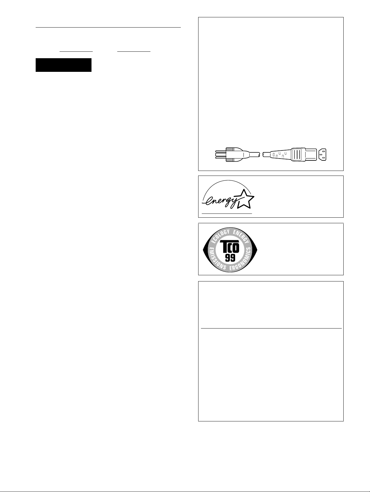
ENERGY STAR Partner, Sony
As an
Corporation has determined that this
product meets the
guidelines for energy efficiency.
ENERGY STAR
INFORMATION
This product complies with SwedishNational Council forMetrology
(MPR) standards issued in December 1990 (MPR II) for very low
frequency (VLF) and extremely low frequency (ELF).
INFORMATION
Ce produit est conforme aux normes du Swedish National Council
for Metrology de décembre 1990 (MPR II) en ce qui concerne les
fréquences très basses (VLF) et extrêmement basses (ELF).
INFORMACIÓN
Este producto cumple las normas del Consejo Nacional Sueco para
Metrología (MPR) emitidas en diciembre de 1990 (MPR II) para
frecuenciasmuy bajas(VLF) y frecuencias extremadamente bajas (ELF).
This monitor complies with the
TCO’99 guidelines.
If you have any questions about th is product, you may call:
Sony Customer Information Center
1-800-222-SONY (7669)
or write to:
Sony Customer Information Center
1 Sony Drive, Mail Drop #T1-11, Park Ridge, NJ 07656
Declaration of Conformity
Trade Name: SONY
Model No.: SDM-N80
Responsible Party: Sony Electronics Inc.
Address: 680 Kinderkamack Road, Oradell, NJ
07649 USA
Telephone No.: 201-930-6972
This device complies withPart 15 of the FCC Rules. Operation is
subject to the f ollowing two conditions: (1) This device may not
cause harmful interference, and (2) this device must accept any
interference received, including interference that may cause
undesired operation.
2
Page 3

Table of Contents
Precautions............................................4
Identifyingpartsandcontrols..............................5
Setup..........................................7
Step 1: Connect the media engine to your computer. . . . . . . . . . . . 7
Step 2: Checkthedigital/analogselectswitch.................7
Step 3: Connectthedisplayandmediaengine................8
Step 4: Connect the audio cord . . . . . . . . . . . . ................8
Step 5: Connectthepowercord............................8
Step 6: Turnonthemonitorandcomputer ...................8
Connecting Universal Serial Bus (USB) compliant peripherals . . . . 9
Usingthestereospeakers...............................10
Selectingtheinputsignal................................10
Adjustingthetiltandheight...............................11
CustomizingYourMonitor.......................12
Navigatingthemenu....................................12
Adjustingthecontrast(CONTRAST).......................13
Adjusting the black level of an image (BRIGHTNESS). . . . . . . . . . 14
Eliminating flicker or blurring (PHASE/PITCH)
(Analog RGB signals only). . . ............................14
Adjusting the picture position (H CENTER/V CENTER)
(Analog RGB signals only). . . ............................15
Adjustingthecolortemperature(COLOR)...................15
Changing the picture size according to the signal (ZOOM) . . . . . . 16
Smoothingthepicture(SMOOTHING)......................16
Changing the menu’s position (MENU POSITION) . . . . . . . . . . . . 16
Resettingtheadjustments(RESET)........................17
Additionalsettings......................................17
GB
• Macintosh is a trademark licensed to
Apple Computer, Inc., registered in the
U.S.A. and other countries.
• Windows
Microsoft Corporation in the United
States and other countries.
• IBM PC/AT and VGA are registered
trademarks of IBM Corporation of the
U.S.A.
• VESA and DDC
Video Electronics Standards
Association.
E
•
mark.
• All other product names mentioned
herein may be the trademarksor
registeredtrademarksof theirrespective
companies.
•Furthermore,“”and“”arenot
mentionedineachcaseinthismanual.
is registered trademark of
are trademarks of the
NERGYSTAR is a U.S. registered
TechnicalFeatures .............................19
Power saving function (user sensor/power saving mode) . . . . . . . 19
If the user sensor does not seem to function properly . . . . . . . . . . 19
Automaticbrightnessadjustmentfunction(lightsensor)........21
Automatic picture quality adjustment function
(Analog RGB signals only). . . ............................21
Troubleshooting................................22
On-screenmessages...................................22
Troublesymptomsandremedies..........................23
Self-diagnosis function . . . . . . ............................26
Specifications..................................26
Appendix.......................................i
Presetmodetimingtable ..................................i
TCO’99Eco-document....................................i
3
Page 4

Precautions
Warning on power connections
• Use the supplied power cord. If you use a different power cord,
be sure that it is compatible with your local power supply.
For the customers in the U.S.A.
If you do not use the appropriate cord, this monitor will not
conform to mandatory FCC standards.
For the customers in the UK
If you use the monitor in the UK, be sure to use the appropriate
UK power cord.
Example of plug types
for 100 to 120 V AC for 200 to 240 V AC for 240 V AC only
The equipment should be installed near an easily accessible
outlet.
Installation
Do not install or leave the monitor:
• In places subject to extreme temperatures, for example near a
radiator, heating vent, or in direct sunlight. Subjecting the
monitor to extreme temperatures, such as in an automobile
parked in direct sunlight or near a heating vent, could cause
deformations of the casing or malfunctions.
• In places subject to mechanical vibration or shock.
• Near any equipmentthat generates a strong magnetic field,
such as a TV or various other household appliances.
• In places subject toinordinate amounts of dust, dirt, or sand, for
example near an open window or an outdoorexit. If setting up
temporarily in an outdoor environment, be sure to take
adequate precautions against airborne dust and dirt. Otherwise
irreparable malfunctions could occur.
Handling the LCD screen
• Do not leave the LCD screen facing the sun as it can damage
theLCDscreen.Takecarewhenyouplacethemonitorbya
window.
• Do notpush on orscratch theLCD screen.Do notplace aheavy
object on the LCD screen. This may cause the screen to lose
uniformity or cause LCD panel malfunctions.
• If the monitor is used in a cold place, a residual image may
appear on the screen. This is not a malfunction. The screen
returns to normal as the temperature rises to a normal operating
level.
• If a still picture is d isplayed for a long time, a residual image
may appear for a while. The residual image will eventually
disappear.
• The LCD panel becomes warm during operation. This is not a
malfunction.
Note on the LCD (Liquid Crystal Display)
Please note that the LCD screen is m ade with highprecision technology. However, black points or bright
points of light (red, blue, or green) may appear
constantly on the LCD screen, and irregular colored
stripes or brightness may appear on the LCD screen.
This is not malfunction. (Effective dots: more than
99.99%)
Replacement of the fluorescent tube
A specially designed fluorescent tube is installed as the lighting
apparatus for this monitor. If the screen becomes dark, unstable,
or does not turn on, replace the fluorescent tube with a new one.
Consult your Sony dealer when replacing the fluorescent tube.
Maintenance
• Be sure to unplug the power cord from the power outlet before
cleaning your monitor.
• CleantheLCDscreenwithasoftcloth.Ifyouuseaglass
cleaning liquid, do not use any type of cleaner containing an
anti-static solution or similar additive as this may scratch the
LCD screen’s coating.
• Clean the cabinet, panel, and controls with a soft cloth lightly
moistened with a mild detergent solution. Do not use any type
of abrasive pad, scouring powder, or solvent, such as alcohol or
benzine.
• Do not rub, touch, or tap the surface of the screen with sharp or
abrasive items such as a ballpoint pen or screwdriver. This type
of contact may result in a scratched picture tube.
• Note that material deterioration or LCD screen coating
degradation may occur if the monitor is exposed to volatile
solvents such as insecticide, or if prolonged contact is
maintained with rubber or vinyl materials.
Transportation
• Disconnect all cables from the monitor when transporting.
When you transport this display, grasp the base sections of the
display stand firmly with both hands. Alsouse both hands when
carryingthe mediaengine. If youdropthe monitor, you may be
injured or the monitor may be damaged.
• When youtransport this monitor forrepair or shipment,use the
original carton and packing materials.
Disposal of the monitor
• Do not dispose of this monitor with general
household waste.
• The fluorescent tube used in this monitor contains
mercury.Disposal of thismonitormust becarried out
in accordance to the regulations of your local
sanitation authority.
About the built-in stereo speakers
Be sure to keep magnetic recording equipment, tapes, and floppy
discs away from the speaker’s opening as the speakers generate a
magnetic field. This magnetic field may affect data stored on
magnetic tapes and discs.
4
Page 5
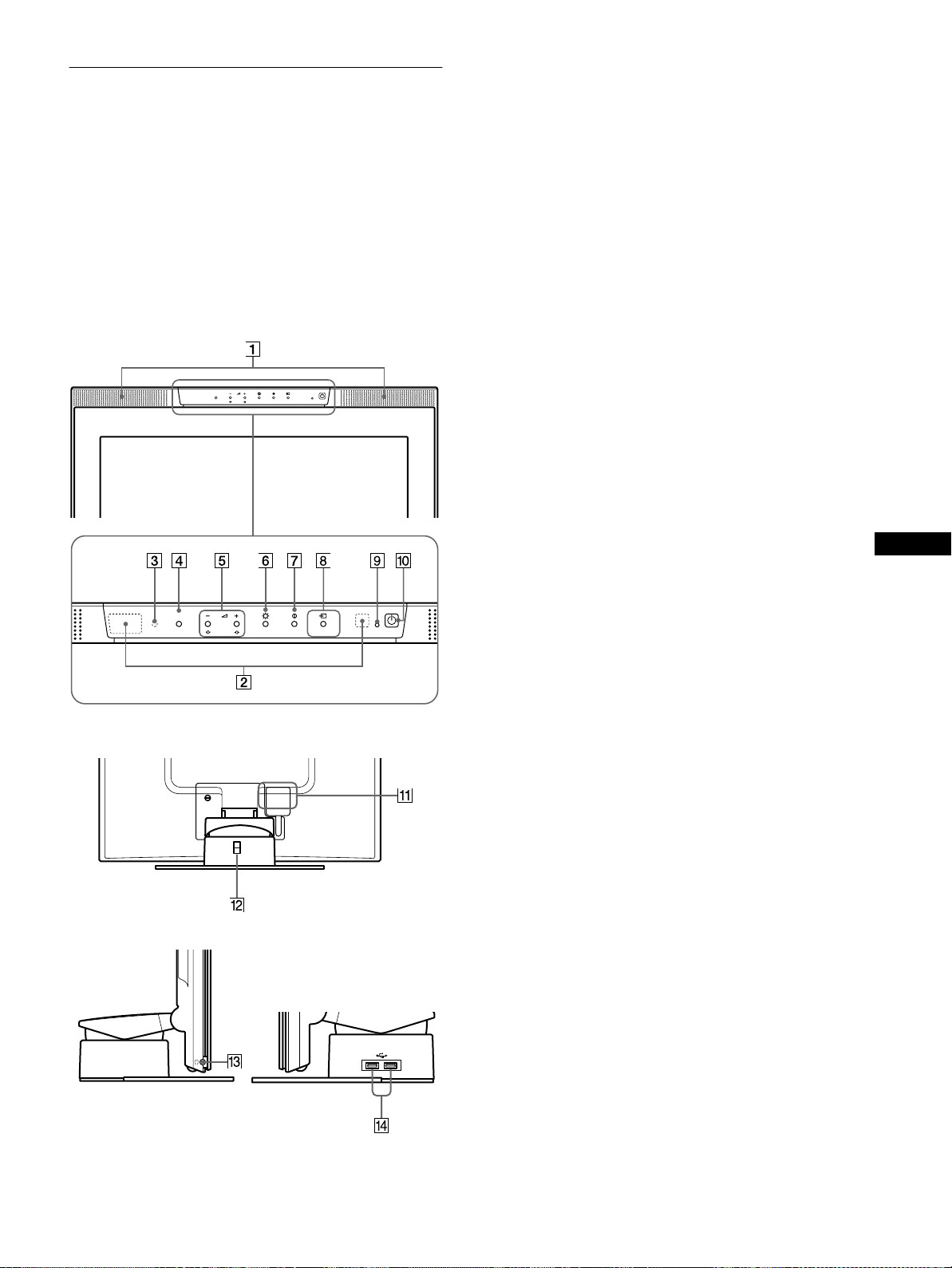
Identifying parts and controls
MENU
OK
1
2
1 Stereo speakers (page 10)
These output the audio signals as sound.
See the pages in parentheses for further details.
LCD display
You can operate the monitor by lightly touching the keys.
Characters and icons that indicate functions of the keys light up
for about 10 secondsafter the monitor is turned on. If you do not
touch any key during this period, all of them will go off. If you
touch any one of the keys during this period,only the characters
or icons that are related to that key’s operationwill stay on. Even
ifall of them go off,if youtouchany oneof the4–8 keys, they
will light up again.
Front
MENU
1
2
OK
2 User sensors (page 19)
These sensors detect when a user is present in front of the
screen. Be sure not to cover it with papers, etc.
3 Light sensor (pages 18, 21)
This sensor measures the brightness of the surrounding area.
Be sure not to cover it with papers, etc.
4 MENU key (page 13)
This key displays the main menu.
5 2 (volume) +/– and M(+)/m(–) keys (pages 10, 13)
These keys display the VOLUME menu and function as the
M(+)/m(–) keys when selecting the menu items and making
adjustments.
6 8 (brightness) key (page 14)
This key displays the BRIGHTNESS menu.
7 6 (contrast) key (page 13)
This key displays the CONTRAST menu.
8 INPUT and OK key, and indicator (pages 10, 13)
This key selects the INPUT1 (HD15 (analog RGB)
connector) or INPUT2 (DVI-I (digital/analog RGB)
connector) video input signal. The input signal and
corresponding inputindicator change each timeyou touch this
key.
This key also functions as the OK key when displaying the
menu on the screen.
GB
Rear
9 1 (Power) indicator (pages 8, 19, 26)
This indicator lights up in green when the monitor is turned
on. The indicator flashes in green and orangewhen the
monitor is in low power consumption mode, and lights up in
orange when the monitor is in power saving mode.
0 1 (Power) switch (pages 8, 26)
This switch turns the display on and off.
qa SYSTEM CONNECTOR (page 8)
This connector inputs signals from the media engine when the
display and the media engine are connected with a system
connecting cable.
qs Security Lock Hole
Right sideLeft side
The security lock hole should be applied with the Kensington
Micro Saver Security System.
Micro Saver Security System is a trademark of Kensington.
qd Headphones jack (page 10)
This jack outputs audio signals to the headphones.
qf USB(Universal Serial Bus) downstream connectors
(page 9)
These connectors are used to connect the monitor to USB
peripheral devices.
5
Page 6

Media engine
Rear Front
AC IN
INPUT 1
AUDIO IN
INPUT 2
ANALOG
DIGITAL
AUDIO IN
*
SYSTEM
CONNECTOR
(TO DISPLAY)
qg AC IN connector (page 8)
This connector provides AC power to the monitor.
qh HD15 (analog RGB) input connector (INPUT1)
(page 7)
Thisconnectorinputs analog RGB video signals(0.700Vp-p,
positive) and SYNC signals.
wa Digital/analog select switch (page 7)
Whenconnectingthe DVI-I input connectorqj to a computer
equippedwith an HD15 (analogRGB)output connectorusing
the DVI-HD15 (analog RGB) video signal cable (supplied),
set this switch to ANALOG.
When connecting it to a computer equipped with a DVI
(digital RGB) output connector using a DVI-DVI (digital
RGB) video signal cable (not supplied), set this switch to
DIGITAL.
The switch is set to ANALOG as the default setting.
ws AC power switch (page 8)
This switch turns the monitor on and off.
wd AC power indicator (page 19)
This indicator lights up in green when the media engine is
turned on. The indicator lights up in red when the display is
turnedoff with the mediaengine on.Theindicatorlightsup in
orange when the monitor is in the power saving mode.
* This connector is used by service personnel only. Do not
connect anything to this outlet.
qj DVI-I (digital/analog RGB) input connector (INPUT2)
(page 7)
Thisconnectorinputs analog RGB video signals(0.700Vp-p,
positive) with sync signals or digital RGB video signals that
comply with DVI Rev. 1.0. You can switch between digital
RGB signals and analog RGB signals with the digital/analog
select switch wa.
qk SYSTEM CONNECTOR (TO DISPLAY) (page 8)
Thisconnectoroutputssignalsto the display when thedisplay
and the media engine are connected with a system connecting
cable.
ql AUDIO IN jacks (pages 8, 18)
These jacks input audio signals when connected to the audio
output jack of the computer or other audio equipment.
w; USB (Universal Serial Bus) upstream connectors
(pages 9, 17)
These connectors are used to connect the monitor to USB
compliant computers.
6
Page 7

Setup
Before using your monitor, check that the following items are
included in your carton:
• LCD display
• Media engine
• Power cord
• System connecting cable (2 m)
• DVI-HD15 (analog RGB) video signal cable
• Audio cord (stereominiplug)
• USB cable
• Macintosh adapter
• Windows Monitor Information/Windows Utility/Macintosh
Utility Disk
• Warranty card
• Notes for Macintoshusers
• This instruction manual
Connecting to a Macintosh
x
Use the supplied Macintosh adapter.
Macintosh adapter
(supplied)*
to INPUT2 connector
Step 1:Connect the media eng ine
to your computer
Turn off the media engine and computer before connecting.
When connecting the monitor to a computer equipped with a DVI
(digital RGB) output connector that complies with DVI Rev.1.0,
use a DVI-DVI (digital RGB) video signal cable (not supplied).
Note
Do not touch the pins of the video signal cable connector as this might
bend the pins.
Connecting to an IBM PC/AT or compatible
x
computer
to INPUT2 connector
DVI-HD15 (analog
to video output
Macintosh
* Refer to the supplied “Notes for Macintosh users” for further details.
RGB)video signal cable
(supplied)
Step 2:Check the digital/analog
select switch
Before turning on the monitor or the computer, be sure to check
the switch setting. When connecting the DVI-I inputconnector on
the monitor to a computer equipped with an HD15 (analog RGB)
output connector using theDVI-HD15 (analog RGB) video signal
cable (supplied), set the switch to ANALOG.
When connecting it to a computer equipped with a DVI (digital
RGB) output connector using a DVI-DVI (digital RGB) video
signal cable (not supplied), set the switch to DIGITAL.
The switch is set to ANALOG as the default setting.
ANALOG
GB
IBM PC/AT or
compatible computer
to video output
DVI-HD15(analogRGB)video
signal cable (supplied)
DIGITAL
Note
Before turning onthe monitor or the computer, be sure to check theswitch
setting.
(continued)
7
Page 8
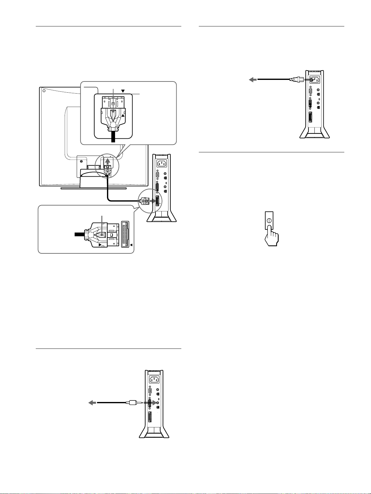
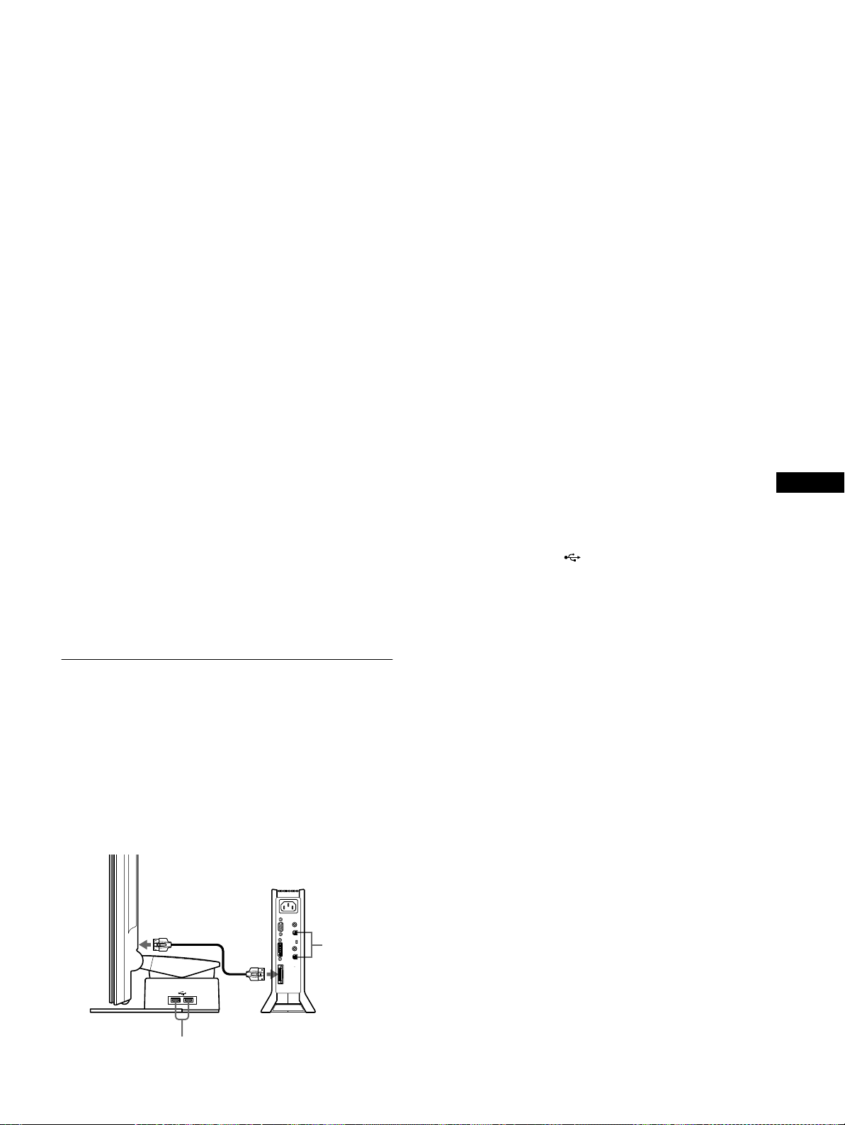
Step 3:Connect the display and
Step 5:Connect the power cord
media engine
Turn off the display and media engine before connecting them.
To connect the system connecting cable to the display easily, set
the display in an upright position.
A
to SYSTEM
CONNECTOR
of the display
System connecting
cable (2 m) (supplied)
A
to SYSTEM
CONNECTOR
of the media
engine
With the media engine, display, and computer switched off,
first connectthe power cord to the media engine, then connect it
to a power outlet.
to AC IN connector
to a power outlet
Power cord (supplied)
Step 6:Turn on the monitor and
computer
1 Turn on the media engine.
The display automatically turns on. The indicators of the
media engine and display light up in green.
Alignthe
and the media engine.
Caution
Be sure to install the media engine vertically as shown above. Installing
the media engine lying flat may block ventilation, and may cause a
malfunction.
Note
When connecting the cable, grasp the plug and insert it firmly into the
connector until you hear it click. When disconnecting the cable, pull out
the plug while holding down locking lever
v
onthe plugs with thevonthe display
.
A
Step 4:Connect the audio cord
to AUDIO I N jack
among the INPUT2
toan audio output jack
on your computer
connectors
Audio cord (supplied)
2 Turn on the computer.
Note
If you turn off the media engine and turn it on again while the display is
off, the display will not turn on automatically.In this case, press the
(power)switchonthedisplaytoturniton.
1
8
Page 9
The installation of the monitor is complete. If necessary, use the
monitor’s controls to adjust the picture.
If no picture appears on your screen
• Check that the monitor is correctly connected to the computer.
• Check that the media engine is on.
• If NO INPUT SIGNAL appears on the screen:
– The computer isin the power saving mode. Trypressing any
key on the keyboard or moving the mouse.
– Check that the input select setting is correct.
– Check that the digital/analog select switch setting is correct.
• If CABLE DISCONNECTED appears on the screen:
– Check that the video signal cable is properly connected.
– Check that the input select setting is correct.
• If OUT OF SCAN RANGE appears on the screen, reconnect
the old monitor. Then adjust the settings of the computer’s
graphics board so that the horizontal frequency is between 28 –
92 kHz and the vertical frequency is between 48 – 85 Hz.
1 Turn on the monitor and computer(s).
2 Connect your computer(s) to the upstream
connectors on the media engine using the supplied
USB cable.
For customers using Windows
Ifa message appearson yourscreen, followthe on-screeninstructions
and select a generic USB hub driver.
3 Connect your USB compliant peripheral devices to
the downstream connectors on the display stand.
For customers using Macintosh computer
When you connect a Macintosh keyboard to the USB downstream
connector, the power button on the keyboard does not function. To
turn your Macintosh computer on, use the power button on the
computer or connect the keyboard to the computer directly and turn
the computer on, then connect the keyboard to the monitor.
For more information about on-screen messages, see “Trouble
symptoms and remedies” on page 23.
No need for specific drivers
The monitor complies with the “DDC” Plug & Play standard and
automatically detects all the monitor’s information. No specific driver
needs to be installed to the computer.
The firsttimeyou turnon your computer after connectingthe monitor, the
setup Wizard may appear on the screen. In this case, follow the on-screen
instructions.T he Plug & Play monitor is automatically selected so that
you can use this monitor.
The vertical frequency turns to 60 Hz.
Since flickers are unobtrusive on the monitor, you can use it as it is. You
do not need to set the vertical frequency to any particular high value.
If your computer orgraphics board has difficulty communicating with this
monitor, install the information file for this monitor using the Windows
Monitor Information Disk. For details on installing,refer to the ReadMe
file on the disk.
Connecting Universal Serial Bus (USB) compliant peripherals
The monitor has two upstream and two downstream USB
connectors. They provide a fast and easy way to connect USB
compliant peripheral devices (such as keyboards, mice, printers
and scanners) to your computer using a standardized USB cable.
To use the monitor as a hub for your peripheral devices, connect
the USB devices as illustrated below.
Notes
• Not all computers and/or operating systems support USB
configurations. Check your computer’s instruction manual to see if you
can connect USB devices.
• In most cases, USB driver software needs to be installed on the host
computer. Refer to the peripheral device’s instruction manual for
further details.
• When you connect a computer whose power is connected to the USB
upstream connector on the monitor, the monitor will not enter the
power saving mode.
• When the monitor is in the powersaving mode, USB peripheral devices
will not function. To resume the use of USB peripheral devices, cancel
the mode by pressing the
• If the peripheral devices do not function properly, confirm that the
upstream input setting in (USB SELECT) is correct (page 17).
• If you connect a keyboard or mouse to the USB connectors and then
boot your computer for the first time, the peripheral devices may not
function. First connect the keyboard and mouse directly to the
computer and set up the USB compliant devices. Then connect them to
this monitor.
• When you connectperipheral devices to the downstream connectors, be
sure not to lean on the display. Otherwise, the display may incline and
catch your fingers.
• The number of USB hubs that can be connected together is defined as
up to six tiers by USB specifications. Two tiers of a USB hub are built
into the monitor. Therefore,you areallowed to connectfour more tiers
of a USB hub together.
1
(power) switch.
GB
USB downstream connectors
To USB compliant peripheral devices
USB
upstream
connectors
To USB
compliant
computers
9
Page 10

Using the stereo speakers
Selecting the input signal
You can listen to music, sound, and other audio files using the
stereospeakerofyourmonitor.
Adjusting the volume
Volume adjustments are made using a separate VOLUME menu,
different from the main menu (page 12).
1 Light up the characters and icons to indicate the
functions of the keys.
Touch any one of the MENU, M(+)/m(–), 8 (brightness), 6
(contrast), or INPUT keys to lightup the characters and icons
indicating the functions of the keys.
2 Touch the 2 +/– keys.
The VOLUME menu appears on the screen.
VOL UME
40
3 Touch the 2 +/– keys to adjust the volume.
The menu automatically disappears after about 3 seconds.
Using the headphones jack
You can listen to the audio signals from your computer or other
audio equipment using headphones. Connect your headphones to
the headphones jack. The speakers turn off when headphones are
connected to the headphones jack. Adjust the volume of the
headphones using the VOLUME menu.
You can connect two computers to thismonitor using the INPUT1
and INPUT2 connectors. To select one of the two computers, use
the INPUT key.
1 Light up the characters and icons to indicate the
functions of the keys.
Touch any one of the MENU, M(+)/m(–), 8 (brightness), 6
(contrast),or INPUTkeys to light up the characters and icons
indicating the functions of the keys.
2 Touch the INPUT key.
The input signal and corresponding input indicator change
each time you touch this key.
• 1: Input via the HD15 (analog RGB) input connector
• 2: Input via the DVI-I (digital/analogRGB) input
connector
2
Notes
• You cannot select the input signal when displaying the main menu on
the screen.
• For USB upstream input and audio input, you can choose whether or
not to allow them to be switched using the I NPUT key.To set the US B
upstream input, use the (USB SELECT) menu (page 17); to set
the audio input, u se the (AUDIO SELECT) m enu (page 18). Both
of them are setto be switched with the INPUT key in thedefault setting.
Notes
• You cannot adjust the volume when displaying the main menu on the
screen.
• When your monitor is in low power consumption mode or power
saving mode, no sound comes from the speakers or the headphones.
10
Page 11
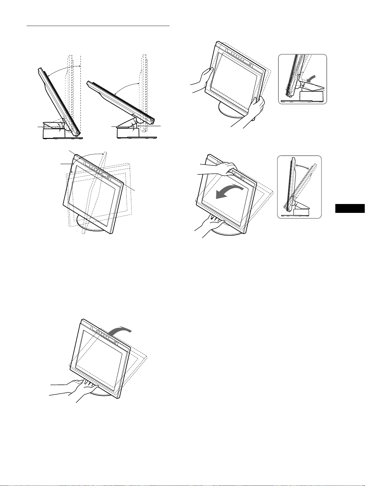
Adjusting the tilt and height
This display can be adjusted within the angles shown below.
30°
59°
2 Grasp the lower sides of the LCD panel, then pull
down the panel to adjust screen height.
29°
60°
Notes
• When you connect cables to the USB downstream connectors, the right
side rotation angle may be narrower than 60 degrees.
• Be careful not to get your fingers caught between the arm and the base
of the stand –
on the illustration above.
A
29°
60°
A
To adjust the angles, follow the procedure below.
1 Grasp the middle part of the bottom of the display
while holding the display stand, then, tilt the LCD
panel sufficiently backward.
3 Grasp the middle part of the top and bottom of the
LCD panel, then adjust screen tilt.
GB
Note
When adjusting the screen tilt and height, proceed slowly and carefully,
being sure not to hit the LCD panel against the desk or the base of the
display stand.
To use the display comfortably
This display is designed so that you can set it up at a comfortable
viewing angle. Adjust the viewing angle of your display
accordingtotheheightofthedeskandchair,andsothatlightis
not reflected from the screen to your eyes.
Note
Do not grasp the portion around the protrusion on the center of the bottom
of the display. Otherwise, the display may catch your fingers.
11
Page 12
Customizing Your Monitor
Before making adjustments
Connect the monitor and the computer, and turn them on.
Wait for at least 30 minutesbefore making adjustmentsfor the
best results.
4 V CENTER (Analog RGB
signals only) (page 15)
Select the V CENTER menu
toadjust the picture’s vertical
centering.
VCENTER
50
EX I T
You can make numerous adjustments to your monitor using the
on-screenmenu.
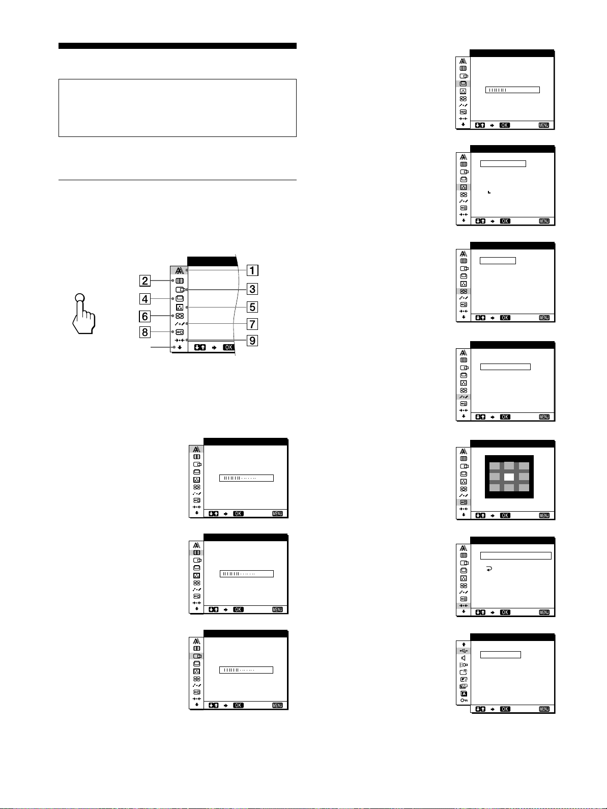
Navigating the menu
TouchtheMENUkeytodisplaythemainmenuonyourscreen.
For more information on using the MENU key, see “Using the
MENU, M(+)/m(–), and OK keys” on page 13.
PHASE
MENU
b
q;
Use the M(+)/m(–) and OK keys to select one of the following
menus. For more information on using the M(+)/m(–)andOK
keys, see “Using the MENU, M(+)/m(–), and OK keys” on
page 13.
1 PHASE (Analog RGB
signals only) (page 14)
Select the PHASE menu to
adjust the phase when the
characters or pictures appear
fuzzy throughout the entire
screen.Adjustthe phase after
adjusting the pitch.
PHASE
16
EX I T
5 COLOR (page 15)
Select the COLOR menu to
adjust the color temperature
of the picture. This adjusts
the tone of the screen.
6 ZOOM (page 16)
Select the ZOOM menu to
adjust the picture’ssize
accordingtotheinput
signal’s aspect ratio or
resolution.
7 SMOOTHING (page 16)
Select the SMOOTHING
menu to adjust the picture’s
sharpness according to the
type of an object displayed
on the screen.
8 MENU POSITION
(page 16)
Select the MENU
POSITION menu to change
the on-screen menu position.
COLOR
9300K
0K
650
5000K
USER
ADJ U ST
ZOOM
FULL 2
FULL 1
REAL
SMOOT H I NG
TEXT
ND
STA
ARD
GRAPH
MEN NUP
OS I IOT
EX I T
EX I T
ICS
EX I T
EX I T
2 PITCH (Analog RGB
signals only) (page 14)
Select the PITCH menu to
adjust the pitch when the
characters or pictures are
unclear in some areas of the
screen.
3 HCENTER(AnalogRGB
signals only) (page 15)
Select the H CENTER menu
to adjust the picture’s
horizontal centering.
12
PITCH
HCENTER
EX I T
50
EX I T
50
9 RESET (page 17)
Select the RESET menu to
reset the adjustments.
0 Other menus (page 17)
Select the m to adjust other
settings listed below:
• USB SELECT
• AUDIO SELECT
• BACKLIGHT
• LIGHT SENSOR
• USER SENSOR
• POWER SAVE
• LANGUAGE
• MENU LOCK
RESET
S CREEN
RESET
ALL
USB SE LECT
AUTO
UT
INP
INPUT12
RESET
EX I T
EX I T
Page 13
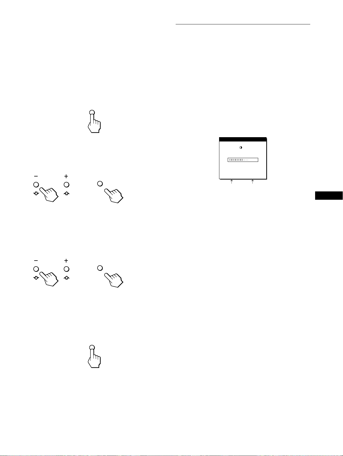
Using the MENU,M(+)/m(–), and OK keys
x
1 Light up the characters and icons to indicate the
functions of the keys.
Touch any one of the MENU, M(+)/m(–), 8 (brightness), 6
(contrast), or INPUTkeys to light up the characters and icons
indicating the functions of the keys.
2 Display the main menu.
TouchtheMENUkeytodisplaythemainmenuonyour
screen.
MENU
3 Select the menu you want to adjust.
TouchtheM(+)/m(–) keys todisplay the desired menu.Touch
the OK key to select the menu item.
Adjusting the contrast (CONTRAST)
Contrast adjustment is made using a separate CONTRAST menu,
differentfrom the main menu(page 12).The setting is thenstored
in memory for INPUT1, INPUT2 (analog RGB), and INPUT2
(digital RGB), respectively.
1 Light up the characters and icons to indicate the
functions of the keys.
Touch any one of the MENU, M(+)/m(–), 8 (brightness), 6
(contrast), or INPUT keys to lightup the characters and icons
indicating the functions of the keys.
2 Touch the 6 (contrast) key.
The CONTRAST menu appears on the screen.
CONTRAST
70
64.0kHz/ 60Hz
OK
OK
2
2
b
4 Adjust the menu.
TouchtheM(+)/m(–) keysto maketheadjustment,thentouch
the OK key.
When you touch the OK key, the settings are stored, then the
display returns to the previous menu.
b
5 Close the menu.
Touch the MENU key once to return to normal viewing. If no
keys are touched, the menu closes automatically after about
30 seconds.
MENU
Horizontal frequency
of the current input
signal
Displaying the current input signal
The horizontal and vertical frequencies of the current input signal are
displayedintheCONTRASTandBRIGHTNESSmenus.
3 Touch the M(+)/m(–) keys to adjust the contrast.
The menu automatically disappears after about 3 seconds.
Note
You can adjust neither contrast nor brightness when the main menu is
displayedonthescreen.
Vertical frequency of
the current input
signal
GB
Resetting the adjustments
x
You can reset the adjustments using the RESET menu. For more
information on resetting the adjustments, see “Resetting the
adjustments (RESET)” on page 17.
13
Page 14
Adjusting the black level of an
Eliminating flicker or blurring
image (BRIGHTNESS)
Brightness adjustment is made using a separate BRIGHTNESS
menu, different from the main menu (page 12). The setting is then
stored in memory for INPUT1, INPUT2 (analog RGB), and
INPUT2 (digital RGB), respectively.
1 Light up the characters and icons to indicate the
functions of the keys.
Touch any one of the MENU, M(+)/m(–), 8 (brightness), 6
(contrast), or INPUT keys to lightup the characters and icons
indicating the functions of the keys.
2 Touch the 8 (brightness) key.
The BRIGHTNESS menu appears on the screen.
B NESSRIGHT
50
64.0kHz/ 60Hz
Horizontal frequency
of the current input
signal
Displaying the current input signal
The horizontal and vertical frequencies of the current input signal are
displayed in the CONTRAST and BRIGHTNESS menus.
3 Touch the M(+)/m(–) keys to adjust the brightness.
The menu automatically disappears after about 3 seconds.
If the screen is too br ight
Adjust the backlight. For more information about adjusting the
backlight, see “Adjusting the backlight” on page 18.
Note
You can adjust neither contrast nor brightness when the main menu is
displayedon the screen.
Vertical frequency of
the current input
signal
(PHASE/PITCH) (Analog RGB
signals only)
When the monitor receives an input signal, the automatic picture
quality adjustment function of this monitor automatically adjusts
the picture position, phase, and pitch, and ensures that a clear
picture appears on the screen. For more information about this
function, see “Automatic picture quality adjustment function
(Analog RGB signals only)” on page 21.
For some input signals, this function may not completely adjust
the picture position, phase, and pitch. In this case, you can
manually set these adjustments according the following
instructions. If you manually set these adjustments, they are
stored in memory and automatically recalled whenever the
monitor receives the same input signals.
These settings may have to b e repeated if you change the input
signal after reconnecting your computer.
1 Set the resolution to 1280 ×××× 1024 on the computer.
2 Load the Utility Disk.
3 Start the Utility Disk and display the test pattern.
For Windows
[Windows]/[Win Utility.exe].
Click [Utility]
For Macintosh
Click [Utility]t[Mac]/[Mac Utility].
4 Light up the characters and icons to indicate the
functions of the keys.
Touch any one of the MENU, M(+)/m(–), 8 (brightness), 6
(contrast),or INPUTkeys to light up the characters and icons
indicating the functions of the keys.
5 Touch the MENU key.
The main menu appears on the screen.
6 Touch the M(+)/m(–) keys to select (PITCH) and
touch the OK key.
The PITCH menu appears on the screen.
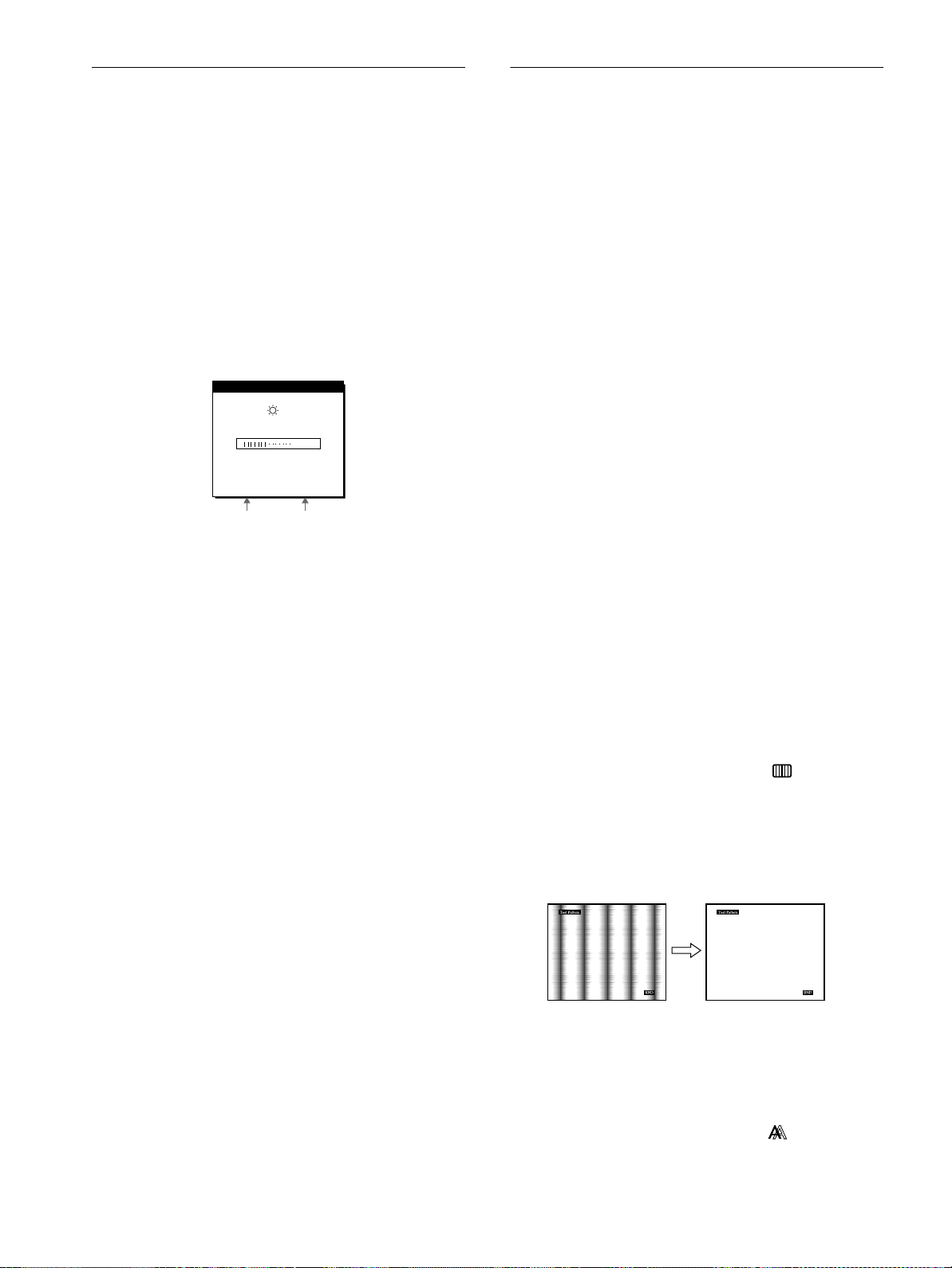
7 Touch the M(+)/m(–) keys until the vertical stripes
disappear.
Adjust so that the vertical stripes disappear.
t
14
8 Touch the OK key.
The main menu appears on the screen.
If horizontal stripes areobserved over theentire screen, adjust
the phase as the next step.
9 Touch the M(+)/m(–) keys to select (PHASE) and
touch the OK key.
The PHASE menu appears on the screen.
Page 15

10 Touch theM(+)/m(–) keys until the horizontal stripes
are at a minimum.
Adjust so that the horizontal stripes are at a minimum.
Adjusting the color temperature (COLOR)
The COLOR settings allow you to adjust the picture’s color
temperature by changing the color level of the white color field.
Colors appear reddish if the temperature is low, and bluish if the
temperature is high.
You can set the color temperature to 5000K, 6500K, 9300K or
user adjustment.
11 Click [END] on the screen to turn off the test pattern.
To reset the automatic picture quality adjustment
Select SCREEN RESET and activate it using the RESET m enu. For more
informationonusingtheRESETmenu,see“Resetting the adjustments
(RESET)” on page 17.
Note
When using digital RGB signals, you do not need to set the PHASE or
PITCH.
Adjusting the picture position
(H CENTER/V CENTER) (Analog
RGB signals only)
If the picture is not in the center of the screen, adjust the picture’s
centering as follows.
Thesesettingsmayhavetoberepeatedifyouchangetheinput
signal after reconnecting your computer.
1 Start the Utility Disk and display the test pattern.
Repeat steps 2 to 4 of “Eliminating flicker or blurring
(PHASE/PITCH)(Analog RGB signals only).”
2 Touch the MENU key.
The main menu appears on the screen.
3 Touch the M(+)/m(–) keys to select (H CENTER)
or (V CENTER) and touch the OK key.
The H CENTER or V CENTER menu appears on the screen.
4 Move the picture up, down, left, or right until the
frame at the perimeter of the test pattern
disappears.
Touch the M(+)/m(–) keys to adjust the picture’s
centering using the H CENTER menu for horizontal
adjustment, or the V CENTER menu for vertical
adjustment.
5 Click [END] on the screen to turn off the test pattern.
Note
When using digital RGB signals, you do not need to set the
H CENTER or V CENTER.
1 Light up the characters and icons to indicate the
functions of the keys.
Touch any one of the MENU, M(+)/m(–), 8 (brightness), 6
(contrast), or INPUT keys to lightup the characters and icons
indicating the functions of the keys.
2 Touch the MENU key.
The main menu appears on the screen.
3 Touch the M(+)/m(–) keys to select (COLOR) and
touch the OK key.
The COLOR menu appears on the screen.
4 Touch the M(+)/m(–) keys to select the desired color
temperature and touch the OK key.
Thepresetcolortemperaturesare 5000K, 6500K, and 9300K.
Since the default setting is 9300K, the whites will change
from a bluish hue to a reddish hue as the temperature is
loweredto6500Kand5000K.
You can set the color temperatures for INPUT1, INPUT2
(analog RGB), and INPUT2 (digital RGB), respectively.
5 If necessary, fine tune the color temperature.
First touch the M(+)/m(–) keys to select ADJUST and touch
the OK key. Next touch the M(+)/m(–) keys to select R (Red)
or B (Blue) and touchthe OK key.Then touchthe M(+)/m(–)
keys to adjust the color temperature and touch the OK key.
Since this adjustment changes the color temperature by
increasing or decreasing the Rand B components with respect
to G (green), the G component is fixed.
USER ADJUST TMEN
R162
G170
B205
EX I T
If you finetune thecolor temperature, the new colorsetting is
stored in memory for USER ADJUSTMENT and
automatically recalled whenever USER is selected.
You can set the USER ADJUSTMENTfor INPUT1, INPUT2
(analog RGB), and INPUT2 (digital RGB), respectively.
GB
15
Page 16

Changing the picture size
Smoothing the picture
according to the signal (ZOOM)
The monitor is set to display the picture on the screen in full,
irrespective of the picture’s mode or resolution in the default
setting. You can also view the picture at its actual aspect ratio or
resolution. Note that an input signal whose resolution is higher
than or equal to 1280 × 1024 (SXGA) fills the entire screen and
the ZOOM function is not activated.
The setting is then stored in memory for INPUT1, INPUT2
(analog RGB), and INPUT2 (digital RGB), respectively.
1 Light up the characters and icons to indicate the
functions of the keys.
Touch any one of the MENU, M(+)/m(–), 8 (brightness), 6
(contrast), or INPUT keys to lightup the characters and icons
indicating the functions of the keys.
2 Touch the MENU key.
The main menu appears on the screen.
3 Touch the M(+)/m(–) keys to select (ZOOM) and
touch the OK key.
The ZOOM menu appears on the screen.
4 Touch the M(+)/m(–) keys to select the desired
mode.
• FULL2:Theinputsignalisdisplayedonthescreeninfull,
irrespective of the picture’s mode or resolution.
• FULL1: The input signal is displayed on the screen at its
actual aspect ratio. Therefore, black bands may appear at
the top and bottom of the picture depending on the signal.
• REAL: The input signal is displayed on the screen at its
actual resolution. Signals whose resolution is lower than
1280 × 1024 are displayed at the center of the screen
surrounded by a black frame.
To restore the default setting (displayed on the screen in full)
Select “FULL2” in step 4.
Note
If you input a picture whose horizontal resolution is 1280 dots or one
whose vertical resolution is 1024 lines, the picture size in the FULL1
mode and the one in the REAL mode are the same size.
(SMOOTHING)
If the picture displayed a t the FULL2 or FULL1 mode of ZOOM
is not smooth, use the picture smoothing function. Note that 1280
×1024 (SXGA) resolution signals are shown only inREAL mode
and the SMOOTHING function is not activated.
The setting is then stored in memory for INPUT1, INPUT2
(analog RGB), and INPUT2 (digital RGB), respectively.
1 Light up the characters and icons to indicate the
functions of the keys.
Touch any one of the MENU, M(+)/m(–), 8 (brightness), 6
(contrast),or INPUTkeys to light up the characters and icons
indicating the functions of the keys.
2 Touch the MENU key.
The main menu appears on the screen.
3 Touch the M(+)/m(–) keys to select
(SMOOTHING), and touch the OK key.
The SMOOTHING menu appears on the screen.
4 Touch the M(+)/m(–) keys to select the desired
mode.
The smoothing effect becomes stronger in the order of TEXT
t STANDARD t GRAPHICS.
• TEXT: To make the characters appear clear (This mode is
suited for text-based applications.)
• STANDARD: Standard smoothing effect (factory preset
smoothing effect)
• GRAPHICS: To make the pictures appear clean (This
modeis suited for CD-ROMsoftwaresuch as photo images
or illustrations.)
Note
When you set the ZOOM menu to REAL, the SMOOTHING menu is not
available.
Changing the menu’s position (MENU POSITION)
You can change the menu position if it is blocking an image on
the screen.
16
1 Light up the characters and icons to indicate the
functions of the keys.
Touch any one of the MENU, M(+)/m(–), 8 (brightness), 6
(contrast),or INPUTkeys to light up the characters and icons
indicating the functions of the keys.
2 Touch the MENU key.
The main menu appears on the screen.
3 Touch the M(+)/m(–) keys to select (MENU
POSITION) and touch the OK key.
The MENU POSITION menu appears on the screen.
4 Touch the M(+)/m(–) keys to select the desired
position.
There are three positions each for the top, center and bottom
of the screen.
Page 17

Resetting the adjustments (RESET)
Additional settings
1 Light up the characters and icons to indicate the
functions of the keys.
Touch any one of the MENU, M(+)/m(–), 8 (brightness), 6
(contrast), or INPUTkeys to light up the characters and icons
indicating the functions of the keys.
2 Touch the MENU key.
The main menu appears on the screen.
3 Touch the M(+)/m(–) keys to select 0 (RESET) and
touch the OK key.
The RESET menu appears on the screen.
Reset the settings according to the following instructions.
Resetting the adjustment data most
x
appropriately for the current input signal
(Analog RGB signals only)
Touch the M(+)/m(–)keys to select SCREEN RESET and
touch the OK key.
The automatic picture quality adjustmentfunction of this monitor
automatically adjusts the picture position, phase, and pitch to the
most appropriate value.
The RESET menu disappears after the adjustment data is reset.
Resetting all of the adjustment data for all
x
input signals
Touch the M(+)/m(–) keys to select ALL RESET and
touch the OK key.
The setting of the LANGUAGE is retained.
The RESET menu disappears after the adjustment data is reset.
To cancel resetting
x
Touch the M(+)/m(–) keys to select and touch the
OK key.
The RESET menu returns to the main menu without resetting the
adjustment data.
You can adjust the following menus:
• USB SELECT
• AUDIO SELECT
• BACKLIGHT
• LIGHT SENSOR
• USER SENSOR
• POWER SAVE
• LANGUAGE
• MENU LOCK
1 Light up the characters and icons to indicate the
functions of the keys.
Touch any one of the MENU, M(+)/m(–), 8 (brightness), 6
(contrast), or INPUT keys to lightup the characters and icons
indicating the functions of the keys.
2 Touch the MENU key.
The main menu appears on the screen.
3 Touch the M(+)/m(–) keys to select m.
Other menu icons appear on the menu screen.
4 Touch the M(+)/m(–)keys to selectthe desiredmenu
and touch the OK key.
Adjust the selected menu according to the following
instructions.
Setting the USB upstream input
x
This monitoris equipped with two USBupstream connectors. The
effective upstream input switches depending on this menu setting.
Touch the M(+)/m(–) keys to select (USB SELECT)
and touch the OKkey. Thentouch theM(+)/m(–)keysto
select the desired mode.
• AUTO: To select upstream input via either connector by
switching with the INPUT key
• INPUT1: To select upstream input via the USB connector
among the INPUT1 connectors
• INPUT2: To select upstream input via the USB connector
among the INPUT2 connectors
GB
Notes
• When you set this menu to INPUT1 or INPUT2, the upstream input
does not switch even if the video input is switched withthe INPUT key.
Ifyou want tolink the upstreaminputto switchingwith theINPUT key,
set the menu to AUTO.
• When you connect devices that require prolonged data
communication with the computer, such as a printer or a
scanner, to a downstream connector on this monitor, set
this menu to INPUT1 or INPUT2. Otherwise, the data
communication with the computer may be interrupted each
time you touch the INPUT key and a failureof the printing or
scanning may occur.
17
Page 18

Setting the audio input
x
This monitor is equipped with two audio input jacks. The
effective audio input switches depending on this menu setting.
Touch the M(+)/m(–) keys to select (AUDIOSELECT)
and touch the OK key. Thentouch theM(+)/m(–)keysto
select the desired mode.
• AUTO: To select either audio input by switching with the
INPUT key
• INPUT1: To select audio input via the AUDIO IN jack among
the INPUT1 connectors
• INPUT2: To select audio input via the AUDIO IN jack among
the INPUT2 connectors
Note
When you set this menu to INPUT1 or INPUT2, the audio input does not
switcheven if the video inputis switchedwith theINPUT key. If you want
to link the audio input to switching with the INPUT key, set the menu to
AUTO.
Adjusting the backlight
x
If the screen is too bright, adjust the backlight.
First touch the M(+)/m(–) keys to select
(BACKLIGHT) and touch the OK key. Then touch
the M(+)/m(–) keys to adjust the desired light level.
Automatically adjusting the screen
x
brightness (light sensor)
This monitor is provided with a sensor to detect the brightness of
the surrounding area (light sensor). This sensor is used to
automatically adjust the brightness of the screen.
First touch the M(+)/m(–) keys to select (LIGHT
SENSOR) and touch the OK key. Then touch the M(+)/
m(–) keys to select either ON or OFF.
Whenyouselect ON, the monitorautomatically adjusts the screen
brightness according to the brightness of the surroundings. For
more informationabout this function, see “Automatic brightness
adjustment function (light sensor)” on page 21.
Setting up the power saving mode
x
This monitor has a function which enables it to enter the power
saving mode automatically according to thepower savingsettings
of the computer. You can prevent the monitor from entering the
power saving mode by setting the following option to OFF.
First touch the M(+)/m(–) keys to select (POWER
SAVE) and touch the OK key. Then touch the M(+)/m(–)
keys to select either ON or OFF.
Selecting the on-screen menu language
x
English, German, French, Spanish, Italian and Japanese versions
of the on-screen menus are available. The default setting is
English.
Firsttouch the M(+)/m(–)keys toselect (LANGUAGE)
and touch the OKkey. Thentouch theM(+)/m(–) keys to
select a language.
• ENGLISH
• DEUTSCH: German
• FRANÇAIS: French
• ESPAÑOL: Spanish
• ITALIANO: Italian
• : Japanese
Locking the menus and controls
x
First touch the M(+)/m(–) keys to select (MENU
LOCK) and touch the OK key. Then touch the M(+)/m(–)
keys and select ON.
Only the 1 (power) switch, and (MENU LOCK) menu will
operate. If any other items are selected, the mark appears on
the screen.
To cancel the menu lock
Repeat the procedure above and set (MENU LOCK) to OFF.
ZZ...
Note
If this function is set to ON, the value of theBACKLIGHT menu does not
change. If the screen brightness is still not appropriate after the automatic
adjustment, you can manually adjust the backlight. After the backlight
adjustment is made, the monitor automatically adjusts the screen
brightnessin accordance with the new backlight value.
Using the user sensor
x
The user sensor function enables the monitor to enter the low
power consumption mode when no one is present in front of the
monitor.
First touch the M(+)/m(–) keys to select (USER
SENSOR) and touch the OK key. Then touch the M(+)/
m(–) keys to select the desired mode.
• 3: To make the sensitivity of the sensor high
• 2: Standard sensitivity
• 1: To make the sensitivity of the sensor low
• OFF: The sensor is not activated.
For more information about the low power consumption mode
and the user sensor, see “Power saving function (user s ensor/
power saving mode)” on page 19 and “If the user sensor does not
seem to function properly” on page 19.
18
Page 19

Technical Features
Power saving function (user sensor/power saving mode)
This monitor meets the power-saving guidelines set by VESA,ENERGYSTAR, and NUTEK. If the monitor is connected to a computer
or video graphics board that is DPMS (Display Power Management Signaling) compliant, the monitor will automatically enter the power
saving mode. It automatically enters the low power consumption mode when the user sensor detects the absence of a user.
Power consumption state Power consumption AC power indicator 1 (power) indicator
normal operation ≤ 67 W green green
1 low power consumption mode ≤ 8.5 W* green green and orange alternate
2 power saving mode ≤ 1.3 W* orange orange
1 (power): off ≤ 1 Wred off
AC power: off 0 W off off
* Figures reflect power consumption when the computer connected to the USB upstream connector on the monitor is turned off.
1 Low power consumption mode (user sensor)
Whenthe user sensorin the monitor detectsthe absence of a user,
the monitor enters low power consumption mode after about 20
seconds. The icon of user sensor appears and flashes onthe screen
before the monitor enters this mode. In low power consumption
mode, the monitor is in a power saving state and shuts off power
to all circuitry (except for that of the sensors) regardless of the
setting of the computer.
The monitor returns to normal operation mode when the presence
of a user is detected by the user sensor.
Whenthe monitor enters the powersaving mode (as setaccording
to the computer’s settings), the power saving mode takes
precedence over the low power consumption mode. In this case,
the monitor stays in the power saving mode regardless of the
presence or absence of a user.
To return the monitor to normal operation mode, reset the
computer’s power saving mode.
If the user sensor does not seem to function properly, refer to the
instructions on the next page.
If the user sensor does not seem to
2 Power saving mode
DPMS defines the active off state according to the state of the
sync signals supplied from the computer. This monitor’spower
consumptionis input at approximately 1.3 W or less in this state
if the power saving function is set to ON.
When your computer enters the power saving mode, the input
signal is cut and NO INPUT SIGNAL appears on the screen.
After a few seconds, the monitor enters power saving mode.
Power saving
state
active off (deep sleep)* horizontal: off / vertical: off
* “Deep sleep” is a power saving mode defined by the Environmental
ProtectionAgency.
Notes
• The power saving function may not work normally depending on the
pattern of supplied sync signals. In such a case, set the power saving
functiontoOFF.
• When you connect a computer whose power is connected to the USB
upstream connector on the monitor, the monitor will not enter the
power saving mode.
Sync signal state
GB
function properly
Are you within the user detection area?
Theuser sensor,as shown below, detects the presence/absence of
auser–the center of the body– up to a distance of approximately
70 cm and at an angle of 30 degrees horizontal/vertical from the
sensor phototransmitter.
19
Page 20

x As seen from above
Display
30°
70 cm
Sensor phototransmitter
Also, the sensitivity of the user sensor is adjustable. For details on
the user sensor adjustment, see “Using the user sensor” on
page 18.
There is a choice of three levels of sensitivity: 1, 2, and 3. To
make the sensitivity high,select the larger number.Keep in mind,
the settings are intended to optimize the sensitivity according to
the angle of the display.
Refer to the table below and adjust the angle of the display or
sensitivity of the sensor.
Display angle
Choice Display angle
315
210°–15°
10°–10°
°–20°
User detection area
x As seen from the side
Detection area gets narrower if
tilted too far upwards
30°
If the user is seated to the right of the center of the display, or
if the display is tilted too far upwards, the user may be out of
range of the user sensor. If so, readjust the placement and
angle of the display, or the user’s seat position.
Are there any photoreflective objects, such as a
wall or a chair, close to the sensor
phototransmitter?
Leave a space of more than 10 cm at the right and left side of
the display and of more than 60 cm at the top.
The sensor’s infrared rays reflected from the wall may be
misunderstood as the presence of a user and the low power
consumption mode may not function.
Similarly, a chair that has a tall back – approximately 80 cm or
over – may cause a misreading and the low power consumption
mode may not function.
Is there any interference from the room
illumination?
Adjust the placement – distance from the illumination – and
angleofthedisplaysothatthelightfromthe illuminationdoes
not shine directly onto the sensor.
The low power consumption mode may not function properly or
the user sensor may not work properly if the light from the room
illumination or a desktop lamp shines directly onto the sensor’s
phototransmitter.
Is the sensor attracted by direct sunlight?
To keep direct sunlight away from the sensor, adjust the
lighting condition of the room using a curtain or a blind, or
place the face of the display away from the window.
If the room is too bright in broad daylight or the display is facing
the window, the strong infrared rays of the sunlight may cause a
malfunction of the user sensor.
20
In addition, the user detection distance and angle may vary
depending on the brightness of the surrounding area or the fabric
of the user’sclothes– particularly with black or dark colors.
If theseinstructions do not resolve userdetection
problems, set the user sensor to OFF.
Page 21

Automatic brightness adjustment function (light sensor)
Thismonitor is provided with afeatureto automatically adjust the
screenbrightnessaccording to thebrightness of thesurroundings.
The brightness of the backlightisset to themost appropriate level
by setting the light sensor to ON. The default setting of t he
brightness of the backlight is set to its maximum.When the light
Backlight brightness
Maximum
User adjustment value
Minimum
Brightnessduring
user adjustment
sensor setting is set to ON, the monitor adjusts the brightness of
the backlight linearly from its lower-to upper-limit values.When
the user adjusts the backlight, the backlight brightness is
automaticallyadjusted between theuser adjustment value and the
upper- and lower-limit values.
Automatic brightness adjustment
after user adjustment
Preset automatic adjustment
Brightness of surroundings
User-specified
brightness value
Automatic picture quality adjustment function (Analog RGB signals only)
GB
When the monitor receives an input signal, the automatic picture
quality adjustment function of this monitor adjusts the picture
position, phase, and pitch to provide a high quality picture at the
center of the screen.
Additionally, several factory preset modes are stored in the
monitor’s memory as recommended adjustment data. (See the
Appendix for a list of the factory preset modes.)
Even when a signal that matches one of the factory preset modes
is input, if it is input for the first time, the automatic picture
quality adjustment functionworks to optimize the picture quality
according to the type of devices connected.
Also, when a signal that does not match any of the preset modes
is input for the first time, the function works and ensures that a
clear picture appears on the screen for a ny timing within the
monitor’s frequency range (horizontal: 28 – 92 kHz, vertical: 48
– 85 Hz).
Notes
• The automatic picture quality adjustment function may not work
properlydepending on the type of signal input.
• For any signal input for the first time, the automaticpicture quality
adjustment function works and the monitor will take a longer time than
normal for displaying the picture.
• While the automatic picture quality adjustment function is activated,
• While the automatic picture quality adjustment function is activated,
1 (power) switch will operate.
only the
AUTO ADJUSTING appears on t he screen.
21
Page 22
Troubleshooting
Before contacting technical support, refer to this section.
If PLEASE CHANGE TO SXGA appears on the
screen
This indicates that the resolution of the input signal exceeds
1280 × 1024 (SXGA). Set your computer to output a signal
1280 × 1024.
On-screen messages
If there is something wrong with the input signal, one of the
followingmessages appears onthe screen.To solvethe problem,
see “Trouble symptoms and remedies” on page 23.
If OUT OF SCAN RANGE appears on the screen
This indicates that the input signal is not supported by the
monitor’s specifications. Check the following items.
INFORMATION
OUT OF SCAN RANGE
xxx.xkHz/ xxHz
If “xxx.x kHz / xx Hz” is displayed
This indicates that either the horizontal or vertical frequency
is not supported by the monitor’sspecifications.
The figures indicate the horizontal and vertical frequencies of
the current input signal.
If “RESOLUTION > UXGA” is displayed
This indicates that the resolution is not supported by the
monitor’s specifications.
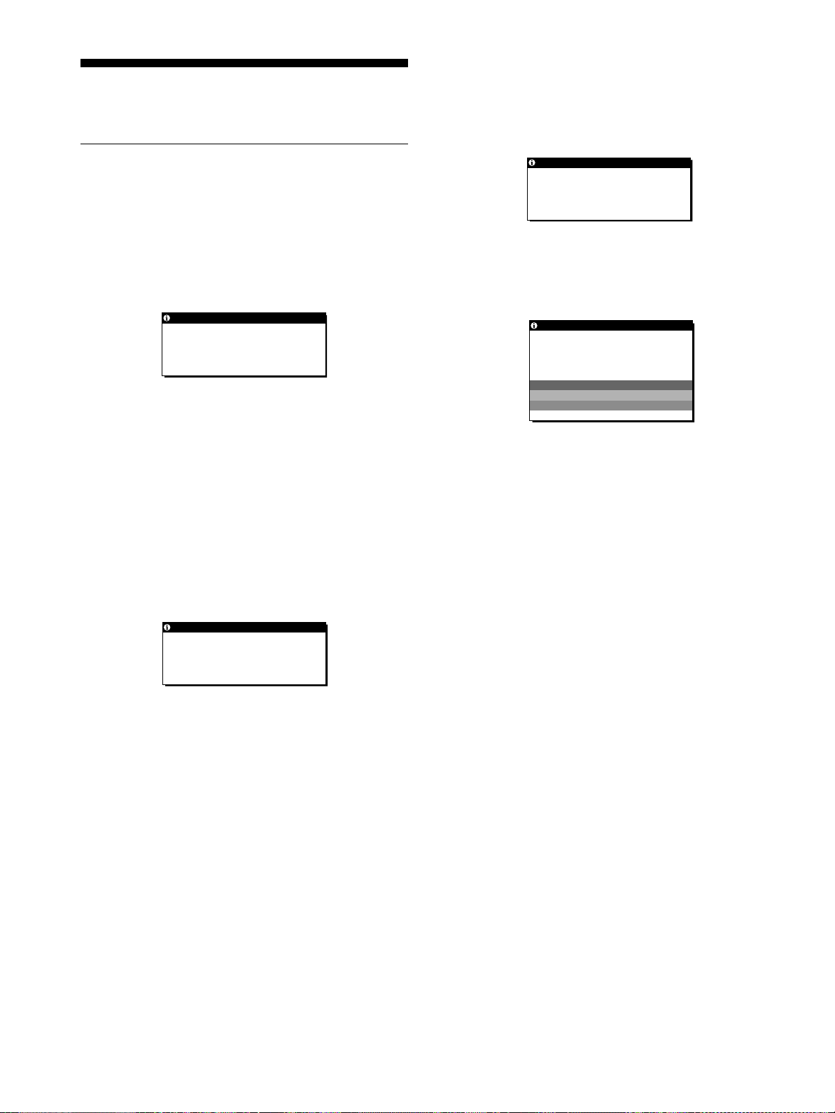
If NO INPUT SIGNAL appears on the screen
This indicates that no signal is being input from the currently
selected connector.
INFORMATION
NO I NPU T S I GNAL
INPU T : 1
GO TO POWER SAVE
INFORMATION
RESOLU T I ON > SXGA
PL EASE CHANGE TO SX AG
If CABLE DISCONNECTED appears on the screen
This indicates that the video signal cable has been
disconnected from the currently selected connector.
INFORMATION
CAB L E D I SCONNECTED
INPUT:1
GO TO POWER SAVE
INPUT:
This indicates the currently selected connector (INPUT: 1 or
INPUT: 2).
If “GO TO POWER SAVE” is displayed
When the POWER SAVE menu is set to ON, the monitor
enters the power saving mode after about 4 seconds from the
time the message is displayed.
If “USB CONNECTED” is displayed
This indicates that acomputer whosepower ison is connected
to the USB upstream connector on the monitor. For that
reason, the monitor willnot enter the power saving mode even
if the POWER SAVE menu is set to ON.
INPUT:
This indicates the currently selected connector (INPUT: 1 or
INPUT: 2).
If “GO TO POWER SAVE” is displayed
When the POWER SAVE menu is set to ON, the monitor
enters the power saving mode after about 4 seconds from the
time the message is displayed.
If “USB CONNECTED” is displayed
This indicates that acomputer whosepower ison is connected
to the USB upstream connector on the monitor. For that
reason,the monitor will not enter the power savingmodeeven
if the POWER SAVE menu is set to ON.
22
Page 23

Trouble symptoms and remedies
If a problem is caused by the connected computer or other equipment, please refer to the connected equipment’s instruction manual.
Use the self-diagnosis function (page 26) if the following recommendations do not resolve the problem.
Symptom Check these items
No picture
If the ACpower indicator is not lit • Check that the power cord is properly connected.
If the AC power indicator is red • Check that the display’spoweris“on.”
If the ACpower indicator is flashing
red
If the 1 (power)indicator is not lit,
or if the 1 (power) indicator will not
light up when the 1 (power) switch
is pressed
If the 1 (power) indicator is green
or flashing orange
If the 1 (power) indicator is
alternating between green and
orange
If inputting a signal to the DVI-I
(digital/analog RGB) input
connector
If CABLE DISCONNECTED
appears on the screen
If NO INPUT SIGNAL appears on
the screen, or the 1 (power)
indicator is orange
• Check that the system connecting cable is properly connected and all plugs are firmly
seated in their sockets (page 8).
• Press the AC power switch twice to turn the monitor off and then on.
• Check that the display’spoweris“on.”
• Check that the media engine’spoweris“on.”
• Check that the system connecting cable is properly connected and all plugs are firmly
seated in their sockets (page 8).
• Use the self-diagnosis function (page 26).
• The monitor cannot return from low power consumption mode because the user sensor
fails to detect the presence of a user.Press the 1 (power) switch twice to turn the monitor
off and then on. If you set the user sensor to OFF, the monitor does not enter low power
consumption mode (page 18).
• Check that the digital/analogselect switch setting matchesthe type of the input signal. Set
the switch to an appropriate position according to the type of signal. Then turn off and on
the media engine. If inputting a digital RGB signal, reboot your computer also
(pages 7, 8).
• Check that the video signal cable is properly connected and all plugs are firmly seated in
their sockets (page 7).
• Check that the video input connector’s pins are not bent or pushed in.
• Check that the input select setting is correct (page 10).
• A non-supplied video signal cable is connected. If you connect a non-supplied video
signal cable, CABLE DISCONNECTED appears on the screen before entering the power
saving mode. This is not a malfunction.
• Check that the video signal cable is properly connected and all plugs are firmly seated in
their sockets (page 7).
• Check that the video input connector’s pins are not bent or pushed in.
• Check that the input select setting is correct (page 10).
• Check that the digital/analog select switch setting matches the type of an input signal. Set
the digital/analog select switch to an appropriate position according to the type of signal
input via the DVI-I (digital/analog RGB) input connector. Then turn off and on the media
engine (pages 7, 8).
GB
If OUT OF SCAN RANGE appears
on the screen
If PLEASE CHANGE TO SXGA
appears on the screen
xProblems caused by the connected computer or other equipment
• The computer is in the power saving mode. Try pressing any key on the keyboard or
moving the mouse.
• Check that your graphics board is attached to the computer properly.
• Check that the computer’spoweris“on.”
xProblems caused by the connected computer or other equipment
• Check that the video frequency range is within that specified for the monitor. If you
replaced an old monitor with this monitor, reconnect the old monitor and adjust the
frequency range to the following:
Horizontal frequency: 28 – 92 kHz, Vertical frequency: 48 – 85 Hz
• The resolution of the input signal exceeds 1280 × 1024 (SXGA). Set your computer to
output a signal 1280 × 1024.
23
Page 24

Symptom Check these items
If using Windows • If you replaced an old monitor with this monitor, reconnect the old monitor and do the
following. Select “SONY” from the “Manufactures” list and select “SDM-N80” from the
“Models” list in the Windows device selection screen. If “SDM-N80” does not appear in
the “Models” list, try “Plug & Play” or install the information file for this monitor using
the Windows Monitor Information Disk (page 9).
If using a Macintosh system • When you connect a Macintosh keyboard to the USB downstreamconnector on the
monitor, the power button on the keyboard does not function. To turn your Macintosh
computer on, use the power button on the computer or connect the keyboard to the
computer directly and turn the computer on, then connect the keyboard to the monitor.
• Check and refer to the supplied “Notes for Macintosh users.”
NO INPUT SIGNAL appears on the
picture
Picture flickers, bounces,
oscillates, or is scrambled
Pictureisfuzzy • Adjust the brightness and contrast (pages 13, 14).
• The digital/analogselect switch setting has been changed while the monitor was operating
normally. Set the switch to an appropriateposition according to the typeof signal input via
the DVI-I (digital/analog RGB) input connector. Then turn off and on the media engine
(pages 7, 8).
• Adjust the pitch and phase (Analog RGB signals only) (page 14).
• Isolate and eliminate any potential sources of electric or magnetic fields such as other
monitors, laser printers, electric fans, fluorescent lighting, or televisions.
• Move the monitor away from power lines or place a magnetic shield near the monitor.
• Try plugging the monitor into a different AC outlet, preferably on a different circuit.
• Change the orientation of the display.
xProblems caused by the connected computer or other equipment
• Check your graphics board manual for the proper monitor setting.
• Confirm that the graphics mode (VESA, Macintosh 19" Color, etc.) and the frequencyof
the input signal are supported by this monitor (Appendix). Even if the frequency is within
the proper range, some graphics boards may have a sync pulse that is too narrow for the
monitor to sync correctly.
• Adjust the computer’s refresh rate (vertical frequency) to obtain the best possible picture.
• Adjust the pitch and phase (Analog RGB signals only) (page 14).
xProblems caused by the connected computer or other equipment
• Set the resolution to SXGA (1280 × 1024) on your computer.
Pictureisghosting • Eliminate the use of video cable extensions and/or video switch boxes.
• Check that all plugs are firmly seated in their sockets.
Picture is not centered or sized
properly
Pictureistoosmall • Set the zoom setting to FULL2 (page 16).
Pictureisdark • Adjust the brightness (page 14).
Wavy or elliptical pattern (moire)
is visible
Color is not uniform • Adjust the pitch and phase (Analog RGB signals only) (page 14).
White does not look white • Adjust the color temperature (page 15).
Monitor keys do not operate
( appears on the screen)
The monitor turns off after a while • SetthepowersavingfunctiontoOFF(page18).
• Adjust the pitch and phase (Analog RGB signals only) (page 14).
• Adjust the picture position (Analog RGB signals only) (page 15). Note that some video
modes d o not fill the screen to the edges.
xProblems caused by the connected computer or other equipment
• Set the computer’sresolutiontothescreen’s resolution.
• Adjust the backlight (page 18).
• It takes a few minutes for the display to become bright after turning on the monitor.
• Adjust the pitch and phase (Analog RGB signals only) (page 14).
• IfthemenulockissettoON,setittoOFF(page18).
• Set the user sensor to OFF (page 18).
xProblems caused by the connected computer or other equipment
• Set the computer’s power saving setting to off.
24
Page 25

Symptom Check these items
USB peripherals do not function
• Check that the (USB SELECT) menu is set appropriately according to the connection
between your computer and the monitor (page 17).
• Check that the plugs of the USB cables (supplied) are firmly seated in their sockets
(page 9).
• Check that the display’s and the media engine’spoweris“on.”
xProblems caused by the connected computer or other equipment
• Check that the power of any self-powered USB compliant peripheral devices is “on.”
• Install the latest version of the device driver on your computer. Contact your device’s
manufacturer for information about the appropriate device driver.
• If your USB compliant keyboard or mouse does not function, connect them directly to
your computer, reboot your computer, and make any necessary adjustments to the USB
settings. Then reconnect the keyboard or mouse to the monitor.If you connect a keyboard
or mouse to the USB connectors and then boot your computer for the first time, the
peripheral devices may not function.
Displaying this monitor’s name, serial number,
and date of manufacture
Whilethe monitoris receiving avideo signal, touchand
hold the MENU key for more than 5 seconds.
The monitor’s information box appears.
MENU
Example
INFORMATION
MODEL : SDM-N80
SER.NO : 1234567
MANUFACTURED : 2001-52
If any problem persists, call your authorized Sony dealer and give
the following information:
• Model name: SDM-N80
• Serial number
• Name and specifications of your computer and graphics board
• Type of input signals (analog RGB/digital RGB)
Model name
Serial number
Week and year
of manufacture
GB
25
Page 26
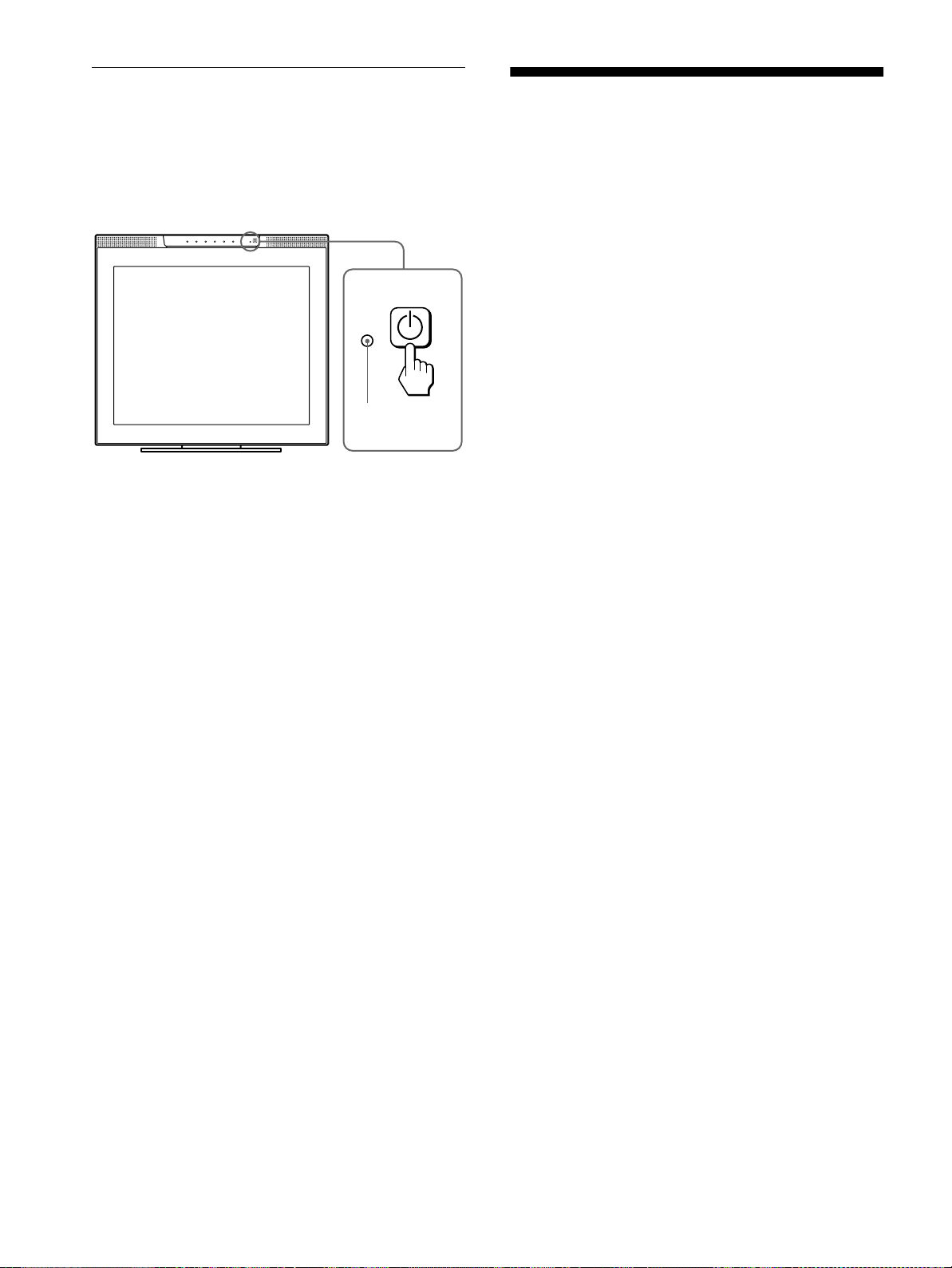
Self-diagnosis function
Thismonitoris equipped with a self-diagnosisfunction. If there is
a problem with your monitor or computer(s), the screen will go
blank and the 1 (power) indicator will either light up green or
flash orange. If the 1 (power) indicator is lit in orange, the
computer is in power saving mode. Try pressing any key on the
keyboard or moving the mouse.
1 (power)
indicator
If the 1 (power) indicator is green
1 Turn off the AC power switch and disconnect the
video signal cables from the INPUT1 and INPUT2
connectors of the media engine.
2 Press the AC power switchtwice toturn the monitor
off and then on.
If all four color bars appear (white, red, green, blue), the monitor
is working properly. Reconnect the video input cables and check
the condition of your computer(s).
If the colorbars do notappear,there is a potential monitor failure.
Inform your authorized Sony dealer of the monitor’s condition.
If the 1 (power) indicator is flashing orange
Press the 1 (power)switch twice to turn the displayoff
and then on.
If the 1 (power)indicatorlightsup green, the monitoris working
properly.
If the 1 (power) indicator is still flashing, there is a potential
monitor failure. Count the number of seconds between orange
flashes of the 1 (power) indicatorand inform your authorized
Sony dealer of the monitor’s condition.Be sure to note the model
name and serial number of your monitor. Also note the make and
model of your computer and graphics board.
Specifications
LCD panel Panel type: a-Si TFT Active Matrix
Picture size: 18.1 inch (46 cm)
Input signal format RGB operating frequency*
Horizontal: 28 – 92 kHz**
Vertical: 48 – 85 Hz**
Resolution** Horizontal: Max.1280 dots
Vertical: Max.1024 lines
Video input connector Analog RGB: HD15
Digital/analog RGB: DVI-I 29 pins
Input signal levels Analog RGB video signal
0.700 Vp-p, 75 Ω, positive
SYNC signal
TTL level, 2 kΩ,
positive or negative
(Separate horizontal and vertical,
or composite sync)
0.3 Vp-p, 75 Ω, negative
(Sync on green)
Digital RGB (DVI) video signal
TMDS (Single link)
Audio output 1 W × 2
Headphones jack Stereo minijack
Accepts impedance of 16 – 48 Ω
AUDIO IN jacks Stereo minijack × 2
Accepts impedance of 47 kΩ
Accepts level 0.5 Vrms
Power requirements 100 – 240 V, 50 – 60 Hz, 0.7 – 0.4 A
Power consumption Max. 67 W
Operating temperature 5 – 35
Dimensions (w/h/d) Display (upright and in the lowest
Mass Display:
Plug & Play DDC2B
Accessories See page 7.
* Recommended horizontal and vertical timing condition
• Horizontalsync widthdutyshouldbe morethan4.8%of total
horizontal time or 0.8 µs, whichever is larger.
• Horizontal blanking width should be more than 2.5 µsec.
• Vertical blanking width should be more than 450 µsec.
**A 1600 × 1200 resolution signal is displayed provisionally as
long as its horizontal and vertical frequencies are lower than
the followingvalues.
• Analog RGB signal: Horizontal 107 kHz, Vertical 85 Hz
• Digital RGB signal: Horizontal 75 kHz, Vertical 60 Hz
°C
position):
Approx. 432 × 400 × 195 mm
1
(17
Media engine:
Approx. 94 × 212 × 204 mm
3
/4
(3
Approx.6.5kg(14lb5oz)
Media engine:
Approx. 1.5 kg (3 lb 5 oz)
/8
× 8
× 15
3
3
/4
× 7
3
1
/8
/8 inches)
× 8
/4 inches)
26
Design and specifications are subject to change without notice.
Page 27

Table des matières
Précautions............................................4
Identification des composants et des commandes. . . . . . . . . . . . . . 5
Installation.....................................7
Etape 1: Raccordez le moteur de support à votre ordinateur . . . . . 7
Etape 2:
Vérifiez le commutateur de sélection numérique/analogique
..7
Etape 3: Raccordezl’écranetlemoteurdesupport............8
Etape 4: Raccordezlecâbleaudio .........................8
Etape 5: Branchezlecâbled’alimentation....................8
Etape 6: Mettez le moniteur et l’ordinateur sous tension . . . . . . . . . 8
Raccordement des périphériques conformes au bus série universel (USB)
..9
Utilisationdeshaut-parleursstéréo.........................9
Sélectiondusignald’entrée..............................10
Réglagedel’inclinaisonetdelahauteur....................10
Personnalisationdevotremoniteur................11
Pilotageparmenu......................................11
Réglageducontraste(CONTRASTE)......................13
Réglage du niveau de noir de l’image (LUMINOSITÉ). . . . . . . . . . 13
Suppression du scintillement ou du flou (PHASE/PITCH)
(signauxanalogiquesRVBuniquement) ....................14
Réglage de la position de l’image (CENTRAGE H/CENTRAGE V)
(signauxanalogiquesRVBuniquement) ....................15
Réglage de la température des couleurs (COULEUR). . . . . . . . . . 15
Modification de la taille de l’image en fonction du signal (ZOOM) . 16
Uniformisationdel’image(SMOOTHING)...................16
Changement de la position du menu (POSITION MENU) . . . . . . . 16
Réinitialisationdesréglages(RESTAURE)..................17
Réglagescomplémentaires ..............................17
FR
• Macintoshest une marquecommerciale
sous licence d’Apple Computer, Inc.,
déposée aux Etats-Unis et dans d’autres
pays.
•Windows
déposée de Microsoft Corporation aux
Etats-Uniset dans d’autres pays.
• IBM PC/AT et VGA sont des marques
commerciales déposées d’IBM
Corporation of the U.S.A.
• VESA et DDC
commerciales de Video Electronics
Standards Association.
ENERGY STAR est une marque
•
déposée aux Etats-Unis.
• Tous les autres noms de produit
mentionnés dans le présent mode
d’emploi peuvent être des marques
commerciales ou des marques
commerciales déposées de leurs
entreprises respectives.
• De plus, les symboles “”et“”ne
sont pas systémat iquement mentionnés
dans ce mode d’emploi.
estune marquecommerciale
sont des marques
Spécificationstechniques........................19
Fonction d’économie d’énergie (capteur utilisateur/mode d’économie d’énergie)
Si le capteur utilisateur ne semble pas fonctionner correctement
Fonction de réglage automatique de la luminosité (capteur de lumière)
Fonction de réglage automatique de la qualité de l’image
(signauxanalogiquesRVBuniquement) ....................21
..19
..20
..21
Dépannage....................................22
Messagesaffichés.....................................22
Symptômesdedéfaillanceetremèdes......................23
Fonctiond’autodiagnostic................................26
Spécifications..................................26
Appendix.......................................i
Presetmodetimingtable ..................................i
TCO’99Eco-document....................................i
3
Page 28
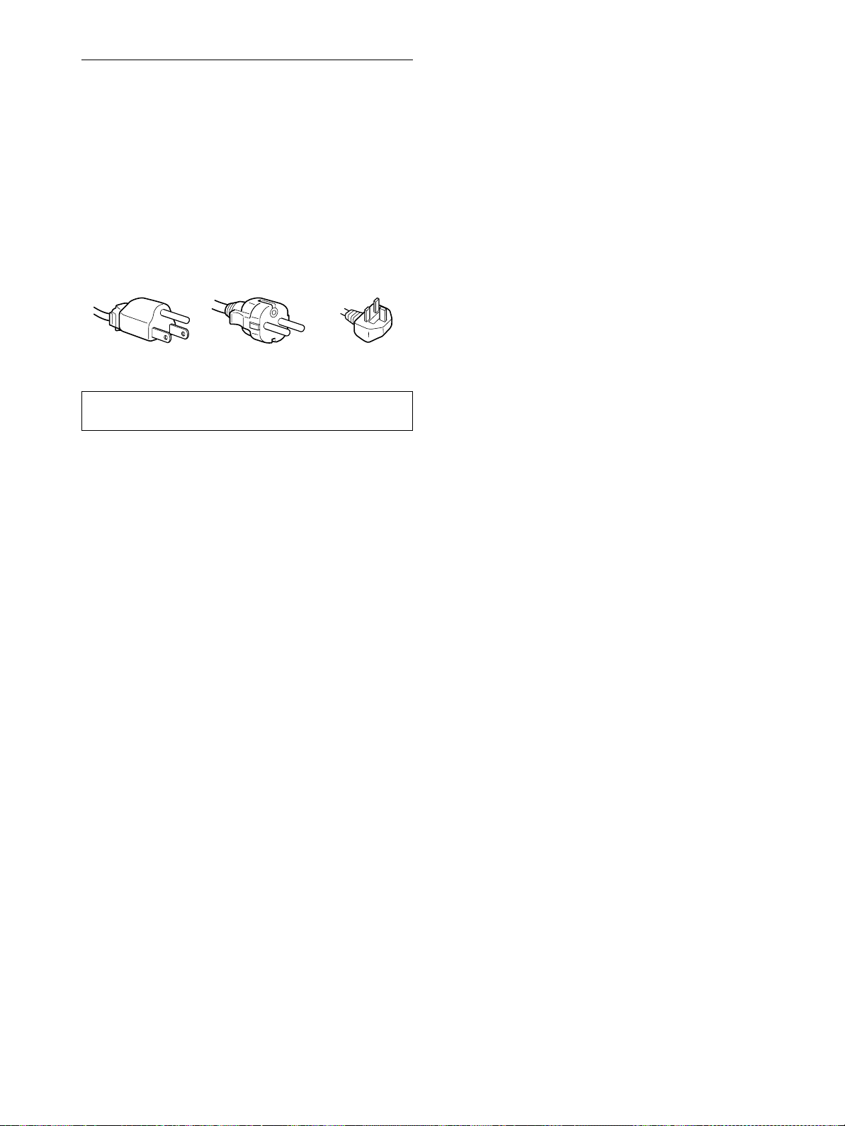
Précautions
Avertissement sur les connexions d’alimentation
• Utilisez le câble d’alimentation fourni. Si vousutilisez uncâble
d’alimentation différent, assurez-vous qu’il est compatible
avec la tension d’alimentation secteur locale.
Pour les clients aux Etats-Unis
Si vous n’utilisez pas le câble approprié, ce moniteur ne sera
pas conforme aux normes FCC obligatoires.
Pour les clients au Royaume-Uni
Si vous utilisez le moniteur au Royaume-Uni, veuillez utiliser
le câble d’alimentationadapté au Royaume-Uni.
Exemples de types de fiches
pour 100 à 120 V CA pour 200 à 240 V CA pour 240 V CA
L’appareil doit être installéàproximité d’uneprise de courant
aisément accessible.
uniquement
A propos des haut-parleurs stéréointégrés
Conservez vos équipements d’enregistrement magnétique, vos
cassettes et vos disquettes à l’écart des ouvertures des hautparleurs qui génèrent des champs magnétiques. Ces champs
magnétiques sont susceptibles d’effacer ou d’endommager les
données stockées sur vos cassettes ou disquettes.
Remarque sur l’affichage à cristaux liquides (LCD
- Liquid Crystal Display)
Veuillez noter que l’écran LCD est issu de technologie
de haute précision. Toutefois, il est possible que des
points noirs ou des points lumineux (rouge, bleu ou
vert) apparaissent constamment sur l’écran LCD, ainsi
que des bandes de couleur irrégulières ou une certaine
luminosité.Ilnes’agit pas d’un dysfonctionnement.
(Points effectifs: plus de 99,99%)
Remplacement du tube fluorescent
Un tube fluorescent de conception spéciale est installé dans ce
moniteur comme source lumineuse. Si l’écran s’assombrit, est
instableou ne s’allume pas, remplacez le tube fluorescent. Pour le
remplacementdu tube fluorescent, consultezvotre revendeur
Sony.
Installation
N’installez pas ou ne laissez pas le moniteur:
•àdes endroits exposés à des températures extrêmes, par
exemple à proximité d’un radiateur, d’un conduit de chauffage
ouaurayonnementdirect soleil. L’expositiondumoniteurà des
températuresextrêmes, comme àl’intérieur d’une voiture garée
en plein soleil ou à proximité d’un conduit de chauffage, risque
d’entraîner des déformations du boîtier ou des
dysfonctionnements;
•àdes endroits soumis à des vibrations mécaniques ou à des
chocs;
•àproximité d’appareils générant de puissants champs
magnétiques, comme un téléviseur ou d’autres appareils
électroménagers;
•àdes endroits soumis à desquantitésinhabituellesdepoussière,
de saletés ou de sable, par exemple à côté d’une fenêtre ouverte
ou d’une porte donnant sur l’extérieur. En cas d’installation
temporaire à l’extérieur, veillez à prendre les précautions
requises contre la poussière et les saletés en suspension dans
l’air. Sinon, des dommages irréparables risquent de se produire.
Manipulation de l’écran LCD
• Ne laissez pas l’écran LCD face au soleil, car vous risquez de
l’endommager.Parconséquent,faites attention si vous installez
le moniteur à côté d’une fenêtre.
• N’appuyez pas sur la surface de l’écran LCD et veillez à ne pas
l’érafler. Ne posez pas d’objets lourds sur l’écran LCD. Vous
risquez d’altérer l’uniformité de l’écran ou de provoquer un
dysfonctionnement.
• Lorsque le moniteur est dans un environnement froid, il est
possible qu’une image rémanente apparaisse sur l’écran. Il ne
s’agit pas d’un dysfonctionnement. L’écran retrouve un état
normal dès que la température revient à un niveaunormal.
• Si uneimage fixe resteaffichée pendant une longue durée, il se
peut qu’une image rémanente apparaisse pendant un certain
temps. Cette image finit par disparaître.
• Le panneau LCD chauffe en cours d’utilisation. Il ne s’agit pas
d’un dysfonctionnement.
Entretien
• Débranchez le câble d’alimentationde la prise secteur avant de
procéder au nettoyage de votre moniteur.
• Nettoyez l’écranLCD avec un chiffondoux. Sivous utilisezun
liquide de nettoyage pour le verre, n’utilisez pas de nettoyant
contenant une solution antistatique ou tout autre additif
similaire, car vous risquez de rayer le revêtement de l’écran
LCD.
• Nettoyez le boîtier, le panneau et les commandesà l’aide d’un
chiffondouxlégèrement imprégné d’une solution détergente
neutre. N’utilisez aucun type de tampon abrasif, de poudreà
récurer ou de solvant tel que de l’alcool ou de la benzine.
• Ne frottez pas, ne touchez pas et ne tapotez pas la surface de
l’écran avec des objets pointus ou abrasifs comme un stylo à
bille ou un tournevis. Ce type de contact risque de rayer le tube
image.
• Sachez qu’une détériorationdesmatériauxoudurevêtement de
l’écran LCD risque de se produire si le moniteur est exposéà
des solvants volatiles comme des insecticides ou en cas de
contact prolongé avec des objets en caoutchouc ou en vinyle.
Transport
• Débranchez tous les câbles du moniteur avant de le transporter.
Pour transporter cet écran, saisissez-le fermement des deux
mains au niveau dusupport et de la base. Utilisezégalementles
deux mains pour transporter le moteur de support. Si vous
laissez tomber le moniteur, vous risquez de vous blesser ou
d’endommager le moniteur.
• Pour transporter ce moniteur afin de leréparerou de l’expédier,
utilisezle carton et les matériaux de conditionnementd’origine.
Mise au rebut du moniteur
• Ne jetez pas ce moniteur avec les ordures
ménagères.
• Le tube fluorescent utilisé dans ce moniteur contient
du mercure. Lamise aurebut de ce moniteur doitêtre
effectuée conformément aux réglementations des
autoritéslocalescompétentesen matière depropreté
publique.
4
Page 29

Identification des composants et
MENU
OK
1
2
des commandes
Pour plus de détails, reportez-vous aux pages entre parenthèses.
Ecran LCD
Vous pouvez mettre le moniteur sous tension en effleurant les
touches. Les caractères et les icônes indiquant les fonctions des
touchess’allumentenviron 10 secondes aprèslamisesoustension
du moniteur. Si vous n’appuyez sur aucune touche pendant cette
période, elles s’éteindront toutes. Si vous appuyez sur l’une des
touches pendant cette période, seuls les caractères et les icônes
associés à cette touche restent allumés. Si elles s’éteignent toutes,
vous n’avez qu’à appuyer sur l’une des touches 4– 8 pour
qu’elles s’allument à nouveau.
Avant
MENU
1
2
OK
1 Haut-parleurs stéréo(page9)
Ces haut-parleurs diffusent les signaux audio sous forme de
sons.
2 Capteurs utilisateur (page 19)
Ces capteurs détectent la présence d’un utilisateur en face de
l’écran. Veillez à ne pas recouvrir le capteur de papiers, etc.
3 Capteur de luminosité (pages 18, 21)
Ce capteur mesure la luminositéambiante. Veillez à ne pasle
recouvrir de papiers, etc.
4 Touche MENU (page 12)
Cettetoucheactivel’affichage du menu principal.
5 Touches 2 (volume) +/– et M(+)/m(–) (pages 9, 12)
Ces touches activent l’affichage du menu VOLUME et
agissentcomme touches M(+)/m(–)poursélectionner des
paramètres de menu et effectuer des réglages.
6 Touche 8 (luminosité) (page 13)
Cettetoucheactivel’affichage du menu LUMINOSITÉ.
7 Touche 6 (contraste) (page 13)
Cettetoucheactivel’affichage du menu CONTRASTE.
8 Touche INPUT, OK et indicateur (pages 10, 12)
Cettetouchepermetdesélectionner le signal d’entréevidéo
INPUT1 (connecteur HD15 (RVB analogique)) ou INPUT2
(connecteur DVI-1 (RVB numérique/analogique)). Le signal
d’entréeetl’indicateur d’entrée correspondant changent à
chaque pression sur cette touche.
Cettetouchesertégalement de touche (de validation) OK
lorsque le menu est affichéàl’écran.
FR
Arrière
9 Indicateur 1 (alimentation) (pages 8, 19, 26)
Cet indicateur s’allume en vert lorsque le moniteur est sous
tension.Il clignoteen vert eten orangelorsque le moniteur est
en mode de faible consommation d’énergie et s’allume en
orange lorsque le moniteur est en mode d’économie
d’énergie.
0 Commutateur 1 (alimentation) (pages 8, 26)
Ce commutateur permet de mettre l’écran sous tension et hors
tension.
qa SYSTEM CONNECTOR (page 8)
Ce connecteur entre les signaux du moteur de support lorsque
l’écran et le moteur de support sont raccordésaumoyende
câble de connexion système.
qs Orificedeverrouillagedesécurité
L’orifice de verrouillage de sécurité doit être utilisé avec le
Côté droitCôté gauche
système de sécurité Kensington Micro Saver.
Le système de sécurité Kensington Micro Saver est une
marque commerciale de Kensington.
qd Prise pour casque d’écoute (page 10)
Cette prise dirige les signaux audio vers un casque d’écoute.
qf Connecteurs en aval USB (bus série universel)
(page 9)
Ces connecteurs sont utilisés pour raccorder le moniteur aux
dispositifs périphériques USB.
5
Page 30

Moteur de support
Arrière Avant
AC IN
INPUT 1
AUDIO IN
INPUT 2
ANALOG
DIGITAL
AUDIO IN
*
SYSTEM
CONNECTOR
(TO DISPLAY)
wa Commutateur de sélection numérique/analogique
(page 7)
Lorsque vous raccordez le connecteur qj d’entréeDVI-Ià un
ordinateur équipé d’une sortie HD15 (RVB analogique) à
l’aidedu câbledesignalvidéoDVI-HD15 (RVB analogique)
(fourni), positionnez ce commutateur sur ANALOG.
Lorsque vous le raccordez à un ordinateur équipé d’une sortie
DVI (RVB numérique) avec un câbledesignalvidéoDVIDVI (RVB numérique) (non fourni), positionnez ce
commutateur sur DIGITAL.
Ce commutateur est positionné par défaut sur ANALOG.
ws Commutateur d’alimentation secteur (page 8)
Ce commutateur permetde mettre le moniteur sous tension et
hors tension.
wd Indicateur d’alimentation secteur (page 19)
Il s’allume en vert lorsque le moteur de support est sous
tension. Cet indicateur s’allume en rouge lorsque l’écran est
hors tension et que le moteur de support est sous tension. Il
s’allume en orange lorsque le moniteur se trouve en mode
d’économie d’énergie.
qg Connecteur AC IN (page 8)
Ce connecteur fournit une alimentation secteur au moniteur.
qh Connecteur d’entrée HD15 (RVB analogique)
(INPUT1) (page 7)
Ce connecteur permet l’entrée des signaux vidéoRVB
analogiques (0,700 Vp-p, positifs) et les signaux SYNC.
qj Connecteur d’entrée DVI-I (RVB numérique/
analogique) (INPUT2) (page 7)
Ce connecteur permet l’entrée des signaux vidéoRVB
analogiques (0,700 Vp-p, positifs) avec des signaux de
synchronisation ou des signaux vidéoRVBnumériques
conformes au DVI Rev. 1.0. Vous pouvez passer des signaux
RVB numériques aux signaux RVB analogiques à l’aide du
commutateur d’entréenumérique/analogique wa.
qk SYSTEM CONNECTOR (TO DISPLAY) (page 8)
Ce connecteur émet les signaux vers l’écran lorsque celui-ci
etle moteurde supportsontraccordésaumoyend’uncâble de
connexion système.
ql Prises AUDIO IN (pages 8, 18)
Cesprisespermettentl’entrée des signaux audio lorsqu’elles
sont raccordées à la prise de sortie audio de l’ordinateur ou
d’un autre appareil audio.
* Ce connecteur est uniquement employé par le personnel de
service. Ne raccordez rien d’autre à cette prise.
w; Connecteurs en amont USB (bus série universel)
(pages 9, 17)
Ces connecteurs sont utilisés pour raccorder le moniteur aux
ordinateurs conformes aux USB.
6
Page 31

Installation
Avant d’utiliser votre moniteur, vérifiez si les accessoires
suivants se trouvent bien dans le carton d’emballage:
• Ecran LCD
• Moteur de support
• Câble d’alimentation
• Câble de connexion système (2 m)
• Câbledesignalvidéo DVI-HD15 (RVB analogique)
• Câble audio (minifiche stéréo)
• Câble USB
• Adaptateur Macintosh
• Disquette Windows Monitor Information/Windows Utility/
Macintosh Utility
• Cartedegarantie
• Remarques pour les utilisateurs Macintosh
• Ce mode d’emploi
Raccordement à un Macintosh
x
Utilisez l’adaptateur Macintosh fourni.
Adaptateur Macintosh
(fourni)*
vers le connecteur
INPUT2
Etape 1:Raccordez le moteur de
support à votre ordinateur
Mettezlemoteurdesupportetl’ordinateur hors tension avant de
procéder au raccordement.
Lorsque vous raccordez le moniteur à un ordinateuréquipé d’un
connecteur de sortie DVI (RVB numérique) conforme au DVI
Rév.1.0, utilisez un câbledesignalvidéo DVI-DVI (RVB
numérique) (non fourni).
Remarque
Ne touchez pas les broches du connecteur du câbledesignalvidéocar
vous risquez
x
de les tordre.
Raccordement à un ordinateur IBM PC/AT
ou compatible
vers le connecteur
INPUT2
Câble de signal vidéo
vers la sortie
vidéo
Macintosh
*Pourplusdedétails, reportez-vous aux “Remarques pour les
utilisateurs Macintosh” fournies.
DVI-HD15 (RVB
analogique) (fourni)
Etape 2:Vérifiezle commutateurde
sélection numérique/
analogique
Avant de mettrele moniteur oul’ordinateursous tension, vérifiez
leréglage du commutateur. Lorsque vous raccordez le connecteur
d’entrée DVI-I du moniteur à un ordinateur équipé d’une sortie
HD15 (RVB analogique) à l’aide du câbledesignalvidéo DVIHD15 (RVB analogique) (fourni), positionnez ce commutateur
sur ANALOG.
Lorsque vous le raccordez à un ordinateuréquipé d’un connecteur
de sortie DVI (RVB numérique) avec un câbledesignalvidéo
DVI-DVI (RVB numérique) (non fourni), positionnez ce
commutateur sur DIGITAL.
Le réglage par défaut de ce commutateur est ANALOG.
FR
Ordinateur IBM PC/AT
ou compatible
ANALOG
vers la sortie vidéo
DIGITAL
Câbledesignal vidéoDVI-HD15
(RVB analogique) (fourni)
Remarque
Avantdemettrelemoniteuroul’ordinateur sous tension, vérifiez le
réglage du commutateur.
(suite)
7
Page 32

Etape 3:Raccordez l’écran et le
Etape 5:Branchez le câble
moteur de support
Mettez l’écran et le moteur de support hors tension avant de
procéder au raccordement.
Pour raccorder facilement le câble de connexion système à
l’écran, placez ce dernier en position v erticale.
A
vers le SYSTEM
CONNECTOR
de l’écran
Cable de connexion
systeme(2 m) (fourni)
A
d’alimentation
Après avoir mis le moteurde support,l’écran et l’ordinateur hors
tension, connectez d’abord le câble d’alimentation au moteur de
support et ensuite sur une prise secteur.
vers le connecteur AC IN
vers une prise
secteur
Câble d’alimentation
(fourni)
Etape 6:Mettez le moniteur et
l’ordinateur sous tension
1 Mettez le moteur de support sous tension.
L’écran se met automatiquement sous tension. Les
indicateurs du moteur de support et de l’écran s’allument en
vert.
vers le
SYSTEM
CONNECTOR
du moteur de
support
Alignez le
du moteur de support.
Attention
Veillez à installer le moteur de support verticalementcomme illustré cidessus. L’installation du moteur de support à plat risque de bloquer les
orifices de ventilation et de provoquer un dysfonctionnement.
Remarque
Lorsquevousraccordezlecâble, saisissez-le par la fiche et insérez-le
fermement dans le connecteur, jusqu’à ce que vous entendiez un déclic.
Lorsque vous débranchez le câble, tirez la fiche tout en maintenant le
levier de verrouillage
v
de la fiche sur levde l’écran et
vers le bas.
A
Etape 4:Raccordez le câble audio
vers les connecteurs
INPUT2 v ia la prise
vers une prise de
sortie audio de votre
ordinateur
AUDIO IN
Câble audio (fourni)
2 Mettez l’ordinateur sous tension.
Remarque
Si vous mettez le moteur de support hors tension puis sous tension, alors
que l’écran est hors tension, ce dernier ne se met pas automatiquement
1
sous tension. Dans ce cas, appuyez sur le commutateur
de l’écran pour le me ttre sous tension.
(alimentation)
L’installation du moniteur est à présent terminée. Si nécessaire,
utilisez les commandes du moniteur pour régler l’image.
Si aucune image n’apparaîtsurl’écran
• Vérifiez que le moniteur est correctement raccordéà
l’ordinateur.
• Vérifiez que le moteur de support est sous tension.
• Si l’indication PAS ENTRÉE VIDEO apparaîtsurl’écran:
– l’ordinateurest enmode d’économie d’énergie. Appuyez sur
n’importe quelle touche du clavier ou déplacez la souris;
– vérifiez que le réglagedesélection de l’entrée est correct.
– vérifiez que le paramétrage du commutateur de sélection
numérique/analogique est correct.
• Si CABLE PAS CONNECTÉ apparaîtsurl’écran:
– vérifiezquelecâble d’entréevidéoestbranchécorrectement;
– vérifiez que le réglagedesélection de l’entrée est correct.
• Si l’indication HORS PLAGE DE BALAYAGE apparaît à
l’écran, rebranchez l’ancien moniteur. Ajustez ensuite les
paramètres de la carte graphique de l’ordinateur de sorte que la
fréquence horizontale soit comprise entre 28 et 92 kHz et que
la fréquence verticale soit comprise entre 48 et 85 Hz.
Pour des informations plus détaillées sur les messages à l’écran,
voir “Symptômes de défaillance et remèdes”àla page 23.
8
Page 33

Vous n’avez besoin d’aucun pilote pour ce moniteur
Le moniteur prend en charge la fonction Plug & Play “DDC” et détecte
automatiquement toutes les autres informations relatives au moniteur. Il
n’est pas nécessaire d’installer de pilote pour cet ordinateur.
Lapremière fois que vous mettez votre ordinateur sous tension après avoir
raccordé le moniteur, l’assistant de réglage peut s’afficher sur l’écran.
Dans ce cas, suivez les instructions indiquées sur l’écran. Le moniteur
Plug & Play est automatiquement sélectionné afin que vous puissiez
l’utiliser.
La fréquence verticale devient 60 Hz.
Etant donné que les scintillements sur le moniteur sont discrets, vous
pouvez l’utiliser tel quel. Vous n’avez pas besoin de régler la fréquence
verticale sur une valeur particulièrement élevée.
Si votre ordinateur ou votre carte graphique rencontre des difficultésde
communication avec ce moniteur, installez le fichier d’informations de ce
moniteurà l’aide de Windows Monitor Information Disk. Pour obtenir de
plus amples informations sur l’installation, consultez le fichier ReadMe
sur le disque.
Raccordement des périphériques conformes au bus série universel (USB)
Le moniteur est équipé de deux connecteurs en amont USB et
deux connecteurs en aval USB. Ils fournissentun moyen de
raccordement rapideet faciledes périphériques conforme à l’USB
(tels que les claviers, les souris, les imprimanteset les scanners) à
votre ordinateur à l’aide d’un câble USB normalisé.
Pour utiliser le moniteur comme concentrateur pour vos
dispositifs périphériques, raccordez lesdispositifs d’USB comme
illustré ci-dessous:
Remarques
• Tousles ordinateurset/ou les systèmesd’exploitation ne supportent pas
les configurations de l’USB. Consultez votre manuel d’instructi ons de
l’ordinateur pour vérifier si vous pouvez raccorder les dispositifs USB.
• Dans la plupart des cas, le logiciel du pilote de l’USB doit être installé
sur l’ordinateur hôte. Consultez le manuel d’instructions du dispositif
périphérique pour obtenir plus de détails.
• Lorsque vous branchez un ordinateur dont l’alimentation est raccordée
au connecteur USB en amont du moniteur, ce dernier ne passe pas en
mode d’économie d’énergie.
• Lorsquelemoniteurestenmoded’économie d’énergie, les
périphériques USB ne fonctionnent pas. Pour les réactiver, annulez ce
mode en appuyant sur le commutateur
• Si les périphériques ne fonctionnent pas correctement, vérifiez que le
paramètre d’entrée amont de (ENTRÉE USB) est correct
(page 17).
• Si vous raccordez un clavier ou une souris aux connecteurs USB et que
vous démarrez votre ordinateur pour la première fois, les dispositifs
périphériques risquent de ne pas fonctionner. Raccordez d’abord le
clavieret la souris directementà l’ordinateur et installez les dispositifs
conformes à l’USB. Raccordez-les ensuite au moniteur.
• Lorsque vous raccordez les dispositifs périphériques aux connecteurs
en aval, assurez-vous de ne pas vous appuyer sur l’écran, sinon l’écran
risque de s’incliner et de coincer vos doigts.
• Les spécifications USB fixent le nombre de concentrateurs USB
pouvant être raccordés ensemble à six niveaux au maximum. Deux
niveaux de connecteurs USB sont intégrésdanslemoniteur.Vous
pouvez par conséquent raccorder quatre autres niveaux de
concentrateurs USB.
1 (alimentation).
Utilisation des haut-parleurs stéréo
Vous pouvez écouter de la musique, des sons et d’autres fichiers
audio via le haut-parleur stéréo de votre moniteur.
FR
Connecteurs
USB en amont
Vers les
ordinateurs
conformes à
l’USB
Connecteurs USB en aval
Vers les dispositifs périphériques
conformes à l’USB
1 Mettez le moniteur et l’ordinateur sous tension.
2Al’aide du câble USB fourni, raccordez l’ordinateur
aux connecteurs en amont du moteur de support.
Pour les clients utilisant Windows
Si un message apparaît à l’écran, suivez les instructions affichées,
puis sélectionnez un pilote générique pour concentrateur USB.
3 Raccordez les périphériques compatibles USB aux
connecteurs en aval du support de l’écran.
Pour une utilisation sur Macintosh
Si vous raccordez un clavier Macintosh au connecteur USB
descendant, la touche d’alimentationsur le clavierne fonctionnepas.
Pour mettre un ordinateur Macintosh sous tension, utilisez la touche
d’alimentation située sur l’ordinateur ou raccordez directement le
clavier à l’ordinateur et mettez l’ordinateursous tension,puis
raccordez le clavier au moniteur.
Réglage du volume
Le réglage du volume se fait via un menu VOLUME distinct du
menu principal (page 11).
1 Allumez les caractères et les icônes pour indiquer
les fonctions des touches.
Appuyez sur l’une des touches du MENU, M(+)/m(–), 8
(luminosité), 6 (contraste), ou INPUT pour allumer les
caractères et les icônes indiquantles fonctions des touches.
2 Appuyez sur les touches 2 +/–.
Le menu VOLUME apparaîtsurl’écran.
VOL UME
40
3 Appuyez sur les touches 2 +/– pour régler le
volume.
Le menu disparaît automatiquement au bout de 3 secondes
environ.
(suite)
9
Page 34

Utilisation de la prise pour casque d’écoute
Vous pouvez écouter les signaux audio de votre ordinateur ou
d’un autre appareil audio à l’aide d’un casque d’écoute.
Raccordezvotre casque d’écoute à la prise pour casque d’écoute.
Les haut-parleurs sont désactivésdès que vous branchez un
casque d’écoute sur laprise.Réglez levolume ducasque d’écoute
à l’aide du menu VOLUME.
Remarques
• Vous ne pouvez pas régler le volume lorsque le menu principal est
affiché sur l’écran.
• Lorsque votre moniteur se trouve en mode de faible consommation
d’énergie ou en mode d’économie d’énergie, aucun son n’est émis par
les haut-parleurs ni le casque d’écoute.
Réglagedel’inclinaison et de la hauteur
Cet écran est réglable suivant les angles indiqués ci-dessous.
30°
59°
Sélection du signal d’entrée
Vous pouvez raccorder deux ordinateurs à ce moniteur à l’aide
des connecteurs INPUT1 et INPUT2. Pour sélectionner l’un des
deux ordinateurs, utilisez la touche INPUT.
1 Allumez les caractères et les icônes pour indiquer
les fonctions des touches.
Appuyez sur l’une des touches du MENU, M(+)/m(–), 8
(luminosité), 6 (contraste), ou INPUT pour allumer les
caractères et les icônes indiquantles fonctions des touches.
2 Appuyez sur la touche INPUT.
Le signal d’entréeetl’indicateur d’entrée correspondant
changent chaque fois que vous appuyez sur cette touche.
• 1:Entrée via le connecteur d’entrée HD15 (RVB
analogique)
• 2:Entrée via le connecteur d’entrée DVI-I (RVB
numérique/analogique)
2
29°
60°
60°
Remarques
• Lorsque vous raccordez des câbles aux connecteurs USB en aval,
l’angle de rotation du côté droit peut être inférieur à 60°.
• Prenez garde de ne pas vous coincer les doigts entre le bras et la base
du support -
, comme représenté dans l’illustration ci-dessus.
A
29°
A
Pour régler les angles d’inclinaison et de hauteur, suivez la
procédure décrite ci-dessous.
Remarques
• Vous ne pouvez pas sélectionner le signal d’entrée lorsque le menu
principal est affichéàl’écran.
• Pour l’entréed’USB en amont et l’entrée audio, vous pouvez choisir ou
non de les faire commuter à l’aide de la touche INPUT. Pour régler
l’entrée en amont USB, utilisez le menu (ENTRÉEUSB)
(page 17), pour régler l’entréeaudio,utilisezlemenu (ENTRÉE
AUDIO) (page 18). Les deux entrées sont réglées pour être commutés
par défaut avec la touche INPUT.
10
1 Saisissez d’unemainlebasdel’écran par le milieu
tout en maintenant son support de l’autre, puis
inclinez l’écran LCD en le poussant suffisamment
en arrière.
Remarque
Ne saisissez pas la partie entourant la pièceensaillieaucentredelapartie
inférieure de l’écran car ce dernier pourrait coincer vos doigts.
Page 35

2 Saisissez la partie inférieure de l’écran LCD et tirez-
le vers le bas pour ajuster la hauteur de l’écran.
Personnalisation de votre moniteur
Avant de procéder aux réglages
Raccordez le moniteur et l’ordinateur et mettez-les sous
tension.
Pour obtenir les meilleurs résultats, attendez au moins 30
minutes avant d’effectuer les réglages.
Vous pouvez effectuer de nombreux réglages à l’aide des menus
d’affichage.
Pilotage par menu
3 Saisissez l’écran LCD en haut et en bas par le
milieu, puis réglez l’inclinaison de l’écran.
Remarque
Lors du réglagedel’inclinaison et de la hauteur de l’écran, procédez
doucement et avec précautionafindenepasheurterl’écran LCD contre
le bureau ou le support de l’écran.
Pour utiliser l’écran confortablement
Cet écran est conçupourêtre installé selon un angle de vision
confortable. Réglez l’angledevisiondel’écran en fonction de la
hauteurde votre bureauet de votrechaise,de sorteque la lumière
de l’écran ne se reflète dans vos yeux.
Appuyez sur la touche MENU pour afficher le menu principal sur
votre écran. Pour plus de détails sur l’utilisation de la touche
MENU, voir “Utilisation des touches MENU, M(+)/m(–), et OK”
à la page 12.
PHASE
MENU
b
q;
Utilisez les touches M(+)/m(–)etOKpoursélectionner l’un des
menus suivants. Pour plus de détails sur l’utilisation des touches
M(+)/m(–) et OK,voir “Utilisation des touchesMENU, M(+)/m(–
), et OKӈla page 12.
1 PHASE (signaux
analogiques RVB
uniquement) (page 14)
Sélectionnez le menu
PHASE pour ajuster laphase
lorsque les caractères ou les
images apparaissentflous sur
toute la surface de l’écran.
Ajustezlaphaseaprèsavoir
réglé le pas.
PHASE
16
EX I T
FR
2 PITCH (signaux
analogiques RVB
uniquement) (page 14)
Sélectionnezle menuPITCH
pour régler le pas lorsque les
caractères ou les images
manquent de clarté dans
certaines parties de l’écran.
3 CENTRAGE H (signaux
analogiques RVB
uniquement ) (page 15)
Sélectionnez le menu
CENTRAGE H pour ajuster
le centrage horizontal de
l’image.
PITCH
50
EX I T
CENT R A GE H
50
EX I T
(suite)
11
Page 36

4 CENTRAGE V (signaux
analogiques RVB
uniquement) (page 15)
Sélectionnez le menu
CENTRAGE V pour ajuster
le centrage vertical de
l’image.
CENT R A GE V
50
EX I T
Utilisation des touches MENU,M(+)/m(–), et
x
OK
1 Allumez les caractères et les icônes pour indiquer
les fonctions des touches.
Appuyez sur l’une des touches du MENU, M(+)/m(–), 8
(luminosité), 6 (contraste), ou INPUT pour allumer les
caractères et les icônes indiquantles fonctions des touches.
5 COULEUR (page 15)
Sélectionnez le menu
COULEUR pour régler la
température des couleurs de
l’image. Ce réglageajustele
ton de l’écran.
6 ZOOM (page 16)
Sélectionnezle menu ZOOM
pour ajuster la taille de
l’image en fonction du
format ou de la résolution du
signal d’entrée.
7 SMOOTHING (page 16)
Sélectionnez le menu
SMOOTHINGpour ajuster
la netteté de l’image en
fonctiondutyped’objet
affiché sur l’écran.
8 POSITION MENU
(page 16)
Sélectionnez le menu
POSITION MENU pour
changer la position
d’affichage du menu sur
l’écran.
COUL EUR
9300K
0K
650
5000K
UT I L I SATEUR
RÉGL ER
ZOOM
FULL 2
FULL 1
ORI G I NAL
SMOOT H I NG
TEXTE
ND
STA
ARD
GRAPH
IQUE
POS UTIION ENM
EX I T
EX I T
EX I T
EX I T
2 Affichez le menu principal.
Appuyez surla touche MENU pour afficher le menuprincipal
sur votreécran.
MENU
3Sélectionnez le menu que vous souhaitez régler.
Appuyez sur les touches M(+)/m(–) pour afficher le menu de
votre choix. Appuyez sur la touche OK pour sélectionner un
élément de ce menu.
OK
OK
2
2
b
4Réglez le menu.
Appuyez sur les touches M(+)/m(–)poureffectuerleréglage,
puis sur la touche OK.
Lorsque vous appuyez sur la touche OK, les réglages sont
enregistrésetl’écran revient au menu précédent.
b
9 RESTAURE (page 17)
Sélectionnez le menu
RESTAURE pour
réinitialiser les réglages.
0 Autres menus (page 17)
Sélectionnez m pour régler
lesautresmenusdu
moniteur. Ces menus
incluent:
• ENTRÉEUSB
• ENTRÉE AUDIO
• RETROÉCLAIRAGE
• CAPTEUR LUMIÉRE
• CAPTEUR UTILIS.
• MODE ÉCO
• LANGUAGE
• VERROU RÉGLAGES
12
REST AURE
RESTAUR
T
AUR TOTA L
RES
EX I T
ENTRÉEUSB
AUTOMAT I QUE
RÉ
ENT E 1
RÉ
ENT E 2
EX I T
ÉCRA N
5 Quittez le menu.
Appuyez une fois sur la touche MENU pour revenir en mode
de visualisation normale. Si vous n’actionnez aucune touche,
le menu se ferme automatiquement au bout 30 secondes
environ.
MENU
Réinitialisation des réglages
x
Vous pouvez réinitialiser les réglages à l’aide du menu
RESTAURE. Pour plus d’informations sur la réinitialisation des
réglages, voir “Réinitialisation des réglages (RESTAURE)”àla
page 17.
Page 37

Réglage du contraste
Réglage du niveau de noir de
(CONTRASTE)
Le réglage du contraste se fait via un menu CONTRASTE,
distinct du menu principal(page 11). Ce réglage est ensuite
enregistré dans la mémoire pour INPUT1, INPUT2 (RVB
analogiques) et INPUT2 (RVB numériques).
1 Allumez les caractères et les icônes pour indiquer
les fonctions des touches.
Appuyez sur l’une des touches du MENU, M(+)/m(–), 8
(luminosité), 6 (contraste), ou INPUT pour allumer les
caractères et les icônes indiquant les fonctions des touches.
2 Appuyez sur la touche 6 (contraste).
Le menu CONTRASTE apparaîtsurl’écran.
CONTRASTE
70
64.0kHz/ 60Hz
Fréquence
horizontale du signal
d’entréeencours
Affichage du signal d’entrée en cours
Les fréquences horizontale et verticale du signal d’entrée en cours sont
affichées dans les menus CONTRASTE et LUMINOSITÉ.
Fréquence verticale
du signal d’entréeen
cours
l’image (LUMINOSITÉ)
Le réglagedelaluminosité s’effectue via un menu
LUMINOSITÉ distinct du menu principal (page 11). Ce réglage
est ensuite enregistré dans la mémoire pour INPUT1, INPUT2
(RVB analogiques) et INPUT2 (RVB numériques).
1 Allumez les caractères et les icônes pour indiquer
les fonctions des touches.
Appuyez sur l’une des touches du MENU, M(+)/m(–), 8
(luminosité), 6 (contraste), ou INPUT pour allumer les
caractères et les icônes indiquantles fonctions des touches.
2 Appuyez sur la touche 8 (luminosité).
Le menu LUMINOSITÉ apparaîtsurl’écran.
LSITÉUM I NO
50
64.0kHz/ 60Hz
Fréquence
horizontale du signal
d’entréeencours
Affichage du signal d’entrée en cours
Les fréquences horizontale et verticale du signal d’entrée en cours sont
affichées dans les menus CONTRASTE et LUMINOSITÉ.
Fréquence verticale
du signal d’entréeen
cours
FR
3 Appuyez sur les touches M(+)/m(–) pour régler le
contraste.
Le menu disparaît automatiquement au bout de 3 secondes
environ.
Remarque
Vous ne pouvez pas régler le contraste ni la luminosité lorsque le menu
principal est affiché sur l’écran.
3 Appuyez sur les touches M(+)/m(–) pour régler la
luminosité.
Le menu disparaît automatiquement au bout de 3 secondes
environ.
Si l’écran est trop lumineux
Ajustezlerétroéclairage. Pour plus de détails sur le réglage du
rétroéclairage, voir “Réglage du rétroéclairage”àla page 18.
Remarque
Vous ne pouvez pas régler le contraste ni la luminosité lorsque le menu
principal est affiché sur l’écran.
13
Page 38

Suppression du scintillement ou
du flou (PHASE/PITCH) (signaux
9 Appuyez sur les touches M(+)/m(–) pour
sélectionner (PHASE) puis sur la touche OK.
Le menu PHASE apparaîtsurl’écran.
analogiques RVB uniquement)
Lorsque le moniteur reçoit un signal d’entrée, la fonction de
réglage automatique de la qualité de l’image ajuste
automatiquementla position de l’image, la phase et le pas et veille
à ce qu’une image nette apparaisse à l’écran. Pour obtenir des
informations complémentaires sur cette fonction, voir “Fonction
de réglage automatique de la qualité de l’image (signaux
analogiques RVB uniquement)ӈla page 21.
Pour certains signaux d’entrée, il se peut que cette fonction
n’ajuste pas complètement la position, la phase et le pas de
l’image. Dans ce cas vous pouvez effectuerces ajustements
manuellement en appliquant les instructions suivantes. Ces
ajustementssont mémorisés et automatiquement rappeléschaque
foisquelemoniteurreçoit les mêmes signaux d’entrée.
Il se peut que ces réglages doivent être répétéssivouschangezle
signal d’entréeaprès avoir reconnecté votre ordinateur.
1Réglez la résolution de l’ordinateur sur 1280 ×××× 1024.
2 Chargez la disquette d’utilitaire.
3Démarrez la disquette d’utilitaire et affichez la mire
de test.
Pour Windows
[Windows]/[Win Utility.exe].
Cliquez sur [Utility]
Pour Macintosh
Cliquez sur [Utility]t[Mac]/[Mac Utility].
t
10 Appuyez sur les touches M(+)/m(–)jusqu’à ce que
les rayures horizontales soient réduites au
minimum.
Réglez la valeur de façon à ce que les rayures horizontales
soient réduites au minimum.
11 Cliquez sur [END] à l’écran pour désactiver la mire
de test.
Pour réinitialiser le réglage automatique de la qualité d’image
Sélectionner RESTAUR ÉCRANet activez-ledansle menuR ESTAURE.
Pour plus de détails sur l’utilisation de la touche RESTAURE, voir
“Réinitialisation des réglages (RESTAURE)”àla page 17.
Remarque
Lorsque vous utilisez des signaux numériques RVB, vous n’avez pas
besoin de rég ler PHASE ou PITCH.
4 Allumez les caractères et les icônes pour indiquer
les fonctions des touches.
Appuyez sur l’une des touches du MENU, M(+)/m(–), 8
(luminosité), 6 (contraste), ou INPUT pour allumer les
caractères et les icônes indiquantles fonctions des touches.
5 Appuyez sur la touche MENU.
Le menu principal apparaîtsurl’écran.
6 Appuyez sur les touches M(+)/m(–) pour
sélectionner (PITCH) puis sur la touche OK.
Le menu PITCH apparaîtsurl’écran.
7 Appuyez sur les touches M(+)/m(–) jusqu’à ce que
les bandes verticales disparaissent.
Ajustezlavaleurjusqu’à ce que les rayures verticales aient
disparu.
8 Appuyez sur la touche OK.
Le menu principal apparaîtsurl’écran.
Si vous observez des rayures horizontales sur toute la surface
de l’écran, ajustez la phase de la manière décrite à l’étape
suivante.
14
Page 39

Réglagedelapositiondel’image
Réglagedelatempérature des
(CENTRAGE H/CENTRAGE V)
(signaux analogiques RVB
uniquement)
Si l’image n’est pas centréesurl’écran, ajustez le centrage de
l’image en procédant comme suit:
Il se peut que ces réglages doivent être répétéssivouschangezle
signal d’entréeaprèsavoirreconnecté votre ordinateur.
1Démarrez la disquette d’utilitaire et affichez la mire
de test.
Répétez les étapes 2 à 4delaprocédure “Suppression du
scintillement ou du flou (PHASE/PITCH) (signaux
analogiques RVB uniquement)”
2 Appuyez sur la touche MENU.
Le menu principal apparaîtsurl’écran.
3 Appuyez sur les touches M(+)/m(–) pour
sélectionner (CENTRAGE H) ou
(CENTRAGE V) puis sur la touche OK.
Le menu CENTRAGEH ou lemenu CENTRAGEV apparaît
à l’écran.
4Déplacez l’imageverslehaut,lebas,lagauche,ou
la droite jusqu’à cequelecadrematérialisant le
contour de la mire de test ait disparu.
Appuyez sur les touches M(+)/m(–) pour ajuster le
centrage de l’image à l’aide du menu CENTRAGE H
pour le réglage horizontal ou du menu CENTRAGE
V pour le réglage vertical.
5 Cliquez sur [END] à l’écran pour désactiver la mire
de test.
Remarque
Lorsque vous utilisez les signaux numériques RVB, vous n’avez pas
besoin de régler CENTRAGE H ou CENTRAGE V.
couleurs (COULEUR)
LesréglagesCOULEUR vous permettentd’ajusterlatempérature
des couleurs de l’image en changeant le niveau de couleur des
zonesde couleur blanche. Les couleursapparaissent rougeâtres si
la températureest basse et bleuâtres si la température est élevée.
Vous pouvez régler la température des couleurs sur 5000K,
6500K, 9300K ou personnaliser votre réglage.
1 Allumez les caractères et les icônes pour indiquer
les fonctions des touches.
Appuyez sur l’une des touches du MENU, M(+)/m(–), 8
(luminosité), 6 (contraste), ou INPUT pour allumer les
caractères et les icônes indiquantles fonctions des touches.
2 Appuyez sur la touche MENU.
Le menu principal apparaîtsurl’écran.
3 Appuyez sur les touches M(+)/m(–) pour
sélectionner (COULEUR) puis sur la touche OK.
Le menu COULEUR apparaîtsurl’écran.
4 Appuyez sur les touches M(+)/m(–) pour
sélectionner la température des couleurs de votre
choix puis sur la touche OK.
Les températures des couleurs présélectionnées sont 5000K,
6500K, et 9300K. Etant donné que le réglage par défaut est de
9300K, les blancs virent d’une nuance bleuâtre à une nuance
rougeâtre lorsque la température est abaissée à 6500K et
5000K.
Vous pouvez régler la température des couleurs pour
INPUT1, INPUT2 (RVB analogiques) et INPUT2 (RVB
numériques).
5Sinécessaire ajustez finement la température des
couleurs.
Appuyez d’abord sur les touches M(+)/m(–)poursélectionner
RÉGLER puis sur la touche OK. Appuyez ensuite sur les
touches M(+)/m(–)poursélectionner R (rouge)ou B (bleu)
puis sur la touche OK. Appuyez sur les touches M(+)/m(–)
pourrégler la température des couleurspuis sur latoucheOK.
Comme ce réglage modifie la température des couleurs en
augmentant ou diminuantles composantesR etB parrapport
à G (vert), la composante G est fixe.
FR
RÉGLER UT I L .ISA
R162
G170
B205
EX I T
Si vous ajustez finement la température des couleurs, le
nouveau réglage des couleurs est enregistré dans la mémoire
sous RÉGLER UTILISA. et est automatiquement rappelé
lorsque UTILISATEUR est sélectionné.
Vous pouvez régler RÉGLER UTILISA. pour INPUT1,
INPUT2 (RVB analogiques) et INPUT2 (RVB numériques).
15
Page 40

Modification de la taille de l’image en fonction du signal (ZOOM)
Cemoniteurest réglé par défaut pour afficher des images sur toute
lasurfacedel’écran, quel que soit le mode ou la résolution de
l’image. Vous pouvez également visualiser l’image à son format
ou à sa résolution réel(le). Notez qu’un signal d’entréedontla
résolution est supérieure ou égale à 1280 × 1024 (SXGA) occupe
tout l’écran et que la fonction de ZOOM n’est pas activée.
Ce réglage est ensuite enregistré dans la mémoire pour INPUT1,
INPUT2 (RVB analogiques) et INPUT2 (RVB numériques).
1 Allumez les caractères et les icônes pour indiquer
les fonctions des touches.
Appuyez sur l’une des touches du MENU, M(+)/m(–), 8
(luminosité), 6 (contraste), ou INPUT pour allumer les
caractères et les icônes indiquantles fonctions des touches.
2 Appuyez sur la touche MENU.
Le menu principal apparaîtsurl’écran.
3 Appuyez sur les touches M(+)/m(–) pour
sélectionner (ZOOM), puis sur la touche OK.
Le menu ZOOM a pparaîtsurl’écran.
2 Appuyez sur la touche MENU.
Le menu principal apparaîtsurl’écran.
3 Appuyez sur les touches M(+)/m(–) pour
sélectionner (SMOOTHING) puis sur la touche
OK.
Le menu SMOOTHING apparaîtsurl’écran.
4 Appuyez sur les touches M(+)/m(–) pour
sélectionner le mode de votre choix.
L’effet d’uniformisation augmente selon l’ordre TEXTE t
STANDARD t GRAPHIQUE.
• TEXTE: Pour que les caractères soient nets (Ce mode est
adapté aux applications de traitement de texte.)
• STANDARD:Effetd’uniformisation standard (effet
d’uniformisation réglé par défaut)
• GRAPHIQUE: Pourque les imagessoientnettes(Cemode
est adapté aux applications CD-ROM telles que les images
photo ou les illustrations.)
Remarque
Lorsque vous réglez le menu ZOOM sur ORIGINAL, le menu
SMOOTHING n’est pas disponible.
Changement de la position du
4 Appuyez sur les touches M(+)/m(–) pour
sélectionner le mode de votre choix.
• FULL2:Lesignald’entrée est affiché sur toute la surface
de l’écran, quel que soit le mode ou la résolution de
l’image.
• FULL1: Le signal d’entrée est affiché sur l’écran dans son
format réel. Cependant, des traces noires peuvent
apparaîtreenhautetenbasdel’image selon le signal.
• ORIGINAL:Lesignald’entrée est affiché sur l’écran avec
sa résolution réelle. Les signaux ayant une résolution
inférieure à 1280 × 1024 sont affichésaucentredel’écran,
dans une fenêtre encadréedenoir.
Pour réinitialiser les réglages par défaut (affichéssurtoutela
surface de l’écran)
Sélectionnez “FULL2”àl’étape 4.
Remarque
Si vous entrez une image ayant une résolution horizontale de 1280 points
ou une image ayant une résolution verticale de 1024 lignes, la taille de
l’image en mode FULL1 et celle du mode ORIGINAL sont identiques.
Uniformisation de l’image (SMOOTHING)
Si l’image affichée en mode FULL2 ou FULL1 du ZOOM n’est
pas uniforme, utilisez la fonction d’uniformisation de l’image.
Notez que les signaux de résolution 1280 × 1024 (SXGA) sont
affichés uniquement en mode ORIGINAL et que la fonction
SMOOTHING n’est pas activée.
Ce réglage est ensuite enregistré dans la mémoire pour INPUT1,
INPUT2 (RVB analogiques) et INPUT2 (RVB numériques).
menu (POSITION MENU)
Vous pouvez changer la position du menu s’il masque une image
à l’écran.
1 Allumez les caractères et les icônes pour indiquer
les fonctions des touches.
Appuyez sur l’une des touches du MENU, M(+)/m(–), 8
(luminosité), 6 (contraste), ou INPUT pour allumer les
caractères et les icônes indiquantles fonctions des touches.
2 Appuyez sur la touche MENU.
Le menu principal apparaîtsurl’écran.
3 Appuyez sur les touches M(+)/m(–) pour
sélectionner (POSITION MENU) puis sur la
touche OK.
Le menu POSITION MENU apparaîtsurl’écran.
4 Appuyez sur les touches M(+)/m(–) pour
sélectionner la position de votre choix.
Vous avez le choix entre trois positions pour le haut, le centre
et le bas de l’écran.
1 Allumez les caractères et les icônes pour indiquer
les fonctions des touches.
Appuyez sur l’une des touches du MENU, M(+)/m(–), 8
(luminosité), 6 (contraste), ou INPUT pour allumer les
caractères et les icônes indiquantles fonctions des touches.
16
Page 41

Réinitialisation des réglages
Réglages complémentaires
(RESTAURE)
1 Allumez les caractères et les icônes pour indiquer
les fonctions des touches.
Appuyez sur l’une des touches du MENU, M(+)/m(–), 8
(luminosité), 6 (contraste), ou INPUT pour allumer les
caractères et les icônes indiquant les fonctions des touches.
2 Appuyez sur la touche MENU.
Le menu principal apparaîtsurl’écran.
3 Appuyez sur les touches M(+)/m(–) pour
sélectionner0 (RESTAURE) puis sur la touche OK.
Le menu RESTAURE apparaîtsurl’écran.
Réinitialisez les réglages conformément aux instructions
suivantes:
Réinitialisation des données de réglage de
x
la manière la plus appropriéeenfonctiondu
signal d’entrée utilisé (signaux analogiques
RVB uniquement)
Appuyez sur les touches M(+)/m(–)poursélectionner
RESTAUR ÉCRAN puis sur la touche OK.
La fonction de réglage automatique de la qualité de l’image de ce
moniteur ajuste automatiquement la position de l’image, la phase
et le pas selon la valeur la plus appropriée.
Le menu RESTAURE disparaît lorsque les données de réglage
ont été réinitialisées.
Réinitialisation de toutes les données de
x
réglage pour tous les signaux d’entrée.
Appuyez sur les touches M(+)/m(–)poursélectionner
RESTAUR TOTAL puis sur la touche OK.
Le réglage de la LANGUAGE est enregistré.
Le menu RESTAURE disparaît lorsque les données de réglage
ont été réinitialisées.
Pour annuler la réinitialisation
x
Appuyez sur les touches M(+)/m(–)pour
sélectionner puis sur la touche OK.
Le menu RESTAURE revient au menu principal sans réinitialiser
les données de réglage.
Vous pouvez régler les options de menu suivantes:
• ENTRÉEUSB
• ENTRÉE AUDIO
• RETROÉCLAIRAGE
• CAPTEUR LUMIÉRE
• CAPTEUR UTILIS.
• MODE ÉCO
• LANGUAGE
• VERROU RÉGLAGES
1 Allumez les caractères et les icônes pour indiquer
les fonctions des touches.
Appuyez sur l’une des touches du MENU, M(+)/m(–), 8
(luminosité), 6 (contraste), ou INPUT pour allumer les
caractères et les icônes indiquantles fonctions des touches.
2 Appuyez sur la touche MENU.
Le menu principal apparaîtsurl’écran.
3 Appuyez sur les touches M(+)/m(–) pour
sélectionner m.
D’autres icônes apparaissent dans l’écran des menus.
4 Appuyez sur les touches M(+)/m(–) pour
sélectionner l’option de menu de votre choix, puis
sur la touche OK.
Réglez l’option de menu sélectionnée en appliquant les
instructions suivantes:
Réglagedel’entréeenamontdel’USB
x
Ce moniteur est équipé de deux connecteurs en amont USB. Les
commutations effectives de l’entréeenamontdépendent de la
configuration de ce menu.
Appuyez sur les touches M(+)/m(–) pour sélectionner
(ENTRÉEUSB), puis surlatouche OK. Appuyezsur
les touches M(+)/m(–)poursélectionner le mode de
votre choix.
• AUTOMATIQUE:poursélectionner une entréeenamontà
l’aide d’un connecteuren appuyant sur la touche INPUT
• ENTRÉE1:Poursélectionner une entrée en amont parmi les
connecteurs INPUT1 via le connecteur USB
• ENTRÉE2:Poursélectionner une entréeenavalparmiles
connecteurs INPUT2 via le connecteur USB
FR
Remarques
• Lorsque vous réglez ce menu surENTRÉE1 ouENTRÉE2, l’entréeen
amont ne commutepas même si l’entréevidéo est commutée à l’aide
de la touche INPUT. Si vous sou haitez que l’entréeen amontcommute
avec la touche INPUT, réglez le menu sur AUTOMATIQUE.
• Lorsque vous raccordez des dispositifs qui nécessitent des
communications de données prolongées avec l’ordinateur,
tels qu’une imprimante ou un scanner, à un connecteur de
ce moniteur en aval, réglez le menu sur ENTRÉE1 ou
ENTRÉE2. La communication de données à l’ordinateur
risque sinon d’être interrompue chaque fois que vous
appuyez sur la touche I NPUT et une défaillance
d’impression ou de scan peut survenir.
17
Page 42

Réglagedel’entrée audio
x
Ce moniteur est équipé de deux prises d’entréeaudio.L’entrée
audio effective commute en fonction de la configuration de ce
menu.
Appuyezsur les touchesM(+)/m(–)pour sélectionner
(ENTRÉE AUDIO), puis sur la touche OK. Appuyez sur
les touches M(+)/m(–)poursélectionner le mode de
votre choix.
• AUTOMATIQUE:Poursélectionner une entréeaudioà l’aide
d’un connecteur en appuyant sur la touche INPUT
• ENTRÉE1:Poursélectionner une entrée audio parmi les
connecteurs INPUT1 via la prise AUDIO IN
• ENTRÉE2:Poursélectionner une entrée audio parmi les
connecteurs INPUT2 via la prise AUDIO IN
Remarque
Lorsque vous réglez ce menu sur ENTRÉE1 ou ENTRÉE2, l’entrée audio
ne commute pas même si l’entréevidéoestmodifiée avec la touche
INPUT. Si vous souhaitez lier l ’entréeaudioà une commutation avec la
touche INPUT, réglez le menu sur AUTOMATIQUE.
Réglage du rétroéclairage
x
Si l’écran est trop lumineux, réglez le rétroéclairage.
Appuyez d’abord sur les touches M(+)/m(–) pour
sélectionner (RETROÉCLAIRAGE), puis appuyez
sur la touche OK. Appuyez ensuite sur les touches
M(+)/m(–) pour ajuster le niveau de luminositésouhaité.
Réglage automatique de la luminosité de
x
l’écran (capteur de lumière)
Ce moniteur est équipé d’un capteur qui détermine la luminosité
ambiante (capteur de luminosité). Ce capteur sert au réglage
automatique de la luminosité de l’écran.
Appuyez d’abord sur les touches M(+)/m(–) pour
sélectionner (CAPTEUR LUMIÉRE), puis sur la
touche OK. Appuyez sur les touches M(+)/m(–) pour
sélectionner OUI ou NON.
Si vous sélectionnez OUI, le moniteur règle automatiquement la
luminosité de l’écranen fonction de la luminositéambiante. Pour
plus d’informations sur cette fonction, voir “Fonction de réglage
automatique de la luminosité (capteur de lumière)”àla page 21.
Remarque
Si cette fonction est r églée sur OUI, la valeur du menu
RETROÉCLAIRAGE ne change pas. Si l a luminosité de l’écran n’est
toujours pas idéale aprèsleréglage automatique, vous pouvez ajuster
manuellement le rétroéclairage.Une fois que le rétroéclairage est réglé,le
moniteur ajuste automatiquement la luminosité de l’écran en fonction de
la nouvelle valeur de rétroéclairage.
Utilisation du capteur utilisateur
x
La fonction de détection de présence permet au moniteur de
passer en mode de faible consommation d’énergie lorsqu’il n’ya
personne face au moniteur.
Appuyez d’abord sur les touches M(+)/m(–) pour
sélectionner (CAPTEURUTILIS.),puis sur latouche
OK. Appuyez sur les touches M(+)/m(–) pour
sélectionner le mode de votre choix.
• 3: Pour augmenter la sensibilité du capteur.
• 2: Sensibilité standard
• 1: Pour diminuer la sensibilité du capteur.
• NON: le capteur n’est pas activé.
Pour plus d’informationssurlemodedefaibleconsommation
d’énergétie, voir “Fonction d’économie d’énergie (capteur
utilisateur/mode d’économie d’énergie)”àla page 19 et “Si le
capteur utilisateur ne semble pas fonctionner correctementӈla
page 20.
Activation du mode d’économie d’énergie
x
Ce moniteur est équipé d’une fonction qui lui permet de passer
automatiquement en mode d’économie d’énergie suivant les
réglages d’économie d’énergie de l’ordinateur. Vous pouvez
empêcherle moniteurde passerenmoded’économied’énergieen
réglant l’option suivante sur NON.
Appuyez d’abord sur les touches M(+)/m(–) pour
sélectionner (MODE ÉCO), puis appuyez sur la
touche OK. Appuyez ensuite sur les touches M(+)/m(–)
pour sélectionner OUI ou NON.
Sélectiondelalangued’affichage des
x
ZZ...
menus
Vous avez le choix entre l’anglais, l’allemand, le français,
l’espagnol,l’italien et le japonais pour l’affichage des menus. La
langue par défaut est l’anglais.
Appuyez d’abord sur les touches M(+)/m(–) pour
sélectionner (LANGUAGE), puis sur la touche OK.
Appuyez sur les touches M(+)/m(–) pour sélectionner
une langue.
• ENGLISH: Anglais
• DEUTSCH: Allemand
• FRANÇAIS
• ESPAÑOL: Espagnol
• ITALIANO: Italien
• :Japonais
Verrouillage des menus et des commandes
x
Appuyez d’abord sur les touches M(+)/m(–) pour
sélectionner (VERROU RÉGLAGES), puis appuyez
sur la touche OK. Appuyez ensuite sur les touches
M(+)/m(–)poursélectionner OUI.
Seul le 1 commutateur (alimentation) et le menu
(VERROU RÉGLAGES) seront actifs. Si vous sélectionnez
d’autres paramètres, le symbole apparaîtsurl’écran.
18
Pour désactiver le verrouillage des réglages
Répétez la procédure ci-dessus et réglez (VERROU RÉGLAGES)
sur N ON.
Page 43

Spécifications techniques
Fonction d’économie d’énergie (capteur utilisateur/mode d’économie d’énergie)
Ce moniteur satisfait aux critères d’économie d’énergie VESA,ENERGYSTAR, et NUTEK. Lorsque le moniteur est raccordéàun
ordinateur ou à une carte graphique vidéo compatible DPMS (Display Power Management S ignaling), le moniteur passe automatiquement
en mode d’économie d’énergie. Il passe automatiquement en mode de faible consommationd’énergie lorsque le capteur d’utilisateur détecte
l’absence d’un utilisateur.
Statut de consommation de
courant
fonctionnement normal ≤ 67W vert vert
1modedefaibleconsommation
d’énergie
2moded’économie d’énergie ≤ 1,3 W* orange orange
Indicateur 1 (alimentation):
éteint
Alimentation secteur: hors
tension
* Ces chiffres correspondent à la consommation électrique lorsque l’ordinateur raccordé au connecteur USB amont du moniteur est hors tension.
1 Mode de faible consommation d’énergie
(capteur utilisateur)
Lorsquele capteur utilisateur détecte l’absence d’un utilisateur,le
moniteur passe en mode de faible consommation d’énergie au
bout de 20 secondes environ. L’icône du capteur utilisateur
apparaît et clignote à l’écran pendant le changement de mode du
moniteur. En mode de faible consommation d’énergie, le
moniteur se trouve dans un état d’économie d’énergie et coupe
l’alimentation de tous les circuits (excepté celui des capteurs)
quels que soient les réglages de l’ordinateur.
Le moniteur revient en mode de fonctionnement normal dèsque
la présence d’un utilisateur est détectée par le capteur
d’utilisateur.
Lorsque le moniteur passe en mode d’économie d’énergie
(suivant les réglages de l’ordinateur), le mode d’économie
d’énergiealapriorité surlemodedefaibleconsommation
d’énergie.Danscecas,lemoniteurresteenmoded’économie
d’énergie qu’un utilisateur soit présent ou non.
Pour ramener le moniteur en mode de fonctionnement normal,
réinitialisez le mode d’économie d’énergie de l’ordinateur.
Si le capteur utilisateur ne semble pas fonctionner correctement,
reportez-vous aux instructions de la page suivante.
Consommation de
courant
≤ 8,5 W* vert vert et orange alternativement
≤ 1 W rouge éteint
0W éteint éteint
Indicateur d’alimentation
secteur
Indicateur 1 (alimentation)
2 Mode d’économie d’énergie
Le DPMS définit le statut de désactivation suivant le statut des
signaux de synchronisation fournis par l’ordinateur.La
consommation électrique de ce moniteur est entrée à environ 1,3
Wau maximumdanscemodesilafonctiond’économie d’énergie
est réglée sur OUI.
Lorsque votre ordinateur passe en mode d’économie d’énergie, le
signal d’entréeestcoupé et PAS ENTRÉE VIDEO apparaîtsur
l’écran. Au bout de quelques secondes, le moniteur passe enmode
d’économie d’énergie.
Statut d’économie
d’énergie
inactif (sommeil profond)* horizontal: désactivé / vertical:
* “Sommeil profond” est un mode d’économie d’énergie défini par
l’Environmental Protection Agency.
Remarques
• La fonction d’économie d’énergie risque de ne pas fonctionner
correctement selon les signaux de synchronisation fournis. Dans ce cas,
réglez la fonction d’économie d’énergie sur NON.
• Lorsque vous branchez un ordinateur dont l’alimentation est raccordée
au connecteur USB en amont du moniteur, ce dernier ne passe pas en
mode d’économie d’énergie.
Statut du signal de
synchronisation
désactivé
FR
19
Page 44

Si le capteur utilisateur ne semble pas fonctionner correctement
Etes-vous dans la zone de détection de
l’utilisateur ?
Lecapteur utilisateur représenté ci-dessous détecte la présence ou
l’absence d’un utilisateur- milieu du corps- jusqu’à une distance
d’environ70 cmetselonun angle horizontal/verticalde 30 degrés
par rapport au capteur photosensible.
x Vue de dessus
Écran
La sensibilité du capteur utilisateur peut également être réglée.
Pour plus de détails sur le réglage du capteur utilisateur, reportezvous à la section “Utilisation du capteur utilisateur”àla page 18.
Il existe trois niveaux de sensibilité : 1, 2 et 3. Au plus grand
chiffre correspond la sensibilité la plus élevée. Notez bien que les
réglages sont destinés à optimiser la sensibilité en fonction de
l’angledel’écran.
Reportez-vous au tableau ci-dessous et ajustez l’angledel’écran
ou la sensibilité du capteur.
Angledel’écran
Sélection Angle de l’écran
315
210°–15°
10°–10°
°–20°
Zone de détection de l’utilisateur
x Vuedecôté
30°
Détecteur photosensible
70 cm
Lazone de détectiondevient plus
étroite lorsque l’écran est trop
incliné vers l’arrière
30°
Des objets réfléchissants tels qu’un mur ou une
chaise se trouvent-ils à proximité du capteur
photosensible ?
Laissez un espacede plusde 10 cmsur les côtés droit etgauche
de l’écran et un espace de plus de 60 cm au-dessus.
Les rayons à infrarouge du capteur réfléchis par le mur peuvent
être faussement interprétés comme la présence d’un utilisateur,
perturbant ainsi le fonctionnement du mode d’économie
d’énergie.
De même, une chaise ayant un dossier haut – 80cm ouplus– peut
entraîner une erreur d’interprétation et perturber le
fonctionnement du mode d’économie d’énergie.
L’éclairage de la pièce provoque-t-il des
interférences ?
Réglez la position – distance par rapport à l’éclairage – et
l’angle de l’écran de sorte que la lumière de l’éclairage ne
frappe pas directement le capteur.
Il est possible que le mode d’économie d’énergie ou que le
capteurutilisateur ne fonctionne pascorrectementsi la lumièrede
l’éclairagede lapièce ou une lampe de bureau frappe directement
le capteur photosensible.
Si l’utilisateur est assis à droite par rapport au centre de
l’écran, ou si l’écran est trop incliné vers le haut, l’utilisateur
peutsortirdela zone de détection du capteurutilisateur. Dans
ce cas, réajustez la position et l’angle de l’écran ou la position
de l’utilisateur.
20
Le capteur est-il directement exposé aux rayons
du soleil ?
Pour tenir le capteur à l’écart du rayonnement direct du
soleil, modifiez les conditions d’éclairage de la pièce à l’aide
d’un rideau ou d’un volet, ou évitez de placer l’écran en face
d’une fenêtre.
Si la pièce est trop lumineuse en plein jour ou si l’écran se trouve
en face d’une fenêtre, les rayons infrarouges puissants du soleil
peuvent perturber le fonctionnement du capteur utilisateur.
En outre, l’angleetladistancededétection de l’utilisateur
peuvent varier en fonction de la luminosité environnante ou du
tissu des vêtements de l’utilisateur – en particulier les couleurs
sombres ou le noir.
Si ces instructions ne vous permettent pas de
résoudre les problèmes de détection de
l’utilisateur, réglez le capteur sur NON.
Page 45

Fonction de réglage automatique de la luminosité (capteur de lumière)
Ce moniteur possède une fonction de réglage automatiquede la
luminosité de l’écran en fonction de la luminosité ambiante. La
luminositédu rétroéclairage est réglée au niveau le plus approprié
en réglant le capteur de luminosité sur OUI. La valeur maximale
constitue le réglage par défaut de la luminosité du rétroéclairage.
Lorsque le capteur de luminosité est réglé sur OUI, le moniteur
Luminosité du rétroéclairage
Maximum
Valeur de réglage par
l’utilisateur
Minimum
Luminosité en
cours de réglage
par l’utilisateur
règlela luminositédurétroéclairagede façon linéaire, dela valeur
limite inférieure à la valeur limite supérieure. Lorsque
l’utilisateurrèglelerétroéclairage, la luminosité du rétroéclairage
est automatiquement ajustéeentre la valeur régléeparl’utilisateur
et les valeurs limites supérieure et inférieure.
Réglage automatique de la luminosité
aprèsréglage par l’utilisateur
Réglage automatique
présélectionné
Luminosité ambiante
Valeur de luminosité
spécifiée par l’utilisateur
Fonction de réglage automatique de la qualité de l’image (signaux analogiques RVB uniquement)
Lorsque le moniteur reçoit un signal d’entrée, la fonction de
réglageautomatiquede la qualitéde l’imagedecemoniteurrègle
la position, la phaseet le pas de l’imageafin d’afficher une image
d’excellente qualité aucentredel’écran.
De plus, plusieurs modes prérégléspardéfaut sont enregistrés
dans la mémoire du moniteur en tant que données de réglage
recommandées. (Voir la liste des modes prérégléspardéfaut en
annexe.)
Même lorsqu’un signal correspondant à l’un des modes préréglés
par défaut est émis, s’il est émis pourla première fois, la fonction
de réglage automatique de la qualité de l’image agit pour
optimiser la qualité de l’image selon le type de dispositifs
raccordés.
De plus, lorsqu’un signal ne correspondant à aucun des modes
prérégléspardéfaut est émis pour la première fois, la fonction est
opérante et garantit l’affichage d’une image nette à l’écran quelle
que soit la synchronisation dans la plage de fréquences du
moniteur (horizontale : 28 – 92 kHz, verticale : 48 – 85 Hz).
Remarques
• La fonction de réglage automatique de la qualité de l’image peut ne pas
fonctionner correctement selon le type du signal entré.
• Pour tout signal émis pour la première fois, la fonction de réglage
automatique de la qualité de l’image est opérante et l’affichage de
l’image par le moniteur prend plus de temps que d’habitude.
• Lorsque la fonction de réglage automatique de la qualité de l’image est
activée, seul le commutateur
• Si la fonction de réglage automatique de la qualité de l’image est
activée, l’indication RÉGLAGE AUTOMATIQUE s’affiche.
1 (alimentation) fonctionne.
FR
21
Page 46

Dépannage
Avant de prendre contact avec l’assistance technique, consultez
les informations présentées dans cette s ection.
Si l’indication SVP PASSER EN MODE SXGA
apparaîtsurl’écran
Cela signifie que la résolution du signal d’entréeest
supérieure à 1280 × 1024 (SXGA). Réglez votre ordinateur
pour produire un signal 1280 × 1024.
Messages affichés
S’il se produit une anomalie au niveau du signal d’entrée, l’un des
messages suivants apparaîtsurl’écran. Pour résoudre le
problème, voir “Symptômes de défaillance et remèdes”àla
page 23.
Si l’indication HORS PLAGE DE BALAYAGE
apparaîtsurl’écran
Cela signifie que lesignal d’entréen’estpasprisencharge par
les spécificationsdu moniteur. Vérifiez les éléments suivants.
IN FORMAT I ONS
HORS PLAGE DE BALAY EGA
xxx.xkHz/ xxHz
Si “xxx.x kHz / xx Hz” est affiché
Cela signifie que la fréquence horizontale ou verticale n’est
pas prise en charge par les spécifications du moniteur.
Les chiffres indiquent les fréquences horizontales et
verticales du signal d’entréeencours.
Si “RÉSOLUTION > UXGA” est affiché
Cela signifie que la résolutionn’est pas prise encharge par les
spécifications du moniteur.
IN FORMAT I ONS+++++++ ++++
RÉSOLU T ION > SXGA
SVP PASSER EN MODE AGXS
Si l’indication CABLE P AS CONNECTÉ apparaît
sur l’écran
Cela signifie que le câble du signal vidéon’est plus branché
sur le connecteur actuellementsélectionné.
INFORMATIONS
CAB L E P AS CONNECTÉ
ENTRÉE:1
PASSER EN MODE ÉCO
ENTRÉE:
Indique le connecteur actuellement sélectionné (INPUT : 1ou
INPUT : 2).
Si “PASSER EN MODE ÉCO” est affiché
Si le menu MODE ÉCO est réglé sur OUI, le moniteur passe
en mode d’économie d’énergie environ 4 secondes après
l’affichage du message.
Si l’indication PAS ENTRÉE VIDEO apparaîtsur
l’écran
Cela signifie qu’aucun signal n’est entré via le connecteur
actuellement sélectionné.
IN FORMAT I ONS
PAS ENTRÉEVIDEO
ENTRÉE:1
PASSER EN MODE ÉCO
ENTRÉE:
Indique le connecteur actuellement sélectionné(INPUT: 1 ou
INPUT : 2).
Si “PASSER EN MODE ÉCO” est affiché
Si le menu MODE ÉCO est réglé sur OUI, le moniteur passe
en mode d’économie d’énergie environ 4 secondes après
l’affichage du message.
Si le message “USB CONNECTÉ” apparaîtsur
l’écran
Cela signifie qu’un ordinateur sous tension est raccordé au
connecteur USB en amont du moniteur. Par conséquent, le
moniteur ne passera pas en mode d’économie d’énergie,
même si le menu MODE ÉCO est réglé sur OUI.
Si le message “USB CONNECTÉ” apparaîtsur
l’écran
Cela signifie qu’un ordinateur sous tension est raccordé au
connecteur USB en amont du moniteur. Par conséquent, le
moniteur ne passera pas en mode d’économie d’énergie,
même si le menu MODE ÉCO est réglé sur OUI.
22
Page 47

Symptômesdedéfaillance et remèdes
Si un problème est causé par l’ordinateur ou tout autre appareil connecté, reportez-vous au mode d’emploi de l’appareil connecté.
Utilisez la fonction d’autodiagnostic (page 26) si les recommandations suivantes ne permettent pas de résoudre le problème.
Symptôme Vérifiez ces éléments
Pas d’image
Si l’indicateur d’alimentation secteur
n’est pas allumé
Si l’indicateur d’alimentation secteur
est allumé en rouge
Si l’indicateur d’alimentation secteur
clignote en rouge
Si l’indicateur 1 (alimentation) est
éteint ou si l’indicateur 1
(alimentation) ne s’allume pas
lorsque vous appuyez sur le
commutateur 1 (alimentation)
Si l’indicateur 1 (alimentation) est
allumé en vert ou clignote en orange
Si l’indicateur 1 (alimentation)
alterne entre le vert ou l’orange
Si un signal est entré vers le
connecteur d’entrée DVI-I (RVB
numérique/analogique)
Si l’indication CABLE PAS
CONNECTÉ apparaîtsurl’écran
Si l’indication PAS ENTRÉE
VIDEO apparaîtsurl’écran ou si
l’indicateur 1 (alimentation) est
allumé en orange
Si l’indication HORS PLAGE DE
BALAYAGE apparaîtsurl’écran
Si l’indication SVP PASSER EN
MODE SXGA apparaîtsurl’écran
• Vérifiez si le câble d’alimentation est correctement raccordé.
• Vérifiez que l’alimentation de l’affichage est régléesur“on”.
• Vérifiez si le câble de raccordement au système est correctement raccordé et si toutes les
fiches sont correctement branchées sur leur prise (page 8).
• Appuyez deux fois sur le commutateur d’alimentation secteur pour éteindre puis rallumer
le moniteur.
• Vérifiez que l’alimentation de l’affichage est régléesur“on”.
• Vérifiez que l’alimentation d u moteur de support est régléesur“on”.
• Vérifiez si le câble de raccordement au système est correctement raccordé et si toutes les
fiches sont correctement branchées sur leur prise (page 8).
• Utilisez la fonction d’autodiagnostic (page 26).
• Le moniteur ne quitte pas le mode de faible consommation d’énergie car le capteur
utilisateur ne parvient pas à détecter la présence d’un utilisateur. Appuyez deux fois sur le
commutateur 1 (alimentation) pour éteindre puis rallumerle moniteur. Si vousdésactivez
le capteur utilisateur (NON), le moniteur ne passe pas en mode de faible consommation
d’énergie (page 18).
• Vérifiezquelesélecteur numérique/analogique correspond au type du signal d’entrée.
Réglez le commutateursur uneposition correspondant au type de signal. Mettez ensuite le
moteur de support hors tension puis sous tension. Si un signal R VB numérique est entré,
redémarrez votre ordinateur (pages 7, 8).
• Vérifiez si le câble du signal vidéo est correctement raccordé et si toutes les fiches sont
correctement branchées sur leur prise (page 7).
• Vérifiez si les broches du connecteur d’entréevidéo ne sont pas pliées ou enfoncées.
• Vérifiezqueleréglagedesélection de l’entrée est correct (page 10).
• Un câbledesignalvidéo non fourni est connecté. Si vous raccordez un câbledesignal
vidéo non fourni,l’indication CABLE PASCONNECTÉ apparaîtsurl’écran avant le
passage au mode d’économie d’énergie. Il ne s’agit pas d’un dysfonctionnement.
• Vérifiez si le câble du signal vidéo est correctement raccordé et si toutes les fiches sont
correctement branchées sur leur prise (page 7).
• Vérifiez si les broches du connecteur d’entréevidéo ne sont pas pliées ou enfoncées.
• Vérifiezqueleréglagedesélection de l’entrée est correct (page 10).
• Vérifiezqueleréglage du sélecteur numérique/analogique correspond au type du signal
d’entrée. Réglez le sélecteur numérique/analogique sur une position correspondant au
type de signal via le connecteur d’entrée DVI-I (RVB numérique/analogique). Mettez
ensuite le moteur de support hors tension puis sous tension (pages 7, 8).
xProblèmes causésparl’ordinateur ou tout autre appareil connecté
• L’ordinateur se trouve en mode d’économie d’énergie. Appuyez sur n’importe quelle
touche du clavier ou déplacez la souris.
• Vérifiez que votre carte graphique est bien inséréedansl’ordinateur.
• Vérifiez si l’alimentation de l’ordinateur est régléesur“on”.
xProblèmes causésparl’ordinateur ou tout autre appareil connecté
• Vérifiez si la plage de fréquence vidéo est comprise dans la plage spécifiéepourle
moniteur. Si vous avez remplacé un ancien moniteur par ce moniteur, rebranchezl’ancien
moniteur et ajustez la plage de fréquences comme suit:
Fréquence horizontale: 28 – 92 kHz, fréquence verticale: 48 – 85 Hz
• La résolution du signal d’entrée est supérieure à 1280 × 1024 (SXGA). Réglez
l’ordinateur pour produire un signal 1280 × 1024.
FR
23
Page 48

Symptôme Vérifiez ces éléments
Si vous utilisez Windows • Si vous avez remplacé votre ancien moniteur par ce moniteur, rebranchez l’ancien
moniteur et suivez la procédure suivante. Sélectionnez “SONY” dans la liste “Fabricants”
et sélectionnez “SDM-N80” depuis la liste “Modèles” dans l’écran de sélection de
périphérique Windows. Si “SDM-N80” n’apparaît pas dans la liste des modèles, essayez
“Plug & Play” ou installez le fichier d’informations de ce moniteur à l’aide de Windows
Monitor Information Disk (page 9).
Si vous utilisez un système
Macintosh
L’indication PAS ENTRÉEVIDEO
apparaîtsurl’image
L’image scintille, sautille, oscille
ou est brouillée
• Si vous raccordez un clavier Macintosh au connecteur USB descendant du moniteur, la
touche d’alimentation sur le clavier ne fonctionne pas. Pour mettre un ordinateur
Macintosh sous tension, utilisez la touche d’alimentation situéesurl’ordinateur ou
raccordez directement le clavier à l’ordinateur et mettez l’ordinateur sous tension, puis
raccordez le clavier au moniteur.
• Reportez-vous aux “Remarques pour les utilisateurs Macintosh” fournies.
• Le réglage du sélecteur numérique/analogique a été modifié alors que le moniteur
fonctionnaitnormalement.Réglez le commutateur sur une position correspondant au type
d’entrée de signal via le connecteur d’entrée DVI-I (RVB numérique/analogique). Mettez
ensuite le moteur de support hors tension, puis sous tension (pages 7, 8).
• Réglez le pas et la phase (signaux analogiques RVB uniquement) (page 14).
• Isolez et supprimez toute source potentielle de champs électriques ou magnétiques telles
que d’autres moniteurs, des imprimantes laser,des ventilateurs électriques, des éclairages
fluorescents ou des téléviseurs.
• Eloignez le moniteur des lignes à haute tension ou placez un blindage magnétique à
proximité du moniteur.
• Branchez le moniteur sur une autre prise secteur, de préférence reliée à un autre circuit.
• Modifiez l’orientation de l’écran.
xProblèmes causésparl’ordinateur ou tout autre appareil connecté
• Consultezlemoded’emploi de votre carte graphiqueafin de régler le moniteur
correctement.
• Assurez-vous que le mode graphique (VESA, Macintosh 19" Couleur, etc.) et la fréquence
du signal d’entrée sont pris en charge par ce moniteur (Appendix). Même si la fréquence
est comprise dans la plage admise, certaines cartes graphiques peuvent offrir une
impulsion de synchronisation trop étroite pour que le moniteur se synchronise
correctement.
• Ajustezletauxderégénération de l’ordinateur (fréquence verticale) de manière à obtenir
la meilleure image possible.
L’image est floue • Réglez la luminosité et le contraste (page 13).
• Réglez le pas et la phase (signaux analogiques RVB uniquement) (page 14).
xProblèmes causésparl’ordinateur ou tout autre équipement connecté
• Réglez la résolution de votre ordinateur sur SXGA (1280 × 1024).
Apparition d’images fantômes • N’utilisez pas de p rolongateurs de câble vidéo et/ou de boîtiers de commutation vidéo.
• Vérifiez si toutes les fiches sont correctement branchéessurleurprise.
L’image n’est pas centrée
correctement, ni du bon format
L’image est trop petite • Réglez le zoom sur FULL2 (page 16).
L’image est sombre • Réglez la luminosité (page 13).
Apparition d’un motif ondulatoire
ou elliptique (moiré)
Les couleurs ne sont pas
uniformes
Le blanc ne semble pas blanc • Réglez la température des couleurs (page 15).
• Réglez le pas et la phase (signaux analogiques RVB uniquement) (page 14).
• Réglez la position de l’image (signaux analogiques RVB uniquement) (page 15). Notez
que certains modes vidéo ne remplissent pas l’écran jusqu’aux bords.
xProblèmes causésparl’ordinateur ou tout autre appareil connecté
• Réglez la résolution de l’ordinateur sur la résolution de l’écran.
• Réglez le rétroéclairage (page 18).
• Plusieurs minutes sont nécessaires avant que l’écran ne devienne lumineux aprèssamise
sous tension.
• Réglez le pas et la phase (signaux analogiques RVB uniquement) (page 14).
• Réglez le pas et la phase (signaux analogiques RVB uniquement) (page 14).
24
Page 49

Symptôme Vérifiez ces éléments
Les touches du moniteur sont
inactives
( apparaîtsurl’écran)
Le moniteur se met hors tension
au bout d’un moment
Les périphériques USB ne
fonctionnent pas
• Si le verrouillage des menus est réglé sur OUI, réglez-le sur NON (page 18).
• Réglez la fonction d’économie d’énergie sur NON (page 18).
• Réglez le capteur utilisateur sur NON (page 18).
xProblèmes causésparl’ordinateur ou tout autre appareil connecté
• Désactivez le mode d’économie d’énergie de l’ordinateur.
• Vérifiez si le menu (ENTRÉEUSB)estréglé correctement en fonction de la
connexion entre votre ordinateur et le moniteur (page 17).
• Vérifiezsilesfichesdescâbles USB (fournis) sont correctement branchées sur leur prise
(page 9).
• Vérifiez si l’alimentation de l’affichage et du moteur de support est régléesur“on”.
xProblèmes causésparl’ordinateur ou tout autre appareil connecté
• Vérifiez si l’alimentation des dispositifs périphériques compatibles USB auto-alimentés
est régléesur“on”.
• Installezladernière version du pilote de l’appareil sur votre ordinateur. Contactez le
fabricant de l’appareil pour toute information concernant le pilote de l’appareil à utiliser.
• Si votre souris ou votre clavier compatible USB ne fonctionne pas, connectez-les
directement à votre ordinateur, redémarrez celui-ci, puis effectuez les réglagesnécessaires
en fonction des réglagesUSB. Reconnectez ensuite le clavier ou la souris au moniteur. Si
vous raccordez un clavier ou une souris aux connecteurs USB et que vous démarrez votre
ordinateur pour la première fois, les dispositifs périphériques risquent de ne pas
fonctionner.
Affichagedeladésignation, dunuméro de série et
de la date de fabrication de ce moniteur
Pendant que le moniteur reçoit un s ignal vidéo,
maintenezla toucheMENU enfoncée pendantau moins
5 secondes.
La zone d’informations de l’écran apparaît.
MENU
Exemple
INFORMATIONS
MODEL : SDM-N80
SER.NO : 1234567
MANUFACTURED : 2001-52
Si le problème persiste, appelez votre revendeurSony agréé et
fournissez-lui les informations suivantes:
• Modèle: SDM-N80
• Numéro de série
• Nom et spécifications de votre ordinateur et de votre carte
graphique
• Type de signaux d’entrée (analogique RVB/numérique RVB)
Modèle
Numéro de série
Semaine et année
de fabrication
FR
25
Page 50

Fonction d’autodiagnostic
Ce moniteur est équipé d’une fonction d’autodiagnostic. En cas
de problème avec votre moniteur ou votre(vos) ordinateur(s),
l’écran est noir et l’indicateur 1 (alimentation) s’allume en vert
ouclignoteenorange. Sil’indicateur1 (alimentation)est allumé
en orange, cela signifie que l’ordinateur se trouve en mode
d’économie d’énergie. Appuyez sur n’importe quelle touche du
clavier ou déplacez la souris.
Indicateur
(alimentation)
Si l’indicateur 1 (alimentation) est allumé en vert
1 Coupez le commutateur d’alimentation secteur et
débranchez les câbles de signal vidéodes
connecteurs INPUT1 et INPUT2 du moteur de
support.
2 Appuyez deux fois sur le commutateur
d’alimentation secteur pour éteindre puis rallumer
le moniteur.
Si les quatre barres decouleur apparaissent (blanche, rouge,verte,
bleue), le moniteur fonctionne correctement. Rebranchez les
câbles d’entréevidéoetcontrôlez l’état de votre(vos)
ordinateur(s).
Silesbarresdecouleurn’apparaissent pas, il est possible que le
moniteursoit défectueux. Informez votre représentant Sony agréé
de l’état du moniteur.
Sil’indicateur 1 (alimentation)clignote en orange
Appuyezdeux fois sur lecommutateur1 (alimentation)
pour éteindre puis rallumer l’écran
Si l’indicateur 1 (alimentation) est allumé en vert, le moniteur
fonctionne correctement.
Si l’indicateur 1 (alimentation) continue de clignoter, il est
possible que le moniteur soit défectueux.Comptez le nombre de
secondes entre les clignotements oranges de l’indicateur 1
(alimentation)et informez votre représentantSony agréé de l’état
du moniteur. Notez bien la désignation et le numéro de série de
votre moniteur. Notezégalement la marque et le modèle de votre
ordinateur et de votre carte graphique.
1
Spécifications
Panneau LCD Type de panneau:a-Si TFT à matrice
active
Taille de l’image: 18,1 pouces (46
cm)
Format du signal d’entréeFréquence opérationnelle RVB*
Horizontale: 28 – 92 kHz**
Verticale: 48 – 85 Hz**
Résolution** Horizontale: max.1280 points
Verticale: max.1024 lignes
Connecteur d’entréevidéo Signal RVB analogique : HD15
Signal RVB analogique/numérique:
DVI-I 29 broches
Niveaux des signaux d’entrée
Signal vidéo analogique RVB
0,700 Vp-p, 75 Ω, positif
Signal SYNC
Niveau TTL, 2 kΩ,
positif ou négatif
(Horizontal et vertical séparés,
ou synchro composite)
0,3 Vp-p, 75 Ω,négatif
(Synchro sur le vert)
Signal vidéoRVBnumérique (DVI)
TMDS (Liaison unique)
Sortie audio 1 W × 2
Prise écouteurs Miniprise stéréo
Accepte une impédancede16– 48 Ω
Prises AUDIO IN Miniprise stéréo × 2
Accepte une impédance de 47 kΩ
Accepte un niveau de 0,5 Vrms
Puissance requise 100 – 240 V, 50 – 60 Hz, 0,7 – 0,4 A
Consommation électrique Max. 67 W
Température de fonctionnement
°C
5 – 35
Dimensions (l/h/p) Ecran (vertical et dans la position la
plus basse):
Approx. 432 × 400 × 195 mm
(171/8
Moteur de support:
Approx. 94 × 212 × 204 mm
3
/
(3
Masse Ecran:
Approx.6,5kg(14lb5oz)
Moteur de support:
Approx. 1,5 kg (3 lb 5 oz)
Plug & Play DDC2B
Accessoires Voir page 7.
* Condition de synchronisation horizontale et verticale
recommandée
• La largeur de synchronisation horizontale doit être
supérieure de plus 4,8% à la durée horizontaletotale ou être
égale à 0,8 µs, suivant la valeur supérieure.
• La largeur de suppression horizontaledoit être supérieure à
2,5 µs.
• La largeur de suppression verticale doit être supérieure à 450
µs.
**Un signal d’une résolution de 1600 × 1200 s’affiche
provisoirement tant que ses fréquences horizontale et verticale
sont inférieures aux valeurs suivantes:
• Signal analogiqueRVB : horizontale 107 kHz,verticale85 Hz
• Signal num
é
rique RVB : horizontale 75 kHz, verticale 60 Hz
3
3
/4
× 7
× 8
/4 pouces)
1
/8pouces)
× 15
3
4
8
/
× 8
26
La conception et les spécifications sont sujettes à modification
sans préavis.
Page 51

Inhalt
Sicherheitsmaßnahmen..................................4
Lage und Funktion der Teile und Bedienelemente. . . . . . . . . . . . . . 5
Installation.....................................7
Schritt 1: Anschließen der Media-Engine an den Computer . . . . . . 7
Schritt 2: Überprüfen des Digital/Analog-Wählschalters . . . . . . . . . 7
Schritt 3: Anschließen des Bildschirms und der Media-Engine. . . . 8
Schritt 4: AnschließendesAudiokabels .....................8
Schritt 5: AnschließendesNetzkabels......................8
Schritt 6: EinschaltenvonMonitorundComputer..............8
Anschließen von USB-kompatiblen Peripheriegeräten
(USB-UniversellerSeriellerBus) ..........................9
DieStereolautsprecher...................................9
AuswählendesEingangssignals ..........................10
EinstellenvonNeigungundHöhe .........................10
EinstellendesMonitors..........................11
NavigierenindenMenüs ................................11
EinstellendesKontrasts(KONTRAST) .....................13
Einstellen des Schwarzwerts eines Bildes (HELLIGKEIT) . . . . . . . 13
Korrigieren eines flimmernden oder verschwommenen Bildes
(PHASE/PITCH)(nuranalogeRGB-Signale).................14
Einstellen der Bildposition (H CENTER/V CENTER)
(nuranalogeRGB-Signale) ..............................15
EinstellenderFarbtemperatur(FARBE).....................15
ÄndernderBildgrößejenachSignal(ZOOM)................16
GlättendesBildes(SMOOTHING).........................16
ÄndernderMenüposition(POSITIONMENÜ)................16
Zurücksetzen der Einstellungen (ZURÜCKSETZEN). . . . . . . . . . . 17
WeitereEinstellungen...................................17
DE
• Macintosh ist ein Warenzeichen der
Apple Computer, Inc., in den USA und
anderen Ländern.
• Windows
Warenzeichender Microsoft
CorporationindenUSAundanderen
Ländern.
• IBM PC /AT und VGA sind
eingetragene Warenzeichen der IBM
CorporationindenUSA.
• VESA und DDC
der Video Electronics Standards
Association.
• ENERGY STAR ist ein eingetragenes
Warenzeichenin den USA.
• Alle anderen in diesem Handbuch
erwähnten Produktnamen können
Warenzeichenoder eingetragene
Warenzeichender jeweiligen
Eigentümer sein.
• Im Handbuch sind die Warenzeichen
und eingetragenen Warenzeichen nicht
in jedem Fall ausdrücklich durch “”
bzw. “” gekennzeichnet.
ist ein eingetragenes
sind Warenzeichen
TechnischeMerkmale...........................19
Die Stromsparfunktion (Benutzersensor/Stromsparfunktion) . . . . . 19
Wenn der Benutzersensor nicht ordnungsgemäß funktioniert . . . . 19
Automatische Helligkeitseinstellung (Lichtsensor) . . . . . . . . . . . . . 21
Automatische Einstellung der Bildqualität (nur analoge RGB-Signale)
..21
Störungsbehebung.............................22
Bildschirmmeldungen...................................22
FehlersymptomeundAbhilfemaßnahmen...................23
Selbstdiagnosefunktion..................................26
TechnischeDaten ..............................26
Anhang(Appendix)..............................i
Presetmodetimingtable ..................................i
TCO’99Eco-document....................................i
3
Page 52

Sicherheitsmaßnahmen
Warnhinweis zum Netzanschluß
• Verwenden Sie ausschließlich das mitgelieferte Netzkabel.
Wenn Sie ein anderes Netzkabel verwenden, achten Sie darauf,
daß es für die Stromversorgung in Ihrem Land geeignet ist.
FürKundenindenUSA
Wenn Sie kein geeignetes Netzkabel verwenden, entspricht
dieser Monitor nicht den obligatorischen FCC-Standards.
Für Kunden in Großbritannien
WennSie den Monitorin Großbritannien verwenden, benutzen
Sie bitte das Kabel mit dem fürGroßbritannien geeigneten
Stecker.
Beispiele für Steckertypen
für 100 bis 120 V
Wechselstrom
Die Netzsteckdose solltesich in der Nähedes Geräts befinden
und leichtzugänglich sein.
für 200 bis 240 V
Wechselstrom
nur für 240 V
Wechselstrom
Aufstellort
Achten Sie darauf, daß der Monitor am Aufstell- oder Lagerort
vor folgenden Bedingungen geschützt ist:
• Vor extremen Temperaturen, wie sie zum Beispiel in der Nähe
eines Heizkörpers, eines Warmluftauslasses oder in direktem
Sonnenlicht auftreten. Extreme Temperaturen, zum Beispiel in
einem in der Sonne geparkten Auto oder in der Nähe eines
Warmluftauslasses, können bei dem Monitor zu einer
Verformung des Gehäuses oder zu Fehlfunktionen führen.
• Vor mechanischen Vibrationen oder Stößen.
• Vor starken Magnetfeldern. Stellen Sie den Monitor daher
nicht in der Nähe von Geräten auf, die solche Magnetfelder
erzeugen, zum Beispiel Fernsehgeräten oder Haushaltsgeräten.
• Vor übermäßig viel Staub, Schmutz oder Sand, wie sie zum
Beispiel an einem offenen Fenster oder einer TürinsFreie
auftreten können. Wenn Sie den Monitor vorübergehend im
Freien benutzen müssen, treffen Sie geeignete
Vorsorgemaßnahmengegen Staub- und Schmutzpartikelin der
Luft. Andernfalls kann es zu irreparablen Schäden am Gerät
kommen.
Hinweise zum LCD-Bildschirm
• Stellen Sie das Gerät nicht so auf,daß der LCD-Bildschirm auf
die Sonne gerichtet ist. Andernfalls könnte der LCDBildschirm beschädigt werden. Achten Sie darauf besonders,
wenn Sie den Monitor in der Nähe eines Fensters aufstellen.
• Stoßen Sie nicht gegen den LCD-Bildschirm, und zerkratzen
Sie ihn nicht. Stellen Sie keine schweren Gegenstände auf den
LCD-Bildschirm. Dadurch könnte die Gleichmäßigkeit des
Bildes beeinträchtigt werden, oder am LCD-Bildschirm
könnten Fehlfunktionen auftreten.
• Wenn Sie den Monitor in einer kalten Umgebung benutzen,
kann ein Nachbild auf dem LCD-Bildschirm zu sehen sein.
Dies ist keine Fehlfunktion. Das Phänomen verschwindet,
sobald wieder eine normale Umgebungstemperatur erreicht ist.
• Wenn Sie überlängere Zeit ein Standbild anzeigen lassen, kann
eine Zeit lang ein Nachbild zu sehen sein. Dieses Nachbild
verschwindet nach einer Weile wieder.
• Der LCD-Bildschirm erwärmt sich bei Betrieb. Dies ist keine
Fehlfunktion.
4
Hinweis zu den integrierten Stereolautsprechern
Die Lautsprecher erzeugen ein Magnetfeld. Halten Sie Bänder/
Disketten und andere magnetische Datenträger von den
Öffnungen der Lautsprecher fern. Das Magnetfeld der
Lautsprecher kann magnetische Datenträger wie Magnetbänder
oder Disketten beschädigen.
Hinweis zum LCD-Bildschirm
(Flüssigkristallbildschirm)
Bitte beachten Sie, daß der LCD-Bildschirm in einer
Hochpräzisionstechnologiehergestellt wird. Schwarze
oder helle Lichtpunkte (rot, blau oder grün) können
jedoch permanent auf dem LCD-Bildschirm zu sehen
sein, und unregelmäßige Farbstreifen oder helle
Bereiche können auf dem LCD-Bildschirmerscheinen.
Dies ist k eine Fehlfunktion. (Effektive Bildpunkte:über
99,99%)
Austauschen der Leuchtstoffröhre
Eine spezielle Leuchtstoffröhre dient in diesem Monitor als
Lichtquelle. Wenn die Anzeige auf dem Bildschirm dunkel oder
instabil wird oder gar nicht mehr erscheint, muß die
Leuchtstoffröhre gegen eine neue ausgetauscht werden. Wenden
Sie sich dazu an Ihren Sony-Händler.
Wartung
• Trennen Sie unbedingt das Netzkabel von der Netzsteckdose,
bevor Sie den Monitor reinigen.
• Reinigen Sie den LCD-Bildschirm mit einem weichen Tuch.
Wenn Sie ein Glasreinigungsmittel verwenden, achten Sie
darauf, daß es keine Antistatik-Lösung oder ähnliche Zusätze
enthält, da diese zu Kratzern auf der Beschichtung des LCDBildschirms führen könnten.
• Reinigen Sie Gehäuse, Bedienfeld und Bedienelemente mit
einem weichen Tuch, das Sie leicht mit einer milden
Reinigungslösung angefeuchtet haben. Verwenden Sie keine
Scheuermittel, Scheuerschwämme oder Lösungsmittel wie
Alkohol oder Benzin.
• Berühren Sie die Bildschirmoberfläche nicht mit scharfen,
rauhen oder spitzen Gegenständen wie zum Beispiel
Kugelschreibern oder Schraubenziehern. Andernfalls könnte
die Bildschirmoberfläche zerkratzt werden.
• Beachten Sie bitte, daß es zu Materialschädenoder zu Schäden
an der LCD-Bildschirmbeschichtung kommen kann, wenn der
Monitor flüchtigen Lösungsmitteln wie zum Beispiel
Insektiziden ausgesetzt ist oder wenn er längere Zeit mit
Gummi- oder Vinylmaterialien in Berühung kommt.
Transport
• Wenn Sie den Monitor transportieren müssen, lösen Sie
zunächst alle Kabel. Um den Bildschirm zu tragen, fassen Sie
den Fuß des Bildschirmständersfest mitbeidenHänden. Wenn
Sie die Media-Engine tragen, fassen Sie auch diese mit beiden
Händen. Wenn Sie den Monitor fallenlassen, könnten Sie sich
verletzen, und der Monitor könnte beschädigt werden.
• Wenn Sie den Monitor zur Reparatur oder bei einem Umzug
transportieren müssen, verpacken Sie ihn mit Hilfe der
Originalverpackungsmaterialien wieder im Originalkarton.
Entsorgen des Monitors
• Entsorgen Sie den Monitor nicht im normalen
Hausmüll.
• Die Leuchtstoffröhre in diesem Monitor enthält
Quecksilber. Der Monitor muß in Übereinstimmung
mit den Vorschriften der lokalen Umwelt- und
Entsorgungsbehörden entsorgt werden.
Page 53

Lage und Funktion der Teile und
MENU
OK
1
2
Bedienelemente
Weitere Informationen finden Sie auf den in Klammern
angegebenen Seiten.
LCD-Bildschirm
Sie können den Monitor bedienen, indem Sie die Tasten leicht
berühren. Die Zeichen und Symbole, die Tastenfunktionen
angeben, leuchten nach dem Einschalten des Monitors etwa 10
Sekunden lang. Wenn Sie in diesem Zeitraum keine Taste
drücken, erlöschen alle Anzeigen. Wenn Sie in diesem Zeitraum
eine der Tasten drücken, leuchten nur die Zeichen bzw. Symbole
weiter,diezudieser Tastenfunktiongehören. Wenn alleAnzeigen
ausgeschaltet sind und Sie eine der Tasten 4 – 8 drücken,
leuchten die Anzeigen wieder.
Vorderseite
MENU
1
2
OK
1 Stereolautsprecher (Seite 9)
Diese Lautsprecher geben Tonsignale aus.
2 Benutzersensoren (Seite 19)
Diese Sensoren erkennen, wenn sich ein Benutzer vor dem
Bildschirm befindet. Decken Sie sie auf keinen Fall mit
Papier o. ä.ab.
3 Lichtsensor (Seite 18, 21)
Dieser Sensor mißt die Helligkeit der Umgebung. DeckenSie
ihn auf keinen Fall mit Papier o. ä.ab.
4 Taste MENU (Seite 12)
Diese Taste dient zum Aufrufen des Hauptmenüs.
5 Tasten 2 (Lautstärke) +/– und M(+)/m(–)
(Seite 9, 12 )
DieseTastendienenzumAufrufendesMenüs
LAUTSTÄRKE und fungieren beim Auswählen von
Menüoptionen und beim Einstellen von Werten als Tasten
M(+)/m(–).
6 Taste 8 (Helligkeit) (Seite 13)
Diese Taste dient zum Aufrufen des Menüs HELLIGKEIT.
7 Taste 6 (Kontrast) (Seite 13)
Diese Taste dient zum Aufrufen des Menüs KONTRAST.
Rückseite
8 Taste und Anzeige INPUT und OK (Seite 10, 12)
Diese Taste dient zum Auswählen des Videoeingangssignals
INPUT1 (HD15-Anschluß (analoges RGB)) oder INPUT2
(DVI-I-Anschluß (digitales/analoges RGB)).Mit jedem
Tastendruck wechseln das Eingangssignal und die
DE
entsprechende Eingangsanzeige.
Wenn das Menü auf dem Bildschirm angezeigt wird, fungiert
diese Taste auch als Taste OK.
9 Netzanzeige 1 (Seite 8 , 19, 26)
Die Netzanzeige leuchtet grün, wenn der Monitor
eingeschaltet ist. Sie blinkt grün und orange, wenn sich der
Monitor im Energiesparmodus befindet, und leuchtet orange,
wenn er in den Stromsparmodus geschaltet ist.
0 Netzschalter 1 (Seite 8, 26)
Dieser Schalter dient zum Ein- und Ausschalten des
Monitors.
qa SYSTEM CONNECTOR (Seite 8)
Über diesen Eingang werden die Signale von der MediaEngine eingespeist, wenn der Monitor und die Media-Engine
mit einem Systemverbindungskabel verbunden sind.
qs Aussparung für die Sicherheitssperre
Rechte SeiteLinke Seite
Die Aussparung für die Sicherheitssperre ist füreinMicro
Saver Security-System von Kensington gedacht.
Micro Saver Security-System ist ein Warenzeichen von
Kensington.
qd Kopfhörerbuchse (Seite 10)
Hier werden Tonsignale an den Kopfhörer ausgegeben.
qf USB-Anschlüsse (Universeller Serieller Bus) für
nachgeschaltete Geräte (Seite 9)
Über diese Anschlüsse können Sie den Monitor mit USBPeripheriegeräten verbinden.
5
Page 54

Media-Engine
Rückseite Vorderseite
AC IN
INPUT 1
AUDIO IN
INPUT 2
ANALOG
DIGITAL
AUDIO IN
*
SYSTEM
CONNECTOR
(TO DISPLAY)
qg Netzeingang AC IN (Seite 8)
Dieser Anschluß dient zur Stromversorgung des Monitors.
qh HD15-Eingang (analoges RGB, INPUT1) (Seite 7)
Dieser Anschluß dient zum Einspeisen von analogen RGBVideosignalen (0,700 Vp-p, positiv) und
Synchronisationssignalen.
wa Digital/Analog-Wählschalter (Seite 7)
Wenn Sie den DVI-I-Eingang qj über das DVI-HD15Videosignalkabel (RGB, analog) (mitgeliefert) mit einem
Computer verbinden, der mit einem HD15-Ausgang
(analoger RGB-Ausgang) ausgestattet ist, schieben Sie diesen
Schalter auf ANALOG.
Wenn Sie den Eingang über ein DVI-DVI-Videosignalkabel
(RGB, digital) (nicht mitgeliefert) mit einem Computer
verbinden, der mit einem DVI-Ausgang (digitaler RGBAusgang) ausgestattet ist, schieben Sie diesen Schalter auf
DIGITAL.
Standardmäßig ist dieser Schalter auf ANALOG eingestellt.
ws Netzschalter (Seite 8)
Dieser Schalter dient zum Ein- und Ausschalten des
Monitors.
wd Netzanzeige (Seite 19)
Diese Netzanzeige leuchtet grün, wenn die Media-Engine
eingeschaltet ist. Die Netzanzeige leuchtet rot, wenn der
Bildschirm aus-,die Media-Engine aber eingeschaltet ist. Die
Netzanzeige leuchtet orange, wenn sich der Monitor im
Stromsparmodus befindet.
*DieserAnschluß wird nurvon Kundendienstpersonal benutzt.
Schließen Sie nichts daran an.
qj DVI-I-Eingang (digitales/analoges RGB, INPUT2)
(Seite 7)
Dieser Anschluß dient zum Einspeisen analoger RGBVideosignale (0,700 Vp-p, positiv) mit
Synchronisationssignalen oder digitaler RGB-Videosignale,
die der Norm DVI Rev. 1.0 entsprechen. Mit dem Digital/
Analog-Wählschalter wa können Sie zwischen digitalen
RGB-Signalen und analogen RGB-Signalen u mschalten.
qk SYSTEM CONNECTOR (TO DISPLAY) (Seite 8)
Über diesen Ausgang werden die Signale an den Monitor
weitergeleitet, wenn der Monitor und die Media-Engine mit
einem Systemverbindungskabel verbunden sind.
ql Buchsen AUDIO IN (Seite 8, 18)
Überdiese Buchsen werdenTonsignale eingespeist, wenndas
Gerät an den Audioausgang eines Computers oder an ein
anderes Audiogerät angeschlossen ist.
w; USB-Anschlüsse (Universeller Serieller Bus) für
vorgeschaltete Geräte (Seite 9, 17)
Über diese Anschlüsse können Sie den Monitor mit USBkompatiblen Computern verbinden.
6
Page 55

Installation
BevorSiemitdemMonitorarbeiten,überprüfen Sie bitte, ob
folgende Teile mitgeliefert wurden:
• LCD-Bildschirm
• Media-Engine
• Netzkabel
• Systemverbindungskabel (2 m)
• DVI-HD15-Videosignalkabel (RGB, analog)
• Audiokabel (Stereoministecker)
• USB-Kabel
• Macintosh-Adapter
• Windows Monitor Information/Windows Utility/Macintosh
Utility Disk
• Garantiekarte
• Hinweise für Macintosh-Benutzer
• Diese Bedienungsanleitung
Anschließen an einen Macintosh
x
Verwenden Sie den mitgelieferten Macintosh-Adapter.
an Anschluß INPUT2
Macintosh-Adapter
(mitgeliefert)*
Schritt 1:Anschließen der Media-
Engine an den Computer
Schalten Sie vor dem Anschließen die Media-Engine und den
Computeraus.
Wenn Sie den Monitor an einen Computer mit einem DVIAusgang (digitaler RGB-Ausgang) anschließen, der der Norm
DVI Rev. 1.0 entspricht, verwenden Sie ein DVI-DVIVideosignalkabel (RGB, digital) (nicht mitgeliefert).
Hinweis
Berühren Sie die Stifte des Videosigna lka belanschlusses nicht. Sie
könntendieStiftesonstmöglicherweise verbiegen.
Anschließen an einen IBM PC/AT oder
x
kompatiblen Computer
an Anschluß INPUT2
DVI-HD15-
an Videoausgang
Macintosh
* In den mitgelieferten Hinweisen für Macintosh-Benutzer finden Sie
weitere Erläuterungen.
Videosignalkabel (RGB,
analog) (mitgeliefert)
Schritt 2:Überprüfen des Digital/
Analog-Wählschalters
Überprüfen Sie vor dem Einschalten des Monitors oder des
Computers unbedingt die Schaltereinstellung. Wenn Sie den
DVI-I-Eingang des Monitors über das DVI-HD15Videosignalkabel (RGB, analog) (mitgeliefert) mit einem
Computer verbinden, der mit einem HD15-Ausgang (analoger
RGB-Ausgang) ausgestattet ist, schieben Sie den Schalter auf
ANALOG.
Wenn Sie den Eingang über ein DVI-DVI-Videosignalkabel
(RGB, digital) (nicht mitgeliefert) mit einem Computer
verbinden, der mit einem DVI-Ausgang (digitaler RGBAusgang) ausgestattet ist, schieben Sie diesen Schalter auf
DIGITAL.
Standardmäßig ist dieser Schalter auf ANALOG eingestellt.
DE
IBM PC/AT oder
kompatibler Computer
an Videoausgang
DVI-HD15-Videosignalkabel
(RGB, analog) (mitgeliefert)
ANALOG
DIGITAL
Hinweis
Überprüfen Sie vor dem Einschalten des Monitors oder des Computers
unbedingt die Schaltereinstellung.
(Fortsetzung)
7
Page 56

Schritt 3:Anschließen des
Schritt 5:Anschließen des
Bildschirms und der
Media-Engine
Schalten Sie vor dem Anschließen die Media-Engine und den
Bildschirm aus.
Stellen Sie den Bildschirm in aufrechter Position auf, damit Sie
das Systemverbindungskabel mühelos anschließen können.
A
an SYSTEM
CONNECTOR
des Bildschirms
Systemverbindungskabel
(2 m) (mitgeliefert)
Netzkabels
Media-Engine, Bildschirm und Computer müssen ausgeschaltet
sein. Schließen Sie zuerst das Netzkabel an die Media-Engine an,
und stecken Sie dann den Netzstecker in eine Netzsteckdose.
an Netzeingang AC IN
an Netzsteckdose
Netzkabel (mitgeliefert)
Schritt 6:Einschalten von Monitor
und Computer
1 Schalten Sie die Media-Engine ein.
Der Bildschirm schaltet sich automatisch ein. Die Anzeigen
an der Media-Engine und am Bildschirm leuchten grünauf.
A
an SYSTEM
CONNECTOR
der MediaEngine
v
Richten Sie die Markierung
der Markierung v am Bildschirm und an der
Media-Engine aus.
Vorsicht
Stellen Sie die Media-Engine unbedingt senkrecht auf, wie auf der
Abbildung oben gezeigt. Wenn Sie die Media-Engineflach hinlegen,
können die Lüftungsöffnungen blockiert werden, was zu Fehlfunktionen
führen könnte.
Hinweis
Um das Kabel anzuschließen, fassen Sie es am Stecker, und stecken Sie
den Stecker so in die Buchse, daß er mit einem Klicken einrastet. Wenn
Sie das Kabel lösen wollen, halten Sie den Sperrhebel
gedrückt, und ziehen Sie den Stecker heraus.
am Stecker an
nach unten
A
Schritt 4:Anschließen des
Audiokabels
an Buchse AUDIO IN
derINPUT2-Anschlüsse
an eine
Audioausgangsbuchse des
Computers
festgelegt
Audiokabel (mitgeliefert)
8
2 Schalten Sie den Computer ein.
Hinweis
Wenn Sie die Media-Engine aus- und wieder einschalten, während der
Bildschirmausgeschaltet ist, schaltet sich der Bildschirm nicht
automatisch ein. Schalten Sie den Bildschirm in diesem Fall mit dem
Netzschalter
Die Installation des Monitors ist damitabgeschlossen. Stellen Sie
gegebenenfalls das Bild mit den Bedienelementendes Monitors
nach Ihren Wünschen ein.
1 am Bildschirm ein.
Wenn auf dem Bildschirm kein Bild erscheint
•Überprüfen Sie, ob der Monitor korrekt an den Computer
angeschlossen ist.
•Überprüfen Sie, ob die Media-Engine eingeschaltet ist.
• Die Meldung KEIN EING SIGNAL erscheint auf dem
Bildschirm:
– Der Computer befindet sich im Stromsparmodus. Drücken
Sie eine beliebige Taste auf der Computer-Tastatur, oder
bewegen Sie die Maus.
– Das Eingangssignal muß korrekt ausgewählt sein.
– Der Digital/Analog-Wählschaltermuß korrekt eingestellt
sein.
• Die Meldung KABEL NICHT VERBUNDEN erscheint auf
dem Bildschirm:
– Das Videosignalkabel muß richtig angeschlossen sein.
– Das Eingangssignal muß korrekt ausgewählt sein.
• Wenn die Meldung NICHT IM ABTASTBEREICH erscheint,
schließen Sie wieder Ihren alten Bildschirm an. Stellen Sie
dann die Grafikkarte des Computers auf eine
Horizontalfrequenzzwischen 28 und 92 kHz und eine
Vertikalfrequenz zwischen 48 und 85 Hz ein.
Page 57

Weitere Informationen zu den Bildschirmmeldungen finden Sie
unter “Fehlersymptome und Abhilfemaßnahmen” auf Seite 23.
Spezielle Treiber werden nicht benötigt
Dieser Monitor entspricht dem Plug-and-Play-Standard “DDC ”,sodaß
alle Daten des Monitors automatisch erkannt werden. Daher muß kein
spezifischer Treiber auf dem Computer installiert werden.
Wenn Sie den Monitor an den Computer anschließenunddiesendann
zum ersten Mal starten, wird möglicherweise der Hardware-Assistent auf
dem Bildschirm angezeigt. Gehen Sie in diesem Fall nach den
Anweisungen auf dem Bildschirm vor. Der Plug-and-Play-Monitor ist
automatisch ausgewählt, so daß Sie ohne weitere Vorbereitungen mit
diesem Monitor arbeiten können.
Die Vertikalfrequenzwechselt zu 60 Hz.
Da das Flimmern auf dem Monitor fast nicht sichtbar ist, können Sie die
Einstellung unverändert lassen. Sie brauchen die Vertikalfrequenz nicht
auf einen besondershohen Wert einzustellen.
Wenn bei der Kommunikation zwischen Ihrem Computer bzw. Ihrer
Grafikkarte und diesem Monitor Probleme auftreten, installieren Sie die
Informationsdatei zu diesem Monitor von der “Windows Monitor
Information Disc”.Näheres zur Installation finden Sie in der ReadMeDatei auf der Diskette.
Anschließen von USB-kompatiblen
Peripheriegeräten (USB Universeller Serieller Bus)
Der Monitorverfügt über zwei USB-Anschlüsse für
vorgeschaltete Geräte und zwei USB-Anschlüsse für
nachgeschaltete Geräte. Über diese Anschlüsse lassen sich mit
Hilfe eines USB-Standardkabels schnell und problemlos USBkompatible Peripheriegeräte (Tastatur, Maus, Drucker, Scanner
usw.) an den Computer anschließen.
Wenn Sie den Monitor als Hub für Peripheriegeräte verwenden
möchten, schließen Sie die USB-Geräte wie unten abgebildet an.
3Schließen Sie die USB-kompatiblen
Peripheriegeräte an die USB-Anschlüsse fürdie
nachgeschalteten Geräte am Bildschirmständer an.
Anschluß an einen Macintosh-Computer
Wenn Sie eine Macintosh-Tastatur an den USB-Anschluß für
nachgeschaltete Geräte anschließen, funktioniert die Netztaste an der
Tastatur nicht. Wenn Sie den Macintosh einschalten wollen, drücken
Sie die Netztaste am Macintosh selbst, oder verbinden Sie die
Tastatur direkt mit dem Macintosh, schalten Sie den Macintosh ein,
und schließen Sie die Tastatur dann an den Monitor an.
Hinweise
• Nicht alle Computer und/oder Betriebssysteme unterstützen USBKonfigurationen. Schlagen Sie im Handbuch zu Ihrem Computer nach,
ob Sie USB-Geräte anschließen können.
• In den meisten Fällen muß USB-Treibersoftware auf dem HostComputer installiert werden. Näheres hierzu finden Sie in den
Bedienungsanleitungen zu den Peripheriegeräten.
• Wenn Sie einen Computer anschließen, der über den USB-Anschluß
für vorgeschaltete Geräteam Monitor mit Strom versorgt wird, schaltet
der Monitor nicht in den Stromsparmodus.
• Wenn sich der Monitor im Stromsparmodus befindet, funktionieren die
USB-Peripheriegeräte nicht. Wenn Sie die USB-Peripheriegeräte
benutzen wollen, beenden Sie den Stromsparmodus, indem Sie den
Netzschalter
• Wenn die Peripheriegeräte nicht ordnungsgemäß funktionieren,
vergewissern Sie sich, daß die Einstellung des Eingangs für
vorgeschaltete Geräte unter (USB-EINGANG) korrekt ist
(Seite 17).
• Wenn Sie den Computer zum ersten Mal starten, nachdem Sie eine
Tastatur oder eine Maus an die USB-Anschlüsse angeschlossen haben,
funktionieren die Peripheriegeräte möglicherweisenicht. Schließen Sie
in diesem Fall die Tastatur und die Maus direkt an den Computer an,
und konfigurieren Sie die USB-kompatiblen Geräte. Schließen Sie sie
dann an diesen Monitor an.
• Achten Sie beim Anschließen von PeripheriegerätenandieAnschlüsse
für nachgeschaltete Geräte darauf, sich nicht auf den Bildschirm zu
stützen. Andernfalls kann sich der Bildschirm neigen, und Sie könnten
sich die Finger einklemmen.
• Die Anzahl der USB-Hubs, die aneinander angeschlossen werden
können, ist durch USB-Spezifikationen auf maximal sechs Ebenen
festgelegt. Zwei USB -Hub-Ebenen sind im Monitor integriert. Deshalb
können Sie noch weitere vier USB-Hub-Ebenen anschließen.
1
betätigen.
DE
USBAnschlüsse für
vorgeschaltete
Geräte
An USBkompatible
Computer
USB-Anschlüsse für nachgeschaltete Geräte
An USB-kompatible Peripheriegeräte
1 Schalten Sie Monitor und Computer ein.
2Schließen Sie Ihre(n) Computer mit dem
mitgelieferten USB-Kabel an die Anschlüsse für
vorgeschaltete Geräte an der Media-Engine an.
Für Benutzer von Windows
Wenn eine Meldung auf dem Bildschirm erscheint, gehen Sie nach
den Anweisungen auf dem Bildschirm vor, und wählen Sie einen
generischen USB-Hub-Treiber aus.
Die Stereolautsprecher
Sie können Musik-, Klang- und andere Audiodateien über die
Stereolautsprecher in Ihrem Monitor wiedergeben lassen.
Einstellen der Lautstärke
Die Lautstärke wird imMenü LAUTSTÄRKE eingestellt, das Sie
über das Hauptmenü aufrufen können (Seite 11).
1 Schalten Sie die Anzeige der Zeichen und Symbole
für die Tastenfunktionen ein.
Drücken Sie eine der Tasten MENU, M(+)/m(–), 8
(Helligkeit), 6 (Kontrast) oder INPUT, damit die Zeichen
und Symbole für die Tastenfunktionenleuchten.
(Fortsetzung)
9
Page 58

2Drücken Sie die Tasten 2 +/–.
Das Menü LAUTSTÄRKE wird auf dem Bildschirm
angezeigt.
ÄRKE
LAUTST
Einstellen von Neigung und Höhe
Sie können den Bildschirm innerhalb der unten abgebildeten
Winkel nach Bedarf einstellen.
40
3 Stellen Sie mit den Tasten 2 +/– die Lautstärke ein.
Nach etwa 3 Sekunden wird das Menü automatischausgeblendet.
Wiedergabe über Kopfhörer
Sie können die Tonsignaledes Computers oder Audiogeräts auch
über Kopfhörer wiedergeben lassen. Schließen Sie die Kopfhörer
an die Kopfhörerbuchse an. Die Lautsprecher werden
ausgeschaltet, wenn Kopfhörer an die Kopfhörerbuchse
angeschlossen werden. Auch die Lautstärke der Kopfhörer
können Sie im Menü LAUTSTÄRKE einstellen.
Hinweise
• Wenn das Hauptmenüauf dem Bildschirmangezeigt wird, läßtsichdie
Lautstärke nicht einstellen.
• Wenn sich der Monit or im Energie- oder Stromsparmodus befindet,
wird über die Lautsprecher oder Kopfhörer kein Ton ausgegeben.
Auswählen des Eingangssignals
Über die Eingänge INPUT1 und INPUT2 können Sie zwei
Computer an diesen Monitor anschließen. Mit der Taste INPUT
schalten Sie zwischen den beiden Computern um.
29°
30°
60°
60°
29°
59°
A
1 Schalten Sie die Anzeige der Zeichen und Symbole
für die Tastenfunktionen ein.
DrückenSieeinederTastenMENU,M(+)/m(–), 8
(Helligkeit), 6 (Kontrast) oder INPUT, damit die Zeichen
und Symbole für die Tastenfunktionenleuchten.
2Drücken Sie die Taste INPUT.
Mit jedem Tastendruck wechseln das Eingangssignal und die
entsprechende Eingangsanzeige.
• 1: Eingang über den HD15-Eingang (analoges RGB)
• 2: Eingang über den DVI-I-Eingang (digitales/analoges
RGB)
2
Hinweise
• Wenn das Hauptmenü auf dem Bildschirmangezeigtwird, läßtsichdas
Eingangssignal nicht auswählen.
• Für denUSB-Eingangfürvorgeschaltete Geräte undden Audioeingang
können Sie festlegen, ob sie ebenfalls mit der Taste INPUT
umgeschaltet werden können. Stellen Sie den USB-Eingan g für
vorgeschaltete Geräte mit der Option (USB-EINGANG)
(Seite 17) und den Audioeingang mit der Option (AUDIOEINGANG) ( Seite 18) ein. Standardmäßig sind beide Optionen so
eingestellt,d aß die Eingänge mit der Taste INPUT umgeschaltet
werden.
Hinweise
• Wenn Sie Kabel an die USB-Anschlüsse für nachgeschaltete Geräte
anschließen, kann der Drehwinkel nach rechts kleiner sein als 60 Grad.
• Achten Sie darauf, sich nicht die Finger zwischen dem Arm und der
Basis des Ständers einzuklemmen (
in der Abbildung oben).
A
Gehen Sie zum Einstellen der Winkel wie unten beschrieben vor.
1 Halten Sie den Bildschirmständer fest. Fassen Sie
den Bildschirm unten in der Mitte, und neigen Sie
den LCD-Bildschirm dann weit genug nach hinten.
Hinweis
Fassen Sie d en Bildschirm nicht in der Nähe des Vorsprungs in der Mitte
unten an. Andernfalls könnten Sie sich die F inger einklemmen.
10
Page 59

2 Halten Sie den LCD-Bildschirmträger unten an den
Seiten fest, und ziehen Sie ihn nach unten, um die
Bildschirmhöhe einzustellen.
3 Fassen Sie den LCD-Bildschirm oben und unten in
der Mitte, und stellen Sie dann die Neigung des
Bildschirms ein.
Einstellen des Monitors
Vor dem Einstellen
Verbinden Sie den Monitor mit dem Computer, und schalten
Sie beide Geräte ein.
Die besten Ergebnisse erzielen Sie, wenn Sie mindestens 30
Minuten warten, bevor Sie Einstellungen vornehmen.
Mit den BildschirmmenüskönnenSieeineVielzahlvon
Einstellungen vornehmen.
Navigieren in den Menüs
DrückenSiedieTasteMENU,umdasHauptmenü auf dem
Monitor aufzurufen. Weitere Informationen zur Taste MENU
finden Sie unter “Verwenden der Tasten MENU, M(+)/m(–)und
OK” auf Seite 12.
PHASE
MENU
b
Hinweis
Wenn Sie Neigung und Höhe des Bildschirms einstellen, gehen Sie
langsam und vorsichtig vor. Achten Sie darauf, den LCD-Bildschirm
nicht gegen die Schreibtischplatte oder den Fuß des Bildschirmständers zu
stoßen.
So können Sie ergonomisch mit dem Bildschirm
arbeiten
Der Bildschirm ist so konstruiert, daß er sich auf einen
angenehmen Sichtwinkel einstellen läßt. Berücksichtigen Sie
beim Einstellen des Bildschirmwinkels die Höhe von
Schreibtisch und Stuhl, und achten Sie darauf, daß auf dem
Bildschirm keine Lichtreflexe auftreten.
q;
Wählen Sie mit den Tasten M(+)/m(–) und OK eines der
folgenden Menüs aus. Weitere Informationen zu den Tasten
M(+)/m(–) und OK finden Sie unter “Verwenden der Tasten
MENU, M(+)/m(–)undOK” auf Seite 12.
1 PHASE (nur analoge
RGB-Signale) (Seite 14)
Im Menü PHASE stellen Sie
die Phase ein, wenn die
Zeichen oder Bilder auf dem
gesamten Bildschirm
verschwommen erscheinen.
Stellen Sie die Phase nach
dem Einstellen des Pitch ein.
2 PITCH (nur analoge
RGB-Signale) (Seite 14)
Im Menü PITCH stellen Sie
den Pitch ein, wenn die
Zeichen oder Bilder in
bestimmten
Bildschirmbereichen
verschwommen erscheinen.
PHASE
16
EX I T
PITCH
50
EX I T
DE
3 H CENTER (nur analoge
RGB-Signale) (Seite 15)
Im Menü H CENTER
können Sie die horizontale
Zentrierung des Bildes
einstellen.
HCENTER
50
EX I T
(Fortsetzung)
11
Page 60

4 V CENTER (nur analoge
RGB-Signale) (Seite 15)
Im Menü V CENTER
können Sie die vertikale
Zentrierung des Bildes
einstellen.
5 FARBE (Seite 15)
ImMenüFARBEkönnenSie
die Farbtemperatur des
Bildes einstellen. Damit
legen Sie fest, ob die Farben
auf dem Bildschirm eher
bläulich oder eher rötlich
erscheinen.
VCENTER
FARBE
9300K
0K
650
5000K
BENUTZER
EINSTELLUNG
50
EX I T
EX I T
Verwenden der Tasten MENU,M(+)/m(–)und
x
OK
1 Schalten Sie die Anzeige der Zeichen und Symbole
für die Tastenfunktionen ein.
Drücken Sie eine der Tasten MENU, M(+)/m(–), 8
(Helligkeit), 6 (Kontrast) oder INPUT, damit die Zeichen
und Symbole für die Tastenfunktionen leuchten.
2 Rufen Sie das Hauptmenü auf.
Drücken Sie die Taste MENU, um das Hauptmenü auf dem
Monitor aufzurufen.
MENU
6 ZOOM (Seite 16)
Im Menü ZOOM können Sie
die Bildgrößejenach
Bildseitenverhältnis oder
Auflösung des
Eingangssignals einstellen.
7 SMOOTHING (Seite 16)
Im Menü SMOOTHING
stellen Sie die Bildschärfe
entsprechend der auf dem
Bildschirm angezeigten
Elemente ein.
8 POSITION MENÜ
(Seite 16)
ImMenü POSITION MENÜ
können Sie die Position des
Bildschirmmenüs einstellen.
9 ZURÜCKSETZEN
(Seite 17)
Im Menü
ZURÜCKSETZEN können
Sie die Einstellungen
zurücksetzen.
ZOOM
FULL 2
FULL 1
ORI G I NALGRÖSS E
EX I T
SMOOT H I NG
TEXT
ND
STA
ARD
GRAF I
K
EX I T
POS ÜTIION ENM
EX I T
ZURÜCKSETZEN
BILD Z
URÜCK
E
SZURÜCK
ALL
EX I T
3Wählen Sie das Menü aus, in dem Sie Einstellungen
vornehmen wollen.
Wählen Sie mit den Tasten M(+)/m(–)dasgewünschteMenü
aus. Rufen Sie mit der Taste OK das gewünschte Menü auf.
OK
2
b
4 Nehmen Sie im Menü die gewünschten
Einstellungen vor.
Nehmen Sie die Einstellung mit den Tasten M(+)/m(–)vor,
und drückenSie dann die Taste OK.
Sobald Sie die Taste OK drücken, werden die Einstellungen
gespeichert, und das vorherige Menü wird wieder angezeigt.
OK
2
b
5Schließen Sie das Menü.
Wenn Sie die Taste MENU einmal drücken, erscheint wieder
dienormaleAnzeige.WennSiekeineweitereTastedrücken,
wird das Bildschirmmenü nach etwa 30 Sekunden
automatisch ausgeblendet.
MENU
0 Weitere Menüoptionen
(Seite 17)
Wählen Sie m,wennSiedie
unten genannten Optionen
einstellen wollen:
• USB-EINGANG
• AUDIO-EINGANG
• HINTERGRUNDBEL.
• LICHTSENSOR
• BENUTZERSENSOR
• STROMSPARMODUS
• LANGUAGE
• MENÜ-SPERRE
12
USB-EINGANG
AUTOMAT I SCH
GA
EIN NG1
GA
EIN NG2
EX I T
Zurücksetzen der Einstellungen
x
Sie können die Einstellungen über das Menü ZURÜCKSETZEN
zurücksetzen. Weitere Informationen zum Zurücksetzen der
Einstellungen finden Sie unter “Zurücksetzen der Einstellungen
(ZURÜCKSETZEN)” auf Seite 17.
Page 61

Einstellen des Kontrasts
Einstellen des Schwarzwerts eines
(KONTRAST)
DerKontrastwirdim MenüKONTRAST eingestellt,das Sie über
das Hauptmenü aufrufen können(Seite 11).Die Einstellung wird
dann für INPUT1, INPUT2 (analoges RGB) bzw. INPUT2
(digitales RGB) gespeichert.
1 Schalten Sie die Anzeige der Zeichen und Symbole
für die Tastenfunktionen ein.
Drücken Sie eine der Tasten MENU, M(+)/m(–), 8
(Helligkeit), 6 (Kontrast) oder INPUT, damit die Zeichen
und Symbole für die Tastenfunktionen leuchten.
2Drücken Sie die Taste 6 (Kontrast).
Das Menü KONTRAST erscheint auf dem Bildschirm.
KONTRAST
70
64.0kHz/ 60Hz
Horizontalfrequenz
des aktuellen
Eingangssignals
Anzeigen des aktuellen Eingangssignals
Die Horizontal- und die Vertikalfrequenz des aktuellen Eingangssignals
werden in den Menüs KONTRAST u nd HELLIGKEIT angezeigt.
3 Stellen Sie mit den Tasten M(+)/m(–)denKontrast
ein.
Nachetwa3SekundenwirddasMenü automatisch ausgeblendet.
Hinweis
Wenn das Hauptmenü auf dem Bildschirm angezeigt wird, lassen sich
Helligkeit und Kontrast nicht einstellen.
Vertikalfrequenz des
aktuellen
Eingangssignals
Bildes (HELLIGKEIT)
Die Helligkeit wird im Menü HELLIGKEIT eingestellt, das Sie
über das Hauptmenü aufrufen können (Seite 11). Die Einstellung
wird dann für INPUT1, INPUT2 (analoges RGB) bzw. INPUT2
(digitales RGB) gespeichert.
1 Schalten Sie die Anzeige der Zeichen und Symbole
für die Tastenfunktionen ein.
Drücken Sie eine der Tasten MENU, M(+)/m(–), 8
(Helligkeit), 6 (Kontrast) oder INPUT, damit die Zeichen
und Symbole für die Tastenfunktionenleuchten.
2Drücken Sie die Taste 8 (Helligkeit).
Das Menü HELLIGKEIT erscheint auf dem Bildschirm.
HKEITELL I G
50
64.0kHz/ 60Hz
Horizontalfrequenz des
aktuellen Eingangssignals
Anzeigen des aktuellen Eingangssignals
Die Horizontal- und die Vertikalfrequenz des aktuellen Eingangssignals
werden in den Menüs KONTRAST und HELLIGKEIT angezeigt.
3 Stellen Sie mit den Tasten M(+)/m(–) die Helligkeit
ein.
Nach etwa 3 Sekunden wird das Menü automatischausgeblendet.
Wenn der Bildschirm zu hell ist
Stellen Sie die Hintergrundbeleuchtung ein. Weitere
Informationen zum Einstellender Hintergrundbeleuchtung finden
Sie unter “Einstellen der Hintergrundbeleuchtung”auf Seite 18.
Vertikalfrequenz des
aktuellen Eingangssignals
DE
Hinweis
Wenn das Hauptmenü auf dem Bildschirm angezeigt wird, lassen sich
Helligkeit und Kontrast nicht einstellen.
13
Page 62

Korrigieren eines flimmernden
oder verschwommenen Bildes
(PHASE/PITCH) (nur analoge RGBSignale)
Wenn am Monitor ein Eingangssignal eingeht, stellt der Monitor
mit Hilfe seiner automatischen Einstellfunktion fürdie
Bildqualität die Bildposition sowie Phase und Pitch automatisch
ein, so daß das Bild auf dem Bildschirm scharf und in guter
Qualität angezeigt wird. Weitere Informationen zu dieser
Funktion finden Sie unter “Automatische Einstellung der
Bildqualität (nur analoge RGB-Signale)” auf Seite 21.
Bei einigen Eingangssignalen werden Bildposition, Phase und
Pitch unter Umständen nicht optimal eingestellt. In diesem Fall
können Sie die Einstellungen von Hand vornehmen. Gehen Sie
wie im folgenden erläutert vor. Wenn Sie diese Einstellungen von
Hand vornehmen, werden sie im Gerät gespeichertund
automatisch abgerufen, wenn am Monitor wieder die gleichen
Eingangssignale eingehen.
Diese Einstellungen müssen Sie unter Umständen erneut
vornehmen,wenn Sie nach dem Anschließen des Computers das
Eingangssignal wechseln.
1 Stellen Sie die Auflösung am Computer auf 1280 ××××
1024 ein.
2 LegenSie dieDienstprogrammdiskette(UtilityDisk)
ein.
3 Starten Sie die Dienstprogrammdiskette, und rufen
Sie das Testmuster auf.
Für Windows
Klicken Sie auf [Utility] t [Windows]/[Win Utility.exe].
FürMacintosh
Klicken Sie auf [Utility] t [Mac]/[Mac Utility].
8Drücken Sie die Taste OK.
Das Hauptmenü erscheintauf dem Bildschirm.
Wenn auf dem gesamten Bildschirm horizontaleStreifen zu
sehen sind, stellen Sie im nächsten Schritt die Phase ein.
9Wählen Sie mit den TastenM(+)/m(–)dieOption
(PHASE) aus, und drücken Sie die Taste OK.
Das Menü PHASE wird auf dem Bildschirm angezeigt.
10 Drücken Sie die Tasten M(+)/m(–), bis die
horizontalen Streifen auf ein Minimum reduziert
sind.
Stellen Sie das Bild so ein, daß die horizontalen Streifen auf
ein Minimum reduziert werden.
11 Klicken Sie auf dem Bildschirm auf [END].Damit
wird das Testmuster ausgeschaltet.
So setzen Sie die automatische Einstellung der Bildqualität
zurück
Aktivieren Sie im Menü ZURÜCKSETZEN die Option BILD ZURÜCK.
Weitere Informationenzum Menü ZURÜCKSETZEN finden Sie unter
“Zurücksetzen der Einstellungen (ZURÜCKSETZEN)” auf Seite 17.
Hinweis
Wenn digitale RGB-Signaleeingespeist werden, brauchen Sie PHASE
und PITCH nicht einzustellen.
4 Schalten Sie die Anzeige der Zeichen und Symbole
für die Tastenfunktionen ein.
DrückenSieeinederTastenMENU,M(+)/m(–), 8
(Helligkeit), 6 (Kontrast) oder INPUT, damit die Zeichen
und Symbole für die Tastenfunktionenleuchten.
5Drücken Sie die Taste MENU.
Das Hauptmenü erscheint auf dem Bildschirm.
6Wählen Sie mit den Tasten M(+)/m(–)dieOption
(PITCH) aus, und drücken Sie die Taste OK.
Das Menü PITCH erscheint auf dem Bildschirm.
7Drücken Sie die Tasten M(+)/m(–), bis die vertikalen
Streifen verschwinden.
Stellen Sie das Bild so ein, daß die vertikalen Streifen
verschwinden.
14
Page 63

Einstellen der Bildposition
Einstellen der Farbtemperatur
(H CENTER/V CENTER)
(nur analog e RGB-Signale)
Wenn sich das Bild nicht in der Bildschirmmitte befindet, stellen
Sie die Bildposition folgendermaßen ein.
Diese Einstellungen müssen Sie unter Umständen erneut
vornehmen,wenn Sie nach dem Anschließen des Computers das
Eingangssignal wechseln.
1 Starten Sie die Dienstprogrammdiskette, und rufen
Sie das Testmuster auf.
GehenSiewieinSchritt2bis4unter“Korrigieren eines
flimmernden oder verschwommenen Bildes (PHASE/
PITCH) (nur analoge RGB-Signale)” erläutert vor.
2Drücken Sie die Taste MENU.
Das Hauptmenü erscheint auf dem Bildschirm.
3Wählen Sie mit den Tasten M(+)/m(–)dieOption
(H CENTER) oder (V CENTER) aus, und drücken
Sie die Taste OK.
Das Menü H CENTER oder V CENTER erscheint auf dem
Bildschirm.
4 Verschieben Sie das Bild nach oben, unten, links
oder rechts, bis der Rahmen um das Testmuster
verschwindet.
StellenSie mit denTastenM(+)/m(–) dieBildposition
ein. Im Menü HCENTERkönnen Sie die horizontale
Bildposition korrigieren, im Menü VCENTERdie
vertikale.
(FARBE)
Mit den Optionen im Menü FARBE können Sie die
Farbtemperatur des Bildes einstellen. Dabei ändert sich der
Farbwert im weißen Farbfeld. Farben erscheinen bei einer
niedrigen Farbtemperatur rötlich, bei einer hohen Farbtemperatur
bläulich.
Siekönnen die Farbtemperaturauf die Werte “5000K”, “6500K”,
“9300K” oder “BENUTZEREINST.” einstellen.
1 Schalten Sie die Anzeige der Zeichen und Symbole
für die Tastenfunktionen ein.
Drücken Sie eine der Tasten MENU, M(+)/m(–), 8
(Helligkeit), 6 (Kontrast) oder INPUT, damit die Zeichen
und Symbole für die Tastenfunktionenleuchten.
2Drücken Sie die Taste MENU.
Das Hauptmenü erscheint auf dem Bildschirm.
3Wählen Sie mit den Tasten M(+)/m(–)dieOption
(FARBE) aus, und drücken Sie die Taste OK.
Das Menü FARBE erscheint auf dem Bildschirm.
4Wählen Sie mit den Tasten M(+)/m(–)die
gewünschte Farbtemperatur aus, und drücken Sie
die Taste OK.
5000K, 6500K und 9300K sind die voreingestellten
Farbtemperaturen. DerStandardwert ist9300K. Wenn Sie die
Farbtemperatur auf 6500K und 5000K senken, erscheinen
weißeFlächen nicht mehr bläulich, sondern rötlich.
Sie können die Farbtemperatur fürINPUT1,INPUT2
(analoges RGB) bzw. INPUT2 (digitales RGB) einstellen.
DE
5 Klicken Sie abschließend auf dem Bildschirm auf
[END]. Damit wird das Testmuster ausgeschaltet.
Hinweis
Wenn digitale RGB-Signale eingespeist werden, brauchen Sie
H CENTER und V CENTER nicht einzustellen.
5 Nehmen Sie bei Bedarf eine Feineinstellung der
Farbtemperatur vor.
Wählen Sie mit den Tasten M(+)/m(–)zunächst die Option
EINSTELLUNG aus, unddrücken Siedie Taste OK. Wählen
Sie dann mit den Tasten M(+)/m(–) die Option R (Rot) oder
B (Blau) aus, und drücken Sie die Taste OK. Stellen Sie
anschließend mit den Tasten M(+)/m(–) die Farbtemperatur
ein, und drücken Sie die Taste OK. Bei dieser Einstellung
wird die Farbtemperatur verändert, indem die Rot- oder die
Blaukomponente im Vergleich zur Grünkomponente
verstärkt oder abgeschwächt wird. Die Grünkomponente
bleibt dabei unverändert.
BENUTZERE I NST .
R162
G170
B205
EX I T
Wenn Sie die Farbtemperatur feineinstellen, werden die
neuen Farbeinstellungen,die Sie unter BENUTZEREINST.
vorgenommen haben, gespeichert und automatisch
abgerufen, wenn Sie BENUTZER auswählen.
Sie können die Einstellung unter BENUTZEREINST. für
INPUT1, INPUT2 (analoges RGB) bzw. INPUT2 (digitales
RGB) vornehmen.
15
Page 64

Ändern der Bildgrößejenach Signal (ZOOM)
Standardmäßig ist der Monitor so eingestellt, daß das Bild in
voller Größe auf dem Bildschirm anzeigt wird, unabhängig von
dem Modus oder der Auflösung des Bildes. Sie können das Bild
aber auch im tatsächlichen Bildseitenverhältnis oder in der
tatsächlichen Auflösung anzeigen lassen. Beachten Sie bitte, daß
Eingangssignale mit einer Auflösung ab 1280 × 1024 (SXGA)
den ganzen Bildschirm füllen. Bei solchen Signalen steht die
Funktion ZOOM nicht zur Verfügung.
Die Einstellung wird dann für INPUT1, INPUT2 (analoges RGB)
bzw. INPUT2 (digitalesRGB) gespeichert.
1 Schalten Sie die Anzeige der Zeichen und Symbole
für die Tastenfunktionen ein.
DrückenSieeinederTastenMENU,M(+)/m(–), 8
(Helligkeit), 6 (Kontrast) oder INPUT, damit die Zeichen
und Symbole für die Tastenfunktionenleuchten.
2Drücken Sie die Taste MENU.
Das Hauptmenü erscheint auf dem Bildschirm.
3Wählen Sie mit den Tasten M(+)/m(–)dieOption
(ZOOM) aus, und drücken Sie die Taste OK.
Das Menü ZOOM erscheint auf dem Bildschirm.
4Wählen Sie mit den Tasten M(+)/m(–)den
gewünschten Modus aus.
• FULL2: Das Eingangssignal wird in voller Größe auf dem
Bildschirm angezeigt, unabhängig von dem Modus oder
der Auflösung des Bildes.
• FULL1: Das Eingangssignal wird im tatsächlichen
Bildseitenverhältnis auf dem Bildschirm angezeigt. Daher
können je nach Signal schwarze Streifen oben und unten
am Bildrand erscheinen.
• ORIGINALGRÖSSE: Das Eingangssignal wird mit der
tatsächlichen Auflösung auf dem Bildschirm angezeigt.
Signale mit einer niedrigeren Auflösung als 1280 × 1024
werden in der Bildschirmmitteund umgeben von einem
schwarzen Rahmen angezeigt.
Wenn wieder die Standardeinstellungengelten sollen
(Anzeige in voller Bildschirmgröße)
Wählen Sie in Schritt 4 “FULL2”.
1 Schalten Sie die Anzeige der Zeichen und Symbole
für die Tastenfunktionen ein.
Drücken Sie eine der Tasten MENU, M(+)/m(–), 8
(Helligkeit), 6 (Kontrast) oder INPUT, damit die Zeichen
und Symbole für die Tastenfunktionen leuchten.
2Drücken Sie die Taste MENU.
Das Hauptmenü erscheintauf dem Bildschirm.
3Wählen Sie mitden TastenM(+)/m(–)dieOption
(SMOOTHING) aus, und drücken Sie die Taste OK.
Das Menü SMOOTHING wird auf dem Bildschirm
angezeigt.
4Wählen Sie mit den Tasten M(+)/m(–)den
gewünschten Modus aus.
Der Glättungseffekt wird in der ReihenfolgeTEXT t
STANDARD t GRAFIK stärker.
• TEXT: Damit werden Zeichen mit scharfen Konturen
angezeigt. Dieser Modus ist für textorientierte
Anwendungen geeignet.
• STANDARD: Standardglättungseffekt (werkseitig
eingestellt).
• GRAFIK: Damit werden Bilder scharf angezeigt. Dieser
Modus eignet sich für CD-ROM-Software wie Fotos oder
Abbildungen.
Hinweis
Wenn Sie ZOOM auf ORIGINALGRÖSSE setzen, steht das Menü
SMOOTHING nicht zur Verfügung.
Ändern der Menüposition (POSITION MENÜ)
Sie können das Menü verschieben, wenn es das Bild auf dem
Bildschirm verdeckt.
1 Schalten Sie die Anzeige der Zeichen und Symbole
für die Tastenfunktionen ein.
Drücken Sie eine der Tasten MENU, M(+)/m(–), 8
(Helligkeit), 6 (Kontrast) oder INPUT, damit die Zeichen
und Symbole für die Tastenfunktionen leuchten.
2Drücken Sie die Taste MENU.
Das Hauptmenü erscheintauf dem Bildschirm.
Hinweis
Wenn ein Bild mit einer horizontalen Auflösung von 1280 Punkten oder
einer vertikalen Auflösung von 1024 Zeilen eingespeist wird, hatdas Bild
in den Modi FULL1 und ORIGINALGRÖSSE die gleiche Größe.
Glätten d es Bildes (SMOOTHING)
Wenn das im Modus FULL2 oder FULL1 der Option ZOOM
angezeigte Bild nicht störungsfrei ist, verwenden Sie die
Bildglättungsfunktion. Beachten Sie, daß Signale mit einer
Auflösung von 1280 × 1024 (SXGA) nur im Modus
ORIGINALGRÖSSE angezeigt werden und die Funktion
SMOOTHING nicht aktiviert ist.
Die Einstellung wird dann für INPUT1, INPUT2 (analoges RGB)
bzw. INPUT2 (digitalesRGB) gespeichert.
16
3Wählen Sie mit den Tasten M(+)/m(–)dieOption
(POSITION MENÜ) aus, und drücken Sie die Taste
OK.
Das Menü POSITION MENÜ wird auf dem Bildschirm
angezeigt.
4Wählen Sie mit den Tasten M(+)/m(–)die
gewünschte Position aus.
Sie können das Menü an eine von drei möglichen Positionen
im oberen, mittleren bzw. unteren Bildschirmbereich stellen.
Page 65

Zurücksetzen der E instellungen
Weitere Einstellungen
(ZURÜCKSETZEN)
1 Schalten Sie die Anzeige der Zeichen und Symbole
für die Tastenfunktionen ein.
Drücken Sie eine der Tasten MENU, M(+)/m(–), 8
(Helligkeit), 6 (Kontrast) oder INPUT, damit die Zeichen
und Symbole für die Tastenfunktionen leuchten.
2Drücken Sie die Taste MENU.
Das Hauptmenü erscheint auf dem Bildschirm.
3Wählen Sie mit den Tasten M(+)/m(–)dieOption0
(ZURÜCKSETZEN) aus, und drücken Sie die Taste
OK.
Das Menü ZURÜCKSETZEN erscheint aufdem Bildschirm.
Setzen Sie die Einstellungen dann anhand der folgenden
Anweisungen zurück.
Zurücksetzen der Einstellungen fürdas
x
aktuelle Eingangssignal auf die
geeignetsten Werte (nur analoge RGBSignale)
Wählen Sie mit den Tasten M(+)/m(–)dieOptionBILD
ZURÜCK aus, und drücken Sie die Taste OK.
Bei der automatischen Einstellung der Bildqualität setzt dieser
Monitor automatisch Bildposition, Phase und Pitch auf die
geeignetsten Werte.
Das Menü ZURÜCKSETZEN wird ausgeblendet, sobald die
Einstelldaten zurückgesetzt wurden.
Zurücksetzen aller Einstellungen füralle
x
Eingangssignale
Wählen Sie mit den Tasten M(+)/m(–) die Option ALLES
ZURÜCK aus, und drücken Sie die Taste OK.
Die Einstellung des Menüs LANGUAGE wird beibehalten.
Das Menü ZURÜCKSETZEN wird ausgeblendet, sobald die
Einstelldaten zurückgesetzt wurden.
So brechen Sie das Zurücksetzen ab
x
Wählen Sie mit den Tasten M(+)/m(–)dieOption
aus, und drücken Sie die Taste OK.
Die Daten werden nicht zurückgesetzt. Das Menü
ZURÜCKSETZEN w ird automatisch ausgeblendet, und das
Hauptmenü erscheint wieder.
Sie können folgende Menüoptionen einstellen:
• USB-EINGANG
• AUDIO-EINGANG
• HINTERGRUNDBEL.
• LICHTSENSOR
• BENUTZERSENSOR
• STROMSPARMODUS
• LANGUAGE
• MENÜ-SPERRE
1 Schalten Sie die Anzeige der Zeichen und Symbole
für die Tastenfunktionen ein.
Drücken Sie eine der Tasten MENU, M(+)/m(–), 8
(Helligkeit), 6 (Kontrast) oder INPUT, damit die Zeichen
und Symbole für die Tastenfunktionenleuchten.
2Drücken Sie die Taste MENU.
Das Hauptmenü erscheint auf dem Bildschirm.
3Wählen Sie mit den Tasten M(+)/m(–)dieOptionm
aus.
Weitere Menüsymbole erscheinen auf dem Menübildschirm.
4Wählen Sie mit den Tasten M(+)/m(–)die
gewünschte Menüoption aus, und drücken Sie die
Taste OK.
Stellen Sie die ausgewählte Menüoption dann anhand der
folgenden Anweisungen ein.
Einstellen des USB-Eingangs
x
vorgeschalteter Geräte
Dieser Monitor ist mit zwei USB-Eingängen für vorgeschaltete
Geräte ausgestattet. Welcher Eingang für vorgeschaltete Geräte
aktiv ist, hängt von dieser Menüeinstellung ab.
Wählen Sie mit den Tasten M(+)/m(–)dieOption
(USB-EINGANG) aus, und drücken Sie die Taste OK.
Wählen Sie dann mit den Tasten M(+)/m(–)den
gewünschten Modus aus.
• AUTOMATISCH: Beide Eingänge für vorgeschaltete Geräte
können mit der Taste INPUT ausgewählt werden
• EINGANG1:AlsEingangfür vorgeschaltete Geräte wird der
USB-Anschluß der INPUT1-Anschlüsse festgelegt.
• EINGANG2:AlsEingangfür vorgeschaltete Geräte wird der
USB-Anschluß der INPUT2-Anschlüsse festgelegt.
Hinweise
• Wenn Sie diese Option auf EINGANG1 oder EINGANG2 setzen,
wechselt der Eingang für vorgeschaltete Geräte nicht,auch wenn Sie
den Videoeingang mit der Taste INPUT wechseln. Wenn Sie den
Eingang für vorgeschaltete Geräte mit der Taste INPUT wechseln
wollen, setzen Sie die Option auf AUTOMATISCH.
• Wenn Sie Geräte, bei denen eine längere
Datenkommunikation mit dem Computer erforderlich ist,
wie z. B. einen Drucker od er einen Scanner, an einen
Anschluß für nachgeschaltete Geräte an diesem Monitor
anschließen, setzen Sie diese Option auf EINGANG1 oder
EINGANG2. Andernfalls wird die Datenkommunikation mit
dem Computer jedes Mal unterbrochen, wenn Sie die Taste
INPUT drücken, und d a s Druc ken oder Scannen kann
fehlschlagen.
DE
17
Page 66

Einstellen des Audioeingangs
x
Dieser Monitor ist mit zwei Audioeingangsbuchsen ausgestattet.
Welcher Audioeingang aktiv ist, hängt von dieser
Menüeinstellung ab.
Wählen Sie mit den Tasten M(+)/m(–)dieOption
(AUDIO-EINGANG) aus, und drücken Sie die Taste OK.
Wählen Sie dann mit den Tasten M(+)/m(–)den
gewünschten Modus aus.
• AUTOMATISCH: Beide Audioeingänge können mit der Taste
INPUT ausgewählt werden
• EINGANG1: Als Audioeingang wird die Buchse AUDIO IN
der INPUT1-Anschlüsse festgelegt.
• EINGANG2: Als Audioeingang wird die Buchse AUDIO IN
der INPUT2-Anschlüsse festgelegt
Hinweis
Wenn Sie diese Option auf EINGANG1 o der EINGANG2 setzen,
wechselt der Audioeingang nicht, auch wenn Sie den Videoeingang mit
der Taste INPUT wechseln. Wenn Sie den Audioeingang mit der Taste
INPUT wechseln wollen, setzen Sie die Option auf AUTOMATISCH.
Einstellen der Hintergrundbeleuchtung
x
Wenn der Bildschirm zu hell ist, muß die
Hintergrundbeleuchtung eingestellt werden.
Wählen Sie mit den Tasten M(+)/m(–)zunächst die
Option (HINTERGRUNDBEL.) aus, und drückenSie
die Taste OK. Stellen Sie dann mit den Tasten M(+)/
m(–)diegewünschte Helligkeit ein.
Der Benutzersensor
x
Mit Hilfe der Benutzersensorfunktion kann der Monitor in den
Energiesparmodus schalten,wennsich niemandvor dem Monitor
aufhält.
Wählen Sie mit den Tasten M(+)/m(–)zunächst die
Option (BENUTZERSENSOR) aus, und drückenSie
die Taste OK. Wählen Sie dann m it den Tasten M(+)/
m(–)dengewünschten Modus aus.
• 3: Hohe Empfindlichkeit des Sensors.
• 2: Standardempfindlichkeit
• 1: Geringe Empfindlichkeit des Sensors.
• AUS: Der Sensor ist nicht aktiviert.
Weitere Informationen zum Energiesparmodus finden Sie unter
“Die Stromsparfunktion (Benutzersensor/Stromsparfunktion)”
aufSeite 19 und “Wenn derBenutzersensor nichtordnungsgemäß
funktioniert” auf Seite 19.
Einstellen des Stromsparmodus
x
DerMonitorverfügt über eineFunktion,die ihn gesteuert überdie
Stromsparkonfiguration des Computers automatisch in den
Stromsparmodus schaltet. Wenn Sie die Stromsparoption auf
AUS setzen, schaltet der Monitor nicht in den Stromsparmodus.
Wählen Sie mit den Tasten M(+)/m(–)zunächst die
Option (STROMSPARMODUS) aus, und drücken
SiedieTasteOK.Wählen Sie dann mit den Tasten M(+)/
m(–) die Option EIN oder AUS.
ZZ...
Automatisches Einstellen der
x
Bildschirmhelligkeit (Lichtsensor)
Der Monitor ist mit einem Lichtsensor ausgestattet, der die
Umgebungshelligkeit erkennt. Über diesen Sensor wird die
Helligkeit des Bildschirms automatisch reguliert.
Wählen Sie mit den Tasten M(+)/m(–)zunächst die
Option (LICHTSENSOR) aus, und drücken Sie die
TasteOK. Wählen Siedannmit den TastenM(+)/m(–)die
Option EIN oder AUS.
Wenn Sie EIN wählen, paßt d er Monitor die Helligkeit des
Bildschirms automatisch an die Lichtverhältnisse der Umgebung
an. Weitere Informationen zu dieser Funktion finden Sie unter
“Automatische Helligkeitseinstellung (Lichtsensor)” auf
Seite 21.
Hinweis
Wenn Sie diese Funktionauf EINsetzen,ändert sich der Einstellwert der
Option HINTERGRUNDBEL. dadurch nicht. Wenn die Bildhelligkeit
nach der automatischen Einstellung nicht korrekt ist, können Sie die
Hintergrundbeleuchtung von Hand korrigieren. Wenn Sie die
Hintergrundbeleuchtung eingestellt haben, reguliert der Monitor die
Bildhelligkeit automatisch unter Berücksichtigung des neuen Werts für
die Hintergrundbeleuchtung.
Auswählen der Sprache fürdie
x
Bildschirmmenüs
Für die Bildschirmmenüsstehen die Sprachen Englisch,Deutsch,
Französisch, Spanisch, Italienisch und Japanisch zur Verfügung.
Die Standardeinstellung ist Englisch.
Wählen Sie mit den Tasten M(+)/m(–)zunächst die
Option (LANGUAGE)aus, und drücken Sie die Taste
OK. Wählen Sie dann mit den Tasten M(+)/m(–)eine
Sprache aus.
• ENGLISH: Englisch
• DEUTSCH
• FRANÇAIS: Französisch
• ESPAÑOL: Spanisch
• ITALIANO: Italienisch
• : Japanisch
Sperren d er Menüs und Bedienelemente
x
Wählen Sie mit den Tasten M(+)/m(–)zunächst die
Option (MENÜ-SPERRE) aus, und drücken Sie die
TasteOK. Wählen Siedannmit den TastenM(+)/m(–)die
Option EIN aus.
Wenn die Bedienelemente gesperrt sind, funktionieren nur noch
der Netzschalter 1 und (MENÜ-SPERRE).WennSie etwas
anderes auswählen, erscheint die Markierung auf dem
Bildschirm.
18
So heben Sie die Sperrung der Bedienelemente und Menüs
wieder auf
Gehen Sie wie oben erläutert vor, und setzen Sie (MENÜ
-SPERRE) auf AUS.
Page 67

Technische Merkmale
Die Stromsparfunktion (Benutzersensor/Stromsparfunktion)
Dieser Monitor erfüllt die Energiesparrichtlinien der VESA, desENERGYSTAR-Programms und des NUTEK-Standards. Wenn der
Monitor an einen Computer oder eine Grafikkarte angeschlossen ist, der bzw. die DPMS (Display Power Management Signaling)
unterstützt,schaltet er automatisch in den Stromsparmodus. Wenn der Monitor erkennt, daß kein Benutzer anwesend ist, schaltet er in den
Energiesparmodus.
Stromsparstatus Leistungsaufnahme Netzanzeige an der Media-Engine Netzanzeige 1 am Bildschirm
Normalbetrieb ≤ 67 Wgrüngrün
1 Energiesparmodus ≤ 8,5 W* grün abwechselnd grün und orange
2 Stromsparmodus ≤ 1,3 W* orange orange
1 (Bildschirm): aus ≤ 1 Wrot aus
Media-Engine: aus 0 W aus aus
* DieZahlen geben den Stromverbrauch fürdenFallan,daß der Computer, der an den USB-Anschluß für vorgeschaltetes Gerät am Monitor angeschlossen
ist, ausgeschaltet ist.
1 Energiesparmodus (Benutzersensor)
Wenn der Benutzersensor im Monitor erkennt, daß kein Benutzer
anwesend ist, schaltet er nach etwa 20 Sekunden in den
Energiesparmodus. Das Symbol für den Benutzersensor erscheint
und blinkt auf dem Bildschirm,bevor d er Monitor in diesen
Modus wechselt. Der Energiesparmodus ist ein Stromsparstatus,
bei dem die Stromversorgung aller Schaltkreise (mit Ausnahme
des Schaltkreises für den Sensor) ausgeschaltet wird, und zwar
unabhängig von der Einstellung des Computers.
Sobaldder Sensorerkennt, daß wieder ein Benutzer anwesend ist,
schaltet der Monitor zurück in den normalen Betriebsmodus.
Wenn der Monitor aufgrund der Stromspareinstellungen des
Computers in den Stromsparmodus wechselt, so hat dieser
StromsparmodusPriorität vor dem Energiesparmodus. In diesem
Fall bleibt der Monitor im Stromsparmodus, u nabhängig davon,
ob ein Benutzer anwesend ist oder nicht.
Um den Monitor in einem solchen Fall wieder in den normalen
Betriebsmodus zu schalten, führen Sie eine Aktion aus, die den
Stromsparmodus beendet.
Wenn der Benutzersensor nicht ordnungsgemäß funktioniert,
schlagen Sie bitte die Anweisungen auf der nächsten Seite nach.
Wenn der Benutzersensor nicht ordnungsgemäß funktioniert
2 Stromsparmodus
Die DPMS-Technologie definiert den deaktivierten Modus je
nach dem Synchronisationssignal, das vom Computer eingeht.
Die Leistungsaufnahme des Monitors beträgt in diesem Modus
etwa maximal 1,3 W, wenn die Stromsparfunktion aktiviert ist.
Wenn der Computer in den Stromsparmodus wechselt, geht kein
Eingangssignal mehrein, und KEINEING SIGNAL erscheint auf
dem Bildschirm. Nach einigen Sekunden schaltet der Monitor in
den Energiesparmodus.
Stromsparstatus Synchronisationssignal
Deaktiviert (Tiefschlaf)* horizontal: aus / vertikal: aus
* “Tiefschlaf” ist ein Energiesparmodus, der von der EPA
(Umweltschutzbehörde der USA) definiert wurde.
Hinweise
• Die Stromsparfunktion arbeitet je nach den eingespeisten
Synchronisationssignalen unter Umständen nicht ordnungsgemäß.
Setzen Sie in diesem Fall die Stromsparfunktion auf AUS.
• Wenn Sie einen Computer anschließen, der über den USB-Anschluß
für vorgeschaltete Geräteam Monitor mit Strom versorgt wird, schaltet
der Monitor nicht in den Stromsparmodus.
DE
Befindet sich der Benutzer innerhalb des
Benutzererkennungsbereichs?
Der Benutzersensor erkennt, wie unten abgebildet, die An- bzw.
Abwesenheit eines Benutzers (etwa die Mittellinie des Körpers)
bis zu einem Abstand von etwa 70 cm und in einem Winkel von
19
Page 68

30 Grad horizontal und vertikal vom Sensor (Lichtsender) aus
gesehen.
x Draufsicht
Bildschirm
Beachten Sie die Tabelle unten, und stellen Sie den Winkel des
Bildschirms oder die Empfindlichkeit des Sensors ein.
Bildschirmwinkel
Option Bildschirmwinkel
315
210
10
°–20°
°–15°
°–10°
x Seitenansicht
30°
Benutzererkennungsbereich
Sensor (Lichtsender)
70 cm
Der Erkennungsbereich wird
schmaler, wenn der Bildschirm zu
stark nach oben geneigt ist.
30°
Befinden sich lichtreflektierende Objekte, zum
Beispiel eine Wand oder ein Stuhl, in geringer
Entfernung rechts vom Sensor (Lichtsender)?
Lassen Sie rechts und links vom Bildschirm mehr als 10 cm
Abstand und an der Oberseite mehr als 60 cm Abstand.
Andernfalls werden die Infrarotstrahlen des Sensors unter
Umständen von der Wand reflektiert und fälschlicherweise als
Benutzer interpretiert, so daß das Gerät nicht in den
Energiesparmodus schaltet.
Ebenso kann ein Stuhl mit einer hohen Rückenlehne (mindestens
etwa 80 cm) eine Fehlinterpretation verursachen, so daß der
Energiesparmodus nicht funktioniert.
Kommt es zu Interferenzen durch die
Raumbeleuchtung?
Indiesem Fall müssenPlazierungund Distanzder Lichtquelle
und der Winkel des Bildschirms so eingestellt werden, daß
das Licht der Lichtquelle nicht direkt auf den Sensor trifft.
Wenn Licht der Raumbeleuchtung oder einer Schreibtischlampe
direkt auf den Sensor (Lichtsender) fällt, schaltet das Gerätunter
Umständen nicht in den Energiesparmodus, oder der
Benutzersensor funktioniert nicht ordnungsgemäß.
Wenn der Benutzer rechts von der Bildschirmmitte sitzt oder
wenn der Bildschirm zu weit nach oben geneigt ist, befindet
sich der Benutzer unter Umständen außerhalb des
Benutzersensorbereichs. In diesem Fall müssen Plazierung
und Winkel des Bildschirms eingestellt werden, oder der
Benutzer muß seine Sitzposition ändern.
Außerdem kann die Empfindlichkeit des Benutzersensors
eingestellt werden. Ausführliche Informationen zum Einstellen
des Benutzersensors finden Sie unter “Der Benutzersensor” auf
Seite 18.
Siekönnen ausdrei Empfindlichkeitsstufen wählen: 1, 2 und 3. Je
höher die Nummer der Stufe, desto stärker die Empfindlichkeit.
Berücksichtigen Sie bitte, daß die Einstellungen die
Empfindlichkeit je nach Winkel des Bildschirms optimieren
sollen.
Fällt direktes Sonnenlicht auf den Sensor?
Direktes Sonnenlicht darf nicht auf den Sensor fallen. Dazu
muß der Lichteinfall in den Raum mit einem Vorhang oder
einer Jalousie reguliert werden, oder der Bildschirm muß so
aufgestellt werden, daß er vom Fenster weg weist.
Wenn der Raum bei Sonnenscheinzu hell erleuchtet oder der
Bildschirmdirekt auf dasFenster gerichtet ist, könnendie starken
Infrarotstrahlen der Sonne zu einer Fehlfunktion des
Benutzersensors führen.
Darüber hinaus hängen Abstand und Winkel, innerhalb dessen
der Sensoreinen Benutzer erkennt,auch von der
Umgebungshelligkeit bzw. von der Kleidung des Benutzers ab.
Dies gilt besonders bei schwarzer oder sehr dunkler Kleidung.
Wenn sich Probleme mit dem Benutzersensor
anhand dieser Hinweise nicht beheben lassen,
setzen Sie die Option BENUTZERSENSOR auf
AUS.
20
Page 69

Automatische Helligkeitseinstellung (Lichtsensor)
Der Monitor kann die Helligkeit des Bildschirmsautomatischauf
die Umgebungshelligkeit einstellen. Wenn Sie die Option
LICHTSENSOR auf EIN setzen, legt der Monitor einen
möglichst günstigen Helligkeitswert für den Bildschirm fest.
Standardmäßigist dieHelligkeit der Hintergrundbeleuchtung auf
den Höchstwert gesetzt. Wenn Sie LICHTSENSOR auf EIN
Hintergrundhelligkeit
Höchstwert
Benutzerdefinierter Wert
Mindestwert
Helligkeit bei
Einstellung
durch Benutzer
setzen, stellt der Monitor die Hintergrundbeleuchtungstufenlos
auf einen Wert zwischen dem Höchst- und dem Mindestwert ein.
Wenn der Benutzer einen Wert für die Hintergrundbeleuchtung
vordefiniert, wird die Hintergrundbeleuchtung automatisch auf
einen Wert zwischen diesem benutzerdefinierten Wert und dem
Höchst- bzw. Mindestwert eingestellt.
Automatische Helligkeitsregulierung
nach Einstellung durch Benutzer
Vordefinierte automatische
Einstellung
Umgebungshelligkeit
Benutzerdefinierter
Helligkeitswert
Automatische Einstellung der Bildqualität (nur analoge RGB-Signale)
Wenn am Monitor ein Eingangssignal eingeht, stellt der Monitor
mit Hilfe seiner automatischen Einstellfunktion fürdie
Bildqualitätdie Bildposition sowie Phaseund Pitch ein, und zwar
so,daß das Bild ind er Mittedes Bildschirmsin sehrguter Qualität
angezeigt wird.
Darüber hinaus sind imMonitormehrere werkseitig vordefinierte
Modi als empfohlene Einstelldaten gespeichert. Eine Liste der
werkseitig vordefinierten Modi finden Sie im Anhang.
Auch bei einem Eingangssignal, das einem der werkseitig
vordefinierten Modi entspricht, wird die Bildqualität, sofern das
Signal zum ersten Mal eingeht, mit Hilfe der automatischen
Einstellfunktion für die Bildqualität je nach dem Typ der
angeschlossenen Geräte optimiert.
Wenn ein Signal, das keinem der vordefinierten Modi entspricht,
zum ersten Mal eingespeist wird, bewirkt diese automatische
Einstellfunktion ebenfalls, daß bei einem beliebigen Timing
innerhalb des fürdenMonitorgültigen Frequenzbereichs
(horizontal: 28 – 92 kHz, vertikal: 48 – 85 Hz) ein scharfes Bild
angezeigt wird.
Hinweise
• Die automatische Einstellung der Bildqualität funktioniert je nach Art
des Eingangssignals nicht immer korrekt.
• Bei jedem Signal, das zum ersten Mal eingeht, wird die automatische
Einstellfunktion für die Bildqualität aktiviert, und der Monitor braucht
etwas länger als normal, um das Bild anzuzeigen.
• Wenn die automatische Einstellung der Bildqualität aktiviert ist,
funktioniert nur noch der Netzschalter
• SolangedieautomatischeEinstellfunktionfür die Bildqualität aktiviert
ist, wird auf dem Bildschirm AUTOMATISCHE EINSTELLUNG
angezeigt.
1.
DE
21
Page 70

Störungsbehebung
Lesen Sie bitte im folgenden Abschnitt nach, bevor Sie sich an
den Kundendienst wenden.
Wenn BITE WÄHLEN SIE SXGA auf dem
Bildschirm erscheint
Diese Meldung gibt an, daß die Auflösung des
Eingangssignals größer ist als 1280 × 1024 (SXGA). Stellen
Sie den Computer bitte so ein, daß er ein Signal mit der
Auflösung1280 × 1024 ausgibt.
Bildschirmmeldungen
Wenn am Eingangssignal ein Fehler vorliegt,erscheinteine der
folgenden Warnmeldungen auf dem Bildschirm. Wie Sie das
Problem beheben, schlagen Sie unter “Fehlersymptome und
Abhilfemaßnahmen” auf Seite 23 nach.
Wenn NICHT IM ABTASTBEREICH auf dem
Bildschirm erscheint
Diese Meldung gibt an, daß das Eingangssignal nicht den
technischen Daten des Monitors entspricht. Überprüfen Sie
folgendes.
INFORMATION
N I CHT IM ABTASTBERE HCI
xxx.xkHz/ xxHz
Wenn “xxx.x kHz / xx Hz” auf dem Bildschirm
erscheint
Diese Meldung gibt an, daß der Monitor die Horizontal- oder
Vertikalfrequenz nicht unterstützt.
Die Zahlen geben die Horizontal- und Vertikalfrequenz des
aktuellen Eingangssignals an.
Wenn “AUFLÖSUNG > UXGA” auf dem Bildschirm
erscheint
Diese Meldung gibt an, daß der Monitor die Auflösung nicht
unterstützt.
Die Meldung KEIN EING SIGNAL erscheint auf
dem Bildschirm.
Diese Meldung gibt an, daß am zur Zeit ausgewählten
Eingang kein Eingangssignal eingeht.
INFORMATION
AUF L ÖSUNG > SXGA
BITE WÄHLEN SIE SXGA
Die Meldung KABEL NICHT VERBUNDEN
erscheint auf dem Bildschirm.
Diese Meldung gibt an, daß das Videosignalkabel nicht mehr
an den zur Zeit ausgewählten Eingang angeschlossen ist.
INFORMATION
KABEL N I CHT VERBUND NE
EINGANG:1
I N STROMSPA RMODUS
EINGANG:
Hier wird der zur Zeit ausgewählte Eingang angegeben
(INPUT: 1 oder INPUT: 2).
Wenn “IN STROMSPARMODUS” auf dem
Bildschirm erscheint
Wenn im Menü STROMSPARMODUS auf EIN gesetzt ist,
schaltet der Monitor etwa 4 Sekunden nach Erscheinen der
Meldung in den Stromsparmodus.
Wenn “USB ANGESCHLOSSEN” angezeigt wird
Diese Meldung gibt an, daß ein eingeschalteter Computer an
den USB-Anschluß für vorgeschaltete Geräte am Monitor
angeschlossen ist. Aus diesem Grund wechselt der Monitor
nicht in den Energiesparmodus, auch wenn im Menü
STROMSPARMODUS auf EIN gesetzt ist.
INFORMATION
KEIN EING SIGNAL
EINGANG:1
I N STROMSPA RMODUS
EINGANG:
Hier wird der zur Zeit ausgewählte Eingang angegeben
(INPUT: 1 oder INPUT: 2).
Wenn “IN STROMSPARMODUS” auf dem
Bildschirm erscheint
Wenn im Menü STROMSPARMODUS auf EIN gesetzt ist,
schaltet der Monitor etwa 4 Sekunden nach Erscheinen der
Meldung in den Stromsparmodus.
Wenn “USB ANGESCHLOSSEN” angezeigt wird
Diese Meldung gibt an, daß ein eingeschalteter Computer an
den USB-Anschluß für vorgeschaltete Geräte am Monitor
angeschlossen ist. Aus diesem Grund wechselt der Monitor
nicht in den Energiesparmodus, auch wenn im Menü
STROMSPARMODUS auf EIN gesetzt ist.
22
Page 71

Fehlersymptome und Abhilfemaßnahmen
Wenn ein Problem auf den angeschlossenen Computer oder andere Geräte zurückzuführen ist, schlagen Sie bitte in der Dokumentation zu
dem angeschlossenen Gerätnach.
FührenSiedieSelbstdiagnosefunktion(Seite 26) aus, wenn sich ein Problem mit den imfolgenden empfohlenenMaßnahmen nicht beheben
läßt.
Symptom Überprüfen Sie bitte folgendes:
Es wird kein Bild angezeigt.
Die Netzanzeige leuchtet nicht • Das Netzkabel muß korrekt angeschlossen sein.
Die Netzanzeige leuchtet rot • DerMonitormuß am Netzschalter 1 eingeschaltet sein.
Die Netzanzeige blinkt rot •Überprüfen Sie, ob das Systemverbindungskabel korrekt angeschlossen ist und alle
Stecker fest in den Buchsen sitzen (Seite 8).
• Schalten Sie den Monitor am Netzschalter aus und dann wieder ein.
Die Netzanzeige 1 leuchtet nicht,
bzw. die Netzanzeige 1 leuchtet
nicht auf, wenn der Netzschalter 1
gedrückt wird
Die Netzanzeige 1 leuchtet grün
oder blinkt orange
Die Netzanzeige 1 leuchtet
abwechselnd grün und orange
Wenn ein Signal in den DVI-IEingang (digitaler/analoger RGBEingang) eingespeist wird
Die Meldung KABEL NICHT
VERBUNDEN erscheint auf dem
Bildschirm
Die Meldung KEIN EING SIGNAL
erscheint auf dem Bildschirm, oder
die Netzanzeige 1 leuchtet orange
• DerMonitormuß am Netzschalter 1 eingeschaltet sein.
•Überprüfen Sie, ob die Media-Engine eingeschaltet ist.
•Überprüfen Sie, ob das Systemverbindungskabel korrekt angeschlossen ist und alle
Stecker fest in den Buchsen sitzen (Seite 8).
• Verwenden Sie die Selbstdiagnosefunktion (Seite 26).
• Der Monitor wechselt nicht aus dem Energiesparmodus in den normalen Betriebsmodus,
weil der Benutzersensor die Anwesenheit eines Benutzers nicht e rkennt. Schalten Sie den
Monitoram Netzschalter 1 aus und dann wieder ein. Wenn Sie die Option
BENUTZERSENSOR auf AUS setzen, schaltet der Monitor nicht in den
Energiesparmodus (Seite 18).
•Überprüfen Sie, ob die Einstellung des Digital/Analog-Wählschalters dem
Eingangssignaltyp entspricht. Stellen Sie den Schalter auf das Eingangssignal ein.
Schalten Sie dann die Media-Engine aus und wieder ein. Wenn ein digitales RGB-Signal
eingespeist werden soll, starten Sie auch den Computer neu (Seite 7, 8).
•Überprüfen Sie, ob das Videosignalkabel korrekt angeschlossen ist und alle Stecker fest in
den Buchsen sitzen (Seite 7).
• Achten Sie darauf, daß am Videoeingangsanschlußkeine Stifte verbogenoder eingedrückt
sind.
• Das Eingangssignal muß korrekt ausgewählt sein (Seite 10).
• Ein nicht mitgeliefertes Videosignalkabel ist angeschlossen. Wenn Sie ein nicht
mitgeliefertes Videosignalkabel anschließen, erscheint KABEL NICHT VERBUNDEN
auf d em Bildschirm, und dann schaltet das Gerät in den Stromsparmodus. Dies ist keine
Fehlfunktion.
•Überprüfen Sie, ob das Videosignalkabel korrekt angeschlossen ist und alle Stecker fest in
den Buchsen sitzen (Seite 7).
• Achten Sie darauf, daß am Videoeingangsanschlußkeine Stifte verbogenoder eingedrückt
sind.
• Das Eingangssignal muß korrekt ausgewählt sein (Seite 10).
•Überprüfen Sie, ob die Einstellung des Digital/Analog-Wählschalters einem
Eingangssignaltyp entspricht. Stellen Sie den Digital/Analog-Wählschalter je nach Typ
der über den DVI-I-Eingang (analoger/digitaler RGB-Eingang) eingespeisten Signale in
die geeignete Position. Schalten Sie dann die Media-Engine aus und wieder ein
(Seite 7, 8).
DE
Die Meldung NICHT IM
ABTASTBEREICH erscheint auf
dem Bildschirm
xDurch den angeschlossenen Computer oder andere Geräte verursachte
Probleme
• Der Computerbefindetsich im Stromsparmodus.Drücken Sie eine beliebige Taste auf der
Computer-Tastatur, oder bewegen Sie die Maus.
•Überprüfen Sie, ob die Grafikkarte korrekt in den Computer eingebaut ist.
•Überprüfen Sie, ob der Computer eingeschaltet ist.
xDurch den angeschlossenen Computer oder andere Geräte verursachte
Probleme
• Stellen Sie sicher, daß die Videofrequenz im für den Monitor angegebenen Bereich liegt.
Wenn Sie einen älteren Monitor durch diesen Monitor ersetzt haben, schließen Sie den
alten Monitor wieder an und stellen eine Frequenz im folgenden Bereich ein:
Horizontalfrequenz: 28 – 92 kHz, Vertikalfrequenz: 48 – 85 Hz.
23
Page 72

Symptom Überprüfen Sie bitte folgendes:
Wenn BITE WÄHLEN SIE SXGA
auf dem Bildschirm erscheint
Sie arbeiten mit einem WindowsSystem
Sie arbeiten mit einem MacintoshSystem
KEIN EING SIGNAL erscheint auf
dem Bildschirm
Das Bild flimmert, springt,
oszilliert oder ist gestört
• Die Auflösung des Eingangssignals ist größer als 1280 × 1024 (SXGA). Stellen Sie den
Computer so ein, daß er ein Signal mit der Auflösung 1280 × 1024 ausgibt.
• Wenn Sie einen älteren Monitor durch diesen Monitor ersetzt haben, schließen Sie den
alten Monitor wieder an und gehen folgendermaßen vor: Wählen Sie in der Liste
“Hersteller” die Option “SONY”,undwählenSiedanninderListe“Modelle” im
Geräteauswahlbildschirm von Windowsdie Option “SDM-N80”.Wenn“SDM-N80” in
der Liste “Modelle” nicht angezeigt wird, probieren Sie es mit “Plug & Play”,oder
installieren Sie die Informationsdatei zu diesem Monitor von der “Windows Monitor
Information Disk” (Seite 9).
• Wenn Sie eine Macintosh-Tastatur an den USB-Anschluß für nachgeschaltete Geräte am
Monitor anschließen, funktioniert die Netztaste an der Tastatur nicht. Wenn Sie den
Macintosh einschalten wollen, drücken Sie die Netztaste am Macintosh selbst, oder
verbindenSie dieTastatur direkt mit dem Macintosh, schalten Sie den Macintoshein, und
schließen Sie die Tastatur dann an den Monitor an.
• Schlagen Sie in den mitgelieferten Hinweisen für Macintosh-Benutzer nach.
• Die Einstellung des Digital/Analog-Wählschalters wurde geändert, während sich der
Monitor im normalen Betrieb befand. Stellen Sie den Schalter je nach Typ der über den
DVI-I-Eingang (analoger/digitaler RGB-Eingang) eingespeisten Signale in die geeignete
Position. Schalten Sie dann die Media-Engineaus und wieder ein (Seite 7, 8).
• Stellen Sie Pitch und Phase ein (nur analoge RGB-Signale) (Seite 14).
• Entfernen Sie alle möglichen Quellen elektrischeroder magnetischer Felder wie andere
Monitore, Laserdrucker, Ventilatoren, Leuchtstoffröhren oder Fernsehgeräte aus der Nähe
des Monitors.
• Halten Sie den Monitor von Stromleitungen fern, oder schützen Sie den Monitor durch
eine Magnetabschirmung.
• Schließen Sie das Netzkabel des Monitors an eine andere Steckdose, möglichst an einem
anderen Stromkreis, an.
•Ändern Sie die Ausrichtung des Bildschirms.
xDurch den angeschlossenen Computer oder andere Geräte verursachte
Probleme
• Schlagen Sie in der Anleitung zur Grafikkarte die korrekte Monitoreinstellung nach.
•Überprüfen Sie, ob der Grafikmodus (VESA, Macintosh 19 Zoll Farbe usw.) und die
Frequenz des Eingangssignalsvon diesem Monitor unterstützt werden (siehe Anhang).
Auch wenn die Frequenz innerhalb des unterstützten Bereichs liegt, arbeiten einige
Grafikkarten möglicherweise mit einem Synchronisationsimpuls, der für eine korrekte
Synchronisation des Monitors zu kurz ist.
• Stellen Sie die Auffrischungsrate am Computer (Vertikalfrequenz) auf den Wert ein, mit
dem Sie die besten Bilder erzielen.
Das Bild ist verschwommen • Stellen Sie Helligkeit und Kontrast ein (Seite 13).
• Stellen Sie Pitch und Phase ein (nur analoge RGB-Signale) (Seite 14).
xDurch den angeschlossenen Computer oder andere Geräte verursachte
Probleme
• Stellen Sie die Auflösung am Computer auf SXGA (1280 × 1024) ein.
Doppelbilder sind zu sehen • Verwenden Sie keine Bildschirmverlängerungskabel und/oder Videoschaltboxen, wenn
dieses Phänomen auftritt.
•Überprüfen Sie, ob alle Stecker fest in den jeweiligen Buchsen sitzen.
Das Bild ist nicht zentriert, oder
die Bildgröße ist nicht korrekt
Das Bild ist zu klein • Setzen Sie die Option ZOOM auf FULL2 (Seite 16).
Das Bild ist dunkel • Stellen Sie die Helligkeitein (Seite 13).
Wellenförmige oder elliptische
Moiré-Effekte sind sichtbar
Die Farbe ist nicht gleichmäßig • Stellen Sie Pitch und Phase ein (nur analoge RGB-Signale) (Seite 14).
• Stellen Sie Pitch und Phase ein (nur analoge RGB-Signale) (Seite 14).
• Stellen Sie die Bildposition ein (nur analoge RGB-Signale) (Seite 15). Beachten Sie, daß
bei bestimmten Videomodi die Anzeige nicht den gesamten Bildschirm füllt.
xDurch den angeschlossenen Computer oder andere Geräte verursachte
Probleme
• Stellen Sie die Auflösung des Computers und des Bildschirms aufeinander ein.
• Stellen Sie die Hintergrundbeleuchtung ein (Seite 18).
• Nach dem Einschalten des Geräts dauert es einige Minuten, bis der Bildschirm hell wird.
• Stellen Sie Pitch und Phase ein (nur analoge RGB-Signale) (Seite 14).
24
Page 73

Symptom Überprüfen Sie bitte folgendes:
Weiß sieht nicht weiß aus • Stellen Sie die Farbtemperatur ein (Seite 15).
Die Bedienelemente am Monitor
funktionieren nicht ( erscheint
auf dem Bildschirm)
Der Monitor schaltet sich nach
einer Weile aus
Die USB-Peripheriegeräte
funktionieren nicht
• Wenn die Tastensperre auf EIN gesetzt ist, setzen Sie sie auf AUS (Seite 18).
• Setzen Sie die Stromsparfunktion auf AUS(Seite 18).
• Setzen Sie die Option BENUTZERSENSOR auf AUS (Seite 18).
xDurch den angeschlossenen Computer oder andere Geräte verursachte
Probleme
• Deaktivieren Sie die Stromsparfunktion des Computers.
•Überprüfen Sie, ob die Option (USB-EINGANG) entsprechend der Verbindung
zwischen dem Computer und dem Monitor richtig eingestellt ist (Seite 17).
•Überprüfen Sie, ob die Stecker der USB-Kabel (mitgeliefert) fest in den Buchsen sitzen
(Seite 9).
•Überprüfen Sie, ob der Bildschirm und die Media-Engine eingeschaltet sind.
xDurch den angeschlossenen Computer oder andere Geräte verursachte
Probleme
• Alle USB-kompatiblen Peripheriegeräte mit eigener Stromversorgung müssen
eingeschaltet sein.
• Installieren Sie die neuesteVersion des Gerätetreibers auf Ihrem Computer.Informationen
zum geeigneten Gerätetreiber erhalten Sie beim H ersteller des Geräts.
• Wenn USB-kompatible Peripheriegeräte wie Tastatur oder Maus nicht funktionieren,
schließen Sie sie zunächst direkt an den Computer an, starten Sie den Computer neu, und
nehmen Sie dann die erforderlichen USB-Einstellungen vor. Schließen Sie Tastatur und
Maus danach wieder an den Monitor an. Wenn Sie den Computer zum ersten Mal starten,
nachdem Sie eine Tastatur oder eine Maus an die USB-Anschlüsse angeschlossen haben,
funktionieren die Peripheriegerätemöglicherweise nicht.
Anzeigen des Namens, der Seriennummer und
des Herstellungsdatums des Monitors
WährendVideosignaleam Monitor e ingehen, haltenSie
die Taste MENU mehr als fünf Sekunden lang gedrückt.
Ein Feld mit Informationen zum Monitor wird angezeigt.
MENU
Beispiel
INFORMATION
MODEL : SDM-N80
SER . NO : 1234567
MANUFACTURED : 2001-52
Läßt sich e in Problem mit den oben angegebenen Maßnahmen
nicht beheben, wenden Sie sich an einen autorisierten SonyHändler. Halten Sie die folgenden Informationen bereit:
• Modellname: SDM-N80
• Seriennummer
• Modellbezeichnung und technische Daten des Computers und
der Grafikkarte
• Typ der eingespeisten Signale (analoge RGB-Signale/digitale
RGB-Signale)
Modellname
Seriennummer
Woche und Jahr
der Herstellung
DE
25
Page 74

Selbstdiagnosefunktion
Dieser Monitor verfügt über eine Selbstdiagnosefunktion. Wenn
an dem Monitor oder am Computer bzw. an den Computern ein
Problem auftritt, erscheint ein leerer Bildschirm, und die
Netzanzeige 1 leuchtet grün auf oder blinkt orange. Wenn die
Netzanzeige 1 orange leuchtet, befindet sich der Computer im
Stromsparmodus. DrückenSieeinebeliebigeTasteaufder
Computer-Tastatur, oder bewegen Sie die Maus.
Netzanzeige
Wenn die Netzanzeige 1 grünleuchtet
1 Schalten Sie das Gerät am Netzschalter aus. Lösen
Sie die Videosignalkabel von den Anschlüssen
INPUT1 und INPUT2 der Media-Engine.
2 Schalten Sie den Monitor am Netzschalter aus und
dann wieder ein.
Wenn alle vier Farbbalken (weiß,rot,grün, blau) angezeigt
werden, funktioniert der Monitor ordnungsgemäß. Schließen Sie
die Videoeingangskabel wieder an, und überprüfen Sie den
Zustand des/der Computer(s).
Wenn die Farbbalken nicht erscheinen, liegt möglicherweise ein
Fehler am Monitor vor. Wenden Sie sich mit der Beschreibung
des Problems an einen autorisierten Sony-Händler.
Wenn die Netzanzeige 1 orange blinkt
Schalten Sie den Bildschirm am Netzschalter 1 aus
und dann wieder ein.
Wenn die Netzanzeige 1 jetzt grün leuchtet, funktioniert der
Monitor ordnungsgemäß.
Wenn die Netzanzeige 1 immer noch blinkt, liegt
möglicherweise ein Fehler am Monitor vor. Ermitteln Sie das
Intervall, in dem die Netzanzeige 1 blinkt (in Sekunden), und
wenden Sie sich mit der Beschreibung des Problems an einen
autorisierten Sony-Händler. Notieren Sie sich unbedingt die
Modellbezeichnung und die Seriennummer des Monitors.
Notieren Sie sich außerdem das Fabrikat und Modell Ihres
Computers und der Grafikkarte.
1
Technische Daten
LCD-Bildschirm Typ: a-Si-TFT-Aktivmatrix
Bildgröße: 46 cm
Eingangssignalformat RGB-Betriebsfrequenz*
Horizontal: 28 – 92 kHz**
Vertikal: 48 – 85 Hz**
Auflösung** Horizontal: max. 1280 Punkte
Vertikal: max. 1024 Zeilen
Videoeingang Analoges RGB-Signal: HD15
Digitales/analoges RGB-Signal:
DVI-I (29polig)
Eingangssignalpegel Analoges RGB-Videosignal
0,700 Vp-p, 75 Ω, positiv
Synchronisationssignal
TTL-Pegel, 2 kΩ, positiv oder
negativ
(Separates horizontales und
vertikales Signal oder
zusammengesetztes
Synchronisationssignal)
0,3Vp-p75Ω, negativ
(Grünsignal mit Synchronisation)
Digitales RGB-Videosignal (DVI)
TMDS (einfache Verbindung)
Audioausgang 1 W × 2
Kopfhörerbuchse Stereominibuchse
geeignet für Impedanz von 16 – 48 Ω
Buchsen AUDIO IN Stereominibuchse × 2
geeignet fürImpedanzvon47kΩ
für 0,5 V effektiven Mittelwert
Betriebsspannung 100 – 240 V, 50 – 60 Hz, 0,7 – 0,4 A
Leistungsaufnahme max. 67 W
Betriebstemperatur 5 – 35 °C
Abmessungen (B/H/T) Bildschirm (aufrecht stehend,
eingestellt auf die tiefste Position):
ca. 432 × 400 × 195 mm
Media-Engine:
ca. 94 × 212 × 204 mm
Gewicht Bildschirm:
ca. 6,5 kg
Media-Engine:
ca. 1,5 kg
Plug & Play DDC2B
ZubehörNäheres dazu finden Sie auf Seite 7.
* Empfohlene Werte für das horizontale und vertikale Timing
• Das horizontale Synchronbreitenverhältnis sollte bei mehr als 4,8%
des horizontalen Gesamt-Timing oder bei 0,8 µSek. liegen,je
nachdem, welcher Wert höher ist.
• Die horizontale Austastbreite sollte über 2,5 µSek. liegen.
• Die vertikale Austastbreite sollte über 450 µSek. liegen.
**Ein Signal mit einer Auflösung von 1600 × 1200 kann zur Not
auch angezeigt werden, sofern seine Horizontal- und
Vertikalfrequenz unter den folgenden Werten liegen.
• Analoges RGB-Signal: horizontal 107 kHz, vertikal 85 Hz
• Digitales RGB-Signal: horizontal 75 kHz, vertikal 60 Hz
26
Änderungen, die dem technischen Fortschritt dienen, bleiben
vorbehalten.
Page 75

Índice
Precauciones..........................................4
Identificacióndecomponentesycontroles....................5
Configuración...................................7
Paso 1: Conexión del dispositivo de medios al ordenador . . . . . . . 7
Paso 2:
Comprobación del interruptor de selección digital/analógica
..7
Paso 3: Conexión de la pantalla y del dispositivo de medios . . . . . 8
Paso 4: Conexióndelcabledeaudio........................8
Paso 5: Conexióndelcabledealimentación..................8
Paso 6: Encendido del monitor y del ordenador . . . . . . . . . . . . . . . 8
Conexión de periféricos compatibles con bus serie universal (USB)
..9
Usodelosaltavocesestéreo..............................9
Seleccióndelaseñaldeentrada..........................10
Ajustedelainclinaciónylaaltura..........................10
Personalizacióndelmonitor......................11
Navegación por el menú. . . . . ............................11
Ajustedelcontraste(CONTRASTE)........................13
Ajuste del nivel de negro de una imagen (BRILLO) . . . . . . . . . . . . 13
Eliminación del parpadeo o de la borrosidad de la imagen
(FASE/ANCHO)(SóloseñalesRGBanalógicas)..............14
Ajuste de la posición de la imagen (CENTRADO H/CENTRADO V)
(SóloseñalesRGBanalógicas)...........................15
Ajustedelatemperaturadelcolor(COLOR).................15
Cambio del tamaño de la imagen de acuerdo con la señal (ZOOM)
Uniformidaddelaimagen(SUAVIZADO)....................16
Cambiodelaposicióndelmenú(POSICIÓNMENÚ)..........16
Restauracióndelosajustes(REST)........................17
Ajustesadicionales.....................................17
..16
ES
• Macintosh es u na marca comercial con
licencia de Apple Computer, Inc.,
registrada en EE.UU. y en otros países.
• Windows
registrada de Microsoft Corporation en
Estados Unidos y en otros países.
• IBM PC/AT y VGA son marcas
comerciales registradas de IBM
Corporationde EE.UU.
• VESA y DDC
de Video Electronics Standards
Association.
E
•
registrada de EE.UU.
• El resto de nombres de productos
mencionados pueden ser marcas
comerciales o marcas comerciales
registradas de sus respectivas
compañías.
•Además,“”y“”no se mencionanen
cada caso en este manual.
es una marca comercial
son marcas comerciales
NERGYSTAR es una marca
Característicastécnicas.........................19
Función de ahorro de energía (sensor de usuario/modo de ahorro de energía)
Si el sensor de usuario no parece funcionar correctamente . . . . . 19
Función de ajuste automático del brillo (sensor de luz) . . . . . . . . . 21
Función de ajuste automático de la calidad de imagen
(SóloseñalesRGBanalógicas)...........................21
19
Solucióndeproblemas..........................22
Mensajesenpantalla...................................22
Problemasysoluciones.................................23
Función de autodiagnóstico . . ............................26
Especificaciones...............................26
Appendix.......................................i
Presetmodetimingtable ..................................i
TCO’99Eco-document....................................i
3
Page 76

Precauciones
Advertencia sobre las conexiones de la
alimentación
• Utilice el cable de alimentación suministrado. Si utiliza un
cable de alimentación diferente, asegúrese de que es
compatible con el suministro eléctrico local.
Para los usuarios en EE.UU.
Si no utiliza el cable adecuado,este monitor no conformará las
normas obligatorias de la FCC.
Para los usuarios en el Reino Unido
Si emplea el monitor en el Reino Unido, utilice el cable de
alimentación apropiado para dicho país.
Ejemplo de tipos de enchufe
para 100 a 120 V CA para 200 a 240 V CA para 240 V CA
solamente
Acerca de los altavoces estéreo i ncorporados
Asegúrese de mantener alejados disquetes, cintas y equipos
magnéticos de grabacióndelaaberturadelaltavoz,yaquelos
altavoces generan un campo magnético. Dicho campo puede
afectar a los datos almacenados en discos y cintas magnéticas.
Nota sobre la pantalla LCD (Pantalla de cristal
líquido)
Tengaen cuenta quela pantallaLCD está fabricadacon
tecnologíadealtaprecisión. No obstante, pueden
aparecer de forma constante en la misma puntos
negros o brillantes de luz (rojos, azules o verdes) y
ocasionalmente brillos o rayas de color irregular. Esto
no es un fallo de funcionamiento. (Puntos efectivos:
más del 99,99%)
Sustitución del tubo fluorescente
Este monitor dispone de un tubo fluorescente especialmente
diseñado para el mismo como dispositivo de iluminación. Si la
pantalla se oscurece, es inestable o no se enciende, sustituya el
tubo fluorescente por uno nuevo. Consulte con el proveedor Sony
para sustituir el tubo fluorescente.
El equipo debe instalarse cerca de una toma de corriente de
fácil acceso.
Instalación
No instale ni deje el monitor:
• En lugares sujetos a temperaturas extremas, por ejemplo cerca
de un ra diador, salidade aire calienteo bajo laluz solar directa.
Expuesto a temperaturas extremas, como en un automóvil
aparcado bajo la luz solar directa o cerca de una salida de aire
caliente, ya que podrían producirse deformaciones del exterior
o fallos de funcionamiento.
• En lugares sujetos a vibraciones mecánicas o golpes.
• Cercadeequiposquegenerancamposmagnéticos intensos,
como un TV o demás electrodomésticos.
• En lugares expuestos a grandes cantidades de polvo, suciedad o
arena, por ejemplo cerca de una ventana abierta o de una salida
al exterior. Si lo instala temporalmente en un lugar exterior,
asegúrese de tomar las precauciones adecuadas contra polvo y
suciedad. En caso contrario, podrían producirse fallos de
funcionamiento irreparables.
Manejo de la pantal la LCD
• No deje la pantalla LCD orientada al sol, ya que puede dañarse.
Tenga cuidado cuando coloque el monitor cerca de una
ventana.
• No presione ni arañelapantallaLCD.Nositúeobjetos pesados
sobre la pantalla LCD. Si lo hace, la pantalla puede perder
uniformidad o podrían producirse fallos de funcionamiento en
el panel LCD.
• Si utiliza el monitor en un lugar frío, es posible que aparezca
unaimagenresidualenlapantalla.Noesunfallode
funcionamiento. La pantalla recuperará el nivel de
funcionamiento normal al aumentar la temperatura.
• Si una imagen fija permanece en pantalla durante mucho
tiempo, es posible que aparezca una imagen residual durante un
tiempo. Dicha imagen residual desaparecerá eventualmente.
• El panel LCD se calienta durante el uso. No es un fallo de
funcionamiento.
Mantenimiento
• Asegúrese de desenchufar el cable de alimentacióndelatoma
de corriente antes de limpiar el monitor.
• Limpie la pantalla LCD con un paño suave. Si utiliza un
producto líquido de limpieza de cristales, no emplee ningún
tipo de producto que contenga soluciones antiestáticas ni
aditivos similares, ya que puede dañar el revestimiento de la
pantalla LCD.
• Limpie el exterior, el panel y los controles con un paño suave
ligeramente humedecido con una solución detergente poco
concentrada. No utilice estropajos abrasivos, detergente en
polvo ni disolventes, como alcohol o bencina.
• Nofrote,toquenigolpeelasuperficiedelapantallaconobjetos
afilados o abrasivos, como un bolígrafo o un destornillador.
Este tipo de contacto puede rayar el tubo de imagen.
• Tenga en cuenta que el material podría deteriorarse o el
revestimiento de la pantalla LCD degradarse si expone el
monitor a disolventes volátiles, como insecticidas, o si está en
contacto durante mucho tiempo con materiales de caucho o de
vinilo.
Transporte
• Desconecte todos los cables del monitor cuando vaya a
transportarlo.Cuando transporte esta pantalla,agarre la base
del soporte de dicha pantalla firmemente con ambas manos.
Utilice también las dos manos cuando transporte el dispositivo
de medios.Si deja caer el monitor, puede producirsedaños
físicos o podríadañar dicho monitor.
• Cuando transporte este monitor para su reparacióno
desplazamiento, utilice la caja de cartón y materiales de
embalaje originales.
Desecho del monitor
• No deseche este monitor en basuras domésticas
ordinarias.
• El tubo fluorescente utilizado en este monitor
contiene mercurio. El desecho de este monitor debe
realizarse de acuerdo con las normas de las
autoridades sanitarias locales.
4
Page 77

Identificación de componentes y
MENU
OK
1
2
controles
Consulte las páginas que aparecen entre paréntesis para obtener
información detallada.
1 Altavoces estéreo (página 9)
Emiten las s eñales de audio como sonido.
2 Sensores de usuario (página 19)
Estos sensores detectan la presencia del usuario enfrente de la
pantalla. Asegúrese de no cubrirlo con papel, etc.
Pantalla LCD
Es posible utilizar el monitor tocando las teclas ligeramente. Los
caracteres e iconos que indican funciones delas teclasse iluminan
duranteunos 10 segundosdespués de encenderseelmonitor.Si no
tocaningunatecladurante este tiempo, se apagarán todos ellos. Si
toca alguna tecla durante este tiempo, permanecerán activados
sólo los caracteres o iconos relacionados con la operacióndeesa
tecla. Aunque se desactiven todos, si toca alguna delas teclas 4–
8, se iluminarándenuevo.
Frontal
MENU
1
2
OK
3 Sensor de luz (páginas 18, 21)
Este sensor mide el brillo del área circundante. Asegúrese de
no cubrirlo con papel, etc.
4 Tecla MENU (página 12)
Esta tecla muestra el menú principal.
5 2 Teclas (volumen)+/– y M(+)/m(–)(páginas 9, 12)
Estas teclas muestran el menú VOLUMENyfuncionancomo
las teclas M(+)/m(–) al seleccionar los elementos de menú y
realizar ajustes.
6 8 Tecla (brillo) (página 13)
Esta tecla muestra el menú BRILLO.
7 6 Tecla (contraste) (página 13)
Esta tecla muestra el menú CONTRASTE.
8 Tecla INPUT y OK, e indicador (páginas 10, 12)
Esta tecla selecciona la señal de entrada de vídeo INPUT1
(conector HD15 (RGB analógico)) o INPUT2 (conector DVII (RGB digital/analógico)). La señal de entrada y el indicador
de entrada correspondiente cambian cada vez que se toca esta
tecla.
Esta tecla tambiénfuncionacomolateclaOKalvisualizarel
menú en pantalla.
Posterior
9 1 Indicador (alimentación) (páginas 8, 19, 26)
Este indicador se ilumina en verde cuando el monitor está
ES
encendido. El indicador parpadea en verde y naranja cuando
el monitor se encuentra en el modo de bajo consumo de
energía, y se ilumina en naranja cuando se encuentra en el
modo de ahorro de energía.
0 1 Interruptor (alimentación) (páginas 8, 26)
Este interruptorenciende y apaga la pantalla.
qa SYSTEM CONNECTOR (conector de sistema)
(página 8)
Este conector introduce las señales del dispositivo de medios
cuando la pantalla y éste están conectados con un cable de
conexión de sistema.
qs Orificio de bloqueo de seguridad
Lado derechoLado izquierdo
El orificio de bloqueo de seguridad debe aplicarse con el
sistema de seguridad Kensington Micro Saver Security
System.
Micro Saver Security System es una marca comercial de
Kensington.
qd Toma de auriculares (página 10)
Esta toma envíalasseñales de audio a los auriculares.
qf Conectores de flujo de entrada USB (Bus serie
universal) (página 9)
Estos conectores se utilizan para conectar el monitor a
dispositivos periféricos USB.
5
Page 78

Dispositivo de medios
Posterior Frontal
AC IN
INPUT 1
AUDIO IN
INPUT 2
ANALOG
DIGITAL
AUDIO IN
*
SYSTEM
CONNECTOR
(TO DISPLAY)
wa Interruptor de selección digital/analógica (página 7)
Cuando conecte el conector de entrada DVI-I qj aun
ordenador equipado con conector de salida HD15 (RGB
analógico) utilizando el cable de señal de vídeo DVI-HD15
(RGB analógico) (suministrado), ajuste este interruptor en
ANALOG.
Cuando lo conecte a un ordenador equipado con conector de
salida DVI (RGB digital) utilizando un cable de señal de
vídeo DVI-DVI (RGB digital) (no suministrado), ajuste este
interruptor en DIGITAL.
El interruptor está ajustado de fábricaenlaposición
ANALOG.
ws Interruptor de alimentacióndeCA(página 8)
Este interruptor enciende y apaga el monitor.
wd Indicador de alimentacióndeCA(página 19)
Este indicador se ilumina en verde cuando el dispositivo de
medios está encendido. El indicador se ilumina en rojo a l
apagar la pantalla con el dispositivo de medios encendido. El
indicador se ilumina en naranja cuando el monitor se
encuentra en el modo de ahorro de energía.
qg Conector AC IN (página 8)
Este conector proporciona alimentación de CA al monitor.
qh Conector de entrada HD15 (RGB analógico)
(INPUT1) (página 7)
Este conector introduce las señales de vídeo RGB analógica
(0,700 Vp-p, positivas) y las SYNC (sincronización).
qj Conector de entrada DVI-I (RGB digital/analógico)
(INPUT2) (página 7)
Este conector introduce señales de vídeo RGB analógicas
(0,700 Vp-p, positivo) con señales de sincronizaciónode
vídeo RGB digitales que cumplencon DVI Rev. 1.0. Puede
cambiarentre señales RGB digitales y analógicas con el
interruptorde selección digital/analógica wa.
qk SYSTEM CONNECTOR (conector de sistema) (TO
DISPLAY) (página 8)
Este conector envíalasseñalesalapantallacuandoésta y el
dispositivo de medios están conectados con un cable de
conexión de sistema.
ql Tomas AUDIO IN (páginas 8, 17)
Estas tomas introducen las señales de audio al conectarse a la
toma de salida de audio del ordenador o de otro equipo de
audio.
*Esteconectorsólo lo utiliza personal de servicio técnico.
No conecte nada a esta toma.
w; Conectores de flujo de salida USB (Bus serie
universal) (páginas 9, 17)
Estos conectores se utilizan para conectar el monitor a
ordenadorescompatibles con USB.
6
Page 79

Configuración
Antes de utilizar el monitor, compruebe que los siguientes
artículos se incluyen en la caja:
• Pantalla LCD
• Dispositivo de medios
• Cable de alimentación
• Cabledeconexión de sistema (2 m)
• Cabledeseñal de vídeo DVI-HD15 (RGB analógico)
• Cable de audio (minienchufe estéreo)
• Cable USB
• Adaptador Macintosh
• Windows Monitor Information/Windows Utility/Macintosh
Utility Disk
• Tarjeta de garantía
• Notas para los usuarios de Macintosh
• Este manual de instrucciones
Conexión a un Macintosh
x
Utilice el adaptador Macintosh sum inistrado.
a conector INPUT2
Adaptador Macintosh
(suministrado)*
Paso 1: Conexión del dispositivo
de medios al ordenador
Apague el dispositivo de medios y el ordenador antes de
conectarlos.
Cuando conecte el monitor a un ordenador equipado con una
conector de salida DVI (RGB digital) que cumpla con DVI Rev.
1.0,utiliceun cable de señal de vídeo DVI-DVI (RGB digital) (no
suministrado).
Nota
No toque los terminales del conector del cable de señal de vídeo, ya que
podrían doblarse.
Conexión de un ordenador IBM PC/AT o
x
compatible
a conector INPUT2
Cabledeseñal de vídeo
asalidadevídeo
Macintosh
* Consultelas “Notasparalosusuarios de Macintosh” suministradas p ara
obtener información detallada.
DVI-HD15 (RGB
analógico)
(suministrado)
Paso 2: Comprobacióndel
interruptor de selección
digital/analógica
Antes de encender el monitor o el ordenador, asegúrese de
comprobar el ajuste del interruptor. Cuando conecte el conector
de entrada DVI-I del monitor a un ordenador equipado con
conector de salida HD15 (RGB analógico) utilizando el cable de
señal de vídeo DVI-HD15 (RGB analógico) (suministrado),
ajuste el interruptor en ANALOG.
Cuando lo conecte a un ordenador equipado con conector de
salida DVI (RGB digital) utilizando un cable de señal de vídeo
DVI-DVI (RGB digital) (no suministrado), ajuste el interruptor
en DIGITAL.
El interruptor está ajustado de fábrica en ANALOG.
ES
Ordenador IBM PC/AT
o compatible
asalidadevídeo
Cable de señal de vídeo DVIHD15 (RGB analógico)
(suministrado)
ANALOG
DIGITAL
Nota
Antes de encender el monitor o el ordenador, asegúrese de comprobar el
ajuste del interruptor.
(continúa)
7
Page 80

Paso 3: Conexióndelapantallay
Paso 5: Conexión del cable de
del dispositivo de medios
Apague la pantalla y el dispositivo de medios antes de
conectarlos.
Para conectar fácilmente el cable de conexión del sistema al
monitor, coloque el monitor en una posición vertical.
A
aSYSTEM
CONNECTOR
de la pantalla
Cable de conexion de
sistema (2 m) (suministrado)
A
alimentación
Con el dispositivode medios, lapantalla y elordenador apagados,
conecte primero el cable de alimentación al dispositivo de medios
y, a continuación, conécteloaunatomadecorriente.
a conector AC IN
a una toma de
corriente
Cable de alimentación
(suministrado)
Paso 6: Encendido del monitor y
del ordenador
1 Encienda el dispositivo de medios.
La pantalla se encenderá automáticamente. Los indicadores
del dispositivo de medios y de la pantalla se iluminaránen
verde.
a SYSTEM
CONNECTOR
del dispositivo
de medios
v
Alinee la
el dispositivo de medios.
Precaución
Asegúrese de instalar el dispositivo de medios verticalmente como se
muestraanteriormente.Si lo instalahorizontalmente,la ventilaciónpodría
bloquearse y producirse fallos de funcionamiento.
Nota
Cuando conecte el cable, agarre el enchufe e insértelo firmemente en el
conector hasta que oiga un “clic”. Para desconectarel cable, tire del
enchufe mientras sujeta la palanca de bloqueo
de la toma con lavdel monitor y
A
.
Paso 4: Conexión del cable de
audio
a toma AUDIO IN
entre los conectores
a una toma de salida
de audio del
ordenador
INPUT2
Cable de audio
(suministrado)
2 Encienda el ordenador.
Nota
Si apaga el dispositivo de medios y vuelve a encenderlo mientras la
pantalla está apagada, ésta no se encenderá automáticamente.En este
caso, pulse el interruptor
1
(alimentación)de la pantalla para encenderla.
La instalación del monitor ha finalizado. Si es necesario, utilice
los controles del monitor para ajustar la imagen.
Si no aparece ninguna imagen en pantalla
• Compruebe que el monitor está correctamente conectado al
ordenador.
• Compruebe que el dispositivo de medios está encendido.
• Si NO SEÑAL aparece en pantalla:
– El ordenador está en el modo de ahorro de energía. Pulse
cualquier tecla del teclado o mueva el ratón.
– Compruebe que el ajuste de selección de entrada es correcto.
– Compruebe que el ajuste del interruptor de selección digital/
analógico es correcto.
• Si CABLE DESCONECTADO aparece en pantalla:
– Compruebequeelcabledeseñalde vídeo estácorrectamente
conectado.
– Compruebe que el ajuste de selección de entrada es correcto.
• Si FUERA DE RANGO EXPLORACIÓN aparece en pantalla,
vuelva a conectar el monitor antiguo. A continuación,
establezca los ajustes de la tarjeta gráfica del ordenador de
forma que la frecuencia horizontal se encuentre entre 28 y 92
kHz y la vertical entre 48 y 85 Hz.
Para obtener más información sobre mensajes en pantalla,
8
consulte “Problemas y soluciones” en la página 23.
Page 81

No es necesario instalar controladores específicos
El monitor cumple con el estándar Plug & Play “DDC” y detecta
automáticamentetoda la información de dicho monitor. No es preciso
instalar ningún controlador específico en el ordenador.
La primera vez que encienda el ordenador después de conectar el monitor,
es posible que aparezca el asistente de instalación en pantalla. En este
caso, siga las instrucciones en pantalla. El monitor Plug & Play se
selecciona automáticamente, por lo que puede utilizar este monitor.
La frecuencia vertical se ajusta en 60 Hz.
Puesto que apenas se aprecian parpadeos en el monitor, puede utilizarlo
talcual. No es necesario ajustar la frecuencia verticalen ningúnvalor alto
específico.
Si el ordenador o la tarjeta gráfica presenta dificultades de comunicación
con este monitor, instale el archivo de información para este monitor
utilizando el disco Windows Monitor Information Disk. Para obtener
información detallada sobre la instalación, consulte el archivo ReadMe
del disco.
Conexióndeperiféricos compatibles con bus serie universal (USB)
El monitor dispone de dos conectores de flujo de salida y dos de
flujo de entrada USB. Proporcionan una forma rápida y sencilla
para conectar dispositivos periféricos compatibles con USB
(como teclados, ratones, impresoras y escáneres) al ordenador
utilizando un cable USB estandarizado.
Para utilizar el monitor como hub de los dispositivos periféricos,
conecte los dispositivos USB como se ilustra a continuación.
3 Conecte los dispositivos periféricos compatibles
con USB a los conectores rectangulares de flujo de
entrada del soporte de la pantalla.
Para los usuarios que utilicen un ordenador Macintosh
Al conectar un teclado Macintosh al conector USB de flujo de
entrada, el botón de alimentación del teclado no funciona. Para
encenderel ordenadorMacintosh,utiliceel botón de alimentacióndel
ordenador o conecte el teclado directamente a él y encienda el
ordenador. A continuación, conecte el teclado al monitor.
Notas
• No todos los ordenadores y/o sistemas operativos admiten
configuraciones USB. Consulte el manual de instrucciones del
ordenador para saber si puede conectar dispositivos USB.
• Enla mayoría de los casos, es preciso instalar software de controlador
USB en el ordenador central. Consulte el manual de instrucciones del
dispositivo periférico para obtener información detallada.
• Cuando conecte un ordenador cuya alimentaciónestéconectada al
conector de flujo de salida USB del monitor, la función de ahorro de
energíanoseactivará en el monitor.
• Cuando el monitor se encuentre en el modo de ahorro de energía, los
dispositivos periféricos USB no funcionarán. Para volver a utilizar los
dispositivos periféricos USB, cancele el modo pulsando el interruptor
1
(alimentación).
• Si los dispositivos periféricosno funcionancorrectamente, compruebe
que el ajuste de entrada de flujo de salida de (SELECCIÓNUSB)
sea correcto (página 17).
• Si conecta un teclado o ratón a los conectores USB y después arranca
el ordenador por primera vez, los dispositivos periféricos pueden no
funcionar. Conecte primero el teclado y el ratón directamente al
ordenador y configure los dispositivos compatibles con USB. Después,
conéctelos a este monitor.
• Cuando conecte dispositivos periféricos a los conectores de flujo de
entrada, asegúrese de no apoyarse en la pantalla. En caso contrario,
dicha pantalla podría inclinarse y pillar sus dedos.
• Las especificaciones deUSB sobre el número de hubsUSB que pueden
conectarse juntos limitan el número de niveles a seis. Hay dos niveles
de hub USB incorporados en el monitor. Por tanto, podráconectar otros
cuatro niveles de hub USB.
ES
Conector
USB de flujo
de salida:
AUSB
ordenadores
compatibles
Conector USB de flujo de entrada:
Adispositivos periféricoscompatibles
con USB
1 Encienda el monitor y el ordenador u ordenadores.
2 Conecte el ordenador u ordenadores a los
conectores cuadrados de flujo de salida del
dispositivo de medios mediante el cable USB
suministrado.
Para los usuarios que utilicen Windows
Si aparece un mensaje en pantalla, siga las instrucciones en pantalla
y seleccione un controladorde hub USB genérico.
Uso de los altavoces estéreo
Es posible escuchar música, sonido y otros archivos de audio
mediante el altavoz estéreo del monitor.
Ajuste del volumen
Los ajustes de volumen se realizan mediante un menú
VOLUMEN independiente, diferente del menú principal
(página 11).
1 Ilumine los caracteres e iconos para indicar las
funciones de las teclas.
Toquecualquierade las teclas MENU,M(+)/m(–),8 (brillo),
6 (contraste) o INPUT para iluminar los caracteres e iconos
que indican las funciones de las teclas.
2 Toque las teclas 2 +/–.
El menú VOLUMEN aparece en pantalla.
N
VOL UME
40
(continúa)
9
Page 82

3 Toque las teclas 2 +/– para ajustar el volumen.
El menú desaparece automáticamente transcurridos unos 3
segundos.
Uso de la toma de auriculares
Es posible escuchar las señales de audio del ordenador o de otro
equipo de audio mediante auriculares. Conecte los auriculares a la
toma correspondiente. Los altavoces se desactivan cuando hay
auriculares conectados a la toma de auriculares. Ajuste el
volumen de los auriculares con el menú VOLUMEN.
Notas
• No es posible ajustar el volumen mientras se visualiza el menú
principal en pantalla.
• Cuando el monitor se encuentra enel modode bajo consumo de energía
o de ahorro de energía, no se recibe son ido a través de los altavoces o
los auriculares.
Ajuste de la inclinaciónylaaltura
Esta pantalla puede ajustarse en los ángulos que se muestran a
continuación.
30°
59°
29°
29°
A
Seleccióndelaseñal de entrada
Es posible conectar dos ordenadores a este monitor utilizando los
conectores INPUT1 y INPUT2. Para seleccionar uno de los dos
ordenadores, utilice la tecla INPUT.
1 Ilumine los caracteres e iconos para indicar las
funciones de las teclas.
Toquecualquierade las teclas MENU,M(+)/m(–),8 (brillo),
6 (contraste) o INPUT para iluminar los caracteres e iconos
que indican las funciones de las teclas.
2 Toque la tecla INPUT.
La señal de entrada y el indicador de entrada correspondiente
cambiancadavezquesetocaestatecla.
• 1: Entrada mediante el conector HD15 (RGB analógico)
• 2: Entrada mediante el conector DVI-I (RGB digital/
analógico)
2
Notas
• No es posible seleccionar la señal de entrada mientras se visualiza el
menú principal en pantalla.
• Para la entrada de flujo de salida USB y la de audio, puede elegir si
desea que cambien mediante el uso de la tecla INPUT. Para establecer
la entrada de flujo de salida USB, utilice el menú (SELECCIÓN
USB) (página 17); para establecerla entrada de audio, utiliceel menú
(SELECCIÓN AUDIO) (página 18). Ambas se ajustan para
cambiar con la tecla INPUT en el valor por omisión.
60°
60°
Notas
• Si conecta cables a los conectores de flujo de entrada USB, es posible
que el ángulo de giro del lateral derecho se estreche en másde60
grados.
• Tenga cuidado de no pillarse los dedos entre el brazo y la base del
soporte (
en la anterior ilustración).
A
Para ajustar los ángulos, siga el procedimiento descrito a
continuación.
1 Agarre la pantalla por la parte central de su base
mientras sujeta el soporte de dicha pantalla y, a
continuación, incline el panel LCD suficientemente
hacia atrás.
10
Nota
No sujete la pantalla por la zona situada alrededor del saliente de la parte
central inferior. En caso contrario, puede herirse los dedos.
Page 83

2 Agarre los laterales inferiores del panel LCD y
bájelo para ajustar la altura de la pantalla.
Personalizacióndel monitor
Antesderealizarajustes
Conecte el monitor y el ordenador, y enciéndalos.
Espere al menos30 minutos antes de realizar los ajustes con el
fin de obtener los mejores resultados posibles.
Es posible realizar diversos ajustes en el monitor mediante el
menú en pantalla.
Navegaciónporelmenú
3 Agarre la parte central de las partes superior e
inferior del panel LCD y, a continuación, ajuste la
inclinacióndelapantalla.
Nota
Cuando ajuste la inclinaciónylaalturadelapantalla,realícelo lenta y
cuidadosamente, asegurándose de que no golpea el panel LCD contra la
mesa o la base del soporte de la pantalla.
Para utilizar la pantalla cómodamente
Esta pantalla está diseñada de forma que pueda instalarse en un
cómodo ángulo de visualización. Ajuste el ángulo de
visualizacióndelapantalladeacuerdoconlaalturadelamesay
la silla, y de forma que la luz nose refleje de la pantalla a sus ojos.
ToquelateclaMENUparamostrarelmenúprincipal en pantalla.
Para obtener más informaciónsobreelusodelateclaMENU,
consulte “Usode las teclas MENU, M(+)/m(–)yOK” en lapágina
12.
FASE
MENU
b
q;
Utilice las teclas M(+)/m(–) y OK para seleccionar uno de los
siguientes menús. Para obtener más informaciónsobreelusode
las teclas M(+)/m(–)yOK,consulte“Uso de las teclas MENU,
M(+)/m(–)yOK” en la página 12.
1 FASE (Sólo señales
RGB analógicas)
(página 14)
Seleccione el menú FASE
para ajustar la fase si los
caracteres o las imágenes
aparecen borrosas en toda la
pantalla. Ajuste la fase
después de ajustar el paso.
FASE
16
EX I T
ES
2 ANCHO (Sólo señales
RGB analógicas)
(página 14)
Seleccioneel menú ANCHO
para ajustar el paso si los
caracteres o las imágenes no
aparecen nítidamente en
algunas partes de la pantalla.
3 CENTRADO H (Sólo
señales RGB
analógicas) (página 15)
Seleccione el menú
CENTRADO H para ajustar
el centradohorizontalde la
imagen.
ANCHO
50
EX I T
CENT R ADO H
50
EX I T
(continúa)
11
Page 84

4 CENTRADO V (Sólo
señales RGB
analógicas) (página 15)
Seleccione el menú
CENTRADO V para ajustar
el centrado vertical de la
imagen.
5 COLOR (página 15)
Seleccione el menú COLOR
para ajustar la temperatura
del color de la imagen. Este
menú permite ajustar el tono
de la pantalla.
CENT R ADO V
COLOR
9300K
0K
650
5000K
USUAR I O
AJUSTAR
50
EX I T
EX I T
Uso de las teclas MENU,M(+)/m(–)yOK
x
1 Ilumine los caracteres e iconos para indicar las
funciones de las teclas.
Toque cualquiera de las teclas MENU, M(+)/m(–),8 (brillo),
6 (contraste) o INPUT para iluminar los caracteres e iconos
que indican las funcionesde las teclas.
2 Muestre el menú principal.
ToquelateclaMENUparamostrarelmenú principal en
pantalla.
MENU
6 ZOOM (página 16)
Seleccione el menú ZOOM
para ajustar el tamañodela
imagen en funcióndela
resolución o la relaciónde
aspecto de la señal de
entrada.
7 SUAVIZADO (página 16)
Seleccione el menú
SUAVIZADOpara ajustar la
nitidezdelaimagensegúnel
tipo de objeto mostrado en
pantalla.
8 POSICIÓNMENÚ
(página 16)
Seleccione el menú
POSICIÓNMENÚ para
cambiar laposicióndelmenú
en pantalla.
9 REST (página 17)
Seleccione el menú REST
para restaurar los ajustes.
ZOOM
COMPL ET
COMPL ETAA21
REAL
SUAV I ZADO
TEXTO
ÁN
EST
DAR
GRÁFI
COS
POS ÚCIIÓNENM
REST
REST PA
T
TODO
RES
EX I T
EX I T
EX I T
NTAL L A
3 Seleccione el menú que desee ajustar.
Toque las teclas M(+)/m(–) para mostrar el menú que desee.
Toque la tecla OK para seleccionar el elemento de menú.
b
OK
2
4 Ajuste el menú.
Toque las teclas M(+)/m(–) para realizar el ajuste y, a
continuación,toquelateclaOK.
Al tocar la tecla OK, los ajustes se almacenan y, a
continuación, la pantalla vuelve al menú anterior.
OK
2
b
5 Cierre el menú.
Toque latecla MENU una vez para recuperar la visualización
normal. Si no toca ninguna tecla, el menú se cerrará
automáticamente después de unos 30 segundos.
0 Otros menús(página 17)
Seleccione m para ajustar
otros valores enumerados a
continuación:
• SELECCIÓNUSB
• SELECCIÓN AUDIO
• RETROILUMIN.
• SENSOR LUZ
• SENSOR USUARIO
• AHORRO ENERGÍA
• LANGUAGE
• BLOQ. DE AJUSTES
12
EX I T
SELECC IÓNUSB
AUTOMÁTICA
RA
ENT DA1
RA
ENT DA2
EX I T
MENU
Restauracióndelosajustes
x
Puede restaurar los ajustes mediante el menú REST. Para obtener
más información sobre la restauración de los ajustes, consulte
“Restauración de los ajustes (REST)” en la página 17.
Page 85

Ajuste d e l contraste (CONTRASTE)
Ajuste del nivel de negro de una
Elajustedecontrasteserealizamedianteunmenú CONTRASTE
independiente, diferente del menú principal (página 11). Este
ajuste se almacena en la memoria para las señales INPUT1,
INPUT2 (RGB analógico) e INPUT2 (RGB digital),
respectivamente.
1 Ilumine los caracteres e iconos para indicar las
funciones de las teclas.
Toque cualquiera delas teclasMENU, M(+)/m(–), 8 (brillo),
6 (contraste) o INPUT para iluminar los caracterese iconos
que indican las funciones de las teclas.
2 Toque la tecla 6 (contraste).
El menú CONTRASTE aparece en pantalla.
CONTRASTE
70
64.0kHz/ 60Hz
Frecuencia
horizontalde laseñal
de entrada actual
Visualizacióndelaseñal de entrada actual
Lasfrecuenciashorizontaly verticalde la señal de entrada actual aparecen
en los menús CONTRASTE y BRILLO.
Frecuencia vertical
de la señal de
entrada actual
imagen (BRILLO)
El ajuste de brillo se realiza mediante un menú BRILLO
independiente, diferente del menú principal (página 11). Este
ajuste se almacena en la memoria para las señales INPUT1,
INPUT2 (RGB analógico) e INPUT2 (RGB digital),
respectivamente.
1 Ilumine los caracteres e iconos para indicar las
funciones de las teclas.
Toquecualquierade las teclas MENU,M(+)/m(–),8 (brillo),
6 (contraste) o INPUT para iluminar los caracteres e iconos
que indican las funciones de las teclas.
2 Toque la tecla 8 (brillo).
El menú BRILLO aparece en pantalla.
BR I LLO
50
64.0kHz/ 60Hz
Frecuenciahorizontal
de la señal de
entrada actual
Visualizacióndelaseñal de entrada actual
Lasfrecuencias horizontaly verticalde la señal de entradaactualaparecen
en los menús CONTRASTE y BRILLO.
Frecuencia vertical
de la señal de
entrada actual
3 Toque las teclas M(+)/m(–) para ajustar el contraste.
El menú desaparece automáticamente transcurridos unos 3
segundos.
Nota
No es posibleajustar el contrasteni el brillo cuando el menú principal se
muestra en la pantalla.
3 Toque las teclas M(+)/m(–) para ajustar el brillo.
El menú desaparece automáticamente transcurridos unos 3
segundos.
Si la pantalla es demasiado brillante
Ajustelaluzdefondo.Paraobtenermás informaciónsobreel
ajuste de la luz de fondo, consulte “Ajuste de la luz de fondo” en
la página 18.
Nota
No es posible ajustar el contraste ni el brillo cuando el menú principal se
muestra en la pantalla.
ES
13
Page 86

Eliminación del parpadeo o de la
borrosidad de la imagen (FASE/
9 Toque las teclas M(+)/m(–) para seleccionar
(FASE) y toque la tecla OK.
El menú FASE aparece en pantalla.
ANCHO) (Sólo señales RGB
analógicas)
Cuando el monitor recibe una señal de entrada, la funciónde
ajuste automático de la calidad de imagen de este monitor
establece automáticamente la posición,lafaseyelpasodela
imagen, y garantiza la presentación en pantalla de imágenes
nítidas. Para obtener más información sobre esta función,
consulte “Función de a juste automático de la calidad de imagen
(Sólo señales RGB analógicas)” en la página 21.
Con ciertas señales de entrada, esta función puede no ajustar por
completo la posición, fase y paso de la imagen. En este caso,
puede establecer manualmente estos ajustes de acuerdo con las
siguientes instrucciones. Si establece estos ajustes manualmente,
se almacenarán en la memoria y se recuperarándeforma
automática cuando el monitor reciba las mismas señales de
entrada.
Es posible que sea necesario volver a realizar estos ajustes si
cambia la señal de entrada después de conectar de nuevo el
ordenador.
1 Ajustelaresoluciónen1280× 1024 en el ordenador.
2 Cargue el disco de utilidades (Utility Disk).
3 Inicie el disco de utilidades y muestre el patrónde
prueba.
Para Windows
[Windows]/[Win Utility.exe].
Haga clic en [Utility]
Para Macintosh
Haga clic en [Utility]t[Mac]/[Mac Utility].
t
10 Toque las teclas M(+)/m(–) hasta que las rayas
horizontales sean mínimas.
Realice el ajuste de forma que las rayas horizontales sean
mínimas.
11 Haga clic en [END] en pantalla para desactivar el
patróndeprueba.
Para restaurar el ajuste automático de la calidad d e imagen
Seleccione REST PANTALLA y a ctívelo utilizandoel menú REST.Para
obtener másinformación sobre el uso del menú REST, consulte
“Restauración de los ajustes (REST)” en la página 17.
Nota
Cuandose u tilizan señales RGB digitales,no es necesario ajustarlaFASE
ni el ANCHO.
4 Ilumine los caracteres e iconos para indicar las
funciones de las teclas.
Toquecualquierade las teclas MENU,M(+)/m(–),8 (brillo),
6 (contraste) o INPUT para iluminar los caracteres e iconos
que indican las funciones de las teclas.
5 Toque la tecla MENU.
El menú principal aparece en pantalla.
6 Toque las teclas M(+)/m(–) para seleccionar
(ANCHO) y toque la tecla OK.
El menú ANCHO aparece en pantalla.
7 Toque las teclas M(+)/m(–) hasta que las rayas
verticales desaparezcan.
Realice el ajuste de forma que las rayas verticales
desaparezcan.
8 Toque la tecla OK.
El menú principal aparece en pantalla.
Si se observan rayas horizontalesen toda la pantalla, ajuste la
fase como el paso siguiente.
14
Page 87

Ajuste de la posicióndelaimagen
Ajuste de la temperatura del color
(CENTRADO H/CENTRADO V)
(Sólo señales RGB analógicas)
Si la imagen no aparece en el centro de la pantalla, ajuste el
centrado de la imagen de la siguiente forma.
Es posible que sea necesario volver a realizar estos ajustes si
cambia la señal de entrada después de conectar de nuevo el
ordenador.
1 Inicie el disco de utilidades y muestre el patrónde
prueba.
Repita los pasos 2 a 4 de “Eliminación del parpadeo o de la
borrosidad de la imagen (FASE/ANCHO) (Sólo señales RGB
analógicas)”.
2 Toque la tecla MENU.
El menú principal aparece en pantalla.
3 Toque las teclas M(+)/m(–) para seleccionar
(CENTRADOH) o (CENTRADOV) ytoque latecla
OK.
El menú CENTRADO H o CENTRADO V aparece en
pantalla.
4 Desplace la imagen hacia arriba, abajo, izquierda o
derechahasta que el marcodel perímetro delpatrón
de prueba desaparezca.
Toque las teclas M(+)/m(–) para ajustar el centrado
de la imagen mediante el menú CENTRADO H para
el ajuste horizontal, o el menú CENTRADO V para el
vertical.
5Hagaclicen[END] en pantalla para desactivar el
patrón de prueba.
Nota
Cuando se utilizan señales RGB digitales, no es necesario ajustar el
CENTRADO H ni el CENTRADO V.
(COLOR)
Los ajustes de COLOR permiten definir la temperatura del color
de la imagen cambiando el nivel de color del campo de color
blanco. Los colores aparecerán con un tono rojizo si la
temperatura es baja, y con un tono azulado si es alta.
Es posible ajustar la temperatura del color en 5000K, 6500K,
9300K o según ajustes de usuario.
1 Ilumine los caracteres e iconos para indicar las
funciones de las teclas.
Toquecualquierade las teclas MENU,M(+)/m(–),8 (brillo),
6 (contraste) o INPUT para iluminar los caracteres e iconos
que indican las funciones de las teclas.
2 Toque la tecla MENU.
El menú principal aparece en pantalla.
3 Toque las teclas M(+)/m(–) para seleccionar
(COLOR) y toque la tecla OK.
El menú COLOR aparece en pantalla.
4 Toque las teclas M(+)/m(–) para seleccionar la
temperaturadel color que desee y toque latecla OK.
Las temperaturas del color predefinidas son 5000K, 6500K y
9300K. Puesto que el ajuste de fábrica es 9300K, el tono del
color blanco cambiará de azulado a rojizo al disminuir la
temperaturahasta 6500K y 5000K.
Es posible ajustar las temperaturas de color para las señales
INPUT1, INPUT2 (RGB analógico) e INPUT2 (RGB
digital), respectivamente.
5 Si es necesario, afine con precisión la temperatura
del color.
Primero toque las teclas M(+)/m(–) para seleccionar
AJUSTAR y toque la tecla OK. Después toque las teclas
M(+)/m(–) para seleccionar R (Rojo) o A (Azul) y toque la
tecla OK. Después toque las teclas M(+)/m(–) para ajustar la
temperatura de color y toque la tecla OK. Puesto que este
ajuste cambia la temperatura del color aumentando o
disminuyendo los componentes R y A con respecto a V
(verde), el componente V será fijo.
ES
AJUSTE USUARIO
R162
V170
A205
EX I T
Si afina con precisión la temperatura del color, elnuevo ajuste
de color se almacenará enlamemoriaparaAJUSTE
USUARIO y se recuperará automáticamente siempre que se
seleccione USUARIO.
Es posible definir AJUSTE USUARIO para las señales
INPUT1, INPUT2 (RGB analógico) e INPUT2 (RGB
digital), respectivamente.
15
Page 88

Cambio del tamañodelaimagen
Uniformidad de la imagen
de acuerdo con la señal (ZOOM)
El monitor está ajustado para mostrar la imagen en pantalla
completa, independientemente del modo o la resolucióndela
imagen en el valor por omisión. También puede ver la imagencon
su relación de aspectoo resoluciónreal. Observe que una señade
entrada cuya resolución sea mayor o igual a 1280 ×1024 (SXGA)
ocupatodalapantallaynoesposibleactivarlafunción ZOOM.
Este ajuste se almacena en la memoria para las señales INPUT1,
INPUT2 (RGB analógico) e INPUT2 (RGB digital),
respectivamente.
1 Ilumine los caracteres e iconos para indicar las
funciones de las teclas.
Toquecualquierade las teclas MENU,M(+)/m(–),8 (brillo),
6 (contraste) o INPUT para iluminar los caracteres e iconos
que indican las funciones de las teclas.
2 Toque la tecla MENU.
El menú principal aparece en pantalla.
3 Toque las teclas M(+)/m(–) para seleccionar
(ZOOM)ytoquelateclaOK.
El menú ZOOM aparece en pantalla.
4 Toque las teclasM(+)/m(–) paraseleccionarel modo
que desee.
• COMPLETA2:Laseñal de entrada se muestra en pantalla
completa, sin tener en cuenta la resoluciónomododela
imagen.
• COMPLETA1:Laseñal de entrada se muestra en pantalla
con su relación de aspecto real. Por tanto, pueden aparecer
bandas negras en las partes superiore inferiorde la imagen
en funcióndelaseñal.
• REAL:Laseñal de entrada se muestra en pantalla con su
resolución real. Las señales cuya resolución sea inferior a
1280 × 1024aparecenenelcentrodelapantallaconun
marco negro alrededor.
Para restaurar el valor por omisión (mostrado en pantalla
completa)
Seleccione “COMPLETA2” en el paso 4.
Nota
Si introduce una imagen cuya resolución horizontal sea de 1280 puntos o
una cuya resolución verticalsea de 1024 líneas, el tamañodelaimagen
delmodoCOMPLETA1yeldelmodoREALserá el mismo.
(SUAVIZADO)
Si la imagen mostrada en el modo COMPLETA2 o
COMPLETA1 de ZOOM no es uniforme, utilice la funciónde
uniformidadde imagen. Observe que las señales con resolución
1280 × 1024 (SXGA) sólo me muestran en modo REAL y no es
posible activar la función SUAVIZADO.
Este ajuste se almacena en la memoria para las señales INPUT1,
INPUT2 (RGB analógico) e INPUT2 (RGB digital),
respectivamente.
1 Ilumine los caracteres e iconos para indicar las
funciones de las teclas.
Toque cualquiera de las teclas MENU, M(+)/m(–),8 (brillo),
6 (contraste) o INPUT para iluminar los caracteres e iconos
que indican las funcionesde las teclas.
2 Toque la tecla MENU.
El menú principal aparece en pantalla.
3 Toque las teclas M(+)/m(–) para seleccionar
(SUAVIZADO) y toque la tecla OK.
El menú SUAVIZADO aparece en pantalla.
4 Toque las teclasM(+)/m(–) para seleccionarel modo
que desee.
El efecto de uniformidad se potencia en el orden de TEXTO
t ESTÁNDAR t GRÁFICOS.
• TEXTO: Para que los caracteres aparezcan con nitidez
(Este modo es adecuado para aplicaciones basadas en
texto.)
• ESTÁNDAR: Efecto deuniformidadestándar (predefinido
en fábrica)
• GRÁFICOS:Paraquelasimágenes aparezcan con nitidez
(EstemodoesadecuadoparasoftwaredeCD-ROMcomo
imágenes fotográficas o ilustraciones.)
Nota
Al ajustar el menú ZOOM en REAL, el menú
encuentra disponible.
SUAVIZADO no se
Cambio de la posicióndelmenú (POSICIÓNMENÚ)
Esposible cambiarla posicióndelmenú si bloquea alguna imagen
en pantalla.
16
1 Ilumine los caracteres e iconos para indicar las
funciones de las teclas.
Toque cualquiera de las teclas MENU, M(+)/m(–),8 (brillo),
6 (contraste) o INPUT para iluminar los caracteres e iconos
que indican las funcionesde las teclas.
2 Toque la tecla MENU.
El menú principal aparece en pantalla.
3 Toque las teclas M(+)/m(–) para seleccionar
(POSICIÓNMENÚ) y toque la tecla OK.
El menú POSICIÓNMENÚ aparece en pantalla.
4 Toque las teclas M(+)/m(–) para seleccionar la
posición que desee.
Existen tres posiciones para la parte superior, central e
inferior de la pantalla.
Page 89

Restauración de los ajustes
Ajustes adicionales
(REST)
1 Ilumine los caracteres e iconos para indicar las
funciones de las teclas.
Toque cualquiera delas teclasMENU, M(+)/m(–), 8 (brillo),
6 (contraste) o INPUT para iluminar los caracterese iconos
que indican las funciones de las teclas.
2 Toque la tecla MENU.
El menú principal aparece en pantalla.
3 Toque las teclas M(+)/m(–) para seleccionar 0
(REST) y toque la tecla OK.
El menú REST aparece en pantalla.
Restaure los ajustes según las siguientes instrucciones.
Restauracióndelosdatosdeajustemás
x
apropiados para la señal de entrada actual
(Sólo señales RGB analógicas)
Toque las teclas M(+)/m(–) para seleccionar REST
PANTALLA y toque la tecla OK.
La funcióndeajusteautomático de la calidad de imagen de este
monitorajusta automáticamente la posición,lafaseyelpasodela
imagen en el valor más adecuado.
El menú REST desaparece después de restaurar los datos de
ajuste.
Es posible ajustar los siguientes menús:
• SELECCIÓNUSB
• SELECCIÓN AUDIO
• RETROILUMIN.
• SENSOR LUZ
• SENSOR USUARIO
• AHORRO ENERGÍA
• LANGUAGE
• BLOQ. DE AJUSTES
1 Ilumine los caracteres e iconos para indicar las
funciones de las teclas.
Toquecualquierade las teclas MENU,M(+)/m(–),8 (brillo),
6 (contraste) o INPUT para iluminar los caracteres e iconos
que indican las funciones de las teclas.
2 Toque la tecla MENU.
El menú principal aparece en pantalla.
3 Toque las teclas M(+)/m(–) para seleccionar m.
Aparecen otros iconos de menú en la pantalla de menú.
4 Toque las teclas M(+)/m(–) para seleccionar el menú
deseado y toque la tecla OK.
Ajuste el menú seleccionado según las siguientes
instrucciones.
Restauración de todos los datos de ajuste
x
para todas las señales de entrada
Toque las teclas M(+)/m(–) para seleccionar REST
TODO y toque la tecla OK.
El ajuste de LANGUAGE se conserva.
El menú REST desaparece después de restaurar los datos de
ajuste.
Para cancelar la restauración
x
Toquelas teclas M(+)/m(–)paraseleccionar y toque
la tecla OK.
Volverá a aparecer el menú principal sin restaurar los datos de
ajuste.
Ajuste de la entrada de flujo de salida USB
x
Este monitor está equipado con dos conectores de flujo de salida
USB. La entrada de flujo de salida efectiva cambia en funciónde
este ajuste de menú.
Toque las teclas M(+)/m(–) para seleccionar
(SELECCIÓN USB) y toque la tecla OK. Después toque
las teclas M(+)/m(–) para seleccionar el modo que
desee.
• AUTOMÁTICA: Para seleccionar la entrada de flujo de salida
mediante cualquier conector cambiándola con la tecla INPUT
• ENTRADA1: Para seleccionar la entrada de flujo de salida
mediante el conector USB entre los conectores INPUT1
• ENTRADA2: Para seleccionar la entrada de flujo de salida
mediante el conector USB entre los conectores INPUT2
Notas
• Cuandoajuste este menú en ENTRADA1 o ENTRADA2,la entradade
flujo de salida no cambiará aunque la de vídeo se cambie con la tecla
INPUT. Si desea enlazar la entrada de flujo de salida para cambiarla
con la tecla INPUT, ajuste el menú en AUTOMÁTICA.
• Cuando conecte a un conector de flujo de entrada de este
monitor dispositivos que requieran una comunicaciónde
datos prolongada con el ordenador, como una impresora o
un escáner, ajuste este menú en ENTRADA1 o ENTRADA2.
En caso contrario, es posible que lacomunicacióndedatos
con el o rdenad or se interrumpa cada vez que toque la tecla
INPUT y pueden producirse fallos en la imp resiónoenla
exploración.
ES
17
Page 90

Ajuste de la entrada de audio
x
Este monitor está equipado con dos tomas de entrada de audio. La
entrada de audio efectiva cambia en funcióndeesteajustede
menú.
Toque las teclas M(+)/m(–) para seleccionar
(SELECCIÓN AUDIO) y toque la tecla OK. Después
toque las teclas M(+)/m(–)paraseleccionarel modoque
desee.
• AUTOMÁTICA: Para seleccionar cualquier entrada de audio
cambiándola con la tecla INPUT
• ENTRADA1: Paraseleccionar laentradade audio mediante la
toma AUDIO IN entre los conectores INPUT1
• ENTRADA2: Paraseleccionar laentradade audio mediante la
toma AUDIO IN entre los conectores INPUT2
Nota
Cuando ajuste este menú en ENTRADA1 o ENTRADA2, la entrada de
audionocambiaráaunque la de vídeo se cambie con la tecla INPUT. Si
deseaenlazarlaentradadeaudioparacambiarlaconlateclaINPUT,
ajuste el menú en AUTOMÁTICA.
Ajuste de la luz de fondo
x
Si la pantalla presenta demasiado brillo, ajuste la luz de fondo.
Primero toque las teclas M(+)/m(–) para seleccionar
(RETROILUMIN.) y toque la tecla OK. A
continuación, toque las teclas M(+)/m(–) para ajustarel
nivel de luz que desee.
Ajuste automático del brillo de la pantalla
x
(sensor de luz)
Estemonitordisponede un sensor que detecta el brillodel entorno
(sensor de luz). Este sensor se utiliza para ajustar
automáticamente el brillo de la pantalla.
Primerotoque lasteclas M(+)/m(–) paraseleccionar
(SENSOR LUZ) y toque la tecla OK. Despuéstoquelas
teclas M(+)/m(–) para seleccionar SI o NO.
Si selecciona SI, el monitor ajustará automáticamente el brillo de
la pantalla según el brillo del entorno. Para obtener más
información sobre esta función, consulte “Funcióndeajuste
automático del brillo (sensor de luz)” en la página 21.
Nota
Si a justa esta funciónenSI,elvalordelmenúRETROILUMIN. no
cambiará.Sielbrillodelapantallasiguesinserelapropiadodespuésdel
ajuste automático, puede ajustar manualmente la luz de fondo. Una vez
realizado el ajuste de la luz de fondo, el monitor establece
automáticamente el brillo de la pantalla de acuerdo con el nuevo valor de
luz de fondo.
Para obtener más información sobreel modo de bajo consumo de
energía, consulte “Función de ahorro de energía (sensor de
usuario/modode ahorro de energía)” en la página 19 y “Si el
sensor de usuario no parece funcionar correctamente” en lapágina
20.
Ajuste del modo de ahorro de energía
x
Este monitor dispone de una función que le permite entrar en el
modo de ahorro de energía automáticamente en funcióndelos
ajustesdeahorrodeenergía del ordenador. Puede evitar que el
monitor entre en el modo de ahorro de energía ajustando la
siguiente opción en NO.
Primerotoque lasteclas M(+)/m(–) paraseleccionar
(AHORRO ENERGÍA) y toque la tecla OK. Después
toque las teclas M(+)/m(–) para seleccionar SI o NO.
Selección del idioma de los menúsen
x
ZZ...
pantalla
Puede disponer de versiones en inglés, alemán, francés, español,
italianoo japonésdelosmenús en pantalla. Elajuste de fábricaes
el idioma inglés.
Primero toque las teclas M(+)/m(–) para seleccionar
(LANGUAGE) y toque la tecla OK. Después toque las
teclas M(+)/m(–) para seleccionar un idioma.
• ENGLISH: Inglés
• DEUTSCH: Alemán
• FRANÇAIS: Francés
• ESPAÑOL
• ITALIANO: Italiano
• :Japonés
Bloqueo de los menúsyloscontroles
x
Primero toque las teclas M(+)/m(–) para seleccionar
(BLOQ.DE AJUSTES) ytoquela tecla OK.Después
toque las teclas M(+)/m(–) y seleccione SI.
Sólo funcionarán el interruptor 1 (alimentación) y el menú
(BLOQ. DE AJUSTES). Si se selecciona algún otro elemento, la
marca aparecerá en pantalla.
Para cancelar el bloqueo del menú
Repitael anteriorprocedimiento yajuste (BLOQ. DE AJUSTES) en
NO.
Uso del sensor de usuario
x
La funcióndesensordeusuariopermitealmonitorentrarenel
modo de bajo consumo de energía cuando no hay nadie enfrente
del monitor.
Primerotoque lasteclas M(+)/m(–) paraseleccionar
(SENSOR USUARIO) y toque la tecla OK. Después
toque las teclas M(+)/m(–)para seleccionarel modo que
desee.
• 3: Para aumentarla sensibilidad del sensor.
• 2: Sensibilidad estándar
• 1: Para reducir la sensibilidad del sensor.
• NO: El sensor no se activa.
18
Page 91

Características técnicas
Funcióndeahorrodeenergía (sensor de usuario/modo de ahorro de energía)
Este monitor cumple con las directrices de ahorrode energíadefinidasporVESA,ENERGYSTAR y NUTEK. Siel monitor está conectado
a un ordenador o tarjeta gráfica de vídeo compatible con DPMS (Display Power ManagementSignaling), dicho monitor entrará
automáticamente en el modo de ahorro de energía. Entrará automáticamenteenelmododebajoconsumodeenergíacuandoelsensorde
usuario detecte que no hay ningúnusuario.
Estado de consumo de
energía
funcionamiento normal ≤ 67Wverde verde
1mododebajoconsumode
energía
2mododeahorrodeenergía ≤ 1,3 W* naranja naranja
1 (alimentación): apagado ≤ 1 W rojo apagado
alimentación de CA: apagado 0 W apagado apagado
* Las cifras reflejan el consumo de energía cuando el ordenador conectado al conector de flujo de salida USB del monitor está desactivado.
1 Modo de bajo consumo de energía (sensor de
usuario)
Cuando el sensor de usuario del monitor detecta la ausencia del
usuario, dicho monitor entra en el modo de bajo consumo de
energía transcurridos unos 20 segundos. El icono de sensor de
usuario aparece y parpadea en la pantalla antes de que el monitor
entre eneste modo. En dicho modo, el monitor se encuentra en un
estado de ahorro de energía y desactiva la alimentacióndetodala
circuitería (excepto la de los sensores) independientemente del
ajuste del ordenador.
El monitor vuelve al modo de funcionamiento normal cuando el
sensor de usuario detectala presenciadel usuario.
Cuando el monitor entra en el modo de ahorro de energía
(establecido de acuerdo con los ajustes del ordenador), dicho
modo tendrá prioridad sobre el de bajo consumo de energía. En
este caso, el monitor permanecerá en el modo de ahorro de
energía independientemente de la presencia o ausencia del
usuario.
Para que el monitor recupere el modo de funcionamiento normal,
reajuste el modo de ahorro de energía del ordenador.
Si el sensor de usuario no parece funcionar correctamente,
consulte las instrucciones de la página siguiente.
Consumo de energía Indicador de
alimentacióndeCA
≤ 8,5 W* verde verde y naranja alternativamente
1 Indicador (alimentación)
2 Modo de ahorro de energía
DPMS define el estado activo inactivo en función del estado de
las señales de sincronización que suministra el ordenador. El
consumo de energíadeestemonitorserá de aproximadamente
1,3 W o menos en este estado si la función de ahorro de energía
está ajustada en SI.
Cuando el ordenador entra en el modo de ahorro de energía, la
señaldeentradaseinterrumpeyNOSEÑAL aparece en pantalla.
Después de unos segundos, el monitor entra en el modo de ahorro
de energía.
Ahorro de energía
estado
activo inactivo (deep sleep)* horizontal: desactivada/ vertical:
* “Deepsleep” es un modo de ahorro de energía definido por la Agencia
de proteccióndelmedioambiente.
Notas
• La función de ahorro de energía puede no activarse con normalidad
dependiendo del patróndeseñales de sincronización suministradas. En
tal caso, ajuste la función de ahorro de energía en NO.
• Cuando conecte un ordenador cuya alimentaciónestéconectada al
conector de flujo de salida USB del monitor, la función de ahorro de
energíanoseactivará en el monitor.
Estado de la señal de
sincronización
apagado
ES
19
Page 92

Si el sensor de usuario no parece funcionar correctamente
¿Se encuentra dentro del área de detecciónde
usuario?
El sensor de usuario, como se muestra abajo, detectala presencia/
ausencia del usuario (centro del cuerpo) hasta una distancia
máxima de aproximadamente 70 cm y un ángulo de 30 grados en
horizontal/vertical desde el fototransmisor del sensor.
x Vista desde arriba
Pantalla
Además, la sensibilidad del sensor de usuario es ajustable. Para
obtener información detallada sobre el ajuste del sensor de
usuario, consulte “Uso del sensor de usuario” en la página 18.
Existen tres niveles de sensibilidad: 1, 2 y 3. Para aumentar la
sensibilidad del sensor, seleccione un número más alto. Tenga en
cuenta que los ajustes estándiseñados para optimizar la
sensibilidad segúnelángulo de la pantalla.
Consulte la tabla siguiente y ajuste el ángulo de la pantalla o la
sensibilidad del sensor.
Elección Ángulo de la
315
210°–15°
10°–10°
pantalla
°–20°
Ángulo de la pantalla
30°
Área de detección de usuario
x Vista desde el lateral
Si el usuario se encuentra sentado a la derecha del centro de
la pantalla, o si inclina ésta demasiado hacia arriba, dicho
usuario puede encontrarse fuera del alcance del sensor de
usuario. En este caso, reajuste la ubicación y el ángulo de la
pantalla, o la posición de la silla del usuario.
Fototransmisor del sensor
70 cm
El área de detecciónseestrechasi
se inclina demasiado hacia arriba
30°
¿Hay objetos reflectantes, como una pared o una
silla, cerca del fototransmisor del sensor?
Deje un espacio superior a 10 cm a la derecha y la izquierda
de la pantalla y de más de 60 cm en la parte superior.
Es posible que los rayos infrarrojos del sensor reflejados en la
pared se detecten como si se tratase del usuario y el modo de bajo
consumo de energía puede no funcionar.
De forma similar, una silla que tenga un re spaldo alto
(aproximadamente 80 cm o más) puede causar una falsa lectura y
evitar el funcionamiento del modo de consumo.
¿Causa interferencias la iluminación de la sala?
Ajuste la ubicación (distancia desde la iluminación) y el
ángulo de la pantalla de forma que la luz de la fuente de
iluminación no llegue directamente al sensor.
El modo de bajo consumo d e energía puede no funcionar
correctamente o el sensor de usuario puede no funcionar
adecuadamentesi la luzde la fuente de iluminacióndelasalaode
unalámpara de escritorio llega directamente al fototransmisor del
sensor.
¿Afecta la luz solar directa al sensor?
Para mantener laluz solar directa alejada del sensor,ajuste la
condición de iluminación de la sala utilizando una cortina o
una persiana, o aleje el frente de la pantalla de la ventana.
Si la sala es demasiado luminosa con luz diurna normal o si la
pantalla está orientada hacia la ventana, los rayos infrarrojos
potentes de la luz solar pueden causar fallos de funcionamiento en
el sensorde usuario.
Además, el ángulo y distancia de detección de usuario puede
variar en función del brillo del entornoo de la ropa del usuario(de
forma particular, el color negro y los oscuros).
Si los problemas de detección de usuario no se
solucionan con estas instrucciones, ajuste el
sensor de usuario en NO.
20
Page 93

Funcióndeajusteautomático del brillo (sensor de luz)
Este monitor dispone de una funciónque ajusta automáticamente
el brillo de la pantalla en función del brillo del entorno. El brillo
de la luz de fondo puede definirse en el nivel más apropiado
ajustando el sensor de luz en SI. El ajuste de fábrica del brillo de
la luz de fondo está definido en el nivel máximo.Sielajustedel
Brillo de la luz de fondo
Máxima
Valor del ajuste de us uario
Mínimo
Brillo durante el
ajuste de usuario
sensor de luz es SI, el monitor ajustará el brillo de la luz de fondo
linealmente desde sus valores de límite inferior hasta el superior.
Si el usuario ajusta la luz de fondo, el brillo de éstasedefinirá
automáticamenteentre elvalor del ajuste de usuarioy losvalores
de límite superior e inferior.
Ajuste automático del brillo
después del ajuste de usuario
Ajuste automático predefinido
Brillo del entorno
Valor de brillo especificado
por el usuario
Funcióndeajusteautomático de la calidad de imagen (Sólo señales RGB analógicas)
Cuando el monitor recibe una señal de entrada, la funciónde
ajuste automático de la calidad de imagen de este monitor ajusta
la posición,faseypasodelaimagenparaproporcionaralta
calidad de visualización del centro de la pantalla.
Asimismo, la memoriadel monitor tienealmacenada una se rie de
modos predefinidos en fábrica como datos de ajuste
recomendados. (Consulte el Apéndice para acceder a la lista de
los modos predefinidos en fábrica.)
Inclusosiserecibeunaseñal correspondiente a alguno de los
modos predefinidos en fábrica por primera vez, la funciónde
ajuste automático de la calidad de imagen permitirá optimizar
dicha calidad según el tipo de dispositivos conectados.
Asimismo, si se recibe por primera vez una señal que no coincida
con ninguno de los modos predefinidos, la función permitirá
igualmente que se muestre una imagen nítida en la pantalla de
cualquier sincronizaciónincluidaenlagamadefrecuenciasdel
monitor (horizontal: de 28 a 92 kHz, vertical:de 48 a 85 Hz).
Notas
• La función de ajuste automático de la calidad de imagen puede no
funcionar correctamente dependiendo del tipo de entrada de señal.
• Siempre que se reciba cualquier entrada de señal por primera vez, la
funcióndeajusteautomático de la calidad de imagen se activará yel
monitor tardará más tiempo del habitual en mostrar la imagen.
• Mientras la funcióndeajusteautomático de la calidad de imagen esté
activada, sólo funcionará el interruptor
• Mientras la funcióndeajusteautomático de la calidad de imagen esté
activada, aparecerá en pantalla AUTO AJUSTE.
1 (alimentación).
ES
21
Page 94

Solucióndeproblemas
Antesdeponerseencontactoconsoportetécnico, consulte esta
sección.
Si POR FAVOR CAMBIE A SXGA aparece en
pantalla
Esto indica que la resolucióndelaseñal de entrada excede
1280 × 1024 (SXGA). Ajuste en el ordenador una señal de
salida de 1280 × 1024.
Mensajes en pantalla
Si la señal de entrada presenta algún problema, la pantalla
mostrará uno de los siguientes mensajes. Para solucionar el
problema, consulte “Problemas y soluciones” en la página 23.
Si FUERA DE RANGO EXPLORACIÓN aparece en
pantalla
Esto indica que la señal de entrada no cumple las
especificaciones del monitor. Compruebe lo siguiente.
IN FORMACI ÓN
FUERA DE RANGO
EXPLORACI ÓN
xxx.xkHz/ xxHz
Si aparece “xxx.x kHz / xx Hz”
Esto indica que la frecuencia horizontal o la vertical no
cumple las especificaciones del monitor.
Las cifras indican las frecuencias horizontal y vertical de la
señal de entrada actual.
Si aparece “RESOLUCIÓN>UXGA”
Esto indica que la resolución no cumple las especificaciones
del monitor.
Si NO SEÑAL aparece en pantalla
Esto indica que no se recibe ninguna señal en el conector
actualmente seleccionado.
INFORMACIÓN
NO SEÑAL
ENTRADA : 1
IR A AHORRO ENERGÍ A
INFORMACIÓN
RESOLUC IÓN>SXGA
POR FAVOR CAMB I E A AGXS
Si CABLE DESCONECTADO aparece en pantalla
Indica que el cable de señal de vídeo se ha desconectado del
conector actualmente seleccionado.
INFORMACIÓN
CAB L E DESCONECTADO
ENTRADA : 1
I R A AHORRO ENERG Í A
ENTRADA:
Esto indica el conector actualmente seleccionado (INPUT: 1
o INPUT: 2).
Si aparece “IR A AHORRO ENERGÍA”
Si el menú AHORRO ENERGÍAestá ajustado en SI, el
monitorentrará en el modo de ahorro deenergía transcurridos
unos 4 segundos después de aparecer el mensaje.
Si aparece “USB CONECTADO”
Indica que un ordenador, cuya alimentaciónestá activada,
estáconectadoal conectorde flujo de salidaUSB delmonitor.
Por esa razón, el monitor no entrará en el modo de ahorro de
energía aunque el menú AHORRO ENERGÍAesté ajustado
en SI.
ENTRADA:
Esto indica el conector actualmente seleccionado (INPUT: 1
oINPUT:2).
Si aparece “IR A AHORRO ENERGÍA”
Si el menú AHORRO ENERGÍAestá ajustado en SI, el
monitor entrará en el modo de ahorro deenergía transcurridos
unos 4 segundos después de aparecer el mensaje.
Si aparece “USB CONECTADO”
Indica que un ordenador, cuya alimentaciónestá activada,
estáconectado al conector de flujo de salida USB delmonitor.
Por esa razón, el monitor no entrará en el modo de ahorro de
energía aunque el menú AHORRO ENERGÍAesté ajustado
en SI.
22
Page 95

Problemas y soluciones
Si el ordenador u otro equipo conectado causa algún problema, consulte el manual de instrucciones del equipo conectado.
Utilice la función de autodiagnóstico (página 26) si el problema no se soluciona mediante las siguientes recomendaciones.
Problema Compruebe lo siguiente
No aparece la imagen
Si el indicador de alimentaciónde
CA no se ilumina
Si el indicador de alimentaciónde
CA se ilumina en rojo
El indicador de alimentacióndeCA
parpadea en rojo
Si el indicador 1 (alimentación) no
seiluminaosielindicador1
(alimentación) no se ilumina al
pulsar el interruptor 1
(alimentación)
Si el indicador 1 (alimentación) se
ilumina en verde o parpadeaen
naranja
Si el indicador 1 (alimentación)
alterna entre verde y naranja
Si se introduce una señal en el
conector de entrada DVI-I (RGB
digital/analógico)
Si CABLE DESCONECTADO
aparece en pantalla
Si NO SEÑAL aparece en pantalla, o
si el indicador 1 (alimentación) se
ilumina en naranja
• Compruebe que el cable de alimentaciónestá correctamente conectado.
• Compruebe que la alimentacióndelapantallaestá activada.
• Compruebequeelcabledeconexiónde sistema está correctamente conectado y que todos
losenchufesestán perfectamente insertados en sus receptáculos (página 8).
• Pluse el interruptor de alimentacióndeCAdosvecesparaapagarelmonitoryvolvera
encenderlo.
• Compruebe que la alimentacióndelapantallaestá activada.
• Compruebe que la alimentación del dispositivo de medios está activada.
• Compruebequeelcabledeconexiónde sistema está correctamente conectado y que todos
losenchufesestán perfectamente insertados en sus receptáculos (página 8).
• Utilice la función de autodiagnóstico (página 26).
• El monitor no puede recuperarse del modo de bajo consumo de energía, porque el sensor
de usuario no detecta la presencia del usuario. Pluse el interruptor 1 (alimentación) dos
veces para apagar el monitor y volver a encenderlo. Si ajusta el sensor de usuario en NO,
el monitor no entrará en el modo de bajo consumo de energía(página 18).
• Compruebe que el ajuste del interruptor de selección digital/analógica coincide con el tipo
de señal de entrada. Ajuste el interruptor en la posición apropiada en funcióndeltipode
señal. A continuación, apague y encienda el dispositivo de medios. Si introduce una señal
RGB digital, reinicie también el ordenador (páginas 7, 8).
• Compruebe que el cable de señal de vídeo está correctamente conectado y que todos los
enchufes están perfectamente insertados en sus receptáculos (página 7).
• Compruebe que los terminales del conector de entrada de vídeonoestán doblados ni
aplastados.
• Compruebe que el ajuste de seleccióndeentradaseacorrecto(página 10).
• Ha conectado un cable de señal de vídeo no suministrado. Si conecta un cable de señal de
vídeo no suministrado, CABLE DESCONECTADO aparecerá en pantalla antes de entrar
en el modo de ahorro de energía. No es un fallo de funcionamiento.
• Compruebe que el cable de señal de vídeo está correctamente conectado y que todos los
enchufes están perfectamente insertados en sus receptáculos (página 7).
• Compruebe que los terminales del conector de entrada de vídeonoestán doblados ni
aplastados.
• Compruebe que el ajuste de seleccióndeentradaseacorrecto(página 10).
• Compruebe que el ajuste del interruptor de selección digital/analógica coincide con el tipo
de señal de entrada. Ajuste el interruptor de selección digital/analógica en la posición
adecuada segúneltipodeseñal introducida mediante el conector de entrada DVI-I (RGB
digital/analógico). A continuación, apague y encienda el dispositivo de medios
(páginas 7, 8).
xProblemas causados por el ordenador u otro equipo conectado
• El ordenador está en el modo de ahorro de energía. Pulse cualquier tecla del teclado o
mueva el ratón.
• Compruebe que la tarjeta gráfica está correctamente instalada en el ordenador.
• Compruebe que la alimentación del ordenador está activada.
ES
23
Page 96

Problema Compruebe lo siguiente
Si FUERA DE RANGO
EXPLORACIÓN aparece en
pantalla
Si POR FAVOR CAMBIE A SXGA
aparece en pantalla
Si utiliza Windows • Si ha sustituido un monitor antiguo por este, vuelva a conectar el antiguo y realice lo
Si utiliza un sistema Macintosh • Al conectar un teclado Macintosh al conector USB de flujo de entrada en el monitor, el
NO SEÑAL aparece en la imagen • Ha cambiado el ajuste del interruptor de seleccióndigital/analógica mientras el monitor
La imagen parpadea, se ondula,
oscila o aparece codificada
La imagen es borrosa • Ajuste el brillo y el contraste (página 13).
Aparecen imágenes fantasma • Deje de utilizar cables prolongadores de vídeo y/o dispositivosde conmutacióndevídeo.
La imagen no está centrada o su
tamaño no es correcto
La imagen es demasiado pequeña • Defina el ajuste de zoom en COMPLETA2 (página 16).
xProblemas causados por el ordenador u otro equipo conectado
• Compruebequeelrangodefrecuenciadevídeo se encuentra dentro del rango
especificado para el monitor. Si ha sustituido un monitor antiguo por este, vuelva a
conectar el antiguo y ajuste el margen de frecuencias a los siguientes valores:
Frecuencia horizontal: 28 – 92 kHz, Frecuencia vertical: 48 – 85 Hz
• La resolucióndelaseñal de entrada excede 1280 × 1024 (SXGA). Ajuste en el ordenador
una señaldesalidade1280× 1024.
siguiente. Seleccione “SONY” en la lista “Manufactures” y elija “SDM-N80” en la lista
“Models” de la pantalla de selección de dispositivos de Windows. Si “SDM-N80” no
aparece en la lista “Models”,intentecon“Plug & Play” o instale el archivo de
información para este monitor utilizando el disco Windows Monitor Information Disk
(página 9).
botón de alimentación del teclado no funciona. Para encender el ordenador Macintosh,
utilice el botóndealimentación del ordenador o conecte el teclado directamente a ély
encienda el ordenador. A continuación, conecte el teclado al monitor.
• Consulte las “Notas para los usuarios de Macintosh” suministradas.
funcionaba con normalidad.Ajuste el interruptor en la posición adecuada segúneltipode
señal introducida mediante el conector de entrada DVI-I (RGB digital/analógico). A
continuación, apague y encienda el dispositivo de medios (páginas7, 8).
• Ajuste el paso y la fase (sólo señales RGB analógicas) (página 14).
• Aísle y elimine las fuentes potenciales de campos eléctricos o magnéticos, como otros
monitores, impresoras láser, ventiladores eléctricos, luces fluorescentes o televisores.
• Alejeelmonitordelíneas eléctricas o instale una protecciónmagnética cerca del monitor.
• Enchufe el monitor en una toma de CA diferente, preferiblemente de un circuito diferente.
• Cambie la orientacióndelapantalla.
xProblemas causados por el ordenador u otro equipo conectado
• Consulte el manual de la tarjeta gráficapara obtener información sobre el ajuste adecuado
para el monitor.
• Compruebe que estemonitor admite el modo gráfico (VESA, Macintosh 19" Color, etc.) y
la frecuencia de la señal de entrada (Appendix). Aunque la frecuencia se encuentre dentro
del margen adecuado, algunas tarjetas gráficas pueden tener un impulso de sincronización
demasiado estrecho para que el monitor se sincronice correctamente.
• Ajuste la frecuencia de barrido (frecuencia vertical) del ordenador para obtener la mejor
imagen posible.
• Ajuste el paso y la fase (sólo señales RGB analógicas) (página 14).
xProblemas causados por el ordenador u otro equipo conectado
• Ajuste la resoluciónenSXGA(1280× 1024) en el ordenador.
• Compruebe que todos los enchufes están firmemente insertados en sus receptáculos.
• Ajuste el paso y la fase (sólo señales RGB analógicas) (página 14).
• Ajuste la posicióndelaimagen(sólo señales RGB analógicas) (página 15). Tenga en
cuenta que algunos modos de vídeo no llenan la pantalla hasta los bordes.
xProblemas causados por el ordenador u otro equipo conectado
• Ajuste la resolucióndelordenadorenladelapantalla.
La imagen es oscura • Ajuste el brillo (página 13).
• Adjust the backbite (página 18).
• La pantalla tarda unos minutos en iluminarse tras encender la unidad.
Aparece un patrón ondulado o
elíptico (muaré)
El color no es uniforme • Ajuste el paso y la fase (sólo señales RGB analógicas) (página 14).
• Ajuste el paso y la fase (sólo señales RGB analógicas) (página 14).
24
Page 97

Problema Compruebe lo siguiente
El blanco no parece blanco • Ajuste la temperatura del color (página 15).
Las teclas del monitor no
funcionan
( aparece en pantalla)
El monitor se apaga tras un
tiempo
Los periféricos USB no funcionan
• Si el bloqueo del menú está ajustado en SI, ajústeloenNO(página 18).
• Ajuste la función de ahorro de energíaenNO(página 18).
• Ajuste el sensor de usuario en NO (página 18).
xProblemas causados por el ordenador u otro equipo conectado
• Desactiveelajustedeahorrodeenergía del ordenador.
• Compruebe que el menú (SELECCIÓNUSB)está ajustado adecuadamente en
funcióndelaconexión entre el ordenador y el monitor (página 17).
• Compruebe que las clavijas de los cables USB (suministrados) estánfirmemente
insertadas en sus tomas (página 9).
• Compruebe que la alimentación de la pantalla y del dispositivo de medios está activada.
xProblemas causados por el ordenador u otro equipo conectado
• Compruebe que está activada la alimentación de los dispositivos periféricos compatibles
con USB con alimentaciónpropia.
• Instale la última versión del controlador de dispositivo en el ordenador.Póngase en
contacto con el fabricante del dispositivo para obtener información sobre el controlador
apropiado.
• Si el teclado o ratón compatible con USB no funciona, conéctelos directamente al
ordenador, reinicie éste y realice los ajustes necesarios en los valores USB. Después
vuelva a conectar el teclado o el ratón al monitor. Si conecta un teclado o ratónalos
conectores USB y después arranca el ordenador por primera vez, los dispositivos
periféricos puedenno funcionar.
Visualización del nombre, número de serie y
fecha de fabricación de este monitor
Mientras el monitor recibe una señal de vídeo, toque la
tecla MENU durante más de 5 segundos.
Aparece el cuadro de información del monitor.
MENU
Ejemplo
INFORMACIÓN
MODEL : SDM-N80
SER.NO : 1234567
MANUFACTURED : 2001-52
Si algún problema no se soluciona,póngase en contacto con un
proveedorSony autorizado y proporciónele la siguiente
información:
• Nombre del modelo: SDM-N80
• Número de serie
• Nombre y especificaciones del ordenador y tarjeta gráfica
• Tipo de señales de entrada (RGB analógico/RGB digital)
Nombre del modelo
Número de serie
Semana y año
de fabricación
ES
25
Page 98

Función de autodiagnóstico
Este monitor dispone de una función de autodiagnóstico. Si existe
algún problema con el monitor o el ordenador, la pantalla
aparecerá en blanco y el indicador 1 (alimentación) se iluminará
en verde o parpadeará en naranja. Si el indicador 1
(alimentación) se ilumina en naranja, significa que el ordenador
está en el modo de ahorro de energía. Pulse cualquier tecla del
teclado o mueva el ratón.
1Indicador
(alimentación)
Si el indicador 1 (alimentación) se ilumina en
verde
1 Desactive el interruptor de alimentacióndeCAy
desconecte los cables de señal de vídeo de los
conectores INPUT1 e INPUT2 del dispositivo de
medios.
2 Pluse el interruptor de alimentación de CA dos
veces para apagar el monitor y volver a encenderlo.
Si aparecen cuatro barras de color (blanco, rojo, verde, azul),
significa que el monitor funciona correctamente.Vuelva a
conectar los cables de entrada de vídeo y compruebe el estado del
ordenador.
Si las barras de color no aparecen, significa que existe un fallo
potencial del monitor. Informe a un proveedor Sony autorizado
sobre el estado del monitor.
Si el indicador 1 (alimentación) parpadea en
naranja
Pluse el interruptor 1 (alimentación) dos veces para
apagar la pantalla y volver a encenderlo.
Si el indicador 1 (alimentación) se ilumina en verde, significa
que el monitor funciona correctamente.
Si el indicador 1 (alimentación) aún parpadea, significa que
existe un fallo potencial del monitor. Cuente el número de
segundos entre los parpadeos en naranja del indicador 1
(alimentación) e informe a un proveedor Sony autorizado del
estado del monitor. Asegúrese de anotar el nombre del modelo y
el número de serie del monitor. Igualmente, tome nota del
fabricante y del modelo del ordenador y de la tarjeta gráfica.
26
Especificaciones
Panel LCD Tipo de panel: Matriz activa a-Si TFT
Tamaño de imagen: 18,1 pulgadas
(46 cm)
Formatodelaseñal de entrada
Frecuencia de funcionamiento RGB*
Horizontal: 28 – 92 kHz**
Vertical: 48 – 85 Hz**
Resolución** Horizontal: Máx. 1280 puntos
Vertical: Máx. 1024 líneas
Conector de entrada de vídeo
RGB analógica: HD15
RGB digital/analógico:
DVI-I de 29 pines
Niveles de señal de entrada
Señal de vídeo RGB analógica
0,700 Vp-p, 75 Ω, positiva
Señal SYNC
Nivel TTL, 2 kΩ,
positivo o negativo
(Horizontal y vertical
independiente, o sincronización
compuesta)
0,3 Vp-p, 75 Ω, negativa
(Sincronizaciónenverde)
Señal de vídeo RGB (DVI) digital
TMDS (Enlace único)
Salida de audio 1 W × 2
Toma de auriculares Minitoma estéreo
Acepta impedancia de 16 – 48 Ω
Tomas AUDIO IN Minitoma estéreo × 2
Acepta impedancia de 47 kΩ
Acepta nivel de 0,5 Vrms
Requisitos de alimentación100– 240 V, 50 – 60 Hz, 0,7 – 0,4 A
Consumo de energíaMáx. 67 W
Temperaturade funcionamiento
°C
5 – 35
Dimensiones (an/al/prf) Pantalla (vertical y enla posiciónmás
baja):
Aprox. 432 × 400 × 195 mm
1
(17
Dispositivo de medios:
Aprox. 94 × 212 × 204 mm
(33/4
Peso Pantalla:
Aprox.6,5kg(14lb5oz)
Dispositivo de medios:
Aprox.1,5kg(3lb5oz)
Plug & Play DDC2B
Accesorios Consulte la página 7.
* Condiciónde sincronización horizontal y vertical recomendada
• La anchura de sincronización horizontal de empleo debe ser
superior al4,8% del tiempo total horizontal o 0,8 µs, segúnel
que sea mayor.
• La anchura de supresión horizontal debe ser superior a 2,5
µseg.
• La anchura de supresión verticaldebe ser superior a 450
µseg.
**Se muestra temporalmente una señalde resolución1600× 1200
siempre y cuando sus frecuencias horizontales y verticales sean
inferiores a los siguientes valores.
• Señal RGB analógica: Horizontal 107 kHz, vertical 85 Hz
• Señal RGB digital: Horizontal 75 kHz, vertical 60 Hz
El diseño y las especificaciones están sujetos a cambios sin previo
aviso.
/8
× 8
× 15
3
/8
3
/4
× 8
× 7
3
/4 pulgadas)
1
/8 pulgadas)
Page 99

Indice
Precauzioni............................................4
Identificazionedellepartiedeicomandi......................5
Installazione....................................7
Punto 1: Collegamento dell’unità di collegamento al computer. . . . 7
Punto 2: Controllodelselettoredigitale/analogico..............7
Punto 3: Collegamento del display e dell’unità di collegamento . . . 8
Punto 4: Collegamentodelcavoaudio......................8
Punto 5: Collegamento del cavo di alimentazione. . . . . . . . . . . . . . 8
Punto 6: Accensionedelmonitoredelcomputer ..............8
Collegamento di periferiche conformi allo standard
UniversalSerialBus(USB)................................9
Utilizzodeidiffusoristereo................................9
Selezione del segnale di ingresso . . . . . . . . . . ...............10
Regolazionedell’inclinazioneedell’altezza..................10
Personalizzazionedelmonitor....................11
Comespostarsiall’internodelmenu........................11
Regolazionedelcontrasto(CONTRASTO) ..................13
Regolazione del livellodel nero di un’immagine (LUMINOSITÀ) . . 13
Eliminazione dello sfarfallio e della sfocatura dell’immagine
(FASE/REGOLAZ. PUNTI) (solo segnali RGB analogici). . . . . . . . 14
Regolazione della posizione dell’immagine (CENTRATURA ORIZ/
CENTRATURAVERT)(solosegnaliRGBanalogici)...........15
Regolazione della temperatura di colore (COLORE) . . . . . . . . . . . 15
Modifica delle dimensioni dell’immagine in base al segnale (ZOOM)
Rifinituradell’immagine(SMOOTHING).....................16
Modifica della posizione dei menu (POSIZIONE MENU) . . . . . . . . 16
Ripristinodelleregolazioni(RIPRISTINO)...................17
Impostazioniaggiuntive .................................17
..16
IT
• Macintosh è un marchio di fabbrica
concesso in licenza a Apple Computer,
Inc., registrato negli Stati Uniti e in altri
paesi.
• Windows
Microsoft Corporation negli Stati Uniti
einaltripaesi.
• IBM PC/AT e VGA sono marchi di
fabbrica registrati di IBM Corporat ion
degli Stati Uniti.
• VESA e DDC
della Video ElectronicsStandards
Association.
ENERGY STAR è un marchio
•
registrato degli Stati Uniti.
• Tutti gli altri nomi di prodotti citati nel
presentemanuale potrebberoessere i
marchi di fabbrica o i marchi di fabbrica
registrati delle rispettive società.
•Inoltre,“”e“”non sempre vengono
citati nel presente manuale.
è un marchio di fabbrica di
sono marchi di fabbrica
Funzioni ......................................19
Funzione di risparmio energetico (sensore dell’utente/modo di
risparmioenergetico)...................................19
Se il sensore dell’utente sembra non funzionare correttamente. . . 20
Funzione di regolazione automatica della luminosità (sensore della luce)
...21
Funzione di regolazione automatica della qualità dell’immagine
(solosegnaliRGBanalogici) .............................21
Guidaallasoluzionedeiproblemi.................22
Messaggiaschermo....................................22
Sintomiesoluzionideiproblemi...........................23
Funzionediautodiagnostica..............................26
Caratteristichetecniche .........................26
Appendix.......................................i
Presetmodetimingtable ..................................i
TCO’99Eco-document....................................i
3
Page 100

Precauzioni
Avvertimento sui collegamenti dell’alimentazione
• Utilizzare il cavo di alimentazione in dotazione. In caso
contrario, assicurarsi che il cavo u tilizzato sia compatibile con
la tensione operativa locale.
Per gli utenti negli Stati Uniti
Se non viene utilizzato il cavo adeguato, il monitor non sarà
conforme agli standard FCC.
Per gli utenti nel Regno Unito
Seil monitor viene utilizzatonelRegno Unito, utilizzareilcavo
di alimentazioneappropriato per il Regno Unito.
Esempio di tipi di spine
da 100 a 120 V CA da 200 a 240 V CA solo240 V CA
L’apparecchio deve essere installato vicino ad una presa
facilmente accessibile.
Installazione
Non installare né lasciare il monitor:
• in luoghi soggetti a temperature eccessivamente elevate, ad
esempioinprossimità di radiatori, condotti d’aria calda o alla
luce solare diretta. L’esposizione del monitor a temperature
elevate, come inprossimità di condotti d’aria caldao all’interno
di un’auto parcheggiata al sole, potrebbe causare la
deformazione del rivestimento del m onitor o problemi di
funzionamento.
• in luoghi soggetti a scosse o vibrazioni meccaniche.
• in prossimità di apparecchiature che generano forti campi
magnetici, quali televisori o altri apparecchi ad uso domestico.
• in luoghi soggetti a sporco, polvere o sabbia eccessivi, ad
esempio in prossimità di finestre aperteo di porte.Se il monitor
viene installato temporaneamente in un luogo aperto,
assicurarsi di prendere le adeguate precauzioni contro sporco e
polvere.Diversamente, è possibile che si verifichino problemi
di funzionamentoirreparabili.
Manutenzione dello schermo LCD
• Non lasciare lo schermo LCD rivolto verso il sole poiché
potrebbe veniredanneggiato. Prendere ledovute precauzioni se
il monitor viene posizionato in prossimità di una finestra.
• Non esercitare alcuna pressione sullo schermo LCD né
graffiarlo. Non appoggiare oggetti pesanti sullo schermo LCD,
onde evitare che perda uniformità oche si verifichino problemi
di funzionamento.
• Se il monitorviene utilizzato in unluogo freddo, è possibileche
sullo schermo appaia un’immagine residua. Ciò non indica un
problema di funzionamento, lo schermo torna alle condizioni
normali non appena la temperatura raggiunge un livello di
utilizzo normale.
• Se un fermo immagine viene visualizzato per un periodo
prolungato,potrebbeappariremomentaneamenteun’immagine
residua che sparirà in poco tempo.
• Durante il funzionamento, il pannello LCD si scalda. Ciò non
indica un problema di funzionamento.
Informazioni sui diffusori stereo incorporati
Assicurarsi di tenere lontani dall’apertura del diffusore
apparecchi di registrazione magnetica, nastri e dischetti floppy,
poichéi diffusori generano un campo magnetico che è in grado di
influire sui dati memorizzati su nastri e dischetti magnetici.
Nota sullo schermo LCD (displaya cristalli liquidi)
Loschermo LCD èstato creato secondounatecnologia
di alta precisione. Tuttavia, sullo schermo LCD
potrebbero apparire punti neri o luminosi (rossi, blu o
verdi), oppure strisce colorate irregolari o luminosità.
Non si tratta di un problema di funzionamento (punti
effettivi: più del 99,99%).
Sostituzione del tubo a fluorescenza
Per il sistema luminoso di questo monitor, è stato appositamente
progettato un tubo a fluorescenza. Se lo schermo diventa scuro,
instabile o non si accende, sostituire il tubo a fluorescenza con
uno nuovo. Per la sostituzione, consultare un rivenditore Sony.
Manutenzione
• Prima di pulire il monitor, assicurarsi di scollegare il cavo di
alimentazione dalla presa di rete.
• Per pulire lo schermo LCD, utilizzare un panno morbido. Se
viene utilizzata una soluzione detergente per vetri, assicurarsi
che non contenga soluzioni antistatiche o additivi simili onde
evitare di graffiare il rivestimento dello schermo LCD.
• Per pulire il rivestimento, il pannello e i comandi,utilizzare un
panno morbido leggermente inumidito con una soluzione
detergente neutra. Non utilizzare alcun tipo di polvere o
spugnetta abrasiva né solventi come alcool o benzene.
• Non strofinare, toccare o tamburellare sulla superficie dello
schermo LCD con oggetti abrasivi o appuntiti come una penna
a sfera o un cacciavite onde evitare di graffiare il cinescopio a
colori.
• I materialiimpiegati e ilrivestimentodello schermo potrebbero
deteriorarsi qualora il monitor venisse esposto a solventi
volatili quali gli insetticidi o rimanesse a lungo in contatto con
gomma o materiali in vinile.
Trasporto
• Durante il trasporto, scollegare tutti i cavi dal monitor.
Per trasportare il display, afferrarne saldamente il supporto e la
base con entrambe le mani. Anche per trasportare l’unità di
collegamento, afferrare con entrambe le mani. Se il monitor
viene fatto cadere, si potrebbero causare danni alle persone o al
monitor stesso.
• Per trasportare il monitor o inviarlo in riparazione,utilizzare il
materiale di imballaggio originale.
Smaltimento del monitor
• Non gettare il monitor insieme ai normali rifiuti
domestici.
• Il tubo a fluorescenza utilizzato per questo monitor
contiene mercurio. Lo s maltimento del monitor deve
quindi essere effettuato in conformità alle norme
sanitarie locali.
4
 Loading...