

Sony SDM-HS75, SDM-HS75D, SDM-HS75P Service Manual

HISTORY
When clicking an item, it’s detail is displayed.
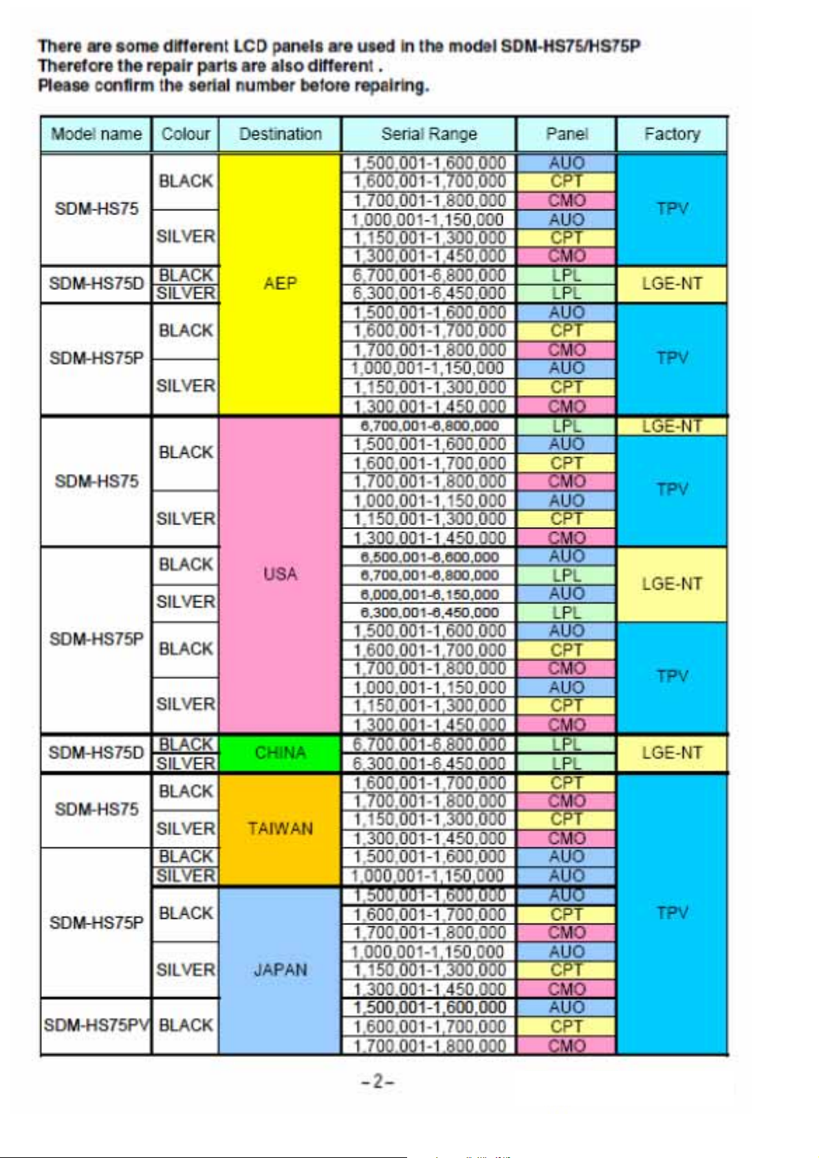
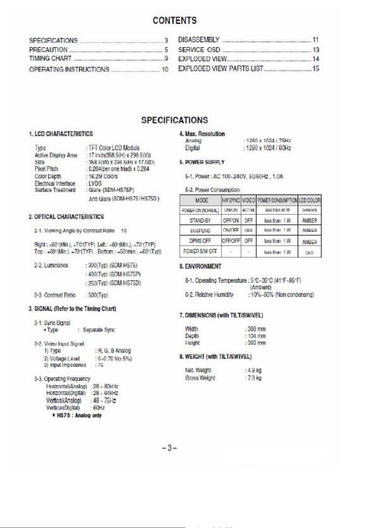
Model Name: SDM-HS75/HS75D/HS75P
SERVICE MANUAL
Part No. : 9-878-333-02
Date SUPP./CORR. Description of SUP/COR
2005.04 NEW –
2006.11 Addition of WB and CH model and SDM-HS75D Yes
Change of
main text
SDM-HS75/HS75D /HS75P
SERVICE MANUAL
US Model
Canadian Model
AEP Model
TFT LCD COLOR COMPUTER DISPLAY
SDM-HS75/HS75D/HS75P (E)
SDM-HS75/HS75D/HS75P (E)

Signal Connector Pin Assignment
• DVI-D Connector
1
9
17
8
16
24
Pin Signal (DVI-D)
T. M. D. S. Data2-
1
T. M. D. S. Data2+
2
T. M. D. S. Data2/4 Shield
3
T. M. D. S. Data4-
4
T. M. D. S. Data4+
5
DDC Clock
6
DDC Data
7
Analog Vertical Sync.
8
T. M. D. S. Data1-
9
T. M. D. S. Data1+
10
T. M. D. S. Data1/3 Shield
11
T. M. D. S. Data3-
12
T. M. D. S. Data3+
13
+5V Power
14
Ground
15
T. M. D. S. (Transition Minimized Differential Signaling)
(return for +5V,
H. Sync. and V. Sync.)
Pin Signal (DVI-D)
Hot Plug Detect
16
T. M. D. S. Data0-
17
T. M. D. S. Data0+
18
T. M. D. S. Data0/5 Shield
19
T. M. D. S. Data5-
20
T. M. D. S. Data5+
21
T. M. D. S. Clock Shield
22
T. M. D. S. Clock+
23
T. M. D. S. Clock-
24
– 4 –
SDM-HS75/HS75D/HS75P (E)

WARNING FOR THE SAFETY-RELATED COMPONENT.
• There are some special components used in LCD
monitor that are important for safety.
These parts are
marked on the schematic diagram and the
replacement parts list.
It is essential that these critical
parts should be replaced with the manufacturer’s
specified parts to prevent electric shock, fire or other
hazard.
• Do not modify original design without obtaining written
permission from manufacturer or you will void the
original parts and labor guarantee.
TAKE CARE DURING HANDLING THE LCD MODULE
WITH BACKLIGHT UNIT.
• Must mount the module using mounting holes arranged
in four corners.
• Do not press on the panel, edge of the frame strongly
or electric shock as this will result in damage to the
screen.
• Do not scratch or press on the panel with any sharp
objects, such as pencil or pen as this may result in
damage to the panel.
• Protect the module from the ESD as it may damage the
electronic circuit (C-MOS).
• Make certain that treatment person’s body are
grounded through wrist band.
• Do not leave the module in high temperature and in
areas of high humidity for a long time.
• The module not be exposed to the direct sunlight.
• Avoid contact with water as it may a short circuit within
the module.
• If the surface of panel become dirty, please wipe it off
with a softmaterial. (Cleaning with a dirty or rough cloth
may damage the panel.)
WARNING
BE CAREFUL ELECTRIC SHOCK !
• If you want to replace with the new backlight (CCFL) or
inverter circuit, must disconnect the AC adapter
because high voltage appears at inverter circuit about
650Vrms.
• Handle with care wires or connectors of the inverter
circuit. If the wires are pressed cause short and may
burn or take fire.
Leakage Current Hot Check Circuit
PRECAUTION
CAUTION
Please use only a plastic screwdriver to protect yourself
from shock hazard during service operation.
1.5 Kohm/10W
To Instrument's
exposed
METALLIC PARTS
Good Earth Ground
such as WATER PIPE,
CONDUIT etc.
AC Volt-meter
– 5 –
SDM-HS75/HS75D/HS75P (E)
 Loading...