

Sony SA-WMS145, SA-WMSP50 Service Manual

1
•SA-WMS145 are the subwoofer
section in SA-VE145.
•SA-WMSP50 are the subwoofer
section in SA-VE2M, HT-SL50/SL55.
Ver 1.0 2003. 05
SERVICE MANUAL
AEP Model
UK Model
SA-WMS145/WMSP50
E Model
SA-WMSP50
Speaker system Active subwoofer, magnetically shielded
Speaker unit Woofer: 20 cm, cone type
Enclosure type Advanced SAW type
Amplifire section
Continuous RMS power output
100 W (6 ohms, 20 - 250 Hz, 0.8% THD)
Reproduction frequency range
28 Hz - 200 Hz
High frequency cut-off frequency
150 Hz
Inputs
INPUT (input pin jack)
General
Power requirements 230 V AC, 50/60 Hz
Power consumptions 100 W
Dimensions (w/h/d) Approx. 270 × 325 × 398 mm, including
front grille
Mass Approx. 10 kg
Design and specifications are subject to change without notice.
SPECIFICATIONS
Sony Corporation
Home Audio Company
Published by Sony Engineering Corporation
9-877-360-01
2003E04-1
© 2003. 05
ACTIVE SUBWOOFER
photo: SA-WMS145
SA-WMS145/WMSP50

2
SA-WMS145/WMSP50
TABLE OF CONTENTS
1. DIAGRAMS
1-1. Circuit Boards Location ...................................................... 3
1-2. Printed Wiring Boards ......................................................... 5
1-3. Schematic Diagram ............................................................. 6
2. EXPLODED VIEWS
2-1. Front Section ....................................................................... 7
2-2. Rear Section ........................................................................ 8
3. ELECTRICAL PARTS LIST........................................... 9
SAFETY-RELATED COMPONENT WARNING!!
COMPONENTS IDENTIFIED BY MARK 0 OR DOTTED LINE
WITH MARK 0 ON THE SCHEMATIC DIAGRAMS AND IN
THE PARTS LIST ARE CRITICAL TO SAFE OPERATION.
REPLACE THESE COMPONENTS WITH SONY PARTS WHOSE
PART NUMBERS APPEAR AS SHOWN IN THIS MANU AL OR
IN SUPPLEMENTS PUBLISHED BY SONY.
3
SA-WMS145/WMSP50
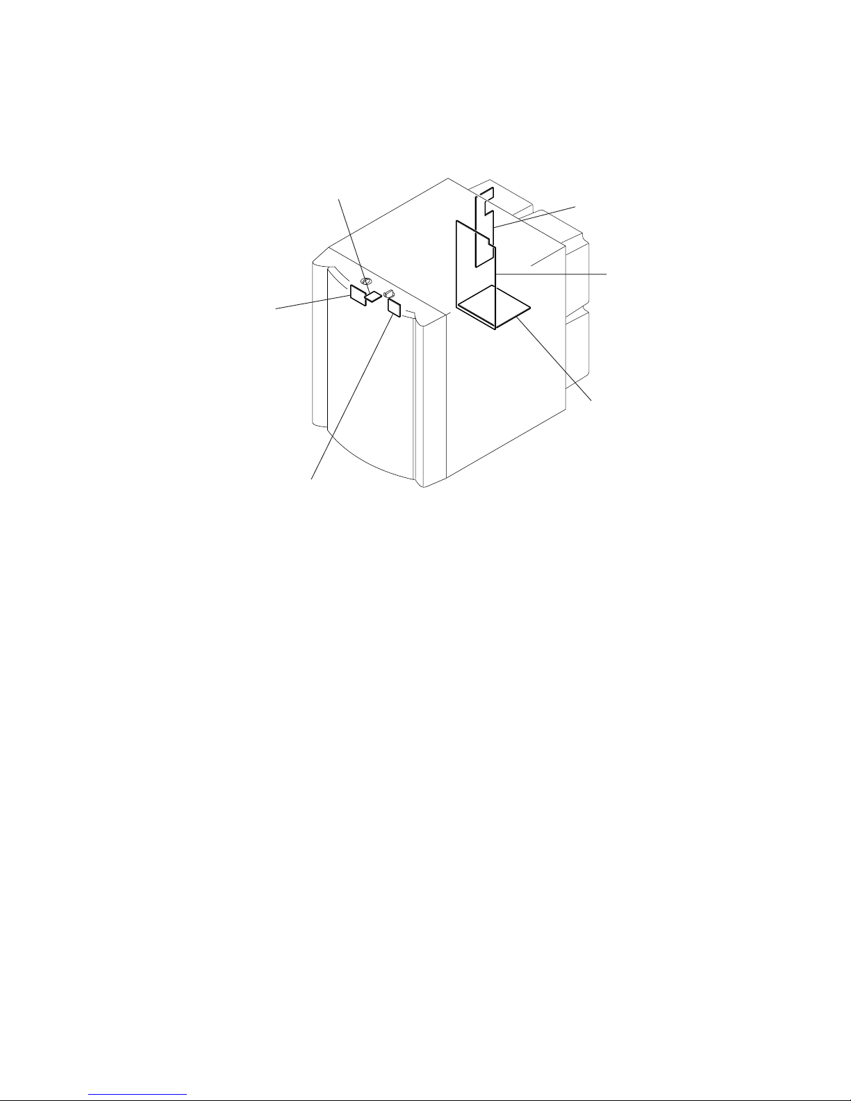
1-1. CIRCUIT BOARDS LOCATION
SECTION 1
DIAGRAMS
CONTROL board
LED board
INPUT board
MAIN board
POWER TRANS boar
d
SWITCH board
4
SA-WMS145/WMSP50
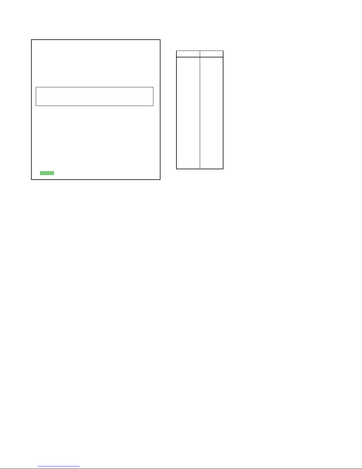
Note on Schematic Diagram:
• All capacitors are in µF unless otherwise noted. pF: µµF
50 WV or less are not indicated except for electrolytics
and tantalums.
• All resistors are in Ω and 1/
4
W or less unless otherwise
specified.
• 2 : nonflammable resistor.
• C : panel designation.
• A : B+ Line.
• B : B– Line.
•Voltage is dc with respect to ground under no-signal
(detuned) condition.
•Voltages are taken with a VOM (Input impedance 10 MΩ).
Voltage variations may be noted due to normal production tolerances.
• Signal path.
F : AUDIO
Note on Printed Wiring Boards:
• X : parts extracted from the component side.
• : Pattern from the side which enables seeing.
Note: The components identified by mark 0 or dotted line
with mark 0 are critical for safety.
Replace only with part number specified.
Ref. No. Location
D205 E-10
D206 E-11
D301 G-7
D302 G-8
D304 E-9
D401 D-6
D402 D-7
D403 D-7
D501 D-8
D502 G-7
D602 D-10
D901 A-10
IC202 E-11
IC203 E-12
IC301 G-9
Q501 D-9
Q502 D-9
Q503 D-10
Q504 D-10
Q505 G-7
• Semiconductor
Location
 Loading...