

Sony SS-V521, SA-VE525, SA-VMS525, SS-MS525 Service Manual
SA-VE522/VE525/WMS525/
SS-MS525/V521
Q
Q
3
7
6
3
1
5
1
5
0
SERVICE MANUAL
Ver.1.0 2001.2
TEL 13942296513 QQ 376315150 892498299
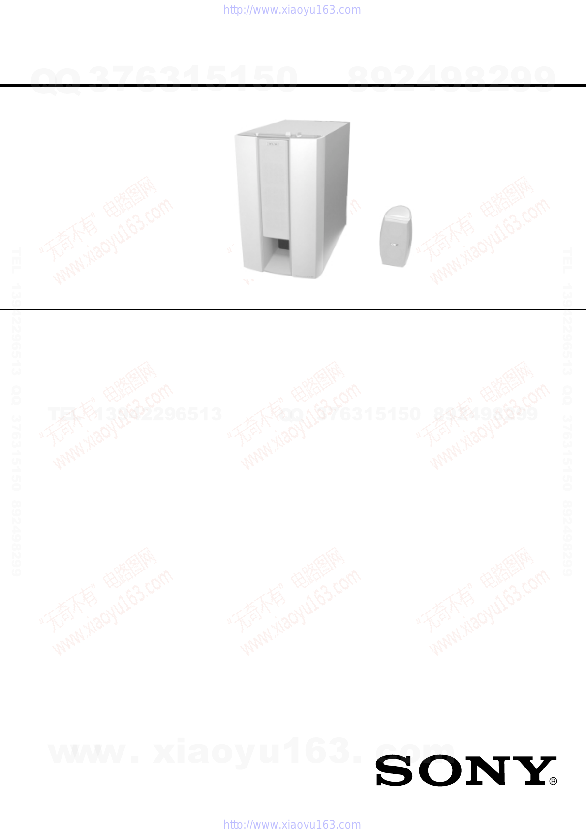
• SA-WMS525 and SS-MS525 is the micro
satellite system in SA-VE522/VE525.
• SS-V521 is SS-MS525 which can be purchased alone.
SS-MS525 (front, center, and rear speakers)
SS-V521
Speaker system Full range x 2,
Speaker units 5 cm (2 in.), balance drive
Enclosure type Bass reflex
TEL
w
w
9-873-807-11
2001B0900-1
© 2001. 2
Rated impedance 8 ohms
13942296513
Power handling capacity
Maximum input power: 120 watts
Sensitivity level 87 dB (1 W, 1 m)
Frequency range 120 Hz - 20,000 Hz
Dimensions (w/h/d) When attached speaker
Mass When attached speaker
SA-WMS525 (subwoofer)
Speaker system Active subwoofer,
Speaker unit Woofer: 20 cm (8 in.),
Enclosure type Advanced SAW type
Reproduction frequency range
Amplifier section
Rated Power Output 120 W (8 ohms 20 Hz - 20
Inputs
LINE IN (input pin jack)
SPEAKER IN (input terminals)
w
Sony Corporation
.
xia
Audio Entertainment Group
General Engineering Dept.
magnetically shielded
type
grille:
Approx. 89 x 144 x 130
5
/8 x 5 3/4 x 5 1/
mm (3
in.)
When attached supplied
speaker stand:
Approx. 89 x 128 x 143
5
mm (3
/8 x 5 1/8 x 5 3/
in.)
(pointed upwards)
Approx. 89 x 122 x 143
5
/8 x 4 7/8 x 5 3/
mm (3
in.)
(pointed downwards)
grille:
Approx.
When attached supplied
speaker stand:
Approx.
magnetically shielded
cone type
26 Hz - 250 Hz
kHz, THD 0.8%)
o
y
750 g
850 g
SA-WMS525
SPECIFICATION
Q
Q
8
4
4
(1 lb 10 oz )
(1 lb 14 oz )
u
1
6
Outputs
LINE OUT (output pin jack)
SPEAKER OUT (output terminals)
General
Power requirements
USA and Canada: 120 V AC, 60 Hz
Europe and Australia:
7
3
E:
Power consumptions 90 W
Dimensions (w/h/d) Approx. 230 x 392 x
Mass
Supplied accessories
SA-VE525
Foot pads (16)
Center speaker stand (1)
Screw (for the center speaker stand) (1)
Washer (for the center speaker stand) (1)
Audio connecting cord (1)
Speaker connecting cords, 10 m (32 ft 9
Speaker connecting cords, 3.5 m (11 ft 6 in.) (3)
Speaker connecting cords, 2.5 m (8 ft 2
SA-VE522
Foot
Audio connecting cord (1)
Speaker connecting cords, 3.5 m (11 ft 6 in.) (2)
Speaker connecting cords, 2.5 m (8 ft 2
SS-V521
Foot pads (4)
Speaker connecting cords, 10m (32 ft 9 in.) (1)
Design and specifications are subject to change without
notice.
3
8
6
pads (8)
3
.
9
1
5
c
2
4
9
8
2
9
9
US Model
Canadian Model
AEP Model
UK Model
E Model
Australian Model
TEL 13942296513 QQ 376315150 892498299
SS-MS525
SS-V521
1
220 - 230 V AC, 50/60 Hz
8
0
5
110-120V/220-240V AC, 50/60Hz
1 W (standby mode)
464 mm (9
3
18
/8 in.), including front
grille
Approx. 13.2 kg
(29 lb 2 oz)
2
9
1
/8 x 15 1/2 x
3
/4 in.) (2)
1
/2 in.) (2)
1
/
in.) (2)
2
3
/
4
4
9
8
2
9
9
ACTIVE SUBWOOFER
o
m
1

SA-VE522/VE525/WM525/SS-MS525/V521
SAFETY CHECK-OUT
7
Q
Q
After correcting the original service problem, perform the
following safety checks before releasing the set to the customer:
Check the antenna terminals, metal trim, “metallized” knobs, screws,
and all other exposed metal parts for AC leakage. Check leakage as
described below.
LEAKAGE
The AC leakage from any exposed metal part to earth ground and
from all exposed metal parts to any exposed metal part having a
return to chassis, must not exceed 0.5 mA (500 microamperes).
Leakage current can be measured by any one of three methods.
TEL 13942296513 QQ 376315150 892498299
1. A commercial leakage tester, such as the Simpson 229 or RCA
WT-540A. Follow the manufacturers’ instructions to use these
instruments.
2. A battery-operated AC milliammeter. The Data Precision 245
digital multimeter is suitable for this job.
3. Measuring the voltage drop across a resistor by means of a
VOM or battery-operated AC voltmeter. The “limit” indication
is 0.75 V, so analog meters must have an accurate low-voltage
scale. The Simpson 250 and Sanwa SH-63Trd are examples of
a passive VOM that is suitable. Nearly all battery operated
digital multimeters that have a 2V AC range are suitable. (See
Fig. A)
3
6
(US model)
3
1
5
1
5
0
1. GENERAL .......................................................................... 3
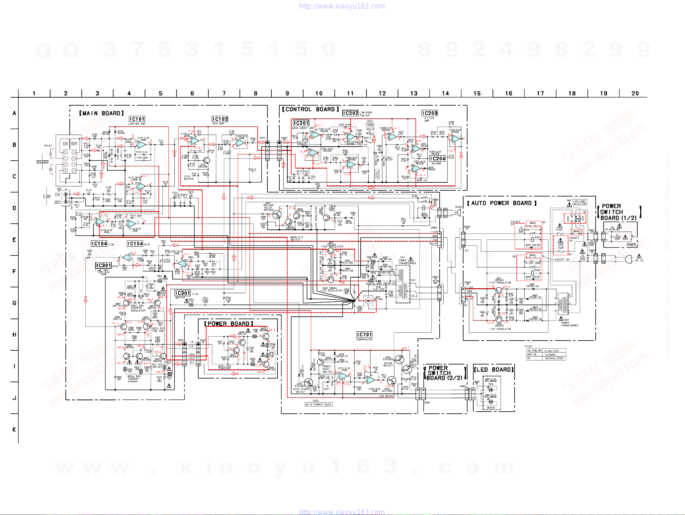
2. DIAGRAMS
2-1. Circuit Boards Location ........................................................ 3
2-2. Schematic Diagram ............................................................... 4
2-3. Printed Wiring Board ............................................................ 5
3. EXPLODED VIEW
3-1. Front Panel Section ............................................................... 6
3-2. Rear Panel Section ................................................................ 6
3-3. SS-V521 Section, SS-MS525 Section .................................. 7
4. ELECTRICAL PARTS LIST ......................................... 8
TABLE OF CONTENTS
4
8
9
2
9
8
2
9
9
TEL 13942296513 QQ 376315150 892498299
TEL
0.15µF
Fig. A. Using an AC voltmeter to check AC leakage.
To Exposed Metal
13942296513
Parts on Set
AC
1.5kΩ
Earth Ground
voltmeter
(0.75V)
Q
Q
3
7
6
3
1
5
1
5
0
8
9
2
4
9
8
2
9
9
SAFETY-RELATED COMPONENT WARNING!!
COMPONENTS IDENTIFIED BY MARK 0 OR DOTTED LINE WITH
MARK 0 ON THE SCHEMATIC DIAGRAMS AND IN THE PARTS
LIST ARE CRITICAL TO SAFE OPERATION. REPLACE THESE
COMPONENTS WITH SONY PARTS WHOSE PART NUMBERS
w
w
APPEAR AS SHOWN IN THIS MANUAL OR IN SUPPLEMENTS
PUBLISHED BY SONY.
2
w
.
xia
o
y
ATTENTION AU COMPOSANT AYANT RAPPORT
LES COMPOSANTS IDENTIFÉS P AR UNE MARQUE 0 SUR LES
DIAGRAMMES SCHÉMA TIQUES ET LA LISTE DES PIÈCES SONT
CRITIQUES POUR LA SÉCURITÉ DE FONCTIONNEMENT. NE
REMPLACER CES COMPOSANTS QUE PAR DES PIÈSES SONY
u
1
6
DONT LES NUMÉROS SONT DONNÉS DANS CE MANUEL OU
DANS LES SUPPÉMENTS PUBLIÉS PAR SONY.
3
À LA SÉCURITÉ!
.
c
o
m
SECTION 1
d
GENERAL
SA-VE522/VE525/WM525/SS-MS525/V521
SECTION 2
DIAGRAMS
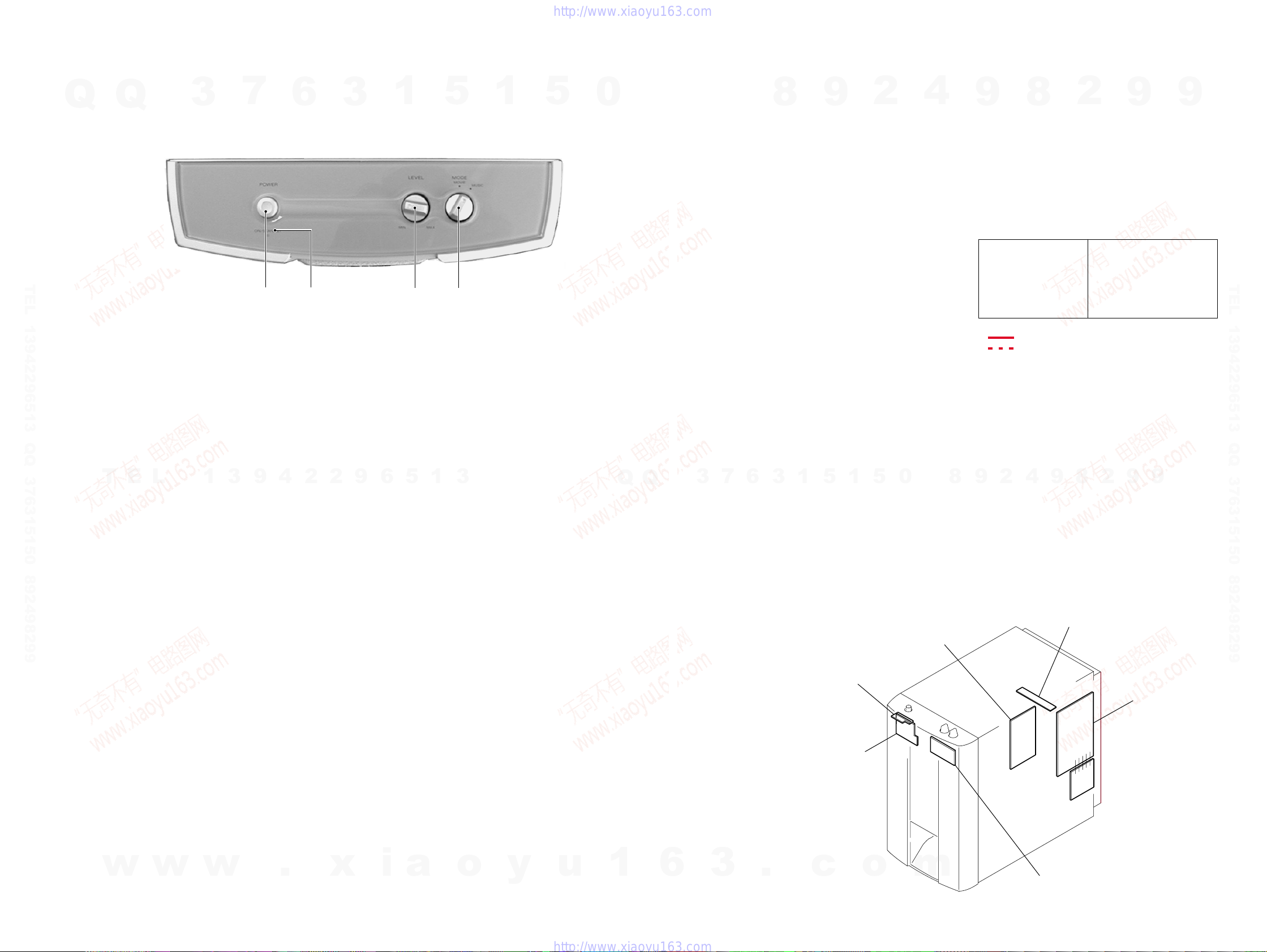
• Location of controls
3
7
9
1
4
6
2
2
2
3
9
Q
– Front view (a part) –
TEL 13942296513 QQ 376315150 892498299
1 POWER button
2 ON/STANDBY indicator
3 LEVEL dial
4 MODE dial
T
Q
E
L
3
1
1
6
5
3 4
5
1
3
1
5
0
Q
Q
THIS NOTE IS COMMON FOR PRINTED WIRING BOARDS AND
SCHEMATIC DIAGRAMS.
(In addition to this, the necessary note is printed in each block.)
For printed wiring boards.
Note:
• X : parts extracted from the component side.
• Y : parts extracted from the conductor side.
• b : Pattern from the side which enables seeing.
7
3
6
8
3
1
9
5
1
2
5
0
4
9
For schematic diagrams.
Note:
• All capacitors are in µF unless otherwise noted. pF: µµF
• All resistors are in Ω and 1/
• C : panel designation.
• : B+ Line.
• : B– Line.
• Voltages are dc with respect to g round under no-signal con-
• Voltages are taken with a VOM (Input impedance 10MΩ).
• Signal path.
• Abbreviation
CND : Canadian model
9
8
SP : Singapore model
MX : Mexican model
9
2
8
8
50 WV or less are not indicated except for electrolytics
and tantalums.
specified.
Note:
The components identified by mark 0 or dotted
line with mark 0 are critical for safety.
Replace only with part
number specified.
ditions.
no mark : Power on
∗ : Impossible to measure
Voltage variations may be noted due to normal preduction
tolerances.
K : AUDIO
4
2
9
4
W or less unless otherwise
Note:
Les composants identifiés par
une marque 0 sont critiques
pour la sécurité.
Ne les remplacer que par une
piéce portant le numéro
spécifié.
9
2
9
9
TEL 13942296513 QQ 376315150 892498299
w
w
w
.
x
i
a
o
y
u
1
6
2-1. Circuit Boards Location
POWER SWITCH board
3
.
c
LED board
o
POWER board
AUTO POWER board
MAIN boar
m
CONTROLboard
33
SA-VE522/VE525/WM525/SS-MS525/V521
2-3. SCHEMATIC DIAGRAM
Q
TEL 13942296513 QQ 376315150 892498299
Q
3
7
6
3
1
5
1
5
0
8
9
2
4
9
8
2
9
9
TEL 13942296513 QQ 376315150 892498299
T
E
L
1
3
9
4
2
2
9
6
5
1
3
Q
Q
3
7
6
3
1
5
1
5
0
8
9
2
4
9
8
2
9
9
w
w
w
.
x
i
a
o
y
u
44
1
6
3
.
c
o
m
 Loading...