

Page 1

TV Sound Bar
System
4-269-544-12(1)
Operating Instructions
SA-32SE1/SA-40SE1/SA-46SE1
©2011 Sony Corporation
Page 2
WARNING
To reduce the risk of fire or electric
shock, do not expose this apparatus to
rain or moisture.
To reduce the risk of fire, do not cover the
ventilation opening of the apparatus with
newspapers, tablecloths, curtains, etc. Do not place
the naked flame sources such as lighted candles on
the apparatus.
To reduce the risk of fire or electric shock, do not
expose this apparatus to dripping or splashing, and
do not place objects filled with liquids, such as
vases, on the apparatus.
Do not expose batteries or apparatus with batteryinstalled to excessive heat such as sunshine, fire or
the like.
Do not install the appliance in a confined space, such
as a bookcase or built-in cabinet.
As the main plug of AC adaptor is used to
disconnect the unit from the mains, connect it to an
easily accessible AC outlet. Should you notice an
abnormality in it, disconnect it from the AC outlet
immediately.
For customers in the United
States, Canada, and Taiwan
The date of manufacturer marking is located on the
bottom exterior.
For customers in the United
States and Canada
ENERGY STAR® is a U.S. registered
mark.
As an ENERGY STAR
Sony Corporation has determined that
this product meets the ENERGY
®
guidelines for energy
STAR
efficiency.
®
partner,
For customers in the United
States
Owner’s Record
The model and serial numbers are located on the
bottom of the unit. Record these numbers in the
space provided below. Refer to them whenever you
call upon your Sony dealer regarding this product.
Model No.
These following indications are located on the
bottom exterior of the AC Adaptor.
Serial No.
The unit is not disconnected from the mains as long
as it is connected to the AC outlet, even if the unit
itself has been turned off.
To prevent injury, this apparatus must be securely
attached to the floor/wall in accordance with the
installation instructions.
Do not use the AC power cord with other products.
The mains switch is located on the rear exterior.
The nameplate is located on the bottom exterior.
The serial number is located on the bottom exterior.
GB
2
This symbol is intended to alert the
user to the presence of uninsulated
“dangerous voltage” within the
product’s enclosure that may be of
sufficient magnitude to constitute a
risk of electric shock to persons.
This symbol is intended to alert the
user to the presence of important
operating and maintenance
(servicing) instructions in the
literature accompanying the
appliance.
Page 3
Important Safety Instructions
1) Read these instructions.
2) Keep these instructions.
3) Heed all warnings.
4) Follow all instructions.
5) Do not use this apparatus near water.
6) Clean only with dry cloth.
7) Do not block any ventilation openings. Install in
accordance with the manufacturer’s instructions.
8) Do not install near any heat sources such as
radiators, heat registers, stoves, or other
apparatus (including amplifiers) that produce
heat.
9) Do not defeat the safety purpose of the polarized
or grounding-type plug. A polarized plug has
two blades with one wider than the other. A
grounding type plug has two blades and a third
grounding prong. The wide blade or the third
prong are provided for your safety. If the
provided plug does not fit into your outlet,
consult an electrician for replacement of the
obsolete outlet.
10)Protect the power cord from being walked on or
pinched particularly at plugs, convenience
receptacles, and the point where they exit from
the apparatus.
11)Only use attachments/accessories specified by
the manufacturer.
12)Use only with the cart, stand, tripod, bracket, or
table specified by the manufacturer, or sold with
the apparatus. When a cart is used, use caution
when moving the cart/apparatus combination to
avoid injury from tip-over.
13)Unplug this apparatus during lightning storms or
when unused for long periods of time.
14)Refer all servicing to qualified service personnel.
Servicing is required when the apparatus has
been damaged in any way, such as power-supply
cord or plug is damaged, liquid has been spilled
or objects have fallen into the apparatus, the
apparatus has been exposed to rain or moisture,
does not operate normally, or has been dropped.
The following FCC statement
applies only to the version of
this model manufactured for
sale in the U.S.A. Other
versions may not comply with
FCC technical regulations.
NOTE:
This equipment has been tested and found to comply
with the limits for a Class B digital device, pursuant
to Part 15 of the FCC Rules. These limits are
designed to provide reasonable protection against
harmful interference in a residential installation.
This equipment generates, uses and can r adiate radio
frequency energy and, if not installed and used in
accordance with the instructions, may cause harmful
interference to radio communications. However,
there is no guarantee that interference will not occur
in a particular installation. If this equipment does
cause harmful interference to radio or television
reception, which can be determined by turning the
equipment off and on, the user is encouraged to try
to correct the interference by one or more of the
following measures:
– Reorient or relocate the receiving antenna.
– Increase the separation between the equipment
and receiver.
– Connect the equipment into an outlet on a circuit
different from that to which the receiver is
connected.
– Consult the dealer or an experienced radio/TV
technician for help.
CAUTION
You are cautioned that any changes or modifications
not expressly approved in this manual could void
your authority to operate this equipment.
continued
GB
3
Page 4
For customers in Europe
Disposal of Old Electrical &
Electronic Equipment
(Applicable in the European
Union and other European
countries with separate
collection systems)
This symbol on the product or on its packaging
indicates that this product shall not be treated as
household waste. Instead it shall be handed over to
the applicable collection point for the recycling of
electrical and electronic equipment. By ensuring this
product is disposed of correctly, you will help
prevent potential negative consequences for the
environment and human health, which could
otherwise be caused by inappropriate waste
handling of this product. The recycling of materials
will help to conserve natural resources. For more
detailed information about recycling of this product,
please contact your local Civic Office, your
household waste disposal service or the shop where
you purchased the product.
Disposal of waste batteries
(applicable in the European
Union and other European
countries with separate
collection systems)
This symbol on the battery or on the packaging
indicates that the battery provided with this product
shall not be treated as household waste.
On certain batteries this symbol might be used in
combination with a chemical symbol. The chemical
symbols for mercury (Hg) or lead (Pb) are added if
the battery contains more than 0.0005% mercury or
0.004% lead.
By ensuring these batteries are disposed of correctly,
you will help prevent potentially negative
consequences for the environment and human health
which could otherwise be caused by inappropriate
waste handling of the battery. The recycling of the
materials will help to conserve natural resources.
In case of products that for safety, performance or
data integrity reasons require a permanent
connection with an incorporated battery, this battery
should be replaced by qualified service staff only.
To ensure that the battery will be treated properly,
hand over the product at end-of-life to the applicable
collection point for the recycling of electrical and
electronic equipment.
For all other batteries, please view the section on
how to remove the battery from the product safely.
Hand the battery over to the applicable collection
point for the recycling of waste batteries.
For more detailed information about recycling of
this product or battery, please contact your local
Civic Office, your household waste disposal service
or the shop where you purchased the product.
GB
4
Page 5

Notice for customers: The following
information is only applicable to
equipment sold in countries applying
EU Directives.
The manufacturer of this product is Sony
Corporation, 1-7-1 Konan Minato-ku Tokyo,
108-0075 Japan. The Authorized Representative for
EMC and product safety is Sony Deutschland
GmbH, Hedelfinger Strasse 61, 70327 Stuttgart,
Germany. For any service or guarantee matters
please refer to the addresses given in separate
service or guarantee documents.
About This Manual
The instructions in this manual are for model
SA-32SE1/SA-40SE1/SA-46SE1. The illustrations
used in this manual are of the SA-32SE1 model and
they may be different from your model. Any
differences in operation are marked in the manual as
“SA-32SE1 model only”.
GB
5
Page 6
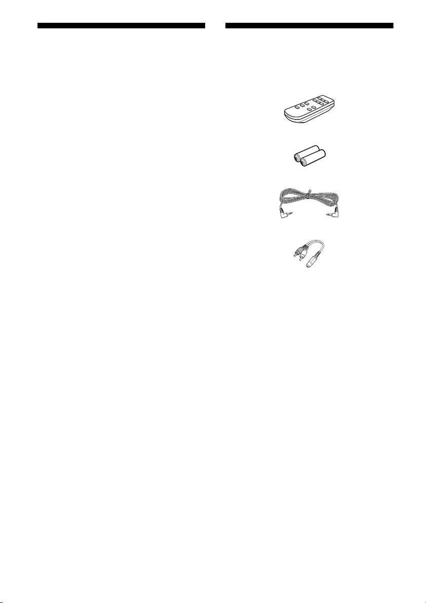
Table of Contents
Supplied accessories
Supplied accessories ................... 6
Guide to parts and controls ......... 7
Getting started............................... 9
Installing a battery ....................................9
Hooking up the unit..................................9
Installing the unit ....................................11
Listening to TV sound from the
speaker of the unit .................... 13
Listening to TV sound ............................13
Control the volume of the unit by
adjusting the TV volume......................13
Selecting the sound field............ 14
Precautions.................................. 15
Troubleshooting.......................... 16
POWER ..................................................16
SOUND ..................................................16
REMOTE CONTROL............................16
OTHER...................................................17
Specifications .............................. 17
• Operating Instructions (this manual)
• Compatible list (Except for China model) (1)
• Remote control (RM-ANU102) (1)
• R03 batteries (size AAA) (2)
• Audio cord (1)
• Plug adaptor (1)
•AC adaptor (1)
• AC power cord (mains lead) (1)
• Foot pads (4)
GB
6
Page 7

Guide to parts and controls
This manual mainly explains operations using the buttons on the remote control, but the same
operations can also be performed using the buttons on the unit having the same or similar names.
Unit
1
564
2
3
Supplied accessories/Guide to parts and controls
Remote control (RM-ANU102)
9
8
7
1
2
3
A ?/1 (POWER) button
B SOUND FIELD button
Selects the sound field (page 14).
Unit: Each time you press the button, the sound
field changes cyclically as follows:
STANDARD t MOVIE t GAME/VOICE
t STANDARD t ...
C Unit: 2 +*/– button
Remote control: VOL 2 +/– button
Adjusts the volume.
* The 2 + button on the unit has tactile dots. Use the
tactile dots as references when operating the unit.
D Remote control sensor
Receives signals from remote control.
continued
GB
7
Page 8

E STANDBY indicator
Lights up in red when the unit is in standby
mode.
Notes
• While the unit is in the standby mode, the unit
turns on when a sound of a TV is detected.
However, it may not turn on if the sound of a
TV is very small.
• The unit enters the standby mode automatically
when there is no sound input from a TV for
about 5 minutes.
F SOUND FIELD indicator
Shows the status of the SOUND FIELD.
The indicator of the selected sound field lights
up in green.
When the volume level is set to maximum or
minimum, the indicator flashes 6 times in quick
succession.
If you are using a Sony TV, the G – I
operations can be performed with the remote
control of the unit.
G TV VOL 2 +/– button
Adjust the TV volume.
TV MUTING button
Activates the TV’s muting function.
H TV ?/1 button
Turns the TV on or off.
I TV INPUT t button
Selects the TV input.
GB
8
Page 9

Getting started
Installing a battery
Slide and remove the battery compartment lid, and insert the two supplied R03 (size AAA)
batteries, E side first, matching the polarities shown below.
Notes
• Do not mix an old battery with a new one or mix different types of batteries.
• Do not leave the remote control in an extremely hot or humid place.
• Do not expose the remote control sensor to direct sunlight or lighting apparatuses. Doing so may cause a
malfunction.
• If you do not intend to use the remote control for an extended period of time, remove the batteries to avoid
possible damage from battery leakage and corrosion.
• When the remote control no longer operates the unit, replace both batteries with new ones.
• Do not drop any foreign object into the remote control casing, particularly when replacing the batteries.
Hooking up the unit
1 Remove the screw on the rear cover of the unit, then remove the rear
cover.
Getting started
continued
GB
9
Page 10

2 Connect an audio cord and a power source.
AUDIO IN
DC IN 18V
A
B
A AUDIO IN jack
Connect the TV audio output jack to the AUDIO IN jack of this unit using an audio cord
(supplied).
TV
Audio output
This unit
Audio cord
(supplied)
If the audio output jack of your TV is not compatible with the audio cord (supplied)
Connect the audio cord (supplied) to the TV audio output jack using the plug adaptor
(supplied).
TV
L
R
Audio output
Plug adaptor (supplied)
L (White)
R (Red)
This unit
Audio cord
(supplied)
10
GB
Page 11

B DC IN 18V jack
AC adaptor (supplied)
AC power cord
(mains lead)
(supplied)
To the AC
power outlet
Attach the AC power cord (mains lead) (supplied) to the AC adaptor (supplied). Then plug
the connector of the AC adaptor into the DC IN 18V jack on the rear of the unit.
After you have made all connections, connect the AC power cord (mains lead) into the AC
power outlet. If the supplied adaptor on the plug does not fit your wall outlet, detach it from
the plug (only for models equipped with an adaptor).
3 Guide the audio cord and the cable attached to the AC adaptor through
the notch at the side of the rear cover, then reattach the rear cover to
the unit and secure it with the screw removed in step 1.
Getting started
Audio cord
Cable attached to the
AC adaptor
Installing the unit
Installing the unit on a flat surface
Be sure to attach the supplied foot pads to prevent vibration or movement as shown in the
illustration below.
Bottom of the unit
continued
11
GB
Page 12

Installing the unit on a wall
You can secure the unit on a wall.
Notes
• Use screws that are suitable for the wall material and strength. As a plaster board wall is especially fragile,
attach the screws securely to a wall beam. Install the speaker on a vertical and flat reinforced area of the wall.
• Be sure to subcontract the installation to Sony dealers or licensed contractors and pay special attention to
safety during the installation.
• Sony is not responsible for accidents or damage caused by improper installation, insufficient wall strength,
improper screw installation or natural calamity, etc.
1 Prepare screws (not supplied) that are suitable for the hook on the rear
of the unit. See the illustrations below.
4 mm (3/16 in)
more than 25 mm (1 in)
5 mm (7/32 in)
10 mm (13/32 in)
Hook on the rear of the unit
2 Fasten the screws to the wall. The screws should protrude from the
wall. See the illustration below.
310 mm (12 1/4 in) (For SA-32SE1) or
320 mm (12 5/8 in) (For SA-40SE1/SA-46SE1)
7 mm to 8 mm (9/32 in to
11/32 in) (For SA-32SE1)
or 8 mm to 9 mm (11/32 in
to 3/8 in) (For SA-40SE1/
SA-46SE1)
3 Hang the unit onto the screws.
Align the holes on the rear of the unit to the screws, then hang the unit onto the two screws.
Installing the unit to the TV (Except for China model)
You can install this unit to the TV using the optional speaker attachment bracket. For details on the
compatible TV model and the speaker attachment bracket, refer to the supplied “Compatible list”.
GB
12
Page 13

Listening to TV sound from the speaker of the unit
Listening to TV sound Control the volume of the unit
Turn on the unit or make sure
1
the unit is in standby mode.
2 Turn on the TV.
While the unit is in the standby mode, the
unit turns on automatically when a sound
of a TV is detected.
3 Adjust the volume of the unit.
by adjusting the TV volume
If the sound output jack of the TV can be set to
“Variable”, the volume of the unit can be
changed by adjusting the TV volume.
For TV settings, refer to the operating
instructions of the TV.
1 Set the sound output jack of the
TV to “Variable”.
Listening to TV sound from the speaker of the unit
Note
When the sound output level of your TV cannot be
changed, adjust the volume of the unit.
2 Adjust the volume of the unit
according to the TV.
The above settings 1 and 2 allow
you to control the volume of the
unit by adjusting the TV volume.
Note
If sufficient volume level cannot be obtained from
the unit when the sound output jack of the TV is set
to “Variable”, set the sound output jack of the TV to
“Fixed” and adjust the volume of the unit.
13
GB
Page 14

Selecting the sound field
Sound field
buttons
Press one of the sound field buttons you want to use.
You can also use SOUND FIELD button on the unit.
Sound field Effect
STANDARD (STD) Suitable for use for a wide range of sources of any type.
MOVIE Provides dynamic sound and realistic sensation.
GAME/VOICE Features easy-to-hear dialogue and clear sound.
14
GB
Page 15

Precautions
On safety
Should any solid object or liquid get into the
unit, unplug the unit, and have it checked by
qualified personnel before operating it again.
On power sources
• Before operating the unit, check that the
operating voltage is identical with your local
power supply.
• Do not plug the AC power cord (mains lead)
for the unit into an electrical outlet until you
have made all other connections. Make sure
the TV or other equipment is unplugged
from the electrical outlet prior to connecting
it to the unit.
• Do not connect the AC power cord (mains
lead) to a voltage transformer or inverter.
Connecting the AC power cord (mains lead)
to a voltage transformer for overseas travel
or an inverter for use in an automobile may
cause heat to build up in the AC adaptor and
may cause burns or a malfunction.
• Do not use an AC adaptor or AC power cord
(mains lead) other than the supplied AC
adaptor and AC power cord (mains lead). Do
not modify the cord.
• Completely disconnect the AC power cord
(mains lead) from the wall socket (mains) if
it is not going to be used for an extended
period of time. When unplugging the unit,
always grip the plug. Never pull the cord
itself.
• (USA and Canada model only)
One blade of the plug is wider than the other
for the purpose of safety and will fit into the
wall outlet only one way. If you are unable
to insert the plug fully into the outlet, contact
your dealer.
• The AC power cord (mains lead) can be
changed only by a qualified service facility.
On placement
• Do not place the unit in an inclined position
or in locations that are extremely hot, cold,
dusty, dirty, or humid or lacking adequate
ventilation, or subject to vibration, direct
sunlight or a bright light.
• Be careful when placing the unit on surfaces
that have been specially treated (for
example, with wax, oil, polish) as staining or
discoloration of the surface may result.
• Since a strong magnet is used for the
speakers, keep personal credit cards using
magnetic coding or spring-wound watches
away from the unit to prevent possible
damage from the magnet.
Selecting the sound field/Precautions
Plug polarity
• Do not touch the plug of the AC power cord
(mains lead) with wet hands.
• Do not touch the AC power cord (mains
lead), AC adaptor or the unit, if connected to
an electrical outlet, during an electrical
storm.
• Do not place heavy items on the cord.
• Do not place the AC power cord (mains
lead) near heating equipment and do not
expose the cord to heat.
On heat buildup
• Heat buildup on the unit during operation is
normal and is not a cause for alarm.
• Do not touch the cabinet if it has been used
continuously at a high volume because the
cabinet may have become hot.
• Do not obstruct the ventilation holes.
On cleaning
Clean this unit with a soft cloth slightly
moistened with a mild detergent solution. Do
not use any type of abrasive pad, scouring
powder, or solvent, such as thinner, benzine,
or alcohol.
15
GB
Page 16

Troubleshooting
If you experience any of the following
difficulties while using the unit, use this
troubleshooting guide to help you remedy the
problem. Should any problem persist, consult
your nearest Sony dealer.
POWER
The power is not turned on.
• Make sure the AC adaptor and the AC
power cord (mains lead) is connected
correctly and firmly (page 11).
• Press the ?/1 (POWER) button on the
unit. The SOUND FIELD indicator lights
up in green.
Sound from the unit is not
synchronized with TV.
• For some TV models, the sound from the
unit and sound of a TV may not be
synchronized when sound is output from
both the unit and TV. Set the sound output
jack of the TV to “Fixed” if it can be
switched between “Fixed” and “Variable”.
Set the TV volume to minimum or mute
the TV sound and adjust the volume of the
unit.
• If any other home theatre system is used at
the same time, turn off the power of the
unit.
The sound is distorted.
•Press TV VOL 2 – repeatedly (page 8).
•Press VOL 2 – (or 2 – on the unit)
repeatedly (page 7).
The unit enters standby mode
automatically.
• The unit enters standby mode
automatically when there is no sound input
for approximately 5 minutes.
SOUND
There is no sound or only a very lowlevel sound is heard.
• Check that the audio cord of the unit and
the TV is fully inserted (page 10).
• Press VOL 2 + (or 2 + on the unit)
repeatedly (page 7).
• Cancel the muting function of the TV.
• Check that headphones are not connected
to the TV.
There is severe noise.
• Someone is using a portable telephone or
other equipment that emits radio waves
near the unit. Move the portable telephone,
etc. away from the unit.
REMOTE CONTROL
The remote control does not function.
• Point the remote control at the remote
control sensor on the unit (page 7).
• Remove any obstacles in the path between
the remote control and the unit.
• Replace all the batteries in the remote
control with new ones, if they are weak.
16
GB
Page 17

OTHER
The STANDBY indicator flashes.
• Turn off the unit and unplug the AC power
cord (mains lead) immediately.
• Remove anything that is blocking the
ventilation hole.
If the unit still does not operate
properly after performing the
above measures, reset the unit
as follows:
Use the button on the unit for the operation.
1 Press ?/1 to turn on the unit.
2 Hold down ?/1 for 5 seconds.
STANDBY indicator flashes 3 times and
the unit is reset to the default settings.
Specifications
Amplifier section
AUDIO POWER
SPECIFICATIONS
POWER OUTPUT AND TOTAL
HARMONIC DISTORTION:
(FTC)
(USA model only)
L + R With 8 ohm loads, both
channels driven, from 300
– 20,000 Hz; rated 14 watts
per channel minimum
RMS power, with no more
than 1% total harmonic
distortion from 250
milliwatts to rated output.
POWER OUTPUT (reference)
L / R 20 W (per channel at
8 ohms, 1 kHz)
(China model only)
POWER OUTPUT (rated)
(Measured under MOVIE sound field)
L + R 9.5 W + 9.5 W
(at 8 ohms, 1 kHz,
1% THD)
Troubleshooting/Specifications
(Other models)
POWER OUTPUT (rated)
L + R 16 W + 16 W
(at 8 ohms, 1 kHz,
1% THD)
POWER OUTPUT (reference)
L / R 20 W (per channel at
8 ohms, 1 kHz, 10% THD)
continued
17
GB
Page 18

Speaker section
Front speaker unit
Speaker system Full range, passive radiator
type
Speaker unit
For SA-32SE1 65 mm (2 5/8 in)
(Cone type)
70 mm × 100 mm
(2 7/8 in × 4 in)
(Passive radiator)
For SA-40SE1/SA-46SE1
65 mm (2 5/8 in)
(Cone type)
65 mm (2 5/8 in) × 2
(Passive radiator)
Rated impedance 8 ohms
General
Inputs AUDIO IN jack (1)
Power requirements DC 18 V (2.6 A)
(100 V - 240 V AC,
50/60 Hz using the
supplied AC adaptor)
Power consumption In standby mode: 0.5 W or
less
Main unit
Dimensions (w/h/d) (Approx.)
For SA-32SE1 754.2 mm × 80 mm ×
76.7 mm (29 3/4 in ×
3 1/4 in × 3 1/8 in)
For SA-40SE1 942.4 mm × 80 mm ×
67.7 mm (37 1/8 in ×
3 1/4 in × 2 3/4 in)
For SA-46SE1 1,077.6 mm × 80 mm ×
67.7 mm (42 1/2 in ×
3 1/4 in × 2 3/4 in)
Mass (Approx.)
For SA-32SE1 1.9 kg (4 lb 4 oz)
For SA-40SE1 2.2 kg (4 lb 14 oz)
For SA-46SE1 2.5 kg (5 lb 9 oz)
AC adaptor
Input 100 V - 240 V AC,
50/60 Hz
Output DC 18 V, 2.6 A
Dimensions (w/h/d) (Approx.)
India model 124 mm × 32 mm × 60 mm
(5 in × 1 5/16 in × 2 3/8 in)
Other models 121 mm × 33 mm × 53 mm
(4 7/8 in × 1 5/16 in ×
2 1/8 in)
Mass (Approx.)
India model 294 g (10.4 oz)
Other models 240 g (8.5 oz)
Design and specifications are subject to
change without notice.
18
GB
Page 19

Page 20

Sony Corporation Printed in Malaysia
(1)
 Loading...