

Sony S75F Service Manual
Service Manual
S75F Sony
SONY
http://www.wjel.net
TFT LCD COLOR COMPUTER DISPLAY
1
Table of contents
Table of contents -------------------------------------------------------------------------- 02
1. Precaution ------------------------------------------------------------------------------------------ 03
2.Specification -----------------------------------------------------------05
2.1 Product character-----------------------------------------------------------05
2.2 Interface description-----------------------------------------------------------------06
2.3 Factory preset mode ------------------------------------------------------------07
3.OSD operation --------------------------------------------------------------------------------08
3.1 Generalization ------------------------------------------------------------------------------08
3.2 Key control -------------------------------------------------------------------------08
3.3 Common adjustment --------------------------------------------------------------------- 09
3.4 Adjustment ---------------------------------------------------------------------------------- 20
3.5 Service OSD ------------------------------------------------------------------------------- 21
S75F Sony
4.Disassembly flow chart -------------------------------------------------------------------------22
4.1 Disassembly steps---------------------------------------------------------------------------22
4.2 Wiring Diagram ---------------------------------------------------------------------------26
4.3 Monitor Exploded View -------------------------------------------------------------------27
5. Circuit principle analysis --------------------------------------------------------------------28
5.1 Main board -------------------------------------------------------------------------------28
5.1.1 Block diagram ------------------------------------------------------------------28
5.1.2 Introduction of IC -------------------------------------------------------29
5.1.3 Introduction of important function -------------------------------------------------26
5.2 PWPC board -------------------------------------------------------------------------31
5.2.1 Block diagram------------------------------------------------------------------------31
5.2.2 Introduction of IC------------------------------------------------------------------32
5.2.3 Introduction of important function-------------------------------------------------33
6.Trouble shooting ---------------------------------------------------------------------40
http://www.wjel.net
6.1 Main board -----------------------------------------------------------------------------40
6.2 PWPC board -------------------------------------------------------------------------43
7. BOM -----------------------------------------------------------------------------------45~61
8. Schematic -------------------------------------------------------------------------------------62~68
2

1. Precaution
Warning on power connections
S75F Sony
Installation
http://www.wjel.net
3
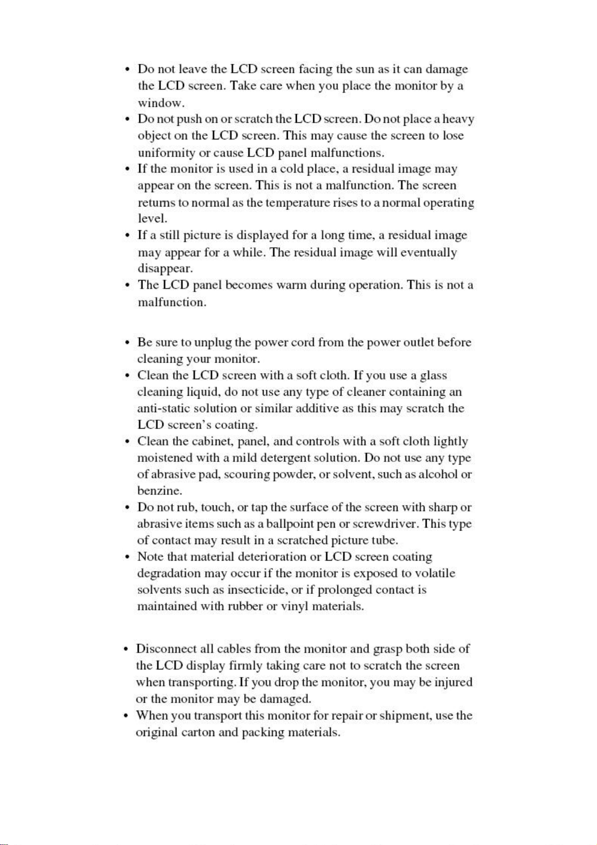
Handing the LCD screen
Maintenance
S75F Sony
Transportation
http://www.wjel.net
4
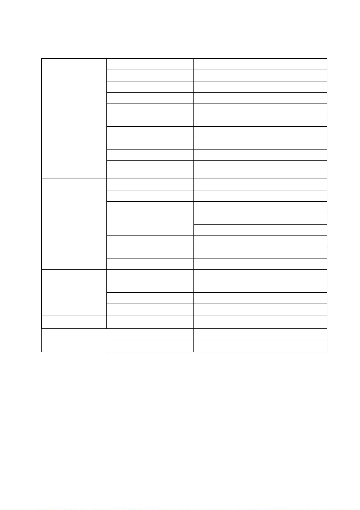
2. Specification
2.1 Product character
Driving system TFT LCD
Pixel pitch 0.264mm(H) x 0.264mm(V)
S75F Sony
Size 17.0"
Type M170E5-L09 Ver.C1
LCD Panel
Input signals
Viewing angle 170(H) 170(V)
Luminance 300 cd/m2 (typ)
Contrast Ratio 500:1 (typ)
Response time 16ms (typ)
Display colors 16.2 million Colors
Max dimension
R G B Analog 0.7Vp-p
R G B Digital TMDS
H/V separate TTL level
Horizontal frequency
Vertical rate
Recommend resolution 1280 x 1024@60HZ
Normal operation
Horizontal: 337.920mm
Vertical: 270.336mm
28kHz–80kHz (Analog)
28kHz–64kHz (Digital)
48-75Hz (Analog)
60Hz (Digital)
≤45W
Power consumption
Active off (deep sleep)
Power off
Main power off
Power supply AC voltage
Temperature 5-35°C
Operating condition
Humidity 10-80%
100~240VAC,50~60Hz
≤1W
≤1W
0W
http://www.wjel.net
5
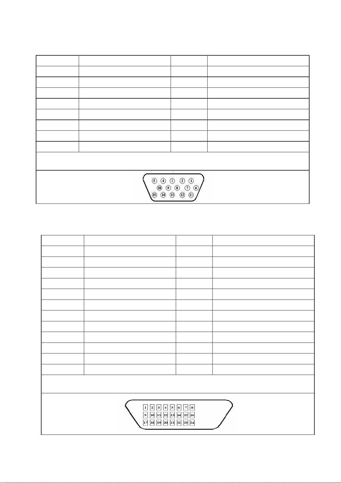
2.2 Interface description
1. HD 15 Signal Input Pin Assignments
NO. Description NO. Description
1. Red Video 9. +5V
2. Green Video(Sync on Green) 10. Sync Return
3. Blue Video 11. ID (GND)
4. ID(GND) 12. DDC Data
5. Sense of connection PC 13. Horizontal Sync
6. Red Video Return 14. Vertical Sync
7. Green Video Return 15. DDC Clock
8. Blue Video Return
VGA Connector layout
S75F Sony
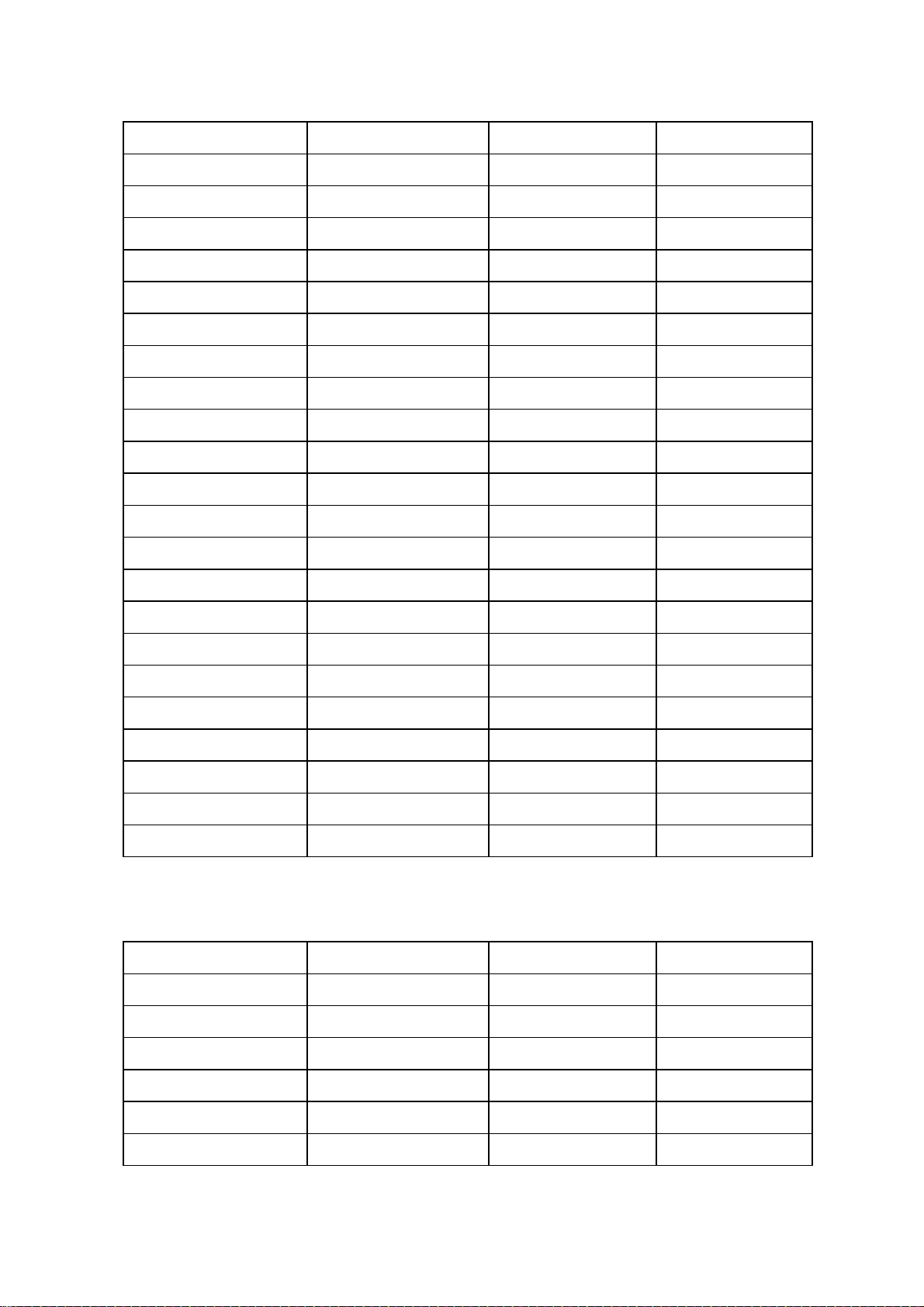
2. DVI Pin Assignments
NO. Description NO. Description
1.
2.
3.
4.
5.
6.
7.
8.
9.
10.
11.
http://www.wjel.net
TMDS Data 2+
TMDS Data 2 Shield
TMDS Data 1+
TMDS Data 1 Shield
TMDS Data 2-
No Connect
No Connect
DDC Clock
DDC Data
No Connect
TMDS Data1-
13.
14.
15.
16.
17.
18.
19.
20.
21.
22.
23.
No Connect
+5V
Sense of connection PC
Hot Plug Detect
TMDS Data 0-
TMDS Data 0+
TMDS Data 0 Shield
No Connect
No Connect
TMDS Clock Shield
TMDS Clock +
12.
No Connect
24.
VGA Connector layout
6
TMDS Clock -
2.3 Factory preset mode
S75F Sony
Resolution Frequency (KHz) Vertical (Hz)
720 × 400 31.469 70.087
640 × 480 31.469 59.940
640 × 480 35.000 66.667
640 × 480 37.500 75.000
720 × 480 35.200 60.000
800 × 600 35.156 56.250
800 × 600 37.879 60.317
800 × 600 48.077 72.188
800 × 600 46.875 75.000
800 × 600 49.725 74.551
1024 × 768 48.363 60.004
1024 × 768 56.476 70.069
1024 × 768 60.023 75.029
1024 × 768 60.2 75
Clock (MHZ)
28.322
25.175
30.240
31.500
31.505
36.000
40.000
50.000
49.500
57.283
65.000
75.000
78.750
80.000
1152 × 864 67.5 75
1152 × 870 68.9 75
1152 × 900 61.8 66
1152 × 900 71.7 76
1170 × 584 31.2 50
1280 × 960 60.0 60
1280 × 1024 63.981 60.020
1280 × 1024 79.976 75.025
DVI TIMING LIST
Resolution Frequency (KHz) Vertical (Hz)
1024 × 768 48.363 60.004
640 × 480 31.469 59.940
800 × 600 37.879 60.317
108.000
100.000
92.940
105.590
46.200
108.000
108.00
135.00
http://www.wjel.net
Clock (MHZ)
65.000
25.175
40.000
1280 × 960 60.0 60
1280 × 480 63.981 60.020
720 × 480 35.200 60.00
7
108.00
108.00
31.505

3. OSD operation
3.1 Generalization
Press the power button to turn the monitor on or off. The other control buttons are located
at front panel of the monitor. By changing these settings, the picture can be adjusted to
your personal preferences.
The power cord should be connected.
-
Connect the video cable from the monitor to the video card.
-
Press the power button to turn on the monitor, the power indicator will light up.
-
3.2 Key control
S75F Sony
Power Switch:
seconds. Besides, Power Switch: the picture and the green LED shall be lit. When the Power button is
pushed again, the status shall be changed into Power Off within 1 second. Besides, the picture and the
green LED shall disappear.
Menu Button: O
OK Button: This button activates the selected menu item and adjustments made using the Arrow buttons.
ECO Button: This button is used to reduce the power consumption.
Main Power Switch: This switch turns the monitor’s main power on and off.
The indication of LED:
(Arrow) Button: These buttons are used to select the menu items make adjustments.
Green — Normal On or Out of range.
Amber — Stand-By or Suspend.
Red — Power Off
When the Power button is pushed, the status shall be changed into Power On within 2
SD window shall be displayed by pressing the “Menu” button in the Power On condition.
http://www.wjel.net
8
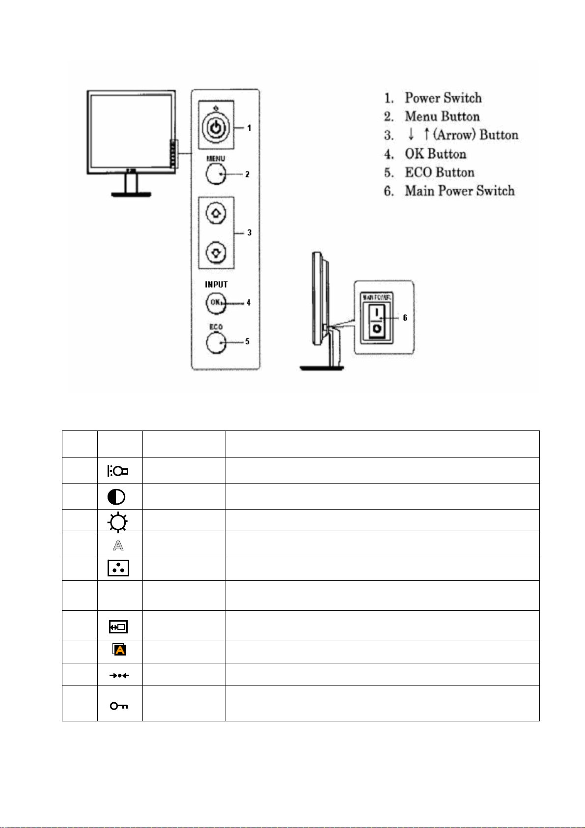
Key control:
S75F Sony
3.3 Common adjustment
NO Icon Tag Description
1
2
3
4
Backlight Adjust the brightness of the backlight
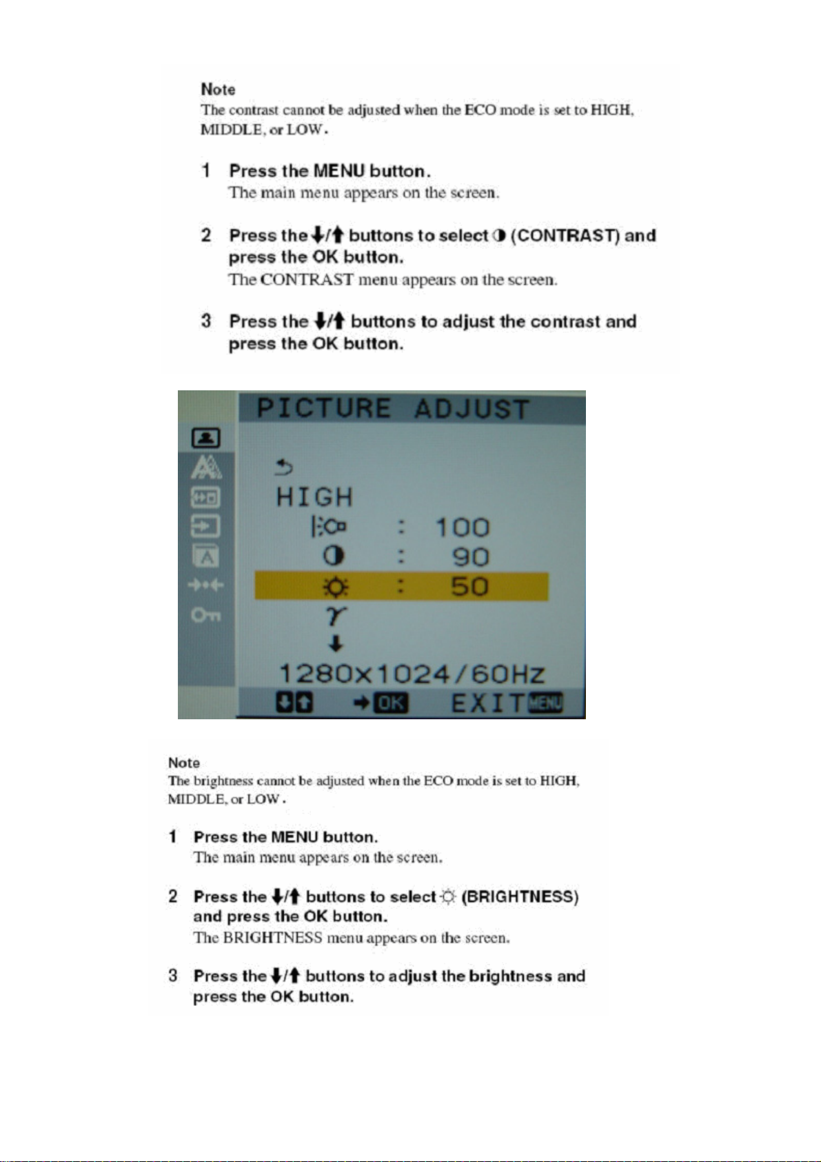
Contrast Adjust the picture contrast
Brightness Adjust the picture brightness (black level)
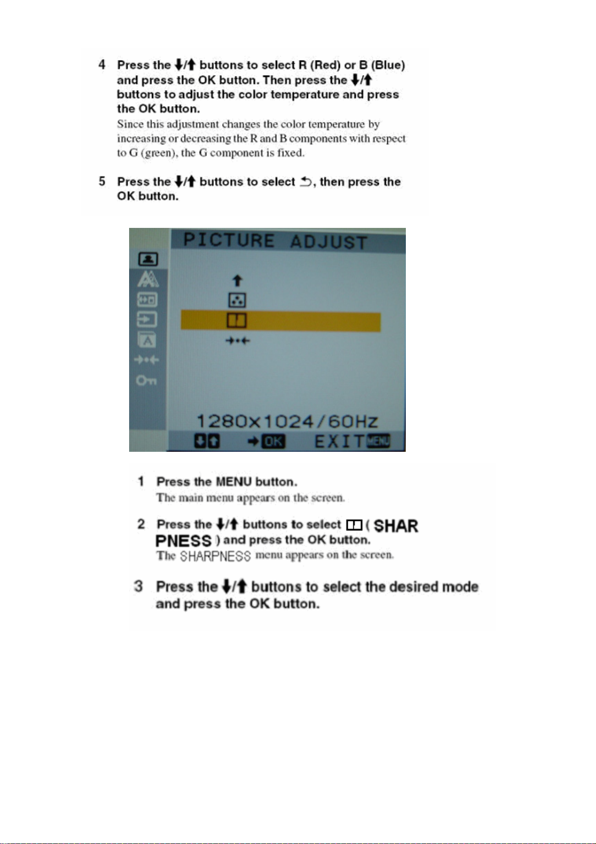
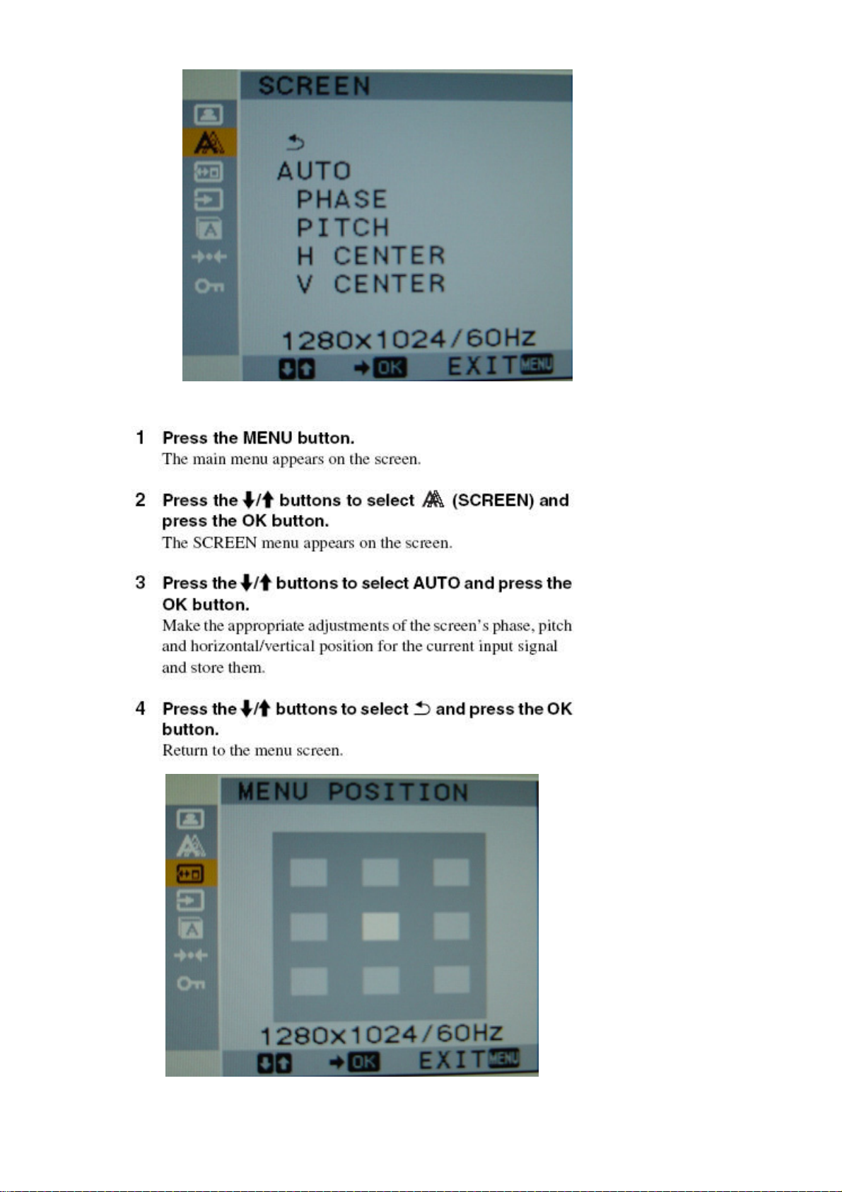
Screen Adjust the picture’s sharpness or its centering
A
5
6
7
8
9
γ
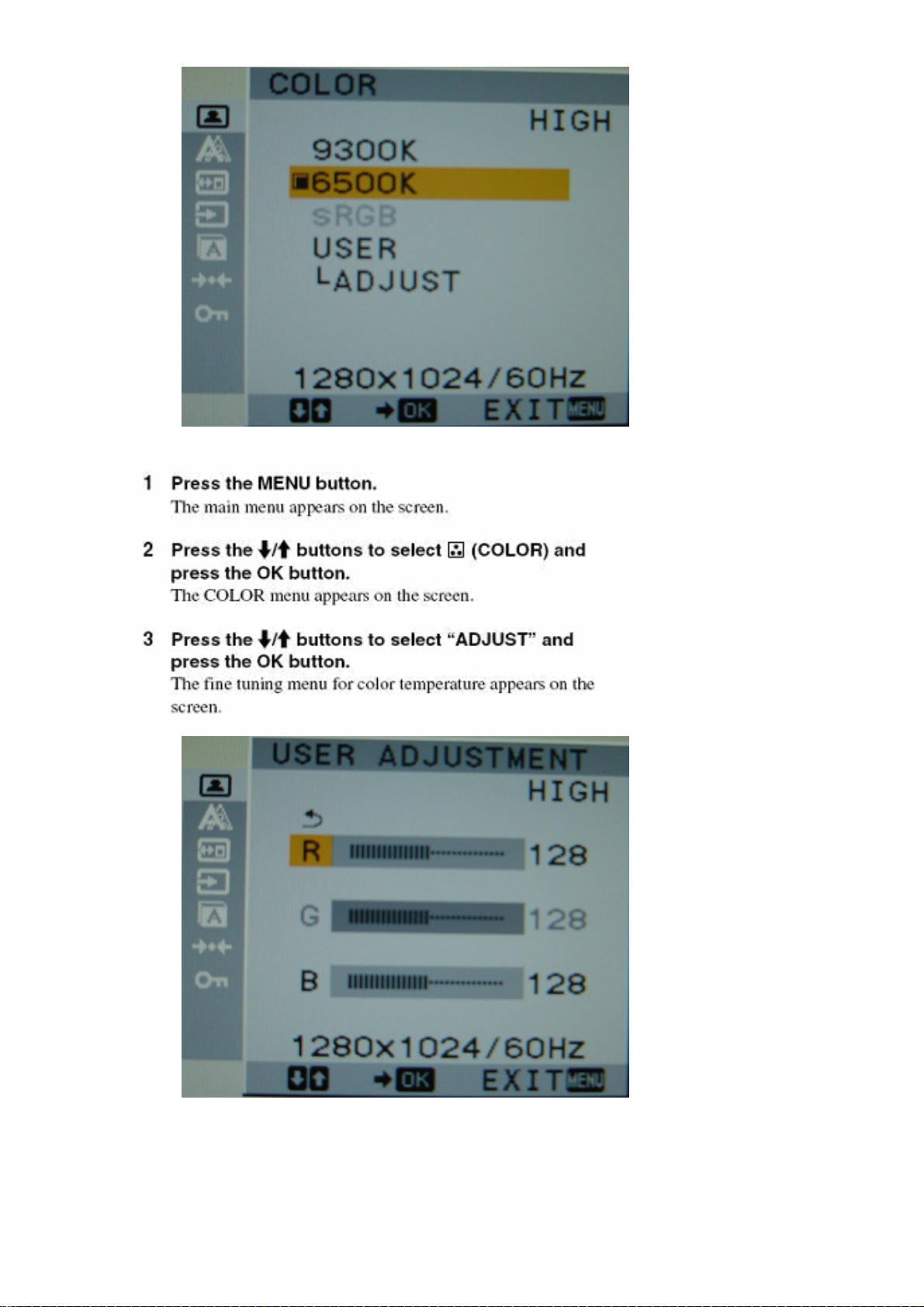
Color Adjust the color temperature of the picture
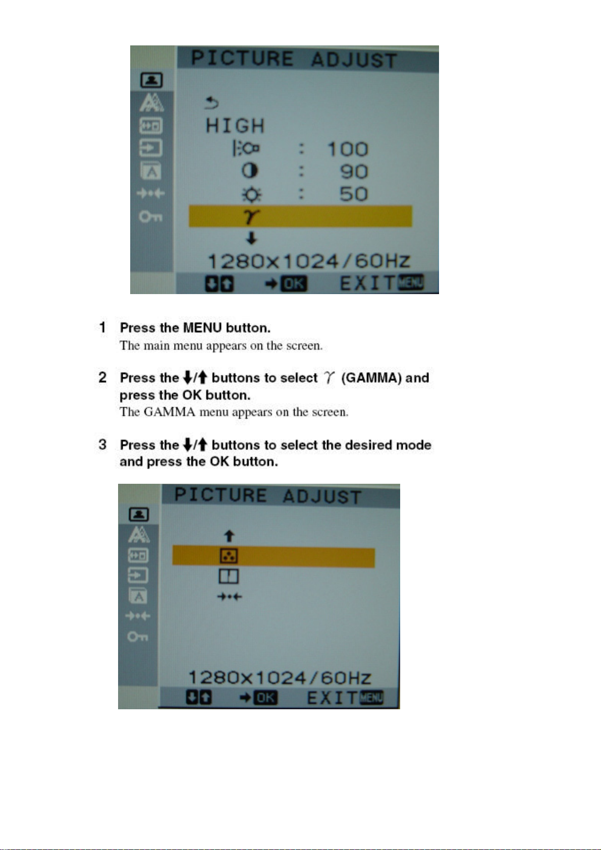
Gamma Change the picture’s color shade settings
http://www.wjel.net
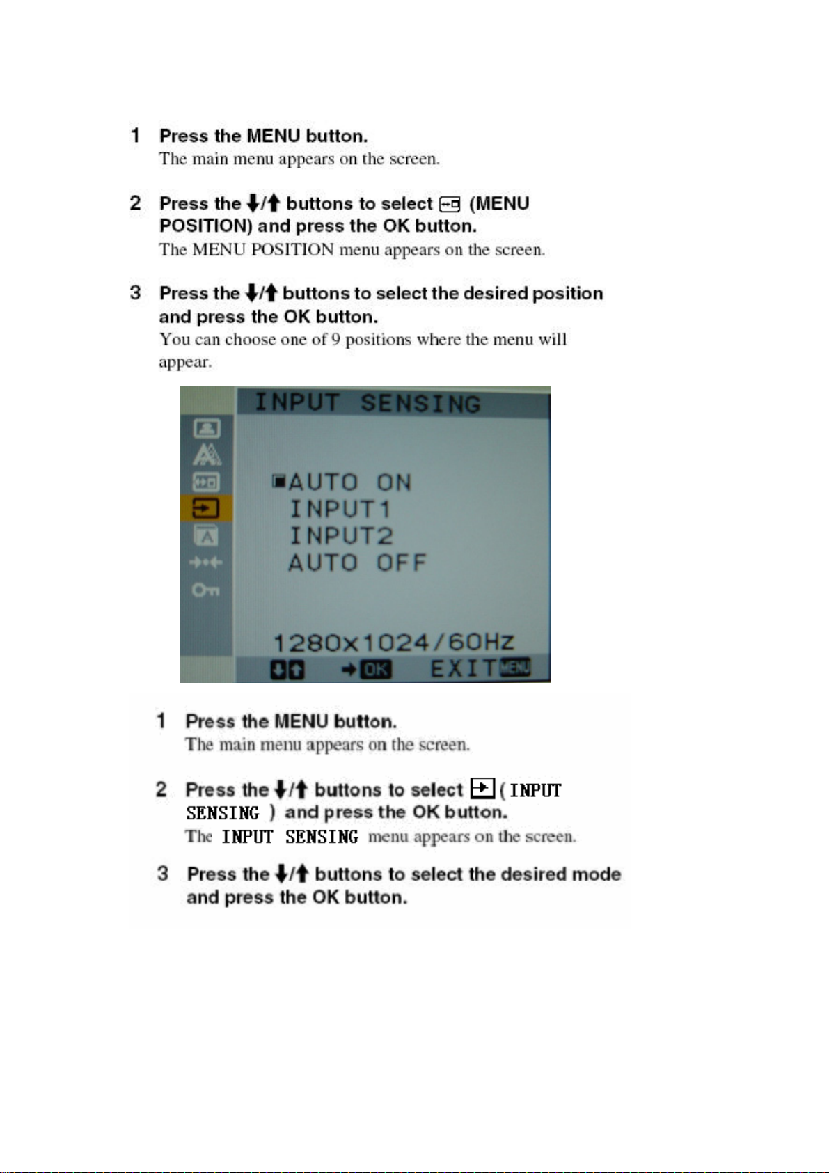
Menu position Change the on screen menu position
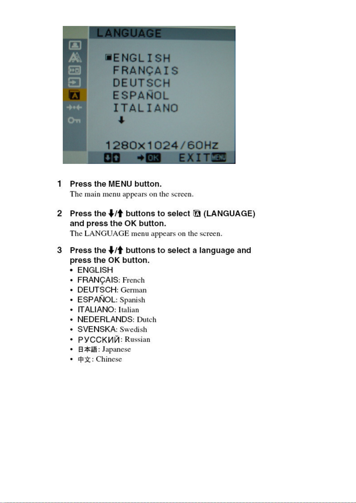
Language Chance the language used on menus or messages
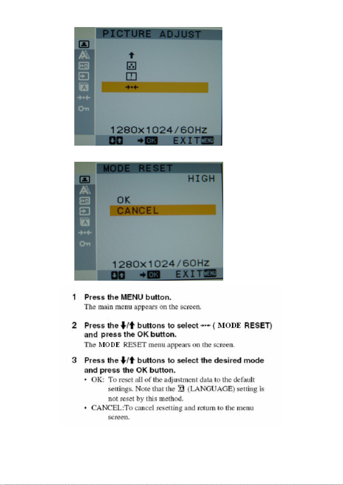
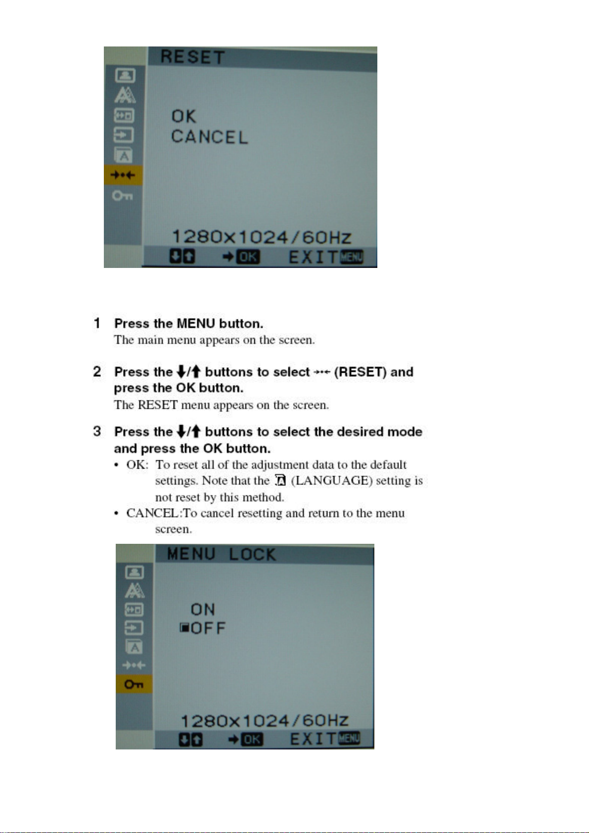
Reset Reset the adjustments to the default settings
10
Menu lock
Lock the control of buttons to prevent accidental adjustments or
resetting
9
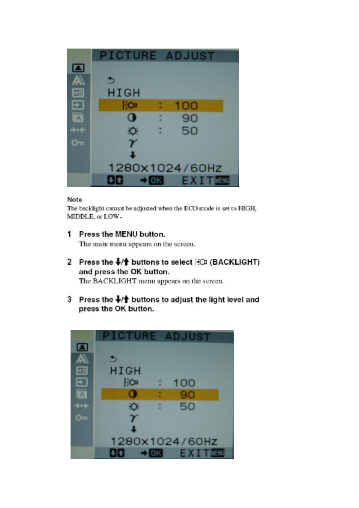
Adjustment steps of each menu
S75F Sony
http://www.wjel.net
10
S75F Sony
http://www.wjel.net
11
S75F Sony
http://www.wjel.net
12
S75F Sony
http://www.wjel.net
13
S75F Sony
http://www.wjel.net
14
S75F Sony
http://www.wjel.net
15
S75F Sony
http://www.wjel.net
16
S75F Sony
http://www.wjel.net
17
S75F Sony
http://www.wjel.net
18
S75F Sony
http://www.wjel.net
19
3.4 Adjustment
S75F Sony
1. Procedures of how to go to service mode.
1) Enter the service mode of this unit by turning on the power while pressing and holding the "MENU" key
simultaneously.
2) Press "MENU" key----MAINTAIN.
3) Press "OK" key to enter the service menu.
4) Select the desired function.
5) Press the "MENU" key to exit OSD.
6) Turn off the power and then turn it on again. The monitor then enters the normal mode.To enter the
service again, repeat the proceduredescribed above.
Note
W/B readjustment is required after the panel, board and microcomputer are replaced. However, be
sure to perform aging for more than 30 minutes for RGB reset before W/B adjustment.
2. Setup
1) Prepare timing and pattern data for a signal generator according to the Sony timing specifications.
2) Connect a monitor video cable to the signal generator.
3) Put Color Analyzer(ex. CA-110) 50cm away from the monitor, specify it vertically in the center of the
display, and adjust the focus to the optimum level using an eyepiece.
http://www.wjel.net
4) Put the monitor and Color Analyzer(ex. CA-110) in a light-shielded room.
5) Set up [SERVICE MODE] of the monitor.
3. Operation
Data is manually set to improve the productivity. The brightness, contrast, and backlight are set to 50,
70 and 100 respectively. After that, the default data of the color temperature to be adjusted is set.
4. Warm up time
Warm up for 30 minutes before performing any adjustment.
20

S75F Sony
5. Adjustment for White Balance
a. Display SMPTE at SXGA/60Hz(Input level 0.73V).
b. Set up [SERVICE MODE].
c. Click "CLEAR EEPROM" and AC Power off.
d. Set up [SERVICE MODE] of the monitor again.
e. Click "WHITE BALANCE" and then select "AUTO".
f. Prepare timing and full black pattern.
g. Click "OFFSET CALIBRATION".
h. After offset calibration is completed prepare full white pattern. i. Click " GAIN CALIBRATION".
6. 9300K color adjustment
a. Select "9300K" in "COLOR TEMP" and enter.
b. Use a 100% IRE white video field in the primary mode.
c. Adjust "CONTRAST " to secure the color temperature.
d. Press "MENU" key to exit adjust mode.
7. 6500K color adjustment
a. Select "6500K" in "COLOR TEMP" and enter.
b. Repeat the adjustment procedure as steps b to d at 9300K.
8. SRGB color adjustment
a. Select "SRGB" in "COLOR TEMP" and enter.
b. Repeat the adjustment procedure as steps b to d at 9300K.
3.5 Service OSD
To enter service OSD menu.
1). Turn off the power switch button.
2). Press volume down,and then power key.
3). Shows the service OSD menu. That menu is located in down side of main menu.
4). The service OSD menu contains additional menus as described below.
a). ADC CALBRATION : Adjust the offset voltage and gain value in PC mode.
b). VIDEO CALBRATION : Adjust the offset voltage and gain value in video input.
c). COLOR TEMP : Adjust R/G/B Color values of contrast and brightness in 9300k, 6500k,User color
http://www.wjel.net
d). AGING : Select aging mode. (on/off)
mode.
e). CLEAR ETI : Initilize the used time of MFT
f). CLEAR EEPROM : Initilize the EDID DATA at DDC2B EEPROM is saved system memory.
Process : Press ok button, and then power key.
g). DEFAULT TIMING 1 : Select the resolution timing of the signal.
Menu is 1152 X 864(VESA standard timing) 1152 x 870 (MAC computer timing).
h). DEFAULT TIMIN G2 : Select the resolution timing of the signal.
Menu is 1080 i (video timing) and 1035i.
21
 Loading...