

Page 1
Remote
Commander
3-864-784-11(1)
Operating Instructions
RM-TP501
1998 by Sony Corporation
Page 2

Precautions
About This Manual
CAUTION (Lithium battery)
Danger of explosion if battery is incorrectly
replaced. Replace only with the same or equivalent
type recommended by the manufacturer. Discard
used batteries according to the manufacturer’s
instructions.
On operation
Before connecting other components, be sure to turn off and
unplug the receiver.
On cleaning
Clean the cabinet, panel and controls with a soft cloth slightly
moistened with a mild detergent solution. Do not use any type of
abrasive pad, scouring powder or solvent such as alcohol or
benzine.
If you have any question or problem concerning your
receiver, please consult your nearest Sony dealer.
• The following icon is used in this manual:
z Indicates hints and tips for making the task easier.
2
Page 3

TABLE OF CONTENTS
Preparations 4
Compatible Components and Functions 4
Preparing the Commander 5
Screen Hierarchy 8
Location of Parts and Basic
Operations 9
Front panel 9
Rear panel 10
Operation 11
Basic Operations 11
Example: Operating a CD Player 13
Example: Operating the Tuner 14
Example: Recording from CD to MD 15
Selecting Sound Fields 16
Adjusting Sound Fields 17
Adjusting the Commander’s Operating
Environment 18
Additional information 22
Precautions during use 22
Troubleshooting 23
Specifications Back Cover
Index Back Cover
3
Page 4

Preparations
Compatible Components and Functions
This chapter describes how to prepare
the remote commander for operation.
Be sure to read this section before
operating.
This unit is a remote control system that utilizes infrared
rays to control a receiver and AV components connected
to the receiver.
Compatible Components
This unit can be used to operate Sony AV components as
well as AV components manufactured by other
manufacturers. Set up is necessary in order to operate
components manufactured by other companies (see page
18).
Functions
This unit is a bidirectional remote commander. Not only
does it transmit infrared rays for operation of the receiver,
it can also receive infrared rays emitted by the receiver to
display characters and other information supplied by
other components connected to the receiver with a
CONTROL A1 cord.
4
Page 5
Preparing the Commander
Please be sure to carry out the procedures described in
“Setting up the commander” on page 6 after inserting the
batteries.
Inserting batteries into the commander
Insert the four size-AA (LR6) alkaline batteries (for
commander operation) and lithium battery (for
preservation of the commander’s internal memory).
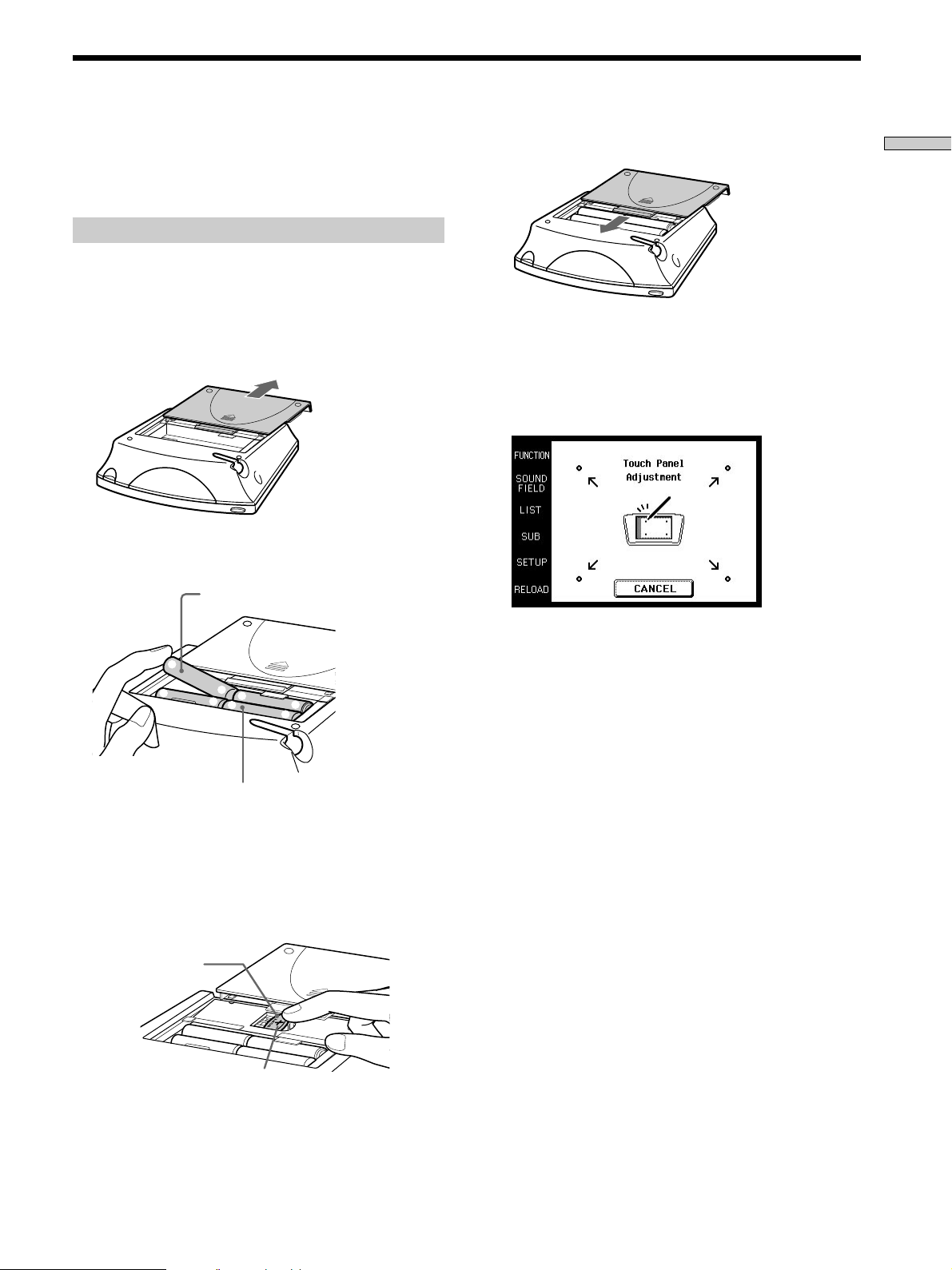
1 Remove the battery compartment cover.
Push in direction of
arrow
2 Insert the alkaline batteries.
Size-AA alkaline batteries
4 Close the battery compartment cover.
Preparations
After inserting the batteries, touching the touch panel
turns on the light and displays the touch panel (LCD)
adjustment screen. Follow the procedure on the next
page for touch panel adjustment and initial
communication.
]
}
Always insert the negative (–) pole
side of batteries first.
}
]
]
}
}
]
3 Insert the lithium battery.
After wiping the lithium battery thoroughly with a
dry cloth, insert it into the compartment with the
positive (+) pole side facing up.
Coin shaped lithium
battery CR2032
Positive (+) pole side up
Notes
• The LCD lights up when touched.
• VOL+/–, MUTING and SLEEP can be used even when the
LCD is not lit.
• Pressing BACK LIGHT/COMMANDER OFF turns the
backlight off. Holding it down for about 2 seconds turns the
LCD off. To conserve battery power, be sure to regularly turn
off the LCD or power when not in use.
• If the commander is not used for approx. 1 minute, the LCD
turns off automatically (Auto Off function). The auto off time
can be adjusted (see page 21).
5
Page 6
Preparing the Commander
Preparations
Setting up the commander
Please be sure to carry out the following 1 to 5 procedures
for preparation of the commander.
The commander’s panel is touch sensitive and can be
operated by simply touching it.
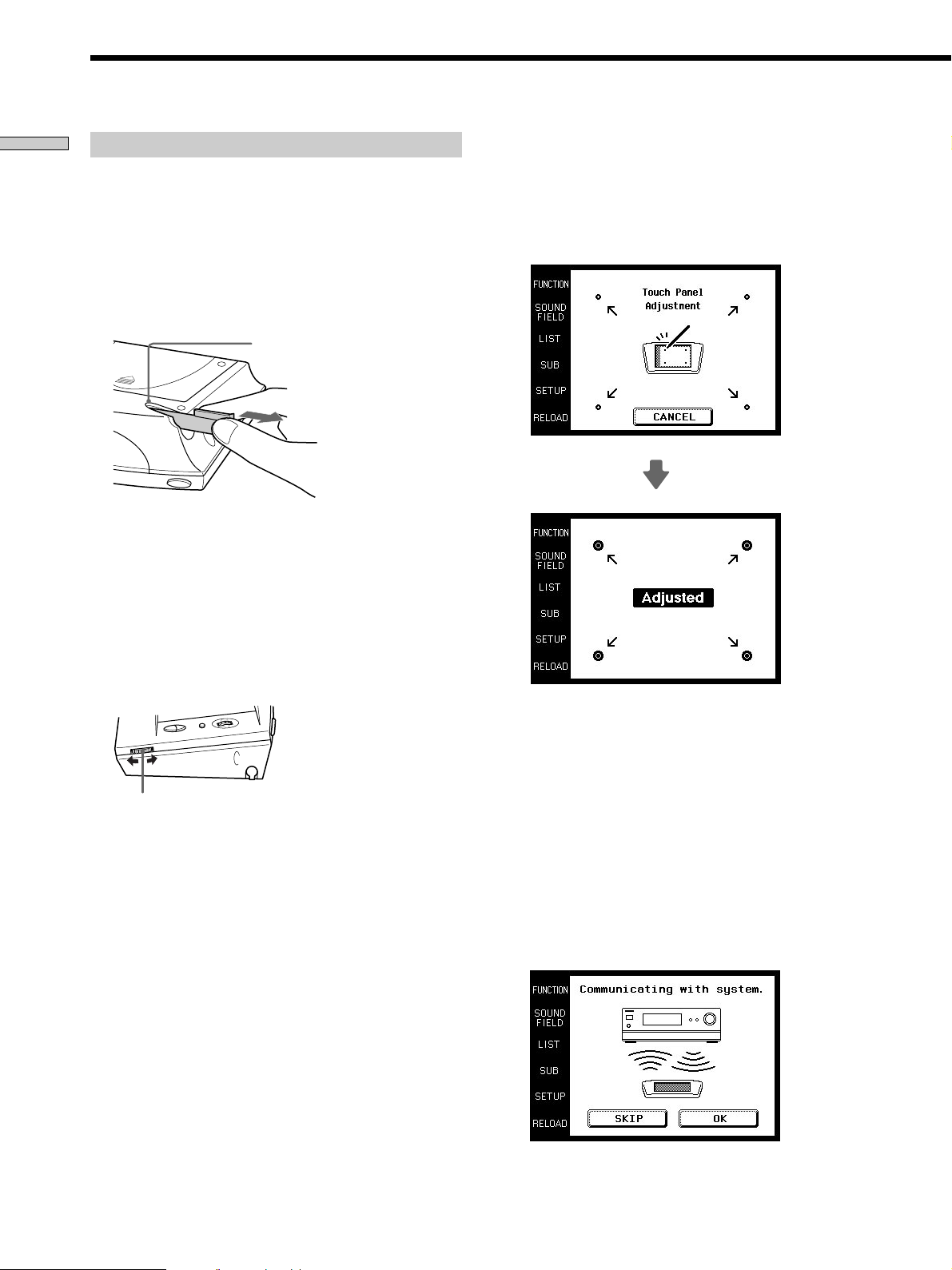
1 Remove the touch pen.
Touch panel adjustment
3 Adjust the position of the touch panel’s LCD.
Touch the center of each of the 4 dots with the touch
pen. When all 4 dots have been touched “Adjusted”
appears, a buzzer sounds, and the initial
communication screen appears.
When returning the touch pen, always slide it in tip
first.
Pen holder
Remove by sliding out
Touch the 4 dots with the touch pen.
Caution
Use only the touch pen provided with this unit or the soft tip
of your finger to operate the touch panel. Using a
commercially available writing utensils may damage the
panel and make correct operation impossible. If the tip of the
touch pen is damaged, or the touch pen is lost, please consult
your nearest Sony dealer.
2 Turn CONTRAST to adjust brightness of the LCD.
CONTRAST control
Caution
Touch panel adjustment must be carried out for proper panel
operation. If used without adjustment, the ”Touch Panel
Adjustment” screen appears each time the LCD lights up.
Initial communication
4 Press 1/u on the receiver to turn on the receiver.
5 Point the commander’s transmitter/receiver section
toward the receiver’s display, and touch OK.
Once initial communication with the receiver has been
established, the commander is ready to operate the
receiver.
6
Page 7
1 m ~ 2 m
Note
• To ensure good communication conditions, carry out initial
setup from directly in front of, and close to the receiver.
• Do not move the unit during initial setup.
If a communication error occurs during setup
An error message will be displayed.
• Touching OK will return to the step 5 setup screen.
• Touching SKIP goes to the regular screen without
carrying out initial setup. Although operation is
possible in this condition, functions not included on the
receiver will be displayed, and some buttons will not be
operable. Also, the initial setup screen will appear each
time the touch panel is turned on.
When replacing the batteries
To ensure preservation of the commander’s internal
memory when replacing batteries, be sure to observe the
following cautions.
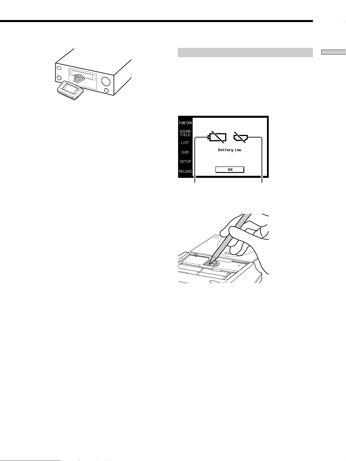
When to replace batteries
When the batteries become weak, a warning sounds and a
message is displayed. Replace batteries as instructed by
the message.
Replace alkaline
batteries.
Replace lithium
battery.
Preparations
Note
The commander receives and displays data transmitted from the
receiver. Communication errors may occur if the commander’s
transmitter/receiver section is not directed properly toward the
receiver’s display.
Be sure to point the commander’s transmitter/receiver section
towards the receiver’s display.
How to remove the lithium battery
Notes
• Disc titles and song titles downloaded from the CD changer are
memorized in the commander. The lithium battery is used for
preservation of this memory. If the unit is used with an
exhausted battery, the settings memorized in the commander
will be erased. Please replace the battery as soon as the message
appears.
• Replace the alkaline batteries with new batteries as soon as
their charge is exhausted. If the unit is used with exhausted
batteries, exhaustion of the lithium battery used to maintain
memory will be quickened and the memorized settings may be
erased.
• The life span of batteries may be shortened depending on the
conditions in which the commander is used.
• If the alkaline batteries and lithium battery become exhausted
at the same time, replace the alkaline batteries first. Replacing
the lithium battery first will erase the data memorized in the
commander.
• When replacing the alkaline batteries, always replace all 4
batteries with new ones.
• After replacing batteries, be sure to carry out touch panel
adjustment (page 6).
7
Page 8
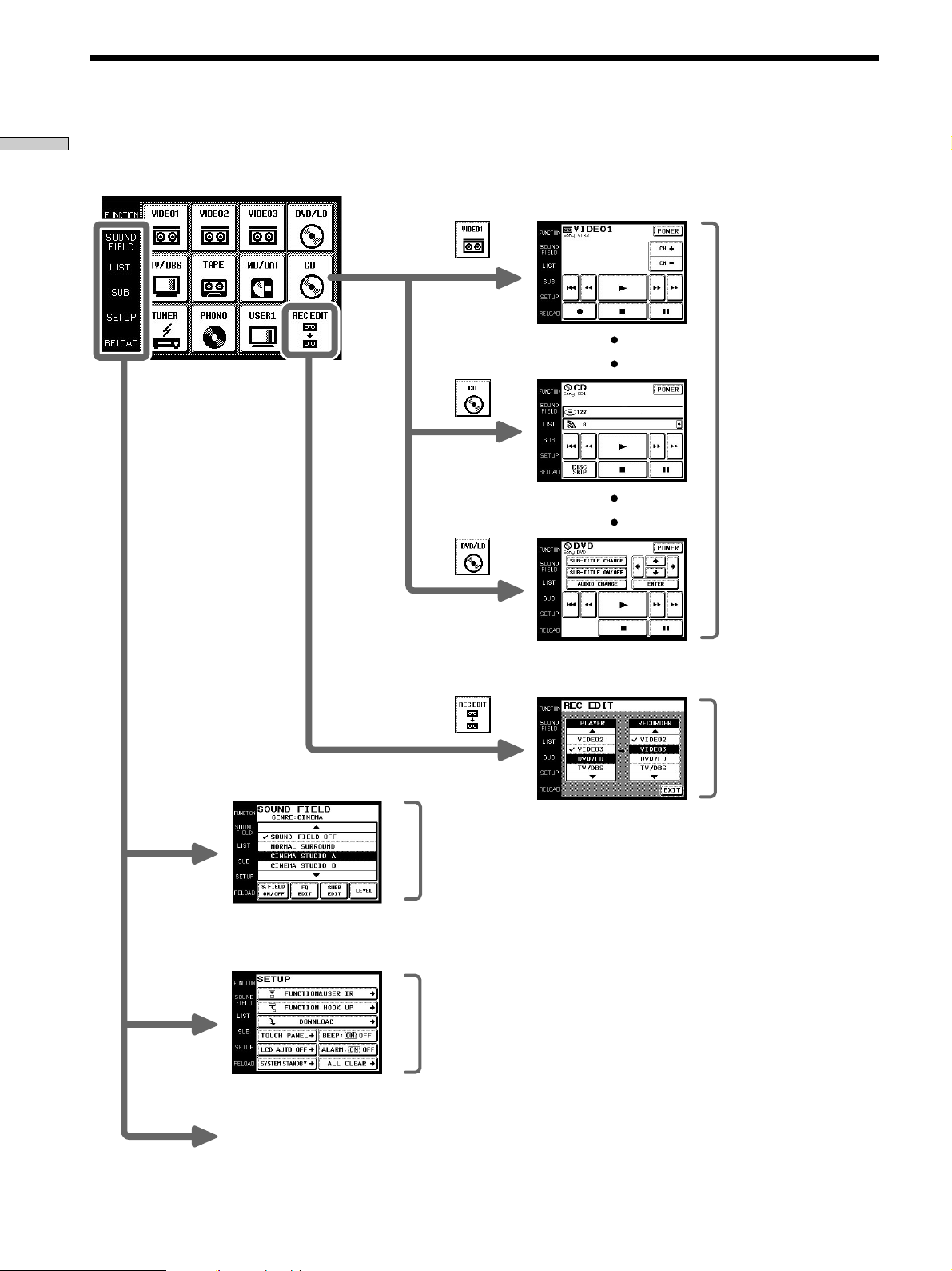
Screen Hierarchy
Preparations
The following diagram show the basic composition of this unit’s screen hierarchy.
FUNCTION screen
Normally, the
FUNCTION
screen is
displayed.
To display a
different screen,
touch the left side
of the LCD.
Screens for selection and
operation of components
connected to the receiver.
SOUND FIELD screen
SETUP screen
RELOAD...
Touch when the song titles of
a CD or MD being played
back are not displayed
correctly.
Screen for selection and
adjustment of the sound fields
(see page 16~18).
Screen for setting up the
operation environment and
control of components made by
other manufacturers (page 18).
Screen for recording audio
and video from one
component to another (see
page 15).
8
Page 9

Location of
Front panel
Parts and Basic
Operations
This chapter provides information
about the locations and functions of
the buttons and controls on this unit.
1
1 BACK LIGHT/COMMANDER OFF
Press to turn the backlight on or off. Hold down for
about 2 seconds to turn the LCD off. When the LCD is
off, press to turn on the LCD and backlight.
2 Touch panel
Touch to operate. The commander turns on
automatically.
23
4
5
Location of Parts and Basic Operations
6
7
8
3 VOL +/– buttons
Use to adjust the volume of the receiver.
4 JOG DIAL control
Rotate to scroll through items in a list (etc.).
Push to select the highlighted item.
5 SYSTEM/STANDBY button
Normally used to turn off all Sony components. Can
also be used to turn the receiver on or off depending
on the settings made in the SETUP screen (see page
21).
6 MUTING button
Use to mute the sound of the receiver.
7 CONTRAST control
Use to adjust the contrast of the LCD.
8 SLEEP button
Use to operate the receiver’s sleep function. The sleep
settings appear in the receiver’s display, not the
commander’s LCD.
9
Page 10

Rear panel
1
Location of Parts and Basic Operations
5
1 Transmitter/receiver section
Transmits and receives infrared signals to and from
the receiver.
2 Battery cover
3 Touch pen
4 SYSTEM/STANDBY button
Normally used to turn off all Sony components. Can
also be used to turn the receiver on or off depending
on the settings made in the SETUP screen (see page
21).
2
3
4
5 Touch pen holder
Pull out and insert touch pen when not in use.
10
Page 11

Operation
Basic Operations
This chapter explains how to operate
the receiver and connected audio/
video components.
Displaying the FUNCTION screen
To operating components connected to the receiver, first
display the FUNCTION screen, then select the component
you wish to operate (CD, MD etc.).
Normally, the FUNCTION screen is displayed. If it is not
displayed, touch FUNCTION to display it.
Touch FUNCTION in the LCD.
FUNCTION
The FUNCTION screen appears.
Operation
Composition of the FUNCTION screen is shown on the
next page.
z
You can change the functions displayed in the FUNCTION
screen
You can set all functions, except REC EDIT, to be displayed, or
not, using the FUNCTION HOOK UP screen (see page 20).
11
Page 12

Basic Operations
The following diagram shows the composition of the FUNCTION screen hierarchy.
The types of icons that can be displayed on the FUNCTION screen can be set using FUNCTION HOOK UP in the SETUP
screen. (For details on FUNCTION HOOK UP, see page 20.)
Operation
FUNCTION screen hierarchy
12
Page 13

Example: Operating a CD Player
This section describes how to operate a CD player
connected to the receiver. Other components can also be
operated in the same way.
For details concerning CD player operation, please refer
to your CD player’s operating instructions.
The screens used in the following example are the screens
that appear when using a SONY CD changer with a
CONTROL A1 terminal.
1 Touch FUNCTION.
The function screen appears.
2 Touch .
The receiver’s function switches to CD and the CD
screen appears.
Selected maker and
category (see page 19).
Disc title*
To operate other functions
Touch SUB. Another set of buttons are displayed and
ready for use.
Operation
To view the LIST
Touch LIST to view the song titles in a Sony CD changer
(5, 50, 200 CD) or MD deck connected by a CONTROL A1
cord. In this case, the information must be downloaded
from the receiver (see page 20 for details).
The LIST screen can only be displayed when the
FUNCTION is set to CD or DAT/MD.
Song title*
• Long titles can be read by touching the scroll icon ( ) to
scroll along the title.
• Only displayed when a Sony CD changer (5/50/200 CDs)
is connected to the receiver by a CONTROL A1 cord.
3 Touch ( to start playback.
z
When the song number or song title is not displayed
correctly
Point the commander toward the receiver and touch RELOAD.
• Touch the disc number to start playing that disc. appears on
the disc being played.
• Use the JOG DIAL or touch 4 or $ to scroll up or down the list.
• Touch NUMBER to sort in numerical order or touch TITLE to
sort in alphabetical order.
• Touch FUNCTION to return to the FUNCTION screen at any
time.
13
Page 14

Example: Operating the Tuner
This section describes how to operate the tuner.
For details on tuner operation, please refer to the
operating instructions provided with the receiver.
1 Touch FUNCTION.
2 Touch .
Operation
The FUNCTION screen appears.
The receiver’s function switches to TUNER and the
tuner screen appears.
Preset station
Station name
To operate other functions
Touch SUB to display the icons used for memorizing
broadcast stations and station names.
• To receive manually, touch DIRECT and input the
frequency.
• When memorizing a received broadcast station, memorize
after touching MEMORY.
Viewing the LIST
Touch LIST to view the names of the broadcast stations
downloaded from the receiver (see page 20 for details).
The LIST screen can only be displayed when the
FUNCTION is set to TUNER.
Band
• Touch AM or FM to change the band.
• Touch PRESET + or – to search for preset stations.
• Touch TUNING + or – to search for stations that can be
received.
• Touch SHIFT to switch memory pages (A, B, C).
• During display of any of the screens, touching FUNCTION
will return to the FUNCTION screen.
z
When broadcast stations or frequencies are not displayed
properly
Point the commander at the receiver and touch RELOAD.
Frequency
14
Page 15

Example: Recording from CD to MD
This section describes how record audio from a CD to an
MD as an example of recording audio/video.
Other operations
Recording from an LD to a video deck is basically the same
procedure. For details on the buttons used in recording, refer to
the operating instructions supplied with the receiver and other
components.
1 Touch FUNCTION.
The FUNCTION screen appears.
2 Touch .
The REC EDIT screen appears.
4 Touch to select the recorder component (MD/DAT
in this example).
When MD/DAT is touched, the REC EDIT operation
screen appears.
Operation
5 Touching r in RECORDER: MD/DAT, then touch (
in PLAYER: CD.
Starts playback from the CD player
3 Touch to select the player component (CD in this
example).
Because CD is not displayed, Use the JOG DIAL or
touch $ to scroll downward through the list. If you
scroll to far, touch 4 to scroll back up.
PLAYER
Touching 4 moves list up
Touching $ moves list down
When PLAYER is selected, the receiver’s FUNCTION
automatically switches to the PLAYER component.
Starts recording on the MD deck.
Recording starts.
The FUNCTION screen returns once the recording
finishes.
To stop recording at any time
Although recording stops automatically in the above
example, recording can also be stopped at any time by
touching p in RECORDER.
To stop the recording procedure at any time
Touch FUNCTION to display the FUNCTION screen.
During steps 2 to 3, touching EXIT will also stop the
recording procedure.
15
Page 16

Selecting Sound Fields
These sections describe how to select and make
adjustments to the sound fields.
For details concerning sound fields, please refer to the
operating instructions supplied with the receiver.
Touch SOUND FIELD.
Operation
Displaying the SOUND FIELD screen
SOUND FIELD
The SOUND FIELD screen appears.
Selecting the sound field
For details concerning which sound fields can be selected,
please refer to the receiver’s operating instructions.
1 Touch SOUND FIELD.
The SOUND FIELD screen appears.
2 Use the JOG DIAL or touch $ or 4 to scroll through
the list.
3 Push the jog dial to select the highlighted sound
field or touch the sound field you desire.
A check (✔) will appear next to the selected sound
field, and the sound field will change.
Genre of
sound field
highlighted
by the cursor
Selected
sound field
The SOUND FIELD screen hierarchy is shown below.
SOUND FIELD screen hierarchy
Cursor
Turns the sound field on or off with each touch
16
Page 17

Adjusting Sound Fields
Sound fields can be adjusted with the following 3 items:
• EQ EDIT (frequency band adjustments)
• SURROUND EDIT (surround parameter adjustments)
• LEVEL (speaker volume adjustments)
For details on what can be adjusted, refer to the operating
instructions supplied with the receiver.
To adjust the frequency bands
1 Touch EQ EDIT on the SOUND FIELD screen.
The EQ EDIT screen appears.
2 Select the item that you wish to adjust (output
speaker, sound range, frequency, or gain).
Output speaker
BASS: low range
MID: mid range
TREBLE: high range
GAIN: gain adjustment
FREQUENCY: frequency
adjustment
To adjust the surround parameters
1 Touch SURR EDIT on the SOUND FIELD screen.
The SURROUND EDIT screen appears.
2 Adjust as desired.
EFFECT: Higher values increase the “presence” of the
surround effect.
WALL TYPE: Use to simulate different sonic
environments.
REVERB TIME: Use to control the spacing of the early
reflections.
LFE MIX LEVEL: Touch
value.
D.RANGE COMPRESSOR: Touch
the desired value.
or to select the desired
or to select
Operation
3 Touch or to adjust to the desired
value.
4 Repeat steps 2 and 3 when there is more than one
item that you wish to adjust.
To display other items, use the JOG DIAL or touch 4
or $ to scroll through the list.
5 Touch EXIT when adjustment is finished.
Notes
• Items that cannot be adjusted due to the current speaker
settings or sound field mode are grayed out.
• If the alarm sounds, or all items appear to be grayed out, touch
RELOAD.
3 Touch EXIT when adjustment is finished.
Notes
• Items that cannot be adjusted due to the current speaker
settings or sound field mode are grayed out.
• If the alarm sounds, or all items appear to be grayed out, touch
RELOAD.
17
Page 18

Adjusting the Sound Fields
Adjusting the Commander’s Operating Environment
1 Touch LEVEL on the SOUND FIELD screen.
Operation
2 Adjust as desired.
3 Touch EXIT when adjustment is finished.
To listen to the adjusted sound and check its balance
Touch TEST TONE.
To emphasize the low range
Touch BASS BOOST.
To adjust the speaker volume
The LEVEL screen appears.
Touch
corresponding speaker.
or to adjust to the level of the
The following explanations allow you to adjust various
setting and customize the commander’s operating
environment.
Displaying the SETUP screen
To adjust the operating environment, first display the
SETUP screen.
Touch SETUP.
SETUP
The SETUP screen appears.
Notes
• Items that cannot be adjusted due to the current speaker
settings or sound field mode are grayed out.
• If the alarm sounds, or all items appear to be grayed out, touch
RELOAD.
18
Page 19

Registering the connected component
The following procedure lets you setup the component
commander to operate the components connected to the
receiver.
When carrying out this operation, make sure that the receiver’s
power is on, and be sure to point the commander’s transmitter/
receiver section toward the display on the receiver.
4 Select the type of component connected (Ex: Sony
VTR1).
To display other items, use the JOG DIAL or touch 4
or $ to scroll through the list.
The FUNCTION&USER IR:MAKER CODE screen
appears.
1 Touch SETUP.
The SETUP screen appears.
2 Touch FUNCTION&USER IR.
The FUNCTION&USER IR screen appears.
3 Select the function that you wish to register (Ex:
VCR).
To display other items, use the JOG DIAL or touch 4
or $ to scroll through the list.
The FUNCTION&USER IR:CATEGORY screen
appears.
Operation
5 Touch the remote controller mode of the connected
component.
The component selected in steps 4 to 5 will be
registered at the function selected in step 3, and the
SETUP screen will reappear. A long beep sound is
emitted to indicate that registration was successful.
Operation is now possible from the FUNCTION
screen.
If a series of short beeps is emitted, redo the
registration procedure. If this occurs, make sure the
receiver is turned on and that the commander is
pointing toward the receiver during operation.
To stop registration at any time
Touch EXIT during step 2 or touch CANCEL during steps 3 to 5.
Notes
• All icons may not be displayed when registering components
made by certain manufacturers.
• Some icons may not function even though they are displayed
when registering components made by certain manufacturers.
19
Page 20

Adjusting the Commander’s Operating Environment
Up to 11 components can be displayed on the FUNCTION
screen. Only connected components will appear on the
FUNCTION screen.
1 Touch SETUP.
2 Touch FUNCTION HOOK UP.
Operation
3 Select the function not to be displayed and touch
FUNCTION screen setup
The SETUP screen will appear.
The FUNCTION HOOK UP screen will appear.
NO.
To display other items, use the JOG DIAL or touch 4
or $ to scroll through the list.
The selected component is set to not appear and the
SETUP screen appears.
2 Touch DOWNLOAD.
The DOWNLOAD screen will appear.
3 Touch to select the data you wish to download and
press:
FUNCTION NAME: Names of connected components.
TUNER PRESET NAME: Broadcast station names etc.,
memorized in receiver.
CD MEMO: CD song titles or disc titles etc., from a
Sony CD changer (5/50/200 CD) connected to
receiver with CONTROL A1 cable.
Downloading starts, and the progress is displayed.
During this time, please leave the commander’s
transmitter/receiver section pointed toward the
display on the receiver.
To display the components set not to display
Touch YES instead of NO is step 3.
z
Components that have been registered (see page 19) are set
to “YES” automatically.
Downloading receiver data
Various types of data can be downloaded from the
receiver.
When carrying out this operation, make sure that the receiver’s
power is on, and be sure to point the commander’s transmitter/
receiver section toward the display on the receiver. Also, operate
the commander at a distance of about 1~2 meters from the
receiver.
1 Touch SETUP.
The SETUP screen will appear.
When you touch CANCEL, the data downloaded
before you touched CANCEL will be saved.
When downloading has finished, the DOWNLOAD
screen returns. A long beep sound will be emitted if
downloading has been carried out properly.
If a series of short beeps is emitted, please redo the
download procedure. If this occurs, make sure the
receiver is turned on and that the commander is
pointing toward the receiver during operation.
4 Repeat step 3 when downloading other data.
5 Touch EXIT.
Download finishes and the SETUP screen appears.
20
Page 21

Other setup
p Adjusting the position of the touch panel
(LCD)
Adjust the position of the LCD when it shifts from the
normal operating position.
1 Touch TOUCH PANEL on the SETUP screen.
The TOUCH PANEL ADJUSTMENT screen appears.
2 Touch the center of each of the 4 dots.
(For details, see “Touch panel adjustment” on page 6.)
“Adjusted” appears in a short while and long beep is
emitted.
p Setting the operation sound on or off
A beep can be set to sound or not sound when the touch
panel is touched.
Touch ON (sound) or OFF (no sound) in BEEP:ON
OFF in the SETUP screen.
p Setting the warning alarm on or off
A warning alarm can be set to sound or not sound when a
communication error has occurred.
Operation
Touch ON (sound) or OFF (no sound) in ALARM:ON
OFF in the SETUP screen.
p Returning settings to their factory preset
settings
Use this function to erase all memorized settings and
return them to their factory presets.
Please note that once erased, settings can not be returned.
When carrying out this operation, make sure that the receiver’s
power is on, and be sure to point the commander’s transmitter/
receiver section toward the display on the receiver.
1 Touch ALL CLEAR on the SETUP screen.
p Setting the LCD to turn off automatically
The LCD backlight can be set to turn off automatically
after operation.
1 Touch LCD AUTO OFF on the SETUP screen.
The LCD AUTO OFF screen appears.
2 Touch + or – to set the desired turn off time.
The turn off time can be set between 1 and 10 minutes
in 1 minute intervals.
3 Touch EXIT.
z
To preserve battery life
Select a short turn off time in step 2.
p Changing the function of the SYSTEM/STANDBY
button
ALL OFF: Switches power of all Sony AV components
off.
ON/OFF: Switches only the receiver on or off.
2 Touch OK.
21
Page 22

Additional
Precautions during use
information
On installment
Do not drop the commander or subject it to strong
vibration as this could cause damage.
On the touch pen
Use only the touch pen provided with this unit or the soft
tip of your finger to operate the touch panel. Using a
commercially available writing utensils may damage the
panel and make correct operation impossible. If the tip of
the touch pen is damaged, or the touch pen is lost, please
consult your nearest Sony dealer.
On handling
The touch panel (display section) is made of glass.
Twisting the touch panel, dropping the unit, placing your
elbow (etc.) on it, or placing heavy objects on top of it,
may break the touch panel and cause bodily harm due to
glass fragments.
On cleaning
Clean the cabinet, panel and controls with a soft cloth
slightly moistened with a mild detergent solution. Do not
use solvent such as thinner, benzine, or alcohol as these
will damage the rear panel.
22
Page 23

Troubleshooting
If you experience any of the following difficulties while
using the commander, use this troubleshooting guide to
help you remedy the problem. Should any problem
persist, consult your nearest Sony dealer.
Operation can not be done with the commander.
/ Check that the receiver and components are
connected correctly.
/ The commander and receiver are too far apart.
/ Make sure that there are no objects between the
commander and receiver.
/ Make sure that the receiver’s power is turned on.
/ The commander’s transmitter/receiver section is
not pointed at the receiver.
/ The commander’s batteries are exhausted. Replace
with new alkaline batteries (see page 7).
/ There is an invertor system florescent light near the
commander or receiver. Please place away from
the florescent light.
/ Make sure you have selected the correct function
on the remote.
/ When you operate a programmed non-Sony
component, the remote may not function properly
depending on the make and model of the
component.
The SOUND FIELD function does not work.
/ If the receiver has the 5.1 INPUT jacks, the SOUND
FIELD function becomes inoperable whenever you
select the component connected to the jacks.
“5.1INPUT” cannot be selected from the function
screen even though the receiver has the 5.1
INPUT jacks.
/ A communication error has occurred. Point the
remote towards the receiver and select “5.1INPUT”
from the function screen again.
Additional information
The receiver’s functions and modes do not
correlate with the displays on the commander.
/ Initial communication setup has not been done.
Use after first carrying out initial communication
setup (see page 6).
/ The commander was not pointed at the receiver
when it was turned ON. Touch RELOAD, and
download component data (see page 8).
/ Select the correct function using the commander.
LCD does not appear.
/ The LCD is not turned on. Touch the touch panel.
/ Contrast is too light or too dark.
Use the CONTRAST control to adjust the contrast
of the LCD (see page 6).
When a CD player, tape deck, or MD deck is
connected to the receiver via S-LINK CONTROL A1
jacks, Auto Function does not work properly.
/ Reprogram the remote (see page 18).
23
Page 24

Specifications
Index
Operating system
Liquid crystal touch
Liquid crystal size
3.8 inches
Liquid crystal type
Reflection system
Touch panel Resistant membrane
Analog type
Additional information
Power requirements
For operation: DC 6V
For memory
panel
(256 x 200 dots)
(Monochrome type)
system
(T ype AA alkaline
batteries)
preservation:
DC 3V
(CR2032 lithium
battery)
A, B
Battery 5, 7
C
CD player 13
D
Downloading receiver data 20
E, F, G
Front panel 9
FUNCTION Screen 11, 12
setup 19
H, I, J, K, L, M, N, O
Operating components
CD player 13
Recording 15
Tuner 14
P, Q, R
Rear panel 10
Recording 15
Registering the connected
component 18
Maximum external dimensions
(width x height x depth, including
projecting parts and controls)
160 x 111 x 46 mm
Mass 290 g (Main unit only
including touch pen)
Design and specifications are subject
to change without notice.
S
Setup
commander 6
environment 18~21
FUNCTION screen 19
SETUP screen 18
SOUND FIELD 16~18
T, U, V, W, X, Y, Z
Tuner 14
24
Sony Corporation Printed in Malaysia
 Loading...