

Page 1

Edge Analytics
5-000-618-11 (1)
Appliance
Operating Instructions
Software Version 1.00
Before operating the unit, please read this manual thoroughly
and retain it for future reference.
REA-C1000
© 2018 Sony Corporation
Page 2

Table of Contents
Overview
Using This Manual ................................................ 3
Precautions for Preventing Access to the Unit by
an Unintended Third Party .................................. 4
Features ..................................................................4
Location and Function of Parts ........................... 5
System Configuration ........................................... 6
Installation and Connection
Installing ................................................................ 7
Mounting using mounting screws ................... 7
Connecting ............................................................. 7
Connecting to AC power supply ..................... 7
Initial Setup
Setting Up a Computer ......................................... 8
Accessing the Unit from a Web Browser ............ 8
Screen Structure .................................................... 9
Configuring Initial Setup Items ........................... 9
Enabling option functions ............................... 9
Starting applications ..................................... 10
Checking notifications .................................. 10
Application Setup and Operation
Configuring an Application ................................21
Common application setup operation ...........21
Running an application .................................21
Handwriting Extraction Application .................22
Preparation before setup ................................22
Configuring the Handwriting Extraction
application .....................................................22
Running the Handwriting Extraction
application .....................................................23
PTZ Auto Tracking Application .........................24
Preparation before setup ................................24
Configuring the PTZ Auto Tracking
application .....................................................24
Running the PTZ Auto Tracking
application .....................................................27
Close-up by Gesture Application .......................28
Preparation before setup ................................28
Configuring the Close-up by Gesture
application .....................................................28
Running the Close-up by Gesture
application .....................................................29
Real-time Cropping Application ........................29
Preparation before setup ................................29
Configuring the Real-time Cropping
application .....................................................29
Running the Real-time Cropping
application .....................................................30
Appendix
Unit Setup (Common Settings)
Basic Operations in the Common Settings
Menu .................................................................... 11
Input/Output ....................................................... 11
Video ..................................................................... 12
Network ................................................................ 13
Security ................................................................ 14
[User] tab ...................................................... 14
[Access] tab .................................................. 14
[SSL] tab ....................................................... 15
[Referer] tab .................................................. 16
License .................................................................. 17
[License] tab ................................................. 17
[History] tab .................................................. 18
System .................................................................. 18
[Information] tab ........................................... 18
[Date & Time] tab ......................................... 19
[Initialize] tab ............................................... 19
[Update] tab .................................................. 19
[EULA] tab ................................................... 20
[Software] tab ............................................... 20
Message List .........................................................31
LED indicators ..............................................31
Web browser display .....................................31
Troubleshooting ...................................................32
About Use of GNU GPL/LGPL Software .........33
Specifications ........................................................33
External Dimensions .....................................34
2
Page 3

Overview
NOTICE TO USERS
Safety Regulations (supplied)
Describes the important points for safe use of the unit.
Be sure to read it.
Operating Instructions (This document/
Web)
These operating instructions describe the names of the
various parts of the unit, and installation, connection,
and operation methods.
Using This Manual
The Operating Instructions document is designed to be
read on a computer display.
The content you need to know in order to use the unit is
described here.
Read it before you operate the unit.
Jumping to a related page
When you read the instructions on a computer display
and click on the related part of the relevant page that is
being displayed, you jump to the related page. Relevant
pages can be searched easily.
Software display examples
The software displays described in this manual are
explanatory examples. Note that some displays may be
different from the ones that actually appear.
Printing the Operating Instructions
Depending on your system, certain displays or
illustrations in the Operating Instructions, when printed
out, may differ from those that appear on your screen.
© 2018 Sony Corporation.
All rights reserved. This manual or the software
described herein, in whole or in part, may not be
reproduced, translated or reduced to any machine
readable form without prior written approval from
Sony Corporation.
SONY CORPORATION PROVIDES NO
WARRANTY WITH REGARD TO THIS
MANUAL, THE SOFTWARE OR OTHER
INFORMATION CONTAINED HEREIN AND
HEREBY EXPRESSLY DISCLAIMS ANY
IMPLIED WARRANTIES OF
MERCHANTABILITY OR FITNESS FOR ANY
PARTICULAR PURPOSE WITH REGARD TO
THIS MANUAL, THE SOFTWARE OR SUCH
OTHER INFORMATION. IN NO EVENT SHALL
SONY CORPORATION BE LIABLE FOR ANY
INCIDENTAL, CONSEQUENTIAL OR SPECIAL
DAMAGES, WHETHER BASED ON TORT,
CONTRACT, OR OTHERWISE, ARISING OUT
OF OR IN CONNECTION WITH THIS MANUAL,
THE SOFTWARE OR OTHER INFORMATION
CONTAINED HEREIN OR THE USE THEREOF.
Sony Corporation reserves the right to make any
modification to this manual or the information
contained herein at any time without notice. The
software described herein may also be governed by
the terms of a separate user license agreement.
• The terms HDMI and HDMI High-Definition
Multimedia Interface, and the HDMI Logo are
trademarks or registered trademarks of HDMI
Licensing Administrator, Inc. in the United States
and other countries.
• Microsoft, Windows, and Internet Explorer are
registered trademarks of United States Microsoft
Corporation in the United States and/or other
countries.
• JavaScript is a trademark or registered trademark of
Oracle Corporation, its affiliates or subsidiaries in
the United States and other countries.
• Adobe, Adobe Reader and Adobe Flash are
trademarks of Adobe Systems Incorporated.
• Google Chrome is a registered trademark of
Google Inc.
Other system names, product names appearing in this
document are trademarks or registered trademarks of
their respective manufacturers. Trademarked items
are not indicated by ® or ™ symbols in this
document.
3
Page 4

Precautions for Preventing Access to the Unit by an Unintended Third Party
The unit may be accessible by an unintended third party
on the network, depending on the usage environment.
Changing the user name and password of the
administrator from the default settings is highly
recommended for security reasons. For details about
changing the user name and password, see “Security”
(page 14).
If the unit is accessed by an unintended third party, there
may be undesired effects, such as operations or settings
that may interfere with operation of the unit.
The unit can be fraudulently accessed in a network
environment where a device is connected or connectable
to the network without the administrator’s permission,
or a computer or other network device connected to the
network can be used without any permission. Connect to
these environments at your own risk. Also, use the SSL
function, Referer check function, or other security
measures to prevent unauthorized access to the unit. For
details about functions, see “Security” (page 14).
Note
The China model does not support the SSL function.
Features
The REA-C1000 is a device that analyzes video that is
input from a camera, computer, or other device, and
automatically generates video content in real-time that
previously would have required significant time and
human resources, and been expensive to create.
REA-C1000 configuration and application operation
can be controlled intuitively using a simple screen
displayed in a web browser on a computer connected to
the network.
The unit features the following applications.
Handwriting Extraction
This application identifies and extracts text and
diagrams drawn on a whiteboard or blackboard in realtime, and renders them so that they appear in front of the
speaker.
PTZ Auto Tracking
This application tracks a moving target, and
automatically moves a remote camera to maintain
optimum composition while shooting.
Note
For details about supported remote cameras, contact
your distributor.
Close-up by Gesture
This application interprets specific gestures of people in
the video, and automatically zooms in on the
corresponding area. You can display two images (a wide
angle view and zoomed view) in real-time.
Real-time Cropping
This application simultaneously displays a wide-angle
view and a cropped view, from a single camera, by
cutting out a desired portion of the whole view in realtime.
4
Page 5
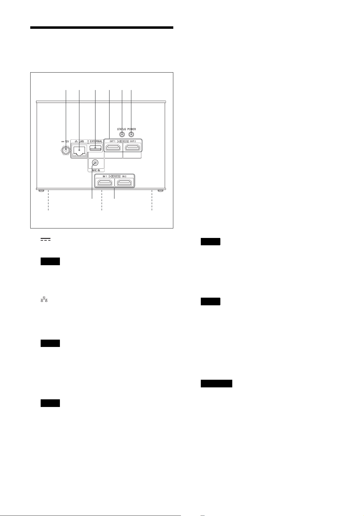
Location and Function
0
of Parts
12 3 456
78
9 9
E STATUS button/LED
• STATUS button
Press and hold the button for 5 seconds with the
unit turned so that the POWER LED starts
flashing green. Press and hold the POWER button
for 3 seconds while the LED is flashing to restart
the unit and restore all settings, including
network settings, to their factory default settings.
• STATUS LED
Lights in green when the unit is operating
normally.
Lights in red when not connected to the network.
Flashes in red when an error (such as an overtemperature alarm) occurs in the unit.
F POWER button/LED
Power is supplied and the POWER LED lights in
green when the unit is connected to an outlet using
an AC adapter (not supplied) and power cord.
To turn the unit off, press and hold the button for 3
seconds. The POWER LED goes out when the unit
turns off.
To turn the unit on again, press the POWER button.
The POWER LED lights in green.
G HDMI IN 1/HDMI IN 2 connectors
Connect to the HDMI output connectors of a
camera, computer, or other video device.
A 12 V (DC power input) connector
Connect to an AC adapter (not supplied).
Note
For details about supported AC adapters (not
supplied), contact your distributor. Use of other AC
adapters may cause a fire or malfunction.
B LAN (network) connector (RJ-45)
Connect to a 10BASE-T, 100BASE-TX, or
1000BASE-T switching hub using a LAN cable (not
supplied, category 5 or higher, shielded twisted
pair).
Note
For safety, do not connect the connector for
peripheral device wiring that might have excessive
voltage to this port. Follow the instructions for this
port.
C EXTERNAL connector
Note
Not supported in the current software version.
Note
Audio from connected devices is not supported in
the current software version.
H MIC IN connector
Connect to the audio output connector of an audio
device.
Note
Not supported in the current software version.
I Mounting screw holes (four locations on
bottom panel)
Use to mount the unit.
For details, see “Mounting using mounting screws”
(page 7).
J Ratings label (bottom panel)
Important
This label shows the name of the unit and its
electrical ratings.
D HDMI OUT 1/HDMI OUT 2 connectors
Connect to the HDMI input connectors of a display,
projector, or other video device to display the output
video from the unit.
5
Page 6
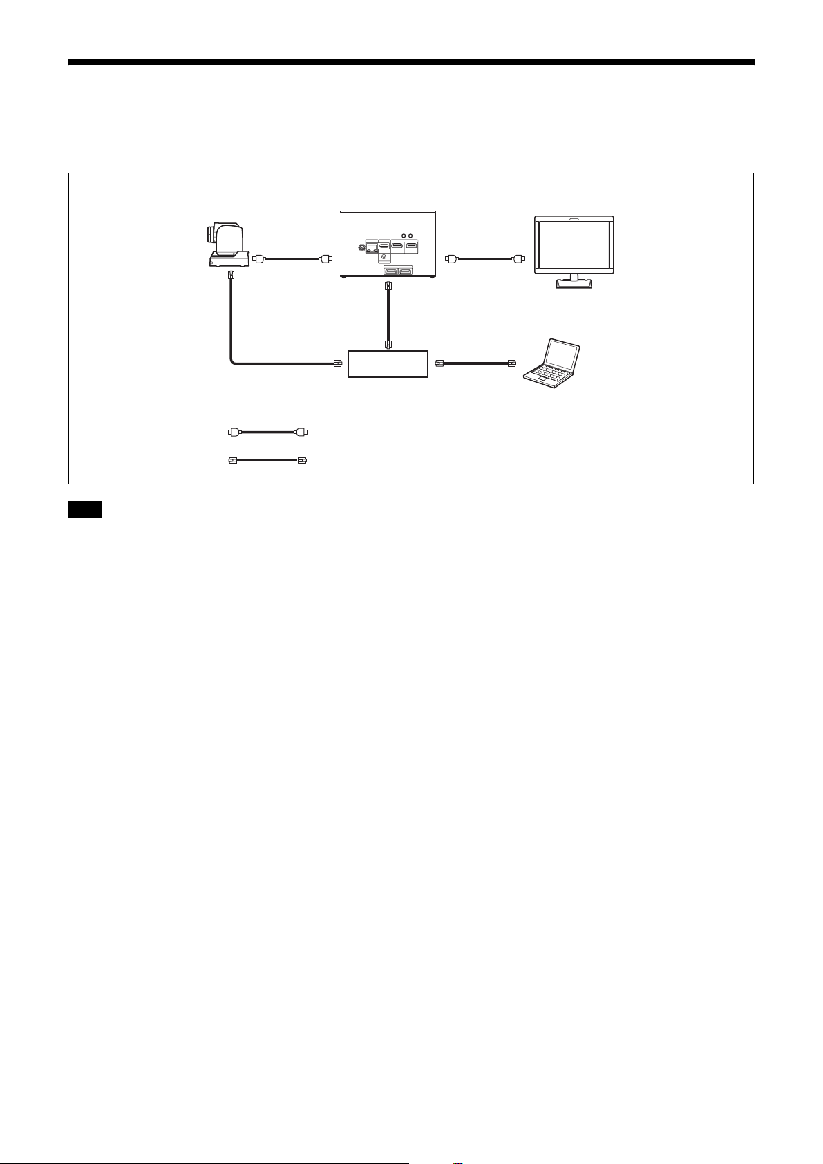
System Configuration
The unit can be arranged into various system configurations with other devices (not supplied). The diagram below
shows a typical system configuration.
REA-C1000
Camera
Monitor
Router
Computer
HDMI cable
LAN cable (category 5e or higher, shielded twisted pair)
Tip
We recommend that you build a 1000BASE-T network to provide for future function expansion.
6
Page 7

Installation and Connection
Connecting
Installing
Install the unit on a level surface, such as a desktop.
If, unavoidably, you need to mount the unit on an
inclined surface, mount the unit using the mounting
screw holes on the bottom panel to prevent the unit from
falling.
Notes
• Cables may catch on the connector shell of other
cables connected to adjacent connectors and not be
connected properly, depending on the cables used.
Check that the cables can be used with the unit
beforehand.
• Mount the unit so that no strong force is applied to the
cables connected to the unit. Cables may be pulled out
or the unit may malfunction.
• Notes about temperature rise of the unit
– The unit may become hot during use. This is not a
malfunction.
– Avoid use where the unit is in direct contact with
exposed skin for extended periods.
– The temperature rise may occur quickly in high-
temperature environments.
Connecting to AC power supply
Connect to the AC power supply using an AC adapter
(not supplied) and power cord.
The POWER LED lights green when power is supplied.
After the unit has powered up, the STATUS LED lights
green when access from a web browser becomes
enabled.
Notes
• For details about supported AC adapters (not
supplied), contact your distributor. Use of other AC
adapters may cause a fire or malfunction.
• Connect the power supply to the unit only after
powering on the other peripheral devices.
Mounting using mounting screws
Attach the unit using the four mounting holes (for M3
screws) on the bottom panel. Use M3 screws that meet
the following criteria. Attach the unit with the screws
against a flat surface, without ridges or undulations, and
tighten securely.
M3 screw
4=3 mm to 8 mm
7
Page 8

Initial Setup
Accessing the Unit from
Perform the following configuration when starting the
unit for the first time. This configuration is performed by
the administrator.
Setting Up a Computer
Prepare a computer and connect it to the network. The
recommended operating environment is given below.
OS: Windows 10 Pro (32-bit version/64-bit version)
Web browser: Google Chrome Ver. 70 or later
Notes
• Turn off tablet mode.
• Do not use the Back button of the browser.
• JavaScript is used for the web page display when
accessing the unit. The web page may not display
correctly if your computer uses certain software, such
as anti-virus software.
a Web Browser
Perform the following configuration to enable access of
the unit from a web browser.
1
Assign an IP address to the unit using
RM-IP Setup Tool.
The IP address of the unit is obtained automatically
using DHCP, but you can change it using RM-IP
Setup Tool if required.
For details about setting the IP address, refer to the
RM-IP Setup Tool guide.
Tip
Download RM-IP Setup Tool and the RM-IP Setup
Tool guide separately from the following website.
www.sony.net/CameraSystem
2
Check the IP address of the unit.
You can check the IP address using RM-IP Setup
Tool.
For details about checking the IP address, refer to
the RM-IP Setup Tool guide.
3
Start a web browser on the computer, and
enter the IP address of the unit in the
address bar.
4
Access the unit.
User name and password authentication is required
to access the unit. The user name and factory-set
password of the unit are given below.
User name: admin
Password: Admin_1234
Tip
In RM-IP Setup Tool, the unit is detected on the
“Camera” tab. You can check and set the name and IP
address of the unit from RM-IP Setup Tool in the same
way as for a remote camera. By default, “Device0” is
displayed as the name of the unit.
8
Page 9
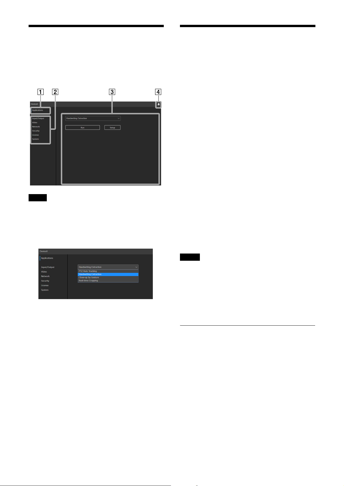
Screen Structure
The following screen appears in the web browser when
you access the unit.
You can configure the unit, and configure and run
applications from this screen.
Note
The initial setup screen appears by default when you
access the unit in its factory default state.
A [Applications]
Click to select, configure, or run an application.
Clicking displays the available applications.
Configuring Initial Setup Items
Access the unit in the factory default state, and configure
the following items.
[EULA]
Displays the EULA (End User License Agreement).
[Language]
Specify the display language of the screen. For details
about configuration, see “System” (page 18).
[Administrator]
Set [User Name] and [Password] for the administrator.
For details about configuration, see “Security”
(page 14).
[Network]
Configure the network settings for connection between
the unit and a computer. For details about configuration,
see “Network” (page 13).
[Date & Time]
Set the date and time on the unit. For details about
configuration, see “System” (page 18).
[System Frequency]
Set the system frequency for the unit to support. For
details about configuration, see “Video” (page 12).
Selecting an application displays the setup and run
screen of the application.
B Common settings menu
Click to configure common settings of the unit, such
as video and network settings.
C Operation/settings area
Displays the selected menu item screen or
application setup screen.
D Notifications button
A red indicator is displayed on the notifications
button when there is a notification relating to the
status of the unit. Click it to display the notifications
dialog.
Notes
• Be sure to change the default user name and password
used when you first start the unit. After changing the
user name and password, reauthentication using the
new user name and password is required.
• If the network settings are changed, access the unit
again using the changed network information.
• The unit must be restarted after completing the initial
setup.
Enabling option functions
Option functions must be enabled before configuring or
running an application. To enable an option function,
you must activate a pre-installed license or purchase and
install a license. For details about installing a license,
see “License” (page 17).
Licenses
The following option function licenses are available for
the unit.
• REA-L0100 Handwriting Extraction license
Enables the Handwriting Extraction function.
• REA-L0200 PTZ Auto Tracking license
Enables the PTZ Auto Tracking function.
• REA-L0300 Close-up by Gesture license
Enables the Close-up by Gesture function.
9
Page 10

Pre-installed licenses
You can trial test option functions by activating preinstalled licenses on the unit, without having to purchase
and install any licenses.
For details about activation, see “License” (page 17).
Notes
• Activating pre-installed licenses enables you to trial
test option functions for a limited time only.
• For details about purchasing licenses, contact your
distributor.
Starting applications
Access the unit from a web browser to select and run an
application.
A license may need to be enabled to run an application.
For details about configuring applications, see
“Application Setup and Operation” (page 21).
Tip
If the unit is turned off normally while an application is
running, the application will automatically restart the
next time the unit is turned on.
Checking notifications
You can check the status of the unit and the status of
connections with external devices in the notifications
dialog.
The notifications dialog is displayed automatically
when the status of the unit changes. You can also display
the dialog by clicking the notifications button at the top
right of the screen.
For details about notifications, see “Message List”
(page 31).
10
Page 11
Unit Setup (Common Settings)
This section describes the common settings of the unit
on each menu page.
This configuration is performed by the administrator.
Basic Operations in the Common Settings Menu
Click an item in the common settings menu on the left
side of the screen to display the setup screen for that
item.
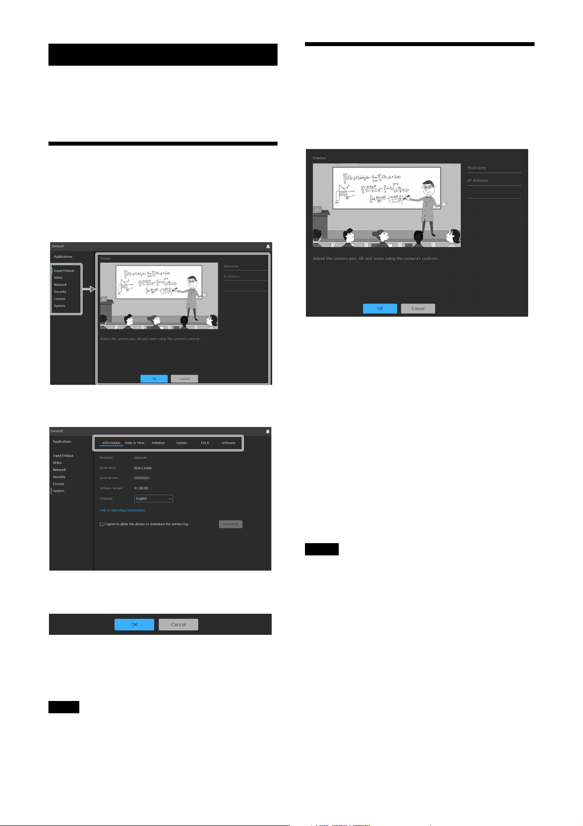
Input/Output
Use to configure the connected camera that supplies the
video input of the unit.
You can preview and adjust the video from the camera
or device connected to the HDMI IN 1 connector.
Preview image
When the camera or other video device connected to the
HDMI IN 1 connector is operating normally, a preview
of the image from the camera is displayed.
If the setup screen displays multiple tabs, click on a tab
to switch the display in the setup screen.
The following buttons at the bottom of the setup screen
are common for all items.
[OK]: Click to apply the settings. The settings are not
applied on the unit until you click this button.
[Cancel]: Click to discard the settings and return to the
previous state.
[Nickname]
Enter a nickname for the connected camera or device.
This is used as an identifier when configuring
applications.
[IP Address]
Enter the IP address of the remote camera to control a
Sony remote camera from the unit using VISCA over IP.
[Model Name]
Select the model name or enter an arbitrary model name
for the remote camera to control from the unit using
VISCA over IP.
Notes
• When using the PTZ Auto Tracking application, [IP
Address] and [Model Name] entry is required. If these
are left blank or the settings are incorrect, the
application may not function correctly.
• When using the Handwriting Extraction application,
you can use the remote camera functions in the
application by adding entries for [IP Address] and
[Model Name].
Note
Only those items that are currently configurable are
displayed. Items that are grayed out cannot be
configured. Functions that are not installed are not
displayed.
11
Page 12

Video
[1920×1080 / 50P]: Output at 1920×1080 50P.
(Available only when the system frequency is
50 Hz)
Use to configure the system frequency and output video
of the unit.
[System Frequency]
Select the system frequency.
[59.94Hz]: Supports input and output video in 59.94 Hz
systems.
[50Hz]: Supports input and output video in 50 Hz
systems.
Note
If the system frequency is changed, you must restart the
unit.
[Video Output 1]
Set the output image size and frame rate of the video
output from the HDMI OUT 1 connector.
[EDID]: Automatically determine and output a video
image that is compatible with the connected output
device.
[3840×2160 / 29.97P]: Output at 3840×2160 29.97P.
(Available only when the system frequency is
59.94 Hz)
[3840×2160 / 25P]: Output at 3840×2160 25P.
(Available only when the system frequency is
50 Hz)
[1920×1080 / 59.94P]: Output at 1920×1080 59.94P.
(Available only when the system frequency is
59.94 Hz)
[1920×1080 / 50P]: Output at 1920×1080 50P.
(Available only when the system frequency is
50 Hz)
[Video Output 2]
Set the output image size and frame rate of the video
output from the HDMI OUT 2 connector.
[EDID]: Automatically determine and output a video
image that is compatible with the connected output
device.
[1920×1080 / 59.94P]: Output at 1920×1080 59.94P.
(Available only when the system frequency is
59.94 Hz)
12
Page 13

Network
Use to configure the network settings for connection
between the unit and a computer.
To specify a fixed IP address (IPv4)
Clear the [Obtain an IP address automatically (DHCP)]
checkbox and enter the following items.
[IP Address]: Enter the IP address of the unit.
[Subnet Mask]: Enter the subnet mask value.
[Default Gateway]: Enter the default gateway.
To obtain an IP address (IPv6) automatically
Place a check mark in [Obtain IPv6 address
automatically] to automatically acquire the IP address,
prefix length, and default gateway.
[IPv6 Address 1] / [IPv6 Address 2]: Displays the
current IPv6 addresses.
[Link-Local IP Address]: Displays the current IPv6
link-local IP address.
[Prefix Length]: Displays the current prefix length.
[IPv6 Default Gateway]: Displays the current IPv6
default gateway.
Notes
• If you select [Obtain IPv6 address automatically],
check with the network administrator whether IPv6
assignment is supported.
• Operation in a multi-prefix environment is not
supported, and communication may not operate
correctly.
[MAC Address]: Displays the MAC address of the unit.
[Ethernet Status]: Displays the current
communications speed.
[HTTP Port Number]: Displays the port number for
HTTP.
[HTTPS Port Number]: Displays the port number for
HTTPS.
Note
The China model does not support the SSL function.
To obtain an IP address (IPv4) automatically
from a DHCP server
Place a check mark in [Obtain an IP address
automatically (DHCP)] to automatically acquire the IP
address, subnet mask, and default gateway.
[IP Address]: Displays the current IP address.
[Subnet Mask]: Displays the current subnet mask
value.
[Default Gateway]: Displays the current default
gateway.
Note
If you select [Obtain an IP address automatically
(DHCP)], check that a DHCP server is operating on the
network.
To specify a fixed IP address (IPv6)
Clear the [Obtain IPv6 address automatically] checkbox
and enter the following items.
[IPv6 Address 1]: Enter the IP address of the unit.
[Prefix Length]: Enter the prefix length.
[IPv6 Default Gateway]: Enter the default gateway.
To obtain the DNS server address
automatically
Place a check mark in [Obtain DNS server address
automatically] to automatically acquire the addresses of
the primary DNS server and secondary DNS server.
[Primary DNS Server]: Displays the current primary
DNS server IP address.
[Secondary DNS Server]: Displays the current
secondary DNS server IP address.
Note
To obtain the DNS server address automatically, either
[Obtain an IP address automatically (DHCP)] or [Obtain
IPv6 address automatically] must be enabled. Check
with the network administrator whether the environment
supports a server address being obtained automatically.
To specify the DNS server address manually
Clear the [Obtain DNS server address automatically]
checkbox and enter the following items.
[Primary DNS Server]: Enter the IP address of the
primary DNS server.
[Secondary DNS Server]: Enter the IP address of the
secondary DNS server.
13
Page 14

Security
Use to configure settings relating to security on the unit.
The screen consists of [User], [Access], [SSL], and
[Referer] tabs.
[User] tab
Use to configure users.
You can configure the user name, password, and user
access permissions of one administrator and nine
general users.
Notes
• The following characters are valid in user names and
passwords. Include at least one upper-case letter, one
lower-case letter, and one number in passwords.
– Alphanumeric characters
– Symbols (!$%'()=-~^|@`[{}]_/?<>+*.)
• A user name and new password must be configured
when adding a user.
• To change the user information, all items must be
specified again.
• When deleting a user, leave all fields other than
[Current Password] blank.
[Access] tab
Use to configure the security function to restrict the
computers that can access the unit.
Similarly, you can also configure security for each
network when using IPv6.
Administrator and general users
Users on the unit are categorized into administrator and
general users.
The administrator can access all functions of the unit,
including configuration of the unit and applications. A
general user has permission to monitor running
applications only.
[Administrator], [User 1] to [User 9]
Set the following items for the administrator and each
general user.
[User Name]: Enter a user name comprising 5 to 16
characters.
[Current Password]: Enter the currently configured
password comprising 8 to 64 characters.
[New Password]: Enter the new password you want to
set comprising 8 to 64 characters.
[Re-type Password]: Re-enter the new password you
want to set to verify the password.
Administrator permission selection: To grant
administrator access to a user, select
[Administrator]. To set a general user without
administrator access, select [User].
To enable IP address restrictions
Place a check mark in [Enable] for [Access restricted by
IP address], and configure the following items.
[Default Policy]
Select [Allow] or [Deny] to allow or deny access from
computers whose network address is outside the ranges
configured in [Network Address/Subnet 1] to [Network
Address/Subnet 10].
[Network Address/Subnet 1] to [Network
Address/Subnet 10]
Enter the network address/subnet mask value that you
want to allow or deny access.
You can specify up to ten network addresses and subnet
mask values.
Enter a subnet mask value of 8 to 32 (8 to 128 for IPv6).
Set access to [Allow] or [Deny] individually for each
network address/subnet mask.
14
Page 15

Tips
• The subnet mask value indicates the number of bits
that are masked off from the left. For example, the
subnet mask value for 255.255.255.0 is 24.
If you set “192.168.0.0/24” and [Allow], computers
having an IP address between 192.168.0.0 and
192.168.0.255 have access allowed.
• You can access the unit even from a computer with an
IP address whose access right is set to [Deny], if you
enter the user name and password set for the
Administrator using the [User] tab of the [Security]
page on the authentication screen.
[SSL] tab
To avoid this, check that SSL connection can be
established before configuration by performing the
following steps.
1
Set the SSL function to [Enable (Allow HTTP
connection for some clients)].
Note
Always select [Enable (Allow HTTP connection for
some clients)]. If it is not selected and the SSL
connection fails, you will not be able to access the
unit.
2
Click the [OK] button to close the web
browser.
Use to configure the SSL or TLS function (hereinafter
referred to as SSL). Configuring these settings allows
the unit to use SSL communication with client devices.
Notes
• The China model does not support the SSL function.
• When using the SSL function, always configure the
settings after setting the date and time of the unit. If
the date and time are not set correctly, it may not be
possible to connect to the unit using a web browser.
• Reload the web browser after you change the SSL
settings.
To enable the SSL function
Select [Enable] from the [SSL Function] pull-down
menu to enable the SSL function.
When [Enable (Allow HTTP connection for some
clients)] is selected, both SSL connections and HTTP
connections are allowed.
When [Enable] is selected, only SSL connections are
allowed.
3
Display the web browser using an SSL
connection.
4
After confirming that SSL connection is
possible, set the SSL function to [Enable].
Tip
If the SSL connection fails while checking the
connection, you can select [Enable (Allow HTTP
connection for some clients)] to connect using an HTTP
connection. Check the settings on the [SSL] tab using an
HTTP connection, and then check the SSL connection
again.
[Certificate Options]
Select the certificate installation mode.
[Use an external certificate]: This mode uses a
certificate (including private key information)
issued by a CA. PKCS#12 and PEM certificate
formats are supported.
[Use a self-signed certificate (For test use)]: This
mode uses a certificate and private key pair
generated as described in “To generate a self-signed
certificate” (page 16). The private key information
corresponding to the certificate is stored within the
unit.
You do not need to install an external certificate, but
validating its existence, which is one of the SSL
functions, is not possible for the following reasons.
• Self-signing uses the private key generated in the
unit.
• A preconfigured value is set for the Distinguished
Name (Common Name, and so on).
• The certificate is not issued by a CA trusted by the
customer’s system.
For reasons of security, we recommend using this
certificate only when there is no problem and a lack
of total security is not a concern, such as for testing.
Precautions with SSL connections
When you use only SSL connections with the SSL
function set to [Enable], you will not be able to access
the unit if the SSL function is not working properly.
In this case, you must reset the unit to the factory
settings. (All settings will be initialized.)
Notes
• When [Use a self-signed certificate (For test use)] is
selected, a security alert appears when initiating an
SSL connection with a web browser.
• SSL connection may not be possible depending on the
type of certificate installed in the unit.
15
Page 16

To import a certificate
Click the [Browse] button at the bottom right of the
setup screen and select the certificate. Click the [OK]
button in the file selection dialog to import the selected
file into the unit.
Note
The import process is invalid if the selected file is not a
certificate or if the format of the imported certificate is
not allowed.
To generate a self-signed certificate
A self-signed certificate must be generated when [Use a
self-signed certificate (For test use)] is selected in
[Certificate Options].
Click the [Generate] button to generate a self-signed
certificate in the unit.
Clicking the [Generate] button again after generating a
self-signed certificate will update the self-signed
certificate stored in the unit.
Notes
• Make sure to set the date and time on the unit before
performing this operation. If the date and time are not
set correctly, it may not be possible to connect to the
unit using a web browser.
• Before clicking the [Generate] button to generate a
self-signed certificate, select [Use a self-signed
certificate (For test use)] in [Certificate Options] and
click the [OK] button.
To display the certificate contents
When the certificate has been configured in the unit
correctly, information from the certificate appears in
[Status], [Issuer DN], [Subject DN], [Available Period],
and [Extended Key Usage].
[Status]
Displays whether the status of the certificate is valid or
invalid. The following status types are displayed.
[Valid]: The certificate is correctly stored and
configured.
[Invalid]: The certificate is not correctly stored and
configured. If invalid, possible causes are as
follows:
• [Use an external certificate] is selected but the
private key password included in the certificate is
not specified correctly.
• [Use an external certificate] is selected but the
private key included in the certificate is not
encrypted. Or the private key password is specified
but is not encrypted.
• [Use an external certificate] is selected but the
required private key is not included in the
certificate.
• [Use a self-signed certificate (For test use)] is
selected but a self-signed certificate has not been
generated.
Note
When the certificate to be imported is in PKCS#12
format and the private key password is not specified
correctly, “<Put correct private key password>” is
displayed in the [Issuer DN], [Subject DN], [Available
Period], and [Extended Key Usage] fields. Specify the
correct private key password.
To delete the imported certificate or self-signed
certificate
Click the [Delete] button on the setup screen to delete
the imported certificate or self-signed certificate.
To specify the private key password
Enter a password comprising up to 50 characters for the
private key included in the certificate in [Private Key
Password]. Entry is supported only when [Certificate
Options] is set to [Use an external certificate].
Leave the field for this parameter blank if the private key
included in the certificate is not encrypted.
To enter the private key password, click the [Reset]
button and enter a password.
Note
Click the [Cancel] button at the bottom of the screen if
you want to cancel changing the private key password
after clicking the [Reset] button. Note that clicking the
[Cancel] button also restores all other setting items on
the [SSL] tab to the previous settings.
[Referer] tab
Use the [Referer] tab to configure the Referer check
function. “Referer Check” is a function that checks
whether the web page which requested the access is
legitimate when the unit is accessed from an external
source. If the web page cannot be confirmed as
legitimate, access is denied.
If you want to access the unit from a web page other than
one that the unit provides, register the host name and
port number that hosts the web page on this tab.
To enable Referer check
Select [Enable] in [Referer Check]. The following items
can be configured when Referer check is enabled.
[No. 1] to [No. 10]: Register hosts that are not subjected
to the Referer check as an exception list.
16
Page 17

[Host Name]: Enter the host name or IP address of the
computer that hosts the web page you want to
register in the exception list.
[Port No.]: Enter the port number of the computer that
hosts the web page you want to register in the
exception list.
[Reset]: Reset the exceptions settings.
License
Configuration of licenses is required to activate option
functions on the unit.
The screen consists of [License] and [History] tabs.
[License] tab
[Installed Licenses]
Displays the option function name, status, installation
date and time, and validity period of installed licenses in
list view.
[Activate Pre-installed Licenses]
Click the [Activate] button to run activation for the
licenses pre-installed on the unit. Select the pre-installed
license you want to activate, and activate it to use the
option function for a limited time.
Notes
• The option function corresponding to an activated preinstalled license is enabled when the unit is restarted.
• The valid period countdown starts immediately after
activation, regardless of when the unit is restarted.
• The valid period of a pre-installed license is 60 days.
[Manage Licenses]
Displays the Unique Device ID and status of the
licenses.
To purchase a license and enable option
functions
You can use option functions by purchasing and
installing a license. Before performing this procedure,
purchase the license and then obtain a purchase code.
Note
For details about purchasing licenses, contact your
distributor.
17
Page 18

Perform steps 1 and 3 on the setup screen of the unit. In
step 2, access the specified site from a web browser on
a computer, and follow the instructions displayed on the
screen.
System
1
Access the device on which to use the
option function, and check [Unique Device
ID] on the [License] tab of the setup screen.
2
Access “Upgrade and License Management
Suite” from a web browser on the computer.
URL: https://ulms.sony.net
2-1 Follow the instructions displayed on the screen
to register a license purchase code and enter the
Unique Device ID obtained in step 1.
2-2 Download the issued license file (installation
key “RQ_LIC.DAT”).
3
Perform the following operations on the
setup screen.
3-1 Click the [Upload] button on the [License] tab,
and select the license file (installation key
“RQ_LIC.DAT”) downloaded in step 2-2.
3-2 Click the [OK] button in the file selection
dialog to import the file into the unit.
3-3 Click the [Install] button to install the license.
3-4 Restart the unit.
Notes
• The option function corresponding to the installed
license is enabled when the unit restarts.
• The Unique Device ID and license file are linked
together. When obtaining a license file, always enter
the Unique Device ID of the device on which the
option function will be used.
• The license cannot be installed correctly if the Unique
Device ID used to obtain the license file and the
Device Unique ID of the device on which the license
file is imported are different.
Use to configure the basic system settings of the unit.
The screen consists of [Information], [Date & Time],
[Initialize], [Update], [EULA], and [Software] tabs.
[Information] tab
[Nickname]
Displays the name of the device configured using
RM-IP Setup Tool.
[Model Name]
Displays the model name of the unit.
[Serial Number]
Displays the serial number of the unit.
[Software Version]
Displays the software version of the unit.
[Language]
Specify the display language of the screen. You can
select [Japanese], [English], or [Chinese].
[History] tab
Displays the log of the installed licenses. You can check
the option function name, license type, and installation
date and time for each license.
[Link to Operating Instructions]
Click the link to display the Operating Instructions (this
document).
To download the service log
You can download device information as a service log
used for service.
Place a check mark in [I agree to allow the device to
download the service log.] to enable the [Download]
button.
Click the [Download] button, then follow the
instructions in the displayed dialog to select a folder and
save the service log of the unit.
18
Page 19

[Date & Time] tab
[Current Date & Time]
Displays the set date and time of the unit.
Note
The date and time set at the time of purchase may not be
accurate. Always check the setting.
[PC Clock]
Displays the date and time of the computer being used.
[Date & Time Format]
Select the date and time format to display.
You can select [yyyy-mm-dd hh:mm:ss], [mm-dd-yyyy
hh:mm:ss], or [dd-mm-yyyy hh:mm:ss].
[Time Setting]
Select the method for setting the date and time.
[Keep current setting]: Select to keep the current
settings for the date and time of the unit.
[Synchronize with PC]: Select to synchronize the date
and time of the unit with the date and time of the
computer.
[Manual Setting]: Select to set the date and time of the
unit manually. Specify a value in the [Current Date
& Time] field.
[Synchronize with NTP]: Select to synchronize the
date and time of the unit with the NTP (Network
Time Protocol) server of a time server. If you select
[Synchronize with NTP], specify the NTP server.
To adjust for Daylight Savings Time
automatically
Place a check mark in [Automatically adjust for
Daylight Savings Time.] to automatically adjust the
time for daylight savings time (summer time) in the
selected time zone.
[Initialize] tab
[Restart]
Click the [Restart] button when you want to restart the
unit. Click the [OK] button in the displayed
confirmation dialog to restart the unit.
[Power Off]
Click the [Power Off] button when you want to shut
down the unit. Click the [OK] button in the displayed
confirmation dialog to shut down the unit.
Press the POWER button on the unit when you want to
turn the unit on again.
[Factory Reset]
Use this when you want to reset the unit to the factory
default settings. Click the [Factory Reset] button, and
click the [OK] button in the displayed confirmation
dialog to reset the settings to the factory default settings
and restart the unit.
You can reset the unit to its factory default settings using
the buttons on the unit (page 5).
To retain network settings
Place a check mark in [Retain current network settings]
to retain only the current network settings when
resetting the unit to the factory default settings. The
corresponding items are configured on the [Network]
and [Security] pages.
Note
Information relating to option function licenses is
retained even when a factory reset is performed.
[NTP Server]
Synchronize using the entered NTP server address.
[Time Zone]
Set the time zone for the region in which the unit is
installed relative to Greenwich Mean Time.
Note
If the time zone selected in [Time Zone] and the time
zone of the computer are different, a date and time
reflecting the difference in time zones is set on the unit.
[Update] tab
Use this to check and update the software version of the
unit.
19
Page 20

To update the software
Click the [Browse] button, select the firmware update
file, and click the [Run] button.
The unit restarts automatically, and the update is
executed.
[EULA] tab
Displays the EULA (End User License Agreement).
[Software] tab
Displays the software licenses used by the unit.
20
Page 21

Application Setup and Operation
Note
Option functions must be enabled before configuring or
running an application. To enable an option function,
you must activate a pre-installed license or purchase and
install a license. For details, see “[License] tab”
(page 17).
Configuring an Application
Configure application settings before running an
application. This configuration is performed by the
administrator.
Note
Connect the unit and external devices before
configuring the application. Disconnecting and
reconnecting an HDMI cable, turning HDMI devices
on/off, or switching video signals while configuring or
running an application may prevent the settings from
being configured successfully or adversely affect the
video output from the unit.
Running an application
After configuring an application, click the [Run] button
on the application screen to run the application.
1
Access the unit from a web browser.
For details about accessing the unit, see “Accessing
the Unit from a Web Browser” (page 8).
2
Select the application to configure from
[Applications].
3
Click the [Setup] button.
The application starts, and the setup screen for the
application appears.
Common application setup
operation
You can configure an application using the setup wizard
help guide displayed on the screen.
Press the [Next] button to move to the next screen of the
setup wizard, or the [Back] button to return to the
previous screen. Click the [Done] button to complete the
configuration.
To exit an application
While configuring or running an application, click [<] at
the top left of the screen or turn off the unit.
Tip
If the unit is turned off while an application is running,
the application will automatically restart the next time
the unit is accessed.
21
Page 22

Handwriting Extraction Application
This application identifies and extracts text and
diagrams drawn on a whiteboard or blackboard in realtime, and renders them so that they appear in front of the
speaker.
Note
The Handwriting Extraction option function must be
enabled before configuring or running the Handwriting
Extraction application. Activate the corresponding preinstalled license, or purchase and install a license.
Preparation before setup
3
Configure the following settings.
Extraction range
Move the four blue circles displayed on the preview
screen to select the target area (blackboard or
whiteboard) to extract. Take care to not select the
parts of the blackboard or whiteboard, such as the
frame, not related to the writing on the board.
1
Connect a camera to the HDMI IN 1
connector, and connect the device to which
you want to output the extracted image to
the HDMI OUT 1 connector.
2
Turn on the camera and peripheral devices.
Notes
• Adjust the position and field of view of the camera
connected to the HDMI IN 1 connector so that the
blackboard or whiteboard fits within the field of view
of the camera.
• Adjust the focus of the remote camera connected to
the HDMI IN 1 connector manually so that the whole
view of the blackboard or whiteboard to extract is in
focus. Adjust the white balance and exposure
manually according to the usage environment.
• When the remote camera configured in [Input/Output]
(page 11) is connected to the HDMI IN 1 connector
and configured correctly, the white balance and
exposure of the camera may be adjusted by the unit
according to the usage environment while the
application is running.
Configuring the Handwriting
Extraction application
Board color
Select the type of board for extraction.
[White]: White surface used for writing, such as a
whiteboard
[Black]: Dark surface used for writing, such as a
blackboard
Text color
Select how to display the extraction result for nonwhite text written on a blackboard.
This setting is enabled only when the board color is
set to [Black].
[Color]: White text on a blackboard is output as
black text, and non-white text on a blackboard is
output in color in the extraction result.
[Monochrome]: White text and non-white text are
both output as black text in the extraction result.
Overlap mode
Select whether to superimpose an image of the
person in the output over the writing when
extracting the handwriting.
You can change the overlap mode using the [Show
Person] checkbox. When the checkbox is cleared,
only the handwriting is extracted.
When [Show Person] is checked: Superimpose an
image of the person writing at the same time
when extracting the handwriting.
1
Select [Handwriting Extraction] from
[Applications].
2
Click the [Setup] button.
The setup screen appears. A preview of the image
from the camera connected to the HDMI IN 1
connector is displayed on the screen.
Note
If the camera image is not displayed, there may be a
problem with the camera connection or settings.
Check the connection and settings again.
22
Page 23

When [Show Person] is cleared: Output the
handwriting extraction only.
Person’s transparency
When the overlap mode is set to [Show Person], set
the transparency of the person to be superimposed
by sliding the bar left/right.
4
When finished, click the [Next] button.
5
Set the output image.
You can check the operating status of the
application in the bottom right of the screen while
the application is running.
[Handwriting Detected]: The contents on the
drawing board are being extracted.
[Trying to Detect Handwriting]: Extraction
cannot be achieved successfully at the current
time. Reset the extraction result up to the current
time, and start extracting again.
Notes
• Extraction may not start immediately after starting the
application due to extraction preprocessing.
• When running, you can change the overlap mode and
person’s transparency. However, the changes are not
saved in the settings.
• During extraction, the extraction may not be
successful if there are changes in the environment,
such as changes in the brightness of the room.
• The extraction may not be successful depending on
the resolution of the input image.
If you want to capture not just the extraction range
but also the person, the output range must be
widened keeping the extraction range in the center.
The output range is displayed by a blue frame on the
preview screen. Move the bar left/right to change
the output range with the extraction range in the
center.
This setting is enabled when the overlap mode is set
to [Show Person].
6
When finished, click the [Done] button.
The setup is saved in the unit.
Running the Handwriting
Extraction application
Run this application to extract text and drawings from a
specified drawing board area from the input video and
then output the extracted video.
1
Select [Handwriting Extraction] from
[Applications].
2
Click the [Run] button.
The run screen appears.
You can check the video that is output using the
preview image while the application is running.
23
Page 24

PTZ Auto Tracking Application
Note
If the camera image is not displayed, there may be a
problem with the camera connection or settings.
Check the connection and settings again.
This application tracks a moving target, and
automatically moves a remote camera to maintain
optimum composition while shooting.
Note
The PTZ Auto Tracking option function must be
enabled before configuring or running the PTZ Auto
Tracking application. Activate the corresponding preinstalled license, or purchase and install a license.
Preparation before setup
1
Connect a camera to the HDMI IN 1
connector, and connect the device to which
you want to output the tracking image to the
HDMI OUT 1 connector.
Connect the unit and remote camera to a network so
that they can communicate using VISCA over IP to
control the camera from the unit. Connect using a
network connection, as shown in “System
Configuration” (page 6).
2
Turn on the camera and peripheral devices.
Camera PTZ (pan, tilt, zoom) operation
You can control the PTZ movement of the camera
on each of the following setup screens. The controls
are common to all screens, but PTZ operations may
be grayed out depending on the settings.
Zoom control
Pan and tilt control
3
Configure the following settings.
Notes
• The settings of the remote camera to be connected
must be configured beforehand as described in
“Input/Output” (page 11).
• It is recommended that the focus, white balance,
and exposure of the remote camera be set to Auto
beforehand.
• The zoom function of the remote camera uses the
optical zoom range only.
• Remote camera settings may be changed from the
unit while the application is running.
• The PTZ Auto Tracking application supports the
following Sony remote cameras.
SRG-300H, SRG-301H, BRC-X1000,
BRC-H800, BRC-H780, SRG-120DH,
SRG-121DH
• For details about other supported remote cameras,
contact your distributor.
Configuring the PTZ Auto Tracking
application
1
Select [PTZ Auto Tracking] from
[Applications].
Tracking mode
Select the tracking mode used for automatic
tracking.
[Free Object Pan Tracking]: Track the person
moving to the left/right in front of the
blackboard or screen.
[Fixed Frame Pan Tracking]: Track the person
moving to the left/right in front of the
blackboard or screen while giving priority to
keeping the contents of the board within the
field of view.
Distortion correction
If the screen movement does not stay level when
panning, due to the remote camera position, size of
the room, or other setup conditions, enable [Correct
for Distortion] so that the screen motion stays level.
2
Click the [Setup] button.
The setup screen appears. A preview of the image
from the camera connected to the HDMI IN 1
connector is displayed on the screen.
Note
To apply the appropriate correction, set appropriate
values for the camera position setup in step 5.
24
Page 25

4
When finished, click the [Next] button.
5
Configure the following settings.
Tracking object size
Select the size of the object to keep within the image
during tracking.
This can be configured when the tracking mode is
set to [Free Object Pan Tracking]. It is not displayed
when the tracking mode is set to [Fixed Frame Pan
Tracking].
[Full Body]: Keep the full body of the person to be
tracked within the image.
[Upper Body]: Keep the upper half of the person to
be tracked within the image.
Tips
• The person to be tracked is assumed to move
across the front of the blackboard or screen.
• Select the units for Depth, Height, and Offset
when entering values.
• The horizontal offset distance is 0 when the
remote camera forward direction (0° pan angle
direction) is parallel to the perpendicular line from
the blackboard or screen (directly opposite).
• When the tracking mode is set to [Free Object Pan
Tracking], the unit automatically controls the
zoom position of the remote camera and
determines the field of view in the zoom direction.
6
When finished, click the [Next] button.
7
Configure the following settings.
Camera position
Set the distance from the remote camera to the
blackboard or screen, the height from the person’s
feet, and the offset.
[Depth]: Specify the horizontal distance from the
remote camera to the blackboard or screen (refer
to “Depth” dimension in the following
diagram).
[Height]: Specify the vertical distance from the feet
of the person to be tracked to the remote camera
(refer to “Height” dimension in the following
diagram).
[Offset]: Specify the horizontal offset distance
when the remote camera forward direction (0°
pan angle direction) is at an angle to the
perpendicular line from the blackboard or
screen (refer to “Offset” dimension in the
following diagram).
Home position
Operate the remote camera using the PTZ controls
to move to the camera position (home position)
where detection of a person will start. Tracking
operation starts from the home position.
Note
When the tracking mode is set to [Fixed Frame Pan
Tracking], the recovery position (page 26) cannot be
set, so set the home position while taking the area of
the board to keep within the image during tracking
into consideration. Also, set the home position while
taking the detection area within the home position,
set in step 9, into consideration.
8
When finished, click the [Next] button.
9
Configure the following settings.
25
Page 26

Detection area
Move the four blue circles displayed on the preview
screen to mark the detection area for tracking within
the home position.
A person will be tracked when they enter this area.
Sensitivity
Set the response sensitivity for tracking when the
person to track starts to move.
[Normal]: Respond with standard sensitivity.
[Sensitive]: Respond with higher sensitivity than
the [Normal] setting.
13
Configure the following settings.
Start tracking automatically
Place a check mark in [Start Tracking
Automatically] to automatically start tracking when
a person is detected within the home position
detection area. Leave the checkbox empty when you
want to start tracking manually.
Also, always set [Tracking Start Time] for
automatic tracking.
Tracking start time
Automatic tracking starts when a person has been
captured continuously for a duration exceeding the
time set in [Tracking Start Time].
10
When finished, click the [Next] button.
11
Configure the following settings.
PTZ limits
Specify the range of the pan operation of the camera
during tracking. If a range is not specified or the
specified range is invalid, the unit automatically sets
the range for pan operations.
This can be configured when the tracking mode is
set to [Free Object Pan Tracking]. It is not
configurable when the tracking mode is set to [Fixed
Frame Pan Tracking].
14
When finished, click the [Next] button.
15
Configure the following settings.
When the tracking mode is set to [Free
Object Pan Tracking]
Mask
Set the mask areas in order to prevent false detection
of objects other than the person to be tracked during
tracking.
Move the four gray circles displayed on the preview
screen, as required, to adjust the height to
effectively narrow the detection area during
tracking.
The mask areas are excluded from the detection
target during tracking.
Note
The mask areas must not cover the area specified for
the home position detection area.
12
When finished, click the [Next] button.
Recovery position
Set the camera position, using the PTZ controls, to
move the camera to where detection is resumed
when the person is no longer visible and tracking is
lost during tracking.
This can be configured when the tracking mode is
set to [Free Object Pan Tracking]. It is not
configurable when the tracking mode is set to [Fixed
Frame Pan Tracking].
After tracking is lost, the camera moves to the
recovery position and detection restarts. After
redetection, tracking restarts automatically when a
person has been captured continuously for a
duration exceeding the time set in [Tracking Start
Time].
Note
It is recommended that you set the camera view for
the recovery position to a slightly wider view than
the home position, but re-detection and tracking
26
Page 27

may not start correctly depending on the configured
position.
Tracking lost wait time
Set the wait time from when the person being
tracked is no longer visible until tracking is deemed
to be lost.
This can be configured when the tracking mode is
set to [Free Object Pan Tracking]. It is not
configurable when the tracking mode is set to [Fixed
Frame Pan Tracking].
When the tracking mode is set to [Fixed
Frame Pan Tracking]
Board limits
When the tracking mode is set to [Fixed Frame Pan
Tracking], the person is tracked while moving left/
right in front of the blackboard or screen while
giving priority to keeping the contents of the board
within the field of view.
Move the four blue circles displayed on the preview
screen to set the board limits to define the capture
area to be maintained on the screen when panning.
16
When finished, click the [Done] button.
The setup is saved in the unit.
You can check the operating status of the
application in the bottom right of the screen while
the application is running.
[Detecting]: Person is detected at the home
position. A face frame is attached to the person.
[Tap on Target Face]: In this state, you can select
the face frame of a person to be tracked
manually. Select a face frame.
[Tracking]: Person was detected and is being
tracked.
[Target Lost]: Person being tracked is no longer
visible and tracking has been lost. If the tracking
mode is set to [Free Object Pan Tracking], the
camera moves to the recovery position and
detection restarts.
To start tracking manually
When [Start Tracking Automatically] is disabled, you
must select the person to be tracked manually while the
application is in the [Tap on Target Face] state.
When [Start Tracking Automatically] is enabled, you
can also select a person while the application is in the
[Detecting] state, before tracking normally starts, to start
tracking that person manually.
In either case, select a displayed face frame to select the
target.
Running the PTZ Auto Tracking
application
Run this application to track a person captured by the
camera, according to the setup, and to output the
tracking image.
1
Select [PTZ Auto Tracking] from
[Applications].
2
Click the [Run] button.
The run screen appears.
You can check the video that is output using the
preview image while the application is running.
To return to the home position
Tracking a person may not be successful occasionally,
depending on their movement or clothing. When the unit
can no longer track correctly, the unit automatically
attempts to re-detect a person. You can also click the
[Reset Camera] button to restart tracking detection from
the home position.
27
Page 28

Close-up by Gesture Application
This application interprets specific gestures of a person,
from the video, and automatically zooms in on the
corresponding area. You can display two images (a wide
angle view and zoomed view) in real-time.
The function is triggered on when a person stands up
from a seated position. The application electronically
zooms in on the area around that person (a close-up) and
outputs the zoomed image. When the person sits down,
the function is triggered off, the zoom is canceled, and
the image returns to the previous state. The original
image can also be output at the same time as the zoomed
image.
Note
The Close-up by Gesture option function must be
enabled before configuring or running the Close-up by
Gesture application. Activate the corresponding preinstalled license, or purchase and install a license.
Preparation before setup
1
Connect a camera to the HDMI IN 1
connector, and connect video output
devices to the HDMI OUT 1 and HDMI OUT 2
connectors.
The video input on the HDMI IN 1 connector is
output unchanged from the HDMI OUT 1
connector. The automatic zoomed close-up image is
simultaneously output from the HDMI OUT 2
connector. Connect appropriate output devices to
each output.
2
Click the [Setup] button.
The setup screen appears. A preview of the image
from the camera connected to the HDMI IN 1
connector is displayed on the screen.
Note
If the camera image is not displayed, there may be a
problem with the camera connection or settings.
Check the connection and settings again.
3
Configure the following settings.
Detection area
Move the four blue circles displayed on the preview
screen to mark the detection area for detecting the
stand-up and sit-down triggers.
Make the detection area large enough to show the
person’s face when they are standing.
The dotted blue line indicates the area previously
set.
[Duration Time]
Set the maximum close-up duration for when the
image is zoomed in response to a stand-up trigger.
The zoom is automatically canceled when the closeup duration elapses, if a sit-down trigger is not
detected beforehand.
2
Turn on the camera and peripheral devices.
Tips
• Position and configure the camera connected to
the HDMI IN 1 connector beforehand so that the
image captures the area to detect when a person
stands or sits.
• It is recommended that the focus, white balance,
and exposure of the camera connected to the
HDMI IN 1 connector be set to Auto beforehand.
• A camera that supports 4K (3840×2160) output is
recommended.
Configuring the Close-up by
Gesture application
1
Select [Close-up by Gesture] from
[Applications].
Sensitivity
Select the sensitivity for detection of the stand-up
and sit-down gesture trigger actions.
[Weak]: Sensitivity weaker than [Medium].
[Medium]: Standard sensitivity of the unit.
[Strong]: Respond with higher sensitivity than the
[Medium] setting.
4
When finished, click the [Next] button.
5
Maximum and minimum sizes for detection
28
Page 29

Set the maximum size and minimum size of the
screen that would be fully occupied by a person
when standing.
Move the four blue circles displayed on the preview
screen to mark the maximum size. Move the four
purple circles displayed on the preview screen to
mark the minimum size.
This is used to distinguish between the difference in
size that occurs between a person standing near the
front and a person standing further away when
viewed from the camera.
6
When finished, click the [Done] button.
The setup is saved in the unit.
Running the Close-up by Gesture
Real-time Cropping Application
This application simultaneously displays a wide-angle
view and a cropped view, from a single camera, by
cutting out a desired portion of the whole view in realtime.
Tip
The Real-time Cropping application can be configured
and run without an option license for the Real-time
Cropping application.
application
Run this application to automatically trigger the zoom
function when a person stands up and to cancel the zoom
when a person sits down.
1
Select [Close-up by Gesture] from
[Applications].
2
Click the [Run] button on the screen.
The run screen appears.
When zoom is active, the normal image is shown on
the right and the close-up image is shown on the left.
Preparation before setup
1
Connect a camera to the HDMI IN 1
connector, and connect video output
devices to the HDMI OUT 1 and HDMI OUT 2
connectors.
The video input on the HDMI IN 1 connector is
output unchanged from the HDMI OUT 1
connector. The cropped image is simultaneously
output from the HDMI OUT 2 connector. Connect
appropriate devices to each output.
2
Turn on the camera and peripheral devices.
Tips
• Position and configure the camera connected to
the HDMI IN 1 connector beforehand so that the
field of view captures the area to crop.
• A camera that supports 4K (3840×2160) output is
recommended.
Configuring the Real-time
Cropping application
Notes
• The close-up operation may not function correctly if
the focus or exposure is not properly set for the
detection area image captured by the camera.
• The close-up operation may not function correctly
depending on the density of people in the detection
area, the size of the person, and the attire of the person.
• The resolution of the close-up output image may be
reduced depending on the resolution of the input
image from the camera and the close-up zoom
magnification.
29
1
Select [Real-time Cropping] from
[Applications].
2
Click the [Setup] button.
The setup screen appears. A preview of the image
from the camera connected to the HDMI IN 1
connector is displayed on the screen.
Note
If the camera image is not displayed, there may be a
problem with the camera connection or settings.
Check the connection and settings again.
Page 30

3
Configure the following settings.
Crop area position
Move the blue frame displayed on the preview
screen to specify the crop position.
Crop area size
Move the four blue circles displayed on the preview
screen to specify the size of the crop area.
4
When finished, click the [Done] button.
The setup is saved in the unit.
Running the Real-time Cropping
application
Run this application to simulate the output of two
cameras by showing a main image and a cropped image.
1
Select [Real-time Cropping] from
[Applications].
2
Click the [Run] button.
The run screen appears.
The normal image is shown on the right and the
cropped image is shown on the left.
Notes
• You can change the crop area position while the
application is running, but the changes are not saved
in the settings.
• The resolution of the close-up output image may be
reduced depending on the resolution of the input
image from the camera.
30
Page 31

Appendix
Message List
The following messages may appear on the unit. Perform the following as necessary.
LED indicators
LED Meaning and solution
STATUS LED is red The unit is not connected to the network. Check the network cable connection.
STATUS LED is flashing red A problem, such as high temperature, occurred in the unit. Turn off the unit and
allow it to cool before turning the unit on again.
POWER LED is green and STATUS LED is
off
Web browser display
If this state occurs after the unit is powered on, the unit did not start up correctly.
Disconnect the AC adapter, and then reconnect it to turn the unit on.
Message Meaning and solution
The device’s temperature is high. Shut down
the device and wait until it has cooled off
before proceeding.
No HDMI Input Signal
There is no HDMI input signal. Correctly
connect a device with an HDMI signal.
Incorrect HDMI
Input The HDMI Input signal format is
incorrect. Switch the HDMI input signal.
Copyrighted Input
Cannot display copyrighted signals (HDCP).
Change the input signal.
License Will Expire
The license will expire soon. Please renew the
license.
The license for operating the application is
invalid. Please validate the license.
Check the software version. Check that the software update was completed successfully or check the software
Connected camera is not compatible.
Connect a compatible camera.
A PTZ capable camera is not connected. The camera may not be connected properly using a network cable or the camera
Power off the unit and wait until it has cooled down. Check that the temperature
has decreased before connecting the power again to start the unit.
There may not be an input device connected correctly to the HDMI IN connector.
Check the input device and its connection.
The HDMI input signal may not be in a format supported on the unit.
Check the input signal.
An input signal protected using HDCP may have been input on HDMI IN.
Check that the input signal is not protected using HDCP.
The license for the currently active option function will expire soon. To continue
using the option function, purchase and activate a license.
An option function license required for the application has not been installed.
Activate a pre-installed license, or purchase and install a license.
version.
An application may not function because a camera that is not compatible is
connected to the unit. Check the camera. Also, check that the camera to be
connected is configured correctly in [Input/Output] (page 11).
may be turned off. Check the connection status and power source. Also, check
that the camera to be connected is configured correctly in [Input/Output]
(page 11).
31
Page 32

Troubleshooting
Before requesting service, check the following as a guide to troubleshooting the problem. If the problem persists,
consult your Sony dealer.
Symptom Cause Solution
The unit does not turn on. The AC adapter is not firmly connected to the
power connector.
The power cord is not firmly connected to the
AC adapter or the power outlet.
There is no picture on
monitor or external device
connected to the HDMI
output.
An application will not run. The option function required for the
Cannot install a license. The correct license file for the target device is
Cannot connect to the
network.
The problem persists after
trying all solutions.
The HDMI cable is not connected correctly. Check the input, external device, and their
The HDMI output video format is not set
correctly.
The camera or other device connected to the
HDMI input may not be turned on.
The output video format of the camera or other
device connected to the HDMI input is not set
correctly.
application is not enabled.
not installed.
— Check that the network cables are connected
— Enable DHCP on your router.
— A network cable may be damaged. Replace
— Disconnect the power cord plug from the AC
Insert the power cord firmly as far as it will go.
Insert the power cord firmly as far as it will go.
connection.
Check the output video format of the unit and the
input video format of the external device.
Check the power source of the camera or other
connected device.
Check the output video format of the camera or
other device.
Purchase and install a license or activate a preinstalled license to enable the option function.
The Unique Device ID used when the license file
was issued may not have been specified correctly.
Check the Unique Device ID on the [License]
screen.
correctly to the unit, router, and computer.
damaged cables.
outlet, then reinsert it into the AC outlet after
waiting a while.
32
Page 33

About Use of GNU GPL/ LGPL Software
This product uses software to which the GNU General
Public License (GPL) or GNU Lesser General Public
License (LGPL) applies. This informs you that you have
a right to have access to, modify, and redistribute source
code for these software programs under the conditions
of the GPL/LGPL.
The source code is provided on the internet. Use the
following URL and follow the download instructions.
http://oss.sony.net/Products/Linux
We would prefer that you do not contact us about the
contents of the source code.
Specifications
Video input signal
HDMI IN 1 connector
3840×2160/29.97p
1920×1080/59.94p
3840×2160/25p
1920×1080/50p
HDMI IN 2 connector
1920×1080/59.94p
1920×1080/50p
Video output signal
HDMI OUT 1 connector
3840×2160/29.97p
1920×1080/59.94p
3840×2160/25p
1920×1080/50p
HDMI OUT 2 connector
1920×1080/59.94p
1920×1080/50p
Audio input
MIC IN connector
Stereo, ø3.5 mm mini jack,
plug in power 5 V (1)
Note
Not supported in the current software version.
Input/output connectors
HDMI IN 1 / HDMI IN 2 connectors
HDMI connector (Type A) (2)
HDMI OUT 1 / HDMI OUT 2 connectors
HDMI connector (Type A) (2)
LAN RJ-45 (1000BASE-T/100BASE-TX/
10BASE-T)
Power IEC 60130-10 Type A (5.5 mm outer
diameter, 2.5 mm inner diameter)
General
Input voltage 12 V DC (Use an AC adapter (not
supplied))
Power consumption
40 W with 12 V DC input
Operating temperature
5
°C to 40 °C (41 °F to 104 °F)
Storage temperature
–20
°C to +55 °C (–4 °F to +131 °F)
External dimensions
See “External Dimensions” (page 34).
Mass Approx. 860 g (1 lb 14 oz)
Design and specifications are subject to change without
notice.
33
Page 34

External Dimensions
)97 (3
8
/
5
91 (3
)
8
/
7
141 (5
Unit: mm (inches)
5
/8)
1) 1)
15.5 (5/8) 110 (4 3/8)
)
32
/
23
50 (2) 18 (
1) 1)
1) Mounting screw holes (M3)
34
Page 35

Sony Corporation
 Loading...