

Page 1
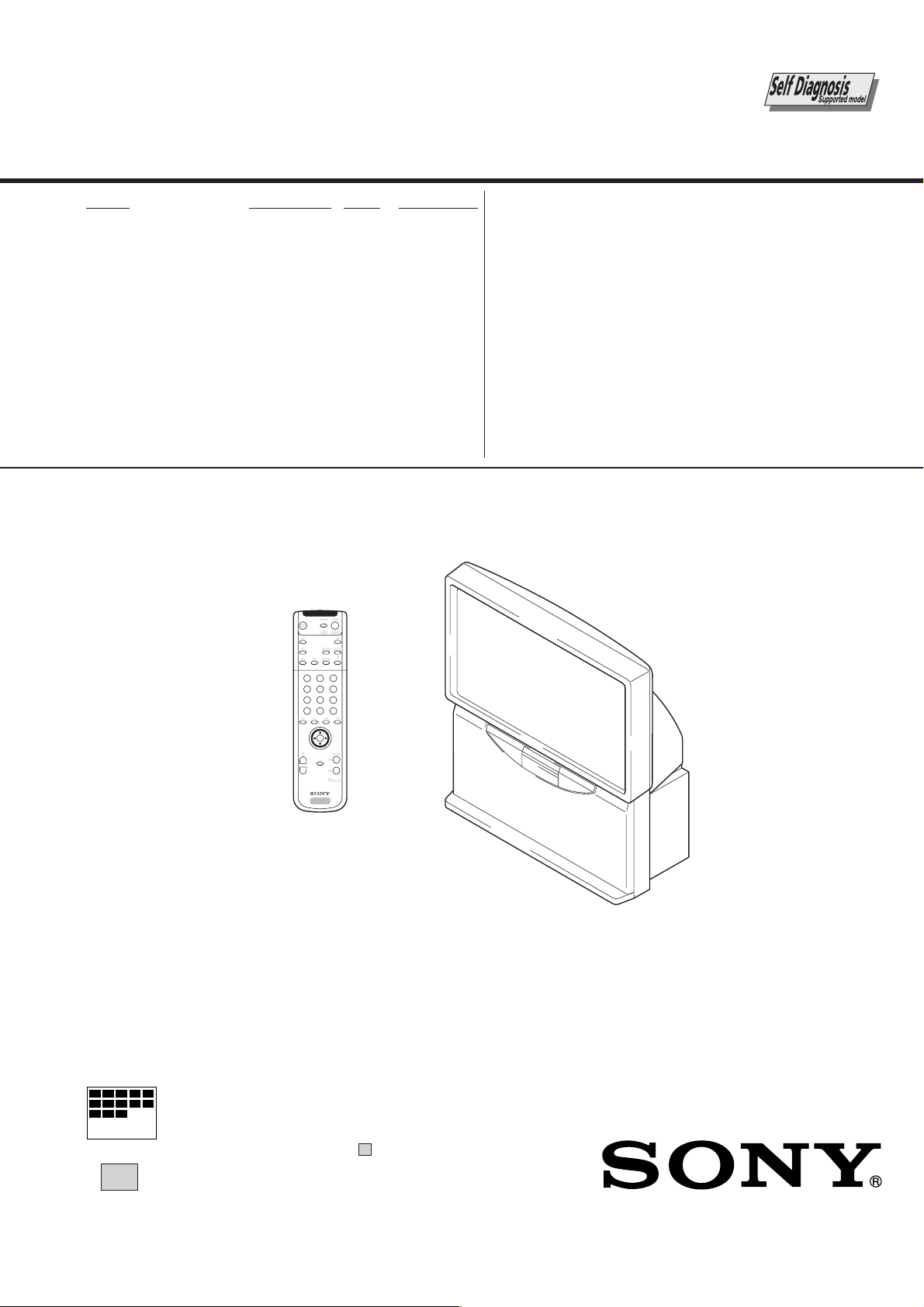
SERVICE MANUAL
MODEL COMMANDER DEST. CHASSIS NO.
RE-2D
CHASSIS
KP-41DS1U
KP-41PZ1B
KP-41PZ1D
KP-41PZ1E
RM-892 UK SCC-P26A-A
RM-892 AEP SCC-P23A-A
RM-892 FR SCC-P22A-A
RM-892 AEP SCC-P22B-A
2
3
1
6
5
4
9
7
8
0
OK
RM-892
MICROFILM
∗ Please file according to model size. ...
41
PROJECTION TV
Page 2
KP-41DS1U/PZ1B/PZ1D/PZ1E
RM-892
SECTION 6
REGISTRATION ADJUSTMENTS
6-1. HOW TO ENTER THE SERVICE MODE
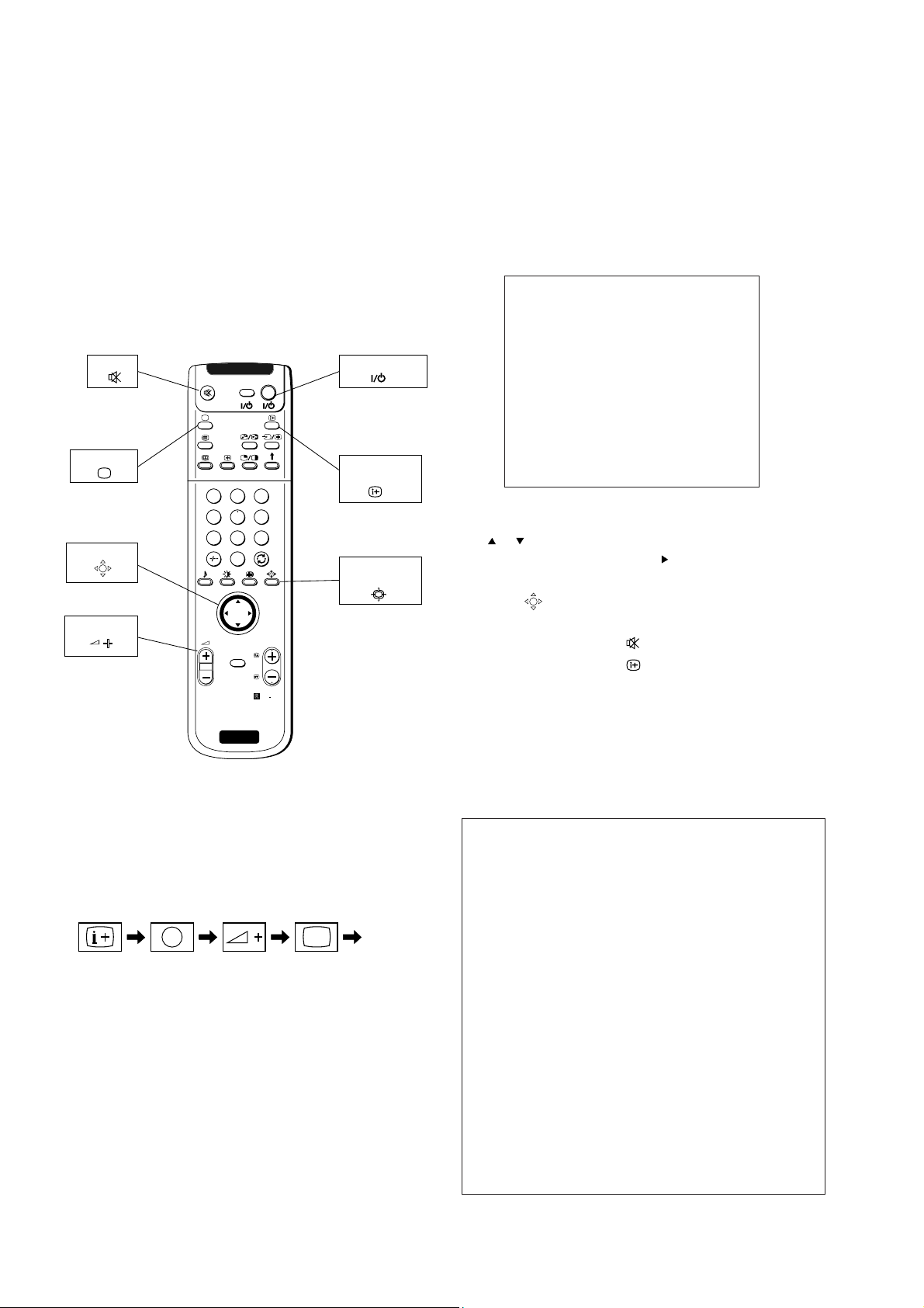
6-1-1. Adjustment Method with Commander
Service adjustment to this model can performed with the supplied remote commander RM-892.
MUTE
TV MODE
JOYSTICK
VOLUME +
1
4
7
2
5
8
0
OK
MENU
SONY
TV
VIDE O TV
3
6
9
PROGR
RM
892
TV STANDBY
ON SCREEN
DISPLAY
SMART/4:3/
ZOOM/WIDE
3. Press “MENU” on the commander to obtain the following
menu on the screen.
TEST MENU
Picture Adjustment
Geometry
Wide
IC Status
MSP
Dynamic Convergence
Current TV Status
Convergence
4. Move to the corresponding adjustment using the joystick
(
or : up or down) on the commander.
5. Move the joystick to the right (
) to enter the selected
adjustment.
6. Press “
(OK)” to exit.
7. Before TURN OFF is necessary:
DATA WRITE : Press “
DATA COPY : Press “
(MUTE)” + “-”
(ON SCREEN DISPLAY)”
+ “-”
8. Turn off the power to quit the service mode when adjustments are completed.
RM-892
1. Turn on the main power switch of the set and enter into
standby mode.
2. Press the following sequence of buttons on the Remote
Commander.
Enter the
“TT MODE”
(
DISPLAY
5
(DIGIT 5) (VOLUME +) (TV MODE)ON SCREEN
)
“TT - -” will appear in the top right corner of the screen.
Other status information will also be displayed.
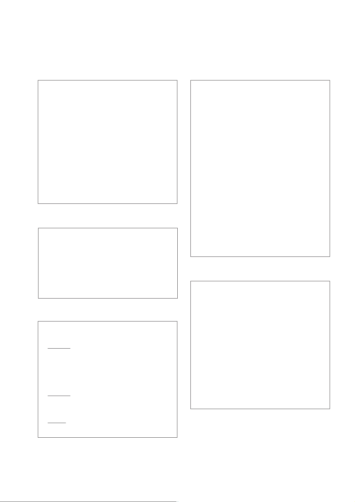
6-1-2. Screen Display on the Test Menu
Picture Adjustment
PICTURE ADJUSTMENT
AFC Mode 1 0 - 3
Ref Position 2 0 - 3
SCP BGR 1 0 - 3
SCP BGF 1 0 - 3
Trap F0 9 0 - 15
Sub Contrast 8 0 - 15
Sub Colour 4 0 - 15
Sub Brightness 16 0 - 63
Green Drive 16 0 - 63
Blue Drive 39 0 - 63
Green Cutoff 6 0 - 15
Blue Cutoff 12 0 - 15
Gamma 0 0 - 3
Pre / Overshoot 3 0 - 3
Y Delay 6 0 - 7
D Pic ON ON/OFF
D Colur ON ON/OFF
DC Transfer OFF ON/OFF
– 50 –
Page 3
KP-41DS1U/PZ1B/PZ1D/PZ1E
RM-892
Geometry (* : No need to adjust)
GEOMETRY ADJUSTMENT
Wide Smart 4:3 Zoom
V Size 50 50 50 50 0 - 63
V Position 31 31 31 31 0 - 63
S Correction 77770 - 15
V Linearity 77770 - 15
H Size 40 40 40 40 0 - 63
H Position 12 12 8 12 0 - 15
*
Pin Amp 20 20 20 20 0 - 63
Pin Phase 88880 - 15
AFC Bow 77770 - 15
AFC Angle 77770 - 15
EHT V 00000 - 3
*
EHT H 00000 - 3
*
Lo Corn Pin22220 - 15
Up Corn Pin55550 - 15
Wide (* : No need to adjust)
WIDE ADJUSTMENT
Wide Smart Zoom
V Aspect 0 15 47 0 - 63
*
V Scroll 31 31 30 0 - 63
*
Upper V Lin 0000 - 15
*
Lower V Lin0000 - 15
*
Left Blanking 15 15 15 0 - 15
*
Right Blanking 15 15 15 0 - 15
*
MSP
MSP ADJUSTMENT
SDR 1 CONCCT 0 FAWCTIST 12
AGC On / Off ON ON/OFF
Constant Gain CDB 0 0 - 20
FM Prescale FMP 36 0 - 127
Zwei Mono-St WHI 36 0 - 127
Zwei St-Mono WLO 18 0 - 127
Zwei Mono-Bi WMH 36 0 - 127
Zwei Bi-Mono WLO 18 0 - 127
Time Zwei WML 41 0 - 127
FAWCT Limit 10 0 - 127
FAWCT Soll Init FAW 12 0 - 127
FAW ER Tol 2 0 - 127
NICAM Err Max CCT 10 0 - 127
NICAM Err Min 0 0 - 127
Time NICAM 26 0 - 127
Audio Clock ACO HIZ ON/HIZ
SCART Prescale 25 0 - 127
SCART Volume 64 0 - 127
NICAM Prescale I 127 0 - 127
NICAM Prescale L 97 0 - 127
NICAM Prescale BG 97 0 - 127
NICAM Prescale DK 97 0 - 127
Dynamic Convergence
DYNAMIC CONVERGENCE
IC Status
IC STATUS (CXA2000 / CXA2040)
CXA2000
H lock 1
IKR 1
V NG 0
XRAY 0
Colour System 2
CV1 Sync 0
CXA2040
Sync Sep 1
S1 Mode Pin 01
S2 Mode Pin 01
TUNER
Tuner Status 01000010
Range 0 0 - 42
H stat 0 OFF - 63
H amp l 0 OFF - 63
H amp r 0 OFF - 63
Up Y 0 OFF - 63
Low Y 0 OFF - 63
Y up l 0 OFF - 63
Y up r 0 OFF - 63
Y low l 0 OFF - 63
Y low r 0 OFF - 63
Mbow up l 0 OFF - 63
Mbow up r 0 OFF - 63
Mbow low l 0 OFF - 63
Mbow low r 0 OFF - 63
V stat 0 OFF - 63
– 51 –
 Loading...