

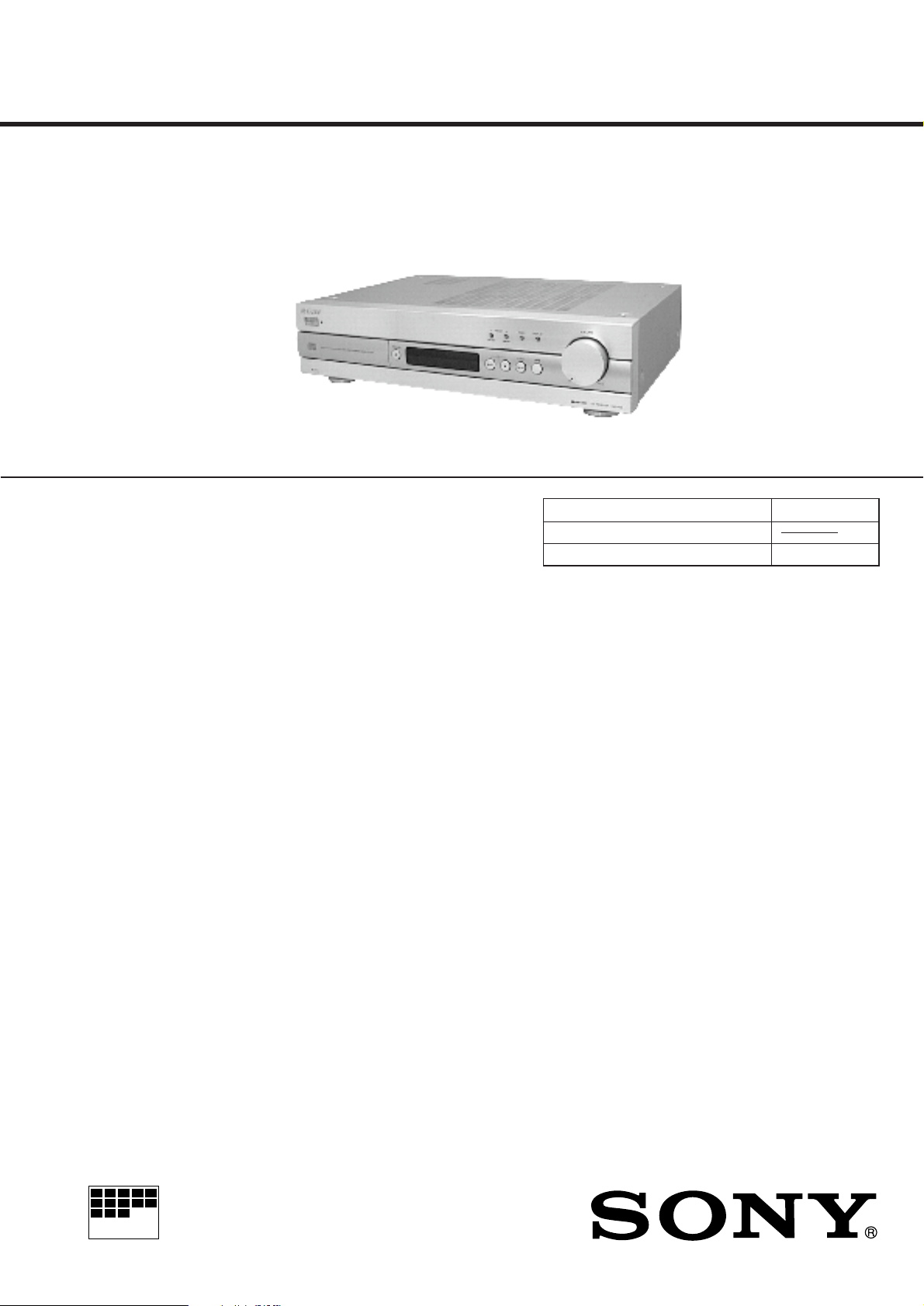
RXD-700
SERVICE MANUAL
SPECIFICATIONS
AEP Model
UK Model
Model Name Using Similar Mechanism NEW
CD Drive Mechanism Type
Optical Pick-up Name KSS-213C/Q-RP
Amplifier section
Continuous RMS power output
55 + 55 watts
(4 ohms at 1 kHz, 0.7% THD)
Inputs
TAPE LINE IN (phono jacks):
sensitivity 150 mV, impedance 50
kilohms
Outputs
TAPE REC OUT (phono jacks):
150 mV, 4.7 kilohms
SPEAKER: accepts impedance of 4 to 16 ohms,
8 to 16 ohms (SPEAKER A + B).
CD player section
System Compact disc and digital audio system
Laser Semiconductor laser
(λ = 780 nm)
Emission duration: continuous
Laser output Max. 44.6 µW*
* This output is the value measured at
a distance of 200 mm from the
objective lens surface on the Optical
Pick-up Block with 7 mm aperture.
Wavelength 780 - 790 nm
Frequency response 20 Hz - 20 kHz (± 0.5 dB)
Signal-to-noise ratio More than 114 dB
Dynamic range More than 100 dB
Harmonic distortion Less than 0.003 %
Channel separation More than 108 dB (1 kHz, 20 kHz LPF)
Tuner section
FM stereo, FM/AM superheterodyne tuner
FM tuner section
Tuning range 87.5 - 108.0 MHz
Aerial FM wire aerial
Aerial terminals 75 ohm unbalanced
Intermediate frequency 10.7 MHz
Sensitivity at 26 dB quieting
Usable sensitivity (IHF) 10.3 dBf, 0.9 µV/ 75 ohms
S/N at 40 kHz deviation
Harmonic distortion
at 1 kHz Mono: 0.04%
Separation 45 dB at 1 kHz
Frequency response 30 Hz - 15 kHz (+0.3/-0.7)
(50 kHz step)
(mono) 10.3 dBf, 0.9 µV/ 75 ohms
at 46 dB quieting
(stereo) 38.5 dBf, 23 µV/ 75 ohms
Mono: 75 dB
Stereo: 70 dB
Stereo: 0.07%
– Continued on next page –
MICROFILM
CD RECEIVER
– 1 –

AM tuner section
r
surface of objective lens
Tuning range 531 - 1,602 kHz
Aerial AM loop aerial, External aerial
Intermediate frequency 450 kHz
Usable sensitivity 300 µV/m
S/N 50 dB (50 mV/m, 999 kHz)
Harmonic distortion 0.3 % (50 mV/m, 400 Hz)
General
Power requirements 230 V AC, 50/60 Hz
Power consumption 150 watts
Dimensions (w/h/d) Approx. 440 × 110 × 340 mm (17 3/8 ×
Mass Approx. 7.4 kg (16 lb. 5 oz.)
Supplied accessories Remote commander (remote) RM-U301 (1)
Design and specifications are subject to change without notice.
(9 kHz step)
terminals
4 3/8 × 13 1/2 in) incl. projecting parts
and controls
R6 (size AA) batteries (2)
AM loop aerial (1)
SERVICE NOTE
CAUTION
Use of controls or adjustments or performance of
procedures other than those specified herein may result in
hazardous radiation exposure.
NOTES ON CLEANING THE OBJECTIVE LENS
cotton swabs
objective lens
2-axis actuato
2-axis cover
slide base
Apply CD lens cleaner B-4 (Part No.:J-2501-000-A) to cotton swabs
(narrow type) (Part No.:J-2501-023-A) to be lightly wet. Use a force
(about 5 g (0.18 oz)) to make the objective lens in contact with the
bottom lightly, and clean the lens by spirals as following below.
Replace the cotton swab and repeat this cleaning two or three times.
Notes on Chip Component Replacement
• Never reuse a disconnected chip component.
• Notice that the minus side of a tantalum capacitor may be
damaged by heat.
NOTES ON HANDLING THE OPTICAL PICK-UP BLOCK
OR BASE UNIT
The laser diode in the optical pick-up block may suffer electrostatic
breakdown because of the potential difference generated by the
charged electrostatic load, etc. on clothing and the human body.
During repair, pay attention to electrostatic breakdown and also use
the procedure in the printed matter which is included in the repair
parts.
The flexible board is easily damaged and should be handled with
care.
NOTES ON LASER DIODE EMISSION CHECK
The laser beam on this model is concentrated so as to be focused on
the disc reflective surface by the objective lens in the optical pickup block. Therefore, when checking the laser diode emission, observe from more than 30 cm away from the objective lens.
NOTES ON PICK-UP FLEXIBLE BOARD
The pick-up flexible board in this set is secured to the optical pickup with an adhesive tape. Once the tape is removed, an adhering
force becomes weak, and it cannot be reused.
Therefore, if the optical pick-up is replaced, replace also the pickup flexible board with a new one.
Notes:
Do not force to push the objective lens. Otherwise, the plate spring
supporting the objective lens will be bent, causing a deteriorated
RF waveform.
Never touch anything other than the objective lens. Otherwise, a
significant deterioration occurs in the RF waveform.
SAFETY-RELATED COMPONENT WARNING!!
COMPONENTS IDENTIFIED BY MARK ! OR DOTTED LINE
WITH MARK ! ON THE SCHEMATIC DIAGRAMS AND IN
THE PARTS LIST ARE CRITICAL TO SAFE OPERATION.
REPLACE THESE COMPONENTS WITH SONY PAR TS WHOSE
P ART NUMBERS APPEAR AS SHOWN IN THIS MANU AL OR
IN SUPPLEMENTS PUBLISHED BY SONY.
– 2 –

This appliance is classified as a CLASS 1
LASER product.
The CLASS 1 LASER PRODUCT
MARKING is located on the rear exterior.
The following caution label is located
inside the unit.
TABLE OF CONTENTS
1. GENERAL
Getting Started
Unpacking........................................................................... 4
Hooking Up the System...................................................... 4
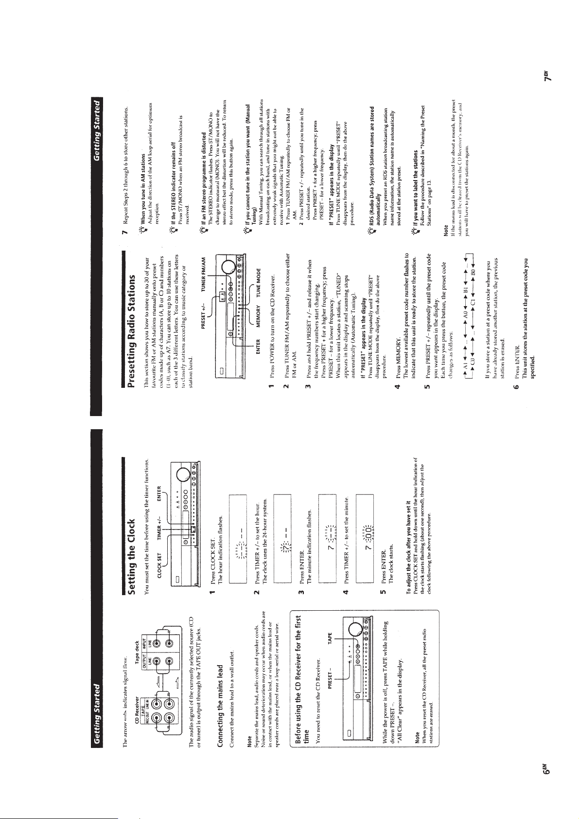
Setting the Clock ................................................................ 5
Presetting Radio Stations.................................................... 5
Basic Operations
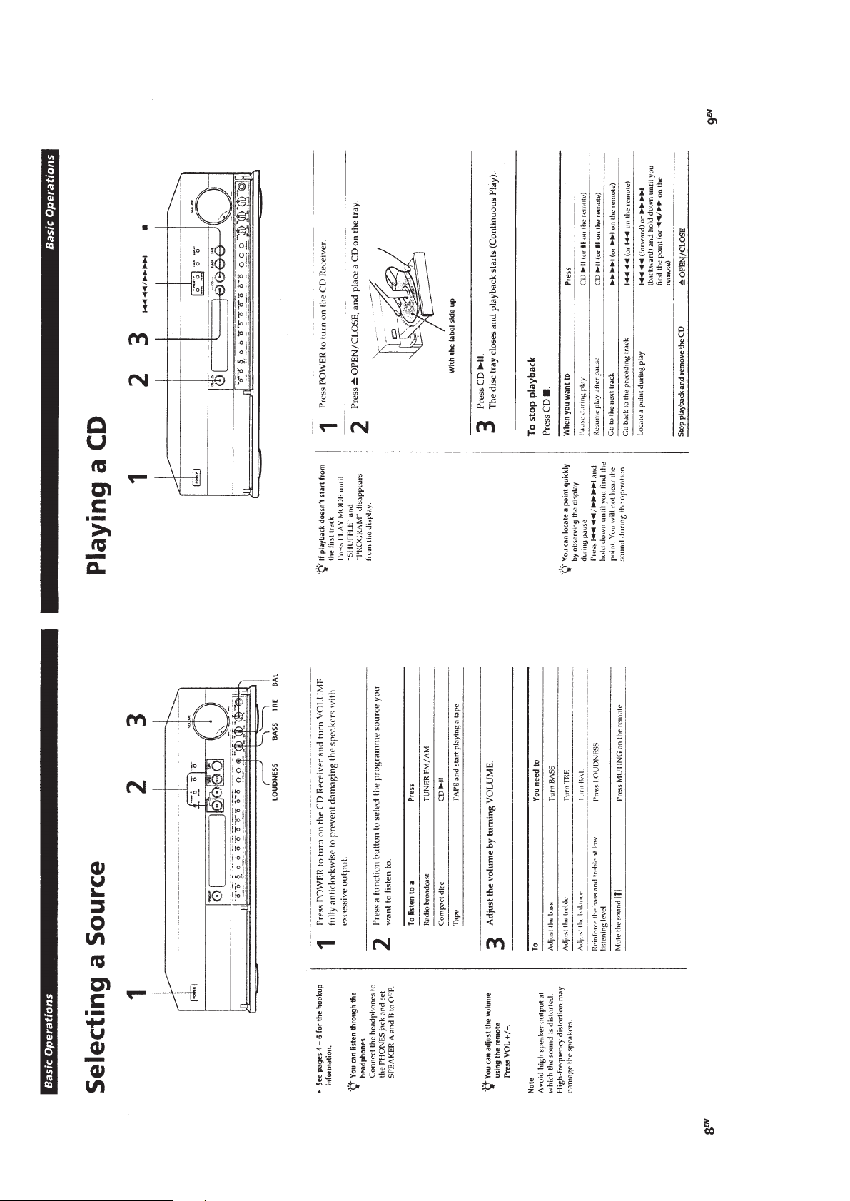
Selecting a Source .............................................................. 6
Playing a CD....................................................................... 6
Receiving Preset Stations ................................................... 7
2. DISASSEMBLY
2-1. Cabinet (Top) ..................................................................... 8
2-2. Front Panel (1) ................................................................... 8
2-3. Front Panel (2) ................................................................... 9
2-4. Front Board ........................................................................ 9
2-5. Mechanism Block ............................................................ 10
2-6. Chassis (Back).................................................................. 10
2-7. Power Transformer........................................................... 11
2-8. Main Board ...................................................................... 11
3. ELECTRICAL ADJUSTMENTS
FM Section ........................................................................... 12
AM Section........................................................................... 13
Audio Section ....................................................................... 13
Front Section ........................................................................ 13
CD Section ........................................................................... 13
4. DIAGRAMS
4-1. Block Diagram –CD Section–.......................................... 15
4-2. Block Diagram –Tuner Section–...................................... 17
4-3. Circuit Boards Location ................................................... 19
4-4. Printed Wiring Boards –CD Section– .............................. 21
4-5. Schematic Diagram –CD Section–................................... 23
4-6. Printed Wiring Board –Front Section–............................. 27
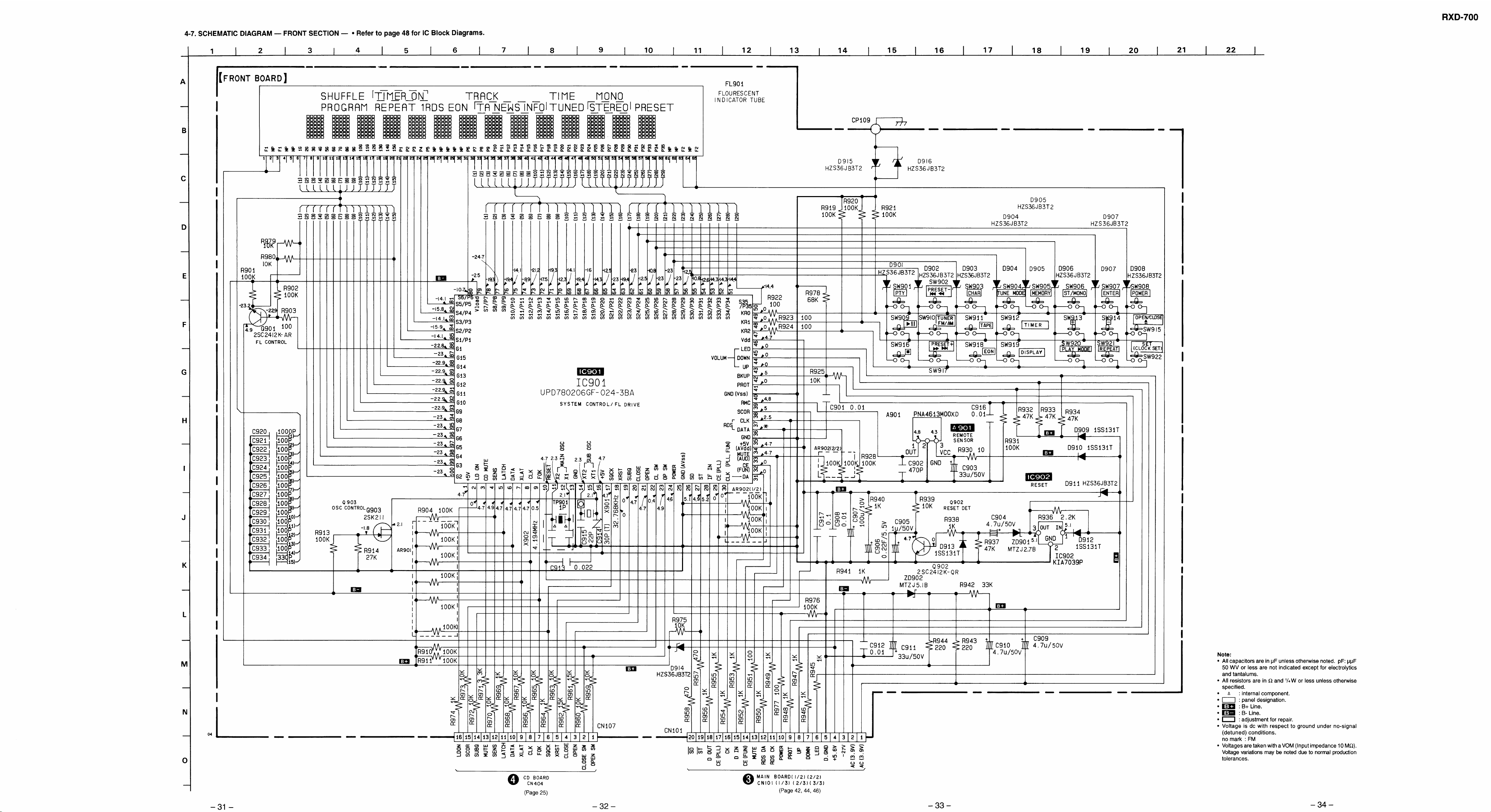
4-7. Schematic Diagram –Front Section– ............................... 31
4-8. Printed Wiring Boards –Main Section– ........................... 36
4-9. Schematic Diagram –Main Section (1/2)– ....................... 39
4-10. Schematic Diagram –Main Section (2/2)– ....................... 43
5. EXPLODED VIEWS
5-1. Case Section ..................................................................... 51
5-2. Front Panel Section .......................................................... 52
5-3. Chassis Section ................................................................ 53
5-4. CD Mechanism Section ................................................... 54
5-5. Optical Pick-up Section ................................................... 55
6. ELECTRICAL PARTS LIST ................................... 56
– 3 –

SECTION 1
GENERAL
This section extracted from
instruction manual.
– 4 –
– 5 –
– 6 –

– 7 –
SECTION 2
DISASSEMBLY
Note : Follow the disassembly procedure in the numerical order given.
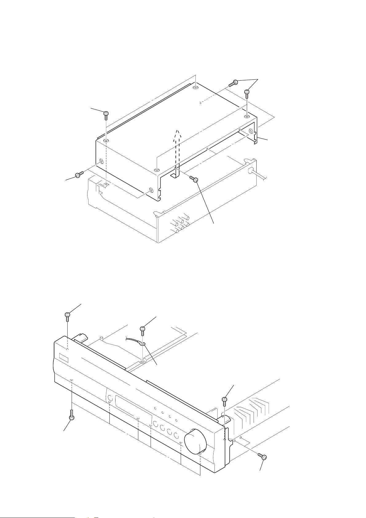
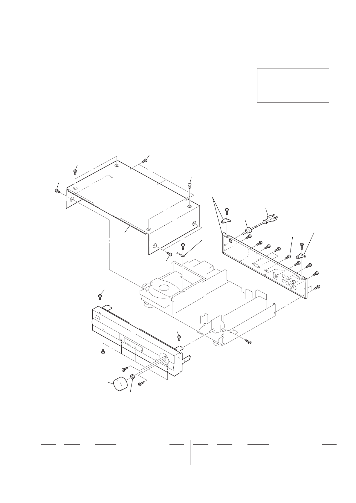
2-1. CABINET (TOP)
4
screws
(case)
1
screws
(case)
3
screws
(case)
5
cabinet (top)
2-2. FRONT PANEL (1)
5
screw
(case)
3
BVTP 3x8
4
lug plate
2
screws
(case)
6
screw
(case)
1
BVTP 3x8
– 8 –
2
BVTP 3x8

2-3. FRONT PANEL (2)
d
8
claw
7
nut
5
BVTP 3x8
1
CN404
9
claw
2
CN101
3
CN103
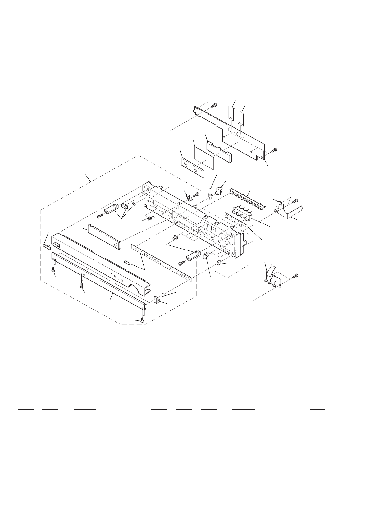
2-4. FRONT BOARD
5
BVTP 3x8
4
knob (volume)
4
BVTP 3x8
6
BVTP 3x8
0
button (control)
0
front panel
1
BVTP 3x8
9
!¡
button (function)
3
TONE boar
FRONT board
7
claw
6
claws
8
claws
– 9 –
2
knob (control)

2-5. MECHANISM BLOCK
3
BVTP 3x8
4
BVTP 3x8
5
mechanism block
2
CN402
2-6. CHASSIS (BACK)
8
BVTP 3x8
2
BVTP 3x8
3
BVTP 3x8
7
BVTP 3x8
4
screw (BV/RING)
9
5
BVTP 3x8
chassis (back)
1
CN403
1
CN107
6
BVTP 3x8
– 10 –
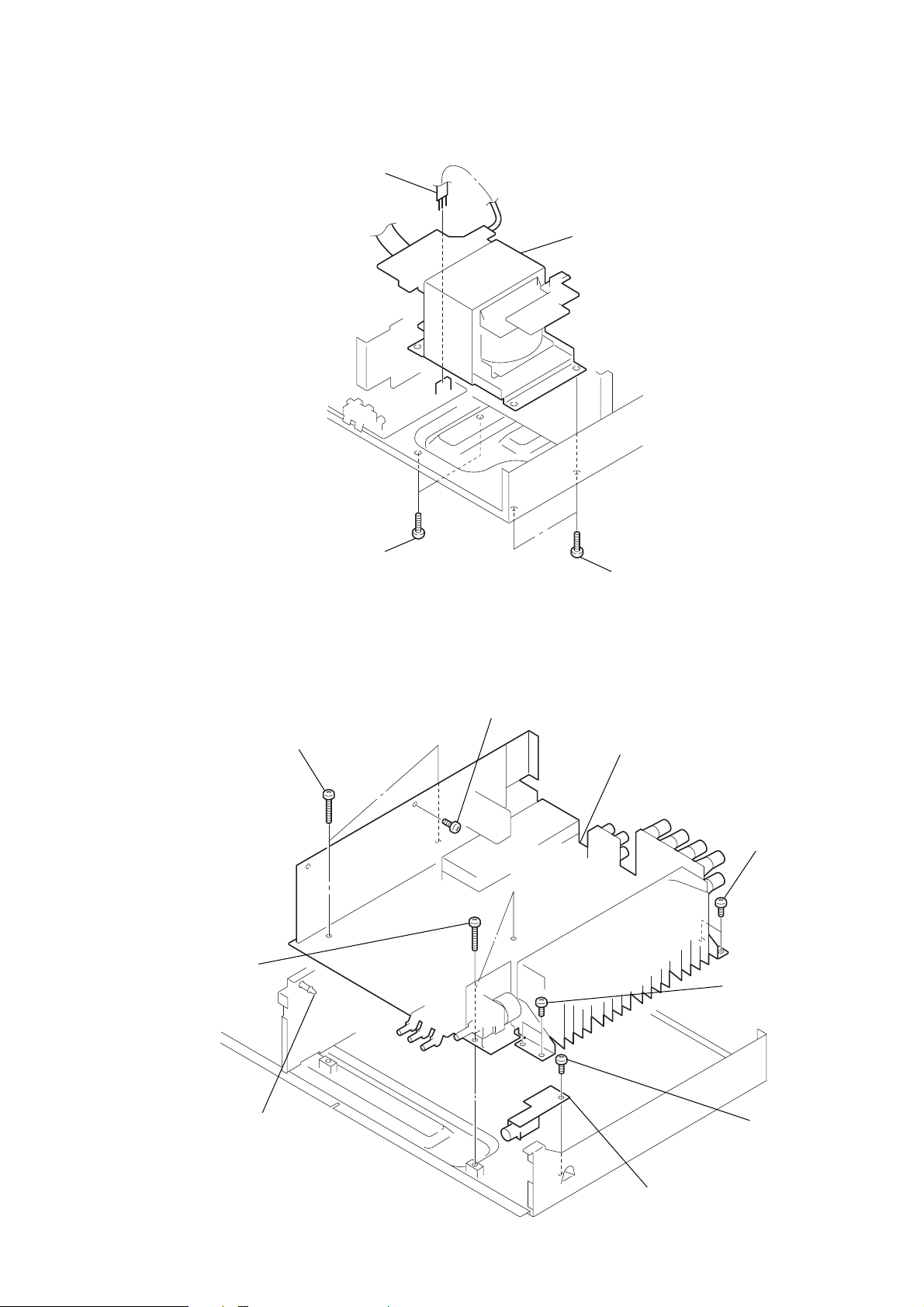
2-7. POWER TRANSFORMER
1
CN102
3
BVTT 4x8
4
power transformer
2
BVTT 4x8
2-8. MAIN BOARD
8
7
BVTP 3x16
BVTP 3x16
3
BVTP 3x8
9
MAIN board
5
4
BVTP 3x8
BVTP 3x8
6
support (cb locking)
– 11 –
2
HEADPHONE board
1
BVTP 3x8

SECTION 3
DISASSEMBLY
FM SECTION
0 dB = 1 µV
Cautions during repair
When the front end is defective, replace it by a new one because
its internal block is difficult to repair.
FM Discriminator Adjustment
(NULL and MONO Distortion Adjustment)
Setting :
TUNER button : FM
FM ANTENNA
75
Ω
COAXIAL
FM RF SSG 1 kHz
Carrier frequency : 98.0 MHz
Output level : 60 dB (1 mV)
Mode : mono
Modulation : 1 kHz, 75 kHz deviation (100%)
TP701
NULL terminal
TAPE
REC OUT
set
high pass
filter
digital voltmeter
(DC range)
distortion meter
Procedure :
1.Tune the set to 98.0 MHz.
2.Adjust L702 for 0 ± 25 mV reading on the digital voltmeter.
............NULL
3.Adjust L703 for a minimum reading on the distortion meter.
............MONO Distortion (THD)
4.Repeat the adjustments of 2 and 3 several times.
FM Stereo Separation Adjustment
Setting :
TUNER button : FM
FM ANTENNA
75
Ω
COAXIAL
FM RF SSG level meter
Carrier frequency : 98.0 MHz
Output level : 60 dB (1 mV)
Mode : stereo
Modulation : main : 1 kHz, 37.5 kHz deviation (50%)
sub : 1 kHz, 37.5 kHz deviation (50%)
19 kHz pilot : 6.75 kHz deviation (9%)
TAPE
REC OUT
set
Procedure :
FM stereo
signal generator
output channel
Level meter Level meter
connection reading (dB)
L-CH L-CH A
B
R-CH L-CH Adjust VR703 for minimum
reading on level meter.
R-CH R-CH C
D
L-CH R-CH Adjust VR703 for minimum
reading on level meter.
L-CH stereo separation : A – B
R-CH stereo separation : C – D
The separations of both channels should be equal.
Note : When replacing the ceramic filter, perform this adjustment.
Adjustment Location : See page 14.
Adjustment Location : See page 14.
FM Tuning Level Adjustment
Setting :
TUNER button : FM
FM RF SSG
Carrier frequency : 98.0 MHz
Output level : 25 dB (17.8 µV)
Mode : mono
Modulation : no modulation
FM ANTENNA
75
Ω
COAXIAL
set
Procedure :
1.Tune the set to 98.0 MHz.
2.Adjust VR701 so that the TUNED indicator goes on.
3.Confirm that the TUNED indicator goes off with FM RF SSG
output level set at 22 dB.
Adjustment Location : See page 14.
– 12 –

FM Stereo Distortion Adjustment
Setting :
TUNER button : FM
FM ANTENNA
75
Ω
COAXIAL
FM RF SSG 1 kHz
Carrier frequency : 98.0 MHz
Output level : 60 dB (1 mV)
Mode : stereo
Modulation : main : 1 kHz, 34.125 kHz deviation (45.5%)
sub : 1 kHz, 34.125 kHz deviation (45.5%)
19 kHz pilot : 6.75 kHz deviation (9%)
TAPE
REC OUT
set
high pass
filter
distortion meter
AUDIO SECTION
Idle Current Adjustment
Setting :
VOLUME control : MIN
digital voltmeter
CP1 (L-CH),
CP2 (R-CH)
Procedure :
1. Adjust VR101 (L-CH), VR102 (R-CH) for 7 ± 0.2mV reading
on digital voltmeter.
(DC range)
Procedure :
1. Tune the set to 98.0 MHz.
2. Adjust IFT on PACK701 for a minimum reading on the
distortion meter.
Adjustment Location : See page 14.
AM SECTION
0 dB = 1 µV
AM Tuning Level Adjustment
Setting :
TUNER button : AM
AM RF SSG
loop
Carrier frequency : 999 kHz
Output level : 55 dB (0.56 mV)
antenna A
60 cm
loop
antenna B
set
Procedure :
1. Set loop antenna A so that the loop antenna B input level
becomes 55 dB (0.56 mV)
2. Tune the set to 999 kHz.
3. Adjust VR702 so that the TUNED indicator goes on.
4. Confirm that the TUNED indicator goes off with AM RF SSG
output level set at 53 dB.
Adjustment Location : See page 14.
FRONT SECTION
Frequency (Clock) Adjustment
Setting :
frequency
counter
TP901
Procedure :
1. Connect the frequency counter to TP901.
2. Adjust C914 for 32.768 kHz ± 0.1 Hz reading on frequency
counter.
Adjustment Location : See page 14.
CD SECTION
• This set is automatically adjustment.
Adjustment Location : See page 14.
– 13 –

Adjustment Location :
– main board (component side) –
FM DISCRIMINATOR ADJ
L702
L703
TP701
VR102 (R-CH)
IDLE CURRENT ADJ
CP2 (R-CH)
CP1 (L-CH)
IDLE CURRENT ADJ
VR101 (L-CH)
– front board (component side) –
VR701
FM TUNING
LEVEL ADJ
VR703
FM STEREO
SEPARATION ADJ
PACK701
IFT
FM STEREO
DISTORTION
ADJ
VR702
AM TUNING
LEVEL ADJ
IC901
TP901
C914
FREQUENCY
(CLOCK) ADJ
– 14 –


• IC Block Diagrams
IC001 CXA1821M
1
LD VCCVCC
PD LD ON
2
A LC/PD
3
B RFE
4
C RFO
5
D FE
6
VEE FE BIAS
F TE
VEE
7
VC
8
VCC
VREF
VEE
VC
RF SUMMING AMP
VC
APC LD AMP
VEE
FOCUS ERROR AMP
TRACKING ERROR AMP
VC
RF EQ AMP
VC
VC
E VC
9
EI EO
VC
10
VCC
VEE
VC BUFFER
20
19
18
17
16
15
14
13
VC
12
11
IC501 CXD8505BQ
IC002 BA6392FP
BUFF
1CH1 OUT F
BUFF
2CH1 OUT R
3CAPA IN 1
R
4CH1 R IN
INTERFACE
F
5CH1 F IN
BUFF
F
R
LEVEL
SHIFT
6VREF IN
7VREF OUT
8GND
FF
9CH2 F IN
INTERFACE INTERFACE
RR
10CH2 R IN
11CAPA IN 2
BUFF BUFF
12CH2 OUT R
BUFF
13CH2 OUT F
RRFF
MUTE
14GND
BUFF
BUFF
BUFF
28 GND
27 CH4 OUT F
26 CH4 OUT R
25 VB IN
24 VS IN
23 VB IN
22 VCC
21 VCC
20 CH3 F IN
19 CH3 R IN
18 CAPA IN 3
17 CH3 OUT R
16 CH3 OUT F
15 MUTE
MUTEL
TEST1
TEST2
DD
DFV
DD
DV
SS
DV
VSUB(C)L
V
DD
V
L1(–)
V
L1(+)
VSS2
O
O
O
S
S
S
256F
MUTER
INVO2
INVO1
INVI
128F
512F
INAF
50
TIMING
CIRCUIT
“O” DETECT
MUTE
52
CIRCUIT
53
54
55
2
56
L
57
L
ATT
FIR1
MODE
58
59
2
DD
60
IIR
FIR2
61
62
SS
63
PLM PLM
64
3rd order
NOISE SHAPER
FIR3
L.I.P
(X8)
AC, DC
DITHER
SS
DFV
VSUB(D)L
CLOCK
GENERATOR
VSUB(D)R
ATT
FIR1
FIR2
FIR3
L.I.P
(X8)
DATAI
S/P
IIR
BCKI
LRCKI
3rd order
NOISE SHAPER
INIT
LATCH
SHIFT
ATT
3334353637383940414244 43454647484951
SYSM
32
31
30
29
28
27
26
25
24
23
22
21
20
XSEL
20/16
SPLM
DD
1
DFV
DD
R
DV
SS
R
DV
VSUB(C)R
VDD2
DD
V
R1(–)
SS
V
R1(+)
V
SS
2
34
1
2
2
SS
SS
V
V
L2(+)
L2(–)
5
6
7
2
DD
DD
V
V
8
DD
XV
VSUB(A)L
91011 12 13 14 15
XOUT
XIN
SSXVSS
XV
DD2
V
VSUB(A)R
16 17 18 19
DD
V
R2(–)
SS
SS2
V
V
R2(+)
– 47 –

IC431 CXD2545Q
SBSO
75
EXCK
SQSO
SQCK
MUTE
SENS
XRST
DIRC
SCLK
DFSW
ATSK
DATA
XLAT
CLOK
COUT
ADD
MIRR
DFCT
FOK
FSW
MON
MDP
MDS
LOCK
SSTP
76
77
78
79
80
81
82
83
84
85
86
87
88
89
90
91
92
93
94
95
96
97
98
99
P-W
SUBCODE
Q
SUBCODE
CPU
CPU
INTERFACE
INTERFACE
PROCESSOR
PROCESSOR
AUTO
SERVO
SEQUENCER
SERVO
SCOR
WFCK
EMPH
72
73
74
TIMING
GENERATOR 1
32K RAM
INTERFACE
MICRO PROGRAM
CPU
ADDRESS
CLV
PROCESSOR
SYNC
PROTECTOR
D/A
DIGITAL
CPU
PRIORITY
INTERFACE
GENERATOR
NOISE
SHAPER
PROCESSOR
ENCODER
INTERFACE
FILTER
18-TIMES
OVER SAMPLING
D OUT
MD2
70
71
OUT
DIGITAL
PEAK
DETECTOR
REGISTER
CPU
ERROR
INTERFACE
CORRECTOR
C16M
C4M
67
68
69
CPU
TIMING
INTERFACE
GENERATOR 2
FSTO
CLOCK
3
XTSL
DVSS
FSTI
64
65
66
GENERATOR
DIGITAL
XTAI
XTAO
62
63
EFM
CPU
INTERFACE
DEMODULATOR
PLL
VARI-PITCH
DOUBLE SPEED
DA01|DA11
61|51
SERIAL
PARALLEL
PROCESSOR
MUX
CPU
INTERFACE
ASYMMETRY
CORRECTION
50
DA12
|
46
DA14
LRCK
45
WDCK
44
PSSL
43
ASYE
42
41
ADD
40
AVDD
ASYO
39
ASYI
38
BIAS
37
RFAC
36
AVSS
35
34
CLTV
PCO
33
32
FILI
FILO
31
SLED
SERVO
SLED PWM
GENERATOR
SFDR
100
2
1
SRON
SRDR
IC902 PNA4613M
1 2 3
OUT
FOCUS
TFON
FOCUS PWM
9
FFDR
FRON
SERVO
SERVO DSP
GENERATOR
PWM GENERATOR
10
11
FFON
FRDR
12
VCO0
PEAK
HOLD
SERVO
TRACKING
GENERATOR
TRACKING PWM
3
678
5
4
TFDR
SFON
TRON
TRDR
COMP INT DEMOD BPF
GND
13
VCO1
14
TEST
MIRR
15
DVSS
DFCT
16
TES2
AGC
FOK DETECTOR
19
18
17
PDO
TES3
VPCO
AMP
CONSTANT
VOLTAGE
20
VCKI
2122232425
AVDD
PD
IGEN
VCC
A/D
AVSS
4
&
SWITCH
CONVERTER
RFC
ADIO
BUFFER
VC
30
FE
29
SE
28
TE
27
26
RFDC
– 48 –

IC701 LA1235 IC702 LA1245
R
VCC
DETECTOR
SHUMITTER
MINUS CIR
1415 12 91016 13
GND
S METER
MUTE DRIVE
11
GURD DET
AMP OUT
OSC
OSC
AGC
SM OUTSMIF VCC
DET OUT
IF GND
15 1219 16 1320
18
17
14 11
DET IN
MUTING
CIRCUIT
LEVEL
DET
FM IF AMP
LIMITER
2 5 81 4
IF IN
METER
DRIVE
IF OFF
NULL METER
SHORTING
3 6
GND
QUADRATURE
IF OUT
DET
DETUNE
DET
AF AMP
OUTPUT
AF/NULL
METER
7
GURD
AFC TUNING
IC703 LA3401
VCC
OSC
PHASE COMPA
PHASE COMP
PLL IN
VCO STEP
22 21 20 19 18 17 16 15 14 13 12
VCC GND
PLL
PILOT DET
LAMP
DRIVE
MUTE
FM/AM SELECT CONTROL
LOGIC / MUTE ON/OFF
MUTING CONT
LAMP DRIVER
MUTING
OUT
GND
AGC
AGC
AM
OSC
AM RF AMP
RF
3
RF IN
AM DET
METER
DRIVE
AM
MIXING
RF OUT
6 92 5 81
MIX IN
4
GND
AM IF AMP
7 10
VCC
IF IN
MIX OUT
IF OUT
FM/AM SELECT
MUTING
1
2 3 4 5 6 7 8 9 10 11
FM IN
AM IN
IC801 SAA6579T
QUALITY BIT
GENERATOR
DIFFERENTIAL
DECODER
T57
14 13
OSCILLATOR
RDCL
BA PA
OSCO
AND
DIVIDER
BIPHASE
SYMBOL
DECODER
MPX
SEP
OSCI
RECONSTRUCTION
FILTER
L OUT
POST AMP
POST AMP
VDDB
COSTAS LOOP
VARIABLE AND
FIXED DIVIDER
CLOCK REGENERATION
R OUT
VSSD
57KHz
BANDPASS
(8th ORDER)
AND SYNC
REFERENCE
VOLTAGE
FM/AM CHANGE
VCC ON MUTE OUT
TEST
TEST LOGIC AND OUTPUT
SELECTOT SWITCH
ANTI-
ALIASING
FILTER
CLOCKED
COMPARATOR
MUTING OUT
TSTLD
91016 15 12 11
1
QUAL
2 3
RDDA
VREF
4
MUX
5 6 7 8
VDDA
VSSA
CIN
SCOUT
– 49 –

IC101 NJU7313L IC351 BA6209N
L-COM1
L-COM2
L-COM3
VSS
1VEE
L1
2
L2
3
L3
4
L4
5
6
L5
7
L6
8
9
L7
10
L8
11
12
13
ST
14
CONTROL
28
27
26
25
24
23
22
21
20
19
18
17
16
15
VDD
R1
R2
R3
R4
R-COM1
R5
R6
R-COM2
R7
R8
R-COM3
DATA
CK
FORWARD
VZ1
4
VR
/REVERSE
CONTROL
5
FIN
MOTOR
DRIVE
6
789
RIN
VCC1
VCC2
VZ2
10
OUT2
MOTOR
DRIVE
2
1
GND
OUT1
3
– 50 –
NOTE:
• The mechanical parts with no reference
number in the exploded views are not supplied.
• Items marked “*” are not stocked since
they are seldom required for routine service.
Some delay should be anticipated
when ordering these items.
5-1. CASE SECTION
6
SECTION 5
EXPLODED VIEWS
• -XX and -X mean standardized parts, so
they may have some difference from the
original one.
• Color Indication of Appearance Parts
Example :
KNOB, BALANCE (WHITE) ... (RED)
6
N
Parts Color Cabinet’s Color
N
• Accessories and packing materials and
hardware (# mark) list are given in
the last of this parts list.
The components identified by
mark ! or dotted line with mark.
! are critical for safety.
Replace only with part number
specified.
6
6
not supplied
#2
4
3
1
not supplied
#2
#2
#2
#2
#2
6
6
5
#2
not supplied
#2
#2
#2
#2
6
#2
#2
#2
2
#2
supplied with RV
Ref. No. Part No. Description Remark Ref. No. Part No. Description Remark
* 1 4-997-301-01 CABINET (TOP)
2 4-997-281-11 KNOB (VOLUME)
3 4-997-291-01 STOPPER, AC CORD
! 4 1-575-651-11 CORD, POWER
5 3-704-515-31 SCREW (BV/RING)
6 4-997-889-01 SCREW (CASE)
– 51 –
5-2. FRONT PANEL SECTION
52
54
56
51
54
#2
53
not
supplied
57
not
supplied
not
supplied
FL901
not
supplied
#2
not
supplied
55
not supplied
63
#2
58
#2
not supplied
p
not
supplied
65
66
62
#2
64
60
(including p )
not supplied
59
#2
61
#2
54
Ref. No. Part No. Description Remark Ref. No. Part No. Description Remark
51 X-4949-438-1 PANEL ASSY, FRONT
52 4-942-568-31 EMBLEM (NO.5), SONY
53 4-997-316-01 DOOR (FRONT)
54 4-997-895-01 SCREW (K 2X6)
55 4-997-317-01 HOLDER (DOOR)
56 4-997-327-01 DOOR (CD)
57 4-997-325-01 SPRING (DOOR)
58 4-997-282-01 KNOB (CONTROL)
* 59 A-4407-350-A TONE BOARD, COMPLETE
60 4-997-284-01 BUTTON (FUNCTION)
61 4-997-283-01 BRACKET (VOLUME)
62 4-997-300-01 BUTTON (CONTROL)
* 63 4-997-304-01 PLATE (FLT)
* 64 A-4407-347-A FRONT BOARD, COMPLETE
65 1-782-465-11 WIRE (FLAT TYPE) (16 CORE)
66 1-769-326-11 WIRE (FLAT TYPE) (20 CORE)
FL901 1-517-750-11 INDICATOR TUBE, FLUORESCENT
– 52 –
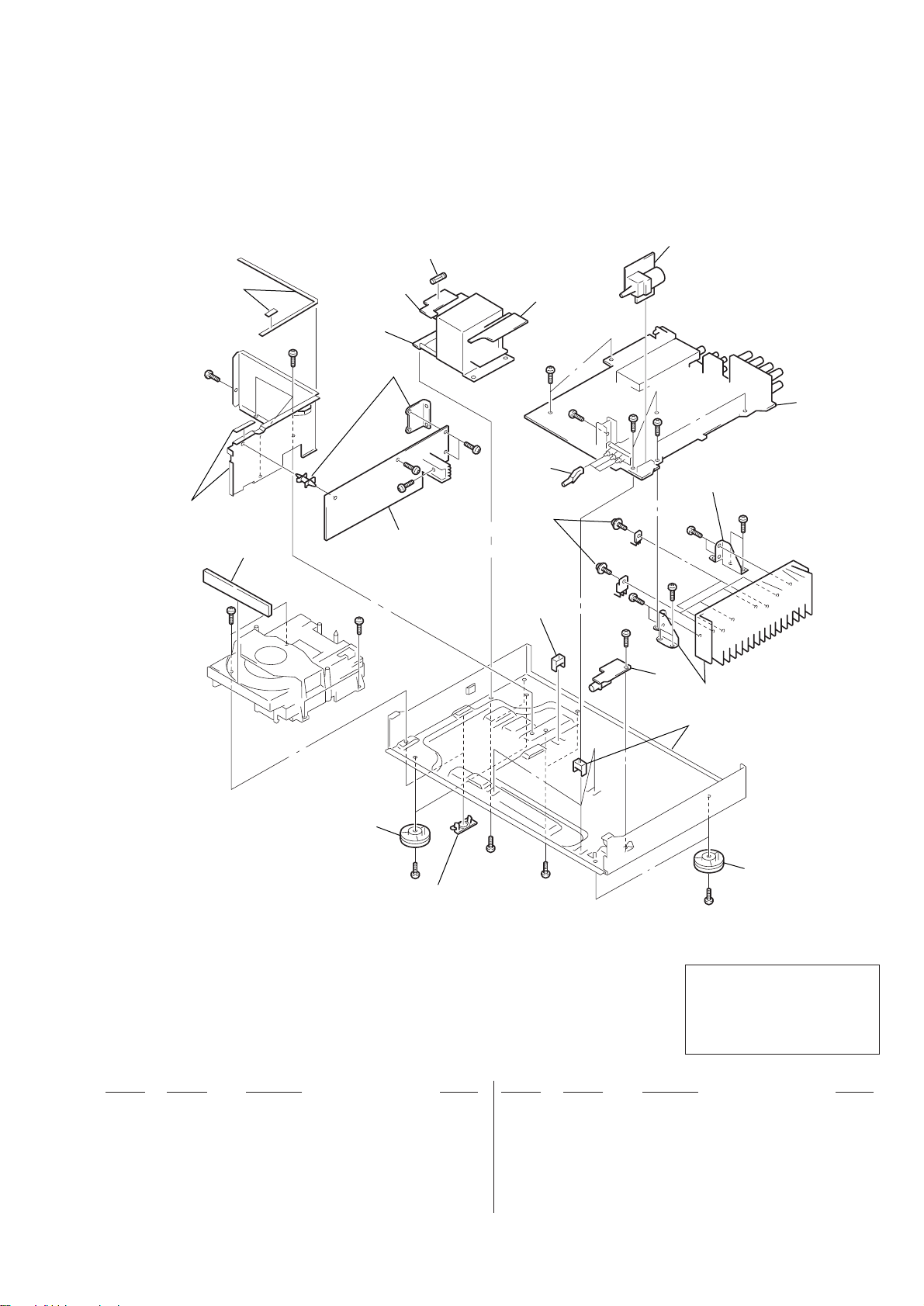
5-3. CHASSIS SECTION
not supplied
#2
not supplied
#2
101
#1
102
T1
not supplied
104
#2
#2
F101
#2
#2
103
#3
107
108
not supplied
#2
#2
#2
#3
105
#2
not supplied
#2
#2
109
106
#2
not supplied
not supplied
110
#2
not supplied
Ref. No. Part No. Description Remark Ref. No. Part No. Description Remark
101 4-997-298-01 COVER (TRAY)
* 102 A-4407-344-A TRANS-1 BOARD, COMPLETE
* 103 A-4407-345-A TRANS-2 BOARD, COMPLETE
* 104 A-4407-348-A CD BOARD, COMPLETE
* 105 A-4407-349-A VOLUME BOARD, COMPLETE
#4
#4
The components identified by mark
! or dotted line with mark. ! are
critical for safety.
Replace only with part number
specified.
107 4-997-285-01 KNOB (PUSH)
108 4-997-888-01 SCREW (TR)
* 109 A-4407-346-A HEADPHONE BOARD, COMPLETE
110 X-4949-439-1 FOOT ASSY
! F101 1-532-388-51 FUSE, TIME LAG (2A/250V)
110
#2
* 106 A-4407-343-A MAIN BOARD, COMPLETE
! T1 1-431-725-11 TRANSFORMER, POWER
– 53 –

5-4. CD MECHANISM SECTION
167
161
155
168
156 157
160
154
#6
#5
151
#6
153
169
158
159
164
163
164
163
164
162
164
162
152
164
M3
165
166
#2
not supplied
Ref. No. Part No. Description Remark Ref. No. Part No. Description Remark
151 4-997-924-01 MAGNET (CORE 3)
152 4-997-934-01 FRAME (FEED)
153 4-997-893-01 STOPPER, RUBBER
154 4-997-926-01 FRAME, GUIDE
155 4-997-928-01 SPRING (RACK)
156 4-997-929-01 GEAR (LOAD)
157 4-997-930-01 GEAR (CENTER)
158 4-997-933-01 BELT
159 4-997-931-01 GEAR (PULLEY)
160 4-997-927-01 BASE, MECHANICAL
161 4-997-932-01 TRAY
162 4-997-892-01 INSULATOR (30’RED)
163 4-997-891-01 INSULATOR (48’GREEN)
164 4-997-894-01 SCREW (W 3X8)
* 165 A-4407-351-A DRIVE BOARD, COMPLETE
166 4-997-890-01 HOLDER (S/W)
167 4-997-922-01 PLATE, CLAMP
168 4-997-923-01 FLAPPER
169 4-997-925-01 CLAMP (4)
M3 X-4949-441-1 MOTOR ASSY, DC (OPEN/CLOSE)
#2
– 54 –

5-5. OPTICAL PICK-UP SECTION
203
201
supplied
with M1
M2
202
M1
204
The components identified by mark
! or dotted line with mark. ! are
critical for safety.
Replace only with part number
specified.
Ref. No. Part No. Description Remark Ref. No. Part No. Description Remark
201 2-625-188-02 GEAR (A) (K)
* 202 2-626-908-01 SHAFT, SLED
! 203 8-848-483-05 OPTICAL PICK-UP KSS-213C/Q-RP
204 1-636-789-13 MOTOR-1 BOARD
M1 X-2626-272-1 MOTOR ASSY (SPINDLE)
M2 X-2625-769-1 MOTOR ASSY, SLED
– 55 –

CD
NOTE:
• Due to standardization, replacements in
the parts list may be different from the
parts specified in the diagrams or the
components used on the set.
• -XX and -X mean standardized parts, so
they may have some difference from the
original one.
• RESISTORS
All resistors are in ohms.
METAL:Metal-film resistor.
METAL OXIDE: Metal oxide-film resistor.
F:nonflammable
Ref. No. Part No. Description Remark Ref. No. Part No. Description Remark
* A-4407-348-A CD BOARD, COMPLETE
*******************
< CAPACITOR >
C401 1-163-031-11 CERAMIC CHIP 0.01uF 50V
C402 1-126-960-11 ELECT 1uF 20% 50V
C403 1-163-031-11 CERAMIC CHIP 0.01uF 50V
C404 1-163-031-11 CERAMIC CHIP 0.01uF 50V
C405 1-163-031-11 CERAMIC CHIP 0.01uF 50V
C406 1-163-031-11 CERAMIC CHIP 0.01uF 50V
C407 1-163-031-11 CERAMIC CHIP 0.01uF 50V
C408 1-163-031-11 CERAMIC CHIP 0.01uF 50V
C409 1-126-943-11 ELECT 2200uF 20% 25V
C411 1-126-943-11 ELECT 2200uF 20% 25V
C412 1-126-933-11 ELECT 100uF 20% 16V
C413 1-126-933-11 ELECT 100uF 20% 16V
C414 1-163-038-00 CERAMIC CHIP 0.1uF 25V
C415 1-163-038-00 CERAMIC CHIP 0.1uF 25V
C416 1-126-933-11 ELECT 100uF 20% 10V
C417 1-163-038-00 CERAMIC CHIP 0.1uF 25V
C418 1-163-038-00 CERAMIC CHIP 0.1uF 25V
C419 1-163-038-00 CERAMIC CHIP 0.1uF 25V
C421 1-163-038-00 CERAMIC CHIP 0.1uF 25V
C430 1-163-038-00 CERAMIC CHIP 0.1uF 25V
C431 1-163-133-00 CERAMIC CHIP 470PF 5% 50V
C432 1-163-038-00 CERAMIC CHIP 0.1uF 25V
C433 1-163-133-00 CERAMIC CHIP 470PF 5% 50V
C434 1-163-011-11 CERAMIC CHIP 0.0015uF 10% 50V
C435 1-163-809-11 CERAMIC CHIP 0.047uF 10% 25V
C436 1-163-017-00 CERAMIC CHIP 0.0047uF 5% 50V
C437 1-126-933-11 ELECT 100uF 20% 10V
C438 1-163-037-11 CERAMIC CHIP 0.022uF 10% 25V
C439 1-163-251-11 CERAMIC CHIP 100PF 5% 50V
C441 1-126-959-11 ELECT 0.47uF 20% 50V
C442 1-163-031-11 CERAMIC CHIP 0.01uF 50V
C443 1-126-933-11 ELECT 100uF 20% 10V
C444 1-163-037-11 CERAMIC CHIP 0.022uF 10% 25V
C445 1-126-933-11 ELECT 100uF 20% 10V
C446 1-163-037-11 CERAMIC CHIP 0.022uF 10% 25V
C447 1-163-038-00 CERAMIC CHIP 0.1uF 25V
C448 1-163-037-11 CERAMIC CHIP 0.022uF 10% 25V
C449 1-126-933-11 ELECT 100uF 20% 10V
C451 1-163-037-11 CERAMIC CHIP 0.022uF 10% 25V
C452 1-126-933-11 ELECT 100uF 20% 10V
ELECTRICAL PARTS LIST
• Items marked “*” are not stocked since
they are seldom required for routine service.
Some delay should be anticipated
when ordering these items.
• SEMICONDUCTORS
In each case, u : µ, for example:
uA.. : µA.. uPA.. : µPA..
uPB.. : µPB.. uPC.. : µPC.. uPD.. : µPD..
• CAPACITORS
uF : µF
• COILS
uH : µH
C453 1-163-037-11 CERAMIC CHIP 0.022uF 10% 25V
C461 1-163-038-00 CERAMIC CHIP 0.1uF 25V
C462 1-163-141-00 CERAMIC CHIP 0.001uF 5% 50V
C463 1-126-933-11 ELECT 100uF 20% 10V
C464 1-163-031-11 CERAMIC CHIP 0.01uF 50V
C465 1-126-933-11 ELECT 100uF 20% 10V
C466 1-163-031-11 CERAMIC CHIP 0.01uF 50V
C467 1-163-038-00 CERAMIC CHIP 0.1uF 25V
C468 1-163-038-00 CERAMIC CHIP 0.1uF 25V
C469 1-163-038-00 CERAMIC CHIP 0.1uF 25V
C471 1-163-038-00 CERAMIC CHIP 0.1uF 25V
C481 1-163-038-00 CERAMIC CHIP 0.1uF 25V
C482 1-163-251-11 CERAMIC CHIP 100PF 5% 50V
C483 1-163-251-11 CERAMIC CHIP 100PF 5% 50V
C484 1-163-251-11 CERAMIC CHIP 100PF 5% 50V
C485 1-163-251-11 CERAMIC CHIP 100PF 5% 50V
C486 1-163-251-11 CERAMIC CHIP 100PF 5% 50V
C487 1-163-227-11 CERAMIC CHIP 10PF 0.5PF 50V
C488 1-163-038-00 CERAMIC CHIP 0.1uF 25V
C501 1-163-037-11 CERAMIC CHIP 0.022uF 10% 25V
C502 1-163-102-00 CERAMIC CHIP 24PF 5% 50V
C503 1-124-584-00 ELECT 100uF 20% 10V
C504 1-163-037-11 CERAMIC CHIP 0.022uF 10% 25V
C505 1-163-037-11 CERAMIC CHIP 0.022uF 10% 25V
C506 1-126-933-11 ELECT 100uF 20% 10V
C507 1-163-037-11 CERAMIC CHIP 0.022uF 10% 25V
C508 1-163-037-11 CERAMIC CHIP 0.022uF 10% 25V
C509 1-163-037-11 CERAMIC CHIP 0.022uF 10% 25V
C511 1-163-037-11 CERAMIC CHIP 0.022uF 10% 25V
C512 1-126-933-11 ELECT 100uF 20% 10V
C513 1-163-037-11 CERAMIC CHIP 0.022uF 10% 25V
C514 1-163-227-11 CERAMIC CHIP 10PF 0.5PF 50V
C515 1-163-227-11 CERAMIC CHIP 10PF 0.5PF 50V
C516 1-163-037-11 CERAMIC CHIP 0.022uF 10% 25V
C517 1-163-037-11 CERAMIC CHIP 0.022uF 10% 25V
C518 1-163-037-11 CERAMIC CHIP 0.022uF 10% 25V
C519 1-126-933-11 ELECT 100uF 20% 10V
C521 1-163-037-11 CERAMIC CHIP 0.022uF 10% 25V
C522 1-163-037-11 CERAMIC CHIP 0.022uF 10% 25V
C523 1-163-037-11 CERAMIC CHIP 0.022uF 10% 25V
C524 1-126-933-11 ELECT 100uF 20% 10V
C527 1-163-251-11 CERAMIC CHIP 100PF 5% 50V
C528 1-163-253-11 CERAMIC CHIP 120PF 5% 50V
C529 1-163-253-11 CERAMIC CHIP 120PF 5% 50V
C531 1-126-933-11 ELECT 100uF 20% 10V
The components identified by mark
! or dotted line with mark. ! are
critical for safety.
Replace only with part number
specified.
When indicating parts by reference
number, please include the board.
SECTION 6
– 56 –

CD
Ref. No. Part No. Description Remark Ref. No. Part No. Description Remark
C532 1-163-037-11 CERAMIC CHIP 0.022uF 10% 25V
C533 1-163-022-00 CERAMIC CHIP 0.012uF 10% 50V
C534 1-163-137-00 CERAMIC CHIP 680PF 5% 50V
C535 1-163-038-91 CERAMIC CHIP 0.1uF 25V
C536 1-126-967-11 ELECT 47uF 20% 50V
C537 1-126-933-11 ELECT 100uF 20% 10V
C538 1-163-037-11 CERAMIC CHIP 0.022uF 10% 25V
C539 1-163-133-00 CERAMIC CHIP 470PF 5% 50V
C541 1-163-251-11 CERAMIC CHIP 100PF 5% 50V
C542 1-163-253-11 CERAMIC CHIP 120PF 5% 50V
C543 1-163-253-11 CERAMIC CHIP 120PF 5% 50V
C546 1-163-137-00 CERAMIC CHIP 680PF 5% 50V
C547 1-163-022-00 CERAMIC CHIP 0.012uF 10% 50V
C548 1-126-933-11 ELECT 100uF 20% 10V
C549 1-163-037-11 CERAMIC CHIP 0.022uF 10% 25V
C551 1-126-933-11 ELECT 100uF 20% 10V
C552 1-163-037-11 CERAMIC CHIP 0.022uF 10% 25V
C553 1-126-967-11 ELECT 47uF 20% 50V
C554 1-163-038-91 CERAMIC CHIP 0.1uF 25V
C555 1-163-133-00 CERAMIC CHIP 470PF 5% 50V
J471 1-216-296-00 CONDUCTOR, CHIP (3216)
J472 1-216-296-00 CONDUCTOR, CHIP (3216)
J473 1-216-296-00 CONDUCTOR, CHIP (3216)
J474 1-216-296-00 CONDUCTOR, CHIP (3216)
J475 1-216-296-00 CONDUCTOR, CHIP (3216)
J476 1-216-296-00 CONDUCTOR, CHIP (3216)
J477 1-216-296-00 CONDUCTOR, CHIP (3216)
J478 1-216-296-00 CONDUCTOR, CHIP (3216)
J479 1-216-296-00 CONDUCTOR, CHIP (3216)
J480 1-216-296-00 CONDUCTOR, CHIP (3216)
J481 1-216-296-00 CONDUCTOR, CHIP (3216)
J482 1-216-296-00 CONDUCTOR, CHIP (3216)
J483 1-216-296-00 CONDUCTOR, CHIP (3216)
J485 1-216-296-00 CONDUCTOR, CHIP (3216)
J486 1-216-296-00 CONDUCTOR, CHIP (3216)
J487 1-216-296-00 CONDUCTOR, CHIP (3216)
< JUMPER RESISTOR >
< COIL >
C581 1-163-809-11 CERAMIC CHIP 0.047uF 10% 25V
C582 1-163-133-00 CERAMIC CHIP 470PF 5% 50V
C583 1-163-038-00 CERAMIC CHIP 0.1uF 25V
C584 1-163-075-00 CERAMIC CHIP 0.047uF 50V
C585 1-163-038-00 CERAMIC CHIP 0.1uF 25V
< CONNECTOR >
CN402 1-695-343-21 PIN, CONNECTOR (PC BOARD) 20P
* CN403 1-565-731-11 PLUG, CONNECTOR (2.5MM) 5P
CN404 1-695-339-21 PIN, CONNECTOR (PC BOARD) 16P
CP105 1-784-445-11 CONNECTOR, 2.0MM PITCH (90) 5P
CP106 1-784-444-11 CONNECTOR, 2.0MM PITCH (90) 4P
< DIODE >
D401 8-719-815-85 DIODE 1S1585
D402 8-719-815-85 DIODE 1S1585
D403 8-719-200-02 DIODE 10E2
D404 8-719-200-02 DIODE 10E2
D405 8-719-200-02 DIODE 10E2
D406 8-719-200-02 DIODE 10E2
D501 8-719-815-85 DIODE 1S1585
< IC >
IC401 8-759-982-07 IC RC7808FA
IC402 8-759-990-36 IC RC7908FA
IC403 8-759-701-75 IC NJM7805FA
IC431 8-752-369-78 IC CXD2545Q
IC461 8-759-710-73 IC NJM4580L
IC501 8-759-370-62 IC CXD8505BQ
IC502 8-759-710-73 IC NJM4580L
IC503 8-759-710-73 IC NJM4580L
L501 1-410-503-11 INDUCTOR 3.3uH
L502 1-410-503-11 INDUCTOR 3.3uH
< TRANSISTOR >
Q461 8-729-043-89 TRANSISTOR KTC3205Y
Q462 8-729-043-88 TRANSISTOR KTA1273Y
Q501 8-729-901-01 TRANSISTOR DTC144EK
Q505 8-729-900-99 TRANSISTOR DTA144WK
Q506 8-729-027-60 TRANSISTOR DTC144TKA-T146
Q507 8-729-027-60 TRANSISTOR DTC144TKA-T146
Q508 8-729-901-06 TRANSISTOR DTA144EK
Q509 8-729-901-06 TRANSISTOR DTA144EK
Q511 8-729-027-56 TRANSISTOR DTC143TKA-T146
Q512 8-729-027-56 TRANSISTOR DTC143TKA-T146
< RESISTOR >
R431 1-216-077-00 METAL CHIP 15K 5% 1/10W
R432 1-216-097-00 METAL GLAZE 100K 5% 1/10W
R433 1-216-077-00 METAL CHIP 15K 5% 1/10W
R434 1-216-085-00 METAL CHIP 33K 5% 1/10W
R435 1-216-073-00 METAL CHIP 10K 5% 1/10W
R436 1-216-061-00 METAL CHIP 3.3K 5% 1/10W
R437 1-216-061-00 METAL CHIP 3.3K 5% 1/10W
R438 1-216-121-00 METAL GLAZE 1M 5% 1/10W
R439 1-216-025-00 METAL GLAZE 100 5% 1/10W
R441 1-216-097-00 METAL GLAZE 100K 5% 1/10W
R442 1-216-073-00 METAL CHIP 10K 5% 1/10W
R443 1-216-049-11 METAL GLAZE 1K 5% 1/10W
R444 1-216-049-11 METAL GLAZE 1K 5% 1/10W
R445 1-216-049-11 METAL GLAZE 1K 5% 1/10W
R446 1-216-121-00 METAL GLAZE 1M 5% 1/10W
– 57 –
R447 1-216-097-00 METAL GLAZE 100K 5% 1/10W
R448 1-216-049-11 METAL GLAZE 1K 5% 1/10W

CD
Ref. No. Part No. Description Remark Ref. No. Part No. Description Remark
R449 1-216-089-00 METAL GLAZE 47K 5% 1/10W
R461 1-216-001-00 METAL CHIP 10 5% 1/10W
R462 1-216-017-00 METAL GLAZE 47 5% 1/10W
R463 1-216-095-00 METAL CHIP 82K 5% 1/10W
R464 1-216-095-00 METAL CHIP 82K 5% 1/10W
R465 1-216-093-00 METAL CHIP 68K 5% 1/10W
R466 1-216-093-00 METAL CHIP 68K 5% 1/10W
R481 1-216-077-00 METAL CHIP 15K 5% 1/10W
R482 1-216-049-11 METAL GLAZE 1K 5% 1/10W
R483 1-216-049-11 METAL GLAZE 1K 5% 1/10W
DRIVE
R581 1-216-049-11 METAL GLAZE 1K 5% 1/10W
< VIBRATOR >
XT501 1-579-161-11 VIBRATOR, CRYSTAL (45.1584MHz)
************************************************************
* A-4407-351-A DRIVE BOARD, COMPLETE
**********************
1-769-326-11 WIRE (FLAT TYPE) (20 CORE)
R484 1-216-198-00 METAL GLAZE 1K 5% 1/8W
R501 1-216-089-00 METAL GLAZE 47K 5% 1/10W
R502 1-216-113-00 METAL CHIP 470K 5% 1/10W
R503 1-216-049-11 METAL GLAZE 1K 5% 1/10W
R504 1-216-033-00 METAL CHIP 220 5% 1/10W
R505 1-249-393-11 CARBON 10 5% 1/4W
R506 1-216-065-00 METAL CHIP 4.7K 5% 1/10W
R507 1-216-085-00 METAL CHIP 33K 5% 1/10W
R508 1-216-085-00 METAL CHIP 33K 5% 1/10W
R509 1-216-085-00 METAL CHIP 33K 5% 1/10W
R511 1-216-085-00 METAL CHIP 33K 5% 1/10W
R512 1-249-401-11 CARBON 47 5% 1/4W
R513 1-216-081-00 METAL CHIP 22K 5% 1/10W
R514 1-216-079-00 METAL CHIP 18K 5% 1/10W
R515 1-216-081-00 METAL CHIP 22K 5% 1/10W
R516 1-216-079-00 METAL CHIP 18K 5% 1/10W
R519 1-216-051-00 METAL CHIP 1.2K 5% 1/10W
R521 1-216-044-00 METAL CHIP 620 5% 1/10W
R522 1-216-056-00 METAL GLAZE 2K 5% 1/10W
R523 1-216-109-00 METAL CHIP 330K 5% 1/10W
R524 1-216-033-00 METAL CHIP 220 5% 1/10W
R526 1-216-033-00 METAL CHIP 220 5% 1/10W
R531 1-216-085-00 METAL CHIP 33K 5% 1/10W
R532 1-216-085-00 METAL CHIP 33K 5% 1/10W
R533 1-216-085-00 METAL CHIP 33K 5% 1/10W
R534 1-216-085-00 METAL CHIP 33K 5% 1/10W
R537 1-216-044-00 METAL CHIP 620 5% 1/10W
R538 1-216-056-00 METAL GLAZE 2K 5% 1/10W
R539 1-216-051-00 METAL CHIP 1.2K 5% 1/10W
R541 1-216-081-00 METAL CHIP 22K 5% 1/10W
R542 1-216-079-00 METAL CHIP 18K 5% 1/10W
R543 1-216-081-00 METAL CHIP 22K 5% 1/10W
R544 1-216-079-00 METAL CHIP 18K 5% 1/10W
R545 1-216-109-00 METAL CHIP 330K 5% 1/10W
R546 1-216-033-00 METAL CHIP 220 5% 1/10W
< CAPACITOR >
C001 1-124-584-00 ELECT 100uF 20% 10V
C002 1-163-037-11 CERAMIC CHIP 0.022uF 10% 25V
C003 1-163-231-11 CERAMIC CHIP 15PF 5% 50V
C004 1-163-037-11 CERAMIC CHIP 0.022uF 10% 25V
C006 1-163-141-00 CERAMIC CHIP 0.001uF 5% 50V
C007 1-124-584-00 ELECT 100uF 20% 10V
C008 1-163-037-11 CERAMIC CHIP 0.022uF 10% 25V
C009 1-124-584-00 ELECT 100uF 20% 10V
C010 1-124-584-00 ELECT 100uF 20% 10V
C020 1-124-252-00 ELECT 0.33uF 20% 50V
C021 1-163-237-11 CERAMIC CHIP 27PF 5% 50V
C022 1-164-004-11 CERAMIC CHIP 0.1uF 10% 25V
C023 1-163-237-11 CERAMIC CHIP 27PF 5% 50V
C024 1-163-011-11 CERAMIC CHIP 0.0015uF 10% 50V
C025 1-164-004-11 CERAMIC CHIP 0.1uF 10% 25V
C026 1-163-019-00 CERAMIC CHIP 0.0068uF 10% 50V
C027 1-163-037-11 CERAMIC CHIP 0.022uF 10% 25V
C028 1-124-584-00 ELECT 100uF 20% 10V
C029 1-124-584-00 ELECT 100uF 20% 10V
< CONNECTOR >
CN001 1-695-381-31 PIN, CONNECTOR (PC BOARD) 20P
CN002 1-770-168-11 CONNECTOR, FFC/FPC 16P
* CN003 1-566-003-11 PIN, CONNECTOR (PC BOARD) 6P
< DIODE >
D001 8-719-815-85 DIODE 1S1585
< IC >
IC001 8-752-072-43 IC CXA1821M
IC002 8-759-176-09 IC BA6392FP
< JUMPER RESISTOR >
R548 1-216-066-00 METAL CHIP 5.1K 5% 1/10W
R549 1-216-073-00 METAL CHIP 10K 5% 1/10W
R551 1-216-097-00 METAL GLAZE 100K 5% 1/10W
R552 1-249-401-11 CARBON 47 5% 1/4W
R553 1-216-097-00 METAL GLAZE 100K 5% 1/10W
R554 1-216-097-00 METAL GLAZE 100K 5% 1/10W
R555 1-216-033-00 METAL CHIP 220 5% 1/10W
R556 1-216-073-00 METAL CHIP 10K 5% 1/10W
J031 1-216-295-00 CONDUCTOR, CHIP (2012)
J032 1-216-295-00 CONDUCTOR, CHIP (2012)
< COIL >
L001 1-410-509-11 INDUCTOR 10uH
– 58 –

FRONTDRIVE
Ref. No. Part No. Description Remark Ref. No. Part No. Description Remark
< TRANSISTOR >
Q001 8-729-141-03 TRANSISTOR 2SA733-QP
< RESISTOR >
C926 1-163-251-11 CERAMIC CHIP 100PF 5% 50V
C927 1-163-251-11 CERAMIC CHIP 100PF 5% 50V
C928 1-163-251-11 CERAMIC CHIP 100PF 5% 50V
C929 1-163-251-11 CERAMIC CHIP 100PF 5% 50V
C930 1-163-251-11 CERAMIC CHIP 100PF 5% 50V
R001 1-216-089-00 METAL GLAZE 47K 5% 1/10W
R002 1-216-081-00 METAL CHIP 22K 5% 1/10W
R003 1-216-101-00 METAL CHIP 150K 5% 1/10W
R004 1-216-101-00 METAL CHIP 150K 5% 1/10W
R005 1-216-073-00 METAL CHIP 10K 5% 1/10W
R006 1-216-081-00 METAL CHIP 22K 5% 1/10W
R007 1-216-009-00 METAL CHIP 22 5% 1/10W
R020 1-216-308-00 METAL CHIP 4.7 5% 1/10W
R021 1-216-101-00 METAL CHIP 150K 5% 1/10W
R022 1-216-091-00 METAL CHIP 56K 5% 1/10W
R023 1-216-101-00 METAL CHIP 150K 5% 1/10W
************************************************************
* A-4407-347-A FRONT BOARD, COMPLETE
**********************
1-769-326-11 WIRE (FLAT TYPE) (20 CORE)
1-782-465-11 WIRE (FLAT TYPE) (16 CORE)
< IC >
A901 8-749-013-49 IC PNA4613M00XD
< CAPACITOR >
C901 1-163-031-11 CERAMIC CHIP 0.01uF 50V
C902 1-162-290-31 CERAMIC 470PF 10% 50V
C903 1-126-966-11 ELECT 33uF 20% 50V
C904 1-126-163-11 ELECT 4.7uF 20% 50V
C905 1-126-301-11 ELECT 1uF 20% 50V
C906 1-104-905-11 DOUBLE LAYERS 0.22F 5.5V
C907 1-124-584-00 ELECT 100uF 20% 10V
C908 1-163-031-11 CERAMIC CHIP 0.01uF 50V
C909 1-126-163-11 ELECT 4.7uF 20% 50V
C910 1-126-163-11 ELECT 4.7uF 20% 50V
C911 1-126-966-11 ELECT 33uF 20% 50V
C912 1-163-031-11 CERAMIC CHIP 0.01uF 50V
C913 1-163-033-91 CERAMIC CHIP 0.022uF 50V
C914 1-141-245-00 CAP, TRIMMER 30PF
C915 1-163-235-11 CERAMIC CHIP 22PF 5% 50V
C916 1-163-031-11 CERAMIC CHIP 0.01uF 50V
C917 1-163-038-91 CERAMIC CHIP 0.1uF 25V
C920 1-163-141-00 CERAMIC CHIP 0.001uF 5% 50V
C921 1-163-251-11 CERAMIC CHIP 100PF 5% 50V
C922 1-163-251-11 CERAMIC CHIP 100PF 5% 50V
C923 1-163-251-11 CERAMIC CHIP 100PF 5% 50V
C924 1-163-251-11 CERAMIC CHIP 100PF 5% 50V
C925 1-163-251-11 CERAMIC CHIP 100PF 5% 50V
C931 1-163-251-11 CERAMIC CHIP 100PF 5% 50V
C932 1-163-251-11 CERAMIC CHIP 100PF 5% 50V
C933 1-163-251-11 CERAMIC CHIP 100PF 5% 50V
C934 1-163-263-11 CERAMIC CHIP 330PF 5% 50V
< CONNECTOR >
CN101 1-695-381-31 PIN, CONNECTOR (PC BOARD) 20P
CN107 1-695-377-21 PIN, CONNECTOR (PC BOARD) 16P
< DIODE >
D901 8-719-927-70 DIODE HZS36JB3T2
D902 8-719-927-70 DIODE HZS36JB3T2
D903 8-719-927-70 DIODE HZS36JB3T2
D904 8-719-927-70 DIODE HZS36JB3T2
D905 8-719-927-70 DIODE HZS36JB3T2
D906 8-719-927-70 DIODE HZS36JB3T2
D907 8-719-927-70 DIODE HZS36JB3T2
D908 8-719-927-70 DIODE HZS36JB3T2
D909 8-719-815-85 DIODE 1S1585
D910 8-719-815-85 DIODE 1S1585
D911 8-719-927-70 DIODE HZS36JB3T2
D912 8-719-815-85 DIODE 1S1585
D913 8-719-815-85 DIODE 1S1585
D914 8-719-927-70 DIODE HZS36JB3T2
D915 8-719-927-70 DIODE HZS36JB3T2
D916 8-719-927-70 DIODE HZS36JB3T2
< FLUORESCENT INDICATOR >
FL901 1-517-750-11 INDICATOR TUBE, FLUORESCENT
< IC >
IC901 8-759-497-96 IC uPD780206GF-024-3BA
IC902 8-749-010-99 IC KIA7039P-AT
< JUMPER RESISTOR >
J951 1-216-296-00 CONDUCTOR, CHIP (3216)
J952 1-216-296-00 CONDUCTOR, CHIP (3216)
J953 1-216-296-00 CONDUCTOR, CHIP (3216)
J954 1-216-296-00 CONDUCTOR, CHIP (3216)
J955 1-216-296-00 CONDUCTOR, CHIP (3216)
J956 1-216-296-00 CONDUCTOR, CHIP (3216)
J957 1-216-296-00 CONDUCTOR, CHIP (3216)
J958 1-216-296-00 CONDUCTOR, CHIP (3216)
J959 1-216-296-00 CONDUCTOR, CHIP (3216)
J960 1-216-296-00 CONDUCTOR, CHIP (3216)
– 59 –

FRONT
Ref. No. Part No. Description Remark Ref. No. Part No. Description Remark
J961 1-216-296-00 CONDUCTOR, CHIP (3216)
J962 1-216-296-00 CONDUCTOR, CHIP (3216)
J963 1-216-296-00 CONDUCTOR, CHIP (3216)
J964 1-216-296-00 CONDUCTOR, CHIP (3216)
J965 1-216-296-00 CONDUCTOR, CHIP (3216)
R945 1-216-049-11 METAL GLAZE 1K 5% 1/10W
R946 1-216-049-11 METAL GLAZE 1K 5% 1/10W
R947 1-216-049-11 METAL GLAZE 1K 5% 1/10W
R948 1-216-049-11 METAL GLAZE 1K 5% 1/10W
R949 1-216-049-11 METAL GLAZE 1K 5% 1/10W
J966 1-216-296-00 CONDUCTOR, CHIP (3216)
J967 1-216-296-00 CONDUCTOR, CHIP (3216)
J968 1-216-296-00 CONDUCTOR, CHIP (3216)
J969 1-216-296-00 CONDUCTOR, CHIP (3216)
J970 1-216-296-00 CONDUCTOR, CHIP (3216)
J971 1-216-296-00 CONDUCTOR, CHIP (3216)
J972 1-216-296-00 CONDUCTOR, CHIP (3216)
J973 1-216-296-00 CONDUCTOR, CHIP (3216)
J974 1-216-296-00 CONDUCTOR, CHIP (3216)
J976 1-216-296-00 CONDUCTOR, CHIP (3216)
J977 1-216-296-00 CONDUCTOR, CHIP (3216)
< TRANSISTOR >
Q901 8-729-620-06 TRANSISTOR 2SC3052-EF
Q902 8-729-620-06 TRANSISTOR 2SC3052-EF
Q903 8-729-033-66 TRANSISTOR 2SK211-O-TE85L
< RESISTOR >
R901 1-216-097-00 METAL GLAZE 100K 5% 1/10W
R902 1-216-097-00 METAL GLAZE 100K 5% 1/10W
R903 1-216-025-00 METAL GLAZE 100 5% 1/10W
R904 1-216-097-00 METAL GLAZE 100K 5% 1/10W
R910 1-216-097-00 METAL GLAZE 100K 5% 1/10W
R911 1-216-097-00 METAL GLAZE 100K 5% 1/10W
R913 1-216-097-00 METAL GLAZE 100K 5% 1/10W
R914 1-216-083-00 METAL CHIP 27K 5% 1/10W
R919 1-216-097-00 METAL GLAZE 100K 5% 1/10W
R920 1-216-097-00 METAL GLAZE 100K 5% 1/10W
R921 1-216-097-00 METAL GLAZE 100K 5% 1/10W
R922 1-216-025-00 METAL GLAZE 100 5% 1/10W
R923 1-216-025-00 METAL GLAZE 100 5% 1/10W
R924 1-216-025-00 METAL GLAZE 100 5% 1/10W
R925 1-216-073-00 METAL CHIP 10K 5% 1/10W
R950 1-216-049-11 METAL GLAZE 1K 5% 1/10W
R951 1-216-025-00 METAL GLAZE 100 5% 1/10W
R952 1-216-049-11 METAL GLAZE 1K 5% 1/10W
R953 1-216-049-11 METAL GLAZE 1K 5% 1/10W
R954 1-216-049-11 METAL GLAZE 1K 5% 1/10W
R955 1-216-049-11 METAL GLAZE 1K 5% 1/10W
R956 1-216-049-11 METAL GLAZE 1K 5% 1/10W
R957 1-216-041-00 METAL CHIP 470 5% 1/10W
R958 1-216-041-00 METAL CHIP 470 5% 1/10W
R959 1-216-073-00 METAL CHIP 10K 5% 1/10W
R960 1-216-073-00 METAL CHIP 10K 5% 1/10W
R961 1-216-077-00 METAL CHIP 15K 5% 1/10W
R962 1-216-077-00 METAL CHIP 15K 5% 1/10W
R963 1-216-073-00 METAL CHIP 10K 5% 1/10W
R964 1-216-049-11 METAL GLAZE 1K 5% 1/10W
R965 1-216-073-00 METAL CHIP 10K 5% 1/10W
R966 1-216-073-00 METAL CHIP 10K 5% 1/10W
R967 1-216-073-00 METAL CHIP 10K 5% 1/10W
R968 1-216-073-00 METAL CHIP 10K 5% 1/10W
R969 1-216-049-11 METAL GLAZE 1K 5% 1/10W
R970 1-216-073-00 METAL CHIP 10K 5% 1/10W
R971 1-216-061-00 METAL CHIP 3.3K 5% 1/10W
R972 1-216-073-00 METAL CHIP 10K 5% 1/10W
R973 1-216-073-00 METAL CHIP 10K 5% 1/10W
R974 1-216-049-11 METAL GLAZE 1K 5% 1/10W
R975 1-216-073-00 METAL CHIP 10K 5% 1/10W
R976 1-216-097-00 METAL GLAZE 100K 5% 1/10W
R977 1-216-025-00 METAL GLAZE 100 5% 1/10W
R978 1-216-093-00 METAL CHIP 68K 5% 1/10W
R979 1-216-073-00 METAL CHIP 10K 5% 1/10W
R980 1-216-073-00 METAL CHIP 10K 5% 1/10W
< SWITCH >
R928 1-216-097-00 METAL GLAZE 100K 5% 1/10W
R930 1-249-393-11 CARBON 10 5% 1/4W
R931 1-216-097-00 METAL GLAZE 100K 5% 1/10W
R932 1-216-089-00 METAL GLAZE 47K 5% 1/10W
R933 1-216-089-00 METAL GLAZE 47K 5% 1/10W
R934 1-216-089-00 METAL GLAZE 47K 5% 1/10W
R936 1-249-421-11 CARBON 2.2K 5% 1/4W
R937 1-249-437-11 CARBON 47K 5% 1/4W
R938 1-249-417-11 CARBON 1K 5% 1/4W
R939 1-249-429-11 CARBON 10K 5% 1/4W
R940 1-249-417-11 CARBON 1K 5% 1/4W
R941 1-216-049-11 METAL GLAZE 1K 5% 1/10W
R942 1-249-435-11 CARBON 33K 5% 1/4W
R943 1-249-409-11 CARBON 220 5% 1/4W
R944 1-249-409-11 CARBON 220 5% 1/4W
SW901 1-762-196-21 SWITCH, TACT (PTY (RDS))
SW902 1-762-196-21 SWITCH, TACT (PRESET -/ = 0)
SW903 1-762-196-21 SWITCH, TACT (CHAR)
SW904 1-762-196-21 SWITCH, TACT (TUNE MODE)
SW905 1-762-196-21 SWITCH, TACT (MEMORY)
SW906 1-762-196-21 SWITCH, TACT (ST/MONO)
SW907 1-762-196-21 SWITCH, TACT (ENTER)
SW908 1-762-196-21 SWITCH, TACT (POWER)
SW909 1-762-196-21 SWITCH, TACT (^ (CD))
SW910 1-762-196-21 SWITCH, TACT (TUNER FM/AM)
SW911 1-762-196-21 SWITCH, TACT (TAPE)
SW912 1-762-196-21 SWITCH, TACT (TIMER)
SW913 1-762-196-21 SWITCH, TACT (+ (TIMER))
SW914 1-762-196-21 SWITCH, TACT (- (TIMER))
SW915 1-762-196-21 SWITCH, TACT (OPEN/CLOSE (6))
– 60 –

FRONT HEADPHONE
Ref. No. Part No. Description Remark Ref. No. Part No. Description Remark
SW916 1-762-196-21 SWITCH, TACT (p (CD))
SW917 1-762-196-21 SWITCH, TACT (PRESET +/ ) +)
SW918 1-762-196-21 SWITCH, TACT (EON (RDS))
SW919 1-762-196-21 SWITCH, TACT (DISPLAY)
SW920 1-762-196-21 SWITCH, TACT (PLAY MODE)
C122 1-126-964-11 ELECT 10uF 20% 50V
C127 1-162-291-31 CERAMIC 560PF 10% 50V
C128 1-162-291-31 CERAMIC 560PF 10% 50V
C129 1-126-967-11 ELECT 47uF 20% 16V
C130 1-126-967-11 ELECT 47uF 20% 16V
MAIN
SW921 1-762-196-21 SWITCH, TACT (REPEAT)
SW922 1-762-196-21 SWITCH, TACT (SET (CLOCK SET))
< VIBRATOR >
X901 1-767-811-11 VIBRATOR, CRYSTAL (32.768kHz)
X902 1-577-101-11 VIBRATOR, CERAMIC (4.19MHz)
< DIODE >
ZD901 8-719-981-95 DIODE MTZJ-2.7B
ZD902 8-719-921-43 DIODE MTZJ-5.1B
************************************************************
* A-4407-346-A HEADPHONE BOARD, COMPLETE
***************************
< JACK >
PHONE101 1-774-933-11JACK (LARGE TYPE) (PHONES)
< RESISTOR >
! R195 1-216-431-11 METAL OXIDE 560 5% 1W F
! R196 1-216-431-11 METAL OXIDE 560 5% 1W F
************************************************************
* A-4407-343-A MAIN BOARD, COMPLETE
*********************
C133 1-126-923-11 ELECT 220uF 20% 10V
C134 1-126-923-11 ELECT 220uF 20% 10V
C135 1-164-054-11 CERAMIC 22PF 5% 50V
C136 1-164-054-11 CERAMIC 22PF 5% 50V
C137 1-162-306-11 CERAMIC 0.01uF 20% 16V
C138 1-162-306-11 CERAMIC 0.01uF 20% 16V
C139 1-126-923-11 ELECT 220uF 20% 10V
C140 1-126-963-11 ELECT 4.7uF 20% 50V
C141 1-136-163-00 FILM 0.068uF 5% 50V
C142 1-136-163-00 FILM 0.068uF 5% 50V
C143 1-136-163-00 FILM 0.068uF 5% 50V
C144 1-136-163-00 FILM 0.068uF 5% 50V
C145 1-164-096-11 CERAMIC 0.01uF 50V
C146 1-164-096-11 CERAMIC 0.01uF 50V
C147 1-164-096-11 CERAMIC 0.01uF 50V
C148 1-164-096-11 CERAMIC 0.01uF 50V
C149 1-164-096-11 CERAMIC 0.01uF 50V
C150 1-164-096-11 CERAMIC 0.01uF 50V
C151 1-164-096-11 CERAMIC 0.01uF 50V
C152 1-164-096-11 CERAMIC 0.01uF 50V
C153 1-126-969-11 ELECT 220uF 20% 50V
C154 1-126-969-11 ELECT 220uF 20% 50V
C155 1-163-235-11 CERAMIC CHIP 22PF 5% 50V
C156 1-163-235-11 CERAMIC CHIP 22PF 5% 50V
C160 1-126-960-11 ELECT 1uF 20% 50V
< COIL >
BD101 1-414-829-11 INDUCTOR 0uH
BD102 1-414-829-11 INDUCTOR 0uH
BD103 1-414-829-11 INDUCTOR 0uH
BD104 1-414-829-11 INDUCTOR 0uH
BD105 1-414-829-11 INDUCTOR 0uH
< CAPACITOR >
C101 1-163-251-11 CERAMIC CHIP 100PF 5% 50V
C102 1-163-251-11 CERAMIC CHIP 100PF 5% 50V
C103 1-163-251-11 CERAMIC CHIP 100PF 5% 50V
C104 1-163-251-11 CERAMIC CHIP 100PF 5% 50V
C105 1-136-163-00 FILM 0.068uF 5% 50V
C106 1-136-163-00 FILM 0.068uF 5% 50V
C107 1-163-263-11 CERAMIC CHIP 330PF 5% 50V
C108 1-163-263-11 CERAMIC CHIP 330PF 5% 50V
C111 1-164-232-11 CERAMIC CHIP 0.01uF 50V
C112 1-164-232-11 CERAMIC CHIP 0.01uF 50V
C113 1-163-259-11 CERAMIC CHIP 220PF 5% 50V
C114 1-163-251-11 CERAMIC CHIP 100PF 5% 50V
C115 1-163-251-11 CERAMIC CHIP 100PF 5% 50V
C119 1-126-960-11 ELECT 1uF 20% 50V
C121 1-126-964-11 ELECT 10uF 20% 50V
C161 1-119-946-11 ELECT 6800uF 50V
C162 1-119-946-11 ELECT 6800uF 50V
! C163 1-102-050-00 CERAMIC 0.01uF 500V
! C164 1-102-050-00 CERAMIC 0.01uF 500V
C165 1-161-063-00 CERAMIC 0.1uF 10% 50V
C166 1-126-951-11 ELECT 470uF 20% 35V
C167 1-161-063-00 CERAMIC 0.1uF 10% 50V
C168 1-126-967-11 ELECT 47uF 20% 16V
C169 1-126-967-11 ELECT 47uF 20% 50V
C170 1-126-933-11 ELECT 100uF 20% 16V
C171 1-126-968-11 ELECT 100uF 20% 50V
C172 1-104-668-11 ELECT 33uF 20% 35V
C173 1-126-941-11 ELECT 470uF 20% 25V
C174 1-126-964-11 ELECT 10uF 20% 50V
C175 1-126-933-11 ELECT 100uF 20% 10V
C176 1-164-004-11 CERAMIC CHIP 0.1uF 10% 25V
C177 1-164-004-11 CERAMIC CHIP 0.1uF 10% 25V
C185 1-162-306-11 CERAMIC 0.01uF 20% 16V
C186 1-162-306-11 CERAMIC 0.01uF 20% 16V
C193 1-162-211-31 CERAMIC 33PF 5% 50V
C194 1-162-211-31 CERAMIC 33PF 5% 50V
C211 1-163-243-11 CERAMIC CHIP 47PF 5% 50V
C212 1-163-243-11 CERAMIC CHIP 47PF 5% 50V
– 61 –
The components identified by mark
! or dotted line with mark. ! are
critical for safety.
Replace only with part number
specified.

MAIN
Ref. No. Part No. Description Remark Ref. No. Part No. Description Remark
C701 1-126-967-11 ELECT 47uF 20% 16V
C702 1-162-306-11 CERAMIC 0.01uF 20% 16V
C703 1-126-967-11 ELECT 47uF 20% 16V
C704 1-126-967-11 ELECT 47uF 20% 16V
C705 1-164-232-11 CERAMIC CHIP 0.01uF 50V
C755 1-164-232-11 CERAMIC CHIP 0.01uF 50V
C756 1-162-294-31 CERAMIC 0.001uF 10% 50V
C757 1-163-133-00 CERAMIC CHIP 470PF 5% 50V
C758 1-136-161-00 FILM 0.047uF 5% 50V
C759 1-126-967-11 ELECT 47uF 20% 16V
C706 1-164-232-11 CERAMIC CHIP 0.01uF 50V
C707 1-164-232-11 CERAMIC CHIP 0.01uF 50V
C708 1-164-232-11 CERAMIC CHIP 0.01uF 50V
C709 1-164-232-11 CERAMIC CHIP 0.01uF 50V
C710 1-162-306-11 CERAMIC 0.01uF 20% 16V
C712 1-126-959-11 ELECT 0.47uF 20% 50V
C713 1-164-232-11 CERAMIC CHIP 0.01uF 50V
C714 1-164-232-11 CERAMIC CHIP 0.01uF 50V
C715 1-164-232-11 CERAMIC CHIP 0.01uF 50V
C716 1-164-232-11 CERAMIC CHIP 0.01uF 50V
C717 1-126-967-11 ELECT 47uF 20% 16V
C718 1-162-306-11 CERAMIC 0.01uF 20% 16V
C719 1-126-967-11 ELECT 47uF 20% 16V
C720 1-162-306-11 CERAMIC 0.01uF 20% 16V
C721 1-164-232-11 CERAMIC CHIP 0.01uF 50V
C722 1-164-232-11 CERAMIC CHIP 0.01uF 50V
C723 1-164-232-11 CERAMIC CHIP 0.01uF 50V
C724 1-163-239-11 CERAMIC CHIP 33PF 5% 50V
C725 1-126-960-11 ELECT 1uF 20% 50V
C726 1-164-232-11 CERAMIC CHIP 0.01uF 50V
C727 1-163-251-11 CERAMIC CHIP 100PF 5% 50V
C728 1-163-141-00 CERAMIC CHIP 0.001uF 5% 50V
C729 1-164-232-11 CERAMIC CHIP 0.01uF 50V
C730 1-110-671-31 CERAMIC 47000PF 50V
C731 1-163-229-11 CERAMIC CHIP 12PF 5% 50V
C760 1-126-960-11 ELECT 1uF 20% 50V
C761 1-126-959-11 ELECT 0.47uF 20% 50V
C762 1-126-960-11 ELECT 1uF 20% 50V
C763 1-126-960-11 ELECT 1uF 20% 50V
C764 1-126-967-11 ELECT 47uF 20% 16V
C765 1-163-263-11 CERAMIC CHIP 330PF 5% 50V
C766 1-126-967-11 ELECT 47uF 20% 16V
C767 1-163-131-00 CERAMIC CHIP 390PF 5% 50V
C768 1-163-131-00 CERAMIC CHIP 390PF 5% 50V
C769 1-130-475-00 MYLAR 0.0022uF 5% 50V
C770 1-130-475-00 MYLAR 0.0022uF 5% 50V
C771 1-126-960-11 ELECT 1uF 20% 50V
C772 1-126-933-11 ELECT 100uF 20% 16V
C773 1-126-964-11 ELECT 10uF 20% 50V
C774 1-126-964-11 ELECT 10uF 20% 50V
C775 1-163-251-11 CERAMIC CHIP 100PF 5% 50V
C776 1-163-251-11 CERAMIC CHIP 100PF 5% 50V
C777 1-126-963-11 ELECT 4.7uF 20% 50V
C778 1-126-963-11 ELECT 4.7uF 20% 50V
C779 1-130-471-00 MYLAR 0.001uF 5% 50V
C780 1-130-471-00 MYLAR 0.001uF 5% 50V
C781 1-126-967-11 ELECT 47uF 20% 16V
C782 1-136-161-00 FILM 0.047uF 5% 50V
C783 1-126-956-91 ELECT 0.1uF 20% 50V
C785 1-163-251-11 CERAMIC CHIP 100PF 5% 50V
C732 1-126-960-11 ELECT 1uF 20% 50V
C733 1-163-239-11 CERAMIC CHIP 33PF 5% 50V
C734 1-126-960-11 ELECT 1uF 20% 50V
C735 1-126-967-11 ELECT 47uF 20% 16V
C736 1-162-306-11 CERAMIC 0.01uF 20% 16V
C737 1-162-294-31 CERAMIC 0.001uF 10% 50V
C738 1-126-960-11 ELECT 1uF 20% 50V
C739 1-126-962-11 ELECT 3.3uF 20% 50V
C740 1-130-486-00 MYLAR 0.018uF 10% 50V
C741 1-162-211-31 CERAMIC 33PF 5% 50V
C742 1-164-232-11 CERAMIC CHIP 0.01uF 50V
C743 1-126-964-11 ELECT 10uF 20% 50V
C744 1-164-232-11 CERAMIC CHIP 0.01uF 50V
C745 1-164-232-11 CERAMIC CHIP 0.01uF 50V
C746 1-162-306-11 CERAMIC 0.01uF 20% 16V
C747 1-162-306-11 CERAMIC 0.01uF 20% 16V
C748 1-126-967-11 ELECT 47uF 20% 16V
C749 1-164-232-11 CERAMIC CHIP 0.01uF 50V
C750 1-164-232-11 CERAMIC CHIP 0.01uF 50V
C751 1-162-306-11 CERAMIC 0.01uF 20% 16V
C752 1-162-306-11 CERAMIC 0.01uF 20% 16V
C753 1-164-232-11 CERAMIC CHIP 0.01uF 50V
C754 1-163-141-00 CERAMIC CHIP 0.001uF 5% 50V
C786 1-163-251-11 CERAMIC CHIP 100PF 5% 50V
C787 1-163-251-11 CERAMIC CHIP 100PF 5% 50V
C789 1-163-141-00 CERAMIC CHIP 0.001uF 5% 50V
C791 1-163-251-11 CERAMIC CHIP 100PF 5% 50V
C801 1-163-237-11 CERAMIC CHIP 27PF 5% 50V
C802 1-163-237-11 CERAMIC CHIP 27PF 5% 50V
C803 1-164-232-11 CERAMIC CHIP 0.01uF 50V
C804 1-126-961-11 ELECT 2.2uF 20% 50V
C805 1-163-263-11 CERAMIC CHIP 330PF 5% 50V
C806 1-164-232-11 CERAMIC CHIP 0.01uF 50V
C807 1-126-964-11 ELECT 10uF 20% 50V
C808 1-163-135-00 CERAMIC CHIP 560PF 5% 50V
C809 1-164-232-11 CERAMIC CHIP 0.01uF 50V
C810 1-126-967-11 ELECT 47uF 20% 16V
< FILTER >
CF701 1-567-389-11 FILTER, CERAMIC
CF702 1-567-389-11 FILTER, CERAMIC
CF703 1-567-389-11 FILTER, CERAMIC
< CONNECTOR >
CN101 1-695-343-21 PIN, CONNECTOR (PC BOARD) 20P
CN102 1-568-269-11 SOCKET, CONNECTOR 3P
– 62 –

MAIN
Ref. No. Part No. Description Remark Ref. No. Part No. Description Remark
* CN103 1-568-276-11 SOCKET, CONNECTOR 10P
CN104 1-784-442-11 CONNECTOR, 2.0MM PITCH 14P
CN105 1-784-441-11 CONNECTOR, 2.0MM PITCH 5P
CN106 1-784-440-11 CONNECTOR, 2.0MM PITCH 4P
< DIODE >
D101 8-719-927-70 DIODE HZS36JB3T2
D102 8-719-927-70 DIODE HZS36JB3T2
D107 8-719-927-70 DIODE HZS36JB3T2
D113 8-719-815-85 DIODE 1S1585
D114 8-719-815-85 DIODE 1S1585
D115 8-719-815-85 DIODE 1S1585
D117 8-719-927-70 DIODE HZS36JB3T2
D118 8-719-815-85 DIODE 1S1585
D119 8-719-815-85 DIODE 1S1585
D120 8-719-927-70 DIODE HZS36JB3T2
D121 8-719-927-70 DIODE HZS36JB3T2
D132 8-719-200-02 DIODE 10E2
D134 8-719-200-02 DIODE 10E2
D202 8-719-500-33 DIODE D3SB20
D701 8-719-815-85 DIODE 1S1585
D702 8-719-815-85 DIODE 1S1585
D703 8-719-815-85 DIODE 1S1585
D704 8-719-815-85 DIODE 1S1585
D705 8-719-200-02 DIODE 10E2
D706 8-719-200-02 DIODE 10E2
< IC >
IC101 8-759-247-11 IC CAT51C464A-70RS
IC102 8-759-982-15 IC RC7815FA
IC701 8-759-812-35 IC LA1235
IC702 8-759-812-45 IC LA1245
IC703 8-759-801-80 IC LA3401
IC704 8-759-705-58 IC NJM4558D-D
IC801 8-759-065-98 IC SAA6579T
< IC LINK >
! IC103 1-532-685-00 LINK, IC (ICP-N20) 0.8A
< JUMPER RESISTOR >
J219 1-216-296-00 CONDUCTOR, CHIP (3216)
J220 1-216-296-00 CONDUCTOR, CHIP (3216)
J221 1-216-296-00 CONDUCTOR, CHIP (3216)
J222 1-216-296-00 CONDUCTOR, CHIP (3216)
J223 1-216-296-00 CONDUCTOR, CHIP (3216)
J224 1-216-296-00 CONDUCTOR, CHIP (3216)
J225 1-216-296-00 CONDUCTOR, CHIP (3216)
J226 1-216-296-00 CONDUCTOR, CHIP (3216)
J227 1-216-296-00 CONDUCTOR, CHIP (3216)
J228 1-216-296-00 CONDUCTOR, CHIP (3216)
J229 1-216-296-00 CONDUCTOR, CHIP (3216)
J230 1-216-296-00 CONDUCTOR, CHIP (3216)
J231 1-216-296-00 CONDUCTOR, CHIP (3216)
J232 1-216-296-00 CONDUCTOR, CHIP (3216)
J233 1-216-296-00 CONDUCTOR, CHIP (3216)
J234 1-216-296-00 CONDUCTOR, CHIP (3216)
J235 1-216-296-00 CONDUCTOR, CHIP (3216)
J236 1-216-296-00 CONDUCTOR, CHIP (3216)
J237 1-216-296-00 CONDUCTOR, CHIP (3216)
J238 1-216-296-00 CONDUCTOR, CHIP (3216)
J239 1-216-296-00 CONDUCTOR, CHIP (3216)
J760 1-216-296-00 CONDUCTOR, CHIP (3216)
J761 1-216-296-00 CONDUCTOR, CHIP (3216)
J762 1-216-296-00 CONDUCTOR, CHIP (3216)
J763 1-216-296-00 CONDUCTOR, CHIP (3216)
J764 1-216-296-00 CONDUCTOR, CHIP (3216)
< JACK >
JACK101 1-784-439-11 JACK, PIN 4P (REC OUT, LINE IN)
JACK701 1-537-897-11 TERMINAL BOARD, PUSH 2P (ANTENNA)
< COIL >
* L101 1-428-203-11 COIL, AIR-CORE 0.15uH
* L102 1-428-203-11 COIL, AIR-CORE 0.15uH
L701 1-410-509-11 INDUCTOR 10uH
L702 1-404-845-11 COIL, DISCRI (PRIMARY)
L703 1-404-846-11 COIL, DISCRI (SECONDARY)
L704 1-234-035-11 ENCAPSULATED COMPONENT (MW.RF)
L705 1-414-142-11 INDUCTOR 1uH
L706 1-410-509-11 INDUCTOR 10uH
L707 1-404-713- TRANSFORMER, IF
L708 1-234-034-11 ENCAPSULATED COMPONENT (FILTER)
L709 1-235-164-00 FILTER, LOW PASS
L710 1-235-164-00 FILTER, LOW PASS
L711 1-410-509-11 INDUCTOR 10uH
L712 1-410-509-11 INDUCTOR 10uH
L713 1-414-142-11 INDUCTOR 1uH
L714 1-414-142-11 INDUCTOR 1uH
< ERONT END >
PACK7011-693-405-11 FRONT END (FM)
< TRANSISTOR >
Q101 8-729-231-55 TRANSISTOR 2SC2878-AB
Q102 8-729-231-55 TRANSISTOR 2SC2878-AB
Q103 8-729-904-34 TRANSISTOR DTA114TS
Q105 8-729-043-86 TRANSISTOR 2SA1928G
Q106 8-729-043-86 TRANSISTOR 2SA1928G
Q107 8-729-199-22 TRANSISTOR 2SA992-FA
Q108 8-729-199-22 TRANSISTOR 2SA992-FA
Q109 8-729-184-52 TRANSISTOR 2SC1845-FA
Q110 8-729-184-52 TRANSISTOR 2SC1845-FA
Q111 8-729-224-62 TRANSISTOR 2SK246-GR
Q112 8-729-224-62 TRANSISTOR 2SK246-GR
Q113 8-729-119-78 TRANSISTOR 2SC2785-HFE
– 63 –
The components identified by mark
! or dotted line with mark. ! are
critical for safety.
Replace only with part number
specified.

MAIN
Ref. No. Part No. Description Remark Ref. No. Part No. Description Remark
Q114 8-729-119-78 TRANSISTOR 2SC2785-HFE
Q115 8-729-199-22 TRANSISTOR 2SA992-FA
Q116 8-729-199-22 TRANSISTOR 2SA992-FA
Q117 8-729-188-23 TRANSISTOR 2SD882
Q118 8-729-188-23 TRANSISTOR 2SD882
R122 1-216-057-00 METAL CHIP 2.2K 5% 1/10W
R123 1-216-057-00 METAL CHIP 2.2K 5% 1/10W
R124 1-216-097-00 METAL GLAZE 100K 5% 1/10W
R125 1-216-061-00 METAL CHIP 3.3K 5% 1/10W
R126 1-216-069-00 METAL CHIP 6.8K 5% 1/10W
Q119 8-729-184-52 TRANSISTOR 2SC1845-FA
Q120 8-729-184-52 TRANSISTOR 2SC1845-FA
Q121 8-729-020-27 TRANSISTOR 2SD2390
Q122 8-729-020-27 TRANSISTOR 2SD2390
Q123 8-729-020-23 TRANSISTOR 2SB1560
Q124 8-729-020-23 TRANSISTOR 2SB1560
Q125 8-729-184-52 TRANSISTOR 2SC1845-FA
Q126 8-729-184-52 TRANSISTOR 2SC1845-FA
Q127 8-729-119-78 TRANSISTOR 2SC2785-HFE
Q128 8-729-119-78 TRANSISTOR 2SC2785-HFE
Q129 8-729-119-76 TRANSISTOR 2SA1175-HFE
Q130 8-729-029-66 TRANSISTOR DTC114ESA
Q131 8-729-029-66 TRANSISTOR DTC114ESA
Q132 8-729-029-92 TRANSISTOR DTC143ES
Q134 8-729-803-76 TRANSISTOR 2SA1371
Q135 8-729-119-78 TRANSISTOR 2SC2785-HFE
Q701 8-729-216-13 TRANSISTOR 2SK161-GR
Q702 8-729-043-87 TRANSISTOR 2SC3193O
Q703 8-729-043-87 TRANSISTOR 2SC3193O
Q704 8-729-043-87 TRANSISTOR 2SC3193O
Q705 8-729-043-87 TRANSISTOR 2SC3193O
Q706 8-729-043-87 TRANSISTOR 2SC3193O
Q707 8-729-119-76 TRANSISTOR 2SA1175-HFE
Q708 8-729-119-78 TRANSISTOR 2SC2785-HFE
Q709 8-729-030-02 TRANSISTOR DTC144ESA
R127 1-216-069-00 METAL CHIP 6.8K 5% 1/10W
R129 1-249-427-11 CARBON 6.8K 5% 1/4W
! R130 1-215-870-11 METAL OXIDE 1.5K 5% 1W F
R131 1-216-097-00 METAL GLAZE 100K 5% 1/10W
R132 1-216-097-00 METAL GLAZE 100K 5% 1/10W
R133 1-216-049-11 METAL GLAZE 1K 5% 1/10W
R134 1-216-049-11 METAL GLAZE 1K 5% 1/10W
R135 1-249-417-11 CARBON 1K 5% 1/4W
R136 1-249-417-11 CARBON 1K 5% 1/4W
R137 1-216-035-00 METAL CHIP 270 5% 1/10W
R138 1-216-035-00 METAL CHIP 270 5% 1/10W
R139 1-247-828-11 CARBON 750 5% 1/4W
R140 1-247-828-11 CARBON 750 5% 1/4W
R141 1-249-421-11 CARBON 2.2K 5% 1/4W
R142 1-249-421-11 CARBON 2.2K 5% 1/4W
R143 1-249-433-11 CARBON 22K 5% 1/4W
R144 1-249-433-11 CARBON 22K 5% 1/4W
R145 1-249-435-11 CARBON 33K 5% 1/4W
R146 1-249-435-11 CARBON 33K 5% 1/4W
R147 1-249-429-11 CARBON 10K 5% 1/4W
R148 1-249-429-11 CARBON 10K 5% 1/4W
R149 1-249-409-11 CARBON 220 5% 1/4W
R150 1-249-409-11 CARBON 220 5% 1/4W
R153 1-249-431-11 CARBON 15K 5% 1/4W
R154 1-249-431-11 CARBON 15K 5% 1/4W
Q710 8-729-216-13 TRANSISTOR 2SK161-GR
Q711 8-729-119-78 TRANSISTOR 2SC2785-HFE
Q712 8-729-043-87 TRANSISTOR 2SC3193O
< RESISTOR >
R101 1-249-411-11 CARBON 330 5% 1/4W
R102 1-249-411-11 CARBON 330 5% 1/4W
R103 1-216-119-00 METAL CHIP 820K 5% 1/10W
R104 1-216-119-00 METAL CHIP 820K 5% 1/10W
R105 1-249-411-11 CARBON 330 5% 1/4W
R106 1-249-411-11 CARBON 330 5% 1/4W
R107 1-216-119-00 METAL CHIP 820K 5% 1/10W
R108 1-247-901-11 CARBON 820K 5% 1/4W
R109 1-249-421-11 CARBON 2.2K 5% 1/4W
R110 1-216-057-00 METAL CHIP 2.2K 5% 1/10W
R111 1-216-073-00 METAL CHIP 10K 5% 1/10W
R112 1-216-073-00 METAL CHIP 10K 5% 1/10W
R113 1-216-073-00 METAL CHIP 10K 5% 1/10W
R114 1-216-073-00 METAL CHIP 10K 5% 1/10W
R115 1-216-121-00 METAL GLAZE 1M 5% 1/10W
R116 1-216-121-00 METAL GLAZE 1M 5% 1/10W
R117 1-249-425-11 CARBON 4.7K 5% 1/4W
R121 1-249-421-11 CARBON 2.2K 5% 1/4W
R155 1-247-692-11 CARBON 22 5% 1/4W
R156 1-247-692-11 CARBON 22 5% 1/4W
R157 1-249-415-11 CARBON 680 5% 1/4W
R158 1-249-415-11 CARBON 680 5% 1/4W
R159 1-249-409-11 CARBON 220 5% 1/4W
R160 1-249-409-11 CARBON 220 5% 1/4W
R161 1-249-899-11 CARBON 100 5% 1/4W
R162 1-249-899-11 CARBON 100 5% 1/4W
R163 1-247-696-11 CARBON 47 5% 1/4W
R164 1-247-696-11 CARBON 47 5% 1/4W
R165 1-247-696-11 CARBON 47 5% 1/4W
R166 1-247-696-11 CARBON 47 5% 1/4W
R167 1-249-416-11 CARBON 820 5% 1/4W
R168 1-249-416-11 CARBON 820 5% 1/4W
R169 1-216-079-00 METAL CHIP 18K 5% 1/10W
R170 1-249-432-11 CARBON 18K 5% 1/4W
R171 1-216-095-00 METAL CHIP 82K 5% 1/10W
R172 1-249-440-11 CARBON 82K 5% 1/4W
! R173 1-219-129-21 METAL OXIDE 0.22X2 5W F
! R174 1-219-129-21 METAL OXIDE 0.22X2 5W F
R175 1-247-696-11 CARBON 47 5% 1/4W
R176 1-247-696-11 CARBON 47 5% 1/4W
R177 1-249-425-11 CARBON 4.7K 5% 1/4W
The components identified by mark
! or dotted line with mark. ! are
critical for safety.
Replace only with part number
specified.
– 64 –
MAIN
Ref. No. Part No. Description Remark Ref. No. Part No. Description Remark
R178 1-249-425-11 CARBON 4.7K 5% 1/4W
R179 1-249-419-11 CARBON 1.5K 5% 1/4W
R180 1-249-419-11 CARBON 1.5K 5% 1/4W
R181 1-249-413-11 CARBON 470 5% 1/4W
R182 1-249-413-11 CARBON 470 5% 1/4W
R732 1-216-089-00 METAL GLAZE 47K 5% 1/10W
R733 1-216-049-11 METAL GLAZE 1K 5% 1/10W
R734 1-247-688-11 CARBON 10 5% 1/4W
R735 1-249-422-11 CARBON 2.7K 5% 1/4W
R736 1-249-441-11 CARBON 100K 5% 1/4W
R183 1-249-437-11 CARBON 47K 5% 1/4W
R184 1-249-437-11 CARBON 47K 5% 1/4W
R185 1-247-850-11 CARBON 6.2K 5% 1/4W
R186 1-249-429-11 CARBON 10K 5% 1/4W
R187 1-247-843-11 CARBON 3.3K 5% 1/4W
R188 1-216-083-00 METAL CHIP 27K 5% 1/10W
R189 1-249-431-11 CARBON 15K 5% 1/4W
R190 1-247-688-11 CARBON 10 5% 1/4W
R191 1-249-393-11 CARBON 10 5% 1/4W
R192 1-249-393-11 CARBON 10 5% 1/4W
! R193 1-215-857-11 METAL OXIDE 10 5% 1W F
! R194 1-215-857-11 METAL OXIDE 10 5% 1W F
R197 1-216-057-00 METAL CHIP 2.2K 5% 1/10W
R198 1-249-427-11 CARBON 6.8K 5% 1/4W
R199 1-216-073-00 METAL CHIP 10K 5% 1/10W
R209 1-216-077-00 METAL CHIP 15K 5% 1/10W
R210 1-249-393-11 CARBON 10 5% 1/4W
R211 1-247-688-11 CARBON 10 5% 1/4W
R701 1-249-437-11 CARBON 47K 5% 1/4W
R702 1-247-688-11 CARBON 10 5% 1/4W
! R703 1-215-888-00 METAL OXIDE 220 5% 2W F
R704 1-249-429-11 CARBON 10K 5% 1/4W
R705 1-216-037-00 METAL CHIP 330 5% 1/10W
R706 1-249-408-11 CARBON 180 5% 1/4W
R707 1-247-688-11 CARBON 10 5% 1/4W
R737 1-249-417-11 CARBON 1K 5% 1/4W
R738 1-247-883-00 CARBON 150K 5% 1/4W
R739 1-216-049-11 METAL GLAZE 1K 5% 1/10W
R740 1-216-121-00 METAL GLAZE 1M 5% 1/10W
R741 1-216-061-00 METAL CHIP 3.3K 5% 1/10W
R742 1-216-081-00 METAL CHIP 22K 5% 1/10W
R743 1-247-702-11 CARBON 150 5% 1/4W
R744 1-216-097-00 METAL GLAZE 100K 5% 1/10W
R745 1-216-073-00 METAL CHIP 10K 5% 1/10W
R746 1-247-807-11 CARBON 100 5% 1/4W
R747 1-247-807-11 CARBON 100 5% 1/4W
R748 1-249-429-11 CARBON 10K 5% 1/4W
R749 1-249-429-11 CARBON 10K 5% 1/4W
R750 1-249-430-11 CARBON 12K 5% 1/4W
R751 1-249-441-11 CARBON 100K 5% 1/4W
R752 1-216-057-00 METAL CHIP 2.2K 5% 1/10W
R753 1-216-057-00 METAL CHIP 2.2K 5% 1/10W
R754 1-247-704-11 CARBON 220 5% 1/4W
R755 1-249-413-11 CARBON 470 5% 1/4W
R756 1-249-422-11 CARBON 2.7K 5% 1/4W
R757 1-249-441-11 CARBON 100K 5% 1/4W
R758 1-216-049-11 METAL GLAZE 1K 5% 1/10W
R759 1-247-688-11 CARBON 10 5% 1/4W
R760 1-216-101-00 METAL CHIP 150K 5% 1/10W
R761 1-216-049-11 METAL GLAZE 1K 5% 1/10W
R708 1-216-029-00 METAL CHIP 150 5% 1/10W
R709 1-249-411-11 CARBON 330 5% 1/4W
R710 1-216-077-00 METAL CHIP 15K 5% 1/10W
R711 1-249-411-11 CARBON 330 5% 1/4W
R712 1-216-037-00 METAL CHIP 330 5% 1/10W
R713 1-216-081-00 METAL CHIP 22K 5% 1/10W
R714 1-247-688-11 CARBON 10 5% 1/4W
R715 1-249-411-11 CARBON 330 5% 1/4W
R716 1-216-077-00 METAL CHIP 15K 5% 1/10W
R717 1-249-411-11 CARBON 330 5% 1/4W
R718 1-216-037-00 METAL CHIP 330 5% 1/10W
R719 1-216-081-00 METAL CHIP 22K 5% 1/10W
R720 1-247-688-11 CARBON 10 5% 1/4W
R722 1-216-079-00 METAL CHIP 18K 5% 1/10W
R723 1-249-417-11 CARBON 1K 5% 1/4W
R724 1-216-093-00 METAL CHIP 68K 5% 1/10W
R725 1-249-899-11 CARBON 100 5% 1/4W
R726 1-216-063-00 METAL GLAZE 3.9K 5% 1/10W
R727 1-249-432-11 CARBON 18K 5% 1/4W
R728 1-216-057-00 METAL CHIP 2.2K 5% 1/10W
R729 1-216-059-00 METAL CHIP 2.7K 5% 1/10W
R730 1-216-037-00 METAL CHIP 330 5% 1/10W
R731 1-249-439-11 CARBON 68K 5% 1/4W
R762 1-216-097-00 METAL GLAZE 100K 5% 1/10W
R763 1-216-056-00 METAL GLAZE 2K 5% 1/10W
R764 1-216-077-00 METAL CHIP 15K 5% 1/10W
R765 1-216-089-00 METAL GLAZE 47K 5% 1/10W
R766 1-216-089-00 METAL GLAZE 47K 5% 1/10W
R767 1-216-067-00 METAL CHIP 5.6K 5% 1/10W
R768 1-216-097-00 METAL GLAZE 100K 5% 1/10W
R769 1-216-065-00 METAL CHIP 4.7K 5% 1/10W
R770 1-247-696-11 CARBON 47 5% 1/4W
R771 1-216-100-00 METAL GLAZE 130K 5% 1/10W
R772 1-216-100-00 METAL GLAZE 130K 5% 1/10W
R773 1-216-101-00 METAL CHIP 150K 5% 1/10W
R774 1-216-101-00 METAL CHIP 150K 5% 1/10W
R775 1-249-421-11 CARBON 2.2K 5% 1/4W
R776 1-249-421-11 CARBON 2.2K 5% 1/4W
R777 1-249-437-11 CARBON 47K 5% 1/4W
R778 1-249-437-11 CARBON 47K 5% 1/4W
R779 1-216-071-00 METAL CHIP 8.2K 5% 1/10W
R780 1-216-071-00 METAL CHIP 8.2K 5% 1/10W
R781 1-216-067-00 METAL CHIP 5.6K 5% 1/10W
R782 1-216-067-00 METAL CHIP 5.6K 5% 1/10W
R783 1-216-067-00 METAL CHIP 5.6K 5% 1/10W
R784 1-216-067-00 METAL CHIP 5.6K 5% 1/10W
The components identified by mark
! or dotted line with mark. ! are
critical for safety.
Replace only with part number
specified.
– 65 –

MAIN MOTOR-2 TONEMOTOR-1
Ref. No. Part No. Description Remark Ref. No. Part No. Description Remark
R785 1-249-413-11 CARBON 470 5% 1/4W
R786 1-216-041-00 METAL CHIP 470 5% 1/10W
R789 1-247-696-11 CARBON 47 5% 1/4W
R790 1-249-417-11 CARBON 1K 5% 1/4W
R791 1-249-421-11 CARBON 2.2K 5% 1/4W
R792 1-249-425-11 CARBON 4.7K 5% 1/4W
R801 1-216-025-00 METAL GLAZE 100 5% 1/10W
R803 1-247-807-11 CARBON 100 5% 1/4W
R804 1-247-807-11 CARBON 100 5% 1/4W
R805 1-249-911-11 CARBON 330 5% 1/4W
CN3 1-564-722-11 PIN, CONNECTOR (SMALL TYPE) 6P
SW1 1-572-085-11 SWITCH, LEAF (LIMIT)
************************************************************
1-636-789-13 MOTOR-1 BOARD
***************
< CONNECTOR >
< SWITCH >
< RELAY >
RY101 1-755-126-11 RELAY
RY102 1-515-720-11 RELAY
RY103 1-515-720-11 RELAY
< SPEAKER >
SP101 1-694-385-11 TERMINAL 8P (SPEAKERS)
< SWITCH >
SW101 1-771-307-11 SWITCH, PUSH (3 KEY) (SPEAKER A,
SPEAKER B, LOUDNESS)
< CABLE >
TP701 1-556-690-00 CABLE ASSY, SHIELD
< VARIABLE RESISTOR >
VR101 1-230-504-11 RES, ADJ, METAL 220
VR102 1-230-504-11 RES, ADJ, METAL 220
VR701 1-230-523-11 RES, ADJ, METAL 10K
VR702 1-230-523-11 RES, ADJ, METAL 10K
VR703 1-230-527-11 RES, ADJ, METAL 100K
< VIBRATOR >
X701 1-527-981-00 FILTER, CERAMIC (450kHz)
X702 1-567-250-11 OSCILLATOR, CERAMIC (456kHz)
X801 1-579-900-21 VIBRA TOR, CRYSTAL (4.332MHz)
< DIODE >
ZD101 8-719-982-20 DIODE MTZJ-30B
ZD102 8-719-921-54 DIODE MTZJ-6.2B
ZD103 8-719-921-43 DIODE MTZJ-5.1B
ZD104 8-719-921-92 DIODE MTZJ-15B
ZD105 8-719-921-43 DIODE MTZJ-5.1B
ZD106 8-719-921-54 DIODE MTZJ-6.2B
ZD107 8-719-921-54 DIODE MTZJ-6.2B
ZD108 8-719-109-72 DIODE RD3.9ES-B2
ZD109 8-719-921-67 DIODE MTZJ-8.2B
ZD701 8-719-921-43 DIODE MTZJ-5.1B
ZD702 8-719-921-43 DIODE MTZJ-5.1B
ZD801 8-719-921-43 DIODE MTZJ-5.1B
MOTOR-2 BOARD (not supplied)
***************
< SWITCH >
SW2 1-571-300-21 LEAF, SWITCH (OPEN/CLOSE)
************************************************************
* A-4407-350-A TONE BOARD, COMPLETE
*********************
< CAPACITOR >
C301 1-126-163-11 ELECT 4.7uF 20% 50V
C302 1-126-163-11 ELECT 4.7uF 20% 50V
C303 1-130-485-00 MYLAR 0.015uF 5% 50V
C304 1-130-485-00 MYLAR 0.015uF 5% 50V
C305 1-136-163-00 FILM 0.068uF 5% 50V
C306 1-136-163-00 FILM 0.068uF 5% 50V
C307 1-130-482-00 MYLAR 0.0082uF 5% 50V
C308 1-130-482-00 MYLAR 0.0082uF 5% 50V
C309 1-163-235-11 CERAMIC CHIP 22PF 5% 50V
C310 1-163-235-11 CERAMIC CHIP 22PF 5% 50V
C311 1-163-251-11 CERAMIC CHIP 100PF 5% 50V
C312 1-163-251-11 CERAMIC CHIP 100PF 5% 50V
C313 1-136-159-00 FILM 0.033uF 5% 50V
C314 1-136-159-00 FILM 0.033uF 5% 50V
< JUMPER RESISTOR >
J302 1-216-296-00 CONDUCTOR, CHIP (3216)
J303 1-216-296-00 CONDUCTOR, CHIP (3216)
J304 1-216-296-00 CONDUCTOR, CHIP (3216)
J305 1-216-296-00 CONDUCTOR, CHIP (3216)
J306 1-216-296-00 CONDUCTOR, CHIP (3216)
< RESISTOR >
R301 1-216-074-00 METAL CHIP 11K 5% 1/10W
R302 1-216-074-00 METAL CHIP 11K 5% 1/10W
R303 1-216-058-00 METAL GLAZE 2.4K 5% 1/10W
R304 1-216-058-00 METAL GLAZE 2.4K 5% 1/10W
R305 1-216-049-11 METAL GLAZE 1K 5% 1/10W
R306 1-216-049-11 METAL GLAZE 1K 5% 1/10W
– 66 –

VOLUMETONE TRANS-1 TRANS-2
Ref. No. Part No. Description Remark Ref. No. Part No. Description Remark
R307 1-216-043-00 METAL GLAZE 560 5% 1/10W
R308 1-216-043-00 METAL GLAZE 560 5% 1/10W
< VARIABLE RESISTOR >
VR301 1-225-595-11 RES, VAR, CARBON 200K (BAL)
VR302 1-225-594-11 RES, VAR, CARBON 100K (TRE)
VR303 1-225-594-11 RES, VAR, CARBON 100K (BASS)
************************************************************
C353 1-126-960-11 ELECT 1uF 20% 50V
< CONNECTOR >
CP104 1-784-446-11 CONNECTOR, 2.0MM PITCH (90) 14P
< IC >
IC351 8-759-988-58 IC BA6209N
* A-4407-344-A TRANS-1 BOARD, COMPLETE
************************
1-533-233-11 HOLDER, FUSE
< CONNECTOR >
* CN107 1-568-226-11 PIN, CONNECTOR 2P
< FUSE >
! F101 1-532-388-51 FUSE, TIME LAG (2A/250V)
************************************************************
* A-4407-345-A TRANS-2 BOARD, COMPLETE
************************
< DIODE >
D122 8-719-200-02 DIODE 10E2
D123 8-719-200-02 DIODE 10E2
D124 8-719-200-02 DIODE 10E2
D125 8-719-200-02 DIODE 10E2
D126 8-719-200-02 DIODE 10E2
D127 8-719-200-02 DIODE 10E2
D128 8-719-200-02 DIODE 10E2
D129 8-719-200-02 DIODE 10E2
< CONNECTOR >
JP101 1-784-443-11 CONNECTOR, 1.5MM PITCH 13P
< RESISTOR >
< JUMPER RESISTOR >
J358 1-216-296-00 CONDUCTOR, CHIP (3216)
J359 1-216-296-00 CONDUCTOR, CHIP (3216)
< TRANSISTOR >
Q351 8-729-029-46 TRANSISTOR DTA143ESA
< RESISTOR >
R351 1-249-417-11 CARBON 1K 5% 1/4W
R352 1-247-807-11 CARBON 100 5% 1/4W
R353 1-249-393-11 CARBON 10 5% 1/4W
< VARIABLE RESISTOR >
VR351 1-225-593-11 RES, VAR, CARBON 100K/100K (VOLUME)
< DIODE >
ZD351 8-719-010-34 DIODE UZ-4.7BSC
ZD352 8-719-921-43 DIODE MTZJ-5.1B
************************************************************
MISCELLANEOUS
***************
! 4 1-575-651-11 CORD, POWER
65 1-782-465-11 WIRE (FLAT TYPE) (16 CORE)
66 1-769-326-11 WIRE (FLAT TYPE) (20 CORE)
! 203 8-848-483-05 OPTICAL PICK-UP KSS-213C/Q-RP
! F101 1-532-388-51 FUSE, TIME LAG (2A/250V)
M1 X-2626-272-1 MOTOR ASSY (SPINDLE)
R201 1-249-447-11 CARBON 1 5% 1/4W
R202 1-249-447-11 CARBON 1 5% 1/4W
R203 1-249-447-11 CARBON 1 5% 1/4W
R204 1-249-447-11 CARBON 1 5% 1/4W
R205 1-249-447-11 CARBON 1 5% 1/4W
R206 1-249-447-11 CARBON 1 5% 1/4W
R207 1-249-447-11 CARBON 1 5% 1/4W
R208 1-249-447-11 CARBON 1 5% 1/4W
************************************************************
* A-4407-349-A VOLUME BOARD, COMPLETE
************************
< CAPACITOR >
C351 1-126-933-11 ELECT 100uF 20% 16V
C352 1-126-960-11 ELECT 1uF 20% 50V
M2 X-2625-769-1 MOTOR ASSY, SLED
M3 X-4949-441-1 MOTOR ASSY, DC (OPEN/CLOSE)
! T1 1-431-725-11 TRANSFORMER, POWER
************************************************************
ACCESSORIES & PACKING MATERIALS
********************************
1-475-593-11 REMOTE COMMANDER (RM-U301)
1-501-986-11 ANTENNA, ROOP
3-860-986-11 MANUAL, INSTRUCTION (ENGLISH,FRENCH,
SPANISH,PORTUGUESE,ITALIAN)
3-860-986-21 MANUAL, INSTRUCTION (GERMAN,DUTCH,
SWEDISH,DANISH,FINNISH)
************************************************************
The components identified by mark
! or dotted line with mark. ! are
critical for safety.
Replace only with part number
specified.
– 67 –

RXD-700
Ref. No. Part No. Description Remark
**************
HARDWARE LIST
**************
#1 7-685-645-79 SCREW +BVTP 3X6 TYPE2 N-S
#2 7-685-646-79 SCREW +BVTP 3X8 TYPE2 N-S
#3 7-685-650-79 SCREW +BVTP 3X16 TYPE2 N-S
#4 7-685-881-09 SCREW +BVTT 4X8 (S)
#5 7-621-775-20 SCREW +B 2.6X5
#6 7-685-647-79 SCREW +BVTP 3X10 TYPE2 N-S
9-920-964-11
Sony Corporation
Home A&V Products Company
– 68 –
Printed in Hungary C1997. 10
97J047554-1
Published by General Engineering Dept. (Shibaura)
 Loading...