

Page 1
RDR-VX500
RMT-V505
SERVICE MANUAL
SPECIFICATIONS
US Model
Canadian Model
TS-10 MECHANISM
Refer to the SERVICE MANUAL of VHS MECHANICAL ADJUSTMENT MANUAL VII for MECHANICAL
ADJUSTMENTS. (9-921-790-11)
System
DVD recorder section
Laser
Semiconductor laser
Audio recording format
Dolby Digital
Video recording format
MPEG Video
VCR section
Format
VHS NTSC standard
Video recording system
Ro
tary head helical scanning
FM system
Video heads
Double azimuth four heads
Video signal
NTSC color, EIA standards
Tape speed
SP: 33.35 mm/s (13/8inches/s)
EP: 11.12 mm/s (
LP: 16.67 mm/s (
playback only
7
/
16
11
/
16
inches/s)
inches/s),
M
aximum recording/
8 hrs. in EP mode (with T-160 tape)
Rewind time
Approx. 1 min (with T-120 tape)
Tuner secti
Channel coverage
Antenna
Timer section
Clo
Timer indication
Timer setting
on
VHF 2 to 13
UHF 14 to 69
CATV A-8 to A-1, A to W, W+1 to
W+84
75-ohm a
ck
Quartz locked
12-hour cycle
12 programs
ntenna terminal for VHF/UHF
playback time
in total (max.)
Inputs and outputs
LINE 1 IN and LINE 2 IN
VIDEO IN, phono jack (1 each)
Input signal: 1 Vp-p, 75 ohms,
unbalanced, sync negative
AUDIO IN, phono jacks (2 each)
Input level: 327 mVrms
Input impedance: more than 47 kilohms
LINE 2 IN
S VIDEO, 4-pin, mini-DIN jack
Y: 1.0 Vp
C: 0.286 Vp-p, load impedance 75 ohms
DV IN, 4-pin jack, i.LINK S100
LINE OUT
VIDEO OUT, phono jack (1)
Output signal: 1 Vp-p, 75 ohms,
unbalanced, sync negative
AUDIO OUT, phono jacks (2)
Standard output: 327 mVrms
Load impedance: 47 kilohms
Ou
-p, unbalanced, sync negative
tput impedance: less than 10 kilohms
— Continued on next page —
VIDEO CASSETTE RECORDER/
DVD RECORDER
Page 2

DIGITAL AUDIO OUT
OPTICAL, Optical output jack
−18 dBm (wave length: 660 nm)
COAXIAL, phono jack
Output signal: 0.5 Vp-p, 75 ohms
COMPONENT VIDEO OUT (Y, Pb, Pr)
Phono jack
Y: 1.0 Vp-p/Pb, Pr: 0.7 Vp-p, 75 ohms
S VIDEO OUT
4-pin, mini-DIN jack
Y: 1.0 Vp-p, unbalanced, sync nega
C: 0.286 Vp-p, load impedanc
e 75 ohms
General
Power requirements
120 V AC, 60 Hz
Power consumption
42 W
Power back-up
Back-up duration: 0 min
Operating temperature
5°C to 35°C (41°F to 95°F)
Storage temperature
tive
−20°C to 60°C (−4°F to 140°F)
Operating humidity
25% to 80%
Dimensions including projecting parts
and controls (w/h/d )
Approx. 430 × 85 × 334 mm
(Approx. 17 × 3.4 × 13
Mass
1
/4 inches)
Approx. 5.9 kg (Approx. 13.0 lbs)
Supplied accessories
Remote commander (remote) (1)
Size AA (R6) batteries (2)
Antenna cable (1)
Audio/video cord (1)
Design and specifications are subject to change
without notice.
— 2 —
Page 3
SAFETY CHECK-OUT
After correcting the original service problem, perform the following
safety checks before releasing the set to the customer:
1. Check the area of your repair for unsoldered or poorly-soldered
connections. Check the entire board surface for solder splashes
and bridges.
2. Check the interboard wiring to ensure that no wires are
“pinched” or contact high-wattage resistors.
3. Look for unauthorized replacement parts, particularly transistors,
that were installed during a previous repair. Point them out to
the customer and recommend their replacement.
4. Look for parts which, though functioning, show obvious signs
of deterioration. Point them out to the customer and recommend
their replacement.
5. Check the line cord for cracks and abrasion. Recommend the
replacement of any such line cord to the customer.
6. Check the B+ voltage to see it is at the values specified.
7. Check the antenna terminals, metal trim, “metallized” knobs,
screws, and all other exposed metal parts for AC leakage. Check
leakage as described below.
To Exposed Metal
Parts on Set
1.5 k
0.15 µF
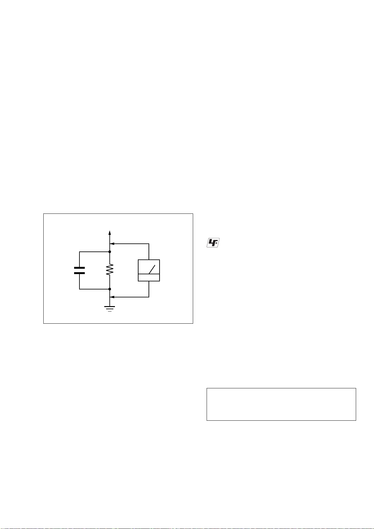
Fig. A. Using an AC voltmeter to check AC leakage.
Ω
Earth Ground
AC
voltmeter
(0.75 V)
LEAKAGE TEST
The AC leakage from any exposed metal part to earth ground
and from all exposed metal parts to any exposed metal part ha ving
a return to chassis, must not exceed 0.5 mA (500 microamperes).
Leakage current can be measured by any one of three methods.
1. A commercial leakage tester , such as the Simpson 229 or RCA
WT -540A. Follow the manufacturers' instructions to use these
instruments.
2. A battery-operated AC milliammeter. The Data Precision 245
digital multimeter is suitable for this job.
3. Measuring the voltage drop across a resistor by means of a V OM
or battery-operated AC voltmeter. The “limit” indication is
0.75V , so analog meters must ha ve an accurate low-voltage scale.
The Simpson 250 and Sanwa SH-63Trd are examples of a
passive VOM that is suitable. Nearly all battery operated digital
multimeters that have a 2V A C range are suitable. (See Fig. A)
Unleaded solder
Boards requiring use of unleaded solder are printed with the leadfree mark (LF) indicating the solder contains no lead.
(Caution: Some printed circuit boards may not come printed with
the lead free mark due to their particular size.)
: LEAD FREE MARK
Unleaded solder has the following characteristics.
• Unleaded solder melts at a temperature about 40°C higher than
ordinary solder.
Ordinary soldering irons can be used but the iron tip has to be
applied to the solder joint for a slightly longer time.
Soldering irons using a temperature regulator should be set to
about 350°C.
Caution: The printed pattern (copper foil) may peel away if the
heated tip is applied for too long, so be careful!
• Strong viscosity
Unleaded solder is more viscous (sticky, less prone to flow) than
ordinary solder so use caution not to let solder bridges occur such
as on IC pins, etc.
• Usable with ordinary solder
It is best to use only unleaded solder but unleaded solder may
also be added to ordinary solder.
WARNING!!
WHEN SERVICING, DO NOT APPROACH THE LASER
EXIT WITH THE EYE TOO CLOSELY. IN CASE IT IS
NECESSARY TO CONFIRM LASER BEAM EMISSION,
BE SURE TO OBSER VE FROM A DISTANCE OF MORE
THAN 25 cm FROM THE SURFACE OF THE
OBJECTIVE LENS ON THE OPTICAL PICK-UP BLOCK.
SAFETY-RELATED COMPONENT WARNING!!
COMPONENTS IDENTIFIED BY MARK 0 OR DOTTED
LINE WITH MARK 0 ON THE SCHEMATIC DIAGRAMS
AND IN THE PARTS LIST ARE CRITICAL TO SAFE
OPERATION. REPLACE THESE COMPONENTS WITH
SONY PARTS WHOSE PART NUMBERS APPEAR AS
SHOWN IN THIS MANUAL OR IN SUPPLEMENTS
PUBLISHED BY SONY.
CAUTION:
The use of optical instrument with this product will increase eye
hazard.
CAUTION
Use of controls or adjustments or performance of procedures
other than those specified herein may result in hazardous
radiation exposure.
ATTENTION AU COMPOSANT AYANT RAPPORT
À LA SÉCURITÉ!
LES COMPOSANTS IDENTIFIÉS PAR UNE MARQUE 0
SUR LES DIAGRAMMES SCHÉMATIQUES ET LA LISTE
DES PIÈCES SONT CRITIQUES POUR LA SÉCURITÉ
DE FONCTIONNEMENT. NE REMPLACER CES COMPOSANTS QUE PAR DES PIÈCES SONY DONT LES
NUMÉROS SONT DONNÉS DANS CE MANUEL OU D ANS
LES SUPPLÉMENTS PUBLIÉS PAR SONY.
— 3 —
Page 4

TABLE OF CONTENTS
Precautions
1 Safety Precautions ······························································ 5
2 Servicing Precautions ························································ 7
3 ESD Precautions·································································8
4 Handling the Optical Pick-up ············································· 9
1. General
Hookups and Settings ······················································1-3
Basic Operation ·······························································1-8
DVD Recording·····························································1-11
Playing Discs ·································································1-13
VCR Recording ·····························································1-16
Playing VHS Tapes························································1-18
DVD Editing··································································1-19
Dubbing (TAPA y DVD) ···········································1-21
DV Dubbing (DV y DVD)·········································1-22
Settings and Adjustments ··············································1-23
Additional Information··················································1-26
2. Disassembly and Reassembly
2-1 Cabinet and PCB ····························································2-1
2-1-1 Cabinet Top Removal ·····················································2-1
2-1-2 Ass’y Botton Cover Removal········································· 2-1
2-1-3 Ass’y Front Panel Removal············································2-1
2-1-4 Chassis Removal ····························································2-2
2-1-5 VCR Main PCB Removal ··············································2-2
2-2 Circuit Board Locations ·················································2-3
2-3 VCR Deck Parts Locations ············································2-4
2-3-1 T op V iew ········································································2-4
2-3-2 Bottom Vie w···································································2-6
2-4 VCR DECK···································································· 2-7
2-4-1 Holder FL Cassette Ass’y Removal ·······························2-7
2-4-2 Lever FL Arm Ass’y Removal ·······································2-7
2-4-3 Lever FL Door Removal ················································2-8
2-4-4 Slider FL Drive, Gear FL Cam Removal ·······················2-8
2-4-5 Gear W orm Wheel Removal··········································· 2-9
2-4-6 Cable Flat Removal························································2-9
2-4-7 Motor Loading Ass’y Removal ····································2-10
2-4-8 Bracket Gear, Gear Joint 2, 1 Removal ························2-10
2-4-9 Gear Loading Drive, Slider Cam,
Lever Load S, T Ass’y Removal ··································2-11
2-4-10Gear Loading Drive, Slider Cam,
Lever Load S, T Ass’y Assembly·································2-11
2-4-11Lever Pinch Drive, Lever Tension Drive Removal·······2-12
2-4-12Lever Tension Ass’y, Band Brake Ass’y Removal ·······2-12
2-4-13Lever Brake S, T Ass’y Removal ·································2-13
2-4-14Gear Idle Ass’y Removal ············································· 2-13
2-4-15Disk S, T Reel Removal ···············································2-14
2-4-16Holder Clutch Ass’y Removal······································2-14
2-4-17Lever Up Down Ass’y, Gear Center Ass’y Removal ··· 2-15
2-4-18Guide Cassette Door Removal ····································· 2-15
2-4-19Lever Unit Pinch Ass’y, Plate Joint,
Spring Pinch Drive Removal ········································2-16
2-4-20Lever #9 Guide Ass’y Removal ···································2-16
2-4-21FE Head Removal ························································2-17
2-4-22ACE Head Removal ·····················································2-17
2-4-23Slider S, T Ass’y Removal ···········································2-18
2-4-24Plate Ground Deck, Cylinder Ass’y Removal··············2-18
2-4-25Hook Capstan, Belt Pulley Removal ····························2-19
2-4-26Motor Capstan Ass’y Removal ···································· 2-19
2-4-27Post #8 Guide Ass’y Removal······································2-20
2-4-28Level Head Cleaner Ass’y Removal ····························2-20
2-4-29How to Eject the Cassette Tape ····································2-20
2-5 The Table of Cleaning, Lubrication and
Replacement Time about Principal Parts ·····················2-21
3. Block Diagram..........................................................3-1
4. PCB Diagrams
4-1 VCR Main PCB·······························································4-3
4-2 DVD Main PCB ······························································4-7
4-3 Jack PCB ·······································································4-11
4-4 DV Input PCB ······························································· 4-15
4-5 Function Timer PCB······················································4-15
5. Schematic Diagrams
◆ Block Identification of Main PCB·········································5-3
5-1 S.M.P.S (VCR Main PCB) ··············································5-5
5-2 Power (VCR Main PCB) ·················································5-7
5-3 Logic (VCR Main PCB)··················································5-9
5-4 A/V (VCR Main PCB) ··················································5-11
5-5 Hi-Fi (VCR Main PCB) ················································5-13
5-6 Function Timer (Function Timer PCB) ·························5-15
5-7 Encoder (DVD Main PCB) ···········································5-17
5-8 Decoder (DVD Main PCB) ···········································5-19
5-9 Video Decoder and Connector (DVD Main PCB) ········5-21
5-10 DV Interface and 1394 Connector (DVD Main PCB)···5-23
5-11 Audio DAC and ADC (DVD Main PCB)······················5-25
5-12 Connectors and Power (DVD Main PCB)·····················5-27
5-13 Mts/Tuner (JACK PCB) ················································5-29
5-14 AV IN/OUT (JACK PCB) ·············································5-31
5-15 Component/Super Out (JACK PCB)·····························5-33
6. Alignment and Adjustments
6-1 VCR Adjustment ·····························································6-1
6-1-1 Reference ·········································································6-1
6-1-2 Head Switching Point Adjustment ··································6-3
6-2 VCR Mechanical Adjustment··········································6-4
6-2-1 Tape Transport System and Adjustment Locations ·········6-4
6-2-2 Tape T ransport System Adjustment·································6-5
6-2-3 Reel Torque ···································································6-10
7. Troubleshooting·················································7-1
8. Repair Parts List
8-1 Exploded Views······························································· 8-2
8-1-1 Cabinet Assembly····························································8-2
8-1-2 VCR Mechanical Parts (Top Side) ··································8-3
8-1-3 VCR Mechanical Parts (Bottom Side) ····························8-4
8-2 Electrical Parts List ·························································8-5
— 4 —
Page 5
PRECAUTIONS
1 SAFETY PRECAUTIONS
1) Before returning an instrument to the customer, always make a
safety check of the entire instrument, including, but not limited
to, the following items:
(1) Be sure that no built-in protective devices are defective or ha v e
been defeated during servicing.
(1)Protective shields are provided to protect both the technician
and the customer. Correctly replace all missing protective
shields, including any removed for servicing convenience.
(2)When reinstalling the chassis and/or other assembly in the
cabinet, be sure to put back in place all protective devices,
including, but not limited to, nonmetallic control knobs,
insulating fish papers, adjustment and compartment covers/
shields, and isolation resistor/capacitor networks. Do not operate
this instrument or permit it to be operated without all protective
devices correctly installed and functioning.
(2) Be sure that there are no cabinet openings through which adults
or children might be able to insert their fingers and contact a
hazardous voltage. Such openings include, but are not limited
to, excessively wide cabinet v entilation slots, and an improperly
fitted and/or incorrectly secured cabinet back cover.
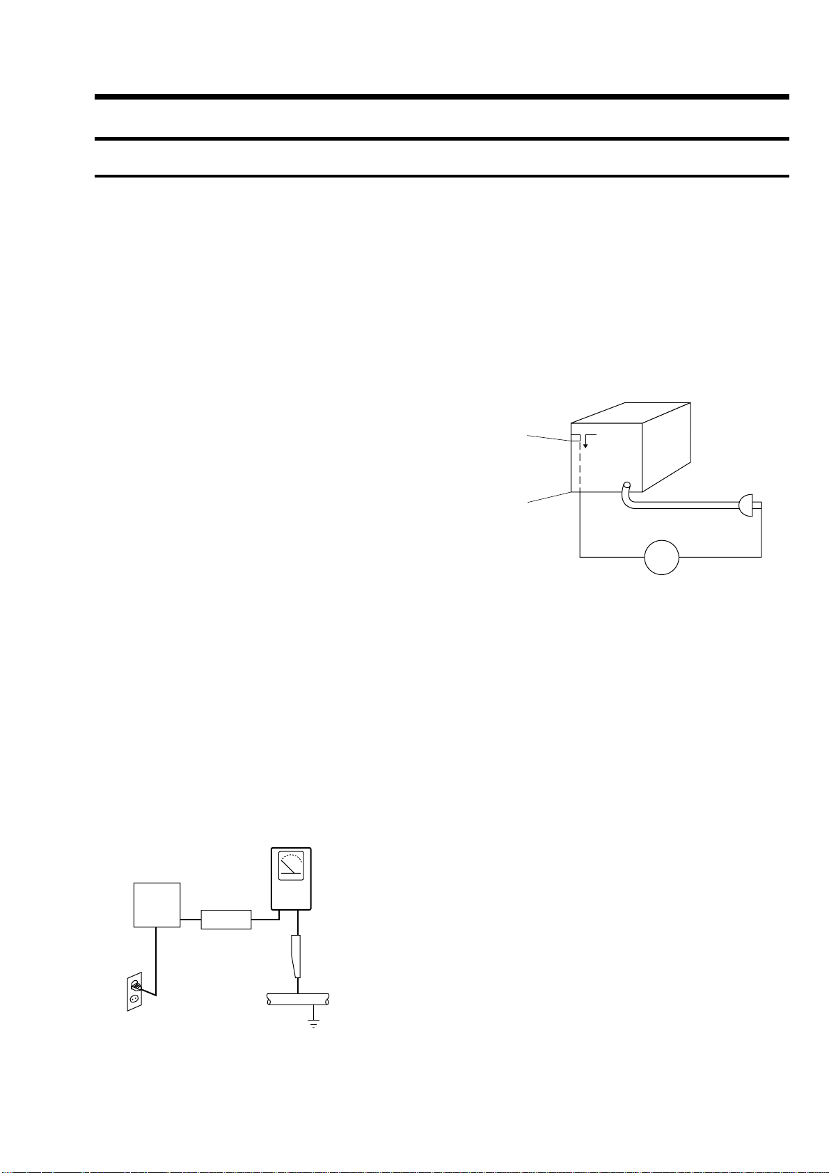
(3) Leakage Current Hot Check-With the instrument completely
reassembled, plug the AC line cord directly into a 120V AC
outlet. (Do not use an isolation transformer during this test.)
Use a leakage current tester or a metering system that complies
with American National Standards institute (ANSI) C101.1
Leakage Current for Appliances and Underwriters Laboratories
(UL) 1270 (40.7). With the instrument’s AC switch first in the
ON position and then in the OFF position, measure from a known
earth ground (metal water pipe, conduit, etc.) to all exposed
metal parts of the instrument (antennas, handle brackets, metal
cabinets, screwheads, metallic overlays, control shafts, etc.),
especially any exposed metal parts that offer an electrical r eturn
path to the chassis.
Any current measured must not exceed 0.5mA. Reverse the
instrument power cord plug in the outlet and repeat the test. See
Fig. 1.
Any measurements not within the limits specified herein indicate
a potential shock hazard that must be eliminated before returning
the instrument to the customer.
(READING SHOULD
NOT BE ABOVE
0.5mA)
EARTH
GROUND
DEVICE
UNDER
TEST
TEST ALL
EXPOSED METER
SURFACES
2-WIRE CORD
ALSO TEST WITH
PLUG REVERSED
(USING AC ADAPTER
PLUG AS REQUIRED)
LEAKAGE
CURRENT
TESTER
(4) Insula tion Resistance Test Cold Check-(1) Unplug the power
supply cord and connect a jumper wire between the two prongs
of the plug. (2) Turn on the po wer switch of the instrument. (3)
Measure the resistance with an ohmmeter between the jumpered
AC plug and all exposed metallic cabinet parts on the instrument,
such as screwheads, antenna, control shafts, handle brackets,
etc. When an exposed metallic part has a return path to the
chassis, the reading should be between 1 and 5.2 megohm. When
there is no return path to the chassis, the reading must be infinite.
If the reading is not within the limits specified, there is the
possibility of a shock hazard, and the instrument must be repared
and rechecked before it is returned to the customer. See Fig. 2.
Antenna
Terminal
Exposed
Metal Part
ohm
ohmmeter
Fig. 2 Insulation Resistance Test
2) Read and comply with all caution and safety related notes on or
inside the cabinet, or on the chassis.
3) Design Alteration W arning-Do not alter or add to the mechanical
or electrical design of this instrument. Design alterations and
additions, including but not limited to, circuit modifications and
the addition of items such as auxiliary audio output connections,
might alter the safety characteristics of this instrument and create
a hazard to the user. Any design alterations or additions will
make you, the servicer, responsible for personal injury or
property damage resulting therefrom.
4) Observe original lead dress. Take extra care to assure correct
lead dress in the following areas:
(1) near sharp edges, (2) near thermally hot parts (be sure that
leads and components do not touch thermally hot parts), (3) the
AC supply, (4) high voltage, and (5) antenna wiring. Always
inspect in all areas for pinched, out-of-place, or frayed wiring,
Do not change spacing between a component and the printedcircuit board. Check the AC power cord for damage.
5) Components, parts, and/or wiring that appear to have overheated
or that are otherwise damaged should be replaced with
components, parts and/ or wiring that meet original
specifications.
Additionally, determine the cause of o verheating and/or damage
and, if necessary, take correcti ve action to remov e any potential
safety hazard.
Fig. 1 AC Leakage Test
— 5 —
Page 6

6) Product Safety Notice-Some electrical and mechanical parts
have special safety-related characteristics which are often not
evident from visual inspection, nor can the protection they giv e
necessarily be obtained by replacing them with components rated
for higher voltage, wattage, etc. Parts that have special safety
characteristics are identified by shading, an ( ) or a ( ) on
schematics and parts lists. Use of a substitute replacement that
does not have the same safety characteristics as the
recommended replacement part might create shock, fire and/or
other hazards. Product safety is under review continuously and
new instructions are issued whenever appropriate.
— 6 —
Page 7

2 SERVICING PRECAUTIONS
CAUTION: Before servicing units covered by this service manual
and its supplements, read and follow the Safety Precautions section
of this manual.
Note: If unforseen circumstances create conflict between the
following servicing precautions and any of the safety precautions,
always follow the safety precautions. Remember: Safety First.
2-1 General Servicing Precautions
(1) a. Always unplug the instrument’ s AC po wer cord from the AC
power source before (1) re-moving or reinstalling any
component, circuit board, module or any other instrument
assembly, (2) disconnecting an y instrument electrical plug or
other electrical connection, (3) connecting a test substitute in
parallel with an electrolytic capacitor in the instrument.
b. Do not defeat any plug/socket B+ voltage interlocks with
which instruments covered by this service manual might be
equipped.
c. Do not apply AC power to this instrument and/or any of its
electrical assemblies unless all solid-state device heat sinks
are correctly installed.
d. Always connect a test instrument’s ground lead to the
instrument chassis ground before connecting the test
instrument positive lead. Always remove the test instrument
ground lead last.
2-2 Insulation Checking Procedure
Disconnect the attachment plug from the AC outlet and turn the
power ON. Connect the insulation resistance meter (500V) to the
blades of the attachment plug. The insulation resistance between
each blade of the attachment plug and accessible conductive parts
(see note) should be more than 1 Megohm.
Note: Accessible conductive parts include metal panels, input
terminals, earphone jacks, etc.
Note: Refer to the Safety Precautions section ground lead last.
(2) The service precautions are indicated or printed on the cabinet,
chassis or components. When servicing, follow the printed or
indicated service precautions and service materials.
(3)The components used in the unit have a specified flame
resistance and dielectric strength.
When replacing components, use components which have the
same ratings. Components identified by shading, by ( ) or by
( ) in the circuit diagram are important for safety or for the
characteristics of the unit. Always replace them with the exact
replacement components.
(4) An insulation tube or tape is sometimes used and some
components are raised above the printed wiring board for safety .
The internal wiring is sometimes clamped to prevent contact
with heating components. Install such elements as they were.
(5) After servicing, always check that the removed screws,
components, and wiring have been installed correctly and that
the portion around the serviced part has not been damaged and
so on. Further, check the insulation between the blades of the
attachment plug and accessible conductive parts.
— 7 —
Page 8

3 ESD PRECAUTIONS
Electrostatically Sensitive Devices (ESD)
Some semiconductor (solid state) devices can be damaged easily
by static electricity.
Such components commonly are called Electrostatically Sensitive
Devices (ESD). Examples of typical ESD devices are integrated
circuits and some field-effect transistors and semiconductor chip
components. The following techniques should be used to help reduce
the incidence of component damage caused by static electricity.
(1) Immediately before handling any semiconductor component or
semiconductor-equipped assembly, drain off any electrostatic
charge on your body by touching a known earth ground.
Alternatively, obtain and wear a commercially available
discharging wrist strap device, which should be removed for
potential shock reasons prior to applying power to the unit under
test.
(2) After removing an electrical assembly equipped with ESD
devices, place the assembly on a conductive surface such as
aluminum foil, to prevent electrostatic charge buildup or
exposure of the assembly.
(3) Use only a grounded-tip soldering iron to solder or unsolder
ESD devices.
(4) Use only an anti-static solder removal devices. Some solder
removal devices not classified as “anti-static” can generate
electrical charges sufficient to damage ESD devices.
(5) Do not use freon-propelled chemicals. These can generate
electrical charges sufficient to damage ESD devices.
(6) Do not remove a replacement ESD device from its protective
package until immediately before your are ready to install it.
(Most replacement ESD devices are packaged with leads
electrically shorted together by conductive foam, aluminum foil
or comparable conductive materials).
(7) Immediately before removing the protective materials from the
leads of a replacement ESD device, touch the protective mater ial
to the chassis or circuit assembly into which the device will be
installed.
CAUTION: Be sure no power is applied to the chassis or circuit,
and observe all other safety precautions.
(8) Minimize bodily motions when handling unpackaged
replacement ESD devices. (Otherwise harmless motion such as
the brushing together of your clothes fabric or the lifting of
your foot from a carpeted floor can generate static electricity
sufficient to damage an ESD device).
— 8 —
Page 9
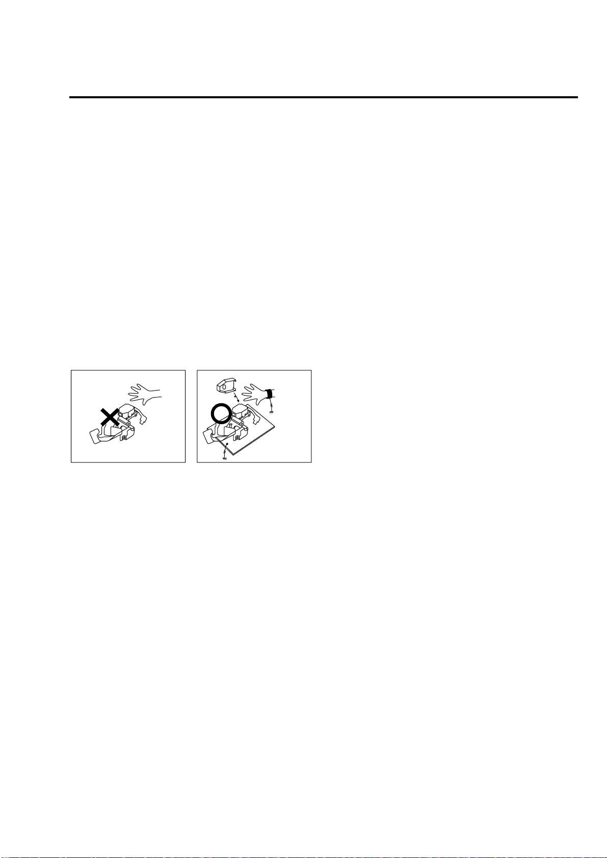
4 HANDLING THE OPTICAL PICK-UP
The laser diode in the optical pick up may suffer electrostatic
breakdown because of potential static electricity from clothing and
your body.
The following method is recommended.
(1) Place a conductive sheet on the work bench (The black sheet
used for wrapping repair parts.)
(2) Place the set on the conductive sheet so that the chassis is
grounded to the sheet.
(3) Place your hands on the conductive sheet(This gives them the
same ground as the sheet.)
(4) Remove the optical pick up block
(5) Perform work on top of the conductive sheet. Be careful not to
let your clothes or any other static sources to touch the unit.
◆ Be sure to put on a wrist strap grounded to the sheet.
◆ Be sure to lay a conductive sheet made of copper etc. Which is
grounded to the table.
WRIST-STRAP
FOR GROUNDING
1M
THE UNIT
1M
CONDUCTIVE SHEET
Fig.3
(6) Short the short terminal on the PCB, which is inside the Pick-
Up ASS’Y, before replacing the Pick-Up. (The short terminal is
shorted when the Pick-Up Ass’y is being lifted or moved.)
(7) After replacing the Pick-up, open the short terminal on the PCB.
— 9 —
Page 10

MEMO
— 10 —
Page 11
RDR-VX500
1. GENERAL
About this manual
•Instructions in this manual
describe the controls on the
remote. You can also use the
controls on the recorder if they
have the same or similar names as
those on the remote.
•The on-screen display illustratio ns
used in this manual may not match
the graphics displayed on your TV
screen.
•The explanations regarding discs
in this manual refer to discs
created on this recorder. The
explanations do not apply to discs
that are created on other recorders
and played back on this recorder.
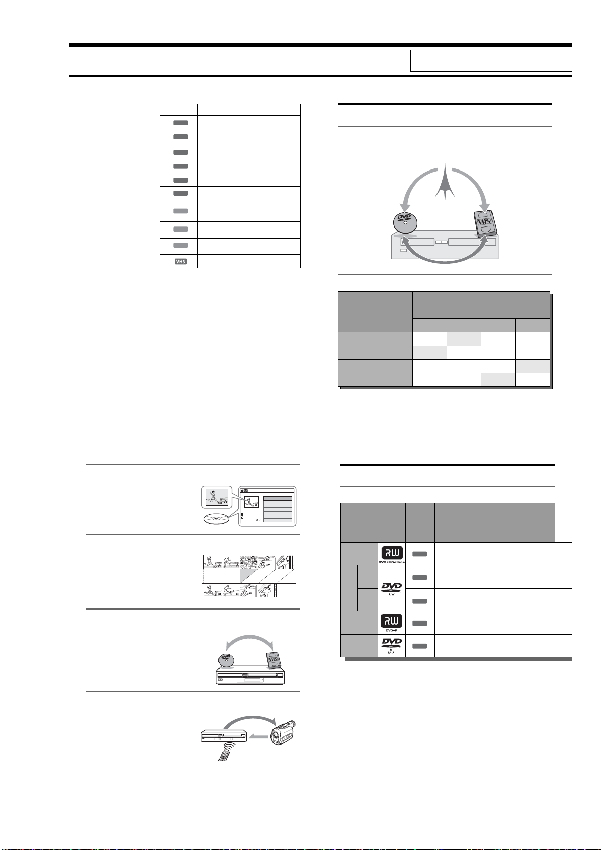
Icon Meaning
Functions available for DVD+RWs
+
RW
Functions available for DVD-RWs in VR (Video
-
RWVR
Recording) mode
Functions available for DVD-RWs in video mode
-
RWVideo
Functions available for DVD+Rs
+
R
Functions available for DVD-Rs
-
R
Functions available for DVD VIDEOs
DVD
Functions available for VIDEO CDs, Super
VCDs or CD-Rs/CD-RWs in video CD format or
VCD
Super VCD format
Functions available for music CDs or CD-Rs/CD-
CD
RWs in music CD format
Functions available for DATA CDs (CD-Rs/CD-
DATA CD
RWs containing MP3
Functions available for VHS VIDEOs
*MP3 (MPEG1 Audio Layer 3) is a standard format defined by ISO/MPEG
which compresses audio data.
* audio tracks or JPEG files)
This section is extracted from instruction manual.
(2-186-506-11)
Ways to Use Your Video Cassette Recorder/DVD Recorder
What is a Video Cassette Recorder/DVD Recorder?
, This is a DVD recorder with built-in VHS video deck. It allows recording to DVD+RWs,
DVD+Rs, DVD-RWs, DVD-Rs, and VHS tapes. In addition, you can also enjo y playback and
editing of DVD discs and VHS tapes.
Operation restrictions
Possible simultaneous operations
Current operation
Playing a VHS tape — No Yes
Recording on a VHS tape No — Yes Yes
Playing a DVD disc Yes
Recording on a DVD disc Yes Yes No —
*1
When pressing DVD, VHS tape playback stops.
*2
When pressing VIDEO, DVD playback stops.
VHS DVD
Playback Recording Playback Recording
*1
Yes
*2
*2
Yes
— No
*1
Quick access to recorded titles – Title List
, Display the Title List to see all of the titles
on the disc, including the recording date,
channel, recording mode, rec ording time
and movie thumbnail image (page 42).
Creating your own program – Playlist
, Record a program on a DVD-RW (VR
mode), then erase, move and add scenes at
will to create your own, original program
(page 84).
One touch button dubbing from VCR to DVD
, This recorder lets you dub from VHS tape
to DVD and from DVD to VHS tape with a
single deck (page 89).
*Note that when playing back and recording a DVD or
VHS tape that includes a copy protect signal, the copy
protect function will prevent normal recording.
Simple dubbing of DV tapes – DV Edit
, Connect your digital video camera to the
DV IN jack and simply dub the entire
contents or just selected scenes to a DVD
disc (page 93).
Title List
Original
Playlist
Control
T
CH 23
Nov/16/2004
08:00 PM
Dubbing
Title List(Original)
No. Title Length Edit
01 CH 23 >01:29:03
02 CH 66 >00:31:23
03 CH 95 >01:59:00
04 CH 97 >00:58:56
10:10 AM
5
8
Quick Guide to DVD Disc Types
Recordable and playable discs
Icon used
VR
mode
Video
mode
Disc
Logo
*1
)
Type
DVD+RW
DVDRW
DVD+R
DVD-R
Usable disc versions (as of Ju ne 2004)
•4x-speed or slower DVD+RWs
•2x-speed or slower DVD-RWs (Ver.1.1, Ver.1.1
with CPRM
•4x-speed or slower DVD-RWs (Ver.1.2, Ver.1.2
with CPRM)
•8x-speed or slower DVD+Rs
•8x-speed or slower DVD-Rs (Ver.2.0)
in this
manual
+
RW
-
RW
-
RW
+
-
VR
Video
R
R
Formatting
(new discs)
Automatically
formatted
Format in VR mode
(page 43)
Format in Video
*2
(page 43)
mode
Automatically
formatted
Automatically
formatted
“DVD+RW,” “DVD-RW,” “DVD+R,” and “DVD-R,”
are trademarks.
*1
CPRM (Content Protection for Recordable Media) is
a coding technology that protects copyrights for
images.
*2
Unused DVD-RWs are formatted in VR mode
automatically.
*3
Erasing titles only frees up disc space if you erase the
last title.
*4
Erasing titles does not free up disc space.
Compatibility with other
DVD players (finalizing)
Playable on DVD+RW
compatible players
(automatically finalized)
Playable only on VR mode
*2
compatible players (finalization
unnecessary) (page 44)
Playable on most DVD players
(finalization necessary)
(page 44)
Playable on DVD+R compatible
players (finalization necessary)
(page 44)
Playable on most DVD players
(finalization necessary)
(page 44)
A list of recordable and playable DVD discs is on page 10.
Dubbing
9
10
1-1
Page 12
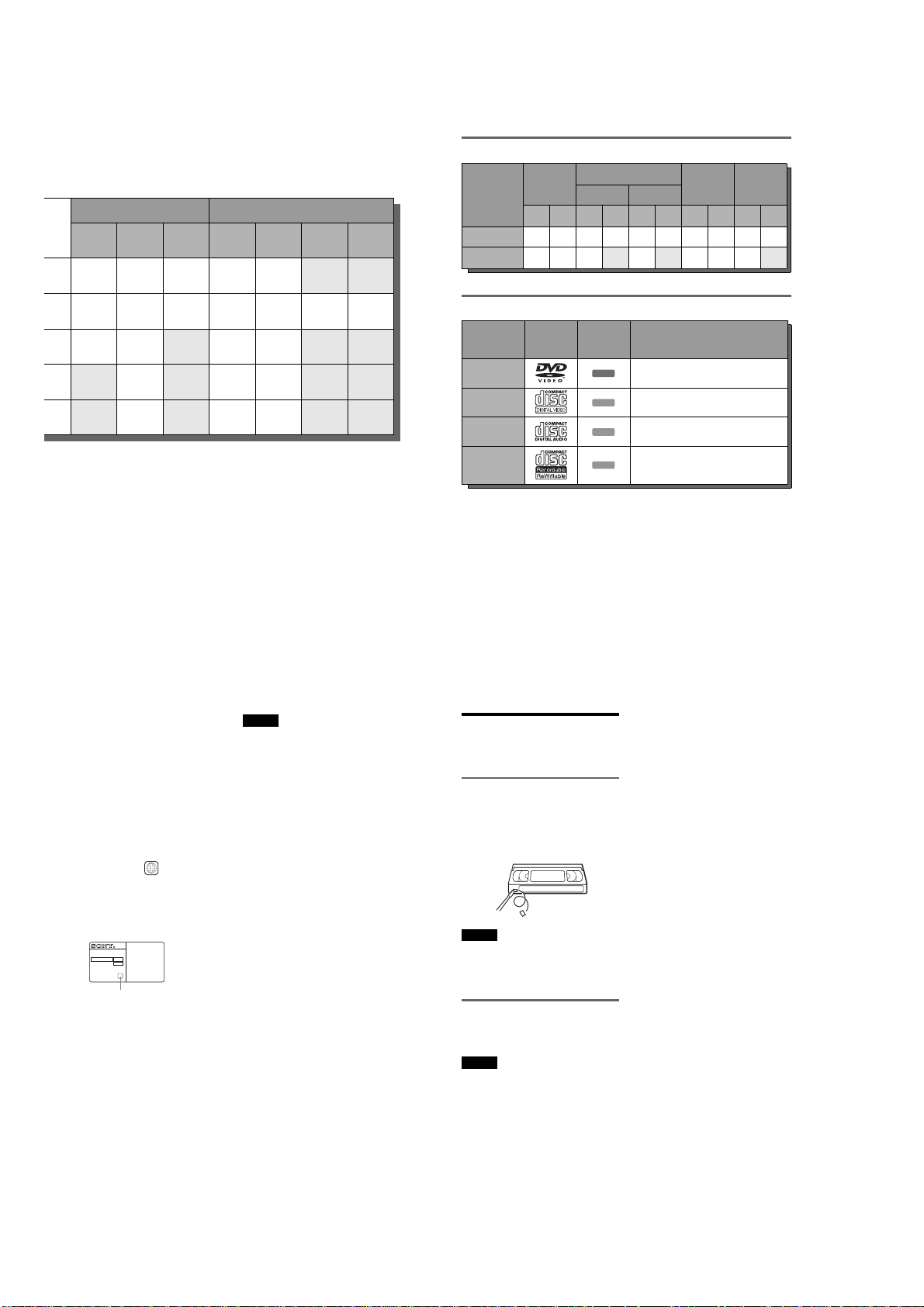
12 cm/8 cm discs
Recording Features Editing Features
Auto
Chapter
(page 104)
Manual
Chapter
(page 84)
Rewrite
(page 48)
Yes Yes YesYesYes*3No No
Yes Yes Yes Yes Yes Yes Yes
Yes Yes No Yes Yes
No Yes No Yes Yes
No Yes No Yes Yes
Discs that cannot be recorded on
•DVD-RWs (V er.1.0)
•DVD+RWs that are not 2.4x-speed compatible
•Double layer discs
•8 cm discs
Change
title name
(page 82)
Erase title
(page 82)
*3
*4
*4
A-B Erase
(page 83)
No No
No No
No No
Playlist
(page 84)
Operation
Playback Yes — Yes Yes Yes Ye s Yes — Yes Yes
Recording Yes — Yes No Yes No Yes — Yes No
DVD+RW
12 cm 8 cm 12 cm 8 cm 12 cm 8 cm 12 cm 8 cm 12 cm 8 cm
DVD-RW
VR mode Video mode
DVD+R DVD-R
Playable discs
Type Disc Logo
DVD VIDEO
VIDEO CD
CD
DATA CD
*A logical format of files and folders on DATA-CDs,
defined by ISO (International Standard Organization).
Discs that cannot be played
•CD-Rs/CD-RWs, othe r than those recorded in
music CD format, MP3 or JPEG format, or
Video CD format
•Data part of CD-Extras
• DVD-ROMs
• DVD Audio discs
• DVD-RAMs
• HD layer on Super Audio CDs
Icon used
in this
manual
DVD
VCD
CD
DATA CD
Characteristics
Discs such as movies that can be purchased or
rented
VIDEO CDs or CD-Rs/CD-RWs in VIDEO CD/
Super VIDEO CD format (with PBC function)
Music CDs or CD-Rs/CD-RWs in music CD
format that can be purchased
CD-Rs/CD-RWs created on a PC or similar
device in music format, or MP3 or JPEG format
that conforms to ISO9660* Lev el 1/Level 2
•DVD VIDEOs with a different region code
(see page 13)
•A disc recorded in a color system other than
NTSC, such as PAL or SECAM
z Hint
This DVD recorder can play 8 cm CDs and 8 cm DVDs
as well.
Note on playback operations of DVD VIDEOs/
VIDEO CDs
Some playback operations of DVD VIDEOs/
VIDEO CDs may be intentionally set by software
producers. Since this recorder plays DVD
VIDEOs/VIDEO CDs according to the disc
contents the software produ cers designed, some
playback features may n ot be available. Also, see
the instructions supplied with the DVD VIDEOs/
VIDEO CDs.
Region code (DVD VIDEO only)
Your recorder has a region code printed on th e rear
of the unit and will only play DVD VIDEOs
(playback only) labeled with identical region
codes. This system is used to prote ct copyrights.
DVD VIDEOs labeled will also play on this
recorder.
If you try to play any other DVD VIDEO, the
message “Please check the Regional code of this
disc.” will appear on the TV screen. Depending on
the DVD VIDEO, no region code indication may
be labeled even though playing the DVD VIDEO
is prohibited by area restrictions.
NO.
Music discs encoded with copyri ght protection
technologies
This product is designed to playba ck discs that
conform to the Compact Disc (CD) standard.
Recently, various music discs encoded with
copyright protection techn ologies are being
marketed by some record compan ies. Please be
aware that among those disc s, there are some that
do not conform to the CD standard and may not be
playable by this product.
ALL
RDR-VX500
X
Region code
,continued
Notes
•Some DVD+RWs/DVD+Rs, DVD-RWs/DVD-Rs, or
CD-RWs/CD-Rs cannot be played on this record er due
to the recording quality or physical condition of the
disc, or the characteristics of the recording device and
authoring software. The disc will not play if it has not
been correctly finalized. For more information, see the
operating instructions for the re cording device.
•You cannot mix VR mode and Video mode on the same
DVD-RW. To change the disc’s format, reformat the
disc (page 43). Note that the disc’s contents will be
erased after reformatting.
•You cannot shorten the time required for recording
even with high-speed discs. Also, you cannot record on
the disc if the disc is not 1x speed compatible.
•It is recommended that you use discs with “For Video”
printed on their packaging.
•You cannot add new recordings to DVD-Rs or DVDRWs (Video mode) that contain recordings made on
other DVD equipment.
•In some cases, you may not be able to add new
recordings to DVD+RWs that contain recordings made
on other DVD equipment. If you do add a new
recording, note that this recorder will rewrite the DVD
menu.
•If the disc contains PC data unrecognizable by this
recorder, the data may be erased.
11
12
Recordable and playable
VHS tapes
This VCR uses the VHS system.
Recording
This VCR records using the VHS system.
z Hint
If you do not want recorded contents to be erased, break
off the erasure prevention tab. To record again on a tape
that has had the erasure prevention tab removed, cover
the hole with cellophane tape, etc.
Safety tab
Notes
•This VCR cannot record using the S-VHS system.
•Tapes recorded in EP (3
played back on standard mode only VHS decks.
•Noise may appear in the image when tapes recorded in
×) mode by this VCR are played back on other
EP (3
VHS decks with 3
Playback
The VCR automatically identifies the recording
system and recording mode (SP (standard) or EP
(3
×)) of recorded tapes during playback.
Notes
•You cannot play back foreign video software t hat uses
non-NTSC color TV systems (PAL, SECAM).
•When playing back tapes recorded using the S-VHS
system, the playback image may be disturbed.
×) mode by this VCR cannot be
× mode.
13
14
1-2
Page 13
Hookups and Settings
Hooking Up the Recorder
Follow steps 1 to 7 to hook up and adju st the
settings of the recorder.
Notes
•Plug cords securely to prevent unwanted noise.
•Refer to the instructions supplied with the components
to be connected.
•Be sure to disconnect the power cord of each
component before connecting.
Step 1: Unpacking
Check that you have the following items:
•Audio/video cord
(pinplug × 3 y pinplug × 3) (1)
•Antenna cable (1)
•Remote commander (remote) (1)
•Size AA (R6) batteries (2)
Step 2: Connecting the
Antenna Cable
Select one of the following antenna hookups. Do
not connect the power cord until you reach
“Connecting the Power Cord” on p age 26.
If you have Hookup
Cable box or satellite receiver wi th a
video/audio output
Cable box with an antenna output
only
Cable without cable box, or antenna
only (no cable TV)
Note to CATV system installe r (in USA)
This reminder is provided to call the CATV
system installer’s attention to Article 820- 40 of
the NEC that provides guidelines for proper
grounding and, in particular, specifies that the
cable ground shall be connected to the grounding
system of the building, as close to the point of
cable entry as practical.
Notes
•If your antenna is a flat cable (300-ohm twin lead
cable), use an external antenna connector (not
supplied) to connect the antenna to the recorder.
•If you have separate cables for VHF and UHF
antennas, use a UHF/VHF band mixer (not supplied) to
connect the ant enna to the recorder.
A (page 16)
B (page 17)
C (page 17)
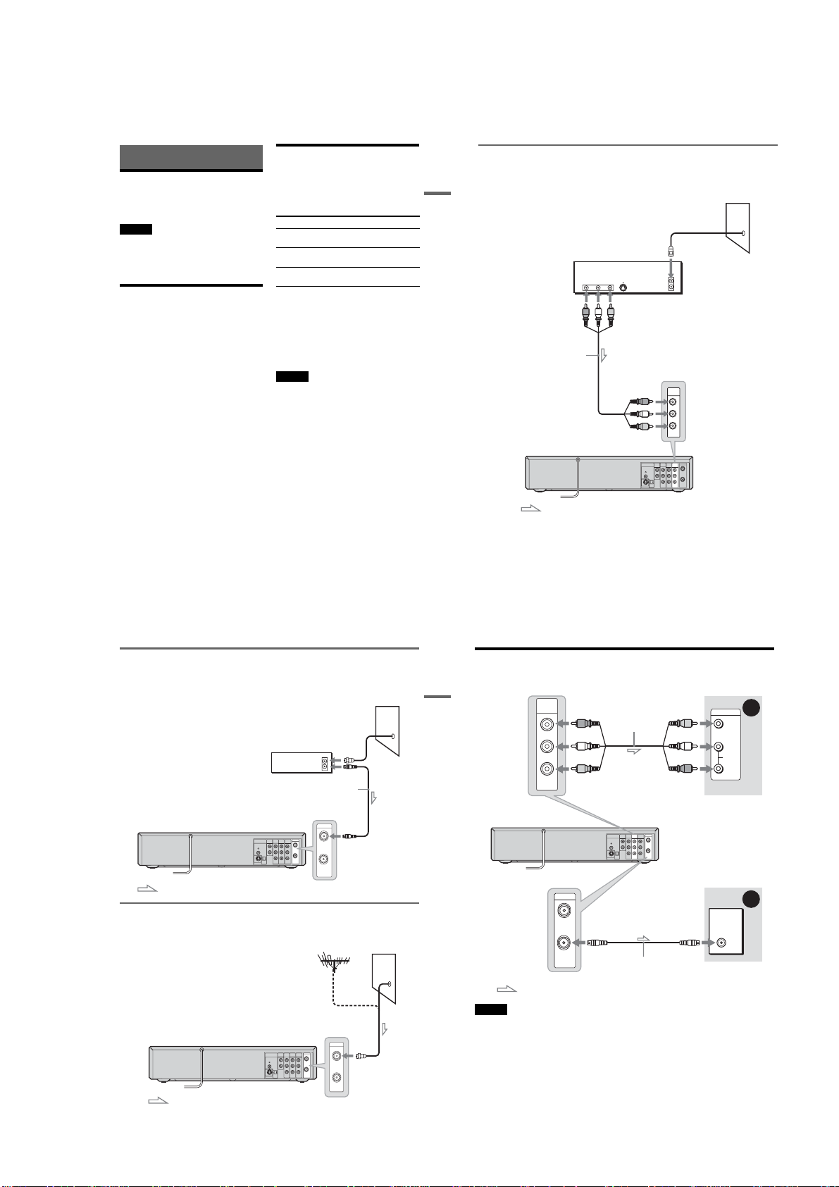
A: Cable box or satellite receiver with a video/audio output
With this hookup, you can record any channel on the cable box or satellite receiver. Be sure that the
satellite receiver or cable box is turned on.
To watch cable or satellite programs , you need to match the channel on the recorder (L1) to the inpu t jack
Hookups and Settings
connected to the cable box or sa tellite receiver (LINE 1 IN).
Cable box/satellite receiver
AUDIO
VIDEO
OUT
OUT
S VIDEO
RL
Audio/video cord
(supplied)
to LINE 1 IN
VCR-DVD recorder
: Signal flow
Wall
ANT IN
TO TV
LINE 1 IN
R
AUDIO
L
VIDEO
VHF/UHF
C
OMPONENT
AUDIO OUT
DIGITAL
AUDIO
OUT
LINE 1 IN
LINE OUT
VIDEO OUT
IN
R
Y
PCM/DTS/
DOLBY DIGITAL
R
AUDIO AUDIO
B
P
L
COAXIAL
L
OUT
OPTICAL
P
R
VIDEO VIDEO
S VIDEO OUT
,continued
B: Cable box with an antenna output only
With this hookup, you can record any channel on the satellite receiver or cable box. Be sure that the
satellite receiver or cable box is turned on.
To watch cable program s, you need to match the channel o n the recorder (2ch, 3ch or 4ch) to the antenna
output channel on the cable box (2 ch, 3ch or 4ch).
Wall
Cable box
ANT IN
TO TV
Antenna cable (supplied)
VCR-DVD recorder
COMPONENT
AUDIO OUT
DIGITAL
AUDIO
OUT
VIDEO OUT
R
PCM/DTS/
DOLBY DIGITAL
L
COAXIAL
OPTICAL
S VIDEO OUT
VHF/UHF
IN
VHF/UHF
LINE 1 IN
LINE OUT
IN
Y
R
AUDIO AUDIO
B
P
L
OUT
P
R
VIDEO VIDEO
OUT
to VHF/UHF IN
: Signal flow
C: Cable without cable box, or antenna only (no cable TV)
Use this hookup if you watch cable channels without a cable box. Also use this hookup if you are using
a VHF/UHF antenna or separat e VHF and UHF antennas.
With this hookup, you can record any channel by selecting the chan nel on the recorder.
Wall
VCR-DVD recorder
COMPONENT
AUDIO OUT
DIGITAL
AUDIO
OUT
VIDEO OUT
R
Y
PCM/DTS/
DOLBY DIGITAL
B
P
L
COAXIAL
OPTICAL
P
R
S VIDEO OUT
VHF/UHF
IN
VHF/UHF
LINE 1 IN
LINE OUT
IN
R
AUDIO AUDIO
L
OUT
VIDEO VIDEO
OUT
to VHF/UHF IN
15
16
Step 3: Connecting to Your TV
Select one of the following patter ns A or B, according to the input jack on you r TV.
Hookups and Settings
VCR-DVD recorder
Note
Do not connect more than one type of video cord between the recorde r and your TV at the same time.
LINE OUT
AUDIO
VIDEO
: Signal flow
(red)
(white)
(yellow)
to LINE OUT (AUDIO L/R)
VHF/UHF
IN
OUT
Audio/video cord
(supplied)
COMPONENT
AUDIO OUT
DIGITAL
AUDIO
OUT
VIDEO OUT
R
PCM/DTS/
DOLBY DIGITAL
L
COAXIAL
OPTICAL
S VIDEO OUT
VHF/UHF
LINE 1 IN
LINE OUT
IN
Y
R
AUDIO AUDIO
B
P
L
OUT
P
R
VIDEO VIDEO
Antenna cable
(supplied)
(yellow)
(white)
(red)
INPUT
VIDEO
L
AUDIO
R
TV or projector
TV
A
B
: Signal flow
17
18
1-3
Page 14
A
Connecting to audio/video input
jacks
If your TV, monitor, projector, or oth er equipment
has audio/video (A/V) input jacks, you will get
better picture and sound if you connect the
recorder using this connecti on.
Yellow
White (L)
Red (R)
B
Connecting to an antenna input
Yellow
White (L)
Red (R)
jack
If your TV does not have audio/video (A/V) input
jack, connect the recorder to a TV using an
antenna cable.
Setting the RF Output channel
When connecting the recorder to the TV using
only the antenna cable, you must s et the RF
Output channel in the “Tuner Preset” so that the
TV can receive the correct signal from the
recorder.
"/1
If your TV has an S video input jack
Connect an S video cord (not supplied). You will enjoy high quality images.
Make audio connections using the AUDIO OUT L/R ja cks when you connect the recorder using this
Hookups and Settings
connection.
S video cord
(not supplied)
to S VIDEO OUT
VCR-DVD recorder
DIGITAL
S VIDEO OUT
PCM/DTS/
DOLBY DIGITAL
AUDIO
INPUT
AUDIO
LRS VIDEO
(white) (red)
AUDIO OUT
OUT
R
L
COAXIAL
OPTICAL
DIGITAL
AUDIO
OUT
AUDIO OUT
R
PCM/DTS/
DOLBY DIGITAL
L
COAXIAL
OPTICAL
S VIDEO OUT
TV or projector
(red)
(white)
to AUDIO OUT L/R
VHF/UHF
COMPONENT
LINE 1 IN
LINE OUT
VIDEO OUT
IN
Y
R
AUDIO AUDIO
B
P
L
OUT
P
R
VIDEO VIDEO
Audio cord
(not supplied)
TV/VIDEO
1
Press "/1 to turn on the recorder.
2
Press
TV/VIDEO
disappears from the front panel display.
3
Turn on your TV and set it to the channel
When using channel 4 to receive the recorder
signal, see “3, 4 Ch Out” on page 98.
repeatedly until “TV”
3.
,continued
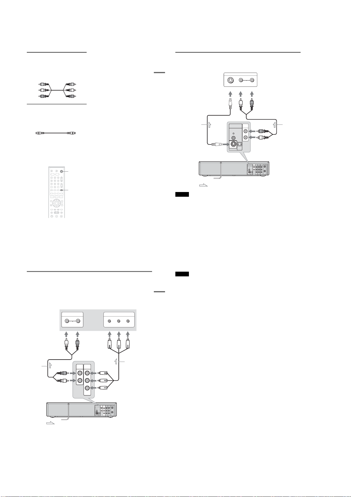
If your TV has component video input jacks
Connect the COMPONENT VIDE O OUT jacks using a component video cord (not supplied) or three
video cords (not supplied) of the same kind and length. You will enjoy accurate color reproduction and
high quality images.
If your TV accepts progressive 480p for mat signals, you must use this connection and then set
“Progressive” of “Video” to “On” in the “Setup” display (page 101). The PROGRESSIVE i ndicator
lights up when the recorder outputs progressive signals.
Make audio connections using the AUDIO OUT L/R jacks when you connect the recorder using this
connection.
INPUT
AUDIO
LR
(white) (red)
TV or projector
COMPONENT VIDEO IN
PBP
Y
(green) (blue) ( red)
R
: Signal flow
Notes
•Do not connect more than one type of video cord between the recorder and your TV at the sam e time.
•When recording a DVD, the DVD video signal is output to the S VIDEO OUT even if you switch the output to
VIDEO.
19
20
Notes
•Consumers should note that not all high definition tel evision sets are fully compatible with this product and ma y cause
artifacts to be displayed in the picture. In the case of 480 progre ssive scan picture problems, it is recommended that
the user switch the connection to the ‘standard definition ’ output. If there are questions regarding our TV set
compatibility with this model 480p DVD re corder, please contact our customer service center.
Hookups and Settings
•When recording a DVD, the DVD video signal is output to the COMPONENT VIDEO OUT even if you switch the
output to VIDEO.
Component video cord
Audio cord
(not supplied)
(red)
(white)
to AUDIO OUT L/R
AUDIO OUT
R
L
COMPONENT
VIDEO OUT
(green)
Y
(blue)
P
B
(red)
P
R
(not supplied)
to COMPONENT VIDEO OUT
VCR-DVD recorder
VHF/UHF
COMPONENT
DIGITAL
AUDIO
OUT
AUDIO OUT
LINE 1 IN
LINE OUT
VIDEO OUT
IN
R
Y
PCM/DTS/
DOLBY DIGITAL
R
AUDIO AUDIO
B
P
L
COAXIAL
L
OUT
OPTICAL
P
R
VIDEO VIDEO
S VIDEO OUT
: Signal flow
When playing “wide screen” im ages
Some recorded images may not fit your TV screen. To change the aspect ratio, see page 100.
z Hint
Video signal can also be output from the COMPONENT VIDEO OUT jack when playing a VHS tape.
,continued
21
22
1-4
Page 15

Step 4: Connecting to Your AV/Amplifier (Receiver)
Select one of the follow ing patterns A or B, according to the input jack on your AV amplifier (receiver).
This will enable you to listen to DVD audio tracks through your AV amplifier (receiver).
LINE OUT
AUDIO
VIDEO
(red)
Audio/video cord
(supplied)
(white)
(yellow)*
to LINE OUT (AUDIO L/R)
(yellow)
(white)
(red)
AV amplifier (receiver)
INPUT
VIDEO
L
AUDIO
R
A
Notes
•Do not connect your TV’s audio output jacks to the LINE IN (AUDIO L/R) jacks at the same time. This will cause
unwanted noise to come from your TV’s speakers.
•When recording a DVD, the DVD video signal is output to the DIGITAL AUDIO OUT even if you switch th e output
to VIDEO.
Hookups and Settings
VCR-DVD recorder
VHF/UHF
COMPONENT
AUDIO OUT
DIGITAL
AUDIO
OUT
LINE 1 IN
LINE OUT
VIDEO OUT
IN
R
Y
PCM/DTS/
DOLBY DIGITAL
R
AUDIO AUDIO
B
P
L
COAXIAL
L
OUT
OPTICAL
P
R
VIDEO VIDEO
S VIDEO OUT
DIGITAL
AUDIO
OUT
to DIGITAL AUDIO OUT
PCM/DTS/
DOLBY DIGITAL
(COAXIAL or OPTICAL)
COAXIAL
OPTICAL
Optical digital cord (not supplied)
[Speakers]
Rear (L)
to optical
digital input
Front (L)
Center
or
to coaxial
digital input
AV amplifier (receiver)
with a decoder
Coaxial digital cord
(not supplied)
[Speakers]
Rear (R)
Front (R)
Subwoofer
: Signal flow
*The yellow plug is used for video signals (page 18).
z Hints
•For correct speaker location, see the operating instructions suppli ed with the connected components.
•Digital audio signal can also be output whe n playing a VHS tape.
A Connecting to audio L/R input
jacks
This connection will use your TV’s or stereo
amplifier’s (receiver’s) two speakers for sound.
Connect using the audio/video cord ( supplied).
Yellow
White (L)
Red (R)
•Surround effect (page 6 0)
Surround1
TV
Surround2
TV
Surround3
TV
B Connecting to a digital audio
input jack
If your AV amplifier (receiver) has a Dolby
*2
Digital or DTS
use this connection.
Connect using a coaxi al or optical digital cord (not
Yellow
supplied).
White (L)
Coaxial cord
Red (R)
Optical cord
•Surround effect
Dolby Digital (5.1ch), DTS (5.1ch)
*1
Manufactured under license from Dolby Laboratories.
“Dolby,” “Pro Logic,” and the double-D symbol are
trademarks of Dolby Laboratories.
*2
“DTS” and “DTS Digital Out” are trademarks of
Digital Theater Systems, Inc.
Notes
•After you have completed the connect ion, make the
appropriate settings under “Audio Connec tion Setup”
in Easy Setup (page 30) . Otherwise, no sound or a loud
noise will come from your speakers.
•The surround sound effects of this recorder cannot be
used when you connect using a coaxial or optical
digital cord.
•This recorder does not support Linear PCM pl ayback
with 2 channels or more.
decoder and a digital input jack,
: Virtual speaker
Note
Do not connect your TV’s audio output ja cks to the LINE
IN (AUDIO L/R) jacks at the same time. This will cause
unwanted noise to come from your TV’s speakers.
B
,continued
*1
23
24
Step 5: Connecting the
Power Cord
Hookups and Settings
Plug the recorder and TV powe r cords into an AC
outlet. After you connect the pow er cord, you
must wait for a short while before
operating the recorder. You can ope rate the
recorder only after the front panel display lights up
and the recorder enters stan dby mode.
If you connect additional equi pment to this
recorder (page 34) , be sure to connect the po wer
cord only after all connections are complete.
Step 6: Preparing the
Remote
You can control the recorder using the supplied
remote. Insert two size AA (R6) batteries by
matching the 3 and # ends on the batteries to the
markings inside the battery compartm ent. When
using the remote, point it at the remote sensor
on the recorder.
AUDIO OUT
DIGITAL
AUDIO
OUT
R
PCM/DTS/
DOLBY DIGITAL
L
COAXIAL
OPTICAL
S VIDEO OUT
to AC outlet
Notes
• If the supplied remote interferes your other Sony DVD
Player/Video Cassette Re corder or Video Cassette
Recorder/DVD Recorder, change the command mode
number for this recorder (page 29).
•Use the batteries correc tly to avoid possible leakage
and corrosion. Do not touch the liquid with bare hands
should leakage occur. Observe the following:
–Do not use a new battery wit h an old battery, or
batteries of different manufacturers.
–Do not attem pt to recharge the batteries.
–If you do not intend to use the remote for an extended
period of time, remove the batteries.
–If batt ery leakage occurs, wipe out any liquid inside
the battery compartment, and insert new batteries.
•Do not expose the remote sensor (marked on the
front panel) to strong light, such as direct sunlight or
lighting apparatus. The recorder may not respond to the
remote.
•With normal use, the batteries should last about three to
six months.
•Do not leave the remote in an extre mely hot or humid
place.
•Do not drop any foreign object into the remote casing,
particularly when replacing the batteries.
25
26
1-5
Page 16
Controlling TVs with the remote
You can adjust the remote contr ol’s signal to
control your TV.
If you connected the recorder to an AV am plifier
(receiver), you can also use the supplied remote to
control the AV amplifier’s (receiver’s) volume.
Notes
•Depending on the connected unit, you may not be able
to control your TV or AV amplifier (receiver) with
some or all of the buttons below.
• If you enter a new code number, the code number
previously entered will be erased.
•When you replace the batteries of the remote, the code
number may be reset to the default sett ing. Set the
appropriate code number again.
Number
buttons,
SET
1
Slide the TV/DVD·VIDEO switch to TV.
2
Hold down "/1.
3
Enter your TV’s manufacturer code (see
below) using the number buttons.
4
Release "/1.
When the TV/DVD·VIDEO switch is set to
TV, the remote performs the following:
Press To
"/1 Turn your TV on or off
VOL +/– Adjust the volume of
CH +/– Select the channel on
TV/VIDEO Switch your TV’s input
Number buttons and
SET
TV/DVD·VIDEO
switch
"/1
CH +/–
VOL +/–
TV/VIDEO
your TV
your TV
source
Select the channel on
your TV
Code numbers of controllable TVs
If more than one code number is listed, try
entering them one at a time until you find the one
that works with your TV.
Manufacturer Code number
Sony 01 (default)
Akai 04
AOC 04
Centurion 12
Coronado 03
Curtis-Mathes 12, 14
Daewoo 04, 22
Daytron 03, 12
Fisher 11
General Electric 04, 06, 10
Hitachi 02, 03, 04
J.C.Penney 04, 10, 12
JVC 09
KMC 03
LG/Gold Star 03, 04, 17
Magnavox 03, 04, 08, 12, 21
Marantz 04, 13
MGA/Mitsubishi 04, 12, 13, 17
NEC 04, 12
Panasonic 06, 19
Philco 02, 03, 04, 08
Philips 08, 21
Pioneer 06, 16
Portland 03
Proscan 10
Quasar 06, 18
Radio Shack 05, 10, 14
RCA 04, 10
Sampo 12
Samsung 03, 04, 12, 20
Sanyo 11, 14
Scott 12
Sears 07, 10, 11
Sharp 03, 05, 18
,continued
Manufacturer Code number
Sylvania 08, 12
Teknika 03, 08, 14
Hookups and Settings
Toshiba 07, 18
Wards 03, 04, 12
Yorx 12
Zenith 14, 15
Controlling the volume of your AV
amplifier (receiver) with the remote
TV/DVD·VIDEO
switch
"/1
Number
buttons
1 Slide the TV/DVD·VIDEO switch to
DVD·VIDEO.
2 Hold down "/1, and enter the
manufacturer code (see the table below)
for your AV amplifier (receiver) using the
number buttons.
3 Release "/1.
The VOL +/– buttons control the A V
amplifier’s volume.
If you want to control the TV’s volume, slide
the TV/DVD·VIDEO switch to TV.
z Hint
If you want to control the TV’s volume even when the
TV/DVD·VIDEO switch is set to DVD·VIDEO, repeat
the steps above and enter the code number 90 (default).
27
28
VOL +/–
Code numbers of controllable AV amplifiers
(receivers)
If more than one code number is listed, try
entering them one at a time until you find the one
that works with your AV amplifier (receiver).
Manufacturer Code number
Sony 78, 79, 80, 91
Denon 84, 85, 86
Kenwood 92, 93
Onkyo 81, 82, 83
Pioneer 99
Sansui 87
Technics 97, 98
Yamaha 94, 95, 96
If you have a Sony DVD Player/Video
Cassette Recorder or Video
Cassette Recorder/DVD Recorder
If the supplied remote interferes with your other
Sony DVD Player/Video Cassette Recorder or
Video Cassette Recorder/DVD Recorder, set the
command mode number for this recorder and the
supplied remote to one that differs from the other
Sony DVD Player/Video Cassette Recorder or
Video Cassette Recorder/DVD Recorder.
The default command mode setting for this
recorder and the supplied remote is DVD
COMBO3.
SYSTEM
MENU
O RETURN
1
Press SYSTEM MENU.
The System Menu appears.
2
Select “Setup,” and press ENTER.
Setup
Title List
Tuner Preset
Clock Set
Timer
Video
Edit
Audio
Features
Disc Setting
Options
Setup
Easy Setup
M/m,
ENTER
COMMAND
MODE switch
10:10 AM
3
Select “Options,” and press ENTER.
Options
Title List
Language
Parental
Timer
Front Display
Edit
Command Mode
Factory Setting
Disc Setting
Setup
4
Select “Command Mode,” and press
ENTER.
Options
Title List
Language
Parental
Timer
Front Display
Edit
Command Mode
Factory Setting
Disc Setting
Setup
5
Select the command mode (“Mode1,”
“Mode2,” or “Mode3”), and press ENTER.
6
Slide the COMMAND MODE switch on the
remote so it matches the mode you
selected above.
To return to the previous display
Press O RETURN.
: Auto
: Mode3
: Auto
: DVD1 No
Mode1
Mode2
Mode3
10:10 AM
10:10 AM
Step 7: Easy Setup
Follow the steps below to make the minimum
number of basic adjustment s for using the
Hookups and Settings
recorder. If you do not complete Easy Setup, it
will appear each time you turn on your recorder.
Settings are made in the following order.
OSD Language Setup
m
Clock Setup
m
Tuner and Channel Setup
m
TV Type Setup
m
Audio Connection Setup
m
Finished!
"/1
M/m/,,
O RETURN
ENTER
2 Press "/1.
The recorder turns on.
3 Switch the input selector on your TV so tha t
the signal from the recorder appears o n
your TV screen.
When connecting the recorder to the TV using
only the antenna cable, see “Setting the RF
Output channel” on page 19.
“Initial setting necessary to operate the DVD
recorder will be made. You can change them
later using Setup.” appears.
•If this message does not appear, select “Easy
Setup” in the “Setup” display to run Easy
Setup (page 107).
4 Press ENTER.
The setup display for selecting the language
used in the on-screen display appears.
Easy Setup
Select the screen language.
English
Français
Español
5 Select a language, and press ENTER.
The setup display for clock setting appears.
Easy Setup
Select a method for setting the clock.
If you select "Auto", this recorder will look
for a time signal when you turn it off.
Auto
Manual
1 Turn on the TV.
29
30
1-6
Page 17
6 Select “Auto,” and press ENTER.
The recorder will automatic ally search for a
channel that carries a time signal when you
turn off the recorder after finishing Easy
Setup.
• If broadcasters in your area are not yet
sending time signals, select “Manual,” and
press ENTER. Press M/m to set the month
and press ,. Set the day, year, hour,
minutes, and AM/PM in the same way. The
day of the week is set automatically.
7 Select whether or not you have a cable
connection.
Easy Setup
Select the way in which you will receive
channels.
Antenna
Cable
If you use an antenna only (no cable TV),
select “Antenna.”
If you use a cable connection without a cable
box, select “Cable.”
8 Press ENTER.
The Tuner Preset function automatica lly starts
searching for all of the receivable channels
and presets them.
Easy Setup
Searching for receivable channels. 25
Please wait.
To set the channels manually, see page 98.
After the Tuner Preset is finished, the setup
display for selecting the aspect ratio of the
connected TV appears.
9 Select the setting that matches your TV
type.
Easy Setup
Select your TV screen type.
16 : 9
4 : 3 Letter Box
4 : 3 Pan Scan
“4:3 Letter Box”: For standard TVs.
Displays “wide screen” pictures with bands
on the upper and lower sections of the s creen.
“4:3 Pan Scan”: For standard TVs.
Automatically displays “wide screen”
pictures on the entire screen and cuts off the
sections that do not fit.
“16:9”: For wide-screen TVs or standard TVs
with a wide screen mode.
For details, see “Video Settings (Video)” on
page 100.
10
Press ENTER.
The setup display for selecting the type of
Dolby Digital signal appears.
Easy Setup
Dolby Digital
D-PCM
Dolby Digital
11
Select the type of Dolby Digital signal you
want to send to your amplifier (receiver).
If your AV amplifier (receiver) has a Dolby
Digital decoder, select “Dolb y Digital.”
Otherwise, select “D-PCM.”
12
Press ENTER.
The setup display for selecting the type of
DTS signal appears.
Easy Setup
On
Off
10:10 AM
10:10 AM
10:10 AM
DTS
13
Select whether or not you want to send a
DTS signal to your amplifier (receiver),
and press ENTER.
If your AV amplifier (receiver) has a D TS
decoder, select “On.” Ot herwise, select “Off.”
14
Hookups and Settings
Press ENTER when “Finish” appears.
Easy Setup is finished. All connections and
setup operations are complete.
Easy Setup
Easy Setup is finished.
Finish
To return to the previous display
Press O RETURN.
z Hint
If you want to run Easy Setup again, select “Easy S etup”
in the “Setup” display (page 107).
Note
To record TV programs using the timer, you m ust set the
clock accurately.
10:10 AM
Setting Up the VCR Plus+
System
Setting up your recorder involves coordinating the
TV channel number (the number you turn to on
your TV or recorder to wat ch a program) with the
guide channel (the number that’s assigned to that
channel in your TV program guide).
To find the guide channel numbers, look at the
“Channel Line-up Chart” in the program guide for
your area that features VCR PlusCode numbers.
Use the Channel Line-up Chart to coordinate the
guide channel number with the TV channel
number. For example, if HBO is liste d in the
Channel Line-up Chart as channel 33 , and the
recorder receives HBO on channel 5, coordinate
these numbers using the following procedure .
SYSTEM
MENU
O RETURN
1 Press SYSTEM MENU while the record er is
stopped.
Title List(Original)
Title List
Press ENTER :
Timer
Title Menu for DVD Title List.
Edit
Disc Setting
Setup
M/m/</,,
ENTER
10:10 AM
®
2 Select “Setup,” and press ENTER.
Title List
Timer
Edit
Disc Setting
Setup
Setup
Tuner Preset
Clock Set
Video
Audio
Features
Options
Easy Setup
10:10 AM
3 Select “Tuner Preset,” and press ENTER.
4 Select “Guide Channel Setup,” and press
ENTER.
The upper row shows VCR Plus+ guid e
channels assigned in the program guide and
the lower row shows TV channels or cable
box or satellite receiver out pu t channels.
Tuner Preset
Title list
Antenna/Cable TV
Guide Channel Setup
Auto Preset
TimerList
Channel Add/Delete
[ Guide CH ]
1 2 3 4 5 6
Edit
3,4 Ch Out
[ TV CH ]
1 2 3 4 5 6
Guide Channel Setup
Setting
Enter actual receiving channel
Setup
5 Select the channel number that does not
match the guide channel usin g </,.
Tuner Preset
Title list
Antenna/Cable TV
Guide Channel Setup
Auto Preset
TimerList
Channel Add/Delete
33 34 35 36 37 38
[ Guide CH ]
Edit
3,4 Ch Out
33 34 35 36 37 38
[ TV CH ]
Guide Channel Setup
Setting
Enter actual receiving channel
Setup
: Cable TV
: 3CH
: Cable TV
: 3CH
10:10 AM
10:10 AM
,continued
6 Enter the TV channel number using M/m.
Tuner Preset
Title list
Antenna/Cable TV
Guide Channel Setup
Auto Preset
TimerList
Channel Add/Delete
[ Guide CH ]
33 34 35 36 37 38
Edit
3,4 Ch Out
[ TV CH ]
5 34 35 36 37 38
Guide Channel Setup
Setting
Enter actual receiving channel
Setup
If you made Hookup A (page 16) or Ho okup
C (page 17) enter the actual channel number
on your TV (and the recorder).
If you made Hookup B (page 17) enter th e
cable box output channel (Usually 2ch, 3ch, or
4ch). See the instructions supplied with your
cable box to confirm the cable box’s output
channel.
7 Repeat steps 5 and 6 for each guide
channel number that does not match the TV
channel number.
: Cable TV
: 3CH
10:10 AM
8 Press SYSTEM MENU to exit the menu.
To return to the previous display
Press O RETURN.
31
32
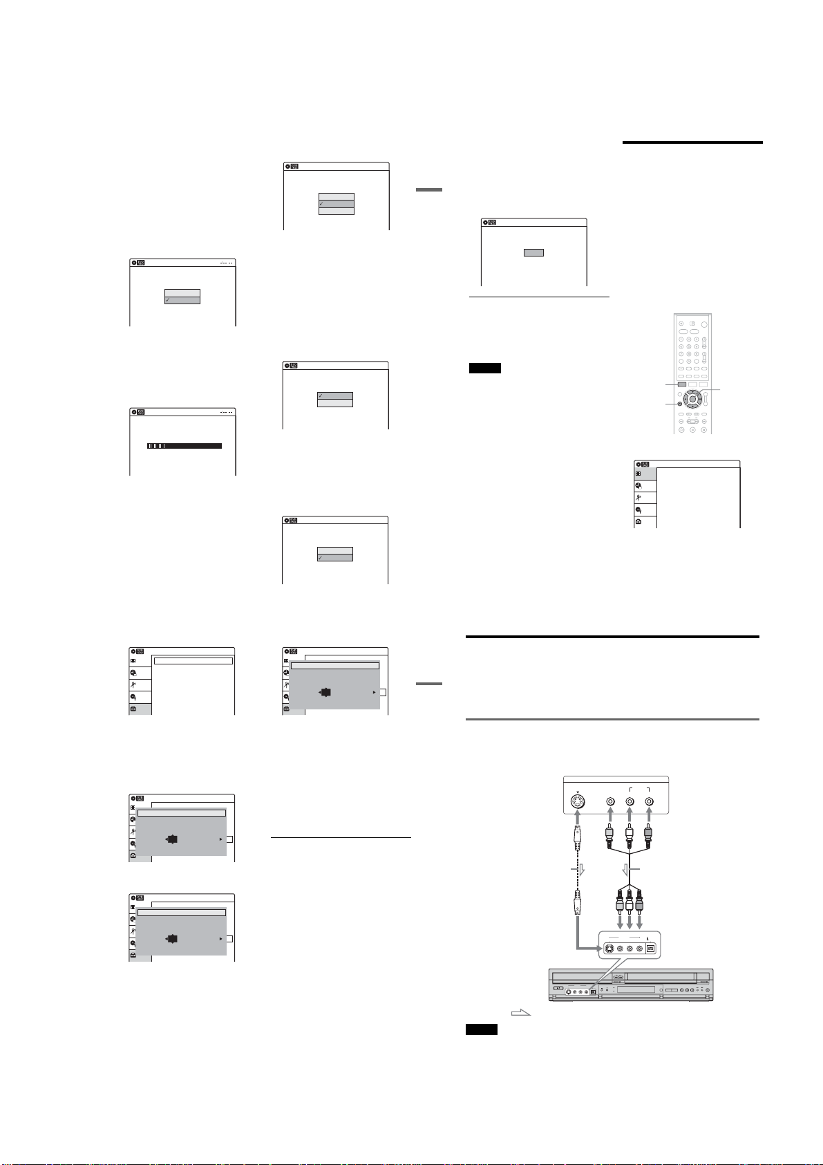
Connecting Another VCR or Similar Device
After disconnecting the recorder’s power cord from an AC outlet, connect other VCR or similar recording
device to the LINE I N jacks of this recorder.
Hookups and Settings
See also the instruction manual supplied with the connected equipment.
To record on this recorder, see “Recording from Connected Equipment with a Timer (Synchro Rec)” on
page 53 and page 72. Connect the equipment to the LINE 1 IN jacks of the recorder to record using the
Synchro Rec function.
Connecting to the LINE 2 IN jacks on the front panel
Connect other VCR or similar device to the LINE 2 IN jacks of this recorder. If the equipment has an
Svideo jack, you can use an S video cord instead of an audio/video cord.
You can connect a second DVD player and record DVDs.
S video cord
(not supplied)
Other VCR, etc.
S VIDEO
OUTPUT
VIDEO
S VIDEO
AUDIO
LR
LINE 2 IN
VIDEO
L AUDIO R
(MONO)
Audio/video cord
(not supplied)
DV IN
to LINE 2 IN
VCR-DVD recorder
: Signal flow
Note
You cannot record DVD video that contains a copy guard signal played back by another DVD player to a disc in this
recorder.
33
34
1-7
Page 18
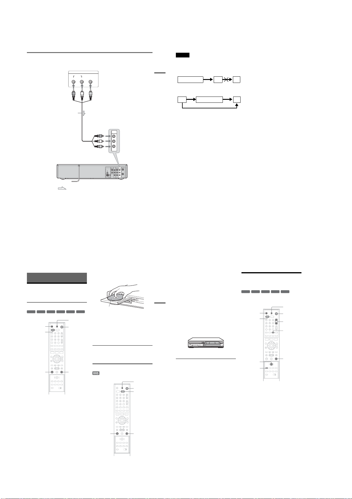
Connecting to the LINE 1 IN jacks
You can connect a second VCR or similar device.
Other VCR, etc.
LINE OUTPUT
AUDIO
RL
Audio/video cord
(not supplied)
VIDEO
to LINE 1 IN
Notes
•Do not connect the yellow LINE IN (VIDEO) jack when using an S video cord.
•Do not connect the output jack of this recorder to another equipment’s input jack with the other equipment’s output
jack connected to the input jack of this recorder. Noise (feedback) may result.
•Pictures containing copy protection signals that prohibit any copying cannot be recorded.
Hookups and Settings
LINE 1 IN
R
AUDIO
L
VIDEO
• If you pass the recorder signals via the VCR, you may not receive a clear image on your TV scree n.
VCRVCR-DVD recorder TV
Be sure to connect your VCR to the VCR-DVD recorder and your TV in the order shown below. To watch video tapes,
watch the tapes through a second Line input on your TV.
VCR VCR-DVD recorder TV
• If you disconnect the recorder’s power cord, you will not be able to view the signals from t he connected VCR.
•Do not connect more than one type of video cord between the recorder and your TV at the sam e time.
LINE 1 IN
LINE 2 IN
VCR-DVD recorder
: Signal flow
z Hint
When the connected equipment outputs onl y monaural sound, use audio cables that distribute monaural sounds to left/
right channels (not supplied).
5
Press Z OPEN/CLOSE, and place a disc on
Basic Operation
the disc tray.
VHF/UHF
COMPONENT
AUDIO OUT
DIGITAL
AUDIO
OUT
LINE 1 IN
LINE OUT
V
IDEO OUT
IN
R
Y
PCM/DTS/
DOLBY DIGITAL
R
AUDIO AUDIO
B
P
L
COAXIAL
L
OUT
OPTICAL
P
R
VIDEO VIDEO
S VIDEO OUT
,continued
Playing a DVD Disc or VHS
Tape
Playing a DVD disc
+
-
-
RW
VR
RW
RW
Z OPEN/
Video
CLOSE
DVD
+
R
-
R
TV/DVD·VIDEO
switch
"/1
With the playback side facing down
DVD
6
7
Press Z OPEN/CLOSE to close the disc
tray.
Wait until “LOAD” disappears from the front
panel display.
Playback starts automatically depending on
the disc.
Press H PL AY.
35
36
1 Turn on the TV.
2 Press "/1.
The recorder turns on.
3 Switch the input selector on your TV so that
the signal from the recorder appears on the
TV screen.
When connecting the recorder to the TV using
Basic Operation
only the antenna cable, see “Set ting the RF
Output channel” on page 19.
4 Slide the TV/DVD·VIDEO switch to
DVD·VIDEO, then press VIDEO to control
the VCR.
5 Insert a tape.
The VCR starts playing automatically if you
insert a tape with its safety tab removed.
Recording a Program to a
DVD Disc
+
-
RWVR-RWVideo
RW
The following explains how to record a current
TV program to a DVD disc.
Z OPEN/
CLOSE
DVD
+
R
-
R
TV/DVD·VIDEO
switch
"/1
CH +/–
INPUT
SELECT
x STOPH PLAY
1
Turn on the TV.
2
Press "/1.
The recorder turns on.
3
Switch the input selector on your TV so that
the signal from the recorder appears on the
TV screen.
When connecting the recorder to the TV using
only the antenna cable, see “Setting the RF
Output channel” on page 19.
4
Slide the TV/DVD·VIDEO switch to
DVD·VIDEO, then press DVD to c ontrol the
DVD recorder.
To stop playback
Press x STOP.
Playing a VHS tape
H PLAY
TV/DVD·VIDEO
switch
"/1
VIDEO
x STOP
,continued
6 Press H PLAY.
To stop playback
Press x STOP.
z REC
REC MODE
x STOP
1 Turn on the TV.
2 Press "/1.
The recorder turns on.
3 Switch the input selector on your TV so tha t
the signal from the recorder appears on the
TV screen.
When connecting the recorder to the TV using
only the antenna cable, see “Setting the RF
Output channel” on page 19.
4 Slide the TV/DVD·VIDEO switch to
DVD·VIDEO, then press DVD to control the
DVD recorder.
37
38
1-8
Page 19
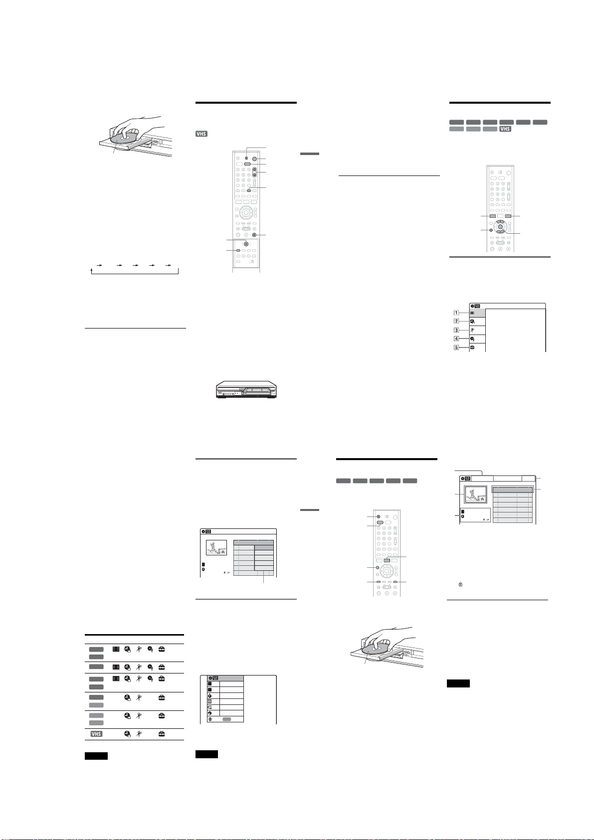
5 Press Z OPEN /CLOSE, and place a
1
recordable disc on the disc tray.
With the playback side facing down
6 Press Z OPEN /CLOSE to close the disc
tray.
Wait until “LOAD” disappears from the front
panel display.
Unused DVD-RWs are formatted in VR mode
automatically.
To format in Video mode, see page 43.
7 Press CH +/– or INPUT SELECT to sele ct the
channel or input source you want to record.
8 Press REC MODE repeatedly to select the
recording mode.
Each time you press the button, the display
changes on the TV screen as follows:
HQ SP LP EPHSP SLP
For more details about the recording mode,
see page 47.
9 Press z REC.
“REC” appears in the front panel d isplay and
recording starts.
Recording continues until yo u stop the
recording or the disc is full.
To stop recording
Press x STOP.
Note that it may take a few seconds for the
recorder to stop r ecording.
z Hint
This recorder can record on various discs. Select the disc
type according to your needs (page 10).
Recording a Program to a
VHS Tape
TV/DVD·VIDEO
switch
"/1
VIDEO
CH +/–
INPUT
SELECT
z REC
REC MODE
x STOP
1 Turn on the TV.
2 Press "/1.
The recorder turns on.
3 Switch the input selector on your TV so that
the signal from the recorder appears on the
TV screen.
When connecting the recorder to the TV using
only the antenna cable, see “Setting the RF
Output channel” on page 19.
4 Slide the TV/DVD·VIDEO switch to
DVD·VIDEO, then press VIDEO to control
the VCR.
5 Insert a tape with its safety tab in place.
7 Press REC MODE repeatedly to select the
tape speed, “SP” or “EP.”
“EP” (Extended Play) provides recording
time three times as long as “SP” (Standard
Play). However, “SP” produc es better picture
and audio quality.
8 Press z REC.
Basic Operation
“REC” appears in the front panel display and
recording starts.
Recording continues until you stop the
recording or the tape reache s the end.
To stop recording
Press x STOP.
Using the On-Screen Menus
+
-
RWVR-RWVideo
RW
VCD
CD
DATA CD
This section introduces the System Menu, TOOLS
menu, and sub-menu. By using these displays, you
can perform most of the recorder’s operations.
SYSTEM
MENU
O RETURN
-
+
DVD
R
R
TOOLS
M/m,
ENTER
System Menu
The System Menu appears when you press
SYSTEM MENU, and provides entries to all of
the recorder’s main functions, such as timer
recording and setup.
Select an option by pressing M/m and ENTER.
A “Title List” (page 42):
Title List(Original)
Title List
Timer
Edit
Disc Setting
Setup
Press ENTER to display the “Title List”
menu, which shows recorded titles on the disc.
10:10 AM
6 Press CH +/– or INPUT SELECT to select the
channel or input source you want to record.
,continued
39
40
B “Timer” (pages 50, 69):
Allows you to set a new timer recording
setting.
You can also display the Timer List men u,
which allows you to check, change, or cancel
timer settings.
C “Edit” (page 81):
Allows you to create and edit a Playlist
(DVD-RW in VR mode only), record a DV
format tape onto a disc, dub from a DVD disc
to a VHS tape and dub from a VHS tape to a
DVD disc.
D “Disc Setting” (page 43):
Allows you to format or finalize a DVD.
E “Setup” (page 96):
Turns on the “Setup” display, which allows
you to set up the recorder to suit your
preferences.
Selectable options
The options that can be selected differ according
to the media.
In addition, the options that can be selected also
differ according to the operat ing mode and the
disc condition.
Example: When a disc or a VHS tape is in stop
mode.
Type Selectable options
+
RW
-
RWVR
-
RWVideo
DVD
VCD
DATA CD
*Unfinalized disc only
Notes
•The System Menu is not displayed when recording
DVD and dubbing a VHS tape to a disc.
•When the System Menu is displayed, DVD and
VIDEO buttons are not available.
*
-
R
+
R
CD
**
Sub-menu
The sub-menu appears when you select an item
from a list menu (e.g. a title from the Title List
menu), and press ENTER. The sub-menu displays
options applicable only to the selected item. The
displayed options differ depending on the
situation and disc type.
Select an option by pressing M/m and ENTER.
Example: The Title List menu
T
CH 23
Nov/16/2004
08:00 PM
Title List(Original)
No. Title Length Edit
Options for the selected item
01 CH 23 >01:29:03
02 CH 66 >00:31:23
Play
03 CH 95 >01:59:00
Erase
Protect
04 CH 97 >00:58:56
Title Name
A·B Erase
10:10 AM
TOOLS
The TOOLS menu appears when you press
TOOLS, and displays options. You can search for
a title/chapter/track, check the playing and
remaining time, or change audio and repeat
settings. The displayed options differ depending
on the media type.
Select the option by pressing M/m and ENTER.
Example: When you press TOOLS while a
DVD-RW (VR mode) is playing.
Title 1/4
T
1/1
Chapter
C
Time
00:00:25
ENG Dolby 5.1 (1/3)
Audio
Repeat
OFF
00:01:30
Remain
Adjust Enter
ENTER
To return to the previous display
Press O RETURN.
Note
The TOOLS menu may not be displayed during DVD
recording.
Using the Title List
+
-
-
RW
VR
RW
The titles of programs recorded on a disc are
displayed in the Title List.
Basic Operation
1
2
With the recording side facing down
3
4
41
42
RW
Z OPEN/
CLOSE
DVD
ORIGINAL/
PLAYLIST
TOP MENU
Press DVD to control the DVD recorder.
Press Z OPEN/CLOSE, and place a disc on
the disc tray.
Press Z OPEN/CLOSE to close the disc
tray.
Wait until “LOAD” disappears from the front
panel display.
Press TITLE LIST.
-R+
Video
R
TITLE LIST
MENU
Example: DVD-RW in VR mode
Title List(Original)
2
T
CH
23
3
Nov/16/2004
08:00 PM
A Title type (DVD-RW in VR mode only):
Displays the title type, “Title List(Original)”
or “Playlist.”
10:10 AM
No. Title Length Edit
01 CH 23 >01:29:03
02 CH 66 >00:31:23
03 CH 95 >01:59:00
04 CH 97 >00:58:56
4
3
B Movie thumbnail image
C Title information:
Displays the title number, title name,
recording date, and recording mode.
“” indicates the protected title.
D Clock
About the Title List for DVD-RWs (VR mode)
You can switch the Title List to show Original or
Playlist.
While the Title List menu is turned on, press
ORIGINAL/PLAYLIST repeatedly to select
either “Title List(Original)” or “Playlist.”
For details, see “Edit options for DVD-RWs (VR
mode)” on page 81.
To turn off the Title List
Press TITLE LIST.
Notes
•The Title List does not appear for DVD-RW (Video
mode), DVD+R, or DVD-R that have been finalized.
To view a title, press TOP MENU or MENU (page 57).
•The Title List may not appear for discs created on other
DVD recorders.
•Letters that cannot be displayed are replaced with an
“*.”
•When playback of the Title List movie thumbnail
image for the selected title finishes, the thumbnail
image display stops at the last image of the movie
thumbnail image.
1-9
Page 20
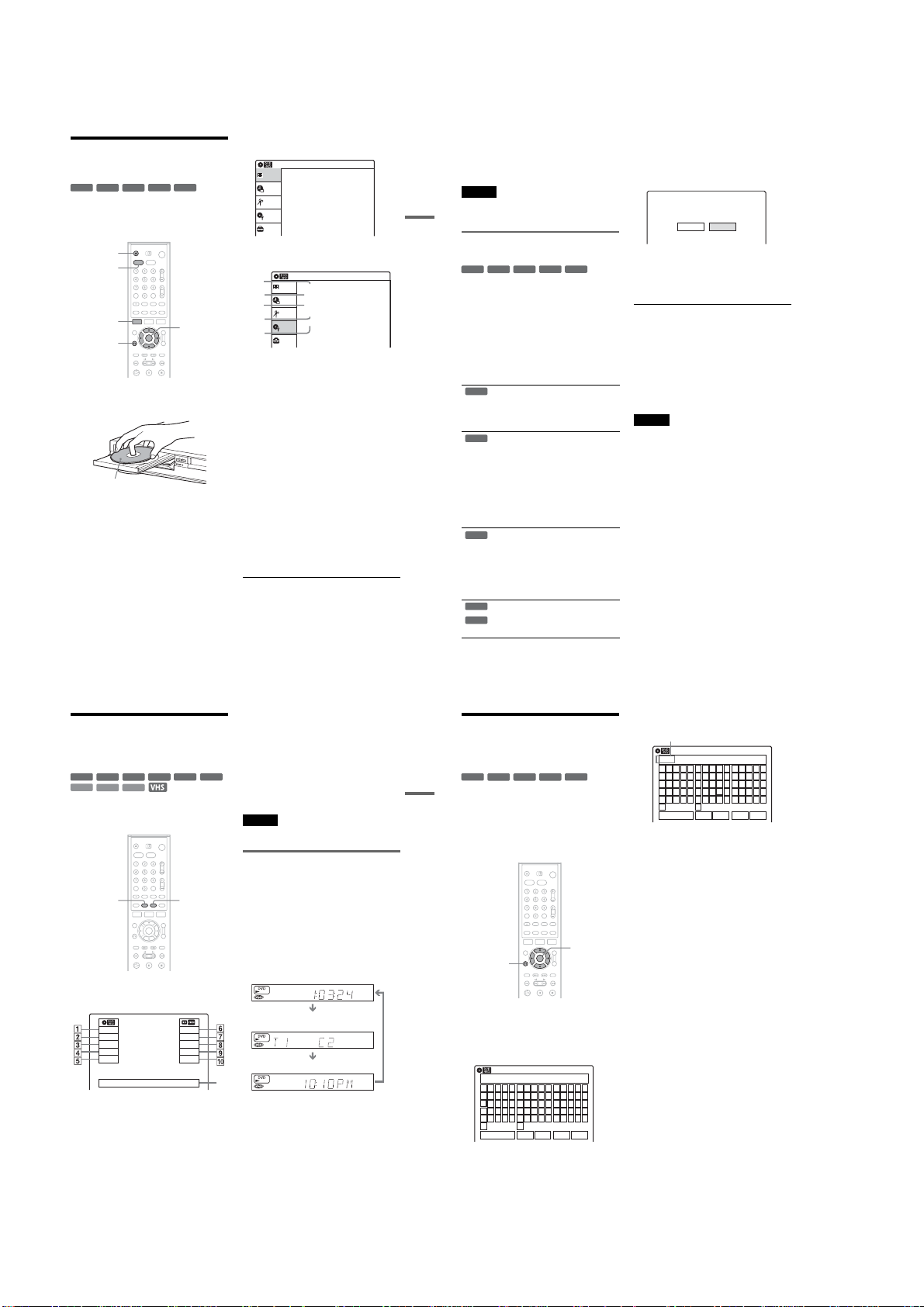
Using the DVD Disc Setting
Displays
+
-
-
RW
VR
RW
CLOSE
DVD
SYSTEM
MENU
Video
RW
With the “Disc Setting” display, you can perform
operations such as formatt ing and finalizing
(page 44).
Z OPEN/
O RETURN
1
Press DVD to control the DVD recorder.
2
Press Z OPEN/CLOSE, and place a disc on
the disc tray.
With the recording side facing down
3
Press Z OPEN /CLOSE to close the disc
tray.
Wait until “LOAD” disappears from the front
panel display.
-R+
R
M/m/</,,
ENTER
4
Press SYSTEM MENU while the recorder is
in stop mode.
Title List(Original)
Title List
Press ENTER :
Timer
Title Menu for DVD Title List.
Edit
Disc Setting
Setup
5
Select “Disc Setting,” and press ENTE R.
The “Disc Setting” display appears.
Disc Setting
1
Title List
2
3
4
5
6
Select an option, and press ENTER.
A “Disc Name”:
B “Disc Protect” (DVD-RW in VR mode
C “Disc Format” (DVD-RW/DVD+RW
D “Disc Finalize”:
E “Erase All Titles” (DVD-RW/
To return to the previous display
Press O RETURN.
Disc Name :
Disc Protect : Not Protected
Timer
Disc Format : VR Mode
Disc Finalize : Unfinalized
Edit
Erase All Titles
Disc Setting
Setup
Labels a disc. Enter the disc name in the
“Disc Name” display (page 46).
only):
Protects all titles on the disc. To cancel
the protection, select “Not protected.”
only):
Erases all contents of the disc to make a
blank disc. For DVD -RWs, select a
recording format (“ VR Mode” or “Video
Mode”) according to your need s.
Finalizes a disc (page 44).
DVD+RW only):
Erases all titles on the disc (except the
protected titles).
10:10 AM
10:10 AM
,continued
z Hints
•You can set protection for individ ual titles (page 82).
•By reformatting, you can change the recording format
on DVD-RWs, or record again on DVD-RWs (Video
mode) that have been finalized.
Note
You can enter up to 32 characters for a disc name. The
disc name may not appear when t he disc is played on
Basic Operation
other DVD equipment.
1 Follow steps 1 to 6 of “Using the DVD Disc
Setting Displays” on page 43 to select
“Disc Finalize” in the “Disc Setting”
display.
The display for confirmation appears.
Do you want to finalize this disc ?
Finalize Unfinalize
Finalizing a disc (preparing a disc
for playback on other equipment)
+
-
-
RW
VR
RW
RW
Finalizing is necessary when yo u play discs
recorded with this record er on other DVD
equipment.
When you finalize a DVD+RW, DVD-RW
(Video mode), DVD+R, or DVD-R, a DVD menu
will be automatically created, which can be
displayed on other DVD equipment.
Before finalizing, check the differences betwe en
the disc types in the table below.
Video
Differences between the disc types
Discs are automatically finalized when
+
RW
stopped recording. If you want to record
on it again, reformat the disc (page 43).
However, after reformatting the disc, all
recorded contents will be eras ed.
Finalizing is unnecessary when playing a
-
RW
VR
disc on VR format compatible equipment.
Even if your other DVD equipment is
VR format compatible, you may need to
finalize the disc, especially if the
recording time is short. After finalizing,
you cannot edit or record on the disc. If
you want to edit or record on it again,
unfinalize or reformat the disc (page 43).
However, after reformatting the disc, all
recorded contents will be erased.
Finalizing is necessary when playing on
-
RW
Video
any equipment other than this reco rder.
After finalizing, you cannot edit or
record on the disc. If you want to edit or
record on it again, unfinali ze or reformat
the disc (page 43). However, after
reformatting the disc, all reco rded
contents will be erased.
Finalizing is necessary when playing on
+
R
any equipment other than this reco rder.
-
R
After finalizing, you cannot edit or
record on the disc.
43
44
-R+
R
2 Select “Finalize,” and press ENTER.
The display for confirmation appears again.
3 Select “OK,” and press ENTER.
The recorder starts finalizing the disc.
To unfinalize a DVD-RW (VR mode)
If you cannot record or edit on a DVD-RW (VR
mode) that has been finalized with other DVD
equipment (a message appears), unfinalize the
disc by selecting “Unfinalize” in step 2 above.
z Hint
You can check whether the disc has been finalized or not.
If you cannot select “Finalize” in step 2 above, the disc
has already been finalized.
Notes
•Depending on the condition of the disc, recording, or
the DVD equipment, discs may not play even if the
discs are finalized.
•The recorder may not be able to finalize the disc if it
was recorded on another record er.
Checking the Play
Information and Playing
Time
+
-
-
RW
VR
RW
RW
VCD
You can check the playing time and re maining
time of the current title, chapter, or track.
Press DISPLAY.
The information display appears .
The display disappears after a short time.
Video
CD
DATA CD
Play
1:23:45
HQ
Rem 16:15
Original
Mon Nov 01. 2004 10:10 AM
◆ DVD
A Play mode
B Playing time
C Recording mode
D Remaining time
E Current channel*
*Title type (Original or Playlist) for DVD-RW in VR
mode
-
+
DVD
R
R
TIME/TEXTDISPLAY
Stop
0:30:00
SP
Rem 01:30
CH 110
◆ VHS
F Play mode
G Time counter
H Recording mode
I Remaining time
J Current channel
K Date and time
Note
The information display may not be displayed during
DVD recording.
Checking the playing/remaining
time
You can view the playing or time information
displayed on the TV screen and the front panel
display.
Press TIME/TEXT repeated ly.
The displays differ depending on the media type
or playing status.
◆ Front panel display
Example: When playing a DVD
Playing time of the current title
Current title number and current chapter
number
Clock
qa
Example: When playing a CD
Playing time of the current track
m
Current track number
m
Clock
Example: When playing a VHS tape
Playing time
m
Remaining time
m
Clock
2 Repeat step 1 to enter the remaining
Changing the Name of a
Recorded Program (Title
Input)
+
-
RWVR-RWVideo
RW
Basic Operation
You can label a title, disc, or program by entering
characters. You can enter up to 32 characters for a
title or disc name, but the actual number of
characters displayed in th e menus such as the Title
List will vary. When the displ ay for entering
characters appears, foll ow the steps below.
O RETURN
1 Select the character you want to enter
using M/m/</,, and press ENTER.
The selected character appe ars at the top of
the display.
-
+
R
R
M/m/</,,
ENTER
characters.
Input row
Disc Name
Kids
_
A B C D E
a b c d e
F G H I J
f g h i j
K L M N O
k l m n o
P Q R S T
p q r s t
U V W X Y
u v w x y
Z
z
Backspace Space Delete Clear Finish
To erase a character, move the cursor to the
right of the character at the input row . Select
“Backspace” and press ENTER.
To erase the character at the position of the
cursor, select “Delete” and press ENTER.
To insert a character, move the cursor to th e
right of the point where you want to insert the
character. Select the character and press
ENTER.
To erase all of the characters, select “Clear ”
and press ENTER.
3 Select “Finish,” and press ENTER.
To cancel the setting, press O RETURN.
1 2 3 4 5
6 7 8 9 0
- _ + = •
@ # $
!
~
%^& ( )
10:10 AM
Example: Disc Name
Disc Name
K
_
A B C D E
a b c d e
F G H I J
f g h i j
K L M N O
k l m n o
P Q R S T
p q r s t
U V W X Y
u v w x y
Z
z
Backspace Space Delete Clear Finish
You can only enter chara cters and symbols
that are displayed.
10:10 AM
1 2 3 4 5
6 7 8 9 0
- _ + = •
@ # $
!
~
%^& ( )
To insert a space, select “Space.”
45
46
1-10
Page 21

DVD Recording
Before Recording
Before you start recording…
•This recorder can rec ord on various discs. Select
the disc type according to your needs (page 1 0).
•Check that the disc has enough available space
for the recording (page 50). For DVD-RWs, you
can free up disc space by erasing title s (page 82).
z Hint
Timer recordings will start rega rdless of whether or not
the recorder is turned on. You cannot turn off the
recorder during a timer recording. The recorder
automatically turns off after the timer recording finishes.
Notes
•This recorder records at x1 speed.
•This recorder shares a single tuner for both the DVD
recorder and the VCR . You cannot record different
programs to a DVD and a VHS tape at the same time.
Recording mode
Like the SP or EP recording mode of VCRs, thi s
recorder has six different recording modes.
Select a recording mode according to the time and
picture quality you need. For ex ample, if picture
quality is your top priority, select the High Quality
mode (HQ). If recording time is your priority,
Super Long Play mode (SLP) ca n be a possible
choice. Note that the record ing time in the
following table is an approximate guide.
Press REC MODE repeated ly to switch the
recording modes.
I want to record with the
best possible picture
quality, so I’ll select HQ.
Recording mode Recording time
HQ (High quality) 60
HSP R 90
SP (Standard mode) 120
LP r 180
EP r 240
SLP (Long duration) 3 60
Note
Situations below may cause slight inaccuracies with the
recording time.
–Recording a program with poor reception, or a program
or video source of low picture quality
–Recording on a disc that has already been edited
–Recording only a still picture or just sound
(minute)
Recording a stereo/SAP program
The recorder can receive and record stereo/SAP
programs.
Stereo programs
When a stereo program is received, the
“STEREO” indicator lights up in the front pan el
display. If there is noise in the stereo program,
press AUDIO repeatedly until the “MONO”
indicator disappears from the TV scr een. The
sound will be recorded in monaural but with less
noise.
SAP (Second Audio Program)
When a SAP (Second Audio Program) is received ,
the “SAP” indicator lights up in the front panel
display. To record only SAP sound, set “Tuner
Audio” of “Audio” to “SA P” in the “Setup”
display (page 102).
Unrecordable pictures
Pictures with copy protectio n cannot be recorded
on this recorder.
Copy control
signals
Copy-Free
DVD Recording
Copy-Once
Copy-Never None
*The recorded disc can be played only on CPRM
compatible equipment.
Recording stops when a copy guard signal is detected.
Recordable discs
+
-
RWVR-RWVideo
RW
-
+
R
R
-
RWVR
Ver.1.1 with CPRM*
Ver.1.2 with CPRM*
DVD Recording without the
Timer
+
-
RWVR-RWVideo
RW
Z OPEN/
CLOSE
DVD
DISPLAY
H PLAY
REC MODE
Press DVD to control the DVD recorder.
1
2 Press Z OPEN/CLOSE, and place a
recordable disc on the disc tray.
With the recording side facing down
3 Press Z OPEN/CLOSE to close the disc
tray.
Wait until “LOAD” disappears from the front
panel display.
Unused DVD-RWs are formatted in VR mode
automatically.
To format in Video mode, see page 43.
4 Press CH +/– or INPUT SELECT to sel ect the
channel or input source you want to record.
+
R
-
R
TV/DVD·VIDEO
switch
VIDEO
CH +/–
INPUT
SELECT
TV/VIDEO
X PAUSE
x STOP
z REC
5 Press REC MODE repeatedly to select the
recording mode.
Each time you press the button, the display
changes on the TV screen as follows:
HQ SP LP EPHSP SLP
For more details about the recording mode,
see page 47.
6 Press z REC.
Recording starts.
Recording continues until yo u stop the
recording or the disc is full.
To stop recording
Press x STOP.
Note that it may take a few seconds for the
recorder to stop r ecording.
To pause recording
Press X PAUSE.
To restart recording, press X PAUSE again.
To watch another TV program while recording
1 Slide the TV/DVD·VIDEO switch to TV.
2 Press TV/VIDEO to switch to the TV’s
antenna input.
3 Select an other channel on the TV.
To watch a VHS tape while recording
Press VIDEO to control the VCR, insert a tape,
then press H PLAY.
,continued
Recording using the Quick Timer
(One-touch Timer Recording)
You can set the recorder to record in 30 minute
increments.
1 Press DVD to control the DVD recorder.
2 Press z RE C repeatedly to set the
duration.
Each press advances the time in 30 minute
increments. The maximum duration is six
hours.
0:30 1:00 5:30 6:00
“OTR” (One-touch Timer Recording) and the
remaining recording time are displayed in the
front panel display while recording.
The time counter decreases minute by minute
to 0:00, then the recorder stops recording
(power turns off).
To cancel the Quick Timer
Press z REC repeatedly until the counter appears
in the front panel display. The recorder returns to
normal recording mode.
To stop recording.
Press x STOP twice.
z Hint
If you do not want to watch TV while recording, you can
turn off the TV. When using a cable box or satellite
receiver, make sure to leave it on.
Notes
•After pressing z REC, it may take a short while to
start recording.
•You cannot change the recording mode while
recording or during recording pause.
•If there is a power failure, the program you are
recording may be erased.
•You cannot change the channel or input source of the
recorder using CH +/– or INPUT SELECT while
recording another TV program.
(normal
recording)
47
48
Checking the disc status while
recording
You can check the recording in formation such as
recording time or disc type.
Press DISPLAY during recording.
The recording information ap pears.
DVD Recording
Record
0:00:03
HQ
Rem 02:28
CH 1
A Disc type
B Recording status
C Recording time
D Recording mode
E Remaining recording time
F Current channel
Press DISPLAY repeatedly to turn off the display.
DVD Timer Recording
(Standard/VCR Plus+)
+
-
-
RW
VR
RW
You can set the timer for a total of 12 programs
together with DVD Timer Recording and VCR
Timer Recording, up to one month in advance.
There are two methods to set the timer: the
standard method and VCR Plus+ method.
•Standard: Set the date, time, and channe l of the
program manually.
•VCR Plus+: Enter the PlusCode number
designated for each TV program (page 52 ).
Note
Do not operate your cable box or satellite receiver just
before or during a timer recording. T his may prevent the
accurate recording of a program.
RW
Setting the timer manually
(Standard)
Z OPEN/
CLOSE
DVD
-
+
Video
R
R
Creating chapters in a title
The recorder will automatically divide a recording
(a title) into chapters by inserting chapter marks at
5 or 15 minute intervals during r ecording. Select
the interval, “5 Min” (default) or “15 Min” in
“DVD Auto Chapter” of “Features” in the “Setup”
display (page 104).
To cancel “DVD Auto Chapter” setting, select
“Off.”
z Hint
You can create chapters manually when playing
DVD+RWs or DVD-RWs (VR mode). For details, see
page 84.
SYSTEM
MENU
[TIMER]
M/m/</,,
ENTER
x STOP
,continued
49
50
1-11
Page 22
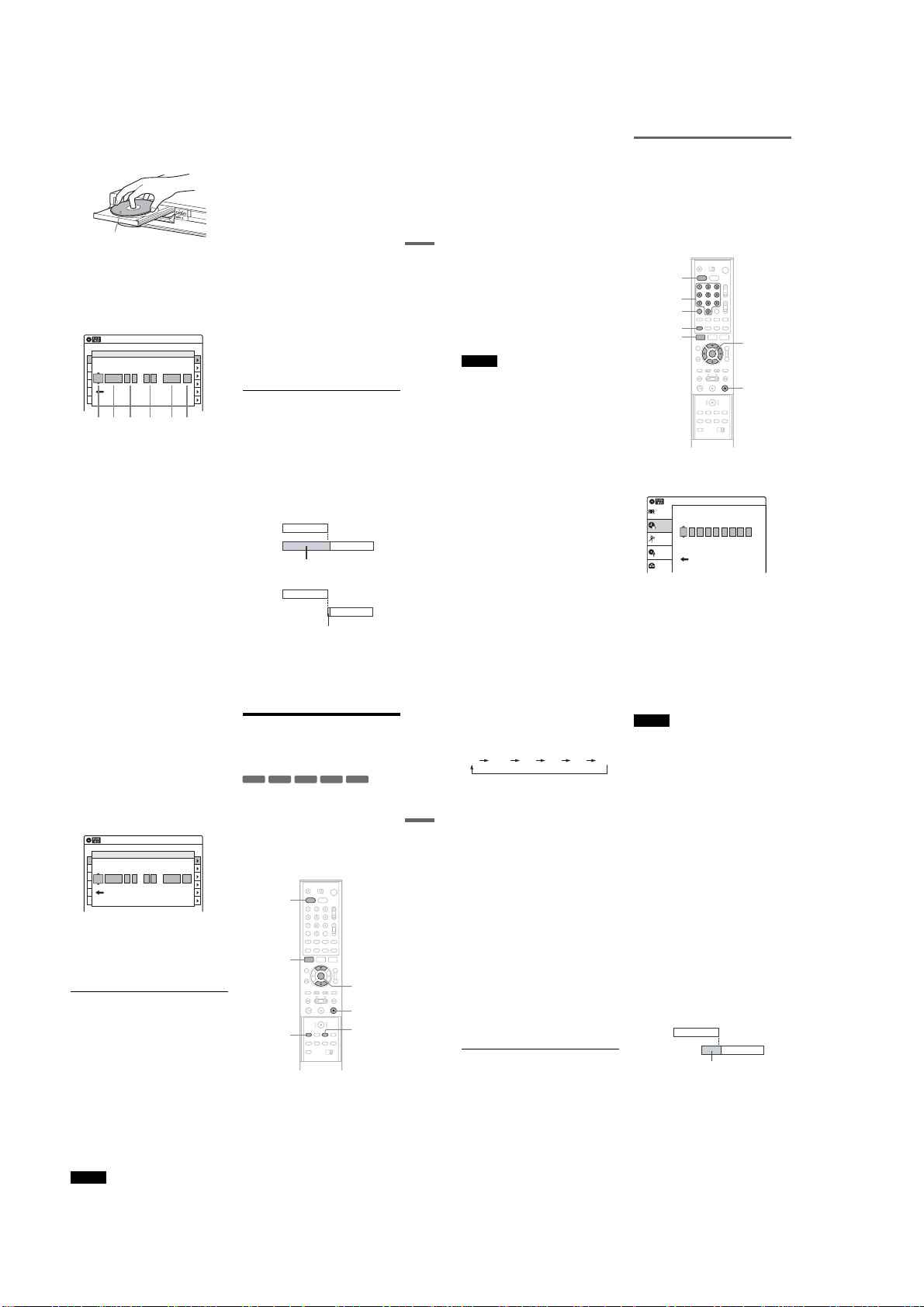
1
12 3 4 56
Press DVD to control the DVD recorder.
2
Press Z OPEN /CLOSE, and place a
recordable disc on the disc tray.
With the recording side facing down
3
Press Z OPEN /CLOSE to close the disc
tray.
Wait until “LOAD” disappears from the front
panel display.
Unused DVD-RWs are formatted in VR mode
automatically.
To format in Video mode, see page 43.
4
Press [TIMER].
Timer – Standard
No Rec To Date Start End Source Mode Edit
No.1
01 DVD 06/14 09:00PM 10:00PM CH8 LP
02 DVD 06/14 09:15PM 09:45PM CH1 LP
RecTo Date Star t Stop CH Mode
03 --- --/-- --:-- --:-- ---- ---
DVD
11/30 02 40 03 0505 CH 100 SP
:
--- --/-- --:-- --:-- ---- ---04
--- --/-- --:-- --:-- ---- ---05
VCR Plus+
--- --/-- --:-- --:-- ---- ---06
If the Timer programming (VCR Plus+) menu
appears, press < to switch the display to
“Standard.”
5
Select an item using </, and adjust
using M/m.
A “RecTo”:
Select “DVD.”
B “Date”:
Sets the date using M.
To record the same program every da y or
the same day every week, press m.
The item changes as follows:
Today y Mon-Fri (Monday to Friday)
y Sun (every Sunday) y Mon (every
Monday) y … y Sat (every Saturday)
y 1month later y … y Today
C “Start”:
Sets the start time.
D “Stop”:
Sets the stop time.
10:10 AM
:
PM
PM
E “CH”:
Selects the channel or input source.
F “Mode”:
Selects the recording mode (page 47).
To use the Rec Mode Adjust func tion,
select “Auto.” For details, se e “To use the
Rec Mode Adjust functio n” on page 52.
If you make a mistake, select the item and
change the setting.
6
Press ENTER.
The Timer List menu (page 55) appears. The
c indicator lights up in the front panel
display, and the recorder is ready to start
recording. If the c indicator flashes in the
front panel display, check that a recor dable
disc is inserted and that there is enough disc
space for the recording.
There is no need to turn off the recorder befo re
the timer recording starts.
If the timer settings overlap, the message
“These timer settings overlap.” appears. To
confirm, change, or cancel timer recording,
see “Checking/Changing/Canceling DV D
Timer Settings (Timer List)” on page 55.
7
Press SYSTEM MENU to exit the menu.
To stop recording
Press x STOP twice.
Note that it may take a few seconds for the
recorder to stop recording.
If the timer settings overlap
The program that starts first has priority and the
second program starts recording only after the first
program has finished. If the programs start at the
same time, the program listed first in the menu has
priority.
7:00 8:00 9:00 10:00
Program 1
Program 2
will be cut off
7:00 8:00 9:00 10:00
Program 1
Program 2
will be cut off
,continued
To confirm, change, or cancel timer recording
See “Checking/Changing/Canceling DVD Timer
Settings (Timer List)” on page 55.
To use the Rec Mode Adjust function
When you are recording a program in the Auto
mode and there is not enough available disc space
for the recording, the recorder automatically
adjust the recording mode to e nable the entire
program to be recorded .
DVD Recording
z Hints
•You can play the recorded program by selecting the
program title in the Title List me nu.
•When the start time and the channel or inpu t source to
be recorded are the same but the “RecTo” setting
differs, the program is recorded to both the DVD disc
and the VHS tape.
•You can also display the Timer programm ing menu as
follows:
1 Press SYSTEM MENU.
The System Menu appears.
2 Select “Timer,” and press ENTER.
3 Select “Timer – Standard,” and press ENTER.
Notes
•To record a cable or satellite program, turn on the cable
box or satellite receiver and select the program yo u
want to record. Leave the cable box or satellite receiver
turned on until the recorder finishes recording.
•Even if the timer is set, timer recordings cannot be
made while recording a program that has priority.
•Before the timer recording starts, “TIMER REC”
flashes in the front panel display.
Recording TV programs using the
VCR Plus+ system
The VCR Plus+ system is a feature that simplifies
setting the timer. Just enter the PlusCode number
listed in the TV program guide. The date, time,
and channel of that program are se t automatically.
Before you start, check that the TV and guide
channels are correctly set in “Guide Channel
Setup” of “Tuner Preset” in the “Setup” display
(page 98).
DVD
Number
buttons
CLEAR
VCR Plus+
SYSTEM
MENU
M/m/</,,
ENTER
x STOP
1 Press DVD to control the DVD recorder.
2 Insert a recordable disc.
3 Press VCR Plus+.
Timer – VCR Plus+
Title List
Set VCR Plus+ Code number. [0~9]
Timer
Edit
Disc Setting
Standard
Setup
If the Timer programming (Standard) menu
appears, press < to switch the display to
“VCR Plus+.”
51
52
10:10 AM
4
Press the number buttons to enter t he
PlusCode number.
If you make a mistake, press CLEAR and reenter the correct number.
5
Press ENTER.
The date, start and stop times, ch annel, and
recording mode appear.
The c indicator lights up in the front panel
display, and the recorder is ready to start
recording. If the c indicator flashes in the
front panel display, check that a recordable
disc is inserted.
Timer – Standard
No Rec To Date Start End Source Mode Edit
No.1
01 DVD 06/14 09:00PM 10:00PM CH8 LP
02 DVD 06/14 09:15PM 09:45PM CH1 LP
RecTo Date Star t Stop CH Mode
03 --- --/-- --:-- --:-- ---- ---
DVD
11/15 9 00 11 00 CH 83 LP
:
--- --/-- --:-- --:-- ---- ---04
--- --/-- --:-- --:-- ---- ---05
VCR Plus+
--- --/-- --:-- --:-- ---- ---06
6
Select “RecTo” using </, and select
“DVD” using M/m, and press ENTER.
If you want to change other settings, press </
, to select the item and press M/m to change
the setting.
7
Press SYSTEM MENU to exit the menu.
To stop recording
Press x STOP twice.
Note that it may take a few seconds for the
recorder to stop r ecording.
If the timer settings overlap
See page 51.
To confirm, change, or can cel timer recording
See “Checking/Changing/Canceling DVD Timer
Settings (Timer List)” on page 55 .
z Hint
You can also display the Timer programming menu as
follows:
1 Press SYSTEM MENU.
The System Menu app ears.
2 Select “Timer,” and press ENTER.
3 Select “Timer – VCR Plus+,” and press ENTER.
Notes
•When the PlusCode num ber is incorrect, “Invalid
code” appears on the TV screen.
•Before the timer recording starts, “TIMER REC”
flashes in the front panel display.
10:10 AM
:
PM
PM
Recording from Connected
Equipment with a Timer
(Synchro Rec)
+
-
-
RW
VR
RW
You can set the recorder to automatically record
programs from connected equipment that has a
timer function (such as a satellite tuner). Connect
the equipment to the LINE 1 IN jacks of the
recorder (page 35).
When the connected equipment turns on, the
recorder starts recording a program from the LINE
1 IN jacks.
1
2
3
RW
DVD
SYSTEM
MENU
REC MODE
Press DVD to control the DVD recorder.
Insert a recordable disc.
Select the line input audio.
Set “Line Audio Input” of “Audio” to
“Stereo” or “Main/Sub” in the “Setup”
display (page 103).
-
+
Video
R
R
M/m,
ENTER
x STOP
SYNCHRO
REC
,continued
4 Press REC MODE repeatedly to select the
recording mode.
Each time you press the button, the display
changes on the TV screen as fol lows:
HQ SP LP EPHSP SLP
For more details about the recording mode,
see page 47.
5 Press SYSTEM MENU while the recorder is
DVD Recording
in stop mode.
6 Select “Setup,” and press ENTER.
7 Select “Features,” and press ENTER.
The “Features” setup appea rs.
8 Select “Synchro Recording,” and press
ENTER.
9 Select “to DVD,” and press ENTER.
10
Press SYSTEM MENU to exit the menu.
11
Set the timer on the connected equipment
to the time of the program you want to
record, and turn it off.
12
Press SYNCHRO REC.
The SYNCHRO REC indicator lights up on
the front panel. The recorder is ready to start
Synchro-Recording.
The recorder automatical ly starts recording
when it receives an input signal from the
connected equipment. The r ecorder stops
recording when the connected equipment
turns off.
To stop recording
Press x STOP twice.
To cancel Synchro Rec functi on
Press SYNCHRO REC. The SYNCHRO REC
indicator on the recorder turns off.
If you press SYNCHRO REC during S ynchroRecording, the Synchro-Recording stops, the
SYNCHRO REC indicator t urns off and the
recorder’s power turns off.
53
54
Notes
•The recorder starts recording only after detecting the
video signal from the connected equipment. The
beginning of the program may not be recorded
regardless of whether or not the recorder’s power is on
or off.
•During Synchro-Recording, other operations such as
normal recording cannot be done.
•To use the connected equipment while the recorder is
standing by for Synchro-Recording, cancel Synch roRecording by pressing SYNCHRO REC. Be sure to
turn off the connected equipment and press
SYNCHRO REC to reset Synchro-Recording before
the timer recording starts.
•The Synchro Rec function does not work with some
tuners. For details, see the tuner’s operating
instructions.
•While the reco rder is standing by for SynchroRecording, the Auto Clock Set function (page 99) does
not work.
•To use the Synchro Rec function, you m ust first set the
recorder’s clock correctly.
•When the recorder’s pow er is on, the recorder enters
the Synchro-Recording standby mode after a SynchroRecording has finished.
If the timer settings of a Synchro-Recording
and another timer recording overlap
Regardless of whether or not the program is a
Synchro Rec program, the program that starts first
has priority. The recorder switches to start
recording the second program around 10 seconds
after the first program has finished.
7:00 8:00 9:00 10:00
Program 1
Program 2
will be cut off
1-12
Page 23
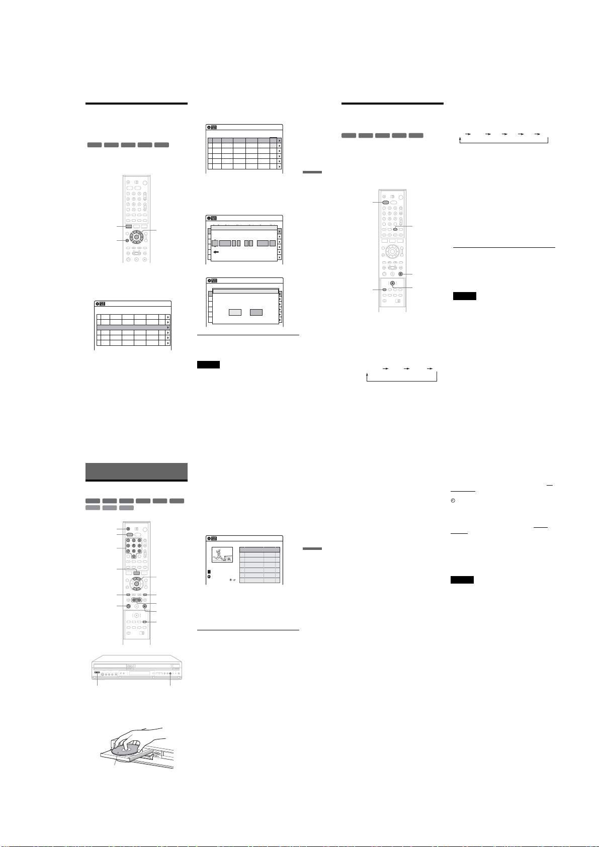
Checking/Changing/
Canceling DVD Timer
Settings (Timer List)
+
-
RWVR-RWVideo
RW
You can check, change, or cancel tim er settings
using the Timer List m enu.
SYSTEM
MENU
O RETURN
1 Press SYSTEM MENU.
The System Menu appears.
-
+
R
R
M/m/</,,
ENTER
2 Select “Timer,” and press ENTER.
3 Select “Timer List,” and press ENTER.
Timer List
No RecTo Date Start Stop CH Mode Edit
01 DVD 11/17 09:00PM 10:00PM CH8 LP
02 DVD 11/28 09:15PM 09:45PM CH1 LP
03 --- --/-- --:-- --:-- ---- ---
--- --/-- --:-- --:-- ---- ---04
--- --/-- --:-- --:-- ---- ---05
--- --/-- --:-- --:-- ---- ---06
Timer information displays the recording
date, time, recording mode, etc.
10:10 AM
4 Select the timer setting you want to check/
change/cancel, and press ENTER.
The sub-menu appears.
Timer List
No RecTo Date Start Stop CH Mode Edit
01 DVD 11/17 09:00PM 10:00PM CH8
DVD 11/28 09:15PM 09:45PM CH1
02 Del
03 --- --/-- --:-- --:-- ---- ---
--- --/-- --:-- --:-- ---- ---04
--- --/-- --:-- --:-- ---- ---05
--- --/-- --:-- --:-- ---- ---06
5 Select one of the options, and press
ENTER.
“Edit”: Changes the timer setting. Select an
item using </, and adjust using M/m.
Press ENTER.
Timer – Standard
No Rec To Date Start End Source Mode Edit
No.1
01 DVD 06/14 09:00PM 10:00PM CH8 LP
02 DVD 06/14 09:15PM 09:45PM CH1 LP
RecTo Date Star t Stop CH Mode
03 --- --/-- --:-- --:-- ---- ---
DVD
11/17 09 15 09 45 CH1 LP
: PM
--- --/-- --:-- --:-- ---- ---04
--- --/-- --:-- --:-- ---- ---05
VCR Plus+
--- --/-- --:-- --:-- ---- ---06
10:10 AM
Edit
10:10 AM
:
PM
“Del”: Erases the timer setting. Press ENTER.
Timer List
No Rec To Date Start End Source Mode Edit
01 DVD 06/14 09:00PM 10:00PM CH8 LP
02 DVD 06/14 09:15PM 09:45PM CH1 LP
Do you want to erase “No.01”?
03 --- --/-- --:-- --:-- ---- ---
--- --/-- --:-- --:-- ---- ---04
OK Cancel
--- --/-- --:-- --:-- ---- ---05
--- --/-- --:-- --:-- ---- ---06
To turn off the Timer List
Press O RETURN.
Note
Even if the timer is set, timer recordings c annot be made
while recording a program that has priority.
10:10 AM
No.1
4 Press REC MODE repeatedly to select the
Recording from Connected
Equipment without a Timer
+
-
RWVR-RWVideo
RW
You can record from a connected VCR or similar
device. To connect other VCR or similar device,
see “Connecting Another VCR or Similar Device”
on page 34.
DVD Recording
Use the DV IN jack on the front panel if the
equipment has a DV output jack (i.LINK jack).
DVD
REC MODE
-
+
R
R
INPUT
SELECT
x STOP
z REC
1 Press DVD to control the DVD recorder.
2 Insert a recordable disc.
3 Press INPUT SELECT to select an input
source according to the connectio n you
made.
The front panel display changes as follows:
program position
LINE2 DVLINE1
recording mode.
Each time you press the button, the display
changes on the TV screen as follows:
HQ SP LP EPHSP SLP
For more details about the recordin g mode,
see page 47.
5 Select the line input audio.
Set “Line Audio Input” of “Audio” to
“Stereo” or “Main/Sub” in the “Setup”
display (page 103).
6 Insert the source tape into the connected
equipment and set to playback pause.
7 At the same time, press z REC on this
recorder and the pause or play button on
the connected equipment.
Recording starts.
To stop recording, press x STOP on this
recorder.
If you connect a digital video camera with a DV
IN jack
See “Dubbing from a DV Format Tape to a DVD”
on page 94 for an explanation of how to reco rd
from the DV IN jack.
Notes
• When recording a video game image, the screen may not
be clear.
Any program that contains a Copy-Never copy guard
•
signal cannot be recorded. The re corder automatically
stops recording after a few seconds.
Playing Discs
Playing
+
-
RWVR-RWVideo
RW
VCD
CD
DATA CD
Z OPEN/
CLOSE
DVD
Number
buttons
TITLE LIST
TOP MENU
H PLAY
"/1 x
-
+
DVD
R
R
M/m,
ENTER
MENU
m/M
x STOP
REPEAT
1 Press DVD to control the DVD recorder.
2 Press Z OPEN/CLOSE, and place a disc on
the disc tray.
With the playback side facing down
3 Press Z OPEN/CLOSE to close the disc
tray.
If you inserted a DVD VIDEO, VIDEO CD,
CD, or DATA CD, press
starts.
Playback starts automatically depending on
the disc.
4 Press TITLE LIST.
For details about the Title List, see “Using the
Title List” on page 42.
Example: DVD-RW (VR mode)
Title List(Original)
T
CH 23
Nov/16/2004
08:00 PM
5 Select the title, and press ENTER.
The sub-menu appears.
6 Select “Play,” and press ENTER.
Playback starts from the selected title on the
disc.
To use the DVD’s Menu
When you play a DVD VIDEO, or a finalized
DVD+RW, DVD-RW (Video mode), DVD+R, or
DVD-R, you can display the disc’s men u by
pressing TOP MENU or MENU.
To play VIDEO CDs with PBC functions
PBC (Playback Control) allows you to play
VIDEO CDs interactively using the menu on your
TV screen.
When you start playing a VIDEO CD with PBC
functions, the menu appears.
Select an item using the number buttons and press
ENTER. Then follow the instructions in the menu
(press H PLAY when “Press SELECT”
appears).
To cancel PBC Playback
Press MENU repeatedly until “Menu: Off”
appears.
To stop playback
Press x STOP.
H PLAY. Playback
10:10 AM
No. Title Length Edit
01 CH 23 >01:29:03
02 CH 66 >00:31:23
03 CH 95 >01:59:00
04 CH 97 >00:58:56
55
56
To resume playback f rom the point where you
stopped the disc (Resume Play)
When you press H PLA Y again after you stop
the disc, the recorder resumes playback fr om the
point where you pressed x STOP.
To start from the beginning, press x STOP twice,
and press H PLAY.
The point where you stopped play ing is cleared
when:
–you open the disc tray.
–you play another title.
–you switch the Title List menu to Original or
Playlist (DVD-RW in VR mode only).
Playing Discs
–you edit the title after stopping playback.
–you turn off the recorder.
–you make a recording.
To repeat a specific port ion (Repeat A-B Play)
(DVD and VIDEO CD (with PBC function off)
only)
1
During playback, press REPEAT.
2
Select “A” using
3
Press ENTER at the starting po int (point A) of
the portion to be played repeatedly.
“A-” lights up.
4
Continue playing or press m/M to locate
the ending point (point B), then press ENTER.
Repeat A-B Play starts.
To play restricted DVDs (Parental Control)
If you play a restricted DVD, the message “Your
selection exceeds the rating limit for this player.
Override the limit?” appears on your TV screen.
1
Select “OK” and press ENTER.
The display for entering your pass word
appears.
2
Enter your four digit pass word using the
number buttons.
The recorder starts playback.
To register or change the passw ord, see “Parental
(DVD VIDEO only)” on page 1 05.
M/m
.
To lock the recorder (Child Lock)
You can lock all of the buttons on the recorder so
that the settings are not canceled by mistake.
When the recorder is turned on, hold down "/1 on
the recorder until “CHILD LOCK” appears in the
front panel display. The recorder turns off and the
indicator remains lit if there is a timer setting.
The recorder will not work except for timer
recordings.
To unlock the recorder, hold down "/1 on the
recorder until “CHILD LOCK” disappears from
the front panel display. The recorder is unl ocked
and turns on.
To stop timer recording while the recorder is
locked, press x twice. The recording stops and the
recorder is unlocked.
Notes
•When playing back a disc recorded by other equipment
on this recorder, be sure to finalize the disc with the
equipment used to record it.
•For details on the operation restrictions, see page 8.
•The recorder will be unlocked when:
–You stop time r recording by pressing x.
–You insert a tape .
–The AC power cord is di sconnected or power supply
stops.
,continued
57
58
1-13
Page 24
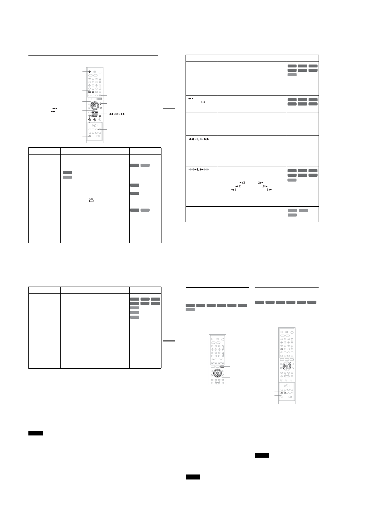
Playback options
Z OPEN/CLOSE
AUDIO
SUBTITLE
M/m/</,,
ENTER
INSTANT REPLAY/
INSTANT ADVANCE
. PREV/NEXT >
H PLAY
SHUFFLE
Buttons Operations Discs
Z
OPEN/CLOSE Stops play and opens the disc tray. All discs
AUDIO Selects one of the audio tracks recorded on the disc
when pressed repeatedly.
Selects the audio source.
DVD
Selects stereo or monaural audio tracks.
VCD
SUBTITLE Selects a subtitle language when pressed repeatedly.
ANGLE Selects an angle when pressed repeatedly.
ZOOM Zooms into a scene during playback or still mode
If various angles (multi-angle s) for a scene are
recorded on the disc, “ ” appears in the front panel
display.
when pressed repeatedly.
Magnification changes as follows:
normal magnification t ×2 t ×4 t normal
magnification
The zoom function may not work depend ing on the
DVD.
To zoom in a JPEG imag e, see page 65.
SURROUND
TOOLS
ZOOM
ANGLE
X PAUSE
REPEAT
DVD
DVD
DVD
DVD
VCD
VCD
Buttons Operations Discs
SURROUND Selects one of the effects when pressed repeatedly.
INSTANT
REPLAY/
INSTANT
Playing Discs
ADVANCE
. PREV/
NEXT >
(fast reverse/fast
forward)
(slow)
.
X PAUSE Pauses playback.
“Off”: No surround effect
“Surround1”: Creates one set o f virtual surround
speakers.
“Surround2”: Creates two sets of virtual surround
speakers.
“Surround3”: Creates three sets of virtual surround
speakers.
Effective when you use two se parate front speakers.
•Replays the scene/briefly fast forwards the scene
when pressed in continuous play mode.
•Goes to the previous/next frame when pressed in
pause mode.
•Goes to the beginning of the current/next title/
chapter/scene/trac k and starts playback when
pressed during playback.
•Goes to the beginning of the previous title/ch apter/
scene/track when . PREV is pressed within 3
seconds after starting a title/chapter/scene/track.
Fast reverses/fast forwards the disc when pressed
during playback.
Search speed changes as follows:
fast reverse fast forward
FR1 Tt FF1
*1
TT tt FF2
FR2
FR3*2TTT ttt FF3
Plays in slow motion when pressed in pause mode.
The playback speed changes as follows:
reverse slow motion forward slow motion
If you pause playback for more than 5 minutes,
playback starts automatically.
Tt
TT tt
TTT ttt
*1
SHUFFLE Plays in random order when pressed during pl ayback. *
*2
+
-
RW
VR
RW
-
+
R
R
CD
+
-
RW
VR
RW
-
+
R
R
All discs
All discs
*1
FR2 and FF2 are not
available for MP3.
*2
FR3 and FF3 are only
available for DVDs
and VIDEO CDs.
+
-
-
RW
VR
RW
-
+
R
R
*
VCD
*Playback direction
only
All discs
VCD
CD
DATA CD
*with PBC function off
-
-
RW
DVD
RW
DVD
RW
DVD
Video
Video
Video
Buttons Operations Discs
REPEAT Selects the item to be repeated using M/m.
When playing a DVD
•Chapter: repeats the current chapter.
•Title: repeats the current ti tle on a disc.
•A-B (Repeat A-B Play): repeats a specific portion
(page 58).
When playing a VIDEO CD (with PBC function off)
•Track: repeats the current track.
•Disc: repe ats all of the tracks.
•A-B (Repeat A-B Play): repeats a specific portion
(page 58).
When playing a CD
•Track: repeats the current track.
•Disc: repe ats all of the tracks.
When playing a DATA CD (MP3 audio)
•File: repeats the current track.
•Folder: repeats the current album.
To cancel Repeat Play, press REPEAT, and select
“Off.”
To resume normal playback, press H PLAY.
To playback quickly with sou nd (Scan Audio)
(DVD with Dolby Digital sound tracks only)
Set “Scan Audio” of “Audio” to “On” in the
“Setup” display (page 103).
You can then play quickly with dialog or sound
during FF1 fast-forwa rd of a DVD disc with
Dolby Digital sound tracks.
z Hint
You can select the audio/subtitle settings and the angle
using the TV screen. Press TOOLS during playback,
select “Audio,” “Subtitle,” or “Angle” using M/m, then
select the setting or angle using </,. Then pre ss
ENTER.
Notes
•Shuffle play will stop when all the tracks are played
back.
•You cannot repeat play in the following cases:
–while in shuf fle play
–VIDEO CDs with PBC function on.
•When the playback si gnal does not contain a signal for
the surround speakers, the surround effects will be
difficult to hear.
•When you select one of the surround modes, turn off
the surround settings of the connected TV or amplifi er
(receiver).
•Make sure that your listening position is between and
at an equal distance from your speakers, and that the
speakers are located in similar surroundings.
Notes on playing DTS sound tracks on a CD
When playing DTS-encoded CD s, excessive noise will
be heard from the analog stereo jacks. To avoid possible
damage to the audio system, the consumer should take
proper precautions when the analog stereo jacks of the
recorder are connected to an amplification system. To
enjoy DTS Digital Surround™ playback, an external 5.1channel decoder system must be connected to t he digital
jack of the recorder.
Notes on playing DVDs with a DTS sound tr ack
DTS audio signals are output only through the DIGITAL
AUDIO OUT (COAXIAL or OPTICAL) jack.
When you play a DVD with DTS sound tracks, set
“Digital Out” – “DTS” to “On” of “Audio” in the “Setup”
display (page 102).
,continued
+
-
-
RW
VR
RW
-
+
R
R
*
VCD
CD
DATA CD
*with PBC f unction off
RW
DVD
59
60
Video
Chapter/Track, etc.
+
-
RWVR-RWVideo
RW
VCD
You can search a DVD by title or chapt er, and
VIDEO CD by track or scene. As titles and tracks
are assigned individua l numbers on the disc, sele ct
the title or track by entering its number. You can
also search for a scene using the time code.
-
+
R
R
Searching for a Title/
Setting and selecting a favorite
scene (Bookmark)
+
-
RWVR-RWVideo
RW
DVD
You can have the recorder store sp ecific portions
of the disc in memory and play them immediately
whenever you want (Bo okmark). Up to 10
bookmarks per disc.
-
+
DVD
R
R
Playing Discs
CLEAR
</,,
TOOLS
M/m/</,,
ENTER
1 Press TOOLS during pl ayback.
The TOOLS menu appears.
2 Select a search method.
“Title” (for DVDs)
“Chapter” (for DVDs)
“Track” (for VIDEO CDs with PBC function
off)
“Time” (for DVDs/VIDEO CDs): Searches
for a starting point by entering the time code.
3 Press </, to select the number of the
title, chapter, track, time code, etc., you
want.
For example: Time
To find a scene at 2 hours, 10 m inutes, and 20
seconds, enter “21020.”
If you make a mistake, wait a bit until the
display returns to the elapsed pl aying time
display, then select another nu mber.
4 Press ENTER.
The recorder starts playback from the selected
number.
Note
Depending on the disc, you cannot use the TOOLS menu
to search for a title, chapter, track, or start from a point by
61
entering the time code.
62
SEARCH
MARKER
You can play back from the bookmar ked scene.
During playback, press SEARCH, an d select the
bookmark using </,, then press ENTER.
To set a bookmark
During playback, press MARKER when you find
a scene to be bookmarked.
To reset the bookmark
During playback, press SEARCH, an d select the
bookmark you want to reset using , then press </
,, then press CLEAR.
Note
When you eject the disc, the bookmark information is
cleared.
ENTER
1-14
Page 25
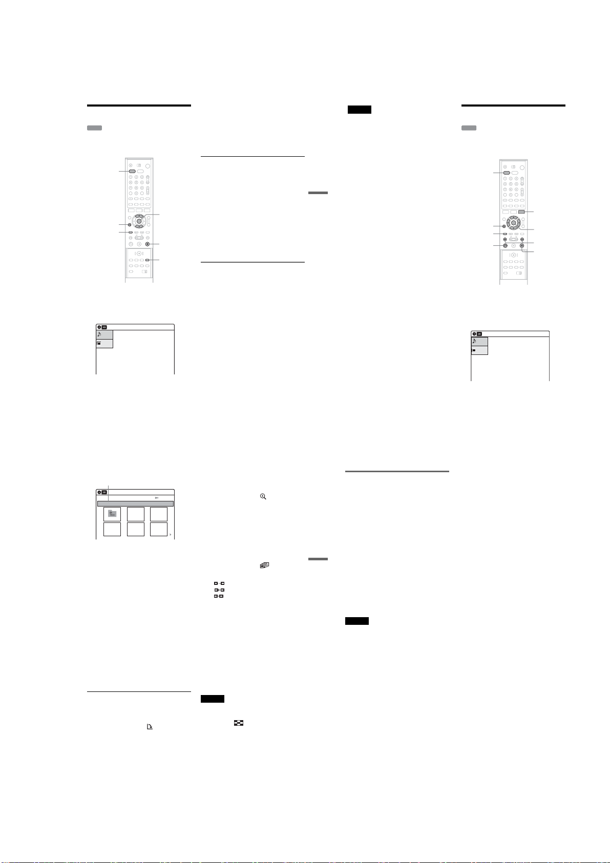
Playing MP3 Audio Tracks
DATA CD
You can play MP3 audio tracks on DATA CD s
(CD-Rs/CD-RWs).
DVD
M/m,
O RETURN
TOP MENU
ENTER
x STOP
REPEAT
1 Press DVD to control the DVD recorder.
2 Place a DATA CD on the disc tra y.
When you load a DATA CD which contains
MP3 audio tracks and JPEG image files, the
display for selecting a media type appears.
Music
Press ENTER :
Photo
Music Menu for this CD
If you load a DATA CD which contains only
MP3 audio files, the MP3 display appears.
Then you can skip step 3.
10:10 AM
3 Select “Music,” then press ENTER.
4 Select the desired directory, then press
ENTER.
5 Select the desired track, then press
ENTER.
The selected track starts playing.
When a track or album is being played, the
title is shown in a box.
To stop play
Press x STOP.
To play repeatedly
Press REPEAT repeatedly during playback.
Off: does not play repeatedly.
File: repeats the current track.
Folder: repeats the current album.
To return to the previous display
Press O RETURN.
To return to the display for selecting a media
type
Press x STOP, then press TOP MENU.
About MP3 audio tracks
MP3 is audio compression technology tha t
satisfies certain ISO/MPEG regulations.
You can play back DATA CDs (CD-Rs/CD-RWs)
recorded in MP3 (MPEG1 Audio Layer 3) format.
However, the discs must be recorded accordi ng to
ISO9660 Level 1, Level 2 or Joliet format for the
recorder to recognize the tracks. You can als o play
discs recorded in Multi Session.
See the instructions supplied with the CD-R/CDRW drives and the recording software (not
supplied) for details on the recording format.
Note on Multi Session discs
If MP3 audio tracks are recorded in the first
session, the recorder will also play MP3 audio
tracks in other sessions. If audio tra cks in Music
CD format are recorded in the first session, only
the first session will be played back.
z Hints
•Since a disc with many trees takes longer to start
playback, it is recommended that you create albums
with no more than two trees.
•When playback of all the MP3 audio tracks wi thin the
album finishes, the recorder stops.
Notes
•The recorder may not be able to play some DATA C Ds
created in the Packet Write format.
•The recorder will play any data with the extension
“.MP3,” even if they are not in MP3 format. Playing
this data may generate a loud noise which could
damage your speaker system.
•The recorder does not conform to audio tracks in
MP3PRO format.
•The recorder can recognize up to 499 MP3 files within
a single folder. The recorder may not recognize some
discs depending on the recording device used for
recording or the disc condition.
•The recorder can play MP3 audio tracks recorded in the
following sampling frequencies: 32 kHz, 44.1 kHz,
Playing Discs
48 kHz.
•ID3 tags cannot be displayed.
•Only alphabe t and numbers can be used for album or
track names. Anything else is displayed as an asterisk.
Playing JPEG Image Files
DATA CD
You can play JPEG image files on DATA CDs
(CD-Rs/CD-RWs).
DVD
TOOLS
O RETURN
TOP MENU
H PLAY
M/m/</,,
ENTER
./>
x STOP
1 Press DVD to control the DVD recorder.
2 Place a DATA CD on the disc tray.
When you load a DATA CD which contains
MP3 audio tracks and JPEG image files, the
display for selecting a media type appears.
Music
Press ENTER :
Photo
Music Menu for this CD
If you load a DATA CD which contains only
JPEG files, the screen shown in step 3
appears. Skip to step 4.
10:10 AM
3 Select “Photo,” then press ENTER.
Directory information
Photo
\\abc\defg
Page 1 / 2
4 Press ./> to select the next/
previous album page, then press M/m/</
, to select an image.
10:10 AM
Slide Show
To display the selected image
1 Press ENTER.
The selected image is displayed ov er the
entire screen.
2 To displ ay the next/previous image, press
./>.
To play the Slide show
1 Press H PLAY.
You can also play the Slide show using
the menu on the selected image.
For details, see “To enjoy the Slide show”
on page 65.
2 Press </, to select the desired playing
speed on the “Slide Show Speed” menu,
then press ENTER.
Slide show starts from the selected image.
To rotate the selected image
1 Press M/ m/</, to select an image in th e
“Index” display, then press ENTER.
2 Press </, to select “ ,” then press
ENTER.
Each time you press ENTER, the image turns
clockwise by 90°.
,continued
To zoom in an image
1 Press M/m/</, to select an image in the
“Index” display, then press E NTER.
2 Press </, to select “ ,” then press
ENTER.
3 Press ENTER repeatedly to change the
magnification. Each time you press ENTER,
the magnification changes as shown below.
2× t 4× t 2× t norma l magnification
To enjoy the Slide show
1 Press M/m/</, to select an image in the
“Index” display, then press E NTER.
2 Press </, to select “ ,” then press
ENTER.
The “Slide Show Speed” menu appears.
“”: Slow
“”: Normal
“”: Fast
3 Press </, to select the desired play speed,
then press ENTER.
Slide show starts.
To turn on/off the menu in the single image
display
Press TOOLS to turn off the menu.
To return to the previous display
Press O RETURN.
To return to the display for selecting a media
type
Press x STOP, then press TOP MENU.
Notes
•Slide show can play in only one direction.
•You cannot rotate or zoom in the image during Slide
show.
If you select “ ” in the rotated image display,
•
the images in the “
Index” display will not be rotated.
63
64
About JPEG image files
You can play JPEG image files on CD -Rs or CDRWs. However, the discs must be recorded
according to ISO9660 lev el 1 or level 2 for the
player to recognize the files.
You can also play discs recorded in Multi Session.
See the instructions of the CD-R /RW device or
recording software (not supplied) for details on t he
recording format.
To play a Multi Session CD
This player can play Multi Session CDs when an
Playing Discs
JPEG image file is located in the first session.
Any subsequent JPEG image files, recorded in the
later sessions, can also be played back. When
audio tracks and images in music CD format or
video CD format are re corded in the first session,
only the first session will be played back.
z Hint
If you add numbers (01, 02, 03, etc.) t o the front of the
file names, the files w ill be played in that order.
Notes
•The system can play the extension “.JPG” or “.JPEG.”
•Some CD-Rs or CD-RWs cannot be played on this
system depending on file format.
• If you add the extension “.JPG” or “.JPEG” to data not
in JPEG format, “Can not Display” will appear.
•Depending on the disc or the size of image files,
playback may take some time to start.
•The recorder can recognize up to 999 JPEG files within
a single folder. The recorder may not recognize some
discs depending on the recording device used for
recording or the disc condition.
•Progr essive and lossless compression JPEG image files
are not supported.
•The image size tha t can be displayed is limited. You
can display the following images;
width 32 – 7,680 pixels by height 32 – 8,192 pixels.
,continued
65
66
1-15
Page 26

VCR Recording
Before Recording
Before you start recording…
Check that the tape is longer than the recording
time.
z Hint
Timer recordings will start rega rdless of whether or not
the recorder is turned on. You cannot turn off the
recorder during a timer recording. The recorder
automatically turns off after the timer recording finishes.
Note
This recorder shares a single tuner for both the DVD
recorder and the VCR. You cannot record different
programs to a DVD and a VHS tape at the same time.
Recording a stereo/SAP program
The recorder can receive an d record stereo/SAP
programs.
Stereo programs
When a stereo program is received, the
“STEREO” indicator lights up in the front pa nel
display. If there is noise in the stereo program,
press AUDIO repeatedly until the “MONO”
indicator disappears from the TV screen. The
sound will be recorded in monaur al but with less
noise.
SAP (Second Audio Program)
When a SAP (Second Audio Program) is received,
the “SAP” indicator lights up in the front panel
display. To record only SAP sound, se t “Tuner
Audio” of “Audio” to “SAP” in the “Setup ”
display (page 102).
VCR Recording without the
Timer
TV/DVD·VIDEO
switch
DVD
DISPLAY
H PLAY
REC MODE
Press VIDEO to control the VCR.
1
2
Insert a tape with its safety tab in place.
3
Press CH +/– or INPUT SELECT to select
the channel or input source you want to
record.
4
Press REC MODE repeatedly to select the
tape speed, “SP” or “EP.”
“EP” (Extended Play) provides recording
time three times as long as “SP” (Standard
Play). However, “SP” produces better picture
and audio quality.
5
Press z RE C.
“REC” appears in the front panel disp lay and
recording starts.
VIDEO
CH +/–
SET
TV/VIDEO
INPUT
SELECT
X PAUSE
x STOP
z REC
To stop recording
Press x STOP.
To pause recording
Press X PAUSE.
To restart recording, press X PAUSE again.
If you pause recording fo r more than 5 minutes,
recording stops automatically.
To watch another TV program while recording
1
Slide the TV/DVD·VIDEO switch to TV.
2
Press TV/VIDEO to sw itch to the TV’s
antenna input.
3
Select another channel on the TV .
VCR Recording
To watch a DVD w hile recording
Press DVD to control the DVD recorder, insert a
disc, then press H PLAY.
To save a recording
To prevent accidental erasure, break off the safety
tab as illustrated. To record on the tape again,
cover the tab hole with adhesive tape.
Safety tab
z Hints
•To select a channel, you can use the number buttons.
Enter the channel number, and press SET.
•You can select a video source from the L INE 1 IN or
LINE 2 IN jacks using the INPUT SELECT button.
•The display appears on the TV screen indicating
information about the tape, but the info rmation will not
be recorded on the tape.
• If you do not want to watch TV while recording, you
can turn off the TV. When using a cable box, m ake sure
to leave it on.
Notes
•You cannot change the channel or input source of the
recorder using CH +/– or INPUT SELECT while
recording another TV program.
• If you insert a tape with its safety tab removed, the tape
is ejected when you press z REC.
Recording using the Quick Timer
(One-touch Timer Recording)
You can set the recorder to record in 30 minute
increments.
1 Press VIDEO to control the VCR.
2 Press z RE C repeatedly to set the
duration.
Each press advances the time in 30m inute
increments. The maximum duration is six
hours.
0:30 1:00 5:30 6:00
“OTR” (One-touch Timer Recording) and the
remaining recording time are displayed in the
front panel display while recording.
The time counter decreases minute by minute
to 0:00, then the recorder stops recording
(power turns off).
To cancel the Quick Timer
Press z REC repeatedly until the counter appears
in the front panel display. The recorder returns to
normal recording mode.
To stop recording
Press xSTOP twice.
z Hint
If you do not want to watch TV while recording, you can
turn off the TV. When using a cable box or satellite
receiver, make sure to leave it on.
Notes
•You cannot change the recording mode while
recording.
•You cannot watch a TV program while recording
another TV program.
(normal
recording)
Checking the remaining time
Press DISPLAY.
Stop
0:30:00
SP
Rem 01:30
CH 110
A Play mode
B Time counter
C Recording mode
D Remaining time
E Current channel
To check the remaining time of a tape, set “VCR
Function” – “Tape Length” of “Feat ures” in the
“Setup” display correctly (p age 104).
Maximum recording time
Tape Length SP EP
T-120 2 hrs 6 hrs
T-160 2 hrs 40 mins 8 hrs
T-180 3 hrs 9 hrs
Notes
•The remaining tape length may not be indicated
accurately for short tapes such as T-20 or T-30, or tapes
recorded in LP mode .
•It may take up to one minute for the VCR to calculate
and display the remaining tape length after you press
DISPLAY.
,continued
VCR Timer Recording
(Standard/VCR Plus+)
You can set the timer for a total of 12 programs
together with DVD Timer Recording and VCR
Timer Recording, up to one month in advance.
There are two methods to set the timer: the
standard method and VCR Plus+ method.
•Standard: Set the date, time, and channel of the
program manually.
•VCR Plus+: Enter the PlusCode number
designated for each TV program (page 71).
Note
Do not operate your cable box or satellite receiver jus t
before or during a timer recording. This may prevent the
accurate recording of a program.
Setting the timer manually
(Standard)
VIDEO
SYSTEM
MENU
[TIMER]
M/m/</,,
ENTER
x STOP
67
68
1 Press VIDEO to control the VCR.
2 Insert a tape with its safety tab in place.
3 Press [TIMER].
Timer – Standard
No Rec To Date Start End Source Mode Edit
No.1
01 DVD 06/14 09:00PM 10:00PM CH8 LP
02 DVD 06/14 09:15PM 09:45PM CH1 LP
RecTo Date Star t Stop CH Mode
03 --- --/-- --:-- --:-- ---- ---
DVD
11/30 02 40 03 0505 CH 100 SP
: PM
--- --/-- --:-- --:-- ---- ---04
--- --/-- --:-- --:-- ---- ---05
VCR Plus+
VCR Recording
--- --/-- --:-- --:-- ---- ---06
12 3 4 56
If the Timer programming (VCR Plus+) me nu
appears, press < to switch the display to
“Standard.”
4 Select an item using </, and adjust
using M/m.
A “RecTo”:
Select “VCR.”
B “Date”:
Sets the date using M.
To record the same program every da y or
the same day every week, press m.
The item changes as follows:
Today y Mon-Fri (Monday to Friday)
y Sun (every Sunday) y Mon (every
Monday) y … y Sat (every Saturday)
y 1month later y … y Today
C “Start”:
Sets the start time.
D “Stop”:
Sets the stop time.
E “CH”:
Selects the channel or input sour ce.
10:10 AM
:
PM
F “Mode”:
Selects the recording mode; “SP” or
“EP.” To use the Auto Tape Speed
function, select “Auto.” For details, see
“To use the Auto Tape Speed function”
on page 71.
If you make a mistake, select the item and
change the setting.
5 Press ENTER.
The Timer List menu (page 74) appears. The
c indicator lights up in the front panel
display, and the recorder is ready to start
recording. If the c indicator flashes in the
front panel display, check that a tape w ith its
safety tab in place is inserted.
If the timer settings overlap, a message
appears. To confirm, change, or cancel timer
recording, see “Checking/Changing/
Canceling VCR Timer Settings (Timer List)”
on page 74.
6 Press SYSTEM MENU to e xit the menu.
To stop recording
Press x STOP twice.
If the timer settings overlap
The program that starts first has priority and the
second program starts recording only after the firs t
program has finished. If the programs start at the
same time, the program listed first in the menu has
priority.
7:00 8:00 9:00 10:00
Program 1
Program 2
will be cut off
7:00 8:00 9:00 10:00
Program 1
Program 2
will be cut off
To confirm, change, or cancel timer recording
See “Checking/Changing/Canceling VCR Timer
Settings (Timer List)” on page 74.
,continued
69
70
1-16
Page 27
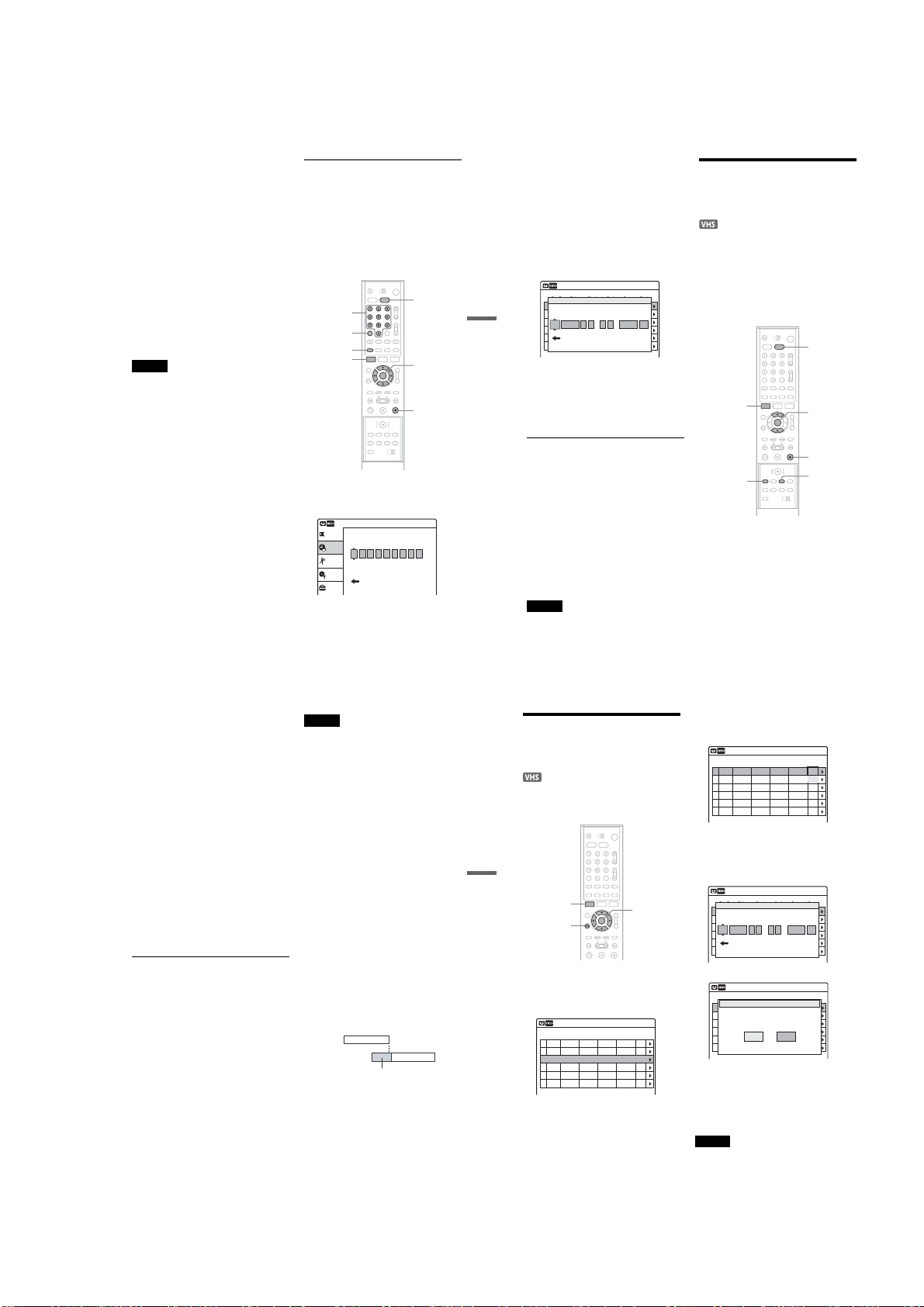
To use the Auto Tape Speed f unction
When you are recording a program in the Auto
mode and the remaining tape becomes shorter than
the recording time, the tape speed is automatically
changed to EP mode. Note that some noise will
appear on the picture when the tape speed is
changed. If you want to k eep the tape speed, select
“SP.” To operate this function, set “VCR
Function” – “Tape Length” of “Feat ures” in the
“Setup” display correctly (p age 104).
z Hints
•When the st art time and the channel or input source to
be recorded are the same but the “RecTo” setting
differs, the program is recorded to both the DVD disc
and the VHS tape.
•You can also display the Timer programming menu as
follows:
1 Press SYSTEM MENU.
The System Menu app ears.
2 Select “Timer,” and press ENTER.
3 Select “Timer – Standard,” and press ENTER.
Notes
•To record a cable or satellite program, turn on the cable
box or satellite receiver and select the program you
want to record. Leave the cable box or satellite receiver
turned on until the recorder finishes recording.
•Even if the timer is set , timer recordings cannot be
made while recording a program that has priority.
•You cannot record on a tape with its safety t ab
removed.
•Before the timer recording starts, “TIMER REC”
flashes in the front panel display.
Recording TV programs using the
VCR Plus+ system
The VCR Plus+ system is a feature that simplifies
setting the timer. Just enter the PlusCode number
listed in the TV program guide. The date, time,
and channel of that program are set automatically.
Before you start, check that the TV and guide
channels are correctly set in “Guide Channel
Setup” of “Tuner Preset” in the “Setup” display
(page 98).
Number
buttons
CLEAR
VCR Plus+
SYSTEM
MENU
VIDEO
M/m/</,,
ENTER
x STOP
1 Press VIDEO to control the VCR.
2 Insert a tape with its safety tab in place.
3 Press VCR Plus+.
Timer – VCR Plus+
Title List
Set VCR Plus+ Code number. [0~9]
Timer
Edit
Disc Setting
Standard
Setup
If the Timer programming (Standard) menu
appears, press < to switch the display to
“VCR Plus+.”
10:10 AM
,continued
4 Press the number buttons to ent er the
PlusCode number.
If you make a mistake, press CLEAR and reenter the correct number.
5 Press ENTER.
The date, start and stop times, cha nnel, and
recording mode appear.
The c indicator light s up in the front panel
display, and the recorder is ready to start
recording. If the c indicator flashes in the
front panel display, check that a tape with its
safety tab in place is inserted.
Timer
Timer – Standard
No Rec To Date Start End Source Mode Edit
No.1
01 DVD 06/14 09:00PM 10:00PM CH8 LP
02 DVD 06/14 09:15PM 09:45PM CH1 LP
RecTo Date Star t Stop CH Mode
VCR Recording
03 --- --/-- --:-- --:-- ---- ---
DVD
11/15 09 00 11 00 CH83 LP
: PM
--- --/-- --:-- --:-- ---- ---04
--- --/-- --:-- --:-- ---- ---05
VCR Plus+
--- --/-- --:-- --:-- ---- ---06
6 Select “RecTo” using </, and select
“VCR” using M/m, and press ENTER.
If you want to change other settings, press </
, to select the item and press M/m to change
the setting.
10:10 AM
:
PM
7 Press SYSTEM MENU to exit the menu.
To stop recording
Press x STOP twice.
If the timer settings overlap
See page 70.
To confirm, change, or cancel timer recording
See “Checking/Changing/Can celing VCR Timer
Settings (Timer List)” on page 74.
z Hint
You can also display the Timer programming menu as
follows:
1 Press SYSTEM MENU.
The System Menu appears.
2 Select “Timer,” and press ENTER.
3 Select “Timer– VCR Plus+,” and press ENTER .
Notes
•When the PlusCode num ber is incorrect, “Invalid
code” appears on the TV screen.
•Before the timer recording starts, “TIMER REC”
flashes in the front panel display.
•You cannot record on a tape with it s safety tab
71
removed.
72
Recording from Connected
Equipment with a Timer
(Synchro Rec)
You can set the recorder to automatically record
programs from connected equipment that has a
timer function (such as a satellite tuner). Connect
the equipment to the LINE 1 IN jacks of the
recorder (page 35).
When the connected equipment turns on, the
recorder starts recording a program from the LINE
1 IN jacks.
VIDEO
SYSTEM
MENU
REC MODE
M/m,
ENTER
x STOP
SYNCHRO
REC
1 Press VIDEO to control the VCR.
2 Insert a tape with its safety tab in place.
3 Press REC MODE repeatedly to select the
tape speed, “SP” or “EP.”
“EP” (Extended Play) provides recording
time three times as long as “SP” (Standard
Play). However, “SP” produces better picture
and audio quality.
4 Press SYSTEM MENU while the recorder is
in stop mode.
5 Select “Setup,” and press ENTER.
6 Select “Features,” and press ENTER.
The “Features” setup ap pears.
7 Select “Synchro Recording,” and press
ENTER.
8 Select “to Video,” and press ENTER.
9 Press SYSTEM MENU to exit the menu.
10
Set the timer on the connected equipment
to the time of the program you want to
record, and turn it off.
11
Press SYNCHRO REC.
The SYNCHRO REC indicator lights u p on
the front panel. The recorder is ready to start
Synchro-Recording.
The recorder automatically starts recording
when it receives an input signal from the
connected equipment. T he recorder stops
recording when the connected equipment
turns off.
To stop recording
Press x STOP twice.
To cancel Synchro Rec function
Press SYNCHRO REC. The SYNCHRO REC
indicator on the recorder turns off.
If you press SYNCHRO REC during SynchroRecording, the Synchro-R ecording stops, the
SYNCHRO REC indicator turns off and the
recorder’s power turn s off.
Notes
•The recorder starts recording only after detecting the
video signal from the connected equipment. The
beginning of the program may not be recorded
regardless of whether or not the recorder’s power is on
or off.
•During Synchro-Recording, other operations such as
normal recording cannot be done.
•To use the connected equipment while the recorder is
standing by for Synchro-Recording, cancel SynchroRecording by pressing SYNCHRO REC. Be sure to
turn off the connected equipment and press
SYNCHRO REC to reset Synchro-Recording before
the timer recording starts.
•The Synchro Rec function does not wor k with some
tuners. For details, see the t uner’s operating
instructions.
•While the recorder is standing by for SynchroRecording, the Auto Clock Set functi on (page 99) does
not work.
•To use the Synchro Rec function, you must first se t the
recorder’s clock correctly.
•When the recorder’s power is on, the recorder enters
the Synchro-Recording standby mode after a SynchroRecording has finished.
•You cannot record on a tape with its safety tab
removed.
If the timer settings of a Synchro-Recording
and another timer recording overlap
Regardless of whether or n ot the program is a
Synchro Rec program, the program that starts first
has priority and the second program starts
recording only after the first program has finished.
7:00 8:00 9:00 10:00
Program 1
Program 2
will be cut off
4
Select the timer setting you want to check/
Checking/Changing/
Canceling VCR Timer
Settings (Timer List)
You can check, change, or cancel timer settings
using the Timer List menu.
VCR Recording
SYSTEM
MENU
O RETURN
1
Press SYSTEM MENU.
The System Menu appears.
2
Select “Timer,” and press ENTER.
3
Select “Timer List,” and press ENTER.
Timer List
No RecTo Date Start Stop CH Mode Edit
01 VCR 11/17 09:00PM 10:00PM CH8 LP
02 VCR 11/28 09:15PM 09:45PM CH1 LP
03 --- --/-- --:-- --:-- ---- ---
--- --/-- --:-- --:-- ---- ---04
--- --/-- --:-- --:-- ---- ---05
--- --/-- --:-- --:-- ---- ---06
Timer information displays the recording
date, time, recording mode, etc.
M/m/</,,
ENTER
10:10 AM
change/cancel, and press ENTER.
The sub-menu appears.
Timer List
No RecTo Date Start Stop CH Mode Edit
01 VCR 11/17 09:00PM 10:00PM CH8
02 VCR 11/28 09:15PM 09:45PM CH1
03 --- --/-- --:-- --:-- ---- ---
--- --/-- --:-- --:-- ---- ---04
--- --/-- --:-- --:-- ---- ---05
--- --/-- --:-- --:-- ---- ---06
5
Select one of the options, and press
ENTER.
“Edit”: Changes the timer setting. Select an
item using </, and adjust using M/m.
Press ENTER.
Timer – Standard
No Rec To Date Start End Source Mode Edit
No.1
01 DVD 06/14 09:00PM 10:00PM CH8 LP
02 DVD 06/14 09:15PM 09:45PM CH1 LP
RecTo Date Star t Stop CH Mode
03 --- --/-- --:-- --:-- ---- ---
VCR
11/17 09 15 09 45 CH1 LP
:
--- --/-- --:-- --:-- ---- ---04
--- --/-- --:-- --:-- ---- ---05
VCR Plus+
--- --/-- --:-- --:-- ---- ---06
10:10 AM
Edit
Del
10:10 AM
:
PM
PM
“Del”: Erases the timer setting. Press ENTER.
Timer List
No Rec To Date Start End Source Mode Edit
01 DVD 06/14 09:00PM 10:00PM CH8 LP
02 DVD 06/14 09:15PM 09:45PM CH1 LP
Do you want to erase “No.01”?
03 --- --/-- --:-- --:-- ---- ---
--- --/-- --:-- --:-- ---- ---04
OK Cancel
--- --/-- --:-- --:-- ---- ---05
--- --/-- --:-- --:-- ---- ---06
To turn off the Timer List
Press O RETURN.
z Hint
While recording, you cannot modify the timer setting for
the current recording.
Note
Even if the timer is set, time r recordings cannot be made
while recording a program that has priority.
10:10 AM
No.1
73
74
1-17
Page 28
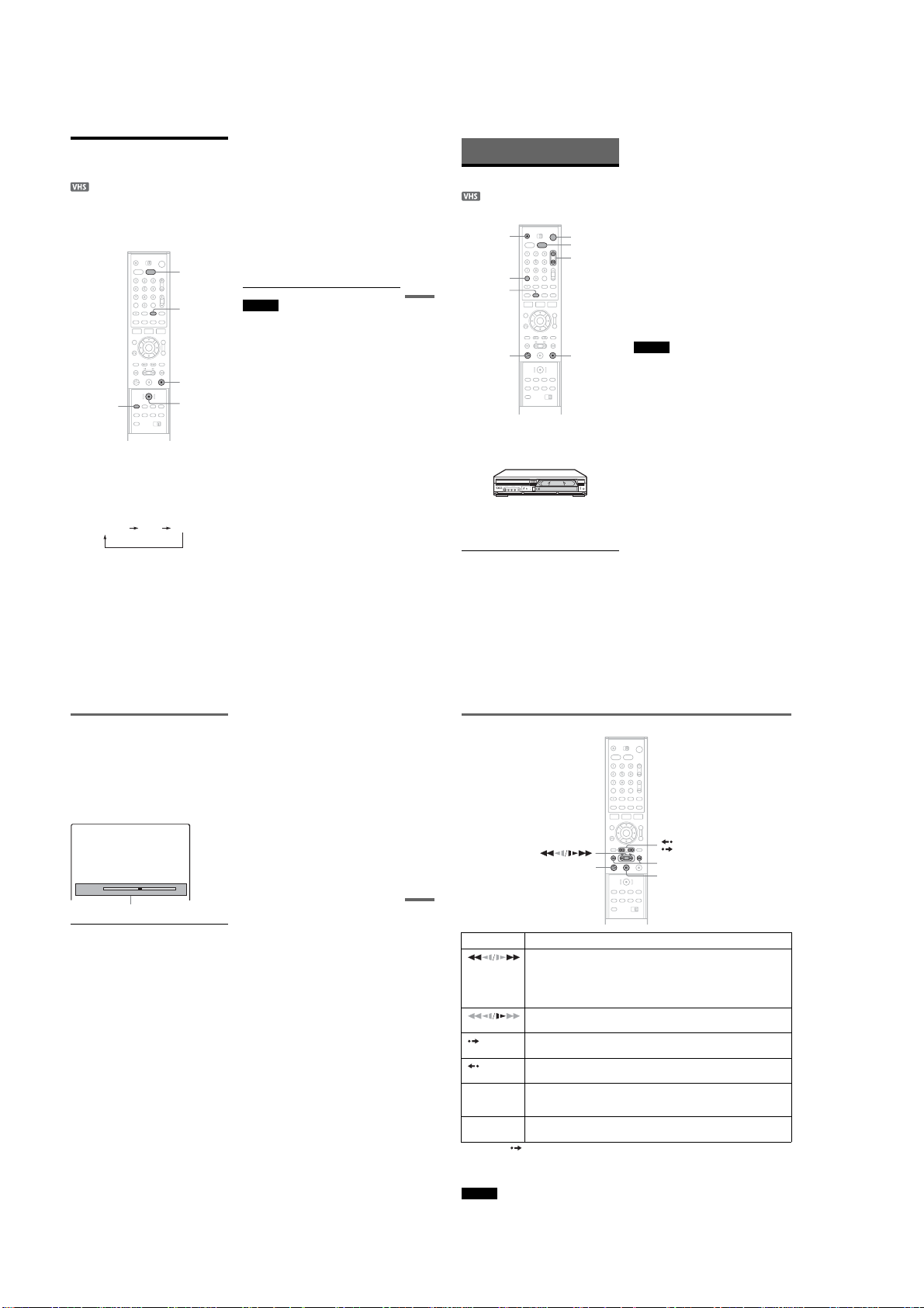
Recording from Connected
Equipment without a Timer
You can record from a connected VCR or similar
device. To connect other VCR or similar device,
see “Connecting Another VCR or Similar Device”
on page 34.
VIDEO
INPUT
SELECT
x STOP
REC MODE
1
Press VIDEO to control the VCR.
2
Insert a tape with its safety tab in place.
3
Press INPUT SELECT to select an input
source according to the connec tion you
made.
The front panel display changes as follows:
program position
z REC
LINE2LINE1
4
Press REC MODE repeatedly to select the
tape speed, “SP” or “EP.”
“EP” (Extended Play) provides recording
time three times as long as “SP” (Standard
Play). However, “SP” produces better picture
and audio quality.
5
Insert the source tape into the connected
equipment and set to playback pause.
6
At the same time, press zREC on this
recorder and the pause or play button on
the connected equipment.
Recording starts.
To stop recording, press x STOP on this
recorder.
Notes
•When recording a video game image, the screen may
not be clear.
•You cannot record on a tape with its safety tab
removed.
To stop playback
Playing VHS Tapes
Playing
Z OPEN/
CLOSE
CLEAR
VCR Recording
DISPLAY
H PLAY
Press VIDEO to control the VCR.
1
2 Insert a tape.
The VCR starts playing automatically if you
insert a tape with its safety tab removed.
3 Press H PLAY.
The display window shows the pl ayback time.
When the tape reaches the end, it will rewind
automatically.
"/1
VIDEO
TRACKING +/–
x STOP
Press x STOP.
To eject the tape
Press Z OPEN/CLOSE.
To turn off the power while rewinding (Rewind
Shut Off)
Press "/1 while the tape is rewinding. The power
will turn off but the tape will keep rewinding until
it reaches the end.
To use the time counter
Press CLEAR at the point on the tape that you
want to find later. The counter in the front pane l
display resets to “0:00:00.” To search for the
counter 0:00:00 point automatically, see
“Searching for the counter 0:00:00 point” on
page 79.
To display the counter on the TV screen, press
DISPLAY.
Notes
•Tapes reco rded in LP mode on other VCR s can be
played back on this VCR but the picture quality cannot
be guaranteed.
•The counter resets to “0:00:00” whenever a tape is
reinserted.
•The counter stops counting w hen it comes to a portion
with no recording.
•When 10 hours have passed, the counter in the front
panel display returns to “0:00:00” and the count starts
over again.
•When playback does not start even if you insert a tape
with its safety tab removed, set “VCR Function” –
“Auto Play” of “Features” to “On” in the “Setup”
display (page 104).
•Stop disc playb ack while playing back a video.
•The VCR can also play S-VHS tapes. The VCR will
automatically identify the type of tape inserted in the
VCR (either VHS or S-VHS). When S-VHS tapes are
played in the VCR, the enhanced resolution will not be
visible on screen; there may also be picture distortion
while playing the S-VHS tape in slow motion or while
utilizing other special playback modes. The VCR will
not record in S-VHS mode on an S-VHS tape.
•For details on the operation restrictions, see page 8.
Adjusting the picture (tracking)
Although the VCR automatically adjusts the
tracking when playing a tape, distortion may occur
if the recording is in poor condition. In this case,
manually adjust the tracking.
Press TRACKING +/– to adjust the picture.
The tracking meter appears.
Press TRACKING +/– repeatedly until the
distortion disappears.
Tracking
Tracking meter
To resume automatic tracking adjustment
Press TRACKING + and TRACKING – at the
same time.
Or, eject the tape and reinsert it.
,continued
75
76
Playback option
INSTANT REPLAY/
INSTANT ADVANCE
H PLAY
Playing VHS Tapes
Buttons Operations
(fast reverse/fast
forward)
(slow)
INSTANT
ADVANCE
INSTANT
REPLAY
. PREV/
NEXT >
X PAUSEPauses playback.
*1
You can press INSTANT ADVANCE up to 4 time. This allows you to fast forward up to 2 minutes in total.
*2
For 10 seconds in SP or LP mode/for 15 seconds in EP mode
To resume normal playback, press H PLAY.
Notes
•The sound is muted during play back at various speeds.
77
•The picture may show noise when pla ying at high speed in reverse.
78
•Fast reverses/fast forwards when pressed during stop.
When you press and hold down the butto n during fast reverse/fast forward, you can
view the picture.
•Plays at high speed when briefly pressed during playback.
When you press and hold down the button during playback, playing at high speed
continues until you release the button.
Plays in slow motion when pressed in p ause mode.
•Plays frame by frame when pressed in pause mode.
•Fast forw ards the current scene for 30 seconds when pressed during playback.
Replays the previous scene when presse d during playback.
Fast reverses/fast forwards when pressed during playback.
Search speed changes as follows:
–×7 y –×5 y –×3 y STILL y SLOW y PLAY y ×2 y ×3 y ×5 y ×7
If you pause playback for more than 5 minutes, playback starts automatically.
. PREV/NEXT >
X PAUSE
*1
*2
1-18
Page 29
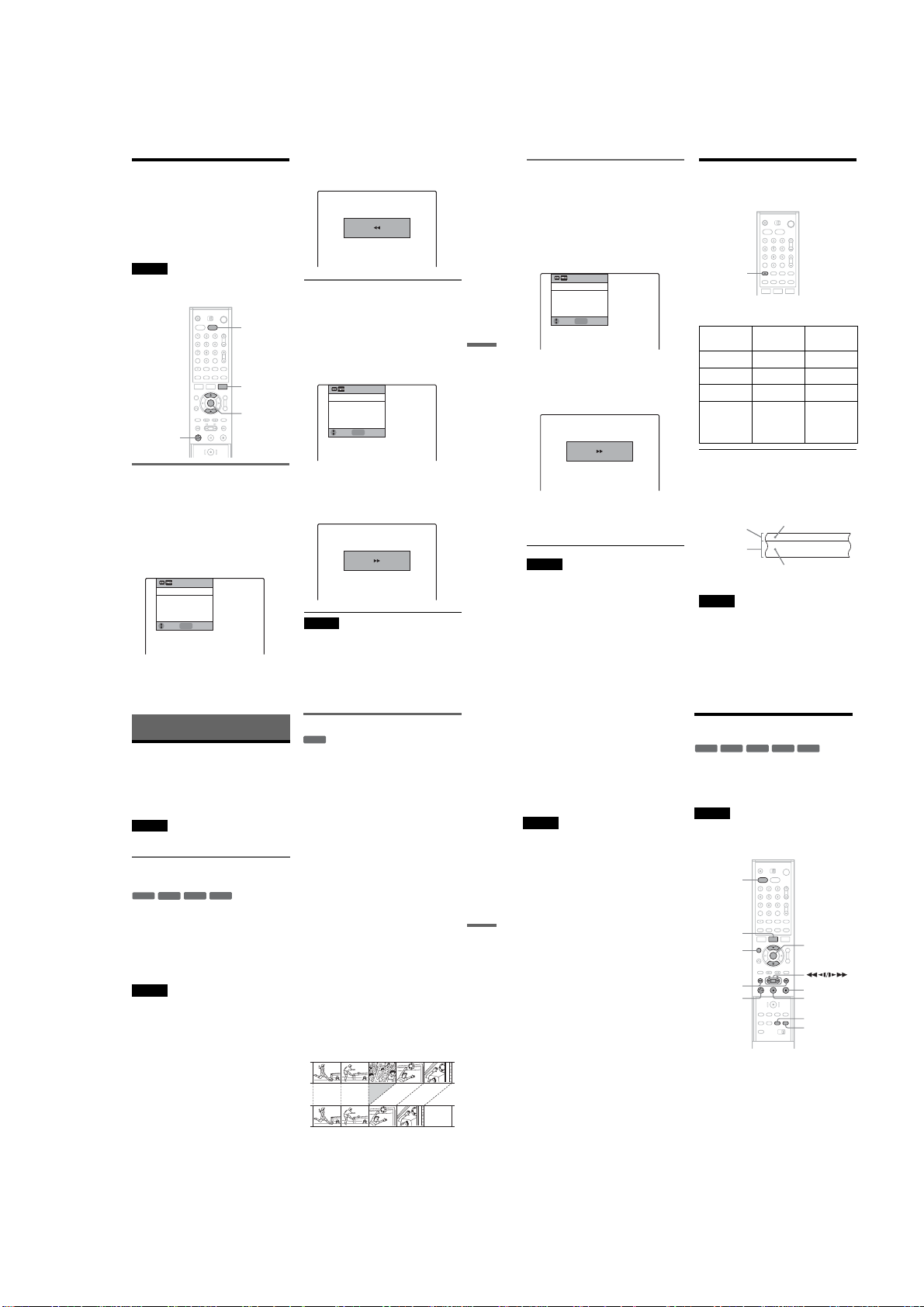
Searching Using Various
Functions
The VCR automatically marks the tape with an
index signal at the point where e ach recording
begins.
You can easily find a specific poin t using various
search functions.
Note
You cannot use these search functions during DVD
recording.
VIDEO
TOOLS
M/m,
ENTER
H PLAY
Searching for the counter 0:00:00
point
To mark a point on the tape that you w ant to find
later, reset the tape counter to “0:00:00.”
The VCR automatically fast-forwards or rewinds
to the 0:00:00 point on the tape counter.
1 Press VIDEO to control the VCR.
2 Press TOOLS.
The TOOLS menu appears.
Go To Zero
End Search
Forward Intro Scan
Reverse Intro Scan
ENTER
Move
Enter
3 Select “Go To Zero,” and press ENT ER.
The VCR starts searching and automatically
stops at the 0:00:00 point.
Go to Zero
0:00:00
Searching for a blank space of the
tape
The VCR automatically searches for the
beginning of a blank space. You can easily find a
point you can start recording from.
1 Press VIDEO to control the VCR.
2 Press TOOLS.
The TOOLS menu appears.
Go To Zero
End Search
Forward Intro Scan
Reverse Intro Scan
ENTER
Move
Enter
3 Select “End Search,” and press ENTE R.
The VCR starts searching and automatically
stops at the beginning of a blank space. If no
blank space is found, the VCR re aches the
end.
End search
0:00:13
Note
The VCR may be unable to recognize the end of a blank
space depending on the length of that blank space.
,continued
Searching using the index function
(Scan and Play)
The VCR automatically marks the tape with an
index signal at the point where ea ch recording
begins. Use these signals as re ferences to find a
specific recording.
Selecting the sound durin g
playback
1 Press VIDEO to control the VCR.
2 Press TOOLS.
The TOOLS menu appears.
Go To Zero
End Search
Forward Intro Scan
Reverse Intro Scan
ENTER
Enter
Move
Playing VHS Tapes
3 Select “Forward Intro Scan” to scan
ahead, or “Reverse Intro Scan ” to scan
backwards.
The VCR searches and then plays back f or
about five seconds.
Scan and play
–0:00:01
4 Press H PLAY to view that program.
If you do not press H PLAY, the VCR
automatically searches for the next index
mark, or until it reaches the end of the tape.
Note
Once in recording mode, if the VCR is put in pause and
then released to start the recordi ng, no index mark will be
inserted. An index mark will be inserted if the channel is
changed while VCR is put in pause.
79
80
AUDIO
Press AUDIO repeatedly during pl ayback.
To listen to On-screen
Stereo Hi-Fi STEREO
Left channel Left STEREO
Right channelRight STEREO
Monaural
sound on the
normal audio
track
How sound is recorded on a video tape
The VCR records sound onto two separate tracks.
Hi-fi audio is recorded onto the main track al ong
with the picture. Monaural sound is recorded onto
the normal audio track along the edge of the tape.
Normal audio track
Hi-fi audio track
(main track)
Notes
•To play a tape in stereo, you must use the A/V
connections.
•When you play a tape recorded in monaural, the sound
is heard in monaural regardless of the AUDIO setting.
display
Mono No i ndicator
Front panel
display
Monaural sound
Stereo sound
(left/right channels)
DVD Editing
Before Editing
This recorder offers various edit options for
various disc types. Befo re you edit, check the disc
type in the front panel display, and select the
option available for your dis c (page 10).
Note
You may lose the edited contents if you remove the disc
or a timer recording starts while e diting.
Edit options for DVD+RWs/DVD-RWs
(Video mode)/DVD+Rs/DVD-Rs
+
-
RWVideo
RW
You can perform simple edits. Since V ideo mode
titles are actual recordings on the disc, you cannot
undo any edits you mak e. The edit functions
available for Video mode titles are:
–Setting protection against er asure (page 82).
–Labeling a title (page 82).
–Erasing a title (page 82).
Notes
•Once the disc is finalized, you cannot edi t or record on
the disc (except for DVD+RWs).
• If a message appears and indicates that the disc’s
control information is fu ll, erase unnecessary titles.
-R+
R
Edit options for DVD-RWs (VR mode)
-
RWVR
You can enjoy advanc ed edit functions. First you
have two options for a DVD-RW (VR mode):
editing either the original recording (called the
“original”), or the playback information cre ated
from the original (called a “Playlist”). Since each
is different in nature and offe rs different merits,
read the following and select the one that better
suits your needs.
To edit original titles
Edits made to the original titles are final. If you
plan to retain an unaltered original recording,
create and edit a Playlist (see below). The edit
functions available for original titles are:
–Labeling a title (page 82).
–Setting protection against erasure (page 82).
–Erasing a title (page 82).
–Erasing a section of a title (A-B Erase) (page 83).
To create and edit Playlist titles
A Playlist is a group of Playlist titles created from
the original title for editing purposes. When you
create a Playlist, only the control information
necessary for playback, such as the playback
order, is stored on the disc. Since the original titles
are left unaltered, Playlist titles can be re-edited.
Example: You have recorded the final few
matches of a soccer tournament on a DVD-RW
(VR mode). You want to create a digest with the
goal scenes and other highlights, but you also want
to keep the original recording.
In this case, you can compile highlight scenes as a
Playlist title. You can even rearrange the scene
order within the Playlist title (“Creating a Playlist”
on page 84).
The advanced edit function s available for Playlist
titles are:
–Labeling a title (page 82).
–Erasing a title (page 8 2).
–Editing a Playlist scene (page 86).
z Hint
You can display the disc’s Playlist titles in the Title List
(Playlist), or the original titles i n the Title List (Original).
To switch the two Title Lists, press TITLE LIST, and
press ORIGINAL/PLAYLIST.
Notes
•You cannot protect Playlist titles.
• If a message appears and indicates that the disc’s
control information is full, erase un necessary titles.
DVD Editing
Editing a Title
+
-
-
RW
VR
RW
This section explains the basic edit functions. Note
that editing is irreversible. To edit a DVD-RW
(VR mode) without changing the original
recordings, create a Playlist title (page 84).
Note
When editing a DVD+R, DVD-R, or DVD-RW (Video
mode), finish all editing before finalizing the disc. You
cannot edit a finalized disc.
1
2
3
RW
DVD
TITLE LIST
ORIGINAL/
PLAYLIST
./>
H PLAY
Press DVD to control the DVD recorder.
Press TITLE LIST.
When editing a DVD-RW in VR mode, press
ORIGINAL/PLAYLIST to switch the “Title
List(Original),” if necessary.
Select a title, and press ENTER.
The sub-menu appears.
-R+
Video
R
M/m,
ENTER
x STOP
X PAUSE
CHAPTER
MARK
MARK ERASE
,continued
81
82
1-19
Page 30
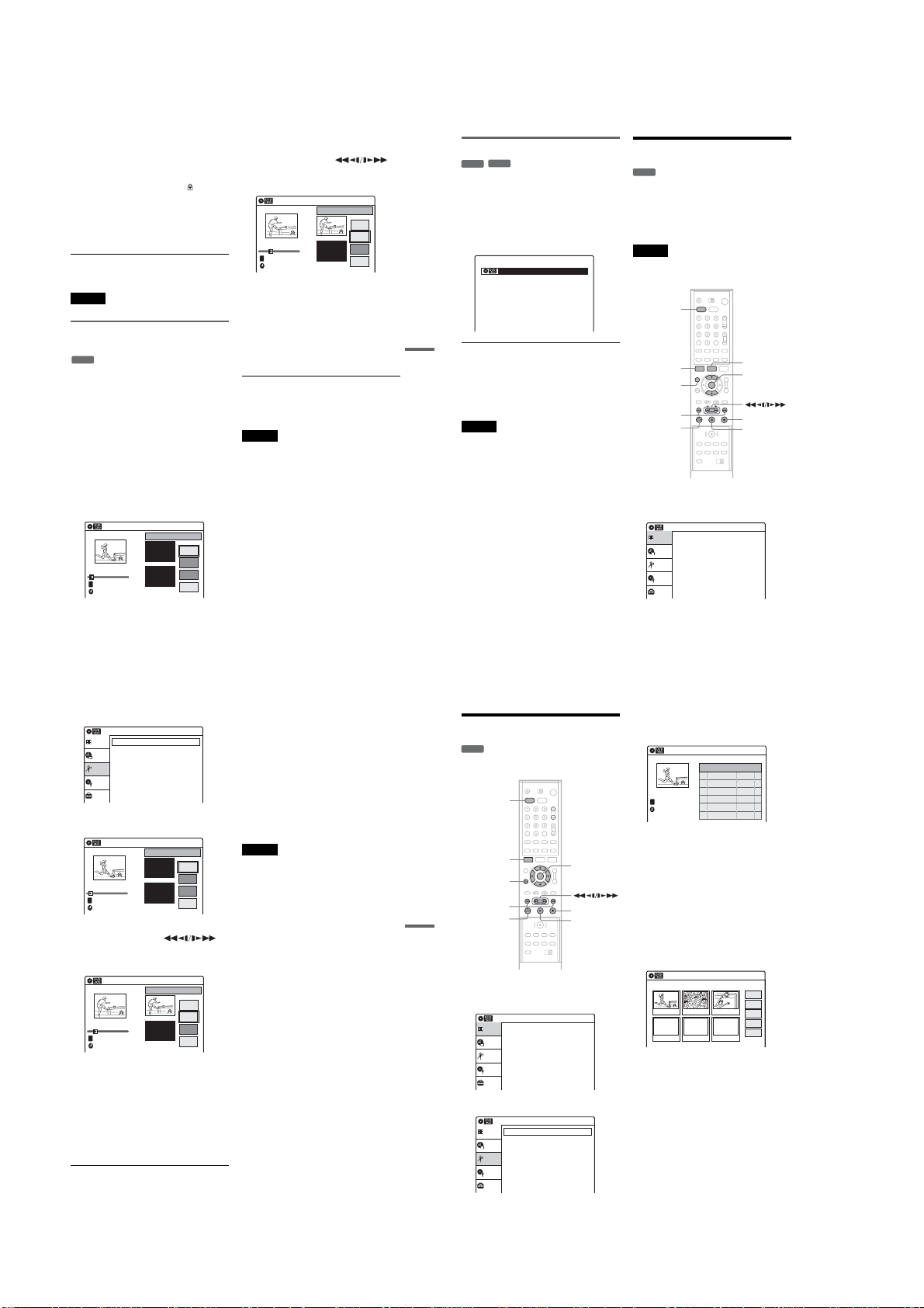
4
Select an option, and press ENTER.
You can make the following edits to the title.
“Erase”: Erases the select ed title. Select “OK”
when asked for confirmation.
“Protect”: Protects the title. Select “On” when
the Protection display appears. “ ” appears
next to the protected title. To cancel the
protection, select “Off.”
“Title Name”: Allows you to enter or re-enter
a title name (page 46).
“A-B Erase”: Erases a section of the title (see
below).
z Hint
You can label or re-label DVDs (page 43).
Note
You cannot protect Playlist titles.
Erasing a section of a title
(A-B Erase)
-
RW
VR
You can select a section (scene) in a title a nd erase
it. Note that erasing scenes in a title cannot be
undone.
1
Press DVD to control the DVD recorder.
2
Press TITLE LIST.
Press ORIGINAL/PLAYLIST to switch the
“Title List(Original),” if necessary.
3
Select a title, and press ENTER.
The sub-menu appears.
4
Select “A-B Erase,” and press ENTER.
The display for setting points A and B
appears.
“Start” is selected.
A-B Erase
CH 6
T
Nov/16/2004 08:00 PM
00:00:07
Start 00:00:00
End 00:00:00
Title No.01
10:10 AM
Start
End
Erase
Finish
5
Press ENTER at the starting point of the
portion to be erased (point A) .
You can use H PLAY, ,
./>, x STOP and X PAUSE to find
the point of the p ortion to be erased.
“End” is selected.
A-B Erase
00:00:10
CH 6
T
Nov/16/2004 08:00 PM
6
Press ENTER at the ending point of the
portion to be erased (point B) .
“Erase” is selected.
7
Select “Erase,” and press ENTER .
The display asks for confirmation.
8
Select “OK,” and press ENTER.
The scene is erased. To continue , repeat from
step 5. To finish , select “Finish.”
z Hint
A chapter mark is inserted after the scene was erased. The
chapter mark divides the title into separate chapters on
either side of the mark.
Notes
•Images or sound m ay be momentarily interrupted at the
point where you erase a section of a title.
•Sections shorter than five seconds may not be erased.
•The start and end points of a title may be different from
what you have set.
•The total playing time of the title does not change even
if a scene was erased.
Start 00:00:10
End 00:00:00
Title No.01
10:10 AM
Start
End
Erase
Finish
Creating chapters manually
-
+
RW
VR
RW
You can manually insert a chapter mark at any
point you like during playback.
Press CHAPTER MARK at the point where you
want to divide the title into chapters.
Each time you press the button, “Markin g mark...”
appears on the screen and the scenes befor e and
after of the mark become separate chapters.
Making mark...VR
DVD Editing
To erase chapter m arks
You can combine two chapters by erasi ng the
chapter mark during play back.
During playback, press MARK ERASE.
The current chapter comb ines with the previous
chapter.
Note
If a message appears and indicates that no more chapter
marks can be added, you may not be able to record or edit .
Creating a Playlist
-
RW
VR
You can add a section of the title to the Playlist
title as one scene without changing the actu al
recordings. A Playlist title can contain up to 99
scenes.
For details, see “Edit options for DVD-RWs (VR
mode)” on page 81.
Note
If you erase an original title used in a Playlist, that Playlist
is also erased.
DVD
SYSTEM
MENU
ORIGINAL/
PLAYLIST
./>
H PLAY
TITLE LIST
M/m,
ENTER
x STOP
X PAUSE
1 Press DVD to control the DVD recorder.
2 Press SYSTEM MENU while the recorder is
stopped.
Title List(Original)
Title List
Timer
Edit
Disc Setting
Setup
Press ENTER :
Title Menu for DVD Title List.
10:10 AM
3
Select “Edit,” and press ENTER.
Edit
Title List
Create Playlist
Edit Playlist
Timer
DV Edit
Edit
Dubbing
Disc Setting
Setup
4
Select “Create Playlist,” and press ENTER.
“Start” is selected.
Create Playlist
00:00:07
Playlist No. 01
T
---/--/---- --:--
5
Press ENTER at the starting point .
You can use H PLAY, ,
./>, x STOP and X PAUSE to find
the point.
“End” is selected.
Create Playlist
00:00:10
Playlist No. 01
T
---/--/---- --:--
6
Press ENTER at the ending point.
“Make” is selected.
To reset the start or end point, select “Start” or
“End” and repeat step 5 or 6.
7
Press ENTER.
The selected section is captured as a scene. To
continue, repeat the steps above.
8
When you finish capturing scenes, select
“Finish” and press ENTER.
Start 00:00:00
End 00:00:00
Start 00:00:10
End 00:00:00
Scene No.01
Scene No.01
10:10 AM
10:10 AM
Start
End
Make
Finish
10:10 AM
Start
End
Make
Finish
,continued
To play the Playlist title
1
Press TITLE LIST.
2
Press ORIGINAL/PLAYLIST to switch to the
“Playlist.”
3
Select a Playlist title, and press ENTER.
The sub-menu appears.
4
Select “Play,” and press ENTER.
z Hint
When a Playlist title is created , the start and end points
will become chapter marks, and each scene will become
a chapter.
Notes
•The picture may pause when the edited scene is played.
•The start and end points of a title may be different from
what you have set.
83
84
4 Select “Edit Playlist,” and press ENTER.
Editing a Playlist
-
RWVR
You can edit a scene of the Playlist titl es.
DVD
SYSTEM
MENU
O RETURN
./>
DVD Editing
H PLAY
M/m/</,,
ENTER
x STOP
X PAUSE
The display for selecting Playlist titles
appears.
Playlist
T
CH 32
Nov/27/2004
03:25 PM
5 Select a Playlist title, and press ENTER.
The sub-menu appears.
6 Select an option, and press ENTER.
You can make the following ed its to the title.
“Erase”: Erases the selected Playlist title.
Select “OK” when asked for confirmation.
“Title Name”: Allows you to enter or re-enter
a Playlist title name (page46).
“Edit Scene”: Allows you to re-edit without
changing the actual recordings (see below).
“Title List”: Switches to the “Title
List(Original).”
10:10 AM
No. Title Length Edit
01 CH 32 >00:05:04
02 CH 96 >00:00:51
7 Select “Edit Scene,” and press ENT ER.
1 Press DVD to control the DVD recorder.
2 Press SYSTEM MENU while the recorder is
stopped.
Title List(Original)
Title List
Timer
Edit
Disc Setting
Setup
Press ENTER :
Title Menu for DVD Title List.
10:10 AM
3 Select “Edit,” and press ENTER.
Title List
Timer
Edit
Disc Setting
Setup
Edit
Create Playlist
Edit Playlist
DV Edit
Dubbing
10:10 AM
Edit Scene
The Scene List menu appears with all of the
selected scenes.
“Modify”: Allows you to change the start and
end point of the selected scene. See
“Modifying a scene (Modify )” on page 87.
“Move”: Changes the scene order. See
“Moving a scene (Move)” on page 87.
“Add”: Allows you to add more scenes before
the selected scene. See “Adding a sce ne
(Add)” on page 88.
“Erase”: Erases the scene. The selection is
canceled. See “Erasing a scene (Erase)” on
page 88.
10:10 AM
Playlist No.01Scene No.1 / 1
Play
Modify
03 00:04:2002 00:00:1001 00:00:34
Move
Add
Erase
85
86
1-20
Page 31

Modifying a scene (Modify)
-
RWVR
You can change the start and end point o f the
selected scene.
1 After step 7 of “Editing a Playlist” on
page 86, select a scene, and pr ess ENTER.
2 Select “Modify,” and press ENTER.
“Start” is selected.
Modify
00:00:07
Playlist No. 01
T
Nov/27/2004 03:25 PM
3 Press ENTER at the starting point .
You can use H PLAY, ,
./>, x STOP and X PAUSE to find
the point.
“End” is selected.
Modify
00:00:10
Playlist No. 01
T
Nov/27/2004 03:25 PM
4 Press ENTER at the ending point.
“Change” is selected.
To reset the start or end point, select “Start” or
“End” and repeat step 3 or 4.
5 Press ENTER.
The display returns to “Edit Scene” display.
The re-selected section is captured as a scene.
To modify other scenes, press O RETURN,
and repeat from step 1.
To cancel modifying
Select “Cancel,” and press ENTER.
Start 00:00:00
End 00:00:00
Start 00:00:10
End 00:00:00
Scene No.01
Scene No.01
10:10 AM
Start
End
Change
Cancel
10:10 AM
Start
End
Change
Cancel
To turn off the display
Press SYSTEM MENU.
Note
The start and end point of a scene may be different from
what you have set.
Moving a scene (Move)
-
RWVR
You can change the scene order within the Playlist
title.
1 After step 7 of “Editing a Playlist” on
page 86, select a scene, and press ENTER.
2 Select “Move,” and press ENTER.
Edit Scene
10:10 AM
Playlist No.01Scene No. 2 / 3
Play
Modify
03 00:04:2002 00:00:1001 00:00:34
Move
Add
Erase
3 Select a new location using </,.
4 Press ENTER.
The selected scene moves to the new location.
To move other scenes press O RETURN,
and repeat from step 1.
Edit Scene
02 00:04:20
01 00:00:34
To turn off the display
Press SYSTEM MENU.
Playlist No.01Scene No. 3 / 3
03 00:00:10
10:10 AM
Play
Modify
Move
Add
Erase
Adding a scene (Add)
-
RWVR
You can add a scene before the se lected scene.
1 After step 7 of “Editing a Playlist” on
page 86, select a scene, an d press ENTER.
2 Select “Add,” and press ENTER.
“Start” is selected.
Add
00:00:07
Playlist No. 01
T
Nov/27/2004 03:25 PM
3 Press ENTER at the starting point.
You can use H PLAY, ,
DVD Editing
./>, x STOP and X PAUSE to find
the point.
“End” is selected.
Add
00:00:10
Playlist No. 01
T
Nov/27/2004 03:25 PM
4 Press ENTER at the ending point.
“Add” is selected.
To reset the start or end point, select “Start” or
“End” and repeat st ep 3 or 4.
5 Press ENTER.
The display returns to “Edit Scene” display.
The selected section is captured as a scene and
added before the selected scene.
To add other scenes, press O RETURN, and
repeat from step 1.
To cancel adding
Select “Cancel,” and press ENTER.
Start 00:00:00
End 00:00:00
Start 00:00:10
End 00:00:00
Scene No.01
Scene No.01
10:10 AM
Start
End
Add
Cancel
10:10 AM
Start
End
Add
Cancel
To turn off the display
Press SYSTEM MENU.
Note
The start and end point of a scene may be different from
what you have set.
Erasing a scene (Erase)
-
RWVR
You can erase a selected scene.
1 After step 7 of “Editing a Playlist” on
page 86, select a scene, and press ENTER.
2 Select “Erase,” and press ENTER.
The display asks for confirmation.
3 Select “OK,” and press ENTER.
The selected scene is erased.
To erase other scenes, press O RETURN,
and repeat from step 1.
To turn off the display
Press SYSTEM MENU.
Dubbing (TAPE y DVD)
Dubbing from a Video to a
DVD
+
-
RWVR-RWVideo
RW
You can record (dub) VHS tape video and audio to
a disc. The audio switching and audio settings
must be made for both the VHS tape and the disc.
DVD
AUDIO
SYSTEM
MENU
H PLAY
REC MODE
T VIDEO
-R+
R
VIDEO
M/m,
ENTER
X PAUSE
x STOP
,continued
Using the T VIDEO button on the
recorder
1 Insert a recordable disc.
2 Insert a source tape.
3 Press T VIDEO on the recorder.
Dubbing starts.
Using the TV screen
1 Insert a recordable disc.
2 Insert a source tape.
3 Press DVD to control the DVD recorder.
4 Press SYSTEM MENU while the recorder is
stopped.
Title List(Original)
Title List
Timer
Edit
Disc Setting
Setup
Press ENTER :
Title Menu for DVD Title List.
10:10 AM
5 Select “Edit,” and press ENTER .
Title List
Timer
Edit
Disc Setting
Setup
Edit
Create Playlist
Edit Playlist
DV Edit
Dubbing
10:10 AM
6 Select “Dubbing,” and press ENTER.
Title List
Timer
Edit
Disc Setting
Setup
Edit
Create Playlist
Edit Playlist
DV Edit
Dubbing
Video --> DVD
DVD --> Video
10:10 AM
88
87
7
Select “Video t DVD,” and press ENTER.
The display for confirmation ap pears.
8
Select “OK,” and press ENTER.
Dubbing starts.
To select the recording mode
Press DVD to control the DVD recorder, then
press REC MODE repeat edly.
Each time you press the button, the display
changes on the TV screen as follows:
HQ SP LP EPHSP SLP
For more details about the recording mode, see
page 47.
To select the sound
1
After step 2 above, press VIDEO to control
the VCR.
2
Press H PLAY.
3
Press AUDIO repeatedly to select the sound
you want.
Dubbing (TAPE y DVD)
For details, see page 80.
4
Press X PAUSE.
5
Follow the instructions abov e from step 3.
To stop dubbing
Press x STOP.
Note that it may take a few seconds for the
recorder to stop du bbing.
To play discs recorded with this recorder on
other DVD equipment
Finalize the disc. For details, see page 44.
z Hints
•A black screen is recorded at the end of the dubbed disc,
but this is not a malfunction. When dubbing stops, there
may be some time difference between the tape and the
disc. In this case, a black (no signal) screen is record ed.
•You can switch the playback tape audi o while dubbing.
•When dubbing a VHS tape to a disc, the VHS tape
counter value may differ slightly from the DVD
recording time.
•The audio output is the VHS playback audio.
Notes
•Dubbing is not possible in the following cases.
–When a non-recordable DVD is set.
–When using V HS software with copy guard
functions.
•Dubbing stops in the following cases.
–When the VHS tape is played back to the end and
stops.
–When the VHS deck or the DVD deck is stopped.
–When the disc remaining time runs out.
•The System menu, TOOLS menu, and information
display are not displayed during dubbing.
•Cop yrights
–Recordings made from VHS tapes and oth er
copyrighted material are solely for individual
enjoyment, and other unauthorized use is prohibited
under copyright law.
–Unauthor ized editing of copyrighted material is
prohibited under copyright law.
,continued
89
90
1-21
Page 32

Dubbing from a DVD to a
Video
+
-
-
RW
VR
DVD
AUDIO
SUBTITLE
SYSTEM
MENU
TOP MENU
REC MODE
RW
DVD t
RW
You can record (dub) DVD video and audio to a
VHS tape. However, note that when you record
copy-protected softwar e to a tape, the video may
appear disrupted when you play back the tape.
-R+
Video
DVD
R
VIDEO
TITLE LIST
M/m,
ENTER
X PAUSE
x STOP
Using the DVD t button on the
recorder
1
Insert a tape with its safety tab in place.
2
Insert a source disc.
3
Press DVD to control the DVD recorder.
4
Press TOP MENU or TITLE LIST, and se lect
a title.
5
Start playing, and press x STOP or
X PA USE.
6
Press DVD t on the recorder.
Dubbing starts.
Using the TV screen
1
Insert a tape with its safety tab in place.
2
Insert a source disc.
3
Press DVD to control the DVD recorder.
4
Press TOP MENU or TITLE LIST, and se lect
a title.
5
Start playing, and press x STOP or
X PA USE.
6
Press SYSTEM MENU.
Title List(Original)
Title List
Press ENTER :
Timer
Title Menu for DVD Title List.
Edit
Disc Setting
Setup
7
Select “Edit,” and press ENTER .
Edit
Title List
Create Playlist
Edit Playlist
Timer
DV Edit
Edit
Dubbing
Disc Setting
Setup
10:10 AM
10:10 AM
8 Select “Dubbing,” and press ENTER.
Edit
Title List
Create Playlist
Edit Playlist
Timer
DV Edit
Edit
Dubbing
Disc Setting
Setup
9 Select “DVD t Video,” and press ENTER.
The display for confirmation ap pears.
10
Select “OK,” and press ENTER.
Dubbing starts.
The disc’s menu may appear depe nding on the
disc when playback of a disc fin ishes. In this
case, press x STOP to stop dubbing,
otherwise the disc’s men u is recorded until the
tape reaches its end.
To select the tape speed
Press VIDEO to control the VCR, then press REC
MODE repeatedly to select “SP” or “EP.”
Dubbing (TAPE y DVD)
“EP” (Extended Play) provid es recording time
three times as long as “SP” (Standard Play).
However, “SP” produces better picture an d audio
quality.
To select the sound or language
After step 5 above, press AUDIO repeatedly to
select the sound you want, or press SUBTITLE
repeatedly to select the lang uage you want. For
details, see page 59.
To stop dubbing
Press x STOP.
Note that it may take a few seconds for the
recorder to stop du bbing.
z Hints
•You can switch the playback DVD audio while
dubbing.
•The brightness of the playback video may differ from
that during normal DVD playback.
•The DVD playback time may differ slightly from the
VHS tape counter value.
•The audio being played back (main audi o, sub audio,
etc.) is the dubbed audio.
Video --> DVD
DVD --> Video
10:10 AM
Notes
•Dubbing is not possible when “Video” of “Progressive”
is set to “On” in the “Setup” display.
•Dubbing stops in the following cases.
–When the DVD is played back to the end and stops.
–When the DVD deck or the VHS deck is stopped.
–When the tape re maining time runs out.
•The System menu, TOOLS menu, and information
display are not displayed during dubbing.
•Cop yrights
–Recordings made from discs and other copyrighted
material are solely for individual enjoy ment, and
other unauthorized use is prohibited under c opyright
law.
–Unauthor ized editing of copyrighted material is
prohibited under copyright law.
DV Dubbing (DV t DVD)
Before DV Dubbing
This section explains dubbing with a digital video
camera via the DV IN jac k on the front panel. If
you want to dub by way of the LINE IN jacks , see
“Recording from Connected E quipment with a
Timer (Synchro Rec)” on page 53.
To record from the DV IN jack
The DV IN jack on this recorder conforms to the
i.LINK standard. You can connect any other
equipment that has an i.LINK (D V) jack, and
record digital signals.
Follow the instructions in “Connecting a Digital
Video Camera to the DV IN Jack,” and then move
on to the section on dubbing . For more
information about i.LINK, see “About i.LINK” on
page 115.
z Hint
If you plan to do additional editing on a disc after the
initial dub, use the DV IN jack and record on a DVD-RW
(VR mode).
Note
When selecting DV input, lines appear on the screen.
This is not a malfunction. Conn ect a digital video camera
and display an image. These lines disappears.
DV
,continued
Connecting a Digital Video
Camera to the DV IN Jack
You can connect a digital video camera to the DV
IN jack on the recorder to reco rd or edit from a DV
format tape. Operation is straightforward because
the recorder will fast forward and rewind the tape
for you – you do not need to operate your digital
video camera. Do the following to s tart using the
“DV Edit” functions of this recorder.
See the instruction manual supplied with the
digital video camera as well before connecting.
Notes
•The DV IN jack is for input only. It will not output
signals.
•You cannot use the DV IN jack when:
– your digital video camera does not work with this
recorder. Connect the camera to the LINE IN jack and
follow the instructions of “Recording from
Connected Equipment without a Timer” on page 56.
–the input signa l is not in DVC-SD format. Do not
connect a MICRO MV format digital video camera
even if it has an i.LINK jack.
–the images on the tape contain copy protection
signals, which limit recording.
VCR-DVD recorder
DV IN
To DV IN
i.LINK cable
(not supplied)
DV output
Digital video camera
: Signal flow
91
92
3 Press Z OPEN/CLOSE to close the disc
Dubbing from a DV Format
Tape to a DVD
+
-
RWVR-RWVideo
RW
You can record a DV format tape onto a disc. The
recorder controls th e digital video camera. You
can fast forward, rewind, play in slow motion, and
stop the tape to select the scenes using the
recorder’s remote co ntrol.
◆How chapters are created
The recorder divides the title i n either 5 or 15minute intervals, according to the setting in “DVD
Auto Chapter” in “Features” setup (page 104).
Z OPEN/
CLOSE
DVD
SYSTEM
DV Dubbing (DV t DVD)
MENU
O RETURN
REC MODE
-R+
R
CH +/–
INPUT
SELECT
M/m,
ENTER
1 Press DVD to control the DVD recorder.
2 Press Z OPEN/CLOSE, and place a
recordable disc on the disc tray.
With the recording side facing down
tray.
Wait until “LOAD” disappears from the front
panel display.
Unused DVD-RWs are formatted in VR mode
automatically.
To format in Video mode, see page 43.
4 Insert the source DV format tape into your
digital video camera.
For the recorder to record or edit, your digital
video camera must be set to video pla yback
mode.
5 Press INPUT SELECT repeatedly t o select
“DV.”
6 Press REC MODE repeatedly to select the
recording mode.
Each time you press the button, the display
changes on the TV screen as follows:
HQ SP LP EPHSP SLP
For more details about the recording mod e,
see page 47.
7 Press SYSTEM MENU while the recorder is
stopped.
Title List(Original)
Title List
Timer
Edit
Disc Setting
Setup
Press ENTER :
Title Menu for DVD Title List.
10:10 AM
8 Select “Setup,” and press ENTER.
Title List
Timer
Edit
Disc Setting
Setup
Setup
Tuner Preset
Clock Set
Video
Audio
Features
Options
Easy Setup
10:10 AM
93
94
1-22
Page 33

9 Select “Audio,” and press ENTER.
Audio
Title list
Tuner Audio
Digital Out
Timer
Downmix
Edit
Audio DRC
Scan Audio
Disc Setting
DV Audio Input
Line Audio Input
Setup
10
Select “DV Audio Input,” and press ENTER.
Audio
Title list
Tuner Audio
Digital Out
Timer
Downmix
Edit
Audio DRC
Scan Audio
Disc Setting
DV Audio Input
Line Audio Input
Setup
“Stereo 1”: Records original sound only.
Normally select this when dubbing a DV
format tape.
“Stereo 2”: Records additional audio only.
Select “Stereo 2” if you have adde d a second
audio channel when recording with your
digital video camera.
11
Select “Stereo 1” or “Stereo 2,” and press
ENTER.
12
Press O RETURN twice.
13
Select “Edit,” and press ENTER.
Edit
Title List
Create Playlist
Edit Playlist
Timer
DV Edit
Edit
Dubbing
Disc Setting
Setup
: Main
: Normal
: Standard
: On
: Stereo 1
: Stereo
: Main
: Normal
: Standard
: On
:
Stereo 1
:
Stereo 2
10:10 AM
10:10 AM
10:10 AM
14
Select “DV Edit,” and press ENTER.
The display for recording and “ DV Tape
Mode” appear.
If “DV Tape Mode” does not appear, check
the connection to your digi tal video camera.
DV Tape Mode
15
Select z on the TV screen, an d press
ENTER.
Starts recording the tape co ntents.
You can use m, x, X,y , H, M, and z
on the TV screen to search the point you w ant
to start rec ording.
To stop during recording
Select x on the TV screen, and press ENTER.
Note that it may take a few seconds for the
recorder to stop recording.
To turn off the display for recording
Press INPUT SELECT or CH +/–.
Notes
•If you want to play the disc on other DVD equipment,
finalize the disc (page 44).
•You cannot connect more than one piece of digital
video equipment to the recorder.
•You cannot control the recorder using another device or
another recorder of the same model.
•You cannot record date, time, or the contents of the
cassette memory onto the disc.
•If you record from a DV format tape with a sound track
that is recorded in m ultiple sampling frequencies
(48kHz, 44.1 kHz, or 32 kHz), no sound or an
unnatural sound will be output w hen playing back the
sampling frequency switch point on the disc.
•The recorded picture may be momentarily affected if
the picture size of the source image changes, or if there
is nothing recorded on the tape.
•Noise may occur when you switch the audi o sampling
mode (48 kHz/16 bits t 32 kHz/12 bits).
2 Select “Setup,” and press ENTER.
Settings and Adjustments
Using the Setup Displays
By using the setup displays, you can m ake various
adjustments to items s uch as picture and sound, as
well as select a language for the subtitles.
The setup displays are used in the following way.
Note
Playback settings stored in the disc take priority over the
setup display settings, and not all of the functions
described may work.
SYSTEM
MENU
DV Dubbing (DV t DVD)
1 Press SYSTEM MENU while the recorder is
in stop mode.
Title List(Original)
Title List
Press ENTER :
Timer
Title Menu for DVD Title List.
Edit
Disc Setting
Setup
M/m,
ENTER
10:10 AM
The “Setup” display appears.
Setup
Title List
Tuner Preset
Clock Set
Timer
Video
Edit
Audio
Features
Disc Setting
Options
Setup
Easy Setup
3 Select “Tuner Preset,” “Clock Set, ”
“Video,” “Audio,” “Features,” “Options,”
or “Easy Setup,” and press ENTER.
The selected setup display appears.
Example: “Video” setup
Video
Title list
TV Type
Black Level
Timer
Picture Control
Edit
Progressive
Disc Setting
Setup
4 Select the item you want to set up, and
press ENTER.
Available options for the item appear.
Example: “TV Type”
Video
Title list
TV Type
Black Level
Timer
Picture Control
Edit
Progressive
Disc Setting
Setup
: 4:3 Pan Scan
: On
: Standard
: Off
: 4:3 Letter Box
16:9
4:3 Letter Box
: On
4:3 Pan Scan
: Composite
: Off
10:10 AM
10:10 AM
10:10 AM
Some items display a d ialog box that provides
further detailed settings.
Example: The following dialog bo x appears
when “Parental” in “Options” setup is
selected.
Enter Password
Title list
Timer
Edit
Disc Setting
Setup
In this case, see “Parental” in “Language,
Parental Control Settings/Factory Settings
(Options)” on page 105.
5 Select an option, and press ENTER.
The currently selected option is displayed
next to the setup item.
Example: when “16:9” is set.
Video
Title list
TV Type
Black Level
Timer
Picture Control
Edit
Progressive
Disc Setting
Setup
To turn off the display
Press SYSTEM MENU.
Enter the password.
: 16:9
: On
: Standard
: Off
10:10 AM
10:10 AM
Antenna Reception Setti ng
(Tuner Preset)
The “Tuner Preset” setup helps you to make tuner,
setting for the recorder.
Select “Tuner Preset” in the “Setup” display. To
use the display, see “Using the Setup Displays” on
page 96.
Setup
Title List
Tuner Preset
Clock Set
Timer
Video
Edit
Audio
Features
Disc Setting
Options
Setup
Easy Setup
Note
You cannot presets channels for the connec ted cable box
or satellite receiver.
Auto Preset
Automatically presets the receivable channels.
The recorder can receive VHF channels 2 to 13,
UHF channels 14 to 69, and unscrambled CATV
channels 1 to 125. First, we recommend that you
preset the receivable channels in your area using
automatic presetting methods.
1 Follow steps 1 to 3 of “Using the Setup
Displays” on page 96 to se lect “Tuner Preset”
in the “Setup” display.
2 Select “Antenna/Cable,” and press ENTER.
Tuner Preset
Title list
Antenna/Cable
Auto Preset
Timer
Manual Set
Edit
3,4 Ch Out
Guide Channel Setup
Disc Setting
Setup
“Antenna”: Presets VHF and UHF channels .
“Cable”: Presets cable TV channels.
3 Select an option, and press ENTER.
: 4:3 Letter Box
Antenna
Cable
: On
: 3CH
10:10 AM
10:10 AM
95
96
Select “Auto Preset,” and press ENTE R.
4
All receivable channels are preset in
numerical sequence.
Auto Preset
Title list
Searching for receivable channels: 3
Timer
Edit
Scanning... Please wait.
Disc Setting
Setup
Manual Set
Presets or disables channels manu ally.
If some channels could not be set using the Auto
Preset or Easy Setup function, you can set them
manually.
1
Follow steps 1 to 3 of “Using the S etup
Displays” on page 96 to s elect “Tuner Preset”
in the “Setup” display.
2
Select “Antenna/Cable,” and press ENTER.
Tuner Preset
Title list
Antenna/Cable
Auto Preset
Timer
Manual Set
Edit
3,4 Ch Out
Guide Channel Setup
Disc Setting
Settings and Adjustments
Setup
“Antenna”: Presets VHF and UH F channels.
“Cable”: Presets cable TV c hannels.
3
Select an option, and press ENTER.
4
Select “Manual Set,” and press ENT ER.
5
Select the channel you want to pre set/disable
using M/m or CH +/–, and press ENTER.
Manual Set
Title list
Timer
Select a channel:
Edit
Disc Setting
Setup
Stop
: 4:3 Letter Box
Antenna
Cable
: On
: 3CH
69
Add Erase
10:10 AM
7%
10:10 AM
10:10 AM
6
Select “Add” or “Erase” using </,, and
press ENTER.
7
To preset or disable another channel, repeat
steps 5 and 6.
3, 4 Ch Out
Set the RF output channel so that the TV can
receive the correct signal from the reco rder.
For details, see page 19.
1
Follow steps 1 to 3 of “Using the Setup
Displays” on page 96 to sele ct “Tuner Preset”
in the “Setup” display.
2
Select “3, 4 Ch Out,” and press ENTER.
Tuner Preset
Title list
Antenna/Cable
Auto Preset
Timer
Manual Set
Edit
3,4 Ch Out
Guide Channel Setup
Disc Setting
Setup
“3CH”: when using channel 3 to receive the
recorder signal.
“4CH”: when using channel 4 to receive the
recorder signal.
3
Select “3CH” or “4CH,” and press ENTER.
The confirmation messages will be displayed
for a while.
Guide Channel Setup
Sets up the guide channel number assigned to each
channel.
You need to set this correctly to make timer
recordings with the VCR Plus+ function. For
details, see page 32.
: Cable
: 3 CH
10:10 AM
3CH
4CH
,continued
97
98
1-23
Page 34

Clock Setting (Clock Set)
The “Clock Set” setup helps you to make clock
setting for the recorder.
Select “Clock Set” in the “ Setup” display. To use
the display, see “Using the Setup Displays” on
page 96.
Auto (Auto Clock Set)
Turns on the Auto Clock Set function when a channel
in your local area broadcasts a time signal.
1
Follow steps 1 to 3 of “Using the Setup
Displays” on page 96 to select “Clock Set” in
the “Setup” display.
2
Select “Auto,” and press ENTER.
Auto
Title list
Clock Set CH
Time Zone
Timer
Daylight Saving
Edit
Disc Setting
Setup
3
Select “Clock Set CH,” “Time Zone,” or
“Daylight Saving” and press ENTER.
4
Adjust these settings by pressing M/m and
ENTER.
◆ Clock Set CH
Select a channel that carries a time signal
using M/m.
Use this option if you know of a channel that
carries a time signal. Most PBS member
stations broadcast a time signal. For the fastest
response select your local PBS station. Leave
the setting at “Auto” to have the recorder
automatically search for a channel that carries
a time signal.
Clock Set CH
Title list
Timer
Edit
Select a channel:
Disc Setting
Setup
10:10 AM
: Auto
: Auto
: Auto
10:10 AM
Auto
◆ Time Zone
Select the time zone for your area, or select
“Auto” to have the recorder automatically set
your time zone.
The options are:
Auto y Atlantic y Eastern y Central
y Mountain y Pacific y Alaska y
Hawaii y Auto
◆ Daylight Saving
Select “On” or “Off” (standard time), or select
“Auto” to have the recorder automatically set
the daylight saving time.
Manual
If the Auto Clock Set function did not set the clock
correctly for your local area, set the clock
manually.
1
Follow steps 1 to 3 of “Using the Setup
Displays” on page 96 to select “Clock Set” in
the “Setup” display.
2
Select “Manual,” and press ENTER.
Clock Set
Title list
Month Day Year
Timer
01
Edit
Hour Min
Disc Setting
Setup
3
Press M/m to set the month, and press ,.
Set the day, year, hour, minutes, and AM/PM
in sequence. Press </, to select the item to
be set, then press M/m to set the numbers. The
day of the week is set automatically.
4
Press ENTER to start the clock.
z Hint
To change the numbers in step 3, press < to return to the
item to be changed, and select the numbers by pressing
M/m.
01 2004 THU
AM/PM
00 AM12 :
10:10 AM
Video Settings (Video)
Video settings will adjust items related to the
image, such as size and color.
Choose the settings according to the type of TV,
tuner, or decoder connected to the recorder.
1 Press SYSTEM MENU while the recorder is
in stop mode.
16:9
4:3 Letter Box
4:3 Pan Scan
2 Select “Setup,” and press ENTER.
3 Select “Video,” and press ENTER.
The “Video” setup appears with th e following
options. The default settings are underlined.
Video
Title list
TV Type
Black Level
Timer
Picture Control
Edit
Progressive
Disc Setting
Setup
TV Type
Selects the aspect ratio of the conne cted TV (4:3
Settings and Adjustments
standard or wide).
16:9 S elect this when connecting to a
wide-screen TV or TV with a
wide mode function.
4:3 Letter
Select this when connecting t o a
Box
4:3 screen TV. Displays a wide
picture with bands on th e upper
and lower portions of the screen.
4:3 Pan
Select this when connecting t o a
Scan
4:3 screen TV. Automatically
displays a wide picture on the
entire screen and cuts off the
portions that do not fit.
: 4:3 Pan Scan
: Off
: Standard
: Off
10:10 AM
Note
Depending on the disc, “4:3 Letter Box” may be selected
automatically instead of “4:3 Pan Scan” or vice versa.
Black Level
Selects the black level (setup level) for the video
signals output from the LINE OUT jacks
(page 18)
.
This setting is not effective when the
PROGRESSIVE indicator lights up in the front
panel and the recorder outputs progressive signals.
On Raises the standard black level.
Select this when the picture
appears too dark.
Off Sets the black level of the output
signal to the standard level.
Normally, select this.
Picture control
You can adjust the video signal of the DVD or
VIDEO CD (with PBC function off) from the
player to obtain the picture quali ty you want.
Select the setting that best suits the program you
are watching.
Dynamic 1 Produces a bold dynamic picture
by increasing the picture contra st
and the color intensity.
Dynamic 2 Produces a more dynamic picture
than Dynamic 1 by further
increasing the picture contrast
and the color intensity.
Off
Standard
Displays a standard picture.
Cinema 1 White colors become brighter
and black colors become richer,
and the color contrast is
increased.
Cinema 2 Enhances details in dark areas by
increasing the black level.
Personal
Adjusts “Contrast,” “Brightness,”
Adjust
“Color,” and “Hue” using M/m/
</,.
z Hint
When you watch a movie, “Cinema 1” or “Cinema 2” is
recommended.
Progressive
If your TV accepts progressive (480 p) format
signals, you will enjoy accurate color reproduct ion
and high quality image.
1
Follow steps 1 to 3 of “Video Settings
(Video)” on page 100.
2
Select “Progressive,” and pr ess ENTER.
3
Select “On,” and press ENTER.
4
Follow the instructions appear ing on the TV
screen.
1Ensure your TV is (480p) Progressive Scan
capable.
2C onnect with Component Video Output
jacks (red/green/blue connecti ons).
See “If your TV has component video input
jacks” on page 21.
3Select [OK] to test your video signal.
4If video signal appears OK, video
connection is complete.
5
Press ENTER.
The PROGRESSIVE indicator on the
recorder lights up.
If picture is distorted, press O RETURN.
Check the connection (page 21).
z Hint
The “Progressive” setting can be canceled by pressing
X PAUSE on the recorder
more, or selecting “Off” in step 3.
Note
If you select progressive signal when you connect the
recorder to a TV that cannot accept the signal in
progressive format, the image quality will deteriorate. In
this case, set “Progressive” to “Off.”
continuously for 5 seconds or
99
100
Digital Out
Audio Settings (Audio)
The Audio setup allows you to adjust the sound
according to the playback and connection
conditions.
1 Press SYSTEM MENU while the recorder is
in stop mode.
2 Select “Setup,” and press ENTER.
3 Select “Audio,” and press ENTER.
The “Audio” setup appears wi th the following
options. The default settings are underlined.
Audio
Title list
Tuner Audio
Digital Out
Timer
Downmix
Edit
Audio DRC
Scan Audio
Disc Setting
DV Audio Input
Line Audio Input
Setup
Tuner Audio
Selects the sound to be recorded.
Main/Sub Records only the main
Settings and Adjustments
If no SAP sound is received, the main sound is recorded
regardless of the setting.
sound.
SAP Records only the SAP
(Second Audio Program)
sound.
Note
: Main
: Dolby Surround
: Standard
: On
: Stereo 1
: Stereo
10:10 AM
The following setup items switch the method of
outputting audio signals when you connect a
component such as an amplifier (re ceiver) with a
digital input jack.
For connection details, see “Connecting to Your
AV/Amplifier (Receiver)” on page23.
Press ENTER, and select “Dolby Digital” or
“DTS.”
Digital Out
Title list
Dolby Digital Output
DTS
Timer
Edit
Disc Setting
Setup
If you connect a component that does no t accept
the selected audio signal, a lou d noise (or no
sound) will come out from the s peakers, and may
affect your ears or cause speaker damage.
•Dolby Digital Output (DVDs only)
Selects the type of Dolby Digital signal.
D-PCM Select this when the reco rder
is connected to an audio
component lacking a built-in
Dolby Digital decoder. You
can select whether the
signals conform to Dolby
Surround (Pro Logic) or not
by making adjustments to
the “Downmix” item in
“Audio” setup (page 103).
Dolby
Select this when the reco rder
Digital
is connected to an audio
component with a built-in
Dolby Digital decoder.
•DTS (DVD VIDEO only)
Selects whether or not to output DTS signals.
On Select this when the recorder
is connected to an audio
component with a built-in
DTS decoder.
Select this when the recorder
Off
is connected to an audio
component without a built-in
DTS decoder.
: 4:3 Letter Box
D-PCM
Dolby Digital
: On
10:10 AM
101
102
1-24
Page 35

Downmix (DVDs only)
Switches the method for mixing down to two
channels when you play a DVD w hich has rear
sound elements (channels) or is recorded in Dolby
Digital format. For details on the rear signal
components, see “Checking the Play Information
and Playing Time” on page 45. This fu nction
affects the output of the following jacks:
–LINE OUT (AUDIO L/R) jacks
–DIGITAL AUDIO OUT (OPTICAL or
COAXIAL) jack when “Dolby Digital Output”
is set to “D-PCM” (page 102).
Dolby
Normally select this
Surround
position.
Multi-channel audio signals
are output to two channels
for enjoying surround
sounds.
Normal Multi-channel audio sign als
are downmixed to two
channels for use with y our
stereo.
Audio DRC (Dynamic Range Control) (DVDs
only)
Makes the sound clear when the volume is turned
down when playing a DVD that conforms to
“Audio DRC.” This affects the output fr om the
following jacks:
–LINE OUT (AUDIO L/R) jacks
–DIGITAL AUDIO OUT (OPTICAL or
COAXIAL) jack only when “Dolby Digital
Output” is set to “D-PCM” (page 102).
Normally select this
Standard
position.
TV Mode Makes low sounds clear
even if you turn the volume
down.
Scan Audio
Outputs audio signal during
On
FF1 fast-forward of a DVD
disc with Dolby Digital
sound tracks.
Off No sound is output during
FF1 fast-forward.
DV Audio Input
Stereo 1 Records original sound only.
Stereo 2 Records additional audio
Select “Stereo 2” if you have added a second audio
channel when recording with your digital video camera.
Line Audio Input
When recording from equipment connected to t he
LINE 1 IN or LINE 2 IN jack to a DVD disc in this
recorder, select line input audio.
Stereo
Main/Sub Records the two different
Note
Normally select this when
dubbing a DV format ta pe.
only.
Records stereo sound only.
Select this for discs other
than DVD-RWs (VR mode).
sound tracks on DVD-RWs
(VR mode). You can select
either sound track when
playing back the disc.
VCR Function
Recording and VCR Settings
(Features)
The “Features” setup allows you t o change the
tape length, auto play and auto repeat settings.
1 Press SYSTEM MENU while the recorder is
in stop mode.
2 Select “Setup,” and press ENTER.
3 Select “Features,” and press ENTER.
The “Features” setup appea rs with the
following options. The default settings are
underlined.
Features
Title list
DVD Auto Chapter
VCR Function
Timer
Synchro Recording
Edit
Disc Setting
Setup
DVD Auto Chapter
Automatically divides a recording (a title) into
Settings and Adjustments
chapters by inserting chapter markings at a
specified interval. The markings are inserted while
the recording is being made.
Off No chapter mark is inserted.
5 Min
15 Min Inse rts chapter marks at
Depending upon the size of the recording being made, the
actual interval may vary from the interval selected in
“DVD Auto Chapter.” The selected interval should only
be used as an approximation to create chapters.
Note
Inserts chapter marks at
approximately 5 minute
intervals.
approximately 15 minute
intervals.
: 5 min
: to DVD
10:10 AM
Press ENTER, and select “Tape Length,” “Auto
Play,” and “Auto Repeat.”
◆ Tape Length
T-120 When using a T-120 or shorter
length tape.
T-160 When using a T-160 length tape.
T-180 When using a T-180 or longer
length tape.
◆ Auto Play
To start playback automatically,
On
when you insert a tape with its
safety tab removed.
Off To turn off Auto play. You need
to press H PLAY to start
playback, even if you insert a tape
with its safety tab removed.
◆ Auto Repeat
On To play back a tape repeatedly.
The VCR rewinds a tape to the
beginning and restarts playback
automatically.
To turn off Auto repeat.
Off
Synchro Recording
Sets the recorder to record
to DVD
programs from connected
equipment that has a timer
function (such as a satellite tuner)
to a DVD disc.
to Video Sets the recor der to record
programs from connected
equipment that has a timer
function (such as a satellite tuner)
to a VHS tape.
Language, Parental Control
Settings/Factory Settings
(Options)
The “Options” setup allows you to set up other
operational settings.
1 Press SYSTEM MENU while the recorder is
in stop mode.
2 Select “Setup,” and press ENTER.
3 Select “Options,” and press ENTER.
The “Options” setup appears w ith the
following options. The default settings are
underlined.
Options
Title list
Language
Parental
Timer
Front Display
Edit
Command Mode
Factory Setting
Disc Setting
Setup
Language
◆ OSD (On-Screen Display)
Switches the display language on the screen.
◆ Disc Menu (DVD VIDEO only)
Switches the language for the DVD menu.
◆ Audio (DVD VIDEO only)
Switches the language of the sound t rack.
When you select “Original,” the language given
priority in the disc is selected.
◆ Subtitle (DVD VIDEO only)
Switches the language of the subtitles recorded on
the disc.
When you select “Auto,” the subtitle language
changes according to the lang uage you selected
for the sound track.
Note
If you select a language in “Disc Menu,” “Subtitle,” or
“Audio” that is not recorded on the DVD VIDEO, one of
the recorded languages will be automatically selected.
: Auto
: Mode3
10:10 AM
Parental (DVD VIDEO only)
Playback of some DVD VIDEOs can be limited
according to a predetermined level, such as the age
of the users. Scenes may be blocked or replaced
with different scenes.
1 After step 3 above, selec t “Parental,” and
press ENTER.
•If you have not entered a pass word, the
display for registering a new password
appears.
Enter a 4-digit password using the number
buttons.
Parental
Title list
Timer
Create the password.
Edit
Disc Setting
Setup
The display for confirming the pa ssword
appears.
Re-enter the password.
Parental
Title list
Timer
Confirm the password.
Edit
Disc Setting
Setup
•When you have already regist ered a
password, the display for entering the
password appears.
Enter a 4-digit password using the number
buttons.
Parental
Title list
Timer
Enter the password.
Edit
Disc Setting
Setup
10:10 AM
10:10 AM
10:10 AM
103
104
Select “Password,” and pres s ENTER.
2
The selection items for “P assword” are
displayed.
3
Select “On,” and press ENTER.
Parental
Title list
Password
Rating Level
Timer
Change Password
Edit
Disc Setting
Setup
4
Select “Rating Level,” and press ENTER.
The selection items for “Rating Level” are
displayed.
Parental
Title list
Password
Rating Level
Timer
Change Password
Edit
Disc Setting
Setup
10:10 AM
: On
: Level 1 (Kids)
10:10 AM
: On: Level 8 (Adults)
Level 8 (Adults)
Level 7
Level 6
Level 5
Level 4
Level 3
Level 2
Level 1 (Kids)
The lower the value, the stricter the limitation.
5
Select the level, and press ENTER .
The Parental setting is complete.
Settings and Adjustments
•To cancel the Parental setting for the disc,
set “Password” to “Off” in step 3.
•To change the password, select “Change
Password” in step 5, and press ENTER.
When the display for registering a password
appears, enter a new four-digit password
using the number buttons.
Notes
• If you forget your password, select “Factory Setting” of
“Options” in the “Setup” display.
•When you play discs which do not have the Parental
Control function, playback cannot be limited on this
recorder.
•Depending on the disc, you may be asked to change the
Parental Control level while playing the disc. In this
case, enter your password, then change the level.
Front Display
Adjusts the lighting of the front panel display.
Auto Adjusts automatically.
Bright Bright ligh ting.
Dimmer Low lighting. Turns off the
lighting when the power is
off.
Command Mode
Changes the command mode of the recorder if
other DVD equipment is assigned the same
command mode. Be sure to match the
COMMAND MODE switch on the remote to the
setting made here. For details, see “If you have a
Sony DVD Player/Video Cassette Recorder or
Video Cassette Recorder/DVD Recorder” on
page 29.
Mode1 Select this if the default
command mode conflicts
with other DVD equipment.
Mode2 Select this if the default
command mode conflicts
with other DVD equipment.
The default command mode
Mode3
of the recorder.
Factory Setting
Allows you to return the setup settings to their
default settings. Note that all of your previous
settings will be lost.
1
After step 3 above, select “Factory Setting,”
and press ENTER.
2
Select “Start,” and press ENTER.
The setup settings return to their default
settings.
3
Press "/1 to turn off the recorder, and press
"/1 again to turn it on.
The “Easy Setup” display appears. Follo w the
instructions for Easy Setup (page 30) from
step 5.
,continued
105
106
1-25
Page 36

Easy Setup
(Resetting the Recorder)
Select this to run the Easy Setup program.
1
Press SYSTEM MENU while the recorder is
in stop mode.
2
Select “Setup,” and press ENTER.
3
Select “Easy Setup,” and press ENTER.
Easy Setup
Follow the guide to make initial setting.
Start Cancel
4
Select “Start,” and press ENTER.
5
Follow the instructions for Easy Setup
(page 30) from step 5.
10:10 AM
TV program reception does not fill the screen.
Additional Information
Troubleshooting
If you experience any of the following difficulties
while using the recorder, use this troubleshooting
guide to help remedy the problem before
requesting repairs. Should any problem persist,
consult your nearest Sony dealer.
Power
The power does not turn on.
, Check that the AC power cord is connected
securely.
Picture
There is no picture.
, Re-connec t all connecting cords securely.
, The connecting cords are damaged.
, Check the c onnection to your TV (page 15).
, Switch the input se lector on your TV (such as to
“VCR”) so that the signal from the recorder
appears on the TV scree n.
Picture noise appears.
, Check the c onnection to your TV (page 15) and
Settings and Adjustments
switch the input selector on your TV so that the
signal from the recorder appears on the TV
screen.
, If the pictur e output signal from your recorder
passes through your VCR to get to you r TV, or if
you are connected to a combination TV/VIDEO
player, the copy-protection sign al applied to
some DVD programs could affect picture
quality. If you still experience this problem even
when you connect your recorder directly to your
TV, try connecting your recorder to your TV’s
S VIDEO input.
, You have set the record er to progressive format
(the PROGRESSIVE indicator lights u p) even
though your TV cannot accept the progressi ve
signal. In this case, set “Progressive” to “Off” in
“Video” setup (page 101).
, Even if your TV is compatible with progressive
format (480p) signals, the image may be affected
when you set the recorder to progressive format.
In this case, set “Progressive” to “Off” in
“Video” setup (page 101).
, Set the channel manually in “Tuner Preset” setup
(page 97).
, Select the correct source using the INPUT
SELECT button, or select a channel of any TV
program using the CH +/– buttons.
TV program pictures are distorted.
, Reorient the TV antenna.
, Adjust the pict ure (see the TV’s instruction
manual).
, Place the recorder and TV farther apart.
, Place the TV and any bunched antenna cables
farther apart.
, The RF cable is conn ected to the VHF/UHF
OUT jack on the recorder. Connect the cable to
the VHF/UHF IN jack.
TV channels cannot be changed.
, The channel is disa bled (page 98).
, A timer recording started, which changed the
channels.
The picture from equipment connected to the
recorder’s input jack does not appear on the
screen.
, If the equipment is connected to the LINE 1 IN
jack, select “LINE1” in the front panel display by
pressing INPUT SELECT.
If the equipment is connected to the LINE 2 IN
jacks, select “LINE2” in the front panel display
by pressing INPUT SELECT.
The playback picture or TV program from the
equipment connected through the recorder is
distorted.
, If the playback picture output from a DVD
player, VCR, or tuner goes through your recorder
before reaching your TV, the copy-protection
signal applied to some programs could affect
picture quality. Disconnect the playback
equipment in question and connect it directly to
your TV.
The picture does not fill the screen.
, Set “TV Type” in “Video” setup in accordance
with the aspect ratio of your TV (page 100).
The picture does not fill the sc reen, even
though the aspect ratio is set in “TV Type” in
“Video” setup.
, The aspect ratio of the disc is fixed on your DVD.
Sound
There is no sound.
, Re-connect all connections securely.
, The connecting cord is damaged.
, The input source setting on the amplifier or the
connection to the amplifie r is incorrect.
, The recorder is in reverse play, fast-forwar d,
slow motion, or pause mode.
, If the audio signal does not come through the
DIGITAL AUDIO OUT (OPTICAL or
COAXIAL) jacks, check the “Audio” setup
settings (page 102) .
Sound is noisy.
, When playing a CD with DTS sound tracks,
noise will come from the LINE OUT (AUDIO L/
R) jacks (page 61).
The sound volume is low
, The sound volume is low on some DVDs.
The sound volume may improve if you set
“Audio DRC” in “Audio” setup to “TV Mode”
(page 103).
An alternate audio track cannot be recorded or
played.
, Second Audio Progra m (SAP) is not available
for all programs. The program you are recording
does not have a second audio program.
, You have set “Tu ner Audio” in “Audio” setup to
“Main” (page 102). Select “SAP” to record
alternate audio programs.
, If you have conn ected an AV amplifier to the
DIGITAL AUDIO OUT (OPTICAL or
COAXIAL) jack and want to change the audio
track for a DVD-RW (VR mode) during
playback, set “Dolby Digital” in “Audio” setup
to “D-PCM” (page 102).
DVD Playback
The disc does not play.
, The disc is upside down. Insert the disc with the
labeled side facing up.
, The disc is not corre ctly inserted.
, Moisture has condensed inside the recorder.
Remove the disc and leave the recorder turned on
for about half an hour until the moisture
evaporates.
, If the disc was recorded on another recorder, the
recorder cannot play the disc if it was not
finalized (page44).
The disc does not start playback from the
beginning.
, Resume play was activated (page 58).
, You have inserted a disc whose Title menu or
DVD menu automatically appears on the TV
screen when it is first inserted. Use the menu to
start playback.
The recorder starts playing the disc
automatically.
, The DVD VIDEO features an auto playback
function.
Playback stops automatically.
, If the disc has an auto pause signal, the recorder
stops playback at the auto pause signal.
Some functions such as Stop, Search, or Slowmotion Play cannot be performed.
, Depending on the disc, you may not be able to do
some of the operations above. See the instruction
manual supplied with the disc.
The language for the sound track cannot be
changed.
, Multilingual tracks are not recorded on the disc
being played.
, The DVD VIDEO prohibits the changing of the
language for the sound track.
, Try changing the language using the DVD
VIDEO’s menu.
107
Additional Information
108
The subtitle language cannot be changed or
turned off.
, Multiling ual subtitles are not recorded on the
DVD VIDEO.
, The DVD VIDEO prohibits chan ging of the
subtitles.
, Try changing the subtitle using the DVD
VIDEO’s menu.
, The subtitles cannot be changed for the titles
recorded on this recorder.
The angles cannot be changed.
, Multi-angles are not recorded on the DVD
VIDEO being played.
, You are trying to change the angles when “ ”
does not appear in the front panel display
(page 59).
, The DVD VIDEO prohibits chan ging angles.
, Try changing the angle using the DVD VIDEO’s
menu.
, The angles cannot be changed for the titles
recorded on this recorder.
The MP3 audio track cannot be pla yed.
, The DATA CD is not recorded in the MP3
format that conforms to ISO9660 Level 1/
Level 2.
, The MP3 audio track does not have the extension
“.MP3.”
, The data is not form atted in MP3 even though it
has the extension “.MP3.”
, The data is not MPEG1 Audio Layer 3 data.
, The player cannot play audio tracks in MP3P RO
format.
The JPEG image file cannot be pl ayed.
, The DATA CD is not recorded in JPEG format
that conforms to ISO9660 Leve l 1/Level 2.
, The JPEG image file does not have the extension
“.JPG” or “.JPEG.”
, The data is not formatted in JPEG even though it
has the extension “.JPG” or “JPEG.”
, Length or width of the image is more than
4,720 dots.
The title of the MP3 audio album/ track or JPEG
image album/file is not correctly displayed.
, The player can only display numbers and
alphabet. Other characters are displayed as
asterisks.
DVD Recording/Timer recording/
Editing
The channel cannot be changed from the
channel you are recording.
, Set the TV’s input source to “TV.”
Recording does not start immediately after yo u
press z REC.
, Operate the recorde r only after “LOAD,”
“FORMAT,” or “INF WRITE” disappears from
the front panel display.
Nothing was recorded even though you set the
timer setting correctly.
, There was a power failure during recording.
, Disconnect the AC power cord from the AC
outlet, and connect it again.
, The program contai ns copy protection signals
that restrict copying.
, The program that sta rts first has priority and the
second program starts recording only after the
first program has finished. If the program s start
at the same time, the program listed first in the
menu has priority (page 51).
, There is no DVD inside the recorder.
, There is not enough disc spac e for the recording.
Recording does not stop immediately after you
press x STOP.
, It will take a few seconds for the recorder to input
disc data before recording can stop.
Timer recording is not compl ete or did not start
from the beginning.
, There was a power failure during recording. If
the power recovers when there is a timer
recording, the recorder resumes recording.
The clock is automatically set by EDS , but it is
reset during a power failure when the EDS signal
cannot be received (page 99).
, The program that sta rts first has priority and the
second program starts recording only after the
first program has finished. If the program s start
at the same time, the program listed first in the
menu has priority (page 51).
, Disc space wa s not enough.
,continued
109
110
1-26
Page 37

Contents previously recorded were erased.
, Data that has been recorded on a DVD with a PC
will be erased from the disc when the disc is
inserted.
VHS Playback
The playback picture does not appear on the TV
screen.
,
Make sure the TV is set to the channel for the VCR.
If you are using a monitor, set it to video input.
The picture is not clear.
, Adjust the tracking with the TRACKING +/–
buttons.
, The video heads are dirty (see page 113). Clean
the video heads using a Sony video head cleaning
cassette. If a Sony cleaning cassette is no t
available in your area, have the heads cleaned at
your nearest Sony dealer (a standard service fee
will be charged). Do not use a commercially
available liquid type cleaning cassette, as it may
damage the video heads.
, The video heads may have to be replaced.
Consult your local Sony dealer for mo re
information.
The picture rolls verticall y during picture
search.
, Adjust the vertical hold control on the TV or
monitor.
The picture has no sound.
, The tape is defective.
, If you made A/V connections, check the audio
cord connection.
VHS Recording
The channel cannot be changed from the
channel you are recording.
, Set the TV ’s input source to “TV.”
A TV program does not appear on th e TV
screen.
, Make sure the TV is set to the channel for the
VCR. If you are using a monitor, set it to video
input.
, Select the correct source with the CH +/– or
INPUT SELECT buttons. Select a channel
number when recording TV programs; select
“LINE1” or “LINE2” when recording from othe r
equipment.
TV reception is poor.
, Adjust the TV antenna.
The tape starts playing as soon as it is
inserted.
, The safety tab ha s been removed. To record on
this tape, cover the tab hole.
The tape is ejected when you press z REC.
, Check that the safety tab has not been removed.
Nothing happens when you press z REC.
, Make sure the tape is not at its end.
VHS Timer recording
The timer does not operate.
, Check that the clock is set.
, Make sure a tape has been inserted.
, Check that the safety tab has not been removed.
, Make sure the tape is not at its end.
, Make sure a program has been set for timer
recording.
, Make sure your timer settings are past the current
time.
, Check that the cable box is turned on.
, The clock stops if the VCR-DVD recorder is
disconnected from the wall outlet for more than
one minute. Reset the clock and timer.
, Turn the power off and unplug the AC power
cord.
, The timer recording will not be activated if the
recorder is on at the preset time.
, The program that starts first ha s priority and the
second program starts recording on ly after the
first program has finished. If the program s start
at the same time, the program listed first in the
menu has priority (page 70).
VHS Others
A tape cannot be inserted.
, Check th at a tape is not already in the tape
compartment.
Display
The clock has stopped.
, Set the cloc k again (page 99).
The c indicator is flashing.
, The disc does not have enough space.
, Insert a recordab le disc or a tape with its safety
tab in place inside the recorder.
Remote control
The remote does not function.
, Batteries are weak.
, The remote is too far from the recorder.
, The remote’s manufacturer code returned to the
default setting when you replaced the batte ries.
Reset the code (page 26).
, Turn on the recorder.
, The remote is not pointed at the remote sensor on
the recorder.
, Different co mmand modes are set for the
recorder and remote. Set the same command
mode (page 29).
, Slide the TV/DVD·VIDEO switch to
DVD·VIDEO (page 27).
Additional Information
Other Sony equipment respon ds to the re mote.
, The same command mode is set for both the
Sony DVD Player/Video Cassette Recorder or
Video Cassette Recorder/DVD Recorder and
recorder. Set a different command mode for the
recorder (page 29).
Others
The recorder does not operate properly.
, Restart the recorder. Pre ss down "/1 on the
recorder for more than ten seconds until “SONY
DVD” appears in the front panel display.
, When static electricity, etc., causes the recorder
to operate abnormally, turn off the reco rder and
wait until the clock appears in the front panel
display. Then, unplug the recorder and after
leaving it off for a while, plug it in again.
The disc tray does not open after you press
Z OPEN/CLOSE.
, It may take a few seconds for the disc tray to
open after you have recorded or edited a disc.
This is because the recorder is adding disc data to
the disc.
The disc tray does not open and “TRAY
LOCKED” appears in the front panel display.
, Conta ct your Sony dealer or local authorized
Sony service facility.
“CAN NOT RECORD BECAUSE OF HIGH TEMP.”
appears in the front panel display.
, Check that the vent on the rear of the recorder is
not blocked. Then, turn off the recorder, wait
until the clock appears in the front panel display,
and disconnect the AC power cord. Leave the
recorder off for a while, then re-connect the
power cord, and press "/1 on the recorder.
“CHILD LOCK” appears in the front panel
display.
, The recorder is locked. Cancel the Child Lock
(page 58).
Control by AV mouse is not possible.
, Some satellite receivers may not support AV
mouse.
Notes About This Recorder
On operation
•If the recorder is brough t directly from a cold to
a warm location, or is placed in a very damp
room, moisture may condense on the lenses
inside the recorder. Should this occur, the
recorder may not operate properly. In this case,
remove the disc and leave the recorder turned on
for about half an hour until the moisture
evaporates.
•When you move the recorder, take out an y discs.
If you don’t, the disc may be damaged.
On adjusting volume
Do not turn up the volume while listening to a
section with very low level inputs or no audio
signals. If you do, the speakers may be damaged
when a peak level section is played.
On cleaning
Clean the cabinet, panel, and contr ols with a soft
cloth slightly moistened with a mild detergent
solution. Do not use any type of abrasive pad,
scouring powder or solvent such as alcoho l or
benzine.
On cleaning discs
Do not use a commercially available cleaning
disc. It may cause a malfunction.
Notes about the discs
•To keep the disc clean, ha ndle the disc by its
edge. Do not touch the surface. Dust,
fingerprints, or scratches o n the disc may cause
it to malfunction.
,continued
•Do not expose the disc to direct sunlight or heat
sources such as hot a ir ducts, or leave it in a car
parked in direct sunlight as the temperature may
rise considerably inside the car.
•After playing, store the disc in its case.
•Clean the disc with a cleani ng cloth. Wipe the
disc from the center out.
•Do not use solvents such as benzine, thinner,
commercially available cleaners, or anti-static
spray intended for vinyl LPs.
•Do not use the fol lowing discs.
–A disc that has a non-stan dard shape (e.g.,
card, heart).
–A disc with a label or sticke r on it.
–A disc that has cellop hane tape or sticker
adhesive on it.
On cleaning the VCR mechanism
Clean the cabinet, panel, and controls with a dry,
soft cloth, or a soft cloth slightly moistened with a
mild detergent solution. Do not use any type of
solvent, such as alcohol or benzine.
Symptoms caused by contaminated video
heads
initial
contamination
terminal
111
112
About i.LINK
The DV IN jack on this recorder is an i.LINKcompliant DV IN jack. This section describes the
i.LINK standard and its features.
What is i.LINK?
i.LINK is a digital serial interface for handling
digital video, digital audio and other data in two
directions between equipment having the i.LI NK
jack, and for controlling other eq uipment.
i.LINK-compatible pieces of equipment can be
connected by a single i.LINK cable. Possible
applications are operations and data transactions
with various digital AV equipment. When two or
more i.LINK-compatible equipment are
connected to this recorder in a daisy chain,
operations and data transactions are possible with
not only the equipment that this recorder is
connected to but also with other devices via the
directly connected equipment.
Note, however, that the method of oper ation
sometimes varies according to the characteristi cs
and specifications of the equipment to be
connected, and that operations and data
transactions are sometimes not possible on some
connected equipment.
Note
Normally, only one piece of equipment can be connected
to this recorder by the i.LINK cable (DV con necting
cable). When connecting this recorder to i.LINK-
Additional Information
compatible equipment having two or more i.LINK jacks
(DV jacks), see the instruction manua l of the equipment
to be connected.
About the name “i.LINK”
i.LINK is a more familiar term for IEEE 1394 data
transport bus proposed by SONY, a nd is a
trademark approved by many corporations.
IEEE 1394 is an international standar d
standardized by the Institute of E lectrical and
Electronics Engineers.
Additional Information
113
1-27
,continued
115
Page 38

i.LINK baud rate
i.LINK’s maximum baud rate varies according to
the equipment. Three maximum baud rates are
defined:
S100 (approx. 100 Mbps*)
S200 (approx. 200 Mbps)
S400 (approx. 400 Mbps)
The baud rate is listed under “Speci fications” in
the instruction manual of each equipment. It is
also indicated near the i.LINK jack on some
equipment.
The maximum baud rate o f equipment on which it
is not indicated such as this unit is “S100.”
When units are connected to equipment having a
different maximum baud rate, the baud rate
sometimes differs from the indicated baud rate.
*What is Mbps?
Mbps stands for megabits per second, or t he amount of
data that can be sent or received in one second. For
example, a baud rate of 100 Mbps means that 100
megabits of data can be sent in one second.
i.LINK functions on this recorder
For details on how to dub when th is recorder is
connected to other video equipme nt having DV
jacks, see page 93.
The DV jack on this recorder can only input DVCSD signals. It cannot output sign als. The DV jack
will not accept MICRO MV signa ls from
equipment such as a MICRO MV digi tal video
camera with an i.LINK jack.
For further precautions , see the notes on page 93.
For details on precautions when connecting this
recorder, also see the inst ruction manuals for the
equipment to be connected.
Required i.LINK cable
Use the Sony i.LINK 4-pin-to-4-pin cable (dur ing
DV dubbing).
i.LINK and are trademarks .
Guide to Parts and Controls
For more information, see the pages in parentheses.
Front panel
Buttons on the recorder have the same function as the buttons on the remote if they have the same or
similar names.
A "/1 (on/standby) button (30)
B Disc tray (37, 48, 57)
C A (open/close) button (37, 48 , 57)
D DVD t button (91)
T VIDEO button (89)
E Tape compartment (37, 67, 76)
F A (eject) button (76)
G z REC (record) button (38, 39, 48, 67)
H m/M (rewind/fast-forward) buttons
(59, 78)
I H (play) button (37, 57, 76) *
X (pause) button (48, 59, 67, 78)
x (stop) button (37, 48, 57, 67, 76, 89)
J SELECT DVD/VIDEO buttons (37)
K (remote sensor) (26)
L Front panel display (45, 121)
M SYNCHRO REC indicator (53, 72)
N PROGRESSIVE indicator (21, 100)
O CHANNEL/TRACKING +/– buttons* (38,
39, 48, 67, 77)
P DV IN jack (93)
Q LINE 2 IN (S VIDEO/VIDEO/AUDIO L/
R) jacks (34)
* H and CHANNEL + buttons have a tactile dot. Use
the tactile dot as a reference.
Additional Information
116
Remote for DVD
Buttons on the remote have the same function as
the buttons on the recorder if they have the same
or similar names. Buttons with an orange dot next
to them can be used with your TV when the TV/
DVD·VIDEO switch is set to TV.
1
2
3
4
5
6
7
8
9
q;
qa
qs
qd
qf
qg
qh
qj
qk
ql
A TV/DVD·VIDEO switch (27)
B Z OPEN/CLOSE button (37, 48, 57, 94)
C DVD button (37)
D Number buttons (27, 52)*
SET button (27)
E CLEAR button (52, 62)
F AUDIO button (59)*
SUBTITLE button (59)
G VCR Plus+ button (52)
H DISPLAY button (45, 50)
TIME/TEXT button (45)
I ORIGINAL/PLAYLIST button (42, 82)
J M/m/</,/ENTER button (30)
K O RETURN button (30)
L TOP MENU button (57)
M m / M (search) buttons (59)
N . PREV (previous)/NEXT >
buttons (59)
O REC MODE button (38, 48, 94)
P [TIMER] button (50)
Q MARKER button (62)
R SEARCH button (62)
S SHUFFLE button (59)
*Number 5 and AUDIO but tons have a tactile dot. Use
the tactile dot as a reference.
Slide the cover.
T ?/1 (on/standby) button (30)
U CH +/– (channel) buttons* (38 , 48)
w;
V VOL (volume) +/– buttons (27)
W TV/VIDEO button (27)
X INPUT SELECT button (38, 48, 94)
wa
Y SURROUND button (59)
Z SYSTEM MENU button (40)
ws
wd
wf
wg
wh
wj
wk
wl
e;
ea
es
ed
ef
eg
eh
TITLE LIST button (42, 57, 82)
TOOLS button (41)
wj ZOOM button (59)
wk ANGLE button (59)
wl INSTANT REPLAY/ INSTANT
ADVANCE buttons (59)
e; MENU button (57)
ea H PL AY button* (37, 57, 83)
X PAUS E button (48, 59, 83)
x STOP button (37, 48, 57, 83, 89)
es z REC (reco rd) button (38, 48)
ed REPEAT button (59)
ef SYNCHRO REC button (53)
eg CHAPTER MARK/ERASE buttons (84)
eh COMMAND MODE switch (DVD
COMBO 1, 2, 3) (29)
*CH + and H PLAY buttons have a tactil e dot. Use the
tactile dot as a reference.
,continued
117
Additional Information
118
Slide the cover.
1-28
,continued
119
Page 39

Remote for VIDEO
Buttons on the remote have the same function as
the buttons on the recorder if they have the same
or similar names. Buttons with an orange dot next
to them can be used with your TV when the TV/
DVD·VIDEO switch is set to TV.
1
2
3
4
5
6
7
8
9
q;
qa
qs
qd
Slide the cover.
A TV/DVD·VIDEO switch (27)
B Z OPEN/CLOSE (eject) button (76)
C Number buttons (27, 71)*
SET button (27, 67)
D CLEAR button (71, 76)
E AUDIO button (80)*
qf
qg
F VCR Plus+ button (71)
G DISPLAY button (45, 69, 76)
qh
TIME/TEXT button (45)
H SYSTEM MENU button (40)
qj
I O RETURN button (30)
qk
J m / M (search) buttons (78)
ql
K . PREV (previous)/NEXT >
buttons (78)
w;
L REC MODE button (39, 67)
M [TIMER] button (69)
wa
N ?/1 (on/standby) button (30)
O VIDEO button (37)
ws
P CH (channel)/TRACKING +/– buttons*
(39, 67, 77)
Q VOL (volume) +/– butto ns (27)
wd
R TV/VIDEO button (27)
wf
S INPUT SELECT button (39, 67)
T TOOLS button (41)
wg
U M/m/</,/ENTER button (30)
V INSTANT REPLAY/ INSTANT
wh
ADVANCE buttons (78)
W H PLAY button* (37, 76)
X PAUSE button (67, 78)
x STOP but ton (37, 67, 76)
X z REC (record) button (39, 67)
Y SYNCHRO REC button (72)
Z COMMAND MODE switch (DVD
COMBO 1, 2, 3) (29)
*Number 5, AUDIO, CH +, and H PLAY buttons have
a tactile dot. Use the tactile dot as a reference.
Front panel display
VR
VCD TV SAP
RW
DVD
A DVD Playing/recording status
B Disc type*/recording format
C Audio signal indicators
D TV indicator
E STEREO indicator (47, 67)
F SAP (Second Audio Program) ind icator
(47)
G VIDEO Playing/recording status
Rear panel
A S VIDEO OUT jack (20)
B DIGITAL AUDIO OUT (COAXIAL/
OPTICAL) jacks (25)
C AUDIO OUT L/R jacks (25)
D COMPONENT VIDEO OUT (Y, P
jacks (21)
B
, PR)
STEREO
VIDEO
H Tape indicator
I Timer indicator
J Displays the following (45):
•Playing time/remaining time
•Current title/chapter/track/index number
•Recording time/recording mode
•Clock
•Channel
K (angle) indicator (59)
L Disc indicator
VHF/UHF
COMPONENT
AUDIO OUT
DIGITAL
AUDIO
OUT
LINE 1 IN
LINE OUT
VIDEO OUT
Y
B
P
P
R
AUDIO AUDIO
VIDEO VIDEO
IN
R
L
OUT
R
PCM/DTS/
DOLBY DIGITAL
L
COAXIAL
OPTICAL
S VIDEO OUT
E LINE OUT (AUDIO L/R/VIDEO) jacks
(18, 23)
F LINE 1 IN (AUDIO L/R/VIDEO) jacks
(35)
G VHF/UHF IN/OUT jacks (15)
Additional Information
120
Glossary
Chapter (page 62)
Sections of a picture or a music fe ature that are
smaller than titles. A title is composed of several
chapters. Depending on the disc, no chapters may
be recorded.
Copy protection sig nals (page 48)
Copy restriction set by copyrigh t owners, etc.
These signals are included in som e software or TV
programs and restrict recording on this recorder.
Dolby Digital (page 102)
Digital audio compression technology developed
by Dolby Laboratories. This technology conforms
to multi-channel surround sound. The rear channel
is stereo and there is a discrete subwoofer channel
in this format. Dolby Digital provides the same
discrete channels of high quality d igital audio
found in “Dolby Digital” th eater surround sound
systems. Good channel separation is realized
because all of the channel data is recorded
discretely, and little deterioration occurs because
all channel data processing is digital.
DTS (page 102)
Digital audio compression technology by Digital
Theater Systems, Inc. This technology conforms
to multi-channel surround sound. The rear channel
is stereo and there is a discrete subwoofer channel
in this format. DTS provides the same discrete
channels of high quality digital audio.
Good channel separation is real ized because all of
the channel data is recorded discretely, and little
deterioration occurs because all channel data
processing is digital.
DVD+RW (page 10)
A DVD+RW (read “plus RW”) is a recordable and
rewritable disc. DVD+RW s use a recording
format that is comparable to the DVD VIDEO
format.
122
DVD-RW (page 10)
A DVD-RW is a recordable and rewritab le disc
that is the same size as a DVD VIDEO. The DVDRW has two different modes: VR mode and Video
mode. DVDs created in Video mode have the
same format as a DVD VIDEO, while discs
created in VR (Video Recording) mode allow the
contents to be programmed or edited.
DVD+R (page 10)
A DVD+R (read “plus R”) is a recordable disc that
is the same size as a DVD VIDEO. Contents can
be recorded only once to a DVD+R, and will have
the same format as a DVD VIDEO.
DVD-R (page 10)
A DVD-R is a recordable disc that is the same size
as a DVD VIDEO. Contents can be recorded only
once to a DVD-R, and will have the same format
as a DVD VIDEO.
DVD VIDEO (page 10)
A disc that contains up to eight hours of moving
pictures on a disc the same diameter as a CD.
The data capacity of a single-layer and sing lesided DVD is 4.7 GB (Giga Byte), which is 7
times that of a CD. The data capacity of a doublelayer and single-sided DVD is 8.5 GB, a singlelayer and double-sided DVD is 9.4 GB, and
double-layer and double-sided DVD is 17 GB.
The picture data uses the MPEG 2 format, which
is a worldwide standard of digital compression
technology. The picture data is compressed to
about 1/40 (average) of its original size. The DVD
also uses a variable rate coding technology th at
changes the data to be allocated according to the
status of the picture. Audio information is
recorded in a multi-channel format, such as Dolby
Digital, allowing you to enjoy a more real audio
presence.
Furthermore, various advanced functions such as
the multi-angle, multilingual, and Parental
Control functions are provided on t he DVD.
Interlace format (page 101)
Interlace format shows every other line of an
image as a single “field” and is the standard
method for displaying images on television. The
even number field shows the ev en numbered lines
of an image, and the odd numbered field shows the
odd numbered lines of an image.
Original (page 81)
Titles actually recorded o n a DVD-RW (VR
mode). Erasing original titles frees up disc space.
Playlist (page 81)
Playback information created from the actual
recordings on a DVD-RW (VR mode). A Playlist
leaves the original titles as they are, and contains
only the information needed to c ontrol playback.
A Playlist title takes up very little disc space.
Progressive format (page 101)
Compared to the Interlace format that alternately
shows every other line of an image (field) to create
one frame, the Progressiv e format shows the entire
image at once as a single frame. This means th at
while the Interlace format can show 30 frames/60
fields in one second, the Progressive format can
show 60 frames in one second. Th e overall picture
quality increases and still im ages, text, and
horizontal lines appear sharper.
Title (page 62)
The longest section of a picture or mus ic feature
on a DVD, movie, etc., in video software, or the
entire album in audio so ftware.
Track (page 62)
Sections of a music feat ure on a CD (the length of
a song).
DVD Audio/Subtitle
Language
Abbreviation Language
ARA Arabic
BUL Bul garian
CHI Chinese
CRO Croatian
CZE Czech
DAN Danish
DEU German
ENG English
ESP Spanish
FIN Finish
FRA French
GRE Greek
HUN Hungarian
IDN Indonesian
IND Hindi
ISL Icelandic
ITA It alian
IWR Hebrew
JPN Japanese
KOR Korean
MAL Malay
NLD Dutch
NOR Norwegian
POL Polish
POR Portuguese
RUS Russian
SVE Swedish
THA Thai
TUR Tur kish
VIE Vietnamese
ZAF Afrikaans
121
Additional Information
123
1-29
Page 40

MEMO
1-30E
Page 41

2. DISASSEMBLY AND REASSEMBLY
2-1 CABINET AND PCB
RDR-VX500
2-1-1 Cabinet Top Removal
Lift up the Cabinet Top in the direction of arrow.
2
1 REMOVE
3 SCREWS
Fig. 2-1 Cabinet Top Removal
2-1-3 Ass’y Front Panel Removal
1 RELEASE 3 HOOKS
Fig. 2-3 Ass’y Front Panel Removal (Top View)
2-1-2 Ass’y Botton Cover Removal
2 REMOVE 7 SCREWS
1 RELEASE 3 HOOKS
(Bottom View)
Fig. 2-2 Ass’y Botton Cover Removal
2 RELEASE 3 HOOKS
Fig. 2-4 Ass’y Front Panel Removal (Bottom View)
2-1
Page 42

2-1-4 Chassis Removal
DVD DECK
3 REMOVE 4 SCREWS
1 REMOVE 2 SCREWS
2 REMOVE 4 SCREWS
VCR DECK
4 REMOVE 7 SCREWS
SHIELD CASE-GROUND PCB
JACK PCB
DVD MAIN PCB
VCR MAIN PCB
DV INPUT PCB
FUNCTION TIMER PCB
Fig. 2-5 Chassis Removal
2-1-5 VCR Main PCB Removal
1
REMOVE 4 SCREWS
Fig. 2-6 VCR Main PCB Removal
When installing the ass'y full deck on the Main PCB,
be sure to align the assembly point of mode switch.
MODE SWITCH
ASSEMBLY POINT
2-2
Page 43

2-2 CIRCUIT BOARD LOCATIONS
VCR MAIN PCB
JACK PCB
FUNCTION TIMER PCB
DV INPUT PCB
Fig. 2-7 Circuit Board Locations
2-3
DVD MAIN PCB
Page 44

2-3 VCR DECK PARTS LOCATIONS
2-3-1 Top View
1
2
3
1 GEAR FL CAM
2 MOTOR LOADING ASS’Y
3 LEVER FL ARM ASS’Y
4 HOLDER FL CASSETTE ASS’Y
5 LEVER FL DOOR
6 SLIDER FL DRIVE
4
5
Fig. 2-8 Top parts Location-1
6
2-4
Page 45

1
2345
1 FE HEAD
2 CYLINDER ASS’Y
3 ACE HEAD ASS’Y
4 LEVER UNIT PINCH ASS’Y
5 LEVER #9 GUIDE ASS’Y
6 LEVER TENSION ASS’Y
7 BAND BRAKE ASS’Y
67 89q;qa q; qs qd
Fig. 2-9 Top Parts Location-2
8 DISK S REEL
9 LEVER S BRAKE ASS’Y
0 GEAR IDLE
qa LEVER IDLE
qs LEVER T BRAKE ASS’Y
qd DISK T REEL
2-5
Page 46

2-3-2 Bottom View
123 4 56 7
1 GEAR JOINT 1
2 GEAR JOINT 2
3 BRAKET GEAR
4 MOTOR CAPSTAN ASS’Y
5 LEVER T LOAD ASS’Y
6 GEAR LOADING DRIVE
7 LEVER S LOAD ASS’Y
8 HOLDER CLUTCH ASS’Y
9 BELT PULLEY
0 SLIDER CAM
89 q;
Fig. 2-10 Bottom Parts Location
2-6
Page 47

2-4 VCR DECK
2-4-1 Holder FL Cassette Ass’y Removal
1) Pull the Holder FL Cassette Ass’y 1 to the eject position.
2) Pull the Holder FL Cassette Ass’y 1 as grasping the Holder FL
Cassette Ass’y 1 and Lever FL Cassette-R 2 in the same time
to release hooking from Main Base until the Boss [A] of Holder
FL Cassette Ass’y 1 is taken out from the Rail [B].
3) Lift the Holder FL Cassette Ass’y 1, in this time, you have to
grasp the Lever FL Cassette-R 2 Continuously until the Holder
FL Cassette Ass’y 1 is taken out completely.
Note: Be sure to insert Lever FL Cassette-R 2 in the direction of
“A” to prevent separation and breakage of the Lev er FL CassetteR 2 at disassembling and reassembling.
y
1 HOLDER FL
CASSETTEE ASS'Y
BOSS [A]
2 LEVER FL CASSETTEE -R
"A"
RAIL [B]
2-4-2 Lever FL Arm Ass’y Removal
1) Push the hole “A” in the direction of arrow “B” use the pin.(about
Dia. 2.5)
2) Pull out the Lever FL Arm Ass’y 1 from the Boss of Main
Base.
3) Remove the Lever FL Arm Ass’y 1 in the direction of arrow
“C”.
HOLE "A"
PIN
"B"
"C"
1
LEVER FL ARM ASS'Y
Fig. 2-12 Lever FL Arm Ass’y Removal
Fig. 2-11 Holder FL Cassette Ass’y Removal
2-7
Page 48

2-4-3 Lever FL Door Removal
2-4-4 Slider FL Drive, Gear FL Cam Removal
1) Release the Hook 2 and Remove the Lever FL Door 1 in the
direction of arrow “A”.
2 LEVER FL DOOR
"A"
"B"
1 SLIDER FL DRIVE
"C"
Fig. 2-13 Lever FL Door Removal
1) Pull the Slider FL Drive 1 to the front direction.
2) Remove the Slider FL Drive 1 in the direction of arro w . (Refer
to Fig. 2-13)
3) Remove the Gear FL cam 2.
Note: When reinstalling be sure to reassemble Slider FL drive 1
after you insert the Boss of Lever FL ARM-R in Groove of Slider
FL drive 1.
Assembly: Align the Gear FL Cam 1 with the Gear worm wheel
Post as shown drawing.
(Refer to Timing point)
Fig. 2-14 Slider FL Drive Removal
1 GEAR FL CAM
POST
TIMING POINT
Fig. 2-15 Gear FL Cam, Gear Worm
GEAR FL CAM2
1 SLIDER FL DRIVE
GEAR WORM WHEEL
2-8
Page 49

2-4-5 Gear Worm Wheel Removal
2-4-6 Cable Flat Removal
1) Remove the Gear Worm wheel 1.
Fig. 2-16 Gear Worm Wheel Removal
1 GEAR WORM WHEEL
1) Remove the Drum connecting part of Cable Flat 1 from
Connector W afer 2.
2) Remove the Loading Motor connecting part of Cable Flat 1
from Connector Wafer 3.
2 CONNECTOR WAFER
Fig. 2-17 Cable Flat Removal
1 CABLE FLAT
3 CONNECTOR
WAFER
2-9
Page 50

2-4-7 Motor Loading Ass’y Removal
2-4-8 Bracket Gear, Gear Joint 2, 1 Removal
1) Remove the Screw 1.
2) Remove the Motor Loading Ass’y 2.
1 SCREW
Fig.2-18 Motor Loading Ass’y Removal
2 MOTOR LOADING ASS`Y
1) Remove the Screw 1.
2) Remove the Bracket Gear 2.
3) Remove the Gear Joint 2 3.
4) Remove the Gear Joint 1 4.
Assembly:
1) Be sure to align dot mark of Gear Joint 1 1 with dot mark of
Gear Joint 2 2 as shown Fig 2-20.
(Refer to Timing point1)
2) Confirm the Timing Point 2 of the Gear Joint 2 2 and Slider
Cam 3.
4 GEAR JOINT 1
3 GEAR JOINT 2
1 SCREW
2 BRAKET GEAR
Fig. 2-19 Bracket Gear, Gear Joint 1,2 Removal
1 GEAR JOINT1
TIMING POINT 1
2 GEAR JOINT2
3 SLIDER CAM
TIMING POINT 2
Fig. 2-20 Gear Joint 1,2 Assembly
2-10
Page 51

2-4-9 Gear Loading Drive, Slider Cam,
Lever Load S, T Ass’y Removal
2-4-10 Gear Loading Drive, Slider Cam,
Lever Load S, T Ass’y Assembly
1) Remove the Belt Pulley. (Refer to Fig. 2-38)
2) Remove the Gear Loading Drive 1 after releasing Hook [A] in
the direction arrow as shown in detail drawing.
3) Remove the Slider Cam 2.
4) Remove the Lever Load S Ass’y 3 & Lever Load T Ass’y 4.
HOOK(A)
2 SLIDE CAM
1 GEAR LOADING DRIVE
4 LEVER LOAD T ASS'Y
3 LEVER LOAD S ASS'Y
1) When reinstalling, be sure to align dot of Lever Load T Ass’y
1 with dot of Lever Load S Ass’y 2 as shown in drawing,
(Refer to Timing Point 1).
2) Insert the Pin A,B,C,D into the Slider Cam 3 hole.
3) Be sure to align dot of Lever Load T 1 and dot of Gear Loading
Drive 4, (Refer to Timing Point 2).
4) Aline dot of Gear Loading drive 4 with mark of Slider Cam 3
as shown in drawing (Refer to Timing Point 3).
TIMING POINT 1
LEVER LOAD T
1
TIMING POINT 2
TIMING POINT 3
2 LEVER LOAD S
Fig. 2-21 Gear Loading Drive, Slider Cam,
Lever T, S Load Ass’y Removal
PIN A
PIN C
3 SLIDER CAM
PIN D
Fig. 2-22 Gear Loading Drive, Slider Cam,
Lever Load S, T Ass’y Assembly
PIN B
2-11
Page 52

2-4-11 Lever Pinch Drive,
Lever Tension Drive Removal
2-4-12 Lever Tension Ass’y,
Band Brake Ass’y Removal
1) Remove the Lever Pinch Drive 1, Lev er Tension Drive 2.
1 LEVER PINCH DRIVE
2 LEVER TENSION DRIVE
Fig. 2-23 Lever Pinch Drive,
Lever Tension Drive Removal
1) Remove the Lever Brake S Ass’y (Refer to Fig 2-25).
2) Remove the Spring Tension Lever 1.
3) Rotate stopper of Main Base in the direction of arrow “A”.
4) Lift the Lever Tension Ass’y 2 & Band Brake Ass’y 3.
Note:
1) When replacing the Lever Tension Ass’y 2, be sure to apply
Grease on the post.
2) Take care not to touch stain on the felt side, and not to be folder
and broken Band Brake Ass’y
3) After Lever T ension Ass’y seated, Rotate stopper of Main Base
to the Mark[B].
3 BAND BRAKE ASS`Y
2 LEVER TENTION ASS`Y
1 SPRING TENTION LEVER
STOPPER
"A"
MARK[B]
Fig. 2-24 Lever Tension Ass’y,
Band Brake Ass’y Removal
2-12
Page 53

2-4-13 Lever Brake S, T Ass’y Removal
2 GEAR IDLE
1 LEVER IDLE
"A"
HOOK "C"
"B"
2-4-14 Gear Idle Ass’y Removal
1) Release the Hook [A] and the Hook [B], [C] in the direction of
arrow as shown in Fig 2-25.
2) Lift the Lever S, T Brake Ass’y 1, 2 with spring brake 3.
Assembly:
1) Assembly the Lever S Brake Ass’y 1 on the Main Base.
2) Assembly the Lever T Brake Ass’y 2 with spring brake 3.
Note: Take extreme care not to be folded and
transformed Spring Brake at removing or reinstalling.
HOOK(A)
3 SPRING BRAKE
1 LEVER S BRAKE ASS'Y
HOOK(C)
HOOK(B)
2 LEVER T BRAKE ASS`Y
1) Push the Lever Idle 1 in the direction of arrow “A”, “B”.
2) Lift the Lever Idle 1.
Assembly:
1) Apply oil in two Bosses of Lever Idle 1.
2) Assemble the Gear Idle 2 with the Lever Idle 1.
Note: When replacing the Gear Idle 2, be sure to add oil in the
boss of Lever Idle 1.
Fig. 2-26 Gear Idle Ass’y Removal
Fig. 2-25 Lever Brake S, T Ass’y Removal
2-13
Page 54

2-4-15 Disk S, T Reel Removal
2-4-16 Holder Clutch Ass’y Removal
1) Lift the Disk S, T Reel 1, 2.
1 DISK S REEL
Fig. 2-27 Disk S, T Reel Removal
2 DISK T REEL
1) Remove the Washer Slit 1.
2) Lift the Holder Clutch Ass’y 2.
Note: When you reinstall Holder Clutch Ass’y
1) Check the condition of spring as shown in detail A.
2) Don't push Holder Clutch Ass’y down with excessiv e force Just
insert Holder Clutch Ass’y into post center with dead force and
Rotate it smoothly.
Be sure to confirm that spring is in the slit of Gear Center Ass’y
as shown in detail B.
1 WASHER SLIT
2 HOLDER CLUTCH ASS`Y
DETAIL A
<BAD> SPRING <GOOD>
DETAIL B
SPRING
<BAD>
Fig. 2-28 Holder Clutch Ass’y Removal
<GOOD>
2-14
Page 55

2-4-17 Lever Up Down Ass’y, Gear Center
Ass’y Removal
1) Remove the 2 hooks in the direction of arrow as shown Fig. 229 and lift the Lever Up Down Ass’y 1.
2) Lift the Gear Center Ass’y 2.
Assembly:
1) Insert the Lever Up Down Ass’y 1 in the rectangular holes on
Main Base as shown in Fig 2-30.
2) Lift the Lever Up Down Ass’y 1 about 35°.
(Refer to Fig 2-30)
3) Insert Ring of the Gear Center Ass’y 2 in the Guide of the
Lever Up Down Ass’y 1.
4) Insert the Gear Center Ass’y 2 in the post on Main Base.
5) Push down the Lever Up Down Ass’y 1 for locking of the Hook.
Note:
1) Take care not to separate and sentence does not mark sense.
2) Be sure to confirm that Ring of the Gear Center Ass’y 2 is in
the Guide of the Lever Up Down Ass’y 1 after finishing
assembly of Lever Up Down Ass’y 1 and Gear Center Ass’y
2.
1 LEVER UP DOWN ASS`Y
2-4-18 Guide Cassette Door Removal
1) Lift the Hook [A].
2) Rotate the Guide Cassette Door 1 in the direction of arrow.
Note: After reinstalling the Guide Cassette Door 1 sure the Hook
[A].
1 GUIDE CASSETTE DOOR
HOOK [A]
Fig. 2-29 Lever Up Down Ass’y Removal
2 GEAR CENTER ASS'Y
RING
GEAR
POST
HOOK
2 GEAR CENTER ASS`Y
Fig. 2-31 Guide Cassette Door Removal
GUIDE
1 LEVER UP DOWN ASS'Y
35
Fig. 2-30 Lever Up Down Ass’y Assembly
MAIN BASE
2-15
Page 56

2-4-19 Lever Unit Pinch Ass’y, Plate Joint,
Spring Pinch Drive Removal
1) Lift the Lever Unit Pinch Ass’y 1.
2) Remove the Plate Joint 2 from Lever Pinch Drive.
3) Remove the Spring Pinch Drive 3.
Note:
1) Take extreme care not to touch the grease on the Roller Pinch.
2) When reinstalling, be sure to apply grease on the post pinch
roller.
2-4-20 Lever #9 Guide Ass’y Removal
1) Remove the Spring #9 Guide 1.
2) Lift the Lever #9 Guide Ass’y 2 in the direction of arrow “A ”.
Note:
1) Take extreme care not to get grease on the tape Guide Post.
2) After reinstalling, check the bottom side of the Post #9 Guide to
the top side of Main Base.
"A"
1 LEVER UNIT PINCH ASS`Y
2 PLATE JOINT
3 SPRING PINCH DRIVE
1 SPRING #9 GUIDE
2 LEVER #9 GUIDE ASS`Y
"B"
Fig. 2-32 Lever Unit Pinch Ass’y, Plate Joint,
Spring Pinch Drive Removal
Fig. 2-33 Lever #9 Guide Ass’y Removal
2-16
Page 57

2-4-21 FE Head Removal
2-4-22 ACE Head Removal
1) Lift the FE Head 1.
1 FE HEAD
Fig. 2-34 FE Head Removal
1) Pull out the FPC from connector of ACE Head Ass’y 2.
2) Remove the Screw 1.
3) Lift the ACE Head Ass’y 2.
1 SCREW
HEAD ACE ASS`Y2
Fig. 2-35 ACE Head Removal
2-17
Page 58

K
2-4-23 Slider S, T Ass’y Removal
1) Move the Slider S, T Ass’y 1, 2 to slot, and then lift it to
remove. (Refer to arrow)
2-4-24 Plate Ground Deck, Cylinder Ass’y Re-
moval
1) Remove the 3 Screws 1.
2) Lift the Plate Ground Deck 2.
3) Lift the Cylinder Ass’y 3.
1 SLIDER S ASS`Y
Fig. 2-36 Slider S, T Ass’y Removal
2 SLIDER T ASS`Y
Assembly:
1) Match the 3 holes in the bottom of Cylinder Ass’y 3 to the 3
holes of Main Base as attending not to drop or knock the Cylinder
Ass’y 3.
2) Tighten the 1 Screw 1.
3) Match the Plate Ground Deck 2 to the Hole of Base Main.
4) Tighten the other 2 Screws 1.
Note:
1) Take care not to touch the Cylinder Ass’y 3 and the tape guide
post at reinstalling.
2) When reinstalling, Don't push down too much on Screw Driver .
1 3 SCREWS
2 PLATE GROUND DEC
3 CYLINDER ASS'Y
Fig. 2-37 Plate Ground Deck, Cylinder Ass’y Removal
2-18
Page 59

2-4-25 Hook Capstan, Belt Pulley Removal
2-4-26 Motor Capstan Ass’y Removal
1) Remove the Hook Capstan 1 after realeasing Hook in the
direction arrow as shown in detail drawing.
2) Remove the Belt Pulley 2.
Note: Take extreme care not to get grease on Belt Pulley 2 at
assembling or reassembling.
2 BELT PULLEY
HOOK
1
HOOK CAPSTAN
1) Remove the 3 Screws 1.
2) Remove the Motor Capstan Ass’y 2.
Assembly:
1) Match the 3 holes of Motor Capstan Ass’y 2 to the 3 holes of
Main Base. Be careful not to drop or knock the Motor Capstan
Ass’y 2.
2) Tighten the 3 Screws 1 in the direction of arrow as shown detail
drawing.
Note: After tightening screws, check if there is gap between the
head of screws and the top side of Main Base. There should hav e no
gap between the head of screws and the top side of Main Base.
After reinstalling, adjusting the tape transport
system again.
1 3 SCREWS
C
A
B
Fig. 2-38 Hook Capstan, Belt Pulley Removal
2 MOTOR CAPSTAN ASS'Y
Fig. 2-39 Motor Capstan Ass’y Removal
2-19
Page 60

2-4-27 Post #8 Guide Ass’y Removal
1) Rotate the Post #8 Guide Ass’y 1 in the direction of arrow to
lift up.
1 POST #8 GUIDE ASS'Y
2-4-29 How to Eject the Cassette Tape
(If the unit does not operate on condition
that is inserted into housing ass’y)
1) Turn the Gear worm 1 clockwise with screw driver.(Refer to
arrow)
(Other method: Remove the Screw of Motor Load Ass’y,
Separate the Motor Load Ass’y)
1 GEAR WORM
Fig. 2-40 Post #8 Guide Ass’y Removal
2-4-28 Lever Head Cleaner Ass’y Removal
1) Release the Hook 1.
2) Lift the Lever Head Cleaner Ass’y 2.
2 LEVER HEAD CLEANER ASS'Y
1 HOOK
SLEEVE-HEAD CLEANE
Fig. 2-42
2) When Slider S,T are approched in the position of unloading,
rotate holder Clutch counterclockwise after inserting screw driver
in the hole of frame's bottom in order to wind the unwinded
tape.
(Refer to Fig.2-43)
(If you rotate Gear Worm 1 continuously when tape is in state
of unwinding, you may cause a tape contamination by grease
and tape damage.
Be sure to wind the unwinded tape in the state of set horizently.)
3) Rotate Gear Worm 1 clockwise using screw driver again up to
the state of eject mode and then pick out the tape.(Refer to Fig.2-
42)
FRAME
Fig. 2-41 Lever Head Cleaner Ass’y Removal
Fig. 2-43
2-20
Page 61

2-5 THE TABLE OF CLEANING, LUBRICATION AND REPLACEMENT TIME ABOUT PRIN-
CIPAL PARTS
1) The replacement time of parts is not life of parts.
2) The table 2-1 is that the VCR Set is in normal condition (normal temperature, normal humidity).
The checking period may be changed owing to the condition of use, runtime and environmental conditions.
3) Life of the Cylinder Ass’y is depend on the condition of use.
4) See exploded view for location of each parts.
<Table 2-1>
* Parts Name
POST TENSION ∆∆∆ ∆∆∆∆∆∆∆
SLANT POST S, T ∆∆∆∆∆∆∆∆∆∆
T
A
P
E
P
A
T
H
S
Y
S
T
E
M
#8 GUIDE SHAFT ∆∆∆ ∆∆ ∆∆∆∆∆
CAPSTAN SHAFT ∆∆∆∆∆ ∆∆∆∆∆
#9 GUIDE POST ∆∆∆∆∆∆∆∆∆∆
#3 GUIDE POST ∆∆∆∆∆∆∆∆∆∆
GUIDE ROLLER S, T ∆∆∆ OOOOOOO
CYLINDER ASS’Y ∆ OOOOOOOOO
FE HEAD ∆∆∆ OOOOOOO
ACE HEAD ∆ OOOOOOOOO
PINCH ROLLER ∆ OOOOOOOOO
POST REEL S, T ◆◆◆◆◆
SLEEVE TENSION ◆◆◆◆◆
POST CENTER ◆◆◆◆◆
LEVER IDLE BOSS (2Point)
D
R
I
V
I
N
G
B
R
A
K
E
CAPSTAN MOTOR PULLEY
S
Y
S
T
E
M
BELT PULLEY O O O O O O O
HOLDER CLUTCH ASS’Y
GEAR CENTER ASS’Y O O O O O O O O O
GEAR IDLE (2Point) O O O O O O O O O
LOADING MOTOR O O O O O O O O O
S
Y
BAND BRAKE ASS’Y O O O O O O O O O
S
T
E
M
BRAKE T ASS’Y O O O O O O O O O
500 1000 1500 2000 2500 3000 3500 4000 4500 5000
◆◆◆◆◆
∆∆∆ ∆∆ OOOOO
∆ OOOOOOOOO
Checking Period
Remark
-To clean the parts, use patch
and alcohol (solvent).
- After cleaning, use the video
tape after alcohol is gone away
completely.
-We recommend to use oil
[EP-50] or solvent.
- One or two drops of oil should
be applied after
cleaning with alcohol.
- Periodic time of applying oil
(Apply oil after cleaning)
- The excessive applying oil may
be the cause of
malfunction.
∆ : Cleaning O : Check and replacement in necessary ◆ : Add Oil
2-21
Page 62

MEMO
2-22E
Page 63

3. Block Diagram
RDR-VX500
VHF/UHF
LINE1 IN(REAR)
LINE2 IN(FRONT)
SUPER IN
DV IN
VIDEO
L/R from Tuner
L
RF Out
RF
SIF
MTS IC
LA72670
Video Mux SW
Audio Mux SW
TM BLOCK
MUX
SV1274
7 to 4
6 to 4
2CH
CVBS
DVD V IN
Y/C NIX IN
VCR V IN
6CH AMP
LA73054
VIDEO
DECORDER
TVP5146
AUDIO ADC
CS5340
IEEE1394PHY
TSB41AB1
AUDIO
DAC
CS4391
EEPROM
24LC32
(I2C)
4MB FLASH
K8D3216UBM
(8bit)
DECODER
CS98202
VCR MICOM
MN 101D10F
AV I-CHIP
LA71207
HI-FI
LA72670
8MB(x2) SDRAM
(32bit)
ENCODER
CS92686
DVD-Rewritable Drive
ND-2500A/REC
2MB(x4) SDRAM
(64bit)
VCR DECK
Pb
SUPER OUT
COAXIAL
OPTICAL
DIGITAL AUDIO OUT
Pr
R
Y
L
R
IEC958
Front Panel
VFD DRIVE, KEY CONTROL
PT6315
Key Input
Remocon
3-23-1
Page 64

MEMO
3-4E
Page 65

4. PCB Diagrams
4-1 VCR Main PCB - - - - - - - - - - - - - - - - - - - - - - - - - - - - - - - - - - - - - - - - 4-3
4-2 DVD Main PCB - - - - - - - - - - - - - - - - - - - - - - - - - - - - - - - - - - - - - - - - 4-7
4-3 Jack PCB - - - - - - - - - - - - - - - - - - - - - - - - - - - - - - - - - - - - - - - - - - - - 4-11
4-4 DV Input PCB - - - - - - - - - - - - - - - - - - - - - - - - - - - - - - - - - - - - - - - - - 4-15
4-5 Function Timer PCB - - - - - - - - - - - - - - - - - - - - - - - - - - - - - - - - - - - - - 4-15
RDR-VX500
4-24-1
Page 66

4-1 VCR Main PCB
COMPONENT SIDE
4-44-3
Page 67

CONDUCTOR SIDE
4-64-5
Page 68

4-2 DVD Main PCB
COMPONENT SIDE
4-84-7
Page 69

CONDUCTOR SIDE
4-104-9
Page 70

4-3 Jack PCB
COMPONENT SIDE
4-124-11
Page 71

CONDUCTOR SIDE
4-144-13
Page 72

4-4 DV Input PCB
COMPONENT SIDE
CONDUCTOR SIDE
4-5 Function Timer PCB
COMPONENT SIDE
CONDUCTOR SIDE
4-16E4-15
Page 73

5. Schematic Diagrams
RDR-VX500
◆ Block Identification of Main PCB - - - - - - - - - - - - - - - - - - - - - - - - - - - - - - 5-3
5-1 S.M.P.S (VCR Main PCB) - - - - - - - - - - - - - - - - - - - - - - - - - - - - - - - - - 5-5
5-2 Power (VCR Main PCB) - - - - - - - - - - - - - - - - - - - - - - - - - - - - - - - - - - 5-7
5-3 Logic (VCR Main PCB) - - - - - - - - - - - - - - - - - - - - - - - - - - - - - - - - - - - 5-9
5-4 A/V (VCR Main PCB) - - - - - - - - - - - - - - - - - - - - - - - - - - - - - - - - - - - - 5-11
5-5 Hi-Fi (VCR Main PCB) - - - - - - - - - - - - - - - - - - - - - - - - - - - - - - - - - - - 5-13
5-6 Function Timer (Function Timer PCB) - - - - - - - - - - - - - - - - - - - - - - - - - 5-15
5-7 Encoder (DVD Main PCB) - - - - - - - - - - - - - - - - - - - - - - - - - - - - - - - - - 5-17
5-8 Decoder (DVD Main PCB) - - - - - - - - - - - - - - - - - - - - - - - - - - - - - - - - - 5-19
5-9 Video Decoder and Connector (DVD Main PCB) - - - - - - - - - - - - - - - - - - 5-21
Note
For schematic Diagram
- Resistors are in ohms, 1/8W unless otherwise noted.
Special note :
Most semiconductor devices are electrostatically sensitive and therefore require the special handling techniques described under the
“electrostatically sensitive (ES) devices” section of this service manual.
Important safety notices :
Components identified with the mark 0 have the special characteristics for safety. When replacing any of these components.
Use only the same type.
5-10 DV Interface and 1394 Connector (DVD Main PCB) - - - - - - - - - - - - - - - - 5-23
5-11 Audio DAC and ADC (DVD Main PCB) - - - - - - - - - - - - - - - - - - - - - - - - - 5-25
5-12 Connectors and Power (DVD Main PCB) - - - - - - - - - - - - - - - - - - - - - - - 5-27
5-13 Mts/Tuner (JACK PCB) - - - - - - - - - - - - - - - - - - - - - - - - - - - - - - - - - - - 5-29
5-14 AV IN/OUT (JACK PCB) - - - - - - - - - - - - - - - - - - - - - - - - - - - - - - - - - - - 5-31
5-15 Component/Super Out (JACK PCB) - - - - - - - - - - - - - - - - - - - - - - - - - - - 5-33
5-25-1
Page 74

◆ Block Identification of Main PCB
VCR MAIN PCB
<Component Side>
<Component Side>
5-45-3
Page 75

5-1 S.M.P.S. (VCR Main PCB)
5-65-5
Page 76

5-2 Power (VCR Main PCB)
5-85-7
Page 77

5-3 Logic (VCR Main PCB)
5-105-9
Page 78

5-4 A/V (VCR Main PCB)
5-125-11
Page 79

5-5 Hi-Fi (VCR Main PCB)
5-145-13
Page 80

5-6 Function Timer (Function Timer PCB)
5-165-15
Page 81

5-7 Encoder (DVD Main PCB)
+
SM_SY S CLK[4]
P1V8
CHANGE Pa rt Typ e(F B14, FB 15) 3225 to 2012
SM_HRESET~[3]
DVCL K4 9MHZ[5]
PLIN KO N[5]
PD[7:0][5]
PCNT 1[5]
PCNT 0[5]
PLPS[5]
PLRE Q[5]
PCMI_LRCK[3,4]
PCM I_DA TA[3,4]
ADC_ B CK[3,6]
P3V3
R12 9
1K
FB1 4
100XL/3A
C1 38
+
47uF /6V
Chang e PLL_VDD - > P LL_1V8_VDD( 041204)
ADD C246, R174 f or EM I modi fy
C246
2
0
pF
HEADE R 4X2
TD I
12
TD O
34
TCK
56
TM S
78
CN101
JTA G P ort
ADD C98, R29 f or EM I modif y
R12 3 2 2R
PLL_1V8_VD DSM1V8
FB1 5
100XL/3A
C1 39
10uF /16V
R12 6 0R
330
R174
PD 7
PD 6
PD 5
PD 4
PD 3
PD 2
PD 1
PD 0
P3V3
R135 10K
R133 10K
R132 10K
R134 10K
C1 40
0.1uF
C142 0.1uF
C157 0.1uF
C158 0.1uF
C161 0.1uF
C164 0.1uF
C9 8
OPEN
R2 9
OPEN
1
2
3
4
5
6
7
8
9
10
11
12
13
14
15
16
17
18
19
20
21
22
23
24
25
26
27
28
29
30
31
32
33
34
35
36
37
38
39
40
41
42
43
44
45
46
47
48
49
50
51
52
53
54
55
56
57
58
59
60
CS92688
PLL_VDD
PLL_VSS
GBL_PWRDN
PLL_BP
SE
DEBUG_EN
SYSCLK
HRSTn
CS_INn
PCLK
PLINKON
PDIRECT
PD7
PD6
PD5
PD4
IO_VSS0
IO_VDD0
PD3
PD2
PD1
PD0
IO_VSS1
IO_VDD1
PCNT1
PCNT0
PLPS
PLREQ
CORE_VSS0
CORE_VDD0
IO_VSS2
IO_VDD2
LRCK_IO
SDA_IO
BCK_IN_DEC
BCK_IN_ENC
IO_VSS3
ND_TREE
GPIO0
GPIO1
IO_VSS4
GPIO2
IO_VDD3
GPIO3
IO_VSS5
GPIO4
GPIO5
IO_VSS6
GPIO6
IO_VDD4
GPIO7
TDO
TCK
CORE_VSS1
CORE_VDD1
TDI
TMS
IO_VDD5
IO_VDD6
IO_VSS7
MD0
MD2
MD1
C133 0.1uF
238
237
236
240
239
MD 0
MD 1
IO_ VSS3 5
IO _VDD26
TST_MODE61MBIST_MSZ
62
63
R1 40 10K
MC LK1
198
104
C137 0.1uF
197
IO _VDD21
DM A_RE Q
105
MC LK0
CHANGE Par t T ype(FB23, FB24, FB25, FB26)
3225 to 2012
R19 4 0R
R19 3 0R
MD31
MD29
MD28
MD30
196
195
194
MD 28
MD 29
MD 30
IO_ VSS2 8
CORE _VDD3
CORE_VSS3
IO_ VSS1 4
DTA C K_ RDY
106
107
108
R144 4.7K_N C
RAS~
WE ~
C AS~
R12 5 47R
R12 4 47R
188
187
192
190
191
189
193
MD 31
MC AS
MR AS
IO_ VSS2 7
IO _VDD20
MC KOU T 1
MC KOU T 0
IO _VDD12
IO_ VSS1 5
HSEL n
109
INTX1 6
110
111
R145 4.7K
R146 4.7K
RWN_S B HE
INT_MOTn
113
112
114
R147 4.7K
LDS _RDN
115
ADD R132, R133, C40 0,C 4 01(041204)
MA0
MA4
MA1
MA3
MA2
C40 0 OPEN
C40 1 OPEN
186
185
184
183
182
181
MA0
MA1
MA2
MA3
MA4
MWE
MA5
MA6
IO_VDD19
IO_VSS26
MA7
MA8
IO_VSS25
MA9
MA10
MBA1
MBA0
IO_VSS24
MD32
MD33
IO_VDD18
MD34
MD35
IO_VSS23
MD36
MD37
CORE_VDD5
CORE_VSS5
MD38
MD39
IO_VDD17
IO_VSS22
MD40
MD41
MD42
MD43
IO_VSS21
MD44
MD45
IO_VDD16
MD46
MD47
IO_VSS20
MD48
MD49
CORE_VDD4
CORE_VSS4
MD50
MD51
IO_VDD15
IO_VSS19
MD52
MD53
MD54
MD55
IO_VSS18
MD56
MD57
IO_VDD14
MD58
MD59
IO_VSS17
MD60
MD61
MD62
MD63
IO _VDD13
IO_ VSS1 6
UDS _WRN
HUI _INTn
SYS_ RD Y
119
116
117
118
120
C169 0.1uF
SM1V8 P3V3
180
179
178
C141 0.1uF
177
176
175
174
173
172
171
170
169
168
167
166
165
164
C143 0.1uF
163
162
161
160
159
158
157
156
155
154
153
152
151
C159 0.1uF
150
149
148
147
146
145
144
143
142
141
C160 0.1uF
140
139
138
137
C162 0.1uF
136
135
134
133
132
131
130
129
128
127
126
C163 0.1uF
125
124
123
122
121
MA5
MA6
MA7
MA8
MA9
MA10
MBA0
MD 32
MD 33
MD 34
MD 35
MD 36
MD 37
MD 38
MD 39
MD 40
MD 41
MD 42
MD 43
MD 44
MD 45
MD 46
MD 47
MD 48
MD 49
MD 50
MD 51
MD 52
MD 53
MD 54
MD 55
MD 56
MD 57
MD 58
MD 59
MD 60
MD 61
MD 62
MD 63
P3V3 P3V3
MD 48
MD 49
MD 50
MD 51
MD 52
MD 53
MD 54
MD 55
WE~
C AS~
RAS~
MBA0
MD 31
MD 30
MD 29
MD 28
MD 27
MD 26
MD 25
MD 24
WE~
C AS~
RAS~
FB2 4
0(2012)
IC103
1
VDD0
2
DQ0
3
DQ1
4
VSSQ0
5
DQ2
6
DQ3
7
VDDQ0
8
DQ4
9
DQ5
10
VSSQ1
11
DQ6
12
DQ7
13
VDDQ1
14
LDQM
15
WE
16
CAS
17
RAS
18
CS
19
FB2 6
0(2012)
BA
20
A10/AP
21
A0
22
A1
23
A2
24
A3
VDD125VSS0
M12L161 6 1-7T
C145 0.1uF
C147 0.1uF
C149 0.1uF
C151 0.1uF
C154 0.1uF
C156 0.1uF
MA10MA8
MA0
MA1
MA2
MA3
P3V3P3V3
VSS1
DQ15
DQ14
VSSQ3
DQ13
DQ12
VDDQ3
DQ11
DQ10
VSSQ2
VDDQ2
N.C/RFU
UDQM
DQ9
DQ8
CLK
CKE
50
49
48
47
46
45
44
43
42
41
40
39
38
37
36
35
R1284.7K
34
33
N.C
32
A9
31
A8
30
A7
29
A6
28
A5
27
A4
26
IC105
MA10
MA0
MA1
MA3
1
VDD0
2
DQ0
3
DQ1
4
VSSQ0
5
DQ2
6
DQ3
7
VDDQ0
8
DQ4
9
DQ5
10
VSSQ1
11
DQ6
12
DQ7
13
VDDQ1
14
LDQM
15
WE
16
CAS
17
RAS
18
CS
19
BA
20
A10/AP
21
A0
22
A1
23
A2
24
A3
VDD125VSS0
M12L161 6 1-7T
C171 0.1uF
C173 0.1uF
C175 0.1uF
C177 0.1uFC176 0.1uF
C180 0.1uF
C182 0.1uF
VSS1
DQ15
DQ14
VSSQ3
DQ13
DQ12
VDDQ3
DQ11
DQ10
VSSQ2
VDDQ2
N.C/RFU
UDQM
DQ9
DQ8
CLK
CKE
50
49
48
47
46
45
44
43
42
41
40
39
38
37
36
35
R137 4.7K
34
33
N.C
32
A9
31
A8
30
A7
29
A6
28
A5
27
A4
26
FB2 3
0(2012)
IC102
1
MD 15
MD 14
MD 13
MD 12
MD 11
MD 10
MD9
MD8
WE~
C AS~
RAS~
MBA0 MBA0
MA10
MA0
MA1
MA2
MA3
VDD0
2
DQ0
3
DQ1
4
VSSQ0
5
DQ2
6
DQ3
7
VDDQ0
8
DQ4
9
DQ5
10
VSSQ1
11
DQ6
12
DQ7
13
VDDQ1
14
LDQM
15
WE
16
CAS
17
RAS
18
CS
19
BA
20
A10/AP
21
A0
22
A1
23
A2
24
A3
VDD125VSS0
M12L16161-7T
C144 0.1uF
C146 0.1uF
C148 0.1uF
C150 0.1uF
C153 0.1uF
C155 0.1uF
VSSQ3
VDDQ3
VSSQ2
VDDQ2
N.C/RFU
MA[1 0:0]
VSS1
DQ15
DQ14
DQ13
DQ12
DQ11
DQ10
UDQM
DQ9
DQ8
CLK
CKE
50
MD0
49
48
47
MD2
46
MD3
45
44
MD4
43
MD5
42
41
MD6
40
MD7
39
38
37
36
MC LK 0 MC LK 0
35
R127 4.7K
34
33
N.C
A9
A8
A7
A6
A5
A4
MA9
32
31
MA7
30
MA6
29
MA5
28
MA4
27
26
Change P3V3 to SDRAM VDD fo r C KE P ull-u p R egis tor(0 41204)
FB25
0(2012)
IC104
1
MD 32
MD 33
MD 34
MD 35
MD 36
MD 37
MD 38
MD 39
WE~
C AS~
RAS~
MBA0
MA10
MA0
MA1
MA2 MA2
MA3 MA4
VDD0
2
DQ0
3
DQ1
4
VSSQ0
5
DQ2
6
DQ3
7
VDDQ0
8
DQ4
9
DQ5
10
VSSQ1
11
DQ6
12
DQ7
13
VDDQ1
14
LDQM
15
WE
16
CAS
17
RAS
18
CS
19
BA
20
A10/AP
21
A0
22
A1
23
A2
24
A3
VDD125VSS0
M12L161 6 1-7T
C170 0.1uF
C172 0.1uF
C174 0.1uF
C179 0.1uF
C181 0.1uF
VSSQ3
VDDQ3
VSSQ2
VDDQ2
N.C/RFU
UDQM
VSS1
DQ15
DQ14
DQ13
DQ12
DQ11
DQ10
DQ9
DQ8
CLK
CKE
50
MD 47
49
MD 46
48
47
MD 45
46
MD 44
45
44
MD 43
43
MD 42
42
41
MD 41
40
MD 40
39
38
37
36
35
R136 4.7K
34
33
N.C
A9
A8
A7
A6
A5
A4
MA9
32
MA8
31
MA7
30
MA6
29
MA5
28
MA4
27
26
MD 16
MD 17MD1
MD 18
MD 19
MD 20
MD 21
MD 22
MD 23
MA9
MA8
MA7
MA6
MC LK 0
MA5
MA4
R13 0
150_N C
C1 52
39pF_N C
MD 63
MD 62
MD 61
MD 60
MD 59
MD 58
MD 57
MD 56
MC LK 1MC LK 1
MA9
MA8
MA7
MA6
MA5
MC LK 1
R13 8
150_N C
C1 78
39pF_N C
MD[31:0]
MD15
MD14
MD12
MD10
MD11
MD8
MD9
MD7
MD4
MD5
MD3
MD6
C134 0.1uF
235
232
231
230
229
226
225
222
233
234
MD 2
MD 3
IO _VDD25
227
228
224
223
221
MD 4
MD 5
MD 6
MD 7
MD 8
MD 9
MD 10
MD 11
MD 12
IO_ VSS3 2
IO _VDD24
IO_ VSS3 3
IO_ VSS3 4
MD17
MD16
MD13
219
220
MD 13
IO _VDD23
MD18
MD19
C135 0.1uF
212
213
216
218
217
215
MD 14
MD 15
IO_ VSS3 1
209
214
211
210
MD 16
MD 17
MD 18
MD 19
IO _VDD22
CORE_VSS6
CORE _VDD6
MD25
MD24
MD21
MD26
MD20
MD22
MD27
MD23
C136 0.1uF
203
208
207
206
205
204
202
201
200
199
MD 20
MD 21
MD 22
MD 23
MD 24
MD 25
MD 26
MD 27
IO_ VSS2 9
IO_ VSS3 0
IC101
CS9268
MQFP- 240
CORE _VDD2
YD 772YD 671YD 570YD 467YD 366YD 265YD 164YD 0
CLK 27_DE M
73
R1 41 47K
IO_ VSS9
HR74CLK 27_MOD
77
76
75
C166 0.1uF
R14 2 22R
CORE_VSS2
IO _VDD8
IO_ VSS1 0
78
80
79
81
IO _VDD990IO _VDD1096IO _VDD11
IO_ VSS1 1
HA D788HA D687HA D586HA D485HA D384HA D283HA D182HA D0
89
C167 0.1uF
IO_ VSS1 2
95
91
IO_ VSS1 3
AS_ AL E
HA D15
HA D1499HA D1398HA D1297HA D1194HA D1093HA D992HA D8
101
103
100
102
C168 0.1uF
68
C165 0.1uF
IO_ VSS8
IO _VDD7
69
YIN3
YIN4
YIN0
YIN1
YIN2
YIN[7:0][3,4]
VIN _CL K[3,4]
SM_SY S CLK[4]
HM_D[15:0][3]
HM_ ALE[3]
HM_RDY[3]
HM_ CS3[3]
HM_ RD~[3]
HM_ WR~[3]
SM_HIUIN T~[3]
ADD C247, C248, R175, R176
for E MI modify
C247
OPEN
C248
OPEN
YIN5
R175 OPE N
R176 OPE N
YIN6
YIN7
HM_D13
HM_D11
HM_D14
HM_D12
HM_ D5
HM_ D0
HM_ D3
HM_ D2
HM_ D4
HM_ D1
HM_D10
HM_ D6
HM_ D9
HM_ D8
HM_ D7
HM_D15
HM _RD Y
HM_ CS3
HM_ALE
HM _WR~
HM_RD~
SM_HIUINT~
1
TP8
MA[1 0:0]
MD[63:3 2]
5-185-17
Page 82

5-8 Decoder (DVD Main PCB)
P3V3
1.8V @ 3A
REG U LA TO R
IC206
R63
10K
330u F/16V
P3V3
2
VIN
1
SD
C58
+
FB2 0
0(3216)
GND3TAB
6
USE SINGLE POINT CONNECTION TO QUIET GND.
DO NOT USE ANT VIAS FOR CONNECTIONS.
PROVIDE 1 SQ. IN THERMAL PAD WITH NO
SOLDER MASK.
Change Part Type( FB13,FB 20 ,F B22 ,F B21 )
3225 to 2012
C820.1uF
C830.1uF
C840.1uF
C850.1uF
VOUT
SENSE
LP3966ES
IC202
MD 31
MD 30
MD 29
MD 28
MD 27
MD 26
MD 25
MD 24
DQM 3
T_ MW E
MC AS L
MR AS L
BS0
BS1
MAP
MA0
MA1
MA2
MA3
P3V3
1
VDD1
2
DQ0
3
VDDQ1
4
DQ1
5
DQ2
6
VSSQ2
7
DQ3
8
DQ4
9
VDDQ3
10
DQ5
11
DQ6
12
VSSQ4
13
DQ7
VDD214VSS2
15
LDQM
16
WE
17
CAS
18
RAS
19
CS
20
BA0
21
BA1
22
AP/A10
23
A0
24
A1
25
A2
26
A3
VDD327VSS3
HY57V651620BT C -75
C109 0.1uF
C110 0.1uF
C112 0.1uF
FB2 2
0(3216)
C118 0.1uF
C119 0.1uF
C120 0.1uF
C121 0.1uF
54
VSS1
53
DQ15
52
VSSQ1
51
DQ14
50
DQ13
49
VDDQ2
48
DQ12
47
DQ11
46
VSSQ3
45
DQ10
44
DQ9
43
VDDQ4
42
DQ8
41
40
NC
39
UDQM
CLK
CKE
NC
A11
A9
A8
A7
A6
A5
A4
T_MCKO
38
37
36
35
34
33
32
31
30
29
28
Add R202,C227 f o r EM I Modify
IC204
1
MD 15
MD 14
MD 13
MD 12
MD 11
MD 10
MD9
MD8 MD0
DQM 1
T_ MW E
MC AS L
MR AS L
BS0
MAP
MA0
MA1
MA2
MA3
VDD1
2
DQ0
3
VDDQ1
4
DQ1
5
DQ2
6
VSSQ2
7
DQ3
8
DQ4
9
VDDQ3
10
DQ5
11
DQ6
12
VSSQ4
13
DQ7
VDD214VSS2
15
LDQM
16
WE
17
CAS
18
RAS
19
CS
20
BA0
21
BA1
22
AP/A10
23
A0
24
A1
25
A2
26
A3
VDD327VSS3
HY57V651620BT C -75
C129 0 1uF
C130 0..1uF
C131 0.1uF
VSS1
DQ15
VSSQ1
DQ14
DQ13
VDDQ2
DQ12
DQ11
VSSQ3
DQ10
VDDQ4
UDQM
54
53
52
51
50
49
48
47
46
45
44
DQ9
43
42
DQ8
41
40
NC
39
T_MCKO
38
CLK
37
CKE
36
NC
35
A11
34
A9
33
A8
32
A7
31
A6
30
A5
29
A4
28
4
5
MD 23
MD 22
MD 21
MD 20
MD 19
MD 18
MD 17
MD 16
DQM 2
MCKEH
MA10
MA9
MA8
MA7
MA6
MA5
MA4
R20 2
OPEN
C2 27
OPEN
MD7
MD6
MD5
MD4
MD3
MD2
MD1
DQM 0
MCKEH
MA10
MA9BS1
MA8
MA7
MA6
MA5
MA4
V_R _OU T[7]
Y_G _OUT[7]
U_B _O UT[7]
P1V8 P3V3
R56
4.7K
C59
C61
+
330u F/16V
0.1uF
R55 10K
BYTE
VSS1
A-1/DQ15
DQ14
DQ13
DQ12
DQ11
DQ10
VSS0
R94 10K
123
JP 1
GND1
GND3
A11
A13
A14
A16
GND5
A19
A3V3
GND6
C3V3
GND9
D10
D11
D13
GND11
DQ7
DQ6
DQ5
DQ4
VDD
DQ3
DQ2
DQ9
DQ1
DQ8
DQ0
OE
CE
47uF/6V
A0
A2
A5
A6
A8
D0
D2
D4
D5
D8
A0
C117
+
2
4
6
8
10
12
14
16
18
20
22
24
26
28
30
32
34
36
38
40
42
44
46
48
50
52
54
56
58
60
R80 N C
10nF
C10
P3V3
48
47
46
45
44
43
42
41
40
39
38
37
36
35
34
33
32
31
30
29
28
27
26
25
R109 10K
R111 10K
R112 10K
R114 10K
TP 6
FL_ CS ~
MD 22
MA0
ROM D7
ROM D6
ROM D5
ROM D4
ROM D3
ROM D2
ROM D1
ROM D0
MAP
MA1
MA0
MA2
MA5
MA6
MA8
MD 16
MD 18
MD 19
MD 21
MD 24
ROM D0
ROM D2
ROM D4
ROM D5
MWE
MAP
NV_ CE ~
SYS_RESET ~[7]
MD 21
MD 20
MD 19
MD 18
MD 17
MD 16
MA10
MA9
MD 25
MD 26
MWE
SYS_RESET ~
MD 27
MD 24
MD 23
MA8
MA7
MA6
MA5
MA4
MA3
MA2
NV_ CE ~
MA1
MA3
MA4
MA7
MA9
MA10
MD 17
MD 20
MD 22
MD 23
MD 25
ROM D1
ROM D3
ROM D6
ROM D7
R110 10K
R113 10K
R115 10K
R116 10K
MD 26
SYS_RESET ~
SYS_RESET ~
ADD C100 for ES D Modif y
C860.1uF
IC203
A151A16
2
A14
3
A13
4
A12
5
A11
6
A10
7
A9
8
A8
9
A19
10
A20
11
WE
12
RST
13
A21
14
WP/ACC
15
RY/BY
16
A18
17
A17
18
A7
19
A6
20
A5
21
A4
22
A3
23
A2
24
A1
MBM29LV320TE/BE
R192
NC
P3V3
FB21
0(3216)
C116 0.1uF
CN201
1
GND0
3
A1
5
A3
7
A4
9
GND2
11
A7
13
A9
15
A10
17
A12
19
GND4
21
A15
23
A17
25
A18
27
A20
29
B3V3
31
GND7
33
D3V3
35
D1
37
D3
39
GND8
41
D6
43
D7
45
D9
47
GND10
49
D12
51
D14
D1553WE
GND1255OE
A2157CE
RST59GND13
V_ R_O UT
Y_G_OUT
U_ B_O UT
R60 75R0/1%
R58 75R0/1%
R61 75R0/1%
R59 75R0/1%
C660.1uF
R79 10K
233
237
236
234
232
235
GPD9
GPD8
SPD IF_ O
IO_ VSS1 2
PC MO_ D 0
IO _VDD5
BS168BS069MAP/N VOE
MC KE66MC KO64RA S70CA S71M_WE73NV _CE
67
65
BS0
MA P
BS1
MCK E H
C2 26
R10 3 Bead(47R)
OPEN
R20 1 0R
T_MCKO
R62 75R0/1%
R39 0 R
R38 OPEN
C99 OPEN
C670.1uF
R64 22R
R65 22R
231
225
230
229
228
227
226
224
IO _VDD11
PC MO_ D 3
PC MO_ D 2
PC MO_ D 1
CORE_VSS5
XTAL OSC _IN
PC MIO_ XC L K
XTAL OSC _OU T
IO_ VSS6
IO _VDD6
MA1076MA977MA878MA779MA680MA582MA485MA387MA288MA189MA0
74
72
75
R10 5 0R
R10 4 0R
C123 0.1uF
MCASL
MRASL
MA1 0
MA 9
NV_ CE ~
R10 6 0R
R17 7 0R
T_M WE
MWE
C24 5 OPEN
C680.1uF
R66 22R
221
219
217
220
223
218
222
PC MO_ B CK
CORE _VDD5
PCMO _LRCK
DA C_A NA _V DD7
DA C_RA IL_V DD1
DAC_GU ARD _VSS1
DA C_GUA RD_V DD1
CS98202
240LQFP
CORE_VSS2
CORE _VDD2
83
84
81
C124 0.1uF
C125 0.1uF
MA 6
MA 7
MA 5
MA 8
C690.1uF
R67 180 R
C700.1uF
C710.1uF
215
214
213
212
216
ISET_ Y UV
VR EF_ Y UV
COM P _YUV
DAC_ANA_ VSS6
DAC_ANA_ VSS7
DA C_A NA _V DD6
IC201
IO_ VSS7
IO _VDD7
86
MA 2
MA 3
MA 0
MA 1
MA 4
HM_ CS 0
HM_ CS 1
HM_ RDY
HM_ CS 3
HM_RD~
HM_ WR~
IO_C LK
IO_TXD
IO_ RXD
C730.1uF
203
204
205
U/B _OUT
DAC_SUB_ VSS1
DA C_WE LL_V DD1
CORE_VSS3
IO_ VSS8
98
97
C127 0.1uF
C126 0.1uF
ROM D5
C132 0.1uF
IO_ RDY
C740.1uF
196
202
200
197
195
198
201
199
SPI_ D I
SPI_ D O
SPI_CLK
SPI_ R DY
PC MI_ BC K
PC MI_ DATA
PCMI_LRCK
194
R68 22R
193
HM _RDY
HM _WR
R71 22R
R72 22R
C750.1uF
R69 22R
R70 22R
190
192
188
191
189
187
186
HM _RD
HM _CS 3
HM _CS 2
HM _CS 1
HM _CS 0
IO_ VSS1 1
IO _VDD10
DAC_RAIL_VSS1
SD AT_ SL V
SCLK_S LV
SD AT_ MST
SCLK_MS T
GPMS8
GPMS9
TXD1
RX D1
109
MS_IC LK
R119 5.6K
P3V3
110
111
MS_ID AT
UART_ TXD
R120 5.6K
113
114
112
115
UA RT_R XD
R107 10K
R108 10K
HEADER 5x 2-2M M
I2C DEBUG PORT
GPMS10
CORE _VDD3
IO _VDD8
ROM D 7
ROM D 699ROM D 596ROM D 495ROM D 394ROM D 293ROM D 192ROM D 0
VIN_D7
VIN_D6
VIN_D5
VIN_D4
100
ROM D6
ROM D7
108
105
101
107
106
104
103
102
YIN7
YIN5
YIN4
YIN6
SLV _IC LK
SLV_IDA T
R117 1.5K
R118 1.5K
VCC
R52 5.1K
C720.1uF
207
210
211
206
209
208
V/R _OU T
Y/G_OUT
DAC_ANA_ VSS4
DAC_ANA_ VSS5
DA C_A NA _V DD4
DA C_A NA _V DD5
90
91
ROM D1
ROM D3
ROM D0
ROM D4
ROM D2
R57 75R0/1%
PCMO_LRCK[6]
PCM O_ BC K[6]
PCMIO _XCLK[6]
CS982_C LK[4]
PCM O _D0[6]
SP DIF_O UT[7]
P3V3
C6 2
+
P1V8
FB1 3
100XL/3A
S6
IR_ IN
1
47uF /6V
CORE_ VDD
C8 0
+
47uF /6V
DQM 3
MD 31
MD 30
MD 29
MD 28
MD 27
MD 26
MD 25
MD 24
MD 23
MD 22
MD 21
MD 20
MD 19
MD 18
MD 17
MD 16
DQM 2
DQM 1
MD 15
MD 14
MD 13
MD 12
MD 11
MD 10
MD9
MD8
MD7
MD6
MD5
MD4
MD3
MD2
MD1
PCM O _D0
R81 1.5K
IDE_IRQ
R83 10K
C870.1uF
C950.1uF
C960.1uF
C106 0.1uF
C107 0.1uF
C108 0.1uF
C113 0.1uF
YIN0
YIN1
YIN2
YIN3
ADD C99,C245, R38, R39
for E MI Modif y
1
PLL_VDD0
2
RSTB
3
TEST
4
IR_IN
5
GPMS18
6
GPMS19
7
GPMS20
8
GPMS21
9
IO_VDD0
10
DQM3
11
MD31
12
MD30
13
RA24/MD29
14
IO_VSS0
15
RA23/MD28
16
RA22/MD27
17
RA21/MD26
18
RA20/MD25
19
IO_VDD1
20
RA19/MD24
21
RA18/MD23
22
CORE_VDD0
23
RA17/MD22
24
CORE_VSS0
25
IO_VSS1
26
RA16/MD21
27
RA15/MD20
28
RA14/MD19
29
RA13/MD18
30
RA12/MD17
31
IO_VDD2
32
RA11/MD16
33
DQM2
34
IO_VSS2
35
DQM1
36
MD15
37
MD14
38
MD13
39
MD12
40
MD11
41
IO_VDD3
42
MD10
43
IO_VSS3
44
CORE_VSS1
45
MD9
46
CORE_VDD1
47
MD8
48
MD7
49
MD6
50
MD5
51
MD4
52
IO_VSS4
53
MD3
54
IO_VDD4
55
MD2
56
MD1
57
VIN_D0
58
VIN_D1
59
VIN_D2
60
VIN_D3
C650.1uF
240
239
238
GPD11
GPD10
PL L_VSS2
IO_ VSS5
MD 0
DQM 0
63
61
62
C122 0.1uF
MD0
DQM 0
Add R201, C226 f or EM I M odify
YIN[7:0] [2, 4]
R17 3 1K
Install Resister when
new DMA function Works.
(R7 3)
R74 10K
C760.1uF
R73 0R NC
185
184
183
182
181
GPD7
GPD6
GPD5
GPD4
PL L_VSS1
PLL_VDD2
HM_ALE
HM_A3
HM_A2
HM_A1
CORE_VSS4
HM_A0
CORE_VDD4
GPD16
DAC_RAIL_VDD0
DAC_GUARD_VDD0
DAC_GUARD_VSS0
DAC_ANA_VDD3
DAC_ANA_VSS3
VREF_YC
ISET_YC
COMP_YC
DAC_ANA_VSS2
DAC_ANA_VDD2
YC_OUT
DAC_ANA_VSS1
DAC_ANA_VDD1
Y_OUT
DAC_ANA_VSS0
DAC_ANA_VDD0
C_OUT
DAC_SUB_VSS0
DAC_WELL_VDD0
DAC_RAIL_VSS0
GPD20
GPD19
GPD18
GPD17
HM_D15
HM_D14
HM_D13
HM_D12
HM_D11
HM_D10
HM_D9
HM_D8
HM_D7
HM_D6
HM_D5
IO_VSS10
VIN_CLK
IO_VDD9
HM_CS5
HM_CS4
HM_D4
HM_D3
HM_D2
HM_D1
HM_D0
IO_VSS9
PLL_VSS0
PLL_V DD1
GPD15
GPD14
GPD13
GPD12
120
119
118
117
116
VCC
CN204
1 2
3 4
5 6
7 8
9 10
GPD3
GPD2
GPD1
GPD0
VCC
180
179
178
177
176
175
174
173
172
171
170
169
168
167
166
165
164
163
162
161
160
159
158
157
156
155
154
153
152
151
150
149
148
147
146
145
144
143
142
141
140
139
138
137
136
135
134
133
132
131
130
129
128
127
126
125
124
123
122
121
IO_ RRQ
IO_S RQ
CN203
4
3
2
1
HDR1X 4 SHRD
C128 0.1uF
IC205
1
A0
2
A1
3
A2
4
VSS
24LC 16B
AD C_B CK [2,6]
PCMI_LRCK [2, 4]
PCMI_DATA[2,4]
IO_RXD [7]
IO_TXD [7]
IO_C LK [7]
HM_RDY [2]
HM_WR~ [2]
HM_ RD~ [2]
HM_CS3 [2]
SM_HIUIN T~ [2]
DV_AV_SE L [4]
AMUTE~ [7]
R82 22R
C81 0.1uF
C88 0.1uF
R51 5 .1K
C89 0.1uF
R85 180 R
C90 0.1uF
C91 0.1uF
C97 0.1uF
C104 0.1uF
C105 0.1uF
ATAPI_0_RST~
R93 0R
HM_D15
HM_D14
HM_D13
HM_D12
HM_D11
HM_D10
HM_ D9
HM_ D8
HM_ D7
HM_ D6
HM_ D5
C111 0.1uF
HM_ D4
HM_ D3
HM_ D2
HM_ D1
HM_ D0
C114 0.1uF
C115 0.1uF
R209 100 R
R208 100 R
P3V3
8
VDD
7
WE
6
SCL
5
SDA
R121 100 R
R122 100 R
VID_P3V3
DAC-3V3_VDD
C231
+
47uF/6V
C2 32
TP 4
TP 5
HM_D[15:0]
VIN_CL K [2,4]
MS _IDAT [4,6 ]
MS_ICLK[4,6]
47uF /6V
Add C231 for N oise Reduction
1
1
R92 2 .2K
R31
ADD R31,C 101
OPEN
for E MI Modif y
C1 01
OPEN
DV_AV_SEL~ [4]
IO_ RRQ [7]
IO_S RQ [7]
Install Resister when
new DMA function Works.
(R95, R 96)
P3V3
FB9
0(2012)
FB10
0(2012)
C230
+
47uF/6V
P1V8DAC_1V8_VDD
FB12
0(2012)
+
HM_ALE[2]
ANALOG_RST~ [4,5,6]
R8675R0/1%
SM_HRESET~ [2]
SM_HIUIN T~ [2]
HM_D[15:0] [2]
Do not Install Resister when
new DMA function Works.
(R93)
R96 0R NC
R95 0R NC
DMA RQ_H
DMACK_L
HM_W R~
HM_ RD~
HM_RDY
IDE_IRQ
HM_ A1
HM_ A0
HM_ CS 0
Chang e Part Type(FB 9 ,F B1 0,F B1 2)
3225 to 2012
VCC
R75 2 K2
R76 2 K2
R77 2 K2
IO_ RXD
IO_TXD
IO_C LK
IO_R DY
CVBS_OUT
Y_ OU T
C_ OU T
R8775R0/1%
R8875R0/1%
R8975R0/1%
R9075R0/1%
R9175R0/1%
HM_ D7
HM_ D6
HM_ D5
HM_ D3
HM_ D2
HM_ D1
HM_ D0
R98 5.6K
R99 5.6K
VCC
R100 10K
CN202
1
3
5
7
9
11
13
15
17
19
21
23
25
27
29
31
333534
37 38
39 40
ATAPI_0_RST~
R97 5.6K
R78 2K2 NC
R181 1K
HM_ A2
HM_ A1
HM_ A0
2
4
6
8
10
12
14
16
18
20
22
24
26
28
30
32
36
CVBS_OUT [7]
Y_OUT [7]
C_OUT [7]
R84 1000nF
HM_ D8
HM_ D9
HM_D10
HM_D11HM _D4
HM_D12
HM_D13
HM_D14
HM_D15
R101 10K
R102 5.6K
HM_ A2
HM_ CS 1
5-205-19
Page 83

5-9 Video Decoder and Connector (DVD Main PCB)
.
1
CVBS_IN[7]
C_IN[7]
Cb_B_IN[7]
Y_IN[7]
Y_G_IN[7]
Cr_R_IN[7]
C21 0.1uF
C22 0.1uF
C322 0.1uF
C26 0.1uF
C323 0.1uF
C327 0.1uF
Change Par t T ype(FB2,FB3, FB4 ,F B5)
3225 to 2012
P1V8 VDEC_1V8 D
FB 3
0(2012)
FB 4
0(2012)
GND_A
GND_A
+
+
C15
100uF/16V
C19
00uF/25V
P3V3 VDEC_3V3D
FB 2
0(2012)
FB 5
0(2012)
100uF/25V
IN_ CVBS
IN _C
IN _Cb_B
IN_Y
IN_Y_G
C29
+
100uF/16V
IN_C r_R
Cha nge Value 22pF to 33pF
(C12,C1 3)
C12 33pF
C13 33pF
C14
+
100uF/16V
VDE C_3V3AVDE C_1V8A
+
C20
GND_A
C23 0.1uF
C25 0.1uF
C27 0.1uF
C305 0.1uF
C30 0.1uF
C31 0.1uF
C35 47nF
C33 47nF
C34 47nF
IC301
1
2
3
4
5
6
7
8
9
10
11
12
13
14
15
16
17
18
19
20
VI_1_B
VI_1_C
CH1_A33GND
CH1_A33VDD
CH2_V33VDD
CH2_A33GND
VI_2_A
VI_2_B
VI_2_C
CH2_A18GND
CH2_A18VDD
A18VDD_REF
A18GND_REF
CH3_A18VDD
CH3_A18GND
AI_3_A
AI_3_B
AI_3_C
CH3_A33GND
CH3_A33VDD
X214.318MHz
R54 100K
1uF
C180.1uF
C304 0
R27 1K
75
80
79
VI_1_A
CH1_A18GND
78
76
77
PLL_A18 VDD
PLL_A18 GND
CH1_A18VDD
72
73
XTAL174XTAL2
VS/VBLK/GPIO
TV P5146
CH4_A33VDD
CH4_A33GND
VI_4_A23CH4_A18GND
CH4_A18VDD
AGND26DGND27SCL28SDA29INTREQ30DVDD31DGND32PWDN33RESETB34FSS/GPIO35AVID/GPIO36IOVDD38IOGND
21
22
24
25
71
FID/GPIO
HS/CS/GPIO
C16 0.1uF
69
70
C_1/GPIO
C_0/GPIO
68
DGND
67
Cha nge Value 1M to 100K
(R54 )
C17 0.1uF
63
64
65
66
61
62
DVDD
IOVDD
IOGND
C_5/GPIO
C_4/GPIO
C_3/GPIO
C_2/GPIO
C_6/GPIO/RED
C_7/GPIO/GREEN
C_8/GPIO/BLUE
C_9/GPIO/FSO
GLCO/I2CA37DATACLK
39
40
I2C ADDR = 0xB 8
DGND
DVDD
IOGND
IOVDD
DGND
DVDD
Y_0
Y_1
Y_2
Y_3
Y_4
Y_5
Y_6
Y_7
Y_8
Y_9
60
59
58
57
C24 0.1uF
56
55
54
53
52
51
50
C280.1uF
49
48
47
46
45
44
43
C32 0.1uF
42
41
YIN0
YIN1
YIN2
YIN3
YIN4
YIN5
YIN6
YIN7
1
TP2
1
TP3
YIN [7:0]
YIN[7:0] [2, 3]
VI N_CLK [2, 3]
C36 0.1uF
C37 0.1uF
R34 0R NC
SCART RGB(YCr cB)I NPUT,
REMOVE C21
AND I NSTALL R3 4
MS_ICL K[3,6]
MS_ ID AT[3,6]
ANALOG_RST ~[3,5,6]
GND_A
MS _ICLK
MS_ ID AT
TUB 2
OR(3216)
C380.1uF
C39 0.1uF
R35 1K
R36 1K
R37 1K
R28 22 R
R33
OPEN
Add R33,C41 for E MI Modi fy
GND_A
C41
OPEN
Add R46, R47,C102 for E MI Modi fy
Change Pa rt T ype (F B19 )
3225 to 2012
P3V3
14
13
12
11
10
9
FB19
0R(2012 )
R186 22R
P3V3
C240 27pF
X3
27MH z
C241 27pF
C243 15pF
C244 15pF
R1 84
0R
C242 OPEN
R18 3
1M
R185 220R
R18 7 1M
R188 100 R
C239 0. 1uF
IC302
1
2
3
4
5
6
7 8
CS982_CLK[3]
CS 982_CLK
R48 0R
R49 22R
Add R46, R47,C102 for E MI Modi fy
C103
OPEN
74 HCU04
R46 0R
DV _A V_SEL~[3]
VIN_CL K[2,3]
R50 4.7K
R47 0R
C102
OPEN
R32 0R
C40
Add R32,C40 for E MI Modi fy
R30 22R
OPEN
1
2
3
4
5
6
74LCX125
IC303
G1
VCC
A1
Y1
G2
A2
Y2
GND7Y3
SM_SYS CLK [2]
P3V3
C42 0.1uF
14
13
G4
12
A4
11
Y4
G3
A3
10
9
8
R139 22R
R131 22R
R41 0R_NC
R40 0R
ADC_SDA [6]
PC MI_DAT A [2,3]
ADC_LRCK [6]
P CMI_LRCK [2,3]
DV_AV_SEL [3]
5-225-21
Page 84

5-10 DV Interface and 1394 Connector (DVD Main PCB)
Chang e V a lue 27pF t o 20pF
(C 1,C 2)
C1
20pF
X1
1 2
24.576M HZ
CL = 20p F
C2
20pF
P3V3
Add C228 f or ESD M odify
C2 28
OPEN
ANALOG_RST~ [3 ,4, 6]
C3
+
100uF/16V
33pF
C3 19
PLR E Q[2]
DVCL K4 9MHZ[2]
PCNT 0[2]
PCNT 1[2]
PD[7:0][2]
PLPS[2]
PLI NKO N[2]
Add R301, C 319 f or EM I Modif y
R3 01 75R
PCN T 0
PCN T 1
PD 0
PD 1
PD 2
PD 3
PD 4
PD 5
PD 6
R1 0R
R2 Bead(120R)
R3 0R
R4 0R
R5 0R
R6 0R
R7 0R
R9 0R
R1 0 0R
R1 1 0R
R1 2 0R
R1 3 0R
R1 4 0R
R1 5
13K
R2 1 0R
1
2
3
4
5
6
7
8
9
10
11
12
13
14
15
16
C41000p F
63
64
DGND
LREQ
SYSCLK
CNA
CTL0
CTL1
D0
D1
D2
TS B 41AB1_64P
D3
D4
D5
D6
D7
PD
LPS
NC
DGND17DGND
18
62
DGND
C/ LKON19PC 020PC 121PC 2
DV DD61DV DD
X060X1
R2 51K _NC
59
22
C5 0.1uF
58
PLLGND
IC 401
/ISO
23
C6 0.1uF
56
57
54
55
PLLV DD
FILTER1
PLLGND
CP S
DV DD25DV DD
24
26
27
R2 3 1K
R2 2 1K
R2 6 1K
FILTER0
TESETM
R2 4 1K
53
52
/RESET
SE28SM
29
50
AVD D51AVD D
AVD D30AVD D
31
C7
0.1uF
AGN D49AGN D
AGND
AVDD
AGND
TPBIAS
TPA+
TPA-
TPB+
TPB-
AGND
AGN D
32
C1 1
100uF/16V
+
48
47
NC
46
NC
45
NC
44
NC
43
NC
42
41
R1
40
R0
39
38
37
36
35
34
33
R8 6. 2K
C8 1000p F
TP A +
TPA-PD 7
TP B +
TPB-
Chang e Value 6. 34K t o 6. 2K
(R8 )
R1 6
56R
C9
1uF / 16V
Chang e Val ue 56 R 2 t o 56 R
(R16, R17,R18, R19 )
Change Value 270pF t o 220pF
(C 10)
Chang e Value 5. 11K t o 5. 1K
(R20)
56R
R1 7
R1 8
56R
C1 0
220 p F
R1 9
56R
R2 0
5.1 K
J1
56
TAP1+ T AP1- T AB1- T AB1+
4
3
1
2
1394C O N
C237 0.001 u F
R1 82 0R
C238 0.001 u F
5-245-23
Page 85

5-11 Audio DAC and ADC (DVD Main PCB)
Chang e Par t Ty pe( FB 16, F1 7)
3225 t o 2012
P3V3
P3V3_ D IG P5V0_ D IG
FB1 6
FB1 7
VCC
P12V0
PCM O _D0
PCM O _BC K
PCMO_LRCK
PCMIO _XCLK
ANALOG_RS T ~
Add C311 f o r ESD M odify
MS _ICL K
MS _ID AT
P3V3_ D IG
Add C249, R197
for E MI Modif y
C24 9 OPEN
R190 2.2K
R191 2K2
R1 97 N C
C3 11
OPEN
Add R195, R196 for I2C
R1 95 N C
R1 96 N C
C183 0.1uF/25V/Y 5V
22uF/ 16V /AL
R43
4.7K N C
R44 NC
R42 0
R45 NC
0(2012)
+
C1 86
3
4
5
6
7
8
9
10
1
IC501
2
VL
SDATA
SCLK
LRCK
MCLK
M3
M2/SCL/CCLK
M1/SDA/CDIN
M0/AD0/CS
RST
CS4391
AGN D
16
C187 22uF/ 16V/A L
17
VA
AOUTA-
AOUTA+
AOUTB+
AOUTB-
AMUTEC
BMUTEC
FILT+
CMOUT
0(2012)
C184 0.1uF/25V/Y 5V
+
19
18
15
14
20
13
11
12
C2 01
+
10uF/ 16V /AL
C2 02
+
10uF/6 V /AL
C2 05
0.1uF/25V/Y 5V
C1 85
+
22u F/16V
C1 90
+
22u F/16V
C1 98
+
22u F/16V
C2 03
+
22u F/16V
R148
R151
R159
R161
9.1K
9.1K
9.1K
9.1K
R1 54
68K
R1 57
68K
C1 89
1000p F
R1 55
10K
C1 95
+
10u F/16V
C1 99
1000p F
R149 10K
R150 1.8K
R152 1.8K
R1 56
10K
R160 1.8K
R162 1.8K
R163 10K
C2 36
0.1uF
ZERO _L
ZERO _R
C1 94
270pF
C2 00
270pF
C188 270pF
IC 503
2
-
3
+
5
+
6
-
BA4560
C204 270pF
8
V+
1
C1 93
+
10u F/16V
7
4
V-
R153 330 R
C2 35
0.1uF
R158 330 R
C1 92
OPEN
C1 97
OPEN
C1 91
+
22u F/16V
C1 96
+
22u F/16V
DAC_ LE FT [7]
DAC_ R IG HT [7]
ZERO_L [7]
ZERO_R [7
P5V0_ D IG
P3V3_ D IG
R1 66
10K/5% 0.1W
ADC_SDA [4]
PCMIO _XCLK
AD C_B CK [2,
AD C_LR C K [
ANALOG_RST~
6
VD
SDOUT
MCLKI
BCKIO
LRCKIO
RST
3
VL
M1
M0
C2 07
+
1uF/ 16V
C209 0.1uF/25V/Y 5V
4
2
R53 22 R
7
8
16
1
9
C210 0.1uF/25V/Y 5V
C2 06
+
1uF/ 16V
P12V0
C2 11
R1 69
68K
22uF/50V
+
22uF/50V
C2 22
+
C2 17
0.1uF
AD C_LE F T[7]
P12V0
R167 68K
ADC_ RI GHT[7]
C2 15
+
10u F/16V
R1 64
12K
R1 72
12K
C212 100pF
R165 5.6K
R171 5.6K
C223 100pF
2
3
5
6
IC 504
-
+
+
-
BA4560
8
V+
1
7
4
V-
C2 16
0.1uF
C2 13
+
10u F/16V
C2 20
+
10u F/16V
R168 2.7K
R170 2.7K
10pF
10pF
C2 14
C2 21
C2 18
0.1uF/25V/Y 5V
C2 25
0.1uF/25V/Y 5V
C208 0.1uF/25V/ Y 5V
IC 502
10
12
15
C2 19
47uF/ 16V /AL
+
14
C2 24
+
47uF/ 16V /AL
11
13
VA
AIN_L
AIN_R
FILT_P
REF_GND
CS5340
VQUIET
GND
5
5-265-25
Page 86

5-12 Connectors and Power (DVD Main PCB)
CN 3
1
2
3
4
5
6
7
8
AVI N (F R I)
ZD01
UDZ9.1B
S_J A CK 1
1
2
3
4
5
6
7
8
9
10
11
12
13
14
AVI N(F R I)
C31 2 OPEN
R198 0R
R199 0R
FVR6 000
VR7 000
F
8
FVR
ZD02
UDZ9.1B
ZD03
UDZ9.1B
FVR2 000
FVR1 000
FVR4 000
FVR3 000
000
ZD04
UDZ9.1B
ZD05
UDZ9.1B
RS 01
75
Y_IN [4]
C_IN [4]
CS 0 1 103P
+
CS02 47/ 16
RS 06
75
VCC P3V3
C3 09
C3 08
+
0.1uF
100uF/16V
RS 02
RS 07
3.9K
47 K
QS 02
C1623
RS 03
22 K
RS 04
47 K
RS 09
3.9K
C3 06
0.1uF
QS 01
A812
RS 08
1k
RS 05
1K
C3 07
+
470uF/10V
QS 03
C1623
RS 10
470
PC5V
+
LS01
100XL/3A
CS 0 4
10/16
L3 BEAD_45 32
FVR5 000
L2 BEAD_45 32
CVB S _IN[4]
AD C_LE F T[6]
ADC_ R IGH T[6]
Cb_B_IN[4]
Y_ G_ IN[4]
Cr_R_IN[4]
CVBS_OUT[3]
Y_ O U T[3]
C_ OUT[3]
U_ B_O UT[3]
Y_ G_ OUT[3]
V_R _O UT[3]
AMUTE~[3]
SP DIF_ O UT[3]
ZE RO _R[6]
DAC_ L EF T[6]
ZE RO _L[6]
DAC_ RI GH T[6]
5V to 3.3V regula tor for T I T VP5146 (278R33 Fairchild)
CN 1
1 G N D
2 G N D
3 V 3.3
4
LINE2 V IN
5 V 3.3
6
SUPER V IN
7 V 3.3
8
LINE2 A L IN
9 V 5C C_2 5
10 LINE2 A R IN
11 V5CC_25
12 DVD V O UT
13 AD D_12V
14 DVD A L O UT
15 G ND
16 DVD A R O UT
17 G ND
18
Cb/B IN
19 G ND
20 Y /G IN
21 G ND
22 C r/R IN
23 G ND
24
CVBS OUT
25 G ND
26 Y OU T
27 G ND
28 C O UT
29 G ND
30 C b /B O UT
31 G ND
32 Y /G O UT
33 GND
34 Cr/R O UT
35 AU DIO MUT E
IEC958
36
37 ZER O -R
38 D A C -L
39 ZE RO -L
40 DAC-R
IO_ C O N1
L4
P12V0
C3 03
0.1uF
BEAD_45 3 2
C3 02
+
100uF/16V
IO_TXD[3]
IO _C LK[3]
POWER ON/OFF
SW 1
SW 4
CH+
1
2
3
4
5
6
U201
G1
VCC
A1
G4
Y1
A4
G2
Y4
A2
G3
Y2
A3
GND7Y3
74VHCT 125
SW 3
CH-
VCC
14
13
12
11
10
9
8
C3 10
0.1uF
IO_ RRQ [3]
SYS_RESET ~[3]
CN 2
1 G N D
2 M_RESET
3
IIC-CLK
4 IIC-D AT A
5 G N D
IO _R XD[3]
IO _SRQ[3]
6 T XD
7 R XD
8 SC LK
9
AU TO _LIN E
10 SV_SNS 1
11 SR Q
12 R RQ
13 G ND
14 G ND
15 SEG 4
16 SEG 3
17 SEG 2
18 KEY 2
19 KEY 1
20 G ND
IO_ C O N2
5-285-27
Page 87

5-13 Mts/Tuner (JACK PCB)
5-305-29
Page 88

5-14 AV IN/OUT (JACK PCB)
5-325-31
Page 89

5-15 Component/Super Out (JACK PCB)
5-345-33
Page 90

MEMO
5-36E
Page 91

RDR-VX500
6. ALIGNMENT AND ADJUSTMENTS
6-1 VCR ADJUSTMENT
6-1-1 Reference
1) X-Point (Tracking center) adjustment, “Head switching adjustment” can be adjusted with remote control.
2) When replacing the Main PCB Micom (IC601) and NVRAM (IC603: EEPROM) be sure to adjust the “Head switching adjustment”.
3) When replacing the cylinder ass’y, be sure to adjust the “X-Point” and “Head switching adjustment”.
4) How to adjust.
- Intermittently short-circuit the Test Point on Function Timer PCB with pincers to the adjustment mode.
- If the corresponding adjustment button is pressed, the adjustment is performed automatically.
- When the adjustment is completed, be sure to turn the power off.
6-1-1(a) Location of adjustment button of remote control
X-Point (Tracking Center) Adjustment ;
Head Switching Adjustment ;
Fig. 6-1
6-1
Page 92

6-1-1(b) TEST location for adjustment mode setting
Short-Circuit for few seconds and release.
(Just one time)
Fig. 6-2 Function Timer PCB (Top View)
6-2
Page 93

6-1-2 Head Switching Point Adjustment
1) Playback the alignment tape.
2) Intermittently short-circuit the two Test Points on Function Timer PCB while setting the adjustment mode. (See Fig. 6-2)
3) Press the “1, 0” buttons ; remote control adjustment operates automatically. (See Fig. 6-1)
6-3
Page 94

6-2 VCR MECHANICAL ADJUSTMENT
6-2-1 Tape Transport System and Adjustment Locations
The tape transport system has been adjusted precisely in the factory. Alignment is not necessary except for the
following :
1) Noise observed on the screen.
2) Tape damage.
3) Parts replacement in the tape transport system.
Lower flange height of tape guide is used as the reference for the transport adjustment.
To maintain the height of the tape guide and prevent damage, do not apply excessive force onto the main base.
CYLINDER ASS'Y
GUIDE ROLLER "S"
GUIDE ROLLER "T"
FULL ERASE HEAD
#3 GUIDE POST
TENSION POST
POST TENSION
TILT SCREW
X - POSITION
ADJUST SILT
AZIMUTH SCREW
#8 GUIDE POST
SUPPLY REEL DISK
Fig. 6-3 Location of Tape Transport Adjustment
FE HEAD CYLINDER ASS'Y
GUIDE ROLLER "S" GUIDE ROLLER "T"
HEIGHT SCREW
PINCH ROLLER
#9 GUIDE POST
CAPSTAN
TAKE UP REEL DISK
PINCH ROLLER
#8 GUIDE POST #9 GUIDE POST
#3 GUIDE POST
Fig. 6-4 Tape Travel Diagram
6-4
ACE HEAD
MAIN BASE
CAPSTAN SHAFT
Page 95

6-2-2 Tape Transport System Adjustment
When parts are replaced, perform the required adjustments by referring to procedures for the tape transport
system. If there are any changes to the tape path, first run a T-120 tape and make sure excessive tape wrinkle does not occur at the tape guides.
◆ If tape wrinkle is observed at the guide roller S, T, turn the guide roller S, T until wrinkle disappears.
◆ If the tape wrinkle is still observed at the tape guide, perform the tilt adjustment of the ACE head.
(1) ACE Head Assembly Adjustment
a. ACE HEAD HEIGHT ADJUSTMENT
1) Run the alignment tape (Color bar) in the playback mode.
2) Observe surface of the audio head using a dental mirror.
3) Turn screw (C) c lockwise or counterclockwise until the gap of lower tape edge and the lo wer edge of the control head is about 0.25mm. (Refer
to Fig. 6-5 and 6-6)
SCREW (A)
TLIT ADJUST
X-POSITION
ADJUSTING SLIT
SCREW (B)
AZIMUTH ADJUST
VIDEO HEAD
SCREW (C)
HEIGHT ADJUST
SCREW (D)
X-POSITION LOCKING
Fig. 6-5 Location of ACE Head Adjustment Screw
AUDIO HEAD
CONTROL HEAD
Fig. 6-6 ACE Head Height Adjustment
6-5
0 ~ 0.25 mm
Page 96

b. ACE HEAD TILT ADJUSTMENT
1) Playback a blank tape and observe the position of the tape at the lower flange of tape guide.
2) Confirm that there is no curl or wrinkle at the lower flange of tape guide as shown in Fig. 6-7 (B).
3) If a curl or wrinkle of the tape occurs, slightly turn the screw (A) tilt adjust on the ACE head ass’y.
4) Reconfirm the ACE head height.
(A) (B)
WRINKLE
(BAD)
Fig. 6-7 Tape Guide Check
c. AUDIO AZIMUTH ADJUSTMENT
1) Load alignment tape (Mono scope) and playback the 7KHz signal.
2) Connect channel-1 scope probe to audio output.
3) Adjust screw (B) to achieve maximum audio level. (See Fig. 6-5)
(GOOD)
6-6
Page 97

d. ACE HEAD POSITION (X-POINT) ADJUSTMENT
1) Playback the alignment tape (Color bar)
2) Intermittently short-circuit the two Test Points on Function Timer PCB. (See Fig. 6-2)
3) Press the “0, 5” remote control buttons, then adjustment is operates automatically. (See Fig. 6-1)
4) Connect the CH-1 probe to “Envelope” the CH-2 probe to “H’D switching pulse” and then trigger to CH-1.
5) Insert the (-) driver into the X-Point adjustment hole and adjust it so that envelope waveform is maximum.
Test point: TP2 (Audio Output)
TP3 (Envelope)
TP4 (H’D S/W -Trigger)
TP5 (Control Pulse)
CONTROL PULSE
iew)
HEAD SWITCHING
ENVELOPE
AUDIO OUTPUT
Fig. 6-8 Location of Test point (VCR Main PCB-Top View)
6-7
Page 98

(2) Linearity adjustment (Guide roller S, T adjustment)
1) Playback the Mono Scope alignment tape (SP mode).
2) Observe the video envelope signal on an oscilloscope (triggered by the video switching pulse).
3) Make sure the video envelope waveform (at its minimum) meets the specification shown in Fig. 6-9.
If it does not, adjust as follows :
Note:
a=Maximum output of the video RF envelope.
b=Minimum output of the video RF envelope at the entrance side.
c=Minimum output of the video RF envelope at the center point.
d=Maximum output of the video RF envelope at the exit side.
4) If the section A in Fig. 6-10 does not meet the specification, adjust the guide roller S up or down.
5) If the section B in Fig. 6-10 does not meet the specification, adjust the guide roller T up or down.
b
H'D SWITCHING PULSE
a
a b c d
c,b,d/a
c
63%
Fig. 6-9 Envelope Waveform Adjustment
A B
d
ENVELOPE
AB
Fig. 6-10 Adjustment Points
6-8
Page 99

6) Play back the Mono Scope alignment tape (SP mode).
7) Connect an oscilloscope CH-1 to the “Envelope” and CH-2 to the “H’D SW Pulse” for triggering.
8) Turn the guide roller heads with a flat head ( ) driver to obtain a flat video RF envelope as shown in Fig. 6-11.
IDEAL ENVELOPE
S HEIGHT TOO HIGH
GUIDE ROLLER S
S HEIGHT TOO LOW
T HEIGHT TOO HIGH
T HEIGHT TOO LOW
GUIDE ROLLER T
Fig. 6-11 Guide Roller S, T Height Adjustment
(3) Check Transitional Operation from RPS to Play
Check transition from RPS mode to play mode : Using a pre-recorded SP tape, make sure the entry side of env elope comes to an appropriate
steady state within 3 seconds (as shown in Fig. 6-12).
If the envelope waveform does not reach specified peak-to peak amplitude within 3 seconds, adjust as follows :
1) Make sure there is no gap between the supply roller lower flange and the tape.
If there is a gap, adjust the supply guide roller again.
2) Change operation mode from the RPS to the play mode (again) and make sure the entry side of envelope rises within 3 second.
ENTRANCE SIDE ENVELOPE
Fig. 6-12 Video Envelope Rising when Operation mode Changes from RPS to Play Mode
6-9
Page 100

(4) Envelope Check
1) Make recordings on T-120 (E-120) and T-160 (E-180) tape.
Make sure the playback output envelope meets the specification as shown in Fig. 6-13.
2) Play back a self recorded tape (recording made on the unit using with T-120 (E-120).
The video envelope should meet the specification as shown in Fig. 6-13.
In SP mode, (A) should equal (B).
If the head gap is wide, upper cylinder should be checked.
A
Fig. 6-13 Envelope Input and Output Level
(5) T ape Wrinkle Check
1) Run the T-160 (E-180) tape in the playback, FPS, RPS and Pause modes and observe tape wrinkle at each guide.
2) If excessive tape wrinkle is observed, perform the following adjustments in Playback mode :
◆ Tape wrinkle at the guide roller S, T section : Linearity adjustment.
◆ Tape wrinkle at tape guide flange : ACE head assembly coarse adjustment.
B
6-2-3 Reel Torque
1) The rotation of the capstan motor causes the holder clutch ass’y to rotate through the belt pulley.
2) The spring wrap PLAY/REV of holder clutch ass’y drives the disk reel S, T through gear idler by rotation of gear center ass’y.
3) Brake is operated by slider cam at FF/REW mode.
4) Transportation of accurate driving force is done by gears. (Gear Center Ass’y)
Note: If the spec. does not meet the followings specifications, replace the holder clutch ass’y and then recheck.
< Table 6-1 >
MODE TORQUE g/cm GAUGE
PB 42 ± 11 Cassette Torquemeter
RPS 145 ± 30 Cassette Torquemeter
6-10E
 Loading...