

Page 1
RDR-HX710/HX910
RMT-D217P
SERVICE MANUAL
SPECIFICATIONS
System
Laser: Semicondu ctor laser
Channel coverage:
PAL/SECAM (B/G, D/K, I, L)
VHF: E2 to E12, R1 to R12, F2 to F10, Italian
A to H, Ireland A to J , South Africa 4 to 13/
UHF: E21 to E69, R21 to R69, B21 to B69,
F21 to F69/CATV: S01 to S05, S1 to S20,
France B to Q/HYPER: S21 to S41
The above channel coverage merely ensures the
channel reception within these ranges. It does not
guarantee the abilit y t o receive signals in all
circumstances.
Video reception: Frequency synthesizer system
Audio reception: Split carrier system
Aerial out: 75-ohm asymmetrical aerial socket
Timer: Clock: Quartz locked/Timer indication:
24-hour cycle (digi tal)/Power back-up
duration: 1 hour
Video recording format: MPEG Video
Audio recording format/applicable bit
rate: Dolby Digital 2 ch/256 kbps
Inputs and outputs
LINE 2 OUT
(AUDIO): Phono jack/2 Vrms/10 kilohms
(VIDEO): Phono jack/1.0 Vp-p
(S VIDEO): 4-pin mini DIN/Y:1.0 Vp-p,
C: 0.3 Vp-p (PAL)
LINE 2 IN/LINE 4 IN
(AUDIO): Phono jack/2 Vrms/more than
22 kilohms
(VIDEO): Phono jack/1.0 Vp-p
(S VIDEO): 4-pin mini DIN/Y:1.0 Vp-p,
C: 0.3 Vp-p (PAL)
LINE 1 – TV: 21-pin
CVBS IN/OUT
S-Video/RGB OUT (upstream)
LINE 3/DECODER: 21-pin
CVBS IN/OUT
S-Video/RGB IN
S-Video OUT (downstream)
Decoder
DV IN: 4-pin/i.LINK S100
DIGITAL OUT (OPTICAL): Optical output jack/
–18 dBm (wave length: 660 nm)
DIGITAL OUT (COAXIAL): Phono jack/
0.5 Vp-p/75 ohms
COMPONENT VIDEO OUT
(Y, P
B/CB
, PR/CR):
Phono jack/Y: 1.0 Vp-p, P
R/CR
: 0.7 Vp-p
P
B/CB
: 0.7 Vp-p,
AEP Model
General
Power requirements: 220-24 0 V AC, 50/
60 Hz
Power consumption:
RDR-HX710: 53 W
RDR-HX910: 55 W
Dimensions (approx.): 430 × 65 × 328 mm
(width/height/depth) incl. projecting parts
Hard disk drive capacity:
RDR-HX710: 160 GB
RDR-HX910: 250 GB
Mass (approx.): 4.9 kg
Operating temperature: 5°C to 35°C
Operating humidity: 25% to 80%
Supplied accessories:
Mains lead (1)
Aerial cable (1)
Remote commander (remote) (1)
R6 (size AA) batteries (2)
Specifications and design are subject to change
without notice.
Compatible colour systems
This recorder is designed t o reco rd using the PAL
colour system and play back using the PAL or
NTSC colour syst em s.
The signals of the SECAM colour system can be
received or recorded but played back in the PAL
colour system only. Recording of video sources
based on other colour systems cannot be
guaranteed.
DVD RECORDER
Page 2

WARNING!!
WHEN SERVICING, DO NO T APPRO A CH THE LASER EXIT WITH
THE EYE TOO CLOSELY. IN CASE IT IS NECESSARY TO
CONFIRM LASER BEAM EMISSION, BE SURE TO OBSERVE
FROM A DIST ANCE OF MORE THAN 25 cm FR OM THE SURF A CE
OF THE OBJECTIVE LENS ON THE OPTICAL PICK-UP BLOCK.
CAUTION:
The use of optical instrument with this product will increase eye
hazard.
CAUTION
Use of controls or adjustments or performance of procedures
other than those specified herein may result in hazardous radiation
exposure.
SAFETY-RELATED COMPONENT WARNING!!
COMPONENTS IDENTIFIED BY MARK 0 OR DOTTED LINE WITH
MARK 0 ON THE SCHEMATIC DIAGRAMS AND IN THE PARTS
LIST ARE CRITICAL TO SAFE OPERATION. REPLACE THESE
COMPONENTS WITH SONY PARTS WHOSE PART NUMBERS
APPEAR AS SHOWN IN THIS MANUAL OR IN SUPPLEMENTS
PUBLISHED BY SONY.
Unleaded solder
Boards requiring use of unleaded solder are printed with the leadfree mark (LF) indicating the solder contains no lead.
(Caution: Some printed circuit boards may not come printed with
the lead free mark due to their particular size.)
: LEAD FREE MARK
Unleaded solder has the following characteristics.
• Unleaded solder melts at a temperature about 40°C higher than
ordinary solder.
Ordinary soldering irons can be used but the iron tip has to be
applied to the solder joint for a slightly longer time.
Soldering irons using a temperature regulator should be set to
about 350°C.
Caution: The printed pattern (copper foil) may peel away if the
heated tip is applied for too long, so be careful!
• Strong viscosity
Unleaded solder is more viscous (sticky, less prone to flow) than
ordinary solder so use caution not to let solder bridges occur such
as on IC pins, etc.
• Usable with ordinary solder
It is best to use only unleaded solder but unleaded solder may
also be added to ordinary solder.
SAFETY CHECK-OUT
After correcting the original service problem, perform the following
safety checks before releasing the set to the customer.
1. Check the area of your repair for unsoldered or poorly-soldered
connections. Check the entire board surface for solder splashes
and bridges.
2. Check the interboard wiring to ensure that no wires are
"pinched" or contact high-wattage resistors.
3. Look for unauthorized replacement parts, particularly
transistors, that were installed during a previous repair . Point
them out to the customer and recommend their replacement.
4. Look for parts which, through functioning, show obvious signs
of deterioration. Point them out to the customer and
recommend their replacement.
5. Check the B+ voltage to see it is at the values specified.
6. Flexible Circuit Board Repairing
• Keep the temperature of the soldering iron around 270˚C
during repairing.
• Do not touch the soldering iron on the same conductor of the
circuit board (within 3 times).
• Be careful not to apply force on the conductor when soldering
or unsoldering.
— 2 —
Page 3

TABLE OF CONTENTS
SERVICE NOTE
1. DISK REMOVAL PROCEDURE IF THE TRAY
CANNOT BE EJECTED (FORCED EJECTION) ············ 5
1. GENERAL
WARNING ············································································1-1
Precautions·············································································1-1
Ways to Use Your DVD Recorder········································· 1-1
Quick Guide to Disc Types ····················································1-2
Recordable and playable discs···············································1-2
Playable discs ········································································ 1-2
Hookups and Settings ································································1-3
Hooking Up the Recorder ······················································1-3
Connecting a VCR or Similar Device····································1-5
Connecting to a Satellite or Digital Tuner ···························· 1-6
Connecting a PAY-TV/Canal Plus Decoder ···························1-6
Seven Basic Operations — Getting to Know Your DVD
Recorder ··········································································1-7
1. Inserting and Formatting a DVD Disc (Disc Info)··········1-7
2. Recording a Programme ··················································1-7
3. Playing the Recorded Programme (Title List)·················1-8
4. Displaying the Playing Time and Play Information ········1-8
5. Changing the Name of a Recorded Programme ··············1-9
6. Labelling and Protecting a Disc ······································1-9
7. Playing the Disc on Other DVD Equipment (Finalize)···1-9
Timer Recording······································································ 1-10
Before Recording·································································1-10
Timer Recording (Standard/ShowView)······························1-10
Checking/Changing/Cancelling Timer Settings
(Timer List)··········································································1-12
Recording From Connected Equipment ······························1-12
Playback ··················································································1-13
Playing ·················································································1-13
Searching for a Title/Chapter/Track, etc ······························1-15
Playing MP3 Audio Tracks or JPEG Image Files··············· 1-15
Erasing and Editing ································································ 1-16
Before Editing····································································· 1-16
Erasing and Editing a Title ················································· 1-16
Creating and Editing a Playlist ············································1-17
Dubbing (HDD y DVD) ······················································1-18
Before Dubbing ·································································· 1-18
Dubbing ···············································································1-18
DV Dubbing (RDR-HX710/HX910 only) ······························1-19
Before DV Dubbing····························································· 1-19
Recording an Entire DV Format Tape (One Touch
Dubbing) ··············································································1-19
Program Edit ········································································1-19
Settings and Adjustments ························································ 1-20
Aerial Reception and Language Settings (Settings) ············1-20
Video Settings (Video) ························································ 1-21
Audio Settings (Audio)························································1-22
Recording and Parental Control Settings (Features) ···········1-22
Disc and Remote Control Settings/Factory Settings
(Options) ············································································· 1-23
Easy Setup (Resetting the Recorder) ···································1-23
Additional Information ····························································1-24
Troubleshooting ·································································· 1-24
Self-diagnosis Function (When letters/numbers appear in the
display) ··············································································· 1-25
Notes About This Recorder ·················································1-25
About i.LINK (RDR-HX710/HX910 only)·························1-26
Guide to Parts and Controls ·················································1-26
Glossary ···············································································1-27
Language Code List ·····························································1-28
Area Code ············································································1-28
2. DISASSEMBLY
2-1. UPPER CASE ·································································2-2
2-2. TRAY COVER ASSEMBLY ··········································2-2
2-3. FRONT PANEL SECTION ·············································2-3
2-4. SLIDE DOOR ·································································2-3
2-5. FR-226 BOARD, FL-144 BOARD·································2-4
2-6. DVD SECTION·······························································2-4
2-7. DVD DRIVE ···································································2-5
2-8. HDD SECTION ······························································2-5
2-9. HDD ················································································2-6
2-10. RD-051 BOARD ·····························································2-6
2-11. D. C. FAN········································································2-7
2-12. ER-036 BOARD······························································2-7
2-13. AV-089 BOARD ······························································2-8
2-14. CIRCUIT BOARDS LOCATION ···································2-9
3. BLOCK DIAGRAMS
3-1. OVERALL BLOCK DIAGRAM (1/2) ···························3-1
3-2. OVERALL BLOCK DIAGRAM (2/2) ···························3-3
3-3. POWER BLOCK DIAGRAM (1/2) ································3-5
3-4. POWER BLOCK DIAGRAM (2/2) ································3-7
3-5. RD-051 BLOCK DIAGRAM (1/2)································· 3-9
3-6. RD-051 BLOCK DIAGRAM (2/2)······························· 3-11
3-7. ER-036 BLOCK DIAGRAM ········································3-13
4. SCHEMATIC DIAGRAMS AND
PRINTED WIRING BOARDS
4-1. FRAME SCHEMATIC DIAGRAM································4-1
WAVEFORMS ································································4-3
4-2. SCHEMATIC DIAGRAMS ············································4-5
• AV-089 (1/8) (POWER SUPPLY)
SCHEMATIC DIAGRAM ······························4-5
• AV-089 (2/8) (AUDIO A/D CONV.)
SCHEMATIC DIAGRAM ······························4-7
• AV-089 (3/8) (AUDIO OUT)
SCHEMATIC DIAGRAM ······························4-9
• AV-089 (4/8) (TUNER)
SCHEMATIC DIAGRAM ····························4-11
• AV-089 (5/8) (SYSTEM CONTROL)
SCHEMATIC DIAGRAM ····························4-13
• AV-089 (6/8) (VIDEO INPUT SELECT)
SCHEMATIC DIAGRAM ····························4-15
• AV-089 (7/8) (VIDEO AMP)
SCHEMATIC DIAGRAM ····························4-17
• AV-089 (8/8) (CONNECTOR)
SCHEMATIC DIAGRAM ····························4-19
• ER-036 (VIDEO/AUDIO I/O INTERFACE)
SCHEMATIC DIAGRAM ····························4-21
• FL-144 (INDICATOR DRIVE)
SCHEMATIC DIAGRAM ····························4-23
• FR-226 (LED DRIVE, FUNCTION KEY)
SCHEMATIC DIAGRAM ····························4-25
• CN-243 (RELAY)
SCHEMATIC DIAGRAM ····························4-28
• RD-051 (1/13) (SYSTEM CONTROL)
SCHEMATIC DIAGRAM ····························4-29
• RD-051 (2/13) (256M SDRAM, 128M FLASH
MEMORY)
SCHEMATIC DIAGRAM ····························4-31
• RD-051 (3/13) (SW/UNSW BUFFER)
SCHEMATIC DIAGRAM ····························4-33
• RD-051 (4/13) (128M NAND FLASH, 2-CH DAC, SRC)
SCHEMATIC DIAGRAM ····························4-35
• RD-051 (5/13) (HOST GLUE)
SCHEMATIC DIAGRAM ····························4-37
— 3 —
Page 4

• RD-051 (6/13) (ATA I/F)
SCHEMATIC DIAGRAM ····························4-39
• RD-051 (7/13) (CARIB DDR)
SCHEMATIC DIAGRAM ····························4-41
• RD-051 (8/13) (NAZCA2)
SCHEMATIC DIAGRAM ····························4-43
• RD-051 (9/13) (NAZCA2 DDR)
SCHEMATIC DIAGRAM ····························4-45
• RD-051 (10/13) (V DECODER)
SCHEMATIC DIAGRAM ····························4-47
• RD-051 (11/13) (DV I/F CONTROL)
SCHEMATIC DIAGRAM ····························4-49
• RD-051 (12/13) (CONNECTOR)
SCHEMATIC DIAGRAM ····························4-51
• RD-051 (13/13) (DV I/F, PLL)
SCHEMATIC DIAGRAM ····························4-53
• SWITCHING REGULATOR (SRV1614EK)
SCHEMATIC DIAGRAM ····························4-55
4-3. PRINTED WIRING BOARDS
• FL-144 (INDICATOR DRIVE)
PRINTED WIRING BOARD ·······················4-57
• AV-089 (AUDIO A/D CONV, AUDIO OUT,
TUNER, SYSTEM CONTROL,
VIDEO INPUT SELECT, VIDEO AMP)
PRINTED WIRING BOARD ·······················4-59
• RD-051 (HOST GLUE, DV I/F CONTROL)
PRINTED WIRING BOARD ·······················4-63
• ER-036 (VIDEO/AUDIO I/O INTERFACE)
PRINTED WIRING BOARD ·······················4-67
• FR-226/CN-243 (LED DRIVE, FUNCTION KEY/
RELAY)
PRINTED WIRING BOARD ·······················4-71
5. IC PIN FUNCTION DESCRIPTION
5-1. IT CONTROL IC (IC604: M306H3FCFP-061U2
(AV-089 BOARD)) ··························································5-1
6. SERVICE MODE
6-1. Checking Item ·································································6-1
6-2. Screen Transition in the Service Mode···························· 6-2
6-3. Service Mode Menu Items and Description ····················6-3
6-4. Device Check Menu (1/2) ···············································6-3
6-5. Device Check Menu (2/2) ···············································6-3
6-6. Path Check Menu ····························································6-3
6-7. Hard Disk Check Menu ···················································6-4
6-8. Path Individual Check (Pasted Screen Check (visual check)
and data check (digital video data auto-check)) Screen
Transition·········································································6-4
7. ADJUSTMENT
7-1. Video System Adjustment ··············································· 7-1
7-2. S-Video Output S-Y Check················································7-1
7-3. S-Video Output S-C Level Check ······································7-2
7-4. Component Video Output Y Check····································7-2
7-5. Component Video Output B-Y Check ·······························7-2
7-6. Component Video Output R-Y Check ·······························7-2
8. REPAIR PARTS LIST
8-1. EXPLODED VIEWS ······················································8-1
8-1-1.OVERALL SECTION·····················································8-1
8-1-2.CHASSIS SECTION·······················································8-2
8-2. ELECTRICAL PARTS LIST ··········································8-3
— 4 —
Page 5
SERVICE NOTE
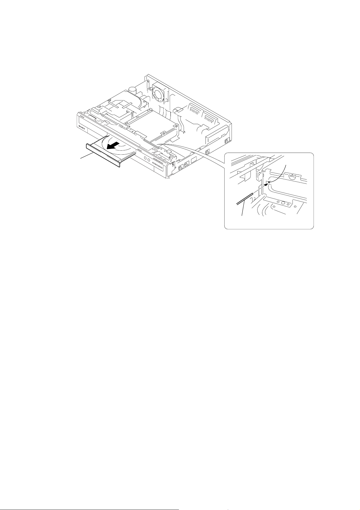
1. DISK REMOVAL PROCEDURE IF THE TRAY CANNOT BE EJECTED (FORCED EJECTION)
1. Remove the upper case.
2. Remove the RD-051 board, RD bracket.
3. IInsert the stiff wire in the hole and eject the tray.
Tray
The hole
Fig. 1
The stiff wire
Fig. 2
NOTES DURING THE FORCED EJECTION
1. If the forced ejection is executed while a blank disc media (DVD±RW , ±R) exists on the tray
• Insert a DVD-ROM (DVD test disc, DVD software available on the market, or the like) in the tray and then close the tray.
Note1: If you close the tray while it is empty, ejection of the tray becomes impossible.
Note2: If you close the tray with a CD disc inserted in it, the CD can be ejected. However, if you close the tray while it is empty, there can be a case that
ejection of the tray becomes impossible.
Note3: Even if you replace the DVD drive unit while the tray remains under the state as described above, the situation cannot be improved.
2. If the tray cannot be ejected while the disc is not inserted
• Execute the forced ejection.
• Insert a DVD-ROM (DVD test disc, DVD software available on the market, or the like) on the tray and try to close the tray.
(There are cases that it recovers the trouble.)
3. Contents of forcedly ejected blank disc media (DVD±RW, ±R) can be damaged. (There can be a case that initialization is also impossible.)
— 5 —
Page 6

MEMO
— 6 —
Page 7
SECTION 1
A li
GENERAL
RDR-HX710/HX910
This section is extracted from instruction manual.
(RDR-HX710/HX910 : 2-589-942-E1 (1))
WARNING
To prevent fire or shock hazard, do not
expose the unit to rain or moisture.
To avoid electrical shock, do not open
the cabinet. Refer servicing to qualified
personnel only.
The mains lead must only be changed
at a qualified service shop.
This appliance is classified as a
CLASS 1 LASER product. The
CLASS 1 LASER PRODUCT
MARKING is located on the laser
protective housing inside the
enclosure.
CAUTION
The use of optical instruments with this
product will increase eye hazard. As
the laser beam used in this DVD
recorder is harmful to eyes, do not
attempt to disassemble the cabinet.
Refer servicing to qualified personnel
only.
This label is located on the laser
protective housing inside the
enclosure.
2
Precautions
• This unit operates on 220 – 240 V
AC, 50/60 Hz. Check that the unit’s
operating voltage is identical with
your local power supply.
• To prevent fire or shock hazard, do
not place objects filled with liquids,
such as vases, on the apparatus.
S
HOWVIEW
is a registered trademark of
Gemstar Development Corporation.
The S
HOWVIEW
system is
manufactured under license from
Gemstar Development Corporation.
Disposal of Old Electrical &
Electronic Equipment
(Applicable in the European
Union and other Europe an
countries with separate
collection systems)
This symbol on the product or on its
packaging indicates that this product
shall not be treated as household waste.
Instead it shall be handed over to the
applicable collection point for the
recycling of electrical and electronic
equipment. By ensuring this product is
disposed of correctly, you will help
prevent potential negative
consequences for the environment and
human health, which could otherwise
be caused by inappropriate waste
handling of this product. The recycling
of materials will help to conserve
natural resources. For more detailed
information about recycling of this
product, please contact your local city
office, your household waste disposal
service or the shop where you
purchased the product.
Precautions
This equipment has been tested and
found to comply with the limits set
out in the EMC Directive using a
connection cable shorter than
3metres.
On safety
Should any solid object or liquid fall
into the cabinet, unplug the recorder
and have it checked by qualified
personnel before operating it any
further.
About the hard disk drive
The hard disk has a high storage
density, which enables long
recording durations and quick
access to the written data. However,
it can easily be damaged by shock,
vibration or dust, and should be kept
away from magnets. To avoid losing
important data, observe the
following precautions.
• Do not apply a strong shock to the
recorder.
• Do not place the recorder in a
location subject to mechanical
vibrations or in an unstable
location.
• Do not place the recorder on top of
a hot surface, such as a VCR or
amplifier (receiver).
• Do not use the recorder in a place
subject to extreme changes in
temperature (temperature gradient
less than 10 °C/hour).
• Do not move the recorder w ith its
mains lead connected.
• Do not disconnect the mains lead
while the power is on.
• When disconnecting the mains
lead, turn off the power and make
sure that the hard disk drive is not
operating (the clock is displayed in
the front panel display and all
recording or dubbing has stopped).
• Do not move the recorder for one
minute after you have unplugged
the mains lead.
• Do not attempt to replace or
upgrade the hard disk by yourself,
as this may result in malfunction.
If the hard disk drive should
malfunction, you cannot recover lost
data. The hard disk drive is only a
temporary storage space.
About repairing the hard disk
drive
• The contents of the hard disk drive
may be checked in case of repair
or inspection during a malfunction
or modification. However, the
contents will not be backed up or
saved by Sony.
• If the hard disk needs to be
formatted or replaced, it will be
done at the discretion of Sony. All
contents of the hard disk drive will
be erased, including contents that
violate copyright laws.
On power sources
• The recorder is not disconnected
from the AC power source (mains)
as long as it is connected to the
wall outlet, even if the recorder
itself has been turned off.
• If you are not going to use the
recorder for a long time, be sure to
disconnect the recorder from the
wall outlet. To disconnect the AC
power cord (mains lead), grasp the
plug itself; never pull the cord.
• Before disconnecting the AC
power cord (mains lead), check
that the recorder’s hard disk is not
operating (recording or dubbing)
on the front panel display.
On placement
• Place the recorder in a location with
adequate ventilation to prevent heat
build-up in the recorder.
• Do not place the recorder on a s oft
surface such as a rug th at might
block the ventilation holes.
• Do not place the recorder in a
confined space such as a bookshelf
or similar unit.
• Do not place the recorder in a
location near heat sources, or in a
place subject to direct sunlight,
excessive dust, or mechanical
shock.
• Do not place the recorder in an
inclined position. It is designed to
be operated in a horizontal
position only.
• Keep the recorder and discs away
from equipment with strong
magnets, such as microwave
ovens, or large loudspeakers.
• Do not place heavy objects on the
recorder.
On recording
• Note that the contents of the
recording cannot be compensated
for under any and all conditions,
including conditions that may
arise due to a malfunction of this
unit.
• Make trial recordings before
making the actual recording.
Copyrights
• Television programmes, films,
video tapes, discs, and other
materials may be copyrighted.
Unauthorized recording of such
material may be contrary to the
provisions of the copyright laws.
Also, use of this recorder with
cable television transmission may
require authorization from the
cable television transmitter and/or
programme owner.
• This product incorporates
copyright protection technology
that is protected by U.S. patents
and other intellectual property
rights. Use of this copyright
protection technology must be
authorized by Macrovision, a nd i s
intended for home and other
limited viewing uses only unless
otherwise authorized by
Macrovision. Reverse engineering
or disassembly is prohibited.
Copy guard function
Since the recorder has a copy guard
function, programmes received
through an external tuner (not
supplied) may contain copy
protection signals (copy guard
function) and as such may not be
recordable, depending on the type of
signal.
IMPORTANT NOTICE
Caution: This recorder is capable
of holding a still video image or
on-screen display image on your
television screen indefinitely. If
you leave the still video image or
on-screen display image
displayed on your TV for an
extended period of time you risk
permanent damage to your
television screen. Plasma display
panels and projection televisions
are especially susceptible to this .
If you have any questions or
problems concerning your recorder,
please consult your nearest Sony
dealer.
About this manual
Check your model name
The instructions in this manual
are for 3 models: RDR-HX510,
RDR-HX710, and RDR-HX910.
Check your model name by
looking at the front panel of the
recorder.
• In this manual, the inte rnal hard
disk drive is written as “HDD,”
and “disc” is used as a general
reference for the HDD, DVDs, or
CDs unless otherwise specified by
the text or illustrations.
• Instructions in this manual
describe the controls on the
remote. You can also use the
controls on the recorder if they
have the same or similar names as
those on the remote.
• The on-screen display illustrations
used in this manual may not match
the graphics displayed on your TV
screen.
• RDR-HX710/HX910 are used for
illustration purposes.
• The explanations regarding DVDs
in this manual refer to DVDs
created on this recorder. The
explanations do not apply to
DVDs that are created on other
recorders and played back on this
recorder.
3
Ways to Use Your DVD Recorder
Recording/Playback Compatible media a nd reference pages
+
-
+
RWVR
RW
RW
CD
-
RWVR-RWVideo
-
RWVR-RWVideo
DATA DVD
Quick access to recorded titles
– Title List
Play the beginning of a title
while it is being recorded
– Chasing Playback
Watching one title while
recording another
– Simultaneous Rec and Play
HDD
,
“3. Playing the Recorded Progr am me (Title List)” on
page 32
HDD
,
“Playing from the beginning of th e pr ogramme you are
recording (Chasing Playback)” on page 58
HDD
VCD
,
“Playing a previous recording while making another
(Simultaneous Rec and Play)” on page 59
Dubbing/Editing Compatible media an d reference pages
Creating your own programme
– Playlist
Copying a recorded title to and
from the HDD
– Dubbing (HDD y DVD)
Automatic dubbing of DV tapes
– DV Dubbing
(RDR-HX710/HX910 only)
,
,
,
st of recordable and playable discs is on page 8.
-
RWVR
HDD
“Creating and Editing a Playlist” on page 70
+
RW
+
RW
-
RWVR-RWVideo
-
RWVR-RWVideo
HDD
“Dubbing (HDD y DVD)” on page 72
HDD
“DV Dubbing (RDR-HX710/HX910 only)” on page 77
DATA CD
+R-
+R-
+R-
+R-
R
R
R
R
7
1-1
Page 8
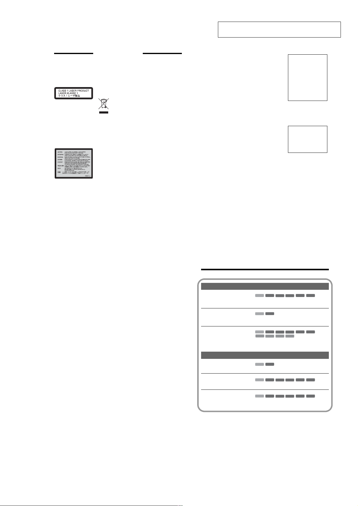
Quick Guide to Disc Types
Recordable and playable discs
Type Disc Logo
Hard disk drive
(internal)
DVD+RW
VR
mode
DVDRW
Video
mode
Icon used in
this manual
*2
HDD
+
-
-
RW
RW
RW
DVD+R
+
R
DVD+R DL
DVD-R
Usable disc versions (as of March 2005)
• 8x-speed or slower DVD+RWs
• 6x-speed or slower DVD-RWs (Ver. 1.1, Ver.1.2
*1
)
with CPRM
• 16x-speed or slower DVD+Rs
• 16x-speed or slower DVD-Rs (Ver.2.0, Ver.2.1)
• 2.4x-speed DVD+R DL (Double Layer) discs
-
R
8
Formatting
(new discs)
(Formatting
unnecessary)
Automatically
formatted in +VR
mode
Format in VR mode
VR
(page 29)
Format in Video mode
Video
(page 29)
Automatically
formatted
Automatically
formatted
“DVD+RW,” “DVD-RW,” “DVD+R,” “DVD+R DL,”
and “DVD-R” are trademarks.
*1
*2
CPRM (Content Protection for Recordable Media) is
a coding technology that protects copyrights for
images.
This logo applies to 4x and 6x speed DVD-RW discs.
Compatibility with other DVD
players (finalizing)
Dub HDD contents to a DVD to
play on other DVD players
Playable on DVD+RW
compatible players
(automatically finalized)
Playable only on VR mode
compatible players (finalizati on
unnecessary)
Playable on most DVD players
(finalization necessary)
(page 39)
Playable on most DVD players
(finalization necessary)
(page 39)
Playable on most DVD players
(finalization necessary)
(page 39)
Recording Features Editing Features
Auto
Manual
Record
Change
Rewrite
(page 41)
Chapter
(page 91)
Chapter
(page 69)
16:9 sizes
(page 47)
title name
(page 66)
Delete
title
(page 68)
A-B Erase
(page 67)
Yes Yes Yes Yes Yes Yes Yes Yes
Yes Yes No No Yes Yes Yes No
Yes Yes Yes Yes Yes Yes Yes Yes
Yes Yes No Yes*3Yes Yes No No
No Yes No No Yes Yes*4No No
No Yes No Yes*3Yes Yes*4No No
*3
Discs that cannot be re corded on
• 8 cm discs
• DVD-R DL (Dual Layer) discs
• DVD-Rs in VR mode (Video Recording format)
Only if the recording mode is LSP, SP , HSP, or HQ,
and “DVD Rec. Picture Size” is set to “16:9.”
*4
Erasing titles does not free up disc space.
Playlist
(page 70)
,continued
9
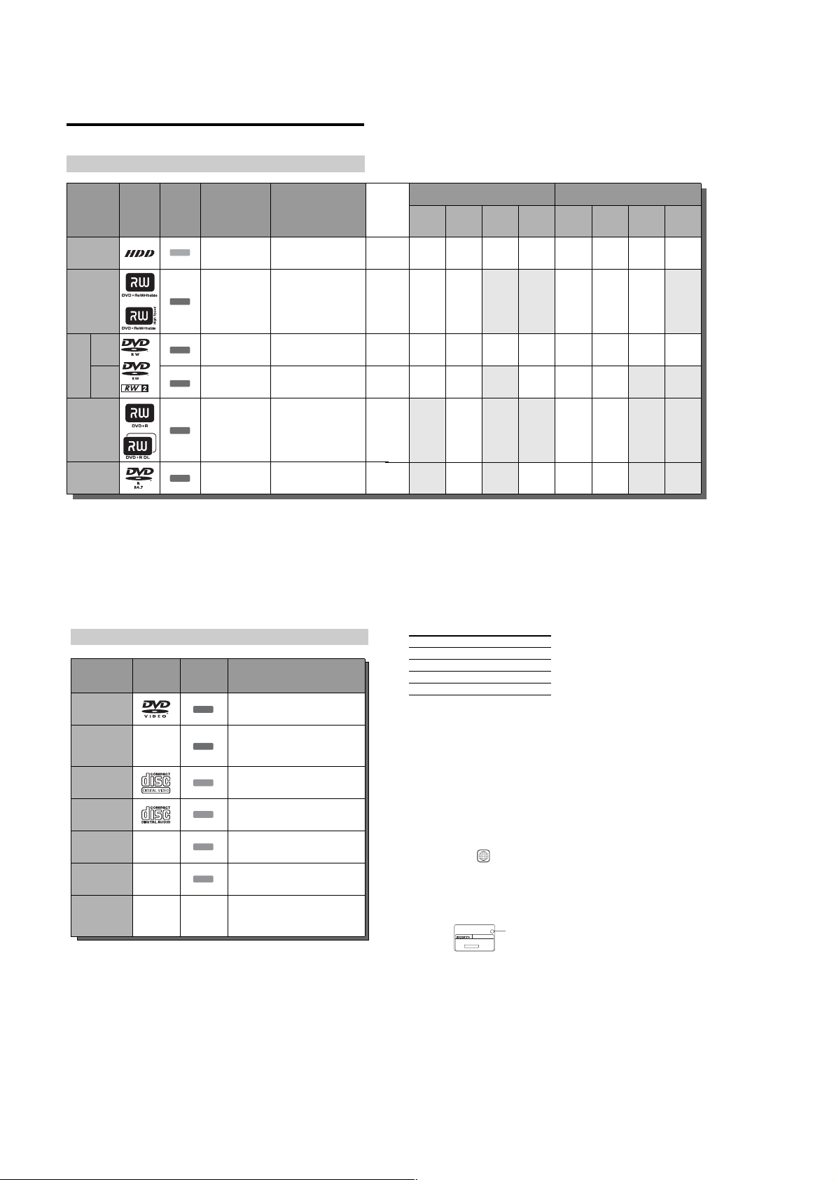
Playable discs
Type Disc Logo
DVD VIDEO
DVD-R DL —
VIDEO CD
CD
DATA DVD —
DATA CD —
8 cm DVD+RW/
DVD-RW/DVD-R
“DVD VIDEO” and “CD” are trademarks.
Discs that cannot be p layed
• PHOTO CDs
• CD-ROMs/CD-Rs/CD-RWs that are not
recorded in music CD or Video CD format, or do
not contain MP3 or JPEG files
• Data part of CD-Extras
• DVD-ROMs that do not contain JPEG files or
are not in DVD Video format
• DVD Audio discs
• DVD-RAMs
• HD layer on Super Audio CDs
• DVD VIDEOs with a different region code
(page 11)
——
10
Icon used
in this
manual
Characteristics
Discs such as movies that can be purc h as ed or
rented
DVD
DVD-R Dual Layer discs that were recorded on
other equipment. This recorder recognizes
DVD
DVD-R Dual Layer discs as DVD Video
compatible discs.
VIDEO CDs or CD-Rs/CD-RWs in VIDEO
VCD
CD/Super VIDEO CD format
Music CDs or CD-Rs/CD-RWs in music CD
CD
format that can be purchased
DVD+RWs/DVD+Rs/DVD-RWs/DVD-Rs/
DATA DVD
DVD-ROMs containing JPEG image files
CD-ROMs/CD-Rs/CD-RWs containing MP3
DATA CD
audio tracks or JPEG image files
8 cm DVD+RW, DVD-RW, and DVD-R
recorded with a DVD video camera.
(Still images recorded with a DVD video
camera cannot be played.)
• DVD-Rs recorded in VR mode (Video
Recording format)
Maximum recordable number of titles
Disc Number of titles*
HDD 300
DVD-RW/DVD-R 99
DVD+RW/DVD+R 49
DVD+R DL 49
* The maximu m le ngth for each title is eight hours.
Note on playback opera tions of DVD VIDEOs/
VIDEO CDs
Some playback operations of DVD VIDEOs/
VIDEO CDs may be intentionally set by software
producers. Since this recorder plays DVD
VIDEOs/VIDEO CDs according to the disc
contents the software producers designed, some
playback features may not be available. Also, see
the instructions supplied with the DVD VIDEOs/
VIDEO CDs.
Region code (DVD VIDEO onl y)
Your recorder has a region code printed on the rear
of the unit and will only play DVD VIDEOs
(playback only) labelled with identical region
codes. This system is used to protect copyrights.
DVD VIDEOs labelled will also play on this
recorder.
If you try to play any other DVD VIDEO, the
message “Playback prohibited by region code.”
will appear on the TV screen. Depending on the
DVD VIDEO, no region code indication may be
labelled even though playing the DVD VIDEO is
prohibited by area restrictions.
ALL
X
Region code
RDR–XXXX
00V 00Hz
NO.
00W
0-000-000-00
Music discs encoded with copyright protection
technologies
This product is designed to play back discs that
conform to the Compact Disc (CD) standard.
Recently, various music di scs encoded with
copyright protecti on technologies are being
marketed by some record companies. Please be
aware that among those discs, there are some that
do not conform to the CD standard and may not be
playable by this product.
Note on DualDiscs
This product is designed to playback discs that
conform to the Compact Disc (CD) standard. A
DualDisc is a two sided dis c prod uct whi ch mat es
DVD recorded material on one side with digital
audio material on the other side.
Please be aware that t he audio side of a DualDisc
may not play on this product bec ause these discs
do not conform to the CD standard.
“DualDisc” is a trademark of the Recording
Industry Association of America (RIAA).
b Notes
• Some DVD+RWs/DVD+Rs, DVD-RWs/DVD-Rs, or
CD-RWs/CD-Rs cannot be played on this recorder due
to the recording quality or physical condition of the
disc, or the characteristics of the recording device and
authoring software. The disc will not play if it has not
been correctly finalized. For mo re info rmatio n, see the
operating instructions for the recording device.
• You cannot mix VR mode and Video mode on the same
DVD-RW. To change the disc’s format, reformat the
disc (page 29). Note that the disc’s contents will be
erased after reformatting.
• You cannot shorten the time required for recording
even with high-speed discs.
• It is recommended that you use discs with “For Video”
printed on their packaging.
• You cannot add new recordings to DVD+Rs, DVD-Rs,
or DVD-RWs (Video mode) that contain recordings
made on other DVD equipment.
• In some cases, you may not be able to add new
recordings to DVD+RWs that contain recordings made
on other DVD equipment. If you do add a new
recording, note that this recorder will rewrite the DVD
menu.
• You cannot edit recordings on DVD+RWs, DVD-RWs
(Video mode), DVD+Rs, or DVD-Rs that are made on
other DVD equipment.
• If the disc contains PC data unrecognizable by this
recorder, the data may be erased.
• You may not be able to record on some recordable
discs, depending on the disc.
11
1-2
Page 9
Hookups and Settings
Hooking Up the Recorder
Follow steps 1 to 7 to hook up and adj us t the settings of the recorder.
b
Notes
• Plug cords securely to prevent unwanted noise.
• Refer to the instructions supplied with the components to be connected.
• You cannot connect this recorder to a TV that does not have a SCART or video input jack.
• Be sure to disconnect the mains lead of each component before connecting.
Step 1: Unpacking
Check that you have the following items:
• Mains lead (1)
• Aerial cable (1)
• Remote commander (remote) (1)
• R6 (size AA) batteries (2)
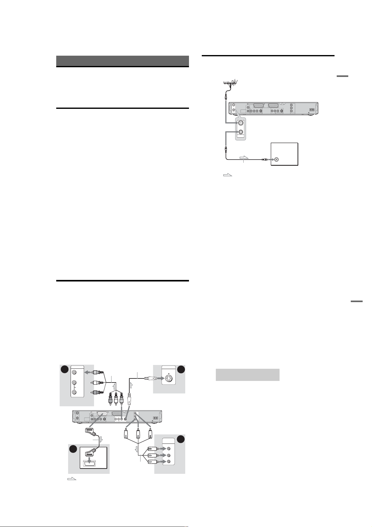
Step 2: Connecting the Aerial Cable
Connect the aerial cable by foll owing the steps below. Do not conne ct the mains lead until you reach
“Step 5: Connecting the Mains Lead” on page 18.
to AERIAL IN
LINE 1 - TV LINE 3
COAXIAL
IN
OUT
DIGITAL OUT
PCM/DTS/MPEG/
AERIAL
DOLBY DIGITAL
IN
OUT
AERIAL
/DECODER
VIDEO S VIDEOR-AUDIO-L
OPTICAL
LINE 4 IN
VIDEO S VIDEOR-AUDIO-L
LINE 2 OUT
TV
to AERIAL OUT
Aerial cable (supplied)
: Signal flow
1 Disconnect the aerial cab le from your TV and connect it to AERIAL IN on the rear panel of the
recorder.
2 Connect AERIAL OUT of the recorder to the aerial input of your TV, using the supplied aerial
cable.
COMPONENT
VIDEO OUT
Y
P
B
/ C
R
/ C
P
B
R
DVD recorder
~
AC IN
Hookups and Settings
12
Step 3: Connecting the Video Cords
Select one of the following patter ns A through D, according to the input jack on your TV monitor,
projector, or AV amplifier (receiver). This will enable you to view pictures.
A Connecting to a SCART inp ut jack
When you set “Line1 Output” to “S Video” or “RGB” in “Easy Setup” (page 22), use a SCART cord that
conforms to the selected signal.
B Connecting to a vid eo input jack
You will enjoy standard quality images.
C Connecting to an S VIDEO input jack
You will enjoy high quality images.
D Connecting to component video input jacks (Y, PB/CB, PR/CR)
You will enjoy accurate colour reproduction and high quality images.
If your TV accepts progressive 525p/625p format signals, you mu st use this connection and set
“Component Out” in “Video” setup to “On” (page 88). Then press PROGRESSIVE on the remote to send
progressive video signals. For details, see “Using the PROGRESSIVE button” on page 16.
B
TV, projector, or AV
amplifier (receiver)
To i LINE 1 – TV
SCART cord (not supplied)
14
INPUT
OUT
A
VIDEO
L
AUDIO
R
IN
AERIAL
DIGITAL OUT
PCM/DTS/MPEG/
DOLBY DIGITAL
Audio/video cord
(not supplied)
to LINE 2 OUT (VIDEO) to LINE 2 OUT (S VIDEO)
LINE 1 - TV LINE 3
COAXIAL
/DECODER
VIDEO S VIDEOR-AUDIO-L
OPTICAL
LINE 4 IN
TV
: Signal flow
S-video cord
(not supplied)
(yellow)
VIDEO S VIDEOR-AUDIO-L
LINE 2 OUT
(red) (blue)
Component video
cord (not supplied)
COMPONENT
VIDEO OUT
INPUT
S VIDEO
TV, projector, or AV
amplifier (receiver)
Y
P
B
/ C
B
P
R
/ C
R
(green)
DVD recorder
~ AC IN
to COMPONENT
VIDEO OUT
COMPONENT
VIDEO IN
Y
P
B/CB
P
R/CR
TV, projector, or AV
amplifier (receiver)
D
(green)
(blue)
(red)
13
When playing “wide scr een” images
Some recorded images may not fit your TV
screen. To change the picture size, see page 87.
If you are connecting to a VCR
Connect your VCR to the LINE 3/DECODER
jack on the recorder (page23).
b Notes
• Do not connect mo r e th a n one type of video cord
between the recorder and your TV at the same time.
• You cannot use the PROGRESSIVE button with the
connections B and C.
• When you connect the recorder to your TV via the
SCART jacks, the TV’s input source is set to the
recorder automatically when you start playback. If
necessary, press t TV/VIDEO to return the input to
the TV.
• For correct SMARTLINK connection, you will need a
SCART cord that has the full 21 pins. Refer to your
TV’s instruction manual as well for this connection.
• If you connect this recorder to a TV with
SMARTLINK, set “Line1 Output” to “Video” in “Easy
Setup.”
C
About the SMARTLINK features
(for SCART connections only)
If the connected TV (or other connect ed
equipment such as a set top box) com plies with
SMARTLINK, NexTView Link
MEGALOGIC*1, EASYLINK*2,
CINEMALINK
LINK
automatically runs the SMARTLINK function
after you complete the connection pattern A on
page 14 (the SMARTLINK indicato r l i ght s up
when you turn on your TV). You can enj oy the
following SMARTLINK features.
• Preset Download
• TV Direct Rec
*2
*4
, or T-V LINK*5, this recorder
You can download the tuner preset data from
your TV to this recorder, and tune the recorder
according to that data in “Easy Setup.” This
greatly simplifies the “Easy Setup” procedure.
Be careful not to disconnect the cables or exit the
“Easy Setup” function during this procedure
(page 22).
You can easily record wh at you a re wa tchi ng on
your TV (page 31).
*3
,
, Q-Link*3, EURO VIEW
• One Touch Play
You can turn on the recorder and TV , set the
TV’s input to the recorder, and start playback
with one touch of the H (play) button
(page 54).
• One Touch Menu
You can turn on the recorder and TV, set the TV
to the recorder’s channel, and display the Title
List menu with one touc h of the TITLE LIST
button (page 54).
• One Touch Timer
You can turn on the recorder and TV, set the TV
to the recorder’s channel, and display the timer
programming menu with one touc h of th e
[TIMER] button (page 44).
• Automatic Power Off
The recorder will turn off automatically if the
recorder is not used after you tu rn of f the TV.
• NexTView Download
You can easily set the timer by using the
NexTView Download function on your TV.
See your TV’s instruction manual.
*1
“MEGALOGIC” is a registered trademark of Grundig
Corporation.
*2
“EASYLINK” and “CINEMALINK” are trademarks
of Philips Corporation.
*3
“Q-Link” and “NexTView Link” are trademarks of
Panasonic Corporation.
*4
“EURO VIEW LINK” is a trademark of Toshiba
Corporation.
*5
“T-V LINK” is a trademark of JVC Corporation.
z Hint
SMARTLINK also works with TVs or other equipment
having EPG Timer Control, EPG Title Download, and
Now Recording functions. For details, refer to the
operating instructions supplied with your TV or other
equipment.
b Notes
• The SMARTLINK features are available only when
“Video” is selected in “Line1 Output.”
• Not all TVs respond to the functions above.
,continued
Hookups and Settings
15
1-3
Page 10
Using the PROGRESSIVE button
By using the PROGRESSIVE button, you can
select the signal format in which the recorder
outputs video signals : interlace or progressive.
1
Connect the recorder using t he
COMPONENT VIDEO OUT jacks (pattern
D on page 14).
2
Set “Component Out” in “Video” setup t o
“On” (page 88).
3
Press the PROGRESSIVE button.
“PROGRESSIVE” appears in the front panel
display when the recorder output s progressive
signals.
Progressive
Select this when:
–your TV accepts progre ssive signals, and,
–the TV is connected to the COMPONENT
VIDEO OUT jacks.
Note that the pictures will not be clear or no
picture will appear if yo u select prog ressive sig nal
output when either of the above conditions is not
met.
Interlace
Set to this position when:
–your TV does not accept progressive signals, or,
–your TV is connected to ja cks ot her than the
COMPONENT VIDEO OUT jacks (LINE 2
OUT (VIDEO or S VIDEO)).
z Hint
When you select pr og r e ssi v e si gn a l out p ut , y ou c an fin etune the signal according to the type of software you are
watching (page 88).
b
Note
Consumers should note that not all high definition
television sets are fully compatible with this product and
may cause artifacts to be displayed in the picture. In the
case of 525/625 progressive scan picture problems, it is
recommended that the user switch the connection to the
‘standard definition’ output. If there are questions
regarding our TV set compatibility with this model 525p/
625p DVD recorder, please contact our customer service
centre.
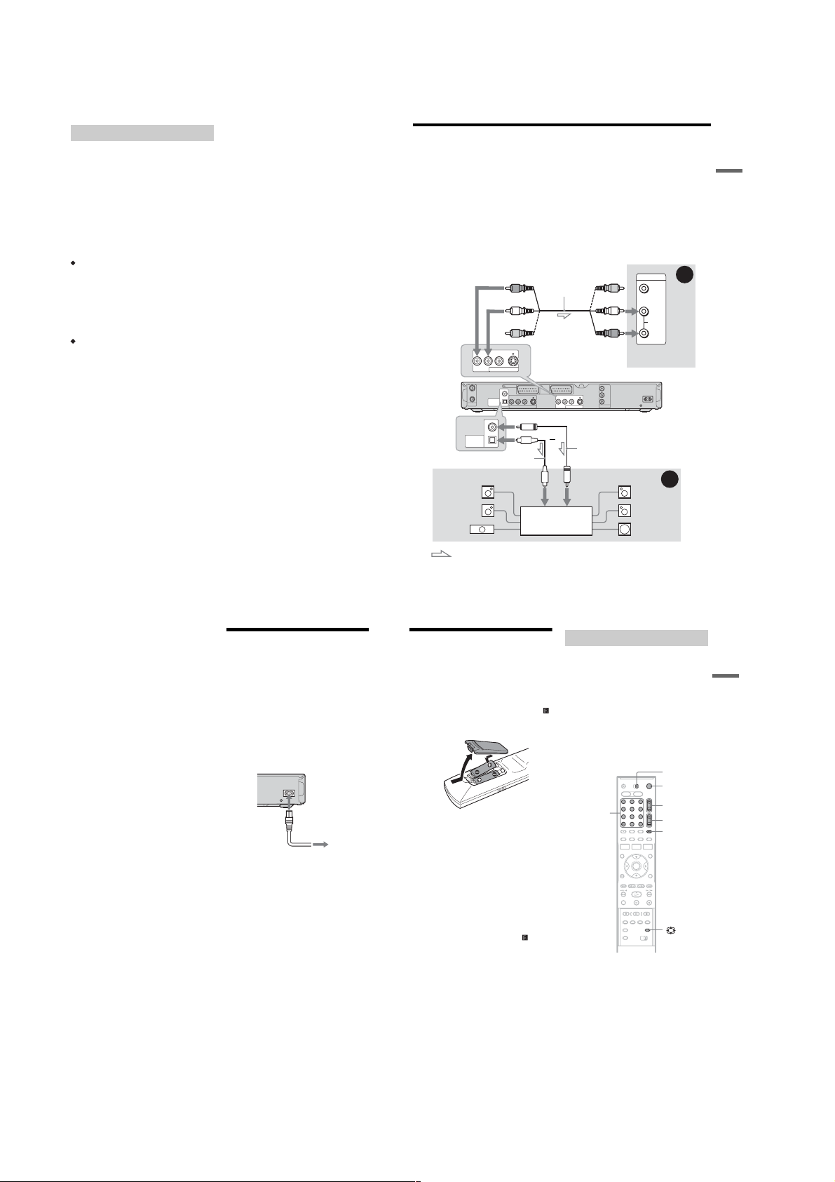
Step 4: Connecting the Audio Cords
Select one of the following patterns A or B, according to the input jack on your TV monitor, projector,
or AV amplifier (receiver). This will enable you to listen to sound.
A Connecting to a udio L/R input jacks
This connection will use your TV ’s or stereo amplifier’s (receiver’s) two speakers for soun d. Y ou can
enjoy the following surround effects (page 55).
• TV: Dynamic, Wide, Night
• Stereo amplifier (receiver): Standard, Night
B Connecting to a digital audio input jack
If your AV amplifier (receiver ) has a Dolby*1 Digital, DTS*2, or MPEG audio decoder and a digital input
jack, use this connection. You can enjoy Dolby Digital (5.1ch), DTS (5.1ch), and MPEG audio (5.1ch)
surround effects.
A
INPUT
(red)
(white)
(yellow)*
VIDEO S VIDEOR-AUDIO-L
LINE 2 OUT
LINE 1 - TV LINE 3
COAXIAL
IN
OUT
DIGITAL OUT
PCM/DTS/MPEG/
AERIAL
DOLBY DIGITAL
OPTICAL
LINE 4 IN
to DIGITAL OUT (COAXIAL or OPTICAL)
COAXIAL
DIGITAL OUT
PCM/DTS/MPEG/
DOLBY DIGITAL
OPTICAL
Optical digital cord (not supplied)
[Speakers]
Rear (L)
Front (L)
Centre
to optical
digital input
Audio/video cord
(not supplied)
to LINE 2 OUT (R-AU DIO-L)
/DECODER
VIDEO S VIDEOR-AUDIO-L
or
AV amplifier (receiver)
with a decoder
(yellow)
(white)
(red)
Y
P
B
/ C
B
VIDEO S VIDEOR-AUDIO-L
R
/ C
R
P
COMPONENT
LINE 2 OUT
VIDEO OUT
Coaxial digital cord (not supplied)
to coaxial
digital input
[Speakers]
VIDEO
L
AUDIO
R
TV, projector, or AV
amplifier (receiver)
DVD recorder
~
AC IN
B
Rear (R)
Front (R)
Subwoofer
Hookups and Settings
16
z Hint
For correct speaker location, see the operati ng
instructions supplied with the connected component s.
b
Notes
• Do not connect your TV’s audio output jacks to the
LINE IN (R-AUDIO-L) jacks at the same time. This
will cause unwanted noise to come from your TV’s
speakers.
• In the connection A, do not c onne c t the LI NE IN (R-
AUDIO-L) and LINE 2 OUT (R-AUDIO-L) jacks to
your TV’s audio output jacks at th e sam e time. This
will cause unwanted noise to come from your TV’s
speakers.
• In the connection B, afte r you ha ve completed the
connection, make the appropriate settings under
“Audio Connection” in “Easy Setup” (page 22).
Otherwise, no sound or a loud noise will come from
your speakers.
• With the connection B, the surround sound effects of
this recorder cannot be used.
*1
Manufactured under license from Dolby Laboratories.
“Dolby,” and the double-D symbol are trademarks of
Dolby Laboratories.
*2
“DTS” and “DTS Digital Out” are trademarks of
Digital Theater Systems, Inc.
Step 5: Connecting the
Mains Lead
Connect the supplied mains lead to the AC IN
terminal of the recorder. Th en plug the recorder
and TV mains leads (power cords) into the mains.
After you connect the mains lead, you must wait
for a short while before operating the
recorder. You can operate the recorder once the
front panel display lights up an d the recorder
enters standby mode.
If you connect additional equipment to this
recorder (page 23), be sure to connect the mains
lead after all connections are complete.
~
AC IN
1
to AC IN
2
to mains
: Signal flow
* The yellow plug is used for video signals (page 14).
Step 6: Preparing the
Remote
You can control the recorder us i ng t h e supplied
remote. Insert two R6 (size AA) batteries by
matching the 3 and # ends on the batteries to the
markings inside the battery comp artment. When
using the remote, point it at the remote sensor
on the recorder.
b Notes
• If the supplied remote interferes your other Sony DVD
recorder or player, change the command mode number
for this recorder (page 2 1).
• Use the batteries correctly to avoid possible leakage
and corrosion. Do not touch the liquid with bare hands
should leakage occur. Observe the following:
– Do not use a new ba tte r y with an old battery, or
batteries of different manufacturers.
– Do not attempt to recharge the batteries.
– If you do not intend to use the remote for an extended
period of time, remove the ba tteries.
– If battery le ak ag e occ ur s, wipe out any liqui d inside
the battery compartment, and insert new bat t e ri es.
• Do not expose the remote sensor (marked on the
front panel) to strong light, such as direct sunlight or
lighting apparatus. The recorder may not respond to the
remote.
,continued
Controlling TVs with the remote
You can adjust the remote’s si gnal to contr ol your
TV.
If you connected the recorder to an AV amplifier
(receiver), you can use the suppl i ed remote to
control the AV amplifier’s (receiver’s) volume.
b Notes
• Depending on the connected unit, you may not be able
to control your TV or AV amplifier (receiver) with
some or all of the buttons below.
• If you enter a new code number, the code number
previously entered will be erased.
• When you replace the batteries of the remote, the code
number may be reset to the default setting. Set the
appropriate code number again.
Number
buttons, SET,
-/--
1 2 3
4 6
7 8 9
TV/DVD switch
[/1
PROG +/–
5
2 +/–
0
t TV/VIDEO
1 Slide the TV/DVD switch to TV.
2 Hold down [/1.
3 Enter your TV’s ma nufacturer code (see
“Code numbers of control lable TVs”
below) using the number buttons.
17
Hookups and Settings
18
,continued
19
1-4
Page 11
4 Release [/1.
When the TV/DVD switch is set to TV, the
remote performs the following:
Buttons Operations
[/1 Turns your TV on or off
2 (volume) +/– Adjusts the volume of
PROG +/– Selects the programme
(wide mode) Switches to or from the
t TV/VIDEO Switches your TV’s
Number buttons
and SET, -/--*
* If you use the number buttons to select the TV’s
programme position, press -/-- followed by the
number buttons for two-digit numbers.
To operate the t TV/VIDEO button
(for SCART connections only)
The t TV/VIDEO button switches between the
recorder and the last i nput source selected on the
TV. Point your remote at the recorder when using
this button. The button works even if the TV/DVD
switch is set to DVD.
When you connect the record er to the TV via the
SCART jacks, the input source for the TV is set to
the recorder automatically when you start
playback. To watch another sourc e, press the
t TV/VIDEO button to switch the TV’s input
source.
Code numbers of cont rollable TVs
If more than one code number is listed, try
entering them one at a time until you find the one
that works with your TV.
your TV
position on your TV
wide mode of a Sony
wide-screen TV
input source
Selects the programme
position on your TV
Manufacturer Code number
Sony 01 (default)
Aiwa 01 (default)
Grundig 11
Hitachi 23, 24, 72
Loewe 06, 45
Nokia 15, 16, 69, 73
Panasonic 17, 49
20
Manufacturer Code number
Philips 06, 07, 08, 23, 45, 72
Saba 12, 13, 36, 43, 74, 75
Samsung 06, 22, 23, 71, 72
Sanyo 25
Sharp 29
Telefunken 12, 13, 36, 43, 74, 75
Thomson 12, 13, 43, 74, 75
Toshiba 38
LG 06
JVC 33
Controlling the volume of your AV
amplifier (receiver) with the
remote
TV/DVD
switch
[/1
5
2 +/–
0
Number buttons
1 2 3
4 6
7 8 9
1 Slide the TV/DVD switch to DVD.
2 Hold down [/1, and enter the
manufacturer code (see the table below)
for your AV amplifier (receiver) using the
number buttons.
3 Release [/1.
The 2 (volume) +/– buttons control the AV
amplifier’s volume.
If you want to control the TV’s volume, sl ide
the TV/DVD switch to TV.
z Hint
If you want to control the TV’s volume even when the
TV/DVD switch is set to DVD, repeat the steps above
and enter the code number 90 (default).
Code numbers of controllable AV amplifiers
(receivers)
If more than one code number is listed, try
entering them one at a time until you find the one
that works with your AV amplifier (receiver).
Manufacturer Code number
Sony 78, 79, 80, 91
Denon 84, 85, 86
Kenwood 92, 93
Onkyo 81, 82, 83
Pioneer 99
Sansui 87
Technics 97, 98
Yamaha 94, 95, 96
If you have a Sony DVD player or
more than one Sony DVD recorder
If the supplied remote interferes with your other
Sony DVD recorder or player, set the command
mode number for this recorder and the supplied
remote to one that differs from the other Sony
DVD recorder or player.
The default command mode setting for this
recorder and the supplied remote is DVD3.
1 2 3
4 6
5
7 8 9
0
SYSTEM
MENU
O RETURN
M/m,
ENTER
COMMAND
MODE
switch
1 Press SYSTEM MENU.
The System Menu appears.
2 Select “SETUP,” a nd press ENTER.
SETUP
Settings
Channel Setting
Video
Channel List
Audio
TV Guide Page
Features
Clock
Options
Language
Easy Setup
3 Select “Options,” and press ENTER.
SETUP
Format DVD-RW : VR
Settings
HDD Bilingual Rec. :
DVD Bilingual Rec. :
Dimmer :
Power Save :
Auto Display :
Command Mode :
Factory Setup
Format DVD-RW : VR
HDD Bilingual Rec. :
DVD Bilingual Rec. :
Dimmer :
Power Save :
Auto Display :
Command Mode :
Factory Setup
Main
Main
Normal
Off
On
DVD3
Main
Main
Normal
Off
DVD1
On
DVD2
DVD3
DVD3
Video
Audio
Features
Options
Easy Setup
4 Select “Command Mo de,” and press
ENTER.
SETUP
Settings
Video
Audio
Features
Options
Easy Setup
5 Select the Comma nd mode (DVD1, DVD2,
or DVD3), and press ENTER.
6 Slide the COMMAND MODE switch on the
remote so it matches the mode you
selected above.
To return to the previous step
Press O RETURN.
Check that the command mode switch on the
remote is set to the default setting of DVD3
before you try to change the command mode for
the recorder. If the command mode for th e remote
is changed to DVD1 or DVD2, you may be
unable to operate this recorder.
Hookups and Settings
21
Step 7: Easy Setup
Make the basic adjustments by following the onscreen instructions in “Easy Setup.”
[/1
1 2 3
4 6
7 8 9
O RETURN
1 Turn on the recor der and switch the input
selector on your TV so that the signal from
the recorder appears on your TV screen.
The message about the initial settings appears.
• If this messag e does not appea r, select “Easy
Setup” from “SETUP” in the System Menu
to run “Easy Setup” func ti on (“Settings and
Adjustments” on page 82).
2 Press ENTER.
Follow the on-scree n ins truct ions to mak e the
following settings.
OSD
Select the language for the on-screen displays.
Tuner System
Select your country or language.
The programme position order will be set
according to the country you s et .
To set the programme positions manually , see
page 82.
• If you live in a French speaking country that
is not listed on the display, select “ELSE.”
Clock
The recorder will automatically search for a
clock signal. If a clock si gnal cannot be found,
set the clock manually using
press ENTER.
5
0
PROG +/–
</M/m/,,
ENTER
</M/m/,, and
TV Type
If you have a wide-screen TV, sele ct “16:9.”
If you have a standard TV, select either “4:3
Letter Box” (shrink to fit) or “4:3 Pan Scan”
(stretch to fit). This will determine how
“wide-screen” images are displayed on your
TV.
Component Out
If you are using the COMPONENT VIDEO
OUT jack, select “On.”
Line3 Input
If you will connect a decoder to the LI N E 3/
DECODER jack, se l e ct “Yes.”
Line1 Output
To output video signals, se le ct “Video.”
To output S video signals, sel ect “S Video.”
To output RGB signals, select “RGB.”
Select “Video” to enjoy the SMARTLINK
features.
• If you set “Component Out” to “On,” you
cannot select “RGB.”
If you set “Line3 Input” to “Yes,” you
cannot select “S Video.”
Audio Connection
If you connected an AV amplifier (receiver)
using either a digital optical or coaxial cord,
select “Yes: DIGITAL OUT” and set the
digital output signal (page 90).
3 Press ENTER when “Fi nish” appears.
“Easy Setup” is finished .
To return to the previous step
Press O RETURN.
z Hints
• If your AV amplifier (receiver) has an MPEG audio
decoder, set “MPEG” to “MPEG” (page 90).
• If you want to run “Easy Setup” again, select “Easy
Setup” from “SETUP” in the System Menu (page 95).
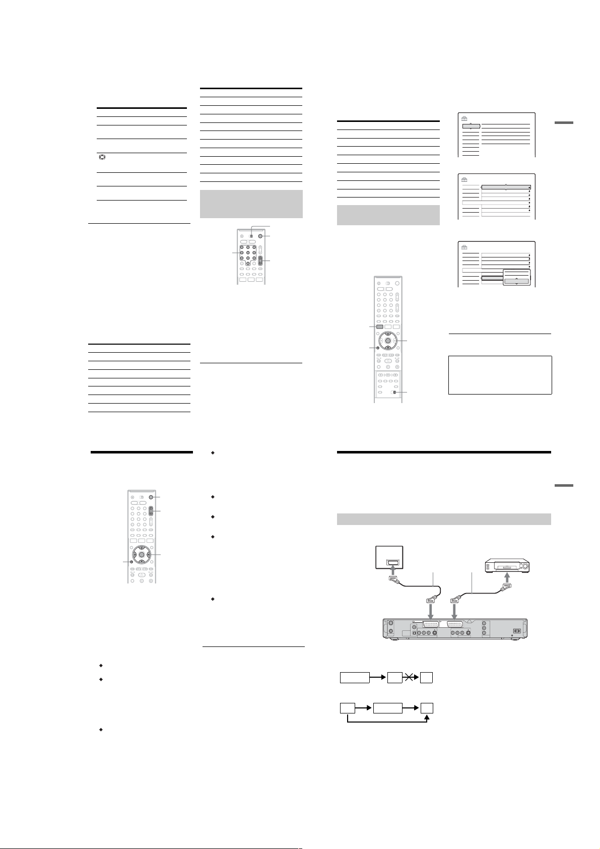
Connecting a VCR or Similar Device
After disconnecting the recorder ’s mains lead fro m the mains, connec t a VCR or similar recordin g device
to the LINE IN jacks of this recorder.
Use the DV IN jack on the front panel if the equipment h as a DV output jack (i.LINK jack) (RDR-HX710/
HX910 only) (page 77).
See also the instruction manual supplied with the connected equipment.
To record on this recorder, see “Recording from connected equipment without a timer” on page 52.
Connecting to the LINE 3/DECODER jack
Connect a VCR or similar recording device to the LINE 3/DECODER jack of this recorder.
TV
VCR
SCART cord (not supplied)
to SCART input
LINE 3
/DECODER
Line input 2
to i LINE 3/DECODER
Y
P
B
/ C
B
VIDEO S VIDEOR-AUDIO-L
P
R
/ C
R
COMPONENT
LINE 2 OUT
VIDEO OUT
DVD recorder
~ AC IN
to i LINE 1 – TV
LINE 1 - TV
COAXIAL
IN
OUT
AERIAL
b Notes
• Pictures containing copy protection signals that prohibit any copying cannot be recorded.
• If you pass the recorder signals via the VCR, you may not receive a clear image on your TV screen.
Be sure to connect your VCR to the DVD recorder and your TV in the order shown below. To watch video tapes,
watch the tapes through a second line input on your TV.
VCR DVD recorder TV
• The SMARTLINK features are not available for devices connected via the DVD recorder’s L INE 3/DECODER ja ck.
• When you record to a VCR from this DVD recorder, do not switch the input source to TV by pressing the t TV/
VIDEO button on the remote.
• If you disconnect the recorder’s mains lead, you will not be able to view the signals from the connected VCR.
VCRDVD recorder TV
VIDEO S VIDEOR-AUDIO-L
DIGITAL OUT
PCM/DTS/MPEG/
DOLBY DIGITAL
OPTICAL
LINE 4 IN
Line input 1
Hookups and Settings
22
,continued
23
1-5
Page 12
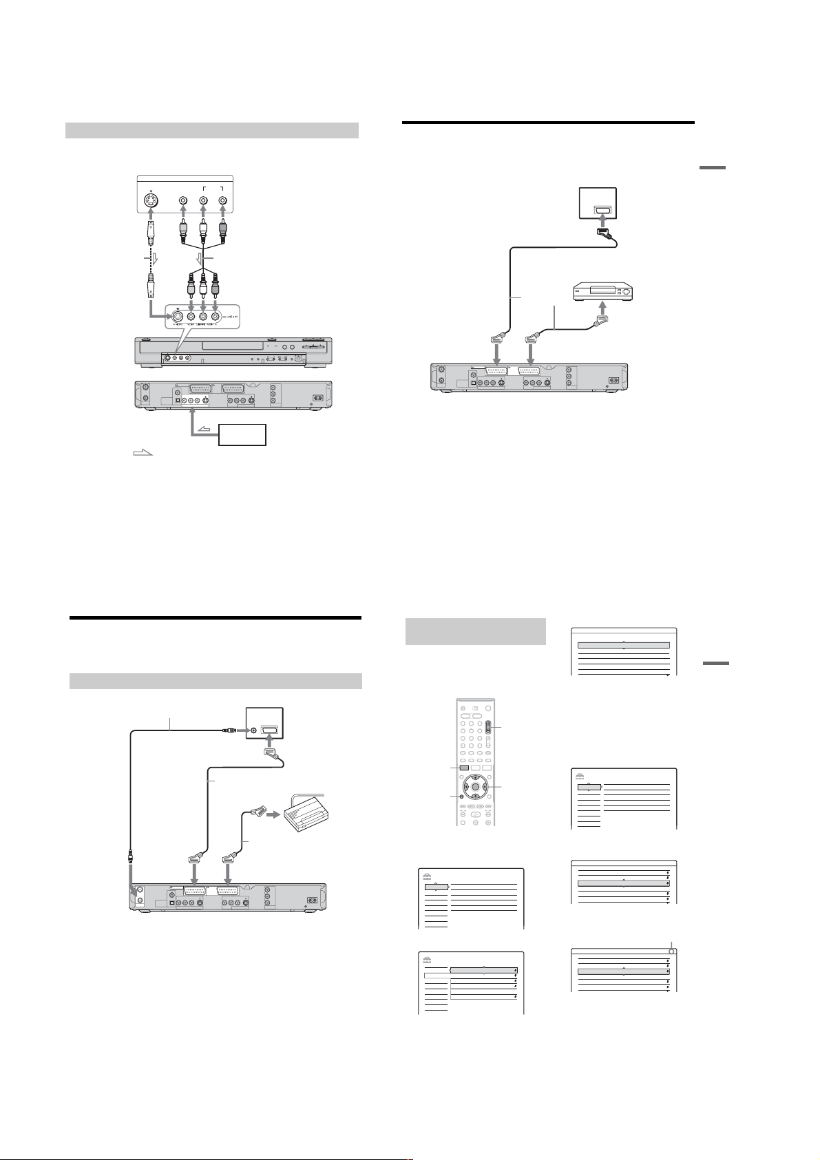
Connecting to the LINE 2 IN or LINE 4 IN jacks
Connect a VCR or similar recording device to the LINE 2 IN or LINE 4 IN jacks of this recorder. If the
equipment has an S-video jack, you can use an S-video cord instead of a n audio/video cord.
VCR, etc.
S VIDEO
VIDEO
OUTPUT
AUDIO
LR
Connecting to a Satellite or Digital Tuner
Connect a satellite or digital tuner to this recorder using the LINE 3/DECODER jack. Disconnect the
recorder’s mains lead from the mains when conn ecting the tuner.
To use the Synchro-Rec function, see below.
to SCART input
TV
Hookups and Settings
LINE 1 - TV LINE 3
COAXIAL
VIDEO S VIDEOR-AUDIO-L
OPTICAL
LINE 4 IN
to LINE 4 IN
Audio/video cord
(not supplied)
/DECODER
VIDEO S VIDEOR-AUDIO-L
LINE 2 OUT
DVD recorder (front)
Y
P
B
/ C
B
R
/ C
R
P
COMPONENT
VIDEO OUT
(rear)
~
AC IN
S-video cord
(not supplied)
to LINE 2 IN
IN
OUT
DIGITAL OUT
PCM/DTS/MPEG/
AERIAL
DOLBY DIGITAL
VCR, etc.
: Signal flow
z Hint
When the connected equipment outputs only monaura l sound, use audio cables that distribute monaural sounds to left/
right channels (not supplied).
b
Notes
• Do not connect the yellow LINE IN (VIDEO) jack when using an S-video cord.
• Do not connect the output jack of this recorder to another equipment’s input jack with the other equipment’s output
jack connected to the input jack of this recorder. Noise (feedback) may result.
• Do not connect more than one type of video cord between the recorder and your TV at the same ti me .
24
Connecting a PAY-TV/Canal Plus Decoder
You can watch or record PAY-TV/Canal Plus programmes if you connect a decoder (not supplied) to the
recorder. Disconnect the recorder’s mains lead from the mains when connecting the decoder.
Connecting a decoder
TV
PAY-TV/Canal Plus
decoder
SCART cord (not supplied)
to i LINE 3/DECODER
DVD recorder
Y
P
B
/ C
B
VIDEO S VIDEOR-AUDIO-L
P
R
/ C
R
COMPONENT
LINE 2 OUT
VIDEO OUT
~
AC IN
to AERIAL OUT
Aerial cable
(supplied)
to i LINE 1 – TV
IN
OUT
DIGITAL OUT
PCM/DTS/MPEG/
AERIAL
DOLBY DIGITAL
to AERIAL IN
to SCART input
SCART cord
(not supplied)
LINE 3
LINE 1 - TV
COAXIAL
/DECODER
VIDEO S VIDEOR-AUDIO-L
OPTICAL
LINE 4 IN
SCART cord
(not supplied)
to i LINE 1 – TV to i LINE 3/DECODER
IN
OUT
DIGITAL OUT
PCM/DTS/MPEG/
AERIAL
DOLBY DIGITAL
If the satellite tuner can output RGB signals
This recorder accepts RGB signals. If the satellite
tuner can output RGB signals, connect the TV
SCART connector on the satellite tuner to the
LINE 3/DECODER jack, and set “Line3 Input” of
“Scart Setting” to “Video/RGB” in “Video” setup
(page 88). Note that this connection and setup
disable the SMARTLINK function. If you want to
use the SMARTLINK f un cti on w i th a co mp ati bl e
set top box, see the instructions supplied with the
set top box.
If you want to use the Synchro Rec function
This connection is necessary to us e t he SynchroRecording function. See “Recording from
connected equipment with a timer (Synchro Rec)”
on page 50.
/DECODER
VIDEO S VIDEOR-AUDIO-L
OPTICAL
LINE 4 IN
LINE 3
LINE 1 - TV
COAXIAL
Setting PAY-TV/Canal Plus
channels
To watch or record PAY-TV/Canal Pl us
programmes, set your recorder to receive the
channels using the on-scree n di splay.
In order to set the channe ls correctly, be sure to
follow all of the steps below.
1 2 3
4 6
7 8 9
SYSTEM
MENU
O R ETURN
1 Press SYSTEM MENU.
The System Menu appears.
PROG +/–
5
0
</M/m/,,
ENTER
2 Select “SETUP,” and pr ess ENTER.
SETUP
Settings
Channel Setting
Video
Channel List
Audio
TV Guide Page
Features
Clock
Options
Language
Easy Setup
3 Select “Video,” and pr ess ENTER.
SETUP
TV Type : 16 : 9
Settings
Video
Pause Mode :
Component Out :
Progressive Mode :
Scart Setting
Line4 Input :
Auto
Off
Auto
Video
Audio
Features
Options
Easy Setup
Satellite tuner, etc.
Y
P
B
/ C
B
VIDEO S VIDEOR-AUDIO-L
R
/ C
R
P
~
COMPONENT
LINE 2 OUT
VIDEO OUT
AC IN
DVD recorder
Set “Line3 Input” of “Scart Setting” in “Video”
setup (page 88) according to the specifications of
your satellite tuner. See your satellite tuner’s
instructions for more information.
If you are using a B Sky B tuner, be sure to
connect the tuner’s VCR SCART jack to the LINE
3/DECODER jack. Then set “Line3 Input” of
“Scart Setting” according to the specifications of
the VCR SCART jack on your satellite tuner.
b
Notes
• Do not set “Line3 Input” of “Scart Setting” in “Video”
setup to “Decoder.”
• Synchro-Recording does not work with some tuners.
For details, see the tuner’s operating instructions.
• If you disconnect the recorder’s mains lead, you will
not be able to view the signals from the connected
tuner.
4 Select “Scart Setting,” and press ENTER.
Video - Scart Setting
Line1 Output Line3 Input Line3 Output
Video Video/RGB Video
Video
Video/RGB
Video
Decoder
S Video
S Video
S Video S Video S Video
RGB
Video/RGB
5 Press M/m to select “Video” or “RGB” for
“Line1 Output,” “Decoder” for “Line3
Input,” and “Video” for “Line3 Output,”
and press ENTER.
The “Video” setup display appears again.
6 Press O RETURN to return the cursor to
the left column.
7 Select “Settings,” and press ENTER.
SETUP
Settings
Channel Setting
Video
Channel List
Audio
TV Guide Page
Features
Clock
Options
Language
Easy Setup
8 Select “Channel Se tting,” and press
ENTER.
Settings - Channel Setting Prog. 8
System : BG
Normal / CATV :
Channel Set :
Station Name :
PAY - TV / CANAL+ :
Audio :
9 Press PROG +/– to select the desired
programme position.
Settings - Channel Setting Prog.6
System :
Normal / CATV :
Channel Set :
Station Name :
PAY - TV / CANAL+ :
Audio :
Normal
2
C
CDE
Off
NICAM
Selected programme position
BG
Normal
24
C
PQR
Off
NICAM
25
S Video
Video
Video
Video
Hookups and Settings
26
,continued
27
1-6
Page 13
10
Select “System,” and press ENTER.
Settings - Channel Setting
System :
Normal / CATV :
Channel Set :
Station Name :
PAY - TV / CANAL+ :
Audio :
11
Press M/m to select an available TV
system, BG, DK, I, or L, and press ENTER.
To receive broadcasts in France, select “L.”
12
Select “Normal/CATV, ” and press ENTER.
Settings - Channel Setting
System :
Normal / CATV :
Channel Set :
Station Name :
PAY - TV / CANAL+ :
Audio :
13
Select “Normal,” and press ENTER.
To preset CATV (Cable Telev ision) cha nnels,
select “CATV.”
14
Select “Channel Set,” and press ENTER.
Settings - Channel Setting
System :
Normal / CATV :
Channel Set :
Station Name :
PAY - TV / CANAL+ :
Audio :
15
Select the PAY-TV/Canal Plus channel,
and press ENTER.
16
Select “PAY-TV/CANAL+,” and press
ENTER.
Settings - Channel Setting
System :
Normal / CATV :
Channel Set :
Station Name :
PAY - TV / CANAL+ :
Audio :
17
Select “On,” and press ENTER.
Prog. 6
BG
BG
Normal
DK
2
C
I
CDE
L
Off
NICAM
Prog. 6
BG
Normal
Normal
2
C
CATV
PQR
Off
NICAM
Prog. 6
BG
Normal
2
C
C24
PQR
Off
NICAM
Prog. 6
BG
Normal
C
24
PQR
Off
On
NICAM
Off
To return to the previous step
Press O RETURN.
b
Notes
• When you set “Line3 Input” to “Decoder” in step 5
above, you will not be able to select “L3” because Line
3 will become a dedicated line for the decoder.
• If you disconnect the recorder’s mains lead, you will
not be able to view the signals from the connected
decoder.
Seven Basic Operations
— Getting to Know Your DVD Recorder
1. Inserting and Formatting
a DVD Disc (Disc Info)
Inserting a Disc
+
-
HDD
DVD
1
2 Press Z (open/close), and place a disc on
3 Press Z (open/close) to close t he disc
RW
RW
VCD
CD
Z
Press DVD.
the disc tray.
With the recording/playing side facing down
tray.
Wait until “LOAD” disappears from the front
panel display.
Unused DVDs are formatt ed automatically.
VR
1 2 3
4 6
7 8 9
-
DATA DVD
5
0
+
RW
-
Video
R
R
DATA CD
DVD
Formatting a DVD disc (Disc Info)
+
-
-
RW
VR
RW
RW
New discs are automatically formatted when
inserted. If necessary, you can manually re -format
a DVD+RW or DVD-RW disc to make a blank
disc. For DVD-RWs, you can select a recording
format (VR mode or Video mode) according to
your needs (page8).
1 Insert a disc.
See “Inserting a Disc” on page 29.
2 Press TOOLS.
The TOOLS menu appears.
The TOOLS menu displays options
applicable to the entire disc (e.g. disc
protection), recorder (e.g. audio settings
during recording), or multiple items on a list
menu (e.g. erasing multiple titles). The
displayed options differ depending on the
situation and disc type.
Video
1 2 3
4 6
5
7 8 9
0
Close
Stop
Erase
Protect
Dubbing
Options for the disc or picture
</M/m/,,
ENTER
TOOLS
Seven Basic Operations
— Getting to Know Your DVD Recorder
28
3 Move the cursor down the TOOLS menu
until “Disc Info” is selected, and press
ENTER.
Example: When a DVD-RW (VR mode) is
inserted.
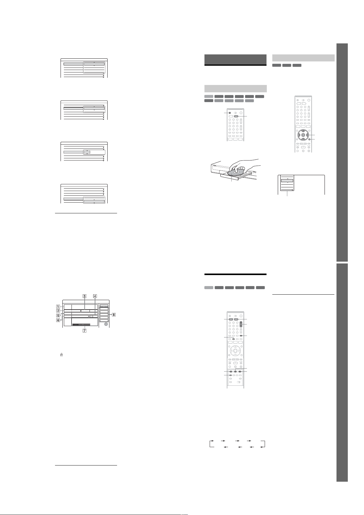
Disc Information
DiscName Movie
Media DVD-RW Format VR
Title no. 2
Original 3 / Playlist
Date Off
13.10.2005 ~ 28.10.2005
HQ : 0H30M HSP : 0H45M SP : 1H00M
Remainder
LSP : 1H15M LP : 1H30M EP : 2H00M
SLP : 3H00M SEP : 4H00M
1 “Disc Name” (DVD only)
2 “Media”: Disc type
3 “Format”: Recording format type (DVD-
RW only)
4
“On”/“Off”: Indicates whether
protection is set (DVD-RW in VR mode
only)
5 “Title no.”: Total number of titles
6 “Date”: Dates of when the oldest and the
most recent titles were recorded (DVD
only)
7 “Continuous Rem. Time”/“Remainder”
(approximate)
• The remaining recording time in each of the
recording modes
• Disc space bar
• Remaining disc space/total disc space
8 Disc setting buttons
“Disc Name” (page38)
“Protect Disc” (page38)
“Finalize”/“Unfinalize” (page 39)
“Erase All” (page69)
“Format”
Available settings differ depending on the
disc type.
GB
2. 3 / 4. 7
4 Select “Format,” and press E NTER.
5 Select “OK,” and press ENTER.
For DVD-RWs, select “VR” or “Video,” and
press ENTER.
All contents on the disc are erased.
Close
Disc Name
Protect Disc
Finalize
Erase All
Format
z Hints
• By reformatting, you can change the recording format
on DVD-RWs, or record again on DVD-RWs that have
been finalized.
• For DVD+RWs and DVD-RWs (Video mode), you can
check free space and title locati on on the disc usi ng the
Disc Map display (page 69).
b Note
On this model, 1 GB (read “gigabyte”) is equivalent to 1
billion bytes. The larger the number, the larger the dis c
space.
2. Recording a Programme
+
-
HDD
This section introduces the basic operation to
record the current TV programme to the hard di sk
(HDD) or to a disc (DVD). For an explanation of
how to make timer recordings, see page 41.
1 Press HDD or DVD.
2 Press PROG +/– to sel ect the programme
3 Press REC MODE repeatedly to select the
RWVR-RWVideo
RW
HDD DVD
1 2 3
4 6
5
7 8 9
DISPLAY
REC MODE
When you record to a DVD, insert a
recordable DVD (see “Inserting a Disc” on
page 29).
position or input source you want to
record.
recording mode.
Each time you press the button, the display on
the TV screen changes as follows:
HQ SPHSP
For more details about the recording mode,
see page 41.
0
SEP EPSLP
-R+
R
PROG +/–
t TV/VIDEO
X REC PAUSE
x REC STOPz REC
LSP
LP
,continued
4 Press z REC.
Recording start s.
Recording stops automatically after 8 hours of
continuous recording or when the HDD or
DVD is full.
To stop recording
Press x REC STOP located beneath the remote
control cover.
Note that it may take a few second s for reco rder to
stop recording.
To pause recording
Press X REC PAUSE located beneath the remote
control cover.
To restart recording, press the button again.
To watch another TV programme while
recording
If your TV is connected to the LINE 1 – TV jack,
set your TV to the TV input using the t TV/
VIDEO button and select the programme you
want to watch. If your TV is connected to the
LINE OUT or COMPONENT VIDEO OUT
jacks, set the TV to TV input using the t TV/
VIDEO button (page 19).
TV Direct Rec
If you use the SMARTLINK connection, you can
easily record what you are watching on your TV.
When the TV is turned on or in standby mode,
z REC. The recorder automatically turns on
press
and starts recording what you are watching on the
TV.
b Note
If “TV” appears in the front panel display, yo u
cannot turn off the TV or chan ge the programme
position during TV Direct Rec. To turn off the
function, set “TV Direct Rec” to “Off” in
“Features” setup (page 91).
29
Seven Basic Operations — Getting to Know Your DVD Recorder
30
,continued
31
1-7
Page 14
About the Teletext function
R
(L/R)
Some broadcasts systems ens ur e a Teletext
service* in which the complete programmes and
their data (title, date, channe l, record ing sta rt time
etc.) are stored day by day. When recording a
programme, the recorder automatically takes the
programme name from the Telete xt pages and
stores it as the title name. For detail, see “TV
Guide Page” on page 85.
Note that the Teletext information will not appear
on your TV screen. To view the Teletext
information on your TV screen, press t TV/
VIDEO on the remote to switch the input source to
your TV.
* not available in some areas
z Hint
If you do not want to watch TV while recording, you can
turn off the TV. When using a decoder, make sure to
leave it on.
b
Notes
z
• After pressing
start recording.
• You cannot change the recording mode while
recording or during recording pause.
• If there is a power failure, the programme you are
recording may be erased.
• You cannot watch a PAY-TV/Canal Plus programme
while recording another PAY-TV/Canal Plus
programme.
• To use the TV Direct Rec function, you must first set
the recorder’s clock correctly.
REC, it may take a short while to
Checking the disc status while
recording
You can check the recording information such as
recording time or disc type.
Press DISPLAY twice during recording.
The recording information appears.
A Disc type/format
B Recording status
C Recording mode
D Recording time
Press DISPLAY to turn off the display.
32
3. Playing the Recorded
Programme (Title List)
+
-
-
RW
VR
1 2 3
4 6
5
7 8 9
0
RW
HDD
RW
To play a recorded title, select the title from the
Title List.
HDD
TITLE LIST
/
1
Press HDD or DVD.
If you select DVD, insert a DVD (see
“Inserting a Disc” on page29).
Playback starts automatically depending on
the disc.
2
Press TITLE LIST.
To show the extended Title List, press
TOOLS to select “Display List,” and press
ENTER.
-R+
Video
R
DVD
M/m,
ENTER
TOOLS
Mm
H/X/x
Title List with Thumbnail Images (Example:
DVD-RW in VR mode)
TITLE LIST
ORIGINAL
12
Tennis
Fri
28.10. 2005 13:00 (0H30M) LSP GB0.9
11
Trav el
26.10. 2005 20:00(0H30M) SEP
Wed
10
Mystery
25.10. 2005 9:00 (1H00M) SLP
Tue
9
World Sports
19.10. 2005 20:00(1H00M) SEP
Wed
Extended Title List
A Disc type:
Displays a media type, HDD or DVD.
Also displays the title type (Original or
Playlist) for DVD-RWs (VR mode).
m
TITLE LIST
ORIGINAL
12
Tennis 28.10
Trav el
11
Mystery
10
World Sports
9
Family
8
Nature
7
News
6
Weather
5
GB4.3 / 4.7
AAB
DEF
GB0.3
AAB
GB0.8
GHI
GB0.6
4.3 / 4.7GB
Fri
AAB
26.10
Wed
DEF
25.10
Tue
AAB
19.10
Wed
GHI
17.10
Mon
DEF
15.10
Sat
L3
14.10
Fri
GHI
13.10
Thu
L3
B Disc space (remainder/total)
C Title information:
Displays the title number, title name, and
recording date. Title size is shown in the
Thumbnail title list.
z (red): Indicates that the titl e i s currently
being recorded.
: Indicates that the title is currently being
dubbed.
: Indicates the protected title.
“NEW” (or N): Indicates that the title is newl y
recorded (not played back) (HDD only).
: Indicates that the Update function is set
(HDD only) (page 43).
: Indicates titles containing “CopyOnce” copy protection signals (HDD only)
(page 73).
D Scroll bar:
Appears when all of the titles do not fit on the
list. To view the hidden titles, press M/m.
E Title’s thumbnail picture
The still images for each title are displayed.
3 Select a title, and press ENTER.
The sub-menu appears.
The sub-menu displays options applicable
only to selected item. The displayed options
differ depending on the model, situation, and
disc type.
TITLE LIST
ORIGINAL
12
Tennis
28.10. 2005 13:00
Fri
11
Trav el
26.10. 2005 20:00
Wed
10
Mystery
25.10. 2005 9:00
Tue
9
World Sports
19.10. 2005 20:00
Wed
4 Select “Play,” and press ENTER.
Playback starts from th e selected title.
To stop playback
Press x.
To scroll the list display by page (Page mode)
Press / while the list display is turned on.
Each time you press
changes to the next/previous page of titles.
About the Title List for HDD/DVD-RWs (VR
mode)
You can switch the Title List to show O rigi nal or
Playlist.
While the Title List menu is turned on, press
TOOLS to select either “Original” or “Playlist,”
and press ENTER.
For details, see “Edit options for the HDD and
DVD-RWs (VR mode)” on page 65.
To change the title order (Sort)
While the Title List menu is turned on, press
TOOLS to select “Sort Titles.” Press M/m to select
the item, and press ENTER.
GB4.3 / 4.7
Close
AAB
Play
(0H30M) LSP GB0.9
Play Beginning
Erase
DEF
(0H30M) SEP
GB0.3
Protect
Dubbing
AAB
Visual Search
(1H00M) SLP
GB0.8
Title Name
Delete Chapter
GHI
(1H00M) SEP
GB0.6
A-B Erase
Sub-menu
/
, the entire Title List
Order Sorted
By Date in order of when the titles w ere
recorded. The title that is rec orded
most recently is listed at the top.
By Title in alphabetical order.
By Number in order of recorded title number.
,continued
Seven Basic Operations
— Getting to Know Your DVD Recorder
33
Order Sorted
Unseen Title
(HDD only)
To change a title t humbnail picture
(Thumbnail) (HDD/DVD-R W in VR mode only)
You can select a favouri te scene f or the thumbnai l
picture shown in the Title List menu.
1
2
3
4
5
To turn off the Title List
Press TITLE LIST.
z Hints
• After recording, the first scene of the recording (the
title) is automatically set as the thumbnail picture.
• You can select “TITLE LIST” from the System Menu.
b
• The title names may not appear for DVDs created on
other DVD recorders.
• The letters that cannot be displayed are replaced with
“*.”
• It may take a few seconds for the thumbnail pictures to
be displayed.
• After editing, the title thumbnail picture may change to
the first scene of the recording (title).
• After dubbing, the title thumbnail picture set on the
source recording is cancelled.
in order of when the titles were
recorded. The title that is r ecorded
most recently and not played back
is listed at the top. Playlist titles
are not displayed.
Press TITLE LIST in stop mode.
Select a title whose thumbnail pi ct ur e you
want to change, and press ENTER.
The sub-menu appears.
Select “Set Thumbnail,” and press ENTER.
The selected title starts to play in the
background.
While watching the playback pi ct ure, press
H, X, or m/M to select the scene you
want to set for a thumbnail picture, and press
ENTER.
The display asks for confirmation.
Select “OK,” and press ENTER.
The scene is set for the title’s thumbnail
picture.
Notes
4. Displaying the Playing
Time and Play Information
+
-
HDD
DVD
You can check the playing time and remaining
time of the current title, chapter, or track. Also,
you can check the disc name recorded on the
DVD/CD.
Press DISPLAY repeatedly.
Each time you press the button, the display
changes as follows:
Display 1 t Display 2 t Display off
The displays differ depending on the disc type or
playing status.
Display 1
Example: When playing a DVD VIDEO
A Title number/name
B Available functions for DVD VIDEOs
RW
RW
VCD
CD
Title
(Shows either track number, track name,
scene number, or file name for CDs, VIDEO
CDs, DATA DVDs, or DATA CDs.)
( angle/ audio/ subtitle, etc.),
or playback data for DATA DVDs and
DATA CDs
VR
1 2 3
4 6
5
7 8 9
0
-
RW
DATA DVD
+
R
DATA CD
TIME/TEXTDISPLAY
-
R
2/0Angle 13(5) 1 : DolbyDigitalEnglish
Video
C The current selected function or audio
setting (appears only temporarily)
Example: Dolby Digital 5.1 ch
Front (L/R) + Centre LFE (Low Frequency
ear
3/2.11 : English DolbyDigital
Effect)
D The current selected angle
Display 2
Example: When playing a DVD- RW (VR mode)
A Disc type*1/format (page 8)
(page 65)
only appears for Playlists)
B Title type (
C Play mode
D Recording mode (page 41)
E Playing status bar
F Title number (chapter number*3) (page 60)
(Shows either track number, scene number,
album number*3, or file number for CDs,
VIDEO CDs, DATA DVDs, or DATA CDs.)
G Album name appears for CDs with CD text,
DATA DVDs or DATA CDs when you
press TIME/TEXT repeatedly.
H Playing time (remaining time
*1
Displays Super VIDEO CDs as “SVCD,” DATA CDs
as “CD” and DATA DVDs as “DVD.”
*2
Does not appear with VIDEO CDs, DATA DVDs, and
DATA CDs.
*3
Displayed when you press TIME/TEXT repeatedly.
*2
*3
)
z Hints
• If “DTS” is set to “Off” in “Audio” setup, the DTS
track selection option will not appear on the screen
even if the disc contains DTS tracks (page 90).
• When “Auto Display” is set to “On” (default) in
“Options” setup (page 94), playback information
automatically appears when the recorder is turned on,
etc.
b Note
The letters or symbols that cannot be displayed are
replaced with “*.”
Checking the playing/remaining
time
You can view the playing or time information
displayed on the TV screen and the fr ont panel
display.
Press TIME/TEXT repea tedly.
The displays differ dependin g on the disc type or
playing status.
Front panel display
Example: When playing a DV D
Playing time and number of the current title
Remaining time of the current title
Playing time and number of the current
chapter
Remaining time of the current chapter
Example: When dubbing a DVD
Remaining time of dubbing in progress
Seven Basic Operations — Getting to Know Your DVD Recorder
34
,continued
35
1-8
Page 15
Example: When playing a VIDEO CD
Playing time and number of the current
scene or track
Example: When playing a CD
Track playing time and the current track/index number
m
Remaining time of the current track
m
Playing time of the disc
m
Remaining time of the disc
m
CD text (when available)
Example: When playing an MP3 audio track
Playing time and number of the current track
m
Current album number
Example: When viewing a JPEG image
Current file number and total number of files in the
current album
m
Current album number and total number of albums
b
Notes
• The recorder can only display the first level of a CD’s
text, such as the disc name.
• The letters or symbols that cannot be displayed are
replaced with “*.”
• Playing time of MP3 audio tracks may not be displayed
correctly.
5. Changing the Name of a
Recorded Programme
You can label a DVD, title, or program by entering
characters. You can en ter up to 64 ch arac ters fo r a
title or disc name, but the actual nu m ber of
characters displayed in th e menus such as the Title
List will vary. The steps below explain how to
change the name of the recorded programme.
Number
buttons, SET
TITLE LIST
1 2 3
4 6
7 8 9
5
0
</M/m/,,
ENTER
1 Press TITLE LIST.
2 Select a title, and press ENTER.
The sub-menu appears.
3 Select “Title Name,” and press ENTER.
The display for ente ri ng characters appears.
4 Press </M/m/, to move the cursor to
the right of the scree n and select “A”
(upper-case), “a” (lower-case), or
“Symbol,” and press ENTER.
The characters of the selected type are
displayed.
5 Press </M/m/, to select the character
you want to enter, and pr ess ENTER.
The selected character appears at the top of
the display.
Example: Input Title Name
Input Title Name
1
2
3
4
5
The type of characters will change according
to the language you select in “Easy Setup.”
Some languages allow you to enter an accent
mark.
To enter a letter with an accent mark, select an
accent followed by the letter.
Example: Select “ ` ” and then “a” to enter “à.”
To insert a space, select “Space.”
6 Repeat steps 4 and 5 to enter the
remaining characters.
Input row
Input Title Name
1
2
3
4
5
To erase a character, move the cursor to the
right of the character at the input row. Select
“Back” and press ENTER.
To insert a character, mov e the cursor to the
right of the point where you wa nt t o insert the
character. Select the character and press
ENTER.
To erase all of the characters, se le ct “Clear
All” and press ENTER.
7 Select “Finish,” and press ENTER.
To cancel the setting, select “Cancel.”
6
Back
Clear All
Space
Back
c
Clear All
f
Space
"A"
7
"a"
8
Symbol
Cancel
9
Finish
0
6
"A"
7
"a"
8
Symbol
Cancel
9
Finish
0
To use the number buttons
You can also use the number butt ons to enter
characters.
1
In step 5 above, press a numbe r b utton
repeatedly to select a character.
Example:
Press the number 3 button once to e nt er “D.”
Press the number 3 button thre e times t o enter
“F.”
2
Press SET and select the next character.
3
Select “Finish” and press ENTER.
z Hints
• You can erase all displayed char act ers by pressi ng and
holding CLEAR for 2 seconds or more.
• You can switch between “A” (upper-case), “a” (lowercase), or “Symbol” even if you press INPUT SELECT.
Seven Basic Operations
— Getting to Know Your DVD Recorder
36
6. Labelling and Protecting
a Disc
You can execute options effe ctive for the entire
disc using the Disc Info rm ation display.
1 2 3
4 6
5
7 8 9
0
</M/m/,,
ENTER
TOOLS
Labelling a disc
+
-
RWVR-RWVideo
RW
1 Insert a disc.
See “Inserting a Disc” on page 29.
2 Press TOOLS to select “Disc Info,” and
press ENTER.
Example: When the inserted disc is a DVDRW (VR mode).
Disc Information
DiscName
Media DVD-RW Format VR
Title no. / Playlist 2
Original 3
Date
13.10.2005 ~ 28.10.2005
HQ : 0H30M HSP : 0H45M SP : 1H00M
LSP : 1H15M LP : 1H30M EP : 2H00M
Remainder
SLP : 3H00M SEP : 4H00M
3 Select “Disc Name, ” and press ENTER.
Enter the disc name in the “Input Disc Name”
display (page 36).
b Note
You can enter up to 64 characters for a DVD’s disc name.
The disc name may not appear when the disc is played on
other DVD equipment.
38
-R+
R
Disc Name
Protect Disc
Off
2. 3 / 4. 7
GB
Close
Finalize
Erase All
Format
Protecting a disc
-
RWVR
1 Insert a disc.
See “Inserting a Disc” on page 29.
2 Press TOOLS to select “Disc Info,” and
press ENTER.
Disc Information
DiscName
Media DVD-RW Format VR
Title no. / Playlist 2
Original 3
Date
13.10.2005 ~ 28.10.2005
HQ : 0H30M HSP : 0H45M SP : 1H00M
LSP : 1H15M LP : 1H30M EP : 2H00M
Remainder
SLP : 3H00M SEP : 4H00M
Close
Disc Name
Protect Disc
Finalize
Off
Erase All
Format
2. 3 / 4. 7
GB
3 Select “Protect Disc,” and press ENTER.
4 Select “Protec t,” and press ENTER.
To cancel the protection
Select “Don’t Protect” in step 4.
z Hint
You can set protection for individual titles (page 66).
7. Playing the Disc on Other
DVD Equipment (Finalize)
+
-
RWVR-RWVideo
RW
Finalizing is necessary when you play discs
recorded with this recorder on other DVD
equipment.
When you finalize a DVD+RW, DVD-RW
(Video mode), DVD+R, or DVD-R, a DVD menu
will be automatically created, which can be
displayed on other DVD equipment.
Before finalizing, check the differences between
the disc types in the table below.
Differences between the disc types
Discs are automatically finalized when
+
RW
removed from the recorder. However,
you may need to finalize the disc for
certain DVD equipment, or if the
recording time is short. You can edit or
record on the disc even after fina lizing.
Finalizing is unnecessary when playing
-
RWVR
a disc on VR format compatible
equipment.
Even if your other DVD equipment is
VR format compatible, you may need to
finalize the disc, especia ll y if t h e
recording time is short. You can edit or
record on the disc even after fina lizing.
Finalizing is necessary when playing on
-
RWVideo
any equipment other than this reco rder.
After finalizing, you cannot edit or
record on the disc. If you want to record
on it again, unfinalize or reformat the
disc (page 29). However, if you reformat
the disc, all recorded contents will be
erased.
Finalizing is necessary when playing on
+
R
any equipment other than this reco rder.
-
R
After finalizing, you cannot edit or
record on the disc.
-R+
R
1 2 3
4 6
5
7 8 9
0
</M/m/,,
ENTER
TOOLS
1 Insert a disc.
See “Inserting a Disc” on page 29.
2 Press TOOLS to select “Disc Info,” and
press ENTER.
The “Disc Information” display appears.
3 Select “Finalize,” an d press ENTER.
The display shows the approximate time
required for finalizing and asks for
confirmation.
Finalize
About xx min is needed for finalizing this disc.
Cannot cancel finalizing during transaction.
Do you want to finalize?
OK Cancel
4 Select “OK,” and press ENTE R.
The recorder starts finalizing the disc.
z Hint
You can check whether the disc has been finalized or not.
If you cannot select “Finalize” in step 3 above, the disc
has already been finalized.
b Notes
• Depending on the condition of the disc, recording, or
the DVD equipment, discs may not play even if the
discs are finalized.
• The recorder may not be able to finalize the disc if it
was recorded on another recorder.
,continued
37
Seven Basic Operations — Getting to Know Your DVD Recorder
39
1-9
Page 16
Unfinalizing a disc
-
-
RW
VR
RW
Video
For DVD-RWs (Video mo de)
DVD-RW (Video mode) that have been finalized
to prohibit additional recording or editing can be
unfinalized to allow further recording or editing.
For DVD-RWs (VR mode)
If you cannot record or edit on a DVD-RW (VR
mode) that has been finalized with other DVD
equipment, “This disc was f in al ized. Unfinalize
it.” may appear.
b
Note
The recorder is not able to unfinalize DVD-RWs (Video
mode) that have been finalized on another recorder.
1
Insert a disc.
See “Inserting a Disc” on page 29.
2
Press TOOLS to select “Disc Info,” and
press ENTER.
The “Disc Information” display appears.
3
Select “Unfinalize ,” and press ENTER.
The recorder starts unfina li zi ng the disc.
Unfinalizing may take several minutes.
Timer Recording
Before Recording
Before you start recording…
• This recorder can record on various discs. Select
the disc type according to your needs (page8).
• Check that the disc has enough available sp ace
for the recording (page29). For HDD,
DVD+RWs, and DVD-RWs, you can free up
disc space by erasing titles (pa ge 69).
• Adjust the recording picture quality and picture
size if necessary (page 47).
z Hint
Timer recordings will be made regardless whether or not
the recorder is turned on. You can turn off the recorder
without affecting the recording even after recording
starts.
b
Note
To play a recorded disc on other DVD equipment,
finalize the disc (page39).
Recording mode
Like the SP or LP recording mode of VCRs, thi s
recorder has eight diffe rent recording modes.
Select a recording mode a ccording to t he time and
picture quality you need. For example, if picture
quality is your top priority, select the High Quality
mode (HQ). If recording time is your priority,
Super Extended Play mode (S EP) can be a
possible choice. Note that recording times in the
following table are approximate and the actual
times may differ. Note also that the maximum
continuous recording time for a single title i s eight
hours. Contents beyond this time will not be
recorded.
Press REC MODE repeatedly to switch the
recording modes.
Recording
Recording time (hours)
mode
HQ (High
quality)
HSP R 25 51 81 1 hr.
SP
(Standard
mode)
LSP r 42 85 135 2 hr.
LP r 51 103 164 3
EP r 68 137 217 4
SLP r 101 204 325 6
SEP (Long
duration)
* The recording time for DVD+R DL (Double Layer)
discs is as follows:
HQ: 1 hour 48 minutes
HSP: 2 hours 42 minutes
SP: 3 hours 37 minutes
LSP: 4 hours 31 minutes
LP: 5 hours 25 minutes
EP: 7 hours 14 minutes
SLP: 10 hours 51 minutes
: 14 hours 28 minutes
SEP
“HQ+” recording mo de
“HQ+” records pictures in hi gher qual ity than HQ
on the HDD. Set “HQ Setting” in “Features” setup
to “HQ+” (page 93). Maximum recording time is
10 hours for RDR-HX510, 21 hour s f or RDRHX710, or 34 hours for RDR -H X 910. “HQ”
appears in the display.
b
Note
Situations below may cause slight inaccuracies with the
recording time.
– Recording a programm e with poor r ece pti on, o r a
programme or video source of low picture quality
– Recording on a disc that has already been edited
– Recording only a still picture or just sound
HDD DVD*
RDR-
RDRHX710
RDRHX910
HX510
16 33 53 1
33 67 107 2
134 269 428 8
30 min.
30 min.
Timer Recording
40
Recording stereo and bilingual
programmes
The recorder automatically receives and records
stereo and bilingual program m es based on the
ZWEITON system or the NICAM system.
The HDD and a DVD-RW (VR mode) can record
both main and sub sounds. You can switch
between main and sub when playing the disc. For
the HDD, you can select the sou nd t ra ck before
recording. Select “Main,” “Sub,” or “Main+Sub”
in “HDD Bilingual Rec.” of “Options” setup
(page 93).
A DVD+RW, DVD-RW (Video mode), DVD+R,
or DVD-R can record only one sound track (main
or sub) at a time. Select the sound track using the
Setup Display before recor di ng starts. Set “DVD
Bilingual Rec.” to “Main” (default) or “Sub” in
“Options” setup (page 94).
ZWEITON (German stereo) system
When a stereo based programme is received,
“Stereo” appears.
When a bilingual ZWEITON based programme is
received, “Main,” “Sub,” or “Main/Sub” appears.
NICAM system
When a stereo or bilingual NICAM based
programme is received, “NICAM” appears in the
front panel display.
To record a NICAM programme, be sure to set
“Audio” of “Channel Setting” in “Settings” setup
to “NICAM” (default). If the sound is not cl ear
when listening to NICAM br oadcasts , set “Audio”
to “Standard” (see “Channel Setting” on page 82).
z Hint
You can select the audio (main or sub) while recording
bilingual programmes using the (audio) button.
This does not affect the recorded sound.
Unrecordable pictures
Pictures with copy protection c ann ot be recorded
on this recorder.
When the recorder receives a copy guard signal,
the recorder continues to record but only a blank,
grey coloured screen will be recorded.
Copy control
signals
Copy-Free
Copy-Once
Copy-Never None (a bla nk screen is
* The recorded disc can be played only on CPRM
compatible equipment (page8).
Recordable discs
+
RW
HDD
-
RW
Video
R
HDD
(Ver.1.1 with CPRM*)
-
RW
VR
recorded)
-
RW
VR
-R+
Timer Recording (Standard/
ShowView)
+
-
RW
RWVR-RWVideo
HDD
You can set the timer for a total of 30 programmes
(8 programmes when using the PDC/VPS
function), up to one month in adva nce.
There are two methods to set the timer: the
standard method and ShowView (RDR-HX710/
HX910 only) method.
• Standard: Set the date, time, and programme
position of the programme manually.
• ShowView (RDR-HX710/HX910 only): Enter
the ShowView number de si gnated for each TV
programme (page45).
Setting the timer manually
(Standard)
1 2 3
4 6
5
7 8 9
0
[TIMER]
-R+
R
</M/m/,,
ENTER
TOOLS
x REC STOP
,continued
1 Press [TIMER].
Timer - Standard
Set the timer manually.
Start:Stop
Date
:
Toda y
VIDEO Plus+
• If the “Timer – ShowView” display ap pears,
press < to switch the display to “Standard”
(RDR-HX710/HX910 only).
2 Select an item using </, and adjust
using M/m.
“Date”: Sets the date.
The item changes as foll ows:
Today y Tomorrow y …… y Thu
28.10 (1 month later) y Sun (every Sunday)
y …… y Sat (every Saturday) y
Mon-Fri (Monday to Friday) y Mon-Sat
(Monday to Saturday) y Sun-Sat (Sunday to
Saturday) y Today
“Start”: Sets the start time.
“Stop”: Sets the stop time.
“Prog.”: Selects the programme position or
input source.
“Media”: Selects the media, HDD or DVD.
“Mode”: Selects the recording mode
(page 41).
• If you want to change the setting for the
PDC/VPS or Update function s, select
“Details” and press ENTER. Select an item
using </, and set using M/m.
“PDC/VPS”: Sets the PDC/VPS function. See
“About the PDC/VPS function” below.
“Update” (HDD only): Automatically records
over a previously recorded programme that is
set to be recorded daily or weekly.
To return to the Timer programming menu,
select “Previous” and ENTER.
• If you make a mistake, select the item and
change the setting.
3 Select “OK,” and press ENTE R.
The Timer List (page 48) appears. The
TIMER REC indicator lights up on the front
panel and the record er is ready to start
recording.
Unlike a VCR, there is no need to turn off the
recorder before the timer recording starts.
OK
Cancel
Prog.
Media
Mode
Details
OffOnPDC/VPS Update
41
Timer Recording
42
,continued
43
1-10
Page 17
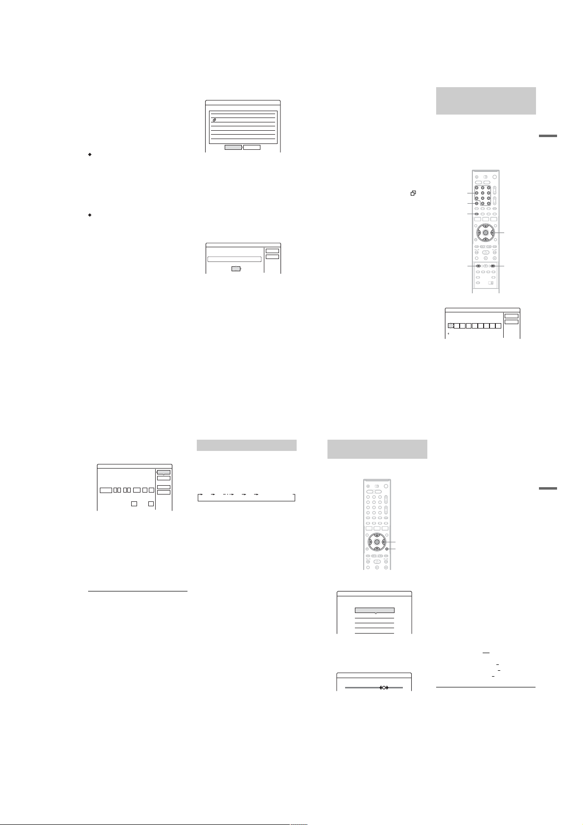
To stop recording during timer recording
Open the remote’s cover and press x REC STOP.
Note that it may take a few seconds for the
recorder to stop recording.
About the PDC/VPS function
PDC/VPS signals are transmitted with TV
programmes in some broa dcast systems. These
signals ensure that timer recordings are made
regardless of an y broa d ca st del ays , ea rly s ta rts , o r
broadcast interruptions.
To use the PDC/VPS function
Set “PDC/VPS” to “On” in step 2 above.
When you turn on thi s funct ion, the rec order st arts
scanning the channel before the timer recording
starts. If you are watching TV wh en scanning
starts, a message will appear on the TV screen. If
you want to watch TV, switch to your TV’s tuner
or turn off the PDC/VPS channel scan function.
Note that if you turn off the PDC/VPS channel
scan function, the timer recording will not start.
To turn off the PDC/VPS chann el scan
Press TOOLS and select “PDC/VPS Scan Off.”
To ensure that the PDC/VPS function works
properly, turn off the recorder before the timer
recording starts. This will automatically turn on
the PDC/VPS channel scan function while the
recorder remains off.
Rec Mode Adjust
If there is not enough available disc space for the
recording, the recorder automatically adjusts the
recording mode to enable the entire programme to
be recorded. This function is normally set to “On.”
To cancel this function, press TOOLS while the
Timer List is displayed. Select “Rec M ode
Adjust” and press ENTER. Select “Off” and press
ENTER.
If the timer settings overlap
Overlapped timer setting s are shown as follows.
Timer
These timer settings overlap.
To store the setting as shown, select “OK.” The
programme that starts first has priority and the
second programme starts recording only after the
first programme has finished.
To cancel the overlapped setting, select “Cancel.”
To confirm, change, or cancel timer recording
See “Checking/Changing/Cancelling Timer
Settings (Timer List)” on page 48.
To extend the recording duration time while
recording
1
Press TOOLS during recording to select
“Extend Rec,” and press ENTER.
Extend Rec. Time
Set the timer extend function.
Wed
2
Press M/m to select the duration time.
You can set the duration in incre ments of 10
minutes, for a maximum of 60 minutes.
3
Select “OK” and press ENTER.
One Touch Timer
If you use the SMARTLINK connection, you can
easily display the timer programming menu.
When the TV is turned on or in standby mode,
press [TIMER]. The recorder automatically turns
on and the TV’s input is switched to the recorder.
The Timer programming menu appears.
Do you want to continue?
Wed 21:00-22:00 AAB DVD SP PDC/VPS
29.10
Wed
29.10 20:30-22:00DEF DVD SP PDC/VPS
OK Cancel
DVD SP28.9 10:00-11:30 AAB
Extend Time
Off
OK
Cancel
z Hint
You can play the recorded programme by selecting the
programme title in the Title List.
b
Notes
• If a message indicating that the disc is full appears on
the screen, change the disc, or mak e availabl e space for
the recording (HDD/DVD+RW/DVD-RW only)
(page 68).
• Check that the clock is correctly set b e fo re s etting the
timer recording. If not, the timer recording cannot be
made.
To record a satellite program me, turn on the satellite
tuner and select the satellite programme you want to
record. Leave the satell ite tuner turned on until the
recorder finishes recording. If you connect equipment
with a timer function, you can use the Synchro Rec
function (page 50).
• Even if the timer is set for the same daily or we ekly
programme, the timer recording cannot be made if it
overlaps with a programme that has priority. “” will
appear next to the overlapped setting in the Timer List.
Check the priority order of the settings.
• Even if the timer is set, timer recordin gs ca nnot be
made while recording a programme that has priority.
• The Rec Mode Adjust function only works with a timer
recording and the PDC/VPS function set to off. It does
not function with Quick Timer or Synchro Rec. In
addition, the Rec Mode Adjust function does not work
when recording to the HDD while “Auto Title Erase” is
set to “On.”
• The beginning of some recordings may not be made
when using the PDC/VPS function.
• You cannot extend the recording duration time when
“PDC/VPS” is set to “On.”
Recording TV programmes using
the ShowView system (RDR-HX710/
HX910 only)
The ShowView system is a feature that simp lifie s
setting the timer. Just enter the ShowView number
listed in the TV programme guide. The date, time,
and programme position of that programme are set
automatically.
Check that the programme po sitions are correctly
set in “Channel Setting” in “Settings” setup
(page 82).
CLEAR
[TIMER]
z REC
1 2 3
4 6
7 8 9
5
0
</M/m/,,
ENTER
x REC STOP
Number
buttons, SET
1 Press [TIMER].
Timer - VIDEO Plus+
Set the timer by entering the timer code.
PlusCode No.
Standard
• If the “Timer – Standa rd ” di splay appears,
press < to switch the display to
“ShowView.”
2 Press the number buttons to enter the
ShowView number, a nd press SET.
• If you make a mistake, press CLEAR and reenter the correct number.
OK
Cancel
Timer Recording
44
3 Select “OK,” and press ENTER.
The date, start and stop times, pr ogr amme
position, recording mode, etc. setting
(page 44) appear.
Timer - VIDEO Plus+
Is the following timer setting correct? To modify,
adjust each item or re-enter the timer code.
Start
Stop
Date
Wed
28.9
• If you want to change the setting, press </
, to select the item and pres s M/m to
change the setting. For the PDC/VPS or
Update functions, select “Details” and
change the settings (page 44).
To re-enter the ShowView numbe r, select
“Change.”
4 Select “OK,” and press ENTER.
The TIMER REC indicator lights up on the
front panel, and the recorder is ready to start
recording.
To stop recording during timer recording
Open the remote’s cover and pre ss x REC STOP.
Note that it may take a few seconds for the
recorder to stop recording.
If the timer settings overlap
See page 44.
To extend the recording duration time while
recording
See page 44.
To confirm, change, or cancel timer recording
See “Checking/Changing/Cancelling Timer
Settings (Timer List)” on page 48.
z Hint
The Rec Mode Adjust func tion also w orks with t his timer
method (page 44).
MediaSPMode
Prog.
:
:
21 00
22 00
12
HDD
Off
OnPDC/VPS Update
Cancel
Details
Change
,continued
45
Using the Quick Timer function
You can set the recorder to record in 30-minute
OK
increments.
Press z REC repeatedly to set the duration.
Each press advances the time in 30-minute
increments. The maximum duration is six hours.
0:30 1:00 5:30 6:00
The time counter decrease s m i nute by minute to
0:00, then the recorder stops recording (power
does not turn off). Even if you turn off the recorder
during recording, the recorder con tinues to rec ord
until the time counter runs out .
Note that the Quick Timer function does not work
if “TV Direct Rec” is set to “On” in “Features”
setup (page 91).
To cancel the Quick Tim er
Press z REC repeatedly until the counter appears
in the front panel display. The recorder returns to
normal recording m ode.
(normal recording)
Adjusting the recording picture
quality and size
You can adjust the recording picture quality and
picture size.
1 2 3
4 6
5
7 8 9
0
</M/m/,,
ENTER
TOOLS
1 Before recording starts, press TOOLS to
select “Rec Settings,” and press ENTER.
Rec. Settings
Select the item you want to change.
Rec Mode : SP
HDD Rec. Picture Size: 4 : 3
DVD Rec. Picture Size:
Rec NR :
Rec Video Equalizer
2 Select the item you want to adjust, and
press ENTER.
The adjustment display appe ars.
4 : 3
2
Example: Rec NR
Rec NR
123Off
“Rec Mode”: Selects the recording mode for
the desired recording time and pi cture qualit y.
For more information, see “Recording mode”
on page 41.
“HDD Rec. Picture Size”/“DVD Rec. Picture
Size”: Sets the picture size of the programme
to be recorded.
• 4:3 (default): Sets the picture size to 4:3.
• 16:9: Sets the picture size to 16:9 (wide
mode).
• Auto (HDD only): Automatically s elects the
actual picture size.
“DVD Rec. Picture Size” works with DVDRs and DVD-RWs (Video mode) when the
recording mode is set to HQ, HSP, or SP. For
all other recording modes, the screen size is
fixed at “4:3.”
For DVD-RWs (VR mode), the actual picture
size is recorded rega rdless of the setting. For
example, if a 16:9 size p ict ure is receiv ed, t he
disc records the picture as 16:9 even if “DVD
Rec. Picture Size” is set to “4:3.”
For DVD+RWs/DVD+Rs, the screen size is
fixed at “4:3.”
“Rec NR” (noise reduction): Reduces noise
contained in the video signal.
“Rec Video Equalizer”: A djusts t he pict ure in
greater detail.
Press M/m to select the item you want to
adjust, then press ENTER.
• Contrast: Changes the contrast.
• Brightness: Changes the overall brightness.
• Colour: Make s t he co lour s dee p er or lig hter .
3 Adjust the setting using </M/m/,, and
press ENTER.
The default setting is underlined.
“Rec NR”: (weak) Off 1 ~ 2 (strong )
“Rec Video Equalizer”:
• Contrast: (weak) –3 ~ 0
• Brightness: (dark) –3 ~ 0 ~ 3 (bright)
• Colour: (light) –3 ~ 0
Repeat steps 2 and 3 to adjust any other items.
~ 3 (strong)
~ 3 (deep)
Timer Recording
46
,continued
47
1-11
Page 18
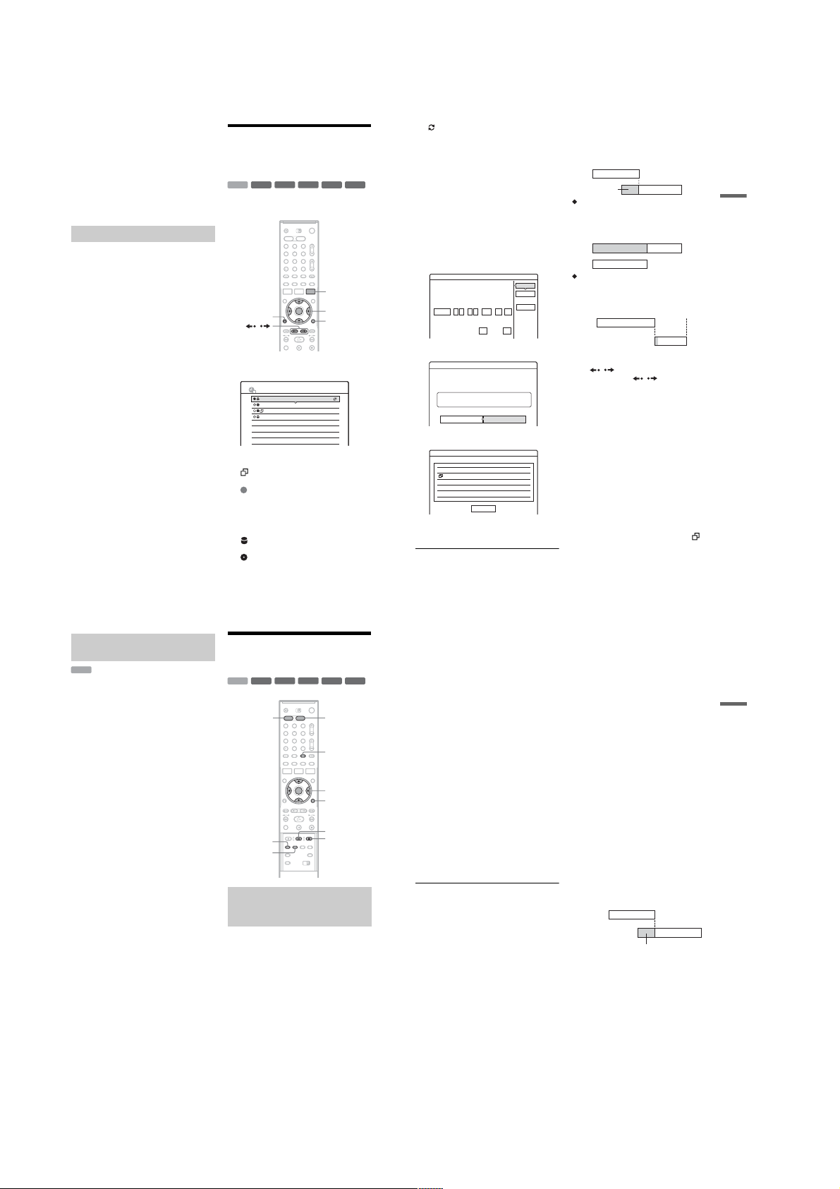
b
Notes
• If one programme contains two picture sizes, the
selected size is recorded. However, if the 16:9 signal
cannot be recorded as 16:9, it is recorded as 4:3.
• When playing a 16:9 size picture recorded as 4:3, The
image is fixed to 4:3 letter box regardless of the setting
in “TV Type” of “Video” setup (page 87).
• Remnants of images may appear on your screen when
using “Rec NR.”
•“Rec Video Equalizer” does not affect the input of the
DV IN jack (RDR-HX710/HX910 only) and does not
work with RGB signals.
Creating chapters in a title
The recorder can automatical ly div ide a record ing
(a title) into chapters by inserting chapter marks
during recording. To disable this function, set
“Auto Chapter” in “Features” setup to “Off”
(page 91).
When recording on the HDD or a DVD-RW (VR
mode)
The recorder detects changes in the picture and
sound and automatically inserts chapter marks.
You can also insert and erase chapter marks
manually (page69).
When recording on other recordable discs
Chapter marks are inserted at approximately 6minute intervals during recording.
b
Note
When dubbing (page 72 ), the chapter marks in the
dubbing source are not retained in the dubbed title.
48
Checking/Changing/
Cancelling Timer Settings
(Timer List)
-
RW
/
TIMER LIST
Mon-Sat
Fri 29.10
Fri 29.10
Sat 30.10
RW
1 2 3
4 6
7 8 9
22:00-22:15
20:30-21:30
21:00-22:00
16:00-17:00
-
+
VR
RW
R
5
0
AAB
DEF
GHI
DEF
Video
SP
SP
SLP
SLP
+
R
TIMER LIST
</M/m/,,
ENTER
TOOLS
10:30
PDC
VPS
PDC
VPS
-
R
+
HDD
You can check, change, or can cel timer settings
using the Timer List.
O
RETURN
1
Press TIMER LIST.
The Timer List appears.
Timer information displays the recording
date, time, recording mode, etc.
: Indicates that the setting is overl apped by
another setting.
(green): Indicates the setting can be
recorded.
(red): Indicates the setting currently being
z
recorded.
(grey): Indicates that the setting cannot be
a
recorded in the select ed recording mode.
: Indicates the setting being r ecorded on
the HDD.
: Indicates the setting being recorded on a
DVD.
: Indicates the setting that the U pdate
function is set for.
When all of the timer settings do not fit on the
list, scroll bar appears.
To view the hidden timer settings, press M/m.
2 Select the timer setting you want to check/
change/cancel, and press EN TER.
The sub-menu appears.
3 Select one of the options, and press
ENTER.
“Modify”: Changes the timer setting.
Select an item using </, and adjust using
M/m. For the PDC/VPS or Update functions,
select “Details” and change the s ettings
(page 44). Select “OK,” and press ENTER.
Modify
Modify the timer setting.
Start
Stop
Date
:
:
Mon-Sat
22 00
22 15
“Erase”: Erases the timer setting. Select
“OK,” and press ENTER.
Erase
Are you sure you want to erase this timer setting?
22:00-22:15 AABMon-Sat
HDD SP
OK Cancel
“Check Overlap”: Checks for ov er la pped
settings.
Check Overlap
These timer settings overlap.
29.10 20:30-21:30 DEF DVD SP PDC/VPS
Fri
29.10 21:00-22:00 GHI
Fri DVD SLP
Select “Close” to return to the Timer List.
To change or cancel the setting, repeat steps 2
and 3 above.
Close
OK
Cancel
MediaSPMode
Prog.
Details
AAB
HDD
OnOffPDC/VPS Update
PDC/VPS
When the timer settings overlap
The programme that starts first has prio rity and the
second programme starts recording only after the
first programme has finished.
7:00 8:00 9:00 10:00
A
will be cut off
When the recordings start at the same time
The programme that is set last has p riori ty. I n t his
example, timer setting B is set after A, so the first
part of timer setting A will not be recorded.
7:00 8:00
When the end time of one recording and the
start time of another are the same
After finishing the previous recording, the other
recording may be delayed.
7:00 9:00 10:00
A
B
A
B
9:00 10:00
B
To scroll the list display by page (Page mode)
Press / while the list display is turned on.
Each time you press
List changes to the next/previous page of timer
settings.
To turn off the Timer List
Press TIMER LIST or ORETURN.
z Hint
While recording, you cannot modify the timer setting for
the current recording, but you can extend the recording
duration of the recording time (page 44).
b
Notes
• When “PDC/VPS” is set to “On” for one or more timer
recordings, the start times may change i n the ev ent of a
broadcast delay or early start.
• Even if the timer is set, timer recordings cannot be
made while recording a programme that has priority.
• Even if the timer is set for the same daily or weekly
programme, the timer recording cannot be made if it
overlaps with a programme that has priority. “” will
appear next to the overlapped setting in the Timer List.
Check the priority order of the settings.
/
, the entire Timer
,continued
Timer Recording
49
Automatically erasing old titles
(Auto Title Erase)
HDD
If there is not enough spac e for a timer recording,
the recorder automatically erases old titles
recorded on the HDD. The oldest, played title is
erased. The protected titles are no t e ra sed.
1
Press TIMER LIST.
The Timer List appears.
2
Press TOOLS to select “Auto Title Erase,”
and press ENTER.
3
Select “On,” and press ENTER.
The default setting is “Off.”
Recording From Connected
Equipment
-
-
+
HDD
REC MODE
SYNCHRO
REC
Recording from connected
equipment with a timer (Synchro
Rec)
You can set the recorder to automatically record
programmes from connected equipment that has a
timer function (such as a satellite tuner) . Con ne ct
the equipment to the LINE 3/DECODER jack of
the recorder (page25).
When the connected equipm ent turns on, the
recorder starts recording a programme from the
LINE 3/DECODER jack.
1
Before recording, select HDD or DVD.
If you select DVD, insert a recordable DVD
(see “Inserting a Disc” on page 29) .
2
Set “Synchro Rec” in “Features” setup to
“Record to HDD” or “Record to DVD”
(page 93).
-
+
RW
VR
RW
VR
1 2 3
4 6
7 8 9
RW
R
5
0
RW
Video
-
+
R
R
DVDHDD
INPUT SELECT
</M/m/,,
ENTER
TOOLS
X REC PAUSE
x
REC STOP
3 Press INPUT SEL ECT repeatedly to select
“L3.”
4 Select the line input audio when recording
a bilingual programme on the HDD or DVDRWs (VR mode).
Press TOOLS to select “Line Audio Input,”
and press ENTER. Then select “Bilingual,”
and press ENTER.
For details about bilingual recording, see
page 42.
5 Press REC MODE repeatedly to select the
recording mode.
For details about the recording mode, see
page 41.
6 Set the timer on the connected equipment
to the time of the programme you want to
record, and turn it off.
7 Press SYNCHRO REC.
The SYNCHRO REC indicator lights up on
the front panel. The recorder is ready to start
Synchro-Recording.
The recorder automatically starts recording
when it receives an input signal from the
connected equipment. The recorder stops
recording when the connec t ed equipment
turns off.
To stop recording
Press x REC STOP or SYNCHRO REC.
To cancel Synchro Rec
Press SYNCHRO REC.
The SYNCHRO REC indica tor on the recorder
turns off.
b Notes
• The recorder starts recording only afte r detecting the
video signal from the connected equipment. The
beginning of the programme may not be recorded
regardless of whether or not the recorder’s power is on
or off.
• During Synchro-Recording, other operations such as
normal recording cannot be done.
• To use the connected equipment while the recorder is
standing by for Synchro-Recording, cancel SynchroRecording by pressing SYNCHRO REC. Be sure to
turn off the connected equipment and press
SYNCHRO REC to reset Synchro-Recording before
the timer recording starts.
• The Synchro Rec function does not work when “Line3
Input” of “Scart Setting” in “Video” setup is set to
“Decoder” (page 89).
• The Synchro Rec function does not work with some
tuners. For details, see the tuner’s operating
instructions.
• While the recorder is standing by for SynchroRecording, the Auto Clock Set function (page 86) does
not work.
• To use the Synchro Rec function, you must first set the
recorder’s clock correctly.
If the timer settings of a Synchro-Recording
and another timer recording overlap
Regardless of whether or not the programme is a
Synchro Rec programme, the programme that
starts first has priority an d t he se cond pr ogra mme
starts recording only after the first programme has
finished.
7:00 8:00 9:00 10:00
First
programme
Second
programme
will be cut off
Timer Recording
50
,continued
51
1-12
Page 19
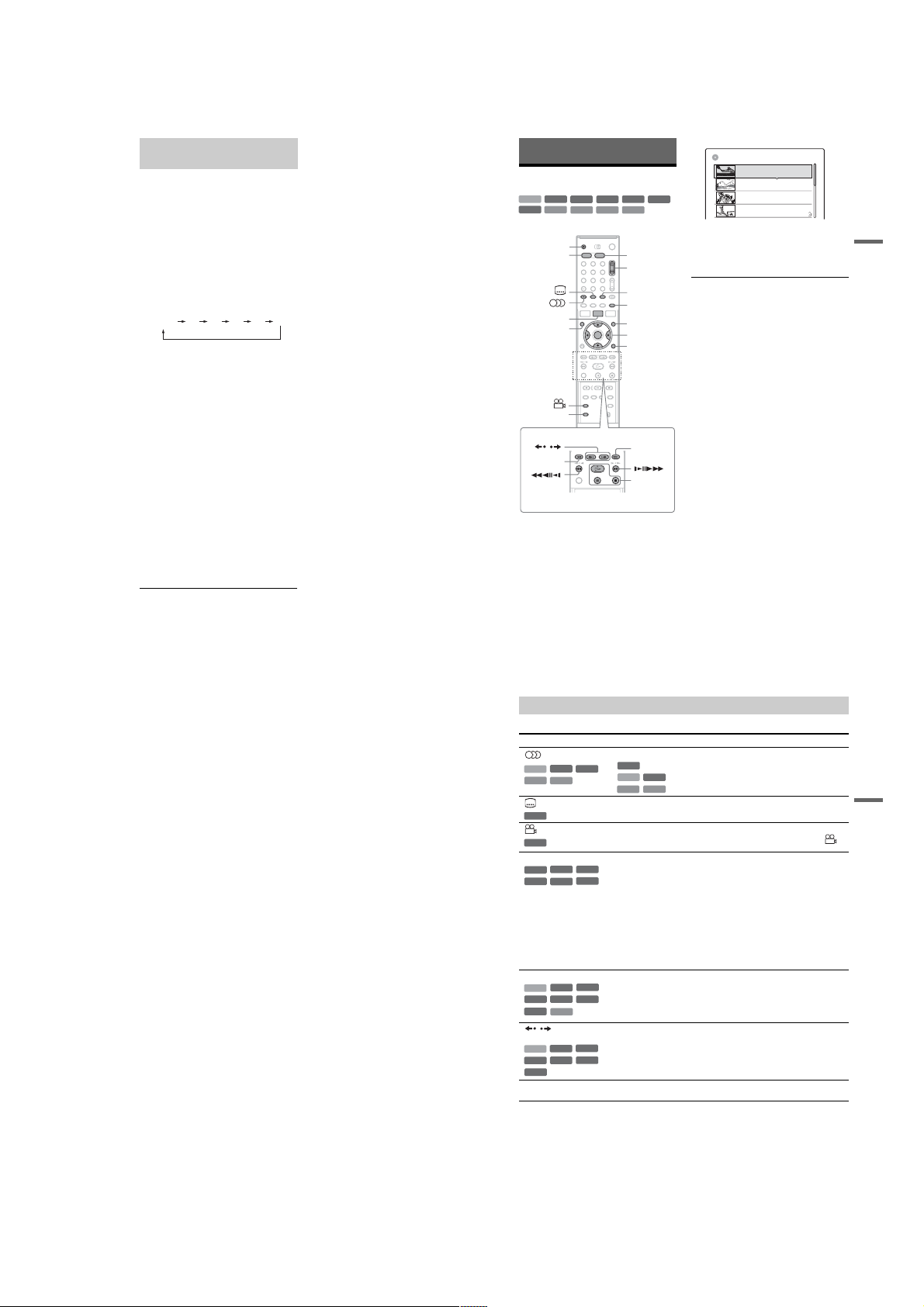
Recording from connected
equipment without a timer
You can record from a connected VCR or similar
device. To connect a VCR or similar device, see
“Connecting a VCR or Similar Device” on
page 23. Use the DV IN jack on the front panel if
the equipment has a DV output jack (i.LINK jack)
(RDR-HX710/HX910 only).
1 Press HDD or DVD.
If you select DVD, insert a recordable DVD
(see “Inserting a Disc” on page 29).
2 Press INPUT SELECT to select an input
source according to the connection you
made.
The front panel display changes as follows:
programme
position
3 Select the line input audio when recording
a bilingual programme on the HDD or DVDRWs (VR mode).
Press TOOLS to select “Line Audio Input,”
and press ENTER. Then select “Bilingual,”
and press ENTER.
For details about bilingual recording, see
page 42.
4 Press REC MODE repeatedly to select the
recording mode.
For details about the recording m ode, see
page 41.
5 Press
record pause.
6 Insert the source tape into the connected
equipment and set to playback pause.
7 At the same time, press
this recorder and th e pause or play button
on the connected equipment.
Recording starts.
To stop recording, pres s x REC STOP on this
recorder.
* RDR-HX710/HX910 only
L2L1 L4L3 DV*
X
REC PAUSE to set this recorder to
X
REC PAUSE on
If you connect a digital video camera with a DV
IN jack (RDR-HX710/HX910 only)
See “DV Dubbing (RDR-HX710/HX910 only)”
on page 77 for an explanation of how to record
from the DV IN jack.
z Hint
You can adjust the settings for the recording picture
before recording. See “Adjusting the recording picture
quality and size” on page 47.
b
Notes
• When recording a video game image, the screen may
not be clear.
• Any programme that contains a Copy-Never copy
guard signal cannot be recorded. The recorder
continues to record, but a blank screen will be recorded.
Playback
Playing
+
-
HDD
DVD
PROGRESSIVE
RW
RW
VCD
CD
Z
HDD DVD
TITLE LIST
TOP MENU
/
.
Press HDD or DVD.
1
• If you select DVD, insert a disc (see
“Inserting a Disc” on page29).
• If you insert a DVD VIDEO, VIDEO CD, or
CD, press H. Playback starts.
2 Press TITLE LIST.
For details about the Title List, see “3. Playing
the Recorded Programme (Title List)” on
page 32.
VR
1 2 3
4 6
7 8 9
-
DATA DVD
5
0
+
RW
Video
R
DATA CD
PROG
INPUT
SELECT
SUR
MENU
</M/m/,,
ENTER
TOOLS
>
H/X/x
Example: DVD-RW (VR mode)
TITLE LIST
ORIGINAL
12
Tenn is
Fri
28.10. 2005 13:00 (0H30M) LSP GB0.9
11
Trav el
26.10. 2005 20:00(0H30M) SEP
Wed
10
-
R
3 Select the title, and press ENTER.
4 Select “Play,” and press ENTER.
+/–
To use the DVD’s Menu
When you play a DVD VIDEO, or a finalized
DVD+RW, DVD-RW (Video mode), DVD+R, or
DVD-R, you can display the di sc’s menu by
pressing TOP MENU or MENU.
To play VIDEO CDs with PBC functions
PBC (Playback Control) allows you to play
VIDEO CDs interactively using the menu on your
TV screen.
When you start playing a VIDEO CD wit h PBC
functions, the menu appears.
Select an item using t he number butt ons an d pre ss
ENTER. Then, follow the instructions in the menu
(press
The PBC function of Super VIDEO CDs does not
work with this recorder. Super VIDEO CDs are
played in continuous play mode on l y.
To stop playback
Press x.
To playback quickly with sound (Scan Audio)
When you press M during playback of a title
recorded in the HDD, you can play quickly with
dialogue or sound (“x1.5” appears).
No sound is output when you press M two or
more times to change se arch speed.
Mystery
25.10. 2005 9:00 (1H00M) SLP
Tue
9
World Sports
19.10. 2005 20:00(1H00M) SEP
Wed
The sub-menu appears.
Playback starts from th e selected title.
H
when “Press SELECT” appears).
GB4.3 / 4.7
AAB
DEF
GB0.3
AAB
GB0.8
GHI
GB0.6
Playback
52
To resume playback f rom the point where you
stopped (Resume Play)
When you press H again after you stop
playback, the recorder resumes playback from the
point where you pressed
To start from the beginning, press TOOLS to
select “Play Beginning,” and press ENTER.
Playback starts from the beginning of the title/
track/scene.
The point where you stopped play ing is cleared
when:
–you open the disc tray (except for HDD).
–you play another title (except for HDD).
–you switch the Title List menu to Original or
Playlist (HDD/DVD-RW in VR mode only).
–you edit the title after stop pi ng playback.
–you change the settings on the recorder.
–you turn off the recorder (VIDEO CD/CD/
DATA DVD/DATA CD only).
–you make a recording (except for HDD/DVD-
RWs in VR mode).
–you switch between JPEG and MP3.
b Note
You cannot resume playback during TV Pause.
To play restricted DVDs (Parental Control)
If you play a restricted DVD, the message “Do
you want temporarily chang e parental control to
*?” appears on your TV screen.
1 Select “OK” and press ENTER.
The display for entering your password
appears.
2 Enter your fo ur-digit password using the
number buttons.
3 Press ENTER to select “OK.”
The recorder starts playback.
To register or change the password, see “Parental
Control (DVD VIDEO only)” on page 92.
To lock the disc tray (Child Lock)
You can lock the disc tray to prevent children from
ejecting the disc.
When the recorder i s turned on, hold down x until
“LOCKED” appears in the front panel display.
The Z (open/close) button does not work while
the Child Lock is set.
To unlock the disc tray, hold down x until
“UNLOCKED” appears in the front panel display
when the recorder is turned on.
x.
54
One Touch Play
If you use the SMARTLINK connection, you can
easily start playing.
Press H. The recorder and your TV
automatically turn on and the TV’s input is
switched to the reco rder. Playback starts
automatically.
One Touch Menu
If you use the SMARTLINK connection, you can
easily display the Title List.
Press TITLE LIST. The recorder and your TV
automatically turn on and the TV’s input is
switched to the recorder. The Title List appears.
z Hints
• You can also use the H button in step 3 (page 5 3) to
start playback.
• Even if you select “Factory Setup” in “Options” setup
(page 94), the Child Lock remains set.
,continued
Playback options
To check the position of the buttons below, see the illustration on page 53.
Buttons
(audio) Selects one of the audio track s recorded on the disc when pressed repeatedly .
-
RWVR
HDD
VCD
CD
(subtitle) Selects a subtitle language when pressed repeatedly.
DVD
(angle) Selects an angle when pressed repeatedl y.
DVD
SUR (surround) Selects one of the TVS effects whe n pr essed repeatedly.
-
+
RWVR
RW
+
-
R
R
PROGRESSIVE Switches the typ e of video output signal to interlace or progressive format
+
+
RW
RW
HDD
+
-
RWVideo
R
DVD
VCD
/ (instant replay/
instant advance)
+
RW
HDD
+
-
RWVideo
R
DVD
. (previous)/
> (next)
Operations
DVD
-
RWVideo
DVD
-
RWVR
-
R
-
RWVR
HDD
VCD
If various angles (multi-angles) for a scene are recorded on the disc, “”
appears in the front panel display.
TVS* (TV Virtual Surround) lets you enjoy virtual surround sound effe c ts
created from the front left and right speakers. The selected setting is displayed
in the front panel display for a few seconds.
“TVS OFF”: No surround effect
“TVS DYNAMIC”: Creates one set of virtual rear speakers.
“TVS WIDE”: Creates five sets of virtual rear speakers.
“TVS NIGHT”: Creates five sets of virtual rear speakers. Effective at low
volume.
“TVS STANDARD”: Creates three sets of virtual rear speakers. Effective
when you use two separate front speakers.
* TVS was developed by Sony to produce home surround sound with just a stereo
: Selects the main or sub sound.
: Selects stereo or monaural audio tracks.
CD
TV.
(page 16).
: Selects the language.
DVD
Replays the scene/briefly fast forwards the scene.
-
RWVR
-
R
Goes to the beginning of the previous/next title/chapter/scene/track.
For the HDD, you cannot go to the be ginning of the previous/next titl e.
,continued
53
Playback
55
1-13
Page 20
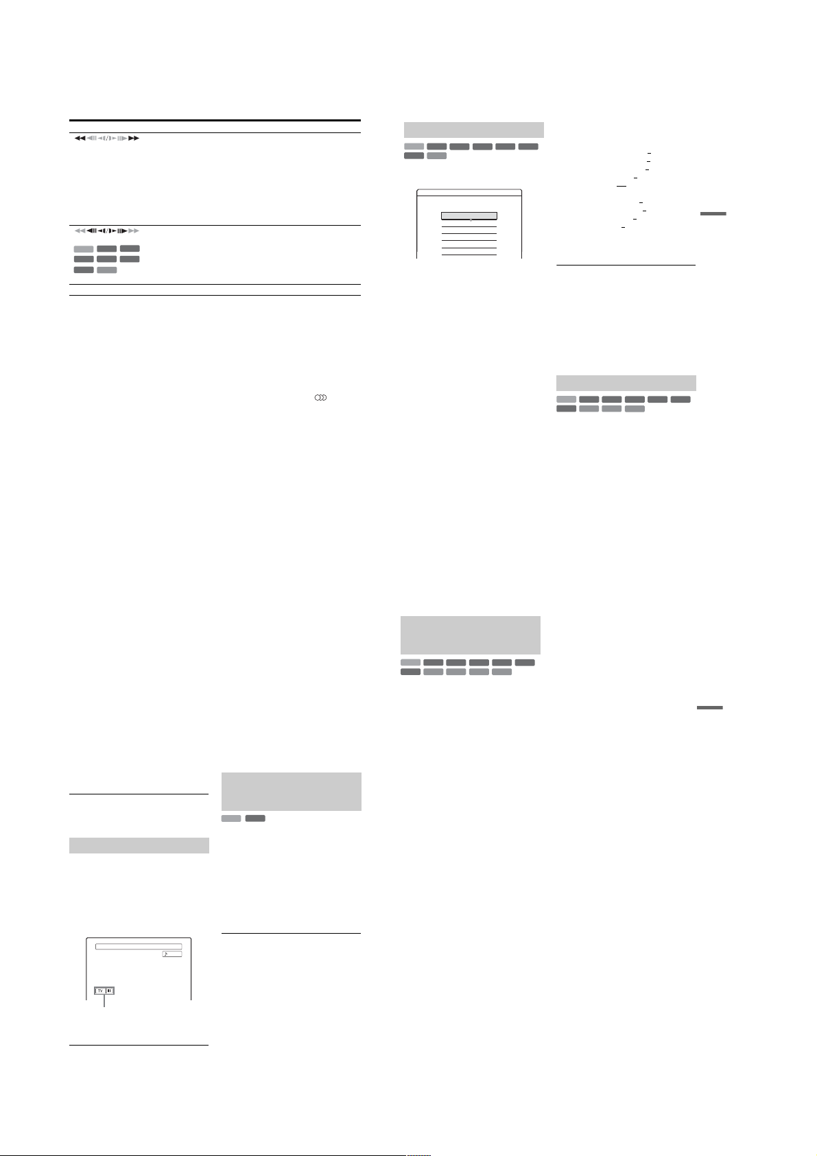
Buttons
(fast reverse/fast forward)
(slow, freeze frame)
+
+
RW
RW
HDD
+
-
RW
Video
R
DVD
VCD
* Playback dire ction only
X (pause) Pauses playback.
Operations
Fast reverses/fast forwards the disc when pressed during playback.
Search speed changes as follows:
fast reverse fast forward
m1 T t 1M
m2 T T t t 2M
*2
m3
T T T t t t 3M
When you press and hold the button, fast forward/fast reverse continues at the
selected speed until you release th e button.
*1
When you press M once during playback of a title recorded in the HDD, you
can play quickly with sound (“x1.5” appears).
*2
m
3 and 3M are only available for the HDD and DVDs.
Plays in slow motion when pressed for more than one second in pause mode.
Plays one frame at a time when pressed briefly in pause mode.
-
RW
VR
-
R
*
To resume normal playback, press H.
b
Notes
• To enjoy the TVS function, set “Digital Out” to “On”
and “Dolby Digital” to “D-PCM” and “MPEG” to
“PCM” in “Audio” setup.
• The volume may be reduced when surround effects are
set.
• When the playback signal does not contain a signal for
the rear speakers, the surround effects will be difficult
to hear.
In addition, the surround effects may also be difficult to
hear depending on the title being played and the
environment where the recorder is being used.
• When you select one of the surround modes, turn off
the surround settings of the connected TV or amplifier
(receiver).
• Make sure that your listening position is between and
at an equal distance from your speakers, and that the
speakers are located in similar surroundings.
• Angles and subtitles cannot be changed with titles
recorded on this recorder.
• When you use the DIGITAL OUT (COAXIAL) jack to
listen to MPEG audio signals and set “MPEG” to
“MPEG” in “Audio” setup, no sound will come from
your speakers if you select one of the TVS modes.
• 96 kHz PCM audio and DTS audio do not have
surround effects.
• The surround effects do not work while performing
playback quickly with sound.
*1
*2
Notes on playing D TS sound tracks on a CD
• When playing DTS-encoded CDs, excessive noise will
be heard from the analogue stereo jacks. To avoid
possible damage to the audio system, the consumer
should take proper precautions when the analogue
stereo jacks of the recorder are connected to an
amplification system. To enjoy DTS Digital
Surround™ playback, an external 5.1-channel decoder
system must be connected to the digital jack of the
recorder.
• Set the sound to “Stereo” using the (audio)
button when you play DTS sound tracks on a CD
(page 55).
Notes on playing DV Ds with a DTS sound track
DTS audio signals are output only through the DIGITAL
OUT (COAXIAL or OPTICAL) jack.
When you play a DVD with DTS sound tracks, set
“DTS” to “On” in “Audio” setup (page 90).
Adjusting the picture quality
+
-
HDD
DVD
1 Press TOOLS during playback to select
2 Select an item, and press ENTER.
RW
RW
VCD
“Video Settings,” and press ENTER.
Video Settings
Select the item you want to change.
Y NR : 2
C NR :
BNR :
MNR :
DVE :
PB Video Equalizer
The adjustment display appe ars.
“Y NR” (luminance noise re duction):
Reduces noise contained in t he l uminance
element of the video signal.
“C NR” (chroma noise reducti on): Reduces
noise contained in the colour element of the
video signal.
“BNR” (block noise reduction): Reduces
“block noise” or mosaic like patterns in the
picture.
“MNR” (mosquito noise reduc ti on) : R educ es
the faint noise appearing around th e outlines
of the images. The no ise re duc tio n effec ts ar e
automatically adjusted within each setting
range according to the video bit rate and other
factors.
“DVE” (digital video enha ncer): Sh arpens th e
outlines of the images.
“PB Video Equalizer” (Playback video
equalizer): Adjusts the picture in greater
detail.
Select an item and press ENTER.
• Contrast: changes the contrast.
• Brightness: changes the overall brightness.
• Colour: makes the colours deeper or lighter.
• Hue: changes the colour balance.
+
-
VR
RW
Video
R
2
2
1
Off
3 Press </, to adjust the setting, and
press ENTER.
-
The default settings are underlined.
R
“
Y NR”: (weak) Off 1 2 3 (strong)
“
C NR”: (weak) Off 1 2 3 (strong)
“
BNR”: (weak) Off 1 2 3 (strong)
“MNR”: (weak) Off 1
“
DVE”*: (weak) Off 1 2 3 (strong)
“
PB Video Equalizer
• Contrast: (weak) –3 ~ 0 ~ 3 (strong)
• Brightness: (dark) –3 ~ 0
• Colour: (light) –3 ~ 0
• Hue: (red) –3 ~ 0
Repeat steps 2 and 3 to adjust any other items.
* “1” softens the outlines of the images. “2”
enhances the outlines and “3” enhances them more
than “2.”
b
Notes
• If the outlines of the images on your screen become
blurred, set “BNR” and/or “MNR” to “Off.”
• Depending on the disc or the scene being played, the
above BNR, MNR, Y NR, or C NR effects may be hard
to discern. And, these functions may not work with
some screen sizes.
• When using the DVE function, noise found in the title
may become more apparent. In this case, it is
recommended that you use the BNR function with the
DVE function. If the condition still does not improve,
set the DVE level to “1” or “Off.”
Adjusting the sound quality
+
-
RW
VCD
VR
RW
CD
HDD
DVD
1 Press TOOLS during pla yback to select
“Audio Settings,” and press ENTER.
2 Select an item, and press ENTER.
“Surround” (TVS): Selects one of the
surround modes. For m ore information, see
“Playback options” on page 55.
2 3 (strong)
”:
~ 3 (bright)
~ 3 (deep)
~ 3 (green)
-
RW
Video
DATA CD
Playback
+
-
R
R
56
“Audio Filter”: Selects the digital filter to
reduce noise above 22.05 kHz (Fs * i s 44.1
kHz), 24 kHz (Fs is 48 kHz), or 48 kHz (Fs is
above 96 kHz).
• Sharp (default): Provides a wide frequency
range and spatial feeling.
• Slow: Provides smooth and warm sound.
“AV SYNC”: When the video is delayed, this
function delays the au di o for syn c hr oni zat ion
with the video (0 to 120 mil liseco nds). L arger
numbers indicate a longer audio delay for
synchronization with the video. When
dubbing to a VCR or other video recordi ng
equipment, be sure to return this setting to 0
ms (default).
* Sampling frequency of audio source. This
function only adjusts the output signals from the
LINE 1 – TV, LINE 3/DECODER, or LINE 2
OUT (AUDIO L/R).
3
Press </M/m/, to select the option,
and press ENTER.
b
Note
There may be little effect by changing the Audio Filter
depending on the disc or playback environment.
Pausing a TV Broadcast (TV Pause)
You can pause a current TV bro adcast, and then
continue watching the programme at a later time.
This is useful when you receive an unexpected
phone call or visitor while watchi ng TV.
1
While viewing a TV br oadcast with this
recorder, press X.
The picture pauses. You can pause the picture
for up to three hours.
News ABCD 9
TV pause
2
Press X or H again to resume watching
the programme.
,continued
57
b
Notes
• Paused titles are not saved to the HDD.
• This function is cancelled when:
– x (stop) is pressed.
– PROG +/– is pressed.
– DVD is pressed.
– Z (open/close) is pressed.
– TITLE LIST is pressed.
– INPUT SELECT is pressed.
– the recorder is turned off.
– a timer recording or Synchro Recording is started.
– the PDC/VPS func tion is “On” and channel scan is
started.
– DV dubbing or regular dubbing is star te d.
• It may take a few seconds to resume playback of the
paused programme.
• Even if you fast forward the recorded programme,
there will always be a time difference of about one
minute or more between the recorded programme and
the current TV broadcast.
Playing from the beginning of the
programme you are recording
(Chasing Playback)
-
RW
VR
HDD
“Chasing Playback” allows yo u t o vi ew t he
recorded part of a programme wh ile the re cordin g
is being made. You do not need to wait until the
recording finishes.
Press TOOLS while recording to select
“Chasing Playback,” and press EN TER.
Playback starts from the beginning of the
programme you are recording.
When you fast forward to the point that you are
recording, Chasing Playback returns to normal
playback.
b
Stereo
Notes
• For DVD-RWs (VR mode), this function does not
work when recording:
– on a 1x-speed DVD-RW.
– in the HQ or HSP recording mode.
• The DVD’s picture on your TV screen freezes for a few
seconds when you fast forward/fast reverse or instant
replay/advance the recording.
• Chasing Playback is possible from one minute or more
after recording starts.
• Even if you fast forward the recorded programme,
there will always be a time difference of about one
minute or more between the recorded programme and
the current TV broadcast.
Playing a previous recording while
making another (Simultaneous Rec
and Play)
+
-
HDD
DVD
“Simultaneous Rec and Play” allows you to view
a previously recorded programme wh ile recording
programmes. Playback continues even if a timer
recording starts. Use this function as follows:
• While recording to the HDD:
Play another title on the HDD.
Play a previously record ed programme on a
DVD by pressing DVD.
• While recording to a DVD:
Play a previously record ed programme on the
HDD by pressing HDD.
• While recording to a DVD-RW (VR mode)
Play another title on the same DVD-RW (VR
mode) disc.
*1
Simultaneous Rec and Play function does not work
when you record:
– on a 1x-speed DVD-RW.
– in the HQ or HSP recording mode.
*2
Picture noise may appear depending upon the
condition of the recording, or when playing a title
recorded in the HQ or HSP recording mode. The
picture freezes for a few seconds when you use fast
forward/fast reverse or instant replay/advance.
You can also play a DVD VIDEO, VIDEO CD,
Super VIDEO CD, CD, DATA DVD, or DATA
CD while recording on the HDD.
Example: Play another title on the HDD while
recording to the HDD.
1 While recording, press TITLE LIST to
2 Select the title you want to play, and press
3 Select “Play” from the sub-m enu, and press
RWVR-RWVideo
RW
VCD CD
*2
display the HDD Title List.
ENTER.
ENTER.
Playback starts from the selected title.
DATA DVD
+
R
DATA CD
Example: Play a DV D while recording to the
HDD.
1 While recording, press DVD and insert the
DVD into the reco rder.
2 Press TITLE LIST to display the DVD Title
-
R
List.
3 Select the tit le you want to play, and press
ENTER.
4 Select “Play” from the sub-menu, and press
ENTER.
Playback starts from th e selected title.
b Note
You cannot play a DVD or VIDEO CD recorded in the
NTSC colour system while recording on the HDD. When
playing a VIDEO CD, be sure to set “Colour System” to
“PAL” (page 93).
*1
:
Playback
58
59
1-14
Page 21
Searching for a Title/
Chapter/Track, etc.
CLEAR
VISUAL
SEARCH
+
RW
1 2 3
4 6
5
7 8 9
0
</M/m/,,
ENTER
TOOLS
-
RW
+
-
VR
RW
Video
Number
buttons, SET
Searching by Thumbnail (Visual
Search)
HDD
Each chapter is displ ayed as a thumbn ail. Yo u can
search for the desired scene visually.
1 Press VISUAL SEARCH during playback.
VISUAL SEARCH
2 Select a scene using </,, and press
ENTER.
Playback of the selected scene is sta rt ed.
60
9 World Sports
Chapter
0:12:45
Searching by title number or time
code
+
-
HDD
DVD
You can search a disc by title, chapter, scene or
track. As titles and tracks are assigned individual
numbers, select the title or track by entering its
number. You can also search for a scene using the
time code.
1 Press TOOLS during playback to select a
-
R
R
2 Press the number buttons to select the
4(30)
3 Press SET.
b
“Title Search” is not applicable to the HDD.
RW
RW
VCD
CD
search method, and press ENTER.
“Title Search” (for DVDs)
“Chapter Search” (for HDD/DVDs)
“Track Search” (for CDs/DATA CDs)
“Search” (for VIDEO CDs)
“Album Search” (for DATA DVDs/DATA
CDs)
“Time Search” (for HDD/DVDs): Searches
for a starting point by entering the time code.
“File Search” (for DATA DVDs/DATA CDs)
The display for ente ri ng the number appears.
Example: Title Search
The number in parentheses indicates the total
number of titles, tracks, etc.
number of the title, chapter, track, time
code, etc., you want.
For example: Time Search
To find a scene at 2 hours, 10 minutes, and 20
seconds, enter “21020.”
If you make a mistake, press CLEAR to
cancel the number, then select another
number.
The recorder starts playback from the s electe d
number.
Note
+
-
VR
RW
DATA DVD
-
Video
R
R
DATA CD
: -- (21)Title
Playing MP3 Audio Tracks
or JPEG Image Files
DATA CD
DATA DVD
You can play MP3 audio tracks an d JPEG image
files on DATA CDs (CD-ROMs/CD-Rs/CDRWs) or JPEG image files on DATA DVDs
(DVD-ROMs/DVD+RWs/DVD+Rs/DVD-RWs/
DVD-Rs).
1 2 3
4 6
5
7 8 9
DISPLAY TIME/TEXT
TITLE LIST
1 Insert a disc.
See “Inserting a Dis c” on page 2 9.
2 Press H.
For MP3 discs, playback sta rts from the first
MP3 audio track on the disc.
For JPEG files, a slideshow of the pictures on
the disc begins.
If the DATA CD contains both MP3 audi o
tracks and JPEG image fil e s , p layback starts
from the JPEG image files the first time H is
pressed.
0
</M/m/,,
ENTER
/
.
m
TOOLS
>
M
H
x
Selecting an MP3 album or track
1 Press TITLE LIST.
The album list appears.
To change the page, press
TITLE LIST
1
Opera
2
Symphony
3
Samba
4
Live
5
Piano
6
My heart
7
Paradise
8
The Best
2 Select an album, and press ENTER.
The sub-menu appears.
3 Select “View Album,” and press ENTER.
The track list appears.
To change the page, press
TITLE LIST
1 01 Holiday
2 02 Lonely
3 03 Candy
4 04 Rainy day
5 05 Station
6 06 Magic
7 07 Moon
8 08 Butterfly
4 Select a track, a nd press ENTER.
“Play”: Plays the track.
“Play Beginning”: Plays the beginning of the
track.
“Track Data”: Shows data about th e t rack
such as artist and album name.
To stop playback
Press x.
To fast forward or review a track
Press m/M during playback.
To go to the next or previous MP3 audio track
Press . or > during playback. If you
repeatedly press . or >, you will go to the
next or previous album.
To go to the next or previous album
Press / during playback.
z Hint
Press the (audio) button
or monaural audio tracks.
Music Album
Classic
Classic
Dance
Jazz
Jazz
Pop music
Pop music
Pop music
8 The Best
to switch between stereo
/ .
/ .
,continued
Playback
61
Selecting a JPEG album or image
1 Press TITLE LIST .
The album list appears.
To change the page, press / .
TITLE LIST
Photo Album
6 Zoo
1
5
9
ROOT
Summer2 Aquarium
Summer3 Festival
Summer
Summer
Summer6 Zoo
Winter
Winter
3
2
7
6
11
10
DSC00029 25.11.2005 15:50
/ .
4
8
12
1 Flowers
4 Hiking
5 Tennis match
7 Consert
8 Party
2 Select an album, and press ENT ER.
The sub-menu appears.
3 Select “View Album,” and press ENTER.
The image list appears.
To change the page, press
TITLE LIST
4 Select an image, and press ENTER.
“View Image”: Sho ws the image on the entire
screen.
“Slideshow”: Shows the images in the album
as a slideshow.
“Image Data”: Shows data ab out when the
picture was taken.
To stop viewing the JPEG image
Press x.
To view the next or previous picture
Press ./> while the pic t ur e is di splayed.
To rotate a picture
Press TOOLS while the image is displayed to
select “Rotate Right” or “Rotate Left,” and press
ENTER.
To change the slides how speed
Press TOOLS while the album list or image list is
displayed to select “Slideshow Speed,” and press
ENTER. Then select the speed from “Fast”
(quick), “Normal,” and “Slow.”
To go to the next or previous album
Press / while the JPEG image is displayed.
z Hints
• If you are playing a DATA CD that has both MP3 and
JPEG files, you can switch between photo and music
albums by using the </, buttons when th e album
list is displayed.
• You can rotate a JPEG image by using the </,
buttons when the image is displ ayed.
• Press DISPLAY repeatedly to show information about
the JPEG album or image on your TV screen. Then
press TIME/TEXT to toggle between the current
selected image number and album number.
b Notes
• If the DVD disc, such as a disc from a DVD video
camera, contains both video and JPEG images, only the
video can be played back.
• Some JPEG files, especially files of three million
pixels or more, may lengthen the slideshow interval.
• Rotated JPEG images will not be saved when you press
x or switch to another folder.
• Images larger than 720 × 480 will be reduced to 720 ×
480 when displayed.
• Images larger than 4 mega bytes cannot be displayed.
• Progressive JPEG images cannot be displayed.
• When you attempt to play a broken file or a file that
does not satisfy the play conditions, appears but
the recorder cannot play the file.
About MP3 audio tracks and JPEG
image files
MP3 is audio compressio n t echnology that
satisfies certain ISO/MPEG regulations. JPEG is
image compression technology.
You can play MP3 (MPEG1 Au di o Layer 3)
format audio tracks and JPEG image files on
DATA CDs (CD-ROMs/CD-Rs/CD-RWs) or
JPEG image files on DATA DVDs (DVD-ROMs/
DVD+RWs/DVD+Rs/DVD-RWs/DVD-Rs).
DATA CDs discs must be recorded according to
ISO9660 Level 1, Level 2 or Joliet format for the
recorder to recognize the MP3 tracks. DATA
DVDs must be recorded in Universal Disc Format
(UDF). You can also play di scs recorded in
MultiSession.
See the instructions supplied with the CD-R/CDRW/DVD-R/DVD-RW drives and the recording
software (not supplied) for details on the recording
format.
Note on MultiSession/Border discs
If MP3 audio tracks or JPEG image files are
recorded in the first session/border, the recorder
will also play MP3 audio tracks or JPEG image
files in other sessions/borders. If audio tracks and
images in Music CD format or Video CD format
are recorded in the fir st session/border, only th e
first session/border will be played back.
b Note
The recorder may not be able to play some DATA CDs/
DATA DVDs created in the Packet Write format.
MP3 audio tracks or JPEG image
files that the recorder can play
The recorder can play the following tracks and
files:
–MP3 audio tracks with the ex te ns i on “.MP3,”
“.mp3,” or “Mp3.”
–JPEG image files with the extension “.JPEG,”
“.jpg,” “.JPG,” “.Jpg,” “.jpeg,” or “.Jpeg.”
–JPEG image files that conform to the DCF*
image file format.
* “Design rule for Camera File system”: Image standards
for digital cameras regulated by JEITA (Japan
Electronics and Information Technology Industries
Association).
b Notes
• The recorder will play any data with the extension
“.MP3,” “.mp3,” “Mp3,” “.JPEG,” “.jpg,” “.JPG,”
“.Jpg,” “.jpeg,” or “.Jpeg” even if they are not in MP3
or JPEG format. Playing these data may generate a loud
noise which could damage your speaker system.
• The recorder does not conform to audio tracks in
mp3PRO format .
• Some files cannot be played.
• The letters that cannot be displayed are replaced with
“*.”
Playback
62
,continued
63
1-15
Page 22
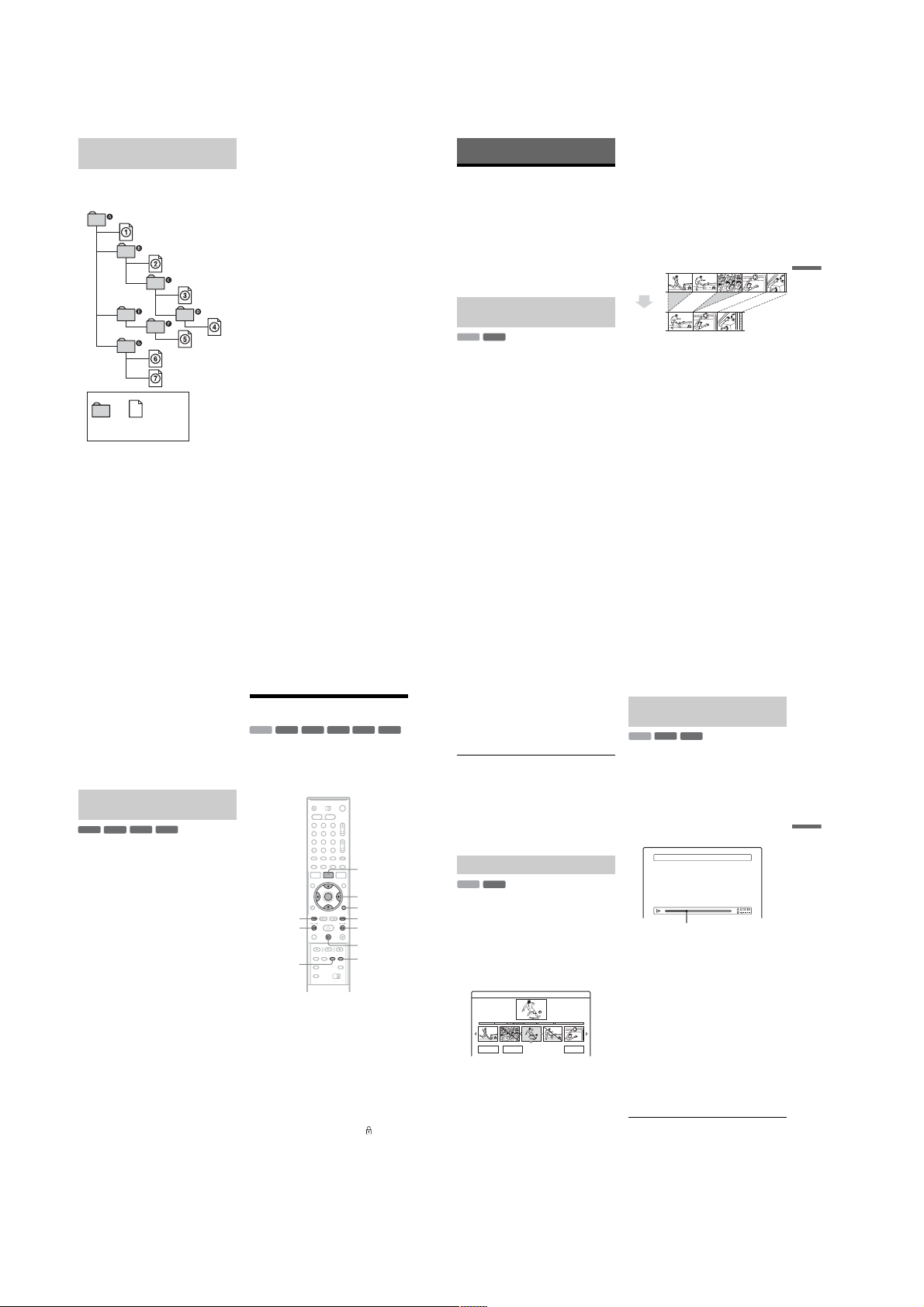
About playback order of albums,
tracks, and files
Albums play in the following order:
Structure of disc contents
Tree 1 Tree 2 Tree 3 Tree 4 Tree 5
ROOT
Album
MP3 audio track/
JPEG image file
When you insert a DATA CD/DATA DVD and
press H, the numbered tra cks (or files) are
played sequentially, from 1 through 7. Any
sub-albums/tracks (or file s) contained within a
currently selected album take priority over the
next album in the same tree. (Example: C
contains D so 4 is played before 5.) When you
press TITLE LIST and the list of album names
appears (page 35), the album names are arranged
in the following order: A t B t C t D t
F t G. Albums that do not con ta in tr acks (or
files) (such as album E) do not appear in the list.
z Hints
• If you add numbers (01, 02, 03, etc.) to the front of the
track/file names when you store the tracks (or fil es) in
a disc, the tracks and files will be played in that order.
• Since a disc with many trees takes longer to start
playback, it is recommended that you create album s
with no more than two trees.
b
Notes
• Depending on the software you use to create the DATA
DVD/DATA CD, the playback order may differ from
the above illustration.
• No more than a total of 199 individual folders can be
played. (Folders that do not contain JPEG/MP3 file s
are counted as well.)
• No more than a total of 999 folder s and files can be
played. (Files other than JPEG/MP3 files, and folders
that do not contain JPEG/MP3 files are counted as
well.)
• No more than 200 folders and files can be recognized
in a single folder. (Folders that do not contain JPEG/
MP3 files are counted as well.)
• Proceeding to the next or another album may take some
time.
• This recorder supports MP3 audio bit rates up to 160
kbps.
Erasing and Editing
Before Editing
This recorder offers various ed it options for
various disc types. Before you edit, check the disc
type in the front panel display, and select the
option available for your dis c (page 8) .
b
Notes
• You may lose the edited contents if you remove the disc
or a timer recording starts while editing.
• DVD discs created by DVD video cameras cannot be
edited on this recorder.
Edit options for the HDD and DVDRWs (VR mode)
-
RW
VR
HDD
You can enjoy advanced edit fu nctions. First you
have two options for the HDD and DVD-RWs
(VR mode): editing either the original recording
(called the “original”), or the playback
information created from the original (called a
“Playlist”). Since each is different in nature and
offers different merits, read the following and
select the one that better suits your needs.
To edit original titles
Edits made to the original titles are final. If you
plan to retain an unaltered original record ing,
create and edit a Playlist (see belo w ) . Th e edit
functions available for original titles are:
–Labelling a title (page 66).
–Setting protection agai nst erasure (page 66).
–Erasing a title (page 66).
–Erasing multiple titles (page 68).
–Erasing a section of a title (A-B Erase) (page 67).
–Erasing all titles on the disc (page69).
–Erasing a chapter (page 67).
–Dividing one title into two titles (HDD only)
(page 68).
To create and edit Playlist titles
A Playlist is a group of Playlist titles crea ted from
the original title for editing purposes. When you
create a Playlist, only the control information
necessary for playback, such as the playback
order, is stored on the disc. Si nce the orig inal title s
are left unaltered, Playlis t t it l es can be re-edited.
Example: You have recorded the final few
matches of a football tournament on a DVD-RW
(VR mode). You want to create a digest with the
goal scenes and other high lights, but you also want
to keep the original recording.
Original
Playlist
In this case, you can compile highlight scenes as a
Playlist title. You can even rearrange the scene
order within the Playlist title (“Creating and
Editing a Playlist” on page 70).
The advanced edit f unctions available for Playlist
titles are:
–Setting protection against erasure (HDD only)
(page 66).
–Labelling a title (page 66).
–Erasing a title (page 66).
–Erasing multiple titles (page 68).
–Erasing a section of a title (A-B Erase) (page 67).
–Rearranging th e ti t le order (DVD-RWs (VR
mode) only) (page 71).
–Dividing a title into multiple titles (page 68).
–Combining multiple titles into one title
(page 71).
–Erasing a chapter (page 67).
z Hint
You can display the disc’s Playlist titles in the Title List
(Playlist), or the original titles in the Title List (Original).
To switch the two Title Lists, press TOOLS while a Title
List is displayed, and select “Original” or “Playlist.”
Erasing and Editing
64
b
Notes
• The Playlist title calls up data from the original titles for
playback. When an original title is used for a Playlist
title, the original title cannot be erased.
• If a message appears and indicates that the disc’s
control information is full, erase or edit unnecessary
titles.
• Playlist titles containing titles recorded with the “CopyOnce” copy protection signal cannot be dubbed or
moved (page 73).
Edit options for DVD+RWs/DVDRWs (Video mode)/DVD+Rs/DVD-Rs
+
-
RW
RW
You can perform simple edits. Since Video mode
titles are actual recordings on the disc, you cannot
undo any edits you make. The edit functions
available for Video mode titles are:
–Setting protection again st erasure (page 66).
–Labelling a title (page 66).
–Erasing a title (page 66).
–Erasing multiple titles (page 68).
–Erasing a section of a title (A-B Erase)
(DVD+RWs only) (page 67).
–Erasing all titles on the disc (page 69).
–Erasing titles to open up disc space (Disc Map)
(DVD+RWs and DVD-RWs (Video mode)
only) (page 69).
b
Notes
• When editing a DVD+R or DVD-R, finish all editing
before finalizing the disc. You cannot edit a finalized
disc.
• The available disc space does not increase even when
you erase titles for DVD+Rs and DVD-Rs.
• If a message appears and indicates that the disc’s
control information is full, erase or edit unnecessary
titles.
-R+
Video
R
66
Erasing and Editing a Title
+
-
-
RW
VR
.
1 2 3
4 6
7 8 9
RW
5
0
HDD
RW
This section explai ns the basi c edit functio ns. Note
that editing is irreversible. To edit the HDD or
DVD-RWs (VR mode) wi t hout changing the
original recordings, create a Playlist title
(page 70).
CHAPTER
MARK
1
Press TITLE LIST.
For HDD titles or DVD-RWs in VR mode,
press TOOLS and select “Original” or
“Playlist” from the TOOLS menu to switch
the Title Lists, if necessary.
2
Select a title, and press ENTER.
The sub-menu appears.
3
Select an option, and press ENTER.
You can make the following edits to the title.
“Erase”: Erases the selected title. Select “OK”
when asked for confirmation.
“Protect”: Protects the title. Select “On” when
the Protection display appe ars. “” appears
next to the protected title. To cancel the
protection, select “Off.”
“Title Name”: Allows you to enter or re-enter
a title name (page 36).
“Set Thumbnail”: Changes the title’s
thumbnail picture that appears in the Title List
(page 34).
Video
-R+
R
TITLE LIST
</M/m/,,
ENTER
TOOLS
>
Mm
X
CHAPTER
MARK ERASE
“A-B Erase”: Erases a section of the title
(page 67).
“Delete Chapter”: Erases chapter units of the
title while viewing thumbnails (see below).
“Divide”: Divides a title into two titles
(page 68).
z Hints
• You can erase multiple titles at one time (page68), or
erase all of the titles on the disc at once (page 69).
• You can automatically erase titles that have already
played.
• You can label or re-label DVDs (page 38).
b Note
DVD-RW (VR mode) playlist titles cannot be protected.
Erasing a chapter (Delete Chapter)
-
RWVR
HDD
Thumbnails are displayed for each chapter. You
can easily select and erase a sec ti on in a title.
Note that erasing a chapter cannot be undone.
1 After step 2 of “Erasing and Editing a
Title,” select “Delete Chapter, ” and press
ENTER.
2 Select a thumbnail of the chapter using
</,, and press ENTER.
Delete Selected Chapters 9 World Sports
4(30)
Chapter
0:12:45
OK Cancel
• To cancel the selecti on, p ress EN TER agai n.
• To erase multiple chapters, repeat step 2.
• To reset all selections, select “Reset All.”
3 Select “OK,” and press ENTER.
The display asks for confirmation.
Reset All
4 Select “Yes,” and press ENTER.
,continued
Erasing a section of a title
(A-B Erase)
+
-
RWVR
RW
HDD
You can select a section (scene) in a title and erase
it. Note that erasing scenes in a title cannot be
undone.
1 After step 2 of “Erasing and Editing a
Title,” select “A-B Erase” and press
ENTER.
The display for setting point A appears.
• To return to the beginning of the title, press
X and then press ..
A–B Erase (Set point A) 5 Weather
Playback point
2 Select point A by pressing m/M, and
press ENTER.
The display for setting point B ap pears.
3 Select point B by pressing m/M, and
press ENTER.
The display asks for confirmation.
• To reset either point A or B, select “Change
A” or “Change B,” and go to step 2 or 3.
• To preview the title without scenes to be
erased, select “Preview” (except for
DVD+RWs).
4 Select “OK,” and press ENT ER.
The scene is erased, and the display asks
whether to erase anothe r scene.
• To continue, select “Yes,” and repeat from
step 2.
• To finish, select “No.”
z Hint
A chapter mark is inserted after the scene was erased. The
chapter mark divides the title into sepa r a te cha p t er s on
either side of the mark.
,continued
65
Erasing and Editing
67
1-16
Page 23
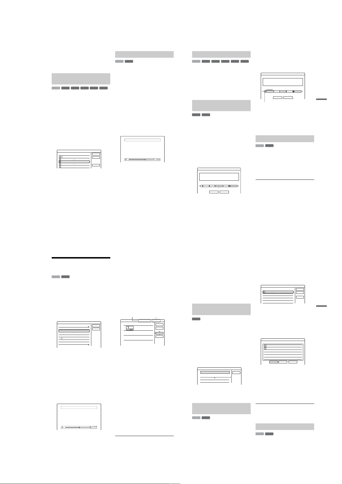
b
Notes
• Images or sound may be momentarily interrupted at the
point where you erase a section of a title.
• Sections shorter than five seconds may not be erased.
• For DVD+RWs, the erased section may be slightly
different from the points you selected.
Erasing multiple titles (Erase
Titles)
+
-
-
RW
VR
RW
HDD
RW
You can select and erase more than one title at one
time using the TOOLS menu.
Video
R
1 Press TITLE LIST.
2 Press TOOLS to select “Erase Titles,” and
press ENTER.
The display for selecting titles to be erased
appears.
3 Select a title, and press ENTER.
A check mark appears in the check box next to
the selected title.
• To clear the check mark, press ENTER
again.
• To clear all of check marks, select “Reset
All.”
Erase Titles
Select the titles to erase.
12
Tennis
11
Trav el
10
Mystry
9
World Sports
8
Family
4 Repeat step 3 to select all of the titles you
want to erase.
5 When you finish selecting titles, select
“OK,” and press ENTER.
The list of the titles to be erased appears for
confirmation.
• To change the selection, select “Change,”
and repeat from step 3.
6 Select “OK” and press ENTER.
The titles are erased.
68
28.10
Cancel
26.10
25.10
19.10
Reset All
17.10
Dividing a title (Divide)
*
-
RW
VR
HDD
If you want to dub a long title to a disc but do not
want to reduce the picture quality, divide the title
into two shorter titles. Note that dividing a title
cannot be undone.
* Only playlist titles can be divided for DVD-RW (VR
mode).
-R+
1 Press TITLE LIST.
Press TOOLS and select “Original” or
“Playlist” from the TOOLS menu to switch
the Title Lists, if necessary.
2 Select a title, and press ENTER.
The sub-menu appears.
3 Select “Divide,” an d press ENTER.
The display for setting th e dividing point
appears. The title starts to play in the
background.
• To return to the beginning of the title, press
X
and then press ..
Divide 1 Vacation
Erasing all titles on the disc
+
-
-
RW
VR
RW
HDD
RW
1 Press TOOLS to select “Disc Info,” and
press ENTER.
The “Disc Information” display appears.
Video
R
2 Select “Erase All,” and press ENTER.
3 Select “OK,” and press ENTER.
All titles on the disc are erased (except the
protected titles).
Erasing titles to open up disc
space (Disc Map)
+
-
RW
Video
RW
When recording on a DVD+RW or DVD-RW
(Video mode), the recorder searches for the largest
open space and records there. Before you start,
check the disc status by usi ng Disc Ma p, and e rase
titles to create a space large enough for the
recording.
1 Insert a disc and press TITLE LIST.
OK
4 Select the dividing point by pressing m/
M, and press ENTER.
The display asks for confirmation.
• To change the dividing point, select
“Change.”
5 Select “OK,” and pre ss ENTER.
The display for entering the title name
appears.
• To use the same title name as before, select
“No.”
6 Select “Yes,” and press ENTER to enter a
new name.
Follow the explanations on page 36. After you
enter a new name, the title is divide d in two.
2 Press TOOLS to select “Disc Map,” and
press ENTER.
The “Disc Map” display appears.
• To check the open space, select the space by
pressing </,.
Disc Map
Empty Title
HQ: 0H30M
HSP: 0H45M
LP : 1H30M
EP : 2H00M
Erase Cancel
• When
b
or B appears on either side of the
screen, you can scroll side w ays by pressing
<
/,.
SP : 1H00M
SLP: 3H00M
LSP: 1H15M
SEP: 4H00M
GB
2.3
3 Select a title by pressing </,, and
press ENTER.
-R+
The display for selecting titles to be erased
appears.
• To cancel the selection, press ENTER again.
• To erase more titles, repeat step 3.
Disc Map
2 Journey
17.9.2004 20:00 (1H00M) GBFri SP 0.6
Erase Cancel
Selected title
4 Select “Erase,” and press ENT ER.
The display asks for confirmation.
5 Select “OK,” and press ENT ER.
The selected titles are erased, freeing up disc
space.
• To change the selection, select “Change.”
Creating chapters manually
-
RW
VR
HDD
You can manually insert a chapter mark at any
point you like during playback or recording.
Press CHAPTER MARK at the poi nt where you
want to divide the title into chapters.
Each time you press the button, “Marking...”
appears on the screen a nd the sc enes t o the lef t and
right of the mark become separate chapters.
To erase chapter ma rks
You can combine two chapte rs by erasing the
chapter mark during playback.
./>
Press
while displaying the chapter containing the
chapter mark you want to erase, press CHAPTER
MARK ERASE.
The current chapter combines with the previous
chapter.
b
• When dubbing, any chapter marks you enter will be
• To insert a chapter mark manually during recording, set
to search for a chapter number, and
Notes
erased.
“Auto Chapter” in “Features” setup to “Off.”
Erasing and Editing
69
Creating and Editing a
Playlist
-
RWVR
HDD
Playlist edit allows you to edit or re-edit without
changing the actual reco rd ings . You ca n c reate up
to 97 Playlist titles.
b Note
Once you create a Playlist title from original titles, you
will be unable to erase or edit the original titles.
1 Press TITLE LIST .
2 Press TOOLS to select “Create Playlist,”
and press ENTER.
Create Playlist
Select a title to start capturing.
ORIGINAL
12
Tennis
11
Trav el
10
Mystry
9
World Sports
Family
8
Nature
7
3 Select the title you want to include in the
Playlist title, and press ENTER.
The sub-menu appears.
“Capture”: Adds a section of the title to the
Playlist title as one scene.
“Capture All”: Adds the entire title to the
Playlist title as one scene. After capturing the
title, go to step 8.
4 Select “Capture,” and pr ess ENTER.
The display for setting the start poin t (IN)
appears. The title starts to play in t he
background.
• To return to the beginning of the title, press
X and then press ..
Capture(Set IN point) 9 World Sports
70
Scene List
Cancel
28.10
26.10
25.10
19.10
17.10
15.10
5 Select the IN point by pressing m/M,
and press ENTER.
The display for setting the end point (OUT)
appears, and the title continues to play in the
background.
6 Select the OUT point by pressing m/M,
and press ENTER.
The display asks for confirmation.
To reset the IN or OUT point, select “Chang e
IN” or “Change OUT” and repeat step 5 or 6.
To view the selected scene , s el ect “Preview.”
7 Select “OK,” and ENTE R.
The Scene List menu appears with all of the
selected scenes.
Total duration of
Total duration of
the selected scene
the selected scene
1
• To add more scenes, select “Add” and go to
step 3.
• To preview all of the captured scenes in the
listed order, select “Preview.”
8 Select the sc ene you want to re-edit, and
press ENTER.
The sub-menu appears.
“Move”: Changes the scene order.
“Erase”: Erases the scene. The selection is
cancelled.
“Preview”: Displays thumbnail pictur es of the
scenes.
“Change IN”: Allows you to change the IN
point, and repeat from step 5.
“Change OUT”: Allows you to change the
OUT point, and repeat from step 6.
9 When you finish editing the Scene List,
select “OK,” and press ENTER.
The display for entering the title name
appears. To enter a new name, select “Enter”
(page 36).
10
Select “OK” to use the default name, and
press ENTER.
Total Scenes
World Sports
0:10:26 - 0:23:45
Total number of scenes
0:13:19 1Scene List
OK
Quit
Add
Preview
To play the Playlist title
Press TOOLS while the Title List menu is turned
on. Then, select “Playlist” and press ENTER.
When the Title List (Playlist ) menu appears , select
a title and press
z Hint
When a Playlist title is created, th e IN a nd O U T points
will become chapter marks, and each scene will become
a chapter.
b Note
The picture may pause when the edited scene is played.
H.
Moving a Playlist title (Change
Order)
-
RWVR
You can change the Playlist title order within the
Title List (Playlist).
1 Press TITLE LIST to turn on the Title List
(Playlist) menu.
If the Title List (Original) menu appears, pres s
TOOLS and select “Playlist.”
2 Select the title you want to move, and
press ENTER.
The sub-menu appears.
3 Select “Change Order,” and press ENTER.
Change Order
1 Vacation
Where do you want to move this title?
2 Journey
4 Select a new location for the title by
pressing M/m, and press ENTER.
The title moves to the new location.
Combining multiple Playlist titles
(Combine)
-
RWVR
HDD
1 Press TITLE LIST to turn on the Title List
(Playlist) menu.
If the Title List (Original) menu appears, pres s
TOOLS and select “Playlist.”
15.9
Cancel
17.9
2 Press TOOLS to sele ct “Combine,” and
press ENTER.
The display for selecting titles appears.
3 Select a title, and press ENTER.
A number indicating the order i n w hi ch you
selected the title appears.
To cancel the selection, press ENTER again.
Combine
Select the titles to combine.
4 Yacht 25. 9
1
3 Cruising 25. 9
2 Journey 17. 9
1 Vacation 15. 9
4 Repeat step 3 to select all of the titles you
want to combine.
To cancel all of the selections, se l ect “Reset
All.”
5 Select “OK,” and press ENT ER.
The list of titles to be combined appears.
To change the selection, select “Change” and
go to step 3.
Combine
Combine the titles in the following order.
4 Yacht 25. 9
1
3 Cruising 25. 9
2
OK Change Cancel
6 Select “OK,” and press ENT ER.
The display for selecting a title name from
among the selected titles appears .
To enter a new name, select “Enter Text,” and
follow the explanat i ons on page 36.
To change the selection, select “Change” and
go to step 3.
7 Select a name, and p ress ENTER.
The titles are combined.
b Note
When the number of chapters in the title to be combined
exceeds the limit, the chapters at the end are combined
into a single chapter.
Cancel
Reset All
OK
Dividing a Playlist title (Divide)
-
RWVR
HDD
You can divide a Playlist title. For operations, see
page 68.
Erasing and Editing
71
1-17
Page 24
Dubbing (HDD y DVD)
,
*
Before Dubbing
+
-
HDD
In this section, “dubbing” refers to “copying a
recorded title on the internal hard disk drive
(HDD) to another disc, or vic e versa.” You can
select to dub one title at a time (Title Dubbing –
see “Dubbing a single title (Title Dub)” on
page 7 4), or multiple titles all at once (Multiple
Title Dubbing – see “Dubbing multiple titles (Dub
Selected Titles)” on page 75).
Before you start, read the following precautions,
which are common to both dubbing methods.
If you want to record from a digital video camera
connected to the DV IN jack (RDR-HX710/
HX910 only), see “DV Dubbing (RDR-HX710/
HX910 only)” on page 77. To record from
equipment connected to the LINE IN jacks, see
“Recording from connected equipment without a
timer” on page 52.
Before you start…
• Select the disc type according to your needs
(page 8). This recorder can record on vario u s
discs.
• You cannot record both the main and sub sound
on a DVD+RW, DVD-RW (Video mode),
DVD+R, or DVD-R. For bilingual programs, set
“DVD Bilingual Rec.” to either “Main” (default)
or “Sub” in “Options” setup (page 94).
• Timer recordings and Synchro-Recording do not
start during dubbing. Before you start, check the
Timer List menu to see if there is any timer
recording due to start during dubbing.
• When “Auto Chapter” of “Features” setup is set
to “On,” chapter marks are automati cally
inserted at approximately 6- m i nut e intervals
while dubbing from the HDD to a DVD, or when
the recorder detects picture and sound changes
while dubbing from a DVD to the HDD. The
chapter marks in the dubbin g s ource are not
retained in the dubbed title.
RW
RW
72
+
-
VR
RW
Video
R
• For a title whose picture size (16:9 or 4:3) is
mixed:
–When dubbed from the HDD to DVD-RW
(Video mode) or DVD-R, the picture size is
determined by the setting in “DVD Rec.
Picture Size” (page 47).
–When dubbed from HDD to DVD+RW or
-
R
DVD+R, the picture size is always 4:3.
–When dubbed from HDD to DVD-RW (VR
mode), the originally recorded picture size is
retained.
z Hints
• When you dub a Playlist title, it is recorded as an
Original title.
• When dubbed from a DVD to the HDD, the picture size
and the sound types originally recorded are retained.
b
Notes
• To play a dubbed disc on other DVD equipment,
finalize the disc (page 39).
• The recorder may not function as described depending
on the disc status. Follow the instructions that appear on
the screen.
• You cannot dub from DVD VIDEOs to the HDD.
• Thumbnails that you have set for the originally
recorded title (page 34) will not be retained in the
dubbed title.
About “Dub Mode”
With this recorder, the recording mode for
dubbing is displayed as “Dub Mode.” Two
dubbing method are available: High-speed
Dubbing and Rec Mode Conversion Dubbing.
Read the following and sel ect according to the
required time, disc space, and picture quality.
Dubbing at high-speed (High-speed Dubbing)
+
-
, ////
RW
RW
HDD
-
Allows you to dub what you have s to re d in the
HDD to a high-speed DVD (8x-speed
DVD+RWs/6x-speed DVD-RWs/16x-speed
DVD+Rs/16x-speed DVD-Rs, or slower versions
of each disc type), without changing the recording
mode.
Set “Dub Mode” to “Fast” in “Title Dub” or “Dub
Selected Titles” display (page 74). You cannot
select “Fast” when titles that cannot be dubbed at
high speed are selec ted (such as the titles displaye d
in “Notes” below). The minimum required time is
as follows (approximate).
R
Required times for High-speed Dubbing from
HDD to DVD (for 60-minute programme)
Speed*26x 6x*38x*48x*42.4x
Rec.
mode
HQ 10 min. 10 min. 8 min. 8 min. 25 min.
HSP 6 min.
SP 5 min. 5 min . 3 min.
LSP 4 min. 4 min. 3 min. 3 min. 10 min.
LP 3 min.
EP 2 min.
SLP 1 min.
SEP 1 min.
*1
The values in the above table are for reference only.
Actual times for dubbing also require time for creating
disc’s control information and other data.
*2
This is the maximum recording speed of this recorder.
The value may vary depending on the disc condition.
Also, this recorder may be unable to record at the
maximum speed for discs that support recording
speeds exceeding the maximum value.
*3
The maximum drive speed of this record er is 6x when
using 6x-speed or faster DVD+RWs.
*4
The maximum drive speed of this record er is 8x when
using 8x-speed or faster DVD+Rs/DVD-Rs.
*5
High-speed dubbing is not available when dubbing
titles recorded in SLP and SEP mode to DVD+RWs
+
-
VR
RW
Video
R
and DVD+Rs.
b
Notes
• High-speed Dubbing is not available for the following
titles:
– Titles recorded in HQ+.
– Titles that contain both main and sub sounds (except
DVD-RWs (VR mode)).
– Titles recorded in mixed picture size (4:3 and 16:9
etc.), (except DVD-RWs (VR mode)).
• When dubbed to a DVD-RW (Video mode)/
DVD+RW/DVD+R/DVD-R, remnants of edited titles
may remain on the disc. If you ed it a title, use the Rec
Mode Conversion Dubbing method. This will smooth
out the pauses between the scenes.
• When dubbing to a DVD+R DL disc, the video may be
momentarily interrupted at th e point where the layers
switch.
Highspeed
DVDRW
40 sec.
20 sec.
30 sec.
40 sec.
15 sec.
High-
High-
speed
speed
DVD+
DVD-R
RW
6 min.
5 min. 5 min. 16 min.
40 sec.
45 sec.
3 min.
2 min.
20 sec.
30 sec.
2 min.
2 min. 2 min. 6 min.
30 sec.
1 min.
60
*5
15 sec.
min.
60
56 sec. 60
*5
min.
Highspeed
DVD+R
3 min.
45 sec.
2 min.
30 sec.
60
min.
min.
Rec Mode Conversion Dubbing
*1
Allows you to dub from the HDD to a DVD or vice
versa, in a dubbing mode that differs from the
DVD+R
original recordings. For example, when you dub
(Double
Layer)
an HQ title (data size is large) in SP mode , you can
reduce the data size, saving more titles using less
space.
Select a mode different from t he original rec ording
in “Dub Mode” in the steps of “Dubbing a single
40 sec.
title (Title Dub)” on page 74 or “Dubbing multiple
12 min.
titles (Dub Selected Titles)” on page 75.
30 sec.
When a title recorded to HDD in HQ or HQ+ mode
is converted to another mode, the re corder
automatically assigns an appr opriate bit rate, thus
8 min.
retaining the original picture quality as much as
20 sec.
possible.
15 sec.
b
The picture quality will not improve even if a title is
60
*5
*5
converted to a recording mode of better picture quality.
min.
60
Dubbing restric tion
*5
*5
min.
You cannot dub movies and other DVD Videos to
the HDD. Also, when dubbing from a DVD to the
HDD, a gray, blank screen will be recorded for
scenes that contain a copy protection signal.
* CPRM-compatible DVD-RWs (VR mode) only
+
n ////
Note
RW
-
R
HDD
HDD
Copy
protection
signals
Copy-Free
(No copy
protection
signal)
Copy-Once
CPRM (Content Protection for Recordable Media) is a
coding technology that protects copyrights for images.
HDD
-
RW
VR
Dubbing
,
-
RW
,
Video
+
RW
-
RW
-
-
RW
+
-
Video
R
VR
,continued
R
Dubbing (HDD y DVD)
RW
VR
+
R
73
Move
-
,
RW
HDD
Titles containing “Copy-Once” copy protection
signals can be moved only fr om HDD t o DVD RW (VR mode)* (after the title is moved, the
original title in the HDD is erased). The “Move”
function is performed using the same procedure as
dubbing (page 74). Titles containing “CopyOnce” copy protection signals are indicated with
b
• The following titles in the HDD cannot be moved.
– Protected titles
– Playlist titles
– Original ti tles referenced from the playlist
• If the move operation is stopped before completion, the
title in the HDD is not erased.
* CPRM-compati ble DVD- RWs ( V R m ode ) only.
VR
.
Notes
Dubbing
+
-
HDD
RW
RW
Dubbing a single title (Title Dub)
Insert the DVD that you are going to dub to
1
or from.
2
Press HDD or DVD to select the source.
3
Press TITLE LIST to turn on the Title List
menu.
4
Select a title, and press ENTER.
The sub-menu appears.
5
Select “Dubbing,” and p ress ENTER.
The display for selecting the dubbing mode
appears.
If a title with (page 74) is selected in the
title list, a confirmation screen is displayed.
To “Move,” select “Yes.”
Title Dub
This title will be dubbed. Set the dub mode.
1 World Cup Final SP
Dub Mode
GB
SP 2.0
A Size of the title (approximate)
B Direction of dubbing
C Available space on the disc to be
dubbed (approximate)
D Information about the title to be dubbe d
E Dubbing mode and the space that
remains after dubbing (approximate)
6
Select “Dub Mode.”
-
VR
RW
2.0 2.6
GB GB
Video
Rec Mode:
+
R
CancelStart
7 Select a dubbing mode by pressing M/m.
Fast*
HQ SPHSP LSP
-
R
* Appears when High-spe ed Dubbing is available
for the title (page 72).
8 Select “Start,” and press ENTER.
The dubbing indication appear s i n the front
panel display (page35).
To automatically a djust the dubbing mode
(Auto Dub Mode)
If there is not enough avai lable sp ace on the targ et
disc, the recorder automatically selects a dubbing
mode with lower picture quality according to the
available space. If there is insufficient disc space
in the selected dubbing mode, the following
display appears after step 8.
Title Dub
There is not enough memory for the dubbing.
Select "Auto Dub Mode" or adjust the mode.
Reset
Select “Auto Dub Mode” and press ENTER to
start dubbing. To manually select another dubbing
mode, select “Reset,” and go to step 7.
To stop dubbing
Press TOOLS to select “Stop Dubbing,” and press
ENTER. When asked for confirmation, select
“Yes,” and press ENTER.
z Hints
• If disc space is still insufficient for the selected dubbing
mode, erase unnecessary parts of the title, or free up
disc space by erasing titles on the disc (page 69).
• You can turn off the recorder during dubbing. The
recorder completes dubbing even after being turned off.
LPEPSLPSEP
CancelAuto Dub Mode
Dubbing multiple titles (Dub
Selected Titles)
A maximum of 30 selected titles can be dubbed at
once. You can select the dubbing mode for each
title.
1 Inser t the DVD that you are goi ng to dub to
or from.
2 Press HDD or DVD to select the source .
3 Press TITLE LIST to turn on the Title List
menu.
4 Press TOOLS to select “Dub Selected
Titles,” and press ENTER.
Select title(s) in the order you want to dub them.
ORIGINAL
5 Select titles in the order you want to dub,
and press ENTER.
The titles are numbered in the selected order.
To cancel the selection, press ENTER again.
If a title with (page 74) is selected in the
title list, a confirmation screen is displayed.
To “Move,” select “Yes.”
6 Repeat step 5 to select all of the titles you
want to dub.
To make adjustments for each of the titles,
select “Settings” (see “To adjust the settings
for each title” below). To cancel all of the
selections, select “Reset,” and go to st ep 5.
7 Select “Start,” and press ENTER.
The dubbing indicati o n appears in the front
panel display (page 35).
4
World Tour – Asia 3
3
World Cup Final
2
World Tour – Asia 2
1
World Tour – Asia 1
GB GBDub Selected Titles
0.0 4.6
25.6
20.6
18.6
11.6
Cancel
Settings
Start
Reset
Dubbing (HDD y DVD)
,continued
74
75
1-18
Page 25
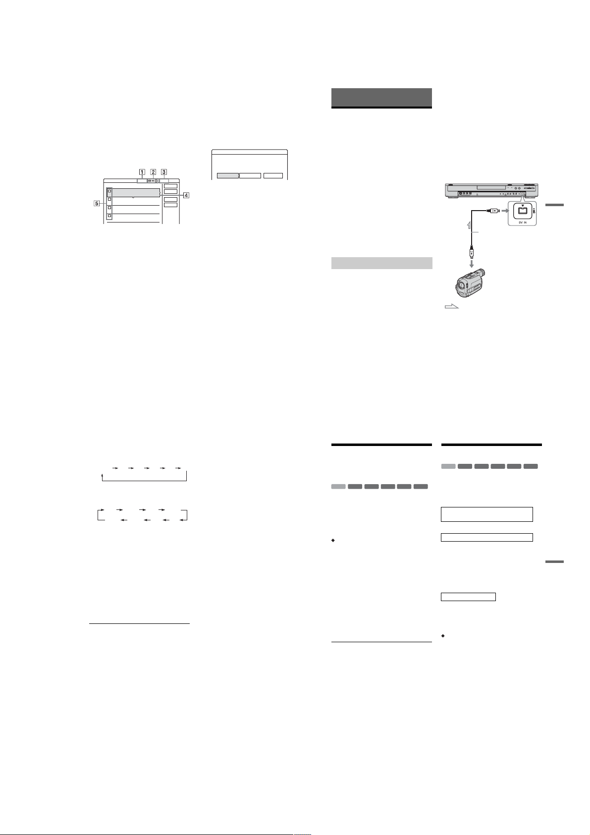
To adjust the settings for each title
You can make detailed settings for each of the
selected titles during Multiple Title Dubbing.
1
In step 6 of “Dubbing multiple titles (Dub
Selected Titles)” on page 75, select “Settings”
and press ENTER.
The following display for making the
adjustments appears.
To re-select titles, select “Change,” and go to
step 5 of “Dubbing multiple titles ( D ub
Selected Titles)” above. To have the recorder
adjust the dubbing mode so all of the selected
titles fit in, select “Auto mode.”
Dub Selected Titles
Adjust the settings for the dubbing here.
1
World Tour – Asia 1
2
World Tour – Asia 2
3
World Tour – Asia 3
4
World Cup Final
GB 4.6
2.1 GB
Dub Mode:Rec Mode:SP Fast GB0.3
Dub Mode:Rec Mode:SP Fast GB0.3
Dub Mode:Rec Mode:SP Fast GB0.3
Dub Mode:Rec Mode:SP Fast GB1.2
Start
11.6
Cancel
18.6
Auto mode
Change
25.6
20.6
1 Total size of the selected titles
2 Direction of dubbing
3 Available space on the disc to be
dubbed (approximate)
4 Information about the title to be dubbed
(title name, original recording mode,
dubbing mode, and data size after
dubbing)
5 Order of dubbing
2
Select the title which you want to adjust, an d
press ENTER.
The sub-menu appears.
“Dub Mode”: Selects the du bbi ng mode for
each title (page 72).
“Change Order”: Moves the title to change the
dubbing order. Press M/m to select a new
location, and press ENTER.
“Cancel”: Cancels the title selection. The title
is excluded from dubbing.
3
Select an option, and press ENTER.
4
When you finish making adjustments, select
“Start,” and press ENTER.
To automatically adjust the dubbing mode
(Auto Dub Mode)
If there is not enough available space on the target
disc, the recorder automatically selects a dubbing
mode with lower picture quality according to the
available space. The same dubb ing mode is set for
all of the titles. If disc space is insufficient for the
selected dubbing mode, the following display
appears after step 8 of “Dubbing multiple titles
(Dub Selected Titles)” on page 75.
Dub Selected Titles
There is not enough memory. Select
"Auto Dub Mode" or change the selection.
Change
CancelAuto Dub Mode
Select “Auto Dub Mode” and press ENTER. If
you have selected only one title, select “OK.”
To stop dubbing
Press TOOLS to select “Stop Dubb ing, ” and press
ENTER. When asked for conf i rmation, select
“Yes,” and press ENTER.
z Hints
• You can turn off the recorder during dubbing. The
recorder completes dubbing even after bein g turned off.
• You can start Multiple Title Dubbing by se lecting
“DUBBING” from the System Menu.
DV Dubbing
(RDR-HX710/HX910 only)
Before DV Dubbing
This section explains dubbing with a digital video
camera via the DV IN j ack on the front panel. If
you want to dub by way of the LINE IN jacks, see
“Recording from connecte d eq uipment without a
timer” on page 52.
To record from the DV IN jack
The DV IN jack on this recorder conforms to the
i.LINK standard. You ca n co nnect any other
equipment that has an i.LINK (D V ) ja ck, and
record digital signals.
Follow the instructions in “Prep aring for DV
dubbing,” and then move on to the sec t ion on
dubbing. For more information about i.LINK, see
“About i.LINK (RDR-HX710/HX910 only)” on
page 105.
z Hint
If you plan to do additional editing on a disc after the
initial dub, use the DV IN jack and record on a DVD-RW
(VR mode) or HDD.
Preparing for DV dubbing
You can connect a digi tal vi deo c amera to the D V
IN jack on the recorder to rec or d or edit from a
DV/Digital 8 format tape. Operation is
straightforward because th e rec order will fast
forward and rewind the tape for you – you do not
need to operate your digital video camera. Do the
following to start using the “DV Edit” functions of
this recorder.
See the instruction manual supplied with the
digital video camera as well befor e connecting.
b
Notes
• The DV IN jack is for input only. It will not output
signals.
• You cannot use the DV IN jack when:
– your digital video camera does not work with this
recorder. Connect the camera to the LINE IN jack
and follow the instructions of “Recording from
connected equipment without a timer” on page 52.
– the input signal is not in DV C-S D form at . Do not
connect a MICRO MV format digital video camera
even if it has an i.LINK jack.
– the images on the tape contain copy protection
signals, which limit recording.
• If you want to play the disc on other DVD equipment,
finalize the disc (page 39).
Hookups
i.LINK cable (not supplied)
DV output
: Signal flow
1 Press HDD or DVD to select the recording
destination.
If you select DVD, insert a disc (see “Inserting
a Disc” on page 29).
2 Insert the source DV/Digital 8 format tape
into your digital video camera.
For the recorder to record or ed it, your d igita l
video camera must be set to video playback
mode.
DVD recorder
to DV IN
Digital video camera
DV Dubbing (RDR-HX710/HX910 only)
76
3 Press INPUT SELECT on the remote
repeatedly to select “DV. ”
The front panel display changes as follows:
Programme
position
4 Pr ess RE C MODE on th e remo te re peat edly
to select the recording mode.
The recording mode chan ges as follows:
L2L1 L4L3 DV
HQ SPHSP
SEP EPSLP
For details about the recording m ode, see
page 41.
5 Press TOOLS on the remote to select “DV
Audio Input,” and pre ss ENTER. Then,
select the setting for the audio input.
“Stereo1” (default): Records original sound
only. Normally select this when dubbing a DV
format tape.
“Mix”: Records both stereo 1 and 2.
“Stereo2”: Records additional audio only.
Select “Mix” or “Stereo2” only if you ha ve
added a second audio cha nnel when rec ording
with your digital video camera.
You are ready to start dubbing. Select one of
the dubbing methods on the fo llowing pages.
z Hints
• You can turn off the recorder during dubbing. The
recorder completes dubbing even after being turned
off.
• You can adjust the settings for the recordin g picture
before recording. See “Adjusting the recording picture
quality and size” on page 47.
78
LSP
b Notes
• You cannot connect more than one piece of digital
video equipment to the recorder.
• You cannot control the recorder using another device
or another recorder of the same model.
• You cannot record date, time, or the contents of the
cassette memory onto the disc.
• If you record from a DV/Digital 8 format tape that is
recorded in multiple sound tracks, such as a tape with
multiple sampling frequencies (48 kHz, 44.1 kHz, or
32 kHz), no sound or an unnatural sound will be output
when playing back the sampling frequency switch
point on the disc.
• In order to use this recorder’s “Auto Chapter” setting
LP
(page 79), be sure to co rre c tly se t the clock on your
digital video camera before shooting.
• The recorded picture may be momentarily affected if
the picture size of the source imag e change s, or if t here
is nothing recorded on the tape.
Recording an Entire DV
Format Tape (One Touch
Dubbing)
+
-
RW
RWVR-RWVideo
HDD
You can record the entire con tents of a DV/
Digital 8 format tape onto a disc with a single
press of the ONE-TOUCH DUB button on the
recorder. The recorder cont rols the digital video
camera for the whole process, and completes the
recording.
How chapters are created
The contents dubbed to the HDD or DVD become
a single title. When “Auto Chapter” of “Features”
setup is set to “On,” this title is divided into
chapters. When dubbing to th e H D D or a DVDRW (VR mode), each shooting session on the tape
becomes a chapter on the disc. For other discs, the
recorder divides the title into chapters at
approximately 6-minute int ervals.
Follow steps 1 to 5 of “Preparing for DV
dubbing” on page 77, and press ONE-TOUCH
DUB on the recorder.
The recorder rewinds the tape and then starts
recording the tape contents.
When the recording is finished, the recorder
rewinds the tape in the digital vi deo camera.
To stop during recording
Open the remote’s cover and press x REC S TOP.
Note that it may take a few seconds for the
recorder to stop recording.
z Hints
• If you set “Finalize Disc” of “One Touch Dubbing” to
“Auto” in “Features” setup (page 93), the recorded disc
(except DVD-RW (VR mode)) will automatically be
finalized after recording is finished.
• You can play back a previously recorded title on the
HDD while One Touch Dubbing is in progress.
b Notes
• When a blank space between the recordings on the tape
continues for more than five minutes, One Touch
Dubbing ends automatically.
• The recorder records a blank for five minut es b efore it
stops dubbing. To stop the blank recording, press
x REC STOP.
-R+
R
,continued
Program Edit
+
-
RW
RWVR-RWVideo
HDD
You can select scenes f rom a DV /Digi tal 8 format
tape, and then automatically record selected
scenes to the HDD or a DVD.
To use this function, you will do the following:
Connect your digital video camera and
prepare for recording
m
Select and edit the scenes y ou want to dub
Using the recorder’s remote control, fast forward
or rewind the tape to select the scenes. At this
point, the selected scenes are not copied to the
disc. The recorder only remembers the IN and
OUT points of the scenes that you selected for
dubbing. You can also rese t, erase, or change the
order of the scenes.
m
Dub the selected scenes
After you have selected th e scenes, the recorder
will fast forward and rewind the ta pe
automatically and record the scenes to the HDD or
a DVD.
How chapters are created
The contents dubbed to the HDD or DVD become
a single title. When “Auto Chapter” of “Features”
setup is set to “On,” th is ti t le is di vi ded into
chapters. When dubbing to the HDD or a DVDRW (VR mode), each sh ooting sessio n on th e tape
becomes a chapter on the disc. For other discs, the
recorder divides the title into chapters at
approximately 6-minute intervals.
1 Follow steps 1 to 5 of “Preparing for DV
dubbing” on page 77, and press SYSTEM
MENU.
R
,continued
-R+
77
DV Dubbing (RDR-HX710/HX910 only)
79
1-19
Page 26
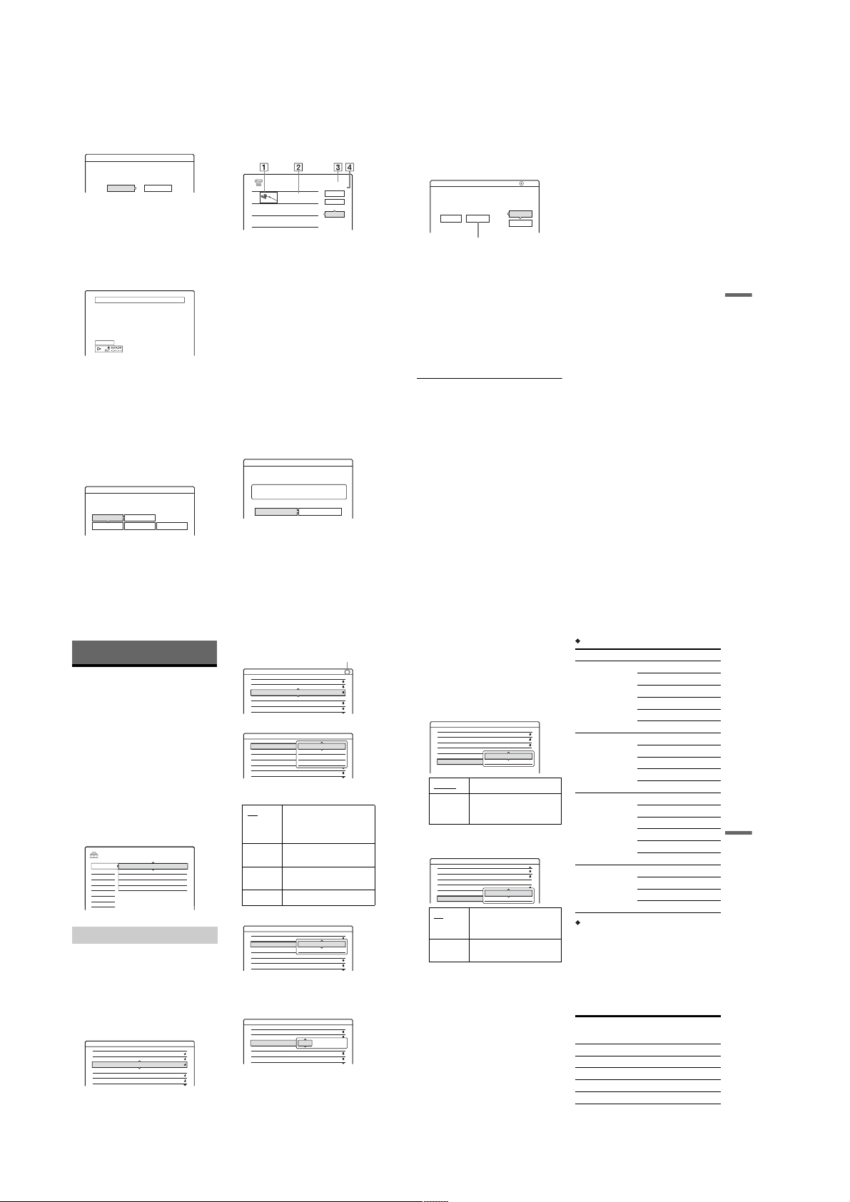
2
Select “DV EDIT,” and press ENTER.
The display asks if you want to start selecting
scenes.
Scenes Selection
Do you want to select a scene?
Start Cancel
• If you have previously saved a programme,
the display asks if you want to edit an
existing programme or to create a new
programme. To resume editing the existing
programme, select “Saved Data , ” and go to
step 6.
3
Select “Start,” and press ENTER.
The display for setting the IN point (start of
the scene) appears.
The scene starts to play in the bac kground.
Select scene(Set IN point)
Controlling...
4
Select the IN point by pressing m/M,
and press ENTER.
The display for setti ng the OUT p oi nt (e nd of
the scene) appears. The scene starts to play in
the background from the IN point.
5
Select the OUT point by pressing m/M,
and press ENTER.
The display asks if you want to add the
selected scene to the Scene List menu.
To preview the scene, select “Preview.”
To reset either the IN or OUT point, select
“Change IN” or “Change OUT, ” and repeat
from step 4.
Scenes Selection
Do you want to capture the scene
0:00:30between IN and OUT 0:00:52?
OK Cancel
Preview Change IN Change OUT
6
Select “OK,” and press ENTER.
A new Scene List menu appear s w ith the
selected scene.
To add a scene, select “Add.”
0:00:22
SCENE LIST
Tota l
Scenes
OK
Quit
Add
DV EDIT
0:00:30-0:00:52
1
0H00M22S
A Thumbnail picture
B Time information
C Total duration of the program
D Total number of scenes
7
When you finish adding scenes, select the
scene you want to e dit, and press ENTER.
The sub-menu appears.
“Move”: Changes the scene order. Follow the
explanations on the sc reen to ch ange the or der
by pressing M/m and ENTER.
“Erase”: Erases the scene. Wh en asked for
confirmation, select “OK.”
“Preview”: Plays the selected scene.
“Change IN”: Changes the start of the scene.
Repeat from step 4.
“Change OUT”: Changes the end of the scene.
Repeat from step 5.
8
When you finish editing the Scene List,
select “OK,” and press ENTER.
The display for entering the title name
appears. To enter a n ew na me, s el ect “Enter,”
and follow the explanations on page36.
Title Name
Enter the title name.
DV
11.10.03 13:30 - 12.11.03 16:46
OK Enter
9 Select “OK,” and press ENTER.
The default title name is fixed, and the display
asks if you want to start recordi ng.
To change the disc media, select “Media” and
press M/m. To change the dubbing mode,
select “Dub Mode” and press M/m.
1
DV Dubbing
Change the dubbing mode if necessary.
Select "Start" to start dubbing.
Media Dub Mode
DVD GB
SP 0.8
Data capacity required for the dubbing.
10
Select “Start,” and press ENTER.
The recorder starts recording the ta pe contents
as programmed.
• If the recording does not fit due to the
dubbing mode you selected, the display asks
if you want to continue.
To change the dubbing mode, select “Reset”
and repeat from step 9.
To have the recorder adjust the dubbing
mode, select “Auto Dub Mode.”
• If there is not enough disc space even after
changing the dubbing mode, th e di splay
asks if you want to record halfway.
To continue, select “OK.”
To stop during recording
Open the remote’s cover and press x REC S TOP.
Note that it may take a few seconds for the
recorder to stop recording.
b
Notes
• Contents recorded to the HDD or a DVD may not be
recorded as programmed if the tape’s time code is not
sequential or there are blanks between the reco rd ings
on the tape. In this case, see “Recording from
connected equipment without a timer” on page 52.
• The start and end points of a programme may be
different from what you have set if the source DV/
Digital 8 format tape is in any of the following
conditions:
– Recording mode was changed during the recording.
– There is a blank spa c e in th e recor de d portion of the
tape.
• If you set the beginning of the tape as the IN point and
the end point as the OUT point, the I N and OUT point s
may move slightly during dubbing.
• You cannot set a scene to be shorter than one second.
Cancel
2.6
GB
Start
DV Dubbing (RDR-HX710/HX910 only)
80
Settings and Adjustments
Aerial Reception and
Language Settings
(Settings)
The “Settings” setup helps you to make tuner,
clock, and programme positio n settings for the
recorder.
1
Press SYSTEM MENU while the recorder is
in stop mode.
2
Select “SETUP,” and press EN TER.
3
Select “Settings,” and press ENTER.
The options of “Settings” ap pear . T h e def au lt
settings are underlined.
To turn off the display, press SYSTEM
MENU repeatedly.
SETUP
Settings
Channel Setting
Video
Channel List
Audio
TV Guide Page
Features
Clock
Options
Language
Easy Setup
Channel Setting
Presets programme positio ns manually.
If some programme positi ons could not be set
using the “Easy Setup” function, you can set them
manually.
If there is no sound or if the picture is distorted, the
wrong tuner system may have been preset during
“Easy Setup.” Set the correct tuner system
manually in the steps below.
1
Select “Channel Setting” in “Settings,” and
press ENTER.
Settings - Channel Setting
System :
Normal / CATV :
Channel Set :
Station Name :
PAY - TV / CANAL+ :
Audio :
82
BG
Normal
3
C
AAB
Off
NICAM
81
2
Press PROG +/– to select the programme
position.
Settings - Channel Setting
System :
Normal / CATV :
Channel Set :
Station Name :
PAY - TV / CANAL+ :
Audio :
3
Select “System,” and press ENTER.
Settings - Channel Setting
System :
Normal / CATV :
Channel Set :
Station Name :
PAY - TV / CANAL+ :
Audio :
4
Select an availabl e TV system, BG, DK, I, or
L, and press ENTER (page 83).
BG Select this when in West
DK Select th is when in East
I Select this when in Great
Selected programme position
BG
Normal
2
C
CDE
Off
NICAM
BG
BG
Normal
DK
3
C
I
AAB
L
Off
NICAM
European countries, except
those listed in “Receivable
channels” on page 83.
8Prog.
8Prog.
European countries.
Britain/Ireland.
L Select this when in France.
5
Select “Normal/CATV,” and press ENTER.
Settings - Channel Setting
System :
Normal / CATV :
Channel Set :
Station Name :
PAY - TV / CANAL+ :
Audio :
6
Select “Normal,” and press ENTER.
To set CATV (Cable Television) channels,
select “CATV.”
7
Select “Channel Set,” and press ENTER.
Settings - Channel Setting
System :
Normal / CATV :
1Prog.
Channel Set :
Station Name :
PAY - TV / CANAL+ :
Audio :
BG
Normal
Normal
3
C
CATV
CDE
Off
NICAM
BG
Normal
3
C
C2
CDE
Off
NICAM
8Prog.
8Prog.
8 Press M/m repeat edly until the channel you
want is displayed, then press ENTER.
The channels are scanned in the order shown
in the table below.
• If you know the number of the channel you
want, press the number button s . Fo r
example, for channel 5, first press “0” and
then press “5.” Then press ENTER.
9 Select “Audio,” and press ENTER.
Settings - Channel Setting 8Prog.
System :
Normal / CATV :
Channel Set :
Station Name :
PAY - TV / CANAL+ :
Audio :
BG
Normal
C
CDE
Off
NICAM
5
5
NICAM
Standard
NICAM Normally, select this.
Standard Select this if the sound from
NICAM broadcasts is not
clear.
10 Select “NICAM,” and press ENTER.
11 Select “AFT” and press ENTER.
Settings - Channel Setting 8Prog.
Normal / CATV :
Channel Set :
Station Name :
PAY - TV / CANAL+ :
Audio :
AFT :
On
Off Allows you to adjust the
12 Select “On” to turn on AFT, and press
ENTER.
• If the Auto Fine Tuning function does not
work effectively, sel ect “Off” and press
ENTER. When the fine tuning bar appears,
press </, to obtain a clearer picture, and
press ENTER.
• To preset another channel, repeat from step
2.
Normal
5
5
C
CDE
Off
NICAM
On
Off
Turns on the Auto Fine
Tuning function. Normally,
select this.
pictures manually.
Receivable channels
TV system Channel coverage
BG (West European
Countries, except
those listed below)
E2 - E12 VHF
Italia A – H VHF
E21 – E69 UHF
S1 – S20 CATV
S21 – S41 HYPER
S01 – S05 CATV
DK (East European
Countries)
R1 – R12 VHF
R21 – R69 UHF
S1 – S20 CATV
S21 – S41 HYPER
S01 – S05 CATV
I (Great Britain/
Ireland)
Ireland A – J VHF
South Africa 4 – 13 VHF
B21 – B69 UHF
S1 – S20 CATV
S21 – S41 HYPER
S01 – S05 CATV
L (France) F2 – F10 VHF
F21 – F69 UHF
B – Q CATV
S21 – S41 HYPER
Tuning the French CATV channels
This recorder can scan the CATV channels B to Q
and the HYPER frequency channels S21 to S41.
On the Channel Set menu, the ch annels are
indicated as S1 to S44. For example, channel B is
indicated by Channel Set n umber S1, an d chann el
Q is indicated by Channel Set number S23 (see the
table below). If the CATV channel you want to
preset is indicated by its freq uency (for example,
152.75 MHz), refer to the table below to find the
corresponding channel number.
Channel
Corre-
sponding
channel
number
Set
Receivable
Frequency range
(MHz)
B S1 116.75–124.75
C S2 124.75–132.75
D S3 132.75–140.75
D S4 140.75–148.75
E S5 148.75–156.75
,continued
Settings and Adjustments
83
1-20
Page 27
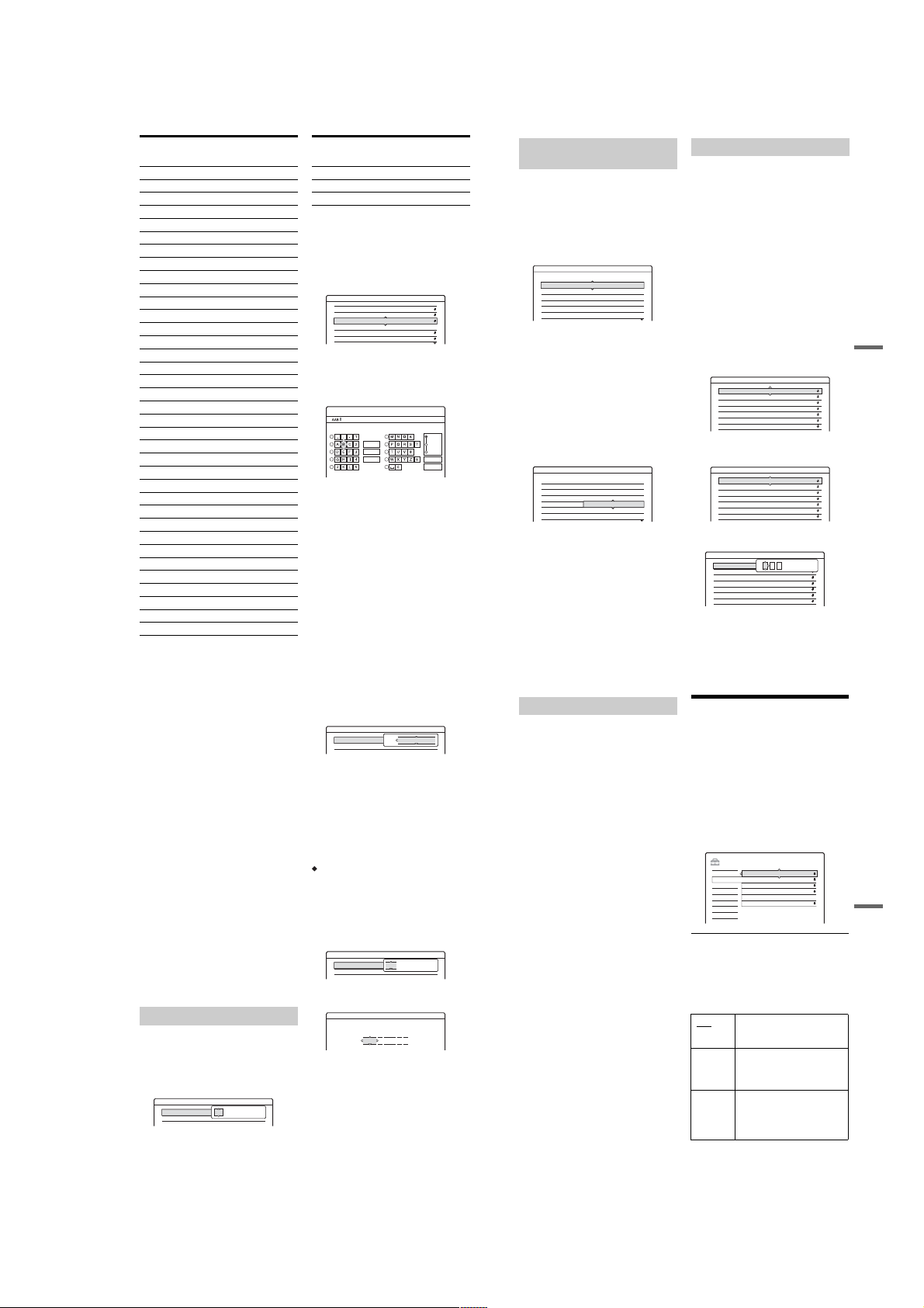
Channel
Corre-
sponding
channel
Set
number
F S6 156.75–164.75
F S7 164.75–172.75
G S8 172.75–180.75
H S9 180.75–188.75
H S10 188.75–196.75
I S11 196.75–204.75
J S12 204.75–212.75
J S13 212.75–220.75
K S14 220.75–228.75
L S15 228.75–236.75
L S16 236.75–244.75
M S17 244.75–252.75
N S18 252.75–260.75
N S19 260.75–268.75
O S20 268.75–276.75
P S21 276.75–284.75
P S22 284.75–292.75
Q S23 292.75–300.75
S21 S24 299.25–307.25
S22 S25 307.25–315.25
S23 S26 315.25–323.25
S24 S27 323.25–331.25
S25 S28 331.25–339.25
S26 S29 339.25–347.25
S27 S30 347.25–355.25
S28 S31 355.25–363.25
S29 S32 363.25–371.25
S30 S33 371.25–379.25
S31 S34 379.25–387.25
S32 S35 387.25–395.25
S33 S36 395.25–403.25
S34 S37 403.25–411.25
S35 S38 411.25–419.25
S36 S39 419.25–427.25
S37 S40 427.25–435.25
S38 S41 435.25–443.25
84
Receivable
Frequency range
(MHz)
Corre-
sponding
channel
Channel
number
Set
Receivable
Frequency range
(MHz)
S39 S42 443.25–451.25
S40 S43 451.25–459.25
S41 S44 459.25–467.25
Station Name
Changes or enters a new station name (up to 5
characters). The recorder must re ceive channel
information (for instance, SMARTLINK
information) for station names to appear
automatically.
1
Select “Channel Setting” in “Settings,” and
press ENTER.
Settings - Channel Setting
System :
Normal / CATV :
Channel Set :
Station Name :
PAY - TV / CANAL+ :
Audio :
2
Press PROG +/– to select the programme
position for which you want to change or enter
a station name.
3
Select “Station Name,” and press ENTER.
The display for ente ri ng characters appears.
Input Station Name
1
2
3
4
5
Clear All
BG
Normal
3
C
AAB
Off
NICAM
6
Back
7
8
9
Space
0
1Prog.
"A"
"a"
Symbol
Cancel
Finish
To enter characters, see page 36.
4
Select “Finish,” and press ENTER.
PAY-TV/CANAL+
Sets the PAY-TV/Canal Plus channels.
For details, see page 27.
Channel List (Changing/Disabling
the channels)
Changes or disables the progra mme positi ons after
setting the channels. If any programme positions
are unused or contain unwanted channels, you can
disable them.
You can also change station names. If the station
names are not displayed, you can enter them
manually.
1
Select “Channel List” in “Settings,” and press
ENTER.
Settings - Channel List
2
Press M/m to select the row cont ai ning the
programme position you w ant to change or
disable.
To change, press ENTER and go to step 3.
To disable, press CLEAR and go to ste p 5.
The disabled positions will be sk ipped when
you press PROG +/–.
To display other pages for pro gramme
positions 7 to 99, press M/m repeatedly.
3
Press M/m until the selected channel row
moves to the desired program m e position.
The selected channel is inse rt ed at the new
programme position.
Settings - Channel List
4
Press ENTER to confirm the setting.
5
To change or disable the programme position
of another station, repeat from step 2.
b
Note
Be sure to correctly select the programme position you
want to disable. If you disable the wrong programme
position by mistake, you need to reset that channel
manually.
Channel
C3
C5
C12
C21
C23
C24
Channel Name
C3
C12
C21
C5
C23
C24
Name
AAB
FGH
PQR
AAB
FGH
PQR
Prog
1
2
3
4
5
6
Prog
1
2
3
4
5
6
TV Guide Page
Some broadcast systems ensure a Teletext
service* in which the complete programmes and
their data (title, date, channel, recording start time,
etc.) are stored day by day. A TV guide page
corresponds to each day of the week. When
recording a programme, the recorder
automatically takes the programme n ame from the
Teletext pages and stores it as the title name. The
TV guide page numbers depend entirely on the
broadcast itself and may be subj ect to change. If
so, you may have to set those TV guide page
numbers manually in the TV Guide Page menu.
* Not available in some areas.
1
Select “TV Guide Page” in “Settings,” and
press , or ENTER.
The TV Guide Page menu appears.
2
Select the programme position for which you
want to set or change the TV gui de page by
pressing PROG +/–.
• The TV guide page numbers (Example:
P301) appear automatically w h en the
recorder detects them.
Settings - TV Guide Page
Sun P 301
Mon
Tue
Wed
Thu
Fri
Sat
• If no page numbers are det ected (P 000), y ou
have to set the appropriate TV guide p age
number manually.
Settings - TV Guide Page
Sun
Mon
Tue
Wed
Thu
Fri
Sat
3
Select the TV guide page number you want to
modify, and press ENTER.
Settings - TV Guide Page
Sun
Mon
Tue
Wed
Thu
Fri
Sat
P 000
P
0 0 0
P 000
P 000
P 000
P 000
P 000
P 000
Prog.
4
P 302
P 303
P 304
P 305
P 306
P 307
Prog.
P 000
P 000
P 000
P 000
P 000
P 000
P 000
4
4
Prog.
,continued
Settings and Adjustments
85
4
Press the number buttons or </M/m/, to
enter the TV guide page number, an d press
ENTER to confirm the setting.
• If you make a mistake, press CLEAR to reenter the correct nu m b er.
To set or change another TV guide page
number, repeat steps 3 and 4 a bove.
z Hint
To view Teletext information on your TV screen during
a broadcast, switch to your TV’s tuner by pressing
t TV/VIDEO.
b Notes
• In step 4 above, enter “000” if you do not want to use
the TV guide page number for automatic labelling. The
recorder will instead store a default title name
(programme position, start time - st op time).
• Refer to the Teletext information on your TV screen to
obtain the TV guide page number with programme
titles and their start times.
• If the Teletext TV guide has a page which always
shows the programmes for the current day, this page
should be input for all days.
• If you start recording more than three minutes before
the programme is scheduled to start, the correct label
information may not be transferred.
• Note that this function may not work correctly with
programmes broadcast from some stations.
• If the broadcast system updates the Teletext
information at the moment recording starts, the title
label may not correspond to the recorded programme .
In this case, you may have to manually enter the correct
title (page 36).
Clock
Auto Adjust
Turns on the Auto Clock Set function when a channel
in your local area broadcasts a time signal.
1 Select “Clock” in “Settings,” and press
ENTER.
2 Select “Auto Adjust,” and press ENTER.
Settings - Clock
Auto Adjust :
Present Time : 1. 1. 2004. 21:39Thu
Off 1
3 Select “On,” and pr ess ,.
4 Press M/m repeatedly until the programme
position of the station that carries a time sig nal
appears, and press ENTER.
Settings - Clock
Auto Adjust :
Present Time : 1. 1. 2004. 21:39Thu
• If the recorder does not receive a time signal
from any station, “Auto Adjust” returns to
“Off” automatically and the menu for setting
the clock manually appear s on the screen.
z Hint
If you set “Auto Adjust” to “On,” the Auto Clock Set
function is activated whenever the recorder is turned off.
b Note
The Auto Clock Set func tion does not work while the
recorder is standing by for Synchro-Recordin g.
To set the clock manuall y
If the Auto Clock Set function did not set the clock
correctly for your local area, try another station for
the Auto Clock Set function or set the c lo ck
manually.
1 Select “Clock” in “Settings,” and press
ENTER.
On 1
2 Select “Auto Adjust,” and press ENTER.
Settings - Clock
Auto Adjust :
Present Time : 1. 1. 2004. 21:39Thu
Off 1
3 Select “Off,” and press ENTER.
4 Select “Present Time,” and press ENTER.
Clock - Present Time
Set the time and date manually.
1 2005
0 00:
Sat 1
5 Press M/m to set the day, and press ,.
Set the month, year, hour, and minutes in
sequence. Press </, to select the item to be
set, then press M/m to set the numbers. The
day of the week is set automatically.
To change the numbers, press < to return to
the item to be changed, and press M/m.
6 Press ENTER to start the clock.
Language
OSD (On-Screen Display)
Switches the display language on the screen.
DVD Menu (DVD VIDEO only)
Switches the language for the DVD menu.
Audio (DVD VIDEO only)
Switches the language of the soun d t rack.
When you select “Original,” the language given
priority in the disc is selected.
Subtitle (DVD VIDEO only)
Switches the lan guage of the subt itl es r ecord ed on
the disc.
When you select “Audio Follow ,” the subtitle
language changes accord i ng to the language you
selected for the sound track.
z Hint
If you select “Others” in “DVD Menu,” “Subtitle,” or
“Audio,” select and enter a language code from
“Language Code List” on page 112 using the number
buttons.
b Note
If you select a language in “DVD Menu,” “Subtitle,” or
“Audio” that is not recorded on the DVD VIDEO, one of
the recorded languages will be automatically selected.
Video Settings (Video)
Video settings will adjust items related to the
image, such as size and colour .
Choose the settings acco rding to the type of TV,
tuner, or decoder connected to the DVD recorder.
1 Press SYSTEM MENU while the recorder is
in stop mode.
2 Select “SETUP,” a nd press ENTER.
3 Select “Video,” and press E NTER.
The “Video” setup appears with the following
options. The default settings are underlined.
SETUP
TV Type : 16 : 9
Settings
Video
Pause Mode :
Audio
Features
Options
Easy Setup
TV Type
Sets the picture size when playing back a title
recorded from 16:9 size vi de o (pa ge47) or a 16:9
size commercial DVD video.
Select the playback picture size according to the
type of connected TV (wide-screen/wide mode
TV or conventional 4:3 screen TV) .
16:9 Select this when co nnecting to a
4:3 Letter
Box
4:3 Pan
Scan
Auto
Component Out :
Off
Progressive Mode :
Auto
Scart Setting
Video
Line4 Input :
wide-screen TV or TV with a wide
mode function.
Select this when connecting to a
4:3 screen TV. Displays a wide
picture with bands on the upper
and lower portions of the screen.
Select this when connecting to a
4:3 screen TV. Automatically
displays a wide picture on the
entire screen and cuts off the
portions that do not fit.
Settings and Adjustments
86
,continued
87
1-21
Page 28
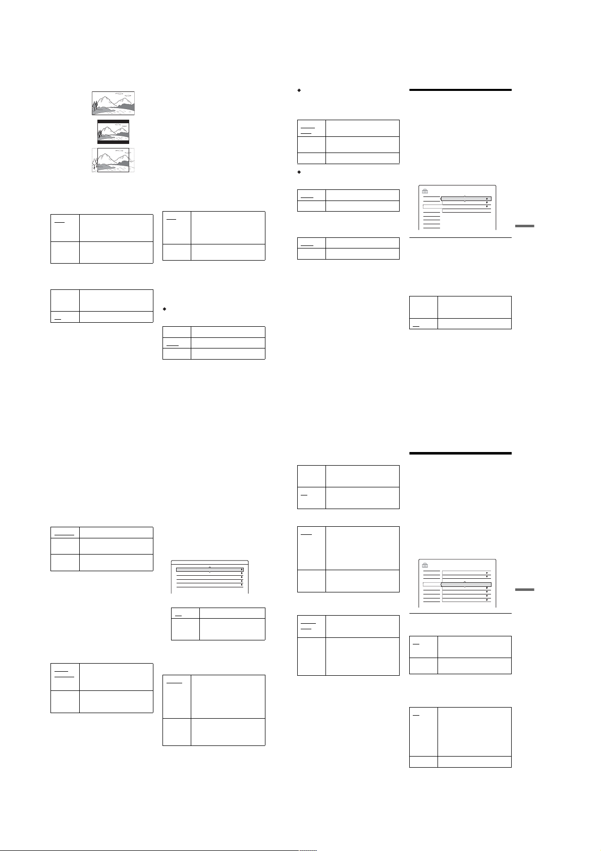
16:9
4:3 Letter Box
4:3 Pan Scan
b
Note
Depending on the disc, “4:3 Letter Box” may be selected
automatically instead of “4:3 Pan Scan” or vice versa.
Pause Mode (HDD/DVDs only)
Selects the picture quality in pause mode.
Auto The picture , including subjects
that move dynamically, is outpu t
with no jitter. Normally select thi s
position.
Frame The picture, including subjects
that do not move dynamically, is
output in high resolution.
Component Out
Selects whether or not to output vi deo signals
from the COMPONENT VIDEO OUT jacks.
On Outputs the component video
signals. Select this when you want
to view progressive signals.
Off
Outputs no signals.
b
Notes
• When you set “Line1 Output” to “RGB,” you cannot
set “Component Out” to “On.”
• When you connect the recorder to a monitor or
projector via only the COMPONENT VIDEO OUT
jacks, do not select “Off.” If you select “Off” in this
case, the picture may not appear.
88
Progressive Mode
DVD software can be divided into two types: film
based software and video ba sed software. Video
based software is derived fr om TV, such as
dramas and sit-coms, and dis pl ays images at 30
frames/60 fields (25 frame s/50 fiel ds) pe r secon d.
Film based software is derived from film and
displays images at 24 frame s per second. Some
DVD software contains both V ideo and Film.
In order for these images to appear natu ral on your
screen when output in PROGRESSIVE mode (50
or 60 frames per second), the progressive video
signal needs to be converted to match the type of
DVD software that you are watc hi ng.
You can fine-tune the progressiv e 525p/625p
video signal that is output when you press
PROGRESSIVE (“PROGRESSIVE” lights up).
Note that you must connect to a pr ogressive
format TV using the COMPONENT VIDEO OUT
jacks (page 14).
Auto Automatically detects the software
type (Film-based or Video-based)
and selects the appropriate
conversion mode. Normally select
this position.
Video Fixes the conversion mode to the
mode for Video-based software.
Scart Setting
Sets the method of inputting/outputting signals
from the SCART jacks on the rear panel of the
recorder. Select an option for each of the items
below according to the combination of jacks and
methods that you are going to us e.
Line1 Output
Selects a method of outputtin g vi deo signals for
the LINE 1 – TV jack.
RGB Outputs RGB signals.
Video
Outputs video signals.
S Video Outputs S-video signals.
b
Notes
• If your TV does not accept S-video or RGB signals, no
picture appears on the TV screen even if you select “S
Video” or “RGB.” See the instructions supplied with
your TV.
• You cannot select “RGB” when “Component Out”
above is set to “On.”
• SMARTLINK is available only when “Video” is
selected.
Line3 Input
Selects a method of inputting video signals for the
LINE 3/DECODER jack. The picture will not be
clear if this setting does not match the type of
video input signal.
Video/
Inputs video signals or RGB
signals.
RGB
Decoder Select this when connecting to a
PAY-TV/Canal Plus decoder.
S Video Inputs S-video signals.
Line3 Output
Selects a method of outputting video signals for
the LINE 3/DECODER jack.
Video
Outputs video signals.
S Video Outputs S-video signals.
Line4 Input
Selects a method of inputting video signals for the
LINE 4 IN jack on the rear panel of th e recorder.
Inputs video signals.
Video
S Video Inputs S-video signals.
Audio Settings (Audio)
The “Audio” setup allows you to adjust th e sou nd
according to the playback and connection
conditions.
1 Press SYSTEM MENU while the recorder is
in stop mode.
2 Select “SETUP,” a nd press ENTER.
3 Select “Audio,” and press ENTER.
The “Audio” setup appears w ith the f ollowing
options. The default settings are underlined.
SETUP
Settings
Video
Audio
Features
Options
Easy Setup
Audio ATT (attenuation)
If the playback sound is distorted, set this item to
“On.” The recorder reduces the audio output level.
This function affects the output of the following
jacks:
–LINE 2 OUT R-AUDIO-L jacks
–LINE 1 – TV jack
–LINE 3/DECODER jack
On S elect this when the play back
Off
OffAudio ATT :
Audio DRC :
Standard
Downmix :
Dolby Surround
Audio Connection
sound from the speakers is
distorted.
Normally select this position.
,continued
Settings and Adjustments
89
Audio DRC (Dynamic Range Control) (DVDs
only)
Makes the sound clear when the volume is turned
down when playing a DVD that conforms to
“Audio DRC.” This affects the output from the
following jacks:
–LINE 2 OUT R-AUDIO-L jacks
–LINE 1 – TV jack
–LINE 3/DECODER jack
–DIGITAL OUT (OPTICAL or COAXIAL) jack
only when “Dolby Digital” is set to “D-PCM”
(page 90).
Standard Normally select this position.
TV Mode Makes low sounds clear even if
you turn the volume down.
Wide
Gives you the feeling of being at a
Range
live performance.
Downmix (DVDs only)
Switches the method for mixing down to two
channels when you play a DVD which has rear
sound elements (channels) or is recorded in Dolby
Digital format. For details on the rear signal
components, see “4. Displaying the Playing Time
and Play Information” on page 34. This function
affects the output of the following jacks:
–LINE 2 OUT R-AUDIO-L jacks
–LINE 1 – TV jack
–LINE 3/DECODER jack
–DIGITAL OUT (OPTICAL or COAXIAL) jack
when “Dolby Digital” is set to “D-PCM”
(page 90).
Dolby
Normally select this position.
Multi-channel audio signals are
Surround
output to two channels for
enjoying surround sounds.
Normal Multi-channel audio signals are
downmixed to two channels for
use with your stereo.
Audio Connection
The following setup items switch the method of
outputting audio signals when you connect a
component such as an amplifier (receiver) with a
digital input jack.
For connection details, see “Step4: Connecting
the Audio Cords” on page 17.
Select “Dolby Digital,” “MPEG,” “DTS,” and
“48kHz/96kHz PCM” after setting “Digital Out”
to “On.”
If you connect a component that does not accept
the selected audio signal, a lou d noise (or no
sound) will come out from the speakers, and may
affect your ears or cause spe aker damage.
1
Select “Audio Connection” in “Audio,” and
press ENTER.
Audio - Audio Connection
Digital Out : On
2
Select “Digital Out,” and press ENTER.
D-PCM
Dolby Digital :
MPEG : PCM
DTS :
Off
48kHz/96kHz PCM : 48kHz/16bit
On N ormally select this p osition.
Off The influence of the digital
circuit upon the analogue
circuit is minimal.
3
Select “On,” and press ENTER.
4
Set the digital output signal.
• Dolby Digital (HDD/DVDs only)
Selects the type of Dolby Digital si gnal.
D-PCM
Select this when the recorder is
connected to an audio component
lacking a built-in Do lby Digital
decoder. The surround effects of
output signals are determined by
the “Downmix” setting item in
“Audio” setup.
Dolby
Select this when the recorder is
Digital
connected to an audio component
with a built-in Dolby Digital
decoder.
• DTS (DVD VIDEO only)
Selects whether or not to output D T S s ignals.
On Select this when the recorder is
connected to an audio component
with a built-in DTS decoder.
Off
Select this when the recorder is
connected to an audio component
without a built-in DTS decoder.
• MPEG (DVD VIDEO only)
Selects the type of MPEG au dio signal.
PCM
Select this when the recorder is
connected to an audio component
without a built-in MPEG decoder.
If you play MPEG audio sound
tracks, the recorder out p u t s s tereo
signals via the DIGITAL OUT
(COAXIAL) jack.
MPEG Select this when the recorder is
connected to an audio component
with a built-in MPEG deco der.
• 48kHz/96kHz PCM (DVD VIDEO only)
Selects the sampling frequency of the audio
signal.
48kHz/
The DVD video audio signal is
converted to 48kHz/16bit and
16bit
output.
96kHz/
All signals containing 96kHz/
24bit
24bit are output without
conversion. However, the signals
are output at 48kHz/16bit if
copyright-protected signals are
contained.
b Notes
•“48kHz/96kHz PCM” setting has no effect when audio
signals are output from the LINE 2 OUT (R-AUDIOL) jacks. If the sampling frequency is 96kHz, signals
are simply converted to 96kHz analog signals and
output.
• When you use the DIGITAL OUT (COAXIAL) jack to
listen to MPEG audio signals and set “MPEG” to
“MPEG” in “Audio” setup, no sound will come from
your speakers if you select one of the TVS modes.
Recording and Parental
Control Settings (Features)
The “Features” setup allows you to adjus t
recording and parental cont ro l settings.
1 Press SYSTEM MENU while the recorder is
in stop mode.
2 Select “SETUP,” and press ENTER.
3 Select “Features,” and press ENTER.
The “Features” setup appears with the
following options. The default settings are
underlined.
SETUP
TV Direct Rec :
Settings
Video
Audio
Features
Options
Easy Setup
TV Direct Rec (HDD/DVD+RW/DVD-RW/
DVD+R/DVD-R only)
On Allows you to easily record what
Off Turns off the TV Direct Rec
Auto Chapter
Selects whether to automatically divide a
recording (a title) into chapters during recording
or dubbing.
On
Off No chapter mark is inserted.
On
On
Auto Chapter :
Parental Control
One Touch Dubbing
Record to HDD
Synchro Rec
HQ Setting
HQ
Colour System
PAL
Screen Saver
On
you are watching on the TV using
SMARTLINK.
function.
For the HDD or a DVD-RW (VR
mode), the recorder detects
changes in the picture and sound
and automatically inserts chapter
marks.
For other recordable discs, the
recorder inserts chapter mark s at
approximately 6-minute intervals.
Settings and Adjustments
90
,continued
91
1-22
Page 29
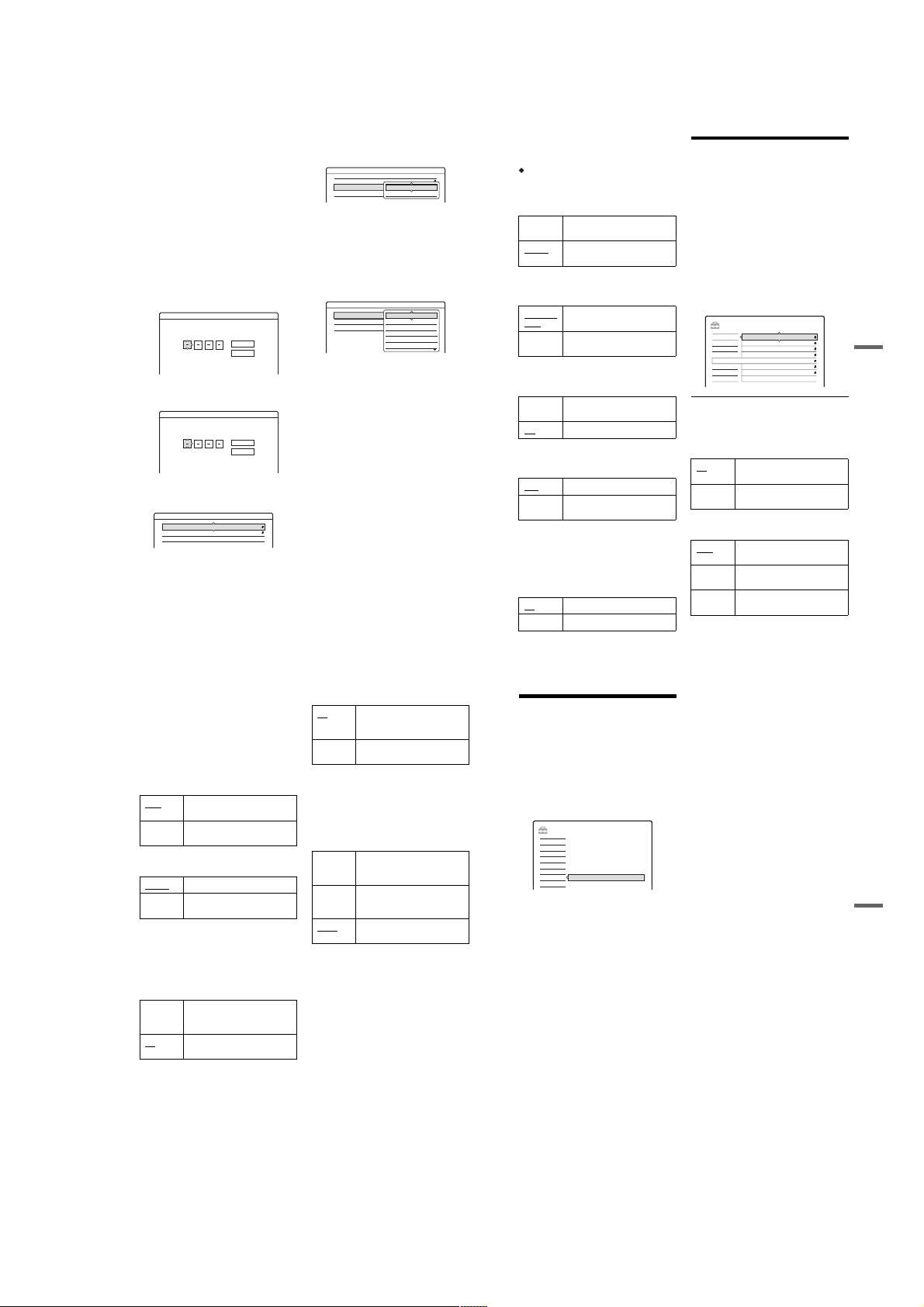
b
Notes
• The actual chapter mark interval may vary depending
on the amount of information contained in the video to
be recorded.
• Chapter marks are automatica lly inserted where the
recordings start on the tape when “Auto Chapter” is set
to “On” during DV dubbing (RDR-HX710/HX910
only) to the HDD or a DVD-RW (VR mode).
Parental Control (DVD VIDEO only)
Playback of some DVD VIDEOs can be limited
according to a predetermined level, such as the age
of the users. Scenes may be block ed or replaced
with different scenes.
1
Select “Parental Control” in “Features,” and
press ENTER.
• If you have not entered a password, the
display for registering a new password
appears.
Features - Parental Control
Enter a new password.
OK
Cancel
• When you have already registered a
password, the display for entering the
password appears.
Features - Parental Control
Enter your password.
OK
Cancel
2
Enter your four-digit pass w ord using the
number buttons, then select “OK” and press
ENTER.
Features - Parental Control
Level : Off
Standard : USA
Password
92
3
Select “Standard,” and press , or ENTER.
The selection items for “Standard” are
displayed.
Features - Parental Control
Level : Off
Standard : USA
Password
4
Select a geographic area as the playback
limitation level, and press ENTER.
The area is selected.
• When you select “Others,” press the number
buttons to select and enter an ar ea code in
the table (page 112). Then select “OK” and
press ENTER.
5
Select “Level,” and press ENTER.
The selection items for “Level” are displayed.
Features - Parental Control
Level :
Standard :
Password
The lower the value, the stricter the limitation.
Discs rated higher than the selected level will
be restricted.
6
Select the level, and press ENTER.
The Parental Control setting is complete.
To cancel the Parental Control setting for the
disc, set “Level” to “Off” in step 6.
To change the password, select “Password” in
step 3, and press ENTER. When the display
for registering a password appear s, en ter a
new four-digit password using the number
buttons, then select “OK” and press ENTER.
b
Notes
• If you forget your password, you will have to reset it by
selecting “Parental Control” of “Fac tory S et up” in
“Options” setup (page 94).
• When you play discs which do not have the Parental
Control function, playback cannot be limited on this
recorder.
• Depending on the disc, you may be asked to change the
Parental Control level while playing the disc. In this
case, enter your password, then change the level.
USA
Others
Off
8
7
6
5
4
One Touch Dubbing (RDR-HX710/HX910 only)
Displays the following options for the One Touch
Dub function.
Finalize Disc (for all recor dable discs except
DVD-RW in VR mode)
Selects whether or not to finalize the disc
automatically following One Touch Dubbing
(page 79).
Auto Automatically finalizes the disc
following One Touch Dubbing.
Manual
Allows you to finalize the disc
manually.
Synchro Rec
Selects the recording destination used for
Synchro-Recording (page 50).
Record to
Records to the HDD.
HDD
Record to
Records to DVDs.
DVD
HQ Setting (HDD only)
Selects the HQ mode used for recording on the
HDD (page 41).
HQ+ Records in higher quality
(approximate 15 Mbps).
HQ Records in the standard HQ mode.
Colour System
Selects the colour system when playing VIDEO
CDs (including Super VIDEO CDs).
Plays a disc in PAL colour system.
PAL
NTSC Plays a disc in NTSC colour
system.
Screen Saver
The screen saver image appears when you do not
use the recorder for more than 10 minutes while an
on-screen display, such as the System Menu, is
displayed on your TV screen. The screen saver
image helps prevent your display device from
becoming damaged (ghosting) .
Turns on the screen saver function.
On
Off Turns off the function.
Disc and Remote Control
Settings/Factory Settings
(Options)
The “Options” setup allows you to set up other
operational settings.
1 Press SYSTEM MENU while the recorder is
in stop mode.
2 Select “SETUP,” and press ENTER.
3 Select “Options,” and press ENTER.
The “Options” setup appears wi t h the
following options. The default settings are
underlined.
SETUP
Format DVD-RW : VR
Settings
HDD Bilingual Rec. :
DVD Bilingual Rec. :
Dimmer :
Power Save :
Auto Display :
Command Mode :
Factory Setup
Main
Main
Normal
Off
On
DVD3
,continued
Video
Audio
Features
Options
Easy Setup
Format DVD-RW (DVD-RW only)
The recorder automatically starts formatting in
VR mode or Video mode, whic hever is selected
below, when a new, unformatted DVD-RW is
inserted.
VR Automatically formats the disc in
VR mode.
Video Automatically formats the disc in
Video mode.
HDD Bilingual Rec. (HDD only)
Selects the sound to be recorded on the HDD.
Main Records the main sound for the
bilingual programme.
Sub Records the sub sound for the
bilingual programme.
Main+Sub Records the main and sub sounds
for the bilingual programme.
Settings and Adjustments
93
b Note
If you set the recording mode to be changed while
dubbing from a DVD to the HDD, the sound recorded in
the source (DVD) is applied regardless of this setting.
DVD Bilingual Rec. (for all recordable discs
except DVD-RW in VR mode)
Selects the sound to be recorded on the recordable
disc. This setting is not necess ary wh en reco rdin g
on DVD-RWs (VR mode) that record both the
main and sub sounds.
Main Records the main sound for the
bilingual programme.
Sub Records the sub sound for the
bilingual programme.
Dimmer
Adjusts the lighting of the front panel display.
Normal
Bright lighting.
Power
Low lighting. Turns off the
Save
lighting when the power is off.
b Note
When “Power Save” in “Options” setup is set to “On,”
the front panel display is turned off during standby
regardless of this setting.
Power Save
Selects whether this recorder is in pow er save
mode when the power is turned off (standby).
On Sets to power save mode. The
front panel display is off when the
recorder is in standby.
Off Does not set to power save mode.
Normally, select this.
b Notes
• Power Save mode does not function in the following
cases, even when “Power Save” is set to “On
– Synchro Recordi ng is se t.
– there is a timer setting with “PDC/VPS” set to “On”
in the Timer List.
• The SMARTLINK features are not available when
“Power Save” is set to “On
.”
.”
Auto Display
On Automatically displays
information on the screen when
the recorder is turned on, etc.
Off Displays information only when
DISPLAY is pressed.
Command Mode
Changes the Command Mode of the recorder if
other DVD equipment is assigned the same
Command Mode. Be sure to match the Command
Mode switch on the remote to the setting made
here. For details, see “If you have a Sony DVD
player or more than one Sony DVD recorder” on
page 21.
DVD1 Select this if the default Command
Mode conflicts with other DVD
equipment.
DVD2 Select this if the default Command
Mode conflicts with other DVD
equipment.
DVD3
The default Command Mode of
the recorder.
Factory Setup
Allows you to select the setup settings by group,
and return them to their default settings. Not e that
all of your previous settings wi ll be lost.
1 Select “Factory Setup” in “Options,” and
press , or ENTER.
The display for selecting a group of settings
appears.
2 Select the group of settings you want to return
to default from “Settings,” “Video,” “Audio,”
“Features,” “Options,” “Parental Control,”
and “All,” and press , or ENTE R.
3 Select “Start,” and press ENTER.
The selected settings return to their default
settings.
4 Press ENTER when “Finish” appears.
Easy Setup
(Resetting the Recorder)
Select this to run the “Easy Setup” programme.
1 Press SYSTEM MENU while the recorder is
in stop mode.
2 Select “SETUP,” and pr ess ENTER.
3 Select “Easy Setup,” an d press ENTER.
SETUP
Settings
Video
Audio
Features
Options
Easy Setup
Easy Setup
4 Press ENTER.
5 Select “Start.”
6 Follow the instructions for “Easy Setup”
(page 22) from step 2.
Settings and Adjustments
94
95
1-23
Page 30

Additional Information
Troubleshooting
If you experience any of the following difficulties
while using the recorder, use this troubleshooting
guide to help remedy the problem bef ore
requesting repairs. Should any problem persist,
consult your nearest Sony dealer.
Power
The power does not tu rn on.
, Check that the mains lead is connected securely.
Picture
There is no picture.
, Re-connect all connecting cords securely.
, The connecting cords are damaged.
, Check the connection to your TV (page 13).
, Switch the input selector on your TV (such as to
“VCR”) so that the signal from the recorder
appears on the TV screen.
, Check that “Scart Setting” in “Video” setup is set
to the appropriate item that conforms to your
system (page 88).
, If you connect the recorder to your TV via only
the COMPONENT VIDEO OUT jacks, set
“Component Out” in “Video” setup to “On”
(page 88).
, This recorder cannot record NTSC signals.
Picture noise appears.
, If the picture output signal from your recorder
passes through your VCR to get to your TV, or if
you are connected to a combi nation TV/VIDEO
player, the copy-protection signal applied to
some DVD programmes could affect picture
quality. If you still experience this problem even
when you connect your recorder directly to your
TV, try connecting your recorder to your TV’s S
VIDEO input.
, You have set the recorder to progressive format
(the PROGRESSIVE indicator lights up) even
though your TV cannot accept the progressive
signal. In this case, press PROGRESSIVE until
the PROGRESSIVE indicator turns off.
, Even if your TV is compatib le with progressive
format (525p/625p) signals, the image may be
affected when you set the recorder to progressive
format. In this case, press PROGRESSIVE so
that the PROGRESSIVE indicator turns off and
the recorder is set to normal (interlace) format.
, You are playing a DVD recorded in a colour
system that is different from your TV.
, Noises may appear in the pictures recorded on
the HDD, which is due to the characteristics of
HDD, and is not a malfunctio n.
TV programme reception does not fill the
screen.
, Set the channel manually in “Channel Setting” in
“Settings” setup (page 82).
, Select the correct source using the INPUT
SELECT button, or select a channel of any TV
programme using the PROG +/– buttons.
TV programme pictur es are distorted.
, Reorient the TV aerial.
, Adjust the picture (see the TV’s instruction
manual).
, Place the recorde r and TV farther apart.
, Place the TV and any bunched aerial cables
farther apart.
, The RF cable is connected to the AERIAL OUT
jack on the recorder. Connect the cable to the
AERIAL IN jack.
TV channels cannot be c hanged.
, The channel is disabled (page 85).
, A timer recording started, which changed the
channels.
The picture from equip ment connected to the
recorder’s input ja ck does not appear on the
screen.
, If the equipment is connected to the LI NE 1 – TV
jack, select “L1” in the front panel display by
pressing PROG +/– or INPUT SELECT.
If the equipment is connected to the LINE 2 IN
jacks, select “L2” in the front panel display by
pressing PROG +/– or INPUT SELECT.
If the equipment is connected to the LINE 4 IN
jacks, select “L4” in the front panel display by
pressing PROG +/– or INPUT SELECT.
If the equipment is connected to the LINE 3/
DECODER jack, select “L3” in the front panel
display by pressing PROG +/– or INPUT
SELECT.
If the equipment is connected to the DV IN jack,
(this is usually for a digital video camera
connection), select “DV” in the fro nt p ane l
display by pressing PROG +/– or INPUT
SELECT (RDR-HX710/HX910 only).
, When an S video ca ble is connected to the
recorder’s LINE 4 IN jack, set “Line4 Input” in
“Video” setup to “S Video” (page 89).
The playback picture or TV programme from
the equipment connected through the recorder
is distorted.
, If the playback picture output from a DVD
player, VCR, or tuner goes through your recorder
before reaching your TV, th e copy-protection
signal applied to some programmes could affect
picture quality. Disconnec t t he playback
equipment in question and connect it directly to
your TV.
The picture does not fill the screen.
, Set “TV Type” in “Video” setup in accordance
with the screen size of your TV (page 87).
The picture does not fill the screen, even
though the picture si ze is set in “TV Type” in
“Video” setup.
, The picture size of the title is fixed.
The picture is black and white.
, Check that “Line1 Output” of “Scart Setting” in
“Video” setup is set to the appro priate item that
conforms to your system (page 88).
, If you are using a SCA RT cord, be sure to use
one that is fully wired (21 pins).
Sound
There is no sound.
, Re-connect all connections securely.
, The conne ct ing cord is damaged.
, The input so urc e setting on the amplifier or the
connection to the amplifier is incorrect.
, The recorde r is in re ve rse pl ay, fast-forward,
slow motion, or pause mode.
, If the audio signal does not come through the
DIGITAL OUT (OPTICAL or COAXIAL)
jacks, check the “Audio” setup settings
(page 89).
Additional Information
96
Sound distortion oc curs.
, Set “Audio ATT ” in “Audio” setup to “On”
(page 89).
Sound is noisy.
, When playing a CD with DTS sound tracks,
noise will come from the LI N E 2 OUT RAUDIO-L jacks, LINE 1 – TV jack, or LINE 3/
DECODER jack (page 56).
The sound volume is low.
, The sound volume is low on some DVDs.
The sound volume may improve if you set
“Audio DRC” in “Audio” setup to “TV Mode”
(page 90).
, Set “Audio ATT” in “Audio” setup to “Off”
(page 89).
, One of the TVS effects is selected (page55).
An alternate audio tra ck cannot be recorded.
, When recording from connected equipment, set
“Line Audio Input” in TOOLS menu to
“Bilingual” (page 52).
, Multilingual tracks (main and sub) cannot be
recorded on DVD+RWs, DVD-RWs (Video
mode), DVD+Rs, or DVD-Rs. To record the
language, select “Main” or “Sub” of “DVD
Bilingual Rec.” in “Options” se t up be fore
recording (page 94). To record both the main and
sub sounds, record on a DVD-RW (VR mode).
, Any discs other than the HDD or DVD-RWs
(VR mode) cannot be used for recording both
main and sub sounds. To record on the HDD, set
“HDD Bilingual Rec.” in “Options” setup to
“Main+Sub” (page 93).
, If you have connected an AV amplifier to the
DIGITAL OUT (OPTICAL or COAXIAL) jacks
and want to change the audio track for a DVDRW (VR mode) during playback, set “Dolby
Digital” in “Audio” setup to “D-PCM”
(page 90).
Playback
The recorder does n ot play any type of disc
(except HDD).
, The disc is upside down. Insert the disc with the
labelled side facing up.
, The disc is not correctly inserted.
, Moisture has condensed inside the recorder.
Remove the disc and leave the reco rder turned on
for about half an hour until the moisture
evaporates.
, If the disc was recorded on another recorder, the
recorder cannot play the disc if it was not
finalized (page 39).
The recorder does not start playback from the
beginning.
, Resume play was activated (page54).
, You have inserted a DVD whose Title menu or
DVD menu automatically appears on the TV
screen when it is fi r s t inserted. Use the men u to
start playback.
The recorder starts playing automatically.
, The DVD VIDEO features an auto playback
function.
Playback stops automatic ally.
, If the DVD has an auto pause signal, the recorder
stops playback at the auto pause signal.
Some functions such as Stop, Search, or Slowmotion Play cannot be performed.
, Depending on the DVD, you may not be able to
do some of the operatio ns above. See the
instruction manual supplied with the disc.
The language for the sound track cannot be
changed.
, Multilingual tracks are not recorded on the DVD
being played.
, The DVD VID EO prohibits the changing of the
language for the sound track.
, Try changing the language using the DVD
VIDEO’s menu.
The subtitle language cannot be changed or
turned off.
, Multil ingual subtitles are not recorded on the
DVD VIDEO.
, The DVD VIDEO prohibits changing of the
subtitles.
, Try changing the subtitle using the DVD
VIDEO’s menu.
, The subtitles cannot be cha nge d for t he titles
recorded on this recorder.
The angles cannot be ch anged.
, Multi-angles are not recorded on the DVD
VIDEO being played.
, You are trying to change the angles when “”
does not appear on the TV screen (page 55).
, The DVD VIDEO prohibits changing angles.
, Try changing the angle using the DVD VIDEO’s
menu.
, The angles cannot be changed for the titles
recorded on this recorder.
The MP3 audio tracks do not play.
, The MP3 audio tracks are not recorded in a
format that the recorder can play (page 61).
The JPEG image files do not play.
, The JPEG image files are not recorded in a
format that the recorder can play (page 61).
, Progressive JPEG images cannot be played.
TV Pause does not wo rk.
, You are recording to the HDD or the HDD is full.
,continued
Recording/Timer recording/
Editing
The programme positio n cannot be changed
from the programme position you are
recording.
, Set the TV’s input source to “TV.”
Recording does not start immediately after you
press z REC.
, Operate t h e r ecorder only after “LOAD,”
“FORMAT,” or “INFOWRITE” disappears
from the front panel display.
Nothing was recorded even though you set the
timer setting correctly.
, There was a pow er failure during recording.
, The recorde r’s int ernal clock stopped due to a
power failure that lasted for more than 1 hour.
Reset the clock (page86).
, The channel was disabled after the timer
recording was set. See “Channel Setting” on
page 82.
, Disconnect the mains lead from the mains, and
connect it again.
, “PDC/VPS Scan Off” was selected in the
TOOLS menu (page 44).
, The programme contains copy protection signals
that restrict copying.
, Other timer setting overlapped the timer setting
(page 49).
, There is no DVD inside the recorder.
, There is not enough disc space for the recording.
, The recorder was in the process of DV Dubbing
(RDR-HX710/HX910 only).
97
Additional Information
98
,continued
99
1-24
Page 31

Recording does not stop immediately after you
press x REC STOP.
, It will take a few seconds for the recorder to input
disc data before recording can stop.
Recording does not stop afte r you press x.
, Open the remote’s cover and press x REC
STOP.
Timer recording is not complete or did not start
from the beginning.
, There was a power failure during recording. If
the power recovers when there is a timer
recording, the recorder resumes record ing.
Should the power failure continue for more than
1 hour, reset the clock (page 86).
, Other timer set ting overlapped the timer setting
(page 49).
, Disc space was not enough.
, The PDC/VPS function is working.
Contents previously reco rded were erased.
, Data that has been recorded on a DVD with a PC
will be erased from the disc w h e n the disc is
inserted.
, “Auto Title Erase” in the TOOLS menu (appears
when you press TOOLS while the Timer List
menu is turned on) is set to “On” (page 50).
, The title was updated and recorded over
(page 43).
The PDC/VPS function does not operate.
, Check that the clock and date are set correct ly.
, Check that th e PDC/VPS time you set is the
correct one (there might be a mistake in the TV
programme guide). If the broadcast you wanted
to record did not send the good PDC/VPS
information, the re corde r wil l not s tart reco rdin g.
, If the reception is poor, the PDC/V PS signa l
might be altered and the recorder might not start
recording.
, “PDC/VPS Scan Off” is selected (page 44).
Recording from the equipment
with a timer
Nothing was recorded even though you set the
Synchro-Rec setting correctly.
, You forgot to turn off the connected equipment.
Turn off the connected equipment and set the
recorder to Synchro-Rec standby mode
(page 50).
, The recorder was not set to the Synchro-
Recording standby mode. Press SYNCHRO
REC to have the recorder stand by for recording.
Make sure the SYNCHRO REC indicator lights
up on the front panel (page 50).
, The recorder is connected to the TV output jack
of the connected equipme nt.
Synchro-Recording d oes not complete.
, The timer setting for the connected equ ipment
overlapped the recorder’s timer setting
(page 51).
, There was a power failure during the recording.
The recorder automatically starts recording
when the satellite receiver is turned on.
, The Synchro-Re c func ti on wa s activat ed . Turn
off the satellite receiver and cancel the SynchroRec function (page 50).
Display
The clock has stopped.
, Set the clock again (page 86).
, The cloc k stopped due to a power failure that
lasted for more than 1 hour. Reset the clock
(page 86).
The TIMER REC indicator is flashing.
, The disc does not have enough space.
, Insert a recordable disc inside the recorde r.
The recording mode i ndication is incorrect.
, When the recording or dubbing is less than three
minutes, the recording mode indication may be
displayed incorrectly. The actual recordi ng itse lf
is correctly made in the selected recording mode.
, After playing titles recorded in SLP and SEP
mode, the recording mode indication may
change depending on the recorded programme.
The clock does not app ear in the front panel
display.
, “Dimmer” in “Options” setup is set to “Power
Save” (page 94).
, The “Power Save” in “Options” setup was set to
“On,” and the recorder is in standby (page 94).
Remote control
The remote does not function.
, Batteries are weak.
, The remote is too fa r from the recorder.
, The remote’s manufacturer code return ed to the
default setting when you replaced the batteries.
Reset the code (page 19).
, Turn on the rec order.
, The remote is not pointed at the remote sensor on
the recorder.
, Different command mo des a re set for the
recorder and remote. Set the same command
mode (page 21). The default command mode
setting for this recorder and the supplied remote
is DVD3.
, Set the T V/DVD switch to DVD (page 2 0).
Other Sony equipment responds to the remote.
, The same command mode is set for both the
equipment and recorder. Set a different
command mode for the recorder (page 21).
Others
The recorder does not operate properly.
, Restart the recorder. Press down [/1 on the
recorder for more than ten second s un ti l
“WELCOME” appears in the f ront pa nel dis play.
, When static electricity, etc., causes the recorder
to operate abnormally, turn off the recorder and
wait until the clock appears i n the front panel
display. Then, unplug the recorder and after
leaving it off for a while, plug it in again.
Five numbers or letters are displayed in the
front panel display.
, The self-diagnosis function was activated (see
the table on page 102).
The disc tray does not open after you press Z
(open/close).
, It may take a few seconds for the disc tray to
open after you have recorded or edited a DVD.
This is because the recorder is adding disc data to
the disc.
The disc tray does not open and “TRAY
LOCKED” appears in the front panel display.
, Contact your Sony dealer or local authorized
Sony service facility.
“RECOVERY” appears in the front panel
display.
, The recorde r’s recovery function was activated
when the recorder was turned on because th e
power was turned off or failed during recording.
Leave the recorder on until “RE COVERY”
disappears from the front panel display.
Additional Information
100
“HDD ERROR” appears in the front panel
display.
, The hard disk error occurred. P res s down @/1 on
the recorder for ten seconds until “WELCOME”
appears in the front panel display. If this does not
resolve the problem, format the recorder’s HDD
by pressing down the HDD button on the
recorder for more than ten seconds until
“FORMAT” appears in the front panel display.
Note that all the contents recorded on the HDD
will be erased. If this does not fix the pro b lem,
contact your nearest Sony dealer.
Mechanical sound is heard when the recorder
is off.
, While the recorder is adjusting the clock for the
Auto Clock Set function or scanning the
channels for the PDC/VPS function, operational
noises (such as the internal fan) may be heard,
even when the powe r is o ff . This is not a
malfunction.
The disc tray does not open and you cannot
remove the disc after you press Z (open/
close).
, Turn off the recorder. Once the clock appears in
the front panel display, disconnect the mains
lead. Connect it again while pressing down A on
the recorder, and release the button when the disc
tray opens. Then, keep
pressed for about ten seconds until
“WELCOME” appears in the front panel display.
“LOCKED” appears in the front panel display.
, The disc tray is locked. Cancel the Child Lock
(page 54).
[/1 on the recorder
Self-diagnosis Function
(When letters/numbers
appear in the display)
When the self-diagnosis function is activated to
prevent the recorder from malfunctioning, a fivecharacter service number (e.g., C 13 00) with a
combination of a letter and four numbers appears
in the front panel display. In this case, check the
following table.
First three
characters of
the service
number
C 13 There is a problem in the HDD.
C 31 The DVD/CD is not inserted
E XX
(xx is a number)
Cause and/or corrective
action
, Contact your nearest Sony
dealer or local authorized
service facility.
The DVD is dirty.
, Clean the disc with a soft
cloth.
correctly.
, Re-insert the disc correctly.
To prevent a malfunction, the
recorder has performed the selfdiagnosis function.
, Contact your nearest Sony
dealer or local authorized
Sony service facility and
give the five-character
service number.
Example: E 61 10
Notes About This Recorder
On operation
• If the recorder is brought directly from a cold to
a warm location, or is placed in a very damp
room, moisture may condense on the lenses
inside the recorder. Should this occur, the
recorder may not operate properly. In this case,
remove the disc and leave the recorder turned on
for about half an hour until the moisture
evaporates.
• When you move the recorder, take out any discs.
If you don’t, the disc may be damaged.
On adjusting volume
Do not turn up the volume while listening to a
section with very low level inpu t s or no audio
signals. If you do, the speakers may be damaged
when a peak level section is pl ayed.
On cleaning
Clean the cabinet, panel, and controls with a soft
cloth slightly moistened with a mild detergent
solution. Do not use any type of abrasive pad,
scouring powder or solvent such as alcohol or
benzine.
About repairing the hard disk drive
• It may be necessary to access data stored on the
hard disk for testing purposes; there is no
intention to copy or store the data, titles or any
other information.
• If replacement or initialization (format) is
required, the hard d isk will be formatted at our
discretion. In this case, please note that all of the
contents recorded there will be erased (including
any data found to violate copyri ght law).
On cleaning discs
Do not use a commercially available cleaning
disc. It may cause a malfunction.
,continued
Notes about the di scs
• To keep the disc clean, handle the disc by its
edge. Do not touch the surface. Dust,
fingerprints, or scratches on the disc may cause
it to malfunction.
• Do not expo se the disc to direct sunl ight or heat
sources such as hot air ducts, or leave it in a car
parked in direct sunlight as the temperature may
rise considerably inside the car.
• After playing, store the disc in its case.
• Clean the disc with a cleaning cloth. Wipe the
disc from the centre out.
• Do not use solvents such as benzine, thinner,
commercially available cle aners, or anti-static
spray intended for vinyl LPs.
• Do not use the following discs.
–A disc that has a non-standard shape (e.g.,
card, heart).
–A disc with a label or sticker on it.
–A disc that has cellophane tape or sticker
adhesive on it.
101
Additional Information
102
103
1-25
Page 32

About i.LINK (RDR-HX710/
HX910 only)
The DV IN jack on this recorder is an i.LINKcompliant DV IN jack. This section describes the
i.LINK standard and its features.
What is i.LINK?
i.LINK is a digital serial interface for handling
digital video, digital audio and other data in two
directions between equipment hav in g the i.LINK
jack, and for controlling other equipment.
i.LINK-compatible equipment can be connected
by a single i.LINK c able. Po ssible applicati ons are
operations and data transact ions with various
digital AV equipment. When two or more i.LINKcompatible equipme nt are connected to this
recorder in a daisy chain, oper ations and data
transactions are possible with not only the
equipment that this recorder is connected to but
also with other devices via the directly connected
equipment.
Note, however, that the method of operation
sometimes varies according to the characteristics
and specifications of the equipment to be
connected, and that operatio ns and data
transactions are sometimes not possible on some
connected equipment.
b
Note
Normally, only one piece of equipment can be connected
to this recorder by the i.LINK cable (DV connecting
cable). When connecting this recorder to i.LINKcompatible equipment having two or more i.LINK jacks
(DV jacks), see the instruction manual of the equipment
to be connected.
About the name “i.LINK”
i.LINK is a more familiar term for IEEE 1394 data
transport bus proposed by SONY, and is a
trademark approved by man y corporations.
IEEE 1394 is an international standard
standardized by the Institute of Elect rical and
Electronics Engineers.
i.LINK baud rate
i.LINK’s maximum baud rate varies according to
the equipment. Three maximum baud rates are
defined:
S100 (approx. 100 Mbps*)
S200 (approx. 200 Mbps)
S400 (approx. 400 Mbps)
The baud rate is listed under “Specifications” in
the instruction manual of each equipment. It is
also indicated near the i.LINK jack on some
equipment.
The maximum baud rate o f equipme nt on wh ich it
is not indicated such as this unit is “S100.”
When units are connected to equipment having a
different maximum baud rate, the baud rate
sometimes differs from the indicated baud rate.
* What is Mbps?
Mbps stands for megabits per second, or the amount of
data that can be sent or received in one second. For
example, a baud rate of 100 Mbps means that 100
megabits of data can be sent in one second.
i.LINK functions on this recorder
For details on how to dub when this recorder is
connected to other video equipment having DV
jacks, see page 77.
The DV jack on this recorder can only input DVCSD signals. It cannot output signals. The DV jack
will not accept MICRO MV si gnals from
equipment such as a MICRO MV digital video
camera with an i.LINK jack.
For further precautions, see the notes on page 77.
For details on precautions when connecting this
recorder, also see the instruction manuals for the
equipment to be connected.
Required i.LINK cable
Use the Sony i.LINK 4-pi n-to-4 -pin cabl e (during
DV dubbing).
i.LINK and are tradem ar ks.
Additional Information
Guide to Parts and Controls
For more information, see the pages in pare ntheses.
Remote
1 2 3
4 6
5
7 8 9
0
106
A TV/DVD switch (19)
B Z (open/close) button (29)
C [/1 (on/standby) button (22)
D HDD button (31)
DVD button (29)
E PROG (programme) +/– buttons (3 1)
The + button has a tactile dot*.
F Number buttons (45, 60)
SET button (45)
The number 5 button has a tact ile dot*.
G2 (volume) +/– buttons (19)
H CLEAR/-/-- (ten digit) button
I (audio) button (55)
(subtitle) button (55)
J INPUT SELECT button (52, 77)
t TV/VIDEO button (19)
K DISPLAY button
TIME/TEXT button (34)
(45)
(34)
L [TIMER] button (43, 45)
M SUR (surround) butt on (55)
N SYSTEM MENU button (79, 82)
TITLE LIST button (32, 53, 61, 66)
TIMER LIST button (48)
O TOP MENU button (53)
P MENU button (53)
Q </M/m/,/ENTER button (22)
R O RETURN button (48)
S TOOLS button (29)
T (instant replay)/ (instant advance)
buttons (32, 61)
U ./> (previous/next) buttons (55)
V mc / CM (search) buttons
(55)
W VISUAL SEARCH button (60)
X H (play) button (53 )
X (pause) button (55)
x (stop) button (53)
The H button has a tactile dot*.
Y z REC button (31)
X REC PAUSE button (31)
x REC STOP button (31)
Z REC MODE button (31)
wj CHAPTER MARK/CHAPTER MARK
ERASE buttons (69)
wk SYNCHRO REC buttons (50)
wl (wide mode) button (19)
e; (angle) button (55)
ea COMMAND MODE switch (DVD 1,2,3)
(21)
es PROGRESSIVE button (16)
* Use the tactile dot as a reference when operating the
recorder.
,continued
105
Additional Information
107
1-26
Page 33

Front panel
RDR-HX510
Front panel display
RDR-HX710/HX910
A [/1 (on/standby) button (22)
B Front panel display (35, 109)
C Disc tray (29)
D TIMER REC indicator (43)
SYNCHRO REC indicator (50)
E A (open/close) button (29)
F HDD button/indicator (31)
DVD button/indicator (29)
G (remote sensor) (19)
H H (play) button (53)
X (pause) button (55)
x (stop) button (53)
108
I z REC button (31)
X REC PAUSE button (31)
x REC STOP button (31)
J ./> (previous/next) buttons (55)
K PROGRAM +/– buttons (31)
The + button has a tactile dot*.
L INPUT SELECT button (52, 77)
M REC MODE button (41)
N LINE 2 IN (S VIDEO/VIDEO/AUDIO L/
R) jacks (24)
O DV IN jack (77)
P ONE-TOUCH DUB button (79)
* Use the tactile dot as a reference when operating the
recorder.
HDD
PROGRESSIVE
SMARTLINK
A HDD/DVD indicators
Displays the selected media and the
playing/recording/dubbing status.
DVD
B Disc type*/recording format
C NICAM indicator (42)
D Audio signal indicators (34)
E TV indicator (31)
DVD RW VCD
VR
F Displays the following (35):
• Playing time/remaining time
• Current title/chapter/track/index number
• Recording time/recording mode
• Clock
• Programme position
• TV Direct Rec indication
G (angle) indicator (55)
NICAM
(31)
appears in the right most tw o digits.
: “TV”
TV
H SMARTLINK indicator (14)
* Displays DATA CDs as “CD.”
z Hint
You can turn off the front panel display when the recorder is tur ne d off by se tting “Dimmer” to “Power Save” in
“Options” setup (page 94).
I PROGRESSIVE indicator (16)
Rear panel
OUT
DIGITAL OUT
PCM/DTS/MPEG/
AERIAL
VIDEO S VIDEOR-AUDIO-L
DOLBY DIGITAL
OPTICAL
LINE 4 IN
LINE 1 - TV LINE 3
COAXIAL
IN
A AERIAL IN/OUT jacks (13)
B LINE 1 – TV jack (14)
C LINE 3/DECODER jack (23)
D COMPONENT VIDEO OUT (Y, P
P
R/CR
) jacks (14)
E AC IN terminal (18)
F LINE 2 OUT (S VIDEO) jack (14)
/DECODER
VIDEO S VIDEOR-AUDIO-L
LINE 2 OUT
G LINE 2 OUT (R-AUDIO-L/VIDEO) jacks
H LINE 4 IN (S VIDEO) jack (24)
I LINE 4 IN (R-AUDIO-L/VIDEO) jacks
B/CB
,
J DIGITAL OUT (COAXIAL/OPTICAL)
(14, 17)
(24)
jacks (17)
COMPONENT
VIDEO OUT
Y
P
B
/ C
B
P
R
/ C
R
~
AC IN
Additional Information
109
Glossary
Chapter (page 60)
Sections of a picture or a music fe at ure that are
smaller than titles. A title is composed of several
chapters. Dependin g on the di sc, no ch apt ers may
be recorded.
Copy protection si gnals (page 42)
Copy restriction set by copyrigh t owners, etc.
These signals are included in some software or TV
programmes and restri ct recording on this
recorder.
Dolby Digital (page 90)
Digital audio compr ession technology develope d
by Dolby Laboratories. This technology conforms
to multi-channel surround sound. The rear channel
is stereo and the re is a dis cret e s ubwoof er ch ann el
in this format. Dolby Digital provides the same
discrete channels of high quality digital audio
found in “Dolby Digital” theater surround sound
systems.
Good channel separation is realized because all of
the channel data is recorded discretely, and little
deterioration occurs because all channel data
processing is digital.
DTS (page 90)
Digital audio compression technology by Digital
Theater Systems, Inc. Th i s technology conforms
to multi-channel surround sound. The rear channel
is stereo and the re is a dis cret e s ubwoof er ch ann el
in this format. DTS provides the same discrete
channels of high quality digital audio.
Good channel separation is realized because all of
the channel data is recorded discretely, and little
deterioration occurs because all channel data
processing is digital.
DVD+R (page 8)
A DVD+R (read “plus R”) is a recordable disc that
is the same size as a DVD VIDEO. Contents can
be recorded only once to a DVD+R, and will hav e
the same format as a DVD VIDEO.
DVD+RW (page 8)
A DVD+RW (read “plus RW”) is a recordable and
rewritable disc. DVD+RWs use a recording
format that is comparable to the DVD VIDEO
format.
DVD-R (page 8)
A DVD-R is a recordable disc tha t is the same size
as a DVD VIDEO. Contents can be recorded only
once to a DVD-R, and will have the same format
as a DVD VIDEO.
DVD-RW (page 8)
A DVD-RW is a recordable and rewritable disc
that is the same size as a DVD VIDEO. The DVDRW has two different mo des: VR mode and Video
mode. DVDs created in Video mode have the
same format as a DVD VIDEO, while discs
created in VR (Video Recording) mode allow the
contents to be programmed or edited.
DVD VIDEO (pag e 10)
A disc that contains up to eight hou rs o f moving
pictures on a disc the same diam eter as a CD.
The data capacity of a single-lay er and singlesided DVD is 4.7 GB (Giga Byte), which is 7
times that of a CD. The data capacity of a doublelayer and single-sided DVD is 8.5 GB, a singlelayer and double-sided DVD is 9.4 GB, and
double-layer and double-sided DVD is 17GB.
The picture data uses the MPEG 2 format, which
is a worldwide standard of digital compression
technology. The picture data is compressed to
about 1/40 (average) of its original siz e. The DVD
also uses a variable rate codi ng technology that
changes the data to be alloca te d according to the
status of the picture. Audio information is
recorded in a multi-channe l format , such as D olby
Digital, allowing you to enjoy a m ore real audio
presence.
Furthermore, various advanced functions such as
the multi-angle, multilingual, and Parental
Control functions are provided on t he DVD.
Hard disk drive (page 2)
A hard disk drive is a whole mechanical system
that consists of disks and drive. Disks are flat,
circular, rigid plates coated with a thin magnetic
media. Magnetic heads record data on the rapidly
spinning disks, and this enables the speedy and
efficient reading and writing of data.
Interlace format (pag e 16)
Interlace format shows every other line of an
image as a single “field” and is the standard
method for displaying images on television. The
even number field shows the even numbered lines
of an image, and the odd numbered field shows the
odd numbered lines of an image.
MPEG Audio (page 90)
International standard coding system used to
compress audio digital signal s authorized by ISO/
IEC. MPEG 2, used on DVDs, conforms to up to
7.1-channel surround.
Original (page 65)
Titles actually recorded on a HDD/DVD-RW (VR
mode). Erasing original titles frees up disc space.
Playlist (page 65)
Playback information created from the actual
recordings on a HDD/DVD-RW (VR mode). A
Playlist leaves the or i ginal titles as they are, and
contains only the informa t ion needed to control
playback. A Playlist title takes up very little disc
space.
Progressive format (pa ge 16)
Compared to the Interlace format that alternately
shows every other line of an image (field) to creat e
one frame, the Progressive format shows the entire
image at once as a single fram e. T his means that
while the Interlace format can show 25-30 frames/
50-60 fields in one s econd, the Pr ogressi ve form at
can show 50/60 frames in one second. The overall
picture quality increases and still images, text, a nd
horizontal lines appear sharper.
Title (page 60)
The longest section of a picture or music feature
on a DVD, movie, etc., in video software, or the
entire album in audio so ftware.
Track (page 60)
Sections of a music feature on a CD/ V ID EO CD
(the length of a song).
Additional Information
110
111
1-27
Page 34

Language Code List
For details, see page 87.
The language spellings conform to the ISO 639: 1988 (E/F) standard.
Code Language Code Language Code Language Code Language
1027 Afar
1028 Abkhazian
1032 Afrikaans
1039 Amharic
1044 Arabic
1045 Assamese
1051 Aymara
1052 Azerbaijani
1053 Bashkir
1057 Byelorussian
1059 Bulgarian
1060 Bihari
1061 Bislama
1066 Bengali;
Bangla
1067 Tibetan
1070 Breton
1079 Catalan
1093 Corsican
1097 Czech
1103 Welsh
1105 Danish
1109 German
1130 Bhutani
1142 Greek
1144 English
1145 Esperanto
1149 Spanish
1150 Estonian
1151 Basque
1157 Persian
1165 Finnish
1166 Fiji
1171 Faroese
1174 French
1181 Frisian
Area Code
For details, see page 92.
Code Area Code Area Code Area Code Area
2044 Argentina
2047 Australia
2046 Austria
2057 Belgium
2070 Brazil
2079 Canada
2090 Chile
2092 China
2115 Denmark
1183 Irish
1186 Scots Gaelic
1194 Galician
1196 Guarani
1203 Gujarati
1209 Hausa
1217 Hindi
1226 Croatian
1229 Hungarian
1233 Armenian
1235 Interlingua
1239 Interlingue
1245 Inupiak
1248 Indonesian
1253 Icelandic
1254 Italian
1257 Hebrew
1261 Japanese
1269 Yiddish
1283 Javanese
1287 Georgian
1297 Kazakh
1298 Greenlandic
1299 Cambodian
1300 Kannada
1301 Korean
1305 Kashmiri
1307 Kurdish
1311 Kirghiz
1313 Latin
1326 Lingala
1327 Laothian
1332 Lithuanian
1334 Latvian;
Lettish
1345 Malagasy
2165 Finland
2174 France
2109 Germany
2248 India
2238 Indonesia
2254 Italy
2276 Japan
2304 Korea
2363 Malaysia
1347 Maori
1349 Macedonian
1350 Malayalam
1352 Mongolian
1353 Moldavian
1356 Marathi
1357 Malay
1358 Maltese
1363 Burmese
1365 Nauru
1369 Nepali
1376 Dutch
1379 Norwegian
1393 Occitan
1403 (Afan)Oromo
1408 Oriya
1417 Punjabi
1428 Polish
1435 Pashto;
Pushto
1436 Portuguese
1463 Quechua
1481 Rhaeto-
Romance
1482 Kirundi
1483 Romanian
1489 Russian
1491 Kinyarwanda
1495 Sanskrit
1498 Sindhi
1501 Sangho
1502 Serbo-
Croatian
1503 Singhalese
1505 Slovak
1506 Slovenian
2362 Mexico
2376 Netherlands
2390 New Zealand
2379 Norway
2427 Pakistan
2424 Philippines
2436 Portugal
2489 Russia
2501 Singapore
1507 Samoan
1508 Shona
1509 Somali
1511 Albanian
1512 Serbian
1513 Siswati
1514 Sesotho
1515 Sundanese
1516 Swedish
1517 Swahili
1521 Tamil
1525 Telugu
1527 Tajik
1528 Thai
1529 Tigrinya
1531 Turkmen
1532 Tagalog
1534 Setswana
1535 Tonga
1538 Turkish
1539 Tsonga
1540 Tatar
1543 Twi
1557 Ukrainian
1564 Urdu
1572 Uzbek
1581 Vietnamese
1587 Volap k
1613 Wolof
1632 Xhosa
1665 Yoruba
1684 Chinese
1697 Zulu
1703
2149 Spain
2499 Sweden
2086 Switzerland
2528 Thailand
2184 United
112
Not specified
Kingdom
1-28E
Page 35

SECTION 2
DISASSEMBLY
NOTE: The following flow chart shows the disassembly procedure.
Set
Upper case
(Page 2-2)
RDR-HX710/HX910
Tray cover assembly
(Page 2-2)
Front panel section
(Page 2-3)
Slide door
(Page 2-3)
RD-051 board
(Page 2-6)
FR-226 board, FL-144 board
(Page 2-4)
D.C. Fan
(Page 2-7)
DVD section
(Page 2-4)
DVD drive
(Page 2-5)
ER-036 board
(Page 2-7)
HDD section
(Page 2-5)
HDD
(Page 2-6)
AV-089 board
(Page 2-8)
2-1
Page 36

NOTE: Follow the disassembly procedure in the numerical order given.
w
2-1. UPPER CASE
4
Upper case
1
Tapping screw
3
Three tapping screws
(+BV 3
×
10)
2
Tapping scre
2-2. TRAY COVER ASSEMBLY
4
Tray cover assembly
3
Two dowels
2
Open the tray
1
The stiff wire
The hole
2-2
Page 37

2-3. FRONT PANEL SECTION
2
Front panel section
1
Seven dowels
2-4. SLIDE DOOR
1
Four dowels
2
Slide door
2-3
Page 38

2-5. FR-226 BOARD, FL-144 BOARD
7
Connector (CN302)
9
FL-144 board
6
Two tapping screws
(+BV 3
8
FL cover
×
8)
1
Flexible flat cable
(FFL-002)
3
Dowel
5
FR-226 board
2
Three tapping screws
(+BV 3
×
8)
4
Flexible flat cable
(FAF-001) (CN101)
2-6. DVD SECTION
7
Remove the DVD section
in the direction of the arrow.
5
Four tapping screws
(+BV 3
6
Harnesses (HE-001)
4
Connector
(CN2)
3
Remove the harnesses
×
8)
2
(FRD-001) (CN602)
in the direction of the arrow.
Flexible flat cable
1
Flexible flat cable
(FRH-001) (CN603)
2-4
Page 39

2-7. DVD DRIVE
s
6
Two tapping screws
(+BV 3
×
3)
7
MD bracket ( L)
5
Harnesses
(PD-133)
4
Flexible cover
8
Two foots
9
DVD drive
1
Flexible flat cable
(FRD-001)
3
MD bracket (R)
2
Two tapping screw
(+BV 3 × 3)
2-8. HDD SECTION
6
HDD section
1
Four HDD damper screws
4
Connector
(CN1)
5
(+BV 3
2
(FRH-001) (CN603)
Tapping screw
×
3)
Flexible flat cable
3
Remove the harnesses
in the direction of the arrow.
2-5
Page 40

2-9. HDD
t
2
CN243 board
4
Harnesses
(PH-068)
1
Two tapes
3
Flexible flat cable
(FRH-001)
7
HDD base
6
Harnesses (HE-001)
5
Four screws
8
HDD
2-10.RD-051 BOARD
2
Flexible flat cable
(FRH-001) (CN603)
1
Flexible flat cable
(FRD-001) (CN602)
3
Connector (CN901)
4
Tapping screw
(+BV 3
5
TU shield bracke
8
RD-051 board
×
8)
2-6
7
Connector
(CN502)
6
Connector
(CN501)
Page 41

2-11.D. C. FAN
1
Connector
(CN1201)
3
D.C. Fan
2
Two tapping screws
(+BV 3
×
10)
2-12.ER-036 BOARD
3
Flexible flat cable
(FAE-007) (CN105)
4
ER-036 board
1
Four tapping screws
(+P 3
2
Flexible flat cable
(FAE-007) (CN106)
×
10)
2-7
Page 42

2-13.AV-089 BOARD
1
Two tapping screws
(+BV 3
×
8)
2
RD bracket
4
Connector
(CN3)
3
Connector
(CN120)
5
Harnesses
(AL-071) (CN701)
9
Six tapping screws
(+BV 3
6
Flexible flat cable
(FAF-001) (CN602)
7
Tree tapping screws
(+BV 3
0
×
8)
AV-89 board
×
10)
8
Screw
(+B 3
×
3)
2-8
Page 43

2-14.CIRCUIT BOARDS LOCATION
Power block
CN-243 board
FL-144 board
ER-036 board
AV-089 board
FR-226 board
RD-051 board
2-9
Page 44

MEMO
2-10E
Page 45

BLOCK DIAGRAMS
3-1. OVERALL BLOCK DIAGRAM (1/2)
SECTION 3
RDR-HX710/HX910
LINE 2 IN
LINE 4 IN
LINE 4 IN
AUDIO
VIDEO
S VIDEO
LEFT
RIGHT
AERIAL
IN
AERIAL
OUT
CN104
DV IN
VIDEO
S VIDEO
AUDIO LEFT
AUDIO RIGHT
AV-089 BOARD (1/2)
J702
J1301
V
Y
C
L
R
TU Y
TU L
UHF/VHF
TUNER
PTA+,PTB+,-
D101-104
SYNCHRO REC
TIMER REC
HDD
DVD
TU R
S101-110,112-123
TU401
FR-226 BOARD
FL-144 BOARD
V2
Y2
C2
FA INL
FA INR
ND1301
FLD
TU SDA
TU SCL
SIF,AM
FUNCTION
SWITCH
IC102
LED DRIVE
IC101
REMOTE
COMMANDER
RECEIVER
POWER
S1302
TU V
V2
Y2
C2
L
R
FA INL
FA INR
TU LI
TU RI
KEY1-4
IC1301
FLD DRIVE
LED DT
LED CK
SIRCS
KEY1
IC701
VIDEO
INPUT
SELECT
IC201
AUDIO
INPUT SELECT
A/D CONV.
LED DT
LED CK
RECVY
RECCCR
TU SDA
TU SCL
VY AD
ADDAT1
EUAU L/R 1
EUAU L/R 3
RD-051 BOARD
CN-243
BOARD
I2CO SDA
I2CO SCL
IC1601
DV I/F
CONTROL
P CONT
IC1202
V DEC
NAZVIDV0-7
SHHD0-31
SHHA0-25
SCIF2 SDO
SCIF2 SDI
SCIF2 SCK
ITSDO5
ITSDI5
ITSCK5
DV DATA
VO YC
P CONT
UNSW12V
UNSW4V
UNSW6VB
UNSW6VA
UNSW-8V
SW12V
SW5V
VIDCARV0-7
NAZVIDV0-7
VO Y
VO C
PO Y
PO PB
PO PR
IC302
IC304
IC802
NAZCA2
SWHD0-31
SWHA0-25
IC303,305
IC307
IC310
IC308,306
SWITCHING
REGULATOR
D0-31
A0-11
SWHD0-31
SWHA0-25
IC901
DDR SDRAM
CARNAZV0-7
AC IN
IC701
DDR SDRAM
128M X 32
IC702
DDR SDRAM
512M X 16
DAC DATA
IC201
IC202
UNHD0-31
UNHA0-25
128M
FLASH
MEMORY
VIDCARV0-7
SRC DATA
DAC DATA
D0-31
A0-11
D0-15
A0-12
IC1402
AUDIO
D/A
CONV.
IC601
ATA I/F
IC501
HOST GLUE
SCIF2 SDO
SCIF2 SDI
SCIF2 SCK
AOUTL +,AOUTR +,-
SPDIF
AT1 D0-D15
AT1 A0-A4
AT2 D0-D15
AT2 A0-A4
IDE D0-D15
IDE A0-A4
IDE D0-D15
IDE A0-A4
HDD
UNIT
DVD
DRIVE
UNIT
ER-036 BOARD
VY AD
ERV,ERY,ERC,ERR,ERG,ERB
TU SDA,TUSCL
SIF,AM
TU LI
TU RI
EUAUIN L/R 3
EUAUIN L/R 1
L3 BGRC
IC301
IC105
IC106
IC103,104
AV-089 BOARD (2/2)
ITSDO5
ITSDI5
ITSCK5
IC604
IT CPU
TU SDA
TU SCL
KEY1-4
LED DT
LED CK
SIRCS
FAN
IC1201
FAN DRIVE
IC605
EEPROM
FAN ON
V, R, G, B IN
V/Y OUT
G OUT
V/Y OUT
R/C OUT
BO/CI
V IN
A(L/R) IN
A(L/R) OUT
A(L/R) IN
A(L/R) OUT
L3(L/R) IN
L1(L/R) IN
VO YC
VO Y
VO C
PO Y
PO PB
PO PR
AOUTL +,-
AOUTR +,-
SPDIF AV
IC802
IC301
AUDIO
AMP
VIDEO
AMP
CN103
LINE3/
DECODER
CN104
LINE1-TV
J801(1/2)
VIDEO
VIDEO
Y
Y
C
C
Y
CB
CR
EUAUOUT L/R
L
R
VIDEO
LINE 2 OUT
S VIDEO
J802
Y
Y
CB
CR
L
R
J801(2/2)
CN301
PB/CB
PR/CR
LEFT
RIGHT
CAXIAL
OPTICAL
COMPONENT
VIDEO OUT
LINE 2 OUT
AUDIO
DIGITAL OUT
RECR,RECG,RECBCB,RECVY,RECCCR
L3 B
L3 G
L3 RC
IC1001
PLL
CLOCK
GENERATOR
DV DATA
TUDV
PTA+,PTB+,-
IC1401
IC1901
DV I/F
IC1602
SDRAM
REC MCK 1-3
PB MCK 1,2
CARSYSCK27M
NAZSYSCK27M
DVSYSCK27M
VIDSYSCK27M
SRC
SRC DATA
PDT0-7
D0-15
A0-11
IC108
IC109
256M
SDRAM
I2CO SDA
I2CO SCL
IC104
CPU
IC101
EEPROM
IC402
DATA0-7
128M
NAND
FLASH
MEMORY
3-1 3-2
Page 46

RDR-HX710/HX910
3-2. OVERALL BLOCK DIAGRAM (2/2)
FR-226 BOARD
SYNCHRO REC
TIMER REC
HDD
2
DVD
3
5
D101-104
6
PLAY, PAUSE, STOP, REC STOP
OPEN/CLOSE, REC MODE,
S102,S108,112-116
REC PAUSE, DVH HDD,
INPUT SELECT,NEXT PREV
FL-144 BOARD
ND1301
FLD
VIDEO
S VIDEO
LINE IN 2
AUDIO
L(MONO)
AUDIO R
AC IN
SWITCHING
REGULATOR
Q101,102
DIMMER
SWITCH
IC102
LED DRIVE
IC101
REMOTE
COMMANDER
RECEIVER
S106-104,101
S107,109-111
CH+, CH-
S103
REC
ONE TOUCH DUB,
S1302
POWER
IC1301
J1301
FLD DRIVE
CN104
DV IN
AV-089 BOARD
Q401
TU VIDEO
BUFFER
UHF/VHF
TUNER
Y/G, CR/R,
CB/B, Y,
V, C
L
17
Q403
TUDV
BUFFER
6
7
10
9
16
2
AGC
11
Q405
BUFFER
AM,SIF
TU SDA
TU SCL
AFT
JST
TU G MAX
TU AUTOP
SW
Q407
UNSW6V
SLICE V
D605
TH001
2
2
IC602
RESET
IC601
POWER FAIL DET
IC605
EEPROM
Q604,605
Q611-615
BUFFER
& SW
XIT RST
3
CNVSS
M2
ITSDI5
4
ITSDO5
5
ITSCK5
6
7
TU VIDEO
11
13
IC701
19
VIDEO
V2
Y2
C2
EUAUINL1
EUAUINR1
AU3IN L
AU3INR
EUAUINL3
EUAUINR3
FA INL
FA INR
48
INPUT
17
SELECT
46
7
15
44
4
7
38
3
42
TU L
TU R
9
IC201
36
AUDIO
1
INPUT SELECT
44
A/D CONV.
5
40
V
Y
C
35
36
43
41
39
21
23
30
27
25
28
29
30
21
23
22
24
9
TU SDA
TU SCL
INSEL PCONT
HDET
SYNCRO DET
VSYNC
VSYNC
ADMUTE
XSWGBRST
INSEL 1
INSEL2
INSEL TU
REC MCK 1
CN501
8
CN601
RECVY
33
RECCCR
RECBCB
RECR
RECG
FSW
ADDATI
ADLRCKI
ADBCKI
256FS
2
TO
RD-051
BOARD
CN1701
3
TO
RD-051
BOARD
CN1701
41
37
38
42
19
5
11
7
15
TU401
CN101
LED DIM
7
LED STB
CN103
FLD CS
LED CK
16
LED DT
9
LED RST
14
12
17
SIRCS
1
KEY1
15
KEY2
10
KEY3
13
KEY4
11
TPA+
TPATPB+
TPB-
2
3
4
5
1
TO
RD-051
BOARD
CN1901
LINE 4 IN
LED STB
LED CK
LED DT
10
LED RST
9
8
11
1
4
3
2
1
CN102
61
62
63
60
V2
Y2
C2
S2 SW
L2
R2
CN1301
CN1302
10
P CONT
2
4
5
7
3
6
2
4
1
8
8
6
5
3
7
UNSW12V
UNSW4V
UNSW6VB
UNSW6VA
UNSW-10V
SW12V
SW5V
KEY1
FLD CS
LED CK
LED DT
LED RST
AERIAL
11
TO
ER-036
BOARD
CN106
5
TO
ER-036
BOARD
CN105
LINE 4 IN
AUDIO
IN
OUT
AVLINK
SIF,AM
FSW
TUDV
TULI,TURI TU L,TU R
VY AD
L3RC
L3B
L3G
EUAUINL1
EUAUINR1
EUAUINL3
EUAUINR3
EURO MUTE
EUAUOUTL
EUAUOUTR
SCL,SDA
XVMUTE
EURO POWER
ERG,ERR
ERB,ERY
ERV,ERC
J702
VIDEO
S VIDEO
LEFT
RIGHT
V2
Y2
C2
S2 SW
L2
R2
CN902
1
2
4
6
14
26
28
16
12
10
8
24
22
20
18
27
25
23
2
4
5
1
7
9
11
13
17
19
CN901
R
CN701
6
2
4
1
8
10
1
1
5
6
7
JST
4
TO
RD-051
BOARD
CN1702
TO
RD-051
BOARD
CN1702
TO
RD-051
BOARD
CN1701
6
7
32.768KHz
EURO MUTE
EURO POWER
AV LINK
X601
XIT RST
X602
10MHz
IT CON TEMP
EEP SDA
EEP SCL
EEP WP
BS C DET
BS V DET
TU AUTOP
TU G MAX
TU AFT
INSEL PCONT
HDET
SYNCRO DET
VSYNC
INSEL 1
INSEL 2
INSEL TU
P FAIL
S2SW
TU SDA
TU SCL
VO YC
PO PB
PO PR
AOUTL+
AOUTL-
AOUTR+
AOUTR-
XL MUTE
XR MUTE
SPDIF AV
9
10
11
14
IC604
IT CPU
12
79
101
61
60
59
109
113
84
104
116
83
20
3
27
85
86
87
17
88
89
90
76
FSW
78
29
28
CN502
V
28
Y
VO Y
20
VO C
C
24
Y/G
PO Y
16
CB/B
12
CR/R
8
CN502
38
36
37
39
34
41
CN501
1
92
91
93
96
97
98
99
2
52
21
6
51
4
50
47
24
26
18
39
40
38
45
48
49
8
53
108
48
95
75
73
Q801-806
BUFFER
XAMUTE
FAN ON
FAN HI
FAN DET
KEY1
KEY2
KEY3
KEY4
SIRCS
LED STB
DIMMER
FLD CK
FLD CS
FLD DT
FLD RST
SHAWAKE DONE
STATUS0
STATUS1
ITREQ5
ITSDO5
ITSCK5
ITSDI5
XAWAKE5
XFLMRST5
XITRST5
CNVSS
M2
XFLMRST5
XP MUTE
XNENTMUTE
XVMUTE
XFLMRST5
XP MUTE
WIDE
ITSDO5
ITSCK5
ITSDI5
7
IC802
3
8
6
12
15
17
IC301
5
6
-
3
2
-
Q304,307,308,3156,316
UNSW 12V
VIDEO
AMP
+
MUTE
LOGIC
1
IC1201
FAN DRIVE
4
5
Q1201
SW5V
WIDE
Q807,808
Q812
16
VIDEO OUT
33
Y OUT
29
C OUT
31
Y OUT
24
CB OUT
22
CR OUT
20
Q310,311
7
MUTE
1
Q313
BUFFER
CN1201
3
2
CN102
12
CN602
3
8
5
7
17
2
11
4
9
6
1
CN501
P CONT P CONT
ADMUTE
XSWGBRST
XAMUTE
XVMUTE
SHAWAKE DONE
STATUS1
ITREQ5
STATUS0
ITSDO5
ITSCK5
ITSDI5
XAWAKE5
XITRST5
XFLMRST5
VSYNC
CN502
1
23
8
6
34
27
30
24
16
20
29
14
28
32
10
33
31
FAN 12V
SENS
KEY1
KEY2
KEY3
KEY4
SIRCS
LED STB
LED DIM
LED CK
FLD CS
LED DT
LED RST
ADSMUTE
AADXRST
IT REQ
STATUS0
IT SOUT
XAMUTE
XVMUTE
AWAKE DONE
STATUS1
J801(1/2)
J802
J801(2/2)
CN301
P CONT
VSYNC
IT SCLK
IT SIN
XAWAKE
IT XRST
FLMRST
VIDEO
S VIDEO
Y
PB/CB
PR/CR
CAXIAL
OPTICAL
FAN
LINE 2 OUT
LINE 2 OUT
AUDIO
DIGITAL OUT
TO
RD-051
BOARD
CN1701
TO
RD-051
BOARD
CN1702
COMPONENT
VIDEO OUT
8
9
3-3 3-4
Page 47

3-3. POWER BLOCK DIAGRAM (1/2)
RDR-HX710/HX910
AC IN
SWITCHING REGULATOR(POWER BLOCK)
1
2
CN101
INLET LINE
INLET
L101,102
LINE
F101
FILTER
D101
IC101
SWITCHING
REGULATOR
L103
D106
PC101
PHOTO
COUPLER
T101
CONVERTER
TRANSFORMER
IC501
SHUNT REG
D301
D302
D401
D501
D601 P602
8
UNSW6VA
9
UNSW12V
1
IC301
SHUNT REG
L401
L501
Q301
IC502
SW5V REG
D402
D303
12
L601
L301
RV501
5A
D304
Q303
4
Q302
P501
P502
P301
P401
2.5A
P601
0.8A
1A
2A
2A
CN3
UNSW 12V
1
2
UNSW 4V
3
UNSW 6VB
6
7
UNSW 6VA
8
9
P CONT
12
UNSW -10V
13
SW12V
1
4
SW5V
DVD
DRIVE
UNIT
CN2
SW12V
1
SW5V
4
HDD
UNSW -8V
P CONT
UNSW4V
UNSW 6VB
13
12
PS101
2A
UNSW6V
P CONT
IC105
1
3.3V REG
2
P CONT
L101
P CONT
UNSW4V
1
2
2
3
6
7
CN102
5
1
1
2
IC101
5V
REG
IC107
UNSW6V
6
3
IC111
SWITCHING
REG
3.3V
REG
6
3
4
3
6
3
IC102
1
2
UNIT
Q104
SWITHING
5V
REG
D108
L103
4
Q106,109
L105
L106
D109
UNSW5V
1
2
4
3
IC106
IC108
IC701
VIDEO
INPUT SELECT
SW-10V
6
1.8V
3
REG
5
1.5V
REG
SW-10V
SW3.3V
SW5V
CN502
CN501
19
2
4
9
11
1
3
5
27
15
14
23
42
23
25
9
UNSW6V
SW3.3V
SW1.8V
SW2.5V
SH SW1.5V
SH SW3.3V
SW5VAV
RD 5V
SWA5V
P CONT
SW5V
TU 5V
1
TO
RD-051
BOARD
CN1702
2
TO
RD-051
BOARD
CN1701
FL-144 BOARD
S1302
POWER
ND1301
FLD
Q1303,1304
T1301
F1,F2
INVERTER
VFL
IC1301
FLD DRIVE
CN1301
L401
2
5
IC801
-5V REG
L403
6
1
1
IC401
DC/DC
CONV.
2
FAN DET
FAN HI
FAN ON
RIPPLE
FILTER
Q301
SWA5V
UNSW12V
SW-10V
UNSW6V
SW3.3V
TU P CONT
IC605
EEPROM
UNSW-8V
RD5V
AV-089 BOARD
CN301
VCC
2
CN1201
3
2
UN5V
2
XIT RST
3
4
5
Q1201
IC1201
FAN DRIVE
UNSW 12V
2
FAN ON
1
FAN HI
FAN DET
UNSW6V
IC301
AUDIO
OUT AMP
IC201
AUDIO
INPUT SELECT
A/D CONV.
FR-226
DIGITAL OUT
OPTICAL
FAN
FAN 12V
SENS
CN601
BOARD
D605
KEY1
3
CN101
15
SIRCS 6V
15
3
SW-8V
16
2
SW-8V
PS601
BUFFER
0.63A
Q616,617
Q611-615
FR6V
14
4
CN602
8
8
IC101
REMOTE
COMMANDER
RECEIVER
9
9
IC102
LED DRIVE
4
4
CN102
D603
C611
Q602
IC602
2
RESET
IC601
2
POWER FAIL DET
REG
Q606-608
PS602
0.5A
XIT RST
1
1
FL P CONT
FR P CONT
P FAIL
VDD2
VDD3
AU12V
D302
IC302
SWA5V
4
15
VCC
69
106
34
112
11
IC604
IT CPU
79
57
77
Q302,303
1
L302
5
5V
REG
KEY1
96
93
91
92
TU PCONT
72
UNSW-8V
SW5V
UNSW5V
L804
L803
Q402,404
IC802
-5V
TU 5V
VIDEO
AMP
L404
30V
4
L406
14
12
TU401
UHF/VHF
TUNER
CN902
CN901
TU 5V
3
UNSW-8V
20
UNSW12V
18
15
UNSW6V
14
TO
ER-036
BOARD
CN106
4
TO
ER-036
BOARD
CN105
3
3-5 3-6
Page 48

RDR-HX710/HX910
3-4. POWER BLOCK DIAGRAM (2/2)
RD-051 BOARD
PCONT
SW3.3V
SH SW1.5VA
SH SW3.3V
SH SW5V
SH SW3.3V
SW3.3V
SW2.5V
SW3.3V
SW2.5V
SW3.3V
SW2.5V
SW1.8V
SW3.3V
SW5VAV
1
TO
AV-089
BOARD
CN502
UNSW6V
SW3.3V
SW1.8V
SW2.5V
SH SW1.5V
SH SW3.3V
SW5VAV
RD 5V
SWA5V
CN1702
UNSW6V
19
2
4
9
11
L1101
1
3
5
27
15
14
SH SW5V
23
A5V
42
FL802
FL103
2
5
FL602
FL603
D4
IC104
IC201
IC202
128M FLASH SDRAM
IC1102
1.2V
REG
IC801
5
CN101
UN3.3V
6
IC108
IC109
CPU
256M SDRAM
IC101
EEOROM
IC105
BUFFER
IC107
BUFFER
IC110
BUFFER
UN5V
7
ER-036 BOARD
SH 3.3V
IC301
L301
6
1
2
5
AUDIO PROCESS
IC101
5V REG
IC102
-5V REG
4
6
IC301IC310
BUFFER
IC601
SW1.2V
4
3.3V
REG
1
FL804
ATA I/F
3.3V
4
IC802
NAZCA2
IC501
HOST GLUE
IC901
DDR SDRAM
FL805
IC402
NAND FLASH
FL1001
128M
IC701
DDR SDRAM
128M X 32
IC1001
PLL
IC401
MULTIPLEXER
IC702
DDR SDRAM
512M X 16
IC1003
BUFFER
3
TO
AV-089
BOARD
CN902
4
TO
AV-089
BOARD
CN901
TU5V
UNSW12V
UNSW6V
UNSW-8V
PS102
CN106
26
11
14
15
0.5A
PS103
2A
PS101
2A
9
CN105
D101
L102
IC106
AUDIO I/O IF
Q104-Q109
BUFFER
L101
IC105
VIDEO OUT
IC103
IC104
AUDIO SWITCH
2
TO
AV-089
BOARD
CN501
P CONT
SW5V
TU 5V
IC1202
CN1701
23
VID5V
25
9
TU 5V
SW3.3V
SW3.3V
VID5V
8
5
IC1201
REG
1
IC1401
SRC
FL1602
FL1401
5
IC1607
3.3V
REG
1
3.3V
4
SW3.3V
A5V
SW3.3V
SW5VAV
SW3.3V
IC1403
DV SEL
IC1604
V DEC
L1201
IC1402
AUDIO
D/A CONV.
SW2.5V
IC1605
VCO
IC1606
PLL
IC1601
DV I/F
CONTROL
Q1201
BUFFER
GR5V
IC1901
DV I/F
IC1602
SDRAM
3-7 3-8
Page 49

3-5. RD-051 BLOCK DIAGRAM (1/2)
RD-051 BOARD (1/2)
CN1701
RECVY
33
RECBCB
RECCCR
SPDIF AV
AOUTL+, -
AOUTR+, -
XLMUTE
XRMUTE
RECR
RECG
FSW
AI SDT
AI LRCK
AI BCK
256FS
TPA+
TPATPB+
TPB-
VO YC
VO Y
VO C
PO Y
PO PB
PO PR
37
41
38
42
19
28
20
24
16
12
8
CN1702
ADDATI
5
ADLRCK
ADBCKI
11
7
REC MCK 1
15
1
CN1701
38
36
37
39
34
41
CN1702
TPA+
TPATPB+
2
|
5
CN1901
TPB-
X1901
24.576MHz
XPHYRST
46
|
43
22
23
55
DV DATA
DV LRCK
DV BCK
REC MCK 3
AOUTL+, -
AOUTR+, -
XLMUTE
XRMUTE
IC1901
DV
I/F
4
6
5
2
12
11
10
9
16
15
IC1401
IC1402
8
|
18
5
6
2
63
59
58
IC1602
SDRAM
IC1604-1606
PLL
TO
AV-089
BOARD
2
CN501
TO
AV-089
4
BOARD
CN502
TO
AV-089
3
BOARD
CN501
TO
AV-089
BOARD
7
CN501
TO
AV-089
6
BOARD
CN502
1
TO
FR-226
BOARD
CN103
SRC
AUDIO
D/A
CONV.
PDTO-7
CTL0,1
SCLK
LREQ
LPS
LINKON
DVSYSCK27M
APWM
AFS1
AMCLK
MDT0-15
MAD0-12
RDR-HX710/HX910
3
|
18
33
35
|
38
23
25
29
1
21
27
31
3
|
18
33
35
|
38
23
25
29
1
21
27
31
CN-243
BOARD
38
|
23
8
IDE A0-A4
6
|
3
IDE WE
IDE RD
IDE DACK
18
IDE RST
16
12
40
IDE DREQ
IDE RDY
IDE INT
20
14
10
CN1802
IDE D0-D15
IDE A0-A4
IDE WE
IDE RD
IDE DACK
IDE RST
IDE DREQ
IDE RDY
IDE INT
CN1801
3
|
18
33
35
|
38
23
25
29
1
21
27
31
SWHD0-31
SWHA0-25
SWDACK0
XCARCS0,1
XCARRD
XCARWE0-3
SWCPCKB
XSWDREQ0
CARRDY
XCARINT0,1
SCIF2 SDO
SCIF2 SCK
XNZCRD
XNAZCS
SWDACK1
XNAZWE0-3
NAZRDY
XSWDREQ1
XNAZINT
DV SEL
XVIDRST
XVIDINT
XSRCRST
SRMUTE
SRCINT
XDSRCS
XDSRCS
XSWGBRST
XSWWE0
XSWRD
XDVCCS
XDVCRST
XDVCWT
XDVCINT
XDVP32
DV AMP1,2
XPHYRST
I2C0 SDA
I2C0 SCL
PLL1FSEL
PLL2FSEL
HDD
UNIT
DVD
DRIVE
UNIT
10
TO
RD-051
BOARD
(2/2)
DV I/F
CONTROL
Q1201
BUFF
I2C0 SDA
I2C0 SCL
XVIDRST
XVIDINT
VIDSYSCK27M
M1,N4
N3,N2
N1,P4
P3,P2
R3
R2
J13
P13
R13
M16
M17
M14
C4
L16
L17
C14
R14
J14
NAZVIDVCK
DVVIDVCK
DV DATA
DV LRCK
DV BCK
XSWWE0
XSWRD
XDVCCS
XDVCRST
XDVCWT
XDVCINT
XDVP32
DV AMP1,2
SWHD0-15
SWHA1-10
167
161
156
154
150
61
11
12
16
14
63
1
2
NAZVIDV0-7
IC1202
A
B
SELECT
IC1403
V DEC
DV SEL
Y
5
6
X1001
27MHz
PLL1FSEL
PLL2FSEL
SRC DATA
DV SEL
SRC LRCK
SRC BCK
72-74
76-80
66
87
89
82
53-60
49
68
DVVIDVCK
47
11
IC1001
12
PLL
3
CLOCK
20
GENERATOR
18
1 7
IC1003
BUFFER
NAZVIDV0-7
VIDCARV0-7
VIDCARVCK
VIDCARHD
VIDCARVD
VIDCARFD
NAZVIDVCK
VIDNAZVCK
VO YC
VO Y
VO C
PO Y
PO PB
PO PR
20
19
15
14
4
6
7
8
Q801-806
BUFF
SRC DATA
SRC LRCK
SRC BCK
DAC DATA
DAC LRCK
DAC BCK
REC MCK 1,2
PB MCK 1,2
CARSYSCK27M
NAZSYSCK27M
DVSYSCK27M
VIDSYSCK27M
REC MCK 3
RV801
XNZCRD
XNAZCS
SWDACK1
XNAZWE0-3
NAZRDY
XSWDREQ1
XNAZINT
F26,J24,G25
J23,H24,J22
G26,K24
L23
B12
E17
E18
E22
E23
F22
A20
A22
C20
E26
B25
D25
Y1
Y2
W3
AC7,AD6,AE6
DDRA DQ0-31
DDRA A0-11
AD5,AE5,AF5
AE4,AF4
18
AF3
AB8
AB9
AB7
D10,A8,B9
C11,A9,D11
B10,A10
VIDCARV0-7
C12
B11
D12
VIDCARHD
VIDCARVD
VIDCARFD
VIDCARV0-7
VIDCARVCK
VIDCARHD
VIDCARVD
VIDCARFD
IC701
DDR SDRAM
128M X 32
IC802
NAZCA2
V1
T3
W2
R3
T2
R4
T1
SWHD0-31
SWHA2-25
C13,A12,D13
B13,A13,C14
B14,D14
D15
A14
C15
B15
U24
SWHD0-31
SWHA0-25
DDRA DQ0-31
DDRA A0-11
NAZSYSCK27M
18
CARNAZV0-7
CARNAZVCK
CARNAZHD
CARNAZVD
CARNAZFD
IC901
DDR SDRAM
IC702
DDR SDRAM
512M X 16
PB MCLK 1
SPDIF AV
CARSYSCK27M
REC MCK 2
SRC DATA
SRC LRCK
SRC BCK
SDR DQ0-15
SDR A0-12
DAC DATA
DAC LRCK
DAC BCK
14
AD9,AE9,AD8
AE8,AF8,AD7
AE7,AF7
AF6
AC11
AB11
AC10
D10
A14
A12
A10
A11
C8
A9
B9
E11
C10
IC601
ATA I/F
AF14,AE14,AC13
AB12,AD,12,AF12
AF11,AF10,AE10
AD11,AE12,AC12
AE13,AF13,AC14
AD14
AE17,AF16
AF17,AF18
AE18
AD15
AF15
AD17
AF9
AC15
AE16
AD16
AB19,AF21,AB21
AE22,AD23,AF23
AD24,AF24,AC23
AE23,AD22,AC21
AC20,AB20,AD20
AC18,AD18
AB18,AC17
AB17
AE21
AF20
AD19
AE25
AE20
AC19
AE19
A5
E9
E8
E10
E7
D7
E6
D5
A13
C5
L5
A6
B6
AT1 D0-D15 IDE D0-D15
AT1 A0-A4
AT1 WE
AT1 RD
AT1 DACK
AT1 RST
AT1 DREQ
AT1 RDY
AT1 INT
AT2 WE
AT2 RD
AT2 DACK
AT2 RST
AT2 DREQ
AT2 RDY
AT2 INT
SWHD0-31
SWHA2-25
XSWDREQ0
CARRDY
XCARINT0,1
AT2 A0-A4
SWDACK0
XCARCS0,1
XCARRD
XCARWE0-3
SWCPCKB
CN602
AT2 D0-D15
CN603
RECVY
RECBCB
RECCCR
RECR
RECG
FSW
DATA
23
LRCK
BCK
24
25
XSRCRST
13
SRMUTE
14
SRCINT
15
DAC DATA
DAC LRCK
3
DAC BCK
4
2
XDSRCS
XSWGBRST
6
5
SCIF2 SDO
SCIF2 SCK
8
7
E2,E3
D1,D2
D3,C1
C2,C3
F4
E1
F2
F1
G4
G3
IC1601
4
P1
R15
T15
J15
A4
3-9 3-10
Page 50

RDR-HX710/HX910
3-6. RD-051 BLOCK DIAGRAM (2/2)
RD-051 BOARD (2/2)
9
AWAKE DONE
8
TO
AV-089
BOARD
CN501
STATUS1
XAMUTE
XVMUTE
VSYNC
IT SCLK
IT SIN
XAWAKE
IT XRST
ADSMUTE
P CONT
IT REQ
STATUS0
IT SOUT
AADXRST
33
31
32
10
CN1702
34
27
30
24
XFLMRST5FLMRST
28
16
20
29
14
6
ADMUTE
P CONT
8
23
CN1701
SH RXD
SH TXD
3
4
CN101
10
TO
RD-051
BOARD
(1/2)
ITREQ5
SHAWAKE DONE
SHSTATUS0
SHSTATUS1
ITSDO5
XCARCS0,1
XCARRD
XCARWE0-3
SWCPCKB
XSWDREQ0
CARRDY
XCARINT0,1
SCIF2 SDO
SCIF2 SCK
XNAZCS
SWDACK1
XNZCRD
XNAZWE0-3
NAZRDY
XSWDREQ1
XNAZINT
DV SEL
XVIDRST
XVIDINT
XSRCRST
SRMUTE
SRCINT
XDSRCS
XSWGBRST
XSWWE0
XSWRD
XDVCCS
XDVCRST
XDVCWT
XDVCINT
XDVP32
DV AMP1,2
XPHYRST
I2C0 SDA
I2C0 SCL
PLL1FSEL
PLL2FSEL
XFLMRST5
ITSCK5
ITSDI5
XAWAKE5
XITRST5
18
11
14
13
16
6
7
9
2
TO
AV-089
BOARD
CN502
IC105
8
IC107
IC105
12
(1/3)
15
IC105
(2/3)
14
13
11
18
ADMUTE
P CONT
XAMUTE
XVMUTE
2
9
6
7
4
5
X102
33MHz
46
3
IC306
F2
R3
D6
D8
B12
(2/2)
XFLMCS0
Y10
CKIO
IC110
1
CLK
3
7
CPUCK66G
2
CPUCK66
5
XFLMCS0
XFLMRST3
XUNRD1
XUNWE0,2
IC201
IC202
128M
FLASH
MEMORY
UNHD0-31
UNHA2-24
IC104
CPU
B11
B13
F4
B1
K19
D4
L2
M20
B16
A16
A1
A2
N20
N19
A11
A10
M20
H2
N3
A13
(3/3)
F20
F19
C5
B5
F3,H1
J3,K2
N1,P2
XSHWE0-3
XSHRD
XSHWE0,2
XSHWE0-3
W7
Y7
W14
Y14
Y6
R2
W6
E1,F1
G1,J1
K1,L1
M1,P1
F17
F18
A15
M19
J2
C1
B14
A18
D19
E19
E20
XSHRD
XSHBS
SH RW
XSHRD
XSHBS
SHRW
NFLDATA0-7
XNFLRE
XNFLCE
NFLCE
NFACE
XNFLWE
XNFLWP
I2C1 SCL
I2C1 SDA
WP
XSHCS0-6
XGPSINT
XGPSINT2
SHRDY
XUNGBRST
SHDACK0,1
XSHDREQ0,1
SHHD0-31
SHHA0-25
XNFLBUSY
IC301
27
46
|
|
|
|
|
|
35
29
IC309
32
33
30
37
38
44
26
29
29
|
IC402
32
41
|
44
IC101
5
6
EEPROM
7
SHRW
SHWE0-3
XSHRD
CKE
XSHCS3
XSHRAS
128M
NAND
FLASH
MEMORY
SHHD0-31
22
5
8
11
13
3
6
9
12
14
16
17
18
SWCPCKB
XCARWE0-3
XSWWE0
XNAZWE0-3
XSWRD
XCARRD
XNZCRD
XSWGT1
XUNWE0,2
XUNRD1,2
XUNBS
UNRW1
17
SWRW
19
12
XUNHDGT
11
5
23
20
IC108
IC109
256M
SDRAM
CLK
SHHA2-15
XUNHDGT
UNRW1
SHHD0-31
SHHA0-25
XSWHDGT0
SWRW
SHHD0-31
XSWGT0
SHHA0-25
XSWHDGT0
XUNHDGT
XUNRD2
XUNWE0
UNWR1
XUNBS
XSWGT0,1
VSYNC3
XSHCS0-6
XGPSINT
XGPSINT2
SHRDY
XUNGBRST
SHDACK0,1
XSHDREQ0,1
P CONT
CPUCK66G
140
139
122
121
110
120
103
104
22
128
|
133
107
108
106
100
77
78
79
80
75
118
IC307,310
SWHA0-25
IC501
HOST GLUE
UNHD0-31
IC308,306
UNHA0-25
IC302,304
SWHD0-31
IC303,305
XSRCRST
SRMUTE
60
39
DV SEL
40
SRCINT
14
SWDACK0
XCARCS0,1
35
10
11
XSWDREQ0
CARRDY
34
27
XDVCCS
XDVCRST
4
42
DV AMP1,2
XDVCWT
17
XDVCINT
20
XDVP32
25
15
16
XNAZCS
SWDACK1
5
33
NAZRDY
XSWDREQ1
26
32
XPHYRST
41
XVIDRST
37
UNHD0-15
UNHA0-5,23-25
AT2 D0-D15
AT2 D0-D15
3-11 3-12
Page 51

3-7. ER-036 BLOCK DIAGRAM
RDR-HX710/HX910
5
TO
AV-089 BOARD
CN901
11
TO
AV-089 BOARD
CN902
ERV,ERY
ERC,ERR
ERG,ERB
XVMUTE
INT
SCL
SDA
EUAUOUTR
EUAUOUTL
EURO MUTE
VY AD
L3B
L3G
L3RC
TUDV
FSW
AM
SIF
TURI
TULI
EUAUINL3
EUAUINR3
EUAUINL1
EUAUINR1
AVLINK
ER-036 BOARD
CN105
12
16
10
20
22
18
24
26
27
25
6
4
2
CN106
13
21
19
17
15
23
25
27
1
3
11
9
5
7
28
IC105
BUFFER
Q104-109
48
2
4
6
8
10
14
18
20
22
41
45
46
47
12
52
7
3
5
15
17
21
23
R/C
G
B
ALL MUTE
INT
SCL
SDA
TU CVBS
FSW
PARALLEL1
FS AUX
FSL1
ASW4
ASW3
ASW2
ASW1
AUX CVBS/Y
AUX R/C
CVBS/Y OUT
LI CVBS
CVBS/Y OUT
R/C OUT
LI FB OUT
C OUT
G OUT
B OUT
AUXG
AUXB
38
40
42
44
34
51
FB
FS2
31
36
24
32
30
29
28
50
FS1
27
IC106
SCL
12
IC301
SDA
13
EURO MSP
MONO IN
43
2
ANA IN+
L
30
R
31
IN
5
OUT
6
X301
18.432MHz
1
ASW1
FS LI OUT
2
ASW2
6
ASW3
ASW4
7
FS L1IN
10
FS AUX IN
12
TU R IN
4
TU L IN
5
DA R IN
8
9
DA L IN
AUX L IN
AUX R IN
AUX L OUT
AUX R OUT
LI L IN
LI R IN
LI L OUT
LI R OUT
24
17
15
16
14
23
21
22
20
BLAKING IN
FUNCTION SW IN
V/Y OUT
A(L)OUT
A(R)OUT
V/Y OUT
R/C OUT
BLAKING OUT
FUNCTION SW OUT
A(L)OUT
A(R)OUT
A(L)IN
A(R)IN
G OUT
AVLINK
A(L)IN
A(R)IN
V IN
20
R IN
15
G IN
11
BI/CQ
7
16
8
19
6
2
3
1
V IN
20
19
15
11
BO/CI
7
16
8
10
6
2
3
1
CN103
LINE 3/
DECODER
CN104
LINE 1 - TV
IC104
1214
2
15
910
IC103
1214
2
15
910
3-13 3-14
Page 52

RDR-HX710/HX910
MEMO
3-16E
Page 53

SCHEMATIC DIAGRAMS AND PRINTED WIRING BOARDS
4-1. FRAME SCHEMATIC DIAGRAM
SECTION 4
RDR-HX710/HX910
A
B
C
D
E
F
G
H
I
J
K
L
M
N
O
P
16
1
FR-226 BOARD(1/2)
9P
CN102
9P
CN1301
FL-144 BOARD
G
S VIDEO VIDEO
SWITCHING REGULATOR
CN101
2P
1L
2M
AC IN
FLD_CS
FLD_CS
LED_RST
LED_RST
VIDEO
AOUDIO L
(MONO)
1SW12V
3
AERIAL
CN101
17P
LED_RST
17
LED_STB
16
KEY1
15
LED_CK
14
KEY3
13
LED_DT
12
KEY4
11
KEY2
10
FLD_CS
9
IT_GND
8
LED_DIM
7
IT_GND
6
IT_GND
5
FR_6V
4
SIRCS_6V
3
SW-8V
2
SIRCS
CN1302
AU GND
AN GND
AN GND
AN GND
S2 SW
LINE 2 OUT
UNSW12V
UNSW4V
UNSW4V
UNSW6VB
UNSW6VB
UNSW6VA
UNSW6VA
P_CONT
UNSW-8V
10P
R2 IN
L2 IN
V2 IN
C2 IN
Y2 IN
J801
S VIDEO
AUDIO L
AUDIO R
COMPONENT
VIDEO OUT
B/CB
Y, P
13PCN3
GND
GND
GND
GND
1
10
9
8
7
6
5
4
3
2
1
VIDEO
J802
, PR/CR
1
2
3
4
5
6
7
8
9
10
11
12
13
SW-8V
KEY1
123456789
KEY1
SW-8V
AUDIO L
AUDIO R
AUDIO R
4P
CN2
2 DGND
3 DGND
4SW5V
PH-068
HARNESS
2 157116 185
IT_GND
FR_6V
IT_GND
LED_CK
LED_DT
123456789
FFS-001 FFC
FR_6V
IT_GND
IT_GND
LED_DT
LED_CK
G
Y C
J1301
LINE 2 IN
4P
CN1
1SW12V
2 DGND
3 DGND
4SW5V
PD-133
HARNESS
FAF-001 FFC
AL-071 HARNESS
DC FAN
B TO B
109
42P
CN501
RECG
RECCCR
DGND
DGND
RECR
CN601
8P
IT_GND
1
UN5V
IN
TU401
OUT
CN602
17P
17
SIRCS
16
SW-8V
15
SIRCS_6V
14
FR_6V
13
IT_GND
12
IT_GND
11
LED_DIM
10
IT_GND
9
FLD_CS
8
KEY2
7
KEY4
6
LED_DT
5
KEY3
4
LED_CK
3
KEY1
2
LED_STB
1
LED_RST
10PCN701
10 R2 IN
9 AU GND
8 L2 IN
7 AN GND
6 V2 IN
5 AN GND
4 C2 IN
3 AN GND
2 Y2 IN
1 S2 SW
XIT_RST
SH_TXD2
SH_RXD2
CEVISCK5
CNVSS
M2
3 GND
2 VCC
1D IN
2
3
4
CHECK
5
6
7
8
J702
LINE 4 IN
AUDIO R
AUDIO L
VIDEO
G
C
S VIDEO
Y
G
DIGITAL OUT
CN301
PCM/DTS/MPEG/
DOLBY DIGITAL
COAXIAL
OPTICAL
AV-089 BOARD
G
YC
G
CN1201
3P
3
FAN12V
SENS
2
GND
1
CN102
13P
1
UNSW-8V
2
P_CONT
3
GND
4
GND
5
UNSW6VA
6
UNSW6VA
7
UNSW6VB
8
UNSW6VB
9
GND
10
GND
11
UNSW4V
12
UNSW4V
13
UNSW12V
28PCN901
28
EUROPOWER
27
SCL
N.C.
26
SDA
25
XVMUTE
24
23
GND
ERG
22
GND
21
20
ERR
19
GND
ERB
18
GND
17
16
ERY
15
UNSW6V
UNSW6V
14
GND
13
ERV
12
UNSW12V
11
ERC
10
UNSW-8V
9
AUGND
8
7
AUGND
6
EUAUOUTR
AUGND
5
EUAUOUTL
4
GND
3
EURO_MUTE
2
N.C.
1
RECBCB
STATUS0
XAWAKE
FLMRST
IT_SOUT
P_CONT
IT_CON_TEMP
IT_SCLK
IT_XRST
EPGGND
AI_LRCK
EPGVIDEO
ADSMUTE
AADXRST
BS_SPDIF
SPDIF_AV
CN502
SW2.5V
SW3.3V
SW2.5V
SW3.3V
SW2.5V
SW1.8V
XVMUTE
SW1.8V
SW5VAV
SH-SW3.3V
UNSW6V
SH_SW5V
SH-SW1.5V
RESERVE
STATUS1
XAMUTE
AWAKE_DONE
CN902
EUAUINL3
EUAUINR3
EUAUINR1
EUAUINL1
IT_REQ
AI_BCK
AI_SDT
LMUTE
AUGND
AUGND
RMUTE
SWA5V
AVLINK
ADGND
ADGND
ADGND
ADGND
ADGND
ADGND
DGND
DGND
Vsync
RECVY
Csync
DGND
DGND
SW5V
DGND
IT_SIN
FSW
DGND
DGND
256FS
DGND
TU_5V
DGND
DGND
42P
DGND
DGND
CR/R
CB/B
DGND
Y/G
DGND
DGND
Y
DGND
DGND
C
DGND
DGND
V
DGND
Lch-
RCH+
Lch+
RCH-
28P
SIF
TU5V
AM
GND
FSW
GND
L3B
GND
L3G
GND
L3RC
GND
TUDV
GND
VY_AD
TULI
TURI
12
CN1701
42P
FAE-007 FFC
42
RECG
RECCCR
41
DGND
40
39
DGND
38
RECR
RECBCB
37
36
DGND
DGND
35
34
Vsync
RECVY
33
Csync
32
DGND
31
STATUS0
30
XAWAKE
29
FLMRST
28
IT_REQ
27
DGND
26
VID5V
25
24
IT_SOUT
P_CONT
23
22
DGND
B TO B
TEMP
21
IT_SIN
20
FSW
19
18
DGND
17
DGND
16
IT_SCLK
256FS
15
14
IT_XRST
13
DGND
EPGGND
12
AI_LRCK
11
10
EPGVIDEO
TU_5V
9
ADSMUTE
8
AI_BCK
7
AADXRST
6
AI_SDT
5
DGND
4
3
DGND
N.C
2
SPDIF_AV
1
CN1702
42P
SW2.5V
1
SW3.3V
2
SW2.5V
3
4
SW3.3V
SW2.5V
5
6
DGND
DGND
7
PO_PR
8
SW1.8V
9
XVMUTE
10
SW1.8V
11
PO_PB
12
13
DGND
14
SW5VAV
SH-SW3.3V
15
PO_Y
16
17
DGND
DGND
18
19
UNSW6V
VO_Y
20
B TO B
DGND
21
22
DGND
23
SH_SW5V
VO_C
24
25
DGND
DGND
26
27
SH-SW1.5V
VO_YC
28
RESERVE
29
DGND
30
31
STATUS1
XAMUTE
32
33
AWAKE_DONE
LMUTE
34
35
AUGND
Lch-
36
RCH+
37
Lch+
38
RCH-
39
40
AUGND
RMUTE
41
42
A5V
28PCN106
1
TURI
2
ADGND
3
TULI
4
ADGND
5
EUAUINL1
6
ADGND
7
EUAUINR1
8
ADGND
9
EUAUINR3
10
ADGND
11
EUAUINL3
12
ADGND
13
VY_AD
14
GND
15
TUDV
16
GND
17
L3RC
FAE-007 FFC
18
GND
19
L3G
20
GND
21
L3B
22
GND
23
FSW
24
GND
25
AM
26
TU5V
27
SIF
28
AVLINK
42
41
40
39
38
37
36
35
34
33
32
31
30
29
28
27
26
25
24
23
22
21
20
19
18
17
16
15
14
13
12
11
10
9
8
7
6
5
4
3
2
1
1
2
3
4
5
6
7
8
9
10
11
12
13
14
15
16
17
18
19
20
21
22
23
24
25
26
27
28
29
30
31
32
33
34
35
36
37
38
39
40
41
42
28
27
26
25
24
23
22
21
20
19
18
17
16
15
14
13
12
11
10
9
8
7
6
5
4
3
2
1
14813
40PCN602
IDE_RST
GND
IDE_D7
IDE_D8
IDE_D6
IDE_D9
IDE_D5
RD-051 BOARD
CN101
7P
DIAG
RS_XEN
SH_RXD2
SH_TXD2
DGND
UN3.3V
UN5V
V/Y_OUT19
V_IN20
GND(E)21
EUROPOWER
XVMUTE
SCL
INT
SDA
1
2
3
4
CHECK
5
6
7
LINE1-TV
G_OUT11
N.C.12
GND(E)13
GND(E)14
R/C_OUT15
BLANKING_OUT16
GND(E)17
GND(E)18
CN104
21P
GND
ERB
GND
GND
ERG
ERY
ERR
GND
IDE_D10
IDE_D4
IDE_D11
IDE_D3
IDE_D12
IDE_D2
IDE_D13
IDE_D1
IDE_D14
IDE_D0
IDE_D15
GND
NC
IDE_DREQ
GND
IDE_W
GND
IDE_R
GND
IDE_IORDY
CSEL
IDE_DACK
GND
IDE_INT
IDE_HD16
IDE_A1
NC
IDE_A0
IDE_A2
IDE_A4(CS0)
IDE_A3(CS1)
DASP
GND
CN603
40P
IDE_RST
GND
IDE_D7
IDE_D8
IDE_D6
IDE_D9
IDE_D5
IDE_D10
IDE_D4
IDE_D11
IDE_D3
IDE_D12
IDE_D2
IDE_D13
IDE_D1
IDE_D14
IDE_D0
IDE_D15
GND
NC
IDE_DREQ
GND
IDE_W
GND
IDE_R
GND
IDE_IORDY
CSEL
IDE_DACK
GND
IDE_INT
IDE_HD16
IDE_A1
SATA_RST
IDE_A0
IDE_A2
IDE_A4(CS0)
IDE_A3(CS1)
DASP
GND
CN1901
GND
TPBTPB+
TPATPA+
GND
GND(A)4
GND(E)5
A(L)IN6
BO/CI7
FUNCTION_SW_OUT8
GND(E)9
AVLINK10
28PCN105
UNSW12V
UNSW6V
UNSW-8V
ERV
GND
ERC
10111213141516171819202122232425262728
UNSW6V
6P
A(L)OUT3
AUGND
1
2
3
4
5
6
7
8
9
10
11
12
13
14
15
16
17
18
19
20
21
22
23
24
25
26
27
28
29
30
31
32
33
34
35
36
37
38
39
40
1
2
3
4
5
6
7
8
9
10
11
12
13
14
15
16
17
18
19
20
21
22
23
24
25
26
27
28
29
30
31
32
33
34
35
36
37
38
39
40
6
5
4
3
2
1
A(R)OUT1
A(R)IN2
EUAUOUTR
AUGND
17
40
39
38
37
36
35
34
33
32
31
30
29
28
27
26
25
24
23
22
21
FRH-001 FFC
20
19
18
17
16
15
14
13
12
11
10
9
8
7
6
5
4
3
2
1
6
5
RV-001
HARNESS
4
3
2
1
ER-036 BOARD
AUGND
GND
EURO_MUTE
EUAUOUTL
N.C.
123456789
CN1802
40P
IDE_RST
GND
IDE_D7
IDE_D8
IDE_D6
IDE_D9
IDE_D5
IDE_D10
IDE_D4
IDE_D11
IDE_D3
IDE_D12
IDE_D2
IDE_D13
IDE_D1
IDE_D14
IDE_D0
IDE_D15
GND
N.C
IDE_DREQ
GND
IDE_W
GND
IDE_R
GND
IDE_IORDY
N.C
IDE_DACK
GND
IDE_INT
IDE_HD16
IDE_A1
N.C
IDE_A0
IDE_A2
IDE_A4(CS0)
IDE_A4(CS1)
DASP
GND
CN103
DGND
TPBTPB+
TPATPA+
DGND
CN-243 BOARD
6P
FR-226 BOARD(2/2)
CN104
4TPA+
3TPA2 TPB+
1 TPB-
20
CN1801
IDE_DREQ
IDE_IORDY
IDE_DACK
IDE_A4(CS0)
IDE_A4(CS1)
4P
19164 21
21PCN103
GND(E)21
V_IN20
V/Y_OUT19
GND(E)18
GND(E)17
BLANKING_IN16
R_IN15
GND(E)14
GND(E)13
N.C.12
G_IN11
AVLINK10
GND(E)9
FUNCTION_SW_IN8
BI/CO7
A(L)IN6
GND(E)5
GND(A)4
A(L)OUT3
A(R)IN2
A(R)OUT1
IDE_RST
IDE_D10
IDE_D11
IDE_D12
IDE_D13
IDE_D14
IDE_D15
IDE_HD16
IDE_D7
IDE_D8
IDE_D6
IDE_D9
IDE_D5
IDE_D4
IDE_D3
IDE_D2
IDE_D1
IDE_D0
IDE_INT
DVD
40P
1
2
GND
3
4
5
6
7
8
9
10
11
12
13
14
15
16
17
18
19
GND
20
N.C
21
22
GND
23
IDE_W
24
GND
25
IDE_R
26
GND
27
28
GND
29
30
GND
31
32
33
IDE_A1
34
N.C
35
IDE_A0
36
IDE_A2
37
38
39
DASP
40
GND
LINE 3/
DECODER
PD-133 HARNESS
HDD
PH-068
HARNESS
DV IN
4-1 4-2
FRAME SCHEMATIC DIAGRAM
Page 54

RDR-HX710/HX910
RD-051
BOARD
30.3 ns
1.7 Vp-p
1
IC104
(JL128)
(JL134)
(JL1627)
30.3 ns
3.9 Vp-p
2
IC104
37.0 ns
4.4 Vp-p
3
IC1008 3,6,7,8
37.0 ns
4.0 Vp-p
4
IC1008 qs
40.7 ns
4.5 Vp-p
5
IC1008 qf,qg
81.5 ns
4.5Vp-p
7
IC1001 w;
40.7 ns
4.2 Vp-p
8
IC1901 ws
77.6 ns
3.6 Vp-p
9
IC1605 5
35.4 ns
5.0 Vp-p
0
IC1606 3
40.7 ns
5.0 Vp-p
6
IC1008 qk,ql
A2
D1
WAVEFORMS
THIS NOTE IS COMMON FOR WIRING BOARDS AND
SCHEMATIC DIAGRAMS
(In addition to this, the necessary note is printed in each block)
(For printed wiring boards)
• b: Pattern from the side which enables seeing.
• Through hole is omitted.
• Circled numbers refer to waveforms.
• There are few cases that the part printed on diagram
isn’t mounted in this model.
• Chip parts.
(For schematic diagrams)
• All capacitors are in µF unless otherwise noted. pF : µµF.
50V or less are not indicated except for electrolytics and
tantalums.
• All resistors are in ohms, 1/4 W (Chip resistors : 1 /10 W) un-less
otherwise specified.
kΩ=1000Ω, MΩ=1000kΩ.
• Caution when replacing chip parts.
New parts must be attached after removal of chip.
Be careful not to heat the minus side of tantalum capacitor, because it is damaged by the heat.
• All variable and adjustable resistors have characteristic curve B,
unless otherwise noted.
• 2 : non flammable resistor
• 5 : fusible resistor
• C : panel designation
• f : internal component.
• C : adjustment for repair.
• U : B+ Line
• V : B– Line
• Circled numbers refer to waveforms.
•Voltages are dc between measurement point.
• Readings are taken with a color-bar signals on DVD reference
disc.
• Readings are taken with a digital multimeter (DC 10MW).
•Voltage variations may be noted due to normal production tolerances.
(The other layers’ patterns are not indicated)
C
EB
Transistor Diode
5
5246
654
54
123
31
123
21
21321321
345
3
AV-089
1 IC604 0
30.5 us
2 IC604 qs
100 ns
BOARD
1.6 Vp-p
4.2 Vp-p
ER-036
1
IC103 ql
H
2
IC104 qg
H
3
IC104 ql
H
4
IC301 6
BOARD
1.9 Vp-p
0.8 Vp-p
1.6 Vp-p
Note : The components identified by mark 0 or dotted
When indicating parts by reference number, please include
the board name.
WAVEFORMS
AV-089/ER-036/RD-051
line with mark 0 are critical for safety.
Replace only with part number specified.
54.3 ns
3.7 Vp-p
4-44-3
Page 55

4-2. SCHEMATIC DIAGRAMS
For Schematic Diagram
• Refer to page 4-59 for printed wiring board.
2
CN102
13P
1
UNSW12V
2
UNSW4V
3
UNSW4V
4
GND
5
GND
6
UNSW6VB
7
UNSW6VB
8
UNSW6VA
9
UNSW6VA
10
GND
11
GND
12
P_CONT
13
UNSW-8V
1
TO(8/8)
2
TO(5/8)
A
B
C
D
E
F
G
H
I
J
1
AV-089 BOARD(1/8)
POWER SUPPLY
-REF.NO.:10,000 SERIES-
TO
SWITCHING REGULATOR
(SEE PAGE 4-56)
16
NO MARK:REC/PB MODE
JL107
JL108
JL109
JL110
JL111
JL112
JL113
JL114
JL103
P_CONT
FAN_DET
FAN_ON
FAN_HI
R102
RDR-HX710/HX910
46 13
B+
B+
B+
B+
0
B-
5
IC101
PQ050DZ01ZPH
C107
47u
25V
BA00BC0WFP-E2
6
OUT
VCC2CTL3OUT4N.C5GND
1
5.8
3.0
5.0 5.0
C111
47u
25V
R148
4700
R131
IC102
220
B+
793
IC101
SW5V REG
R175
0R121
0
8
R157
0
R143
0
R144
0
C132
220u
IC105
SW3.3V REG
R129
0
IC105
PQ070XZ02Z
IN2CTL3OUT4ADJ5GND
1
4.3
2.5
C124
C140
C127
1000u
4.7u
47u
50V
25V
25V
IC106
PQ070XZ02ZPH
6
OUT
3.5
1.2
2.0
6
OUT
UN2111-TX
3.5 3.4
B+
R134
1200
±
0.5%
R135
4700
±0.5%
R136
3300
±0.5%
Q106
R150
2200
R151
2200
Q106,109
SW-10V REG
R152
10k
-6.9
Q109
2SD1781K-T146-QR
R163
0
B-
B+
-7.6
R156
0
B-
-7.6
IC106
ET101
PS101
IC102
R118
33k
±0.5%
UNSW5V REG
5600
Q104
UPA1919TE-T1
SWITCHING
6
5
2
1
R116
100k
±0.5%
R186
0
L103
22uH
B+
2.7
D108
CMS04-TE12R
C115
1u
B
C116
1000u
R125
0
R177
0
R178
0
R179
0
R180
0
10V
R1205
R117
±0.5%
B+
4
3
2.7
CTL2VCC3GND4VO5ADJ
1
5.8
5.8
5.2
R112
0
C108
0.33u
L101
4.7uH
2A
R183
C101
C104
1500u
47u
10V
25V
4700
±0.5%
R182
330
±0.5%
B
S-8520E25MC-BJKT2G
3.0
1
2
3
IC111
CTL
GND
2.5
VOUT4EXT
1.3
C110
25V47u
5.6
5
VIN
IC111
SWITCHING
SW1.8V REG
L105
4.7uH
C120
150u
6.3V
L106
4.7uH
C121
150u
6.3V
IC107
SH_SW3.3V REG
10k
BD7800FP-E2
R130
0
IC1201
1
2.7
PQ033DZ01ZPH
4.2
C126
47u
25V
IN2CTL3OUT4ADJ5GND
2.0
1.2
C128
47u
25V
IC107
3.3
6
OUT
IN1CTL2OUT3ADJ4GND
C129
47u
25V
5
3.3
6
B+
B+
1SR154-400TE-25
R137
470
±0.5%
R138
1500
±0.5%
R139
3300
±0.5%
D109
Note
IC108
PQ1MX55M2SPQ
2.5
1.62.5
45
VIN
VOUT
GNDVCNR
123
1.2
R185
1k
±
0.5%
R188
3300
±0.5%
Note:Pin number and index mark
of IC201 are shown as
viewed from the bottom.
IC108
SH_SW1.5V REG
B+
C133
47u
25V
B+
B+
B+
B+
IC1201
FAN12V REG
R1201
0
2W
0
MUN2213T1
SWITCH
0.2
Q1201
CTL1IN2GND3OUT4ADJ
5.0
C1201
0.1u
B
8.5
11.6
R1203
±0.5%
R1204
±0.5%
R1204
2k
2.7k
5
0.8
R1202
91k
±0.5%
6.8k
(HX910)
(HX710)
C1202
0.01u
B+
JL1205
C1203
47u
B
25V
25V
JL1201
JL1202
JL1203
JL1204
CN1201 3P
3
FAN12V
SENS
2
GND
1
1411 1210 15
B+
B+
B-
B+
B+
DC FAN
UNSW6V
UNSW12V
SW-10V
DGND
UNSW6V
UNSW12V
SW5V
UNSW-8V
DGND
UNSW6V
UNSW-8V
DGND
DGND
SW3.3V
UNSW6V
SW5V
SW3.3V
UNSW5V
SW5VAV
SW1.8V
SW2.5V
SH_SW1.5V
SH_SW3.3V
DGND
UNSW5V
DGND
3
4
5
6
7
TO(4/8,6/8)
TO(3/8)
TO(7/8)
TO(5/8)
TO(2/8)
TO(8/8)
8
Note : The components identified by mark 0 or dotted
line with mark 0 are critical for safety.
Replace only with part number specified.
4-5 4-6
POWER SUPPLY
AV-089 (1/8)
Page 56

RDR-HX710/HX910
For Schematic Diagram
• Refer to page 4-59 for printed wiring board.
1
24 12814
39H13
65
10
117
AV-089 BOARD(2/8)
R227
±0.5%
RIN2
R205
0
R203
C218
0
47u
25V
47k
JL210
37
TEST5
C221
47u
25V
TO(5/8,8/8)
16
15
TO(6/8)
R402
R401
REC
PB
VY_AD
0
0
R228
47k
JL212
JL211
2.5
5.0
34
35
36
I2C
M/S
RIN1
JL213
SEL2
SEL1
SEL0
LRCK
3.5
33
JL214
32
JL215
31
JL216
0
30
JL217
3.5
29
JL218
3.5
28
0
27
3.5
26
JL219
3.2
PDN
25
JL220
1.7
24
JL221
1.8
23
R229
R230
R231
C225
CSN/CAD1
CCLK/SCL
CDTI/SDA
SMUTE
TVDD
MCLK
22
3.5
1.3
1.7
C220
0.1u
B
C222
10u
50V
B+
B+
R235
10k
22k
R236
10k
22k
R237
10k
22k
R245
0.1u
22
B
R238
100
R239
100
R240
22
R232
22
R233
22
AVLINK
INSEL_TU
INSEL_2
INSEL_1
ADMUTE
XSWGBRST
REC_MCK_1
ADLRCKI
ADBCKI
ADDATI
13
TO(5/8)
14
TO(8/8)
FSW
L3RC
L3B
L3G
VIDEO SIGNAL
Y
B+
TU5V
SIF
AM
TUDV
SIF
TU5V
AM
TUDV
B+
Y/CHROMA
TU5V
SIF
AM
TUDV
JL924
JL925
JL926
JL927
JL928
JL929
JL930
JL931
JL932
JL933
JL934
JL935
JL936
JL937
JL938
JL939
JL940
JL941
JL942
JL943
CN902
1
2
3
4
5
6
7
8
9
10
11
12
13
14
15
16
17
18
19
20
21
22
23
24
25
26
27
28
9
10
AVLINK
SIF
TU5V
AM
GND
FSW
GND
L3B
GND
L3G
GND
L3RC
GND
TUDV
GND
VY_AD
ADGND
EUAUINL3
ADGND
EUAUINR3
ADGND
EUAUINR1
ADGND
EUAUINL1
ADGND
TULI
ADGND
TURI
28P
AUDIO
SIGNALCHROMA
TO(4/8)
TO(4/8)
TO
ER-036 BOARD
CN106
(SEE PAGE 4-21)
A
AUDIO A/V CONV.
-REF.NO.:10,000 SERIES-
C211
NO MARK:REC/PB MODE
B
R204
0
C
C205
47u
25V
FA_INR
TO(6/8)
AU3INR
AU3INL
FA_INL
R212
0
D
11
E
C206
C207
C208
C209
47u
25V
47u
25V
47u
25V
47u
25V
F
R217
47k
R218
47k
R219
47k
±0.5%
R220
47k
±0.5%
R221
47k
R222
10k
C210
4.7u
50V
JL201
JL202
JL203
JL204
2.5
1
LIN5
2
TEST1
2.5
3
LIN4
4
TEST2
2.5
5
LIN3
6
TEST3
2.5
7
LIN2
8
TEST4
2.5
9
LIN1
2.5
LOPIN
10
2.5
LOUT
11
47u
25V
R223
47k
JL205
2.5
2.5
42
43
44
RIN5
TEST8
IPGAL
IPGAR13ROUT14ROPIN15AVDD16AVSS17VCOM18DVSS19DVDD20SDTO21BICK
2.5
2.5
12
2.5
JL207
JL206
C212
4.7u
50V
G
TO(3/8,8/8)
36
TO(3/8,6/8,7/8,8/8)
12
6
TO(1/8)
SWA5V
SW3.3V
DGND
AUGND
B+
B+
C226
0.01u
630V
R224
±0.5%
RIN4
R225
10k
±0.5%
C213
47k
47u
25V
41
2.5
C216
C214
47u
25V
R226
47k
±0.5%
JL208
2.5
39
40
RIN3
TEST7
IC201
AUDIO A/D CONV.
IC201
AK5366VQ-L
5.0
C215
0.1u
B
10u
50V
TEST6
C217
0.1u
C219
2.2u
JL209
2.5
38
2.5
B
50V
16
AUDIO A/V CONV.
AV-089 (2/8)
4-84-7
Page 57

For Schematic Diagram
• Refer to page 4-59 for printed wiring board.
1
2 98
3 12
6
75
RDR-HX710/HX910
1311410
AV-089 BOARD(3/8)
A
AUDIO OUT
-REF.NO.:10,000 SERIES-
AOUTL-
AOUTL+
B
Note:Pin number and index mark
C
17
TO(8/8)
of IC201 are shown as
viewed from the bottom.
D
AOUTR+
AOUTRXAMUTE
XLMUTE
XRMUTE
E
R341
10k
F
18
TO(5/8,8/8)
XFLMRST5
5.1
G
19
TO(5/8)
H
3
TO(3/8)
I
J
36
TO(2/8,6/8,7/8,8/8)
XP_MUTE
UNSW12V
SW-10V
UNSW6V
DGND
AUGND
B+
B-
B+
NO MARK:REC/PB MODE
R :REC MODE
P :PB MODE
Q315
BC857CE6327
PWR SW
5.85.8
5.1
R363
10k
0
Q316
MUN2213T1
RESET
-7.6
R312
470
R307
8200
±0.5%
R308
8200
±0.5%
R309
8200
±0.5%
R310
8200
±0.5%
2
1
R302
470
C302
330u
6.3V
Q301-Q303
CURRENT SW
R311
220k
D301
BAV70
2SB1561T100Q
-7.3
R313
10k
C301
47u
25V
Q301
R322
1500
C310
560p
50V
R314
10k
±0.5%
3
JL302
R316
10k
R319
5600
-6.6
-6.0
R317
100k
C304
150p
50V
JL301
C308
220u
16V
11.611.6
2SB1561T100Q
10.9
BC847CE6327
-6.7
1SR154-400TE-25
R320
1500
1.3
5678
HA17558AFEL-E
Note
IC301
-6.0
C307
150p
50V
R315
10k
±0.5%
C309
560p
50V
R301
1k
JL303
Q303
Q302
JL304
D302
R324
10k
±0.5%
C312
150p
50V
JL305
1.3
0
C314
150p
1500
50V
R318
R321
1500
D303
DAP202K-T-146
R325
4700
D304
DAP202K-T-146
R326
4700
B+
C317
220u
C318
220u
C319
47u
25V
B+
11.6
R327
470
C326
0.01u
R331
B
47k
25V
0
JL307
Q310
2SD1938(F)-T(TX).SO
MUTE
R-6.0
P0.8
R342
4700
R345
100k
IC301
AUDIO OUT AMP
C325
0.01u
R332
B
47k
R9.1
P6.6
R333
C324
10k
R334
47k
R335
0.1u
R9.1
P5.9
R337
10k
10k
R336
47k
B
25V
2SD1938(F)-T(TX).SO
R-9.1
P0
DTC124TKA-T146
2SB709A-QRS-TX
R338
10k
DTC124TKA-T146
1234
0
B-
JL306
C320
47u
25V
R323
10k
±0.5%
R3.6
P0.6
Q304
MUN2213T1
16V
16V
L302
47uH
R328
470
C321
R329
10k
R0
P4.0
C322
R330
10k
Q305
UN2213-TX
C323
47u
16V
1u
50V
1u
0
Q311
MUTE
R-6.1
P6.5
Q308
BC857CE6327
POWER SW
Q306
Q304,306
MUTE
Q309
POWER SW
Q307
Q305,307
MUTE
5.7
IC302
123
TK11150CSCL-G
11.6
R-6.0
P0.8
C327
0.1u
JL308
JL309
JL310
5.0
45
1.3
B
R344
4700
C328
0.1u
B
R386
0
B+
R346
100k
B-
IC302
5V REG
C329
47u
16V
L301
47uH
C346
0.1u
R347
B
1k
R348
1k
R388
R352
0
2W
R365
R354
470
C335
100p
50V
C336
100p
50V
R356
470
R357
0
2W
5.0
3.6
R389
1k
220
BC847CE6327
2.9
R358
68
Q313
BUFFER
C334
0
2W
R367
0
2W
JL311
47u
25V
R362
100
JL316
JL317
JL312
JL313
JL314
5
4
GND3
VCC2
D IN1
CN301
SPDIF_AV
EUAUOUTL
AUOUTL2
AUGND
AUOUTR2
EUAUOUTR
COAXIAL
OPTICAL
20
TO(7/8)
DIGITAL OUT
PCM/DTS/MPEG/
DOLBY DIGITAL
21
TO(8/8)
B+
C341
47u
25V
AUDIO
SIGNAL
REC
PB
B+
SWA5V
12
TO(2/8,8/8)
16
AUDIO OUT
4-9 4-10
AV-089 (3/8)
Page 58

RDR-HX710/HX910
For Schematic Diagram
• Refer to page 4-59 for printed wiring board.
1
A
AV-089 BOARD(4/8)
B
C
TUNER
XX MARK:NO MOUNT
-REF.NO.:10,000 SERIES-
NO MARK:REC/PB MODE
2
5119
IC401
30V REG
IC401
TK11819MTL
GND
6
T1
5
4
C407
10u
50V
B+
R418
100k
L404
10uH
C453
0.001u
1
V-IN
2
OSC
3
DK
R409
V-OUT
1k
R475
2W
L401
10uH
0
JL401
C401
47u
16V
L403
1mH
B+
5.0
4.6
33.9 32.4
C405
0.1u
B
50V
710
C410
10u
50V
TU401
L405
10uH
R420
100
AERIAL
C409
0.1u
50V
IN
OUT
B
8463
TUNER
NC1JST2NC3AS4NC5L_OUT6R_OUT7GND8SCL9SDA10AGC115V12IF_AGC1330V14GND15AFT16VIDEO
JL408
JL409
C447
100p
50V
JL410
C446
100p
50V
JL411
JL412
C454
C455
0.001u
C456
CH
22p
0.001u
JL413
1k
R428
JL414
1k
R429
JL415
C414
25V
47u
C449
10p
C415
100u
16V
JL416
B+
L406
10uH
JL417
C416
0.1u
JL418
B
17
JL419
D
E
F
G
H
22
TO(5/8,6/8,7/8)
9
TO(1/8,6/8)
24
10
TO(2/8)
8
TO(6/8)
TO(2/8)
TU_SCL
TU_SDA
TU5V
UNSW5V
DGND
TU_VIDEO
TUDV
TU_SDA
TU_SCL
TU_SDA
B+
B+
R479
C422
0.1u
R423
0
TU_SCL
REC
AGC
CHROMA
JST
5.15.1
5.1
L402
AGC
10uH
4.1
JL402
Q401
JL403
BC847CE6327
BUFFER
JL406
B+
Q405
0
MUN2213T1
SWITCH
1.5
R405
1k
Q407
C408
0.1u
B
16V
5.0
1.5
2.1
R410
JL404
TU_G_MAX
0
C452
R477
2W
0.001u
C459
0.001u
0
B
TU_AUTOP
C406
0.1u
B
JL405
5.2 5.1
R406
10k
4.9
100
4.4
R413
470
0.1
UN2211-TX
R415
27k
3.6 4.1
R414
100k
JL407
Q404
2SB1197K-T-146-R
TU PWR SW
Q402
SWITCH
BC847CE6327
BUFFER
JL430
2.1
Q403
MSD601-RT1
BUFFER
R412
100
R407
1k
R439
5.0
10k
R411
100
4.4
JL432
Q412
2SB1197K-T-146-R
SWITCH
R441
1k
0
Q410
UN2211-TX
SWITCH
C457
0.001u
JL433
C458
0.001u
R422
100
TU_AFT
VIDEO SIGNAL
JST
TU_G_MAX
TU_AUTOP
TU_AFT
Y/CHROMAY SIGNAL
JST
TU_G_MAX
TU_AUTOP
TU_AFT
TU_BST_C
TU_PCONT
25
AUDIO
TO(5/8)
PB
AM
SIF
TUNER
AV-089 (4/8)
16
4-11 4-12
Page 59

For Schematic Diagram
• Refer to page 4-59 for printed wiring board. • Refer to page 4-3 for waveforms.
1
2
3812
RDR-HX710/HX910
10 15 20
13
16 19 2114971154
176
18
AV-089 BOARD(5/8)
A
SYSTEM CONTROL
-REF.NO.:10,000 SERIES-
UNSW-8V
B
5
C
TO(1/8)
UNSW6V
D
DGND
E
F
G
H
I
26
TO(3/8,8/8)
27
J
FOR CHECK
K
TO(4/8,6/8,7/8)
L
SLICE_V
TO(6/8)
RESET5V
18
XFLMRST5
SHSTATUS1
SHSTATUS0
XAWAKE5
XITRST5
XIT_RST
SH_TXD2
SH_RXD2
CEVISCK5
TU_SCL
TU_SDA
ITSDO5
ITSDI5
ITSCK5
ITREQ5
CN601 8P
IT_GND
UN5V
CNVSS
SHAWAKE_DONE
JL601
1
JL602
2
JL603
3
JL604
4
JL605
5
M2
JL606
6
JL607
7
JL608
8
TO(8/8)
SHAWAKE_DONE
22
M
B+
B+
XFLMRST5
SHSTATUS1
SHSTATUS0
XAWAKE5
ITSDO5
ITSDI5
ITSCK5
ITREQ5
XITRST5
ITSDI5
ITSDO5
ITSCK5
NO MARK:REC/PB MODE
R :REC MODE
P :PB MODE
4.9
5.8
C606
0.01u
B
D603
EC10DA40-TE12
R1684
0
3.4
B+
IC601
POWER FALL DET
IC601
S-80852CNMC-B9DT2G
1
VOUT
2
VDD
3
GND
C623
0.1u
B
Q619
UN2211-TX
R629
470
3.5
Q604
BC857CE6327
BUFFER
N.C.
N.C.
D605
EC10DA40-TE12
Q618
MSB709-RT1
R673
10k
0
±0.5%
R631
C609
1u
±0.5%
50V
C662
0.1u
B
R630
6800
1600
5
4
4.2
R674
1.4
4.95.0
1k
D606
1SS355TE-17
PS602
0.5A
Q606-Q608
SWITCH
C611
C612
47u
0.1u
16V
B
16V
Q618,619
SWITCH
5.0
B+
4.9
Q605
CLAMP
BC847CE6327
2.8
JL626
R677
10k
±0.5%
JL609
R632
680k
R678
3300
±0.5%
C667
470u
6.3V
R1690
Q606
MUN2113T1
5.0
R633
0
2W
R634
0
2W
C663
0.1u
B
JL624
-7.5 -7.5 -7.5
R638
2SD1766-T100-QR
10k
R641
R640
2200
2200
2200
4.6
Q607
MUN2113T1
0
5.0
C615
47u
16V
R636
47k
R637
470k
C614
0.01u
B
470u
C626
25V
2SA1162-YG-TE85L
R679
R682
10k
10k
Q611
UN2213-TX
R683
10k
Q608
JL610
JL611
S-80928CNMC-G8YT2G
4.8
1
5.0
2
3
Q612
R691
10k
R620
IC602
RESET
IC602
OUT
VDD
GND
Q611-Q615
BUFFER
220
-6.2-6.8
D604
INSEL_PCONT
CD
NC
Q613
MSD601-RT1
R1601
10k
MM3Z6V2ST1
5
4
C616
B+
R1609
MSD601-RT1
B+
-5.6
Q602
2SB1561T100Q
REG
C605
0.1u
B
0
0.1u
B
150k
Q614
R1614
B+
SIRCS
KEY3
KEY2
KEY1
±0.5%
TU_AFT
R686
15k
R687
10k
R688
10k
R689
10k
R690
10k
TU_G_MAX
KEY4
IT_CON_TEMP
B+
100
100
R693
B
C640
0.47u
TH001
0
C638
R681
560p
CH
JL614
R646
100
R642
SIRCS
47k
JST
FLD_DATA
FLD_CLK
C618
22p
CH
C619
22p
CH
C620
3p
CJ
C621
3p
CJ
VSYNC
ITREQ5
EUROPOWER
DIMMER
SHSTATUS0
SHSTATUS1
R1621
R1613
33k
22k
D608
1SS355TE-17
C649
0.01u
B
10k
Q615
MSD601-RT1
X601
32.768kHz
R614
10k
R663
10k
R657
10k
R647
R648
C624
X602
0.01u
10MHz
C625
0.1u
R610
0
2W
R676
10k
B+
C635
0.01u
B
B+
R656
10k
10k
330k
B
B
R668
0
100
4.1
JL653
5.0
R653
0
100
0
R654
5.0
100
0
R664
0
100
0.5
R655
100
R644
10k
R660
4700
R661
4700
0.8
4.8
1.8
2.1
5.0
R665
5.0
10k
JL617
4.1
R650
0
470
R651
0.3
2W
0
5.0
R652
5.0
100
JL618
JL619
0
JL620
0
JL621
0
JL622
0
R669
4.8
100
R670
4.8
100
0
116
ANEX1
(TU_AFT T)
1
ANEX0(GRADEt)
2
TB4IN(SIRCSt)
3
TB3IN(JUST_CLKt/AV_LINK_INt)
4
TXD3(FLD_DATAT)
5
RXD3(FLD_INt)
6
CLK3(FLD_CLKT)
7
BYTE
8
CNVSS
9
_XCIN
1
XCOUT
10
_RESET
11
XOUT
12
2
VSS
13
XIN
14
VCC
15
_NMI
16
_INT2(SYNC_Vt)
17
_INT1(IT_REQt)
18
_INT0(SLICEON_INt)
19
P81(EUROPCONTT/BS_PCONTt)
20
TA4OUT(DIMMERT)
21
P77(SH_P_CONT)
22
TA3OUT(BUZZERT)
23
P75(STATUS0t)
24
P74(RESET5VT)
25
P73(STATUS1t)
26
TA1OUT(AV_LINK_OUTT)
27
SCL2(TU_SCL)
28
SDA2(TU_SDA)
29
VSS2
30
B+
B+
JL615
R675
R671
510
C627
R658
0.01u
0
2W
R672
2200
2200
C628
47p
CH
B
C631
C630
47p
C633
0.1u
CH
0.1u
B
JL628
1.2
110
111
112
113
114
115
1.8
5.1
VSS3
VDD3
FSCIN
CVIN1
TEST2
SVREF
LP231LP332LP433VDD234TEST135M136SLICEON37TXD(IT_SOUTT)38RXD(IT_SINt)39CLK(IT_CLKt)40P64(TXT_ENT)41SDA0(TXT_SDA)/TXD0(STB_TXD)
1.9
1.8
2.1
5.1
2.600.3
JL652
JL651
JL625
10k
R680
C636
C637
0.01u
0.01u
B
B
C634
47p
CH
B
C639
0.01u
1.805.1
108
109
START
SYNCIN
0.1
100
R694
ITSDI5
B
JL629
107
P97(XL3MUTEt)
0.7
470
R696
ITSDO5
5.0
105
106
AVCC
4.8
2W0
100
R699
R692
ITSCK5
C641
0.47u B
0
102
103
104
VREF
AVSS
AN0(TU_G_MAXT)
IC604
IT CPU
IC604
M306H3FCFP-061U2
SCL0(TXT_SCL)/RXD0(STB_RXD)
42
43
100
100
R1607
R1606
R1610
R1605
25V
25V
25V
B
B
B
C643
C645
C646
0.01u
0.01u
0.01u
C647
3.8
5.0
5.0
5.0
5.0
100
101
AN1(BS_C/N_DETT)
AN2(IT_CON_TEMPT)
P61(STB_CNTT)44P60(XAWAKE5T)45P57(CLKOUT)46P56(AWAKE_DONEt)47P55(XFLMRSTT)48P54(IT_XRSTT)49P53(FLD_XRESETT)50P52(FLD_CST)51P51(LED_STBT)52P50(_CET)53P47(AREA0)54P46(AREA1)55P45(IMUTE)56P44(FL_PCONTT)57P43
5.1
0
5.0
5.1
5.1
JL630
5.1
JL631
2W0
2W0
10k
R1664
R1611
R1672
R1608
XITRST5
XAWAKE5
XFLMRST5
SHAWAKE_DONE
FAN_DET
XP_MUTE
100
25V
25V
B
C648
0.01u
0.01u B
JL632
5.005.000
93
94
95
P01(IDETT)
AN7(KEY1T)96AN6(KEY2T)97AN5(KEY3T)98AN4(KEY4T)99AN3(KEY5T)
P00(XP_MUTEt)
4.7
5.105.0
2W0
100
100
100
R1617
R1616
R1612
FLD_RST
FLD_CS
LED_STB
FAN_HI
FAN_ON
100
R1619
JL634
91
92
P02(FAN_DETT)
P03(FAN_ONOFFt)
P04(FAN_SPEEDt)
5.0
10k
R1618
INSEL_1
INSEL_2
INSEL_TU
JL636
JL638
JL640
5.0
5.0
88
89
90
P07
P06
(INSEL1t)
(INSEL2t)
P05(INSEL_TUt)
(SYNCRO_DETt)
P11(H_DETT)
P12(INSEL_PCONTt)
P13(AUTO_PRESETt)
P14(EURO_MUTEt)
_INT3(KEY1_INTt)
_INT4(KEY2_INTt)
_INT5(AVLINK_IN_INTT)
P20(P_FAIL)
P21(FSW)
P22(FR_PCONTt)
P23(S2SWT)
P24(WIDEt)
P25(DSELt)
P26(XNENTMUTEt)
P27(TU_PCONTt)
P30(BS_BST_CONTt)
P31(BS_CONV_CONTt)
P32(BS_VOL_DETT)
P33(BS_C_DETT)
P34(BS_DECSWt)
P35(BS_BIT_SWT)
P36(AREA2t)
P37(EXT_PCONTT)
P40(EEP_SDA)
P41(EEP_SCL)
(EEP_WPt)
(TU_BST_C2t)
58
5.1
10k
R1622
Q616,617
SWITCH
Q617
2SB1561T100Q
PS601
0.63A
5.0 5.0
4.2
R1657
C658
0.1u
4700
B
100
R1634
R1638
R1639
0
0
2W
2W
0
P10
87
0
86
5.0
85
0
84
JL644
83
82
81
4.9
80
JL647
4.9
79
78
JL649
4.9
77
4.9
76
JL650
0
75
74
73
R5.0
P0
72
VSS
71
5.0
70
5.1
VCC
69
68
67
66
65
64
0
63
0
62
5.0
61
5.0
60
5.0
P42
59
C651
0.22
5.5V
R1642
R1643
100
R1636
R1645
100
R1641
100
0
0
R1662
0
C652
0.1u
B
R1635
10k
±0.5%
R1670
10k
R1650
R1651
JL657
1
2
3
4
SYNCRO_DET
HDET
INSEL_PCONT
TU_AUTOP
EURO_MUTE
R1656
220k
S2SW
R1654
WIDE
10k
XNENTMUTE
2W
TU_PCONT
TU_BST_C
100
100
IC605
EEP ROM
IC605 S-24C04BFJ-TB
NC
NC
NC
VSS
2200
2200
R1653
R1655
5.0
VCC
WP
SCL
SDA
R1658
330
0.1
5.0
Q616
UN2211-TX
B+ B+
8
5.0
7
5.0
6
5.0
5
C654
C656
0.01u
47u
B
16V
25V
DIMMER
FLD_CS
KEY2
KEY4
FLD_DATA
KEY3
FLD_CLK
KEY1
LED_STB
FLD_RST
VSYNC
IT_CON_TEMP
XP_MUTE
INSEL_PCONT
HDET
SYNCRO_DET
S2SW
EUROPOWER
WIDE
EURO_MUTE
XNENTMUTE
FAN_ON
FAN_HI
FAN_DET
TU_BST_C
TU_AUTOP
TU_G_MAX
JST
TU_AFT
TU_PCONT
VSYNC
IT_CON_TEMP
XP_MUTE
INSEL_PCONT
HDET
SYNCRO_DET
S2SW
EUROPOWER
WIDE
EURO_MUTE
XNENTMUTE
FAN_ON
FAN_HI
FAN_DET
TU_BST_C
TU_AUTOP
TU_G_MAX
JST
TU_AFT
TU_PCONT
FSW
RD_5V
B+
INSEL_1
INSEL_2
INSEL_TU
INSEL_1
INSEL_2
INSEL_TU
AVLINK
17P
CN602
JL669
17
SIRCS
JL660
16
SW-8V
JL672
15
SIRCS_6V
JL671
14
FR_6V
JL674
13
IT_GND
12
IT_GND
JL670
11
LED_DIM
10
IT_GND
JL673
9
FLD_CS
JL668
8
KEY2
JL666
7
KEY4
JL661
6
LED_DT
JL664
5
KEY3
JL663
4
LED_CK
JL662
3
KEY1
JL665
2
LED_STB
JL667
1
LED_RST
28
TO(6/8,8/8)
TO(8/8)
29
TO(3/8)
19
TO(6/8)
30
TO(7/8)
31
TO(1/8)
2
TO(4/8)
25
15
TO(2/8,8/8)
TO(8/8)
32
TO(2/8)
13
TO
FR-226 BOARD
CN101
(SEE PAGE 4-25)
16
Note : The components identified by mark 0 or dotted
line with mark 0 are critical for safety.
Replace only with part number specified.
4-13 4-14
SYSTEM CONTROL
AV-089 (5/8)
Page 60

RDR-HX710/HX910
For Schematic Diagram
• Refer to page 4-59 for printed wiring board.
1
AV-089 BOARD(6/8)
VIDEO INPUT SELECT
A
TO(4/8,5/8,7/8)
B
TO
FL-144 BOARD
CN1302
C
(SEE PAGE 4-24)
-REF.NO.:10,000 SERIES-
28
TO(5/8,8/8)
22
11
TO(2/8)
D
36
TO(2/8,3/7,7/8,8/8)
30
TO(5/8)
E
F
CHROMA
REC
PB
G
H
8
TO(1/8,4/8)
TO(4/8)
24
I
TO(2/8)
16
16
2
VSYNC
TU_SDA
TU_SCL
AU3INR
AU3INL
FA_INR
FA_INL
AUGND
S2SW
SYNCRO_DET
HDET
INSEL_PCONT
VIDEO SIGNAL
UNSW5V
DGND
TU_VIDEO
VY_AD
L3G RECG
L3B
CN701
Y
R703
10P
10R2 IN
0
2W
JL701
1S2 SW
JL702
2Y2 IN
JL703
3AN GND
JL704
4C2 IN
JL734
5AN GND
JL705
6V2 IN
7AN GND
JL706
8L2 IN
JL735
9AU GND
JL707
Y/CHROMA
3
4 119
8576
1210 13
14
NO MARK:REC/PB MODE
C705
0.01u
B
C706
0.01u
C703
0.01u
L701
10uH
B
AUDIO
SIGNAL
C707
0.01u
B
B
Y1/Cy
40
5.2
SDETOUT2
41
Y2
42
5.0
PD
43
1.4
Y3
R746
44
5.2
ADR
45
1.9
Y4
46
5.2
VCC
47
Y5
48
GND
49
C1/Cr
50
GND4
51
0.1
S1/S2_DET1
52
0
2W
C711
0.01u
B
0.01u
R706
100k
R707
2W
C710
0
B
0
SDETOUT1
C713
0.01u
B
5.2
37
38Cb39
DVCC
C715
0.033u
B
4.6
4.5
34
35
36
SCL
SDA
DAGND
IC701
VIDEO INPUT SELECT
BH7623KS2
S1/S2_DET22C23VCC34C35S1/S2_DET36GND37C48VREF9C510GND211CVBS112VCC213CVBS2
1
5.2
3.0
C714
0.01u
B
IC701
C718
C716
1u
100p
B
470k
R751
330k
R711
0.8
0
0.1
31
33
32
SSC2
MMT2
3.0
3.0
C717
10u
50V
4.1
30
DETC2
V_SYNC_OUT29C_SYNC_OUT
C719
0.01u
B
C720
C721
C722
1u
C724
B
100p
R744
JL714
330k
R712
4.8
2.8
2.2
28
27
C732
0.01u
C734
0.01u
C735
0.01u
B
B
B
MMT1
DETC1
R752
0.8
SSC1
CVBS/Cb_OUT
SYN_VCC
C/Cr_OUT
GND
Y/CVBS/Cy_OUT
VCC1
CVBS5
TEST1
CVBS4
TEST2
CVBS3
GND1
1.4
5.2
1.4
C725
0.01u
B
47u
25V
47u
25V
470k
26
25
5.2
24
2.4
23
22
1.8
21
5.2
20
1.4
19
JL708
18
1.4
17
JL709
16
1.4
15
14
C726
0.033u
16V
C727
0.01u
B
B
C729
0.01u
B
R739
82
HZM6.8ZWA1TL
2
R740
82
1
2
R741
82
1
HZM6.8ZWA1TL
R733
0
2W
R738
0
2W
R726
0
2W
D712
D713
C738
25V
C739
47u
47u
25V
0
JL717
JL716
JL719
JL721
JL722
JL723
J702
G
YC
G
SLICE_V
RECBCB
RECVY
RECCCR
CSYNC
RECRL3RC
LINE 4 IN
AUDIO R
AUDIO L
VIDEO
S VIDEO
TO(5/8)
26
TO(8/8)
33
VIDEO INPUT SELECT
AV-089 (5/8)
4-15 4-16
Page 61

For Schematic Diagram
• Refer to page 4-59 for printed wiring board.
1
2 14485 156
AV-089 BOARD(7/8)
A
B
C
D
E
F
G
H
VIDEO AMP
XX MARK:NO MOUNT
-REF.NO.:10,000 SERIES-
TO
ER-036 BOARD
CN105
(SEE PAGE 4-21)
TO(2/8,3/8,6/8,8/8)
34
31
22
TO(4/8,6/8)
35
36
4
TO(8/8)
TO(5/8)
TO(8/8)
TO(1/8)
XVMUTE
XNENTMUTE
EURO_MUTE
EUROPOWER
TU_SCL
TU_SDA
EUROPOWER
XVMUTE
UNSW6V
UNSW6V
UNSW12V
UNSW-8V
AUGND
AUGND
EUAUOUTR
AUGND
EUAUOUTL
EURO_MUTE
AUGND
UNSW12V
UNSW6V
WIDE
CB/B
CR/R
SW5V
V
C
Y
Y/G
28PCN901
SCL
N.C.
SDA
GND
ERG
GND
ERR
GND
10
ERB
11
GND
12
ERY
13
14
15
GND
16
ERV
17
18
ERC
19
20
21
22
23
24
25
GND
26
27
N.C.
28
I
UNSW-8V
J
DGND
3
JL923
1
JL922
2
JL921
3
JL920
4
JL919
5
6
JL918
7
8
JL917
9
JL916
JL915
JL914
JL913
JL912
JL911
JL910
JL909
JL908
JL907
JL906
JL905
JL904
JL903
JL902
JL901
B+
B+
B+
B-
NO MARK:REC/PB MODE
V
C
Y
Y/G
CB/B
CR/R
B+
B+
B-
RDR-HX710/HX910
20
TO(3/8)
J802
COMPONENT
VIDEO OUT
Y, P
B/CB, PR/CR
16
LINE 2 OUT
AUDIO R
AUDIO L
VIDEO
S VIDEO
IC802
VIDEO AMP
IC802
LA73056-TLM-E
VIDEO SIGNAL
11
(GND)NC
(GND)NC
+5V
VIDEO_OUT
GND
32 33 34 35 36
C_OUT
(GND)NC
Y_OUT
-5V
-5V
(GND)NC
+5V(NC)
Y_OUT
GND
Cb_OUT
22 23 24 25 26 27 28 29 30 31
(GND)NC
Cr_OUT
-5V
19 20 21
Y Y/CHROMAPBSIGNAL
7
L803
22uH
B+ B+
IC801
TK72250CMCL-G
B-
C806
C807
R856
0.1u
0
B
2W
16V
Q801-Q806
BUFFER
47u
25V
B-
B+
C804
47u
25V
C805
0.1u
16V
B
R857
0
R803
R805
R807
22
22
22
R809
22
R811
22
R813
22
MSD601-RT1
1.0
R815
2200
MSD601-RT1
1.2
R816
MSD601-RT1
1.0
MSD601-RT1
1.0
MSD601-RT1
1.2
MSD601-RT1
1.2
EURO_MUTE
EUROPOWER
TU_SCL
TU_SDA
V
EUROPOWER
TU_SCL
TU_SDA
EUAUOUTR
EUAUOUTL
EURO_MUTE
R855
47k
R858
100k
C802
0.01u
25V
B
-1.2
NP
IC801
22uH
-5V REG
L804
C817
47u
25V
B-
C
Y
Y/G
CB/B
CR/R
-7.5
2.9
1
2
3
VEE
CONT
VOUT
VEE
GND
4
5
6
-5.0
-7.5
C803
47u
25V
DAP202K-T-146
Q801
5.0
0.4
Q802
5.0
0.6
2200
Q803
5.0
0.4
R817
2200
Q804
5.0
0.4
R818
2200
Q805
5.0
0.6
R819
2200
Q806
5.0
0.6
R820
2200
910
D812
R853
22k
C810
47u
25V
C811
47u
25V
-5.0
B-
C809
C808
470u
0.1u
6.3V
16V
B
REC
12345
NC(GND)
NC(GND)
0.4
VIDEO_IN
0.5
DCCNT1
GND
0.6
6789101112131415
C_IN
3.1
MUTE1
0.4
Y_IN
0.9
NC(DCCNT2)
NC(GND)
NC(GND)
0.4
Y_IN(NC)
0.9
DCCNT2
GND
0.6
Cb_IN
3.5
MUTE2
161718
0.6
Cr_IN
-5V
CHROMA
12
Q808
MUN2113T1
4.9
0
Q807
MUN2213T1
C812
470u
6.3V
0.47u
C813
0.47u
C816
25V
F
25V
F
4.9
0.5
0.2
0.5
-5.0
-5.0
4.9
0.5
0.2
0.2
-5.0
13
4.9
Q807,808
SWITCH
0
R822
3300
R825
10k
R826
82
C815
0.1u
B
R829
16V
82
2
D808
1
HZM6.8ZWA1TL
2
1
D805
R830
82
HZM6.8ZWA1TL
R832
82
R833
82
82R834
R852
0
EUAUOUTL
EUAUOUTR
JL801
JL803
JL805
JL808
JL809
JL810
JL812
JL813
JL814
EUAUOUTL
EUAUOUTR
AUOUTL2
AUOUTR2
AUGND
J801
G
G
YC
AUDIO
16
VIDEO AMP
4-17 4-18
AV-089 (7/8)
Page 62

RDR-HX710/HX910
For Schematic Diagram
• Refer to page 4-59 for printed wiring board.
1
2 95
4 12387
6
10
11
V
C
Y
Y/G
CB/B
CR/R
B+
B+
B+
B+
B+
B+
B+
B+
B+
B+
RD_5V
SWA5V
AUGND
AOUTL+
AOUTL-
AOUTRAOUTR+
XAMUTE
XLMUTE
XRMUTE
V
C
Y
Y/G
CB/B
CR/R
32
XVMUTE
SW1.8V
SW5VAV
SH_SW1.5V
UNSW6V
SH_SW3.3V
SW3.3V
SW2.5V
SW5V
UNSW5V
DGND
12
36
17
35
TO(5/8)
34
7
TO(2/8,3/8)
TO(2/8,3/8
6/8,7/8)
TO(3/8)
TO(7/8)
TO(7/8)
TO(1/8)
14
21
15
TO(2/8,5/8)
27
18
TO(3/8,5/8)
29
1
28
TO(5/8,6/8)
33
TO(2/8)
TO(3/8)
TO(5/8)
TO(5/8)
TO(1/8)
TO(6/8)
ADMUTE
XSWGBRST
REC_MCK_1
ADLRCKI
ADBCKI
ADDATI
SPDIF_AV
FSW
SHSTATUS1
SHSTATUS0
XAWAKE5
SHAWAKE_DONE
ITSDO5
ITSDI5
ITREQ5
ITSCK5
XITRST5
XFLMRST5
IT_CON_TEMP
P_CONT
VSYNC
RECBCB
RECVY
RECCCR
CSYNC
RECR
RECG
ADMUTE
XSWGBRST
REC_MCK_1
ADLRCKI
ADBCKI
ADDATI
SHSTATUS1
SHSTATUS0
XAWAKE5
SHAWAKE_DONE
ITSDO5
ITSDI5
ITREQ5
ITSCK5
XITRST5
XFLMRST5
IT_CON_TEMP
VSYNC
RECBCB
RECVY
RECCCR
CSYNC
RECR
RECG
ADDATI
XSWGBRST
ADBCKI
ADMUTE
ADLRCKI
XITRST5
REC_MCK_1
ITSCK5
ITSDI5
IT_CON_TEMP
ITSDO5
ITREQ5
XFLMRST5
XAWAKE5
SHSTATUS0
CSYNC
RECVY
VSYNC
RECBCB
RECR
RECCCR
RECG
C502
0.01u
JL501
25V
42P
SPDIF_AV
BS_SPDIF
DGND
DGND
AI_SDT
AADXRST
AI_BCK
ADSMUTE
TU_5V
EPGVIDEO
AI_LRCK
EPGGND
DGND
IT_XRST
256FS
IT_SCLK
DGND
DGND
FSW
IT_SIN
IT_CON_TEMP
DGND
P_CONT
IT_SOUT
SW5V
DGND
IT_REQ
FLMRST
XAWAKE
STATUS0
DGND
Csync
RECVY
Vsync
DGND
DGND
RECBCB
RECR
DGND
DGND
RECCCR
RECG
B TO B
TO
RD-051 BOARD(12/13)
CN1701
(SEE PAGE 4-51)
CN501
JL502
1
JL503
2
JL504
3
B
B+
B+
JL505
JL506
JL507
JL508
JL509
JL562
JL510
JL511
JL512
JL513
JL514
JL515
JL516
JL517
JL518
JL519
JL520
JL521
JL522
JL523
JL524
JL525
JL526
JL527
JL528
JL529
JL530
JL531
JL532
4
5
6
7
8
9
10
11
12
13
14
15
16
17
18
19
20
21
22
23
24
25
26
27
28
29
30
31
32
33
34
35
36
37
38
39
40
41
42
AV-089 BOARD(8/8)
CONNECTOR
A
B
C
D
E
F
G
16
-REF.NO.:10,000 SERIES-
TO
RD-051 BOARD(12/13)
CN1702
(SEE PAGE 4-52)
CHROMA Y
REC
VIDEO SIGNAL
B TO B
42P
CN502
SWA5V
42
RMUTE
41
AUGND
40
RCH-
39
Lch+
38
RCH+
37
Lch-
36
AUGND
35
LMUTE
34
AWAKE_DONE
STATUS1
RESERVE
SH-SW1.5V
SH_SW5V
SH-SW3.3V
XAMUTE
DGND
DGND
DGND
DGND
DGND
UNSW6V
DGND
DGND
SW5VAV
DGND
CB/B
SW1.8V
XVMUTE
SW1.8V
CR/R
DGND
DGND
SW2.5V
SW3.3V
SW2.5V
SW3.3V
SW2.5V
33
32
31
30
29
V
28
27
26
25
C
24
23
22
21
Y
20
19
18
17
Y/G
16
15
14
13
12
11
10
9
8
7
6
5
4
3
2
1
Y/CHROMA SIGNAL
JL561
JL560
JL559
JL558
JL557
JL556
JL555
JL554
JL553
JL552
JL551
JL550
JL549
JL548
JL547
JL546
JL545
JL544
JL543
JL542
JL541
JL540
JL566
JL539
JL538
JL537
JL536
JL565
JL564
JL563
JL535
JL534
AUDIO
XRMUTE
AOUTRAOUTL+
AOUTR+
AOUTL-
XLMUTE
XAMUTE
JL533
AOUTL+
AOUTLAOUTRAOUTR+
XAMUTE
XLMUTE
XRMUTE
SHAWAKE_DONE
SHSTATUS1
V
C
Y
Y/G
CB/B
CR/R
PB
CONNECTOR
AV-089 (8/8)
4-19 4-20
Page 63

For Schematic Diagram
• Refer to page 4-67 for printed wiring board. • Refer to page 4-4 for waveforms.
1
ER-036 BOARD
VIDEO/AUDIO I/O INTERFACE
A
-REF.NO.:50,000 SERIES-
B
TO
AV-089 BOARD(7/8)
CN901
(SEE PAGE 4-17)
C
D
E
F
G
H
I
TO
AV-089 BOARD(2/8)
CN902
(SEE PAGE 4-8)
J
K
L
M
N
O
P
16
3
NO MARK:REC/PB MODE
R :REC MODE
P :PB MODE
28PCN105
JL101
1
N.C.
JL102
2
EURO_MUTE
JL103
3
GND
JL104
4
EUAUOUTL
JL105
5
AUGND
JL106
6
EUAUOUTR
JL107
7
AUGND
JL108
8
AUGND
JL109
9
UNSW-8V
UNSW12V
UNSW6V
UNSW6V
EUROPOWER
EUAUINL3
EUAUINR3
EUAUINR1
EUAUINL1
ERC
ERV
GND
ERY
GND
ERB
GND
ERR
GND
ERG
GND
XVMUTE
SDA
INT
SCL
28P CN106
AVLINK
AVLINK
SIF
SIF
TU5V
TU5V
AM
AM
GND
FSW
GND
L3B
GND
L3G
GND
L3RC
GND
TUDV
GND
VY_AD
ADGND
ADGND
ADGND
ADGND
ADGND
TULI
ADGND
TURI
JL110
R101
10
JL111
11
JL112
R102
12
JL113
13
JL114
14
JL115
15
JL116
R103
16
JL117
17
JL118
R104
18
JL119
19
JL120
R105
20
JL121
21
JL122
R106
22
JL123
23
JL124
24
JL125
25
JL126
26
JL127
27
JL128
28
JL129
28
JL130
27
JL131
26
JL132
25
JL133
24
JL134
23
JL135
22
JL136
21
JL137
20
JL138
19
JL139
18
JL140
17
JL141
16
JL142
15
JL143
14
JL144
13
JL145
12
JL146
11
JL147
10
JL148
9
JL149
8
JL150
7
6
JL152
5
4
JL154
3
2
JL156
1
CL101
0
PS103
2A
CL102
0
PS101
2A
CL103
0
CL104
0
CL105
0
CL106
0
SIF
PS102
0.5A
AM
Note : The components identified by mark 0 or dotted
line with mark 0 are critical for safety.
5
B-
B+
B+
C103
0.01u
1
VCONT
2
GND
3
NP
VIDEO SIGNAL
3.2
-6.9
-1.2
B
16V
IC101
TK11250CMCL-G
IC101
5V REG
IC102
TK72250CMCL-G
CONT
1
2
VEE
3
NP
R226
D101
0
B-
EC10DA40-TE12
R107
47k
R110
100k
C102
0.1u
B
B+
R111
0
5.7
1.3
C101
0.01u
16V
B
B+
B+
B+
REC
PB
Replace only with part number specified.
713
-5V REG
IC102
VOUT
VEE
GND
VIN
GND
VOUT
Y/CHROMACHROMA
8
B-
-5.0
6
-6.9
5
C106
0.01u
B
4
16V
C104
5.6
10u
6
16V
5
5.0
4
B+
C105
10u
16V
AUDIO
SIGNALY
9 23
Q104
MSD601-RT1
R118
22
5.0
1.1
0.5
R135
2200
Q105
MSD601-RT1
R120
22
5.0
1.1
0.5
R136
2200
Q106
MSD601-RT1
R122
22
5.0
1.2
0.6
R137
2200
Q107
MSD601-RT1
R124
22
5.0
1.2
0.6
R138
2200
Q108
MSD601-RT1
R126
22
5.0
1.1
0.5
R139
2200
Q109
MSD601-RT1
R128
22
5.0
1.2
0.5
R113
R140
0
2200
C107
47u
16V
L101
47uH
C109
47u
16V
L102
47uH
C110
100u
16V
R130
C108
0.1u
B
B+
5.00000
VDD
CD74HCT4053PWR
1Y20Y31Z4ZC50Z6INH7VEE8VSS
1
0
B-
10
12 1911
B+
B-
C115
0.1u
B
C114
0.1u
B
C116
0.1u
B
C117
0.1u
B
C121
100u
16V
C118
0.1u
B
C119
0.1u
B
C111
0.1u
B
C112
0.1u
B
0
R225
220k
R134
220k
0
9C10B11A120X131X14XC15YC16
IC103
-5.0
JL157
C113
0.1u
B
R232
B+
1.7
2.1
P4.9
1.3
R145
10k
1.7
2.8
1.3
R146
10k
2.6
R147
10k
220k
R148
C120
0.1u
B
005.0
VDD
CD74HCT4053PWR
1Y20Y31Z4ZC50Z6INH7VEE8VSS
1
0
1k
C123
47u
16V
DGND
ENC_Y
FS_AUX
ENC_C
FSL1
ENC_R
PARALLEL1
ENC_G
VREF
ENC_B
PARALLEL2
TU_CVBS
PARALLEL3
C122
0.1u
TU_L
9C10B11A120X131X14XC15YC16
B
R153
R155
TU_R
0
000
52
14
0.7
1k
R154
51
FSW
CVBS/Y_OUT_to_INPUT_AD
0.1
0
1
2
0
3
4
R0
5
6
0
7
8
9
10
0
11
12
0
13
220k
R150
000-5.0
IC104
JL158
0.1u
C125
B
75
0.1u
C124
R157
75
R159
5.0
1.7
48
49
50
FB
VDD
ENC_CVBS
L1_FB_OUT
VIDEO I/O INTERFACE
ASW415for_VPS_PDC16ASW317R/C18GND219G20ASW221B22ASW123L1_CVBS24ADR25L1_C
0
2.2
JL159
C126
47u
16V
C127
16V 47u
IC103,104
SELECTOR
14 20
SDA
SCL
B
4.3
47
SDA
IC105
IC105
BH7624KS2
R163
330
R164
330
4.401.3
46
0.8
B
82
B
0.1u
C132
44
45
INT
SCL
AUX_B
4.9
0.8
B+
C131
0.1u
R169
47k
R170
47k
R165
330
R166
330
B-
R230
B
0.1u
R176
C134
0.1u
C136
82
R179
10k
R171
0
R174
1.3
5.0
2.1
40
41
42
43
4.9
AUX_G
AUX_R/C
ALL_MUTE
PARALLEL4
0.1
1.3
82
R173
R4.9
P0.1
R0
P4.9
B
-5.0
C133
0.1u
B
0
0
R175
C135
0.1u
B
0
0
0
0
0
0
0
0
0
CVBS/Y_OUT_to_AUX
CVBS/Y_OUT_to_L1
1
ASW1
2
ASW2
3
4
5
6
ASW3
7
ASW4
8
9
10
11
12
GND1
AUX_CVBS/Y
TEST1
VCC1
C_OUT_to_AUX
VCC2
FS2
R/C_OUT_to_L1
G_OUT_to_L1
B_OUT_to_L1
FS1
26
2.1
C137
0.1u
B
IC106
AUDIO I/O INTERFACE
IC106
BD3825FS-E2
FS_L1_OUT
L1_L_IN
+5V
L1_L_OUT
TU_R_IN
L1_R_IN
TU_L_IN
L1_R_OUT
FS_AUX_OUT
DA_R_IN
AUX_L_IN
DA_L_IN
AUX_L_OUT
FS_L1_IN
AUX_R_IN
-5V
AUX_R_OUT
FS_AUX_IN13+12V
R228
0
16
C146
39
0.1u
B
1.3
38
37
R0.7
P1.8
36
5.0
35
0
34
5.0
33
1.9
32
0
31
2.2
30
0.7
29
0.7
28
0
27
B+
GND
R188
82
R189
75
C143
47u
Q110
16V
RJK005N03-T146
0
C144
0.1u
B
R186
100k
R187
0
0
24
0
23
0
22
0
21
0
20
19
18
0
17
0
16
0
15
0
14
12.0
C145
0.1u
B
R194
MUTE
82
4.9
R192
1M
R195
82
R190
R196
100k
100k
R197
JL160
82
R198
JL161
82
R199
JL162
82
R180
330
R181
330
C139
R114
47u
0
16V
R182
330
C140
47u
16V
R184
330
C141
47u
16V
R185
330
C142
47u
16V
C164
47u
16V
C147
47u
16V
C148
47u
16V
R116
0
R202
R201
100k
100k
R221
0
R222
0
B+
RDR-HX710/HX910
184 172
21 22
1
CN103
21P
JL163
GND(E)21
0uHFB101
FB102
0uH
FB103
0uH
FB104
0uH
FB105
0uH
0uH
FB106
0uHFB107
R205
100k
R206
100k
FB108
0uH
FB109
0uH
0uHFB110
FB111
0uH
FB112
0uH
FB113
0uH
FB114
0uH
100k
R207
100k
R208
C149
47u
16V
C150
47u
R203
16V
100k
L301
47uH
AM
SIF
R204
100k
C301
47u
16V
HZM6.8ZWA1TL
HZM6.8ZWA1TL
UDZSTE-176.2B
UDZSTE-1713B
HZM6.8ZWA1TL
HZM6.8ZWA1TL
100p
C151
100p
C152
HZM6.8ZWA1TL
HZM6.8ZWA1TL
UDZSTE-176.2B
UDZSTE-1713B
HZM6.8ZWA1TL
HZM6.8ZWA1TL
100p
C153
100p
C154
R301
1k
B+
C302
0.1u
B
C303
56p
50V
C304
2p
50V
C305
2p
50V
2
0uH
0uHFB116
0uH
0uH
0uHFB119
0uHFB120
0uH
0uH
Q301
JL301
18.432MHz
4
1
2
1
2
1
2
1
HZM6.8ZWA1TL
1
2
2
1
HZM6.8ZWA1TL
1
2
2
1
2
1
2
1
HZM6.8ZWA1TL
1
2
2
1
HZM6.8ZWA1TL
Q302
MSD601-RT1
4.9
R305
0
4.9
1.5
X301
4.9
1
3
2
3
D139
3
HZM6.8ZWA1TL
C161
100p
C162
100p
3
3
D131
D140
HZM6.8ZWA1TL
2
3
3
1
1
3
3
2
D132
D141
HZM6.8ZWA1TL
1
3
3
2
D142
HZM6.8ZWA1TL
3
C159
100p
C160
100p
D125
3
UDZSTE-176.2B
3
D143
D137
HZM6.8ZWA1TL
2
3
3
1
1
3
3
2
D138
D144
HZM6.8ZWA1TL
FB124
0uH
C308
1u
B
10V
R306
100
2.1
1.5
4.2
2.2
R307
680
44
AVSS
1
AVSUP
1.5
2
ANA_IN+
3
ANA_IN-
4
TESTN
2.3
5
XTAL_IN
2.2
6
XTAL_OUT
7
TP
8
D_CTR_I/O_1
9
D_CTR_I/O_00
ADR_SEL
10
STANDBYQ
11
SCL
12
4.4
R308
100
SCL
D127
D128
D114
D115
D129
D130
FB115
100p
C155
100p
C156
FB117
FB118
D133
D134
D116
D117
D135
D136
100p
C157
100p
C158
FB121
FB122
Q301,302
BUFFER
R302
1500
MSB709-RT1
C306
0.1u
B
C307
56p
50V
R303
1k
JL164
V_IN20
JL165
V/Y_OUT19
JL166
GND(E)18
JL167
GND(E)17
JL168
BLANKING_IN16
JL169
R_IN15
JL170
GND(E)14
JL171
GND(E)13
JL172
N.C.12
JL173
G_IN11
JL174
AVLINK10
JL175
GND(E)9
JL176
FUNCTION_SW_IN8
JL177
BI/CO7
JL178
A(L)IN6
JL179
GND(E)5
JL180
GND(A)4
JL181
A(L)OUT3
JL182
A(R)IN2
JL183
A(R)OUT1
2
CN104
JL184
JL185
JL186
JL187
JL188
JL189
JL190
JL191
JL192
JL193
JL194
JL195
JL196
JL197
JL198
JL199
JL200
JL201
JL202
JL203
JL204
40
SC1_IN_L
IC301
21P
GND(E)21
V_IN20
V/Y_OUT19
GND(E)18
GND(E)17
BLANKING_OUT16
R/C_OUT15
GND(E)14
GND(E)13
N.C.12
G_OUT11
AVLINK10
GND(E)9
FUNCTION_SW_OUT8
BO/CI7
A(L)IN6
GND(E)5
GND(A)4
A(L)OUT3
A(R)IN2
A(R)OUT1
C311
C312
R310
0.1u
3.3u
2200
B
50V
R311
2200
JL304
2.4
3.9
34
35
36NC37NC38NC39
AHVSS
AGNDC
IC301
22
4.9
JL303
C313
0.1u
B
4.0
R312
120k
3
C310
C309
0.1u
10u
B
16V
JL302
2.5
2.6
41
42
43
VREFTOP
MONO_IN
SC1_IN_R
AUDIO PROCESSOR
MSP3417G-QG-B8V3
SDA13TP14TP15TP16TP17TP_CO18DVSUP19DVSS20TP21RESETQ
4.3
R309
100
SDA
C314
10u
16V
CAPL_M
SC1_OUT_L
SC1_OUT_R
1SS355TE-17
AHVSUP
NC
VREF1
NC
DACM_L
DACM_R
VREF2
NC
NC
D301
24156
LINE 3/
DECODER
LINE 1-TV
C316
47u
16V
4.9
33
32
31
30
29
28
27
26
25
24
23
JL305
C315
0.22u
C317
0.1u
B
C318
1u
JL306
2.4
JL307
2.4
B
TU_L
TU_R
C319
1u
B
B+
B
4-21 4-22
VIDEO/AUDIO I/O INTERFACE
ER-036
Page 64

RDR-HX710/HX910
For Schematic Diagram
• Refer to page 4-57 for printed wiring board.
FLD_SCLK
100
R1317
5.1
DA
-18.6
100
CP
FLD1_CS
100
R1318
R1319
4.9
CS
AD1
-16.6
6
FLD_RESET
R1320
100
5.1
JL1344
2.1
RESET
SEG1
-22.6
-22.6
3300
OSC1
SEG2
2.1
-22.6
C1312
0.1u
50V
OSC0
SEG3
B
C1311
-22.6
39p
GND
SEG4
-22.6
-20.6
VFL
SEG5
JL1402
-20.6
SEG6
JL1401
-22.6
JL1400
SEG7
-22.6
NCNCNC
SEG8
COM13
-20.6
-22.6
-20.6
COM13
SEG9
-20.6
COM9
COM10
COM11
COM12
-20.6
-20.6
-20.6
COM9
COM12
COM11
COM10
IC1301
ML9208-06MBZ03W
SEG11
SEG10
SEG12
SEG13
-22.6
-22.6
-22.6
COM8
-20.6
-22.6
811
COM1
COM2
COM3
COM4
COM5
COM6
COM7
-20.6
-20.6
COM3
SEG19
-20.6
-20.6
-20.6
COM2
SEG20
-20.6
JL1399
COM1
SEG21
JL1386
COM8
SEG14
-20.6
-20.6
-20.6
COM7
SEG15
-22.6
COM6
SEG16
-20.6
-22.6
-20.6
COM5
SEG17
-22.6
COM4
SEG18
1
A
FL-144 BOARD
2
5
INDICATOR DRIVE
-REF.NO.:40,000 SERIES-
FLD_SOUT
0.01u
B
25V
R1316
5.0
5.0
VDD
P1P2AD2
12345678910111213 14 15 16 17 18 19 20 21 22 23 24 25 26 27 28 29 30 31 32
JL1337
JL1339
NO MARK:REC/PB MODE
B
TO
FR-226 BOARD
CN102
(SEE PAGE 4-26)
C
IT_GND
IT_GND
LED_DT
FR_6V
LED_CK
FLD_CS
LED_RST
KEY1
SW-8V
9PCN1301
JL1301
9
JL1302
8
JL1306
7
JL1303
6
JL1308
5
JL1305
4
JL1307
3
JL1304
2
JL1309
1
FLD_SOUT
B+
FLD_SCLK
FLD1_CS
FLD_RESET
B-
JL1330
FLUORESCENT TUBE
S1302
(POWER)
IC1301
C1307
47u
16V
DRIVE
C1308
D
AD2
AD1
SEG1
SEG2
SEG3
SEG4
SEG5
SEG6
SEG7
SEG8
SEG9
SEG10
SEG11
SEG12
SEG13
SEG14
SEG15
SEG16
SEG17
SEG18
SEG19
SEG20
SEG21
Q1303
3300
2SC2411K-T-146-CR
-5.7
-5.7
1
2
1
2
1
2
1
2
2
1
1
2
R1314
C1306
100u
D1303
D1304
D1305
D1306
D1307
D1308
STZ6.8N-T146
R1327
16V
0
3
3
3
3
3
3
E
F
R1325
2W
R1303
0
2W
R1301
82
R1302
82
R1304
2W
0
R1305
2W0
0
R1326
0
2W
R1306
82
R1324
STZ6.8N-T146
STZ6.8N-T146
STZ6.8N-T146
STZ6.8N-T146
2W0
STZ6.8N-T146
J1301
G
G
LINE 2 IN
S VIDEO
VIDEO
C
Y
G
H
AUDIO
L(MONO)
AUDIO
R
14
S3
C
4
S1
6
CGND
2
1 YGND
5S2
Y
3
V
7
VGND
8
L
9
LGND
10
R
11
RBR
13
RGND
12
15
S4
I
C1303
16
100p
C1304
100p
0
1
2
3
-5.6
3
2
0
1
Q1304
2SC2411K-T-146-CR
R1310
220k
R1311
220k
C1309
6800p
100V
L1301
100uH
JL1318
JL1319
JL1320
JL1321
JL1322
JL1323
JL1324
JL1325
JL1326
T1301
DC/DC CONVERTER
TRANSFORMER
2
3
4
6
5
10PCN1302
S2 SW
1
Y2 IN
2
AN GND
3
C2 IN
4
AN GND
5
V2 IN
6
AN GND
7
L2 IN
8
AU GND
9
R2 IN
10
REC
PB
10
1
7
8
9
CHROMA SIGNAL
D1314
1SS355TE-17
D1315
1SS355TE-17
D1312
1SS355TE-17
D1313
1SS355TE-17
TO
AV-089 BOARD(6/8)
CN701
(SEE PAGE 4-15)
VIDEO SIGNAL
JL1359
JL1360
Y/CHROMAY
937410
JL1316
SEG21
JL1317
SEG20
JL1328
SEG19
JL1329
SEG18
JL1331
SEG17
JL1332
SEG16
JL1333
SEG15
JL1334
SEG14
JL1335
SEG13
SEG12
SEG11
SEG10
SEG9
SEG8
SEG7
SEG6
SEG5
SEG4
SEG3
SEG2
SEG1
AD2
AD1
COM13
COM12
COM11
COM10
COM9
COM8
COM7
COM6
COM5
COM4
COM3
COM2
COM1
JL1336
JL1338
JL1340
JL1341
JL1342
JL1343
JL1345
JL1346
JL1347
JL1348
JL1349
JL1350
JL1351
JL1352
JL1373
JL1374
JL1375
JL1376
JL1377
JL1378
JL1379
JL1380
JL1381
JL1382
JL1383
JL1384
JL1385
NC
NC
JL1398
NCNCNC
NC
JL1387
JL1397
NC
JL1388
JL1395
JL1396
NCNCNC
JL1389
JL1390
JL1394
NC
JL1391
3334353637383940414243444546474849505152535455565758596061626364
NC
JL1392 JL1393
C1314
0.1u
B
50V
R1323
27k
AUDIO
NC
NC
D1317
MM3Z6V2ST1
C1318
0.1u
50V
B
C1315
22u
50V
12
ND1301
FLUORESCENT TUBE
F1
P23
P22
P21
P20
P19
P18
P17
P16
P15
P14
P13
P12
P11
P10
P9
P8
P7
P6
P5
P4
P3
P2
2544 172645 61837 171938 13 82039 92140 102241 14 112342 15 122443 516 44647484952
P1
13G
12G
11G
10G
9G
8G
7G
6G
5G
4G
3G
2G
1G
F2
INDICATOR DRIVE
FL-144
4-244-23
Page 65

For Schematic Diagram
• Refer to page 4-71 for printed wiring board.
1
25
FR-226 BOARD
A
LED DRIVE,FUNCTION KEY
XX MARK:NO MOUNT
-REF.NO.:40,000 SERIES-
B
C
TO
AV-089 BOARD(5/8)
CN602
(SEE PAGE 4-14)
D
E
F
G
H
CN104
DV IN
CN101
LED_RST
LED_STB
KEY1
LED_CK
KEY3
LED_DT
KEY4
KEY2
FLD_CS
IT_GND
LED_DIM
IT_GND
IT_GND
FR_6V
SIRCS_6V
SW-8V
SIRCS
17P
RDR-HX710/HX910
10 11
JL122
JL123
LEDT
LECK
FLCS
LERST
S112
S113
S102
S108
S114
S115
S116
B+
B-
R120
2200
R121
2200
R130
3300
R122
5600
R123
8200
R124
22k
JL124
JL125
JL126
JL128
JL129
CN102
1
2
3
4
5
6
7
8
9
9P
IT_GND
IT_GND
LED_DT
FR_6V
LED_CK
FLD_CS
LED_RST
KEY1
SW-8V
Q102
BC857CE6327
PWR SW
R111
220
R112
220
R118
150
R119
560
98
R117
0
DVD
HDD
3
ET101
4
6
IC102
LED DRIVE
JL101
17
JL102
16
JL103
15
JL104
14
JL105
13
JL106
12
JL107
11
JL108
10
JL109
9
JL110
8
JL111
7
JL112
6
JL113
5
JL114
4
JL138
3
JL139
2
JL115
1
LERST
LESTB
LECK
LEDT
FLCS
LEDIM
HDD
DVD
JL116
JL134
JL135
JL117
JL118
JL119
1
P3
2
P4
3
P5
4
VSS
5
P6
6
P7
7
P8
IC102
BU2050F-E2
VDD
XCLR
XSTB
CLK
DATA
14
P2
13
P1
12
11
10
9
8
B+
B-
B+
B+
R102
2W
7
0
LEDIM
JL136
LERST
LESTB
LECK
LEDT
C104
0.1u
B
C103
0.01u
B
R110
2200
R109
4700
DTC114EKA-T146
SWITCH
D101
SLR-332VRT32
TIMER REC
D102
SLR-332VRT32
SYNCHRO REC
EB3804X-TP-J555K
HDD
SLI-343YCT32WST
DVD
Q101
D103
HDD
D104
DVD
IC101
(REC_PAUSE)
ONE-TOUCH
DUB
INPUT_SELECT
TPB- 1
TPB+ 2
TPA- 3
TPA+ 4
REMOTE COMMANDER
RECEIVER
IC101
GP1UM27XK0SF
(PLAY)
123
R101
0
C102
2W
0.01u
B
R129
0
4P
JL130
JL131
JL132
JL133
JL120
JL121
CN103
6
5
4
3
2
1
DGND
TPBTPB+
TPATPA+
DGND
(PAUSE)
(STOP)
(REC STOP)
6P
R103
S106
2200
R104
S105
2200
R105
S104
3300
R106
S101
5600
TO
RD-051 BOARD(13/13)
CN1901
(SEE PAGE 4-54)
(OPEN/CLOSE)
PROGRAM
+
PROGRAM
-
REC_MODE
S107
S109
S110
S111
R114
2200
R115
2200
R116
3300
S103
(REC)
12
TO
FL-144 BOARD
CN1301
(SEE PAGE 4-23)
16
4-25 4-26
LED DRIVE, FUNCTION KEY
FR-226
Page 66

RDR-HX710/HX910
For Schematic Diagram
• Refer to page 4-71 for printed wiring board.
A
B
C
D
E
F
1
CN-243 BOARD
RELAY
-REF.NO.:30,000 SERIES-
TO HDD
16
CN1801
IDE_RST
IDE_D7
IDE_D8
IDE_D6
IDE_D9
IDE_D5
IDE_D10
IDE_D4
IDE_D11
IDE_D3
IDE_D12
IDE_D2
IDE_D13
IDE_D1
IDE_D14
IDE_D0
IDE_D15
IDE_DREQ
IDE_W
IDE_R
IDE_IORDY
IDE_DACK
IDE_INT
IDE_HD16
IDE_A1
IDE_A0
IDE_A2
IDE_A4(CS0)
IDE_A4(CS1)
DASP
GND
GND
GND
GND
GND
GND
GND
GND
N.C
N.C
40P
52
40P
4
TO
RD-051 BOARD(6/13)
CN603
(SEE PAGE 4-40)
3
CN1802
40
39
38
37
36
35
34
33
32
31
30
29
28
27
26
25
24
23
22
21
20
19
18
17
16
15
14
13
12
11
10
9
8
7
6
5
4
3
2
1
IDE_RST
GND
IDE_D7
IDE_D8
IDE_D6
IDE_D9
IDE_D5
IDE_D10
IDE_D4
IDE_D11
IDE_D3
IDE_D12
IDE_D2
IDE_D13
IDE_D1
IDE_D14
IDE_D0
IDE_D15
GND
N.C
IDE_DREQ
GND
IDE_W
GND
IDE_R
GND
IDE_IORDY
N.C
IDE_DACK
GND
IDE_INT
IDE_HD16
IDE_A1
N.C
IDE_A0
IDE_A2
IDE_A4(CS0)
IDE_A4(CS1)
DASP
GND
1
2
3
4
5
6
7
8
9
10
11
12
13
14
15
16
17
18
19
20
21
22
23
24
25
26
27
28
29
30
31
32
33
34
35
36
37
38
39
40
RELAY
CN-243
4-284-27
Page 67

For Schematic Diagram
• Refer to page 4-63 for printed wiring board. • Refer to page 4-4 for waveforms.
NO MARK:REC/PB MODE
R :REC MODE
P :PB MODE
R190
2200
R184
10
C113
10u
R193
16V
10k
47
C114
0.1u
B
R194
10k
R179
R195
47
10k
R185
10k
R147
4700
R148
4700
R187
10k
R197
10k
C117
0.1u
B
R168
R198
56
10k
R170
10k
R3145
10k
C118
0.1u
B
R3148
10k
C202
100p
50V
CH
R102
10k
1k
R188
R189
10k
R105
10k
C119
0.1u
B
R3011
10k
R3013
10k
C120
0.1u
B
10u
C121
16V
0.1u
B
C122
0.1u
B
C123
10u
16V
C115
8p
50V
C116
8p
50V
6 172
R3024
56
(A20)PH2
A20
(A19)VDD-PLL3
R161
A19
JL116
10k
(B19)NF(Pull-Down)
B19
A18
B18
C18
R157
A17
4700
R159
B17
4700
JL125
C17
R156
4700
D17
A16
B16
C16
R3006
D16
10k
A15
R3014
68
B15
JL109
C15
D15
R3015
A14
47
B14
C14
D14
A13
B13
C13
D13
A12
B12
JL112
C12
JL111
D12
A11
B11
C11
D11
A10
JL126
B10
JL110
C10
D10
JL127
A9
R117
B9
10k
C9
D9
A8
B8
C8
D8
A7
B7
C7
D7
R119
10k
A6
B6
C6
D6
A5
R3017
56
B5
R3018
56
C5
JL129
R3019
D5
10k
A4
B4
C4
A3
B3
A2
JL128
XTAL
1
1234567
RB101
10kX4
8
SHDIP5
ICE_MD
RB102
100X4
1
2
NFL_DATA7
4
3
6
5
NFL_DATA6
7
8
NFL_DATA5
NFL_DATA4
RB103
100X4
1
2
NFL_DATA3
4
3
6
5
NFL_DATA2
7
8
NFL_DATA1
NFL_DATA0
1
RD-051 BOARD(1/13)
SYSTEM CONTROL
A
XX MARK:NO MOUNT
-REF.NO.:20,000 SERIES-
B
TO(10/13)
1
C
D
E
F
G
R3025
H
47
R3022
56
R3023
56
I
J
K
CHECK CONNECTOR
L
TO(12/13)
2
M
N
O
16
47R192
I2C0_SCL
I2C0_SDA
C124
0.1u
B
CN101
DIAG
RS_XEN
SH_RXD2
SH_TXD2
DGND
UN3.3V
UN5V
SH_SW5V
SW3.3V
SH_SW3.3V
SH_SW1.5VA
3
:Voltage measurement of the CSP IC
and the Transistors with mark,is
not possible.
IC101
CAT24WC32W-TE13
1
A0
2
A1
3
A2
4
VSS
IC101
EEP ROM
IC105
BUFFER
IC105
R3027
SN74LVC541APWR
47
3.2
3.2
3.0
3.2
3.2
3.2
Vss
Y8
11
A8
Y7
12
0
A7
Y6
13
A6
Y5
14
A5
Y4
15
A4
Y3
16
A3
Y2
17
A2
Y1
18
A1
G2
19
G1
LVcc
20
R158
JL113
0
XSHRST
7P
JL101
1
JL102
10kR107
2
JL103
3
JL104
4
JL105
5
JL106
6
7
JL107
B+
B+
B+
B+
DGND
C104
VCC
WP
SCL
SDA
10
5.0
9
5.0
8
0.1
7
4.8
6
3.2
5
3.2
4
0
3
5.0
2
1
R3045
10k
R112
100
R113
100
R114
100
D101
FTZ6.8E-T148
1.4V 3.2V
FL101
C110
47u
47u
R1829
4V
4V
10k
JL1830
XSHCA
3.2
8
3.2
7
3.2
6
3.2
5
C107
0.01u
B
16V
SHDACK1
SHDACK0
XUNGBRST
SCIF2_SDI
XAWAKE3
SCIF2_SDO
XAWAKE5
XFLMRST5
ITSDI5
ITSCK5
XITRST5
8
1234567
RB104
10kX4
XSHRST
XSWGBRST
XFLMRST3
SH_RXD
SH_TXD
FL103
511
R166
R162
2200
2200
R178
2200
R3005
JL122
R191
56
JL123
SH_TXD
SH_RXD
JL120
XUNGBRST
XSWGBRST
JL121
ITSDO3
SCIF2_SCK
STATUS1
STATUS0
PLL2FSEL
PLL1FSEL
100R172
56R173
R175
10k
R154
0
JL114
R167
JL150
56
R163
JL151
56
R182
10k
R183
10k
R164
10
C112
R165
10
X102
33MHz
R177
470
NFLDATA7
NFLDATA6
NFLDATA5
NFLDATA4
TO(4/13)
3
NFLDATA3
NFLDATA2
NFLDATA1
NFLDATA0
F18
I2C1_SCL(F17)
I2C1_SDA(F18)
10k
R3044
10k
NFL_DATA0
F19
I2C0_SCL(F19)
R3052
G17
F20
I2C0_SDA(F20)
10k
NFL_DATA1
C127
0.1u
G18
VSS(G17)
R3056
56
ITREQ3
9
B
R3055
4700
VDD(G18)
R3058
R3057
G19
XNFLBUSY
G20
MD5/FRB(G20)
MD6/IOIS16(G19)
47
10k
4700
R3059
XSHCS0
XAWAKE3
8
XSHDREQ1
XSHDREQ0
C126
0.1u
10k
10k
R3146
R176
JL117
JL119
D18
C20
VSSQ(C19)
NF(Pull-Down)(C20)
R3030
JL132
READY
D19
DRAK1(D18)
56
SHRDY
0
R3147
D20
DACK1(D19)
10k
R3034
E17
1W
NF/PH0(D20)
47
R3035
JL134
33MHz
SHDCK
B
E18
VSSQ(E17)
E19
VDDQ(E18)
R3073
E20
DREQ1(E20)
DREQ0(E19)
0
P_CONT
F17
R3040
R3021
10k
C19
B20
VDDQ(B20)
(A18)DACK0
(B18)VSS-PLL3
(C18)PH1
(A17)MD4/CE2B
(B17)MD3/CE2A
(C17)DRAK0
(D17)MD1
(A16)SCIF0_TXD/PG5
(B16)SCIF0_RXD/PG6
(C16)MD2
(D16)MD0
(A15)SCIF0_CLK/PG7
(B15)SCIF1_RTS/PG2
(C15)TCK
(D15)VSSQ
(A14)SCIF2_RTS/PH5
(B14)SCIF1_CTS/PG3
(C14)VDD
(D14)VSS
(A13)SCIF2_CTS/PH6
(B13)SCIF1_RXD/PG1
(C13)VDDQ
(D13)VSSQ
(A12)SCIF2_RXD/PH4
(B12)SCIF1_TXD/PG0
(C12)TDO
(D12)TDI
(A11)SCIF2_TXD/PH3
(B11)SCIF1_CLK/PG4
(C11)VDDQ
(D11)VSSQ
(A10)SCIF2_CLK/PH7
(B10)NMI
(C10)TMS
(D10)TRST
(A9)CMT_CTR3/PB1
(B9)CMT_CTR2/PB2
(C9)VDDQ
(D9)VSSQ
(A8)CMT_CTR1/PB3
(B8)CMT_CTR0/TCLK/PB4
(C8)ASEBRK/BRKACK
(D8)STATUS1
(A7)NF/PF1
(B7)NF/PF0
(C7)VDD
(D7)VSS
(A6)NF/PF3
(B6)NF/PF2
(C6)NF/PJ3
(D6)STATUS0
(A5)NF/BS2/PB7
(B5)NF/PB6
(C5)NF/PB5
(D5)MRESET
(A4)VDD-PLL1
(B4)VSS-PLL1
(C4)NF/PJ6
(A3)VDD-CPG
(B3)VDD-PLL2
(A2)XTAL
(A1)EXTALB1(B1)RESETB2(B2)VSS-CPGC1(C1)RDYC2(C2)NF/PJ7C3(C3)VSS-PLL2D1(D1)DCK/PJ1D2(D2)NF/PJ4D3(D3)NF/PJ5D4(D4)NF/PJ2E1(E1)PD7/NF/FL-D0E2(E2)NF/IRQ5/PE0E3(E3)CAE4(E4)BREQF1(F1)PD6/NF/FL-D1F2(F2)PC7F3(F3)CS0F4(F4)NF/IRQ4/PE1G1(G1)PD5/NF/FL-D2G2(G2)PC6G3(G3)VDDG4(G4)VSSH1(H1)CS1H2(H2)PC5/NF/IRQ6H3(H3)VDDQH4(H4)VSSQJ1(J1)PD4/NF/FL-D3J2(J2)PC4/NF/IRQ7J3(J3)CS2J4(J4)BACKK1(K1)PD3/NF/FL-D4K2(K2)CS4K3(K3)PC3/NF/DREQ2K4(K4)VSSQL1(L1)PD2/NF/FL-D5L2(L2)PC1/NF/DREQ3
A1
100
R3029
H17
R3048
R3053
MD7(H17)
NFL_DATA2
4700
4700
H18
NFLALE
56
R3061
H20
H19
MD8(H18)
FOE/AUDCK/PK4(H19)
C128
0.1u
B
ICE_MD
ICE_MD
10
NFLCLE
XNFLRE
56
56
R3068
R3063
10k
R3064
J19
J18
J17
VSSQ(J17)
VDDQ(J18)
FSC/AUDSYNC/PK3(H20)
47
R3065
C129
0.1u
B
4700
R3066
JL138
XVIDINT
XSHCS1
XVIDINT
XNFLCE
R3071
K17
J20
FCE/AUDATA[3]/PK7(J20)
FCDE/AUDATA[2]/PK6(J19)
R3070
10k
NFL_DATA3
XNFLWE
ADMUTE
56
68
R3075
K20
K19
K18
AVSS_ADC(K17)
AVCC_ADC(K18)
ADTRG/AUDATA[0]/PK2(K19)
CSP(CHIP SIZE PACKAGE)IC
JL140
47
R3076
4700
R3077
JL139
XGPSINT2
XSHCS2
XGPSINT2
2
56
R3078
R3079
10k
JL141
JL142
L19
L18
L17
AN2(L18)
AN3(L17)
FWE/AUDATA[1]/PK5(K20)
IC104
SYSTEM CONTROL
IC104
HD6417306BL200V
47
R3080
R3081
NFL_DATA4
XSHCS4
IRL3
JL145
C131
0.1u
B
JL144
JL143
M19
M18
M17
L20
AN0(L20)
AN1(L19)
VSSQ(M17)
VDDQ(M18)
56
R3082
R103
10k
10k
10k
4700
R3083
R3084
NFL_DATA5
XNFLWP
XAMUTE
XNAZINT
XGPSINT
XCARINT0
XCARINT1
IRL2
IRL1
IRL0
JL146
JL147
JL148
C132
0.1u
B
P19
P18
P17
N20
N19
N18
N17
M20
VSS(P17)
VDD(P18)
IRL0(N20)
IRL1(N19)
IRL2(M20)
IRL3(M19)
VSSQ(N17)
VDDQ(N18)
(N2)NF/PE7
(N1)CS5
(M4)VDDQ
(M3)A21
(M2)PC0/NF/DRAK3/DACK3P2(P2)CS6
(M1)PD1/NF/FL-D6
(L4)A20
(L3)PC2/NF/DRAK2/DACK2N3(N3)NF/PE6
L4
L3
N2
N1
M4
M3
M2
M1
47
68
56
R3092
R3088
R3094
10k
4700
R3093
R3089
NFL_DATA6
SHDIP5
XVMUTE
XSHCS5
XDSRCS
NF/AUDCK/PA7(P19)
R3095
P20
N4
10k
R18
R17
A24(R17)
NF/AUDSYNC/PA4(P20)
(P1)PD0/NF/FL-D7
(N4)VSSQ
P1
R3096
NFL_DATA7
1312
47
XSHCS6
RB106
56X4
R19
A25(R18)
P3
R3097
4700
8
SHHA20
R20
NF/AUDATA[2]/PA6(R19)
(P3)VSS
C133
0.1u
SHHA21
RDR-HX710/HX910
18144 222115
SHHA22
SHHA23
SHHA24
SHHA25
1234567
8
T18
T17
A23(T18)
A22(T17)
NF/AUDATA[3]/PA3(R20)
(R2)BS
(R1)A1
(P4)VDD
R2
R1
P4
47
R3098
B
R3099
1234567
33X4
RB105
SHHA0
SHHA1
XSHBS
T19
R3
4700
AWAKE_DONE
T20
NF/AUDATA[0]/PA5(T19)
(R3)NF/PE5
R4
56
R3100
10k
R3101
RB107
47X4
U18
U17
D20(U17)
NF/AUDATA[1]/PA2(T20)
(R4)A0T1(T1)NF/PE2
T2
R3104
SHHD16
SHHD28
SHHD20
8
U19
D16(U19)
D28(U18)
(T2)NF/PE3T3(T3)D11
10k
U20
SHHD31
1234567
T4
D31(U20)
(T4)NF/PE4
V18
U1
V19
VDDQ(V18)
(U1)D15
U2
D17(V19)
(U2)D0
SHHD30
SHHD17
8
W20
W19
V20
D30(V20)
VSSQ(W19)
WE2/DQM2/ICIORD(W14)
WE3/DQM3/ICIOWR(Y14)
WE0/DQM0/REG(W7)
RD/CASS/FRAME(Y6)
(U3)D3V1(V1)D14
U3
V2
SHHD18
SHHD29
1234567
Y20
D18(Y20)
D29(W20)
WE1/DQM1(Y7)
(V2)D1W1(W1)D2
RB108
47X4
D19(Y19)
D27(W18)
D26(Y18)
D21(V17)
D25(W17)
D22(Y17)
VSSQ(U16)
VDDQ(V16)
D24(W16)
D23(Y16)
A19(U15)
A16(V15)
RAS(W15)
CS3(Y15)
VSS(U14)
VDD(V14)
A18(U13)
A15(V13)
A14(W13)
A13(Y13)
VSSQ(U12)
VDDQ(V12)
A12(W12)
A11(Y12)
VSSQ(U11)
VDDQ(V11)
A10(W11)
A9(Y11)
VSSQ(U10)
VDDQ(V10)
A8(W10)
CKIO(Y10)
A17(U9)
VSSQ(U8)
VDDQ(V8)
VSS(U7)
VDD(V7)
CKE(U6)
RD/WR(W6)
VSSQ(U5)
VDDQ(V5)
VDDQ(U4)
D10(V4)
VDDQ(V3)
VSSQ(W2)
D12(Y2)
D13(Y1)
A6(W9)
A4(W8)
D7(W5)
D6(W4)
D4(W3)
1
2
4
3
RB109
6
5
4700X4
7
8
1
2
4
3
RB110
6
5
4700X4
7
8
RB124
RB121
4700X4
4700X4
8
8
RB111
47X4
1
Y19
W18
Y18
V17
W17
Y17
U16
V16
W16
Y16
U15
R3109
V15
56
R3110
W15
56
Y15
U14
R3111
V14
22
R3112
W14
33
Y14
U13
V13
W13
Y13
U12
V12
W12
Y12
U11
V11
W11
Y11
U10
V10
W10
Y10
U9
A7(V9)
V9
W9
A5(Y9)
Y9
U8
V8
W8
A3(Y8)
Y8
U7
V7
R3113
10
W7
R3114
33
Y7
U6
A2(V6)
V6
R3115
10
W6
R3116
10
Y6
U5
V5
W5
D8(Y5)
Y5
U4
V4
W4
D9(Y4)
Y4
V3
W3
D5(Y3)
Y3
W2
Y2
Y1
3
5
7
RB112
47X4
1
3
5
7
R3130
33
R3131
33
R3122
4700
R3123
4700
C135
0.1u
B
R3124
4700
1
3
R3125
5
4700
7
RB113
33X4
C136
RB114
0.1u
33X4
B
1
3
5
7
RB115
33X4
1
3
5
7
RB116
33X4
1
3
5
7
C137
0.1u
B
C138
0.1u
B
R3126
4700
R3127
4700
RB117
47X4
1
3
5
7
C139
0.1u
B
RB118
47X4
1
3
5
7
RB119
47X4
1
3
5
7
1234567
1234567
2
4
6
8
2
4
6
8
2
4
6
8
2
4
6
8
2
4
6
8
R3132
47
2
4
6
8
R3128
4700
R3129
4700
RB122
4700X4
1234567
2
4
6
8
2
4
6
8
RB123
4700X4
1234567
2
4
6
8
SHHD19
SHHD27
SHHD26
SHHD21
SHHD25
SHHD22
SHHD24
SHHD23
SHHA19
SHHA16
SHHA18
SHHA15
SHHA14
SHHA13
SHHA12
SHHA11
SHHA10
SHHA9
SHHA8
SHHA17
SHHA7
SHHA6
JL149
SHHA5
SHHA4
SHHA3
SHHA2
R3133
47
8
8
RB125
4700X4
1234567
SHHD7
SHHD8
SHHD11
SHHD10
SHHD6
SHHD9
SHHD4
SHHD5
RB126
4700X4
8
8
1234567
SHHD12
SHHD13
SHHD2
SHHD1
B+
B+
1
2
4
3
6
5
7
8
RB120
47X4
SHHD14
SHHD3
SHHD0
SHHD15
ITREQ3
ITSDO3
STATUS0
STATUS1
AWAKE_DONE
B+
19167
R3106
10k
R3107
10k
R3108
10k
XDSRCS
XNFLWE
XNFLCE
NFLCLE
XNFLRE
NFLALE
XNFLBUSY
XNFLWP
XSHCS0
ICE_MD
XSHCS1
XGPSINT2
XSHCS2
XSHCS4
XSHCS5
XSHCS6
XSHDREQ0
XSHDREQ1
XSHRST
XGPSINT
SHDACK0
SHDACK1
SHRDY
XUNGBRST
P_CONT
XSWGBRST
PLL2FSEL
PLL1FSEL
SCIF2_SDO
SCIF2_SCK
XVIDINT
ITREQ5
ITSDO5
SHSTATUS0
SHSTATUS1
XFLMRST3
SHAWAKE_DONE
XAWAKE5
XFLMRST5
ITSDI5
ITSCK5
XITRST5
XAMUTE
XVMUTE
ADMUTE
SHDCK
XSHBS
R0.2
SW3.3V_FL103
20
XDSRCS
XNFLWE
XNFLCE
NFLCLE
3
XNFLRE
NFLALE
XNFLBUSY
XNFLWP
XSHCS0
ICE_MD
XSHCS1
XGPSINT2
XSHCS2
XSHCS4
XSHCS5
XSHCS6
XSHDREQ0
XSHDREQ1
XSHRST
XGPSINT
SHDACK0
SHDACK1
SHRDY
XUNGBRST
P_CONT
XSWGBRST
PLL2FSEL
PLL1FSEL
SCIF2_SDO
SCIF2_SCK
XSHWE1
XSHWE3
XSHWE2
XSHWE0
SHRW
XSHRD
XSHRAS
XSHCS3
CKIO
XFLMRST3
CKE
XVIDINT
ITREQ5
ITSDO5
SHSTATUS0
SHSTATUS1
SHAWAKE_DONE
XAWAKE5
XFLMRST5
ITSDI5
ITSCK5
XITRST5
XAMUTE
XVMUTE
ADMUTE
SHDCK
XSHBS
IC107
SN74AHCT541PWR
1
OE1
0
2
A1
0
3
A2
P0
4
A3
0
5
A4
0
6
A5
0
7
A6
0
8
A7
3.2
9
A8
GND
10
IC107
BUFFER
TO(2/13)
16
TO(4/13)
4
TO(5/13)
5
TO(5/13)
6
TO(5/13,12/13)
TO(4/13,12/13)
7
8
TO(15/15)
9
TO(4/13)
10
TO(2/15,3/15)
11
TO(2/13)
TO(10/13)
12
TO(12/13)
13
TO(3/13)
15
C134
5.0
Vcc
OE2
Y1
Y2
Y3
Y4
Y5
Y6
Y7
Y8
0.1u
20
19
0
18
17
0
16
15
0
14
0
13
12
4.9
11
XNAZINT
XCARINT1
XCARINT0
SHHA17
SHHA18
SHHA19
SHHA20
SHHA21
SHHA22
SHHA23
SHHA24
SHHA25
SHHA0
SHHA1
SHHA2
SHHA3
SHHA4
SHHA5
SHHA6
SHHA7
SHHA8
SHHA9
SHHA10
SHHA11
SHHA12
SHHA13
SHHA14
SHHA15
SHHA16
SHHD0
SHHD1
SHHD2
SHHD3
SHHD4
SHHD5
SHHD6
SHHD7
SHHD8
SHHD9
SHHD10
SHHD11
SHHD12
SHHD13
SHHD14
SHHD15
SHHD16
SHHD17
SHHD18
SHHD19
SHHD20
SHHD21
SHHD22
SHHD23
SHHD24
SHHD25
SHHD26
SHHD27
SHHD28
SHHD29
SHHD30
SHHD31
B
R3117
ITREQ5
56
R3118
ITSDO5
56
R3119
SHSTATUS0
56
R3120
SHSTATUS1
56
R3121
SHAWAKE_DONE
56
XNAZINT
XCARINT1
XCARINT0
SHHA17
SHHA18
SHHA19
SHHA20
SHHA21
SHHA22
SHHA23
SHHA24
SHHA25
SHHA0
SHHA1
SHHA2
SHHA3
SHHA4
SHHA5
SHHA6
SHHA7
SHHA8
SHHA9
SHHA10
SHHA11
SHHA12
SHHA13
SHHA14
SHHA15
SHHA16
SHHD0
SHHD1
SHHD2
SHHD3
SHHD4
SHHD5
SHHD6
SHHD7
SHHD8
SHHD9
SHHD10
SHHD11
SHHD12
SHHD13
SHHD14
SHHD15
SHHD16
SHHD17
SHHD18
SHHD19
SHHD20
SHHD21
SHHD22
SHHD23
SHHD24
SHHD25
SHHD26
SHHD27
SHHD28
SHHD29
SHHD30
SHHD31
23
17
TO(8/13)
18
TO(6/13)
105
TO(3/13)
TO(2/13,3/13)
19
4-29 4-30
SYSTEM CONTROL
RD-051 (1/13)
Page 68

RDR-HX710/HX910
For Schematic Diagram
• Refer to page 4-63 for printed wiring board.
1
47
913
10283 15
11 14 176
12
165
RD-051 BOARD(2/13)
256M SDRAM,128M FLASH MEMORY
A
-REF.NO.:20,000 SERIES-
NO MARK:REC/PB MODE
SHHD0
B
C
TO(1/13,3/13)
D
E
SHHD1
SHHD2
SHHD3
SHHD4
SHHD5
SHHD6
SHHD7
SHHD8
SHHD9
SHHD10
SHHD11
SHHD12
SHHD13
SHHD14
19
SHHD15
SHHD16
SHHD17
SHHD18
SHHD19
SHHD20
SHHD21
SHHD22
SHHD23
SHHD24
SHHD25
SHHD26
SHHD27
SHHD28
SHHD29
SHHD30
SHHD31
F
G
H
I
J
K
16
SHHD0
SHHD1
SHHD2
SHHD3
SHHD4
SHHD5
SHHD6
SHHD7
SHHD8
SHHD9
SHHD10
SHHD11
SHHD12
SHHD13
SHHD14
SHHD15
SHHD16
SHHD17
SHHD18
SHHD19
SHHD20
SHHD21
SHHD22
SHHD23
SHHD24
SHHD25
SHHD26
SHHD27
SHHD28
SHHD29
SHHD30
SHHD31
TO(1/13,3/13)
11
16
TO(1/13,3/13)
10
TO(1/13)
TO(1/13)
IC108,IC109
256M SDRAN
C140
0.1u
B+
3.1
SHHD0
SHHD1
SHHD2
SHHA2
SHHA2
SHHA3
SHHA3
SHHA4
SHHA4
SHHA5
SHHA5
SHHA6
SHHA6
SHHA7
SHHA7
SHHA8
SHHA8
19
SHHA10
SHHA11
SHHA12
SHHA13
SHHA14
SHHA15
SHHA16
XSHWE0
XSHWE1
XSHWE2
SHRW
XSHRD
XSHWE3
XSHRAS
XSHCS3
CKE
XFLMRST3
CKIO
SW3.3V_FL103
SHHA9
SHHA9
SHHA10
SHHA11
SHHA12
SHHA13
SHHA14
SHHA15
SHHA16
B+
SHHA15
SHHA16
SHHA12
SHHA2
SHHA3
SHHA4
SHHA5
SHHD3
SHHD4
SHHD5
SHHD6
SHHD7
SHHA15
SHHA16
SHHA12
SHHA2
SHHA3
SHHA4
SHHA5
SHHD16
SHHD17
SHHD18
SHHD19
SHHD20
SHHD21
SHHD22
SHHD23
R3134
R152
2W
2W
IC110
BUFFER
2.3
3.1
2.4
2.4
2.4
2.4
3.1
2.3
2.3
2.3
3.1
2.8
3.1
2.7
3.1
2.6
0.2
1.5
2.8
0.5
0.8
0.8
1.1
3.1
C143
0.1u
B
C141
0.1u
B
3.1
2.4
3.1
2.4
2.4
2.3
2.2
3.1
2.3
2.2
2.3
3.1
2.7
3.1
2.8
3.1
2.6
0.2
2.0
2.9
0.6
0.8
0.8
1.1
3.1
0
0
1.6
1
1.6
2
1.6
3
4
B
IC108
HY57V561620CTP-HDR
12345678910111213141516171819202122
VCC
DQ0
VCCQ
DQ1
DQ2
VSSQ
DQ3
DQ4
VCCQ
DQ5
DQ6
VSSQ
DQ7
VCC
DQML
WE
CAS
RAS
CS
BA0
BA1
A10
A0
2324252627
A1
A2
A3
VCC
IC109
HI57V561620CTPHDR
12345678
VCC
DQ0
VCCQ
DQ1
DQ2
VSSQ
DQ3
DQ4
910111213141516171819202122
VCCQ
DQ5 DQ10
DQ6
VSSQ
DQ7
VCC
DQML
WE
CAS
RAS
CS
BA0
BA1
A10
A0
2324252627
A1
A2
A3
VCC
C144
IC110
CDCVF2505PWR
CLKIN
1Y1
1Y0
GND
0.1u B
CLKOUT
DQ15
VSSQ
DQ14
DQ13
VCCQ
DQ12
DQ11
VSSQ
DQ10
VCCQ
DQMU
DQ15
VSSQ
DQ14
DQ13
VCCQ
DQ12
DQ11
VSSQ
VCCQ
DQMU
1Y3
VDD
1Y2
UNHD0
UNHD1
VSS
2.3
2.4
2.3
3.1
2.3
2.3
47 48 49 50 51 52 53 54
2.4
2.4
DQ9
3.1
2.4
DQ8
VSS
NC
2.8
*
CLK
3.1
CKE
0.2
A12
0.2
A11
0.2
A9
1.4
A8
33 34 35 36 37 38 39 40 41 42 43 44 45 46
1.7
A7
1.6
A6
1.8
A5
1.6
A4
VSS
28 29 30 31 32
SHHD15
SHHD14
SHHD13
SHHD12
SHHD11
SHHD10
SHHD9
SHHD8
TO(3/13,5/13)
20
B+
SHHA14
SHHA13
SHHA11
SHHA10
SHHA9
SHHA8
SHHA7
SHHA6
TO(3/13)
21
B+
VSS
2.5
2.4
2.4
3.1
2.3
2.5
47 48 49 50 51 52 53 54
2.5
2.5
DQ9
3.1
2.4
DQ8
VSS
NC
2.8
*
CLK
3.1
CKE
0.2
A12
0.2
A11
0.2
A9
1.4
A8
33 34 35 36 37 38 39 40 41 42 43 44 45 46
1.7
A7
1.6
A6
1.8
A5
1.6
A4
VSS
28 29 30 31 32
8
1.6
7
3.2
6
1.6
5
SHHD31
SHHD30
SHHD29
SHHD28
SHHD27
SHHD26
SHHD25
SHHD24
SHHA13
SHHA11
SHHA10
C142
0.1u
B
R3144
68
R3141
33
R3142
33
R3143
68
SHHA14
SHHA9
SHHA8
SHHA7
SHHA6
CKE
B+
SH3.3V
TO(4/13)
44
22
TO(3/13,5/13)
23
TO(3/13,5/13)
TO(12/13)
TO(3/13,5/13)
27
28
TO(3/13)
24
25
26
TO(3/13)
TO(5/13)
UNHD2
UNHD3
UNHD4
UNHD5
UNHD6
UNHD7
UNHD8
UNHD9
UNHD10
UNHD11
UNHD12
UNHD13
UNHD14
UNHD15
UNHD16
UNHD17
UNHD18
UNHD19
UNHD20
UNHD21
UNHD22
UNHD23
UNHD24
UNHD25
UNHD26
UNHD27
UNHD28
UNHD29
UNHD30
UNHD31
UNHA2
UNHA3
UNHA6
UNHA7
UNHA8
UNHA9
UNHA10
UNHA11
UNHA12
UNHA13
UNHA14
UNHA15
UNHA16
UNHA17
UNHA18
UNHA19
UNHA20
UNHA21
UNHA22
UNHA23
UNHA24
UNHA4
UNHA5
SH_SW3.3V
DGND
XUNWE0
XUNRD1
XUNWE2
CPUCK66
XFLMCS0
CPUCK66G
JL215
JL216
JL217
JL218
JL219
JL220
JL221
JL222
JL223
JL224
JL225
JL226
JL227
JL228
JL229
JL230
JL231
JL232
JL233
JL234
JL235
JL236
JL237
JL238
JL239
JL240
JL241
JL242
JL243
JL244
JL245
JL246
JL247
JL248
JL249
JL250
JL251
JL252
JL214
UNHD0
UNHD1
UNHD2
UNHD3
UNHD4
UNHD5
UNHD6
UNHD7
UNHD8
UNHD9
UNHD10
UNHD11
UNHD12
UNHD13
UNHD14
UNHD15
UNHD16
UNHD17
UNHD18
UNHD19
UNHD20
UNHD21
UNHD22
UNHD23
UNHD24
UNHD25
UNHD26
UNHD27
UNHD28
UNHD29
UNHD30
UNHD31
UNHA2
UNHA3
UNHA6
UNHA7
UNHA8
UNHA9
UNHA10
UNHA11
UNHA12
UNHA13
UNHA14
UNHA15
UNHA16
UNHA17
UNHA18
UNHA19
UNHA20
UNHA21
UNHA22
UNHA23
UNHA24
UNHA4
UNHA5
B+
1SS355TE-17
C209
10u
16V
JL255
JL253
JL259
D202
C203
47u
4V
FL201
JL257
JL258
JL254
C204
0.1u
B
UNHA18
UNHA24
UNHA17
UNHA16
UNHA15
UNHA14
UNHA13
UNHA12
UNHA11
UNHA10
UNHA21
UNHA22
UNHA23
B+
UNHA20
UNHA19
UNHA9
UNHA8
UNHA7
UNHA6
UNHA5
UNHA4
UNHA3
UNHA2
UNHA18
UNHA24
UNHA17
UNHA16
UNHA15
UNHA14
UNHA13
UNHA12
UNHA11
UNHA10
UNHA21
UNHA22
UNHA23
UNHA20
UNHA19
UNHA9
UNHA8
UNHA7
UNHA6
UNHA5
UNHA4
UNHA3
UNHA2
R232
10k
1/16W
JL260 JL261 JL262 JL263 JL264 JL265
IC201,IC202
12345678910111213141516171819202122232425262728
N.C
0.1
A22
0.2
A15
1.8
A14
0.2
A13
0.2
A12
0.3
A11
2.8
A10 DQ14
0.3
A9
1.4
A8
1.9
A19
0.8
A20
2.6
WE
3.1
RESET
2.0
A21
3.0
WP/ACC
RY/BY
1.6
A18
0.7
1.6
A7
1.6
A6
1.6
A5
1.7
A4
1.3
A3
1.0
A2
1.0
A1
N.C
N.C
12345678910111213141516171819202122232425262728
N.C
0.1
A22
0.2
A15
1.8
A14
0.2
A13
0.2
A12
0.3
A11
2.8
A10
0.3
A9
1.4
A8
1.9
A19
0.8
A20
2.6
WE
3.1
RESET
2.0
A21
3.0
WP/ACC
RY/BY
1.6
A18
0.7
A17
1.6
A7
1.6
A6
1.6
A5
1.7
A4
1.3
A3
1.0
A2
1.0
A1
N.C
N.C
128M FLASH MEMORY
IC201
MBM29Z0003PCN-KE1
IC202
MBM29Z0003PCN-KE1
DQ15
DQ13
DQ12
DQ11
DQ10
VCCQ
DQ15
DQ14
DQ13
DQ12
DQ11
DQ10
VCCQ
N.C
N.C
0.2
A16
3.1
BYTE
VSS
2.7
2.6
DQ7
2.7
49 50 51 52 53 54 55 56
2.6
DQ6
2.7
2.7
DQ5
2.7
2.7
DQ4
3.1
VCC
2.6
2.7
DQ3
2.8
2.8
DQ2
2.8
DQ9A17
2.9
DQ1
2.9
DQ8
2.8
DQ0
35 36 37 38 39 40 41 42 43 44 45 46 47 48
2.7
OE
VSS
2.7
CE
0.5
A0
N.C
3.1
29 30 31 32 33 34
UNHD15
UNHD7
UNHD14
UNHD6
UNHD13
UNHD5
UNHD12
UNHD4
C205
0.1u
B
UNHD11
UNHD3
UNHD10
UNHD2
UNHD9
UNHD1
UNHD8
UNHD0
C207
0.1u
B
B+
N.C
N.C
0.2
A16
3.1
BYTE
VSS
2.9
2.9
DQ7
2.9
49 50 51 52 53 54 55 56
2.9
DQ6
2.9
2.9
DQ5
2.8
2.9
DQ4
3.1
VCC
2.9
2.9
DQ3
2.9
2.9
DQ2
2.9
DQ9
2.9
DQ1
2.9
DQ8
2.7
DQ0
35 36 37 38 39 40 41 42 43 44 45 46 47 48
2.7
OE
VSS
2.7
CE
0.5
A0
N.C
3.1
29 30 31 32 33 34
UNHD31
UNHD23
UNHD30
UNHD22
UNHD29
UNHD21
UNHD28
UNHD20
C206
0.1u
B
UNHD27
UNHD19
UNHD26
UNHD18
UNHD25
UNHD17
UNHD24
UNHD16
C208
0.1u
B
256M SDRAM, 128M FLASH MEMORY
RD-051 (2/13)
4-31 4-32
Page 69

For Schematic Diagram
• Refer to page 4-63 for printed wiring board.
3 17
NO MARK:REC/PB MODE
RB301
RB303
10kX4
10kX4
1234567
1234567
8
8
8
6
4
2
RB305
*
68X4
8
6
4
2
RB306
68X4
8
6
4
RB307
56X4
8
6
4
2
RB308
56X4
1234567
1234567
8
8
RB304
RB302
10kX4
10kX4
SHHA15
SHHA14
SHHA13
SHHA12
SHHA11
SHHA10
SHHA9
SHHA8
SHHA7
SHHA6
SHHA5
SHHA4
SHHA3
SHHA2
SHHA1
SHHA0
R304
56
R306
33
R307
56
R308
68
R309
68
FL302
XSHWE2
XSHWE0
SWHD15
SWHD14
SWHD13
SWHD12
SWHD11
SWHD10
SWHD9
SWHD8
SWHD7
SWHD6
SWHD5
SWHD4
SWHD3
SWHD2
SWHD1
SWHD0
XUNWE2
XUNRD1
R302
0
1W
XSHRD
SHRW
XSHBS
SHDCK
FL301
C302
10p
A
29
TO(5/13)
B
C
D
E
F
19
TO(1/13,2/13)
G
H
I
105
J
K
27
TO(2/13)
L
10
M
TO(1/13,2/13)
N
15
TO(1/13)
O
30
TO(12/13)
P
16
XUNHDGT
XSWHDGT0
XSWGT0
SHHD10
SHHD11
SHHD12
SHHD13
SHHD14
SHHD15
SHHD16
SHHD17
SHHD18
SHHD19
SHHD20
SHHD21
SHHD22
SHHD23
SHHD24
SHHD25
SHHD26
SHHD27
SHHD28
SHHD29
SHHD30
SHHD31
SHHA10
SHHA11
SHHA12
SHHA13
SHHA14
SHHA15
SHHA16
SHHA17
SHHA18
SHHA19
SHHA20
SHHA21
SHHA22
SHHA23
SHHA24
SHHA25
XUNWE2
XUNRD1
CPUCK66
XSHWE3
XSHWE2
XSHWE1
XSHWE0
SH_SW3.3V
SHHD0
SHHD1
SHHD2
SHHD3
SHHD4
SHHD5
SHHD6
SHHD7
SHHD8
SHHD9
SHDCK
SW3.3V
2
SHHD10
SHHD11
SHHD12
SHHD13
SHHD14
SHHD15
SHHD16
SHHD17
SHHD18
SHHD19
SHHD20
SHHD21
SHHD22
SHHD23
SHHD24
SHHD25
SHHD26
SHHD27
SHHD28
SHHD29
SHHD30
SHHD31
SHHA2
SHHA3
SHHA4
SHHA5
SHHA6
SHHA7
SHHA8
SHHA9
SHHA10
SHHA11
SHHA12
SHHA13
SHHA14
SHHA15
SHHA16
SHHA17
SHHA18
SHHA19
SHHA20
SHHA21
SHHA22
SHHA23
SHHA24
SHHA25
SHHA0
SHHA1
XSHRD
SHRW
XSHBS
DGND
1
RD-051 BOARD(3/13)
SW/UNSW BUFFER
XX MARK:NO MOUNT
-REF.NO.:20,000 SERIES-
TO(1/13)
SHHD0
SHHD1
SHHD2
SHHD3
SHHD4
SHHD5
SHHD6
SHHD7
SHHD8
SHHD9
SHHA2
SHHA3
SHHA4
SHHA5
SHHA6
SHHA7
SHHA8
SHHA9
SHHA0
SHHA1
B+
B+
RDR-HX710/HX910
58
IC302
SN74LVC16245ADGGR
3.1
2OE
25
7
5
3
1
7
5
3
1
7
5
3
12
7
5
3
1
3.1
2A8
26
3.1
2A7
27
GND
28
3.1
2A6
29
3.1
2A5
C307
0.1u
B
C308
0.1u
B
30
3.2
VCC
31
3.1
2A4
32
3.1
2A3
33
GND
34
3.1
2A2
35
3.1
2A1
36
3.1
1A8
37
3.1
1A7
38
GND
39
3.1
1A6
40
3.1
1A5
41
3.2
VCC
42
3.1
1A4
43
3.1
1A3
44
GND
45
3.1
1A2
46
3.1
1A1
47
3.1
1OE
48
B+
IC303
SN74LVC16244ADGGR
0
2OE2
25
0.3
2A8
26
0.3
2A7
27
GND
28
0.3
2A6
29
2.8
2A5
C303
0.1u
B
C304
0.1u
B
C305
0.1u
B
C306
0.1u
B
30
VCC
31
0.3
2A4
32
2A3
33
GND
34
1.7
2A2
35
1.5
2A1
36
1.7
1A8
37
1.8
1A7
38
GND
39
1.4
1A6
40
0.9
1A5
41
VCC
42
1.0
1A4
43
0.4
1A3
44
GND
45
0
1A2
46
0
1A1
47
0
1OE2
48
B+
IC301
SN74LVC16244ADGGR
2OE2
25
2A8
26
1.6
2A7
27
GND
28
2.7
2A6
29
2.7
2A5
30
3.2
VCC
31
2A4
32
2A3
33
GND
34
2.7
2A2
35
2A1
36
2.7
1A8
37
1A7
38
GND
39
2.7
1A6
40
1A5
41
3.2
VCC
42
2.7
1A4
43
1A3
44
GND
45
1A2
46
1A1
47
1OE2
48
3.1
2DIR
24
2.2
2B8
23
2.4
2B7
22
GND
21
2.3
2B6
20
2.2
2B5
19
3.2
VCC
18
2.1
2B4
17
2.2
2B3
16
GND
15
2.2
2B2
14
2.4
2B1
13
2.3
1B8
12
2.3
1B7
11
GND
10
2.3
9
1B6
2.3
8
1B5
3.2
7
VCC
2.3
6
1B4
2.3
5
1B3
4
GND
2.3
3
1B2
2.2
2
1B1
3.1
1
1DIR
2OE1
24
2.0
2Y8
23
0.3
2Y7
22
GND
21
0.3
2Y6
20
2.8
2Y5
19
3.2
VCC
18
0.3
2Y4
17
R1.51.5
2Y3
16
GND
15
1.7
2Y2
14
1.7
2Y1
13
1.7
1Y8
12
1.8
1Y7
11
GND
10
1.4
9
1Y6
1.2
8
1Y5
3.2
7
VCC
1.0
6
1Y4
0.4
5
1Y3
4
GND
0
3
1Y2
2
1Y1
0
1
1OE1
2OE1
24
0
2Y8
23
1.4
2Y7
22
GND
21
2.7
2Y6
20
2.7
2Y5
19
3.2
VCC
18
2.7
2Y4
17
2.7
2Y3
16
GND
15
2.7
2Y2
14
2.7
2Y1
13
2.7
1Y8
12
2.7
1Y7
11
GND
10
2.7
9
1Y6
2.7
8
1Y5
3.2
7
VCC
2.7
6
1Y4
2.7
5
1Y3
4
GND
2.7
3
1Y2
0
2
1Y1
0
1
1OE1
7 19
IC301-IC305
RB316
10kX4
1234567
SHHD15
SHHD14
SHHD13
SHHD12
C313
0.1u
B
SHHD11
SHHD10
C314
0.1u
B
C311
0.1u
B
C312
0.1u
RB313
B
56X4
R311
100
R322
22
R323
56
C309
0.1u
R324
B
82
R325
47
R312
82
R313
100
R314
82
R315
100
R316
82
R317
82
C310
0.1u
R318
B
82
R319
82
R320
47
SWHD31
SWHD30
SWHD29
SWHD28
SWHD27
SWHD26
SHHD9
SHHD8
SHHD7
SHHD6
SHHD5
SHHD4
SHHD3
SHHD2
SHHD1
SHHD0
R326
RB311
56X4
R327
RB312
68X4
R328
SWHD25
SWHD24
SWHD23
SWHD22
SWHD21
SWHD20
SWHD19
SWHD18
SWHD17
SWHD16
1234567
RB317
10kX4
56
SWHA15
SWHA14
SWHA13
SWHA12
SWHA11
SWHA10
56
SWHA9
SWHA8
SWHA7
SWHA6
SWHA5
SWHA4
SWHA3
SWHA2
56
SWHA1
RB309
10kX4
JL301
JL314
XSWGT1
SWCPCKB
XNZCRD
XCARRD
XSWRD
XNAZWE3
XCARWE3
XNAZWE2
XCARWE2
XNAZWE1
XCARWE1
XNAZWE0
XCARWE0
XSWWE0
8
8
R330
10k
1234567
1234567
RB315
RB310
10kX4
10kX4
9
SW BUFFER UNSW BUFFER
RB318
10kX4
1234567
8
8
1
2
4
3
6
5
7
8
RB320
68X4
1
2
4
3
6
5
7
8
RB321
68X4
1
2
4
3
6
5
7
8
RB322
68X4
1
2
4
3
6
5
7
8
RB323
68X4
1234567
8
8
RB319
10kX4
SHHA25
SHHA24
SHHA23
SHHA22
SHHA21
SHHA20
SHHA19
SHHA18
SHHA17
SHHA16
SHHA25
SHHA24
SHHA23
SHHA22
SHHA21
SHHA20
SHHA19
SHHA18
SHHA17
SHHA16
C320
0.1u
VSYNC
R337
10k
3.1
25
3.1
26
3.1
27
28
3.1
29
3.1
C317
0.1u
B
C318
0.1u
B
R379
0
1W
C321
0.1u
B
C322
0.1u
B
C319
0.1u
B
B
30
3.2
31
3.2
32
3.1
33
34
3.1
35
3.1
36
3.1
37
3.1
38
39
3.1
40
3.1
41
3.2
42
3.1
43
3.1
44
45
3.1
46
3.1
47
3.1
48
0
25
26
0
27
28
29
30
3.2
31
32
33
34
1.5
35
0.2
36
2.1
37
0.8
38
39
1.7
40
1.4
41
3.2
42
0.7
43
0.2
44
45
0.2
46
1.5
47
0
48
0
25
1.3
26
0.2
27
28
1.8
29
1.0
30
3.2
31
2.1
32
1.7
33
34
0.7
35
0.2
36
0.3
37
1.7
38
39
40
41
42
43
44
45
4.1
46
47
48
B+
R339
10k
SN74LVC16245ADGGR
2OE
2A8
2A7
GND
2A6
2A5
VCC
2A4
2A3
GND
2A2
2A1
1A8
1A7
GND
1A6
1A5
VCC
1A4
1A3
GND
1A2
1A1
1OE
SN74LVC16244ADGGR
2OE2
2A8
2A7
GND
2A6
2A5
VCC
2A4
2A3
GND
2A2
2A1
1A8
1A7
GND
1A6
1A5
VCC
1A4
1A3
GND
1A2
1A1
1OE2
SN74LVC16244ADGGR
2OE2
2A8
2A7
GND
2A6
2A5
VCC
2A4
2A3
GND
2A2
2A1
1A8
1A7
GND
1A6
1A5
VCC
1A4
1A3
GND
1A2
1A1
1OE2
11
RB329
IC304
3.1
2DIR
24
2.3
2B8
23
2.2
2B7
22
GND
21
2.2
2B6
20
2.1
2B5
19
3.2
VCC
18
2.3
2B4
17
2.3
2B3
16
GND
15
2.3
2B2
14
2.3
2B1
13
2.3
1B8
12
2.3
1B7
11
GND
10
2.3
9
1B6
2.3
8
1B5
3.2
7
VCC
2.3
6
1B4
2.3
5
1B3
4
GND
2.4
3
1B2
2.3
2
1B1
3.1
1
1DIR
SHHD31
SHHD30
SHHD29
SHHD28
C323
0.1u
B
SHHD27
SHHD26
SHHD25
SHHD24
SHHD23
SHHD22
SHHD21
SHHD20
C324
0.1u
SHHD19
B
SHHD18
SHHD17
SHHD16
B+
IC305
IC306
0
2OE1
24
JL303
2Y8
23
2Y7
22
GND
21
JL315
2Y6
20
JL316
2Y5
19
C325
VCC
2Y4
2Y3
GND
2Y2
2Y1
1Y8
1Y7
GND
1Y6
1Y5
VCC
1Y4
1Y3
GND
1Y2
1Y1
1OE1
2OE1
2Y8
2Y7
GND
2Y6
2Y5
VCC
2Y4
2Y3
GND
2Y2
2Y1
1Y8
1Y7
GND
1Y6
1Y5
VCC
1Y4
1Y3
GND
1Y2
1Y1
1OE1
0.1u
18
17
16
15
14
13
12
11
10
9
8
7
6
5
4
3
2
1
B
JL317
JL318
R347
1.4
0.2
2.0
0.8
1.7
1.8
3.2
0.8
0.2
0.2
1.5
0
56
R348
56
RB326
68X4
C326
0.1u
B
RB327
68X4
B+
24
1.7
23
0.2
22
21
2.1
20
0.8
19
C327
3.2
0.1u
18
17
16
15
14
13
12
11
10
9
8
7
6
5
4
3
2
1
B
1.8
2.0
0.7
0.2
0.3
1.8
JL304
JL305
JL306
JL307
3.1
JL309
0
RB324
33X4
RB325
33X4
C328
0.1u
B
JL310
10kX4
8
UNHD15
UNHD14
UNHD13
UNHD12
UNHD11
UNHD10
UNHD9
UNHD8
UNHD7
UNHD6
UNHD5
UNHD4
UNHD3
UNHD2
UNHD1
UNHD0
RB330
10kX4
SWHA25
SWHA24
SWHA23
SWHA22
SWHA21
SWHA20
SWHA19
SWHA18
SWHA17
SWHA16
R340
82
UNHA25
R341
UNHA24
33
UNHA23
UNHA22
UNHA21
UNHA20
UNHA19
UNHA18
UNHA17
UNHA16
VSYNC3
146
1610 13 23
1815
IC306-IC310
RB331
10kX4
12
34567
12
34567
8
RB333
56X4
C329
0.1u
B
RB334
56X4
RB335
33X4
C330
0.1u
B
RB336
33X4
RB332
10kX4
SHRW
XSHWE2
XSHWE0
XSHRD
XSHBS
SHDCK
SHHA15
SHHA14
SHHA13
SHHA12
SHHA11
SHHA10
SHHA9
SHHA8
SHHA7
SHHA6
SHHA5
SHHA4
SHHA3
SHHA2
SHHA1
SHHA0
R354
R355
R356
R353
47
B+
C331
0.1u
B
C332
0.1u
B
B+
R359
0
56
56
56
1W
C333
0.1u
B
C334
0.1u
B
2.8
2.8
2.9
2.9
2.7
3.1
2.8
2.8
2.9
2.9
2.8
2.8
2.9
2.9
3.1
2.8
2.9
2.8
2.8
2.8
0.4
0.3
0.3
2.9
3.2
0.3
1.4
1.7
1.7
1.6
1.7
1.2
0.9
3.2
1.0
0.6
0.1
0.1
3.2
3.2
3.2
2.7
3.2
2.7
2.7
2.7
2.7
3.2
3.1
1.6
0
0
SN74LVC16245ADGGR
2OE
25
2A8
26
2A7
27
GND
28
2A6
29
2A5
30
VCC
31
2A4
32
2A3
33
GND
34
2A2
35
2A1
36
1A8
37
1A7
38
GND
39
1A6
40
1A5
41
VCC
42
1A4
43
1A3
44
GND
45
1A2
46
1A1
47
1OE
48
SN74LVC16244ADGGR
2OE2
25
2A8
26
2A7
27
GND
28
2A6
29
2A5
30
VCC
31
2A4
32
2A3
33
GND
34
2A2
35
2A1
36
1A8
37
1A7
38
GND
39
1A6
40
1A5
41
VCC
42
1A4
43
1A3
44
GND
45
1A2
46
1A1
47
1OE2
48
SN74LVC16244ADGGR
2OE2
25
2A8
26
2A7
27
GND
28
2A6
29
2A5
30
VCC
31
2A4
32
2A3
33
GND
34
2A2
35
2A1
36
1A8
37
1A7
38
GND
39
1A6
40
1A5
41
VCC
42
1A4
43
1A3
44
GND
45
1A2
46
1A1
47
1OE2
48
IC307
IC308
IC309
3.1
2DIR
24
2.3
2B8
23
2.3
2B7
22
GND
21
2.3
2B6
20
2.3
2B5
19
3.1
VCC
18
2.4
2B4
17
2.4
2B3
16
GND
15
2.4
2B2
14
2.3
2B1
13
2.3
1B8
12
2.4
1B7
11
GND
10
2.4
9
1B6
2.3
8
1B5
3.1
7
VCC
2.4
6
1B4
2.4
5
1B3
4
GND
2.4
3
1B2
2.3
2
1B1
3.1
1
1DIR
2OE1
24
0.5
2Y8
23
0.3
2Y7
22
GND
21
0.3
2Y6
20
2.9
2Y5
19
1.4
VCC
18
0.3
2Y4
17
1.4
2Y3
16
GND
15
1.7
2Y2
14
1.7
2Y1
13
1.9
1Y8
12
1.9
1Y7
11
GND
10
1.2
9
1Y6
0.8
8
1Y5
3.2
7
VCC
1.0
6
1Y4
0.6
5
1Y3
4
GND
0.1
3
1Y2
0.1
2
1Y1
1
1OE1
0
2OE1
24
3.2
2Y8
23
3.2
2Y7
22
GND
21
3.2
2Y6
20
2.7
2Y5
19
3.2
VCC
18
2.7
2Y4
17
2.7
2Y3
16
GND
15
2.7
2Y2
14
2Y1
13
2.7
1Y8
12
2.7
1Y7
11
GND
10
2.7
9
1Y6
2.7
8
1Y5
3.2
7
VCC
2.7
6
1Y4
3.1
5
1Y3
4
GND
1.6
3
1Y2
0
2
1Y1
0
1
1OE1
SHHD15
SHHD14
SHHD13
SHHD12
C335
0.1u
B
SHHD11
SHHD10
SHHD9
SHHD8
SHHD7
SHHD6
SHHD5
SHHD4
C336
0.1u
B
SHHD3
SHHD2
SHHD1
SHHD0
RB337
33X4
UNHA15
UNHA14
UNHA13
UNHA12
C337
RB338
0.1u
33X4
B
UNHA11
UNHA10
UNHA9
RB339
UNHA8
33X4
UNHA7
UNHA6
UNHA5
UNHA4
C338
0.1u
RB340
B
33X4
UNHA3
UNHA2
UNHA1
UNHA0
RB343
RB342
RB341
10kX4
10kX4
10kX4
1234567
R361
JL311
10
R362
33
R363
JL312
33
R364
47
C339
0.1u
R365
B
33
R366
33
R367
47
R369
22
R370
68
R371
47
R372
47
C340
0.1u
B
R374
68
R375
47
JL313
8
8
1234567
8
1234567
UNRW1
XUNWE2
XUNWE0
XUNRD1
XUNRD2
XUNBS
10k
R377
UNHA0
UNHA1
UNHA25
UNHA2
UNHA3
UNHA6
UNHA7
UNHA8
UNHA9
UNHA10
UNHA11
UNHA12
UNHA13
UNHA14
UNHA15
UNHA16
UNHA17
UNHA18
UNHA19
UNHA20
UNHA21
UNHA22
UNHA23
UNHA24
UNHA4
UNHA5
UNHD31
UNHD30
UNHD29
UNHD28
UNHD27
UNHD26
UNHD25
UNHD24
UNHD23
UNHD22
UNHD21
UNHD20
UNHD19
UNHD18
UNHD17
UNHD16
204
RB346
RB344
10kX4
10kX4
RB348
68X4
C342
0.1u
B
RB349
68X4
RB350
68X4
C343
0.1u
B
RB351
68X4
31
22
23
24
B+
TO(5/13)
TO(2/13,5/13)
TO(2/13)
TO(2/13,5/13)
RB347
RB345
10kX4
10kX4
UNHA0
UNHA1
UNHA25
UNHA2
UNHA3
UNHA6
UNHA7
UNHA8
UNHA9
UNHA10
UNHA11
UNHA12
UNHA13
UNHA14
UNHA15
UNHA16
UNHA17
UNHA18
UNHA19
UNHA20
UNHA21
UNHA22
UNHA23
UNHA24
JL422
UNHA4
JL423
UNHA5
2.8
2.9
2.8
2.8
2.8
3.1
2.8
2.8
2.9
2.9
2.8
2.8
2.9
2.9
3.1
2.9
2.9
2.8
2.9
2.8
SWHA25
SWHA24
SWHA23
SWHA22
SWHA21
SWHA20
SWHA19
SWHA18
SWHA17
SWHA16
SWHA15
SWHA14
SWHA13
SWHA12
SWHA11
SWHA10
SWHA9
SWHA8
SWHA7
SWHA6
SWHA5
SWHA4
SWHA3
SWHA2
SWHA1
UNRW1
XUNRD2
XUNBS
VSYNC3
XSWGT1
SWCPCKB
XCARRD
XCARWE3
XCARWE2
XCARWE1
XCARWE0
XNZCRD
XNAZWE3
XNAZWE2
XNAZWE1
XNAZWE0
XSWRD
XSWWE0
VSYNC
XUNWE0
SN74LVC16245ADGGR
2OE
25
2A8
26
2A7
27
GND
28
2A6
29
2A5
30
VCC
31
2A4
32
2A3
33
GND
34
2A2
35
2A1
36
1A8
37
1A7
38
GND
39
1A6
40
1A5
41
VCC
42
1A4
43
1A3
44
GND
45
1A2
46
1A1
47
1OE
48
IC310
SWHA25
SWHA24
SWHA23
SWHA22
SWHA21
SWHA20
SWHA19
SWHA18
SWHA17
SWHA16
SWHA15
SWHA14
SWHA13
SWHA12
SWHA11
SWHA10
SWHA9
SWHA8
SWHA7
SWHA6
SWHA5
SWHA4
SWHA3
SWHA2
SWHA1
UNRW1
XUNRD2
XUNBS
VSYNC3
XSWGT1
SWCPCKB
XCARRD
XCARWE3
XCARWE2
XCARWE1
XCARWE0
XNZCRD
XNAZWE3
XNAZWE2
XNAZWE1
XNAZWE0
XSWRD
XSWWE0
VSYNC
XUNWE0
2DIR
2B8
2B7
GND
2B6
2B5
VCC
2B4
2B3
GND
2B2
2B1
1B8
1B7
GND
1B6
1B5
VCC
1B4
1B3
GND
1B2
1B1
1DIR
33
34
TO(6/13,8/13,11/13)
35
38
39
40
101
41
26
3.1
24
2.4
23
2.4
22
21
2.3
20
2.2
19
3.1
18
2.3
17
2.4
16
15
2.4
14
2.3
13
2.3
12
2.3
11
10
2.3
9
2.3
8
3.1
7
2.3
6
2.3
5
4
2.4
3
2.4
2
3.1
1
TO(6/13,8/13)
TO(11/13)
TO(5/13)
TO(6/13)
TO(8/13)
TO(11/13)
TO(12/13)
TO(2/13,5/13)
SHHD31
SHHD30
SHHD29
SHHD28
C344
0.1u
SHHD27
SHHD26
SHHD25
SHHD24
SHHD23
SHHD22
SHHD21
SHHD20
C345
0.1u
SHHD19
SHHD18
SHHD17
SHHD16
B
B
UNHD0
UNHD1
UNHD2
UNHD3
UNHD4
UNHD5
UNHD6
UNHD7
UNHD8
UNHD9
UNHD10
UNHD11
UNHD12
UNHD13
UNHD14
UNHD15
UNHD16
UNHD17
UNHD18
UNHD19
UNHD20
UNHD21
UNHD22
UNHD23
UNHD24
UNHD25
UNHD26
UNHD27
UNHD28
UNHD29
UNHD30
UNHD31
SWHD0
SWHD1
SWHD2
SWHD3
SWHD4
SWHD5
SWHD6
SWHD7
SWHD8
SWHD9
SWHD10
SWHD11
SWHD12
SWHD13
SWHD14
SWHD15
SWHD16
SWHD17
SWHD18
SWHD19
SWHD20
SWHD21
SWHD22
SWHD23
SWHD24
SWHD25
SWHD26
SWHD27
SWHD28
SWHD29
SWHD30
SWHD31
24
JL428
UNHD0
JL429
UNHD1
JL430
UNHD2
JL431
UNHD3
JL432
UNHD4
JL433
UNHD5
JL434
UNHD6
JL435
UNHD7
UNHD8
UNHD9
UNHD10
UNHD11
UNHD12
UNHD13
UNHD14
UNHD15
UNHD16
UNHD17
UNHD18
UNHD19
UNHD20
UNHD21
UNHD22
UNHD23
UNHD24
UNHD25
UNHD26
UNHD27
UNHD28
UNHD29
UNHD30
UNHD31
SWHD0
SWHD1
SWHD2
SWHD3
SWHD4
SWHD5
SWHD6
SWHD7
SWHD8
SWHD9
SWHD10
SWHD11
SWHD12
SWHD13
SWHD14
SWHD15
SWHD16
SWHD17
SWHD18
SWHD19
SWHD20
SWHD21
SWHD22
SWHD23
SWHD24
SWHD25
SWHD26
SWHD27
SWHD28
SWHD29
SWHD30
SWHD31
TO(2/13,5/13)
20
21
TO(2/13)
36
TO(6/13,8/13,11/13)
37
TO(6/13,8/13)
252112 22
4-33 4-34
SW/UNSW BUFFER
RD-051 (3/13)
Page 70

RDR-HX710/HX910
For Schematic Diagram
• Refer to page 4-63 for printed wiring board.
1
RD-051 BOARD(4/13)
128M NAND FLASH,2-CH DAC,SRC
A
XX MARK:NO MOUNT
-REF.NO.:20,000 SERIES-
AUGND
43
TO(12/13)
A5V
DGND
B
SW3.3V
C
44
TO(3/13)
SH3.3V
XNFLBUSY
XNFLRE
XNFLCE
D
3
TO(1/13)
NFLCLE
NFLALE
E
F
XNFLWE
XNFLWP
XDSRCS
NFLDATA7
NFLDATA6
NFLDATA5
NFLDATA4
NFLDATA3
NFLDATA2
NFLDATA1
NFLDATA0
G
H
I
16
24 138
R1424
0
2W
B+
JL401
FL1401
B+
C1401
10u
16V
JL1401
B+
JL402
JL403
JL404
JL405
JL406
JL407
JL408
JL409
JL410
JL411
JL412
JL413
JL414
JL415
JL416
C1412
47u
6.3V
C1402
0.01u
RB401
10kX4
6115
7
1039
12
AUDIO
NO MARK:REC/PB MODE
SIGNAL
REC
C1411
0.22u
B
B+
IC401
MULTIPLEXER
IC401
3.2
3.2
3.2
8
1234567
DV_DATA
DV_BCK
DV_LRCK
XSRCRST
SRMUTE
MA2S111-(K8).SO
TC7WH157FK(TE85R)
5
Y
6
A/B
7
G
8
VCC
8
RB402
10kX4
NFLDATA7
NFLDATA6
NFLDATA5
NFLDATA4
NFLDATA3
NFLDATA2
NFLDATA1
NFLDATA0
D1401
GND
C1404
0.01u
C1403
0.1u
10V
R1408
47k
1/16W
4
JL1402
JL1403
JL1404
JL1405
R404
1/16W
JL417
1k
C402
0.1u
3.2
3.2
0
1
2
3
4
5
6
7
8
9
10
11
12
13
14
3.2
0
0
3.2
3.1
IC1401
NC
MCLK_IN
MCLK_OUT
DATA_IN
BCK_IN
LRCK_IN
VDD
GND
BYPASS
SMODEIN0
SMODEIN1
SMODEIN2
RESET
MUTE_IN
1SS389(TPL3)
B
1.8
3.4
3.4
3.4
3.4
3.2
0
R402
3
Y
10k
1/16W
2
B
3.2
1
A
0.1
R1402
0
B
B
B
C401
0.1u
B
1234567
128M NAND FLASH
1234
N.C.
N.C.
N.C.
N.C.
567891011
N.C.
GND
R/B
RE
CE
N.C.
N.C.
VCC
12131415161718
VSS
N.C.
N.C.
CLE
ALE
WE
WP
192021222324
N.C.
N.C.
N.C.
N.C.
N.C.
AD1895AYRSZRL
BCK_OUT
LRCK_OUT
DATA_OUT
VDD_CORE
SMODE_OUT0
SMODE_OUT1
WLNGTH_OUT0
WLNGTH_OUT1
MUTE_OUT
D1402
IC402
IC402
K9F2808U0C-PCB0T
MMODE2
MMODE1
MMODE0
GND
TDM_IN
N.C.
N.C.
N.C.
N.C.
I/O8
I/O7
I/O6
I/O5
N.C.
N.C.
N.C.
VCC
VSS
N.C.
N.C.
N.C.
I/O4
I/O3
I/O2
I/O1
N.C.
N.C.
N.C.
N.C.
IC1401
28
27
26
1.7
25
1.7
24
1.1
23
3.4
22
21
20
19
18
17
16
0
15
SRC
DAC_BCK
DAC_DATA
DAC_LRCK
0
R1413
XSWGBRST
SCIF2_SCK
SCIF2_SDO
1.2
1.1
TC7WH157FU(TE12R)
1
A ADC
2
B DV
3
XY
4
GND
IC1403
45 46 47 48
3.2
3.2
3.2
3.2
C403
0.1u
38 39 40 41 42 43 44
3.2
3.2
3.2
31 32 33 34 35 36 37
3.2
3.2
25 26 27 28 29 30
JL1406
JL1407
JL1408
NFLDATA7
NFLDATA6
NFLDATA5
NFLDATA4
B
NFLDATA3
NFLDATA2
NFLDATA1
NFLDATA0
R1409
0
R1410
0
R1411
0.01u
R1412
0
0R1420
B
0
C1407
IC1403
DV SEL
R1414
R1415
R1416
R1417
R1419
100
100
22
SELECT
Y OUT
C1405
0.1u
10V
VCC
XST
PB
B+
REC_MCK_3
1/16W
1/16W
100
100
1/16W
B
1.6
1.6
3.2
3.2
3.2
C1406
0.001u
B
50V
12345678
MCLK DZFL
BICK DZFR
1.2
SDTI VDD
1.6
LRCK
PDN
CSN
CCLK
0
CDTI
AK4385VT-E2IC1402
IC1402
2-CH DAC
AOUTL+
AOUTL-
AOUTR+
AOUTR-
VSS
5.0
5.0
5.0
2.4
2.4
2.4
2.4
9 10 11 12 13 14 15 16
SCIF2_SCK
SCIF2_SDO
DAC_BCK
DAC_DATA
DAC_LRCK
SRC_DATA
SRC_LRCK
SRC_BCK
PB_MCK_2
XLMUTE
XRMUTE
AOUTL+
AOUTLAOUTR+
AOUTR-
ADDATI
ADBCKI
ADLRCKI
SCIF2_SCK
SCIF2_SDO
DAC_BCK
DAC_DATA
DAC_LRCK
SRC_DATA
SRC_LRCK
SRC_BCK
45
46
9
47
TO(13/13)
TO(12/13)
TO(1/13)
TO(6/13)
B+
SRCINT
SRMUTE
XSRCRST
DVSEL
DV_DATA
DV_BCK
SRCINT
C1408
0.01u
B
3.2
8
7
0
6
1.2
5
R1421
R1422
0
0
DVSEL
SRC_LRCK
SRC_BCK
SRC_DATA
DV_LRCK
XSWGBRST
SRCINT
SRMUTE
XSRCRST
DVSEL
DV_DATA
DV_BCK
DV_LRCK
XSWGBRST
48
TO(5/13)
49
TO(11/13)
7
TO(1/13,12/13)
128M NAND FLASH, 2-CH DAC, SRC
RD-051 (4/13)
4-35 4-36
Page 71

For Schematic Diagram
• Refer to page 4-63 for printed wiring board.
1
24
RD-051 BOARD(5/13)
A
B
C
D
HOST GLUE
-REF.NO.:20,000 SERIES-
29
TO(3/13)
38
TO(3/13)
48
TO(4/13)
50
TO(6/13)
51
TO(8/13)
XUNHDGT
XSWHDGT0
XSWGT0
UNRW1
XUNRD2
XUNBS
VSYNC3
XSWGT1
SRCINT
SRMUTE
XSRCRST
DVSEL
XCARRST2
XCARCS0
XCARCS1
CARRDY
XSWDREQ0
SWDACK0
XNAZRST2
XNAZCS
NAZRDY
XSWDREQ1
SWDACK1
XUNHDGT
XSWHDGT0
XSWGT0
UNRW1
XUNRD2
XUNBS
VSYNC3
XSWGT1
SRCINT
SRMUTE
XSRCRST
DVSEL
XCARRST2
XCARCS0
XCARCS1
CARRDY
XSWDREQ0
SWDACK0
XNAZRST2
XNAZCS
NAZRDY
XSWDREQ1
SWDACK1
E
XDVCCS
XDVCINT
XDVP32
53
TO(11/13)
F
54
TO(13/13)
DV_AEMP1
DV_AEMP2
XDVCWT
XDVCRST
XPHYRST
XDVCCS
XDVCINT
XDVP32
DV_AEMP1
DV_AEMP2
XDVCWT
XDVCRST
XPHYRST
G
55
TO(10/13)
XVIDRST
XVIDRST
H
SW3.3V
56
I
TO(12/13)
SH_SW3.3V
DGND
B+
B+
3
NO MARK:REC/PB MODE
R576
FL501
R537
R544
R571
R532
R536
10k
10k
B+
10k
10k
10k
10k
XDVCCS
XNAZCS
XCARCS0
XCARCS1
SRCINT
XDVCINT
XDVP32
DV_AEMP1
DV_AEMP2
VSYNC3
XDVCWT
NAZRDY
CARRDY
XSWDREQ1
SWDACK1
XSWDREQ0
SWDACK0
R525
10k
C514
0.1u
R524
R585
RDR-HX710/HX910
8
XUNHDGT
XSWHDGT0
B+
CL533
3.2
2.7
VSS
XSWHDGT0
SRCMSSEL
XPHYRST
3.3
CL562
3.3
CL528
VSS
XUNHDGT
XDVCRST
HDMIPCONT
XFLMCS1
XHDMIRST1
XICECS
XROMCS1
XROMCS0
3.2
12345678
VDD
VSS
XMSCS
3.2
XDVCCS
3.2
C513
0.1u
B
R584
10k
CL511
CL512
CL513
CL514
CL508
CL509
CL516
CL517
CL518
CL519
CL520
CL521
10k
B
CL522
R541
CL523
10k
CL524
10k
XNAZCS
XDBGCS
XEPGCS
3.2
VDD
9101112131415161718192021222324252627282930313233343536
VSS
3.2
XCARCS0
3.2
XCARCS1
3.2
XGDCCS
XEPGINT
0
SRCINT
0
XDVCINT
0
XDVP32
0
DVAEMP1
3.2
VDD
VSS
0
DVAEMP2
3.2
XHDMIINT1
3.2
XHDMIINT2
3.2
XMSINS
3.2
XMSINT
3.2
XDVCWT
0
NAZRDY
0
CARRDY
3.2
XMSDREQ
XMSDACK
VSS
3.2
VDD
3.2
XNAZDREQ
0
NAZDACK
3.2
XCARDREQ
0
CARDACK
MSPCONT
XMSRST
XMSRD
SRMUTE
39 40 41 42 43 44 45 46 47 48 49 50 51 52 53 54 55 56 57 58 59 60 61 62 63 64 65 66 67 68 69 70 71 72
37 38
0
0
3.2
CL527
CL510
CL526
CL525
R513
100k
XFLMCS0
2.7
XFLMCS0
VSS
C517
0.1u
C515
0.1u
10
R538
XFLMHDGT
VDD
3.2
B
B
JL503
3.2
3.2
VDD
XHDMIRST2
3.2
CL532
XSHCS6
XSHCS6
XNAZRST
XSHCS5
JL504
3.2
XSHCS5
XCARRST
3.2
CL534
XSHCS4
JL505
3.2
XSHCS2
JL506
3.2
XSHCS4
MSDT0
XSHCS1
JL507
3.2
XSHCS2
MSDT1
XSHCS0
JL508
2.7
XSHCS1
XSHCS0
IC501
HOST GLUE
CXD9830Q
MSDT2
MSDT3
C508
0.1u
IC501
3.2
B
UNHA25
JL501
1.8
UNHA25
MSBS
XUNRD2
CL545
2.7
XUNWE0
CL547
2.7
XUNRD
GPO0
3.3
CL544
XUNBS
CL549
3.1
XUNWE0
GPO1
CL546
XUNBS
GPO2
1.6
VSS
GPO3
CPUCK66G
CLK66
XAFCS
UNHA24
UNHA23
C509
0.1u
B
3.2
2.0
0.1
VSS
VDD
UNHA23
UNHA24
MSCKO
VSS
VDD
VSS
976115 14
UNHA0
UNHA1
UNHA2
UNHA3
UNHA4
UNHA5
UNRW1
CL553
0.2
0.1
0.4
1.0
1.0
1.5
3.2
VSS
UNHA0
BSMODE
GPI0
CL551
114115116117118119120121122123124125126127128129130131132133134135136137138139140141142143144
UNHA1
VSS
CL552
UNHA2
GPI1
JL1821
UNHA3
TDO
JL1822
UNHA4
TDI
JL1824JL1804
UNHA5
TMS
3.2
109110111112113
UNRW
TRST
0
JL1823
JL1803
10 12
VPDX
3.2
3.2
0
0
0
VSS
3.2
VDD
101102103104105106107108
3.1
2.8
2.9
2.8
2.6
2.6
2.7
2.8
2.9
VSS
3.2
VDD
2.7
2.8
2.8
87 88 89 90 91 92 93 94 95 96 97 98 99 100
2.8
2.8
2.8
2.9
2.8
VSS
3.2
3.2
CL556
0
CL557
0
CL560
3.2
CL558
3.1
CL559
3.2
3.2
VDD
73 74 75 76 77 78 79 80 81 82 83 84 85 86
C511
0.1u
B
B+
R1820
JL1825
2200
C516
0.1u
B
JL502
C404
C512
0.01u
B
16V
R407
10k
47u
4V
B+
TCK
XGPSINT2
XGPSINT
XSHRDY
XGPSRW
XSWGT1
XSWGT0
XUNGBRST
UNHD15
UNHD14
UNHD13
UNHD12
UNHD11
UNHD10
UNHD9
UNHD8
UNHD7
UNHD6
UNHD5
UNHD4
UNHD3
UNHD2
UNHD1
UNHD0
XSHDREQ1
XSHDREQ0
SHDACK1
SHDACK0
XDBGWT
PCONT
ICEMD
R1843
10k
JL509
XGPSINT2
XGPSINT
SHRDY
XSWGT1
XSWGT0
XUNGBRST
UNHD15
UNHD14
UNHD13
UNHD12
UNHD11
UNHD10
UNHD9
UNHD8
UNHD7
UNHD6
UNHD5
UNHD4
UNHD3
UNHD2
UNHD1
UNHD0
XSHDREQ1
XSHDREQ0
SHDACK1
SHDACK0
P_CONT
ICE_MD
UNHD15
UNHD14
UNHD13
UNHD12
UNHD11
UNHD10
UNHD9
UNHD8
UNHD7
UNHD6
UNHD5
UNHD4
UNHD3
UNHD2
UNHD1
UNHD0
UNHA0
UNHA1
UNHA25
UNHA2
UNHA3
UNHA5
UNHA4
UNHA23
UNHA24
XSHCS6
XSHCS5
XSHCS4
XSHCS2
XSHCS1
XSHCS0
XGPSINT2
XGPSINT
SHRDY
XSHDREQ1
XSHDREQ0
SHDACK1
SHDACK0
ICE_MD
P_CONT
CPUCK66G
XFLMCS0
XUNWE0
XUNGBRST
13
UNHD15
UNHD14
UNHD13
UNHD12
UNHD11
UNHD10
UNHD9
UNHD8
UNHD7
UNHD6
UNHD5
UNHD4
UNHD3
UNHD2
UNHD1
UNHD0
UNHA0
UNHA1
UNHA25
UNHA2
UNHA3
UNHA5
UNHA4
UNHA23
UNHA24
XSHCS6
XSHCS5
XSHCS4
XSHCS2
XSHCS1
XSHCS0
XGPSINT2
XGPSINT
SHRDY
XSHDREQ1
XSHDREQ0
SHDACK1
SHDACK0
ICE_MD
XSHRST
P_CONT
CPUCK66G
XFLMCS0
XUNWE0
XUNGBRST
20
TO(2/13,3/13)
31
TO(3/13)
22
TO(2/13,3/13)
24
TO(2/13,3/13)
4
TO(1/13)
6
TO(1/13,14/13)
28
TO(2/13)
26
TO(2/13,3/13)
5
TO(1/13)
DVSEL
J
XVIDRST
SRMUTE
XDVCRST
XPHYRST
XNAZRST2
XCARRST2
XSRCRST
16
HOST GLUE
4-37 4-38
RD-051 (5/13)
Page 72

RDR-HX710/HX910
For Schematic Diagram
• Refer to page 4-63 for printed wiring board.
SWCPCKB
XCARRD
XCARWE0
XCARWE1
XCARWE2
XCARWE3
CARRDY
XCARCS1
XCARCS0
SWDACK0
XSWDREQ0
XCARRST2
XCARINT0
XCARINT1
JTAGTCK
JTAGTMS
CARTDO
VDCTDO
VIDCARVCK
PB_MCK_1
REC_MCK_2
CARSYSCK27M
SPDIF_AV
DAC_DATA
DAC_BCK
DAC_LRCK
SRC_DATA
SRC_LRCK
SRC_BCK
SDR_A0
SDR_A1
SDR_A2
SDR_A3
SDR_A4
SDR_A5
SDR_A6
SDR_A7
SDR_A8
SDR_A9
SDR_A10
SDR_A11
SDR_A12
SDR_BA0
SDR_BA1
SDR_CLK
SDR_CKN
SDR_RAS
SDR_CAS
SDR_CS
SDR_WE
SDR_CKE
SDR_DQS0
SDR_DQS1
SDR_DM0
SDR_DM1
SDR_DQ0
SDR_DQ1
SDR_DQ2
SDR_DQ3
SDR_DQ4
SDR_DQ5
SDR_DQ6
SDR_DQ7
SDR_DQ8
SDR_DQ9
SDR_DQ10
SDR_DQ11
SDR_DQ12
SDR_DQ13
SDR_DQ14
SDR_DQ15
ADJ2PVCC3GND4VO5VCC
1
0.8
B+
3
:Voltage measurement of the CSP IC
and the Transistors with mark,is
not possible.
SDR_A0
SDR_A1
SDR_A2
SDR_A3
SDR_A4
SDR_A5
SDR_A6
SDR_A7
SDR_A8
SDR_A9
SDR_A10
SDR_A11
SDR_A12
SDR_BA0
SDR_BA1
SDR_DM0
SDR_DM1
SDR_DQ0
SDR_DQ1
SDR_DQ2
SDR_DQ3
SDR_DQ4
SDR_DQ5
SDR_DQ6
SDR_DQ7
SDR_DQ8
SDR_DQ9
SDR_DQ10
SDR_DQ11
SDR_DQ12
SDR_DQ13
SDR_DQ14
SDR_DQ15
IC1102
BA00HC5FP-E2
2.3
1.2
3.2
R1119
0
R1105
10k
1/10W
±0.5%
C1108
R1106
C1107
20k
1u
B
1/10W
±0.5%
FL602
C603
10u
16V
1
RD-051 BOARD(6/13)
ATA I/F
A
-REF.NO.:20,000 SERIES-
39
TO(3/13)
B
50
TO(5/13)
18
TO(1/13)
C
57
TO(8/13,10/13)
58
TO(8/13)
59
TO(10/13)
D
60
TO(13/13)
68
TO(12/13)
47
TO(4/15)
E
F
G
H
I
J
K
L
62
TO(7/13)
M
63
TO(12/13)
N
O
16
SWCPCKB
XCARRD
XCARWE0
XCARWE1
XCARWE2
XCARWE3
CARRDY
XCARCS1
XCARCS0
SWDACK0
XSWDREQ0
XCARRST2
XCARINT0
XCARINT1
JTAGTCK
JTAGTMS
CARTDO
VDCTDO
VIDCARVCK
PB_MCK_1
REC_MCK_2
CARSYSCK27M
SPDIF_AV
DAC_DATA
DAC_BCK
DAC_LRCK
SRC_DATA
SRC_LRCK
SRC_BCK
SW2.5VB_DDR
SW2.5V
SW3.3V
61
TO(7/13)
R1125
0
DGND
B+
B+
DGND
6
NO MARK:REC/PB MODE
SPDIF_AV
R635
0
1W
B+
B+
B+
R616
R601
0
PB_MCK_1
REC_MCK_2
SDR_A0
SDR_A1
SDR_A2
SDR_A3
SDR_A4
SDR_A5
SDR_A6
SDR_A7
SDR_A8
SDR_A9
SDR_A10
SDR_A11
SDR_A12
SDR_BA0
SDR_BA1
SDR_DM0
SDR_DM1
SDR_DQ0
SDR_DQ1
SDR_DQ2
SDR_DQ3
SDR_DQ4
SDR_DQ5
SDR_DQ6
SDR_DQ7
SDR_DQ8
SDR_DQ9
SDR_DQ10
SDR_DQ11
SDR_DQ12
SDR_DQ13
SDR_DQ14
SDR_DQ15
SWDACK0
XSWDREQ0
XCARINT0
XCARINT1
XCARCS0
R3679
IC1102
1.2V REG
B+
C1109
100u
4V
1u
B
2.4V
FL603
C604
C605
0.1u
10u
B
16V
0
1W
1W
R615
0
1W
RB604
22X4
1
2
4
3
6
5
7
8
RB605
22X4
1
2
4
3
6
5
7
8
C613
RB606
0.1u
22X4
RB601
22
R609
22X4
R610
22
R611
22
22R612
R613
22
R614
22
RB603
22X4
RB607
22X4
RB608
22X4
R619
10k
10k
10k
R3681
R3680
FL601
C606
C608
0.1u
0.1u
B
B
B
1
2
4
3
6
5
7
8
1
2
4
3
6
5
7
8
22R620
R621
22
22R622
22R623
22
R624
RB602
22X4
1
2
4
3
6
5
7
8
C610
1
2
0.1u
B
4
3
6
5
7
8
8
7
5
6
3
4
2
1
8
7
5
6
3
4
2
1
JL601
JL602
JL603
JL604
JL605
56R618
56
R627
56
1.2V
C602
0.1u
B
3.2V
R637
N22
22
D10
B26
C26
D24
P22
E23
H22
D23
C23
B24
E21
A25
B22
A21
JL606
C609
0.1u
B
C611
0.1u
B
T22
T24
T26
D21
B21
U22
D20
D19
E19
D17
B18
C17
A18
V4
D15
AE2
AD3
AC4
AE1
AA5
C7
A5
C5
B6
L11
L13
L15
M11
M13
M15
N11
N13
N15
P11
P13
P15
R11
R13
R15
T11
T13
T15
C612
0.1u
B
710
64
TO(7/13)
DDR_DM2
DDR_DM1
DDR_DM0
DDR_CKE
DDR_WE
DDR_CS
DDR_RAS
DDR_CAS
DDR_BA0
DDR_BA1
C10
E11
D25
N5
(N5)VSSC
(D24)SDC_SA3
C25
(C25)SDC_SA4
(P22)VSSC
F22
(F22)SDC_SA5
(E23)SDC_SA6
P25
(P25)VDD25I
(H22)SDC_SA7
G22
(G22)SDC_SA8
(D23)SDC_SA9
P5
(P5)VSSO
(C23)SDC_SA10
B25
(B25)SDC_SA11
(B24)SDC_SA12
D22
(D22)SDC_BA0
(E21)SDC_BA1
A24
(A24)SDC_CK
(A25)SDC_CKN
E17
(E17)SDC_VREF
(B22)SDC_RAS
R5
(R5)VDDC
(A21)SDC_CAS
E20
(E20)SDC_CS0
(T22)VDD25O
B23
(B23)SDC_CS1
(T24)VDD25I
A20
(A20)SDC_WE
(T26)VDD25O
A23
(A23)SDC_CKE
(D21)SDC_DM0
C21
(C21)SDC_DM1
(B21)SDC_DQS0
B20
(B20)SDC_DQS1
(U22)NC
C20
(C20)SDC_DQ0
(D20)SDC_DQ1
B19
(B19)SDC_DQ2
(D19)SDC_DQ3
U3
(U3)VDD33O
(E19)SDC_DQ4
D18
(D18)SDC_DQ5
(D17)SDC_DQ6
C18
(C18)SDC_DQ7
(B18)SDC_DQ8
V23
(V23)VDD25I
(C17)SDC_DQ9
A17
(A17)SDC_DQ10
(A18)SDC_DQ11
(C16)SDC_DQ12
C16
(V4)VDD33I
(D16)SDC_DQ13
D16
(D15)SDC_DQ14
(C15)SDC_DQ15
C15
(AE2)IC1_TDO
(AB6)IC1_TDI
AB6
(AD3)IC1_TCK
AF2
(AF2)IC1_TMS
(AC4)IC1_BKTG
AC5
(AC5)IC2_TDO
(AE1)IC2_TDI
AD4
(AD4)IC2_TCK
(AA5)IC2_TMS
AE3
(AE3)IC2_BKTG
(C7)HST_PERR
Y23
(Y23)VDD25I
(A5)HST_DACK
B5
(B5)HST_SERR
(C5)HST_DREQ
A6
(A6)HST_INT0
(B6)HST_INT1
E9
(E9)HST_CS0
(L11)VSSC(THERMAL)
L12
(L12)VSSC(THERMAL)
(L13)VSSC(THERMAL)
L14
(L14)VSSC(THERMAL)
(L15)VSSC(THERMAL)
L16
(L16)VSSC(THERMAL)
(M11)VSSC(THERMAL)
M12
(M12)VSSC(THERMAL)
(M13)VSSC(THERMAL)
M14
(M14)VSSC(THERMAL)
(M15)VSSC(THERMAL)
M16
(M16)VSSC(THERMAL)
(N11)VSSC(THERMAL)
N12
(N12)VSSC(THERMAL)
(N13)VSSC(THERMAL)
N14
(N14)VSSC(THERMAL)
(N15)VSSC(THERMAL)
N16
(N16)VSSC(THERMAL)
(P11)VSSC(THERMAL)
P12
(P12)VSSC(THERMAL)
(P13)VSSC(THERMAL)
P14
(P14)VSSC(THERMAL)
(P15)VSSC(THERMAL)
P16
(P16)VSSC(THERMAL)
(R11)VSSC(THERMAL)
R12
(R12)VSSC(THERMAL)
(R13)VSSC(THERMAL)
R14
(R14)VSSC(THERMAL)
(R15)VSSC(THERMAL)
R16
(R16)VSSC(THERMAL)
T12
T14
T16
A7
D9
A8
B7
AUOB_DAT(A8)
AUOB_BCK(B7)
AUOA_CH56(D9)
AUOB_LRCK(A7)
(A1)VSSO
(E10)HST_RD
(E8)HST_CS1
E8
A1
E10
XCARCS1
XCARRD
DAC_BCK
DAC_LRCK
DAC_DATA
22
R661
22R660
22
R662
A9
C8
B9
C9
C11
AUOA_BCK(B9)
AUIB_BCK(C11)
AUOA_CH34(C9)
AUOA_CH12(C8)
AUOA_LRCK(A9)
(N22)NC
(C10)AUOACK
(D10)AUOBCK
(E11)AUO_DO
(B26)SDC_SA0
(D25)SDC_SA1
(C26)SDC_SA2
(E7)HST_WE0
(A15)NC
(D8)HST_WR
(D7)HST_WE1
(E6)HST_WE2
E6
D8
D7
E7
A15
XCARWE1
XCARWE0
XCARWE2
SRC_BCK
SRC_LRCK
1W0
R667
1W
0
B
R666
C626
0.1u
M1
A11
M22
B11
D11
NC(M22)
VDD33I(M1)
AUIA_BCK(A11)
AUIB_DAT(D11)
AUIB_LRCK(B11)
(T11)VSSC(THERMAL)
(T12)VSSC(THERMAL)
(T13)VSSC(THERMAL)
(T14)VSSC(THERMAL)
(T15)VSSC(THERMAL)
(T16)VSSC(THERMAL)
(D5)HST_WE3
(A19)VDD25O
(A3)HST_D1
(L5)HST_RDY
(A4)HST_D0
L5
A4
A3
D5
A19
56
10k
1234567
R3682
R3683
47X4
RB609
SWHD1
SWHD2
SWHD0
CARRDY
XCARWE3
SWHD0
SWHD1
VDCTDO
JTAGTCK
SRC_DATA
JL1808
JL1807
1W0
B
R668
C627
0.1u
L24
A12
A10
AB4
AD2
TDI(AD2)
TCK(AB4)
VDD25O(L24)
AUIA_DAT(A12)
AUIA_LRCK(A10)
(A22)VDD25I
(B3)HST_D4
(A2)HST_D2
(B4)HST_D3
(B2)HST_D5
B4
A2
B2
B3
A22
8
1234567
47X4
RB610
SWHD3
SWHD4
SWHD5
SWHD2
SWHD3
SWHD4
SWHD5
JTAGTMS
JL1809
L22
VSSO(L22)
(A26)VSSO
A26
8
SWHD6
SWHD6
SWHD7
XCARRST2
JL1806
JL1810
JL619
AC3
AD1
TMS(AD1)
TRST(AC3)
(C3)HST_D7
(B1)HST_D6
B1
C3
1234567
47X4
RB611
SWHD7
SWHD8
CARTDO
R3678
0
R669
2200
16V
C628
10u
AA23
AC2
W22
TDO(AC2)
PLB_AVS(W22)
PLB_DVS(AA23)
(D4)HST_D9
(C1)HST_D8
(D3)HST_D10
C1
D3
D4
SWHD8
SWHD9
SWHD10
SWHD9
SWHD10
SWHD11
B
1W0
C629
0.1u
R672
1W
R671
0
Y22
AA22
V22
PLB_BP(AA22)
PLB_AVD(V22)
PLB_DVD(Y22)
(D2)HST_D11
(E4)HST_D13
(D1)HST_D12
D1
E4
D2
8
1234567
47X4
RB612
SWHD11
SWHD12
SWHD13
SWHD12
SWHD13
SWHD14
JL620
RB623
R674
B
C630
0.1u
K22
AE26
AD25
VDDC(K22)
PLB_CK(AE26)
PLB_CN(AD25)
(E2)HST_D15
(E3)HST_D14E3
(E1)HST_D16
E1
E2
8
1234567
RB613
SWHD14
SWHD15
SWHD16
SWHD15
DDR_A10
DDR_A11
DDR_A10
DDR_A11
DDR_A10
DDR_A11
22X4
1234567
1W
0
J23
H25
H23
DDR_SA12(J23)
DDR_SA11(H23)
DDR_SA10(H25)
(F5)HST_D17
(AA26)VDD25O
(F4)HST_D18
F4
F5
AA26
8
56X4
SWHD17
SWHD18
SWHD19
SWHD16
SWHD17
SWHD18
DDR_A7
DDR_A8
DDR_A9
DDR_A6
DDR_A7
DDR_A8
DDR_A9
DDR_A6
DDR_A7
DDR_A8
DDR_A9
8
1234567
J24
K23
H26
DDR_SA8(J24)
DDR_SA9(K23)
DDR_SA7(H26)
(F2)HST_D20
(F3)HST_D19
(F1)HST_D21
F1
F3
F2
1234567
56X4
RB614
SWHD20
SWHD21
SWHD19
SWHD20
SWHD21
DDR_A6
DDR_A4
DDR_A5
DDR_A3
DDR_A4
DDR_A5
DDR_A4
DDR_A5
RB624
8
B
C631
0.1u
J22
J25
K24
VDD25O(J22)
DDR_SA6(J25)
DDR_SA5(K24)
(G5)HST_D22
(G3)HST_D24
(G4)HST_D23
G4
G3
G5
8
1234567
SWHD22
SWHD23
SWHD24
SWHD22
SWHD23
SWHD24
SWHD25
DDR_A2
DDR_A1
DDR_A3
DDR_A0
DDR_A1
DDR_A2
RB625
DDR_A2
DDR_A3
22X4
1234567
0.1u
C632
J26
H5
L23
VDD33O(H5)
DDR_SA3(J26)
DDR_SA4(L23)
(AB13)VSSC
(G2)HST_D25
(AB14)VSSO
G2
AB14
AB13
C614
0.1u
B
8
SWHD25
SWHD26
SWHD27
SWHD26
SWHD27
SWHD28
DDR_A0
22X4
DDR_A0
DDR_A1
8
B
K25
M23
F23
K26
DDR_BA1(F23)
DDR_SA1(K26)
DDR_SA2(K25)
DDR_SA0(M23)
(AB15)VDDC
(H4)HST_D26
(AB16)VDD33O
(H3)HST_D27
H3
AB16
H4
AB15
56X4
RB615
C615
0.1u
B
SWHD29
SWHD30
SWHD31
22
22R676
22
R677
R675
B
C633
0.1u
H24
E24
VDD25O(H24)
DDR_BA0(E24)
(H2)HST_D28
(H1)HST_D29
H1
H2
1234567
SWHD28
SWHD29
DDR_DM3
D26
DDR_DM3(D26)
(J5)HST_D30
J5
SWHD30
22R683
22
22
22R678
22R680
22
22
22
22
R679
R681
R684
R685
R686
R682
B
C634
0.1u
F25
F24
R22
G25
G24
F26
E26
E25
G23
G26
VDD25O(G23)
DDR_CS(G24)
DDR_WE(G26)
DDR_CKE(F25)
DDR_CAS(F26)
DDR_RAS(G25)
DDR_DM1(F24)
DDR_DM0(E26)
DDR_DM2(E25)
DDR_VREF(R22)
IC601
ATA I/F
IC601
CXD4702GB
CSP(CHIP SIZE PACKAGE)IC
(AB22)VDDC
(J3)HST_A2
(J1)HST_A4
(K3)HST_A6
(K2)HST_A7
(J4)HST_D31
(AB23)NC
(J2)HST_A3
(K4)HST_A5
(AB5)VDDC
J2
J4
K4
AB5
AB23
J3
J1
K2
K3
AB22
C616
0.1u
B
8
56X4
RB616
SWHD31
SWHA2
SWHA3
SWHA4
SWHA5
SWHA6
SWHA7
SWHA8
SWHA2
SWHA3
SWHA4
SWHA5
SWHA6
SWHA7
SWHA8
SWHA9
DDR_CKN
DDR_CK
DDR_DQS3
47
22
R687
R688
C635
0.1u B
G1
V26
U25
VDD33O(G1)
DDR_CK(V26)
DDR_CKN(U25)
(L4)HST_A9
(K1)HST_A8
(L3)HST_A10
L3
K1
L4
SWHA9
SWHA10
SWHA11
SWHA10
DDR_DQS2
DDR_DQS0
DDR_DQS1
RB626
DDR_DQ31
47
47
47
R689
R691
R690
1234567
T25
L25
M24
Y25
P26
DDR_DQS1(T25)
DDR_DQS3(L25)
DDR_DQS0(Y25)
DDR_DQS2(P26)
DDR_DQ31(M24)
(L2)HST_A11
(M4)HST_A13
(M2)HST_A15
(L1)HST_A12
(M3)HST_A14
L1
M3
L2
M4
M2
SWHA12
SWHA13
SWHA14
SWHA15
SWHA11
SWHA12
0X4
DDR_DQ28
DDR_DQ29
DDR_DQ30
8
M25
L26
DDR_DQ30(L26)
DDR_DQ29(M25)
(N3)HST_A17
(N4)HST_A16
N4
N3
SWHA16
SWHA17
SWHA18
SWHA13
SWHA14
SWHA15
DDR_DQ31
DDR_DQ31
0X47
RB627
DDR_DQ24
DDR_DQ25
DDR_DQ26
DDR_DQ27
8
1234567
N25
N24
N23
M26
DDR_DQ28(N23)
DDR_DQ25(N25)
DDR_DQ27(N24)
DDR_DQ26(M26)
(P4)HST_A20
(N1)HST_A19
(P3)HST_A21
(N2)HST_A18
N2
P4
P3
N1
SWHA19
SWHA20
SWHA22
SWHA21
SWHA16
SWHA17
SWHA18
SWHA19
DDR_DQ28
DDR_DQ29
DDR_DQ30
DDR_DQ27
DDR_DQ27
DDR_DQ28
DDR_DQ29
DDR_DQ30
DDR_DQ21
DDR_DQ22
DDR_DQ23
0X4
RB628
1234567
B
0.1u
C636
P24
R26
E5
P23
N26
VDDC(E5)
DDR_DQ21(P23)
DDR_DQ22(P24)
DDR_DQ24(N26)
DDR_DQ23(R26)
(R1)HST_A25R1(AC24)NC
(P2)HST_A22
(R2)HST_A24R2(AC22)NC
(P1)HST_A23
P2
P1
AC22
SWHA23
SWHA24
SWHA25
SWHA20
SWHA21
SWHA22
SWHA23
12
DDR_DQ25
DDR_DQ26
DDR_DQ24
DDR_DQ23
DDR_DQ23
DDR_DQ24
DDR_DQ25
DDR_DQ26
DDR_DQ17
DDR_DQ18
DDR_DQ19
DDR_DQ20
8
1234567
T23
R25
R24
DDR_DQ18(T23)
DDR_DQ19(R24)
DDR_DQ20(R25)
(AC25)NC
(K5)HST_CK
AC25
K5
AC24
C617
0.1u
B
R647
0
1W
SWHA24
SWHA25
DDR_DQ20
DDR_DQ21
DDR_DQ22
DDR_DQ19
DDR_DQ20
DDR_DQ21
DDR_DQ22
DDR_DQ16
DDR_DQ14
DDR_DQ15
0X4
RB629
8
1234567
E22
U24
U26
R23
VDDC(E22)
DDR_DQ16(U26)
DDR_DQ17(R23)
DDR_DQ15(U24)
(A14)SYS_CK
(AC6)VDD33I
(C12)SYS_PWM
(B12)XRST
A14
C12
B12
AC6
CARSYSCK27M
SWCPCKB
DDR_DQ17
DDR_DQ16
DDR_DQ19
DDR_DQ18
DDR_DQ16
DDR_DQ17
DDR_DQ18
DDR_DQ12
DDR_DQ13
0X4
RB630
8
V24
W26
E18
V25
VSSC(E18)
DDR_DQ14(V25)
DDR_DQ12(V24)
DDR_DQ13(W26)
(AC9)VDD33O
(A13)S33_CK
(AC8)VDD33I
(B13)PLA_CK
A13
AC9
B13
AC8
DDR_DQ15
DDR_DQ14
DDR_DQ13
DDR_DQ12
DDR_DQ13
DDR_DQ14
DDR_DQ15
DDR_DQ9
DDR_DQ10
DDR_DQ11
1234567
U23
E16
W25
NC(E16)
DDR_DQ11(U23)
DDR_DQ10(W25)
(AD10)VDD33O
(D13)PLA_CN
(C13)PLA_BP
C13
AD10
D13
JL607
DDR_DQ11
DDR_DQ12
DDR_DQ10
DDR_DQ11
DDR_DQ8
RB631
8
0.1u
C637
E13
E12
VSSO(E13)
VDDC(E12)
(AD13)NC
(E15)PLA_AVD
E15
AD13
C620
0.1u
B
138 162
DDR_DQ10
DDR_DQ9
DDR_DQ7
DDR_DQ8
DDR_DQ6
DDR_DQ7
DDR_DQ8
DDR_DQ9
DDR_DQ6
DDR_DQ7
0X4
1234567
B
Y24
Y26
W23
W24
DDR_DQ7(Y24)
DDR_DQ9(Y26)
DDR_DQ6(W23)
DDR_DQ8(W24)
(E14)PLA_AVS
(M5)HST_MODE
(A16)PLA_DVD
(B16)PLA_DVS
M5
E14
A16
B16
DDR_DQ4
DDR_DQ3
DDR_DQ6
DDR_DQ5
DDR_DQ2
DDR_DQ3
DDR_DQ4
DDR_DQ5
DDR_DQ2
DDR_DQ3
DDR_DQ4
DDR_DQ5
0X4
RB632
8
1234567
C638
0.1u B
D6
AA25
AA24
AB26
VDD33I(D6)
DDR_DQ3(AA24)
DDR_DQ4(AB26)
DDR_DQ5(AA25)
VDI_D7(AF4)
VDI_D6(AE4)
VDI_D5(AF5)
VDI_D4(AE5)
VDI_D3(AD5)
STI_D1(W4)
STI_D0(V3)
STI_XREQ(U5)
VDD33O(AE11)
STI_CK(AB1)
STI_EN(T5)
(AD21)VDD33I
(T1)HST_RDPLT1(R4)STO_D0R4(R3)STO_D1
AD21
R3
JL608
JL609
10k
R654
C621
0.1u
B
DDR_DQ0
DDR_DQ1
DDR_DQ2
DDR_DQ0
DDR_DQ1
DDR_DQ1
DDR_DQ0
8
RB633
AB24
AB25
V5
AC26
TST_D4(V5)
DDR_DQ1(AC26)
DDR_DQ0(AB24)
DDR_DQ2(AB25)
NC(D14)
(U1)STO_D5U1(AD26)NC
(T3)STO_D2T3(T2)STO_D3T2(U2)STO_D4
U2
JL610
JL611
JL612
JL613
0X4
R692
0
1W
JL621
Y4
AA4
AB2
Y5
AC1
AB3
FTSTCK(Y5)
TST_D3(Y4)
TST_D0(AC1)
TST_D2(AB3)
TST_D1(AB2)
RST_BP(AA4)
VDI_D2(AE6)
VDI_D1(AD6)
VDI_D0(AC7)
VDI_HD(AB8)
VDI_VD(AB9)
VDI_FID(AB7)
VDD33O(C6)
VDI_CK(AF3)
VDD33O(C4)
VDO_D7(AF7)
VDO_D6(AE7)
VDO_D5(AD7)
VDD25O(C24)
VDO_D4(AF8)
VDD25O(C22)
VDO_D3(AE8)
VDO_D2(AD8)
VDD33I(C2)
VDD25I(C19)
VDO_D1(AE9)
VDO_D0(AD9)
VDO_HD(AC11)
VDO_VD(AB11)
VDO_FID(AC10)
VDO_CKO(AF6)
VDO_CKI(AB10)
AT1_D15(AD14)
AT1_D14(AC14)
AT1_D13(AF13)
VDD33O(B8)
AT1_D12(AE13)
AT1_D11(AC12)
AT1_D10(AE12)
AT1_D9(AD11)
AT1_D8(AE10)
AT1_D7(AF10)
AT1_D6(AF11)
AT1_D5(AF12)
AT1_D4(AD12)
AT1_D3(AB12)
AT1_D2(AC13)
AT1_D1(AE14)
AT1_D0(AF14)
AT1_OE(AC16)
AT1_CSN1(AE18)
VDD25I(B17)
AT1_CSN0(AF18)
AT1_DA2(AF17)
AT1_DA1(AF16)
AT1_DA0(AE17)
VDD33I(B10)
AT1_INTREQ(AD16)
AT1_DMACK(AD17)
AT1_IORDY(AE16)
AT1_DIOR(AF15)
AT1_DIOW(AD15)
AT1_DMARQ(AC15)
AT1_XRST(AF9)
ATA_MODE(AF22)
VSSO(AF26)
NET_CK(AF25)
AT2_D15(AD20)
AT2_D14(AB20)
AT2_D13(AC20)
AT2_D12(AC21)
AT2_D11(AD22)
AT2_D10(AE23)
AT2_D9(AC23)
AT2_D8(AE24)
AT2_D7(AF24)
AT2_D6(AD24)
AT2_D5(AF23)
AT2_D4(AD23)
AT2_D3(AE22)
AT2_D2(AB21)
AT2_D1(AF21)
AT2_D0(AB19)
AT2_OE(AF19)
AT2_CSN1(AB17)
AT2_CSN0(AC17)
AT2_DA2(AB18)
AT2_DA1(AD18)
AT2_DA0(AC18)
AT2_INTREQ(AE19)
AT2_DMACK(AD19)
AT2_IORDY(AC19)
AT2_DIOR(AF20)
AT2_DIOW(AE21)
AT2_DMARQ(AE20)
AT2_XRST(AE25)
STI_D7(AA1)
STI_D6(AA2)
STI_D5(AA3)
STI_D4(Y2)
STI_D3(Y3)
STI_D2(W3)
VDD33I(AE15)
(V2)STO_D6
(T4)STO_XREQT4(W2)STO_STRT
(V1)STO_D7
(Y1)STO_EN
V2
Y1
V1
W2
AD26
JL614
JL615
JL622
W5
XFTST(W5)
NC(D12)
NC(C14)
NC(B15)
NC(B14)
VSSO(AF1)
(W1)STO_CK
W1
171411 21
C641
0.1u
B
R3630
R3631
R3601
1W
0
C646
0.1u
C644
0.1u
CRB_AT2_D15
CRB_AT2_D14
CRB_AT2_D13
CRB_AT2_D12
CRB_AT2_D11
CRB_AT2_D10
AT2_DACK
AT2_DREQ
C645
0.1u
B
RB636
22X4
7
5
3
1
7
5
3
1
RB637
22X4
B
B
CRB_AT2_D9
CRB_AT2_D8
CRB_AT2_D7
CRB_AT2_D6
CRB_AT2_D5
CRB_AT2_D4
CRB_AT2_D3
CRB_AT2_D2
CRB_AT2_D1
CRB_AT2_D0
AT2_AD4
AT2_AD3
AT2_AD2
AT2_AD1
AT2_AD0
AT2_INT
AT2_RDY
AT2_RD
AT2_WE
AT2_RST
8
6
4
2
8
6
4
2
22
22
AT1_AD4
AT1_AD3
AT1_AD2
AT1_AD1
AT1_AD0
AT1_INT
AT1_DACK
AT1_RDY
AT1_RD
AT1_WE
AT1_DREQ
AT1_RST
VIDCARV7
VIDCARV6
VIDCARV5
VIDCARV4
VIDCARV3
VIDCARV2
VIDCARV1
VIDCARV0
CARNAZV7
CARNAZV6
CARNAZV5
CARNAZV4
CARNAZV3
CARNAZV2
CARNAZV1
CARNAZV0
R3619
R3620
CRB_AT1_D15
CRB_AT1_D14
CRB_AT1_D13
CRB_AT1_D12
CRB_AT1_D11
CRB_AT1_D10
CRB_AT1_D9
CRB_AT1_D8
CRB_AT1_D7
CRB_AT1_D6
CRB_AT1_D5
CRB_AT1_D4
CRB_AT1_D3
CRB_AT1_D2
CRB_AT1_D1
CRB_AT1_D0
VIDCARV7
VIDCARV6
VIDCARV5
VIDCARV4
VIDCARV3
VIDCARV2
VIDCARV1
VIDCARV0
CARNAZV7
CARNAZV6
CARNAZV5
CARNAZV4
CARNAZV3
CARNAZV2
CARNAZV1
10k
10k
10k
CARNAZV0
R3638
R3637
R3639
22
22
VIDEO SIGNAL
REC
PB
AF4
AE4
AF5
AE5
D14
AD5
D12
AE6
AD6
AC7
AB8
AB9
AB7
C6
AF3
C4
AF7
AE7
AD7
C24
AF8
C22
AE8
AD8
C2
C19
AE9
AD9
AC11
AB11
C14
AC10
AF6
AB10
AD14
AC14
AF13
B8
AE13
AC12
AE12
AD11
AE10
AF10
AF11
AF12
AD12
AB12
AC13
AE14
AF14
AC16
AE18
B17
AF18
B15
B14
AF17
AF16
AE17
B10
AD16
AD17
AE16
AF15
AD15
AC15
AF9
AF22
AF26
AF25
AD20
AB20
AC20
AC21
AD22
AE23
AC23
AE24
AF24
AD24
AF23
AD23
AE22
AB21
AF21
AB19
AF1
AF19
AB17
AC17
AB18
AD18
AC18
AE19
AD19
AC19
AF20
AE21
AE20
AE25
AA1
AA2
AA3
Y2
Y3
W3
AE15
W4
V3
U5
AE11
AB1
T5
(U4)STI_STRT
U4
C642
0.1u
B
JL623
C643
0.1u
B
JL624
JL627
B+
B+
C618
C619
47u
0.1u
4V
B
R3629
68
VIDCARVCK
184 155 20
DDR_VREF
65
TO(7/13)
VIDCARV7
VIDCARV6
VIDCARV5
VIDCARV4
VIDCARV3
66
VIDCARV2
VIDCARV1
TO(8/13,10/13)
VIDCARV0
VIDCARHD
VIDCARVD
VIDCARFD
CARNAZV7
CARNAZV6
CARNAZV5
CARNAZV4
CARNAZV3
CARNAZV2
67
CARNAZHD
CARNAZVD
CARNAZFD
CARNAZVCK
TO(8/13)
Y/CHROMA
CARNAZV1
CARNAZV0
YCHROMA
AUDIO
SIGNAL
AT1_AD3
AT1_AD4
AT1_AD2
AT1_AD0
AT1_AD1
AT1_INT
AT1_DACK
AT1_RDY
AT1_RD
AT1_WE
AT1_DREQ
CRB_AT1_D15
CRB_AT1_D0
CRB_AT1_D14
CRB_AT1_D1
CRB_AT1_D13
CRB_AT1_D2
CRB_AT1_D12
CRB_AT1_D3
CRB_AT1_D11
CRB_AT1_D4
CRB_AT1_D10
CRB_AT1_D5
CRB_AT1_D9
CRB_AT1_D6
CRB_AT1_D8
CRB_AT1_D7
AT1_RST
AT2_AD3
AT2_AD4
AT2_AD2
AT2_AD0
AT2_AD1
AT2_INT
AT2_DACK
AT2_RDY
AT2_RD
AT2_WE
AT2_DREQ
CRB_AT2_D15
CRB_AT2_D0
CRB_AT2_D14
CRB_AT2_D1
CRB_AT2_D13
CRB_AT2_D2
CRB_AT2_D12
CRB_AT2_D3
CRB_AT2_D11
CRB_AT2_D4
CRB_AT2_D10
CRB_AT2_D5
CRB_AT2_D9
CRB_AT2_D6
CRB_AT2_D8
CRB_AT2_D7
AT2_RST
19
40PCN602
GND
40
JL625
DASP
39
IDE_A3(CS1)
38
IDE_A4(CS0)
37
IDE_A2
RB654
33X4
R3650
33
R3651
82
R3652
22
R3653
82
R3672
R3654
22
R3655
22
R3675
5600
R3656
82
RB655
220X4
RB656
220X4
RB657
220X4
RB658
220X4
R3657
33
C655
C656
RB659
150X4
R3658
150
R3659
220
R3676
R3660
22
R3661
R3673
220
R3662
22
R3663
22
R3677
R3664
82
RB660
220X4
RB661
220X4
RB662
220X4
RB663
220X4
R3665
33
36
IDE_A0
35
NC
34
IDE_A1
33
IDE_HD16
32
IDE_INT
31
R3674
10k
1k
0.1u
B
0.1u
B
10k
1k
5600
GND
30
IDE_DACK
29
CSEL
28
IDE_IORDY
27
GND
26
IDE_R
25
GND
24
IDE_W
23
GND
22
IDE_DREQ
21
NC
20
GND
19
IDE_D15
18
IDE_D0
17
IDE_D14
16
IDE_D1
15
IDE_D13
14
IDE_D2
13
IDE_D12
12
IDE_D3
11
IDE_D11
10
IDE_D4
9
IDE_D10
8
IDE_D5
7
IDE_D9
6
IDE_D6
5
IDE_D8
4
IDE_D7
3
GND
2
IDE_RST
1
C657
0.1u
B
C658
0.1u
B
CN603
40P
40
GND
JL626
39
DASP
38
IDE_A3(CS1)
37
IDE_A4(CS0)
36
IDE_A2
35
IDE_A0
34
SATA_RST
33
IDE_A1
32
IDE_HD16
31
IDE_INT
30
GND
29
IDE_DACK
28
CSEL
27
IDE_IORDY
26
GND
25
IDE_R
24
GND
23
IDE_W
22
GND
21
IDE_DREQ
20
NC
19
GND
18
IDE_D15
17
IDE_D0
16
IDE_D14
15
IDE_D1
14
IDE_D13
13
IDE_D2
12
IDE_D12
11
IDE_D3
10
IDE_D11
9
IDE_D4
8
IDE_D10
7
IDE_D5
6
IDE_D9
5
IDE_D6
4
IDE_D8
3
IDE_D7
2
GND
1
IDE_RST
229
FRD-001
FFC
DVD
UNIT
TO
CN-243 BOARD
CN1802
(SEE PAGE 4-28)
B+
ATA I/F
RD-051 (6/13)
SWHA2
SWHA3
SWHA4
SWHA5
SWHA6
SWHA7
SWHA8
SWHD2
SWHD1
SWHD0
36
TO(3/13,8/13,13/13)
SWHD3
SWHD4
SWHD5
SWHD6
SWHD7
SWHD8
SWHD9
SWHD10
SWHD21
SWHD20
SWHD19
SWHD18
SWHD17
SWHD16
SWHD15
SWHD14
SWHD13
SWHD12
SWHD11
37
TO(3/13,8/13) TO(3/13,8/13,13/13)
SWHD22
SWHD23
SWHD24
SWHD25
SWHD26
SWHD27
SWHD28
SWHD29
SWHD30
SWHD31
34 33
SWHA9
SWHA10
SWHA11
SWHA12
SWHA13
SWHA14
TO(3/13,8/13)
SWHA15
SWHA16
SWHA17
SWHA18
SWHA19
SWHA20
SWHA21
SWHA22
SWHA23
SWHA24
SWHA25
4-39 4-40
Page 73

For Schematic Diagram
• Refer to page 4-63 for printed wiring board.
1
3
RDR-HX710/HX910
4
5 13
8
10 11 1972 159 16
12
146
1817
RD-051 BOARD(7/13)
A
DDR_CK
DDR_CKN
DDR_CKE
DDR_CS
DDR_RAS
DDR_CAS
B
C
D
64
TO(6/15)
E
F
G
H
I
62
TO(6/15)
DDR_WE
DDR_DQS0
DDR_DQS1
DDR_DQS2
DDR_DQS3
DDR_DM0
DDR_DM1
DDR_DM2
DDR_DM3
DDR_BA0
DDR_BA1
DDR_A0
DDR_A1
DDR_A2
DDR_A3
DDR_A4
DDR_A5
DDR_A6
DDR_A7
DDR_A8
DDR_A9
DDR_A10
DDR_A11
DDR_DQ0
DDR_DQ1
DDR_DQ2
DDR_DQ3
DDR_DQ4
DDR_DQ5
DDR_DQ6
DDR_DQ7
DDR_DQ8
DDR_DQ9
DDR_DQ10
DDR_DQ11
DDR_DQ12
DDR_DQ13
DDR_DQ14
DDR_DQ15
DDR_DQ16
DDR_DQ17
DDR_DQ18
DDR_DQ19
DDR_DQ20
DDR_DQ21
DDR_DQ22
DDR_DQ23
DDR_DQ24
DDR_DQ25
DDR_DQ26
DDR_DQ27
DDR_DQ28
DDR_DQ29
DDR_DQ30
DDR_DQ31
SW2.5VB_DDR
DGND
DDR_DQ0
DDR_DQ1
DDR_DQ2
DDR_DQ3
DDR_DQ4
DDR_DQ5
DDR_DQ6
DDR_DQ7
DDR_DQ8
DDR_DQ9
DDR_DQ10
DDR_DQ11
DDR_DQ12
DDR_DQ13
DDR_DQ14
DDR_DQ15
DDR_DQ16
DDR_DQ17
DDR_DQ18
DDR_DQ19
DDR_DQ20
DDR_DQ21
DDR_DQ22
DDR_DQ23
DDR_DQ24
DDR_DQ25
DDR_DQ26
DDR_DQ27
DDR_DQ28
DDR_DQ29
DDR_DQ30
DDR_DQ31
DDR_BA0
DDR_BA1
DDR_A0
DDR_A1
DDR_A2
DDR_A3
DDR_A4
DDR_A5
DDR_A6
DDR_A7
DDR_A8
DDR_A9
DDR_A10
DDR_A11
DDR_DQS0
DDR_DQS1
DDR_DQS2
DDR_DQS3
DDR_DM0
DDR_DM1
DDR_DM2
DDR_DM3
B+
CARIB DDR
XX MARK:NO MOUNT
-REF.NO.:20,000 SERIES-
R702
DDR_DQS0
DDR_DQS1
R705
DDR_DQS2
DDR_DQS3
R707
DDR_DM0
DDR_DM1
DDR_DM2
DDR_DM3
DDR_BA0
DDR_BA1
DDR_A0
DDR_A1
DDR_A2
DDR_A3
DDR_A4
DDR_A5
DDR_A6
DDR_A7
DDR_A8
DDR_A9
DDR_A10
DDR_A11
CL701
CL702
CL703
CL704
CL705
CL706
CL707
CL708
CL709
CL710
CL711
CL712
CL713
CL714
CL715
CL716
J10
K5
K10
VSSQ(K5)
VSSQ(J10)
1W
0
M11
1W0R703
M12
N12
N2
M2
L2
L3
33R704
B2
33
H13
33R706
H2
33
B13
B3
H12
H3
B12
N4
M5
N5
N6
M6
N7
N8
M9
N9
N10
N11
M8
L6
M7
C4
C11
H4
H11
L12
L13
M3
(M11)CLK
(M12)/CLK
(N12)CKE
(N2)/CS
(M2)/RAS
(L2)/CAS
(L3)/WE
(B2)DQS0
(H13)DQS1
(H2)DQS2
(B13)DQS3
(B3)DM0
(H12)DM1
(H3)DM2
(B12)DM3
(N4)BA0
(M5)BA1
(N5)A0
(N6)A1
(M6)A2
(N7)A3
(N8)A4
(M9)A5
(N9)A6
(N10)A7
(N11)A8/AP
(M8)A9
(L6)A10
(M7)A11
(C4)NC
(C11)NC
(H4)NC
(H11)NC
(L12)NC
(L13)NC
(M3)NC
VSSQ(K10)
(M4)NCN3(N3)NCL9(L9)NC2
M4
M10
16
:Voltage measurement of the CSP IC
and the Transistors with mark,is
not possible.
E6
E9
F5
F10
G5
G10
H5
H10
J5
VSSQ(H5)
8
DDR_DQ1
VSSQ(G10)
RB701
DDR_DQ2
VSSQ(G5)
33x4
DDR_DQ3
VSSQ(F10)
DDR_DQ4
VSSQ(F5)
DDR_DQ5
VSSQ(E9)
CL718
RB702
DDR_DQ6
VSSQ(J5)
VSSQ(H10)
(M10)NC3B7(B7)DQ0C6(C6)DQ1B6(B6)DQ2B5(B5)DQ3C2(C2)DQ4D3(D3)DQ5D2(D2)DQ6E2(E2)DQ7
CL717
1234567
DDR_DQ0
D10
D11
VSSQ(E6)
VSSQ(D10)
VSSQ(D11)
CSP(CHIP SIZE PACKAGE)IC
(K13)DQ8
(K12)DQ9
K13
K12
CL719
1234567
33x4
8
DDR_DQ7
DDR_DQ8
DDR_DQ9
D6
D9
VSSQ(D6)
VSSQ(D9)
HY5DU283222AFP-36
(J13)DQ10
(J12)DQ11
J13
J12
33x4
RB703
DDR_DQ10
DDR_DQ11
J9
B4
B11
D4
VSSQ(B4)
VSSQ(D4)D5VSSQ(D5)
VSSQ(B11)
VSS(THERMAL)(J9)
IC701
128MX32 DDR
IC701
(G13)DQ12
(G12)DQ13
(F13)DQ14
(F12)DQ15F3(F3)DQ16F2(F2)DQ17G3(G3)DQ18G2(G2)DQ19J3(J3)DQ20J2(J2)DQ21K2(K2)DQ22K3(K3)DQ23
G13
G12
F13
F12
CL720
CL721
1234567
33x4
RB704
8
DDR_DQ12
DDR_DQ13
DDR_DQ14
DDR_DQ15
DDR_DQ16
J6
J7
J8
VSS(THERMAL)(J7)
VSS(THERMAL)(J8)
33x4
RB705
DDR_DQ17
DDR_DQ18
DDR_DQ19
VSS(THERMAL)(J6)
H7
H8
H9
VSS(THERMAL)(H8)
VSS(THERMAL)(H9)
DDR_DQ20
DDR_DQ21
NO MARK:REC/PB MODE
R :REC MODE
P :PB MODE
* :Cannot be measured
G7
G8
G9
H6
VSS(THERMAL)(G7)
VSS(THERMAL)(G8)
VSS(THERMAL)(G9)
VSS(THERMAL)(H6)
VSS(THERMAL)(H7)
(E13)DQ24
(D13)DQ25
(D12)DQ26
E13
D13
D12
CL722
CL723
1234567
33x4
RB706
RB707
8
DDR_DQ22
DDR_DQ23
DDR_DQ24
DDR_DQ25
DDR_DQ26
F8
F9
G6
VSS(THERMAL)(F9)
VSS(THERMAL)(G6)
(C13)DQ27
(B10)DQ28B9(B9)DQ29C9(C9)DQ30B8(B8)DQ31
C13
B10
1234567
33x4
DDR_DQ27
DDR_DQ28
F6
F7
VSS(THERMAL)(F6)
VSS(THERMAL)(F7)
VSS(THERMAL)(F8)
MCL,DSF(M13)
CL724
33x4
RB708
8
DDR_DQ29
DDR_DQ30
DDR_DQ31
VSS(L10)
VSS(L5)
VSS(K9)
VSS(K8)
VSS(K7)
VSS(K6)
VSS(E10)
VSS(E8)
VSS(E7)
VSS(E5)
VREF(N13)
VDDQ(K11)
VDDQ(K4)
VDDQ(J11)
VDDQ(J4)
VDDQ(G11)
VDDQ(G4)
VDDQ(F11)
VDDQ(F4)
VDDQ(E12)
VDDQ(E3)
VDDQ(C12)
VDDQ(C10)
VDDQ(C8)
VDDQ(C7)
VDDQ(C5)
VDDQ(C3)
VDD(L11)
VDD(L8)
VDD(L7)
VDD(L4)
VDD(E11)
VDD(E4)
VDD(D8)
VDD(D7)
SDR_CLK
SDR_CKN
L10
L5
K9
K8
K7
K6
E10
E8
E7
E5
N13
K11
K4
J11
J4
G11
G4
F11
F4
E12
E3
C12
C10
C8
C7
C5
C3
L11
L8
L7
L4
E11
E4
D8
D7
M13
2.6V
C718
0.01u
B
16V
C719
0.01u
B
16V
C704
0.1u
C705
B
0.1u
B
C706
0.1u
B
C707
0.1u
B
B+
C708
0.1u
B
C709
0.1u
B
C710
0.1u
B
C711
0.1u
B
C712
0.1u
C713
B
0.1u
B
C714
0.1u
C715
B
0.1u
B
C716
0.1u
C717
B
0.1u
B
R708
10k
±0.5%
R709
JL701
10k
VREF
±0.5%
1.3V
SDR_DQ0
SDR_DQ1
SDR_DQ2
SDR_DQ3
SDR_DQ4
SDR_DQ5
SDR_DQ6
SDR_DQ7
RB715
RB713
220x4
220x4
1234567
1234567
8
RB714
220x4
8
1234567
1234567
8
1
2
4
3
6
5
7
8
RB709
33x4
1
2
4
3
6
5
7
8
RB710
33x4
8
RB716
220x4
R710
33
SDR_BA0
SDR_BA1
SDR_A10
SDR_A0
SDR_A1
SDR_A2
SDR_A3
B+
C720
2.3
0.1u
B
*
C721
2.3
0.1u
B
*
*
*
*
C722
2.3
0.1u
B
*
*
*
C723
0.1u
B
2.3
R0.6
P0.3
C724
2.3
0.1u
B
2.3
2.3
*
*
0
R1.1
P0.2
R1.1
P0.2
R1.8
P2.1
0
0
R0.1
P1.8
R2.0
P0.4
2.3
C725
0.1u
B
1
VDD
2
DQ0
3
VDDQ
4
DQ1
5
DQ2
6
VSSQ
7
DQ3
8
DQ4
9
VDDQ
DQ5
10
DQ6
11
VSSQ
12
DQ7
13
NC
14
VDDQ
15
LDQS
16
NC
17
VDD
18
DNU
19
LDM
20
WE
21
CAS
22
RAS
23
CS
24
NC
25
BA0
26
BA1
27
A10/AP
28
A0
29
A1
30
A2
31
A3
32
VDD
33
IC702
K4H511638B-UCBOT
IC702
512MX16 DDR
VSSQ
VDDQ
VSSQ
VDDQ
VSSQ
UDQS
8
1234567
RB717
VSS
66
*
DQ15
65
64
*
DQ14
63
*
DQ13
62
2.3
61
*
DQ12
60
*
DQ11
59
58
*
DQ10
57
*
DQ9
56
2.3
55
*
DQ8
54
NC
53
52
*
51
DNU
50
1.1
VREF
49
VSS
48
2.2
UDM
47
1.1
CK
46
1.1
CK
45
2.3
CKE
44
NC
43
0
A12
42
0
A11
41
R1.0
P0.5
A9
40
R1.0
P0.5
A8
39
R1.0
P0.3
A7
38
R1.0
P0.5
A6
37
R1.0
P0.4
A5
36
R1.0
P0.3
A4
35
VSS
34
220x4
1234567
8
7
5
6
3
4
2
1
RB711
33x4
C726
0.1u
B
8
7
5
6
3
4
2
1
RB712
33x4
C727
0.1u
B
R711
R712
SDR_A12
SDR_A11
SDR_A9
SDR_A8
SDR_A7
SDR_A6
SDR_A5
SDR_A4
1234567
RB719
220x4
R713
33
1W0
1W
0
RB718
220x4
8
SDR_DQ15
SDR_DQ14
SDR_DQ13
SDR_DQ12
SDR_DQ11
SDR_DQ10
SDR_DQ9
SDR_DQ8
8
RB720
220x4
1234567
8
SDR_BA0
SDR_BA1
SDR_A0
SDR_A1
SDR_A2
SDR_A3
SDR_A4
SDR_A5
SDR_A6
SDR_A7
SDR_A8
SDR_A9
SDR_A10
SDR_A11
SDR_A12
SDR_DQ0
SDR_DQ1
SDR_DQ2
SDR_DQ3
SDR_DQ4
SDR_DQ5
SDR_DQ6
SDR_DQ7
SDR_DQ8
SDR_DQ9
SDR_DQ10
SDR_DQ11
SDR_DQ12
SDR_DQ13
SDR_DQ14
SDR_DQ15
B+
SDR_CKE
SDR_CS
SDR_RAS
SDR_CAS
SDR_WE
SDR_DQS0
SDR_DQS1
SDR_DM0
SDR_DM1
SDR_BA0
SDR_BA1
SDR_A0
SDR_A1
SDR_A2
SDR_A3
SDR_A4
SDR_A5
SDR_A6
SDR_A7
SDR_A8
SDR_A9
SDR_A10
SDR_A11
SDR_A12
SDR_DQ0
SDR_DQ1
SDR_DQ2
SDR_DQ3
SDR_DQ4
SDR_DQ5
SDR_DQ6
SDR_DQ7
SDR_DQ8
SDR_DQ9
SDR_DQ10
SDR_DQ11
SDR_DQ12
SDR_DQ13
SDR_DQ14
SDR_DQ15
DDR_VREF
61
TO(6/15)
65
TO(6/15)
4-41 4-42
CARIB DDR
RD-051 (7/13)
Page 74

RDR-HX710/HX910
For Schematic Diagram
• Refer to page 4-63 for printed wiring board.
1
Q801
MSB709-RT1
2
R803
2200
0.4
1.1
3
1
IC801
3.3V REG
TO(3/13,6/13,13/13)
3
Q802
MSB709-RT1
2
C806
0.01u
B
67
66
TO(6/13,10/13)
TO(3/13,6/13)
34
70
51
17
40
58
TO(6/13,10/13)
80
81
0.5
1.1
TO(6/13)
33
TO(13/13)
TO(5/13)
TO(1/13)
TO(3/13)
TO(6/13)
57
TO(10/13)
TO(12/13)
R804
2200
3
1
MSB709-RT1
3.2
1.3
NO MARK:REC/PB MODE
:Voltage measurement of the CSP IC
and the Transistors with mark,is
not possible.
R805
2200
Q803
0.5
2
1.0
3
IC801
TK11133CSC
1
COUT
2
GND
3
NP4VOUT
CARNAZVD
CARNAZFD
CARNAZVCK
CARNAZHD
CARNAZV7
CARNAZV6
CARNAZV5
CARNAZV4
CARNAZV3
CARNAZV2
CARNAZV1
CARNAZV0
VIDCARVD
VIDCARHD
NAZSYSCK27M
XNAZRST2
XSWDREQ1
SWDACK1
VIDNAZVCK
SW5VAV
SW3.3V
SW1.8V
DGND
SW2.5V
1
RD-051 BOARD(8/13)
TO(12/13)
69
NAZCA2
XX MARK:NO MOUNT
-REF.NO.:20,000 SERIES-
PO_Y
PO_PB
PO_PR
VO_YC
VO_Y
VO_C
R802
2200
1.0
3
A
B
C
D
E
F
G
H
I
J
K
L
M
N
O
P
16
MSB709-RT1
1
VIDCARFD
VIDCARV7
VIDCARV6
VIDCARV5
VIDCARV4
VIDCARV3
VIDCARV2
VIDCARV1
VIDCARV0
SWHA25
SWHA24
SWHA23
SWHA22
SWHA21
SWHA20
SWHA19
SWHA18
SWHA17
SWHA16
SWHA15
SWHA14
SWHA13
SWHA12
SWHA11
SWHA10
SWHA9
SWHA8
SWHA7
SWHA6
SWHA5
SWHA4
SWHA3
SWHA2
NAZRDY
XNAZCS
XNAZINT
XNZCRD
XNAZWE0
XNAZWE1
XNAZWE2
XNAZWE3
CARTDO
JTAGTCK
JTAGTMS
CL811
CL810
R25
R24
DO2_VD
DO2_HD
VSS
DDR_DQ25
AF3
AD4
DDRA-DQ25
CL812
JL835
JL834
T26
R23
DO_CK2
DO2_FID
DDR_DQ12
VDDQ
AD5
AD3
DDRA-DQ12
DDRA-DQ15
JL836
R22
PLLS_FB
DDR_DQ15
AE4
C834
T25
PLLS_L
VSS
AC4
0.1u
U26
T24
VSS
VDDP(PLL_S)
DDR_DQ24
DDR_DQ14
AF4
AC5
CL803
DDRA-DQ14
B
U25
T23
VDDE
VSSP(PLL_S)
VDDQ
VDDI
AE5
AB6
R3805
16
NAZSYSCK27M
0
C835
B+
JL837
V26
T22
U24
VSS
VDDE
SYS_CK
TEST_CK
XDATEST
ICE_BOOT
ICE_BKTG
VDDP(DLL1)
VSSP(DLL1)
DDR_DQ0
DDR_DQ1
DDR_DQ5
DDR_DQ3
DDR_DQ2
DDR_DM0
DDR_DQ4
DDR_DQS0
DDR_DQ17
DDR_DQ7
DDR_VREF0
DDR_DQ6
DDR_DQ18
DDR_DM2
DDR_DQ16
DDR_DQ21
DDR_DQ20
DDR_DQ23
DDR_DQ19
DDR_CAS
DDR_DQS2
DDR_DQ22
DDR_RAS
DDR_BA0
DDR_SA1
DDR_BA1
DDR_SA0
DDR_SA10
DDR_SA3
DDR_SA2
DDR_SA4
DDR_SA11
DDR_SA9
DDR_SA12
DDR_SA5
DDR_SA6
DDR_SA8
DDR_SA7
DDR_CKE
DDR_CKN
DDR_DQ9
DDR_VREF1
DDR_DQ11
DDR_DQ8
DDR_DQS1
DDR_DQ10
VSS
DDR_DQ13
DDR_DM1
VDDQ
AF5
AD6
AC6
AC7
DDRA-DQ13
DDRA-DM1
0.1u
V25
PLLS_CK
PLLS_S
ICE_TMS
ICE_TCK
ICE_TDI
ICE_TDO
I2C_SDA
I2C_SCL
DDR_CS
DDR_WE
DDR_CK
B
VSS
VDDI
VDDI
VSS
VDDE
VDDQ
VDDI
VSS
VDDQ
VSS
VDDQ
VDDI
VSS
VDDQ
VSS
VDDQ
VSS
VDDQ
VSS
VDDI
VDDQ
VSS
VDDQ
VSS
VDDQ
VSS
VDDQ
VSS
VDDQ
VDDI
VSS
VDDQ
VSS
VDDQ
VSS
VDDQ
VSS
VDDQ
VSS
VDDQ
VSS
VDDQ
VDDI
VSS
VDDQ
VSS
VDDQ
VSS
VDDQ
VSS
VDDQ
VDDI
VSS
VDDQ
VSS
VDDQ
VSS
VDDQ
VSS
511
R807
R806
2200
Q805
0
0.4
1.0
MSB709-RT1
C807
100u
4V
CARNAZVCK
CARNAZV7
CARNAZV6
CARNAZV5
CARNAZV4
CARNAZV3
CARNAZV2
CARNAZV1
CARNAZV0
VIDCARV7
VIDCARV6
VIDCARV5
VIDCARV4
VIDCARV3
VIDCARV2
VIDCARV1
VIDCARV0
SWHA25
SWHA24
SWHA23
SWHA22
SWHA21
SWHA20
SWHA19
SWHA18
SWHA17
SWHA16
SWHA15
SWHA14
SWHA13
SWHA12
SWHA11
SWHA10
SWHA9
SWHA8
SWHA7
SWHA6
SWHA5
SWHA4
SWHA3
SWHA2
NAZSYSCK27M
L801
47uH
3
1
Q806
CARNAZVD
CARNAZFD
XNAZRST2
XSWDREQ1
NAZRDY
SWDACK1
XNAZCS
XNAZINT
XNZCRD
XNAZWE0
XNAZWE1
XNAZWE2
XNAZWE3
CARTDO
JTAGTCK
JTAGTMS
VIDNAZVCK
B+
R810
22
R812
22
R814
22
R816
22
R818
22
R820
22
2
0.5
R808
1k
C803
C804
0.01u
47u
B
6.3V
C808
47u
4V
C809
47u
4V
2200
Q804
0.4
2
1.0
MSB709-RT1
3
2
1
4.7
5
VIN
3.3
R801
B+
B+
B+
6 20
R822
±0.5%
B+
VIDNAZVCK
FL802
FL803
R823
R825
R824
75
75
±0.5%
C810
0.1u
B
C811
0.1u
B
R831
75
75
±0.5%
±0.5%
±0.5%
C813
0.1u
B
RV801
R821
1k
470
C812
0.01u
B
CARNAZV7
CARNAZV6
CARNAZV5
CARNAZV4
CARNAZV3
CARNAZV2
CARNAZV1
CARNAZV0
VIDCARV7
VIDCARV6
VIDCARV5
VIDCARV4
VIDCARV3
VIDCARV2
VIDCARV1
VIDCARV0
SWHA25
SWHA24
SWHA23
SWHA22
SWHA21
SWHA20
SWHA19
SWHA18
SWHA17
SWHA16
SWHA15
SWHA14
SWHA13
SWHA12
SWHA11
SWHA10
SWHA9
SWHA8
SWHA7
SWHA6
JL801
JL802
B+
R835
75
75
±0.5%
R832
0
R827
47
R836
C814
0.1u
B
JL803
3.2V
1.7V
B+
8
CARNAZFD
CARNAZVD
CARNAZVCK
C816
C815
0.1u
0.1u
B
B
B+
A14
DI1_HD
D14
DI1_D7
B14
DI1_D6
C14
DI1_D5
A13
DI1_D4
E13
VSS
B13
DI1_D3
D13
DI1_D2
A12
DI1_D1
C13
DI1_D0
B12
DI2_CK
E12
VDDE
A11
VDDI
D12
DI2_FID
B11
DI2_VD
C12
DI2_HD
A10
DI2_D7
E11
VSS
B10
DI2_D6
D11
DI2_D5
A9
DI2_D4
C11
DI2_D3
B9
DI2_D2
E10
VDDI
A8
DI2_D1
JL804
D10
DI2_D0
B8
XFTEST
C10
10k
XRST
A7
HST_MODE
E9
VDDE
10kR829
C8
HST_RDPL
D9
HST_A25
B7
HST_A24
HST_A23
C9
HST_A22
A6
VSS
E8
HST_A21
C7
HST_A20
D8
HST_A19
B6
HST_A18
D7
HST_A17
A5
VDDE
E7
C6
HST_A16
E6
VDDI
B5
HST_A15
D5
HST_A14
A4
HST_A13
D6
HST_A12
A3
HST_A11
B2
HST_A10
C5
VDDI
E5
VSS
B4
HST_A9
C4
HST_A8
A2
HST_A7
B3
HST_A6
A1
VSS(THERMAL)
K10
VSS(THERMAL)
K11
VSS(THERMAL)
K12
VSS(THERMAL)
K13
VSS(THERMAL)
K14
VSS(THERMAL)
K15
VSS(THERMAL)
K16
VSS(THERMAL)
K17
VSS(THERMAL)
L10
VSS(THERMAL)
L11
VSS(THERMAL)
L12
VSS(THERMAL)
L13
VSS(THERMAL)
L14
VSS(THERMAL)
L15
VSS(THERMAL)
L16
VSS(THERMAL)
L17
VSS(THERMAL)
M10
VSS(THERMAL)
M11
VSS(THERMAL)
M12
VSS(THERMAL)
M13
VSS(THERMAL)
M14
VSS(THERMAL)
M15
VSS(THERMAL)
M16
VSS(THERMAL)
M17
VSS(THERMAL)
N10
VSS(THERMAL)
N11
VSS(THERMAL)
N12
VSS(THERMAL)
N13
VSS(THERMAL)
N14
VSS(THERMAL)
N15
VSS(THERMAL)
N16
VSS(THERMAL)
N17
VSS(THERMAL)
P10
VSS(THERMAL)
P11
VSS(THERMAL)
P12
VSS(THERMAL)
P13
VSS(THERMAL)
P14
VSS(THERMAL)
P15
VSS(THERMAL)
P16
VSS(THERMAL)
P17
VSS(THERMAL)
R10
VSS(THERMAL)
R11
VSS(THERMAL)
R12
VSS(THERMAL)
R13
VSS(THERMAL)
R14
VSS(THERMAL)
R15
VSS(THERMAL)
R16
VSS(THERMAL)
R17
VSS(THERMAL)
T10
VSS(THERMAL)
T11
VSS(THERMAL)
T12
VSS(THERMAL)
T13
VSS(THERMAL)
T14
VSS(THERMAL)
T15
VSS(THERMAL)
T16
VSS(THERMAL)
T17
VSS(THERMAL)
U10
VSS(THERMAL)
U11
VSS(THERMAL)
U12
VSS(THERMAL)
U13
VSS(THERMAL)
U14
VSS(THERMAL)
U15
VSS(THERMAL)
U16
U17
RB806
SWHA5
10k
R843
JL805
JL808
JL807
JL806
E15
E14
C16
C15
D16
D15
A17
B16
A16
B15
A15
VSS
VDDI
VDDE
DI1_CK
DI1_VD
PLLV_L
PLLV_S
DI1_FID
PLLV_FB
PLLV_CK
VDDP(PLL_V)
VSS(THERMAL)
VSS(THERMAL)
HST_A5
HST_A4
HST_A2
VSS
VSS
HST_D30
VDDI
HST_A3
VDDE
HST_D31
VDDE
E4
B1
D3
C3
D4
E2
E3
C1
D2
D1
C2
56X4
56X4
RB807
SWHA2
SWHA3
SWHA4
SWHD30
SWHD31
SWHD0
SWHD1
SWHD2
SWHD3
SWHD4
SWHD5
SWHD6
SWHD7
SWHD0
SWHD1
SWHD2
SWHD3
SWHD4
SWHD5
SWHD6
TO(3/13,6/13,13/13)
36 37
JL809
E16
A18
B17
VSS
PDT_IN
VSSP(PLL_V)
HST_D29
VDDI
HST_D28
F4
F5
F3
0.1u
C817
56X4
RB808
SWHD27
SWHD29
SWHD28
SWHD8
SWHD9
SWHD10
SWHD7
SWHD8
SWHD9
R846
JL810
C17
DLL_WL2
HST_D27
E1
SWHD10
10k
JL811
B
SWHD26
SWHD11
SWHD11
D17
B18
DLL_ENX
DLL_WL1
HST_D25
HST_D26
G4
F2
SWHD25
SWHD12
SWHD12
VSS
VDDE
G5
SWHD13
SWHD13
C818
A19
SWHD24
SWHD14
SWHD14
B
0.1u
E17
VREF5
HST_D24
F1
RB809
SWHD15
B19
AVS5
VSS
H5
C820
56X4
SWHD23
SWHD15
R848
0.1u BC819
C18
C19
AVD5
COMP5
HST_D23
HST_D22
H4
G3
0.1u
SWHD22
2700
B
SWHD21
10472
JL812
D18
VRO5
HST_D21
G2
±0.5%
SWHD16
A20
VO_YC
VDDE
J5
SWHD17
SWHD16
E18
VREF4
VSS
G1
RB810
SWHD20
SWHD18
SWHD17
56X4
SWHD18
JL813
B
0.1u
C821
D19
B20
AVS4
COMP4
HST_D19
HST_D20
J4
H3
SWHD18
SWHD19
SWHD19
SWHD20
SWHD19
SWHD20
TO(3/13,6/13)
R849
C20
VO_C
J3 HST_D18
SWHD17
SWHD21
SWHD21
2700
E19
VRO4
HST_D17
H2
SWHD22
±0.5%
A21
AVD4
VDDI
K5
SWHD23
SWHD22
E20
VREF3
VDDE
H1
SWHD23
R850
B21
AVS3
VSS
K4
RB811
SWHD16
SWHD24
SWHD25
SWHD24
JL814
2700
VRO3
HST_D16
J2
47X4
SWHD25
±0.5%
D20
SWHD15
SWHD26
C822
C823
A22
VO_Y
HST_D15
K3
SWHD14
SWHD27
SWHD26
0.1u B
SWHD27
0.1u
D21
COMP3
HST_D14
J1
SWHD28
B
C21
AVD3
VSS
L5
SWHD13
SWHD29
SWHD28
R3817
E21
VDDI
HST_D13
K2
SWHD30
SWHD29
R852
2200
B22
VDDE
VDDE
L4
SWHD12
SWHD31
SWHD30
0
R851
D22
VSS
HST_D12
K1
RB812
SWHD11
SWHD31
0
R853
A23
I_VPD
XDLL_TST
HST_D10
HST_D11
L3
L2
47X4
SWHD10
XNAZRST2
10k
JL815
D23
B23
TRST
VDDE
M5
1234567
JTAGTMS
JL1820
JL816
JTAGTCK
JL1819
C24
TMS
VSS
L1
SWHD9
CARTDO
JL1818
C22
TCK
HST_D9
M4
8
SWHD8
JL1817
C824
C23
TDI
HST_D8
M2
SWHD7
A24
VDDE
HST_D7
M3
0.1u
RB813
SWHD6
A25
VDDI
HST_D6
M1
JL1816
B
A26
B24
VSS
TDO
VDDE
VDDI
N5
N1
47X4
1234567
129
JL821
JL822
B
2700
0.1u
R857
C825
R859
±0.5%
B
0.1u
C826
E24
B26
D25
E22
B25
C25
D24
AVS2
AVD2
VRO2
VREF2
PO_PB
PO_PR
COMP2
CSP(CHIP SIZE PACKAGE)IC
HST_D2
HST_D5
HST_D3
VDDE
VSS
VSS
HST_D4
P5
P4
N3
N4
N2
P2
P1
8
47X4
RB814
1234567
SWHD1
SWHD4
SWHD5
SWHD2
SWHD3
2700
±0.5%
C827
0.1u
C26
D26
F23
AVS1
AVD1
VRO1
IC802
NAZCA2
IC802
CXD4705GB
HST_D1
VSS
HST_D0
P3
R5
R2
R1
8
0X4
RB815
SWHD0
13 21
TO(10/13,13/13)
91
NAZVIDVCK
NAZVIDV7
NAZVIDV0
NAZVIDV6
NAZVIDV5
NAZVIDV4
NAZVIDV2
NAZVIDV1
NAZVIDV3
8
8
33X4
RB828
1234567
1234567
B
E23
VREF1
VDDE
1234567
XNAZWE3
E25
F22
VREF0
COMP1
HST_WE3
HST_WE2
R4
T1
XNAZWE2
2700
R860
F24
AVD0
HST_WE1
T2
8
XNAZWE0
XNAZWE1
JL823
±0.5%
G22
VRO0
HST_WE0
R3
JL824
C828
E26
PO_Y
HST_CK
U1
0.1u B
G23
COMP0
VSS
T5
RB833
10kX4
1
3
5
7
RB832
10kX4
1
3
5
7
JL842
F25
G24
H23
VSS
AVS0
PO_HD
VDDE
HST_RD
HST_WR
T4
V1
U2
10k
R861
10k
R3850
XNZCRD
2
4
6
8
2
4
6
8
B
0.1u
C829
JL843
F26
H22
VDDE
PO_VD
REG_CKU5VDDIW1VDDEU4VSSW2HST_DACKU3VSSY1HST_RDY
HST_CS
T3
V2
JL825
10k
R864
C830
0.1u
B
XNAZCS
SWDACK1
J24
DO1_D0
G25
DO1_D1
J23
DO1_D2
H24
DO1_D3
R872
J22
DO1_D4
56
NAZRDY
G26
K24
DO1_D6
DO1_D5
VDDEW3HST_INT
V5
R3849
R874
R3851
H25
VSS
10k
56
XNAZINT
100k
H26
K23
VDDE
DO1_D7
VDDEY2HST_DREQ
V4
B
0.1u
C831
10k
R3848
R3803
56
R876
XSWDREQ1
33X4
RB831
J25
K22
VDDI
DO1_HD
HST_DVSL
HST_PERRW5VSSY3HST_SERRW4VDDE
V3
AA1
JL826
JL827
10k
R880
L24
DO1_VD
1.8V
FL805
33
JL829
J26
DO1_FID
JL828
L25
K26
K25
L22
L23
M24
VSS
VDDE
DO2_D1
DO_CK1
DO2_D2
DO2_D0
VDDP(DLL2)
VSS
DLL_PD
VSSP(DLL2)
DDR_DQ30
Y4
Y5
AA2
AB1
AA3
JL830
10k
R881
DDRA-DQ30
C849
C852
0.1u
0.1u
B
B
C850
47u
4V
B+
M23
DO2_D3
VDDI
AA5
DDRA-DQ29
L26
M22
DO2_D5
DO2_D4
VDDQ
DDR_DQ29
AB4
AB2
M25
VDDI
VSS
AC1
FL804
M26
N24
VSS
DO2_D6
DDR_DQ31
DDR_DM3
AA4
AD1
CL804
DDRA-DM3
N23
VDDE
VDDQ
AE2
CL805
N25
N22
DO2_D8
DO2_D7
DDR_DQ26
VSS
AB5
AB3
DDRA-DQ26
DDRA-DQ28
CL806
CL807
N26
P24
DO2_D9
DO2_D10
VDDQ
DDR_DQ28
AC3
AC2
B
C832
0.1u
15
CL808
CL809
P25
P23
DO2_D12
DO2_D11
VSS
DDR_DQS3
AD2
AE1
DDRA-DQ27
DDRA-DQS3
0.1u
C833
P26
P22
VSS
VDDI
VDDQ
DDR_DQ27
AE3
AF1
B
R26
VDDE
VDDI
AF2
17
U23
W26
JL838
U22
W25
JL839
V24
JL840
W24
V23
Y26
V22
Y25
W23
Y24
W22
AA26
Y22
AA25
Y23
AB26
AA23
CL801
AA24
AA22
AB25
AB23
AC26
AC23
AC25
AD24
AB24
AC24
AD26
AE26
AD25
AF26
AE24
AF25
AD23
AE23
CL802
AB22
AD22
AE25
AF24
AC21
AF23
AC22
AE22
AB21
AD21
AB20
AF22
AC20
AE21
AC19
AD20
AB19
AF21
AD18
AE20
AC18
AD19
AB18
AF20
AD17
AE19
AC17
AF19
AB17
AE18
AD16
AF18
AC16
AE17
AB16
AF17
AD15
AE16
AC15
AF16
AB15
AE15
AD14
AF15
AC14
AE14
AB14
AF14
AD13
AE13
AC13
AF13
AB13
AF12
AD12
AE12
AC12
AF11
AB12
AE11
AD11
AF10
AC11
AE10
AB11
AF9
AD10
AE9
AC10
AF8
AB10
AE8
AD9
AD8
AC9
AF7
AB9
AE7
AC8
AD7
AB8
AF6
AB7
AE6
B+
1814
C843
0.1u
B
FL806
B+
10k
C836
R3814
0.1u
B
R3811
R3810
2200
2200
C853
0.1u B
C844
0.1u
B
C845
0.01u
16V
B
C837
C847
0.1u
0.01u
B
B
16V
C838
0.1u
B
C839
0.1u
B
C840
0.1u
B
C841
0.1u
B
C846
0.1u
B
C842
0.1u
B
2.4V
B+
VIDEO SIGNAL
CHROMA
Y Y/CHROMA
REC
PB
1.8V
R3818
33
R3819
33
DDRA-DQ0
DDRA-DQ1
DDRA-DQ5
DDRA-DQ3
DDRA-DQ2
DDRA-DM0
DDRA-DQ4
DDRA-DQS0
DDRA-DQ17
DDRA-DQ7
DDRA-VREF
DDRA-DQ6
DDRA-DQ18
DDRA-DM2
DDRA-DQ16
DDRA-DQ21
DDRA-DQ20
DDRA-DQ23
DDRA-DQ19
DDRA-CAS
DDRA-DQS2
DDRA-CS
DDRA-DQ22
DDRA-RAS
DDRA-BA0
DDRA-WE
DDRA-A1
DDRA-BA1
DDRA-A0
DDRA-A10
DDRA-A3
DDRA-A2
DDRA-A4
DDRA-A11
DDRA-A9
DDRA-A12
DDRA-A5
DDRA-A6
DDRA-A8
DDRA-A7
DDRA-CKE
DDRA-CK
DDRA-CKN
DDRA-DQ9
DDRA-DQ11
DDRA-DQ8
DDRA-DQS1
DDRA-DQ10
19
RB817
100X4
8
DDRA-A0
7
DDRA_A0
6
DDRA-A10
5
DDRA_A10
4
DDRA-A1
3
DDRA_A1
2
DDRA-A2
1
DDRA_A2
RB818
100X4
8
DDRA-A3
7
DDRA_A3
6
DDRA-A11
5
DDRA_A11
4
DDRA-A4
3
DDRA_A4
2
DDRA-A9
1
DDRA_A9
RB819
100X4
8
DDRA-A6
7
DDRA_A6
6
DDRA-A5
5
DDRA_A5
4
DDRA-A7
3
DDRA_A7
2
DDRA-A12
1
R3828
DDRA-A8
100
DDRA_A8
RB820
33X4
8
JL841
DDRA-DQ0
DDRA-DQ1
DDRA-DQ2
DDRA-DQ3
DDRA-DM0
DDRA-DM1
DDRA-DM2
DDRA-DM3
DDRA-DQS0
DDRA-DQS1
DDRA-DQS2
DDRA-DQS3
DDRA-BA0
DDRA-BA1
DDRA-VREF
DDRA-CAS
DDRA-CS
DDRA-RAS
DDRA-WE
DDRA-CKE
DDRA-CK
DDRA-CKN
DDRA-DQ4
DDRA-DQ5
DDRA-DQ6
DDRA-DQ7
DDRA-DQ8
DDRA-DQ9
DDRA-DQ10
DDRA-DQ11
DDRA-DQ12
DDRA-DQ13
DDRA-DQ14
DDRA-DQ15
DDRA-DQ16
DDRA-DQ17
DDRA-DQ18
DDRA-DQ19
DDRA-DQ20
DDRA-DQ21
DDRA-DQ22
DDRA-DQ23
DDRA-DQ24
DDRA-DQ25
DDRA-DQ26
DDRA-DQ27
DDRA-DQ28
DDRA-DQ29
DDRA-DQ30
DDRA-DQ31
7
DDRA_DQ0
6
5
DDRA_DQ1
4
3
DDRA_DQ2
2
1
DDRA_DQ3
RB821
33X4
8
7
DDRA_DQ4
6
5
DDRA_DQ5
4
3
DDRA_DQ6
2
1
DDRA_DQ7
RB822
47X4
8
7
DDRA_DQ8
6
5
DDRA_DQ9
4
3
DDRA_DQ10
2
1
DDRA_DQ11
RB823
8
7
47X4
DDRA_DQ12
6
5
DDRA_DQ13
4
3
DDRA_DQ14
2
1
DDRA_DQ15
RB824
8
7
47X4
DDRA_DQ16
6
5
DDRA_DQ17
4
3
DDRA_DQ18
2
1
DDRA_DQ19
RB825
8
7
47X4
DDRA_DQ20
6
5
DDRA_DQ21
4
3
DDRA_DQ22
2
1
DDRA_DQ23
RB826
8
33X4
7
DDRA_DQ24
6
5
DDRA_DQ25
4
3
DDRA_DQ26
2
1
DDRA_DQ27
RB827
8
7
33X4
DDRA_DQ28
6
5
DDRA_DQ29
4
3
DDRA_DQ30
2
1
DDRA_DQ31
R3829
47
DDRA_DM0
R3845
68
DDRA_DM1
R3830
68
DDRA_DM2
R3846
47
DDRA_DM3
R3831
33
DDRA_DQS0
R3832
47
DDRA_DQS1
R3833
47
DDRA_DQS2
R3847
33
DDRA_DQS3
R3834
100
DDRA_BA0
R3835
100
DDRA_BA1
R3836
0
DDRA_VREF
R3837
100
DDRA_CAS
R3838
100
DDRA_CS
R3839
100
DDRA_RAS
R3840
100
DDRA_WE
R3841
100
DDRA_CKE
R3842
100
DDRA_CK
R3843
100
DDRA_CKN
SW2.5VA_DDR
DGND
TO(9/13)
83
TO(9/13)
84
NAZCA2
RD-051 (8/13)
4-43 4-44
Page 75

For Schematic Diagram
• Refer to page 4-63 for printed wiring board.
1
23
RDR-HX710/HX910
4
65
7
8
9
10
11
12
A
B
C
D
E
F
G
RD-051 BOARD(9/13)
NAZCA2 DDR
XX MARK:NO MOUNT
-REF.NO.:20,000 SERIES-
DDRA_CK
DDRA_CKN
DDRA_CKE
DDRA_CS
DDRA_RAS
DDRA_CAS
DDRA_WE
DDRA_DQS0
DDRA_DQS1
DDRA_DQS2
DDRA_DQS3
DDRA_DM0
DDRA_DM1
83
TO(8/15)
DDRA_DM2
DDRA_DM3
DDRA_BA0
DDRA_BA1
DDRA_A0
DDRA_A1
DDRA_A2
DDRA_A3
DDRA_A4
DDRA_A5
DDRA_A6
DDRA_A7
DDRA_A8
DDRA_A9
DDRA_A10
DDRA_A11
R906
R909
R901
R903
CL901
1W0
CL902
1W0
CL903
CL904
CL905
CL906
CL907
CL908
10R904
CL909
22R902
CL910
22
CL911
10
CL912
CL913
CL914
CL915
CL916
CL917
CL918
CL919
CL920
CL921
CL922
M11
M12
N12
N2
M2
L2
L3
B2
H13
H2
B13
B3
H12
H3
B12
N4
M5
N5
N6
M6
N7
N8
M9
N9
N10
N11
M8
L6
M7
C4
C11
H4
H11
L12
L13
M3
:Voltage measurement of the CSP IC
and the Transistors with mark,is
not possible.
H10
J5
J10
K5
K10
VSSQ
VSSQ
VSSQ
VSSQ
CLK
CLK
CKE
CS
RAS
CAS
WE
DQS0
DQS1
DQS2
DQS3
DM0
DM1
DM2
DM3
BA0
BA1
A0
A1
A2
A3
A4
A5
A6
A7
A8/AP
A9
A10
A11
NC
NC
NC
NC
NC
NC
NC
NCN3NCL9NC2
M4
NC3B7DQ0C6DQ1B6DQ2B5DQ3C2DQ4D3DQ5D2DQ6E2DQ7
M10
CL923
1234567
VSSQ
B+
E13
CL929
1234567
DQ24
D13
DQ25
D12
8
G7
VSSG8VSSG9VSSH6VSSH7VSS
DQ26
RB907
C13
10X4
DQ27
B10
1234567
F6
VSSF7VSSF8VSSF9VSSG6VSS
DQ28B9DQ29C9DQ30B8DQ31
CL930
8
10X4
RB908
VREF
VDDQ
VDDQ
VDDQ
VDDQ
VDDQ
VDDQ
VDDQ
VDDQ
VDDQ
VDDQ
VDDQ
VDDQ
VDDQ
VDDQ
VDDQ
VDDQ
MCL_DSF
VSS
VSS
VSS
VSS
VSS
VSS
VSS
VSS
VSS
VSS
VDD
VDD
VDD
VDD
VDD
VDD
VDD
VDD
L10
L5
K9
K8
K7
K6
E10
E8
E7
E5
N13
K11
K4
J11
J4
G11
G4
F11
F4
E12
E3
C12
C10
C8
C7
C5
C3
L11
L8
L7
L4
E11
E4
D8
D7
M13
C901
0.1u
C902
0.1u
C903
0.1u
C904
0.1u
C905
0.1u
C906
0.1u
C907
0.1u
C908
0.1u
C909
0.1u
C910
0.1u
C911
0.1u
C912
0.1u
2.4V
R907
VREF
10k
1/10W
JL901
±0.5%
R908
10k
B
1/10W
±0.5%
B
B
B
B
B
B
B
B
B
B
B
1.2V
DDRA_DQ0
DDRA_DQ1
DDRA_DQ2
DDRA_DQ3
DDRA_DQ4
DDRA_DQ5
DDRA_DQ6
DDRA_DQ7
DDRA_DQ8
DDRA_DQ9
DDRA_DQ10
DDRA_DQ11
DDRA_DQ12
DDRA_DQ13
DDRA_DQ14
DDRA_DQ15
DDRA_DQ16
DDRA_DQ17
DDRA_DQ18
DDRA_DQ19
DDRA_DQ20
DDRA_DQ21
DDRA_DQ22
DDRA_DQ23
DDRA_DQ24
DDRA_DQ25
DDRA_DQ26
DDRA_DQ27
DDRA_DQ28
DDRA_DQ29
DDRA_DQ30
DDRA_DQ31
J9
B4
B11
D4
D5
D6
D9
D10
D11
E6
E9
F5
F10
G5
G10
H5
VSSQ
VSSQ
VSSQ
VSSQ
VSSQ
VSSQ
VSSQ
VSSQ
VSSQ
VSSQ
VSSQ
VSSQ
VSSQ
VSSQ
VSSQ
VSS
H8
VSSH9VSSJ6VSSJ7VSSJ8VSS
IC901
SDRAM DDR
IC901
HY5DU283222AFP-36 2AF
CSP(CHIP SIZE PACKAGE)IC
DQ8
DQ9
DQ10
DQ11
DQ12
DQ13
DQ14
DQ15F3DQ16F2DQ17G3DQ18G2DQ19J3DQ20J2DQ21K2DQ22K3DQ23
K13
K12
J13
J12
G13
G12
F13
F12
CL924
CL925
10X4
1234567
8
RB902
8
RB901
10X4
1234567
8
22X4
RB903
1234567
CL926
CL927
22X4
1234567
8
22X4
RB905
8
RB904
1234567
CL928
8
22X4
RB906
DGND
SW2.5VA_DDR
DDRA_VREF
DDRA_DQ0
DDRA_DQ1
DDRA_DQ2
DDRA_DQ3
DDRA_DQ4
DDRA_DQ5
DDRA_DQ6
DDRA_DQ7
DDRA_DQ8
DDRA_DQ9
DDRA_DQ10
DDRA_DQ11
DDRA_DQ12
DDRA_DQ13
DDRA_DQ14
DDRA_DQ15
DDRA_DQ16
DDRA_DQ17
DDRA_DQ18
DDRA_DQ19
DDRA_DQ20
DDRA_DQ21
DDRA_DQ22
DDRA_DQ23
DDRA_DQ24
DDRA_DQ25
DDRA_DQ26
DDRA_DQ27
DDRA_DQ28
DDRA_DQ29
DDRA_DQ30
DDRA_DQ31
84
TO(8/15)
83
TO(8/15)
H
DDRA_DQ0
DDRA_DQ1
DDRA_DQ3
DDRA_DQ2
DDRA_DQ5
DDRA_DQ4
DDRA_DQ7
DDRA_DQ6
DDRA_DQ8
DDRA_DQ9
DDRA_DQ11
DDRA_DQ10
DDRA_DQ13
DDRA_DQ12
DDRA_DQ15
DDRA_DQ14
DDRA_DQ17
DDRA_DQ16
DDRA_DQ18
DDRA_DQ19
DDRA_DQ20
DDRA_DQ22
DDRA_DQ21
DDRA_DQ23
DDRA_DQ24
DDRA_DQ26
DDRA_DQ25
DDRA_DQ28
DDRA_DQ27
DDRA_DQ30
DDRA_DQ29
DDRA_DQ31
16
NAZCA2 DDR
4-45 4-46
RD-051 (9/13)
Page 76

RDR-HX710/HX910
For Schematic Diagram
• Refer to page 4-63 for printed wiring board.
1
2
69
7
84 14510
11 153
12
13
RD-051 BOARD(10/13)
A
V DECODER
-REF.NO.:20,000 SERIES-
NO MARK:REC/PB MODE
R :REC MODE
P :PB MODE
B
C
D
E
F
G
H
12
TO(1/13)
55
TO(5/13)
59
TO(6/13)
1
TO(1/13)
57
TO(6/15,8/15)
86
TO(13/13)
87
TO(12/13)
80
TO(8/13)
88
TO(11/13)
REC
PB
XVIDINT
XVIDRST
VDCTDO
VIDCARVCK
I2C0_SDA
I2C0_SCL
JTAGTCK
JTAGTMS
VIDSYSCK27M
RECBCB
RECCCR
VIDNAZVCK
CHROMA
RECG
RECR
RECVY
FSW
DVVIDVCK
VIDEO SIGNAL
Y/CHROMAY
XVIDINT
XVIDRST
VDCTDO
VIDCARVCK
I2C0_SDA
I2C0_SCL
JTAGTCK
JTAGTMS
VIDSYSCK27M
RECVY
RECBCB
RECCCR
VIDNAZVCK
DVVIDVCK
RECG
RECR
R1240
470
Q1201
BC857CE6327
RECVY
FSW
I2C0_SDA
I2C0_SCL
XVIDINT
XVIDRST
JTAGTCK
JTAGTMS
VDCTDO
RB1202
0X4
RB1203
0X4
RB1201
0X4
1.9
BUFFER
R1243
1k
8
6
4
2
1
3
5
7
1
3
5
7
JL1827
JL1828
3
1.2
2
R1241
1
2200
C1217
0.01u
B
16V
R1221
0
1W
C1213
0.01u
B
16V
R1216
10k
C1211
0.01u
B
R1845
R1810
2200
C1206
0.01u
10k
C1205
0.01u
16V
16V
B
16V
B
TCK
JL1808
JL1819
TMS
7
5
3
1
2
4
6
8
2
4
6
8
R1249
D1201
0
1SS355TE-17
VIDSYSCK27M
C1212
R1223
0.01u
0
B
1W
16V
B+
B+
1.6
1.8
171
172
173
174
175
176
VS6
AVS22
AVS23
REFCK27
REFCK80
3.2
1
AVD1
0
2
REFSEL
3
PCK
4
AVS1
5
HPLLO
6
AVS2
7891011121314151617181920212223242526272829303132333435363738394041424344
RPLLHD
3.2
SADSEL0
SADSEL1
3.2
SDA
3.2
SCL
AVS3
3.2
INTR
JL1201
NOSIGDET
3.2
XRST
IRAMSEL
IRAMWCK
MODE
1.8
VD1
VS1
JL1813
0
TCK
JL1812
TDI
JL1814
3.2
TMS
JL1815
3.2
XTRST
TSTEN
TSTIN
XCE
3.2
AVD3
3.2
TDO
TESTOUT0
TESTOUT1
AVS4
0
GRCK
3.2
AVD4
0
GRIN0
0
GRIN1
0
GRIN2
0
GRIN3
0
GRIN4
0
GRIN5
0
GRIN6
0
GRIN7
0
GRIN8
C1242
47u
4V
RECG
R1238
R1237
153
RIN
0
AVSAD2
C1227
0.1u
152
0
C1229
0.1u
B
C1222
0.01u
B
16V
B
0.9
1.8
1.8
148
149
150
151
GIN
VRT1
VRM1
AVSAD1
R1235
VRB1
0
1W
157
AVSAD3
RECCCR
0.9
156
C1232
0.01u
CIN
RECR
B
16V
1.800.9
154
155
AVDAD1
RECBCB
R1234
0
C1231
1W
0.01u
C1224
16V
0.1u
C1218
B
0.01u
B
16V
P0.5
R0.7
1.8
0.9
166
167
165
168
169
170
VD6
VRB2
VRM2
CVBSIN
AVSPL1
AVDPL1
AVSAD5
R1236
0
B
164
1W
C1223
C1226
1.8
AVDAD2
0.1u
0.1u
B
1.8
163
B
0.9
1.8
158
159
160
161
162
BIN
VRT2
DVSAD
DVDAD
AVSAD4
IC1202
V DECODER
IC1202
CXD3805R
AVDPL2
C1219
0.01u
B
16V
C1220
47u
R1233
4V
220
C1230
0.01u
B
16V
0.6
147
1.8
3.2
138
139
140
141
142
143
144
145
146
VCI
VS5
VD5
VCO
AVSPL2
AVD12
AVS21
ADDR5
ADDR3
ADDR4
133
134
135
136
137
AVS20
ADDR7
ADDR1
ADDR6
ADDR2
ADDR0
132
ADDR8
131
ADDR10
130
ADDR9
129
BA1
128
ADDR11
127
AVD11
XRAS
AVS19
SDCK
AVS18
AVD10
XCAS
AVS17
AVS16
DQ10
DQ11
AVD9
AVS15
DQ12
DQ13
AVS14
DQ14
DQ15
AVD8
AVS13
BA0
126
3.2
125
XCS
124
CKE
123
122
121
120
119
3.2
118
117
XWE
116
DQM
115
VS4
114
1.8
VD4
113
112
DQ8
111
DQ7
110
DQ9
109
DQ6
108
107
106
DQ5
105
104
DQ4
103
3.2
102
101
100
DQ3
99
98
DQ2
97
96
95
DQ1
94
93
DQ0
92
3.2
91
90
3.2
VDO
89
C1233
0.01u
C1234
C1235
C1215
16V
C1221
0.01u
0.01u
0.01u
0.01u
B
B
16V
B
16V
B
16V
B
16V
V DECODER
RD-051 (10/13)
I
VID5V
93
TO(12/13)
SW3.3V
L1201
10uH
B+
J
DGND
3.2
K
3.2
C1244
0.01u
C1241
47u
6.3V
B
16V
5678
CONT
NC
NC
VIN
IC1201
MM1591JFBEG
IC1201
1.5V REG
R1201
VOUT
0
2W
C1201
47u
4V
C1202
0.1u
B
0.5
CN
GND
NC
1234
C1203
B+
1.8
1u
B
C1204
47u
4V
L
16
AVS546DCK147AVS648DCK249AVD550DIN051DIN152DIN253DIN354DIN455DIN556DIN657DIN758DIN859DIN960YS61AVS762FSCK63VD264VS265CKO166AVS867CKO268AVD669DOUT070DOUT171DOUT272DOUT373DOUT474AVS975DOUT576DOUT677DOUT778DOUT879DOUT980AVS1081FDO82AVD783VD384VS385AVS1186HDO87AVS12
GRIN9
45
0
R1203
1.7
1.6
3.2
3.2
3.2
3.2
3.2
C1208
0.01u
B
16V
0
1W
DVVIDVCK
NAZVIDV0
NAZVIDV1
NAZVIDV2
NAZVIDVCK
91
NAZVIDV3
TO(8/13,11/13)
3.2
NAZVIDV4
3.2
NAZVIDV5
3.2
NAZVIDV6
3.2
NAZVIDV7
0
1.6
1.8
1.9
1.9
3.2
R1207
0
VIDCARVCK
C1209
0.01u
B
16V
R1208
0
VIDNAZVCK
C1207
0.01u
B
16V
0
R1205
R1248
0
1W
FSW
1.4
VIDCARV0
R1.2
P0.9
VIDCARV1
1.2
RB1204
VIDCARV2
1.2
1.2
1.0
1.7
1.6
1.4
3.2
1.8
C1214
C1210
0.01u
0.01u
B
16V
16V
R1209
22
VIDCARV3
VIDCARV4
VIDCARV5
VIDCARV6
RB1205
22X4
VIDCARV7
66
VIDCARFD
TO(6/13,8/13)
22X4
88
2.9
B+
B+
B
R1210
22
VIDCARHD
R1211
22
VIDCARVD
4-47 4-48
Page 77

For Schematic Diagram
• Refer to page 4-63 for printed wiring board. • Refer to page 4-4 for waveforms.
1
A
B
RD-051 BOARD(11/13)
DV I/F CONTROL
-REF.NO.:20,000 SERIES-
:Voltage measurement of the CSP IC
and the Transistors with mark,is
not possible.
NO MARK:REC/PB MODE
C
98
TO(13/13)
D
E
24 13
PDT0
PDT0
PDT1
PDT1
PDT2
PDT2
PDT3
PDT3
PDT4
PDT4
PDT5
PDT5
PDT6
PDT6
PDT7
PDT7
CTL1
CTL0
SCLK
LREQ
LPS
LINKON
JL1601
JL1602
JL1603
JL1604
JL1605
JL1606
JL1607
JL1608
F
JL1614
JL1615
G
NAZVIDV0
NAZVIDV1
NAZVIDV2
TO(10/13)
TO(12/13)
NAZVIDV3
NAZVIDV4
NAZVIDV5
NAZVIDV6
NAZVIDV7
NAZVIDVCK
DVVIDVCK
SW2.5V
SW3.3V
SW5VAV
DGND
91
H
TO(8/13,10/13)
88
I
J
99
JL1616
JL1617
JL1618
3
PDT7
PDT6
PDT5
PDT4
PDT3
JL1611
JL1609
JL1612
JL1610
RB1605
10kX4
1
3
5
7
R1604
EX_SD0
EX_SD1
EX_SD2
EX_SD3
EX_SD4
EX_SD5
EX_SD6
EX_SD7
8
10kX4
RB1601
RB1603
1234567
R1603
R1602
10k
10k
RB1620
7
5
3
1
RB1621
7
5
3
1
C1601
10u
FL1601
16V
B+
B+
B+
JL1613
FL1602
RB1606
1
3
5
7
RB1607
1
3
5
7
R1607
R1608
C1604
0.01u
PDT2
PDT1
PDT0
R1649
33X4
2
4
6
8
33X4
2
4
6
8
0
1W
33
B
2
4
6
8
10k
8
10kX4
1234567
R1605
10k
0X4
8
6
4
2
0X4
8
6
4
2
2.4V
C1602
0.01u
B
C1603
10u
16V
5
B+
B+
R1609
100
C4
C3
C2
C1606
0.01u
B
1W0
C1607
0.01u
B
R1611
R1688
100k
C1608
0.01u
B
3.2V
C1
D4
D3
D2
D1
E4
E3
E2
E1
F4
F3
F2
F1
G4
G3
G2
G1
H4
H3
H2
H1
J4
J3
J2
J1
K4
K3
K2
K1
L4
L3
L2
L1
M4
10k
JL1619
M3
M2
M1
N4
N3
N2
N1
P4
P3
P2
P1
JL1620
R4
R3
R2
R1
RESETB
PHY_D7
PHY_D6
PHY_D5
3.3V
PHY_D4
PHY_D3
PHY_D2
GND
PHY_D1
PHY_D0
CTL1
CTL0
2.5V
SCLK
LREQ
LPS
LINKON
STREAM10
STREAM11
STREAM12
STREAM13
STREAM14
STREAM15
STREAM16
STREAM17
PACKETEN1
TSERROR1
TSRW1
SYNC1
3.3V
TSSUB1
PACKETEN2/VSYNC
TSERROR2/HSYNC
GND
TSRW2/FLD
SYNC2
TSSUB2
GND
VD0
VD1
VD2
VD3
VD4
VD5
VD6
VD7
AFS1
AFS2
VCLKI
VCLKO
3.3V
JL1621
B1
A1
IFIROME
VPWM
T1
MDT0
K
L
VIDEO SIGNAL
CHROMA Y/CHROMA SIGNAL
Y
REC
PB
AUDIO
M
N
O
16
86
10kX4
RB1611
R1612
10k
A3
IC(L)B2IC(L)A2IC(L)
P30(ICPL)
MD0U1MD1T2GNDU2MD2T3MD3U3MD4T4MD5U4MD6P5MD7R53.3VT5MD8U5MD9P6MD10R62.5VT6GNDU6MD11P7MD12R7MD13T7MD14U7MD15P8MWER8MCAST8MRASU8MCLKP93.3VR9MAD0T9MAD1U9MAD2
MDT1
MDT2
10kX4
RB1608
IC1602
SDRAM
C1609
0.01u
B
D5
C5
B5
A5
B4
A4
B3
IC(L)
HS_CLK
MDT3
MDT4
IC(L)
PLLDVDA
PLLDVDD
PLLAGND
PLLDGND
C1610
0.01u
B
MDT8
MDT5
MDT6
MDT7
8
10kX4
RB1609
50
VSS
VDD2DQ03DQ14VSSQ5DQ26DQ37VDDQ8DQ49DQ510VSSQ11DQ612DQ713VDDQ14DQML15WE16CAS17RAS18CS19BA20A1021A022A123A224A325VDD
1
3.2
10kX4
RB1612
C6
B6
A6
D15
GND
MDT9
MDT10
MDT11
MDT12
8
10kX4
RB1610
1234567
B
MDT14
MDT13
MDT12
MDT15
3.2
3.2
MDT0
C1611
0.01u
3.2
3.2
3.2
3.2
44
45
47
48
DQ1246DQ13
DQ1449DQ15
VSSQ
VDDQ
3.2
3.2
3.2
3.2
MDT2
MDT3
MDT1
D10C7D11B7D12A7D13D6D14
MDT13
MDT14
1234567
RB1613
MDT10
MDT11
3.2
3.2
42
3.2
3.2
MDT5
MDT4
RB1614
C1612
0.01u
B
B8
A8D9D7
3.3V
GND
CSP(CHIP SIZE PACKAGE)IC
MDT15
33
33
R1613
R1614
10kX4
MDT8
MDT9
3.2
3.2
39
41
DQ1043DQ11
VSSQ
IC42S16100-7TG
3.2
3.203.2
MDT6
MDT7
10kX4
IC1601
DV I/F CONTROL
UPD72893BF1-FN3-A
C1613
0.01u
33
33
R1615
R1616
R1618
3.201.5
37NC38
DQ840DQ9
VDDQ
IC1602
3.2
R1617
10k
10kX4
RB1615
IC1601
P10
B
MAD1
MAD2
MAD0
10k
R1619
10k
3.2000000
36
CKE35CLK
DQMH
0000000
3.2
3.2
R1620
10k
107 159 1611
R1622
R1621
0
0
1W
1W
B11
A11
D10
C10D1B10D2A10D3D9D4C9D5B9D6A9D7D8D8C8
D0
RDZ
WRZ
GND
MAD3
MAD4
MAD5
U10
P11
R11
R10
T10
MAD5
MAD6
MAD4
MAD3
MAD6
MAD8
MAD9
MAD7
MAD5
MAD1
MAD0
MAD10
MAD2
MAD11
RDR-HX710/HX910
TO(13/13)
TO(5/13)
TO(3/13,6/13,8/13)
TO(3/13)
101
TO(3/13,6/13,8/13)
TO(3/13)
TO(4/13)
TC7W74FU(TE12R)
33-1OUT
33-2OUT
512-1OUT
512-2OUT
PLL
17
R1677
0
1W
VCC
8
XPR
7
XCLR
6
Q
5
1.7
N.C
3.2
FSEL
3.2
VDD
VSS
1.6
910111213141516
B+
18
R1676
0
2W
3.2
9
R1680
10
C1633
0.01u
B
R1679
33
R1681
3.2
4700
1
2
0
3
Q1601
DTC144EKA-T146
1412
C1616
C1615
0.01u
0.01u
B
B
R1610
0
1W
C11
A15
A16
A17
A14
2.5V
GND
MAD6
MAD7
MAD8
MAD9
MAD10
GND
T11
U11
P12
R12
T12
U12
MAD10
MAD7
MAD11
MAD9
MAD8
MAD4
26
27A428A529A630A731A832A933NC34
VSS
3.2
C1614
0.1u
B
10V
MAD3
A13
MAD11
A9
A11
A12
A10
3.3V
ALRCK
ABCK
3.3V
PCM1
PCM2
AEMP1
P13
R1624
R14
R13
T13
U13
P14
C1617
0.01u
B
33
33
33
R1628
R1626
10k
10k
10k
10k
R1629
R1630
R1627
R1625
B+
A14
D13
C13
B13
A13
D12
C12
B12
A12
D11
B17A3A17A4B16A5A16A6B15A7A15A8B14
A2
A1
C17
BR_MON
C16
IC(PL)
C15
P32(DV_INT)
C14
IC(PL)
D17
SCS
D16
RXD
D15
TXD
D14
GND
E17
SCK
E16
SI
E15
SO
E14
GND
F17
P_D15
F16
P_D14
F15
P_D13
F14
3.3V
G17
P_D12
G16
P_D11
G15
P_D10
G14
P_D9
H17
P_D8
H16
P_D7
H15
P_D6
H14
P_D5
J17
GND
J16
P_D4
J15
P_D3
J14
P_D2
K17
3.3V
K16
P_D1
K15
P_D0
K14
INT
L17
IOCHRDY
L16
IC(O)
L15
IC(H)
L14
IOR
M17
RWZ
M16
2.5V
M15
CS
M14
AD10
N17
AD9
N16
AD8
N15
AD7
N14
AD6
P17
AD5
P16
AD4
R17
AD3
R16
AD2
T17
AD1
T16
PSSEL1
U17
PSSEL0
U16
GND
AEMP2
AMCLKO
APWM
AMCLK44
T14
JL1624
R1631
220k
±0.5%
AMCLK48
U14
P15
R15
T15
U15
JL1622
R1636
10k
R1638
47k
±0.5%
C1618
R1639
0.1u
47k
B
±0.5%
10V
C1619
R1640
0.1u
47k
B
±0.5%
10V
C1620
R1641
0.1u
0
B
1W
10V
R1642
270k
±0.5%
JL1623
3
D1602
1
2
KV1870STL-G
C1624
0.1u
D1601
HSM88WK-TL
B
2
1
10V
3
R1635
47k
R1634
R1646
0
1W
1.6
1
2
1IN
GND
IC1604
C1623
0.1u
B
SN74LVC2G04DCKR
10V
1OUT
VCC
5
6
L1601
1.5uH
1.6
3.3
R1647
0
1W
IC1604
47k
VCO
JL1625
R1660
10k
R1661
10k
R1662
R1682
10k
47
R1663
10k
R1654
10k
R1655
10k
R1656
10k
R1657
10k
R1658
10k
R1659
10k
RB1616
C1625
56X4
0.01u
B
RB1617
56X4
RB1618
56X4
C1626
0.01u
RB1619
B
56X4
R1683
47
R1684
47
R1669
XDVCINT
10k
XDVCWT
R1670
10k
0R1672
1W
1W
R1673
0
C1627
R1674
0.01u
0
B
1W
XDVCCS
R1664
10k
R1665
10k
B+
B+
R1686
10k
DV_AEMP2
R1685
10k
1.6
3
2IN
B+
R1689
2OUT
4
1.7
JL1626
DV_AEMP1
DV_DATA
DV_BCK
DV_LRCK
IC1607
3.3V REG
IC1607
TK11133CSCL-G
0
3.3
4.9
R1690
0
C1628
100u
4V
C1629
0.1u
B
10V
1.2
45
3.3
123
10
R1648
0
1W
XDVCINT
XDVCWT
XDVCCS
DV_AEMP2
DV_AEMP1
DV_DATA
DV_BCK
DV_LRCK
C1638
0.1u
DVSYSCK27M
100
XDVCRST
XDVP32
XDVCINT
XDVCWT
53
XDVCCS
DV_AEMP2
DV_AEMP1
SWHD15
SWHD14
SWHD13
SWHD12
SWHD11
SWHD10
SWHD9
SWHD8
SWHD7
36
SWHD6
SWHD5
SWHD4
SWHD3
SWHD2
SWHD1
SWHD0
XSWRD
XSWWE0
SWHA10
SWHA9
SWHA8
SWHA7
SWHA6
34
SWHA5
SWHA4
SWHA3
SWHA2
SWHA1
35
DV_DATA
DV_BCK
49
DV_LRCK
C1632
IC1605
0.1u
B
PLL
10V
IC1605
1.6
1
CLK
1.6
2
D
3
XQ
4
GND
IC1606
SM8707EV-G-E2
27M
JL1627
3.2
12345678
VDD
VSS
27-1OUT
27-2OUT
3.2
VDD
VSS
1.7
XTI
XTO
C1630
0.01u
B
C1631
0.01u
B
IC1606
4-49 4-50
DV I/F CONTROL
RD-051 (11/13)
Page 78

RDR-HX710/HX910
For Schematic Diagram
• Refer to page 4-63 for printed wiring board.
1
RD-051 BOARD(12/13)
CONNECTOR
A
B
C
D
E
F
G
XX MARK:NO MOUNT
-REF.NO.:20,000 SERIES-
TO
AV-089 BOARD(8/8)
CN501
(SEE PAGE 4-20)
CN1701
RECG
RECCCR
DGND
DGND
RECR
RECBCB
DGND
DGND
Vsync
RECVY
Csync
DGND
STATUS0
XAWAKE
FLMRST
IT_REQ
DGND
VID5V
IT_SOUT
P_CONT
DGND
TEMP
IT_SIN
DGND
DGND
IT_SCLK
256FS
IT_XRST
DGND
EPGGND
AI_LRCK
EPGVIDEO
TU_5V
ADSMUTE
AI_BCK
AADXRST
AI_SDT
DGND
DGND
SPDIF_AV
FSW
3
SHSTATUS0
42P
JL1718
42
JL1712
41
40
39
JL1717
38
JL1715
37
36
35
JL1713
34
JL1711
33
JL1714
32
31
JL1746
30
JL1768
29
JL1754
28
JL1752
27
26
JL1767
25
JL1750
24
JL1753
23
22
JL1766
21
JL1751
20
JL1716
19
18
17
JL1749
16
JL1708
15
JL1747
14
13
JL1765
12
JL1703
11
JL1701
10
9
JL1709
8
JL1707
7
JL1704
6
JL1705
5
JL1710
4
JL1706
3
2
N.C
JL1736
1
JL1774
C1703
100p
50V
JL1769
B+
FB1701
R1701
R1703
R1702
R1714
0uH
33
33
33
0
1W
RECG
RECCCR
RECR
RECBCB
VSYNC
RECVY
SHSTATUS0
XAWAKE5
XFLMRST5
ITREQ5
ITSDO5
P_CONT
ITSDI5
FSW
ITSCK5
REC_MCK_1
XITRST5
ADLRCKI
ADMUTE
ADBCKI
ADDATI
SPDIF_AV
XVMUTE
SHSTATUS1
XAMUTE
SHAWAKE_DONE
ITSCK5
XITRST5
XAWAKE5
XFLMRST5
ITREQ5
ITSDO5
ITSDI5
ADMUTE
RECR
RECG
RECBCB
RECCCR
FSW
RECVY
VSYNC
P_CONT
SPDIF_AV
PO_PR
PO_PB
PO_Y
VO_Y
VO_C
VO_YC
XLMUTE
XRMUTE
AOUTLAOUTR+
AOUTL+
AOUTRADDATI
ADLRCKI
ADBCKI
REC_MCK_1
SHSTATUS0
XVMUTE
SHSTATUS1
XAMUTE
SHAWAKE_DONE
ITSCK5
XITRST5
XAWAKE5
XFLMRST5
ITREQ5
ITSDO5
ITSDI5
ADMUTE
RECR
RECG
RECBCB
RECCCR
FSW
RECVY
VSYNC
P_CONT
SPDIF_AV
PO_PR
PO_PB
PO_Y
VO_Y
VO_C
VO_YC
XSWGBRST
XLMUTE
XRMUTE
AOUTLAOUTR+
AOUTL+
AOUTR-
ADDATI
ADLRCKI
ADBCKI
REC_MCK_1
13
TO(1/13)
87
TO(10/13)
TO(3/13)
41
6
TO(1/13,5/13)
68
TO(6/13)
69
TO(8/13)
7
TO(1/13,4/13)
46
TO(4/13)
102
TO(13/13)
103
2
25
30
43
56
63
81
93
99
TO(1/13)
TO(2/13)
TO(3/13)
TO(4/13)
TO(5/13)
TO(6/13)
TO(8/13)
TO(10/13)
TO(11/13)
TO(13/13)
SH_SW5V
SW3.3V
SH_SW3.3V
SH_SW1.5V
DGND
SH_SW3.3V
DGND
SH_SW3.3V
SW3.3V
DGND
SW3.3V
DGND
AUGND
SW3.3V
SH_SW3.3V
DGND
SW3.3V
SW2.5V
DGND
DGND
SW5VAV
SW3.3V
SW1.8V
SW2.5V
VID5V
SW3.3V
DGND
SW2.5V
SW3.3V
SW5VAV
DGND
SW3.3V
DGND
91124 14
A5V
105
L1101
10uH
B+
B+
PO_PR
12687
JL1777
JL1778
B+
XVMUTE
PO_PB
PO_Y
VO_Y
VO_C
B+
VO_YC
SHSTATUS1
XAMUTE
SHAWAKE_DONE
XLMUTE
AOUTLAOUTR+
AOUTL+
AOUTR-
XRMUTE
R1712
R1124
2W
B+
B+
0
C1701
0.01u
B
16V
B+
0
JL1776
JL1775
B+
R1715
0
C1702
0.01u
16V
JL1772
B
JL1732
JL1731
JL1729
JL1727
JL1733
JL1726
JL1725
JL1779
JL1783
JL1730
JL1724
JL1780
JL1728
JL1723
JL1781
JL1764
JL1722
JL1771
JL1734
JL1720
JL1770
JL1782
JL1757
JL1763
JL1755
JL1743
JL1756
JL1744
JL1737
JL1742
JL1739
JL1738
JL1741
13
CN1702
42P
SW2.5V
1
SW3.3V
2
SW2.5V
3
SW3.3V
4
SW2.5V
5
DGND
6
DGND
7
PO_PR
8
SW1.8V
9
XVMUTE
10
SW1.8V
11
PO_PB
12
DGND
13
SW5VAV
14
SH-SW3.3V
15
PO_Y
16
DGND
17
DGND
18
UNSW6V
19
VO_Y
20
DGND
21
DGND
22
SH_SW5V
23
VO_C
24
DGND
25
DGND
26
SH_SW1.5V
27
VO_YC
28
RESERVE
29
DGND
30
STATUS1
31
XAMUTE
32
AWAKE_DONE
33
LMUTE
34
AUGND
35
Lch-
36
RCH+
37
Lch+
38
RCH-
39
AUGND
40
RMUTE
41
A5V
42
VIDEO SIGNAL
YCHROMA
Y/CHROMA
TO
AV-089 BOARD(8/8)
CN502
(SEE PAGE 4-19)
AUDIO
SIGNAL
REC
PB
JL1773
H
16
CONNECTOR
RD-051 (12/13)
4-51 4-52
Page 79

For Schematic Diagram
• Refer to page 4-63 for printed wiring board. • Refer to page 4-4 for waveforms.
1
35
RDR-HX710/HX910
4
7
8
1261011
132 9
RD-051 BOARD(13/13)
DV I/F,PLL
A
XX MARK:NO MOUNT
-REF.NO.:20,000 SERIESNO MARK:REC/PB MODE
B
C
D
98
TO(13/15)
LINKON
LREQ
SCLK
CTL0
CTL1
PDT0
PDT1
PDT2
PDT3
PDT4
PDT5
PDT6
PDT7
R1907
100
LPS
64
1
DGND
1.6
2
SCLK
3
C1903
0.1u
C1904
0.1u
B
B
IC(DL)
3.3
4
DVDD
0
5
CTL0
0
6
CTL1
7
DGND
0
8
D0
0
9
D1
3.3
DVDD
10
0
D2
11
0
D3
12
DGND
13
0
D4
14
0
D5
15
DGND
16
DGND
C1906
R1904
0.1u
10k
B
0
1.1
3.3
1.7
0
58
59
60
61
62
63
LPS
SPD
TEST
LREQ
DVDD
IC1901
UPD72852AGB-8EU-A
LKON
57
DV I/F
IC1901
DGND
C1911
0.1u
B
3.3
3.2
3.3
54
55
56
DVDD
RESETB
AVDD
R1911
10k
49
50
51
52
53
3.3
AGND
AGND
AGND
IC(AL)
DIRECT
JL1901
TpBIAS1
AVDD
TpA1p
TpA1n
TpB1p
TpB1n
AGND
TpBIAS0
AVDD
TpA0p
TpA0n
TpB0p
TpBOn
AGND
AGND
3.3
48
3.3
47
JL1902
3.3
46
JL1903
3.3
45
JL1904
0
44
JL1905
0
43
42
JL1906
41
3.3
40
JL1907
39
JL1908
38
JL1909
37
JL1910
36
35
1.2
RI1
34
33
C1913
0.1u
C1914
0.1u
R1915
±0.5%
B
B
C1915
9100
0.01u
16V
LF1901
0uH
1
2
3
45
56
56
56
C1917
270p
50V
R1919
±0.5%
R1920
56
±0.5%
R1921
5100
±0.5%
±0.5%
R1916
R1917
±0.5%
C1916
1u
B
6.3V
B
JL1911
8
JL1912
7
JL1913
6
JL1914
B+
XPHYRST
DGND
SW3.3V
103
54
TO(5/15)
CN1901
6P
1
GND
2
3
4
5
6
TO(14/15)
TPA+
TPA-
TPB+
TPB-
GND
TO
FR-226 BOARD
CN103
(SEE PAGE 4-25)
8
000
3.3
1.6
B
C1905
0.1u
R1015
R1016
C1006
0.1u
C1007
C1008
10p
50V
C1010
C1907
B
10p
50V
0.1u
8p
B
1.6
C1908
R1018
R1019
000
3.3
B
8p
10k
R1908
C1909
0.1u
330
33
33R1017
5
33
33
10k
R1909
REC_MCK_1
REC_MCK_2
PB_MCK_1
PB_MCK_2
REC_MCK_3
10k
R1910
PLL2FSEL
0
R1913
0
3.3
R1912
10k
10k
C1912
0.1u B
B+B+
C1001
10u
16V
FL1902
FL1001
C1901
10u
16V
R1901
0
2W
C1002
0.1u
B
PLL1FSEL
PLL2FSEL
CARSYSCK27M
REC_MCK_2
PB_MCK_1
VIDSYSCK27M
DVSYSCK27M
REC
PB
PLL1FSEL
PLL2FSEL
CARSYSCK27M
REC_MCK_2
PB_MCK_1
VIDSYSCK27M
DVSYSCK27M
CHROMA
VIDEO SIGNAL
TO(1/13)
60
TO(6/13)
TO(10/13)
TO(11/13)
86
8
100
Y/CHROMAY
SIGNAL
AUDIO
SUS/RES20DVDD21DGND22XO23XI24AGND25AVDD26PC027PC128PC229IC(AL)30CMC31AVDD32CPS
17D618D719
VDD1
VSS1
FSEL2
XTAL_IN
VCC
1Y
2B
2A
X1901
24.576MHz
7
20
19
18
17
16
15
14
13
12
11
8
7
6
5
6
1.6
1.6
1.6
3.2
1.6
1.6
3.2
R1011
1.5
1.5
R1025
3.2
1.7
IC1003
680
X1001
27MHz
56
10k
R1905
BUFFER
E
F
IC1001
PLL
PLL1FSEL
CARSYSCK27M
G
NAZSYSCK27M
DVSYSCK27M
VIDSYSCK27M
R1004
R1005
R1003
33
33
C1003
0.1u
C1004
0.1u
56
33R1006
C1005
0.1u
B
B
H
B+
IC1001
3
3.2
3.2
1.6
3.2
1.6
1.6
1.6
R1023
4700
R1022
1W
3.2
0
B
1
VDD
2
VSS
3
FSEL1
4
CLK27M1
5
VDD2
6
CLK27M2
7
CLK27M3
8
CLK27M4
9
AVDD
AVSS
10
SN74LVC2G08DCUR
1.6
1
1A
3.2
2
1B
3
2Y
4
GND
BU2357FV-E2
CLK256FS_1
CLK512FS_1_1
CLK512FS_1_2
CLK512FS_2_1
CLK512FS_2_2
4
IC1003
XTAL_OUT
I
NAZSYSCK27M
16
REC_MCK_3
PB_MCK_2
REC_MCK_1
NAZSYSCK27M
REC_MCK_3
PB_MCK_2
REC_MCK_1
4-53 4-54
70
45
102
TO(8/15)
TO(4/15)
TO(14/15)
DV I/F PLL
RD-051 (13/13)
Page 80

RDR-HX710/HX910
SWITCHING REGULATOR
(SRV1614EK)
C105
150u
400V
C109
10u
50V
F101
T3.15A/250V
C107
C110
Z102
500V
R102
220
1/2W
L102
LFT
L101
LFT
R101
4.7M
C101
0.1u
Z101
470V
IC101
AC-INLET
C103
100p
1/2W
250V
D101
S1WBA60
C104
100p
LN
22p
1kV
0.1u
L103
R112
10
C106
1000p
1kV
IC101
MIP-3E7
PC101(1/2)
PC123
PHOTO COUPLER
D107
MTZJ7.5B
D106
PR1007
D106
D1NL20U
C108
10u
50W
C112
1000p
D104
P6KE220
IC101
SWITCHING
R105
0
T101
CONVERTER
TRANSFORMER
D301
SF5LC20U
C302
470u
35V
D501
FCQ08A04
C501
3900u
10V
D601
21DQ10
D302
MTZJ22V
D401
FCQ08A04
R501
2.2k
P602
5A
L301
3.7uH
C303
47u
35V
R502
22
5.0
Q301
2SJ438
12V REG
13.8
R301
680
IC301
M523ML
C401
470u
35V
L501
3.7uH
PC101(1/2)
PS2501AL1
PHOTO COUPLER
R5031kC501
2.4
IC501
TL431CLP
C601
220u
25V
R302
270
1W
11.0
1.3
IC301
SHUNT REG
D402
1SS119
0.1u
L601
10uH
12.2
R303
22k
11.8
R304
82k
D303
1SS113
R305
12k
R501
R504
R505
56k
22k
68k
D304
D1NL20U
0
C402
100u
16V
PQ05RD21
IC502
R506
1k
12.1
8.4
R306
22k
43
2.1
12.2
R307
10k
C304
47u 35v
(C305)
L401
10uH
12
5.9
C503
100u
16V
L602
47u
35V
P301
1A
Q302
2SJ525
12V SW
5.0
Q303
DTC114EKA
SW
P401
2.5A
5.0
C512
470u
C513
47u
35V
P601
P501
2A
P502
2A
16V
0.8A
C306
470u
16V
R507
22k
C706
1u
1
2
3
4
1
2
3
4
1
2
3
4
5
6
7
8
9
10
11
12
13
CN1
CN2
CN3
SW12V
GND
GND
SW5V
SW12V
GND
GND
SW5V
UNSW+12V
UNSW+4V
UNSW+4V
GND
GND
UNSW+6VB
UNSW+6VB
UNSW+6VA
UNSW+6VA
GND
GND
P_CONT
UNSW-10V
TO DVD
TO HDD
TO
AV-089 BOARD
(1/8)
CN102
(SEE PAGE 4-5)
Note : The components identified by mark 0 or dotted
line with mark 0 are critical for safety.
Replace only with part number specified.
IC501 IC502
SHUNT REG
5V REG
SWITCHING REGULATOR
4-55 4-56
Page 81

4-3. PRINTED WIRING BOARDS
FL-144
For Printed Wiring Board
• : Uses unleaded solder. • Refer to page 2-9 for Circuit Boards Location.
FL-144 BOARD (SIDE A)
FL-144 BOARD (SIDEA)
CN1301 C-3
CN1302 C-12
A
C1310
R1315
R1319
R1318
R1317
RDR-HX710/HX910
There are a few cases that the part isn't mounted in this model is printed on this diagram.
R1316
FL-144 BOARD (SIDE B)
D1303 C-6
D1304 C-5
D1305 C-4
D1306 D-7
D1307 D-7
D1308 D-8
D1312 C-7
D1313 C-7
D1314 B-7
D1315 C-7
D1317 B-6
IC1301 B-4
Q1303 B-10
Q1304 B-9
B
C1318
R1327
R1314
C
1
CN1302
10
D
05
D
C
B
A
05
1
FL-144 BOARD (SIDE B)
ET1301
S1302
(POWER)
1
2 3 4 5 6 7 8 9 10 11 12
LINE 2 IN
S1301
JL1386
C1307
C1313
JL1402
JL1399
JL1400
JL1318
JL1390 JL1391 JL1392
JL1387
C1308
C1312
JL1401
JL1398
JL1394
JL1397
JL1388
JL1396
JL1395
JL1389
JL1379
JL1393
JL1385
JL1320
JL1319
32
33
JL1384
JL1383
JL1322
JL1321
JL1382
JL1381
JL1323
JL1380
IC1301
JL1378
JL1325
JL1324
C1301
JL1377
JL1376
1
D1305
JL1375
JL1374
3
2
JL1373
JL1326
R1303
R1301
D1304
JL1344
AUDIO
3
12
C1323
4
C1304
JL1343
L (MONO)
R1310
R1326
JL1342
JL1341
JL1340
D1308
3
2
JL1336
JL1338
1
R1311
R1313
JL1335
S VIDEO VIDEO
J1301
D1307
D1306
12
C1319
3
VL
D1312
D1314
ND301
JL1360
10
9
8
R1306
D1313
1
T1301
7
JL1347
3
D1303
2
1
C1314
JL1359
(FLUORESCENT INDICATOR TUBE)
JL1351
R1324
2
JL1346
C1305
D1301
D1315
3
5
6
JL1345
R1302
D1317
JL1350
R1304
YC
C1322
R1323
JL1349
JL1352
GG
3
1
2
C1302
R1305
1
64
R1320
JL1337
JL1339
JL1348
C1315
JL1330
C1311
R1325
C1303
C1309
JL1334
C1320
JL1333
AUDIO
R
R
C1321
JL1332
C
JL1331
Q1303
Q1304
EB
JL1329
C
EB
C1306
JL1328
JL1317
JL1316
JL1306
JL1308
L1301
14510152025263740454952
JL1305
JL1307
JL1309
1-864-556-
2 3 4 5 6 7 8 9 10 11 12
1
2
CN1301
8
9
1-864-556-
JL1301
11
11
JL1302
JL1303
JL1304
4-57 4-58
INDICATOR DRIVE
FL-144
Page 82

RDR-HX710/HX910
AV-089
For Printed Wiring Board
• : Uses unleaded solder. • Refer to page 2-9 for Circuit Boards Location.
AV-089 BOARD (SIDE A)
There are a few cases that the part isn't mounted in this model is printed on this diagram.
A
D807
D804
D801
B
6
3
IC113
C106
IC102
245
1
R1204
1
R112
C108
C1201
R1203
B
C
E
Q1201
Q101
C
R102
C
D
E
F
R116R117
5
R118
R106
R1201
E
B
6
6
IC112
IC105
1
15
R186
5
B
G
H
Q104
1
85
4
Q110
IC801
1
6
3
4
R858
R175
L804
R143
R144
B
E
C
Q107
R149
Q108
E
R148
R136
R146
I
D107
J
R179
20
19
CN802
1
R147
C
IC111
3
4
2
1
5
R178
R183
R182
R851
R850
2
R853
C813
R854
C816
D812
R856
B
C
E
Q302
R174
R173
R824
C
R823
B
L803
R821
D304
D303
R385
R820
B
E
Q806
R317
Q805
R819
C
R815
R816
R817
R818
B
E
C
Q804
B
E
E
B
E
4
5
C
3
2
IC108
1
C
C
123
C606
C610
R188
E
R384
Q801Q802Q803
B
E
R624
45
Q810
IC601
R342
R345
C326
C
C
TH001
Q309
B
B
E
E
R330
R329
C
D301
R302
R382
C325
R334
C
Q304
E
B
E
R301
Q315
C
R363
B
E
B
C
E
R341
Q316
27
28
R336
B
R167
Q308
Q305
B
C
K
AV-089 BOARD (SIDE A)
CN602 H-19
CN901 F-9
1
CN902 E-12
D301 E-8
D303 D-6
D304 C-6
D603 J-15
D604 L-17
D605 I-15
D608 H-23
D812 D-5
IC102 C-2
IC105 F-2
IC108 I-6
2 3 4 5 6 7 8 9 10 11 12 13 14 15 16 17 18 19 20 21 22 23 24
L
M
N
05
IC111 G-4
IC302 I-15
IC401 G-23
IC601 F-7
IC602 L-20
IC605 K-19
IC801 C-4
Q104 H-2
Q302 F-5
Q304 D-8
Q305 D-7
Q308 C-7
Q309 C-8
Q313 B-18
Q315 E-8
Q316 E-8
Q401 E-24
Q402 F-23
Q403 F-23
Q405 E-22
Q407 E-22
Q410 D-17
Q602 K-17
Q604 H-17
Q605 H-17
Q606 M-18
Q607 M-18
Q608 L-17
Q611 I-24
Q612 I-24
Q613 H-24
Q614 H-24
Q615 I-23
Q616 I-18
Q617 H-19
Q618 K-16
Q619 J-16
Q801 F-7
Q802 F-7
Q803 F-6
Q804 F-6
Q805 E-6
Q806 E-6
Q1201 D-17
CN901
D811
R343
R344
R346
C716
C715
C718
R711
D103
C710
C709
C713
C722 C724
B
C
E
Q701
1
2
D102
R187
C740
C714
C711
C727
R751
R712
L701
R703
C
Q702
B
E
C702
R704
R702
C741
C742
C703
C725
C729
C704
27
CN902
28
C733
R241
R244
R245
R242
C225
R230
R243
R229
1
2
R237
R238
R231
IC302
123
45
C327
R391
R222
R225
C220
R239
R232
R233
Q620
B
R1676
C324
R1681
E
C661
R613
D605
D603
R1685
R1675
R627
C662
R617
E
B
C
E
C623
R674
R673
Q618
C
Q619
C
Q314
B
C
Q410
R441
R611
Q605
E
C
B
R629
Q604
B
R630
C
E
E
C
B
D609
R1677
Q603
R628
R1649
R1662
B
R622
E
C
Q602
B
R1612
R620
C
Q608
E
B
R639
C605
R638
R1633
R386
D604
C
E
B
R677
R678
C663
R1646
R1616
E
R1637
B
E
C659
R1648
R1623
C
R1663
C
Q606
R1647
R1620
R1690
Q312
E
Q313
E
C
B
B
R350
R351
R388
R389
E
C
R450
R442
B
Q411
C423
R440
B
C
Q617
PS601
E
R1689
17
CN602
16
E
C
Q616
R606
B
R610
R609
R1645
R1688
C652
R1635
R1670
5
R1650
R1651
8
R1653
C657
R1652
R1655
R652
R1611
R1664
R680
R1617
R1622
R1618
R695
R697
B
E
Q607
C
R640
R641
R1643
IC605
14
C654
C634
R672
R675
C630
C633
C631
R1608
R1639
R1666
R1640
R1667
R1669
R665
R651
C637
Q1103
C628
E
R671
C627
C1104
R1111
R658
E
Q1102
C
C1102
R1129
R1124
R1125
C1107
C427
R447
R446
R444
R433
R436
R434
R432
C425
1
4
IC402
R445
58
D402
D401
D403
D412
R454
R455
C653
R1687
1
2
C645
R1615
C646
R1604
C647
C648
R676
C639
C641
C625
R655
R637
123
45
IC602
C614
C616
B
R666
C
R1110
R1104
B
32
1
1
R1656
R1654
R1634
R1641
R688
R689
R1610
R690
R1605
R1606
R1607
R1603
C642
C644
R654
C620
2
C624
C640
C618
R1114
CN1001
E
Q609
C
R1686
R686
R607
R635
R614
R656
C635
R653
R663
C619
R648
X601
C621
X602
R649
R1113
R1115
R1116
R1117
R1118
R1119
8
9
IC1101
R687
D607
B
R684
R642
R1120
17
16
1
3
LF401
6
4
C408
R414
D404
Q405
R438
B
E
R486
C
Q407
C1106
C
L402
B
E
R477
R408
Q402
B
R413
R406
C406
B
C
Q610
E
C643
R1602
R693
R645
R735
R664
R636
R726
E
Q1101
C
E
R724
Q703
R1106
C
R733
R728
E
C
B
R729
R1108
B
R723
R722
R485
C426
R443
R698
R685
R643
C617
R667
C638
R668
R647
R644
R650
R1121
R1112
R1107
R1128
B
R738
E
R476
Q704
Q705
R1613
R407
C
Q615
C
R411
E
Q403
B
E
C
E
6
341
IC401
D608
Q614
C
B
B
E
R1601
R1614
B
R737
R736
Q401
C447
C446
R426
R427
R428
R429
C403
R405
R412
B
ET104
C
R409
R679
Q613
C
C
B
E
R646
B
E
R683
Q612
E
C
B
C
E
R691
Q611
11
1-864-555-
4-59
AUDIO A/D CONV, AUDIO OUT, TUNER, SYSTEM CONTROL, VIDEO INPUT SELECT, VIDEO AMP
AV-089
4-60
Page 83

RDR-HX710/HX910
AV-089 BOARD
(SIDE B)
C415
L406
C410
L404
JL602
JL603
JL604
JL605
JL606
JL607
JL608
05
C412
C413
CN601
JL515
JL517
JL520
JL407
JL509
B
C332
JL305
C312
R320
IC106
LINE 2 OUT
L
C335
R354
C337
D714
E
R352
JL307
JL904
C319
JL309
JL310
R324
R322
C310
R307
R803
R804
JL908
R138
15
R132
6
L106
VIDEO
J801
R852
R838
R839
JL806
R827
R826
R364
Q808
R353
Q807
R327
C321
C322
R338
C308
R805
R806
R390
C126
C129
C120
JL805
Q306
C122
R822
C
B
E
E
B
Q809
C
B
E
R333
R335
B
B
R807
R184
C125
R828
C
LP801
R337
C
E
JL302
C
Q307
E
R813
R811
R812
R810
R808
R809
C318
1
IC107
5
C139
R142
R185
L105
S VIDEO
JL809
JL807
JL808
CY
R840
R841
JL810
R829
3
3
12
1
2
D803
D808
R825
JL841
C815
C814
JL826
C812
JL824
JL822
JL825
R325
1
JL823
R326
C810
JL838
C804
R814
C805
C806
C807
Q303
JL303
JL304
C317
6
IC110
42
R171
D109
C133
CN801
9
13
JL821
JL818
14
8
JL819
R849
JL840
1936
C802
R109
18
R306
15
R189
D110
C301
R313
R140
R170
C115
C116
IC109
6
7
JL817
1
3
D802
R837
C809
C808
JL839
C107
R855
6
C134
C127
JL811
R842
R843
3
3
1
2
2
1
D809
D805
JL835
R831
R830
JL833
JL831
JL827
JL829
IC802
C811
E
C
R319
D302
Q301
C303
R311
15
R125
C803
R857
JL910
B
C302
R316
E
B
C132
C
R312
B
C
E
Q106
R130
R115
R172
C138
C137
R177
JL820
2
R847
1
JL815
12
JL816
R848
3
2
D810
R835
R836
C110
6
IC101
C817
1
5
R105
C105
3
CN103
1
R156
C
R151
B
E
R152
R150
R135
R134
C140
C104
FB101
JL103
JL102
R157
R153
1
2
3
D806
R154
R155
D105
L103
R119
C113
K
D108
A
ET101
R180
C111
LP1201
Q109
C124
COMPONENT
VIDEO OUT
B/CB
, PR/C
R
Y, P
J802
Cr
JL814
R846
C
R844
JL812
R834
R832
Y
6
C1203
IC1201
1
5
R1202
JL1202
3
R121
JL1203
CN1201
R1205
1
JL1204
R163
R1207
JL116
15
JL115
14
JL113
JL109
JL112
CN102
JL111
JL110
R131
C119
2
JL108
1
R129
C101
C103
L101
A
Cb
JL813
R845
B
R833
C1202
C
JL1201
D
R1208
JL1205
JL114
E
F
JL107
PS101
G
H
I
J
K
AV-089 BOARD (SIDE B)
CN102 F-1
CN301 A-18
CN501 I-23
CN502 K-16
CN601 L-23
CN701 E-12
CN1201 D-1
D108 I-3
D109 I-6
D302 F-5
D606 J-17
D712 B-13
D713 B-12
D805 B-5
D808 B-5
IC101 C-3
IC106 I-8
IC107 H-6
IC201 D-15
IC301 C-8
IC604 K-19
IC701 D-10
IC802 C-5
IC1201 C-2
Q106 G-4
Q109 F-2
Q301 F-5
Q303 F-5
Q306 D-7
Q307 D-6
Q310 B-8
Q311 B-8
Q404 F-23
Q412 D-17
Q807 C-7
Q808 B-7
L
M
N
23456789101112131415161718192021222324
1
DIGITAL OUT
JL651
R387
L410
JL437
C424
C658
JL660
BZ601
JL451
C437
JL644
C636
JL314
C340
JL317
R362
C428
R473
C431
C432
JL420
C421
JL609
R1658
R1619
R1638
R1642
JL649
R699
D602
(COAXIAL/
OPTICAL)
CN301
JL312
13
JL311
JL313
45
R349
R348
R347
R358
R359
C330
C346
C331
L409
JL432
L407
R437
JL422
JL423
L408
JL433
B
JL634
R1644
59
58
JL631
R1672
R696
C651
C342
JL714
RRLLVV
JL316
1
C345
3
D702
C341
C334
C
Q412
B
E
R439
C422
JL430
C418
C419
C
Q413
E
JL672
R631
C609
C660
R1636
JL624
D606
R632
JL611
C626
R1668
C656
R1624
R662
C613
C667
PS602
AERIAL
IN/OUT
R1126
JL456
3
D1102
R464
R458
C435
R484
15
R448
JL406
JL428
JL425
JL426
JL427
R681
JL629
R657
JL630
C1103
JL1008
JL1007
D407
J1102
1
2
C438
C434
IC403
JL675
JL610
R694
JL1006
R478
J1101
JL461
12
3
R1127
D1101
JL443
R1122
R1123
D405
D406
R435
JL441
6
C448
JL455
JL667
JL669
JL662
116
1
JL618
JL620
JL1102
JL1101
R1103
JL1001
R669
JL424
JL453
JL664
R1102
J301
JL665
JL434
C429
JL454
JL440
JL444
JL446
JL448
R451
JL435
JL442
JL632
JL315
TU402
JL436
JL438
JL439
C430
R449
B
E
C
Q416
R472
C453
JL445
JL447
JL449
C
Q409
B
E
JL450
JL421
JL452
C457
JL431
R1657
JL668
JL670
JL666
JL661
JL673
JL663
JL647
88
87
JL650
IC604
30
29
JL625
R670
JL652
R660
R661
JL1005
R692
X1101
JL657
R612
JL460
TU401
1
JL409
JL410
5
JL411
JL413
10
JL414
C416
JL417
R421
15
C409
17
R420
C407
C405
L403
R1621
R682
JL505
C502
JL503
2
JL507
JL510
JL513
JL526
JL601
1
42
JL530
JL528
JL525
JL532
JL523
8
JL1004
ET103
JL622
R1609
JL531
C454
JL415
JL416
JL418
JL419
R404
C401
JL501
C455
JL408
JL614
CN501
JL504
4
JL512
40
R422
JL511
JL514
JL516
JL518
JL519
JL522
C411
L405
R480
JL927
JL412
C458
R423
R481
JL925
C456
R482
C449
R483
R403
JL402
C451
JL403
R418
Q404
R475
C
B
E
L401
JL401
C452
JL674
C649
JL502
1
3
JL521
JL524
39
41
JL527
C721
JL529
C720
R742
C739
J401
D411
3
12
JL462
JL458
C445
R467
JL459
JL457
R466
R459
R460
L411
C440
RY401
C439
D409
C414
Q415
C
R415
E
B
C450
JL508
C459
JL404
JL934
JL405
JL429
R479
R474
JL628
JL653
L702
C737
JL1003
JL617
JL619
JL1002
C1105
R725
C738
R410
JL671
JL506
C730
AUDIO
R
JL713
JL717
R1674
C615
3
R215
C208
C209
R1684
R1678
JL557
R1665
R1673
42
2
1
2
3
D705
C206
R202
C207
R219
R220
C201
R221
JL936
JL206
C210
C216
C215
C602
JL626
C611
R633
C612
CN502
2
4
JL541
JL552
JL555
40
JL559
JL553
1
2
D701
C204
L301
JL938
JL207
R431
C212
R430
C226
R1683
R1682
R1679
R1680
R634
JL561
JL560
C666
JL621
LINE 4 IN
JL551
JL535
VIDEO
J702
JL716
R744
JL719
2
R717
R212
R204
R217
JL205
JL201
JL202
1
IC201
22
C217
JL221
C222
JL640
JL537
JL539
JL563
JL565
JL566
JL543
JL536
JL547
JL533
JL548
JL550
JL545
ET102
C732
44
23
1
3
D711
JL208
1-864-555-
JL718
R739
R716
R730
2
1
3
C731
D707
R718
R213
C213
R223
R224
R226
R227
JL209
JL210
JL211
JL212
34
JL213
33
JL215
JL214
JL217
JL216
R236
JL220
JL219
JL218
R240
C224
JL924
JL636JL638
11
L
JL715
1
3
D704
R211
C205
R218
C203
JL203
JL204
11
12
C219
C323
L302
C329
C328
JL564
1
3
JL534
JL538
39
41
S VIDEO
JL722
JL720
CY
JL721
R731
2
2
1
1
3
3
D708
D712
R203
C211
R201
R206
R228
C221
JL707
R235
JL926
LP701
JL558
JL556
JL549
JL546
JL735
JL728
CN702
D703
R727
C719
JL709
JL730
JL729
JL725
JL726
3
3
3
1
1
2
2
D706
D710
R734
R743
R748
R749
13
14
JL708
C705
R752
C708
JL935
JL942
JL943
R402
R750
JL923
JL542
JL540
JL554
JL733
JL732
JL731
JL724
JL929
R732
JL727
R741
R721
2
2
1
1
3
R720
D713
C735
R214
R216
R205
C707
JL734
JL705
CN701
JL928
JL932
2
C736
3
D709
C717
C202
C706
JL702
JL703
JL704
JL701
110
JL941
JL933
JL940
JL937
JL939
JL723
R740
2
R719
C734
C214
C218
JL706
JL930
JL931
JL544
J701
C743
JL712
JL710
1
R747
1
52
IC701
26
27
C726
JL615
JL920
R401
JL921
D714
R745
JL801
RRLLVV
JL711
R367
C336
R356
R357
R706
R746
R705
R328
C320
R707
JL306
R323
40
39
JL922
JL918
JL916
JL917
JL562
JL301
JL906
R321
C309
JL902
JL919
AUDIO
R
JL802
JL308
JL913
JL803 JL804
R366
R365
Q311
Q310
B
C
C
E
R331
R332
C343
C333
C344
1
8
IC301
C314
4
5
C304
C307
R318
R314
R315
R308
R309
JL901
JL903
JL911
JL915
JL909
JL914
JL907
JL905
R137
JL912
LP101
C128
R139
C121
C338
R355
R310
R165
4-61
4-62
AUDIO A/D CONV, AUDIO OUT, TUNER, SYSTEM CONTROL, VIDEO INPUT SELECT, VIDEO AMP
AV-089
Page 84

RDR-HX710/HX910
RD-051
For Printed Wiring Board
• : Uses unleaded solder.
• Refer to page 2-9 for Circuit Boards
Location.
RD-051 BOARD (SIDE A)
RD-051 BOARD (SIDE A)
CN101 E-2
CN602 A-3
CN603 A-1
CN1901 A-8
D202 E-2
D1201 D-6
D1401 D-8
D1402 D-8
IC104 D-4
IC110 D-3
IC301 C-3
IC303 C-4
IC306 D-3
IC308 D-3
IC309 E-3
IC402 D-5
IC501 D-2
IC601 B-3
IC801 B-4
IC802 B-5
IC901 B-6
IC1001 C-5
IC1202 D-6
IC1401 C-8
IC1402 A-4
IC1601 B-7
IC1604 C-6
IC1607 C-6
IC1901 B-8
Q801 A-5
Q802 A-4
Q803 A-5
Q804 A-4
Q805 A-4
Q806 B-4
Q1201 D-7
A
B
C
D
E
R1515
R1514
R1513
CN501
FL602
C604
Q1502
C1508
C603
R1520
C1503
Q1503
R1516
C1512
R1512
C1511
C1509
C1507
15
2
11
12
FL502
C502
R501
C1501
R1116
001
KJ001
KA003
R3685
R3686
40
39
HA003
RB659
C706
RB701
CL724
RB708
C712
C713
R707
C714
RB707
R1509
C1517
R1518
R1519
C1513
C1510
R1528
FL1501
L1503
45
C1530
IC1503
123
CL501
R506
CL502
R505
CL503
R504
CL504
R569
CL505
R513
R503
CL506
CL507
CL562
R570
R587
C504
R588
C505
CL532
R522
R519
R523
R590
R542
R531
Q501
R530
CL551
R510
R511
R1501
C1502
FL501
C503
R502
HA001
C404
FL401
C405
15
KA001
21015202728
KJ004
ZU003
R3673
C658
R3661
30
CN603
2535
R3659
R3658
R3660
R3663
R3662
002
R3676
C704
C705
CL722
C707
R706
C710
R705
C711
CL719
CL720
CL723
RB703
RB704
R1522
R1523
R1525
C1529
C518
R533
R528
R544
R517
R541
C514
R534
R508
CL524
CL523
CL525
R585
CL522
CL510
CL526CL527
37
CL528
40
45
C517
R589
50
CL534
R521
R518
55
C508
R526
60
CL546
CL544
R509
R591
65
CL552
72
73 80 85 90 95 100 105
R514
C511
CL557
CL559
CL558
CL560
CL556
R1115
R407
R413
R411
R409
CN401
R410
R408
R412
PG003
R3664
R3677
RB660
CL516
ZU004
There are a few cases that the part isn't mounted in this model is printed on this diagram.
R3666
R3667
D604
R3668
R3671
R3680
R3144
RB634RB635
JL603
C3 H3F3 Y3L3J3 AA3W3G3 AC3M3D3 E3 P3 U3R3 V3 AD3AB3K3 N3 T3B3A3 AE3 AF3
C4 H4F4 Y4L4J4 AA4W4G4 AC4M4D4 E4 P4 U4R4 V4 AD4AB4K4 N4 T4B4A4 AE4 AF4
R634
R641
R323
R322
R355
119
120
CN601
JL601
JL605
JL602
JL610
C2 H2F2 Y2L2J2 AA2W2G2 AC2M2D2 E2 P2 U2R2 V2 AD2AB2K2 N2 T2B2A2 AE2 AF2
C1 H1F1 Y1L1J1 AA1W1G1 AC1M1D1 E1 P1 U1R1 V1 AD1AB1K1 N1 T1B1A1 AE1 AF1
R617
R618
R643
R3679
R325
RB310
R324
R312
R314
R313
R315
IC301
C306
R306
R307
R308
R152
C142
85
IC110
4
1
R3143
R218
R201
R202
105115
2101314
R1112
R316
R3125
15
FL603
C606
R669
JL627
JL604
JL614
JL615
JL612
JL613
JL609
JL608
JL611
RB621
RB619
RB616
RB615
RB614
RB612
RB611
RB610
RB609
RB315
R317
R318
R319
R330
C310
R320
JL314
15101520
48
R309
R3141
R130
R3124
R208
R209
D606
D601
D602
D603
40
30
39
RB654
R3650
2535
R3651
R3674
C628
CN602
R3656
RB655
R3675
10
20
15
RB656
RB657
RB658
125
R3657
RB637
RB636
R3631
RB633
RB632
RB631
RB630
RB629
RB628
IC601
RB627
RB626
RB625
C9 AC9D9 E9 AD9AB9B9A9 AE9 AF9
C8 AC8D8 E8 AD8AB8B8A8 AE8 AF8
C5 H5F5 Y5L5J5 AA5W5G5 AC5M5D5 E5 P5 U5R5 V5 AD5AB5K5 N5 T5B5A5 AE5 AF5
C7 AC7D7 E7 AD7AB7B7A7 AE7 AF7
R648
RB608
RB711
C11 L11 AC11M11D11 E11 P11 R11 AD11AB11N11 T11B11A11 AE11 AF11
C12 L12 AC12M12D12 E12 P12 R12 AD12AB12N12 T12B12A12 AE12 AF12
C10 AC10D10 E10 AD10AB10B10A10 AE10 AF10
R628
R639
RB716
C302
FL301
RB714
R301
R302
48
25 30 35 40 45
48
25 30 35 40 45
48
R360
25 30 35 40 45
R221
C6 AC6D6 E6 AD6AB6B6A6 AE6 AF6
R627
R640
R619
R642
R3681
RB309
RB719
R311
RB717
C309
JL301
24
25 30 35 40 45
C305
R339
R304
R303
R337
R336
R335
C319
C320
C332
R3142
C331
R357
C334
R353
R356
R354
C333
R359
R213
C22 H22F22 Y22L22J22 AA22W22G22 AC22M22D22 E22 P22 U22R22 V22 AD22AB22K22 N22 T22B22A22 AE22 AF22
C21 AC21D21 E21 AD21AB21B21A21 AE21 AF21
C20 AC20D20 E20 AD20AB20B20A20 AE20 AF20
C23 H23F23 Y23L23J23 AA23W23G23 AC23M23D23 E23 P23 U23R23 V23 AD23AB23K23 N23 T23B23A23 AE23 AF23
C19 AC19D19 E19 AD19AB19B19A19 AE19 AF19
C18 AC18D18 E18 AD18AB18B18A18 AE18 AF18
C24 H24F24 Y24L24J24 AA24W24G24 AC24M24D24 E24 P24 U24R24 V24 AD24AB24K24 N24 T24B24A24 AE24 AF24
C25 H25F25 Y25L25J25 AA25W25G25 AC25M25D25 E25 P25 U25R25 V25 AD25AB25K25 N25 T25B25A25 AE25 AF25
RB605
RB606
RB604
RB601
C26 H26F26 Y26L26J26 AA26W26G26 AC26M26D26 E26 P26 U26R26 V26 AD26AB26K26 N26 T26B26A26 AE26 AF26
R624
R610
R623
RB602
R621
R612
R622
RB624
RB623
R677
C618
RB709
R710
R584
R525
R537
R574
R576
R546
CL518
R515
R535
R507
R512
R529
R527
C506
CL533
15101520253036
144
140
135
C515
130
125
C509
120
R566
115
109
108
CL553
R540
R561
R543
C516
R241
R577
R236
R238
R240
R234
D202
R233
CN101
C315
R555
R557
R553
R545
R559
R538
R551
R592
R593
R594
R595
R596
R597
JL307
R331
JL306
FL302
C316
JL304
RB324
R341
R340
RB340
CL549
CL547
CL545
R562
R560
RB337
R375
C341
R374
R377
R373
R376
R372
R371
RB343
R370
R369
R368
R367
R366
RB342
R365
R364
R363
R362
RB341
R361
17
RB325
RB338 RB339
C209
C13 L13 AC13M13D13 E13 P13 R13 AD13AB13N13 T13B13A13 AE13 AF13
C14 L14 AC14M14D14 E14 P14 R14 AD14AB14N14 T14B14A14 AE14 AF14
C15 L15 AC15M15D15 E15 P15 R15 AD15AB15N15 T15B15A15 AE15 AF15
C16 L16 AC16M16D16 E16 P16 R16 AD16AB16N16 T16B16A16 AE16 AF16
C17 AC17D17 E17 AD17AB17B17A17 AE17 AF17
RB603
RB607
RB712
RB710
C301
15101520
JL309
C328
JL305
IC306
C327
24
15101520
C338
IC308
C337
24
15101520
JL313
C340
IC309
C339
24
FL202
C201
R219
R1452
R1450
C605
R1451
C1109
C602
FL601
C806
IC801
45
RB622
RB620
RB618
RB617
RB613
R326
R327
RB312
RB311
C311
24
R332
IC303
25 30 35 40 45
R378
C303
RB126
RB123
RB125
RB122
R3116
R3115
R3114
R3113
R3112
R3111
RB121
RB124
R3109
R3122
CN201
RB113
C807
RB114
RB115
R1120
RB116
RB111 RB112
1
R1414
R1415
R1416
R1417
R1419
R1447
R1448
R1449
R1103
123
C804
85
C1406
C1106
C812
R808
RV801
IC1402
16
C1411
C1412
9
Q802
Q803
R814
R812
R803
R811
R823
R824
B24A24 AE24 AF24
B21
A21 AE21 AF21
A19
JL810
JL811
B18A18
JL805
JL806
B16A16 AE16 AF16
B14A14
A13 AE13 AF13
B11A11 AE11 AF11
RB801
B8A8 AE8 AF8
RB802
A4 AE4 AF4
RB804
A3 AE3 AF3
RB805
Q804
Q806
R837
R817
R806
R818
Q805
R831
R815
R805
R816
R825
R807
R819
R835
R820
R844
R842
JL809
R821
JL808
C813
RB803
RB806
RB807
R328
RB313
JL302
C312
R329
15101520
48
C304
JL139
R3084
R3089
R3097
RB106
R3081
R3099
R214
R215
R3088
R3098
R3096
R3080
R3092
H1
J1
K1
L1
M1
N1
P1
R1
H2
J2
K2
L2
M2
N2
P2
R2
H3
J3
K3
L3
M3
N3
P3
R3
H4
J4
K4
L4
M4
N4
P4
R4
IC104
H17
J17
K17
L17
M17
N17
P17
R17
H18
J18
K18
L18
M18
N18
P18
R18
H19
J19
K19
L19
M19
N19
P19
R19
H20
J20
K20
L20
M20
N20
P20
R20
R3090
R3070
R3078
R3086
R3091
R3068
R3061
R3087
RB120
RB119
RB118
RB117
R3123
R3110
R205
R3105
RB105
Y1
Y2
Y3
Y4
Y5
Y6
Y7
Y8
Y9
Y10
Y11
Y12
Y13
Y14
Y15
Y16
Y17
Y18
Y19
Y20
RB110
R3104
R3102
U1
V1
W1
T1
U2
V2
W2
T2
U3
V3
W3
T3
U4
V4
W4
T4
U5
V5
W5
U6
V6
W6
U7
V7
W7
U8
V8
W8
U9
V9
W9
U10
V10
W10
U11
V11
W11
U12
V12
W12
U13
V13
W13
U14
V14
W14
U15
V15
W15
U16
V16
W16
T17
U17
V17
W17
T18
U18
V18
W18
T19
U19
V19
W19
T20
U20
V20
W20
RB107RB108
RB109
IC1103
JL134
RB101
R3034
R3056
R3044
R3036
R3035
R3065
A1
B1
C1
D1
E1
F1
G1
A2
B2
C2
D2
E2
F2
G2
A3
B3
C3
D3
E3
F3
G3
A4
B4
C4
D4
E4
F4
G4
A5
B5
C5
D5
A6
B6
C6
D6
A7
B7
C7
D7
A8
B8
C8
D8
A9
B9
C9
D9
A10
B10
C10
D10
A11
B11
C11
D11
A12
B12
C12
D12
A13
B13
C13
D13
A14
B14
C14
D14
A15
B15
C15
D15
A16
B16
C16
D16
A17
B17
C17
D17
E17
F17
G17
A18
B18
C18
D18
E18
F18
G18
A19
B19
C19
D19
E19
F19
G19
A20
B20
C20
D20
E20
F20
G20
JL116
R3043
R3041
R3051
R3050
JL117
R162
R166
R190
R178
R147
R148
R151
R3047
R3048
JL145
R3053
R156
R160
R3055
JL146
JL147
JL148
210152015302540355045605570658075908510095110
R3669
R3670
C657
C656
D605
RB661
RB662
RB663
21020
1515
R3665
024
C708
C709
C703
C1528
CL520
CL517
CL519
C1527
CL513
R599
CL514
CL512
R532
R572
CL511
CL508
CL509
R536
R520
R583
C507
R539
C513
X1501
R516
R524
CL521
IC501
C510
C512
R548
R567
R547
C203
R231
FL201
C204
R416
JL436
PG002
R1728
R1722
R1712
C1701
Q801
R810
R804
R813
R822
F26 Y26L26 R26 V26 AD26AB26
C26 H26
C25 H25F25 Y25L25J25
D25
C24 H24F24 Y24L24J24
C23 R23
C22 H22F22
D22 E22 P22 U22R22 V22 AD22AB22K22 N22 T22B22A22 AE22 AF22
C21 AC21D21 E21
C20 AC20D20 E20 AD20AB20B20A20 AE20 AF20
C19
C18
D18 E18
C17 AC17D17 E17 AD17AB17B17A17 AE17 AF17
C16 L16 AC16M16
D16 E16 P16 R16 AD16AB16
C15 L15 AC15M15D15 E15 P15 R15 AD15AB15N15
C14
D14 E14
C13 L13 AC13M13D13 E13 P13 R13 AD13
C12
C11 L11 AC11M11D11 E11 P11 R11
C10
C9 AC9D9 E9 AD9
C8 AC8D8 E8 AD8AB8
D7 E7 AD7AB7B7A7 AE7 AF7
C7 AC7
C6 AC6D6
E6 AD6AB6B6A6 AE6
C5 H5F5 Y5L5J5
C4 H4F4 Y4L4J4 AA4W4G4 AC4M4D4 E4 P4
C3 H3F3 Y3B3 L3J3 AA3
C2 M2D2 E2 P2 U2R2 V2 AD2AB2K2
E1 P1 U1R1 V1
C1 H1F1 Y1L1J1 AA1W1
RB809
RB808
JL113
4
3
2
1
5
X102
R177
JL128
R3017
R3011
R3013
R105
R145
R3001
R189
R154
R199
R174
R172
R171
R169
R3015
JL120
JL121
C114
R161
R176
R3021
R3024
FL101
R157
R159
R1727
R1725
R1726
R1723
R1724
R1733
R1734
R809
R802
RB834
H23F23 Y23
G1 AC1M1D1
RB810
CL806
CL807
CL809
RB830
RB829
CL805
CL808
CL810
K26 N26 T26B26A26 AE26 AF26
J26 AA26W26G26 AC26M26D26 E26 P26 U26
P25 U25E25 R25 V25 AD25AB25K25 N25
T25B25A25 AE25 AF25
U24
R24
V24 AD24AB24K24 N24 T24
V23 AD23AB23K23 N23
T23B23A23 AE23 AF23
M22
IC802
N16 T16
U16
U15
T15B15A15 AE15
U14
T14
P14 R14
U13
N12 T12B12A12 AE12 AF12
R12 AD12AB12
U12
U11
N10 T10L10 M10 P10 R10K10 U10
N5 T5B5A5
U4R4 V4 AD4
N2 T2B2A2 AE2 AF2
JL826
RB813
RB815
RB814
H2F2 Y2L2
J2
RB811
K16
K15
K14
K13
K12
K11
L23J23 AA23W23G23
L17 M17 N17 T17P17 R17K17 U17
L14
L12 AC12M12D12 E12 P12
RB812
C1007
R1124
X1001
C1006
20
IC1001
5
1
C1003
C1004
C123
C112
C403
C1111
R197
R187
C1110
C1112
R1122
R3026
C115
D103
D102
R3020
JL132
C116
R182
R120
R165
R164
R119
R104
JL138
R175
R102
R170
R118
R3009
R101
R117
R3008
R126
R103
IC402
C113
R184
C108
15 10 15 20 24
C104
R139
R140
R141
R142
R138
R137
22
21
CN102
R1735
R1729
R1731
R1730
R1732
R1736
R3819
R3818
CL811
CL801
R3810
R3811
CL812
AA25W25G25 AC25M25
AA24W24G24 AC24M24D24 E24 P24
AC23M23D23 E23 P23 U23
Y22L22J22 AA22W22G22
AC22
AC19D19 E19 AD19AB19B19
AC18
AC14M14
AB13N13 T13B13
AC10D10 E10
AB9B9A9 AE9 AF9
AA5W5G5 AC5M5D5 E5 P5 U5R5 V5 AD5AB5K5
AB4K4 N4 T4B4
W3G3 AC3M3D3 E3 P3 U3R3 V3
AA2W2G2 AC2
R3848
JL827JL828
CL804
R865
R874
R862
R872
C1008
R1011
1115
R1005
R1028
10
C1005
FL1001
R1001
IC1004
123
C1002
R405
R406
RB403RB404
C402
R125
R134
R136
C102
210
1515
AD21AB21
AD18AB18
AD14AB14N14
AD11AB11N11 T11
AD10AB10B10A10 AE10 AF10
AD3AB3K3 N3 T3
AD1AB1K1 N1 T1B1A1 AE1 AF1
R876
R3849
C808
C1001
C1011
253035404548
FL103
C111
R1739
AE19 AF19
AE18 AF18
AE14 AF14
R1740
AE5 AF5
RB827
R3803
45
R1743
R1744
RB820
R3829
R3831
CL802
AF15
R3836
R3842
AF6
CL803
R3847
R3846
R1210
R1211
C1215
RB1209
RB1208
C1235
RB1207
RB1206
R1224
R1232
R1228
C1233
RB1212
C1204
C1220
C1201
C110
15211
CN1703
L1101
RB821
RB824
R3837
RB825
R3839
R3838
R3840
R3834
R3835
RB817
CL916
RB818
R3828
RB819
CL921
R3841
R905
R906
R3843
RB822
R3832
R3845
RB823
RB826
C809
C1210
C1214
85
88
8995100105110115120125
C1259
C1234
C1221
C1260
C1253
132
133
R1249
D1201
C1219
R1233
28
12
R3830
R3833
CL907
CL914
CL918
CL919
CL922
S102
R1209
R909
RB1205
140
CL904
CL912
CL913
CL915
CL917
CL920
CL903
CL901
80
C850
C1230
RB906
CL906
CL905
CL902
RB903
L1601
R1113
RB1204
75
C1256
40
41455055
60
61
C1252
145
C1229
71
005
19
CN801
2
8
R901
RB905
RB902
CL910
CL909
IC901
J2 K2 L2 M2 N2H2B2 C2 D2 E2 F2 G2
J3 K3 L3 M3 N3H3B3 C3 D3 E3 F3 G3
J4 K4 L4 M4 N4H4
J5 K5 L5 M5 N5H5B5 C5 D5 E5 F5 G5
J6 K6 L6 M6 N6H6B6 C6 D6 E6 F6 G6
J7 K7 L7 M7 N7H7
J8 K8 L8 M8 N8H8B8 C8 D8 E8 F8 G8
J9 K9 L9 M9 N9H9B9 C9 D9 E9 F9 G9
J10 K10 L10 M10 N10H10B10
J11 K11 L11 M11 N11H11B11 C11 D11 E11F11 G11
J12 K12 L12 M12 N12H12B12 C12 D12 E12F12 G12
J13 K13 L13 M13 N13H13B13 C13
D13 E13 F13 G13
RB907
RB904
CL908
C10 D10 E10 F10 G10
CL911
R902
R1689
R1690
123
C1628
R1675
R1647
6
4
3
1
IC1604
C1629
C1209
R1208
R1207
C1207
60
65
70
C1254
C1258
21
25
30
35
IC1202
IC1204
657075
C1251
150
C1222
C1232
C1249
80
C1250
C1248
155
160
165
C1223
C1226
C1231
L1501
C1504
Q1201
R1505
R1510
Q1501
R1529
R1511
C101
S101
R3816
B4 C4 D4 E4 F4 G4
B7 C7 D7 E7 F7 G7
45
201510
1
C1236
R1234
R1241
R1243
IC803
3
1
5
4
R3815
R3817
R3824
R1107
R1121
FL2103
C2104
R2115
R904
RB901
RB908
R903
R1687
IC1607
C1638
C1621
C1208
50
55
C1257
C1255
5
C1261
170
C1218
C1212
R1240
C1244
R1242
L1201
C848
C902
C901
RB1609
R1688
R1646
R1665
R1667
R1672
R1686
R1203
R1213
R2110
R2104
R2109
R2121
JL2101
R2106
R2123
R2127
R2126
FL2104
R2125
C2107
R2122
R2118
R2116
R2111
R2102
R2107
R2120
FL2101
C2102
C2101
FL2102
R2101
R2114
C2103
RB1601
JL1607
JL1603
JL1604
JL1608
JL1613
RB1606
RB1607
RB1608
R1 T1 U1K1
U3
R1613
R1664
R1671
R1669
45
R4 T4 U4
R1614
R1615
R1685
T12 U12
T14 U14
R14
R1636
R1637
R1673
R1666
R1684
R1670
R1683
R1668
RB2010
44
RB2009
RB2011
C1206
JL1610
P5 R5 T5 U5
P8 R8 T8 U8
P9 R9 T9 U9
JL1616
P17 R17 T17 U17
RB1619
46
40
30
20
210
RB1605
JL1609
JL1611
JL1612
R1605
R1604
L1 M1 N1 P1
IC1601
RB1618
RB2012
R2028
R2029
R2030
R2031
R2105
47
35
25
CN2101
15
R2103
C2108
C2106
C2105
15
C1911
RB1603
JL1602
JL1601
JL1606
JL1605
F1
J1
G4 H4 J4 K4 L4 M4 N4 P4
G17 H17 J17 K17 L17 M17 N17
F17
RB1617
R1403
R1404
R1405
R2027
R2119
R2124
R2117
R2108
C1906
R1649
RB1616
C1205
C1211
R1245
C1302
RB2006
C1213
C1217
15 10 15 20 25 30 35 40
176
C1242
16
17
RB2007
20
RB2008
25
RB2001
C2003
32
RB2002
RB2004
RB2003
85
IC1301
1
D002
4
C1303
R1320
C1241
C1301
R1109
KA002
003
LF1901
184
C1913
48 45 40 33
49
55
60
64
15 10 16
C1903
A1 B1 C1 D1 E1 G1 H1
A2 B2
C2 D2 E2 F2 G2 H2 J2 K2 L2 M2 N2 P2 R2 T2 U2
A3 C3 D3 E3 F3 G3B3 H3 J3 K3 L3 M3 N3 P3 R3 T3
A4 B4 C4D5D4 E4 F4
A5 B5 C5
A6 B6 C6 D6 P6 R6 T6 U6
A7 B7 C7 D7 P7 R7 T7 U7
A8 B8 C8 D8
A9 B9 C9 D9
A10 B10 C10 D10 P10 R10 T10 U10
D11 P11 R11 T11 U11
A11
B11 C11
A12 B12 C12 D12 P12 R12
A13 B13 C13 D13 P13 R13 T13 U13
A14 B14 C14 D14 E14 F14 G14H14 J14 K14 L14M14 N14 P14
B15 C15 D15 E15 F15 G15 H15J15 K15 L15 M15N15 P15 R15 T15 U15
A15
B16
A16 C16 D16 E16 F16 G16 H16 J16 K16L16 M16 N16 P16 R16 T16 U16
A17 B17 C17 D17 E17
R1657
1510
C1404
C1403
14
R1406
R1408
R1407
RB2005
R2002
R2004
C2004
IC2001
48
40 4533
C2005
R2007
R2003
R2009
R2005
C1335
C1336
R1319
KJ002
IC1901
R1653
R2006
1510
C1914
R1622
R1660
IC1401
R2008
64
60
55
49
R2011
ZU002
PG001
5
R1612
C1605
R1610
RB1612
R1654
D1402
R2010
R2014
R2013
D001
C1904
R1651
D1401
R2012
C1318
R1661
2825
15 20
HA002
R1656
R1659
R1655
R1658
R1652
R2017
C2006
C2007
RB1615
R1663
R2001
Q2001
C2008
R1915
R2024
ZU001
R2018
R2019
R2020
R2021
R2022
R2023
R2015
32
25
20
17
RB1611
R1412
FL2001
R1901
RB1614
C1407
C2002
R2025
R2026
R1606
R2016
CL2006
CL2004
CL2002
R1912
JL1617
JL1618
FL2002
1
6
FL1901
C1901
004
C1912
FL1602
C1604
R1401
R1454
CL2007
CL2005
CL2003
CL2001
C2010
R1922
FL1902
C1602
C1401
C2001
C2009
CN1901
FL1401
C1402
C2011
KJ003
X1901
FL1601
C1601
C1908
C1907
R1902
R1601
C1603
15
2
CN2001
11
12
11
1-864-559-
16
HOST GLUE, DV I/F CONTROL
RD-051
1 234567
8
4-63 4-64
Page 85

RD-051 BOARD (SIDE B)
JL1914
R1623
R1905
HB002
R1914
R1913
R1910
R1909
R1908
C1909
R1906
C1905
C1622
JL1910
JL1905
JL1909
R1921
R1920
JL1908
IC1603
15 10 15 20 24
R1643
R1644
R1632
R1645
R1409
R1422
JL1406
R1410
R1421
JL1407
JL1408
R1455
1
R1411
R1413
R1420
IC1403
4
JL1401
C1324
C1325
72
60
65
7380859095100105
C1321
C1319
R1311
R1310
108
109
115
R1309
C1308
120
C1917
R1919
JL1906
C1329
JL1913
JL1907
8
5
JL1904
C1910
R1907
R1903
253035404548
JL1303
C1309
R1918
R1917
R1650
X1301
C1307
KB002
JL1911
JL1912
C1916
C1915
R1916
JL1902
JL1614
R1609
R1911
R1423
C1330
C1327
JL1901
R1313
50
JL1621
R1602
JL1615
R1621
C1609
R1618
C1616
R1619
R1682
R1662
R1603
C1606
C1625
C1611
RB1613
C1615
JL1402
JL1403JL1404
JL1405
JL1305
45
R1314
C1328
JL1625
R1402
Q1302
263035404550
RB1610
C1332
40
C1626
C1627
C1607
R1317
R1316
37
R1904
55
JL1903
JL1620
JL1619
C1408
C1612
C1326
IC1302
15 10 15 20 25 30
C1306
R1308
R1307
135
C1312
C1313
R1306
C1315
144
140
C1316
C1317
R1304
C1314
Q1301
125
130
C1310
C1311
36
R1303
R1616
L1301
R1611
C1334
JL1624
R2113
R2112
IC1602
C1608
R1674
C1613
C1333
R1315
C1323
C1331
R1312
C1322
C1320
RB1303
RB1302
RB1301
RB2104
RB2103
JL2118
R1630
R1302
FL1302
R1301
FL1301
R1607
R1608
C1617
R1318
C1304
JL2117
JL2115
JL2113
JL2111
25
15 10 15 20
R1628
R1629
JL2116
JL2114
C1610
JL2112
JL2110
C1614
R1620
R1617
CL930
JL1730
JL1776
CL923
R1679
JL1775
JL1728
CL924
C903
C908
C1637
Q1601
R1625
R1217
R1219
R1218
JL1815
JL1201
R1220
R1221
R1222
R1714
JL1811
JL1813
R1677
RB1201
RB1202 RB1203
JL1814
JL1812
JL1736
JL1622
R1214
C1618
R1809
R1825
IC1605
R1810
R1807
R1216
R1223
R1215
FL1201
R1639
R1201
R1244
JL1710
R1638
JL1705
4
518
R1633
R1640
C1619
R1702
R1626
R1624
R1627
R1806
C1703
15 15 25 35
210 20 30 42
JL1769
JL1765
JL1767
R1719
CL929
R1681
R1680
C1620
C1202
C1224
JL1707
JL1709
R106
R1631
R1703
C106
R1808
JL1734
JL1764
CL926
4
R1236
C909
C1633
R1641
C904
R1205
C1238
JL1701
1
R121
CL927
C910
R1676
R1642
R1212
IC1201
JL1703
IC103
8
C1632
R1701
R1235
RDR-HX710/HX910
RD-051 BOARD (SIDE B)
CN1701 D-6
11
CN1702 A-5
D101 E-2
D1601 C-6
D1602 C-6
IC101 E-5
IC105 D-5
IC106 D-5
IC107 D-5
IC108 D-3
IC109 D-3
IC201 D-2
IC202 E-2
IC302 C-3
IC304 C-4
IC305 C-4
IC307 D-3
IC310 E-3
IC401 E-5
IC701 B-1
IC702 C-2
IC1003 C-5
IC1102 A-4
IC1201 D-6
IC1403 C-8
IC1602 B-7
IC1605 C-6
IC1606 B-6
Q1601 B-7
C640
C639
R698
R696
R693
JL1738
JL1779
C1702
JL1781
JL821
JL822
C824
C826
C827
R857
C823
C821
C819
R845
JL807
R838
R840
R839
R827
R834
R828
R833
R829
R836
JL804
R830
JL803
JL316
R342
JL303
R343
24
R344
R379
25 30 35 40 45
RB102
RB103
R3057
C124
R3029
C125
R3023
C122
R3004
C120
R3002
JL151
R146
JL150
R3148
JL126
R188
JL127
R196
R194
R3014
R179
R195
JL119
JL123
R3005
R193
JL122
R3069
R3064
R149
58
JL1772
JL1741
R858
R841
R843
R832
JL317 JL318
JL315
R3030
R3032
C121
R3058
R191
JL1756
JL815
R853
R851
C325
R3059
R3146
R3018
R3063
R3067
C119
R3039
R3147
C321
R163
R3012
R167
R3037
R1117
JL1757
JL1755
JL1809
JL1810
75
RB320RB321
C317
JL1770
JL1806
JL1808
IC606
R3684
R3678
JL1807
14
R625
R626
810
R632
25303540452448
C1405
R1424
R1715
R1418
R347
JL1739
JL814
JL812
R348
JL1737
R1119
R1105
R1106
JL813
RB326
JL1780
12 45
JL1783
C801
FL801
C802
C803
RB327
C326
3
IC1102
C1108
R1102
R1125
C1107
R1118
R801
L801
JL1818
R1804
R1815
R1805
JL1820
R1814
R1811
JL1819
R1826
R1802
JL1816
R1801
JL1817
R1812
R1824
R1813
R1803
R603
R607
1
R604
R602
R605
R608
R601
R606
RB316RB317 RB318RB319
RB322
RB323
JL509
C318
15101520
IC305
48
15 10 15 20
C322
R3066
R204
R183
JL129
R3019
C118
R3075
R3062
R3003
C127
R3046
C117
R3071
R3040
R226
R3093
R3100
R203
R3095
R3101
R3038
R3072
R3083
R3042
R3077
C133
R3076
R3082
R3060
JL140
R3052
C129
C128
C135
JL141JL142
C132
C131
C126
JL143
JL144
R3079
JL202
JL208
C324
C143
R131
R3094
R3133
C139
28 35 40 45 502754
C138
C137
R3132
C136
JL149
R3131
R3130
C144
28 35 40 45 502754
JL209
C202
R358
15 10 15 20
C323
JL312
IC108
R217
R3129
R207
IC109
R223
R210
JL201
R224
R225
15
2101520
JL1777
JL1778
C907
C1631
JL1627
C1630
R1246
R1634
C1623
R1741
JL1731
R1742
RB1621
RB1620
C811
C849
JL841
FL803
FL804
R1110
1
1
IC1203
25 20 15 10 5
27 20 15 10 5
RB1211
RB1210
JL1715
JL1711
JL1752
JL1768
16 9
R1248
C1203
C1237
R3823
C911
R1648
JL1626
JL1623
R3821
IC1606
R1635
85
C1239
R1237
FB1701
C914
C912
C1624
1
JL1708
JL1773
R3820
C905
D1601
C1227
CL928
CL925
1
2
D1602
RB1214
R1114
R1239
R1238
C913
185
FL1203
C1240
JL1782
C906
R907
3
R1225
R1226
R1230
R1247
JL1716
JL1732
R3826
R3822
R3825
R908
JL901
2
1
3
RB1213
C1245
TH1701
JL1766
CN1701
JL1713
JL1714
JL1746
JL1751
JL1750
JL1749
R1716
R1718
R1717
R1704
5
81014
R192
4
R155
R153
75
R124
IC102
JL115
R1721
R128
JL1758
1
JL1759
R158
R1720
JL1747
C810
IC1205
JL1748
FL802
JL1760
R1737
R1738
JL1712
R1745
JL1761
JL1727
C847
JL801
26 30 35 40 45 50
JL1717
41
JL1704
JL1762
JL1725
JL1726
JL1733
R1711
R1710
JL1729
R3813
R3814
C844
C845
C838
C846
C832
FL805
R1841
R1840
R1839
R1838
R1844
C1801
JL401
28 35 40 45 50 54
RB401 RB402
JL402
JL1706
JL1718
JL408
R404
R415
R132
JL830
C1246
C1247
R1231
R403
R1709
JL416
C852
JL415
C401
IC401
8
1
JL1724
JL839
C839
C840
C837
C841
C842
C831
JL1753
JL1774
JL407
R133
R3808
R3809
JL840
JL838
C853
FL806
R884
R864
814
R1829
R1019
JL414
JL413
R3108
R3121
5
4
CN1702
JL1723
R1708
JL837
R3807
R3812
C836
C843
JL829
R3851
R881
JL825
JL824
R1020
R1018
R1029
R1004
R1006
R3073
C130
10 5
RB128
11 15
JL406
JL404
JL405
R401
R414
R402
R135
25
30
JL1720
R1706
R1707
JL1722
R3805
R3804
JL834
JL1771
C835
R3802
JL836
JL835
C834
C833
RB833
RB832
RB828
RB831
R880
JL802
C851
C830
R861
R863
R3850
R1849
R1847
R1848
IC1801
R1846
17
JL1837
JL1836
R1025
C1010
R1021
8
1
R1016
R1017
R1015
R1023
R1022
R1003
R3045
RB104
JL412
JL410
JL1754
JL411
JL409
5
4
IC106
8
1
R3107
R3074
R3106
1
RB127
20
C134
R3120
R3117
R3118
R3119
R111
R109
JL403
JL417
JL110
JL109
R108
R110
R122
R115
354241
JL1742
JL1744
JL1763
JL1743
C829
JL842JL843
R878
R879
R877
JL833
C822
JL831
JL832
R848
C828
R850
R849
C825
R859
R860
C818
R847
JL816
C815
R852
C814
R826
C816
C817
C820
R1835
JL1828
JL1827
R1834
R1833
R1845
R1832
R1843
R1830
R1842
JL1803
JL1804
JL1805
JL1830
R1024
R1026
5
IC1003
4
R1027
1
20
IC105
10 5
11 15
R3022
R3027
R3025
R3010
R3145
R168
IC107
R185
R123
R116
R129
R186
JL111
JL114
JL112
IC101
C107
14
R127
JL823
R846
R1823
R1822
R1828
JL1801
R173
R198
JL125
R3006
R150
IC603
54
1
C607
R629
R630
R631
RB302
RB308
R3126
R3128
3
JL619
C308
R206
R211
IC602
54
3
1
R3640
R635
R636
R633
RB304
RB307
IC302IC304
C314
R3127
R216
R220
JL203
JL204
R694
R695
R699
R697
R3629
C616
R3618
R3617
C617
R654
C626
R645
R3682
R3683
C635
C641
R658
JL616
RB301
RB303
RB305
RB306
C307
R3628
JL621
R692
JL622
R3601
C611
C610
C609
C636
R653
C659
R646
C632
JL617
R659
R665
R615
C644
C638
C646
R644
R638
R616
R637
R657
R655
R656
R666
R667
R662
R661
R660
RB720
RB718
25303540452448
RB713 RB715
C313
C140
JL507
15101520
C336
15101520
R3134
C141
C335
15101520
24
15101520
C345
C342
JL206
JL213
R222
JL210
JL211
24
JL207
JL205
JL212
R663
R3637
R3619
R664
R650
C637
R668
R647
JL506
R3638
R3630
R212
R3639
R3620
C645
C619
C612
JL508
IC307
IC310
JL623
C614
JL607
C623
R670
R649
R673
C620
66 344045505560
C720
JL505
JL504
JL503
R3611
C721
48
25 30 35 40 45
48
25 30 35 40 45
JL625
R3672
C655
R3652
R3653
R3654
R3655
R3609
R3613
R3607
R3612
R3614
R3608
R3615
R3602
R3616
JL624
R3605
R3604
R3606
C621
C615
JL701
C613
C627
R651
C633
C642
C622
R614
C643
R652
R613
C726
JL502
JL310
C330
RB334 RB335
C329
C343C344
RB350
RB349
R3603
R674
C629
R671
R672
R678
R611
JL501
RB336
RB333
RB351
RB348
JL620
R691
C608
C630
R686
R687
C634
C624
C625
C631
R681
R679
JL606
R713
C727
C723
C722
JL249
JL251
RB332
RB330
RB331
RB329
RB346 RB347
RB344 RB345
JL311
R690
R689
R688
R682
R684
R685
R680
R620
R609
R712
R711
C729
C728
CL704
CL705
CL703
CL702
CL707
CL708
CL710
CL709
CL712
CL711
CL713
CL714
CL706
R683
R675
R708
R709
R702
CL716
R703
CL715
R676
CL701
C719
C718
IC702
C725
R598
3315 101520 25 30
C724
JL432
JL433
R245
JL435
JL247
JL434
R1527
R1504
R571
JL428
JL429
JL431
C205
56 2935404550
IC201
JL239
JL418
JL420
JL240
JL419
JL263
51015202528
1
JL257
JL246
JL242
JL259
JL424
JL427
JL244
JL214
JL258
JL264
JL265
R112
JL101
1
JL245
JL243
JL241
R242
JL252
R239
JL255
JL254
R232
JL253
R244
R237
JL250
R243
JL256
R235
D101
28 25 20 15 10 5
R114
R144
R107
R113
R143
JL106
JL102
JL103
JL104
JL422
JL425
JL426
JL248
JL423
IC202
JL107
JL105
C103
RB705
RB706
CL718
CL721
IC701
J2 K2 L2 M2 N2H2B2 C2 D2 E2 F2 G2
J3 K3 L3 M3 N3H3B3 C3 D3 E3 F3 G3
J4 K4 L4 M4 N4H4
J5 K5 L5 M5 N5H5B5 C5 D5 E5 F5 G5
J6 K6 L6 M6 N6H6B6 C6 D6 E6 F6 G6
J7 K7 L7 M7 N7H7
J8 K8 L8 M8 N8H8B8 C8 D8 E8 F8 G8
J9 K9 L9 M9 N9H9B9 C9 D9 E9 F9 G9
J10 K10 L10 M10 N10H10B10
J11 K11 L11 M11 N11H11B11 C11 D11 E11F11 G11
J12 K12 L12 M12 N12H12B12 C12 D12 E12F12 G12
J13 K13 L13 M13 N13H13B13 C13
R1521
JL1501
JL1502
R1517
11
12
15
C1526
R1524
20
R1526
R1503
C207
22
23 25 3330
RB1501
34
C1524
IC1501
40
R1502
44
C1518
1
JL430
RB1504
C1514
JL421
JL261JL262
JL1823
R1818
R1820
5629 35 40 45 50
C208
RB702
C1525
JL1825
R1819
025
B4 C4 D4 E4 F4 G4
B7 C7 D7 E7 F7 G7
C10 D10 E10 F10 G10
D13 E13 F13 G13
C1522
IC1502
C1521
RB1505
JL1821
JL1824
JL1822
R1827
R1816
R1817
R246
JL260
JL230
JL229
JL236
JL235
C206
JL232
JL223
KB003
HB003
JL626
R704
C717
C716
CL717
C715
C1520
C1516
C1519
C1515
51
44
40
34
RB1502
RB1503
232533 30
22
20
RB1507
JL220
C1523
15
JL221
RB1506
12
115
JL215
JL216
JL217
JL218
JL219
JL222
JL238
JL237
HB001
JL228
JL227
JL233
JL234
JL225
JL226
JL231
JL224
KB001
A
R1108
B
C
D
E
1-864-559-
8
1234567
16
HOST GLUE, DV I/F CONTROL
4-65 4-66
RD-051
Page 86

RDR-HX710/HX910
ER-036
For Printed Wiring Board
• : Uses unleaded solder. • Refer to page 2-9 for Circuit Boards Location.
ER-036 BOARD (SIDE A)
A
B
R206
R204
R203
R205
There are a few cases that the part isn't mounted in this model is printed on this diagram.
C150
C149
C
C146
C143
R162
R167
C132
C123
L102
B
R118
C134
C136
R177
R157
C
Q104 Q105
E
R119
R131
R115
B
R120
R153
39
40
52
1
R155
R154
C
C
Q106 Q107 Q108 Q109
B
B
R121
E
R117
R132
R122
E
R123
R161
D
R159
C110
E
1
F
CN107
13
G
C109
L101
IC105
C
R124
E
R125
R188
R191
27
26
14
13
C119
C
B
B
E
R126
R127
CL102
CL101
C
R128
R189
R200
R195
R197
R198
C138
C121
E
R129
CL103
PS101
R103
CL104
R104
R102
R101
CL105
R172
R168
R105
R220
C106
CL106
R106
R216
C107
C164
R156
C103
C102
IC102
R107
C105
C163
3
4
1
6
R226
1
3
C101
IC101
4
6
C104
Q115
D101
R228
R111
Q117
Q118
C165
Q119
C
R109
BE
Q114
R160
B
E
R230
R231
PS103
R183
D126
R229
C
Q121
C
E
Q120
B
C142
C127
R151
R308
D301
C141
R158
R181
C126
B
E
R112
R225
Q101
C
C131
R169R170
C140
C139
81
C113
IC103
16
9
R133
C108
R141
R130
R134
R142
R150
C122
8
9
C148
C147
IC104
R149
R148
R312
C315
C316
1
16
C120
R152
C319
C318
C317
C314
C313
22
23
IC301
33
34 44
R311
C311
PS102
C310
12
L301
11
C305
X301
C303
1-866-593-
C304
11
1
C306
C302
C301
H
05
1
ER-036 BOARD (SIDE A)
CN105 H-5
CN106 H-9
D101 E-8
D301 C-13
IC101 F-7
2 3 4 5 6 7 8 9 10 11 12 13 14 15
IC102 E-7
IC103 E-11
IC104 E-11
IC105 E-4
IC301 D-13
Q104 F-2
VIDEO/AUDIO I/O INTERFACE
ER-036
Q105 F-3
Q106 F-3
Q107 F-4
Q108 F-4
Q109 F-4
128
CN105
1
CN106
28
4-67 4-68
Page 87

ER-036 BOARD (SIDE B)
RDR-HX710/HX910
FB108
JL301
1
D142
E
Q301
C308
3
R302
C
C307
2
R303
B
R305
JL132
FB109
Q302
B
JL184
C
R307
R304
JL130
JL185
1
R309
E
JL302
JL186
D133
FB111
JL303
R306
C309
21
3
JL304
2
R301
C312
20
JL189
C159
JL305
R310
JL131
JL188
D116
12
D134
3
FB110
JL307
JL306
1
D135
JL187
JL190
FB113
CN104
LINE 1-TV
JL191
2
3
JL129
JL192
FB124
D125
JL194
C160
JL158
JL148
JL193
JL195
D117
FB112
R201
R180
JL196
FB114
1
D136
C157
JL197
JL199
JL201
2
JL203
JL198
2
1
D143
3
3
FB119
R202
JL157
JL200
2
C153
R207
R114
JL202
FB120
12
D137
3
C158
R144
JL204
12
D144
3
FB122
R208
R116
R182
1
12
D138
R221
24
1
R163
3
FB121
C154
IC106
R164
JL149
R184
R210
R222
13
12
R185
Q116
R219
R166
R165
C
R217
EB
Q113
C145
C133
R212
R214
C
EB
E
Q112
R215
R213
R223
R224
B
C
JL127
JL128
JL164
21
1
D139
FB101
R218
20
JL163
2
3
R110
R108
JL167
JL165
12
D127
3
FB102
C135
JL125
JL166
C161
JL126
JL170
JL169
JL168
12
D128
D114
R173
JL160
JL161
JL124
3
FB104
JL162
LINE 3/DECODER
JL172
JL171
1
D129
FB103
JL159
R113
JL173
3
FB106
R199
CN103
2
R211
R140
JL174
D124
FB123
JL176
JL175
C162
R175
R178
R147
C118
R186
R145
R187
C137
D115
Q111
R146
JL177
1
D130
FB107
R196
FB105
R190
C117
R193
3
R139
2
S
JL178
JL179
Q110
R138
R192
D
C116
G
JL180
1
D140
R194
C144
C114
C125
R137
JL181
3
FB115
R171
JL182
2
JL183
1
2
FB117
D132
C130
C152
R209
C129
C128
2
D131
C155
3
FB116
D141
R179
3
C151
FB118
C156
R176
1
3
2
1
1
2
A
LP102
B
C
D
R174
Q103
C115
R136
R232
C
EB
R135
C124
Q102
C112
C
R143
EB
JL210
JL209
JL208
JL207
JL206
JL205
E
F
G
05
JL121
JL118
JL119
JL114
JL117
JL116
JL115
JL112
JL113
JL110
JL108
JL106
JL105
JL104
JL107
JL102
JL103
JL101
C111
1-866-593-
H
11
LP101
23456789101112131415
1
JL139
JL133
JL137
JL135
JL134
JL136
JL141
JL138
JL140
JL142
JL144
JL143
JL146
JL150
JL152
JL154
JL156
JL145
JL147
JL109
JL111
JL122
JL120
JL123
ER-036 BOARD (SIDE B)
CN103 A-5
CN104 A-12
D114 B-5
D115 B-4
D116 B-13
D117 B-11
D125 B-12
D127 B-6
D128 B-5
D129 B-5
D130 B-4
D131 B-3
D132 B-2
D133 B-13
D134 B-13
D135 B-12
D136 B-11
D137 B-10
D138 B-9
D139 B-6
D140 B-3
D141 B-2
D142 B-14
D143 B-10
D144 B-9
IC106 E-9
Q110 E-3
Q301 D-14
Q302 D-14
4-69 4-70
VIDEO/AUDIO I/O INTERFACE
ER-036
Page 88

RDR-HX710/HX910
FR-226/CN-243
For Printed Wiring Board
• : Uses unleaded solder. • Refer to page 2-9 for Circuit Boards Location.
There are a few cases that the part isn't mounted in this model is printed on this diagram.
FR-226 BOARD
CN101 D-11
CN102 A-2
CN103 A-13
CN104 A-11
D101 C-6
D102 C-7
D103 C-9
D104 C-10
IC101 C-11
IC102 A-9
Q101 C-8
Q102 C-7
JR115
JR118
S110
PROGRAM
–
R115
JR123
JR122
S109
+
R114
JR106
JL135
JR121
JR120
JL116
JR107
R102
JR116
.
S115
C103
R123
JR114
FR-226 BOARD
JL122
1
2
A
CN102
8
9
REC MODE INPUT SELECT
JL123
S111
JL124
JL126
R127
JL129
JL128
JL125
JR101
JR103
JR105
S116
JR131
R116
R124
JR102
JR104
B
R128
JL134
D105
C
TIMER
REC
JR126
D101
D
05
1
2 3 4 5 6 7 8 9 10 11 12 13 14 15 16
R111
R110
JR124
S107
JR129
JR125
R109
ET101
SYNCHRO
REC
D102
JR127
C
EB
Q102
R112
JR128
A (OPEN/CLOSE)
Q101
HDD
C
S113
JR157
EB
JR108
JL136
JL117 JL118
JR138
D103
JR130
R126
R117
S114
1
R118
JR141
JR139
.
JR156
JR140
IC102
R119
JR136
R122
JR144
DVD
S112
814
7
R120
JL139
JR109
JR110
JR112
JR113
JL119
JR143
JR142
ONE-TOUCH
DUB
S108
D104
JL115
1
2
JL114
JL138
JR145
JR135
JR133
JR132
JL113
JL112
JR137
JL111
JL110
JR111
JR134
JL109
CN101
DV IN
3
1
2
4
CN104
C101
13
R101
IC101
JL107
JL108
JL121
16
CN103
C104
JR149
C102
JR146
JR147
JL105
JL101
JL104
17
JL102
16
JL106
JR150
(REC)
JL120
JR148
JR151
JR153
z
S103
JL103
R103
S106
G (PLAY)
JR159
JL131JL132JL133
JR152
JR158
JR154
JL130
R121
S102
S105
X (PAUSE)
JR155
D106
R129
R130
(REC PAUSE)
R104
R106
X
R105
x (STOP)
S101
S104
x
(REC STOP)
1-864-561-
11
CN-243 BOARD (SIDE A)
05
CN-243 BOARD (SIDE B)
2
CN1801
1
1
CN1802
40
11
1-865-206-
05
40
39
1-865-206-
11
LED DRIVE, FUNCTION KEY/RELAY
FR-226, CN-243
4-71 4-72E
Page 89

SECTION 5
IC PIN FUNCTION DESCRIPTION
5-1. IT CONTROL IC (IC604: M306H3FCFP-061U2 (AV-089 BOARD))
Pin No.
1
2
3
4
5
6
7
8
9
10
11
12
13
14
15
16
17
18
19
20
21
22
23
24
25
26
27
28
29
30
31
32
33
34
35
36
37
38
39
40
41
42
43
44
45
46
47
48
49
50
Pin Name
GRADE
SIRCS
AV_LINK_IN
FLD_DATA
FLD_IN
FLD_CLK
BYTE
CNVSS
XCIN
XCOUT
XRESET
XOUT
VSS
XIN
VCC
XNMI
SYNC_V
IT_REQ
SLICEON_IN
EUROCONT
DIMMER
SH_P_CONT
BUZZER
STATUS0
RESET5V
STATUS1
AV_LINK_OUT
TU_SCL
TU_SDA
VSS2
LP2
LP3
LP4
VDD2
TEST1
M1
SLICEON
IT_SOUT
IT_SIN
IT_CLK
TXT_EN
TXT_SDA
TXT_SCL
STB_CNT
XAWAKE5
CLKOUT
AWAKE_DONE
XFLMRST
IT_XRST
FLD_XRESE
I/O
I
Fixed at “L”
I
Remote control signal input
I
AV LINK signal input
O
Output of FLD data signal
I
Fixed at “L”
O
Output of FLD clock signal
I
Fixed at “L”
I
Connected to VCC when the FLASH is overwritten
I
Clock signal input (32.768KHz)
O
Clock signal output (32.768KHz)
I
System reset signal input
O
Clock signal output (10MHz)
–
GND
I
Clock signal input (10MHz)
–
Power supply input (Analog 6V)
I
Fixed at “H” (Analog 6V)
I
Detection of Vsync signal
I
Input of communication request signal with host IC
I
Input of slicer operation detection
O
Output of Euro power control
O
Output of LED power supply switch
I/O
Not used
O
Not used
I
Status signal 0
O
Not used
I
Status signal 1
O
AV LINK output signal
O
IIC clock signal output
I/O
IIC data signal input / output
–
GND
O
Filter output 2 (For Fsc)
O
Filter output 3 (For VPS)
O
Filter output 4 (For PDC)
–
Power supply input of backup 5 V
–
Fixed at “L”
–
Fixed at “L”
O
Output of slicer operation detection
O
Output of communication data with host IC
I
Input of communication data with host IC
I
Output of communication clock with host IC
O
Not used
–
Not used
–
Not used
O
Not used
O
O
Fixed at “L”
I
Input of wake-up state
O
Output of communication reset with Flash memory IC
O
Output of communication reset with host IC
O
Output of communication reset with FLD drive
Function
RDR-HX710/HX910
5-1
Page 90

Pin No.
51
52
53
54
55
56
57
58
59
60
61
62
63
64
65
66
67
68
69
70
71
72
73
74
75
76
77
78
79
80
81
82
83
84
85
86
87
88
89
90
91
92
93
94
95
96
97
98
99
100
Pin Name
FLD_CS
LED_STB
_CE
AREA0
AREA1
IMUTE
FL_PCONT
TU_BST_C2
EEP_WP
EEP_SCL
EEP_SDA
EXT_PCONT
AREA2
BS_BIT_SW
BS_DECSW
BS_C_DET
BS_BOL_DET
BS_CONV_CONT
VCC
BS_BST_CONT
VSS
TU_PCONT
XNENTMUTE
DSEL
WIDE
S2SW
FR_PCONT
FSW
P_FAIL
AVLINK_IN_INT
KEY2_INT
KEY1_INT
EURO_MUTE
AUTO_PRESET
INSEL_PCONT
H_DET
SYNCRO_DET
INSEL1
INSEL2
INSEL_TU
FAN_SPEED
FAN_ONOFF
FAN_DET
IDET
XP_MUTE
KEY1
KEY2
KEY3
KEY4
KEY5
I/O
O
Output of FLD driver chip select signal
O
Output of FLD driver storove signal
O
O
Fixed at “H”
O
Fixed at “H”
Not used
O
Output of FLD DC/DC converter power control signal
I
Not used
O
EEPROM writing protect signal input
O
Output of IIC clock signal with EEPROM
I/O
Input/output of IIC data signal with EEPROM
I
Fixed at “L”
O
Fixed at “L”
I
Not used
O
Not used
I
Not used
I
Not used
O
Not used
–
Power supply input (Analog 6V)
O
Not used
–
Digital GND
O
Tuner power supply control signal
O
Muting of S terminal/component signal output
O
D terminal output progressive / interlace switching
O
D terminal output aspect output signal (set to 4:3)
I
Detection of Line 2 S video signal
O
Output of FLD driver power control
I
–
Input of FALL power detection
I
AV LINK signal input
O
Not used
O
Not used
O
Not used
O
System reset signal
O
Output of video signal select
I
Detection of H sync signal
O
Output of sync detect
O
Output switching signal of Line 1
O
Output switching signal of Line 2
O
Output switching signal of tuner
O
Fan direction speed switching signal
O
Fan ON/OFF signal output
I
Detect of Fan stopping
I
Not used
O
Output muting signal of Audio
I
Input switching sigal of 1
I
Input switching sigal of 2
I
Input switching sigal of 3
I
Input switching sigal of 4
I
Digital GND
Function
5-2
Page 91

Pin No.
101
102
103
104
105
106
107
108
109
110
111
112
113
114
115
116
Pin Name
IT_CON_TEMP
BS_C/N_DET
AVSS
TU_G_MAX
VREF
AVCC
XL3MUTE
START
SYNCIN
SVREF
TEST2
VDD3
CVIN1
VSS3
FSCIN
TU_ATF
I/O
I
Terminal control signal input
I
Fixed at “L”
–
Analog GND
I
Tuner gain detect signal input
–
Power supply input (Analog 5V)
–
Power supply input (Analog 6V)
O
Not used
I
Oscillation selection input
I
Composite video signal input 2
I
When slice the vertical synchronous signal input slice power
–
Digital GND
–
Power supply input (Analog 5V)
I
Component video signal input 1
–
Analog GND
I
Not used
I
Tuner AFT control
Function
5-3
Page 92

MEMO
5-4E
Page 93

SECTION 6
RDR-HX710/HX910
SERVICE MODE
This is the diagnostics to define the faulty position.
The diagnostics can be executed using the remote commander (Remote Control Mode 3) and monitor.
To execute the service mode, connect the VIDEO OUT (L2 OUT) connector to the monitor.
Connect the AC power cord to the power outlet.
A message, “WELCOME” appears on the display panel of the main unit.
Keep holding down the “REC PAUSE”, “REC STOP” and “REC” keys, of the main unit (about 10 seconds) until the scr een appears on the
monitor display.
Either “OK” or “NG” appears on the monitor screen while the diagnostics is in progress.
You can judge the respective device or its peripheral from the message of either “OK” or “NG” on the monitor screen.
When an abnormality is detected, the diagnostics is stopped at that moment and you can select to proceed the diagnostics or to stop it.
Use the keys on the front panel of the main unit to operate the diagnostics.
6-1. Checking Item
Checking item IC name REF
GRIPS2 IC CXD9830Q IC501
NAZCA IC CXD4705GB IC802
CARIB IC CXD4702GB IC601
VIDEO DEC IC CXD 3805R IC1204
EEPROM IC CAT24WC32W IC101
NAND FLASH IC K9F2808U0C IC402
DV IC UPD72893BFI IC1601
All parts are mounted on the RD-051 assembly board.
When NG is displayed as the result of the DEVICE TEST , the IC or
its peripheral is defective. When NG is displayed on the P ATH TEST,
defect exists in between ICs.
Note: Do not execute 4) NAND Factory Setup in the 3)TEST MODE menu.
(This item is dedicated for Factory use.)
Otherwise, the memory data is deleted and the setting cannot be
recovered.
6-1
Page 94

6-2. Screen Transition in the Service Mode
Main menu
<< MAIN MENU >>
1) DEVICE TEST
2) PATH TEST
3) TEST
9) HDD MODE
MODEL
SYSCON Version [
MODE
***
***
DEVICE TEST menu DEVICE TEST menu
<< DEVICE TEST MENU 1/2 >>
1) GRIPS2
1<>
<RETURN>
]
<>
2
<RETURN>
<>
3
<RETURN>
2) NAZCA
•
•
•
MENU 2
t
PATH TEST menu
<< PATH TEST MENU >>
1) NAZCA
2) CARIB-NAZCA PB
•
•
•
TEST MODE menu
<< TEST MODE MENU >>
1) Version No
•
•
•
T< t>>/ <
<< DEVICE TEST MENU 2/2 >>
1) MS-IF
2) GR
•
•
•
•
T
MENU 1
<RETURN>
Note: Do not execute 4) NAND Factory Setup
in the 3)TEST MODE menu. (This item
is dedicated for Factory use.)
Otherwise, the memory data is deleted
and the setting cannot be recovered.
< 9 >
<RETURN>
HDD MODE menu
<< HDD MODE >>
1) Indicate ID
•
•
•
6-2
Page 95

6-3. Service Mode Menu Items and Description
<< DEVICE TEST MENU 1/2 >>
1) GRIPS2
2) NAZCA
3) CARIB
4) VIDEO DEC
5) EEPROM
6) NAND FLASH
7) EPG SLICER
8) GEMSTAR
t
9) DV
T Not used
T Not used
MENU 2
<< DEVICE 2/2TEST MENU >>
1) MS-IF
2) GR
T MENU 1
T Not used
T Not used
<< PATH TEST MENU >>
1) NAZCA
2) CARIB-NAZCA PB
3) VDEC-NAZCA EE
4) GR-VDEC-NAZCA EE
5) CARIB ReEnc
6) CARIB Audio EE
7) DV-VDEC-NAZCA
T Not used
1) When the key “1” is pressed down, the monitor display moves
to the device check menu screen.
2) When the key “2” is pressed down, the monitor display moves
to the path check menu screen between deivces.
3) When the key “3” is pressed down, the monitor display moves
to the version check screen.
4) When the key “9” is pressed down, the monitor display moves
to the hard disk check screen.
5) When the key “8” is pressed down, the monitor display moves
to the TV guide check screen.
6-4. Device Check Menu (1/2)
1) When the key “1” is pressed down, the GRIPS2 device check
will be executed.
2) When the key “2” is pressed down, the NAZCA device check
will be executed.
3) When the key “3” is pressed down, the CARIB device check
will be executed.
4) When the key “4” is pressed down, VIDEO DEC de vice check
will be executed.
5) When the key “5” is pressed down, the EEPROM de vice check
will be executed .
6) When the key “6” is pressed down, the NAND FLASH device
check will be executed.
7) Key “7” is not used.
8) Key “8” is not used.
9) When the key “9” is pressed down, the DV device check will
be executed.
10) When the key “t” is pressed down, the monitor display moves
to the next device check screen.
<< MAIN MENU >>
1) DEVICE TEST
2) PATH TEST
3) TEST
8) TV GUIDE MODE
9) HDD MODE
MODEL
SYSCON Version [
SONY ID [
HDD Serial ID [
MODE
***
***
***
***
]
]
]
6-5. Device Check Menu (2/2)
1) Key “1” is not used.
2) Key “2” is not used.
3) When the key “T” is pressed down, the monitor display returns
to the previous device check menu screen.
6-6. Path Check Menu
1) When the key “1” is pressed down, the NAZCA path check is
executed.
2) When the key “2” is pressed down, the path check of PB
between CARIB to NAZCA will be executed.
3) When the key “3” is pressed down, the path check of EE
between VDEC to NAZCA will be executed.
4) Key “4” is not used.
5) When the key “5” is pressed down, the path check of CARIB
ReEnc will be executed.
6) When the key “6” is pressed down, the path check of EE
between CARIB Audio will be executed.
7) When the key “7” is pressed down, the path check between
DV to VDEC to NAZCA will be executed.
6-3
Page 96

6-7. Hard Disk Check Menu
<< PATH TEST MENU >>
1) NAZCA
· · · ·
<< NAZCA >>
GRAPHICS OK
<< OK >>
The device pasted screen
(top of the color bar) is displayed.
<< PATH TEST MENU >>
1) NAZCA
· · · ·
1) When the key “1” is pressed down, the ID check will be
executed.
2) When the key “2” is pressed down, performance check will be
executed.
3) When the key “3” is pressed down, WRITE ID will be ex ecuted.
4) When the key “4” is pressed down, Format will be executed.
5) When the key “9” is pressed down, Factory check will be
executed.
6) When the “RETURN” key is pressed, the monitor display
moves to the menu screen.
6-8. Path Individual Check
(Pasted Screen Check (visual check) and
data check (digital video data auto-check))
Screen T ransition
1) Select the NAZCA item from the menu.
2) The device pasted screen (top of the color bar) is displayed.
(When visual check is required, the display does not move to
the judgement screen but remains displaying the picture.)
3) When the “ENTER” key is pressed, the monitor display moves
to the judgement screen.
4) When the “RETURN” key is pressed on the judgement screen,
the monitor display moves to the menu screen.
<< HDD MODE >>
1) Indicate ID
2) Performance Check
3) Write ID
4) Format
9) Factory Check
6-4E
Page 97

SECTION 7
p
p
ADJUSTMENT
RDR-HX710/HX910
7-1. Video System Adjustment
Preparing for Adjustment
1. Equipments
• Oscilloscope
• Reference Disk
HLX-507 (PAL single layer disk) J-6090-077-A
HLX-506 (PAL dual layer disk) J-6090-078-A
1. Video Levl Adjustment (RD-051 Board)
<Purpose>
This adjustment is made to satisfy the P AL standard, If it is adjusted
incorrectly, brightness will be too bright or too dark.
Mode Video level adjustment in test mode
Signal Color bars
Test point LINE OUT (VIDEO) connector
(terminated in 75 Ω)
Instrument Oscilloscope
Adjusting element RV801
Specification 1.0 Vp-p
Adjusting method:
1) Insert the reference disk and play back the 100% color bars.
2) Adjust RV801 for 1.0 Vp-p.
7-2. S-Video Output S-Y Check
<Purpose>
This check confirms that the S-video output. If it adjusted incorrectly ,
color will be to dark or too thin.
Mode Video level adjustment in test mode
Signal Color bars
Test point S VIDEO OUT (S-Y) connector
(terminated in 75 Ω)
Instrument Oscilloscope
Specification 1.0 ± 0.06Vp-p
Adjusting method:
1) Insert the reference disk and play back the 100% color bars.
2) Confirm that the S-Y level is 1.0 ± 0.06 Vp-p.
1.0 ± 0.06Vp-
Fig. 7-2.
Fig. 7-1.
+ 0.04
1.0 Vp-
– 0.02
7-1
Page 98

7-3. S-Video Output S-C Level Check
<Purpose>
This check confirms that the S-video output S-C conforms to the
PAL standard. If it is adjusted incorrectly, color will be too dark or
too thin.
Mode Video level adjustment in test mode.
Signal Color bars
Test point S VIDEO OUT (S-C) connector
(terminated in 75 Ω)
Instrument Oscilloscope
Specification 300 ± 30mVp-p
Adjustment method :
1) Insert the reference disk and play back the 100% color bars.
2) Confirm that the burst signal level of S-C is 300 ± 30 mVp-p.
300 ± 30 mVp-p
7-5. Component Video Output B-Y Check
<Purpose>
This check confirms that the B-Y signal of the component video
output is correct. If this signal level is not correct, color of the video
signal will have different color when the COMPONENT connector
output signal is connected to the projector having COMPONENT
input.
Mode Video level adjustment in test mode
Signal Color bars
Test point COMPONENT VIDEO OUT
(PB/CB)
terminal (terminated in 75 Ω)
Instrument Oscilloscope
Specification 700 ± 50mVp-p
Adjustment method:
1) Insert the reference disk and play back the 100% color bars.
2) Confirm that the B-Y level is 700 ± 50 mVp-p.
Fig. 7-3.
7-4. Component Video Output Y Check
<Purpose>
This check confirms that the Y signal output is correct. If this signal
level is not correct, brightness of the video signal will be too bright
or too dark when the COMPONENT connector output signal is
connected to the projector having COMPONENT input.
Mode Video level adjustment in test mode
Signal Color bars
Test point COMPONENT VIDEO OUT (Y)
connector,D1/D2 VIDEO OUT
connector (terminated in 75 Ω)
Instrument Oscilloscope
Specification 1.0 ± 0.06Vp-p
Adjustment method:
1) Insert the reference disk and play back the 100% color bars.
2) Check that the Y level is 1.0 ± 0.06 Vp-p.
1.0 ± 0.06Vp-p
700 ± 50 mVp-p
Fig. 7-5.
7-6. Component Video Output R-Y Check
<Purpose>
This check confirms that the R-Y signal of the component video
output is correct. If this signal level is not correct, color of the video
signal will have different color when the COMPONENT connector
output signal is connected to the projector having COMPONENT
input.
Mode Video level adjustment in test mode
Signal Color bars
Test point COMPONENT VIDEO OUT
(PR/CR)
connector (terminated in 75 Ω)
Instrument Oscilloscope
Specification 700 ± 50mVp-p
Adjustment method:
1) Insert the reference disk and play back the 100% color bars.
2) Confirm that the R-Y level is 700 ± 50 mVp-p.
Fig. 7-4.
700 ± 50 mVp-p
Fig. 7-6.
7-2E
Page 99

8-1. EXPLODED VIEWS
NOTE:
• -XX, -X mean standardized parts, so they may
have some differences from the original one.
• Items marked “*” are not stocked since they
are seldom required for routine service. Some
delay should be anticipated when ordering these
items.
8-1-1. OVERALL SECTION
10
SECTION 8
REPAIR PARTS LIST
• The mechanical parts with no reference number
in the exploded views are not supplied.
14
8
RDR-HX710/HX910
The components identified by mark 0 or
dotted line with mark 0 are critical for safety.
Replace only with part number specified.
9
not
supplied
3
12
11
Chassis section
(See page 8-2)
5
4
6
8
7
4
2
1
Ref. No. Part No. Description Remarks Ref. No. Part No. Description Remarks
1 X-2055-183-1 PANEL ASSY, FRONT (HX910)
1 X-2055-107-1 PANEL ASSY, FRONT (1320)(HX710;BRACK)
1 X-2050-199-1 PANEL ASSY, FRONT (HX710:SILVER)
2 2-515-217-21 DOOR,SLIDE (SERVICE)
3 X-2055-184-1 COVER ASSY, TRAY (HX910)
3 X-2055-129-1 COVER ASSY, TRAY (1320) (HX710:BRACK)
3 X-2055-182-1 COVER ASSY, TRAY (HX710:SILVER)
4 3-077-331-01 +BV3 (3-CR)
* 5 A-1108-590-A FL-144 (S) COMPL
* 6 A-1108-592-A FR-226 (BS) COMPL
7 1-829-814-11 CABLE, FLEXIBLE FLAT (FFL-002)
8 3-070-883-41 SCREW, TAPPING
9 3-077-331-31 +BV3 (3-CR)
10 1-479-289-11 REMOTE COMMANDER (RMT-D217P)
11 3-071-119-91 LID, BATTERY (FOR RMT-D217P)
12 2-189-250-11 COVER, FL (HX910)
12 2-583-904-01 SHEET, FL (HX710:SILVER)
14 A-1109-676-A CASE, UPPER (SERVICE)(EXCEPT;HX710:BR)
14 A-1110-271-A CASE, UPPER (SERVICE)(HX710:BRACK)
8-1
Page 100

8-1-2. CHASSIS SECTION
54
not
supplied
52
not
supplied
51
53
not supplied
not
supplied
56
55
not
supplied
67
59
not
supplied
59
57
70
65
70
63
64
not
supplied
not
supplied
62
58
59
56
61
59
59
66
not
supplied
59
not
supplied
59
69
A
70
A
56
59
A
68
60
not
supplied
not
supplied
not
supplied
Ref. No. Part No. Description Remarks Ref. No. Part No. Description Remarks
51 1-787-290-11 FAN, D.C
52 3-089-380-01 DAMPER
53 2-159-920-01 SCREW, HDD DAMPER
54 1-829-812-11 CABLE, FLEXIBLE FLAT (FRH-001)
55 A-1082-555-A HDD (WD-XL80-2-160G) ASSY (HX710)
55 A-1082-743-A HDD (WD-XL80-2-250G) ASSY (HX910)
56 3-088-023-01 +B3 (3-CR)
57 1-797-247-12 DRIVE, DVD DRW-V35P
58 2-159-921-11 COVER, FLEXIBLE
59 3-077-331-01 +BV3 (3-CR)
62 1-829-815-11 CABLE, FLEXIBLE FLAT (FAF-001)
063 1-468-922-11 POWER BLOCK
* 64 A-1109-461-A AV-089 (CS) COMPL(HX910)
* 64 A-1109-617-A AV-089 (BS) COMPL(HX710)
65 3-077-331-31 +BV3 (3-CR)
66 8-597-979-00 TUNER, FSS BTF-DF421
67 3-087-675-01 6-32UNCX5
68 A-1108-594-A ER-036 (S) COMPL
69 A-1122-592-A RD-051 (S) ECBS COMPLE (HX710)
69 A-1122-594-A RD-051 (S) ECHS COMPLE (HX910)
60 1-830-443-11 CABLE, FLEXIBLE FLAT(FAE-007)
61 1-830-665-11 CABLE, FLEXIBLE FLAT (FRD-002)
70 3-088-022-01 +P3 (B TYPE) (3-CR)
8-2
 Loading...