

Page 1

RDR-GX7
RMT-D203A
SERVICE MANUAL
SPECIFICATIONS
System
Laser
Semiconductor laser
Format
NTSC
Channel coverage
VHF: 2 to 13
UHF: 14 to 69
CATV: A-8 to A-1, A to W, W+1 to
W+84
Video reception
Frequency synthesizer system
Audio reception
Split carrier system
Antenna
75-ohm antenna terminal for VHF/
UHF
Timer
Clock: Quartz locked
Timer indication: 12-hour cycle
(digital)
Power back-up duration: 1 hour
Video recording format
MPEG Video
Audio recording format/applicable bit
rate
Dolby Digital/2 ch, 256 kbps
Audio characteristics (Playback)
Frequency response
DVD (PCM 96 kHz): 4 Hz to 44 kHz
(±1.0 dB)/DVD (PCM 48 kHz): 4 Hz
to 22 kHz (±0.5 dB)/CD: 4 Hz to 20
kHz (±0.5 dB)
Signal-to-noise ratio (S/N ratio)
DVD: 115 dB (LINE OUT (AUDIO
L/R) 2 jacks only)
Harmonic distortion
DVD: 0.002 %
Dynamic range
DVD: 110 dB/CD: 100 dB
Wow and flutter
DVD: Less than detected value
(0.001% W PEAK)
Audio characteristics (Recording/
Playback)
Frequency response
DVD (Dolby Digital 48 kHz):
10 Hz-20 kHz (±1.0 dB)
Signal-to-noise ratio
DVD: 96 dB
Harmonic distortion
DVD: 0.004 %
Dynamic range
DVD: 96 dB
The signals from LINE OUT (AUDIO
L/R) jack are measured. When you play
PCM sound tracks with a 96 kHz
sampling frequency, the output signals
from the DIGITAL OUT (OPTICAL or
COAXIAL) jack are converted to 48
kHz sampling frequency.
Inputs and outputs
LINE OUT 1/2
(AUDIO)
Phono jack
Output level: 2 Vrms
Load impedance: 10 kilohm s
(VIDEO)
Phono jack
Output level: 1.0 Vp-p
(S VIDEO)
4-pin mini DIN
Output level: Y:1.0 Vp-p, C: 0.286
Vp-p (NTSC)
LINE IN 1/2/3
(AUDIO)
Phono jack
Input level: 2 Vrms
Input impedance:
more than 22 kilohms
(VIDEO)
Phono jack
Input level: 1.0 Vp-p
(S VIDEO)
4-pin mini DIN
Input level: Y:1.0 Vp-p, C: 0.286
Vp-p (NTSC)
DV IN
4-pin
i.LINK S100
DIGITAL OUT (OPTICAL)
Optical output jack
Output level: –18 dBm (wave
length: 660 nm)
DIGITAL OUT (COAXIAL)
Phono jack
Output level: 0.5 Vp-p
Load impedance: 75 ohms
COMPONENT VIDEO OUT(Y, P
Phono jack/Y: 1.0 Vp-p/P
interlace*=0.648 Vp-p, progressive
or interlace**=0.7 Vp-p
* Component Black Level is On
** Component Black Level is Of f
CONTROL S IN
Mini jack
General
Power requirements
120 V AC, 60 Hz
Power consumption
43 W
Dimensions (approx.)
430 × 89 × 381 mm
5
(17 × 3
/8 × 15 in.) (width/height/
depth) incl. projecti ng parts
Mass (approx.)
5.6 kg (11.16 lb)
Operating temperature
5 ºC to 35 ºC (41 ºF to 95 ºF)
Operating humidity
25 % to 80 %
B
, PR:
US Model
Canadian Model
Supplied accessories
Audio/video cord (1)
Power cord (1)
Antenna cable (1)
Remote commander (remote) (1)
Size AA(R6) batteries (2)
Specifications and design are subject to
change without notice.
B
, PR)
DVD RECORDER
Page 2

SAFETY CHECK-OUT
After correcting the original service problem, perform the following
safety checks before releasing the set to the customer.
1. Check the area of your repair for unsoldered or poorly-soldered
connections. Check the entire board surface for solder splashes
and bridges.
2. Check the interboard wiring to ensure that no wires are
"pinched" or contact high-wattage resistors.
3. Look for unauthorized replacement parts, particularly
transistors, that were installed during a previous repair . Point
them out to the customer and recommend their replacement.
4. Look for parts which, though functioning, show obvious signs
of deterioration. Point them out to the customer and
recommend their replacement.
5. Check the line cord for cracks and abrasion.
Recommend the replacement of any such line cord to the
customer.
6. Check the B+ voltage to see it is at the values specified.
7. Check the antenna terminals, metal trim, "metallized" knobs,
screws, and all other exposed metal parts for AC leakage.
Check leakage as described below.
To Exposed Metal
Parts on Set
AC
0.15 µF
Fig. A. Using an AC voltmeter to check AC leakage.
WHEN SERVICING, DO NOT APPROACH THE LASER EXIT WITH
THE EYE TOO CLOSELY. IN CASE IT IS NECESSARY TO
CONFIRM LASER BEAM EMISSION, BE SURE TO OBSERVE
FROM A DISTANCE OF MORE THAN 25 cm FROM THE SURFACE
OF THE OBJECTIVE LENS ON THE OPTICAL PICK-UP BLOCK.
1.5 kΩ
Earth Ground
WARNING!!
Voltmeter
(0.75 V)
CAUTION:
The use of optical instrument with this product will increase eye
hazard.
LEAKAGE TEST
The AC leakage from any exposed metal part to earth ground and
from all exposed metal parts to any exposed metal part having a
return to chassis, must not exceed 0.5mA (500 microampers).
Leakage current can be measured by any one of three methods.
1. A commercial leakage tester, such as the Simpson 229 or RCA
TW-540A. Follo w the manufacturers' instructions to use these
instruments.
2. A battery-operated A C milliammeter. The Data Precision 245
digital multimeter is suitable for this job.
3. Measuring the voltage drop across a resistor by means of a
VOM or battery-operated AC v oltmeter. The "limit" indication
is 0.75V, so analog meters must hav e an accurate lo w v oltage
scale. The Simpson 250 and Sanwa SH-63Trd are examples
of a passive VOM that is suitable. Nearly all battery operated
digital multimeters that have a 2V A C range are suitable. (See
Fig. A)
Unleaded solder
Boards requiring use of unleaded solder are printed with the leadfree mark (LF) indicating the solder contains no lead.
(Caution: Some printed circuit boards may not come printed with
the lead free mark due to their particular size.)
: LEAD FREE MARK
Unleaded solder has the following characteristics.
• Unleaded solder melts at a temperature about 40°C higher than
ordinary solder.
Ordinary soldering irons can be used but the iron tip has to be
applied to the solder joint for a slightly longer time.
Soldering irons using a temperature regulator should be set to
about 350°C.
Caution: The printed pattern (copper foil) may peel away if the
heated tip is applied for too long, so be careful!
• Strong viscosity
Unleaded solder is more viscous (sticky, less prone to flow) than
ordinary solder so use caution not to let solder bridges occur such
as on IC pins, etc.
• Usable with ordinary solder
It is best to use only unleaded solder but unleaded solder may
also be added to ordinary solder.
CAUTION
Use of controls or adjustments or performance of procedures
other than those specified herein may result in hazardous radiation
exposure.
SAFETY-RELATED COMPONENT WARNING!!
COMPONENTS IDENTIFIED BY MARK 0 OR DOTTED LINE WITH
MARK 0 ON THE SCHEMATIC DIAGRAMS AND IN THE PARTS
LIST ARE CRITICAL TO SAFE OPERATION. REPLACE THESE
COMPONENTS WITH SONY PARTS WHOSE PART NUMBERS
APPEAR AS SHOWN IN THIS MANUAL OR IN SUPPLEMENTS
PUBLISHED BY SONY.
ATTENTION AU COMPOSANT AYANT RAPPORT
À LA SÉCURITÉ!
LES COMPOSANTS IDENTIFÉS PAR UNE MARQUE 0 SUR LES
DIAGRAMMES SCHÉMATIQUES ET LA LISTE DES PIÈCES SONT
CRITIQUES POUR LA SÉCURITÉ DE FONCTIONNEMENT. NE
REMPLACER CES COMPOSANTS QUE PAR DES PIÈSES SONY
DONT LES NUMÉROS SONT DONNÉS DANS CE MANUEL OU
DANS LES SUPPÉMENTS PUBLIÉS PAR SONY.
— 2 —
Page 3

TABLE OF CONTENTS
SERVICE NOTE
1. DISK REMOVAL PROCEDURE IF THE TRAY
CANNOT BE EJECTED (FORCED EJECTION) ············ 5
1. GENERAL
Features··················································································1-1
About This Manual ································································1-1
DVD Recorder Basics····························································1-1
Guide to Parts and Controls ···················································1-2
Basic Hookups and Settings ······················································1-3
Quick Overview·····································································1-3
Step 1: Unpacking ································································· 1-3
Step 2: Connecting the Antenna Cable ··································1-3
Step 3: Connecting the Video Cords ······································1-4
Step 4: Connecting the Audio Cords ·····································1-4
Step 5: Connecting the Power Cord·······································1-5
Step 6: Preparing the Remote ················································1-5
Step 7: Easy Setup ·································································1-5
Setting Up the VCR Plus ® System ······································1-5
Setting Up the Remote···························································1-6
Connecting a VCR or Similar Recording Device to the LINE
Jacks·······················································································1-6
Connecting to a Satellite Receiver or a Cable Box················1-7
Operating the Recorder······························································1-7
Guide to Displays ··································································1-7
How to Use the Displays ·······················································1-7
How to Enter Characters························································1-8
Recording/Timer Recording ······················································1-8
Before Recording···································································1-8
Recording TV programs ························································1-9
Timer Recording ····································································1-9
Adjusting the Recording Picture Quality and Size ··············1-11
Recording from External Equipment with a Timer
(Synchro Rec) ······································································1-11
Playback ··················································································1-11
Before Playing ·····································································1-11
Playing Discs ·······································································1-12
Selecting a Recorded Title on a Disc··································· 1-12
Searching for a Title/Chapter/Track ····································1-13
Checking the Play Information and Playing Time···············1-13
Selecting the Sound ·····························································1-13
TV Virtual Surround Settings (TVS) ···································1-14
Changing the Angles····························································1-14
Displaying the Subtitles ·······················································1-14
Adjusting the Playback Picture and Sound·························· 1-14
Editing a DVD ·········································································1-15
Before Editing······································································ 1-15
Basic Editing········································································ 1-15
Advanced Editing (Playlist Edit) ·········································1-16
Labeling, Protecting, or Finalizing the Disc ························1-17
Connecting a Digital Video Camera or Other Equipment ·······1-18
Before Recording/Editing ····················································1-18
Available DV Dubbing Functions········································1-18
Recording an Entire DV/Digital8 Format Tape
(ONE TOUCH DUB) ··························································1-19
Program Edit ········································································1-19
Advanced Program Edit······················································· 1-19
Re-editing the “program” in the DV/D8 Edit List··············· 1-20
Creating a Copy of the Edited Contents (Copy Dubbing) ···1-21
Recording From Equipment Connected to the LINE IN
Jacks····················································································· 1-21
Settings and Adjustments ························································1-22
About the Setup Display Structure ······································1-22
Using the Setup Displays·····················································1-22
Settings (Basic Settings) ······················································1-22
Video Settings······································································ 1-23
Audio Settings ·····································································1-23
Features Settings ··································································1-23
Options Settings···································································1-24
Easy Setup (Resetting the Recorder) ···································1-24
Additional Information ····························································1-24
Troubleshooting ···································································1-24
Self-diagnosis Function (When letters/numbers appear in the
display) ················································································1-25
About i.LINK······································································· 1-26
Glossary ···············································································1-26
Language Code List ·····························································1-26
2. DISASSEMBLY
2-1. TOP CASE ······································································2-1
2-2. POWER BLOCK·····························································2-1
2-3. D. C. FAN········································································2-3
2-4. REAR PANEL ·································································2-3
2-5. TRAY COVER ASSEMBLY ··········································2-4
2-6. FRONT PANEL SECTION ·············································2-4
2-7. ALUMINUM DOOR, DOOR BASE······························2-5
2-8. SHAFT (R) ······································································2-5
2-9. RD-045 BOARD ·····························································2-6
2-10. FL-130 BOARD ······························································2-7
2-11. FR-195 BOARD······························································2-7
2-12. DVD DRIVE ···································································2-8
2-13. AV-071 BOARD ······························································2-9
2-14. CIRCUIT BOARDS LOCATION ································· 2-10
3. BLOCK DIAGRAMS
3-1. OVERALL BLOCK DIAGRAM (1/2) ···························3-1
3-2. OVERALL BLOCK DIAGRAM (2/2) ···························3-3
4. PRINTED WIRING BOARDS AND
SCHEMATIC DIAGRAMS
4-1. FRAME SCHEMATIC DIAGRAM································ 4-1
4-2. PRINTED WIRING BOARDS AND
SCHEMATIC DIAGRAMS ············································4-3
WAVEFORMS ································································4-4
• AV-071 (VHF/UHF TUNER)(1/9)
SCHEMATIC DIAGRAM ······························4-5
• AV-071 (VIDEO IN PROCESS)(2/9)
SCHEMATIC DIAGRAM ······························4-7
• AV-071 (RD I/F)(3/9)
SCHEMATIC DIAGRAM ······························4-9
• AV-071 (A/V IN/OUT TERMINAL)(4/9)
SCHEMATIC DIAGRAM ····························4-11
• AV-071 (AUDIO IN)(5/9)
SCHEMATIC DIAGRAM ····························4-13
• AV-071 (AUDIO OUT)(6/9)
SCHEMATIC DIAGRAM ····························4-15
• AV-071 (UV IC)(7/9)
SCHEMATIC DIAGRAM ····························4-17
• AV-071 (SYSTEM CONTROL)(8/9)
SCHEMATIC DIAGRAM ····························4-19
• AV-071 (POWER)(9/9)
SCHEMATIC DIAGRAM ····························4-21
• AV-071 (TUNER, VIDEO IN PROCESS, RD I/F, AV IN/
OUT, UV IC, SYSTEM CONTROL, PDC, POWER)
PRINTED WIRING BOARD ·······················4-23
• FL-130 (FL DRIVER)
PRINTED WIRING BOARD ·······················4-27
• FL-130 (FL DRIVER)
SCHEMATIC DIAGRAM ····························4-29
• FR-195 (SWITCH, LED)
PRINTED WIRING BOARD ·······················4-31
• FR-195 (SWITCH, LED)
SCHEMATIC DIAGRAM ····························4-33
— 3 —
Page 4

• CN-177 (CONNECTOR)
PRINTED WIRING BOARD ·······················4-35
• CN-177 (CONNECTOR)
SCHEMATIC DIAGRAM ····························4-36
5. IC PIN FUNCTION DESCRIPTION
5-1. IT CONTROL IC (IC605: µPD703033BYGF-M29-3BA-A
(AV-071 BOARD)) ·························································· 5-1
6. SERVICE MODE
6-1. Device relation diagram.
Display data (for your reference to check the signal path) ··
6-2. Block diagram
(for your reference to check the devices)·······················6-2
6-3. Screen Transition in the Service Mode···························· 6-2
6-4. Service Mode. Menu Items and Description ···················6-3
6-5. Device Check Menu (1/2) ···············································6-3
6-6. Device Check Menu (2/2) ···············································6-3
6-7. Path Check Menu (1/2)····················································6-4
6-8. Path Check Menu (2/2)····················································6-4
6-9. Device All Check. Screen Transition······························· 6-5
6-10. Device Individual Check. Screen Transition ··················· 6-5
6-11. Path Individual Check (Pasted Screen Check).
Screen Transition·····························································6-6
6-12. Path Individual Check (Data Check Confirmation).
Screen Transition·····························································6-6
6-1
7. ADJUSTMENT
7-1. VIDEO SYSTEM ADJUSTMENT·································7-1
1. Video Level Adjustment (RD-045 Board)·······················7-1
2. Component Video Output Level Adjustment
(RD-045 board) ·······························································7-1
3. S-Video Output S-Y Level Check ···································7-1
4. S-Video Output S-C Check ·············································7-1
5. Component Video Output Y Check ································· 7-2
6. Component Video Output B-Y Check ····························· 7-2
7. Component Video Output R-Y Check ····························· 7-2
8. REPAIR PARTS LIST
8-1. EXPLODED VIEWS
8-1-1.OVERALL ······································································8-1
8-1-2.FRONT PANEL SECTION ·············································8-2
8-1-3.CHASSIS SECTION·······················································8-3
8-2. ELECTRICAL PARTS LIST ··········································8-4
— 4 —
Page 5

SERVICE NOTE
1. DISK REMOVAL PROCEDURE IF THE TRAY CANNOT BE EJECTED (FORCED EJECTION)
1. Pull out the power cord.
2. Remove the top case.
3. Prepare a hexagonal wrench or L-shaped stiff wire. (See Fig.1.1)
4. Insert a hexagonal wrench (or hard wire) into a hole on the side of the DVD drive in the right angle. (See Fig. 1-1. and 1-2.)
Note: If a hexagonal wrench (or hard wire) is not inserted in at the right angle, belt may be damaged.
5. Press the rack to open the tray a little.
6. Pull out the tray slowly and gently.
Right way of pushing the wrench
Tr ay
Wrong way of pushing the wrench
Fig. 1-1 Fig. 1-2
NOTES DURING THE FORCED EJECTION
1. If the forced ejection is executed while a blank disc media (DVD±RW, ±R) exists on the tray
• Insert a DVD-ROM (DVD test disc, DVD software available on the market, or the like) in the tray and then close the tray.
Note1: If you close the tray while it is empty, ejection of the tray becomes impossible.
Note2: If you close the tray with a CD disc inserted in it, the CD can be ejected. However, if you close the tray while it is empty, there can be a case that
ejection of the tray becomes impossible.
Note3: Even if you replace the DVD drive unit while the tray remains under the state as described above, the situation cannot be improved.
2. If the tray cannot be ejected while the disc is not inserted
• Execute the forced ejection.
• Insert a DVD-ROM (DVD test disc, DVD software available on the market, or the like) on the tray and try to close the tray.
(There are cases that it recovers the trouble.)
3. Contents of forcedly ejected blank disc media (DVD±R W, ±R) can be damaged. (There can be a case that initialization is also impossible.)
— 5 —
Page 6

MEMO
— 6 —
Page 7

SECTION 1
7
About This Manual
DV Edit
Only one i.LINK cable is required to transfer co ntents from a
digital video camera to the DVD recorder. Since the recorder
controls the digital video camera, dubbing and editing are easy
to perform.
One Touch Dubbing function
(page 78)
One press on the ONE TOUCH DUB button is enough to
complete the procedure. The recorder controls the digital video
camera from start to finish — from playing the DV/Digital8
format tape to stop and rewind. The entire tape contents are
dubbed to a DVD in the process.
Program Edit
(page 79)
This function allows you to select scenes on a DV/Digital8
format tape and save them on recordable DVDs, including nonrewritable DVD-Rs. The recorder controls the digital video
camera to record the contents of a DV/Digital8 format tape to the
disc as programmed. The recorder will remember which scenes
you selected and saves this information as a program. You can
call up a program at any time and make add itio na l copies of the
program to DVDs.
Advanced Program Edit
(page 81)
This function takes advantage of a DVD’s random access
capabilities to enable fast and flexible editing.
The recorder copies the entire contents of a DV/Digital8 format
tape to a DVD-RW in VR mode, whereupon the contents are
automatically divided into chapters. The c hapters are displayed
as scenes in a scene list where you can instantly delete or
rearrange the scenes at will. The recorder remembers which
scenes you selected, and saves this informati on as a program.
You can call up a program at any time and make additional
copies of the program to a DVD.
Auto Scene Chaptering (DVD-RW in VR mode
only)
(page 78, 79, 81)
While copying a DV/Digital8 format tape to a DVD-RW, the
recorder automatically inserts chapter marks at each point where
you started recording on your digita l video camera. This enables
you to quickly find the scenes you want during playback and
editing.
About This Manual
Instructions in this manual describe the controls on the remote.
You can also use the controls on the recorder if they have the
same or similar names as those on the remote.
The meanings of the icons used in this manual are described
below:
Notes
• The on-screen displa y illustrations used in this manual may not match
the graphics displayed on your TV sc reen.
• The explanations reg ard ing discs in this manual refer to discs created
on this recorder. The explanations do not ap ply to discs that are created
on other recorders and played back on this recorder.
Control
Dubbing
Icon Meaning
Functions available for DVD VIDEOs or
DVD+Rs
Functions available for DVD-RWs
formatted in VR mode on this recorder
Functions available for DVD-RWs
formatted in Video mode on this recorder
Functions available for DVD+RWs
Functions available for DVD-Rs
Functions available for music CDs or CD-
Rs/CD-RWs in music CD format
9
DVD Recorder Basics
Step 3: Digital Recording
Record a program. When using the timer, you’ll
find familiar, convenient features as found on
conventional VCRs, such as VCR Plus+. You can
also dub and edit the contents of connected video
equipment such as a digital video camera.
Step 4: Playing the recorded contents
You can select the title you want to play from a
displayed menu, and immediately start playback.
Recorded contents are more accessible on a disc
than on a tape, the procedure is simple, and
unlike conventional VCRs, no rewinding is
necessary!
What are titles and chapters?
DVD contents consist of sections, called titles,
and smaller sub-sections called chapters.
On this recorder, a title is created between the
points where you start and stop a recording.
Chapters are created automatically at specified
intervals, or can be created manually (DVD-RWs
in VR mode only).
A recorded disc contains title(s), and each title
contains chapter(s)
Title 1
Chapters
Go to the next page.
Title 2
Start Rec. Stop/Start
Chapters
Chapter marksChapter marks
Stop Rec.
,
continued
GENERAL
RDR-GX7
This section is extracted from instruction
manual. (RDR-GX7 : 3-081-195-71)
Features
This recorder can play DVDs or CDs, record on DVD-Rs, DVDRWs or DVD+RWs, and by using a variety of editing functions,
you can enjoy editing recorded programs and othe r ima ge s.
Recording
Dual RW compatible
The recorder is compatible with rewritable disc types, DVD-RW
and DVD+RW, and the write-once type, DVD-R. These
available disc types accommodate a wide range of uses, such as
recording programs and creating personal video libraries. These
discs can be played back on a wide variety of other DVD
equipment.
Various recording/timer recording functions
(page 35)
In addition to the usual recording functions, such as Timer
Recording and VCR Plus+, Synchro Rec allows sync hronized
recording with a set top box or similar device.
Automatic searching for recording space
(page 37)
The recorder automatically searches for available blank space on
the disc after you press the Rec button. No searching is required
on your part – a feature possible only with a DVD recorder.
Adjustments for both recording and playback
picture
The recorder allows you to adjust the picture quality of input
sources, such as a VCR, which can then be recorded on a DVD.
For instance, if you want to create an archive of your VHS tapes,
you can adjust the recording picture quality to compensate for
the quality of the tapes. Various picture quality adjustments are
also available for DVD-Video software playback.
DVD- RW
DVD+ RW
(page 46, 60)
(page 35)
DVD- R
Playback
Easy playback with the Title List menu
(page 53)
The recorder will display all of the titles you recorded on a disc
in a list display, called the “Title List.” By selecting a title from
the Title List menu, you can easily start playing or editing the
disc. Moreover, you can have the recorder show the title’s
contents using thumbnail images.
The recorder also automatically takes program label information
from the XDS (Extended Data Service)* and displays it as the
title name.
* n o t available in some areas
TV Virtual Surround Settings, “TVS”
Using only your TV’s stereo speakers, the recorder is capable of
reproducing dynamic surround sound from DVD-Video
software’s multi-channel audio signals. There are four surround
modes to choose from.
Title List
-RW.VR
Sort
Date
Number
Title
TITLE LIST
ORIGINAL
1 2ch 1:00PM - 2:00PM
Mon 9/15 1:00PM( 1H00M) SP
2 5ch 8:00PM - 9:00PM
Wed 9/17 8:00PM( 1H00M) SLP
3 12ch 9:00AM - 9:30AM
Thu 9/25 9:00AM( 0H30M)
4 3ch 8:00PM - 8:30PM
Thu 9/25 8:00PM( 0H30M) SLP
My Movies
(page 58)
1.5/4.7GB
2ch
5ch
12ch
EP
3ch
Editing a disc
Playlist edit (DVD-RW in VR mode only)
(page 67)
You can edit not only the recorded original title, but also perform
advanced edit functions by creating a Playlist on the same disc.
Since a Playlist does not require much disc space, you can create
numerous Playlist titles. A Playlist edit can be redone as many
times as you like, as the original title remains unchanged.
Chapter Marking function
On DVD-RWs in VR mode, you can manually insert chapter
marks to divide a title into chapters which will enable you to
quickly find specific scenes for playback or editing. For other
disc types and recording formats, the recorder automatically
creates chapter marks at specified intervals while recording.
Quick Search function
The remote has a Jog Stick for the recorder’s main operations.
You can search forward or backwards, or play a t various speeds
by using just your thumb. The feature helps you find sce nes
easily, which is especially useful for both p layback and editing.
Jog Stick
(page 67)
(page 52)
Search
Slow motion
Features
6
DVD Recorder Basics
Step 1: Select the disc type
Unlike a video tape which is sold by length, such
as 60 min. or 120 min., recordable DVDs are sold
by type. Select the disc type by following the
chart on the back cover, as each type has different
features.
This recorder can record on the following type of
discs.
When you want to record repeatedly on the same
disc, or when you want to edit the disc after
recording, select either the rewritable DVD-RW
or DVD+RW type disc.
When you want to save recordings without any
alteration, a non-rewritable DVD-R can be your
choice.
Step 2: Format the disc to start recording
Insert the disc in the recorder. Unlike a VCR, the
recorder automatically starts formatting when an
unused disc is inserted. This is necessary to
prepare the disc for recording.
When using a DVD-RW
This type of disc can be formatted in either DVD
Video format (Video mode) or DVD Video
Recording format (VR mode). Video mode discs
can be played back on a variety of other DVD
equipment.VR mode discs allow for more varied
editing.
When using a DVD+RW
These discs will be formatted in DVD+RW Video
format. This type of disc can be played back on a
variety of other DVD equipment.
“What can I expect from DVD recording?” is a
natural question for anyone new to the experience.
This section explains the basic steps involved with
DVD recording.
Note
There are other differences besides just being
rewritable/non-rewritable.
See “Quick Guide to DVD Disc Types” on the back cover
to select a disc most suitable for your needs.
When using a DVD-R
These discs will be formatted in DVD-Video
format. This type of disc can be played back
on a variety of other DVD equipment.
Notes
• You cannot mix two formats in one DVD-RW.
• You can change a DVD-RW’s format to the other
format. However, the disc’s contents will be lost
when reformatting.
• Not all discs can be played on other DVD equipment.
When formatting is complete, you are
ready to record on the disc.
DVD Recorder Basics
8
1-1
Page 8

Step 5: Editing the recorded disc
You will find editing discs a lot easier than a
conventional tape, and the recorder offers
numerous edit functions, possible only with
DVDs.
Quick and easy edits on the displayed menu
Editing is performed by simply selecting titles
and scenes from the displayed menus.
Protection of individual titles
With conventional VCRs, you had to protect an
entire tape to save the recordings from erasure
or alteration. This recorder allows you to
individually protect recorded titles (except for
Playlist titles).
Edit and save on a single disc
– Playlist edit (DVD-RWs in VR mode only)
To edit a conventional tape without affecting the
original recording, you had to connect another
VCR, copy the master tape using the two VCRs
and one more tape, and start editing the copied
tape.
Playing on other DVD equipment
For your DVD to play on other equipment,
finalizing may be necessary in some cases. If so,
finish up all your editing and recording first, and
then finalize the disc.
When using a DVD-RW in VR mode
Although finalizing is generally unnecessary
when playing the disc on VR mode compatible
equipment, playback on some equipment requires
a finalized disc. You can still edit and record on
the disc even after finalizing.
When using a DVD+RW
The recorder automatically finalizes a disc before
ejecting it. Finalizing in this case still allows you
to further edit or record on the disc.
DVD Recorder Basics
10
With this recorder, you can create
a Playlist (playback information) on the same
disc, and edit the Playlist without changing the
original recording(s). A Playlist does not take up
much disc space, and all you need is one
recorder and one disc.
Example: You have recorded a few football
games on a DVD-RW in VR mode. You want to
save the original recording, but you also want to
create a digest by putting the goal scenes
together. In this case, you can create a Playlist
by selecting just the goal scenes, leaving the
original recording as it is.
Original
Playlist
You’ve got your own DVD!
When using a DVD-RW in Video mode
The disc needs to be finalized first to enable
playback on anything other than this recorder.
No more editing or recording can be made on
the disc once it has been finalized. To enable
recording on the disc again, you will need to
format it again. (Reformatting will erase all
previous contents.)
When using a DVD-R
You will need to finalize the disc to play it on
equipment other than this recorder. You cannot
edit or record on the disc once it has been
finalized.
Guide to Parts and Controls
For more information, see the pages in parentheses.
Front panel
Buttons on the recorder have the same
function as the buttons on the remote if
they have the same or similar names.
Open the
panel.
(14, 57)
(22)
(38)
(50)
(38)
L x REC ST OP button
Stops recording.
M SYNCHRO REC indicator
Lights up when the Synchro
Rec function is set to on.
TIMER REC indicator
Lights up when a timer
recording is set.
FINALIZED indicator
Lights up if an inserted disc has
been finalized.
PROGRESSIVE indicator
Lights up when outputting
progressive signals.
N ZOOM +/– buttons
Switches the information
displayed in the Title List
menu.
O CURSOR MODE button
Switches the cursor/page mode
in the Title List, etc.
P TOOLS button
Displays the TOOLS menu.
Q </M/m/,/ENTER button
(33)
Selects items or settings.
R RETURN button
Returns to the previously
selected display, etc.
A @/1 (o n/standby) button/
indicator
(22, 38)
Turns the recorder on and off.
Lights up in green when the
power is on.
B Front panel display
Displays the playing status,
title/chapter/time, etc.
C Disc tray
(38)
Opens to accept a disc.
D (remote sensor)
Accepts the remote control
signal.
E Disc type indicators
Lights up to indicate the disc/
format type of the current disc.
F A (open/close) button
Opens or closes the disc tray.
G H (play) button/indicator
Plays a disc.
H X (pause) button/indicator
(52)
Pauses playing a disc.
I x (stop) button
J z REC button/indicator
K X REC PAUSE button/indicator
Stops playing a disc.
Starts recording.
(39)
Pauses recording.
(51)
(39)
S SYSTEM ME NU button
Displays the System Menu on
the TV screen.
(47)
T ONE TOUCH DUB button
Records the contents of a DV/
(51)
(32)
Digital8 format tape with a
single touch of the button.
U REC MODE button
Selects the recording mode.
V ./> (previous/next)
buttons
Goes to the next title/chapter/
track, or goes back to the
previous title/chapter/track.
W CHANNEL +/– buttons
Selects the channel or input
line.
X PROGRESSIVE button
Switches the output signal,
progressive or interlace.
Y INPUT SELECT button
(38, 75, 88)
Selects equipment connected to
the line inputs.
Z LINE 2 IN (S VIDEO/VIDEO/
AUDIO L/R) jacks
Connects external equipment.
wj DV IN jack
Connects digital equipment
with a DV jack.
Guide to Parts and Controls
(40)
(73)
(32)
(32)
(33)
(31)
(78)
(38)
(52)
(38)
(51)
(88)
(76)
,
continued
11
Remote
Buttons on the remote have the same function as the buttons on
the recorder if they have the same or similar names. Buttons with
an orange dot next to them can be used with your TV when th e
TV/DVD switch is set to TV.
Slide the
cover.
A TV/DVD switch
B Z OPEN/CLOSE button
C Number buttons
D CLEAR button
E SUBTITLE button
F AUDIO button
G [TIMER] button
H TOP MENU button
I DISPLAY button
J TIME/TEXT button
K SYSTEM MEN U button
L TITLE LIST button
M CURSOR MODE button
N RETURN button
O . PREV (previous) button
P m / M (search) Jog Stick
Q H PLAY button
R X PAUSE b utton
(26)
Switches the remote control to TV or DVD.
Opens or closes the disc tray. Note that it may take a
few seconds for the disc tray to open after you have
recorded or edited a disc.
Select a number such as a channel or a title number.
The number 5 button has a tactile dot.*
Cancels an entered number when used with this
recorder.
Changes the subtitles while playing a disc.
Changes the sound while playing a disc.
The button has a tactile dot.*
Displays the Timer progr amming menu on the TV
screen.
Displays the disc’s menu on the TV screen.
Displays disc information or playing/recording
status on the TV screen.
Displays the time information of the disc.
Displays the System Menu on the TV screen.
Displays the Title List menu on the TV screen.
Switches the cursor/page mode in the Title List, etc.
Returns to the previously selected display, etc.
Goes back to the previous title/chapter/track.
Searches fast-forward or reverses a scene (while
playing a disc), or plays a disc in slow motion or
frame by frame (in the pause mode).
Plays a disc.
The button has a tactile dot.*
Pauses playing a disc.
(38)
(38, 44)
(44)
(60)
(57)
(40, 44)
(51)
(40, 56)
(56)
(31)
(32, 53, 64)
(32)
(33)
(52)
(52)
(50)
(52)
S z REC button
T REC MODE button
U INPUT SELECT button
V SYNCHRO REC button
W
X CH (channel) +/– buttons
Y VOL ( volume) +/– buttons
Z SET button
wj TV/VIDEO button
wk ANGLE button
wl WIDE MODE button
e; MENU button
ea
es INSTANT REPLAY b utton
ed TOOLS button
ef ZOOM +/– buttons
eg </M/m/,/(ENTER) button
eh > NEXT button
ej x STOP button
ek x REC STOP button
el X REC PAUS E button
(38)
Starts recording.
(38)
Selects the recording mode.
Selects equipment connected to the line inputs.
Synchronizes the recorder and the timer recording set
on the connected external equipment.
[/1
(on/standby) button
Turns the recorder on and off.
Selects the channel or input line.
Adjusts the volume of your TV or AV amplifier
(receiver).
Use to enter the number selected with the number
buttons 3.
Switches your TV’s input source.
Changes the angles when playing a DVD VIDEO.
Changes the wide mode settings of your TV.
Displays the disc’s menu on the TV screen.
Briefly fast forwards the current scene.
Replays the current scene.
Displays the TOOLS menu.
Switches the information displayed in the Title List
menu.
Selects items or settings.
Goes to the next title/chapter/track.
Stops playing a disc.
Stops recording.
Pauses recording.
(38, 75, 88)
(47)
(38)
(34)
(26)
(59)
(26)
(51)
INSTANT SEARCH button
(32)
(32)
(52)
(51)
(39)
(39)
(38)
(26)
(52)
(52)
(33)
r; CHAPTE R MARK/ERASE buttons
Inserts/erases a chapter mark in the recorded title.
ra SUR (surround) button
Selects the surround mode.
rs COMMAND MODE switch (DVD 1,2,3)
Switches the command mode for this recorder.
Match the switch to the same command mode set in
the Options Setup (page 99).
*Use the tactile dot as a reference when operating the recorder.
(67)
(58)
(28)
Guide to Parts and Controls
12
1-2
Guide to Parts and Controls
,
continued
13
Page 9
Front panel display
15
Quick Overview
Basic Hookups and Settings
Basic Hookups
and Settings
Quick Overview
A quick overview presented in this guide will give you enough
information to start using the recorder.
Notes
• You cannot connect thi s rec orde r to a TV that does not have a video
input jack.
• Be sure to disconnect the pow e r cor d of each component before
connecting.
Step 1: Unpacking
m
Step 2: Connecting the Antenna Cable
m
Step 3: Connecting the Video Cords
m
Step 4: Connecting the Audio Cords
m
Step 5: Connecting the Power Cord
m
Step 6: Preparing the Remote
m
Step 7: Easy Setup
•
Quick Overview
. . . . . . . . . . . . . . . . . .
page 15
•
Step 1: Unpacking
. . . . . . . . . . . . . . . .
page 16
•
Step 2: Connecting the Antenna Cable
. . . . . . . . . . . . . . . . . . . . . . . . . . . .
page 16
•
Step 3: Connecting the Video Cords
. . .
page 18
•
Step 4: Connecting the Audio Cords
. . . . . . . . . . . . . . . . . . . . . . . . . . . .
page 19
•
Step 5: Connecting the Power Cord
. . .
page 22
•
Step 6: Preparing the Remote
. . . . . . .
page 22
•
Step 7: Easy Setup
. . . . . . . . . . . . . . . .
page 22
•
Setting up the VCR Plus
R
System
. . . .
page 25
•
Setting Up the Remote
. . . . . . . . . . . . .
page 26
•
Connecting a VCR or Similar Recording Device to
the LINE Jacks
. . . . . . . . . . . . . . . . .
page 29
•
Connecting to a Satellite Receiver or a Cable Box
. . . . . . . . . . . . . . . . . . . . . . . . . . . .
page 30
17
Step 2: Connecting the Antenna Cable
Basic Hookups and Settings
Hookup 2: Connecting a cable box with
many scrambled channels
Use this hookup if your cable system scrambles all or most
channels.
With this hookup:
–You can record any un scrambled channel by selecting the
channel on the cable box. Be sure that the cable box is turned
on.
–You canno t record one channel while watching another
channel.
z
Hint
If the cable box has the audio/video output jacks, connect them to the
LINE IN 1 or 3 jacks of this recorder. You can record unscram ble d
channels by setting the recorder’s input to “L1” or “L3.”
Note
When connecting the cable box with the antenna ho oku p only, set the
recorder to the channel where the signal from the cabl e bo x appears on
the TV screen.
Hookup 3: Connecting a cable box with
only a few scrambled channels
Use this hookup if your cable system scrambles only a few
channels.
With this hookup:
–You can record any n on-scrambled channel by selecting the
channel on the recorder.
–You cannot rec ord scrambled channels that require a cabl e box.
IN
OUT
~
AC IN
S VIDEO
VIDEO
R-AUDIO-L
COMPONENT
VIDEO OUT
PB
Y
PR
S VIDEO
VIDEOR-AUDIO-L
131
2
VHF/UHF
IN
OUT
DIGITAL OUT
PCM/DTS/DOLBY DIGITAL
COAXIAL
OPTICAL
CONTROL S IN
VHF/UHF
IN
OUT
LINE IN LINE OUT
to VHF/UHF IN
Wall
DVD recorder
to VHF/UHF OUT
Cable box
to antenna
input
Antenna cable (supplied)
: Signal flow
TV
IN
OUT
~
AC IN
S VIDEO
VIDEO
R-AUDIO-L
COMPONENT
VIDEO OUT
PB
Y
PR
LINE IN LINE OUT
S VIDEO
VIDEOR-AUDIO-L
131
2
VHF/UHF
IN
OUT
DIGITAL OUT
PCM/DTS/DOLBY DIGITAL
COAXIAL
OPTICAL
CONTROL S IN
VHF/UHF
IN
OUT
to VHF/UHF IN
Wall
DVD recorder
to VHF/UHF OUT
Cable box
to antenna
input
Antenna cable (supplied)
: Signal flow
TV
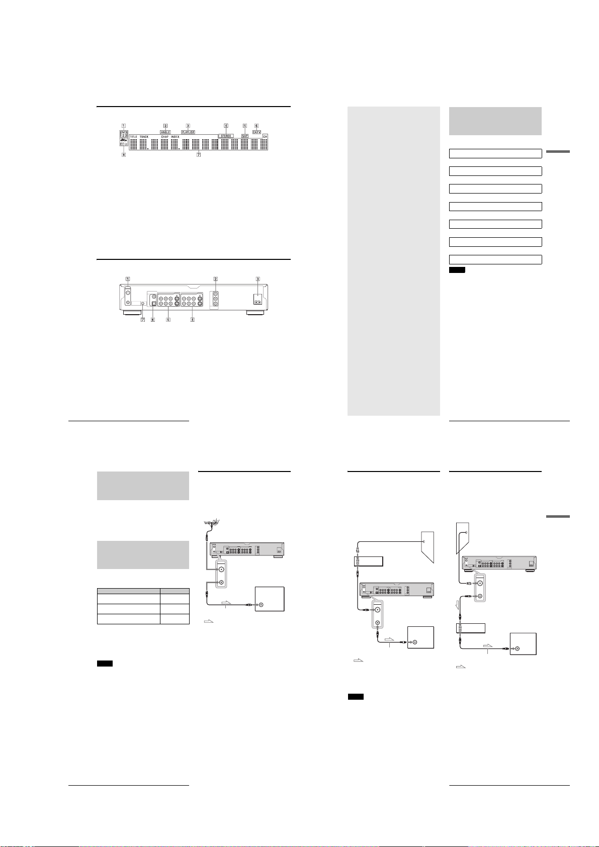
A Command mode indicator
99)
Indicates the selected remote
command mode.
B ANGLE indicator
C PLAYLIST indicator
D STEREO indicators
z
Hint
You can turn off the front panel display by setting “Dimmer” to “Display Off” in Options Setu p (page 99).
(59)
Lights up when you can change
the angle.
Lights up when the Playlist is
selected.
Lights up when receiving a
stereo program.
(28,
(32)
(39)
E SAP (Second Audio Program)
(39)
indicator
Lights up when receiving a
SAP signal.
F CATV indicator
Lights up when receiving a
Cable TV programs.
Rear panel
VHF/UHF
IN
DIGITAL OUT
PCM/DTS/DOLBY DIGITAL
LINE IN LINE OUT
S VIDEO
VIDEOR-AUDIO-L
COAXIAL
1
OUT
CONTROL S IN
OPTICAL
1
3
2
Y
S VIDEO
R-AUDIO-L
VIDEO
P
B
P
R
COMPONENT
VIDEO OUT
G Displays the following
• Playing time/remaining time
• Current title/chapter/track/
index number
• Recording time
• Clock
• Channel
H Audio signal indicators
Lights up when playing Dolby
Digital or DTS sound tracks.
~
AC IN
(57)
:
(58)
A VHF/UHF IN/OUT jacks
B COMPONENT VIDEO OUT (Y,
C AC IN terminal
D LINE OUT (S VIDEO/VIDEO/
Guide to Parts and Controls
14
Step 1: Unpacking
Check that you have the following items:
• Audio/video cord (pinplug u 3 y pinplug u 3) (1)
• Power cord (1)
• Antenna cable (1)
• Remote commander (remote) (1)
• Size AA (R6) batteries (2)
Step 2: Connecting the
Antenna Cable
Select one of the following antenna hookups that best suits you
below. Do not connect the power cord until you reach “Step 5:
Connecting the Power Cord” (page 22).
If you have Use
Antenna only (no cable TV), or cable
without cable box
Cable box with many scrambled channels Hookup 2
Cable box with a few scrambled channels Hookup 3
Note to CATV system installer (in USA)
This reminder is provided to call the CATV system installer’s
attention to Article 820- 40 of the NEC that provides guidelines
for proper grounding and, in particular, specifies t hat the cable
ground shall be connected to the grounding system of the
building, as close to the point of cable entry as practical.
Notes
• If your antenna is a flat cable (300-ohm twin lead cable), use an
external antenna connector (not sup plied) to connec t the antenn a to the
recorder.
• If you have separate cabl es for VHF and UHF antennas, use a UHF/
VHF band mixer (not supplied) to connect the antenna to the recorder.
Step 1: Unpacking
16
E LINE IN (S VIDEO/VIDEO/AUDIO
Connects antenna cables.
B
, PR) jacks
P
Connects equipment having
component video input jacks.
Connects the power cord.
AUDIO L/R) 1/2 jacks
Connects the input of external
equipment using an audio/
video or S VIDEO cord.
(16)
(18)
(22)
(18, 20)
L/R) 1/3 jacks
Connects the output of external
equipment using an audio/
video or S VIDEO cord.
F DIGITAL OUT (COAXIAL/
OPTICAL) jacks
Connects an amplifier
(receiver) having a digital input
jack.
G CONTROL S IN jack
Connects equipment having a
CONTROL S jack.
Hookup 1
(page 16)
(page 17)
(page 17)
(29)
(20)
(18)
Hookup 1: Antenna only (no cable TV),
or cable without cable box
Use this hookup if you are using a VHF/UHF ant enna or separate
VHF and UHF antennas. Also use this hookup if you watch ca ble
channels without cable box. With this hookup , you can record
any non-scrambled channel by selecting the channel on the
recorder.
to VHF/UHF IN
VHF/UHF
IN
DIGITAL OUT
PCM/DTS/DOLBY DIGITAL
LINE IN LINE OUT
S VIDEO
VIDEOR-AUDIO-L
COAXIAL
131
OUT
CONTROL S IN
OPTICAL
VHF/UHF
IN
OUT
to VHF/UHF OUT
to antenna input
Antenna cable (supplied)
: Signal flow
DVD recorder
~
AC IN
Y
S VIDEO
R-AUDIO-L
VIDEO
PB
2
PR
COMPONENT
VIDEO OUT
TV
1-3
Page 10

Step 3: Connecting the
Video Cords
Connect this recorder to your TV monitor, projector, or AV
amplifier (receiver) using a video cord. Select one of the
following patterns A through C, according to the input jack on
your TV monitor, projector, or AV amplifier (receiver). This will
enable you to view pictures. Audio connections are e xplained in
“Step 4: Connecting the Audio Cords” (page19).
If you are connecting to a VCR
Connect your VCR to the LINE IN (VIDEO) jack on the
recorder (page 29).
A Connecting to a video input jack
Connect the yellow plug of the audio/video co rd (supplied) to the
yellow (video) jacks. You will enjoy standard quality images.
Use the red and white plugs to connect to the audio input jacks
(page 20).
VHF/UHF
IN
DIGITAL OUT
PCM/DTS/DOLBY DIGITAL
LINE IN LINE OUT
VIDEOR-AUDIO-L
COAXIAL
131
OUT
CONTROL S IN
OPTICAL
LINE OUT
S VIDEO
VIDEO
R-AUDIO-L
1
2
(yellow)
Audio/video cord (supplied)
: Signal flow
B Connecting to an S VIDEO input jack
Connect using an S VIDEO cord (not supplied). You will enjoy
high quality images.
VHF/UHF
IN
DIGITAL OUT
PCM/DTS/DOLBY DIGITAL
LINE IN LINE OUT
VIDEOR-AUDIO-L
COAXIAL
131
OUT
CONTROL S IN
OPTICAL
LINE OUT
S VIDEO
R-AUDIO-L
VIDEO
1
2
S VIDEO cord (not supplied)
: Signal flow
Step 3: Connecting the Video Cords
18
DVD recorder
Y
S VIDEO
S VIDEO
R-AUDIO-L
VIDEO
P
B
2
P
R
COMPONENT
VIDEO OUT
to LINE OUT (VIDEO) 1 or 2
(yellow)
DVD recorder
Y
S VIDEO
S VIDEO
R-AUDIO-L
VIDEO
P
B
2
P
R
COMPONENT
VIDEO OUT
to LINE OUT (S VIDEO) 1 or 2
~
AC IN
INPUT
VIDEO
L
AUDIO
R
TV, projector, or AV
amplifier (receiver)
~
AC IN
INPUT
S VIDEO
TV, projector, or AV
amplifier (receiver)
C Connecting to component video
input jacks (Y, P
Connect the component via the COMPONENT VIDEO OUT jacks
using a component video cord (not supplied) or thr ee video cords
(not supplied) of the same kind an d le ngth . Yo u wil l en jo y acc ur at e
color reproduction and high quality images. If your TV accepts
progressive (480p) format signals, yo u must use this connection and
then press PROGRESSIVE on the front panel t o accept progressive
video signals. See “Using the PROGRESSIVE button” (page 51) for
more information.
VHF/UHF
IN
OUT
CONTROL S IN
Y
P
B
P
R
COMPONENT
VIDEO OUT
PCM/DTS/DOLBY DIGITAL
COAXIAL
OPTICAL
DIGITAL OUT
LINE IN LINE OUT
131
(green)
(blue)
(red)
VIDEOR-AUDIO-L
B
, PR)
S VIDEO
S VIDEO
R-AUDIO-L
VIDEO
2
to COMPONENT
VIDEO OUT
Component video
cord (not supplied)
Y
P
B
P
R
COMPONENT
VIDEO OUT
DVD recorder
(green)
(blue)
(red)
TV, projector, or AV
amplifier (receiver)
~
AC IN
COMPONENT
VIDEO IN
Y
PB
PR
: Signal flow
When connecting to a standard 4:3 screen TV
Depending on the disc, the image may not fit yo ur TV screen. To
change the aspect ration, see page 94.
If your TV has a CONTROL S jack
You can control the recorder by operating the remote toward the
TV. This feature is convenient when you placed the rec order and
the TV away from each other.
After connecting the recorder to other equipment in pattern A,
B, or C above, connect the CONTROL S IN jack to your TV’s
CONTROL S (OUT) jack using a control S cord (not supplied).
Refer to the instructions supplied with the TV to be connected.
LINE IN LINE OUT
S VIDEO
R-AUDIO-L
VIDEOR-AUDIO-L
2
to CONTROL S IN
DVD recorder
~
AC IN
Y
S VIDEO
VIDEO
P
B
P
R
COMPONENT
VIDEO OUT
VHF/UHF
OUT
CONTROL S IN
IN
DIGITAL OUT
PCM/DTS/DOLBY DIGITAL
COAXIAL
131
CONTROL S IN
OPTICAL
CONTROL S
Control S cord (not supplied)
: Signal flow
TV
Note
Consumers should note that not all high definition television sets are
fully compatible with this pr o d uct and may cause artifacts to b e
displayed in the picture. In the case of 480 progressive scan picture
problems, it is recommended that the user switch the connection to the
‘standard definition’ output. If there are quest ions regarding our TV set
compatibility with this model 480p DVD recorder, please contact our
customer service center.
Step 4: Connecting the
Audio Cords
Select the connection that best suits your system. Be sure to read
the instructions for the components you wish to connect.
Connection Your setup
A
TV
• Surround effects: Dynamic, Wide
B
Stereo amplifier (receiver)
two speakers
• Surround effects: Standard
MD deck/DAT deck
• Surround effects: N one
C
AV amplifier (receiver) having a
Dolby Surround (Pro Logic)
decoder*1 and 3 to 6 speakers
• Surround effects: Dolby Surround
(Pro Logic)
D
AV amplifier (receiver) with a
digital input jack having a Dolby
Digital or DTS*2 decoder and 6
speakers
• Surround effects: Dolby Digital
(5.1ch), DTS (5.1ch)
*1
Manufactured under license from Dolby laborato ries.
“Dolby,” “Pro Logic,” and the double-D symbol are trademarks of
Dolby Laboratories.
*2
“DTS” and “DTS Digital Out” are trademarks of Digit al Theater
Systems, Inc.
and
Step 4: Connecting the Audio Cords
,
Basic Hookups and Settings
continued
19
A
Connecting to your TV
This connection will use your TV’s speakers for sound.
VHF/UHF
IN
DIGITAL OUT
PCM/DTS/DOLBY DIGITAL
LINE IN LINE OUT
VIDEOR-AUDIO-L
COAXIAL
131
OUT
CONTROL S IN
OPTICAL
A
LINE OUT
S VIDEO
VIDEO
R-AUDIO-L
1
2
(yellow)*
(white)
(red)
Audio/video cord
(supplied)
: Signal flow
* Th e yellow pl ug i s used for video signals (page18).
z
Hint
When connecting to a monaural TV, use a stereo-mon o conversion cord
(not supplied). Connect the LINE OUT (R-AUDIO-L) 1/2 j acks to the
TV’s audio input jack.
Note
Do not connect the LINE IN (AUDIO L/R) jacks to your TV’s audio
output jacks at the same time.
DVD recorder
Y
S VIDEO
S VIDEO
VIDEO
R-AUDIO-L
P
B
2
P
R
COMPONENT
VIDEO OUT
to LINE OUT (R-AUDIO-L) 1 or 2
(yellow)
(white)
(red)
~
AC IN
TV
INPUT
VIDEO
L
AUDIO
R
B
Connecting to a stereo amplifier
(receiver) and 2 speakers/Connecting
to an MD deck or DAT deck
If your stereo amplifier (receiver) only has audio input jacks L
B-1
and R, use . If your amplifier (receiver) has a digital input
jack, or when connecting to an MD deck or DAT deck, use .
In this case, you can also connect the recorder directly t o the MD
deck or DAT deck without using your stereo amplifie r
(receiver).
VHF/UHF
IN
DIGITAL OUT
PCM/DTS/DOLBY DIGITAL
LINE IN LINE OUT
VIDEOR-AUDIO-L
COAXIAL
131
OUT
CONTROL S IN
OPTICAL
Coaxial digital cord
B-2 B-1
(not supplied)
DIGITAL OUT
PCM/DTS/DOLBY DIGITAL
COAXIAL
OPTICAL
to DIGITAL OUT
(COAXIAL or OPTICAL)
Optical digital cord
(not supplied)
to coaxial or optical
digital input
[Speakers]
Front (L)
Y
S VIDEO
S VIDEO
VIDEO
R-AUDIO-L
P
B
2
P
R
COMPONENT
VIDEO OUT
or
Stereo amplifier (receiver)
MD deck/DAT deck
DVD recorder
R-AUDIO-L
1
2
LINE OUT
VIDEO
to LINE OUT
(R-AUDIO-L)
1 or 2
(white)(red)
Stereo audio
cord (not
supplied)
(white)(red)
to audio input
~
AC IN
S VIDEO
Front (R)
: Signal flow
z
Hint
B-1
For connection , you can use the supplied audio/video cord instead
of using a separate stereo audio cord.
C
Connecting to an AV amplifier
(receiver) having a Dolby Surround (Pro
Logic) decoder and 3 to 6 speakers
If your AV amplifier (receiver) only has L and R audio in put
C-1
jacks, use . If your amplifier (receiver) has a digital input
B-2
jack, use .
C-2
You can enjoy Dolby Surround effects only wh en playing Dolby
Surround audio or multi-channel audio (Dolby Di gital) discs.
VHF/UHF
IN
DIGITAL OUT
PCM/DTS/DOLBY DIGITAL
LINE IN LINE OUT
VIDEOR-AUDIO-L
COAXIAL
131
OUT
CONTROL S IN
OPTICAL
Coaxial digital cord
C-2 C-1
(not supplied)
DIGITAL OUT
PCM/DTS/DOLBY DIGITAL
COAXIAL
OPTICAL
to DIGITAL OUT
(COAXIAL or OPTICAL)
Optical digital cord
(not supplied)
DVD recorder
~
AC IN
Y
S VIDEO
S VIDEO
R-AUDIO-L
VIDEO
PB
2
PR
COMPONENT
VIDEO OUT
LINE OUT
VIDEO
R-AUDIO-L
1
2
or
to LINE OUT
(R-AUDIO-L)
1 or 2
(white)
(red)
Stereo audio
cord (not
supplied)
(white)(red)
to coaxial or optical
digital input
[Speakers] [Speakers]
Amplifier (receiver)
with Dolby Surround
decoder
Rear (L) Rear (R)
Subwoofer
Center
to audio input
Front (R)
Front (L)
Rear (mono)
: Signal flow
z
Hint
For correct speaker location, see the operating instructions of the
connected components.
Note
When connecting 6 speakers, replace the monaural rear speaker with a
center speaker, 2 rear speakers, and a su bwoofer.
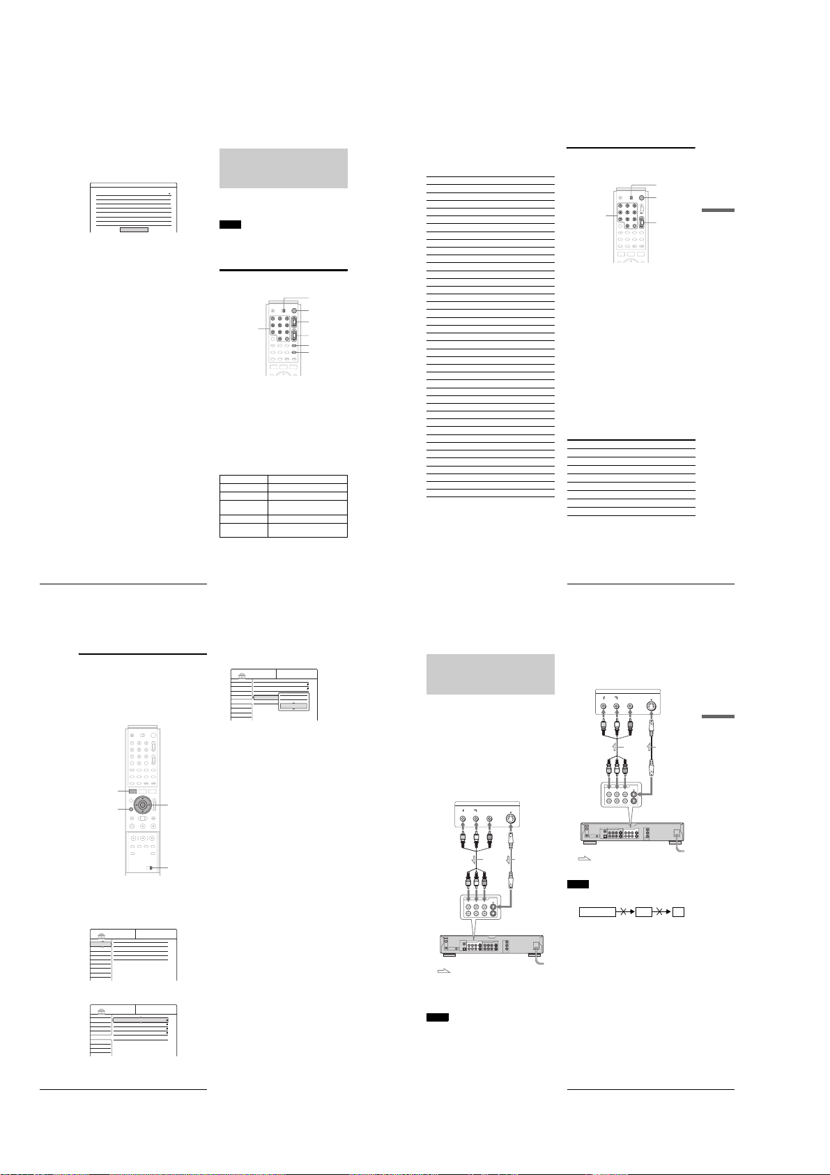
D
Connecting to an AV amplifier
(receiver) with a digital input jack and
6 speakers
If your AV amplifier (receiver) has a Dolby Digital or DTS
decoder and a digital input jack, use this connection. Note that
the surround sound effects of this recorder cannot be used with
this connection.
VHF/UHF
IN
DIGITAL OUT
PCM/DTS/DOLBY DIGITAL
LINE IN LINE OUT
S VIDEO
VIDEOR-AUDIO-L
COAXIAL
131
OUT
CONTROL S IN
OPTICAL
to DIGITAL OUT
(COAXIAL or OPTICAL)
D
DIGITAL OUT
S VIDEO
PCM/DTS/DOLBY DIGITAL
COAXIAL
OPTICAL
Optical digital cord
(not supplied)
[Speakers] [Speakers]
AV amplifier
(receiver) having a
decoder
Rear (L)
Rear (R)
Subwoofer Front (L)
: Signal flow
z
Hint
For correct speaker location, see the operating instructions of the
connected components.
Note
After you have completed the connection, be sure to set “Dolby Digital”
to “Dolby Digital” and “DTS” to “On” under “Audio” in Easy Setup
(page 24). Otherwise, no sound or a loud noise will com e from your
speakers.
DVD recorder
Y
S VIDEO
R-AUDIO-L
VIDEO
PB
2
PR
COMPONENT
VIDEO OUT
Basic Hookups and Settings
~
AC IN
or
Coaxial digital cord
(not supplied)
to coaxial digital inputto optical digital input
Center
Front (R)
Step 4: Connecting the Audio Cords
20
1-4
Step 4: Connecting the Audio Cords
21
Page 11
Step 5: Connecting the
23
Step 7: Easy Setup
Basic Hookups and Settings
d
Press ENTER.
The Setup Display for selecting the language used in
the on-screen display appears.
e
Press M/m to select a language, then press
ENTER.
The Setup Display for clock setting appears.
f
Press M/m to select the item that matches the
antenna connection you selected on page 16
(Hookup 1, 2, or 3).
◆ Hookup 1 and 3
Select “Auto,” then press ENTER.
The recorder automatically sets the clock by
searching for a channel that carries a time signal and
sets your time zone and Daylight Saving Time (if
applicable).
To activate the Auto Clock function, turn off the
recorder after finishing Easy Setup.
If your clock is set to the wrong time zone or
Daylight Saving Time, you can adjust these settings
(page 93).
If your clock cannot be set automatically, set the
clock manually (page 93).
◆ Hookup 2
Select “Manual,” then press ENTER.
Set the clock manually using </M/m/,, and press
ENTER.
Once the clock is set, the Tuner Preset display
appears.
g
Press M/m to select the item that matches the
antenna connection you selected on page 16
(Hookup 1, 2, or 3).
◆ Hookup 1 and 2
• Antenna
◆ Hookup 3
• Cable
h
Press ENTER.
The Tuner Preset function automatically starts
searching for all of the receivable channels and
presets them.
To set the channels manually, see page 92.
After the Tuner Preset is finished, the Setup Display
for selecting the aspect ratio of the connected TV
appears.
i
Press M/m to select the setting that matches
your TV type.
◆ If you have a 4:3 standard TV
• 4:3 Letter Box
Displays a wide picture with bands on the upper and
lower sections of the screen.
• 4:3 Pan Scan
Automatically displays a wide picture on the en tire
screen and cuts off the sections that do not fit.
◆ If you have a wide-screen TV or a 4:3 standard
TV with a wide-screen mode
• 16:9
For details, see “TV type” on page 94.
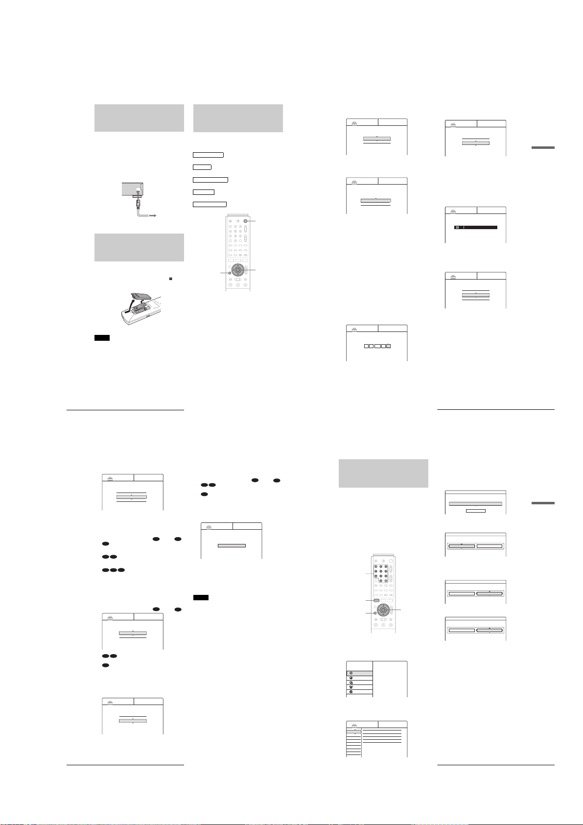
Language 1/5
Select the screen Language.
English
Français
EASY SETUP
EASY SETUP
Clock 2/5
Select a method for setting the clock.
If you select "Auto", this recorder will look for a
time signal when you turn it off.
Auto
Manual
EASY SETUP
Clock 2/5
Set the time and date manually.
9Sun / /14 9 00 AM:2003
Tuner Preset 3/5
Select the way in which you will receive channels.
Antenna
Cable
EASY SETUP
EASY SETUP
Tuner Preset 3/5
Searching for receivable channels.
Please wait.
Ch45
EASY SETUP
TV Type 4/5
Select your TV screen type.
16 : 9
4 : 3 Letter Box
4 : 3 Pan Scan
,
continued
25
Setting Up the VCR Plus® System
Basic Hookups and Settings
Setting Up the VCR Plus®
System
Setting up your recorder involves coordina ting the TV channel
number (the number you turn to on your TV or recorder to watch
a program) with the guide channel (the number that’s assigned to
that channel in your TV program guide).
To find the guide channel numbers, look at the “Channel Lineup Chart” in the program gu i d e f o r your area that features VCR
PlusCode numbers.
Use the Channel Line-up Chart to check that the guide channel
numbers match the TV channel your recorder receives. If not,
you need to coordinate these numbers using the following
procedure. If the guide and TV channel numbers are the same,
you can skip this procedure.
a
Press SYSTEM MENU while the recorder is
stopped.
The System Menu appears.
b
Press M/m to select “SETUP,” then press
ENTER.
The Setup Display appears.
c
Press M/m to select “Settings,” then press
ENTER.
d
Press M/m to select “Set VCR Plus+
Channels,” then press ENTER.
The display for setting VCR Plus+ channels appears.
e
Press M/m to select “Guide CH – TV CH,”
then press ENTER.
f
Enter the guide channel number assigned in
the program guide using the number buttons,
then press SET.
g
Enter the TV channel number.
◆ For Hookup 1 or 3
(page 16)
Enter the actual number on your TV (and recorder)
using the number buttons, then press SET.
◆ For Hookup 2
(page 17)
Enter the cable box output channel (usually 2, 3, or
4) using the number buttons, then press SET.
h
Repeat steps 5 to 7 for each channel number
that does not match.
i
Press SYSTEM MENU repeatedly to exit the
menu.
To return to the previous step
Press RETURN.
</M/m/,,
ENTER
RETURN
SYSTEM MENU
Number buttons,
SET
TITLE LIST
TIMER
TIMER LIST
DV/D8 EDIT
SETUP
Plays/erases/edits recorded titles.
SYSTEM
MENU
DVD Recorder
Dual RW
Compatible
SETUP
Settings
Video
Audio
Features
Options
Easy Setup
Tuner Preset
Set VCR Plus+ Channels
Clock
Language
Settings - Set VCR Plus+ Channels
----
Channel list
Guide CH TV CH
- -
- -
Settings - Set VCR Plus+ Channels
Guide CH TV CH
- - ----
- -
- -
- -
Settings - Set VCR Plus+ Channels
Guide CH TV CH
- - ----
- -
25
25
Settings - Set VCR Plus+ Channels
Guide CH TV CH
- - ----
- -
25
36
,
continued
Power Cord
Connect the supplied power cord to the AC IN terminal of the
recorder. Then plug the recorder and TV power cords into an
AC outlet. After you connect the power cord, you must wait for
a short while before operating the recorder. You can operate
the recorder once the front panel display lights up and the
recorder enters standby mode.
If you connect additional equipment to this recorde r (pages 29 to
30), be sure to connect the power cord after all connections are
complete.
~
AC IN
to AC IN
to AC outlet
Step 6: Preparing the
Remote
You can control the recorder using the supplied remote. Insert
two Size AA (R6) batteries by matching the 3 and # ends on
the batteries to the markings inside the battery compartment.
When using the remote, point it at the remote sensor on the
recorder.
Notes
• If the supplied remote interferes your other Sony DVD recorder or
player, change the command mode number for this recorder. For
details, see page 28.
• Do not leave the remo te in an extremely hot or humid place.
• Do not drop any foreign objec t into the remote casing, particularly
when replacing the batteries.
• Do not expose the remote sensor to direct sunlig ht or a light in g
apparatus. Doing so may cause a malfunction.
• If you do not use the remote for an extended period of time, remove the
batteries to avoid possible damag e from bat ter y leakag e and co rrosi on.
Step 7: Easy Setup
Follow the steps below to make the minimum number of basic
adjustments for using the recorder. If you do not complete Easy
Setup, it will appear each time you turn on your recorder.
Make the settings below in the following order.
OSD Language Setup
m
Clock Setup
m
Tuner and Channel Setup
m
TV Type Setup
m
Audio Connection Setup
"/1
RETURN
a
Turn on the TV.
b
Press [/1.
The recorder turns on and the power indicator on the
front panel lights up in green.
c
Switch the input selector on your TV so that
the signal from the recorder appears on your
TV screen.
“Initial settings necessary to operate the DVD
recorder will be made. You can change them later
using Setup.” appears. If this message does not
appear, select “Easy Setup” from “SETUP” in the
System Menu to run Easy Setup. For details, see
“Settings and Adjustments” on page90.
</M/m/,,
ENTER
Step 5: Connecting the Power Cord
22
j
24
k
l
m
Step 7: Easy Setup
Press ENTER.
The Setup Display for selecting the type of jack used
to connect to your amplifier (receiver) appears.
EASY SETUP
Audio Connection 5/5
Is this recorder connected to an amplifier (receiver)?
Select the type of jack you are using.
Yes :
LINE OUT(R-AUDIO-L)
Yes :
DIGITAL OUT
No
Press M/m to select the type of jack (if any)
you are using to connect to an amplifier
(receiver), then press ENTER.
Choose the item that matches the audio connection
you selected on pages 20 to 21 ( through ).
A
• If you connect just a TV and nothing else, select “No,”
then go to step 15.
B-1 C-1
• Select “Yes: LINE OUT (R-AUDIO-L),” then go to
step 15.
D
B-2 C-2
• Select “Yes: DIGITAL OUT.” The Setup Display for
“Dolby Digital” appears.
Press M/m to select the type of Dolby Digital
signal you wish to send to your amplifier
(receiver).
Choose the signal that matches the audio connection
you selected on pages 20 to 21 ( through ).
EASY SETUP
Dolby Digital
D-PCM
Dolby Digital
B-2 C-2
• D-PCM
D
• Dolby Digital (only if the amplifier (receiv er) has a
Dolby Digital decoder)
Press ENTER.
The Setup Display for selecting the type of DTS
signal appears.
EASY SETUP
DTS
On
Off
A D
Audio Connection 5/5
Audio Connection 5/5
B
n
Press M/m to select whether or not you wish
to send a DTS signal to your amplifier
(receiver) and press ENTER.
Choose the item that matches the audio connection
you selected on pages 20 to 21 ( through ).
B-2 C-2
• Off
D
• On (only if the amplifier (receiver) ha s a DTS decoder)
o
Press ENTER when “Finish” appears.
Easy Setup is finished. All connections and setup
operations are complete.
EASY SETUP
Easy Setup is finished
Finish
To return to the previous step
Press RETURN.
z
Hint
If you want to run Easy Setup again, select “Easy Setup” in the Setup
Display (page 100).
Notes
• If there are only a few channels in your area that carry time signals ,
setting the clock automatically may take up to about 20 minutes after
D
the recorder turns off. If nothing happens even after you wait about 20
minutes, set the clock manually in “Clock” of “Settings” (page9 3).
• If you use the antenn a connection Hookup 2 (page 17), make sure you
leave the cable box on.
• To record TV programs using the time r, you m ust set the clock
accurately.
B
D
1-5
Page 12
To check the channel settings
When displaying the “Set VCR Plus+ Channels” menu, press
M/m to select “Channel List,” then press ENTER.
The display lists the channels whose guide channel number is not
as same as the TV channel number.
Settings - VCR Plus+ Channel List
Guide CH TV CH
2
-
21
4
-
32
6
-
9
10
-
121
11
-
13
25
-
36
28
-
2
To go to the next page, press m.
To return to the previous page, press M.
Guide CH TV CH
Close
Page2
45
-
18
53
-
5
- -
-
- -
- -
-
- -
- -
-
- -
- -
-
- -
- -
-
- -
Setting Up the Remote
You can control your TV with the supplied remote by adjusting
the remote control’s signal.
If you connected the recorder to an AV amplifier (receiver), you
can also control the volume with the supplied remote.
Notes
• Depending on the connec ted unit, you may not be able to control your
TV or AV amplifier (receiver) with some or all of the bu tt on s below.
• If you enter a new cod e number, the code number previously entered
will be erased.
• When you replace the batteries of the remote, the code numb er may be
reset to the default setting. Set the appropriate code num ber again.
Controlling TVs with the remote
TV/DVD switch
"/1
Number buttons,
SET
a Slide the TV/DVD switch to TV.
b Hold down [/1.
c Enter your TV’s manufacturer code (see
“Code numbers of controllable TVs” below)
using the number buttons.
d Release [/1.
When the TV/DVD switch is set to TV, the remote
performs the following:
[/1 Turns your TV on or off
VOL +/– Adjusts the volume of your TV
CH +/– Selects the channel on your TV
WIDE MODE Switches to or from the wide mode of a
TV/VIDEO Switches your TV’s input source
Number buttons and
SET
Sony wide-screen TV
Selects the channel on your TV
CH +/–
VOL +/–
TV/VIDEO
WIDE MODE
Code numbers of controllable TVs
If more than one code number is listed, try entering them one at
a time until you find the one that works with your TV.
Manufacturer Code number
Sony 01 (default)
Akai 04
AOC 04
Centurion 12
Coronado 03
Curtis-Mathes 12
Daytron 12
Emerson 03, 04, 14
Fisher 11
General Electric 06, 10
Gold Star 03, 04, 17
Hitachi 02, 03
J.C.Penney 04, 12
JVC 09
KMC 03
Magnavox 03, 08, 12
Marantz 04, 13
MGA/Mitsubishi 04, 12, 13, 17
NEC 04, 12
Panasonic 06, 19
Philco 03, 04
Philips 08, 21
Pioneer 16
Portland 03
Proscan 10
Quasar 06, 18
Radio Shack 05, 14
RCA 04, 10
Sampo 12
Samsung 03, 12, 20
Sanyo 11, 14
Scott 12
Sears 07, 10, 11
Sharp 03, 05, 18
Sylvania 08, 12
Teknika 03, 08, 14
Toshiba 07
Wards 03, 04, 12
Yorx 12
Zenith 15
Controlling the volume of your AV
amplifier (receiver) with the remote
TV/DVD switch
"/1
Number buttons,
SET
VOL +/–
a Slide the TV/DVD switch to DVD.
b Hold down [/1, and enter the manufacturer
code (see the table below) for your AV
amplifier (receiver) using the number
buttons.
c Release [/1.
The VOL +/– buttons control the AV amplifier’s
volume.
◆ If you want to control the TV’s volume
Slide the TV/DVD switch to TV.
z
Hint
If you want to control the TV’s volume even when the TV/DVD switch
is set to DVD, repeat the steps above and enter the code number 90
(default).
Code numbers of controllable AV amplifiers
(receivers)
If more than one code number is listed, try entering th e m on e at
a time until you find the one that works with your AV amplifier
(receiver).
Manufacturer Code number
Sony 80, 88, 89, 91
Denon 84, 85, 86
Kenwood 92, 93
Onkyo 81, 82, 83
Pioneer 99
Sansui 87
Technics 97, 98
Yamaha 94, 95, 96
Basic Hookups and Settings
Setting Up the Remote
26
If you have a Sony DVD player or more
than one Sony DVD recorder
If the supplied remote interferes with your other Sony DVD
recorder or player, set the command mode number for this
recorder and the supplied remote to one that differs from the
other Sony DVD recorder or player.
The default command mode setting for this recorder and the
supplied remote is DVD3.
SYSTEM
MENU
RETURN
a Press SYSTEM MENU.
The System Menu appears.
b Press M/m to select “SETUP,” then press
ENTER.
SETUP
Settings
Tuner Preset
Video
Set VCR Plus+ Channels
Audio
Clock
Features
Language
Options
Easy Setup
c Press M/m to select “Options,” then press
ENTER.
SETUP
Settings
Selectable
Format Disc :
Video
Bright
Dimmer :
Audio
On
Auto Display :
Features
DVD3
Command Mode :
Options
Factory Setup
Easy Setup
M/m, ENTER
COMMAND MODE
d Press M/m to select “Command Mode,” then
press ENTER.
SETUP
Settings
Selectable
Format Disc :
Video
Bright
Dimmer :
Audio
On
Auto Display :
Features
DVD3
Command Mode :
Factory Setup
DVD1
DVD2
DVD3
Options
Easy Setup
e Press M/m to select the Command mode
(DVD1, DVD2, or DVD3), then press
ENTER.
f Slide the COMMAND MODE switch on the
remote so it matches the mode you selected
above.
To return to the previous step
Press RETURN.
Connecting a VCR or Similar
Recording Device to the
LINE Jacks
You can use this recorder as the source player or as the recording
deck.
After disconnecting the recorder’s power cord from an AC
outlet, connect a VCR or similar recording device to the LINE
jacks of this recorder.
Use the DV IN jack on the front panel if the equipment has a DV
output jack (i.LINK jack) (page 75).
See also the instruction manual supplied with the connected
equipment.
How to connect to record on this recorder
Connect a VCR or similar recording device to the LINE IN jacks
of this recorder. See “Recording from connected equipment” on
page 88.
VCR, etc.
OUTPUT
AUDIO
VIDEO
1
3
131
LINE IN
LINE IN LINE OUT
S VIDEO
VIDEOR-AUDIO-L
Audio/video
cord (not
supplied)
S VIDEO
VIDEOR-AUDIO-L
R-AUDIO-L
VIDEO
2
S Video
S VIDEO cord
(not supplied)
DVD recorder
~
AC IN
Y
S VIDEO
PB
PR
COMPONENT
VIDEO OUT
RL
to LINE IN 1 or 3
VHF/UHF
IN
DIGITAL OUT
PCM/DTS/DOLBY DIGITAL
COAXIAL
OUT
CONTROL S IN
OPTICAL
: Signal flow
z
Hint
You can also use the LINE 2 IN jacks on the front panel of the recorder
(page 88).
Notes
• Do not connect the yellow LINE IN (VIDE O) ja c k whe n usin g an S
VIDEO cord (not supplied).
• Pictures conta ining copy protection signals that prohibit any copying
cannot be recorded.
Setting Up the Remote
How to connect to record on other equipment
Connect a VCR or similar recording device to the LINE OUT
jacks of this recorder.
VCR, etc.
INPUT
AUDIO
VIDEO
LINE IN LINE OUT
131
LINE OUT
VIDEOR-AUDIO-L
VIDEOR-AUDIO-L
S VIDEO
2
Audio/video
cord (not
supplied)
S VIDEO
S VIDEO
R-AUDIO-L
VIDEO
COMPONENT
VIDEO OUT
S Video
Y
PB
PR
S VIDEO cord
(not supplied)
DVD recorder
~
AC IN
to LINE OUT 1 or 2
VHF/UHF
IN
OUT
CONTROL S IN
RL
1
3
DIGITAL OUT
PCM/DTS/DOLBY DIGITAL
COAXIAL
OPTICAL
: Signal flow
Notes
• If you pass the recorder sign als via the VCR, you may not receive a
clear image on the TV screen.
VCRDVD recorder TV
• Do not connect the ye ll ow LINE IN (VIDEO) jack when using an S
VIDEO cord (not supplied).
,
continued
27
Basic Hookups and Settings
Setting Up the Remote
28
1-6
Connecting a VCR or Similar Recording Device to the LINE Jacks
29
Page 13

Connecting to a Satellite
31
Guide to Displays
Operating the Recorder
Operating the
Recorder
The recorder’s overall operati on is simple.
Generally, most operations can be
performed by pressing only </M/m/,,
and ENTER. Once you know the common
procedure, you will find the recorder easy
to operate.
Guide to Displays
The recorder uses the following four types of displays for most
operations: System Menu, Title List, TOOLS, and Sub-menu.
It also has a Disc Information displa y f o r ch ec k i ng the s t at us of
the inserted disc, and an on-screen keyboard that enables yo u to
label a title or disc.
System Menu
The System Menu appears when you press SYSTEM MENU,
and provides entries to all of the recorder’s main functions.
1 TITLE LIST (page 53, 64):
Turns on the Title List menu, which shows
recorded titles on the disc.
2 TIMER (page 40):
Allows you to set a new timer recording setting.
3 TIMER LIST (page 42):
Turns on the Timer List menu, which allows you
to check, change, or cancel timer settings.
4 DV/D8 EDIT (page 79):
Activates the DV Edit function, which allows you
to record and edit the contents of a DV/Digital8
format tape.
5 SETUP (page 91):
Turns on the Setup Display, which allows you to
set up the recorder to suit your preferences.
Number buttons,
SET
TITLE LIST
TOOLS
ZOOM +/–
</M/m/,,
ENTER
SYSTEM MENU
CURSOR MODE
RETURN
TITLE LIST
TIMER
TIMER LIST
DV/D8 EDIT
SETUP
Plays/erases/edits recorded titles.
SYSTEM
MENU
DVD Recorder
Dual RW
Compatible
•
Guide to Displays
. . . . . . . . . . . . . . . . .
page 31
•
How to Use the Displays
. . . . . . . . . . .
page 33
•
How to Enter Characters
. . . . . . . . . . .
page 34
,
continued
33
How to Use the Displays
Operating the Recorder
Sub-menu
The sub-menu appears when you select an item from the
displayed list menu and press ENTER. The sub-menu displays
options applicable only to the selected item.
Example: The Title List menu
How to Use the Displays
Use the displays in the following way. The procedure is common
to many of the operations.
a
Press SYSTEM MENU.
The System Menu appears with entries to the main
functions.
b
Press M/m to select a function, then press
ENTER.
The display for the selected function appears.
Example: When “TITLE LIST” is selected.
◆ Using the TOOLS menu
Use the TOOLS menu to display options for the
entire disc.
A Press TOOLS.
The TOOLS menu appears.
B Press M/m to select the option, then press
ENTER.
◆ Using the sub-menu
The sub-menu displays options for a specific title.
A Press M/m to select the title on the list, then
press ENTER.
The sub-menu appears.
B Press M/m to select the option, then press
ENTER.
c
Press RETURN repeatedly to turn off the list
display.
To return to the previous display
Press RETURN.
Sort
Date
Number
Title
My Movies
TITLE LIST
ORIGINAL
-RW.VR
1.5/4.7GB
1 2ch 1:00PM - 2:00PM
2 5ch 8:00PM - 9:00PM
3 12ch 9:00AM - 9:30AM
4 3ch 8:00PM - 8:30PM
5 25ch 8:00PM - 8:30PM
6 L2 9:00PM - 9:30PM
7 8ch 9:00PM - 9:30PM
8 125ch 10:00AM - 10:30AM
9/15
9/17
9/25
9/25
10/15
10/19
10/26
10/28
Close
Play
Play From Start
Erase
Protect Title
Title Name
Set Thumbnail
A-B Erase
Options for the
selected item
Sort
Date
Number
Title
My Movies
TITLE LIST
ORIGINAL
-RW.VR
1.5/4.7GB
1 2ch 1:00PM - 2:00PM
2 5ch 8:00PM - 9:00PM
3 12ch 9:00AM - 9:30AM
4 3ch 8:00PM - 8:30PM
5 25ch 8:00PM - 8:30PM
6 L2 9:00PM - 9:30PM
7 8ch 9:00PM - 9:30PM
8 125ch 10:00AM - 10:30AM
9/15
9/17
9/25
9/25
10/15
10/19
10/26
10/28
Receiver or a Cable Box
Connect a satellite receiver, digital cable box, or a cable box to
this recorder using the LINE IN 1/3 jacks. Disconnect the
recorder’s AC power cord from an AC outlet when connecting
the box.
To record on this recorder, see page 88. To use the Synchro Rec
function, see below.
Satellite receiver, etc.
OUTPUT
VIDEO
AUDIO
RL
Audio/video cord
(not supplied)
LINE IN
S VIDEO
VIDEOR-AUDIO-L
1
3
to LINE IN 1 or 3 DVD recorder
VHF/UHF
IN
DIGITAL OUT
PCM/DTS/DOLBY DIGITAL
LINE IN LINE OUT
S VIDEO
R-AUDIO-L
VIDEO
VIDEOR-AUDIO-L
COAXIAL
131
OUT
CONTROL S IN
OPTICAL
2
: Signal flow
If you want to use the Synchro Rec function
Connect a satellite receiver to LINE IN 1 jacks of this recorder.
See “Recording from External Equipme nt with a Timer (Synchro
Rec)” on page 47.
Refer to your satellite receiver’s instructions for more
information.
Notes
• Synchro-Recording doe s not work with some boxes. For details, refer
to the box’s operating instructions.
• When connecting the LINE IN jacks to the cable box, be sure to also
connect the recorder’s antenna to the cable box.
~
AC IN
Y
S VIDEO
PB
PR
COMPONENT
VIDEO OUT
Connecting to a Satellite Receiver or a Cable Box
30
Title List
The recorder uses list displays for some operations. The most
frequently used is the Title List menu.
The Title List menu appears when you press TITLE LIST or
when you select “TITLE LIST” from the System Menu, and
displays all of the titles on the disc.
To show the list in greater details (zoom), press ZOOM+. To
return to the previous display, press ZOOM–.
Standard Title List
“Zoomed” Title List
Notes
• The letters that c ann ot be displayed are replaced with “*”.
• The Title List does not appear when you play DVD VIDEOs, CDs,
CD-Rs, or CD-RWs.
• The Title List may not appear for discs created on other DVD
recorders.
• On this model, 1 GB is eq ui val e nt to 1 billion bytes.
Guide to Displays
32
-RW.VR
Sort
Date
Number
Title
-RW.VR
Sort
Date
Number
Title
1 Sort buttons (page 54):
Sorts the title order.
2 Zooming indicator (page54):
Shows the current zoom status.
3 Disc name (page 72)
4 Disc space (remainder/total)
5 Title information (page 54):
Displays the title number, title name, and
recording date.
6 Scroll bar:
Appears when all the titles do not fit on the list.
To view the hidden titles, press M/m.
7 Title’s thumbnail picture (page 54)
My Movies
TITLE LIST
1 2ch 1:00PM - 2:00PM
2 5ch 8:00PM - 9:00PM
3 12ch 9:00AM - 9:30AM
4 3ch 8:00PM - 8:30PM
5 25ch 8:00PM - 8:30PM
6 L2 9:00PM - 9:30PM
7 8ch 9:00PM - 9:30PM
8 125ch 10:00AM - 10:30AM
TITLE LIST
1.5/4.7GB
ORIGINAL
9/15
9/17
9/25
9/25
10/15
10/19
10/26
10/28
My Movies
1.5/4.7GB
ORIGINAL
1 2ch 1:00PM - 2:00PM
2ch
Mon 9/15 1:00PM( 1H00M) SP
2 5ch 8:00PM - 9:00PM
5ch
Wed 9/17 8:00PM( 1H00M) SLP
3 12ch 9:00AM - 9:30AM
12ch
EP
Thu 9/25 9:00AM( 0H30M)
4 3ch 8:00PM - 8:30PM
3ch
Thu 9/25 8:00PM( 0H30M) SLP
About the types of Title List menus
The appearance of the Title List menu differs according to the
disc type and recording format.
◆For DVD+RWs, DVD-Rs, DVD-RWs (Video mode):
The Title List menu appears and displays the titles on the disc.
◆For DVD-RWs (VR mode):
The Title List (Original) or Title List (Playlist) menu appears and
displays the Original or Playlist titles on the disc. The
“PLAYLIST” indicator lights up on the front p anel display wh en
the Title List (Playlist) menu is selected.
To switch the Title List menu for a DVD-RW (VR
mode)
The recorder displays either the Original or Playlist Title List.
Follow the steps below.
1
Press TITLE LIST.
The Title List menu appears.
2
Press TOOLS.
The TOOLS menu appears.
3
Press M/m to select either “Original” or
“Playlist,” whichever is not displayed, then press
ENTER.
The display switches to the selected Title List menu.
To scroll the list display by page (Page mode)
Press CURSOR MODE while the list display is turned on. The
display enters Page mode. Each time you press M/ m, the entire
Title List changes to the next/previous page of titles.
To return to the Cursor mode, press CURSOR MODE again.
Notes
• When you turn off the list displ ay, th e Page mode is canceled.
• When all the ti tles on the disc fit on a single page, you cannot sele ct the
Page mode.
TOOLS
The TOOLS menu appears when you press TOOLS, and
displays options applicable to the entire disc or recorder.
Example 1: When you press TOOLS while the Title List menu
is turned on.
Options for the
disc or menu
-RW.VR
Close
Sort
Date
Playlist
Number
Erase Titles
Title
Create Playlist
Disc Info.
TOOLS
Example 2: When you press TOOLS while a DVD is playing.
Close
Stop
Title Search
Chapter Search
Time Search
TOOLS
Options for the
disc or picture
TITLE LIST
ORIGINAL
1 2ch 1:00PM- 2:00PM
2 5ch 8:00PM- 9:00PM
3 12ch 9:00AM- 9:30AM
4 3ch 8:00PM- 8:30PM
5 25ch 8:00PM- 8:30PM
6 L2 9:00PM- 9:30PM
7 8ch 9:00PM- 9:30PM
8 125ch 10:00AM-10:30AM
My Movies
1.5/4.7GB
9/15
9/17
9/25
9/25
10/15
10/19
10/26
10/28
1-7
Page 14

How to Enter Characters
You can label a title, disc, or program by ente r ing characters.
You can enter up to 64 characters for a title/disc/program name,
but the actual number of characters displayed in the menus such
as the Title List will vary. When the display for entering
characters appears, follow the steps below.
a
Press </M/m/, to move the cursor to the
right of the screen and select “A” (uppercase), “a” (lower-case), or “Symbol,” then
press ENTER.
The characters of the selected type are displayed.
Example: Input Title Name
Input Title Name
25ch 1:00PM - 2:00PM
,. - 1
1
BA C 2
2
ED F 3
3
HG I 4
4
KJ L5
5
b
Press </M/m/, to select a character you
want to enter, then press ENTER.
The selected character appears at the top of the
display.
Input Title Name
K
,. - 1
1
BA C 2
2
ED F 3
3
HG I 4
4
KJ L5
5
To enter a letter with an accent mark, select an accent
followed by the letter.
Example: Select “ ` ” and then “a” to enter “à.”
To insert a space between the characters, select
“Space.”
c
Repeat steps 1 and 2 to enter all the
characters for the name.
Input Title Name
Kids
,. - 1
1
BA C 2
2
ED F 3
3
HG I 4
4
KJ L5
5
How to Enter Characters
34
"A"
NM O 6
6
"a"
Back
QP R S
7
Symbol
Clear All
UT V 8
8
XW Y Z79
9
Space
Cancel
0
0
Finish
"A"
NM O 6
6
"a"
Back
QP R S
7
Symbol
Clear All
UT V 8
8
XW Y Z79
9
Space
Cancel
0
0
Finish
"A"
NM O 6
6
"a"
Back
QP R S
7
Symbol
Clear All
UT V 8
8
XW Y Z79
9
Space
Cancel
0
0
Finish
◆ To erase a character
A Press </M/m/, to move the cursor to the
input row.
B Press </, to move the cursor to the right of
the character you want to erase.
C Press </M/m/, to select “Back,” then press
ENTER.
◆ To insert a character
A Press </M/m/, to move the cursor to the
input row.
B Press </, to move the cursor to the right of
the point where you want to insert a character.
C Press </M/m/, to select the character you
want to insert, then press ENTER.
◆ To erase all the characters
Press </M/m/, to select “Clear All,” then press
ENTER.
d
Press </M/m/, to select “Finish,” then
press ENTER.
To cancel the setting, select “Cancel.”
To use the number buttons
You can also use the number buttons to enter characters.
1
In step 2 above, press the number buttons
repeatedly to select the character you want to
enter.
Example:
Press the number 3 button once to enter “D.”
Press the number 3 button three times to enter “F.”
2
Select the next character, or press SET.
3
Repeat steps 1 and 2 to enter all of the characters
for the name.
4
Press </M/m/, to select “Finish,” then press
ENTER.
Recording/
Timer
Recording
This section covers the basics of DVD
recording, and the available methods for
setting the timer.
•
Before Recording
•
•
•
•
. . . . . . . . . . . . . . . . .
Recording TV programs
. . . . . . . . . . . . . . . .
Timer Recording
. . . . . . . . . . . . . . . . . . . . . .
Adjusting the Recording Picture Quality and Size
. . .
Recording from External Equipment with a Timer
(Synchro Rec)
. . . . . . . . . . . . . . . . . . . . . .
page 35
page 38
page 40
page 46
page 47
Before Recording
This recorder can record on various discs. Before you record,
read the following and select the disc type according to your
needs.
Recordable discs
This recorder can record on the following discs.
◆Disc type
1
DVD-RW*
Ver. 1.1
Ver. 1.1 with CPRM*
DVD+RW*
DVD-R*
Ver. 2.0
*1“DVD-RW,” “DVD+RW,” and “DVD-R” are trademarks.
2
*
CPRM (Content Protection for Recordable Media) is a coding
technology that protects copyrights fo r im ag es .
DVD-RWs and DVD+RWs are rewritable. DVD-Rs are nonrewritable.
The recorder cannot record on the following discs:
• 8 cm discs
• DVD+R
• DVD-RW (Ver 1.0)
• DVD-RAM
• CD-R/CD-RW
Notes
• The following type of high-speed discs can be used for recording: up
to 2×-speed DVD-RWs (Revision 1.0), up to 4×-speed DVD-Rs
(Revision 1.0), or up to 4×-speed DVD+RWs. Note that high-speed
discs will not record at higher speed. You cannot re cord on the disc if
it is not 1×-speed compatible.
• Use a disc with CPRM to record Copy-Once TV programs (page 36).
• It is recommen ded that you use discs with “For Video” printed on their
packing.
• You cannot add new recordings to DVD-Rs and DVD-RWs (Video
mode) that contain recordings made on other DVD recorders.
• In some cases, you may not be able to add ne w recordi ng s to
DVD+RWs that contain recordings made on other DVD recorders. If
you do add a new recording, note that this recorder wil l re w ri te the
DVD menu. If the disc contains PC data unrecognizable by this
recorder, the data will be erased.
2
1
1
Before Recording
Recording/Timer Recording
,
continued
35
About recording formats
When you insert an unused disc, the recorder automatically starts
formatting. Since available functions differ depending on the
disc type, select the disc that best suits your needs using the chart
below.
You can preset the format for unused DVD-RWs in Options
Setup. When “Format Disc” is set to either “VR” or “Video”
(page 99), the recorder starts formatting in the selected mode
without asking for confirmation. Select “Selectable” if yo u want
to select the mode each time you insert an unused DVD-RW.
Differences between the disc types
See pages in parentheses for details.
Disc type Characteristics
– Automatically creates chapters at specified
intervals (page 97)
– Simple editing (erasing titles/changing
title name) (page 64)
– Creates chapters manually or
automatically (page 67 )
– Various editing options using a create d
Playlist (page 67)
– Records Copy-Once programs provided
that the disc has CPRM
Notes
• To play a recorded disc on other DVD equipment, you need to finalize
the disc. For details on finalizing, see page 73.
• You cannot mix the two formats on one DVD-RW. To change the
disc’s format, reformat the disc (page 74). Note that the disc’s contents
will be erased after reformatting.
Recording mode
While the recorder is stopped, you can select one of six recording
modes by pressing REC MODE repeatedly for the desired
recording time and picture quality. The picture quality generally
improves as the recording time decreases.
Recording mode Recording time (minute)
HQ 60
HSP 90
SP (Standard mode) 120
LP 180
EP 240
SLP 360
Notes
• The recording times are an estimate and actual times may differ.
• Situations below ma y cause slight inaccuracies with the recording
time.
– Recording a program with poor reception, or a program or video source
of low picture quality
– Recording on a disc that has already been edited
– Recording only a still picture or just sound
Before Recording
36
Unrecordable pictures
Pictures with copy protection cannot be recorded on this
recorder.
When the recorder receives a copy guard signal while recording,
the recorder stops recording and a message appears on your TV
screen.
About pictures with Copy Control Signals
Broadcasts that contain Copy Control Signals m ay h ave one of
the following three signal types, Copy-Free, Copy-Once, and
Copy-Never. This recorder limits the recording according to
copy protection signal as shown below.
If you want to record a Copy-Once program, use a DVD-RW
with CPRM in VR mode.
◆Available recording options
Copy-
CopyOnce
a*——
CopyNever
—
DVD-RW (Ver.1.1) a ——
DVD-RW (Ver.1.1
with CPRM
DVD+RW a ——
DVD-R (Ver.2.0) a ——
*The recorded disc can be played only on CPRM compatible
equipment.
Free
VR mode
Video modeaa
Checking the available disc space
(Disc Info.)
When recording on a used disc, make sure that there is enough
disc space for recording. With DVD-RWs or DVD+RWs, you
can free up disc space by erasing titles.
a Press TOOLS while the disc is in the
recorder.
The TOOLS menu appears.
b Press M/m to select “Disc Info.,” then press
ENTER.
The Disc Information display appears.
Items in the display differ depending on the disc type
or recording format. Note that the remaining disc
space indicator is an estimate and actual available
space may differ.
Example: DVD-RW (VR mode)
Disc Information
DiscName Movie
Media DVD-RW Format VR
Title no. Original 3 / Playlist 2
Protected Not Protected
Date 9/15/2003 ~ 10/28/2003
HQ : 0H30M
LP : 1H30M
Remainder
1 Disc Name
2 Media:
Disc type
3 Format:
Recording format type (DVD-RW only)
4 Title no.:
Total number of titles
5 Protected:
Indicates whether protection is set (DVD-RW in
VR mode only)
6 Date:
Dates when the oldest and the most recent titles
are recorded
7 Continuous Rem. Time/Remainder:
• The longest continuous recording time in each of the
recording modes (approximate)
• D isc space bar (approximate)
• Re maining disc space/total disc space (approximate)
8 Disc setting buttons
• Disc Name: Labels the disc (page 72)
• Prote ct Disc: Protects the disc (DVD-RW in VR
mode only) (page72)
• Fina lize: Finalizes the disc/Creates a DVD menu
(page 73)
• Unfinalize: Unfinalizes the disc if it has already been
finalized (DVD-RW in VR mode only) (page 73)
• Eras e All: Erases all titles on the disc (page 73)
• Format: Reformats the disc (page 74)
HSP : 0H45M
EP : 2H00M
SP : 1H00M
SLP : 3H00M
2. 3 / 4. 7GB
Close
Disc Name
Protect Disc
Finalize
Erase All
Format
◆How programs are recorded on a DVD-R
A new program is recorded on the last space [a] only. Check that
the remaining disc space is large enough for the recording.
Erasing “B” does not free up any space
A CB
You cannot free up disc space on a DVD-R. Erasing a title will
only hide the title name in the Title List menu. The erased titles
will still take up space on the disc.
◆How programs are recorded on a DVD-RW (VR mode)
A program is recorded on the free disc space [a]. Check that the
total remaining disc space is large enough for recording.
Erasing “B” frees up more space
A CB
A C
New recording New recording
◆To free up disc space
You can free up disc space by erasing titles. The original title
used for a Playlist cannot be erased.
To erase a title, see page 65.
To erase multiple titles, see page 65.
◆How programs are recorded on a DVD-RW (Video mode) or
DVD+RW
The recorder searches for the largest block of space [a] and
records there. Check that there is a continuous free block large
enough for the recording. If not, the recording will stop.
Erasing “B” and “C” creates a block of free space
A D
B C
A
New recording
◆To check or free up disc space
For DVD-RWs (Video mode) and DVD+RWs only, you can
check free disc space and title location, and also erase titles using
the Disc Map display (see below).
z
Hint
You can erase all of the disc’s titles (other than protected titles) at once
(page 73).
Notes
• When you er ase titles, the title order may change d epending on the disc
type or format.
• After finalizing, you cannot record further on a DVD-RW (Vid eo
mode) or DVD-R.
a
New recording
aa
(continued)
a
D
Before Recording
Recording/Timer Recording
,
continued
37
1-8
Page 15
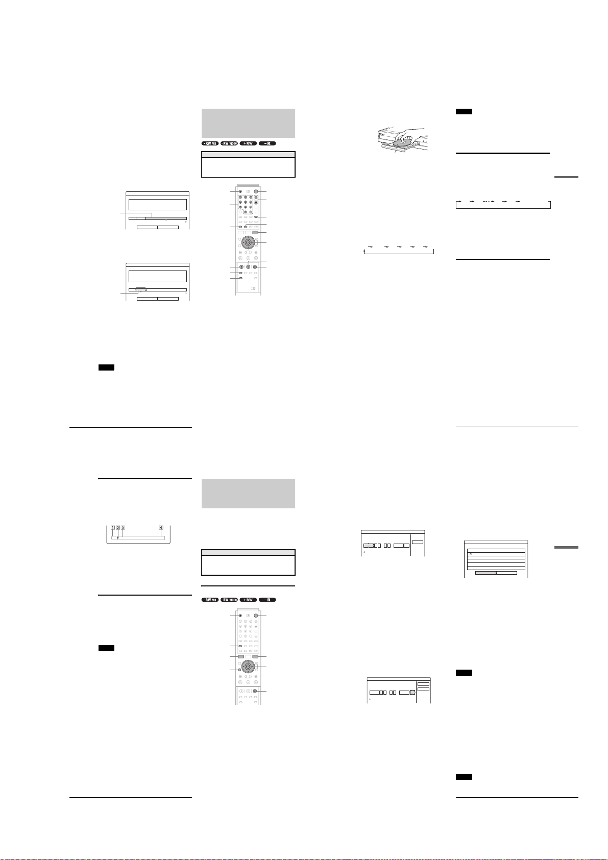
To free up disc space using the Disc Map
39
Recording TV programs
Recording/Timer Recording
c
Press Z OPEN/CLOSE, and place a
recordable disc on the disc tray.
d
Press Z OPEN/CLOSE to close the disc tray.
Wait until “LOAD” disappears from the front panel
display.
If you use an unused DVD, formatting starts
automatically.
When using an unused DVD-RW, select the
recording format, VR or Video.
e
Press CH +/– to select the channel or input
source you want to record.
f
Press REC MODE repeatedly to select the
recording mode.
Each time you press the button, the display changes
on the TV screen as follows:
For more details of the recording mode, see page 36.
g
Press z REC.
Recording starts.
Recording continues until you stop the recording or
the disc is full.
To stop recording
Press x REC STOP. Note that it may take a few seconds for
recording to stop.
To pause recording
Press X REC PAUSE. To restart recording, press the button
again.
To watch another TV program while recording
Set the TV to TV input using the TV/VIDEO button.
z
Hints
• You can also start and stop reco rding using the TOOLS menu. Press
TOOLS and select “Record” or “Rec Stop,” then press ENTER.
• You can stop re cording from the Title List menu as well. Select the title
you are currently recording and pr ess EN TER. Th en se lect “Rec Stop”
from the sub-menu.
• If you do not want to w at c h TV w hi l e recording, you can turn off the
TV. When using a cable box, make sure to leave it on.
• To select a chann el, you can also use the number buttons and SET
button in step 5 above.
• If you record fro m e quipment connected to the recorder’s input jack ,
you can also use the INPUT SELECT button to select “L1,” “L2,”
“L3,” or “DV” in step 5. For details, see “Recording from connected
equipment” (page 88).
• You can also sele c t the rec ord ing mode using the TOOLS menu
(page 46).
Notes
• After pressing z REC, it may take a short while to start recording.
• While recording or during re cording pause, you cannot change the
recording mode.
• If there is a power fail ur e, the program you are recording may be
erased.
• When you use Hookup 2 (page 17), you cannot watch a cable TV
program while recording another cable TV program .
Using the Quick Timer function
You can set the recorder to record in 30 minute increments by
pressing just the z REC button.
Press z REC repeatedly to set the duration time.
Each press advances the time in 30 minute increments. Th e
maximum duration is six hours.
The time counter decreases minute by minute to 0:00, then the
recorder stops recording (power does not turn off). Even if you
turn off the recorder during recording, the recorder continues to
record until the time counter runs out.
To cancel the Quick Timer
Press z REC repeatedly until the counter appears in the front
panel display. The recorder returns to normal recording mode.
Recording a stereo program and SAP
The recorder automatically receives and records a stereo
program and SAP.
◆Stereo programs
When a stereo program is received, the “STEREO” indicator
lights up on the front panel display. If there is noise in the stereo
program, set “Auto Stereo” in Audio Setup to “Off” (p age 95).
The sound will be recorded in monaural but with less noise.
◆SAP (Second Audio Program)
When a SAP (Second Audio Program) is received, the “SAP”
indicator lights up on the front pan el display. To record only
SAP sound, set “Tuner Audio” in Audio Setup to “SAP”
(page 95).
With the recording side facing down
HQ SP LP EPHSP SLP
0:30 1:00
5:30
6:00
(normal recording)
,
continued
41
Timer Recording
Recording/Timer Recording
d Press Z OPEN/CLOSE to close the disc tray.
Wait until “LOAD” disappears from the front panel
display.
If you use an unused DVD, formatting starts
automatically.
When using an unused DVD-RW, select the
recording format, VR or Video.
e Press [TIMER].
The Timer programming (Standard) menu appears.
If the Timer programming (VCR Plus+) menu
appears, press < to switch the display.
f Set the following items using
</M/m/,
.
A Press M/m to set the date, then press ,.
Each time you press M/m, the item changes as
follows.
Today y Tomorrow y …… y Tue 10/28
(1 month later) y Sun (every S unday) y ……
y Sat (every Saturday) y Mon-Fri (Monday
to Friday) y Mon-Sat (Monday to Saturday)
y Sun-Sat (Sunday to Saturday) y Today
B Press M/m to set the start time, then press ,.
C Press M/m to set the stop time, then press ,.
D Press M/m to set the channel, then press ,.
When you set the timer for recording from
connected equipment, select “Line1,” “Line2,” or
“Line3.”
E Press M/m to select the recording mode (HQ,
HSP, SP, LP, EP, or SLP), then press ,.
◆ If you make a mistake
Press </, to select the item you want to change.
◆ To exit without saving the current setting
Press </M/m/, to select “Cancel,” then press
ENTER.
g Press </M/m/, to select “OK,” then press
ENTER.
The Timer List menu appears. The TIMER REC
indicator lights up on the front panel and the recorder
is ready to start recording.
h Press RETURN to turn off the Timer List, or
press [TIMER] and repeat from step 5 to
enter additional timer settings.
Unlike a VCR, there is no need to turn off the
recorder before the timer recording starts.
To stop recording during timer recording
Press x REC STOP.
If the timer settings overlap
Overlapped timer settings are shown as follows.
To store the setting, press </, to select “OK,” then press
ENTER. The programs are recorded in order of priority
(page 43). To cancel or chan ge t he setting, select “Cancel.”
To confirm, change, or cancel timer recording
See “Checking/changing/canceling timer settings (Timer List) ”
(page 42).
z
Hints
• For recording over the next day, leave the starting date setting as it is,
and enter the ending time in the se tting. The date will automatica lly
change to the next day.
• You can also displa y the timer programming menu by:
– selecting “TIMER” from the System Menu.
– selecting “Set Timer” from the TOOLS menu while the Timer List
menu is displayed.
• You can also use th e re corder even when the recorder stands by for
recording. To remind you of the timer setting, a message appears on
your TV screen five minutes before the timer recording starts.
Notes
• If “The disc is full or nearly full” appears on the screen, change the
disc, or make available space for the recording (DVD-RW/DVD+RW
only).
• Check that the cloc k is correctly set before setting the timer recording.
If not, the timer recording cannot be made.
To record a satellite program , turn on the satellite receiv er a nd select
the satellite program you want to record. Leave the satellite receiver
turned on until the recorder finishes recording. If yo u co nnect
equipment with a timer function, you can use the Synchro Rec function
(page47).
Rec Mode Adjust
If there is not enough available disc space for the recording, the
recorder automatically selects the recording mode to enable the
program to be recorded. This function is normally set to on.
◆To cancel the function
A Press TOOLS while the Timer List is displayed.
B Press M/m to select “Rec Mode Adjust,” then press
ENTER.
C Press </, to select “Off,” then press ENTER.
Note
This function only works with a timer recording. It does not function
with Quick Timer or Synchro Rec.
Timer - Standard
Set the timer manually.
Date
VCR Plus+
Today
Start CH
ModeStop
Cancel
::
Timer - Standard
VCR Plus+
OK
Cancel
Set the timer manually.
Date
Tomorrow PM PM
Start CH Mode
Stop
::
800 830
107 SP
Timer
These timer settings overlap. Do you want to save this setting?
OK
Cancel
Mon-Sat 10:00AM - 10:30AM 25ch SP
Wed 10/29 9:00AM - 10:15AM 3ch SLP
,
continued
display (DVD-RWs in Video mode, DVD+RWs
only)
The Disc Map display in the TOOLS menu allows you to check
the disc status and erase titles on the disc.
1
Press TITLE LIST while the disc is in the
recorder.
2
Press TOOLS.
3
Press M/m to select “Disc Map” from the TOOLS
menu, then press ENTER.
The Disc Map display appears.
◆ To check free disc space
Press </, to select an open space.
The remaining space and the longest recording time
in each of the recording modes appears.
Disc Map
Empty
HQ[ 0H30M]
HSP[ 0H45M]
SP[ 1H00M]
EP[ 2H00M]
2.3GB
SLP[ 3H00M]
Cancel
Selected open
space
◆ To free up disc space by erasing a title using the
Disc Map
A Press </, to select the title you want to
Selected title
B Press m to select “Erase,” then press ENTER.
C Press </, to select “OK.”
D Press RETURN repeatedly to turn off the Title
Note
You cannot erase a title during playback or reco rdi ng.
LP [ 1H30M]
Erase
erase, then press ENTER.
The title is selected.
Disc Map
2 5ch 8:00PM - 9:00PM
Wed 9/17 8:00PM( 1H00M) SP 0.6GB
To cancel the selection, press ENTER again.
Repeat step 1 to erase multiple titles.
Erase Cancel
The display asks for confirmation.
All of the selected titles are erased, freeing up
disc space. If you want to change your selection,
select “Change.”
List menu.
Recording TV programs
Before you start…
• Check that the disc has enough available spa ce for the
recording (page 37).
• Adjust the recording picture quality and picture size if
necessary (page 46).
}/1Z OPEN/CLOSE
Number
buttons,
SET
DISPLAY
z REC
REC MODE
INPUT SELECT
a
Press }/1.
The recorder turns on and the power indicator on the
front panel lights up in green.
b
Turn on the TV, and switch the input selector
on your TV so that the signal from the
recorder appears on the TV screen.
◆ When using an amplifier (receiver)
Turn on the amplifier (receiver) and select the
appropriate channel so that you can hear sound from
the recorder.
CH +/–
TV/VIDEO
TIME/TEXT
TOOLS
</M/m/,,
ENTER
X REC PAUSE
x REC STOP
Recording TV programs
38
Checking the disc status while
recording
You can check the recording information such as recordi ng time
or disc type.
a Press DISPLAY twice during recording.
b Press DISPLAY to turn off the display.
Creating chapters in a title
The recorder can automatically divide a recording (a title) into
chapters by inserting chapter marks at 6 or 15 mi nute intervals
during recording. Select the interval, “6Min” (default) or
“15Min” in “Auto Chapter” of Features Setup (page 97) .
z
You can make chapters manually when playing DV D-RWs (VR mode).
For details, see page 67.
Notes
• If “Auto Chap te r” is set to “Off” in Features Setup, no chapters are
automatically created.
• When no more chapter mar ks can be added, you may not be able to
make additional recordings or edit the disc.
Timer Recording
40
The recording information appears.
DVD-RW
VIDEO
1 Disc type/format
2 Recording status
3 Recording mode
4 Recording time
Hint
1:23:45SP
Timer Recording
You can set the timer for a total of 30 programs up to one month
in advance.
There are two setting methods: the manual setting and VCR
Plus+ setting.
• Standard: Set the date, time, and channel of the program
manually.
• VCR Plus+: Enter the PlusCode number designated for each
TV program (page 44).
Before you start…
• Check that the disc has enough available spa ce for the
recording (page 37).
• Adjust the recording picture quality and picture size if
necessary (page 46).
Setting the timer manually (Standard)
[TIMER]
SYSTEM MENU
RETURN
a Press }/1.
b Turn on the TV, and switch the input selector
on your TV so that the signal from the
recorder appears on the TV screen.
◆ When using an amplifier (receiver)
Turn on the amplifier (receiver) and select the
appropriate channel so that you can hear sound from
the recorder.
c Press Z OPEN/CLOSE, and place a
recordable disc on the disc tray.
"/1Z OPEN/CLOSE
TOOLS
</M/m/,,
ENTER
x REC STOP
1-9
Page 16

To extend the recording duration time
You can extend the recording duration while recording.
1
Press TOOLS during recording.
2
Press M/m to select “Extend Rec. Time,” then
press ENTER.
The following display appears.
Extend Rec. Time
Set the timer extend function.
Sun 9/28 10:00AM - 11:30AM 3ch SP
Extend Time
Off
3
Press M/m to select the duration time, then press
ENTER.
You can set the duration in increments of 10 minutes,
up to 60 minutes.
4
Press </M/m/, to select “OK,” then press
ENTER.
z
Hint
You can also extend the recording duration tim e using “Extend Rec” in
the sub-menu of the Timer List.
Timer Recording
42
OK
Cancel
Checking/changing/canceling timer
settings (Timer List)
You can check, change, or cancel timer settings using the Timer
List menu.
a Press SYSTEM MENU.
The System Menu appears.
b Press M/m to select “TIMER LIST,” then
press ENTER.
The Timer List menu appears.
Start CH ModeStop
::
10 00 10 15
Sports
-RW VR
HQ
SP
SLP
SLP
OK
Cancel
25 SP
TIMER LIST
Sat 10/25 8:30PM - 9:30PM 4ch
Mon-Sat 10:00AM - 10:30AM 25ch
Wed 10/29 9:00AM - 10:15AM 3ch
Thu 10/30 4:00PM - 5:00PM 125ch
1 Disc name
To enter a disc name, see “Labeling a disc (Disc
Name)” (page 72).
2 Timer information:
Displays the recording date, time, recording
mode, etc.
•❐ indicates the overlapped setting.
(red) indicates the setting currently being
•
a
recorded.
(grey) indicates that the setting cannot be recorded
•
z
in the selected recording mode.
c Press M/m to select the setting you want to
check/change/cancel, then press ENTER.
The sub-menu appears.
d Press M/m to select one of the following ite ms.
• Modify
• Erase
• Check Overlap
◆ To modify the setting
A Select “Modify,” then press ENTER.
The display for modifying appears.
Modify
Modify the timer setting.
Date
Mon-Sat PM PM
B Press </M/m/, to select the item and
change the setting.
To undo the change, press </M/m/, to select
“Cancel,” then press ENTER or RETURN.
To change another setting, repeat step 2.
C Press </M/m/, to select “OK,” then press
ENTER.
◆ To erase the setting
A Select “Erase,” then press ENTER.
The display asks for confirmation.
Erase
Are you sure you want to erase
this timer setting?
Mon-Sat 10:00AM - 10:30AM 25ch SP
OK Cancel
If you do not want to erase the setting, select
“Cancel,” then press ENTER or RETURN.
B Press </, to select “OK,” then press
ENTER.
◆ To check for overlapped settings
A Select “Check Overlap,” then press ENTER.
The display for confirming overlapped settings
appears.
The timer setting set most recently is listed at the
top and has priority. You may not be able to
record the program that has low priority.
Check Overlap
These timer settings overlap.
Mon-Sat 10:00AM - 10:30AM 25ch SP
Wed 10/29 9:00AM - 10:15AM 3ch SLP
Change priority Close
To change a priority, press </, to select
“Change priority.” For details, see “Changing the
priority of overlapped settings” below.
B Press </, to select “Close.”
To change or cancel the setting, press RETURN
to return to the Timer List menu, and repeat steps
3 and d above.
e Press RETURN to turn off the Timer List.
z
Hint
While recording, you cannot modify the timer setting for the current
recording, but you can extend the recording duration of the rec ording
time (page 42).
Note
Even if the timer is set for the same program daily or weekly, the timer
recording cannot be made if it overlaps with the program that has
priority. A mark will appear ne xt to th e overlapped setting in the
Timer List. Check the priority order of the settings.
Changing the priority of overlapped
settings
The recorder records the programs according to priority if the
timer settings overlap. The timer setting set last has priority.
If the timer settings overlap, the program that has priority will be
recorded. A timer recording of lower priority will be canceled,
start from the middle, or stop on the way.
Check the overlapped timer settings and change the priority if
necessary.
When the timer settings overlap
If the timer is set using the manual or VCR Plus+ setting, the
program set last has priority.
Example: you set the timer in order of A, B, and C (setting C has
first priority)
7:00
Actual recording
7:00 9:00 10:30
If you give priority to setting B over setting C, program B will
be entirely recorded and program C is recorded only after
program B has finished.
7:00 9:00 11:00
z
Hint
You can change the priority of a timer setting during recording.
Note
If the end time of one recording an d the start time of another are th e
same, the beginning or end of a program of lower priority may be c ut.
Example: you made the timer setting A after B
7:00 9:00 10:00
a Press SYSTEM MENU.
The System Menu appears.
b Press M/m to select “TIMER LIST,” then
press ENTER.
The Timer List menu appears.
TIMER LIST
Sat 10/25 8:30PM - 9:30PM 4ch
Mon-Sat 10:00AM - 10:30AM 25ch
Wed 10/29 9:00AM - 10:15AM 3ch
Thu 10/30 4:00PM - 5:00PM 125ch
will be cut off
A
9:00 11:00
B
10:30
ABC
ABC
A
B
Sports
-RW VR
HQ
SP
SLP
SLP
C
Timer Recording
Recording/Timer Recording
,
continued
43
c Press M/m to select the setting for which you
want to change a priority order, then press
ENTER.
The sub-menu appears.
d Press M/m to select “Check Overlap,” then
press ENTER.
The display for confirming overlapped settings
appears.
Check Overlap
These timer settings overlap.
Mon-Sat 10:00AM - 10:30AM 25ch SP
Wed 10/29 9:00AM - 10:15AM 3ch SLP
Change priority Close
e Press </, to select “Change priority,”
then press ENTER.
The display for changing priority appears.
Change priority
3ch Wed 10/29 9:00AM
Where do you want to move this timer setting?
25ch Mon-Sat 10:00AM
f Press M/m to move the timer setting where
you want, then press ENTER.
The program moves to its new location in the list. A
program higher up in the list has higher priority.
To return to the Timer List, select “Cancel.”
Cancel
g Press RETURN to turn off the Timer List.
Recording TV programs using the VCR
Plus+ system
The VCR Plus+ system is a feature that simplifies setting timer
recordings. Just enter the PlusCode number listed in the TV
program guide. The date, time, and channel of that program are
set automatically.
Check that the TV and guide channels are correctly set in “Set
VCR Plus+ Channels” in “Settings” (page 93).
"/1Z OPEN/CLOSE
Number
buttons
CLEAR
[TIMER]
RETURN
SET
</M/m/,,
ENTER
x REC STOP
a Press }/1.
b Turn on the TV, and switch the input selector
on your TV so that the signal from the
recorder appears on the TV screen.
◆ When using an amplifier (receiver)
Turn on the amplifier (receiver) and select the
appropriate channel so that you can hear sound from
the recorder.
c Press Z OPEN/CLOSE, and place a
recordable disc on the disc tray.
d Press Z OPEN/CLOSE to close the disc tray.
Wait until “LOAD” disappears from the front panel
display.
If you use an unused DVD, formatting starts
automatically.
When using an unused DVD-RW, select the
recording format, VR or Video.
e Press [TIMER].
The Timer programming (VCR Plus+) menu
appears.
Timer - VCR Plus+
Set the timer by entering the PlusCode.
PlusCode
Standard
If the Timer programming (Standard) menu appears,
press < to switch the display.
f Press the number buttons to enter the
PlusCode number, then press SET.
◆ If you make a mistake
Press CLEAR and re-enter the correct number.
◆ To cancel the setting
Press </M/m/, to select “Cancel,” then press
ENTER.
g Press </M/m/, to select “OK,” then press
ENTER.
The date, start and stop times, channel, and recording
mode appears.
Timer - VCR Plus+
Is the follwing timer setting correct? To modify,
adjust each item or re-enter the PlusCode.
Date
Start CH ModeStop
Mon 6/28 AM AM
::
10 00 11 30
◆ If you want to change the setting
A Press </, to select the item you want to
change.
B Press M/m to change the setting.
To cancel the setting, select “Cancel.”
To re-enter the PlusCode number, select “Change.”
h Press </M/m/, to select “OK,” then press
ENTER.
The TIMER REC indicator lights up on the front
panel, and the recorder is ready to start recording.
i Press RETURN to turn off the display.
To record from a decoder or other source, leave the
connected equipment turned on.
To stop recording during timer recording
Press x REC STOP.
If the timer settings overlap
See page 41.
To confirm, change, or cancel timer recording
See “Checking/changing/canceling timer settings (Timer List)”
(page 42).
107 HQ
Cancel
OK
Cancel
Change
z
Hints
• The Rec Mode Adjust function also works with this timer setting
method (page 41).
• You can extend the recording duration time during recording
(page42).
• You can also displa y the timer programming menu by:
– selecting “TIMER” from the System Menu.
– selecting “Set Timer” from the TOOLS menu while the Timer List
menu is displayed.
Notes
• Check the clock set before setting the timer recording. If not, the timer
recording cannot be made.
• You can also use th e re corder even when the recorder stands by for
recording. To remind you of the timer setting, a message appears on
your TV screen five minutes before the timer recording starts.
Recording/Timer Recording
44
Timer Recording
1-10
Timer Recording
45
Page 17

Adjusting the Recording
47
Recording from External Eq uipment with a Timer (Synchro Rec)
Recording/Timer Recording
Recording from External
Equipment with a Timer
(Synchro Rec)
You can set the recorder to automatically record programs from
connected equipment that has a timer function (such as a satellite
receiver). Connect the equipment to the LINE IN 1 jacks of the
recorder (page 30).
When the connected equipment turns on, the recorder starts
recording a programme from the LINE IN 1 jacks.
a
Press }/1.
b
Turn on the TV, and switch the input selector
on your TV so that the signal from the
recorder appears on the TV screen.
◆ When using an amplifier (receiver)
Turn on the amplifier (receiver) and select the
appropriate channel so that you can hear the sound
from the recorder.
c
Press Z OPEN/CLOSE, and place a
recordable disc on the disc tray.
d
Press Z OPEN/CLOSE to close the disc tray.
Wait until “LOAD” disappears from the front panel
display.
If you use an unused DVD, formatting starts
automatically.
When using an unused DVD-RW, select the
recording format, VR or Video.
e
Select the line input audio when recording a
program having two types of sound.
A Press INPUT SELECT to select “L1.”
B Press TOOLS.
C Press M/m to select “Line Audio Input,” then
press ENTER.
D Press M/m to select “Main/Sub*,” then press
ENTER.
* W he n re cording a program having two types of sound, select
“Main/Sub.” Both sounds can be recorded. You can select e ither
sound when playing a disc.
Select “Main/Sub” only when using a DVD-RW (VR mode).
For other discs, select “Stereo.” Only stereo sound is recorded.
f
Press REC MODE repeatedly to select the
recording mode, HQ, HSP, SP, LP, EP, or
SLP.
g
Set the timer on the connected equipment to
the time of the program you want to record,
and turn it off.
h
Press SYNCHRO REC.
The SYNCHRO REC indicator lights up on the front
panel. The recorder automatically turns off and
stands by for Synchro-Recording.
The recorder automatically starts recording when it
receives an input signal from the connected
equipment. The recorder stops recording when the
connected equipment turns off.
To stop recording
Press x REC STOP.
To cancel Synchro Rec
Press SYNCHRO REC or turn on the recorder before the
Synchro-Recording Starts. The SYNCHRO REC indicator turns
off.
If the timer settings of a Synchro-Recording and
another timer recording overlap
Regardless of whether or not the program is a Synchro Rec
program, the program that starts first has priority and the seco nd
program starts recording only after the first program has
finished.
Before you start…
• Check that the disc has enough availabl e space for the
recording (page 37).
• Adjust the recording pictu re quality and picture size if
necessary (page 46).
REC MODE
</M/m/,,
ENTER
"/1
Z OPEN/CLOSE
x REC STOP
SYNCHRO REC
TOOLS
INPUT SELECT
7:00 8:00 9:00 10:00
First program
Second program
will be cut off
,
continued
49
Before Playing
Playback
Playback
This section explains the basics of
playback, such as playable disc types, and
describes the settings necessary for
playback in general.
Before Playing
Read the following information before playing a disc.
Playable discs
This recorder can play the following discs in both the 12 cm and
8 cm sizes.
◆Disc types
* “DVD VIDEO,” “DVD-RW,” “DVD+R,” “DVD+RW,” and “DVD-
R” are trademarks.
Region code (DVD VIDEO only)
Your recorder has a region code printed on the rear of the unit
and will only play DVD VIDEOs (playback only) labeled with
identical region codes. This system is used to protect copy rights.
DVD VIDEOs labeled will also play on this recorder.
If you try to play any other DVD VIDEO, the message
“Playback prohibited by region code.” will appear on the TV
screen. Depending on the DVD VIDEO, no region code
indication may be labeled even though playing the DVD VIDEO
is prohibited by area restrictions.
DVD VIDEO*
DVD-RW*
Ver. 1.0
Ver. 1.1
Ver. 1.1 with CPRM
DVD+RW*
DVD-R*
DVD+R*
Music CD
CD-R/CD-RW
(Music CD format
only)
ALL
RDR–XXXX
00V 00Hz
00W
NO.
0-000-000-00
X
Region code
•
Before Playing
. . . . . . . . . . . . . . . . . . .
page 49
•
Playing Discs
. . . . . . . . . . . . . . . .
page 50
•
Selecting a Recorded Title on a Disc
. . . . . . . . .
page 53
•
Searching for a Title/Chapter/Track
. . . . . . . . . . . . . . . . . . . . . . . . . . . .
page 55
•
Checking the Play Information and Playing Time
. . . . . . . . . . . . . . . . . . . . . .
page 56
•
Selecting the Sound
. . . . . . . . . . . . . . . . . . . . . . . . . . . .
page 57
•
TV Virtual Surround Settings (TVS)
. . . . . . . . . . . . . . . . . . . . . . . . . . . .
page 58
•
Changing the Angles
. . . . . . . .
page 59
•
Displaying the Subtitles
. . . . . .
page 60
•
Adjusting the Playback Picture and Sound
. . . . . . . . . . . . . . . . . . . . . . . . . . . .
page 60
,
continued
Picture Quality and Size
You can adjust the recording picture quality and picture size.
TOOLS
RETURN
a
Press TOOLS before recording starts.
The TOOLS menu appears.
b
Press M/m to select “Rec Settings,” then press
ENTER.
The following display appears.
Rec. Settings
Select the item you want to change.
Rec Mode :
Rec Screen Size :
Rec NR :
Rec Video Equalizer
c
Press M/m to select the item you want to
adjust, then press ENTER.
The adjustment display appears.
Example: Rec NR
Rec NR
Off 1 2 3
</M/m/,,
ENTER
SP
4 : 3
1
◆ Rec Mode
Selects the recording mode for the desired recording
time and picture quality. For more information, see
“Recording mode” (page 36).
• HQ
• HSP
• SP (default)
• LP
• EP
• SLP
◆ Rec Screen Size
Sets the picture size of the program to be recorded
• 4:3 (default): Sets the picture size to 4:3.
• 16:9: Sets the picture size to 16:9 (wide mode).
This function works with DVD-Rs and DVD-RWs
(Video mode) when the recording mode is set to HQ,
HSP, or SP. For all other recording modes, the screen
size is fixed at “4:3.”
For DVD-RWs (VR mode), the actual picture size is
recorded regardless of the setting. For instance, if a
16:9 size picture is received, the disc records the
picture as 16:9 even if “Rec Screen Size” is set to
“4:3.”
For DVD+RWs, the screen size is fixed at “4:3.”
◆ Rec NR (noise reduction)
Reduces noise contained in the video signal.
◆ Rec Video Equalizer
Adjusts the picture in greater detail.
Press M/m to select the item you want to adjust, then
press ENTER.
• Contrast: Changes the contrast .
• Brightness: Changes the overall brightness.
• Color: Makes the colors deep er or lighter.
• Hue: Changes the color balance.
d
Adjust the setting using < /M/m/,, then
press ENTER.
The larger the number, the greater the effect. The
default setting is underlined.
Items Settings
Rec NR Off
Rec Video Equalizer
Contrast –3 ~ 0
Brightness –3 ~ 0
Color –3 ~ 0
Hue –3 ~ 0
e
Repeat steps 3 and 4 to adjust any other
items.
f
Press RETURN to turn off the display.
Note
The adjustments made here are for the recorder and ca nnot be saved for
individual titles.
1 ~ 3
~ 3
~ 3
~ 3
~ 3
Adjusting the Recording Picture Quality and Size
46
Notes
• The recorder starts record ing only after detecting the video signal from
the connected equipment. The beginning of the pro gram may not be
recorded.
• You cannot set Synchro-Recording only by pre ssin g the SYNCH RO
REC button when the recorder is turned off. Be sure to turn on the
recorder first to set Synchro-Recording.
• While Synchro-Re cording, other operations such as normal recording
cannot be done.
• Do not turn on the recorder wh ile it stands by for Synchro-Recording.
Synchro-Recording will be canceled.
• Any program that contains a Copy-Never copy guard signal cannot be
recorded. When you record a program that contains a Copy-Once
signal, use a DVD-RW (Ver. 1.1 with CPRM) in VR mode for
recording. For details, see “Unrecordable pictures” (pag e 36).
• When using the Synchro Rec function, do not use the VCR control
function on connected equipment.
• To use the connected equipment while the recorder is standing by for
Synchro-Recording, cancel Synchro-Recording by pressing
SYNCHRO REC. Before timer recording starts, be sure to turn off the
connected equipment, then turn on the recorder and press SYNCHRO
REC to reset Synchro-Recording.
• The Synchro Rec function does not work with some satellite receivers.
For details, refer to the satellit e receiver’s operating inst ructions.
Recording from External Equipment with a Timer (Synchro Rec)
48
1-11
Page 18

Discs that cannot be played on this recorder
The recorder cannot play the following discs:
• All CD-ROMs (including PHOTO CDs)
• CD-Rs/CD-RWs, other than those recorded in the music CD
format
• Data part of CD-Extras
• VIDEO CDs
• Super VCDs
• DVD-ROMs
• DVD Audio discs
• DVD-RAMs
• HD layer on Super Audio CDs
• DVD VIDEOs with a different region code (page 49)
• A disc recorded in a color system other than NTSC, such as
PAL or SECAM
Notes on playing DTS sound tracks on a CD
• When playing DTS-encoded CDs, excessive noise will be
heard from the analog stereo jacks. To av oid possible damage
to the audio system, the consumer should take proper
precautions when the analog stereo jacks of the recorder are
connected to an amplification system. To enjoy DTS Digital
Surround™ playback, an external 5.1-channel decode r system
must be connected to the digital jack of the recorder.
• Set the sound to “Stereo” using the AUDIO button when you
play DTS sound tracks on a CD (page 57).
• Do not play DTS sound tracks without fi rst connecting the
recorder to an audio component having a built-in DT S decoder.
The recorder outputs the DTS signal via the DIGITAL OUT
(COAXIAL or OPTICAL) jack even if “DTS” is set to “Off”
in the Audio Setup (page 96), and m ay affect your ears or cause
your speakers to be damaged.
Notes on playing DVDs with a DTS sound track
• DTS audio signals are out put only through the DIGITAL OUT
(COAXIAL or OPTICAL) jack.
• When you play a DVD with DTS sound tracks, set “DTS” to
“On” in the Audio Setup (page 96).
• If you connect the recorder to audio equipment without a builtin DTS decoder, do not set “DTS” to “On” in the Audi o Setup
(page 96). A loud noise may come out from the speakers,
affecting your ears or causing th e speakers to be damaged.
Notes
• The following type of high -speed discs can be played back on this
recorder: up to 2u-speed DVD-RWs (Revision 1.0), up to 4u-speed
DVD-Rs (Revision 1.0), or up to 4u-speed DVD+RWs/DVD+Rs.
• DVD-RW/-Rs, DVD+RWs/+Rs, or CD-RW/-Rs recorded on another
recording device cannot be played on this recorder i f they have not
been correctly finalized. Some discs cannot be p layed due to the
recording quality or physical condition of the disc, or th e
characteristics of the recording device and authoring software.
Playing Discs
50
Playing Discs
Depending on the disc, some operations may differ, or certain
restrictions may apply. Refer to the operating i nstructions
supplied with your disc.
"/1Z OPEN/CLOSE
Number
buttons, SET
TOP MENU
H PLAY
a
Press }/1.
The recorder turns on and the power indicator lights
up in green.
b
Turn on the TV, and switch the input selector
on your TV so that the signal from the
recorder appears on the TV screen.
◆ When using an amplifier
Turn on the amplifier (receiver) and select the
appropriate channel so that you can hear sound from
the recorder.
c
Press Z OPEN/CLOSE to open the disc tray.
d
Place a disc on the disc tray.
With the playing side facing down
e
Press Z OPEN/CLOSE to close the disc tray.
Wait until “LOAD” disappears in the front panel
display.
MENU
</M/m/,,
ENTER
x STOP
◆ When playing a DVD-RW/DVD+RW/DVD-R
You can select the title from the Title List menu. See
“Selecting a Recorded Title on a Disc” (page 53).
◆ If a menu appears on the TV screen
See “Using the DVD’s Menu” below.
f
Press H PLAY.
The recorder starts playback.
To adjust the volume
Adjust the volume of your TV or amplifier (receiver).
To stop playback
Press x STOP.
To turn off the recorder
Press @/1.
z
Hint
You can also start or stop playback using the TOOLS menu.
To play a DVD VIDEO for which Parental Control
is set
When the message “Do you want temporarily change parental
control to *?” appears on the TV screen, follow the steps below.
1
Press </, to select “OK,” then press ENTER.
The display for entering your password appears.
Parental Control
Enter your password.
Password
2
Enter your four digit password using the number
buttons.
The cursor moves to “OK.”
3
Press ENTER to select “OK.”
The recorder starts playback.
To register or change the password, see “Parental Control (DVD
VIDEO only)” (page 97).
Cancel
Using the DVD’s Menu
When you play a DVD VIDEO which contains several titles, you
can select the title you want using the TOP MENU or MENU
button.
When you play DVD VIDEOs that allow you to select items
such as the language for the subtitles and the language for the
sound, select these items using the MENU button.
a Press TOP MENU or MENU.
The disc’s menu appears on the TV screen.
The contents of the menu vary from disc to disc.
b Press </M/m/, or the number buttons to
select the item you want t o play or change.
c Press ENTER.
z
Hint
If you are playing a finalized DVD-R, DVD+RW, or DVD-RW (Video
mode), you can display the menu with the TOP MENU or MENU button.
See “Finalizing a disc (Finalize)” (page 73) for more informat ion about
finalizing and DVD menus.
Using the PROGRESSIVE button
You can fine-tune the Progressive 480p video signal ou t put
when you press PROGRESSIVE on the front panel (the
PROGRESSIVE indicator lights up) and connect the recorder
using the COMPONENT VIDEO OUT jacks to a TV that is able
to accept the video signal in progressive format.
Press PROGRESSIVE repeatedly to toggle the displays as
follows:
INTERLACE (the PROGRESSIVE indicator turns off)
PROGRESSIVE (the PROGRESSIVE indicator lights up)
• INTERLACE
Select this when you are connected to a standard (Interlace
format) TV.
• PROGRESSIVE
Select this when you are connected to a TV compatible with
progressive signals. The recorder outputs video sig nals in
progressive format.
◆Conve rsion modes
DVD software can be divided into two types: film based
software and video based software. Video based software is
derived from the TV, such as dramas and sit- coms, and displays
images at 30 frames/60 fields per second. Film based software is
derived from film and displays images at 24 frames per second.
Some DVD software contains both Video and Film.
In order for these images to appear natural on your screen w hen
output in PROGRESSIVE mode (60 frames per second), the
progressive video signal needs to be converted to match the type
of DVD software that you are watching. The title recorded on
this recorder is Video based software. If you want to set the
conversion mode for Video based software regardless of the
software type, set “Progressive Mode” in Video Setup to
“Video” (page 95).
Notes
• When you play video ba sed software with progressive signals, sections
of some types of images may appear unnatural due to the conve rsio n
process when output through the COMPONENT VIDEO OUT jacks.
Images from the LINE OUT (S VIDEO) 1/2 and LINE OUT (VIDEO)
1/2 jacks are unaffected as they are output in the normal (interlace)
format.
• If you have set th e recorder to progressive format even though your TV
is not compatible with progressive format (480p) signals, you cannot
view pictures. Some video signals recorded on the disc may not be
converted in progressive format. In either of thes e ca ses, set the
recorder to interlace format.
Playing Discs
,
Playback
continued
51
Basic operations/Changing the
playback speed
Z OPEN/CLOSE
INSTANT REPLAY
INSTANT SEARCH
m / M (Search)
Jog Stick
To: Operations Discs
Pause Press X PAUSE. To resume playback, press X PAUSE or H PLAY. All discs
Locate the beginning of
the title/chapter/track
Stop play and remove
the disc
Replay the previous
scene
Briefly fast forward the
current scene
Fast forward/fast
reverse (search)
Frame by frame (Slowmotion play)
Watch one frame at a
time (Freeze Frame)
Playing Discs
52
During playback, press > NEXT or . PREV.
• > NEXT : Goes to the next title/chapter/track.
• . PREV : Goes back to the beginning of the previous title/c ha p ter /
track.
For DVD-RWs (VR mode), you can manually add chapter marks
(page 67).
Press Z OPEN/CLOSE. All discs
INSTANT REPLAY.
Press
This function is useful when you want to review a scene or dialogue you
missed.
Press INSTANT SEARCH.
This function is useful for skipping a scene you do not want to watch.
During playback, briefly push the Jog Stick to the left or right. Ea ch time
you push the Jog Stick, the search speed changes as follows:
fast reverse m fast forward M
FR1 T t FF1
FR2 T T t t FF2
FR3* T T T t t t FF3*
To resume to the normal speed, press H PLAY.
When you push and hold the Jog Stick down to the lef t or right, fast
forward/fast reverse continues at the selected speed until yo u release the
Jog Stick. Actual speeds may differ with some discs or reco rding modes.
* Music CDs cannot be played at FR3/FF3.
Push m / M Jog Stick for more than one second when the
recorder is in pause mode.
To return to the normal speed, press H PLAY.
Push m / M Jog Stick briefly when the recorder is in pause
mode.
To return to the normal speed, press H PLAY.
TOOLS
</M/m/,, ENTER
./> PREV/NEXT
x STOP
X PAUSE
H PLAY
All discs
All discs
To resume playback from the point where you
stopped the disc (Resume Play)
When you stop the disc, the recorder remembers the point where
you pressed x STOP.
• For DVDs:
Resume Play works as long as you do not open the disc tray
(you may turn off the recorder).
• For CDs:
Resume Play works as long as you do not turn off the recorder
or open the disc tray.
1
While playing a disc, press x STOP to stop
playback.
“RESUME” appears on the front panel display.
If “RESUME” does not appear, Resume Play is not
available.
2
Press H PLAY.
The recorder starts playback from the point where
you stopped the disc in step 1.
◆To play from the beginning o f the disc
Reset the resume point using the TOOLS menu.
Press TOOLS and press M/m to select “Reset Resume,” then
press ENTER.
◆To play from the beginning o f the title
You can locate the beginning of the title/trac k using the TOOLS
menu. Press TOOLS and press M/m to select “Play From Start,”
then press ENTER. Playback automatically starts from the
beginning of the title.
Notes
• Depending on the disc, the recorder may not resume playback from
where you stopped the disc.
• Depending on w he r e yo u stopped the disc, the recorder may not
resume playback from exactly the same point.
• The point where you stopped playing is cleared when:
– you open the disc tray.
– you play another title.
– you switch the Title List menu (Original or Playlist).
– you edit the disc, such as erasing a title.
– you change the settings on the recorder.
– you turn off the recorder (CD only).
– you make a recording (except for DVD-RWs in VR mode).
Selecting a Recorded Title
on a Disc
The Title List menu displays all the titles recorded on the disc
and you can select the one you want to pl ay. For details, see also
page 32.
My Movies
1.5/4.7GB
10/15
10/19
10/26
10/28
9/15
9/17
9/25
9/25
TITLE LIST
</M/m/,,
ENTER
ZOOM +/–
m/M
X PAUSE
SYSTEM MENU
CURSOR MODE
RETURN
H PLAY
a
Insert a disc and press TITLE LIST.
The Title List menu appears.
For a DVD-RW (VR mode), select “Original” or
“Playlist” using the TOOLS menu (page 32).
TITLE LIST
ORIGINAL
-RW.VR
1 2ch 1:00PM - 2:00PM
Sort
Date
2 5ch 8:00PM - 9:00PM
Number
3 12ch 9:00AM - 9:30AM
Title
4 3ch 8:00PM - 8:30PM
5 25ch 8:00PM - 8:30PM
6 L2 9:00PM - 9:30PM
7 8ch 9:00PM - 9:30PM
8 125ch 10:00AM - 10:30AM
b
Press M/m to select the title, then press
ENTER.
The sub-menu appears.
c
Press M/m to select “Play,” then press
ENTER.
Playback starts from the selected title on the disc.
z
Hints
• You can also display the Title List menu using th e System Menu. Press
SYSTEM MENU and select “TITLE LIST,” then press ENTER
(page32).
• You can select Page m ode by pressing CURSOR MODE (page 32). In
Page mode, you can change the page of the Title List using M/m.
• You can also use the H PLAY button to start playback.
• To change th e title name, see “Labeling a title (Title Name)”
(page64).
Selecting a Recorded Title on a Disc
,
Playback
continued
53
1-12
Page 19

To change the title order (Sort)
55
Searching for a Title/Chapter/Track
Playback
Searching for a Title/
Chapter/Track
You can search a DVD by title or chapter, and a CD by track.
Since titles and tracks are assigned unique numbers on the disc,
you can select the desired title/chapter/track by entering its
number. Or, you can search for a scene using the time code.
a
Press TOOLS during playback.
The TOOLS menu appears.
b
Press M/m to select the search method, then
press ENTER.
• Title Search (for DVDs)
• Chapter Search (for DVDs)
• Track Search (for CDs)
• Time Search (for DVDs): Searches for a starting point
by entering the time code.
The display for entering the number appears.
Example: Title Search
The number in parentheses indicates the total number
of titles, tracks, etc.
c
Press the number buttons to select the
number of the title, chapter, track, time code,
etc., you want.
For example: Time Search
To find a scene at 2 hours, 10 minutes, and 20
seconds, enter “21020.”
◆ If you make a mistake
Press CLEAR to cancel the number, then select
another number.
d
Press SET.
The recorder starts playback from the selected title/
chapter/track/scene.
To cancel searching
Press RETURN.
Notes
• You cannot search for a still picture on a DVD-RW (VR mode) using
Time Search.
• If you enter a number that does not exist, the current selection does not
change.
TOOLS
M/m, ENTER
Number buttons,
SET
CLEAR
RETURN
Title : -- (21)
57
Selecting the Sound
Playback
Checking the playing time on the front
panel display
You can view the playing or time information and text displayed
on the TV screen also on the front panel display.
Press TIME/TEXT repeatedly.
Each press of the button changes the information as follows:
◆When playing a DVD
◆When playing a CD
z
Hint
Long text that does not fit in a single line will scroll across the front panel
display.
Notes
• Depending on th e type of disc being played, the disc’s text may not be
displayed.
• The recorder ca n only display the first level of a CD’s text, such as the
disc name.
• The letters or symb ols that cannot be displayed are replaced with “*.”
Selecting the Sound
When playing a DVD VIDEO recorded in multiple audio
formats (PCM, Dolby Digital, or DTS), you can select the audio
format. If a DVD VIDEO is recorded with multilingual tracks,
you can also change the language.
With CDs, you can select the sound from the right or left channel
and listen to the sound of the selected channel through both the
right and left speakers. For example, when playing a disc
containing a song with the vocals on the right channel and the
instruments on the left channel, you can listen to the instruments
only from both speakers, by selecting the lef t channel.
Press AUDIO repeatedly during playback to
select one of the audio options.
The following display appears.
Example: DVD VIDEO
◆When playing a DVD VIDEO
Depending on the DVD VIDEO, the choice of language varies.
When four numbers are displayed, they indic ate a language
code. To see which language the code represents, see “Language
Code List” (page 108). When the same language is displayed
two or more times, the DVD VIDEO is recorded in multiple
audio formats.
◆When playing a DVD-RW in VR mode
The types of sound tracks recorded on a disc are displayed. The
default setting is underlined.
For a disc recorded on this recorder, the sound can be selected
only if recorded from equipment connected to the LINE IN
jacks.
Example:
• 1: Main
(main sound)
• 1: Sub (sub sound)
• 1: Main/Sub (main and sub sound)
Title playing time and the current title/chapter number
Remaining time of the current title
Playing time and number of the current chapter
Remaining time of the current chapter
Disc name
Track playing time and the current track/index number
Remaining time of the current track
Remaining time of the disc
Disc name
Playing time of the disc
DISPLAY
AUDIO
1 : English DolbyDigital 2/0
,
continued
You can sort the titles according to date, number, or title.
1
Press < while the Title List menu is turned on.
The Sort buttons are selected.
My Movies
TITLE LIST
-RW.VR
1 2ch 1:00PM - 2:00PM
Sort
Date
Sort buttons
2
Press M/m to select date, number, or title, then
press ENTER.
The titles are sorted in selected order.
Order Sorted
Date in order of date (when the titles were
Number in order of recorded title number.
Title in alphabetical order.
To show the list in greater detail (Zoom)
Press ZOOM+ while the Title List menu is turned on to view
detailed information about the title.
To return to the normal Title List menu, press ZOOM–.
2 5ch 8:00PM - 9:00PM
Number
3 12ch 9:00AM - 9:30AM
Title
4 3ch 8:00PM - 8:30PM
5 25ch 8:00PM - 8:30PM
6 L2 9:00PM - 9:30PM
7 8ch 9:00PM - 9:30PM
8 125ch 10:00AM - 10:30AM
recorded). The title that is recorded
most recently is listed at the top.
1.5/4.7GB
ORIGINAL
9/15
9/17
9/25
9/25
10/15
10/19
10/26
10/28
Example: DVD-RW (VR mode)
My Movies
ORIGINAL
1 2ch 1:00PM - 2:00PM
Mon 9/15 1:00PM( 1H00M) SP
2 5ch 8:00PM - 9:00PM
Wed 9/17 8:00PM( 1H00M) SLP
3 12ch 9:00AM - 9:30AM
Thu 9/25 9:00AM( 0H30M)
4 3ch 8:00PM - 8:30PM
Thu 9/25 8:00PM( 0H30M) SLP
1.5/4.7GB
2ch
5ch
12ch
EP
3ch
TITLE LIST
-RW.VR
Sort
Date
Number
Title
1 Title’s thumbnail picture
2 Title information:
Displays the title number, title name, date/time of
recording, channel, and recording mode*.
• indicates that the title is protected.
• a (red) indicates that the title is being recorded.
* Th e di spla ye d re co rding mode refers to the mode selected when the
program was recorded on this recorder.
To change a title thumbnail picture (Thumbnail)
(DVD-RW in VR mode only)
You can select a favourite scene for a thumbnail picture in a
zoomed Title List menu.
1
Press TITLE LIST while a disc is in the recorder.
The Title List menu appears.
2
Press M/m to select a title whose thumbnail
picture you want to change, then press ENTER.
The sub-menu appears.
3
Press M/m to select “Set Thumbnail,” then press
ENTER.
The display for setting a thumbnail picture appears.
The selected title starts to play in the background.
Set Thumbnail 1 2ch 1:00PM - 2:00PM
0:00:45
4
While watching the playback picture, press H
PLAY, X PAUSE, or m/M to select the scene
you want to set for a thumbnail picture, then
press ENTER.
Playback pauses at the selected scene, and the
display asks for confirmation.
Set Thumbnail
Do you want to set this point as a Thumbnail?
OK Change
Cancel
To change the selection, select “Change.”
5
Press </, to select “OK,” then press ENTER.
The scene is set for the title’s thumbnail picture.
6
Press RETURN to turn off the display.
z
Hint
After recording, the first scene of the recording (the tit le) is
automatically set for th e thumbnail picture.
Notes
• Title thu m bnail pictures are displayed on ly on this recorder.
• It may take a few seconds for the thumbnail pictures to be displayed.
Selecting a Recorded Title on a Disc
54
Checking the Play
Information and Playing
Time
You can check the playing time and remaining time of the
current title, chapter, or track. Also, you can check the disc name
recorded on the disc.
Press DISPLAY repeatedly.
Each time you press the button, the display ch anges as follows:
Title/track information (Display 1)
m
Play mode/time information (Display 2)
m
(Display off)
The displays differ depending on the d isc type or playing status.
◆Displa y 1
Example: When playing a DVD VIDEO
Checking the Play Information and Playing Time
56
DISPLAY
Title 1
1 Title/track number/name
2 Available disc functions (angle/audio/subtitle,
etc.)
3 The current selected function or audio setting
(appears only temporarily)
1 : English DolbyDigital 2/0
TIME/TEXT
◆Display 2
Example: When playing a DVD-RW (VR mode)
Original
DVD-RW
VR
1 Disc type/format (page 35)
2 Title type (Original or Playlist) (page 32)
3 Play mode
4 Recording mode* (page 36)
5 Playing status bar
6 Title number (page 53)
7 Playing time
*The displayed recording mode refers to the mode selected when the
program was recorded on this recorder.
To check the remaining time
Press TIME/TEXT repeatedly while the Display 2 is displayed
above.
Each time you press the button, the display changes in the
following order.
◆When playing a DVD
• Playing time of the current title (hours: minutes: seconds)
• Remaining time of the current title
• Playing time of the cu rrent chapter
• Remaining time of the current chapter
• Disc name (DVD-RW/DVD+RW/DVD-R only)
◆When playing a CD
• Playing time of the cur rent track (minutes: seconds)
• Remaining time of the curre nt track
• Playing time of the cu rrent disc
• Remaining time of the curre nt disc
• Disc name
To check the disc name (except DVD VIDEO)
Press TIME/TEXT repeatedly while the Display 2 is displayed.
The text appears only when text is recorded on a CD, or if you
input the disc’s name. To label a DVD-RW/DVD+RW/DVD-R,
see “Labeling a disc (Disc Name)” (page 72).
DVD-RW
SP
VR
z
Hint
When “Auto Display” is set to “On” (default) in Options Setup
(page99), playback information automatically appears for several
seconds after starting playback.
0:00:45
T1SP
Movies
Text, Disc
0:00:45T2
name
1-13
Page 20
◆When playing a CD
The default setting is underlined.
The standard stereo sound
• Stereo:
• 1/L: The sound of the left channel (monaural)
• 2/R: The sound of the right channel (monaural)
Notes
• Depending on th e disc, you may not be able to change the audio format.
• When playing a DVD-RW in VR mode: If you connected to an AV
amplifier (receiver) using the DIGITAL OUT (COAXIAL or
OPTICAL) jack and want to switch between the sound tracks, set
“Dolby Digital” in Audio Set up to “D-PCM.”
Checking the audio signal format
When playing a DVD, you can check the format of the current
audio signal (Dolby Digital, DTS, PCM, etc.).
Press DISPLAY.
The following display appears.
Example: Dolby Digital 5.1 ch
Front (L/R)
+ Center
◆About audio signals
Audio signals recorded in a disc contain the sound elements
(channels) shown below. Each channel is output from a separate
speaker.
• Front (L)
• Front (R)
• Center
• Rear (L)
• Rear (R)
• Rear (Monaural): This signal can be either Dolby Surround
Sound processed signals or Dolby Digital sound’s monaural
rear audio signals.
• LFE (Low Frequency Effect) signal
Note
If “DTS” is set to “Off” in Audio Setup, the DTS tra ck selection option
will not appear on the screen even if the disc contains DTS trac ks
(page 96).
Rear (L/R)
1 : English DolbyDigital 3/2.1
LFE (Low Frequency
Effect)
TV Virtual Surround
Settings (TVS)
When you connect a stereo TV or two front speakers, TVS (TV
Virtual Surround) lets you enjoy surroun d sound effects by using
sound imaging to create virtual rear speakers from the sound of
the front speakers (L: left, R: right) without using actual rear
speakers.
If the recorder is set up to output the signal from the DIGITAL
OUT (OPTICAL or COAXIAL) jack, the surround effect will
only be heard when “Dolby Digital” in Audio Setup is set to “DPCM” (page 96).
TVS was developed by Sony to produce surround sound for
home use using just a stereo T V.
SUR
Press SUR repeatedly during playback to select
one of the TVS sounds.
Refer to the following explanations given for each item.
• Off
• Dynamic
• Wide
• Night
• Standard
TV Virtual Surround modes
◆Dynamic
Creates one set of virtual rear speakers from the sound of the
actual front speakers (L, R) as shown below.
This mode is effective when the distance between the front L and
R speakers is short, such as with built-in speakers on a stereo TV.
TV
◆Wide
Creates five sets of virtual rear speakers from the sound of the
actual front speakers (L, R) as shown below.
This mode is effective when the distance between the front L and
R speakers is short, such as with built-in speakers on a stereo TV.
TV
◆Night
Large sounds, such as explosions, are suppressed, but quieter
sounds are unaffected. This feature is useful when you want to
hear the dialogue and enjoy the surround sound effects of
“Wide” at low volume.
◆Standard
Creates three sets of virtual rear speakers from the sound of the
actual front speakers (L, R) as shown below.
This mode is effective when you use two separate front speakers.
L R
L: Front speaker (left)
R: Front speaker (right)
: Virtual speaker
To cancel the setting
Select “Off”.
z
Hint
You can select the TVS mode from the TOOLS menu (page 61).
Notes
• When the playing signal does not contain a signal fo r the re ar spea kers,
the surround effects will be difficult to hear.
• When you selec t on e of t he surround modes, turn off the surround
setting of the connected TV or amplifier (receive r).
• Make sure that your liste ni ng po sition is between and at an equal
distance from your speakers, and that the speakers are loca ted in
similar surroundings.
• Not all discs will respond to the “Night” function in the same way.
• The TVS functio n cannot be used with discs recorded on this recorder.
Changing the Angles
If various angles (multi-angles) for a scene are recorded on a
DVD VIDEO, “ANGLE” appears in the front panel display,
indicating that you can change the viewing angle.
ANGLE
Press ANGLE repeatedly during playback to
select an angle.
The scene changes to the selected angle.
Angle 1(3)
Notes
• Depending on the DVD VIDEO, you may not be able to change the
angles even if multi-angles are recorded on the disc.
• You cannot change th e angles when playing a disc recorded on this
recorder.
Playback
TV Virtual Surround Settings (TVS)
58
Displaying the Subtitles
If subtitles are recorded on a disc you can change the subtitle
language or turn the subtitles on and off whenever you want
during playback.
SUBTITLE
Press SUBTITLE repeatedly during playback to
select a setting.
1 : English
Depending on the DVD VIDEO, the choice of language varies.
When four numbers are displayed, they indicate a la ng ua g e
code. To see which language the code repre sents, see “Language
Code List” (page 108).
To turn off the subtitles
Select “Off”.
Notes
• Depending on the DVD VIDEO, you may not be able to change the
subtitle language even if multilingual subt itles are recorded on it. You
also may not be able to turn them off.
• You cannot change the subtitles when playing a disc rec orde d on this
recorder.
Adjusting the Playback
Picture and Sound
You can adjust the video/audio signal from the recorder to obtain
the picture or sound quality you want.
TOOLS
RETURN
Adjusting the picture quality
a Press TOOLS during playback.
The TOOLS menu appears.
b Press M/m to select “Video Settings,” then
press ENTER.
The following display appears.
Video Settings
Select the item you want to change.
Y NR :
C NR :
BNR :
DVE :
PB Video Equalizer
c Press M/m to select the item you want to
adjust, then press ENTER.
The adjustment display appears.
Example: Y NR
Y NR
Off 1 2 3
◆ Y NR (luminance noise reduction)
Reduces noise contained in the luminance element of
the video signal.
</M/m/,,
ENTER
2
2
2
Off
◆ C NR (chroma noise reduction)
Reduces noise contained in the color element of the
video signal.
◆ BNR (block noise reduction)
Reduces “block noise” or mosaic like patterns in the
picture.
◆ DVE (digital video enhancer)
Sharpens the outlines of the images.
◆ PB Video Equalizer (Playback video equalizer)
Adjusts the picture in greater detail.
Press M/m to select the item you want to adjust, then
press ENTER.
• Contrast: changes the cont rast.
• Brightness: changes the overall brightness.
• Color: makes the colors deeper or lighter.
• Hue: changes the color balance.
d Press </, to adjust the setting, then press
ENTER.
The larger the number, the greater the effect. The
default settings are underlined.
Items Settings
Y NR Off 1 2
C NR Off 1 2
BNR Off 1 2
DVE Off
PB Video Equalizer
Contrast –3 ~ 0
Brightness –3 ~ 0
Color –3 ~ 0
Hue –3 ~ 0
e Repeat steps 3 and 4 to adjust any other
items.
1 2 3
~ 3
~ 3
~ 3
~ 3
3
3
3
f Press RETURN to turn off the display.
Notes
• If the outlines of the images on your screen become blurred, set “BNR”
to “Off.”
• Depending on the disc or the scene being played, the BNR effect may
be hard to discern. The BNR function may no t work with some screen
sizes.
• When playing a disc recorded in SLP recording mode, the BNR setting
may have little effect.
Changing the Angles
Adjusting the sound quality
a Press TOOLS.
The TOOLS menu appears.
b Press M/m to select “Audio Settings,” then
press ENTER.
The following display appears.
Audio Settings
Select the item you want to change.
Surround :
Off
Audio Filter :
Sharp
c Press M/m to select the item, then pr ess
ENTER.
Example: Surround (TVS)
)
Surround (TVS
Select a surround effect.
Off
Dynamic
Wide
Night
Standard
◆ Surround (DVD VIDEO only)
Selects one of the surround modes. For more
information, see “TV Virtual Surround Settings
(TVS)” (page 58).
• Off (default)
• Dynamic
• Wide
• Night
• Standard
◆ Audio Filter (all discs)
Selects the digital filter to reduce noise above 22.05
kHz (Fs* is 44.1 kHz), 24 kHz (Fs is 48 kHz), or 48
kHz (Fs is above 96 kHz).
• Sharp (default): Prov ides a wide frequency range and
spatial feeling.
• Slow: Provides smooth and warm soun d.
*Sampling frequency of audio source
This function affects output signals from the LINE
OUT (AUDIO L/R) 1/2 jacks.
d Press </M/m/, to select the option, then
press ENTER.
e Press RETURN to turn off the display.
Note
There may be little effect by changing the Audio Filt er depending on the
disc or playback environment.
59
Playback
Displaying the Subtitles
60
1-14
Adjusting the Playback Pic ture and Sound
61
Page 21

Before Editing
63
Before Editing
Editing a DVD
Edit options for DVD-RWs (VR mode)
You have two options for a DVD-RW (VR mode): editing either
the original recording (called the “Original”), or the playback
information created from the Original (called a “Playlist”). Since
each is different in nature and offers different merits, read the
following and select the one that better suits your needs.
Editing the “Original”
Basic edit functions available with Originals:
–Labeling a title (page 64).
–Setting protection against erasure (page 64).
–Erasing a title (page 65) .
–Erasing multiple titles (page 65).
–Erasing a section of a title (A-B Erase) (page 66).
All edits made to the original title are final. If you plan to retain
an unaltered original recording, create and edit a Playlist (see
below).
Note
Original titles provide a source for the created Playlist. If you use an
original title for a Playlist, you will be unable to erase the original title.
Editing the “Playlist”
A Playlist is a group of Playlist titles created from the original
title for editing purposes. When you create a Playlist, only the
control information necessary for playback, such as the pl ayback
order, is stored on the disc.
Example: You have recorded the final few matches of a football
tournament on a DVD-RW (VR mode). You want to create a
digest with the goal scenes and other highlights, but yo u also
want to keep the original recording.
In this case, you can collect the scenes of the highlights, and
create playback information (a Playlist title). You can even
rearrange the scene order within the Playlist title.
The above is only an example. Try using the Playl ist’s various
edit functions, or use them in conjunction with an Original ed it.
Devise your own ways of editing with Playlists and Originals.
Advanced edit functions available with the Playlist:
–Labeling a title (page 64).
–Erasing a title (page 65).
–Erasing multiple titles (page 6 5).
–Erasing a section of a title (A-B Erase) (pag e 66).
–Creating a Playlist title from selected titles and scenes
(page 67).
–Rearranging the title order (page 70).
–Dividing a title into multiple titles (page 70).
–Combining multiple titles into one title (page 71).
Sort
Date
Number
Title
My Movies
TITLE LIST
ORIGINAL
-RW.VR
1.5/4.7GB
1 2ch 1:00PM - 2:00PM
2 5ch 8:00PM - 9:00PM
3 12ch 9:00AM - 9:30AM
4 3ch 8:00PM - 8:30PM
5 25ch 8:00PM - 8:30PM
6 L2 9:00PM - 9:30PM
7 8ch 9:00PM - 9:30PM
8 125ch 10:00AM - 10:30AM
9/15
9/17
9/25
9/25
10/15
10/19
10/26
10/28
The Title List (Original) menu displays all the original titles on the disc.
Disc type/
Recording format
Title type
Sort
Date
Number
Title
My Movies
TITLE LIST
PLAYLIST
-RW.VR
1.5/4.7GB
1 2ch 1:00PM - 2:00PM
2 5ch 8:00PM - 9:00PM
9/15
9/17
The Title List (Playlist) menu displays the Playlist titles on the disc.
Disc type/
Recording format
Title type
65
Basic Editing
Editing a DVD
To cancel the protection
1
Select the protected title in step 2.
2
Press M/m to select “Protect Title,” then press
ENTER.
3
Press </, to select “Off,” then press ENTER.
To protect the entire disc
See page 72.
Note
You cannot protect Playlist titles.
Erasing a title (Erase)
You can erase titles individually using the sub-menu.
◆For DVD-Rs:
Note that erasing titles on a DVD-R does not increase available
disc space.
◆For DVD-RWs (VR mode):
Note that you are unable to erase the original title if there is a
Playlist title derived from the original title.
a Press TITLE LIST.
The Title List menu appears. If you are using a DVDRW (VR mode), press TOOLS and select either
“Original” or “Playlist” from the TOOLS menu to
change the Title List, if necessary.
b Press M/m to select the title you want to erase,
then press ENTER.
The sub-menu appears.
c Press M/m to select “Erase,” then press
ENTER.
The display asks for confirmation .
d Press </, to select “OK,” then press
ENTER.
The title is erased.
◆ When the selected title is protected
• To continue the procedure, press , to select
“Change.”
The protection display appears. Select “Off” by
pressing </,, then press ENTER.
• To cancel the procedure, select “Close” by pressing
</,, then press ENTER.
◆ When the selected title is referred to by a
Playlist
Select “Close” as you are unable to delete an original
title that is referred to by a Playlist.
If you want to delete the original title, first delete the
Playlist title. Then, delete the original title.
z
Hint
If you are using a DVD-RW (Video mode) or DVD+RW, you can erase
a title using the Disc Map (page 38).
Erasing multiple titles (Erase Titles)
You can erase more than two titles at one time using the TOOLS
menu.
◆For DVD-Rs:
Note that erasing titles on a DVD-R does not increase available
disc space.
◆For DVD-RWs (VR mode):
Note that you are unable to erase the original title if there is a
Playlist title derived from the original title.
a Press TITLE LIST.
The Title List menu appears. If you are using a DVDRW (VR mode), press TOOLS and select either
“Original” or “Playlist” from the TOOLS menu to
change the Title List, if necessary.
b Press TOOLS.
The TOOLS menu appears.
c Press M/m to select “Erase Titles,” then press
ENTER.
The display for selecting titles to be erased appears.
d Press M/m to select the title, then press
ENTER.
A check mark appears in the check box next to the
selected title.
To clear the check mark, press ENTER again.
Sort
Date
Number
Title
My Movies
TITLE LIST
ORIGINAL
-RW.VR
1.5/4.7GB
1 2ch 1:00PM - 2:00PM
2 5ch 8:00PM - 9:00PM
3 12ch 9:00AM - 9:30AM
4 3ch 8:00PM - 8:30PM
5 25ch 8:00PM - 8:30PM
6 L2 9:00PM - 9:30PM
7 8ch 9:00PM - 9:30PM
8 125ch 10:00AM - 10:30AM
9/15
9/17
9/25
9/25
10/15
10/19
10/26
10/28
Sort
Date
Number
Title
My Movies
TITLE LIST
ORIGINAL
-RW.VR
1.5/4.7GB
1 2ch 1:00PM - 2:00PM
2 5ch 8:00PM - 9:00PM
3 12ch 9:00AM - 9:30AM
4 3ch 8:00PM - 8:30PM
5 25ch 8:00PM - 8:30PM
6 L2 9:00PM - 9:30PM
7 8ch 9:00PM - 9:30PM
8 125ch 10:00AM - 10:30AM
9/15
9/17
9/25
9/25
10/15
10/19
10/26
10/28
Erase Titles
Select the titles to erase.
Cancel
1 2ch 1:00PM - 2:00PM
2 5ch 8:00PM - 9:00PM
3 12ch 9:00AM - 9:30AM
4 3ch 8:00PM - 8:30PM
5 25ch 8:00PM - 8:30PM
9/15
9/17
9/25
9/25
10/15
Erase Titles
Select the titles to erase.
OK
Cancel
List
Reset All
1 2ch 1:00PM - 2:00PM
2 5ch 8:00PM - 9:00PM
3 12ch 9:00AM - 9:30AM
4 3ch 8:00PM - 8:30PM
5 25ch 8:00PM - 8:30PM
9/15
9/17
9/25
9/25
10/15
,
continued
Editing a DVD
This section introduces the basics of DVD
editing, and explains both edit functions for
the recording on a disc and the edit
functions for the entire disc .
•
Before Editing
. . . . . . . . . . . . . . . . . . .
•
Basic Editing
. . . . . . . . . . . . . . . . . . . . . . . . . . . .
•
Advanced Editing (Playlist Edit)
. . . . . . . . . . . . . . . . . . . . . .
•
Labeling, Protecting, or Finalizing the Disc
. . . . . . . . . . . . . . . . . . . . . . . . . . . .
Before Editing
62
page 62
page 64
page 67
page 72
This recorder offers various edit options. Before you edit, read
the following to see what is available for your disc.
Note that you may lose the edited contents if you remove the disc
or a timer recording starts while editing.
Checking the disc type, recording
format, and title type
Press TITLE LIST, and check the disc type and recording format
indicated at the top of the Title List menu. If the disc is a VR
mode disc, check also the title type, Original or Playlist. If you
edit an original title instead of a Playlist title by mistake, it is
irreversible. You will be unable to recover the erased title, or
revert the edited title to the previous status.
Edit options for DVD-RWs (Video
mode)/DVD+RWs/DVD-Rs
You can perform simple edits. Since Video mode titles are actual
recordings on the disc, you cannot undo the edits you have done.
Title List menu for DVD-RWs (Video
mode)/DVD+RWs/DVD-Rs
-RW.VIDEO
Disc type/
Recording
Sort
format
Date
Number
Title
Basic edit functions available with Video mode titles:
–Setting protection against erasure (page 64).
–Labeling a title (page 64).
–Erasing a title (page 65).
–Erasing multiple titles (page 65).
Notes
• Once the disc is finalized, you cannot edit or record on t he disc (except
for DVD-RWs in VR mode and DVD+RWs).
• You cannot create a Playlist (see below) on a DVD-RWs (Video
mode), DVD+RW, or DVD-Rs.
TITLE LIST
1 2ch 1:00PM - 2:00PM
2 5ch 8:00PM - 9:00PM
3 12ch 9:00AM - 9:30AM
4 3ch 8:00PM - 8:30PM
5 25ch 8:00PM - 8:30PM
6 L2 9:00PM - 9:30PM
7 8ch 9:00PM - 9:30PM
8 125ch 10:00AM - 10:30AM
My Movies
1.5/4.7GB
10/15
10/19
10/26
10/28
9/15
9/17
9/25
9/25
Basic Editing
This section explains the basic edit functions. Note that these
edits are irreversible to the original status.
If you want to edit a DVD-RW (VR mode) without changing the
original recordings, create a Playlist (page67).
Notes
• If “No new data can be a dded to this disc” appears on the screen, erase
any unwanted titles before editing.
• For DVD-Rs/DVD-RWs (Video mode):
Finish all the editing before finalizing the disc. You cannot edit a
finalized disc.
• For original titles in DVD-RWs (VR mode):
Original titles provide a source for derived Playlist. W he n you use an
original title for a Playlist, yo u will be unable to erase or edit the
original title.
CHAPTER MARK
Labeling a title (Title Name)
You can enter up to 64 characters for a name. The title name will
be displayed in the Title Li st menu.
a Press TITLE LIST.
Basic Editing
64
My Movies
TITLE LIST
TOOLS
</M/m/,,
ENTER
m/M
X PAUSE
CHAPTER ERASE
1.5/4.7GB
9/15
9/17
9/25
9/25
10/15
10/19
10/26
10/28
./>
PREV/NEXT
H PLAY
The Title List menu appears. If you are using a DVDRW (VR mode), press TOOLS and select either
“Original” or “Playlist” from the TOOLS menu to
change the Title List, if necessary.
TITLE LIST
ORIGINAL
-RW.VR
1 2ch 1:00PM - 2:00PM
Sort
Date
2 5ch 8:00PM - 9:00PM
Number
3 12ch 9:00AM - 9:30AM
Title
4 3ch 8:00PM - 8:30PM
5 25ch 8:00PM - 8:30PM
6 L2 9:00PM - 9:30PM
7 8ch 9:00PM - 9:30PM
8 125ch 10:00AM - 10:30AM
b Press M/m to select the title, then press
ENTER.
The sub-menu appears.
c Press M/m to select “Title Name,” then press
ENTER.
The display for entering a title name appears.
To enter character, see page 34.
Input Title Name
25ch 1:00PM - 2:00PM
,. - 1
1
BA C 2
2
ED F 3
3
HG I 4
4
KJ L5
5
d When you finish entering the title name,
press </M/m/, to select “Finish.”
A new Title List menu appears with the title of the
entered name.
"A"
NM O 6
6
"a"
Back
QP R S
7
Symbol
Clear All
UT V 8
8
XW Y Z79
9
Space
Cancel
0
0
Finish
Protecting a title (Protect Title)
You can set protection for a title so that the title cannot be erased.
a Press TITLE LIST.
The Title List menu appears. If you are using a DVDRW (VR mode), press TOOLS and select “Original”
from the TOOLS menu.
My Movies
TITLE LIST
-RW.VR
1 2ch 1:00PM - 2:00PM
Sort
Date
2 5ch 8:00PM - 9:00PM
Number
3 12ch 9:00AM - 9:30AM
Title
4 3ch 8:00PM - 8:30PM
5 25ch 8:00PM - 8:30PM
6 L2 9:00PM - 9:30PM
7 8ch 9:00PM - 9:30PM
8 125ch 10:00AM - 10:30AM
b Press M/m to select the title, then press
ENTER.
The sub-menu appears.
c Press M/m to select “Protect Title,” then
press ENTER.
The following display appears.
Protect
Select the protection status for this title.
1 2ch 1:00PM - 2:00PM Mon 9/15
On Off
d Press </, to select “On,” then press
ENTER.
The protection is set.
1.5/4.7GB
ORIGINAL
9/15
9/17
9/25
9/25
10/15
10/19
10/26
10/28
1-15
Page 22
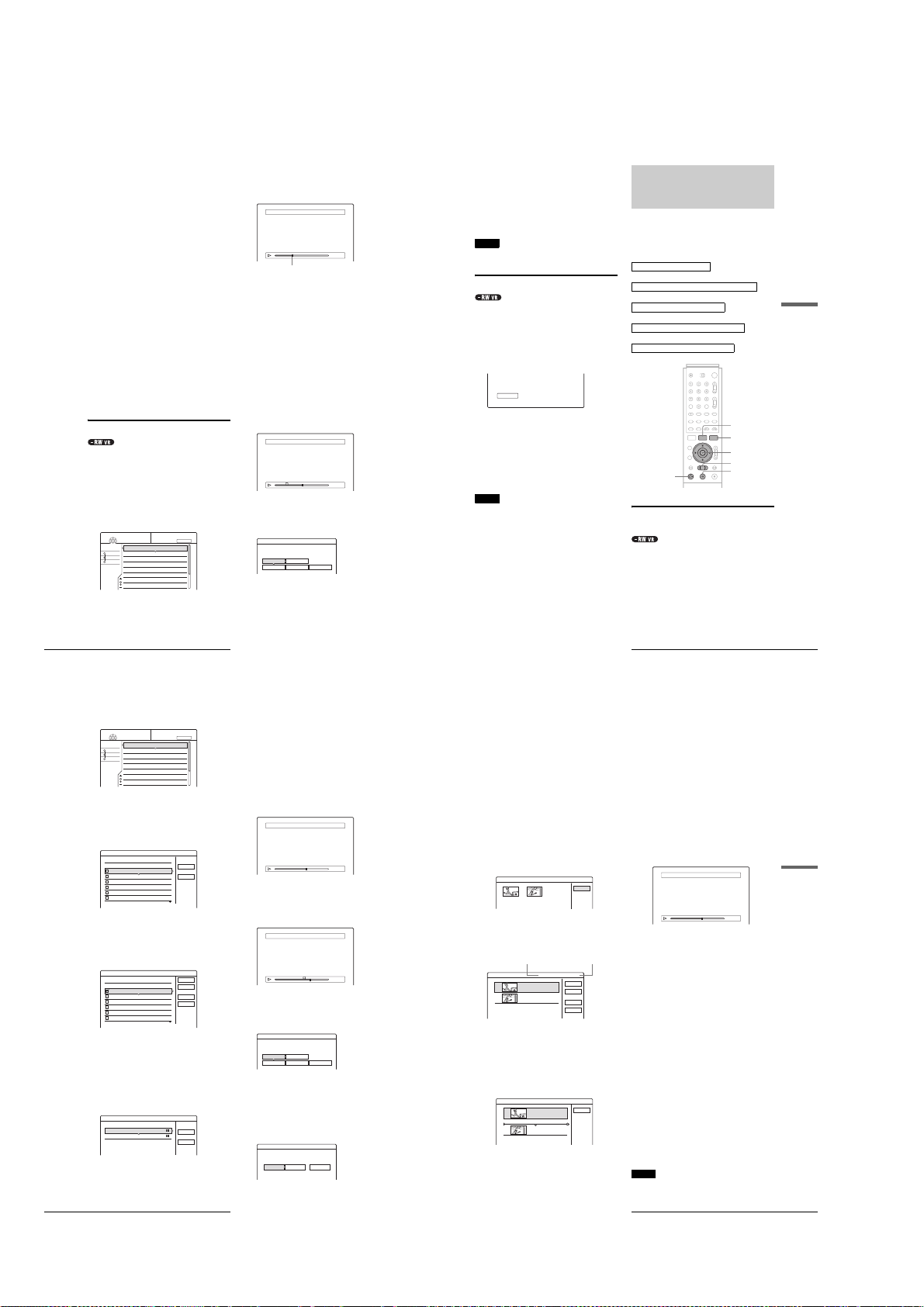
To list all of the titles to be erased, select “List.”
To clear all the check marks, select “Reset All.”
e Repeat step 4 to select all the titles you want
to erase.
◆ When the selected title is protected
The display asks for confirmation.
• To continue the procedure, press , to select
“Change.”
The protection display appears. Select “Off” by
pressing </,, then press ENTER.
• To cancel the procedure, se le ct “Close” by pressing
</,, then press ENTER.
◆ When the selected title is referred to by a
Playlist
Select “Close” as you are unable to delete an original
title that is referred to by a Playlist.
If you want to delete the original title, first delete the
Playlist title. Then, delete the original title.
f Press </, to select “OK,” then press
ENTER.
The display asks for confirmation.
To return to the display for selecting titles, select
“View All.”
g Press </, to select “OK,” then press
ENTER.
z
Hint
If you are using a DVD-RW (Video mode) or DVD+RW, you can erase
a title using the Disc Map (page 38).
Erasing a section of a title (A-B Erase)
You can erase a section of a title using the sub-menu.
◆For original titles in a DVD-RW (VR mode):
Note that you are unable to erase the original title if there is a
Playlist title derived from the original title.
a Press TITLE LIST.
The Title List menu appears. If you are using a DVDRW (VR mode), press TOOLS and select either
“Original” or “Playlist” from the TOOLS menu to
change the Title List, if necessary.
My Movies
TITLE LIST
-RW.VR
1 2ch 1:00PM - 2:00PM
Sort
Date
2 5ch 8:00PM - 9:00PM
Number
3 12ch 9:00AM - 9:30AM
Title
4 3ch 8:00PM - 8:30PM
5 25ch 8:00PM - 8:30PM
6 L2 9:00PM - 9:30PM
7 8ch 9:00PM - 9:30PM
8 125ch 10:00AM - 10:30AM
b Press M/m to select the title, then press
ENTER.
The sub-menu appears.
Basic Editing
66
1.5/4.7GB
ORIGINAL
9/15
9/17
9/25
9/25
10/15
10/19
10/26
10/28
c Press M/m to select “A-B Erase,” then press
ENTER.
The display for setting point A appears.
The selected title plays in the background. The slider
indicates the current playback point.
A-B Erase (Set point A)
2 5ch 8:00PM - 9:00PM
A 0:12:34
–– –– –
B : :
2 5ch 8:00PM - 9:00PM
A 0:12:34
B 0:23:45
Playback point
◆ When the selected title is protected
The display asks for confirmation.
• To continue the proc edure, press </, to select
“Change.”
The protection display appears. Select “Off” by
pressing </,, then press ENTER.
• To cancel the procedure, select “Close” by pressing
</,, then press ENTER.
◆ When the selected title is referred to by a
Playlist
Select “Close” as you are unable to delete an original
title that is referred to by a Playlist.
If you want to delete a section of the original title,
first delete the Playlist title. Then, delete the section.
d While watching the playback picture, set
point A using H PLAY, X PAUSE, and
m/M, then press ENTER.
The display for setting point B appears, and the title
continues to play in the background.
A-B Erase (Set point B)
A
e While watching the playback picture, set
point B using H PLAY, X PAUSE, and
m/M, then press ENTER.
The display asks for confirmation.
A-B Erase
Erase the scene
between A 0:12:34 and B 0:23:45?
OK Cancel
Preview Change A Change B
To preview, select “Preview.”
To reset either point A or B, select “Change A” or
“Change B.”
f Press </M/m/, to select “OK,” then press
ENTER.
The scene is erased, and the display asks whether to
erase another scene.
g To exit, press </, to select “No,” then
press ENTER.
The display returns to the Title List menu.
To continue, select “Yes” and repeat the steps above.
Notes
• Images or sound may be momentarily interrupted at the point where
you erase a section of a title.
• Sections shorter than five seco nds m ay not be era sed .
Creating chapters manually
You can manually insert a chapter mark at any point you like.
Press CHAPTER MARK during playback at the
point where you want to divide the title into
chapters.
Each time you press the button, “Marking…” appears on the
screen and the scene to the left and right of the mark becomes a
chapter.
Marking...
To erase chapter marks
You can combine two chapters by erasing a chapter mark during
playback.
1
Press . PREV or > NEXT to search for a
chapter number.
2
Press CHAPTER ERASE while displaying the
chapter you want to erase.
The current playing chapter combines with the
previous chapter.
Notes
• Playback may momentarily stop when inserting a chapter mark.
• A message wil l ap pear when no more chapter marks can be added. In
this case, you may not be able to record or edit the disc.
Advanced Editing (Playlist
Edit)
This section explains how to create a Playlist, and then covers
available edit functions for the created Playlist.
Playlist titles can be created from scenes that are selected
original titles or other Playlist titles.
Since edits to the Playlist does not affect the original title, you
can redo editing as many times as you like.
To create a Playlist title, you will do the following.
1.Select a title or titles for editing
m
2.“Capture” multiple scenes from the selected title(s)
m
3.Confirm the scenes on the Scene List
m
4.If necessary, edit the scenes on the S cene List
m
5.Connect scenes to create a “Play list” title
TITLE LIST
TOOLS
</M/m/,,
ENTER
m/M
H PLAY
Creating a Playlist title from other
titles
Collect your favourite scenes from original t itles or other Playlist
titles to create a new Playlist title. You can rearrange the order of
the scenes, delete scenes, or edit the scenes as well.
a Press TITLE LIST.
The Title List (Original) menu or the Title List
(Playlist) menu appears.
Example: The Title List (Original) menu.
X PAUSE
Advanced Editing (Playlist Edit)
,
Editing a DVD
continued
67
My Movies
TITLE LIST
-RW.VR
1 2ch 1:00PM - 2:00PM
Sort
Date
2 5ch 8:00PM - 9:00PM
Number
3 12ch 9:00AM - 9:30AM
Title
4 3ch 8:00PM - 8:30PM
5 25ch 8:00PM - 8:30PM
6 L2 9:00PM - 9:30PM
7 8ch 9:00PM - 9:30PM
8 125ch 10:00AM - 10:30AM
b Press TOOLS.
The TOOLS menu appears.
c Press M/m to select “Create Playlist,” then
press ENTER.
The display for selecting titles appears.
Create Playlist
Select the titles you want to capture.
Original
1 2ch 1:00PM - 2:00PM
2 5ch 8:00PM - 9:00PM
3 12ch 9:00AM - 9:30AM
4 3ch 8:00PM - 8:30PM
5 25ch 8:00PM - 8:30PM
6 L2 9:00PM - 9:30PM
d Press M/m to select the title you want to
include in the Playlist title, then press
ENTER.
A check mark appears in the check box next to the
selected title.
To clear the check mark, press ENTER again.
Create Playlist
Select the titles you want to capture.
Original
1 2ch 1:00PM - 2:00PM
2 5ch 8:00PM - 9:00PM
3 12ch 9:00AM - 9:30AM
4 3ch 8:00PM - 8:30PM
5 25ch 8:00PM - 8:30PM
6 L2 9:00PM - 9:30PM
1.5/4.7GB
ORIGINAL
10/15
10/19
10/26
10/28
9/15
9/17
9/25
9/25
10/15
10/19
9/15
9/17
9/25
9/25
10/15
10/19
To select all of the titles, select “Select All.”
e Repeat step 4 when adding more titles.
To go to the next page, press m.
To clear all the check marks, select “Reset All.”
f Press </, to select “OK,” then press
ENTER.
The list of selected titles appears.
Create Playlist - Selected Titles
Select a title to start capturing.
1 2ch 1:00PM - 2:00PM
2 5ch 8:00PM - 9:00PM
9/15
9/17
To add another title, select “Add Title.”
Advanced Editing (Playlist Edit)
68
9/15
9/17
9/25
9/25
Select All
Select All
Reset All
Add Title
g Press M/m to select one of the titles, then press
ENTER.
The sub-menu appears.
◆ To add the entire title as one scene to the
Playlist title
Select “Capture All” and go to step 14.
h Press M/m to select “Capture,” then press
ENTER.
The display for setting the start point (IN) appears.
The selected title starts to play in the background.
Capture (Set IN point)
2 5ch 8:00PM - 9:00PM
Cancel
i While watching the playback picture, select
the start of the scene using H PLAY, X
PAUSE, and m/M, then press ENTER.
The display for setting the end point (OUT) appears,
and the title continues to play in the background.
Capture (Set OUT point)
OK
Cancel
Cancel
j While watching the playback picture, select
the end point of the scene using H PLAY,
X PAUSE, and m/M, then press ENTER.
The display asks for confirmation.
Capture
Do you want to capture the scene
between IN 0:10:26 and OUT 0:23:45?
OK Cancel
Preview Change IN Change OUT
To view the selected scene, select “Preview.”
To reset either the IN or OUT point, select “Change
IN” or “Change OUT.”
k Press </, to select “OK,” then press
ENTER.
The selected portion is captured as a scene, and the
display asks whether to continue scene capture.
Capture
Do you want to select another scene?
More No More New Title
2 5ch 8:00PM - 9:00PM
IN
IN
0:10:26
OUT
- : - - : - -
IN
0:10:26
OUT
0:23:45
l Press </, to select an option on the screen,
then press ENTER.
To capture a scene from the same title, select
“More,” and repeat the steps above.
To capture a scene from another title, select “New
Title,” and repeat the steps above.
m To end scene capture, press </, to select
“No More” and press ENTER.
The display returns to the list of selected titles.
◆ To check the captured scenes in a single title
A Press M/m to select a title from the list of
selected titles, then press ENTER.
The sub-menu appears.
B Press M/m to select “Check Scenes,” then press
ENTER.
The thumbnail pictures of the captured scenes
within the title appear.
Check Scenes
1 2
n Press </M/m/, to select “Scene List,” then
press ENTER.
The Scene List menu appears with all of the selected
scenes.
Total duration of the selected scene
Scene List
1
2
◆ To change the scene order (Move)
A Press M/m to select the scene you want to
move, then press ENTER.
The sub-menu appears.
B Press M/m to select “Move,” then press
ENTER.
The display for selecting the insertion point
appears.
Move
1
Where do you want to move this scene to?
2
C Press M/m to select the insertion point, then
press ENTER.
The scene moves to its new position, and the
display returns to the Scene List menu.
Total 0:33:28 Scenes 2
5ch 8:00PM - 9:00PM -1
0:10:26 - 0:23:45
5ch 8:00PM - 9:00PM -2
0:25:00 - 0:45:08
5ch 8:00PM - 9:00PM -1
0:10:26 - 0:23:45
5ch 8:00PM - 9:00PM -2
0:25:00 - 0:45:08
2 5ch 8:00PM - 9:00PM
Total number of scenes
OK
Quit
Add
Preview
Cancel
Close
◆ To erase the scene (Erase)
A Press M/m to select the scene you want to
erase, then press ENTER.
The sub-menu appears.
B Press M/m to select “Erase,” then press
ENTER.
C When the display asks for confirmation, press
</, to select “OK,” then press ENTER.
◆ To change the scene contents (Change IN/
Change OUT)
A Press M/m to select the scene you want to
change, then press ENTER.
The sub-menu appears.
B Press M/m to select “Change IN,” then press
ENTER.
The display for setting the IN point appears.
Capture (Set IN point)
2 5ch 8:00PM - 9:00PM
IN
0:10:26
OUT
0:23:45
C Repeat steps 9 to 14.
To reset the OUT point, select “Change OUT,”
then repeat steps 10 to 14.
The display returns to the Scene List menu.
◆ To add another scene
Press </M/m/, to select “Add,” then press
ENTER. Repeat steps above.
◆ To preview the entire Playlist title
Press </M/m/, to select “Preview,” then press
ENTER. The captured scenes start to play in the
listed order. When the playback is finished, the
display returns to the Scene List menu.
o Press </, to select “OK,” then press
ENTER.
The scenes are connected to create a new Playlist
title, and the display for entering the title name
appears.
◆ To enter a new name
Select “Enter” and follow the explanations on
page 34.
◆ To use the default name
Press </, to select “OK,” then press ENTER.
A new Title List menu appears with the title of the
entered name.
z
Hint
When a Playlist title is created, the “IN” point and “OUT” point will
become chapter marks, and each scene will become a chapter.
Notes
• You can capture, m ove , or change the IN and OUT points for a
maximum of 50 scenes per title.
• The picture may pa us e when the edited scene is played.
Advanced Editing (Playlist Edit)
,
Editing a DVD
continued
69
1-16
Page 23

Moving a Playlist title (Move Title)
71
Advanced Editing (Playlist Edit)
Editing a DVD
Combining multiple Playlist titles
(Combine Titles)
You can add new contents to an existing Playlist title by
combining the title with other Playlist titles.
a Press TITLE LIST.
The Title List menu appears.
If the Title List (Original) menu appears, press
TOOLS, and select “Playlist” from the TOOLS
menu.
b Press TOOLS.
The TOOLS menu appears.
c Press M/m to select “Combine Titles,” then
press ENTER.
The display for selecting titles appears.
d Press M/m to select the title, then press
ENTER.
A number appears next to the selected title,
indicating the order in which you selected the title.
To cancel the selection, move the cursor to the
selected title by pressing M/m, then press ENTER
again.
e Repeat step 4 to select all the titles you want
to combine.
To list the titles to be combined, select “List.”
To cancel all of the selections, select “Reset All.”
f Press , to select “OK,” then press ENTER.
The display asks for confirmation.
To change the selection, select “Change.”
g Press
</,
to select “OK,” then press
ENTER.
The display for selecting a title name from among the
selected titles appears.
To enter a new name, select “Enter Text,” and follow
the explanations on page34.
h Press M/m to select a name, then press
ENTER.
The titles are combined, and the display returns to the
Title List menu.
Additional Playlist edit functions
You can also do the following edits for Playlists.
–Label a Playlist title (page 64).
–Erase a Playlist title (page 65).
–Erase multiple Playlist titles (page 65).
–Erase a section of a Playlist title (A-B Erase) (page 66).
–Create chapters in a title (page 67).
To perform these edits, press TITLE LIST * and then follow the
same steps for these functions explained in “Basic Editing”
(page 64).
*If the Title List (Original) menu appears, press TOOLS and select
“Playlist” from the TOOLS menu.
Note
Erasing Playlist titles will not free up disc space.
Sort
Date
Number
Title
1.5 / 4.7GB
My Movies
TITLE LIST
PLAYLIST
-RW.VR
1 2ch 1:00PM - 2:00PM
2 5ch 8:00PM - 9:00PM
3 2ch 1:00PM - 2:00PM
4 2ch 1:00PM - 2:00PM
9/15
9/17
9/28
10/ 5
Combine
Select the titles to combine.
Cancel
1 2ch 1:00PM - 2:00PM
2 5ch 8:00PM - 9:00PM
3 2ch 1:00PM - 2:00PM
4 2ch 1:00PM - 2:00PM
9/15
9/17
9/28
10/ 5
Combine
Select the titles to combine.
Cancel
Reset All
1
1 2ch 1:00PM - 2:00PM
2 5ch 8:00PM - 9:00PM
3 2ch 1:00PM - 2:00PM
4 2ch 1:00PM - 2:00PM
9/15
9/17
9/28
10/ 5
Combine
Combine the titles in the following order.
OK Change
1
2
3
1 2ch 1:00PM - 2:00PM
2 2ch 1:00PM - 2:00PM
3 2ch 1:00PM - 2:00PM
9/15
9/28
10/ 5
73
Labeling, Protecting, or Finalizing the Disc
Editing a DVD
c Press M/m to select “Protect Disc,” then press
ENTER.
The display for setting disc protection appears.
d Press </, to select “Protect,” then press
ENTER.
The display returns to the Disc Information display.
e Press RETURN to turn off the display.
To cancel the disc protection
1
Repeat steps 1 to 3 above.
The display for setting disc protection appears.
2
Press </, to select “Don’t Protect.”
The display returns to the Disc Information display.
3
Press RETURN to turn off the display.
Finalizing a disc (Finalize)
Finalizing is necessary when you play discs recorded with this
recorder on other DVD equipment.
Before finalizing, check the differences between the disc types
on the table below.
When you finalize a DVD-RW (Video mode), DVD+RW, or
DVD-R, a DVD menu will be automatically created, which can
be displayed on other DVD equipment.
When a finalized disc is in the recorder, the FINALIZED
indicator lights up on the front panel.
Differences between the disc types
a Press TOOLS while the disc is in the
recorder.
The TOOLS menu appears.
b Press M/m to select “Disc Info.,” then press
ENTER.
The Disc Information display appears.
c Press M/m to select “Finalize,” then press
ENTER.
The display shows the approximate time required for
finalizing and asks for confirmation.
d Press </, to select “OK,” then press
ENTER.
The recorder starts finalizing the disc.
To unfinalize a disc
If you cannot record or edit on the DVD-RW (VR mode) that has
been finalized with other DVD equipment (a message appears),
unfinalize the disc.
Select “Unfinalize” in step 3 above.
z
Hint
You do not need to finalize a disc again once t he disc has been finalized
with this recorder.
Notes
• Depending on the cond ition of the disc, recording, or the DVD
equipment, discs may not play even when the discs are finalized.
• The recorder may not be able to finalize the disc if it was recorded on
another recorder.
Erasing all the titles on the disc (Erase
All)
You can erase all the titles on the disc except the titles you have
set protection.
The disc name and recording format remain the same.
a Press TOOLS while the disc is in the
recorder.
The TOOLS menu appears.
Finalizing is unnecessary when playing a disc
on VR format compatible equipment.
You may need to finalize the disc depending on
the DVD equipment, or if the recording time is
short. You can edit or record on the disc even
after finalizing.
Finalizing is unnecessary, since DVD+RWs are
automatically finalized when removed from the
recorder. However, you may need to finalize the
disc by following the steps below for certain
DVD equipment, or if the recording time is
short. You can edit or record on the disc even
after finalizing.
Finalizing is necessary when playing on
equipment other than this recorder. After
finalizing, you cannot edit or record on the disc.
If you want to record on it again, reformat the
disc (page 74). However, all contents recor de d
on the disc will be erased.
Finalizing is necessary when playing on
equipment other than this recorder. After
finalizing, you cannot edit or record on the disc.
Protect Disc
Select the protection status for this disc.
Protect Don't Protect
Disc Information
DiscName Movie
Close
Media DVD-RW Format VR
Title no. Original 3 / Playlist 2
Protected Not Protected
Date 9/15/2003 ~ 10/28/2003
HQ : 0H30M
LP : 1H30M
HSP : 0H45M
EP : 2H00M
SP : 1H00M
2. 3 / 4. 7GB
SLP : 3H00M
Remainder
Disc Name
Format
Erase All
Finalize
Protect Disc
Finalize
About xx min is needed for finalizing this disc.
Cannot cancel finalizing during transaction.
Do you want to finalize?
OK Cancel
,
continued
You can change the Playlist title order within the Title List
(Playlist).
a Press TITLE LIST.
The Title List menu appears.
If the Title List (Original) menu appears, press
TOOLS, and select “Playlist” from the TOOLS
menu.
My Movies
-RW.VR
Sort
Date
Number
Title
TITLE LIST
1 2ch 1:00PM - 2:00PM
2 5ch 8:00PM - 9:00PM
1.5/4.7GB
PLAYLIST
9/15
9/17
b Press < to select the sort buttons.
c Press M/m to select “Number,” then press
ENTER.
d Press M/m to select the title you want to move,
then press ENTER.
The sub-menu appears.
e Press M/m to select “Move Title,” then press
ENTER.
The display for moving titles appears.
f Press M/m to select the new location, then
press ENTER.
The title moves to its new location, and the display
returns to the new Title List (Playlist) menu.
Dividing a Playlist title (Divide Title)
You can divide a Playlist title into two Playlist titles. For
example, if a Playlist title contains two football matches, you can
divide the title where the first match ends.
a Press TITLE LIST.
The Title List menu appears.
If the Title List (Original) menu appears, press
TOOLS, and select “Playlist” from the TOOLS
menu.
My Movies
PLAYLIST
1 2ch 1:00PM - 2:00PM
1.5/4.7GB
9/15
9/17
0:12:34
TITLE LIST
-RW.VR
1 2ch 1:00PM - 2:00PM
Sort
Date
2 5ch 8:00PM - 9:00PM
Number
Title
b Press M/m to select the title, then press
ENTER.
The sub-menu appears.
c Press M/m to select “Divide Title” then press
ENTER.
The display setting the dividing point appears.
The selected title starts to play in the background.
Divide
d While watching the picture on the screen,
move the playback point using H PLAY,
X PAUSE, and m/M.
e Press ENTER at the point where you want to
divide the title.
The display asks for confirmation.
Divide
Do you want to divide this title at this point?
OK Change Cancel
To change the dividing point, select “Change.”
f Press </, to select “OK,” then press
ENTER.
The display asks if you want to enter a new name.
◆ To enter a new name
Select “Yes” and follow the explanations on page34.
◆ To use the same name as before
Select “No.”
The title is divided and the Title List menu appears
with the two divided titles.
Advanced Editing (Playlist Edit)
70
Labeling, Protecting, or
Finalizing the Disc
Using the Disc Information display, you can label, protect, or
finalize your disc. You can even eras e the entire disc except for
the protected titles. This section explains settings effective for
the entire disc.
Labeling a disc (Disc Name)
You can enter up to 64 characters for a disc name (the actual
number of displayed characters will vary). The disc name will be
displayed in the Title List, etc.
a Press TOOLS while the disc is in the
b Press M/m to select “Disc Info.,” then press
Labeling, Protecting, or Finalizing the Disc
72
RETURN
recorder.
The TOOLS menu appears.
ENTER.
The Disc Information display appears.
Example: When the inserted disc is a DVD-RW (VR
mode).
Disc Information
DiscName
Media DVD-RW Format VR
Title no. Original 3 / Playlist 2
Protected Not Protected
Date 9/15/2003 ~ 10/28/2003
HQ : 0H30M
LP : 1H30M
Remainder
HSP : 0H45M
SP : 1H00M
SLP : 3H00M
EP : 2H00M
2. 3 / 4. 7GB
TOOLS
</M/m/,,
ENTER
Close
Disc Name
Protect Disc
Finalize
Erase All
Format
c Press M/m to select “Disc Name,” then press
ENTER.
The display for entering a disc name appears.
Input Disc Name
,. - 1
1
BA C 2
2
ED F 3
3
HG I 4
4
KJ L5
5
d Enter a name by following the explanation on
page 34.
The Disc Information display appears with the new
disc name.
Disc Information
DiscName Movie
Media DVD-RW Format VR
Title no.
Original 3 / Playlist 2
"A"
NM O 6
6
"a"
Back
QP R S
7
Symbol
Clear All
UT V 8
8
XW Y Z79
9
Space
Cancel
0
0
Finish
Close
Disc Name
Protect Disc
e Press RETURN to turn off the display.
Note
The disc name will not appear when the disc is played on a differ ent
recorder.
Protecting a disc (Protect Disc)
You can protect an entire disc. To protect individ ual titles, see
page 64.
Note that this protection is effective only for inadvertent edit
commands and erasure.
a Press TOOLS while the disc is in the
recorder.
The TOOLS menu appears.
b Press M/m to select “Disc Info.,” then press
ENTER.
The Disc Information display appears.
Disc Information
DiscName Movie
Media DVD-RW Format VR
Title no. Original 3 / Playlist 2
Protected Not Protected
Date 9/15/2003 ~ 10/28/2003
HQ : 0H30M
LP : 1H30M
Remainder
HSP : 0H45M
EP : 2H00M
SP : 1H00M
SLP : 3H00M
2. 3 / 4. 7GB
Close
Disc Name
Protect Disc
Finalize
Erase All
Format
1-17
Page 24

b Press M/m to select “Disc info.,” then press
ENTER.
The Disc Information display appears.
Disc Information
DiscName Movie
Media DVD-RW Format VR
Title no. Original 3 / Playlist 2
Protected Not Protected
Date 9/15/2003 ~ 10/28/2003
HQ : 0H30M
LP : 1H30M
Remainder
c Press M/m to select “Erase All,” then press
ENTER.
The display asks for confirmation.
When there is a protected title on the disc, a list of
protected titles appears.
Erase All Titles
Do you want to erase all the titles?
OK Cancel
d Press </, to select “OK,” then press
ENTER.
The titles are erased.
HSP : 0H45M
EP : 2H00M
SP : 1H00M
SLP : 3H00M
2. 3 / 4. 7GB
Close
Disc Name
Protect Disc
Finalize
Erase All
Format
Reformatting a disc (Format)
By reformatting, you can change the recording format of DVDRWs, or record again on DVD-RWs (Video mode) that have
been finalized. Make sure nothing important is left on the disc,
as all the disc contents will be erased. For DVD+RWs, reformat
the disc if you want to create a blank disc.
a Press TOOLS while the disc is in the
recorder.
The TOOLS menu appears.
b Press M/m to select “Disc Info.,” then press
ENTER.
The Disc Information display appears.
Disc Information
DiscName Movie
Media DVD-RW Format VR
Title no. Original 3 / Playlist 2
Protected Not Protected
Date 9/15/2003 ~ 10/28/2003
HQ : 0H30M
LP : 1H30M
Remainder
c Press M/m to select “Format,” then press
ENTER.
The display asks for confirmation.
d Press </, to select “OK,” then press
ENTER.
Labeling, Protecting, or Finalizing the Disc
74
HSP : 0H45M
EP : 2H00M
SP : 1H00M
SLP : 3H00M
2. 3 / 4. 7GB
Close
Disc Name
Protect Disc
Finalize
Erase All
Format
◆ When you place a DVD-RW and set “Format
Disc” to “Selectable” in Options Setup
The display asks you to select the recording format.
Format
Select the recording format.
VR Video
Press </, to select “VR” or “Video,” then press
ENTER.
The recorder starts formatting the disc.
Notes
• Even when you have set protection for the title, all the c ontents will be
erased after formatting the disc.
• A protected disc cannot be reformatted (DVD-RW in VR mode only ).
Connecting a
Digital Video
Camera or
Other
Equipment
You can record from connected equipment,
such as a digital video camera.
•
Before Recording/Editing
•
Available DV Dubbing Functions
•
Recording an Entire DV/Digital8 Format Tape
(ONE TOUCH DUB)
•
Program Edit
. . . . . . . . . . . . . . . . . . . . . . . . . . . .
•
Advanced Program Edit
•
Re-editing the “program” in the DV/D8 Edit List
•
Creating a Copy of the Edited Contents (Copy
Dubbing)
. . . . . . . . . . . . . . . . . . . . . . . . . . . .
•
Recording From Equipment Connected to the
LINE IN Jacks
. . . . . . . . . .
page 75
. . . . .
page 77
. . . . . . . . . . . . . . . . . . . . . .
. . . . . . . . . . . . . . . . . . . . . .
. . . . . . . . . . . . . . . . . . . . . .page88
page 78
page 79
. . . . . .
page 81
page 84
page 86
Before Recording/Editing
The recorder has a DV IN jack that inputs digital signals, and
LINE jacks that input/output analogue signals.
The DV IN jack on this recorder conforms to the i.LINK
standard. You can connect other equipme nt tha t ha s an i.LIN K
(DV) jack. For more information, see “About i.LINK”
(page 106).
If you plan to do additional editing on a disc afte r the initia l dub,
use the DV IN jack and record on a DVD-RW in VR mode.
◆When recording from the DV IN jack
See “Preparing for recording using the DV IN jack” below.
◆When recording from the LINE IN jacks
See “Recording From Equipment Connected to the LINE IN
Jacks” (page 88).
Preparing for recording using the DV IN
jack
You can connect a digital video camera to the DV IN jack on the
recorder to record or edit from a DV/Digital8 format tape.
Operation is smooth because the recorder will fast forward and
rewind the tape for you – you do not need to operate your di gital
video camera. Do the following to start using the DV Edit
functions of this recorder.
See also the instruction manual supplied with the digital video
camera before connecting.
◆If you connect a digital video camera but cannot use the DV
Edit functions
See “Recording from connected equipment” (page 88).
Notes
• The DV IN jack on this recorder is for input only. If you want to have
the recorder output signals, for example, w hen you use this r ecorder as
source player, connect other equipment to this recorde r’s LINE OUT
jacks.
• Only DVC-SD form at signals can be input to the DV IN jac k on this
recorder. Do not connect a MICRO MV format digital video camera
even if it has an i.LIN K jack.
• Recording may be l imited if the images on the tape contain copyrig ht
protection signals.
Before Recording/Editing
,
Connecting a Digital Video Camera or Other Equipment
continued
75
Hookups
Digital video camera
: Signal flow
Z OPEN/CLOSE
REC MODE
INPUT SELECT
a Turn on your TV and this recorder, then set
the TV to the connected channel (“VIDEO”
etc.).
b Press Z OPEN/CLOSE, and place a
recordable disc on the tray.
Make sure that the disc has enough free space to
record the contents of your tape.
To DV IN
i.LINK cable
(not supplied)
DV output
DVD recorder
TOOLS
M/m, ENTER
c Press Z OPEN/CLOSE to close the disc tray.
Wait until “LOAD” disappears from the front panel
display.
If you use an unused DVD, formatting starts
automatically.
When using an unused DVD-RW, select the
recording format, VR or Video.
d Insert the source DV/Digital8 format tape
into the digital video camera.
For the recorder to record or edit, the digital video
camera must be set to video playback mode.
e Press INPUT SELECT on the remote
repeatedly to select “DV.”
The front panel display changes as follows.
Channel
number
f Press REC MODE on the remote repeatedly
to select the recording mode.
The recording mode changes as follows:
L2L1 L3 DV
HQ SP LP EPHSP SLP
g Select the audio input for the digital video
camera using the TOOLS menu.
A Press TOOLS.
B Press M/m to select “DV/D8 Audio Input,”
then press ENTER.
C Press M/m to select the item, then press
ENTER.
• Stereo1 (default)
• Mix (both stereo 1 and stereo 2)
• Stereo2
You are ready to start recording.
z
Hints
• You can adjust the set tings for the recording picture before recording.
See “Adjusting the Recording Picture Quality and Si ze” (page46).
• If you plan to re-e dit the “program” (page 77), insert a DVD-RW and
format it in VR mode.
Notes
• You cannot conne ct more than two pieces of digital video equipment
to the recorder.
• Depending on the digital vid eo e qui pment, you may not be able to
control the equipment.
• You cannot control the rec orde r using another device or another
recorder of the same model.
• You cannot record date , time or the contents of the cassette memory
onto the disc.
• If you record from a DV / D ig ital8 format tape with a sound track that
is recorded in multiple sampling frequen cies (48 kHz, 44.1 kHz, or 32
kHz), no sound will be output when playing b ack the switched point on
the disc.
• In order to use this recorder’s Auto Scene Chaptering feature, be sure
to correctly set the clock on your digital video camera be fore shooting.
• The recorded picture m ay be m omentarily affected if the picture size
of the source image changes, or if the re is nothing recorded on the tape.
Available DV Dubbing
Functions
◆One Touch Dub
(page 78)
Records the entire contents of a DV/Digital8 format tape to a
disc of your choice with a single touch of the ONE TOUCH
DUB button.
(page 79)
◆Program Edit
Allows you to select scenes from a DV/Digital8 format tape, and
then record the selected scenes to a disc of your choice. As you
select the scenes, you will create a “program” (see below), which
will then be used to dub the selected scenes to a disc. Before you
dub the scenes, you can rearrange the order and make other
changes using the “Scene List” (see below).
◆Advanced Program Edit
Allows you to select scenes from a DV/Digital8 format tape by
first recording the entire contents of the tape to a DVD-RW (VR
mode), whereupon you can easily create a “program” (see
below). By first copying the entire contents of the tape to a disc,
the start and stop points on the tape automatically beco me scenes
(you can also select scenes manually). These scenes are
displayed in a “scene list” (see below). You can then delete,
rearrange, or select new scenes to create a “program.” Once the
“program” is complete, you will use it to copy the scenes to a
disc of your choice from the “DV/D8 Edit List” (see below).
Furthermore, you can also automatically create a Playlist of the
edited scenes and save it on the DVD-RW (VR mode) you used
to originally record the entire contents of the tape.
◆Re-editing the “program” in the DV/D8 Edit List (DVD-RW in
VR mode only)
Allows you to select the “program” (see below) created during
One Touch Dub or Advanced Program Edit from the “DV/D8
Edit List” (see below), and make further edits before coping the
contents to a disc. You can delete or create new scenes, or
rearrange the order of existing scenes.
◆Copy Dubbing
Allows you to make duplicate copies of the “programs” (see
below) in the “DV/D8 Edit List” (see below) to a disc of your
choice. When making copies, you will need the original DV/
Digital8 format tapes used to create the “program.”
About “programs”
“Programs” are automatically created whenever you make a On e
Touch Dub, Program Edit, or Advanced Program Edit . These
programs are stored in the “DV/D8 Edit List” (see below) and
contain editing information such as which scenes have been
selected, moved, or deleted.
Programs are useful when you want to make duplicates of the
edited contents because you do not have to select the same
scenes again from the tape – just select the program. You can
also re-edit the program to create different variations of the
original program. Note that programs contain onl y th e start and
stop points of the scenes; they do not contain the actual scenes
themselves so you need to use the original DV/Digital8 format
tapes to copy a program to a disc.
(page 81)
(page 84)
(page 86)
◆About the “DV/D8 Edit List”
The “DV/D8 Edit List” contains the “programs.” If you re-edit
the program, the re-edited program is stored in the DV/D8 Edit
List, but the original program is lost. You can st ore up to 20
programs in the DV/D8 Edit List.
DV/D8 EDIT LIST
DV10/11/02 1:30PM - 11/12/02 4:46PM
DV12/11/02 1:00PM - 12/11/02 7:05PM
DV12/24/02 11:34AM - 12/25/02 1:24PM
1 Disc mark
2 Program name
3 Total playing time
4 Date of editing or recording
◆About the “Scene List”
The contents of the programs are contained in the “Scene Li st.”
A thumbnail of each scene, as well as the length of the scene is
displayed in the list. You can add or delete scene s, or chan ge the
order of the scenes. 50 scenes can be made for each program.
SCENE LIST
1
2
3
4
1 Thumbnail picture
2 Time information
3 Total duration of the program
4 Total number of scenes
Note
After you make a dubbing, do not throw away or record over y our tapes.
You will need them later to make additional edits or c opi es.
0:00:30-0:00:52
Duration 0:00:22
0:01:40-0:06:23
Duration 0:06:43
0:07:07-0:10:51
Duration 0:03:44
0:11:40-0:16:19
Duration 0:04:39
1H12M 6/ 5
1H16M 6/10
1H24M 6/18
Total 1:23:30 Scenes 20
OK
Quit
Add
Connecting a Digital Video Camera or Other Equipment
Before Recording/Editing
76
1-18
Available DV Dubbing Functions
77
Page 25

Recording an Entire DV/
79
Program Edit
Connecting a Digital Video Camera or Other Equipment
Program Edit
You can select scenes from a DV/Digital8 format tape, and then
automatically record selected scenes to a disc of your choice.
Example for DVD-RWs (VR mode)
When using a DVD-RW (VR mode), chapter marks [b] are
marked where the recordings start on the tape [a] (Auto Scene
Chaptering). Chapter marks are also inserted at the IN points of
the selected scenes [c].
For other discs, the recorder marks chapters either in 6 or 15
minute intervals depending on the setting in “Auto Cha pt er” in
Features Setup (page 97).
To use this function, you will do the fol l owing:
m
Using the recorder’s remote control, you will fast forward or
rewind the tape to select the scenes. At this point, the selected
scenes are not copied to the disc. The recorder only remembers
the IN and OUT points of the scenes that you selected for
dubbing. You can also reset, erase, or change the order of the
scenes.
m
After you have selected the scenes, the recorder will fast forward
and rewind the tape automatically and record the scenes to a disc
of your choice.
a Follow steps 1 to 7 of “Preparing for recording
using the DV IN jack” (page 75), then press
SYSTEM MENU.
b Press M/m to select “DV/D8 EDIT,” then
press ENTER.
The DV/D8 Edit menu appears.
c Press M/m to select “Program Edit,” then
press ENTER.
The display asks whether to start selecting scenes.
◆ If you have previously saved a program
The display asks whether to edit an existing program
or to create a new program. To resume editing the
existing program, select “Saved Data.”
d Press
</,
to select “Start,” then press
ENTER.
The display for setting the IN point (start of the scene
on the tape) appears.
e Press H PLAY to start playback of the tape
in your digital video camera.
The scene starts to play in the background.
Connect your digital video camera and prepa re for recording
Select and edit the scenes you want to dub
Dub the selected scenes to a disc
aa
bbb
cc
</M/m/,,
ENTER
RETURN
m/M
SYSTEM MENU
x REC STOP
H PLAY
DV/D8 EDIT
Select only the scenes you want to copy
from the DV/D8 tape.
Program Edit
Advanced Program Edit
DV/D8 Edit List
Scenes Selection
Do you want to select a scene?
Start Cancel
,
continued
81
Advanced Program Edit
Connecting a Digital Video Camera or Other Equipment
l Press </, to select “Start,” then press
ENTER.
The recorder starts recording the tape contents as
programmed.
To quit recording, press x REC STOP.
m When the recording is finished, press
ENTER to select “Close.”
The display returns to the DV/D8 Edit menu.
n Press RETURN repeatedly to turn off the
display.
Notes
• The disc may not be recorded as programmed if the tape’s time code is
not sequential or there are blanks between the rec ord ings on the tape.
In this case, follow the instructions of “Recording From Equi pment
Connected to the LINE IN Jacks” (page 88).
• The start a nd end points of a program may be different f rom what you
have set if the source DV/Digital8 format ta pe is in an y of the
following conditions:
– Recording mode was changed during the recording.
– There is a blank space in the recorded portion of the ta pe .
• If you set the be ginning of the tape as the IN point and the end point as
the OUT point, the IN and OUT points may change slightly during
dubbing.
• You cannot set a sce ne short er than one second.
• This function ma y not work with certain digital video cameras. In this
case, follow the instructions of “Recording From Equipment
Connected to the LINE IN Jacks” (page 88).
Advanced Program Edit
You can quickly edit a DV/Digital8 format tape by first copying
the entire contents of the tape to a DVD-RW (VR mode) and
then select the scenes you want from the disc. After you select
the scenes, you can change discs and record the scen es to another
disc of your choice. If necessary, you can also create a Pla ylist
title of the selected scenes in the DVD-RW (VR mode).
When dubbing to a DVD-RW (VR mode), chapter marks [b] are
marked where the recordings start on the tape [a] (Auto Scene
Chaptering). Chapter marks are also inserted at the I N p oints of
the selected scenes [c].
To use this function, you will do the following:
m
m
Taking advantage of the disc’s quick accessibility, you will
select the scenes you want from the recorded DVD-RW. You do
not have to fast forward or rewind the tape as exp lained in
“Program Edit” (page 79). You can also reset, erase, or change
the order of the scenes.
m
After you have selected the scenes, you can dub the selected
scenes to another disc of your choice. Or, you can create a
Playlist of the selected scenes.
Connect your digital video camera and prepare for recording
Record the entire contents of the DV/Digital8 tape to a
DVD-RW (VR mode)
Select and edit the scenes you want to dub
Dub the scenes to another disc
aa
bbb
cc
DVD-RW
(VR)
New disc
,
continued
Digital8 Format Tape (ONE
TOUCH DUB)
You can record the entire contents of a DV/Digital8 format tape
onto a disc with a single press of the ONE TOUCH DUB button.
The recorder controls the digital video camera for the whole
process, and completes the recording.
Example for all disc types
aa
bb
When using a DVD-RW (VR mode), chapter marks [b] are
marked where the recordings start on the tape [a] (Auto Scene
Chaptering).
For other discs, the recorder marks chapters either in 6 or 15
minute intervals depending on the setting in “Auto Chapter” in
Features Setup (page 97).
Follow steps 1 to 7 of “Preparing for recording
using the DV IN jack” (page 75), then press ONE
TOUCH DUB on the front panel of the recorder.
The recorder rewinds the tape and then starts recording the tape
contents.
When the recording is finished, the recorder rewinds the tape in
the digital video camera, and turns off.
To stop during recording
Press x REC STOP.
z
Hints
• The date and time of th e recording made with your digital video
camera is assigned as the program name in the DV/D8 Edit Li st
(page 84) (example: DV 10/25/03 10:00PM – 10/31/03 11:30PM) .
• If you set “Finalize Disc” to “Auto” in Features Setup (page 98), the
recorded disc will automatically be finalized after rec ordi ng is
finished.
Notes
• The recorder does not start One Touch Dub when you set “Add to Edit
List” to “On” (default) in Features Setup (page 98) and there are
already twenty programs on the recorder. In th is cas e, the recorder
beeps and the front panel display lights up. Delete unnecessary
programs from the DV/D8 Edit List menu (page84) and repeat the
steps above.
• When a blank space on the tape continues for more than five minutes,
One Touch Dub ends automatically.
• This function may not wo rk with certain digital video cameras. In this
case, follow the instructions of “Recording From Eq uipment
Connected to the LINE IN Jacks” (page88).
• In order for a On e Touch Dub recording to be added to the D V/D8 Edit
List, “Add to Edit List” in Features Setup must be set to “On” (def ault)
(page 98).
• The recorder au tomatically records a blank for five minutes before it
stops dubbing. When you press
recording, rewinds the tape, and turns off.
x
REC STOP, the recorder stops
Recording an Entire DV/Digital8 Format Tape (ONE TOUCH DUB)
78
f While watching the playback picture, search
g While watching the playback picture, search
h Press </M/m/, to select “OK,” then press
i Press </M/m/, to select “Add” and press
Program Edit
80
Select scene(Set IN point)
IN 0:00:30
OUT : :
–– – – –
for the IN point by pressing m or M, then
press ENTER.
The display for setting the OUT point (end of the
scene on the tape) appears. The scene starts to play in
the background from the IN point.
Select scene(Set OUT point)
IN 0:00:30
OUT 0:00:52
for the OUT point by pressing m or M,
then press ENTER.
The display asks whether to add the selected scene to
the Scene List menu.
Scenes Selection
Do you want to capture the scene
between IN 0:00:30 and OUT 0:00:52?
OK Cancel
Preview Change IN Change OUT
To preview the scene, select “Preview.”
To reset either the IN or OUT point, select “Change
IN” or “Change OUT.” Repeat from step 5.
ENTER.
A new Scene List menu appears with the selected
scene.
SCENE LIST
1
ENTER. Then repeat steps 5 to 9 to select all
the scenes you want to include.
You can add up to 50 scenes to a title.
Total 0:00:22 Scenes 1
0:00:30-0:00:52
Duration 0:00:22
OK
Quit
Add
Total 1:23:30 Scenes 20
SCENE LIST
0:00:30-0:00:52
1
Duration 0:00:22
0:01:40-0:06:23
2
Duration 0:06:43
0:07:07-0:10:51
3
Duration 0:03:44
0:11:40-0:16:19
4
Duration 0:04:39
To edit the Scene List, select a scene by pressing </
M/m/,, and then press ENTER. When the sub-
menu appears, select an edit option you want to apply
to the scene.
◆ To erase the scene
A Press M/m to select “Erase,” then press
ENTER.
B When the display asks for confirmation, press
</, to select “OK,” then press ENTER.
◆ To move the scene
A Press M/m to select “Move,” then press
ENTER.
The display for selecting the scene insertion point
appears.
B Press M/m to select the point, then press
ENTER.
The scene moves to the selected location.
◆ To reset the start or end of the scene
Press M/m to select “Change IN” or “Change OUT,”
then press ENTER.
◆ To preview the scene
Press M/m to select “Preview,” then press ENTER.
To cancel, press </M/m/, to select “Quit” in the
Scene List menu, then press ENTER.
j When you finish editing the Scene List, press
<
/M/m/, to select “OK,” then press
ENTER.
The display for entering a title name appears.
Title Name
Enter the title name.
DV10/11/02 1:30PM - 11/12/02 4:46PM
OK Enter
To enter a new name, select “Enter,” and follow the
explanations on page 34.
k To use the default name, press </, to select
“OK,” then press ENTER.
The default title name is fixed, and the display asks
whether to start recording. If you want to change the
recording mode, press </, to move the cursor,
then press M/m to select the mode.
DV/D8 Dubbing
Change the recording mode if necessary.
Select "Start" to start dubbing.
SP
Start Cancel
OK
Quit
Add
1-19
Page 26

SYSTEM MENU
RETURN
a Follow steps 1 to 7 of “Preparing for recording
using the DV IN jack” (page75), then press
SYSTEM MENU.
Insert a DVD-RW (VR mode) into the recorder.
Make sure that the disc has enough free space to
record the contents of your tape.
b Press M/m to select “DV/D8 EDIT,” then
press ENTER.
The DV/D8 Edit menu appears.
DV/D8 EDIT
Select only the scenes you want to copy
Program Edit
from the DV/D8 tape.
Advanced Program Edit
DV/D8 Edit List
c Press M/m to select “Advanced Program
Edit,” then press ENTER.
The display asks whether to start recording.
DV/D8 Dubbing
Change the recording mode if necessary.
Select "Start" to start dubbing.
SP
Start Cancel
If you want to change the recording mode, press
</, to move the cursor, then press M/m to select
the mode.
d Press </, to select “Start,” then press
ENTER.
The recorder starts recording the tape contents.
To quit recording, press x REC STOP.
When recording is finished, the display asks if you
want to create scenes within the generated program
automatically or manually, or quit editing.
</M/m/,,
ENTER
m/M
x REC STOP
Edit
Select the method for dividing scenes.
DV10/11/02 1:30PM - 11/12/02 Chapter 2
Auto Manual Cancel
◆ To create scenes automatically
Press </, to select “Auto,” then press ENTER.
The recorder divides the generated program into
scenes, and the Scene List menu appears.
◆ To create scenes manually
A Press </, to select “Manual,” then press
ENTER.
The display for setting the IN point appears. The
scene starts to play in the background.
B While watching the playback picture, press
m or M to search for the IN point, then
press ENTER.
The IN point is set, and the display for setting the
OUT point (end of the scene) appears.
C While watching the playback picture, press
m or M to search for the OUT point, then
press ENTER.
The OUT point is set, and the display asks
whether to add the selected scene to the Scene
List menu.
Scenes Selection
Do you want to capture the scene
between IN 0:00:30 and OUT 0:00:52?
OK Cancel
Preview Change IN Change OUT
• To preview the scene, select “Preview.”
• To reset either the IN or OUT point, select
“Change IN” or “Change OUT.”
D Press </M/m/, to select “OK,” then press
ENTER.
A new Scene List menu appears with the selected
scene.
E Press </M/m/, to select “Add,” then press
ENTER.
The display for selecting the scene insertion point
appears.
F Press M/m to select the insertion point in the
Scene List, then press ENTER.
The display for setting the IN point (start of the
scene) appears.
G Repeat steps 2 to 6 to create all the scenes
you want to add to the Scene List.
You can add up to 50 scenes.
◆ To quit editing
Press </, to select “Cancel,” then press ENTER.
e To edit the Scene List, press </M/m/, to
select a scene in the Scene List menu and
press ENTER.
When the sub-menu appears, select an edit option
you want to apply to the scene.
◆ To erase the scene
A Press M/m to select “Erase,” then press
ENTER.
B When the display asks for confirmation, press
</, to select “OK,” then press ENTER.
◆ To move the scene
A Press M/m to select “Move,” then press
ENTER.
The display for selecting the scene insertion point
appears.
B Press M/m to select the point, then press
ENTER.
The scene moves to the selected location.
◆ To reset the start or end of the scene
Press M/m to select “Change IN” or “Change OUT,”
then press ENTER.
◆ To preview the scene
Press M/m to select “Preview,” then press ENTER.
To cancel, press </M/m/, to select “Quit” in the
Scene List menu, then press ENTER.
f When you finish creating the Scene List,
press </M/m/, to select “OK,” then press
ENTER.
The edited program is saved, and the display asks if
you want to create a Playlist title.
If you select “No,” the display returns to the DV/D8
Edit menu. Go to step 9.
g Press </, to select “Yes,” then press
ENTER.
The display for entering a Playlist title name appears.
To enter a new name, select “Enter,” and follow the
explanations on page 34.
h To use the default name, press </, to
select “OK,” then press ENTER.
A Playlist title of the default title name is created on
the same disc, and the display returns to the DV/D8
Edit menu.
You now have a disc containing both the entire
contents of the DV/Digital8 format tape and a
Playlist of the selected scenes.
To edit the Playlist title, see “Advanced Editing
(Playlist Edit)” (page 67).
i Dub the selected scenes to a disc.
Make copies of the selected scenes to a disc of your
choice. Go to step 3 of “Creating a Copy of the
Edited Contents (Copy Dubbing)” (page86).
Notes
• The disc may not be rec orded as programmed if the tape’s time code is
not sequential or there are blanks between the reco rdings on the tape.
In this case, follow the instru c tions of “Recording From Equipment
Connected to the LINE IN Jacks” (page 88).
• You cannot set a scene to be shorter than one seco nd.
• The start and end poin t of a program may be different from what you
have set if the source DV/Digital8 format tape is in any of the
following conditions:
– Recording mode was changed during the recording.
– There is a blank space in the recorded portion.
• This function may no t work with certain digital video cameras. In this
case, follow the instructions of “Recording From Equipment
Connected to the LINE IN Jacks” (page 88) .
• In step 4, the recorder automatically records a blank for five minutes
before it stops dubbing. When you press x REC STOP, the recorder
stops recording.
Connecting a Digital Video Camera or Other Equipment
Advanced Program Edit
82
Re-editing the “program”
in the DV/D8 Edit List
Each time you dub a DV/Digital8 format tape, the sta rt and stop
points of the selected scenes (called a “program”) are saved in a
DV/D8 Edit List. You can make additional changes to these
“programs” if they were created by One Touch Dub or Advanced
Program Edit on a DVD-RW (VR mode). You can reset, erase,
or change the order of the scenes and then d ub the re-edited
program to a disc of your choice.
To use this function, you will do the following:
Connect your digital video camera and prepare for editing
Be sure to use the original DV/Digital8 format tape and the
DVD-RW (VR mode) that corresponds to the program in the
DV/D8 Edit List.
m
Select a program from the DV/D8 Edit List
m
Edit the program in the DV/D8 Edit List
m
Dub the selected scenes to a disc
The recorder will fast forward and rewind the tape automatically
and record the scenes to a disc of your choice.
SYSTEM MENU
a Follow steps 1 to 4 of “Preparing for recording
using the DV IN jack” (page 75), then press
SYSTEM MENU.
Be sure to use the original DV/Digital8 format tape
and the DVD-RW (VR mode) that corresponds to the
program in the DV/D8 Edit List.
Re-editing the “program” in the DV/D8 Edit List
84
</M/m/,,
ENTER
m/M
b Press M/m to select “DV/D8 EDIT,” then
press ENTER.
The DV/D8 Edit menu appears.
DV/D8 EDIT
Select only the scenes you want to copy
Program Edit
from the DV/D8 tape.
Advanced Program Edit
DV/D8 Edit List
c Press M/m to select “DV/D8 Edit List,” then
press ENTER.
The DV/D8 Edit List menu appears.
A disc mark will appear next to the program that
corresponds to the inserted disc. You can only edit
the programs that display a disc mark (
DV/D8 EDIT LIST
DV10/11/02 1:30PM - 11/12/02 4:46PM
DV12/11/02 1:00PM - 12/11/02 7:05PM
DV12/24/02 11:34AM - 12/25/02 1:24PM
1 Disc mark
2 Program name
3 Total playing time
4 Date of editing or recording
d Press M/m to select the program you want to
edit, then press ENTER.
The sub-menu appears.
e Press M/m to select “Edit,” then press
ENTER.
The Scene List menu appears with all the scenes the
program contains.
Total duration of the program
SCENE LIST
0:00:30-0:00:52
1
Duration 0:00:22
0:01:40-0:06:23
2
Duration 0:06:43
0:07:07-0:10:51
3
Duration 0:03:44
0:11:40-0:16:19
4
Duration 0:04:39
◆ To add a new scene to the Scene List
A Press </M/m/, to select “Add,” then press
ENTER.
The display for selecting the scene insertion point
appears.
B Press M/m to select the insertion point in the
Scene List, then press ENTER.
The display for setting the IN point (start of the
scene) appears.
1H12M 6/ 5
1H16M 6/10
1H24M 6/18
Total number of scenes
Total 1:23:30 Scenes 20
OK
Quit
Add
1
).
C While watching the playback picture, press
m or M to search for the IN point, then
press ENTER.
The IN point is set, and the display for setting the
OUT point (end of the scene) appears.
D While watching the playback picture, press
m or M to search for the OUT point, then
press ENTER.
The OUT point is set, and the display asks
whether to add the selected scene to the Scene
List menu.
Scenes Selection
Do you want to capture the scene
between IN 0:00:30 and OUT 0:00:52?
OK Cancel
Preview Change IN Change OUT
• To preview the scene, select “Preview.”
• To reset either the IN or OUT point, select
“Change IN” or “Change OUT.”
E Press </M/m/, to select “OK,” then press
ENTER.
A new Scene List menu appears with the selected
scene. To add another scene, repeat from step 1.
◆ If you select a program that contains no scenes
The display asks whether to generate scenes within
the selected program.
To generate scenes automatically, press </, to
select “Auto,” then press ENTER.
Scenes are generated and a new Scene List menu
appears.
To capture scenes manually, select “Manual,” then
press ENTER. The display for adding a scene
appears. Follow steps 3 to 5 above. You can add a
maximum of 50 scenes.
f Press M/m to select the scene you want to edit,
then press ENTER.
The sub-menu appears.
g Press M/m to select the edit option you want
to apply to the scene, then press ENTER.
◆ To erase the scene
A Press M/m to select “Erase,” then press
ENTER.
B When the display asks for confirmation, press
</, to select “OK,” then press ENTER.
◆ To move the scene
A Press M/m to select “Move,” then press
ENTER.
The display for selecting the scene insertion point
appears.
B Press M/m to select the point, then press
ENTER.
The scene moves to the selected location.
Advanced Program Edit
◆ To reset the start or end of the scene
Press M/m to select “Change IN” or “Change OUT,”
then press ENTER.
◆ To preview the scene
Press M/m to select “Preview,” then press ENTER.
To cancel, press </M/m/, to select “Quit” in the
Scene List menu, then press ENTER.
h When you finish editing the Scene List, press
</M/m/, to select “OK,” then press
ENTER.
The display asks if you want to make a Playlist title.
If you select “No,” the edited program is saved, and
the display returns to the DV/D8 Edit List. Note that
the original program will be rewritten.
To dub the selected scenes to a disc, go to step 4 of
“Creating a Copy of the Edited Contents (Copy
Dubbing)” (page 86).
i Press </, to select “Yes,” then press
ENTER.
The display for entering a Playlist title name appears.
To enter a new name, select “Enter,” and follow the
explanations on page 34.
j To use the default name, press </, to
select “OK,” then press ENTER.
A Playlist title of the default title name is created on
the same disc, and the display returns to the DV/D8
Edit List.
You now have a disc containing both the entire
contents of the DV/Digital8 format tape and a
Playlist of the selected scenes.
To edit the Playlist title, see “Advanced Editing
(Playlist Edit)” (page 67).
k Dub the selected scenes to a disc.
Make copies of the selected scenes to a disc of your
choice. Go to step 4 of
Edited Contents (Copy Dubbing)” (page86).
To preview a program
After you edit a program, you can preview the changes you
made.
1
While the DV/D8 Edit List is displayed, press M/
m to select the program, then press ENTER.
2
Press M/m to select “Preview,” from the submenu, then press ENTER.
To create a Playlist title of the program
After you edit a program, you can create a Playlist title of the
edited program. The Playlist will be created on the inserted
DVD-RWs (VR mode).
1
While the DV/D8 Edit List is displayed, press M/
m to select the program, then press ENTER.
2
Press M/m to select “Make a Playlist,” from the
sub-menu, then press ENTER.
The display for entering a Playlist title name appears.
To enter a new name, select “Enter,” and follow the
explanations on page 34.
“Creating a Copy of the
Re-editing the “program” in the DV/D8 Edit List
,
83
Connecting a Digital Video Camera or Other Equipment
continued
85
1-20
Page 27

3
87
Creating a Copy of the Edited C ontents (Copy Dubbing)
Connecting a Digital Video Camera or Other Equipment
c Press M/m to select “DV/D8 Edit List,” then
press ENTER.
The DV/D8 Edit List menu appears.
1 Disc mark
2 Program name
3 Total playing time
4 Date of editing or recording
d Press M/m to select the program you want to
record on a disc, then press ENTER.
The sub-menu appears.
e Press M/m to select “DV Dubbing,” then
press ENTER.
The display for entering a title name appears.
To enter a new name, select “Enter,” and follow the
explanations on page 34.
f To use the default name, press </, to
select “OK,” then press ENTER.
The default title name is fixed, and the display asks
whether to start recording. If you want to change the
recording mode, press </, to move the cursor
then press M/m to select the mode.
g Press </, to select “Start,” then press
ENTER.
The recorder starts recording the tape contents as
programmed.
To stop during recording, press x REC STOP.
h When the recording is finished, press
ENTER to select “Close.”
The display returns to the DV/D8 Edit menu.
i Press RETURN repeatedly to turn off the
display.
To change the name of a program
1
While the DV/D8 Edit List is displayed, press M/
m to select the program name you want to change,
then press ENTER.
2
Press M/m to select “Rename” from the submenu, then press ENTER.
The display for entering the program name appears.
3
Enter a name by following the explanations on
page 34.
To erase a program
1
While the DV/D8 Edit List is displayed, press M/
m to select the program you want to erase, then
press ENTER.
2
Press M/m to select “Erase” from the sub-menu,
then press ENTER.
3
Press </, to select “OK,” then press ENTER.
z
Hints
• You can preview the scenes with in the program title by selecting
“Preview” in step 5.
• On a DVD-RW (VR mode), chapter marks are inserted at the start of
each scene and where the record in gs start on the tape. For other discs,
the recorder marks chapters ei ther in 6 or 15 minute intervals
depending on the setting in “Auto Chapter” in Features Setup
(page97).
Notes
• If you want to play the disc on other DVD equipment, finalize the disc
(page73).
• In order for a One Touch Dub recording to be added to the DV /D8 Edit
List, “Add to Edit List” in Features Setup must be set to “On”
(page98).
• Copy dubbing may not wo rk if yo u ha ve edited sections that do not
contain any recorded material .
• This function may no t work with certain digital video cameras. In this
case, follow the instructions of “Recording From Equipment
Connected to the LINE IN Jacks” (page 88) .
DV/D8 EDIT LIST
DV10/11/02 1:30PM - 11/12/02 4:46PM
DV12/11/02 1:00PM - 12/11/02 7:05PM
DV12/24/02 11:34AM - 12/25/02 1:24PM
1H12M 6/ 5
1H16M 6/10
1H24M 6/18
Title Name
Enter the title name.
OK Enter
DV10/11/02 1:30PM - 11/12/02 4:46PM
SP
DV/D8 Dubbing
Change the recording mode if necessary.
Select "Start" to start dubbing.
Start Cancel
89
Recording From Equipment Connected to the LINE IN Jacks
Connecting a Digital Video Camera or Other Equipment
f Select the audio input using the TOOLS
menu.
A Press TOOLS.
B Press M/m to select “Line Aud io Inpu t,” then
press ENTER.
C Press M/m to select the item, then press
ENTER.
• Stereo (default)
• Main/Sub*
* When “Main/Sub” is selected, the two different types of sounds
are recorded. You can select either sound when playi ng a di sc.
Select “Main/Sub” only when using a DVD-RW (VR mode).
For other discs, select “Stereo.” Only stereo sound is recorded.
g Press X REC PAUSE to set this recorder to
record pause.
h Insert the source tape into the connected
equipment and set to playback pause.
i At the same, press X REC PAUSE on this
recorder and the pause or play button on the
connected equipment.
Recording starts.
j To stop recording, press x REC STOP on
this recorder.
◆If you connect a digital video camera with a DV IN jack
(without using the DV Edit functions)
• Select “DV” in step 4.
• Select “Stereo1,” “Mix,” or “Stereo2” from “DV/D8 Audio
Input” in step 6.
z
Hint
You can adjust the settings for the recording pi cture before recording.
See “Adjusting the Recording Picture Quality and Size” (page 46).
Note
When recording a video game image, the screen may not be clear.
To use the default name, press </, to select
“OK,” then press ENTER.
Notes
• You cannot set a scene to be shorte r than on e second.
• In order for a On e Touch Dub recording to be added to the D V/D8 Edit
List, “Add to Edit List” in Features Setup must be set to “On”
(page 98).
Creating a Copy of the
Edited Contents
(Copy Dubbing)
You can make copies of the programs in the DV/D8 Edit List .
Each time you dub a DV/Digital8 format tape, the start and stop
points of the selected scenes (called a “program”) are saved in a
DV/D8 Edit List. You can select a program from the DV/D8 Edit
List and use this information to copy the same contents onto
another disc of your choice.
To use this function, you will do the following:
Connect your digital video camera and prepare for recording
Be sure to insert the original DV/Digital8 format tape that
corresponds to the program in the DV/D8 Edit List.
m
Select a program from the DV/D8 Edit List
m
Dub the selected scenes to a disc
The recorder will fast forward and rewind the tape automatically
and record the scenes to a disc of your choice. On a DVD-RW
(VR mode), chapter marks are inserted at the start of each scene
and where the recordings start on the tape. For other discs, the
recorder marks chapters either in 6 or 15 minute intervals
depending on the setting in “Auto Chapter” in Features Setup
(page97)
.
Creating a Copy of the Edited Contents (Copy Dubbing)
86
Recording From Equipment
Connected to the LINE IN
Jacks
You can connect other equipment (e.g. a VCR or video camera),
and output the audio/video si gnal s to the r ec orde r fo r r eco rdi ng.
Use the DV IN jack on the front panel if the equipment has a DV
output jack (i.LINK jack).
See also the instruction manual supplied with the connected
equipment.
Connecting other equipment to the
LINE 2 IN jacks
You can monitor the recorded picture with a TV connected to the
recording equipment.
z
When the connected equipment o utputs only monaural sound, use audio
cables that distribute monaural sounds to left/right channels (not
supplied).
Notes
• Do not connect the yellow LINE IN (VIDEO) jack when using an S
VIDEO cord (not supplied).
• Do not connect the outp ut jack of this recorder to another equipment’s
input jack with the other equipment’s output jack connected to the
input jack of this recorder. Noise (feedback) may result.
• Pictures containing copy pr otection signals that prohibit any copying
cannot be recorded.
Recording From Equipment Connected to the LINE IN Jacks
88
VCR, etc.
OUTPUT
AUDIO
VIDEO
S VIDEO
LR
Audio/video cord
S VIDEO
(not supplied)
cord (not
supplied)
to LINE 2 IN
: Signal flow
Hint
DVD recorder
SYSTEM MENU
RETURN
a Follow steps 1 to 7 of “Preparing for recording
using the DV IN jack” (page 75), then press
SYSTEM MENU.
Be sure to insert the original DV/Digital8 format tape
that corresponds to the program in the DV/D8 Edit
List.
b Press M/m to select “DV/D8 EDIT,” then
press ENTER.
The DV/D8 Edit menu appears.
</M/m/,,
ENTER
x REC STOP
Recording from connected equipment
Z OPEN/CLOSE
TOOLS
M/m, ENTER
X REC PAUSE
REC MODE
INPUT SELECT
a Turn on your TV and this recorder, then set
it to the connected channel (“VIDEO,” etc.).
b Press Z OPEN/CLOSE, and place a
recordable disc on the tray.
c Press Z OPEN/CLOSE to close the disc tray.
Wait until “LOAD” disappears from the front panel
display.
d Press INPUT SELECT to select a input
source according to the connection you made.
The front panel display changes as follows:
Channel
number
e Press REC MODE repeatedly to select the
recording mode.
The recording mode changes as follows:
HQ SP LP EPHSP SLP
x REC STOP
L2L1 L3 DV
1-21
Page 28

Settings and
Adjustments
The Setup Displays allow you to adjust the
recorder to suit your preferences.
This section first lists the ty pes of Setup
Displays, and then explains how to use the
Setup Displays (“Using the Setup
Displays”).
•
About the Setup Display Structure
•
Using the Setup Displays
•
Settings (Basic Settings)
•
Video Settings
. . . . . . . . . . . . . . . . . .
•
Audio Settings
. . . . . . . . . . . . . . . . . .
•
Features Settings
•
Options Settings
•
Easy Setup (Resetting the Recorder)
. . . . . . . . . . . . . . . . . . . . . . . . . .
. . . . . . . . . .
. . . . . . . . . .
. . . . . . . . . . . . . . . .
. . . . . . . . . . . . . . . . .
. . .
page 90
page 91
page 92
page 94
page 95
page 97
page 99
page 100
About the Setup Display
Structure
By using the Setup Displays, you can make various adju stments
to items such as picture and sound, as well as select a language
for the subtitles.
System Menu
DVD Recorder
Dual RW
Compatible
SYSTEM
MENU
TITLE LIST
Plays/erases/edits recorded titles.
TIMER
TIMER LIST
DV/D8 EDIT
SETUP
Select “SETUP”
m
Setup Displays
SETUP
Settings
Video
Audio
Features
Options
Easy Setup
SETUP
Settings
Video
Audio
Features
Options
Easy Setup
SETUP
Settings
Video
Audio
Features
Options
Easy Setup
SETUP
Settings
Video
Audio
Features
Options
Easy Setup
SETUP
Settings
Video
Audio
Features
Options
Easy Setup
SETUP
Settings
Video
Audio
Features
Options
Easy Setup
Tuner Preset
Set VCR Plus+ Channels
Clock
Language
TV Type :
Pause Mode :
Component Black Level :
Progressive Mode :
Line1 Input :
Line3 Input :
Auto Stereo :
Tuner Audio :
Audio ATT :
Audio DRC :
Downmix :
Digital Out :
Dolby Digital
DTS :
Auto Chapter :
Parental Control
One Touch Dubbing
Format Disc :
Dimmer :
Auto Display :
Command Mode :
Factory Setup
Easy Setup
Selectable
Bright
On
DVD3
4 : 3 Letter Box
Auto
On
Auto
Video
Video
On
Main
Off
Standard
Dolby Surround
On
D-PCM
Off
6 Min
1. “Settings”
(page 92)
2. “Video”
(page 94)
3. “Audio”
(page 95)
4. “Features”
(page 97)
5. “Options”
(page 99)
6. “Easy Setup”
(page 100)
Using the Setup Displays
The Setup Displays are used in the following way.
Note
Playback settings stored in the disc take priority over the Setup Display
settings, and not all the functions described may work.
SYSTEM MENU
RETURN
a
Press SYSTEM MENU while the recorder is
stopped.
The System Menu appears.
DVD Recorder
Dual RW
Compatible
SYSTEM
MENU
TITLE LIST
TIMER
TIMER LIST
DV/D8 EDIT
SETUP
b
Press M/m to select “SETUP,” then press
ENTER.
The Setup Display appears.
SETUP
Settings
Tuner Preset
Video
Set VCR Plus+ Channels
Audio
Clock
Features
Language
Options
Easy Setup
Plays/erases/edits recorded titles.
</M/m/,,
ENTER
c
Press M/m to select “Settings,” “Video,”
“Audio,” “Features,” “Options,” or “Easy
Setup,” then press ENTER.
The selected Setup Display appears.
Example: “Video”
SETUP
Settings
Features
Options
Easy Setup
d
Press M/m to select the item you want to set
up, then press ENTER.
Available options for the item appear.
Example: “TV Type”
Settings
Features
Options
Easy Setup
Some items display a dialogue box that provides
further detailed settings.
Example: The following dialogue box appears when
“Parental Control” in Features Setup is selected.
Features - Parental Control
Enter your password.
In this case, see “Parental Control” in “Features
Settings” (page 97).
e
Press M/m to select an option, then press
ENTER.
The set option is displayed next to the setup item.
Example: when “16:9” is set.
Settings
Features
Options
Easy Setup
To turn off the display
Press SYSTEM MENU repeatedly.
Video
Audio
SETUP
Video
Audio
SETUP
Video
Audio
TV Type :
Pause Mode :
Component Black Level :
Progressive Mode :
Line1 Input :
Line3 Input :
TV Type :
Pause Mode :
Component Black Level :
Progressive Mode :
Line1 Input :
Line3 Input :
TV Type :
Pause Mode :
Component Black Level :
Progressive Mode :
Line1 Input :
Line3 Input :
4 : 3 Letter Box
Auto
On
Auto
Video
Video
4 : 3 Letter Box
16 : 9
Auto
4 : 3 Letter Box
On
4 : 3 Pan Scan
Auto
Video
Video
OK
Cancel
16 : 9
Auto
On
Auto
Video
Video
Settings and Adjustments
About the Setup Display Structure
90
Settings (Basic Settings)
The Settings Setup helps you to make fundamental settings for
the recorder.
Select “Video” in the Setup Display. To use the display, see
“Using the Setup Displays” (page 91).
The default settings are underlined.
SETUP
Settings
Tuner Preset
Video
Set VCR Plus+ Channels
Audio
Clock
Features
Language
Options
Easy Setup
Tuner Preset
◆Auto Preset
Automatically presets the receivable channels.
The recorder can receive VHF channels 2 to 13, UHF channels
14 to 69, and unscrambled CATV channels 1 to 125. First, we
recommend that you preset the receivable channe ls in your area
using automatic presetting methods.
1
Follow steps 1 to 3 of “Using the Setup Displays”
(page 91) to select “Settings” in the Setup Display.
2
Press M/m to select “Tuner Preset,” then press
ENTER.
Settings - Tuner Preset
Antenna / Cable :
Cable
Auto Preset
Manual Set :
Add
AFT :
On
3
Press M/m to select “Antenna/Cable,” then press
ENTER.
Settings - Tuner Preset
Antenna / Cable :
Cable
Antenna
Auto Preset
Cable
Add
Manual Set :
On
AFT :
◆ To preset cable TV channels
Press M/m to select “Cable,” then press ENTER.
◆ To preset VHF and UHF channels
Press M/m to select “Antenna,” then press ENTER.
4
Press M/m to select “Auto Preset,” then press
ENTER.
All receivable channels are preset in numerical
sequence.
Settings - Tuner Preset - Auto Preset
Settings (Basic Settings)
92
Searching for receivable channels.
Please Wait.
Ch 23
Using the Setup Displays
◆Manual Set
Presets or disables channels manually.
If some channels could not be set using th e Auto Preset or Easy
Setup function, you can set them manually.
If there is no sound or if the picture is distorted, the tuner sy stem
may not have been preset correctly or completely during Auto
Preset or Easy Setup. Set the correct tuner system manually by
the steps below.
1
Follow steps 1 to 3 of “Using the Setup Displays”
(page 91) to select “Settings” in the Setup Display.
2
Press M/m to select “Tuner Preset,” then press
ENTER.
Settings - Tuner Preset
Antenna / Cable :
Auto Preset
Manual Set :
AFT :
3
Press M/m to select “Antenna/Cable,” then press
ENTER.
Settings - Tuner Preset
Antenna / Cable :
Auto Preset
Manual Set :
AFT :
◆ To preset cable TV channels
Press M/m to select “Cable,” then press ENTER.
◆ To preset VHF and UHF channels
Press M/m to select “Antenna,” then press ENTER.
4
Ch1
Ch1
Select the channel you want to preset or disable.
Settings - Tuner Preset
Antenna / Cable :
Auto Preset
Manual Set :
AFT :
◆ To preset a channel
A Enter the channel number using the number
button(s), then press SET.
B Press M/m to select “Manual Set,” then press
ENTER.
C Press M/m to select “Add,” then press ENTER.
◆ To disable a channel
A Press CH +/– to select the channel number.
B Press M/m to select “Manual Set,” then press
ENTER.
C Press M/m to select “Erase,” then press
ENTER.
Cable
Add
On
Cable
Antenna
Cable
Add
On
Channel to be preset/disabled
Cable
Add
Add
On
Erase
Ch1
Ch1
Ch34
5
Press M/m to select “AFT,” then press ENTER.
Settings - Tuner Preset
Antenna / Cable :
Auto Preset
Manual Set :
AFT :
6
Press M/m to select “On,” then press ENTER.
On Normally select this.
Off Allows you to adjust the pictures manually.
Select this if the Auto Fine Tuning function
does not work effectively.
◆ If the picture is not clear
A Press
M/m
to select “Off,” then press ENTER.
The fine tuning bar appears.
Fine Tuning
B Press
</,
press ENTER.
7
To preset or disable another channel, repeat steps
3 and 6.
Set VCR Plus+ Channels
Sets up the guide channel number assigned to each channel.
You need to set this correctly when you set the timer recording
using the VCR Plus+ function. For details, see page25.
Clock
◆Auto (Auto Clock Set)
Turns on the Auto Clock Set function when a channel in your
local area broadcasts a time signal.
1
Follow steps 1 to 3 of “Using the Setup Displays”
(page 91) to select “Settings” in the Setup Display.
2
Press M/m to select “Clock,” then press ENTER.
Settings - Clock
Select a method for setting the clock.
If you select "Auto", this recorder will look for a
time signal when you turn it off.
Auto Manual
3
Press </, to select “Auto,” then press ENTER.
Settings - Clock - Auto Clock Set
Full Auto :
Clock Set CH :
Time Zone :
Daylight Saving :
4
Press M/m to select “Full Auto,” then press
ENTER.
5
Press M/m to select “Yes,” then press ENTER.
The recorder automatically sets the clock by
searching for a channel that carries a time signal and
sets your time zone and Daylight Saving Time (if
applicable).
Ch1
Cable
Add
On
On
Off
Ch34
to obtain a clearer picture, the
Yes
– –
◆If the clock does not activate
If your clock is set to the wrong time zone or Daylight Saving
Time, you can adjust these settings without turning off the Auto
Clock Set function.
1
Follow steps 1 to 3 of “Using the Setup Displays”
(page 91) to select “Settings” in the Setup Display.
2
Press M/m to select “Clock,” then press ENTER.
3
Press </, to select “Auto,” then press ENTER.
4
Press M/m to select “Full Auto,” then press
ENTER.
5
Press M/m to select “No,” then press ENTER.
Settings - Clock - Auto Clock Set
Full Auto :
No
Clock Set CH :
– –
Time Zone :
Auto
Daylight Saving :
Auto
6
Press M/m to select the item you want to set and
press ENTER. Then press M/m to make the
setting and press ENTER.
◆ Clock Set CH
Select a channel that carries a time signal using the
number buttons.
Use this option if you know of a channel that carries
a time signal. Most PBS member stations broadcast a
time signal. For the fastest response select your local
PBS station. Leave the setting at “--” to have the
recorder automatically search for a channel that
carries a time signal. To return to “- -,” enter “0.”
Settings - Clock - Auto Clock Set
Full Auto :
No
Clock Set CH :
– –
– –
Time Zone :
Auto
Daylight Saving :
Auto
◆ Time Zone
Select the time zone of your area, or select “Auto” to
have the recorder automatically set your time zone.
The options are:
Auto y Atlantic y Eastern y Central y
Mountain y Pacific y Alaska y Hawaii y
Auto
◆ Daylight Saving
Select “On” or “Off” (standard time), or select
“Auto” to have the recorder automatically set the
daylight saving time.
z
Hint
If you set “Full Auto” to “Yes,” the Auto Clock Set functi on is activated
whenever the recorder is turned off.
◆Manual (Manual Clock Set)
If the Auto Clock Set function did not set the clock correctly for
your local area, set the clock manually.
1
Follow steps 1 to 3 of “Using the Setup Displays”
(page 91) to select “Settings” in the Setup Display.
Settings (Basic Settings)
,
91
Settings and Adjustments
continued
93
1-22
Page 29

2
95
Audio Settings
Settings and Adjustments
Pause Mode (DVDs only)
Selects the picture in pause mode.
Component Black Level
Selects the black level (setup lev el) for the video signals output
from the COMPONENT VIDEO OUT jacks (page 51).
This setting is not effective when the recorder outputs
progressive signal and the PROGRESSIVE indicator lights up
on the front panel.
Progressive Mode
Selects the conversion mode of software when the recorder is set
to output video signals in progressive format (page 51).
Line1 Input
Selects a method of inputting video signals for t he LINE IN 1
jack on the rear panel of the recorder.
Line3 Input
Selects the method of inputting video signals fo r t he L INE IN3
jack on the rear panel of the recorder.
Audio Settings
The Audio Setup allows you to set the sound according to the
playback and connection conditions.
Select “Audio” in the Setup Display. To use the display, see
“Using the Setup Displays” (page91).
The default settings are underlined.
Auto Stereo
This function affects only w hen “Tuner Audio” is set to “Main.”
Tuner Audio
Selects the sound to be recorded.
Notes
• If no SAP sound is received, the main sound is recorded regardless of
the setting.
• When “Tuner Audio” is set to “SAP,” set “Auto Stereo” to “On.”
Audio ATT (attenuation)
If the playback sound is distorted, set this item to “On.” The
recorder reduces the audio output level.
This function affects the output of the following jacks:
–LINE OUT (AUDIO L/R) 1/2 jacks
Auto
The picture, including subjects that
move dynamically, is output with no
jitter. Normally select this position.
Frame The picture, including subjects tha t d o
not move dynamically, is output in
high resolution.
On
Sets the black level of the output signal
to the standard level.
Off Select this when connecting equipment
for which the black level (setup level)
is set to “0.”
Auto
Automatically detects if you are
playing Film based or Video based
software and convert the signal to the
appropriate conversion mode.
Normally select this.
Video Selects the conversion mode for Video
based software, regardless of the
software type that you are playing.
Video
Inputs video signals.
S Video In puts S video signals.
Video
Inputs video signals.
S Video In puts S video signals.
On Receives stereo programs. Normally
select this.
Off Select this to reduce noise. Th e sound
changes to monaural.
Main
Records only main sound.
SAP Records onl y t he S A P (S eco nd Audio
Program) sound.
On Select this when the playback sound
from the speakers is distorted.
Off
Normally select this position.
Settings
Video
Audio
Features
Options
Easy Setup
Auto Stereo :
Tuner Audio :
Audio ATT :
Audio DRC :
Downmix :
Digital Out :
Dolby Digital
DTS :
On
Main
Off
Standard
Dolby Surround
On
D-PCM
Off
SETUP
,
continued
97
Features Settings
Settings and Adjustments
Features Settings
The Features Setup provides entries to the following features.
Select “Audio” in the Setup Display. To use the display, see
“Using the Setup Displays” (page 91) .
The default settings are underlined.
Auto Chapter
Automatically divides a recording (a title) into chapters by
inserting chapter markings at a specified interval. The markings
are made during recording.
Notes
• Depending upon the size of the recording being made, the actual
interval may vary from the interval selected in “Auto Chapter.” The
selected interval should only be used as an approximation to create
chapters.
• This function is not available when using DVD-RWs in VR mode with
the DV Edit function. Chapter marks are automatically entered where
the recordings start on the tape (page78, 79, 81).
Parental Control (DVD VIDEO only)
Playback of some DVD VIDEOs can be limited according to a
predetermined level, such as the age of the use rs. Scenes may be
blocked or replaced with different scenes.
1
Follow steps 1 to 3 of “Using the Setup Displays”
(page 91) to select “Features” in the Setup
Display.
2
Press M/m to select “Parental Control,” then
press ENTER.
◆ If you have not entered a password
The display for registering a new password appears.
◆ When you have already registered a password
The display for entering the pas sword appears.
3
Enter your four digit password using the number
buttons, then select “OK” and press ENTER.
4
Press M/m to select “Standard,” then press , or
ENTER.
The selection items for “Standard” are displayed.
5
Press M/m to select a geographic area as the
playback limitation level, then press ENTER.
The area is selected.
When you select “Others,” press the number buttons
to select and enter an area code in the table on
page 98. Then select “OK” and press ENTER.
6
Press M/m to select “Level,” then press ENTER.
The selection items for “Level” are displayed.
7
Select the level you want using M/m, then press
ENTER.
Parental Control setting is complete.
The lower the value, the stricter the limitation.
• To cancel the Parental Control setting for the disc
Set “Level” to “Off” in step 7.
• To change the password
A In step 4, select “Password,” then press ENTER.
The display for registering a password appears.
B Enter a new four-digit password using the number
buttons, then select “OK” and press ENTER.
Notes
• If you forget your password, you will have to re set it by selec ting
“Parental Control” under “Factory Setup” in Options Setup (page 99).
• When you play discs which do not hav e the Parental Control function,
playback cannot be limited on this recorder.
• Depending on the disc , you may be asked to change the Parental
Control level while playing the disc. In this ca se, enter your password,
then change the level. If the Resume Play mode is canceled, the level
returns to the previous level.
Off No chapter mark is inserted.
6Min
Inserts chapter marks at approximately 6
minute intervals.
15Min Inserts chapter marks at approximately 15
minute intervals.
Settings
Video
Audio
Features
Options
Easy Setup
Auto Chapter :
Parental Control
One Touch Dubbing
6 Min
SETUP
Features - Parental Control
Enter a new password.
OK
Cancel
Features - Parental Control
Enter your password.
OK
Cancel
Features - Parental Control
Level :
Standard :
Password
Off
USA
Features - Parental Control
Level :
Standard :
Password
Off
Others
USA
Others
Features - Parental Control
Level :
Standard :
Password
Off
Others
Off
8
7
6
5
4
,
continued
Press M/m to select “Clock,” then press ENTER.
Settings - Clock
Select a method for setting the clock.
If you select "Auto", this recorder will look for a
time signal when you turn it off.
Auto Manual
3
Press </, to select “Manual,” then press
ENTER.
Settings - Clock - Present Time
Set the time and date manually.
2003/
1/112:Wed 00 AM
4
Press M/m to set the month, then press ,.
Set the day, year, hour, and minutes in sequence.
Press </, to select the item to be set, then press
M/m to set the numbers. The day of the week is set
automatically.
5
Press ENTER to start the clock.
z
Hint
To change the numbers in step 3, press < to return to the item to be
changed, and select the numbers by pressing M/m.
Language
◆OSD (On-Screen Display)
Switches the display language on the screen.
◆DVD Menu
Switches the language for the DVD menu.
◆Audio
Switches the language of the sound track.
When you select “Original,” the language given priority in the
disc is selected.
◆Subtitle
Switches the language of the subtitles recorded on the disc.
When you select “Audio Follow,” the subtitle language changes
according to the language you selected for the soun d track.
z
Hint
If you select “Others” in “DVD Menu,” “Subtitle,” or “Audio,” select
and enter a language code from “Language Code List” (page 108) using
the number buttons.
Note
If you select a language in “DVD Menu,” “Subtit le,” or “Audio” that is
not recorded on the DVD VIDEO, one of the recorded languages will be
automatically selected.
Video Settings
Choose the settings according to the TV, tuner, or decoder to be
connected.
Select “Video” in the Setup Display. To use the display, see
“Using the Setup Displays” (page91).
The default settings are underlined.
SETUP
Settings
Features
Options
Easy Setup
TV Type
Selects the aspect ratio of the connected TV (4:3 standard or
wide).
16:9 Select this when connecting to a wide-
4:3 Letter Box
4:3 Pan Scan Select this when connecting to a 4:3
16:9
4:3 Letter Box
4:3 Pan Scan
Note
Depending on the disc, “4:3 Letter Box” may be selected automatically
instead of “4:3 Pan Scan” or vice versa.
TV Type :
Video
Pause Mode :
Audio
Component Black Level :
Progressive Mode :
Line1 Input :
Line3 Input :
screen TV or TV with a wide mode
function.
Select this when connecting to a 4:3
screen TV. Displays a wide picture
with bands on the upper and lower
portions of the screen.
screen TV. Automatically displays a
wide picture on the entire screen and
cuts off the portions that do not fit.
4 : 3 Letter Box
Auto
On
Auto
Video
Video
Video Settings
94
Audio DRC (Dynamic Range Control) (DVDs
only)
Makes the sound clear when the volume is turned down when
playing a DVD that conforms to “Audio DRC.” This affects the
output from the following jacks:
–LINE OUT (AUDIO L/R) 1/2 jacks
–DIGITAL OUT (OPTICAL or COAXIAL) jack only when
“Dolby Digital” is set to “D-PCM” (page 96).
Standard
TV Mode Makes low sounds clear even if you
Wide Range Gives you the feeling of be ing at a live
Downmix (DVDs only)
Switches the method for mixing down to two channels when you
play a DVD which has rear sound elements (channels) or is
recorded in Dolby Digital format. For details on the rear signal
components, see “Checking the audio signal format” (page 58).
This function affects the output of the following jacks:
–LINE OUT (AUDIO L/R) 1/2 jacks
–DIGITAL OUT (OPTICAL or COAXIAL) jack when “Dolby
Digital” is set to “D-PCM” (page96).
Dolby Surround
Normal Multi-channel audio signals are
Digital Out
Selects if audio signals are output via the DIGITAL OUT
(OPTICAL or COAXIAL) jacks.
On
Off The influence of the digital circuit upon the analog
• To set the digital output signal
The following setup items switch the method of outputting audio
signals when you connect a component such as an amplifier
(receiver) or MD deck with a digital input jack.
For connection details, see “Connecting the Audio Cords”
(page 19).
Select “Dolby Digital” and “DTS” after setting “Digital Out” to
“On.”
If you connect a component that does not accept the selected
audio signal, a loud noise (or no sound) will come o ut from the
speakers, and may affect your ears or cause speaker damage.
Audio Settings
96
Normally select this position.
turn the volume down.
performance.
Normally select this position.
Multi-channel audio signals are output
to two channels for enjoying surround
sounds.
downmixed to two channels for use
with your stereo.
Normally select this position. When you select
“On,” see “To set the digital output signal” for
further settings.
circuit is minimal.
SETUP
Settings
Auto Stereo :
Video
Tuner Audio :
Audio
Audio ATT :
Features
Audio DRC :
Options
Downmix :
Digital Out :
Easy Setup
Dolby Digital
DTS :
On
Main
Off
Standard
Dolby Surround
On
D-PCM
Off
◆Dolby Digital (DVDs only)
Selects the type of Dolby Digital signal.
D-PCM Select this when the recorder is connected to an
audio component lacking a built-in Dolby
Digital decoder. You can select whether the
signals conform to Dolby Surround (Pro Logic)
or not by making adjustments to the
“Downmix” item in Audio Setup (page 96).
Dolby
Select this when the recorder is connected to an
Digital
audio component with a built-in Dolby Digital
decoder.
◆DTS (DVD VIDEO only)
Selects whether or not to output DTS signals.
On Select this when the recorder is co nnected to an
audio component with a built-in DTS decoder.
Select this when the recorder is connected to an
Off
audio component without a built-in DTS
decoder.
1-23
Page 30

• Area code
Standard Code number
Argentina 2044
Australia 2047
Austria 2046
Belgium 2057
Brazil 2070
Canada 2079
Chile 2090
China 2092
Denmark 2115
Finland 2165
France 2174
Germany 2109
India 2248
Indonesia 2238
Italy 2254
Japan 2276
Korea 2304
Malaysia 2363
Mexico 2362
Netherlands 2376
New Zealand 2390
Norway 2379
Pakistan 2427
Philippines 2424
Portugal 2436
Russia 2489
Singapore 2501
Spain 2149
Sweden 2499
Switzerland 2086
Thailand 2528
United Kingdom 2184
One Touch Dubbing
Displays the following items.
◆Finalize Disc
Selects whether or not to finalize the disc automatically
following One Touch Dub (page78).
Auto Automatically finalizes the disc following
One Touch Dub.
Allows you to finalize the disc manually.
Manual
◆Add to Edit List
Automatically generates a program in the DV/D8 Edit List
during One Touch Dub of DV/Digital8 forma t tapes. You can
use the created program for further editing. For details, see
page 78.
On Automatically generates a program during One
Touch Dub of DV/Digital8 format tapes.
Off No program is generate d.
Options Settings
The Options Setup allows you to set up other operational
settings.
Select “Options” in the Setup Display. To use the display, see
“Using the Setup Displays” (page 91) .
The default settings are underlined.
SETUP
Settings
Format Disc :
Selectable
Video
Dimmer :
Bright
Audio
Auto Display :
On
Features
Command Mode :
DVD3
Options
Factory Setup
Easy Setup
Format Disc (DVD-RW only)
Selects the recording format when formatting a DVD-RW.
VR Automatically formats the disc in VR
Video Automatically formats the disc in
Selectable
Dimmer
Adjusts the lighting of the front panel display.
Bright
Dark Low lighting.
Display Off Turns off the lighting.
Auto Display
On
Off Displays information only when DISPLAY is
Command Mode
Changes the Command Mode of the recorder if other DVD
equipment is assigned the same Command Mode. Be sure to
match the Command Mode switch on the remote to the setting
made here. For details, see “Preparing the Remote” on page 22.
DVD1 Select this if the default Command Mode
DVD2 Select this if the default Command Mode
DVD3
mode.
Video mode.
Allows you to select the format before
formatting.
Bright lighting.
Automatically displays information on the
screen when the recorder is turned on, etc.
pressed.
conflicts with other DVD equipment.
conflicts with other DVD equipment.
The default Command Mode of the recorder.
Factory Setup
Allows you to select the setup settings by group, and return them
to their default settings. Note that all of your previous settings
will be lost.
1
Follow steps 1 to 3 of “Using the Setup Displays”
(page 91) to select “Options” in the Setup Display.
2
Press M/m to select “Factory Setup,” then press
, or ENTER.
The display for selecting the group of settings
appears.
3
Press M/m to select the group of settings you want
to return to default from “Settings,” “Video,”
“Audio,” “Features,” “Options” “Parental
Control,” and “All,” then press , or ENTER.
The dialogue box appears.
4
Press </, to select “Start,” then press ENTER.
The selected settings return to the default settings.
5
Press ENTER when “Finish” appears.
Settings and Adjustments
Features Settings
98
Easy Setup
(Resetting the Recorder)
Select this to restart Easy Setup mode for basic setup.
Select “Easy Setup” in the Setup Display. To use the display, see
“Using the Setup Displays” (page 91).
SETUP
Settings
Easy Setup
Video
Audio
Features
Options
Easy Setup
Easy Setup
1
Follow steps 1 to 3 of “Using the Setup Displays”
(page 91) to select “Easy Setup” in the Setup
Display.
2
Press </, to select “Start,” then press ENTER.
3
Follow the Easy Setup explanation from step 5 on
page 22.
Easy Setup (Resetting the Recorder)
100
Additional
Information
•
Troubleshooting
. . . . . . . . . . . . . . . . .
•
Self-diagnosis Function (When letters/numbers
appear in the display)
•
Specifications
. . . . . . . . . . . . . . . . . . .
•
About i.LINK
. . . . . . . . . . . . . . . . . . . .
•
Glossary
. . . . . . . . . . . . . . . . . . . . . . .
•
Language Code List
. . . . . . . . . .
. . . . . . . . . . . . . .
page 101
page 104
page 105
page 106
page 107
page 108
Options Settings
Troubleshooting
If you experience any of the following difficulties while using
the recorder, use this troubleshooting g ui de to help remedy the
problem before requesting repairs. Should an y pr oblem persist,
consult your nearest Sony dealer.
Power
The power does not turn on.
, Check that the AC power cord is connected securely.
Picture
There is no picture.
, Re-connect the connecting cord securely.
, The connecting cords are damaged.
, The Setup Display appears. Press RETURN to turn off t he
display.
, Check the connection to your TV (page 16).
, Switch the input selector on your TV (su ch as to “VCR”) so
that the signal from the recorder appears on the TV screen.
Picture noise appears.
, The disc is dirty or flawed.
, If the picture output signal from your r ecorder passes
through your VCR to get to your TV, or if you are connected
to a combination TV/VIDEO player, the copy-protection
signal applied to some DVD programs could affect pict ur e
quality. If you still experience this problem even when you
connect your recorder directly to your TV, try connecting
your recorder to your TV’s S VIDEO input.
, You have set the recorder to progressive format (the
PROGRESSIVE indicator lights up) even though your TV
cannot accept the progressive signal. In this case, press the
PROGRESSIVE button on the front panel until the
progressive indicator turns off.
, Even if your TV is compatible with progressive form at
(480p) signals, the image may be affected when you set the
recorder to progressive format. In this case, press the
PROGRESSIVE button so that the PROGRESSIVE
indicator turns off and the recorder is set to normal
(interlace) format.
TV program reception does not fill the screen.
, Set the channel manually in “Tuner Preset” in Settings Setup
(page 92).
, Select the correct source using the INPUT SELECT button,
or select a channel of any TV program using the CH +/–
buttons.
Troubleshooting
,
99
Additional Information
continued
101
1-24
Page 31

TV program pictures are distorted.
103
Troubleshooting
Additional Information
The language for the sound track cannot be
changed.
, Multilingual tracks are not recorded on the DVD VIDEO,
DVD-R, DVD+R, DVD+RW, or DVD-RW being played.
, The DVD VIDEO prohibits the changing of the language for
the sound track.
, Try changing the language using the DVD VIDEO’s menu.
The subtitle language cannot be changed or
turned off.
, Multilingual subtitles are not recorded on the DVD VIDEO.
, The DVD VIDEO prohibits changing of the subtitles.
, Try changing the subtitle using the DVD VIDEO’s menu.
The angles cannot be changed.
, Multi-angles are not recorded on the DVD VIDEO being
played.
, You are trying to change the angles when “ANGLE” does
not appear on the TV screen (page 59).
, The DVD VIDEO prohibits changing angles.
, Try changing the angle using the DVD VIDEO’s menu.
Recording/Timer recording/Editing
The channel cannot be changed from the
channel you are recording.
, Set the TV’s input source to “TV.”
Recording does not start immediately after you
press the z REC button.
, An unused DVD-RW was inserted. It takes a while for the
recorder to automatically format a DVD-RW (VR mode).
Nothing was recorded even though you set the
timer setting correctly.
, There was a power failure during recording.
, The recorder’s internal clock stopped due to a power failure
that lasted for more than 1 hour. Reset the clock (page 93).
, The channel was disabled after the timer recording is set.
(See “Manual Set” on page 92.)
, Disconnect the AC power cord from the AC outlet, and
connect it again.
, The program contains copy protection signals that restricts
copying.
, The timer setting overlapped with another setting that was
set later or has priority (page43).
Recording does not stop immediately after you
press the x REC STOP button.
, It will take a few seconds for the recorder to input disc data
before recording can stop.
Recording does not stop after you press x
STOP.
, Press x REC STOP.
Timer recording is not complete or did not start
from the beginning.
, There was a power failure during recording. If the power
recovers during the time a timer recording is set, the recorder
resumes recording.
Should the power failure continue for more than 1 hour, reset
the clock (page 93).
, The timer setting overlapped with another setting that was
set later or has priority (p age 43).
, Disc space was not enough.
Contents previously recorded were erased.
, Data that has been recorded on a DVD with a PC will be
erased from the disc when the disc is inserted.
Recording from the equipment with a
timer
Nothing was recorded even though you set the
Synchro-Rec setting correctly.
, You forgot to turn off the connected equipment. Turn off the
connected equipment and set the recorder to Synchro-Rec
standby mode (page 47).
, The recorder was not set to the Synchro-Recor ding standby
mode. Press SYNCHRO REC to have the recorder stand by
for recording. Make sure the SYNCHRO REC indicator
lights up on the front panel (page 47).
, The recorder is connected to the TV output jack of the
connected equipment.
Synchro-Recording does not complete.
, The timer setting for the connected equipment overl app ed
the recorder’s timer setting (page 47).
, There was a power failure during the recording.
The recorder automatically starts recording
when the satellite receiver is turned on.
, The Synchro-Rec function was activated. Turn off the
satellite receiver and cancel the Synchro-Rec function
(page 47).
Display
The clock has stopped.
, Set the clock again (page 93).
, The clock stopped due to a power failure tha t lasted for more
than 1 hour. Reset the clock (page 93).
The TIMER REC indicator is flashing.
, The disc does not have enough space or there are more than
99 titles in the disc. Insert a recordable disc.
, There is no recordable disc inside the recorder.
The recording mode indication is incorrect.
, If you make a recording that is less than three minutes long,
the recording mode indication shown during playback may
not match the recording mode you selected during recording.
Note that the actual recording mode will always match the
mode you selected, not the indication during playba ck.
,
continued
, Reorient the TV antenna.
, Adjust the picture (see the TV’s instruction manual).
, Place the recorder and TV farther apart.
, Place the TV and any bunched antenna cables farther apart.
TV channels cannot be changed.
, Switch the input selector to TV.
, Connect the antenna cable correctly (page 16).
The picture from equipment connected to the
recorder’s input jack does not fill the screen.
, If the equipment is connected to the LINE IN 1 jack, select
“L1” in the front panel display by pressing CH +/– or INPUT
SELECT.
If the equipment is connected to the LINE 2 IN jacks, select
“L2” in the front panel display by pressing CH +/– or INPUT
SELECT.
If the equipment is connected to the LINE IN 3 jack, select
“L3” in the front panel display by pressing CH +/– or INPUT
SELECT.
If the equipment is connected to the DV IN j ack, (this is
usually for a digital video camera connection), select “DV”
in the front panel display by pressing CH +/– or INPUT
SELECT.
The playback picture or TV program from the
equipment connected through the recorder is
distorted.
, If the playback picture output from a DVD player, VCR, or
tuner goes through your recorder before rea ching your TV,
the copy-protection signal applied to some programs could
affect picture quality. Disconnect the playback equipment in
question and connect it directly to your TV.
The picture does not fill the screen, even
though the aspect ratio is set in “TV Type” in
Video Setup.
, The aspect ratio of the disc is fixed on your DVD.
Sound
There is no sound.
, The disc is dirty or flawed.
, Re-connect all connections secure ly.
, The connecting cord is damaged.
, Check the connections to the amplifier input.
, The input source setting on the amplifier is incorrect.
, The recorder is in pause mode or in Slow-motion Play mod e.
, The recorder is in fast forward or fast reverse mode.
, If the audio signal does not come through the DIGITAL
OUT (OPTICAL or COAXIAL) jacks, check the Audio
Setup settings (page 95).
Sound distortion occurs.
, Set “Audio ATT” in Audio Setup to “On” (page95).
Sound is noisy.
, The disc is dirty or flawed.
, When playing a CD with DTS sound tracks, noise will come
from the LINE OUT (AUDIO L/R) 1/2 jacks (page 50).
The sound volume is low
, The sound volume is low on some DVDs.
The sound volume may improve if you set “Audio DRC” in
Audio Setup to “TV Mode” (page 96).
, Set “Audio ATT” in Audio Setup to “Off” (page95).
An alternate audio track cannot be recorded.
, Second Audio Program (SAP) is not available for all
programs. A program you are recording does not have a
second audio program.
, You have set “Tuner Audio” in Audio Settings to “Main”
(page 95). Select “SAP” to record alternate audio programs.
Playback
The disc does not play.
, No disc is inserted.
, A blank disc is inserted.
, The disc is upside down.
Insert the disc with the labeled side facing up.
, The disc is not correctly inserted.
, The recorder cannot play certain discs (such as a CD-ROM)
(page 50).
, The region code on the DVD VIDEO does not match the
recorder (page 49).
, Moisture has condensed inside the recorder. Remove the
disc and leave the recorder turned on for about half an hour
until the moisture evaporates (page2).
, If the disc was recorded on another recorder, the recorder
cannot play the disc if it was not finalized (page 73).
The disc does not start playback from the
beginning.
, Resume play was activated (page 53). During stop, select
“Reset Resume” in the TOOLS menu, then press ENTER.
, You have inserted a disc whose Title menu or DVD menu
automatically appears on the TV screen when it is first
inserted.
The recorder starts playing the disc
automatically.
, The DVD VIDEO features an auto playback function.
Playback stops automatically.
, While playing discs with an auto pause signal, the recorder
stops playback at the auto pause signal.
Some functions such as Stop, Search, or Slowmotion Play cannot be performed.
, Depending on the disc, you may not be able to do some of
the operations above. See the instruction manual supplied
with the disc.
Troubleshooting
102
Remote commander
The remote does not function.
, Batteries are weak.
, There are obstacles between the remote and the recorder.
, The remote is too far from the recorder.
, There are no batteries in the remote.
, The remote’s manufacturer code returned to the default
, Turn on the recorder.
, The remote is not pointed at the remote sensor on the
, Different command modes are set for the recorder and
Other Sony equipment responds to the remote.
, The same command mode is set for both the equipment and
Others
The recorder does not operate properly.
, When static electricity, etc., causes the recorder to operate
Nothing appears in the front panel display.
, “Dimmer” in Options Setup is set to “Display Off”
Five numbers or letters are displayed on the
front panel display.
, The self-diagnosis function was activated (see the table on
The disc tray does not open when you press the
Z OPEN/CLOSE button.
, It may take a few seconds for the disc tray to open after you
The disc tray does not open and “TRAY
LOCKED” appears on the front panel display.
, Contact your Sony dealer or local authorized Sony service
“RECOVERY” appears in the front panel
display.
, The recorder’s recovery function was activated when the
Mechanical sound is heard when the recorder is
off.
, When the recorder’s clock is being adjusted, operational
Self-diagnosis Function (When letters/numbers appear in the display)
104
setting when you replaced the batteries. Reset the code
(page 26).
recorder.
remote. Set the same command mode (page 28).
recorder. Set a different command mode for the recorder
(page 28).
abnormally, unplug the recorder and then plug it in again.
(page 99).
page 104).
have recorded or edited a disc. This is because the recorder
is adding disc data to the disc.
facility.
recorder was turned on because the power was turned off or
failed during recording. Leave the recorder on until
“RECOVERY” disappears from the front panel display.
noises (such as the internal fan) may be heard, even when the
power is off. This is not malfunction.
Self-diagnosis Function
(When letters/numbers
appear in the display)
When the self-diagnosis function is activated to prevent the recorder
from malfunctioning, a five-cha racter service number (e.g., C 13 50)
with a combination of a letter and four numbers appears on the front
panel display. In this case, check the following table.
First three characters
of the service number
C 13 The disc is dirty.
C 31 The disc is not inser t ed correctly.
E XX
(xx is a number)
Cause and/or corrective action
, Clea n the disc with a soft cloth (page 3).
, Re-i ns er t the disc correctly.
To prevent a malfunction, the record er ha s
performed the self-diagnosis function.
, Contac t your nearest Sony dealer or local
authorized Sony service facility and give
the five-character service number.
Example: E 61 10
1-25
Page 32

About i.LINK
The DV IN jack on this recorder is an i.LINK-compliant DV IN
jack. This section describes the i.LINK standard and its features.
What is i.LINK?
i.LINK is a digital serial interface for handling digital video,
digital audio and other data in two directions betwe en equipment
having the i.LINK jack, and for controlling other equipment.
i.LINK-compatible equipment can be conn ected by a single
i.LINK cable. Possible applications are operations and data
transactions with various digital AV equipment. When two or
more i.LINK-compatible equipment are connected to this
recorder in a daisy chain, operations and data transactions are
possible with not only the equipment that this recorder is
connected to but also with other devices via the di rectly
connected equipment.
Note, however, that the method of operation sometimes varies
according to the characteristics and specific ations of the
equipment to be connected, and that operations and data
transactions are sometimes not possible on some connected
equipment.
Note
Normally, only one piece of equ ipment can be conn ected to this r ecorder
by the i.LINK cable (DV connecting cable). When connecting this
recorder to i.LINK-compatible equipment having two or more i.LINK
jacks (DV jacks), see the instruction manual of the equipment to be
connected.
About the Name “i.LINK”
i.LINK is a more familiar term for IEEE 1394 data transport bus
proposed by SONY, and is a trademark approved by many
corporations.
IEEE 1394 is an international standard standardized by the
Institute of Electrical and Electronics Engineers.
i.LINK Baud rate
i.LINK’s maximum baud rate varies according to the equi pment.
Three maximum baud rates are defined:
S100 (approx. 100 Mbps* )
S200 (approx. 200 Mbps)
S400 (approx. 400 Mbps)
The baud rate is listed under “Specifications” in the instruction
manual of each equipment. It is also indicated near the i.LINK
jack on some equipment.
The maximum baud rate of equipment on whic h it is not
indicated such as this unit is “S100.”
When units are connected to equipment having a different
maximum baud rate, the baud rate sometimes differs from the
indicated baud rate.
*What is Mbps?
Mbps stands for megabits per second, or the amount of data that c an be
sent or received in one second. For example, a baud rate of 100 Mbps
means that 100 megabits of data can be sent in one second.
About i.LINK
106
i.LINK functions on this recorder
For details on how to dub when this recorder is connected to
other video equipment having DV jacks, see page 75.
The DV jack on this recorder can only input DVC-SD signals. It
cannot output signals. The DV jack will not accept MICRO MV
signals from equipment such as a MICRO MV digital video
camera with an i.LINK jack.
For further precautions, see the notes on page 75.
For details on precautions when connecting this recorder, also
see the instruction manuals for the equipment to be connected.
Required i.LINK Cable
Use the Sony i.LINK 4-pin-to-4-pin cable (during DV dubbing).
i.LINK and are trademarks.
Glossary
Chapter
(page 55)
Sections of a picture or a music feature
that are smaller than titles. A title is
composed of several chapters.
Depending on the disc, no chapters m a y
be recorded.
CPRM
(page 35)
CPRM (Content Protection for
Recordable Media) is a coding
technology that protects copyrights for
images.
Dolby Digital
(page 96)
Digital audio compression technology
developed by Dolby Laboratories. This
technology conforms to multi-chan nel
surround sound. The rear channel is
stereo and there is a discrete subwoofer
channel in this format. Dolby Digital
provides the same discrete channels of
high quality digital audio found in
“Dolby Digital” theater surround sound
systems. Good channel separation is
realized because all of the channel data is
recorded discretely and little
deterioration occurs because all channel
data processing is digital.
Dolby Surround (Pro Logic)
(page 96)
Audio signal processing technology that
Dolby Laboratories developed for
surround sound. When the input signal
contains a surround component, the Pr o
Logic process outputs the front, center
and rear signals. The rear channel is
monaural.
DTS
(page 96)
Digital audio compression technology
that Digital Theater Systems, Inc.
developed. This technology conforms to
multi-channel surround sound. The rear
channel is stereo and there is a discrete
subwoofer channel in this format. DTS
provides the same discrete channels of
high quality digital audio.
Good channel separation is realized
because all of the channel data is
recorded discretely and little
deterioration occurs because all channel
data processing is digital.
DVD VIDEO
(page 49)
A disc that contains up to eight hours of
moving pictures even though its
diameter is the same as a CD.
The data capacity of a single-layer and
single-sided DVD is 4.7 GB (Giga Byte),
which is 7 times that of a CD. The data
capacity of a double-layer and single-
sided DVD is 8.5 GB, a single-layer and
double-sided DVD is 9.4 GB, and
double-layer and double-sided DVD is
17GB.
The picture data uses the MPEG 2
format, one of the worldwide standards
of digital compression technology. The
picture data is compressed to about 1/40
(average) of its original size. The DVD
also uses a variable rate coding
technology that changes the data to be
allocated according to the status of the
picture. Audio information is recorded in
a multi-channel format, such as Dolby
Digital, allowing you to enjoy a more
real audio presence.
Furthermore, various advanced
functions such as the multi-angle,
multilingual, and Parental Control
functions are provided with the DVD.
DVD-R
(page 35)
A DVD-R is a recordable disc that is the
same size as a DVD VIDEO. Contents
can be recorded only once to a DVD-R,
and will have the same format as a DVD
VIDEO.
DVD-RW
(page 35)
A DVD-RW is a recordable and
rewritable disc that is the same size as a
DVD VIDEO. The DVD-RW has two
different modes: VR mode and Vi deo
mode. DVDs created in Video mode
have the same format as a DVD VIDEO,
while discs created in VR (Video
Recording) mode allow the contents to
be programmed or edited.
DVD+RW
(page 35)
A DVD+RW (plus RW) is a recordable
and rewritable disc. DVD+RWs use a
recording format that is comparable to
the DVD VIDEO format.
Film based software, Video based
software
(page 51)
DVDs can be classified as Film based or
Video based software. Film based DVDs
contain the same images (24 frames per
second) that are shown at movie theaters.
Video based DVDs, such as television
dramas or sit-coms, display images at 30
frames (or 60 fields) per second.
Index
(page 57)
A number that divides a track into
sections to easily locate the point you
want on a CD. Depending on the disc, no
index may be recorded.
Interlace format
(page 51)
Interlace format shows every other line
of an image as a single “field” and is the
standard method for displaying images
on television. The even number field
shows the even numbered lines of an
image, and the odd numbered field
shows the odd numbered lines of an
image.
Progressive format
Compared to the Interlace format that
alternately shows every other line of an
image (field) to create one frame, the
Progressive format shows the entire
image at once as a single frame. This
means that while the Interlace format can
show 30 frames/60 fields in one second,
the Progressive format can show 60
frames in one second. The overall
picture quality increases and still images,
text, and horizontal lines appear sharper.
Title
The longest section of a picture or mus ic
feature on a DVD, movie, etc., in video
software, or the entire album in audio
software.
Track
Sections of a music feature on a CD (the
length of a song).
(page 51)
(page 55)
(page 55)
Glossary
Additional Information
107
Language Code
List
For details, see pages 57, 60, 94.
The language spellings conform to the
ISO 639: 1988 (E/F) standard.
Code Language
1027 Afar
1028 Abkhazian
1032 Afrikaans
1039 Amharic
1044 Arabic
1045 Assamese
1051 Aymara
1052 Azerbaijani
1053 Bashkir
1057 Byelorussian
1059 Bulgarian
1060 Bihari
1061 Bislama
1066 Bengali; Bangla
1067 Tibetan
1070 Breton
1079 Catalan
1093 Corsican
1097 Czech
1103 Welsh
1105 Danish
1109 German
1130 Bhutani
1142 Greek
1144 English
1145 Esperanto
1149 Spanish
1150 Estonian
1151 Basque
1157 Persian
1165 Finnish
1166 Fiji
1171 Faroese
1174 French
1181 Frisian
1183 Irish
1186 Scots Gaelic
1194 Galician
1196 Guarani
1203 Gujarati
1209 Hausa
1217 Hindi
1226 Croatian
1229 Hungarian
1233 Armenian
Language Code List
108
Code Language
1235 Interlingua
1239 Interlingue
1245 Inupiak
1248 Indonesian
1253 Icelandic
1254 Italian
1257 Hebrew
1261 Japanese
1269 Yiddish
1283 Javanese
1287 Georgian
1297 Kazakh
1298 Greenlandic
1299 Cambodian
1300 Kannada
1301 Korean
1305 Kashmiri
1307 Kurdish
1311 Kirghiz
1313 Latin
1326 Lingala
1327 Laothian
1332 Lithuanian
1334 Latvian; Lettish
1345 Malagasy
1347 Maori
1349 Macedonian
1350 Malayalam
1352 Mongolian
1353 Moldavian
1356 Marathi
1357 Malay
1358 Maltese
1363 Burmese
1365 Nauru
1369 Nepali
1376 Dutch
1379 Norwegian
1393 Occitan
1403 (Afan)Oromo
1408 Oriya
1417 Punjabi
1428 Polish
1435 Pashto; Pushto
1436 Portuguese
1463 Quechua
1481 Rhaeto-Romance
1482 Kirundi
1483 Romanian
1489 Russian
1491 Kinyarwanda
1495 Sanskrit
1498 Sindhi
1501 Sangho
Code Language
1502 Serbo-Croatian
1503 Singhalese
1505 Slovak
1506 Slovenian
1507 Samoan
1508 Shona
1509 Somali
1511 Albanian
1512 Serbian
1513 Siswati
1514 Sesotho
1515 Sundanese
1516 Swedish
1517 Swahili
1521 Tamil
1525 Telugu
1527 Tajik
1528 Thai
1529 Tigrinya
1531 Turkmen
1532 Tagalog
1534 Setswana
1535 Tonga
1538 Turkish
1539 Tsonga
1540 Tatar
1543 Twi
1557 Ukrainian
1564 Urdu
1572 Uzbek
1581 Vietnamese
1587 Volapük
1613 Wolof
1632 Xhosa
1665 Yoruba
1684 Chinese
1697 Zulu
1703 Not specified
1-26E
Page 33

SECTION 2
DISASSEMBLY
NOTE: The following flow chart shows the disassembly procedure.
Set
Top case
(Page 2-2)
RDR-GX7
Tray cover assembly
(Page 2-4)
Front panel section
(Page 2-4)
FL-130 board
(Page 2-7)
Power block
(Page 2-2)
Aluminum door, Door base
(Page 2-5)
FR-195 board
(Page 2-7)
D.C. fan
(Page 2-3)
Shaft (R)
(Page 2-5)
Rear panel
(Page 2-3)
RD-045 board
(Page 2-6)
DVD drive
(Page 2-8)
AV-071 board
(Page 2-9)
2-1
Page 34

NOTE: Follow the disassembly procedure in the numerical order given.
P
2-1. TOP CASE
1
Tapping screw
4
Top case
2
Tapping screw
3
Three tapping screws
(+BV sumitite B3 × 10)
2-2. POWER BLOCK
6
Remove the power block in the
direction of the arrow.
1
A
A
Connector (CN4, 14P)
5
Five tapping screws
(+BV sumitite B3
B
C
B
C
×
8)
7
P.C. board spacer
4
Two tapping screws
(+BV sumitite B3
3
Connector (CN3, 13
×
10)
2
From DVD drive (CN1, 4P)
2-2
Page 35

2-3. D. C. FAN
)
s
)
4
Remove the D.C. fan in the
direction of the arrow.
1
Connector (CN102, 3P)
2
Two tapping screws
(+BV sumitite B3 ×10
2-4. REAR PANEL
1
Connector
(CN102, 3P)
4
Three tapping screws
(+BV sumitite B3
5
(+BV sumitite B3
×
10)
Tapping screw
6
Cap (rear)
×
10)
2
Seven tapping screw
(+BV sumitite B3 ×10
3
Screw
(+B 3
7
Rear panel
×
3)
2-3
Page 36

2-5. TRAY COVER ASSEMBLY
3
Two claws
1
Open the tray
4
Tray cover assembly
2-6. FRONT PANEL SECTION
1
Two tapping screws
(+BV sumitite B3
×
8)
2
Tapping screw
(+B 2 × 3.5)
2
Five claws
3
Front panel section
2-4
Page 37

2-7. ALUMINUM DOOR, DOOR BASE
)
2
door base in the direction of the arrow.
1
Four tapping bind screws
(
+
B 2.6 × 8)
Ground door plate
Aluminum door,
Door base
Remove the aluminum door,
2-8. SHAFT (R)
5
Shaft (R)
1
Shaft (L
2
Two shaft (C)
3
Tapping bind screw
(+B 2.6
4
Damper
×
8)
2-5
Page 38

2-9. RD-045 BOARD
)
7
Remove the harness
in the direction of the arrow.
4
Harness
(RD-FL) (CN2001, 6P)
5
Harness
(RD-PS) (CN1701, 14P)
6
Senven tapping screws
(+BV sumitite B3
8
RD-045 board,
Bracket (RD)
1
Flexible flat cable
(FRD-002) (CN1103, 40P
2
Flexible flat cable
(FRA-003) (CN1902, 40P)
3
Flexible flat cable
(FRA-002) (CN1901, 47P)
×
8)
qa
RD-045 board
9
Seven tapping screws
(+BV sumitite B3
×
8)
2-6
0
Bracket (RD)
Page 39

2-10.FL-130 BOARD
)
2
Harness
(RD-FL) (CN1704, 6P)
4
Two tapping screws
(+BV sumitite B3
5
Two claws
×
8)
1
Flexible flat cable
(FFF-018) (CN1702, 11P)
6
FL-130 board
3
Harness
(AV-FL) (CN1705, 11P)
2-11.FR-195 BOARD
1
Flexible flat cable
(FFF-018) (CN102, 10P)
3
Two tapping screws
(+BV sumitite B3
×
2
Flexible flat cable
(FAR-003) (CN101, 19P
4
8)
6
5
Cursor
Three claws
FR-195 board
2-7
Page 40

2-12.DVD DRIVE
3
Four tapping screws
(+BV sumitite B3
×
8)
1
Harness
(DR-PS) (CN1, 4P)
4
Remove the DVD section
in the direction of the arrow.
5
Harness
(DR-PS, 4P)
6
(CN1801, 44P)
7
Flexible flat cable
(FRD-002)
(CN1802, 40P)
CN-177 board
2
Two tapping screws
(+BV sumitite B3
×
8)
9
8
Two s crews
(+B 3
Bracket (right)
×
3)
0
Two s crews
(+B 3
qa
×
3)
Bracket (left)
qs
DVD drive
2-8
Page 41

2-13.AV-071 BOARD
d
r
1
Harness
(AV-FL) (CN801, 11P)
3
Connector
(CN3, 13P)
4
Five tapping screws
(+BV sumitite B3 × 8)
2
Flexible flat cable
(FAR-003) (CN602, 19P)
5
AV-071 boa
6
Flexible flat cable
(FRA-003) (CN202, 39P)
7
Flexible flat cable
(FAE-012) (CN502, 27P)
9
8
Two P.C. board spacer
AV-071 boar
2-9
Page 42

2-14.CIRCUIT BOARDS LOCATION
FL-130 board
Power block
CN-177 board
AV-071 board
RD-045 board
FR-195 board
2-10E
Page 43

BLOCK DIAGRAMS
3-1. OVERALL BLOCK DIAGRAM (1/2)
SECTION 3
RDR-GX7
AV-071(1/2)
BOARD
UNSW6V
TU PCONT
IC402
TU+5V
REG
P CONT
Q415
Q416
IC406
TU+30V
REG
TU401 TUNER
BB
9V/5V
SDA
ST/BIL/SIF
SCL
AFT
30V
5V
AGC
SAP
MODE
FMONO
VIDEO
R
L
Q409,411
Q412,414
EPG VIDEO
VIDEO
AMP
Q408,410
TU VDET
DET
AGC
Q404
V
TU L
TU R
TU G MAX
FMONO
MODE
SAP
ST/BIL/SIF
AFT
SCL
SDA
TU VDET
TU G MAX
TU FMONO
TU M/SAP
TU SAP D
TU S/B D
TU AFT
TU SCL
TU SDA
LINE IN
V
L
R
S VIDEO
IN
VIDEO
AUDIO L
AUDIO R
J802
C
Y
J1701
FL-130(1/2) BOARD
G
C
Y
G
G
G
C2 IN
Y2 IN
V2 IN
L2 IN
R2 IN
L2 YCC
L2 YCY
L2 CVBS
FA IN L
FA IN R
IC701
VIDEO
REC AMP
BUFF
Q707
BUFF
Q705
BUFF
Q712
BUFF
Q710
Q713,715
SYNC
BUFF
Q709,711,716
H
DET
IC201
AUDIO
L1 YCC
L3 YCC
G
C
Y
G
L3 YCY
L1 YCY
L1 CVBS
L3 CVBS
AU1 IN L
AU3 IN L
AU1 IN R
AU3 IN R
PROCESSOR
IC301
2ch
D/A
CONV
Q708
+5V
P CONT
Q801
UVI CV
VSYNC
H DET
SEP V
EPG VIDEO
REC Y/CVBSS
GTUD DATA
GTUD LRCK
GTUD BCK
AAD DATA
AAD LRCK
AAD BCK
CEVA SDO
CEVA SDO
IC303 IC304
3
31
1
2
5
57
7
6
UNSW5V
SW5V
TU PCONT
SYNC POW
REC C
RD-045(1/2)
BOARD
V
C
Y
Y/G
CB/B
CR/R
SW5V
AU12V
-10V
UVI CV
VSYNC
H DET
SEP V
BUFF
Q809
BUFF
Q810
BUFF
Q811
BUFF
Q812
BUFF
Q813
BUFF
Q814
+5V
IC302
+5V
REG
Y/C
PROCESSOR
IC801
+5V
REG
Q303
P CONT
Q302
Q802
P CONT
Q801
Q301
0UT L1
0UT L2
0UT R1
0UT R2
UNSW10V
SW3.3V
UNSW12V
SW-10V
G
C
Y
G
Cr Cb Y
IC802
J801
V
G
C
Y
G
L
R
J805
COMPONENT
OUT
3-1 3-2
Page 44

RDR-GX7
3-2. OVERALL BLOCK DIAGRAM (2/2)
TU VDET
JUST CLK
TU FMONO
TU M/SAP
TU SAP D
TU S/B D
TU AFT
TU SCL
TU SDA
UVI CV
VSYNC
H DET
AV-071(2/2)
BOARD
BUFF
Q1101
BUFF
Q1102
BUFF
Q1105
DVD
DRIVER
LPF
Q1103,1104
V DATA
SYNC
IC1101
CN-177
BOARD
UVIC
UVIC SIN
UVIC SOUT
UVIC SCLK
IDE D0-15
16
IDE A0-2
3
IDE W
IDE R
IDE DACK
IDE IO RDY
IDE HD16
IDE DREQ
IDE INT
X1101
3.579545MHz
RD-045(2/2)
BOARD
IC602
EEPROM
CEVI SDO5
CEVI SDI5
CEVI SCK5
STATUS 0
STATUS 1
TPA,NTPA
TPB,NTPB
4
SPDIFO
FAN ON/OFF
FAN SPEED
FAN DET
IT5V
SWITCHING
Q606-610
IC605
µCOM
T601
VFL
-F
+F
ND1701
IC1701
FLD
DRIVER
FLD SOUT
FLD SCLK
KEY4
TU PCONT
SYNC POW
X601
32.768kHz
X602
20MHz
KEY1
KEY2
KEY3
KEY5
S1701
POWER
IC103
LED
DRIVER
S101-107
FUNCTION
KEY
S108-110
FUNCTION
KEY
S111-116
FUNCTION
KEY
S117-122
FUNCTION
KEY
Q1703
LED
DRIVE
Q1704
LED
DRIVE
IC101
SIRCS
DIMMER P CONT
IC603
P
P FAIL
FAIL
REMOTE
CONTROL
RECIVER
Q102
IC604
RESET
RESET
VDD
+5V
BUZZER
UNSW18V
UNSW6V
SW3.3V
SW5V
DET
D602
D603
IC102
+5V
REG
Q612,613
UNSW+6V
SW
Q315-317
IC101
FAN
DRIVE
AMP/
BUFF
FAN12V
SENS
UNSW18V
SW3.3V
UNSW6V
J601
BZ601
CN301
COAX OUT
3P
OPTICAL
DIGITAL
OUT
FAN
IC106
UNSW5V
UNSW13V
+5V
REG
FROM
POWER
IC105
UNSW12V
SW-10V
UNSW-10V
SW12V
+12V
REG
Q100
-10V
REG
UNSW13V
UNSW-10V
FAN12V
FL-130(2/2)
BOARD
D1702
D1703
D102-107
D109-112
D114-119
FR-195
BOARD
Q101
+5V
REG
POWER
STAND BY
TPA,NTPA
TPB,NTPB
+5VLED+5V
CN1703
4
DV IN
3-3 3-4E
Page 45

PRINTED WIRING BOARDS AND SCHEMATIC DIAGRAMS
4-1. FRAME SCHEMATIC DIAGRAM
SECTION 4
RDR-GX7
19144 1763
2 GND
3 GND
45V
YC
CN703
DV IN
11
R
L(MONO)
VIDEO
S VIDEO
1
A
B
FR-195 BOARD
C
D
E
F
19PCN101
KEY4
-F
FLD RESET
VFL
123456789
19
-F
+F
VFL
KEY4
FLD RESET
19PCN602
SIRCS
FLD CS
GND5VGND
FAR-003
FLAT CABLE
GND
SIRCS
FLD CS
KEY1
KEY3
KEY2
101112131415161718
9
8
101112131415161718
GND
KEY2
KEY1
KEY3
GND
KEY5+FFLD CLK
GND
KEY5
FLD CLK
11PCN102
1
-F
+F
2
VFL
3
4
5V
FFF-018
5
KEY4
FLAT CABLE
6
FLD RESET
7
FLD CS
8
GND
9
FLD SCLK
10
GND
11
FLD SOUT
DIMMER
FLD DATA
LED STB
19
HARNESS HARNESS
1234567
5V
FLD LCK
DIMMER
FLD DATA
11PCN1702
-F
11
+F
10
VFL1
9
8
5V
KEY4
7
6
FLD RESET
FLD CS
5
4
GND
FLD SCLK
3
2
GND
1
FLD SOUT
CN1705 11P
AU GND11
AU GND 11
CN801 11P
AN GND5
V2 IN6
AN GND7
L2 IN8
AU GND9
R2 IN10
L2 IN 8
V2 IN 6
R2 IN 10
AN GND 5
AN GND 7
AU GND 9
AN GND3
C2 IN4
C2 IN 4
AN GND 3
FL-130 BOARD
S2 SW1
Y2 IN2
Y2 IN 2
S2 SW 1
CN1704 6P
6PCN2001
TPB-
TPB+3
DGND1
2
1GND
2TPB-
3TPB+
9
J1701
G
G
1TPB2TPB+
3TPA-
TPA-4
TPA+5
DGND6
4TPA+
RF-133AL-066
4TPA-
5TPA+
6GND
12
182 225 15 16
BASE UNIT
IDE_D1
IDE_D13
IDE_D2
IDE_D12
IDE_D3
10111213141516171819202122232425262728293031323334353637383940
IDE_D11
10111213141516171819202122232425262728293031323334353637383940
IDE_D4
IDE_D10
IDE_D5
LINE
2 IN
N.C
GND
GND
IDE_R
GND
IDE_W
IDE_DREQ
IDE_D15
IDE_D0
IDE_D14
CN1801
DASP
IDE_A4(CS1)
IDE_A4(CS0)
IDE_A2
IDE_A0
N.C
GND
IDE_A1
IDE_HD16
IDE_INT
N.C
GND
GND
IDE_DACK
IDE_IORDY
IDE_D9
IDE_D6
IDE_D8
IDE_D7
123456789
GND
IDE_RST
123456789
1 12V
CN-177 BOARD
40PCN1802
IDE_A0
IDE_A4(CS0)
N.C
DASP
IDE_A4(CS1)
GND
IDE_A2
GND 1
CN1103 40P
NC 7
DASP 2
IDE_A2 5
IDE_A0 6
IDE_A3(CS1) 3
IDE_A4(CS0) 4
IDE_A1
IDE_A1 8
IDE_HD16
IDE_HD16 9
IDE_INT
IDE_INT 10
N.C
IDE_IORDY
GND
GND
IDE_R
GND
IDE_DACK
GND 11
IDE_DACK 12
NC 13
GND 15
IDE_IORDY 14
IDE_W
FRD-002
FLAT CABLE
GND 17
IDE_R 16
IDE_W 18
IDE_D0
IDE_D2
IDE_D14
GND
N.C
GND
IDE_DREQ
GND 19
IDE_DREQ 20
IDE_D1
IDE_D15
NC 21
GND 22
IDE_D0 24
IDE_D15 23
IDE_D3
IDE_D13
IDE_D12
IDE_14 25
IDE_D1 26
IDE_D2 28
IDE_D3 30
IDE_D13 27
IDE_D12 29
IDE_D11
10111213141516171819202122232425262728293031323334353637383940
IDE_D11 31
IDE_D4
IDE_D4 32
IDE_D10
IDE_D10 33
IDE_D5
IDE_D5 34
IDE_D9
IDE_D9 35
IDE_D6
IDE_D6 36
IDE_D8
IDE_D8 37
IDE_D7
IDE_D7 38
IDE_RST
GND
123456789
DP-090
HARNESS
GND 39
IDE_RST 40
20810 13 217
AV-071 BOARD
J801
G
G
G
YC
J802
YC
G
G
112V
2GND
3GND
UNSW6V
UNSW13V
101112
101112
UNSW6V
UNSW13V
UNSW6V UNSW6V
AC_CONT
13
13
AC_CONT
45V
G
G
Y
PB/CB
PR/CR
CN301
1D IN
2VCC
3GND
J601
CN102
3P
1FAN 12V
2SENS
FAN
3GND
G
J805
COMPONENT
VIDEO
COAXIAL
OPTICAL
YC
G
DIGITAL OUT
PCM/DST/MPEG
DOLBY DIGITAL
YC
RD-045 BOARD
(NOT SCHEMATIC DIAGRAM)
H
I
14PCN1701
1UNSW6V
2AGND
3AGND
4UNSW3.3V
5UNSW3.3V
6UNSW3.3V
7DGND
8DGND
9SW3.3V
10SW3.3V
11SW3.3V
12DGND
13DGND
14P_CONT
RP-118
HARNESS
CN4
1 UNSW6V
2 AGND
3 AGND
4 UNSW3.3V
5 UNSW3.3V
6 UNSW3.3V
7 DGND
8 DGND
9 SW3.3V
10 SW3.3V
11 SW3.3V
12 DGND
13 DGND
14 P_CONT
POWER BLOCK
J
CN1901 47P
R41
AGND
B31
AGND
AGND
AGND
RECC
RECY
AGND
AGND
FC43
3738394041424344454647
K
123456789
R41
FC43
AGND
AGND
L
16
47P
CN1201
10111213141516171819202122232425262728293031323334353637383940414243444546
B31
RECC
RECY
AGND
AGND
AGND
AGND
AGND
AI_BCK
FY33
AGND
36
XITFLMRST
CVBSS
AGND
G21
IT_XAWAKE
AI_SDT
FSW
FLAT CABLE FLAT CABLE
G21
FY33
FSW
AGND
AGND
AGND
CVBSS
AI_SDT
XITFLMRST
IT_XAWAKE
DGND
DGND
SHAWAKE5
DGND
IT_XRST
AI_LRCK
DGND
23242526272829303132333435
IT_SIN
256FS
AAD_XRST
512FS
AAD_XSCS
FRA-002 FRA-003
DGND
DGND
DGND
DGND
256FS
512FS
AI_BCK
IT_XRST
AI_LRCK
IT_SIN
AAD_XRST
AAD_XSCS
SHAWAKE5
DGND
SPDIFO
IT_SCLK
DGND
9
IT_SCLK
SPDIFI
DGND
8
DGND
DGND
DGND
SPDIFI
SPDIFO
SHSTATUS1
IT_REQ
IT_SOUT
SHSTATUS0
10111213141516171819202122
IT_REQ
IT_SOUT
SHSTATUS1
SHSTATUS0
EPG_PCONT
EPGGND
EPGGND
EPG_PCONT
EPGVIDEO
1234567
47
EPGVIDEO
CN1902 40P
CR/R
CB/B
AGND
TEMP
AGND
123456789
CB/B
CR/R
TEMP
AGND
AGND
40PCN1202
C
DIAG
AGND
AGND
Y
AGND
XVMUTE
AGND
Y/G
10111213141516171819202122232425262728293031323334353637383940
C
Y
Y/G
AGND
AGND
AGND
AGND
XVMUTE
RS_XEN
DGND
AGND
V
DGND
V
DIAG
AGND
DGND
DGND
RS_XEN
RESERVED
SH_TXD2
DGND
ADA_FS96
SH_RXD2
DGND
DGND
DGND
SH_TXD2
SH_RXD2
ADA_FS96
RESERVED
RESERVED
RESERVED
DGND
DGND
AO_SDT
XAMUTE
AO_BCK
10111213141516171819202122232425262728293031323334353637383940
DGND
DGND
AO_SDT
AO_BCK
XAMUTE
AO_LRCK
AO_LRCK
RESERVED
RESERVED
AV_XRST
AV_XRST
ADA_XSCS
TTXT_ENABLE
ADA_XSCS
TTXT_ENABLE
ADA_SIN
ADA_SIN
ADA_SCK
ADA_SCK
TTXT_SCL
TTXT_SCL
TTXT_SDA
123456789
TTXT_SDA
SW3.3V
DGND
DGND
FAN12V
N.C
CN3
123456789
123456789
N.C
DGND
DGND
FAN12V
SW3.3V
CN101 13P
UNSW-10V
UNSW-10V
B to B
UNSW18V
AGND
AGND
AGND
AGND
UNSW18V
4-1 4-2
FRAME SCHEMATIC DIAGRAM
Page 46

RDR-GX7
4-2. PRINTED WIRING BOARDS AND SCHEMATIC DIAGRAMS
THIS NOTE IS COMMON FOR WIRING BOARDS AND SCHEMATIC DIAGRAMS
(In addition to this, the necessary note is printed in each block)
(For printed wiring boards)
• X : indicates a lead wire mounted on the component side.
• x : indicates a lead wire mounted on the printed side.
• a : Through hole.
• b : Pattern from the side which enables seeing.
(The other layers' patterns are not indicated.)
Caution:
Pattern face side: Parts on the pattern face side seen from
(Side B) the pattern face are indicated.
Parts face side: Parts on the parts face side seen from
(Side A) the parts face are indicated.
(For schematic diagrams)
• All capacitors are in µF unless otherwise noted. pF : µµF.
50V or less are not indicated except for electrolytics and
tantalums.
• All resistors are in ohms, 1/4 W (Chip resistors : 1 /10 W) un-less
otherwise specified.
kΩ=1000Ω, MΩ=1000kΩ.
• Caution when replacing chip parts.
New parts must be attached after removal of chip.
Be careful not to heat the minus side of tantalum capacitor, because it is damaged by the heat.
• All variable and adjustable resistors have characteristic curve B,
unless otherwise noted.
• 2 : non flammable resistor
• 5 : fusible resistor
• C : panel designation
• f : internal component.
• C : adjustment for repair.
• U : B+ Line
• V : B– Line
• Circled numbers refer to waveforms.
• Voltages are dc between measurement point.
• Readings are taken with a color-bar signals on DVD reference
disc.
• Readings are taken with a digital multimeter (DC 10MW).
• Voltage variations may be noted due to normal production tolerances.
Note :
The components identified by
mark 0 or dotted line with mark
0 are critical for safety.
Replace only with part number
specified.
Note :
Les composants identifiés par
une marque 0 sont critiques
pour la sécurité.
Ne les remplacer que par une
pièce portant le numéro spécifié.
WAVEFORMS
AV-071
BOARD
1 IC407 6
54.3ns
2 IC605 eh
30.5µs
3 IC605 ek
50ns
4 IC701 qa (S-VIDEO IN)
H
670mVp-p
4.2Vp-p
3.4Vp-p
3.3Vp-p
9 IC802 wf (PLAY)
H
q; IC802 wl (PLAY)
H
qa IC802 ea (PLAY)
H
qs IC802 ed (PLAY)
H
2.0Vp-p
2.0Vp-p
1.8Vp-p
2.5Vp-p
When indicating parts by reference number, please include
the board name.
5 IC701 wa (S-VIDEO IN)
1.0Vp-p
H
6 IC701 ef (VIDEO IN)
H
1.0Vp-p
7 IC802 w; (PLAY)
H
1.4Vp-p
8 IC802 ws (PLAY)
qd IC1101 es
226ns (PAL)
279ns (NTSC)
5.4Vp-p
WAVEFORMS
AV-071
H
1.4Vp-p
4-44-3
Page 47

For Schematic Diagram
• Refer to page 4-23 for printed wiring board.
1
RDR-GX7
7
9
11
12
1825 15 16
19144 1763
20810 13
5V
B+
C459
IC407
XX
30V
JL415
XX
JL414
JL436
VHF/UHF TUNER
JL416
JL432
R454
0
C462
XX
C460
R452
XX
XX
R453
C461
XX
VIDEO SIGNAL
AM
JL435
C464
34
CAPL_M
22
R456
RESET5V
Y/CHROMA
JL419
C466
XX
TU_AFT
XX
AHVSUP
SC1_OUT_L
SC1_OUT_R
DACM_L
DACM_R
D410
XX
XX
VIDEO
20
181318103141512 16217546 9
19
JL420
JL421
22k
R459
R460
XX
XX
R457
R458
TU_SCL
TU_SDA
33
NC
32
31
30
VREF1
29
NC
28
27
26
VREF2
25
NC
24
NC
23
C465
XX
RESET5V
SIGNAL
IF
JL418
JL417
JL433
R455
XX
C463
XX
XX
JL446
35
36NC37NC38NC39
AHVSS
AGNDC
R471
XX
YCHROMA
GND/SCL
SDA
GND
AGC OUT
9V/5V
AFT
MUTE
ST/BIL/SIF
MODE
F MONO
SAP
21 22 23 24 25 26 27
JL425
JL423
JL424
JL422
0
R465
R467
R468
4700
0
0
R461
R463
XX
22k
R462
R464
XX
R466
0
TU_FMONO
TU_AMUTE
TU_M/SAP
TU_S/B_D
TU_SAP_D
C467
XX
C468
XX
JL447
JL448
NOT USE
AUDIO
L
R
JL426
R482
4700
100
100
100
R470
R469
A
AV-071 BOARD(1/9)
VHF/UHF TUNER
-REF.NO.;10000 SERIESXX MARK:NO MOUNT
NO MARK:REC/PB MODE
B
Q407
XX
Q418
Q404
Q406
IC401
XX
AGC
AGC
0
OUT
GND
CONT
CONT
JL403
0
0
JL438
0
5678
R413
XX
47k
C408
XX
RELAY
C
TU_SCL
TU_SDA
TU_S/B_D
TU_SAP_D
TU_FMONO
TU_AMUTE
D
(8/9)
1
E
(5/9)
2
F
(3/9)
3
NOT USE
G
(2/9)
4
TU_M/SAP
TU_AUTOP
TU_G_MAX
TU_PCONT
TU_VDET
JUST_CLK
EPGVIDEO
TU_VIDEO
BS_VIDEO
TU_AFT
TU_R
TU_L
BS_R
BS_L
TUDV
TU_L
TU_R
XXCN401
TU_SCL
TU_SDA
TU_S/B_D
TU_SAP_D
TU_FMONO
TU_AMUTE
TU_AFT
TU_M/SAP
TU_AUTOP
TU_G_MAX
C401
10u
50V
C402
10u
50V
R480
R412
R411
H
TO
BS-005 BOARD
CN1501
THROUGH
THE AV-BS
FLAT CABLE
I
J
(SEE PAGE 4-47)
TO
BS-005 BOARD
CN1502
THROUGH
THE AV-BS
HARNESS
(SEE PAGE 4-47)
XXCN402
AGC
JL401
TU_G_MAX
TU_AUTOP
XX
100k
100k
13TU BST C
12NC
11SCL
10SDA
9C/N_OUT
8BIT_SW
7DEC_SW
6C_DET
5V_DET
4CNV_C
3DETIN_DET
2AGND
1AGND
1UNSW18V
2SW5V
3BS_VIDEO
4TU5V
5BS_L
6UNSW12V
7SW12V
8BS_R
9AGND
10AGND
RELAY
TU_SCL
TU_SDA
8PIN
VYL3
TUDVD
XRGBSEL
CDINSEL
DVDEXT
BS_D_DET
B+
JL405
B+
JL406
B+
B+
JL407
D405XXD406
D404
XX
XX
0
Q402
XX
R405
100
R408
R404
100k
XX
R406
XX
R407
XX
C403
XX
0
2SD601A-QRS-TX
0
R410
27k
0
UN2213-TX
JL402
C407
XX
0
1234
F IL
C405
0
XX
LPF
JL437
0
INPUT
0
VCC
C406
XX
B+
K
R416
XX
L401
10uH
B+
C413
47u
16V
C410
XX
C411
XX
R417
XX
R414
D407
XX
XX
L402
10uH
C415
2.2u
2012
C414
0.1u
B
JL404
JL431
Q409
2SD601A-QRS-TX
BUFFER
R418
1500
B
0
Q408
2SD601A-QRS-TX
L403
XX
JL427
0
0
JL428
L411
47uH
C436
4.7u
50V
1SS355TE-17
0
R420
1k
JL430
Q410
2SB709A-QRS-TX
D408
C416
0.022u
B
C418
0.001u
Q411
0
XX
0
0
R486
2.2
D411
B
R422
XX
RB501V-40TE-17
Q408,410,413,420
V DET
R423
R424
4700
R421
2700
0
Q412
UN2211-TX
CLAMP
0
0
0
0
C422
2200p
R427
B
1500
0
1M
R488
1k
0
AMP
Q414
2SB709A-QRS-TX
IC406
TK11850L-1TL
1
VIN
2
IS
3
EXT
4
VO
0
0
C419
4700p
B
R419
3900
R425
XX
0
R426
100
R440
1
L412
100uH
C444
4.7u
50V
R431XXR435
1k
0
0
GND
VFB
2SB709A-QRS-TX
0
0
R436
XX
8
EN
7
CX
6
5
Q413
R428
1k
0
R437
0
C426
XX
0
0
0
R483
330k
±0.5%
IC403
R429
1500
0
R432
100
0
Q420
2SD601A-QRS-TX
R430
820
C431
C430
47u
0.1u
16V
B
IC406
+30V REG
C469
68p
R484
5600
±
0.5%
C440
0.1u
B
L409
47uH
0
XX
6
OUT
VCC2CTL3OUT4NC5GND
1
0
0
12.2
R433
C433
XX
XX
R415
0
R434
XX
L404
10uH
R485
100
2012
B+
R441
1M
D412
C447
C448
0.1u
XX
47u
B
35V
JL429
B+
L405
XX
L406
B+
47uH
L407
47uH
C437
0.1u
B
C438
C441
C446
C439
C443
47u
1000u
0.1u
6.3V
16V
XX
XX
16V
B+
B+
VHF/UHT
INPUT
OUTPUT
(TO TV)
B+
R444
XX
R472
XX
R473
XX
R487
XX
C452
XX
C454
XX
C449
XX
X401
C450
XX
C451
XX
XX
R443
XX
B+
C427
XX
L
8PIN
RELAY
(8/9)
M
N
5
(9/9)
6
16
VYL3
TUDVD
CDINSEL
DVDEXT
XRGBSEL
BS_D_DET
SW12V
UNSW12V
UNSW18V
UNSW6V
GND
(ANALOG)
SW5V
8PIN
RELAY
VYL3
TUDVD
CDINSEL
DVDEXT
XRGBSEL
BS_D_DET
B+
B+
B+
B+
B+
IC402
PQ070XZ01ZP
VCC2CTL3OUT4NC5GND
1
5.9
5.9
R401
1k
C404
0.22u
B
C409
0.1u
IC402
+5V REG
6
5.3
B
5.3
PS401
R402
OUT
C412
47u
16V
100k
±0.5%
R403
5600
±0.5%
1.3
JL439
±0.5%
B+
R409
33k
0.7A
B+ B+
C428
XX
Q415
UN2211-TX
JL440
SWITCH
0
5.3
R439
1k
C432
100u
10V
C429
0.1u
B
R438
10k
2SB1561T100Q
Q416
SWITCH
5.3
JL441
05.3
JL444
5 SW5V
JL443
L408
C442
C445
XX
XX
XX
4 SIF IN
3 AGND
JL442
2 SIF OUT
1 AGND
TU401
AGC
ADRS
SCLIFSDA
BB
711
B+
JL408
JL409
R447
XX
L410
XX
R448
C456
XX
C455
XX
R481
XX
Q417
XX
Q419
XX
R442
XX
43
44
AVSS
1
AVSUP
2
ANA_IN+
3
ANA_IN-
4
TESTN
5
XTAL_IN
6
XTAL_OUT
7
TP
8
D_CTR_I/O_1
9
D_CTR_I/O_00
ADR_SEL
10
STANDBYQ
11
SCL
12
R445
XX
TU_SDA
TU_SCL
JL413
JL410
JL411
JL412
XX
470
470
R450
R451
R449
XX
TU_SDA
TU_SCL
AGC
JL434
C457
C458
XX
XX
JL445
40
41
42
VREFTOP
MONO_IN
SC1_IN_L
SC1_IN_R
SDA13TP14TP15TP16TP17TP_CO18DVSUP19DVSS20TP21RESETQ
R446
XX
SIGNAL PATH
REC
PB
XXCN403
4-5 4-6
VHF/UHF TUNER
AV-071 (1/9)
Page 48

RDR-GX7
For Schematic Diagram
• Refer to page 4-23 for printed wiring board.
• Refer to page 4-4 for waveforms.
1
25 15 16
AV-071 BOARD(2/9)
VIDEO IN PROCESS
A
-REF.NO.:1000 SERIESXX MARK:NO MOUNT
B
C
D
NO MARK:REC/PB MODE
(10/9)
8
(1/9)
4
GND
(DIGITAL)
B+
SW5V
B+ B+
UNSW5V
C703
BS_VIDEO
TU_VIDEO
L2_YCYIN
L3_YCYIN
L3_CVBSIN
L2_CVBSIN
XX
C707
B
0.1u
C701
0.1u
B
C702
0.1u
B
C704
0.1u
B
C705
0.1u
B
E
(4/9)
F
9
IC701
VIDEO INPUT
SELECT
G
C706
B
L1_CVBSIN
H
10
I
10
L1_YCCIN
L2_YCCIN
L3_YCCIN
L1_YCYIN
(5/9)
(8/9)
INSEL_1
INSEL_2
INSEL_TU
0.1u
C708
B
0.1u
C709
B
0.1u
C710
B
0.1u
C711
B
0.1u
R755
0
3216
SYNCPOW
TU_PCONT
6
R715
4700
C768
XX
R707
R741
XX
R765
0
JL715
35
36
2.002.002.2
COMPOSITE IN3
IC701
STANDBY ON/OFF
LA73030-TLM-E
2.0
4.9
COMPOSITE IN226DBAMP ON/OFF-13COMPOSITE IN14VCC15CHROMAIN-16INPUT SELECT-17CHROMA IN28INPUT SELECT-29CHROMA IN310INPUT SELECT-311CHROMA IN412VCC213CHROMA IN514YC DISABLE15Y IN-1166DBAMP ON/OFF-217Y IN-218OUT SELECT
1
JL708
R701
XX
R702
0
C714
XX
R712
JL716
33
34
COMPOSITE IN4
2.0
4.9
JL709
CLP-I UP
XX
0
C716
47u
16V
JL717
JL718
30
31
32
GND1
COMPOSITE IN5
COMPOSITE OUT
2.002.902.9
JL710
C715
0.1u
B
C717
0.1u
B
JL719
25
26
27
28
29
0.4
2.6
2.1
C SYNC OUT
JL711
2.3
GND4
CHROMA OUT
5.2
2.9
JL712
C720
C724
0.1u
47u
B
16V
R750
XX
REG
C725
XX
JL721
Y OUT
JL722
21
23
0.4
2.2
Y IN422Y IN5
GND3
2.0
4.9
R736
XX
C728
R725
0.1u
0
B
C726
0.1u
B
JL720
24
GND2
4.9
2.9
JL713
4
C729
XX
5
JL723
19
20
2.1
COMPOSITE ON/OFF
2.0
5.2
JL714
1SS355TE-17
1SS355TE-17
C727
2.1
Y IN3
7
C766
0.1u
B
D705
D706
R716
4700
D709
R766
XX
XX
XX
R719
0
R720
330
R745
680
B+
R754
XX
810 13
Q708
2SB1561T100Q
SWITCH
4.3
R723
1k
0.1
UN2212-TX
SWITCH
5.05.0
Q706
R717
10k
R718
4700
3.8
C735
47u
16V
R721
0
9
L703
10uH
L701
L702
10uH
10uH
JL703
JL704
JL701
11
12
B+
C745
0.1u
B
Q712
2SA1162-YG-TE85L
BUFFER
R729
1200
R731
470
2.5
1.8
R732
3900
B+
B+
R722
XX
0.9
0.2
R746
220
0.9
XX
Q707
Q705
0.2
BUFFER
2SB709A-QRS-TX
JL724
JL725
C738
0.1u
B
Q716
2SD601A-QRS-TX
B+
Q709,711,716
B+
R742
1k
0.1
HSYNC DET
C739
JL702
R743
33k
0.7
R744
10k
2SC2412K-T-146-QR
R724
1500
2SA1037AK-T146-QR
2.2u
B
4.8
1SS355TE-17
Q709
R726
0
0.9
Q710
2SA1162-YG-TE85L
Q711
D707
0.2
C740
0.022u
B
C741
0.001u
B
C743
4700p
R727
R728
4700
1.5
C746
47u
16V
5.0
C748
2200p
B
4.4
R733
1M
1.8
R734
B
4700
R730
3900
2700
C753
47u
16V
R735
1500
C751
XX
50V
C757
C754
R739
0.01u
XX
B
13
14
NC
XXIC707
1NC2
R737
XX
C756
XX
R738
144 1763
C763
2.2u
50V
C764
0.1u
B
C759
C761
XX
XX
X701
XX
XX
R740
XX
11
12
VCC
AFC CTL
VIDEO IN3F.B.CLAMP4SYNC OUT5VD OUT6GND7EXC
C760
XX
XX
VCO OUT
8
9
10
VCO IN
HD OUT
DET OUT
C762
XX
4.4
R747
220
R748
1M
Q713
2SA1162-YG-TE85L
C765
5600p
B
R749
510
R752
0
R753
0
Q713,715
VSYNC DET
5.0
0.4
R751
1300
JL705
JL706
JL707
0.1
R756
510
Q715
2SC2712-YG-TE85L
RECY/CVBSS
RECC
(3/9)
11
RECY/CVBSS
L3RC
SEPV
NOT USE
CSYNC
VSYNC
UVICV
R764
1k
5.0
VSYNC
HDET
YCSEPON
13
14
(7/9)
(8/9)
VIDEO IN PROCESS
AV-071 (2/9)
R708
R703
XX
XX
J
C712
L1VID
16V
R709
D701
XX
R704
D702
XX
Q703
XX
XX
XX
XX
Q701
XX
R713
XX
C723
XX
C718
XX
C719
XX
IC702
XX
456
123
K
R710
R705
XX
XX
R711
L
M
NOT USE
L3VID
L1VI
L3VI
L1BC
L3RC
C713
XX
16V
D703
D704
R706
XX
Q704
XX
XX
XX
XX
Q702
XX
R714
XX
C721
XX
C722
XX
16
IC703
XX
456
123
C767
XX
R767
0
C734
XX
IC704
C732
XX
C733
XX
C730
XX
C731
XX
XX
456
123
IC705
XX
456
123
C736
XX
C737
XX
SIGNAL PATH
SYNCPOW
TU_PCONT
SYNCPOW
TU_PCONT
L1SEL
VIDEO SIGNAL
CHROMA Y/CHROMA
Y
REC
PB
4-84-7
Page 49

For Schematic Diagram
• Refer to page 4-23 for printed wiring board.
1
25
AV-071 BOARD(3/9)
A
B
C
D
E
F
RD I/F
-REF.NO.;10000 SERIESXX MARK:NO MOUNT
(9/9)
15
NOT USE
RECY/CVBSS
(5/9)
11
16
17
18
3
RECY/CVBSS
(6/9)
(5/9)
AWAKE_DONE
(8/9)
(1/9)
XVMUTE
AADDATA
AADBCK
AADLRCK
CEVASDO
CEVASCK
PL2256L1
XAADRST
XAADCS
XAVRST
XFLMRST
XAWAKE5
XITRST5
CEVISDO5
STATUS1
STATUS0
ITREQ5
CEVISDI5
CEVISCK5
TU_PCONT
EPGVIDEO
ONDO
SEPC
SEPY
L3B
L3G
FSW
RECC
L3RC
G
H
(4/9)
19
I
J
K
(6/9)
20
L
(9/9)
21
16
XVMUTE
CR/R
CB/B
Y/G
Y
C
V
CN1203
5P
RS_XEN
SH_RXD2
SH_TXD2
OPSFS96
GTUDBCK
XAMUTE
GTUDDATA
GTUDLRCK
XADACS
XAVRST
SPDIFO
PL1512L1
SW3.3V
GND
(DIGITAL)
GND
(ANALOG)
R1207
100
1
DIAG
R1213
100
2
R1208
100
3
R1209
100
4
5
DGND
HZM6.8ZWA1TL
B+
1
3
D1202
HZM6.8ZWA1TL
RDR-GX7
R1223
R1225
R1224
R1221
R1220
R1226
R1228
R1227
810 137
R1222
XX
XX
XX
XX
XX
XX
XX
XX
XX
JL1246
JL1214
JL1247
JL1248
JL1215
JL1216
JL1217
JL1218
JL1219
JL1220
JL1221
JL1222
JL1223
JL1224
JL1225
JL1226
JL1227
JL1228
JL1201
JL1229
JL1230
JL1231
JL1232
JL1233
JL1234
JL1235
JL1203
JL1205
JL1207
JL1236
JL1213
JL1245
JL1212
JL1237
JL1238
JL1239
JL1240
JL1208
JL1241
JL1209
JL1242
JL1243
JL1244
JL1210
JL1211
9
47P
CN1201
AGND
1
2
R41
AGND
3
FC43
4
AGND
5
6
RECC
7
AGND
B31
8
9
AGND
10
RECY
11
AGND
12
FY33
13
AGND
14
G21
15
AGND
16
JL1249
10kR1217
JL1250
JL1202
JL1204
JL1206
17
18
19
20
21
22
23
24
25
26
27
28
29
30
31
32
33
34
35
36
37
38
39
40
41
42
43
44
45
46
47
1
2
3
4
5
6
7
8
9
10
11
12
13
14
15
16
17
18
19
20
21
22
23
24
25
26
27
28
29
30
31
32
33
34
35
36
37
38
39
40
CVBSS
AGND
FSW
XITFLMRST
AI_SDT
IT_XAWAKE
AI_BCK
IT_XRST
AI_LRCK
DGND
256FS
DGND
DGND
512FS
DGND
IT_SIN
AAD_XRST
SHAWAKE5
AAD_XSCS
SHSTATUS1
SHSTATUS0
IT_REQ
IT_SOUT
IT_SCLK
DGND
DGND
SPDIFO
DGND
SPDIFI
EPG_PCONT
EPGGND
EPGVIDEO
40PCN1202
TEMP
CR/R
AGND
CB/B
AGND
Y/G
AGND
Y
AGND
XVMUTE
AGND
C
AGND
V
AGND
DGND
DIAG
DGND
RS_XEN
DGND
SH_RXD2
ADA_FS96
SH_TXD2
DGND
RESERVED
RESERVED
DGND
AO_BCK
XAMUTE
AO_SDT
DGND
AO_LRCK
RESERVED
AV_XRST
TTXT_ENABLE
ADA_XSCS
ADA_SIN
ADA_SCK
TTXT_SCL
TTXT_SDA
11
TO
RD-045 BOARD
CN1901
THROUGH
THE FRA-002
FLAT CABLE
(NOT SCHEMATIC DIAGRAM)
SIGNAL PATH
CHROMA
REC
PB
TO
RD-045 BOARD
CN1902
THROUGH
THE FRA-003
FLAT CABLE
(NOT SCHEMATIC DIAGRAM)
12
VIDEO SIGNAL
Y
Y/CHROMA
AUDIO
SIGNAL
463
R1206
XX
SPDIFO
PL1512L1
B+
XX
XX
R1203
R1218XXR1215
R1210
XX
R1214
XX
R1211
XX
R1212
XX
C1203
XX
PL1512L1
SPDIFO
XX
XX
XX
10k
R1219
R1204
R1216
2
2
1
3
C1202
C1201
XX
C1204
D1201
XX
JL305
4-9
4-10
RD I/F
AV-071 (3/9)
Page 50

RDR-GX7
For Schematic Diagram
• Refer to page 4-23 for printed wiring board.
1
AV-071 BOARD(4/9)
A/V IN/OUT TARMINAL
A
-REF.NO.;10000 SERIESXX MARK:NO MOUNT
B
C
D
E
F
G
H
I
J
K
L
M
N
O
NO MARK:REC/PB MODE
TO
FL-130 BOARD
CN1705
THROUGH THE
AL-066 HARNESS
(
(SEE PAGE
4-29)
16
22
19
)
23
(8/9)
(3/9)
NOT USE
(9/9)
CN801
S2 SW 1
Y2 IN 2
AN GND 3
C2 IN 4
AN GND 5
V2 IN 6
AN GND 7
L2 IN 8
AU GND 9
R2 IN 10
AU GND 11
GND
GND
XNENTMUTE
S2SW
WIDE
DSEL
11P
UNSW-10V
XVMUTE
UNSW6V
(DIGITAL)
(ANALOG)
SW12V
SW3.3V
V
C
Y
Y/G
CB/B
CR/R
ERV
ERC
ERY
ERYG
ERCB
ERCR
ER+5V
ER-5V
ER+6V
ER12V
SW5V
V
C
Y
Y/G
CB/B
CR/R
JL839
JL840
L2_YCYIN
JL841
L2_YCCIN
JL842
L2_CVBSIN
FA_INL
FA_INR
FL804
C805
0.01u
B
FL801
B+
FL802
B+
B- B-
B+
J805
COMPONENT
VIDEO
14
8
20810
G
YC
G
G
YC
G
J801
OUTPUT2
R
AUDIORAUDIO
L
VIDEO
S VIDEO
J802
INPUT3
R
AUDIO
L
VIDEO VIDEO
S VIDEO
217
OUTPUT1
L
VIDEO
S VIDEO
INPUT2
R
AUDIO
L
S VIDEO
SIGNAL PATH
VIDEO SIGNAL
CHROMA
Y
Y/CHROMA
REC
7
1
PB
AUDIO
SIGNAL
Cb_OUT
Cr_OUT
13
AUOUTR1
AUOUTR2
(6/10)
B-
NC
NC
4.9
+5V
-0.1
GND
-0.1
C_OUT
NC
-0.1
Y_OUT
29 30 31 32 33 34 35 36
-5.0
-5V
-5.0
-5V
NC
4.9
-0.7
Y_OUT
GND
-1.3
NC
2120
-1.3
-5.0
-5V
19 22 23 24 25 26 27 28
B-
C818
C819
0.47u
470u
F
6.3V
2012
24
12
10 11
9
7
25
9
AUOUTL1
AUOUTL2
R841
R840
10k
10k
R857
R849
XX
C820
0.1u
B
C821
0.1u
B
68
R858
R850
XX
68
R842
68
R843
68
D802
HZM6.8ZWA1TL
D808
HZM6.8ZWA1TL
R870
XX
R871
XX
8
D809
R844
68
R845
68
FA_INL
FA_INR
AU1INR
(5/10)
AU3INR
AU1INL
AU3INL
L1_CVBSIN
L3_CVBSIN
L1_YCCIN
L3_YCCIN
(2/10)
L3_YCYIN
L1_YCYIN
L2_YCYIN
L2_YCCIN
L2_CVBSIN
FA_INL
FA_INR
D803
HZM6.8ZWA1TL
HZM6.8ZWA1TL
XX
XX
XX
XX
C822
C824
C825
C823
D801
HZM6.8ZWA1TL
R855
75
R881
XX
R882
XX
FB801
0uH
D810
HZM6.8ZWA1TL
R865
75
R868
75
R889
XX
D813
HZM6.8ZWA1TL
R890
XX
L2_YCYIN
L2_YCCIN
L2_CVBSIN
R846
68
R847
68
R848
68
R852
XX
R859
XX
D804
XX
R853
R860
XX
XX
D805
XX
R854
XX
R861
XX
D806
XX
R862
XX
R863
XX
HZM6.8ZWA1TL
R869
75
HZM6.8ZWA1TL
R866
75
R867
75
HZM6.8ZWA1TL
R872
XX
R873
XX
D807
D811
D812
R874
XX
R875
XX
R876
XX
182 225 15 16
R877
XX
JL819
JL820
JL821
JL822
JL823
JL802
JL825
JL803
JL804
JL826
R878
XX
R879
XX
JL814
JL815
JL824
JL816
JL817
JL818
JL827
FB802
JL805
JL806
JL807
JL828
0uH
JL829
JL830
JL808
JL809
JL810
JL831
JL811
JL812
JL813
9
D814
XX
R833
XX
L803
47uH
B+ B+ B+
B-
Q809
2SD601A-QRS-TX
BUFFER
R821
22
5.0
0.9
0.3
R815
2200
R809
22
Q803
XX
R802
2200
Q810
2SD601A-QRS-TX
BUFFER
5.0
0.6
R810
22
Q804
XX
R803
2200
Q811
2SD601A-QRS-TX
BUFFER
5.0
0.3
R811
22
Q805
XX
R804
2200
Q812
2SD601A-QRS-TX
BUFFER
5.0
0
R812
22
Q806
XX
R805
2200
Q813
2SD601A-QRS-TX
BUFFER
5.0
0
R813
22
Q807
XX
R806
2200
Q814
2SD601A-QRS-TX
BUFFER
5.0
0
R814
22
Q808
XX
R807
2200
FL803
C803
0.01u
B
C801
0.01u
B
Q801,802
SWITCH
C802
0.01u
B
2SD1766-T100-QR
R801
10k
R808
2200
3216
Q802
-11.4
R827
3.03.2
Q801
UN2111-TX
-12.2-12.2
2200
3216
L79M05TLL-SONY-TL
C804
0.01u
B
R816
2200
R817
2200
R818
2200
R819
2200
R820
2200
R822
1.2
R823
0.9
R824
0.7
R825
0.7
R826
0.7
IC801
GND1IN2OUT
-5.1
-12.2
C807
C809
47u
XX
16V
C808
C810
47u
16V
B-
XX
B+
22
22
22
B-
B+
22
22
L801
100uH
C811
0.1u
B
C812
0.1u
B
L802
100uH
IC801
-5V REG
3
JL832
C806
47u
16V
V
C
Q816
UN2111-TX
SWITCH
4.9
Q815
UN2213-TX
SWITCH
0
Y
Y/G
CB/B
CR/R
B+
B-B-
R898
XX
R835
XX
C814
47u
16V
R836
XX
4.9
C815
47u
16V
0
R834
3300
11
C816
0.47u
F
R837
XX
R838
XX
R839
XX
0
Q817
XX
5.0
JL833
JL834
JL801
R897
0
JL835
JL836
JL837
JL838
4.9
12
IC802
VIDEO OUT PROCESS
IC802
LA73053-TLM-E
12345678
NC
NC
0.3
VIDEO_IN
0.7
VIDEO_OUT
DCCNT1
GND
0.6
C_IN
3.3
MUTE1
0.3
Y_IN
1.3
91011
NC(DCCNT2)
NC(GND)
NC
0
+5V(NC)
Y_IN(NC)
12
1.3
DCCNT2
13
GND
1415
0
Cb_IN
3.3
MUTE2
161718
0
Cr_IN
-5.0
-5V
C817
47u
16V
0
Q818
XX
19144 1763
G
YC
G
G
YC
G
PR/Cr PB/CB Y
CN802
XX
1
Y
2
GND
3
Cb
4
GND
5
Cr
6
GND
7
N.C.
8
LINE1
9
LINE2
N.C.
10
LINE3
11
SW_GND
12
N.C.
13
SW
14
B+B+
A/V IN/OUT TERMINAL
AV-071 (4/9)
4-11 4-12
Page 51

For Schematic Diagram
• Refer to page 4-23 for printed wiring board.
1
AV-071 BOARD(5/9)
AUDIO IN
A
B
-REF.NO.;10000 SERIESXX MARK:NO MOUNT
(4/9)
25
AU1INR
FA_INR
AU3INR
AU3INL
FA_INL
AU1INL
C
NO MARK:REC/PB MODE
R210
0
R206
JL203
XX
R202
JL204
XX
R201
JL202
XX
R205
JL201
XX
R209
0
R204
RDR-GX7
463
8107
11
12925
SIGNAL PATH
AUDIO
SIGNAL
REC
PB
B+
2.5
40
C221
47u
16V
R222
47k
±0.5%
JL232
C242
XX
C226
R224
47k
±0.5%
JL231
2.5
38
39
47u
16V
C235
47u
16V
R227
47k
±0.5%
JL229
JL230
2.5
36
37
JL228
5.0
35
34
C246
C245
C204
R208
D201
XX
XX
XX
R212
XX
D202
XX
XX
XX
XX
C217
XX
R219
XX
JL233
2.5
44
C220
47u
16V
R220
47k
±0.5%
2.5
41
42
43
M/S
RIN1
TEST5
2.5
C228
0.1u
B
C236
10u
50V
CTRL
R248
10k
R250
10k
R253
10k
R277
100
R254
R255
100
R256
R239
XX
R245
XX
R246
XX
INSEL_TU
INSEL_2
INSEL_1
XAADCS
XAVRST
XX
22
XAADRST
PL2256L1
CEVASCK
CEVASDO
AADLRCK
AADBCK
AADDATA
10
10
17
16
16
(2/9)
(8/9)
(3/9)
(3/9)
(6/9)
CNS/CAD1
CCLK/SCL
CDTI/SDA
SEL2
SEL1
SEL0
SMUTE
ALC
PDN
MLCK
LRCK
1.6
1.2
3.2
B
JL227
33
3.3
JL226
32
3.3
JL225
31
3.3
JL224
30
3.6
JL223
29
0
JL222
28
0
27
26
JL221
25
3.2
JL220
24
1.6
JL219
23
1.6
R278
22k
R279
22k
R280
22k
R257
R258
10
22
IC201
5.0
TEST6
C227
2.2u
50V
RIN2
C224
0.1u
B+
TEST7
AUDIO IN PROCESS
2.5
2.5
C222
0.1u
B
R221
22k
±0.5%
RIN3
IC201
AK5365VQ
C223
10u
50V
2.5
JL215
TEST8
RIN4
2.5
TU_R
(1/9)
2
D
NOT USE
TU_L
BS_R
BS_L
EUAUINR3
EUAUINL3
EUAUINR1
EUAUINL1
E
R260
R262
R259
R261
R275
R276
C243
C211
XX
C210
47u
16V
47u
16V
C207
C244
C241
R213
XX
XX
R214
C208
47k
47u
±0.5%
16V
R215
47k
XX
±0.5%
C209
47u
16V
R216
47k
±0.5%
R217
47k
XX
±0.5%
R218
22k
±0.5%
JL208
JL209
JL210
JL211
1
LIN5
2.5
2
WTM1
3
LIN4
2.5
4
WTMO
5
LIN3
2.5
6
ZELMN
7
LIN2
2.5
8
FS
9
LIN1
2.5
LOPIN
10
2.5
LOUT
11
2.5
XX
XX
XX
XX
XX
XX
C203
C205
XX
R207
D204
XX
XX
C201
XX
XX
D203
XX
F
C212
4.7u
50V
RIN5
IPGAL13IPGAR14ROUT15ROPIN16AVDD17AVSS18VCOM19DVSS20DVDD21SDTO22BICK
12
JL214
C218
4.7u
50V
G
(6/9)
26
16
(9/9)
27
GND
GND
SWA5V
SW3.3V
(ANALOG)
(DIGITAL)
B+
B+
R231
XX
B+
4-13 4-14
AUDIO IN
AV-071 (5/9)
Page 52

RDR-GX7
For Schematic Diagram
• Refer to page 4-23 for printed wiring board.
1
25 15 16
810 137
11
129
144 1763
AV-071 BOARD(6/9)
A
B
C
D
E
F
G
H
I
AUDIO OUT
-REF.NO.;10000 SERIESXX MARK:NO MOUNT
NO MARK:REC/PB MODE
20
(3/9)
16
(5/9)
16
(9/9)
28
GND
GND
(8/9)
29
OPSFS96
SPDIFO
XAMUTE
PL1512L1
GTUDBCK
GTUDDATA
GTUDLRCK
XAVRST
XADACS
CEVASCK
CEVASDO
AADBCK
AADDATA
AADLRCK
SW3.3V
UNSW12V
SW-10V
UNSW6V
(ANALOG)
(DIGITAL)
XP_MUTE
R322
8200
±0.5%
R323
8200
±0.5%
IC303
AUDIO AMP
R324
8200
±0.5%
R325
8200
±0.5%
R326
10k
±0.5%
R327
10k
±0.5%
IC301
2ch DAC
C307
R310
22
R311
100
R314
XX
R312
XX
R313
100
R315
XX
R316
XX
R317
R304
XX
R305
XX
R306
XX
XX
XX
JL308
1.6
JL309
1.6
JL310
JL311
JL312
JL313
JL314
JL315
C306
XX
C308
0.001u
0
1.6
3.2
3.3
3.3
3.3
B
IC301
CXD9627A-E2
1234567
MCLK
BICK
SDTI
LRCK
PDN
CSN
CCLK
8
CDTI
AOUTL+
AOUTL-
AOUTR+
AOUTR-
DZFL
DZFR
VDD
VSS
2.5
2.5
2.5
2.5
C313
0.01u
B
0
0
5.0
9 10111213141516
JL316
JL317
B+
JL318
JL319
JL320
JL321
C314
0.22u
B
C316
XX
R329
C319
1500
XX
C367
15p
CH
-10.3
BA44558F-E2IC303
5678
1.4
C369
150p
CH
C370
150p
CH
C320
XX
C323
560p
C324
R331
560p
1500
R333
10k
±0.5%
C325
R335
XX
1800
JL324
C368
150p
CH
1.4
1.4
0
1234
0
1.4
12.2
R336
1800
JL325
C327
XX
1500
R328
R332
10k
±0.5%
R330
1500
B+
-10.3
-11.0
SWITCH
Q301
R307
R308
100k
R368
XX
Q303
2SB1561T100Q
SWITCH
10k
R309
5600
12.212.2
11.5
-10.9
Q302
2SD601A-QRS-TX
SWITCH
-11.0
D302
EC10DA40-TE12
JL322
JL323
B+B+
B-
C304
C343
XX
47u
16V
C305
C344
XX
47u
16V
R320
1k
R382
470
NJM78M05DL1A-TE1
C310
47u
63V
D351
DAN202K-T-146
2
1
R367
XX
IC302
+5V REG
IC302
IN2GND3OUT
1
5.112.2 0.6
B+ B+
C311
XX
3
C315
C312
47u
XX
16V
JL333
JL334
C357
220u
16V
D303
DAP202K-T-146
R334
4700
D304
XX
R337
XX
R321
XX
3216
C302
330u
6.3V
R301
220k
C303
XX
-12.2
2SB1561T100Q
R302
470
-11.6
R303
10k
C301
47u
25V
C329
1200p
R340
1800
BA44558F-E2IC304
R341
1800
C330
1200p
C364
470p
CH
C334
XX
C331
1u
50V
R338
10k
4.6
Q304
UN2213-TX
C332
XX
R339
XX
Q305
XX
C335
R348
XX
C363
470p
CH
R349
C336
XX
0
0
-10.3
5678
0
0
0
C333
XX
R347
XX
R342
XX
Q308
2SB709A-QRS-TX
R343
10k
R344
47k
Q309
XX
R345
XX
R346
XX
XX
JL326
XX
0
1234
12.2
JL327
7.57.5
6.8
R350
10k
0
DTC124TKA-T146
R351
XX
Q307
XX
Q306
C338
47u
50V
C342
XX
B-
IC304
AUDIO AMP
B+
C339
XX
C340
47u
50V
JL331
JL332
R352
470
R354
47k
R355
47k
R353
470
Q304,306,308
MUTE CONT.
C348
0.1u
0
C347
0.1u
Q311
MUTE
2SD1938(F)-T(TX).SO
JL328
Q310
2SD1938(F)-T(TX).SO
MUTE(3/9)
0.8
R356
4700
R357
4700
R358
XX
0.8
0
JL329
R381
XX
R359
100k
R360
XX
B+
B-
SIGNAL PATH
AUDIO
J
16
REC
SIGNAL
C362
0.01u
PB
B
B+
Q314
UN2113-TX
3.2
POWER SW
JL330
0
3.1
R362
R361
100k
0.8
0.8
470
0.001u
Q312
SWITCH
2SD1938(F)-T(TX).SO
0
0
Q313
0.001u
SWITCH
2SD1938(F)-T(TX).SO
C349
2200p
2200p
C350
C351
C352
R318
XX
R363
470
R364
470
R365
470
R366
470
R319
XX
FB301
0uH
FB302
0uH
C355
C353
100p
100p
C354
C356
100p
100p
FB303
0uH
FB304
0uH
AUOUTL1
AUOUTL2
(4/9)
24
AUOUTR1
AUOUTR2
EUAUOUTR
NOT USE
EUAUOUTL
B+
SWA5V
26
(5/9)
B+
R371
1k
R372
22k
3.6
2.1
R373
10k
R370
C359
1k
47u
16V
C317
XX
C360
47u
16V
R369
XX
C318
XX
R375
100
Q315
1.4
2SC2712-YG-TE85L
R374
1k
C326
JL304
JL303
JL302
JL306
R380
XX
47p
JL301
C361
47u
16V
5.0
3.6
R377
C358
47u
16V
R378
68
68
2SC2712-YG-TE85L
2.9
Q317
5
4
B+
Q316
Q315-317
DIGITAL AUDIO OUT
2SA1162-YG-TE85L
GND3
VCC2
D IN1
J301
XX
CN301
DIGITAL OUT
PCM/DTS/MPEG
DOLBY DIGITAL
COAXIAL
OPTICAL
AUDIO OUT
AV-071 (6/9)
4-15 4-16
Page 53

For Schematic Diagram
• Refer to page 4-23 for printed wiring board.
• Refer to page 4-4 for waveforms.
RDR-GX7
1
463
87
925
AV-071 BOARD(7/9)
UV IC
A
B
-REF.NO.;10000 SERIESXX MARK:NO MOUNT
(9/9)
30
GND
SW5V
(DIGITAL)
B+ B+
C
13
(2/9)
UVICV
JL1110
NO MARK:REC/PB MODE
L1101
10uH
R1101
47k
2.1
C1106
10u
50V
C1101
22u
25V
C1105
0.01u
B
L1102
10uH
5
R1102
47k
R1105
220
C1107
22u
25V
Q1101
XN4501-TW
1
6
1.4
4
3
C1108
0.01u
L1103
10uH
C1109
R1106
B
5.0
2.5
50V
220k
Q1101-1105
DATA/SYNC SEPA
Q1102
XN4501-TW
R1108
22k
3.0
2
1u
C1110
22u
25V
R1109
33k
2.5
5
C1112
10u
50V
C1111
0.01u
5.0
1.8 1.5
B
1
6
R1110
470
4
3
R1112
390
R1111
1k
2.8
R1113
470
2
C1114
0.1u
2.1
B
2SD601A-QRS-TX
R1114
10k
2.8
R1115
18k
C1113
10u
50V
R1116
22k
Q1103
5.0
2.2
R1118
330
R1117
1k
Q1104
2SB709A-QRS-TX
2.2
C1116
C1117
27p
15p
L1104
47uH
R1119
1k
JL1104
2.8
C1118
0.1u
Q1105
R1127
3.3
C1121
0.1u
R1130
100k
1k
B
R1124
47k
B
R1120
1k
C1119
220p
JL1105
C1120
10u
50V
2.6
R1125
47k
2SB709A-QRS-TX
B+
B+
5.0
5.0
5.0
0
1.4
1718192021222324
D
E
F
G
16
C1102
XX
C1103
27p
C1104
27p
JL1111
R1103
10k
JL1101
R1104
470k
X1101
3.579545MHZ
5.2
5.0
2.5
2.6
JL1102
2526272829303132
PLLTD
TEST
PAR/SER
RESET
BUSY
VSS3
OSC1/EXT
OSC2
R1107
100
VDD1
XFC
VDD3
PLLTA
VSS1
VSS2
IC1101
UVIC
IC1101
MC68HC68VBIFB
13
AD2/SWIN
JL1103
AD3
AD1/SDTA
AD0/SCLK
12345678
AD4
AD5
VDATA
AD6
SYNC
AD7
VDD2
VSS3
SCK/E
SDO/RW
SDI/AS
VDD3
CSA
5.0
3.9
CS
4.8
3.8
3.9
5.0
9 10111213141516
R1123
47k
R1122
4700
R1121
10k
R1126
R1128
R1129
JL1106
0
JL1107
JL1108
0
JL1109
0
UVICCS
UVICSCLK
UVICSIN
UVICSOUT
UVICBSY
RESET5V
31
7
(8/9)
(8/9)
4-17 4-18
UV IC
AV-071 (7/9)
Page 54

RDR-GX7
For Schematic Diagram
• Refer to page 4-23 for printed wiring board.
• Refer to page 4-4 for waveforms.
1
A
AV-071 BOARD(8/9)
SYSTEM CONTROL
XX MARK:NO MOUNT
NO MARK:REC/PB MODE
B
C
32
D
E
F
31
7
G
18
H
I
J
K
L
M
N
16
AC_CONT
FAN_ONOFF
FAN_SPEED
FAN_DET
GND
(DIGITAL)
(9/9)
UNSW6V
Q607_5V
UNSW5V
FL_PCONT
UVICSIN
UVICSOUT
UVICSCLK
(7/9)
UVICBSY
UVICCS
(7/9)
RESET5V
CEVISDO5
CEVISDI5
CEVISCK5
ITREQ5
XITRST5
XAWAKE5
(3/9)
AWAKE_DONE
XFLMRST
STATUS0
STATUS1
TUPCONT
ONDO
JL659
JL660
J601
MA8068-TX-146
BZ601
XXCN601
1
VPP
2
VDD
3
GND
4
RESET
5
SIN
6
SOUT
7
SCLK
HS
8
33
1
5
29
10
14
22
NOT USE
20810 13
(10/10)
TO
FR-195 BOARD
CN101
THROUGH
THE FAR-003
FLAT CABLE
(SEE PAGE 4-39)
(1/9)
(1/9)
(6/9)
(2/9)
10
(2/9)
(4/9)
(5/9)
7
R684
47k
D611
DAN202K-T-146
Q613
DETECT
XL3MUTE
R128
15K
±0.5%
JL604
R608
JL621
0
R609
JL630
0
B+
B+
B+
10k
4700
4700
R611
R613
R612
UVICSOUT
UVICSCLK
CEVISDO5
CEVISDI5
CEVISCK5
LED_LCK
R614
FLD_DAT
FLD_CLK
SIRCS
FLD_RST
FLD_CS
DIMMER
RESET5V
UVICCS
XITRST5
XFLMRST
STATUS0
R610
10k
100k
R675
10k
IC603
B+
IC603
BD4745G-TR
VCC
VOUT
4.9
5.0
45
C609
XX
C610
0.01u
B
C603
C604
47u
0.1u
16V
B
D602
Q612
UN2113-TX
SWITCH
C639
2.2u
6.3V
EC10DA40-TE12
D603
EC10DA40-TE12
R685
2200
UN2213-TX
FL601
123
NC
R695
4700
±0.5%
R604
470
±0.5%
AC_CONT
R605
470
FAN_ONOFF
±0.5%
FAN_SPEED
FAN_DET
B+
B+
R602
XX
UVICSIN
UVICSOUT
UVICSCLK
UVICBSY
UVICCS
RESET5V
CEVISDO5
CEVISDI5
CEVISCK5
ITREQ5
XITRST5
XAWAKE5
AWAKE_DONE
XFLMRST
STATUS0
STATUS1
TUPCONT
ONDO
R651
0
D612
C640
XX
R601
XX
UVICSCLK
SUB
GND
R603
0
R653
0
IC602
IC602
S-24C04BFJ-TB
1
NC
2
NC
3
NC
4
VSS
B+
5.2
8
VCC
5.2
7
WP
5.2
6
SCL
5.2
5
SDA
C605
C606
0.01u
XX
B
IC604
RESET
9
TU_PCONT
IT_SCL
UVICSIN
XX
R633
R668XXR669
220k
R2603
10k
R2604
10k
C608
470u
6.3V
C607
0.1u
B
R625
JL632
3.8
0
R626
JL636
4.6
100
R627
JL637
5.2
100
R628
JL647
5.2
100
R629
JL654
470
R630
JL655
4.7
100
R631
JL658
4.9
100
5.2
R615
R694
R617
R618
R619
R620
R621
R622
R623
R616
R624
5.2
100
10k
4.7
100
5.2
100
0.3
0.6
100
1.1
100
5.2
100
4.5
100
JL661
100
JL601
JL602
JL603
5.2
2.6
100
JL605
5.2
JL662
3.9
100
JL606
5.2
JL607
3.3
JL608
B+
IC604
PST3241NL
4.9
1
VOUT
2
VDD
GND3NC
NC
5.2
R634
0
JL663
JL610
3.8
99100
SIN
T
TTXT_SCL
12345678
SOUT
SCLK
IIC1 SDA
0
IIC SW FOR GR
IIC1 SCL
0
IT SOUT
IT SCLK
91011
EVDD
EVSS
LED LCK
0
BUZZER
1213141516
SIRCS
FL PCONT
FLD IN
FLD DATA
FLD CLK
1718
UNSWXRESET
FLD CS
19
0
F MONO(32KOUT)
2021
0
VPP
0
AV LINK OUT
22
0
X3MUTE
2324252627282930
EEP WP
DIMMER
RESET5V
UVIC CS
IT XRST
XFLMRST
0
STATUS0
C612
0.047u
5
R632
470k
4
TP601
XX
TP602
XX
T
T
T
T t
T
T
t
T
T
T
T
t
T
t
T
T
T
T
T
T
T
T
T
T
T
T
T
t
t
T
AWAKE
STATUS1
0
5.2
31 32
JL611
JL609
B
XAWAKE5
STATUS1
C611
0.01u
B
11
WIDE
IT_SDA
UVICBSY
XPDCDAV
IT_ENABLE
10k
R2601
*
100
R636
JL618
JL616
JL617
JL614
JL612
JL664
0.5
0.7
5.00000.4
WIDE
t
TTXT_SDA
AV LINC IN
UVIC BUSY
T
TTXT_ENABLE
T
T
t
23
t
REGC
RESET
XT1
XT2
AWAKE DONE
5.0
5.0
1.3
1.5
3.3
33 34 35 36 37 38 39 40 41 42 43 44 45 46
JL613
AWAKE_DONE
1.4
JL619
JL615
X601
100
R635
32.768kHz
C614
22p
C613
C615
22p
1u
B
1
X602
20MHz
Q601
XX
IMUTE
VSYNC
ITREQ5
10k
R639
0
470
R640
R637
JL623
JL620
JL665
JL666
IT REQ
P_FAIL
SYNC V
XPDCDAV
T
T
T
T
IC605
SYSTEM CONTROL
IC605
UPD70F3033
X1
VSS
VDD
X2
5.2000000
1.3
JL622
JL624
C616
C618
0.1u
1000u
B
6.3V
3
2
R638XXR643
10k
ONDO
XX
C617
0
R641
3.905.105.0
IMUTE
t
CLKOUT
JL625
XNENTMUTE
TU_G_MAX
JL667
ONDO
T
XNENTMUTE
JL626
VYL1
R644
XX
C642
R6470R645
AGC
T
T
VYL1
TU_S/B_D
JL668
JL627
VYL3
Q602
12
8PIN
KEY5
KEY4
TU_AFT
B
470k
2200p
R2602
0
100
100
100
100
R654
R657
R652
R650
R659
JL669
JL670
5.2
5.20000
8586878889909192939495969798
KEY4
KEY5
TU AFT
TTT
T
STEREO/BILINGUAL
T
BS C/N DET/ EURO8_DET
TT
t
t
SYNCHRO POWER
t
T
Tt
T
T
T
Tt
CDINSEL /BS VOL DET
DVDEXT
XRGBSEL /BS COR DET
TUDVD /BS DET SW
VYL3 /BS BLT SW
0
47 48 49 50
JL628
JL629
JL635
JL631
JL633
DVDEXT
CDINSEL
XRGBSEL
TUDVD
XX
Q603
XX
R656
R649
XX
XX
KEY3
10k
R661
100
5.2
81828384
KEY3
T
RELAY_CONT
t
t
FAN_ONOFF
t
FAN_SPEED
t
INSEL TU
t
t
T
TU V DET
t
TU PCONT
t
AUTO PRESET
T
JUST CLK
t
t
MAIN/SAP
t
XP MUTE
t
T
t
YC SEP ON
t
CMUTE/DSEL
T
T
/BS CONV CONT
RELAY
/BS BST CONT
5.2
R607
XX
RELAY
8200
R663
T
T
FAN_DET
T
t
INSEL2
INSEL1
TA MUTE
SAP DET
L1 SEL
Q604
1825 15 16
KEY1
C619
2200p
B
C620
2200p
B
C621
10k
2200p
R665
B
R658
1800
KEY2
C622
2200p
B
C623
2200p
10k
10k
B
R687
R688
B+
B+
R673
100
5.2
KEY2
KEY1
AREA
AVref
AVSSIT SIN
AVDD
IDET
73 74 75 76 77 78 79 80
BVSS
59 60 61 62 63 64 65 66 67 68 69 70 71 72
BVDD
S2SW
H DET
51 52 53 54 55 56 57 58
R674
5.2
100
JL634
5.0
5.1
5.2
1.0
0
0
0
5.2
0
0
0
0
0
0
0.1
0
0
5.2
5.1
0
5.1
5.2
0
0
0.1
R676
100
JL638
JL639
JL640
R677
100
JL641
JL642
JL643
JL644
R678
JL671
100
R679
JL672
100
R680
JL673
100
JL645
JL646
R681
JL674
100
R682
JL675
100
JL648
JL649
R683
JL676
100
JL650
JL651
JL652
JL653
IC606
XX
0
1234
OE1
0
A1
4.7
B1
GND
C629
XX
R693
R690
10k
R691
10k
C627
470u
6.3V
R648
10k
C628
0.1u
B
R655
10k
VCC
OE2
B2
A2
XX
R692
XX
B+
5.2
0
4.8
5.2
5678
MUON_DET
FAN_ONOFF
FAN_SPEED
TU_PCONT
TU_AMUTE
TU_AUTOP
JUST_CLK
TU_SAP_D
TU_M/SAP
FAN_DET
AC_CONT
INSEL_TU
INSEL_2
INSEL_1
TU_VDET
IDET
XP_MUTE
YCSEPON
SYNCPOW
L1SEL
S2SW
DSEL
HDET
B+
IC607
XX
B+
R689
0
3216
C624
C625
0.22
XX
5.5V
AVLINK
1234
5678
C641
XX
R660
XX
R664
XX
R662
XX
R666
XX
B+
R667
XX
R671
R686
XX
R670
XX
XX
D604
XX
XX
C626
XX
Q605
XX
TU_M/SAP
TU_AUTOP
TU_G_MAX
TU_S/B_D
TU_AMUTE
JUST_CLK
TU_VDET
TU_AFT
TU_SAP_D
TU_PCONT
RELAY
8PIN
DVDEXT
VYL3
TUDVD
XRGBSEL
CDINSEL
XP_MUTE
INSEL_1
INSEL_2
INSEL_TU
L1SEL
YCSEPON
SYNCPOW
HDET
VSYNC
S2SW
XNENTMUTE
WIDE
DSEL
INSEL_TU
XPDCDAV
VYL1
AVLINK
IDET
WIDE
DSEL
IMUTE
XL3MUTE
IT_ENABLE
IT_SDA
IT_SCL
KEY4
FLD_RST
FLD_CS
SIRCS
KEY1
KEY2
KEY3
KEY5
FLD_CLK
FLD_DAT
LED_LCK
DIMMER
B+
19144 1763
B-
VFL
+F
-F
19PCN602
JL677
19
-F
JL678
18
+F
JL679
17
VFL
JL680
16
KEY4
JL681
FLD RESET
15
JL682
FLD CS
14
13
GND
JL683
12
SIRCS
11
GND
JL684
10
KEY1
JL685
9
KEY2
JL686
8
KEY3
JL687
KEY5
7
6
GND
JL688
FLD CLK
5
JL689
5V
4
JL690
FLD DATA
3
JL691
FLD LCK
2
JL692
DIMMER
1
TU_SCL
TU_SDA
TU_FMONO
TU_M/SAP
TU_AUTOP
TU_G_MAX
TU_S/B_D
TU_AMUTE
JUST_CLK
TU_VDET
TU_AFT
TU_SAP_D
TU_PCONT
RELAY
8PIN
DVDEXT
VYL3
TUDVD
XRGBSEL
CDINSEL
XP_MUTE
INSEL_1
INSEL_2
INSEL_TU
TU_PCONT
L1SEL
YCSEPON
SYNCPOW
HDET
VSYNC
S2SW
XNENTMUTE
WIDE
DSEL
SCL
SDA
INSEL_TU
XPDCDAV
VYL1
AVLINK
IDET
WIDE
DSEL
IMUTE
XL3MUTE
IT_ENABLE
IT_SDA
IT_SCL
TU_SCL
TU_SDA
RESET5V
SYSTEM CONTROL
AV-071 (8/9)
4-19 4-20
Page 55

For Schematic Diagram
• Refer to page 4-23 for printed wiring board.
1
25 15 16
RDR-GX7
810 137
9
11
12
14463
A
B
C
D
E
F
G
H
I
J
POWER
-REF.NO.;10000 SERIESXX MARK:NO MOUNT
NO MARK:REC/PB MODE
FAN
CN102
CN103
TO
POWER BLOCK
CN3
(SEE PAGE
4-42)
3P
JL109
1FAN12V
JL110
2SENS
3GND
XX
JL111
1FAN12V
JL112
2SENS
3GND
R134
CN101 13P
B+
R118
0
XX
R136
XX
D102
D103
XX
XX
JL101
R126
10k
R133
XX
DGND
DGND
FAN12V
SW3.3V
UNSW-10V
AGND
AGND
UNSW18V
UNSW13V
UNSW6V
UNSW6V
AC_CONT
C104
10u
50V
1
JL118
2
3
N.C
JL103
B+
4
JL102
B+
5
JL106
B-
6
JL119
7
8
JL108
B+
9
JL107
B+
10
11
JL105
B+
12
JL104
13
7.6
6
OUT
2.6
R123
±0.5%
R124
12k
C102
±0.5%
0.1u
B
R125
3900
±0.5%
FAN CONT SW
IC101
PQ20WZ5U
7.6
33k
Q103
UN2213-TX
R130
R129
0
0
PS102
0.7A
R137
0
B+
PS101
1A
ET101
XX
D101
XX
AC_CONT
BS_D_DET
IC102
+5V REG
5.1
IC102
PQ050DZ01ZPH
R108
ET102
XX
C120
XX
0
R114
C106
0
XX
IC106
IC101
FAN DRIVE
IN2CTL3OUT4ADJ5GND
1
R135
5.2
0
0
B+
16.6
FAN_ONOFF
C101
0.1u
B
0
FAN_SPEED
FAD_DET
JL120
B+ B+
R131
R115
0
C107
XX
6
OUT
IN1CTL2OUT3N.C4GND
6.0
B+
5
3.3
5.1
B+ B+
C108
C110
47u
47u
16V
16V
C121
+5V REG
PQ1L503M2SPQ
4
3
0
6.0 1.3
IC103
XX
IN2CTL3OUT4N.C5GND
1
R109
XX
C109
47u
16V
XX
IC106
5.16.0
5
VIN
VOUT
NR1GND2VC
C103
0.1u
B
6
OUT
C111
47u
16V
JL113
ET103
XX
JL114
JL122
R110
XX
R119
XX
C112
XX
R120
0
C113
XX
R116
0
JL121
C123
XX
R117
0
B+
C118
XX
R113
10k
-12.4 -12.3
IC104
XX
IN2CTL3OUT4ADJ5GND
1
C114
XX
IC105
PQ20WZ5U
IN2CTL3OUT4ADJ5GND
1
16.2
R111
C115
47u
25V
ET104
XX
3.1
R112
3300
Q108
2SD1766-T100-QR
6
C116
XX
6
16.2
12.2
0
C117
47u
16V
JL123
-11.6
Q107
UN2111-TX
3.2
R132
3300
R121
0
JL115
OUT
JL116
R101
XX
R102
XX
R103
XX
12.2
OUT
2.7
R104
4700
R105
3300
R106
2200
L101
R122
IC105
+12V REG
JL117
B+
B+
SW3.3V
B-
UNSW-10V
B+
UNSW18V
B+
UNSW18V
B+
UNSW6V
B-
SW_10V
B+
SW5V
R107
XX
XX
XX
B+
SW12V
R127
0
B+
UNSW12V
B+
UNSW5V
UNSW12V
UNSW6V
SW12V
SW5V
BS_DET
UNSW5V
SW5V
SW3.3V
UNSW6V
UNSW-10V
SW12V
SW5V
SW3.3V
SW3.3V
UNSW12V
UNSW6V
SW3.3V
SW-10V
SW5V
UNSW6V
UNSW5V
Q607_5V
AC_CONT
FAN_ONOFF
FAN_SPEED
FAN_DET
FL_PCONT
SW5V
SW3.3V
UNSW18V
B+
UNSW12V
B+
UNSW6V
B+
SW12V
B+
SW5V
BS_DET
(ANALOG)
GND
B+
UNSW5V
B+
SW5V
(DIGITAL)
GND
B+
SW3.3V
(DIGITAL)
GND
(ANALOG)
GND
B+
UNSW6V
B-
UNSW-10V
B+
SW12V
B+
SW5V
B+
SW3.3V
(DIGITAL)
GND
(ANALOG)
GND
B+
SW3.3V
(DIGITAL)
GND
(ANALOG)
GND
B+
UNSW12V
B+
UNSW6V
B+
SW3.3V
B-
SW-10V
(DIGITAL)
GND
(ANALOG)
GND
B+
SW5V
(DIGITAL)
GND
B+
UNSW6V
B+
UNSW5V
B+
Q607_5V
AC_CONT
FAN_ONOFF
FAN_SPEED
FAN_DET
FL_PCONT
(DIGITAL)
GND
B+
SW5V
B+
SW3.3V
(DIGITAL)
GND
6
8
21
23
27
28
30
32
NOT USE
(1/9)
(2/9)
(3/9)
(4/9)
(5/9)
(6/9)
(7/9)
(8/9)
AV-071 BOARD(9/9)
R606
L601
0
R699
2700
K
Q606
Q606,607
FL POWER SW
L
16
FL_PCONT
Q607_5V
UN2211-TX
C630
B+
R672
Q607
UN2111-TX
0
R696
5.1
XX
XX
R642
R646
3300
5.2
10k
-11.4
-12.1
Q608
2SD1781K-T146-QR
SWITCH
3300
5.0
47uH
Q609
-12.1
C631
220u
16V
2SC5053T100Q
OSC
-12.4
-12.1
-12.3
Q610
2SC5053T100Q
OSC
0
C632
0.018u
C633
B
0.018u
B
C643
0.012u
B
C644
0.01u
B
-0.1
2
3
4
6
5
T601
SB-Q3532
10
1
7
8
9
R697
2200
D607
1SS355TE-17
D608
1SS355TE-17
D605
1SS355TE-17
D606
1SS355TE-17
JL656
JL657
B-
C635
C634
22u
0.1u
50V
B
Q611
2SA1037AK-T146-QR
VFL REG
R698
-22.8
1k
D609
UDZS-TE17-22B
-22.2-26.6
C637
XX
C636
0.1u
B
D610
R700
27k
MA8062-L-TX
C638
0.1u
B
B-
VFL
-F
+F
33
(8/9)
POWER
4-21 4-22
AV-071 (9/9)
Page 56

RDR-GX7
AV-071 (TUNER, VIDEO IN PROCESS, RD I/F, AV IN/OUT, UV IC, SYSTEM CONTROL, PDC, POWER) PRINTED WIRING BOARD
AV-071 BOARD (SIDE A)
BZ601 H-12
CN101 E-1
CN102 D-1
CN301 A-9
CN602 H-8
CN801 C-7
CN1201 D-10
CN1202 E-7
CN1203 A-1
D303 C-1
D408 E-11
D602 I-10
D603 I-10
D611 I-10
D707 C-6
IC106 F-3
IC201 C-8
IC301 D-5
IC402 F-11
IC406 F-12
IC603 E-2
IC604 I-12
IC701 B-7
IC1101 F-5
PS101 E-2
PS102 E-2
PS401 F-12
Q103 F-2
Q304 C-1
Q306 C-2
Q404 E-12
Q406 E-12
Q408 E-11
Q409 E-11
Q410 E-11
Q412 E-11
Q413 E-11
Q414 E-11
Q415 F-11
Q416 F-12
Q609 H-8
Q612 I-10
Q613 I-10
Q705 B-6
Q709 C-7
Q710 C-7
Q713 C-6
Q716 C-7
Q801 B-1
Q802 B-1
Q1101 F-7
Q1102 F-6
Q1103 F-6
Q1104 F-6
Q1105 F-6
X601 I-12
X602 I-12
X1101 F-5
AV-071 BOARD(SIDE A)
A
B
Q801
C
CN102
D
E
CN103
F
Q802
CN1203
5
1
2
C806
L801
C803
L802
C807
C808
R801
R808
R827
LP102
Q304
D303
R121
CN101
C331
C118
R119
R129
LP101
D101
13
R137
1
3
Et101
PS102
FL803
Q818
C817
C815
Q306
Q305
R344
R346
D304
R337
R334
C332
C115
R105
R106
R104
IC603
C114
R103
R102
R101
R107
L101
FL801
C801
R123R124
R125
Q103
Q307
J805
Q817
R839
C819
C811 C812
C357
C117
45
R114
PS101
123
C116
R122
C104
CN802
J801
R835
R836
R898
C818
C816
R897
D814
C814
R320
R368
R116
C110
C103
R504
C111
FL802
FL804
C802
C805
IC106
C108
C109
R131
4
3
2
1
5
10
CN402
1
C304
C343
C344
R321
C305
C303
C311
C310
R505
C315
R506
C351
C349
C338
C302
C301
C347
C342
C335
C329
LP103
C319
C325
C324
16
C314
C316
1
R311
R310
C312
27
C1107
X1101
25
C1103
R1104
C1104
IC301
32
C352
C350
C727
C339
R1130
R1127
C1118
C730
C1113
R1125
C1121
R1119
C340
3
IC705
4
Q1104
R1124
C733
1
6
Q1103
C721
R1117
2
C1119
R1111
R741
C1109
C768
C703
1
C334
C348
C330
C320
C327
C323
9
R317
8
R316
R315
R313
R312
R314
CN501
C1110
C1120
C1114
17
24
16
IC1101
Q1105
9
8
1
R754
C726
R750
C763
R765
IC704
13
3
IC703
4
R1120
R736
R725
C714
C729
18
C724
19
C725
R719
R721
C732
C1112
R745
Q707
Q705
R720
C746
R726
R735
R728
C743
R734
R751
C751
R749
D707
Q713
R764
C718
C723
R714
Q704
R710
R705
C712
C713
C1101
R1108
Q1102
C1105
JL701
46
1
6
C722
R1118
C1117
C1116
L1104
• : Uses unleaded solder.
R727
CN801
C1106
R1105
IC701
Q710
C741
R724
C737
Q1101
Q709
C707
1
C716
36
R753
JL704
L703
X701
R739
R742
C759
R730
C757
Q716
C754
R744
JL703
C756
R737
R743
C740
C739
JR014
R713
C719
Q703
40
CN901
2
1
R1106
R1102
R503
JL707
CN1202
C241
C244
C208
C210
Q701
39
C209
C212
C207
C243
R752
JL706
C735
D702
R958
R950
C941
40
R1227
C745
R731
C753
R709
R704
R708
R703
D701
1
R1228
R1216
R1215
R501
Q916
CN301
J802
C246
C226
C242
44
1
IC201
R218
11
12
C224
R221
R217
C218
C223
C236
27
X901
R953
C954
R954
R956
C957
50
L910
C955
51
C952
C944
80
81
C937
C926
C927
C928
C929
C916
C911
C920
R908
C220
R248
C221
R280
R279
34
33
R278
C217
23
22
R257
C245
R258
C227
C235
CN502
C956
C945
C949
C950
31
30
IC903
1
100
C935
C931
C932
C934
C936
C938
C918
4
1
R922
C909
IC902
C905
5
7
R925
FL903
R909
C903
C317
C359
R250
R253
R277
R254
R255
R256
C211
D407
R417
1
2
R1206
2
R902
1
Q903
R906
L903
R905
C914
C910
C958
R903
R901
Q902
C901
R904
R907
C924
FL902
9
R914
R911
7
R921
R915
R940
C908
Q907
Q912
R929
R935
L901
C919
C358
R411
R412
R414
IC401
85
C410
R1222
C902
C904
C913
FL901
C907
C922
R1223
J301
C360
C361
C401
C402
4
1
C406
C405
C407
R1217
CN1201
L902
J601
C446
L409
C438
L406
C448
L407
L405
L410
C408
L402
R1224
R1225
JL431
Q417
R1221
C441
C462
X401
R472
Q419
R481
R444
C458
C442
R1220
R480
46
47
Q411
C431
L403
C413
R418
C414
Q408
C404
C412
CN403
15
R487
C449
C454
R442
C464
C459
R431
R435
Q409
C426
R426
R425
R488
Q412
Q414
R429
R419
D408
Q410
R424
R421
C418
C416
C419
R423
2
CN401
1
1
C409
R401
IC402
5
R403
R409
R402
L412
C444
JL436
JL435
JL434
C467
R459
R462
R464
R466
C466
C433
R428
Q413
C422
R427
D406
D405
13
D404
Q416
6
Q415
R439
R438
C429
PS401
1
8
IC406
5
4
R484
Q404
C436
tU401
JL432
JL433
R410
Q406
R405
R408
R404
Q402
C428
Et104
C432
C469
L411
G
Power block
AV-071 board
H
I
FL-130 board
CN-177 board
RD-045 board
FR-195 board
J
16
1234567
TUNER, VIDEO IN PROCESS, RD I/F, AV IN/OUT, UV IC, SYSTEM CONTROL, PDC, POWER
AV-071
R662
R666
5
4
IC607
8
1
R664
C641
C629
R693
R658
R660
8
1
IC606
4
C606
R612
R611
R615
R618
R681
R655
5
R613
R622
R616
R621
R684
BZ601
C608
R2603
R617
C615
R2604
R619
R620
R607
X601
R635
C612
X602
C618
R632
tP601
tP602
8
2
CN001
9
1
Q609
19
R128
L1001
R1010
C1001
20
IC1001
Et102
C631
R697
t601
CN602
18
R675
Et103
1
R602
L601
C635
C634
R603
R606
1
2
C1003
11
R1003
10
R1004
C1002
C621
FL601
D603
C603
D602
C630
C625
C619
C620
C623
R609
C622
R608
C624
R671
R656
Q605
R670
D604
R644
Q604
C626
R667
R686
Q603
R643
R639
R638
Q602
R634
R649
Q601
C617
R636
C642
R2602
R652
R640
R641
R650
R2601
Q613
Q612
R648
R685
R691
R679
D611
C639
R682
R680
C627
R683
8 9 10 11 12
4-24
C611
IC604
8
CN601
1
123
5
4
13
Page 57

AV-071 board
FR-195 board
RD-045 board
FL-130 board
CN-177 board
Power block
AV-071 BOARD(SIDE B)
tU401
C456
R447
JL408
JL409
C443
JL410
JL411
JL412
JL413
JL415
JL416
JL417
JL418
JL419
JL420
JL421
R460
JL422
R482
JL423
JL424
JL425JL426
JL606
JL607
JL608
JL609
JL611
JL613
R601
C123
R468
Et104
JL430
JL402
R610
R623
JL662
R624
JL615
JL621
JL1302
R448
R449
R450
R451
C437
D412
R441
C447
C439
R456
R454
D410
C463
C461
R455
C465
22
2
R471
R457
R458
R461
R463
JL448
R465
JL447
R467
R469
R470
C
R430
Q420
JL429
C428
IC403
C432
R486
R483
R440
L411
JL1220
C440
C436
41
5
BZ601
JL1224
R694
R614
JL661
JL602
JL601
JL603
30
31
C614
C613
X602
JL625
JL626
JL1305
JL1307
JL1303
JL1306
JL414
3
IC602
JL619
C446
JL443
JL442
CN403
R443
R445
R446
11
12
IC
407
34
3
3
C468
R453
JL446
C467
C464
C460
JL444
R436
C426
C466
R437
C433
R415
R434
R432
R433
BE
JL441
C427
L412
D411
C606
C605
8
R631
R627
R628
R629
R630
JL637JL647JL654JL655JL658
C608
C607
IC
JL624
50
51
C618
C616
JL653
JL650
JL652
JL635
JL631
JL651
JL628
JL633
JL629
JL627
JL1304
JL691
JL692
RDR-GX7
• : Uses unleaded solder.
AV-071 BOARD (SIDE B)
D302 D-4
D351 D-2
D411 F-11
D605 I-9
D606 H-8
D607 I-9
D608 I-9
D609 I-9
D610 I-8
D612 A-10
D705 C-7
D706 D-8
D801 B-7
D802 B-4
D803 B-3
D808 B-4
D809 B-3
D810 A-7
D811 B-7
D812 B-6
D813 B-6
D1201 B-1
D1202 A-2
IC101 F-2
IC102 E-3
IC105 D-2
IC302 E-3
IC303 D-5
IC304 C-5
IC602 G-11
IC605 I-11
IC801 A-1
IC802 B-3
JL812
JL801
JL1232
JL317
D351
JL316
C
R382
JL121
R604
R108
R115
C109
R109
J805
JL806JL807
R876
R875
R848
R847
R846
JL805
R874
C819
JL832
JL837
R838
R818 R819 R820
R804
R805 R806 R807
Q805 Q806
Q812 Q813
R824 R825 R826
R812 R813 R814
JL504
C
JL332
R351
AK
JL334
Q309
BE
R345
C357
C117
R127
JL117
R695
C609
C610
R605
C112
JL116
C116
IC104
C104
C102
IC101
C817
C815
R339
IC105
C101
R350
C332
C113
C114
C1201
D1202
L803
C807
C809
JL836
Q807 Q808
C
Q308
BE
C115
R111
JL107
R110
R135
R1207
CN1203
C806
R343
R120
R1213
R1208
R1209
IC801
C1204
D1201
C1202
C804
C1203
R833
R1214
R1211
R1212
R1210
C810
C808
JL506
JL838
B
Q814
JL1229JL1230JL1231
JL503
LP102
D102
C
D103
JL109
JL111
JL110
JL115
R338
Q108
C331
R112
R113
R132
C118
JL123
C
BE
Q107
D
A
JL105
JL104
JL108
JL119
JL102
JL106
R130
JL103
CN101
JL118
LP101
R133
R136
JL101
JL112
E
R126
R118
R134
Et101
F
G
H
I
JL306
J301
D612
J601
JL659
C640
JL660
R651
R653
L409
C438
JL304
C441
C451
1
44
C457
C455
C459
R452
JL1227
JL1228
R422
R420
JL428
JL427
L404
JL404
L401
C415
C444
R625
R626
R668
JL632
JL636
JL663
JL610
100
1
605
C628
JL676
JL648
JL649
L406
C448
R485
L407
C462
L410
C450
X401
C452
C445
JL1226
C413
JL439
JL612
JL1301
R669
JL614
JL622
JL675
C408
R473
JL445
C458
JL403
L408
C442
JL1225
C431
C430
BE
Q407Q418
CBEC
R416
JL440
C412
JL616
JL620
JL1223
JL618
JL664
JL401
R637
JL617
JL665
R645
JL666
JL669
JL623
JL668
JL667
JL670
81
80
R674
JL634
JL684
R676
R692
JL644
JL643
R690
JL642
JL641
JL640
JL671
C627
R677
R678
JL639
JL645
JL672
JL674
JL646
JL673
JL305
JL303
C360
R377
C
BE
Q316
R371
C361
R378
C358
Q317
L405
C401
C402
R406
C403
JL438
JL437
R413
R407
C407
C411
C410
JR002
JR003
JL1218
JL1216
JL1221
JL1249
JL1219
C913
C
Q901
JL904
C915
BE
BE
C
Q906
R924
R920
C912
R927
BE
R930
Q908
C
JL525
JL1241
JL605
JL630
JL604
R633
R647
R661
JL687
R654
JL689
R657
R659
R663
JL680
JL686
R673
JL685
R665
R687
R688
JL205
JL638
CN301
JL302
R375
R380
C326
JL301
C317
R369
C318
R374
R373
R370
C359
JL223
BE
C
Q315
BE
R372
C
JL220
R381
C362
JL221
R231
JL219
C211
JL522
JR009
JL1248
R510
R509
JL1247
JL1246
R917
JL1214
R916
R923
BE
C
Q904
C
BE
JL903
R910
R912
R934
C917
R933
R919
C
BE
Q913
R937
R931
C925
BE
Q909
C907
C923
R938
R932
JL905
C922
C919
C921
R936
C1007
R1014
R1012
C1004
R1008
R1009
R1006
Q1001
BE
C
R1007
C1002
R1005
C630
R696
C624
R689
JL681
JL682
JL683
R204
D201
C246
R220
C220
C204
R206
R208
JL203
C221
JL228
JL227
JL1222
JL224
JL229
R239
JL222
JL233
C217
R219
C228
C245
C227
C235
R227
R259
JL230
Q905
C603
JL521
R260
JL908
JR001
JL909
R926
BE
C625
R507
R508
JL524
L909
C949
C945
C946
C951
C947
L907
R949
D901
R918
JL910
C939
C933
R943
L906
C938
C936
C930
JL902
C903
R1011
R1013
C1006
C1005
R1015
JL1001
JL1002
C635
JL656
R699
R672
R646
BE
C
Q607
BE
C
R642
Q606
JL688
JL690
C121
JL523
R941
C
C604
JL814
JL815
J802
JL204
R212
R202
R210
C953
D608
D607
D605
D202
R222
JL232
C242
C222
C236
R957
C942
JL912
L905
JL901
L601
D609
Q608
C
D204
C201
C226
R275
JL231
R955
C943
L904
C920
C208
R224
C209
JL226
JL214
R245
C212
JL215
C223
C218
JL519
JL407
JL225
R716
JR008
R246
JR007
L908
C944
R948
FB903
C940
C937
C916
C120
Et102
C631
JL657
C633
C632
D606
t601
C636
R698
C
Q611
BE
R700
JL678
Et103
JL816
R201
D706
R879
R881
R882
JL824
JL818
JL202
JL518
JL209
R215
JL210
R207
JL406
R766
D709
JL926
JL930
C941
C948
JL906
JL907
FB902
R1203 R1204
Q610
C643
C644
JL677
C637
JL679
C638
R869
R209
D203
C205
R276
R214
JL208
JL520
C243
JR015
JL1244
D807
C704
C241
JR013
C244
JL719
R729
C210
JL211
R216
C203
R205
JL201
R213
C207
R261
R262
C735
R718
Q708
BE
Q706
R717
C
C766
R723
R755
JL927
JL928
CN901
JL929
JL915
JL922
JL914
JL913
JL916
JL919
JL917
JL920
JL931
JL918
JL932
JL921
JL1242
JL1211
JL1210
JL1212
JL1209
JL1208
JL1245
JL1213
JL1201
D610
JL705
D705
JL1243
JL827
JL817
D810
JL828 JL829
R855
D801
C706
JL716
JL708
C717
R732
BE
C753
L702
L701
JL925
JL1206
JL1236JL1237
JL1207
R1226
JL1203
JL1202
FB802
R889
FB802
FB801
R865
R866
C708
JL710
R702
R701
C716
R722
R712
C
JL718
Q712
X701
R740
14
IC707
1
C760
R738
JL924
JL923
R913
JL911
JL1233
R1219
R1218
JL1205
JL1204
JL1238
JL1109
D812
D811
C710
JL712
C715
C728
JL709
C720
R707
JL722
R715
R746
JL711
C709
C705
JL717
JL842
JL715
R733
C748
BE
C761
C
C738
Q711
8
C764
7
BE
Q715
C762
C
JL702
46
C719
IC702
13
C737
R711
C712
C1106
L1101
JL1110
R1101
R1116
R1112
JL1250
R878
JL830
R868
R890
R867
D813
C711
C702
JL724
JL714
C724
JL713
JL723
JL721
JL720
C701
JL840JL841
JL839
CN801
JL725
C746
C763
R747
C751
C765
R748
R756
C732
C718
C734
C767
D703
C722
JL514 JL515
C
BE
Q702
C713
R706
D704
C1101
C1112
R1109
R1113
R1115
R1110
R1114
JL819
JL820
J801
C354
C356
FB304
FB303
R366
R365
R319
R355
R357
BE
R360
R358
JR012
JL329
C350
R353
JL327
C339
C340
R336
C733
R330
R332
R767
C736
C731
JL321
JL405
C721
JL513
JL512
JL517
JL516
C1109
C1113
JL1104
JL1105
R1126
JL1107
R1128
JL1108
R1129
C353
FB302
R364
R354
C
C
Q311
Q310
C352
BE
C
Q313
C334
C364
R342
5
C333
IC304
R347
R341
8
C348
C330
C320
C369
58
R328
C370
R325
JL315
IC303
JR006
JL325
C327
R327
C323
R324
JL320
C306
C308
C313
JL314
JL311
JL313
JL1217
R306
JL310
JL1240
R304
R305
JL1239
JL1215
JL511
C1110
C1120
L1103
C1108
R1103
C1111
JL1106
R1123
R1122
JL1111
JL1103
R1121
JL1102
JL1101
JL821JL822
C355
R363
JL312
FB301
R318
R356
BE
C347
4
C336
1
LP103
4
1
R326
JL318
JL309
C307
C1107
L1102
R1107
C1102
R329
JR005
Q312
C351
R349
JL308
C
BE
C363
R348
C329
C367
C325
JL324
R323
JL502
JL505
X1101
R877
JL802
JL823
R857
R849
R850
R858
C
R361
R359
R362
BE
JL328
R352
C349
JL326
C342
C335
R340
R335
C319
R307
C368
R331
C302
R333
C324
R322
Q301
JL319
R302
C316
C312
JL804
JL803
R870 R871
JL825
D802
Q314
C822 C823
JL330
C338
JR011
JR010
C304
Q303
C
Q302
R309
BE
R308
JR004
R301
C301
R303
3
C315
JL826
R872 R873
D808
D803
D809
C824 C825
R842
C820
R843
C821
C
Q815
BE
JL331
R834
CN402
C343
JL323
C305
C344
D302
C303
JL322
C311
1
C310
IC302
2
JL507
JL509
JL811
R862
R845
R844
R840
BE
R837
JL813
D806
R854
R841
C
1
Q816
R815
C814
C
Q809
BE
R821
JL1235
JL333
R367
CN802
JL831
JL809
JL810
JL808
R860
R861
D805
36
JL833 JL834
R802
Q803 Q804
BE
R809 R810 R811
R863
D804
R859
R852
R853
19
IC802
18
JL835
JL501
JL508
R816 R817
R803
C
C
C
Q810 Q811
BECBECBECBECBE
BECBECBECBECBE
R822 R823
JL1234
JL510
JL122
C108
C106
IC102
JL113
C110
JL120
C107
C111
JL114
IC103
R117
13
123456789101112
16
Q107 D-1
Q108 D-1
Q301 D-4
Q302 D-4
Q303 D-4
Q308 C-2
Q310 B-5
Q311 B-5
Q312 B-5
Q313 B-5
Q314 B-4
Q315 B-9
Q316 B-10
Q317 B-10
Q420 E-11
Q606 I-9
Q607 I-9
Q608 I-9
Q610 H-8
Q611 I-8
Q706 D-8
Q708 D-7
Q711 C-7
Q712 B-7
Q715 C-6
Q809 C-3
Q810 C-3
Q811 C-2
Q812 C-2
Q813 C-2
Q814 C-2
Q815 B-3
Q816 B-3
4-25
TUNER, VIDEO IN PROCESS, RD I/F, AV IN/OUT, UV IC, SYSTEM CONTROL, PDC, POWER
AV-071
Page 58

RDR-GX7
FL-130 (FL DRIVE) PRINTED WIRING BOARD
FL-130 BOARD (SIDE A)
❈✵✻✴✶
❅❏
❅❏
❈✵✻✴✷
❘✵✻✴✵
❇M✵✻✴✸
✵✺
❇M✵✻✴✷
✼
✺
• : Uses unleaded solder.
❇✵✻✴✻
I✵✻✴✵
M❈✵✻✴✵
❇✵✻✴✶
❘✵✻✴✶
✵✵
❇M✵✻✴✶
✶
✵
FL-130 board
Power block
CN-177 board
FR-195 board
AV-071 board
RD-045 board
✸
✻
✵✶✷
FL-130 BOARD (SIDE B)
R1702
JL1776
JL1773
JL1772
JL1702
JL1704
JL1703
JL1705
JL1780
✹
JL1706
JL1707
JL1708
JL1709
JL1710
JL1779
JL1781
JL1711
JL1712
R1708
R1707
C1704
JL1713
R1703
R1706
JL1714
JL1715
JL1777
JL1778
JL1716
JL1717
R1710
R1709
JL1775
JL1718
JL1719
JL1720
JL1721
JL1769
JL1722
JL1723
JL1724
JL1726
JL1730
JL1732
JL1734
JL1737
JL1729
JL1725
JL1731
JL1733
JL1736
IC1701
3364
C1711
C
D1709
FB1703
FB1702
C1712
R1716
AK
JL1768
AK
D1710
C
JL1767
C1708
JL1770
JL1738
K
C
D1708
JL1774
JL1739
D1704
A
JL1741
JL1740
FB1701
C
AK
JL1742
JL1743
1 32
JL1744
C1710
JL1745
C1705
R1711
AK
JL1746
D1705
R1715
JL1747
AK
C1706
C1703
D1706
C
JL1748
JL1735
JL1763
JL1749
JL1771
JL1701
JL1764
C
R1718
JL1750
JL1751
R1719
JL1765
#PC00126
D1713
JL1752
FB1704
JL1753
JL1755
R1712R1713R1714
JL1754
R1723
JL1756
R1724
JL1766
R1704
R1705
AK
D1707
C
Q1703
B
C
E
JL1727
D1712
Q1704
B
C
E
JL1728
JL1762
JL1760
JL1758
JL1761
JL1759
JL1757
D1711
K
A
C
FL DRIVE
FL-130
4-27 4-28
Page 59

For Schematic Diagram
• Refer to page 4-27 for printed wiring board.
1
A
FL-130
FL DRIVE
XX MARK:NO MOUNT
B
C
D
E
TO
FR-195 BOARD
CN102
THROUGH
THE FFF-108
FLAT CABLE
F
(SEE PAGE
4-40)
11PCN1702
FLD RESET
FLD CS
FLD SCLK
FLD SOUT
JL1772
-F
11
JL1773
+F
10
JL1774
JL1775
JL1776
JL1777
JL1778
JL1779
JL1780
JL1781
BB+
VFL1
9
8
5V
KEY4
7
6
5
4
GND
3
2
GND
1
G
16
810 137
ND1701
15ST-41GNK
FLUORESCENT TUBE DISPLAY
+F
+F
AD2
AD1
SEG35
SEG34
SEG32
JL1703
AD1
JL1704
SEG35
JL1705
SEG34
JL1706
SEG33
SEG33
JL1707
SEG32
2 5 6 7 8 9 10 11 12 13 14 15 16 17 18 19 20 21 22 23 24 25 26 27 28 29 30 31 32 33 34 35 36 37 38 39 40 41 42 43 44 451 46 47 48 49 50 51 52 53 54 55 56 59 60
JL1702
AD2
JL1708
SEG31
SEG31
JL1709
SEG30
SEG30
JL1710
SEG29
SEG29
JL1711
SEG28
SEG28
JL1712
SEG27
SEG27
JL1713
SEG26
SEG26
JL1714
SEG25
SEG25
JL1715
SEG24
SEG24
JL1716
SEG23
SEG23
JL1717
SEG22
SEG22
JL1718
SEG21
SEG21
JL1719
SEG20
SEG20
JL1720
SEG19
SEG19
JL1721
SEG18
SEG18
JL1722
SEG17
SEG17
JL1723
SEG16
SEG16
JL1724
SEG15
SEG15
JL1725
SEG14
SEG14
JL1726
SEG13
SEG13
JL1729
SEG12
SEG12
JL1730
SEG11
SEG11
JL1731
SEG10
SEG10
JL1732
SEG9
SEG9
SEG5
SEG7
SEG8
SEG6
JL1733
JL1736
JL1734
JL1737
JL1738
SEG4
SEG5
SEG6
SEG7
SEG8
SEG4
JL1739
SEG3
COM15
COM14
COM12
COM13
COM10
COM8
COM11
COM9
COM6
COM7
COM3
COM4
COM5
COM2
JL1753
COM4
JL1754
COM3
JL1755
COM2
COM1
JL1756
COM1
SEG3
SEG2
SEG1
JL1741
JL1742
JL1743
JL1740
JL1744
JL1748
JL1749
JL1745
JL1747
JL1746
COM10
COM11
COM12
COM13
COM14
COM15
SEG1
SEG2
COM9
COM8
JL1750
COM7
JL1751
COM6
JL1752
COM5
B-
C1707
XX
C1705
0.1u
C1704
FLD1_CS
R1709
4.4
-19.4
AD1
100
CS
AD1
XX
FLD_RESET
100
R1710
5.0
-17.9
SEG1
R1711
RESET
SEG1
3300
JL1735
2.3
-17.9
SEG2
B
COM16
SEG6
COM15
-20.9
-19.4
SEG7
COM15
SEG7
COM14
-20.9
-20.9
SEG8
COM14
SEG8
COM13
-20.9
COM13
SEG9
-17.9
SEG9
IC1701
FL DRIVE
COM10
COM11
COM12
-20.9
-20.9
-20.9
COM12
COM11
COM10
IC1701
ML9206-07MBZ03B
SEG11
SEG10
SEG12
-16.4
-13.4
-20.9
SEG10
SEG11
SEG12
COM9
-20.9
-19.4
SEG13
COM9
SEG13
COM8
-20.9
-20.9
SEG14
COM8
SEG14
COM7
-20.9
-14.9
SEG15
COM7
SEG15
COM6
-20.9
-11.9
SEG16
COM6
SEG16
COM5
-20.9
-22.4
SEG17
COM5
SEG17
COM4
-20.9
-20.9
SEG18
COM4
SEG18
COM3
-20.9
-20.9
SEG19
COM3
SEG19
COM2
-20.9
-14.9
SEG20
COM2
SEG20
COM1
-20.9
-11.9
SEG21
COM1
SEG21
SEG35
-17.9
SEG35
SEG22
-19.4
SEG22
C1706
47p
2.3
-22.4
VFL
GND
OSC0
OSC1
SEG2
SEG4
SEG3
SEG5
-16.4
-16.4
-20.9
-14.9
SEG3
SEG4
SEG5
SEG6
FLD_RESET
FLD1_CS
FLD_SCLK
FLD_SOUT
(POWER)
R1702
XX
XX
S1701
S1702
R1704
220
POWER STANDBY
Q1703
UN2211-TX
LED DRIVE
R1703
XX
D1702
SML-512MWT86
0.1
R1705
470
D1703
CL-196HR-CD-T
5.0
4.1
2SB709A-QRS-TX
5.0
Q1704
LED DRIVE
JL1701
JL1771
JL1727
JL1728
R1706
XX
FLD_SCLK
C1702
47u
16V
FLD_SOUT
C1703
0.01u
B
B+
100
100
R1707
R1708
5.1
0.6
1.1
CP
DA
VDD
P1P2AD2
1 2 3 4 5 6 7 8 9 10 11 12 13 14 15 16 17 18 19 20 21 22 23 24 25 26 27 28 29 30 31 32
5.0
-20.8
R1723
XX
R1724
AD2
10k
SIGNAL PATH
CHROMA Y
REC
PB
VIDEO SIGNAL
Y/CHROMA
AUDIO
SIGNAL
SEG34
-14.9
-19.4
SEG23
SEG34
SEG23
-F
SEG33
-14.9
-19.4
SEG24
SEG33
SEG24
-F
SEG32
-16.4
-13.4
SEG25
SEG32
SEG25
SEG31
-17.9
-13.4
SEG26
SEG31
SEG26
SEG30
-14.9
-22.4
SEG27
SEG30
SEG27
SEG29
-20.9
3334353637383940414243444546474849505152535455565758596061626364
-22.4
SEG28
SEG29
SEG28
11
R1718
C1712
FB1704
FB1701
FB1702
100p
0uH
0uH
0uH
C1710
0
XX
R1719
D1712
0
144 1763
UDZSTE-174.7B
FB1703
0uH
C1711
100p
TPB- 1
TPB+ 2
TPA- 3
TPA+ 4
MA152WK-TX
STZ6.8N-T146
STZ6.8N-T146
STZ6.8N-T146
STZ6.8N-T146
STZ6.8N-T146
STZ6.8N-T146
D1704
D1705
D1706
D1707
D1708
D1709
D1710
C1708
3
3
3
3
3
3
0.01u
B
129 1825 15 16
CN1703
DV IN
D1711
STZ6.8N-T146
14
S3
C
4
S1
J1701
LINE 2 IN
S VIDEO
L(MONO)
YC
VIDEO
R
6
CGND
2
G
G
D1713
1SS355TE-17
1 YGND
5S2
Y
3
V
7
VGND
8
L
9
LGND
10
R
11
RBR
13
RGND
12
15
S4
RDR-GX7
CN1704 6P
JL1757
DGND1
JL1758
TPB-2
JL1759
TPB+3
JL1760
TPA-4
JL1761
TPA+5
JL1762
DGND6
1
2
1
R1712
75
2
1
R1713
75
2
1
R1714
75
2
2
1
1
2
R1716
220k
R1715
220k
JL1763
JL1764
JL1765
JL1766
JL1767
JL1768
JL1769
JL1770
CN1705 11P
S2 SW1
Y2 IN2
AN GND3
C2 IN4
AN GND5
V2 IN6
AN GND7
L2 IN8
AU GND9
R2 IN10
AU GND11
TO
RD-45 BOARD
CN2001
THROUGH
THE RF-113
HARNESS
(NOT
SCHEMATIC
DIAGRAM)
TO
AV-071 BOARD
(4/9)
CN801
THROUGH
THE AL-066
HARNESS
(SEE PAGE
4-17)
4-29 4-30
FL DRIVE
FL-130
Page 60

RDR-GX7
FR-195 (SWITCH, LED) PRINTED WIRING BOARD
FR-195 BOARD (SIDE A)
1
CN102
11
2
2
1
CN101
S101
C101
D116
AK
IC101
D105
AK
S112
S116
18
19
D117
AK
D106
AK
D102
AK
S121
S114
D118
AK
D107
AK
• : Uses unleaded solder.
D103
AK
S119
D104
AK
D108
AK
S107
D119
AK
D111
AK
S117
S103
D114
AK
S122
D109
AK
D112
AK
S108
D115
AK
S120
D110
AK
D113
AK
S106
S118
C104
S102
FL-130 board
Power block
CN-177 board
FR-195 board
AV-071 board
RD-045 board
S115
FR-195 BOARD (SIDE B)
JL155
R134
JL118
R135
JL134
R120
JL137
R121
R122
R113
R115
S113
JL113
JL129
R123
BE
Q102
C
R112
S111
C
R152
Q101
JL117
R126 R127
R124
JL112
R114
JL142
JL128
JL138
BE
R125
R151
R138
R117
R118
JL127
JL131
JL132
JL106
R128
R144
JL136
JL130
S110
R111
JL110
JL109
JL126
R116
16
1732
R139
R140
JL140
JL143
R107
JL144
R106
IC103
R136
JL122
S109
JL116
S104S105
JL108
JL107
R101
R137
JL115
JL146
JL149
JL133
R119
JL151
JL147JL148
JL153
JL145
JL152
JL150
JL154
R102
JL119
R142
JL121
R143
JL120
R141
JL123
R109
JL124JL125
R110
JL104
JL103
JL101
1
JL105
JL102
C105
R108
JL111
JL114
R147
R149
C106
R148
R105
R132
JL139
R131
R133
R129
JL141
R133
R130
JL135
SWITCH, LED
FR-195
4-31 4-32
Page 61

For Schematic Diagram
• Refer to page 4-31 for printed wiring board.
1
A
FR-195 BOARD
25 15
SWITCH,LED
-REF.NO.;20000 SERIESXX MARK:NO MOUNT
NO MARK:REC/PB MODE
B
IC101
REMOTE CONTROL
RECEIVER
C
IC101
GP1UM28SXK0F
C101
47u
6.3V
54
5.2
JL111
123
5.1
D
R102
RDR-GX7
810 137
R141
1k
IC103
LED DRIVE
IC103
BU2152FS
1
0.7
2
3
0.2
4
5.2
5
5.2
6
5.2
7
5.2
8
5.2
9
5.2
10
5.2
11
5.2
12
5.2
13
5.2
14
5.2
15
5.2
16
VSS
CLK
VSS
DATA
PLAY
PAUSE
REC
REC_PAUSE
DVD
-RW
+RW
-R
CD
VR
VIDEO
Reserve17SYNCRO_REC
JL107
FLD_SCLK
JL108
FLD_SOUT
PLAY
PAUSE
REC
REC_PAUSE
DVD
Q101
2SB710A-RTX
SWITCH
B+
9.2
R151
2200
0
4.3
JL112
4.8
R152
2200
2.6
Q102
UN2211-TX
SWITCH
JL113
DIMMER
2.5
-RW
+RW MS
-R
CD
VR
VIDEO
RESERVE
VDD
CLB
STB
P24
P23
P22
P21
P20
P19
PROGRESSIVE
FINALIZED
DT_REC
TIMER
B+
JL114
5.2
32
JL105
5.1
31
JL106
5.2
30
SO
29
JL101
28
JL102
27
JL103
26
JL104
25
JL109
24
JL110
23
5.2
MS
22
5.2
21
5.2
20
5.2
19
5.2
18
5.2
R105
R149
R148
100
XX
10k
C106
XX
R147
0
FLD_RESET
PROGRESSIVE
FINALIZED
DT_REC
TIMER
SYNCRO_REC
LED_STB
JL115
JL116
JL117
JL118
R101
R106
2200
R112
2200
R113
2200
680
D102
SML-512MWT86
(PLAY)
D103
SML-512WWT86
(PAUSE)
D114
CL-196HR-CD-T
(REC)
D115
SML-512WWT86
(REC_PAUSE)
JL119
JL120
JL121
JL122
JL123
JL124
JL125
JL126
R142
R143
R107
R108
R109
R110
R111
1k
1k
1k
1k
1k
1k
XX
D116
SML-512WWT86
DVD
D117
SML-512WWT86
-RW
D118
SML-512WWT86
+RW
D104
SML-512WWT86
-R
D105
SML-512WWT86
CD
D106
SML-512WWT86
VR
D107
SML-512WWT86
VIDEO
D108
XX
11
JL127
JL128
JL129
JL130
JL131
JL132
129
R144
R114
R115
R116
R117
R118
1k
1k
1k
1k
1k
XX
D119
CL-196HR-CD-T
SYNCRO_REC
D109
CL-196HR-CD-T
TIMER
D110
CL-196HR-CD-T
D111
SML-512WWT86
FINALIZED
D112
SML-512WWT86
PROGRESSIVE
D113
XX
REC
-F
+F
VFL
KEY4
FLD_RESET
FLD_CS
FLD_SCLK
FLD_SOUT
B+
C104
C105
47u
0.01u
6.3V
B
JL151
JL152
JL153
JL154
JL155
14463
11PCN102
-F
1
+F
2
BB+
VFL
3
4
5V
5
KEY4
6
FLD RESET
7
FLD CS
8
GND
9
FLD SCLK
10
GND
11
FLD SOUT
TO
FL-130 BOARD
CN1702
THROUGH
THE FFF-018
FLAT CABLE
(SEE PAGE
4-33)
E
TO
AV-071 BOARD
F
(8/9)
CN602
THROUGH
THE FAR-003
FLAT CABLE
(SEE PAGE
4-26)
G
H
I
19PCN101
FLD RESET
FLD CS
SIRCS
FLD CLK
FLD DATA
LED STB
DIMMER
KEY4
KEY1
KEY2
KEY3
KEY5
-F
+F
VFL
GND
GND
GND
5V
JL150
1
2
3
JL145
4
JL146
5
JL147
6
7
8
9
10
11
12
13
14
15
JL148
16
JL149
17
18
19
B-
B+
FLD_RESET
FLD_CS
FLD_SCLK
FLD_SOUT
LED_STB
DIMMER
KEY4
-F
+F
VFL
OPEN
/CLOSE ZOOM+
)
(
S101
JL133
R119
2200
“«'¤
JL134
JL135
R124
2200
(NEXT)
S111
R129
2200
(STOP) REC STOP (PAUSE) REC PAUSE (PLAY) REC
S108
INPUT
SELECT
SYSTEM
S102
R120
2200
2
1
3
R125
2200
S112
R130
2200
ZOOM-
MENU
S103
JL137 JL143
R121
3300
ENTER
456
JL138 JL144
R126
3300
S113
JL139 JL141
R131
3300
TOOL
S105
S104
R122
R123
5600
8200
R128
R127
8200
5600
CH+ CH-PROGRESSIVE(PREV)
S114
S115
R132
R133
5600
8200
CURSOR
REC MODEMODE
S106
R139
22k
ONE TOUCH
RETURN DUBBING
S109
R140
22k
S116
S107
S110
J
S122
5600
S120
R138
8200
S121
S117
S118
R135
2200
S119
JL140 JL142
R137
R136
3300
16
JL136
R134
2200
SWITCH, LED
4-33 4-34
FR-195
Page 62

RDR-GX7
CN-177 (CONNECTOR) PRINTED WIRING BOARD
CN-177 BOARD (SIDE A)
40
CN-177 BOARD (SIDE B)
JL1830
JL1801
JL1803
JL1802
JL1804
JL1805
JL1808
JL1807
JL1809
JL1811
JL1813
JL1806
JL1810
JL1812
JL1815
JL1814
JL1816
JL1817
#PC00050
JL1823
JL1818
JL1821
JL1828
JL1819
JL1820
JL1822
• : Uses unleaded solder.
39
JL1835
JL1833
JL1825
JL1824
JL1837
JL1826
#PC00049
JL1827
CN1802
JL1829
JL1831
JL1832
2
1
JL1836
JL1834
CN1801
CN-177 BOARD
TO
RD-045 BOARD
CN1103
(NOT SCHEMATIC
DIAGRAM)
CN1801
40P
IDE_DREQ
IDE_IORDY
IDE_DACK
IDE_HD16
IDE_A4(CS0)
IDE_A4(CS1)
IDE_RST
GND
IDE_D7
IDE_D8
IDE_D6
IDE_D9
IDE_D5
IDE_D10
IDE_D4
IDE_D11
IDE_D3
IDE_D12
IDE_D2
IDE_D13
IDE_D1
IDE_D14
IDE_D0
IDE_D15
GND
GND
IDE_W
GND
IDE_R
GND
GND
IDE_INT
IDE_A1
IDE_A0
IDE_A2
DASP
GND
N.C
N.C
N.C
1
2
3
4
5
6
7
8
9
10
11
12
13
14
15
16
17
18
19
20
21
22
23
24
25
26
27
28
29
30
31
32
33
34
35
36
37
38
39
40
JL1801
JL1802
JL1803
JL1804
JL1805
JL1806
JL1807
JL1808
JL1809
JL1810
JL1811
JL1812
JL1813
JL1814
JL1815
JL1816
JL1817
JL1818
JL1819
JL1820
JL1821
JL1822
JL1823
JL1824
JL1825
JL1826
JL1827
JL1828
JL1829
JL1830
JL1831
JL1832
JL1833
JL1834
JL1835
JL1836
JL1837
1
2
3
4
5
6
7
8
9
10
11
12
13
14
15
16
17
18
19
20
21
22
23
24
25
26
27
28
29
30
31
32
33
34
35
36
37
38
39
40
40PCN1802
IDE_RST
GND
IDE_D7
IDE_D8
IDE_D6
IDE_D9
IDE_D5
IDE_D10
IDE_D4
IDE_D11
IDE_D3
IDE_D12
IDE_D2
IDE_D13
IDE_D1
IDE_D14
IDE_D0
IDE_D15
GND
N.C
IDE_DREQ
GND
IDE_W
GND
IDE_R
GND
IDE_IORDY
N.C
IDE_DACK
GND
IDE_INT
IDE_HD16
IDE_A1
N.C
IDE_A0
IDE_A2
IDE_A4(CS0)
IDE_A4(CS1)
DASP
GND
BASE
UNIT
CONNECTOR
CN-177
Power block
FL-130 board
CN-177 board
FR-195 board
AV-071 board
RD-045 board
4-35 4-36E
Page 63

SECTION 5
IC PIN FUNCTION DESCRIPTION
5-1. IT CONTROL IC (IC605: µPD703033BYGF-M29-3BA-A (AV-071 BOARD))
Pin No.
1
2
3
4
5
6
7
8
9
10
11
12
13
14
15
16
17
18
19
20
21
22
23
24
25
26
27
28
29
30
31
32
33
34
35
36
37
38
39
40
41
42
43
44
45
46
47
48
49
50
Pin Name
SOUT
SCLK
IIC1 SDA
IIC SW for GR
IIC1 SCL
IT SIN
IT SOUT
IT SCLK
EVDD
EVSS
LED LCK
BUZZER
SIRCS in
FL PCONT
FLD IN
FLD DATA
FLD CLK
FLD XRST
FLD CS
F MONO
VPP
AV LINK OUT
XL3MUTE
EEP WP
DIMMER
RESET5V
UVIC CS
IT XRST
XFLMRST
STATUS0
STATUS1
AWAKE
AWAKE DONE
RESET
XT1
XT2
REGC
X1
X2
VSS
VDD
CLKOUT
XNENTMUTE
VYL1
VYL3
TUDVD
XRGBSEL
CDINSEL
DVDEXT
RELAY
I/O
O
Serial data output
Serial clock
I/O
IIC data input/output
IIC bus switch control
O
IIC clock output
I
Input of Communication data with SH
O
Output of communication data with SH
O
Output of communication clock with SH
–
–
O
LED serial/parallel latch output
O
Buzzer output
I
Remote control output
FL power supply ON/OFF
FLD driver data
FLD driver clock
Reset for FLD driver
CS for FLD driver
Switching to monaural
–
O
AVLINK output
Write protect
Dimmer pulse
O
Reset output to 5V series LSI
O
Reset output to SH
Flash memory reset
I
SH status input
I
SH status input
O
AWAKE request to SH
I
Input of SH wake up state
I
Reset input
Oscillation
Oscillation
Muting components
L1 terminal V/Y switching
L3 terminal V/Y switching
Tuner/DVD switching
RGB/YV switching
INSEL switching to C+dec
DVD (this unit)/external
Relay control
Function
RDR-GX7
5-1
Page 64

Pin No.
51
52
53
54
55
56
57
58
59
60
61
62
63
64
65
66
67
68
69
70
71
72
73
74
75
76
77
78
79
80
81
82
83
84
85
86
87
88
89
90
91
92
93
94
95
96
97
98
99
100
Pin Name
H DET
DSEL(CMUTE)
Syncro Power
YC SEP ON
S2SW
L1 SEL
XP MUTE
BDVV
BVSS
MAIN/SAP
SAP DET
JUST CLK
AUTO PRESET
TA MUTE
TU PCONT
TU V DET
INSEL1
INSEL2
INSEL TU
FAN SPEED
FAN ONOFF
RELAY CONT
IDET
AVDD
AVSS
Avref
AREA
F AN DET
KEY1
KEY2
KEY3
KEY4
KEY5
TU AFT
EURO 8DET
STEREO DET
AGC
ONDO
iMute
P FAIL
IT REQ
SYNC V
XPDCDAV
AV LINK IN
UVIC BUSY
TTXT ENABLE
TTXT SDA
WIDE
TTXT SCL
SIN
I/O
With sync / no sync
Mute of C+ signal
Power supply ON during Syncro standby
YC sep circuit ON/OFF
With S PIN input
Audio mute
Sound multiplex MSP
Tuner power supply control
With V sync/no V sync
Output switching
Output switching
Output switching
Speed switching
FAN ON/OFF
AC relay ON/OFF
With L3 Icont/no L3 Icont
Abbreviation
FAN stopping detection
L3 8PIN input
Tuner gain
Temperature detection
Mute ICONT signal
AC off detection
I
Request input from SH
I
V sync input
PDC data reception OK
I
AV LINK input
TTXT data
Wide switching
TTNT clock
I
Serial data input
Function
5-2E
Page 65

RDR-GX7
d
SECTION 6
SERVICE MODE
This is the diagnostics to locate the faulty position.
The diagnostics can be executed using the remote commander (Remote Control Mode1) and a monitor.
To execute the diagnostics mode, connect the VIDEO OUT (L2 OUT) connector to a monitor. While pressing INPUT SELECT, REC
MODE and STOP of the main unit, connect the AC power cord to the power outlet to start the diagnostics.
Keep pressing INPUT SELECT , REC MODE and STOP of the main unit (about 10 seconds) until the diagnostics screen appears on monitor
display.
Either “OK” or “NG” appears on the monitor screen while the diagnostics is in progress. You can judge the respective device or its
peripheral from the message of either “OK” or “NG” on the monitor screen.
When an abnormality is detected, the diagnostics is stopped at that moment and you can select to proceed the diagnostics or to stop it.
Use the remote commander (DVD1) keys or the keys on the front panel of the main unit to operate the diagnostics.
6-1. Device relation diagram.
Display data (for your reference to check the signal path)
Video signal
Audio signal
VIDEO
DECODER
ADC
DAC
VIDEO
ENCODER
IP
CONVERTER
TL750
DV
GT R
FBI
Data read
Data read
AV
ENCODER
Data rea
MSP
AV
DECODER
Checking item IC name REF
VIDEO ENC IC ADV7300AKST IC2303
IP CONV IC CXD9698R IC2301
TL750 IC TL750B5 IC1402
GTR IC CXD9735Q IC701
FBI IC CXD9537AR IC1301
VIDEO DEC IC SAA7118E/V1.518 IC2202
AVENC IC UPD61052GD-LML IC903
MSP IC CXD9736GG IC1101
AVDEC IC CXD1935Q IC1203
DV
CPRM
CCM
IC UPD72852GB-8EU IC2001
IC UPD72893GD-LML IC2102
IC CXD9754R IC1001
EPGSLICER IC TC90A73U IC1802
GEMSTAR IC UPD65881GB-072-8ES IC1807
All parts are mounted on the RD045M’T assembly.
If NG is displayed as the result of DEVICE test, IC is defective or
peripheral of the IC is defective.
If NG is displayed as the result of “PATH” test, defect exists in
between ICs.
6-1
Page 66

6-2. Block diagram (for your reference to check the devices)
Video out
Audio In
Tuners
Video In
DV
ADV7300
NT/PAL Enc
(
VIDEO ENC
Audio Out
Display
Tube
uPD703033A
IT Con
uPD72852
PHY
)
Conv
CXD9698R
UVIC
MC68HC68VBIFB
Audio
ADC
DV+
LINK
AD1895A
R/C
IP
TL750
Audio
DAC
CXD9627A
HD6417292ABP200
Syscon
uPD72893
OSD
AK5365
SAA7118E
NT/PAL
(VIDEO
DEC)
ROM
Dec
Host
Glue
A/V
Glue
GTR
(
Post
Video
(FBI)
CXD9537AR
CXD9734AQCXD9741R
RAM
CXD9735Q
)
Host
Glue
uPD61052
AV
Enc
SM8707EV
PLL
CXD1935
AV
Dec
CXD9754R
CCM
(CPRM)
CXD9736GG
ATA I/F
(
MSP
Power
Supply
)
DVD Drive
6-3. Screen Transition in the Service Mode
Main menu
<< MAIN MENU >>
1) DEVICE TEST
2) PATH TEST
3) TEST MODE
1<>
<RETURN>
<>
2
<RETURN>
<>
3
DEVICE TEST menu
<< DEVICE TEST MENU 1/2 >>
0) ALL CHECK
1) VIDEO ENC
2) IPCONV
t
<< PATH TEST MENU 1/2 >>
1) VIDEO ENC
2) IP CONV
3) TL750
t
<< TEST MODE MENU >>
1) Version No
•
•
•
MENU 2
•
•
•
MENU 2
DEVICE TEST menu
<< DEVICE TEST MENU 2/2 >>
1) DV
T< t>>/ <
menuPATH TEST
T< t>>/ <
menuTEST MODE
2) CPRM
•
•
•
MENU 1
T
<RETURN>
menuPATH TEST
<< PATH TEST MENU 2/2 >>
1) FBI-GTR
2) AVDEC-FBI
3) MSP-AVDEC
4) ADC
•
•
MENU 1
T
<RETURN>
<RETURN>
6-2
Page 67

6-4. Service Mode. Menu Items and Description
1) When the key ‘1’ is pressed down, the monitor display moves
to the device check menu screen.
2) When the key ‘2’ is pressed down, the monitor display moves
to the path check menu screen between devices.
3) When the key ‘3’ is pressed down, the monitor display moves
to the version check screen.
<< MAIN MENU >>
1) DEVICE TEST
2) PATH TEST
3) TEST MODE
6-5. Device Check Menu (1/2)
0) When the key ‘0’ is pressed down, all devices are checked
automatically.
1) When the key ‘1’ is pressed down, the VIDEOENC de vice check
will be executed.
2) When the key ‘2’ is pressed down, the IPCONV device check
will be executed. (This item is not installed in the EUR O models,
NG is displayed but it is not indicating any default of the main
unit.)
3) When the key ‘3’ is pressed down, the TL750 device check
will be executed.
4) When the key ‘4’ is pressed down, the GTR device check will
be executed.
5) When the key ‘5’ is pressed down, the FBI device check will
be executed.
6) When the key ‘6’ is pressed down, the VIDEODEC de vice check
will be executed.
7) When the key ‘7’ is pressed down, the AVENC device check
will be executed.
8) When the key ‘8’ is pressed down, the MSP device check will
be executed.
9) When the key ‘9’ is pressed down, the AVDEC device check
will be executed.
10) When the key ‘t’ is pressed down, the monitor display moves
to the next path check menu screen.
<< DEVICE TEST MENU 1/2 >>
0) ALL CHECK
1) VIDEO
2) IPCONV
3) TL750
4) GTR
5) FBI
6) VIDEO DEC
7) AVENC
8) MSP
9) AVDEC
t
MENU 2
ENC
6-6. Device Check Menu (2/2)
1) When the key ‘1’ is pressed down, the DV device chec k will be
executed.
2) When the key ‘2’ is pressed down, the CPRM device check
will be executed.
3) When the key ‘3’ is pressed down, the CCM device check will
be executed.
4) When the key ‘4’ is pressed down, the EPGSLICER device
check will be executed. (This item is not installed in the EURO
models, NG is displayed but it is not indicating any default of
the main unit.)
5) When the key ‘5’ is pressed down, the GEMST AR device check
will be executed. (This item is not installed in the EUR O models,
NG is displayed but it is not indicating any default of the main
unit.)
6) When the key ‘T’ is pressed down, the monitor display returns
to the previous device check menu screen.
<< DEVICE 2/2TEST MENU >>
1) DV
2) CPRM
3) CCM
4) EPGSLICER
5) GEMSTAR
T
MENU 1
6-3
Page 68

6-7. Path Check Menu (1/2)
1) When the key ‘1’ is pressed down, VIDEOENC path check is
executed.
2) When the key ‘2’ is pressed down, IPCONV path check is
executed. (This item is not installed in the EUR O models, NG
is displayed but it is not indicating any default of the main
unit.)
3) When the key ‘3’ is pressed down, TL750 path check is
executed.
4) When the key ‘4’ is pressed down, path check from GTR t
AVENC is executed.
5) When the key ‘5’ is pressed down, path check from GTR t
TL750 is executed.
6) When the key ‘6’ is pressed down, path check from GTR t
FBI is executed.
7) When the key ‘7’ is pressed down, path check from VDEC t
GTR is executed.
8) When the key ‘8’ is pressed down, path check from AVENC
t MSP is executed.
9) When the key ‘9’ is pressed down, path check from AVENC
t GTR is executed.
10) When the ke y ‘t’ is pressed down, the monitor display moves
to the previous device check menu screen.
<< PATH TEST MENU 1/2 >>
1) VIDEO ENC
2) IPCONV
3) TL750
t4) GTR AVENC
t5) GTR TL750
t6) GTR FBI
t7) VDEC GTR
t8) AVENC MS P
t9) AVENCtGTR
MENU 2
6-8. Path Check Menu (2/2)
1) When the key ‘1’ is pressed down, path check from FBItGTR
is executed.
2) When the key ‘2’ is pressed down, path check from AVDEC
t FBI is executed.
3) When the key ‘3’ is pressed down, path check from MSP t
AVDEC is executed.
4) When the key ‘T’ is pressed down, the monitor display returns
to the previous path check menu screen.
<< PATH 2/2TEST MENU >>
t1) FBI GTR
t2) AVDEC FBI
t3) MSPTAVDEC
1MENU
6-4
Page 69

6-9. Device All Check. Screen Transition
<< DEVICE TEST MENU 1/2 >>
· · · ·
3) TL750
· · · ·
<< TL750 >>
REGISTER OK
SDRAM OK
<< OK >>
<< TL750 >>
REGISTER OK
SDRAM NG
<< NG >>
1. Select the item “ALL CHECK” from the menu.
2. Device check is executed automatically starting from No. 1
one device after another.
3. When all devices are checked, number of OK/NG items and
names of the NG devices are displayed as the RESULT.
4. When the ENTER key of the remote commander is pressed,
the monitor display returns to the menu screen.
<< DEVICE TEST MENU 1/2 >>
0) ALL CHECK
<< VIDEO ENC >>
REGISTER OK
<< OK >>
<< IP CONV >>
REGISTER NG
<< NG >>
6-10. Device Individual Check. Screen Transition
1. Select the TL750 item from the menu.
2. The register read/write that is the first item of the check is
executed and its result is displayed.
3. The SDRAM check that is the second item of the check is
executed and its result is displayed.
4. When check results of all items are OK, the message OK is
displayed. If any one of the check items is found NG, the
message NG is displayed.
5. When the ENTER key is pressed, the monitor display moves
the to the menu screen.
<< RESULT >>
-- OK [27] -- NG [1] - NG[ IP CONV ]
6-5
Page 70

6-11. Path Individual Check (Pasted Screen Check).
Screen Transition
1. Select the TL750 item from the menu.
2. The device pasted screen (top of the color bar) is displayed.
(When visual check is required, the display does not move the
judgment screen but remains displaying the picture.
3. When the ENTER key is pressed, the monitor display moves
the to the judgment screen.
4. When the ENTER key is pressed on the judgment screen again,
the monitor display moves the to the menu screen.
<< PATH TEST MEN
U 1/2 >>
· · · ·
3) TL750
· · · ·
Pasted picture
(Top of color bar is displayed.)
<< OSD >>
GRAPHICS OK
<< OK >>
6-12. Path Individual Check
(Data Check Confirmation).
Screen Transition
1. Select the check item “AVDEC t FBI” from the menu.
2. The path check is executed and result of judgment is displayed.
3. When the ENTER key is pressed on the judgment screen again,
the monitor display moves the to the menu screen.
<< PATH TEST MEN
· · · ·
3) TL750
· · · ·
<< PATH TEST MEN
· · · ·
t2) AVDEC
FBI
· · · ·
Pasted picture
<< AVDEC FBI >>
CAPTURE OK
<<OK>>
U 1/2 >>
U 2/2 >>
6-6E
<< PATH TEST MEN
· · · ·
t3) AVDEC
FBI
· · · ·
U 2/2 >>
Page 71

SECTION 7
ADJUSTMENT
RDR-GX7
7-1. VIDEO SYSTEM ADJUSTMENT
Reference Disk
HLX-505 (NTSC Single layer disk) J-6090-089-A
HLX-504 (NTSC Dual layer disk) J-6090-088-A
1. Video Level Adjustment (RD-045 Board)
< Purpose >
This adjustment is made to satisfy the NTSC standard. If it is adjusted
incorrectly, brightness will be too bright or too dark.
Mode Video level adjustment in test mode
Signal Colour bars
Test point LINE OUT (VIDEO) connector
(terminated in 75Ω)
Instrument Oscilloscope
Adjusting element RV2301
Specification 1.00 Vp-p
Adjusting method:
1 ) Insert the reference disk and play back the 100% colour bars.
2 ) Adjust RV2301 for 1.0 Vp-p.
2. Component Video Output Level Adjustment
(RD-045 board)
< Purpose >
This is the adjustment for component video output. If this adjustment
is made incorrectly, brightness of the component signal that is
connected to the projector having COMPONENT input will have
incorrect brightness.
Mode Video level adjustment in test mode
Signal Colour bars
Test point COMPONENT VIDEO OUT (Y)
Instrument Oscilloscope
Adjusting element RV2302
Specification 1.00 Vp-p
+ 0.04
– 0.02
1.0 Vp-p
Fig. 7-1
connector (terminated in 75Ω)
+ 0.04
– 0.02
+ 0.04
– 0.02
3. S-Video Output S-Y Level Check
< Purpose >
This check confirms that the video output level at the S-video output
connector is correct. If this adjustment is made incorrectly, picture
will not be displayed correctly when the S-video connector output
signal is connected to TV using cable.
Mode Video level adjustment in test mode
Signal Colour bars
Test point S-VIDEO OUT (S-Y) connector
(terminated in 75Ω)
Instrument Oscilloscope
Specification 1.0 ± 0.05Vp-p
Adjusting method:
1 ) Insert the reference disk and play back the 100% colour bars.
2 ) Check that the S-Y level is 1.0 ± 0.05 Vp-p.
1.0 ± 0.05 Vp-p
Fig. 7-3
4. S-Video Output S-C Check
< Purpose >
This check confirms that the S-video output S-C conforms to the
NTSC standard. If it is adjusted incorrectly, colour will be too dark
or too thin.
Mode Video level adjustment in test mode
Signal Colour bars
Test point S-VIDEO OUT (S-C) connector
(terminated in 75Ω)
Instrument Oscilloscope
Specification 286 ± 30mVp-p
Checking method:
1 ) Insert the reference disk and play back the 100% colour bars.
2 ) Confirm that the burst signal level of S-C is 300 ± 30mVp-p.
286 ± 30 mVp-p
Fig. 7-4
Adjusting method:
1 ) Insert the reference disk and play back the 100% colour bars.
2 ) Check that the Y level is 1.00 Vp-p.
+ 0.04
– 0.02
+ 0.04
1.0 Vp-p
– 0.02
Fig. 7-2
7-1
Page 72

5. Component Video Output Y Check
< Purpose >
This check confirms that the Y signal output is correct. If this signal
level is not correct, brightness of video signal will be too bright or
too dark when the COMPONENT connector output signal is
connected the projector having COMPONENT input.
Mode Video level adjustment in test mode
Signal Colour bars
Test point
Instrument Oscilloscope
Specification 1.0 ± 0.05 Vp-p
Checking method:
1 ) Insert the reference disk and play back the 100% colour bars.
2 ) Check that the Y level is 1.0 ± 0.05 Vp-p.
COMPONENT VIDEO OUT (Y) connector,
D1/D2 VIDEO OUT connector, pin-1
(terminated in 75Ω)
1.0 ± 0.05 Vp-p
Fig. 7-5
7. Component Video Output R-Y Check
< Purpose >
This check confirms that the R-Y signal of the component video
output is correct. If this signal level is not correct, colour of the
video signal will have different colour when the COMPONENT
connector output signal is connected the projector having
COMPONENT input.
Mode Video level adjustment in test mode
Signal Colour bars
Test point COMPONENT VIDEO OUT (PR/CR)
connector,
D1/D2 VIDEO OUT connector,
pin-5 (terminated in 75Ω)
Instrument Oscilloscope
Specification 700 ± 50 mVp-p
Checking method:
1 ) Insert the reference disk and play back the 100% colour bars.
2 ) Confirm that the R-Y level is 700 ± 50 mVp-p.
700 ± 50 mVp-p
6. Component Video Output B-Y Check
< Purpose >
This check confirms that the B-Y signal of the component video
output is correct. If this signal level is not correct, colour of the
video signal will have different colour when the COMPONENT
connector output signal is connected the projector having
COMPONENT input.
Mode Video level adjustment in test mode
Signal Colour bars
Test point COMPONENT VIDEO OUT (PB/CB)
connector,
D1/D2 VIDEO OUT connector,
pin-3 (terminated in 75Ω)
Instrument Oscilloscope
Specification 700 ± 50 mVp-p
Checking method:
1 ) Insert the reference disk and play back the 100% colour bars.
2 ) Confirm that the B-Y level is 700 ± 50 mVp-p.
700 ± 50 mVp-p
Fig. 7-7
Fig. 7-6
7-2E
Page 73

8-1. EXPLODED VIEWS
d
NOTE:
• -XX, -X mean standardized parts, so they may
have some differences from the original one.
• Items marked “*” are not stocked since they
are seldom required for routine service. Some
delay should be anticipated when ordering these
items.
8-1-1. OVERALL
11
10
SECTION 8
REPAIR PARTS LIST
• The mechanical parts with no reference number
in the exploded views are not supplied.
not
supplied
B
A
12
15
4
RDR-GX7
The components identified by mark 0or
dotted line with mark 0 are critical for safety.
Replace only with part number specified.
Les composants identifiés par une marque
0 sont critiques pour la sécurité.
Ne les remplacer que par une pièce portant
le numéro spécifié.
4
D
4
13
F
not
supplied
not
supplied
G
10
not
supplied
#1
9
14
D
not
supplie
4
not
supplied
C
6
4
4
H
#1
not
supplied
A
4
5
3
1
2
not
supplied
H
not
supplied
4
4
8
7
Front panel block
(See page 8-2)
4
B
Chassis block
(See page 8-3)
F
G
C
Ref. No. Part No. Description Remarks Ref. No. Part No. Description Remarks
1 X-3953-198-1 COVER ASSY, TRAY
2 3-081-148-01 EMBLEM (DUAL), DVD
3 4-942-568-61 EMBLEM (NO.5), SONY
4 3-970-608-11 SUMITITE (B3), +BV
5 3-081-120-01 COVER, FL
* 6 A-6061-470-A FL130 (E) COMPL
7 3-081-137-01 CURSOR
* 8 A-6071-047-A FR195 (U) COMPL
9 8-457-501-00 DRIVE, DVD DW-U11A
10 3-070-883-11 SCREW, TAPPING
11 3-081-139-11 TOP CASE
* 12 3-632-494-01 RE-USE CLAMP
* 13 A-6071-264-A RD045 (U) COMPL (SVC)
* 14 A-6061-471-A CN177 (E) COMPL
15 3-970-608-51 SUMITITE (B3), +BV
8-1
Page 74

8-1-2. FRONT PANEL SECTION
54
56
51
70
52
54
D
55
59
53
70
61
D
58
64
63
66
69
65
68
67
54
71
57
60
54
Ref. No. Part No. Description Remarks Ref. No. Part No. Description Remarks
51 3-081-146-02 PANEL, ALUMINUM
52 3-081-147-11 WINDOW, INDICATION
53 3-081-126-22 DOOR, ALUMINUM
54 4-921-277-11 SCREW (B2.6X8), TAPPING, BIND
55 3-081-128-01 PLATE, GROUND DOOR
56 3-736-779-71 MAGNET
57 3-081-129-01 SHAFT (R)
58 3-081-127-01 RETAINER, MAGNET
59 3-081-131-01 SHAFT (C)
60 3-047-468-01 DAMPER
61 3-081-125-01 BASE, DOOR
62 3-081-117-03 BUTTON, CONTROL
63 3-081-118-01 INDICATOR(PLAY)
64 3-081-130-01 SHAFT (L)
65 3-081-156-01 CUSHION, DRIVE
66 3-080-678-11 PANEL, BASE
67 3-081-119-02 SPRING, GROUND
68 X-3953-197-1 BUTTON ASSY, POWER
69 X-3953-196-1 BUTTON ASSY, PLAY
70 3-081-428-01 CUSHION, DOOR
71 3-083-631-11 DAMPER, SOUND
62
8-2
Page 75

8-1-3. CHASSIS SECTION
102
101
103
102
C
103
106
not
supplied
D
105
107
104
not
supplied
not
supplied
C
107
D
not
supplied
107
#1
Ref. No. Part No. Description Remarks Ref. No. Part No. Description Remarks
0 101 1-468-785-11 POWER BLOCK
102 3-970-608-11 SUMITITE (B3), +BV
* 103 3-691-950-01 SPACER, P.C.BOARD
104 1-787-006-11 FAN, D.C.
105 X-3953-201-1 FOOT ASSY
* 106 A-6071-051-A AV071 (U) COMPL
107 3-970-608-51 SUMITITE (B3), +BV
Note :
The components identified by
mark 0 or dotted line with mark
0 are critical for safety.
Replace only with part number
8-3
specified.
Note :
Les composants identifiés par
une marque 0 sont critiques
pour la sécurité.
Ne les remplacer que par une
pièce portant le numéro spécifié.
Page 76

AV-071
8-2. ELECTRICAL PARTS LIST
NOTE:
• Due to standardization, replacements in the
parts list may be different from the parts
specified in the diagrams or the components
used on the set.
• -XX, -X mean standardized parts, so they may
have some difference from the original one.
• Items marked “*” are not stocked since they
are seldom required for routine service. Some
delay should be anticipated when ordering these
items.
• CAPACITORS:
uF: µF
Ref. No. Part No. Description Remarks Ref. No. Part No. Description Remarks
* A-6071-051-A AV-071 (U) BOARD, COMPLETE
*************************
< BUZZER >
BZ601 1-544-886-11 BUZZER
< CAPACITOR >
C101 1-115-339-11 CERAMIC CHIP 0.1uF 10.00% 50V
C102 1-107-826-11 CERAMIC CHIP 0.1uF 10.00% 16V
C103 1-107-826-11 CERAMIC CHIP 0.1uF 10.00% 16V
C104 1-126-964-11 ELECT 10uF 20.00% 50V
C108 1-126-947-11 ELECT 47uF 20.00% 16V
C109 1-126-947-11 ELECT 47uF 20.00% 16V
C110 1-126-947-11 ELECT 47uF 20.00% 16V
C111 1-126-947-11 ELECT 47uF 20.00% 16V
C115 1-126-947-11 ELECT 47uF 20.00% 25V
C117 1-126-947-11 ELECT 47uF 20.00% 16V
C208 1-126-947-11 ELECT 47uF 20.00% 16V
C209 1-126-947-11 ELECT 47uF 20.00% 16V
C210 1-126-947-11 ELECT 47uF 20.00% 16V
C211 1-126-947-11 ELECT 47uF 20.00% 16V
C212 1-126-963-11 ELECT 4.7uF 20.00% 50V
C218 1-126-963-11 ELECT 4.7uF 20.00% 50V
C220 1-126-947-11 ELECT 47uF 20.00% 16V
C221 1-126-947-11 ELECT 47uF 20.00% 16V
C222 1-107-826-11 CERAMIC CHIP 0.1uF 10.00% 16V
C223 1-126-964-11 ELECT 10uF 20.00% 50V
C224 1-107-826-11 CERAMIC CHIP 0.1uF 10.00% 16V
C226 1-126-947-11 ELECT 47uF 20.00% 16V
C227 1-126-961-11 ELECT 2.2uF 20.00% 50V
C228 1-107-826-11 CERAMIC CHIP 0.1uF 10.00% 16V
C235 1-126-947-11 ELECT 47uF 20.00% 16V
C236 1-126-964-11 ELECT 10uF 20.00% 50V
C301 1-126-947-11 ELECT 47uF 20.00% 25V
C302 1-126-924-11 ELECT 330uF 20.00% 6.3V
C308 1-162-964-11 CERAMIC CHIP 0.001uF 10% 50V
C310 1-126-947-11 ELECT 47uF 20.00% 16V
C313 1-162-970-11 CERAMIC CHIP 0.01uF 10% 25V
C314 1-127-715-91 CERAMIC CHIP 0.22uF 10% 16V
C315 1-126-947-11 ELECT 47uF 20.00% 16V
C323 1-107-737-11 MYLAR 560PF 5.00% 50V
C324 1-107-737-11 MYLAR 560PF 5.00% 50V
C326 1-162-923-11 CERAMIC CHIP 47PF 5% 50V
C329 1-130-472-00 MYLAR 0.0012uF 5% 50V
C330 1-130-472-00 MYLAR 0.0012uF 5% 50V
C331 1-126-960-11 ELECT 1uF 20.00% 50V
C338 1-126-947-11 ELECT 47uF 20.00% 16V
• COILS
uH: µH
• RESISTORS
All resistors are in ohms.
METAL: metal-film resistor
METAL OXIDE: Metal Oxide-film resistor
F: nonflammable
• SEMICONDUCTORS
In each case, u: µ, for example:
uA...: µA... , uPA... , µPA... ,
uPB... , µPB... , uPC... , µPC... ,
uPD..., µPD...
C340 1-126-947-11 ELECT 47uF 20.00% 16V
C343 1-126-947-11 ELECT 47uF 20.00% 16V
C344 1-126-947-11 ELECT 47uF 20.00% 16V
C347 1-104-987-11 MYLAR 0.001uF 5.00% 200V
C348 1-104-987-11 MYLAR 0.001uF 5.00% 200V
C349 1-104-987-11 MYLAR 0.001uF 5.00% 50V
C350 1-104-987-11 MYLAR 0.001uF 5.00% 50V
C351 1-106-351-00 MYLAR 2200PF 5% 200V
C352 1-106-351-00 MYLAR 2200PF 5% 200V
C353 1-162-927-11 CERAMIC CHIP 100PF 5% 50V
C354 1-162-927-11 CERAMIC CHIP 100PF 5% 50V
C355 1-162-927-11 CERAMIC CHIP 100PF 5% 50V
C356 1-162-927-11 CERAMIC CHIP 100PF 5% 50V
C357 1-126-934-11 ELECT 220uF 20.00% 16V
C358 1-126-947-11 ELECT 47uF 20.00% 16V
C359 1-126-947-11 ELECT 47uF 20.00% 16V
C360 1-126-947-11 ELECT 47uF 20.00% 16V
C361 1-126-947-11 ELECT 47uF 20.00% 16V
C362 1-162-970-11 CERAMIC CHIP 0.01uF 10% 25V
C363 1-164-315-11 CERAMIC CHIP 470PF 5.00% 50V
C364 1-164-315-11 CERAMIC CHIP 470PF 5.00% 50V
C367 1-164-217-11 CERAMIC CHIP 150PF 5.00% 50V
C368 1-164-217-11 CERAMIC CHIP 150PF 5.00% 50V
C369 1-164-217-11 CERAMIC CHIP 150PF 5.00% 50V
C370 1-164-217-11 CERAMIC CHIP 150PF 5.00% 50V
C401 1-126-964-11 ELECT 10uF 20.00% 50V
C402 1-126-964-11 ELECT 10uF 20.00% 50V
C404 1-127-715-91 CERAMIC CHIP 0.22uF 10% 16V
C409 1-107-826-11 CERAMIC CHIP 0.1uF 10.00% 16V
C412 1-126-947-11 ELECT 47uF 20.00% 16V
C413 1-126-947-11 ELECT 47uF 20.00% 16V
C414 1-107-826-11 CERAMIC CHIP 0.1uF 10.00% 16V
C415 1-125-838-11 CERAMIC CHIP 2.2uF 10% 6.3V
C416 1-164-227-11 CERAMIC CHIP 0.022uF 10% 25V
C418 1-162-964-11 CERAMIC CHIP 0.001uF 10% 50V
C419 1-162-968-11 CERAMIC CHIP 0.0047uF 10% 50V
C422 1-162-966-11 CERAMIC CHIP 0.0022uF 10% 50V
C429 1-107-826-11 CERAMIC CHIP 0.1uF 10.00% 16V
C430 1-107-826-11 CERAMIC CHIP 0.1uF 10.00% 16V
C431 1-126-947-11 ELECT 47uF 20.00% 16V
C432 1-104-665-11 ELECT 100uF 20.00% 10V
C436 1-126-963-11 ELECT 4.7uF 20.00% 50V
C437 1-107-826-11 CERAMIC CHIP 0.1uF 10.00% 16V
C438 1-126-916-11 ELECT 1000uF 20.00% 6.3V
C439 1-107-826-11 CERAMIC CHIP 0.1uF 10.00% 16V
When indicating parts by reference number,
please include the board name.
The components identified by mark 0 or
dotted line with mark 0 are critical for safety.
Replace only with part number specified.
Les composants identifiés par une marque
0 sont critiques pour la sécurité.
Ne les remplacer que par une pièce portant
le numéro spécifié.
8-4
Page 77

AV-071
Ref. No. Part No. Description Remarks Ref. No. Part No. Description Remarks
C440 1-115-339-11 CERAMIC CHIP 0.1uF 10.00% 50V
C441 1-126-947-11 ELECT 47uF 20.00% 16V
C444 1-126-963-11 ELECT 4.7uF 20.00% 50V
C447 1-115-339-11 CERAMIC CHIP 0.1uF 10.00% 50V
C448 1-126-947-11 ELECT 47uF 20.00% 35V
C741 1-162-964-11 CERAMIC CHIP 0.001uF 10% 50V
C743 1-162-968-11 CERAMIC CHIP 0.0047uF 10% 50V
C745 1-107-826-11 CERAMIC CHIP 0.1uF 10.00% 16V
C746 1-126-947-11 ELECT 47uF 20.00% 16V
C748 1-162-966-11 CERAMIC CHIP 0.0022uF 10% 50V
C469 1-162-925-11 CERAMIC CHIP 68PF 5.00% 50V
C603 1-126-947-11 ELECT 47uF 20.00% 16V
C604 1-107-826-11 CERAMIC CHIP 0.1uF 10.00% 16V
C605 1-162-970-11 CERAMIC CHIP 0.01uF 10% 25V
C607 1-107-826-11 CERAMIC CHIP 0.1uF 10.00% 16V
C608 1-126-935-11 ELECT 470uF 20.00% 6.3V
C610 1-162-970-11 CERAMIC CHIP 0.01uF 10% 25V
C611 1-162-970-11 CERAMIC CHIP 0.01uF 10% 25V
C612 1-165-176-11 CERAMIC CHIP 0.047uF 10.00% 16V
C613 1-162-919-11 CERAMIC CHIP 22PF 5% 50V
C614 1-162-919-11 CERAMIC CHIP 22PF 5% 50V
C615 1-165-908-11 CERAMIC CHIP 1uF 10% 10V
C616 1-107-826-11 CERAMIC CHIP 0.1uF 10.00% 16V
C618 1-126-916-11 ELECT 1000uF 20.00% 6.3V
C619 1-162-966-11 CERAMIC CHIP 0.0022uF 10% 50V
C620 1-162-966-11 CERAMIC CHIP 0.0022uF 10% 50V
C621 1-162-966-11 CERAMIC CHIP 0.0022uF 10% 50V
C622 1-162-966-11 CERAMIC CHIP 0.0022uF 10% 50V
C623 1-162-966-11 CERAMIC CHIP 0.0022uF 10% 50V
C624 1-115-456-21 CAPACITOR 0.22F 5.5V
C627 1-126-935-11 ELECT 470uF 20.00% 6.3V
C628 1-107-826-11 CERAMIC CHIP 0.1uF 10.00% 16V
C631 1-126-934-11 ELECT 220uF 20.00% 16V
C632 1-163-024-00 CERAMIC CHIP 0.018uF 10.00% 50V
C633 1-163-024-00 CERAMIC CHIP 0.018uF 10.00% 50V
C753 1-126-947-11 ELECT 47uF 20.00% 16V
C754 1-162-970-11 CERAMIC CHIP 0.01uF 10% 25V
C763 1-126-961-11 ELECT 2.2uF 20.00% 50V
C764 1-107-826-11 CERAMIC CHIP 0.1uF 10.00% 16V
C765 1-164-172-11 CERAMIC CHIP 0.0056uF 10.00% 25V
C766 1-107-826-11 CERAMIC CHIP 0.1uF 10.00% 16V
C801 1-162-970-11 CERAMIC CHIP 0.01uF 10% 25V
C802 1-162-970-11 CERAMIC CHIP 0.01uF 10% 25V
C803 1-162-970-11 CERAMIC CHIP 0.01uF 10% 25V
C804 1-162-970-11 CERAMIC CHIP 0.01uF 10% 25V
C805 1-162-970-11 CERAMIC CHIP 0.01uF 10% 25V
C806 1-126-947-11 ELECT 47uF 20.00% 16V
C807 1-126-947-11 ELECT 47uF 20.00% 16V
C808 1-126-947-11 ELECT 47uF 20.00% 16V
C811 1-107-826-11 CERAMIC CHIP 0.1uF 10.00% 16V
C812 1-107-826-11 CERAMIC CHIP 0.1uF 10.00% 16V
C814 1-126-947-11 ELECT 47uF 20.00% 16V
C815 1-126-947-11 ELECT 47uF 20.00% 16V
C816 1-164-005-11 CERAMIC CHIP 0.47uF 25V
C817 1-126-947-11 ELECT 47uF 20.00% 16V
C818 1-164-005-11 CERAMIC CHIP 0.47uF 25V
C819 1-126-935-11 ELECT 470uF 20.00% 6.3V
C820 1-107-826-11 CERAMIC CHIP 0.1uF 10.00% 16V
C821 1-107-826-11 CERAMIC CHIP 0.1uF 10.00% 16V
C1101 1-128-551-11 ELECT 22uF 20.00% 25V
C634 1-100-566-91 CERAMIC CHIP 0.1uF 10.00% 25V
C635 1-126-965-91 ELECT 22uF 20.00% 50V
C636 1-115-339-11 CERAMIC CHIP 0.1uF 10.00% 50V
C638 1-107-826-11 CERAMIC CHIP 0.1uF 10.00% 16V
C639 1-125-838-11 CERAMIC CHIP 2.2uF 10% 6.3V
C640 1-162-964-11 CERAMIC CHIP 0.001uF 10% 50V
C642 1-162-966-11 CERAMIC CHIP 0.0022uF 10% 50V
C643 1-163-022-00 CERAMIC CHIP 0.012uF 10% 50V
C644 1-163-021-91 CERAMIC CHIP 0.01uF 10.00% 50V
C701 1-107-826-11 CERAMIC CHIP 0.1uF 10.00% 16V
C702 1-107-826-11 CERAMIC CHIP 0.1uF 10.00% 16V
C704 1-107-826-11 CERAMIC CHIP 0.1uF 10.00% 16V
C705 1-107-826-11 CERAMIC CHIP 0.1uF 10.00% 16V
C706 1-107-826-11 CERAMIC CHIP 0.1uF 10.00% 16V
C707 1-107-826-11 CERAMIC CHIP 0.1uF 10.00% 16V
C708 1-107-826-11 CERAMIC CHIP 0.1uF 10.00% 16V
C709 1-107-826-11 CERAMIC CHIP 0.1uF 10.00% 16V
C710 1-107-826-11 CERAMIC CHIP 0.1uF 10.00% 16V
C711 1-107-826-11 CERAMIC CHIP 0.1uF 10.00% 16V
C715 1-107-826-11 CERAMIC CHIP 0.1uF 10.00% 16V
C716 1-126-947-11 ELECT 47uF 20.00% 16V
C717 1-107-826-11 CERAMIC CHIP 0.1uF 10.00% 16V
C720 1-107-826-11 CERAMIC CHIP 0.1uF 10.00% 16V
C724 1-126-947-11 ELECT 47uF 20.00% 16V
C726 1-107-826-11 CERAMIC CHIP 0.1uF 10.00% 16V
C728 1-107-826-11 CERAMIC CHIP 0.1uF 10.00% 16V
C735 1-126-947-11 ELECT 47uF 20.00% 16V
C738 1-107-826-11 CERAMIC CHIP 0.1uF 10.00% 16V
C739 1-125-838-11 CERAMIC CHIP 2.2uF 10% 6.3V
C740 1-164-227-11 CERAMIC CHIP 0.022uF 10% 25V
C1103 1-162-920-11 CERAMIC CHIP 27PF 5% 50V
C1104 1-162-920-11 CERAMIC CHIP 27PF 5% 50V
C1105 1-162-970-11 CERAMIC CHIP 0.01uF 10% 25V
C1106 1-126-964-11 ELECT 10uF 20.00% 50V
C1107 1-128-551-11 ELECT 22uF 20.00% 25V
C1108 1-162-970-11 CERAMIC CHIP 0.01uF 10% 25V
C1109 1-126-960-11 ELECT 1uF 20.00% 50V
C1110 1-128-551-11 ELECT 22uF 20.00% 25V
C1111 1-162-970-11 CERAMIC CHIP 0.01uF 10% 25V
C1112 1-126-964-11 ELECT 10uF 20.00% 50V
C1113 1-126-964-11 ELECT 10uF 20.00% 50V
C1114 1-107-826-11 CERAMIC CHIP 0.1uF 10.00% 16V
C1116 1-162-920-11 CERAMIC CHIP 27PF 5% 50V
C1117 1-162-917-11 CERAMIC CHIP 15PF 5% 50V
C1118 1-107-826-11 CERAMIC CHIP 0.1uF 10.00% 16V
C1119 1-164-230-11 CERAMIC CHIP 220PF 5.00% 50V
C1120 1-126-964-11 ELECT 10uF 20.00% 50V
C1121 1-107-826-11 CERAMIC CHIP 0.1uF 10.00% 16V
< CONNECTOR >
CN101 1-778-317-11 CONNECTOR, BOARD TO BOARD 13P
CN102 1-794-509-11 PIN, CONNECTOR (PC BOARD) (3P)
CN602 1-779-937-11 CONNECTOR, FFC/FPC 19P
CN801 1-573-489-11 PIN, CONNECTOR (PC BOARD) 11P
< DIODE >
D302 8-719-075-77 DIODE EC10DA40-TE12
D303 8-719-914-44 DIODE DAP202K-T-146
D351 8-719-914-43 DIODE DAN202K-T-146
D408 8-719-988-61 DIODE 1SS355TE-17
D411 8-719-058-24 DIODE RB501V-40TE-17
8-5
Page 78

AV-071
Ref. No. Part No. Description Remarks Ref. No. Part No. Description Remarks
D602 8-719-075-77 DIODE EC10DA40-TE12
D603 8-719-075-77 DIODE EC10DA40-TE12
D605 8-719-988-61 DIODE 1SS355TE-17
D606 8-719-988-61 DIODE 1SS355TE-17
D607 8-719-988-61 DIODE 1SS355TE-17
D608 8-719-988-61 DIODE 1SS355TE-17
D609 8-719-083-85 DIODE UDZS-TE17-22B
D610 8-719-422-62 DIODE MA8062-L-TX
D611 8-719-914-43 DIODE DAN202K-T-146
D612 8-719-017-58 DIODE MA8068-TX
D705 8-719-988-61 DIODE 1SS355TE-17
D706 8-719-988-61 DIODE 1SS355TE-17
D707 8-719-988-61 DIODE 1SS355TE-17
D801 8-719-071-15 DIODE HZM6.8ZWA1TL
D802 8-719-071-15 DIODE HZM6.8ZWA1TL
D803 8-719-071-15 DIODE HZM6.8ZWA1TL
D807 8-719-071-15 DIODE HZM6.8ZWA1TL
D808 8-719-071-15 DIODE HZM6.8ZWA1TL
D809 8-719-071-15 DIODE HZM6.8ZWA1TL
D810 8-719-071-15 DIODE HZM6.8ZWA1TL
D811 8-719-071-15 DIODE HZM6.8ZWA1TL
D812 8-719-071-15 DIODE HZM6.8ZWA1TL
D813 8-719-071-15 DIODE HZM6.8ZWA1TL
D1201 8-719-071-15 DIODE HZM6.8ZWA1TL
D1202 8-719-071-15 DIODE HZM6.8ZWA1TL
< FERRITE BEAD >
FB301 1-414-766-22 FERRITE 0uH
FB302 1-414-766-22 FERRITE 0uH
FB303 1-414-766-22 FERRITE 0uH
FB304 1-414-766-22 FERRITE 0uH
FB801 1-414-230-22 FERRITE 0uH
FB802 1-414-230-22 FERRITE 0uH
< FILTER >
FL601 1-233-893-21 FILTER, CHIP EMI
FL801 1-233-893-21 FILTER, CHIP EMI
FL802 1-233-893-21 FILTER, CHIP EMI
FL803 1-233-893-21 FILTER, CHIP EMI
FL804 1-233-893-21 FILTER, CHIP EMI
< IC >
IC101 8-759-521-89 IC PQ20WZ5U
IC102 6-703-758-01 IC PQ050DZ01ZPH
IC105 8-759-521-89 IC PQ20WZ5U
IC106 6-703-756-01 IC PQ1L503M2SPQ
IC201 6-703-503-01 IC AK5365VQ
IC301 6-701-565-01 IC CXD9627A-E2
IC302 8-759-052-52 IC NJM78M05DL1A-TE1
IC303 8-759-909-71 IC BA4558F-E2
IC304 8-759-909-71 IC BA4558F-E2
IC402 8-759-712-65 IC PQ070XZ01ZP
IC406 6-703-750-01 IC TK11850L-1TL
IC603 6-702-767-01 IC BD4745G-TR
IC604 6-703-873-01 IC PST3241NL
IC605 6-704-473-01 IC uPD703033BYGF-M29-3BA-A
IC701 6-703-155-01 IC LA73030-TLM-E
IC801 8-759-667-17 IC L79M05TLL-SONY-TL
IC802 6-701-820-01 IC LA73053-TLM-E
IC1101 8-759-349-01 IC MC68HC68VBIFB
J601 1-764-188-21 JACK (SMALL TYPE) (DIA. 3.5)
J801 1-785-535-11 JACK BLOCK, PIN
J802 1-785-535-11 JACK BLOCK, PIN
J805 1-815-360-11 JACK, PIN 3P (COMPONENT OUT)
JR001 1-216-295-91 SHORT CHIP 0
JR002 1-216-296-11 SHORT CHIP 0
JR003 1-216-296-11 SHORT CHIP 0
JR004 1-216-296-11 SHORT CHIP 0
JR005 1-216-295-91 SHORT CHIP 0
JR006 1-216-295-91 SHORT CHIP 0
JR007 1-216-296-11 SHORT CHIP 0
JR008 1-216-296-11 SHORT CHIP 0
JR009 1-216-296-11 SHORT CHIP 0
JR010 1-216-296-11 SHORT CHIP 0
JR011 1-216-296-11 SHORT CHIP 0
JR012 1-216-295-91 SHORT CHIP 0
JR013 1-216-296-11 SHORT CHIP 0
JR014 1-216-295-91 SHORT CHIP 0
JR015 1-216-296-11 SHORT CHIP 0
L401 1-469-967-21 INDUCTOR 10uH
L402 1-469-967-21 INDUCTOR 10uH
L404 1-469-967-21 INDUCTOR 10uH
L406 1-414-187-11 INDUCTOR 47uH
L407 1-414-187-11 INDUCTOR 47uH
L409 1-414-187-11 INDUCTOR 47uH
L411 1-414-187-11 INDUCTOR 47uH
L412 1-410-431-11 INDUCTOR 100uH
L601 1-412-755-11 INDUCTOR 47uH
L701 1-469-967-21 INDUCTOR 10uH
L702 1-469-967-21 INDUCTOR 10uH
L703 1-469-967-21 INDUCTOR 10uH
L801 1-419-387-21 INDUCTOR 100uH
L802 1-419-387-21 INDUCTOR 100uH
L803 1-400-145-21 INDUCTOR 47uH
L1101 1-469-967-21 INDUCTOR 10uH
L1102 1-469-967-21 INDUCTOR 10uH
L1103 1-469-967-21 INDUCTOR 10uH
L1104 1-400-145-21 INDUCTOR 47uH
PS101 1-576-509-21 IC LINK 1A 50V
PS102 1-576-508-21 IC LINK 0.7A 50V
PS401 1-576-259-11 IC LINK 0.7A 50V
Q103 8-729-421-19 TRANSISTOR UN2213-TX
Q107 8-729-424-08 TRANSISTOR UN2111-TX
Q108 8-729-048-28 TRANSISTOR 2SD1766-T100-QR
Q301 8-729-045-17 TRANSISTOR 2SB1561T100Q
Q302 8-729-422-27 TRANSISTOR 2SD601A-QRS-TX
Q303 8-729-045-17 TRANSISTOR 2SB1561T100Q
Q304 8-729-421-19 TRANSISTOR UN2213-TX
Q306 8-729-027-53 TRANSISTOR DTC124TKA-T146
Q308 8-729-424-02 TRANSISTOR 2SB709A-QRS-TX
Q310 8-729-046-97 TRANSISTOR 2SD1938(F)-T(TX).SO
< JACK >
< JUMPER RESISTOR >
< COIL >
< IC LINK >
< TRANSISTOR >
8-6
Page 79

AV-071
Ref. No. Part No. Description Remarks Ref. No. Part No. Description Remarks
Q311 8-729-046-97 TRANSISTOR 2SD1938(F)-T(TX).SO
Q312 8-729-046-97 TRANSISTOR 2SD1938(F)-T(TX).SO
Q313 8-729-046-97 TRANSISTOR 2SD1938(F)-T(TX).SO
Q314 8-729-424-18 TRANSISTOR UN2113-TX
Q315 8-729-230-49 TRANSISTOR 2SC2712-YG-TE85L
R112 1-216-210-00 RES-CHIP 3.3K 5% 1/8W
R113 1-216-833-11 METAL CHIP 10K 5% 1/16W
R114 1-216-296-11 SHORT CHIP 0
R115 1-216-296-11 SHORT CHIP 0
R116 1-216-295-91 SHORT CHIP 0
Q316 8-729-230-49 TRANSISTOR 2SC2712-YG-TE85L
Q317 8-729-216-22 TRANSISTOR 2SA1162-YG-TE85L
Q404 8-729-422-27 TRANSISTOR 2SD601A-QRS-TX
Q406 8-729-421-19 TRANSISTOR UN2213-TX
Q408 8-729-422-27 TRANSISTOR 2SD601A-QRS-TX
Q409 8-729-422-27 TRANSISTOR 2SD601A-QRS-TX
Q410 8-729-424-02 TRANSISTOR 2SB709A-QRS-TX
Q412 8-729-421-22 TRANSISTOR UN2211-TX
Q414 8-729-424-02 TRANSISTOR 2SB709A-QRS-TX
Q415 8-729-421-22 TRANSISTOR UN2211-TX
Q416 8-729-045-17 TRANSISTOR 2SB1561T100Q
Q420 8-729-422-27 TRANSISTOR 2SD601A-QRS-TX
Q606 8-729-421-22 TRANSISTOR UN2211-TX
Q607 8-729-424-08 TRANSISTOR UN2111-TX
Q608 8-729-921-73 TRANSISTOR 2SD1781K-T146-QR
Q609 8-729-056-46 TRANSISTOR 2SC5053T100Q
Q610 8-729-056-46 TRANSISTOR 2SC5053T100Q
Q611 8-729-026-49 TRANSISTOR 2SA1037AK-T146-QR
Q612 8-729-424-18 TRANSISTOR UN2113-TX
Q613 8-729-421-19 TRANSISTOR UN2213-TX
Q705 8-729-424-02 TRANSISTOR 2SB709A-QRS-TX
Q706 8-729-424-59 TRANSISTOR UN2212-TX
Q708 8-729-045-17 TRANSISTOR 2SB1561T100Q
Q709 8-729-120-28 TRANSISTOR 2SC2412K-T-146-QR
Q710 8-729-216-22 TRANSISTOR 2SA1162-YG-TE85L
R117 1-216-295-91 SHORT CHIP 0
R118 1-216-295-91 SHORT CHIP 0
R120 1-216-296-11 SHORT CHIP 0
R121 1-216-295-91 SHORT CHIP 0
R123 1-208-818-11 METAL CHIP 33K 0.5% 1/10W
R124 1-208-808-11 METAL CHIP 12K 0.5% 1/10W
R125 1-216-665-11 METAL CHIP 3.9K 0.5% 1/10W
R126 1-216-833-11 METAL CHIP 10K 5% 1/16W
R127 1-216-295-91 SHORT CHIP 0
R128 1-208-810-11 METAL CHIP 15K 0.5% 1/10W
R129 1-216-296-11 SHORT CHIP 0
R130 1-216-296-11 SHORT CHIP 0
R131 1-216-864-11 METAL CHIP 0 5% 1/16W
R132 1-216-210-00 RES-CHIP 3.3K 5% 1/8W
R135 1-216-296-11 SHORT CHIP 0
R137 1-216-296-11 SHORT CHIP 0
R209 1-216-864-11 METAL CHIP 0 5% 1/16W
R210 1-216-864-11 METAL CHIP 0 5% 1/16W
R214 1-218-887-11 METAL CHIP 47K 0.5% 1/10W
R215 1-218-887-11 METAL CHIP 47K 0.5% 1/10W
R216 1-218-887-11 METAL CHIP 47K 0.5% 1/10W
R217 1-218-887-11 METAL CHIP 47K 0.5% 1/10W
R218 1-218-879-11 METAL CHIP 22K 0.5% 1/10W
R220 1-218-887-11 METAL CHIP 47K 0.5% 1/10W
R221 1-218-879-11 METAL CHIP 22K 0.5% 1/10W
Q711 8-729-026-49 TRANSISTOR 2SA1037AK-T146-QR
Q712 8-729-216-22 TRANSISTOR 2SA1162-YG-TE85L
Q713 8-729-216-22 TRANSISTOR 2SA1162-YG-TE85L
Q715 8-729-230-49 TRANSISTOR 2SC2712-YG-TE85L
Q716 8-729-422-27 TRANSISTOR 2SD601A-QRS-TX
Q801 8-729-424-08 TRANSISTOR UN2111-TX
Q802 8-729-048-28 TRANSISTOR 2SD1766-T100-QR
Q809 8-729-422-27 TRANSISTOR 2SD601A-QRS-TX
Q810 8-729-422-27 TRANSISTOR 2SD601A-QRS-TX
Q811 8-729-422-27 TRANSISTOR 2SD601A-QRS-TX
Q812 8-729-422-27 TRANSISTOR 2SD601A-QRS-TX
Q813 8-729-422-27 TRANSISTOR 2SD601A-QRS-TX
Q814 8-729-422-27 TRANSISTOR 2SD601A-QRS-TX
Q815 8-729-421-19 TRANSISTOR UN2213-TX
Q816 8-729-424-08 TRANSISTOR UN2111-TX
Q1101 8-729-402-81 TRANSISTOR XN4501-TW
Q1102 8-729-402-81 TRANSISTOR XN4501-TW
Q1103 8-729-422-27 TRANSISTOR 2SD601A-QRS-TX
Q1104 8-729-424-02 TRANSISTOR 2SB709A-QRS-TX
Q1105 8-729-424-02 TRANSISTOR 2SB709A-QRS-TX
< RESISTOR >
R104 1-218-857-11 METAL CHIP 2.7K 0.5% 1/16W
R105 1-218-849-11 METAL CHIP 1.2K 0.5% 1/16W
R106 1-218-849-11 METAL CHIP 1.2K 0.5% 1/16W
R108 1-216-864-11 METAL CHIP 0 5% 1/16W
R111 1-216-864-11 METAL CHIP 0 5% 1/16W
R222 1-218-887-11 METAL CHIP 47K 0.5% 1/10W
R224 1-218-887-11 METAL CHIP 47K 0.5% 1/10W
R227 1-218-887-11 METAL CHIP 47K 0.5% 1/10W
R248 1-216-833-11 METAL CHIP 10K 5% 1/16W
R250 1-216-833-11 METAL CHIP 10K 5% 1/16W
R253 1-216-833-11 METAL CHIP 10K 5% 1/16W
R255 1-216-809-11 METAL CHIP 100 5% 1/16W
R256 1-216-801-11 METAL CHIP 22 5% 1/16W
R257 1-216-797-11 METAL CHIP 10 5% 1/16W
R258 1-216-801-11 METAL CHIP 22 5% 1/16W
R277 1-216-809-11 METAL CHIP 100 5% 1/16W
R278 1-216-837-11 METAL CHIP 22K 5% 1/16W
R279 1-216-837-11 METAL CHIP 22K 5% 1/16W
R280 1-216-837-11 METAL CHIP 22K 5% 1/16W
R301 1-216-849-11 METAL CHIP 220K 5% 1/16W
R302 1-216-817-11 METAL CHIP 470 5% 1/16W
R303 1-216-833-11 METAL CHIP 10K 5% 1/16W
R307 1-216-833-11 METAL CHIP 10K 5% 1/16W
R308 1-216-845-11 METAL CHIP 100K 5% 1/16W
R309 1-216-830-11 METAL CHIP 5.6K 5% 1/16W
R310 1-216-801-11 METAL CHIP 22 5% 1/16W
R311 1-216-809-11 METAL CHIP 100 5% 1/16W
R313 1-216-809-11 METAL CHIP 100 5% 1/16W
R320 1-216-049-11 RES-CHIP 1K 5% 1/10W
R322 1-218-869-11 METAL CHIP 8.2K 0.5% 1/10W
R323 1-218-869-11 METAL CHIP 8.2K 0.5% 1/10W
R324 1-218-869-11 METAL CHIP 8.2K 0.5% 1/10W
R325 1-218-869-11 METAL CHIP 8.2K 0.5% 1/10W
R326 1-218-871-11 METAL CHIP 10K 0.5% 1/10W
R327 1-218-871-11 METAL CHIP 10K 0.5% 1/10W
8-7
Page 80

AV-071
Ref. No. Part No. Description Remarks Ref. No. Part No. Description Remarks
R328 1-216-823-11 METAL CHIP 1.5K 5% 1/16W
R329 1-216-823-11 METAL CHIP 1.5K 5% 1/16W
R330 1-216-823-11 METAL CHIP 1.5K 5% 1/16W
R331 1-216-823-11 METAL CHIP 1.5K 5% 1/16W
R332 1-218-871-11 METAL CHIP 10K 0.5% 1/10W
R432 1-216-809-11 METAL CHIP 100 5% 1/16W
R437 1-216-864-11 METAL CHIP 0 5% 1/16W
R438 1-216-833-11 METAL CHIP 10K 5% 1/16W
R439 1-216-821-11 METAL CHIP 1K 5% 1/16W
R440 1-218-446-11 METAL CHIP 1 5% 1/10W
R333 1-218-871-11 METAL CHIP 10K 0.5% 1/10W
R334 1-216-829-11 METAL CHIP 4.7K 5% 1/16W
R335 1-216-824-11 METAL CHIP 1.8K 5% 1/16W
R336 1-216-824-11 METAL CHIP 1.8K 5% 1/16W
R338 1-216-833-11 METAL CHIP 10K 5% 1/16W
R340 1-216-824-11 METAL CHIP 1.8K 5% 1/16W
R341 1-216-824-11 METAL CHIP 1.8K 5% 1/16W
R343 1-216-833-11 METAL CHIP 10K 5% 1/16W
R344 1-216-841-11 METAL CHIP 47K 5% 1/16W
R350 1-216-833-11 METAL CHIP 10K 5% 1/16W
R352 1-216-817-11 METAL CHIP 470 5% 1/16W
R353 1-216-817-11 METAL CHIP 470 5% 1/16W
R354 1-216-841-11 METAL CHIP 47K 5% 1/16W
R355 1-216-841-11 METAL CHIP 47K 5% 1/16W
R356 1-216-829-11 METAL CHIP 4.7K 5% 1/16W
R357 1-216-829-11 METAL CHIP 4.7K 5% 1/16W
R359 1-216-845-11 METAL CHIP 100K 5% 1/16W
R361 1-216-845-11 METAL CHIP 100K 5% 1/16W
R362 1-216-817-11 METAL CHIP 470 5% 1/16W
R363 1-216-817-11 METAL CHIP 470 5% 1/16W
R364 1-216-817-11 METAL CHIP 470 5% 1/16W
R365 1-216-817-11 METAL CHIP 470 5% 1/16W
R366 1-216-817-11 METAL CHIP 470 5% 1/16W
R370 1-216-821-11 METAL CHIP 1K 5% 1/16W
R371 1-216-821-11 METAL CHIP 1K 5% 1/16W
R441 1-216-857-11 METAL CHIP 1M 5% 1/16W
R450 1-216-817-11 METAL CHIP 470 5% 1/16W
R451 1-216-817-11 METAL CHIP 470 5% 1/16W
R454 1-216-295-91 SHORT CHIP 0
R459 1-216-837-11 METAL CHIP 22K 5% 1/16W
R460 1-216-296-11 SHORT CHIP 0
R461 1-216-864-11 METAL CHIP 0 5% 1/16W
R462 1-216-837-11 METAL CHIP 22K 5% 1/16W
R463 1-216-864-11 METAL CHIP 0 5% 1/16W
R465 1-216-809-11 METAL CHIP 100 5% 1/16W
R467 1-216-829-11 METAL CHIP 4.7K 5% 1/16W
R468 1-216-809-11 METAL CHIP 100 5% 1/16W
R469 1-216-809-11 METAL CHIP 100 5% 1/16W
R470 1-216-809-11 METAL CHIP 100 5% 1/16W
R482 1-216-829-11 METAL CHIP 4.7K 5% 1/16W
R483 1-208-842-11 METAL CHIP 330K 0.5% 1/10W
R484 1-208-800-11 METAL CHIP 5.6K 0.5% 1/10W
R485 1-216-025-11 RES-CHIP 100 5% 1/10W
R486 1-216-789-11 METAL CHIP 2.2 5% 1/16W
R488 1-216-821-11 METAL CHIP 1K 5% 1/16W
R509 1-216-864-11 METAL CHIP 0 5% 1/16W
R603 1-216-296-11 SHORT CHIP 0
R604 1-208-774-11 METAL CHIP 470 0.5% 1/10W
R605 1-208-774-11 METAL CHIP 470 0.5% 1/10W
R606 1-216-864-11 METAL CHIP 0 5% 1/16W
R372 1-216-837-11 METAL CHIP 22K 5% 1/16W
R373 1-216-833-11 METAL CHIP 10K 5% 1/16W
R374 1-216-821-11 METAL CHIP 1K 5% 1/16W
R375 1-216-809-11 METAL CHIP 100 5% 1/16W
R377 1-216-807-11 METAL CHIP 68 5% 1/16W
R378 1-216-807-11 METAL CHIP 68 5% 1/16W
R382 1-216-041-00 METAL CHIP 470 5% 1/10W
R401 1-216-049-11 RES-CHIP 1K 5% 1/10W
R402 1-208-830-11 METAL CHIP 100K 0.5% 1/10W
R403 1-208-800-11 METAL CHIP 5.6K 0.5% 1/10W
R405 1-216-809-11 METAL CHIP 100 5% 1/16W
R408 1-216-845-11 METAL CHIP 100K 5% 1/16W
R409 1-208-818-11 METAL CHIP 33K 0.5% 1/10W
R410 1-216-838-11 METAL CHIP 27K 5% 1/16W
R411 1-216-845-11 METAL CHIP 100K 5% 1/16W
R412 1-216-845-11 METAL CHIP 100K 5% 1/16W
R413 1-216-841-11 METAL CHIP 47K 5% 1/16W
R415 1-216-864-11 METAL CHIP 0 5% 1/16W
R418 1-216-823-11 METAL CHIP 1.5K 5% 1/16W
R419 1-216-828-11 METAL CHIP 3.9K 5% 1/16W
R420 1-216-821-11 METAL CHIP 1K 5% 1/16W
R421 1-216-826-11 METAL CHIP 2.7K 5% 1/16W
R423 1-216-857-11 METAL CHIP 1M 5% 1/16W
R424 1-216-829-11 METAL CHIP 4.7K 5% 1/16W
R426 1-216-809-11 METAL CHIP 100 5% 1/16W
R608 1-216-296-11 SHORT CHIP 0
R609 1-216-296-11 SHORT CHIP 0
R610 1-216-833-11 METAL CHIP 10K 5% 1/16W
R611 1-216-829-11 METAL CHIP 4.7K 5% 1/16W
R612 1-216-829-11 METAL CHIP 4.7K 5% 1/16W
R613 1-216-833-11 METAL CHIP 10K 5% 1/16W
R614 1-216-845-11 METAL CHIP 100K 5% 1/16W
R615 1-216-809-11 METAL CHIP 100 5% 1/16W
R616 1-216-809-11 METAL CHIP 100 5% 1/16W
R617 1-216-809-11 METAL CHIP 100 5% 1/16W
R618 1-216-809-11 METAL CHIP 100 5% 1/16W
R619 1-216-809-11 METAL CHIP 100 5% 1/16W
R620 1-216-809-11 METAL CHIP 100 5% 1/16W
R621 1-216-809-11 METAL CHIP 100 5% 1/16W
R622 1-216-809-11 METAL CHIP 100 5% 1/16W
R623 1-216-809-11 METAL CHIP 100 5% 1/16W
R624 1-216-809-11 METAL CHIP 100 5% 1/16W
R625 1-216-864-11 METAL CHIP 0 5% 1/16W
R626 1-216-809-11 METAL CHIP 100 5% 1/16W
R627 1-216-809-11 METAL CHIP 100 5% 1/16W
R628 1-216-809-11 METAL CHIP 100 5% 1/16W
R629 1-216-817-11 METAL CHIP 470 5% 1/16W
R630 1-216-809-11 METAL CHIP 100 5% 1/16W
R631 1-216-809-11 METAL CHIP 100 5% 1/16W
R632 1-216-853-11 METAL CHIP 470K 5% 1/16W
R427 1-216-823-11 METAL CHIP 1.5K 5% 1/16W
R428 1-216-864-11 SHORT CHIP 0
R429 1-216-864-11 METAL CHIP 1.5K 5% 1/16W
R430 1-216-821-11 METAL CHIP 1K 5% 1/16W
R431 1-216-821-11 METAL CHIP 1K 5% 1/16W
R633 1-216-849-11 METAL CHIP 220K 5% 1/16W
R634 1-216-864-11 METAL CHIP 0 5% 1/16W
R635 1-216-809-11 METAL CHIP 100 5% 1/16W
R636 1-216-809-11 METAL CHIP 100 5% 1/16W
R637 1-216-817-11 METAL CHIP 470 5% 1/16W
8-8
Page 81

AV-071
Ref. No. Part No. Description Remarks Ref. No. Part No. Description Remarks
R638 1-216-833-11 METAL CHIP 10K 5% 1/16W
R639 1-216-833-11 METAL CHIP 10K 5% 1/16W
R640 1-216-864-11 METAL CHIP 0 5% 1/16W
R641 1-216-864-11 METAL CHIP 0 5% 1/16W
R642 1-216-833-11 METAL CHIP 10K 5% 1/16W
R728 1-216-829-11 METAL CHIP 4.7K 5% 1/16W
R729 1-216-822-11 METAL CHIP 1.2K 5% 1/16W
R730 1-216-826-11 METAL CHIP 2.7K 5% 1/16W
R731 1-216-817-11 METAL CHIP 470 5% 1/16W
R732 1-216-828-11 METAL CHIP 3.9K 5% 1/16W
R645 1-216-864-11 METAL CHIP 0 5% 1/16W
R646 1-216-210-00 RES-CHIP 3.3K 5% 1/8W
R647 1-216-864-11 METAL CHIP 0 5% 1/16W
R648 1-216-833-11 METAL CHIP 10K 5% 1/16W
R650 1-216-809-11 METAL CHIP 100 5% 1/16W
R651 1-216-864-11 METAL CHIP 0 5% 1/16W
R652 1-216-809-11 METAL CHIP 100 5% 1/16W
R653 1-216-864-11 METAL CHIP 0 5% 1/16W
R654 1-216-809-11 METAL CHIP 100 5% 1/16W
R655 1-216-833-11 METAL CHIP 10K 5% 1/16W
R657 1-216-809-11 METAL CHIP 100 5% 1/16W
R658 1-216-824-11 METAL CHIP 1.8K 5% 1/16W
R659 1-216-809-11 METAL CHIP 100 5% 1/16W
R661 1-216-833-11 METAL CHIP 10K 5% 1/16W
R663 1-216-832-11 METAL CHIP 8.2K 5% 1/16W
R665 1-216-833-11 METAL CHIP 10K 5% 1/16W
R672 1-216-210-00 RES-CHIP 3.3K 5% 1/8W
R673 1-216-809-11 METAL CHIP 100 5% 1/16W
R674 1-216-809-11 METAL CHIP 100 5% 1/16W
R675 1-216-833-11 METAL CHIP 10K 5% 1/16W
R676 1-216-809-11 METAL CHIP 100 5% 1/16W
R677 1-216-809-11 METAL CHIP 100 5% 1/16W
R678 1-216-809-11 METAL CHIP 100 5% 1/16W
R679 1-216-809-11 METAL CHIP 100 5% 1/16W
R680 1-216-809-11 METAL CHIP 100 5% 1/16W
R733 1-216-857-11 METAL CHIP 1M 5% 1/16W
R734 1-216-829-11 METAL CHIP 4.7K 5% 1/16W
R735 1-216-823-11 METAL CHIP 1.5K 5% 1/16W
R742 1-216-821-11 METAL CHIP 1K 5% 1/16W
R743 1-216-839-11 METAL CHIP 33K 5% 1/16W
R744 1-216-833-11 METAL CHIP 10K 5% 1/16W
R745 1-216-819-11 METAL CHIP 680 5% 1/16W
R746 1-216-813-11 METAL CHIP 220 5% 1/16W
R747 1-216-813-11 METAL CHIP 220 5% 1/16W
R748 1-216-857-11 METAL CHIP 1M 5% 1/16W
R749 1-218-289-11 METAL CHIP 510 5% 1/10W
R751 1-218-850-11 METAL CHIP 1.3K 5% 1/10W
R752 1-216-864-11 METAL CHIP 0 5% 1/16W
R753 1-216-864-11 METAL CHIP 0 5% 1/16W
R755 1-216-296-11 SHORT CHIP 0
R756 1-218-289-11 METAL CHIP 510 5% 1/10W
R764 1-216-821-11 METAL CHIP 1K 5% 1/16W
R765 1-216-864-11 METAL CHIP 0 5% 1/16W
R767 1-216-864-11 METAL CHIP 0 5% 1/16W
R801 1-216-833-11 METAL CHIP 10K 5% 1/16W
R802 1-216-825-11 METAL CHIP 2.2K 5% 1/16W
R803 1-216-825-11 METAL CHIP 2.2K 5% 1/16W
R804 1-216-825-11 METAL CHIP 2.2K 5% 1/16W
R805 1-216-825-11 METAL CHIP 2.2K 5% 1/16W
R806 1-216-825-11 METAL CHIP 2.2K 5% 1/16W
R681 1-216-809-11 METAL CHIP 100 5% 1/16W
R682 1-216-809-11 METAL CHIP 100 5% 1/16W
R683 1-216-809-11 METAL CHIP 100 5% 1/16W
R684 1-216-841-11 METAL CHIP 47K 5% 1/16W
R685 1-216-825-11 METAL CHIP 2.2K 5% 1/16W
R687 1-216-833-11 METAL CHIP 10K 5% 1/16W
R688 1-216-833-11 METAL CHIP 10K 5% 1/16W
R689 1-216-296-11 SHORT CHIP 0
R690 1-216-833-11 METAL CHIP 10K 5% 1/16W
R691 1-216-833-11 METAL CHIP 10K 5% 1/16W
R694 1-216-833-11 METAL CHIP 10K 5% 1/16W
R695 1-208-798-11 METAL CHIP 4.7K 0.5% 1/10W
R697 1-216-825-11 METAL CHIP 2.2K 5% 1/16W
R698 1-216-821-11 METAL CHIP 1K 5% 1/16W
R699 1-216-208-00 RES-CHIP 2.7K 5% 1/8W
R700 1-216-838-11 METAL CHIP 27K 5% 1/16W
R702 1-216-864-11 METAL CHIP 0 5% 1/16W
R712 1-216-864-11 METAL CHIP 0 5% 1/16W
R715 1-216-829-11 METAL CHIP 4.7K 5% 1/16W
R716 1-216-829-11 METAL CHIP 4.7K 5% 1/16W
R717 1-216-833-11 METAL CHIP 10K 5% 1/16W
R718 1-216-829-11 METAL CHIP 4.7K 5% 1/16W
R719 1-216-864-11 METAL CHIP 0 5% 1/16W
R720 1-216-815-11 METAL CHIP 330 5% 1/16W
R721 1-216-864-11 METAL CHIP 0 5% 1/16W
R807 1-216-825-11 METAL CHIP 2.2K 5% 1/16W
R808 1-216-206-00 RES-CHIP 2.2K 5% 1/8W
R809 1-216-801-11 METAL CHIP 22 5% 1/16W
R810 1-216-801-11 METAL CHIP 22 5% 1/16W
R811 1-216-801-11 METAL CHIP 22 5% 1/16W
R812 1-216-801-11 METAL CHIP 22 5% 1/16W
R813 1-216-801-11 METAL CHIP 22 5% 1/16W
R814 1-216-801-11 METAL CHIP 22 5% 1/16W
R815 1-216-825-11 METAL CHIP 2.2K 5% 1/16W
R816 1-216-825-11 METAL CHIP 2.2K 5% 1/16W
R817 1-216-825-11 METAL CHIP 2.2K 5% 1/16W
R818 1-216-825-11 METAL CHIP 2.2K 5% 1/16W
R819 1-216-825-11 METAL CHIP 2.2K 5% 1/16W
R820 1-216-825-11 METAL CHIP 2.2K 5% 1/16W
R821 1-216-801-11 METAL CHIP 22 5% 1/16W
R822 1-216-801-11 METAL CHIP 22 5% 1/16W
R823 1-216-801-11 METAL CHIP 22 5% 1/16W
R824 1-216-801-11 METAL CHIP 22 5% 1/16W
R825 1-216-801-11 METAL CHIP 22 5% 1/16W
R826 1-216-801-11 METAL CHIP 22 5% 1/16W
R827 1-216-206-00 RES-CHIP 2.2K 5% 1/8W
R834 1-216-827-11 METAL CHIP 3.3K 5% 1/16W
R840 1-216-833-11 METAL CHIP 10K 5% 1/16W
R841 1-216-833-11 METAL CHIP 10K 5% 1/16W
R842 1-216-807-11 METAL CHIP 68 5% 1/16W
R723 1-216-821-11 METAL CHIP 1K 5% 1/16W
R724 1-216-823-11 METAL CHIP 1.5K 5% 1/16W
R725 1-216-864-11 METAL CHIP 0 5% 1/16W
R726 1-216-864-11 METAL CHIP 0 5% 1/16W
R727 1-216-828-11 METAL CHIP 3.9K 5% 1/16W
R843 1-216-807-11 METAL CHIP 68 5% 1/16W
R844 1-216-807-11 METAL CHIP 68 5% 1/16W
R845 1-216-807-11 METAL CHIP 68 5% 1/16W
R846 1-216-807-11 METAL CHIP 68 5% 1/16W
R847 1-216-807-11 METAL CHIP 68 5% 1/16W
8-9
Page 82

AV-071 CN-177 FL-130
Ref. No. Part No. Description Remarks Ref. No. Part No. Description Remarks
R848 1-216-807-11 METAL CHIP 68 5% 1/16W
R849 1-216-807-11 METAL CHIP 68 5% 1/16W
R850 1-216-807-11 METAL CHIP 68 5% 1/16W
R855 1-218-285-11 METAL CHIP 75 5% 1/10W
R865 1-218-285-11 METAL CHIP 75 5% 1/10W
R866 1-218-285-11 METAL CHIP 75 5% 1/10W
R867 1-218-285-11 METAL CHIP 75 5% 1/10W
R868 1-218-285-11 METAL CHIP 75 5% 1/10W
R869 1-218-285-11 METAL CHIP 75 5% 1/10W
R897 1-216-864-11 METAL CHIP 0 5% 1/16W
R1101 1-216-841-11 METAL CHIP 47K 5% 1/16W
R1102 1-216-841-11 METAL CHIP 47K 5% 1/16W
R1103 1-216-833-11 METAL CHIP 10K 5% 1/16W
R1104 1-216-853-11 METAL CHIP 470K 5% 1/16W
R1105 1-216-813-11 METAL CHIP 220 5% 1/16W
X601 1-781-913-11 VIBRATOR, CRYSTAL (32.768kHz)
X602 1-795-721-21 VIBRATOR, CERAMIC (20MHz)
X1101 1-579-041-11 VIBRATOR, CRYSTAL (3.579545MHz)
************************************************************
* A-6061-471-A CN-177 (E) BOARD, COMPLETE
************************************************************
* A-6061-470-A FL-130 (E) BOARD, COMPLETE
3-081-222-01 SPACER
< VIBRATOR >
*************************
*************************
< CAPACITOR >
R1106 1-216-849-11 METAL CHIP 220K 5% 1/16W
R1107 1-216-809-11 METAL CHIP 100 5% 1/16W
R1108 1-216-837-11 METAL CHIP 22K 5% 1/16W
R1109 1-216-839-11 METAL CHIP 33K 5% 1/16W
R1110 1-216-817-11 METAL CHIP 470 5% 1/16W
R1111 1-216-821-11 METAL CHIP 1K 5% 1/16W
R1112 1-216-816-11 METAL CHIP 390 5% 1/16W
R1113 1-216-817-11 METAL CHIP 470 5% 1/16W
R1114 1-216-833-11 METAL CHIP 10K 5% 1/16W
R1115 1-216-836-11 METAL CHIP 18K 5% 1/16W
R1116 1-216-837-11 METAL CHIP 22K 5% 1/16W
R1117 1-216-821-11 METAL CHIP 1K 5% 1/16W
R1118 1-216-815-11 METAL CHIP 330 5% 1/16W
R1119 1-216-821-11 METAL CHIP 1K 5% 1/16W
R1120 1-216-821-11 METAL CHIP 1K 5% 1/16W
R1121 1-216-833-11 METAL CHIP 10K 5% 1/16W
R1122 1-216-829-11 METAL CHIP 4.7K 5% 1/16W
R1123 1-216-841-11 METAL CHIP 47K 5% 1/16W
R1124 1-216-841-11 METAL CHIP 47K 5% 1/16W
R1125 1-216-841-11 METAL CHIP 47K 5% 1/16W
R1126 1-216-864-11 METAL CHIP 0 5% 1/16W
R1127 1-216-821-11 METAL CHIP 1K 5% 1/16W
R1128 1-216-864-11 METAL CHIP 0 5% 1/16W
R1129 1-216-864-11 METAL CHIP 0 5% 1/16W
R1130 1-216-845-11 METAL CHIP 100K 5% 1/16W
C1702 1-124-589-11 ELECT 47uF 20% 16V
C1703 1-162-970-11 CERAMIC CHIP 0.01uF 10% 25V
C1705 1-115-339-11 CERAMIC CHIP 0.1uF 10.00% 50V
C1706 1-162-923-11 CERAMIC CHIP 47PF 5% 50V
C1708 1-162-970-11 CERAMIC CHIP 0.01uF 10% 25V
C1711 1-162-927-11 CERAMIC CHIP 100PF 5% 50V
C1712 1-162-927-11 CERAMIC CHIP 100PF 5% 50V
< CONNECTOR >
CN1702 1-774-766-11 CONNECTOR, FFC/FPC 11P
CN1703 1-785-828-21 CONNECTOR, SQUARE TYPE 4P
* CN1704 1-695-108-11 PIN, CONNECTOR (PC BOARD) 6P
CN1705 1-573-489-11 PIN, CONNECTOR (PC BOARD) 11P
< DIODE >
D1702 6-500-287-01 DIODE SML-512MWT86
D1703 8-719-077-09 DIODE CL-196HR-CD-T
D1704 8-719-801-78 DIODE MA152WK-TX
D1705 8-719-067-40 DIODE STZ6.8N-T146
D1706 8-719-067-40 DIODE STZ6.8N-T146
D1707 8-719-067-40 DIODE STZ6.8N-T146
D1708 8-719-067-40 DIODE STZ6.8N-T146
D1709 8-719-067-40 DIODE STZ6.8N-T146
D1710 8-719-067-40 DIODE STZ6.8N-T146
D1711 8-719-067-40 DIODE STZ6.8N-T146
R1204 1-216-833-11 METAL CHIP 10K 5% 1/16W
R1207 1-216-809-11 METAL CHIP 100 5% 1/16W
R1208 1-216-809-11 METAL CHIP 100 5% 1/16W
R1209 1-216-809-11 METAL CHIP 100 5% 1/16W
R1213 1-216-809-11 METAL CHIP 100 5% 1/16W
R1217 1-216-833-11 METAL CHIP 10K 5% 1/16W
R2601 1-216-833-11 METAL CHIP 10K 5% 1/16W
R2602 1-216-853-11 METAL CHIP 470K 5% 1/16W
R2603 1-216-833-11 METAL CHIP 10K 5% 1/16W
R2604 1-216-833-11 METAL CHIP 10K 5% 1/16W
< TRANSFORMER >
T601 1-439-651-11 TRANSFORMER, DC-DC CONVERTER
< TUNER >
TU401 8-598-612-00 TUNER, FSS BTF-DA401
D1712 8-719-083-60 DIODE UDZSTE-174.7B
D1713 8-719-988-61 DIODE 1SS355TE-17
< FERRITE BEAD >
FB1701 1-414-233-22 FERRITE 0uH
FB1702 1-414-233-22 FERRITE 0uH
FB1703 1-414-233-22 FERRITE 0uH
FB1704 1-414-230-22 FERRITE 0uH
< IC >
IC1701 6-703-765-01 IC ML9206-07MBZ03B
< JACK >
J1701 1-694-980-21 TERMINAL BOARD (S TERMINAL+3P)
8-10
Page 83

FL-130 FR-195
Ref. No. Part No. Description Remarks Ref. No. Part No. Description Remarks
< FLUORESCENT INDICATOR >
< IC >
ND1701 1-518-883-11 TUBE, FLUORESCENT INDICATOR
< TRANSISTOR >
Q1703 8-729-421-22 TRANSISTOR UN2211-TX
Q1704 8-729-424-02 TRANSISTOR 2SB709A-QRS-TX
< RESISTOR >
R1704 1-216-813-11 METAL CHIP 220 5% 1/16W
R1705 1-216-817-11 METAL CHIP 470 5% 1/16W
R1707 1-216-809-11 METAL CHIP 100 5% 1/16W
R1708 1-216-809-11 METAL CHIP 100 5% 1/16W
R1709 1-216-809-11 METAL CHIP 100 5% 1/16W
R1710 1-216-809-11 METAL CHIP 100 5% 1/16W
R1711 1-216-827-11 METAL CHIP 3.3K 5% 1/16W
R1712 1-218-285-11 METAL CHIP 75 5% 1/10W
R1713 1-218-285-11 METAL CHIP 75 5% 1/10W
R1714 1-218-285-11 METAL CHIP 75 5% 1/10W
R1715 1-216-849-11 METAL CHIP 220K 5% 1/16W
R1716 1-216-849-11 METAL CHIP 220K 5% 1/16W
R1718 1-216-864-11 METAL CHIP 0 5% 1/16W
R1719 1-216-864-11 METAL CHIP 0 5% 1/16W
R1724 1-216-833-11 METAL CHIP 10K 5% 1/16W
< SWITCH >
S1701 1-771-349-21 SWITCH, TACT
************************************************************
* A-6071-047-A FR-195 (U) BOARD, COMPLETE
*************************
< CAPACITOR >
C101 1-124-589-11 ELECT 47uF 20% 16V
C104 1-124-589-11 ELECT 47uF 20% 16V
C105 1-162-970-11 CERAMIC CHIP 0.01uF 10% 25V
< CONNECTOR >
CN101 1-779-937-11 CONNECTOR, FFC/FPC 19P
CN102 1-774-766-11 CONNECTOR, FFC/FPC 11P
IC101 6-600-162-01 IC GP1UM28SXK0F
IC103 6-701-888-01 IC BU2152FS
< TRANSISTOR >
Q101 8-729-049-31 TRANSISTOR 2SB710A-RTX
Q102 8-729-421-22 TRANSISTOR UN2211-TX
< RESISTOR >
R101 1-216-819-11 METAL CHIP 680 5% 1/16W
R102 1-216-864-11 METAL CHIP 0 5% 1/16W
R106 1-216-825-11 METAL CHIP 2.2K 5% 1/16W
R107 1-216-821-11 METAL CHIP 1K 5% 1/16W
R108 1-216-821-11 METAL CHIP 1K 5% 1/16W
R109 1-216-821-11 METAL CHIP 1K 5% 1/16W
R110 1-216-821-11 METAL CHIP 1K 5% 1/16W
R112 1-216-825-11 METAL CHIP 2.2K 5% 1/16W
R113 1-216-825-11 METAL CHIP 2.2K 5% 1/16W
R114 1-216-821-11 METAL CHIP 1K 5% 1/16W
R116 1-216-821-11 METAL CHIP 1K 5% 1/16W
R117 1-216-821-11 METAL CHIP 1K 5% 1/16W
R119 1-216-825-11 METAL CHIP 2.2K 5% 1/16W
R120 1-216-825-11 METAL CHIP 2.2K 5% 1/16W
R121 1-216-827-11 METAL CHIP 3.3K 5% 1/16W
R122 1-216-830-11 METAL CHIP 5.6K 5% 1/16W
R123 1-216-832-11 METAL CHIP 8.2K 5% 1/16W
R124 1-216-825-11 METAL CHIP 2.2K 5% 1/16W
R125 1-216-825-11 METAL CHIP 2.2K 5% 1/16W
R126 1-216-827-11 METAL CHIP 3.3K 5% 1/16W
R127 1-216-830-11 METAL CHIP 5.6K 5% 1/16W
R128 1-216-832-11 METAL CHIP 8.2K 5% 1/16W
R129 1-216-825-11 METAL CHIP 2.2K 5% 1/16W
R130 1-216-825-11 METAL CHIP 2.2K 5% 1/16W
R131 1-216-827-11 METAL CHIP 3.3K 5% 1/16W
R132 1-216-830-11 METAL CHIP 5.6K 5% 1/16W
R133 1-216-832-11 METAL CHIP 8.2K 5% 1/16W
R134 1-216-825-11 METAL CHIP 2.2K 5% 1/16W
R135 1-216-825-11 METAL CHIP 2.2K 5% 1/16W
R136 1-216-827-11 METAL CHIP 3.3K 5% 1/16W
< DIODE >
D102 6-500-287-01 DIODE SML-512MWT86
D103 6-500-252-01 DIODE SML-512WWT86
D104 6-500-252-01 DIODE SML-512WWT86
D105 6-500-252-01 DIODE SML-512WWT86
D106 6-500-252-01 DIODE SML-512WWT86
D107 6-500-252-01 DIODE SML-512WWT86
D109 8-719-077-09 DIODE CL-196HR-CD-T
D111 6-500-252-01 DIODE SML-512WWT86
D112 6-500-252-01 DIODE SML-512WWT86
D114 8-719-077-09 DIODE CL-196HR-CD-T
D115 6-500-252-01 DIODE SML-512WWT86
D116 6-500-252-01 DIODE SML-512WWT86
D117 6-500-252-01 DIODE SML-512WWT86
D118 6-500-252-01 DIODE SML-512WWT86
D119 8-719-077-09 DIODE CL-196HR-CD-T
R137 1-216-830-11 METAL CHIP 5.6K 5% 1/16W
R138 1-216-832-11 METAL CHIP 8.2K 5% 1/16W
R139 1-216-837-11 METAL CHIP 22K 5% 1/16W
R140 1-216-837-11 METAL CHIP 22K 5% 1/16W
R141 1-216-821-11 METAL CHIP 1K 5% 1/16W
R142 1-216-821-11 METAL CHIP 1K 5% 1/16W
R143 1-216-821-11 METAL CHIP 1K 5% 1/16W
R144 1-216-821-11 METAL CHIP 1K 5% 1/16W
R147 1-216-864-11 METAL CHIP 0 5% 1/16W
R148 1-216-833-11 METAL CHIP 10K 5% 1/16W
R149 1-216-809-11 METAL CHIP 100 5% 1/16W
R151 1-216-825-11 METAL CHIP 2.2K 5% 1/16W
R152 1-216-825-11 METAL CHIP 2.2K 5% 1/16W
8-11
Page 84

FR-195 POWER RD-045
Ref. No. Part No. Description Remarks Ref. No. Part No. Description Remarks
< SWITCH >
S101 1-771-349-21 SWITCH, TACT
S102 1-771-349-21 SWITCH, TACT
S103 1-771-349-21 SWITCH, TACT
S104 1-771-349-21 SWITCH, TACT
S105 1-771-349-21 SWITCH, TACT
S106 1-771-349-21 SWITCH, TACT
S107 1-771-349-21 SWITCH, TACT
S108 1-786-502-11 SWITCH, TACTILE
S109 1-771-349-21 SWITCH, TACT
S110 1-771-349-21 SWITCH, TACT
S111 1-771-349-21 SWITCH, TACT
S112 1-771-349-21 SWITCH, TACT
S113 1-771-349-21 SWITCH, TACT
S114 1-771-349-21 SWITCH, TACT
S115 1-771-349-21 SWITCH, TACT
1-477-804-31 REMOTE COMMANDER (RMT-D203A)
1-751-271-11 CORD, CONNECTION (AV CABLE)
1-765-635-71 CORD, CONNECTION (NTSC)
0 1-823-701-11 CORD, POWER
3-071-119-81 LID, CASE BATTERY (FOR RMT-D203A)
3-081-195-71 MANUAL,INSTRUCTION (OPERATIONS)
3-081-195-81 MANUAL,INSTRUCTION (OPERATIONS)
3-081-196-41 MANUAL, INSTRUCTION (HOOKUPS)
************************************************************
ACCESSORIES & PACKING MATERIALS
********************************
(ENGLISH)
(FRENCH) (CANADIAN)
**************
HARDWARE LIST
**************
S116 1-771-349-21 SWITCH, TACT
S117 1-771-349-21 SWITCH, TACT
S118 1-771-349-21 SWITCH, TACT
S119 1-771-349-21 SWITCH, TACT
S120 1-771-349-21 SWITCH, TACT
S121 1-771-349-21 SWITCH, TACT
S122 1-771-349-21 SWITCH, TACT
************************************************************
0 1-468-785-11 POWER BLOCK
************
************************************************************
* A-6071-264-A RD-045 (UC2) COMPLE(SVC)
***********************
************************************************************
MISCELLANEOUS
**************
9 8-457-501-00 DRIVE, DVD DW-U11A
0 101 1-468-749-11 POWER BLOCK
104 1-787-006-11 FAN, D.C.
************************************************************
#1 7-682-544-09 SCREW +B 3X3
Note :
The components identified by
mark 0 or dotted line with mark
0 are critical for safety.
Replace only with part number
specified.
Note :
Les composants identifiés par
une marque 0 sont critiques
pour la sécurité.
Ne les remplacer que par une
pièce portant le numéro spécifié.
8-12E
Page 85

RDR-GX7
9-929-744-21
Sony Corporation
Home Storage Company
— 110 —
2003F1600-1
©2003.6
Published by Customer Support Dept.
 Loading...