

Page 1
2-149-120-11(1)
DVD Recorder
Operating Instructions
RDR-GX300
© 2004 Sony Corporation
Page 2
WARNING
To prevent fire or shock hazard,
do not expose the unit to rain or
moisture.
To avoid electrical shock, do not
open the cabinet. Refer servicing
to qualified personnel only.
The AC power cord must be
changed only at a qualified
service shop only.
CAUTION
The use of optical instruments with this
product will increase eye hazard. As
the laser beam used in this DVD
recorder is harmful to eyes, do not
attempt to disassemble the cabinet.
Refer servicing to qualified personnel
only.
This symbol is intended
to alert the user to the
presence of uninsulated
“dangerous voltage”
enclosure that may be of sufficient
magnitude to constitute a risk of
electric shock to persons.
instructions in the literature
accompanying the appliance.
CAUTION
TO PREVENT ELEC TRIC SHOCK,
MATCH WIDE BLADE OF PLUG
TO WIDE SLOT, FULLY INSERT.
2
within the product’s
This symbol is intended
to alert the user to the
presence of important
operating and
maintenance (servicing)
For customers in the U.S.A
Owner’s Record
The model and serial numbers are located at
the rear of the unit.
Record the serial number in the space
provided below. Refer to them
whenever you call upon your Sony dealer
regarding this product.
Model No. RDR-GX300
Serial No.______________
CAUTION
You are cautioned that any change or
modifications not expressly approved
in this manual could void your
authority to operate this equipment.
Note
This equipment has been tested and
found to comply with the limits for a
Class B digital device, pursuant to Part
15 of the FCC Rules. These limits are
designed to provide reasonable
protection against harmful interference
in a residential installation. This
equipment generates, uses, and can
radiate radio frequency energy and, if
not installed and used in accordance
with the instructions, may cause
harmful interference to radio
communications. However, there is no
guarantee that interference will not
occur in a particular installation. If this
equipment does cause harmful
interference to radio or television
reception, which can be determined by
turning the equipment off and on, the
user is encouraged to try to correct the
interference by one or more of the
following measures:
– Reorient or relocate the receiving
antenna.
– Increase the separation between the
equipment and receiver.
– Connect the equipment into an outlet
on a circuit different from that to
which the receiver is connected.
– Consult the dealer or an experienced
radio/TV technician for help.
VCR Plus+ and PlusCode are
registered trademarks of Gemstar
Development Corporation. The VCR
Plus+ system is manufactured under
license from Gemstar Development
Corporation.
Precautions
This equipment has been tested and
found to comply with the limits set
out in the EMC Directive using a
connection cable shorter th an 3
meters.
On safety
Should any solid object or liquid fall
into the cabinet, unplug the recorder
and have it checked by qualified
personnel before operating it any
further.
On power sources
• The recorder is not disconnecte d
from the AC power source as long
as it is connected to the wall outlet,
even if the recorder it self has be en
turned off.
• If you are not going to use the
recorder for a long ti me, be s ure to
disconnect the rec order from the
wall outlet. To disconnect the AC
power cord, grasp the plug itself;
never pull the cord.
On placement
• Place the recorder in a loca ti o n
with adequate ventilation to
prevent heat build-up in the
recorder.
• Do not place the recorder o n a soft
surface such as a rug that might
block the ventilation hole s.
• Do not place the recorder in a
confined space such as a bookshelf
or similar unit.
• Do not place the recorder in a
location near heat sources , or in a
place subject to direct sunlight,
excessive dust, or mechan ical
shock.
• Do not place the recorder in an
inclined position. It is designed to
be operated in a horizontal
position only.
• Keep the recorder and discs away
from equipment with strong
magnets, such as microwave
ovens, or large loudspeakers.
• Do not place heavy objects on the
recorder.
• To prevent fire or shock hazard, do
not place objects filled with
liquids, such as vases, on the
apparatus.
Page 3

On recording
• Note that the contents of the
recording cannot be compensated
for under any and all conditions,
including conditions that may
arise due to a malfunc tion of this
unit.
• Make trial recordings before
making the actual recording.
Copyrights
• Television programs, films, video
tapes, discs, and other mate r ia ls
may be copyrighted. Unauthorized
recording of such material may be
contrary to the provisions of the
copyright laws. Also, use of this
recorder wit h ca b le television
transmission may requ ir e
authorization from the cab l e
television transmitt er a nd/or
program owner.
• This product incorporates
copyright protection technology
that is protected by U.S. patents
and other intellectual property
rights. Use of this copyrig ht
protection technology must be
authorized by Macrovision, and is
intended for home and other
limited viewing uses only unle ss
otherwise authorized by
Macrovision. Reverse engineering
or disassembly is prohibited .
Copy guard function
Since the recorder has a copy guard
function, programs received through
an external tuner (not supplied) may
contain copy protection signals
(copy guard function) and as such
may not be recordable, depending
on the type of signal.
IMPORTANT NOTICE
Caution: This recorder is capable
of holding a still video image or
on-screen display image on your
television screen indefinitely. If
you leave the still video image or
on-screen display image displayed
on your TV for an extended period
of time you risk permanent damage
to your television screen. Plasma
display panels and projection
televisions are especi al ly
susceptible to this.
If you have any questions or
problems concerning your recorder,
please consult your nearest Sony
dealer.
IMPORTANT SAFETY
INSTRUCTIONS
1 Read these instructions .
2 Keep these instructio ns.
3 Heed all warnings.
4 Follow all instruc tions.
5 Do not use this apparatus near
water.
6 Clean only with dry cloth.
7 Do not block any ventilation
openings. Install in accordance
with the manufacturer’s
instructions.
8 Do not install near any heat
sources such as radiators, heat
registers, stoves, or other
apparatus (including amplifiers)
that produce heat.
9 Do not defeat the safety purpose
of the polarized or groundingtype plug. A polarized plug has
two blades with one w ider than
the other. A grounding type plug
has two blades and a third
grounding prong. The wide
blade or the third prong are
provided for your safety. If the
provided plug does not fit into
your outlet, consult an
electrician for replacement of
the obsolete outlet.
10 Protect the power cord from
being walked on or pinched
particularly at plugs,
convenience receptacles, and the
point where they exit from the
apparatus.
11 Only use attachments/
accessories specified by the
manufacturer.
12 Use only with the cart, stand,
tripod, bracket, or table specified
by the manufact urer, or sold
with the apparatus. When a cart
is used, use cau tion when
moving the cart/apparatus
combination to avoid injury
from tip-over.
13 Unplug this apparatus during
lightning storms or when unused
for long periods of time.
14 Refe r all servicing to qualified
service personnel. Servicing is
required when the appar atus has
been damaged in any way, such
as power-supply cord or plug is
damaged, liquid has been spilled
or objects have fallen into the
apparatus, the apparatus has
been exposed to rain or
moisture, does not operate
normally, or has been dropped.
About this manual
• Instructions in this m anual
describe the controls on the
remote. You can also use the
controls on the recorder if they
have the same or similar names as
those on the remote.
• The on-screen display illustrations
used in this manual may not match
the graphics displayed on your TV
screen.
• The explanations regarding discs
in this manual refer to discs
created on this recorder. The
explanations do not apply to discs
that are created on other reco rder s
and played back on this recorder.
3
Page 4

Table of Contents
WARNING . . . . . . . . . . . . . . . . . . . . . . . . . . . . . . . . . . . . . . . . . . . . . . . . . . . . . . . . . . .2
Precautions . . . . . . . . . . . . . . . . . . . . . . . . . . . . . . . . . . . . . . . . . . . . . . . . . . . . . . . . . . 2
Ways to Use Your DVD Recorder . . . . . . . . . . . . . . . . . . . . . . . . . . . . . . . . . . . . . . . . .6
Quick Guide to Disc Types . . . . . . . . . . . . . . . . . . . . . . . . . . . . . . . . . . . . . . . . . . . . . .8
Hookups an d Settings . . . . . . . . . . . . . . . . . . . . . . . . . . . . . . . . . . . . . 12
Hooking Up the Recorder . . . . . . . . . . . . . . . . . . . . . . . . . . . . . . . . . . . . . . . . . . . . . .12
Step 1: Unpacking . . . . . . . . . . . . . . . . . . . . . . . . . . . . . . . . . . . . . . . . . . . . . . . . . . . .12
Step 2: Connecting the Antenna Cable and Set Top Box Controller . . . . . . . . . . . . .12
Step 3: Connecting the Video Cords . . . . . . . . . . . . . . . . . . . . . . . . . . . . . . . . . . . . . .16
Step 4: Connecting the Audio Cords . . . . . . . . . . . . . . . . . . . . . . . . . . . . . . . . . . . . . .18
Step 5: Connecting the Power Cord . . . . . . . . . . . . . . . . . . . . . . . . . . . . . . . . . . . . . .20
Step 6: Preparing the Remote . . . . . . . . . . . . . . . . . . . . . . . . . . . . . . . . . . . . . . . . . .20
Step 7: Easy Setup . . . . . . . . . . . . . . . . . . . . . . . . . . . . . . . . . . . . . . . . . . . . . . . . . . .23
Setting Up the VCR Plus® System . . . . . . . . . . . . . . . . . . . . . . . . . . . . . . . . . . . . . . .27
Connecting a VCR or Similar Device . . . . . . . . . . . . . . . . . . . . . . . . . . . . . . . . . . . . .29
Guide to Displays . . . . . . . . . . . . . . . . . . . . . . . . . . . . . . . . . . . . . . . . 31
Using the On-Screen Menus . . . . . . . . . . . . . . . . . . . . . . . . . . . . . . . . . . . . . . . . . . . .31
Using the Title List . . . . . . . . . . . . . . . . . . . . . . . . . . . . . . . . . . . . . . . . . . . . . . . . . . .32
Using the “Disc Info” Screen (disc settings) . . . . . . . . . . . . . . . . . . . . . . . . . . . . . . . .34
Checking the Play Information and Playing Time . . . . . . . . . . . . . . . . . . . . . . . . . . . .37
How to Enter Characters . . . . . . . . . . . . . . . . . . . . . . . . . . . . . . . . . . . . . . . . . . . . . . .39
Recording . . . . . . . . . . . . . . . . . . . . . . . . . . . . . . . . . . . . . . . . . . . . . 40
Before Recording . . . . . . . . . . . . . . . . . . . . . . . . . . . . . . . . . . . . . . . . . . . . . . . . . . . .40
Timer Recording (Standard/VCR Plus+) . . . . . . . . . . . . . . . . . . . . . . . . . . . . . . . . . . .41
Checking/Changing/Canceling Timer Settings (Timer List) . . . . . . . . . . . . . . . . . . . .44
Recording Without the Timer . . . . . . . . . . . . . . . . . . . . . . . . . . . . . . . . . . . . . . . . . . .47
Recording From a VCR or Similar Device . . . . . . . . . . . . . . . . . . . . . . . . . . . . . . . . .49
Playback . . . . . . . . . . . . . . . . . . . . . . . . . . . . . . . . . . . . . . . . . . . . . . 5 1
Playing . . . . . . . . . . . . . . . . . . . . . . . . . . . . . . . . . . . . . . . . . . . . . . . . . . . . . . . . . . . .51
Chasing Playback/Simultaneous Rec and Play . . . . . . . . . . . . . . . . . . . . . . . . . . . . .57
Searching for a Title/Chapter/Track, etc. . . . . . . . . . . . . . . . . . . . . . . . . . . . . . . . . . .58
Playing MP3 Audio Tracks . . . . . . . . . . . . . . . . . . . . . . . . . . . . . . . . . . . . . . . . . . . . .59
Editing . . . . . . . . . . . . . . . . . . . . . . . . . . . . . . . . . . . . . . . . . . . . . . . 61
Before Editing . . . . . . . . . . . . . . . . . . . . . . . . . . . . . . . . . . . . . . . . . . . . . . . . . . . . . . .61
Editing a Title . . . . . . . . . . . . . . . . . . . . . . . . . . . . . . . . . . . . . . . . . . . . . . . . . . . . . . .62
Creating and Editing a Playlist . . . . . . . . . . . . . . . . . . . . . . . . . . . . . . . . . . . . . . . . . .65
4
Page 5

Settings an d Adjustments . . . . . . . . . . . . . . . . . . . . . . . . . . . . . . . . . . . 69
Using the Setup Displays . . . . . . . . . . . . . . . . . . . . . . . . . . . . . . . . . . . . . . . . . . . . . . 69
Antenna Reception and Language Settings (Settings) . . . . . . . . . . . . . . . . . . . . . . . . 70
Video Settings (Video) . . . . . . . . . . . . . . . . . . . . . . . . . . . . . . . . . . . . . . . . . . . . . . . .74
Audio Settings (Audio) . . . . . . . . . . . . . . . . . . . . . . . . . . . . . . . . . . . . . . . . . . . . . . . .76
Recording and Parental Control Settings (Features) . . . . . . . . . . . . . . . . . . . . . . . . . 78
Disc and Remote Control Settings/Factory Settings (Options) . . . . . . . . . . . . . . . . . . 80
Easy Setup (Resetting the Recorder) . . . . . . . . . . . . . . . . . . . . . . . . . . . . . . . . . . . . . 81
Additional Information . . . . . . . . . . . . . . . . . . . . . . . . . . . . . . . . . . . . . 82
Troubleshooting . . . . . . . . . . . . . . . . . . . . . . . . . . . . . . . . . . . . . . . . . . . . . . . . . . . . . 82
Self-diagnosis Function (When letters/numbers appear in the display) . . . . . . . . . . .86
Notes About This Recorder . . . . . . . . . . . . . . . . . . . . . . . . . . . . . . . . . . . . . . . . . . . .87
Specifications . . . . . . . . . . . . . . . . . . . . . . . . . . . . . . . . . . . . . . . . . . . . . . . . . . . . . . . 88
Guide to Parts and Controls . . . . . . . . . . . . . . . . . . . . . . . . . . . . . . . . . . . . . . . . . . . . 89
Glossary . . . . . . . . . . . . . . . . . . . . . . . . . . . . . . . . . . . . . . . . . . . . . . . . . . . . . . . . . . . 93
Language Code List . . . . . . . . . . . . . . . . . . . . . . . . . . . . . . . . . . . . . . . . . . . . . . . . . .95
Cable Box/Satellite Receiver Brand Code . . . . . . . . . . . . . . . . . . . . . . . . . . . . . . . . . 96
Index . . . . . . . . . . . . . . . . . . . . . . . . . . . . . . . . . . . . . . . . . . . . . . . . . . . . . . . . . . . . . 101
5
Page 6
Ways to Use You r DVD Recorder
Remote cable box or satellite receiver control – Set top box control
, Connect the supplied set top box contr oller
to have the recorder change th e channel of
your cable box or satel lite receiver during a
103
timer recording (page 14).
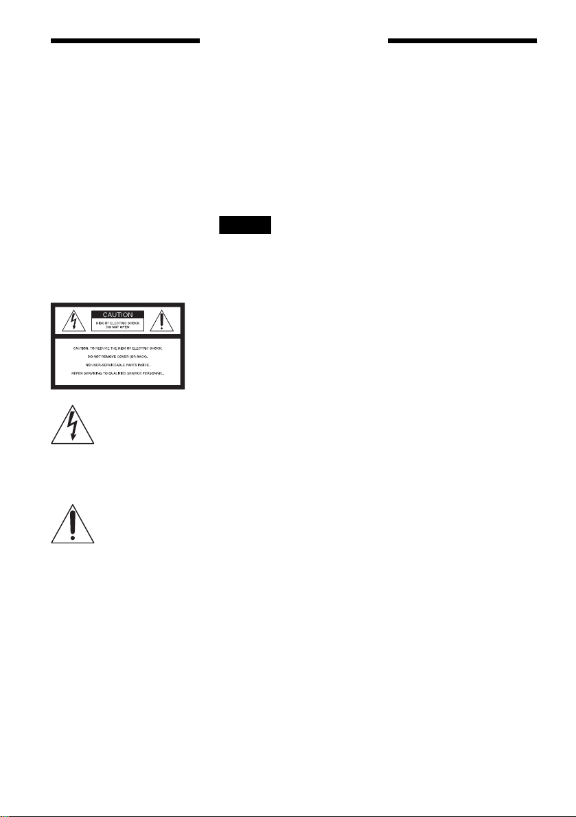
Quick access to recorded titles – Title List
, Display the Title List to see all of the titles
on the disc, including recording date,
channel, recording mode and thumbnail
image (page 32). The recorder will
automatically take program la bel
information from the XDS (Extended Data
Service)* and display it as the title name
(page 32).
* not available in some areas.
Title List
Sort
Date
Title
Number
TITLE LIST
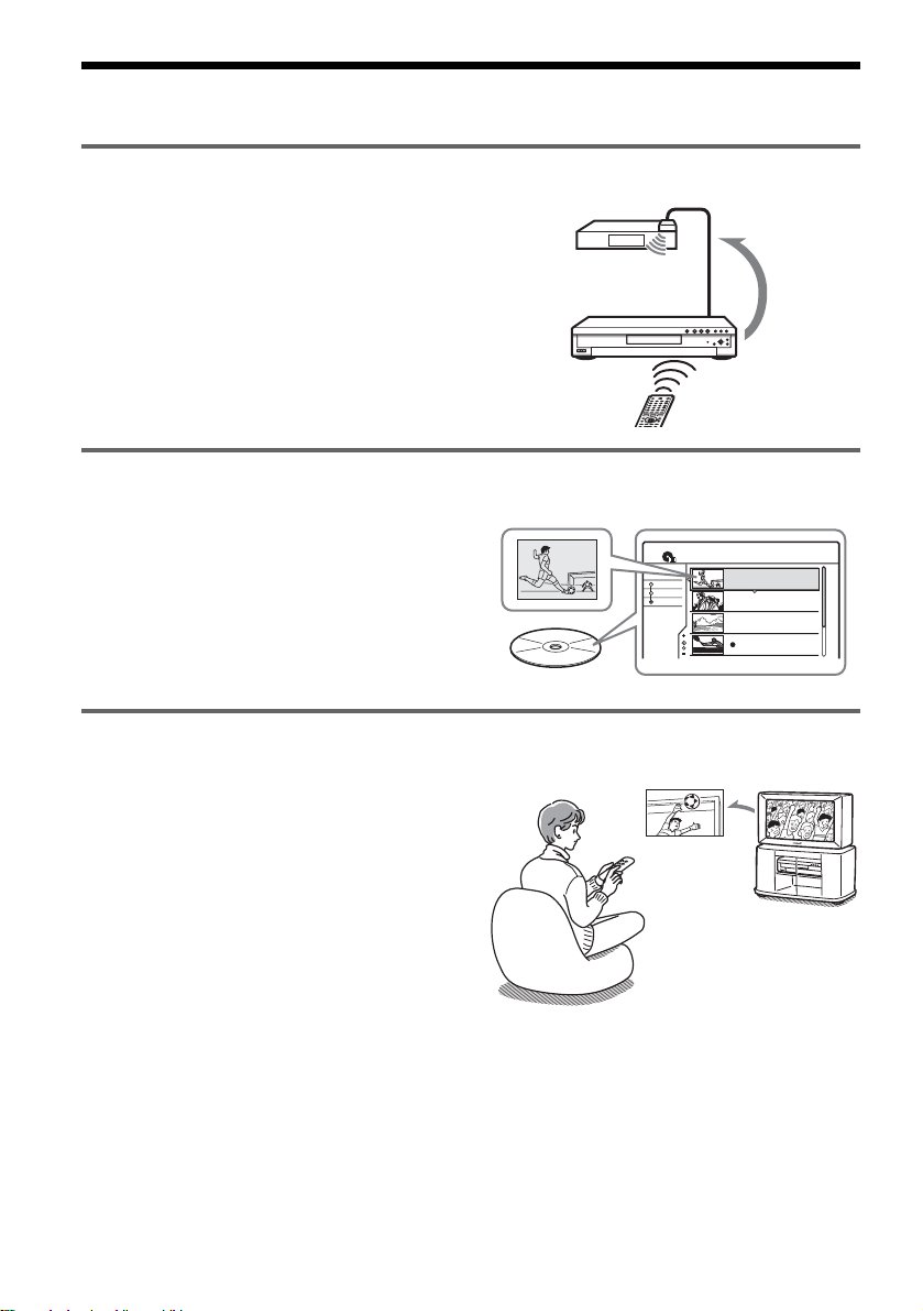
Play the beginning of a title while it is being recorded – Chasing Playback
, If you are using a DVD-RW (VR mode),
you can watch a program from the
beginning while it is being recorded
(page 57).
Recording
CH 103!
My Movies
ORIGINAL
1 2ch 1:00PM - 2:00PM
Wed 9/15 1:00PM( 1H00M)SP
2 5ch 8:00PM - 9:00PM
Fri 9/17 8:00PM( 1H00M)SLP
3 12ch 9:00AM - 9:30AM
Sat 9/25 9:00AM( 0H30M)EP
4 3ch 8:00PM - 8:30PM
Sat 9/25 8:00PM( 0H30M)SLP
1.5/4.7GB
2ch
5ch
12ch
3ch
The game isn’t over
yet, but I’ll start
watching it from the
beginning now.
6
Page 7
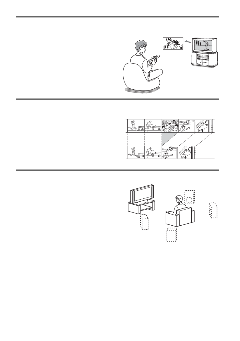
Watching one title while recording another – Simultaneous Rec and Play
, If you are using a DVD-RW (VR mode),
you can watch a previously recorded
program while recording another program
on the same disc (page 57).
Recording
I think I’ll watch
yesterday’s golf game
now, even though I
am recording a movie.
Creating your own program – Playlist
, Record a program on a DVD-RW (VR
mode), then delete, move and add scenes at
will to create your own, original program
(page 65).
Original
Playlist
Dynamic surround sound – TVS
, Enjoy virtual surround sound effects from
just your TV’s speakers with the TV Virtual
Surround settings when playing a DVD
VIDEO with multichannel audio tracks
such as Dolby Digital (5.1ch) (pa ge 53).
A list of recordable and playable discs is on page 8.
7
Page 8

Quick Guide to Disc Types
Recordable and playable discs
Type
DVD+RW
VR
mode
DVDRW
Video
mode
DVD+R
DVD-R
Disc
Logo
Icon
used in
this
manual
+
RW
-
RW
VR
-
RW
Video
+
R
-
R
Formatting
(new discs)
Automatically
formatted
Format in VR
mode
(page 35)
Format in
Video mode
(page 35)
Automatically
formatted
Automatically
formatted
Compatibility with
other DVD players
(finalizing)
Playable on DVD+RW
compatible players
(automatically finalized)
Playable only on VR mode
compatible players
(finalization unnecessary)
Playable on most DVD
players (finalization
necessary) (page 36)
Playable on DVD+R
compatible players (finalization
necessary) (page 36)
Playable on most DVD
players (finalization
necessary) (page 36)
Usable disc versions (as of May 2004)
• 4x-speed or slower DVD+RWs
• 2x-speed or slower DVD-RWs (Ver.1.1, Ver.1.1
with CPRM*
• 8x-speed or slower DVD+Rs
• 8x-speed or slower DVD-Rs (Ver.2.0)
1
)
8
“DVD+RW,” “DVD-RW,” “DVD+R,” and “DVD-R,”
are trademarks.
*1
CPRM (Content Protection for Recordable Media) is
a coding technology that protects co pyr ights for
images.
*2
Only if the recording mode is SP, HSP, or HQ, and
“Rec Screen Size” is set to “16:9.”
*3
Erasing titles does not free up disc space.
Page 9

Recording Features Editing Features
Rewrite
(page 41)
Yes
Yes
Yes
No
No
Auto
Chapter
(page 78)
Yes
Yes
Yes
Yes
Yes
Manual
Chapter
(page 65)
No
Yes
No
No
No
Record
16:9 sizes
(page 48)
No
Yes
2
Yes *
No
2
Yes *
Change
title name
(page 62)
Yes
Yes
Yes
Yes
Yes
Delete title
(page 63)
Yes
Yes
Yes
3
Yes *
3
Yes *
A-B Erase
(page 63)
Yes
Yes
No
No
No
Playlist
(page 65)
No
Yes
No
No
No
Discs that cannot be re corded on
• 4 x- speed compatible D V D-RWs (Ver. 1.2/4x)
• DVD-RWs (Ve r. 1.0)
• DVD+RWs that are not 2.4x-speed compatible
• Dual layer discs
• 8 cm discs
,continued
9
Page 10
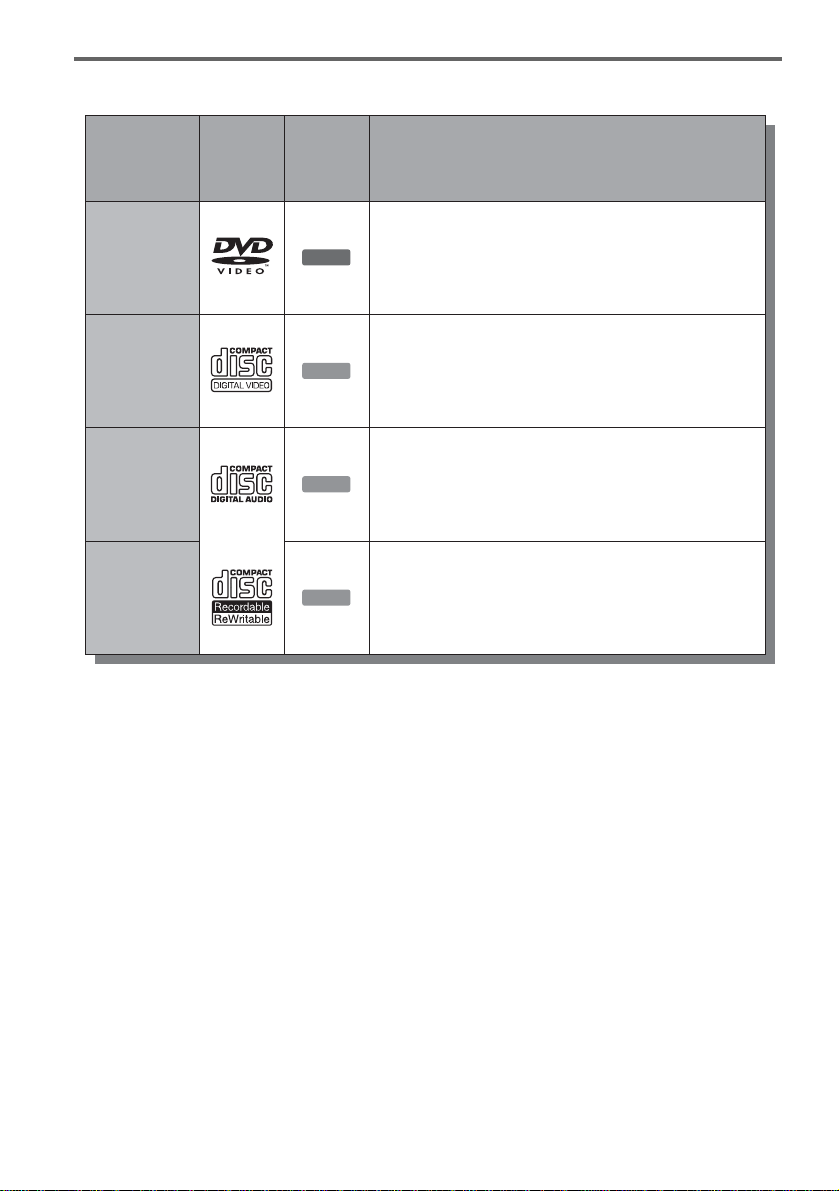
Playable discs
Type Characteristics
Disc
Logo
DVD VIDEO
VIDEO CD
CD
used in
this
manual
DVD
VCD
CD
Discs such as movies that can be purchased or rented
VIDEO CDs or CD-Rs/CD-RWs in
VIDEO CD/Super VIDEO CD format
Music CDs or CD-Rs/CD-RWs in music CD format
that can be purchased
CD-ROMs/CD-Rs/CD-RWs created on a PC or
Icon
DATA CD
DATA CD
similar device in music format containing MP3
audio tracks
Discs that cannot be played
• All CD-ROMs (including PHOTO CDs)
• CD -Rs/CD-RW s, ot her than those recorded in
music CD format, MP3 format, or Video CD
format
• Data part of CD-Extras
• DVD-ROMs
• DVD Audio discs
• DVD-RAMs
• HD layer on Super Audio CDs
• DVD VIDEOs with a different region code (see
below)
• A di sc recorded in a c o l or system other than
NTSC, such as PAL or SE CA M
z Hint
This DVD recorder can play 8 cm CDs and 8 cm DVDs
as well.
10
Page 11

Note on playback operations of DVD VIDEOs/
VIDEO CDs
Some playback operations of DVD VIDEOs/
VIDEO CDs may be intentionally set by software
producers. Since this recorder plays DVD
VIDEOs/VIDEO CDs according to the disc
contents the sof tware producers designed, some
playback features may not be available. Also, see
the instructions supplied with the DVD VIDEOs/
VIDEO CDs.
Region code (DVD VIDEO only )
Your recorder has a region code printed on the rear
of the unit and will only play DVD VIDEOs
(playback only) labeled with identical region
codes. This system is us ed to protect copyrig ht s.
DVD VIDEOs labeled will also play on this
ALL
recorder.
If you try to play any other DVD VIDEO, the
message “Playback prohibited by region code.”
will appear on the TV scr een. Depending on the
DVD VIDEO, no region code indication may be
labeled even though playing the DVD VIDEO is
prohibited by area r es tr i ct io ns .
X
RDR–XXXX
00V 00Hz
NO.
00W
Region code
0-000-000-00
Notes
• You cannot mix VR mode and Video mode on the same
DVD-RW. To change the disc’s format, reformat the
disc (page 35). Note that the disc’s contents will be
erased after reformatting.
• You cannot shorten the time required for rec or ding
even with high-speed discs. Also, you cannot record on
the disc if the disc is not 1x speed compa tible.
• It is recommended that you use discs with “For Video”
printed on their packaging.
• You cannot add new recordings to DVD-Rs or DVDRWs (Video mode) that contain recordings made on
other DVD equipment.
• In some cases, you may not be able to add new
recordings to DVD+RWs that contain recordings made
on other DVD equipment. If you do add a new
recording, note that this recorder will rewrite t he DVD
menu.
• If the disc contains PC data unrecogniz able by this
recorder, the data may be erased.
• Some DVD+RWs/DVD+Rs, DVD-RWs/DVD-Rs, or
CD-RWs/CD-Rs cannot be played on this recorder due
to the recording quality or physical c ondi tion of the
disc, or the characteristics of the recording device and
authoring software. The disc will not pla y if it ha s not
been correctly final ized. For m ore in formati on, s ee t he
operating instructions for the recording device.
Music discs encoded with copyright protection
technologies
This product is designed to playback discs th at
conform to the Compact Disc (CD) standard.
Recently, various music disc s encoded with
copyright prote ct i on t echnologies are bei ng
marketed by so me record companies. Please be
aware that among those discs, there are some that
do not confor m to the CD sta ndard and may n ot be
playable by this pro duct.
11
Page 12

Hookups and Settings
Hooking Up the Recorder
Follow steps 1 to 7 to hoo k up and adjust the
settings of the r ecorder.
Notes
• Plug cords securely to prevent unwanted noise.
• Refer to the instructions supplied with the components
to be connected.
• You cannot connect this recorder to a TV that does not
have a video input jack.
• Be sure to disconnect the power cord of each
component before connecting.
Step 1: Unpacking
Using the cable box/satellite
receiver control function
The cable box/satellite receiver contro l fu nction
can be used with hookup A or B. It allows the
recorder to control a cable box or satellite receiver
via the supplied set top box controller. The
recorder controls channels on the cable box or
satellite receiver for time r recording. You can also
use the recorder’s remote co ntrol to change
channels on the cable box/satellite receiver
whenever the cable box/satellit e receiver is t urned
on, even if the recorder is turned off.
To use the cable box/satellite receiver control
function, you need t o connect the set top bo x
controller an d set the code number and output
channel (page 23) . After setting up the cable box/
satellite receiver control, check that the recorder
can correctly control the cabl e box or satellite
receiver (page 26).
Check that you have the following items:
• Audio/video cord (pinplug × 3 y pinplug × 3)
(1)
• Power cord (1)
• Antenna cable (1)
• Remote commander (remote) (1)
• Set top box controller (1)
• Size AA (R6) batteries (2)
Step 2: Connecting the Antenna Cable and Set Top Box Controller
Select one of the following antenna hookups. Do
not connect the power cord until you reach “Step
5: Connectin g t h e Power Cord” (page 20).
If you have Hookup
Cable box with a video/audio output
or a satellite receiv er
Cable box with an antenna output
only
Cable without cable box, or antenna
only (no cable TV)
A (page 13)
B (page 15)
C (page 14)
Note to CATV system installer (in USA)
This reminder is provided to call the CATV
system installer’s attention to Article 820- 40 of
the NEC that provides guidelines for proper
grounding and, in par t ic ul ar, specifies that the
cable ground shall be connected to the grounding
system of the buildi ng, as close to the point of
cable entry as practical.
Notes
• If your antenna is a flat cable (300- ohm twin lead
cable), use an external ante nna co n ne c t or (no t
supplied) to connect the antenna to the recorder.
• If you have separate cables for VHF and UHF
antennas, use a UHF/VHF band mixer (not supplied) to
connect the antenna to the recorder.
12
Page 13
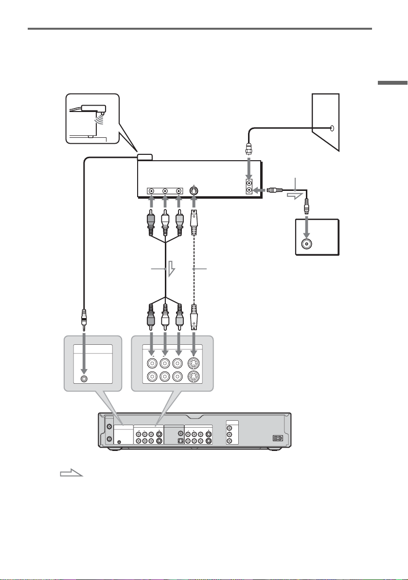
A: Cable box or satellite receiver with a video/audio output
With this hookup, you can record any channel on the cable box or sat ellite receiver. Be sur e t hat the
satellite receiver or cable box is turned on.
To watch cable or satellite programs, you need to match the channel on the recorder (L1 or L3) to the
input jack connec te d t o the cable box or satel lit e receiver (LINE IN 1 or 3).
Place the set top box controller
near the remote sensor on the
cable box/satellite receiver.
Set top box
controller
(page 12)
AUDIO
OUT
RL
VIDEO
OUT
S VIDEO
Cable box/
satellite receiver
ANT IN
TO TV
to antenna input
Antenna cable
(supplied)
Wall
TV
Hookups and Settings
SET TOP BOX
CONTROL
to SET TOP BOX
CONTROL
Audio/video
cord (supplied)
to LINE IN
1 or 3
VHF/UHF
IN
SET TOP BOX
CONTROL
1
OUT
3
AUDIORL
1
3
LINE IN DIGITAL OUT
S VIDEO
VIDEO
AUDIORL
LINE IN
PCM/DTS/
DOLBY DIGITAL
VIDEO
COAXIAL
OPTICAL
S VIDEO
AUDIORL
1
2
LINE OUT
VIDEO
S-video cord (not
supplied)
COMPONENT
VIDEO OUT
Y
S VIDEO
B
P
P
R
~ AC IN
DVD recorder
: Signal flow
z Hints
• If your cable box or satellite receiver has an S-video jack, you can use an S-video cord (not supplied) instead of the
audio/video cord.
• If you connect an S-video cord to the LINE IN 1 jack, set “Line1 Input” in Video Setup to “S VIDEO” (page 75). If
you connect an S-video cord to the LINE IN 3 jack, set “Line3 Input” in Video Setup to “S VIDEO” (page 74).
,continued
13
Page 14
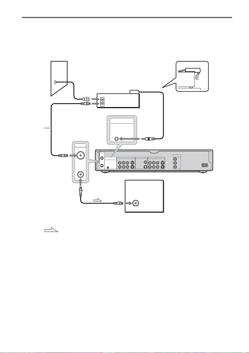
B: Cable box with an antenna output only
With this hookup, y ou can record any chann el on the satellite recei ver or cable box. Be sure t hat the
satellite receiver or cable box is turned on.
To watch cable programs, you need to match the channel on the recorder (2ch, 3ch, or 4ch) to the antenna
output channel on the cable box (2ch, 3ch, or 4ch) .
Wall
Set top box
controller
Antenna cable
(supplied)
to VHF/UHF IN
VHF/UHF
VHF/UHF
IN
OUT
OUT
Cable box
ANT IN
TO TV
SET TOP BOX
CONTROL
IN
VHF/UHF
IN
SET TOP BOX
CONTROL
AUDIORL
1
OUT
3
to SET TOP
BOX
CONTROL
LINE IN DIGITAL OUT
S VIDEO
VIDEO
PCM/DTS/
DOLBY DIGITAL
(supplied)
AUDIORL
1
COAXIAL
2
OPTICAL
Place the set top box controller
near the remote sensor on the
cable box/satellite receiver.
DVD recorder
COMPONENT
LINE OUT
VIDEO
VIDEO OUT
Y
S VIDEO
B
P
P
R
~ AC IN
14
to VHF/UHF OUT
: Signal flow
TV
to antenna
input
Page 15
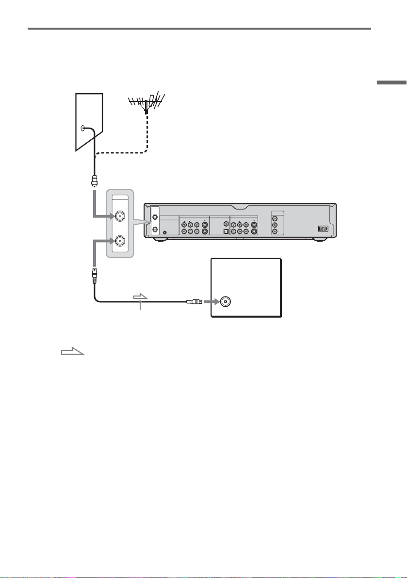
C: Cable without cable box, or antenna only (no cable TV)
Use this hookup if yo u w atch cable channels w ithout a cable box. Also use this hookup if you ar e using
a VHF/UHF antenna or separate VH F and UHF antennas.
With this hookup , you can record any channel by selecting th e channel on the reco rder.
Wall
to VHF/UHF IN
COMPONENT
VIDEO OUT
Y
B
P
P
R
DVD recorder
~ AC IN
VHF/UHF
IN
OUT
VHF/UHF
IN
SET TOP BOX
LINE IN DIGITAL OUT
CONTROL
OUT
1
3
AUDIORL
S VIDEO
VIDEO
DOLBY DIGITAL
LINE OUT
S VIDEO
VIDEO
AUDIORL
1
COAXIAL
PCM/DTS/
2
OPTICAL
Hookups and Settings
to VHF/UHF OUT
Antenna cable (supplied)
: Signal flow
TV
to antenna input
15
Page 16
Step 3: Connecting the Video Co rds
Select one of the following patterns A th rough C, according to the input jack on your TV monitor,
projector, or AV amplifier (receiver). This will enable you to view pictures. Audio connections are
explained in “Step 4: Connecting the Audio Cords” (page 18).
A
INPUT
VIDEO
L
AUDIO
R
TV, projector, or AV
amplifier (receiver)
to LINE OUT (VIDEO) 1 or 2
VHF/UHF
IN
OUT
SET TOP BOX
CONTROL
LINE IN DIGITAL OUT
AUDIORL
1
3
Audio/video
cord (supplied)
S VIDEO
VIDEO
PCM/DTS/
DOLBY DIGITAL
(yellow)
LINE OUT
AUDIORL
1
COAXIAL
2
OPTICAL
(red) (blue)
S-video cord
(not supplied)
to LINE OUT (S VIDEO) 1 or 2
COMPONENT
VIDEO OUT
Y
S VIDEO
VIDEO
B
P
P
R
(green)
Component video
cord (not supplied)
S VIDEO
TV, projector, or AV
amplifier (receiver)
DVD recorder
~ AC IN
to COMPONENT
VIDEO OUT
COMPONENT
VIDEO IN
TV, projector, or AV
amplifier (receiver)
INPUT
Y
P
B
P
R
B
C
(green)
(blue)
(red)
: Signal flow
Note
Do not connect more than one type of video c or d bet wee n the recorder and your TV at the same time .
16
Page 17

A Connecting to a video input jack
Connect the yellow pl ug of the audio/video cor d
(supplied) to the yellow (video) jack. You will
enjoy standard quality images.
Note that you cannot use the PROGRESSIVE
button with this connection.
Yellow
White (L)
Red (R)
Yellow
White (L)
Red (R)
B Connecting to an S VIDEO input
jack
Connect an S-video cord (not supplied). You will
enjoy high quality im ages.
Note that you cannot use the PROGRESSIVE
button with this connection.
C Connecting to component video
input jacks (Y, P
Connect the COMPONENT VIDEO OUT jacks
using a component vi deo cord (not supplie d) or
three video cords (not supplied ) of the same kind
and length. You will enjoy accurate color
reproduction and hi gh quality images.
If your TV accepts pr ogressive 480p for mat
signals, you must use this connection and then
press PROGRESSIVE on the remote to send
progressive video signals. For details, see “Using
the PROGRESSI V E but ton” (page 17).
Green
Blue
Red
B, PR)
Green
Blue
Red
Using the PROGRESSIVE button
By using the PROGR ESSIVE button on the
remote, you can sel ect the signal form at in which
the recorder o ut p uts video signals: Interlace or
Progressive.
Connect the recorder using the COMPO NEN T
VIDEO OUT jacks (pattern C above), and press
PROGRESSIVE repeatedly. “PROGRESSIVE”
appears in the front panel display when the
recorder output s progressive signals.
◆Progressive
Select this when:
–your TV accepts progressive signal s, and,
–the TV is c onnecte d to the COM PONENT
VIDEO OUT jacks.
Note that the pic tu res will not be clear or no
picture will appear if you select progressive signal
output when either of the above conditions is not
met.
◆Interlace
Set to this position when:
–your TV does not accept progressive signals, or,
–your TV is connected to jacks other than the
COMPONENT VIDEO OUT jacks (LINE OUT
(VIDEO) or S VIDEO).
z Hint
When you select progressive signal output, you can finetune the signal according to the type of software you are
watching (page 75).
Note
Consumers should note tha t not a ll high definition
television sets are fully compatible with this product and
may cause artifacts to be displayed in th e p icture. In the
case of 480 progressi ve scan pict ure problems, it is
recommended that the user switch the conne c tion to the
‘standard definition’ output. If there are questions
regarding our TV set compatibility with this model 480p
DVD recorder, please contact our customer service
center.
Hookups and Settings
When playing “wide screen” images
Some recorded images may not fit your TV
screen. To change the aspect ratio, see page 74.
If you are connecting to a VCR
Connect your VCR to the LINE IN (VIDEO) jack
on the recorder (page 29).
17
Page 18

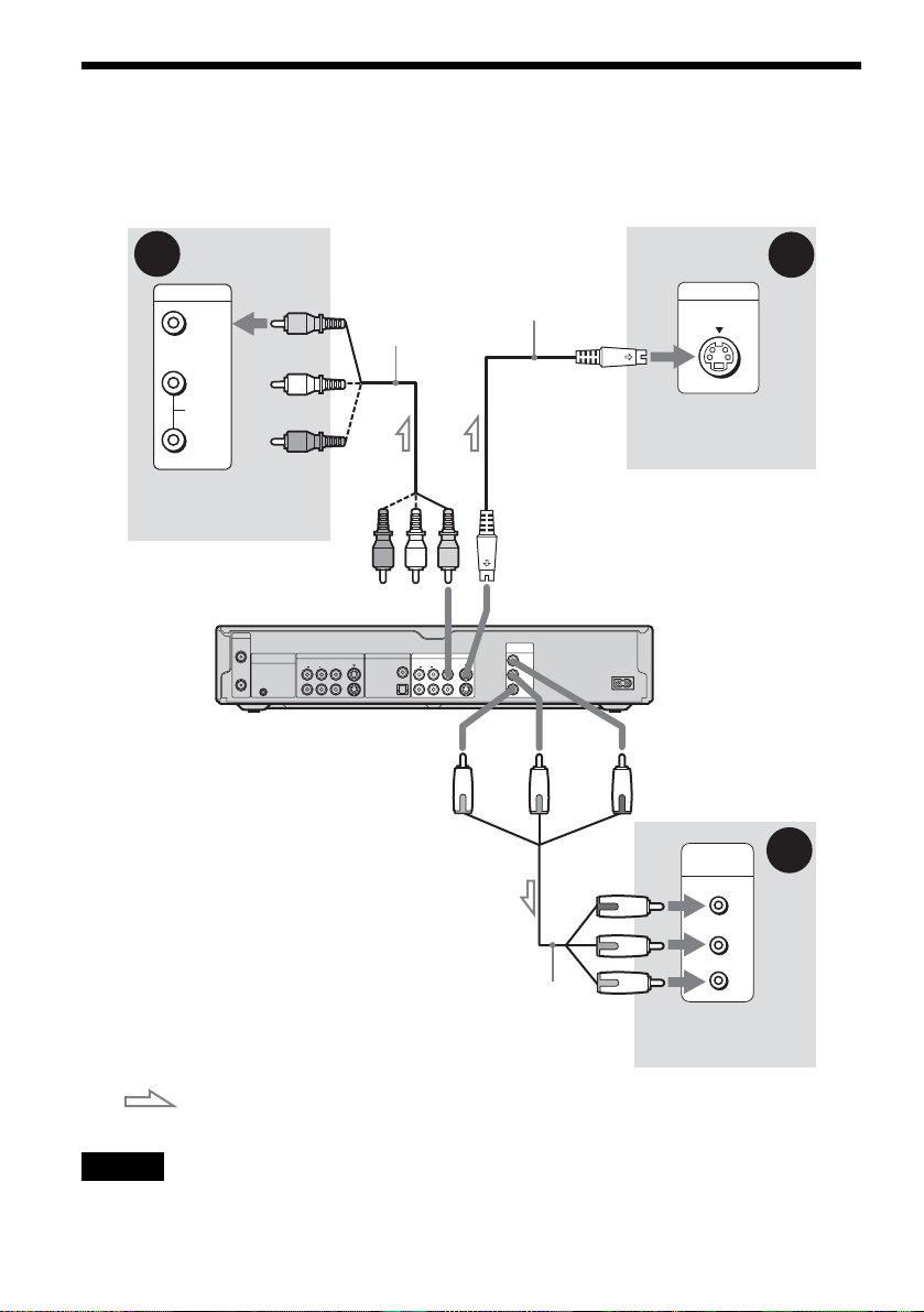
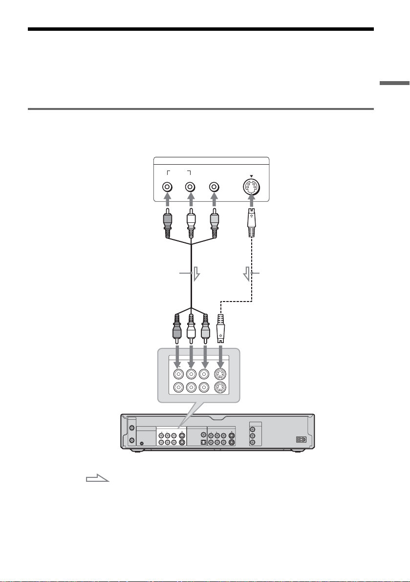
Step 4: Connecting the Audio Co rds
Select one of th e foll ow in g pat ter ns A or B, according to the input jack on your TV monitor, pro jector,
or AV amplifie r (receiver).
This will enable you to listen to sound.
(red)
(white)
(yellow)*
LINE OUT
S VIDEO
VIDEO
AUDIORL
1
2
VHF/UHF
IN
SET TOP BOX
LINE IN DIGITAL OUT
DIGITAL OUT
PCM/DTS/
DOLBY DIGITAL
OUT
COAXIAL
OPTICAL
CONTROL
S VIDEO
VIDEO
AUDIORL
1
3
to DIGITAL OUT (COAXIAL or
OPTICAL)
Optical digital cord (not supplied)
[Speakers]
to optical
digital input
Rear (L)
Audio/video
(yellow)
cord (supplied)
to LINE OUT (R-AUDIO-L) 1 or 2
COMPONENT
VIDEO OUT
Y
S VIDEO
B
P
P
R
DOLBY DIGITAL
LINE OUT
VIDEO
AUDIORL
1
COAXIAL
PCM/DTS/
2
OPTICAL
or
Coaxial digital cord
(not supplied)
to coaxial
digital input
(white)
(red)
DVD recorder
INPUT
VIDEO
L
AUDIO
R
TV, projector, or AV
amplifier (receiver)
~ AC IN
[Speakers]
B
Rear (R)
A
Front (L)
Front (R)
AV amplifier (receiver)
Center
with a decoder
Subwoofer
: Signal flow
* The yel low pl ug is use d f or video signals (page 17).
z Hint
For correct speaker location, see the operating instructions supplied with the connected components.
Note
Do not connect your TV’s audio output jacks to the LINE IN (AUDIO L/R) jacks at the same time. This will cause
unwanted noise to come from your TV’s spea kers .
18
Page 19
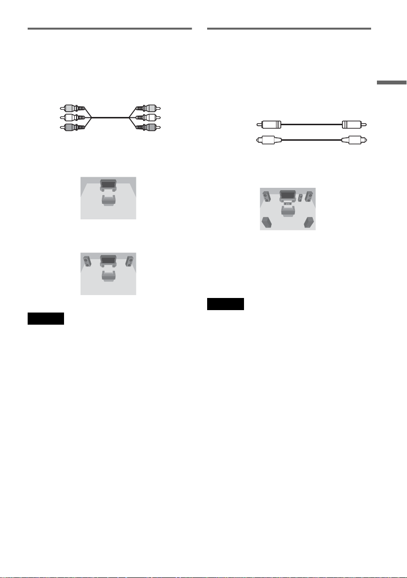
A Connecting to audio L/R input
jacks
This connection wil l us e your TV’s or stereo
amplifier’s (receiver’s) two speakers for sound.
Connect using the audio/video cord (supplied).
Yellow
White (L)
Red (R)
• S urround effect (page 53)
TV: Dynamic, Wide, Night
Yellow
White (L)
Red (R)
B Connecting to a digital audio
input jack
If your AV amplifier (receiver) has a Dolby*1
Digital or DTS*
use this c o nnection .
Connect using a coaxial or optical digital cord (not
supplied).
Coaxial cord
Optical cord
• Surround effect
Dolby Digital (5.1ch), DTS (5.1ch)
2
decoder and a digital input jack,
Hookups and Settings
Stereo amplifier (receiver): Standard, Night
Note
Do not connect your TV’s audio output jacks to the LINE
IN (AUDIO L/R) jacks at the same time. This will cause
unwanted noise to come from your TV’s spea ke rs.
*1
Manufactured under license from Dolby Laboratories.
“Dolby,” “Pro Logic,” and the double-D symbol are
trademarks of Dolby Laboratories.
*2
“DTS” and “DTS Digital Out” are trademarks of
Digital Theater Systems, Inc.
Notes
• After you have completed the connection, make the
appropriate settings under “Audio Connection” in Easy
Setup (page 23). Otherwise, no sound or a loud noise
will come from your speakers.
• The surround sound effects of this recorder cann ot be
used with this connection.
19
Page 20
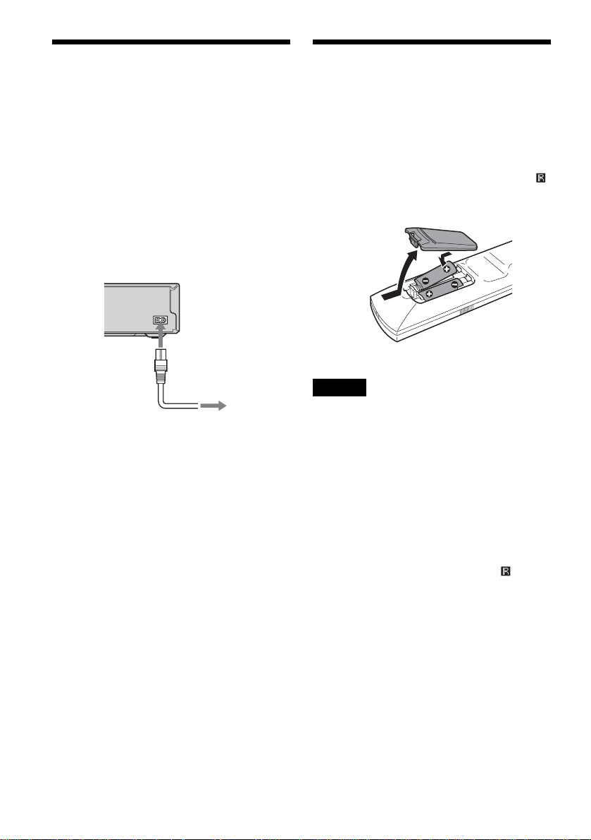
Step 5: Connecting the
Step 6: Preparing the
Power Cord
Connect the supplied power cord to the AC I N
terminal of the recorder. Then plug the r ecorder
and TV power cords into an AC outlet. After you
connect the power cord, you must wait for a
short while before operating the recorder. You
can operate the recorder only after the front panel
display lights up an d the recorder enters standby
mode.
If you connect addi ti onal equipment to thi s
recorder (page 29), be sure to connect the power
cord only after all connections are complete.
~ AC IN
1
to AC IN
2
to AC outlet
Remote
You can control the recorder using the supplied
remote. Insert two size AA (R6) batterie s by
matching the 3 and # ends on the batteries to the
markings insi de the battery comp artment. When
using the remote, point it at the remote sens or
on the recorder.
Notes
• If the supplied remote interferes your other Sony DVD
recorder or player, chang e the comm and mode n umber
for this recorder (page22).
• Use the batteries correc tly to avoid po ss ible leakag e
and corrosion. Do not touch the liquid with bare hands
should leakage occur. Observe the followi ng:
– Do not us e a new batte r y wit h an ol d batte r y, or
batteries of different manufacturers.
– Do not a ttempt to recharge the batteries.
– If you do not intend to use the remote for an extended
period of time, remove the batteries.
– If batt ery le a ka ge occu rs, wipe out a ny liquid inside
the battery compartment, and insert new batteries.
• Do not expose the remote sensor ( ma r ke d on the
front panel) to strong light, such as direct sunlight or
lighting apparatus. The recorder may not respond to the
remote.
20
Page 21

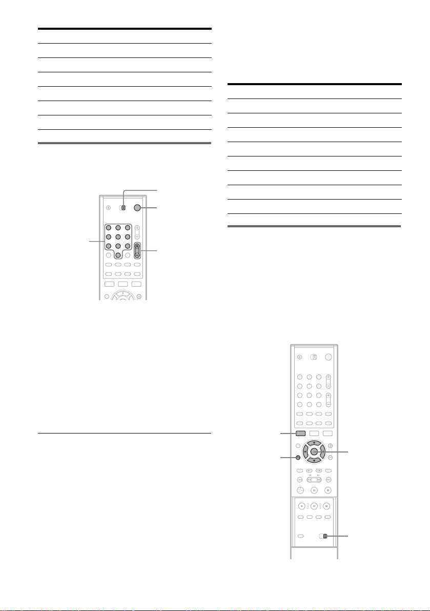
Controlling TVs with the remote
You can adjust th e remote control’s signal to
control your TV .
If you connected the recorder to an AV am plifier
(receiver), you can also use the supplied remote to
control the AV amplifier’s (receiver’s) volume.
Notes
• Depending on the connected unit, you may not be able
to control your TV or AV amplifier (receiver) with
some or all of the buttons below.
• If you enter a new code number, the code number
previously entered will be erased.
• When you replace the batteries of the remote, the code
number may be reset to th e de f ault setting. Set the
appropriate code number again.
TV/DVD
switch
"/1
Number
buttons, SET
1 2 3
4 5 6
7 8 9
0
CH +/–
VOL +/–
TV/VIDEO
1 Slide the TV/DVD switch to TV.
2 Hold down [/1.
3 Enter your TV’s man ufacturer code (see
“Code numbers of c on t rollable TVs”
below) using the number buttons.
4 Release [/1.
When the TV/DVD switch is set to TV, the
remote performs the following:
[/1 Turns your TV on or off
VOL +/– Adjusts the volume of your
CH +/– Selects the channel o n your
TV/VIDEO Switches your TV’s input
Number buttons and
SET
TV
TV
source
Selects the channel on your
TV
Code numbers of controllable TVs
If more than one c ode number is listed, tr y
entering them one at a time until you fin d th e one
that works with your TV.
Manufacturer Code number
Sony 01 (default)
Akai 04
AOC 04
Centurion 12
Coronado 03
Curtis-Mathes 12, 14
Daewoo 04, 22
Daytron 03, 12
Fisher 11
General Electric 04, 06, 10
Gold Star/LG 03, 04, 17
Hitachi 02, 03, 04
J.C.Penney 04, 10, 12
JVC 09
KMC 03
Magnavox 03, 04, 08, 12, 21
Marantz 04, 13
MGA/Mitsubishi 04, 12, 13, 17
NEC 04, 12
Panasonic 06, 19
Philco 02, 03, 04, 08
Philips 08, 21
Pioneer 06, 16
Portland 03
Proscan 10
Quasar 06, 18
Radio Shack 05, 10, 14
RCA 04, 10
Sampo 12
Samsung 03, 04, 12, 20
Sanyo 11, 14
Scott 12
Sears 07, 10, 11
Sharp 03, 05, 18
,continued
Hookups and Settings
21
Page 22
Manufacturer Code number
Sylvania 08, 12
Teknika 03, 08, 14
Toshiba 07, 18
Wards 03, 04, 12
Yorx 12
Zenith 14, 15
Controlling the volume of your AV
amplifier (receiver) with the remote
TV/DVD
switch
"/1
Code numbers of co ntrollable AV amplifiers
(receivers)
If more than one code number is listed, try
entering them one at a time until you fin d t he one
that works with your AV amplifier (receiver).
Manufacturer Code number
Sony 78, 79, 80, 91
Denon 84, 85, 86
Kenwood 92, 93
Onkyo 81, 82, 83
Pioneer 99
Sansui 87
Technics 97, 98
Yamaha 94, 95, 96
Number
buttons, SET
1 2 3
4 5 6
7 8 9
0
VOL +/–
1 Slide the TV/DVD switch to DVD.
2 Hold down [/1, and enter the
manufacture r code (see the table below)
for your AV amplifier (receiver) using the
number buttons.
3 Release [/1.
The VOL +/– buttons control the AV
amplifier’s volume.
If you want to control th e TV’s volume, slide
the TV/DVD switch to TV.
z Hint
If you want to control the TV’s volume even when the
TV/DVD switch is set to DVD, repeat the steps above
and enter the code number 90 (default).
If you have a Sony DVD player or
more than one Sony DVD recorder
If the sup p lied remote interfe res with y o ur other
Sony DVD recorder or player, set the command
mode number for this recorder and the supplied
remote to one that diffe rs from the other Sony
DVD recorder or pl ayer.
The default command mode setting for this
recorder and the supplied remote is DVD3.
1 2 3
4 5 6
7 8 9
0
SYSTEM
MENU
O RETURN
M/m,
ENTER
22
COMMAND
MODE
Page 23
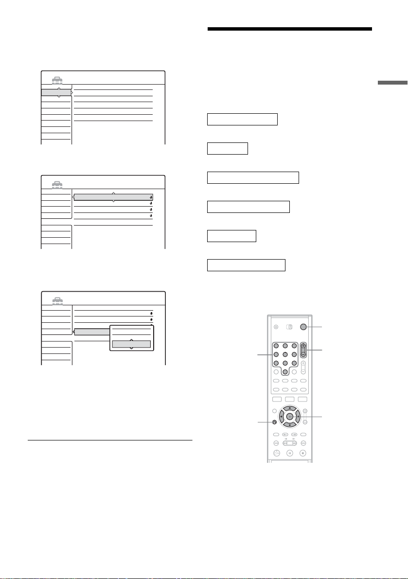
1 Press SYSTEM MENU.
The System Menu a ppears.
2 Select “SETUP, ” and press ENTER.
SETUP
Settings
Tuner Preset
Video
Set VCR Plus+ Channels
Audio
Clock
Features
Set Top Box Control
Options
Language
Easy Setup
3 Select “Options,” and press ENTER .
SETUP
Settings
Video
Audio
Features
Options
Easy Setup
Format DVD :
Dimmer :
Auto Display :
Command Mode :
Factory Setup
VR
Normal
On
DVD3
4 Select “Comman d Mo de , ” and pre s s
ENTER.
SETUP
Settings
Video
Audio
Features
Options
Easy Setup
Format DVD :
Dimmer :
Auto Display :
Command Mode :
Factory Setup
VR
Normal
On
DVD3
DVD1
DVD2
DVD3
5 Select the Command mode (DVD1, DVD 2,
or DVD3), and press ENTER.
6 Slide the COMMAND MODE switch on the
remote so it mat c hes the mode you
selected above.
Step 7: Easy Setup
Follow the steps below to make the minimum
number of basic adjustments for using the
recorder. If you do not complete Easy Set up, i t
will appear each time you turn on your recorder.
Settings are made in the following order.
OSD Language Setup
m
Clock Setup
m
Cable Box/Sat. Control Setup
m
Tuner and Channel Setup
m
TV Type Setu p
m
Audio Connection Setup
m
Finished!
"/1
Number
buttons
O RETURN
1 2 3
4 5 6
7 8 9
0
CH +/–
</M/m/,,
ENTER
Hookups and Settings
To return to the previous step
Press O RETURN.
1 Turn on the TV.
2 Press [/1.
The recorder turn s on.
,continued
23
Page 24
3 Switch the input selector on your TV so that
the signal from the recorder appears on
your TV screen.
“Initial settings necessary to operate the DVD
recorder will be m ade. You can chang e them
later using Setup. Before you start, check that
you have made all ne cessary connections.”
appears.
• If this message does not ap pear, select “Easy
Setup” from “S E TU P ” in the System Me nu
to run Easy Setup. For details, see “Set tings
and Adjustment s” on page 69.
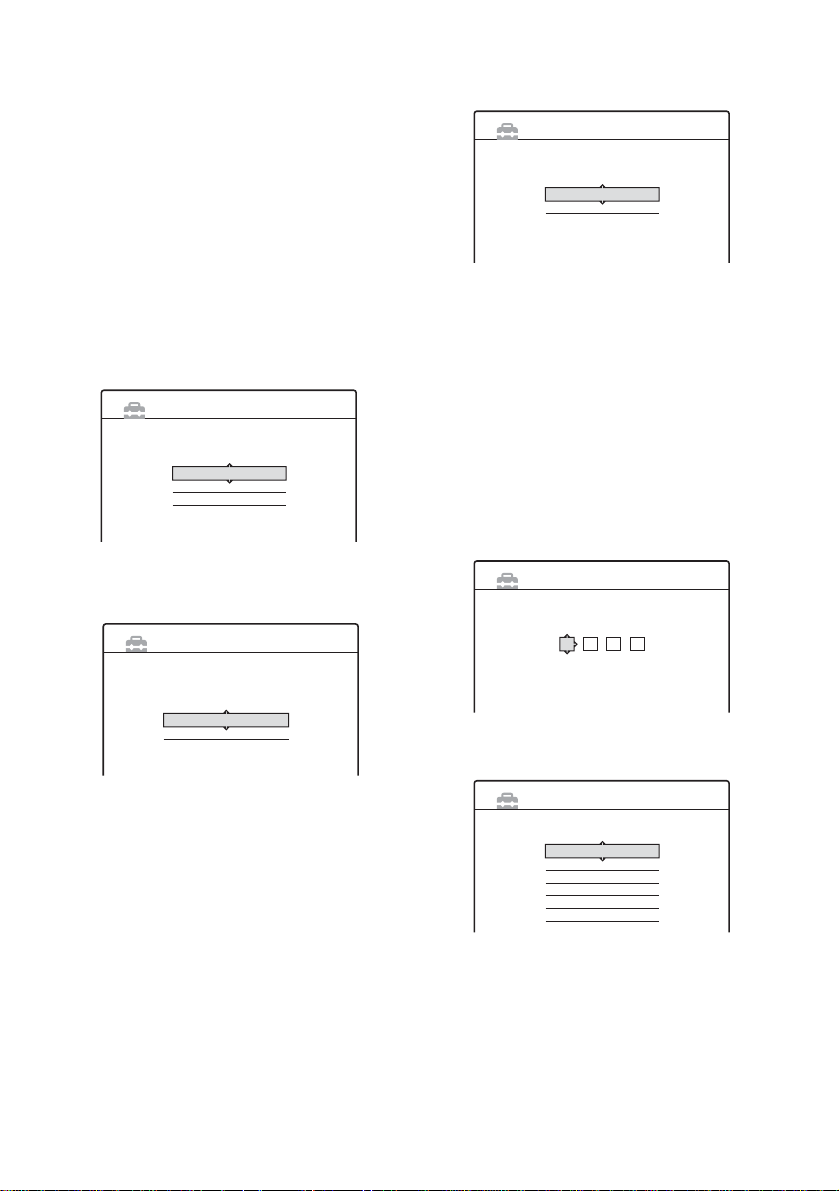
4 Press ENTER.
The Setup Display f or sel ec ti ng the language
used in the on-scr een display appears.
English
Français
Español
Language 1/6
EASY SETUP
Select the screen Language.
Once the clock is set, the Setup Display for
cable box/satellite receiver control appears.
Yes
No
Set Top Box Control 3/6
EASY SETUP
Do you want to control your set top box
with this recorder?
(Changes to the current setting will erase all timer settings.)
7 Set the cable box/satellite receiver
control, and pre s s ENT E R .
If you want to use th e cable box/satellite
receiver contro l (page 14), select “Yes.”
If you do not have a cab l e box, select “No,”
then go to step 11.
8 Enter the brand code of your c ab l e bo x/
satellite receiver.
See “Cable Box/Satellite Receiver Brand
Code” (page 96).
Use M/m to select the number and </, to
move the cursor.
5 Select a languag e, and press ENTER.
The Setup Display for clock setting appears.
EASY SETUP
Select a method for setting the clock.
If you select "Auto", this recorder will look for a
time signal when you turn it off.
Auto
Manual
Clock 2/6
6 Select “Manua l,” and press ENTE R.
Press M/m to set the month and press ,. Set
the day, year, hour, and minutes in the same
way. The day of the week i s set automati cally.
If you used antenna hookup C (page 15), you
can select “Auto. ” The recorder will
automatically search fo r a channel that c arries
a time signal whe n you turn off the rec order
after finishing Easy Setup.
EASY SETUP
Enter the brand code of your set top box.
Set Top Box Control 3/6
- - - -
9 Press ENTER .
Line1
Line2
Line3
Ch2
Ch3
Ch4
Set Top Box Control 3/6
EASY SETUP
Select input line or Set Top Box's output channel.
10Select the cable box output channel.
If you connect your cable box or satellite
receiver to the recorder’s audio/video input
(page 1 3), select “Line1,” “Line2,” or
“Line3,” then go to step 13.
24
Page 25
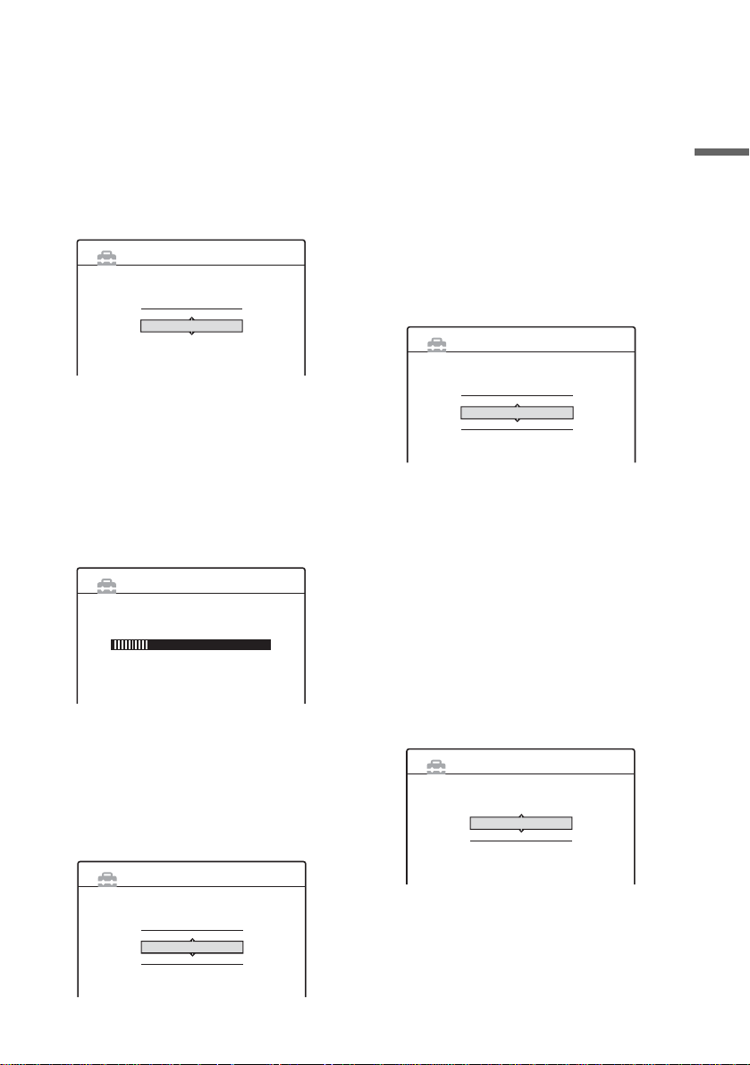
If you connect the satellite receiver or cable
box to the record er’s an tenna i nput (p age 14),
select “Ch2,” ‘Ch3,” or “Ch4” and press
ENTER, then go to step 13. See the
instructions supplied with your cabl e box to
confirm the cable box’s antenna output
channel.
11Select whether or not you have a cabl e
connection.
Antenna
Cable
Tuner Preset 4/6
EASY SETUP
Select the way in which you will receive channels.
If you use an antenna onl y (no cable TV),
select “Antenna.”
If you use a cable connection without a cable
box, select “Cabl e.”
12Press ENTER.
The Tuner Preset function automatically starts
searching for all of th e receivable chann el s
and presets them.
EASY SETUP
Searching for receivable channels.
Please wait.
Tuner Preset 4/6
Ch45
To set the channels manually, see page 7 1.
After the Tuner Preset is finished, the Setup
Display for selecting the aspect ratio of the
connected TV appe ar s.
13Select the setting that matches your TV
type.
“4:3 Letter Box”: For standard TVs.
Displays “wid e s creen” pictures with bands
on the upper and lower sections of the screen.
“4:3 Pan Scan”: For standard TVs.
Automatically displays “wid e screen”
pictures on the ent ir e screen and cuts of f t he
sections that do not fit.
“16:9”: For wide -scree n TVs or stan dard TVs
with a wide screen mode.
For details, see “TV type” on page 74.
14Press ENTER.
The Setup Display for selecting the type of
jack used to connect to your amplifier
(receiver) appe ars.
EASY SETUP
Is this recorder connected to an amplifier (receiver)?
Select the type of jack you are using.
Yes :
Yes :
No
Audio Connection 6/6
LINE OUT(R-AUDIO-L)
DIGITAL OUT
15Select the type of jack (if any) you are
using to connect to an amplifie r (receiver),
and press ENTER .
If you did not connec t an A V amp l ifier
(receiver), select “No,” then go to step 19.
If you connected an AV amplifier (receiver)
using just an audio cord, select “Yes: LINE
OUT (R-AUDIO-L),” then go to step 19.
If you connected an AV amplifier (receiver)
using either a digital optical or coaxial cord,
select “Yes: DI G I T A L O UT. ”
16Select the type of Dolb y Digit al sig nal you
wish to send to your amplifier (receiver).
EASY SETUP
Dolby Digital
D-PCM
Dolby Digital
Audio Connection 6/6
Hookups and Settings
EASY SETUP
Select your TV screen type.
16 : 9
4 : 3 Letter Box
4 : 3 Pan Scan
TV Type 5/6
If your AV amplifier (receiver) has a Dolby
Digital decoder, select “Dolb y D igital.”
Otherwise, select “D-PCM.”
,continued
25
Page 26
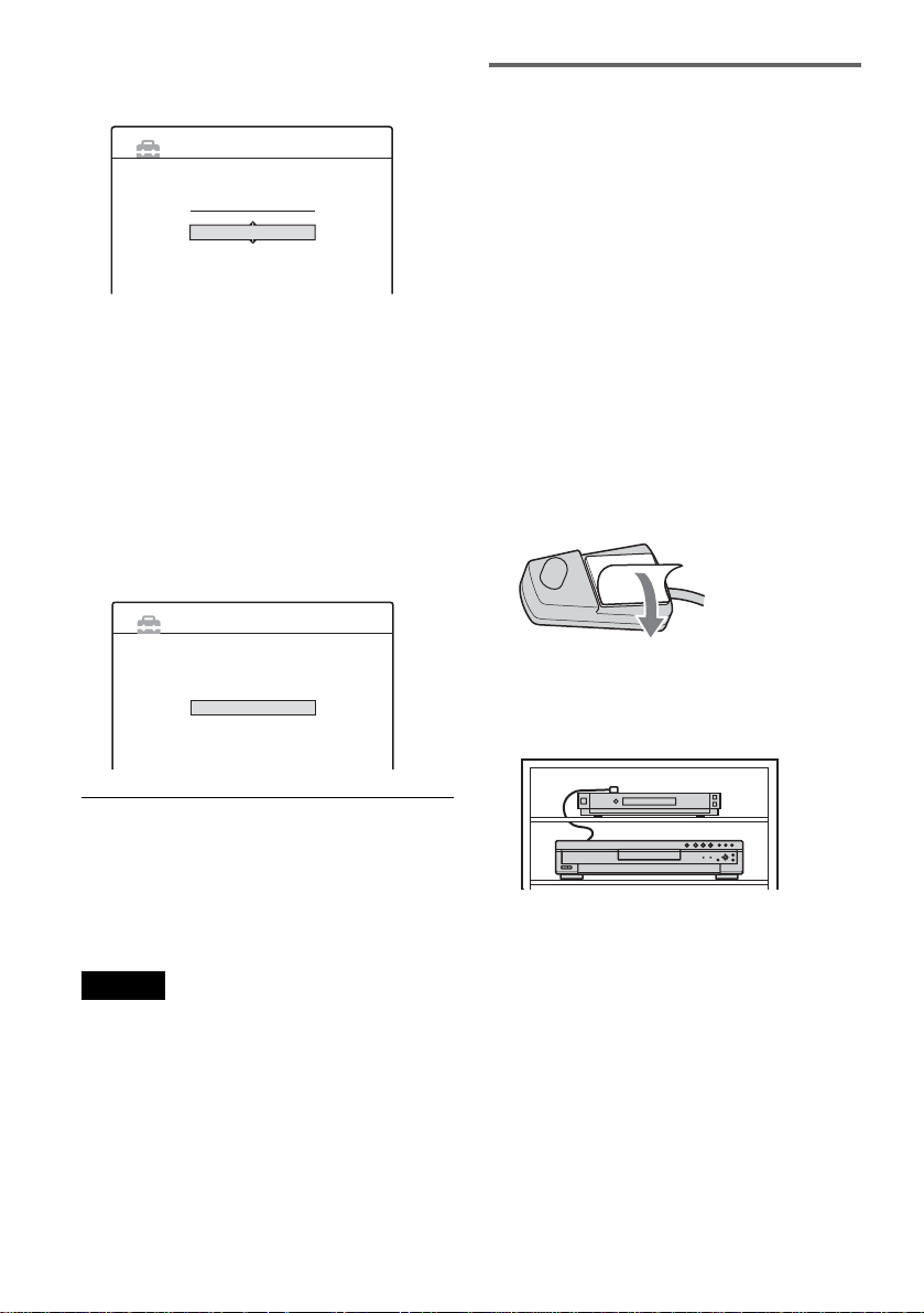
17Press ENTER.
The Setup Display for the DTS signal appears.
On
Off
Audio Connection 6/6
EASY SETUP
DTS
18Select whether or not you wish to send a
DTS signal to your amplifier (receiver),
and press ENTER.
If your AV ampli fie r (receiver) has a DT S
decoder, sel ect “ On.” Ot herwi se, select “Off .”
19Press ENTER w hen “Finish” ap pears.
Easy Setup is finished. All connections and
setup operations ar e complete.
If you use the cable box/satellite receiver
control, check that the control works correctly
(see below).
EASY SETUP
Checking the cable box/satellite
receiver control setting
1 Point the remote at the recorder (not at the
cable box/satellite receiver.)
2 Press CH +/– and check that the channel
changes on the c able box/satellite re ceiver
window.
3 Press the number buttons and c heck that
the channel changes on the cable box/
satellite receiver window.
To fix the set top box controller to your cable
box/satellite receiver
Once you have confirmed that the set top box
controller controls your cable box or satellite
receiver, fix it in place.
1 Remove the backing on the double-sided tape.
Easy Setup is finished.
Finish
To return to the previous step
Press O RETURN.
z Hint
If you want to run Easy Setup again, select “Easy Setup”
in the Setup Display (page 81).
Notes
• If there are only a few chann el s in your area that carry
time signals, settin g the clock automatically may ta ke
up to about 20 minutes afte r th e r ec or der turns off. If
nothing happens even after you wait about 20 minutes,
set the clock manually in “Clock” of “Settings”
(page 72).
• To record TV programs using the timer, you must set
the clock accurately.
• If you use an S-video cord to connect your cable box or
satellite receiver, set “Line1 Input” or “Line3 Input” in
Video Setup to “S Video” (page 75).
26
2 Attach it so that the cable mous e is di rectly
above the remote control sensor on your cable
box/satellite receiver.
If you cannot get the recorder to control your
cable box/satellite receiver
Check the settings at “Set Top Box Control” in
Settings Setup (page 73).
Check the connecti on and position of the cable
mouse (page 13).
If your cable box or satellite receiver still does not
operate with this recorder, contact your cable
company to see if t hey can provide yo u w i t h a
compatible ca bl e box or satellite receiver.
Page 27

Setting Up the VCR Plus® System
Setting up your rec order i nvolves coordina ting th e
TV channel number (th e number you turn to on
your TV or reco rder to watc h a pr ogra m) wi t h the
guide channel (the number that’s assigned to that
channel in your TV program guide).
To find the guide chann el num bers, look at the
“Channel Line-up Chart” in the program guide for
your area that featu re s V C R PlusCode number s .
Use the Channel Line -up Chart to coordinate th e
guide channel number with the TV channe l
number. For example, if HBO is listed in the
Channel Line-u p Chart as channel 33, an d the
recorder rece iv es HBO on channel 5 , co ordinate
these numbers using the following procedure.
Number
buttons, SET
SYSTEM
MENU
O RETURN
1 2 3
4 5 6
7 8 9
0
</M/m/,,
ENTER
SETUP
Settings
Tuner Preset
Video
Set VCR Plus+ Channels
Audio
Clock
Features
Set Top Box Control
Options
Language
Easy Setup
3 Select “Settings,” and press ENTER.
4 Select “Set VCR Plus+ Channels,” and
press ENTER.
Settings - Set VCR Plus+ Channels
Guide CH TV CH
- -
Channel list
- -
----
5 Select “Guide CH – TV CH,” and press
ENTER.
Settings - Set VCR Plus+ Channels
Guide CH TV CH
- -
- - ----
- -
- -
6 Enter the guide channel number assigned
in the program guide using the number
buttons, and press SET.
Hookups and Settings
1 Press SYSTEM MENU whi le the r ecorder is
stopped.
SYSTEM MENU
TITLE LIST
TIMER
TIMER LIST
SETUP
2 Select “SETUP, ” and press ENTER.
Settings - Set VCR Plus+ Channels
Guide CH TV CH
33
- - ----
- -
33
7 Enter the TV channel number using the
number buttons, and press SET.
Settings - Set VCR Plus+ Channels
Guide CH TV CH
33
- - ----
- -
5
,continued
27
Page 28

If you connected a cable box or satellite
receiver to the recorder and set “Set To p Box
Control” to “On,” e n ter the TV c hannel
number on your cable box.
If you connected a cable box and set “Set Top
Box Control” to “Off,” enter the cable box
output channel (Usually 2ch, 3ch, or 4ch). See
the instructions supplied with your cable box
to confirm the cable box’s output chan nel.
8 Repeat steps 5 to 7 fo r each guide chann el
number that does no t match the TV channe l
number.
9 Press SYSTEM MENU repeatedly to exit the
menu.
To return to the previous step
Press O RETURN.
To check the channel settings
When displaying th e “Set VCR Plus+ Channels”
menu, select “Ch annel List,” then press ENTER.
The display lists the channels for which the guide
channel number do es not match the TV channel
number.
Settings - VCR Plus+ Channel List
Guide CH TV CH
2
-
4
-
6
-
10
-
11
-
25
-
28
-
21
32
9
121
13
36
2
Guide CH TV CH
45
53
- -
- -
- -
- -
- -
Close
To go to the next page, pr ess m.
To return to the previous page, press M.
28
Page1
-
18
-
5
-
- -
-
- -
-
- -
-
- -
-
- -
Page 29
Connecting a VCR or Similar Device
After disconnecting the recorder’s power cord from an AC outlet, connect a VCR or similar recording
device to the LINE IN jacks of this recorder.
See also the instruction manual supplied with the connected equipment.
To record on this recorder, see “Recording From a VCR or Similar Device” (page 49).
Connecting to the LINE IN 1 or 3 jacks
If the equipment ha s an S-video jack, you ca n use an S-video cord ins t ead of an audio/video c or d .
VCR, etc.
LINE OUTPUT
AUDIO
RL
VIDEO
S Video
Hookups and Settings
Audio/video cord
(not supplied)
to LINE IN 1 or 3
VHF/UHF
IN
SET TOP BOX
CONTROL
OUT
: Signal flow
1
3
LINE IN DIGITAL OUT
AUDIORL
1
3
AUDIORL
S VIDEO
VIDEO
DOLBY DIGITAL
PCM/DTS/
LINE IN
COAXIAL
OPTICAL
VIDEO
AUDIORL
1
2
S VIDEO
LINE OUT
S-video cord
(not supplied)
DVD recorder
COMPONENT
VIDEO OUT
Y
S VIDEO
VIDEO
B
P
P
R
~ AC IN
,continued
29
Page 30

Connecting to the LINE 2 IN jacks on the front panel
Connect a VCR or similar recording device to the LINE 2 IN jacks of thi s recorder . If the eq uipment has
an S-video jack, yo u can use an S-video cord i nstead of an audio/vi deo cord.
VCR, etc.
OUTPUT
S VIDEO
VIDEO
AUDIO
LR
S-video
cord (not
supplied)
to LINE 2 IN
S VIDEO VIDEO
Audio/video cord
(not supplied)
L
(MONO)
AUDIO R
LINE 2 IN
DVD recorder
: Signal flow
z Hint
When the connected equipment o utputs only monaural sound, use audio cable s tha t distribute monaural sounds to left/
right channels (not supplied).
Notes
• Do not connect the yellow LINE IN (VIDEO) jack when using an S-video cord.
• Do not connect the output jack of this recorder to another equipment’s input jack with the other equipment’s output
jack connected to the input jack of this recorder. Noise (feedback) may result.
• Pictures containing copy protection signals that prohibit any copying ca nnot be recor de d .
• If you pass the recorder signals via the VCR, you may not rec ei ve a clear ima ge on your TV sc ree n.
VCRDVD recorder TV
Be sure to connect your VCR to the DVD recorder and your TV in the order shown below. To watch videotapes, watch
the tapes through a second Line input on your TV.
LINE IN 1
VCR DVD recorder TV
LINE IN 2
• Do not connect more than one type of video cord be twe en the recorder and your TV at the same time.
30
Page 31

Guide to Displays
Using the On-Screen Menus
+
-
-
RW
VR
RW
RW
VCD
CD
Video
DATA CD
This section introduces the System Menu, TOOLS
menu, and sub-menu. By using these displays, you
can perform most of the recorder’s operations.
1 2 3
4 5 6
7 8 9
0
-
+
R
DVD
R
Number
buttons, SET
B TIMER (page 41):
Allows you to set a new timer recording
setting.
C TIMER LIST (page 44):
Turns on the Timer List menu, which allows
you to check, change , or cancel tim er set tings .
D SETUP (page 69):
Turns on the Setup Display, which allows you
to set up the recorder to suit your preferences.
Sub-menu
The sub-menu appears when you select an item
from a list menu (e.g. a title from the Title List
menu), and press ENTER. The sub-menu displays
options applicable only to the selected item. The
displayed option s di f fer depending on the
situation and disc t ype.
Select an option by pr es sing M/m and ENTER.
Guide to Displays
SYSTEM
MENU
O RETURN
TOOLS
</M/m/,,
ENTER
System Menu
The System Menu a ppears when you pre ss
SYSTEM MENU, and provides entries to all of
the recorder’s main functions, such as timer
recording and set u p.
Select an option by pressing M/m and ENTER.
SYSTEM MENU
TITLE LIST
TIMER
TIMER LIST
SETUP
A TITLE LIST (page 32):
Turns on the Title Lis t me nu, which shows
recorded titles on the disc.
Example: The Title List menu
ORIGINAL
My Movies
Play Beginning
Set Thumbnail
TITLE LIST
Sort
Date
Title
Number
1 2ch 1:00PM - 2:00PM
2 5ch 8:00PM - 9:00PM
3 12ch 9:00AM - 9:30AM
4 3ch 8:00PM - 8:30PM
5 25ch 8:00PM - 8:30PM
6 L2 9:00PM - 9:30PM
7 8ch 9:00PM - 9:30PM
8 125ch 10:00AM - 10:30AM
Options for the selected item
1.5/4.7GB
Close
Wed
Play
Fri
Sat
Erase
Protect Title
Sat
Title Name
Fri
10/19
Tue
A-B Erase
10/26
Tue
10/28
Thu
9/15
9/17
9/25
9/25
10/15
,continued
31
Page 32

TOOLS
The TOOLS menu ap pears when you press
TOOLS, and displays options applicable to the
entire disc (e.g. disc protection), recorder (e.g.
audio settings during recording), or multiple items
on a list menu (e.g. erasing multiple titles). The
displayed options differ depending on the
situation and disc type.
Select the option by pressin g M/m and ENTER.
Example 1: When you press TOOLS while the
Title List menu is turned on.
My Movies
TITLE LIST
ORIGINAL
1 2ch 1:00PM - 2:00PM
Close
Sort
Date
2 5ch 8:00PM - 9:00PM
Disc Info.
Title
3 12ch 9:00AM - 9:30AM
Erase Titles
Number
4 3ch 8:00PM - 8:30PM
Playlist
5 25ch 8:00PM - 8:30PM
Create Playlist
6 L2 9:00PM - 9:30PM
TOOLS
7 8ch 9:00PM - 9:30PM
8 125ch 10:00AM - 10:30AM
Options for the disc or menu
Wed
Fri
Sat
Sat
Fri
Tue
Tue
Thu
1.5/4.7GB
9/15
9/17
9/25
9/25
10/15
10/19
10/26
10/28
Using the Title Lis t
+
-
-
RW
VR
RW
RW
Video
The titles of pro gr ams recorded on a di sc are
displayed in the Title List.
Z OPEN/
CLOSE
1 2 3
4 5 6
7 8 9
0
TITLE LIST
CURSOR
MODE
-
+
R
R
TOOLS
</M/m/,,
ENTER
ZOOM +/–
Example 2: When you press TOOLS while a
DVD-RW (VR mode) is playing.
Close
Stop
Disc Info.
Erase Title
Protect Title
TOOLS
Options for the disc or picture
To return to the previous disp lay
Press O RETURN.
1 Press Z OPEN/CLOSE, and place a disc on
the disc tray.
With the recording side facing down
2 Press Z OPEN/CLOSE to close the disc
tray.
Wait until “LOAD” disappears from the fr ont
panel displ ay.
3 Press TITLE LI ST.
To show the list in greater detail (zoom), pr ess
ZOOM+.
32
Page 33

Standard Title List (Example: DVD-RW in VR
mode)
My Movies
TITLE LIST
Sort
Date
Title
Number
ORIGINAL
1 2ch 1:00PM - 2:00PM
2 5ch 8:00PM - 9:00PM
3 12ch 9:00AM - 9:30AM
4 3ch 8:00PM - 8:30PM
5 25ch 8:00PM - 8:30PM
6 L2 9:00PM - 9:30PM
7 8ch 9:00PM - 9:30PM
8 125ch 10:00AM - 10:30AM
Wed
Fri
Sat
Sat
Fri
Tue
Tue
Thu
1.5/4.7GB
9/15
9/17
9/25
9/25
10/15
10/19
10/26
10/28
m
“Zoomed” Title List
My Movies
TITLE LIST
ORIGINAL
Sort
Date
Title
Number
1 2ch 1:00PM - 2:00PM
Wed 9/15 1:00PM( 1H00M)SP
2 5ch 8:00PM - 9:00PM
Fri 9/17 8:00PM( 1H00M)SLP
3 12ch 9:00AM - 9:30AM
Sat 9/25 9:00AM( 0H30M)EP
4 3ch 8:00PM - 8:30PM
Sat 9/25 8:00PM( 0H30M)SLP
A Title type (DVD-RW in VR mode only):
Displays the title type, Original or Playlist.
B Sort buttons:
Sorts the title order (see below).
C Zooming indicator:
Shows the curren t zoom status.
D Disc name (page 35)
E Disc space (remainder/total)
F Title information:
Displays the title number, title name, and
recording date.
“z” (red) indicates that the title is currently
being recorded.
“ ” indicates the protected title.
G Scroll bar:
Appears when all of the titles do not fit on the
list. To view the hidden titles, press M/m.
H Title’s thumbnail picture
1.5/4.7GB
2ch
5ch
12ch
3ch
To scroll the list display by page (Page mode)
Press CURSOR MODE while the list display is
turned on. The display enters Page mode. Each
time you press M/m, the entire Title List changes
to the next/previous page of titles.
To return to the Cursor mode, press CURSOR
MODE again.
About the Title List for DVD-RWs (VR mode)
You can switch the Ti tle Li st to show Original or
Playlist.
While the Title List menu is turned on, press
TOOLS and select either “Original” or “Playlist,”
and press ENTER. “PLAYLIST” appears on the
front panel display when “Playlist” is selected.
For details, see “Edit options for DVD-RWs (VR
mode)” (page 61).
To change the title order (Sort)
Press < while the Title List menu is turned on to
move the cursor to the Sort column. Press M/m to
select the item, and press ENTER.
Order Sorted
Date in order of when the titles w ere
recorded. The title that is recorde d
most recently is listed at the top.
Title in alphabetical order.
Number in order of recorded title num be r.
To change a title thumbnail pic tu re
(Thumbnail) (DVD-RW in VR mode only)
You can select a favorite scene for the thumbnail
picture shown in the Title List menu.
1 Press TITLE LIST while a disc is in the
recorder, and press ZOOM+.
2 Sele ct a titl e whose thumbnail picture you
want to change, and press ENTER.
3 Select “Set Thumbnail” from the sub-menu,
and press ENTER.
The selected title starts to play in the
background.
4 While watching the playback picture, press
H PLAY, X PAUSE, or m/M to sel ect
the scene you want to set for a thumb nail
picture, and pres s EN TER.
The scene is set for the title’s thumbnail
picture.
Guide to Displays
To turn off the Title List
Press TITLE LIST.
,continued
33
Page 34

z Hint
After recording, the firs t scene of the reco rding (the t itle)
is automaticall y se t as the thumbnail picture.
Notes
• The Title List may not appear for discs created on other
DVD recorders.
• Letters that cannot be displayed are repla ced with an
“*”.
• Title thumbnail pictures are disp la ye d only on this
recorder.
• It may take a few seconds for the thumbnail pictures to
be displayed.
• After editing, the title thumbnail picture may change to
the first scene of the recording (title).
Using the “Disc Info” Screen (disc settings)
+
-
-
RW
VR
RW
RW
Video
With the Disc Info rmati on disp lay, you can ch eck
the disc type and remaining disc space. Also, you
can perform operations such as formatting and
finalizing (page 35).
Z OPEN/
CLOSE
1 2 3
4 5 6
7 8 9
0
-
+
R
R
TOOLS
</M/m/,,
ENTER
1 Press Z OPEN/CLOSE, and place a disc on
the disc tray.
34
With the recording side facing down
2 Press Z OPEN/CLOSE to close the disc
tray.
Wait until “LOAD” disappears from the fr ont
panel displ ay.
3 Press TOOLS.
The TOOLS menu appears.
4 Select “Disc Info.,” and press EN TER.
Items in the displa y di ffer depending on the
disc type or re cording format.
Page 35

Example: DVD-RW (VR mode)
Disc Information
DiscName Movie
Media DVD-RW Format VR
Title no. Original 3 / Playlist 2
Protected Not Protected
Date 9/15/2003 ~ 10/28/2003
HQ : 0H30M
HSP : 0H45M
LP : 1H30M
Remainder
EP : 2H00M
SLP : 3H00M
SP : 1H00M
2. 3 / 4. 7GB
Close
Disc Name
Protect Disc
Finalize
Erase All
Format
A “Disc Name”
B “Media”: Disc type
C “Format”: Recording format type (DVD-
RW only)
D “Title no.”: Total number of titles
E “Protected”: Indicates whether protection is
set (DVD-RW in VR mode only)
F “Date”: Dates of when the oldest and the
most recent titles were recorded
G “Continuous Rem. Time”/“Rema in der”
(approximate)
• The longest continuous recording time in
each of the reco rding modes
• Di sc space bar
• Remaining disc space/total disc space
H Disc setting buttons (page 35)
• “Disc Name”
• “ Pr ot ect Disc”
• “Finalize”/“Unfinalize”
• “Erase All”
•“Format”
Available settin gs differ depending on the disc
type.
Labeling, protecting, or formatting
a disc
+
-
-
RW
VR
RW
RW
Video
+
R
R
-
You can execute options effective for the entire
disc using the Disc Information display.
1 Press TOOLS while the disc is in the
recorder.
The TOOLS menu appears.
2 Select “Disc Info.,” and press ENTER.
Example: When the inserted disc is a DVDRW (VR mode).
Disc Information
DiscName
Media DVD-RW Format VR
Title no. Original 3 / Playlist 2
Protected Not Protected
Date 9/15/2003 ~ 10/28/2003
HQ : 0H30M
HSP : 0H45M
LP : 1H30M
Remainder
EP : 2H00M
SLP : 3H00M
SP : 1H00M
2. 3 / 4. 7GB
Close
Disc Name
Protect Disc
Finalize
Erase All
Format
3 Select an option, and press ENTER.
“Disc Name”: Labels a disc. Enter the disc
name in the “Inp ut D is c N ame” display
(page 39).
“Protect Disc” (DVD-RW in VR mode only):
Protects all titles on the disc. To cancel the
protection, select “Don’t Protect.”
“Erase All” (DVD-RW/DVD+RW only):
Erases all titles on the disc (except the
protected titles).
“Format” (DVD-RW/DVD+RW only):
Erases all con tents of the disc to make a bl ank
disc. For DVD-RWs, select a recording
format (VR or Vid eo) according to you r
needs.
Guide to Displays
z Hint
For DVD-RWs (Video mode) and DVD+RWs, you can
check free space and title location on the disc using the
Disc Map display (page 64).
Note
On this model, 1 GB (read “gigabyte”) is equivalent to 1
billion bytes. The larger the number, the larger the disc
space.
z Hints
• You can set protection for individual titles (page 62).
• By reformatting, you can change the recording forma t
on DVD-RWs, or record again on DVD-RWs (Video
mode) that have been finalized.
Note
You can enter up to 64 characters for a disc name. The
disc name may not appear when the dis c is play ed on
other DVD equipment.
,continued
35
Page 36

Finalizing a disc (preparing a disc
for playback on other equipment)
-
+
-
-
RW
VR
RW
RW
Finalizing is nece ssary when you play discs
recorded with t his recorder on other DVD
equipment.
When you finalize a DVD+RW, DVD-RW
(Video mode), DVD+R, or DVD-R, a DVD menu
will be automatically created, which can be
displayed on other DVD equipment.
Before finalizing, check the differences between
the disc types in the table below.
Video
+
R
R
3 Select “Finalize,” and press EN TER.
The display shows the approximate time
required for finalizing and asks for
confirmation.
Finalize
About xx min is needed for finalizing this disc.
Cannot cancel finalizing during transaction.
Do you want to finalize?
OK Cancel
4 Select “OK,” and press ENTER.
The recorder starts finalizing the disc.
Differences between the disc types
Discs are automatically finalized when
RW
removed from the recorder. However,
you may need to finalize the disc for
certain DVD equipment, or if the
recording time is short. You can edit or
record on the disc even after finalizing.
Finalizing is unnecessary w hen playing
VR
a disc on VR format comp atible
equipment.
Even if your other DVD equip ment is
VR format compatib le, yo u may need to
finalize the disc , es pecially if the
recording time is short. You can edit or
record on the disc even after finalizing.
Finalizing is necessary when playing on
Video
any equipment other tha n th is recorder.
After finalizing, you cannot edit or
record on the disc. If you want to record
on it again, reformat the disc (pa ge 35).
However, all recorded contents will be
erased.
Finalizing is necessary when playing on
+
R
any equipment other tha n th is recorder.
-
R
After finalizing, you cannot edit or
record on the disc.
-
-
+
RW
RW
1 Press TOOLS while the disc is in the
recorder.
The TOOLS menu ap pears.
2 Select “Disc Info.,” and press ENTER.
The Disc Information display app ears.
To unfinalize a DVD-RW (VR mo de )
If you cannot record or edit on a DVD-RW (VR
mode) that has been finalized with other DVD
equipment (a message appears), unfinalize the
disc by selecting “Unfinalize” in step 3 above.
z Hint
You can check whether the disc has been finali zed or not.
If you cannot select “Finaliz e” in step 3 above, the disc
has already been finalized.
Notes
• Depending on the condition of the di sc , recor ding, or
the DVD equipment, discs may not play eve n if the
discs are finalized.
• The recorder ma y not be able to finalize the d isc if it
was recorded on another recorder.
36
Page 37

Checking the Play Information and Playing Time
+
-
-
RW
VR
RW
RW
VCD
CD
Video
DATA CD
You can check the pl aying time and rem ai ning
time of the current title, chapter, or track. Also,
you can check the disc name recorded on the disc.
-
+
R
DVD
R
B Available functions for DVD VIDEOs
( angle/ audio/ subtitle, etc.)
C The current selected function or audio
setting (appears on ly te mp orarily)
D The current selected angle
Example: Dolby Digital 5.1 ch
Rear (L/R)
1 : English DolbyDigital 3/2.1
Guide to Displays
1 2 3
4 5 6
7 8 9
0
TIME/TEXTDISPLAY
Press DISPLAY repeatedly.
Each time you press the button, the display
changes as follows:
Title/track info rmation (Display 1)
m
Play mode/time information (Display 2)
m
(Display off)
The displays differ depending on the disc t y pe or
playing status.
◆Display 1
Example: When pl ay i ng a DVD VIDEO
Title 1
1 : English DolbyDigital 2/0Angle3(5)
Front (L/R) + Center
LFE (Low Frequency
Effect)
◆D i splay 2
Example: When playing a DVD-RW (VR mode)
Original
DVD-RW
VR
Movies
0:00:45
T1SP
A Disc type*2/format (page 8)
B Title type (Original or Playlist) (page 61)
C Play mode
D Recording mode (page 40)
E Playing status bar*
3
F Title number (chapter numb er*1) (page 58)
(Track number for CDs/VIDEO CDs without
PBC, scene number for VIDEO CDs with
PBC, track number (albu m number*
1
) for
DATA CDs)
G CD text (album name) appears when text is
recorded on a CD.
1
H Playing time (remaining time*
*1Displayed when you press TIME/TEXT repeated ly.
2
Displays Super VCDs as “SVCD”, DATA CDs as
*
“CD”.
3
Does not appear with VCDs, or DATA CDs.
*
)
A Title number/name
(Track number for CDs/VIDEO CDs without
PBC, scene number for VIDEO CDs with
PBC, track number/ name for DATA CDs)
,continued
37
Page 38

z Hints
• If “DTS” is set to “Of f” in Audio Set up, t he DTS t rac k
selection option will not appear on th e scr e en e ve n if
the disc contains DTS tracks (page 77).
• When “Auto Display” is set to “On” (def a u lt ) in
Options Setup (page 80), playback information
automatically appears when the recorder is turned on,
etc.
Notes
• The recorder can only display the first level of a C D ’s
text, such as the disc name.
• The letters or symbols that cannot be displ ayed are
replaced with “*.”
Example: When playing a CD
Track playin g ti me an d the c urr ent track /in dex
number
m
Remaining time of the current track
m
Playing time of the disc
m
Remaining time of the disc
m
CD text (when available)
Checking the playing/remaining
time
You can view the p laying or time information
displayed on the TV s cr een and the front panel
display.
Press TIME/TEXT repeatedly.
The displays differ depending on the disc type or
playing status.
◆Front panel display
Example: When playing a DVD
Playing time and number of the current title
Remaining time of the current title
Playing time and number of the current chapter
Remaining time of the current chapter
Notes
• The recorder can only displa y the firs t le ve l o f a CD’ s
text, such as the disc name.
• The letters or symbols that can not be displayed are
replaced with “*.”
• Playing time of MP3 audio tracks may not be displayed
correctly.
38
Page 39

How to Enter Characters
You can label a title, disc, or program by en tering
characters. You ca n ente r up to 64 charac ters for a
title or disc name, but the actual number of
characters displayed in the menus such as the Title
List will va ry. When the d isplay for en tering
characters ap pears, follow the st eps below.
Number
buttons, SET
1 2 3
4 5 6
7 8 9
0
</M/m/,,
ENTER
1 Press </M/m/, to move the cursor to
the right of the screen and select “A”
(upper-case), “a” (lower-case), or
“Symbol,” and press ENTER.
The characters of the selected type are
displayed.
2 Press </M/m/, to select the character
you want to enter, and press ENTER.
The selected ch ar acter appears at the top of
the display.
Example: Input Title Name
Input Title Name
K
,. - 1
1
BA C 2
2
ED F 3
3
HG I 4
4
KJ L5
5
Back
Clear All
Space
6
7
8
9
0
NM O 6
QP R S
UT V 8
XW Y Z79
0
"A"
"a"
Symbol
Cancel
Finish
To enter a let ter with an accent ma rk, selec t an
accent followed by the letter.
Example: Sel ect “ ` ” and the n “a” to enter “à.”
To insert a space, select “Space.”
3 Repeat steps 1 an d 2 to enter the
remaining characters.
Input row
Input Title Name
Kids
XW Y Z79
0
"A"
"a"
Symbol
Cancel
Finish
,. - 1
1
BA C 2
2
ED F 3
3
4
HG I 4
KJ L5
5
Back
Clear All
Space
NM O 6
6
QP R S
7
UT V 8
8
9
0
To erase a character, move the cursor to the
right of the char acter at the input row. Select
“Back” and press EN TER.
To insert a character, move the cursor to the
right of the point where you want to insert the
character. Se l e ct t he character and press
ENTER.
To erase all of the characters, select “Clear
All” and press ENTER.
4 Select “Finish,” and press ENTER.
To cancel the se tt i ng, select “Cance l.”
To use the number but tons
You can also use the number buttons to enter
characters.
1 In step 2 above, press the number but t ons
repeatedly to select a character.
Example:
Press the number 3 button once to enter “D.”
Press the number 3 button three time s to enter
“F.”
2 Press SET and select the next char acter.
3 Select “Finish” and press ENTER.
Guide to Displays
The type of characters will change according
to the language you select in Easy Setup.
Some languages al l ow you to enter an accent
mark.
39
Page 40

Recording
Before Recording
Before you start recording…
• This recorder can record on various discs. Select
the disc type ac cording to your n eeds (page 8).
• Check that the disc ha s enough available space
for the recording (pa ge 34). For DVD+RWs and
DVD-RWs, you can free up disc space by
erasing titles (page 64).
• Adjust the recording picture quality and picture
size if necessary (page 48).
z Hint
Timer reco rdi ngs will be m ade r ega rdle ss w het her or not
the recorder is turned on. You can turn off the recorder
without affecting the recording even after recording
starts.
Recording mode
Like the SP or LP recording mode of VCRs, this
recorder has six different re cor d i ng modes.
Select a recording mode according to the time and
picture quality yo u need. For example, if pic t ure
quality is yo ur top priorit y, select the Hi gh Quality
mode (HQ). If recording time is your priority,
Super Long Play mode (SLP) can be a possibl e
choice. Note that the recording t im e in the
following table is an approximate guid e.
Press REC MOD E repeatedly to swi tc h t h e
recording m odes.
I want to record with the
best possible picture
quality, so I’ll select HQ.
Recording mode Recording time
(minute)
HQ (High quality) 60
HSP R 90
SP (Standard mode) 120
LP r 180
EP r 240
SLP (Long duration) 360
Note
Situations below may cause slight inaccuracies with the
recording time.
– Recording a program with poor reception, or a program
or video source of low picture quality
– Recording on a disc that has already been edited
– Recording only a still picture or just sound
Recording a stereo/SAP program
The recorder can receive and record stereo/SAP
programs.
Stereo programs
When a stereo p ro g r am is received, the
“STEREO” indicato r l ig ht s up on the front panel
display. If there is noise in the stereo progr am, set
“Auto Stereo” in Audio Setup to “Off” (page 76).
The sound will be recorded in monaural but with
less noise.
SAP (Second Audio Program)
When a SAP (Second Audio Program) is received,
the “SAP” indicator lights up on the front panel
display. To record only SAP sound, set “Tuner
Audio” in Audio Set up t o “SAP” (page 76).
z Hint
You can select the audio (main or SAP) while recording
bilingual programs using the AUDIO button. This does
not affect the recorded sound.
40
Unrecordable pictures
Pictures with copy protection cannot be recorded
on this reco rder.
When the recorder receives a copy guard signal,
the recorder continues to record but only a blank,
grey colored screen will be rec o r ded.
Page 41

Copy control
Recordable discs
signals
Copy-Free
Copy-Once Ver.1.1 with
+
-
-
RW
VR
RW
+
R
-
RW
VR
RW
-
R
CPRM*
Copy-Never None (a bl a nk scre en is
recorded)
* Th e recorde d disc can be played only on CPRM
compatible equipment.
Timer Recording (Standard/ VCR Plus+)
Video
+
-
-
RW
VR
RW
RW
You can set the timer for a total of 30 programs, up
to one month in ad vance.
There are two methods to set the timer: the
standard method and VCR Plus+ method.
• Standard: Set the date, time, and channel of the
program manually.
• VCR Plus+: Enter the PlusCode num ber
designated for eac h TV program (page 43 ).
Note
Do not operate your cable box or satel lit e receiver just
before or during a timer recording. This may prevent the
accurate recording of a program.
Setting the timer manually
(Standard)
Z OPEN/
CLOSE
Video
1 2 3
4 5 6
7 8 9
0
+
R
-
R
Recording
[TIMER]
TOOLS
</M/m/,,
ENTER
x REC
STOP
,continued
41
Page 42

1 Press Z OPEN/CLOSE, and pl ace a
recordable disc on the disc tray.
With the recording side facing down
2 Press Z OPEN/CLOSE to close the disc
tray.
Wait until “LOAD” disappears fr om the front
panel display.
Unused DVDs are formatted automatically.
3 Press [TIMER].
Timer - Standard
Set the timer manually.
Start CH
Date
Tod ay
::
VCR Plus+
OK
ModeStop
Cancel
“Mode”: Select s the recording mode
(page 40).
If you make a mistake, select the item and
change the setting.
5 Select “OK,” and press ENTER.
The Timer List men u ( page 44) appears. Th e
TIMER REC indic at or lights up on the front
panel and the recorder is ready to start
recording.
Unlike a VCR, there is no need to tu rn off the
recorder before the timer recording starts.
To stop recording during timer recording
Open the remote’s cover and press x REC STOP.
Note that it may tak e a few secon ds for the
recorder to stop recording.
Rec Mode Adjust
If there is not enough available disc space for the
recording, the recorder automatically adjusts the
recording mode to enable the entire program to be
recorded. This function is normally set to “On.”
If the Timer programming (VCR Plus+) menu
appears, press < to switch t h e display to
“Standard.”
4 Select an item using </, and adjust
using M/m.
“Date”: Sets the da t e.
The item changes as follows.
Today y Tomorrow y …… y Tue 10/
28 (1 month later) y Sun (every Sunday)
y …… y Sat (every Saturday) y
Mon-Fri (Monday to Friday) y Mon-Sat
(Monday to Saturday) y Sun-Sat (Sunday to
Saturday) y Today
“Start”: Sets the start time.
“Stop”: Sets the stop time.
“CH”: Selects the channel or input source.
◆When using the cable box/satellite box
control
Turn on the cable box or satellite receiver and
enter the channel number.
Example: When selecting 215ch
Select 2 and press , for the next digit. Select
1 and press ,. Then select 5.
To cancel this function, press TOOLS while the
Timer List is displayed. Select “Rec Mode
Adjust” and press ENTER. Select “Off” and press
ENTER.
If the timer settings overlap
Overlapped timer settings are shown as follows.
Timer
These timer settings overlap. Do you want to continue?
Mon-Sat 10:00AM - 10:30AM 25ch SP
Fri 10/29 9:00AM - 10:15AM 3ch SLP
OK
Cancel
To store the setting as shown, select “OK.” The
program at the top of the list has priority over the
rest of the programs.
To cancel the overlapped timer setting, select
“Cancel.”
To confirm, change, or cancel timer recording
See “Checking / C hanging/Can celing Timer
Settings (Timer List)” (page 44).
42
Page 43

To extend the recording duration time while
recording
1 Press TOOLS during recording.
The TOOLS menu ap pears.
2 S elect “Extend R ec Tim e,” and press ENT ER.
Extend Rec. Time
Set the timer extend function.
Tue 9/28 10:00AM - 11:30AM 3ch SP
Extend Time
Off
OK
Cancel
3 Press M/m to select the duration time.
You can set the duration in increments of 10
minutes, for a maximum of 60 minutes.
4 Select “OK,” and press ENTER.
z Hint
You can play the recorded program by selecting the
program title in the Title List menu.
Recording TV programs using the
VCR Plus+ system
The VCR Plus+ system is a feature that simp lifies
setting the timer. Just enter the PlusCode number
listed in the TV program guide. The date, time,
and channel of t hat progr am are se t automat icall y.
Before you start, check that the TV and guide
channels are correctly set in “Set VCR Plus+
Channels” in “S ettings” (page 71).
1 2 3
CLEAR
[TIMER]
4 5 6
7 8 9
0
Number
buttons, SET
Recording
Notes
• If “The disc is full or nearly full” appears on the screen,
change the disc, or make available space for the
recording (DVD+RW/DVD-RW only) (page 64).
• To record a cable or satellite prog r am without using
cable box/satellite box control, turn on the cable box or
satellite receiver and select the program you want to
record. Leave the cable box or satellite receiver turned
on until the recorder finishes record in g .
• Even if the timer is set for the sa me daily or weekly
program, the timer recor ding cannot be made if it
overlaps with a program that has priority. The mark
will appear next to the overlapped setting in the Timer
List. Check the priority order of the settings (page 44).
• Even if the timer is set, time r re c o r dings cannot be
made while recording a program that has pr ior i ty.
• The Rec Mode Adjust function only works with a timer
recording. It does not function with Quick Timer
(page 47).
</M/m/,,
ENTER
x REC
STOP
1 Insert a recordable disc.
2 Press [TIMER].
Timer - VCR Plus+
Set the timer by entering the PlusCode.
PlusCode
Standard
If the Timer programming (Standard) menu
appears, pres s < to switch the display to
“VCR Plus+.”
OK
Cancel
3 Press the number buttons to enter the
PlusCode number, and press SET.
If you make a mistake, press CLEAR and reenter the correct number.
,continued
43
Page 44

4 Select “OK,” and press ENTER.
The date, start and stop times, channel , and
recording mode appear.
Timer - VCR Plus+
Is the following timer setting correct? To modify,
adjust each item or re-enter the PlusCode.
Date
Start CH ModeStop
::
Mon 6/28 AM AM
10 00 11 30
107 HQ
If you want to change the setting, press </
, to select the item and press M/m to change
the setting.
OK
Cancel
Change
Checking/Changing/ Canceling Time r Settings (Timer List)
+
-
-
RW
VR
RW
RW
Video
You can check, change, or cancel timer settings
using the Timer List menu.
-
+
R
R
To re-enter the PlusCode number, select
“Change.”
5 Select “OK,” and press ENTER.
The TIMER REC indicator lights up on the
front panel, and the recorder is ready to start
recording.
To stop recording during timer recording
Open the remote’s cover and press x REC STOP.
Note that it may take a few seconds for the
recorder to stop recording.
If the timer settings overlap
See page 41.
To extend the recording duration time while
recording
See page 41.
To confirm, change, or cancel timer recording
See “Checking/C ha nging/Canceling Timer
Settings (Timer List)” (page 44).
z Hint
The Rec Mode Adju st functi on also wor ks with thi s timer
method (page 41).
1 2 3
4 5 6
7 8 9
0
SYSTEM
MENU
O RETURN
</M/m/,,
ENTER
1 Press SYSTEM MENU.
The System Menu ap pears.
2 Select “TIM ER LIST,” and press E NTER.
TIMER LIST
Mon 10/25 8:30PM - 9:30PM 4ch
Mon-Sat 10:00AM - 10:30AM 25ch
9:00AM - 10:15AM 3ch
Fri 10/29
Sat 10/30 4:00PM - 5:00PM 125ch
Timer information displays the recording
date, time, recording mode, etc.
“
❐”: Indicates that the setting is overlapped
by another setting.
“
” (green): Indicates that the setting is fully
a
recordable.
“
” (red): Indi cates the sett ing currently
z
being recorded .
“
” (grey): Indicates that the setting cannot
z
be recorded in the selected recording mode.
HQ
SP
SLP
SLP
10:30 PM
3 Select the timer setting you want to check/
change/cancel, and press ENTER.
The sub-menu appears.
44
Page 45

4 Select one of the option s , and pres s
ENTER.
“Modify”: Changes the timer setting. Select
an item using </, and adjust using M/m.
Select “OK” and pr es s EN TER.
Modify
Modify the timer setting.
Date
Start CH ModeStop
::
Mon-Sat PM PM
10 00 10 15
25 SP
“Erase”: Erases the timer se tting. Select “OK”
and press ENTER.
Erase
Are you sure you want to erase this timer setting?
Mon-Sat 10:00AM - 10:30AM 25ch SP
OK Cancel
“Check Overlap”: Checks for overlapped
settings.
The timer setting set mos t recently is listed a t
the top and has priority over the other settin gs.
You may not be abl e to record a program of
lower priority.
OK
Cancel
To turn off the Timer List
Press O RETURN.
z Hint
While recording, you cannot modify the timer setting for
the current recording, but you can extend the recording
duration of the recording time (pa ge 41).
Notes
• Even if the timer is set, timer recordi ngs c annot be
made while recording a program that has priority.
• Even if the timer is set for the same daily or weekly
program, the timer recording canno t be mad e if it
overlaps with a program that has prio rity. “ ” will
appear next to the overlapped setting in the Timer List.
Check the priority order of the settings.
Recording
Check Overlap
These timer settings overlap.
Mon-Sat 10:00AM - 10:30AM 25ch SP
Fri 10/29 9:00AM - 10:15AM 3ch SLP
Change Close
To change the priority of a program, press </
, to select “Change.” For details, see
“Changing the pri or it y of overlapped
settings” (page 46).
Select “Close” to return to the Timer List.
To change or cancel the setting, repeat steps 3
and 4 above.
,continued
45
Page 46

Changing the priority of overlapped
settings
If the timer settings overlap, the program that was
set last has priority and will be recorded. A timer
recording of lower priority may be canceled, start
from the middle or stop midway through the
program.
You can change the priority of a program if
necessary.
When the timer settings overlap
The program set last has priority.
Example: You set the timer in order of A, B, and
C (setting C has first priority)
7:00
A
9:00 11:00
will be cut off
B
1 Press SYSTEM MENU.
The System Menu ap pears.
2 Select “TIM ER LIST,” and press E NTER.
TIMER LIST
Mon 10/25 8:30PM - 9:30PM 4ch
Mon-Sat 10:00AM - 10:30AM 25ch
9:00AM - 10:15AM 3ch
Fri 10/29
Sat 10/30 4:00PM - 5:00PM 125ch
HQ
SP
SLP
SLP
10:30 PM
3 Select an overlapped timer set ti ng, and
press ENTER.
indicates that the timer setting is
overlapped by another timer setting.
4 Select “Check Over lap,” and p ress ENTE R.
Check Overlap
These timer settings overlap.
Mon-Sat 10:00AM - 10:30AM 25ch SP
Fri 10/29 9:00AM - 10:15AM 3ch SLP
10:30
Actual recording
C
ABC
7:00 9:00 10:30
If you give setting B priority over setting C, all of
program B will be recorded and program C is
recorded only af t er program B has ende d.
ABC
7:00 9:00 11:00
If the end time of one recording and the start
time of another ar e the same
The end of program A wi ll be cut.
7:00 9:00 10:00
A
B
Change Close
5 Select “Change,” and press ENTER.
Change priority
Fri 10/29 9:00AM - 10:15AM 3ch SLP
Where do you want to move this timer setting?
Mon-Sat 10:00AM - 10:30AM 25ch SP
Cancel
6 Press M/m to change the timer setting’s
priority, and press ENTER.
The setting moves to its new location in the
list. A timer setting higher up in the list has
higher priority.
To return to th e Timer List, selec t “Cancel.”
z Hint
You can change the priority of a timer set ting while
recording.
46
Page 47

Recording Without th e Timer
+
RW
-
RW
-
VR
RW
Video
-
+
R
R
To stop recording
Press x REC STOP located beneath the remote
control cover. Note that it may t ake a few seconds
for recording to stop.
To pause recording
Press X REC PAUSE located beneath the remote
control cover. To restart recording, press the
button again.
1 2 3
4 5 6
7 8 9
0
z REC
REC MODE
CH +/–
TV/VIDEO
</M/m/,,
ENTER
X REC
PAUSE
x REC
STOP
1 Insert a recordable disc.
2 Press CH +/– to select the channel or input
source you want to record.
3 Press REC MODE repeatedly to select the
recording mode.
Each time you press the button, the display
changes on the TV screen as follows:
HQ SP LP EPHSP SLP
To watch another TV program while recording
Set your TV to the TV input using the TV/VIDEO
button.
Using the Quick Timer function
You can set the recorder to record in 30 minute
increments.
Press z REC repeatedly to set the duration.
Each press advances the time in 30 minute
increments. The maximum duration is six hours.
0:30 1:00 5:30 6:00
The time counter decreases minute by minute to
0:00, then the recorder stops recording (power
does not turn off). Even if you turn off the recorder
during recordi ng, th e reco rder co ntin ues to record
until the time counter runs out.
To cancel the Quick Timer
Press z REC repeatedl y unt il the c oun ter ap pears
in the front panel display. The recorder returns to
normal reco rding mode.
z Hint
If you do not want to watch TV while recording, you can
turn off the TV. When using a cable box, ma ke sure to
leave it on.
(normal
recording)
Recording
For more details about the recording mode,
see page 40.
4 Press z REC.
Recording start s.
Recording conti nues until you stop th e
recording or the disc is full.
Notes
• After pressing z REC, it may take a short while to start
recording.
• You cannot change the recording mode while
recording or during recording pause.
• If there is a power failure, the program you are
recording may be erased.
• You cannot watch a TV program while recording
another TV program.
,continued
47
Page 48

Adjusting the recording picture
quality and size
You can adjust th e recording picture quality and
picture size.
1 2 3
4 5 6
7 8 9
0
DISPLAY
TOOLS
</M/m/,,
ENTER
1 Before recording st arts , pre ss TOOL S an d
select “Rec Settings.” Then press ENTER.
Rec. Settings
Select the item you want to change.
Rec Mode :
DVD Rec. Picture Size :
Rec NR :
Rec Video Equalizer
SP
4 : 3
Off
2 Select the item you want to adjust, and
press ENTER.
The adjustment dis pl ay appears.
This function works with DVD-Rs and DVDRWs (Video mode) when the recording mode
is set to HQ, HSP, or SP. For all other
recording modes, the screen size is fixed at
“4:3.”
For DVD-RWs (VR m ode), the actu al pi cture
size is recorded regardless of the setting. For
example, if a 16 :9 siz e pic ture i s rece ived, the
disc records the picture as 16:9 even if “Rec
Screen Size” is set to “4:3.”
For DVD+RWs/DVD+Rs, th e screen size is
fixed at “4:3.”
“Rec NR” (noise reduction): Reduces noise
contained in t he video signal .
“Rec Video Equal izer ”: Adjus ts the pi cture in
greater d etail.
Press M/m to select the item you want to
adjust, then press ENTER.
• Contrast: Changes the contrast.
• Bri ghtness: Changes the overall brigh t ness.
• Col or : Makes the colors deeper or lighter.
• Hue: changes the col or balance.
3 Adjust the setting using </M/m/,,
and press ENTER.
The default setting is underlined.
“Rec NR”: (weak) Off
“Rec Video Equalizer”:
• Con tr as t: (weak) –3 ~ 0
• Bri ghtness: (dark) –3 ~ 0
• Color: (light) –3 ~ 0
• Hue : ( re d) –3 ~ 0 ~ 3 (green)
Repeat steps 2 and 3 to adjust any other items.
1 ~ 3 (strong)
~ 3 (strong)
~ 3 (bright)
~ 3 (deep)
48
Example: Rec NR
Rec NR
Off 1 2 3
“Rec Mode”: Sel ects the recording m ode for
the desired recording time and picture quality.
For more information, see “Reco rding mode”
(page 40).
“DVD Rec. Picture Size”: Sets the picture size
of the program to be recorded.
• 4:3 (default): Sets the picture size to 4:3.
• 1 6: 9: Set s the picture size to 16:9 (wide
mode).
Notes
• If one program cont ai n s two p icture sizes, the s el ected
size is recorded. However, if the 16:9 signal cannot be
recorded as 16:9, it is recorded as 4:3.
• When pla ying a 16:9 size pictur e recorded as 4:3, the
image is fixed to 4:3 letter box regardless of the setting
in “TV Type” of Video Setup (page 74).
• Remnants of images may appear on your screen when
using “Re c NR.”
Page 49

Checking the disc status while
recording
You can check the recording infor m ation such as
recording tim e or d i sc type.
Press DISPLAY twice during recording.
The recording in f ormation appears.
Recording From a VCR or Similar Device
+
-
-
RW
VR
RW
RW
Video
You can record from a connected VCR or similar
device. To connec t a VCR or similar device, see
“Connecting a VCR or Similar De vice” (p age 29) .
-
+
R
R
DVD-RW
VIDEO
1:23:45SP
A Disc type/format
B Recording status
C Recording mode
D Recording time
Press DISPLAY to turn off the display.
Creating chapters in a title
The recorder will automatically divide a recording
(a title) into chap ters by inserti ng chapter mark s at
6 or 15 minute interva ls during recording. Select
the interval, “6Min” (default) or “15Min” in
“Auto Chapter” of Fe at ures Setup (page 78) .
z Hint
You can create chapters manually when playing DVDRWs (VR mode). For details , see page 65.
1 2 3
4 5 6
7 8 9
0
TOOLS
M/m, ENTER
X REC
PAUSE
x REC
REC MODE
INPUT
SELECT
STOP
1 Insert a recordable disc.
2 Press INPUT SELECT to select an input
source according to the connection you
made.
The front panel di splay changes as follows:
*
Channel
number
L2L1 L3
Recording
* Does not appear when “Se t Top Bo x Control” is
set to “On.”
3 Press REC MODE repeatedly to select the
recording mode.
The recording mod e changes as follows:
HQ SP LP EPHSP SLP
,continued
49
Page 50

4 Press TOOLS and se lect “Line Audio
Input.” Then press ENTER.
“Main/Sub”: Records t he two di ffer ent sou nd
tracks on DVD-RWs (VR mode). You can
select either sound track when playing back
the disc.
“Stereo” (default): Records stereo sound only.
Select th is for discs o ther than D VD-RWs
(VR mode).
5 Press X REC P AUSE to set this rec order to
record pause.
6 Insert the source tape into the connected
equipment and s et to playback pause.
7 At the same time, press X REC PAUSE on
this recorder and the pause or play b utton
on the connected equipment.
Recording starts.
To stop recording, pr ess x REC STOP on this
recorder.
z Hint
You can adjust the settings for the recording picture
before recording. See “Adjusting the rec ording picture
quality and size” (page 48).
Notes
• When recording a video game image, the screen m ay
not be clear.
• Any program that contains a Copy-Never copy guard
signal cannot be recorded. The recorder continues to
record, but a blank screen will be recorded.
50
Page 51

Playback
Playing
+
-
RW
VCD
Z OPEN/
CLOSE
Number
buttons
TITLE LIST
O RETURN
TOP MENU
m/M
H PLAY
RW
CD
VR
-
RW
Video
DATA CD
1 2 3
4 5 6
7 8 9
0
-
+
R
DVD
R
"/1
TOOLS
</M/m/,,
ENTER
MENU
x STOP
X PAUSE
1 Press Z OPEN/CLOSE, and place a disc on
the disc tray.
With the playback side facing down
3 Press TITLE LIST.
For details about the Title List, s ee “Using the
Title List” (page 32).
Example: DVD-RW (VR mode)
My Movies
TITLE LIST
Sort
Date
Title
Number
ORIGINAL
1 2ch 1:00PM - 2:00PM
2 5ch 8:00PM - 9:00PM
3 12ch 9:00AM - 9:30AM
4 3ch 8:00PM - 8:30PM
5 25ch 8:00PM - 8:30PM
6 L2 9:00PM - 9:30PM
7 8ch 9:00PM - 9:30PM
8 125ch 10:00AM - 10:30AM
Wed
Fri
Sat
Sat
Fri
Tue
Tue
Thu
1.5/4.7GB
9/15
9/17
9/25
9/25
10/15
10/19
10/26
10/28
4 Select the title, and press ENTER.
The sub-menu appears.
5 Select “Play,” and press ENTER.
Playback starts from the selected title on the
disc.
To use the DVD’ s Menu
When you play a DVD VIDEO, or a finalized
DVD+RW, DVD-RW (Video mode), DVD+R, or
DVD-R, you can di splay the disc’s m enu by
pressing TOP MENU or MENU.
To play VIDEO CDs with PBC functions
PBC (Playback Control) allows you to play
VIDEO CDs interactively using the menu on your
TV screen.
When you start playi ng a V I D EO CD with PBC
functions, the menu appears.
Select an item using the n umber buttons a nd press
ENTER. Then follow the instructions in the menu
(press
H PLAY when “Press SELECT” ap pears).
The PBC function of Super VCDs does not wor k
with this recorder. Super VCDs are played in
continuous play mode only.
Playback
2 Press Z OPEN/CLOSE to close the disc
tray.
If you inserted a DVD VIDEO, VIDEO CD,
CD, or DATA CD, press H PLAY. Playback
starts.
To stop playback
Press x STOP.
To resume playback from the point w here you
stopped the disc ( Res ume Play)
When you press H PLAY again after you stop
the disc, the recorder resumes playback from the
point where you pressed
x STOP.
To start from the beginning, press TOOLS, select
“Play Beginning” and press ENTER. Playback
starts from the beginning of the title/track/scene.
,continued
51
Page 52

The point where you st opped playing is cle ar ed
when:
–you open the disc tray.
–you play anothe r title.
–you switch the Title List menu to Original or
Playlist (DVD-RW in VR mode only).
–you edit the title after stopping playback.
–you change the settings on the recor der.
–y ou turn off the recorder (VIDEO CD/CD/
DATA CD only).
–you make a recording (except for DVD-RWs in
VR mode).
To play restric ted DVDs (Parental Control)
If you play a restricted DVD, the message “Do
you want temporarily change pare ntal control to
*?” appears on you r TV screen.
1 Select “OK” and press ENTER.
The display for enter i ng your password
appears.
2 Enter your four digit password using the
number buttons.
3 Press ENTER to select “OK.”
The recorder starts playback.
To register or change the password, see “Parental
Control (DVD VIDEO only)” (page 78).
To lock the disc tray (Child Lock)
You can lock the disc tray to preve nt children from
ejecting the disc.
When the record er is in standby mode , press
O RETURN, ENTER, and then {/1 on the
remote.
The recorder turns on and “LOCKED” appears on
the front panel display. The Z OPEN/CLOSE
button does not work while the Child Lock is set .
To unlock the disc tray, press O RETURN,
ENTER, and then {/1 on the remote again when
the recorder is in st andby mode.
z Hints
• You can also use the H PLAY button in step 4
(page 51) to start playback.
• Even if a timer recording starts during playback,
neither the recording nor playback will stop (DVD-
RWs (VR mode) only). See page 57.
• Even if you select “Factory Setup” in Options Set up
(page 80), the Child Lock r e mains set.
52
Page 53

Playback options
INSTANT REPLAY/
INSTANT ADVANCE
./> PREV/NEXT
Z OPEN/CLOSE
AUDIO
SUBTITLE
H PLAY
PROGRESSIVE
1 2 3
4 5 6
7 8 9
0
ANGLE
SUR
Playback
m / M
X PAUSE
Buttons Operations Discs
Z OPEN/CLOSE Sto ps pla y and opens the disc tray. All discs
AUDIO Selects one of the audio tracks recorded on the disc
when pressed repeatedly.
Selects the la n guage.
DVD
-
RW
VR
Selects the main or second ary audi o program
-
RW
VR
CD
(SAP).
CD VCD
Selects stereo or monaural
DATA CD
audio trac ks .
SUBTITLE Selects a subtitle language when pressed repeatedly.
DVD
ANGLE Selects an angle when pressed repeatedly.
If various angles (multi-angles) for a sc ene are
recorded on the disc, “ ” appears in the front panel
DVD
display.
DVD
DATA CD
,continued
VCD
53
Page 54

Buttons Operations Discs
SUR (surround) Selects one of the TVS eff ec ts whe n pre ssed
repeatedly.
TVS* (TV Virtual Surround) lets you enjoy virtual
surround sound effects created from the front left and
right speakers. The selected setting is displayed in the
front panel display for a few seconds.
“TVS OFF”: No surround effect
“TVS DYNAMIC”: Creates one set of virtual rear
speakers.
“TVS WIDE”: Creates five se ts of vi rtual rear
speakers.
“TVS NIGHT”: Create s five sets of virtual rear
speakers. Effective at lo w vol ume.
“TVS STANDARD”: Creates three sets of virtual rear
speakers. Effective when you use two separate front
speakers.
PROGRESSIVE Switches the type of video output signal to interlace or
progressive format (page 17).
INSTANT
Replays the scene/briefly fast forwards the scene.
REPLAY/
INSTANT
ADVANCE
. PREV/
> NEXT
(fast reverse/fast
forward)
Goes to the beginning of t he previous/next titl e/
chapter/scene/track.
Fast reverses/fast forwards the disc when pressed
during playback.
Search speed changes as follows:
fast reverse fast forward
FR1 T t FF1
FR2 T T t t FF2
FR3* T T T t t t FF3*
DVD
* TV S was dev elope d
by Sony to produce
home surround sound
with just a stereo T V .
This only works with
multichannel Dolby
Digital soundtracks.
-
RW
-
VR
RW
-
DVD
R
+
RW
+
R
VCD
+
-
-
RW
VR
RW
+
R
RW
-
DVD
R
All discs
All discs
* FR3 and FF3 are only
available for DVDs.
Video
Video
When you press and hold the button, fast forward/fast
reverse continues at the selected speed until you
release the but to n.
(slow, freeze frame)
Plays in slow motion when pressed for more than one
second in pause mode.
Plays one frame at a time when pressed br ie fly in
pause mode.
X PAUSE Pauses playback. All discs
To resume normal play back, press H PLAY.
54
+
-
-
RW
RW
+
R
VCD
VR
-
R
*
* Pla yback direction
only
RW
DVD
Video
Page 55

Notes
• To enjoy the TVS function, set “Digital Output” to
“On” and “Dolby Digital” to “D-PC M” in Audi o
Setup.
• When the playback signal does not contain a signal for
the rear speakers, the surro u nd effects will be difficult
to hear.
• When you select one of the surround modes, turn off
the surround settings of the connected TV or amplifier
(receiver).
• Make sure that your listening position is between and
at an equal distance from your speakers, and that the
speakers are located in similar surroundings.
• The TVS function cannot be used with discs recorded
on this recorder. Angles and subtitles also cannot be
changed.
Notes on playing DTS sound tracks on a CD
• When playing DTS-encoded CDs, excessive noise will
be heard from the analog stereo jac ks. To avoi d
possible damage to the audio system, the consumer
should take proper precautions when the analog stereo
jacks of the recorder are co nnec ted to an ampli ficat ion
system. To enjoy DTS Digital Surround™ playback, an
external 5.1-channel decod er system must be
connected to the digital jack of the recorder.
• Set the sound to “Stereo” using the AUDIO button
when you play DTS sound tracks on a CD (page 53).
Notes on playing DVDs with a DTS sound track
DTS audio signals are output only through the DIGITAL
OUT (COAXIAL or OPTICAL) jack.
When you play a DVD with DTS sound tracks, set
“DTS” to “On” in Audio Setup (page 77).
Adjusting the picture quality
+
RW
VCD
-
RW
-
VR
RW
Video
-
+
R
R
1 Press TOOLS during playback.
The TOOLS menu appears.
2 Select “Video Settings,” and press
ENTER.
Video Settings
Select the item you want to change.
Y NR :
C NR :
BNR :
DVE :
PB Video Equalizer
2
2
2
Off
3 Select an item, and pre s s ENT ER.
The adjustment display appears.
“Y NR” (luminance noise reduction):
Reduces noise contained i n the luminance
element of the video signal.
“C NR” (chroma noise reduction): Reduces
noise containe d i n th e color element of th e
video signal.
“BNR” (block noise reduction): Reduces
“block noise” or m osaic like patterns in the
picture.
“DVE” (digit al video e nhancer): Sharpens the
outlines of the images.
“PB Video Equalizer” (Playback vi de o
equalizer): Adjusts the pictur e i n gr eater
detail.
Select an item and press ENTER.
• Contrast: changes the contrast.
• Brightness: changes the overall brightness.
• Color: makes the colors deeper or lighter.
• Hue: changes the color balance.
DVD
Playback
,continued
55
Page 56

4 Press </, to adjust the setting, and
press ENTER.
The default settings are underlined.
“Y NR”: (weak) Off 1 2 3 (strong)
“C NR”: (weak) Off 1 2 3 (strong)
“BNR”: (weak) Off 1 2 3 (strong)
“DVE”*: (weak) Off 1 2 3 (strong)
“PB Video Equalizer”:
• Contrast: (weak) –3 ~ 0 ~ 3 (strong)
• Br ightness: (dark) –3 ~ 0
• Color: (light) –3 ~ 0 ~ 3 (deep)
• Hue: (red) –3 ~ 0
Repeat steps 3 and 4 to adjust any other items.
* “ 1” so f tens the outlines of the images. “2”
enhances the outlin es and “3” e nhances them mo re
than “2.”
Notes
• If the outlines of the images on your screen be co me
blurred, set “BNR” to “Off.”
• Depending on the disc or the scene being played, the
above BNR, Y NR, or C NR effects may be hard to
discern. And, these functions may not work with some
screen sizes.
• When playing a disc recorded in SLP recording mode,
the BNR setting may have little effect.
• When using the DVE function, noise found in the disc
may become more apparent. In this case, it is
recommended that you use the BNR fun ction with the
DVE function. If the condition still does not improve,
set the DVE level to “1” o r “O f f. ”
~ 3 (bright)
~ 3 (green)
Adjusting the sound quality
+
RW
VCD
-
-
RW
VR
RW
Video
CD
-
+
R
DVD
R
1 Press TOOLS during playback.
The TOOLS menu appears.
2 Select “Audio Settings,” and press
ENTER.
3 Select an item, and press ENTER.
“Surround (TVS)” (DVD VIDEO only):
Selects one of th e surround modes. For m o r e
information, see “Playback options”
(page 53).
“Audio Filter” (all discs): Selec ts th e digital
filter to reduce noise above 22.05 kHz (Fs* is
44.1 kHz), 24 kHz (Fs is 48 kHz), or 48 kHz
(Fs is above 96 kHz).
• Sha rp (default): Prov id es a wide frequency
range and spatial feeling.
• Slow: Provides smooth and warm sound.
* Sampling frequency of audio source
This function only adjusts the output signals
from the LINE OUT (AUDIO L/R) 1/2 jacks.
4 Press </M/m/, to select the option,
and press ENTER .
56
Note
There may be little effect by changing the Audio Filter
depending on the disc or playback en vir onment.
Page 57

Chasing Playba ck/ Simultaneous Rec and Play
-
RW
VR
“Chasing Playb ack” allows you to view t he
beginning of a program while it is being recorded.
“Simultaneous Rec and Play ” allows you to view
a previously recorded program while recording
another on the sa m e disc.
1 2 3
4 5 6
7 8 9
0
TITLE LIST
TOOLS
M/m,
ENTER
Playing from the beginning of the
program you are recording
You can view the recorded part of a program while
the recording is being made. You do not need to
wait until the recording finishes.
1 Press TOOLS while rec ording.
The TOOLS menu ap pears.
2 Select “Chasing Playback,” and press
ENTER.
Playback sta rts from the begi nning of the
program you are recording.
When you fast forward to the point that you
are recording, Chasing Playback returns to
normal playba ck.
Playing a previous recording while
making another
You can play a previously recorded program while
recording another on the same disc. Playback
continues even if the recording is a timer
recording.
1 While recording, press TITLE LIST.
The Title List menu appears.
2 Select the title you want to play, and press
ENTER.
The sub-menu appears.
3 Select “Play”, and press ENTER.
Playback sta rt s f rom the selected title.
Notes
• This function does not work when recording:
– on a 1x-speed DVD-RW.
– in the HQ or HSP recor ding mode.
• The picture on your TV screen freezes for a few
seconds when you fast-forward/fas t- r ev erse or inst an t
replay/instant advance the recording.
• When playing a title record ed in the HQ or HSP
recording mode, picture noise may appear depending
upon the condition of the recording.
Playback
Notes
• This function does not work when recording:
– on a 1x-speed DVD-RW.
– in the HQ or HSP recording mode.
• The picture on your TV screen freezes for a few
seconds when you fast-forward/fast-reverse or Instant
Replay/Advance the recor ding.
57
Page 58

Searching for a Title/ Chapter/Track, etc.
+
-
-
RW
VR
RW
RW
VCD
CD
Video
DATA CD
You can search a DVD by title or chapter, and
VIDEO CD/CD/DATA-CD by track or scene. As
titles and tra cks are assigned in dividual numbers
on the disc, select the title or track by entering its
number. You can also search for a scene using the
time code.
-
+
R
DVD
R
3 Press the number buttons to select the
number of the title, chapter, track, time
code, etc., you want.
For example: Time Search
To find a scene at 2 hours, 10 minutes, and 20
seconds, enter “21020.”
If you make a mistake, pr ess CLEAR to
cancel the number, then select another
number.
4 Press SET.
The recorder star ts playback from the selecte d
number.
Number
buttons, SET
CLEAR
1 2 3
4 5 6
7 8 9
0
TOOLS
M/m,
ENTER
1 Press TOOLS during playback.
The TOOLS menu ap pears.
2 Select a search method, and press ENTER.
“Title Search” (for DVDs)
“Chapter Search” (for DVDs)
“Track Searc h” (for CDs/DATA C D s)
“Search” (for VIDEO CDs)
“Album Search ” (f or DATA CDs)
“Time Search” (for DVDs): Searches for a
starting point by entering the time code.
The display for enter i ng the number appears.
Example: Title Search
Title : -- (21)
58
The number in parentheses indicates the total
number of titles, tracks, etc.
Page 59

Playing MP3 Audio Tr ac ks
DATA CD
You can play MP3 au di o t ra cks on DATA CDs
(CD-ROMs/CD-Rs/CD-RWs).
1 2 3
4 5 6
7 8 9
0
H PLAY
1 Insert a DATA CD on the disc tray.
2 Press H PLAY.
Playback starts from the first MP3 audio track
on the disc. Not e t hat the pla y back or der m ay
be different fro m th e edited order. See
“Playback order of MP3 audio trac ks. ”
Playback order of MP3 audio tracks
Albums containi ng MP3 audio tracks pl ay in the
following order.
A t B t C t D t F t G. Albums that
do not contain tracks (such as album E) are
skipped.
Tree 1 Tree 2 Tree 3 T ree 4 Tree 5
ROOT
Album
MP3 audio track
Playback
About MP3 audio tracks
MP3 is audio compression tech nology that
satisfies certain ISO/MPEG regulations.
You can play back DATA CDs (CD-ROMs/CDRs/CD-RWs) recorded in MP3 (MPEG1 Audio
Layer 3) forma t. H owever, the discs must be
recorded according to ISO9660 Level 1, Level 2
or Joliet form at for the recorder to recognize the
tracks. You can also play discs recorded in Multi
Session.
See the instructions supplied with the CD-R/CDRW drives and th e recording sof tware (not
supplied) for details on the recording format.
Note on Multi Session discs
If MP3 audio tracks are recorded in the first
session, the recorder will also play MP3 audio
tracks in other sessions. If audio tracks in Music
CD format are recorded in the fi rst session, onl y
the first session will be played back.
When you insert a D A TA CD and press
H PLAY, the numbered tracks are played
sequentially, from 1 through 7. Any subalbums/tracks contained within a cur r ent l y
selected album take priority over the next album in
the same tree. (Example: C contains D so 4 is
played before 5.)
z Hints
• You can view the disc information while playing MP3
audio tracks (page 38).
• If you add numbers (01, 02, 03, etc.) to the front of the
track names when you store the tracks in a disc, the
tracks will be played in that order.
• Since a disc with many trees takes longer to start
playback, it is recommen de d t ha t you cr eat e albums
with no more than two trees.
,continued
59
Page 60

Notes
• Depending on the software you use to create the DATA
CD, the playback order may differ fro m the above
illustration.
• Proceeding to the next or another album may take some
time.
• The recorder may not be able to play some DATA CDs
created in the Packet Write format.
• The recorder will play any data with the extension
“.MP3,” even if they are not in MP3 format. Playing
this data may generate a loud noi se which coul d
damage your speaker system.
• The recorder does not conform to audi o tr acks in
MP3PRO format.
• The playback order above may not be applicabl e if
there are more than a total of 999 albums and tracks in
the DATA CD.
• The recorder can recognize up to 499 albums (t he
recorder will count just albums, including albums that
do not contain MP3 audio tracks). The recorder will not
play any albums beyond the first 499 albums. Of the
first 499 albums, the recorder will pl ay no more th an a
combined total of 999 albu ms an d tr acks.
• The recorder can play MP3 aud io tracks recorded in th e
following sampling frequenci e s: 32 kHz, 44.1 kHz,
48 kHz.
• ID3 tags cannot be displayed.
• Only alphabet and numbers can be used for album or
track names. Anything else is dis pla ye d as an aste r isk.
60
Page 61

Editing
Before Editing
This recorder offers various edit options for
various disc types. Before you edit, check the disc
type in the front panel display, and select the
option available for your disc (pag e 8 ) .
Note
You may lose the edited contents if you remove the disc
or a timer recording sta rts while editing.
Edit options for DVD+RWs/DVD-RWs
(Video mode)/DVD+Rs/DVD-Rs
+
-
RW
RW
Video
You can perform simple edits. Since Vi deo mode
titles are actual recordings on the disc, you cannot
undo any edits you make. The edit functions
available for Video mode titles are:
–Setting protec tion against erasure ( page 62).
–Labeling a titl e (page 62).
–Erasing a title (page 62).
–Erasing multiple titles (page 63).
–Erasing a sec t io n of a title (A-B Erase)
(DVD+RWs only) (page 63).
–Erasing titles to open up disc spa c e (Disc Map)
(DVD-RWs in Video mode and DVD+RWs
only) (page 64).
Notes
• Once the disc is finalized, you cannot edit or record on
the disc (except for DVD-RWs (VR mode) and
DVD+RWs).
• You cannot create a Playlist (see below).
• If a message appears and indicates that the disc’s
control information is full, erase unnecessary titles.
-
+
R
R
Edit options for DVD-RWs (VR mode)
-
RW
VR
You can enjoy advanced edit functions. First you
have two options for a DVD-RW (VR mode):
editing either the original recording (called the
“original”), or th e playback informat i on created
from the original (called a “Playlist”). Since each
is different in nature and offers diffe rent merits,
read the following and select the one that better
suits your needs.
To edit original titles
Edits made to the original titles are final. If you
plan to retain an unaltered original recording,
create and edit a Playlist (se e below). The edit
functions avai la bl e for original titles ar e:
–Labeling a title (page 62).
–Setting protection against erasure (page 62).
–Erasing a title (page 62).
–Erasing multiple titles (page 63).
–Erasing a section of a title (A-B Eras e) (page 63).
To create and edit Playlist titles
A Playlist is a group of Playli st titl es create d fro m
the original title for editing purposes. When you
create a Playlist, only the control information
necessary for playback, such as the playback
order, is stored on the dis c. Since the o riginal title s
are left unaltered, Playlist titles can be re-edited.
Example: You have recorded the final few
matches of a soccer tournament on a DVD-RW
(VR mode). You want to create a digest with the
goal scenes and ot her highlig hts, but you also want
to keep the original recording.
Editing
In this case, you can compile highlight scenes as a
Playlist title. Y ou can even rearrange the scene
order within the Playlist title (“Creating and
Editing a Playlist” on page 65).
,continued
61
Page 62

The advanced edit functions available for Playlist
titles are:
–Labeling a title (page 62).
–Erasing a title (page 62).
–Erasing multiple titles (page 63).
–Erasing a section of a title (A-B Erase) (page 63).
–Rearranging the title order (page67).
–Dividing a title into multiple titles (page 67).
–Combining multiple titles into one title
(page 68).
Editing a Titl e
+
-
-
RW
VR
RW
RW
Video
This section explains t he basic edit functions . Note
that editing is irreversible. To edit a DVD-RW
(VR mode) without changing the original
recordings, cr eate a Playlist title (page 84).
-
+
R
R
z Hint
You can display the disc’s Playlist titles in the Title List
(Playlist), or the original titles in the Title List (Original).
To switch the two Title Lists, press TOOLS while a Title
List is displayed, and select “O r igin al ” or “P l ayl ist.”
Notes
• The Playlist title calls up data from the original titles for
playback. When an or iginal title is used for a Pl aylist
title, the original title cannot be erased.
• You cannot protect Playlist titles.
• If a message appears and indicates tha t the disc ’ s
control informat ion is full, erase unnece ssary titles.
Note
When editing a DVD+R, DVD-R, or DVD-RW (Video
mode), finish all editing befor e fina l iz ing the disc. You
cannot edit a finalized disc.
1 2 3
4 5 6
7 8 9
0
TITLE LIST
TOOLS
</M/m/,,
ENTER
m/M
CHAPTER
MARK
CHAPTER
ERASE
1 Press TITLE LIST.
When editing a DVD-RW in VR mode, press
TOOLS and select “O riginal” or “Playlist”
from the TOOLS menu to switch the Title
Lists, if necessary.
2 Select a title, and press ENTER.
The sub-menu appears.
3 Select an option, and press ENT ER .
You can make the following edits to the title.
“Erase”: Erases the selected title. Select “OK”
when asked for confirmation. When the ti tle is
protected, th e di splay asks for conf irmation.
To erase, select “C hange,” and when the
Protection display appears, selec t “Off.”
62
Page 63

“Protect Title”: Protects the title. Select “On”
when the Protection display appears. “ ”
appears next to the protected title. To canc el
the protection, select “Off.”
“Title Name”: Allows you to enter or re -ent er
a title name (page 39).
“Set Thumbnail”: Changes the title’s
thumbnail picture that appears in the Title List
(page 32).
“A-B Erase” : Erases a section of t he title (see
below).
z Hints
• You can erase multipl e ti tles at one time (page 63), or
erase all of the titles on the disc at onc e (page 3 5) .
• You can label or re-label DVDs (page 35).
Note
You cannot protect Playlist titles.
A-B Erase (Set point B)
A
2 5ch 8:00PM - 9:00PM
A 0:12:34
B 0:23:45
3 Select point B by pressing m/M, and
press ENTER.
The display asks for confirmation. To reset
either point A or B, select “Change A” or
“Change B,” an d go to step 2 or 3.
4 Select “OK,” and pr ess ENTER.
The scene is erased, and the display asks
whether to erase another scen e. To continue,
select “Yes,” and repeat from step 2. To finish,
select “No.”
Editing
Erasing a section of a title
(A-B Erase)
+
-
RW
RW
VR
You can select a section (scene) in a title and erase
it. Note that erasing scenes in a title cannot be
undone.
1 After step 2 of “Editing a Title,” sele ct
“A-B Erase” and pr e s s ENTER.
The display for setting point A appears.
A-B Erase (Set point A)
Playback point
2 5ch 8:00PM - 9:00PM
A 0:12:34
– – – – –
B : :
When the title is protected, the d isplay asks for
confirmation. To continue, select “Change,”
and when the protection display appears,
select “Off.”
2 Select point A by pressing m/M, and
press ENTER.
The display for setting point B appears.
z Hint
A chapter mark is inserted after t he scene was erased. The
chapter mark divide s the title into separate chapters on
either side of the mark.
Notes
• Images or sound may be momentarily interrupted at the
point where you erase a section of a title.
• Sections shorter than five seconds may not be e ras ed.
• For DVD+RWs, the erased section may be slightly
different from the points you selected.
Erasing multiple titles (Erase Titles)
+
-
-
RW
VR
RW
RW
Video
You can select and erase two or more titles at one
time using the TOOLS menu.
-
+
R
R
1 Press TITLE LIST to turn on the Title List
menu, and press TOOLS .
The TOOLS menu ap pears.
2 Select “Erase Titl es ,” and pr e s s ENT E R.
The display for selecting titles to be erased
appears.
,continued
63
Page 64

3 Select a title, and press ENTER.
A check mark appears in the check box next to
the selected title. To clear the check mark,
press ENTER again . To cl ear all of check
marks, select “Reset All.”
Erase Titles
Select the titles to erase.
1 2ch 1:00PM - 2:00PM
2 5ch 8:00PM - 9:00PM
3 12ch 9:00AM - 9:30AM
4 3ch 8:00PM - 8:30PM
5 25ch 8:00PM - 8:30PM
10/15
OK
9/15
Cancel
9/17
9/25
9/25
Reset All
• When the title is protected, the display asks
for confirmation. To continue, select
“Change,” and when the protection dis pl ay
appears, selec t “Off.” To cancel, sel ect
“Close.”
4 Repeat step 3 to s ele c t a ll of the titles you
want to erase.
5 When you finish selecting titles, select
“OK,” and press ENTER.
The list of the titles to be erased appears for
confirmation. To change the selection, selec t
“Change,” and re peat from step 3.
6 Select “OK,” and press ENTER.
The titles are era sed.
2 Press TOOLS and select “Disc Map ,” and
press ENTER.
The Disc Map appears. To check the open
space, select the space by pressing </,.
Disc Map
Empty Title
HQ: 0H30M
HSP: 0H45M
SP: 1H00M
LP : 1H30M
EP: 2H00M
Erase
•When
b or B appears on ei th er side of the
Cancel
Selected open space
SLP: 3H00M
2.3GB
screen, you can s cr ol l s ideways by pressing
</,.
3 Select a title by pressing </,, and
press ENTER.
The display for selecting titles to be erased
appears. To cancel the selection, press
ENTER again.
Disc Map
2 5ch 8:00PM - 9:00PM
Fri 9/17 8:00PM( 1H00M) SP 0.6GB
Erasing titles to open up dis c space
(Disc Map)
+
-
RW
RW
Video
When recording on a DVD+RW or DVD-RW
(Video mode), the recorder searches for the largest
open space and reco rd s t he re. Before you start,
check the di sc stat us by us ing Dis c Map, an d erase
titles to create a space large enough for the
recording.
1 Insert a disc and press TITLE LIST.
64
Erase Cancel
Selected title
• W hen the title is protected, th e display asks
for confirmation. To continue, s el ect
“Change,” and w hen the protection display
appears, select “Off.” To cancel, select
“Close.”
4 Repeat step 3 when erasing more titles.
5 Select “Era se,” and press ENTER .
The display asks for confi rma tion. To change
the selection, select “Change.”
6 Select “OK, ” and press ENTER.
The selected titl es are erased, freeing up disc
space.
Page 65

Creating chapters manually
-
RW
VR
You can manually insert a chapter mark at any
point you like during playbac k or recording.
1 Press CHAPTER MARK at the point where
you want to divide the title into chapters.
Each time you press the button, “Marking...”
appears on the screen and the scenes to the lef t
and right of the mark become separate
chapters.
Marking...
To erase chapter marks
You can combine two chapters by erasin g th e
chapter mark d ur ing playback.
Press
./> to search for a chap ter number, and
while displaying the chapter containing the
chapter mark you want to erase, press CHAPTER
ERASE.
The current chap t er co m bines with the previ ous
chapter.
Note
If a message appears and indicates tha t no mor e chapter
marks can be added, you may not be able to record or edit.
Creating and Editing a Playlist
-
RW
VR
Playlist edit allows you to edit or re-edit without
changing the actual recordings. A Play list title can
contain up to 50 sc enes.
For details, see “Edit options for DVD-RWs (VR
mode)” (page 61).
Note
Once you create a Playlist title from original title s, y ou
will be unable to eras e or edit the original titles.
1 2 3
4 5 6
7 8 9
0
TITLE LIST
TOOLS
</M/m/,,
ENTER
m/M
H PLAY
1 Press TITLE LIST to turn on the Title List
menu, and press TOOLS .
The TOOLS menu ap pears.
2 Select “Create Playlist,” and press ENTER.
The display for selecting titles appears.
Editing
,continued
65
Page 66

3 Select the title you want to include in the
Playlist title, and press ENTER.
A check mark appears in the check box next to
the selected title. To clear the check mark,
press ENTER again. To select all o f the ti tle s,
select “Select All.”
Create Playlist
Select the titles you want to capture.
Original
1 2ch 1:00PM - 2:00PM
2 5ch 8:00PM - 9:00PM
3 12ch 9:00AM - 9:30AM
4 3ch 8:00PM - 8:30PM
5 25ch 8:00PM - 8:30PM
6 L2 9:00PM - 9:30PM
10/15
10/19
OK
Cancel
9/15
9/17
Select All
9/25
Reset All
9/25
4 Repeat step 3 to add more titles.
To go to the next page of titles, press m. To
clear all of the chec k m arks, select “Reset
All.”
5 Select “OK,” and press ENTER.
The list of selected tit le s appears. To add
another title, se le ct “A dd Title.”
Create Playlist - Selected Titles
Select a title to start capturing.
1 2ch 1:00PM - 2:00PM
2 5ch 8:00PM - 9:00PM
Scene List
9/15
9/17
Cancel
Add Title
6 Select one of the titles, and press ENTER.
The sub-menu ap pears.
“Capture”: Adds a section of the title to the
Playlist title as on e scene.
“Capture All”: Adds the entire title to the
Playlist title as one scene. After capturing the
title, select “Scene List” and go to step 12.
“Check Scenes”: A llows you to check the
captured scene.
7 Select “Capture , ” and press ENTER.
The display for setti ng t h e st art point (IN)
appears. The title st ar ts to play in the
background.
Capture (Set IN point) 2 5ch 8:00PM - 9:00PM
IN
0:10:26
OUT - : - - : - -
8 Select the IN point by pressing m/M,
and press ENTE R.
The display for setting the end point (OUT)
appears, and the title continues to play in the
background.
Capture (Set OUT point)IN2 5ch 8:00PM - 9:00PM
IN
0:10:26
OUT 0:23:45
9 Select the OUT point by pressing m/M,
and press ENTE R.
The display asks for confirmation . To reset the
IN or OUT point, select “Change IN” or
“Change OUT” and repeat step 8 or 9. To view
the selected scene, select “Pre view.”
10Select “OK,” and ENTER.
The selected section is captured as a scene,
and the display as ks whether you want to
continue. To continue, select “More,” and
repeat the step s above. To capture a s cene
from another title, select “New Title.”
11When you finish capturing scenes, select
“No More” and press ENTER.
The Scene List menu appears with all of the
selected scenes.
Total duration of
the selected scene
Scene List Total 0:33:28 Scenes 2
1
2
5ch 8:00PM - 9:00PM
0:10:26 - 0:23:45
5ch 8:00PM - 9:00PM
0:25:00 - 0:45:08
Total number of scenes
OK
Quit
Add
Preview
12Select the scene you want to edit, and
press ENTER.
The sub-menu appears.
“Move”: Changes the scene orde r.
“Erase”: Erases the scene. The select io n i s
canceled.
“Preview”: Di splays thu mbnail pi ctures of t he
scenes.
“Change IN”: A llows you to change the IN
point, and repe at from step 8.
66
Page 67

“Change OUT”: Al l o w s you to change the
OUT point, and repeat from step 9.
To add more scenes, select “Add” and go t o
step 6. To prev iew all of the cap tured scenes in
the listed order, select “Preview.”
13When you finish editing the Scene List,
select “OK,” and press ENTER.
The display for entering the title name
appears. To enter a new name, select “Enter”
(see page 39).
14Select “OK” to use the default name, and
press ENTER.
To play the Playlist title
Press TOOLS while the Title List menu is turned
on. Then, select “Playlist” and press ENTER.
When the Titl e List (Pla ylist) men u appears, s elect
a title and press
z Hint
When a Playlist title is created, the IN and OUT points
will become chapter marks, and each scene will become
a chapter.
Note
The picture may pause when the edited scene is played.
Moving a Playlist title (Move Title)
H PLAY.
4 Select “Move Titl e,” and press ENTER.
Move
1 2ch 1:00PM - 2:00PM
Where do you want to move this title?
2 5ch 8:00AM - 9:00AM
9/15
Wed
Fri
Cancel
9/17
5 Select a new location for the title by
pressing M/m and press ENTER.
The title moves to the new location.
Dividing a Playlist title ( Div ide Titl e)
-
RW
VR
1 Press TITLE LIST to turn on the Title List
(Playlis t) menu.
If the Title List (Original) menu appears, press
TOOLS and select “Playlist.”
2 Select a title, and pres s ENT ER.
The sub-menu ap pears.
3 Select “Divide Ti tle,” and press ENTER.
The display for set ti ng the dividing point
appears. The title starts to play in the
background.
Divide
1 2ch 1:00PM - 2:00PM
Editing
-
RW
VR
You can change the Playlist title order within the
Title List (Playlist).
1 Press TITLE LIST to turn on the Title List
(Playlist) menu.
If the Title List (Ori ginal) menu appears, press
TOOLS and select “Playlist.”
2 Select “Number” in the “Sort” column,
and press ENTER.
The titles are sorted in order of title number.
3 Select a title, and press ENTER.
The sub-menu ap pears.
0:12:34
4 Select the divi ding point by pressing
m/M, and press ENTER.
The display asks for confirmation. To change
the dividing point, select “Change.”
5 Select “OK,” and pr ess ENTER.
The display for entering the title name
appears. To use the same title name as before,
select “No.”
6 Select “Yes,” an d press ENTER to ente r a
new name.
Follow the explanations on page 39. After you
enter a new name, th e t itle is divided in two.
,continued
67
Page 68

Combining multiple Playlist titles
(Combine Titles)
-
RW
VR
1 Press TITLE LI ST to turn on the Title List
(Playlist) menu.
If the Title List (Original) menu appears, press
TOOLS and select “Playlist.”
2 Press TOOLS to sel ect “Combine Title s,”
and press ENTER.
The display for selecting titles appears.
3 Select a title, and press ENTER.
A number indicatin g t he order in which you
selected the title ap pears. To cancel the
selection, press ENTER agai n.
Combine
Select the titles to combine.
1 2ch 1:00PM - 2:00PM
1
2 5ch 8:00PM - 9:00PM
3 2ch 1:00PM - 2:00PM
4 2ch 1:00PM - 2:00PM
10/ 5
OK
9/15
Cancel
9/17
9/28
Reset All
4 Repeat step 3 to s ele c t a ll of the titles you
want to combine.
To cancel all of th e selections, se lect “Reset
All.”
5 Select “OK,” and press ENTER.
The list of titles to be combined appears. To
change the selection, select “Change” and go
to step 3.
Combine
Combine the titles in the following order.
1
1 2ch 1:00PM - 2:00PM
2
2 2ch 1:00PM - 2:00PM
3
3 2ch 1:00PM - 2:00PM
10/ 5
9/15
9/28
OK Change Cancel
6 Select “OK,” and press ENTER.
The display for selecting a title name from
among the select ed titles appears. To e nter a
new name, select “Enter Text,” and follow the
explanations on page 39.
7 Select a name, and pr ess ENTER.
The titles are combined.
68
Page 69

Settings and Adjustments
Using the Setup Displays
By using the Setup Displays, you can make
various adjustments to items such as picture and
sound, as well as se le ct a l anguage for the
subtitles.
The Setup Disp lays are used in the fo ll owing way.
Note
Playback settings stored in the disc take priority over the
Setup Display settings, and no t a ll of the fun ct ions
described may work.
1 2 3
4 5 6
7 8 9
0
SYSTEM
MENU
</M/m/,,
ENTER
1 Press SYSTEM MENU whi le the r ecorder is
in stop mode.
The System Menu a ppears.
SETUP
Settings
Tuner Preset
Video
Set VCR Plus+ Channels
Audio
Clock
Features
Set Top Box Control
Options
Language
Easy Setup
3 Select “Settings,” “Video,” “Audio,”
“Features,” “Options,” or “Easy Setup,”
and press ENTER .
The selected Setup Display appears.
Example: “Video” setup
SETUP
Settings
Video
Audio
Features
Options
Easy Setup
TV Type :
Pause Mode :
Y/Pb/Pr Out Black Level
Progressive Mode :
Screen Saver :
Line1 Input :
Line3 Input :
4 : 3 Letter Box
Auto
:
Off
Auto
On
Video
Video
4 Select the item you want to set up, and
press ENTER.
Available options for the item appear.
Example: “TV Type”
SETUP
Settings
Video
Audio
Features
Options
Easy Setup
TV Type :
Pause Mode :
Y/Pb/Pr Out Black Level
Progressive Mode :
Screen Saver :
Line1 Input :
Line3 Input :
4 : 3 Letter Box
16 : 9
Auto
4 : 3 Letter Box
:
Off
4 : 3 Pan Scan
Auto
On
Video
Video
Settings and Adjustments
SYSTEM MENU
TITLE LIST
TIMER
TIMER LIST
SETUP
2 Select “SETUP, ” and press ENTER.
The Setup Display appears.
Some items display a dialog b ox that provid es
further detailed settings.
Example: The fo ll ow i ng dialog box appea rs
when “Parental Control” in Features Setup is
selected.
Features - Parental Control
Enter your password.
OK
Cancel
In this case, se e “Parental Control” in
“Recording and Parental Control Setti ngs
(Features)” (page 78).
,continued
69
Page 70

5 Select an option, and press ENTER .
The currently sel ec ted option is displayed
next to the setup ite m .
Example: when “16:9” is set.
SETUP
Settings
TV Type :
Video
Pause Mode :
Y/Pb/Pr Out Black Level
Audio
Progressive Mode :
Features
Screen Saver :
Options
Line1 Input :
Line3 Input :
Easy Setup
To turn off the display
Press SYSTEM MENU repeatedly.
16 : 9
Auto
:
Off
Auto
On
Video
Video
Antenna Reception and Language Settings (Settings)
The Settings Setup helps you to make tuner, clock,
and language settings for the recorder.
Select “Settings” in the Setup Display. To use the
display, see “Using the Setup Displays” (page 69).
SETUP
Settings
Tuner Preset
Video
Set VCR Plus+ Channels
Audio
Clock
Features
Set Top Box Control
Options
Language
Easy Setup
Tuner Preset
Notes
• You cannot presets channels for the connec te d c abl e
box or satellite receiver.
• You cannot select “Tuner Prese t” whe n you se t “ Se t
Top Box Control” to “On.”
70
Auto Preset
Automatically presets the receivable channels.
The recorder ca n receive VHF channels 2 to 13,
UHF channels 14 to 69, and unscrambled CATV
channels 1 to 125. Fir s t, w e recommend that you
preset the receivable channels in your area using
automatic presetting methods.
1 Follow steps 1 to 3 of “Using the Setup
Displays” (page 69) to select “Settings” in the
Setup Display.
2 Sel ect “Tuner Pres et ,” and press ENTER.
Settings - Tuner Preset
Antenna / Cable :
Auto Preset
Manual Set :
AFT :
Cable
Add
On
Ch1
Page 71

3 Select “Antenna/Cable,” and press ENTER.
Settings - Tuner Preset
Antenna / Cable :
Auto Preset
Manual Set :
AFT :
Cable
Antenna
Cable
Add
On
Ch1
4 Select the channel you want to preset us ing
the number button s and the SET button.
To disable a channel, select the channel using
CH +/–.
Channel to be preset/disabled
“Cable”: Presets cable TV channels.
“Antenna”: Presets VHF and UHF channels.
4 Select an option, and press ENTER.
5 Select “Auto Preset,” and press ENT ER .
All receivable c hannels are preset in
numerical sequence.
Settings - Tuner Preset - Auto Preset
Searching for receivable channels.
Please Wait.
Ch 23
Manual Set
Presets or disable s ch annels manually.
If some channels could not be set using the Auto
Preset or Easy Setup function, you can set them
manually.
1 Follow steps 1 to 3 of “Using the Setup
Displays” (page 69) to select “Settings” in the
Setup Display.
2 Select “Tuner Preset,” and press ENTER.
Settings - Tuner Preset
Antenna / Cable :
Auto Preset
Manual Set :
AFT :
Cable
Add
On
Ch1
3 Select “Antenna/Cable,” and press ENTER.
Settings - Tuner Preset
Antenna / Cable :
Auto Preset
Manual Set :
AFT :
Cable
Antenna
Cable
Add
On
“Cable”: Presets cable TV channels.
“Antenna”: Presets VHF and UHF channels.
Ch1
Settings - Tuner Preset
Antenna / Cable :
Auto Preset
Manual Set :
AFT :
Cable
Add
Add
On
Erase
Ch34
5 Select “Manual Set,” and press ENT E R.
“Add”: Presets the channel.
“Erase”: Disa bl es the channel.
6 Select “Add” to preset the channel, and press
ENTER.
7 Select “AFT” and press ENTER.
Settings - Tuner Preset
Antenna / Cable :
Auto Preset
Manual Set :
AFT :
Cable
Add
On
On
Off
“On”: Turns on the Auto Fine Tuning
function. Normally, select this.
“Off”: Allows you to adjust the picture
manually.
Ch34
8 Select “On” to turn on AFT, and press
ENTER.
To preset or disable another chan nel, repeat
from step 3.
• If the A ut o Fine Tuning function does not
work effectively, select “Off” in step 7 and
press ENTER. Wh en the fine tuning bar
appears, press </, to obtain a clearer
picture, and press ENTER.
Fine Tuning
Ch34
9 To preset or disable another channel, repeat
steps 4 to 8.
Set VCR Plus+ Channels
Sets up the guide channel number assigned to each
channel.
You need to set this correctly to make timer
recordings with the VCR Plus+ function. For
details, see page 27.
,continued
Settings and Adjustments
71
Page 72

Clock
Auto (Auto Clock S et)
Turns on the Auto Clock Set function when a channel
in your local area broadcasts a time signal.
1 Follow steps 1 to 3 of “Using the Setup
Displays” (page 69) to select “Settings” in the
Setup Display.
2 Select “Clock,” and press ENTER.
3 Select “Auto,” and press ENTER.
Settings - Clock - Auto Clock Set
Full Auto :
Clock Set CH :
Time Zone :
Daylight Saving :
Yes
4 Select “Full Auto,” and press ENTER.
“Yes”: Automatically sets your time z one and
Daylight Saving Tim e (if applicable).
“No”: Allows you to adjust your time zone
and Daylight Saving Time manually, without
turning off the Auto Clock Set function.
5 Select “Yes,” and press ENTER.
The recorder aut omatically sets the clock by
searching for a cha nnel that carries a tim e
signal and sets your time zone and Daylight
Saving Time (if applicable).
• If the clock does not activ ate, your cloc k
setting is incorrect. Af ter repeating steps 1 to
4 above, select “N o” in step 5 and pres s
ENTER. Then select “Clock Set CH,”
“Time Zone,” or “D ayl i ght Saving” and
press ENTER. Adjust these settings by
pressing M/m and ENTER.
◆ Cloc k Set CH
Select a channel that carries a time signal
using the number buttons.
Use this option if you kn ow of a channel that
carries a time signal. Most PBS member
stations br oadcast a ti me signal. For the faste st
response select your local PBS station. Leave
the setting at “- -” to have the recorder
automatically search fo r a channel that c arries
a time signal. T o return to “- -,” enter “0.”
Settings - Clock - Auto Clock Set
Full Auto :
Clock Set CH :
Time Zone :
Daylight Saving :
No
– –
Auto
Auto
– –
◆ Time Zone
Select the time zone for your area, or select
“Auto” to have the recorder automaticall y set
your time zone.
The options are:
Auto y Atlantic y Eastern y Central
y Mountain y Pacific y Alaska y
Hawaii y Auto
◆ Daylight Saving
Select “On” or “Off” ( standard time), o r select
“Auto” to have the recorder automaticall y set
the daylight saving time.
z Hint
If you set “Full Auto” to “Yes,” the Auto Clock S et
function is activated whenever the recorder is turned off.
Note
If “Set Top Box Control” is set to “O n, ” th e ch a nne l on
the cable box or satellite receiver change s whe n the
recorder searches for a chan n el that carries a time signa l
and sets your time zone.
Manual (Manual Clock Set)
If the Auto Clock Set function did not set the clock
correctly for your local area, set the clock
manually.
1 Follow steps 1 to 3 of “Using the Setup
Displays” (page 69) to select “Settings” in the
Setup Display.
2 Select “Clock,” and press ENT ER .
3 Select “Manual,” and press ENTER.
Settings - Clock - Present Time
Set the time and date manually.
2004//
112:Thu 00 AM1
4 Press M/m to set the month, and press ,.
Set the day, year, ho ur , a nd m i nutes in
sequence. Pres s </, to select the item to be
set, then press M/m to set the numbers. The
day of the week is set automatically.
5 Press ENTER to start the clock.
z Hint
To change the numbers in step 4, press < to return to the
item to be changed, and select the numbers by pressing
M/m.
72
Page 73

Set Top Box Control
You can control your cable box/satellite receiver
using the supplied s et to p box controller. See
“Step 7: Easy Setup” for details.
Set Top Box Control
On Turns on the cable box/satellite
Off
When “Set Top Box Control” is set to “On, ” you
can make the following settings. Note that when
you change “Set Top Box Control” to “On” or
“Off,” all of the timer recording settings will be
canceled.
◆Brand Code
See “Cable Box/Satellite Receiver Brand Code”
(page 96) for the brand code for your cable box or
satellite receiver, and enter the code using the
number buttons and ENTER.
◆Connection
Selects the connection you used for your cable b ox
or satellit e receiver. Whe n the cable box or
satellite receiver is connected to the recorder’s
LINE IN jacks, select the connection from
“Line1,” “Line2,” or “Line3.” When the cable box
or satellite receiver is connecte d t o th e recorder’s
VHF/UH F IN jack, se lect the output channel,
“Ch2,” “Ch3,” or “Ch4.”
◆Ch. digit lock
Allows you to select whether to fix the digits for
your cable box or satellite receiver.
receiver control function. See
“Using the cable box/satellite
receiver control functi on”
(page 12).
Turns off the cable box/satellite
receiver control function. Select
this if you do not want to use the
supplied set top box controller.
◆Mode for SET button
Select “Mode 1” or “Mode 2” if your cable box or
satellite re ceiver requires pressing an ENTER
button or a SET button etc., after entering the
channel number . I f “M ode 1” does not work , try
“Mode 2.” If your cable box or satellite recei ver
does not respond to either setting, contact the
manufacturer of the cable box or satellit e receiver.
Off No code is sent when SET is
pressed. Normally select this.
Mode 1 Sends the channel nu mb er you
entered.
Mode 2 Sends the channel nu mb er you
entered.
Language
OSD (On-Screen Display)
Switches the display language on the screen.
DVD Menu (DVD VIDEO only)
Switches the language for the DVD menu.
Audio (DVD VI DEO only)
Switches the language of the sound track.
When you select “Original,” the language given
priority in the disc is selected.
Subtitle (DVD VIDEO only)
Switches the language of the subtitles recorded on
the disc.
When you select “Audio Follow,” the subtitle
language chan ges according to the lang uage you
selected for the sound track.
z Hint
If you select “Others” in “DVD Menu,” “Subtitle,” or
“Audio,” select and enter a la ngua ge cod e fr om
“Language Code List” (page 95) using the number
buttons.
Settings and Adjustments
Off
Lock to
two digits
Select this when your cable box or
satellite receiver only accepts a
three or more digit channel
number. Normally select this.
Select this only when your cabl e
box or satellite receiver only
accepts a two digit channel
number.
Note
If you select a language in “DVD Menu,” “Subtitle,” or
“Audio” that is not recorded on the DVD VIDEO, one of
the recorded languages will be automatically selected.
73
Page 74

Video Settings (Video)
Video settings will adjust items related to the
image, such as size and color.
Choose the settings according to the type of TV,
tuner, or decoder connected to the D VD recorder.
16:9
4:3 Letter Box
1 Press SYSTEM MENU whil e the rec order is
in stop mode.
2 Select “SETUP,” and press ENTER.
3 Select “Video,” and press ENTER.
The Video Setup ap pears with the follow in g
options. The defaul t settings are underlined.
SETUP
Settings
TV Type :
Video
Pause Mode :
Y/Pb/Pr Out Black Level
Audio
Progressive Mode :
Features
Screen Saver :
Options
Line1 Input :
Line3 Input :
Easy Setup
TV Type
Selects the aspect rat i o of th e connected TV (4:3
standard or wide ).
16:9 Sel ect this when connecti ng t o a
wide-screen TV or TV with a
wide mode function.
4:3 Letter
Box
Select this when connecting to a
4:3 screen TV. Displays a wide
picture with bands on the upper
and lower portions of the screen.
4:3 Pan
Scan
Select this when connecting to a
4:3 screen TV. Automatically
displays a wide picture on t he
entire screen an d cuts off the
portions that do not fit.
4 : 3 Letter Box
Auto
:
Off
Auto
On
Video
Video
4:3 Pan Scan
Note
Depending on the disc, “4:3 Letter Box” may be selected
automatically instead of “4:3 Pan Scan” or vice versa.
Pause Mode (DVD s only)
Selects the picture quality in pause mode.
Auto The picture, including subjects
that move dynamically, is output
with no jitter. Normally select this
position.
Frame The picture, includi ng subjects
that do not move dynamical ly, is
output in high resolution.
Y/Pb/Pr Out Black Level
Selects the black level (setup level) for the video
signals output from the COMPONENT VIDEO
OUT jacks (pag e 17).
This setting is not effective when the
PROGRESSIVE indicator lights up on the front
panel and the record er output s progr essive signal s.
On Raises the standard black level.
Select this when the pict ure
appears too dark.
Off
Sets the black level of the output
signal to the standard level.
Normally, select this.
74
Page 75

Progressive Mode
DVD software can be divided i nto two t ypes: film
based software and video based so ft w are. Video
based software is d er ived from TV, such as
dramas and sit-coms, and displays images at 30
frames/60 fie ld s per second. Film based software
is derived from fi lm and displays images at 24
frames per second. Some DVD softwa re co nt ains
both Video and Film.
In order for the se images to ap pear natu ral on your
screen when output in PROGRESSIVE mode, the
progressive video signal needs to b e converted to
match the type of DVD software that you are
watching.
You can fine-tu ne t he progressive 480 p vi deo
signals that are output when you press
PROGRESSIVE (“PROGRESSIVE” lights up).
Note that you mu st connect to a progressive
format TV using the COMPONENT VIDEO OUT
jacks (page 17).
Auto Automatically detects the
software type (Film-based or
Video-based) and selec ts t h e
appropriate conversi on m ode.
Normally select this position.
Line3 Input
Selects the method of inputting video signals for
the LINE IN 3 jack on the rear panel of the
recorder. The pictures will not be clear if this
setting does not match the type of video input
signal.
Video Inputs video signals.
S Video Inputs S-video signals.
Settings and Adjustments
Video Fixes the conversion mode to the
mode for Vi deo-based software.
Screen Saver
The screen save r im age appears when you do not
use the recorder for more than 10 minutes while
the power is turned on. The screen saver image
helps prevent your display device from becoming
damaged (ghosting).
On
Off Turns off the function.
Turns on the screen saver
function.
Line1 Input
Selects a method of inputting video signals for the
LINE IN 1 jack on the rear panel of the recorder.
Video
S Video Inputs S video sign al s.
Inputs video signals.
75
Page 76

Audio Settings (Audio)
The Audio Setup allo w s you to adjust the soun d
according to the pl ayback and connection
conditions.
1 Press SYSTEM MENU whil e the rec order is
in stop mode.
2 Select “SETUP,” and press ENTER.
3 Select “Audio,” and press ENTER.
The Audio Setup ap pears with the follow in g
options. The defaul t settings are underlined.
SETUP
Settings
Video
Audio
Features
Options
Easy Setup
Auto Stereo :
Tuner Audio :
Audio ATT :
Audio DRC :
Downmix :
Digital Out :
Dolby Digital :
DTS :
On
Main
Off
Standard
Dolby Surround
On
D-PCM
Off
Audio ATT (att enuation)
If the playback sound is distorted, set this item to
“On.” The recorder reduces the audio output level.
This function affects the output of the following
jacks:
– LINE O UT (AUDIO L/R ) 1/2 jacks
On Select this when the
playback sound from the
speakers is distorted.
Off
Normally select this
position.
Audio DRC (Dy n amic Range Cont rol) (DVDs
only)
Makes the sound clear when the volume is turned
down when playing a DVD that conforms to
“Audio DRC.” This affects the out put from the
following jacks:
– LINE O UT (AUDIO L/R ) 1/2 jacks
–DIGITAL OUT (OPTICAL or COAXIAL) jack
only when “Dolby Digital” is set to “D-PCM”
(page 77).
Auto Stereo
This function is effective only when “Tuner
Audio” is set to “Main.”
On Receives stereo programs .
Normally select this.
Off Select this to reduce noise.
The sound changes to
monaural.
Tuner Audio
Selects the so und to be recorded.
Main
Records only the main
sound.
SAP Records only th e SAP
(Second Audio Program)
sound.
Note
If no SAP sound is received, the main sound is recorded
regardless of the setting.
Standard
Normally select this
position.
TV Mode Makes low sounds clear
even if you turn the volume
down.
Wide
Range
Gives you the feeling of
being at a live performance.
Downmix (DVDs only)
Switche s the method for mixing dow n to two
channels when you play a DVD which has rear
sound elements (channels) or is recorded in Dolby
Digital format. For details on the rear signal
components, s ee “Checking the Pla y Information
and Playing Time” (page 37). This function
affects the output of the following j acks:
– LINE O UT (AUDIO L/R ) 1/2 jacks
–DIGITAL OUT (OPTICAL or COAXIAL) jack
when “Dolby D i gi tal” is set to “D-PC M”
(page 77).
76
Page 77

Dolby
Surround
Normally select this
position.
Multi-channel audio signals
are output to two chan nel s
for enjoying surround
sounds.
Normal Multi-channel audio signals
are downmixed to two
channels for use with your
stereo.
Digital Out
Selects if audio signa l s ar e output via the
DIGITAL OUT (OPTICAL or COAXIAL) jacks.
On
Normally select this
position. When you select
“On,” see “To set the digital
output signal” for further
settings.
Off The infl uence of the digital
circuit upon the anal og
circuit is minimal.
If you connect a component that does not accept
the selected audio signal, a loud noise (or no
sound) will come out from the speakers , and ma y
affect your ear s or cause speaker damage.
• Dolby Digital (DVDs only)
Selects the type of Dolby Digital signal.
D-PCM Select this when the recorder
is connected to an audio
component lacking a built-in
Dolby Digital decoder. You
can select whether the
signals conform to Dolby
Surround (Pro Logic) or not
by making adjustments to
the “Downmix” item in
Audio Setup (page 76).
Dolby
Digital
Select this when the recorder
is connected to an audio
componen t w ith a built-in
Dolby Digital decoder.
• DTS (DVD VIDEO only)
Selects whether or not to output DTS signals.
Settings and Adjustments
◆To set the digital out put signal
The following setup items switch the method of
outputting audio s ig nals when you connect a
component such as an amplifier (receiver) with a
digital input jack.
For connection details, see “Connecting the Audio
Cords” (page 18).
Select “Dolby Digital” and “DTS” after setting
“Digital Out” to “ On.”
SETUP
Settings
Video
Audio
Features
Options
Easy Setup
Auto Stereo :
Tuner Audio :
Audio ATT :
Audio DRC :
Downmix :
Digital Out :
Dolby Digital :
DTS :
On
Main
Off
Standard
Dolby Surround
On
D-PCM
Off
On Select this when the recorder
is connected to an audio
componen t w ith a built-in
DTS decoder.
Off
Select this when the rec order
is connected to an audio
component without a built-in
DTS decoder.
77
Page 78

Recording and Parental Control Settings (Features)
The Features Setup allows you to adjust recor ding
and parental cont rol settings.
1 Press SYSTEM MENU whil e the rec order is
in stop mode.
2 Select “SETUP,” and press ENTER.
3 Select “Feature s,” and press ENTER.
The Features Setup appears with the
following options. The default settings are
underlined.
Parental Control (DVD VIDEO only)
Playback of some DVD VIDEOs can be limited
according to a predetermi ned level, such as the age
of the users. Scenes may be blocked or repl aced
with different scenes.
1 After s te p 3 above, select “Pare ntal Control,”
and press ENTER.
• If you have not entered a pass wo rd , t he
display for regist er ing a new password
appears.
Features - Parental Control
Enter a new password.
OK
Cancel
SETUP
Settings
Video
Audio
Features
Options
Easy Setup
Auto Chapter :
Parental Control
6 Min
Auto Chapter
Automatically divides a recording (a title) into
chapters by inserting chapter markings at a
specified interval. The markings a re inserted while
the recording is being made.
Off No chapter mark is inserted.
6Min
Inserts chapter marks at
approximately 6 minute
intervals.
15Min Inserts chapter marks at
approximately 15 minute
intervals.
Note
Depending upon the size of the recording being made, the
actual interval may vary from the interval selected in
“Auto Chapter.” The selected in te r val should only be
used as an approximation to create chapters.
• When you have already registered a
password, the disp l ay f or entering the
password appear s.
Features - Parental Control
Enter your password.
OK
Cancel
2 Enter your four-d ig it pa ssword using the
number buttons, then select “OK” and press
ENTER.
Features - Parental Control
Level :
Standard :
Password
Off
USA
3 Sel ect “Standard,” and press , or ENTE R.
The selection items for “Standard” are
displayed.
Features - Parental Control
Level :
Standard :
Password
Off
Others
USA
Others
78
Page 79

4 Select a geographic area as the playba ck
limitation level, and press ENTER.
The area is selected.
When you select “O thers,” press the num ber
buttons to sel ec t and en te r an area cod e in t he
table (see bel ow). Then se lect “OK” and press
ENTER.
5 Select “Level,” and press ENTER.
The selection it ems fo r “L evel ” a re di sp la yed.
Features - Parental Control
Level :
Standard :
Password
Off
Off
Others
8
7
6
5
4
The lower the value, the stricter the limitatio n.
6 Select the level, and press ENTER.
The Parental Control setting is complete.
• To cancel the Parental Control setting for the
disc, set “Lev el ” to “Off” in step 6 .
• To change the password, select “Password”
in step 3, and press EN TER. When the
display for registering a password appears,
enter a new four -digit password us i ng t he
number buttons, then select “OK” and press
ENTER.
Notes
• If you forget your password, you will have to reset it by
selecting “Parental Control” under “Factory Setup” in
Options Setup (page 80).
• When you play discs which do not have the Parental
Control function, playb ack c annot be limited on this
recorder.
• Depending on the disc, you may be asked to change the
Parental Contr ol level while playing th e disc. In this
case, enter your password, then change the level.
◆Area code
Standard Code numbe r
Argentina 2044
Australia 2047
Austria 2046
Belgium 2057
Brazil 2070
Canada 2079
Chile 2090
China 2092
Denmark 2115
Finland 2165
France 2174
Germany 2109
India 2248
Indonesia 2238
Italy 2254
Japan 2276
Korea 2304
Malaysia 2363
Mexico 2362
Netherlands 2376
New Zealand 2390
Norway 2379
Pakistan 2427
Philippines 2424
Portugal 2436
Russia 2489
Singapore 2501
Spain 2149
Sweden 2499
Switzerland 2086
Thailand 2528
United Kingdom 2184
Settings and Adjustments
79
Page 80

Disc and Remot e Control Settings/Factory Settings (Options)
Auto Display
On Automa ti ca ll y di spla ys
information on the screen
when the recorder is turned
on, etc.
The Options Setup allows you to set up other
operational settings.
1 Press SYSTEM MENU whil e the rec order is
in stop mode.
2 Select “SETUP,” and press ENTER.
3 Select “Optio ns,” and press ENT ER.
The Options Setup appears with the following
options. The defaul t settings are underlined.
SETUP
Settings
Format DVD :
Video
Dimmer :
Audio
Auto Display :
Features
Command Mode :
Options
Factory Setup
Easy Setup
Format DVD (DVD-RW only)
The recorder automatically starts formatting in
VR mode or Video mode, whichever is selected
below, when a new, unformatted DVD-RW is
inserted.
VR Automatically formats the
Video Automatically for mats the
disc in VR mode.
disc in Video mode.
Dimmer
Adjusts the lighting of the front panel display.
Normal
Power
Save
Bright lighting.
Low lighting. Turns off the
lighting when the power is
off.
VR
Normal
On
DVD3
Off Displays informa tion only
when DISPLAY is pressed.
Command Mode
Changes the Co m mand Mode of the r ecorder if
other DVD equipment is assigned the same
Command Mode. Be sure to match the Command
Mode switch on the remote to the setting made
here. For details, see “If you have a Sony DVD
player or more than one Sony DVD recorder” on
page 22.
DVD1 Select this if the default
DVD2 Select this if the default
DVD3
Command Mode conflicts
with other DVD equipment.
Command Mode conflicts
with other DVD equipment.
The default Command Mode
of the recorder.
Factory Setup
Allows you to select the setup settings by group,
and return them to their default setti ngs. Note that
all of your previous settings will be lost .
1 After step 3 above, select “Factory Setup, ”
and press , or ENTER.
The display for selecting a group of setting s
appears.
2 Select the group of settings you want to return
to default fr om “Sett ings, ” “Video ,” “Audi o,”
“Features,” “Options,” “Parental Control,”
and “All,” and press , or EN TER.
3 Sel ect “Start,” and press ENTER.
The selected settings return to their default
settings.
4 Press ENTER when “Finish” appears.
80
Page 81

Easy Setup (Resetting the Recorder)
Select this to run the Easy Setup program.
1 Press SYSTEM MENU whi le the r ecorder is
in stop mode.
2 Select “SETUP, ” and press ENTER.
3 Select “Easy Set up,” and press ENTER .
SETUP
Settings
Easy Setup
Video
Audio
Features
Options
Easy Setup
4 Press ENTER.
5 Select “Start,” and press ENTER .
6 Follow the instructions for Easy Setup
(page 23) fr om step 5.
Settings and Adjustments
81
Page 82

Additional Information
Troubleshooting
If you experience any of the following difficulties
while using the recorder, use this troubleshooting
guide to help remedy th e problem before
requesting repairs. Should any p ro b l em persist,
consult your neares t Sony dealer.
Power
The power does not turn on.
, Check that the AC power cord is connected
securely.
TV program reception does not fill the screen.
, Set the channel manuall y in “T une r Prese t” in
Settings Setup (page 70).
, Select the correct source using the INPUT
SELECT button, or select a channel of any TV
program using the CH + /– butt ons.
TV program pictures are distorted.
, Reorien t the TV antenna.
, Adjust th e picture (see the TV’s instruction
manual).
, Place the recorder and TV farther apart.
, Place the TV and any bunched antenna cables
farther apart.
, The RF cable is connected to the VHF/UHF
OUT jack on the recorder. Connect the cable to
the VHF/UHF IN jack.
Picture
There is no picture.
, Re-connect all connecting cords sec ur ely.
, The connecting cor ds are damaged.
, Check the connection to your TV (page 12).
, Switch the input selector on your TV (such as to
“VCR”) so that the signal from the recorder
appears on the TV screen.
Picture noise appears.
, If the picture output signal from your recorder
passes through your VCR to get to your TV, or if
you are connected to a combinat ion TV/VIDEO
player, the copy-protection signal applied t o
some DVD programs could affect picture
quality. If you stil l experie nce this problem even
when you connect your recorder directly to your
TV, try connecting you r recorder to your TV’s
S VIDEO input.
, You have set the recorder to pro gre ssive format
(the PROGRESSIVE indicator lights up) even
though your TV cannot acce pt t he progressive
signal. In this case, press PROGRESSIVE until
the progressive indicator turn s off.
, Even if your TV is compatible with progressive
format (480p) signals, the image may be affected
when you set the recorder to progressive format.
In this case, press PROGRESSIVE so that the
PROGRESSIVE indicator turns off and the
recorder is set to normal (interlace) format.
The channel on the cable box/sate llite receiver
has been changed.
, The set top box controller is connected and “Set
Top Box Control” is s et to “On .” C heck the “Se t
Top Box Control” settings in Settings Setup
(page 73).
TV channels cannot be changed.
, The chann el is disabled (page 71).
, A timer recording started, which changed the
channels.
The picture from equip m en t co nn ec te d to t he
recorder’s input jack does not appear on the
screen.
, If the equipment is connected to the LINE IN 1
jack, select “L1” in the front panel display by
pressing CH +/– or INP U T S ELECT.
If the equipment is connecte d to the LINE 2 IN
jacks, select “L2” in the front panel disp lay by
pressing CH +/– or INP U T S ELECT.
If the equipment is connecte d to the LINE IN3
jack, select “L3” in the front panel display by
pressing CH +/– or INP U T S ELECT.
, When an S video cable is connected to the
recorder’s LINE IN 1 or LINE IN 3 jack, set
“Line1 Input” or “Line3 Input” in Video Setup to
“S Video” (page 75).
82
Page 83

The playback picture or TV program from the
equipment connected throug h the recorder is
distorted.
, If the playback picture output from a DVD
player, VCR, or tuner goes through your recorder
before reaching your T V , th e c opy-protection
signal applied to some programs could affect
picture quality. Disconnect the playback
equipment in question and conne c t it dir ectl y to
your TV.
The picture does not fill the screen.
, Set “TV Type” in V ideo Setup in accord ance
with the aspect ratio of your TV (page 74).
The picture does not fill the scree n, even
though the aspect ratio is set in “TV Type” in
Video Setup.
, The aspect ratio of the disc is fixed on your DVD.
Sound
There is no sound.
, Re-connect all co nnections secur ely.
, The connecting cord is damaged.
, The input source setting on the amplifier or the
connection to the amplif ier is incorrec t.
, The recorder is in reverse play, fast -forward,
slow motion, or pause mode.
, If the audio signal does not come through the
DIGITAL OUT (OPTICAL or COAXIAL)
jacks, check the Audio Setup settings (page 76).
Sound distortion occurs.
, Set “Audio ATT” in Audio Setu p to “On”
(page 76).
Sound is noisy.
, When playing a CD with DTS sound tracks,
noise will come from the LINE OUT (AUDIO
L/R) 1/2 jacks (page 55).
The sound volume is low
, The sound volume is low on some DVDs.
The sound volume may improve if you set
“Audio DRC” in Audio Setup to “T V Mode”
(page 76).
, Set “Audio A TT” in Audio Se tup to “Off”
(page 76).
An alternate audio track cannot be recorded or
played.
, Second Audio Program (SAP) is not available
for all progra ms. The pro gram you are reco rdin g
does not have a second audio program.
, You have set “Tuner Audio” in Audio Settings to
“Main” (page 76). Select “SAP” to record
alternate audio programs.
, When recording from co nnected equipment, set
“Line Audio Input” in TOOLS menu to “Mai n/
Sub” (page 49).
, If you have connected an A V am plifier to the
DIGITAL OUT (OPTICAL or COAXIAL) jack
and want to change the audio track for a DVDRW (VR mode) during playback, set “Dolby
Digital” in Audio Setup t o “D-PCM” (page 77).
Playback
The disc does not play.
, The disc is upside down. Insert the disc with the
labeled side facing up.
, The disc is not correctly inserted .
, Moisture has condensed inside the recorder.
Remove the disc and lea ve the recorder turned on
for about half an hour until the moisture
evaporates.
, If the disc was reco rd ed on anot h er re cor de r, th e
recorder cannot play the disc if it was not
finalized (page 36).
The disc does not start playback from the
beginning.
, Resume play was acti va te d (pa g e 51).
, You have inserted a disc whose Title menu or
DVD menu automatically appears on the TV
screen when it is first inserted. Use the menu to
start playback.
The recorder starts playing the disc
automatically.
, The DVD VIDEO features an auto playback
function.
Playback stops automatically .
, If the disc has an auto pause signal, the recorder
stops playback at the auto pause sig nal.
Additional Informati o n
,continued
83
Page 84

Some functions such as Stop, Search, or Slowmotion Play cannot be performed.
, Depending on the disc, you may not be able to do
some of the operations above. See the instruction
manual supplied with the disc.
Recording/Timer recording/Editing
The channel cannot be changed from the
channel you are recording.
, Set the TV’s input source to “TV.”
The language fo r the sound track cannot be
changed.
, Multiling u al tracks are no t recorded o n th e disc
being played.
, The DVD VIDEO pr ohibits the changing of the
language for the sound track.
, Try changing the la nguage using the DVD
VIDEO’s menu.
The subtitle language cannot be changed or
turned off.
, Multiling u al subtitles ar e not record ed on the
DVD VIDEO.
, The DVD VIDEO pr ohi bits changing of the
subtitles.
, Try changing the subtitle using the DVD
VIDEO’s menu.
, The subtitles cannot be changed for the titles
recorded on this recorder.
The angles cannot be changed.
, Multi-angles are not recorded on the DVD
VIDEO being played.
, You are trying to change th e angles when “ ”
does not appear on the TV screen (page 53).
, The DVD VIDEO pr ohi bits changing angles .
, Try changing the angle using the DVD VIDEO’s
menu.
, The angles cannot be changed for the titles
recorded on this recorder.
The MP3 audio track does not play.
, The MP3 audio track is no t re cor ded in a form at
that the recorder can play (page 59).
Recording does not start immediately after you
press z REC.
, Operate the recorder only after “LOAD”,
“FORMAT,” or “INFOWRITE” disappears
from the front panel display.
Nothing was recorded even though you set the
timer setting correctly.
, There was a power failure during recording.
, The recorder ’s int ernal clock stopped due to a
power failure that lasted for mor e th an 1 hour.
Reset the clock (page 72).
, The channel was disabled after the timer
recording was set. (See “Manual Set” on
page 71.)
, Disconnect the AC power cord from the AC
outlet, and connect it again.
, The program contai ns copy protection signals
that restrict copying.
, The timer setting overlapped another setting that
was set later or has priority (page 46).
, There is no DVD inside the recorder.
, There is not enough disc space for the recording.
, The set top box was turned off .
, The set top box contr oller was incorrectly
connected (pag e 13).
, The settings in “Set Top Box Control” in Sett ings
Setup have been chan ged (page 73).
Recording doe s not stop im mediately after you
press x REC STOP.
, It will take a few seconds for the recorder to input
disc data before recording ca n sto p.
Recording does not stop after you press x
STOP.
, Open the remote’s cover and press x REC
STOP.
84
Page 85

Timer recording is not compl ete or did not start
from the beginning.
, There was a power failure duri ng recording. If
the power recovers when there is a timer
recording, the recorder resumes recording.
Should the power failu re cont inue for more th an
1 hour, reset the clock (page 72) .
, The timer setting overlapped another setting that
was set later or has priority (page 46).
, Disc space was not enough.
Contents previously recorded were erased.
, Data that has been recorded on a DVD with a PC
will be erased from the disc when th e disc is
inserted.
Remote control
The remote does not function.
, Batteries a r e w eak.
, The remote is too far from the recorder.
, The remote’s manufac turer code returned to the
default setting when you repl ac e d the bat teries.
Reset the code (page20).
, Turn on the recorder .
, The remote is not pointed at the remote sensor on
the recorder.
, Different command modes are set for the
recorder and remote. Set the same command
mode (page 22).
, Set the TV/DVD switch to DVD (page 21).
Display
The clock has stoppe d.
, Set the clock again (page 72).
, The clock stoppe d du e to a power failure that
lasted for more than 1 hour. Re se t th e cl ock
(page 72).
The TIMER REC indicator is flashing.
, The disc does not have enough space.
, Insert a recordable disc inside the recorder.
The recordin g mode indication is incorrect.
, When the recording or dubbing is less than three
minutes, the recording mode indication may be
displayed incorrec tly. Th e actu al rec ording i tself
is correctly made in the selected recording mode.
The clock does not appear in the front panel
display.
, “Dimmer” in Options Setup is set to “Power
Save” (page 80).
Other Sony equipment responds to the remote.
, The same command mode is set for both the
equipment and re corder. Set a diffe rent
command mode for the re corder (page 22).
Others
The recorder does not operate properly.
, Restart the re corder. Press down "/1 on the
recorder for more than ten seconds until
“WELCOME” appears in the f ront pa nel dis play.
, When static electricity, etc., causes the recorder
to operate abnorm a lly, turn off the recorder and
wait until the clock appears in the front panel
display. Then, unplug the recorder and after
leaving it off for a while, plug it in again .
Five numbers or let ters are display ed on the
front panel display.
, The self-diagnosis func tion was activated (see
the table on page 86).
The disc tray does no t op en after you press Z
OPEN/CLOSE.
, It may take a few seconds for the disc tray to
open after you have recorded or edited a disc.
This is because the recorder is adding disc data to
the disc.
Additional Informati o n
The disc tray does not open and “TRAY
LOCKED” appear s on the front panel display.
, Contact your Sony dealer or local authorized
Sony service facility.
,continued
85
Page 86

“RECOVERY” appears in the front panel
display.
, The recorder’s recovery function was activated
when the recorder was turned on because the
power was turned off or failed during recording.
Leave the recorde r on un til “RECOVERY”
disappears from the front panel display.
“FAN ERROR” appears in the front panel
display.
, Check that the vent on the rear of the recorder is
not blocked. Then, turn off the recorder, wait
until the clock appears in the front panel display,
and disconnect the AC power cord. Leave the
recorder off for a while, then re-c onnect the
power cord, and press "/1 on the re corder.
The disc tray does not open and you cannot
remove the disc after you press Z OPEN/
CLOSE.
, Turn off the recorder, Once the clock appears in
the front panel display, disconnect the AC power
cord. Connect it again while pressing down A on
the recorder, and release the button when the disc
tray opens. Then, keep [/
pressed for about ten seconds until
“WELCOME” appears in the front panel display.
1 on the recorder
“LOCKED” appears in the front pane l display.
, The disc tray is locked . Can cel the Child Lock
(page 52).
Self-diagnosis Function (When letters/numbers appear in the display)
When the self-diagnosis function is activated to
prevent the recorder from malfunctioning, a fivecharacter service number (e.g., C 13 50) with a
combination of a letter and four numbers appears
on the front pan el di splay. In this case, check the
following table.
First three
characters of the
service number
C 13 The disc is di rty .
C 31 The disc is not insert ed
E XX
(xx is a number)
Cause and/or
corrective action
, Clean the disc with a
soft cloth.
correctly.
, Re-insert the disc
correctly.
To prevent a malfunction,
the recorder has
performed the selfdiagnosis function.
, Contact your near est
Sony dealer or local
authorized Sony
service facility and
give the fivecharacter service
number.
Example: E 61 10
86
Page 87

Notes About This Recorder
On operation
• If the recorder is brought directly from a cold to
a warm location, or is placed in a very damp
room, moisture may condense on the lenses
inside the recorder. Should this occur, the
recorder may not operate properly. In t hi s case,
remove the disc and leave the recorder turned on
for about half an hour until the moisture
evaporates.
• When you move the recorder, take out any discs.
If you don’t, the disc may be damaged.
On adjusting volume
• Do not turn up the volume while listening to a
section with very low level inputs or no audio
signals. If you do , the speak ers may be dama ged
when a peak level sec tion is played.
• Aft er playing, store t he disc in its case.
• Clean the disc with a cleaning cloth. Wipe the
disc from the cente r out.
• Do not use solvents such as benzine, thinner,
commercially av ai l abl e cleaners, or anti-s ta t ic
spray intended for vinyl LPs.
• Do not use the following discs.
–A disc that has a non-standard shape (e.g.,
card, heart).
–A disc with a label or sticker on it.
–A disc that has cellophane tape or sticker
adhesive on it.
On cleaning
Clean the cabinet, panel, and contr ol s w i th a soft
cloth slightly moistened with a mild detergent
solution. Do not use any type of abrasive pad,
scouring powder or solvent such as alcohol or
benzine.
On cleaning discs
Do not use a commercially available cleaning
disc. It may cause a malfunction.
Notes about the discs
• T o keep the disc clean, ha ndle the disc by its
edge. Do not touch t he surface. Dust,
fingerprints , or scratches on the disc may cause
it to malfunction.
• Do not expose the disc to direct sunlight or heat
sources such as hot air ducts, or leav e i t i n a car
parked in direct sunlight as th e temperature may
rise considerably inside the car.
Additional Informati o n
87
Page 88

Specifications
System
Laser: Semiconductor laser
Channel coverage:
NTSC
VHF: 2 to 13/UHF: 14 to 69/CATV: A-8 to
A-1, A to W, W+1 to W+84
Video reception: Frequenc y synthesizer
system
Audio reception: Split carrier system
Antenna: 75-ohm antenna terminal for VHF/
UHF
Timer: Clock: Quartz locked/Time r indication:
12-hour cycle (digital)/Power back-up
duration: 1 hour
Video recording f ormat: MPEG Video
Audio recording format/applicable bit rate:
Dolby Digital/2 ch, 256 kbps
Outputs
(Jack name: Jack type/output level/output
impedance)
LINE OUT 1/2
(AUDIO): Phono jack/2 Vrms/10 kilohms
(VIDEO): Phono jack/1.0 Vp- p
(S VIDEO): 4-pin mini DIN/Y:1.0 Vp-p, C:
0.286 Vp-p
DIGITAL OUT (OPTICAL):
Optical output jack/–18 dBm (wave length:
660 nm)
DIGITAL OUT (COAXIAL):
Phono jack/0.5 Vp-p/75 ohms
COMPONENT VIDEO OUT (Y, P
Phono jack/Y: 1.0 Vp-p/P
B, PR):
B, PR:
interlace*=0.648 Vp-p, progressiv e or
interlace**=0.7 Vp-p
* “Y/Pb/Pr Out Black Leve l” is “On”
** “Y/Pb/Pr Out Black Level” is “Off”
SET TOP BOX CONTROL:
Mini jack
When you play PCM sound tracks with a 9 6 kH z
sampling frequency, the output signals from the
DIGITAL OUT (OPTICAL or COAXIAL) jack
are converted to 48 k H z s ampling frequency.
Inputs
(Jack name: Jack type/input level/input
impedance)
LINE IN 1/2/3
(AUDIO): Phono jack/2 Vrms/more than 22
kilohms
(VIDEO): Phono jack/1.0 Vp-p
(S VIDEO): 4-pin mini DIN/Y:1.0 Vp-p, C:
0.286 Vp-p
General
Power requirements: 120 V AC, 60 Hz
Power consumption: 37 W
Dimensions (approx.): 430 × 85 × 345 mm
3
/8 × 13 5/8 in.) (width/height/depth)
(17 × 3
incl. projecting parts
Mass (approx.): 4.8 kg (10.58 lb)
Operating temperature: 5 ºC to 35 ºC
(41 ºF to 95 ºF)
Operating humidity: 25 % to 80 %
Supplied accessories:
Audio/video cord (1)
Power cord (1)
Antenna cable (1)
Set top box controller ( 1)
Remote commander (remote) (1)
Size AA(R6) batteries (2)
Specifications and design are subject to change
without notice.
88
Page 89

Guide to Parts and Controls
For more information, see the pages in parentheses.
Front panel
Buttons on the recorder have the same function as the buttons on the remote if they have the same or
similar names.
A @/1 (on/standby) button (23)
B Front panel display (38, 92)
C Disc tray (41)
D (remote sensor) (20)
E TIMER REC indicator (41)
F A (open/close) butto n (41 )
G H (play) bu tton (51)
X (pause) button (51)
x (stop) button (51)
H z REC button (47)
X REC PAUSE button (47)
x REC STOP button (47)
I SYSTEM MENU button (31)
TOOLS button (32)
J </M/m/,/ENTER button (31)
K O RETURN button (32)
L ./> (previous/next) buttons (53)
M CHANNEL +/– buttons (47)
N INPUT SELECT button (49)
O REC MODE button (40)
P LINE 2 IN (S VIDEO/VIDEO/AUDIO L/
R) jacks (30)
Additional Informati o n
,continued
89
Page 90

Remote
Buttons on the remote have the same function as
the buttons on the recorder if they have the same
or similar names. Buttons with an orange dot next
to them can be used wit h your TV when the TV/
DVD switch is set to TV.
1 2 3
4 5 6
7 8 9
0
A TV/DVD switch (21)
B Z OPEN/CLOSE button (41)
C Number buttons (21, 43)*
SET button (21, 43)
The number 5 button has a tactile dot.
D CLEAR button (43)
E AUDIO button (53)*
SUBTITLE button (53)
ANGLE button (53)
F [TIMER] button (41, 43)
G SYSTEM MENU button (31)
TITLE LIST button (32, 51, 62)
TOOLS button (32)
H CURSOR MODE butt on ( 32)
I O RETURN button (32)
J TOP MENU button (51)
K . PREV (previous)/> NEXT
buttons (53)
L z REC button (47)
X REC PAUSE button (47)
x REC STOP button (47)
M REC MODE button (40)
N PROGRESSIVE button (17)
O [/1 (on/standby) button (23)
P CH (channel) +/ – buttons (21)
The + button has a tactile dot.
Q VOL (volume ) +/– buttons (21)
R TV/VIDEO button (21)
S DISPLAY button (37, 49)
TIME/TEXT butt on (38)
T SUR (surround) button ( 53)
U </M/m/,/ENTER button (31)
V ZOOM +/– buttons (32)
W INSTANT REPLAY/ INSTANT
ADVANCE buttons (53)
X MENU button (51)
Y m / M (search) buttons (53)
90
Page 91

Z H PLAY button* (51)
The button has a tac til e dot.
X PAUSE button (51)
x STOP button (51)
wj CHAPTER MARK/ERASE buttons (65)
wk INPUT SELECT button (49)
wl COMMAND MODE switch (DVD 1,2,3)
(22)
* Use the tactile dot as a reference when operating the
recorder.
Additional Informati o n
,continued
91
Page 92

Front panel display
DVD RW
VCDVR
PLAYLIST
STEREO
SAP
CH
PROGRESSIVE
A Playing/recording status
B Disc type*/recording format
C (angle) indicator (53)
D PLAYLIST indicator (32)
E Audio signal indi cators (37)
F STEREO indicator (40)
G SAP (Second Audio Program) indicator
(40)
H Displays the following (38):
• Playing time/remaining time
• Current title/chapter/track/index number
• Recording time/recording mode
•Clock
• Channel
* Displays DATA CDs as “CD.”
I PROGRESSIVE indicator
z Hint
You can turn off the front panel display when the recorder is turned off by setting “Dimmer” to “Power Save” in Options
Setup (page 80).
Rear panel
VHF/UHF
IN
OUT
SET TOP BOX
CONTROL
LINE IN DIGITAL OUT
VIDEO
AUDIORL
1
3
S VIDEO
PCM/DTS/
DOLBY DIGITAL
COAXIAL
OPTICAL
AUDIORL
1
2
LINE OUT
VIDEO
S VIDEO
COMPONENT
VIDEO OUT
Y
P
B
P
R
~ AC IN
A VHF/UHF IN/OUT jacks (12)
B SET TOP BOX CONTROL jack (13, 14)
C LINE IN (AUDIO L/R/VIDEO) 1/3 jacks
(29)
D LINE IN (S VIDEO) 1/3 jacks (29)
E DIGITAL OUT (COAXIAL/OPTICAL)
jacks (19)
92
F LINE OUT (AUDIO L/R/VIDEO) 1/2
jacks (16, 18, 19)
G LINE OUT (S VIDEO) 1/2 jacks (17)
H COMPONENT VIDEO OUT (Y, P
B, PR)
jacks (17)
I AC IN terminal (20)
Page 93

Glossary
Chapter (page 58)
Sections of a pictur e or a m usic feature that are
smaller than titles. A title is composed of several
chapters. De pe ndi ng o n t he di sc , no ch apte rs may
be recorded.
DVD-RW (page 8)
A DVD-RW is a recordable and rewritable disc
that is the same size as a DVD VIDEO. The DVDRW has two different modes: VR mode and Video
mode. DVDs created in Video mode have the
same format as a DVD VIDEO, while discs
created in VR (Video Recording) mode allow the
contents to be progr ammed or edited.
Copy protection signals (page40)
Copy restriction set by copyright owners , e tc .
These signals are included in some software or TV
programs and res tr i ct recording on this recorder.
Dolby Digital (page 77)
Digital audio compression technology developed
by Dolby Laboratories. This technology conforms
to multi-channel surround sound. The rear channel
is stereo a nd ther e is a dis cret e sub woofer chan nel
in this format. Dolby Digital provides the same
discrete channels of high quality digital audi o
found in “Dolby Digital” theater surround sound
systems. Goo d channel separati on is realized
because all of the channel data is recorded
discretely, and little deterioration occurs because
all channel data processing is digital.
DTS (page 77)
Digital audio compression technology by Digital
Theater System s, Inc. This technology conforms
to multi-channel surround sound. The rear channel
is stereo a nd ther e is a dis cret e sub woofer chan nel
in this format. DTS provides the same discrete
channels of high qu al i ty dig ital audio.
Good channel separation is realized because all of
the channel data is recorded discretely, and little
deterioration occu r s because all channel dat a
processing is digi ta l .
DVD+RW (page 8)
A DVD+RW (read “plu s RW”) is a record able and
rewritable disc. DVD+RWs use a recording
format that is comparable to the DVD VIDEO
format.
DVD+R (page 8)
A DVD+R (read “plus R”) is a recordable disc that
is the same size as a DVD VIDEO. Contents can
be recorded only once to a DVD+R, and wil l have
the same format as a DVD VIDEO.
DVD-R (page 8)
A DVD-R is a recordable d isc that is the same size
as a DVD VIDEO. Contents can be recorded only
once to a DVD-R, and will have the same format
as a DVD VIDEO.
DVD VIDEO (page 8)
A disc that contain s up to eight hours of movi ng
pictures on a disc t he same diameter as a C D .
The data capaci t y of a single-layer and singlesided DVD is 4.7 GB (Giga Byte), which is 7
times that of a CD. The data capacity of a doublelayer and single-sided DVD is 8.5 GB, a singlelayer and double-sided DVD is 9.4 GB, and
double-layer and double-sided DVD is 17 GB.
The picture data uses the MPEG 2 format, which
is a worldwide standard of digital compression
technology. The picture data is compressed to
about 1/40 (average) of i ts original size. The DVD
also uses a variable rate coding technology that
changes the data to be allocated according to the
status of the pict ure. Audio inform ation is
recorded in a multi-ch annel f ormat, such as Do lby
Digital, allowi ng you to enjoy a more real audio
presence.
Furthermore, various advanced functions such a s
the multi-angle, multilingual, and Parental
Control functi ons are provided on the DVD.
Additional Informati o n
,continued
93
Page 94

Interlace format (page17)
Interlace format shows every other line of an
image as a single “field” and is the standard
method for displaying images on television. The
even number field shows the even numbered lines
of an image, and the odd numbered field shows the
odd numbered lines of an image.
Original (page61)
Titles actually recorded on a DVD-RW (VR
mode). Erasing original titles frees up disc space.
Playlist (page 61)
Playback information created from the actual
recordings on a DVD-RW (VR mode). A Playlist
leaves the original t it l es as t hey are, and contains
only the inform ation needed to cont r ol playback.
A Playlist title takes up very little disc space.
Progressive format (page 17)
Compared to th e Interlace form at that alternately
shows every ot her line of an ima ge (field) to cr eate
one frame, the Progressive format shows the entire
image at once as a single frame. This m eans that
while the Interlace fo rmat can sh ow 30 fr ames/ 60
fields in one second, the Progressive format can
show 60 frames in one second. The overall picture
quality increases and still images, text, and
horizontal lin es ap pear sharper.
Title (page 58)
The longest section of a picture or music feature
on a DVD, movie, etc., in video software, or the
entire album in audio software.
Track (page 58)
Sections of a music feature on a CD (the length of
a song).
94
Page 95

Language Code List
For details, see pag e 73.
The language spellings conform to the ISO 639: 1988 (E/F) standard.
Code Language Code Language Code Language Code Language
1027 Afar
1028 Abkhazian
1032 Afrikaans
1039 Amharic
1044 Arabic
1045 Assamese
1051 Aymara
1052 Azerbaijani
1053 Bashkir
1057 Byelorussian
1059 Bulgarian
1060 Bihari
1061 Bislama
1066 Bengali;
Bangla
1067 Tibetan
1070 Breton
1079 Catalan
1093 Corsican
1097 Czech
1103 Welsh
1105 Danish
1109 German
1130 Bhutani
1142 Greek
1144 English
1145 Esperanto
1149 Spanish
1150 Estonian
1151 Basque
1157 Persian
1165 Finnish
1166 Fiji
1171 Faroese
1174 French
1181 Frisian
1183 Irish
1186 Scots Gaelic
1194 Galician
1196 Guarani
1203 Gujarati
1209 Hausa
1217 Hindi
1226 Croatian
1229 Hungarian
1233 Armenian
1235 Interlingua
1239 Interlingue
1245 Inupiak
1248 Indonesian
1253 Icelandic
1254 Italian
1257 Hebrew
1261 Japanese
1269 Yiddish
1283 Javanese
1287 Georgian
1297 Kazakh
1298 Greenlandic
1299 Cambodian
1300 Kannada
1301 Korean
1305 Kashmiri
1307 Kurdish
1311 Kirghiz
1313 Latin
1326 Lingala
1327 Laothian
1332 Lithuanian
1334 Latvian;
Lettish
1345 Malagasy
1347 Maori
1349 Macedonian
1350 Malayalam
1352 Mongolian
1353 Moldavian
1356 Marathi
1357 Malay
1358 Maltese
1363 Burmese
1365 Nauru
1369 Nepali
1376 Dutch
1379 Norwegian
1393 Occitan
1403 (Afan)Oromo
1408 Oriya
1417 Punjabi
1428 Polish
1435 Pashto;
Pushto
1436 Portuguese
1463 Quechua
1481 Rhaeto-
Romance
1482 Kirundi
1483 Romanian
1489 Russian
1491 Kinyarwanda
1495 Sanskrit
1498 Sindhi
1501 Sangho
1502 Serbo-
Croatian
1503 Singhalese
1505 Slovak
1506 Slovenian
1507 Samoan
1508 Shona
1509 Somali
1511 Albanian
1512 Serbian
1513 Siswati
1514 Sesotho
1515 Sundanese
1516 Swedish
1517 Swahili
1521 Tamil
1525 Telugu
1527 Tajik
1528 Thai
1529 Tigrinya
1531 Turkmen
1532 Tagalog
1534 Setswana
1535 Tonga
1538 Turkish
1539 Tsonga
1540 Tatar
1543 Twi
1557 Ukrainian
1564 Urdu
1572 Uzbek
1581 Vietnamese
1587 Volapük
1613 Wolof
1632 Xhosa
1665 Yoruba
1684 Chinese
1697 Zulu
1703 Not specified
Additional Informati o n
95
Page 96

Cable Box/Satellite Receiver Brand Code
If more than one code number is listed, try
entering them one at a time until you find the one
that works with your cable box/satellite receiver.
Cable box brand Code number
3M 0033
ABC 0003, 0011, 0017, 0008,
0014, 0001, 0013, 0206,
0047, 0237, 0033
Accuphase 0003, 0013, 0047, 0001,
0011, 0017, 0014, 0206
Acorn 1102, 0237
Action 0237
Active 0237, 1102
Aim 0015
Allegro 0315, 0153
Amark 0008, 0277, 0144 , 00 56
American 0060
Americast 0899
Antronix 0207, 0022
Anvision 0211, 0111
Apache 0770
Arbatron 0014, 0011, 0003, 0476
Archer 0153, 0022, 0207, 0039,
0797, 0237, 0260
ASE 1080
Auna 1269
BBT 0267
BCC 0276
Belcor 0056, 0022
Bell & Howell 001 4
Bell Atlantic 0641
Bell South 0899
Bestlink 0303
Betavue 0022
British Telecom 0003
BVS 0641
Cable box brand Code number
Cable Healthcare 0769, 0058
Cable Star 0056
Cabletenna 0022, 0039
Cableview 0022
Century 0153, 0618, 0008, 0315
Citation 0017
Citizen 0153, 0315, 0078, 0242
Clearmaster 0883
ClearMax 0883, 1247
Colour Voice 003 1, 0025
Comband 0233, 0232
Comtec 0274
Comtronics 0060, 0040
Comtronics Eagle 0040, 0060
Contec 0019
Coolmax 0883
Curtis Mathes 0015, 0242
Dae Ryung Eagle 0008
Daeryung 0008, 0877, 0477, 0277,
1877
Diamond 0035
Digeo 1476
Digi 0637
Director 0476
Dumont 0637
Eagle Comtronics 0060, 0028
Eastern 0002, 0274, 0418
Electricord 0078
Emerson 0797, 0303, 0015, 0014
Everquest 0040, 0015
Focus 0400
Fosgate 0276
Funai 0248, 0019
FutureVision 0649
Garrard 0153
Gateway 0764
GC Electronics 0207, 0056, 0330, 0016,
0040, 0077, 0030
96
Page 97

Cable box brand Code number
GE 0232, 0233, 0144, 0021
Gemini 0015 , 00 70, 0057, 0242,
0014, 0797, 0013, 0400
General Instrument 0476, 0011, 0014, 0098,
0810, 0024, 0003, 0015,
0276
GHZ 0078
Gibraltar 0003
Global 1327
GMI 0069, 0057, 0015, 07 97
GoldStar 0144, 0040
Goodmind 0770, 0797
Gradiente 1136
Hamlin 0020 , 00 09, 0034, 0259,
0015, 0273, 0206
Healthway Interactive 0058, 1020, 1015, 0769
Hitachi 0011, 0154, 0009, 0008,
0003, 0033, 0014, 0255
Houston Track er 0011
Hwalin 0 303
IBM 0670
IEEC 1018
Interbuy 0274
Jasco 0315, 0153, 0015
Jebsee 0014, 04 00
Jerrold 0003, 0014, 0276, 0011,
0012, 0020, 0024, 0015,
0047, 0098, 0476, 0031,
0029, 0111, 0032, 0054,
0810, 0028
Kuang Yu 0024
Leon 0069, 0015
LG 0040, 0144
Linsay 0440
Macom 0033
Maestro 0812
Magnavox 0797, 0027, 0032, 0334,
0069
Millennium 0618, 0153
Memorex 0000
Mitsubishi 0003
Cable box brand Code number
Motorola 0476, 0276, 1476, 0810,
1376, 1254, 0400, 1106
Movie Time 0156, 0078, 0063, 0203
MS 0069, 0015, 1018, 0303
MultiVision 0012
Myrio 1117
NET 0274
Next Level 076 4, 1316, 1315, 1314
Nexus 0770
Northcoast 0671, 0314
Nova Vision 0277, 0008
Novabeam 0277
Novaplex 0618, 0277, 0017, 0008
NSC 0156, 0070, 0203, 0063,
0400, 0012, 0618, 0022,
0637, 0010, 0044
Oak 0019, 0303, 0248, 0017
Omega 0015
Omniview 0371
Optimus 0021
Pace 0237
Pacific Bell 0843
Panasonic 0107, 0021, 0144, 0008,
0124, 0307, 0000, 0040
Panther 0637
Paragon 0000, 0525, 0008
Penney 0637, 0000
Philips 0025, 0031, 0290, 0027,
0030, 0153, 0060, 0242,
0028, 0334, 0211, 0029,
0259, 0307, 0652, 0013,
0069, 0649, 0255, 0305,
0032, 0111, 0317
Pioneer 0144, 0023, 0533, 1877,
0877, 0260
Popular Mechanics 0400
Prelude 0770
Prism 0012, 0013, 0059
Protelcon 0786
Pulsar 0000, 0040
Quasar 0000
Additional Informati o n
,continued
97
Page 98

Cable box brand Code number
Quest 0144, 0020
R Line 0040
RadioShack 0883, 0015, 0315, 0303,
0797
Rampage 0255
Ranger 1247
RCA 0021, 0060, 0797, 0047,
1256, 0843
Realistic 0207, 0153
Recoton 0153, 0400
Regal 0259, 0020, 0273, 0279,
0276
Regency 0002, 0020, 0682
Rembrandt 0070, 0153, 0040, 0022,
0011
RK 03 04, 0479
Runco 0000
Samsung 0040, 0144, 0023, 0003,
0070, 0000
Sasktel 1737
Scientific Atlanta 0008, 0277, 0017, 0006,
0237, 0025, 0477, 0207,
0877, 0003, 0012, 0000,
0021, 1877
Seam 0510
Sears 0510
Sejin 1265
Sigma 0019
Signal 0040, 0015, 0011, 0035
Signature 0011
SkyCable 0112
Skygiant 1091
SL Marx 0040
Sony 1006, 1506, 1606
Spectradyne 0769, 0058
Spectravision 0058
Sprucer 0021, 0307, 0010, 0144
Standard Components 0203, 0096, 0155
Starcom 0003, 0015, 0047, 0014,
0098, 0305
Cable box brand Code number
Stargate 0015, 0040, 0770, 0865,
0797, 0305, 0014
Starquest 0015
StarSight 0542, 0422
Stealth 0274
Stellar One 0807
Storm 1018, 0637
Suena Madritel 1230
Supercable 0276
Supermax 0883
Sylvania 0001
Tandy 0258
Tatung 0097
Teac 1018
Technics 0029
Teknika 0146
Teleavia 0040
TeleCaption 0221
Teleview 0063, 0040
Texscan 0001, 0096, 0010
TFC 0310
Thomson 1256
Timeless 0418, 0274, 0040
Tocom 0012, 0013, 0029, 0019,
0059, 0017
Torx 0003
Toshiba 0000
Trans PX 0303, 0276, 0153, 0315
Trinity 1248
Tristar 0883
TS 0255, 0024, 1018, 0003,
0303
Tusa 0015
TV COMM 0035, 0019
TV Guide 1476
TV86 0063, 0040
Uniden 0022
Unika 0207, 0153, 0022
98
Page 99

Cable box brand Code number
United Cable 0003, 0014, 0011, 0276
Universal 0191, 0078, 0207, 00 56,
0022, 0039, 0153, 0077,
0322, 0315
US Electronics 0276, 0008, 0003, 0017
V2 0883
Videoway 0250, 0000
VideoWorks 0124
Vidtech 0244
Viewmaster 0 883, 0770
Viewstar 0 258, 0289, 0060, 0063,
0211, 0027, 0111, 0030,
0121
Vision 0883
Visionetics 1264
Vortex View 0883
WaveMaster 0565
Wiso 0078
Zenith 0000, 0525, 0054, 0017,
0039, 0153, 0060, 0315,
0191, 0899
Zentek 0400
Satellite receiver
brand
AlphaStar 0772
Atlantic Telephone 133 3
Bell ExpressVu 0775
Century 0856
Chaparral 0216
Crossdigital 1109
DirecTV 0749, 0566, 0392, 1749,
Dish Network System 0775, 1005, 1170
Dishpro 0775, 1005
Echostar 0775, 1170, 1005
Expressvu 0775
Galaxis 0863
GE 0566
General Instrument 0361, 0869, 0627
GOI 0775
Gradiente 0856
Hitachi 0819, 0749
Houston Tracker 0775
HTS 0775
Hughes Network Systems 0749, 1749, 1442, 1142
Humax 1176, 1359, 1048, 0863,
Innova 0099
Jerrold 0361, 0036, 0627
JVC 0775, 1170
Magnavox 0722, 0724
McIntosh 0869
Memorex 0724
Mitsubishi 0749
Motorola 0869
NEC 1270
Netsat 0099
Next Level 0869
Optimus 0724
Panasonic 0247, 0701
Code number
0099, 1109, 1076, 1442,
1856, 0247, 1142, 1639,
0724, 0639, 0819
0283
Additional Informati o n
,continued
99
Page 100

Satellite receiver
brand
Paysat 0724
Philips 1076, 0099, 1142, 0724,
Primestar 0361, 0627, 0869
Proscan 0392, 0566
QNS 1367
RadioShack 0869
RCA 0566, 0392, 0143, 0855
Samsung 1109, 1276
Sky 0856, 0099, 1856
Sony 0639, 1639
Star Choice 0869
Star Trak 0869, 0772
Thomson 0566, 0392
Tivo 11 42, 1442
Toshiba 0790, 0749, 1749, 1285
UEC 1333, 1358
Uniden 0724, 0722
Video Cipher II Plus 0361
Zenith 0856, 1856
Code number
0722, 0749, 1442, 1749,
0856, 0775
100
 Loading...