

Sony RDRGX300 User Manual
2-024-212-31(2)
DVD Recorder
Operating Instructions
RDR-GX300/RDR-GX700
© 2004 Sony Corporation

WARNING
To prevent fire or shock hazard, do not
expose the unit to rain or moisture.
To avoid electrical shock, do not open
the cabinet. Refer servicing to qualified
personnel only.
The mains lead must only be changed
at a qualified service shop.
Precautions
• This unit operates on 220 – 240 V
AC, 50/60 Hz. Check that the unit’s
operating voltage is identical with
your local power supply.
• To prevent fire or shock hazard, do
not place objects filled with liquids,
such as vases, on the apparatus.
VIDEO Plus+ and PlusCode are
registered trademarks of Gemstar
Development Corporation. The
VIDEO Plus+ system is manufactured
under license from Gemstar
Development Corporation.
Precautions
This equipment has been tested and
found to comply with the limits set
out in the EMC Directive using a
connection cable shorter th an 3
metres.
On safety
Should any solid object or liquid fall
into the cabinet, unplug the recorder
and have it checked by qualified
personnel before operating it any
further.
This appliance is classified as a
CLASS 1 LASER product. The
CLASS 1 LASER PRODUCT
MARKING is located on the rear
exterior.
CAUTION
The use of optical instruments with this
product will increase eye hazard. As
the laser beam used in this DVD
recorder is harmful to eyes, do not
attempt to disassemble the cabinet.
Refer servicing to qualified personnel
only.
CLASS 3B VISIBLE AND INVISIBLE LASER RADIATION WHEN OPEN.
CAUTION
AVOID DIRECT EXPOSURE TO THE BEAM.
RADIATIONS LASER VISIBLES ET INVISIBLES DE CLASSE 3B EN CAS
ATTENTION
D’OUVERTURE. EVITER TOUTE EXPOSITION DIRECTE AU FAISCEAU.
KLASSE 3B SICHTBARE UND UNSICHTBARE LASERSTRAHLUNG WENN
VORSICH T
GEÖFFNET. DIREKTEN KONTAKT MIT DEM STRAHL VERMEIDEN.
SYNLIG OG USYNLIG LASERSTRÅLING AF KLASSE 3B VED ÅBNING.
ADVARSEL
UNDGÅ DIREKTE UDSÆTTELSE FOR STRÅLING.
SYNLIG OG USYNLIG LASERSTRÅLING I KLASSE 3B NÅR DEKSEL ÅPNES.
ADVARSEL
UNNGÅ DIREKTE EKSPONERING FOR STRÅLEN.
KLASS 3B SYNLIG OCH OSYNLIG LASERSTRÅLNING NÄR DENNA DEL ÄR
VARNING
ÖPPNAD. UNDVIK ATT DIREKT EXPONERA DIG FÖR STRÅLNINGEN.
AVATTUNA LUOKAN 3B NÄKYVÄÄ JA NÄKYMÄTÖNTÄ LASERSÄTEILYÄ.
VARO!
VÄLTÄ SUORAA ALTISTUMISTA SÄTEELLE.
This label is located on the laser
protective housing inside the
enclosure.
Notice for customers in the
United Kingdom an d Republi c of
Ireland
A moulded plug complying with
BS1363 is fitted to this equipment for
your safety and convenience.
Should the fuse in the plug supplied
need to be replaced, a 5 AMP fuse
approved by ASTA or BSI to BS1362,
(i.e., marked with or mark)
must be used.
If the plug supplied with this
equipment has a detachable fuse cover,
be sure to attach the fuse cover after
you change the fuse. Never use the
plug without the fuse cover. If you
should lose the fuse cover, please
contact your nearest Sony service
station.
On power sources
• The recorder is not disconnected
from the AC power source (mains)
as long as it is connected to the
wall outlet, even if the recorder
itself has been turned off.
• If you are not going to use the
recorder for a long ti me, be s ure to
disconnect the rec order from the
wall outlet. To disconnect the AC
power cord (mains lead), grasp the
plug itself; never pull the c or d .
On placement
• Place the recorder in a loca tion
with adequate ventilation to
prevent heat build-up in the
recorder.
• Do not place the record er on a soft
surface such as a rug that might
block the ventilation hole s.
• Do not place the recorder in a
confined space such as a bookshelf
or similar unit.
• Do not place the recorder in a
location near heat sources , or in a
place subject to direct sunlight,
excessive dust, or mechan ical
shock.
• Do not place the recorder in an
inclined position. It is designed to
be operated in a horizontal
position only.
• Keep the recorder and discs away
from equipment with strong
magnets, such as microwave
ovens, or large loudspeakers.
• Do not place heavy objects on the
recorder.
2

On recording
• Note that the conten ts of the
recording cannot be compensated
for under any and all conditions,
including conditions that may
arise due to a malfunction of this
unit.
• Make trial recordings before
making the actual recording.
Copyrights
• Television programme s, films,
video tapes, discs, and other
materials may be copyright ed .
Unauthorized recording of such
material may be contrary to th e
provisions of the copyright laws.
Also, use of this recorder with
cable television transmission may
require authorization from the
cable television transmitter and/or
programme owner.
• This product incorporates
copyright protection technology
that is protected by U.S. patents
and other intellectual proper ty
rights. Use of this copyright
protection technology must be
authorized by Macrovision, and is
intended for home and other
limited viewing uses only unle ss
otherwise authorized by
Macrovision. Reverse engineering
or disassembly is prohibited.
If you have any questions or
problems concerning your recorder,
please consult your nearest Sony
dealer.
About this manual
Check your model name
The instructions in this manual are
for 2 models: RDR-GX300 and
RDR-GX700. Check your model
name by looking at the front panel
of the recorder. RDR-GX7 00 is the
model used for illustration
purposes. Any difference in
operation is cle arly indi cated in the
text, for example, “RDR-GX700
only.”
• Instr uctions in this man u a l
describe the controls on the
remote. You can also use the
controls on the recorder if they
have the same or si milar na mes as
those on the remote.
• The on-screen display illustrations
used in thi s manua l may no t matc h
the graphics displayed on your TV
screen.
• The explanations regarding discs
in this manual refer to di sc s
created on this recorder. The
explanations do not apply to discs
that are created on other reco rders
and played back on this recorder.
Copy guard function
Since the recorder has a copy guard
function, programmes received
through an external tuner (not
supplied) may contain copy
protection signals (copy guard
function) and as such may not be
recordable, depending on the type of
signal.
IMPORTANT NOTICE
Caution: This recorder is capable
of holding a still video image or
on-screen display image on your
television screen indefinitely. If
you leave the still video image or
on-screen display image displayed
on your TV for an extended period
of time you risk permanent damage
to your television screen. Plasma
display panels and projection
televisions are especi al ly
susceptible to this.
3

Table of Contents
WARNING . . . . . . . . . . . . . . . . . . . . . . . . . . . . . . . . . . . . . . . . . . . . . . . . . . . . . . . . . . .2
Precautions . . . . . . . . . . . . . . . . . . . . . . . . . . . . . . . . . . . . . . . . . . . . . . . . . . . . . . . . . . 2
Ways to Use Your DVD Recorder . . . . . . . . . . . . . . . . . . . . . . . . . . . . . . . . . . . . . . . . .6
Quick Guide to Disc Types . . . . . . . . . . . . . . . . . . . . . . . . . . . . . . . . . . . . . . . . . . . . . .8
Hookups an d Settings . . . . . . . . . . . . . . . . . . . . . . . . . . . . . . . . . . . . . 12
Hooking Up the Recorder . . . . . . . . . . . . . . . . . . . . . . . . . . . . . . . . . . . . . . . . . . . . . .12
Step 1: Unpacking . . . . . . . . . . . . . . . . . . . . . . . . . . . . . . . . . . . . . . . . . . . . . . . . . . . .12
Step 2: Connecting the Aerial Cable . . . . . . . . . . . . . . . . . . . . . . . . . . . . . . . . . . . . . .13
Step 3: Connecting the Video Cords . . . . . . . . . . . . . . . . . . . . . . . . . . . . . . . . . . . . . .14
Step 4: Connecting the Audio Cords . . . . . . . . . . . . . . . . . . . . . . . . . . . . . . . . . . . . . .17
Step 5: Connecting the Mains Lead . . . . . . . . . . . . . . . . . . . . . . . . . . . . . . . . . . . . . .19
Step 6: Preparing the Remote . . . . . . . . . . . . . . . . . . . . . . . . . . . . . . . . . . . . . . . . . .19
Step 7: Easy Setup . . . . . . . . . . . . . . . . . . . . . . . . . . . . . . . . . . . . . . . . . . . . . . . . . . .22
Connecting a VCR or Similar Device . . . . . . . . . . . . . . . . . . . . . . . . . . . . . . . . . . . . .26
Connecting to a Satellite or Digital Tuner . . . . . . . . . . . . . . . . . . . . . . . . . . . . . . . . . .28
Connecting a PAY-TV/Canal Plus Decoder . . . . . . . . . . . . . . . . . . . . . . . . . . . . . . . .29
Guide to Displays . . . . . . . . . . . . . . . . . . . . . . . . . . . . . . . . . . . . . . . . 32
Using the On-Screen Menus . . . . . . . . . . . . . . . . . . . . . . . . . . . . . . . . . . . . . . . . . . . . 32
Using the Title List . . . . . . . . . . . . . . . . . . . . . . . . . . . . . . . . . . . . . . . . . . . . . . . . . . .33
Using the “Disc Info” Screen (disc settings) . . . . . . . . . . . . . . . . . . . . . . . . . . . . . . . .35
Checking the Play Information and Playing Time . . . . . . . . . . . . . . . . . . . . . . . . . . . .38
How to Enter Characters . . . . . . . . . . . . . . . . . . . . . . . . . . . . . . . . . . . . . . . . . . . . . . .40
Recording . . . . . . . . . . . . . . . . . . . . . . . . . . . . . . . . . . . . . . . . . . . . . 41
Before Recording . . . . . . . . . . . . . . . . . . . . . . . . . . . . . . . . . . . . . . . . . . . . . . . . . . . .41
Timer Recording (Standard/VIDEO Plus+) . . . . . . . . . . . . . . . . . . . . . . . . . . . . . . . . .42
Checking/Changing/Cancelling Timer Settings (Timer List) . . . . . . . . . . . . . . . . . . . .45
Recording Without the Timer . . . . . . . . . . . . . . . . . . . . . . . . . . . . . . . . . . . . . . . . . . .47
Recording From Connected Equipment With a Timer (Synchro Rec) . . . . . . . . . . . .50
Recording From Connected Equipment Without a Timer . . . . . . . . . . . . . . . . . . . . . .51
Playback . . . . . . . . . . . . . . . . . . . . . . . . . . . . . . . . . . . . . . . . . . . . . . 52
Playing . . . . . . . . . . . . . . . . . . . . . . . . . . . . . . . . . . . . . . . . . . . . . . . . . . . . . . . . . . . .52
Chasing Playback/Simultaneous Rec and Play . . . . . . . . . . . . . . . . . . . . . . . . . . . . .58
Searching for a Title/Chapter/Track, etc. . . . . . . . . . . . . . . . . . . . . . . . . . . . . . . . . . .59
Playing MP3 Audio Tracks . . . . . . . . . . . . . . . . . . . . . . . . . . . . . . . . . . . . . . . . . . . . .60
Editing . . . . . . . . . . . . . . . . . . . . . . . . . . . . . . . . . . . . . . . . . . . . . . . 62
Before Editing . . . . . . . . . . . . . . . . . . . . . . . . . . . . . . . . . . . . . . . . . . . . . . . . . . . . . . .62
Editing a Title . . . . . . . . . . . . . . . . . . . . . . . . . . . . . . . . . . . . . . . . . . . . . . . . . . . . . . .63
Creating and Editing a Playlist . . . . . . . . . . . . . . . . . . . . . . . . . . . . . . . . . . . . . . . . . .66
4

DV Dubbing (RDR-GX700 only) . . . . . . . . . . . . . . . . . . . . . . . . . . . . . . . 70
Before DV Dubbing . . . . . . . . . . . . . . . . . . . . . . . . . . . . . . . . . . . . . . . . . . . . . . . . . . . 70
Available DV Dubbing Functions . . . . . . . . . . . . . . . . . . . . . . . . . . . . . . . . . . . . . . . . 72
Recording an Entire DV Format Tape (One Touch Dubbing) . . . . . . . . . . . . . . . . . . . 73
Program Edit . . . . . . . . . . . . . . . . . . . . . . . . . . . . . . . . . . . . . . . . . . . . . . . . . . . . . . . . 74
Advanced Program Edit . . . . . . . . . . . . . . . . . . . . . . . . . . . . . . . . . . . . . . . . . . . . . . . 76
Creating a Copy of the Edited Contents (Copy Dubbing) . . . . . . . . . . . . . . . . . . . . . . 78
Settings an d Adjustment s . . . . . . . . . . . . . . . . . . . . . . . . . . . . . . . . . . . 82
Using the Setup Displays . . . . . . . . . . . . . . . . . . . . . . . . . . . . . . . . . . . . . . . . . . . . . .82
Aerial Reception and Language Settings (Settings) . . . . . . . . . . . . . . . . . . . . . . . . . .83
Video Settings (Video) . . . . . . . . . . . . . . . . . . . . . . . . . . . . . . . . . . . . . . . . . . . . . . . . 87
Audio Settings (Audio) . . . . . . . . . . . . . . . . . . . . . . . . . . . . . . . . . . . . . . . . . . . . . . . .89
Recording and Parental Control Settings (Features) . . . . . . . . . . . . . . . . . . . . . . . . . 91
Disc and Remote Control Settings/Factory Settings (Options) . . . . . . . . . . . . . . . . . . 95
Easy Setup (Resetting the Recorder) . . . . . . . . . . . . . . . . . . . . . . . . . . . . . . . . . . . . . 96
Additional Information . . . . . . . . . . . . . . . . . . . . . . . . . . . . . . . . . . . . . 97
Troubleshooting . . . . . . . . . . . . . . . . . . . . . . . . . . . . . . . . . . . . . . . . . . . . . . . . . . . . . 97
Self-diagnosis Function (When letters/numbers appear in the display) . . . . . . . . . . 102
Notes About This Recorder . . . . . . . . . . . . . . . . . . . . . . . . . . . . . . . . . . . . . . . . . . .102
Specifications . . . . . . . . . . . . . . . . . . . . . . . . . . . . . . . . . . . . . . . . . . . . . . . . . . . . . . 103
About i.LINK . . . . . . . . . . . . . . . . . . . . . . . . . . . . . . . . . . . . . . . . . . . . . . . . . . . . . . . 104
Guide to Parts and Controls . . . . . . . . . . . . . . . . . . . . . . . . . . . . . . . . . . . . . . . . . . . 106
Glossary . . . . . . . . . . . . . . . . . . . . . . . . . . . . . . . . . . . . . . . . . . . . . . . . . . . . . . . . . . 110
Language Code List . . . . . . . . . . . . . . . . . . . . . . . . . . . . . . . . . . . . . . . . . . . . . . . . . 112
Index . . . . . . . . . . . . . . . . . . . . . . . . . . . . . . . . . . . . . . . . . . . . . . . . . . . . . . . . . . . . . 113
5
Ways to Use You r DVD Recorder
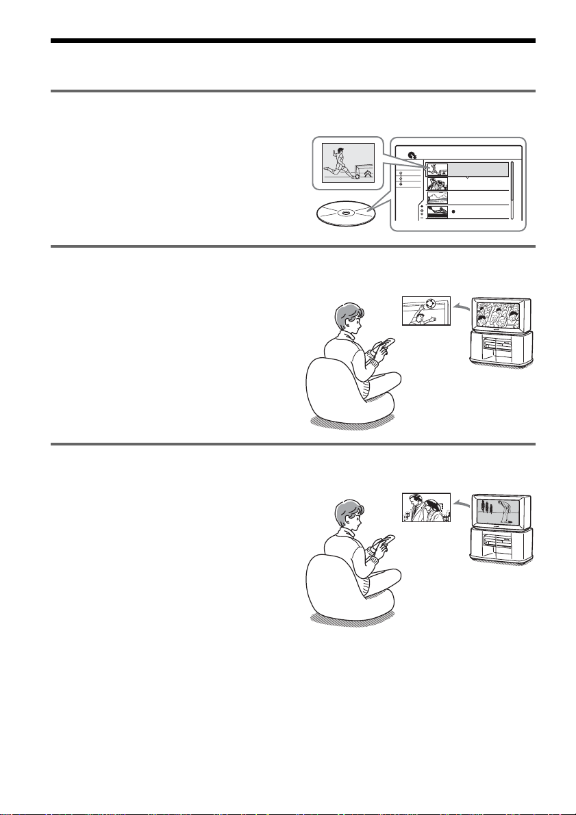
Quick access to recorded titles – Title List
, Display the Title List to see all of the titles
on the disc, including recording date,
channel, recording mode and thumbnail
image (page 33).
Play the beginning of a title while it is being recorded – Chasing Playback
, If you are using a DVD-RW (VR mode),
you can watch a programme from the
beginning while it is being recorded
(page 58).
Watching one title while recording another – Simultaneous Rec and Play
, If you are using a DVD-RW (VR mode),
you can watch a previously recorded
programme while recording another
programme on the same disc (page 58).
Title List
TITLE LIST
Date
Title
Number
ORIGINAL
Sort
Recording
The match isn’t over
yet, but I’ll start
watching it from the
beginning now.
Recording
My Movies
1 AAB 13:00-14:00
Wed 5. 9 13:00 (1H00M) SP
2 DEF 20:00-21:00
Fri 17. 9 20:00 (1H00M) SLP
3 AAB 9:00-9:30
Sat 25. 9 9:00 (0H30M) EP
4 GHI 20:00-20:30
Sat 25. 9 20:00 (0H30M) SLP
1.5/4.7GB
AAB
DEF
AAB
GHI
I think I’ll watch
yesterday’s golf match
now, even though I am
recording a movie.
6
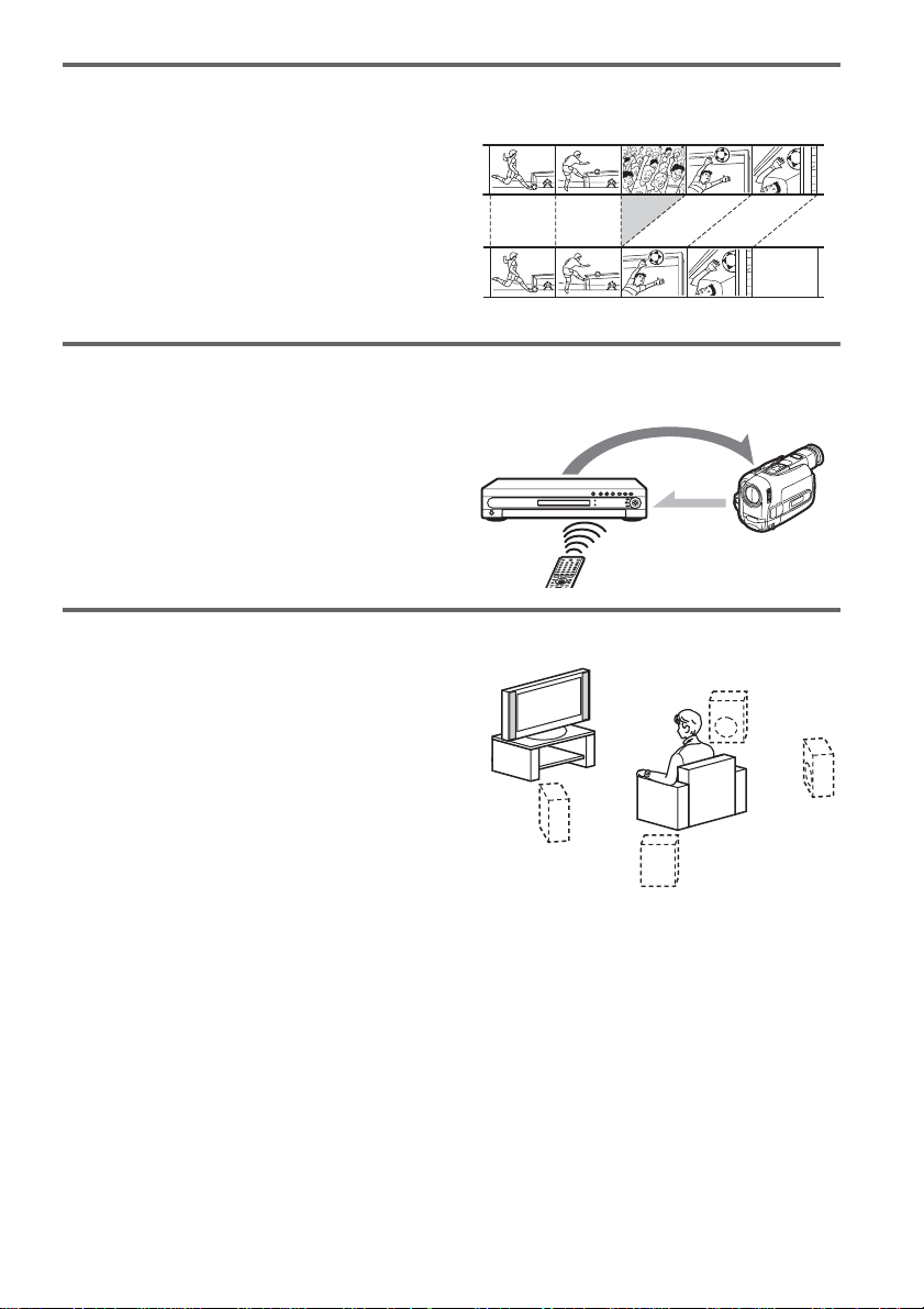
Creating your own programme – Playlist
, Record a programme on a DVD-RW (VR
mode), then delete, move and add scenes at
will to create your own, original
programme (page 66).
Original
Playlist
Automatic dubbing of DV tapes – DV Dubbing (RDR-GX700 only)
, Connect your digital video camera to the
DV IN jack and automatically dub the
entire contents or just selected scenes to a
DVD disc (page 70).
Control
Dubbing
Dynamic surround sound – TVS
, Enjoy virtual surround sound effects from
just your TV’s speakers with the TV Virtual
Surround settings when playing a DVD
VIDEO with multichannel audio tracks
such as Dolby Digital (5.1ch) (pa ge 54).
A list of recordable and playable discs is on page 8.
7
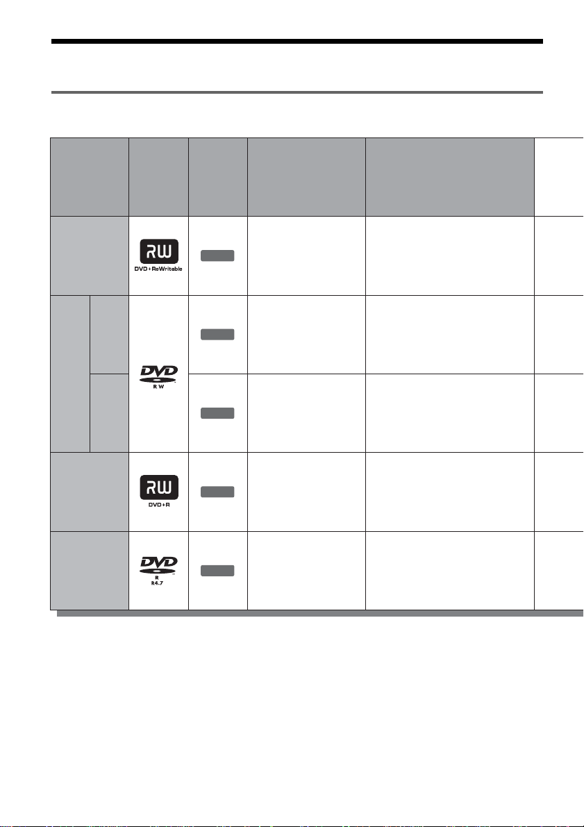
Quick Guide to Disc Types
Recordable and playable discs
Type
DVD+RW
VR
mode
DVDRW
Video
mode
DVD+R
DVD-R
Disc
Logo
Icon
used in
this
manual
+
RW
-
RW
VR
-
RW
Video
+
R
-
R
Formatting
(new discs)
Automatically
formatted
Format in VR
mode
(page 36)
Format in
Video mode
(page 36)
Automatically
formatted
Automatically
formatted
Compatibility with
other DVD players
(finalizing)
Playable on DVD+RW
compatible players
(automatically finalized)
Playable only on VR mode
compatible players
(finalization unnecessary)
Playable on most DVD
players (finalization
necessary) (page 37)
Playable on DVD+R
compatible players (finalization
necessary) (page 37)
Playable on most DVD
players (finalization
necessary) (page 37)
Usable disc versions (as of May 2004)
• 4x-speed or slower DVD+RWs
• 2x-speed or slower DVD-RWs (Ver.1.1, Ver.1.1
with CPRM*
• 8x-speed or slower DVD+Rs
• 8x-speed or slower DVD-Rs (Ver.2.0)
1
)
8
“DVD+RW,” “DVD-RW,” “DVD+R,” and “DVD-R,”
are trademarks.
*1
CPRM (Content Protection for Recordable Media) is
a coding technology that protects co pyr ights for
images.
*2
Only if the recording mode is SP, HSP, or HQ, and
“DVD Rec Picture Size” is set to “16:9.”
*3
Erasing titles does not free up disc space.

Recording Features Editing Features
Rewrite
(page 41)
Yes
Yes
Yes
No
No
Auto
Chapter
(page 91)
Yes
Yes
Yes
Yes
Yes
Manual
Chapter
(page 66)
No
Yes
No
No
No
Record
16:9 sizes
(page 48)
No
Yes
2
Yes *
No
2
Yes *
Change
title name
(page 63)
Yes
Yes
Yes
Yes
Yes
Delete title
(page 64)
Yes
Yes
Yes
3
Yes *
3
Yes *
A-B Erase
(page 64)
Yes
Yes
No
No
No
Playlist
(page 66)
No
Yes
No
No
No
Discs that cannot be re corded on
• 4x-sp eed compatible DVD-RWs (Ver. 1.2/4x)
• DVD-RWs (Ver. 1. 0)
• DVD+RWs that are not 2.4x-speed compatible
• Dual la yer discs
• 8 cm discs
,continued
9
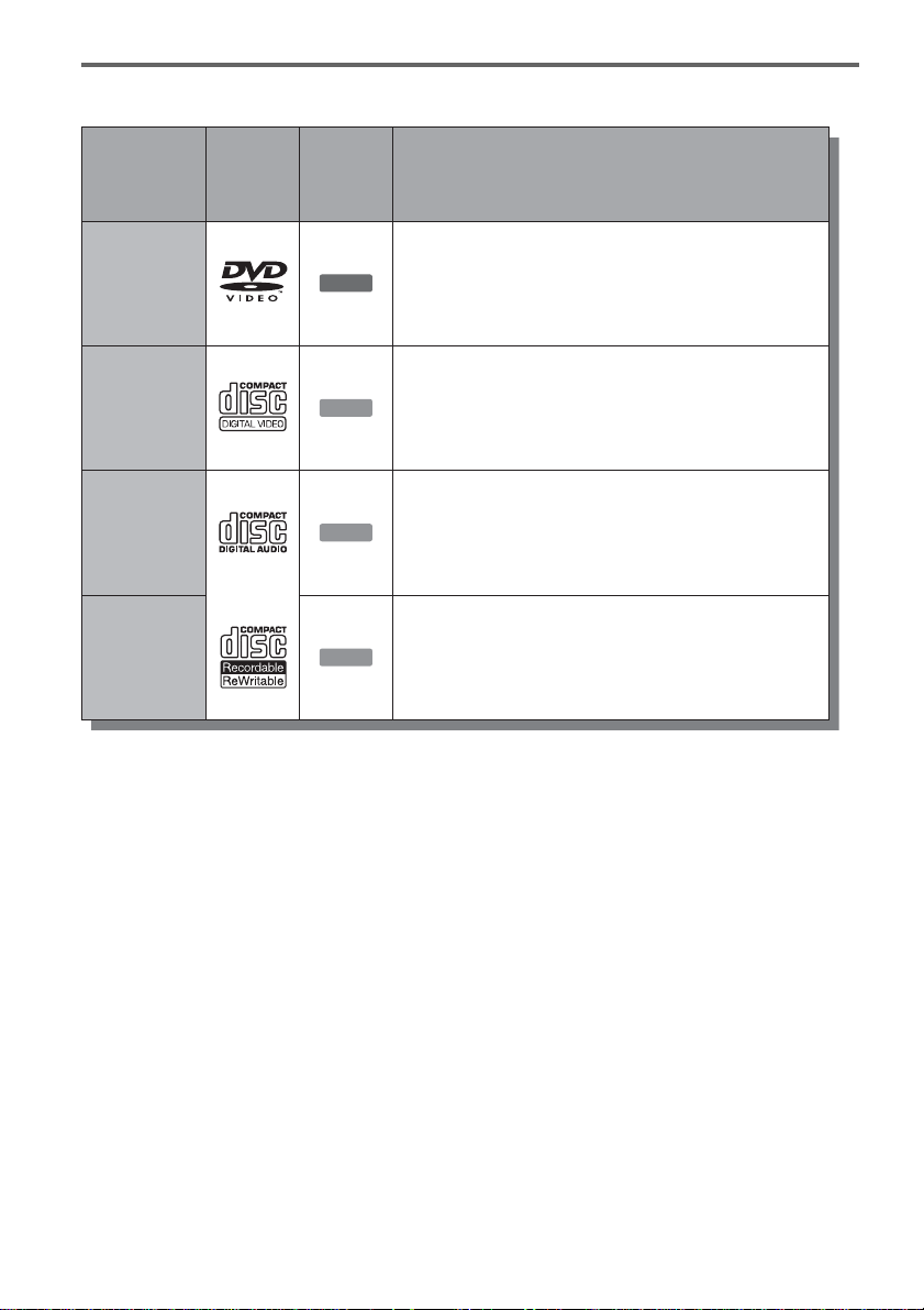
Playable discs
Type Characteristics
Disc
Logo
DVD VIDEO
VIDEO CD
CD
used in
this
manual
DVD
VCD
CD
Discs such as movies that can be purchased or rented
VIDEO CDs or CD-Rs/CD-RWs in
VIDEO CD/Super VIDEO CD format
Music CDs or CD-Rs/CD-RWs in music CD format
that can be purchased
CD-ROMs/CD-Rs/CD-RWs created on a PC or
Icon
DATA CD
DATA CD
similar device in music format containing MP3
audio tracks
Discs that cannot be played
• All CD-ROMs (including PHOTO CDs)
• CD-R s /CD-RWs, othe r than those recorded in
music CD format, MP3 format, or Video CD
format
• Data part of CD-Extras
• DVD-ROMs
• DVD Audio discs
• DVD-RAMs
• HD layer on Super Audio CDs
• DVD VIDEOs with a different region code
(page 11)
z Hint
This DVD recorder can play 8 cm CDs and 8 cm DVDs
as well.
10
Note on playback operations of DVD VIDEOs/
VIDEO CDs
Some playback operations of DVD VIDEOs/
VIDEO CDs may be intentionally set by software
producers. Since this recorder plays DVD
VIDEOs/VIDEO CDs according to the disc
contents the sof tware producers designed, some
playback features may not be available. Also, see
the instructions supplied with the DVD VIDEOs/
VIDEO CDs.
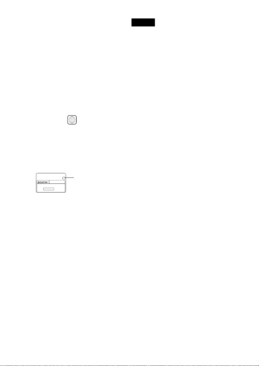
Region code (DVD VIDEO only )
Your recorder has a region code printed on the rear
of the unit and will only play DVD VIDEOs
(playback only) labelled with identical region
codes. This system is us ed to protect copyrig ht s .
DVD VIDEOs labelled will also play on this
ALL
recorder.
If you try to play any other DVD VIDEO, the
message “Playback prohibited by region code.”
will appear on the TV scr een. Depending on the
DVD VIDEO, no region code indication may be
labelled even though playing the DVD VIDEO is
prohibited by area r es tr i ct io ns .
X
RDR–XXXX
00V 00Hz
NO.
00W
Region code
0-000-000-00
Notes
• Some DVD+RWs/DVD+Rs, DVD-RWs/DVD-Rs, or
CD-RWs/CD-Rs cannot be played on this recorder due
to the recording quality or physical c ondi tion of the
disc, or the characteristics of the recording device and
authoring software. The disc will not pla y if it ha s not
been correctly final ized. For m ore in formati on, s ee t he
operating instructions for the recording device.
• You cannot mix VR mode and Video mode on the same
DVD-RW. To change the disc’s format, reformat the
disc (page 36). Note that the disc’s contents will be
erased after reformatting.
• You cannot shorten the time required for r ecor ding
even with high-speed discs. Also, you cannot record on
the disc if the disc is not 1x speed compa tible.
• It is recommended that you use discs with “For Video”
printed on their packaging.
• You cannot add new recordings to DVD-Rs or DVDRWs (Video mode) that contain recordings made on
other DVD equipment.
• In some cases, you may not be able to add new
recordings to DVD+RWs that contain recordings made
on other DVD equipment. If you do add a new
recording, note that this recorder will rewrite t he DVD
menu.
• If the disc contains PC data unrecogniz ab le by this
recorder, the data may be erased.
Music discs encoded with copyright protection
technologies
This product is designed to play back discs th at
conform to the Compact Disc (CD) standard.
Recently, various music disc s enc oded with
copyright prote ct i on t echnologies are bei ng
marketed by so me record companies. Please be
aware that among those discs, there are some that
do not confor m to the CD sta ndard and may n ot be
playable by this pro duct.
11

Hookups and Settings
Hooking Up the Recorder
Follow steps 1 to 7 to hook up and adjust the settings of the recorder.
Notes
• Plug cords securely to prevent unwanted noise.
• Refer to the instructions supplied with the components to be connected.
• You cannot connect this recorder to a TV that does not hav e a SC ART or vid eo input jack.
• B e sure to disconnect the mains lead of each component before connecting.
Step 1: Unpacking
Check that you have the following items:
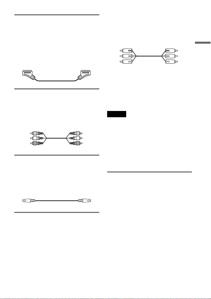
• Audio/video cord (pinplug × 3 y pinplug × 3) (1)
• Mains lead (1)
• Aerial cable (1)
• Remote commander (remote) (1)
• R6 (size AA) batteries (2)
12
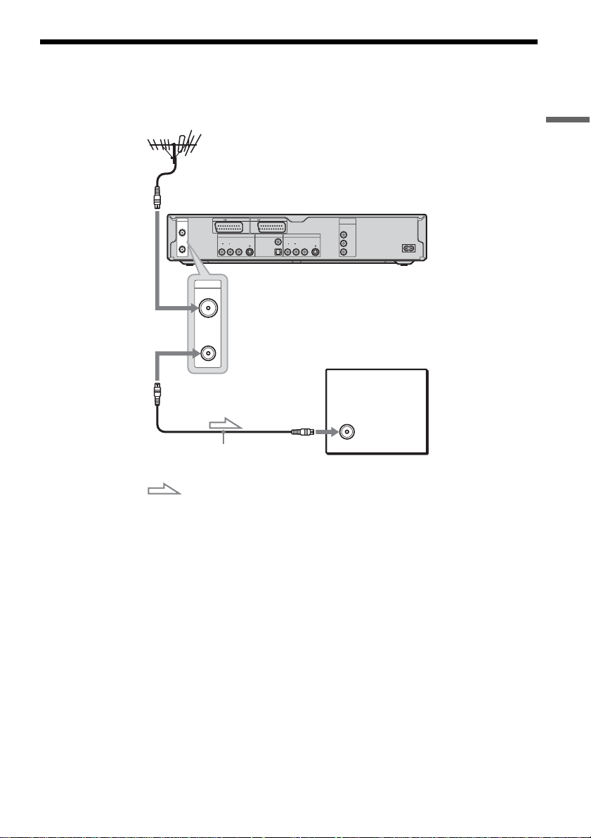
Step 2: Connecting the Aerial Cable
Connect the aerial cable by following the steps below. Do not connect the mains lead until you reach “Step
5: Connecting the Mains Lead” (page 19).
Hookups and Settings
to AERIAL IN
AERIAL
IN
OUT
AERIAL
IN
LINE 1 - TV LINE 3 / DECODER
LINE 4 IN DIGITAL OUT
VIDEO
AUDIOR L
S VIDEO
PCM/DTS/MPEG/
DOLBY DIGITAL
LINE 2 OUT
COAXIAL
VIDEO
AUDIOR L
OPTICAL
S VIDEO
COMPONENT
VIDEO OUT
Y
B
/ C
B
P
P
R
/ C
R
DVD recorder
~ AC IN
OUT
TV
to AERIAL OUT
Aerial cable (supplied)
: Signal flow
1 Disconnect the aerial cable from your TV and connect it to AERIAL IN on the rear panel of the
recorder.
2 Connect AERIAL OUT of the recorder to the aerial input of your TV, using the supplied aerial
cable.
13
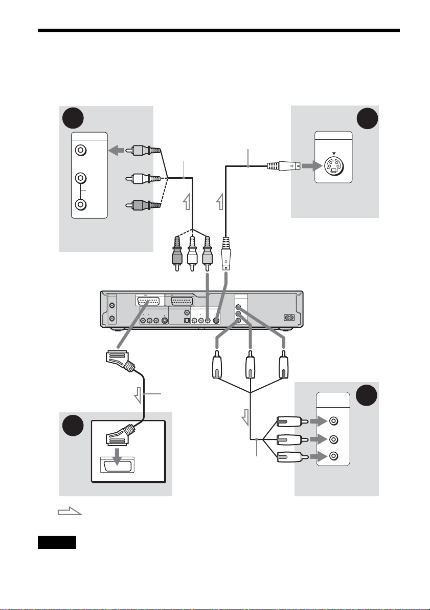
Step 3: Connecting the Video Co rds
Select one of the following patterns A th rough D, according to the input jack on your TV monitor,
projector, or AV amplifier (receiver). This will enable you to view pictures. Audio connections are
explained in “Step 4: Connecting the Audio Cords” (page 17).
B
INPUT
VIDEO
L
AUDIO
R
TV, projector, or AV
amplifier (receiver)
AERIAL
IN
OUT
A
TV
Audio/video
cord (supplied)
to LINE 2 OUT (VIDEO)
LINE 1 - TV LINE 3 / DECODER
LINE 4 IN DIGITAL OUT
COAXIAL
VIDEO
AUDIOR L
S VIDEO
PCM/DTS/MPEG/
DOLBY DIGITAL
OPTICAL
To LINE 1 – TV
SCART cord (not
supplied)
S-video cord
(not supplied)
(yellow)
to LINE 2 OUT (S VIDEO)
LINE 2 OUT
VIDEO
AUDIOR L
S VIDEO
(red) (blue)
Component video
cord (not supplied)
COMPONENT
VIDEO OUT
Y
P
P
B
/ C
R
/ C
B
R
(green)
S VIDEO
TV, projector, or AV
amplifier (receiver)
DVD recorder
~ AC IN
to COMPONENT
VIDEO OUT
COMPONENT
VIDEO IN
TV, projector, or AV
amplifier (receiver)
INPUT
Y
P
B
P
R
C
D
(green)
(blue)
(red)
: Signal flow
Note
Do not connect more than one type of video c or d bet wee n the recorder and your TV at the same time .
14
A Connecting to a SCART input jack
Connect using a SCART cord (n ot suppli ed) to the
LINE 1-TV jack and your TV. Be sure to make the
connections firmly to avoid hum and noise.
See the operating instructions supplied with the
TV to be connecte d. Also, when you se t “Line1
Output” t o “S Vi deo” o r “RGB” in st ep 15 o f Easy
Setup (page 24), use a SCART cord that conforms
to the selected signal.
If your TV accepts progressive 525p/625p format
signals, you mus t us e t hi s connection and se t
“Component Ou t” in Video Setup to “On.” Then
press PROGRESSIVE on the remote to send
progressive video signals. For details, see “Using
the PROGRESSIVE button” (page 16).
Green
Blue
Red
Green
Blue
Red
When playing “wide screen” images
Some recorded images may not fit your TV
screen. To change the aspect ratio, see pa ge 87.
Hookups and Settings
B Connecting to a video input jack
Connect the yellow pl ug of the audio/video cor d
(supplied) to the yellow (video) jack. You will
enjoy standard quality images.
Note that you cannot use the PROGRESSIVE
button with this connection.
Yellow
White (L)
Red (R)
Yellow
White (L)
Red (R)
C Connecting to an S VIDEO input
jack
Connect using an S-v i deo cord (not supplied) .
You will enjoy high quality images.
Note that you cannot use the PROGRESSIVE
button with this connection.
D Connecting to component video
input jacks (Y, P
Connect the COMPONENT VIDEO OUT jacks
using a component vi deo cord (not supplie d) or
three video cords (not supplied ) of the same kind
and length. You wi l l en j oy accurate colour
reproduction and hi gh quality images.
B/CB, PR/CR)
If you are connecti ng to a VCR
Connect your VCR to the LINE 3/DECODER
jack on the reco rder (page 26).
Notes
• When you connect the recorder to your TV via the
SCART jacks, the T V ’ s input source is set to the
recorder automatically when you sta r t pl ayback. If
necessary, press TV/DVD on the remote to return the
input to the TV.
• For correct SMARTLINK connection, you will need a
SCART cord that has the full 21 pins. Refer to your
TV’s instruction ma nual as well for this connection.
• If you connect this recorder to a TV with
SMARTLINK, set “Line1 Output” to “Video” in step
15 of Easy Setup.
About the SMARTLINK features
(for SCART connections only)
If the connected TV (or other connected
equipment such as a set top box) complies with
SMARTLINK, NexTView Link,
MEGALOGIC*
CINEMALINK*
4
LINK*
automatically runs the SMARTLINK function
after you complete the connection pattern A on
page 14 (the SMARTLI N K i ndicator lights up
when you turn o n your TV). You can enj oy the
following SMARTLINK features.
•Preset Download
You can downloa d t h e t uner preset data fro m
your TV to this recorder, and tune the recorder
according to that data in Easy Setup. This
greatly simplifies the Easy Setup proce dure. Be
careful not to disconnect the cables or exit the
Easy Setup func tion duri ng t his proced ure (page
22).
1
, EASYLIN K *2,
2
, Q-Link*3, EURO VIEW
, or T-V LINK*5, this recorder
,continued
15

•TV Direct Rec
You can easily reco rd what you are watc hing on
your TV (page 47).
• One Touch Play
You can turn on the rec o r der and TV, set the
TV’s input to the recorder, and start pl ayback
with one touch of the H (play) button
(page 53).
• One Touch Menu
You can turn on the recorder an d TV, set the TV
to the recorder’s channel, and display the Title
List menu with one touch of the TITLE LIST
button (page 53).
• One Touch Timer
You can turn on the recorder an d TV, set the TV
to the recorder’s channel, and display the timer
programming menu with one touch of the
TIMER button on the remote (page 44).
• Automatic Power Off
The recorder will turn off automatically if the
recorder is not used after you turn of f t he TV.
• NexTView Download
You can easily set the timer by using the
NexTView Down lo ad function on your TV .
See your TV’s instruction manual.
*1
“MEGALOGIC” is a register ed trademark of Gr undig
Corporation.
*2
“EASYLINK” and “CINEMALINK” are trademarks
of Philips Corporation.
*3
“Q-Link” is a trademark of Panasonic Corpor a ti on.
*4
“EURO VIEW LINK” is a trademark of Toshiba
Corporation.
*5
“T-V LINK” is a trademark of JVC Corporation.
z Hint
SMARTLINK also works with TVs or other equipment
having EPG Timer Control, EPG Title Download, and
Now Recording functions. For details, refer to the
operating instructions supplied with your TV or other
equipment.
Notes
• The SMARTLINK features are available only when
“Video” is selected in “Line1 Output.”
• The SMARTLINK features are not available for
devices connected via the DVD recorder’s LINE 3/
DECODER jack.
• Not all TVs respond to the functions above.
Using the PROGRESSIVE button
By using the PROGRES SI V E button on the
remote, you can select the signal format in which
the recorder outputs video signals: interlace or
progressive.
Connect the recorder using the COMPONENT
VIDEO OUT jacks (pattern D on page 15), and
set “Component Out” in Video Setup to “On”
(page 88). Then press the PROGRESSIVE button.
“PROGRESSIVE” appears in the f ro nt panel
display when the recorder outp uts progressive
signals.
◆Progressive
Select this when:
– your TV accepts p ro gressive signals, and,
– the TV is connected to the CO MPONENT
VIDEO OUT jacks.
Note that the pictures will not be clea r or no
picture wi ll appe ar if you sel ect pr ogres sive s ignal
output when either of the above conditions is not
met.
◆Interlace
Set to this position when:
–your TV does no t accept progressive signals, or,
– your TV is connecte d t o ja cks other than the
COMPONENT VIDEO OUT jacks (LINE OUT
(VIDEO) or S VIDEO).
z Hint
When you select progressive signal output, you can finetune the signal according to the type of software you are
watching (page 88).
Note
Consumers should note th at n ot al l high definition
television sets are fully compatible with this product and
may cause artifacts to be displayed in the pict ure . In the
case of 525/625 progressive scan picture problems, it is
recommended that the use r sw itc h the connection to the
‘standard definition’ output. If there are questions
regarding our TV set compatibility with this model 525p/
625p DVD recorder, please contact our customer service
centre.
16
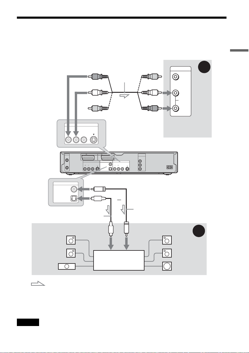
Step 4: Connecting the Audio Cords
Select one of the following patterns A or B, according to the input jack on your TV monitor, projecto r,
or AV amplifier (receiver).
This will enable you to listen to sound.
Hookups and Settings
(red)
(white)
(yellow)*
LINE 2 OUT
VIDEO
DIGITAL OUT
PCM/DTS/MPEG/
DOLBY DIGITAL
AERIAL
IN
OUT
COAXIAL
OPTICAL
AUDIOR L
S VIDEO
LINE 1 - TV LINE 3 / DECODER
LINE 4 IN DIGITAL OUT
VIDEO
AUDIOR L
to DIGITAL OUT (COAXIAL or
OPTICAL)
Optical digital cord (not supplied)
[Speakers]
to optical
digital input
Rear (L)
Audio/video
cord (supplied)
to LINE 2 OUT (R-AUDIO-L)
LINE 2 OUT
COAXIAL
VIDEO
PCM/DTS/MPEG/
DOLBY DIGITAL
AUDIOR L
OPTICAL
S VIDEO
S VIDEO
or
(yellow)
(white)
(red)
COMPONENT
VIDEO OUT
Y
B
/ C
B
P
P
R
/ C
R
DVD recorder
Coaxial digital cord
(not supplied)
to coaxial
digital input
INPUT
VIDEO
L
AUDIO
R
TV, projector, or AV
amplifier (receiver)
~ AC IN
[Speakers]
B
Rear (R)
A
Front (L)
Front (R)
AV amplifier (receiver)
Centre
with a decoder
Subwoofer
: Signal flow
* The yellow plug is used for vide o signals (page 14).
z Hint
For correct speaker location, see the operating instructions supplied with the connected components.
Note
Do not connect your TV’s audio output jacks to the LINE IN (AUDIO L/R) jacks at the same time. This will cause
unwanted noise to come from your TV’s spea ke rs.
,continued
17
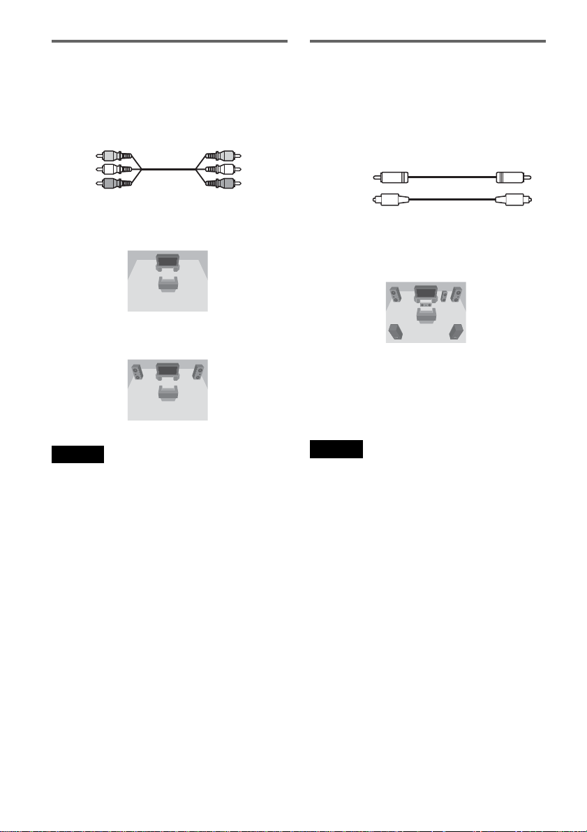
A Connecting to audio L/R input
jacks
This connection wil l use your TV’s or stereo
amplifier’s (receiver’s) two speakers for so und.
Connect using the audi o/ video cord (supplied).
Yellow
White (L)
Red (R)
• Surround effect (pag e54)
TV: Dynamic, Wide, Night
Stereo amplifie r (r eceiver): Standar d , N i ght
Yellow
White (L)
Red (R)
B Connecting to a digital audio
input jack
If your AV ampli f ie r (receiver) has a Dolby*1
Digital, DTS*
digital input jack, use this connection.
Connect using a coaxial or optical digital cord (not
supplied).
Coaxial cord
Optical cord
• Surround effect
Dolby Digital (5.1ch), DTS (5.1ch), MPEG audio
(5.1ch)
*1
Manufactured under license from Dolby Laboratories.
“Dolby,” “Pro Logic,” and the double-D symbol are
trademarks of Dolby Laboratories.
*2
“DTS” and “DTS Digital Out” are trademark s of
Digital Theater Systems, Inc.
2
, or MPEG audio decoder and a
Note
Do not connect the LINE 4 IN (R-AUDIO-L) and LINE
2 OUT (R-AUDIO-L) jacks to your TV’s audio output
jacks at the same time. This will cause unwanted noise to
come from your TV’s speakers.
18
Notes
• After you have completed connection B, make the
appropriate settings under “Audio Connection” in Easy
Setup (page 22). If your AV amplifier (receiver) has an
MPEG audio decoder function, set “MPEG” to
“MPEG” in Audio Setup (page 90). Otherwise, no
sound or a loud noise will come from your spea ke rs.
• The surround sound effects of this recorde r cannot be
used with connection B.
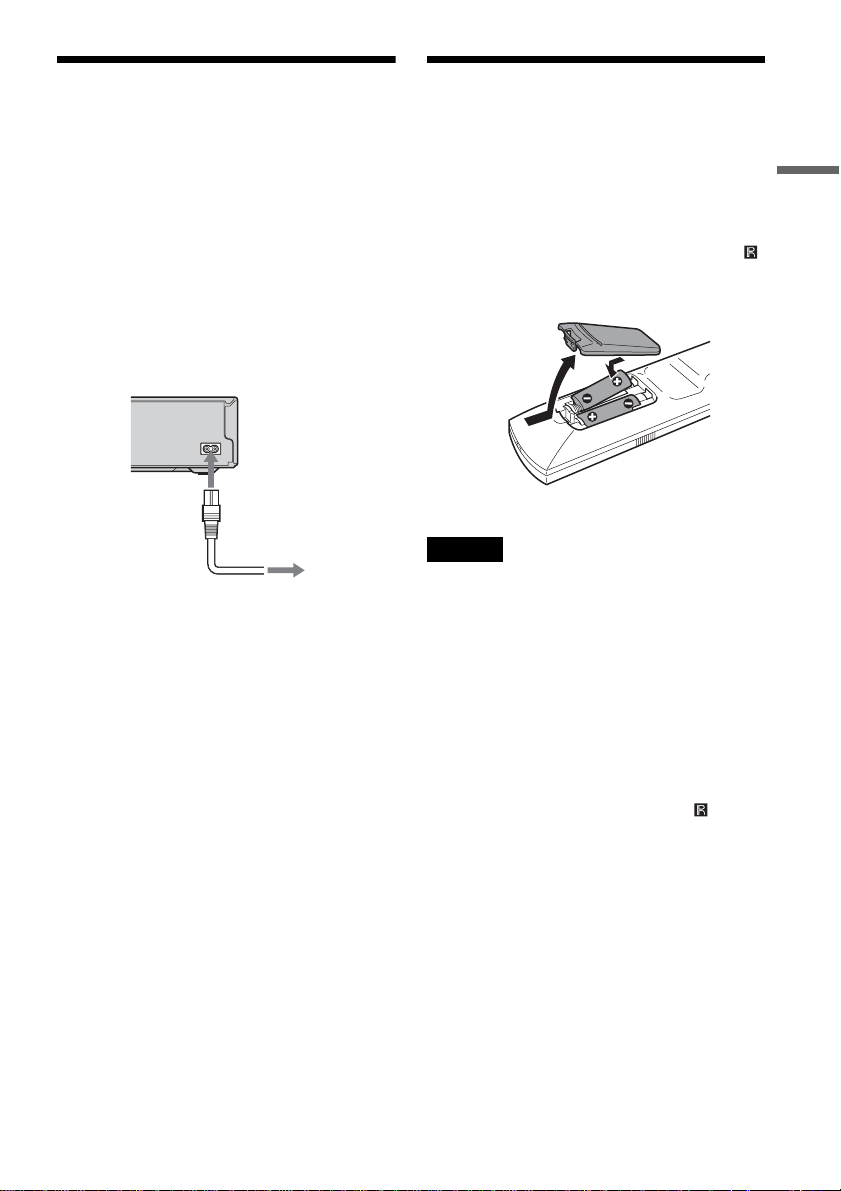
Step 5: Connecting the
Step 6: Preparing the
Mains Lead
Connect the supplied mains lead to the AC IN
terminal of the re corder. Then plug t he recorder
and TV mains leads (power cords) into the mai ns.
After you connect the mains lead, you must wait
for a short while before operating the recorder.
You can operat e the re co rder onc e the fr on t pa nel
display lights up and the recorder en te rs standby
mode.
If you connect addi tional equipment to this
recorder (page 26), b e s u r e to connect the mains
lead after all connections are complete.
~ AC IN
1
to AC IN
2
to mains
Remote
You can control th e recorder using the supplied
remote. Insert two R6 (size AA) batteries by
matching the 3 and # ends on the batteries to the
marking s inside the battery compartment. Whe n
using the remote, point it at the remote sensor
on the recorder.
Notes
• If the supplied remote interferes your other Sony DVD
recorder or player, ch ange the command mo de number
for this recorder (page 21).
• Use the batteries correctly to avoid possible leakage
and corrosion. Do not touch the liquid with bare hands
should leakage occur. Observe the following:
– Do not use a new battery with an old battery, or
batteries of different manufacturers.
– Do not attempt to rec harge the batteries.
– If you do not intend to use the remote for an extended
period of time, remove the batter ie s.
– If battery leakag e occur s, wipe out any liquid inside
the battery compar tment, and insert new bat teries.
• Do not expose the remote sensor (marked on the
front panel) to strong light, such as direct sunlight or
lighting apparatus. The recorder may not respond to the
remote.
Hookups and Settings
,continued
19
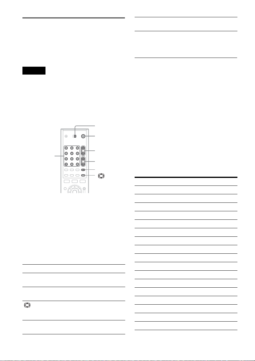
Controlling TVs with the remote
You can adjust the remote’s signal to control your
TV.
If you connected the recorder to an A V amplifier
(receiver), you can use the supplied remote to
control the AV amplifier’s (receiver’s) volume.
Number buttons and
SET, -/--*
* If you use the number buttons to select the TV’s
programme position, press -/-- followed by the number
buttons for two-digit num be r s.
Selects the programme
position on your TV
Notes
• Depending on the connected unit, you may not be able
to control your TV or AV amplifier (receive r) with
some or all of the buttons below.
• If you enter a new code number, the code number
previously entered will be erased.
• When you replace the batteries of the remote, the code
number may be reset to the default setting. Set the
appropriate code number again.
TV/DVD
switch
"/1
Number buttons,
SET/-/--
1 2 3
4 5 6
7 8 9
0
PROG +/–
2 +/–
t, TV/DVD
1 Slide the TV/DVD switch to TV .
2 Hold down [/1.
3 Enter your TV’s manufacturer code (see
“Code numbers of controllable TVs”
below) using the number buttons.
4 Release [/1.
When the TV/DVD switch is set to TV, the
remote performs the following:
[/1 Turns your TV on or off
2 (volume) +/– Adjusts the volume of your
PROG +/– Selects the programme
(wide mode) Switches to or from the
t (TV/video) Switches your TV’s input
TV
position on your TV
wide mode of a Sony widescreen TV
source
To operate the TV/DVD butto n
(for SCART connections only)
The TV/DVD butt on s w itches between the
recorder and the last input source selected on the
TV. Point your remote at the record er when us ing
this button. The button works e ven if the TV/DVD
switch is set to DVD.
When you connect the recorder to the TV via the
SCART jacks, the input source for the TV is set to
the recorder automatically when you start
playback. To watch another source, press the TV/
DVD button to switch the TV’s input source.
Code numbers of controllable TVs
If more than one code number is listed, try
entering them one at a time until you fin d t he one
that works with your TV.
Manufacturer Code number
Sony 01 (default)
Aiwa 01 (default)
Grundig 11
Hitachi 23, 24, 72
Loewe 06, 45
Nokia 15, 16, 69, 73
Panasonic 17, 49
Philips 06, 07, 08, 23, 45, 72
Saba 12, 13, 36, 43, 74, 75
Samsung 06, 22, 23, 71, 72
Sanyo 25
Sharp 29
Telefunken 12, 13, 36, 43, 74, 75
Thomson 12, 13, 43, 74, 75
Toshiba 38
LG 06
JVC 33
20
Controlling the volume of your AV
amplifier (receiver) with the remote
TV/DVD
switch
"/1
1 2 3
Number
buttons
4 5 6
7 8 9
0
2 +/–
1 Slide the TV/DVD switch to DVD.
2 Hold down [/1, and enter the
manufacturer code (see the table below)
for your AV ampli fi er (receiver) usi ng the
number buttons.
3 Release [/1.
The 2 (volume) +/– buttons control the AV
amplifier’s volu m e.
If you want to control the TV’s volume, slide
the TV/DVD switch to TV.
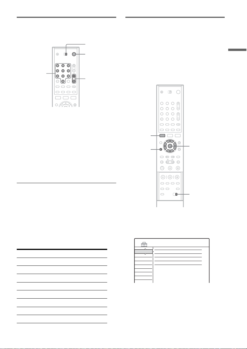
If you have a Sony DVD player or
more than one Sony DVD recorder
If the supplied remote interferes with your other
Sony DVD recorder or player, set the command
mode number for this recorder and the supplied
remote to one that differs from the ot her Sony
DVD recorde r o r pl ayer.
The default command mode setting for this
recorder and the supplied remote is DVD3.
1 2 3
4 5 6
7 8 9
0
SYSTEM
MENU
O RETURN
M/m,
ENTER
Hookups and Settings
z Hint
If you want to control the TV’s volume even when the
TV/DVD switch is set to DVD, repeat the steps above
and enter the code number 90 (default).
Code numbers of controllable AV amplifiers
(receivers)
If more than one code number is listed, try
entering them one at a time until y ou fin d the one
that works with your AV amplifier (receiver).
Manufacturer Code number
Sony 78, 79, 80, 91
Denon 84, 85, 86
Kenwood 92, 93
Onkyo 81, 82, 83
Pioneer 99
Sansui 87
Technics 97 , 98
Yamaha 94, 95, 96
COMMAND
MODE
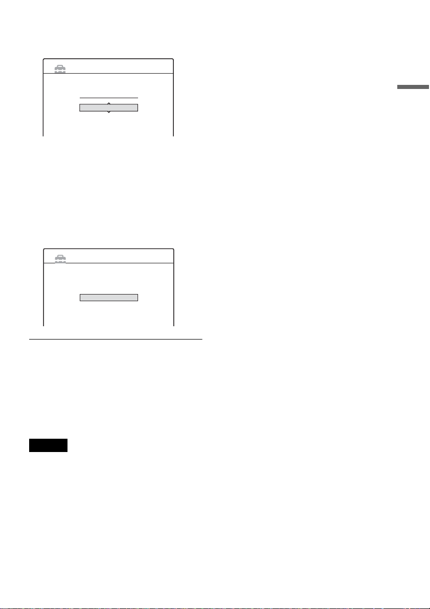
1 Press SYSTEM MENU.
The System Menu appears.
2 Select “SETUP,” and press ENTER.
SETUP
Settings
Channel Setting
Video
Channel List
Audio
Clock
Features
Language
Options
Easy Setup
,continued
21
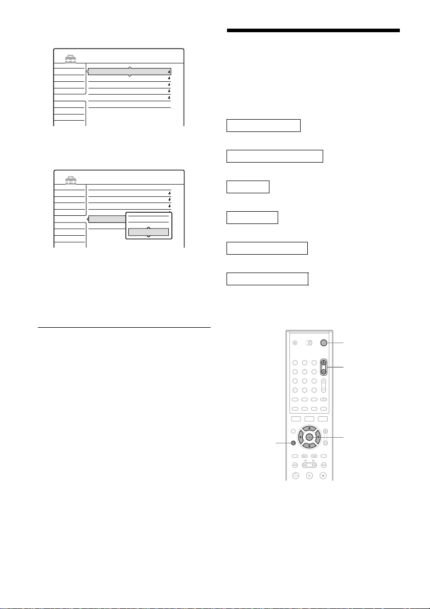
3 Select “Optio ns,” and press ENT ER.
SETUP
Settings
Video
Audio
Features
Options
Easy Setup
Format DVD :
DVD Bilingual Rec. :
Dimmer :
Auto Display :
Command Mode :
Factory Setup
VR
Main
Normal
On
DVD3
4 Select “Command Mode,” and press
ENTER.
SETUP
Settings
Video
Audio
Features
Options
Easy Setup
Format DVD :
DVD Bilingual Rec. :
Dimmer :
Auto Display :
Command Mode :
Factory Setup
DVD1
DVD2
DVD3
VR
Main
Normal
On
DVD3
5 Select the Com m and mode (DVD1, DVD2,
or DVD3), and press ENT ER.
6 Slide the COMMAND MODE switch on the
remote so it matches the mode you
selected above.
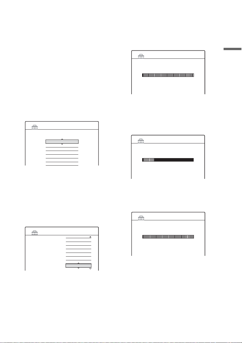
Step 7: Easy Setup
Follow the steps below to make the minimum
number of basic adjustments for using the
recorder. If you do n ot complete Easy Setup, it
will appear each t ime you turn on your recorder.
Settings are made in the following order.
OSD Language Setup
m
Tuner and Channel Setup
m
Clock Setup
m
TV Type Setup
m
Video Connection Setup
m
Audio Connection Setup
m
Finished!
To return to the previous step
Press O RETURN.
22
O RETURN
1 Turn on the TV.
2 Press [/1.
The recorder turn s on.
1 2 3
4 5 6
7 8 9
0
"/1
PROG +/–
</M/m/,,
ENTER
3 Switch the input selecto r on your TV so that
the signal from the recorder appears on
your TV screen.
“Initial settings necessary to operate the DVD
recorder will be ma de. You can change them
later using Setup. Before you start, check that
you have made all n ecessary connections.”
appears.
• If this message does not appear, select “Easy
Setup” from “SETUP” in the System Menu
to run Easy Setup. For details, see “Settin gs
and Adjustments” (page 82).
4 Press ENTER.
The Setup Display f or sel ec ting the language
used in the on-screen display appe ar s.
5 Select a language.
English
Français
Deutsch
Italiano
Español
Nederlands
Dansk
OSD 1/9
EASY SETUP
Select the screen Language.
6 Press ENTER.
The Setup Display for selecting your countr y
and language for th e t uner system appears.
The channel order will be set according to the
country or language you select.
7 Select your country or language.
• If you live in a French speaking country that
is not listed on the display, select “EL SE. ”
EASY SETUP
Select a country and
language.
Tuner System 2/9
– Français
L
– Dansk/Norsk
N
– Nederlands
NL
– Português
P
– Svenska
S
– Suomi
SF
– English
UK
– English
ELSE
8 Press ENTER.
• If you made conne ction A (page14) and the
connected TV com pl ie s wi t h
SMARTLINK, the Preset Download
function automatically starts.
EASY SETUP
Loading data from TV.
Please wait.
Preset Download 3/9
Prog. 1
• If the Pres et D ow nload function does not
work or if you made a connection other than
A, the Auto Tuner Preset function
automatically starts sear chin g fo r all of the
receivable chan nels and presets th em .
EASY SETUP
Searching for receivable channels.
Please wait.
Auto Tuner Preset 3/9
Prog. 1
To set the channels manually, see page 83.
9 After the download or search is complete,
the Clock function automatically starts.
EASY SETUP
Searching for clock data.
Please wait.
Once the clock s ig n al is received, the S et up
Display for selecting the aspect ratio of the
connected TV ap pears.
• If the current time or date is not set, the
display for setting the clock manually
appears. Set the clock manually using </
M/m/,, and press EN TER.
Clock 4/9
Hookups and Settings
,continued
23

10Select the setting that matches your TV
type.
EASY SETUP
Select your TV screen type.
16 : 9
4 : 3 Letter Box
4 : 3 Pan Scan
TV Type 5/9
“16:9”: For wide-screen TVs or standard TVs
with a wide screen mode.
“4:3 Letter Box”: For standard TVs.
Displays “wide screen” pictures with bands
on the upper and lower sections of the screen.
“4:3 Pan Scan”: For standard TVs.
Automatically displays “wide screen”
pictures on the entire screen and cuts off the
sections that do not fit.
For details, see “TV Ty pe” on page 87.
11Press ENTER.
The Setup Display f or the com ponent out
jacks appears.
12Select an op tion.
Select “On” if you are using the
COMPONENT VIDEO OUT jacks.
Otherwise, select “Off.”
13Press ENTER.
The Setup Display for the LINE 3/DECODER
jack appears.
14Select an op tion.
Select “Yes” if you will connect a decoder to
the LINE 3/DECODER jack. Otherwise,
select “No.”
15Press ENTER.
The Setup Display f or sel ec ti ng the type of
video signal ou tp ut fr om t he L INE1-TV jack
appears.
EASY SETUP
Line1 Output 8/9
16Select the type of signal you want to output
from the LINE1 -TV jack.
“Video”: Outputs video signals.
“S Video”: Outp ut s S vi deo signals.
“RGB”: Outputs RGB signals.
Note that if you select “On” in step 12, you
cannot select “RGB,” and that if you select
“Yes” in step 14, you cannot select “S Video.”
• If you select “S Video” or “RGB,”
SMARTLINK will be deacti vated.
17Press ENTER.
The Setup Display for selecting the type of
jack used to connect to your amplifier
(receiver) appears.
EASY SETUP
Is this recorder connected to an amplifier (receiver)?
Select the type of jack you are using.
Yes :
Yes :
No
Audio Connection 9/9
LINE2 OUT(R-AUDIO-L)
DIGITAL OUT
18Select the type of jack (if any) you are
using to connect to an amplifier (receiver),
and press ENTER .
If you did not connect an AV amplifier
(receiver), sel ect “No,” then go to ste p 22.
If you connected an AV amplifier ( re cei ver)
using just an audio cord, select “ Yes: LINE 2
OUT (R-AUDIO-L),” then go to step 22.
If you connected an AV amplifier ( re cei ver)
using either a digital optical or coaxial cord,
select “Yes: DIGITAL OUT.”
19Select the type of Dolby Di gital s ignal you
wish to send to your amplifier (receiver).
EASY SETUP
Dolby Digital
D-PCM
Dolby Digital
Audio Connection 9/9
24
Select the Line1 output signal.
Video
S Video
RGB
If your AV amplifier (receiver) ha s a Dolby
Digital decoder, select “Dolby Digital.”
Otherwise, se lect “D-PCM.”
20Press ENTER.
The Setup Display for the DTS signal appears.
On
Off
Audio Connection 9/9
EASY SETUP
DTS
21Select whether or not you wish to send a
DTS signal to your amplifier (receiver),
and press ENTER.
If your AV amplifi er (receiver) has a D TS
decoder, select “On.” Otherwise, select “Off.”
22Press ENTER whe n “Finish” appears.
Easy Setup is fin i shed. All conne ct ions and
setup operat i ons are complete .
EASY SETUP
Easy Setup is finished.
Finish
To return to the previous step
Press O RETURN.
Hookups and Settings
z Hints
• If your AV amplifier (receiver) has an MPEG audio
decoder, set “MPEG” to “MPEG” (page 90).
• If you want to run Easy Setup again, select “Easy
Setup” in the Setup Display (pag e 96).
Note
To record TV programmes using the timer, you must set
the clock accurate ly.
25
Connecting a VCR or Similar Device
After disconnecting the record er’s mains lead from th e mains, connect a VCR or similar recor ding device
to the LINE IN jacks of this recorder.
For RDR-GX700, use the DV IN jack on the front panel if th e equipment has a DV outpu t jack (i.LINK
jack) (page 70).
See also the instruction manual supplied with the connected equipment.
To record on this recor d e r, see “Recording From Connected Eq ui pm ent Without a Timer” (page 51).
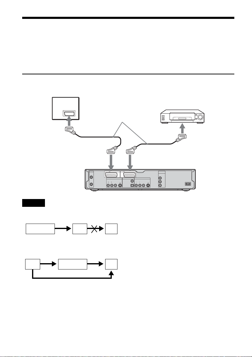
Connecting to the LINE 3 jack
Connect a VCR or similar recording device to the LINE 3/DECODER jack of this recorder.
TV
VCR
SCART cord
(not supplied)
to SCART input
S VIDEO
PCM/DTS/MPEG/
DOLBY DIGITAL
COAXIAL
OPTICAL
to i LINE
3/DECODER
LINE 2 OUT
VIDEO
AUDIOR L
S VIDEO
COMPONENT
VIDEO OUT
Y
B
/ C
B
P
P
R
/ C
R
DVD recorder
~ AC IN
to i
LINE1-TV
AERIAL
IN
OUT
LINE 1 - TV LINE 3 / DECODER
LINE 4 IN DIGITAL OUT
VIDEO
AUDIOR L
Notes
• Pictures containing copy protection si gna ls tha t prohibit any copying cannot be recorde d.
• If you pass the recorder signals via the VCR, you may not rec ei ve a clear ima ge on your TV sc ree n.
VCRDVD recorder TV
Be sure to connect your VCR to the DVD recorder and your TV in the order shown below. To watch video tapes,
watch the tapes through a second line in put on your TV.
Line input 1
VCR DVD recorder TV
Line input 2
• The SMARTLINK features are not available for device s conne cte d via the DVD recor der’s LINE 3/DECO DER jack.
• When you record to a VCR from this DVD recorder, do not switch the input source to TV by pressing the TV/DVD
button on the remote.
• If you disconnect the recorder’s main s le ad , you wil l not be ab le to vie w the signals from the connected VCR.
26
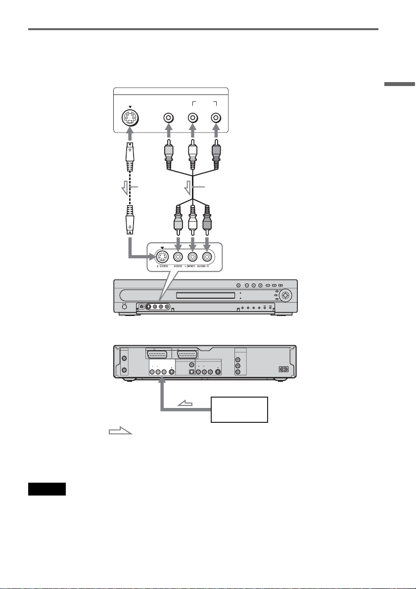
Connecting to the LINE 2 IN or LINE 4 IN jacks
Connect a VCR or similar recording device to the LINE 2 IN or LINE 4 IN jacks of this recorder. If the
equipment has an S-video jack, you can us e an S-video cord inst ead of an audio/video co rd.
VCR, etc.
OUTPUT
S VIDEO
VIDEO
AUDIO
LR
Hookups and Settings
S VIDEO
cord (not
supplied)
Audio/video cord
(not supplied)
to LINE 2 IN DVD recorder (front)
(rear)
AERIAL
IN
OUT
LINE 1 - TV LINE 3 / DECODER
LINE 4 IN DIGITAL OUT
VIDEO
AUDIOR L
S VIDEO
PCM/DTS/MPEG/
DOLBY DIGITAL
LINE 2 OUT
COAXIAL
AUDIOR L
OPTICAL
COMPONENT
VIDEO OUT
Y
B
/ C
B
VIDEO
P
S VIDEO
P
R
/ C
R
~ AC IN
to LINE 4 IN
VCR, etc.
: Signal flow
z Hint
When the connected equipment o utputs only monaural sound, use audio cables that distribute monaural sounds to left/
right channels (not supplie d) .
Notes
• Do not connect the yellow LINE IN (VIDEO) jack when using an S-video cord.
• Do not connect the output jack of this recorder to another equipment’s input jack with the other equipment’s output
jack connected to the input jack of this recorder. Noise (feedback) may result.
• Do not connect more than one type of video cord between the recorder and your TV at the same time.
27
Connecting to a Satellite or Digital Tuner
Connect a satellite or digital tuner to this recorder using the LINE 3/DECODER jack. Disconnect the
recorder’s m ai n s lead from the mains when connec ti ng the tuner.
To use the Synchro-Rec function, see below.
TV
to SCART input
SCART cord (not
supplied)
Satellite tuner, etc.
to i
LINE1-TV
AERIAL
IN
OUT
LINE 1 - TV LINE 3 / DECODER
LINE 4 IN DIGITAL OUT
VIDEO
AUDIOR L
If the satellite tuner can output RGB signals
This recorder accepts RGB signals. I f the sa telli te
tuner can output RGB signals, connect the TV
SCART connector on the satellite tuner to the
LINE 3/DECODER jack, and set “Line3 Input” of
“Scart Setting” to “Video/RGB” in Video Setup
(page 88). Note that this connection and setup
disable the SMARTLINK function. If you want to
use the SMARTLINK function with a compatible
set top box, see the instructions supplied with the
set top box.
If you want to use the Synchro Rec function
This connection is necessary to use the
Synchronized Recording function. See
“Recording From Connected Equipment With a
Timer (Synchro Re c)” (page 50).
28
S VIDEO
PCM/DTS/MPEG/
DOLBY DIGITAL
to i LINE
3/DECODER
LINE 2 OUT
COAXIAL
AUDIOR L
OPTICAL
DVD recorder
COMPONENT
VIDEO OUT
Y
B
/ C
B
VIDEO
P
S VIDEO
P
R
/ C
R
~ AC IN
Set “Line3 Input” of “Scart Setting” in Video
Setup (page 88) according to the specifications of
your satellite tuner. See your satellite tuner’s
instructions for more information.
If you are using a B Sky B tuner, be sure to
connect the tuner’s VCR SCART jack to the LINE
3/DECODER jack. Then set “Line3 Input” of
“Scart Setting” according to the specifications of
the VCR SCART jack on your satellite tuner.
Notes
• Do not set “Line3 Input” of “Scart Setting” in Video
Setup to “Decoder.”
• Synchronized Recording does not work with some
tuners. For details, see the tuner’s operating
instructions.
• If you disconnect the recorder’s mai ns le a d, you w ill
not be able to view the signals from the connected
tuner.
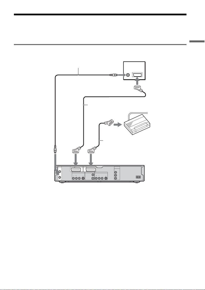
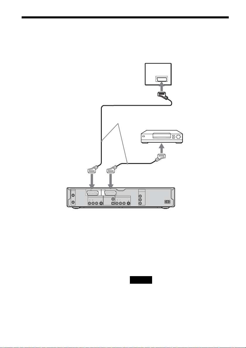
Connecting a P AY -T V/Canal Plus Decode r
You can watch or record PAY-TV/Canal Plus programmes if you connect a decoder (not supplied) to the
recorder. Disconnect the recorder’s mains lead from the mains whe n connecting the de coder.
Connecting a decoder
Hookups and Settings
Aerial cable
(supplied)
to AERIAL
OUT
to i
LINE1-TV
AERIAL
IN
OUT
LINE 1 - TV LINE 3 / DECODER
LINE 4 IN DIGITAL OUT
VIDEO
AUDIOR L
S VIDEO
PCM/DTS/MPEG/
DOLBY DIGITAL
to AERIAL IN
to SCART input
SCART cord (not
supplied)
SCART cord (not
supplied)
to i LINE 3/DECODER
COMPONENT
LINE 2 OUT
COAXIAL
AUDIOR L
OPTICAL
VIDEO OUT
VIDEO
P
S VIDEO
P
PAY-TV/Canal
Plus decoder
DVD recorder
Y
B
/ C
B
R
/ C
R
TV
~ AC IN
,continued
29
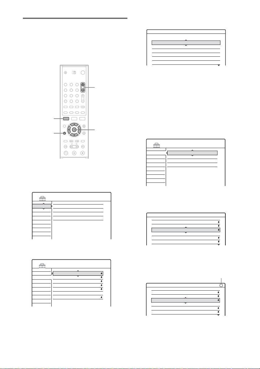
Setting PAY-TV/Canal Plus channels
To watch or record PA Y -TV/Canal Plus
programmes, set your recorder to receive the
channels using th e on-screen display.
In order to set the c hannels correctly, be sure to
follow al l o f the steps below.
1 2 3
4 5 6
7 8 9
0
SYSTEM
MENU
O RETURN
PROG +/–
</M/m/,,
ENTER
1 Press SYSTEM MENU.
The System Menu a ppears.
2 Select “SETUP,” and press ENTER.
4 Select “Scart Setting,” and press ENTER.
Video - Scart Setting
Line1 Output Line3 Input Line3 Output
Video
Video
Video
S Video
S Video
RGB
Video/RGB
Video/RGB
Decoder
S Video
S Video
Video/RGB
Video
S Video
Video
Video
S Video
Video
5 Press M/m to select “Video” or “RGB” for
“Line1 Output,” “Decoder” for “Line3
Input,” and “Video” for “Line3 Output,”
and press ENTER .
The Video Setup di splay appears ag ain.
6 Press O RETURN to return the cursor to
the left column.
7 Select “Sett ings,” and press ENTER.
SETUP
Settings
Channel Setting
Video
Channel List
Audio
Clock
Features
Language
Options
Easy Setup
SETUP
Settings
Channel Setting
Video
Channel List
Audio
Clock
Features
Language
Options
Easy Setup
3 Select “Video,” and press ENTER.
SETUP
Settings
30
Video
Audio
Features
Options
Easy Setup
TV Type :
Pause Mode :
Component Out :
Progressive Mode :
Screen Saver :
Scart Setting
Line4 input :
16 : 9
Auto
Off
Auto
On
Video
8 Select “Cha nnel Setting,” and press
ENTER.
Settings - Channel Setting
System :
Normal / CATV :
Channel Set :
Station Name :
PAY - TV / CANAL+ :
Audio :
BG
Normal
C2
CDE
Off
NICAM
Prog. 8
9 Press PROG +/– to select the desired
programme position.
Selected programme position
Settings - Channel Setting
System :
Normal / CATV :
Channel Set :
Station Name :
PAY - TV / CANAL+ :
Audio :
BG
Normal
C24
PQR
Off
NICAM
Prog. 6
 Loading...