

Page 1

4-137-706-02(1)
HXC-100
HXCU-100
RCP-750
RCP-920
Operating Instructions
Before operating the unit, please read this manual thoroughly
and retain it for future reference.
HXC-100
© 2009 Sony Corporation
Page 2

WARNING
To reduce the risk of fire or electric shock,
do not expose this apparatus to rain or
moisture.
To avoid electrical shock, do not open the
cabinet. Refer servicing to qualified
personnel only.
For the customers in the U.S.A.
This equipment has been tested and found to comply with the
limits for a Class A digital device, pursuant to Part 15 of the
FCC Rules. These limits are designed to provide reasonable
protection against harmful interference when the equipment is
operated in a commercial environment. This equipment
generates, uses, and can radiate radio frequency energy and,
if not installed and used in accordance with the instruction
manual, may cause harmful interference to radio
communications. Operation of this equipment in a residential
area is likely to cause harmful interference in which case the
user will be required to correct the interference at his own
expense.
You are cautioned that any changes or modifications not
expressly approved in this manual could void your authority to
operate this equipment.
All interface cables used to connect peripherals must be
shielded in order to comply with the limits for a digital device
pursuant to Subpart B of Part 15 of FCC Rules.
This device complies with Part 15 of the FCC Rules. Operation
is subject to the following two conditions: (1) this device may
not cause harmful interference, and (2) this device must
accept any interference received, including interference that
may cause undesired operation.
For the customers in Canada
This Class A digital apparatus complies with Canadian ICES-
003.
For the customers in Europe
This product with the CE marking complies with both the EMC
Directive and the Low Voltage Directive issued by the
Commission of the European Community.
Compliance with these directives implies conformity to the
following European standards:
• EN60950-1: Product Safety
• EN55103-1: Electromagnetic Interference (Emission)
• EN55103-2: Electromagnetic Susceptibility (Immunity)
This product is intended for use in the following
Electromagnetic Environments:
E1 (residential), E2 (commercial and light industrial), E3
(urban outdoors), E4 (controlled EMC environment, ex. TV
studio).
For the State of California, USA only
Perchlorate Material - special handling may apply, See
www.dtsc.ca.gov/hazardouswaste/perchlorate
Perchlorate Material : Lithium battery contains perchlorate.
For the customers in Taiwan only
The manufacturer of this product is Sony Corporation, 1-7-1
Konan, Minato-ku, Tokyo, Japan.
The Authorized Representative for EMC and product safety is
Sony Deutschland GmbH, Hedelfinger Strasse 61, 70327
Stuttgart, Germany. For any service or guarantee matters
please refer to the addresses given in separate service or
guarantee documents.
2
Page 3

Table of Contents
Overview .................................................................... 4
Features ..........................................................................4
System Configuration ......................................................5
Standalone operation example ..................................5
System operation example (with a Camera Control
Unit) .......................................................................6
Parts Identification ...........................................................6
Front right ..................................................................6
Front left ....................................................................7
Rear ...........................................................................8
Operation panel .........................................................8
Connector panel ........................................................9
Installation ............................................................... 10
Connecting a Camera Control Unit (CCU) ....................10
Attaching a Lens ...........................................................11
Attaching a Viewfinder ..................................................11
Attaching a Microphone ................................................12
Mounting the Camera to a Tripod .................................13
Adjusting the Shoulder Pad Position .............................14
Preparatory Settings............................................... 14
Adjusting the Black Balance and White Balance ..........14
Setting the Electronic Shutter ........................................15
Setting the Local Time ..................................................16
Adjusting the Flange Focal Length ................................16
Setting the Focus Assist Function .................................17
Setting the Camera Outputs ..........................................18
Outputting a Trunk Signal .............................................20
Basic Procedure for Shooting ............................... 20
Menus....................................................................... 21
Displaying Menu Pages ................................................21
Setting the Menu ...........................................................22
Editing the USER Menu ................................................23
OPERATION Menu .......................................................26
PAINT Menu ..................................................................29
MAINTENANCE Menu ..................................................32
FILE Menu .....................................................................34
DIAGNOSIS Menu ........................................................36
Appendices.............................................................. 36
Precautions ...................................................................36
Error Messages .............................................................37
Using a “Memory Stick” .................................................37
Specifications ................................................................38
Menu Tree .....................................................................40
Table of Contents
3
Page 4

option. (Part No.: A-8286-346-A)
Overview
The HXC-100 is a 2/3-type high-definition por table video
camera equipped with CCD units for 2,200,000 pixels, which
can be used as a standalone camera as well as in a studio in
combination with the HXCU-100 or HSCU-300
Control Unit.
The camera incorporates the latest image capturing device
and digital signal-processing LSI, and it performs newly
developed digital transmission with the camera control unit
(CCU), thus yielding high picture quality and high stability in
image creation in addition to superior camera functions and
operability.
1) An HXC-100 and HSCU-300 can be connected if both units are of
version 1.10 or later.
Features
High picture quality and high performance
The latest 2/3-type Progressive IT CCD units for 2,200,000
pixel achieve high sensitivity and low smear. In addition, the
14-bit A/D converter and an original developed signalprocessing LSI provide high picture quality of optimal grade.
Multiple formats
The camera covers 1080/59.94i, 720/59.94P, 1080/50i, and
720/50P.
With its wide-range down-converter, the camera also enables
output of high-quality SD signals (525i/625i) from the camera
and the connected CCU, establishing an optimum camera
system for SD-system operations.
Newly designed integrated unit with low center
of gravity
The camera has stylish appearance with low-slung design.
Even when used in combination with a studio-use viewfinder,
stable operation is achieved, thanks to its low center of gravity.
Optimized handle shape and VF slide
mechanism for stable shooting
A new handle design has been adopted. A slight protrusion of
the upper front part of the handle enables stable holding of the
camera while you are shooting, by holding the front part of the
handle. Furthermore, a slide mechanism is located at the
viewfinder attachment position. Any difference in weight
balance caused by having a different lens attached can be
counteracted by adjusting the viewfinder attachment position,
in combination with the movable shoulder pad position. This
provides the best balance for shooting with the camera on your
shoulder.
Position-adjustable shoulder pad
The position of the shoulder pad can be adjusted for stable
shooting according to the build of the camera operator, the
type of lens in use, or the shooting style.
A low-repulsion shoulder pad (position fixed) is available as an
1)
Camera
Function-assignable switches
The camera has buttons to which various functions can be
assigned on the side panel and the rear. You can activate your
desired function, such as electronic color-temperature
conversion, instantly when shooting by assigning it to one of
these buttons in advance.
Buttons on the handle are also available as function
assignable switches.
Auto Lens Aberration Compensation function
The Auto Lens Aberration Compensation function (ALAC) is
provided with this camera. This automatically reduces
chromatic aberration of magnification when a lens that
supports auto aberration compensation is attached.
For details on lenses supporting auto aberration
compensation, contact a Sony sales representative or Sony
service representative.
Focus assist functions
The VF detail function and focus assist indicator function
facilitate focusing.
VF detail
Various functions are provided for the VF detail signal, which
can be added only on images on the viewfinder screen in order
to facilitate focusing in various situations: Functions for
coloring the VF detail signal, flickering the VF detail signal by
adding modulation, thickening the VF detail signal, and
automatically compensating the VF detail level according to
the zoom position.
Focus Assist Indicator
The focusing level indicator on the viewfinder screen provides
a guide for focusing. The best focus setting can be easily
determined by observing fluctuation of the level indicator as a
guide.
“Memory Stick”
The camera is equipped with a “Memory Stick” port, which
enables setup data storage and software upgrading using a
“Memory Stick.”
1) “Memory Stick” and are trademarks of Sony
Corporation.
1)
operation
Various color-reproduction functions
Selection of multiple gamma tables
Seven types of standard and 4 types of hyper gamma tables
are provided with this camera. The hyper gamma values
enable cinemalike image creations with wide dynamic range,
which are different from those achieved with conventional
video gamma.
Multimatrix color correction
In addition to the standard 6-axis matrix function, the camera
has a multimatrix function that permits you to adjust the hue
and chroma for color components in 16-axis directions
independently. This is quite useful in color matching among
multiple cameras.
4
Overview
Page 5
Knee saturation
Change of hue and decrease in chroma that occur in
highlighted areas can be compensated.
This enables reproduction of natural skin tones under strong
lighting.
Low key saturation
Hue and chroma in low-key zones can be compensated. Thus,
compensation for color reproduction in all zones is enabled in
combination with matrix color compensation and knee
saturation functions.
Versatile detail control functions
Skin-tone detail function
This function allows control (emphasis or suppression) of the
detail level for just a certain hue or chroma area in the image,
by creating a detail gate signal from color components of your
specified hue, such as skin tones.
Detail boost-frequency control
The boost frequency can be adjusted from 20 to 30 MHz. This
allows the detail thickness to be set appropriately for the
subject, thus enabling more subtle image expression.
H/V ratio control
The ratio between horizontal and vertical detail can be
adjusted.
Versatile choices of viewfinders
Multiformat monochrome CRT viewfinders, HDVF-200 (2type) and HDVF-550 (5-type) can be selected for use in studio
and portable systems.
Color LCD viewfinders, HDVF-C35W (3.5-type), HDVFC550W (5-type), and HDVF-C730W (6.5-type), are also
selectable to cover various applications.
Prevention of electrical shock
When the power connection is unsafe, the power supply from
the connected Camera Control Unit will be shut off.
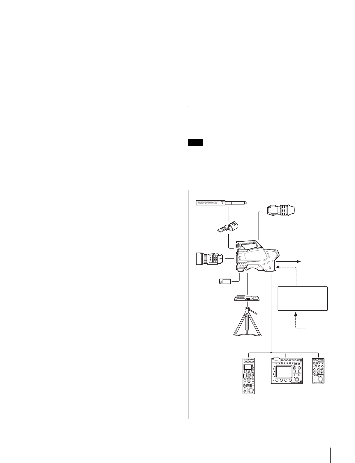
System Configuration
Peripherals and related devices for the camera are shown in
figures.
Note
Production of some of the peripherals and related devices
shown in the figures has been discontinued. For advice on
choosing devices, please contact your Sony dealer or a Sony
sales representative.
Standalone operation example
Microphone
HDVF-200/C35W
Viewfinder
White/black limiter
The white and black details can be limited independently.
Easy menu-based setting
Selections and settings for viewfinder display items, safetyzone marker
be made quickly and easily, using setup menus displayed on
the viewfinder screen or an external monitor.
1) Safety zone marker: A box-shaped marker displayed on the
viewfinder screen which indicates 80%, 90%, 92.5%, or 95% of the
total screen area
2) Center marker: A cross-shaped marker which indicates the center
of the viewfinder screen
1)
or center marker,
2)
screen size marker, etc. can
Wide variety of viewfinder display options
Along with items such as operation messages, a zebra
pattern,
settings may also be displayed on the viewfinder screen.
Furthermore, there are various cautionary and warning
indications to be occasionally displayed, making it simple to
check the status of the camera.
1) Zebra pattern: A stripe pattern displayed on the viewfinder screen
1)
a safety-zone marker, and a center marker, camera
which indicates the portions where the video level is above about
70% or 100%. Used to check the video level of the subject.
Digital triax transmission
The camera uses an industry standard dual-shield coaxial
(triax) camera cable for connection between the camera and a
CCU. Newly developed original digital transmission
technology is built into the camera, and high-quality pictures
can be transmitted between the camera and CCU, regardless
of the cable length.
CAC-12
Microphone
holder
Zoom Lens
(for ENG/EFP)
“Memory Stick”
VCT-U14
Tripod Adaptor
Tripod for
portable
camera
RCP-1000-series
Remote Control Panel
1) No subcarrier phase-lock function with respect to external
reference is available for the VBS signal output from the camera.
HXC-100
Video output
HD-SDI/SD-SDI/VBS
(selectable)
AC Adaptor
AC-DN10/DN2B
Battery Charger
BC-L70/L160
AC power
CCA-5 cable
RM-B750/B150
Remote Control Unit
1)
Overview
5
Page 6
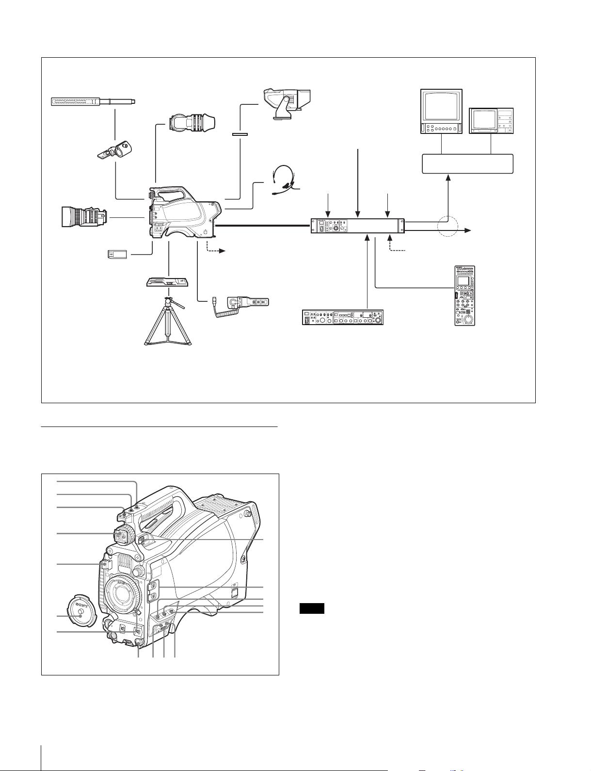
System operation example (with a Camera Control Unit)
HDVF-550/C550W/C730W
Microphone
HDVF-200/C35W
Viewfinder
CAC-12
Microphone
Holder
Zoom Lens
(for ENG/EFP)
“Memory Stick”
VCT-U14
Tripod Adaptor
Tripod for
portable
camera
a) Supplied with the HDVF-550/C550W/C730W, Part No.: A-7612-405-E
b) 600 m (1969 ft) at maximum and 50 m (164 ft) at minimum when using Fujikura 8.5-mm dia. cables.
For information of other cables, see “About the distances of triax transmission” (page 37).
An HXC-100 and HSCU-300 can be connected if both units are of version 1.10 or later.
c)
d) Enabled only when an HXCU-100 is connected.
HXC-100
CAC-6
Return Video Selector
Viewfinder
VF attachment shoe
Intercom headset
Triax cable
Power supply
for a script light
DC 12 V
(Max. 0.5 A)
Sync input
b)
HXCU-100/
HSCU-300
Camera Control Unit
(attached to the front)
HKCU-FP1
Front Control Panel
a)
Return video input
c)
d)
Picture
Monitor
Wavefo rm
Monitor
BNC BNC
Video router
Prompter video input
Video output
HD-SDI/SD-SDI/VBS
to router/switcher
AC power
CCA-5 cable
RCP-1000-series
Remote Control Panel
Parts Identification
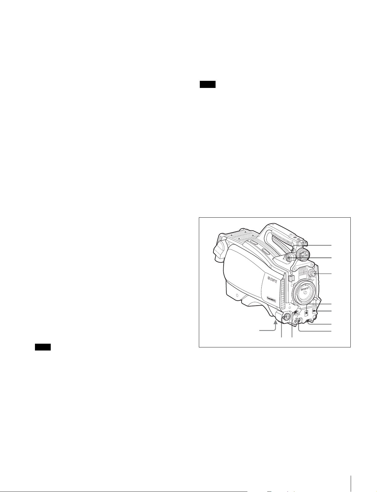
Front right
1
2
3
4
5
6
7
qh
qg
qf qd
8
9
0
qa
qs
a INCOM (intercom) button (UC model)/ENG (engineer
line) button (CE model)
UC model: The intercom microphone is on while this button is
held pressed.
CE model: The intercom microphone is on and the engineer
line is selected while this button is held pressed.
You can also assign other functions with a menu operation.
b RET 1 (return video 1) button
The return video 1 signal from the CCU is monitored on the
viewfinder screen while this button is held pressed. It functions
the same as the RET 1 button on the operation panel (page 8)
on the rear of the camera.
You can also assign other functions with a menu operation.
c Accessory shoe
To attach an accessory using a 1/4-inch screw.
Note
When you wish to replace it with a slide-type shoe, consult
Sony service personnel.
d Viewfinder shoe
Mount a viewfinder.
For details, see “Attaching a Viewfinder” (page 11).
e Lens cable clamp
To secure the cable of the lens (optional).
6
Overview
Page 7
f Lens mount cap
908
1
2
3
4
5
6
7
The cap can be removed by moving the lens fixing lever
upward. Always keep the lens mount covered with this cap
when a lens is not attached.
g Lens fixing lever
Move the lever down to secure the lens in the lens mount.
For details, see “Attaching a Lens” (page 11).
h Viewfinder front-rear position lock lever
The viewfinder position can be adjusted forward or backward
when the lock is released by the lever.
For details on the adjustment, see “To adjust the viewfinder’s
front-rear position” (page 11).
i Assignable buttons
You can assign a function to the upper button by using
ASSIGNABLE 1 and the lower button with ASSIGNABLE 2 on
the <SWITCH ASSIGN1> page of the OPERATION menu.
j GAIN switch
To select the gain of the video amplifier based on lighting
conditions when the camera is used in standalone status
without connecting a CCU.
When shipped from the factory, the values set are L = 0 dB,
M = 6 dB, and H = 12 dB.
k AUTO KNEE and output signal selection switch
To select the signal (color-bar signal or camera’s video signal)
to be used as output to a VTR, the viewfinder, or a video
monitor when the camera is used in standalone status without
connecting a CCU.
When the camera’s video signal is being used as output, the
auto knee function can be selected.
BARS/OFF: Output is a color-bar signal.
CAM/OFF: Output is the camera’s video signal. The auto knee
circuit is disabled.
CAM/ON: Output is the camera’s video signal. The auto knee
circuit is enabled.
The switch functions the same as the DISPLAY/MENU switch
on the rear operation panel.
n “Memory Stick” slot and access lamp
When you insert a “Memory Stick” into the slot, the access
lamp lights in green.
The lamp is lit in red while writing/reading data to/from the
“Memory Stick.”
Note
When the access lamp is lit in red, do not insert/remove the
“Memory Stick” or turn off the camera.
o STATUS/CANCEL switch
STATUS: To display status information of this camera in the
viewfinder when no menu is displayed with the DISPLAY/
MENU switch set to DISPLAY.
CANCEL: To cancel changed settings or return the display to
the previous menu when a menu is displayed in the
viewfinder.
p Menu control knob (rotary encoder)
Used to select settings from menus displayed on the
viewfinder screen (by rotating it) and to confirm settings (by
pushing it).
This knob functions the same as that on the rear operation
panel.
Front left
l WHITE BAL (white balance memory selection) switch
To select the white balance adjustment method or the memory
used to store the adjusted value when the camera is used in
standalone status without connecting a CCU.
PRST (preset): White balance is adjusted to a preset value
corresponding to a color temperature of 3200K.
A: To select memory A.
B: To select memory B.
Note
When a CCU or an external control device, such as an RCP/
RM, is connected, the functions of 0 to qs are controlled from
the external device or the HKCU-FP1 attached to the CCU,
and the controls on the camera are disabled.
m DISPLAY/MENU switch
Select the display on the viewfinder screen.
DISPLAY: To display various textual information and markers,
such as messages showing the camera settings and
operating status, the center marker, and the safety zone
marker, in addition to camera images.
OFF: To not display textual information and markers.
MENU: To display menus for camera settings, in addition to
camera images.
a Shoulder strap fitting post
Attach one end of a shoulder strap (optional, part No. A-6772374-C) to this fitting post and the other end to the fitting post
on the other side of the camera.
b VF (viewfinder) connector (20-pin)
Connect the cable of the viewfinder (optional).
c Filter select knob
Used to select the built-in ND filters (1: clear, 2: 1/4 ND, 3:
1/16 ND, 4: 1/64 ND).
d SHUTTER switch
When the camera is used in standalone status without
connecting a CCU, use this switch to turn ON or OFF the
electronic shutter and change (SEL) the shutter speed and
shutter mode.
Overview
7
Page 8
For details, see “Setting the Electronic Shutter” (page 15).
908
6789
e AUTO W/B BAL (white and black balance automatic
adjustment) switch
To automatically adjust white and black balance when the
camera is used in stand-alone status without connecting to a
CCU.
WHT: To automatically adjust white balance.
BLK: To automatically adjust black balance.
For details, see “Adjusting the Black Balance and White
Balance” (page 14).
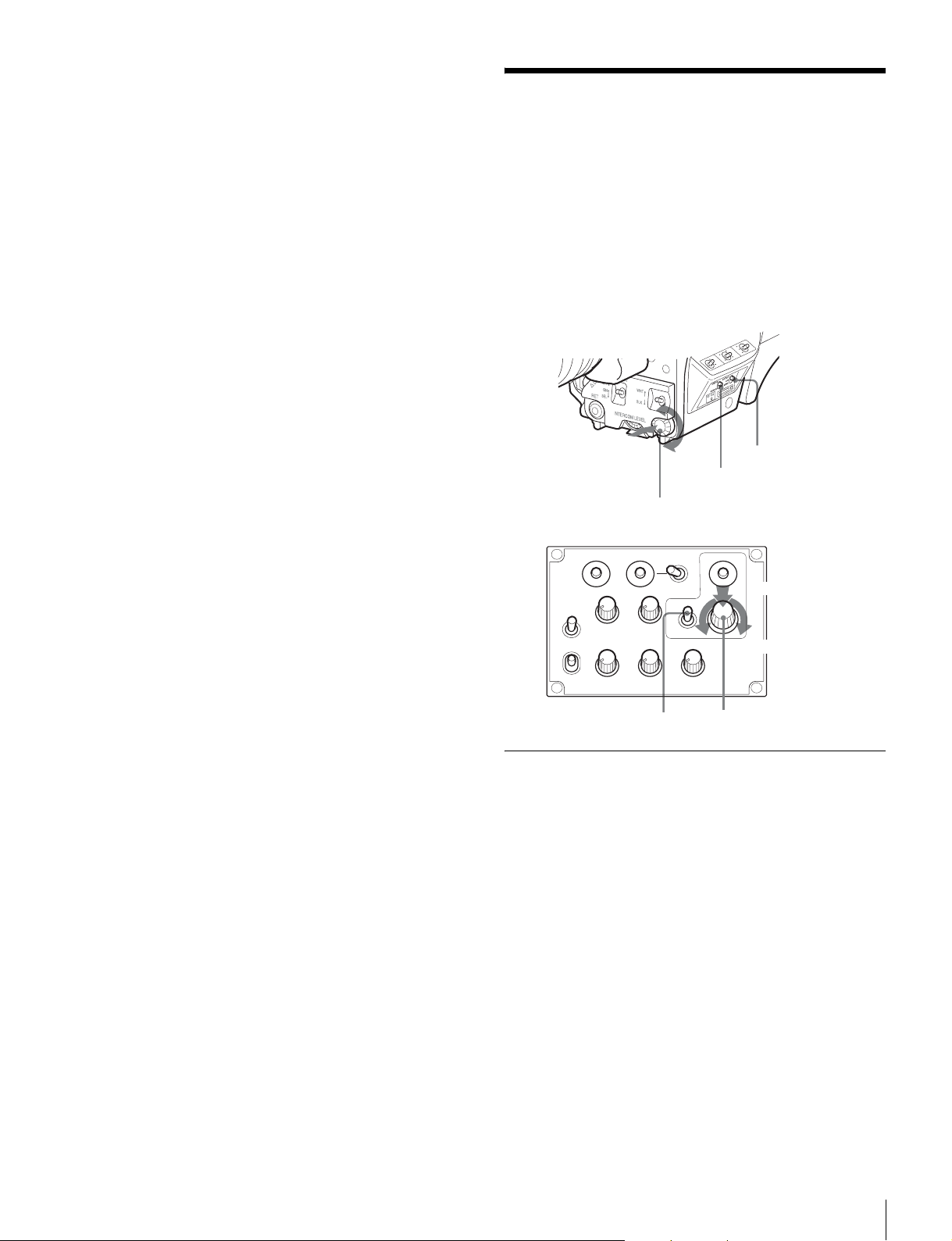
f INTERCOM LEVEL control
To adjust the intercom/earphone volume level.
The intercom level adjustment is enabled when the LEVEL/
MIC switch on the UC-type operation panel (page 9) or the
LEVEL switch on the CE-type operation panel (page 9) on the
rear is set to “FRONT.”
g RET (return video) button
When this button is pressed, the picture on the viewfinder
changes to the return video signal selected with the RET 2/3/
4 select switch (page 9) on the operation panel on the rear of
the camera.
You can also assign other functions with a menu operation.
h LENS connector (12-pin)
Connect the lens cable. The camera can control the lens
functions through this cable.
i MIC 1 IN (microphone 1 input) connector (XLR 3-pin)
Connect a microphone.
This connector and the AUDIO IN CH1 connector are
alternately activated with the MIC 1 select switch on the rear
connector panel.
j Tripod mount (bottom)
Attach the VCT-U14 Tripod Adaptor when mounting the
camera on a tripod.
For details, see “Mounting the Camera to a Tripod” (page 13).
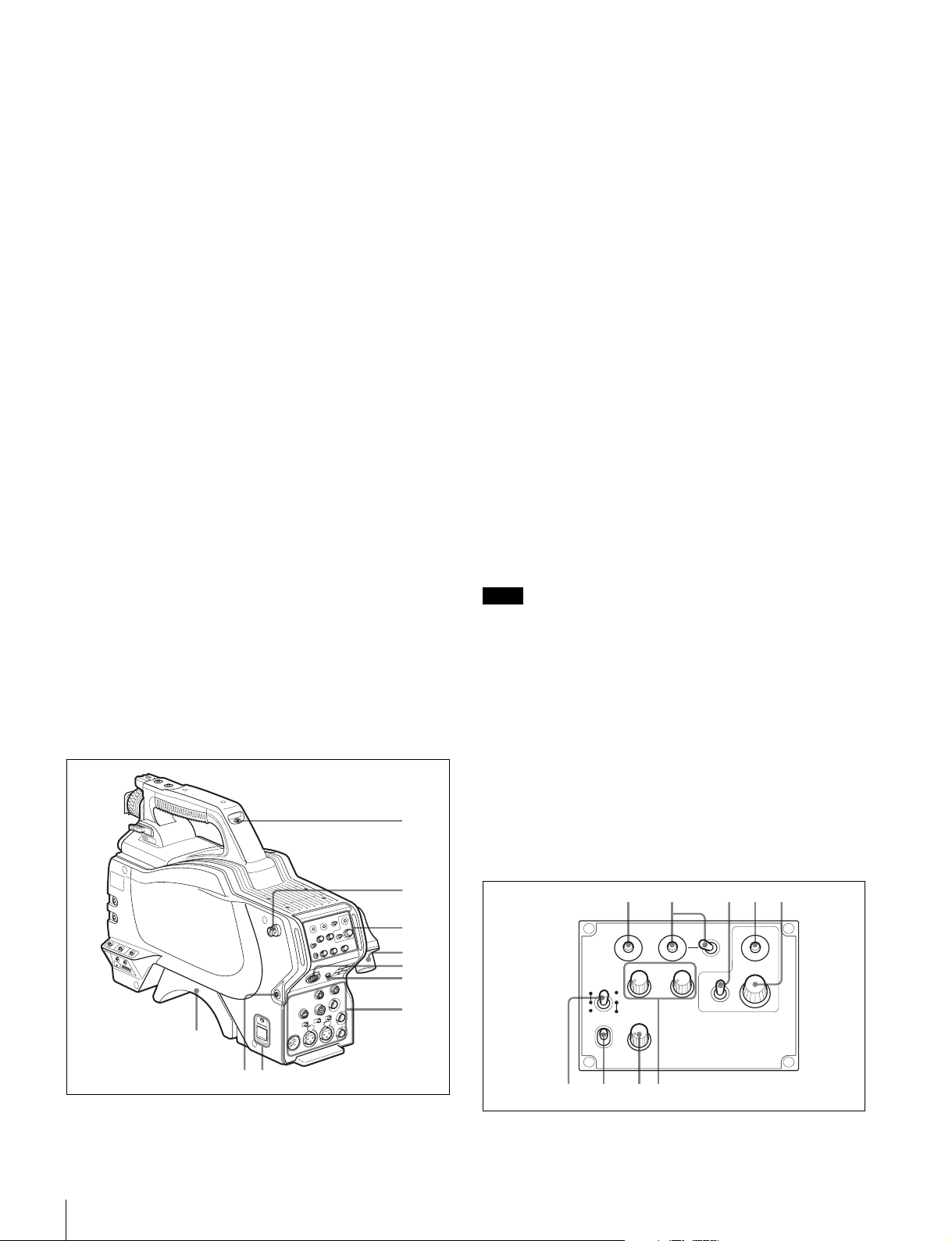
Rear
1
a Tally lamp and switch
ON: The tally lamp lights when a tally signal is input to the
connected CCU or a call signal is generated in response to
pressing of a CALL button.
OFF: The tally lamp is prevented from lighting.
b Shoulder strap fitting post
c Operation panel (See “Operation panel”.)
d Camera Control Unit (CCU) connector (triax
connector)
Connect an HXCU-100 or HSCU-300 Camera Control Unit
using a triax cable.
e INTERCOM connector (XLR 5-pin)
Connect an XLR 5-pin headset for input and output of intercom
audio signals.
The connector can be used for communication over the
engineer line when the camera is in standby status.
f EARPHONE jack (stereo minijack)
For connecting an earphone for output of the intercom audio.
g Connector panel (See “Connector panel” on page 9.)
h CAMERA POWER switch and indicator
CCU: To operate on power supply via the connected CCU.
EXT: To operate on power supply through the DC IN
connector.
The indicator is lit in green during operation. It is lit in red while
standby power is being supplied from the CCU, even if the
switch is set to OFF.
Note
When a CCU is connected, external power supply (EXT)
cannot be used.
i CALL button
When you press this button, the red tally lamp of the
connected external control device (RCP/RM, HKCU-FP1, etc.)
will light. Use to call the operator of the external control device.
j Shoulder pad
You can adjust the position on your shoulder.
For details, see “Adjusting the Shoulder Pad Position” (page
14).
Operation panel
Overview
8
2
3
4
5
6
7
UC type: Model for NTSC areas
12 345
RET1 RET
PGM1
MICLEVEL
ON
REAR
FRONT
OFF
PROD
ENG
INTERCOM EARPHONE
PGM2
OFF
INCOM
234
DISPLAY
MENU
ASSIGNABLE
Page 9
a RET 1 (return video 1) button
12 345
678 0 q
9
The return video signal is displayed on the viewfinder screen
while the button is held pressed.
b RET (return video) button and 2/3/4 (return video 2/3/4)
select switch
When other return video systems are used in addition to return
video 1, the signal selected with the 2/3/4 switch is displayed
on the viewfinder screen while holding the RET button
pressed.
Note
The RET 1 button has priority over the RET (2/3/4) button if
both buttons are pressed.
c DISPLAY/MENU switch
This switch functions the same as the DISPLAY/MENU switch
on the front (page 7).
d ASSIGNABLE button
You can assign a function with ASSIGNABLE REAR on the
<SWITCH ASSIGN1> page of the OPERATION menu.
e Menu control knob (rotary encoder)
This knob functions the same as the menu control knob on the
front (page 7).
f LEVEL/MIC (intercom level control/microphone)
switch
To determine whether to use the INTERCOM LEVEL control
(page 8) on the front and to turn the intercom headset
microphone ON/OFF.
Switch position INTERCOM LEVEL
control on the front
REAR/ON Inactive ON
REAR/OFF OFF
FRONT/OFF Active
Headset microphone
g Line select switch
To select the intercom line:
PROD: Producer line
ENG: Engineer line
1 to 5 are the same as those of the UC type.
f MIC LINE (intercom microphone line) switch
To select the talk line for intercom:
PROD: To talk over the producer line
OFF: To turn off the headset microphone for the intercom line
ENG: To talk over the engineer line
g LEVEL switch
REAR: The intercom audio listening level is adjusted with the
ENG or PROD control on this panel.
FRONT: The levels adjusted on the rear panel can be totally
adjusted with the INTERCOM LEVEL control on the front.
h ENG (engineer line) control
To adjust the intercom audio listening level of the engineer line.
i PGM1 (program 1) and PGM2 (program 2) controls
To adjust the audio listening level of program 1 or program 2,
respectively.
j PROD (producer line) control
To adjust the intercom audio listening level of the producer
line.
k TRACKER control
To adjust the intercom audio listening level at the TRACKER
connector on the connector panel.
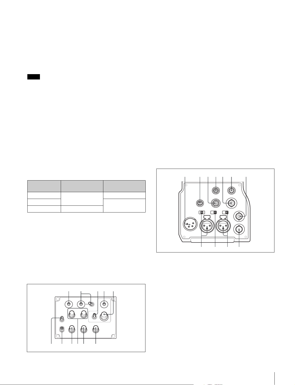
Connector panel
1234567
REAR
PROMPTER
/GENLOCK
/RET IN
+
48V
MICLINE
REMOTE
TEST
OUT
SDI
DC IN
DC OUT
10.5-17V
+
48V
MICLINE
RET CTRL
TRACKER
MIC1
FRONT
AUDIO IN
CH1 CH2
h INCOM (intercom) level control
To adjust the intercom audio listening level.
i PGM1 (program 1) and PGM2 (program 2) controls
To adjust the audio listening level of program 1 or program 2,
respectively.
CE type: Models for PAL areas
RET1 RET
PGM1
MIC
LINE
PROD
OFF
ENG
LEVEL
ENG PROD TRACKER
REAR
FRONT
INTERCOM EARPHONE
PGM2
234
OFF
DISPLAY
MENU
ASSIGNABLE
a
890qa
a DC IN (DC power supply input) connector (XLR 4-pin)
For connection to an AC-DN10 AC Adaptor, etc. to supply
power to the camera. (When a CCU is connected, this
connector cannot be used.)
b DC OUT (DC power supply output) connector (4-pin)
To supply power to a script light or equivalent (12 V DC, max.
0.5 A).
c TRACKER connector (10-pin)
For external interfaces, such as intercom and tally.
d RET CTRL (return control) connector (6-pin)
For connection to a CAC-6 Return Video Selector.
e PROMPTER/GENLOCK/RET IN (prompter signal
output/external sync signal input/VBS return input)
connector (BNC type)
• When a CCU is connected, this connector outputs a VBS
prompter signal.
Overview
9
Page 10
• When the camera is used in standalone status without
connecting a CCU, use this connector for input of an
external sync signal (BB or 3-level sync). If a VBS signal is
input, you can check the input image by pressing the RET
button.
Installation
Notes
• Even when a BB signal is used for the external sync signal,
no subcarrier phase-lock function is available for the VBS
output signal.
• As PROMPTER is set to PWR SAVE at the factory, a
prompter signal is not output. Set it to ACTIVE on the
POWER SAVE page of the MAINTENANCE menu.
f REMOTE connector (8-pin)
For connection to an RM-B150/B750 Remote Control Unit or
RCP-1000-series Remote Control Panel.
Note
When a CCU is used in combination, this connector functions
as the trunk signal input/output. Do not connect any remote
control device to this connector.
g TEST OUT connector (BNC type)
To output an analog signal.
This supplies a VBS signal, an HD-Y signal equal to the signal
output from the VF connector, an HD-SYNC signal, or an SDSYNC signal, depending on which of these you have selected
on the menu.
Note
The VBS output signal has no subcarrier phase-lock function
with respect to external sync signals.
h AUDIO IN CH1 connector (XLR 3-pin) and input select
switch
Connect a channel 1 audio signal and set the switch according
to the connected source device.
LINE: When a line-level (0 dBu) signal source is connected
MIC: When an external microphone is connected
+48V: To supply power of +48 V to the connected external
microphone
i MIC 1 (microphone 1) select switch
Select the microphone for channel 1.
FRONT: To use the microphone connected to the MIC 1 IN
connector
REAR: To use the microphone connected to the AUDIO IN
CH1 connector
j AUDIO IN CH2 connector (XLR 3-pin) and input select
switch
Connect a channel-2 audio signal and set the switch according
to the connected source device in the same manner as with
channel 1.
k SDI (serial digital interface) connector (BNC type)
For HD-SDI or SD-SDI signal output.
You can select from among camera line signal, return signal,
and VF signal for the output with a menu operation.
Connecting a Camera Control Unit
(CCU)
When operating the camera in a system with a CCU, connect
between the CCU connector of the camera and the CAMERA
connector of the CCU, using a triax cable.
When required, secure the cable, using the supplied cable
clamp belt.
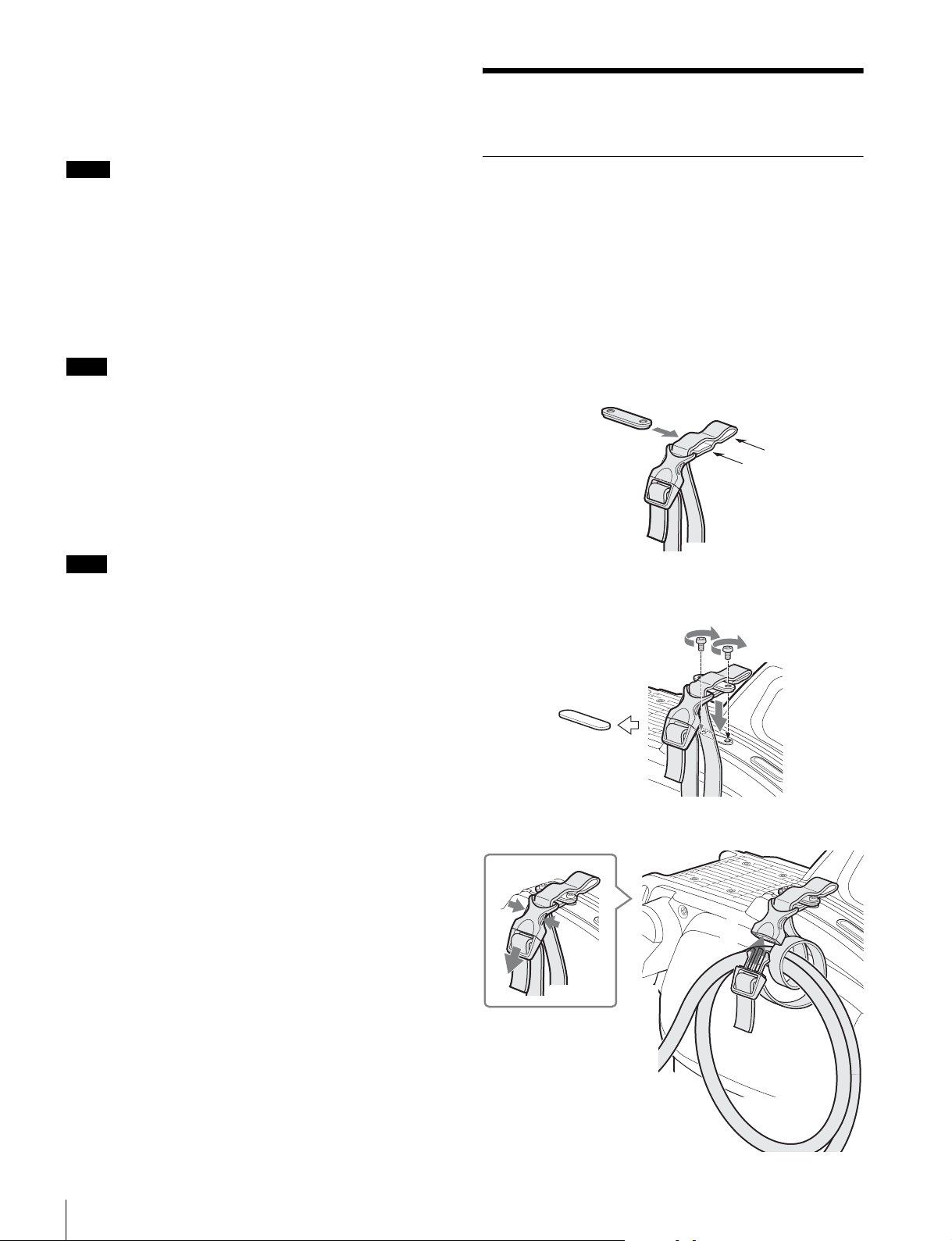
To use the cable clamp belt
1 Insert the belt bracket C into hole A or B of the cable
clamp belt.
C
B
A
2 1 Remove the back screw-hole cover on the top of
the camera and 2 secure the cable clamp belt to the
camera, using the two supplied screws (+B3×10).
2
1
3 1 Release the buckle, 2 bundle the cable with the
belt, 3 then lock the buckle again.
1
3
2
10
Installation
Page 11
4 Adjust the length by pulling down the end of the belt.
2
B
I
NCO
M
R
E
T
1
1
A
Attaching a Lens
For information on handling lenses, refer to the operation
manual for the par ticular lens
V
F
B
A
1
C
3
2
R
E
T
T
T
U
H
H
W
S
S
F
F
O
N
K
L
B
E
L
N
O
L
E
S
T
L
E
E
R
V
E
L
M
O
C
R
E
T
E
N
I
5
M
IC
4
3
VF
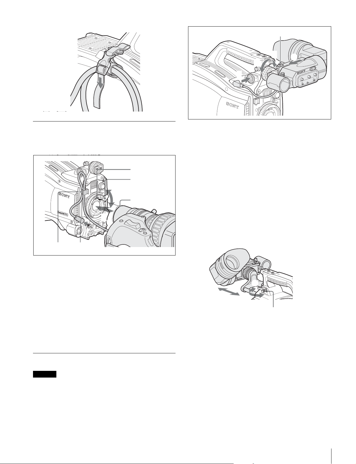
1 Loosen the viewfinder left-right positioning ring and
slide the viewfinder in the direction of arrow A.
The viewfinder stopper B automatically pops down.
2 Tighten the viewfinder left-right positioning ring to
secure the viewfinder at the most convenient
position.
3 Connect the viewfinder cable to the VF connector.
To adjust the viewfinder’s front-rear position
The viewfinder can slide in the range of 53 mm (2 1/8 inches).
Adjust the front-rear position so that you can easily operate it
on your shoulder.
1 Pulling the LOCK lever backward permits you to slide the
viewfinder backward or forward. 2 Adjust the viewfinder frontrear position and 3 lock it by returning the lever forward to the
original position.
1 Push the lens fixing lever A upward and remove the
lens mount cap from the lens mount.
2 Align the lens’ alignment pin C with the notch B in
the upper part of the lens mount and insert the lens
into the mount.
3 While supporting the lens, push the lens fixing lever
A downward to secure the lens.
4 Connect the lens cable to the LENS connector.
5 Secure the lens cable with the cable clamp.
Attaching a Viewfinder
Caution
When the viewfinder is attached, do not leave the camera with
the eyepiece facing the sun. Direct sunlight can enter through
the eyepiece, be focused in the viewfinder and cause fire.
Example: Attaching an HDVF-200 Viewfinder
For details on the viewfinder, refer to the operation manual for
the viewfinder.
3
L
O
C
2
K
1
LOCK lever
To detach the viewfinder
Loosen the viewfinder left-right positioning ring, pull the
viewfinder stopper, then pull out the viewfinder by sliding it in
the direction opposite to that when attached.
Status displays in the viewfinder
Besides the video image, the viewfinder can display
characters and messages showing the camera settings and
operation status, as well as items such as a center marker or
safety-zone marker.
Installation
11
Page 12
When the DISPLAY/MENU switch is set to DISPLAY
9
12
Items set to ON using the menu or related switches will be
displayed.
1
6
2
3
EX Z55
TALK
5600
1 A
W:
7
8
0dB 1/125
0
45
F255
12.5V
F5.6
qa
FORMAT :1080-59.94i
ASSIGNABLE1 :5600K
ASSIGNABLE2 :OFF
ASSIGNABLE REAR:OFF
!ND :2
!FAN :MAX
3
!EXT :ON
!FORMAT :1080-59.94i
a Assignable button indication
The functions assigned to the assignable buttons are
indicated.
For the functions that can be assigned, see OPERATION
menu <SWITCH ASSIGN1> (page 28).
a TALK indication
Displayed when the intercom microphone is set to ON.
b EX (lens extender) indication
Displayed when a lens extender is in use.
c Zoom position indication
Indicates the approximate position of the zoom lens variator
between wide angle (0) and telephoto (99).
d Battery voltage indication
When the CAMERA POWER switch is set to EXT, the DC IN
voltage is displayed.
When the switch is set to CCU, the internal voltage of the
camera is displayed.
e Focus position indication
Shows the focus position of a zoom lens as a numeric value (0
to 255 [infinity]).
f 5600K mode indication
Displayed when the internal electrical filter (5600K) is set to
ON.
g Filter indication
Displays the type of ND filter currently selected with a number
(1, 2, 3, or 4).
h White balance memory indication
Shows the currently selected white balance automatic
adjustment memory. This is not displayed when a CCU is
connected.
W:A: The WHITE BAL switch is set to A.
W:B: The WHITE BAL switch is set to B.
W:P: The WHITE BAL switch is set to PRST.
b Format indication
The current video format is displayed.
c ‘!’ indication area
This area is used to display abnormal statuses, using the ‘!’
IND function. Display options can be set, using the menu.
For details, see OPERATION menu <‘!’ IND> (page 26).
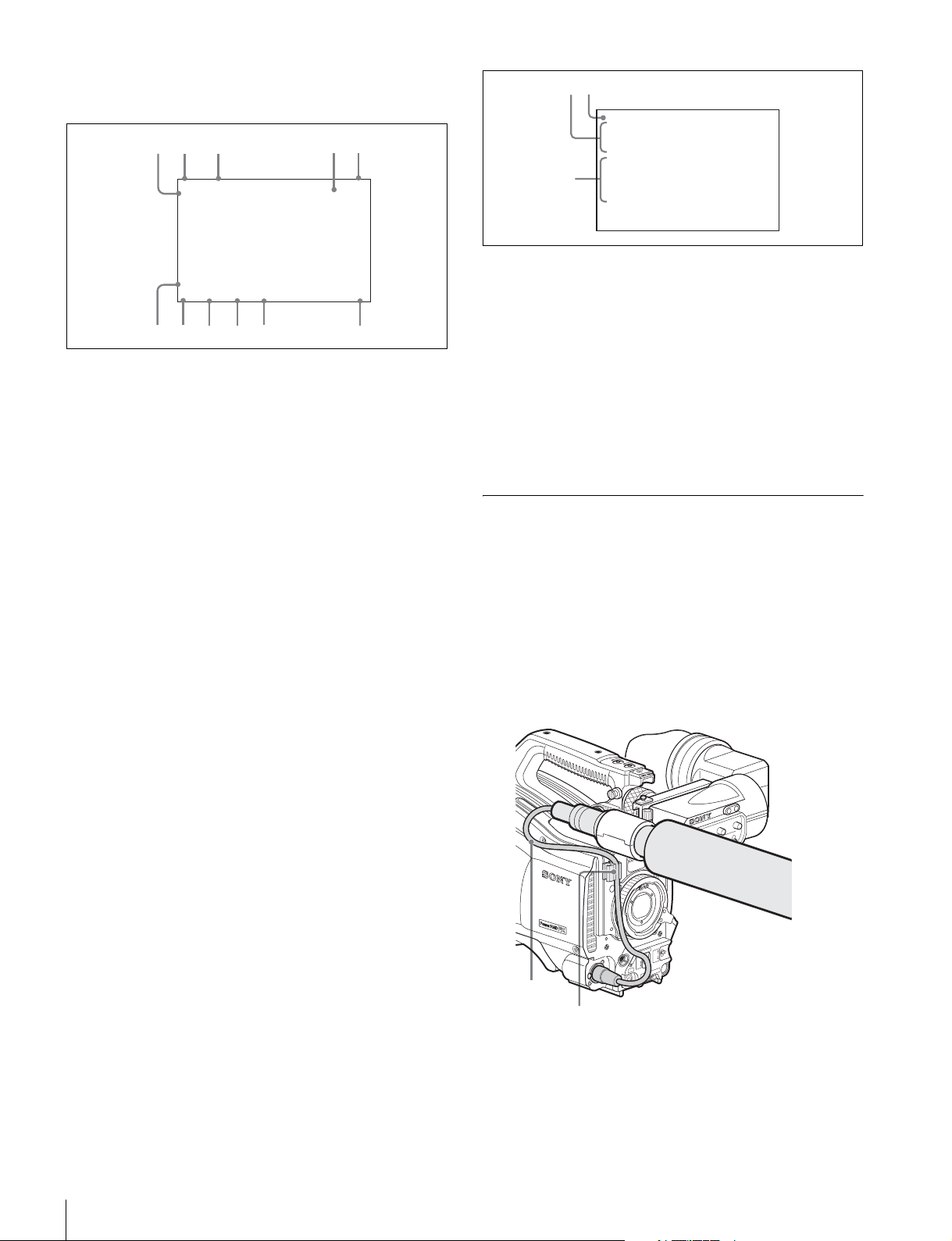
Attaching a Microphone
A microphone can be attached to the camera, using the
microphone holder of the viewfinder or an optional CAC-12
Microphone Holder.
For attaching to the microphone holder of the viewfinder, refer
to the instruction manual for the viewfinder.
When the microphone is attached to the
microphone holder of the viewfinder
Secure the microphone cable A to the cable clamp B of the
camera.
V
F
i Gain value indication
Shows the video gain value (dB) set with the GAIN switch.
j Shutter/ECS indication
Displays the shutter/ECS status. Nothing is displayed if the
electronic shutter is set to OFF.
k F-value indication
Indicates the lens F (iris opening) value.
When the STATUS/CANCEL switch is set to
STATUS
The status display is changed to show the following items:
Installation
12
A
B
R
E
T
T
T
U
H
H
W
S
S
F
F
O
N
K
L
B
E
L
N
O
L
E
S
T
L
E
E
R
V
E
L
M
M
IC
O
C
R
E
T
E
IN
Page 13
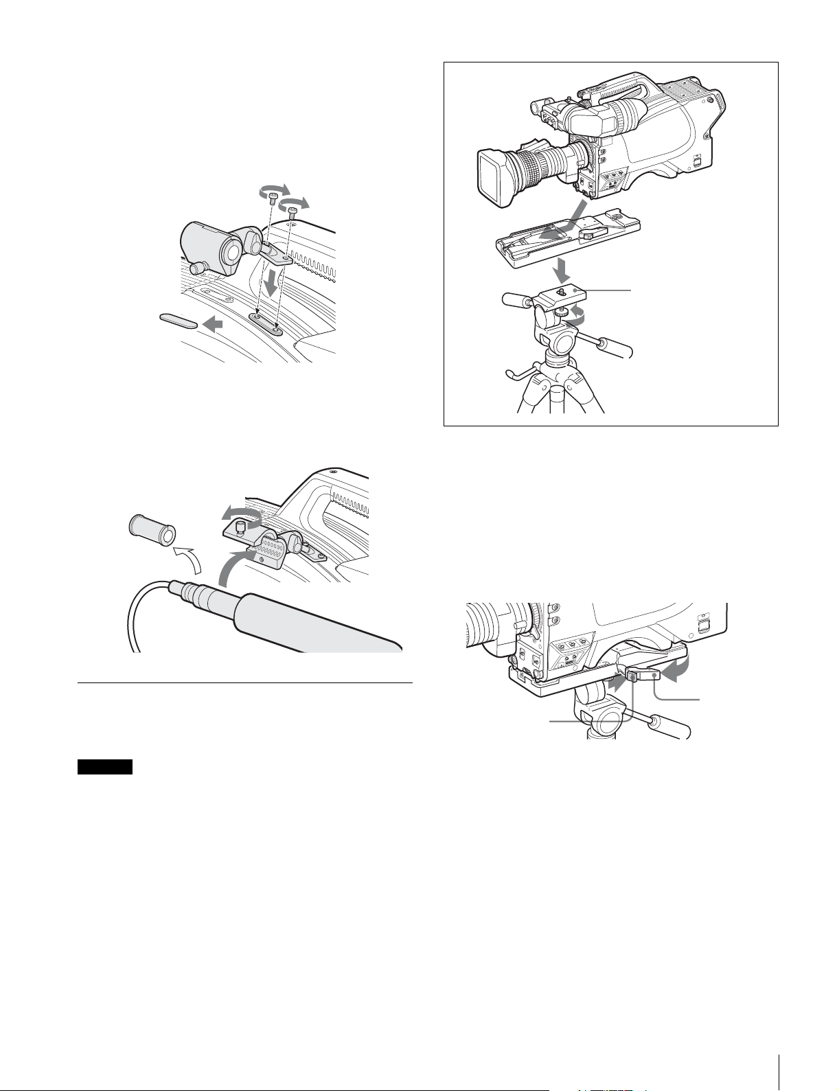
To attach a microphone, using a CAC-12
A
When attaching a long-type microphone, such as an ECM674/678, use an optional CAC-12 Microphone Holder.
1 1 Remove the front screw-hole cover on the top then
2 fix the CAC-12 in place with the two screws (+B4
supplied with the CAC-12.
2
CAC-12
×8)
2
Tripod adaptor
1
2 Loosen the screw to open the CAC-12 and attach the
microphone.
If the microphone diameter is small, attach the adaptor A
(supplied with the CAC-12 or the microphone) to the
microphone.
1
1
Platform
2
1 1 Attach the tripod adaptor to the tripod and 2
secure it with the screw.
2 Place the camera on the tripod adaptor and slide
forward it along the groove of the tripod adaptor until
it clicks.
To remove the camera from the tripod adaptor
Hold down the red button and pull the lever in the direction of
the arrow.
Mounting the Camera to a Tripod
Mount the camera to a tripod, using an optional VCT-U14
Tripod Adaptor.
Caution
• Select an appropriate hole from among those at the bottom
of the tripod adaptor considering the balance of the weight
of the camera and the tripod adaptor. If an inappropriate
hole is selected, the camera may fall over.
• Check that the size of the selected hole matches that of the
screw of the tripod. If they do not match, the tripod adaptor
cannot be attached to the tripod securely.
Lever
Red button
If the pin of the tripod adaptor does not return to its
original position
After removing the camera, if the pin of the tripod adaptor does
not return to its original position, hold down the red button and
move the lever in the direction of the arrow to return the pin to
its original position. It is not possible to mount a camera with
the pin not seated.
Installation
13
Page 14
Original position
O
F
F
O
N
S
E
L
W
H
T
B
L
K
SHUTTER
RET
LEN
S
INTERCOM LEVEL
Pin
Preparatory Settings
Adjusting the Black Balance and White
Balance
In order to maintain high picture quality when using the
camera, it is necessary to set the black balance and white
balance appropriately for the conditions.
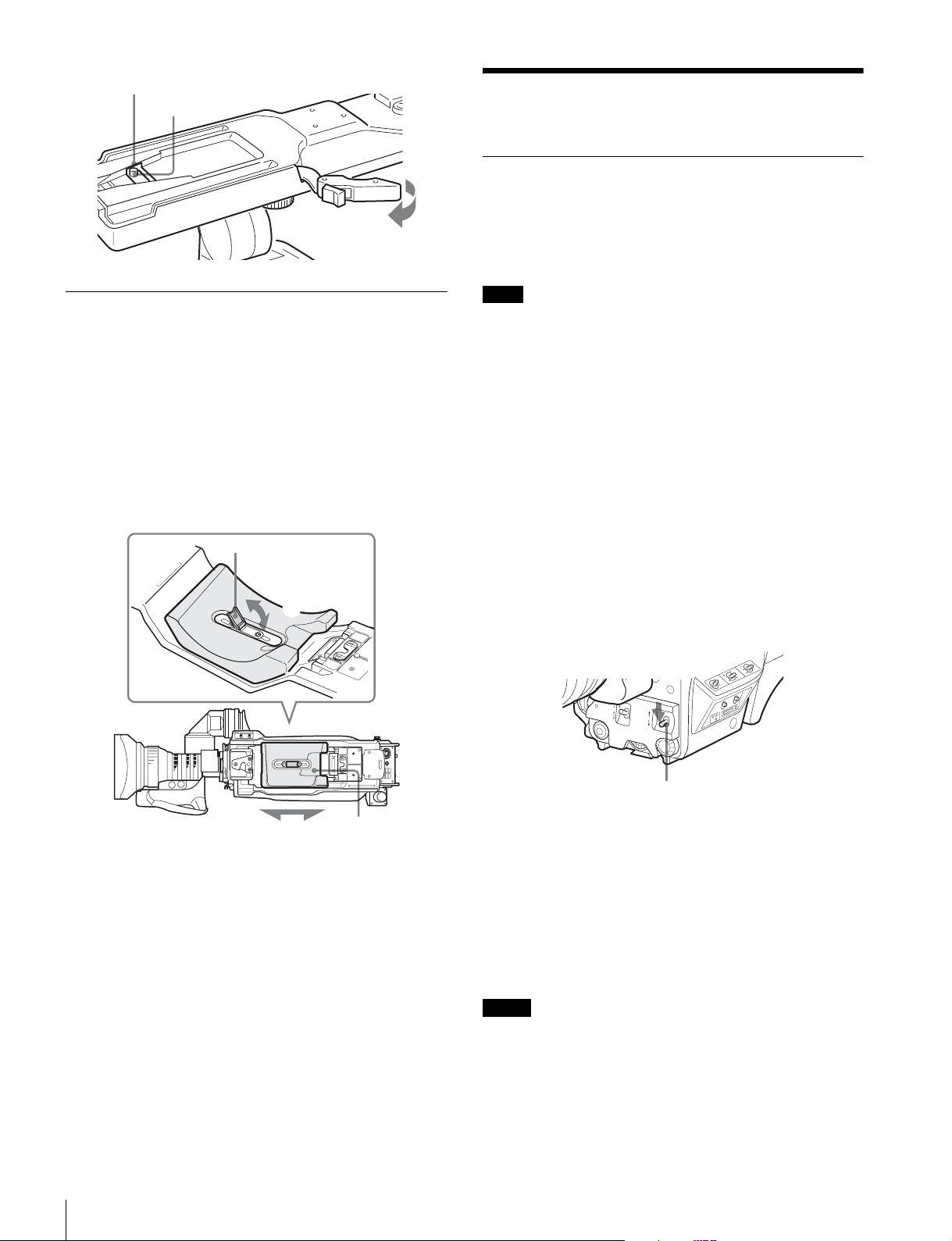
Adjusting the Shoulder Pad Position
You can shift the shoulder pad in the range of 28 mm (1 1/8
inches). This adjustment helps you get the best balance for
shooting with the camera on your shoulder.
To adjust
1 Raise the lever in the center of the shoulder pad to unlock
the shoulder pad, 2 slide the shoulder pad backward or
forward until it is in the most convenient position, and 3 move
the lever down to lock the shoulder pad in the selected
position.
Shoulder pad lock lever
1
3
Bottom of the camera
Note
When a CCU or an external control device, such as an RCP/
RM, is connected, the black balance and white balance are
controlled from the external device or the HKCU-FP1 attached
to the CCU, and adjustment on the camera is disabled.
Black balance adjustment
The black balance needs adjustment in situations like the
following:
• The first time the camera is used
• When the camera is used after a long period of disuse
• When the surrounding temperature changes greatly
• When the gain value is changed using the setup menus
Normally, there is no need to adjust the black balance every
time the camera is turned on.
White balance adjustment
Always adjust the white balance when lighting conditions
change.
To adjust the black balance
Push the AUTO W/B BAL switch to BLK.
14
Preparatory Settings
2
Shoulder pad
AUTO W/B BAL switch
Automatic black balance adjustment begins.
In automatic adjustment of black balance, both the black set
and black balance are adjusted.
During adjustment, the message “ABB: EXECUTING” will be
displayed on the viewfinder screen.
When the adjustment process is completed, the message
“ABB: OK” will be displayed.
The adjusted value is automatically stored in memory.
The black balance values stored in memory will be preserved
even when the camera power is turned off.
Notes
• During black balance adjustment, the iris will be
automatically closed.
• During black balance adjustment, the gain switching circuit
will work automatically, and the viewfinder screen will flicker
several times. This is not a malfunction.
Page 15
To adjust the white balance
O
F
F
O
N
S
E
L
W
H
T
B
L
K
SHUTTER
RET
LEN
S
INTERCOM LEVEL
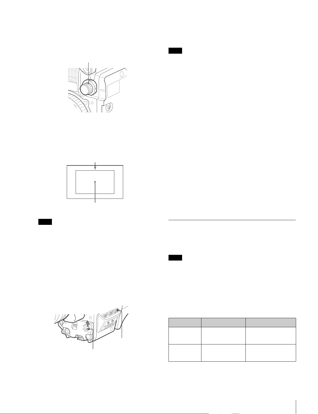
1 Select the built-in filter according to the lighting
conditions with the filter select knob (1: Clear, 2:
1/4 ND, 3: 1/16 ND, 4: 1/64 ND).
Filter select knob
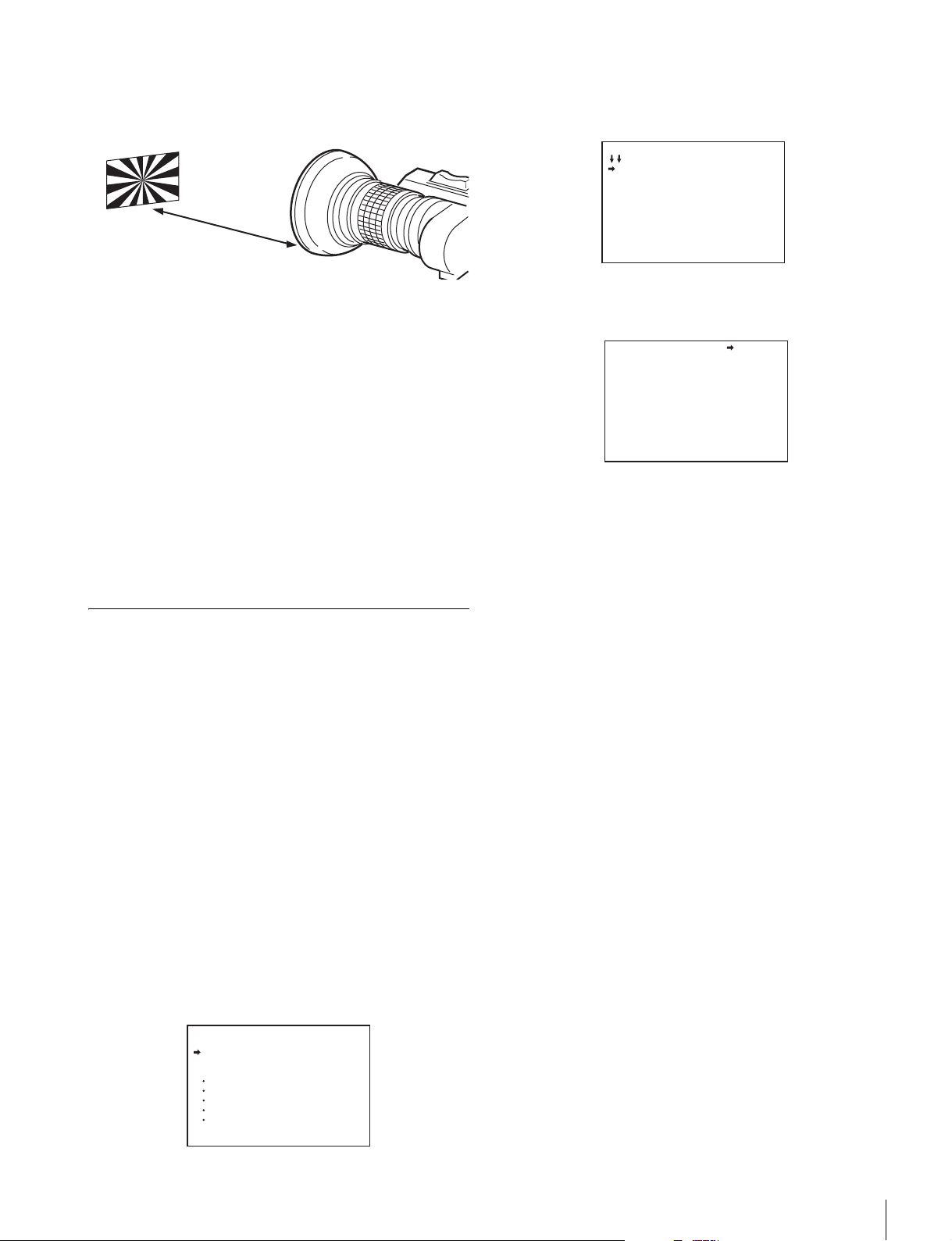
2 Place a white pattern, as shown below, with the same
lighting conditions as the subject, and zoom in on it.
A white object (white cloth, a white wall, etc.) near the
subject may be used in place of a white pattern.
A rectangle centered in the screen:
The length of the sides must be at least 70% of the
height and width of the screen.
Within this rectangle, there must be an area of
white greater than 10% of the entire screen.
After about one second, the message “AWB: OK” will be
displayed, and the adjustment process will complete.
The adjusted value will be automatically stored in the selected
memory (A or B).
Note
When using a zoom lens with automatic iris control capability,
hunting1) may occur. Adjust the lens’ iris gain control (labeled
IG, IS, S, etc.).
1) Hunting: The automatic iris responds over and over, and the image
repeatedly darkens and lightens.
For more information, refer to the operation manual for the
lens.
About white balance memory
There are two white balance memories: A and B.
When you execute automatic white balance adjustment, the
adjusted white balance value and the setting of the filter select
knob will be stored in either memory A or B, selected with the
WHITE BAL switch.
The white balance values stored in memory will be preserved
even when power is turned off. When power is turned on
again, the white balance in memory corresponding to the
current WHITE BAL switch setting is retrieved.
If automatic black balance or white balance
adjustment fails
If the adjustment process does not end successfully, the error
message “ABB: NG” or “AWB: NG” will be displayed on the
viewfinder screen for approximately three seconds.
If this error message is displayed, try the adjustment again.
If the error message continues to be displayed after several
attempts, the camera requires internal inspection.
Note
Be careful not to have any spots of high illumination in the
rectangle.
3 Adjust the lens iris opening.
With a manually adjusted lens: Set the opening to an
appropriate value.
With a lens which has automatic iris control: Set the
lens’ automatic/manual iris control switch to
automatic.
4 Select white balance memory A or B with the WHITE
BAL switch and push the AUTO W/B BAL switch
toward WHT.
WHITE BAL switch
AUTO W/B BAL switch
Automatic white balance adjustment begins.
During adjustment, the message “AWB: EXECUTING” will be
displayed on the viewfinder screen.
Setting the Electronic Shutter
This section explains the different modes which can be used
for the electronic shutter and gives the procedures for setting
the shutter mode and shutter speed.
Note
When a CCU or an external control device, such as an RCP/
RM, is connected, the electronic shutter is controlled from the
external control device or the HKCU-FP1 mounted on the
CCU, and the switch on the camera is disabled.
About the shutter modes
The shutter modes that can be used with the electronic shutter
of the camera and the shutter speeds that may be selected are
as follows:
Shutter mode
Standard 1/100, 1/125, 1/250,
ECS (Extended
Clear Scan)
1) The values in the table are those with 59.94i. With other formats, the
available values may be different.
Shutter speed
1/500, 1/1000, 1/2000
seconds
Continuously variable
in the range of 60.0
Hz to 4300 Hz
1)
Usage
Use to obtain clear
images of quickly moving
subjects
Use to obtain images of
video monitors without
horizontal striping
Preparatory Settings
15
Page 16
Note
O
F
F
O
N
S
E
L
W
H
T
B
L
K
SHUTTER
RET
LENS
INTERCOM LEVEL
With artificial lighting, particularly fluorescent lights and
mercury vapor lamps, the brightness appears to be constant,
but in fact the strength of the red, green, and blue components
varies with the power supply frequency. This phenomenon is
known as “flicker.” When using the electronic shutter under
these lighting conditions, there are certain cases in which the
flicker is more noticeable. In particular, color flicker is evident
when the power frequency is 60 Hz. In areas where the power
frequency is 50 Hz, setting the shutter speed to 1/100 second
will reduce the flicker.
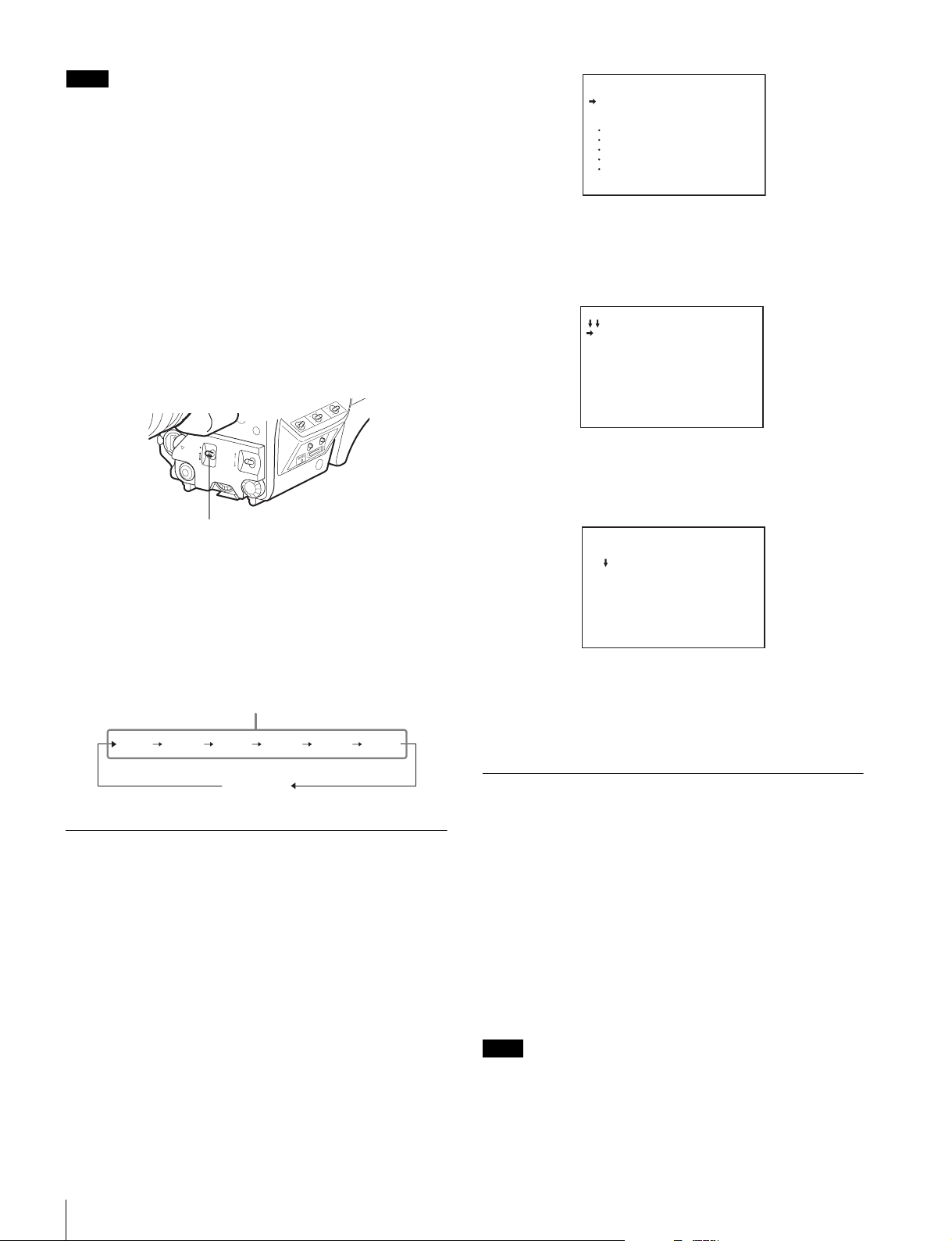
Selecting the mode and speed of the shutter
The mode and the shutter speed in Standard mode are set
using the SHUTTER switch.
1 Push the SHUTTER switch from the ON position to the
SEL position.
SHUTTER switch
The current shutter setting will be displayed in the
viewfinder for about three seconds.
Example: “Shutter: 1/250”
<TOP MENU>
USER
USER MENU CUSTOMIZE
ALL
OPERATION
PAINT
MAINTENANCE
FILE
DIAGNOSIS
4 Rotate the menu control knob to position the cursor
to MAINTENANCE and push on the menu control
knob.
The CONTENTS page of the MAINTENANCE menu is
displayed.
CONTENTS M00 TOP
01.<AUTO SETUP>
02.<WHITE SHADING>
03.<BLACK SHADING>
04.<OHB MATRIX>
05.<AUTO IRIS>
06.<MIC GAIN>
07.<CALL/TALLY>
08.<OUTPUT FORMAT>
09.<DOWN CONVERTER>
10.<TEST OUT>
5 Turn the menu control knob to scroll the page and
position the pointer to <DATE> then push on the
menu control knob.
The <DATE> page is displayed.
<DATE> M15 TOP
DATE/TIME
2008/12/23 08:32
2 Push the SHUTTER switch to the SEL position again
before the display disappears. Repeat this action until
the desired mode or speed is displayed.
Example: with 59.94i
Standard mode
1/100
1/5001/2501/125
ECS mode
1/1000
1/2000
Setting the Local Time
When using the camera for the first time, set the built-in clock
to the local time, using the <DATE> page of the
MAINTENANCE menu displayed on the viewfinder screen.
For details on menu operations, see “Menus” (page 21).
1 Turn on the camera.
2 While holding the menu control knob pressed, set the
DISPLAY/MENU switch to MENU.
The camera enters Menu mode, and “TOP” is displayed at
the upper-right corner of the screen.
3 Rotate the menu control knob to set the cursor to
“TOP” and push on the menu control knob.
The TOP MENU screen is displayed.
6 Turn the menu control knob and set the date and time.
Push on the menu control knob to shift to the next digit.
7 When the date/time setting is completed, set the
DISPLAY/MENU switch to OFF to exit Menu mode.
Adjusting the Flange Focal Length
Adjustment of the flange focal length (the distance between
the lens mount attachment plane and the imaging plane) is
necessary in the following situations:
• The first time a lens is attached
• When changing lenses
• If the focus is not sharp at both telephoto and wide angle
when zooming
The flange focal length can be more precisely adjusted by
using the focus assist indicators.
See “Displaying the focus assist indicators” (page 18) for the
focus assist indicators.
Note
The various parts of the lens used in adjusting the flange focal
length are in different positions on different lenses. Refer to the
operation manual for the lens.
1 Set the iris control to manual and open the iris fully.
Preparatory Settings
16
Page 17
2 Place the supplied flange focal length adjustment
chart approximately 3 meters from the camera and
adjust the lighting to get an appropriate video output
level.
About 3 meters (10 ft)
4 Rotate the menu control knob to align the pointer to
OPERATION and push on the knob.
The CONTENTS page of the OPERATION menu is
displayed.
CONTENTS 00 TOP
01.<VF DISPLAY>
02.<'!'IND>
03.<VF MARKER>
04.<VF DETAIL>
05.<FOCUS ASSIST>
06.<ZEBRA>
07.<CURSOR>
08.<VF OUT>
09.<SWITCH ASSIGN1>
10.<SWITCH ASSIGN2>
3 Loosen the Ff (flange focal length) ring lock screw.
4 With either manual or power zoom, set the zoom ring
to telephoto.
5 Aim at the flange focal length adjustment chart and
turn the focus ring to focus the image.
6 Set the zoom ring to wide angle.
7 Turn the Ff ring to bring the chart into focus.
Take care not to move the distance ring.
8 Repeat steps 4 through 7 until the image is in focus at
both telephoto and wide angle.
9 Tighten the Ff ring lock screw.
Setting the Focus Assist Function
Using the OPERATION menu, the assist functions for easier
focusing on the viewfinder screen can be activated.
Adding a VF detail signal
Adding a VF detail signal to sharp edges in the image on the
viewfinder screen makes it easier to check the focusing
condition by observing changes in the detail signal or in the
color converted from the detail signal (color detail).
The focus setting where the detail signal becomes strongest is
the best focus setting.
1 Turn on the camera.
2 Set the the DISPLAY/MENU switch to MENU while
holding the menu control knob pressed.
The camera enters Menu mode, and “TOP” is displayed at
the upper right corner of the screen.
3 Rotate the menu control knob to align the pointer to
“TOP” and push on the knob.
The TOP MENU screen is displayed.
<TOP MENU>
USER
USER MENU CUSTOMIZE
ALL
OPERATION
PAINT
MAINTENANCE
FILE
DIAGNOSIS
5 Rotate the menu control knob to align the pointer to
<VF DETAIL> and push on the knob.
The <VF DETAIL> page is displayed.
<VF DETAIL> 04 TOP
VF DETAIL : ON 25%
CRISP : 0
FREQUENCY: 9M
FAT MODE : OFF
FLICKER : OFF
AREA : 70%
ZOOM LINK: 100%
COLOR DETAIL : ON BLUE
PEAK COLOR : ON
CHROMA LEVEL: 100%
6 Rotate the menu control knob to align the pointer to
the item to be set and push on the knob.
To use the VF detail signal
Set VF DETAIL to ON to activate the VF detail function to
add the detail signal to sharp edges in the image. You can
adjust the signal level (strength) in the range of 0 to 100%
(default 25%).
You can adjust the characteristics of the detail signal with
the menu items below:
CRISP: Adjust to eliminate fine portions of the detail
signal.
FREQUENCY: Change the detection band of sharp
edges.
FAT MO DE: Turn the function ON/OFF to thicken the
detail signal.
FLICKER: Turn the function ON/OFF to flicker the detail
signal, which makes it easier to check the signal on a
CRT screen.
AREA: To limit the area where to display the detail signal.
ZOOM LINK: Set the VF detail level at the full WIDE
position. (The VF detail level changes according to the
zoom position.)
To use the color detail
Set COLOR DETAIL to ON to convert the VF detail signal
to a specified color. This makes it easier to check the
signal on an LCD screen, including the viewfinder screen.
The display color can be selected at the column next to
ON.
You can adjust the coloring with the menu items below:
PEAK COLOR: Turn the function ON/OFF to change the
color where the detail signal is strongest.
CHROMA LEVEL: To reduce the chroma components of
the video signal (only for video signals on the
viewfinder).
7 Rotate the menu control knob to display the desired
setting and push on the knob.
Preparatory Settings
17
Page 18
8 To finish the adjustments, set the DISPLAY/MENU
switch to OFF to exit Menu mode.
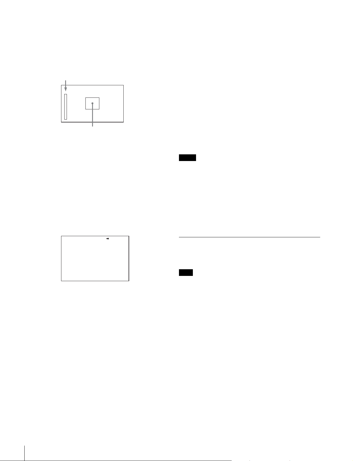
Displaying the focus assist indicators
The focus assist indicator function extracts the irregularities of
a subject and converts the integrated values to a level
indicator, which shows the focus condition.
Level indicator (Its position and operations can be adjusted.)
Area marker to display the detection area of the focus (Its size
and position can be adjusted.)
The focus setting where the indicator shows the maximum
level is the best focus setting. (The range of the indicator
substantially changes depending on picture elements or
shooting environments. Adjust it with GAIN and OFFSET as
required.)
1 Display the CONTENTS page of the OPERATION
menu (referring to step 1 to 4 in “Adding a VF detail
signal”).
2 Rotate the menu control knob to align the pointer to
<FOCUS ASSIST> and push on the menu control
knob.
The <FOCUS ASSIST> page is displayed.
To use the area marker
Setting AREA MARKER to ON displays the detection area
of the focus as a marker on the viewfinder screen.
You can set the size and position of the detection area with
the menu items below.
SIZE: The size of the detection area can be changed. (If
the area size is too large, both the subject and the
background are included in the area, making the
indicator display easily deviate from the subject.)
POSITION: Roughly set the position of the detection area.
POSITION H: Finely adjust the position of the detection
area in the horizontal directions.
POSITION V: Finely adjust the position of the detection
area in the vertical directions.
4 Rotate the menu control knob to display the desired
setting and push on the knob.
5 To finish the adjustments, set the DISPLAY/MENU
switch to OFF to exit Menu mode.
.
Notes
• The level indicator and the effect area marker cannot be
displayed simultaneously, whichever you set to ON later is
preferentially displayed.
• The area marker and the aspect safety marker cannot be
displayed simultaneously, whichever you set to ON later is
preferentially displayed.
• When displaying the focus assist indicators, check that the
flange focal length has been precisely adjusted.
See “Adjusting the Flange Focal Length” (page 16) for the
flange focal length.
<FOCUS ASSIST> 05 TOP
INDICATOR : OFF
MODE : BOX BOTTOM
LEVEL : 3 QUICK
GAIN : 50
OFFSET : 50
AREA MARKER: ON
SIZE : MIDDLE
POSITION : CENTER
POSITION H: 50
POSITION V: 50
3 Rotate the menu control knob to align the pointer to
the item to be set and push on the knob.
To use the level indicator
Setting INDICATOR to ON displays the level indicator on
the viewfinder.
You can set the display format with the menu items below.
MODE: Set the type and position of the indicator.
LEVEL: Set the density and the response speed of the
indicator.
GAIN: Set the sensitivity of the indicator.
OFFSET: Set the offset of the focus detection value.
1) Normally, the sensitivity of the indicator is automatically set to
the optimum value in conjunction with the AREA MARKER
SIZE set value. Use this setting when an optimum sensitivity
value cannot be obtained, depending on the shooting
environment.
2) Normally, the optimum offset is automatically set in conjunction
with the AREA MARKER SIZE and MASTER GAIN set values.
Use this setting when the optimum offset cannot be obtained,
depending on the shooting environment.
1)
2)
Setting the Camera Outputs
You can specify video signals directly output from the camera,
with menu operations.
Note
The MAIN (camera picture), RET (return video), or VF (the same
picture as that displayed on the viewfinder screen) setting is common
to SD-SDI and VBS. Different signals cannot be output.
The menu pages used for the output settings have been
registered to the USER menu at the factory.
• <POWER SAVE> (U11)
• <OUTPUT FORMAT> (U16)
• <TEST OUT> (U17)
• <SDI OUT> (U18)
• <DOWN CONVERTER> (U19)
Set the menu items on the above menu pages to the settings
shown in the following tables.
For details on menu operations and the USER menu, see
“Menus” on page 21.
Outputting the signal being shot (camera
picture)
The same textual information as that displayed on the
viewfinder screen can be added to the output signal by setting
CHARACTER to ON on the <SDI OUT> or <TEST OUT>
page.
Preparatory Settings
18
Page 19
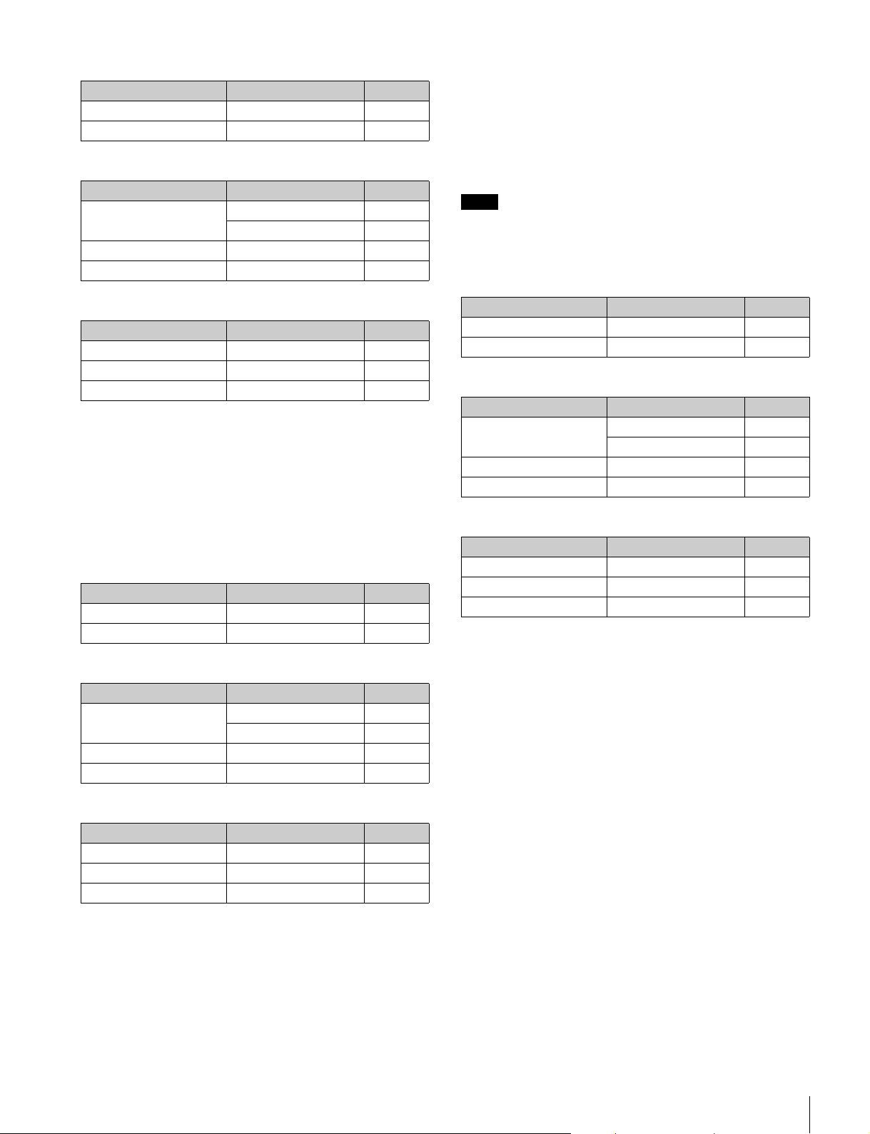
To output as HD-SDI
Menu page Item Setting
<POWER SAVE> SDI OUT ACTIVE
<SDI OUT> OUTPUT MAIN
To output as SD-SDI
Menu page Item Setting
<POWER SAVE> SDI OUT ACTIVE
DOWN CONVERTER ACTIVE
<DOWN CONVERTER> OUTPUT SIGNAL MAIN
<SDI OUT> OUTPUT SD-SDI
To output as VBS
Menu page Item Setting
<POWER SAVE> DOWN CONVERTER ACTIVE
<DOWN CONVERTER> OUTPUT SIGNAL MAIN
<TEST OUT> OUTPUT VBS
Constantly outputting a return video
• When a CCU is connected, one of the signals being
supplied to the CCU can be output from the camera.
• The last selected return signal is output.
• The same character information as that displayed on the
viewfinder screen can be added to the output signal by
setting CHARACTER to ON on the <SDI OUT> or <TEST
OUT> page.
To output as HD-SDI
Menu page Item Setting
<POWER SAVE> SDI OUT ACTIVE
<SDI OUT> OUTPUT RET
To output as SD-SDI
Menu page Item Setting
<POWER SAVE> SDI OUT ACTIVE
DOWN CONVERTER ACTIVE
<DOWN CONVERTER> OUTPUT SIGNAL RET
<SDI OUT> OUTPUT SD-SDI
To output as VBS
Menu page Item Setting
<POWER SAVE> DOWN CONVERTER ACTIVE
<DOWN CONVERTER> OUTPUT SIGNAL RET
<TEST OUT> OUTPUT VBS
The output is synchronized with switching among Y, R, G,
and B or switching to a return signal.
• With SD-SDI or VBS, the output is synchronized only with
switching between a return signal and the camera image. It
does not correspond to switching among Y, R, G, and B.
Information other than CHARACTER (such as VF
MARKER, VF DETAIL, and ZEBRA) cannot be added to the
output.
Note
With the settings for outputting the same image as that on the
viewfinder, the output will be obtained in 1080i, even if the
format setting is 720P.
To output as HD-SDI
Menu page Item Setting
<POWER SAVE> SDI OUT ACTIVE
<SDI OUT> OUTPUT VF
To output as SD-SDI
Menu page Item Setting
<POWER SAVE> SDI OUT ACTIVE
DOWN CONVERTER ACTIVE
<DOWN CONVERTER> OUTPUT SIGNAL VF
<SDI OUT> OUTPUT SD-SDI
To output as VBS
Menu page Item Setting
<POWER SAVE> DOWN CONVERTER ACTIVE
<DOWN CONVERTER> OUTPUT SIGNAL VF
<TEST OUT> OUTPUT VBS
Outputting a prompter signal (when an HXCU100 is connected)
The VBS signal supplied to the PROMPTER connector of the
CCU is output from the PROMPTER/GENLOCK/RET IN
connector of the camera.
Outputting a prompter signal (when an HSCU300 is connected)
The VBS signal supplied to the PROMPTER 1 connector of
the CCU is output from the PROMPTER/GENLOCK/RET IN
connector of the camera.
The VBS signal supplied to the PROMPTER 2 connector or
the SDI prompter signal supplied to the RETURN INPUT
connector of the CCU is not output from the camera.
Outputting the same image as that on the
viewfinder screen
• With HD-SDI, you can obtain a signal that includes the same
information as that being displayed on the viewfinder
according to the settings for VF MARKER, CHARACTER,
VF DETAIL, ZEBRA, etc. The ON/OFF or other settings for
adding information are common to those for the viewfinder.
Preparatory Settings
19
Page 20
Outputting a Trunk Signal
The trunk signal can be used for communication between an
external device connected to the REMOTE connector of the
camera and an external device connected to the TRUNK
connector of the CCU.
Basic Procedure for
Shooting
To output the trunk signal from the REMOTE
connector
Menu page Item Setting
<TRUNK> TRUNK ON
Note
When an HXCU-100 Camera Control Unit or an external
control device, such as an RCP-series Remote Control Panel,
is connected, the white balance, black balance and shutter
adjustments are controlled from the external device, and the
controls on the camera are disabled.
For operations on the external control device, refer to the
operation manual for the device.
1 Turn the camera on.
To operate the camera on power supplied through the DC
IN connector of the camera via an AC power adaptor, set
the CAMERA POWER switch to EXT.
To operate the camera on power via the connected
HXCU-100, set the CAMERA POWER switch to CCU.
2 Set the filter select knob and 5600K appropriately for
the lighting conditions.
Filter select knob setting
Filter select knob Lighting conditions
1 (CLEAR) Indoor shooting
2 (1/4 ND) Outdoor (cloudy or rainy) or indoor
3 (1/16 ND) Outdoor shooting in daytime
4 (1/64ND) Outdoor shooting when you wish to
1) Depth of field: This is the range over which the subject is
sharply in focus.
From the viewpoint of the characteristics of lenses,
shooting with the iris set in the range of F4 to F8 is
generally recommended for good quality pictures. Set the
filter select knob to bring the iris setting into that range.
However, this may not apply when special composition is
desired.
5600K setting
The 5600K ON/OFF function has been assigned to
assignable button 1 (front right, upper) at the factory.
shooting when you wish to reduce the
depth of field
reduce the depth of field, or especially
under bright outdoor ambient light
1)
Basic Procedure for Shooting
20
5600K Example of lighting conditions
OFF Indoor shooting under lighting with lower color
temperature, such as a halogen or tungsten lamp
ON Outdoor shooting in daytime, or indoor shooting
under lighting with higher color temperature
3 Check the settings of the camera.
• Settings of switches/control knobs
• Settings on the OPERATION menu (page 26) and the
PAINT menu (page 29)
• Electronic shutter setting (page 15)
Page 21
• Settings for the output signals from the camera (page
18)
• Flange focal length setting (page 16)
4 Adjust the eyepiece focus as well as the contrast and
brightness of the viewfinder image.
For viewfinder settings, refer to the operation manual for
the viewfinder.
5 If required, switch on the center marker and/or safety
zone and zebra pattern in the viewfinder image, using
the OPERATION menu.
6 Check the sound system settings.
• Microphone connections
• Settings of the AUDIO IN switches
• Settings on the VTR (Refer to the operation manual for
the VTR.)
7 Adjust the white balance and black balance (page 14).
Menus
The menus displayed on the viewfinder screen enable various
settings of the camera.
The following controls are used to operate the menus.
To enter Menu mode, you can use the DISPLAY/MENU switch
either on the side or on the rear operation panel.
The menu control knob at the low on the front panel and that
on the rear operation panel function the same. Rotate the knob
to select menu items or values and push on it to register
(enter) the selection.
Front right
8 Turn the focusing ring so that the subject is sharply in
focus.
9 Set up the VTR according to your shooting objectives
then start recording, using the button on the VTR.
For details on VTR setup and operations, refer to the
operation manual for your VTR.
10When shooting is finished, stop recording, using the
button on the VTR.
Push on
Rear operation panel
RET1 RET
PGM1
MIC
LINE
PROD
OFF
ENG
LEVEL
ENG PROD TRACKER
REAR
FRONT
INTERCOM EARPHONE
DISPLAY/MENU switch
Rotate
Menu control knob
234
PGM2
DISPLAY
OFF
MENU
DISPLAY/MENU switch
STATUS/CANCEL switch
ASSIGNABLE
Push on
Rotate
Menu control knob
Displaying Menu Pages
To display a menu page
Set the DISPLAY/MENU switch to MENU.
The menu page last accessed will be displayed. If it is the first
time, the CONTENTS page of the USER menu will be
displayed.
To display the TOP MENU screen
If you set the DISPLAY/MENU switch to MENU while holding
the menu control knob pressed, “TOP” is displayed at the
upper right corner of the screen.
Turn the menu control knob to move the pointer (
display to “TOP” and push on the knob. The TOP MENU
screen is displayed, listing the available menus.
,) on the
Menus
21
Page 22
<TOP MENU>
USER
USER MENU CUSTOMIZE
ALL
OPERATION
PAINT
MAINTENANCE
FILE
DIAGNOSIS
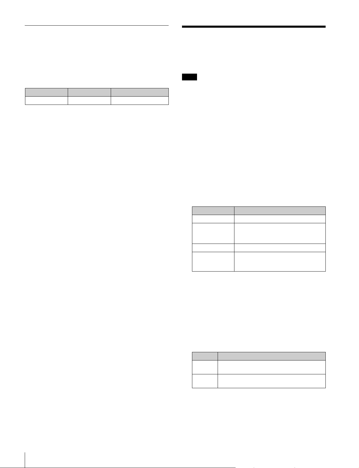
Menu Purpose
USER This menu can include menu pages selected
USER MENU
CUSTOMIZE
ALL This menu permits you to control all items of
OPERATION This menu contains items for camera operators
PAINT This menu contains items for making detailed
MAINTENANCE This menu contains items for performing
FILE This menu is for performing file operations,
DIAGNOSIS This menu enables you to confirm the self-
from among the OPERATION, PAINT,
MAINTENANCE, FILE, and DIAGNOSIS
menus, for convenience. Changing, adding,
and deleting pages can be performed with the
USER MENU CUSTOMIZE menu.
This menu allows you to edit the USER menu.
For details on the USER menu, see “Editing
the USER Menu” (page 23).
the OPERATION menu, PAINT menu,
MAINTENANCE menu, FILE menu, and
DIAGNOSIS menu as a single menu.
to operate the camera. It mainly permits
viewfinder, intercom, and switch settings.
image adjustments while using a waveform
monitor to monitor the waveforms output from
the camera. Support of a video engineer is
usually required to use this menu.
Although you can also use an external control
device to set the items on this menu, the menu
is effective when using the camera by itself
outdoors.
camera maintenance operations, such as
changing the system or setting infrequently
used “paint” items.
such as writing or clearing the reference file.
diagnostic information.
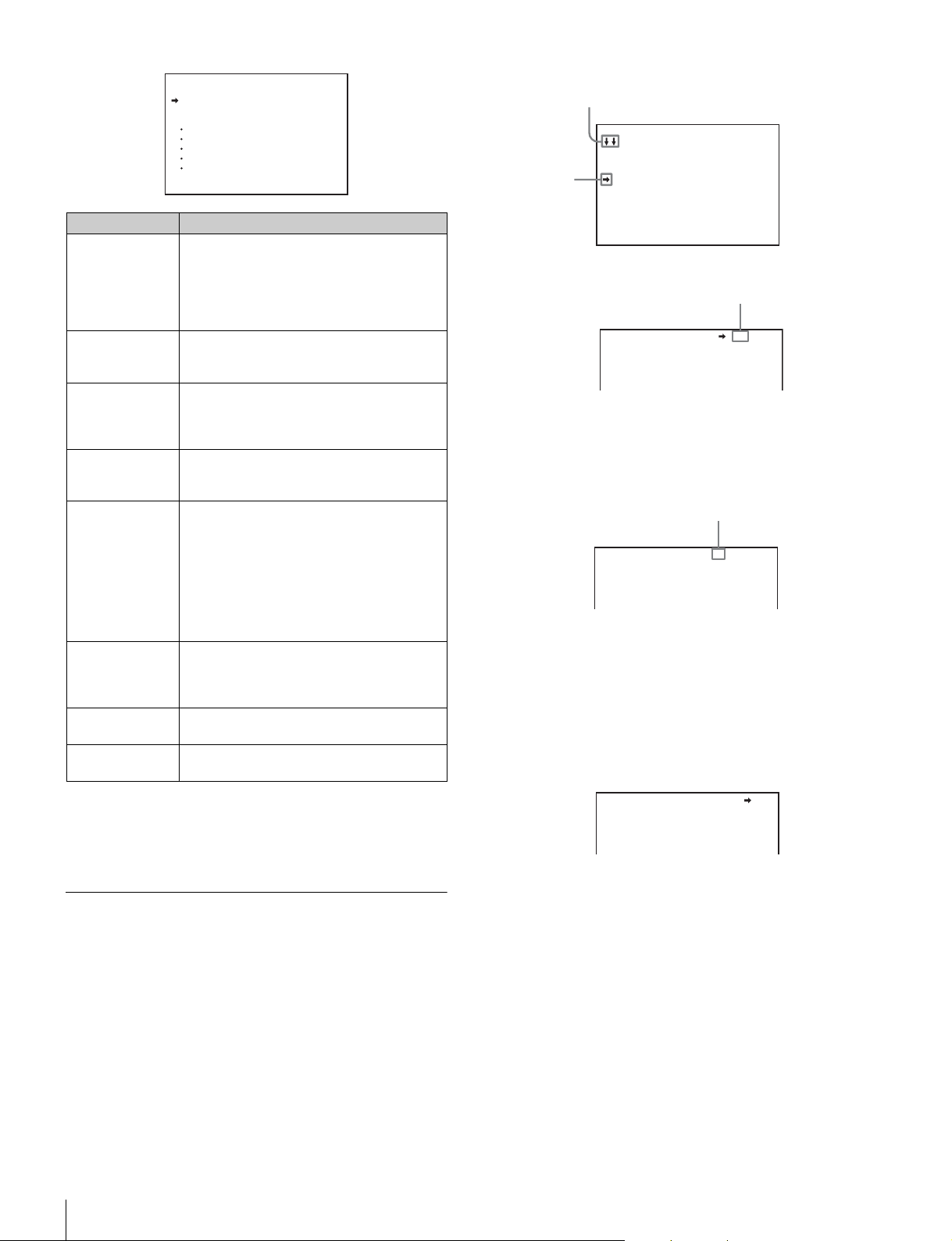
If the screen can be scrolled, arrows will
indicate the direction for scrolling.
CONTENTS 00 TOP
01.<VF DISPLAY>
02.<'!'IND>
Pointer
03.<VF MARKER>
04.<VF DETAIL>
05.<FOCUS ASSIST>
06.<ZEBRA>
07.<CURSOR>
08.<VF OUT>
09.<SWITCH ASSIGN1>
10.<SWITCH ASSIGN2>
The selected page is displayed.
Page number
<VF DETAIL> 04 TOP
VF DETAIL : ON 25%
CRISP : 0
FREQUENCY: 9M
FAT MODE : OFF
To change the displayed page
1 Check that the pointer is located at the left of the page
number then push on the menu control knob.
The pointer changes to a flashing question mark.
flash
<VF DETAIL> ? 04 TOP
VF DETAIL : ON 25%
CRISP : 0
FREQUENCY: 9M
FAT MODE : OFF
2 Rotate the menu control knob to flip through the
pages, and push on the knob when the desired page
is displayed.
The question mark will change back to the pointer, and
operations with the displayed page are enabled.
To return to the TOP MENU screen
Align the pointer with “TOP” at the top right of the menu
page then push on the menu control knob.
To disable the “TOP” indication
Turn the power off then on again, or set the DISPLAY/MENU
switch to MENU while holding the STATUS/ CANCEL switch
pressed toward CANCEL. This disables the TOP selection.
Setting the Menu
To select a menu on the TOP MENU screen
Rotate the menu control knob to align the pointer with the
desired menu indication then push on the knob.
The CONTENTS page (page No. 00) or the last accessed
page of the selected menu is displayed.
To select a page from a CONTENTS page
Rotate the menu control knob to align the pointer with the
desired page indication then push on the menu control knob.
Menus
22
<VF DETAIL> 04 TOP
VF DETAIL : ON 25%
CRISP : 0
FREQUENCY: 9M
FAT MODE : OFF
To set the Menu Items
If a question mark is flashing at the left of the page number,
push on the menu control knob to change it to the pointer.
Operation on the displayed page is enabled.
1 Align the pointer with the desired item, then push on
the menu control knob.
The pointer will change to a flashing question mark.
2 Rotate the menu control knob to change the setting
value.
When the knob is rotated quickly, the values will change
quickly; when rotated slowly, the values will change slowly.
Page 23

To reset a changed value
If you press the STATUS/ CANCEL switch toward
CANCEL before pushing on the menu control knob, the
setting will be returned to its previous value.
To interrupt settings
Set the DISPLAY/MENU switch to OFF to turn off the
menu screen display.
The setting operation can be restarted by setting the
DISPLAY/MENU switch back to MENU.
Editing the USER Menu
You can select desired pages and items from the
OPERATION, PAINT, MAINTENANCE, FILE, and
DIAGNOSIS menus and register them to the USER menu.
If you specify pages or items frequently used for the USER
menu, you can easily call and use them.
The following pages are included on the factory-set USER
menu:
3 Push on the menu control knob.
The question mark will change back to the pointer, and the
new setting will be registered.
4 To change other setting items on the same menu
page, repeat steps 1 through 3.
To specify a character string
When you press the menu control knob with the pointer
pointing to an item for which a character string, such as a file
ID, is to be specified, a cursor and the list of selectable
characters are displayed.
The displayed cursor can be moved by rotating the menu
control knob.
1 Set the cursor to the position where you wish enter a
character, then push on the menu control knob.
Another cursor appears on the character list.
2 Set the cursor to the character to be entered and push
on the menu control knob.
Repeat steps 1 and 2.
• By selecting INS on the line below the character list, you
can enter a space at the cursor position.
• Selecting DEL deletes the character at the cursor
position.
• You can return to step 1 without changing the character
by selecting RET.
• If you enter the permitted maximum number of
characters (up to the stop mark at the right end of the
line), the cursor moves to ESC on the line below the
character list.
3 Select END and push on the menu control knob.
The new string you have set is registered.
To restore the previous string, select ESC and push on
the menu control knob.
To return a menu item to its standard value
Select the menu item to be returned to its standard value then
hold the menu control knob pressed for 3 seconds while the
arrow marker (,) is displayed.
If “10 SEC CLEAR” has been set to ON on the <FILE CLEAR>
page of the FILE menu, you can return the setting in the
reference file for the item being selected to the factory-set
value by holding the menu control knob pressed for another 10
seconds.
Menu page title USER menu
No.
<VF OUT> U01 OPERATION 08
<VF DETAIL> U02 OPERATION 04
<FOCUS ASSIST> U03 OPERATION 05
<VF DISPLAY> U04 OPERATION 01
<‘!’ IND> U05 OPERATION 02
<VF MARKER> U06 OPERATION 03
<CURSOR> U07 OPERATION 07
<ZEBRA> U08 OPERATION 06
<SWITCH ASSIGN1> U09 OPERATION 09
<SWITCH ASSIGN2> U10 OPERATION 10
<POWER SAVE> U11 MAINTENANCE M12
<LENS FILE> U12 OPERATION 17
<HEAD SET> U13 OPERATION 11
<INTERCOM LEVEL> U14 OPERATION 12
<MIC GAIN> U15 MAINTENANCE M06
<OUTPUT FORMAT> U16 MAINTENANCE M08
<TEST OUT> U17 MAINTENANCE M10
<SDI OUT> U18 MAINTENANCE M11
<DOWN CONVERTER> U19 MAINTENANCE M09
<TRUNK> U20 MAINTENANCE M13
<ROM VERSION> U21 DIAGNOSIS D03
For the items on each page, see “OPERATION Menu” (page
26), “MAINTENANCE Menu” (page 32), or “DIAGNOSIS
Menu” (page 36).
The USER MENU CUSTOMIZE menu allows you to configure
the USER menu as follows:
• Creating a new page with items selected from multiple menu
pages
• Adding (registering) a menu page (new page you create or
existing menu page) to the USER menu
• Deleting (unregistering) a page from the USER menu
• Changing the order of pages of the USER menu
Source menu / page No.
Editing by items
While the EDIT page contains factory-preset items, the USER
1 EDIT to USER 19 EDIT pages are all blank in their initial
state. You can register up to 10 items, including blank lines, on
each of these pages.
To end menu operations
Set the DISPLAY/MENU switch to OFF.
Menus
23
Page 24

To add items to a page
5 Add the items.
1 Select USER MENU CUSTOMIZE on the TOP MENU
screen (page 21).
If this is the first time the USER MENU CUSTOMIZE
menu has been displayed, the CONTENTS page of the
menu appears.
CONTENTS E00
xx
01.EDIT PAGE
02.USER 1 EDIT
c
03.USER 2 EDIT
04.USER 3 EDIT
05.USER 4 EDIT
06.USER 5 EDIT
07.USER 6 EDIT
08.USER 7 EDIT
09.USER 8 EDIT
10.USER 9 EDIT
TOP
If the USER MENU CUSTOMIZE menu has been used
before, the page last accessed appears.
2 If the CONTENTS page is displayed, turn the menu
control knob to move the pointer to any of USER 1
EDIT to USER 19 EDIT then push on the menu control
knob to display the page.
If a different page is displayed, turn the menu control
knob until the desired page appears then push on the
menu control knob to select the page.
Example: When you select the USER 2 EDIT page
USER 2 EDIT E03cTOP
1 Turn the menu control knob until the page that has the
desired items appears, then push on the menu control
knob.
2 Turn the menu control knob to move the pointer to the
desired item, then push on the menu control knob
The USER 2 EDIT page appears again, displaying the
newly added item.
6 Add the remaining items by repeating steps 3 to 5.
You can add up to 10 items on one page.
To change the order of items on a page
1 Move the pointer to the item to be moved then push
on the menu control knob.
The EDIT FUNCTION screen appears.
2 Select MOVE then push on the menu control knob.
The previously displayed page appears again.
3 Move the pointer to the position where you wish to
move the item then push on the menu control knob.
ITEM MOVE
xx
c
VF OUT : COLOR
VF DETAIL : OFF
MARKER : ON
CURSOR : OFF
ZEBRA SW : OFF
: 1
z
ASSIGNABLE1 : OFF
ESC
3 Move the pointer to the item to be added (this
operation is unnecessary if no item exists on the
page, as shown in the figure for the previous step)
then push on the menu control knob.
The EDIT FUNCTION screen appears.
EDIT FUNCTION
c
INSERT
MOVE
DELETE
BLANK
ESC
4 Move the pointer to INSERT and push on the menu
control knob.
The page with the last item added appears.
<SW STATUS> P01
FLARE :
GAMMA : ON
BLK GAM : OFF
KNEE : ON
WHT CLIP: ON
DETAIL : ON
LVL DEP : ON
SKIN DTL: OFF
MATRIX : OFF
c
ON
ESC
The item selected in step 1 moves to the position that you
selected in step 3.
In the above example, ASSIGNABLE1 is moved to the top,
and the other items are moved down one line.
To delete items from a page
1 Move the pointer to the item to be deleted then push
on the menu control knob.
The EDIT FUNCTION screen appears.
2 Select DELETE and push on the menu control knob.
The previously displayed page appears again, and the
message “DELETE OK? YESbNO” appears.
3 To delete, turn the menu control knob to move the
pointer to YES and push on the menu control knob.
To insert a blank line
1 Move the pointer to the item above which you wish to
insert a blank line.
The EDIT FUNCTION screen appears.
2 Select BLANK then push on the menu control knob.
The previously displayed page appears again, and a blank
line is inserted above the specified item.
24
Menus
Page 25

Note
You cannot insert a blank line on a page where 10 items have
already been registered.
Editing by pages
You can add a page to the USER menu, delete a page from
the USER menu, or replace pages, using the EDIT PAGE of
the USER MENU CUSTOMIZE menu.
To add a page
1 Select USER MENU CUSTOMIZE on the TOP MENU
screen.
If this is the first time the USER MENU CUSTOMIZE
menu has been displayed, the CONTENTS page of the
menu appears. If the menu has been used before, the
page last accessed appears.
2 If the CONTENTS page is displayed, turn the menu
control knob to move the pointer to EDIT PAGE then
push on the menu control knob to display the EDIT
PAGE screen.
If a different page is displayed, turn the menu control
knob until the EDIT PAGE screen appears then push
on the menu control knob to select the page.
EDIT PAGE E01
xx
01.<VF OUT>
c
02.<VF DETAIL>
03.<FOCUS ASSIST>
04.<VF DISPLAY>
05.<'!' IND>
06.<VF MARKER>
07.<CURSOR>
08.<ZEBRA>
09.<SWITCH ASSIGN1>
10.<SWITCH ASSIGN2>
TOP
To delete a page
1 On the EDIT PAGE screen of the USER MENU
CUSTOMIZE menu, move the pointer to the page to be
deleted and push on the menu control knob.
The EDIT FUNCTION screen appears.
2 Select DELETE then push on the menu control knob.
The previously displayed page appears again, and the
message “DELETE OK? YESbNO” appears.
ITEM DELETE
DELETE OK? YES
01.<VF OUT>
02.<VF DETAIL>
03.<FOCUS ASSIST>
z
04.<VF DISPLAY>
05.<'!' IND>
06.<VF MARKER>
07.<CURSOR>
08.<ZEBRA>
09.<SWITCH ASSIGN1>
10.<SWITCH ASSIGN2>
ESC
c
NO
3 To delete, turn the menu control knob to move the
pointer to YES then push on the menu control knob.
To change the order of pages
1 Display the EDIT PAGE screen of the USER MENU
CUSTOMIZE menu. Turn the menu control knob to
move the pointer to the page that you wish to move.
The EDIT FUNCTION screen appears.
2 Select MOVE then push on the menu control knob.
The EDIT PAGE screen appears again.
3 Move the pointer to the position where you wish to
move the page then push on the menu control knob.
3 Move the pointer to the position where you wish to
add the page then push on the menu control knob.
The EDIT FUNCTION screen appears.
4 Select INSERT then push on the menu control knob.
The selection screen appears.
CONTENTS
xx
c
01.USER 1
02.USER 2
03.USER 3
04.USER 4
05.USER 5
06.USER 6
07.USER 7
08.USER 8
09.USER 9
10.USER 10
ESC
5 Move the pointer to the desired page then push on the
menu control knob.
This adds the number and name of the selected page
above the item selected in step 3.
To cancel addition of a page
Before pushing the menu control knob in step 5, turn the
menu control knob to move the pointer to ESC at the top
right of the screen then push on the menu control knob.
The EDIT PAGE screen appears again.
ITEM MOVE
xx
01.<VF OUT>
02.<VF DETAIL>
03.<FOCUS ASSIST>
c
04.<VF DISPLAY>
05.<'!' IND>
06.<VF MARKER>
07.<CURSOR>
08.<ZEBRA>
z
09.<SWITCH ASSIGN1>
10.<SWITCH ASSIGN2>
ESC
The page selected in step 1 is moved to the position
selected in step 3.
In the above example, <SWITCH ASSIGN1> moves to the
“04” position, and the <VF DISPLAY> and following pages
move down one line.
Menus
25
Page 26
OPERATION Menu
Note
These remarks are common for all the following menu tables.
ON, OFF, 0, ... , in the Settings columns: Default settings
Page No. nn (Unn): For the pages that have been registered
on the USER menu at the factory, the USER menu page
numbers are indicated in parenthesis.
Execute by ENTER: Execute by pushing on the menu control
knob.
Page title
Page No.
<VF DISPLAY>
01(U04)
Item Settings
EX ON
ZOOM ON, OFF
DISP LEFT, RIGHT
FOCUS
Valid only when a
serial lens is
used
ND ON, OFF
5600K ON
IRIS ON
WHITE ON, OFF
GAIN ON, OFF
SHUTT ON
BATT ON, OFF
RETURN ON, OFF
TA LK ON
MESSAG ALL
, OFF
ON, OFF
, OFF
, OFF
, OFF
, OFF
, AT, WRN, OFF
ALL: To display all
messages
AT: To display Auto
Setup information and
higher
WRN: To display
warning messages
and higher
Page title
Page No.
<'!' IND>
02 (U05)
Item Settings
[IND]: Activate/deactivate the '!' indication (page
12).
[NORMAL]: Specify the conditions under which
the ‘!’ indication is not to be displayed even if
[IND] is ON. (By specifying the standard or
normal conditions here, non-standard or
abnormal conditions can be found with the ‘!’
indication on the viewfinder.)
ND [IND] ON
[NORMAL] 1
WHITE [IND] ON
[NORMAL] P, A
5600K [IND] ON
[NORMAL] ON, OFF
GAIN [IND] ON, OFF, - - -
[NORMAL] H, M, L
SHUTT [IND] ON
[NORMAL] ON, OFF
FAN [IND] ON, OFF
[NORMAL] AUTO1,
AUTO2, MIN, MAX
EXT [IND] ON
FORMAT [IND] ON
[NORMAL]
UC model:
59.94i
CE model:
59.94i, 50i
, OFF
, 2, 3, 4
(combination allowed)
, OFF, - - -
- - - : with CCU
connected
, B
(combination allowed)
, OFF, - - -
- - - : with CCU
connected
- - - : with CCU
connected
(combination allowed)
, OFF, - - -
- - - : with CCU
connected
, OFF
, OFF
, 50i, 59.94P, 50P
, 59.94P, 50P
26
Menus
Page 27
Page title
Page No.
<VF MARKER>
03 (U06)
<VF DETAIL>
04 (U02)
Item Settings
MARKER ON, OFF
WHITE
, BLACK, DOT
CENTER ON, OFF
1, 2, 3, 4
1: Entire cross
2: Entire cross with a
hole
3: Center
4: Center with a hole
SAFETY ZONE ON, OFF
80.0, 90.0, 92.5, 95.0%
EFFECT ON, OFF
ASPECT ON, OFF
16:9, 15:9, 14:9, 13:9, 4:3
MASK ON, OFF
0 to 15 12
SAFETY
For the safety
marker in
Aspect mode
VF DETAIL ON
CRISP
FREQUENCY 9M, 14M, 18M
FAT MODE ON, OFF
FLICKER ON, OFF
AREA 100%, 70%, 60%, 50%,
ZOOM LINK 0%, 25%, 50%, 75%,
COLOR DETAIL ON, OFF
PEAK COLOR ON, OFF
CHROMA
LEVEL
ON, OFF
80.0, 90.0
0 to 100% 25%
–99 to 99 0
40%
100%
BLUE, RED, YELLOW
100%, 50%, 25%, 0%
, (FOCUS)
(FOCUS): Displayed
when INDICATOR of
<FOCUS ASSIST> is
ON.
Set the level to darken
outside the aspect area.
, (AREA)
(AREA): Displayed when
AREA MARKER of
<FOCUS ASSIST> is
ON.
, 92.5, 95.0%
, OFF
Page title
Page No.
<FOCUS
ASSIST>
05 (U03)
<ZEBRA>
06 (U08)
<CURSOR>
07 (U07)
<VF OUT>
08 (U01)
Item Settings
INDICATOR ON, OFF, (EFFECT)
MODE BOX
LEVEL 1 to 5 3
GAIN 0 to 99 50
OFFSET 0 to 99 50
AREA MARKER ON, OFF, (ASPECT)
SIZE SMALL, MIDDLE
POSITION LEFT, CENTER
POSITION H 0 to 99 50
POSITION V 0 to 99 50
ZEBRA ON, OFF
ZEBRA1 LEVEL 50 to 109% 70
WIDTH 0 to 30% 10
ZEBRA2 50 to 109% 100
CURSOR ON, OFF
BOX/CROSS BOX
H POSITION 0 to 99 50
V POSITION 0 to 99 50
WIDTH 0 to 99 50
HEIGHT 0 to 99 50
VF OUT COLOR, Y, R, G, B
RET MIX VF ON, OFF
MIX DIRECTION MAIN, RET
MIX VF MODE Y-MIX, WIRE(W), WIRE(B)
MIX VF LEVEL 0 to 80
VF SCAN 16:9
(EFFECT): Displayed
when EFFECT of <VF
MARKER> is ON.
, B&W, COL
BOTTOM
RIGHT
QUICK, SMOOTH
1, 2, 1&2
WHITE, BLACK, DOT
, LEFT, TOP,
(ASPECT): Displayed
when ASPECT
SAFETY of <VF
MARKER> is ON.
, LARGE
, RIGHT
, CROSS
%
, 4:3
Menus
27
Page 28

Page title
Page No.
<SWITCH
ASSIGN1>
09 (U09)
Item Settings
GAIN
ASSIGNABLE 1 UC model:
ASSIGNABLE 2 UC model:
ASSIGNABLE
REAR
RE.ROTATION
Specify operation
mode of the
menu control
knob on the front.
–3, 0, 3, 6, 9, 12 dB
[L]:
[M]:
–3, 0, 3, 6, 9, 12 dB
[H]:
–3, 0, 3, 6, 9, 12 dB
OFF, RETURN1 SW,
RETURN2 SW, INCOM,
VF DETAIL, MIX VF,
, FAN MAX
5600K
CE model:
OFF, RETURN1 SW,
RETURN2 SW, ENG,
PROD, VF DETAIL, MIX
VF, 5600K
OFF
, RETURN1 SW,
RETURN2 SW, INCOM,
VF DETAIL, MIX VF,
5600K, FAN MAX
CE model:
, RETURN1 SW,
OFF
RETURN2 SW, ENG,
PROD, VF DETAIL, MIX
VF, 5600K, FAN MAX
UC model:
, RETURN1 SW,
OFF
RETURN2 SW, INCOM,
VF DETAIL, MIX VF,
5600K, FAN MAX, VF
SCAN, CURSOR,
MARKER
CE model:
, RETURN1 SW,
OFF
RETURN2 SW, ENG,
PROD, VF DETAIL, MIX
VF, 5600K, FAN MAX, VF
SCAN, CURSOR,
MARKER
, RVS
STD
STD: Clockwise rotation
moves the pointer
down or increases
values on the menu
screen.
RVS: Counterclockwise
rotation moves the
pointer down or
increases values on
the menu screen.
, FAN MAX
Page title
Page No.
<SWITCH
ASSIGN2>
10 (U10)
<HEAD SET>
11 (U13)
<INTERCOM
LEVEL>
12 (U14)
<RECEIVE
SEL1>
13
Item Settings
LENS VTR S/S
Assign a function
to the VTR
START/STOP
switch on the
mounted lens.
FRONT RET2
HANDLE SW1 UC model:
HANDLE SW2 UC model:
ZOOM SPEED 0 to 99 20
INTERCOM MIC DYNAMIC, CARBON,
LEVEL
UC model:
OFF, RETURN1 SW,
RETURN2 SW
CE model:
OFF, RETURN1 SW,
RETURN2 SW
PROD
OFF, RETURN1 SW
RETURN2 SW, INCOM,
ZOOM(T)
CE model:
OFF, RETURN1 SW
RETURN2 SW, ENG,
PROD, ZOOM(T)
OFF, RETURN1 SW,
RETURN2 SW, INCOM
ZOOM(W)
CE model:
OFF, RETURN1 SW,
RETURN2 SW, ENG
PROD, ZOOM(W)
MANUAL
, INCOM
, ENG,
,
,
–60,–40, –20 dB, (–60 dB)
Settings in ( ): With
DYNAMIC or
CARBON (cannot be
changed)
–6, 0, 6 dB
Input gain
POWER ON, OFF, (ON), (OFF)
UNBAL ON
SIDE TONE MU, 1 to 99, 50
INTERCOM
RECEIVE SELECT
INTERCOM
UC model
only
ENG
CE model
only
PROD
CE model
only
PGM1 - - -, LEFT, RIGHT
PGM2 - - -, LEFT, RIGHT
TRACKER - - -, LEFT
Settings in ( ): With
DYNAMIC or
CARBON (cannot be
changed)
, OFF, (ON), (OFF)
Settings in ( ): With
CARBON (cannot be
changed)
SEPARATE, MIX
- - -, LEFT, RIGHT, BOTH
- - -, LEFT
- - -, LEFT
, RIGHT, BOTH
, RIGHT, BOTH
, BOTH
, BOTH
, RIGHT, BOTH
,
,
28
Menus
Page 29

Page title
Page No.
<RECEIVE
SEL2>
14
<RECEIVE
SEL3>
15
<OPERATOR
FILE>
16
See FILE menu
F01.
<LENS FILE>
17 (U12)
Item Settings
TRACKER
RECEIVE SELECT
INTERCOM
UC model
only
TA LK
CE model
only
ENG
CE model
only
PROD
CE model
only
PGM1 - - -, LEFT, RIGHT
PGM2 - - -, LEFT, RIGHT
EARPHONE
RECEIVE SELECT
INTERCOM
UC model
only
ENG
CE model
only
PROD
CE model
only
PGM1 - - -, LEFT, RIGHT
PGM2 - - -, LEFT, RIGHT
TRACKER - - -, LEFT
READ (MS→CAM) Execute by ENTER.
WRITE (CAM→MS) Execute by ENTER.
PRESET Execute by ENTER.
FILE ID Max.16 characters
CAM CODE Display only
DATE Display only
FILE 1
CENTER MARKER
To set and store the center marker position.
H POS
V POS
STORE Execute by ENTER.
SEPARATE, MIX
- - -, LEFT
- - -, LEFT
- - -, LEFT
- - -, LEFT
SEPARATE, MIX
- - -, LEFT
- - -, LEFT
- - -, LEFT
to 17:
Lens file name
F number (iris open) of the
lens
, RIGHT, BOTH
, RIGHT, BOTH
, RIGHT, BOTH
, RIGHT, BOTH
, RIGHT, BOTH
, RIGHT, BOTH
, RIGHT, BOTH
, RIGHT, BOTH
1 to 16: When using a
non-serial lens
17: When using a serial
lens
Changeable only when
using a non-serial lens
Changeable only when
using a non-serial lens
–20 to 20 0
Increasing the value
moves it to the right.
–20 to 20 0
Increasing the value
moves it downwards.
, BOTH
, BOTH
, BOTH
, BOTH
PAINT Menu
Page title
Page No.
<SW STATUS>
P01
<VIDEO
LEVEL>
P02
<COLOR
TEMP>
P03
Item Settings
FLARE ON
GAMMA ON
BLK GAM ON, OFF
KNEE ON, OFF
WHT CLIP ON
DETAIL ON
LVL DE P ON
SKIN DTL ON, OFF
MATRIX ON, OFF
WHITE
BLACK
FLARE
GAMMA
V MOD
FLARE ON, OFF
V MOD ON
D. SHAD ON, OFF
TEST OFF
WHITE
AUTO WHITE
BALANCE
COLOR TEMP 0K to 65535K 3200K
BALANCE
AT W O N , OFF
SPEED 1 to 5 4
MASTER
, OFF
, OFF
, OFF
, OFF
, OFF
–99 to 99 0
R/G/B:
R/G/B/M:
R/G/B:
R/G/B/M:
R/G/B/M:
10STEP
R/G/B:
Execute by ENTER.
–99 to 99 0
–99 to 99 0
–99 to 99 0
–99 to 99 0
, OFF
Selectable only when a
lens supporting dynamic
shading is used.
, SAW, 3STEP,
–99 to 99 0
–99 to 99 0
–3.0dB to 12.0dB, 0.0dB
Menus
29
Page 30

Page title
Page No.
<GAMMA>
P04
<BLACK
GAMMA>
P05
<SATURATION>
P06
Item Settings
LEVEL
COARSE 0.35 to 0.45 to 0.90
TA BL E STANDARD
GAMMA ON
TEST OFF
LEVEL
RANGE LOW, L.MID, H.MID, HIGH
TEST OFF, SAW, 3 STEP, 10
SATURATION
LOW KEY SAT
TEST OFF, SAW, 3 STEP, 10
R/G/B/M:
With STANDARD selected:
UC model:
1, 2, 3
CE model:
1, 2
With HYPER selected:
1, 2, 3, 4
(When you change the
TABLE setting, noise may
be generated. This is not
malfunction.)
STEP
–99 to 99 0
ON, OFF
STEP
–99 to 99 0
ON, OFF
–99 to 99 0
ON, OFF
STEP
–99 to 99 0
(0.05 steps)
, HYPER
, 4, 5, 6, 7
, 3, 4, 5, 6, 7
1: equivalent to a
camcorder
2: 4.5-times gain
3: 3.5-times gain
4: equivalent to SMPTE-
240M
5: equivalent to ITU-
R709
6: 5.0-times gain
7: 5.0-times gain - 709
1: 325% to 100%
2: 460% to 100%
3: 325% to 109%
4: 460% to 109%
, OFF
, SAW, 3 STEP, 10
Master level only
Page title
Page No.
<KNEE>
P07
<WHITE CLIP>
P08
<DETAIL 1>
P09
<DETAIL 2>
P10
Item Settings
K POINT
K SLOPE
KNEE ON, OFF
KNEE MAX ON, OFF
KNEE SAT
AUTO KNE E OFF, AUTO
POINT LIMIT
SLOPE
ABS When highlighted (ABS
W CLIP M
ABS When highlighted (ABS
DETAIL ON
LEVEL
LIMITER [M]
LIMITER [WHT]
LIMITER [BLK]
CRISP
LVL D E P
ABS When highlighted (ABS
H/V RATIO
FREQ
MIX RATIO
KNEE APT
ABS When highlighted (ABS
R/G/B/M:
R/G/B/M:
–99 to 99 0
ON, OFF
–99 to 99 0
–99 to 99 0
mode): K POINT R/G/B, K
SLOPE R/G/B, and POINT
LIMIT are displayed in
absolute values.
–99 to 99 0
ON, OFF
mode): W CLIP M
displayed in absolute
values.
–99 to 99 0
–99 to 99 0
–99 to 99 0
–99 to 99 0
–99 to 99 0
–99 to 99 0
ON, OFF
mode): LEVEL, LIMITER
WHT, LIMITER BLK,
CRISP, and LVL DEP are
displayed in absolute
values.
–99 to 99 0
–99 to 99 0
–99 to 99 0
–99 to 99 0
ON, OFF
mode): H/V RATIO, FREQ,
MIX RATIO, and KNEE
APT are displayed in
absolute values.
–99 to 99 0
–99 to 99 0
, OFF
30
Menus
Page 31

Page title
Page No.
<SKIN DETAIL>
P11
<USER
MATRIX>
P12
Item Settings
SKIN DTL ON, OFF
SKIN GATE ON, OFF, (MAT)
AUTO HUE Execute by ENTER.
PHASE 0
WIDTH 0 to 90 29
SAT
LEVEL
ABS When highlighted (ABS
R-G
R-B
G-R
G-B
B-R
B-G
MATRIX ON, OFF
PRESET ON, OFF, - -
USER ON, OFF
MULTI ON, OFF
(MAT): Displayed when
GATE of <MULTI
MATRIX> is ON.
to 359
–99 to 99 –89
–99 to 99 0
mode): LEVEL is displayed
in an absolute value.
–99 to 99 0
–99 to 99 0
–99 to 99 0
–99 to 99 0
–99 to 99 0
–99 to 99 0
- - : When MATRIX is set
to OFF (cannot be
changed)
SMPTE-240M, ITU-709
SMPTE-WIDE, NTSC,
EBU, ITU-601, - -
- - : When MATRIX is set
to OFF (cannot be
changed)
, - -
- - : When MATRIX is set
to OFF (cannot be
changed)
, - -
- - : When MATRIX is set
to OFF (cannot be
changed)
Page title
Page No.
<MULTI
MATRIX>
P13
,
<SHUTTER>
P14
Item Settings
PHASE
Select an axis
(angle) for which
the multimatrix
adjustment to be
made.
HUE
Independently set
for 16 axes.
SAT
Independently set
for 16 axes.
ALL CLEAR Execute by ENTER.
GATE ON, OFF
MATRIX ON, OFF
PRESET ON, OFF, - -
USER ON, OFF
MULTI ON, OFF
SHUTTER ON, OFF
ECS FREQ 59.94i: 60.00 to 4300 Hz
, 23, 45, 68, 90, 113, 135,
0
158, 180, 203, 225, 248,
270, 293, 315, 338
–99 to 99 0
–99 to 99 0
The HUE and SAT
values for all PHASE
settings are cleared.
, (SKN)
(SKN): Displayed when
SKIN GATE of <SKIN
DETAIL> is ON.
- - : When MATRIX is set
to OFF (cannot be
changed)
SMPTE-240M, ITU-709
SMPTE-WIDE, NTSC,
EBU, ITU-601, - -
- - : When MATRIX is set
to OFF (cannot be
changed)
, - -
- - : When MATRIX is set
to OFF (cannot be
changed)
, - -
- - : When MATRIX is set
to OFF (cannot be
changed)
59.94i: 1/100, 1/125,
1/250, 1/500, 1/1000,
1/2000 (sec)
1/100 sec
50i: 1/60, 1/125, 1/250,
1/500, 1/1000, 1/2000
(sec)
1/60 sec
59.94P: 1/100, 1/125,
1/250, 1/500, 1/1000,
1/2000 (sec)
50P: 1/60, 1/125,
1/250, 1/500, 1/1000,
1/2000 (sec)
60.00 Hz
50i: 50.00 to 4700 Hz
50.00 Hz
59.94P: 59.96 to 4600 Hz
50P: 50.03 to 4600 Hz
(UC model)
(CE model)
(UC model)
(CE model)
,
Menus
31
Page 32

Page title
Page No.
<SCENE FILE>
P15
See “FILE
menu” F02.
Item Settings
1 To store and read scene
2
3
4
5
STORE
STANDARD Execute by ENTER.
READ (MS→CAM) Execute by ENTER.
WRITE (CAM→MS) Execute by ENTER.
FILE ID Max.16 characters
CAM CODE Display only
DATE Display only
MAINTENANCE Menu
Page title
Page No.
<AUTO
SETUP>
M01
<WHITE
SHADING>
M02
<BLACK
SHADING>
M03
Item Settings
AUTO B LACK Exec ute by ENTER.
AUTO WHITE Execute by ENTER.
AUTO LEVEL Execute by ENTER.
AUTO W HITE
SHADING
AUTO B LACK
SHADING
TEST OFF
V SAW
V PARA
H SAW
H PARA
WHITE
AUTO W HITE
SHADING
WHITE SHAD
MODE
V SAW
V PARA
H SAW
H PARA
BLK SET
BLACK
MASTER GAIN −3, 0, 3, 6, 9, 12 dB
AUTO B LACK
SHADING
files (paint data).
Execute by ENTER.
Execute by ENTER.
, SAW, 3STEP,
10STEP
–99 to 99 0
R/G/B:
–99 to 99 0
R/G/B:
–99 to 99 0
R/G/B:
–99 to 99 0
R/G/B:
–99 to 99 0
R/G/B:
Execute by ENTER.
RGB, RB
R/G/B:
–99 to 99 0
R/G/B:
–99 to 99 0
R/G/B:
–99 to 99 0
R/G/B:
–99 to 99 0
R/G/B:
–99 to 99 0
R/G/B/M:
Execute by ENTER.
–99 to 99 0
Page title
Page No.
<OHB MATRIX>
M04
<AUTO IRIS>
M05
<MIC GAIN>
M06 (U15)
Settings in ( ):
When a CCU
is connected
(cannot be
changed)
Item Settings
PHASE
Select an axis
(angle) for which
the OHB matrix
adjustment to be
made.
HUE
Independently set
for 16 axes.
SAT
Independently set
for 16 axes.
ALL CLEAR Execute by ENTER.
OHB MATRIX ON, OFF
MATRIX ON, OFF
AUTO IRIS ON, OFF
WINDOW 1, 2, 3, 4, 5, 6
OVERRIDE
IRIS LEVEL
APL RATIO
IRIS GAIN
IRIS CLOSE ON, OFF
MIC1 20 dB, 30 dB, 40 dB, 50
MIC2 20 dB, 30 dB, 40 dB, 50
FRONT MIC +48V ON
, 23, 45, 68, 90, 113, 135,
0
158, 180, 203, 225, 248,
270, 293, 315, 338
–99 to 99 0
–99 to 99 0
The HUE and SAT
values for all PHASE
settings are cleared.
Select the auto iris
windows:
123
456
The shaded parts
indicate the area where
light detection occurs.
–99 to 99, - -
Set the override to
temporarily change the
reference value for
brightness of the
automatic iris level in the
range of ±2 steps.
–99: Two steps to fully
closed iris
99: Two steps to fully
open iris
- - : OFF
The setting returns to
“ - - ” when the power is
turned off.
–99 to 99 0
±4 steps
–99 to 99 65
–99 to 99 0
dB, 60 dB
dB), (40 dB), (50 dB), (60
dB)
dB, 60 dB
dB), (40 dB), (50 dB), (60
dB)
, (20 dB), (30
, (20 dB), (30
, OFF
32
Menus
Page 33

Page title
Page No.
<CALL/TALLY>
M07
Invalid when
no CCU
connected
<OUTPUT
FORMAT>
M08 (U16)
<DOWN
CONVERTER>
M09 (U19)
<TEST OUT>
M10 (U17)
Item Settings
CCU CALL - - -, ON
CAM CALL - - -, ON, OFF
CURRENT Displays the current
ACTIVE LINE
Not displayed
when a CCU
connected
OUTPUT SIGNAL MAIN
SETTING CAM, CCU
SD MATRIX ON, OFF, (ON)
DETAIL ON, OFF, (ON)
DTL LEVEL
H DTL FREQ
ASPECT SQ, EC, (SQ), (EC)
OUTPUT SD-SYNC, VF, HD-SYNC,
(PWR SAVE) Displayed in POWER
VBS-OUT
CHARACTER ON, OFF
GAIN
CHROMA
SETUP
UC model
only
HD SYNC-OUT
V-PHAS E
H-PHASE
, OFF
format.
UC model:
1080 59.94i
720 59.94P, 720 50P
CE model:
1080 59.94i, 1080 50i
720 59.94P, 720 50P
(When you change the
ACTIVE LINE setting, once
turn the camera off. The
camera will operate in the
selected mode when next
turned on.)
When a CCU is
When a CCU is not
, 1080 50i,
,
, VF, RET
connected: Either
CAM (settings made
with the camera) or
CCU (settings taken
from the linked CCU)
can be selected.
When CCU is
selected, the values
for the items shown
below are displayed in
parenthesis and
cannot be changed
with the camera.
connected: CCU
cannot be selected.
, (OFF)
, (OFF)
–99 to 99 (–20)
–99 to 99 (–20)
VBS
SAVE mode only
–127 to 127 0
–127 to 127 0
ON, OFF
Displayed when the
format is NTSC
–127 to 127 0
–127 to 127 0
Page title
Page No.
<SDI OUT>
M11 (U18)
<POWER
SAVE>
M12 (U11)
<TRUNK>
M13 (U20)
<GENLOCK>
M14
Items other
than
REFERENCE
are displayed
only when no
CCU
connected.
<DATE>
M15
<BATTERY
ALARM>
M16
Item Settings
OUTPUT MAIN, VF, RET, SD-SDI
(PWR SAVE) Displayed in POWER
CHARACTER ON, OFF
EMB AUDIO ON, OFF
(1-MIC1 2-MIC2)
(3-AES1 4-AES2)
(1-PGM1 2-PGM2)
(3-ENG 4-PROD)
SDI OUT PWR SAVE
DOWN
CONVERTER
PROMPTER PWR SAVE, ACTIVE
TRUNK ON
REFERENCE Condition of
GENLOCK DISABLE
STATUS Display only
FORMAT
PHASE
V
HD H
SD H
DATE/TIME yyyy/mm/dd
BEFORE END 11.5 V
END 11.0 V
SAVE mode only
Not displayed if
OUTPUT is set to VF
Displayed when OUTPUT
is MAIN
Displayed when OUTPUT
is other than MAIN
, ACTIVE
PWR SAVE, ACTIVE
, OFF
synchronisation, display
only
, ENABLE
–1024 to 1023 0
–1700 to 1700 0
–1024 to 1023 0
hh:mm
to 17.0 V
to 11.5 V
Menus
33
Page 34

Page title
Page No.
<OTHERS 1>
M17
<OTHERS 2>
M18
<EXT
RETURN>
M19
Item Settings
FAN MODE OFF, AUTO1, AUTO2,
CAM BARS ON, OFF
V DTL CREATION NAM, G, R+G, Y
DTL H/V MODE H/V, V Only
TEST2 MODE 3STEP
WHITE SETUP
MODE
ALAC AUTO, OFF
DATE TYPE 1 Y/Mn/D, 2 Mn/D, 3 D/M/Y
F NO. DISP CONTROL
SD ASPECT SQ
MIN, MAX
AUTO1: Normal rotation
AUTO2: Slow rotation
(The internal temperature
may raise with the OFF
setting.)
, 10STEP
AWB, A.LVL
With AUTO selected, the
status is displayed at the
right.
(ACTIVE):
Compensation in
progress
(WAIT): Waiting for
completion of lens
initialization
(STOP): Compensation
is turned off for a nonapplicable lens
4 D/M, 5 M/D/Y
Y: Year
Mn: Month (numeric)
M: Month (character
string)
D: Day
Select the iris indication
on the panel when
AUTO IRIS is off:
CONTROL: To display
the value from the
camera
RETURN: To display the
value returned from
the lens
(When AUTO IRIS is on,
the value returned from
the lens is always
displayed.)
, EC
, 6 M/D
, RETURN
FILE Menu
Five types of files can be used for easy adjustments of the
camera; Operator, Reference, Scene, OHB, and Lens.
You can store the items set with the OPERATION menu and
customized USER menu in the Operator file.
For the specific items included in these files, refer to the
Maintenance Manual.
Page title
Page No.
<OPERATOR
FILE>
F01
<SCENE FILE>
F02
Item Settings / Default
READ (MS→CAM) Execute by ENTER.
WRITE (CAM→MS) Execute by ENTER.
PRESET Execute by ENTER.
STORE PRESET
FILE
FILE ID Max.16 characters
CAM CODE Camera code
DATE Date
1 To store and read scene
2
3
4
5
STORE
STANDARD Execute by ENTER.
READ (MS→CAM) Execute by ENTER.
WRITE (CAM→MS) Execute by ENTER.
FILE ID Max.16 characters
CAM CODE Camera code
DATE Date
To read the operator file
from a “Memory Stick”
To write the current
settings of the operator
file items to a “Memory
Stick”
To set the operator file
items to the preset
values in internal
memory
Execute by ENTER.
To store the current
settings of the operator
file items in the operator
file in internal memory.
Enter a comment for the
operator file to be written to
a “Memory Stick.”
See “To specify a character
string” on page 23.
(display only)
(display only)
files (paint data):
When storing a file in
camera memory, specify
the number for STORE and
execute by ENTER.
When reading, only specify
the number.
To read the standard
paint data
To load five scene files
from a “Memory Stick” to
internal memory
To write five scene files
in the camera’s memory
to a “Memory Stick”
Enter a comment for the
scene files to be written
to a “Memory Stick.”
See “To specify a character
string” on page 23.
(display only)
(display only)
34
Menus
Page 35

Page title
Page No.
<REFERENCE>
F03
<LENS FILE>
F04
<OHB FILE>
F05
Item Settings / Default
STORE FILE Execute by ENTER.
STANDARD Execute by ENTER.
ALL PRESET Execute by ENTER.
READ (MS→CAM) Execute by ENTER.
WRITE (CAM→MS) Execute by ENTER.
FILE ID Max.16 characters
CAM CODE Camera code
DATE Date
STORE FILE Execute by ENTER.
No. 1
NAME Lens file name
F NO F1.0 to F3.4 F1.7
CENTER MARKER
To set and store the center marker position
H POS
V POS
STORE Execute by ENTER.
STORE FILE Execute by ENTER.
To store the current
settings of the reference
file items in the
reference file in internal
memory.
To read the standard
values in the reference
file in internal memory.
To resume the factorypreset reference file
To load a reference file
from a “Memory Stick”
To write the current
settings of the reference
file items to a “Memory
Stick”
Enter a comment for the
reference file to be
written to a “Memory
Stick.”
See “To specify a character
string” on page 23.
(display only)
(display only)
to 17
1 to 16: When using a
non-serial lens
17: When using a serial
lens
Changeable only when
using a non-serial lens
–20 to 20 0
Increasing the value
moves it to the right.
–20 to 20 0
Increasing the value
moves it downwards.
To store the offset
values of the items
specific to the CCD (No
repeated store operation
is necessary even if the
CCD is reattached.)
Page title
Page No.
<FILE CLEAR>
F06
Item Settings / Default
PRESET
OPERATOR
REFERENCE (ALL) Execute by ENTER.
10 SEC CLEAR ON, OFF
OHB WHITE
SHADE (ALL)
OHB BLACK
SHADE
OHB ND OFFSET Execute by ENTER.
OHB MATRIX Execute by ENTER.
M.S. FORMAT Execute by ENTER.
Execute by ENTER.
To activate/deactivate
the function to clear the
current menu item.
See “To return a menu
item to its standard
value” on page 23.
Execute by ENTER.
Execute by ENTER.
To initialize a “Memory
Stick”
Menus
35
Page 36

DIAGNOSIS Menu
This menu is only for viewing and no setting is made using this
menu.
Appendices
Page title
Page No.
<BOARD
STATUS>
D01
<PLD
VERSION>
D02
<ROM
VERSION>
D03 (U21)
<SERIAL NO.>
D04
Item Indication
OHB OK, NG
DPR OK, NG
CD OK, NG
TX OK, NG
SY OK, NG
PS OK, NG
TG Vx.xxIT
AT V x. xx
VDAP Vx.xx
VSOP Vx.xx
ASSIST Vx.xx
DEMUX Vx.xx
DEMAP Vx.xx
AT V x. xx
MODEL HXC-100
NO Serial No.
Precautions
Note on laser beams
Laser beams may damage the CCDs. If you shoot a scene that
includes a laser beam, be careful not to let a laser beam
become directed into the lens of the camera.
Do not subject to severe shocks
Damage to the case or internal components may result.
When finished using
Set the power switch to OFF.
Operation and storage environment
Store in a level place with air conditioning.
If the unit gets wet, make sure it is completely dry before
storage.
Avoid use or storage in the following places:
• Extremely hot or cold places
• Places with high humidity
• Places with strong vibration
• Near strong magnetic fields
• In places where it receives much direct sunlight, or near
heating equipment
Condensation
If you move the camera from a very cold place to a warm
place, or use it in a damp location, condensation may form on
the lens or inside the camera.
The camera has no built-in condensation indicator. If you find
condensation on the body or lens, switch the camera off and
wait for the condensation to disappear for about one hour.
Phenomena specific to CCD image sensors
The following phenomena that may appear in images are
specific to CCD (Charge Coupled Device) image sensors.
They do not indicate malfunctions.
White flecks
Although the CCD image sensors are produced with highprecision technologies, fine white flecks may be generated on
the screen in rare cases, caused by cosmic rays.
This is related to the principle of CCD image sensors and is
not a malfunction.
The white flecks especially tend to be seen
• when operating at a high environmental temperature
• when you have raised the master gain (sensitivity)
The problem may be alleviated by automatic black balance
adjustment (see page 14).
Smear
When an extremely bright object, such as a strong spotlight or
flashlight, is being shot, vertical tails may be produced on the
screen, or the image may be distorted.
36
Appendices
Page 37

Aliasing
F
When fine patterns, stripes, or lines are shot, they may appear
jagged or flicker.
About digital triax transmission
A powerful error-correction function is incorporated for the
transmission between the camera and CCU. However, if an
error occurs on long-distance transmission because of
external noise or for some other reason, the compensation by
interpolation that partially uses the previous picture may
operate.
In digital triax transmission, the following video delay in
transmission may occur:
• The video delay in transmission between the camera and
the CCU is approx. 9 msec to 12 msec.
• A delay of about 1 frame occurs on the viewfinder display if
a camera image is sent back from the CCU to the camera as
a return signal.
• The prompter video will delay approx. 5 frames in the
standard mode. (For the prompter video, either the standard
mode or the low-delay mode using simplified images can be
selected on the CCU).
• An appropriate delay is applied to the MIC 1 and 2 audio
signals from the CCU according to the video delay.
• It takes a certain time until the video signal transmitted
between the camera and the CCU becomes stable after
power is applied. This is not a malfunction.
About the distances of triax transmission
The maximum and minimum transmission distances allowed
for triax cable connection are shown in the table below. The
distances may vary according to the conditions, such as cable
degradation.
Allowable transmission range when using triax cables with the
following characteristics:
Attenuation: 3.8 dB to 45.6 dB at 100 MHz (including the
loss at connectors)
Cable (for example) Max. distance Min. distance
Fujikura 8.5-mm dia. 600 m
Fujikura 14.5-mm dia. 1200 m (3937 ft) 100 m (328 ft)
Belden 9232 13.2-mm dia 850 m (2789 ft) 75 m (246 ft)
(1969 ft) 50 m (164 ft)
Error Messages
If a problem occurs during operation, a warning message is
displayed.
Note
To display a message, set the DISPLAY/MENU switch to
DISPLAY or MENU.
Message Meaning
TEMP WARNING The internal temperature is
FAN STOP The built-in fan is not rotating properly.
SET SYSTEM CLOCK The time/date of the internal clock have
OHB BLOCK NG! A problem is detected in the optical block.
extraordinarily high.
not been set.
Message Meaning
MSU RPN BUSY RPN compensation was attempted using
VF RPN BUSY RPN compensation was attempted from
NO MEMORY STICK A “Memory Stick” operation was
MEMORY STICK
ERROR
FORMAT ERROR! A “Memory Stick” operation was
MEMORY STICK
LOCKED
FILE ERROR An error occurred while reading a file
OTHER MODEL’S FILE You attempted to read a file of other
FILE NOT FOUND The file you attempted to read does not
the camera menu while being operated
from an external device.
Consult Sony service personnel.
an external device while being operated
using the camera menu.
Consult Sony service personnel.
attempted with no “Memory Stick” in the
slot.
An error occurred during access to a
“Memory Stick.”
attempted with an unformatted “Memory
Stick.”
File writing was attempted with a writeprotected “Memory Stick.”
from a “Memory Stick.”
models having no compatibility.
exist in the “Memory Stick.”
Using a “Memory Stick”
When a “Memory Stick” is inserted in the camera, the file data
can be stored on the “Memory Stick,” which enables you to
share data among cameras.
Usable types of “Memory Stick”
You can use a “Memory Stick,” a “Memory Stick Duo,” a
“Memory Stick PRO,” a “Memory Stick PRO Duo,” and a
“MagicGate Memory Stick” with this product. You can use a
“Memory Stick Duo” or a “Memory Stick PRO Duo” without any
adaptor. However, the MagicGate copyright protection
valid with this product.
1) MagicGate is copyright protection technology that uses encryption
technology.
Note on data read/write speed
Data read/write speed may vary depending on the
combination of the “Memory Stick” and “Memory Stick”
compliant product you use.
To insert a “Memory Stick”
Insert a “Memory Stick” with the label side up into the “Memory
Stick” slot until it clicks and the access lamp lights in red.
STATUS
CANCEL
Access lamp
OF
MENU
Label side
“Memory Stick”
1)
is not
Appendices
37
Page 38

Access lamp
If the access lamp is lit or is flashing, data is being read from
or written to the “Memory Stick.” At this time, do not shake the
product or subject it to shock. Do not turn off the power of the
product or remove the “Memory Stick.” This may damage the
data.
About a “Memory Stick”
Terminal
Write-protect tab
Labelling position
• When you set the “Memory Stick” write-protect tab to
“LOCK,” data cannot be recorded, edited, or erased.
• Data may be damaged if:
— You remove the “Memory Stick” or turn off the unit while
it is reading or writing data.
— You use the “Memory Stick” in a location subject to the
effects of static electricity or electric noise.
Notes
• Do not attach anything other than the supplied label to the
“Memory Stick” labeling position.
• Attach the label so that it does not stick out beyond the
labeling position.
• Carry and store the “Memory Stick” in its case.
• Do not touch the terminal of the “Memory Stick” with
anything, including your finger or metallic objects.
• Do not strike, bend, or drop the “Memory Stick.”
• Do not disassemble or modify the “Memory Stick.”
• Do not allow the “Memory Stick” to get wet.
• Do not use or store the “Memory Stick” in a location that is:
— Extremely hot, such as in a car parked in the sun
— Under direct sunlight
— Very humid or subject to corrosive substances
Precautions
• To prevent data loss, make backups of data frequently. In no
event will Sony be liable for any loss of data.
• Unauthorized recording may be contrary to the provisions of
copyright law. When you use a “Memory Stick” that has been
pre-recorded, be sure that the material has been recorded
in accordance with copyright and other applicable laws.
• The “Memory Stick” application software may be modified or
changed by Sony without prior notice.
• “Memory Stick” and are trademarks of Sony Corporation.
• “Memory Stick Duo” is a trademark of Sony Corporation.
• “Memory Stick PRO” and are trademarks
of Sony Corporation.
• “Memory Stick PRO Duo” is a trademark of Sony Corporation.
• “MagicGate” is a trademark of Sony Corporation.
Specifications
General
Power requirements 180 V DC, 1.0 A (max.)
12 V DC, 7 A (max.)
Operating temperature −10°C to +45°C (14°F to +113°F)
Storage temperature −20°C to +60°C (−4°F to +140°F)
Mass Approx. 4.4 kg (9 lb 11 oz) (camera
Imager
Imager 2/3-type Progressive Scan CCD
Method 3-CCD, RGB
Effective resolution 1920 (horizontal) × 1080 (vertical)
Electrical characteristics
Sensitivity f10.0 with 59.94 Hz/f11.0 with 50.00 Hz
Image S/N HD output: Typical 55 dB
Horizontal resolution HD: 1000 TV lines (at center of screen)
Geometric distortion Negligible (not including lens distortion)
Optical system specifications
Spectral system F1.4 prism
Built-in filters ND filters
Input/output connectors
CCU Triax connector (1)
LENS 12-pin (1)
VF 20-pin (1)
MIC 1 IN XLR 3-pin, female (1)
AUDIO IN CH1, CH2 XLR 3-pin, female (1 each)
INTERCOM XLR 5-pin, female (1)
EARPHONE Stereo minijack (1)
DC IN XLR 4-pin (1), 10.5 to 17 V DC
DC OUT 4-pin (1), 10.5 to 17 V DC, 0.5 A
SDI BNC type (1)
TEST OUT BNC type (1)
PROMPTER/GENLOCK/
RET IN
RET CTRL 6-pin (1)
REMOTE 8-pin (1)
TRACKER 10-pin (1)
head only)
(at 2000 lx with 89.9% reflectivity)
SD output: Typical 65 dB (59.94 Hz)
Typical 63 dB (50.00 Hz)
5% or higher modulation
1: Clear
2: 1/4 ND
3: 1/16 ND
4: 1/64 ND
For MIC: −60 dBu (variable up to −20
dBu by menu or HXCU-100 operation),
balanced
For LINE: 0 dBu, balanced
maximum
It may be limited depending on the load
and input conditions.
BNC type (1), 1 Vp-p, 75 ohms
38
Appendices
Page 39

Supplied accessories
Operating instructions (1)
CD-ROM (1)
Cable clamp belt (1)
Switch label (1)
Flange focal length adjustment sheet (1)
Optional accessories
HD Electronic Viewfinder
HDVF-200 (2-type, monochrome)
HDVF-550 (5-type, monochrome)
HDVF-C35W (3.5-type, color)
HDVF-C550W (5-type, color)
HDVF-C730W (6.5-type, color)
CAC-12 Microphone Holder
CAC-6 Return Video Selector
VCT-U14 Tripod Adaptor
“Memory Stick”
Low-repulsion Shoulder Pad A-8286-346-A
Shoulder Strap A-6772-374-C
Related equipment
Camera Control Unit
HXCU-100
HSCU-300
HKCU-FP1 Option Panel
RCP-1000-series Remote Control Panel
RM-B150/B750 Remote Control Unit
Dimensions
Unit: mm (inches)
)
4
/
1
136 (5
3
/8)
)
4
/
1
184 (7
105 (4
363 (14 3/8)
Design and specifications are subject to change without
notice.
Note
Always verify that the unit is operating properly before use.
SONY WILL NOT BE LIABLE FOR DAMAGES OF ANY
KIND INCLUDING, BUT NOT LIMITED TO,
COMPENSATION OR REIMBURSEMENT ON ACCOUNT
OF THE LOSS OF PRESENT OR PROSPECTIVE
PROFITS DUE TO FAILURE OF THIS UNIT, EITHER
DURING THE WARRANTY PERIOD OR AFTER
EXPIRATION OF THE WARRANTY, OR FOR ANY OTHER
REASON WHATSOEVER.
)
8
/
3
263 (10
Appendices
39
Page 40

Menu Tree
OPERATION
VF DISPLAY (01)
EX
ZOOM
FOCUS
ND
5600K
IRIS
WHITE
GAIN
SHUTT
BATT
RETURN
TA LK
MESSAG
‘ ! ’ IND (02)
ND
WHITE
5600K
GAIN
SHUTT
FAN
EXT
FORMAT
VF MARKER (03)
MARKER
CENTER
SAFETY ZONE
EFFECT
ASPECT
VF DETAIL (04)
VF DETAIL
COLOR DETAIL
FOCUS ASSIST (05)
INDICATOR
AREA MARKER
DISP
MASK
SAFETY
CRISP
FREQUENCY
FAT MO DE
FLICKER
AREA
ZOOM LINK
PEAK COLOR
CHROMA LEVEL
MODE
LEVEL
GAIN
OFFSET
SIZE
POSITION
POSITION H
POSITION V
ZEBRA (06)
ZEBRA
ZEBRA1 LEVEL
WIDTH
ZEBRA2
CURSOR (07)
CURSOR
BOX/CROSS
H POSITION
V POSITION
WIDTH
HEIGHT
VF OUT (08)
VF OUT
RET MIX VF
MIX DIRECTION
MX VF MODE
MX VF LEVEL
VF SCAN
SWITCH ASSIGN 1 (09)
GAIN
ASSIGNABLE 1
ASSIGNABLE 2
ASSIGNABLE REAR
RE. ROTATION
SWITCH ASSIGN 2 (10)
LENS VTR S/S
FRONT RET2
HANDLE SW1
HANDLE SW2
ZOOM SPEED
HEAD SET (11)
INTERCOM MIC
LEVEL
POWER
UNBAL
INTERCOM LEVEL (12)
SIDE TONE
RECEIVE SEL1 (13)
INTERCOM RECEIVE SELECT
INTERCOM (UC model)
ENG (CE model)
PROD (CE model)
PGM1
PGM2
TRACKER
RECEIVE SEL2 (14)
TRACKER RECEIVE SELECT
INTERCOM (UC model)
TALK (CE model)
ENG (CE model)
PROD (CE model)
PGM1
PGM2
RECEIVE SEL3 (15)
EARPHONE RECEIVE SELECT
INTERCOM (UC model)
ENG (CE model)
PROD (CE model)
PGM1
PGM2
TRACKER
OPERATOR FILE (16)
READ (MStCAM)
WRITE (CAMtMS)
PRESET
FILE ID
CAM CODE
DATE
LENS FILE (17)
FILE
CENTER MARKER
H POS
V POS
STORE
40
Appendices
Page 41

PA INT
SW STATUS (P01)
FLARE
GAMMA
BLK GAM
KNEE
WHT CLIP
DETAIL
LV L D EP
SKIN DTL
MATRIX
VIDEO LEVEL (P02)
WHITE
BLACK
FLARE
GAMMA
VMOD
FLARE
VMOD
D.SHAD
TEST
COLOR TEMP (P03)
WHITE
COLOR TEMP
BALANCE
ATW
MASTER
GAMMA (P04)
LEVEL
COARSE
TABLE
GAMMA
TEST
BLACK GAMMA (P05)
LEVEL
RANGE
TEST
SATURATION (P06)
SATURATION
LOW KEY SAT
TEST
KNEE (P07)
K POINT
KSLOPE
KNEE
KNEE MAX
KNEE SAT
AUTO KNEE
ABS
WHITE CLIP (P08)
WCLIPM
ABS
AUTO WHIT E BALANCE
SPEED
POINT LIMIT
SLOPE
DETAIL 1 (P09)
DETAIL
LEVEL
LIMITER [M]
LIMITER [WHT]
LIMITER [BLK]
CRISP
LV L D EP
ABS
DETAIL 2 (P10)
H/V RATIO
FREQ
MIX RATIO
KNEE APT
ABS
SKIN DETAIL (P11)
SKIN DTL
SKIN GATE
AUTO HUE
PHASE
WIDTH
SAT
LEVEL
ABS
USER MATRIX (P12)
R-G
R-B
G-R
G-B
B-R
B-G
MATRIX
PRESET
USER
MULTI
MULTI MATRIX (P13)
PHASE
HUE
SAT
ALL CLEAR
GATE
MATRIX
PRESET
USER
MULTI
SHUTTER (P14)
SHUTTER
ECS FREQ
SCENE FILE (P15)
1/2/3/4/5
STORE
STANDARD
READ (MStCAM)
WRITE (CAMtMS)
FILE ID
CAM CODE
DATE
MAINTENANCE
AUTO SETUP (M01)
AUTO BLACK
AUTO WHITE
AUTO LEVEL
AUTO WHITE SHADING
AUTO BLACK SHADING
TEST
WHITE SHADING (M02)
VSAW
VPARA
HSAW
H PARA
WHITE
AUTO WHITE SHADING
WHITE SHAD MODE
BLACK SHADING (M03)
VSAW
VPARA
HSAW
H PARA
BLK SET
BLACK
MASTER GAIN
AUTO BLACK SHADING
OHB MATRIX (M04)
PHASE
HUE
SAT
ALL CLEAR
OHB MATRIX
MATRIX
AUTO IRIS (M05)
AUTO IRIS
WINDOW
OVERRIDE
IRIS LEVEL
APL RATIO
IRIS GAIN
IRIS CLOSE
MIC GAIN (M06)
MIC1
MIC2
FRONT MIC +48V
CALL/TALLY (M07)
CCU CALL
CAM CALL
OUTPUT FORMAT (M08)
CURRENT
ACTIVE LINE
DOWN CONVERTER (M09)
OUTPUT SIGNAL
SETTING
SD MATRIX
DETAIL
DTL LEVEL
HDTLFREQ
ASPECT
Appendices
41
Page 42

TEST OUT (M10)
OUTPUT
(PWR SAVE)
VBS-OUT
CHARACTER
GAIN
CHROMA
SETUP (UC model)
HD SYNC-OUT
V-P HAS E
H-PHASE
SDI OUT (M11)
OUTPUT
(PWR SAVE)
CHARACTER
EMB AUDIO
(1-MIC1 2-MIC2)/(3-AES1 4-AES2)
(1-PGM1 2-PGM2)/(3-ENG 4-PROD)
POWER SAVE (M12)
SDI OUT
DOWN CONVERTER
PROMPTER
TRUNK (M13)
TRUNK
GENLOCK (M14)
REFERENCE
GENLOCK
STATUS
FORMAT
PHASE
V
HD H
SD H
DATE (M15)
DATE/TIME
BATTERY ALARM (M16)
BEFORE END
END
OTHERS 1 (M17)
FAN MODE
CAM BARS
V DTL CREATION
DTL H/V MODE
TEST2 MODE
WHITE SETUP MODE
ALAC
OTHERS 2 (M18)
DATE TYPE
F NO. DISP
EXT RETURN (M19)
SD ASPECT
FILE
OPERATOR FILE (F01)
READ (MStCAM)
WRITE (CAMtMS)
PRESET
STORE PRESET FILE
FILE ID
CAM CODE
DATE
SCENE FILE (F02)
1/2/3/4/5
STORE
STANDARD
READ (MStCAM)
WRITE (CAMtMS)
FILE ID
CAM CODE
DATE
REFERENCE (F03)
STORE FILE
STANDARD
READ (MStCAM)
WRITE (CAMtMS)
FILE ID
CAM CODE
DATE
LENS FILE (F04)
STORE FILE
No.
NAME
F NO
CENTER MARKER
OHB FILE (F05)
STORE FILE
FILE CLEAR (F06)
PRESET OPERATOR
REFERENCE (ALL)
OHB WHITE SHADE (ALL)
OHB BLACK SHADE
OHB ND OFFSET
OHB MATRIX
M.S. FORMAT
DIAGNOSIS
BOARD STATUS (D01)
OHB
DPR
CD
TX
SY
PS
PLD VERSION (D02)
TG
AT
VDAP
VSOP
ASSIST
DEMUX
DEMAP
ROM VERSION (D03)
AT
SERIAL NO. (D04)
MODEL
NO
ALL PRESET
H POS
V POS
STORE
10 SEC CLEAR
42
Appendices
Page 43

Page 44

4-140-418-12 (1)
HD Camera Control Unit
The supplied CD-ROM includes operating instructions for the HXCU-100 HD
Camera Control Unit professional disc recorder (English, French, German, Italian
and Spanish versions) in PDF format.
For more details, see “Using the CD-ROM Manual” on page 7.
Operating Instructions
Before operating the unit, please read this manual thoroughly
and retain it for future reference.
HXCU-100
© 2009 Sony Corporation
Page 45

For the HXCU-100
WARNING
WARNING: THIS WARNING IS APPLICABLE FOR USA
ONLY.
If used in USA, use the UL LISTED power cord specified
below.
DO NOT USE ANY OTHER POWER CORD.
To reduce the risk of fire or electric shock, do
not expose this apparatus to rain or moisture.
To avoid electrical shock, do not open the
cabinet. Refer servicing to qualified personnel
only.
THIS APPARATUS MUST BE EARTHED.
AVERTISSEMENT
Afin de réduire les risques d’incendie ou
d’électrocution, ne pas exposer cet appareil à
la pluie ou à l’humidité.
Afin d’écarter tout risque d’électrocution,
garder le coffret fermé. Ne confier l’entretien
de l’appareil qu’à un personnel qualifié.
CET APPAREIL DOIT ÊTRE RELIÉ À LA
TERRE.
WARNUNG
Plug Cap Parallel blade with ground pin (NEMA 5-15P
Configuration)
Cord Type SJT, three 16 or 18 AWG wires
Length Minimum 1.5 m (4 ft. 11in.), Less than 2.5 m
(8 ft. 3 in.)
Rating Minimum 10A, 125V
Using this unit at a voltage other than 120V may require the
use of a different line cord or attachment plug, or both. To
reduce the risk of fire or electric shock, refer servicing to
qualified service personnel.
WARNING: THIS WARNING IS APPLICABLE FOR OTHER
COUNTRIES.
1. Use the approved Power Cord (3-core mains lead)/
Appliance Connector/Plug with earthing-contacts that
conforms to the safety regulations of each country if
applicable.
2. Use the Power Cord (3-core mains lead)/Appliance
Connector/Plug conforming to the proper ratings (Voltage,
Ampere).
If you have questions on the use of the above Power Cord/
Appliance Connector/Plug, please consult a qualified service
personnel.
Um die Gefahr von Bränden oder elektrischen
Schlägen zu verringern, darf dieses Gerät
nicht Regen oder Feuchtigkeit ausgesetzt
werden.
Um einen elektrischen Schlag zu vermeiden,
darf das Gehäuse nicht geöffnet werden.
Überlassen Sie Wartungsarbeiten stets nur
qualifiziertem Fachpersonal.
DIESES GERÄT MUSS GEERDET WERDEN.
This symbol is intended to alert the user to
the presence of important operating and
maintenance (servicing) instructions in the
literature accompanying the appliance.
AVERTISSEMENT
1. Utilisez un cordon d’alimentation (câble secteur à 3 fils)/
fiche femelle/fiche mâle avec des contacts de mise à la
terre conformes à la réglementation de sécurité locale
applicable.
2. Utilisez un cordon d’alimentation (câble secteur à 3 fils)/
fiche femelle/fiche mâle avec des caractéristiques
nominales (tension, ampérage) appropriées.
Pour toute question sur l’utilisation du cordon d’alimentation/
fiche femelle/fiche mâle ci-dessus, consultez un technicien du
service après-vente qualifié.
WARNUNG
1. Verwenden Sie ein geprüftes Netzkabel (3-adriges
Stromkabel)/einen geprüften Geräteanschluss/einen
geprüften Stecker mit Schutzkontakten entsprechend den
Sicherheitsvorschriften, die im betreffenden Land gelten.
2. Verwenden Sie ein Netzkabel (3-adriges Stromkabel)/
einen Geräteanschluss/einen Stecker mit den geeigneten
Anschlusswerten (Volt, Ampere).
Wenn Sie Fragen zur Verwendung von Netzkabel/
Geräteanschluss/Stecker haben, wenden Sie sich bitte an
qualifiziertes Kundendienstpersonal.
2
Page 46

For kundene i Norge
Dette utstyret kan kobles til et IT-strømfordelingssystem.
For the customers in the U.S.A.
This equipment has been tested and found to comply with the
limits for a Class A digital device, pursuant to Part 15 of the
FCC Rules. These limits are designed to provide reasonable
protection against harmful interference when the equipment is
operated in a commercial environment. This equipment
generates, uses, and can radiate radio frequency energy and,
if not installed and used in accordance with the instruction
manual, may cause harmful interference to radio
communications. Operation of this equipment in a residential
area is likely to cause harmful interference in which case the
user will be required to correct the interference at his own
expense.
You are cautioned that any changes or modifications not
expressly approved in this manual could void your authority to
operate this equipment.
All interface cables used to connect peripherals must be
shielded in order to comply with the limits for a digital device
pursuant to Subpart B of Part 15 of FCC Rules.
This device complies with Part 15 of the FCC Rules. Operation
is subject to the following two conditions: (1) this device may
not cause harmful interference, and (2) this device must
accept any interference received, including interference that
may cause undesired operation.
For the customers in Canada
This Class A digital apparatus complies with Canadian ICES-
003.
Pour les clients au Canada
Cet appareil numérique de la classe A est conforme à la
norme NMB-003 du Canada.
For the customers in Europe
This product with the CE marking complies with both the EMC
Directive and the Low Voltage Directive issued by the
Commission of the European Community.
Compliance with these directives implies conformity to the
following European standards:
• EN60950-1:Product Safety
• EN55103-1: Electromagnetic Interference (Emission)
• EN55103-2: Electromagnetic Susceptibility (Immunity)
This product is intended for use in the following
Electromagnetic Environment: E4 (controlled EMC
environment, ex. TV studio).
La conformité à ces directives implique la conformité aux
normes européennes suivantes :
• EN60950-1 : Sécurité des produits
• EN55103-1 : Interférences électromagnétiques (émission)
• EN55103-2 : Sensibilité électromagnétique (immunité)
Ce produit est prévu pour être utilisé dans l’environnement
électromagnétique suivants : E4 (environnement EMC
contrôlé, ex. studio de télévision).
Für Kunden in Europa
Dieses Produkt besitzt die CE-Kennzeichnung und erfüllt die
EMV-Richtlinie sowie die Niederspannungsrichtlinie der EGKommission.
Angewandte Normen:
• EN60950-1: Sicherheitsbestimmungen
• EN55103-1: Elektromagnetische Verträglichkeit
(Störaussendung)
• EN55103-2: Elektromagnetische Verträglichkeit
(Störfestigkeit)
Für die folgenden elektromagnetischen Umgebungen:
E4 (kontrollierter EMV-Bereich, z.B. Fernsehstudio).
For the customers in Europe, Australia and
New Zealand
WARNING
This is a Class A product. In a domestic environment, this
product may cause radio interference in which case the user
may be required to take adequate measures.
Pour les clients en Europe, Australie et
Nouvelle-Zélande
AVERTISSEMENT
Il s’agit d’un produit de Classe A. Dans un environnement
domestique, cet appareil peut provoquer des interférences
radio, dans ce cas l’utilisateur peut être amené à prendre des
mesures appropriées.
Für Kunden in Europa, Australien und
Neuseeland
WARNUNG
Dies ist eine Einrichtung, welche die Funk-Entstörung nach
Klasse A besitzt. Diese Einrichtung kann im Wohnbereich
Funkstörungen verursachen; in diesem Fall kann vom
Betreiber verlangt werden, angemessene Maßnahmen
durchzuführen und dafür aufzukommen.
Pour les clients en Europe
Ce produit portant la marque CE est conforme à la fois à la
Directive sur la compatibilité électromagnétique (EMC) et à la
Directive sur les basses tensions émises par la Commission
de la Communauté Européenne.
For the customers in Europe
The manufacturer of this product is Sony Corporation, 1-7-1
Konan, Minato-ku, Tokyo, Japan.
The Authorized Representative for EMC and product safety is
Sony Deutschland GmbH, Hedelfinger Strasse 61, 70327
Stuttgart, Germany. For any service or guarantee matters
3
Page 47

please refer to the addresses given in separate service or
guarantee documents.
For the HKCU-FP1
This apparatus shall not be used in a residential area.
Pour les clients en Europe
Le fabricant de ce produit est Sony Corporation, 1-7-1 Konan,
Minato-ku, Tokyo, Japon.
Le représentant autorisé pour EMC et la sécurité des produits
est Sony Deutschland GmbH, Hedelfinger Strasse 61, 70327
Stuttgart, Allemagne. Pour toute question concernant le
service ou la garantie, veuillez consulter les adresses
indiquées dans les documents de service ou de garantie
séparés.
Ne pas utiliser cet appareil dans une zone résidentielle.
Für Kunden in Europa
Der Hersteller dieses Produkts ist Sony Corporation, 1-7-1
Konan, Minato-ku, Tokyo, Japan.
Der autorisierte Repräsentant für EMV und Produktsicherheit
ist Sony Deutschland GmbH, Hedelfinger Strasse 61, 70327
Stuttgart, Deutschland. Bei jeglichen Angelegenheiten in
Bezug auf Kundendienst oder Garantie wenden Sie sich bitte
an die in den separaten Kundendienst- oder
Garantiedokumenten aufgeführten Anschriften.
For the customers in Europe
This product with the CE marking complies with the EMC
Directive issued by the Commission of the European
Community.
Compliance with this directive implies conformity to the
following European standards:
• EN55103-1: Electromagnetic Interference (Emission)
• EN55103-2: Electromagnetic Susceptibility (Immunity)
This product is intended for use in the following
Electromagnetic Environment: E4 (controlled EMC
environment, ex. TV studio).
Pour les clients en Europe
Ce produit portant la marque CE est conforme à la Directive
sur la compatibilité électromagnétique (EMC) émise par la
Commission de la Communauté européenne.
La conformité à cette directive implique la conformité aux
normes européennes suivantes :
• EN55103-1 : Interférences électromagnétiques (émission)
• EN55103-2 : Sensibilité électromagnétique (immunité)
Ce produit est prévu pour être utilisé dans l’environnement
électromagnétique suivant : E4 (environnement EMC
contrôlé, ex. studio de télévision).
Dieser Apparat darf nicht im Wohnbereich verwendet werden.
For the State of California, USA only
Perchlorate Material - special handling may apply, See
www.dtsc.ca.gov/hazardouswaste/perchlorate
Perchlorate Material : Lithium battery contains perchlorate.
For the customers in Taiwan only
Für Kunden in Europa
Dieses Produkt besitzt die CE-Kennzeichnung und erfüllt die
EMV-Richtlinie der EG-Kommission.
Angewandte Normen:
• EN55103-1: Elektromagnetische Verträglichkeit
(Störaussendung)
• EN55103-2: Elektromagnetische Verträglichkeit
(Störfestigkeit)
Für die folgende elektromagnetische Umgebung: E4
(kontrollierter EMV-Bereich, z.B. Fernsehstudio).
For the customers in Europe, Australia and
New Zealand
WARNING
This is a Class A product. In a domestic environment, this
product may cause radio interference in which case the user
may be required to take adequate measures.
Pour les clients en Europe, Australie et
Nouvelle-Zélande
AVERTISSEMENT
Il s’agit d’un produit de Classe A. Dans un environnement
domestique, cet appareil peut provoquer des interférences
radio, dans ce cas l’utilisateur peut être amené à prendre des
mesures appropriées.
4
Page 48

Für Kunden in Europa, Australien und
Neuseeland
WARNUNG
Dies ist eine Einrichtung, welche die Funk-Entstörung nach
Klasse A besitzt. Diese Einrichtung kann im Wohnbereich
Funkstörungen verursachen; in diesem Fall kann vom
Betreiber verlangt werden, angemessene Maßnahmen
durchzuführen und dafür aufzukommen.
For the customers in Europe
The manufacturer of this product is Sony Corporation, 1-7-1
Konan, Minato-ku, Tokyo, Japan.
The Authorized Representative for EMC and product safety is
Sony Deutschland GmbH, Hedelfinger Strasse 61, 70327
Stuttgart, Germany.
This apparatus shall not be used in a residential area.
Pour les clients en Europe
Le fabricant de ce produit est Sony Corporation, 1-7-1 Konan,
Minato-ku, Tokyo, Japon.
Le représentant autorisé pour EMC et la sécurité des produits
est Sony Deutschland GmbH, Hedelfinger Strasse 61, 70327
Stuttgart, Allemagne.
Ne pas utiliser cet appareil dans une zone résidentielle.
Für Kunden in Europa
Der Hersteller dieses Produkts ist Sony Corporation, 1-7-1
Konan, Minato-ku, Tokyo, Japan.
Der autorisierte Repräsentant für EMV und Produktsicherheit
ist Sony Deutschland GmbH, Hedelfinger Strasse 61, 70327
Stuttgart, Deutschland.
Dieser Apparat darf nicht im Wohnbereich verwendet werden.
5
Page 49

Table of Contents
Using the CD-ROM Manual....................................... 7
Overview .................................................................... 7
Features .......................................................................... 7
System Configuration Example ......................................9
Locations and Functions of Parts ......................... 10
Front Panel ................................................................... 10
Rear Panel ....................................................................11
HKCU-FP1 CCU Control Panel (Optional) ................... 13
Status Display ......................................................... 15
Displaying the Status Screen ........................................ 15
Status Display Screen .................................................. 15
Setup Menu.............................................................. 18
Changing Menu Item Settings ......................................18
Menu List ...................................................................... 20
Appendix.................................................................. 29
Notes on Use ................................................................ 29
Digital Triax Transmission ............................................29
Error Messages ............................................................ 29
Return Signal Combinations ......................................... 29
License Declarations ....................................................30
Specifications ................................................................30
Table of Contents
6
Page 50

Using the CD-ROM
Manual
The supplied CD-ROM includes versions of the Operation
Manuals for the HSCU-300 in English, French, German,
Italian, and Spanish in PDF format.
Preparations
The following program must be installed on your computer in
order to read the Operation Manuals contained on the
CD-ROM.
• Adobe Reader Version 6.0 or higher
If Adobe Reader is not installed, you can download it from the
following URL:
http://www.adobe.com/
Adobe and Adobe Reader are trademarks of Adobe Systems
Incorporated in the United States and/or other countries.
Reading the CD-ROM Manual
To read the Operation Manuals contained on the CD-ROM, do
the following.
Overview
The HXCU-100 Camera Control Unit connects to a Sony
HXC-100/HSC-300
processing, provides an interface for external equipment, and
supplies power to the camera.
The CCU features a down converter which converts HD
1)
signals
return video up converter which converts SD signals to HD
signals. It is compatible with both HD camera system and SD
camera system formats, making it flexible to use.
1) An HSC-300 and HXCU-100 can be connected if both units are of
2) HD (High Definition) signal: Name for 1125/750-line HDTV signals
3) SD (Standard Definition) signal: Name for NTSC/PAL, 525/625
The CCU can be combined with an RCP-1000-series Remote
Control Panel (optional) to form a camera control system.
The CCU also supports an HKCU-FP1 CCU Control Panel
(optional) which can be mounted on the front of the CCU to
form a simple remote control system.
from a camera to SD signals2), and a simplified
version 1.10 or later.
component, and 525/625 composite signals
Features
1)
HD color camera. It performs signal
1 Insert the CD-ROM in your CD-ROM drive.
A cover page appears automatically in your browser.
If it does not appear automatically in the browser, double
click on the index.htm file on the CD-ROM.
2 Select and click on the Operation Manuals that you
want to read.
This opens the PDF file of the Operation Manuals.
Memo
The files may not be displayed properly, depending on the version of
Acrobat Reader. In such a case, install the latest version you can
download from the URL mentioned in “Preparations” above.
Note
If you have lost or damaged the CD-ROM, you can purchase a new
one to replace it. Contact your Sony service representative.
Multi-system input/output interface
The HXCU-100 is equipped with the following input and output
signal connectors as standard equipment.
Video outputs
• SDI (main), 2-system (HD/SD selectable, embedded digital
audio)
• SDI (monitor), 2-system (HD/SD selectable, embedded
digital audio, superimposed character and marker display)
• Analog composite (VBS 2-system, PIX 1-system,
WF 1-system)
• Analog component, 1-system (HD Y/Pb/Pr, HD R/G/B,
SD Y/R-Y/B-Y, SD R/G/B 4-format selectable)
• Sync, 1-system (HD/SD selectable)
Video inputs
• Reference input (HD/SD selectable)
• SDI return input, 2-system (HD/SD selectable)
• VBS return input, 2-system
• VBS teleprompter input, 1-system
Audio input/outputs
• Microphone (analog) output, 2-system (XLR-3-pin)
• Intercom input/output, 2-system (D-sub 25-pin)
• PGM (program audio) input, 2-system (D-sub 25-pin)
Other input/outputs
•Tally (R/G)
• Microphone remote (D-sub 15-pin)
• WF (waveform monitor) remote output (D-sub 15-pin)
• WF (waveform monitor) mode output (4-pin)
• Trunk (D-sub 9-pin)
Using the CD-ROM Manual / Overview
7
Page 51

• REMOTE (8-pin)
• LAN (RJ-45, 8-pin)
External sync signals
The CCU can be locked to an external sync signal. Either an
HD tri-level sync signal or an SD sync (black burst) signal can
be used as the sync signal.
Digital triax transmission
The CCU and camera are connected using the industrystandard double-shielded triaxial camera cable (commonly
referred to as triax). The camera and CCU are equipped with
the latest Sony-developed digital transmission technology
which can transmit high-resolution pictures between the
camera and CCU, regardless of the cable length.
Built-in down converter
HD signals from the camera can be converted to highresolution SD component SDI output signals using the
wideband down converter. The output signal aspect ratio can
be set to 4:3 edge crop, 16:9 squeeze, or letterbox. The down
converted SD signal has independent image enhancement,
gamma, and matrix functions that can be controlled externally.
Built-in simplified up converter
SD signal return video is displayed in the HD viewfinder using
a simple up converter. The return video aspect ratio can be set
to 4:3 edge crop, 16:9 squeeze, or letterbox.
Rack mountable
The CCU can be installed in a standard EIA 19-inch rack. The
height of the unit is 1.5U.
HKCU-FP1 CCU Control Panel (optional)
The HKCU-FP1 is a control panel that can be mounted in
place of the standard front panel on the CCU. Operating
switches and knobs are used to adjust the basic CCU
functions. The control panel is connected to the CCU using
only 5 screws and an internal wiring harness for easy
installation and removal.
Electric shock prevention
A safety function cuts the high-voltage supply from the CCU if
the connection to the camera becomes unsafe.
When power is applied, low-voltage power is first supplied to
the camera. After the connected camera is correctly identified
using tone signal detection, the regular DC180 V high-voltage
power is supplied to the camera. Power is not supplied to
cameras not connected via the triax cable.
Alarm indicators are also fitted to indicate cable open-circuit
and short-circuit conditions.
Wide range of audio functions
The CCU is fitted with two-channel microphone output, video
signals with embedded audio, and PGM (program) audio
input/output connectors. It also features an intercom system
with two independent channels, and supports four-wire and
RTS/Clear-Com intercom systems.
For information on support for RTS/Clear-Com systems,
contact a Sony service or sales representative.
Microphone volume control
The camera’s microphone volume can be controlled via the
MIC REMOTE connector.
Character monitor signal output
The self-diagnosis status screens and setup menu can be
output as a text character display on the video output signal.
See “Video outputs” on page 7.
8
Overview
Page 52

System Configuration Example
Microphone
CAC-12
Microphone
Holder
Zoom Lens
(for ENG/EFP)
“Memory Stick”
VCT-U14
Tripod Adaptor
Tripod for
portable
camera
HDVF-200/C35W
Viewfinder
HXC-100/HSC-300
HD Color Camera
CAC-6
Return Video Selector
HDVF-550/C550W/C730W
Viewfinder
VF attachment shoe
Intercom headset
b)
Tr iax ca ble
Power supply
for a script light
DC 12 V
(Max. 0.5 A)
a)
Sync input
c)
HXCU-100
Camera
Control Unit
(attached to the front)
HKCU-FP1
Front Control Panel
Return video input
Prompter video input
Picture
Monitor
Waveform
Monitor
BNC BNC
Video router
Video output
HD-SDI/SD-SDI/VBS
to router/switcher
AC power
CCA-5 cable
RCP-1000-series
Remote Control Panel
a) Supplied with the HDVF-550/C550W/C730W, Part No.: A-7612-405-E
An HSC-300 and HXCU-100 can be connected if both units are of
b)
version 1.10 or later.
c) 600 m maximum and 50 m minimum when using Fujikura 8.5-mm dia.
cables
For information of other cables, see “Triax transmission distances” on
page 29.
Overview
9
Page 53

Locations and Functions of Parts
Front Panel
a
bc d
ef g
a Tally light
Turns on red to indicate a red tally signal is being received
(such as when the picture from the camera connected to the
CCU is being used). When the CALL button on the camera,
the MSU-1000/1500 Master Setup Unit, or the RCP-1000series Remote Control Panel is pressed, the light turns off if lit
or turns on if not lit.
Turns on green to indicate a green tally signal is being
received.
A number plate supplied with the CCU can be attached here
(see the following figure).
b CABLE ALARM indicators
OPEN: Turns on when a camera is not connected (open
circuit) to the CAMERA connector on the rear panel via a
triax cable. While on, the CCU does not supply any power
to the camera.
It flashes when there is a problem with the transmission
between the camera and the CCU.
Note
It may also turn on when using the camera with an external DC
supply.
SHORT: Turns on when there is an overcurrent condition
(short circuit) on the triax cable. While on, the CCU does
not supply any power to the camera.
c INTERCOM audio input/output and control block
INTERCOM (intercom adjustment) knob
MIC/PGM (microphone/program) switch
INTERCOM (intercom select) switch
INTERCOM
connector
• INTERCOM (intercom adjustment) knob
Adjusts the headset audio level.
• MIC/PGM (microphone/program) switch
ON: Turns the headset microphone on.
OFF: Turns the headset microphone off.
PGM: Selects program audio output. In this mode, the
INTERCOM knob adjusts the headset program audio level.
• INTERCOM (intercom select) switch
Selects the intercom signal input/output connection source for
the INTERCOM connector on the rear panel.
PROD: Connects the producer line.
PRIV: Disconnects both the producer line and engineer line,
allowing private communication between CCU and camera
only.
ENG: Connects the engineer line.
• INTERCOM connector (XLR 5-pin)
Intercom headset connection.
Locations and Functions of Parts
10
Page 54

d MENU control block
DISP/MENU (display/menu) lever and indicator
CANCEL/ENTER lever
CONTROL knob
• DISP/MENU (display/menu) lever and indicator
Selects the status display or setup menu display. In setup
menu mode, the indicator turns on.
• CANCEL/ENTER lever
In setup menu mode, used to cancel and enter settings.
• CONTROL knob (rotary encoder)
In status screen mode, used to change the displayed page.
In setup menu mode, used to move the cursor on a page and
to change menu settings. Pressing the CONTROL knob
performs the same function as setting the CANCEL/ENTER
lever to the ENTER position.
e POWER switch
Switches the power for the entire system on and off, including
the CCU, camera, and the RCP-1000-series Remote Control
Panel connected to the REMOTE connector on the rear panel.
Pressing the “?” side turns the camera system on, and
pressing the “a” side turns it off.
f POWER indicator
CAM: Turns on when power is supplied to the camera.
MAIN: Turns on when the CCU power supply is turned on. It
flashes when there is a problem with the fan.
g NETWORK indicator
Displays the network system connection status.
On: Indicates that external control equipment (MSU-
1000/1500 Master Setup Unit, RCP-1000-series Remote
Control Panel, or other device) is connected.
Flashing: Indicates a connection problem with the external
control equipment (MSU-1000/1500 Master Setup Unit,
RCP-1000-series Remote Control Panel, or other device).
Off: Indicates that a LAN cable is not connected or that the
network system connection parameters have not been set.
See “Network diagnostics” on page 16 and “NETWORK
SETTINGS menu” on page 28.
Rear Panel
a
lm no pqr s
a SDI OUTPUT 1 to 4 connectors (BNC type)
Outputs the camera signals in HD SDI or SD SDI signal
format.
The SDI OUTPUT 3 and SDI OUTPUT 4 connectors can also
output signals with superimposed character or marker display.
b VBS OUTPUT 1, 2 (composite video signal 1, 2)
connectors (BNC type)
Outputs (2-system) the camera signals in composite signal
format.
c LAN jack (RJ-45, 8-pin)
Connects to a LAN hub (10BASE-T/100BASE-TX), when
using a network connection, via a LAN cable (shielded type,
category 5 or higher).
CAUTION
• For safety, do not connect the connector for peripheral device wiring
that might have excessive voltage to this port. Follow the
instructions for this port.
• When you connect the LAN cable of the unit to peripheral device,
use a shielded-type cable to prevent malfunction due to radiation
noise.
bc d efgh i j k
ATTENTION
• Par mesure de sécurité, ne raccordez pas le connecteur pour le
câblage de périphériques pouvant avoir une tension excessive à ce
port. Suivez les instructions pour ce port.
VORSICHT
• Aus Sicherheitsgründen nicht mit einem Peripheriegerät-Anschluss
verbinden, der zu starke Spannung für diese Buchse haben könnte.
Folgen Sie den Anweisungen für diese Buchse.
d PROMPTER (teleprompter input) connectors
(BNC type)
Inputs the VBS signal for the teleprompter. The input signal is
output from the other connector as-is (loop-through output). If
the loop-through output is not used, connect it to a 75 Ω
terminator.
e PIX (picture monitor output) connector (BNC type)
Outputs a video signal for a picture monitor. It can also output
a signal with superimposed character display.
f WF (waveform monitor output) connector (BNC type)
Outputs a video signal for a waveform monitor.
Locations and Functions of Parts
11
Page 55

g SYNC (sync signal output) connector
Outputs a sync signal for connection to the sync signal input
connector of a waveform monitor or picture monitor.
h REMOTE connector (8-pin)
Transmits and receives control signals from a MSU-1000/1500
Master Setup Unit or RCP-1000-series Remote Control Panel
via a CCA-5 cable (optional). It also supplies power when
connected to an RCP-1000-series Remote Control Panel.
i MIC OUT1, MIC OUT2 (microphone output 1, 2)
connectors (XLR 3-pin)
Outputs the camera microphone signals.
j CAMERA connector (triax connector)
Connects to the camera via a triax cable. The camera sends
all video and audio signals to the CCU, and the CCU sends
control signals, return video and audio signals, as well as
power, to the camera over a single triax cable.
k AC supply input connector
Connects to the AC supply via the specified power cord
(optional). A plug holder (optional) can be used to secure the
power cord to the CCU.
l REFERENCE (reference input) connectors (BNC type)
Inputs an HD tri-level reference sync signal or SD reference
sync signal (black burst signal) on either of the two connectors.
The input signal is output from the other connector as-is (loopthrough output). If the loop-through output is not used, connect
it to a 75 Ω terminator.
q Pr/R/R-Y, Y/G/Y, Pb/B/B-Y (component signals)
connectors (BNC type)
Outputs the HD component signals, SD component signals,
HD RGB signals, or SD RGB signals from the corresponding
connectors.
r TRUNK connector (D-sub 9-pin, RS-422A standard)
Connects to an external device to provide a communication
path via the CCU between that device and another external
device connected to the REMOTE connector on the camera.
s WF MODE (waveform monitor mode output) connector
(4-pin)
Connects to a waveform monitor and is used when monitoring
each of the 3 R/G/B waveforms simultaneously in sequential
mode.
When the SEQ button on the MSU-1000/1500 Master Setup
Unit or RCP-1000-series Remote Control Panel is pressed,
the video signal output from the WF connector changes to a
sequence signal.
m INTERCOM/TALLY/PGM (intercom/tally/program
audio) connector (D-sub 25-pin)
Transmits and receives the various intercom, tally, and
program audio signals. It connects to the intercom/tally/
program audio connector of the intercom system.
n RETURN INPUT (return video input) connector block
• SDI 1/3, 2/4 (SDI return video 1/3, 2/4 input) connectors
(BNC type)
• VBS 1/3, 2/4 (VBS return video 1/3, 2/4 input) connectors
(BNC type)
Inputs the HD SDI return video signals and SD SDI return
video signals (2-system), and the VBS return video signals
(2-system).
For information on the return video signal combinations, see
“Return Signal Combinations” on page 29.
o MIC REMOTE (microphone remote) connector
(D-sub 15-pin)
Connects to an external control device, such as an audio
mixer, which can select the camera microphone gain to one of
five values (20/30/40/50/60 dB) in response to the audio
conditions when shooting.
This connector can also output a red tally signal and green
tally signal.
p WF REMOTE (waveform monitor remote) connector
(D-sub 15-pin)
Outputs signals for a waveform monitor when controlling the
waveform monitor display remotely from the MSU-1000/1500
Master Setup Unit or RCP-1000-series Remote Control Panel.
It connects to a recall-type waveform monitor.
For connection details, refer to the waveform monitor manual.
Locations and Functions of Parts
12
Page 56

HKCU-FP1 CCU Control Panel (Optional)
The switches and knobs not described below are identical to those on the front panel. See “Front Panel” on page 10.
abcd e f g
hi j k l m
a PANEL ACTIVE button
Activates the optional HKCU-FP1 CCU Control Panel to
control the camera connected to the CCU (panel active state).
When the button is lit, the IRIS/MB ACTIVE indicator also
turns on simultaneously. When the button is not lit, the optional
panel is deactivated (lock state) to prevent inadvertent
operation.
b SW1, SW2 (assignable switch 1, 2) buttons
Controls the function assigned to each button on the <FRONT
PANEL 1> page in the CCU CONFIGURATION menu. The
button light turns on/off as the assigned function is switched
on/off.
See “ASSIGNABLE/CUSTOM” on <FRONT PANEL 1> on
page 26.
c BARS (color bars) button
Switches on the color bar signal output to the monitor
connected to the CCU (button light turns on). Pressing the
button again restores the previous signal output.
Optional panel controls
• UP/DOWN lever
When the ECS button is lit: Adjusts the clear scan frequency.
UP increases the frequency, and DOWN decreases the
frequency.
When the ON button is lit: Adjusts the shutter speed. UP
increases the shutter speed, and DOWN decreases the
shutter speed.
Holding the lever UP or DOWN advances the setting in that
direction.
f MASTER GAIN controls
Controls the video output signal gain in response to the
lighting of the subject.
Display
UP/DOWN lever
d STANDARD button
Stores the current camera settings as the reference file data
values in the camera (button light turns on for a few seconds).
While the button is lit, pressing the button again cancels the
operation and restores the previous data values.
e SHUTTER controls
Controls the shutter settings.
ON button
ECS (extended clear scan) button
Display
UP/DOWN lever
• ON button
Switches the normal shutter function on/off (button light turns
on/off).
• ECS (extended clear scan) button
Switches the extended clear scan function on/off (button light
turns on/off).
•Display
When the ECS button is lit: Displays the clear scan frequency.
When the ON button is lit: Displays the shutter speed.
•Display
Displays the video output signal gain setting (dB units).
• UP/DOWN lever
Adjusts the video output signal gain setting (dB units).
UP increases the gain, and DOWN decreases the gain.
Holding the lever UP or DOWN advances the setting in that
direction.
g ALARM indicator
Lights up red to indicate an error in the CCU or camera
system.
h CALL button
Sends a call signal to the camera connected to the CCU and
any external controller (such as the MSU-1000/1500 Master
Setup Unit or RCP-1000-series Remote Control Panel).
The CALL button is commonly used to raise the camera
operator or external control equipment operators on the
intercom.
i CUSTOM (custom volume) knob
Controls the function assigned to the knob on the <FRONT
PANEL 1> page in the CCU CONFIGURATION menu. Turning
the knob adjusts the assigned function.
See “VOLUME” on <FRONT PANEL 1> on page 27 and
“CUSTOM” on <FRONT PANEL 2> on page 27.
Locations and Functions of Parts
13
Page 57

j White balance adjustment controls
m IRIS/MASTER BLACK adjustment controls
ATW (auto tracing white balance) button
WHITE (white balance manual adjustment) knobs
• ATW (auto tracing white balance) button
Switches the white balance auto adjustment function on/off
(button light turns on/off). The white balance is automatically
adjusted in response to the lighting conditions.
• WHITE (white balance manual adjustment) knobs
Adjusts the white balance manually. The left knob adjusts the
R coefficient, and the right knob adjusts the B coefficient.
The adjustment can be set to relative or absolute value mode
on the <FRONT PANEL 1> page in the CCU
CONFIGURATION menu. The default value is relative value
mode.
See “R/B WHITE” on <FRONT PANEL 1> on page 27 and
“R/B WHITE” on <FRONT PANEL 2> on page 27.
Note
When the ATW button is lit, the WHITE knobs are deactivated.
k AUTO WHITE/BLACK (white balance/black balance
auto adjustment) lever
Initiates the white balance or black balance auto adjustment
function.
WHITE automatically adjusts the white balance, and BLACK
automatically adjusts the black balance.
Notes
• When the WHITE knobs are set to absolute value mode, the white
balance cannot be automatically adjusted using the AUTO
WHITE/BLACK lever.
• When the BLACK/FLARE indicator is not lit and the BLACK/FLARE
knobs are set to absolute value mode, the black balance cannot be
automatically adjusted using the AUTO WHITE/BLACK lever.
l BLACK/FLARE (black balance/flare balance manual
adjustment) knobs and indicator
Adjusts the black balance and flare balance manually. When
the indicator is not lit, the knobs adjust the black balance.
When the indicator is lit, the knobs adjust the flare balance.
The left knob adjusts the R coefficient, and the right knob
adjusts the B coefficient.
The indicator operating mode (on/off function) can be set on
the <FRONT PANEL 1> page in the CCU CONFIGURATION
menu.
The adjustment can be set to black balance or flare balance
adjustment in relative or absolute value mode on the <FRONT
PANEL 1> page in the CCU CONFIGURATION menu. The
default value is black balance adjustment in relative value
mode.
See “R/B BLACK” on <FRONT PANEL 1> on page 27 and
“R/B BLACK” on <FRONT PANEL 2> on page 27.
MASTER BLACK (master black adjustment) knob
EXT (lens extender) indicator
AUTO (auto iris) button
IRIS/MB ACTIVE (iris/master black
active) indicator
IRIS (iris adjustment) knob
• MASTER BLACK (master black adjustment) knob
Adjusts the master black manually.
The adjustment can be set to relative or absolute value mode
on the <FRONT PANEL 1> page in the CCU
CONFIGURATION menu. The default value is relative value
mode.
See “M BLACK” on <FRONT PANEL 1> on page 27 and
“M BLACK” on <FRONT PANEL 2> on page 27.
• EXT (lens extender) indicator
Turns on to indicate that the lens extender is in-use on the
camera.
• AUTO (auto iris) button
Switches the lens auto iris adjustment function on/off (button
light turns on/off). The iris is automatically adjusted in
response to the input light level.
When the button is not lit, the iris is adjusted manually.
• IRIS/MB ACTIVE (iris/master black active) indicator
Indicates, when lit, that the iris and master black controls are
active (in panel active state set by the PANEL ACTIVE button).
When the indicator is lit, the iris and master black can be
adjusted from the CCU.
• IRIS (iris adjustment) knob
When the AUTO button is not lit: Adjusts the lens iris manually.
When the AUTO button is lit: Finely adjusts the auto adjusted
iris value.
The adjustment can be set to relative or absolute value mode
on the <FRONT PANEL 1> page in the CCU
CONFIGURATION menu. The default value is relative value
mode.
See “IRIS” on <FRONT PANEL 1> on page 27 and “IRIS” on
<FRONT PANEL 2> on page 27.
Locations and Functions of Parts
14
Page 58

Camera settings
Status Display
The CCU system status can be monitored using a picture
monitor connected to the PIX output.
For information on monitoring and changing settings, see
“Setup Menu” on page 18.
Displaying the Status Screen
The status screen is controlled using the knob and levers in
the MENU control block on the front panel.
DISP/MENU lever and indicator
CONTROL knob
To display the status screen
Set the DISP/MENU lever to the DISP position.
The most recently viewed status screen page is displayed
(when first powered on, the camera settings page is
displayed).
Turning the CONTROL knob changes the displayed page.
To exit the status screen display
In status screen display mode, set the DISP/MENU lever to the
DISP position.
Status Display Screen
The following information is displayed on the status display
screen.
• Camera settings
• System status
• CCU hardware diagnostics
• Camera system diagnostics
• Network diagnostics
• CCU SY board diagnostics
• CCU DPR board diagnostics
• Front panel diagnostics (displayed only when the
HKCU-FP1 CCU Control Panel is fitted)
• Camera hardware diagnostics
• ROM version information for major components
Page 1
a
6dB 1/2000 OFF
ND:1 F:4.7 EX
b
cd
efg
a Master gain value
Video output signal gain (dB units)
b Shutter speed/Clear scan frequency
Shutter speed value. When ECS is on, the clear scan
frequency is displayed.
c Shutter/ECS
Shutter/ECS on/off indicator
d Camera auto control information area
Top : Displays the Auto Setup category and execution status
Bottom: Displays the execution item
e ND filter
Current ND filter selection
f F-stop value
Lens f-stop value (iris value)
g EX (lens extender)
Lens extender indicator
Notes
• Items that are turned off using the <DISPLAY> page settings of the
CCU CONFIGURATION menu are not displayed.
• A “-” mark is displayed for each item when a camera is not
connected.
• Even if an HSC-300 is connected, the CC filter selection is not
displayed.
Page 2
6dB 1/2000 OFF
White Black
R: 0 R: 0
G: 0 G: 0
B: 0 B: 0
M: 0
BLK γ Flare
: 0 R: 0
DTL G: 0
: 0 B: 0
ND:1 F:4.7 EX
White: White balance R/G/B value
Black: Black balance R/G/B/Master value
BLK γ: Black gamma value
Flare: Flare balance R/G/B value
DTL: Detail level
Note
The items along the bottom edge are common to both pages 1 and 2.
Status Display
15
Page 59

System status
*System Status* 1/12
HXC-100 1080/59.94I
Reference:Free Lock
SDI-1/2 :1080/59.94I
SDI-3/4 :525/59.94I
Component:SD YCD
Return1 :1080/59.94I
Return2 :525/59.94I
Return3 :NTSC
Return4 :NTSC
The camera model name and signal format are displayed at
the top of the page (a “-” mark is displayed instead when a
camera is not connected).
Reference: Reference signal format and lock status
SDI-1/2: SDI OUTPUT 1/2 connector output format setting
SDI-3/4: SDI OUTPUT 3/4 connector output format setting
Component: Component signal connector output format
setting
Return1: Return 1 return signal format setting
Return2: Return 2 return signal format setting
Return3: Return 3 return signal format setting
Return4: Return 4 return signal format setting
CCU hardware diagnostics
*Diagnosis* 2/12
DPR :OK SDI :OK
SY :OK VIF :OK
Front Panel : OK
The camera Auto Setup category, and the corresponding
setup item and status are displayed at the top of the page.
DPR: DPR board status
SDI: SDI board status
SY: SY board status
VIF: VIF board status
Front Panel: HKCU-FP1 CCU Control Panel status (displayed
only when the HKCU-FP1 CCU Control Panel is fitted)
Camera system diagnostics
Page 1
*System Diag 1/3* 3/12
TRIAX Type Digital
Cable Connect
Comp. Auto
Step 4
Fan Power OK
Timer 96H
CCU Power AC OK
SerialNo 100001
TRIAX Step: Triax cable compensation step (internal circuit
step display)
Fan Power: CCU power supply fan status
Timer: Elapsed time since power-on
CCU Power: CCU power supply type and status
SerialNo: CCU serial number
Page 2
*System Diag 2/3* 4/12
CAMERA Cable Connect
Data OK
Power OK
Tone Detect
REMOTE Cable Connect
Data OK
Power OK
CAMERA Cable: Camera cable connection status
CAMERA Data: Camera data transmission status
CAMERA Power: Camera power supply status
CAMERA Tone: Camera identification tone detection status
REMOTE Cable: Remote device cable connection status
REMOTE Data: Remote device data transmission status
REMOTE Power: Remote device power supply status
Page 3
*System Diag 3/3* 5/12
Intercom
CCU Private
CAMERA CH1 ENG
MIC OFF
CH2 ENG
MIC OFF
CAM MIC Gain Local
CH1 60
CH2 60
dB
dB
Intercom CCU: CCU intercom selection
Intercom CAMERA CH1: Camera intercom channel 1
selection and microphone status
Intercom CAMERA CH2: Camera intercom channel 2
selection and microphone status
CAM MIC Gain: Camera microphone circuit control selection
CAM MIC CH1: Camera microphone channel 1 amplifier gain
CAM MIC CH2: Camera microphone channel 2 amplifier gain
Network diagnostics
Page 1
*Network Diag 1/3* 6/12
MacAddress:000000-000000
Auto Negotiation: ON
Auto MDI/MDIX : ON
Connection Speed:100M
Duplex Mode :HALF
MDI/MDIX :MDIX
Link Status :OK
TRIAX Type: Triax transmission mode
TRIAX Cable: CCU triax cable connection status
TRIAX Comp.: Triax cable compensation mode selection
Status Display
16
MacAddress: MAC address stored in CCU EEPROM
Auto Negotiation: Auto negotiation setting
Auto MDI/MDIX: Auto-MDIX setting
Page 60

Connection Speed: Connection speed setting
Duplex Mode: Communication method setting
MDI/MDIX: Communications port wiring configuration
selection
Link Status: Network connection status
Page 2
*Network Diag 2/3* 7/12
CNS Mode :BRIGDE
CCU No. :1
CNS Mode: REMOTE and LAN connectors mode setting
CCU No.: CCU number setting
Page 3
*Network Diag 3/3* 8/12
CCU DPR board diagnostics
*DPR Diag* 10/12
HD CB :BAR 16:9(100%)
SD CB :SMPTE
SEQ ON:NPN
PLD Status:OK
DE-MUX:1.00
ANALOG:1.00
POST :1.00
MAP :1.00
IIC :OK
DPR PWR:OK SDI PWR:OK
HD CB: HD color bar setting
SD CB: SD color bar setting
SEQ ON: SEQ ON polarity
PLD Status: PLD status
PLD DE-MUX: DEMUX-PLD version
PLD ANALOG: ANALOG-PLD version
PLD POST: POST-PLD version
PLD MAP: MAP-PLD version
IIC: IIC bus control status
DPR PWR: DPR board power supply status
SDI PWR: SDI board power supply status
IP Address
0. 0. 0. 0
Subnet Mask
0. 0. 0. 0
Default Gateway
0. 0. 0. 0
IP Address: CCU IP address setting
Subnet Mask: CCU subnet mask setting
Default Gateway: CCU default gateway setting
CCU SY board diagnostics
*SY Diag* 9/12
Reference :HD
HD-SD Delay:Line(90H)
PLD Status :OK
SY :1.00
RET :1.00
SY PWR:OK VIF PWR:OK
Reference: Reference signal setting
HD-SD Delay: HD to SD delay setting
PLD Status: PLD status
PLD SY: SY-PLD version
PLD RET: RET-PLD version
SY PWR: SY board power supply status
VIF PWR: VIF board power supply status
Front panel diagnostics
This screen is displayed only when the HKCU-FP1 CCU
Control Panel is fitted.
*Front Panel Diag* 11/13
Assignable/Custom
SW1 :CAM POWER
SW2 :5600K
VOLUME :SD DTL Level
SW Bright:Low
IIC :OK
Assignable/Custom SW1: Function assigned to the SW1
button
Assignable/Custom SW2: Function assigned to the SW2
button
Assignable/Custom VOLUME: Function assigned to the
CUSTOM knob
SW Bright: Button lights LED brightness setting
IIC: IIC bus control status
Camera hardware diagnostics
*CAMERA Diag* 11/12
ALL BOARD OK
Displays the camera hardware status.
Status Display
17
Page 61

ROM Version Information
*ROM Version* 12/12
CAMERA HXC-100
1.00 09.01.01
CCU HXCU-100
1.00 09.01.01
REMOTE RCP-920
1.20 09.01.01
CAMERA: Camera model name and ROM version
CCU: CCU model name and ROM version
REMOTE: REMOTE connector device model name and ROM
version
Setup Menu
The CCU system and peripheral settings can be modified
using a picture monitor connected to the PIX output.
Changing Menu Item Settings
The menu screen is controlled using the knob and levers in the
MENU control block on the front panel.
Setting the CANCEL/ENTER lever to the ENTER position and
pressing the CONTROL knob perform the same function.
DISP/MENU lever and indicator
CANCEL/ENTER lever
CONTROL knob
To display a menu page
Set the DISP/MENU lever to the MENU position.
When first powered on, the CCU MENU page is displayed.
To display the CCU MENU page
In menu display mode, turn the CONTROL knob to move the
, arrow to TOP in the upper right corner of the menu page,
then press the CONTROL knob.
The CCU MENU showing the menu configuration is displayed.
** CCU MENU **
c SYSTEM OPERATION
CCU CONFIGURATION
NETWORK SETTINGS
Menu name Description
SYSTEM OPERATION Input/output signal format and
CCU CONFIGURATION CCU configuration settings
NETWORK SETTINGS Network-related settings
system-related settings
18
To select an item in the CCU MENU
Turn the CONTROL knob to move the , arrow up/down to the
desired menu item, then press the CONTROL knob.
The most recently viewed page in the selected menu is
displayed.
Setup Menu
Page 62

To change the displayed page
1 Turn the CONTROL knob to move the , arrow to the
page number, then press the CONTROL knob.
The , arrow changes to a flashing ? question mark.
Flashing
<OUTPUT SELECT> ?S01 TOP
OUTPUT:*CAMERA
BAR
TEST1
TEST2
PIX:*ENC R G B
R&B G&B R&B RGB
WF :*ENC R G B SEQ
R&B G&B R&B RGB
2 Turn the CONTROL knob to change the displayed
page to the desired page, then press the CONTROL
knob.
The ? question mark changes back to the , arrow. Items
on the page can now be selected and changed.
To change a menu item setting
If a ? question mark is displayed beside the page number,
press the CONTROL knob to restore the , arrow. Items on
the page can now be selected and changed.
1 Turn the CONTROL knob to move the , arrow to the
desired item, then press the CONTROL knob.
The , arrow changes to a flashing ? question mark.
2 Turn the CONTROL knob to change the setting.
To cancel a changed setting
Set the CANCEL/ENTER lever to the CANCEL position
before pressing the CONTROL knob. The item is restored
to its current setting.
To suspend menu changes
Set the DISP/MENU lever to the MENU position to exit the
menu screen.
The DISP/MENU lever can be set to the MENU position
again to restart the operation.
To enter a character string
Some menu items require a character string input.
Moving the , arrow to an item with a character string input
and pressing the CONTROL knob displays a rectangular
cursor and a list of selectable characters. Turning the
CONTROL knob moves the cursor between characters.
The following menu item has character strings:
• CCU CONFIGURATION menu → <BAR CHARACTER>
page → BAR CHARACTER
1 Move the text cursor to the input position, then press
the CONTROL knob.
A second cursor is displayed in the character list.
2 Turn the CONTROL knob to move the cursor to the
desired character, then press the CONTROL knob.
Repeat steps 1 and 2 to enter other characters.
• Select INS to insert a space character at the cursor
position.
• Select DEL to delete the character at the cursor
position.
• Select RET to return to step 1 without changing the
string.
• Entering the maximum number of characters (up to the
right edge) moves the cursor to ESC on the lower right
of the character list.
3 Turn the CONTROL knob to move the cursor to END,
then press the CONTROL knob.
The new input string is registered.
To cancel the character string setting
Turn the CONTROL knob to move the cursor to ESC, then
press the CONTROL knob.
To exit the menu display
In menu display mode, set the DISP/MENU lever to the MENU
position.
3 Press the CONTROL knob.
The ? question mark changes back to the , arrow, and
the item setting is registered.
4 Repeat steps 1 to 3 to change other settings on the
same page.
Setup Menu
19
Page 63

Menu List
Note
The following conventions are used in the menu list table.
Settings column values (e.g. ON
ENTER to execute: Press the CONTROL knob or move the
CANCEL/ENTER lever to the ENTER position to execute.
SYSTEM OPERATION menu
Page name
Page No.
<OUTPUT
SELECT>
S01
<GENLOCK
PHASE>
S02
Item Settings
OUTPUT
Output signal
selection
PIX
PIX connector
output signal
selection
WF
WF connector
output signal
selection
REFERENCE (NONE), (EXT IN)
GENLOCK
External reference
signal lock mode
selection, lock
status, and signal
format
Reference signal lock phase adjustments
H STEP When GENLOCK is HD:
COARSE –99 to 99 0
SC PHASE 0 to 359
V PHASE 0
SYNC OUT
SYNC connector
output signal
selection
, OFF, 0): Default settings
CAMERA
TEST2
ENC
R&B, RGB
ENC
G&B, R&B, RGB
HD, SD
(OK), (NG)
External reference signal
format
–3.01 to 3.45 µs 0.00
When GENLOCK is SD:
–8.29 to 9.48 µs 0.00
to 7
HD SYNC, SD SYNC
, BAR, TEST1,
TEST1 and TEST2 are
not selectable if there is
no communication with
the camera.
, R, G, B, R&G, G&B,
, R, G, B, SEQ, R&G,
Reference signal input
status (read only)
External reference signal
lock status (read only)
(OK): Locked
(NG): Unlocked
Displayed only when a
reference signal is
present (read only)
Page name
Page No.
<MULTI
FORMAT>
S03
Note
FREQUENCY
or CAMERA
FORMAT
mode setting
changes take
effect only
after the CCU
power supply
is turned off
and then on
again.
Item Settings
FREQUENCY
Operating frequency selection
HD 1.001, 1.000
Note
The default setting is
different among the
sales areas.
United States and
Canada: 1.001
Other areas: 1.000
SD (525 NTSC), (625 PAL)
(Read only)
When FREQUENCY HD
is 1.001: (525 NTSC)
When FREQUENCY HD
is 1.000: (625 PAL)
Note
The default setting is
different among the
sales areas.
United States and
Canada: (525 NTSC)
Other areas: (625 PAL)
CAMERA FORMAT
Transmission
format selection
When FREQUENCY HD is
1.001: 1080/59.94i,
720/59.94P
When FREQUENCY HD is
1.000: 1080/50i, 720/50P
Note
The default setting is
different among the
sales areas.
United States and
Canada: 1080/59.94i
Other areas: 1080/50i
20
Setup Menu
Page 64

Page name
Page No.
<OUTPUT
FORMAT>
S04
Item Settings
SLOT NO
1-1&2
SDI OUTPUT
1/2 connector
output format
selection
Sequence of
format options:
1: HD
2: SD
When CAMERA FORMAT
is 1080/59.94i:
1080/59.94i, 525/59.94i
When CAMERA FORMAT
is 720/59.94P: 720/59.94P,
525/59.94i
When CAMERA FORMAT
is 1080/50i: 1080/50i,
625/50i
When CAMERA FORMAT
is 720/50P: 720/50P,
625/50i
Note
The default setting is
different among the
sales areas.
United States and
Canada: 1080/59.94i
Other areas: 1080/50i
3&4
SDI OUTPUT
3/4 connector
output format
selection
Sequence of
format options:
1: HD
2: SD
When CAMERA FORMAT
is 1080/59.94i:
M1080/59.94i,
M525/59.94i
When CAMERA FORMAT
is 720/59.94P:
M720/59.94P, M525/59.94i
When CAMERA FORMAT
is 1080/50i: M1080/50i,
M625/50i
When CAMERA FORMAT
is 720/50P: M720/50P,
M625/50i
Note
The default setting is
different among the
sales areas.
United States and
Canada: M525/59.94i
Other areas: M625/50i
COMPONENT
Component signal
connector output
format selection
HD-SD DELAY
HD signal to SD
signal delay mode
selection
HD RGB, HD YPbPr,
SD RGB, SD YCD
When CAMERA FORMAT
is 1080 system format:
0-Delay
(1F)
When CAMERA FORMAT
is 720 system format:
0-Delay, Line (120H),
Frame (2F)
When GENLOCK is HD:
to –71.1 µs
0
When GENLOCK is SD:
to –51.7 µs
0
, Line (90H), Frame
Page name
Page No.
<SD ASPECT>
S05
Item Settings
SD ASPECT
SD output aspect
selection
SD LB SEL
LETTER BOX
aspect ratio
selection
H POSITION
Horizontal
position setting
CENTER
Horizontal
centering
selection
V POSITION
Vertical position
setting
CENTER
Ver ti ca l
centering
selection
H INTERP
Down converter
horizontal filter
selection
V INTERP
Down converter
vertical filter
selection
SQUEEZE, EDGE CROP,
LETTER BOX
16:9
, 15:9, 14:9, 13:9
–99 to 99, (–99) to (99) 0
( ) displayed when SD
ASPECT is SQUEEZE
or LETTER BOX (read
only)
, OFF, (ON), (OFF)
ON
( ) displayed when SD
ASPECT is SQUEEZE
or LETTER BOX (read
only)
–99 to 99, (–99) to (99) (0)
( ) displayed when SD
ASPECT is SQUEEZE
or EDGE CROP (read
only)
ON, OFF, (ON)
( ) displayed when SD
ASPECT is SQUEEZE
or EDGE CROP (read
only)
, B, C, D, E
A
, B, C, D, E
A
, (OFF)
Setup Menu
21
Page 65

Page name
Page No.
<RETURN
FORMAT>
S06
The RET1 to 4
signal outputs
support 16
combinations.
See “Return
Signal
Combinations”
on page 29.
Item Settings
RET1
Return 1 signal
format, aspect,
and letterbox
aspect ratio
selection
Sequence of
format options:
1: HD SDI
2: SD SDI
3: VBS
RET2
Return 2 signal
format, aspect,
and letterbox
aspect ratio
selection
Sequence of
format options:
1: HD SDI
2: SD SDI
3: VBS
RET3
Return 3 signal
format, aspect,
and letterbox
aspect ratio
selection
Sequence of
format options:
1: HD SDI
2: SD SDI
3: VBS
When CAMERA FORMAT
is 1080/59.94i:
1080/59.94i
NTSC
When CAMERA FORMAT
is 720/59.94P: 720/59.94P,
525/59.94i, NTSC
When CAMERA FORMAT
is 1080/50i: 1080/50i,
625/50i, PAL
When CAMERA FORMAT
is 720/50P: 720/50P,
625/50i, PAL
SQUEEZE, EDGE CROP,
LETTER BOX
Not displayed for HD SDI
signals
16:9, 15:9, 14:9, 13:9
Not displayed for HD SDI
signals
When CAMERA FORMAT
is 1080/59.94i:
1080/59.94i, 525/59.94i,
NTSC
When CAMERA FORMAT
is 720/59.94P: 720/59.94P,
525/59.94i, NTSC
When CAMERA FORMAT
is 1080/50i: 1080/50i,
625/50i, PAL
When CAMERA FORMAT
is 720/50P: 720/50P,
625/50i, PAL
SQUEEZE
LETTER BOX
Not displayed for HD SDI
signals
, 15:9, 14:9, 13:9
16:9
Not displayed for HD SDI
signals
, 525/59.94i,
, 525/59.94i,
, EDGE CROP,
Page name
Page No.
<RETURN
FORMAT>
S06
The RET1 to 4
signal outputs
support 16
combinations.
See “Return
Signal
Combinations”
on page 29.
Item Settings
RET4
Return 4 signal
format, aspect,
and letterbox
aspect ratio
selection
Sequence of
format options:
1: HD SDI
2: SD SDI
3: VBS
SD RET ASPECT
SD return signal
aspect selection
When CAMERA FORMAT
is 1080/59.94i:
1080/59.94i, 525/59.94i,
NTSC
When CAMERA FORMAT
is 720/59.94P: 720/59.94P,
525/59.94i, NTSC
When CAMERA FORMAT
is 1080/50i: 1080/50i,
625/50i, PAL
When CAMERA FORMAT
is 720/50P: 720/50P,
625/50i, PAL
SQUEEZE
LETTER BOX
Not displayed for HD SDI
signals
, 15:9, 14:9, 13:9
16:9
Not displayed for HD SDI
signals
AUTO, MANUAL
AUTO: Automatically
follows the SD output
aspect setting
MANUAL: Set manually,
independent of SD
output aspect setting
, EDGE CROP,
22
Setup Menu
Page 66

CCU CONFIGURATION menu
Page name
Page No.
<COLOR BAR>
C01
<BAR
CHARACTER>
C02
<MONITOR 1>
C03
Item Settings
HD BAR
HD output color bar settings
SEL BAR 16:9 (100%)
MF CB MODIFY
SLOPE WIDE
SD BAR
SD output color
bar setting
BAR CHARA
Character
superimposed on
color bar signal
GRAY ON, OFF
BAR CHARACTER Settings for strings 1 to 11
<ALL CLEAR> ENTER to execute
CHARACTER
WHITE LEVEL 0.0 to 107.0% 71.5
BLACK LEVEL 0.0 to 107.0%
PIX CHARACTER
WHITE LEVEL 75.0
BLACK LEVEL 0.0
16:9 (75%), SMPTE 16:9
(BLACK), SMPTE 16:9
(–I/Q), BAR 4:3 (100%),
BAR 4:3 (75%), SMPTE
4:3 (BLACK), SMPTE 4:3
(–I/Q), MF-ARIB (75%),
MF-ARIB (100%),
MF-ARIB (+I), MF-SMPTE
(–I,Q), MF-SMPTE
(75%,Q), MF-SMPTE
(100%,Q), MF-SMPTE
(+I,Q), HD-CUSTOM, SDI
CHECK FIELD, Y -RAMP,
Y/C-RAMP, HD-CUSTOM2
, EVEN
, NARROW
For NTSC: SMPTE
FULL, 95%, NTSC100%,
Y/C-RAMP, Y -RAMP,
DISABLE
For PAL: SMPTE
EBU, 95%, PAL100%,
Y/C-RAMP, Y -RAMP,
DISABLE
DISABLE: Down
conversion output of HD
color bar signal
ON, OFF
ON: Gray screen output
when camera power
supply is off
OFF: Color bar signal
output when camera
power supply is off
that are superimposed on
the color bar signal
Execute to clear all
character strings
to 107.0%
to 25.0%
, BAR
, EIA,
, EIA,
Page name
Page No.
<MONITOR 2>
C04
Item Settings
LEVEL GATE ---, 1&2, 1, 2, OFF
---: Displayed when
camera not connected,
video output not set to
CAMERA, or video
output is set to CAMERA
and GATE MARKER is
ON (read only)
Y LEVEL1
Level gate 1
minimum and
maximum
detection
levels and
zebra range
settings
Y LEVEL2
Level gate 2
minimum and
maximum
detection
levels and
zebra range
settings
GATE MARKER
Gate signal
display on/off and
signal level setting
MODULATION
4:3 aspect ratio
mask function
on/off when
EDGE CROP is
ON, and mask
video level setting
MARKER
Marker signal
on/off and
superimposed
signal selection
0 to 108% 49
–99 to 99 –25
0 to 108% 74
–99 to 99 –25
---, ON, OFF
---: Displayed when
camera not connected
(read only)
–99 to 99 0
---, ON, OFF
---: Displayed when
camera not connected
(read only)
–99 to 99 0
ON, OFF
4:3, 13:9, 14:9, EU VISTA,
VISTA, CINEMA, FOLLOW
DC
61
108
Setup Menu
23
Page 67

Page name
Page No.
<MIC/AUDIO>
C05
<INCOM/PGM>
C06
Item Settings
CAM MIC GAIN (REMOTE), (LOCAL)
(REMOTE): MIC
REMOTE source
(LOCAL): Not MIC
REMOTE source
CH1 ---, 20, 30, 40, 50, 60
---: Displayed when
camera not connected
(read only)
CH2 ---, 20, 30, 40, 50, 60
---: Displayed when
camera not connected
(read only)
MIC REMOTE
MIC REMOTE
gain control
method
MIC OUT
DELAY
MIC OUT 1,2
delay setting
MIC1 LEVEL –20, 0
MIC2 LEVEL –20, 0
SYSTEM INTERFACE
ENGINEER
Engineer line
intercom
system
selection
PRODUCER
Producer line
intercom
system
selection
PGM1 LEVEL –20, 0
PGM2 LEVEL –20, 0
MIC 1&2
0
CLEAR COM, RTS, (4W)
CLEAR COM, RTS, (4W)
, MIC 1.2
MIC 1&2: MIC 1, 2
common gain control
MIC 1.2: MIC 1, 2
independent gain control
to 3328 Fs
dBu
dBu
(4W): Displayed when
the internal hardware
switch is set to 4-Wire
(read only)
(4W): Displayed when
the internal hardware
switch is set to 4-Wire
(read only)
, +4 dBu
, +4 dBu
dB
dB
Page name
Page No.
<FRONT
INCOM>
C07
<PROMPTER>
C08
Item Settings
CCU front panel
MIC/PGM switch
position (read only)
CCU front panel
INTERCOM switch
position (read only)
INCOM MIC
Headset
microphone type
connected to
INTERCOM on
the front panel
MIC TYPE
Headset
microphone type
connected to
INTERCOM on
the front panel
MIC GAIN
Input gain setting
SIDE TONE 0 to 99 50
PGM MIX OFF, INCOM+PGM,
PGM SEL PGM1
PGM1 LVL 0 to 99 50
PGM2 LVL 0 to 99 50
MODE
Video resolution
mode switch
TRANSFER (VBS)
(MIC ON), (OFF), (PGM
ON)
(PRIVATE), (PROD),
(ENG)
CARBON, ECM,
DYNAMIC
CARBON: Carbon
microphone (power
supply, 20 dB gain)
ECM: Electret
condenser microphone
(power supply, 40 dB
gain)
DYNAMIC: Dynamic
microphone (no power
supply, 60 dB gain)
BALANCE, UNBALANCE
BALANCE: Balanced
microphone
UNBALANCE:
Unbalanced microphone
–6dB, 0dB
L-INCOM/R-PGM
PGM1+PGM2
NORMAL
, +6dB
, PGM2,
, LOW LATENCY
NORMAL: Color picture
transmitted as-is in
standard resolution with
delay of approximately 5
frames
LOW LATENCY: SD
B&W picture transmitted
as low resolution
simplified images on
VBS Y only with delay
less than 1 frame
, (VBS Y Only)
(VBS): Displayed when
MODE is NORMAL
(read only)
(VBS Y Only): Displayed
when MODE is LOW
LATENCY (read only)
24
Setup Menu
Page 68

Page name
Page No.
<VIDEO
SETUP>
C09
<VIDEO
ADJUST>
C10
Item Settings
SETUP ON, OFF, --
--: Displayed when
format is PAL (read only)
Q FILTER
Q FILTER
bandwidth setting
SD G/Y SYNC
SD RGB
component signal
Gch-SYNC or SD
YCD component
signal Ych-SYNC
on/off
WF SYNC
WF signal SYNC
on/off
VBS
LEVEL –99 to 99 0
CHROMA –99 to 99 0
PIX
LEVEL –99 to 99 0
CHROMA –99 to 99 0
WF
LEVEL –99 to 99 0
CHROMA –99 to 99 0
G/Y LEVEL –99 to 99 0
B/B-Y LEVEL –99 to 99 0
R/R-Y LEVEL –99 to 99 0
NARROW
--: Displayed when
format is PAL (read only)
, OFF
ON
, OFF
ON
, WIDE, --
Page name
Page No.
<MENU
SETTINGS>
C11
Item Settings
RESUME
In menu mode,
resume display of
previously
displayed page
function
RE DIRECTION
CONTROL knob operating mode settings
CATEGORY STD, RVS
PAG E STD
ITEM STD
DATA STD
, OFF
ON
STD: CONTROL knob
clockwise rotation moves
the CCU MENU ,
arrow down
RVS: CONTROL knob
counterclockwise
rotation moves the CCU
MENU , arrow down
, RVS
STD: CONTROL knob
clockwise rotation
displays the next page in
the menu
RVS: CONTROL knob
counterclockwise
rotation displays the next
page in the menu
, RVS
STD: CONTROL knob
clockwise rotation moves
the , arrow down to
the next item on the
page
RVS: CONTROL knob
counterclockwise
rotation moves the ,
arrow down to the next
item on the page
, RVS
STD: CONTROL knob
clockwise rotation
selects the next data
option
RVS: CONTROL knob
counterclockwise
rotation selects the next
data option
Setup Menu
25
Page 69

Page name
Page No.
<DISPLAY>
C12
Camera
messages and
switch settings
on/off.
Displayed on
the camera
diagnostics
screen.
<DATE>
C13
<OTHERS>
C14
Item Settings
MESSAGE ALL
ALARM JUMP
In menu mode,
jump to display
page if an error
occurs function
MASTER GAIN ON, OFF
ECS/SHUTTER ON
ND FILTER ON
IRIS ON
EXTENDER ON
DATE/TIME
Date and time
settings
TIME ZONE
Time zone setting
REAR PREVIEW
REMOTE device
preview operation
switching
CAM POWER
REMOTE
, WARNING, OFF
ALL: Displays all
messages
WARNING: Displays
system warning
messages and menu
control messages
OFF: Displays only
menu control messages
ON, OFF
, OFF
, OFF
, OFF
, OFF
20YY/MM/DD hh:mm
Time displayed in
24-hour format
hh:mm
−11h59m to +11h59m
MOMENTARY
MOMENTARY: Display
preview while PREVIEW
button on REMOTE
device is pressed
TOGGLE: Toggle
preview on/off when the
PREVIEW button on
REMOTE device is
pressed
NORMAL
NORMAL: When CCU
power is applied, power
is supplied to camera
BACKUP: When CCU
power is applied, camera
supply remains in state
when CCU power was
last turned off.
, TOGGLE
, BACKUP
Page name
Page No.
<FRONT PANEL
1>
C15
Displayed only
when the
HKCU-FP1
CCU Control
Panel is fitted
Item Settings
ASSIGNABLE/CUSTOM
SWITCH1
HKCU-FP1
CCU Control
Panel SW1
button
assignment
SWITCH2
HKCU-FP1
CCU Control
Panel SW2
button
assignment
NOT ASSIGN
OFF, HD DTL OFF, SD
DTL OFF, BLK GAMMA,
KNEE OFF, AUTO KNEE,
5600K, CAM POWER
NOT ASSIGN: Not
assigned (indicator
always off)
GAMMA OFF: Gamma
off when indicator on
HD DTL OFF: HD detail
off when indicator on
SD DTL OFF: SD detail
off when indicator on
BLK GAMMA: Black
gamma on when
indicator on
KNEE OFF: Knee off
when indicator on
AUTO KNEE: Auto knee
on when indicator on
5600K: 5600K on when
indicator on
CAM POWER: Camera
power on when indicator
on
, GAMMA
, GAMMA
26
Setup Menu
Page 70

Page name
Page No.
<FRONT PANEL
1>
C15
Displayed only
when the
HKCU-FP1
CCU Control
Panel is fitted
Item Settings
VOLUME
HKCU-FP1
CCU Control
Panel
CUSTOM
knob
assignment
VOLUME MODE
IRIS
IRIS knob
operating
mode
M BLACK
MASTER
BLACK knob
operating
mode
R/B BLACK
BLACK/FLARE
knob function
and operating
mode
R/B WHITE
WHITE knob
operating
mode
NOT ASSIGN
GAMMA, SD GAMMA, HD
DTL LEVEL, SD DTL
LEVEL, BLK GAMMA
NOT ASSIGN: Not
assigned (knob
deactivated)
HD GAMMA: HD
M-gamma setting
SD GAMMA: SD
M-gamma setting
HD DTL LEVEL: HD
detail level setting
SD DTL LEVEL: SD
detail level setting
BLK GAMMA: Black
gamma setting
REL, ABS
REL: Relative value
mode
ABS: Absolute value
mode
, ABS
REL
REL: Relative value
mode
ABS: Absolute value
mode
REL/BLACK, ABS/BLACK,
REL/FLARE, ABS/FLARE
REL/BLACK: BLACK
(relative value mode)
ABS/BLACK: BLACK
(absolute value mode)
REL/FLARE: FLARE
(relative value mode)
ABS/FLARE: FLARE
(absolute value mode)
, ABS
REL
REL: Relative value
mode
ABS: Absolute value
mode
, HD
Page name
Page No.
<FRONT PANEL
2>
C16
Displayed only
when the
HKCU-FP1
CCU Control
Panel is fitted
Item Settings
VOLUME REL COEFF
IRIS
Relative
coefficient
when the IRIS
knob is set to
relative value
mode
M BLACK
Relative
coefficient
when the
MASTER
BLACK knob
is set to
relative value
mode
R/B BLACK
Relative
coefficient
when the
BLACK/FLARE
knob is set to
relative value
mode
R/B WHITE
Relative
coefficient
selection when
the WHITE
knob is set to
relative value
mode
CUSTOM
Relative
coefficient
when the
CUSTOM
knob is set to
relative value
mode
SW BRIGHT
Front panel button
lights LED
brightness
1/1, 1/2
1/1: Variable range
roughly 100% of total
variation
1/2: Variable range
roughly 50% of total
variation
1/4: Variable range
roughly 25% of total
variation
1/1, 1/2, 1/4
1/1: Variable range
roughly 100% of total
variation
1/2: Variable range
roughly 50% of total
variation
1/4: Variable range
roughly 25% of total
variation
1/1, 1/2, 1/4, (FLARE)
1/1: Variable range
roughly 100% of total
variation
1/2: Variable range
roughly 50% of total
variation
1/4: Variable range
roughly 25% of total
variation
(FLARE): Displayed
when the
BLACK/FLARE knob is
assigned to the FLARE
function (read only)
1/1, 1/2, 1/4
1/1: Variable range
roughly 100% of total
variation
1/2: Variable range
roughly 50% of total
variation
1/4: Variable range
roughly 25% of total
variation
1/1, 1/2
1/1: Variable range
roughly 100% of total
variation
1/2: Variable range
roughly 50% of total
variation
1/4: Variable range
roughly 25% of total
variation
NORMAL
, 1/4
, 1/4
, LOW
Setup Menu
27
Page 71

NETWORK SETTINGS menu
Page name
Page No.
<TCP/IP
SETTING>
N01
<LAN
SETTINGS>
N02
<CNS
SETTINGS>
N03
<NETWORK
RESET>
N04
Item Settings
IP ADDRESS 0.0.0.0
SUBNET MASK 0.0.0.0
DEFAULT
GATEWAY
SET ENTER to execute
AUTO
NEGOTIATION
AUTO MDI/MDIX ON
CONNECTION
SPEED
DUPLEX MODE HALF, FULL
MDI/MDIX MDI, MDIX
LINK CONDITION (DOWN), (UP)
SET ENTER to execute
CNS MODE
Network
connection mode
selection
CCU NO Default: 0
SET ENTER to execute
ALL RESET ENTER to execute
to 255.255.255.255
to 255.255.255.255
to 255.255.255.255
0.0.0.0
A “SET OK?” message
is displayed. Press
ENTER again to confirm
the change.
, OFF
ON
, OFF
10M, 100M
(Read only)
A “SET OK?” message
is displayed. Press
ENTER again to confirm
the change.
LEGACY
, BRIDGE
LEGACY: External
controller connected
using CCA-5 cable only
BRIDGE: External
controller connected
using point-to-point LAN
cable
1 to 96, A to Z
A “SET OK?” message
is displayed. Press
ENTER again to confirm
the change.
A “NET SETTINGS
RESET OK?” message
is displayed. Press
ENTER again to reset
NETWORK SETTINGS
menu items to factory
default values.
28
Setup Menu
Page 72

Appendix
Notes on Use
Use and storage locations
Avoid using or storing the unit in the following places:
• Where it is subject to extremes of temperature (operating
temperature: +5 to +40 °C (41 to 104 °F)). Note that in
summer the temperature in a car with the windows closed
can reach 50 °C (122 °F).
• Very damp or dusty places.
• Where rain is likely to reach the unit.
• Places subject to severe vibration.
• Near strong magnetic fields.
• Near transmitting stations generating strong radio waves.
• A certain time is required for the video signal transmitted
between the camera and the CCU to stabilize after power is
applied. This is not a malfunction.
Triax transmission distances
The maximum and minimum transmission distances allowed
for triax cable connections are shown in the table below. The
distances may vary according to the conditions, such as cable
degradation.
Allowable transmission range when using triax cables with the
following characteristics:
Attenuation: 3.8 to 45.6 dB at 100 MHz (including the
connector loss)
Cable (for example) Max. distance Min. distance
Fujikura 8.5 mm dia. 600 m (1969 ft.) 50 m (164 ft.)
Fujikura 14.5 mm dia. 1200 m (3937 ft.) 100 m (328 ft.)
Belden 9232 13.2 mm dia. 850 m (2789 ft.) 75 m (246 ft.)
Avoid violent impacts
Dropping the unit, or otherwise imparting a violent shock to it,
is likely to cause it to malfunction.
Do not cover with cloth
While the unit is in operation, do not cover it with a cloth or
other material. This can cause the temperature to rise, leading
to a malfunction.
After use
Set the POWER switch on the CCU to the OFF position.
Care
If the body or panels of the unit become dirty, wipe them with
a dry cloth. For severe dirt, use a soft cloth steeped in a small
amount of neutral detergent, then wipe dry. Do not use volatile
solvents such as alcohol or thinners, as these may damage
the finish.
Digital Triax Transmission
Digital transmission between camera and CCU with powerful
error correction function built-in. However, some errors, for
example errors due to external noise in long-distance
transmission, may be corrected by partial image interpolation
of images in frame store.
In digital triax transmission, the following video delay in
transmission may occur.
• The video delay in transmission between the camera and
the CCU is approximately 9 to 12 ms.
• A delay of about 1 frame occurs on the viewfinder display if
a camera image is sent back from the CCU to the camera as
a return signal.
• A delay of about 5 frames occurs on the teleprompter video
in standard mode (standard mode or low-latency mode
using simplified images can be selected on the CCU).
• An appropriate delay is applied to the MIC 1 and 2 audio
signals from the CCU to match the video delay.
Error Messages
When an error is detected in the CCU or the camera, the
ALARM indicator turns on and an error message is displayed
on the CCU.
Error message Indication
CCU: GEN LOCK NG External reference sync error
CCU: DPR NG Front DPR board power supply,
PLD error
CCU: SDI NG Rear SDI board power supply
error
CCU: PS FAN NG Power supply block fan error
CCU: PS CABLE SHORT CAMERA connector triax cable
short circuit error
CCU: PS CABLE OPEN CAMERA connector triax cable
open circuit error
CCU: PS RCP PWR SUPPLY NGRemote control panel
(connected to REMOTE
connector) power supply error
CCU: VIF NG Rear VIF board power supply
error
CCU: SY NG Front SY board power supply,
PLD error
CCU:RX WARNING Transmission error between
camera and CCU
Return Signal Combinations
The return signals are grouped into the following 16
combinations. The number of the return signal (RET 1 to 4) on
the RETURN INPUT connectors is set on the <RETURN
FORMAT> page in the SYSTEM OPERATION menu.
SDI 1/3 SDI 2/4 VBS 1/3 VBS 2/4
RET1 HD SDI RET2 HD SDI RET3 VBS RET4 VBS
RET1 HD SDI RET2 SD SDI RET3 VBS RET4 VBS
RET1 SD SDI RET2 HD SDI RET3 VBS RET4 VBS
RET1 SD SDI RET2 SD SDI RET3 VBS RET4 VBS
Appendix
29
Page 73

SDI 1/3 SDI 2/4 VBS 1/3 VBS 2/4 Input/output connectors
RET1 HD SDI RET4 HD SDI RET3 VBS RET2 VBS
RET1 HD SDI RET4 SD SDI RET3 VBS RET2 VBS
RET1 SD SDI RET4 HD SDI RET3 VBS RET2 VBS
RET1 SD SDI RET4 SD SDI RET3 VBS RET2 VBS
RET3 HD SDI RET2 HD SDI RET1 VBS RET4 VBS
RET3 HD SDI RET2 SD SDI RET1 VBS RET4 VBS
RET3 SD SDI RET2 HD SDI RET1 VBS RET4 VBS
RET3 SD SDI RET2 SD SDI RET1 VBS RET4 VBS
RET3 HD SDI RET4 HD SDI RET1 VBS RET2 VBS
RET3 HD SDI RET4 SD SDI RET1 VBS RET2 VBS
RET3 SD SDI RET4 HD SDI RET1 VBS RET2 VBS
RET3 SD SDI RET4 SD SDI RET1 VBS RET2 VBS
License Declarations
CAMERA Triax (1)
INTERCOM XLR 5-pin (1)
INTERCOM/TALLY/
PGM
REMOTE 8-pin multiconnector (1)
TRUNK D-sub 9-pin, female (1), RS-422A 1 system
LAN 8-pin (1)
Input connectors
AC IN (1), AC 100 to 240 V
SERIAL RETURN
INPUT
The CCU teleprompter video circuit uses MPEG-2 technology.
MPEG-2 Video Patent Portfolio License
ANY USE OF THIS PRODUCT OTHER THAN CONSUMER
VBS RETURN INPUT BNC type (2), 1.0 Vp-p, 75 Ω
REFERENCE INPUT BNC type (2), loop-through output
PERSONAL USE IN ANY MANNER THAT COMPLIES WITH
THE MPEG-2 STANDARD FOR ENCODING VIDEO
INFORMATION FOR PACKAGED MEDIA IS EXPRESSLY
PROHIBITED WITHOUT A LICENSE UNDER APPLICABLE
PATENTS IN THE MPEG-2 PATENT PORTFOLIO, WHICH
PROMPTER INPUT BNC type (2), loop-through output, VBS
LICENSE IS AVAILABLE FROM MPEG LA, L.L.C., 250
STEELE STREET, SUITE 300, DENVER, COLORADO
MIC REMOTE D-sub 15-pin, female (1)
80206.
“PACKAGED MEDIA” means any storage media storing
MPEG-2 video information such as DVD movie which are sold/
Output connectors
SDI OUT BNC type (2)
distributed to general consumers. Disc replicators or sellers of
the PACKAGED MEDIA need to obtain licenses for their own
business from MPEG LA. Please contact MPEG LA for any
further information. MPEG LA. L.L.C., 250 STEELE STREET,
SUITE 300, DENVER, COLORADO 80206
http://www.mpegla.com
SDI OUT (MONITOR) BNC type (2)
Specifications
HXCU-100
General
Power supply AC 100 to 240 V, 50/60 Hz
Current consumption 4.5 A (max)
Peak inrush current (1) Power ON, current probe method: 43 A
(240 V)
(2) Hot switching inrush current, measured
in accordance with European standard
EN55103-1: 8 A (230 V)
Operating temperature 5 to 40 °C (41 to 104 °F)
Storage temperature −20 to +60 °C (−4 to +140 °F)
Weight Approx. 8.3 kg (18 lb 5 oz)
Pr/R/R-Y, Y/G/Y,
Pb/B/B-Y
VBS OUT BNC type (2), VBS 1.0 Vp-p, 75 Ω
PIX OUT BNC type (1), VBS/R/G/B (VBS 1.0 Vp-p,
United States and Canada: Kings type
Other areas: Fischer type
D-sub 25-pin, female (1)
• INCOM (PROD/ENG), 4W/RTS/CC,
0dBu
• TALLY (R, G)
• PGM 2 systems, –20/0/+4 dBu
BNC type (2)
HD SDI: SMPTE 292M, 0.8 Vp-p, 75 Ω,
1.485/1.4835 Gbps bit rate
SD SDI: SMPTE 259M, 270 Mbps bit rate
HD: SMPTE 274M, tri-level sync, 0.6 Vp-p,
75 Ω
SD: Black burst (NTSC: 0.286 Vp-p, 75 Ω;
PAL: 0.3 Vp-p, 75Ω)
signal, 1.0 Vp-p, 75 Ω, 1 system
(JAE DA-C1-J10 series recommended)
HD SDI: SMTPE 292M, 0.8 Vp-p, 75 Ω,
1.485/1.4835 Gbps bit rate
SD SDI: SMPTE 259M, 0.8 Vp-p, 75 Ω,
270 Mbps bit rate
HD SDI/SD SDI selectable
HD SDI: SMTPE 292M, 0.8 Vp-p, 75 Ω,
1.485/1.4835 Gbps bit rate
SD SDI: SMPTE 259M, 0.8 Vp-p, 75 Ω,
270 Mbps bit rate
HD SDI/SD SDI selectable
BNC type (3)
• HD component video
Y (100% white): 0.7 Vp-p
Pr/Pb (75% color bar): 0.7 Vp-p, 75 Ω
• HD RGB video
R/G/B (100% white): 0.7 Vp-p, 75 Ω
• SD RGB video
R/G/B (100% white): 0.7 Vp-p, 75 Ω
• SD component video
Y (100% white): 0.714 Vp-p
Pr/Pb (75% color bar): 0.756 Vp-p, 75 Ω
75 Ω)
30
Appendix
Page 74

WF OUT BNC type (1), VBS/R/G/B/SEQ (VBS
1.0 Vp-p, 75 Ω)
SYNC OUT BNC type (1)
HD: BTA-S001A, tri-level sync, 0.6 Vp-p,
75 Ω
SD: composite sync, 0.3 Vp-p, 75 Ω
HD SYNC/SD SYNC selectable
MIC OUT XLR 3-pin, male (2), 0/–20 dBu
WF REMOTE D-sub 15-pin, female (1)
(JAE DA-C1-J10 series recommended)
WF MODE 4-pin (1)
Supplied accessories
Number plates (1 set)
Operating Instructions(1)
CD-ROM (1)
Warranty booklet (1)
Optional accessories
HKCU-FP1 CCU Control Panel
United States and Canada: Plug holder B (2-990-242-01)
Other areas: Plug holder C (3-613-640-01)
United States and Canada: Power cord set (1-551-812-XX)
Other areas: Power cord set (1-782-929-XX)
CCA-5-3 (3 m), CCA-5-10 (10 m) connection cables
Extension board
Service manual
Related equipment
HD Color Camera
HXC-100
HSC-300
RCP-1000-series Remote Control Panel
MSU-1000/1500 Master Setup Unit
Dimensions
HKCU-FP1 CCU Control Panel (Optional)
Power consumption Approx. 3 W (supplied from the CCU)
Design and specifications are subject to change without
notice.
Note
Always verify that the unit is operating properly before use.
SONY WILL NOT BE LIABLE FOR DAMAGES OF ANY
KIND INCLUDING, BUT NOT LIMITED TO,
COMPENSATION OR REIMBURSEMENT ON ACCOUNT
OF THE LOSS OF PRESENT OR PROSPECTIVE
PROFITS DUE TO FAILURE OF THIS UNIT, EITHER
DURING THE WARRANTY PERIOD OR AFTER
EXPIRATION OF THE WARRANTY, OR FOR ANY OTHER
REASON WHATSOEVER.
424 mm
3
/4 in)
(16
482 mm
(19 in)
66 mm
5
/8 in)
(2
in)
4
/
3
395 mm (15
Appendix
31
Page 75

Sony Corporation
Printed in Japan
Page 76

REMOTE CONTROL PANEL
RCP-750/751
*3-206-914 -05*
(1)
電気製品は、安全のための注意事項を守らないと、火災
や人身事故になることがあります。
このオペレーションマニュアルには、事故を防ぐための重要な注意事項と製
品の取り扱いかたを示してあります。このオペレーションマニュアルをよく
お読みのうえ、製品を安全にお使いください。お読みになったあとは、いつ
でも見られるところに必ず保管してください。
OPERATION MANUAL
[Japanese/English]
1st Edition (Revised 4)
Page 77

English
English
WARNING
To reduce the risk of fire or electric shock, do not expose this
apparatus to rain or moisture.
To avoid electrical shock, do not open the cabinet. Refer
servicing to qualified personnel only.
AVERTISSEMENT
Afin de réduire les risques d’incendie ou d’électrocution, ne
pas exposer cet appareil à la pluie ou à l’humidité.
Afin d’écarter tout risque d’électrocution, garder le coffret
fermé. Ne confier l’entretien de l’appareil qu’à un personnel
qualifié.
WARNUNG
Um die Gefahr von Bränden oder elektrischen Schlägen zu
verringern, darf dieses Gerät nicht Regen oder Feuchtigkeit
ausgesetzt werden.
Um einen elektrischen Schlag zu vermeiden, darf das
Gehäuse nicht geöffnet werden. Überlassen Sie
Wartungsarbeiten stets nur qualifiziertem Fachpersonal.
For the customers in the U.S.A.
This equipment has been tested and found to comply with
the limits for a Class A digital device, pursuant to Part 15 of
the FCC Rules. These limits are designed to provide
reasonable protection against harmful interference when the
equipment is operated in a commercial environment. This
equipment generates, uses, and can radiate radio frequency
energy and, if not installed and used in accordance with the
instruction manual, may cause harmful interference to radio
communications. Operation of this equipment in a residential
area is likely to cause harmful interference in which case the
user will be required to correct the interference at his own
expense.
You are cautioned that any changes or modifications not
expressly approved in this manual could void your authority
to operate this equipment.
All interface cables used to connect peripherals must be
shielded in order to comply with the limits for a digital device
pursuant to Subpart B of Part 15 of FCC Rules.
This product (fluorescent lamp in the liquid crystal display)
contains mercury. Disposal of this product may be regulated
if sold in the United States. For disposal or recycling
information, please contact your local authorities or the
Electronics Industries Alliance (www.eiae.org http://
www.eiae.org).
For the customers in Europe
This product with the CE marking complies with the EMC
Directive issued by the Commission of the European
Community.
Compliance with this directive implies conformity to the
following European standards:
• EN55103-1:Electromagnetic Interference(Emission)
• EN55103-2: Electromagnetic Susceptibility(Immunity)
This product is intended for use in the following
Electromagnetic Environments: E1 (residential), E2
(commercial and light industrial), E3 (urban outdoors), E4
(controlled EMC environment, ex. TV studio).
The manufacturer of this product is Sony Corporation, 1-7-1
Konan, Minato-ku, Tokyo, Japan.
The Authorized Representative for EMC and product safety
is Sony Deutschland GmbH, Hedelfinger Strasse 61, 70327
Stuttgart, Germany. For any service or guarantee matters
please refer to the addresses given in separate service or
guarantee documents.
Pour les clients européens
Ce produit portant la marque CE est conforme à la Directive
sur la compatibilité électromagnétique (EMC) émise par la
Commission de la Communauté européenne.
La conformité à cette directive implique la conformité aux
normes européennes suivantes :
• EN55103-1 : Interférences électromagnétiques (émission)
• EN55103-2 : Sensibilité électromagnétique (immunité)
Ce produit est prévu pour être utilisé dans les
environnements électromagnétiques suivants : E1
(résidentiel), E2 (commercial et industrie légère), E3 (urbain
extérieur) et E4 (environnement EMC contrôlé, ex. studio de
télévision).
Le fabricant de ce produit est Sony Corporation, 1-7-1
Konan, Minato-ku, Tokyo, Japon.
Le représentant autorisé pour EMC et la sécurité des
produits est Sony Deutschland GmbH, Hedelfinger Strasse
61, 70327 Stuttgart, Allemagne. Pour toute question
concernant le service ou la garantie, veuillez consulter les
adresses indiquées dans les documents de service ou de
garantie séparés.
Für Kunden in Europa
Dieses Produkt besitzt die CE-Kennzeichnung und erfüllt die
EMV-Richtlinie der EG-Kommission.
Angewandte Normen:
• EN55103-1: Elektromagnetische Verträglichkeit
(Störaussendung)
• EN55103-2: Elektromagnetische Verträglichkeit
(Störfestigkeit)
Für die folgenden elektromagnetischen Umgebungen: E1
(Wohnbereich), E2 (kommerzieller und in beschränktem
Maße industrieller Bereich), E3 (Stadtbereich im Freien) und
E4 (kontrollierter EMV-Bereich, z.B. Fernsehstudio).
1(E)
Page 78

Der Hersteller dieses Produkts ist Sony Corporation, 1-7-1
Konan, Minato-ku, Tokyo, Japan.
Der autorisierte Repräsentant für EMV und Produktsicherheit
ist Sony Deutschland GmbH, Hedelfinger Strasse 61, 70327
Stuttgart, Deutschland. Bei jeglichen Angelegenheiten in
Bezug auf Kundendienst oder Garantie wenden Sie sich bitte
an die in den separaten Kundendienst- oder
Garantiedokumenten aufgeführten Anschriften.
For the customers in the USA
Lamp in this product contains mercury. Disposal of these
materials may be regulated due to environmental
considerations. For disposal or recycling information, please
contact your local authorities or the Electronic Industries
Alliance (www.eiae.org).
For the State of California, USA only
Perchlorate Material - special handling may apply, See
www.dtsc.ca.gov/hazardouswaste/perchlorate
Perchlorate Material : Lithium battery contains perchlorate.
For the customers in Taiwan only
2(E)
Page 79

Table of Contents
Overview............................................................................................... 4(E)
Features ........................................................................................... 4(E)
Locations and Functions of Parts....................................................... 5(E)
Operation Panel ...............................................................................5(E)
Connector Panel ............................................................................ 11(E)
Mounting on a Console ..................................................................... 12(E)
Menu Configuration and Basic Menu Operations ......................... 13(E)
Basic Operating Procedure ............................................................13(E)
Basic Configuration of Menu Display...........................................14(E)
Menu Items.................................................................................... 18(E)
Initial Settings .................................................................................... 25(E)
Setting the Operating Conditions of the RCP-750/751 .................25(E)
Setting the Built-in Clock..............................................................25(E)
Adjusting the Buzzer Sound..........................................................26(E)
Adjusting the Brightness of the LEDs...........................................27(E)
Changing the Functions of the Rotary Encoders........................... 27(E)
Adjusting the Brightness of the LCD ............................................27(E)
Memory Sticks ................................................................................... 28(E)
Using a Memory Stick...................................................................28(E)
Notes on Memory Stick.................................................................28(E)
Specifications...................................................................................... 30(E)
3(E)
Page 80

Overview
The RCP-750/751 Remote Control Panel is designed
for remote control of the Sony BVP/HDC-series Color
Video Camera via the CCU/HDCU-series Camera
Control Unit.
The panel is connected to the CCU/HDCU-series
Camera Control Unit (or the CNU-series Camera
Command Network Unit, which is connected to the
CCU/HDCU-series) by a special cable of up to 200 m
(656 feet) in length.
The RCP-750 and RCP-751 are completely identical in
their functions except with respect to the iris and
master black adjustments.
For the iris and master black adjustments, the RCP-750
uses a joystick type control while the RCP-751 uses
rotary knobs.
Features
Optimal control parts arrangement for
basic camera operation
This remote control panel is provided with essential
control functions for basic operation of a BVP/HDCseries camera.
The buttons, knobs, and other controls have been
arranged according to their functions and with
consideration to their frequency of use. Indicators and
buttons light or flash to indicate the status of the
system operation. Also, guard frames are provided to
protect against accidental use of those buttons vital to
camera operation. These features ensure easy and
error-free use of this remote control panel.
Controlling the automatic setup function
The RCP-750/751 has built-in microcomputers that
reliably perform automatic setup for the majority of
the control items. The various items can be
automatically adjusted independently or in
combination.
camera to the shooting conditions for that particular
scene. This panel enables up to five scene files to be
created and handled.
Controlling the ECS/shutter function of
the camera
The ECS (Extended Clear Scan) and electronic shutter
functions of the camera can be turned on/off from this
panel. The ECS frequency and shutter speed are also
selected.
Signal transmission via a digital line
Between this remote control panel and the camera
control unit, signals are digitally transmitted via a
single connection cable (CCA-5), ensuring a reliable
signal. Operating power is also supplied via the cable.
Memory Stick slot
Various data, including scene files and reference files,
can be stored on a Memory Stick and reproduced at
any time.
Touch panel with 31/2-inch LCD for various
operations
The control panel has a touch panel that permits
various items to be selected and adjusted on the LCD
in menu format.
Parallel operation with another control
panel
Video cameras can be concurrently controlled from
this panel and another controller, such as the MSU900/950 Master Setup Unit.
Four units mountable on a 19-inch rack
Controlling the scene file function
Camera adjustment and control data such as paint data
for a particular scene can be stored in the video camera
in the form of a scene file. The stored data can easily
be retrieved at any time to automatically adjust the
4(E)
Up to four units of this control panel can be mounted
in a line on a 19-inch EIA standard rack.
Page 81

Locations and Functions of Parts
Operation Panel
RCP-750
1 Control select block
2 STANDARD button
3 Camera/CCU function
ON/OFF buttons
4 WHITE knobs
5 BLACK/FLARE knobs and
indicator
6 Camera number/tally indication
window
7 ALARM indicator
8 CALL button
9 PANEL ACTIVE button
PARA
MASTER SLAVE
SKIN DTL
CHAR
STANDARD
REMOTE CONTROL PANEL
ACTER
AUTO
5600K
KNEE
PAINT 1 PAINT 2
MASTER
BLACK
RELATIVE
ALARM CALL
PANEL
ACTIVE
AUTO HUE
SKIN
DETAIL
PAINT 3 SCENE MAINTE
WHITE
BLACK/FLARE
IRIS/MB
ACTIVE
RELATIVE
AUTO
TEST BARS CLOSE
CAM PW
AUTO SETUP
LEVEL
START/
BREAK
DTL
BLACK
GATE
GAMMA
NANCE
a
WHITE BLACK
FUNCTION
DETAIL
EXT
SENS
COARSE
IRIS
0 Power and output signal select block
qa AUTO SETUP block
qs Menu operation block
qd DETAIL knob
qf MEMORY STICK slot and
access lamp
Iris/master black control block
OPENCLOSE
(page 9(E))
RCP-751
6 Camera number/tally indication
window
7 ALARM indicator
8 CALL button
9 PANEL ACTIVE button
BLACK/FLARE
MASTER
BLACK
RELATIVE
IRIS/MB
ACTIVE
ALARM CALL
PANEL
ACTIVE
REMOTE CONTROL PANEL
AUTO
a
EXT
SENS
OPEN
CLOSE
COARSE
Iris/master black control block
(page 10(E))
IRIS
5(E)
Page 82

Locations and Functions of Parts
1 Control select block
AB
PARA MASTER SLAVE
A PARA (parallel mode) button
This button lights when Parallel mode is active, in
which concurrent operation with another control panel
is possible.
When this button is lit, all the buttons and controls on
this panel except for the iris/master black control block
are active, even if the PANEL ACTIVE button is not
lit.
If you press the button when lit, it goes dark and
Parallel mode is cancelled.
B MASTER and SLAVE buttons
When adjusting the white balance of multiple cameras
in Master/Slave mode, designate the master camera or
the slave cameras. Press and light up the MASTER
button to specify the connected camera for the master.
Press and light up the SLAVE button to specify the
connected camera for the slave. The slave cameras
follow the master camera settings.
If you press a button when lit, it goes dark.
2 STANDARD button
When you press this button, the video camera is
initialized to its standard state and the button lights for
several seconds.
If you press the button while it lights, the video camera
retrieves the state before the button was lit.
3 Camera/CCU function ON/OFF buttons
Various functions of the video camera or the CCU/
HDCU-series can be turned on and off from this panel.
CHAR
ACTER
5600K: 5600K electric color temperature conversion
function
AUTO KNEE: Auto knee function. When this button
is lit (ON), the knee point is automatically adjusted
according to the light content of the picture.
SKIN DETAIL: Skin tone detail function
DTL GATE: Skin tone detail gate function. When
this button is lit (ON), the adjustment range of the
skin tone detail is displayed in white on the PIX
(picture) monitor screen.
BLACK GAMMA: Black gamma function
CHARACTER: Self-diagnostic display function.
When this button is lit (ON), the contents of the
self-diagnosis of the CCU/HDCU-series are
displayed on the monitor connected to the
CHARACTER OUTPUT connector of the CCU/
HDCU-series. The contents are also mixed to the
video signal to be output from the PIX1 OUTPUT
connector. Each time you press this button, the
status changes as follows.
OFF c ON (page 1) c ON (page 2) . . .
c ON (page
n
) c OFF
The contents of the self-diagnosis may be
displayed when required even if this button is not
lit.
The right two buttons are for future use and do not
function at present.
4 WHITE (white balance manual adjustment)
knobs
Used to manually adjust the white balance. From the
left, the knobs are for R, G, and B signal adjustment.
5 BLACK/FLARE (black balance/flare balance
manual adjustment) knobs and indicator
Used to manually adjust the black balance (when the
indicator is not lit) or the flare balance (when the
indicator is lit).
From the left, the knobs are for R, G, and B signal
adjustment.
Selection between black balance and flare balance is
made using the Maintenance menu.
See “Changing the Function of the Rotary Encoders” on
page 27(E).
5600K AUTO
6(E)
KNEE
SKIN
DETAIL
DTL
GATE
BLACK
GAMMA
Page 83

6 Camera number/tally indication window
The number of the camera being controlled from this
panel is displayed in orange.
When a red tally signal is sent to the camera, the
number is displayed in black and the background of
the number lights in red.
When a green tally signal is sent to the camera, the
number is displayed in black and the background of
the number lights in green.
When both the red and green tally signals are
simultaneously sent, the left half of the background
lights in red and the right half lights in green.
7 ALARM indicator
Lights when trouble occurs in the camera system and
the self-diagnostic function activates at the video
camera or the CCU/HDCU-series.
8 CALL button
Press to send a call signal to the video camera, on
which the CALL button lights. The tally lamps on the
camera and the red tally lamp on the CCU/HDCUseries light when not lit, or go dark when lit.
When the CALL button on the video camera is
pressed, the CALL button on this panel lights and a
buzzer sounds.
B Signal output select buttons
Press and light up one of these buttons to activate the
test signal generator of the video camera and send the
respective signals.
TEST: To send a signal to test the video circuits
BARS: To send a color bar signal
Note
The BARS button takes priority to the TEST button. If
the BARS button is lit, press the button to turn it dark
before pressing the TEST button.
C CLOSE button
Press and light the button to close the iris. To release
the close mode, press the button again so that it goes
dark.
qa AUTO SETUP block
ABDC
AUTO SETUP
SKIN DTL
AUTO HUE
LEVEL
START/
BREAK
WHITE BLACK
9 PANEL ACTIVE button
Press and light up the button to permit this panel to
control the camera system (Panel active status).
The IRIS/MB ACTIVE button also lights.
If you press this button so that it goes dark, the panel
will be locked, preventing accidental misoperation.
0 Power and output signal select block
AB C
CAM PW TEST BARS CLOSE
A CAM PW (camera power) button
Press and light up this button to turn the power supply
to the video camera ON. (The button promptly flashes
until the camera becomes ready for transmission.)
When you press this button again, it starts flashing and
the power supply is turned off.
A Auto adjustment item select buttons
Press and light up these buttons to select the items to
be automatically adjusted.
SKIN DTL AUTO HUE: Skin tone detail automatic
hue
LEVEL: Gamma balance, knee point, master black
level, etc.
B START/BREAK button
Press to start automatic adjustment of the selected
items.
The button lights during adjustment and goes dark
when adjustment is completed. If you press the button
when lit, the automatic adjustment is canceled and the
button flashes. To stop the flashing, press the button
again.
C WHITE (white balance) button
Press to automatically adjust the white balance.
The button lights during adjustment and goes dark
when adjustment is completed.
If you press this button when lit or the START/
BREAK button, the automatic adjustment is canceled
and the button flashes. To stop the flashing, press the
button again.
7(E)
Page 84

Locations and Functions of Parts
D BLACK (black balance) button
Press to automatically adjust the black balance and
black set.
The button lights during adjustment and goes dark
when adjustment is completed.
If you press this button when lit or the START/
BREAK button, the automatic adjustment is canceled
and the button flashes. To stop the flashing, press the
button again.
Note
If an error occurs during adjustment, the pressed
button flashes.
qs Menu operation block
A
PAINT 1 PAINT 2 PAINT 3 SCENE MAINTE
NANCE
FUNCTION
B
B LCD/touch panel
Normally displays the statuses
(see page 14(E)).
When you press a MODE button, the corresponding
menu is displayed to permit you to adjust the displayed
items.
C Control knobs (rotary encoders)
Adjust the selected items on the touch panel.
qd DETAIL knob
Used to adjust the detail level.
You may select HD detail or SD detail using the
Maintenance menu.
See “Changing the Functions of the Rotary Encoders” on
page 27(E).
qf MEMORY STICK slot and access lamp
Insert a Memory Stick to store setting data, such as
reference files and scene files of the video camera or
CCU/HDCU.
The access lamp shows the status of the Memory
Stick.
Off: No Memory Stick is inserted.
Lit in green: There is a Memory Stick in the slot. In
this condition, you can safely eject the Memory
Stick.
Lit in red: Data are being read/written. If you eject
the Memory Stick in this condition, the data are
not guaranteed. All the data may be lost.
For details on Memory Sticks, see page 28(E).
C
A MODE (mode select) buttons
Select the menu mode.
If you press and light one of these buttons, the menu
for the selected mode appears on the LCD.
PAINT 1/2/3: Each selects the Paint menu to adjust
various paint items, such as white, black, and flare.
SCENE: Selects the File operation menu to register
and retrieve scene files.
MAINTENANCE: Selects the Maintenance menu to
set the H and SC phases of CCU/HDCU and
operational conditions of this control panel.
FUNCTION: Selects the Function menu to control
various camera and CCU/HDCU functions.
When none of the buttons are lit, the status display
(page 14(E)) is obtained.
For the items of each menu, see “Menu Items” on page 18(E).
8(E)
Page 85

Iris/master black control block (RCP-750)
IRIS/MB
ACTIVE
1 MASTER BLACK display
2 MASTER BLACK RELATIVE
button
MASTER
BLACK
RELATIVE
AUTO
RELATIVE
3 IRIS/MB ACTIVE button
4 AUTO button
5 f-number display
6 EXT indicator
EXT
COARSE
IRIS
7 SENS control knob
SENS
8 COARSE control knob
OPENCLOSE
9 Master black control ring
0 IRIS control lever
qa IRIS RELATIVE button
1 MASTER BLACK display
Displays the current master black setting in the range
from –99 to +99.
2 MASTER BLACK RELATIVE button
When the IRIS/MB ACTIVE button is lit, the master
black adjustment mode can be selected with this
button.
Press and light up the button for Relative mode, or
press and turn it dark for Absolute mode.
When the IRIS/MB ACTIVE button is not lit, Relative
mode is automatically selected and this button is not
operative.
3 IRIS/MB ACTIVE (iris/master black active)
button
Press and light up this button to enable the iris/master
black control block of the panel.
When the PANEL ACTIVE button is pressed, this
button also lights.
If you press this button so that it goes dark, the panel
will be locked, preventing accidental misoperation.
4 AUTO button
Press and light the button to automatically adjust the
iris according to the amount of input light.
When this button is lit, the reference value for
automatic iris adjustment can be set in a range of ±1f
with the iris control.
If you press the button when lit, it goes dark and
manual iris adjustment is enabled.
5 f-number display
Displays the f number of the current iris setting. When
the iris is closed, “CL” is displayed.
6 EXT (lens extender) indicator
Lights when a lens extender or digital extender is used.
7 SENS (sensitivity) control knob
Used for manual iris adjustment in Absolute mode.
This control is not operative when Relative mode is
selected.
See the table “Iris adjustment functions” on the next page.
8 COARSE control knob
Used for manual iris adjustment.
See the table “Iris adjustment functions” on the next page.
9(E)
Page 86

Locations and Functions of Parts
9 Master black control ring
Turn to manually adjust the master black level.
0 IRIS control lever
When the AUTO button is not lit, you can adjust the
iris manually by moving the lever.
When the AUTO button is lit, the reference value for
automatic iris adjustment can be set in a range of ±1f
with this lever.
See the table “Iris adjustment functions” to the right.
qa IRIS RELATIVE (iris relative) button
When the IRIS/MB ACTIVE button is lit, the iris
adjustment mode can be selected with this button.
Press and light up the button for Relative mode or
press so that it goes dark for Absolute mode.
When the IRIS/MB ACTIVE button is not lit, Relative
mode is automatically selected and this button is not
operative.
Iris/master black control block (RCP-751)
Iris adjustment functions
Relative mode Absolute mode
(RELATIVE button lit) (RELATIVE button not lit)
IRIS lever Adjusts the iris with Adjusts the iris
(RCP-750)/ relative values within within the variable
IRIS control 1/4 of the total range range set by the
(RCP-751) from OPEN to SENS and COARSE
CLOSED. controls.
COARSE Adjusts the total Sets the lower limit
control range from OPEN for CLOSED.
to CLOSED in relative
values.
SENS Does not function. Sets the upper limit
control for OPEN according
to CLOSED value
set by the COARSE
control.
4 IRIS RELATIVE button
1 MASTER BLACK display
2 MASTER BLACK control
MASTER
3 IRIS/MB ACTIVE button
BLACK
IRIS/MB
ACTIVE
RELATIVE
AUTO
qa AUTO button
1 MASTER BLACK display
Displays the current master black setting in the range
from –99 to +99.
2 MASTER BLACK control
Manually adjust the master black level. The setting is
displayed in the MASTER BLACK display.
10(E)
5 f-number display
EXT
SENS
CLOSE
COARSE
IRIS
6 EXT indicator
7 SENS control knob
8 COARSE control knob
OPEN
9 IRIS control
0 Iris gauge
3 IRIS/MB ACTIVE (iris/master black active)
button
Press and light up this button to enable the iris/master
black control block of the panel.
When the PANEL ACTIVE button is pressed, this
button also lights.
If you press this button so that it goes dark, the panel
will be locked, preventing accidental misoperation.
Page 87

4 IRIS RELATIVE (iris relative) button
When the IRIS/MB ACTIVE button is lit, the iris
adjustment mode can be selected with this button.
Press and light up the button for Relative mode or
press so that it goes dark for Absolute mode.
When the IRIS/MB ACTIVE button is not lit, Relative
mode is automatically selected and this button is not
operative.
5 f-number display
Displays the f number of the current iris setting. When
the iris is closed, “CL” is displayed.
6 EXT (lens extender) indicator
Lights when a lens extender or digital extender is used.
7 SENS (sensitivity) control knob
Used for manual iris adjustment in Absolute mode.
This control is not operative when Relative mode is
selected.
See the table “Iris adjustment functions” on the previous
page.
qa AUTO button
Press and light the button to automatically adjust the
iris according to the amount of input light.
When this button is lit, the reference value for
automatic iris adjustment can be set in a range of ±1f
with the iris control.
If you press the button when lit, it goes dark and
manual iris adjustment is enabled.
Connector Panel
1 CCU/CNU REMOTE connector
2 AUX REMOTE connector
3 EXT I/O connector
REMOTE
CCU/CNU AUX
EXT I/O
8 COARSE control knob
Used for manual iris adjustment.
See the table “Iris adjustment functions” on the previous
page.
9 IRIS control
When the AUTO button is not lit, you can adjust the
iris manually by turning the control.
When the AUTO button is lit, the reference value for
automatic iris adjustment can be set in a range of ±1f
with this control.
See the table “Iris adjustment functions” on the previous
page.
0 Iris gauge
The white line on the gauge provides a click position
for the IRIS control. Turn the gauge to set the line to
the most frequently used iris position, and it can be
used as the reference for manual iris adjustment.
The gauge rotates infinitely in either direction. When
no click position is required, set the line outside the
rotation range of the IRIS control.
1 CCU/CNU REMOTE (camera control unit/
camera command network unit remote)
connector (8-pin)
Connect to the RCP/CNU connector of a camera
control unit or the RCP connector of a camera
command network unit.
2 AUX REMOTE (auxiliary remote) connector
(8-pin)
Connect to the RCP-700/701.
3 EXT I/O (external input/output) connector
(9-pin)
With expansion functions added, this connector
permits you to control an external device.
Caution
When installing this panel, provide a gap of 7 cm (3
inches) or more behind the connector panel to prevent
damage to cables.
11(E)
Page 88

Mounting on a Console
The RCP-750/751 can be mounted on a console as
shown below:
12(E)
Page 89

Menu Configuration and Basic Menu Operations
The RCP-750/751 provides menu operations for
various functions such as adjustments of system
equipment.
Basic Operating Procedure
1
PAINT 1 PAINT 2 PAINT 3 SCENE MAINTE
When all the MODE buttons are not lit, the status
display (see the next page) is obtained.
NANCE
FUNCTION
1 To display a menu, press and light one of the
MODE buttons.
The menu operation mode is initiated and the menu
for the pressed button appears on the display.
PAINT 1/2/3: Paint menu
See page 14(E) for the display configuration and page
18(E) for the menu items.
SCENE: Scene file operation menu
See page 16(E) for the display configuration and
operation.
MAINTENANCE: Maintenance menu
See page 21(E) for the menu items and page 25(E) for
adjustments.
FUNCTION: Function menu
See page 17(E) for the display configuration and page
24(E) for the menu items.
2
3
2 Select the item to be adjusted.
Press the button that shows the name of the item on
the menu to obtain the corresponding adjustment
display or operation area.
When the selected menu is composed of
multiple pages
With the menu that is composed of multiple pages
such as Paint menu, press v or V to flip the pages.
See “Initial display (Paint menu)” on the next page.
When a submenu is shown
Press the desired submenu item to change the
display.
See “Submenu” on page 15(E).
3 Set or adjust the item (parameters).
• Turn the control knobs (or press the button) to
adjust (or set) the corresponding item
(parameters) to the desired values.
See “Adjustment display (Paint menu)” on page 15(E).
• When a message is displayed, follow the
instruction and press
When the adjustment is finished
• To adjust another item of the same menu, press the
names of that item.
• To adjust items of another menu, press the
corresponding MODE button.
• To release the menu operation mode, press the lit
MODE button.
• You may select Function menu without exiting the
currently selected menu. When you exit Function
menu by either of the following methods, the
previous menu is restored.
– Press the lit FUNCTION button so that it goes dark.
– Press the lit MODE button for the previous menu.
[OK].
13(E)
Page 90

Menu Configuration and Basic Menu Operations
Basic Configuration of Menu Display
Status display
When you do not select any of the MODE buttons
(PAINT 1, PAINT 2, PAINT 3, SCENE,
MAINTENANCE, FUNCTION) of the menu
operation block (all unlit), the LCD shows the
following status display:
On the status display, each item is
only displayed. The setting is made
with the Function menu or with the
corresponding knob on the
operation panel.
Shutter60M. Gain
0
0
CAM
CCU
0dB
White
00
Black
00
Initial display (Paint menu)
When you press and light the PAINT 1 (or PAINT 2,
PAINT 3) button of the menu operation block, the
initial display of the Paint menu is obtained.
Gamma
0.45
Digital EXT : ON
ND
1
Detail
CC
A
0
You may adjust these items using the
Function menu.
You may adjust these items using the
WHITE knobs, BLACK/FLARE knobs, or
DETAIL knob.
The “Detail” and “Black” columns can be
changed to “SD Detail” or “Flare” using
the Maintenance menu.
The optical fiber levels at the
camera and CCU and the
status of the digital extender
are displayed.
To clear the adjusted values
The names of the items are
displayed. Press the name
of the item to be adjusted.
The color of the pressed
name area will change, and
the lower half of the panel
will become the adjustment
display (see the next page).
14(E)
Current page number / total number of pages
Clear
White Black Flare Gamma
1 / 7
Press either to flip the pages of the
menu.
Page 91

Adjustment display (Paint menu)
When you select an item on the initial display of the
Paint menu, the lower half of the panel becomes the
adjustment display for the selected item.
Example: when you select “White” from the initial display
Clear
When you press this, the upper
half of the panel becomes the
monitor output setting display
(see the next page).
White
WF/PIX
Select
RGB
Black Flare Gamma
White RGB
Color
Temp
R
0
G
0
Submenu
If the selected item has many parameters, a submenu is
displayed.
Example: when you select “Skin Detail” from the initial display
1 / 7
ATW
B Master
0 12.0dB
The name of the item selected on the
initial display is displayed.
If you press this area after pressing
[Clear], all the adjustment values for the
selected item are initialized to standard.
When there are any ON/OFF functions
related to the adjustment, the names of
the functions are displayed on this line.
The adjustment parameters for the
selected item and their adjustment
values are displayed.
You may adjust these items using the
corresponding control knobs.
If you press a value area after
pressing [Clear], that adjustment value
is initialized to standard.
Submenu
Clear
Detail1Skin
WF/PIX
Select
Detail
Sat
Skin Detail
123
Level
WF/PIX
Select
Phase
0
Width
0
Skin Detail
123
Level
Phase
0
Width
0
2 / 7
Black
Gamma
Skin
DTL 1
Sat
0
0
Press to switch the parameters.
Skin
DTL 2
Sat
0
0
15(E)
Page 92

Menu Configuration and Basic Menu Operations
Monitor output set display (Expansion menu)
When you press
display of the Paint menu, the upper half of the panel
becomes the monitor output setting display.
[WF/PIX Select] on an adjustment
WF/PIX Monitor Select
RGBRGB SEQ ENC
Press again to return to
the previous display.
WF/PIX
Select
Scene file operation menu display
When you press and light the SCENE button of the
menu operation block, the scene file operation menu
display is obtained.
R/G/B: To independently select the R,
G, or B signal.
RGB: To select the R, G, and B signals
in combination.
SEQ: Only the WF output is enabled,
and you can monitor the waveforms of
the R, G, and B signals in sequence.
ENC (encode): The encoded signal is
output.
To recall a scene file:
Press the number of the desired
scene file, and the settings stored
in the corresponding scene file
will be retrieved.
The color of the number of the
retrieved file changes.
When you press the same
number again, the previous
condition will be restored.
16(E)
Scene File Recall
Store
12345
To store the current settings
in a scene file:
First press and light [Store], then select
the desired scene file number.
When file registration is finished, [Store]
returns to its original color.
Page 93

Function menu displays
When you press and light the FUNCTION button of
the menu operation block, the scene file operation
menu display is obtained.
When “Operation” is selected
Press v or V to select the desired filter.
The number of ND and CC filters you may select
depends on the camera.
Press [Filter Ctrl] and change its
color to enable filter selection
from this display.
When “SW” is selected
Opera-
tion
Filter
Ctrl
SW
ND GammaCC
1A 0.45
Shutter ECS
Master
Gain
60 30.00 0dB
You may adjust these items using the
corresponding control knobs.
Opera-
tion
S-Skin
Knee
Sat Mono
Black
Gamma
5600K
SW
Low Key
Sat
Auto
Knee
ATW PsF
Knee
Aperture
Skin
Detail
Knee
Sat
Detail
Gate
Press v or V to set the gamma value.
You may change it in ±0.05 steps.
Press v or V to set the master gain
The value increases when v is pressed
and decreases when V is pressed.
Current page number /
total number of pages
1 / 2
Press either to flip the pages of
the menu.
These buttons turn on and off the
corresponding functions.
Any button whose designation includes “Off”
turns the respective function OFF when you
light it. Other buttons turn the respective
functions ON when you light them.
17(E)
Page 94

Menu Configuration and Basic Menu Operations
Menu Items
The “Control items” marked with z are those assigned to the control knobs. The other items are operated on the
menu display.
Paint menu
Paint menu consists of pages 1 to 7.
You can select page 1 through 3 directly by pressing the MODE buttons, PAINT 1, PAINT 2, or PAINT 3.
Pressing v or V of the page selected with a MODE button flip pages 1 through 7 in sequence.
Page Menu Submenu Control item Function
Paint 1 White RGB z R/G/B/Master Adjusts the white balance.
ATW Executes the auto-trace white balance adjustment.
Color Temp z Master/Balance/Color Temp Adjusts the color temperature.
ATW Executes the auto-trace white balance adjustment.
Black z R/G/B/Master Adjusts the black balance.
Flare z R/G/B Adjusts the flare balance.
Flare Off Turn the flare ON/OFF.
Gamma z R/G/B/Master Adjusts the gamma.
Gamma Off Turns the gamma ON/OFF.
Paint 2 Detail 1 HD
Skin Detail 1/2/3 (common) z Level Adjusts the skin detail level.
Saturation z Level Adjusts the saturation.
Black Gamma RGB z R/G/B/Master Adjusts the black gamma.
a)
a)
SD
Y z Y Adjusts the black gamma.
z Level Adjusts the HD detail level.
z Limiter Adjusts the HD detail limiter.
z Crispening Adjusts the HD detail crispening.
z Level Dep Adjusts the HD level dependence.
Detail Off Turns the HD detail ON/OFF.
SD DTL Off Turns the SD detail ON/OFF.
z Level Adjusts the SD detail level.
z Limiter Adjusts the SD detail limiter.
z Crispening Adjusts the SD detail crispening.
z Level Dep Adjusts the SD level dependence.
Detail Off Turns the HD detail ON/OFF.
SD DTL Off Turns the SD detail ON/OFF.
z Phase Adjusts the skin detail phase.
z Width Adjusts the skin detail width.
z Sat Adjusts the skin detail saturation.
Gate # Turns the skin detail gate ON/OFF (each channel).
Skin DTL # Turns the skin detail ON/OFF (each channel).
Sat Turns the saturation ON/OFF.
Range Adjusts the black gamma range.
Range Adjusts the black gamma range.
Black Gam Y Turns the black gamma Y ON/OFF.
a) The submenu to select HD or SD is displayed only when an HD camera is connected.
18(E)
Page 95

Page Menu Submenu Control item Function
Paint 3 Knee Point z R/G/B/Master Adjusts the knee point.
Knee Off Turns the knee ON/OFF.
Knee Slope z R/G/B/Master Adjusts the knee slope.
Knee Off Turns the knee ON/OFF.
Matrix Matrix 1 z R-G/G-B/B-R Adjusts the matrix coefficients.
User Matrix Turns the user matrix ON/OFF.
Preset Matrix Turns the preset matrix ON/OFF.
Matrix Off Turns all the matrixes ON/OFF.
Matrix 2 z R-B/G-R/B-G Adjusts the matrix coefficients.
User Matrix Turns the user matrix ON/OFF.
Preset Matrix Turns the preset matrix ON/OFF.
Matrix Off Turns all the matrixes ON/OFF.
Multi Matrix z Phase Adjusts the multi matrix phase.
z Hue Adjusts the multi matrix hue.
z Sat Adjusts the multi matrix saturation.
Matrix Gate Turns the multi matrix gate ON/OFF.
Multi Matrix Turns the multi matrix ON/OFF.
Matrix Off Turns all the matrixes ON/OFF.
All Clear Clears all the matrix settings.
Paint 4 Gamma/Knee z Gamma Adjusts the master gamma.
z Blk Gamma Adjusts the master black gamma.
z Knee Point Adjusts the master knee point.
z Knee Slope Adjusts the master knee slope.
Gamma Off Turns the gamma ON/OFF.
Knee Off Turns the knee ON/OFF.
Knee Saturation z Knee Point Adjusts the master knee point.
z Knee Slope Adjusts the master knee slope.
z Level Adjusts the knee saturation.
Knee Off Turns the knee ON/OFF.
Knee Sat Turns the knee saturation ON/OFF.
Low Key Saturation z Level Adjusts the low key saturation level.
Low Key Sat Turns the low key saturation ON/OFF.
White Clip z R/G/B/Master Adjusts the white clip.
White Clip Off Turns the white clip ON/OFF.
Paint 5 Detail 1 HD
a)
z Level Adjusts the HD detail level.
z Limiter Adjusts the HD detail limiter.
z Crispening Adjusts the HD detail crispening.
z Level Dep Adjusts the HD level dependence.
Detail Off Turns the HD detail ON/OFF.
SD DTL Off Turns the SD detail ON/OFF.
a)
SD
z Level Adjusts the SD detail level.
z Limiter Adjusts the SD detail limiter.
z Crispening Adjusts the SD detail crispening.
z Level Dep Adjusts the SD level dependence.
Detail Off Turns the HD detail ON/OFF.
SD DTL Off Turns the SD detail ON/OFF.
a) The submenu to select HD or SD is displayed only when an HD camera is connected.
19(E)
Page 96

Menu Configuration and Basic Menu Operations
Page Menu Submenu Control item Function
SD
SD
a)
z H/V Ratio Adjusts the HD detail H/V ratio.
z N. Freq Adjusts the HD detail boost frequency.
z Mix Ratio Adjusts the HD detail mix ratio.
z Comb Adjusts the HD detail comb.
Detail Off Turns the HD detail ON/OFF.
SD DTL Off Turns the SD detail ON/OFF.
a)
z H/V Ratio Adjusts the SD detail H/V ratio.
z N. Freq Adjusts the SD detail boost frequency.
z Comb Adjusts the SD detail comb.
Detail Off Turns the HD detail ON/OFF.
SD DTL Off Turns the SD detail ON/OFF.
a)
z W.Limiter Adjusts the HD detail white limiter.
z B.Limiter Adjusts the HD detail black limiter.
z Fine Adjusts the HD fine detail level.
z Knee Apert Adjusts the HD knee aperture.
Fine Detail Turns the HD fine detail ON/OFF.
Knee Aperture Turns the HD knee aperture ON/OFF.
a)
z W.Limiter Adjusts the SD detail white limiter.
z B.Limiter Adjusts the SD detail black limiter.
Fine Detail Turns the SD fine detail ON/OFF.
Knee Aperture Turns the SD knee aperture ON/OFF.
z N. Level Adjusts the notch level.
z N. Freq Adjusts the notch frequency.
CCS Turns the cross color suppression ON/OFF.
z Hyper Adjusts the hyper gamma table.
z Special Adjusts the special gamma table.
z User Adjusts the user gamma table.
Standard Selects the standard gamma table.
Hyper Selects the hyper gamma table.
Special Selects the special gamma table.
User Selects the user gamma table.
Gamma Off Turns the gamma ON/OFF.
z Auto Slope Adjusts the knee slope for auto knee.
Adaptive Turns the adaptive highlight control for auto knee ON/OFF.
Knee Off Turns the knee ON/OFF.
z Phase Adjusts the skin tone auto iris phase.
z Width Adjusts the skin tone auto iris width.
Normal Mode Selects Normal mode for auto iris.
Skin Mode Selects Skin mode for auto iris.
Iris Auto Hue Executes the auto hue.
Auto Iris Gate Turns the skin tone auto iris gate ON/OFF.
Paint 5 Detail 2 HD
(Continued)
Detail 3 HD
Cross Color Suppression z CCS Level Adjusts the level for cross color suppression.
Paint 6 Gamma Table z Standard Adjusts the gamma table.
Auto Knee z Point Limit Adjusts the point limit for auto knee.
Auto Iris z Pattern Adjusts the auto iris pattern.
a) The submenu to select HD or SD is displayed only when an HD camera is connected.
20(E)
Page 97

Page Menu Submenu Control item Function
Paint 6 ECS/S-EVS z SLS Adjusts the slow-shutter speed.
(Continued)
z Shutter Adjusts the shutter speed.
z ECS Adjusts the ECS frequency.
z S-EVS Adjusts the Super EVS.
Slow Shutter Turns the slow-shutter mode ON/OFF.
Shutter Turns the shutter mode ON/OFF.
ECS Turns the ECS mode ON/OFF.
S-EVS Turns the Super EVS mode ON/OFF.
Paint 7 Noise Suppression z Level Adjusts the noise suppression level.
Noise Sup Turns the noise suppression ON/OFF.
Maintenance menu
Menu 2ndary menu Submenu Control item Function
Adjusting Black Shading R/G/B z H Saw/H Para/V Saw/V Para Adjusts the black shading.
Auto B Shading Executes the auto black shading.
White Shading R/G/B z H Saw/H Para/V Saw/V Para Adjusts the white shading.
Auto W Shading Executes the auto white shading.
Phase H Phase z H Step Adjusts the H phase.
z H Coarse
z H Fine
SC Phase z SC Adjusts the SC phase.
z BF Adjusts the black burst signal phase.
Auto Iris z Pattern Adjusts the auto iris patterns.
z Level Adjusts the auto iris level.
z APL Ratio Adjusts the auto iris APL ratio.
z Iris Gain Adjusts the auto iris gain.
Camera Config Preset Matrix SMPTE-240M Sets the preset matrix.
ITU-709
SMPTE Wide
NTSC
EBU
ITU-601
16:9 t 4:3
File Reference File Store
Reference File Transfer
Scene File Transfer CAM t MS Transfers a scene file (from a camera to a Memory Stick).
OHB File Store
b)
b)
b)
Crop Turns the crop in aspect conversion ON/OFF.
Stores a reference file.
CAM t MS Transfers a reference file (from a camera to a Memory Stick).
MS t CAM Transfers a reference file (from a Memory Stick to a camera).
MS t CAM Transfers a scene file (from a Memory Stick to a camera).
b)
Stores a OHB file.
b) This function becomes operable if enabled with g) (page 23(E)) or in Engineer mode only.
21(E)
Page 98

Menu Configuration and Basic Menu Operations
Menu 2ndary menu Submenu Control item Function
SD Adjusting SD Matrix Matrix 1 z R-G/G-B/B-R Set the matrix coefficients.
User Matrix Turns the user matrix ON/OFF.
Preset Matrix Turns the preset matrix ON/OFF.
Matrix Off Turns all the matrixes ON/OFF
Matrix 2 z R-B/G-R/B-G Set the matrix coefficients.
User Matrix Turns the user matrix ON/OFF.
Preset Matrix Turns the preset matrix ON/OFF.
Matrix Off Turns all matrixes ON/OFF.
SD Multi Matrix z Phase Select the multi matrix phase.
z Hue Adjust the multi marrâx hue.
z Sat Adjust the multi matrix saturation.
Multi Matrix Turns the multi matrix ON/OFF.
Matrix Off Turns all the matrixes ON/OFF
All Clear Clears all the multi matrix settings.
CCU Config Menu Cont
Super Motion Flicker Reduction
Field Rate
Frame Interpolation
Flicker Reduction
RCP Config RCP Adjusting Buzzer Volume z Call Adjusts the volume of the call buzzer.
Rotary Encoder BLACK/FLARE Black Selects the black balance adjustment.
Setting
b)
Menu Disp On Displays the CCU Menu.
Enter Activates/deactivates “Enter.”
Cancel Activates/deactivates “Cancel.”
z Select Selects the menu item.
c)
Flicker Reduction Turns the flicker suppression of the HD Super-Motion
camera ON/OFF.
d)
d)
[ x1, x3 ] Sets the field rate when using a Super-Motion camera.
[ OFF, A, B, C ] Sets the pattern to make the reference output picture in
3-times mode.
d)
[ OFF, Normal, Strong ] Sets the flicker suppression in 3-times mode.
z Touch Adjusts the volume of the response sound of the touch panel.
z Switch Adjusts the volume of the confirmation sound of self-
illuminating switches.
z Master Adjusts the total buzzer sound volume.
Call Buzzer Turns the call buzzer ON/OFF.
Touch Click Turns the response sound of the touch panel ON/OFF.
SW Click Turns the confirmation sound of switches ON/OFF.
All Off Turns all the buzzers ON/OFF.
LED Bright z Switch Adjust the brightness of the corresponding LEDs.
z Tally
z Other
z Master Adusts the master brightness of the LEDs.
Flare Selects the flare balance adjustment.
DETAIL Detail (HD) Selects the HD detail adjustment.
SD Detail Selects the SD detail adjustment.
b) This function becomes operable if enabled with g) (page 23(E)) or in Engineer mode only.
c) When connected to an HD system
d) When connected to an SD system
22(E)
Page 99

Menu 2ndary menu Submenu Control item Function
RCP Config Date/Time Date z Year Adjusts the date for the built-in clock of this unit.
(Continued)
z Month
z Day
Set
Cancel
Time z Hour Adjusts the time for the built-in clock of this unit.
z Minute
z Second
Set
Cancel
Information
e)
Displays the software version of this unit.
Preview Setting RCP RCP contact preview
CCU CCU rear preview
CNU S-BUS CNU S-BUS preview
Camera Gate Phase InterLock Turns the gate phase interlock for the multi matrix ON/OFF.
Security Engineer Mode Sets the unit to Engineer Mode.
Status
e)
CCU Mnu Enable
Ref. Enable
OHB Enable
Crop Enable
g)
g)
g)
g)
Enables CCU menu control.
Enables registration and transfer of the reference file.
Enables registration of the OHB file.
Enables crop ON/OFF in aspect conversion.
f)
LCD LCD Brightness z Bright Adjusts the brightness of the LCD of this panel.
Memory Stick Memory Stick Format Formats a Memory Stick.
e) Selectable or displayed only in Engineer Mode
f) Engineer Mode will be canceled when you turn off the unit.
g) The corresponding function becomes operable in Engineer mode regardless of this setting.
23(E)
Page 100

Menu Configuration and Basic Menu Operations
Function menu
Menu Submenu Control item Function
Operation Filter Ctrl Selects the filter remote or local mode.
ND (1/2/3/4/5) Selects ND filters.
CC (A/B/C/D/E) Selects CC filters.
Gamma Selects the step gamma.
Master Gain Selects the master gain.
Shutter Turns the shutter mode ON/OFF.
ECS Turns the ECS mode ON/OFF.
z Shutter Selects the shutter speed.
z ECS Selects the ECS frequency.
SW page 1 5600K Turns 5600K electric color temperature conversion function ON/OFF.
Auto Knee Turns the auto knee function ON/OFF.
When this button is in inverse video (ON), the knee point is automatically adjusted according to
the light content of the picture.
Skin Detail Turns the skin detail function ON/OFF.
Detail Gate Skin tone detail gate function.
When this button is in inverse video (ON), the adjustment range of the skin tone detail is
displayed in white on the monitor screen.
Black Gamma Turns the black gamma function ON/OFF.
Knee Aperture Turns the knee aperture function ON/OFF.
Knee Sat Turns the knee saturation function ON/OFF.
Sat Turns the saturation function ON/OFF.
Mono Turns the mono color function ON/OFF. This function mixes the chroma signals of a single hue
to the luminance signal. The chroma level is modulated according to the luminance signal.
S-Skin Knee Turns the Super-skin knee function ON/OFF.
Low Key Sat Turns the function to compensate the chroma level in dark areas ON/OFF.
ATW Turns the auto-tracing white function ON/OFF.
PsF Turns the CCD progressive read function ON/OFF.
page 2 Knee Off Turns the knee compensation function ON/OFF (OFF when lit).
Gamma Off Turns the gamma function ON/OFF (OFF when lit).
Detail Off Turns the detail compensation function ON/OFF (OFF when lit).
Matrix Off Turns the linear matrix function to enhance color fidelity ON/OFF (OFF when lit).
White Clip Off Turns the limiter function for highlight signals ON/OFF (OFF when lit).
Level Dep Off Turns the level dependence which controls the details in the dark part of a picture ON/OFF
(OFF when lit).
Chroma Off Turns the chroma function ON/OFF (OFF when lit).
SD DTL Off Turns the detail function for SD output ON/OFF with a HDTV camera connected
(OFF when lit).
SD MTX Off Turns the linear matrix function for SD output ON/OFF wit a HDTV camera connected
(OFF when lit).
24(E)
 Loading...