

Page 1

REMOTE CONTROL PANEL
RCP-920
RCP-921
*3-096-914-03*
電気製品は、安全のための注意事項を守らないと、火災や
人身事故になることがあります。
このオペレーションマニュアルには、事故を防ぐための重要な注意事項と
製品の取り扱いかたを示してあります。このオペレーションマニュアルを
よくお読みのうえ、製品を安全にお使いください。お読みになったあとは、
いつでも見られるところに必ず保管してください。
OPERATION MANUAL [Japanese/English]
1st Edition (Revised 2)
Page 2
日本語
安全のために
ソニー製品は安全に充分配慮して設計されています。しかし、電気製品はまちがった
使い方をすると、火災や感電などにより死亡や大けがなど人身事故につながることが
あり、危険です。
事故を防ぐために次のことを必ずお守りください。
安全のための注意事項を守る
4 ページの注意事項をよくお読みください。
定期点検を実施する
長期間安全に使用していただくために、定期点検を実施することをおすすめします。
点検の内容や費用については、ソニーのサービス担当者または営業担当者にご相談く
ださい。
故障したら使用を中止する
ソニーのサービス担当者、または営業担当者にご連絡ください。
万一、異常が起きたら
異常な音、におい、煙が出たら
m
a 接続ケーブルを抜く。
b ソニーのサービス担当者、または営業担当者に修理を依頼する。
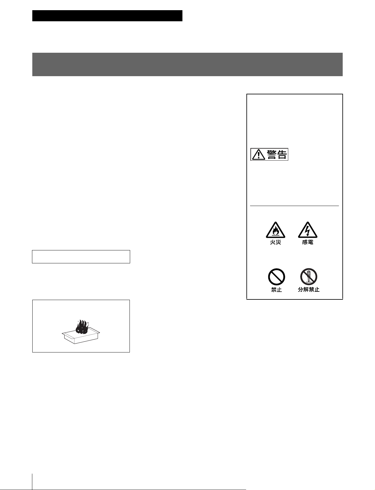
警告表示の意味
オペレーションマニュアルおよび
製品では、次のような表示をして
います。表示の内容をよく理解し
てから本文をお読みください。
この表示の注意事項を守らないと、
火災や感電などにより死亡や大け
がなど人身事故につながることが
あります。
注意を促す記号
行為を禁止する記号
炎が出たら
m
すぐに接続ケーブルを抜き、消火する。
2
Page 3

目次
警告....................................................................................................................... 4
使用上のご注意............................................................................................................ 4
概要.............................................................................................................................. 5
特長 .................................................................................................................. 5
システム構成例 ................................................................................................ 6
イーサネットシステム接続時のご注意 ............................................................ 8
各部の名称と働き ........................................................................................................ 9
操作パネル ....................................................................................................... 9
コネクターパネル........................................................................................... 16
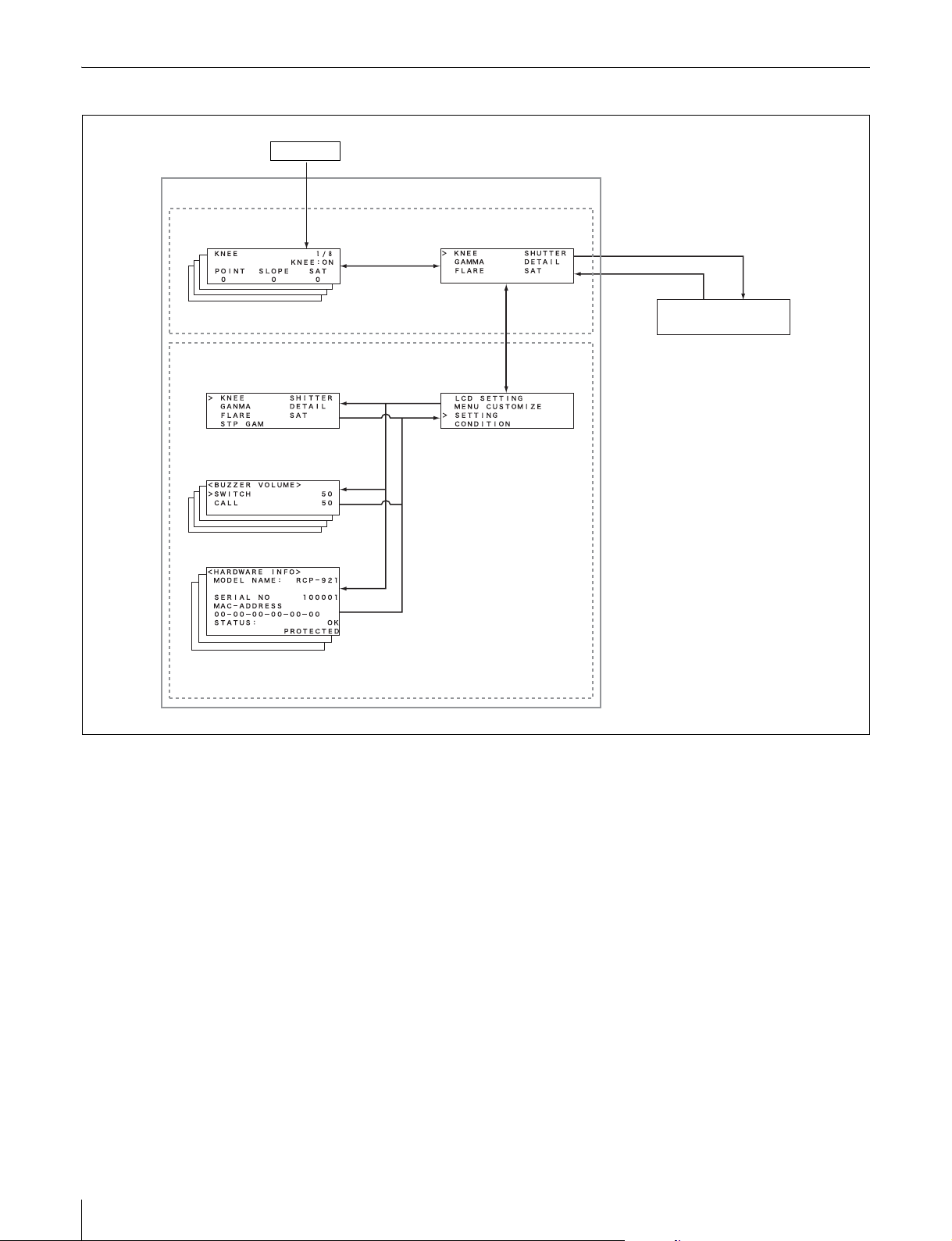
メニューの構成と基本操作........................................................................................ 17
基本操作 ......................................................................................................... 17
メニュー画面の基本構成................................................................................ 18
メニュー遷移図 .............................................................................................. 20
メニュー項目.................................................................................................. 21
初期設定 .................................................................................................................... 26
RCP-920/921 の動作環境の設定 ..................................................................... 26
LCD ディスプレイの調整 ......................................................................................... 38
仕様............................................................................................................................ 39
JP
目次
3
Page 4
警告
使用上のご注意
液晶画面の輝点・滅点について
本機の液晶パネルは有効画素 99.99%以上の非常に精密度
の高い技術で作られていますが、画面上に黒い点が現れた
り(画素欠け)、常時点灯している輝点(赤、青、緑など)
や滅点がある場合があります。また、液晶パネルの特性
上、長期間ご使用の間に画素欠けが生じることもありま
す。これらの現象は故障ではありませんので、ご了承の上
本機をお使いください。
外装をはずさない、改造しな
い
外装をはずしたり、改造したりすると、
感電の原因となります。
内部の調整や設定および点検を行う必要
がある場合は、必ずサービストレーニン
グを受けた技術者にご依頼ください。
内部に水や異物を入れない
水や異物が入ると火災や感電の原因とな
ることがあります。
万一、水や異物が入ったときは、すぐに
接続ケーブルを抜いて、ソニーのサービ
ス担当者または営業担当者にご相談くだ
さい。
油煙、湯気、ほこりの多い場
所では設置・使用しない
上記のような場所で設置・使用すると、
火災や感電の原因となります。
4
警告 / 使用上のご注意
Page 5

概要
特長
リモートコントロールパネル RCP-920/921 は、ソニーのス
タジオ / 中継用 CCD カラービデオカメラ BVP/HDC シ
リーズの調整機能を、カメラコントロールユニット CCU/
HDCU を介してリモートコントロールするためのコント
ロールパネルです。本機は、専用のケーブルで CCU/
HDCU(または CCU/HDCU に接続したカメラコマンド
ネットワークユニット CNU-700)に接続することにより、
CCU/HDCU(CNU-700) から最大 200m 離して使用するこ
とができます。
カメラの SLS/ECS/ シャッター機能をコントロール
CCD カメラの SLS(スローシャッター)、ECS(Extended
ClearScan:拡張クリアスキャン )や電子シャッター機能
の ON/OFF、ECS 周波数やシャッタースピードの切り換
えが可能です。
専用ケーブル接続とイーサネット接続
カメラコントロールユニットと本機との間は、1 本の接続
ケーブル(CCA-5)ですべての信号の送受信を確実に行うこ
とができます。また、イーサネットケーブルでも接続する
ことができます。本機には接続ケーブルを介して接続先か
ら電源が供給されます。
他のコントロールパネルとのパラレルコントロールが可能
マスターセットアップユニット MSU-900/950 など、他の
コントロールパネルとの同時コントロールが可能です。
RCP-920 と RCP-921 では、アイリス / マスターブラック調
整部の構成・形状が異なるだけで、他の機能は共通です。
アイリス / マスターブラック調整部は、RCP-920 ではジョ
イスティック( レバー )タイプ、RCP-921 ではつまみに
なっています。
RCP-920/921 の主な特長は次のとおりです。
カメラの基本的オペレーションに適した操作性
本機は、カメラの基本的オペレーションに必要なコント
ロール機能を備えています。操作ボタン、調整つまみな
ど、機能および使う頻度に応じてパネル上に配置されてい
ます。また、自照式ボタンの点滅や点灯の状態により、操
作状況がわかるようになっています。
さらに、誤操作するとカメラの動作やセットアップに重大
な影響を及ぼすボタンの周囲にはガードを付けるなど、さ
まざまな機能を簡単かつ正確に操作できるようになってい
ます。
オートセットアップ機能のコントロール
マイクロコンピューター制御でカメラの各調整項目を自動
的に調整するオートセットアップをコントロールする機能
を備えています。各種のレベルを、同時または個別に自動
調整することができます。
19 インチのラックに 4 台取り付け可能
本機は、19 インチの EIA 標準ラックに 4 台並べて取り付
けることができます。
シーンファイル機能のコントロール
ペイントメニューなどを使い、撮影シーンに合わせて調整
したデータを、シーンファイルとしてカメラ内に最大 5 つ
保存しておくことができます。また、必要に応じてシーン
ファイルを呼び出して、シーンに合った撮影条件を簡単に
再現することができます。
概要
5
Page 6
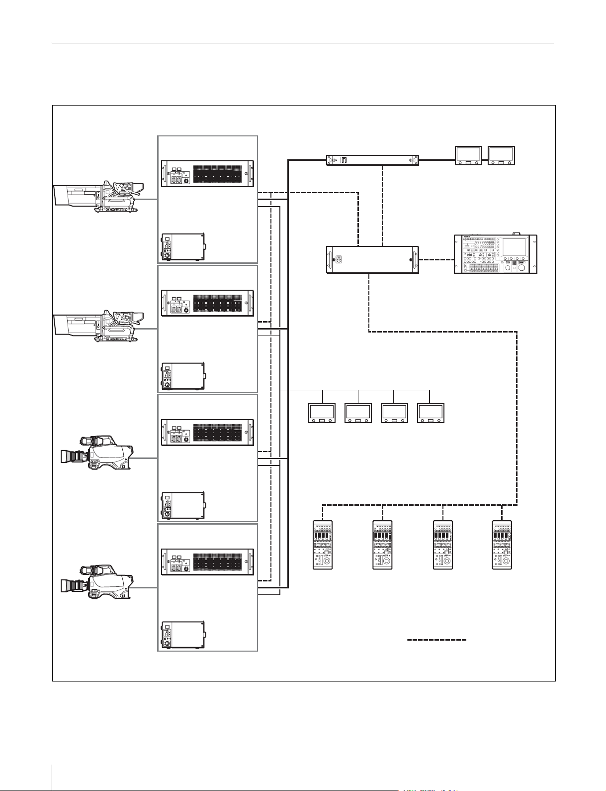
システム構成例
コマンドケーブルシステム(HDC シリーズの場合)
HDC1000
HDC1000
HDC1500
HDCU1000
(+HKCU1001/HKCU1003)
または
HDCU1500
(+HKCU1001/HKCU1003)
HDCU1000
(+HKCU1001/HKCU1003)
または
HDCU1500
(+HKCU1001/HKCU1003)
HDCU1000
(+HKCU1001/HKCU1003)
PIX/WF
VCS-700
CCU(1 〜 6)
CNU-700 RCP(1 〜 6)
VCS
MSU-900 シリーズ
HDC1500
または
HDCU1500
(+HKCU1001/HKCU1003)
HDCU1000
(+HKCU1001/HKCU1003)
または
HDCU1500
(+HKCU1001/HKCU1003)
CCU/CNU
REMOTE
CCA-5 ケーブル
CCU/CNU
REMOTE
CCU/CNU
REMOTE
RCP-920/921
CCA-5 ケーブル
CCU/CNU
REMOTE
6
概要
Page 7
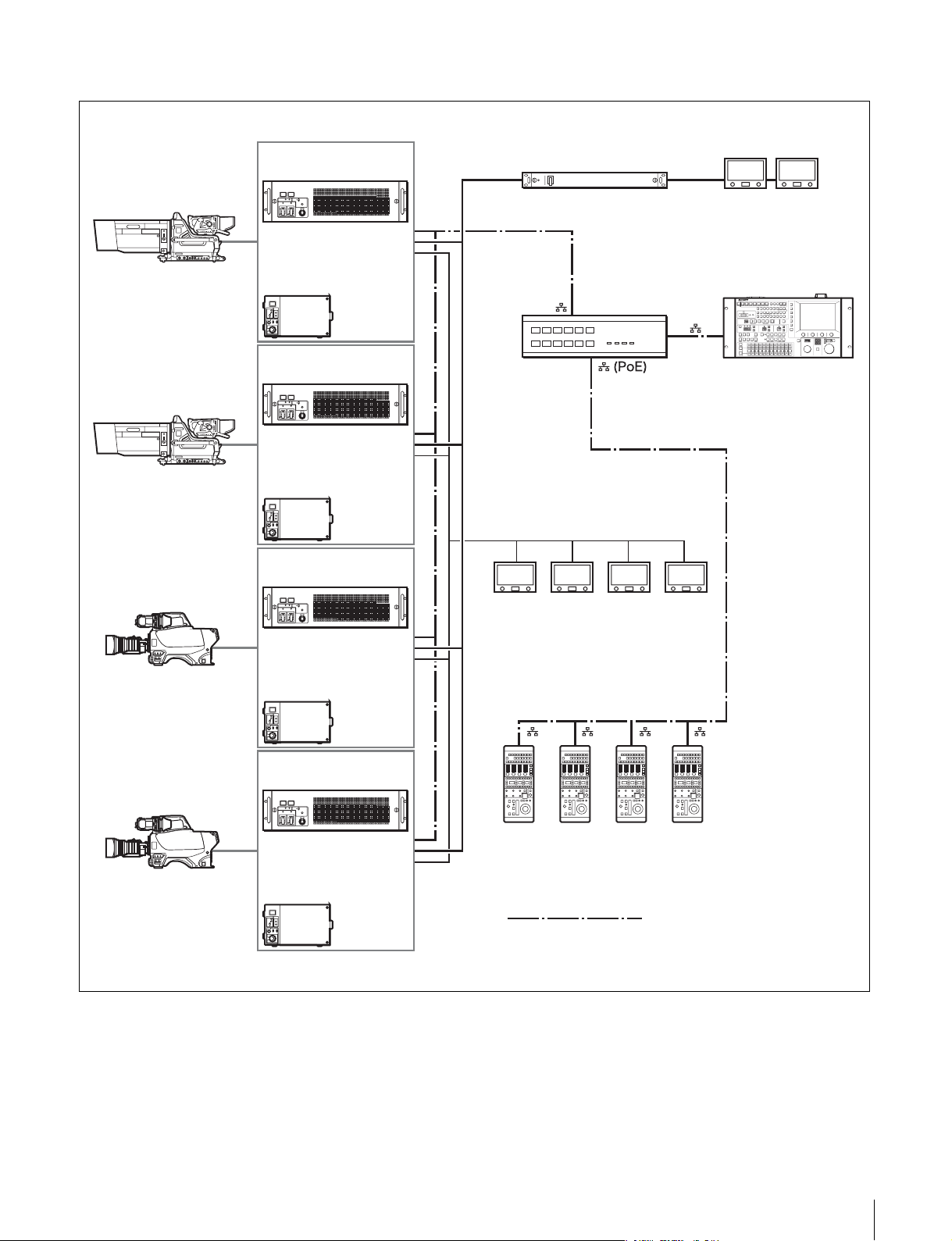
イーサネットシステム(HDC シリーズの場合)
HDC1000
HDC1000
HDC1500
HDCU1000
(+HKCU1001/HKCU1003)
または
HDCU1500
(+HKCU1001/HKCU1003)
HDCU1000
(+HKCU1001/HKCU1003)
または
HDCU1500
(+HKCU1001/HKCU1003)
HDCU1000
(+HKCU1001/HKCU1003)
ビデオスイッチャー
1)
PoE
ングハブ
対応スイッチ
MSU-900 シリーズ
HDC1500
または
HDCU1500
(+HKCU1001/HKCU1003)
HDCU1000
(+HKCU1001/HKCU1003)
RCP-920/921
または
HDCU1500
(+HKCU1001/HKCU1003)
イーサネットストレートケーブル
(カテゴリ 5 以上)
1)PoE は PoweroverEthernet の略です。
スイッチングハブの電源供給に関して
RCP-920/921 は最大 14 W に設定されていますので、ハ
ブ側の電源供給能力は、14 W ×接続 RCP の台数で考え
てください。
概要
7
Page 8
イーサネットシステム接続時のご注意
イーサネットケーブルを使い、本機をシステムに接続する
場合は、本機をアースに接地してください。
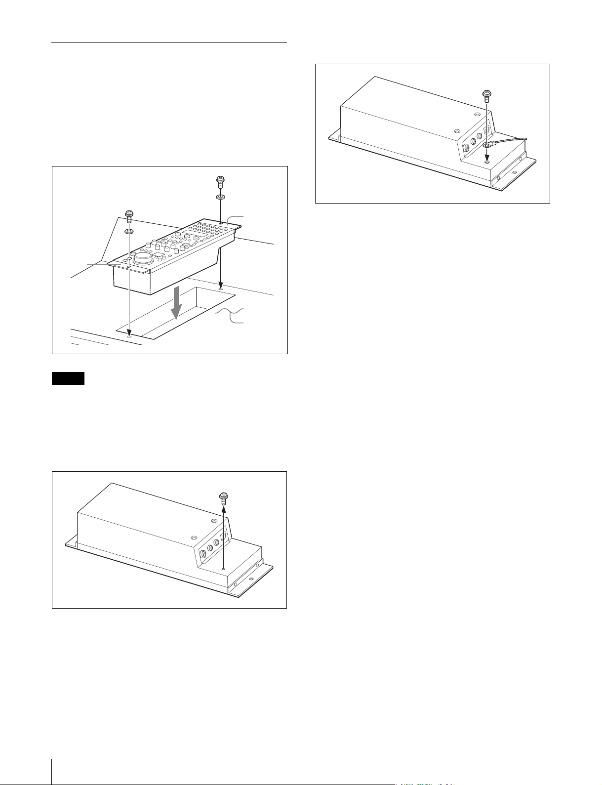
アースの接地には以下の方法があります。
• 本機のフランジをネジ止めする。
• 本機の底面に安全アースを接続する。
本機のフランジをネジ止めするには
フランジ
フランジ
調整卓など
2
取りはずしたネジで安全アースを取り付ける。
ご注意
ネジは付属されていません。設置先に応じてご用意くださ
い。
本機の底面に安全アースを接続するには
1
本機裏面のアース接続用のネジをはずす。
8
概要
Page 9
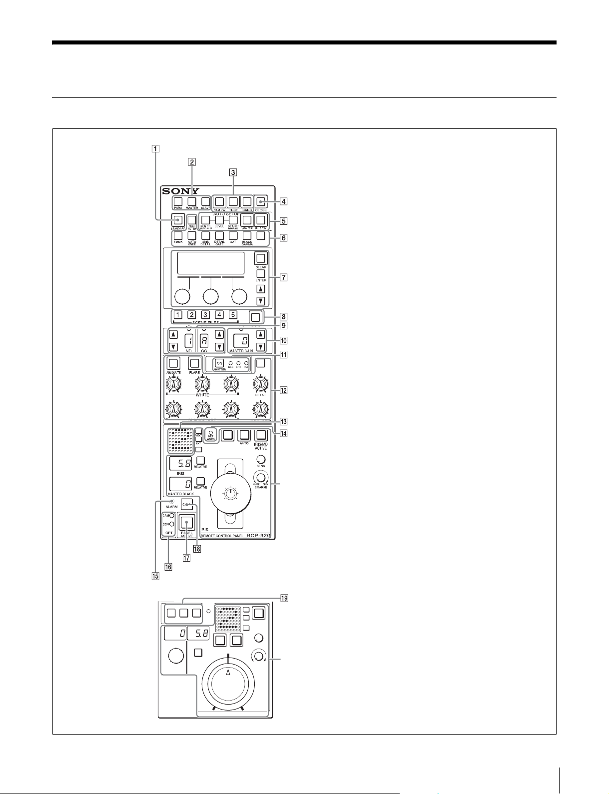
各部の名称と働き
操作パネル
STANDARD ボタン
コントロール選択部
電源 / 出力信号選択部
CLOSE ボタン
AUTOSETUP 部
カメラ /CCU 機能 ON/OFF ボタン
ペイント調整部
シーンファイル操作部
フィルターコントロール部
マスターゲイン制御部
SHUTTER 制御部
RCP-920
RCP-921
CALL ボタン
PANELACTIVE ボタン
OPT インジケーター
ALARM インジケーター
NET
DETAIL
OFF
IRIS
WORK
RELATIVE AUTO
KNEE
OFF
MASTER
BLACK
D EXT
EXT
IRIS/MB
ACTIVE
SENS
CLOSE OPEN
COARSE
ホワイトバランス / ブラックバランス調整部
カメラナンバー / タリー表示部
NETWORK インジケーター
アイリス / マスターブラック調整部(14、15 ページ )
拡張カメラ /CCU 機能 ON/OFF ボタン
アイリス / マスターブラック調整部(15 ページ )
IRIS
REMOTE CONTROL PANEL
RCP-
921
各部の名称と働き
9
Page 10
1 STANDARD( 標準 )ボタン
押すと、ビデオカメラの各種設定がビデオカメラに保存さ
れているリファレンスファイルデータ値になり、ボタンが
数秒間点灯します。
ボタンが点灯している間にもう一度押すと、点灯する前の
状態に戻ります。
2 コントロール選択部
TEST( テスト ):ビデオ回路チェック用のテスト信号( の
こぎり波形 )
BARS( カラーバー ):カラーバー信号
ご注意
BARS ボタンが点灯している場合は、BARS ボタンの機能
が優先します。TEST を選択するときは、BARS ボタンを
押して消灯させてください。
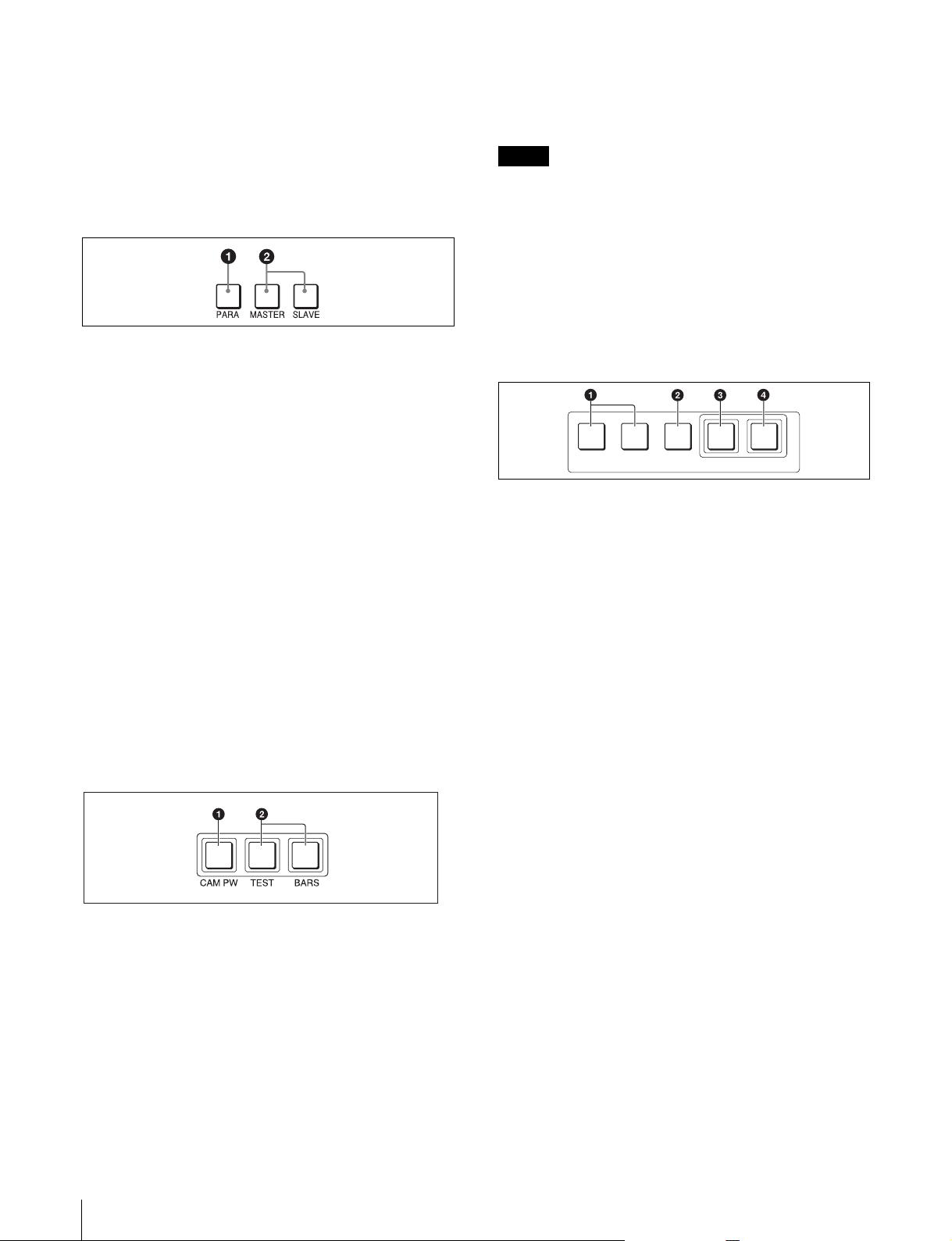
4 CLOSE( アイリスクローズ )ボタン
押して点灯させると、絞りがクローズします。もう一度押
すとボタンは消灯し、クローズが解除されます。
a PARA( 同時コントロール )ボタン
他のコントロールパネルとの同時コントロール状態に設定
されていると点灯します。
このボタンが点灯しているときは、PANELACTIVE ボタ
ンが消灯している場合でも、アイリス / マスターブラック
調整部と CLOSE ボタンを除く本機のすべてのボタン / 調
整部が有効です。
ボタンを押して消灯させると、同時コントロールが解除さ
れます。
b MASTER( マスター)ボタンと SLAVE( スレーブ )ボ
タン
マスター / スレーブモードで、複数のカメラのホワイトバ
ランスを同時に調整するとき、マスター機、スレーブ機を
指定します。
本機でコントロールしているカメラをマスターにするとき
は MASTER ボタンを押して点灯させ、スレーブにすると
きは SLAVE ボタンを押して点灯させます。
どちらのボタンも、もう一度押すと消灯します。
3 電源 / 出力信号選択部
5 AUTOSETUP( オートセットアップ )部
カメラの自動調整を行います。
AUTO SETUP
SKIN DTL
AUTO HUE
LEVEL
START/
BREAK
WHITE BLACK
a 自動調整項目選択ボタン
押して点灯させ、自動調整する項目を選択します。
SKINDTLAUTOHUE( スキンディテールオートヒュー):
スキントーンディテールオートヒュー
LEVEL( レベル ):ガンマバランス、ニーポイント、マス
ターブラックレベルなど
b START/BREAK( 自動調整開始 / 中止 )ボタン
このボタンを押すと、点灯している項目選択ボタンに対応
する項目の自動調整が実行されます。
調整中はボタンが点灯し、調整が完了すると消灯します。
自動調整実行中にこのボタンを押すと、自動調整が中止さ
れ、ボタンが点滅します。もう一度ボタンを押すと点滅が
止まります。
a CAMPW( カメラ電源 )ボタン
押して点灯させると、ビデオカメラに電源が供給されま
す。( ボタンを押してから、カメラが立ち上がって通信可
能になるまでの間は、高速で点滅します。)
もう一度押すと点滅に変わり、カメラへの電源供給が遮断
されます。
b テスト信号出力選択ボタン
押して点灯させると、カメラのテスト信号発生器が作動
し、対応する信号が出力されます。
10
各部の名称と働き
c WHITE( ホワイトバランス自動調整 )ボタン
押すと、ホワイトバランスが自動調整されます。
調整中はボタンが点灯し、調整が完了すると消灯します。
自動調整実行中にもう一度このボタンを押すか、START/
BREAK ボタンを押すと、自動調整が中止され、ボタンが
点滅します。もう一度ボタンを押すと点滅が止まります。
d BLACK( ブラックバランス自動調整 )ボタン
押すと、ブラックバランス、ブラックセットが自動調整さ
れます。
調整中はボタンが点灯し、調整が完了すると消灯します。
自動調整実行中にもう一度このボタンを押すか、START/
BREAK ボタンを押すと、自動調整が中止され、ボタンが
点滅します。もう一度ボタンを押すと点滅が止まります。
Page 11
ご注意
自動調整中にエラーが発生した場合は、点灯させたボタン
が点滅します。
6 カメラ /CCU 機能 ON/OFF ボタン
ビデオカメラや CCU/HDCU の機能を、本機から ON/
OFF することができます。
工場出荷時は、7 個のボタンにそれぞれ次のスイッチ機能
が割り当てられ、1 個は空きになっています。
押して点灯させると ON、もう一度押して消灯させると
OFF になります。
.5600K:5600K の電気色温度補正機能
AUTOKNEE( オートニー ):オートニー機能。ON では、
ハイライトが入ると自動的にニーが働きます。
SKINDETAIL( スキンディテール ):スキントーンディ
テール機能
DETAILGATE( ディテールゲート ):スキントーンディ
テールゲート機能。ON では、スキントーンディテール
の調整範囲がモニター上に白く表示されます。
SAT( サチュレーション ):サチュレーション機能
BLACKGAMMA( ブラックガンマ ):ブラックガンマ
機能
CHARACTER( 文字情報 ):自己診断表示機能。
CCU/HDCU の CHARACTEROUTPUT 端子に接続した
モニターに、CCU/HDCU の自己診断内容を表示します。
この内容は、PIX1OUTPUT のビデオ信号にもミックスさ
れて出力されます。
表示はボタンを押すたびに次のように切り替わります。
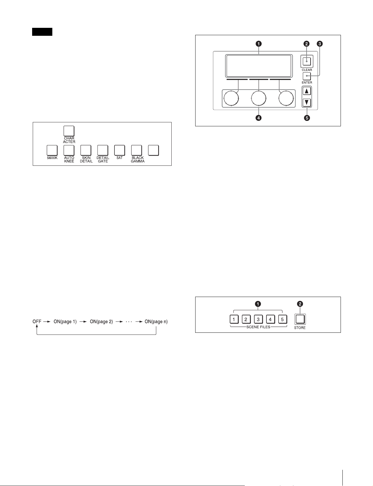
7 ペイント調整部
a 液晶画面
調整項目などを表示します。
b CLEAR(クリア)ボタン
1秒以上押し続けると、表示されている調整項目の手動調
整値がクリアされ、標準値に戻ります。(標準値はユー
ザーが任意に設定できます。)
c ENTER(エンター)ボタン
メニューや調整項目などを選択や決定するときに押しま
す。
d ペイント調整つまみ(ロータリーエンコーダー)
選択されたペイント調整項目の値を変更できます。
e MENUUP/DOWN ボタン
メニューのページ送りに使います。v を押すと前のページ
に、V を押すと次のページに移動します。
8 シーンファイル操作部
自己診断内容は、このボタンが消灯していても必要に応じ
て自動的に表示されます。
a SCENEFILES( シーンファイル選択 )ボタン
STORE ボタン点滅時 :これらのボタンの 1 つを押して点
灯させると、その番号のファイルに現在の調整値が保
存されます。
STORE ボタン消灯時 :これらのボタンの 1 つを押して点
灯させると、その番号のファイルが呼び出されます。
もう一度押してボタンを消灯させると、ファイル呼び
出し前の状態に戻ります。
各部の名称と働き
11
Page 12
b STORE( シーンファイル登録 )ボタン
シーンファイルを登録するとき、このボタンを押して点滅
させてから、SCENEFILES ボタンでシーンファイルの番
号を選択します。ファイル登録が終了すると、このボタン
は消灯します。
登録を途中で中止するときは、SCENEFILES ボタンを押
す前に、もう一度このボタンを押して消灯させます。
I フィルターコントロール部
CCND
a ND フィルター選択ボタン
一度押すと点灯します。点灯中はボタンを押すたびに、
ND フィルターが次のように切り替わります。(下記のフィ
ルターは参考例です。お使いのカメラによって異なりま
す。)
v:1t2t3t4t5t1t...
V:5t4t3t2t1t5t...
ボタンを押し続けると連続して変わります。
ご注意
1 と 4 のボタンは、いずれかひとつを押せばすべてが点灯
し、ND フィルター、CC フィルターともに切り換えが可能
になります。
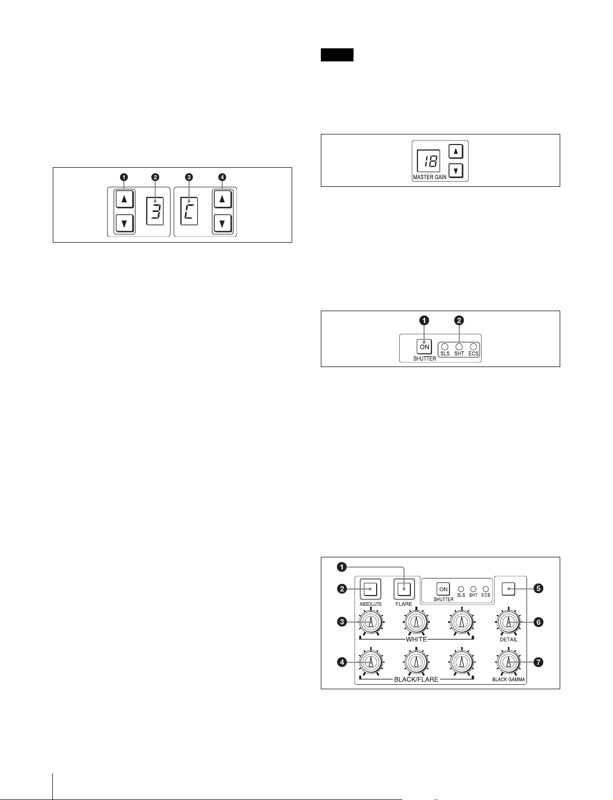
J マスターゲイン制御部
MASTERGAIN( マスターゲイン調整 )ボタンと表示部
被写体の照度に応じて映像出力信号の利得( ゲイン )を調
整します。設定値( 単位 dB)が表示部に表示されます。
利得は、v( アップ )ボタンを押すたびに大きくなり、
V( ダウン )ボタンを押すたびに小さくなります。ボタンを
押し続けると連続して変わります。
K SHUTTER 制御部
b ND フィルターディスプレイ
現在選択されている ND フィルターに対応する番号を表示
します。(下記のフィルターは参考例です。お使いのカメ
ラによって異なります。)
1: 素通し
2: 1/4ND
3: 1/8ND
4: 1/16ND
5: 1/64ND
c CC( 色温度変換 )フィルターディスプレイ
現在選択されている CC フィルターに対応する記号を表示
します。(下記のフィルターは参考例です。お使いのカメ
ラによって異なります。)
A: クロスフィルター
B: 3200K( 素通し )
C: 4300K
D: 6300K
E: 8000K
d CC( 色温度変換 )フィルター選択ボタン
一度押すと点灯します。点灯中はボタンを押すたびに、CC
フィルターが次のように切り替わります。(下記のフィル
ターは参考例です。お使いのカメラによって異なります。)
v:AtBtCtDtEtAt...
V:EtDtCtBtAtEt...
ボタンを押し続けると連続して変わります。
a ON(オン)ボタン
カメラの SLS 機能、シャッター機能、または ECS 機能を
ON/OFF します。このボタンを押して点灯させると ON、
もう一度押して消灯させると OFF になります。
b SLS/SHUTTER/ECS インジケーター
選択されている機能に対応するインジケーターが点灯しま
す。機能の選択はメニューで行います。
SLS:スローシャッターモード
SHT:シャッターモード
ECS:ECS(拡張クリアスキャン)モード
L ホワイトバランス / ブラックバランス調整部
12
各部の名称と働き
Page 13
a FLARE( フレアバランス調整モード )ボタン
BLACK/FLARE つまみの調整モードを切り換えます。押
して点灯させるとフレアバランス調整モードになり、もう
一度押して消灯させるとブラックバランス調整モードにな
ります。
b ABSOLUTE( 絶対値モード )ボタン
このボタンを押して点灯させると、WHITE、BLACK、
FLARE、BLACKGAMMA および DETAIL の各つまみに
よる手動調整値が、相対値モードから絶対値モードに切り
替わります。
次の場合は、自動的に相対値モード(消灯)になります。
• オートセットアップ( レベル、ホワイト、ブラック )終了
時
• シーンファイルを呼び出したとき
• FLARE ボタンを押して、フレアバランス調整モードとブ
ラックバランス調整モードを切り換えたとき
• マスターセットアップユニット(MSU)の RCPAssign
設定によって、コントロールする CCU/HDCU が変更さ
れたとき
また、PANELACTIVE ボタンが消灯しているときや、
PARA、MASTER、SLAVE ボタンのいずれかが点灯して
いるときは、常に相対値モードになり、このボタンは機能
しません。
レッドタリー信号とグリーンタリー信号が同時に入力され
た場合は、背景の左半分が赤、右半分が緑に点灯します。
N NETWORK(ネットワーク)インジケーター
イーサネットシステム接続時の状態を表示します。
点灯:コントロール機器(CCU/HDCU)との接続が正常。
点滅:コントロール機器(CCU/HDCU)と接続できない。
消灯:カメラネットワークに接続できていない、または、
イーサネットシステムの接続設定がされていない。
O ALARM( アラーム )インジケーター
システムに異常が発生し、カメラヘッドや CCU/HDCU で
自己診断機能が動作すると、赤く点灯します。
P OPT(オプティカル)インジケーター
光伝送のカメラシステムへの接続時に、光信号の受信状態
(受信レベル)を表示します。
CAM インジケーターには CCU/HDCU からカメラへの受
信状態が、CCU インジケーターにはカメラから CCU/
HDCU への受信状態が表示されます。
緑:受信状態が良好。
オレンジ:受信レベルが低下している。
赤:受信レベルが著しく低下している。
消灯:
通信に異常が発生している、または光伝送ではない。
c WHITE( ホワイトバランス手動調整 )つまみ
ホワイトバランス手動調整用のつまみで、左から順に R、
G、B 信号を調整します。
d BLACK/FLARE(ブラックバランス/フレアバランス手
動調整 )つまみ
FLARE ボタン消灯時はブラックバランスを調整し、
FLARE ボタン点灯時はフレアバランスを調整します。左
から順に R、G、B 信号を調整します。
e スペアボタン
将来の拡張用です。
f DETAIL( ディテール調整 )つまみ
ディテールレベルを調整します。
g BLACKGAMMA( ブラックガンマ調整 )つまみ
ブラックガンマを調整します。
M カメラナンバー / タリー表示部
本機でコントロールしているカメラのナンバーを、オレン
ジ色で表示します。
カメラにレッドタリー信号が入力されると、背景が赤く点
灯し、ナンバーは黒で表示されます。グリーンタリー信号
が入力されると背景が緑に点灯し、ナンバーは黒で表示さ
れます。
Q PANELACTIVE( パネルアクティブ )ボタン
押して点灯させると、本機に接続したカメラシステムをコ
ントロールできる状態( パネルアクティブ状態 )になりま
す。このとき IRIS/MBACTIVE ボタンも同時に点灯しま
す。また、消灯させるとパネルはロックされ、誤作動防止
になります。
R CALL( コール )ボタン
押すとビデオカメラにコール信号が送出され、カメラ側の
CALL ボタンが点灯します。また、カメラのタリーランプ
と CCU/HDCU のレッドタリーランプは、それぞれ点灯し
ていた場合は消灯し、消灯していた場合は点灯します。
カメラ側で CALL ボタンが押されると、本機の CALL ボ
タンが点灯し、ブザーが鳴ります。
S 拡張カメラ /CCU 機能 ON/OFF ボタン(RCP-921 の
み)
a KNEEOFF(ニーオフ)ボタン
ニー機能を OFF にしたいときに押して点灯させます。
各部の名称と働き
13
Page 14
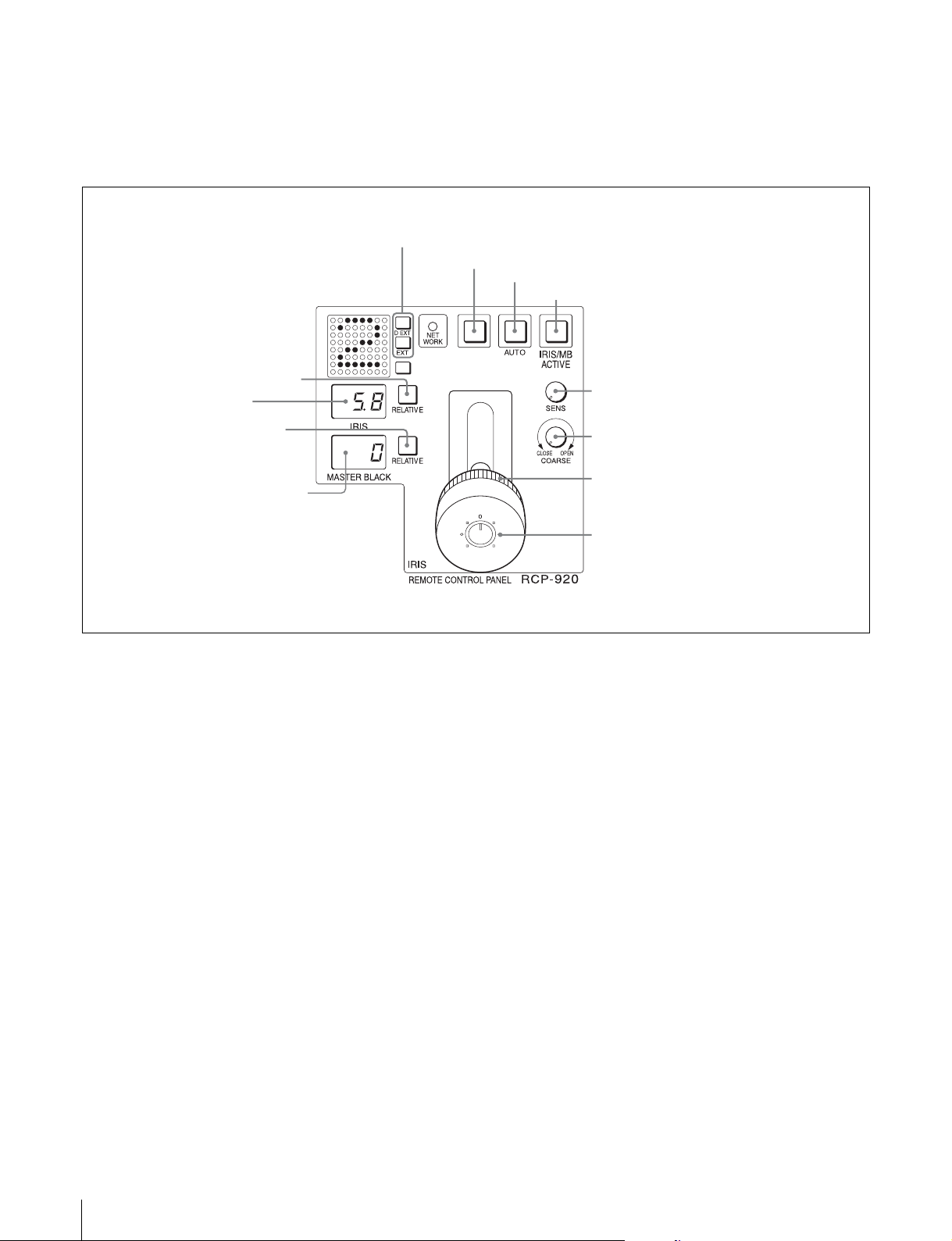
b DETAILOFF(ディテールオフ)ボタン
ディテール機能を OFF にしたいときに押して点灯させま
す。
アイリス / マスターブラック調整部(RCP-920)
a EXT インジケーター
b スペアボタン
c スペアボタン
将来の拡張用です。
c AUTOボタン
d IRIS/MBACTIVEボタン
e IRISRELATIVE ボタン
f IRIS 表示部
g MASTERBLACK
RELATIVE ボタン
h MASTERBLACK 表示部
a EXT( レンズエクステンダー )インジケーター
EXT:レンズエクステンダーを使用しているときに点灯し
ます。
DEXT:デジタルエクステンダー機能を持つカメラで機能
が ON になると点灯します。
b スペアボタン
将来の拡張用です。
i SENSつまみ
j COARSEつまみ
k マスターブラック調整リング
l IRIS レバー兼プレビュースイッチ
e IRISRELATIVE( アイリス相対値モード )ボタン
IRIS/MBACTIVE ボタン点灯時にこのボタンを押して点
灯させると、絞りの手動調整のモードが絶対値モードから
相対値モードに切り替わります。
絶対値モードに戻すときは、もう一度ボタンを押して消灯
させます。
IRIS/MBACTIVE ボタン消灯時は、自動的に相対値モー
ドになり、このボタンは機能しません。
c AUTO( 自動絞り )ボタン
押して点灯させると、レンズの絞りが入力光に応じて自動
的に調整されます。
ボタン点灯時は、絞りの自動調整の基準値を± 1F の範囲
で微調整することができます。
もう一度押すと消灯し、絞りの手動調整が可能になりま
す。
d IRIS/MBACTIVE( アイリス / マスターブラックアク
ティブ )ボタン
押して点灯させると、本機で絞りと CLOSE ボタンによる
制御、マスターブラックの調整が行えます。
PANELACTIVE ボタンを押すと、このボタンも同時に点
灯します。
14
各部の名称と働き
f IRIS( アイリス )表示部
絞りの設定値をF ナンバーで表示します。レンズをクロー
ズすると「CL」が表示されます。
g MASTERBLACKRELATIVE(マスターブラック相対
値モード )ボタン
IRIS/MBACTIVE ボタン点灯時に、このボタンを押して
点灯させると、マスターブラックの調整が絶対値モードか
ら相対値モードに切り替わります。
絶対値モードに戻すときは、もう一度ボタンを押して消灯
させます。
IRIS/MBACTIVE ボタン消灯時は、自動的に相対値モー
ドになり、このボタンは機能しません。
Page 15
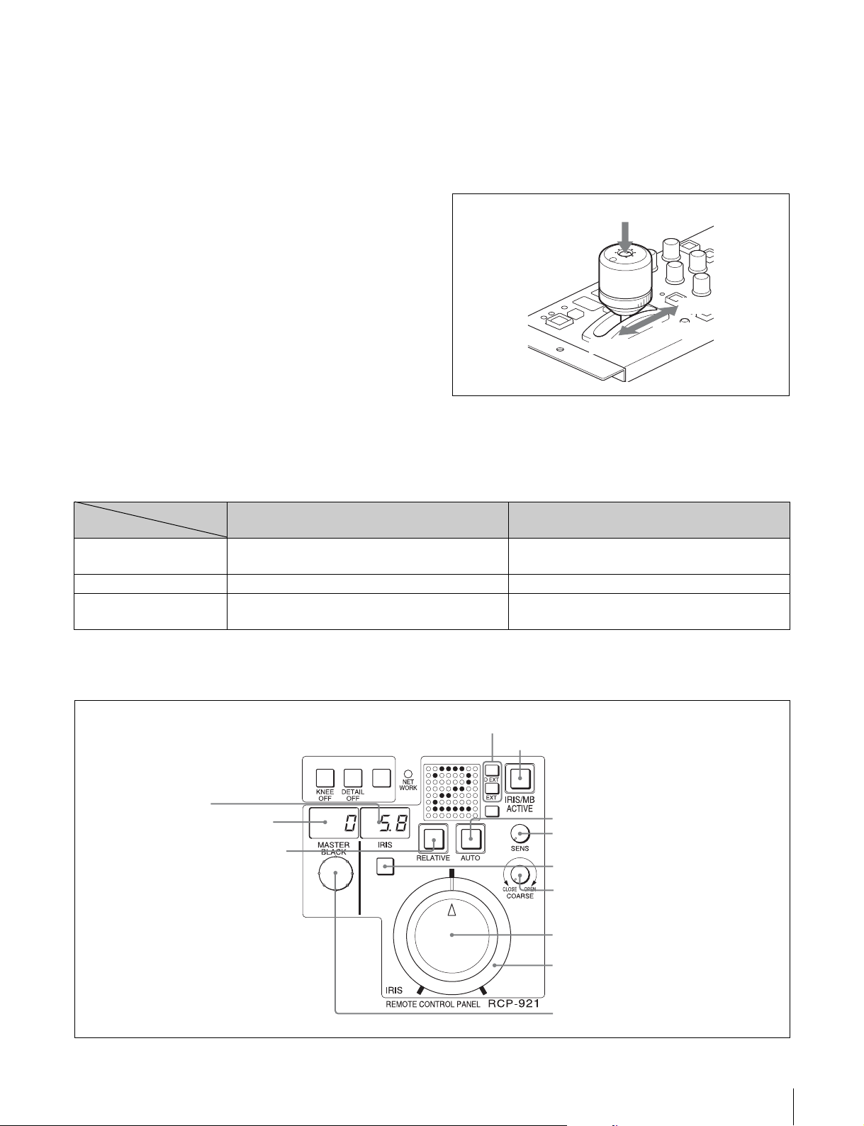
h MASTERBLACK( マスターブラック )表示部
マスターブラックの設定を、−99 〜 +99 で表示します。
i SENS( アイリス調整範囲 )つまみ
絶対値モードで絞りの手動調整を行うとき使用します。相
対値モードでは、このつまみは機能しません。
◆「アイリス調整機能」表(15 ページ)を、あわせてご覧くださ
い。
j COARSE( アイリス粗調整 )つまみ
絞りの手動調整を行うとき使用します。
◆「アイリス調整機能」表(15 ページ)を、あわせてご覧くださ
い。
AUTO ボタン点灯時は、絞りの自動調整の基準値を微調整
( ± 1F)します。
軸方向に押すと、EXTI/O 端子のプレビュー用キー信号を
出力します。
◆「アイリス調整機能」表(15 ページ)を、あわせてご覧くださ
い。
押す
軸方向
OPEN
k マスターブラック調整リング
マスターブラックの手動調整を行います。
CLOSE
スロット方向
MASTERBLACK 表示部に設定値が表示されます。
l IRIS( アイリス調整 )レバー兼プレビュースイッチ
AUTO ボタン消灯時に、スロット方向に動かすと、レンズ
の絞りを手動で調整できます。
アイリス調整機能
相対値モード
(IRISRELATIVE ボタン点灯)
IRIS レバー(RCP-920)
IRIS つまみ(RCP-921)
COARSE つまみ OPEN から CLOSE までの全範囲を相対値で調整する。 CLOSE 側の下限を設定する。
SENS つまみ 機能しない。 COARSE つまみで設定した CLOSE 側を基準にして、
OPEN から CLOSE までの約 1/4 の範囲を相対値で調整
する。
SENS つまみと COARSE つまみで設定した可変範囲内で
絞りを調整する。
OPEN 側の上限を設定する。
(IRISRELATIVE ボタン消灯)
絶対値モード
アイリス / マスターブラック調整部(RCP-921)
a EXT インジケーター
d IRIS/MBACTIVEボタン
f IRIS表示部
h MASTERBLACK表示部
e IRISRELATIVEボタン
c AUTOボタン
i SENSつまみ
b スペアボタン
j COARSEつまみ
k IRISつまみ
l アイリスゲージ
m MASTERBLACK つまみ
各部の名称と働き
15
Page 16
1 〜 0 の機能は、RCP-920 と共通です。
k IRIS( アイリス調整 )つまみ
AUTO ボタン消灯時は、レンズの絞りを手動調整します。
AUTOIRIS ボタン点灯時は、絞りの自動調整の基準値を
微調整 ( ± 1F)できます。
◆「アイリス調整機能」表(15 ページ)を、あわせてご覧くださ
い。
l アイリスゲージ
白いマーカーラインが、IRIS つまみのクリック位置になり
ます。ゲージを回して使用頻度の高い位置にマーカーライ
ンを合わせておくと、IRIS つまみの設定基準として使用で
きます。
ゲージは 360°回転しますので、クリック位置が不要の場
合は、マーカーラインがつまみの回転範囲の外になるよう
に設定してください。
m MASTERBLACK( マスターブラック調整 )つまみ
マスターブラックの手動調整を行います。
MASTERBLACK 表示部に設定値が表示されます。
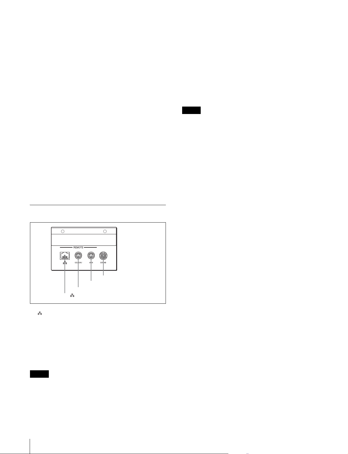
b CCU/CNUREMOTE( カメラコントロールユニット /
カメラコマンドネットワークユニットリモート )端子
(8 ピン、マルチコネクター、凹 )
カメラコントロールユニットの RCP/CNU 端子、またはカ
メラコマンドネットワークユニットの RCP 端子に接続し
ます。
c AUXREMOTE( 補助リモート )端子(8ピン、マルチコ
ネクター、凹 )
RCP-700/701 を接続します。
ご注意
AUXREMOTE 端子には、電源が出力されているため、リ
モートコントロールパネル(RCP)以外は接続しないでく
ださい。
d EXT I/O 端子 (10 ピン、凸 )
プレビュー信号を出力します。
コネクターパネル
d EXTI/O 端子
c AUXREMOTE 端子
b CCU/CNUREMOTE 端子
a (ネットワーク)端子
a (ネットワーク)端子 (RJ-45 型 8 ピン )
イーサネット接続時に使用します。
ネットワークケーブル(シールドタイプ、カテゴリー 5 以
上)を使用し、ネットワーク(10BASE-T/100BASE-TX)
のハブと接続します。この端子より、IEEE802.3af 準拠の
電源供給装置(PoE 方式のハブなど)からの電源供給がで
きます。
ご注意
安全のために、周辺機器を接続する際は、過大電圧を持つ
可能性があるコネクターをこの端子に接続しないでくださ
い。
接続については本書の指示に従ってください。
16
各部の名称と働き
Page 17
コンフィギュレーションメニュー
メニューの構成と基本操作
RCP-920/921 では、メニュー操作により、システム機器の
調整などさまざまな機能に対応します。
基本操作
工場出荷時の設定では、電源が供給されると液晶画面にペ
イントメニューの 1 ページ目が表示されます。それ以降
は、最後に表示されたペイントメニューのページが表示さ
れます。
◆ その他の画面からの切り換え方法については「メニュー遷移
図」(20 ページ)をご覧ください。
ペイントメニュー
1
メニューを表示させる。
電源が供給されるとペイントメニューが表示されます。
ペイントメニューの他のページを表示させたい場合は、
ペイント調整部の MENUUP/DOWN ボタンの v また
は V を押して切り換えてください。
2
項目を設定・調整する。
各設定・調整項目に対応するペイント調整つまみを回
して、希望の値に調整(または希望の設定を選択)し
てください。
ご注意
以下の場合、ペイントメニューで操作できない項目があり
ます。
1
コンフィギュレーションメニューを表示させる。
ENTER ボタンを押してペイントメニューのトップ画
面を表示させます。
さらに ENTER ボタンを 1 秒以上押し続けると、コン
フィギュレーションメニューのトップ画面が表示され
ます。
2
設定したい項目がある画面を表示させる。
右側のペイント調整つまみを回して表示させたい設
定・調整画面の項目にカーソルを合わせ、ENTER ボ
タンを押してください。選択した設定・調整画面が表
示されるので、必要に応じて v または V で設定・調整
画面を切り換えてください。
3
項目を選択する。
ペイント調整つまみを回して設定したい項目にカーソ
ルを合わせ、ENTER ボタンを押してください。
カーソルの形状が「?」に変わります。
4
項目を設定・調整する。
右側のペイント調整つまみを回して希望の値に調整
(または希望の設定を選択)し、ENTER ボタンを押し
てください。変更が反映され、カーソルの形状が「>」
に戻ります。
メモ
画面内に「SET」という項目があるページでは、確定
処理をするまでページ内の変更が反映されません。変
更を反映させるには、「SET」にカーソルを合わせ、
ENTER ボタンを 2 回押してください。
ボタンの状態 操作できない項目
ABSOLUTE ボタン:点灯 WHITE
COLORTEMP
DETAILLEVEL
ABSOLUTE ボタン:点灯
FLARE ボタン:消灯
ABSOLUTE ボタン:点灯
FLARE ボタン:点灯
ABSOLUTE ボタン:点灯
SD ボタン:消灯
ABSOLUTE ボタン:点灯
SD ボタン:点灯
1)
いずれかのスペアボタンに、SD 機能を割り当てている場合。
スペアボタンには、コンフィギュレーションメニューの SW
ASSIGN 画面で SD 機能を割り当てることができます。
1)
1)
BLACK
FLARE
DETAILLEVEL
SDDETAILLEVEL
メニューの構成と基本操作
17
Page 18
メニュー画面の基本構成
ペイントメニュー
トップ画面
各設定・調整
画面の名称が
表示されます。
回すと、カーソルが移動します。
設定・調整画面
例:ニー調整画面(ペイントメニューのトップ画面から
KNEE を選択したとき)
各設定・調
整項目と設
定値が表示
されます。
押すと、LCD が消灯します。
押すと、選択されている設定・調整画面に移動します。
LCD 消灯時に押すと、復帰します。
1秒以上押すと、表示されている設定・調整項目の
手動調整値が標準に戻ります。
押すと、ペイントメニューのトップ画面に戻ります。
押すと、ペイントメニュー内の前後の設定・調整画
面に移動します。
回すと、各ペイント調整つまみに対応する設定・
調整項目の設定値が変更されます。
コンフィギュレーションメニュー
設定・調整画面
例:VRSETTING 画面
各設定・調
整項目と設
定値が表示
されます。
回すと、カーソルが移動します。設定項目が 1 画面分以上ある場合は、項目表示がスクロールします。
設定・調整項目が選択されているときは、設定・調整項目の設定が変更されます。
押すと、コンフィギュレーションメニューのトップ画面に
戻ります。調整中の場合はデータが調整前に戻ります。
押すと、カーソルが合っている設定・調整項目が選択され、
カーソルが「?」に変わります。
設定・調整項目が選択されているときは、設定の変更が反映
され、カーソルが「>」に変わります。
押すと、メニュー内の前後の設定・調整画面に移動します。
18
メニューの構成と基本操作
Page 19
SET 項目がある画面
SET 項目がある設定・調整画面では、設定を変更したあと
に確定することで変更が反映されます。確定せずに別の画
面に移動した場合、変更内容は反映されません。
例:ETHERNETIF 画面
連続した数値を入力する場合
例:CNSSETTING 画面
ここにカーソルが合った状態で ENTER を押すとカーソルが
「?」に変わります。再度 ENTER を押すと「>」に戻り、設定
が確定します。
押すと、メニュー内の前後の設定・調整画面に移動します。
この項目では、各数値を個別に設定します。最初の数値を設定
し ENTER を押すと、次の数値を設定できる状態に変わりま
す。最後の数値まで設定して ENTER を押すと、選択が解除さ
れカーソルが「>」に戻ります。
押すと、メニュー内の前後の設定・調整画面に移動します。
回すと、選択された項目の数値が変更されます。
メニューの構成と基本操作
19
Page 20
メニュー遷移図
メニュー
ペイントメニュー
v/V でページを切り換え
電源 ON
ENTER
CLEAR
ENTER
ENTER 長押し
コンフィギュレーションメニュー
v/V でページを切り換え
v/V でページを切り換え
ENTER
CLEAR
(LCD 表示 OFF)
LCD の表示およびバックライト
が OFF になります。
20
メニューの構成と基本操作
Page 21
メニュー項目
◆ 各機能の詳細については、接続されているカメラや CCU のオペレーションマニュアルをご覧ください。
ペイントメニュー
1次メニュー 2 次メニュー 操作/調整項目 設定値 機能 工場出荷時
TOPMENU
SELECTMENU
KNEE Point − マスターニーポイント調整 −
Slope − マスターニースロープ調整 −
Sat − ニーサチュレーション調整 −
GAMMA R − Rch ガンマ調整 −
Master − マスターガンマ調整 −
B − Bch ガンマ調整 −
FLARE R − Rch フレア調整 −
G − Gch フレア調整 −
B − Bch フレア調整 −
BLACK R − Rch ブラック調整 −
G − Gch ブラック調整 −
B − Bch ブラック調整 −
SHUTTER Mode − シャッターモード選択 −
−−− −
1)
Speed
DETAIL Level − ディテールレベル調整 −
Limit − ディテールリミット調整 −
Crisp − クリスプニング調整 −
SAT Saturation − サチュレーションレベル調整 −
−−− −
−−− −
STPGAM Step
WHITE R − Rch ホワイト調整 −
CTEMP − − − −
PHASE HCoarse − H位相調整 −
SKINDTL Level − スキンディテールレベル調整 −
SDDTL Level − SD ディテールレベル調整 −
AUTOIRIS Level − オートアイリスレベル調整 −
1)
−−− −
−−− −
G − Gch ホワイト調整 −
B − Bch ホワイト調整 −
Bal − 色温度補正 −
C.Temp − 色温度調整 −
HFine − H位相ファイン調整 −
SC − SC位相調整 −
−−− −
−−− −
Limit − SD ディテールリミット調整 −
Crisp − SD ディテールクリスプニング調整 −
Ratio − オートアイリス APL レシオ調整 −
Gain − オートアイリスゲイン調整 −
− 選択されたペイントメニューの一覧 KNEE/GAMMA/FLARE/
SHUTTER/DETAIL/SAT
−
− ステップガンマ選択 −
シャッタースピード /ECS 周波数 / スローシャッター
フレーム数選択
−
メニューの構成と基本操作
21
Page 22
1次メニュー 2 次メニュー 操作/調整項目 設定値 機能 工場出荷時
SSM − − − −
−−− −
SELECTMENU
(続き)
M.WHITE MasterWhite
FlickerReduce ON/OFF SuperMotion フリッカーリダクション機能の設定 −
Gain
Master
WhiteGain
マスターホワイトゲインの調整 −
−−− −
−−− −
1) 設定値のみ表示。項目名は表示されていません。
コンフィギュレーションメニュー
1次メニュー 2 次メニュー 操作/調整項目 設定値 機能 工場出荷時
LCD
SETTING
MENU
CUSTOMIZE
SETTING
SWASSIGN
VRRELMODE
1)
SET
RCPNo.SET RCPNo. 1 〜 24 RCP 本体のシステムナンバー(RCP ナン
PREVIEW CONTACT ON/OFF RCP 本体の EXTI/O コネクターよりプレ
BRIGHT 0 〜 99 LCD のバックライトの明るさ設定 50
CONTRAST 0 〜 99 LCD のコントラストの設定 50
ペイントメニュートップ画面に表示する項目
の設定
1)
SW01 5600K/ATKNEE/
SW02 ATKNEE
SW03 SKINDTL
SW04 DTLGATE
SW05 SAT
SW06 B.GAM
SW07 −
SKINDTL/DTL
GATE/SAT/B.GAM/
IRISREL/SD/KNEE
OFF/GAMOFF/DTL
OFF/W.CLPOFF/
CLOSE/SDDTLOFF/
SEQ
各ボタンへの機能の割り付け設定 5600K
SW08 −
SW09 IRISREL
2)
SW10
2)
SW11
2)
SW12
2)
SW13
WHITE 1/1、1/2、1/4 のいず
相対値モード時のホワイトの可変範囲の設定 1/2
れかを選択
BLACK(FLARE) 1/1、1/2、1/4 のいず
れかを選択
DETAIL 1/1、1/2、1/4 のいず
相対値モード時のブラック(フレア)の可変
範囲の設定
相対値モード時のディテールの可変範囲の設定1/2
れかを選択
B.GAM 1/1、1/2、1/4 のいず
れかを選択
相対値モード時のブラックガンマの可変範囲
の設定
バー)の設定
3)
ビュー信号を出力する機能の設定
CCU ON/OFF CCU よりプレビュー信号を出力する機能の設定OFF
KNEE/
GAMMA/
FLARE/
SHUTTER/
DETAIL/SAT
KNEEOFF
DTLOFF
−
−
1/2
1/2
−
ON
2)
22
メニューの構成と基本操作
S-BUS ON/OFF S-BUS システム側にプレビュー信号を出力す
る機能の設定
OFF
Page 23
1次メニュー 2 次メニュー 操作/調整項目 設定値 機能 工場出荷時
LED
BRIGHTNESS
SWITCH/LED 0 〜 99 照光スイッチおよび LED の明るさ設定 50
TALLY 0 〜 99 タリー表示部の明るさ設定 50
7SEGMENT 0 〜 99 7 セグメント LED(MASTERGAIN/ND/
50
CCFILTER/IRIS/MASTERBLACK)の明
るさ設定
BUZZER
VOLUME
SWITCH 0 〜 99 RCP のスイッチを押したときの操作確認音量
の設定
50
CALL 0 〜 99 CALL 時のブザー音量の設定 50
TIME DATE XXXX/XX/XX 日付の設定 −
TIME XX:XX 時刻の設定 −
TIMEZONE COUNTRY 地域の設定 (GMT)London
SECURITY
MODE
CNSSETTING
MODE NORMAL/ENGINEER セキュリティレベルの設定 NORMAL
SET − モード決定入力 −
1)
CNSMODE LEGACY/BRIDGE/
MCS
カメラネットワークシステムへの接続モード
設定
LEGACY
LEGACY:従来の 700Protocol ケーブルでの
接続システム
BRIDGE:ネットワークを使用した一対一の
接続モード
MCS:ネットワークを使用したマルチカメラ
システムモード
SETTING
(続き)
(Submode)
LEGACY:無し
BRIDGE:
CONNECT
MCS:M/C
CONNECT:
PASSIVE/ACTIVE/
SEMI-AT
ブリッジモードでのサブモード設定
PASSIVE:接続を待つモード
ACTIVE:接続を行うモード
SEMI-AT:700Protocol で接続されている機
器から PASSIVE/ACTIVE を半自動で設定
SEMI-AT
するモード
M/C:
マルチカメラシステムモードのサブモード設定CLIENT
CLIENT
MASTERIPADDR xxx.xxx.xxx.xxx マルチカメラシステムモードの Master の IP
0.0.0.0
アドレス設定
TARGETIPADDR xxx.xxx.xxx.xxx ブリッジモードの接続先の IP アドレス設定 0.0.0.0
1)
ETHERNETIF
ETHERNET ON/OFF イーサネット接続機能の ON/OFF の設定 OFF
AUTONEGO ON/OFF オートネゴシエーション機能の ON/OFF の設定ON
CONDITION
AUTOMDIX ON/OFF オート MDI/MDIX 機能の ON/OFF の設定 ON
4)
TCP/IP
SETTING
1)
SPEED
DUPLEX
MDI/MDIX
4)
4)
IPADDRESS xxx.xxx.xxx.xxx IP アドレスの設定 0.0.0.0
SUBNETMASK xxx.xxx.xxx.xxx サブネットマスクの設定 0.0.0.0
DEFAULT
10M/100M 回線速度の設定 100M
HALF/FULL 回線の前二重/半二重の設定 FULL
MDI/MDIX MDI/MDIX の設定 MDI
xxx.xxx.xxx.xxx デフォルトゲートウェイの設定 0.0.0.0
GATEWAY
1)
ALLRESET
ALLRESET − コンフィギュレーションメニューでの設定値
をすべて工場出荷状態に戻す
ShutterDisplay Angle ON/OFF シャッター表示を角度で表示する機能の ON/
OFF 設定
HARDWARE
INFO
Modelname − 機種名の表示 −
SerialNo. − シリアルナンバーの表示 −
Mac-address − Mac アドレスの表示 −
メニューの構成と基本操作
−
OFF
23
Page 24
1次メニュー 2 次メニュー 操作/調整項目 設定値 機能 工場出荷時
SOFTWARE
INFO
RCPDATA/
TIME
CNSSETTING
MainVersion − メインプログラムのバージョンの表示 −
MainReleaseDate − メインプログラムの作成日付の表示 −
MainComment − メインプログラムの ROM コメントの表示 −
PLDVersion − PLD プログラムのバージョンの表示 −
Date − 日付設定の表示 −
Time − 時刻設定の表示 −
TimeZone − 地域設定の表示 −
1)
CONNECT − カメラネットワークシステムへの接続状態の表示−
CONDITION
(続き)
ETHERNET
1)
IF
TCP/IP
SETTING
1)
CNSMODE − カメラネットワークシステムへの接続モード
の表示
RCPNo. − RCP 本体のシステムナンバー(RCP ナン
バー)の表示
TARGET/
MASTERIPADDR
LINK − イーサネットの接続状況の表示 −
ETHERNET − イーサネット機能の有効 / 無効設定の表示 −
AUTONEGO − オートネゴシエーション機能の ON/OFF の
AUTOMDIX − オート MDI/MDIX 機能の ON/OFF の設定
SPEED − 現在の回線速度の表示 −
DUPLEX − 現在の全二重 / 半二重状態の表示 −
MDI/MDIX − 現在の MDI/MDIX 状態の表示 −
IPADDR − 割り当てられている IP アドレスの表示 −
SUBNETMASK − 設定されているサブネットマスクの表示 −
DEFAULT
GATEWAY
− 接続先 IP アドレスの設定
BRIDGE:TARGETIPADDR
MCS:MASTERIPADDR
設定の表示
の表示
− 設定されているデフォルトゲートウェイの表示−
−
−
−
−
−
1)SECURITYMODE 画面の MODE で ENGINEER が選択されているときのみ表示および設定変更ができます。
2)RCP-921 のみ。
3)CNSSETTING の CNSMODE が MCS のときのみ有効です。
4)AUTONEGO が ON の時は、AUTO 固定となります。
24
メニューの構成と基本操作
Page 25

MENUCUSTOMIZE 選択項目
表示 機能 左調整つまみ 中央調整つまみ 右調整つまみ
K N E E KNEE POINT SLOPE SAT
G A M M A GAMMA Rch Master Bch
F L A R E FLARE Rch Gch Bch
B L A C K BLACK Rch Gch Bch
S T P G A M STEPGAMMA STEP
S H U T T E R SHUTTER SELECT SPEED
D E T A I L DETAIL LEVEL LIMIT CRISP
S A T SATURATION SATURATION
W H I T E WHITE Rch Gch Bch
C . T E M P COLORTEMP BAL C.TEMP
P H A S E H/SCPHASE HCOARSE HFINE SC
S K I N D T L SKINDETAIL LEVEL
S D D T L SDDETAIL LEVEL LIMIT CRISP
A . I R I S AUTOIRIS LEVEL RATIO GAIN
S S M SUPERMOTION FlicerReduce
M . W H I T E MASTERWHITEGAIN M.WhiteGain
(空白) (機能割当無し) − − −
メニューの構成と基本操作
25
Page 26

初期設定
RCP-920/921 の動作環境の設定
2
右側の調整つまみを回して、変更する項目に「>」を
合わせる。
ǽǽᵈᵋᵂᵂǽǽǽǽǽǽǽᵐᵅᵒᵑᵑᵂᵏ
ǽǽᵄᴾᵊᵊᴾǽǽǽǽǽǽᵁᵂᵑᴾᵆᵉ
ᴻǽᵃᵉᴾᵏᵂǽǽǽǽǽǽᵐᴾᵑ
ǽǽᵐᵑᵂᵍǽᵄᴾᵊ
RCP コンフィギュレーションメニューでは、RCP-920/921
に内蔵されている時計の時刻合わせや警告ブザー音の音
量、ランプや液晶ディスプレイの明るさを調整できます。
液晶ディスプレイを調整する
メニュー操作部のディスプレイの明るさとコントラストを
調整できます。
1
RCP コンフィギュレーションメニューの「LCD
SETTING」にカーソル(「>」記号)を合わせ、
ENTER ボタンを押す。
LCD 設定メニュー画面が表示されます。
ᴹᵉᵀᵁǽᵁᵆᵐᵍᵉᴾᵖᴻ
ǽᴿᵏᵆᵄᵅᵑǽǽǽǽǽǽᵀᵌᵋᵑᵏᴾᵐᵑ
ǽǽǽᴲᴭǽǽǽǽǽǽǽǽǽǽǽǽᴲᴭ
2
左側の調整つまみを回して明るさを、右側のつまみを
回してコントラストを調整する。
3
CLEAR ボタンを押す。
RCP コンフィギュレーションメニューのトップ画面に
戻ります。
3
ENTER ボタンを押して、設定変更モードに切り換え
る。
カーソルが「?」で表示され、項目名が反転点滅しま
す。
ǽǽᵈᵋᵂᵂǽǽǽǽǽǽǽᵐᵅᵒᵑᵑᵂᵏ
ǽǽᵄᴾᵊᵊᴾǽǽǽǽǽǽᵁᵂᵑᴾᵆᵉ
ᴼǽᵃᵉᴾᵏᵂǽǽǽǽǽǽᵐᴾᵑ
ǽǽᵐᵑᵂᵍǽᵄᴾᵊ
4
右側の調整つまみを回して、設定項目を変更する。
ǽǽᵈᵋᵂᵂǽǽǽǽǽǽǽᵐᵅᵒᵑᵑᵂᵏ
ǽǽᵄᴾᵊᵊᴾǽǽǽǽǽǽᵁᵂᵑᴾᵆᵉ
ᴼǽᵔᵅᵆᵑᵂǽǽǽǽǽǽᵐᴾᵑ
ǽǽᵐᵑᵂᵍǽᵄᴾᵊǽǽǽᵐᵔǽᵆᵋᵃᵌ
5
ENTER ボタンを押して、設定を確定する。
カーソルが「>」記号に戻ります。
ǽǽᵈᵋᵂᵂǽǽǽǽǽǽǽᵐᵅᵒᵑᵑᵂᵏ
ǽǽᵄᴾᵊᵊᴾǽǽǽǽǽǽᵁᵂᵑᴾᵆᵉ
ᴻǽᵔᵅᵆᵑᵂǽǽǽǽǽǽᵐᴾᵑ
ǽǽᵐᵑᵂᵍǽᵄᴾᵊ
6
2 〜 5 を繰り返し、各項目を変更する。
ペイントメニューをカスタマイズする
ペイントメニューに表示される項目を、最大 8 種類選択し
て設定することができます。
1
RCP コンフィギュレーションメニューの「MENU
CUSTOMIZE」にカーソル(「>」記号)を合わせ、
ENTER ボタンを押す。
ペイントメニューカスタマイズ画面が表示されます。
ᴻǽᵈᵋᵂᵂǽǽǽǽǽǽǽᵐᵅᵒᵑᵑᵂᵏ
ǽǽᵄᴾᵊᵊᴾǽǽǽǽǽǽᵁᵂᵑᴾᵆᵉ
ǽǽᵃᵉᴾᵏᵂǽǽǽǽǽǽᵐᴾᵑ
ǽǽᵐᵑᵂᵍǽᵄᴾᵊ
7
CLEAR ボタンを押す。
RCP コンフィギュレーションメニューのトップ画面に
戻ります。
時計を合わせる
RCP-920/921 には時計が内蔵されています。時計合わせ
は、次の手順で行います。
1
RCP コンフィギュレーションメニューの「SETTING」
にカーソル(「>」記号)を合わせ、ENTER ボタンを
押す。
設定・調整画面が表示されます。
2
v または V で設定・調整画面を切り換え、<DATE/
TIME> 画面を表示させる。
26
初期設定
Page 27

ご注意
項目が 4 行以上になると、すべての項目が液晶画面に
表示されません。その場合は、右側の調整つまみを回
して画面をスクロールさせてください。
ᴹᵁᴾᵑᵂ ¯ ᵑᵆᵊᵂᴻǽǽǽǽǽǽǽᵐᵂᵑ
ǽǽᵁᴾᵑᵂǽᴯᴭᴭᴵ ¯ ǽᴯ ¯ ᴯᴮ
ǽǽᵑᵆᵊᵂǽᴮᴯᴷᴮᴮ
ǽǽᵑᵆᵊᵂǽᵗᵌᵋᵂ
ǽǽ¨ᵄᵊᵑ©ᵉᵬᵫᵡᵬᵫ
3
右側の調整つまみを回して、「TIMEZONE」に「>」
を合わせる。
5 右側の調整つまみを回して日表示を変更し、
ENTER ボタンを押す。
設定・調整画面に戻ります。
ᴹᵁᴾᵑᵂ ¯ ᵑᵆᵊᵂᴻǽǽǽǽǽǽǽᵐᵂᵑ
ᴼǽᵁᴾᵑᵂǽᴯᴭᴭᴵ ¯ǽᴯ¯ᴯᴮ
ǽǽᵑᵆᵊᵂǽᴮᴯᴷᴮᴮ
ǽǽᵑᵆᵊᵂǽᵗᵌᵋᵂ
ǽǽ¨ᵄᵊᵑ©ᵉᵬᵫᵡᵬᵫ
6
時間を設定する。
1 右側の調整つまみを回して、「TIME」に「>」を合
わせる。
ᴹᵁᴾᵑᵂ ¯ ᵑᵆᵊᵂᴻǽǽǽǽǽǽǽᵐᵂᵑ
ǽǽᵁᴾᵑᵂǽᴯᴭᴭᴵ ¯ ǽᴯ ¯ ᴯᴮ
ǽǽᵑᵆᵊᵂǽᴮᴯᴷᴮᴮ
ᴻǽᵑᵆᵊᵂǽᵗᵌᵋᵂ
ǽǽ¨ᵄᵊᵑ©ᵉᵬᵫᵡᵬᵫ
4
タイムゾーンを設定する。
1 ENTER ボタンを押して、設定変更モードに切り換
える。
カーソルが「?」で表示され、タイムゾーン表示が
反転点滅します。
2 右側の調整つまみを回してタイムゾーンを変更し、
ENTER ボタンを押す。
設定・調整画面に戻ります。
ᴹᵁᴾᵑᵂ ¯ ᵑᵆᵊᵂᴻǽǽǽǽǽǽǽᵐᵂᵑ
ǽǽᵁᴾᵑᵂǽᴯᴭᴭᴵ ¯ ǽᴯ ¯ ᴯᴮ
ǽǽᵑᵆᵊᵂǽᴮᴯᴷᴮᴮ
ᴼǽᵑᵆᵊᵂǽᵗᵌᵋᵂ
ǽǽ¨ᵄᵊᵑ©ᵉᵬᵫᵡᵬᵫ
5
日付を設定する。
1 右側の調整つまみを回して、「DATE」に「>」を
合わせる。
2 ENTER ボタンを押して、設定変更モードに切り換
える。
カーソルが「?」で表示され、年表示が反転点滅し
ます。
3 右側の調整つまみを回して年表示を変更し、
ENTER ボタンを押す。
月表示が反転点滅します。
4 右側の調整つまみを回して月表示を変更し、
ENTER ボタンを押す。
日表示が反転点滅します。
2 ENTER ボタンを押して、設定変更モードに切り換
える。
カーソルが「?」で表示され、時表示が反転点滅し
ます。
3 右側の調整つまみを回して時表示を変更し、
ENTER ボタンを押す。
分表示が反転点滅します。
4 右側の調整つまみを回して分表示を変更し、
ENTER ボタンを押す。
設定・調整画面に戻ります。
ᴹᵁᴾᵑᵂ ¯ ᵑᵆᵊᵂᴻǽǽǽǽǽǽǽᵐᵂᵑ
ǽǽᵁᴾᵑᵂǽᴯᴭᴭᴵ ¯ǽᴯ¯ᴯᴮ
ᴼǽᵑᵆᵊᵂǽᴮᴯᴷᴮᴮ
ǽǽᵑᵆᵊᵂǽᵗᵌᵋᵂ
ǽǽ¨ᵄᵊᵑ©ᵉᵬᵫᵡᵬᵫ
7
日付 / 時刻設定を保存する。
1 右側の調整つまみを回して、画面右上の「SET」
に「>」を合わせる。
2 ENTER ボタンを押して、設定変更モードに切り換
える。
カーソルが「?」で表示されます。
3 ENTER ボタンを押して、設定を保存する。
ᴹᵁᴾᵑᵂ ¯ ᵑᵆᵊᵂᴻǽǽǽǽǽǽᴻᵐᵂᵑ
ǽǽᵁᴾᵑᵂǽᴯᴭᴭᴵ ¯ ǽᴯ ¯ ᴯᴮ
ǽǽᵑᵆᵊᵂǽᴮᴯᴷᴮᴮ
ǽǽᵑᵆᵊᵂǽᵗᵌᵋᵂ
ǽǽ¨ᵄᵊᵑ©ᵉᵬᵫᵡᵬᵫ
8
CLEAR ボタンを押す。
RCP コンフィギュレーションメニューのトップ画面に
戻ります。
初期設定
27
Page 28

シャッター表示を角度表示に変更する
RCP 番号を変更する
RCP-920/921 では、StepShutter の表示を角度値で表示す
ることもできます。
1
RCP コンフィギュレーションメニューの「SETTING」
にカーソル(「>」記号)を合わせ、ENTER ボタンを
押す。
設定・調整選択画面が表示されます。
2
v または V で設定・調整画面を切り換え、<Shutter
Display> 画面を表示させる。
ᴹᵐᵥᵲᵱᵱᵢᵯǽᵁᵦᵰᵭᵩᵞᵶᴻ
ᴻᴾᵫᵤᵩᵢᴷǽᵌᵃᵃ
3
シャッター表示設定を変更する。
1 ENTER ボタンを押して、設定変更モードに切り換
える。
カーソルが「?」で表示され、項目名が反転点滅し
ます。
RCP-920/921 をマルチカメラネットワークシステムで使用
する場合には、機体に個別の番号を設定する必要がありま
す。CCU と直接接続する場合や CNU に接続する場合は、
設定する必要はありません。
ご注意
イーサネット接続によるマルチカメラシステムでは、RCP
番号が重複していると正常に機能しません。必ず、各機体
の番号を重複しないように設定してください。
1
RCP コンフィギュレーションメニューの「SETTING」
にカーソル(「>」記号)を合わせ、ENTER ボタンを
押す。
設定・調整画面が表示されます。
2
v または V で設定・調整画面を切り換え、<RCPNo.
SET> 画面を表示させる。
ᴹᵏᵀᵍǽᵋᵬᴫᵐᵂᵑᴻ
ᴻᵏᵀᵍǽᵋᵬᴫᴷǽᴮ
2 右側の調整つまみを回して設定項目を変更し、
ENTER ボタンを押す。
ᴹᵐᵥᵲᵱᵱᵢᵯǽᵁᵦᵰᵭᵩᵞᵶᴻ
ᴼᴾᵫᵤᵩᵢᴷǽǽᵌᵋ
設定・調整画面に戻ります。
ᴹᵐᵥᵲᵱᵱᵢᵯǽᵁᵦᵰᵭᵩᵞᵶᴻ
ᴻᴾᵫᵤᵩᵢᴷǽǽᵌᵋ
4
CLEAR ボタンを押す。
RCP コンフィギュレーションメニューのトップ画面に
戻ります。
ペイントメニューの <SHUTTER> 画面の SHUTTER
表示が、角度値(単位:degree)で表示されます。
ǽᵐᵅᵒᵑᵑᵂᵏǽǽǽǽǽǽǽǽǽᴮ ¯ ᴵ
ǽǽǽǽǽǽǽǽǽǽᵐᵅᵒᵑᵑᵂᵏᴷᵌᵋ
ǽᵊᵬᵡᵢ
ǽᵐᵅᵒᵑᵑᵂᵏǽǽǽǽǽǽǽǽǽǽᴮᴳ
3
RCP 番号設定を変更する。
1 ENTER ボタンを押して、設定変更モードに切り換
える。
カーソルが「?」で表示され、項目名が反転点滅し
ます。
2 右側の調整つまみを回して設定項目を変更し、
ENTER ボタンを押す。
ᴹᵏᵀᵍǽᵋᵬᴫᵐᵂᵑᴻ
ᴼᵏᵀᵍǽᵋᵬᴫᴷǽᴱ
設定・調整画面に戻ります。
ᴹᵏᵀᵍǽᵋᵬᴫᵐᵂᵑᴻ
ᴻᵏᵀᵍǽᵋᵬᴫᴷǽᴱ
4
CLEAR ボタンを押す。
RCP コンフィギュレーションメニューのトップ画面に
戻ります。
28
初期設定
Page 29

プレビューの出力先を変更する(RCP-920)
LED の明るさを設定する
RCP-920 は、IRIS レバー兼プレビュースイッチを押すと、
プレビュー用のキー信号を出力できます。また、信号出力
先の有効/無効を個別に設定することもできます。
設定できる出力先は、以下のとおりです。
• RCP 本体の EXTI/O 端子(工場出荷時:ON)
• CCU の外部出力端子(工場出荷時:OFF)
• CNU 経由で S-BUS システム(工場出荷時:OFF)
1
RCP コンフィギュレーションメニューの「SETTING」
にカーソル(「>」記号)を合わせ、ENTER ボタンを
押す。
設定・調整画面が表示されます。
2
v または V で設定・調整画面を切り換え、
<PREVIEW> 画面を表示させる。
ᴹᵍᵏᵂᵓᵆᵂᵔᴻ
ᴻᵀᵌᵋᵑᴾᵀᵑᴷǽǽǽǽǽǽǽǽǽᵌᵋ
ǽᵀᵀᵒᴷǽǽǽǽǽǽǽǽǽǽǽǽᵌᵃᵃ
ǽᵐᴪᴿᵒᵐᴷǽǽǽǽǽǽǽǽǽǽᵌᵃᵃ
3
右側の調整つまみを回して、設定を変更する出力先に
「>」を合わせる。
RCP 本体の EXTI/O 端子を設定する場合は、
「CONTACT」に合わせます。
4
プレビューの設定を変更する。
1 ENTER ボタンを押して、設定変更モードに切り換
える。
カーソルが「?」で表示され、項目名が反転点滅し
ます。
2 右側の調整つまみを回して設定項目を変更し、
ENTER ボタンを押す。
ᴹᵍᵏᵂᵓᵆᵂᵔᴻ
ᴼᵀᵌᵋᵑᴾᵀᵑᴷǽǽǽǽǽǽǽǽᵌᵃᵃ
ǽᵀᵀᵒᴷǽǽǽǽǽǽǽǽǽǽǽǽᵌᵃᵃ
ǽᵐᴪᴿᵒᵐᴷǽǽǽǽǽǽǽǽǽǽᵌᵃᵃ
RCP-920/921 では、操作ボタンやタリー表示部の LED の
明るさを調整できます。
1
RCP コンフィギュレーションメニューの「SETTING」
にカーソル(「>」記号)を合わせ、ENTER ボタンを
押す。
設定・調整画面が表示されます。
2
v または V で設定・調整画面を切り換え、<LED
BRIGHTNESS> 画面を表示させる。
ᴹᵉᵂᵁǽᴿᵏᵆᵄᵅᵑᵋᵂᵐᵐᴻ
ᴻᵐᵔᵆᵑᵀᵅ ¯ ᵉᵂᵁǽǽǽǽǽǽǽᴲᴭ
ǽᵑᴾᵉᵉᵖǽǽǽǽǽǽǽǽǽǽǽǽᴲᴭ
ǽᴴᵐᵂᵄᵊᵂᵋᵑǽǽǽǽǽǽǽǽǽᴲᴭ
3
右側の調整つまみを回して、設定を変更する項目に
「>」を合わせる。
設定できる項目は、以下のとおりです。
SWITCH/LED:操作ボタン内蔵の LED や OPT、
ALARM インジケーターの明るさを設定します。
TALLY:カメラナンバー / タリー表示部の LED の明
るさを設定します。
7SEGMENT:ND/CCFILTER、MASTERGAIN、
IRIS、MASTERBLACK 数値表示の LED の明る
さを設定します。
4
各 LED の明るさを設定する。
1 ENTER ボタンを押して、設定変更モードに切り換
える。
カーソルが「?」で表示され、項目名が反転点滅し
ます。
2 右側の調整つまみを回して設定項目を変更し、
ENTER ボタンを押す。
ᴹᵉᵂᵁǽᴿᵏᵆᵄᵅᵑᵋᵂᵐᵐᴻ
ᴼᵐᵔᵆᵑᵀᵅ ¯ ᵉᵂᵁǽǽǽǽǽǽǽᴯᴭ
ǽᵑᴾᵉᵉᵖǽǽǽǽǽǽǽǽǽǽǽǽᴲᴭ
ǽᴴᵐᵂᵄᵊᵂᵋᵑǽǽǽǽǽǽǽǽǽᴲᴭ
設定・調整画面に戻ります。
ᴹᵍᵏᵂᵓᵆᵂᵔᴻ
ᴻᵀᵌᵋᵑᴾᵀᵑᴷǽǽǽǽǽǽǽǽᵌᵃᵃ
ǽᵀᵀᵒᴷǽǽǽǽǽǽǽǽǽǽǽǽᵌᵃᵃ
ǽᵐᴪᴿᵒᵐᴷǽǽǽǽǽǽǽǽǽǽᵌᵃᵃ
5
CLEAR ボタンを押す。
RCP コンフィギュレーションメニューのトップ画面に
戻ります。
設定・調整画面に戻ります。
ᴹᵉᵂᵁǽᴿᵏᵆᵄᵅᵑᵋᵂᵐᵐᴻ
ᴻᵐᵔᵆᵑᵀᵅ ¯ ᵉᵂᵁǽǽǽǽǽǽǽᴯᴭ
ǽᵑᴾᵉᵉᵖǽǽǽǽǽǽǽǽǽǽǽǽᴲᴭ
ǽᴴᵐᵂᵄᵊᵂᵋᵑǽǽǽǽǽǽǽǽǽᴲᴭ
5
CLEAR ボタンを押す。
RCP コンフィギュレーションメニューのトップ画面に
戻ります。
初期設定
29
Page 30

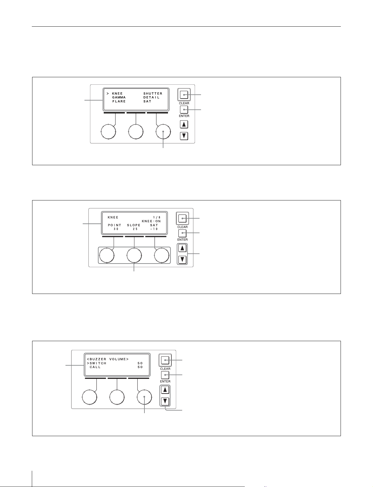
ブザーを設定する
セキュリティモードを変更する
RCP-920/921 では、コ−ル信号を受信したときや、パネル
を操作したときにブザ−音を鳴らします。必要に応じて音
量を調整してください。
1
RCP コンフィギュレーションメニューの「SETTING」
にカーソル(「>」記号)を合わせ、ENTER ボタンを
押す。
設定・調整画面が表示されます。
2
v または V で設定・調整画面を切り換え、<BUZZER
VOLUME> 画面を表示させる。
ᴹᴿᵒᵗᵗᵂᵏǽᵓᵌᵉᵒᵊᵂᴻ
ᴻᵐᵔᵆᵑᵀᵅǽǽǽǽǽǽǽǽǽǽǽᴲᴭ
ǽᵀᴾᵉᵉǽǽǽǽǽǽǽǽǽǽǽǽǽᴲᴭ
3
右側の調整つまみを回して、設定を変更する項目に
「>」を合わせる。
設定できる項目は、以下のとおりです。
SWITCH:操作パネル上のボタンを押したときのブ
ザーの音量を設定します。
CALL:コ−ル信号受信時のブザーの音量を設定しま
す。
4
各ブザーの音量を設定する。
1 ENTER ボタンを押して、設定変更モードに切り換
える。
カーソルが「?」で表示され、項目名が反転点滅し
ます。
2 右側の調整つまみを回して設定項目を変更し、
ENTER ボタンを押す。
RCP-920/921 には、設定機能を制限するためのエンジニア
モードがあります。一部の設定は、エンジニアモードを有
効にしていないと変更することができません。
1
RCP コンフィギュレーションメニューの「SETTING」
にカーソル(「>」記号)を合わせ、ENTER ボタンを
押す。
設定・調整画面が表示されます。
2
v または V で設定・調整画面を切り換え、<SECURITY
MODE> 画面を表示させる。
ᴹᵐᵂᵀᵒᵏᵆᵑᵖǽᵊᵌᵁᵂᴻ
ᴻᵊᵌᵁᵂᴷᵋᵌᵏᵊᴾᵉ
ǽǽᵐᵂᵑᴷ
3
右側の調整つまみを回して、「MODE」に「>」を合わ
せる。
4
セキュリティモード設定を変更する。
1 ENTER ボタンを押して、設定変更モードに切り換
える。
カーソルが「?」で表示され、項目名が反転点滅し
ます。
2 右側の調整つまみを回して、設定項目を
「ENGINEER」に変更し、ENTER ボタンを押す。
ᴹᵐᵂᵀᵒᵏᵆᵑᵖǽᵊᵌᵁᵂᴻ
ᴼᵊᵌᵁᵂᴷᵂᵋᵄᵆᵋᵂᵂᵏ
ǽǽᵐᵂᵑᴷ
設定・調整画面に戻ります。
30
ᴹᴿᵒᵗᵗᵂᵏǽᵓᵌᵉᵒᵊᵂᴻ
ᴼᵐᵔᵆᵑᵀᵅǽǽǽǽǽǽǽǽǽǽǽᴰᴭ
ǽᵀᴾᵉᵉǽǽǽǽǽǽǽǽǽǽǽǽǽᴲᴭ
設定・調整画面に戻ります。
ᴹᴿᵒᵗᵗᵂᵏǽᵓᵌᵉᵒᵊᵂᴻ
ᴻᵐᵔᵆᵑᵀᵅǽǽǽǽǽǽǽǽǽǽǽᴰᴭ
ǽᵀᴾᵉᵉǽǽǽǽǽǽǽǽǽǽǽǽǽᴲᴭ
5
CLEAR ボタンを押す。
RCP コンフィギュレーションメニューのトップ画面に
戻ります。
初期設定
ᴹᵐᵂᵀᵒᵏᵆᵑᵖǽᵊᵌᵁᵂᴻ
ᴻᵊᵌᵁᵂᴷᵂᵋᵄᵆᵋᵂᵂᵏ
ǽǽᵐᵂᵑᴷ
5
セキュリティモード設定を保存する。
1 右側の調整つまみを回して、「SET」に「>」を合
わせる。
Page 31

2 ENTER ボタンを押して、設定変更モードに切り換
える。
カーソルが「?」で表示され、項目名が反転点滅し
ます。
ᴹᵐᵂᵀᵒᵏᵆᵑᵖǽᵊᵌᵁᵂᴻ
ǽᵊᵌᵁᵂᴷᵂᵋᵄᵆᵋᵂᵂᵏ
ᴼǽᵐᵂᵑ
3 ENTER ボタンを押して、設定を保存する。
ᴹᵐᵂᵀᵒᵏᵆᵑᵖǽᵊᵌᵁᵂᴻ
ǽᵊᵌᵁᵂᴷᵂᵋᵄᵆᵋᵂᵂᵏ
ᴻǽᵐᵂᵑᴷ
6
CLEAR ボタンを押す。
メモ
設定変更モードに切り換えると、すべてのアサイナブ
ルスイッチが消灯し、「>」を合わせたスイッチの LED
ランプのみが点灯します。どのスイッチの機能を変更
しているかは、点灯している LED を確認することで
行ってください。
4
ENTER ボタンを押して、設定変更モードに切り換え
る。
カーソルが「?」で表示され、項目名が反転点滅しま
す。
ᴹᵐᵔǽᴾᵐᵐᵆᵄᵋᴻ
ǽᵐᵔᴭᴮᴷᴲᴳᴭᴭᵈ
ᴼᵐᵔᴭᴯᴷᴾᵑǽᵈᵋᵂᵂ
ǽᵐᵔᴭᴰᴷᵐᵈᵆᵋǽᵁᵑᵉ
RCP コンフィギュレーションメニューのトップ画面に
戻ります。
メモ
セキュリティモードは、本機の電源を切ると NORMAL に
戻ります。
スイッチアサインを変更する
RCP-920/921 では、一部のスイッチがアサイナブルスイッ
チとなっており、各スイッチの機能を変更することができ
ます。
ご注意
この設定はエンジニアモードで行います。
1
RCP コンフィギュレーションメニューの「SETTING」
にカーソル(「>」記号)を合わせ、ENTER ボタンを
押す。
設定・調整画面が表示されます。
2
v または V で設定・調整画面を切り換え、<SW
ASSIGN> 画面を表示させる。
ご注意
項目が 4 行以上になると、すべての項目が液晶画面に
表示されません。その場合は、右側の調整つまみを回
して画面をスクロールさせてください。
5
右側の調整つまみを回して設定項目を変更する。
ᴹᵐᵔǽᴾᵐᵐᵆᵄᵋᴻ
ǽᵐᵔᴭᴮᴷᴲᴳᴭᴭᵈ
ᴼᵐᵔᴭᴯᴷᵈᵋᵂᵂǽᵌᵃᵃ
ǽᵐᵔᴭᴰᴷᵐᵈᵆᵋǽᵁᵑᵉ
6
ENTER ボタンを押して、設定を確定する。
カーソルが「>」に戻ります。
ᴹᵐᵔǽᴾᵐᵐᵆᵄᵋᴻ
ǽᵐᵔᴭᴮᴷᴲᴳᴭᴭᵈ
ᴻᵐᵔᴭᴯᴷᵈᵋᵂᵂǽᵌᵃᵃ
ǽᵐᵔᴭᴰᴷᵐᵈᵆᵋǽᵁᵑᵉ
7
3 〜 6 を繰り返し、各スイッチの機能を変更する。
8
CLEAR ボタンを押す。
RCP コンフィギュレーションメニューのトップ画面に
戻ります。
機能を変更したスイッチは、付属の機能表示ラベルを
所定の位置に貼って使用してください。
RCP コンフィギュレーションメニューの設
定をリセットする
RCP コンフィギュレーションメニューの設定をすべてリ
セットし、工場出荷時の状態に戻します。
ᴹᵐᵔǽᴾᵐᵐᵆᵄᵋᴻ
ǽᵐᵔᴭᴮᴷᴲᴳᴭᴭᵈ
ᴻᵐᵔᴭᴯᴷᴾᵑǽᵈᵋᵂᵂ
ǽᵐᵔᴭᴰᴷᵐᵈᵆᵋǽᵁᵑᵉ
3
右側の調整つまみを回して、変更するスイッチに「>」
を合わせる。
ご注意
この設定はエンジニアモードで行います。
初期設定
31
Page 32

1
RCP コンフィギュレーションメニューの「SETTING」
にカーソル(「>」記号)を合わせ、ENTER ボタンを
押す。
1
RCP コンフィギュレーションメニューの「SETTING」
にカーソル(「>」記号)を合わせ、ENTER ボタンを
押す。
設定・調整画面が表示されます。
2
v または V で設定・調整画面を切り換え、<ALL
RESET> 画面を表示させる。
ᴹᴾᵉᵉǽᵏᵂᵐᵂᵑᴻ
ᴻᴾᵉᵉǽᵏᵂᵐᵂᵑ
3
設定をリセットする。
1 ENTER ボタンを押して、設定変更モードに切り換
える。
カーソルが「?」で表示され、「START?」表示が反
転点滅します。
ᴹᴾᵉᵉǽᵏᵂᵐᵂᵑᴻ
ᴼᴾᵉᵉǽᵏᵂᵐᵂᵑǽǽᵐᵑᴾᵏᵑᴼ
2 再度 ENTER ボタンを押す。
「OK」が表示され、設定がすべて消去されます。
リセットしない場合は、「START?」表示時に
CLEAR ボタンを押してください。
ご注意
「OK」が表示されると、RCP コンフィギュレーション
メニューのすべての設定がリセットされ、工場出荷時
の状態に戻ります。
設定・調整画面が表示されます。
2
v または V で設定・調整画面を切り換え、<VRREL
MODESET> 画面を表示させる。
ご注意
項目が 4 行以上になると、すべての項目が液晶画面に
表示されません。その場合は、右側の調整つまみを回
して画面をスクロールさせてください。
ᴹᵓᵏǽᵏᵂᵉǽᵊᵌᵁᵂǽᵐᵂᵑᴻ
ᴻᵔᵅᵆᵑᵂᴷǽǽᴮ ¯ ᴯ
ǽᴿᵉᴾᵀᵈᴷǽǽᴮ ¯ ᴯ
ǽᵁᵂᵑᴾᵆᵉᴷǽᴮ ¯ ᴯ
ǽᴿᴫᵄᴾᵊᴷǽǽᴮ ¯ ᴯ
3
右側の調整つまみを回して、変更する項目に「>」を
合わせる。
4
各調整つまみの感度設定を変更する。
1 ENTER ボタンを押して、設定変更モードに切り換
える。
カーソルが「?」で表示され、項目名が反転点滅し
ます。
2 右側の調整つまみを回して設定項目を変更し、
ENTER ボタンを押す。
ᴹᵓᵏǽᵏᵂᵉǽᵊᵌᵁᵂǽᵐᵂᵑᴻ
ᴼᵔᵅᵆᵑᵂᴷǽǽᴮ¯ᴱ
ǽᴿᵉᴾᵀᵈᴷǽǽᴮ ¯ ᴯ
ǽᵁᵂᵑᴾᵆᵉᴷǽᴮ ¯ ᴯ
ᴹᴾᵉᵉǽᵏᵂᵐᵂᵑᴻ
ᴻᴾᵉᵉǽᵏᵂᵐᵂᵑǽǽᵌᵈ
4
CLEAR ボタンを押す。
RCP コンフィギュレーションメニューのトップ画面に
戻ります。
調整つまみの感度を変更する
RCP-920/921 では、WHITE、BLACK/FLARE、
DETAIL、BLACKGAMMA の各調整つまみの相対値モー
ドでの調整感度を変更することができます。
ご注意
この設定はエンジニアモードで行います。
32
初期設定
設定・調整画面に戻ります。
ᴹᵓᵏǽᵏᵂᵉǽᵊᵌᵁᵂǽᵐᵂᵑᴻ
ᴻᵔᵅᵆᵑᵂᴷǽǽᴮ ¯ ᴱ
ǽᴿᵉᴾᵀᵈᴷǽǽᴮ ¯ ᴯ
ǽᵁᵂᵑᴾᵆᵉᴷǽᴮ ¯ ᴯ
5
CLEAR ボタンを押す。
RCP コンフィギュレーションメニューのトップ画面に
戻ります。
システム接続を設定する
RCP-920/921 は、CCU/CNUREMOTE 端子によるシステ
ム接続と、イーサネット端子によるカメラネットワークシ
ステムへの接続に対応しています。システム接続の設定
は、次の手順で行います。
Page 33

ご注意
• 設定を反映させるには、機器の電源を入れなおす必要が
あります。
• この設定はエンジニアモードで行います。
1
RCP コンフィギュレーションメニューの「SETTING」
にカーソル(「>」記号)を合わせ、ENTER ボタンを
押す。
設定・調整画面が表示されます。
2
v または V で設定・調整画面を切り換え、<CNS
SETTING> 画面を表示させる。
ご注意
項目が 4 行以上になると、すべての項目が液晶画面に
表示されません。その場合は、右側の調整つまみを回
して画面をスクロールさせてください。
1 右側の調整つまみを回して、画面右上の「SET」
に「>」を合わせる。
2 ENTER ボタンを押して、設定変更モードに切り換
える。
カーソルが「?」で表示されます。
3 再度 ENTER ボタンを押して、設定を保存する。
ᴹᵀᵋᵐǽᵐᵂᵑᵑᵆᵋᵄᴻǽǽǽǽᴻᵐᵂᵑ
ǽǽᵀᵋᵐǽᵊᵌᵁᵂᴷᵉᵂᵄᴾᵀᵖ
ǽǽᵊᴾᵐᵑᵂᵏǽᵆᵍǽᴾᵁᵁᵏ
ǽǽǽǽǽǽǽǽᴭᴫǽǽᴭᴫǽǽᴭᴫǽǽᴭ
ǽǽᵑᴾᵏᵄᵂᵑǽᵆᵍǽᴾᵁᵁᵏ
ǽǽǽǽǽǽǽǽᴭᴫǽǽᴭᴫǽǽᴭᴫǽǽᴭ
5
CLEAR ボタンを押す。
RCP コンフィギュレーションメニューのトップ画面に
戻ります。
ᴹᵀᵋᵐǽᵐᵂᵑᵑᵆᵋᵄᴻǽǽǽǽǽᵐᵂᵑ
ᴻǽᵀᵋᵐǽᵊᵌᵁᵂᴷᵉᵂᵄᴾᵀᵖ
ǽǽᵊᴾᵐᵑᵂᵏǽᵆᵍǽᴾᵁᵁᵏ
ǽǽǽǽǽǽǽǽᴭᴫǽǽᴭᴫǽǽᴭᴫǽǽᴭ
ǽǽᵑᴾᵏᵄᵂᵑǽᵆᵍǽᴾᵁᵁᵏ
ǽǽǽǽǽǽǽǽᴭᴫǽǽᴭᴫǽǽᴭᴫǽǽᴭ
3
システム接続モードを選択する。
以下のモードから選択できます。お使いのシステムに
応じて設定してください。
LEGACY:CCU/CNUREMOTE 端子を使用して、
CCA-5 ケーブルでシステム接続を行うモードです。
BRIDGE:イーサネットを使用して、RCP と CCU、
カメラを 1 対 1 で接続するモードです。
MCS:イーサネットを使用して、複数台のカメラや
CCU、パネルによって構成されるマルチカメラシ
ステム(MCS)に接続するモードです。
(工場出荷時:LEGACY)
ご注意
• 各モードを設定する場合は、「Legacy モードに設定
する」、「Bridge モードに設定する」、「マルチカメラ
システム(MCS)モードに設定する」を参照してく
ださい。
• イーサネット接続を行う場合は、イーサネット接続
設定を行ってください。
4
システム接続設定を保存する。
Legacy モードに設定する
1
カメラネットワークシステムモード(CNSMODE)を
Legacy モードに設定する。
1 右側の調整つまみを回して、「CNSMODE」にカー
ソル(「>」記号)を合わせる。
2 ENTER ボタンを押して、設定変更モードに切り換
える。
カーソルが「?」で表示され、項目名が反転点滅し
ます。
3 右側の調整つまみを回して「LEGACY」を選択し、
ENTER ボタンを押す。
ᴹᵀᵋᵐǽᵐᵂᵑᵑᵆᵋᵄᴻǽǽǽǽǽᵐᵂᵑ
ᴼǽᵀᵋᵐǽᵊᵌᵁᵂᴷᵉᵂᵄᴾᵀᵖ
ǽǽᵊᴾᵐᵑᵂᵏǽᵆᵍǽᴾᵁᵁᵏ
ǽǽǽǽǽǽǽǽᴭᴫǽǽᴭᴫǽǽᴭᴫǽǽᴭ
ǽǽᵑᴾᵏᵄᵂᵑǽᵆᵍǽᴾᵁᵁᵏ
ǽǽǽǽǽǽǽǽᴭᴫǽǽᴭᴫǽǽᴭᴫǽǽᴭ
設定・調整画面に戻ります。
ᴹᵀᵋᵐǽᵐᵂᵑᵑᵆᵋᵄᴻǽǽǽǽǽᵐᵂᵑ
ᴻǽᵀᵋᵐǽᵊᵌᵁᵂᴷᵉᵂᵄᴾᵀᵖ
ǽǽᵊᴾᵐᵑᵂᵏǽᵆᵍǽᴾᵁᵁᵏ
ǽǽǽǽǽǽǽǽᴭᴫǽǽᴭᴫǽǽᴭᴫǽǽᴭ
ǽǽᵑᴾᵏᵄᵂᵑǽᵆᵍǽᴾᵁᵁᵏ
ǽǽǽǽǽǽǽǽᴭᴫǽǽᴭᴫǽǽᴭᴫǽǽᴭ
初期設定
33
Page 34

2
システム接続設定を保存する。
1 右側の調整つまみを回して、画面右上の「SET」
に「>」を合わせる。
2 ENTER ボタンを押して、設定変更モードに切り換
える。
カーソルが「?」で表示されます。
3 再度 ENTER ボタンを押して、設定を保存する。
3
CLEAR ボタンを押す。
RCP コンフィギュレーションメニューのトップ画面に
戻ります。
Bridge モードに設定する
Bridge モードは、イーサネット接続で RCP と CCU を 1 対
1 で接続します。接続先の機器をターゲットと呼びます。
1
カメラネットワークシステムモード(CNSMODE)を
Bridge モードに設定する。
1 右側の調整つまみを回して、「CNSMODE」にカー
ソル(「>」記号)を合わせる。
2 ENTER ボタンを押して、設定変更モードに切り換
える。
カーソルが「?」で表示され、項目名が反転点滅し
ます。
3 右側の調整つまみを回して「BRIDGE」を選択し、
ENTER ボタンを押す。
ᴹᵀᵋᵐǽᵐᵂᵑᵑᵆᵋᵄᴻǽǽǽǽǽᵐᵂᵑ
ᴼǽᵀᵋᵐǽᵊᵌᵁᵂᴷᴿᵏᵆᵁᵄᵂ
ǽǽᵊᴾᵐᵑᵂᵏǽᵆᵍǽᴾᵁᵁᵏ
ǽǽǽǽǽǽǽǽᴭᴫǽǽᴭᴫǽǽᴭᴫǽǽᴭ
ǽǽᵑᴾᵏᵄᵂᵑǽᵆᵍǽᴾᵁᵁᵏ
ǽǽǽǽǽǽǽǽᴭᴫǽǽᴭᴫǽǽᴭᴫǽǽᴭ
設定・調整画面に戻ります。
ᴹᵀᵋᵐǽᵐᵂᵑᵑᵆᵋᵄᴻǽǽǽǽǽᵐᵂᵑ
ᴻǽᵀᵋᵐǽᵊᵌᵁᵂᴷᴿᵏᵆᵁᵄᵂ
ǽǽǽᵀᵌᵋᵋᵂᵀᵑᴷᵐᵂᵊᵆᴪᴾᵑ
ǽǽᵊᴾᵐᵑᵂᵏǽᵆᵍǽᴾᵁᵁᵏ
ǽǽǽǽǽǽǽǽᴭᴫǽǽᴭᴫǽǽᴭᴫǽǽᴭ
ǽǽᵑᴾᵏᵄᵂᵑǽᵆᵍǽᴾᵁᵁᵏ
ǽǽǽǽǽǽǽǽᴭᴫǽǽᴭᴫǽǽᴭᴫǽǽᴭ
1 右側の調整つまみで「CONNECT」に「>」を合わ
せる。
2 ENTER ボタンを押して、設定変更モードに切り換
える。
カーソルが「?」で表示され、項目名が反転点滅し
ます。
3 右側の調整つまみを回して、設定項目を変更する。
接続状態に合わせて、以下から選択してください。
ACTIVE:自らターゲットに対して接続処理を行
います。
PASSIVE:相手からの接続を待ち受けます。
SEMI-AT:接続環境に応じて、Active/Passive を
切り換えるモードです。RCP 単独の場合は
Active に、CCA-5 ケーブルで CCU やカメラに
接続されている場合は Passive になります。
(工場出荷時:SEMI-AT)
ご注意
接続する機器が両方とも Active に設定されていると、
正常に動作しませんので注意してください。
ᴹᵀᵋᵐǽᵐᵂᵑᵑᵆᵋᵄᴻǽǽǽǽǽᵐᵂᵑ
ǽǽᵀᵋᵐǽᵊᵌᵁᵂᴷᴿᵏᵆᵁᵄᵂ
ᴼǽǽᵀᵌᵋᵋᵂᵀᵑᴷᵐᵂᵊᵆᴪᴾᵑ
ǽǽᵊᴾᵐᵑᵂᵏǽᵆᵍǽᴾᵁᵁᵏ
ǽǽǽǽǽǽǽǽᴭᴫǽǽᴭᴫǽǽᴭᴫǽǽᴭ
ǽǽᵑᴾᵏᵄᵂᵑǽᵆᵍǽᴾᵁᵁᵏ
ǽǽǽǽǽǽǽǽᴭᴫǽǽᴭᴫǽǽᴭᴫǽǽᴭ
3
ターゲット IP アドレスを設定する
1 右側の調整つまみを回して、「TARGETIP
ADDRESS」に「>」を合わせる。
Active および Semi-Auto 時に接続するターゲット
機器の IP アドレスを設定します。Passive の場合
は設定しなくてもかまいません。
2 ENTER ボタンを押して、設定変更モードに切り換
える。
カーソルが「?」で表示され、IP アドレスの 1 桁目
が反転点滅します。
3 右側の調整つまみを回して設定項目を変更し、
ENTER ボタンを押す。
反転点滅部が IP アドレスの 2 桁目へ移動します。
同様の手順で、IP アドレスを設定してください。
34
2
Bridge モードのサブモードを設定する。
Bridge モードでは、サブモードとターゲット IP アド
レスを設定して動作を決定します。通常は、RCP を
ACTIVE か SEMI-AT に設定してください。
初期設定
ᴹᵀᵋᵐǽᵐᵂᵑᵑᵆᵋᵄᴻǽǽǽǽǽᵐᵂᵑ
ǽǽᵀᵋᵐǽᵊᵌᵁᵂᴷᴿᵏᵆᵁᵄᵂ
ǽǽǽᵀᵌᵋᵋᵂᵀᵑᴷᵐᵂᵊᵆᴪᴾᵑ
ǽǽᵊᴾᵐᵑᵂᵏǽᵆᵍǽᴾᵁᵁᵏ
ǽǽǽǽǽǽǽǽᴭᴫǽǽᴭᴫǽǽᴭᴫǽǽᴭ
ᴼǽᵑᴾᵏᵄᵂᵑǽᵆᵍǽᴾᵁᵁᵏ
ǽǽǽǽǽǽᴮᴶᴯᴫǽǽᴭᴫǽǽᴭᴫǽǽᴭ
Page 35

4 IP アドレスを全桁入力し、ENTER ボタンを押す。
設定・調整画面に戻ります。
ᴹᵀᵋᵐǽᵐᵂᵑᵑᵆᵋᵄᴻǽǽǽǽǽᵐᵂᵑ
ǽǽᵀᵋᵐǽᵊᵌᵁᵂᴷᴿᵏᵆᵁᵄᵂ
ǽǽǽᵀᵌᵋᵋᵂᵀᵑᴷᵐᵂᵊᵆᴪᴾᵑ
ǽǽᵊᴾᵐᵑᵂᵏǽᵆᵍǽᴾᵁᵁᵏ
ǽǽǽǽǽǽǽǽᴭᴫǽǽᴭᴫǽǽᴭᴫǽǽᴭ
ᴻǽᵑᴾᵏᵄᵂᵑǽᵆᵍǽᴾᵁᵁᵏ
ǽǽǽǽǽǽᴮᴶᴯᴫᴮᴳᴵᴫǽǽᴭᴫᴮᴭᴮ
4
システム接続設定を保存する。
1 右側の調整つまみを回して、画面右上の「SET」
に「>」を合わせる。
2 ENTER ボタンを押して、設定変更モードに切り換
える。
カーソルが「?」で表示されます。
3 再度 ENTER ボタンを押して、設定を保存する。
5
CLEAR ボタンを押す。
RCP コンフィギュレーションメニューのトップ画面に
戻ります。
マルチカメラシステム(MCS)モードに設
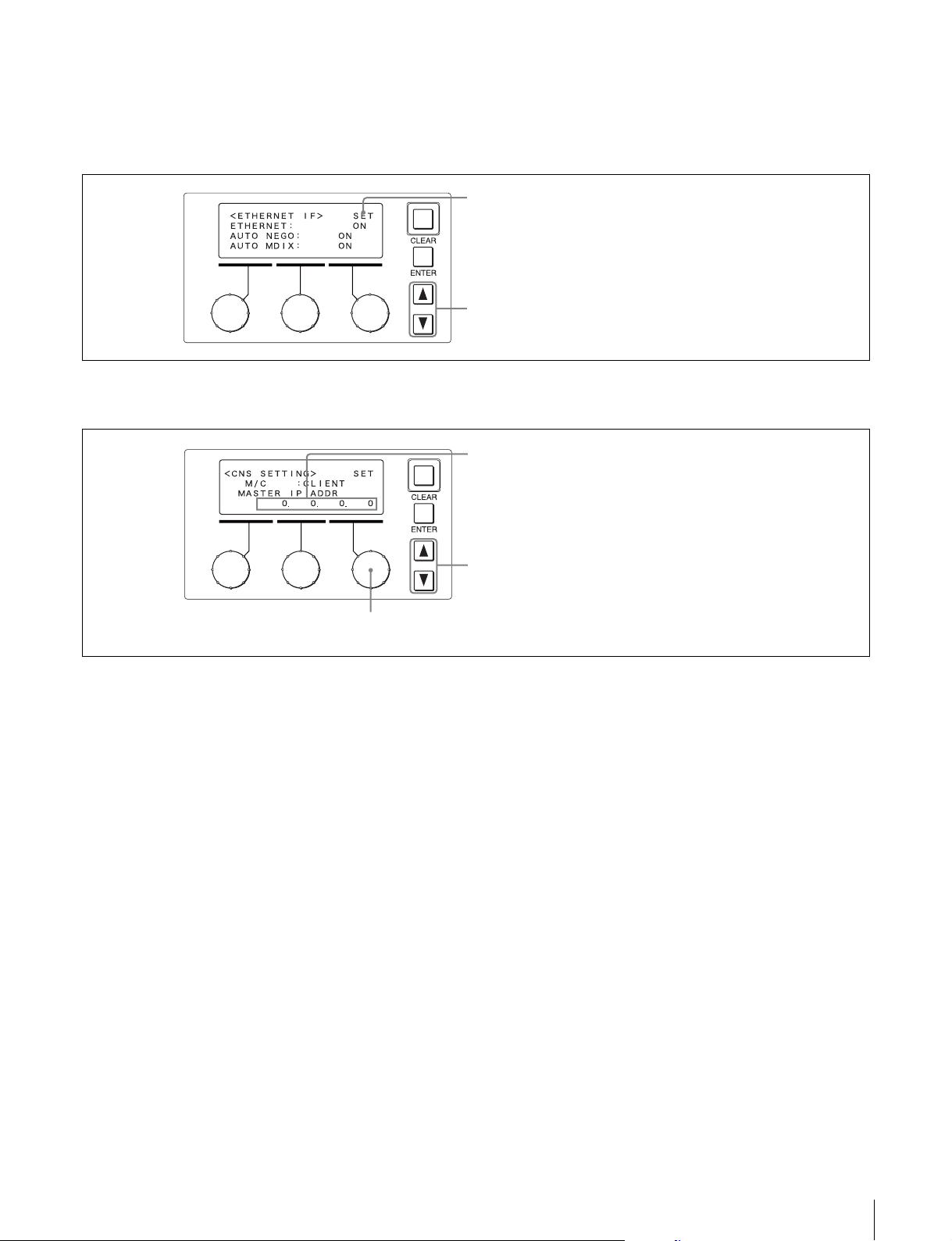
定する
マルチカメラシステム(MCS)モードは、MSU や RCP な
どのパネルと、CCU やカメラを複数使用してシステムを構
成するモードです。
次のようにサブモードを設定し、動作を決定します。
1
カメラネットワークシステムモード(CNSMODE)を
MCS に設定する。
1 右側の調整つまみを回して、「CNSMODE」にカー
ソル(「>」記号)を合わせる。
2 ENTER ボタンを押して、設定変更モードに切り換
える。
カーソルが「?」で表示され、項目名が反転点滅し
ます。
設定・調整画面に戻ります。
ᴹᵀᵋᵐǽᵐᵂᵑᵑᵆᵋᵄᴻǽǽǽǽǽᵐᵂᵑ
ᴻǽᵀᵋᵐǽᵊᵌᵁᵂᴷᵊᵀᵐ
ǽǽǽᵊ ¯ ᵀǽǽǽǽᴷᵀᵉᵆᵂᵋᵑ
ǽǽᵊᴾᵐᵑᵂᵏǽᵆᵍǽᴾᵁᵁᵏ
ǽǽǽǽǽǽǽǽᴭᴫǽǽᴭᴫǽǽᴭᴫǽǽᴭ
ǽǽᵑᴾᵏᵄᵂᵑǽᵆᵍǽᴾᵁᵁᵏ
ǽǽǽǽǽǽǽǽᴭᴫǽǽᴭᴫǽǽᴭᴫǽǽᴭ
2
マスター IP アドレスを設定する
RCP-920/921 は、マルチカメラシステムではクライア
ント固定になりますので、サブモード(Master/
Client)は自動で CLIENT に設定されます。
マルチカメラシステムのクライアント機器には、シス
テムのマスター機の IP アドレスを設定してください。
1 右側の調整つまみを回して、「MASTERIP
ADDRESS」に「>」を合わせる。
2 ENTER ボタンを押して、設定変更モードに切り換
える。
カーソルが「?」で表示され、IP アドレスの 1 桁目
が反転点滅します。
3 右側の調整つまみを回して設定項目を変更し、
ENTER ボタンを押す。
反転点滅部が IP アドレスの 2 桁目へ移動します。
同様の手順で、IP アドレスを設定してください。
ᴹᵀᵋᵐǽᵐᵂᵑᵑᵆᵋᵄᴻǽǽǽǽǽᵐᵂᵑ
ǽǽᵀᵋᵐǽᵊᵌᵁᵂᴷᵊᵀᵐ
ǽǽǽᵊ ¯ ᵀǽǽǽǽᴷᵀᵉᵆᵂᵋᵑ
ᴼǽᵊᴾᵐᵑᵂᵏǽᵆᵍǽᴾᵁᵁᵏ
ǽǽǽǽǽǽᴮᴶᴯᴫǽǽᴭᴫǽǽᴭᴫǽǽᴭ
ǽǽᵑᴾᵏᵄᵂᵑǽᵆᵍǽᴾᵁᵁᵏ
ǽǽǽǽǽǽǽǽᴭᴫǽǽᴭᴫǽǽᴭᴫǽǽᴭ
4 IP アドレスを全桁入力し、ENTER ボタンを押す。
設定・調整画面に戻ります。
ᴹᵀᵋᵐǽᵐᵂᵑᵑᵆᵋᵄᴻǽǽǽǽǽᵐᵂᵑ
ǽǽᵀᵋᵐǽᵊᵌᵁᵂᴷᵊᵀᵐ
ǽǽǽᵊ ¯ ᵀǽǽǽǽᴷᵀᵉᵆᵂᵋᵑ
ᴻǽᵊᴾᵐᵑᵂᵏǽᵆᵍǽᴾᵁᵁᵏ
ǽǽǽǽǽǽᴮᴶᴯᴫᴮᴳᴵᴫǽǽᴭᴫᴮᴭᴭ
ǽǽᵑᴾᵏᵄᵂᵑǽᵆᵍǽᴾᵁᵁᵏ
ǽǽǽǽǽǽǽǽᴭᴫǽǽᴭᴫǽǽᴭᴫǽǽᴭ
3 右側の調整つまみを回して「MCS」を選択し、
ENTER ボタンを押す。
ᴹᵀᵋᵐǽᵐᵂᵑᵑᵆᵋᵄᴻǽǽǽǽǽᵐᵂᵑ
ᴼǽᵀᵋᵐǽᵊᵌᵁᵂᴷᵊᵀᵐ
ǽǽᵊᴾᵐᵑᵂᵏǽᵆᵍǽᴾᵁᵁᵏ
ǽǽǽǽǽǽǽǽᴭᴫǽǽᴭᴫǽǽᴭᴫǽǽᴭ
ǽǽᵑᴾᵏᵄᵂᵑǽᵆᵍǽᴾᵁᵁᵏ
ǽǽǽǽǽǽǽǽᴭᴫǽǽᴭᴫǽǽᴭᴫǽǽᴭ
3
システム接続の設定を保存する。
1 右側の調整つまみを回して、画面右上の「SET」
に「>」を合わせる。
2 ENTER ボタンを押して、設定変更モードに切り換
える。
カーソルが「?」で表示されます。
3 再度 ENTER ボタンを押して、設定を保存する。
初期設定
35
Page 36

4
CLEAR ボタンを押す。
RCP コンフィギュレーションメニューのトップ画面に
戻ります。
イーサネット接続の設定をする
RCP-920/921 は、イーサネット端子によるカメラネット
ワークシステムへの接続に対応しています。イーサネット
接続の設定は、次の手順で行います。
ご注意
• 設定を反映させるには、機器の電源を入れなおす必要が
あります。
• この設定はエンジニアモードで行います。
1
RCP コンフィギュレーションメニューの「SETTING」
にカーソル(「>」記号)を合わせ、ENTER ボタンを
押す。
設定・調整画面が表示されます。
2
v または V で設定・調整画面を切り換え、<TCP/IP
SETTING> 画面を表示させます。
ご注意
項目が 4 行以上になると、すべての項目が液晶画面に
表示されません。その場合は、右側の調整つまみを回
して画面をスクロールさせてください。
カーソルが「?」で表示され、IP アドレスの最上位
が反転点滅します。
3 右側の調整つまみを回して設定項目を変更し、
ENTER ボタンを押す。
反転点滅部が IP アドレスの 2 桁目へ移動します。
同様の手順で、IP アドレスを設定してください。
ᴹᵑᵀᵍ ¯ ᵆᵍǽᵐᵂᵑᵑᵆᵋᵄᴻǽǽᵐᵂᵑ
ᴼᵆᵍǽᴾᵁᵁᵏᵂᵐᵐ
ǽǽǽǽǽǽᴮᴶᴯᴫǽǽᴭᴫǽǽᴭᴫǽǽᴭ
ǽᵐᵒᴿᵋᵂᵑǽᵊᴾᵐᵈ
ǽǽǽǽǽǽǽǽᴭᴫǽǽᴭᴫǽǽᴭᴫǽǽᴭ
ǽᵁᵂᵃᴾᵒᵉᵑǽᵄᴾᵑᵂᵔᴾᵖ
ǽǽǽǽǽǽǽǽᴭᴫǽǽᴭᴫǽǽᴭᴫǽǽᴭ
4 IP アドレスを全桁入力し、ENTER ボタンを押す。
設定・調整画面に戻ります。
ᴹᵑᵀᵍ ¯ ᵆᵍǽᵐᵂᵑᵑᵆᵋᵄᴻǽǽᵐᵂᵑ
ᴻᵆᵍǽᴾᵁᵁᵏᵂᵐᵐ
ǽǽǽǽǽǽᴮᴶᴯᴫᴮᴳᴵᴫǽǽᴭᴫǽǽᴮ
ǽᵐᵒᴿᵋᵂᵑǽᵊᴾᵐᵈ
ǽǽǽǽǽǽǽǽᴭᴫǽǽᴭᴫǽǽᴭᴫǽǽᴭ
ǽᵁᵂᵃᴾᵒᵉᵑǽᵄᴾᵑᵂᵔᴾᵖ
ǽǽǽǽǽǽǽǽᴭᴫǽǽᴭᴫǽǽᴭᴫǽǽᴭ
4
サブネットマスクおよびデフォルトゲートウェイを設
定する。
同様の手順でサブネットマスクの設定を、必要に応じ
てデフォルトゲートウェイの設定を行ってください。
ᴹᵑᵀᵍ ¯ ᵆᵍǽᵐᵂᵑᵑᵆᵋᵄᴻǽǽᵐᵂᵑ
ᴻᵆᵍǽᴾᵁᵁᵏᵂᵐᵐ
ǽǽǽǽǽǽǽǽᴭᴫǽǽᴭᴫǽǽᴭᴫǽǽᴭ
ǽᵐᵒᴿᵋᵂᵑǽᵊᴾᵐᵈ
ǽǽǽǽǽǽǽǽᴭᴫǽǽᴭᴫǽǽᴭᴫǽǽᴭ
ǽᵁᵂᵃᴾᵒᵉᵑǽᵄᴾᵑᵂᵔᴾᵖ
ǽǽǽǽǽǽǽǽᴭᴫǽǽᴭᴫǽǽᴭᴫǽǽᴭ
3
TCP/IP 関連の設定をする。
設定できる項目は、以下のとおりです。
IPADDRESS:RCP に割り当てる IP アドレスを設定
します。
SUBNETMASK:お使いのネットワーク環境のサブ
ネットマスクを設定します。
DEFAULTGATEWAY:必要に応じて、お使いの
ネットワーク環境のデフォルトゲートウェイを設
定します。
本機の IP アドレスを設定する。
1 右側の調整つまみで「IPADDRESS」に「>」を合
わせる。
ᴹᵑᵀᵍ ¯ ᵆᵍǽᵐᵂᵑᵑᵆᵋᵄᴻǽǽᵐᵂᵑ
ǽᵆᵍǽᴾᵁᵁᵏᵂᵐᵐ
ǽǽǽǽǽǽᴮᴶᴯᴫᴮᴳᴵᴫǽǽᴭᴫǽǽᴮ
ᴻᵐᵒᴿᵋᵂᵑǽᵊᴾᵐᵈ
ǽǽǽǽǽǽᴯᴲᴲᴫᴯᴲᴲᴫᴯᴲᴲᴫǽǽᴭ
ǽᵁᵂᵃᴾᵒᵉᵑǽᵄᴾᵑᵂᵔᴾᵖ
ǽǽǽǽǽǽǽǽᴭᴫǽǽᴭᴫǽǽᴭᴫǽǽᴭ
5
TCP/IP 設定を保存する。
1 右側の調整つまみを回して、画面右上の「SET」
に「>」を合わせる。
2 ENTER ボタンを押して、設定変更モードに切り換
える。
カーソルが「?」で表示されます。
3 再度 ENTER ボタンを押して、設定を保存する。
6
CLEAR ボタンを押す。
RCP コンフィギュレーションメニューのトップ画面に
戻ります。
36
2 ENTER ボタンを押して、設定変更モードに切り換
える。
初期設定
Page 37

イーサネットインターフェースの設定をす
設定・調整画面に戻ります。
る
ご注意
• 設定を反映させるには、機器の電源を入れなおす必要が
あります。
• この設定はエンジニアモードで行います。
1
RCP コンフィギュレーションメニューの「SETTING」
にカーソル(「>」記号)を合わせ、ENTER ボタンを
押す。
設定・調整画面が表示されます。
2
v または V で設定・調整画面を切り換え、
<ETHERNETIF> 画面を表示させる。
ご注意
項目が 4 行以上になると、すべての項目が液晶画面に
表示されません。その場合は、右側の調整つまみを回
して画面をスクロールさせてください。
ǽᴹᵂᵑᵅᵂᵏᵋᵂᵑǽᵆᵃᴻǽǽǽǽᵐᵂᵑ
ᴻᵂᵑᵅᵂᵏᵋᵂᵑᴷǽǽǽǽǽǽǽǽᵌᵃᵃ
ǽᴾᵒᵑᵌǽᵋᵂᵄᵌᴷǽǽǽǽǽᴪᴪᴪ
ǽᴾᵒᵑᵌǽᵊᵁᵆᵕᴷǽǽǽǽǽᴪᴪᴪ
ǽᵐᵍᵂᵂᵁᴷǽǽǽǽǽǽǽǽǽᴪᴪᴪᴪ
ǽᵁᵒᵍᵏᵂᵕᴷǽǽǽǽǽǽǽǽᴪᴪᴪᴪ
ǽᵊᵁᵆ ¯ ᵊᵁᵆᵕᴷǽǽǽǽǽǽᴪᴪᴪᴪ
3
イーサネットインターフェース設定の有効/無効を切り
換える。
イーサネットを使用する場合は、イーサネットイン
ターフェース設定を有効にします。
(工場出荷時:OFF)
1 右側の調整つまみを回して、「ETHERNET」に
「>」を合わせる。
2 ENTER ボタンを押して、設定変更モードに切り換
える。
カーソルが「?」で表示され、項目名が反転点滅し
ます。
3 右側の調整つまみを回して設定項目を変更し、
ENTER ボタンを押す。
ǽᴹᵂᵑᵅᵂᵏᵋᵂᵑǽᵆᵃᴻǽǽǽǽᵐᵂᵑ
ᴼᵂᵑᵅᵂᵏᵋᵂᵑᴷǽǽǽǽǽǽǽǽᵌᵋ
ǽᴾᵒᵑᵌǽᵋᵂᵄᵌᴷǽǽǽǽǽᴪᴪᴪ
ǽᴾᵒᵑᵌǽᵊᵁᵆᵕᴷǽǽǽǽǽᴪᴪᴪ
ǽᵐᵍᵂᵂᵁᴷǽǽǽǽǽǽǽǽǽᴪᴪᴪᴪ
ǽᵁᵒᵍᵏᵂᵕᴷǽǽǽǽǽǽǽǽᴪᴪᴪᴪ
ǽᵊᵁᵆ ¯ ᵊᵁᵆᵕᴷǽǽǽǽǽǽᴪᴪᴪᴪ
ǽᴹᵂᵑᵅᵂᵏᵋᵂᵑǽᵆᵃᴻǽǽǽǽᵐᵂᵑ
ᴻᵂᵑᵅᵂᵏᵋᵂᵑᴷǽǽǽǽǽǽǽǽᵌᵋ
ǽᴾᵒᵑᵌǽᵋᵂᵄᵌᴷǽǽǽǽǽᵌᵋ
ǽᴾᵒᵑᵌǽᵊᵁᵆᵕᴷǽǽǽǽǽᵌᵋ
ǽᵐᵍᵂᵂᵁᴷǽǽǽǽǽǽǽǽǽᴾᵒᵑᵌ
ǽᵁᵒᵍᵏᵂᵕᴷǽǽǽǽǽǽǽǽᴾᵒᵑᵌ
ǽᵊᵁᵆ ¯ ᵊᵁᵆᵕᴷǽǽǽǽǽǽᴾᵒᵑᵌ
4
イーサネットインターフェースの各種設定を行う。
設定できる項目は、以下のとおりです。
AUTONEGO:本機のイーサネットインターフェース
は AutoNegotiation に対応しています。接続機器
が AutoNegotiation に対応している場合は、ON に
すると、接続機器に応じて接続速度(Speed)や通
信方式(Duplex)が自動で設定されます。接続機
器が対応していない場合は、OFF にしてください。
(工場出荷時:ON)
AUTOMDIX:接続するイーサネットケーブルの端子
極性の自動設定機能を設定します。Auto
Negotiation が有効の場合は [ON] 設定が可能です。
(工場出荷時:ON)
SPEED:イーサネット回線接続速度設定です。
Negotiation が OFF の場合に、接続機器に応じて
手動で設定(10Mまたは100M)してください。
(工場出荷時:100M)
DUPLEX:イーサネット回線通信方式設定です。
Negotiation が OFF の場合に、接続機器に応じて
手動で設定(半二重:HALF または全二重:
FULL)してください。
(工場出荷時:FULL)
MDI/MDIX:接続するイーサネットケーブルの端子極
性を設定します。AUTOMDIX が OFF の場合は、
接続機器やケーブルに応じた極性(MDI/MDIX)
を手動で設定してください。
(工場出荷時:MDI)
1 右側の調整つまみを回して、設定する項目に「>」
を合わせる。
2 ENTER ボタンを押して、設定変更モードに切り換
える。
カーソルが「?」で表示され、項目名が反転点滅し
ます。
3 右側の調整つまみを回して設定項目を変更し、
ENTER ボタンを押す。
ǽᴹᵂᵑᵅᵂᵏᵋᵂᵑǽᵆᵃᴻǽǽǽǽᵐᵂᵑ
ǽᵂᵑᵅᵂᵏᵋᵂᵑᴷǽǽǽǽǽǽǽǽᵌᵋ
ᴼᴾᵒᵑᵌǽᵋᵂᵄᵌᴷǽǽǽǽǽᵌᵋ
ǽᴾᵒᵑᵌǽᵊᵁᵆᵕᴷǽǽǽǽǽᵌᵋ
ǽᵐᵍᵂᵂᵁᴷǽǽǽǽǽǽǽǽǽᴾᵒᵑᵌ
ǽᵁᵒᵍᵏᵂᵕᴷǽǽǽǽǽǽǽǽᴾᵒᵑᵌ
ǽᵊᵁᵆ ¯ ᵊᵁᵆᵕᴷǽǽǽǽǽǽᴾᵒᵑᵌ
初期設定
37
Page 38

設定・調整画面に戻ります。
ǽᴹᵂᵑᵅᵂᵏᵋᵂᵑǽᵆᵃᴻǽǽǽǽᵐᵂᵑ
ǽᵂᵑᵅᵂᵏᵋᵂᵑᴷǽǽǽǽǽǽǽǽᵌᵋ
ᴻᴾᵒᵑᵌǽᵋᵂᵄᵌᴷǽǽǽǽǽᵌᵋ
ǽᴾᵒᵑᵌǽᵊᵁᵆᵕᴷǽǽǽǽǽᵌᵋ
ǽᵐᵍᵂᵂᵁᴷǽǽǽǽǽǽǽǽǽᴾᵒᵑᵌ
ǽᵁᵒᵍᵏᵂᵕᴷǽǽǽǽǽǽǽǽᴾᵒᵑᵌ
ǽᵊᵁᵆ ¯ ᵊᵁᵆᵕᴷǽǽǽǽǽǽᴾᵒᵑᵌ
5
イーサネットインターフェース設定を保存する。
1 右側の調整つまみを回して、画面上部の「SET」
に「>」を合わせる。
2 ENTER ボタンを押して、設定変更モードに切り換
える。
カーソルが「?」で表示されます。
3 再度 ENTER ボタンを押して、設定を保存する。
6
CLEAR ボタンを押す。
RCP コンフィギュレーションメニューのトップ画面に
戻ります。
LCD ディスプレイの調整
RCP-920/921 には、ペイント調整部の LCD ディスプレイ
の明るさ(ブライト)およびコントラストを調整する LCD
ディスプレイ調整モードがあります。
LCD ディスプレイ調整モードに入るには
PARA ボタンと MASTER ボタンを押しながら、ペイント
調整項目選択ボタンの ENTER ボタンを押します。
LCD ディスプレイに次のように表示されます。
調整するには
ペイント調整つまみを回します。
左のつまみでブライト、右のつまみでコントラストを調整
します。
LCD ディスプレイ調整モードを解除するには
PARA ボタンと MASTER ボタンを同時に押します。
LCD ディスプレイ調整モードに入る前のメニューに戻りま
す。
ご注意
LCD ディスプレイモードでの設定は、モードを解除した時
点でメモリーに書き込まれます。必ず電源を切る前にモー
ドを解除してください。
38
LCD ディスプレイの調整
Page 39

仕様
一般
電源 DC10.5 〜 30 V
消費電力 最大 4 W
最大ケーブル長 200 m(CCA-5 ケーブルで接続時)
動作温度 5 ℃〜 40 ℃
外形寸法(幅/高さ/奥行き、突起物含まず)
RCP-920/921:102 × 310 × 67mm
外形寸法(幅/高さ/奥行き、突起物含む)
RCP-920:102 × 310 × 125mm
RCP-921:102 × 310 × 84mm
質量 1.8 kg
入出力
REMOTE
RJ-45 型 8 ピン(1)
CCU/CNU 8 ピンマルチコネクター、凹(1)
AUX 8 ピンマルチコネクター、凹(1)
EXT I/O 10 ピン、凸(1)
付属品
オペレーションマニュアル(1)
別売り品
外部 I/O コネクター HIROSEHR10A-10PA-10S(74)
1-566-437-12
CCA-5-3リモートケーブル(3m)
CCA-5-10リモートケーブル(10m)
CCA-5-30リモートケーブル(30m)
この装置は、情報処理装置等電波障害自主規制協議会
(VCCI)の基準に基づくクラス A 情報技術装置です。こ
の装置を家庭環境で使用すると電波妨害を引き起こすこ
とがあります。この場合には使用者が適切な対策を講ず
るよう要求されることがあります。
本機の仕様および外観は、改良のため予告なく変更するこ
とがありますが、ご了承ください。
お使いになる前に、必ず動作確認を行ってください。故
障その他に伴う営業上の機会損失等は保証期間中および
保証期間経過後にかかわらず、補償はいたしかねますの
でご了承ください。
仕様
39
Page 40

40
仕様
Page 41

English
For the customers in the U.S.A.
This equipment has been tested and found to comply with the
limits for a Class A digital device, pursuant to Part 15 of the
FCC Rules. These limits are designed to provide reasonable
protection against harmful interference when the equipment is
operated in a commercial environment. This equipment
generates, uses, and can radiate radio frequency energy and,
if not installed and used in accordance with the instruction
manual, may cause harmful interference to radio
communications. Operation of this equipment in a residential
area is likely to cause harmful interference in which case the
user will be required to correct the interference at his own
expense.
You are cautioned that any changes or modifications not
expressly approved in this manual could void your authority to
operate this equipment.
All interface cables used to connect peripherals must be
shielded in order to comply with the limits for a digital device
pursuant to Subpart B of Part 15 of FCC Rules.
For the customers in Europe
This product with the CE marking complies with the EMC
Directive issued by the Commission of the European
Community.
Compliance with this directive implies conformity to the
following European standards:
• EN55103-1: Electromagnetic Interference (Emission)
• EN55103-2: Electromagnetic Susceptibility (Immunity)
This product is intended for use in the following
Electromagnetic Environments: E1 (residential), E2
(commercial and light industrial), E3 (urban outdoors), E4
(controlled EMC environment, ex. TV studio).
Pour les clients en Europe
Ce produit portant la marque CE est conforme à la Directive
sur la compatibilité électromagnétique (EMC) émise par la
Commission de la Communauté européenne.
La conformité à cette directive implique la conformité aux
normes européennes suivantes :
• EN55103-1 : Interférences électromagnétiques (émission)
• EN55103-2 : Sensibilité électromagnétique (immunité)
Ce produit est prévu pour être utilisé dans les environnements
électromagnétiques suivants : E1 (résidentiel), E2
(commercial et industrie légère), E3 (urbain extérieur) et E4
(environnement EMC contrôlé, ex. studio de télévision).
Für Kunden in Europa
Dieses Produkt besitzt die CE-Kennzeichnung und erfüllt die
EMV-Richtlinie der EG-Kommission.
Angewandte Normen:
• EN55103-1: Elektromagnetische Verträglichkeit
(Störaussendung)
• EN55103-2: Elektromagnetische Verträglichkeit
(Störfestigkeit)
Für die folgenden elektromagnetischen Umgebungen: E1
(Wohnbereich), E2 (kommerzieller und in beschränktem
Maße industrieller Bereich), E3 (Stadtbereich im Freien) und
E4 (kontrollierter EMV-Bereich, z.B. Fernsehstudio).
For the customers in Europe
The manufacturer of this product is Sony Corporation, 1-7-1
Konan, Minato-ku, Tokyo, Japan.
The Authorized Representative for EMC and product safety is
Sony Deutschland GmbH, Hedelfinger Strasse 61, 70327
Stuttgart, Germany. For any service or guarantee matters
please refer to the addresses given in separate service or
guarantee documents.
Pour les clients en Europe
Le fabricant de ce produit est Sony Corporation, 1-7-1 Konan,
Minato-ku, Tokyo, Japon.
Le représentant autorisé pour EMC et la sécurité des produits
est Sony Deutschland GmbH, Hedelfinger Strasse 61, 70327
Stuttgart, Allemagne. Pour toute question concernant le
service ou la garantie, veuillez consulter les adresses
indiquées dans les documents de service ou de garantie
séparés.
Für Kunden in Europa
Der Hersteller dieses Produkts ist Sony Corporation, 1-7-1
Konan, Minato-ku, Tokyo, Japan.
Der autorisierte Repräsentant für EMV und Produktsicherheit
ist Sony Deutschland GmbH, Hedelfinger Strasse 61, 70327
Stuttgart, Deutschland. Bei jeglichen Angelegenheiten in
Bezug auf Kundendienst oder Garantie wenden Sie sich bitte
an die in den separaten Kundendienst- oder
Garantiedokumenten aufgeführten Anschriften.
For the State of California, USA only
Perchlorate Material - special handling may apply, See
www.dtsc.ca.gov/hazardouswaste/perchlorate
Perchlorate Material : Lithium battery contains perchlorate.
For the customers in Taiwan only
GB
41
Page 42

Table of Contents
Precautions........................................................................... 43
Overview .............................................................................. 43
Location and Function of Parts .......................................... 48
Menu Configuration and Basic Operation ......................... 56
Initial Settings....................................................................... 65
Adjusting the LCD Display .................................................. 76
Specifications ......................................................................76
Features......................................................................................43
Examples of System Configurations .........................................45
Precautions for Ethernet System Connections...........................47
Operation Panel .........................................................................48
Connector Panel.........................................................................55
Basic operation .......................................................................... 56
Basic configuration of menu pages ...........................................57
Menu transition diagram............................................................59
Menu Items ................................................................................60
Configuring the RCP-920/921 Operating Environment............65
42
Table of Contents
Page 43

Precautions
Overview
Note on faulty pixels on the LCD panel
The LCD panel fitted to this unit is manufactured with
high precision technology, giving a functioning pixel ratio
of at least 99.99%. Thus a very small proportion of pixels
may be “stuck,” either always off (black), always on (red,
green, or blue), or flashing. In addition, over a long period
of use, because of the physical characteristics of the liquid
crystal display, such “stuck” pixels may appear
spontaneously. These problems are not a malfunction.
Features
The RCP-920/921 Remote Control Panel is designed for
remote control of the BVP/HDC series Color Video
Camera via the CCU/HDCU Camera Control Unit. This
panel is connected to the CCU/HDCU Camera Control
Unit (or the CNU-700 Camera Command Network Unit,
which is connected to the CCU/HDCU) by a dedicated
cable of up to 200 m (656 feet) in length and controls the
camera functions which are used most frequently in basic
applications from a distance.
The RCP-920 and RCP-921 are completely identical in
their functions except with respect to the iris and master
black adjustments.
For the iris and master black adjustments, the RCP-920
uses a joystick type control while the RCP-921 uses rotary
knobs.
The principal features of the RCP-920/921 are as follows.
Optimized control arrangement for basic camera
operation
This remote control panel is provided with essential
control functions for basic operation of a BVP/HDCseries camera.
The buttons, knobs, and other controls have been arranged
according to their functions and with consideration to their
frequency of use. Indicators and buttons light or flash to
indicate the status of the system operation.
Also, guard frames are provided to protect against
accidental use of those buttons vital to camera operation.
These features ensure easy and error-free use of this
remote control panel.
Auto setup control
The RCP-920/921 has built-in microcomputers that
reliably perform automatic setup for the majority of the
control items. The various items can be automatically
adjusted independently or in combination.
Scene file control
Using the paint menu, camera adjustment data for a
particular scene can be stored in the video camera as a
scene file. Up to five such files can be stored. This allows
quick adaptation to various shooting conditions simply by
calling up a scene file.
Precautions / Overview
43
Page 44

Camera SLS/ECS/shutter function control
The SLS (Slow Shutter), ECS (Extended Clear Scan), and
electronic shutter functions of the camera can be turned
ON/OFF from this panel. The ECS frequency and shutter
speed are also selected using the buttons on the panel.
Dedicated cable or Ethernet connection
The connection between the remote control panel and the
camera control unit is established by a single dedicated
cable (CCA-5) that reliably sends and receives all
necessary signals and also provides power for the panel.
Alternatively, a connection via Ethernet cable is also
possible.
Support for parallel operation with other control
panels
Video cameras can be concurrently controlled from this
panel and other controller, such as the MSU-900/950
Master Setup Unit.
Four units fit in 19-inch rack
Up to four units of this control panel can be mounted in
line on a 19-inch EIA standard rack.
44
Overview
Page 45

Examples of System Configurations
Command cable system (for HDC series)
HDC1000
HDC1000
HDC1500
HDCU1000
(+HKCU1001/HKCU1003)
or
HDCU1500
(+HKCU1001/HKCU1003)
HDCU1000
(+HKCU1001/HKCU1003)
or
HDCU1500
(+HKCU1001/HKCU1003)
HDCU1000
(+HKCU1001/HKCU1003)
PIX/WF
VCS-700
CCU (1 to 6)
CNU-700 RCP (1 to 6)
VCS
MSU-900 series
HDC1500
or
HDCU1500
(+HKCU1001/HKCU1003)
HDCU1000
(+HKCU1001/HKCU1003)
or
HDCU1500
(+HKCU1001/HKCU1003)
CCU/CNU
REMOTE
CCA-5 cable
CCU/CNU
REMOTE
CCU/CNU
REMOTE
RCP-920/921
CCU/CNU
REMOTE
CCA-5 cable
Overview
45
Page 46

Ethernet system (for HDC series)
HDC1000
HDC1000
HDC1500
HDCU1000
(+HKCU1001/HKCU1003)
or
HDCU1500
(+HKCU1001/HKCU1003)
HDCU1000
(+HKCU1001/HKCU1003)
or
HDCU1500
(+HKCU1001/HKCU1003)
HDCU1000
(+HKCU1001/HKCU1003)
Video switcher
PoE
switching hub
1)
compatible
MSU-900 series
HDC1500
or
HDCU1500
(+HKCU1001/HKCU1003)
HDCU1000
(+HKCU1001/HKCU1003)
RCP-920/921
or
HDCU1500
(+HKCU1001/HKCU1003)
Ethernet straight cable
(Category 5 or higher)
1) Power over Ethernet
About the switching hub power supply
As the maximum power of the RCP-920/921 is
14 W, multiply 14 W by the number of connected
RCP units when considering the power supply
from the switching hub.
46
Overview
Page 47

Precautions for Ethernet System
Connections
When connecting the unit to the system with an Ethernet
cable, make sure to ground the unit using one of the
following methods.
• Secure the flanges on the unit with screws.
• Connect a ground wire to the bottom of the unit.
To secure the flanges on the unit with screws
Flange
Flange
Console,
etc.
2
Attach the ground wire with the removed screw.
Note
The screws are not supplied with this unit. Use screws that
are suited to the installation location.
To connect a ground wire to the bottom of the
unit
1
Unscrew the screw on the rear of the unit.
Overview
47
Page 48

Location and Function of Parts
Operation Panel
STANDARD button
Control select block
Power and output signal select block
CLOSE button
AUTO SETUP block
Camera/CCU function ON/OFF buttons
Paint control block
Scene file control block
Filter control block
Master gain control block
SHUTTER control block
RCP-920
RCP-921
CALL button
PANEL ACTIVE button
OPT indicators
ALARM indicator
NET
DETAIL
OFF
IRIS
WORK
RELATIVE AUTO
KNEE
OFF
MASTER
BLACK
D EXT
EXT
IRIS/MB
ACTIVE
SENS
CLOSE OPEN
COARSE
White balance/black balance control block
Camera number/tally indication window
NETWORK indicator
Iris/master black control block (pages 53 and 54)
Expanded camera/CCU function ON/OFF buttons
Iris/master black control block (page 54 and 55)
48
Location and Function of Parts
IRIS
REMOTE CONTROL PANEL
RCP-
921
Page 49

1 STANDARD button
When you press this button, the video camera settings are
initialized to the reference values stored on the video
camera, and the button lights for several seconds.
If you press the button while it lights, the video camera
retrieves the state before the button was lit.
2 Control select block
a PARA (parallel mode) button
Lights when Parallel mode is active, in which concurrent
operation with another control panel is possible.
When this button is lit, all the buttons and controls on this
panel except for the iris/master black control block and
CLOSE button are active, even if the PANEL ACTIVE
button is not lit.
If you press the button while lit, it goes dark and Parallel
mode is cancelled.
b MASTER and SLAVE buttons
When adjusting the white balance of multiple cameras in
Master/Slave mode, designate the master camera or the
slave camera with these buttons.
Press and light up the MASTER button to specify the
connected camera for the master. Press and light up the
SLAVE button to specify the connected camera for the
slave. The slave cameras follow the master camera
settings.
If you press a button when lit, it goes dark.
Note
The BARS button takes priority to the TEST button. If the
BARS button is lit, press the button to turn it dark before
pressing the TEST button.
4 CLOSE (iris close) button
Press and light up this button to close the iris. If you press
the button while lit, it goes dark and iris closure is
canceled.
5 AUTO SETUP block
This block has various buttons for automatic adjustment of
the camera.
AUTO SETUP
SKIN DTL
AUTO HUE
LEVEL
START/
BREAK
WHITE BLACK
a Auto adjustment item select buttons
Press and light up these buttons to select items to be
automatically adjusted.
SKIN DTL AUTO HUE: Skin tone detail automatic hue
LEVEL: Gamma balance, knee point, master black level,
etc.
b START/BREAK button
Press to start automatic adjustment of the selected items.
The button lights during adjustment and goes dark when
adjustment is completed.
If you press the button when lit, the automatic adjustment
is cancelled and the button flashes. To stop the flashing,
press the button again.
3 Power and output signal select block
a CAM PW (camera power) button
Press and light up this button to turn the power supply to
the video camera ON. (The button promptly flashes until
the camera becomes ready for transmission.)
When you press this button again, it starts flashing and the
power supply is turned OFF.
b Test signal output select buttons
Press and light up one of these buttons to activate the test
signal generator of the video camera and send the
respective signals.
TEST: To send a sawtooth signal to test the video circuits.
BARS: To send a color bar signal.
c WHITE (white balance) button
Press to automatically adjust the white balance.
The button lights during adjustment and goes dark when
adjustment is completed.
If you press this button when lit or the START/BREAK
button, the automatic adjustment is cancelled and the
button flashes. To stop the flashing, press the button again.
d BLACK (black balance) button
Press to automatically adjust the black balance and black
set.
The button lights during adjustment and goes dark when
adjustment is completed.
If you press this button when lit or the START/BREAK
button, the automatic adjustment is cancelled and the
button flashes. To stop the flashing, press the button again.
Note
If an error occurs during adjustment, the pressed button
flashes.
Location and Function of Parts
49
Page 50

6 Camera/CCU function ON/OFF buttons
Various functions of the video camera or the CCU/HDCU
can be turned ON and OFF from this panel.
The following switching functions are assigned to seven of
the buttons at the factory and the rightmost button is
reserved for future use.
Press and light up these buttons to turn ON the respective
functions.
Press again so that the buttons go dark to turn OFF the
functions.
7 Paint control block
a LCD panel
Shows adjustment items and other information.
5600K: 5600K electric color temperature conversion
function
AUTO KNEE: Auto knee function. When this button is lit
(ON), the knee point is automatically adjusted
according to the light content of the picture.
SKIN DETAIL: Skin tone detail function
DETAIL GATE: Skin tone detail gate function. When
this button is lit (ON), the adjustment range of the skin
tone detail is displayed in white on the monitor screen.
SAT: Saturation function
BLACK GAMMA: Black gamma function
CHARACTER: Self-diagnostic display function.
When this button is lit (ON), the contents of the selfdiagnosis of the CCU/HDCU is displayed on a monitor
connected to the CHARACTER OUTPUT connector of
the CCU/HDCU.
The contents are also mixed to the video signal to be
output from the PIX1 OUTPUT connector.
Each time you press this button, the display changes as
follows:
The contents of the self-diagnosis may be displayed when
required even if this button is not lit.
b CLEAR button
Press and hold for more than 1 second to clear the
manually adjusted settings of the selected items and
resume the standard settings (which can be defined by the
user).
c ENTER button
Press to select or confirm menu and adjustment items, etc.
d Paint controls (rotary encoders)
Adjust the value of the selected paint adjustment item.
e MENU UP/DOWN button
Used for moving between menu pages. Press the v button
to go back one page and the V button to go to the next
page.
8 Scene file control block
a SCENE FILES buttons
While the STORE button is flashing: When you press
one of these buttons, the current setting data is stored
as a file of the corresponding number.
While the STORE button is out: The stored data can be
retrieved by pressing and lighting up the button of the
desired number. Press the lit button to turn it dark and
resume the previous status.
50
Location and Function of Parts
Page 51

b STORE (scene file store) button
To store a scene file, first press this button so that the
button starts flashing, then press the SCENE FILES button
of the desired number. When file storage is completed, the
STORE button goes dark.
To cancel storage, press the flashing button again before
pressing the SCENE FILES button. The STORE button
goes dark.
9 Filter control block
CCND
a ND filter select buttons
Once either button is pressed, both buttons light up. Each
time you press the buttons, the ND filter setting changes as
follows. (Filters shown below are examples. Actual filters
will differ, depending on the camera.)
v : 1 t 2 t 3 t 4 t 5 t 1 t …
V : 5 t 4 t 3 t 2 t 1 t 5 t …
It continuously changes when either button is kept
pressed.
Note
Once you press any of the buttons 1 and 4, all the four
buttons light, enabling both the ND and CC filter
selections.
J Master gain control block
MASTER GAIN buttons and display
Select the appropriate video gain according to the
illumination of the subject to be shot. The selected value
(in dB) is displayed in the window.
The gain value increases when the v (up) button is pressed
and decreases when the V (down) button is pressed. It
continuously changes when either button is kept pressed.
K SHUTTER control block
b ND filter display
Indicates the number corresponding to the selected ND
filter. (Filters shown below are examples. Actual filters
will differ, depending on the camera.)
1: Clear
2: 1/4 ND
3: 1/8 ND
4: 1/16 ND
5: 1/64 ND
c CC (color temperature conversion) filter display
Indicates the type corresponding to the selected CC filter.
(Filters shown below are examples. Actual filters will
differ, depending on the camera.)
A: Cross filter
B: 3200K (clear)
C: 4300K
D: 6300K
E: 8000K
d CC (color temperature conversion) filter select
buttons
Once either button is pressed, both buttons light up. Each
time you press the buttons, the CC filter setting changes as
follows. (Filters shown below are examples. Actual filters
will differ, depending on the camera.)
v : A t B t C t D t E t A t …
V : E t D t C t B t A t E t …
It continuously changes when either button is kept
pressed.
a ON button
Turns the camera SLS function, shutter function, or ECS
function ON and OFF. Pressing the button causes it to light
and turns the function ON. Pressing the button again
causes it to go dark and turns the function OFF.
b SLS/SHUTTER/ECS indicators
The indicator for the function selected via the menu lights.
SLS: Slow Shutter mode
SHT: Shutter mode
ECS: ECS (Extended Clear Scan) mode
L White balance/black balance control block
a FLARE (flare balance adjustment mode) button
Toggle the black balance adjustment mode and flare
balance adjustment mode for the BLACK/FLARE knobs.
Press and light the button to select the flare balance
adjustment mode. Press the button again so that it goes
dark when adjusting the black balance.
Location and Function of Parts
51
Page 52

b ABSOLUTE (absolute value mode) button
Press and light up this button to set the mode of manual
adjustment with the WHITE, BLACK, FLARE, BLACK
GAMMA, and DETAIL knobs from Relative mode to
Absolute mode.
In the following cases, Relative mode is automatically
selected (the lit button goes dark).
• When an automatic setup (level, white, black) is
completed.
• When a scene file is retrieved.
• When the adjustment mode is switched between the
flare balance and black balance by pressing the FLARE
button.
• When the controlled CCU/HDCU is changed due to the
RCP Assign settings of the master setup unit (MSU).
When the PANEL ACTIVE button is out, or one of the
PARA, MASTER, or SLAVE buttons is lit, Relative mode
is automatically selected and this ABSOLUTE button is
not operative.
c WHITE (white balance manual adjustment) knobs
Used to manually adjust the white balance. From the left,
the knobs are for R, G, and B signal adjustment.
d BLACK/FLARE (black balance/flare balance
manual adjustment) knobs
Used to manually adjust the black balance (when the
FLARE button is out) or the flare balance (when the
FLARE button is lit).
From the left, the knobs are for R, G, and B signal
adjustment.
Lit: Normal connection to the control device (CCU/
HDCU) is established.
Flashing: There is no connection to the control device
(CCU/HDCU).
Out: No camera network connection is established, or
settings for connection to an Ethernet system are not
configured.
O ALARM indicator
Lights in red when trouble occurs in the camera system
and the self-diagnostic function activates at the video
camera head or the CCU/HDCU.
P OPT (optical) indicators
When this panel is used in a camera system with optical
fiber connection, indicates the reception status of the
optical signal (the reception level).
The CAM indicator shows the reception status for the
CCU/HDCU-to-camera link. The CCU indicator shows
the reception status for the camera-to-CCU/HDCU link.
Green: Good reception
Orange: Weakened reception
Red: Severely weakened reception
Out: Connection problem, or no optical fiber connection
Q PANEL ACTIVE button
Press and light up this button to enable control (panel
active condition) of the camera system connected to this
panel. The IRIS/MB ACTIVE button will also be lit at the
same time.
If you press this button so that it goes dark, the panel will
be locked, preventing accidental misoperation.
e Spare button
For future use.
f DETAIL adjustment knob
Turn to adjust the detail level.
g BLACK GAMMA adjustment knob
Turn to adjust the black gamma.
M Camera number/tally indication window
The number of the camera being controlled from this panel
is displayed in orange.
When a red tally signal is sent to the camera, the number
is displayed in black and the background of the number
lights in red.
When a green tally signal is sent to the camera, the number
is displayed in black and the background of the number
lights in green.
When both the red and green tally signals are
simultaneously sent, the left half of the background lights
in red and the right half lights in green.
N NETWORK indicator
Indicates the status during connection to an Ethernet
system.
R CALL button
Press this button so that signal is sent to the camera and the
CALL button on the camera lights. If the tally lamps on the
camera and the red tally lamp on the CCU/HDCU were lit,
they will go dark. Conversely, if they were out, they will
light.
When the CALL button on the camera is pressed, the
CALL button on this panel lights and a buzzer sounds.
S Expanded camera/CCU function ON/OFF buttons
(RCP-921 only)
a KNEE OFF button
Press and light up this button to turn the knee function OFF.
b DETAIL OFF button
Press and light up this button to turn the detail function OFF.
c Spare button
For future use.
52
Location and Function of Parts
Page 53

Iris/master black control block (RCP-920)
a EXT indicator
b Spare button
c AUTO button
d IRIS/MB ACTIVE button
e IRIS RELATIVE button
f IRIS display
g MASTER BLACK
RELATIVE button
h MASTER BLACK display
a EXT (lens extender) indicator
EXT: Lights when lens extender is used.
D EXT: Lights when digital extender function is ON in a
camera equipped with that function.
b Spare button
For future use.
c AUTO button
Press and light
up this
button to automatically adjust the
iris according to the amount of input light.
While the button is lit, the reference value for auto
adjustment can be fine-adjusted in the range of ±1F.
If you press the button when lit, it goes dark and Manual
iris adjustment is enabled.
i SENS control knob
j COARSE control knob
k Master black control ring
l IRIS control lever/preview switch
g MASTER BLACK RELATIVE button
When the IRIS/MB ACTIVE button is lit, the master black
adjustment mode can be selected with this button. Press
and light up the button for the Relative mode or press so
that it goes dark for Absolute mode. When the IRIS/MB
ACTIVE button is out, Relative mode is automatically
selected and this button is not operative.
h MASTER BLACK display
Displays the current master black setting in the range from
–99 to +99.
i SENS (sensitivity) control knob
Used for manual iris adjustment in Absolute mode. This
control is not operative when Relative mode is selected.
d IRIS/MB ACTIVE (iris/master black active) button
Press and light up this button to enable iris, CLOSE
button, and master black controls on the panel.
When the PANEL ACTIVE button is pressed, this button
also lights up.
e IRIS RELATIVE button
When the IRIS/MB ACTIVE button is lit, the iris manual
adjustment mode can be selected with this button. Press
and light up the button for the Relative mode or press so
that it goes dark for Absolute mode. When the IRIS/MB
ACTIVE button is out, Relative mode is automatically
selected and this button is not operative.
f IRIS display
Displays the F number of the current iris setting. When the
lens is closed, “CL” is displayed.
See the table “Iris adjustment functions” (page 54).
j COARSE control knob
Used for manual iris adjustment.
See the table “Iris adjustment functions” (page 54).
k Master black control ring
Turn to manually adjust the master black level.
The setting is displayed on the MASTER BLACK display.
l IRIS control lever/preview switch
When the AUTO button is out, you can adjust the iris
manually by moving the lever.
When the AUTO button is lit, the reference value for
automatic iris adjustment can be set in a range of ±1F with
this lever.
Location and Function of Parts
53
Page 54

Press the switch axially to output preview key signals from
the EXT I/O connector.
See the table “Iris adjustment functions” (page 54).
Iris adjustment functions
Press
OPEN
CLOSE
IRIS lever (RCP-920)
IRIS control knob
Relative mode
(IRIS RELATIVE button lit)
Adjusts the iris with relative values within 1/4 of
the total range from OPEN to CLOSED.
Adjusts the iris within the variable range set by
the SENS and COARSE controls.
Absolute mode
(IRIS RELATIVE button out)
(RCP-921)
COARSE control knob Adjusts the total range from OPEN to CLOSED
Sets the lower limit for CLOSED.
in relative values.
SENS control knob Does not function. Sets the upper limit for OPEN, referenced to the
CLOSED value set by the COARSE control.
Iris/master black control block (RCP-921)
a EXT indicator
d IRIS/MB ACTIVE button
f IRIS display
h MASTER BLACK display
e IRIS RELATIVE button
c AUTO button
i SENS control knob
b Spare button
j COARSE control knob
54
Location and Function of Parts
k IRIS control knob
l Iris gauge
m MASTER BLACK control knob
Page 55

Parts 1 through 0 have the same function as shown for
the RCP-920.
k IRIS control
When the AUTO button is out, you can adjust the iris
manually by turning the control.
When the AUTO button is lit, the reference value for
automatic iris adjustment can be set in a range of ±1F with
this control.
See the table “Iris adjustment functions” (page 54).
ATTENTION
Par mesure de sécurité, ne raccordez pas le connecteur
pour le câblage de périphériques pouvant avoir une tension
excessive à ce port.
Suivez les instructions pour ce port.
ACHTUNG
Aus Sicherheitsgründen nicht mit einem PeripheriegerätAnschluss verbinden, der zu starke Spannung für diese
Buchse haben könnte.
Folgen Sie den Anweisungen für diese Buchse.
l Iris gauge
The white line on the gauge provides a click position for
the IRIS control. Turn the gauge to set the line to the most
frequently used iris position, and it can be used as the
reference for manual iris adjustment.
The gauge rotates infinitely in either direction. When no
click position is required, set the line outside the rotation
range of the IRIS control.
m MASTER BLACK control knob
Manually adjust the master black level.
The setting is displayed on the MASTER BLACK display.
Connector Panel
b CCU/CNU REMOTE (camera control unit/camera
command network unit remote) connector (8-pin
multiconnector, female)
Connects to the RCP/CNU connector of the camera
control unit or the RCP connector of the camera command
network unit.
c AUX REMOTE (auxiliary remote) connector (8-pin
multiconnector, female)
Connects to the RCP-700/701.
Note
The AUX REMOTE connector supplies power to the
remote control panel (RCP). Do not connect anything
other than the RCP to this connector.
d EXT I/O connector (10-pin, male)
Supplies preview signals.
d EXT I/O connector
c AUX REMOTE connector
b CCU/CNU REMOTE connector
a (network) connector
a (network) connector (8-pin RJ-45)
Used for establishing an Ethernet connection.
Connect to the network (10BASE-T/100BASE-TX) hub
using a network cable (shielded type with Category 5 and
higher). Through this connector, you can receive power
from devices, such as hubs supporting PoE, that are
compatible with IEEE802.3af standard.
CAUTION
For safety, do not connect the connector for peripheral
device wiring that might have excessive voltage to this
port.
Follow the instructions for this port.
Location and Function of Parts
55
Page 56

Menu Configuration and
Basic Operation
The RCP-920/921 provides menu operations for various
functions such as adjustments of system equipment.
Basic operation
In the factory default condition, the first page of the paint
menu appears on the LCD panel when power is supplied.
During subsequent use, the last used menu page will
appear.
For information on how to switch from and to other menu
pages, see “Menu transition diagram” (page 59).
Paint menu
1
Display the menu.
Configuration menu
1
Display the configuration menu.
Press the ENTER button once to go to the top page of
the paint menu.
Press the ENTER button again and hold it for at least
1 second. The top page of the configuration menu
appears.
2
Go to the page with the item to be set.
Turn the right paint control to move the cursor to the
setting or adjustment item that you want to set, and
press the ENTER button. A display for the respective
setting appears. Use the v and V buttons as required
to move between pages.
3
Select the item.
Turn the paint control to move the cursor to the item
and press the ENTER button. The cursor shape
becomes “?.”
4
Set or adjust the item.
The paint menu appears when power is supplied.
To call up other paint menu pages, press v or V on the
MENU UP/DOWN button in the paint control block.
2
Set or adjust the item.
Turn the paint control for the respective setting to
adjust the value (or select a setting).
Note
In the following cases, some items cannot be operated
from the paint menu.
Button status Unavailable items
ABSOLUTE button: Lit WHITE
COLOR TEMP
DETAIL LEVEL
ABSOLUTE button: Lit
FLARE button: Out
ABSOLUTE button: Lit
FLARE button: Lit
ABSOLUTE button: Lit
SD button: Out
ABSOLUTE button: Lit
SD button: Lit
1)
1)
BLACK
FLARE
DETAIL LEVEL
SD DETAIL LEVEL
Turn the right paint control to adjust the value (or
select a setting), and press the ENTER button. The
change becomes active, and the cursor shape returns to
“>.”
Note
For pages which contain a “SET” item, any changes
on the page will not become active until confirmed by
the setting procedure. To do this, move the cursor to
“SET” and press the ENTER button twice.
1) Only when an SD function is assigned to either of the
spare buttons. You can assign an SD function to the
spare button in the SW ASSIGN menu of the
configuration menu.
56
Menu Configuration and Basic Operation
Page 57

Basic configuration of menu pages
Paint menu
Top page
Shows a list of
setting/
available
adjustment
items.
Turn to move the cursor.
Setting/adjustment page
Example: Knee point adjustment page (accessed by
selecting KNEE from the paint menu top page)
Shows the
setting/
adjustment
item and its
current
value.
Press to turn off the LCD.
Press to go to the setting/adjustment page for the
selected item.
When the LCD is off, press to turn on the display.
Press and hold for more than 1 second to return the manually
adjusted settings and items displayed to standard settings.
Press to return to the paint menu top page.
Press to move between pages in the paint menu.
Turn the respective knob to change the assigned
setting as indicated on the display.
Configuration menu
Setting/adjustment page
Example: VR SETTING page
Shows the
setting/
adjustment
item and its
current
value.
Turn to move the cursor. When a setting item spans more than one screen, the display scrolls. When a setting/
adjustment item is selected, turn to change the setting.
Press to return to the configuration menu top page. If this button is
pressed during adjustment, the value returns to what it was before
adjustment.
Press to select the item indicated by the cursor. The cursor
shape becomes “?.”
When a setting/adjustment item is selected, the change
becomes active, and the cursor shape returns to “>.”
Press to move between pages in the menu.
Menu Configuration and Basic Operation
57
Page 58

Page with SET item
For pages which have a “SET” item, changes must be
confirmed by the setting procedure before they become
active.
Otherwise the changes will be lost when switching to
another page.
Example: ETHERNET IF page
Entering a series of numeric values
Example: CNS SETTING page
When you press ENTER once while the cursor is here, the cursor
shape becomes “?.” Press ENTER once more to activate the
changes. The cursor shape returns to “>.”
Press to move between pages in the menu.
For this item, a series of separate values must be set. Pressing
ENTER moves to the next field. When the last field has been set,
pressing ENTER cancels the item selection and the cursor
shape returns to “>.”
Press to move between pages in the menu.
Turn to change the numeric value of the selected field.
58
Menu Configuration and Basic Operation
Page 59

Menu transition diagram
POWER ON
Menu
Paint menu
Use v/V to switch pages
ENTER
CLEAR
ENTER
Press and
hold ENTER
Configuration menu
v/V to switch pages
Use
v/V to switch pages
Use
(LCD panel OFF)
The LCD display and backlight
turn OFF.
ENTER
CLEAR
Menu Configuration and Basic Operation
59
Page 60

Menu Items
For details on the respective functions, see the operation manual of the connected camera or CCU.
Paint menu
Primary
menu
TOP MENU — — — Lists items on the paint menu KNEE/GAMMA/FLARE/
SELECT
MENU
Secondary
menu
KNEE Point — Adjusts master knee point —
GAMMA R — Adjusts R channel gamma —
FLARE R — Adjusts R channel flare —
BLACK R — Adjusts R channel black —
SHUTTER Mode — Selects shutter mode —
DETAIL Level — Adjusts detail level —
SAT Saturation — Adjusts saturation level —
STP GAM
WHITE R — Adjusts R channel white —
C TEMP — — — —
PHASE H Coarse — Adjusts H Phase —
SKIN DTL Level — Adjusts skin detail level —
Operation/
adjustment item
Slope — Adjusts master knee slope —
Sat — Adjusts knee saturation —
Master — Adjusts master gamma —
B — Adjusts B channel gamma —
G — Adjusts G channel flare —
B — Adjusts B channel flare —
G — Adjusts G channel black —
B — Adjusts B channel black —
——— —
1)
Speed
Limit — Adjusts detail limit —
Crisp — Adjusts crispening —
——— —
——— —
1)
Step
——— —
——— —
G — Adjusts G channel white —
B — Adjusts B channel white —
Bal — Color temperature compensation —
C.Temp — Adjusts color temperature —
H Fine — Adjusts H Phase fine —
SC — Adjusts SC Phase —
——— —
——— —
Settings Function Factory default
SHUTTER/DETAIL/SAT
— Selects shutter speed/ECS
frequency/number of slow shutter
frames
— Selects step gamma —
—
60
Menu Configuration and Basic Operation
Page 61

Primary
menu
Secondary
menu
Operation/
adjustment item
Settings Function Factory default
SD DTL Level — Adjusts SD detail level —
Limit — Adjusts SD detail limit —
Crisp — Adjusts SD detail crispening —
AUTO IRIS Level — Adjusts auto iris level —
Ratio — Adjusts auto iris APL ratio —
SELECT
MENU
(Continue)
SSM — — — —
Gain — Adjusts auto iris gain —
——— —
Flicker Reduce ON/OFF Sets SuperMotion flicker reduction
function
M.WHITE Master White Gain Master
Adjusts master white gain —
White Gain
——— —
——— —
1) Only the setting value is displayed. The item name is not displayed.
Configuration menu
—
Primary
menu
LCD
SETTING
MENU
CUSTOMIZE
SETTING
Secondary
menu
SW ASSIGN
Operation/
Settings Function Factory default
adjustment item
BRIGHT 0 to 99 Sets backlight brightness for LCD 50
CONTRAST 0 to 99 Sets LCD contrast 50
Sets items displayed on paint menu
top page
KNEE/GAMMA/
FLARE/
SHUTTER/
DETAIL/SAT
1)
SW01 5600K/AT KNEE/
SW02 AT KNEE
SW03 SKIN DTL
SW04 DTL GATE
SW05 SAT
SW06 B.GAM
SKIN DTL/DTL
GATE/SAT/
B.GAM/IRIS REL/
SD/KNEE OFF/
GAM OFF/DTL
OFF/W.CLP OFF/
CLOSE/SDDTL
OFF/SEQ
Sets function assignments for each
button
5600K
SW07 —
SW08 —
SW09
SW10
SW11
SW12
SW13
2)
2)
2)
2)
IRIS REL
KNEE OFF
DTL OFF
—
—
2)
Menu Configuration and Basic Operation
61
Page 62

Primary
menu
SETTING
(Continue)
Secondary
menu
VR REL
MODE SET
RCP No. SET RCP No. 1 to 24 Specifies System Number (RCP
PREVIEW CONTACT ON/OFF Sets function for preview signal output
Operation/
Settings Function Factory default
adjustment item
WHITE Select from 1/1,
1)
1/2, or 1/4
BLACK (FLARE) Select from 1/1,
1/2, or 1/4
DETAIL Select from 1/1,
1/2, or 1/4
B.GAM Select from 1/1,
1/2, or 1/4
Sets variable range for white balance
in Relative mode
Sets variable range for black (flare)
balance in Relative mode
Sets variable range for detail level in
Relative mode
Sets variable range for black gamma
in Relative mode
Number) of RCP unit
3)
1/2
1/2
1/2
1/2
—
ON
from EXT I/O connector on RCP
CCU ON/OFF Sets function for preview signal output
OFF
from CCU
S-BUS ON/OFF Sets function for preview signal output
OFF
to S-BUS system
LED
BRIGHTNESS
SWITCH/LED 0 to 99 Sets lighted switch and LED
brightness
TALLY 0 to 99 Sets tally indication window
50
50
brightness
7SEGMENT 0 to 99 Sets brightness for 7-segment LED
50
display (MASTER GAIN/ND/CC
FILTER/IRIS/MASTER BLACK)
BUZZER
VOLUME
SWITCH 0 to 99 Sets volume of the sound emitted
when a switch on the RCP is pressed
50
CALL 0 to 99 Sets call volume of buzzer 50
TIME DATE XXXX / XX / XX Sets date —
TIME XX : XX Sets time —
TIME ZONE COUNTRY Sets time zone (GMT) London
SECURITY
MODE
MODE NORMAL/
ENGINEER
Specifies security level NORMAL
SET — Specifies mode —
CNS
SETTING
CNS MODE LEGACY/
1)
BRIDGE/MCS
Sets camera network system
connection mode
LEGACY: System connection using
LEGACY
conventional 700 protocol cable
BRIDGE: Mode for one-to-one
connections using the network
MCS: Mode for multi-camera systems
using the network
(Sub mode)
LEGACY: None
BRIDGE:
CONNECT
MCS: M/C
CONNECT:
PASSIVE/
ACTIVE/SEMI-AT
Sets submode for bridge mode
PASSIVE: Waits for connection
ACTIVE: Actively connects
SEMI-AT: Semi-automatic mode that
switches between PASSIVE/ACTIVE
SEMI-AT
based on device connected via 700
protocol
MASTER IP
ADDR
TARGET IP
ADDR
M/C:
CLIENT
xxx.xxx.xxx.xxx Sets master IP address of multi-
xxx.xxx.xxx.xxx Sets IP address for connection target
Sets submode for multi-camera
system mode
camera system mode
in bridge mode
CLIENT
0.0.0.0
0.0.0.0
62
Menu Configuration and Basic Operation
Page 63

Primary
menu
SETTING
(Continue)
CONDITION
Secondary
menu
ETHERNET
1)
IF
TCP/IP
SETTING
1)
ALL RESET
Shutter
Display
HARDWARE
INFO
SOFTWARE
INFO
RCP DATA/
TIME
CNS
SETTING
1)
ETHERNET
1)
IF
Operation/
Settings Function Factory default
adjustment item
ETHERNET ON/OFF Turns Ethernet connection ON/OFF OFF
AUTO NEGO ON/OFF Turns the Auto Negotiation function
ON/OFF
AUTO MDIX ON/OFF Turns the AUTO MDI/MDIX function
ON/OFF
SPEED
4)
DUPLEX
MDI/MDIX
4)
4)
10M/100M Sets the connection speed 100M
HALF/FULL Sets the connection to full duplex or
half duplex
MDI/MDIX Sets MDI/MDIX MDI
IP ADDRESS xxx.xxx.xxx.xxx Sets the IP address 0.0.0.0
SUBNET MASK xxx.xxx.xxx.xxx Sets the subnet mask 0.0.0.0
DEFAULT
xxx.xxx.xxx.xxx Sets the default gateway 0.0.0.0
GATEWAY
1)
ALL RESET — Returns all configuration menu
settings to factory defaults
Angle ON/OFF Turns the angle display function for
shutter display ON/OFF
Model name — Shows model name —
Serial No. — Shows serial number —
Mac-address — Shows Mac address —
Main Version — Shows main program version —
Main Release
— Shows main program release date —
Date
Main Comment — Shows main program ROM comments —
PLD Version — Shows PLD program version —
Date — Shows date setting —
Time — Shows time setting —
TimeZone — Shows time zone setting —
CONNECT — Shows status of connection to camera
network system
CNS MODE — Shows mode of connection to camera
network system
RCP No. — Shows RCP unit’s system number
(RCP number)
TA RG E T /
MASTER IP
ADDR
— Shows IP address of connection
target
BRIDGE: TARGET IP ADDR
MCS: MASTER IP ADDR
LINK — Shows Ethernet connection status —
ETHERNET — Shows whether Ethernet function is
enabled/disabled
AUTO NEGO — Shows whether Auto Negotiation
function is ON/OFF
AUTO MDIX — Shows whether AUTO MDI/MDIX
function is ON/OFF
SPEED — Shows current connection speed —
DUPLEX — Shows current full/half duplex status —
MDI/MDIX — Shows current MDI/MDIX status —
ON
ON
FULL
—
OFF
—
—
—
—
—
—
—
Menu Configuration and Basic Operation
63
Page 64

Primary
menu
CONDITION
(Continue)
Secondary
menu
TCP/IP
SETTING
1)
Operation/
adjustment item
IP ADDR — Shows assigned IP address —
SUBNET MASK — Shows configured subnet mask —
DEFAULT
GATEWAY
Settings Function Factory default
— Shows configured default gateway —
1) Can only be displayed or configured if ENGINEER is selected as MODE on SECURITY MODE screen.
2) RCP-921 only.
3) Only enabled if CNS MODE in CNS SETTING is MCS.
4) Fixed at AUTO when AUTO NEGO is set to ON.
Items available for MENU CUSTOMIZE
Display Function Left adjustment knob Center adjustment knob Right adjustment knob
K N E E KNEE POINT SLOPE SAT
GAMMA GAMMA Rch Master Bch
F L A R E FLARE Rch Gch Bch
BLACK BLACK Rch Gch Bch
S T P G A M STEP GAMMA STEP
S H U T T E R SHUTTER SELECT SPEED
D E T A I L DETAIL LEVEL LIMIT CRISP
S A T SATURATION SATURATION
W H I T E WHITE Rch Gch Bch
C . T E M P COLOR TEMP BAL C.TEMP
P H A S E H/SC PHASE H COARSE H FINE SC
S K I N D T L SKIN DETAIL LEVEL
S D D T L SD DETAIL LEVEL LIMIT CRISP
A . I R I S AUTO IRIS LEVEL RATIO GAIN
S S M SUPERMOTION Flicer Reduce
M . W H I T E MASTER WHITE GAIN M.White Gain
(Blank) (No function assignment) — — —
64
Menu Configuration and Basic Operation
Page 65

3
Press ENTER button to enable configuration.
Initial Settings
Configuring the RCP-920/921
Operating Environment
The RCP configuration menu allows you to configure
settings on the RCP-920/921 such as the internal clock,
buzzer volume, and LED and LCD brightness.
To adjust the LCD
You can adjust the brightness and contrast for the menu
display panel.
1
Move the cursor to LCD SETTING in the RCP
configuration menu, and press ENTER button.
The LCD settings screen appears.
ᴹᵉᵀᵁǽᵁᵆᵐᵍᵉᴾᵖᴻ
ǽᴿᵏᵆᵄᵅᵑǽǽǽǽǽǽᵀᵌᵋᵑᵏᴾᵐᵑ
ǽǽǽᴲᴭǽǽǽǽǽǽǽǽǽǽǽǽᴲᴭ
2
Turn the left adjustment knob to adjust the brightness,
and turn the right adjustment knob to adjust the
contrast.
3
Press CLEAR button.
The cursor appears as “?” and the selected item
flashes.
ǽǽᵈᵋᵂᵂǽǽǽǽǽǽǽᵐᵅᵒᵑᵑᵂᵏ
ǽǽᵄᴾᵊᵊᴾǽǽǽǽǽǽᵁᵂᵑᴾᵆᵉ
ᴼǽᵃᵉᴾᵏᵂǽǽǽǽǽǽᵐᴾᵑ
ǽǽᵐᵑᵂᵍǽᵄᴾᵊ
4
Turn the right adjustment knob to change the setting
item.
ǽǽᵈᵋᵂᵂǽǽǽǽǽǽǽᵐᵅᵒᵑᵑᵂᵏ
ǽǽᵄᴾᵊᵊᴾǽǽǽǽǽǽᵁᵂᵑᴾᵆᵉ
ᴼǽᵔᵅᵆᵑᵂǽǽǽǽǽǽᵐᴾᵑ
ǽǽᵐᵑᵂᵍǽᵄᴾᵊǽǽǽᵐᵔǽᵆᵋᵃᵌ
5
Press ENTER button to confirm the selection.
The cursor appears as “>” again.
ǽǽᵈᵋᵂᵂǽǽǽǽǽǽǽᵐᵅᵒᵑᵑᵂᵏ
ǽǽᵄᴾᵊᵊᴾǽǽǽǽǽǽᵁᵂᵑᴾᵆᵉ
ᴻǽᵔᵅᵆᵑᵂǽǽǽǽǽǽᵐᴾᵑ
ǽǽᵐᵑᵂᵍǽᵄᴾᵊ
6
Repeat steps 2 to 5 for each paint menu item you want
to change.
7
Press CLEAR button.
The first screen of the RCP configuration menu
reappears.
The first screen of the RCP configuration menu
reappears.
To customize the paint menu
You can select up to eight setting items to appear in the
paint menu.
1
Move the cursor to MENU CUSTOMIZE in the RCP
configuration menu, and press ENTER button.
The paint menu customization screen appears.
ᴻǽᵈᵋᵂᵂǽǽǽǽǽǽǽᵐᵅᵒᵑᵑᵂᵏ
ǽǽᵄᴾᵊᵊᴾǽǽǽǽǽǽᵁᵂᵑᴾᵆᵉ
ǽǽᵃᵉᴾᵏᵂǽǽǽǽǽǽᵐᴾᵑ
ǽǽᵐᵑᵂᵍǽᵄᴾᵊ
2
Turn the right adjustment knob to move the cursor to
the item you want to change.
ǽǽᵈᵋᵂᵂǽǽǽǽǽǽǽᵐᵅᵒᵑᵑᵂᵏ
ǽǽᵄᴾᵊᵊᴾǽǽǽǽǽǽᵁᵂᵑᴾᵆᵉ
ᴻǽᵃᵉᴾᵏᵂǽǽǽǽǽǽᵐᴾᵑ
ǽǽᵐᵑᵂᵍǽᵄᴾᵊ
To set the clock
The RCP-920/921 has an internal clock. Perform the
following steps to set the clock.
1
Move the cursor to SETTING in the RCP
configuration menu, and press ENTER button.
The settings and adjustment screens appear.
2
Use the v and V buttons to move through the settings
and adjustment screens, and display the <DATE/
TIME> page.
Note
The LCD can only display up to four setting items at
one time. If a page has more than four items, turn the
right adjustment knob to scroll the page.
ᴹᵁᴾᵑᵂ ¯ ᵑᵆᵊᵂᴻǽǽǽǽǽǽǽᵐᵂᵑ
ǽǽᵁᴾᵑᵂǽᴯᴭᴭᴵ ¯ ǽᴯ ¯ ᴯᴮ
ǽǽᵑᵆᵊᵂǽᴮᴯᴷᴮᴮ
ǽǽᵑᵆᵊᵂǽᵗᵌᵋᵂ
ǽǽ¨ᵄᵊᵑ©ᵉᵬᵫᵡᵬᵫ
Initial Settings
65
Page 66

3
Turn the right adjustment knob to move the cursor to
TIME ZONE.
3 Turn the right adjustment knob to change the hour
setting, and press ENTER button.
The minute setting flashes.
ᴹᵁᴾᵑᵂ ¯ ᵑᵆᵊᵂᴻǽǽǽǽǽǽǽᵐᵂᵑ
ǽǽᵁᴾᵑᵂǽᴯᴭᴭᴵ ¯ ǽᴯ ¯ ᴯᴮ
ǽǽᵑᵆᵊᵂǽᴮᴯᴷᴮᴮ
ᴻǽᵑᵆᵊᵂǽᵗᵌᵋᵂ
ǽǽ¨ᵄᵊᵑ©ᵉᵬᵫᵡᵬᵫ
4
Set the time zone.
1 Press ENTER button to enable configuration.
The cursor appears as “?” and the selected time
zone flashes.
2 Turn the right adjustment knob to change the time
zone, and press ENTER button.
The time zone is set.
ᴹᵁᴾᵑᵂ ¯ ᵑᵆᵊᵂᴻǽǽǽǽǽǽǽᵐᵂᵑ
ǽǽᵁᴾᵑᵂǽᴯᴭᴭᴵ ¯ ǽᴯ ¯ ᴯᴮ
ǽǽᵑᵆᵊᵂǽᴮᴯᴷᴮᴮ
ᴼǽᵑᵆᵊᵂǽᵗᵌᵋᵂ
ǽǽ¨ᵄᵊᵑ©ᵉᵬᵫᵡᵬᵫ
5
Set the date.
1 Turn the right adjustment knob to move the cursor
to DATE.
2 Press ENTER button to enable configuration.
The cursor appears as “?” and the year setting
flashes.
4 Turn the right adjustment knob to change the
minute setting, and press ENTER button.
The time is set.
ᴹᵁᴾᵑᵂ ¯ ᵑᵆᵊᵂᴻǽǽǽǽǽǽǽᵐᵂᵑ
ǽǽᵁᴾᵑᵂǽᴯᴭᴭᴵ ¯ǽᴯ¯ᴯᴮ
ᴼǽᵑᵆᵊᵂǽᴮᴯᴷᴮᴮ
ǽǽᵑᵆᵊᵂǽᵗᵌᵋᵂ
ǽǽ¨ᵄᵊᵑ©ᵉᵬᵫᵡᵬᵫ
7
Save the date and time settings.
1 Turn the right adjustment knob to move the cursor
to SET in the upper right of the screen.
2 Press ENTER button to enable configuration.
The cursor appears as “?.”
3 Press ENTER button again to save the settings.
ᴹᵁᴾᵑᵂ ¯ ᵑᵆᵊᵂᴻǽǽǽǽǽǽᴻᵐᵂᵑ
ǽǽᵁᴾᵑᵂǽᴯᴭᴭᴵ ¯ ǽᴯ ¯ ᴯᴮ
ǽǽᵑᵆᵊᵂǽᴮᴯᴷᴮᴮ
ǽǽᵑᵆᵊᵂǽᵗᵌᵋᵂ
ǽǽ¨ᵄᵊᵑ©ᵉᵬᵫᵡᵬᵫ
8
Press CLEAR button.
The first screen of the RCP configuration menu
reappears.
3 Turn the right adjustment knob to change the year
setting, and press ENTER button.
The month setting flashes.
4 Turn the right adjustment knob to change the
month setting, and press ENTER button.
The day setting flashes.
5 Turn the right adjustment knob to change the day
setting, and press ENTER button.
The date is set.
ᴹᵁᴾᵑᵂ ¯ ᵑᵆᵊᵂᴻǽǽǽǽǽǽǽᵐᵂᵑ
ᴼǽᵁᴾᵑᵂǽᴯᴭᴭᴵ ¯ǽᴯ¯ᴯᴮ
ǽǽᵑᵆᵊᵂǽᴮᴯᴷᴮᴮ
ǽǽᵑᵆᵊᵂǽᵗᵌᵋᵂ
ǽǽ¨ᵄᵊᵑ©ᵉᵬᵫᵡᵬᵫ
6
Set the time.
1 Turn the right adjustment knob to move the cursor
to TIME.
2 Press ENTER button to enable configuration.
The cursor appears as “?” and the hour setting
flashes.
To change the shutter display to an angle
value
You can change settings on the RCP-920/921 to change
the Step Shutter display to an angle value.
1
Move the cursor to SETTING in the RCP
configuration menu, and press ENTER button.
The settings and adjustment screens appear.
2
Use the v and V buttons to move through the settings
and adjustment screens, and display the <Shutter
Display> page.
ᴹᵐᵥᵲᵱᵱᵢᵯǽᵁᵦᵰᵭᵩᵞᵶᴻ
ᴻᴾᵫᵤᵩᵢᴷǽᵌᵃᵃ
3
Change the shutter display setting.
1 Press ENTER button to enable configuration.
The cursor appears as “?” and the setting flashes.
66
Initial Settings
Page 67

2 Turn the right adjustment knob to change the
setting, and press ENTER button.
2 Turn the right adjustment knob to change the
setting, and press ENTER button.
ᴹᵐᵥᵲᵱᵱᵢᵯǽᵁᵦᵰᵭᵩᵞᵶᴻ
ᴼᴾᵫᵤᵩᵢᴷǽǽᵌᵋ
The shutter display setting is changed.
ᴹᵐᵥᵲᵱᵱᵢᵯǽᵁᵦᵰᵭᵩᵞᵶᴻ
ᴻᴾᵫᵤᵩᵢᴷǽǽᵌᵋ
4
Press CLEAR button.
The first screen of the RCP configuration menu
reappears.
The SHUTTER display on the SHUTTER page of the
paint menu will be displayed as an angle (degree
units).
ǽᵐᵅᵒᵑᵑᵂᵏǽǽǽǽǽǽǽǽǽᴮ ¯ ᴵ
ǽǽǽǽǽǽǽǽǽǽᵐᵅᵒᵑᵑᵂᵏᴷᵌᵋ
ǽᵊᵬᵡᵢ
ǽᵐᵅᵒᵑᵑᵂᵏǽǽǽǽǽǽǽǽǽǽᴮᴳ
To change the RCP number
When using the RCP-920/921 in a multi-camera network
system, you must assign the unit a unique device number.
When connecting the unit to a CCU directly or connecting
the unit to a CNU, this configuration is not necessary.
ᴹᵏᵀᵍǽᵋᵬᴫᵐᵂᵑᴻ
ᴼᵏᵀᵍǽᵋᵬᴫᴷǽᴱ
The RCP number setting is changed.
ᴹᵏᵀᵍǽᵋᵬᴫᵐᵂᵑᴻ
ᴻᵏᵀᵍǽᵋᵬᴫᴷǽᴱ
4
Press CLEAR button.
The first screen of the RCP configuration menu
reappears.
To change the output destination for
previews (RCP-920)
When you press the IRIS control lever/preview switch on
the RCP-920, preview key signals are output. You can
enable or disable the output settings for destinations
individually.
The output destinations you can configure are as follows.
• EXT I/O connector on the RCP unit (Factory setting:
ON)
• External output connector on the CCU (Factory setting:
OFF)
• S-BUS system via the CNU (Factory setting: OFF)
Note
Malfunctions may occur if you assign the RCP a number
that is already in use by another device in a multi-camera
system connected via Ethernet. Be sure to assign a
different number for each device.
1
Move the cursor to SETTING in the RCP
configuration menu, and press ENTER button.
The settings and adjustment screens appear.
2
Use the v and V buttons to move through the settings
and adjustment screens, and display the <RCP No.
SET> page.
ᴹᵏᵀᵍǽᵋᵬᴫᵐᵂᵑᴻ
ᴻᵏᵀᵍǽᵋᵬᴫᴷǽᴮ
3
Change the RCP number setting.
1 Press ENTER button to enable configuration.
The cursor appears as “?” and the setting flashes.
1
Move the cursor to SETTING in the RCP
configuration menu, and press ENTER button.
The settings and adjustment screens appear.
2
Use the v and V buttons to move through the settings
and adjustment screens, and display the <PREVIEW>
page.
ᴹᵍᵏᵂᵓᵆᵂᵔᴻ
ᴻᵀᵌᵋᵑᴾᵀᵑᴷǽǽǽǽǽǽǽǽǽᵌᵋ
ǽᵀᵀᵒᴷǽǽǽǽǽǽǽǽǽǽǽǽᵌᵃᵃ
ǽᵐᴪᴿᵒᵐᴷǽǽǽǽǽǽǽǽǽǽᵌᵃᵃ
3
Turn the right adjustment knob to move the cursor to
the preview output destination you want to configure.
To configure the EXT I/O connector on the RCP unit,
move the cursor to CONTACT.
4
Change the preview output setting.
1 Press ENTER button to enable configuration.
The cursor appears as “?” and the setting flashes.
Initial Settings
67
Page 68

2 Turn the right adjustment knob to change the
setting, and press ENTER button.
2 Turn the right adjustment knob to change the
setting, and press ENTER button.
ᴹᵍᵏᵂᵓᵆᵂᵔᴻ
ᴼᵀᵌᵋᵑᴾᵀᵑᴷǽǽǽǽǽǽǽǽᵌᵃᵃ
ǽᵀᵀᵒᴷǽǽǽǽǽǽǽǽǽǽǽǽᵌᵃᵃ
ǽᵐᴪᴿᵒᵐᴷǽǽǽǽǽǽǽǽǽǽᵌᵃᵃ
The preview output setting is changed.
ᴹᵍᵏᵂᵓᵆᵂᵔᴻ
ᴻᵀᵌᵋᵑᴾᵀᵑᴷǽǽǽǽǽǽǽǽᵌᵃᵃ
ǽᵀᵀᵒᴷǽǽǽǽǽǽǽǽǽǽǽǽᵌᵃᵃ
ǽᵐᴪᴿᵒᵐᴷǽǽǽǽǽǽǽǽǽǽᵌᵃᵃ
5
Press CLEAR button.
The first screen of the RCP configuration menu
reappears.
To adjust LED brightness
You can adjust the brightness of buttons and the LEDs in
the tally indication window on the RCP-920/921.
1
Move the cursor to SETTING in the RCP
configuration menu, and press ENTER button.
The settings and adjustment screens appear.
2
Use the v and V buttons to move through the settings
and adjustment screens, and display the <LED
BRIGHTNESS> page.
ᴹᵉᵂᵁǽᴿᵏᵆᵄᵅᵑᵋᵂᵐᵐᴻ
ᴼᵐᵔᵆᵑᵀᵅ ¯ ᵉᵂᵁǽǽǽǽǽǽǽᴯᴭ
ǽᵑᴾᵉᵉᵖǽǽǽǽǽǽǽǽǽǽǽǽᴲᴭ
ǽᴴᵐᵂᵄᵊᵂᵋᵑǽǽǽǽǽǽǽǽǽᴲᴭ
The brightness is set.
ᴹᵉᵂᵁǽᴿᵏᵆᵄᵅᵑᵋᵂᵐᵐᴻ
ᴻᵐᵔᵆᵑᵀᵅ ¯ ᵉᵂᵁǽǽǽǽǽǽǽᴯᴭ
ǽᵑᴾᵉᵉᵖǽǽǽǽǽǽǽǽǽǽǽǽᴲᴭ
ǽᴴᵐᵂᵄᵊᵂᵋᵑǽǽǽǽǽǽǽǽǽᴲᴭ
5
Press CLEAR button.
The first screen of the RCP configuration menu
reappears.
To adjust the buzzer volume
When a call signal is received on the RCP-920/921 or the
panel is operated, the buzzer will emit a sound. You can
adjust the buzzer volume as necessary.
1
Move the cursor to SETTING in the RCP
configuration menu, and press ENTER button.
The settings and adjustment screens appear.
2
Use the v and V buttons to move through the settings
and adjustment screens, and display the <BUZZER
VOLUME> page.
ᴹᵉᵂᵁǽᴿᵏᵆᵄᵅᵑᵋᵂᵐᵐᴻ
ᴻᵐᵔᵆᵑᵀᵅ ¯ ᵉᵂᵁǽǽǽǽǽǽǽᴲᴭ
ǽᵑᴾᵉᵉᵖǽǽǽǽǽǽǽǽǽǽǽǽᴲᴭ
ǽᴴᵐᵂᵄᵊᵂᵋᵑǽǽǽǽǽǽǽǽǽᴲᴭ
3
Turn the right adjustment knob to move the cursor to
the item you want to configure.
The items you can configure are as follows.
SWITCH/LED: Adjusts the brightness for the button
LEDs and the OPT and ALARM indicators.
TAL LY: Adjusts the brightness for the LEDs in the
camera number/tally indication window.
7SEGMENT: Adjusts the brightness for the LED
number displays of the ND/CC filter, MASTER
GAIN, IRIS, and MASTER BLACK indicators.
4
Set the brightness for each LED.
1 Press ENTER button to enable configuration.
The cursor appears as “?” and the setting flashes.
ᴹᴿᵒᵗᵗᵂᵏǽᵓᵌᵉᵒᵊᵂᴻ
ᴻᵐᵔᵆᵑᵀᵅǽǽǽǽǽǽǽǽǽǽǽᴲᴭ
ǽᵀᴾᵉᵉǽǽǽǽǽǽǽǽǽǽǽǽǽᴲᴭ
3
Turn the right adjustment knob to move the cursor to
the item you want to configure.
The items you can configure are as follows.
SWITCH: Adjusts the buzzer volume for when the
buttons on the operation panel are pressed.
CALL: Adjusts the buzzer volume for when call
signals are received.
4
Set the buzzer volume for each item.
1 Press ENTER button to enable configuration.
The cursor appears as “?” and the setting flashes.
2 Turn the right adjustment knob to change the
setting, and press ENTER button.
ᴹᴿᵒᵗᵗᵂᵏǽᵓᵌᵉᵒᵊᵂᴻ
ᴼᵐᵔᵆᵑᵀᵅǽǽǽǽǽǽǽǽǽǽǽᴰᴭ
ǽᵀᴾᵉᵉǽǽǽǽǽǽǽǽǽǽǽǽǽᴲᴭ
68
Initial Settings
Page 69

The buzzer volume is set.
ᴹᴿᵒᵗᵗᵂᵏǽᵓᵌᵉᵒᵊᵂᴻ
ᴻᵐᵔᵆᵑᵀᵅǽǽǽǽǽǽǽǽǽǽǽᴰᴭ
ǽᵀᴾᵉᵉǽǽǽǽǽǽǽǽǽǽǽǽǽᴲᴭ
5
Press CLEAR button.
The first screen of the RCP configuration menu
reappears.
To change the security mode
The RCP-920/921 has an Engineer mode to limit access to
certain settings. These settings cannot be configured
unless Engineer mode is enabled.
1
Move the cursor to SETTING in the RCP
configuration menu, and press ENTER button.
The settings and adjustment screens appear.
2
Use the v and V buttons to move through the settings
and adjustment screens, and display the <SECURITY
MODE> page.
ᴹᵐᵂᵀᵒᵏᵆᵑᵖǽᵊᵌᵁᵂᴻ
ᴻᵊᵌᵁᵂᴷᵋᵌᵏᵊᴾᵉ
ǽǽᵐᵂᵑᴷ
2 Press ENTER button to enable configuration.
The cursor appears as “?” and the setting flashes.
ᴹᵐᵂᵀᵒᵏᵆᵑᵖǽᵊᵌᵁᵂᴻ
ǽᵊᵌᵁᵂᴷᵂᵋᵄᵆᵋᵂᵂᵏ
ᴼǽᵐᵂᵑ
3 Press ENTER button again to save the settings.
ᴹᵐᵂᵀᵒᵏᵆᵑᵖǽᵊᵌᵁᵂᴻ
ǽᵊᵌᵁᵂᴷᵂᵋᵄᵆᵋᵂᵂᵏ
ᴻǽᵐᵂᵑᴷ
6
Press CLEAR button.
The first screen of the RCP configuration menu
reappears.
Note
The security mode returns to NORMAL when the unit is
turned off.
To change switch assignments
You can change the functions of certain switches on the
RCP-920/921 (the camera/CCU function ON/OFF
buttons), and assign them different functions.
Note
This setting can only be configured in Engineer mode.
3
Turn the right adjustment knob to move the cursor to
MODE.
4
Change the security mode setting.
1 Press ENTER button to enable configuration.
The cursor appears as “?” and the setting flashes.
2 Turn the right adjustment knob to change the
setting to ENGINEER, and press ENTER button.
ᴹᵐᵂᵀᵒᵏᵆᵑᵖǽᵊᵌᵁᵂᴻ
ᴼᵊᵌᵁᵂᴷᵂᵋᵄᵆᵋᵂᵂᵏ
ǽǽᵐᵂᵑᴷ
The security mode setting is changed.
ᴹᵐᵂᵀᵒᵏᵆᵑᵖǽᵊᵌᵁᵂᴻ
ᴻᵊᵌᵁᵂᴷᵂᵋᵄᵆᵋᵂᵂᵏ
ǽǽᵐᵂᵑᴷ
5
Save the security mode setting.
1 Turn the right adjustment knob to move the cursor
to SET.
1
Move the cursor to SETTING in the RCP
configuration menu, and press ENTER button.
The settings and adjustment screens appear.
2
Use the v and V buttons to move through the settings
and adjustment screens, and display the <SW
ASSIGN> page.
Note
The LCD can only display up to four setting items at
one time. If a page has more than four items, turn the
right adjustment knob to scroll the page.
ᴹᵐᵔǽᴾᵐᵐᵆᵄᵋᴻ
ǽᵐᵔᴭᴮᴷᴲᴳᴭᴭᵈ
ᴻᵐᵔᴭᴯᴷᴾᵑǽᵈᵋᵂᵂ
ǽᵐᵔᴭᴰᴷᵐᵈᵆᵋǽᵁᵑᵉ
3
Turn the right adjustment knob to move the cursor to
the switch you want to configure.
Note
When you enter the settings configuration mode, the
LEDs for all of the assignable switches dim temporarily,
and only the switch selected for configuration with the
cursor will remain lit. This allows you to confirm the
switch for which you are currently changing the function.
Initial Settings
69
Page 70

4
Press ENTER button to enable configuration.
The cursor appears as “?” and the setting flashes.
1 Press ENTER button to enable configuration.
The cursor appears as “?” and the START? display
flashes.
ᴹᵐᵔǽᴾᵐᵐᵆᵄᵋᴻ
ǽᵐᵔᴭᴮᴷᴲᴳᴭᴭᵈ
ᴼᵐᵔᴭᴯᴷᴾᵑǽᵈᵋᵂᵂ
ǽᵐᵔᴭᴰᴷᵐᵈᵆᵋǽᵁᵑᵉ
5
Turn the right adjustment knob to change the setting
item.
ᴹᵐᵔǽᴾᵐᵐᵆᵄᵋᴻ
ǽᵐᵔᴭᴮᴷᴲᴳᴭᴭᵈ
ᴼᵐᵔᴭᴯᴷᵈᵋᵂᵂǽᵌᵃᵃ
ǽᵐᵔᴭᴰᴷᵐᵈᵆᵋǽᵁᵑᵉ
6
Press ENTER button to confirm the selection.
The cursor appears as “>” again.
ᴹᵐᵔǽᴾᵐᵐᵆᵄᵋᴻ
ǽᵐᵔᴭᴮᴷᴲᴳᴭᴭᵈ
ᴻᵐᵔᴭᴯᴷᵈᵋᵂᵂǽᵌᵃᵃ
ǽᵐᵔᴭᴰᴷᵐᵈᵆᵋǽᵁᵑᵉ
7
Repeat steps 3 to 6 for each switch you want to
configure.
8
Press CLEAR button.
ᴹᴾᵉᵉǽᵏᵂᵐᵂᵑᴻ
ᴼᴾᵉᵉǽᵏᵂᵐᵂᵑǽǽᵐᵑᴾᵏᵑᴼ
2 Press ENTER button again.
OK appears, and all the settings are reset.
To cancel resetting, press CLEAR button when
START? is displayed.
Note
The resetting procedure is complete when OK
appears, and all the settings in the RCP configuration
menu will be set to their factory default
configurations.
ᴹᴾᵉᵉǽᵏᵂᵐᵂᵑᴻ
ᴻᴾᵉᵉǽᵏᵂᵐᵂᵑǽǽᵌᵈ
4
Press CLEAR button.
The first screen of the RCP configuration menu
reappears.
The first screen of the RCP configuration menu
reappears.
Use the supplied function labels to relabel each switch
for which the function has been changed.
To reset the settings in the RCP
configuration menu
You can reset all the settings in the RCP configuration
menu to their default configurations.
Note
This setting can only be configured in Engineer mode.
1
Move the cursor to SETTING in the RCP
configuration menu, and press ENTER button.
The settings and adjustment screens appear.
2
Use the v and V buttons to move through the settings
and adjustment screens, and display the <ALL
RESET> page.
ᴹᴾᵉᵉǽᵏᵂᵐᵂᵑᴻ
ᴻᴾᵉᵉǽᵏᵂᵐᵂᵑ
To change adjustment knob sensitivity
You can adjust the sensitivity of the WHITE, BLACK/
FLARE, DETAIL, and BLACK GAMMA adjustment
knobs when they are used in Relative mode.
Note
This setting can only be configured in Engineer mode.
1
Move the cursor to SETTING in the RCP
configuration menu, and press ENTER button.
The settings and adjustment screens appear.
2
Use the v and V buttons to move through the settings
and adjustment screens, and display the <VR REL
MODE SET> page.
Note
The LCD can only display up to four setting items at
one time. If a page has more than four items, turn the
right adjustment knob to scroll the page.
ᴹᵓᵏǽᵏᵂᵉǽᵊᵌᵁᵂǽᵐᵂᵑᴻ
ᴻᵔᵅᵆᵑᵂᴷǽǽᴮ ¯ ᴯ
ǽᴿᵉᴾᵀᵈᴷǽǽᴮ ¯ ᴯ
ǽᵁᵂᵑᴾᵆᵉᴷǽᴮ ¯ ᴯ
ǽᴿᴫᵄᴾᵊᴷǽǽᴮ ¯ ᴯ
70
3
Reset the settings.
Initial Settings
Page 71

3
Turn the right adjustment knob to move the cursor to
the item you want to change.
4
Change the sensitivity for each adjustment knob.
1 Press ENTER button to enable configuration.
The cursor appears as “?” and the setting flashes.
2 Turn the right adjustment knob to change the
setting, and press ENTER button.
ᴹᵓᵏǽᵏᵂᵉǽᵊᵌᵁᵂǽᵐᵂᵑᴻ
ᴼᵔᵅᵆᵑᵂᴷǽǽᴮ¯ᴱ
ǽᴿᵉᴾᵀᵈᴷǽǽᴮ ¯ ᴯ
ǽᵁᵂᵑᴾᵆᵉᴷǽᴮ ¯ ᴯ
3
Select a system connection mode.
The following three modes are available. Select one
based on your system environment.
LEGACY: Select this mode when using the CCU/
CNU REMOTE connector and a CCA-5 cable for
system connection.
BRIDGE: Select this mode when using Ethernet to
connect the RCP to a CCU or camera on a one-toone basis.
MCS: Select this mode when using Ethernet to
connect to a multi-camera system (MCS)
comprised of multiple cameras, CCUs, and panels.
(Factory setting: LEGACY)
The sensitivity is changed.
ᴹᵓᵏǽᵏᵂᵉǽᵊᵌᵁᵂǽᵐᵂᵑᴻ
ᴻᵔᵅᵆᵑᵂᴷǽǽᴮ ¯ ᴱ
ǽᴿᵉᴾᵀᵈᴷǽǽᴮ ¯ ᴯ
ǽᵁᵂᵑᴾᵆᵉᴷǽᴮ ¯ ᴯ
5
Press CLEAR button.
The first screen of the RCP configuration menu
reappears.
To configure system connection settings
The RCP-920/921 supports system connections via the
CCU/CNU REMOTE connector and connections to
camera network systems via the Ethernet connector.
Perform the following steps to configure system
connection settings.
Notes
• To apply the configurations, you must restart the unit.
• This setting can only be configured in Engineer mode.
1
Move the cursor to SETTING in the RCP
configuration menu, and press ENTER button.
The settings and adjustment screens appear.
Notes
• For details on selecting your mode, see one of the
sections that follow: “To configure Legacy mode,”
“To configure Bridge mode,” or “To configure
multi-camera system (MCS) mode.”
• When using an Ethernet connection, be sure to
configure the Ethernet connection settings.
4
Save the system connection settings.
1 Turn the right adjustment knob to move the cursor
to SET in the upper right of the screen.
2 Press ENTER button to enable configuration.
The cursor appears as “?.”
3 Press ENTER button again to save the settings.
ᴹᵀᵋᵐǽᵐᵂᵑᵑᵆᵋᵄᴻǽǽǽǽᴻᵐᵂᵑ
ǽǽᵀᵋᵐǽᵊᵌᵁᵂᴷᵉᵂᵄᴾᵀᵖ
ǽǽᵊᴾᵐᵑᵂᵏǽᵆᵍǽᴾᵁᵁᵏ
ǽǽǽǽǽǽǽǽᴭᴫǽǽᴭᴫǽǽᴭᴫǽǽᴭ
ǽǽᵑᴾᵏᵄᵂᵑǽᵆᵍǽᴾᵁᵁᵏ
ǽǽǽǽǽǽǽǽᴭᴫǽǽᴭᴫǽǽᴭᴫǽǽᴭ
5
Press CLEAR button.
The first screen of the RCP configuration menu
reappears.
2
Use the v and V buttons to move through the settings
and adjustment screens, and display the <CNS
SETTING> page.
Note
The LCD can only display up to four setting items at
one time. If a page has more than four items, turn the
right adjustment knob to scroll the page.
ᴹᵀᵋᵐǽᵐᵂᵑᵑᵆᵋᵄᴻǽǽǽǽǽᵐᵂᵑ
ᴻǽᵀᵋᵐǽᵊᵌᵁᵂᴷᵉᵂᵄᴾᵀᵖ
ǽǽᵊᴾᵐᵑᵂᵏǽᵆᵍǽᴾᵁᵁᵏ
ǽǽǽǽǽǽǽǽᴭᴫǽǽᴭᴫǽǽᴭᴫǽǽᴭ
ǽǽᵑᴾᵏᵄᵂᵑǽᵆᵍǽᴾᵁᵁᵏ
ǽǽǽǽǽǽǽǽᴭᴫǽǽᴭᴫǽǽᴭᴫǽǽᴭ
To configure Legacy mode
1
Set the camera network system mode (CNS MODE)
to Legacy.
1 Turn the right adjustment knob to move the cursor
to CNS MODE.
2 Press ENTER button to enable configuration.
The cursor appears as “?” and the setting flashes.
Initial Settings
71
Page 72

3 Turn the right adjustment knob to select LEGACY,
and press ENTER button.
ᴹᵀᵋᵐǽᵐᵂᵑᵑᵆᵋᵄᴻǽǽǽǽǽᵐᵂᵑ
ᴼǽᵀᵋᵐǽᵊᵌᵁᵂᴷᵉᵂᵄᴾᵀᵖ
ǽǽᵊᴾᵐᵑᵂᵏǽᵆᵍǽᴾᵁᵁᵏ
ǽǽǽǽǽǽǽǽᴭᴫǽǽᴭᴫǽǽᴭᴫǽǽᴭ
ǽǽᵑᴾᵏᵄᵂᵑǽᵆᵍǽᴾᵁᵁᵏ
ǽǽǽǽǽǽǽǽᴭᴫǽǽᴭᴫǽǽᴭᴫǽǽᴭ
The CNS mode is set.
ᴹᵀᵋᵐǽᵐᵂᵑᵑᵆᵋᵄᴻǽǽǽǽǽᵐᵂᵑ
ᴻǽᵀᵋᵐǽᵊᵌᵁᵂᴷᵉᵂᵄᴾᵀᵖ
ǽǽᵊᴾᵐᵑᵂᵏǽᵆᵍǽᴾᵁᵁᵏ
ǽǽǽǽǽǽǽǽᴭᴫǽǽᴭᴫǽǽᴭᴫǽǽᴭ
ǽǽᵑᴾᵏᵄᵂᵑǽᵆᵍǽᴾᵁᵁᵏ
ǽǽǽǽǽǽǽǽᴭᴫǽǽᴭᴫǽǽᴭᴫǽǽᴭ
2
Save the system connection settings.
1 Turn the right adjustment knob to move the cursor
to SET in the upper right of the screen.
2 Press ENTER button to enable configuration.
The cursor appears as “?.”
3 Press ENTER button again to save the settings.
3
Press CLEAR button.
The first screen of the RCP configuration menu
reappears.
To configure Bridge mode
Bridge mode connects the RCP to the CCU on a one-toone basis via Ethernet. The device that connects to the unit
is referred to as the “target.”
1
Set the camera network system mode (CNS MODE)
to Bridge.
1 Turn the right adjustment knob to move the cursor
to CNS MODE.
2 Press ENTER button to enable configuration.
The cursor appears as “?” and the setting flashes.
The CNS mode is set.
ᴹᵀᵋᵐǽᵐᵂᵑᵑᵆᵋᵄᴻǽǽǽǽǽᵐᵂᵑ
ᴻǽᵀᵋᵐǽᵊᵌᵁᵂᴷᴿᵏᵆᵁᵄᵂ
ǽǽǽᵀᵌᵋᵋᵂᵀᵑᴷᵐᵂᵊᵆᴪᴾᵑ
ǽǽᵊᴾᵐᵑᵂᵏǽᵆᵍǽᴾᵁᵁᵏ
ǽǽǽǽǽǽǽǽᴭᴫǽǽᴭᴫǽǽᴭᴫǽǽᴭ
ǽǽᵑᴾᵏᵄᵂᵑǽᵆᵍǽᴾᵁᵁᵏ
ǽǽǽǽǽǽǽǽᴭᴫǽǽᴭᴫǽǽᴭᴫǽǽᴭ
2
Set the submode for Bridge mode.
In Bridge mode, you must configure the submode and
target IP address to determine functioning. Under
normal circumstances, set the RCP to ACTIVE or
SEMI-AT.
1 Turn the right adjustment knob to move the cursor
to CONNECT.
2 Press ENTER to enable configuration.
The cursor appears as “?” and the setting flashes.
3 Turn the right adjustment knob to change the
setting item.
Select one of the following based on the
connection status.
ACTIVE: Connects to the target automatically.
PASSIVE: Awaits connection from the target.
SEMI-AT: Switches between Active and Passive
depending on the connection environment.
Active is enabled when the RCP stands alone,
and Passive is enabled when the RCP is
connected to a CCU or camera via CCA-5
cable.
(Factory setting: SEMI-AT)
Note
If both devices in the connection are set to Active,
malfunctions may occur.
ᴹᵀᵋᵐǽᵐᵂᵑᵑᵆᵋᵄᴻǽǽǽǽǽᵐᵂᵑ
ǽǽᵀᵋᵐǽᵊᵌᵁᵂᴷᴿᵏᵆᵁᵄᵂ
ᴼǽǽᵀᵌᵋᵋᵂᵀᵑᴷᵐᵂᵊᵆᴪᴾᵑ
ǽǽᵊᴾᵐᵑᵂᵏǽᵆᵍǽᴾᵁᵁᵏ
ǽǽǽǽǽǽǽǽᴭᴫǽǽᴭᴫǽǽᴭᴫǽǽᴭ
ǽǽᵑᴾᵏᵄᵂᵑǽᵆᵍǽᴾᵁᵁᵏ
ǽǽǽǽǽǽǽǽᴭᴫǽǽᴭᴫǽǽᴭᴫǽǽᴭ
72
3 Turn the right adjustment knob to select BRIDGE,
and press ENTER button.
ᴹᵀᵋᵐǽᵐᵂᵑᵑᵆᵋᵄᴻǽǽǽǽǽᵐᵂᵑ
ᴼǽᵀᵋᵐǽᵊᵌᵁᵂᴷᴿᵏᵆᵁᵄᵂ
ǽǽᵊᴾᵐᵑᵂᵏǽᵆᵍǽᴾᵁᵁᵏ
ǽǽǽǽǽǽǽǽᴭᴫǽǽᴭᴫǽǽᴭᴫǽǽᴭ
ǽǽᵑᴾᵏᵄᵂᵑǽᵆᵍǽᴾᵁᵁᵏ
ǽǽǽǽǽǽǽǽᴭᴫǽǽᴭᴫǽǽᴭᴫǽǽᴭ
Initial Settings
3
Set the target IP address.
1 Turn the right adjustment knob to move the cursor
to TARGET IP ADDRESS.
Enter the IP address of the target device for
connection when Active or Semi-Auto is selected.
This configuration is not necessary when Passive is
selected.
2 Press ENTER button to enable configuration.
The cursor appears as “?” and the first section of
the IP address flashes.
Page 73

3 Turn the right adjustment knob to change the
setting, and press ENTER button.
The second section of the IP address flashes. Set
this section of the IP address as you did above.
ᴹᵀᵋᵐǽᵐᵂᵑᵑᵆᵋᵄᴻǽǽǽǽǽᵐᵂᵑ
ǽǽᵀᵋᵐǽᵊᵌᵁᵂᴷᴿᵏᵆᵁᵄᵂ
ǽǽǽᵀᵌᵋᵋᵂᵀᵑᴷᵐᵂᵊᵆᴪᴾᵑ
ǽǽᵊᴾᵐᵑᵂᵏǽᵆᵍǽᴾᵁᵁᵏ
ǽǽǽǽǽǽǽǽᴭᴫǽǽᴭᴫǽǽᴭᴫǽǽᴭ
ᴼǽᵑᴾᵏᵄᵂᵑǽᵆᵍǽᴾᵁᵁᵏ
ǽǽǽǽǽǽᴮᴶᴯᴫǽǽᴭᴫǽǽᴭᴫǽǽᴭ
3 Turn the right adjustment knob to select MCS, and
press ENTER button.
ᴹᵀᵋᵐǽᵐᵂᵑᵑᵆᵋᵄᴻǽǽǽǽǽᵐᵂᵑ
ᴼǽᵀᵋᵐǽᵊᵌᵁᵂᴷᵊᵀᵐ
ǽǽᵊᴾᵐᵑᵂᵏǽᵆᵍǽᴾᵁᵁᵏ
ǽǽǽǽǽǽǽǽᴭᴫǽǽᴭᴫǽǽᴭᴫǽǽᴭ
ǽǽᵑᴾᵏᵄᵂᵑǽᵆᵍǽᴾᵁᵁᵏ
ǽǽǽǽǽǽǽǽᴭᴫǽǽᴭᴫǽǽᴭᴫǽǽᴭ
The CNS mode is set.
4 Enter the entire IP address, and press ENTER
button.
The target IP address is set.
ᴹᵀᵋᵐǽᵐᵂᵑᵑᵆᵋᵄᴻǽǽǽǽǽᵐᵂᵑ
ǽǽᵀᵋᵐǽᵊᵌᵁᵂᴷᴿᵏᵆᵁᵄᵂ
ǽǽǽᵀᵌᵋᵋᵂᵀᵑᴷᵐᵂᵊᵆᴪᴾᵑ
ǽǽᵊᴾᵐᵑᵂᵏǽᵆᵍǽᴾᵁᵁᵏ
ǽǽǽǽǽǽǽǽᴭᴫǽǽᴭᴫǽǽᴭᴫǽǽᴭ
ᴻǽᵑᴾᵏᵄᵂᵑǽᵆᵍǽᴾᵁᵁᵏ
ǽǽǽǽǽǽᴮᴶᴯᴫᴮᴳᴵᴫǽǽᴭᴫᴮᴭᴮ
4
Save the system connection settings.
1 Turn the right adjustment knob to move the cursor
to SET in the upper right of the screen.
2 Press ENTER button to enable configuration.
The cursor appears as “?.”
3 Press ENTER button again to save the settings.
5
Press CLEAR button.
The first screen of the RCP configuration menu
reappears.
ᴹᵀᵋᵐǽᵐᵂᵑᵑᵆᵋᵄᴻǽǽǽǽǽᵐᵂᵑ
ᴻǽᵀᵋᵐǽᵊᵌᵁᵂᴷᵊᵀᵐ
ǽǽǽᵊ ¯ ᵀǽǽǽǽᴷᵀᵉᵆᵂᵋᵑ
ǽǽᵊᴾᵐᵑᵂᵏǽᵆᵍǽᴾᵁᵁᵏ
ǽǽǽǽǽǽǽǽᴭᴫǽǽᴭᴫǽǽᴭᴫǽǽᴭ
ǽǽᵑᴾᵏᵄᵂᵑǽᵆᵍǽᴾᵁᵁᵏ
ǽǽǽǽǽǽǽǽᴭᴫǽǽᴭᴫǽǽᴭᴫǽǽᴭ
2
Set the master IP address.
The RCP-920/921 is always defined as a client in a
multi-camera system, and the submode (Master/
Client) is automatically set to CLIENT.
You must set the IP address of the master device when
configuring a client device in a multi-camera system.
1 Turn the right adjustment knob to move the cursor
to MASTER IP ADDRESS.
2 Press ENTER button to enable configuration.
The cursor appears as “?” and the first section of
the IP address flashes.
3 Turn the right adjustment knob to change the
setting, and press ENTER button.
The second section of the IP address flashes. Set
this section of the IP address as you did above.
To configure multi-camera system (MCS)
mode
Use MCS mode for systems that include multiple
connected CCUs, cameras, and panels such as the MSU
and RCP.
Configure the submode as follows to determine
functioning.
1
Set the camera network system mode (CNS MODE)
to MCS.
1 Turn the right adjustment knob to move the cursor
to CNS MODE.
2 Press ENTER button to enable configuration.
The cursor appears as “?” and the setting flashes.
ᴹᵀᵋᵐǽᵐᵂᵑᵑᵆᵋᵄᴻǽǽǽǽǽᵐᵂᵑ
ǽǽᵀᵋᵐǽᵊᵌᵁᵂᴷᵊᵀᵐ
ǽǽǽᵊ ¯ ᵀǽǽǽǽᴷᵀᵉᵆᵂᵋᵑ
ᴼǽᵊᴾᵐᵑᵂᵏǽᵆᵍǽᴾᵁᵁᵏ
ǽǽǽǽǽǽᴮᴶᴯᴫǽǽᴭᴫǽǽᴭᴫǽǽᴭ
ǽǽᵑᴾᵏᵄᵂᵑǽᵆᵍǽᴾᵁᵁᵏ
ǽǽǽǽǽǽǽǽᴭᴫǽǽᴭᴫǽǽᴭᴫǽǽᴭ
4 Enter the entire IP address, and press ENTER
button.
The master IP address is set.
ᴹᵀᵋᵐǽᵐᵂᵑᵑᵆᵋᵄᴻǽǽǽǽǽᵐᵂᵑ
ǽǽᵀᵋᵐǽᵊᵌᵁᵂᴷᵊᵀᵐ
ǽǽǽᵊ ¯ ᵀǽǽǽǽᴷᵀᵉᵆᵂᵋᵑ
ᴻǽᵊᴾᵐᵑᵂᵏǽᵆᵍǽᴾᵁᵁᵏ
ǽǽǽǽǽǽᴮᴶᴯᴫᴮᴳᴵᴫǽǽᴭᴫᴮᴭᴭ
ǽǽᵑᴾᵏᵄᵂᵑǽᵆᵍǽᴾᵁᵁᵏ
ǽǽǽǽǽǽǽǽᴭᴫǽǽᴭᴫǽǽᴭᴫǽǽᴭ
3
Save the system connection settings.
1 Turn the right adjustment knob to move the cursor
to SET in the upper right of the screen.
Initial Settings
73
Page 74

2 Press ENTER button to enable configuration.
The cursor appears as “?.”
3 Press ENTER button again to save the settings.
4
Press CLEAR button.
The first screen of the RCP configuration menu
reappears.
To configure Ethernet connection settings
The RCP-920/921 supports connections to camera
network systems via the Ethernet connector. Perform the
following steps to configure Ethernet connection settings.
3 Turn the right adjustment knob to change the
setting, and press ENTER button.
The second section of the IP address flashes. Set
this section of the IP address as you did above.
ᴹᵑᵀᵍ ¯ ᵆᵍǽᵐᵂᵑᵑᵆᵋᵄᴻǽǽᵐᵂᵑ
ᴼᵆᵍǽᴾᵁᵁᵏᵂᵐᵐ
ǽǽǽǽǽǽᴮᴶᴯᴫǽǽᴭᴫǽǽᴭᴫǽǽᴭ
ǽᵐᵒᴿᵋᵂᵑǽᵊᴾᵐᵈ
ǽǽǽǽǽǽǽǽᴭᴫǽǽᴭᴫǽǽᴭᴫǽǽᴭ
ǽᵁᵂᵃᴾᵒᵉᵑǽᵄᴾᵑᵂᵔᴾᵖ
ǽǽǽǽǽǽǽǽᴭᴫǽǽᴭᴫǽǽᴭᴫǽǽᴭ
4 Enter the entire IP address, and press ENTER
button.
The IP address of this unit is set.
Notes
• To apply the configurations, you must restart the unit.
• This setting can only be configured in Engineer mode.
1
Move the cursor to SETTING in the RCP
configuration menu, and press ENTER button.
The settings and adjustment screens appear.
2
Use the v and V buttons to move through the settings
and adjustment screens, and display the <TCP/IP
SETTING> page.
Note
The LCD can only display up to four setting items at
one time. If a page has more than four items, turn the
right adjustment knob to scroll the page.
ᴹᵑᵀᵍ ¯ ᵆᵍǽᵐᵂᵑᵑᵆᵋᵄᴻǽǽᵐᵂᵑ
ᴻᵆᵍǽᴾᵁᵁᵏᵂᵐᵐ
ǽǽǽǽǽǽǽǽᴭᴫǽǽᴭᴫǽǽᴭᴫǽǽᴭ
ǽᵐᵒᴿᵋᵂᵑǽᵊᴾᵐᵈ
ǽǽǽǽǽǽǽǽᴭᴫǽǽᴭᴫǽǽᴭᴫǽǽᴭ
ǽᵁᵂᵃᴾᵒᵉᵑǽᵄᴾᵑᵂᵔᴾᵖ
ǽǽǽǽǽǽǽǽᴭᴫǽǽᴭᴫǽǽᴭᴫǽǽᴭ
3
Configure the TCP/IP settings.
The items you can configure are as follows.
IP ADDRESS: Set the IP address to assign the RCP.
SUBNET MASK: Set the subnet mask of your
network environment.
DEFAULT GATEWAY: If necessary, set the default
gateway of your network environment.
Set the IP address of this unit.
1 Turn the right adjustment knob to move the cursor
to IP ADDRESS.
2 Press ENTER button to enable configuration.
The cursor appears as “?” and the first section of
the IP address flashes.
ᴹᵑᵀᵍ ¯ ᵆᵍǽᵐᵂᵑᵑᵆᵋᵄᴻǽǽᵐᵂᵑ
ᴻᵆᵍǽᴾᵁᵁᵏᵂᵐᵐ
ǽǽǽǽǽǽᴮᴶᴯᴫᴮᴳᴵᴫǽǽᴭᴫǽǽᴮ
ǽᵐᵒᴿᵋᵂᵑǽᵊᴾᵐᵈ
ǽǽǽǽǽǽǽǽᴭᴫǽǽᴭᴫǽǽᴭᴫǽǽᴭ
ǽᵁᵂᵃᴾᵒᵉᵑǽᵄᴾᵑᵂᵔᴾᵖ
ǽǽǽǽǽǽǽǽᴭᴫǽǽᴭᴫǽǽᴭᴫǽǽᴭ
4
Set the subnet mask and default gateway.
Configure the subnet mask and (if necessary) the
default gateway as you did the IP address.
ᴹᵑᵀᵍ ¯ ᵆᵍǽᵐᵂᵑᵑᵆᵋᵄᴻǽǽᵐᵂᵑ
ǽᵆᵍǽᴾᵁᵁᵏᵂᵐᵐ
ǽǽǽǽǽǽᴮᴶᴯᴫᴮᴳᴵᴫǽǽᴭᴫǽǽᴮ
ᴻᵐᵒᴿᵋᵂᵑǽᵊᴾᵐᵈ
ǽǽǽǽǽǽᴯᴲᴲᴫᴯᴲᴲᴫᴯᴲᴲᴫǽǽᴭ
ǽᵁᵂᵃᴾᵒᵉᵑǽᵄᴾᵑᵂᵔᴾᵖ
ǽǽǽǽǽǽǽǽᴭᴫǽǽᴭᴫǽǽᴭᴫǽǽᴭ
5
Save the TCP/IP settings.
1 Turn the right adjustment knob to move the cursor
to SET in the upper right of the screen.
2 Press ENTER to enable configuration.
The cursor appears as “?.”
3 Press ENTER button again to save the settings.
6
Press CLEAR button.
The first screen of the RCP configuration menu
reappears.
To configure Ethernet interface settings
Notes
• To apply the configurations, you must restart the unit.
• This setting can only be configured in Engineer mode.
1
Move the cursor to SETTING in the RCP
configuration menu, and press ENTER button.
The settings and adjustment screens appear.
74
Initial Settings
Page 75

2
Use the v and V buttons to move through the settings
and adjustment screens, and display the <ETHERNET
IF> page.
Note
The LCD can only display up to four setting items at
one time. If a page has more than four items, turn the
right adjustment knob to scroll the page.
ǽᴹᵂᵑᵅᵂᵏᵋᵂᵑǽᵆᵃᴻǽǽǽǽᵐᵂᵑ
ᴻᵂᵑᵅᵂᵏᵋᵂᵑᴷǽǽǽǽǽǽǽǽᵌᵃᵃ
ǽᴾᵒᵑᵌǽᵋᵂᵄᵌᴷǽǽǽǽǽᴪᴪᴪ
ǽᴾᵒᵑᵌǽᵊᵁᵆᵕᴷǽǽǽǽǽᴪᴪᴪ
ǽᵐᵍᵂᵂᵁᴷǽǽǽǽǽǽǽǽǽᴪᴪᴪᴪ
ǽᵁᵒᵍᵏᵂᵕᴷǽǽǽǽǽǽǽǽᴪᴪᴪᴪ
ǽᵊᵁᵆ ¯ ᵊᵁᵆᵕᴷǽǽǽǽǽǽᴪᴪᴪᴪ
3
Enable or disable Ethernet interface.
When using Ethernet, enable Ethernet interface.
(Factory setting: OFF)
1 Turn the right adjustment knob to move the cursor
to ETHERNET.
2 Press ENTER button to enable configuration.
The cursor appears as “?” and the setting flashes.
3 Turn the right adjustment knob to change the
setting, and press ENTER button.
ǽᴹᵂᵑᵅᵂᵏᵋᵂᵑǽᵆᵃᴻǽǽǽǽᵐᵂᵑ
ᴼᵂᵑᵅᵂᵏᵋᵂᵑᴷǽǽǽǽǽǽǽǽᵌᵋ
ǽᴾᵒᵑᵌǽᵋᵂᵄᵌᴷǽǽǽǽǽᴪᴪᴪ
ǽᴾᵒᵑᵌǽᵊᵁᵆᵕᴷǽǽǽǽǽᴪᴪᴪ
ǽᵐᵍᵂᵂᵁᴷǽǽǽǽǽǽǽǽǽᴪᴪᴪᴪ
ǽᵁᵒᵍᵏᵂᵕᴷǽǽǽǽǽǽǽǽᴪᴪᴪᴪ
ǽᵊᵁᵆ ¯ ᵊᵁᵆᵕᴷǽǽǽǽǽǽᴪᴪᴪᴪ
The Ethernet interface setting is configured.
ǽᴹᵂᵑᵅᵂᵏᵋᵂᵑǽᵆᵃᴻǽǽǽǽᵐᵂᵑ
ᴻᵂᵑᵅᵂᵏᵋᵂᵑᴷǽǽǽǽǽǽǽǽᵌᵋ
ǽᴾᵒᵑᵌǽᵋᵂᵄᵌᴷǽǽǽǽǽᵌᵋ
ǽᴾᵒᵑᵌǽᵊᵁᵆᵕᴷǽǽǽǽǽᵌᵋ
ǽᵐᵍᵂᵂᵁᴷǽǽǽǽǽǽǽǽǽᴾᵒᵑᵌ
ǽᵁᵒᵍᵏᵂᵕᴷǽǽǽǽǽǽǽǽᴾᵒᵑᵌ
ǽᵊᵁᵆ ¯ ᵊᵁᵆᵕᴷǽǽǽǽǽǽᴾᵒᵑᵌ
SPEED: This is the connection speed setting for the
Ethernet line. If Auto Negotiation is disabled,
manually configure this setting (10M or 100M)
based on the devices to be connected.
(Factory setting: 100M)
DUPLEX: This is the transmission method setting for
the Ethernet line. If Auto Negotiation is disabled,
manually configure this setting (HALF or FULL)
based on the devices to be connected.
(Factory setting: FULL)
MDI/MDIX: Set the polarity of the Ethernet cable to
be connected. If AUTO MDIX is disabled,
manually set the polarity (MDI or MDIX) based on
the devices and cable to be connected.
(Factory setting: MDI)
1 Turn the right adjustment knob to move the cursor
to the item you want to configure.
2 Press ENTER button to enable configuration.
The cursor appears as “?” and the setting flashes.
3 Turn the right adjustment knob to change the
setting, and press ENTER button.
ǽᴹᵂᵑᵅᵂᵏᵋᵂᵑǽᵆᵃᴻǽǽǽǽᵐᵂᵑ
ǽᵂᵑᵅᵂᵏᵋᵂᵑᴷǽǽǽǽǽǽǽǽᵌᵋ
ᴼᴾᵒᵑᵌǽᵋᵂᵄᵌᴷǽǽǽǽǽᵌᵋ
ǽᴾᵒᵑᵌǽᵊᵁᵆᵕᴷǽǽǽǽǽᵌᵋ
ǽᵐᵍᵂᵂᵁᴷǽǽǽǽǽǽǽǽǽᴾᵒᵑᵌ
ǽᵁᵒᵍᵏᵂᵕᴷǽǽǽǽǽǽǽǽᴾᵒᵑᵌ
ǽᵊᵁᵆ ¯ ᵊᵁᵆᵕᴷǽǽǽǽǽǽᴾᵒᵑᵌ
The Ethernet interface settings are configured.
ǽᴹᵂᵑᵅᵂᵏᵋᵂᵑǽᵆᵃᴻǽǽǽǽᵐᵂᵑ
ǽᵂᵑᵅᵂᵏᵋᵂᵑᴷǽǽǽǽǽǽǽǽᵌᵋ
ᴻᴾᵒᵑᵌǽᵋᵂᵄᵌᴷǽǽǽǽǽᵌᵋ
ǽᴾᵒᵑᵌǽᵊᵁᵆᵕᴷǽǽǽǽǽᵌᵋ
ǽᵐᵍᵂᵂᵁᴷǽǽǽǽǽǽǽǽǽᴾᵒᵑᵌ
ǽᵁᵒᵍᵏᵂᵕᴷǽǽǽǽǽǽǽǽᴾᵒᵑᵌ
ǽᵊᵁᵆ ¯ ᵊᵁᵆᵕᴷǽǽǽǽǽǽᴾᵒᵑᵌ
5
Save the Ethernet interface settings.
1 Turn the right adjustment knob to move the cursor
to SET in the upper right of the screen.
4
Configure each Ethernet interface setting.
The items you can configure are as follows.
AUTO NEGO: The Ethernet interface of this unit
supports Auto Negotiation. If the devices to which
you are connecting support Auto Negotiation, set
this to ON and the transmission rate (Speed) and
transmission method (Duplex) will be set
automatically. If the devices do not support Auto
Negotiation, set this to OFF.
(Factory setting: ON)
AUTO MDIX: Automatically set the polarity of the
Ethernet cable to be connected. If Auto
Negotiation is enabled, you can set this to ON.
(Factory setting: ON)
2 Press ENTER button to enable configuration.
The cursor appears as “?.”
3 Press ENTER button again to save the settings.
6
Press CLEAR button.
The first screen of the RCP configuration menu
reappears.
Initial Settings
75
Page 76

Adjusting the LCD
Display
The RCP-920/921 is provided with LCD-display
adjustment mode, which permits you to adjust the
brightness and contrast of the LCD display of the paint
control block.
To enter LCD-display adjustment mode
While holding down the PARA and MASTER buttons,
press the ENTER button on the paint control block.
The LCD display shows the following:
To adjust the LCD display
Turn the paint controls (rotary encoders). You can adjust
the brightness with the left control and the contrast with
the right control.
To release LCD-display adjustment mode
Press the PARA and MASTER buttons simultaneously.
The menu display before entering the LCD-display
adjustment mode reappears.
Note
The values set in LCD-display adjustment mode are stored
in memory when the modes are canceled. Be sure to
release the modes before turning OFF the power.
Specifications
General
Power requirements 10.5 to 30 V DC
Power consumption 4 W max.
Maximum cable length
200 m (656 ft) (with CCA-5 cable
connection)
Operating temperature
5°C to 40°C (41°F to 104°F)
Dimensions (w/h/d, excluding projections)
RCP-920/921: 102 × 310 × 67 mm
(4 1/8 × 12 1/4 × 2 3/4 in)
Dimensions (w/h/d, including projections)
RCP-920: 102×310×125 mm
(4 1/8 × 12 1/4 × 5 in)
RCP-921: 102 × 310 × 84 mm
(4 1/8 × 12 1/4 × 3 3/8 in)
Mass 1.8 kg (3 lb 15 oz)
Inputs/outputs
REMOTE
8-pin RJ-45 connector
CCU/CNU 8-pin multiconnector, female (1)
AUX 8-pin multiconnector, female (1)
EXT I/O 10-pin, male (1)
Supplied accessories
Operation Manual (1)
Optional accessories
External I/O connector
HIROSE HR10A-10PA-10S (74)
1-566-437-12
CCA-5-3 remote cable (3 m)
CCA-5-10 remote cable (10 m)
CCA-5-30 remote cable (30 m)
76
Adjusting the LCD Display / Specifications
Design and specifications are subject to change without
notice.
Note
Always verify that the unit is operating properly before
use. SONY WILL NOT BE LIABLE FOR DAMAGES
OF ANY KIND INCLUDING, BUT NOT LIMITED
TO, COMPENSATION OR REIMBURSEMENT ON
ACCOUNT OF THE LOSS OF PRESENT OR
PROSPECTIVE PROFITS DUE TO FAILURE OF
THIS UNIT, EITHER DURING THE WARRANTY
PERIOD OR AFTER EXPIRATION OF THE
WARRANTY, OR FOR ANY OTHER REASON
WHATSOEVER.
Page 77

Specifications
77
Page 78

78
Specifications
Page 79

このマニュアルに記載されている事柄の著作権は当社にあ
り、説明内容は機器購入者の使用を目的としています。
従って、当社の許可なしに無断で複写したり、説明内容
(操作、保守等)と異なる目的で本マニュアルを使用するこ
とを禁止します。
The material contained in this manual consists of
information that is the property of Sony Corporation
and is intended solely for use by the purchasers of the
equipment described in this manual.
Sony Corporation expressly prohibits the duplication of
any portion of this manual or the use thereof for any
purpose other than the operation or maintenance of the
equipment described in this manual without the
express written permission of Sony Corporation.
商標について
Ethernet は、Xerox 社の登録商標です。
Trademark
Ethernet is a registered trademark of Xerox Corporation.
Page 80

*3-096-914-03*
RCP-920 (SY)
RCP-921 (SY)
3-096-914-03(1)
Sony Corporation
Printed in Belgium
2008.06.08
© 2006
 Loading...