

Page 1

REMOTE CONTROL PANEL
RCP-750/751
電気製品は、安全のための注意事項を守らないと、火災
や人身事故になることがあります。
このオペレーションマニュアルには、事故を防ぐための重要な注意事項と製
品の取り扱いかたを示してあります。このオペレーションマニュアルをよく
お読みのうえ、製品を安全にお使いください。お読みになったあとは、いつ
でも見られるところに必ず保管してください。
OPERATION MANUAL
[Japanese/English]
1st Edition (Revised 1)
Page 2
安全のために
ソニー製品は安全に十分に配慮して設計されています。しかし、電気製品は
まちがった使い方をすると、火災や感電などにより死亡や大けがなど人身事
故につながることがあり、危険です。
事故を防ぐために次のことを必ずお守りください。
安全のための注意事項を守る
2(J)〜3(J)ページの注意事項をよくお読みください。
定期点検を実施する
長期間安全に使用していただくために、定期点検を実施することをおすすめ
します。点検の内容や費用については、ソニーのサービス担当者または営業
担当者にご相談ください。
故障したら使用を中止する
ソニーのサービス担当者または営業担当者にご連絡ください。
万一、異常が起きたら
警告表示の意味
このオペレーションマニュアル
および製品では、次のような表
示をしています。表示の内容を
よく理解してから本文をお読み
ください。
この表示の注意事項を守らない
と、火災や感電などにより死亡
や大けがなど人身事故につなが
ることがあります。
この表示の注意事項を守らない
と、感電やその他の事故により
けがをしたり周辺の物品に損害
を与えたりすることがあります。
異常な音、に
おい、煙が出
たら
炎が出たら
1 電源を切る。
,
2 ソニーのサービス担当者または営業担当者に修
理を依頼する。
すぐに接続コードを抜き、消火する。
,
注意を促す記号
行為を禁止する記号
Page 3

目次
警告 ....................................................................................................................
注意 ....................................................................................................................
概要 .........................................................................................................................
主な特長 .......................................................................................................................... 4(J)
各部の名称と働き ....................................................................................................
操作パネル ...................................................................................................................... 5(J)
コネクターパネル ........................................................................................................ 11(J)
コンソールへの取り付け ........................................................................................
メニューの構成と基本操作 ....................................................................................
基本操作手順 ................................................................................................................ 13(J)
メニュー画面の基本構成 ............................................................................................ 14(J)
メニュー項目 ................................................................................................................ 18(J)
初期設定 ................................................................................................................
RCP-750/751の動作環境の設定 ................................................................................. 23(J)
時計を合わせる ............................................................................................................ 23(J)
ブザーを設定する ........................................................................................................ 24(J)
LEDの明るさを設定する ............................................................................................ 25(J)
ロータリーエンコーダーの設定を変更する ............................................................ 25(J)
液晶ディスプレイの明るさ/コントラストを設定する.......................................... 25(J)
メモリースティック ...............................................................................................
メモリースティックの取り付け ................................................................................ 26(J)
メモリースティックについて .................................................................................... 26(J)
主な仕様 ................................................................................................................
2(J)
3(J)
4(J)
5(J)
12(J)
13(J)
23(J)
26(J)
28(J)
日
本
語
1 (J)
Page 4
下記の注意を守らないと、
火災や感電により死亡や大けがにつながることがあります。
外装を外さない、改造しない
外装を外したり、改造したりすると、感電の原因となります。
内部の調整や設定および点検を行う必要がある場合は、必ずサービストレー
ニングを受けた技術者にご依頼ください。
内部に水や異物を入れない
水や異物が入ると火災や感電の原因となります。
万一、水や異物が入ったときは、接続コードを抜いて、ソニーのサービス担
当者または営業担当者にご相談ください。
油煙、湯気、湿気、ほこりの多い場所では設置•使用しない
上記のような場所で設置・使用すると、火災や感電の原因となります。
2 (J)
Page 5
下記の注意を守らないと、
けがをしたり周辺の物品に損害を与えることがあります。
AUX REMOTE
定以外の機器を接続しない
このオペレーションマニュアルに記載している以外の機器を接続すると、
火災や感電の原因となることがあります。
リモートケーブル
リモートケーブルを傷つけると、火災の原因となることがあります。
端子や
(CCA
CCU/CNU REMOTE
ケーブル)を傷つけない
端子には指
3 (J)
Page 6

概要
リモートコン トロールパネルRCP-750/751は、ソニーBVP/HDCシ
リーズのスタジオ/中継用CCDカラービデオカメラの調整機能を、
CCU/HDCUシリーズのカ メラコン トロールユニ ットを介してリ モ ート
コン トロールするためのコントロールパネルです。
本機は、専用のケーブルでCCU/HDCU(またはCCU/HDCUに
接続したCNUシリーズのカメラコマンドネ ットワークユニット)に接
続することにより、CCU/HDCU(CNU)から最大200m離して使
用することができ ます。
RCP-750とRCP-751では、アイリス / マスターブ ラック調 整 部 の 構
成・形状が異なるだけで、他の機能は共通です。
アイリス / マ スターブラック 調 整 部は、 RCP-750ではジョイステ ィック
(レバー)タイ プ、RCP-751ではつまみになっています。
主な特長
カメラの基本的オペレーションに適した操作性
本機は、カメ ラの基本的オペレーションに必要なコ ントロール機能を
備えています。操作ボタン、調整つまみなど、機能と使 う頻度に応
じてパネル上に配置さ れています。また、 自照式ボタンの点滅や
点灯の状態により、操作状況がわかるようになっています。
さらに、誤操作した場合にカ メラの動作やセ ットアップに重大な影 響
を及ぼすボタン の周囲にはガードを付けるなど、 様々な機能を簡単
かつ正確に操作できるようになっています。
カメラの
CCDカメラのECS(ExtendedClearScan)や電子シャッター機能
のON/OFF、ECS周波数やシャッタースピードの切り 換 えが可能で
す。
シャッター機能をコントロール
ECS/
デジタル回線による接続
カメ ラコントロールユニットと本機との間は、デジタル回線によ り信
号の受け渡しを行います。1本の接続ケーブル(CCA-5)ですべて
の信号の授受を確実に行うことが できます。本 機には接続ケーブ
ルを介して電源が供給されます。
メモリースティックスロット
シー ンフ ァ イ ル、リファレンスファイルなど各種データをメモ リースティッ
クに保存し、必要なときに読み出して再現させることができ ます。
タッチパネルと
LCDに表示される機能をタッチパネルで選択することにより、各機
能の設定を変更することができます。
3.5型LCD
により各種機能に対応
他のコントロールパネルとのパラレルコントロー
ルが可能
オートセットアップ機能のコントロール
マイクロコンピューター制 御 でカメラの各調整項目 を 自動的 に調整
するオートセッ トアップをコ ントロールする機能を備えています。各種
のレベルを、同時または個別に自動調整することができます。
シーンファイル機能のコントロール
撮影シーンに合わせて、ペインティングなどの操作によ り調整した
デー タを 、シー ンフ ァ イ ル と して最大5つまでカメラ内に保存してお
き、必要に応じて呼び出して、シーンに合った撮影条件を簡単に
再現することができ ます。
4 (J)
マスタ ーセットアップユニッ トMSU-700A/750など、他のコントロー
ルパネルとの同時コントロールが可能です。
インチのラックに4台取り付け可能
19
19インチのEIA標準ラックに4台並べて取り付けることができます。
Page 7
各部の名称と働き
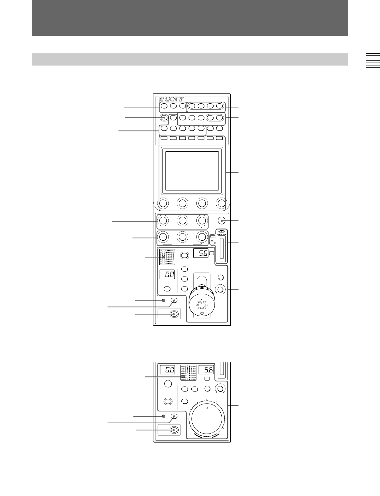
操作パネル
RCP-750
1
コントロール選択部
2
STANDARD
3
カメラ
ON/OFF
/CCU
ボタン
ボタン
機能
PARA
MASTER SLAVE
STANDARD
5600K
PAINT 1 PAINT 2
SKIN DTL
CHAR
AUTO HUE
ACTER
AUTO
SKIN
KNEE
DETAIL
PAINT 3 SCENE MAINTE
TEST BARS CLOSE
CAM PW
AUTO SETUP
LEVEL
START/
BREAK
DTL
BLACK
GATE
GAMMA
NANCE
WHITE BLACK
FUNCTION
0
出力信号選択部
電源/
qa
AUTO SETUP
qs
メニュー操作部
部
RCP-751
4
WHITE
5
BLACK/FLARE
6
7
ALARM
8
CALL
9
PANEL ACTIVE
6
7
ALARM
8
CALL
9
PANEL ACTIVE
つまみ
つまみ
カメラナンバー/タリー表示部
インジケーター
ボタン
ボタン
カメラナンバー/タリー表示部
インジケーター
ボタン
ボタン
WHITE
BLACK/FLARE
IRIS/MB
ACTIVE
MASTER
BLACK
RELATIVE
RELATIVE
ALARM CALL
PANEL
ACTIVE
REMOTE CONTROL PANEL
BLACK/FLARE
MASTER
BLACK
RELATIVE
IRIS/MB
ACTIVE
ALARM CALL
PANEL
ACTIVE
REMOTE CONTROL PANEL
AUTO
AUTO
qd
DETAIL
a
EXT
SENS
OPENCLOSE
COARSE
IRIS
a
EXT
SENS
OPEN
CLOSE
COARSE
DETAIL
qf
MEMORY STICK
アクセスランプ
アイリス/マスターブラック調整部
(
9(J)
ページ
つまみ
スロットと
)
アイリス/マスターブラック調整部
(
ページ
10(J)
IRIS
)
5 (J)
Page 8
各部の名称と働き
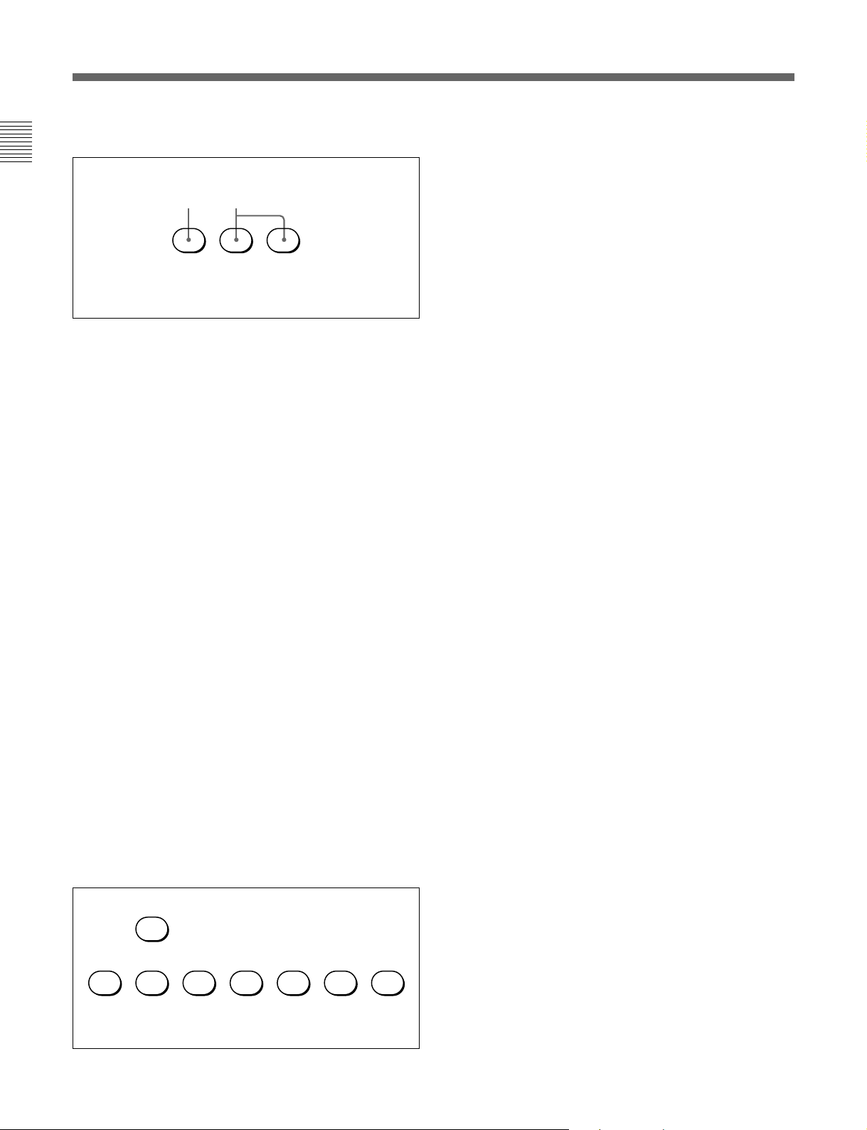
1 コン トロール選択部
AB
PARA MASTER SLAVE
A
他の コントロールパネルとの同時コ ントロール状態(パラレルモ ード)
に設定されていると点灯 します。
このボタンが点灯 している とき は、PANELACTIVEボタンが消灯し
ている場合でも、アイリス/ マスターブラック調整部を除く本機のす
べてのボタン/調整部が有効です。
ボタ ンを押して消灯 させる と、パラレルモー ドが解除されます。
B
マスタ ー/スレー ブモードで、複数のカメラのホワイトバランスを同時
に調整するとき、マスター機、スレーブ機を指定します。
本機でコントロールしているカメ ラをマス ターにす るときはMASTER
ボタ ンを押して点灯 させ、スレーブにするときはSLAVEボタンを押
して点灯させます。
どち らのボタン も 、 もう1度押すと消灯 します。
2
押す とビデオカメラの各種設定が標準状態になり、ボタ ンが数秒間
点灯します。
ボタ ンが点灯している間にもう1度押すと、点灯する前の状態に戻
ります 。
3 カメ ラ
ビデオカメラや CCU/HDCUの機能を、本機からON/OFFするこ
とができます。
(パラレルモード)ボタン
PARA
MASTER
STANDARD
(マスター)ボタン と
(標準)ボタン
/CCU機能ON/OFF
SLAVE
ボタン
(スレーブ)ボタン
:5600K の電気色温度補正機能
5600K
AUTO KNEE
の明るさに応じて自動的にニーが働きます。
SKIN DETAIL
機能
DTL GATE
ト機能。 ONでは、スキントーンディテールの調整範囲がPIX
(ピクチャー)モニター上に白く 表示されます。
BLACK GAMMA
CHARACTER
CCU/HDCUのCHARACTEROUTPUT端子に接続したモ
ニターに、CCU/HDCUの自己診断内容を表示します。この
内容は、PIX1OUTPUTのビデオ信号にもミックスされて出力
されます。
表示はボタンを押すたびに次のように切り換わり ます。
OFF c ON(1
c
ON(n
自己診断内容は、このボタンが消灯 していても必要に応じて
自動的に表示されます。
右側2個のボタンは機能拡張用です。現在は機能しません。
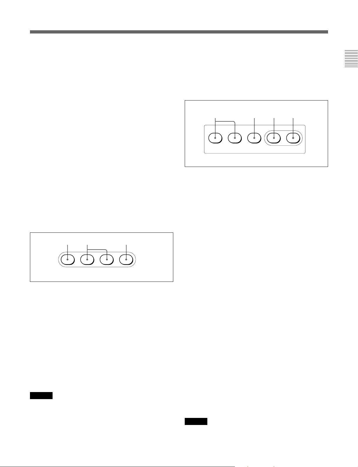
4
WHITE
ホワイトバランス手動調整用のつまみです。左から順にR、G、B信
号を調整します。
5
BLACK/FLARE
調整)つまみ とインジケーター
インジケーター消灯時はブラックバ ラン スを、インジケーター点灯時
はフ レアバラ ンス を調整しま す。左から順にR、G、B信号を調整し
ます。
ブラ ッ クバラ ンス/フレアバランスの選択はメ ンテナン スメニューで
行います。
◆「ロー タリーエンコーダ ー の 設 定を変更する」(25(J)ページ)をご覧く ださ
い。
(オートニー):オートニー機 能。ONでは、画面
(スキンディテール):スキン トーンディテール
(ディテールゲート):スキン トーンディテールゲー
(ブラックガンマ):ブラッ クガンマ機能
(文字情報):自己診断表示機能
ページ)
c ON(2
ページ)
c OFF
(ホワイトバランス手動調整)つまみ
(ブラッ クバランス/フレア バランス手動
ページ) ・・・
5600K AUTO
6 (J)
CHAR
ACTER
KNEE
SKIN
DETAIL
DTL
GATE
BLACK
GAMMA
6 カメ ラナンバー/タリー表示部
本機でコントロールしてい るカ メラのナンバーが、オレンジ色で表 示
されます。
カメ ラにレッドタ リー 信 号 が入力されると、背景が赤く 点 灯し、ナン
バーは黒で表示されます。グリ ーンタリー信 号 が入力されると背景
が緑に点灯し、ナンバーは黒で表示されます。
レッ ドタ リー 信 号 とグリーンタリー信号が同時に入力された場合は、
背景の左半分が赤、右半分が緑に点灯します。
Page 9
7
ALARM
システムに異常が発生し、カメラヘ ッドやCCU/HDCUで自己診断
機能が動作すると、赤く点灯します。
(アラーム)インジケーター
C
CLOSE
押して点 灯させると、 絞りがクローズします。 もう1度押すとボタン
は消灯し、クローズが解除されます。
(アイリス クローズ)ボタン
8
押すとビデオカメラにコール信号が送出され、カメラ側のCALLボ
タンが点灯します。また、カメラのタリーランプとCCU/HDCUの
レッ ドタリーランプ は、 それぞれ点灯していた場合は消灯し、消灯し
ていた場合は点灯します。
カメ ラ側で CALLボタンが押されると、本機のCALLボタンが点灯
し、 ブザーが鳴ります。
9
押して点灯させると、本機に接続したカ メラシス テム を コントロール
でき る状態(パネルアクティブ状態)にな ります。このとき アイリス /
マス ターブラ ック調整部のIRIS/MBACTIVEボタンも同時に点灯
します。
また、消 灯させるとパネルはロックされ、誤動作防止になります。
0 電源
A
押して点 灯させると、ビデオカメラに電源が供給さ れます 。(ボタン
を押 してから、カメラが立ち上がって通信可能になるまでの間は、
高速で点滅します。)
もう1 度 押すと点滅に変わり、カメ ラへの電源供給が遮断さ れま す。
B
押して点 灯させると、 カメ ラのテスト信号発生器が作動し、対応す
る信号が出力されます。
TEST
BARS
BARSボタンが点灯している場合は、BARSボタンの機能が優先し
ます。 TESTを選択するときは、BARSボタンを押して消灯させてく
ださい。
(コール)ボタ ン
CALL
PANEL ACTIVE
出力信号選択部
/
CAM PW TEST BARS CLOSE
CAM PW
テスト信号出力選択ボタン
ご注意
(カメラ電源)ボタン
(テスト):ビデオ回路チェック用の テスト信号
(カラーバー):カラーバー信号
(パネルアクティブ)ボタン
AB C
qa
AUTO SETUP
(オートセットアップ)部
ABDC
AUTO SETUP
SKIN DTL
AUTO HUE
A
自動調整項目選択ボタン
押して点灯させ、自動調整する項目を選択します。
SKIN DTL AUTO HUE
スキントーンディテールオートヒュー
(レベル):ガンマバラ ンス、ニーポイント、 マスターブラッ
LEVEL
クレベ ル など
B
START/BREAK
このボタ ンを押すと、点灯している項目選択ボタンに対応す る項目
の自動調整が実行されます。
調整中はボタンが点灯し、調整が完了すると消灯します。
自動調整実行中にこのボタンを押すと、自動調整が中止され、ボ
タンが点滅します。もう1 度ボタン を押す と 点滅が止まります。
C
WHITE
押すと、ホワイトバランスが自動調整されます。
調整中はボタンが点灯し、調整が完了すると消灯します。
自動調整実行中にもう1度このボタンを押すか、START/BREAK
ボタ ンを押すと、自動調整が中止され、ボタ ンが点滅します。もう1
度ボタンを押す と 点滅が止まります 。
D
BLACK
押すと、ブラックバランス 、ブラッ クセ ットが自動調整されます。
調整中はボタンが点灯し、調整が完了すると消灯します。
自動調整実行中にもう1度このボタンを押すか、START/BREAK
ボタ ンを押すと、自動調整が中止され、ボタ ンが点滅します。もう1
度ボタンを押す と 点滅が止まります 。
ご注意
自動調整中にエラーが発生した場合は、点灯させたボタンが点滅
します。
(ホワイトバランス自動調整)ボタン
(ブラックバランス自動調整)ボタン
LEVEL
START/
BREAK
(スキンディテールオートヒュー):
(自動調整開始/中止)ボタン
WHITE BLACK
7 (J)
Page 10
各部の名称と働き
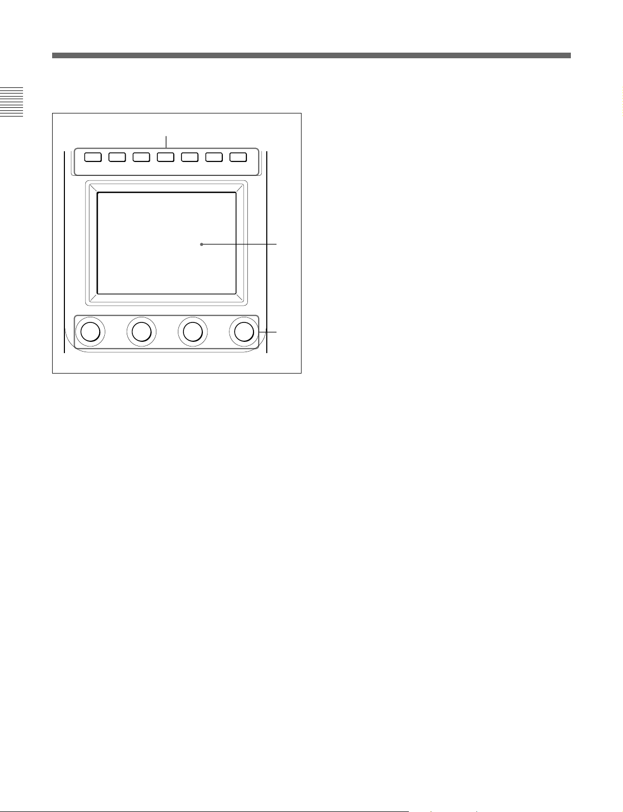
qs メニュー操作部
A
PAINT 1 PAINT 2 PAINT 3 SCENE MAINTE
A
MODE
メニューのモー ドを選 択します。
押して点灯させたボ タンに対応するモードのメニュ ーが液晶ディス
プレイ に表示されます。
PAINT 1/2/3
SCENE
MAINTENANCE
FUNCTION
すべてのボタンを消灯さ せると、ステータス表示 (14(J)ページ)に
なります。
◆それぞれのメニューの項目については、「メ ニ ュ ー項目」(18(J)ページ)
をご覧く ださい。
(モード選択)ボタン
(ペイント):ペイントメニ ューを 選択します。
ホワイト、ブラック、フレア などを調整します。
(シーンファイル):ファイル操作メニューを選択しま
す。
シー ンフ ァ イ ルの呼び出し、登録を行います。
(メンテナンス):メンテナンスメニューを選
択します。
CCU/HDCUのH位相、SC位相などの設定や本機の動作環
境の設定を行います。
(ファンクション):ファンクションメ ニューを選択
します。
カメ ラおよび CCU/HDCUの各種機能のON/OFFや設定を
行います。
NANCE
FUNCTION
B
C
B
(液晶ディスプレイ)/タッチパネル
LCD
通常はステータス
MODEボタンを押すと、選択したモードのメニュ ーが表示され、各
種の設定が可能になります。
調整つまみ(ロータリ ーエンコーダー)
C
タッチパネルで選択した項目を調整します。
qd
DETAIL
ディ テールレベルを調整します。
メンテナンスメニューを使 用して、HDディテールを調整するか、SD
ディ テールを調整するかを選択することができます。
◆「ロー タリーエンコーダ ー の 設 定を変更する」(25(J)ページ)をご覧く ださ
い。
qf
MEMORY STICK
スランプ
カメ ラやCCU/HDCUのリファレンスファイル、 シー ン フ ァ イ ルな どを
保存する
アクセス ラ ンプが
メモリースティックが挿入されていません。
消灯:
緑点灯:メモリースティックが挿入されています。この状態のと
メモリースティックを安全に抜くことが できます 。
きは
赤点灯:データ の読み出し/書き込み中です。この状態でメモ
リースティック
全データが消えて し まうこともあります。
◆メ モリーステ ィックに つ いては、26(J)ページをご覧ください。
(14(J)ページ参照)を表示します。
(ディテール調整)つまみ
(メモリ ー ス ティック) スロ ットとアクセ
メモリースティックをス ロ ットに 挿 入します。
メモリースティックの状態を表示します。
を抜き差 しすると、データは保証されません。
8 (J)
Page 11
アイリス/マスターブラック調整部(
RCP-750
)
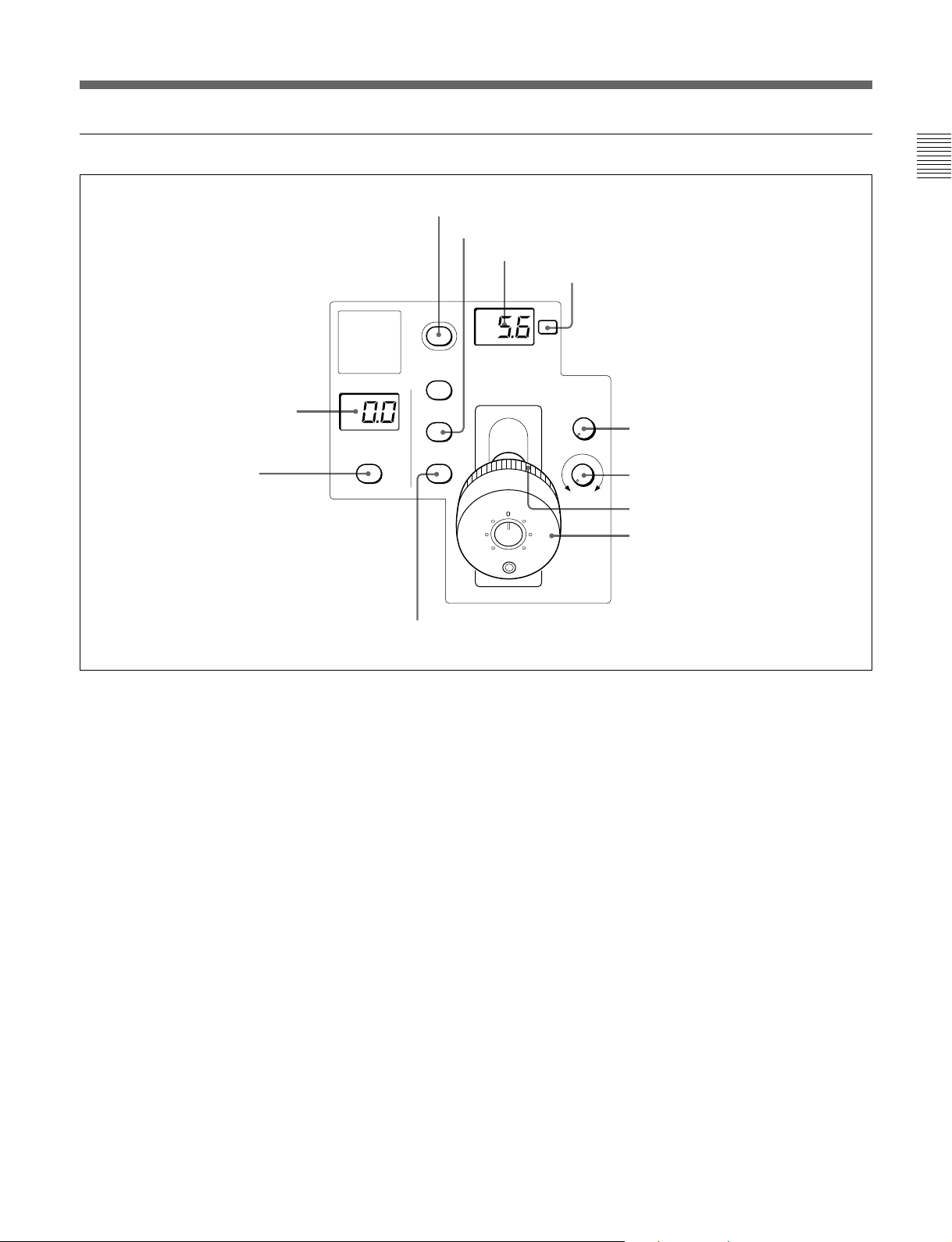
1
MASTER BLACK
2
MASTER BLACK
RELATIVE
ボタン
表示部
MASTER
BLACK
RELATIVE
3
IRIS/MB ACTIVE
4
AUTO
IRIS/MB
ACTIVE
AUTO
RELATIVE
qa
IRIS RELATIVE
ボタン
5
ナンバー表示部
F
EXT
IRIS
ボタン
ボタン
6
EXT
SENS
COARSE
インジケーター
7
SENS
8
COARSE
OPENCLOSE
9
0
IRIS
つまみ
つまみ
マスターブラック調整リング
レバー
1
MASTER BLACK
マス ターブラックの 設 定を、
2
MASTER BLACK RELATIVE
(マスターブラック)表示部
+99〜−99の範囲で表示します。
(マスターブラック相対
値モード)ボタン
IRIS/MBACTIVEボタン点灯時に、このボタ ンを押して点灯させ
ると、 マス タ ー ブラックの 調 整が絶対値モ ードから相対値モードに切
り換わります。
絶対値モードに戻すと きは、もう1度ボタ ン を押 して消灯さ せます。
IRIS/MBACTIVEボタン消灯時は、自動的に相対値モードにな
り、このボタ ンは機能しません。
3
IRIS/MB ACTIVE
(アイリス/マスタ ーブラックアクテ ィ
ブ)ボタ ン
押して点灯させると 、本機で絞りとマスターブラ ックの調整が行えま
す。
PANELACTIVEボタンを押すと、このボタン も同時に点灯します。
消灯させるとパネルはロックされ、誤動作防止になります。
4
AUTO
ボタン
押して点灯させると、レンズ の 絞りが入力光に応じて自動的に調整
されます。
ボタ ン点灯時は、絞りの自動調整の基準値を±1Fの範囲で微調
整することができ ます。
もう1 度押すと消灯し、絞りの手動調整が可能になります。
ナンバー表示部
5
F
絞りの設定値をFナンバーで表示します。レンズをクローズする と、
「CL」が表示されます。
(レンズエクステンダー)インジケーター
6
EXT
レンズエクステンダーを使 用しているとき点灯します。
7
(アイリス調整範囲)つまみ
SENS
絶対値モードで絞りの手動調整を 行うとき使 用します。 相対値モー
ドでは、このつまみは機能しません。
◆「アイリス調 整機能」表(次ページ)を、併せてご覧ください。
9 (J)
Page 12
各部の名称と働き
8
COARSE
(アイリス粗調整)つまみ
絞りの手動調整を行うとき使 用します。
◆「アイ リス調 整機能」表(右記)を、併せてご覧ください。
9 マスターブラ ック調整リング
マス ターブラ ックの 手動調整を行います。
0
(アイリス調整)レバー
IRIS
AUTOボタン消灯時に動かすと、レンズ の 絞りを手動で調整できま
す。
AUTOボタン点灯時は、絞りの自動調整の基準値を微調整(±
1F)します。
◆「アイ リス調 整機能」表(右記)を、併せてご覧ください。
qa
IRIS RELATIVE
(アイリス相対値モード)ボタ ン
IRIS/MBACTIVEボタン点灯時にこのボタンを押して点灯させる
と、絞りの手動調整のモードが絶対値モードか ら相対値モードに切
り換わります。
絶対値モードに戻すと きは、もう1 度ボタ ンを押して消灯させます。
IRIS/MBACTIVEボタン消灯時は、自動的に相対値モードにな
り、このボタ ンは機能しません。
アイリス調整機能
相対値モード 絶対値モード
(
RELATIVE
IRISレバー OPENからCLOSEまでの SENSつまみとCOARSE
(RCP-750)/ 約1/4の範囲を相対値で つまみで設定した可変範
IRISつまみ 調整します。 囲内で絞りを調整します。
(RCP-751)
COARSE OPENからCLOSEまでの CLOSE側の下限を設定
つまみ 全範囲を相対値で調整し します。
ます。
SENSつまみ 機能しません。 COARSEつまみで設定
ボタン点灯
)(
RELATIVE
したCLOSE側を基準に
して、OPEN側の上限を
設定します。
ボタン消灯
)
アイリス/マスターブラック調整部(
1
MASTER BLACK
2
MASTER BLACK
3
IRIS/MB ACTIVE
表示部
つまみ
ボタン
RCP-751
4
MASTER
BLACK
IRIS/MB
ACTIVE
qa
)
IRIS RELATIVE
RELATIVE
AUTO
ボタン
AUTO
ボタン
EXT
SENS
CLOSE
OPEN
COARSE
IRIS
5
ナンバー表示部
F
6
インジケーター
EXT
7
8
9
0
つまみ
SENS
COARSE
つまみ
IRIS
アイリスゲージ
つまみ
1
MASTER BLACK
(マスターブラック)表示部
マス ターブラックの 設 定を、
10 (J)
+99〜−99の範囲で表示します。
2
MASTER BLACK
(マスターブラック調整)つま み
マス ターブラ ックの 手動調整を行います。
MASTERBLACK表示部に設定値が表示されます。
Page 13
3
IRIS/MB ACTIVE
ブ)ボタ ン
押して点灯させると 、本機で絞りとマスターブラ ックの調整が行えま
す。
PANELACTIVEボタンを押すと、このボタン も同時に点灯します。
また、消 灯させるとパネルはロックされ、誤動作防止になります。
(アイリス/マスタ ーブラックアクテ ィ
AUTO
ボタン
qa
押して点灯させると、レンズ の 絞りが入力光に応じて自動的に調整
されます。
ボタ ン点灯時は、絞りの自動調整の基準値を±1Fの範囲で微調
整することができ ます。
もう1 度押すと消灯し、絞りの手動調整が可能になります。
4
IRIS RELATIVE
IRIS/MBACTIVEボタン点灯時にこのボタンを押して点灯させる
と、絞りの手動調整のモードが絶対値モードか ら相対値モードに切
り換わります。
絶対値モードに戻すと きは、もう1度ボタ ン を押 して消灯さ せます。
IRIS/MBACTIVEボタン消灯時は、自動的に相対値モードにな
り、このボタ ンは機能しません。
ナンバー表示部
5
F
絞りの設定値をFナンバーで表示します。レンズをクローズする と、
「CL」が表示されます。
(レンズエクステンダー)インジケーター
6
EXT
レンズエクステンダーを使 用しているとき点灯します。
7
絶対値モードで絞りの手動調整を 行うとき使 用します。 相対値モー
ドでは、このつまみは機能しません。
◆「アイリス調 整機能」表(前ページ)を、併せてご覧ください。
(アイリス調整範囲)つまみ
SENS
(アイリス相対値モード)ボタ ン
コネクターパネル
1
CCU/CNU REMOTE
2
AUX REMOTE
REMOTE
CCU/CNU AUX
1
CCU/CNU REMOTE
カメ ラコマンドネットワークユニットリモート)端子(8ピン)
カメ ラコントロールユニットの RCP/CNU端子、またはカメラ コマン
ドネ ットワークユニットの RCP端子に接続します。
(カメラコ ントロールユニッ ト
3
EXT I/O
端子
端子
EXT I/O
端子
/
8
COARSE
絞りの手動調整を行うとき使 用します。
◆「アイリス調 整機能」表(前ページ)を、併せてご覧ください。
9
IRIS
AUTOボタン消灯時は、レンズの絞りを手動調整します。
AUTOボタン点灯時は、絞りの自動調整の基準値を微調整(±
1F)できます。
◆「アイリス調 整機能」表(前ページ)を、併せてご覧ください。
0 アイリスゲージ
白いマーカーラ インが、アイリス調整つまみのクリック位 置 になりま
す。ゲージを回 して使用頻度の高い位置にマーカーラインを合わせ
てお くと、アイリス 調整つまみの設定基準として使用できま す。
ゲー ジは360°回転しますので、クリック位置が不要の場合は、マー
カーライ ンがつまみの回転範囲の外にな るように設定してく ださい。
(アイリス粗調整)つまみ
(アイリス調整)つまみ
2
AUX REMOTE
RCP-700/701を接続します。
3
EXT I/O
拡張機能を追加したときに、外部機器を制御するための端子で
す。
ご注意
本機を設置するときは、ケーブルの損傷を防ぐため、コネク ターパ
ネルの後方に約7cm以上の空間を設けてください。
(外部
(補助リモー ト)端子(8ピン)
)端子(9ピン)
I/O
11 (J)
Page 14
コンソールへの取り付け
RCP-750/751は、下図のようにコンソールに取り付けることができ
ます。
12 (J)
Page 15
メニューの構成と基本操作
RCP-750/751では、メニュー操作によ り、シス テム機器の調整など
様々 な機能に対応し ます。
基本操作手順
1
PAINT 1 PAINT 2 PAINT 3 SCENE MAINTE
NANCE
FUNCTION
2
3
2 操作する項目を選択する。
メニュー画 面の項目ボタンを押し、設定・調整画面または操
作エリアを表示させます。
メニューが複数ページある場合は
ペイントメニューやファンクションメニューのよう にメ ニュー が複
数ページある場 合は、vまたは Vを押して、 必要に応じてメ
ニューのページ を切り換えます。
◆次ページ「初期画面(ペイントメニュー)」参照。
サブメニューがある場合は
ボタ ンを押して設定・調整画面を切り換えます。
◆15(J)ページ「サブメニュー」参照。
3 項目を設定・調整する。
• 設定・調整項目(パラメーター) に対応するつまみを回して
(またはボタンを押して)、希望の値に調整(希望の設定を選
択)します。
◆15(J)ページ「設定・調整画面」参照。
• メッセージが表示された場合は、メッセージに従って操作し、
[OK]を押 します。
MODEボタンがすべて消灯しているときは、ディ スプレイはステー
タス表示(次ページ参照)になっています。
1 メニューを表示させると きは、MODEボタンのいずれかを押し
て点灯させる。
メニュー操作モー ドになり 、押したMODEボタンに対応するメ
ニュー がディスプレイに表示されます。
PAINT 1/2/3
◆画面構成については14(J)ページ、メニュー項目に ついては18(J)
ページをご覧く ださい。
SCENE
◆画面構成と操作については16(J)ページをご覧ください。
MAINTENANCE
◆メニ ュ ー項目については21(J)ページ、設定については「初期設
定」(23(J)ページ)をご覧く ださい。
FUNCTION
◆画面構成については17(J)ページ、メニュー項目に ついては22(J)
ページをご覧く ださい。
:ペイントメニュー
:シー ンフ ァ イ ル操作メニュー
:メンテナ ンスメニュー
:ファンクションメニュー
設定・調整が終わったら
• 引き続き同じメニューの別の項目を設定・調整するときは、その
項目のボタンを押します。
• 引き続き別のメニューの設定・調整を行うときは、対応する
MODEボタンを押してメニューを切り換えます。
• メニュー操作モー ドを解 除すると きは、 点灯しているMODEボタ
ンを押します。
• ファンクションメニューは、 現在設定・調整しているメニューを解
除しないで選択することができます。
下記のいずれかの方法でファンクションメニューを解除すると、
ファンクションメニューに切り換え る前に表示されていたメニュー
画面に戻ります。
- FUNCTIONボタンを押して消灯させる。
- 点灯している(直前に表示されていたメ ニュ ーの)MODEボタ
ンを押す。
13 (J)
Page 16
メニューの構成と基本操作
メニュー画面の基本構成
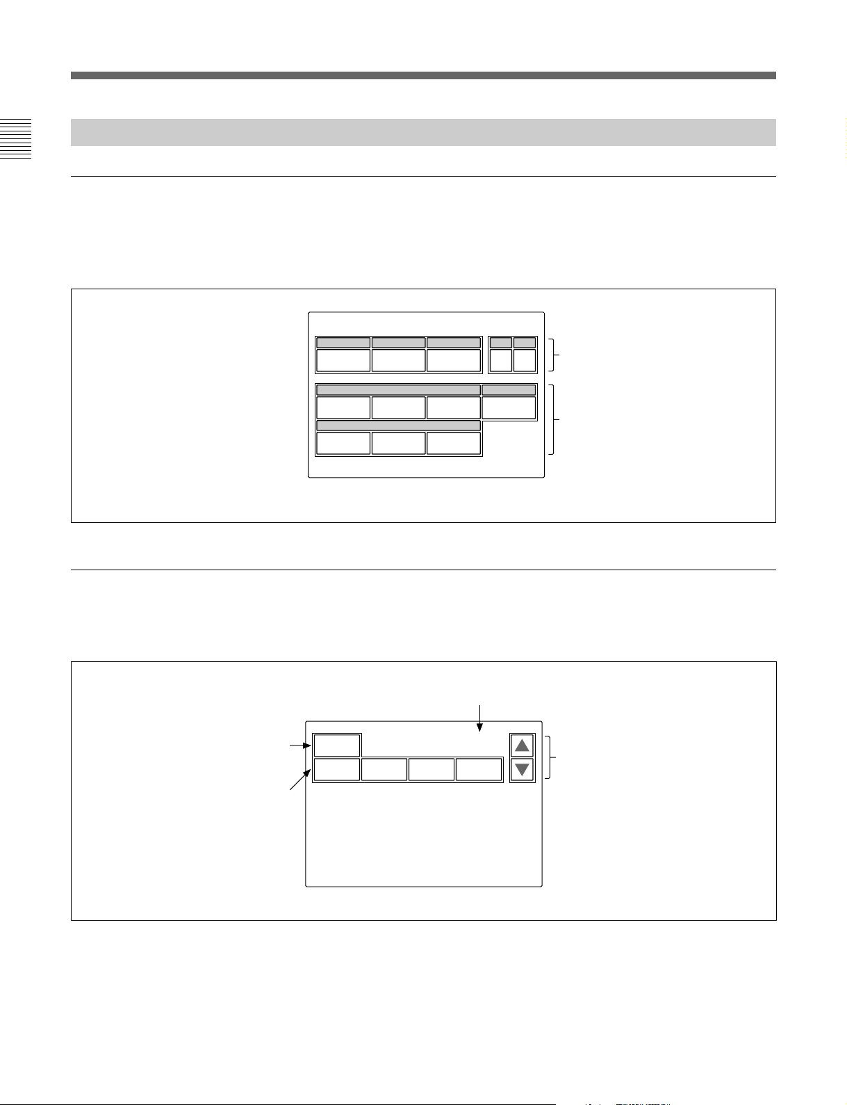
ステータス表示
メニュー操作部のMODEボタン(PAINT1、PAINT2、PAINT3、
MAINTENANCE、FUNCTION、SCENE)を選択 し ないと(すべ
て消灯)、ディ スプレイ は下図のようなステータス表示になります。
ステータス表示では、各項目は状態表示
のみで、設定はファンクションメニュー
や操作パネルのつまみで行います。
Status
Shutter
60
M. Gain
0dB
White
0
Black
0
初期画面(ペイントメニュー)
メニュー操作部のPAINT1(またはPAINT2、PAINT3)ボタ ン を押
すと、 ペイ ントメニューの初期画面になります。
Gamma
0.45
ND
1
Detail
00
00
ページ画面/総ページ数
ND
0
これらの項目は、ファンクションメ
A
ニューで設定できます
これらの項目は、操作パネルの
WHITE、BLACK/FLARE
DETAIL
Detail
メニューでそれぞれ
Flare
の各つまみで調整できます。
および
Black
に変更することができます。
、
は、メンテナンス
SD Detail
、
設定値をクリアすることができます。
この画面で調整可能な項目の名称が
表示されます。
調整したい項目の部分を押すと、押
した部分の色が変わり、パネルの下
半分が調整画面になります(次ぺ−
ジ参照)。
14 (J)
Clear
White Black Flare Gamma
1 / 6
押すと、メニューのページ(1〜6)が
順次切り換わります。
Page 17
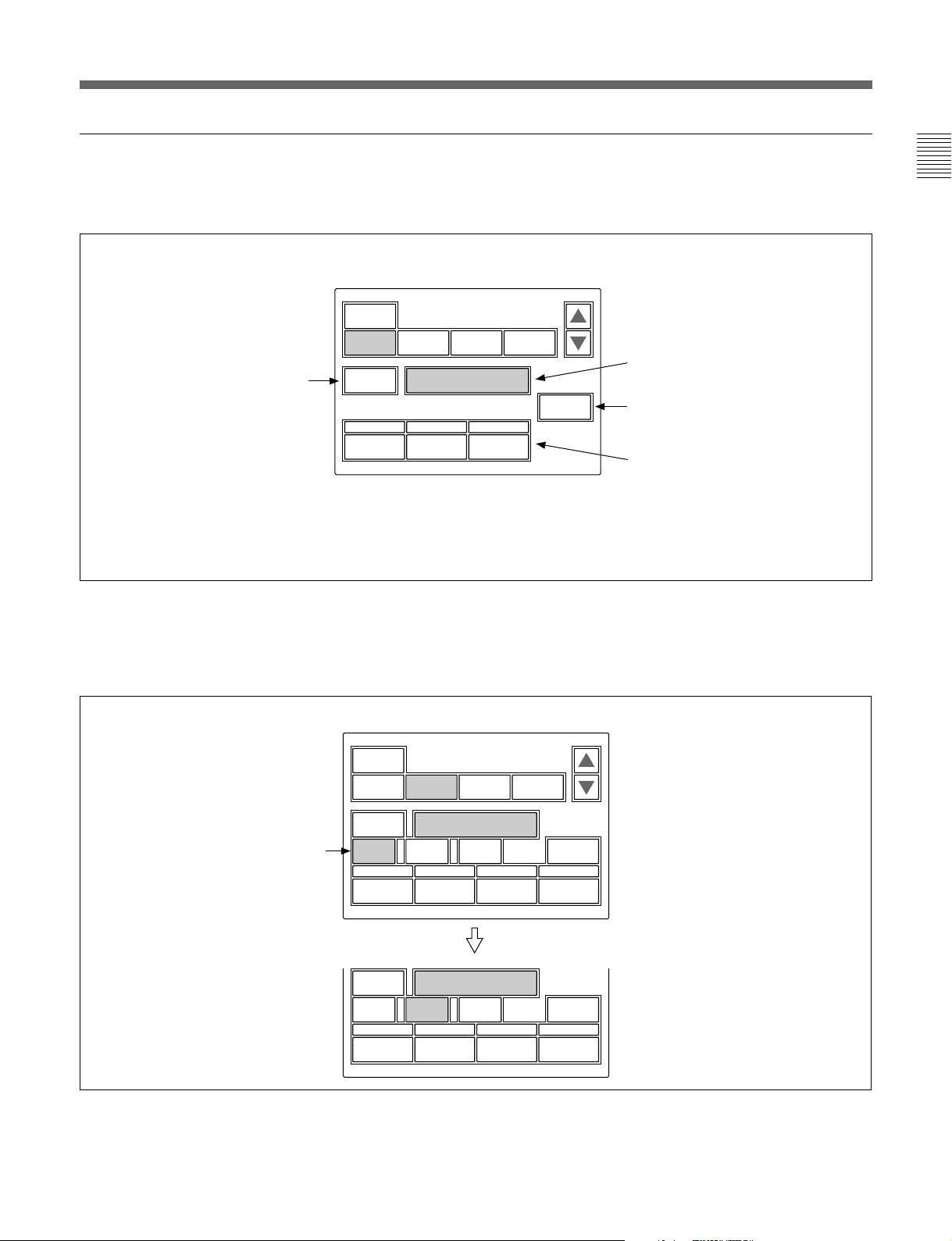
設定・調整画面(ペイントメニュー)
ペイントメニューの初期画面で項目を選択す ると、画面の下半分が
選択した項目の設定・調整画面になります。
例:初期画面で
押すと、モニター出力設定画面(次
ページ参照)が上半分に表示されま
す。
を選択したとき
White
Clear
White Black Flare Gamma
WF/PIX
Select
R
0
G
0
サブメニュー
初期画面で選択した項目内で調整パラメーター等が多い場合、サ
ブメ ニュ ー が表示されます。
White
1 / 6
ATW
B
0
初期画面で選択した項目名が表示されま
す。
を押してからこの部分を押すと、
Clear
選択した項目の全調整値が標準状態に戻
ります。
調整に関連する
場合は、この列に表示されます。
選択した項目の調整パラメーターおよ
び調整値が表示されます。
それぞれに対応する位置の調整つまみ
で調整することができます。
を押して調整値を押すと、調整
Clear
値が標準状態に戻ります。
ON/OFF
機能がある
例:初期画面で
Skin Detail
を選択したとき
サブメニュー
Clear
Detail1Skin
WF/PIX
Select
Detail
Sat
Skin Detail
123
Level
WF/PIX
Select
Phase
0
Width
0
Skin Detail
123
Level
Phase
0
Width
0
2 / 6
Black
Gamma
Skin
DTL 1
Sat
0
サブメニューで調整パラメーターを切り換えます。
0
0
Skin
DTL 2
Sat
0
15 (J)
Page 18
メニューの構成と基本操作
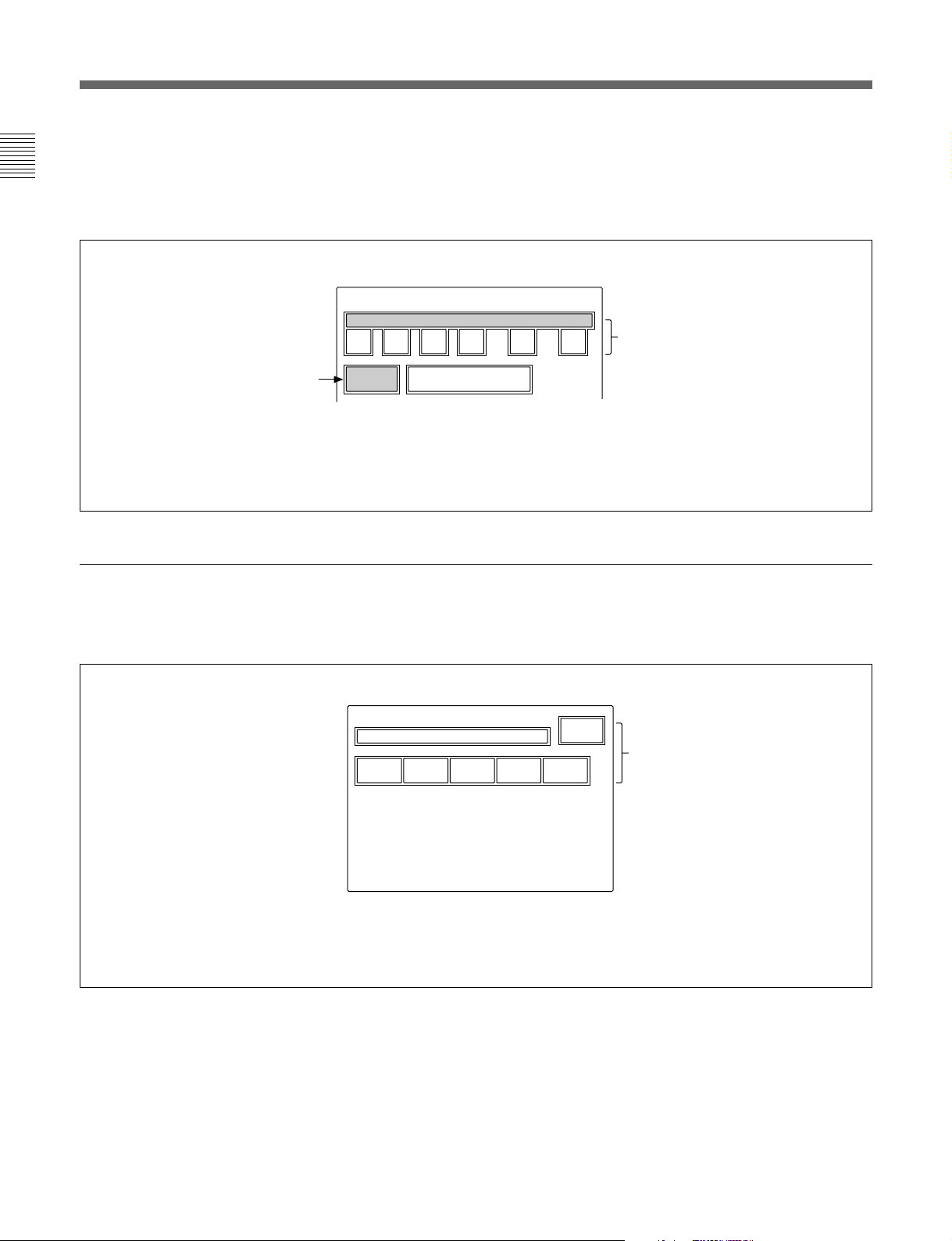
モニター出力設定画面(拡張メニュー)
ペイントメニューの設定・調整画面で[WF/PIX Select]を押 して点灯
させると、画面上半分にモニター出力設定画面が表示されます。
WF/PIX Monitor Select
RGBRGB SEQ ENC
表示を戻したいときは、もう1度
この項目を押してください。
WF/PIX
Select
:それぞれR信号、G信号、
R/G/B
信号を選択します。
B
RGB:R
SEQ:WF
ENC
信号、G信号、B信号を組み
合わせて選択できます。
出力のみ有効で、R、G、
つの信号の波形をシーケン
Bの3
シャルモードでモニターすること
ができます。
:エンコードされた信号が出力
されます。
シーンファイル操作メニュー画面
メニュー操作部のSCENEボタンを押すと、シーンファイル操作メ
ニュー画面にな ります。
シーンファイルの呼び出し:
呼び出したいシーンファイルの番号を選択
して押すと、登録されているファイルが呼
び出されます。
このとき呼び出されているシーンファイル
番号は色が変わります。
同じシーンファイル番号を押すと呼び出さ
れる前の状態に戻ります。
Scene File Recall
12345
Store
シーンファイルの登録:
を押して点灯させてから、希
Store
望するシーンファイル番号を選択し
ます。ファイル登録が終了すると
の色が元に戻ります。
Store
16 (J)
Page 19

ファンクションメニュー画面
メニュー操作部のFUNCTIONボタンを押すと、ファンクションメ
ニュー画面にな ります。
Operation
Filter Ctrl
この画面でフィルターを選択でき
る状態になります。
選択時
を押して色を変えると
v
Vを押して希望するフィルターを選択します。
/
フィルター、CCフィルターの枚数はカメラに依存します。
ND
Opera-
tion
Filter
Ctrl
SW
ND GammaCC
1A 0.45
Shutter ECS
Master
Gain
60 30.00 0dB
それぞれ対応する位置の調整つまみで
調整できます。
v
Vを押してガンマ値を選択します。
/
±
ステップで変更できます。
0.05
v
Vを押してマスターゲインを選択し
/
ます。
vを押すたびに値が大きくなり、
Vを押すたびに小さくなります。
SW
選択時
Opera-
tion
S-Skin
Knee
Sat Mono
Black
Gamma
5600K
それぞれ対応する機能を
Off
の機能が
SW
Low Key
Sat
Auto
Knee
ATW PsF
Knee
Aperture
Skin
Detail
ON/OFF
Knee
Sat
Detail
Gate
します。
の表示があるボタンは選択(点灯)時にそ
になり、それ以外のボタンは選
OFF
択(点灯)時に機能がONになります。
ページ番号/総ページ数
1 / 2
押すと、メニューのページが切り換わ
ります。
17 (J)
Page 20

メニューの構成と基本操作
メニュー項目
操作/調整項目欄で●が付いている項目は調整つまみに割り 当て
られる項目、それ以外の項目は、メニュー画面上で操作する項目
です。
ペイントメニュー
ペイントメニューは ページ 1 〜 6 で構成されています。
ペー ジ1〜3は、MODEボタンのPAINT1、PAINT2、PAINT3を押
して直接選択することができま す。MODEボタンで選択したページ
のv/Vを押すことに よって、ページ1 〜 6を順次切り換えるこ とが
でき ます。
ページ メニュー サブメニュー 操作/調整項目 機能
Paint1 White ●R/G/B ホワイトバランス調整
ATW オートトレース ホワイトバランス調整
Black ●R/G/B/Master ブラックバランス調整
Flare ●R/G/B フレアバランス調整
FlareOff フレアON/OFF
Gamma ●R/G/B/Master ガンマ調整
GammaOff ガンマON/OFF
Paint2 Detail1 HD
SkinDetail 1/2/3(項目共通) ●Level スキンディテールレベル調整
Saturation ●Saturation サチュレーション調整
BlackGamma RGB ●R/G/B/Master ブラックガンマ調整
a)
●Level HDディテールレベル調整
●Limiter HDディテールリミッター 調 整
●Crispening HDディテールクリスプ ニ ング 調 整
●LevelDep HDレベルディペンド調整
DetailOff HDディテールON/OFF
SDDTLOff SDディテール ON/OFF
a)
SD
●Level SDディテールレベル調整
●Limiter SDディテールリミッター 調 整
●Crispening SDディテールクリスプ ニ ング調整
●LevelDep SDレベルディペンド調整
DetailOff HDディテールON/OFF
SDDTLOff SDディテール ON/OFF
●Phase スキンディテール色相調整
●Width スキンディテール色相幅調整
●Saturation スキンディテールサチュレー ション調整
SkinDTL# スキンディテールON/OFF(チャンネル別)
Saturation サチュレーションON/OFF
Y ●Yブラックガンマ調整
a)HDカメラ接続時のみ、HD/SDのサブメニューが表示されます。
18 (J)
Page 21

ぺ−ジ メニュー サブメニュー 操作/調整項目 機能
Paint3 KneePoint ●R/G/B/Master ニーポイント調 整
KneeOff ニーON/OFF
KneeSlope ●R/G/B/Master ニースロープ調整
KneeOff ニーON/OFF
Matrix Matrix1 ●R-G/G-B/B-R マトリックス定数設定
UserMatrix ユーザーマトリックス ON/OFF
PresetMatrix プリセットマトリックスON/OFF
MatrixOff 全マトリックス ON/OFF
Matrix2 ●R-B/G-R/B-G マトリックス定数設定
UserMatrix ユーザーマトリックス ON/OFF
PresetMatrix プリセットマトリックスON/OFF
MatrixOff 全マトリックス ON/OFF
MultiMatrix ●Phase マルチマトリックス領 域選 択
●Hue マルチマトリックス色 相 設 定
●Sat マルチマトリックス彩 度 設 定
MultiMatrix マルチマトリックス ON/OFF
MatrixOff 全マトリックス ON/OFF
AllClear 全マルチマトリックス設 定をクリア
Paint4 Gamma/Knee ●Gamma マスターガンマ調整
●BlkGamma マスターブラックガンマ調整
●KneePoint マスターニーポイント調整
●KneeSlope マスターニースロープ調整
GammaOff ガンマON/OFF
KneeOff ニーON/OFF
KneeSaturation ● KneePoint マスターニーポイント調整
●KneeSlope マスターニースロープ調整
●Level ニーサチュレーションレベル調整
KneeOff ニーON/OFF
KneeSat ニーサチュレーションON/OFF
LowKeySaturation ●Level LowKeyサチュレーションレベ ル調整
LowKeySat LowKeyサチュレーションON/OFF
WhiteClip ●R/G/B/Master ホワイトクリップ調整
WhiteClipOff ホワイトクリップ ON/OFF
Paint5 Detail1 HD
a)
●Level HDディテールレベル調整
●Limiter HDディテールリミッター 調 整
●Crispening HDディテールクリスプ ニング 調 整
●LevelDep HDレベルディペンド調整
DetailOff HDディテールON/OFF
SDDTLOff SDディテール ON/OFF
a)
SD
●Level SDディテールレベル調整
●Limiter SDディテールリミッター 調 整
●Crispening SDディテールクリスプ ニング調整
●LevelDep SDレベルディペンド調整
DetailOff HDディテールON/OFF
SDDTLOff SDディテール ON/OFF
a)HDカメラ接続時のみ、HD/SDのサブメニューが表示されます。
19 (J)
Page 22

メニューの構成と基本操作
ページ メニュー サブメニュー 操作/調整項目 機能
SD
SD
a)
●H/VRatio HDディテールH/Vレシオ調整
●Frequency HDディテールブースト周波数調整
●MixRatio HDディテール ミックスレシオ調整
●Comb HDディテールコム調整
DetailOff HDディテールON/OFF
SDDTLOff SDディテール ON/OFF
a)
●H/VRatio SDディテールH/Vレシオ調整
●Frequency SDディテールブースト周 波数調整
●MixRatio SDディテール ミックスレシオ調 整
●Comb SDディテールコム調整
DetailOff HDディテールON/OFF
SDDTLOff SDディテール ON/OFF
a)
●W.Limiter HDディテールホワ イトリミッター調 整
●B.Limiter HDディテールブラッ クリミッター 調 整
●Fine HDファインディテールレベル調整
●KneeApert HDニーアパーチャー調整
FineDetail HDファインディテール ON/OFF
KneeAperture HDニーアパーチャーON/OFF
a)
●W.Limiter SDディテールホワイトリミッター 調 整
●B.Limiter SDディテールブラッ クリミッター 調 整
●Fine SDファインディテールレベル調整
●KneeApert SDニーアパーチャー調整
FineDetail SDファインディテール ON/OFF
KneeAperture SDニーアパーチャーON/OFF
●User ユーザーガンマテーブル設定
Standard 標準ガンマテーブル選択
User ユーザーガンマテーブル選択
GammaOff ガンマON/OFF
●AutoSlope オートニー時のニースロープ調整
Adaptive アダプティブハイライトコントロール ON/OFF
KneeOff ニーON/OFF
●Width スキントーン オートアイリス色 相 幅調整
NormalMode オートアイリスノーマル モード選択
SkinMode オートアイリススキンモード選択
IrisAutoHue オートヒュー調整
AutoIrisGate スキントーンオ ートアイリスゲ ートON/OFF
●ECS ECS周波数選択
●S-EVS スーパーEVS調整
Shutter シャッターON/OFF
ECS ECSON/OFF
S-EVS スーパーEVSON/OFF
Paint5 Detail2 HD
(続き)
Detail3 HD
Paint6 GammaTable ●Standard ガンマテーブル設定
AutoKnee ●PointLimit オートニー時のニーポイントの下限値設定
AutoIris ●Phase スキントーン オ ートアイリス色 相 調整
ECS/S-EVS ●Shutter シャッタースピード選択
a)HDカメラ接続時のみ、HD/SDのサブメニューが表示されます。
20 (J)
Page 23

メンテナンスメニュー
次メニュー2次メニュー サブメニュー 操作/調整項目 機能
1
Adjusting BlackShading R/G/B ●HSaw/HPara/VSaw/VPara ブラックシェーディング調整
AutoBShading オートブ ラックシェー ディング調整
BlkShdOFF ブラックシェーディング ON/OFF
WhiteShading R/G/B ●HSaw/HPara/VSaw/VPara ホワイトシ ェー ディング調整
AutoWShading オートホワイ トシェー ディング調整
Phase HPhase ● HStep H位相の調整
●HCoarse
●HFine
SCPhase ●SC SC位相の調整
●BF ブラックバースト信号位相の調整
AutoIris ●Level オートアイリスレベ ル調整
●APLRatio オートアイリス APLレシオ調整
●IrisGain オートアイリスゲ イン調整
File ReferenceFileStore リファレンスファイル 登録
ReferenceFileTransfer CAM–>MS リファレンスファイル転送(カメラからメモリーステ ィック)
MS–>CAM リファレンスファイル 転 送(メモリースティ ックからカメラ)
SceneFileTransfer CAM–>MS シーンファイル転送(カメラからメモリ ースティック)
MS–>CAM シーンファイル転送(メモリーステ ィックからカメ ラ)
OHBFileStore OHBファイル登録
RCPConfig RCPAdjusting BuzzerVolume ●Call コールブザーの音量設定
●Touch タッチパネルの反応音量設定
●Switch 照光スイッチの確認 音量設定
●Master 全体の音量設定
CallBuzzer コールブザーのON/OFF
TouchClick タッチパネル音のON/OFF
SWClick スイッチ音のON/OFF
AllOff 全ブザー音のON/OFF
LEDBright ● Switch 各 LEDの明るさの設定
●Tally
●Other
●Master 全体の明るさ設定
RotaryEncoder BLACK/FLARE Black ブラックバランス調整選択
Setting
DETAIL Detail(HD) HDディテール調整選択
Date/TimeSet Date ●Year 本機内蔵の時計の日付合わせ
Time ●Hour 本機内蔵の時計の時刻合わせ
Information 本機のソフトウェアバージョ ン表示
Flare フレアバランス調整選択
SDDetail SDディテール調整選択
●Month
●Day
Set
Cancel
●Minute
●Second
Set
Cancel
21 (J)
Page 24

メニューの構成と基本操作
次メニュー2次メニュー サブメニュー 操作/調整項目 機能
1
LCD LCDBrightness/Contrast ● Bright 本機の液晶ディスプレイ の明るさ設定
●Contrast 本機の液晶ディスプレイ のコントラスト設定
MemoryStick MemoryStick Format メモ リースティックのフ ォーマ ット
ファンクションメニュー
メニュー サブメニュー 操作/調整項目 機能
Operation FilterCtrl フィルターリモート/ローカルモー ドの選択
ND(1/2/3/4/5) NDフィルターの選択
CC(A/B/C/D/E) CCフィルターの選択
Gamma ステップガンマの選択
MasterGain マスターゲインの選択
Shutter シャッターモードの ON/OFF
ECS ECSモードのON/OFF
●Shutter シャッタースピードの選択
●ECS ECS周波数の選択
SW page1 5600K 5600Kの電気色温度補正機能の ON/OFF
AutoKnee オートニー機能のON/OFF。ONでは、ハイライトが 入ると自 動 的 にニーが働く。
SkinDetail 肌色部分(顔など)のディテールを抑制するス キントーン ディテール機能のON/OFF
DetailGate スキントーン ディテールゲート機 能のON/OFF。
ONでは、スキントーンディテールの調整範囲がモニター上に白く表示される。
BlackGamma ブラックガンマ機能のON/OFF
KneeAperture ニーアパーチャー機能のON/OFF
KneeSat ニーサチュレーション機能のON/OFF
Sat サチュレーション機能のON/OFF
Mono 輝度信号に単一色相のクロマ信号をミックスするためのモノカラー機能のON/OFF。
ONでは、クロマレベルが輝度信号で変調される。
S-SkinKnee スーパースキンニー機能のON/OFF
LowKeySat 暗部でのクロマレベル補正機能のON/OFF
ATW オートトレー シングホワイト機 能のON/OFF
PsF CCDのプログレッシブ読み出し動作機能のON/OFF
page2 KneeOff ニー補償機能のON/OFF(点灯時OFF)
GammaOff ガンマ機能のON/OFF(点灯時OFF)
DetailOff 輪郭補正を行うディテール機能の ON/OFF(点灯時OFF)
MatrixOff 忠実な色再現を行うためのリニアマトリックス機能のON/OFF(点灯時OFF)
WhiteClipOff ハイライト信号のリミッター機能のON/OFF(点灯時OFF)
LevelDepOff 暗部でのディテールを抑制する レベルディ ペ ンド機能のON/OFF(点灯時OFF)
ChromaOff クロマ機能のON/OFF(点灯時OFF)
SDDetailOff HDTVカメラ接続時にSD出力のディテール機能のON/OFF(点灯時OFF)
SDMatrixOff HDTVカメラ接続時にSD出力のリニアマトリックス機能のON/OFF(点灯時OFF)
22 (J)
Page 25

初期設定
RCP-750/751
メンテナンスメニューのRCPコンフィギュレー ションメニューやLCD
設定画面では、RCP-750/751に内蔵されている時計の時刻合わ
せや、警告ブザー音の音量、インジケーターやディ スプレイの明る
さを調整することもできます。
コンフィギュレーションメニュー
RCP
の動作環境の設定
/LCD
設定
画面を表示させるには
次の手順で操作します。
1
PAINT 1 PAINT 2 PAINT 3 SCENE MAINTE
Maintenance Menu
NANCE
FUNCTION
RCP Config. Menu
RCP
AdjustingRESetting
設定画面を表示させるときは、[LCD]を押す。
LCD
LCD設定画面(25(J)ページ)に切り換わります。
Date
Time
Exit
Infor-
mation
時計を合わせる
RCP-750/751には、メモリ ースティックにリファレンスファイル やシーン
ファイルを保 存した 日 時を 記 録 するための時計が内蔵されていま
す。
時計合わせは、次の手順で行います。
Adjusting File
2
RCP
Config
LCD
Memory
Stick
1 メニュー操作部のMAINTENANCEボタンを押して点灯させ
る。
メンテナンスメニューが 表 示されます。
2
コンフィギュレーションメニューを表示させるとき
RCP
[RCP Config]を押す。
は、
RCPコンフィギュ レー ションメニューに切り換わり ます。
1 RCPコンフィギュ レー ションメニューの[Date/Time]を押す。
時計合わせメニューに切り換わり、現在の設定が表示されま
す。
Date Time Set Menu
Date Time
2001/11/17
(Sat)
22
: 12 :
31
Exit
2 日付を合わせる。
1) [Date]を押 して点灯 させる。
Date Time Setting
2001/11/17
(Sat)
22 : 12 : 31
Exit
Date Time
Year
Month
2001
Set Cancel
Day
8
8
23 (J)
Page 26

初期設定
2) 左3つの調整つまみでそれぞれ年(Year)、月(Month)、
日(Day)を合わせる 。
[Set]を押す。
3)
設定した日付が有効になります。
[Set]を押す前に[Cancel]を押すと元の日付に戻ります。
3 時刻を合わせる。
1) [Time]を押 して点灯 させる。
Date Time Setting
2001/11/17
(Sat)
22 : 12 : 31
Date Time
Hour
Minute32Second
17
2) 左の 3つの調整つまみ でそれぞれ時(Hour)、分
(Minute)、秒(Second)を合わせる。
3)ラジオなどの 時報に合わせて
Set Cancel
25
Exit
[Set]を押す。
Clear
Buzzer
Volume
LED
Bright
Exit
2 RCP設定メニューの[Buzzer Volume]を押 して点灯 させる。
ディ スプレイ の下半分が、ブザー設定画面になります。
Clear
Buzzer
Volume
Call
Buzzer
Call
50
LED
Bright
Buzzer
Volume
Touch
Click
Touch50Switch Master
SW
Click
50 50
All
Off
Exit
設定した時刻が有効になります。
[Set]を押す前に[Cancel]を押すと元の時刻に戻ります。
日時の設定が終わったら
[Exit]を押して メニューを抜 け ます。
ブザーを設定する
RCP-750/751では、コール信号を受信したときや、パネルを操作
する と ブザー音が聞こえ ます。
必要に応じて、ON/OFFしたり、音量を調整してください。
設定は、次の手順で行います。
1 RCPコンフィギュレーションメ ニューの[RCP Adjusting]を押
す。
RCP設定メニューに切り換わります。
3 対応する調整つまみで、ブザーの音量を調整する(標準設定
値はすべて50)。
:コール信号受信時のブザーの音量
Call
:メニュー画面 (タ ッ チパネル)に表示 された操作ボ
Touch
タンを押し たときのブザーの音量
Switch
右端のつまみ(
ブザーを個別に
対応するボタンを押します。点灯時がONになります。
[Call Buzzer]:コール信号受信時のブザー
[Touch Click]:メニュー画面(タ ッチパネル)に表示された操作
ボタ ンを押したと きのブザー
[SW Click]:操作パネル上のボタンを押したときのブザー
ブザー音をすべて
[All Off]を押して点灯 させま す。
:操作パネル上のボタンを押し たときのブザーの音
量
Master
ON/OFF
OFF
)で、全体の音量を調整できます。
するには
にするには
24 (J)
設定が終わったら
[Exit]を押して メニューを抜 け ます。
Page 27

の明るさを設定する
LED
RCP-750/751では、操作ボタンやタリー表 示 部のLEDの明るさと
コン トラストを調整できます。
Rotary Encoder
Setting
Exit
1 RCPコンフィギュレー ションメニューの[RCP Adjusting]を押 し
て、RCP設定メニューに切り換える。
2 RCP設定メニューの[LED Bright]を押 して点灯 させる。
ディ スプレイの下半分が、LED明るさ設定画面になります。
Clear
Buzzer
Volume
Switch
50
LED
Bright
Tally
50
LED
Bright
Other Master
50 50
Exit
3 対応する調整つまみで、LEDの明るさを調整する(標準設定
値はすべて50)。
Switch
Tally
Other
右端のつまみ(
:操作ボタン内蔵のLEDの明るさ
:カメ ラナンバー /タ リー表示部のLEDの明るさ
:マス ターブ ラック表示、Fナンバー表示やインジケー
ター /ランプの LEDの明るさ
Master
)で、全体の明るさを調整できます。
BLACK/FLARE DETAIL
FlareBlack
Detail
(HD)
SD
Detail
2 BLACK/FLARE調整つまみの機能を変更するときは、[Black]
または [Flare]を押す。
DETAILつまみの機能を変更するときは、[Detail$HD%]または
[SD Detail]を押す。
設定が終わったら
[Exit]を押して メニューを抜 け ます。
液晶ディスプレイの明るさ/コントラスト
を設定する
LCD設定画面で、メニュー操作部の液晶ディスプレイの明るさやコ
ントラストを調整できます。
1 メンテナ ンスメニューの[LCD]を押して、LCD設定画面に切り
換える 。
Clear
Exit
設定が終わったら
[Exit]を押して メニューを抜 け ます。
ロータリーエンコーダーの設定を変更す
る
BLACK/FLARE調整つまみとDETAILつまみの機能を変更する
ことが できます。
1 RCPコンフィギュ レー ションメニューの[RE Setting]を押 して、
ロータ リーエンコーダー設定画面に切り換える。
LCD Brightness
/Contrast
Bright
Contrast
50 50
2 対応する調整つまみで、Bright(明るさ)およびContrast(コ
ントラスト)を調整する(標準設定値はどちらも50)。
設定が終わったら
[Exit]を押して メニューを抜 け ます。
25 (J)
Page 28

メモリースティック
メモリースティックの取り付け
別売りのメモリースティックを使用すると 、ファイル 情 報を保 存し、
他のRCPでも同じファイル情報を共有することができます。
メモリースティックを取り付けるには
ラベル面を左にして、端子を奥に向けてメモリースティック装着
部に差し込みます。カチッと音がして 、アクセスランプ が 赤く点灯す
るまで 差し込んでください。
ラベル面
アクセスランプ
メモリースティック
DETAIL
メモリースティックについて
メモリースティックとは?
メモリースティックは、小さ くて 軽く、しか もフ ロッピ ーディスクより
容量が大きい新世代のIC記録メディアです。
対応機器間でデータをやりとりするのにお使いいただ ける だけでな
く、着脱可能な外部記録メディアの1つとしてデータの保存にもお
使いいただけます。
メモリースティックの種類
メモリースティックには、著作権保護技術(マジックゲート) を搭
載したマジックゲートメモリーステ ィックと、 搭載していない一般
のメモリースティックの2種類があります。
本機ではマジックゲートメモリーステ ィック と一般のメモリー
スティックのどちらもご使用いただけます。ただし、本機はマ
ジックゲー ト規 格に 対 応していないため、本機で記録したデータは
マジッ クゲートに よる著作権の保護の対象にはなりません。
メモリースティック
T
X
HITE
W
BLACK/FLARE
a
IRIS/MB
ACTIVE
E
ご注意
アクセス ラ ンプが赤く 点灯している間は
メモリースティックの抜き
差しはしない でく ださい。
メモリースティックを外すには
装着されている
メモリースティック を押します。先端が少し出てき
ますので、引き抜き ます。
アクセスランプについて
アクセス ラ ンプがメモリースティックの状態を表示します。
メモリースティックが挿入されていません。
消灯:
緑点灯:メモリースティックが挿入されています。この状態のと
メモリースティックを安全に抜くことが できます 。
きは
赤点灯:データ の読み出し/書き込み中です。この状態でメモ
リースティック
全データが消えて し まうこともあります。
を抜き差 しすると、データは保証されません。
マジックゲートとは?
マジ ッ クゲートは、暗 号 化 技術を使っ て著作権を保護する技術で
す。
メモリースティックの構造
端子
誤消去防止つまみ
ラベル貼り付け部
誤消去防止つまみを「LOCK」にすると記録、消去などができなく
なります。
大切なデータはバックアップを取っておく ことをお 奨 めします 。
26 (J)
Page 29

メモリースティックの取り扱いについてのご注意
• 以下の場合、データが破壊されることがあります。
―読み込み中、書き込み中に
本機の電源を切った場合
―静電気や電気的ノイズの影響を受ける場所で使用した場合
大切なデータはバックアップ を 取 っておくことを お 奨 めします 。
• 端子部に触れたり、金属を接触させたりしないでください。
• ラベル の 貼り付け部には、専用ラベル以外は貼らないでください。
• ラベルを貼るときは所 定のラベル貼り付け部に貼ってください 。は
みださないようにご注意ください。
• 強い衝撃を与えたり、曲げたり、落したりしないでください。
• 分解したり、改造したりしないでください。
• 水にぬらさないでください。
• 以下のような場所でのご使用や保管は避けてください。
―高温になった車の中や炎天下などの気温の高い場所
―直射日光のあたる場所
―湿気の多い場所や腐食性のある場所
• 持ち運びや保管の際は付属の収納ケースに入れてください。
• RCP-750/751で使用できる容量のメモリースティックは 、カメラ側
では使用できない場合があります。
メモリースティックを 使 っ てカメラとデータを交換する際は、カメラ
とRCP-750/751双方で使用可能な容量のメモリースティックをご
使用ください 。
メモリースティックを抜いたり、
• MemoryStick(メモリースティック)および は、
ソニー株式会社の商標です。
• MagicGateMemoryStick(マジックゲートメモリー スティック)
および
は、ソ ニー株式会社の商標です。
27 (J)
Page 30

主な仕様
一般
電源 DC10.5〜35V
消費電力 最大4W
最大ケーブル長 200m(CCU/HDCU接続時)
動作温度 5℃〜40℃
最大外形寸法 RCP-750:102
RCP-751:102
(幅/高さ/奥行き)
質量 RCP-750:1.5kg
RCP-751:1.3kg
入出力
REMOTE CCU/CNU: 8ピンマルチコネクター(1)
AUX: 8ピンマルチコネクター(1)
EXTI/O 9ピンD-subコネクター(1)
×354×126.5mm
×354×86.5mm
付属品
オペ レー ションマニュアル (1)
別売りアクセサリー
リモートケーブル CCA-5-3(3m)
リモートケーブル CCA-5-10(10m)
リモートケーブル CCA-5-30(30m)
メンテナンスマニュアル
メモリ ースティック
本機の仕様および外観は、改良のため予告なく変更することがあ
ります が、ご了承ください。
28 (J)
Page 31

English
English
WARNING
To prevent fire or shock hazard, do not expose the unit to
rain or moisture.
To avoid electrical shock, do not open the cabinet. Refer
servicing to qualified personnel only.
AVERTISSEMENT
Afin d’éviter tout risque d’incendie ou d’électrocution, ne pas
exposer cet appareil à la pluie ou à l’humidité.
Afin d’écarter tout risque d’électrocution, garder le coffret
fermé. Ne confier l’entretien de l’appareil qu’à un personnel
qualifié.
WARNUNG
Um Feuergefahr und die Gefahr eines elektrischen Schlages
zu vermeiden, darf das Gerät weder Regen noch
Feuchtigkeit ausgesetzt werden.
Um einen elektrischen Schlag zu vermeiden, darf das
Gehäuse nicht geöffnet werden. Überlassen Sie
Wartungsarbeiten stets nur qualifiziertem Fachpersonal.
For the customers in the USA
This equipment has been tested and found to comply with
the limits for a Class A digital device, pursuant to Part 15 of
the FCC Rules. These limits are designed to provide
reasonable protection against harmful interference when the
equipment is operated in a commercial environment. This
equipment generates, uses, and can radiate radio frequency
energy and, if not installed and used in accordance with the
instruction manual, may cause harmful interference to radio
communications. Operation of this equipment in a residential
area is likely to cause harmful interference in which case the
user will be required to correct the interference at his own
expense.
For the customers in Europe
This product with the CE marking complies with the EMC
Directive (89/336/EEC) issued by the Commission of the
European Community.
Compliance with this directive implies conformity to the
following European standards:
• EN55103-1: Electromagnetic Interference (Emission)
• EN55103-2: Electromagnetic Susceptibility (Immunity)
This product is intended for use in the following
Electromagnetic Environment(s):
E1 (residential), E2 (commercial and light industrial),
E3 (urban outdoors) and E4 (controlled EMC environment,
ex. TV studio).
Pour les clients européens
Ce produit portant la marque CE est conforme à la Directive
sur la compatibilité électromagnétique (EMC) (89/336/CEE)
émise par la Commission de la Communauté Européenne.
La conformité à cette directive implique la conformité aux
normes européennes suivantes:
• EN55103-1: Interférences électromagnétiques (émission)
• EN55103-2: Sensibilité électromagnétique (immunité)
Ce produit est prévu pour être utilisé dans les
environnements électromagnétiques suivants:
E1 (résidentiel), E2 (commercial et industrie légère),
E3 (urbain extérieur) et E4 (environnement EMC contrôlé,
ex. studio de télévision).
Für Kunden in Europa
Dieses Produkt besitzt die CE-Kennzeichnung und erfüllt die
EMV-Direktive (89/336/EEC) der EG-Kommission.
Die Erfüllung dieser Direktive bedeutet Konformität für die
folgenden Europäischen Normen:
• EN55103-1: Elektromagnetische Interferenz (Emission)
• EN55103-2: Elektromagnetische Empfindlichkeit
(Immunität)
Dieses Produkt ist für den Einsatz unter folgenden
elektromagnetischen Bedingungen ausgelegt:
E1 (Wohnbereich), E2 (kommerzieller und in beschränktem
Maße industrieller Bereich), E3 (Stadtbereich im Freien) und
E4 (kontrollierter EMV-Bereich, z.B. Fernsehstudio).
You are cautioned that any changes or modifications not
expressly approved in this manual could void your authority
to operate this equipment.
The shielded interface cable recommended in this manual
must be used with this equipment in order to comply with the
limits for a digital device pursuant to Subpart B of Part 15 of
FCC Rules.
1(E)
Page 32

Table of Contents
Overview............................................................................................... 3(E)
Features ...........................................................................................3(E)
Locations and Functions of Parts....................................................... 4(E)
Operation Panel ...............................................................................4(E)
Connector Panel ............................................................................10(E)
Mounting on a Console ..................................................................... 11(E)
Menu Configuration and Basic Menu Operations ......................... 12(E)
Basic Operating Procedure............................................................12(E)
Basic Configuration of Menu Display ..........................................13(E)
Menu Items....................................................................................17(E)
Initial Settings .................................................................................... 22(E)
Setting the Operating Conditions of the RCP-750/751 .................22(E)
Setting the Built-in Clock..............................................................22(E)
Adjusting the Buzzer Sound..........................................................23(E)
Adjusting the Brightness of the LEDs...........................................24(E)
Changing the Functions of the Rotary Encoders...........................24(E)
Adjusting the Brightness/Contrast of the LCD .............................24(E)
Memory Sticks ................................................................................... 25(E)
Using a Memory Stick...................................................................25(E)
Notes on Memory Stick.................................................................25(E)
Specifications...................................................................................... 27(E)
2(E)
Page 33

Overview
The RCP-750/751 Remote Control Panel is designed
for remote control of the Sony BVP/HDC-series Color
Video Camera via the CCU/HDCU-series Camera
Control Unit.
The panel is connected to the CCU/HDCU-series
Camera Control Unit (or the CNU-series Camera
Command Network Unit, which is connected to the
CCU/HDCU-series) by a special cable of up to 200 m
(656 feet) in length.
The RCP-750 and RCP-751 are completely identical in
their functions except with respect to the iris and
master black adjustments.
For the iris and master black adjustments, the RCP-750
uses a joystick type control while the RCP-751 uses
rotary knobs.
Features
Optimal control parts arrangement for
basic camera operation
This remote control panel is provided with essential
control functions for basic operation of a BVP/HDCseries camera.
The buttons, knobs, and other controls have been
arranged according to their functions and with
consideration to their frequency of use. Indicators and
buttons light or flash to indicate the status of the
system operation. Also, guard frames are provided to
protect against accidental use of those buttons vital to
camera operation. These features ensure easy and
error-free use of this remote control panel.
Controlling the automatic setup function
The RCP-750/751 has built-in microcomputers that
reliably perform automatic setup for the majority of
the control items. The various items can be
automatically adjusted independently or in
combination.
camera to the shooting conditions for that particular
scene. This panel enables up to five scene files to be
created and handled.
Controlling the ECS/shutter function of
the camera
The ECS (Extended Clear Scan) and electronic shutter
functions of the camera can be turned on/off from this
panel. The ECS frequency and shutter speed are also
selected.
Signal transmission via a digital line
Between this remote control panel and the camera
control unit, signals are digitally transmitted via a
single connection cable (CCA-5), ensuring a reliable
signal. Operating power is also supplied via the cable.
Memory Stick slot
Various data, including scene files and reference files,
can be stored on a Memory Stick and reproduced at
any time.
Touch panel with 31/2-inch LCD for various
operations
The control panel has a touch panel that permits
various items to be selected and adjusted on the LCD
in menu format.
Parallel operation with another control
panel
Video cameras can be concurrently controlled from
this panel and another controller, such as the MSU700A/750 Master Setup Unit.
Four units mountable on a 19-inch rack
Controlling the scene file function
Camera adjustment and control data such as paint data
for a particular scene can be stored in the video camera
in the form of a scene file. The stored data can easily
be retrieved at any time to automatically adjust the
Up to four units of this control panel can be mounted
in a line on a 19-inch EIA standard rack.
3(E)
Page 34

Locations and Functions of Parts
Operation Panel
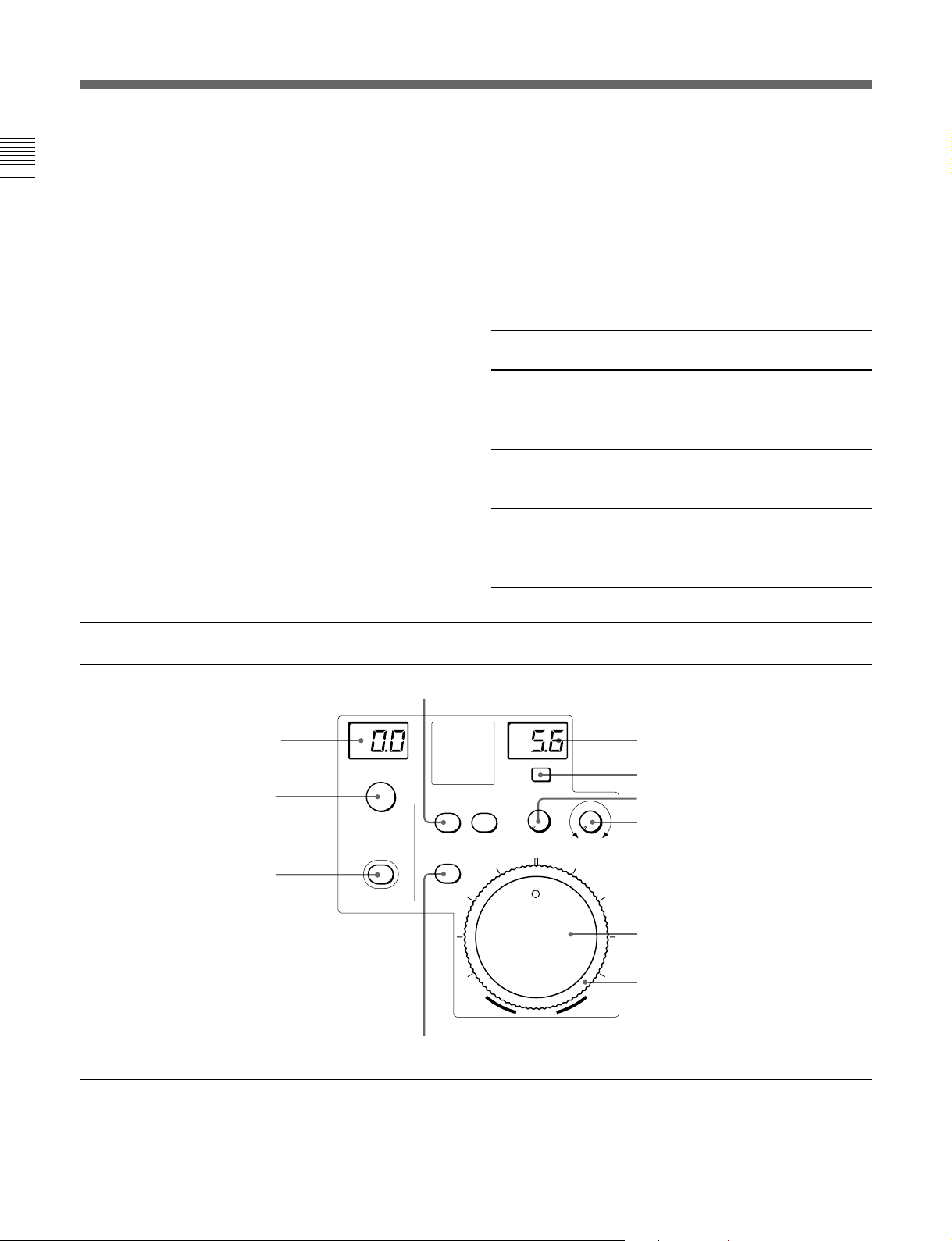
RCP-750
1 Control select block
2 STANDARD button
3 Camera/CCU function
ON/OFF buttons
4 WHITE knobs
5 BLACK/FLARE knobs and
indicator
6 Camera number/tally indication
window
7 ALARM indicator
8 CALL button
9 PANEL ACTIVE button
PARA
MASTER SLAVE
SKIN DTL
CHAR
STANDARD
REMOTE CONTROL PANEL
ACTER
AUTO
5600K
KNEE
PAINT 1 PAINT 2
MASTER
BLACK
RELATIVE
ALARM CALL
PAN E L
ACTIVE
AUTO HUE
SKIN
DETAIL
PAINT 3 SCENE MAINTE
WHITE
BLACK/FLARE
IRIS/MB
ACTIVE
RELATIVE
AUTO
TEST BARS CLOSE
CAM PW
AUTO SETUP
LEVEL
START/
BREAK
DTL
BLACK
GATE
GAMMA
NANCE
a
WHITE BLACK
FUNCTION
DETAIL
EXT
SENS
COARSE
IRIS
0 Power and output signal select block
qa AUTO SETUP block
qs Menu operation block
qd DETAIL knob
qf MEMORY STICK slot and
access lamp
Iris/master black control block
OPENCLOSE
(page 8(E))
4(E)
RCP-751
6 Camera number/tally indication
window
7 ALARM indicator
8 CALL button
9 PANEL ACTIVE button
BLACK/FLARE
MASTER
BLACK
RELATIVE
IRIS/MB
ACTIVE
ALARM CALL
PAN E L
ACTIVE
REMOTE CONTROL PANEL
AUTO
a
EXT
SENS
OPEN
CLOSE
COARSE
Iris/master black control block
(page 9(E))
IRIS
Page 35

1 Control select block
AB
PARA MASTER SLAVE
A PARA (parallel mode) button
This button lights when Parallel mode is active, in
which concurrent operation with another control panel
is possible.
When this button is lit, all the buttons and controls on
this panel except for the iris/master black control block
are active, even if the PANEL ACTIVE button is not
lit.
If you press the button when lit, it goes dark and
Parallel mode is cancelled.
B MASTER and SLAVE buttons
When adjusting the white balance of multiple cameras
in Master/Slave mode, designate the master camera or
the slave cameras. Press and light up the MASTER
button to specify the connected camera for the master.
Press and light up the SLAVE button to specify the
connected camera for the slave. The slave cameras
follow the master camera settings.
If you press a button when lit, it goes dark.
2 STANDARD button
When you press this button, the video camera is
initialized to its standard state and the button lights for
several seconds.
If you press the button while it lights, the video camera
retrieves the state before the button was lit.
3 Camera/CCU function ON/OFF buttons
Various functions of the video camera or the CCU/
HDCU-series can be turned on and off from this panel.
CHAR
ACTER
5600K: 5600K electric color temperature conversion
function
AUTO KNEE: Auto knee function. When this button
is lit (ON), the knee point is automatically adjusted
according to the light content of the picture.
SKIN DETAIL: Skin tone detail function
DTL GATE: Skin tone detail gate function. When
this button is lit (ON), the adjustment range of the
skin tone detail is displayed in white on the PIX
(picture) monitor screen.
BLACK GAMMA: Black gamma function
CHARACTER: Self-diagnostic display function.
When this button is lit (ON), the contents of the
self-diagnosis of the CCU/HDCU-series are
displayed on the monitor connected to the
CHARACTER OUTPUT connector of the CCU/
HDCU-series. The contents are also mixed to the
video signal to be output from the PIX1 OUTPUT
connector. Each time you press this button, the
status changes as follows.
OFF c ON (page 1) c ON (page 2) . . .
c ON (page
n
) c OFF
The contents of the self-diagnosis may be
displayed when required even if this button is not
lit.
The right two buttons are for future use and do not
function at present.
4 WHITE (white balance manual adjustment)
knobs
Used to manually adjust the white balance. From the
left, the knobs are for R, G, and B signal adjustment.
5 BLACK/FLARE (black balance/flare balance
manual adjustment) knobs and indicator
Used to manually adjust the black balance (when the
indicator is not lit) or the flare balance (when the
indicator is lit).
From the left, the knobs are for R, G, and B signal
adjustment.
Selection between black balance and flare balance is
made using the Maintenance menu.
See “Changing the Function of the Rotary Encoders” on
page 24(E).
5600K AUTO
KNEE
SKIN
DETAIL
DTL
GATE
BLACK
GAMMA
5(E)
Page 36

Locations and Functions of Parts
6 Camera number/tally indication window
The number of the camera being controlled from this
panel is displayed in orange.
When a red tally signal is sent to the camera, the
number is displayed in black and the background of
the number lights in red.
When a green tally signal is sent to the camera, the
number is displayed in black and the background of
the number lights in green.
When both the red and green tally signals are
simultaneously sent, the left half of the background
lights in red and the right half lights in green.
7 ALARM indicator
Lights when trouble occurs in the camera system and
the self-diagnostic function activates at the video
camera or the CCU/HDCU-series.
8 CALL button
Press to send a call signal to the video camera, on
which the CALL button lights. The tally lamps on the
camera and the red tally lamp on the CCU/HDCUseries light when not lit, or go dark when lit.
When the CALL button on the video camera is
pressed, the CALL button on this panel lights and a
buzzer sounds.
B Signal output select buttons
Press and light up one of these buttons to activate the
test signal generator of the video camera and send the
respective signals.
TEST: To send a signal to test the video circuits
BARS: To send a color bar signal
Note
The BARS button takes priority to the TEST button. If
the BARS button is lit, press the button to turn it dark
before pressing the TEST button.
C CLOSE button
Press and light the button to close the iris. To release
the close mode, press the button again so that it goes
dark.
qa AUTO SETUP block
ABDC
AUTO SETUP
SKIN DTL
AUTO HUE
LEVEL
START/
BREAK
WHITE BLACK
9 PANEL ACTIVE button
Press and light up the button to permit this panel to
control the camera system (Panel active status).
The IRIS/MB ACTIVE button also lights.
If you press this button so that it goes dark, the panel
will be locked, preventing accidental misoperation.
0 Power and output signal select block
AB C
CAM PW TEST BARS CLOSE
A CAM PW (camera power) button
Press and light up this button to turn the power supply
to the video camera ON. (The button promptly flashes
until the camera becomes ready for transmission.)
When you press this button again, it starts flashing and
the power supply is turned off.
A Auto adjustment item select buttons
Press and light up these buttons to select the items to
be automatically adjusted.
SKIN DTL AUTO HUE: Skin tone detail automatic
hue.
LEVEL: Gamma balance, knee point, master black
level, etc.
B START/BREAK button
Press to start automatic adjustment of the selected
items.
The button lights during adjustment and goes dark
when adjustment is completed. If you press the button
when lit, the automatic adjustment is canceled and the
button flashes. To stop the flashing, press the button
again.
C WHITE (white balance) button
Press to automatically adjust the white balance.
The button lights during adjustment and goes dark
when adjustment is completed.
If you press this button when lit or the START/
BREAK button, the automatic adjustment is canceled
and the button flashes. To stop the flashing, press the
button again.
6(E)
Page 37

D BLACK (black balance) button
Press to automatically adjust the black balance and
black set.
The button lights during adjustment and goes dark
when adjustment is completed.
If you press this button when lit or the START/
BREAK button, the automatic adjustment is canceled
and the button flashes. To stop the flashing, press the
button again.
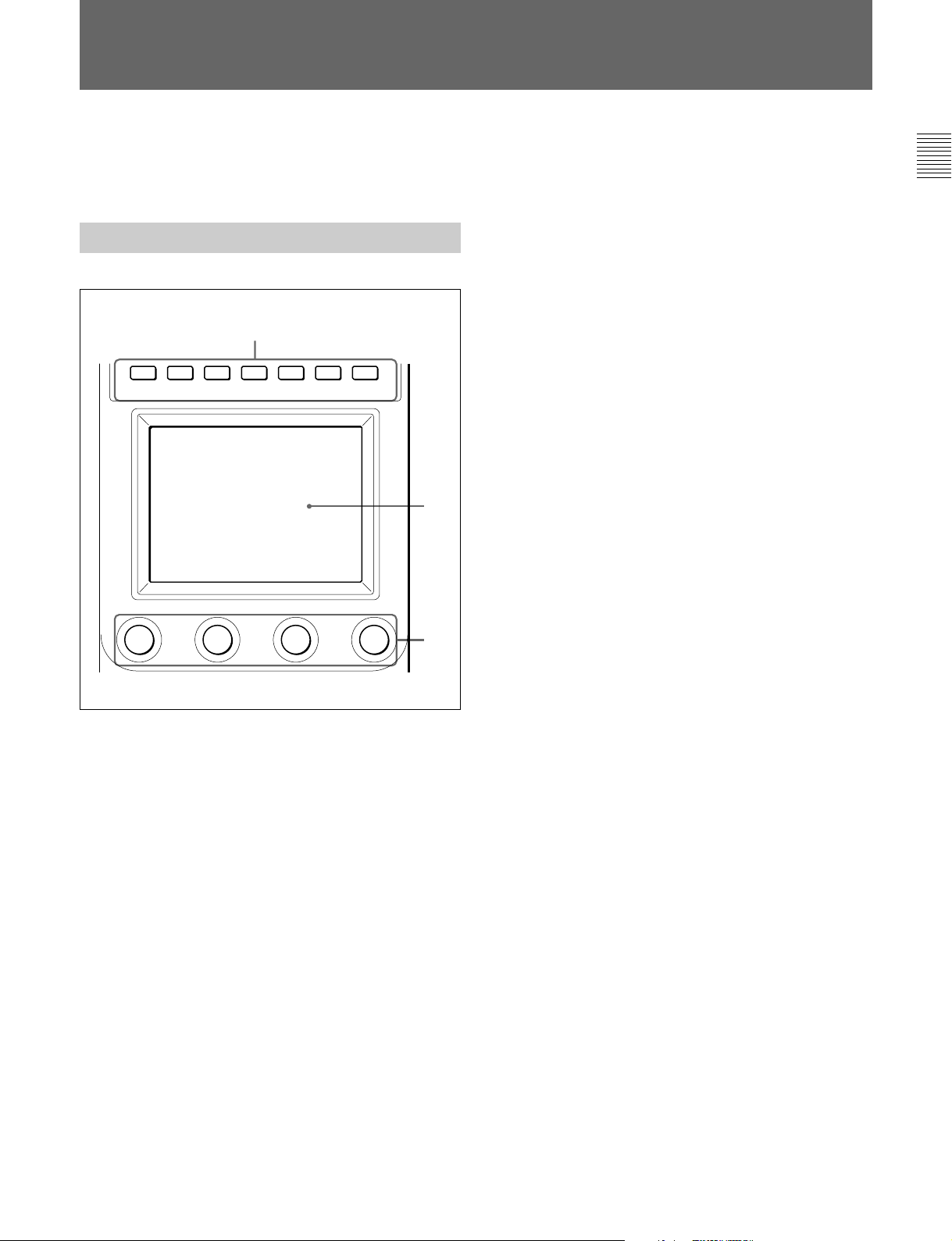
B LCD/touch panel
Normally displays the statuses
(see page 13(E)).
When you press a MODE button, the corresponding
menu is displayed to permit you to adjust the displayed
items.
C Control knobs (rotary encoders)
Adjust the selected items on the touch panel.
Note
If an error occurs during adjustment, the pressed
button flashes.
qs Menu operation block
A
PAINT 1 PAINT 2 PAINT 3 SCENE MAINTE
NANCE
FUNCTION
B
qd DETAIL knob
Used to adjust the detail level.
You may select HD detail or SD detail using the
Maintenance menu.
See “Changing the Functions of the Rotary Encoders” on
page 24(E).
qf MEMORY STICK slot and access lamp
Insert a Memory Stick to store setting data, such as
reference files and scene files of the video camera or
CCU/HDCU.
The access lamp shows the status of the Memory
Stick.
Off: No Memory Stick is inserted.
Lit in green: There is a Memory Stick in the slot. In
this condition, you can safely eject the Memory
Stick.
Lit in red: Data are being read/written. If you eject
the Memory Stick in this condition, the data are
not guaranteed. All the data may be lost.
For details on Memory Sticks, see page 25(E).
C
A MODE (mode select) buttons
Select the menu mode.
If you press and light one of these buttons, the menu
for the selected mode appears on the LCD.
PAINT 1/2/3: Each selects the Paint menu to adjust
various paint items, such as white, black, and flare.
SCENE: Selects the File operation menu to register
and retrieve scene files.
MAINTENANCE: Selects the Maintenance menu to
set the H and SC phases of CCU/HDCU and
operational conditions of this control panel.
FUNCTION: Selects the Function menu to control
various camera and CCU/HDCU functions.
When none of the buttons are lit, the status display
(page 13(E)) is obtained.
For the items of each menu, see “Menu Items” on page 17(E).
7(E)
Page 38

Locations and Functions of Parts
Iris/master black control block (RCP-750)
IRIS/MB
ACTIVE
1 MASTER BLACK display
2 MASTER BLACK RELATIVE
button
MASTER
BLACK
RELATIVE
AUTO
RELATIVE
3 IRIS/MB ACTIVE button
4 AUTO button
5 f-number display
6 EXT indicator
EXT
COARSE
7 SENS control knob
SENS
8 COARSE control knob
OPENCLOSE
9 Master black control ring
qa IRIS RELATIVE button
1 MASTER BLACK display
Displays the current master black setting in the range
from –99 to +99.
2 MASTER BLACK RELATIVE button
When the IRIS/MB ACTIVE button is lit, the master
black adjustment mode can be selected with this
button.
Press and light up the button for Relative mode, or
press and turn it dark for Absolute mode.
When the IRIS/MB ACTIVE button is not lit, Relative
mode is automatically selected and this button is not
operative.
3 IRIS/MB ACTIVE (iris/master black active)
button
Press and light up this button to enable the iris/master
black control block of the panel.
When the PANEL ACTIVE button is pressed, this
button also lights.
If you press this button so that it goes dark, the panel
will be locked, preventing accidental misoperation.
0 IRIS control lever
IRIS
4 AUTO button
Press and light the button to automatically adjust the
iris according to the amount of input light.
When this button is lit, the reference value for
automatic iris adjustment can be set in a range of ±1f
with the iris control.
If you press the button when lit, it goes dark and
manual iris adjustment is enabled.
5 f-number display
Displays the f number of the current iris setting. When
the iris is closed, “CL” is displayed.
6 EXT (lens extender) indicator
Lights when the lens extender is used.
7 SENS (sensitivity) control knob
Used for manual iris adjustment in Absolute mode.
This control is not operative when Relative mode is
selected.
See the table “Iris adjustment functions” on the next page.
8 COARSE control knob
Used for manual iris adjustment.
See the table “Iris adjustment functions” on the next page.
8(E)
Page 39

9 Master black control ring
Turn to manually adjust the master black level.
0 IRIS control lever
When the AUTO button is not lit, you can adjust the
iris manually by moving the lever.
When the AUTO button is lit, the reference value for
automatic iris adjustment can be set in a range of ±1f
with this lever.
See the table “Iris adjustment functions” to the right.
qa IRIS RELATIVE (iris relative) button
When the IRIS/MB ACTIVE button is lit, the iris
adjustment mode can be selected with this button.
Press and light up the button for Relative mode or
press so that it goes dark for Absolute mode.
When the IRIS/MB ACTIVE button is not lit, Relative
mode is automatically selected and this button is not
operative.
Iris/master black control block (RCP-751)
Iris adjustment functions
Relative mode Absolute mode
(RELATIVE button lit) (RELATIVE button not lit)
IRIS lever Adjusts the iris with Adjusts the iris
(RCP-750)/ relative values within within the variable
IRIS control 1/4 of the total range range set by the
(RCP-751) from OPEN to SENS and COARSE
CLOSED. controls.
COARSE Adjusts the total Sets the lower limit
control range from OPEN for CLOSED.
to CLOSED in relative
values.
SENS Does not function. Sets the upper limit
control for OPEN according
to CLOSED value
set by the COARSE
control.
4 IRIS RELATIVE button
1 MASTER BLACK display
2 MASTER BLACK control
MASTER
3 IRIS/MB ACTIVE button
BLACK
IRIS/MB
ACTIVE
RELATIVE
AUTO
qa AUTO button
1 MASTER BLACK display
Displays the current master black setting in the range
from –99 to +99.
2 MASTER BLACK control
Manually adjust the master black level. The setting is
displayed in the MASTER BLACK display.
5 f-number display
EXT
SENS
CLOSE
COARSE
IRIS
6 EXT indicator
7 SENS control knob
8 COARSE control knob
OPEN
9 IRIS control
0 Iris gauge
3 IRIS/MB ACTIVE (iris/master black active)
button
Press and light up this button to enable the iris/master
black control block of the panel.
When the PANEL ACTIVE button is pressed, this
button also lights.
If you press this button so that it goes dark, the panel
will be locked, preventing accidental misoperation.
9(E)
Page 40

Locations and Functions of Parts
4 IRIS RELATIVE (iris relative) button
When the IRIS/MB ACTIVE button is lit, the iris
adjustment mode can be selected with this button.
Press and light up the button for Relative mode or
press so that it goes dark for Absolute mode.
When the IRIS/MB ACTIVE button is not lit, Relative
mode is automatically selected and this button is not
operative.
5 f-number display
Displays the f number of the current iris setting. When
the iris is closed, “CL” is displayed.
6 EXT (lens extender) indicator
Lights when the lens extender is used.
7 SENS (sensitivity) control knob
Used for manual iris adjustment in Absolute mode.
This control is not operative when Relative mode is
selected.
See the table “Iris adjustment functions” on the previous
page.
qa AUTO button
Press and light the button to automatically adjust the
iris according to the amount of input light.
When this button is lit, the reference value for
automatic iris adjustment can be set in a range of ±1f
with the iris control.
If you press the button when lit, it goes dark and
manual iris adjustment is enabled.
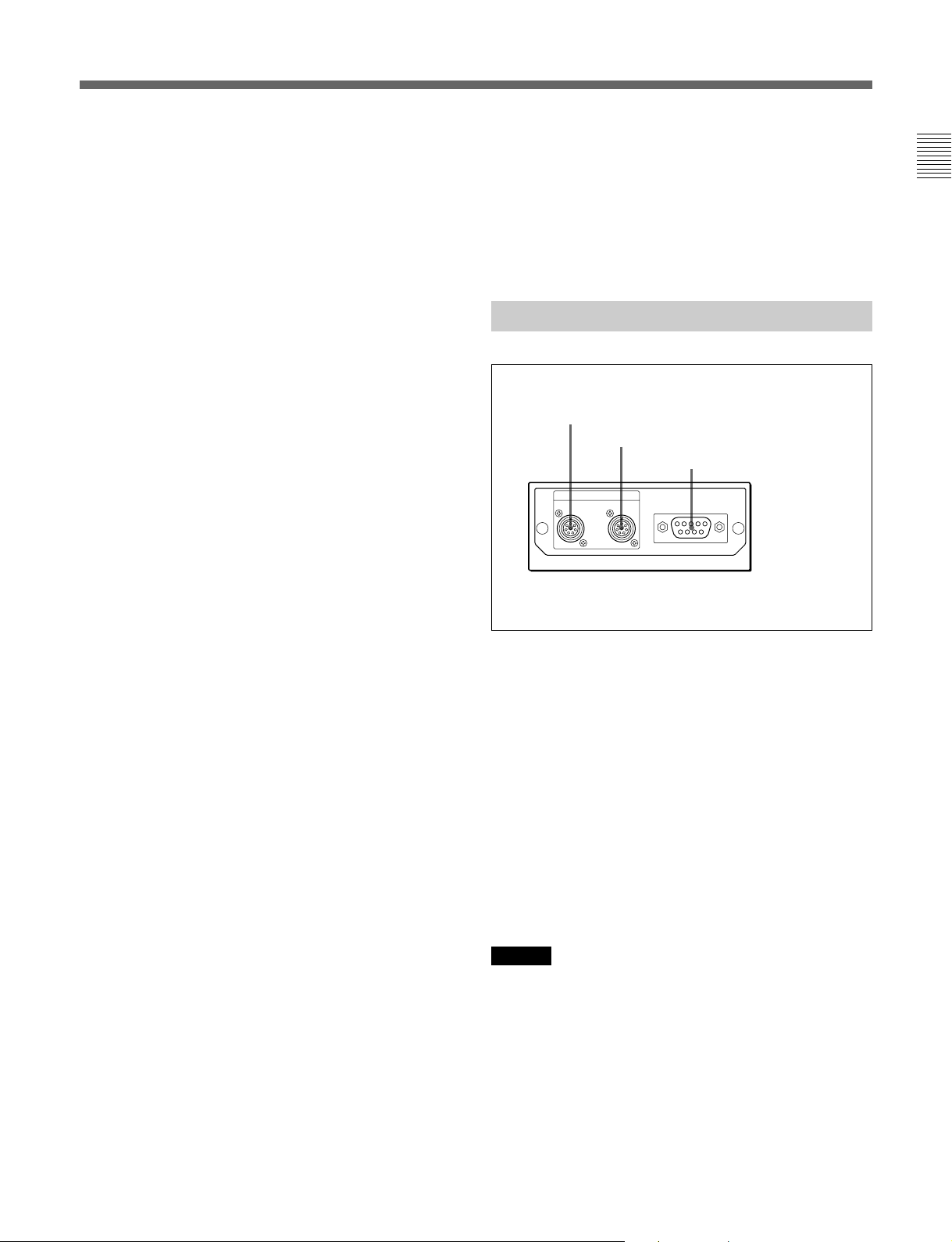
Connector Panel
1 CCU/CNU REMOTE connector
2 AUX REMOTE connector
3 EXT I/O connector
REMOTE
CCU/CNU AUX
EXT I/O
8 COARSE control knob
Used for manual iris adjustment.
See the table “Iris adjustment functions” on the previous
page.
9 IRIS control
When the AUTO button is not lit, you can adjust the
iris manually by turning the control.
When the AUTO button is lit, the reference value for
automatic iris adjustment can be set in a range of ±1f
with this control.
See the table “Iris adjustment functions” on the previous
page.
0 Iris gauge
The white line on the gauge provides a click position
for the IRIS control. Turn the gauge to set the line to
the most frequently used iris position, and it can be
used as the reference for manual iris adjustment.
The gauge rotates infinitely in either direction. When
no click position is required, set the line outside the
rotation range of the IRIS control.
1 CCU/CNU REMOTE (camera control unit/
camera command network unit remote)
connector (8-pin)
Connect to the RCP/CNU connector of a camera
control unit or the RCP connector of a camera
command network unit.
2 AUX REMOTE (auxiliary remote) connector
(8-pin)
Connect to the RCP-700/701.
3 EXT I/O (external input/output) connector
(9-pin)
With expansion functions added, this connector
permits you to control an external device.
Caution
When installing this panel, provide a gap of 7 cm (3
inches) or more behind the connector panel to prevent
damage to cables.
10(E)
Page 41

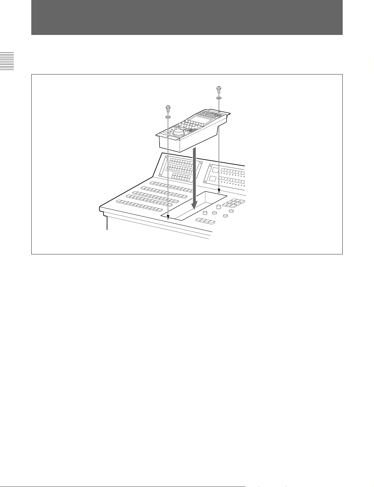
Mounting on a Console
The RCP-750/751 can be mounted on a console as
shown below:
11(E)
Page 42

Menu Configuration and Basic Menu Operations
The RCP-750/751 provides menu operations for
various functions such as adjustments of system
equipment.
Basic Operating Procedure
1
PAINT 1 PAINT 2 PAINT 3 SCENE MAINTE
When all the MODE buttons are not lit, the status
display (see the next page) is obtained.
NANCE
FUNCTION
1 To display a menu, press and light one of the
MODE buttons.
The menu operation mode is initiated and the menu
for the pressed button appears on the display.
PAINT 1/2/3: Paint menu
See page 13(E) for the display configuration and page
17(E) for the menu items.
SCENE: Scene file operation menu
See page 15(E) for the display configuration and
operation.
MAINTENANCE: Maintenance menu
See page 20(E) for the menu items and page 22(E) for
adjustments.
FUNCTION: Function menu
See page 16(E) for the display configuration and page
21(E) for the menu items.
2
3
2 Select the item to be adjusted.
Press the button that shows the name of the item on
the menu to obtain the corresponding adjustment
display or operation area.
When the selected menu is composed of
multiple pages
With the menu that is composed of multiple pages
such as Paint menu, press v or V to flip the pages.
See “Initial display (Paint menu)” on the next page.
When a submenu is shown
Press the desired submenu item to change the
display.
See “Submenu” on page 14(E).
3 Set or adjust the item (parameters).
• Turn the control knobs (or press the button) to
adjust (or set) the corresponding item
(parameters) to the desired values.
See “Adjustment display” on page 14(E).
• When a message is displayed, follow the
instruction and press
When the adjustment is finished
• To adjust another item of the same menu, press the
names of that item.
• To adjust items of another menu, press the
corresponding MODE button.
• To release the menu operation mode, press the lit
MODE button.
• You may select Function menu without exiting the
currently selected menu. When you exit Function
menu by either of the following methods, the
previous menu is restored.
– Press the lit FUNCTION button so that it goes dark.
– Press the lit MODE button for the previous menu.
[OK].
12(E)
Page 43

Basic Configuration of Menu Display
Status display
When you do not select any of the MODE buttons
(PAINT 1, PAINT 2, PAINT 3, SCENE,
MAINTENANCE, FUNCTION) of the menu
operation block (all unlit), the LCD shows the
following status display:
On the status display, each item is
only displayed. The setting is made
with the Function menu or with the
corresponding knob on the
operation panel.
Status
Shutter
60
M. Gain
0dB
White
0
0
00
Black
00
Initial display (Paint menu)
When you press and light the PAINT 1 (or PAINT 2,
PAINT 3) button of the menu operation block, the
initial display of the Paint menu is obtained.
Gamma
0.45
ND
1
Detail
ND
A
0
You may adjust these items using the
Function menu.
You may adjust these items using the
WHITE knobs, BLACK/FLARE knobs, or
DETAIL knob.
The “Detail” and “Black” columns can be
changed to “SD Detail” or “Flare” using
the Maintenance menu.
To clear the adjusted values
The names of the items are
displayed. Press the name
of the item to be adjusted.
The color of the pressed
name area will change, and
the lower half of the panel
will become the adjustment
display (see the next page).
Current page number / total number of pages
Clear
White Black Flare Gamma
1 / 6
Press either to flip the pages of the
menu.
13(E)
Page 44

Menu Configuration and Basic Menu Operations
Adjustment display (Paint menu)
When you select an item on the initial display of the
Paint menu, the lower half of the panel becomes the
adjustment display for the selected item.
Example: when you select “White” from the initial display
Clear
White Black Flare Gamma
When you press this, the upper
half of the panel becomes the
WF/PIX
Select
White
monitor output setting display
(see the next page).
R
0
G
0
Submenu
If the selected item has many parameters, a submenu is
displayed.
Example: when you select “Skin Detail” from the initial display
1 / 6
The name of the item selected on the
initial display is displayed.
If you press this area after pressing
[Clear], all the adjustment values for the
selected item are initialized to standard.
ATW
B
0
When there are any ON/OFF functions
related to the adjustment, the names of
the functions are displayed on this line.
The adjustment parameters for the
selected item and their adjustment
values are displayed.
You may adjust these items using the
corresponding control knobs.
If you press a value area after
pressing [Clear], that adjustment value
is initialized to standard.
14(E)
Submenu
Clear
Detail1Skin
WF/PIX
Select
Detail
Sat
Skin Detail
123
Level
WF/PIX
Select
Phase
0
Width
0
Skin Detail
123
Level
Phase
0
Width
0
2 / 6
Black
Gamma
Skin
DTL 1
Sat
0
0
Press to switch the parameters.
Skin
DTL 2
Sat
0
0
Page 45

Monitor output set display (Expansion menu)
When you press
[WF/PIX Select] on an adjustment
display of the Paint menu, the upper half of the panel
becomes the monitor output setting display.
WF/PIX Monitor Select
RGBRGB SEQ ENC
Press again to return to
the previous display.
WF/PIX
Select
Scene file operation menu display
When you press and light the SCENE button of the
menu operation block, the scene file operation menu
display is obtained.
R/G/B: To independently select the R,
G, or B signal.
RGB: To select the R, G, and B signals
in combination.
SEQ: Only the WF output is enabled,
and you can monitor the waveforms of
the R, G, and B signals in sequence.
ENC (encode): The encoded signal is
output.
To recall a scene file:
Press the number of the desired
scene file, and the settings stored
in the corresponding scene file
will be retrieved.
The color of the number of the
retrieved file changes.
When you press the same
number again, the previous
condition will be restored.
Scene File Recall
Store
12345
To store the current settings
in a scene file:
First press and light [Store], then select
the desired scene file number.
When file registration is finished, [Store]
returns to its original color.
15(E)
Page 46

Menu Configuration and Basic Menu Operations
Function menu displays
When you press and light the FUNCTION button of
the menu operation block, the scene file operation
menu display is obtained.
When “Operation” is selected
Press v or V to select the desired filter.
The number of ND and CC filters you may select
depends on the camera.
Press [Filter Ctrl] and change its
color to enable filter selection
from this display.
When “SW” is selected
Opera-
tion
Filter
Ctrl
SW
ND GammaCC
1A 0.45
Shutter ECS
Master
Gain
60 30.00 0dB
You may adjust these items using the
corresponding control knobs.
Opera-
tion
S-Skin
Knee
Sat Mono
Black
Gamma
5600K
SW
Low Key
Sat
Auto
Knee
ATW PsF
Knee
Aperture
Skin
Detail
Knee
Sat
Detail
Gate
Press v or V to set the gamma value.
You may change it in ±0.05 steps.
Press v or V to set the master gain
The value increases when v is pressed
and decreases when V is pressed.
Current page number /
total number of pages
1 / 2
Press either to flip the pages of
the menu.
16(E)
These buttons turn on and off the
corresponding functions.
Any button whose designation includes “Off”
turns the respective function OFF when you
light it. Other buttons turn the respective
functions ON when you light them.
Page 47

Menu Items
The “Control items” marked with z are those assigned
to the control knobs. The other items are operated on
the menu display.
Paint menu
Paint menu consists of pages 1 to 6.
You can select page 1 through 3 directly by pressing
the MODE buttons, PAINT 1, PAINT 2, or PAINT 3.
Pressing v or V of the page selected with a MODE
button flip pages 1 through 6 in sequence.
Page Menu Submenu Control item Function
Paint 1 White z R/G/B Adjusts the white balance.
ATW Executes the auto-trace white balance adjustment.
Black z R/G/B/Master Adjusts the black balance.
Flare z R/G/B Adjusts the flare balance.
Flare Off Turn the flare ON/OFF.
Gamma z R/G/B/Master Adjusts the gamma.
Gamma Off Turns the gamma ON/OFF.
Paint 2 Detail 1 HD
Skin Detail 1/2/3 (common) z Level Adjusts the skin detail level.
Saturation z Saturation Adjusts the saturation.
Black Gamma RGB z R/G/B/Master Adjusts the black gamma.
a)
a)
SD
Y z Y Adjusts the black gamma.
z Level Adjusts the HD detail level.
z Limiter Adjusts the HD detail limiter.
z Crispening Adjusts the HD detail crispening.
z Level Dep Adjusts the HD level dependence.
Detail Off Turns the HD detail ON/OFF.
SD DTL Off Turns the SD detail ON/OFF.
z Level Adjusts the SD detail level.
z Limiter Adjusts the SD detail limiter.
z Crispening Adjusts the SD detail crispening.
z Level Dep Adjusts the SD level dependence.
Detail Off Turns the HD detail ON/OFF.
SD DTL Off Turns the SD detail ON/OFF.
z Phase Adjusts the skin detail phase.
z Width Adjusts the skin detail width.
z Saturation Adjusts the skin detail saturation.
Skin DTL # Turns the skin detail ON/OFF (each channel).
Saturation Turns the saturation ON/OFF.
a) The submenu to select HD or SD is displayed only when an HD camera is connected.
17(E)
Page 48

Menu Configuration and Basic Menu Operations
Page Menu Submenu Control item Function
Paint 3 Knee Point z R/G/B/Master Adjusts the knee point.
Knee Off Turns the knee ON/OFF.
Knee Slope z R/G/B/Master Adjusts the knee slope.
Knee Off Turns the knee ON/OFF.
Matrix Matrix 1 z R-G/G-B/B-R Adjusts the matrix coefficients.
User Matrix Turns the user matrix ON/OFF.
Preset Matrix Turns the preset matrix ON/OFF.
Matrix Off Turns all the matrixes ON/OFF.
Matrix 2 z R-B/G-R/B-G Adjusts the matrix coefficients.
User Matrix Turns the user matrix ON/OFF.
Preset Matrix Turns the preset matrix ON/OFF.
Matrix Off Turns all the matrixes ON/OFF.
Multi Matrix z Phase Adjusts the multi matrix phase.
z Hue Adjusts the multi matrix hue.
z Saturation Adjusts the multi matrix saturation.
Multi Matrix Turns the multi matrix ON/OFF.
Matrix Off Turns all the matrixes ON/OFF.
All Clear Clears all the matrix settings.
Paint 4 Gamma/Knee z Gamma Adjusts the master gamma.
z Blk Gamma Adjusts the master black gamma.
z Knee Point Adjusts the master knee point.
z Knee Slope Adjusts the master knee slope.
Gamma Off Turns the gamma ON/OFF.
Knee Off Turns the knee ON/OFF.
Knee Saturation z Knee Point Adjusts the master knee point.
z Knee Slope Adjusts the master knee slope.
z Level Adjusts the knee saturation.
Knee Off Turns the knee ON/OFF.
Knee Sat Turns the knee saturation ON/OFF.
Low Key Saturation z Level Adjusts the low key saturation level.
Low Key Sat Turns the low key saturation ON/OFF.
White Clip z R/G/B/Master Adjusts the white clip.
White Clip Off Turns the white clip ON/OFF.
SD
a)
z Level Adjusts the HD detail level.
z Limiter Adjusts the HD detail limiter.
z Crispening Adjusts the HD detail crispening.
z Level Dep Adjusts the HD level dependence.
Detail Off Turns the HD detail ON/OFF.
SD DTL Off Turns the SD detail ON/OFF.
a)
z Level Adjusts the SD detail level.
z Limiter Adjusts the SD detail limiter.
z Crispening Adjusts the SD detail crispening.
z Level Dep Adjusts the SD level dependence.
Detail Off Turns the HD detail ON/OFF.
SD DTL Off Turns the SD detail ON/OFF.
Paint 5 Detail 1 HD
a) The submenu to select HD or SD is displayed only when an HD camera is connected.
18(E)
Page 49

Page Menu Submenu Control item Function
Paint 5 Detail 2 HD
(Continued)
a)
z H/V Ratio Adjusts the HD detail H/V ratio.
z Frequency Adjusts the HD detail boost frequency.
z Mix Ratio Adjusts the HD detail mix ratio.
z Comb Adjusts the HD detail comb.
Detail Off Turns the HD detail ON/OFF.
SD DTL Off Turns the SD detail ON/OFF.
a)
SD
z H/V Ratio Adjusts the SD detail H/V ratio.
z Frequency Adjusts the SD detail boost frequency.
z Mix Ratio Adjusts the SD detail mix ratio.
z Comb Adjusts the SD detail comb.
Detail Off Turns the HD detail ON/OFF.
SD DTL Off Turns the SD detail ON/OFF.
Detail 3 HD
a)
z W.Limiter Adjusts the HD detail white limiter.
z B.Limiter Adjusts the HD detail black limiter.
z Fine Adjusts the HD fine detail level.
z Knee Apert Adjusts the HD knee aperture.
Fine Detail Turns the HD fine detail ON/OFF.
Knee Aperture Turns the HD knee aperture ON/OFF.
a)
SD
z W.Limiter Adjusts the SD detail white limiter.
z B.Limiter Adjusts the SD detail black limiter.
z Fine Adjusts the SD fine detail level.
z Knee Apert Adjusts the SD knee aperture.
Fine Detail Turns the SD fine detail ON/OFF.
Knee Aperture Turns the SD knee aperture ON/OFF.
Paint 6 Gamma Table z Standard Adjusts the gamma table.
z User Adjusts the user gamma table.
Standard Selects the standard gamma table.
User Selects the user gamma table.
Gamma Off Turns the gamma ON/OFF.
Auto Knee z Point Limit Adjusts the point limit for auto knee.
z Auto Slope Adjusts the knee slope for auto knee.
Adaptive Turns the adaptive highlight control for auto knee ON/OFF.
Knee Off Turns the knee ON/OFF.
Auto Iris z Phase Adjusts the skin tone auto iris phase.
z Width Adjusts the skin tone auto iris width.
Normal Mode Selects Normal mode for auto iris.
Skin Mode Selects Skin mode for auto iris.
Iris Auto Hue Executes the auto hue.
Auto Iris Gate Turns the skin tone auto iris gate ON/OFF.
ECS/S-EVS z Shutter Adjusts the shutter speed.
z ECS Adjusts the ECS frequency.
z S-EVS Adjusts the Super EVS.
Shutter Turns the shutter mode ON/OFF.
ECS Turns the ECS mode ON/OFF.
S-EVS Turns the Super EVS mode ON/OFF.
a) The submenu to select HD or SD is displayed only when an HD camera is connected.
19(E)
Page 50

Menu Configuration and Basic Menu Operations
Maintenance menu
Menu 2ndary menu Submenu Control item Function
Adjusting Black Shading R/G/B z H Saw/H Para/V Saw/V Para Adjusts the black shading.
Auto B Shading Executes the auto black shading.
Blk Shd OFF Turns the black shading ON/OFF.
White Shading R/G/B z H Saw/H Para/V Saw/V Para Adjusts the white shading.
Auto W Shading Executes the auto white shading.
Phase H Phase z H Step Adjusts the H phase.
z H Coarse
z H Fine
SC Phase z SC Adjusts the SC phase.
z BF Adjusts the black burst signal phase.
Auto Iris z Level Adjusts the auto iris level.
z APL Ratio Adjusts the auto iris APL ratio.
z Iris Gain Adjusts the auto iris gain.
File Reference File Store Stores a reference file.
Reference File Transfer CAM t MS Transfers a reference file (from a camera to a memory stick).
MS t CAM Transfers a reference file (from a memory stick to a camera).
Scene File Transfer CAM t MS Transfers a scene file (from a camera to a memory stick).
MS t CAM Transfers a scene file (from a memory stick to a camera).
OHB File Store Stores a OHB file.
RCP Config RCP Adjusting Buzzer Volume z Call Adjusts the volume of the call buzzer.
z Touch Adjusts the volume of the response sound of the touch panel.
z Switch Adjusts the volume of the confirmation sound of self-
illuminating switches.
z Master Adjusts the total buzzer sound volume.
Call Buzzer Turns the call buzzer ON/OFF.
Touch Click Turns the response sound of the touch panel ON/OFF.
SW Click Turns the confirmation sound of switches ON/OFF.
All Off Turns all the buzzers ON/OFF.
LED Bright z Switch Adjusts the brightness of the corresponding LEDs.
z Tally
z Other
z Master
Rotary Encoder BLACK/FLARE Black Selects the black balance adjustment.
Setting
DETAIL Detail (HD) Selects the HD detail adjustment.
Date/Time Date z Year Adjusts the date for the built-in clock of this unit.
Time z Hour Adjusts the time for the built-in clock of this unit.
Information Displays the software version of this unit.
Flare Selects the flare balance adjustment.
SD Detail Selects the SD detail adjustment.
z Month
z Day
Set
Cancel
z Minute
z Second
Set
Cancel
20(E)
Page 51

Menu 2ndary menu Submenu Control item Function
LCD LCD Brightness/Contrast z Bright Adjusts the brightness of the LCD of this panel.
z Contrast Adjusts the contrast of the LCD of this panel.
Memory Stick Memory Stick Format Formats a Memory Stick.
Function menu
Menu Submenu Control item Function
Operation Filter Ctrl Selects the filter remote or local mode.
ND (1/2/3/4/5) Selects ND filters.
CC (A/B/C/D/E) Selects CC filters.
Gamma Selects the step gamma.
Master Gain Selects the master gain.
Shutter Turns the shutter mode ON/OFF.
ECS Turns the ECS mode ON/OFF.
z Shutter Selects the shutter speed.
z ECS Selects the ECS frequency.
SW page 1 5600K Turns 5600K electric color temperature conversion function ON/OFF.
Auto Knee Turns the auto knee function ON/OFF.
When this button is in inverse video (ON), the knee point is automatically adjusted according to
the light content of the picture.
Skin Detail Turns the skin detail function ON/OFF.
Detail Gate Skin tone detail gate function.
When this button is in inverse video (ON), the adjustment range of the skin tone detail is
displayed in white on the monitor screen.
Black Gamma Turns the black gamma function ON/OFF.
Knee Aperture Turns the knee aperture function ON/OFF.
Knee Sat Turns the knee saturation function ON/OFF.
Sat Turns the saturation function ON/OFF.
Mono Turns the mono color function ON/OFF. This function mixes the chroma signals of a single hue
to the luminance signal. The chroma level is modulated according to the luminance signal.
S-Skin Knee Turns the Super-skin knee function ON/OFF.
Low Key Sat Turns the function to compensate the chroma level in dark areas ON/OFF.
ATW Turns the auto-tracing white function ON/OFF.
PsF Turns the CCD progressive read function ON/OFF.
page 2 Knee Off Turns the knee compensation function ON/OFF (OFF when lit).
Gamma Off Turns the gamma function ON/OFF (OFF when lit).
Detail Off Turns the detail compensation function ON/OFF (OFF when lit).
Matrix Off Turns the linear matrix function to enhance color fidelity ON/OFF (OFF when lit).
White Clip Off Turns the limiter function for highlight signals ON/OFF (OFF when lit).
Level Dep Off Turns the level dependence which controls the details in the dark part of a picture ON/OFF
(OFF when lit).
Chroma Off Turns the chroma function ON/OFF (OFF when lit).
SD Detail Off Turns the detail function for SD output ON/OFF with a HDTV camera connected
(OFF when lit).
SD Matrix Off Turns the linear matrix function for SD output ON/OFF wit a HDTV camera connected
(OFF when lit).
21(E)
Page 52

Initial Settings
Setting the Operating Conditions
of the RCP-750/751
By using the RCP Configuration menu or LCD setting
display, you can set the built-in clock of the RCP-750/
751 and adjust various conditions of the RCP-750/751,
such as the sound volume of the warning buzzer and
the brightness of the indicators and LCD.
To display the RCP Configuration menu/
LCD setting display
Proceed as follows:
1
PAINT 1 PAINT 2 PAINT 3 SCENE MAINTE
Maintenance Menu
Adjusting File
NANCE
FUNCTION
RCP Config. Menu
RCP
AdjustingRESetting
Date
Time
Exit
Infor-
mation
To obtain the LCD setting display, press [LCD].
The LCD setting display
(page 24(E)) appears.
Setting the Built-in Clock
The RCP-750/751 has a built-in clock to record the
date and time when reference and scene files are saved
to Memory Sticks.
To set the clock, proceed as follows.
1 Press [Date/Time] on the RCP Configuration
menu.
RCP
Config
LCD
Memory
Stick
1 Press to light the MAINTENANCE button of the
menu operation block.
The Maintenance Menu appears.
2 To display RCP Configuration menu, press
[RCP Config].
The RCP Configuration menu appears.
2
The current setting is displayed on the Date/Time
Set menu.
Date Time Set Menu
Date Time
2001/11/17
(Sat)
: 12 :
31
22
Exit
2 To set the date:
1)Press and light
Date Time
Year
2001
[Date].
Date Time Setting
2001/11/17
(Sat)
22 : 12 : 31
Set Cancel
Month
Day
8
Exit
8
22(E)
Page 53

2)Set the Year, Month and Day with the left three
control knobs.
3)Press
[Set].
The set date becomes valid.
To restore the previous setting, press
[Cancel]
instead of [Set].
3 To set the time:
Clear
Buzzer
Volume
LED
Bright
Exit
1)Press and light
Date Time
Hour
17
[Time].
Date Time Setting
2001/11/17
(Sat)
22 : 12 : 31
Set Cancel
Minute32Second
25
Exit
2)Set the Hour, Minute and Second with the left
three control knobs.
3)Press
[Set] in synchronization with a time
signal.
The set time becomes valid.
To resume the previous setting, press
[Cancel]
instead of [Set].
When the clock setting is completed
[Exit] to leave the menu.
Press
Adjusting the Buzzer Sound
2 Press and light [Buzzer Volume].
The lower half of the display becomes the Buzzer
Volume adjustment display.
Clear
Buzzer
Volume
Call
Buzzer
Call
50
LED
Bright
Buzzer
Volume
Touch
Click
Touch50Switch Master
SW
Click
50 50
All
Off
Exit
3 Adjust the levels with the corresponding control
knobs (50 is the standard value with all items).
Call: Sound volume of the buzzer when a call
signal is received
Touch: Sound volume of the buzzer when a
button displayed on the menu display is operated
Switch: Sound volume of the buzzer when a
button on the panel is operated
The master volume can be adjusted with the
rightmost control knob (Master).
A buzzer sounds on the RCP-750/751 when it receives
call signal or a panel control is operated.
When required, you may turn on/off the buzzer or
adjust the sound volume.
To adjust the buzzer, proceed as follows:
1 Press [RCP Adjusting] on the RCP Configuration
menu.
The RCP adjustment menu appears.
To turn on/off the buzzers independently
Press the corresponding button. When it is lit, the
buzzer is on.
[Call Buzzer]: For the buzzer sound when a call signal
is received
[Touch Click]: For the buzzer sound when a button
displayed on the menu display is operated
[SW Click]: For the buzzer sound when a button on
the panel is operated
To turn off all the buzzers
Press and light
[All Off].
When the adjustment is completed
[Exit] to leave the menu.
Press
23(E)
Page 54

Initial Settings
Adjusting the Brightness of the
LEDs
You can adjust the brightness of the LEDs of the panel
buttons and camera number/tally indication window.
To adjust the brightness, proceed as follows.
1 Press [RCP Adjusting] on the RCP Configuration
menu to display the RCP adjustment menu.
2 Press and light [LED Bright].
The lower half of the display becomes the LED
Brightness adjustment display.
Clear
Buzzer
Volume
Switch
50
LED
Bright
Tally
50
LED
Bright
Other Master
50 50
Exit
1 Press [RE Setting] on the RCP Configuration
menu to obtain the Rotary Encoder Setting display.
Exit
Rotary Encoder
Setting
BLACK/FLARE DETAIL
FlareBlack
Detail
(HD)
SD
Detail
2 When changing the function of the BLACK/
FLARE control knobs, press
desired.
When changing the function of the DETAIL
control knob, press
[Detail $HD%] or
[SD Detail] as desired.
When the adjustment is completed
[Exit] to leave the menu.
Press
[Black] or [Flare] as
3 Adjust the brightness with the corresponding
control knobs (50 is the standard value with all
items).
Switch: Brightness of the built-in LEDs of the
control buttons
Tally: Brightness of the built-in LEDs of the
camera number/tally indication window
Other: Brightness of the other LED indicators/
lamps, including the master black indicator and
f-number indicator
The master brightness can be adjusted with the
rightmost control knob (Master).
When the adjustment is completed
[Exit] to leave the menu.
Press
Changing the Functions of the
Rotary Encoders
You can change the functions of BLACK/FLARE
control knobs and DETAIL control knob.
Proceed as follows:
Adjusting the Brightness/
Contrast of the LCD
You can adjust the brightness and contrast of the
display of the menu control block.
Proceed as follows:
1 Press [LCD] on the Maintenance menu to display
the LCD setting display.
Clear
Bright
50 50
LCD Brightness
/Contrast
Contrast
Exit
2 Adjust the brightness and contrast with the
corresponding control knobs (50 is the standard
value with both items).
24(E)
When the adjustment is completed
[Exit] to leave the menu.
Press
Page 55

Memory Sticks
Using a Memory Stick
When a Memory Stick is inserted in the panel, the file
data can be stored on the Memory Stick, which
enables you to share data among RCPs.
Inserting a Memory Stick
Insert a Memory Stick with the label side to the left
into the Memory Stick slot until it clicks and the
access lamp lights in red.
Label side
Access lamp
Memory Stick
DETAIL
Notes on Memory Stick
On Memory Stick
Memory Stick is a new compact, portable and
versatile IC recording medium with a data capacity
that exceeds that of a floppy disk. Memory Stick is
specially designed for exchanging and sharing digital
data among Memory Stick compatible products.
Because it is removable, Memory Stick can also be
used for external data storage.
Types of Memory Stick
There are two types of Memory Stick: “MagicGate
Memory Stick” that are equipped with the MagicGate
copyright protection technology and general “Memory
Stick.” You can use either type of Memory Stick with
your camera. However, because your camera does not
support the MagicGate standards, data recorded with
your camera is not subject to MagicGate copyright
protection.
EXT
Note
WHITE
BLACK/FLARE
a
IRIS/MB
ACTIVE
Never insert/remove a Memory Stick while the access
lamp is lit in red.
To remove a Memory Stick
If you push the inserted Memory Stick, the Memory
Stick will pop out a little. Then pull the Memory
Stick out.
Access lamp
The access lamp shows the status of the Memory
Stick.
Off: No Memory Stick is inserted.
Lit in green: There is a Memory Stick in the slot. In
this condition, you can safely eject the Memory
Stick.
Lit in red: Data are being read/written. If you eject
the Memory Stick in this condition, the data are
not guaranteed. All the data may be lost.
We recommend backing up important data.
On MagicGate
MagicGate is copyright-protection technology that
uses encryption technology.
Structure of Memory Stick
Terminal
Write-Protect tab
Labeling position
You cannot record or erase data when the write-protect
tab on the Memory Stick is set to LOCK.
25(E)
Page 56

Memory Sticks
Handling of Memory Stick
•Image data may be damaged in the following cases:
– If you remove the Memory Stick, or turn the power
off when the access lamp is lit in red
– If you use a Memory Stick near static electricity or
a magnetic field
We recommend backing up important data.
•Prevent metallic objects or your finger from coming
into contact with the terminal of the connecting
section.
•Do not attach any material other than the supplied
label to the label space.
•Attach the label at the prescribed labeling position.
Make sure the label is attached at the labeling
position properly.
•Do not bend, drop, or apply strong shock to a
Memory Stick.
•Do not disassemble or modify a Memory Stick.
•Do not let the Memory Stick get wet.
•Do not use or keep a Memory Stick in locations that
are:
– Extremely hot such as in a car parked in the sun
– Under direct sunlight
– Very humid or subject to corrosive gases
•When you carry or store a Memory Stick, keep it in
its case.
•Memory Sticks of the sizes that can be used with the
RCP-750/751 may not be used with som cameras. To
exchagne the setting data with a camera via a
Memory Stick, be sure to use Memory Sticks of a
size that can be used with both the RCP-750/751 and
the camera.
Memory Stick and are the trademarks of Sony
Corporation.
MagicGate Memory Stick and are the trademarks
of Sony Corporation.
26(E)
Page 57

Specifications
General
Power requirements 10.5 to 35 V DC
Power consumption 4 W max.
Maximum cable length
200 m (656 feet) with CCU/
HDCU connected
Operating temperature
5°C to 40°C (41°F to 104°F)
Dimensions (w/h/d) RCP-750:
102 × 354 × 126.5 mm
1
/8 × 14 × 5 inches)
(4
RCP-751:
102 × 354 × 86.5 mm
1
/8 × 14 × 31/2 inches)
(4
Mass RCP-750: 1.5 kg (3 lb 5 oz)
RCP-751: 1.3 kg (2 lb 14 oz)
Inputs/outputs
REMOTE CCU/CNU:
8-pin multiconnector (1)
AUX: 8-pin multiconnector (1)
EXT I/O 9-pin D-sub connector (1)
Supplied accessory
Operation Manual (1)
Optional accessories
Remote cable CCA-5-3 (3 m)
Remote cable CCA-5-10 (10 m)
Remote cable CCA-5-30 (30 m)
Maintenance Manual
Memory Stick
Design and specifications are subject to change
without notice.
27(E)
Page 58

Page 59

The material contained in this manual consists of
information that is the property of Sony Corporation and is
intended solely for use by the purchasers of the equipment
described in this manual.
Sony Corporation expressly prohibits the duplication of any
portion of this manual or the use thereof for any purpose
other than the operation or maintenance of the equipment
described in this manual without the express written
permission of Sony Corporation.
Le matériel contenu dans ce manuel consiste en
informations qui sont la propriété de Sony Corporation et
sont destinées exclusivement à l’usage des acquéreurs de
l’équipement décrit dans ce manuel.
Sony Corporation interdit formellement la copie de quelque
partie que ce soit de ce manuel ou son emploi pour tout
autre but que des opérations ou entretiens de l’équipement
à moins d’une permission écrite de Sony Corporation.
Das in dieser Anleitung enthaltene Material besteht aus
Informationen, die Eigentum der Sony Corporation sind,
und ausschließlich zum Gebrauch durch den Käufer der in
dieser Anleitung beschriebenen Ausrüstung bestimmt sind.
Die Sony Corporation untersagt ausdrücklich die
Vervielfältigung jeglicher Teile dieser Anleitung oder den
Gebrauch derselben für irgendeinen anderen Zweck als die
Bedienung oder Wartung der in dieser Anleitung
beschriebenen Ausrüstung ohne ausdrückliche schriftliche
Erlaubnis der Sony Corporation.
Page 60

RCP-750/751(SY)
3-206-914-02(1)
Sony Corporation
B&P Company
Printed in Belguim
2002.03.08
2002
 Loading...