

Sony R501PC User Manual
MZ-R501/R501PC
SERVICE MANUAL
Ver 1.0 2001. 01
Ver 1.1 2002. 03
Photo: Silver
US and foreign patents licensed from Dolby
Laboratories.
SPECIFICATIONS
System
Audio playing system
MiniDisc digital audio system
Laser diode properties
Material: GaAlAs
Wavelength: λ = 790 nm
Emission duration: continuous
Laser output: less than 44.6 µW
(This output is the value measured at a
distance of 200 mm from the lens surface
on the optical pick-up block with 7 mm
aperture.)
Recording and playback time
When using MDW-80
Maximum 160 min. in monaural
Maximum 320 min. in stereo
Revolutions
350 rpm to 2,800 rpm (CLV)
Error correction
ACIRC (Advanced Cross Interleave Reed
Solomon Code)
Sampling frequency
44.1 kHz
Sampling rate converter
Input: 32 kHz/44.1 kHz/48 kHz
Coding
ATRAC (Adaptive TRansform Acoustic
Coding)
ATRAC3-LP2
ATRAC3-LP4
Modulation system
EFM (Eight to Fourteen Modulation)
Number of channels
2 stereo channels
1 monaural channel
Frequency response
20 to 20,000 Hz ± 3 dB
Wow and Flutter
Below measurable limit
Inputs
Line in: stereo mini-jack, minimum input
level 49 mV
Optical (Digital) in: optical (digital) minijack
Outputs
i: stereo mini-jack, maximum output level
5 mW + 5 mW, load impedance 16 ohm
US Model
Canadian Model
AEP Model
UK Model
Chinese Model
MZ-R501
E Model
East European Model
MZ-R501/R501PC
Model Name Using Similar Mechanism MZ-R500
Mechanism T ype MT -MZR500-172
Optical Pick-up Name LCX-4R
General
Power requirements
Sony AC Power adaptor connected at the
DC IN 3 V jack
120 V AC, 60 Hz (US, Canadian model)
230 V AC, 50/60 Hz (AEP model)
230 – 240 V AC, 50 Hz (UK model)
100 – 240 V AC, 50/60 Hz (E model)
220 V AC, 50 Hz (Chinese, Argentina
model)
One LR6 (size AA) alkaline dry battery (not
supplied)
– Continued on next page –
9-873-408-02
2002C0400-1
© 2002. 03
PORTABLE MINIDISC RECORDER
Sony Corporation
Personal Audio Company
Published by Sony Engineering Corporation
1

MZ-R501/R501PC
Ver 1.1
Battery operation time
Battery life
LR6 (SG) alkaline dry battery3)Normal LP2 LP4
Recording
Playback 36 42 48
1)
2)
3)
4)
Dimensions
Approx. 83.0 × 27.8 × 75.8 mm (w/h/d)
(3 3/8 × 1 1/8 × 3 in.) without projections.
Mass
Approx. 113 g (4.0 oz) the recorder only
Supplied accessories
AC power adaptor (except R501: US, Canadian, E model) (1)
Headphones/earphones (1)
Optical cable (except R501: US, E model) (1)
Design and specifications are subject to change
without notice.
1)
4)
The battery life may be shorter due to operating conditions, the
temperature of the location, and varieties of batteries.
Measured value by the standard of JEITA (Japan Electronics and
Information Technology Industries Association).
When using a Sony LR6 (SG) “STAMINA” alkaline dry battery
(produced in Japan).
To prevent interrupted recording due to drained battery, use new
battery for recording operations.
(Unit: approx.hours) (JEITA2))
7.5 10 13.5
Flexible Circuit Board Repairing
• Keep the temperature of the soldering iron around 270°C
during repairing.
• Do not touch the soldering iron on the same conductor of the
circuit board (within 3 times).
• Be careful not to apply force on the conductor when soldering
or unsoldering.
Notes on chip component replacement
• Never reuse a disconnected chip component.
• Notice that the minus side of a tantalum capacitor may be
damaged by heat.
CAUTION
Use of controls or adjustments or performance of procedures
other than those specified herein may result in hazardous
radiation exposure.
SAFETY-RELATED COMPONENT WARNING!!
COMPONENTS IDENTIFIED BY MARK 0 OR DO TTED LINE
WITH MARK 0 ON THE SCHEMATIC DIAGRAMS AND IN
THE PARTS LIST ARE CRITICAL TO SAFE OPERATION.
REPLACE THESE COMPONENTS WITH SONY PARTS WHOSE
PART NUMBERS APPEAR AS SHOWN IN THIS MANUAL
OR IN SUPPLEMENTS PUBLISHED BY SONY.
ATTENTION AU COMPOSANT AYANT RAPPORT
LES COMPOSANTS IDENTIFIÉS P AR UNE MARQUE 0 SUR LES
DIAGRAMMES SCHÉMA TIQUES ET LA LISTE DES PIÈCES SONT
CRITIQUES POUR LA SÉCURITÉ DE FONCTIONNEMENT. NE
REMPLACER CES COMPOSANTS QUE PAR DES PIÈCES SONY
DONT LES NUMÉROS SONT DONNÉS DANS CE MANUEL OU
DANS LES SUPPLÉMENTS PUBLIÉS PAR SONY.
À LA SÉCURITÉ!!
2

TABLE OF CONTENTS
MZ-R501/R501PC
1. SERVICING NOTE......................................................... 4
2. GENERAL
Looking at the Controls ...................................................... 5
3. DISASSEMBLY
3-1. Case (Lower) Assy .............................................................. 6
3-2. Case (Upper) Assy .............................................................. 6
3-3. LCD Module ....................................................................... 7
3-4. Main Board ......................................................................... 7
3-5. MD Mechanism Deck ......................................................... 8
3-6. Service Assy, OP................................................................. 8
3-7. Holder Assy......................................................................... 9
3-8. Motor Flexible Board .......................................................... 9
3-9. DC Motor (M602) ............................................................. 10
3-10. DC Motor (M601), DC Motor (M603) ............................. 10
4. TEST MODE
4-1. Outline...............................................................................11
4-2. Setting Method of Test Mode............................................ 11
4-3. Operation in Setting the Test Mode................................... 11
4-4. Releasing the Test Mode ................................................... 11
4-5. Configuration of Test Mode .............................................. 12
4-6. Manual Mode .................................................................... 12
4-7. Overall Adjustment Mode ................................................. 13
4-8. Self-Diagnosis Result Display Mode ................................ 13
4-9. Reset the Error Display Code............................................ 14
4-10. Sound Skip Check Result Display Mode .......................... 15
4-11. Key Check Mode............................................................... 15
5. ELECTRICAL ADJUSTMENTS
5-1. Outline...............................................................................17
5-2. Precautions for Adjustment...............................................17
5-3. Adjustment Sequence........................................................17
5-4. NV Reset ........................................................................... 17
5-5. Power Supply Manual Adjustment.................................... 18
5-6. Temperature Correction..................................................... 19
5-7. Laser Power Check ........................................................... 19
5-8. Overall Adjustment Mode.................................................20
5-9. Mode Settings ................................................................... 22
5-10. Resume Clear .................................................................... 23
6. DIAGRAMS
6-1. IC Pin Function Description ............................................ 24
6-2. Block Diagram – Servo Section – .....................................30
6-3. Block Diagram – Audio Section – ....................................31
6-4. Block Diagram – System Control/Power Section – ..........32
6-5. Printed Wiring Board – Main Section – ............................ 34
6-6. Schematic Diagram – Main Section (1/3) – ...................... 36
6-7. Schematic Diagram – Main Section (2/3) – ...................... 37
6-8. Schematic Diagram – Main Section (3/3) – ...................... 38
7. EXPLODED VIEWS
7-1. Panel Section..................................................................... 43
7-2. Chassis Section ................................................................. 44
7-3. MD Mechanism Deck Section .......................................... 45
8. ELECTRICAL PARTS LIST...................................... 46
3
MZ-R501/R501PC
SECTION 1
SERVICING NOTE
NOTES ON HANDLING THE OPTICAL PICK-UP
BLOCK OR BASE UNIT
The laser diode in the optical pick-up block may suffer electrostatic break-down because of the potential difference generated
by the charged electrostatic load, etc. on clothing and the human
body.
During repair, pay attention to electrostatic break-down and also
use the procedure in the printed matter which is included in the
repair parts.
The flexible board is easily damaged and should be handled with
care.
NOTES ON LASER DIODE EMISSION CHECK
Never look into the laser diode emission from right above when
checking it for adjustment. It is feared that you will lose your sight.
NOTES ON HANDLING THE OPTICAL PICK-UP BLOCK
(LCX-4R)
The laser diode in the optical pick-up block may suffer electrostatic break-down easily. When handling it, perform soldering
bridge to the laser-tap on the flexible board. Also perform measures against electrostatic break-down sufficiently before the operation. The flexible board is easily damaged and should be handled
with care.
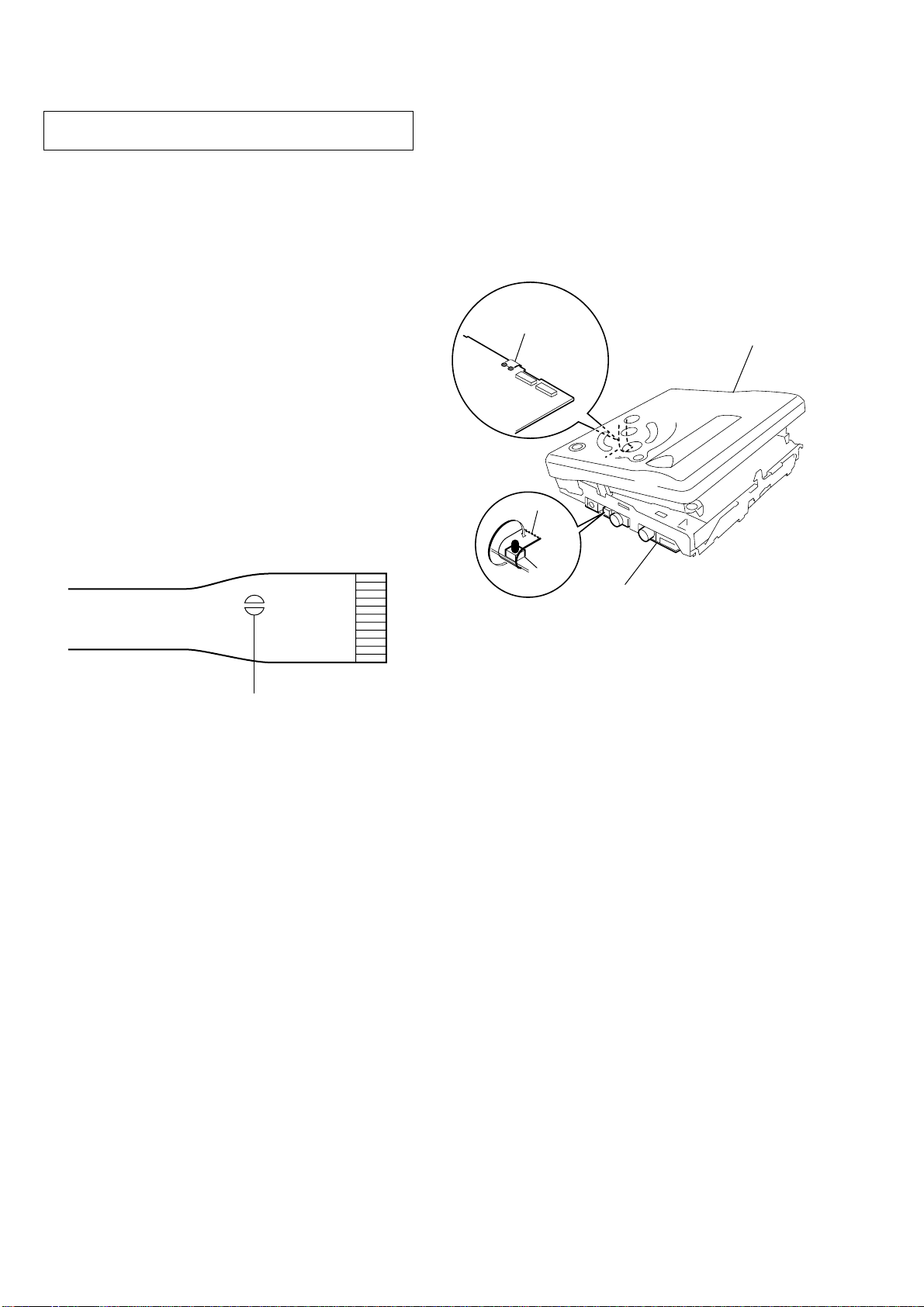
• In performing the repair with the power supplied to the set,
removing the MAIN board causes the set to be disabled.
In such a case, fix a convex part of the open/close detect switch
(S806 on MAIN board) with a tape in advance.
Handle the FLEXIBLE board (overwrite head) with care, as it
has been soldered directly to the MAIN board.
In repairing the component side of MAIN board, connect the
FLEXIBLE board (overwrite head) and the MAIN board with
the lead wires in advance. (See page 7)
FLEXIBLE board
(Over write head)
panel assy, upper
Tape
laser-tap
OPTICAL PICK-UP FLEXIBLE BOARD
S806
MAIN board
• Replacement of CDX2671-204GA (IC801) used in this set
requires a special tool.
• On the set having the microcomputer version 1.000, some
adjusted values were set in the manual mode at the shipment,
but these data will be cleared when the NV is reset. Therefore,
on the set having the microcomputer version 1.000, change the
adjusted values following the Change of Adjusted Values
immediately after the NV was reset. (See page 17)
4
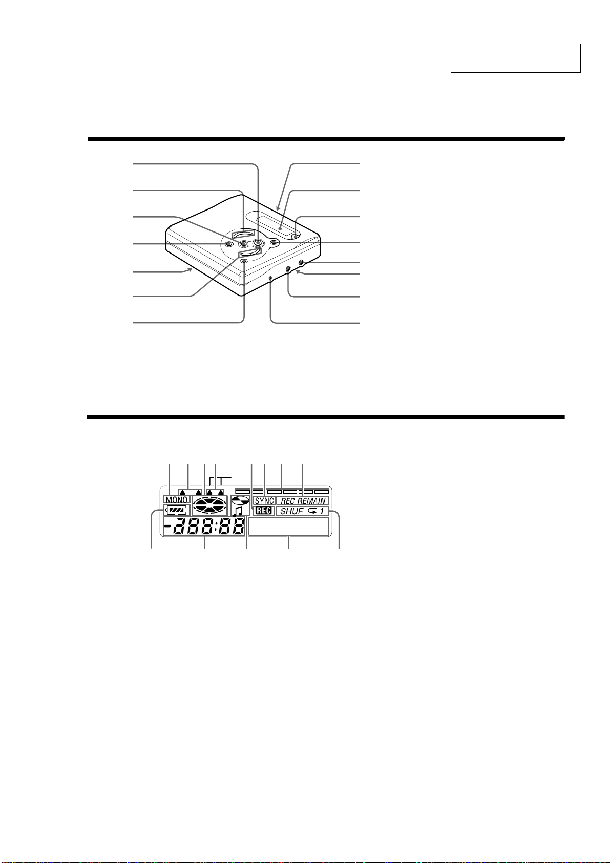
Looking at the controls
See pages in ( ) for more de tails.
The recorder
A
B
C
D
E
F
G
SECTION 2
GENERAL
H
I
J
K
L
M
N
O
MZ-R501/R501PC
This section is extracted from
instruction manual.
A N button (11) (13 ) (17) (25)
B VOL +/– buttons (13) (26)
C x button (11) (13) (27)
D X button (11) (13) (20) (26) (29)
E HOLD switch (at the rear) (9) (25)
F SELECT >/. buttons (16)
(23) (26)
./> (sea rch /AMS) buttons
(11) (13) (26) (29)
G MENU/ENTER button (16) (23) (26)
H OPEN switch (9)
I Display window (18) (23)
J END SEARCH button (11) (26)
K T MARK button (28)
REC (record) button (11) (17)
L i (
headphones) jack (9) (25)
M Battery compa rtment (at the rear) (8)
N LI NE IN (OPTICAL) jack (10) (16)
O DC IN 3V jack (10) (3
1)
The display window
LP2.4
CAB D
JI
E
Digital
K
FG
MEGA BASS
H
LM
A MONO (monaural) indication
B LP mode indication (17)
C Disc ind ic ation
Shows that
recording, playing or editing an MD
D Mega ba ss indication (24).
E REC indication
Lights up while recording. When
flashing, the re corder is in record
stan dby mo de .
F SYN C (synchro-recordi ng) indication
(18)
G Level meter (21)
Shows the volume of the MD being
played or record ed .
H REC REMAIN/REMAIN(rema ining
time/tracks) indication (21) (24)
Lights up along with the remaining
time of the track, the remaining time
of the MD, or the remaining number
of tracks.
I Battery indica tion (9)
Shows approximate battery condition.
J Time display
K Disc name/track nam e indication
Lights up when labeling a disc or a
track.
L Charac ter information display (21)
(25)
Displays the disc an d track names,
error messages, track numbers, etc.
M Play mode indication (23)
Shows the play mode of the MD.
th
e d isc is rotating for
5
MZ-R501/R501PC
I
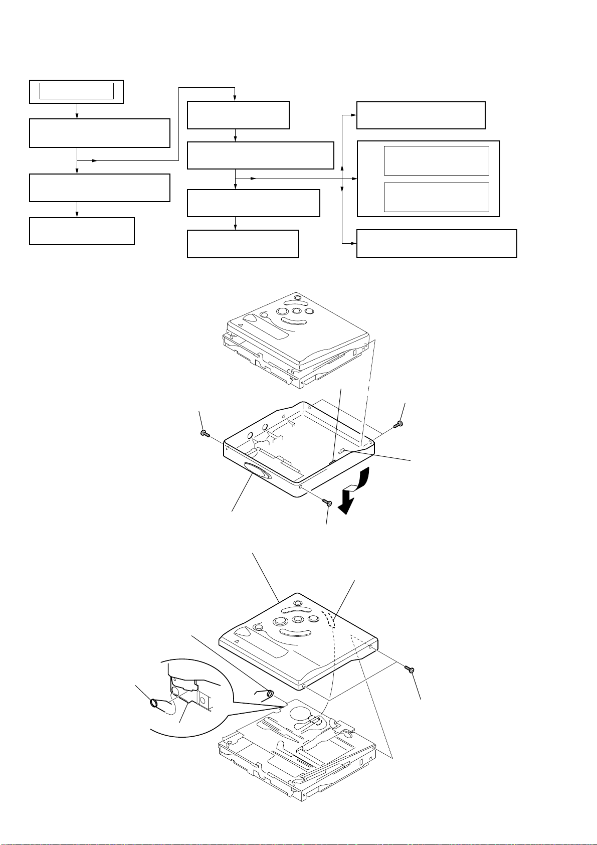
SECTION 3
DISASSEMBLY
Note : This set can be disassemble according to the following sequence.
SET
3-4. MAIN BOARD
3-1. CASE (LOWER) ASSY
(Page 7)
(Page 6)
3-5. MD MECHANISM DECK
(Page 8)
3-2. CASE (UPPER) ASSY
(Page 6)
3-6. SERVICE ASSY, OP
(Page 8)
3-3. LCD MODULE
(Page 7)
3-7. HOLDER ASSY
(Page 9)
Note : Follow the disassembly procedure in the numerical order given.
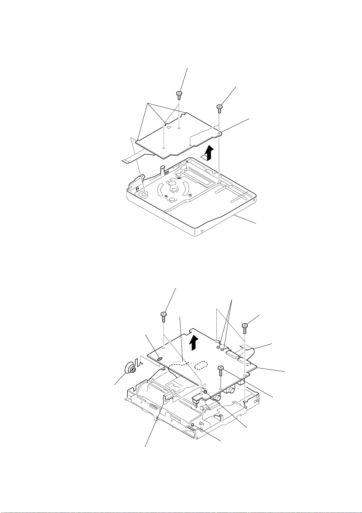
3-1. CASE (LOWER) ASSY
1
screw (1.7), MI
3-9. DC MOTOR (M602)
(Page 10)
3-10. DC MOTOR (M601)
(Page 10)
DC MOTOR (M603)
(Page 10)
3-8. MOTOR FLEXIBLE BOARD
(Page 9)
4
claw
3
screws (1.7), MI
3-2. CASE (UPPER) ASSY
4
spring (POP-L), torsion
spring (POP-L), torsion
chassis assy
6
case(lower) assy
3
case (upper) assy
2
screw (1.7), MI
2
5
CN801
knob (hold)
1
screws (1.7), M
6
3-3. LCD MODULE
y
d
claws
2
screws (1.7x3), tapping
3
1
screws (1.7x3), tapping
4
LCD module
MZ-R501/R501PC
3-4. MAIN BOARD
qd
terminal (-), battery
qs
Remove the solder
4
screws (M1.4x2),
toothed lock
8
CN501
7
case (upper) ass
2
Remove the solders
3
toothed lock
screws (M1.4x2),
1
CN701
9
MAIN boar
5
screw (M1.4x2),
toothed lock
qa
terminal (+), battery
6
claw
0
Remove the solder
7
MZ-R501/R501PC
t
e
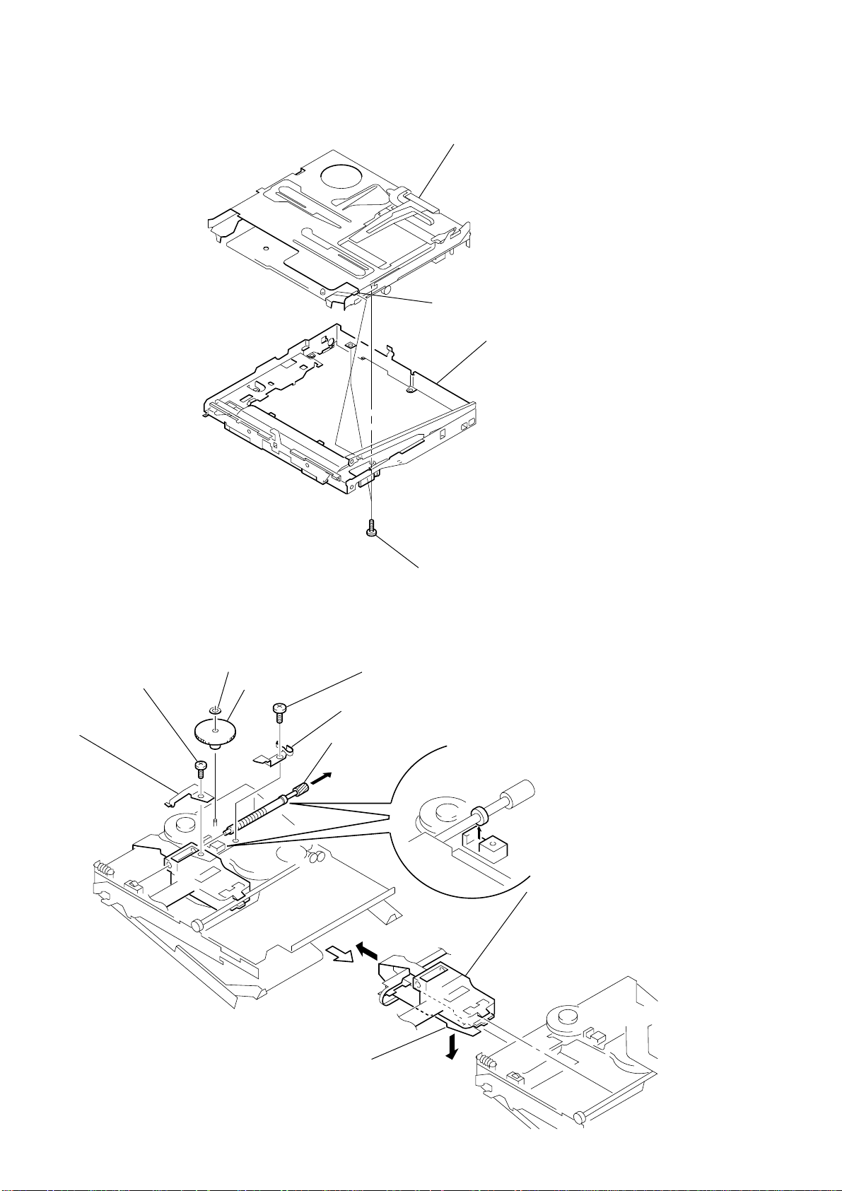
3-5. MD MECHANISM DECK
3 MD mechanism deck
boss
2 chassis assy, se
3-6. SERVICE ASSY, OP
3
precision pan screw
(M1.4)
4
spring (S), rack
1
washer (0.8 - 2.5)
2
gear (SA)
5
precision pan screw
(M1.4)
6
spring, thrust detent
8
Pull off the lead screw.
B
1 screws (1.7), MI
7
Opening the over write head
9
toward the direction
OP Service assy toward
the direction
Note: Do not open the entire assy
forcibly, when opening
the over write head.
B
.
A
, remove th
over write head section
A
8
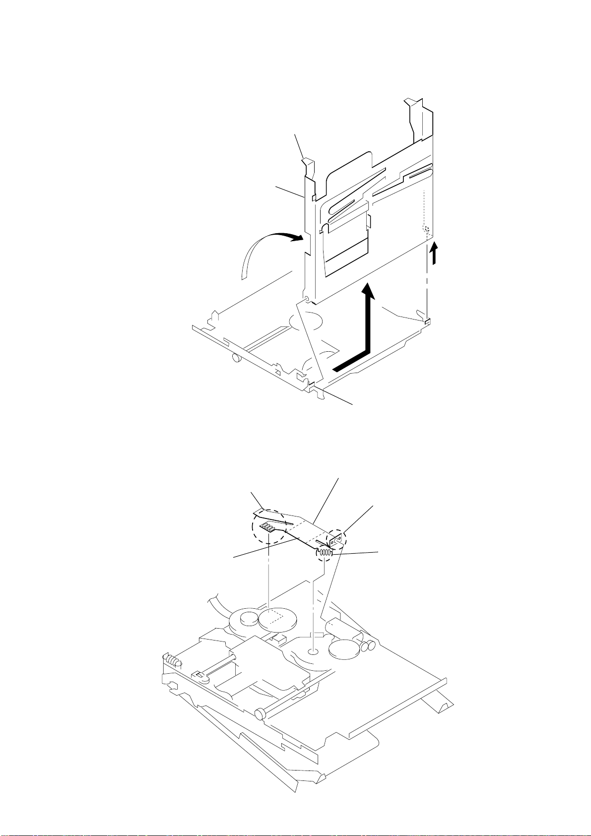
3-7. HOLDER ASSY
MZ-R501/R501PC
4 Remove the holder assy to
direction of the arrow B.
1 Open the holder assy.
A
2
3-8. MOTOR FLEXIBLE BOARD
1 Remove four solders of
DC motor (sled) (M602).
4 adhesive sheet
Note: Align a circular hole in the stripping paper
with a circular hole in the DC motor (sled),
when mounting the motor
flexible board.
B
3 boss
5 motor flexible board
2 Remove two solders of
DC motor (over write head up/down) (M603).
3 Remove four solders of
DC motor (spindle) (M601).
9
MZ-R501/R501PC
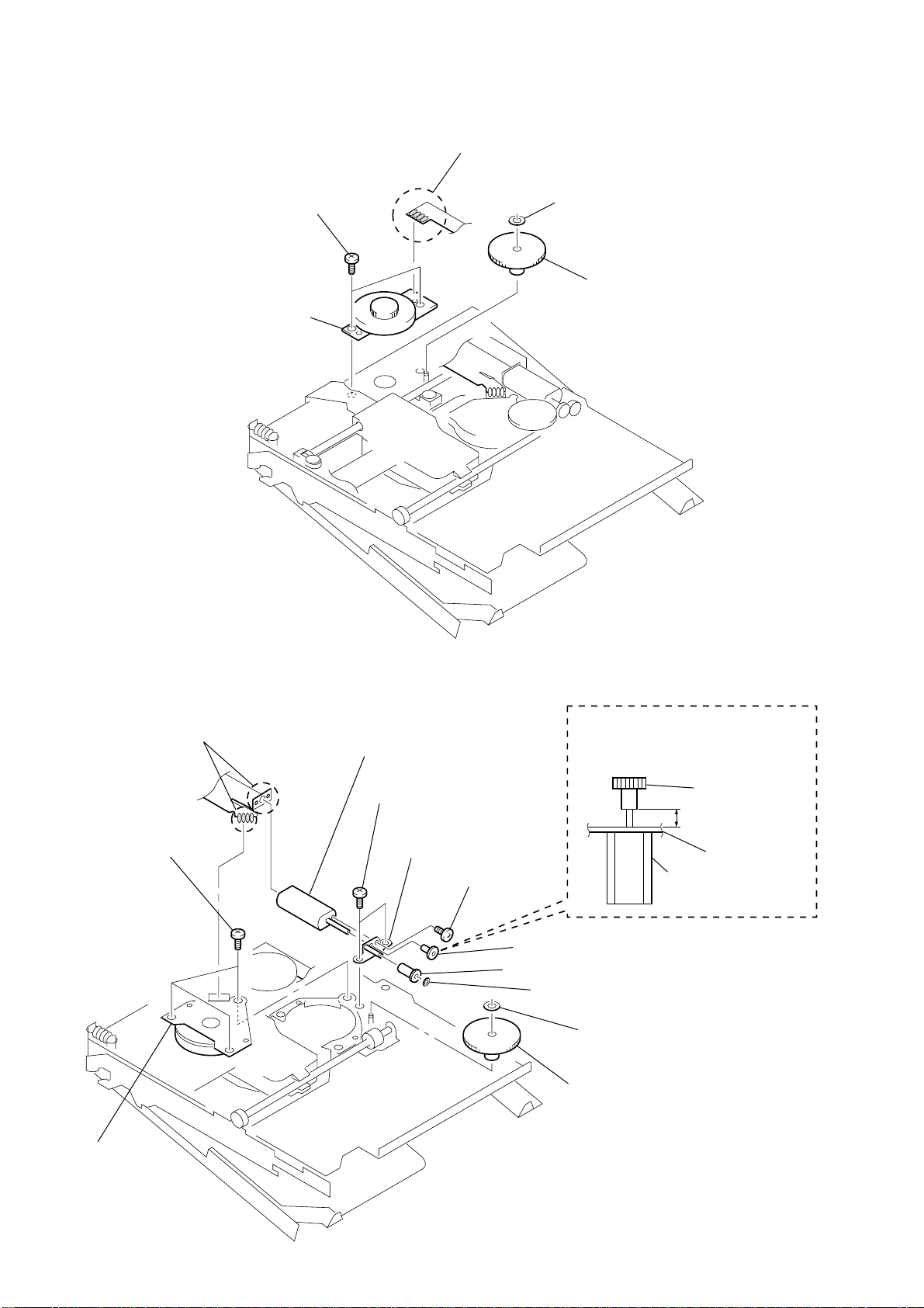
3-9. DC MOTOR (M602)
1 Remove four solders of
motor flexible board.
4 two precision pan screws
(M1.4)
5 DC motor (sled) (M602)
2 washer (0.8 - 2.5)
3 gear (SA)
3-10. DC MOTOR (M601), DC MOTOR (M603)
1 Remove six solders of
motor flexible board.
4 three precision pan screws
(M1.4)
qs DC motor (over write head up/down)
(M603)
6 two precision pan screws
(M1.4)
qa chassis assy, gear
0 screw
(M1.2 × 1.5)
9 gear (HA)
8 gear (HB)
Note: Press-fit the gear (HA) up to the
position of the DC motor (over write
head up/down) (M603) as shown
below.
gear (HA)
2.65 mm
gear chassis assy
DC motor
(over write head up/down)
(M603)
7 washer (0.8 - 2.5)
2 washer (0.8 - 2.5)
3 gear (HC)
10
5 DC motor
(spindle)
(M601)
SECTION 4
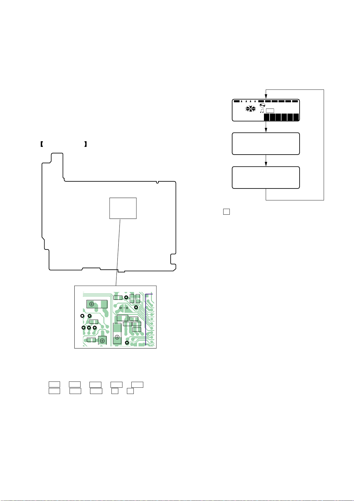
All lit
This set LCD display
All off
Microcomputer
version
display
SYNCMONO REC REMAIN
SHUFREC
u
1F
-a 8 8 : 8 8
00 6
V1.300
TEST MODE
MZ-R501/R501PC
4-1. Outline
• This set provides the Overall adjustment mode that allows CD
and MO discs to be automatically adjusted when in the test mode.
In this overall adjustment mode, the disc is discriminate between
CD and MO, and each adjustment is automatically executed in
order. If a fault is found, the system displays its location. Also,
the manual mode allows each individual adjustment to be automatically adjusted.
4-2. Setting Method of T est Mode
There are two different methods to set the test mode:
1 Short TAP801 (TEST) on the MAIN board with a solder bridge
(connect pin 3 of IC801 to the ground). Then, turn on the
power.
MAIN BOARD (SIDE B)
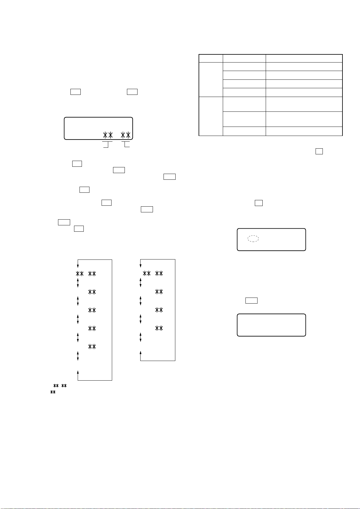
4-3. Operation in Setting the Test Mode
• When the test mode becomes active, first the display check mode
is selected.
• Other mode can be selected from the display check mode.
• When the test mode is set, the LCD repeats the following dis-
play.
• When the
time is held so that display can be checked.
X key is pressed and hold down, the display at that
2 In the normal mode, turn on the [HOLD] switch. While press-
ing the [VOL --] key press the following order:
> t > t . t . t > t
. t > t . t X t X
AP526
AP529
AP530
R811
AP528
C521
C815
AP531
R805
TAP801
(TEST)
AP856
FB801
C830
C807
AP802
R806
AP803
C808
R810
R830
4-4. Releasing the Test Mode
For test mode set with the method 1:
Turn off the power and open the solder bridge on TAP801 (TEST)
on the MAIN board.
Note: Remove the solders completely. Remaining could be shorted
with the chassis, etc.
For test mode set with the method 2:
Turn off the power.
Note: If electrical adjustment (see page 17) has not been finished
completely, always start in the test mode. (The set cannot
start in normal mode)
R807
11
MZ-R501/R501PC
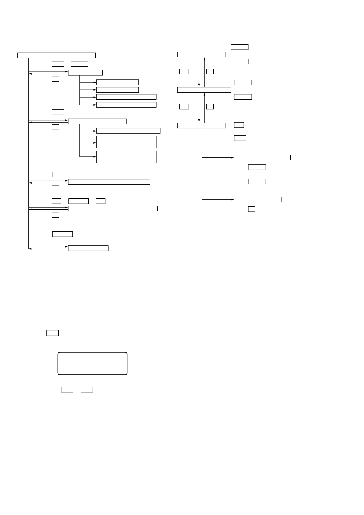
4-5. Configuration of T est Mode
Test mode (Display Check Mode)
Press the > or VOL+ key
Manual Mode
Press the x key
Press the . or VOL– key
Overall Adjustment Mode
Press the x key
ENTER key
Self-Diagnosis Result Display Mode
Press the x key
Press the N or T.MARK + N keys.
Sound Skip Check Result Display Mode
Press the x key
Press the T.MARK + X keys.
Key Check Mode
The key check quits,or open the upper panel
Servo Adjustment
Audio Adjustment
Power Supply Adjustment
OP Alignment Adjustment
Electrical Offset Adjustment
Power Supply Adjustment
Auto item Feed
CD Overall Adjustment/
MO Overall Adjustment
Major item switching
x key N key
Medium item switching
x key N key
Minor item switching
VOL + key: 100th Place of item number
increase.
VOL – key: 100th Place of item number
decrease.
VOL + key: 10th Place of item number
increase.
VOL – key: 10th Place of item number
decrease.
N key: Unit Place of item number
increase.
. key: Unit Place of item number
decrease.
Adjusted value variation
VOL + key: Increases the
adjusted value
VOL – key: Decreases the
adjusted value
Adjusted value write
X key: When adjusted value is
chaged:
Adjusted value is written.
When adjusted value is
not changed:
That item is adjusted
automatically.
4-6. Manual Mode
Mode to adjust or check the operation of the set by function.
Normally, the adjustment in this mode is not executed.
However, the Manual mode is used to clear the memory, power
supply adjustment, and laser power check before performing
automatic adjustments in the Overall Adjustment mode.
• Transition method in Manual Mode
1. Setting the test mode (see page 11).
2. Press the > or[VOL +] key activates the manual mode where
the LCD display as shown below.
This set LCD display
0 0 0
3. During each test, the optical pick-up moves outward or inward while the > or . key is pressed for several seconds respectively.
4. Each test item is assigned with a 3-digit item number;
100th place is a major item, 10th place is a medium item, and
unit place is a minor item.
The values adjusted in the test mode are written to the
nonvolatile memory (for the items where adjustment was
made).
Manual
12
MZ-R501/R501PC
e
e
e
e
0 XX1
0 XXN
0 XXN1
0 XXN2
0 XXR_
XX
:Error code
:Total recording time
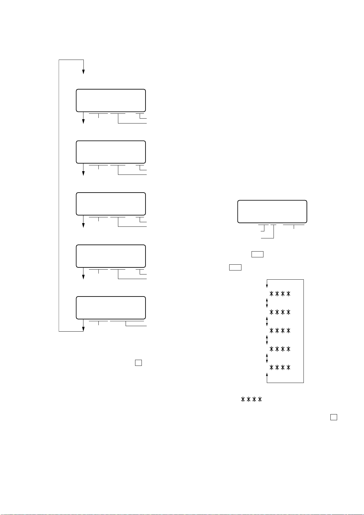
5. The display changes a shown below each time the
[ENTER] key on the set is pressed.
• Address & Adjusted V alue Display
This set LCD display
0 11
item number
• Jitter Value & Adjusted Value Display
This set LCD display
0 11
item number
• Block Error Value & Adjusted Value Display
This set LCD display
0 11
item number
• ADIP Error Value & Adjusted Value Display
This set LCD display
3A4S1D
adjustment valu
address
OFEJ1D
adjustment valu
jitter value
063B1D
adjustment valu
block error value
4-8. Self-Diagnosis Result Display Mode
This set uses the self-diagnostic function system in which if an
error occurred during the recording or playing, the mechanism
control block and the power supply control block in the
microcomputer detect it and record its cause as history in the
nonvolatile memory.
By checking this history in the test mode, you can analyze a fault
and determine its location.
Total recording time is recorded as a guideline of how long the
optical pickup has been used, and by comparing it with the total
recording time at the time when an error occurred in the selfdiagnosis result display mode, you can determine when the error
occurred.
Clear both self-diagnosis history data and total recording time, if
the optical pickup was replaced.
• Self-Diagnosis Result Display Mode Setting Method
1. Setting the test mode (see page 11).
2. In the display check mode, press the [ENTER] key activates the
self-diagnosis result display mode where the LCD display as
shown below.
This set LCD display
0 XX 1 0000
error
display code
history code
Total recording time
when error occurred
0 11
item number
• Item Title Display
This set LCD display
0 11
item number
However in the power mode (item number 700’s), only the
item is displayed.
6. Quit the manual mode, and press the
test mode (display check mode).
072A1D
adjustment valu
ADIP error value
LrefPw
item title
x key to return to the
4-7. Overall Adjustment Mode
Mode to adjust the servo automatically in all items.
Normally, automatic adjustment is executed in this mode at the
repair.
For further information, refer to “Section 5 Electrical Adjustments”
(see page 17).
3. Then, each time the
by one as shown below. Also, the LCD display ascends by one
when the
4. Quit the self-diagnosis result display mode, and press the x key
to return to the test mode (display check mode).
. key is pressed.
> key is pressed, LCD display descends
13
MZ-R501/R501PC
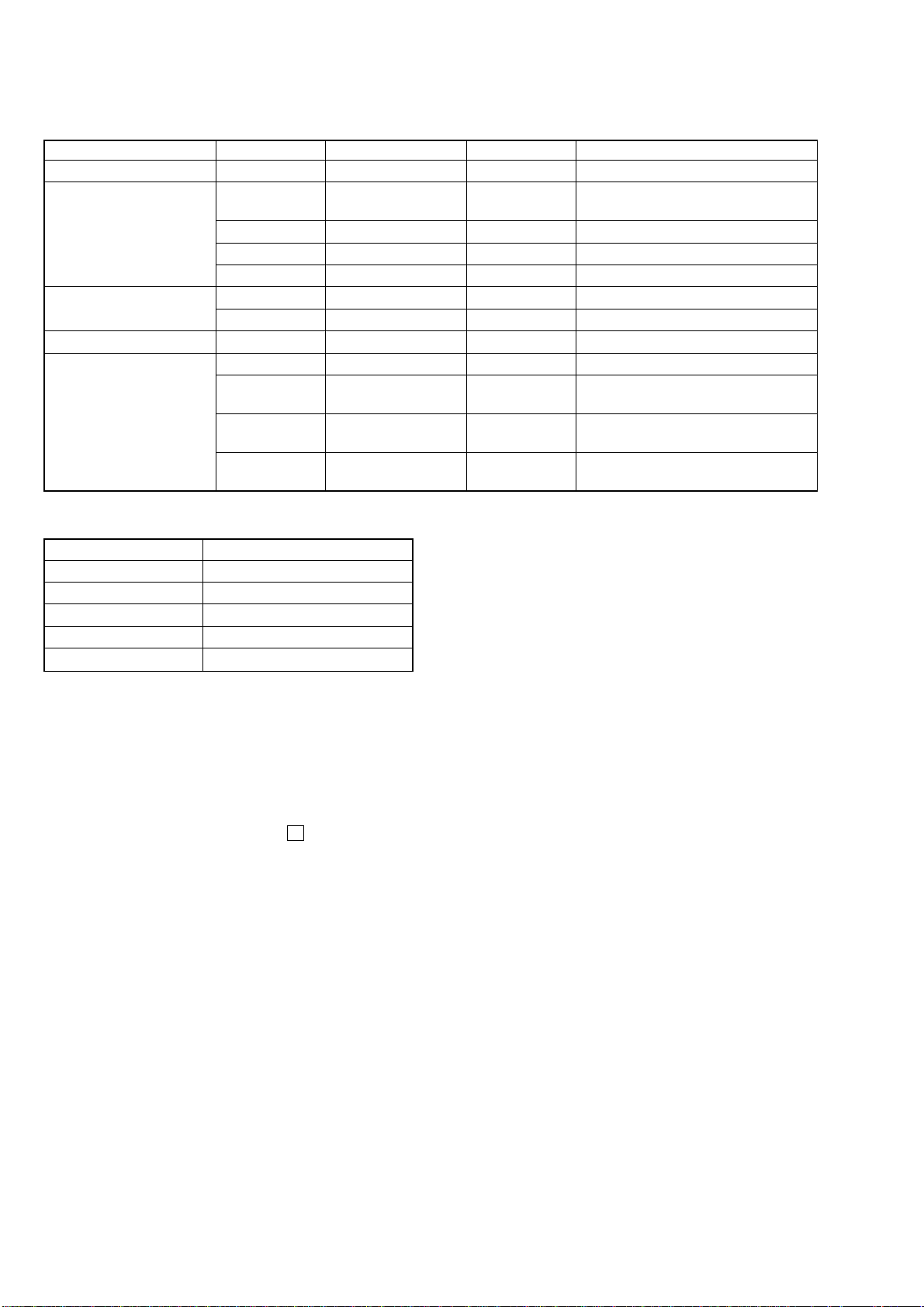
• Description of Error Indication Codes
Problem Indication code Meaning of code Simple display Description
No error 00 No error --- No error
01
Servo system error 02 High temperature Temp High temperature
03 Focus error Fcus Disordered focus
04 Spindle error Spdl Abnormal rotation of disc
TOC error
Power supply system error 22 Low battery LBat Momentary interruption detected
Offset system error
11 TOC error TOC Faulty TOC contents
12 Data reading error Data Data could not be read at SYNC
31 Offset error Ofst Offset error
32
33
34
Illegal access target
address was specified
Focus error ABCD
offset error
Tracking error
Offset error
X1 tracking error
Offset error
Adrs Attempt to access an abnormal address
ABCD Focus error ABCD offset error
TE Tracking error Offset error
X1TE X1 tracking error Offset error
• Description of Indication History
History code number Description
1 The first error
N The last error
N1 One error before the last.
N2 Two errors before the last.
R_ Total recording time
4-9. Reset the error display code
After servicing, reset the error display code.
• Setting method of Reset the Error Display Code
1. Setting the test mode (see page 11).
2. Press [ENTER] key activates the self-diagnosis result display
mode.
3. To reset the error display code, press the X key (2 times) when
the code is displayed (except “R_****”).
(All the data on the 1, N, N1, and N2 will be reset)
14
MZ-R501/R501PC
g
)
This set LCD display
8 8 8
RMC OK
This set LCD display
8 8 8 FF
4-10. Sound Skip Check Result Display Mode
This set can display the count of errors that occurred during the
recording/playing for checking.
• Setting method of sound skip check result display
mode
1. Set the test mode (see page 11).
2. Press the N key or [T.MARK] + N keys, and the playing
or recording sound skip result display mode becomes
active respectively where the LCD displays the following.
This set LCD display
0 00
Total count of play
system errors(hex.)
3. When the N key is pressed, total error count is displayed on
the LCD, and each time the > key is pressed, the display
item moves down by one as sho wn below . Also, if the . key
is pressed, the display item moves up by one, then if the
P R
Total count record
system errors(hex.)
[T.MARK] + N keys is pressed, the display in the record
mode appears.
When the [T.MARK] + N keys is pressed, total error count
is displayed on the LCD, and each time the > key is pressed ,
the display item moves down by one as sho wn below . Also, if
the . key is pressed, the display item moves up by one,
then if the N key is pressed, the display in the play mode
appears.
• Cause of Sound Skip Error
Cause of error Description of error
EIB Sound error correction error
Play
Record
4. To quit the sound skip check result display mode and to return
to the test mode (display check mode), press the
Stat Decoder status error
Adrs Address access error
BEmp Buffer is empty
BOvr
Bful
Rtry Retry times over
Buffer is full, and sounds were
dumped
Buffer capacity becomes less,
and forcible writing occurred
x key.
4-11. Key Check Mode
This set can check if the set function normally.
• Setting Method of Key Check Mode
1. Setting the test mode (see page 11).
2. Press the [T.MARK] + X keys activates the key check mode.
(At the last two digits, AD value of remote commander key
line is displayed in hexadecimal)
Playing sound skip
result display
0 00 P R
0 00 EIB
0 00 Stat
0 00 Adrs
0 00 BEmp
0 00 ######
P R
:Total play/record errors(hex.)
:Counter of sound skip check each item(hex.)
:6-di
######
it address where sound was skipped last(hex.
Recording sound skip
result display
0 00 P R
0 00 BOvr
0 00 Bful
0 00 Rtry
0 00 ######
3. When each key on the set and on remote commander is pressed,
its name is displayed on the LCD. (The operated position is
displayed for 4 seconds after the slide switch is operated. If
any other key is pressed during this display, the remote commander LCD switches to its name display)
Example1: When > key on the set is pressed:
15

MZ-R501/R501PC
4. When all the keys on the set and on the remote commander are
considered as OK, the following displays are shown for 4 seconds.
Example1: When the keys on the set are considered as OK:
This set LCD display
8 8 8
5. When all keys were checked or if the upper panel is opened,
the key check mode quits and the test mode (display check
mode) comes back.
RMC OK
16
 Loading...