

Page 1

MULTI PORT AV STORAGE UNIT
PWS-4400
OPERATION MANUAL [English]
1st Edition (Revised 3)
Page 2

Table of Contents
Chapter 1 Overview
Features............................................................................................4
High-quality video and audio recording................................................ 4
Multi-codec ........................................................................................... 4
Multi-resolution..................................................................................... 4
High frame rate recording ..................................................................... 4
Multi-port .............................................................................................. 4
Large-capacity memory storage ............................................................ 5
Playlist playback.................................................................................... 5
Loop recording ...................................................................................... 5
Network ................................................................................................. 5
Remote control ...................................................................................... 5
Chapter 2 Names and Functions of Parts
Front Panel .......................................................................................6
Connector Panel ..............................................................................7
Chapter 3 Setup
Connecting External Devices .......................................................10
Using the unit as a recorder ................................................................. 10
Using the unit as a player .................................................................... 11
Displaying the Web Menu .............................................................12
Configuring the Network...............................................................12
Setting the System and Boards....................................................13
Maximum Recording Time of Memory.........................................14
Chapter 4 Web Menu
2
Table of Contents
Title Bar............................................................................................... 15
Home Screen ....................................................................................... 15
Status Screen.................................................................................19
System Screen...............................................................................20
Board tab ............................................................................................. 20
Page 3

Appendix
Setup tab .............................................................................................. 20
Remote tab ........................................................................................... 23
Network tab ......................................................................................... 24
Bank tab ............................................................................................... 25
Power tab ............................................................................................. 26
Port Screen .................................................................................... 27
For input ports...................................................................................... 27
For output ports.................................................................................... 30
Storage Screen .............................................................................. 33
Info tab................................................................................................. 33
Setup tab .............................................................................................. 34
Loop tab ............................................................................................... 35
HD SDI Connector Input/Output Specifications ......................... 36
File Operations via FTP................................................................. 38
Directory structure ...............................................................................38
Setting Up ............................................................................................38
Connecting via FTP ............................................................................. 38
Command list....................................................................................... 39
Usage Precautions ........................................................................ 42
Troubleshooting ............................................................................ 42
Salvaging memory when recording ends abnormally ......................... 42
Error Messages ....................................................................................43
Warning Messages............................................................................... 44
Displaying the error log .......................................................................47
Recording Format.......................................................................... 48
Specifications ................................................................................ 50
MPEG-4 Visual Patent Portfolio License ..................................... 52
Table of Contents
3
Page 4
Chapter 1 Overview
Overview
Chapter
1
Features
The PWS-4400 is a multi-channel recorder that is
equipped with the MPEG-4 AVC/H.264 codec and can
handle 4K to HD resolutions.
Utilizing its high-speed, large-capacity memory storage,
the unit is capable of real-time recording and playback of
high-quality video for increased efficiency in video
production applications, such as live broadcasts and studio
productions.
High-quality video and audio recording
The unit employs XAVC format in conformance with the
MPEG-4 AVC/H.264 codec as the recording system to
obtain digital recording and playback of high-quality
video.
The unit also supports 16-ch audio (uncompressed, 24-bit,
48 kHz).
Multi-codec
High frame rate recording
The unit can record video signals at high frame rates, in
addition to the standard frame rate.
Signals recorded at a high frame rate can be played back at
normal speed, and can also be played back as smooth slow
motion video.
The unit supports recording at the following high frame
rates.
• HD (1280×720) 100p/119p/200p/239p/300p/359p
• HD (1920×1080) 100i/119i/200i/239i/300i/359i
• HD (1920×1080) 200p/239p/300p/359p
• QFHD (3840×2160) 100p/119p
Multi-port
The unit is equipped with four input/output ports, each
capable of handling 4K and HD signals.
The input/output of each port can be switched via a
configuration menu that can be viewed in your web
browser.
You can flexibly arrange input/output into 4-input, 3input/1-output, 2-input/2-output, 1-input/3-output, or 4output configurations to suit your production needs and
environment.
XAVC or Avid DNxHD(R) codec can be selected for HD
recording and playback (when PWA-CD401 is installed).
Multi-resolution
The unit allows recording and playback of 4:2:2 (10-bit)
signals in 1280×720 (HD), 1920×1080 (HD), 2048×1080
(2K), 3840×2160 (QFHD), and 4096×2160 (4K)
resolutions.
The unit’s video compression rates are as follows.
• HD, 2K: XAVC Class 100, DNxHD145, DNxHD220x
• QFHD, 4K: XAVC Class 300
4
Features
Additional HD input ports
For HD, the unit supports simultaneous dual-system
recording using a single input board. This enables 4-in/2out and 6-in/1-out configurations.
Port sync operation
The unit can be configured for operation with synced input
ports and synced output ports.
When input ports or output ports are grouped, changing the
operation of one port also changes the other ports within
the group in unison.
Page 5

HD cutout function
This function allows you cut out a portion of a video signal
recorded in 4K or QFHD, using the PWA-PRC1
application, and view it at HD size.
4-channel simultaneous recording and
playback
By allowing simultaneous recording and playback of video
and audio from its four input/output ports, the unit enables
efficient video production.
Chasing playback and delay-free data
transfer
You can play back high-quality video while it is being
recorded.
The unit also supports variable-speed playback, allowing
slow replays of live broadcasts.
Large-capacity memory storage
The unit is standard-equipped with a 2 TB memory board.
With four additional memory slots available, you can
expand the storage capacity to up to 8 TB by adding
PWSK-4401 expansion memory boards.
Remote control
You can simultaneously connect up to four controllers that
support the RS422A (9-pin serial) signal format.
The SONY VTR/Disk Protocol, VDCP, and Odetics
control protocols are supported.
Remote control using parallel interface (25-pin) and
gigabit Ethernet is also supported.
Chapter 1 Overview
Playlist playback
The unit supports play back of playlists created using the
PWA-PRC1 application from the output ports of the unit.
Loop recording
This function records video in a continuous loop. A loop
recording area must be assigned to input ports beforehand
using the web menu. When the recorded video reaches the
capacity of the assigned area, recording continues from the
start, overwriting the previous recording.
Network
Equipped with FTP server functions, the unit allows you to
transfer video files in MXF format via a network.
The unit is equipped with two Gigabit Ethernet ports as
standard. In addition, 10-Gigabit Ethernet option is also
supported by installing a board in the PCIe expansion slot.
Features
5
Page 6
Names and Functions of
Parts
Chapter 2 Names and Functions of Parts
Front Panel
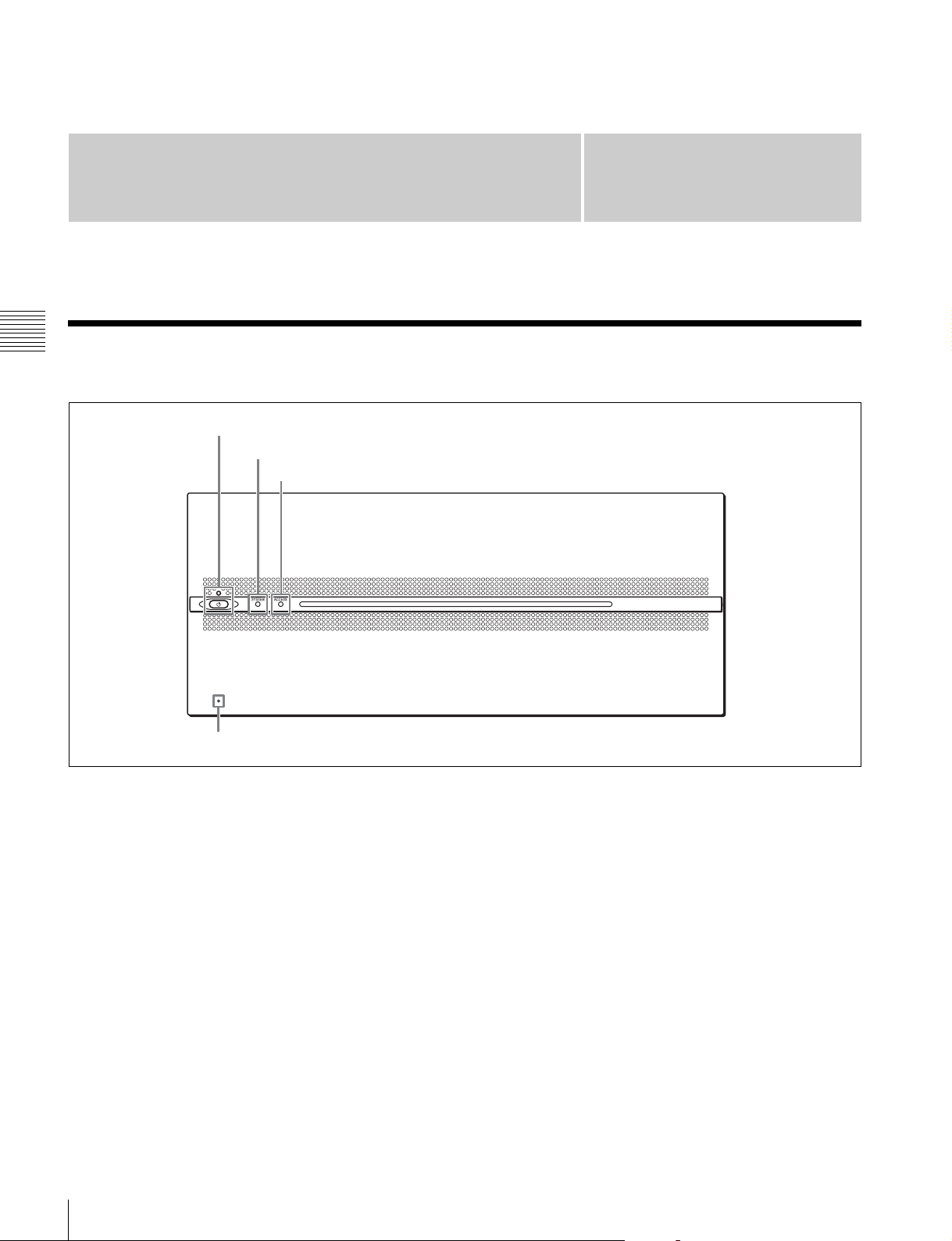
1 On/Standby button and indicator
2 SYSTEM indicator
3 ACCESS indicator
Chapter
2
4Network reset switch
a On/Standby button and indicator
Switches the unit between on and standby. When the main
power switch on the rear panel is turned on, the unit is in
standby mode and the indicator is lit red. When the On/
Standby button is pressed while in standby mode, the unit
is turned on and the indicator is lit green. The indicator is
off when the main power switch is turned off.
b SYSTEM indicator
Displays the status of the unit.
Green: Operating normally
Green (flashing once per second): Starting up
Orange (flashing once per second): Warning message
was issued.
Red (high-speed flashing four times per second):
Serious error has occurred.
Purple (flashing once per second): Network reset is in
progress.
c ACCESS indicator
Displays the access status of storage.
Off: Not being accessed
Blue: Accessing
Blue (flashing): Formatting or deleting files
d Network reset switch
Resets the IP address and network settings to their default
values. Insert and hold the end of a paper clip or other thin
object into the hole to operate the internal switch and then
start the unit. The SYSTEM indicator will begin flashing
purple.
6
Front Panel
Page 7

Connector Panel
Port A
Port B
Port C
Port D
AInput/output ports (see page 7)
Chapter 2 Names and Functions of Parts
BRemote input/output
A Input/output ports
There are four ports (A to D), where each port has the
following 16 connectors. The ports can be configured as
inputs or outputs using the web menu.
1234
56789
HD SDI
IN/OUT
For input ports
a HD SDI IN/OUT 1 to 4 connectors
Inputs HD SDI signals (up to four cables).
b HD SDI IN/OUT 5 to 8 connectors
Outputs the same signals input as connectors HD SDI IN/
OUT 1 to 4 for monitors (up to four cables).
c HD SDI IN/OUT 9 connector
Outputs an HD SDI signal with superimposed text
information for a monitor. To superimpose text
information, set [Character On/Off] to “On” on the Port
screen of the web menu.
When the input is a 4K signal, it outputs a down-converted
HD signal.
The audio signal is not output.
section (see page 8)
Note
CPower supply section
(see page 9)
The input/output signal on the HD SDI IN/OUT
connectors varies with the port setting (input or output)
and the SDI signal format. For details, see “HD SDI
Connector Input/Output Specifications” (page 36).
10 IN OUT 1/2 3/4 5/6 7/8
MONITOR
TIME CODE AUDIO (AES/EBU)
IN/OUT
d HD SDI IN/OUT 10 connector
For ports A to C, this outputs the same signal as the HD
SDI IN/OUT 9 connector. When “HD Multi” (dual-system
input) is configured in the port settings, the x-1 (main port)
monitor signal is output from the HD SDI IN/OUT 9
connector and the x-2 (sub port) monitor signal is output
from the HD SDI IN/OUT 10 connector.
For port D, this outputs one of the following video signals
according to the web menu settings. To output the same
signal as the HD SDI IN/OUT 9 connector, set [Board D
SDI-10 Output] to [Off] on the [Setup] tab of the [System]
screen in the web menu.
• Port A to D signals are output in multi-monitor format
• Same signal output as the HD SDI IN/OUT 9 connector
e TIME CODE IN connector
Inputs a time code generated by an external device.
Connector Panel
7
Page 8
f TIME CODE OUT connector
When the time code generator is synchronized to the
external time code signal input on the TIME CODE IN
connector, the external time code is output according to the
[TC Out Select] setting on the Port screen of the web
menu.
g AUDIO (AES/EBU) connector
Inputs the audio signals in AES/EBU format for channels
1 to 8.
For output ports
a HD SDI IN/OUT 1 to 4 connectors
Outputs HD SDI signals (up to four cables).
Chapter 2 Names and Functions of Parts
When [Output Port SDI-1,2,3,4] is set to [Off] on the
[Setup] tab of the [System] screen in the web menu, no
signal is output.
information, set [Character On/Off] to “On” on the Port
screen of the web menu.
The output signal format can be set to Interlace,
Progressive, or PsF in [Port Configuration] of the [Port]
screen of the web menu. When the playback file format is
a 4K signal, the outputs is down-converted to an HD
signal.
d HD SDI IN/OUT 10 connector
For ports A to C, outputs the same signals as connector HD
SDI IN/OUT 9.
For port D, this outputs one of the following video signals
according to the web menu settings. To output the same
signal as the HD SDI IN/OUT 9 connector, set [Board D
SDI-10 Output] to [Off] on the [Setup] tab of the [System]
screen in the web menu.
• Port A to D signals are output in multi-monitor format
• Same signal output as the HD SDI IN/OUT 9 connector
b HD SDI IN/OUT 5 to 8 connectors
Outputs the same signals as connectors HD SDI IN/OUT 1
to 4 (up to four cables).
c HD SDI IN/OUT 9 connector
Outputs an HD SDI signal with superimposed text
information for a monitor. To superimpose text
B Remote input/output section
e TIME CODE IN connector
Not used.
f TIME CODE OUT connector
Outputs the playback time code.
g AUDIO (AES/EBU) connector
Outputs the audio signals in AES/EBU format for channels
1 to 8.
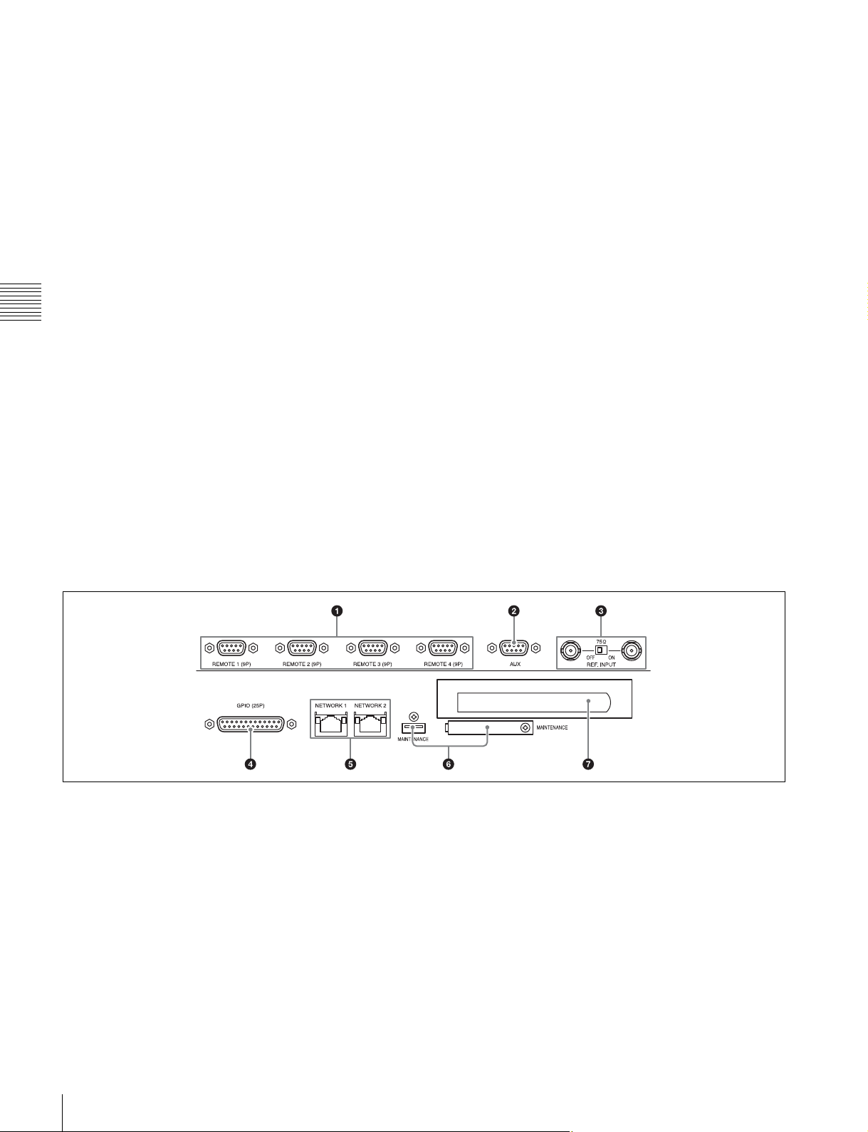
a REMOTE 1 to 4 (9-pin) connectors
Connects to an external device used to control the unit
using a 9-pin remote control cable.
SONY VTR/Disk protocol, VDCP, and Odetics control
protocols are supported.
b AUX connector
Currently cannot be used.
c REF. INPUT connector and 75 Ω termination
switch
Inputs the reference video signal of the selected field
frequency. Input an HD tri-level SYNC signal or SD black
burst signal.
8
Connector Panel
A bridge connection is also supported. Set the 75 Ω
termination switch to OFF if using a bridge connection, or
set it to ON if not using a bridge connection.
d GPIO (25-pin) connector
Parallel I/O connector.
For details, refer to the Maintenance Manual or Interface
Manual.
e NETWORK 1/2 connectors
Connects to a network cable for monitoring the unit by
SNMP, configuring or checking the unit via HTTP,
transferring files via FTP, etc.
Page 9
Notes
• For safety, do not connect the connector for peripheral
device wiring that might have excessive voltage to this
port.
Follow the instructions for this port.
• When connecting a network cable, use a shielded-type
cable to prevent malfunction due to radiation noise.
f MAINTENANCE connector
For use by service personnel. Not used for normal
operation.
g Blank panel for PCI Express board
Removable panel for when installing a PCI Express board
to use a 10 Gbit Ethernet interface.
For details about PCI Express board installation, refer to
the Installation Manual.
C Power supply section
Chapter 2 Names and Functions of Parts
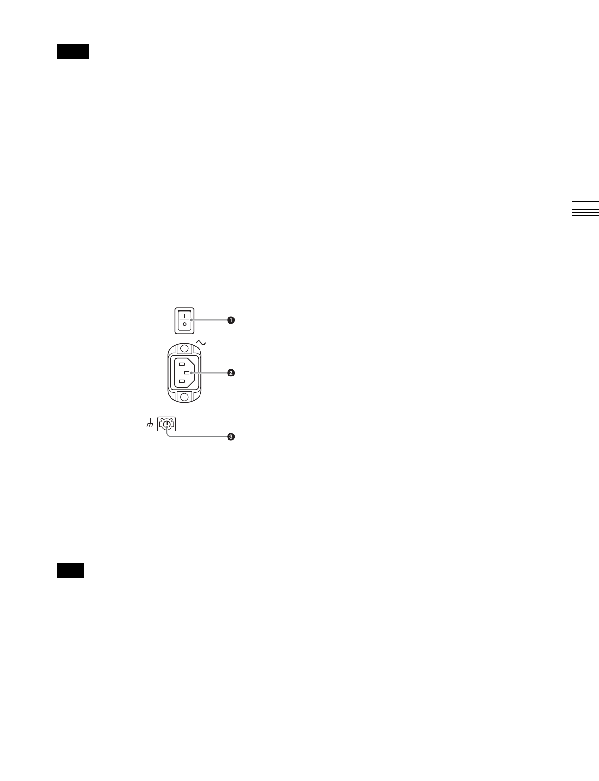
a Main power switch
Turns the main power supply on/off. When the main power
switch is turned on, the On/Standby indicator on the front
panel is lit.
For operation, always set the switch to the up position
(On), and switch the unit between On and standby mode
using the On/Standby button on the front panel.
Note
When turning off the main power, always check that the
On/Standby indicator on the front panel is lit red, and then
set the switch to the down position (Off).
b - AC IN connector
Connects to an AC power outlet using the recommended
power cord.
c U Ground terminal
Connect to ground as required.
Connector Panel
9
Page 10
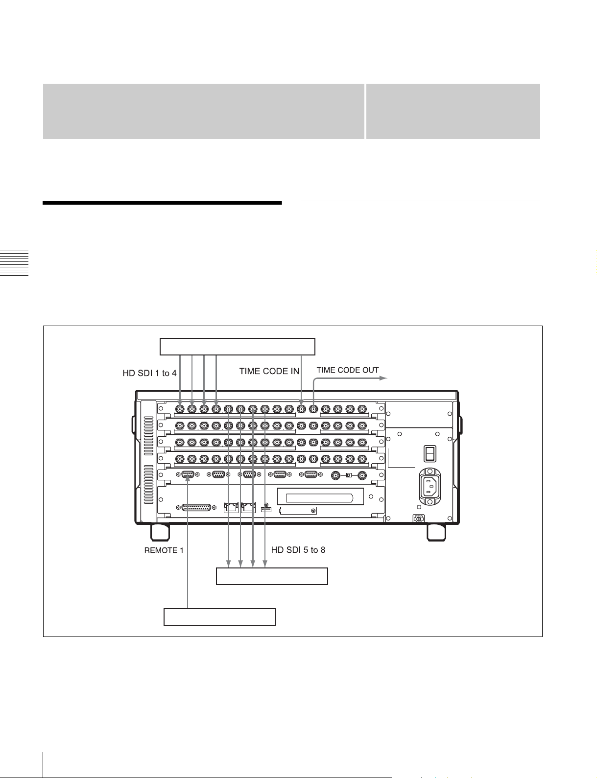
Setup
Chapter
3
Connecting External Devices
Chapter 3 Setup
This section describes how to connect the unit to external
devices to record or play back data. This section describes
the configuration with ports A and C used for inputs and
ports B and D used for outputs.
4K digital player
Using the unit as a recorder
The following shows an example of connecting a 4K
digital player or other devices to the input ports and using
the unit as a recorder.
10
Connecting External Devices
Video monitor
Remoter controller
Page 11

Using the unit as a player
The following shows an example of connecting a 4K
digital recorder or other devices to the output ports and
using the unit as a player.
HD digital recorder
Chapter 3 Setup
Remoter controller
Video monitor
Connecting External Devices
11
Page 12

Displaying the Web Menu
Configuring the Network
You set up and control the unit by connecting to a
computer via the network and displaying the web menu in
a web browser on the computer.
Validated operating environments
Web browser:
• Windows: Microsoft Internet Explorer 9 to 11, Google
Chrome 38, Firefox 33, or Opera 25, Safari 5
• Mac OS: Safari 6
Display: Screen width of 1024 pixels or greater
Connect a computer that satisfies the above requirements
to NETWORK connector 1 or 2 on the rear panel of the
unit. Enter “http://(device_IP_address)/” in the address bar
of a web browser on the computer to display the web
menu. The following IP addresses are configured at the
Chapter 3 Setup
factory for the NETWORK connectors of the unit.
• NETWORK 1 connector: 192.168.0.1
• NETWORK 2 connector: 192.168.0.2
If the IP addresses are changed, specify the new addresses.
The IP address to connect to can be specified on the
[System] screen > [Network] tab of the web menu.
Notes
Access the [System] screen > [Network] tab of the web
menu to configure settings related to the IP address and
network. For details about settings, see “Network tab”
(page 24).
Configure each setting on the [Network] tab, and then click
the [Submit] button. A confirmation message appears.
Click [OK] to restart the unit. The settings are enabled
after the unit restarts.
To display the web menu subsequently, enter the IP
address you specified.
Accessing over a network
When accessing files using a network cable, you can also
transfer files while recording or playback is in progress.
However, since SDI input/output has priority, the transfer
rate over the network may decrease depending on input/
output port usage.
• For details about network settings, contact your network
administrator.
• You may be unable to connect to the network, depending
on your proxy server settings.
• It may not be possible to set the appropriate setting due
to conflicts if the computer is using a multi-session
connection. If this occurs, reconfigure the settings.
• The web menu cannot be displayed over the optional 10
Gbit Ethernet interface. To display the web menu,
always connect the computer to NETWORK connector
1 or 2.
12
Displaying the Web Menu / Configuring the Network
Page 13

Setting the System and Boards
You set the system frequency and board settings for the
unit using the web menu. The settings are specified using
a setup wizard.
1
Display the [System] screen of the web menu, and
click the [Board] tab.
2
Click the [Setting] button.
The [Step 1] screen appears.
3
Select the system frequency, and click the [Next]
button.
settings on the [Loop] tab on the [Storage] screen of the
web menu, as required.
Select 23.98, 24, 25, or 29.97 Hz.
The [Step 2] screen appears.
4
Select the input/output grouping of each port, and click
the [Next] button.
The [Step 3] screen appears.
5
Select the video codec of each port, and click the
[Next] button.
The [Step 4] screen appears.
6
Select the video signal format of each port, and click
the [Next] button.
For each port, select the video signal format group
from the matrix.
The [Step 5] screen appears.
7
Select the sync operation grouping of each port, and
click the [Next] button.
The [Step 6] screen appears, displaying the selections
made on the [Step 1] to [Step 5] screens.
Chapter 3 Setup
8
Check the selected items, and click the [Submit]
button. A confirmation message appears. Click [OK].
The unit restarts automatically and the settings are
enabled.
To set each port individually, see “Port Screen” (page 27)
of the web menu.
Note
Changing the system frequency or other board settings will
disable the loop recording area settings. Reconfigure the
Setting the System and Boards
13
Page 14
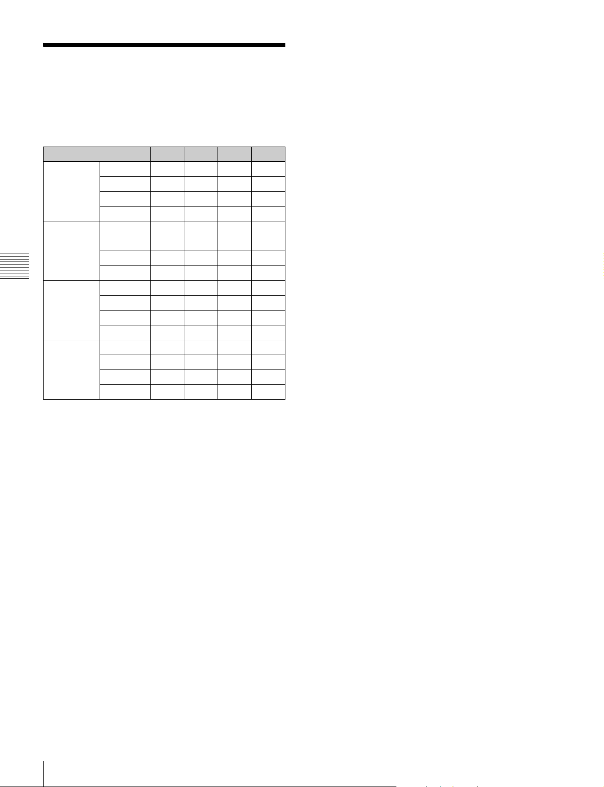
Maximum Recording Time of Memory
The following is a guide to the maximum recording time
when recording to internal memory.
Format 2 TB 4 TB 6 TB 8 TB
XAVC
Class 300
XAVC
Class 100
Chapter 3 Setup
DNxHD145 HD 50i 27.5 55.1 82.7 110.3
DNxHD220x HD 50i 19.4 38.8 58.2 77.7
4K 23.98p 14.8 29.7 44.6 59.4
4K 29.97p 11.8 23.7 35.6 47.5
4K 50p 7.3 14.7 22.1 29.5
4K 59.94p 6.1 12.3 18.4 24.6
HD 50i 27.5 55.1 82.7 110.3
HD 59.94i 27.6 55.2 82.9 110.5
HD 50p 14.9 29.9 44.9 59.9
HD 59.94p 15.2 30.5 45.8 61.1
HD 59.94i 22.9 45.9 68.9 91.9
HD 50p 14.9 29.9 44.9 59.9
HD 59.94p 12.4 24.9 37.4 49.9
HD 59.94i 16.1 32.3 48.5 64.7
HD 50p 10.2 20.5 30.8 41.1
HD 59.94p 8.5 17.1 25.7 34.3
Unit: Hours (approx.)
The maximum recording time varies depending on the
recording format.
14
Maximum Recording Time of Memory
Page 15
Web Menu
Chapter
4
The web menu comprises the following screens.
Home screen: Displays the operating status of unit’s
boards and the network.
Status screen: Displays a list of errors and warnings that
have occurred on the unit.
System screen: Makes basic settings for the unit.
Port screen: Makes settings for each port of the unit.
Storage screen: Displays information about memory and
configures the memory of the unit.
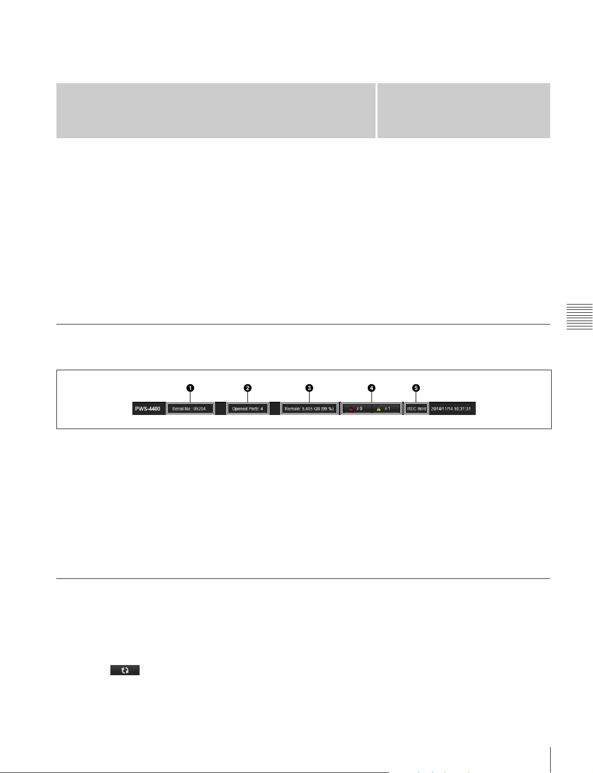
Title Bar
The title bar is common to each screen of the web menu.
a Serial number
Displays the serial number of the unit.
b Number of open ports
c Storage capacity
Maintenance screen: Performs maintenance of the unit.
For details about this screen, refer to the Maintenance
Manual.
SNMP screen: Makes SNMP settings. For details about
this screen, refer to the Maintenance Manual.
In the descriptions of each screen, the underlined option is
the default value for each item.
Chapter 4 Web Menu
Clicking the indicator displays detailed information about
the error/warning.
e REC INHI indicator
Indicates when recording is inhibited (red).
The indicator is white when recording is supported.
d Error/warning indicators
Displays the number of errors and warnings that have
occurred.
Home Screen
Displays the operating status of units boards and the
network.
The Home screen supports simple display mode and detail
display mode. You can switch mode using the [Simple]/
[Detail] buttons.
Clicking the button, turning it on, updates the
screen display automatically.
15
Page 16
Chapter 4 Web Menu
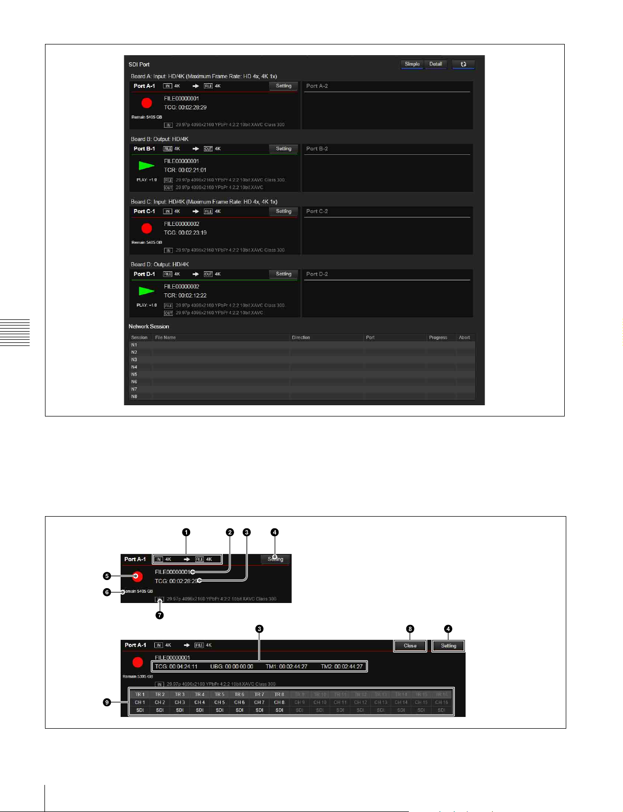
HD-SDI Port
Displays the status of each port.
For input
The following information is displayed.
Simple indicator
Detailed indicator
The port settings vary depending on whether the port is
used for input or for output.
16
Page 17
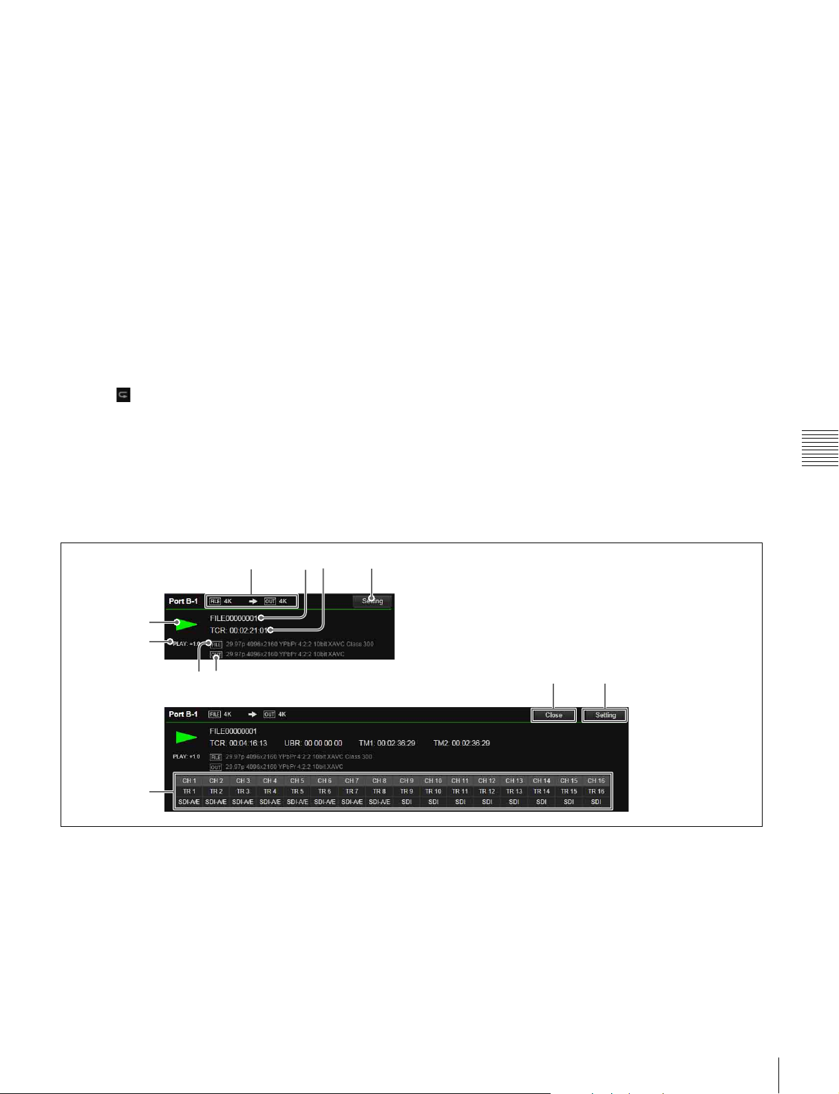
a Input/recording format
[IN] displays the video format (HD/2K/QFHD/4K) of the
input signal, and [FILE] displays the video format of the
recording.
b File name
Displays the name of the file being recorded. “File:
NEXT” is displayed before recording.
c Time code display
Displays time code data (TCG).
In detail display mode, UBG, TM1, and TM2 are also
displayed simultaneously.
d [Setting] button
Displays the [Port] screen (page 27) for the corresponding
port to configure port settings.
e Recording indicator
Displays z mark when recording.
Displays icon when a loop recording area is specified.
f Remaining capacity
Displays the remaining memory capacity.
When a loop recording area is specified, this displays the
capacity of the writable area of the capacity assigned to the
loop recording area. In loop recording, the recording loops
back to the start of the loop recording area when it reaches
the end of the area, overwriting the previous recording.
However, if a subclip is created in a loop recording area
file, the subclip area cannot be overwritten. Accordingly,
the capacity of the loop recording area decreases by the
size of the subclip.
If the remaining capacity that can be used for loop
recording is reduced to less than five minutes after creating
a subclip in the loop recording area, further subclips cannot
be created.
g [IN]
Displays the video format of the input signal.
h [Close] button (detail display mode only)
Closes the port.
i Audio track (detail display mode only)
Displays the signal (SDI or AES/EBU) used for each audio
track.
Chapter 4 Web Menu
For outputs
The following information is displayed.
Simple indicator
e
f
g
Detailed indicator
j
a File/output format
[FILE] displays the video format (HD/2K/QFHD/4K) of
the file, and [OUT] displays the video format of the output
signal.
h
a
bc
d
di
c Time code display
Displays time code data (TCR).
In detail display mode, UBR, TM1, and TM2 are also
displayed simultaneously.
b File name
Displays the name of the file being played back. “Sub” is
displayed beside the file name when playing back a
subclip.
d [Setting] button
Displays the [Port] screen (page 27) for the corresponding
port to configure port settings.
17
Page 18

e Playback indicator
Displays “B” during playback. The following are
displayed as the playback mode.
• No indication: Normal file playback
• (File Repeat): File repeat playback
• (List): Normal playlist playback
• (List Repeat): Playlist repeat playback
f Playback status indicator
The following are displayed as the playback status.
•CLOSE
•STOP
•PLAY
• SHUTTLE
•JOG
• VAR
•STILL
•REV
•FWD
• Playback speed
g [FILE]
Displays the video format of the file being played back.
h [OUT]
Chapter 4 Web Menu
Displays the video format of the video signal being output.
i [Close] button (detail display mode only)
Closes the port.
j Audio track (detail display mode only)
Displays which external channel is used for each audio
track, and the signal (SDI or AES/EBU) used.
Network Session
Displays the operating status of the network connection.
The following information is displayed.
Session
Displays the session name (N1 to N8).
File Name
Displays the name of the file being transferred.
Direction
Displays the transfer direction as an icon (unit t
computer, unit T computer).
Speed
Displays the transfer speed (1G/10G) of the network.
Progress
Displays the transfer progress.
Abort
Clicking the button displayed for each session forcibly
terminates network transfer.
18
Page 19
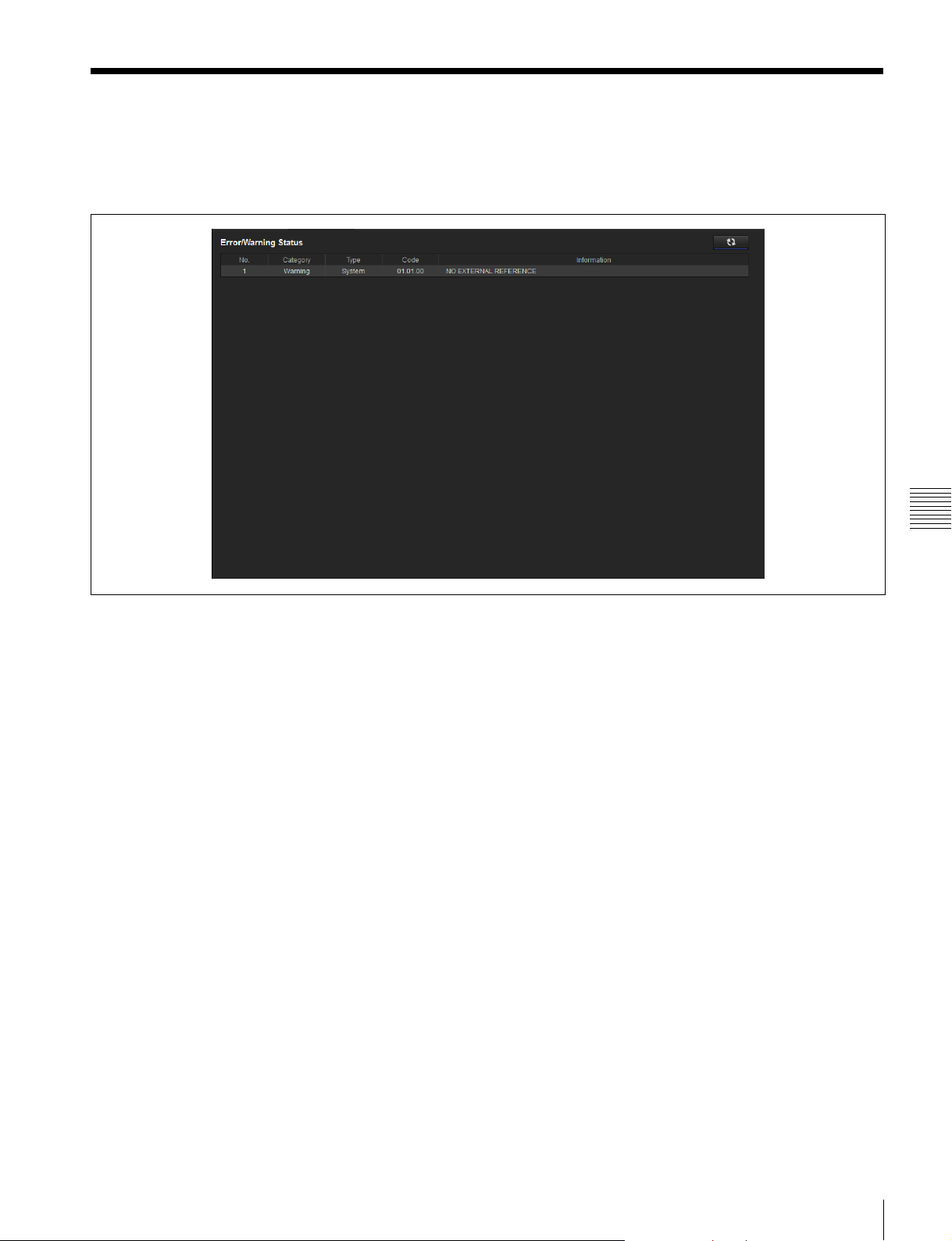
Status Screen
Displays a list of errors and warnings that have occurred on
the unit. The screen display is updated automatically at
regular intervals.
Chapter 4 Web Menu
Status Screen
19
Page 20
System Screen
Makes basic settings for the unit.
Board tab
• Output
• HD Input Multi (dual-system input)
• HFR (High Frame Rate) Input (high frame rate
recording)
• HD Cut Out (for 4K/QFHD video HD cutout)
For high frame rate recording (HD 300p/359p, 4K 100p/
119p), two boards are used.
No audio signal is recorded if high frame rate recording is
selected.
Makes input/output board settings using a setup wizard.
Click the [Setting] button at the bottom of the screen to
start configuration.
For details about settings, see “Setting the System and
Boards” (page 13).
Step 1
Sets the system frequency of the unit.
• 23.98 Hz
•24 Hz
•25 Hz
• 29.97 Hz
Step 2
Sets the mode for each of the ports (A to D).
Chapter 4 Web Menu
• Input
Step 3
Sets the video codec of each port.
Select the codec using the radio buttons.
Step 4
Sets the video format of each port.
Select the format to use from the matrix.
Step 5
Sets the sync operation of each port.
Select the grouping to use from the pull-down menu.
Step 6
Check the settings made in steps 1 to 5, and submit the
settings.
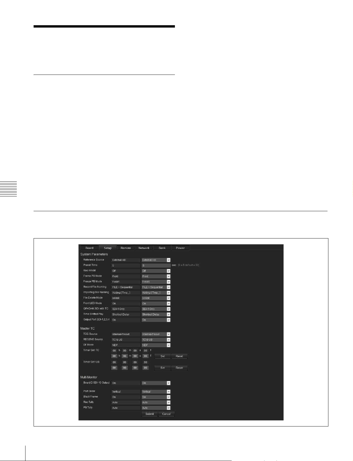
Setup tab
Makes basic operating mode settings of the unit.
20
System Screen
Page 21

System Parameter
Reference Source
Selects the reference signal for operation of the unit.
• External HD
INPUT connector
• External SD: SD signal input on the REF. INPUT
connector
• Input Board A-1, Input Board A-2 to Input Board D-1,
Input Board D-2: Signal input to the HD SDI INPUT
signal on the corresponding board
Preroll Time
Sets the preroll time in units of seconds.
•0 to 5
Rec Inhibit
Sets record inhibit mode.
•Off
: Enables recording
• On: Disables recording
Frame PB Mode
Selects the playback mode during variable speed playback.
• Field
: Field playback
• Frame: Frame playback
Freeze PB Mode
Specifies the freeze mode and freeze timing for manual
freeze (freeze control using the front panel, REMOTE 1 to
4 (9-pin) connectors, and GPIO (25-pin) connector) and
auto freeze.
• Field 1
• Field 2: Freezes the 2nd (even) field.
• Frame: Freezes in frame mode.
Record File Naming
Selects the file naming convention for automatically
generated files.
• File + Sequential
• Serieal + Time: Uses the recorded time as the file name.
• User Specified Name: Allows the user to specify a 4character prefix for the file name.
Importing File Naming
Selects whether to add a “Tmp_” prefix to the file name
during importing.
• Adding [Tmp_]
•Off
File Delete Mode
Selects whether to disable deletion of files while playback
is in progress.
• Inhibition
• Permit: Permits the deletion of files during playback. All
playback ports are closed while file deletion is in
progress.
Front LED Mode
Selects whether the front panel indicators are enabled/
disabled.
: Tri-level SYNC signal input on the REF.
to 30 seconds
: Freezes the 1st (odd) field.
: Assigns a sequential number.
: Prevents deletion of files during playback.
• Off: Indicators are always off.
•On
: Indicators are enabled to indicate the status of the
unit.
QFHD/4K with TC
Selects whether to superimpose the time code on the
output from the HD SDI 1 connector only or on all SDI
signals, if QFHD or 4K is specified as the video format.
• SDI-1 only
•All SDI
Time Shifted Play
Selects, when using chasing playback, whether to play
back video stored in a buffer for playback with the shortest
delay, or to play back video that is recorded in storage.
• Shortest Delay
• From Storage Only
Output Port SDI-1, 2, 3, 4
When using each port as an output port, this selects
whether to output the signal from the HD SDI 1 to 4
connectors. When set to Off, signals are output from the
SDI 5 to 8 connectors only.
•Off
•On
Master TC
Makes master time code settings.
TCG Source
Selects the source signal for synchronizing the internal
time code generator. You can select a signal input on ports
A to D.
• Internal-Preset
• External-LTC: A
• External-LTC: B
• External-LTC: C
• External-LTC: D
REGENE Source
Selects the signal to regenerate when the time code
generator is in regenerate mode or in automatic editing
mode.
•TC&UB
bit signal.
• TC Only: Regenerates the time code signal only.
• UB Only: Regenerates the user bit signal only.
DF Mode
Sets the drop frame mode of the time code generator or
timer counter.
•DF
• NDF
Note
This setting is valid only when [TCG Source] is set to
“Internal-Preset” and the frame frequency is 29.97 Hz.
: Regenerates both the time code signal and user
Chapter 4 Web Menu
System Screen
21
Page 22

Timer Set: TC
This sets the time code when [TCG Source] is set to
“Internal-Preset” or REGENE Source is set to UB Only.
Enter a numeric value and click the [Set] button to change
the time code. Clicking the [Reset] button resets the
counter.
Timer Set: UB
This sets the user bits when [TCG Source] is set to
“Internal-Preset” or REGENE Source is set to TC Only.
Enter a numeric value and click the [Set] button to change
the user bits. Clicking the [Reset] button resets the counter.
Multi Monitor
Makes settings for the multi-monitor signal output from
the HD SDI IN/OUT 10 connector of port D.
Board D SDI-10 Output
Selects whether to output a multi-monitor signal. When
off, it outputs the same signal as the HD SDI IN/OUT 9
connector.
•Off
•On
Port Order
Chapter 4 Web Menu
Specifies the ordering of ports.
•Vertical
• Horizontal
Black Frame
Selects whether to display a black frame around the screen
for each port.
•Off
•On
REC Tally
Sets whether to add a tally indicator for the monitor signal
from the input port.
•Off
•Auto
PB Tally
Sets whether to add a tally indicator for the monitor signal
from the output port.
•Off
•Auto
When changing the Multi Monitor settings, click the
[Submit] button to apply the settings. Click the [Cancel]
button to return to the current settings.
22
System Screen
Page 23
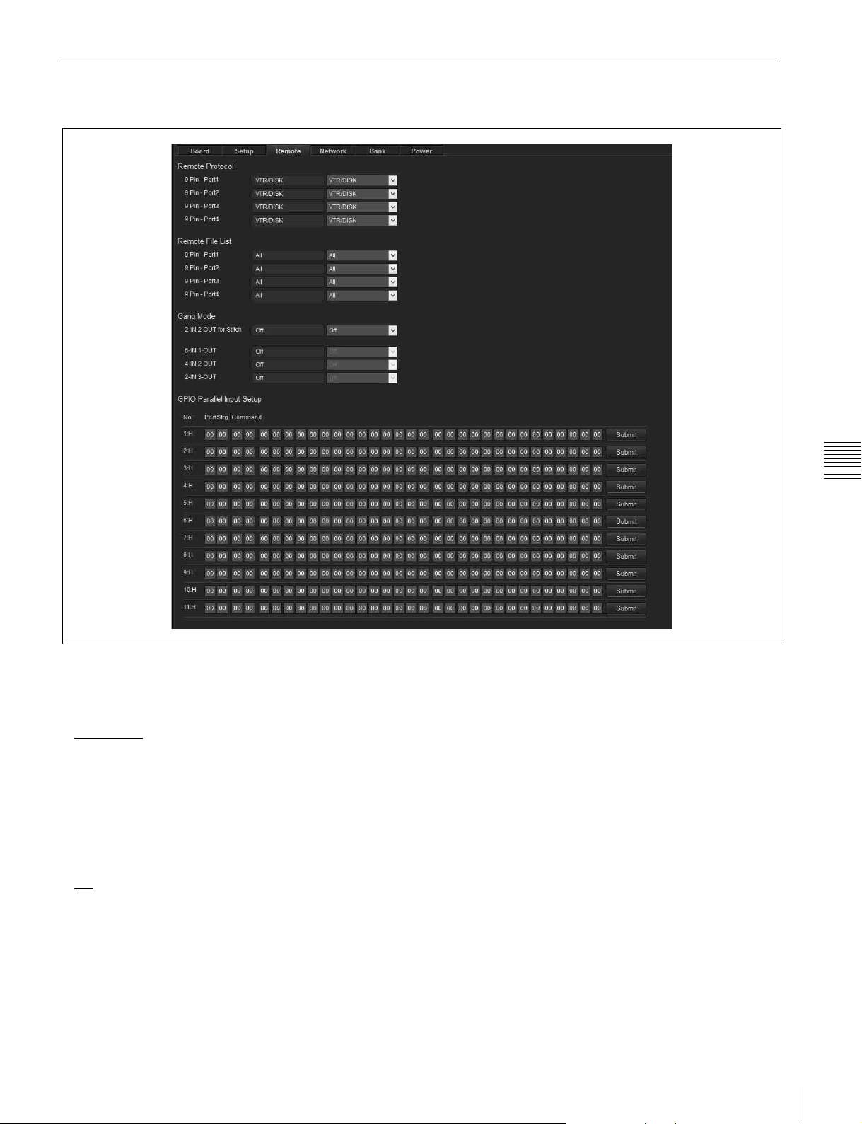
Remote tab
Makes settings related to remote control.
Chapter 4 Web Menu
Remote Protocol
Selects the protocol used on the REMOTE 1 to 4
connectors.
•VTR/DISK
• VDCP: VDCP protocol
• Odetics: Odetics protocol
: SONY VTR/Disk protocol
Remote File List
Selects the information returned in response to a file
information sense command on the REMOTE 1 to 4
connectors.
•All
: Information about all files
• Port A Playable: Information about playable files on port
A
• Port A Editable: Information about files that can be
switched seamlessly during playback on port A
• Port B Playable: Information about playable files on port
B
• Port B Editable: Information about files that can be
switched seamlessly during playback on port B
• Port C Playable: Information about playable files on port
C
• Port C Editable: Information about files that can be
switched seamlessly during playback on port C
• Port D Playable: Information about playable files on port
D
• Port D Editable: Information about files that can be
switched seamlessly during playback on port D
Gang Mode
2-IN 2-OUT for Stitch
When the system configuration is 2-in/2-out, this enables
operation with input port syncing and output port syncing.
6-IN 1-OUT
When the system configuration is 6-in/1-out, this enables
operation with input port syncing.
4-IN 2-OUT
When the system configuration is 4-in/2-out, this enables
operation with input port syncing.
System Screen
23
Page 24
2-IN 3-OUT
When the system configuration is 2-in/3-out, this enables
operation with input port syncing.
GPIO Parallel Input Setup
Assigns the commands for the input side of the GPIO (25pin) connector.
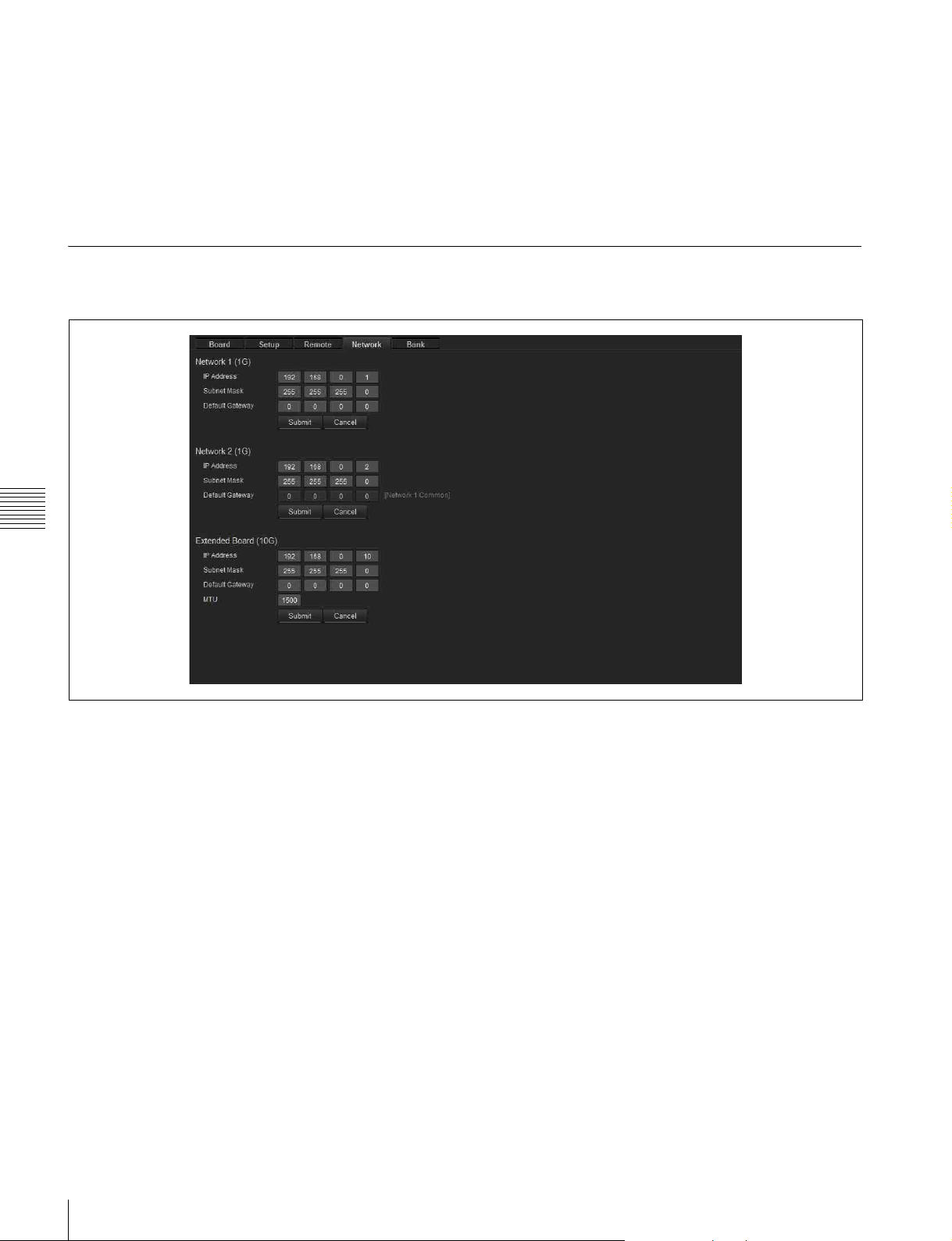
Network tab
Makes network settings.
A 32-byte setting can be specified for pin 1 to pin 11.
GPIO Parallel Output Setup
Assigns the commands for the output side of the GPIO (25pin) connector.
A 32-byte setting can be specified for pin 13 to pin 24.
For details about commands, refer to the Interface Manual.
Chapter 4 Web Menu
Network 1 (1G)
Sets the IP address, subnet mask, and default gateway of
the NETWORK 1 connector.
The following values are the factory default values.
IP Address: 192.168.0.1
Subnet Mask: 255.255.255.0
Default Gateway: 0.0.0.0
Network 2 (1G)
Sets the IP address and subnet mask of the NETWORK 2
connector.
The default gateway setting for Network 1 is displayed.
The following values are the factory default values.
IP Address: 192.168.0.2
Subnet Mask: 255.255.255.0
Extended Board (10G)
When an optional 10 Gigabit network is used, this sets the
IP address, subnet mask, default gateway, and MTU.
The following values are the factory default values.
IP Address: 192.168.0.10
Subnet Mask: 255.255.255.0
Default Gateway: 0.0.0.0
MTU: 1500
24
System Screen
Page 25
Bank tab
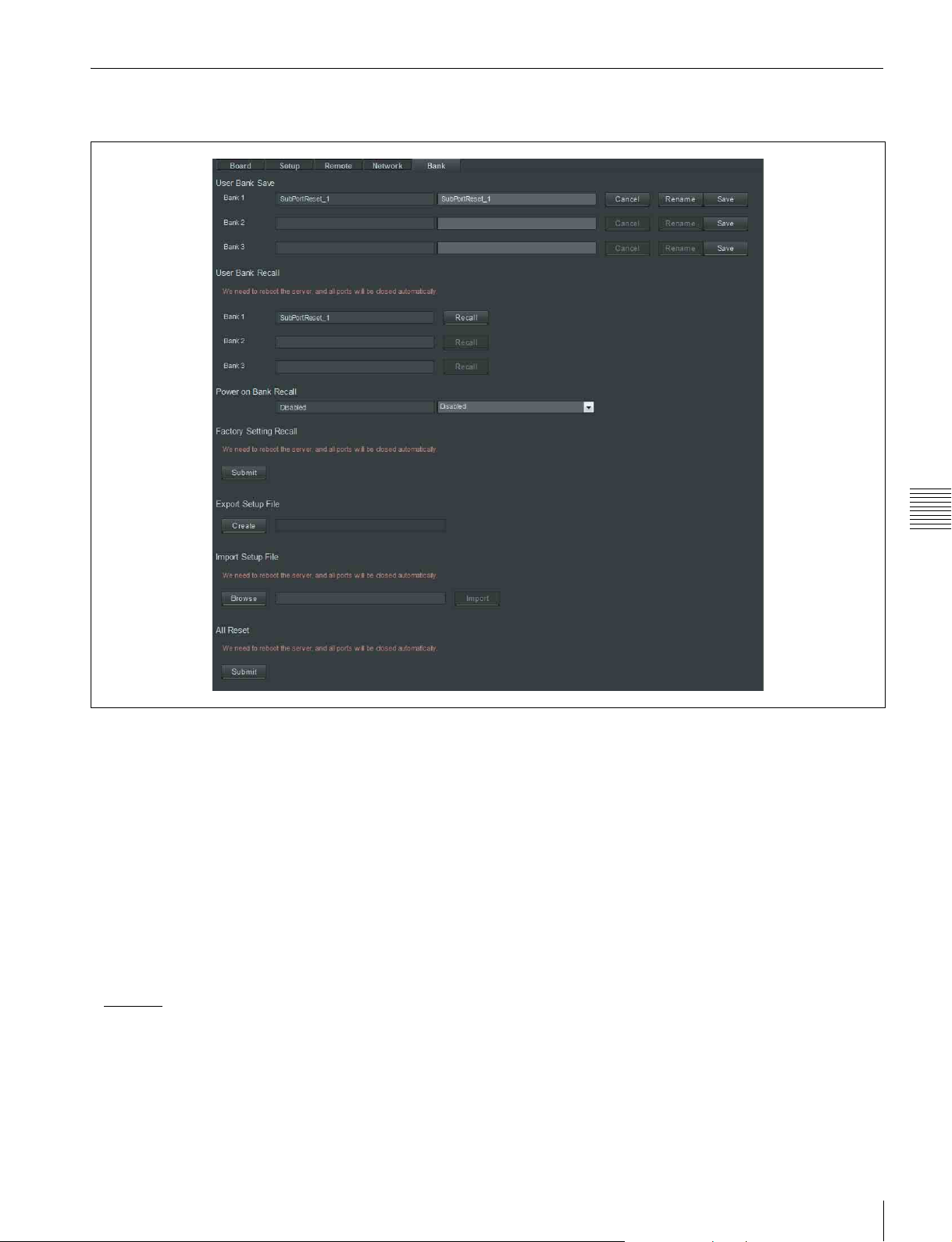
Makes settings for user banks of saving settings.
Chapter 4 Web Menu
User Bank Save
Saves the settings on the System screen to user banks.
Click the [Save] button for the bank (Bank 1 to 3) you want
to save. To save named settings, enter a name in the text
box on the right and then click the [Save] button.
To rename saved settings, enter a new name in the text box
on the right and then click the [Rename] button.
User Bank Recall
Recalls settings from the user banks. Click the [Recall]
button for the bank (Bank 1 to 3) you want to recall.
Power On Bank Recall
Specifies the user bank to recall when the power to the unit
is turned on.
• Disabled
• BANK1
• BANK2
• BANK3
Factory Setting Recall
Click the [Submit] button to restore the settings on the
System screen to the factory default status.
Export Setup File
Click the [Create] button to create a setup file that stores
all settings of the PWS-4400.
The file name is displayed after the setup file is
successfully created. You can right-click the file name to
save the data file on the computer.
Import Setup File
Loads the settings from a setup file (.dat) stored on the
computer, and configures the PWS-4400.
All Reset
Click the [Submit] button to reset all settings. The IP
addresses and other network settings and the menu settings
saved in all banks are also reset.
System Screen
25
Page 26
Power tab
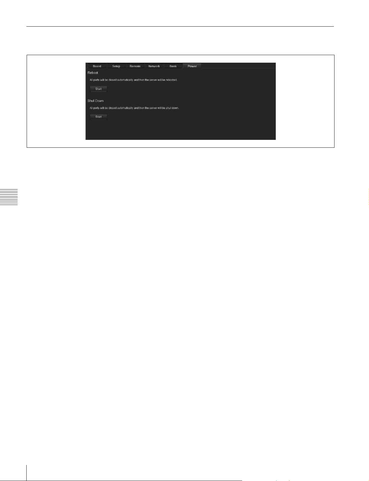
Used to reboot and shut down the unit.
Reboot
Click the [Start] button to close all ports and reboot the
unit.
Shut Down
Click the [Start] button to close all ports and shut down the
unit.
Chapter 4 Web Menu
26
System Screen
Page 27
Port Screen
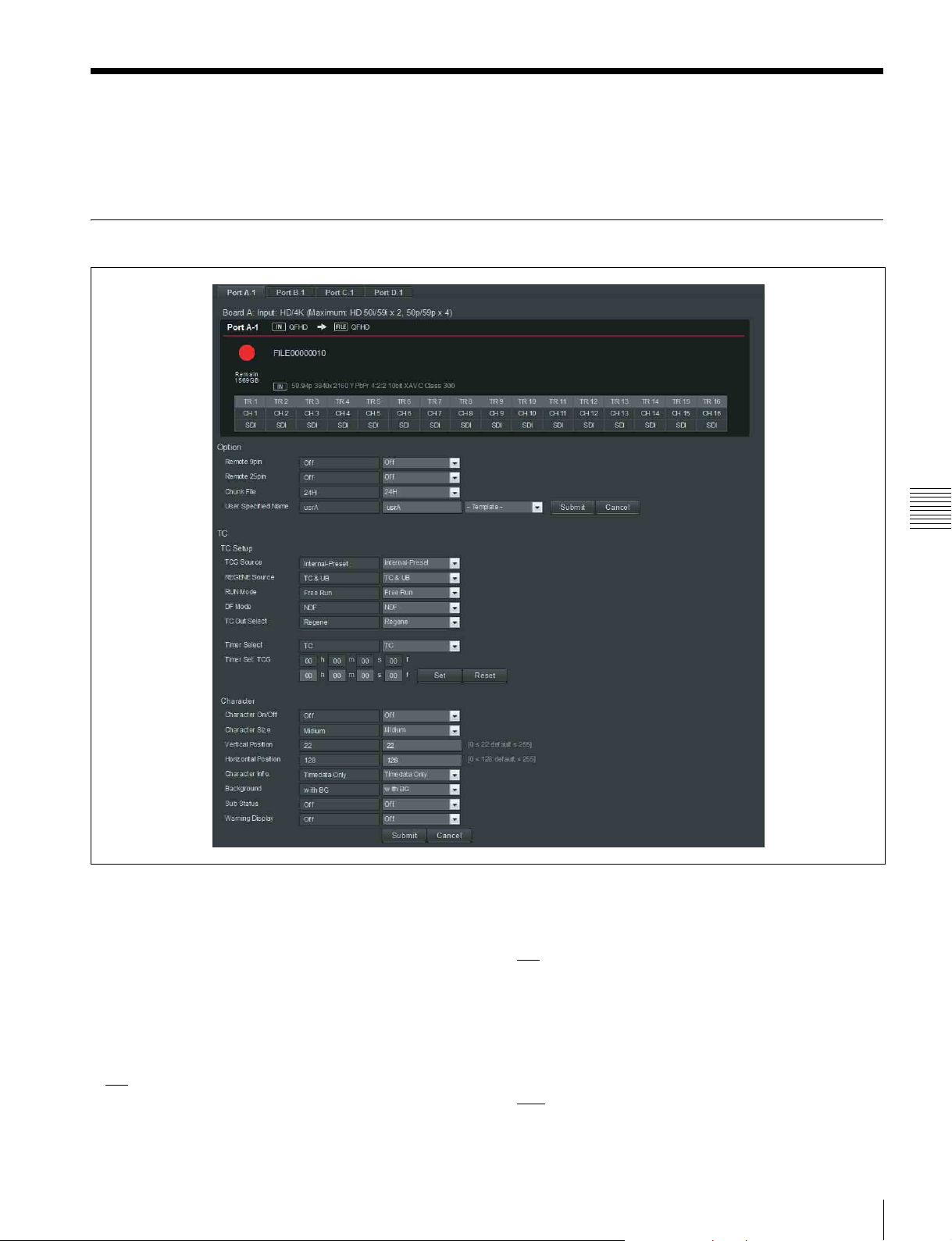
Makes settings for each port of the unit. The settings vary depending on whether the port is for
input or for output.
For input ports
Chapter 4 Web Menu
Port information
Displays the operating status of the selected port. The
display is the same as on the Home screen.
Option
Remote 9pin
Selects whether to enable remote control from the device
connected to the REMOTE 1 to 4 (9-pin) connector.
•Off
•On
Remote 25pin
Selects whether to enable remote control from the device
connected to the GPIO (25-pin) connector.
•Off
•On
Chunk File
When recording continuously, this sets the number of
hours before splitting the recording into separate files.
When split into separate files, each file is appended with an
incrementing suffix (_01, _02, and so on).
•24H
•6H
Port Screen
27
Page 28

User Specified Name
Sets the 4-character prefix for the names of recorded files.
Enter an arbitrary string in the text box or select a prefix
from the drop-down list.
To change the counter, enter a value and click the [Set]
button. Clicking the [Reset] button resets the counter.
Note
TC
Makes time code settings.
TCG Source
Selects the source signal for synchronizing the internal
time code generator.
• Internal-Preset
• External-LTC
• SDI-LTC
• SDI-VITC
•Master TC
REGENE Source
Selects the signal to regenerate when the time code
generator is in regenerate mode or in automatic editing
mode.
•TC&UB
bit signal.
• TC Only: Regenerates the time code signal only.
• UB Only: Regenerates the user bit signal only.
Chapter 4 Web Menu
RUN Mode
Sets the running mode of the time code generator.
•Free Run
regardless of the unit’s operating mode.
• Rec Run: The time code advances during recording only.
DF Mode
Sets the drop frame mode of the time code generator or
timer counter.
• NDF
•DF
Note
This setting is valid only when [TCG Source] is set to
“Internal-Preset” and the frame frequency is 29.97 Hz.
TC Out Select
Sets the output time code from the TIME CODE OUT
connector when recording.
• Regene
• Through
Timer Select
Selects the time data to display.
•TC
•UB
•TM1
•TM2
Timer Set
Displays the time counter.
: Regenerates both the time code signal and user
: The time code advances when the power is on
Displayed only when [Timer Select] is set to TC, UB, or
TM1.
Character
Character On/Off
Selects whether to display superimposed character
information, such as the time code, on the monitor signal.
Character Size
Sets the display size of character information.
•Small
•Medium
Vertical Position
Sets the vertical display position of character information.
• 0 (top) to 22
Horizontal Position
Sets the horizontal display position of character
information.
• 0 (left) to 128
Character Info.
Sets the character information content if [Character On/
Off] is set to “On.”
• Timedata Only
• Timedata & TM1: Timer counter and TM1
• Timedata & TM2: Timer counter and TM2
• Timedata & UB: Timer counter and user bits
• Timedata & Status: Timer counter and operating status
• Timedata & Audio: Timer counter and audio level
Background
Sets the character information background.
• Outline: White characters with black outlines
• Translucent: White characters on a gray transparent
background.
• without BG: White characters with no background
•with BG
Sub Status
Sets additional information displayed with the character
information.
•Off
: Displays no additional information.
• File Name: Displays the file name.
Warning Display
Sets whether to display a flashing warning message on the
second line of character information when [Character
Info.] is set to an item other than “Timedata Only”.
•Off
•On
to 255
to 255
: Timer counter only
: White characters on a black background
28
Port Screen
Page 29

Meta Data Input
Sets from which lines to acquire uncompressed metadata.
Meta Line 1
•9H
to 16H
• 18H to 20H (up to 25H for 720p)
Meta Line 2
• 9H to 16H
• 18H to 19H
Meta Line 3
• 9H to 16H
• 18H to 20H
to 20H (up to 25H for 720p)
(up to 25H for 720p)
Video
Port Configuration
Selects the video format of each port from the matrix.
Internal Video SG
Selects the type of signal output from the internal signal
generator.
•Off
• CB100
• CB75
•SMPTE
•ARIB
•MB1
•MB2
•10STEP
•PBAR
•RAMP
• Black
•White
• x-1: Selects the main port audio signal.
• x-2: Selects the sub-port audio signal.
“x” represents the port (A to D).
Non-Audio Input Select
Selects whether to input non-audio data.
• Invalid
• SDI-Data
• A/E Data
Internal Audio SG
Selects the type of signal output from the internal signal
generator.
•Off
: No output
• Silence: Silence signal
• 1kHz: 1 kHz sine wave
Chapter 4 Web Menu
Audio
Audio Input Select
Selects the external channel to record for each audio file
track. Also selects the type of each signal (SDI or AES/
EBU) to record.
Track Number
Selects the number of audio tracks for recording.
• 8 track
•16 track
AES/EBU Input Mode
Selects whether to pass the input AES/EBU signal through
a sampling rate converter when recording.
•Auto
: Use converter. In this case, there are no limitations
on input signals.
• Vlock: Do not use converter. In this case, the input
signals need to be locked to the video signal at 48 kHz.
Noise will occur if this condition is not met.
SDI Source Port
For dual-system input per board, this selects whether the
audio signal is input on the main port or the sub-port.
Port Screen
29
Page 30
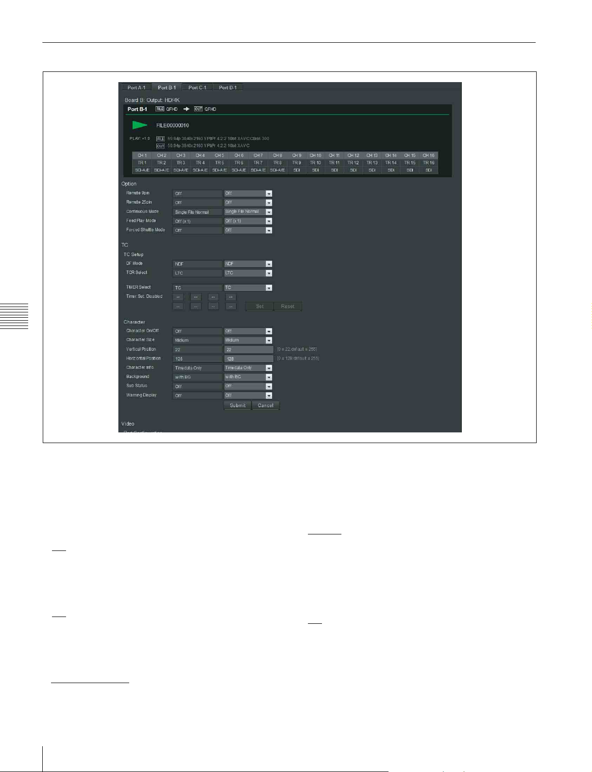
For output ports
Chapter 4 Web Menu
Option
Displays the operating status of the selected port. The
display is the same as on the Home screen.
Remote 9pin
Selects whether to enable remote control from the device
connected to the REMOTE 1 to 4 (9-pin) connector.
•Off
•On
Remote 25pin
Selects whether to enable remote control from the device
connected to the GPIO (25-pin) connector.
•Off
•On
Continuous Mode
Sets the preview file or list selection, and the repeat
operation.
• Single File Normal
• Single File Repeat
• File List Normal
•File List Repeat
Feed Play Mode
Sets the playback speed of feed play.
If the playback speed is controlled using the PWA-PRC1
application, this setting is ignored.
• Off (1x)
• On (2x)
• On (4x)
• On (6x)
Forced Shuttle Mode
Selects whether to forcibly switch to shuttle control when
using the Jog/Var command.
•Off
•On
30
Port Screen
Page 31

TC Setup
DF Mode
Sets the drop frame mode of the timer counter.
• NDF
•DF
• Timedata & VITC: Timer counter and VITC
• Timedata & TM1: Timer counter and TM1
• Timedata & TM2: Timer counter and TM2
• Timedata & UB: Timer counter and user bits
• Timedata & Status: Timer counter and operating status
• Timedata & Audio: Timer counter and audio level
TCR Select
Sets the readout value of the time code reader.
•LTC
•VITC
Timer Select
Selects the time data to display.
•TC
•UB
•TM1
•TM2
Timer Set
Displays the time counter.
To change the counter, enter a value and click the [Set]
button. Clicking the [Reset] button resets the counter.
Note
Displayed only when [Timer Select] is set to TM1.
Board TC Output
Selects the signal to output from the TIME CODE OUT
connector of the connector panel.
•TC
• Through
•TM1
•TM2
Character
Character On/Off
Selects whether to display superimposed character
information, such as the time code, on the monitor signal.
Character Size
Sets the display size of character information.
•Small
•Medium
Vertical Position
Sets the vertical display position of character information.
• 0 (top) to 22
Horizontal Position
Sets the horizontal display position of character
information.
• 0 (left) to 128
Character Info.
Sets the character information content if [Character On/
Off] is set to “On.”
• Timedata Only
to 255
to 255
: Timer counter only
Background
Sets the character information background.
• Outline: White characters with black outlines
• Translucent: White characters on a gray transparent
background.
• without BG: White characters with no background
•with BG
Sub Status
Sets additional information displayed with the character
information.
•Off
• File Name: Displays the file name.
Warning Display
Sets whether to display a flashing warning message on the
second line of character information when [Character
Info.] is set to an item other than “Timedata Only.”
•Off
•On
: White characters on a black background
: Displays no additional information.
Video
Port Configuration
Selects the video format of each port from the matrix.
Sync Phase
Sets the sync phase of the video signal output on the HD
SDI connector.
Sync
Coarse adjustment of the sync phase.
–128 to 0
Fine
Fine adjustment of the sync phase.
0
to 1024
to 127
Others
SDI OUT Blank
Turns on/off vertical interval blanking processing of the
video signal output on the SDI OUTPUT connector.
• Through
• Blank: Performs blanking processing.
Y add
Selects whether to forcibly turn off “Y add.”
•Auto
•Off
: Does not perform blanking processing.
Chapter 4 Web Menu
Port Screen
31
Page 32

Audio
Audio Output Select
Selects the file track to output for each audio output
channel.
Shuttle Muting
Sets whether to output the audio signal during shuttle
playback.
• On: No output
•Off
: Audio is output.
Audio Output Phase
Adjusts the audio output phase.
• 0 to 128
Chapter 4 Web Menu
to 255 samples
32
Port Screen
Page 33
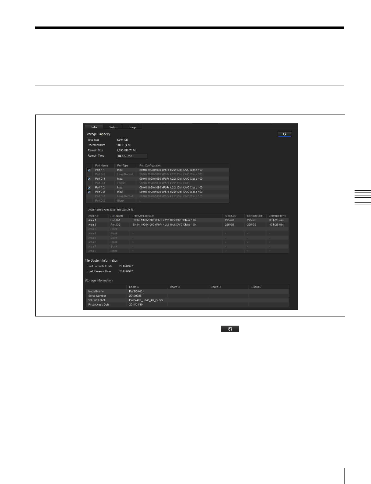
Storage Screen
Displays information about memory and configures the
memory of the unit.
Info tab
Displays the status of internal memory and boards A to D.
Chapter 4 Web Menu
Storage Capacity
Total Size
Displays the total capacity of internal memory.
Recorded Size
Displays the size of internal memory usage (excluding
Loop Recording Area) containing recordings.
Remain Size
Displays the remaining capacity (excluding Loop
Recording Area) of internal memory.
Remain Time
Displays the remaining recording time to internal memory
when simultaneously recording all ports with enabled
checkboxes in the port name display.
Click the button, turning it on, to update the
display automatically. When the button is off, clicking the
[Calculate] displays the latest values.
Port name display
Displays the name, type, and settings of the ports in the
unit.
Loop Recording Area Size
Displays the size and usage status of each area for loop
recording.
File System Information
Last Formatted Date
Displays the date the file system was last formatted.
Storage Screen
33
Page 34
Last Renewal Date
Displays the date the file system was last renewed.
Serial Number
Displays the serial number of the memory board.
Storage Information
Displays information about memory boards A to D.
Model Name
Displays the model name of the memory board.
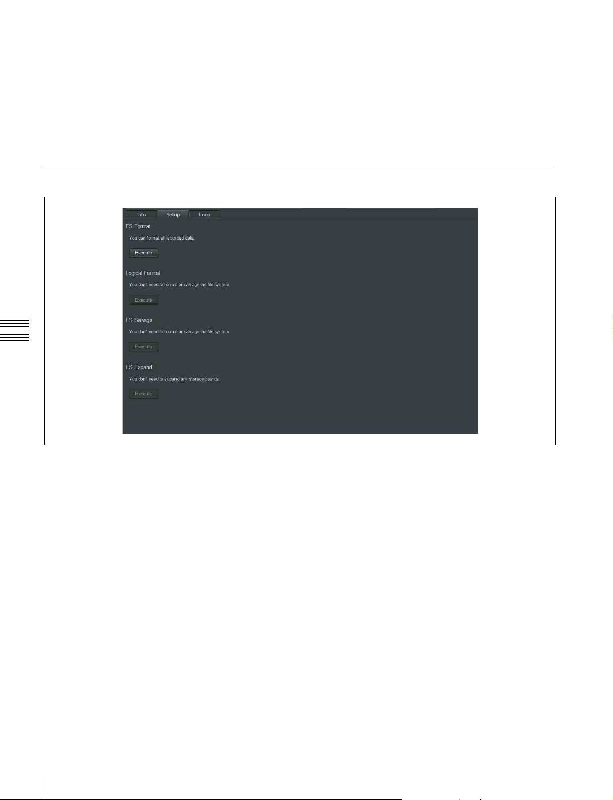
Setup tab
Chapter 4 Web Menu
Volume Label
Displays the volume label of the memory board.
First Access Date
Displays the date that files were first accessed.
FS Format
Formats the file system.
Logical Format
Formats the logical file system.
FS Salvage
Salvages the file system.
FS Expand
Expands the file system when an additional memory board
is installed.
34
Storage Screen
Page 35
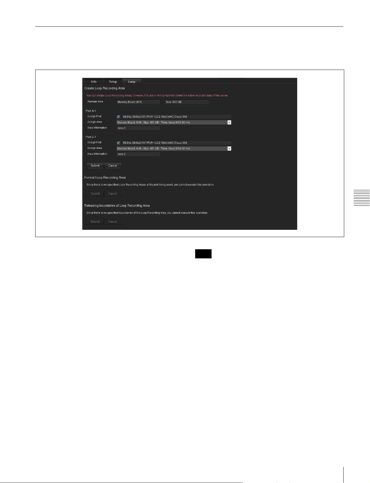
Loop tab
Assigns the recording area for each input/output when
using loop recording. The recording loops back to the start
of the loop recording area when it reaches the end of the
area, overwriting the file. If there is more than one file in
the loop recording area, files are overwritten starting with
the oldest file.
Chapter 4 Web Menu
Create Loop Recording Area
Remain Area
Displays the remaining area capacity assigned for loop
recording.
Assign Port
Selects the input board to assign a loop recording area.
Assign Area
Specifies the capacity assigned for loop recording for the
corresponding port. Also, the loop recording time is
calculated for display from the specified capacity.
The capacity is specified in 1/16 units of the capacity of the
memory board (2 TB) installed in the unit.
• For one memory board:
1/16, 2/16 to 15/16, 1
• For two memory boards:
1/16, 2/16 to 15/16, 1, 1 + 1/16 to 1 + 15/16, 2
Area Information
Displays the Loop Recording Area numbers for use.
When finished making settings, click the [Submit] button.
The storage is formatted, and the specified capacity and the
loop recording areas are assigned. Click the [Cancel]
button to return to the current settings.
Note
When a loop recording area is specified, all files in
memory are deleted.
Format Loop Recording Area
Deletes the files recorded in the loop recording area of
each port, and then formats the loop recording area. You
can select individual areas to be formatted.
Releasing boundaries of Loop Recording
Area
Deallocates the loop recording area of each port, deleting
the recorded data. You can select individual areas to be
deleted.
Storage Screen
35
Page 36
Appendix
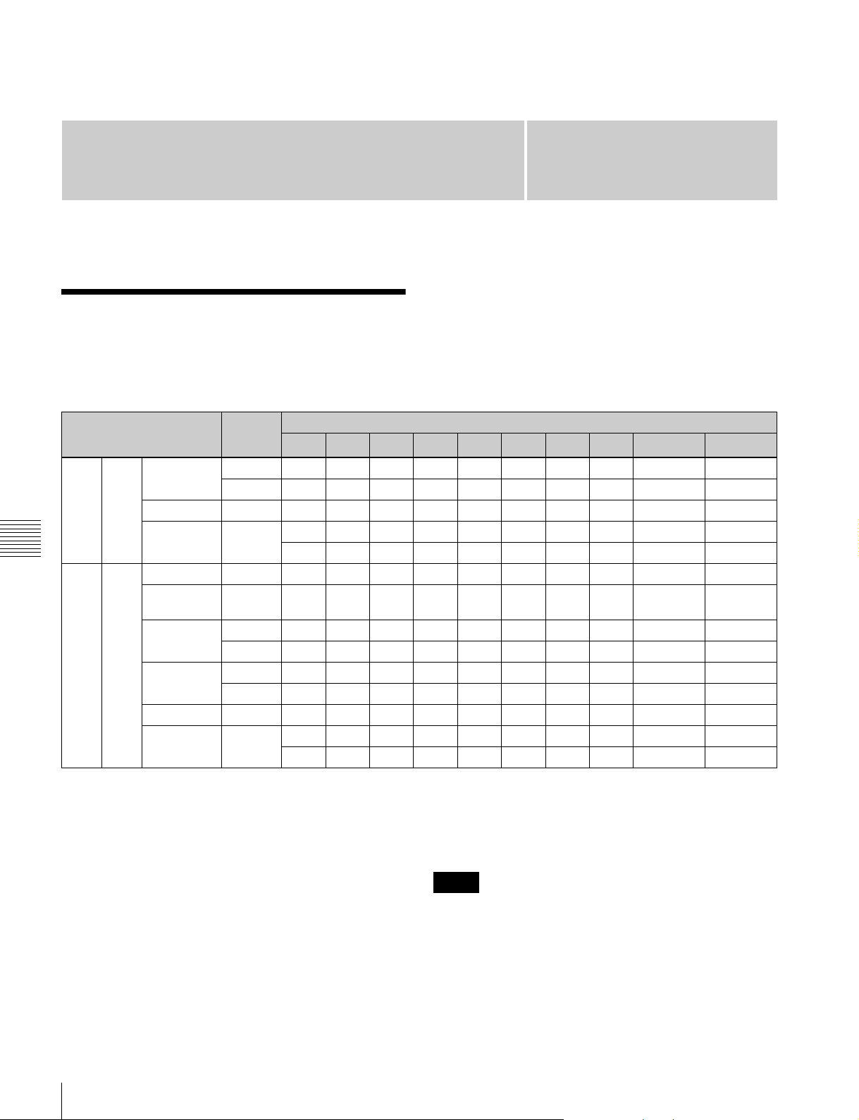
The input/output signals and connectors used on each HD
HD SDI Connector Input/ Output Specifications
For input ports
Format SDI HD SDI IN/OUT connector
1 2 3 4 5 6 7 8
4K 422 23p/Psf to
29p/Psf
50p/59p 3G In1-1 In1-2 In1-3 In1-4 IM1-1 IM1-2 IM1-3 IM1-4 DC/Char DC/Char
100p/119p
Appendix
HD 422 50i/59i 1.5G In1 In2 – – IM1 IM2 – – Char1 Char2
23p/Psf to
29p/Psf
50p/59p 1.5G In1-1 In1-2 In2-1 In2-2 IM1-1 IM1-2 IM2-1 IM2-2 Char1 Char2
100i/119i 1.5G In1-1 In1-2 – – IM1-1 IM1-2 – – Char Char
200p/239p 3G In1-1 In1-2 In1-3 In1-4 IM1-1 IM1-2 IM1-3 IM1-4 Char Char
300/359p
1.5G In1-1 In1-2 In1-3 In1-4 IM1-1 IM1-2 IM1-3 IM1-4 DC/Char DC/Char
3G In1-1 In1-2 – – IM1-1 IM1-2 – – DC/Char DC/Char
b)
3G In1-1 In1-2 In1-3 In1-4 IM1-1 IM1-2 IM1-3 IM1-4 Char Char
In1-5 In1-6 In1-7 In1-8 IM1-5 IM1-6 IM1-7 IM1-8 – –
1.5G In1 In2 – – IM1 IM2 – – Char1 Char2
3G In1In2––IM1IM2––Char1Char2
3G In1–––IM1–––Char Char
b)
3G In1-1 In1-2 In1-3 – IM1-1 IM1-2 IM1-3 – Char Char
In1-4 In1-5 In1-6 – IM1-4 IM1-5 IM1-6 – – –
SDI port vary depending on the input port setting, output
port, setting, and signal format.
a)
9
10
a)
In: SDI signal input. In1 and In2 represent inputs 1 and 2,
respectively, of the dual-system input of each port.
Input 1 is the main port, and input 2 is the sub-port.
For single system signal formats transferred using
more than one SDI cable, it is represented by In1-1,
In1-2, and so on.
IM (Input Monitor): Input SDI signal output for monitor.
IM1 and IM2 represent inputs 1 and 2, respectively,
when using dual-system input.
DC: Down-converted 4K to HD signal output for monitor.
Char: Superimposed character information output for
monitor. For dual-system input, Char1 and Char2
represent monitor outputs 1 and 2, respectively.
–: Not used.
36
HD SDI Connector Input/Output Specifications
a) The format of the signals output from the HD SDI IN/OUT 9 and 10
connectors is set when the video format is specified on the [Board] tab of
the [System] screen of the web menu. The supported formats for the HD
SDI IN/OUT 9 and 10 connectors vary depending on the signal format
specified for the HD SDI IN/OUT 1 to 8 connectors.
b) Two input ports are used to input a single system signal.
Notes
• To connect a BPU-4000 for HD 4x speed recording,
connect the SDI-1 to SDI-4 connectors of the BPU-4000
to the HD SDI-1 to HD-SDI-4 connectors of the unit.
• To connect a BPU-4000 for HD 6x speed recording,
connect the SDI-1 to SDI-4 connectors of the BPU-4000
to the HD SDI-1 to HD-SDI-4 connectors of port A of
the unit, and connect the SDI-5 to SDI-8 connectors of
Page 37
the BPU-4000 to the HD SDI-1 to HD-SDI-4 connectors
of port B of the unit.
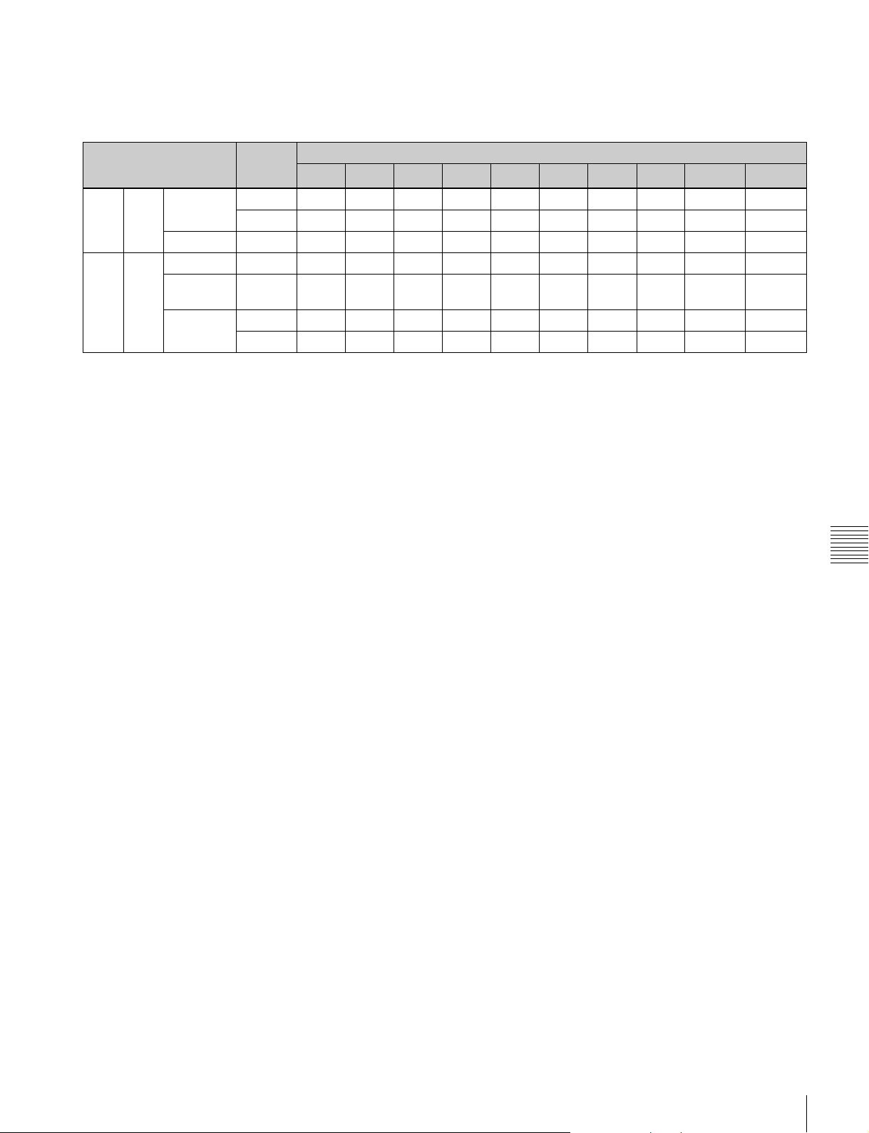
For output ports
Format SDI HD SDI IN/OUT connector
a)
1
4K 422 23p/Psf to
29p/Psf
50p/59p 3G Out1-1 Out1-2 Out1-3 Out1-4 Out1-1 Out1-2 Out1-3 Out1-4 DC/Char DC/Char
HD 422 50i/59i 1.5G Out Out Out Out Out Out Out Out Char Char
23p/Psf to
29p/Psf
50p/59p 1.5G Out1-1 Out1-2 Out1-1 Out1-2 Out1-1 Out1-2 Out1-1 Out1-2 Char Char
1.5G Out1-1 Out1-2 Out1-3 Out1-4 Out1-1 Out1-2 Out1-3 Out1-4 DC/Char DC/Char
3G Out1-1 Out1-2 Out1-1 Out1-2 Out1-1 Out1-2 Out1-1 Out1-2 DC/Char DC/Char
1.5G Out Out Out Out Out Out Out Out Char Char
3G Out Out Out Out Out Out Out Out Char Char
a)
2
a)
3
a)
4
5 6 7 8
b)
9
10
b)
Out: Represents all SDI IN/OUT 1 to 8 connector outputs.
For single system signal formats transferred using
more than one SDI cable, it is represented by Out1-1,
Out1-2, and so on. 8-system output is supported for
formats that are transferred using one SDI cable
(Single Link), 4-system output for formats using two
cables (Dual Link), and 2-system output for formats
using four cables (Quad Link).
DC: Down-converted 4K to HD signal output for monitor.
Char: Superimposed character information output for
monitor.
–: Not used.
a) When [Output Port SDI-1,2,3,4] is set to [Off] on the [Setup] tab of the
[System] screen in the web menu, no signal is output.
b) The format of the signals output from the HD SDI IN/OUT 9 and 10
connectors is set when the video format is specified on the [Board] tab of
the [System] screen of the web menu. The supported formats for the HD
SDI IN/OUT 9 and 10 connectors vary depending on the signal format
specified for the HD SDI IN/OUT 1 to 8 connectors.
Appendix
HD SDI Connector Input/Output Specifications
37
Page 38
File Operations via FTP
File operations between the unit and the computer are
performed using the File Transfer Protocol (FTP).
Directory structure
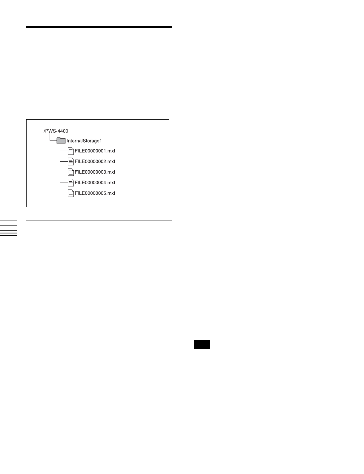
The following diagram shows the PWS-4400 internal
directory structure that is visible on the computer.
Connecting via FTP
You can connect the unit and computer via FTP using the
following methods.
• Using the command prompt.
• Using FTP client software.
This section describes using the command prompt method.
If using FTP client software, set up the software as
required.
Logging in
1
Launch the command prompt.
2
Enter “ftp <SP> <IP_address>” and press the Enter
key (where <SP> is a space character).
For example, if the IP address of the unit is set to
“192.168.000.001”, enter “ftp 192.168.0.1”.
For information about the FTP command, refer to the
Help in Windows.
Setting Up
Appendix
1
Connect the unit and the computer network terminals
using a network cable. Alternatively, connect the unit
to the same network as the computer.
2
Set the IP address and other settings of the unit.
See “Network tab” (page 24).
Connecting a computer running Windows Vista/
Windows 7/Windows 8
Disable internet protocol version 6 (TCP/IPv6).
On Windows Vista: (1) Open [Network and Sharing
Center] > [Manage network connections] > [Local
Area Connection] in Control Panel. (2) Display
[Local Area Connection Properties], uncheck the
[Internet Protocol Version 6 (TCP/IPv6)] checkbox,
and click the [OK] button.
On Windows 7/Windows 8: (1) Open [View network
status and tasks] > [Change adapter settings] > [Local
Area Connection] in Control Panel. (2) Display
[Local Area Connection Properties], uncheck the
[Internet Protocol Version 6 (TCP/IPv6)] checkbox,
and click the [OK] button.
If the connection is successful, you will be prompted
to enter a user name.
3
Enter a user name of “usr1” and press the Enter key.
If the user name is authenticated, you will be prompted
for a password.
4
Enter the password and press the Enter key.
The password is the model name (“pws-4400”).
If the password is verified, login is complete.
You can change both the user name and password.
If a connection timeout occurs
The unit disconnects the FTP connection if no
command is received within 90 seconds of the last
command being received. In this case, first log out (see
next section) and then repeat steps 1 to 3.
Note
If the power to the unit is turned off during an FTP
connection, any data being transferred will be
discarded.
Logging out
To log out after completing file operations, enter “QUIT”
at the command prompt and press the Enter key.
38
File Operations via FTP
Page 39
Command list
The FTP protocol commands supported on the unit
comprise standard commands (below) and extended
commands “Extension commands” (page 41).
Notes
• To execute an FTP command, the application software
must be installed on the computer.
• The supported commands may vary depending on the
application software.
• Only ASCII characters can be used in file names.
Standard commands
In the command syntax, <SP> represents a space
character, and <CRLF> represents a carriage-return/linefeed entered using the Enter key.
TYPE
Specifies the data type.
Syntax: TYPE <SP> <type_code (<SP>-delimited
options)> <CRLF>
The following type codes exist. However, this unit
transmits code “I” regardless of the specified code.
• A: ASCII
- N: Non-print
- T: Telnet format
- C: ASA carriage control
• E: EBCDIC
- N: Non-print
- T: Telnet format
- C: ASA carriage control
• I: IMAGE (Binary) (default)
• L: LOCAL BYTE
- SIZE: Byte size
Example: TYPE I
USER
Authenticates a user name.
Syntax: USER <SP> <user_name> <CRLF>
Example: USER usr1
PASS
Authenticates a password.
Syntax: PASS <SP> <password> <CRLF>
Example: PASS pws-4400
QUIT
Terminates the FTP connection. If executed during a file
transfer, the connection closes after the file transfer ends.
Syntax: QUIT <CRLF>
PORT
Notifies the unit of the IP address and port number of the
computer to use for data connection (for initiating data
connection from the unit).
Syntax: PORT <SP> <h1,h2,h3,h4,p1,p2> <CRLF>
• h1 (byte 1) to h4 (byte 4): IP address
• p1 (byte 1) and p2 (byte 2): Port number
Example: PORT 10,0,0,1,242,48
(IP address: 10.0.0.1, Port number: 62000)
STRU
Specifies the data structure.
Syntax: STRU <SP> <structure_code> <CRLF>
The following structure codes exist. However, this unit
transmits code “F” regardless of the specified code.
• F: File structure (default)
• R: Record structure
• P: Page structure
Example: STRU F
MODE
Specifies the transfer mode.
Syntax: MODE <SP> <mode_code> <CRLF>
The following mode codes exist. However, this unit
transmits code “S” regardless of the specified code.
• S: Stream mode (default)
• B: Block mode
• C: Compressed mode
Example: MODE S
LIST
Transfers a list of files from the unit to the computer.
Syntax: LIST <SP> <path_name> <CRLF>
Appendix
PASV
Requests that the unit listen to a port other than the default
data connection port (sets the unit to Passive mode for
initiating a data connection from the computer).
Syntax: PASV <CRLF>
The following data is transferred, depending on the
presence or otherwise of the directory or file specified in
<path_name>.
• When a directory is specified: A list of files in the specified
directory
• When a file is specified: Information about the specified file
• Nothing specified: A list of files in the current directory
Example 1: LIST InternalStorage1
Example 2: LIST FILE00000010.mxf
File Operations via FTP
39
Page 40
NLST
Transfers a list of file names only from the unit to the
computer.
Syntax: NLST <SP> <path_name> <CRLF>
The following data is transferred, depending on the
presence or otherwise of the directory specified in
<path_name>.
• When a directory is specified: A list of the names of files in
the specified directory
• Nothing specified: A list of names of files in the current
directory
Example: NLST InternalStorage1
RETR
Copies files from the specified path on the unit to the
current directory on the computer.
Syntax: RETR <SP> <path_name> <CRLF>
Example: RETR FILE00000010.mxf
STOR
Copies MXF files on the computer to the current directory.
Syntax: STOR<SP><path_name><CRLF>
Example: STOR FILE00000010.mxf
RNFR
RNTO
Appendix
Renames a file.
Specify the current file name using the RNFR command
and specify the new file name using the RNTO command
(always execute the RNFR command before executing the
RNTO command).
STAT
Transmits attribute information about the file at the
specified path or transmits data transfer status from the
unit to the computer. If a file is specified, the following
attribute information is displayed.
• MXF file
- File name (excluding .mxf extension)
- File protection information
- File type
- File length (number of frames)
- File size (number of bytes)
- File recording date
- File recording time
- File update date
- File update time
- DF flag (NDF/DF)
- First LTC value
- Flag (OK/NG/KEEP)
- System frequency (23/24/25/29)
- Video system frequency (23/24/25/29/50/59/100/119/
200/239/300/359)
- Video scan type (Interlaced/Progressive)
- Number of video pixels (e.g. 1920 × 1080)
- Video signal type (YPbPr/RGB/XYZ)
- Video bit depth (8/10/12 bits)
- Video codec information
- Video compression mode
- Audio codec and sample frequency information
- Number of audio channels
- Non-audio information (1-bit × 16 channels)
- Emphasis information (2-bit × 16 channels)
- Recording model information (11: PWS-4400)
- Playback permission information and editing permission
information
- Subclip In-point information
- Subclip Out-point information
Note
Files cannot be renamed during recording or playback.
Syntax: RNFR <SP> <path_name (current file name)>
<CRLF>
RNTO <SP> <path_name (new file name)>
<CRLF>
Example: RNFR FILE00000010.mxf
RNTO SCENE100.mxf
DELE
Deletes the file at the specified path on the unit.
Notes
• Files cannot be deleted during recording or playback.
• Files may not be deleted, depending on the type of
directory or file.
Syntax: DELE <SP> <path_name> <CRLF>
Example: DELE FILE00000099.mxf
If a storage folder is specified, detailed storage information
is displayed.
- Model name
- Serial number
- Protection information
- Volume label
- Access start date
- Final formatting date
- Final update date
- Remaining capacity (GB)
- General file area remaining capacity (%)
Syntax: STAT <SP> <path_name> <CRLF>
The following data is transferred, depending on the
presence or otherwise of the file specified in
<path_name>.
• When a file is specified: Attribute information about the
specified file
• When storage is specified: Detailed information about the
specified storage
40
File Operations via FTP
Page 41
• Nothing specified: RETR transfer progress rate (%) (over 8
sessions)
Typical output: 211 45 75 10 25 50 30 15 80
Example 1: STAT FILE0000001.mxf
Example 2: STAT InternalStorage1
ABOR
Aborts the currently executing data transfer and other tasks
on the unit.
Syntax: ABOR <CRLF>
SYST
Displays the system name of the unit.
Syntax: SYST <CRLF>
NOOP
No operation (command used to check operation of the
unit).
Syntax: NOOP <CRLF>
PWD
Displays the current directory (“/” is displayed for the root
directory).
Syntax: PWD <CRLF>
Syntax: SITE REPF <SP> <path_name> <SP>
<start_frame> <SP> <transfer_size> <SP>
<number_of_audio_channels> <SP>
<metadata_packets> <CRLF>
<start_frame> specifies the offset of the start video frame
to transfer from the first frame in the file (first frame is 0).
<transfer_size> specifies the number of video frames to
transfer (specify 0 to transfer all frames to the end of the
file).
<number_of_audio_channels> specifies the number of
audio data channels to transfer with the video.
<metadata_packets> specifies whether to add metadata
packets. Specify “1” to add packets, or “0” to not add
packets.
Example: SITE REPF FILE00000010.mxf 50 200 4 0
This command transfers FILE00000010.mxf. It
transfers a body portion of 200 frames from frame 50,
audio channels 1 to 4, and does not add metadata
packets.
CWD
Changes the current directory (transfers from the current
directory to another directory).
Syntax: CWD <SP> <path_name> <CRLF>
Changes to the following directory, depending on the
presence or otherwise of the directory specified in
<path_name>.
• When a directory is specified: The specified directory
• Nothing specified: The root directory
Example: CWD InternalStorage1
CDUP
Changes the current directory to the directory one level up
(parent directory).
Syntax: CDUP <CRLF>
Extension commands
In the command syntax, <SP> represents a space
character, and <CRLF> represents a carriage-return/linefeed entered using the Enter key.
Appendix
SITE REPF
Transfers the MXF file from the specified path on the unit
to the current directory on the computer.
You can use this command to specify a portion of the body
of the MXF file to transfer required portions only.
File Operations via FTP
41
Page 42

Usage Precautions
Troubleshooting
Condensation
If the unit is suddenly taken from a cold to a warm location,
or if ambient temperature suddenly rises, moisture may
form on the outer surface of the unit and/or inside of the
unit. This is known as condensation. If condensation
occurs, turn off the unit and wait until the condensation
clears before operating the unit. Operating the unit while
condensation is present may damage the unit.
Appendix
Salvaging memory when recording ends abnormally
When recording ends, press the On/Standby switch on the
front panel to finish operation of the unit. Recording will
not end normally if the main power switch of the connector
panel is turned off or the power cord is disconnected
during recording. If this happens, the file system will not
be updated and the video/audio data that was recorded in
real time will not be recognized as a file, resulting in the
content of the file that was recorded being lost.
The unit is equipped with a function (salvage function) for
restoring the data in memory with minimal loss. The
salvage function allows the file to be restored based on
marker and other information recorded to memory.
The salvage process can take a few seconds or up to 10
minutes, depending on the state of the memory when the
recording was interrupted.
Notes
• Before turning off the main power switch on the
connector panel, switch the unit to standby mode using
the On/Standby button on the front panel.
• The salvage function is designed to salvage as much
recorded material as possible in the event that an
unforeseen accident occurs but there is no guarantee that
100% of the data will be restored.
• Data immediately before recording was interrupted
cannot be restored even if you execute this function.
Approximately one second of data prior to the
interruption is lost.
• A dialog prompting you to salvage or format is displayed
each time you turn the power on if there are files that
have not been restored.
• Recording and playback cannot be performed if files
have not been restored.
• Formatting memory will immediately enable you to use
it again as storage, but all recorded data will be lost.
• Even if data is successfully restored after a salvage, it is
recommended that you transfer files you want to keep to
external network storage or run SDI playback to copy the
files to other media, and then reformat the memory.
42
Usage Precautions / Troubleshooting
Restoring files using salvage
1
If memory for which recording did not end normally is
detected, a warning message appears on the web menu
screen and a confirmation message appears prompting
you to salvage or format memory.
Page 43
Note
The salvage process cannot be stopped once it is
started. Allow plenty of time for the salvage process to
complete.
2
Select [FS Salvage] on the Storage screen of the web
menu.
The salvage process begins and a “Please wait.”
message appears.
The message window closes automatically when the
process ends.
When files cannot be restored using
salvage
If files cannot be restored even by performing a salvage,
the internal memory cannot be used in this condition.
Formatting memory will enable you to use it again.
1
If memory for which recording did not end normally is
detected, a warning message appears on the web menu
screen and a confirmation message appears prompting
you to salvage or format memory.
2
Select [FS Format] on the Storage screen of the web
menu.
The format process begins and a “Please wait.”
message appears.
The message window closes automatically when the
process ends.
Note
If [Rec Inhi] is set to “On” on the [Setup] tab of the
System screen of the web menu, change the setting to
“Off.”
Error Messages
If the unit ceases to operate correctly due to malfunction or
an internal system error, the SYSTEM indicator on the
front panel starts flashing yellow or red, and an error
message appears on the web menu screen.
Code 1)
14xx00
14xxpp
260100 POWER SUPPLY UNIT TROUBLE A power failure was detected.
960100 CALENDAR CLOCK ERROR An internal calendar clock error was detected.
B3xx00
B3xxpp
B80300 SYS1-NW NO COMMUNICATION ERROR An error occurred in communications with the CPU (SYS1)
B9zz00 CP-SYS1 NO COMMUNICATION ERROR, etc. The CP CPU detected a communications error between
D101pp PORT x DIO DMA1 ERROR, etc. An error occurred in the input/output board data
D103pp PORT x ENC PROC ERROR An error occurred during encoding. For details, refer to the
D203pp PORT x DEC PROC ERROR An error occurred during decoding. For details, refer to the
D3xx01 AV WRITE ERROR1, etc. An error occurred while writing to memory. For details, refer
Indication Description
PS FAN1 TROUBLE, etc. A malfunction of cooling fan motor was detected. For
SY CPLD2 INITIAL ERROR, etc. An error was detected at the device initialization stage. For
After an error message appears, resolve the cause of the
error based on the error message and then turn the unit
back on. If the error message appears again when the unit
is turned on, contact your Sony representative.
details, refer to the Maintenance Manual.
details, refer to the Maintenance Manual.
on the SY-422 board and the CPU (NW) on the CPU-453
board.
CPUs (SYS1, CP). For details, refer to the Maintenance
Manual.
processing.
Recording or playback may not have been performed
successfully.
Maintenance Manual.
Maintenance Manual.
to the Maintenance Manual.
Appendix
Troubleshooting
43
Page 44
Code 1)
D4xx01 AV READ ERROR1, etc. An error occurred while reading from memory. For details,
D5xx01 SLOT Mx INTERFACE ERROR1, etc. Cannot use memory because cannot communicate with the
D6xx01 SLOT Mx UNMOUNT ERROR1, etc. An error occurred when attempting to unmount memory.
D7xx01 SLOT Mx MOUNT ERROR1, etc. An error occurred when detecting the memory.
D80101 SLOT Mx FILE SYSTEM ERROR An error was detected with the file system in memory.
E101pp PORT x COND3 BAD, STOP REC Recording was aborted because all the swap space to
E106pp PORT x FS STUFFED, STOP REC Recording was aborted because file system control limits
E108pp PORT x WRITE FAIL, STOP REC Recording was aborted to protect existing data because an
E10901 SLOT Mx CANNOT REC An abnormality was detected in an unrecorded area in
E43100 INTERNAL MEMORY LACK Some or all of the internal memory boards are not installed.
Appendix
E43200 INTERNAL MEMORY WRONG POSITION An internal memory board was inserted in the wrong
Indication Description
refer to the Maintenance Manual.
memory inserted in the unit. If this error persists after
turning the unit on again, the unit or memory may be faulty.
The memory may not be usable. If error D7xx01 occurs
every time the power is turned on, the data must be
salvaged.
If error D7xx01 occurs every time the power is turned on,
the data must be salvaged.
If the same error occurs every time the power is turned on,
the memory must be formatted. Follow the on-screen
instructions to format memory.
replace bad memory cells has been consumed in the
memory in use.
have been reached in the memory in use. Format the
memory to use it for recording.
attempt was made to overwrite data in the memory in use.
Format the memory to use it for recording.
memory. This memory cannot be used for recording.
Format the memory to use it for recording.
position.
1) The portion in lower case letters in the above codes is one of the following
numbers.
pp: Number identifying the corresponding port.
81: Port A
82: Port B
83: Port C
84: Port D
xx: Number identifying the error location. For details, refer to the
Maintenance Manual.
zz: Number identifying the error type. For details, refer to the Maintenance
Manual.
Warning Messages
When one of the problems described below is detected by
the unit, a warning mark appears on the status bar of the
web menu. Operation can continue even when the warning
mark appears. When multiple errors occur simultaneously,
the number of errors is indicated to the right of the warning
mark.
Code 1) Indication 2)
010100 NO EXTERNAL REFERENCE
(NO EXT REF)
020100 LOST LOCK Synchronization was lost during playback, recording, or
0601pp PORT x SDI INPUT PHASE NG
(P-x PHASE)
After a warning message appears, resolve the cause of the
warning based on the message.
For details on resolving the causes of warning messages,
refer to the Maintenance Manual.
Description
No reference signal is input to the selected REF. INPUT
port. The unit is using the internal reference signal.
editing.
The input signals to the HD SDI 1 to 4 connectors on the
indicated port are out of phase.
44
Troubleshooting
Page 45
Code 1) Indication 2)
0801pp PORT x NO SDI-1 INPUT
(P-x NO SDI-1)
0802pp PORT x NO SDI-2 INPUT
(P-x NO SDI-2)
0803pp PORT x NO SDI-3 INPUT
(P-x NO SDI-3)
0804pp PORT x NO SDI-4 INPUT
(P-x NO SDI-4)
0B01pp PORT x VIDEO DATA ERROR Part of the playback video signal on the indicated port was
1901pp PORT x NO A1/A2 INPUT
(P-x NO A1/A2)
1A01pp PORT x NO A3/A4 INPUT
(P-x NO A3/A4)
1B01pp PORT x NO A5/A6 INPUT
(P-x NO A5/A6)
1C01pp PORT x NO A7/A8 INPUT
(P-x NO A7/A8)
1D01pp PORT x NO A9/A10 INPUT
(P-x NO A9/10)
1E01pp PORT x NO A11/A12 INPUT
(P-x NO A11/12)
1F01pp PORT x NO A13/A14 INPUT
(P-x NO A13/A14)
2001pp PORT x NO A15/A16 INPUT
(P-x NO A15/A16)
210101 REC INHIBIT
(REC INHBIT)
220201 FS LOCKED
(FS LOCKED)
220400 UNFORMATTED MEMORY BOARD
DETECTION
2901pp PORT x VPID MISMATCH BITDEPTH
(P-x VPID B-DP)
2A01pp PORT x VPID MISMATCH COLORSPACE
(P-x VPID C-SP)
2B01pp PORT x VPID MISMATCH LINK INFORMATION
(P-x VPID LINK)
2C01pp PORT x 2x ORDER MISMATCH
(P-x 2x ORDER)
2D01pp PORT x INVALID SDI DATA
(P-x INVLD SDI)
2E01pp PORT x SDI INPUT ORDER MISMATCH There was a mismatch in the input order of HD SDI 1 to 4
470100 RTC BATTERY LOW LEVEL
(RTC BATT LOW)
7401pp PORT x ASYNCHRONOUS VIDEO INPUT
(P-x ASYNC VIN)
Description
The input signal to the HD SDI 1 connector on the indicated
port cannot be detected.
The input signal to the HD SDI 2 connector on the indicated
port cannot be detected. This message appears only for
signal formats that use the HD SDI 2 connector.
The input signal to the HD SDI 3 connector on the indicated
port cannot be detected. This message appears only for
signal formats that use the HD SDI 3 connector.
The input signal to the HD SDI 4 connector on the indicated
port cannot be detected. This message appears only for
signal formats that use the HD SDI 4 connector.
accompanied by noise.
No carrier was detected on digital audio channel 1/channel
2 input for the indicated port.
No carrier was detected on digital audio channel 3/channel
4 input for the indicated port.
No carrier was detected on digital audio channel 5/channel
6 input for the indicated port.
No carrier was detected on digital audio channel 7/channel
8 input for the indicated port.
No carrier was detected on digital audio channel 9/channel
10 input for the indicated port.
No carrier was detected on digital audio channel 11/
channel 12 input for the indicated port.
No carrier was detected on digital audio channel 13/
channel 14 input for the indicated port.
No carrier was detected on digital audio channel 15/
channel 16 input for the indicated port.
Cannot record to memory due to a menu setting.
The memory in the indicated slot is locked and cannot be
recorded.
An unformatted memory board was detected.
The bit length specified in the VPID of the input signal from
the indicated port does not match the system bit length.
The color space specified in the VPID of the input signal
from the indicated port does not match the system color
space.
The link data specified in the VPID of the input signal from
the specified port does not match the data of the connected
port.
The order specified in the VPID of the input signal from the
indicated port does not match the system order.
Note
Warning occurs only when 2x is selected using Port Config.
The data of the SDI input signal for the indicated port is not
valid.
connectors.
The lithium battery on the SY-350 board is low on power.
The HD SDI input signal for the indicated port is out of
phase by ±5H or more from the reference signal.
Appendix
Troubleshooting
45
Page 46
Code 1) Indication 2)
E10101 MEMORY FULL, NOT RECORDABLE
(M1 FULL)
E10201 MEMORY COND3 BAD, NOT RECORDABLE
(M1 COND3 BAD)
E10301 MEMORY FUNCTION LIMIT
(M1 FUNC LIMIT)
E10501 MEMORY MAXIMUM FILES, NOT
RECORDABLE
(M1 MAX FILES)
E10601 MEMORY FILE SYSTEM STUFFED, NOT
RECORDABLE
(M1 FS STUFFED)
E202pp PORT x FULL, STOP RECORDING
(P-x FULL STOP)
Description
The recording operation/command was terminated
because there was insufficient remaining recording
capacity in memory.
Deletes files from memory.
Cannot record because the swap space to replace bad
memory cells has been consumed in memory. The
recording operation/command was terminated.
The recording/playback operation was terminated due to
memory function limits related to recording and playback.
The recording operation/command was terminated
because the number of files in memory has reached the
upper limit.
Deletes files from memory.
The recording operation/command was terminated
because the memory file system control limits have been
reached.
Format the memory to use it for recording.
Recording was terminated for the indicated port because
the memory is full.
1) The portion in lower case letters in the above codes is one of the following
numbers.
pp: Number identifying the corresponding port.
81: Port A
82: Port B
83: Port C
Memory status messages
The following warning messages appear depending on the
Appendix
wear or usage of the memory. Using memory repeatedly
gradually increases the possibility that errors will occur
during recording and playback. When any of the following
Code Indication Description
C10101 SLOT Mx CONDITION1 DOUBTFUL
C10201 SLOT Mx CONDITION1 BAD
C10301 SLOT Mx CONDITION2 DOUBTFUL
C10401 SLOT Mx CONDITION2 BAD
C10501 SLOT Mx CONDITION3 DOUBTFUL
C10601 SLOT Mx CONDITION3 BAD
(M1 COND1 DBT)
(M1 COND1 BAD)
(M1 COND2 DBT)
(M1 COND2 BAD)
(M1 COND3 DBT)
(M1 COND3 BAD)
84: Port D
2) Information in parentheses () indicates short messages for display on the
status bar or superimposed display.
messages appear, it is time to replace with new memory.
Specifically, if the “CONDITION x BAD” message
appears, it is best to replace with new memory as soon as
possible.
The number of errors when writing/reading is becoming larger.
Although all errors can be corrected, it is recommended that
you replace with new memory.
The number of errors when writing/reading has become
extremely large.
Although all errors can be corrected, it is strongly
recommended that you replace with new memory.
The number of memory repetitive operations has become
large.
Although there is currently no problem, it is recommended that
you replace with new memory.
The number of memory repetitive operations has become
extremely large.
Although there is currently no problem, it is strongly
recommended that you replace with new memory.
The swap space used to replace bad memory cells is
becoming smaller.
Although there is currently no problem, it is recommended that
you replace with new memory.
The swap space used to replace bad memory cells has been
exhausted.
Although playback is still available, recording is no longer
possible.
It is strongly recommended that you replace with new memory.
46
Troubleshooting
Page 47

To clear a warning message
1
Display the Warning tab of the Maintenance screen of
the web menu.
2
Select [Warning Cancel].
3
Select the category of warning message whose
detection you want to change.
• SYSTEM: Items related to the system devices
• STORAGE: Items related to memory
• PORT: Items related to input/output ports
4
Place a check mark in the messages whose settings you
want to change.
5
When finished, click the [OK] button.
For details, refer to the Maintenance Manual.
Displaying the error log
You can check up to 99 detected error messages and
warning messages on the [Log] tab of the [Maintenance]
screen. You can also export the log to a file.
The error and warning messages are displayed in [Error/
Warning Table] on the [Log] tab of the [Maintenance]
screen.
Appendix
To export the error log to a file
1
Click the [Log] tab on the [Maintenance] screen.
2
Click the [Create Error Log] button.
3
Right-click [Download Log File] and save the file.
Note
The [Create Command Log 1/2] button and [Create
Storage Log 1/2] button are for maintenance use.
Troubleshooting
47
Page 48
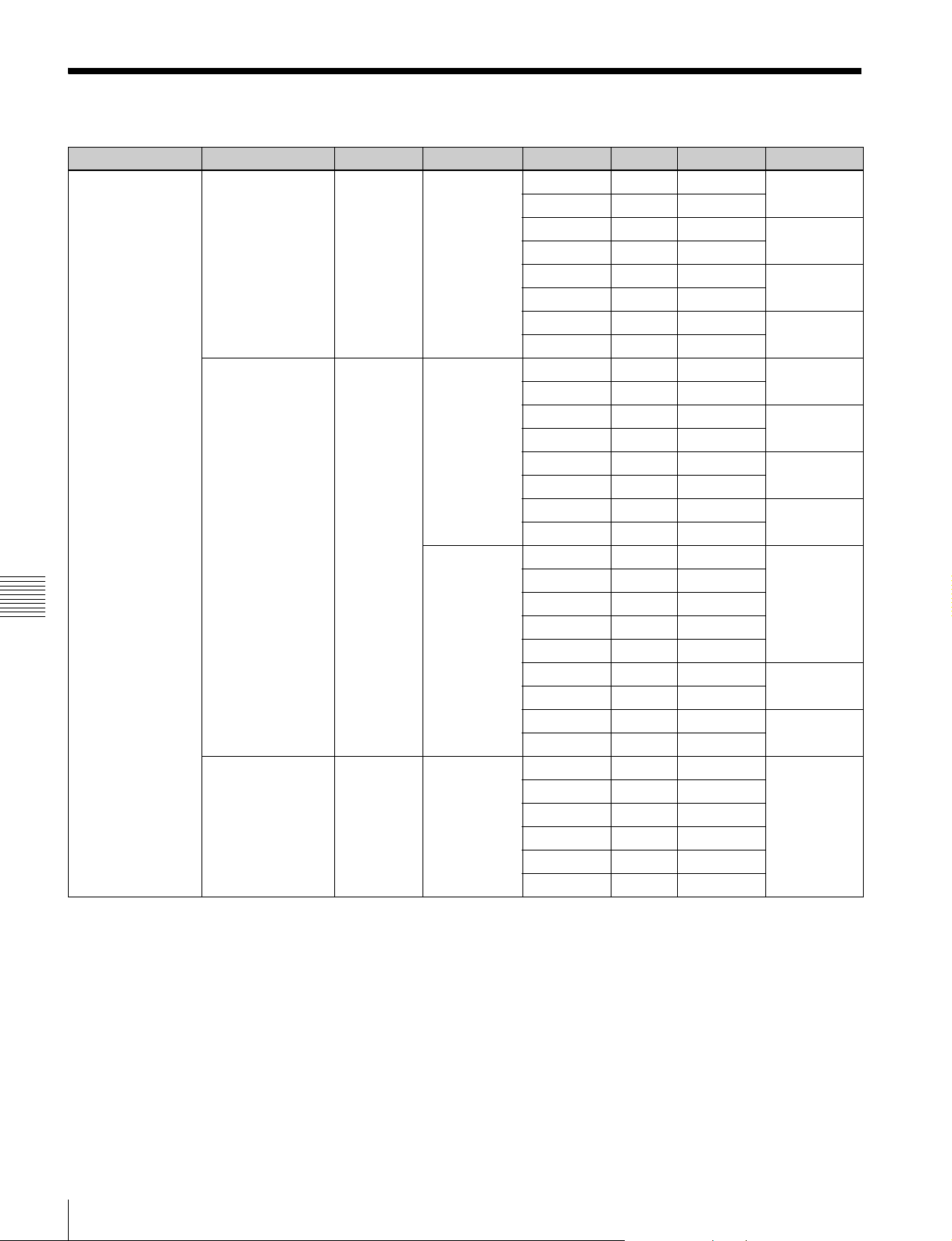
Recording Format
COMPRS SIGNAL/SIZE DEPTH SCAN FRAME SDI Rec Rate MULTIPLE
Class100 YPbPr (4:2:2)
1280:720
YPbPr (4:2:2)
1920:1080
Appendix
YPbPr (4:2:2)
2048:1080
10 Progressive 50 1.5G 100 1x
59.94 1.5G 100
100 1.5G 200 2x
119.88 1.5G 200
200 1.5G 400 4x
239.76 1.5G 400
300 1.5G 600 6x
359.64 1.5G 600
10 Interlace 25 1.5G 100 1x
29.97 1.5G 100
50 1.5G/3G 200 2x
59.94 1.5G/3G 200
200 1.5G 400 4x
239.76 1.5G 400
300 1.5G 600 6x
359.64 1.5G 600
Progressive 23.98 1.5G 80 1x
25 1.5G 100
29.97 1.5G 100
50 1.5G/3G 200
59.94 1.5G/3G 200
200 3G 800 4x
239 3G 800
300 3G 1200 6x
359 3G 1200
10 Progressive 23.98 1.5G 80 1x
24 1.5G 80
25 1.5G 83
29.97 1.5G 100
50 1.5G/3G 166
59.94 1.5G/3G 200
48
Recording Format
Page 49
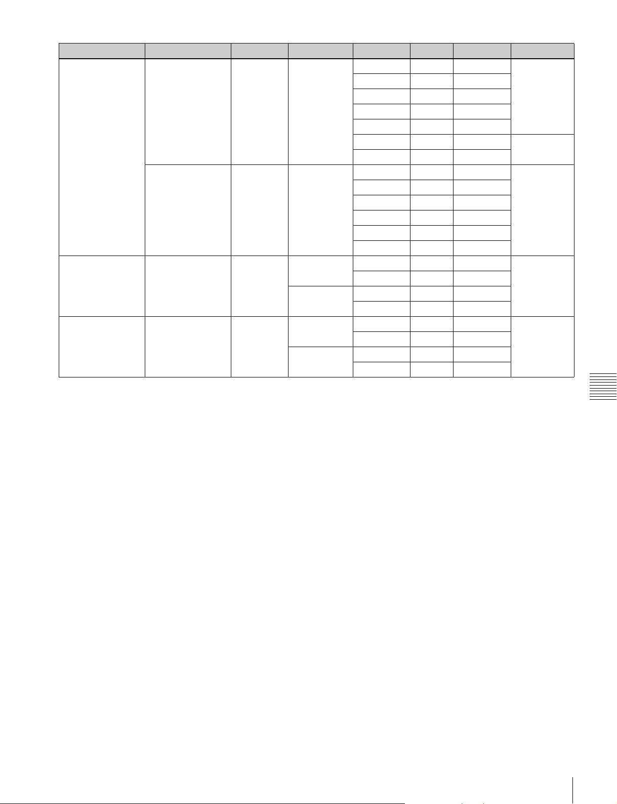
COMPRS SIGNAL/SIZE DEPTH SCAN FRAME SDI Rec Rate MULTIPLE
Class300 YPbPr (4:2:2)
3840:2160
YPbPr (4:2:2)
4096:2160
DNxHD145 YPbPr (4:2:2)
1920:1080
DNxHD220x YPbPr (4:2:2)
1920:1080
10 Progressive 23.98 3G 240 1x
25 3G 250
29.97 3G 300
50 3G 500
59.94 3G 600
100 3G 1000 2x
119 3G 1200
10 Progressive 23.98 3G 240 1x
24 3G 240
25 3G 250
29.97 3G 300
50 3G 500
59.94 3G 600
8 Interlace 25 1.5G 121 1x
29.97 1.5G 145
Progressive 50 1.5G/3G 242
59.94 1.5G/3G 290
10 Interlace 25 1.5G 184 1x
29.97 1.5G 220
Progressive 50 1.5G/3G 367
59.94 1.5G/3G 440
Appendix
Recording Format
49
Page 50
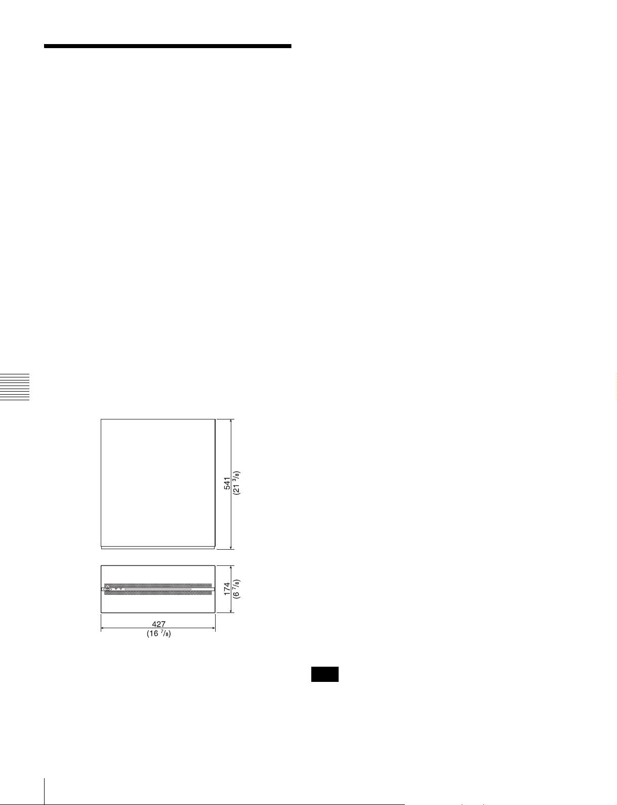
Specifications
General
Recording format
XAVC, Avid DNxHD(R)
Power requirements
100 V to 240 V AC
Power consumption
Maximum 480 W
Inrush current
(1) Maximum possible inrush current at initial switch-
on (Voltage changes caused by manual
switching):
75A peak, 5 A r.m.s. (240 V AC)
(2) Inrush current after a mains interruption of five
seconds (Voltage changes caused at zerocrossing):
75 A peak, 5 A r.m.s. (240 V AC)
Operating temperature
5 °C to 40 °C (41 °F to 104 °F)
Storage temperature
–20°C to +60°C (–4°F to +140°F)
Humidity 25% to 90% (non-condensing)
Mass 20 kg (44 lb. 1.5 oz.) (excluding options)
Dimensions 427 × 174 × 541 mm
Appendix
7
(16
/8 × 6 7/8 × 21 3/8 in.) (W×H×D)
Video
422 format
Sampling frequency
Y: 74.25 MHz
Pb/Pr: 37.125 MHz
Quantization 8/10 bits
Compression XAVC, Avid DNxHD(R)
Audio
Digital audio signal format
Sampling frequency
48 kHz (video sync)
Quantization 24 bits
Headroom 20 dB / 18 dB / 16 dB / 15 dB / 12 dB /
9 dB (selectable)
I/O connectors
When ENCODER mode is selected (per board)
HD SDI INPUT
1 to 4 BNC (4),
HD SDI (1.485 Gbps) SMPTE292M/
BTA-S004B standard
3G SDI (2.97 GHz) SMPTE-424M Level
A, B
HD SDI OUTPUT
INPUT MONITOR 5 to 8
BNC (4),
HD SDI (1.485 Gbps)
3G SDI (2.97 GHz)
Does not satisfy the SDI signal standard, and should be
used for input signal monitor applications only.
MULTI MONITOR
BNC (1),
HD SDI (1.485 Gbps) SMPTE292M/
BTA-S004B standard
DOWN CONVERTER
BNC (1),
HD SDI (1.485 Gbps) SMPTE292M/
BTA-S004B standard
TIMECODE INPUT
BNC (1), 0.5 to 5 Vpp, 10 kΩ
TIMECODE OUTPUT
BNC (1), 1.5 Vpp, low impedance
DIGITAL AUDIO (AES/EBU) INPUT
BNC (4),
CH 1/2 to CH 7/8, AES/EBU format,
unbalanced
50
Note
When connecting devices for AES/EBU signal input/
output, use a cable whose length is less than 300 meters
(984 feet).
Specifications
Page 51
When DECODER mode is selected (per board)
HD SDI OUTPUT
1 to 8 BNC (8),
HD SDI (1.485 Gbps) SMPTE292M/
BTA-S004B standard
3G SDI (2.97 GHz) SMPTE-424M Level
A, B
HD SDI OUTPUT
MONITOR
BNC (1),
HD SDI (1.485 Gbps) SMPTE292M/
BTA-S004B standard
MULTI MONITOR
BNC (1),
HD SDI (1.485 Gbps) SMPTE292M/
BTA-S004B standard
TIMECODE OUTPUT
BNC (1), 1.5 Vpp, low impedance
DIGITAL AUDIO (AES/EBU) OUTPUT
BNC (4),
CH 1/2 to CH 7/8, AES/EBU format,
unbalanced
Reference
REF INPUT BNC (2, including 1 loop through),
75 Ω with terminal switch
HD (tri-level sync)
SD (Black Burst)
NTSC: 0.286 Vpp, 75 Ω
PAL: 0.3 Vpp, 75 Ω
Remote
REMOTE1 to REMOTE4
9-pin D-Sub, female (4)
AUX 9-pin D-Sub, female (1)
GPIO (25P) 25-pin D-Sub, female (1)
NETWORK1 to 2
RJ-45 jack (2), 1000BASE-T
MAINTENANCE
USB (1)
Supplied accessories
Operation Guide (1)
Installation Manual (1)
Operation Manual (CD-ROM) (1)
Notes
• Always make a test recording, and verify that it was
recorded successfully.
SONY WILL NOT BE LIABLE FOR DAMAGES OF
ANY KIND INCLUDING, BUT NOT LIMITED TO,
COMPENSATION OR REIMBURSEMENT ON
ACCOUNT OF FAILURE OF THIS UNIT OR ITS
RECORDING MEDIA, EXTERNAL STORAGE
SYSTEMS OR ANY OTHER MEDIA OR
STORAGE SYSTEMS TO RECORD CONTENT OF
ANY TYPE.
• Always verify that the unit is operating properly before
use. SONY WILL NOT BE LIABLE FOR
DAMAGES OF ANY KIND INCLUDING, BUT
NOT LIMITED TO, COMPENSATION OR
REIMBURSEMENT ON ACCOUNT OF THE LOSS
OF PRESENT OR PROSPECTIVE PROFITS DUE
TO FAILURE OF THIS UNIT, EITHER DURING
THE WARRANTY PERIOD OR AFTER
EXPIRATION OF THE WARRANTY, OR FOR
ANY OTHER REASON WHATSOEVER.
• SONY WILL NOT BE LIABLE FOR CLAIMS OF
ANY KIND MADE BY USERS OF THIS UNIT OR
MADE BY THIRD PARTIES.
• SONY WILL NOT BE LIABLE FOR THE LOSS,
REPAIR, OR REPRODUCTION OF ANY DATA
RECORDED ON THE INTERNAL STORAGE
SYSTEM, RECORDING MEDIA, EXTERNAL
STORAGE SYSTEMS OR ANY OTHER MEDIA
OR STORAGE SYSTEMS.
• SONY WILL NOT BE LIABLE FOR THE
TERMINATION OR DISCONTINUATION OF ANY
SERVICES RELATED TO THIS UNIT THAT MAY
RESULT DUE TO CIRCUMSTANCES OF ANY
KIND.
Depending on the operating environment, unauthorized
third parties on the network may be able to access the
unit. When connecting the unit to the network, be sure to
confirm that the network is protected securely.
Appendix
Optional accessories
Expansion memory board
PWSK-4401 (2 TB)
Codec option (Avid DNxHD(R))
PWA-CD401
Power cord
Design and specifications are subject to change without
notice.
Specifications
51
Page 52

MPEG-4 Visual Patent Portfolio License
THIS PRODUCT IS LICENSED UNDER THE MPEG-4
VISUAL PATENT PORTFOLIO LICENSE FOR THE
PERSONAL AND NON-COMMERCIAL USE OF A
CONSUMER FOR
(i) ENCODING VIDEO IN COMPLIANCE WITH THE
MPEG-4 VISUAL STANDARD (“MPEG-4
VIDEO”)
AND/OR
(ii) DECODING MPEG-4 VIDEO THAT WAS
ENCODED BY A CONSUMER ENGAGED IN A
PERSONAL AND NON-COMMERCIAL
ACTIVITY AND/OR WAS OBTAINED FROM A
VIDEO PROVIDER LICENSED BY MPEG LA TO
PROVIDE MPEG-4 VIDEO.
NO LICENSE IS GRANTED OR SHALL BE IMPLIED
FOR ANY OTHER USE. ADDITIONAL
INFORMATION INCLUDING THAT RELATING TO
PROMOTIONAL, INTERNAL AND COMMERCIAL
USES AND LICENSING MAY BE OBTAINED FROM
MPEG LA, LLC. SEE HTTP://WWW.MPEGLA.COM
Appendix
MPEG LA is offering licenses for (i) manufacturing/sales
of any storage media storing MPEG-4 Visual video
information (ii) distribution/broadcasting of MPEG-4
Visual video information in any manner (such as online
video distribution service, internet broadcasting, TV
broadcasting). Other usage of this product may be required
to obtain license from MPEGLA.
Please contact MPEG LA for any further information.
MPEG LA, L.L.C., 250 STEELE STREET, SUITE 300,
DENVER, COLORADO 80206, http://www.mpegla.com
52
MPEG-4 Visual Patent Portfolio License
Page 53

• Microsoft, Windows, and Internet Explorer are registered
trademarks of Microsoft Corporation in the United States
and/or other countries.
• Google Chrome is a registered trademark of Google Inc.
• Firefox is a trademark or registered trademark of the Mozilla
Foundation in the United States and other countries.
• © 1995-2013 Opera® Browser, Opera® browser, and Opera
logo are trademarks of Opera Software ASA.
• Mac OS and Safari are trademarks of Apple Inc., registered
in the US and other countries.
All other product names and brand names are registered
trademarks or trademarks of their respective owners.
®
Trademarked items are not indicated by
or ™ symbols in
this document.
Page 54

Sony Corporation
PWS-4400 (SYL)
4-531-287-14 (1) © 2013
 Loading...