

Sony PVM-5041Q Operating Instructions
3-755-607-17 (1)
日本語
トリニトロン®カラービデオモニター/Trinitron® Color Video Monitor
PVM-5041Q/6041Q
PVM-6041QM
取扱説明書
お買い上げいただき、ありがとうございます。
電気製品は安全のための注意事項を
警告
この取扱説明書には、事故を防ぐための重要な注意事項と
製品の取り扱いかたを示しています。この取扱説明書と別
冊の 「安全のために」 をよくお読みのうえ、製品を安全にお
使いください。お読みになったあとは、いつでも見られる
ところに必ず保管してください。
守らないと、火災や人身事故になる
ことがあります。
English
Français Deutsch
Español
Italiano
Operating Instructions
Before operating the unit, please read this manual
thoroughly and retain it for future reference.
Mode d’emploi
Avant la mise en service de cet appareil, prière de lire
attentivement ce mode d’emploi et de le conserver pour
toute référence ultérieure.
Bedienungsanleitung
Vor Inbetriebnahme des Geräts lesen Sie bitte diese
Anleitung aufmerksam durch und bewahren Sie sie zum
späteren Nachschlagen gut auf.
Manual de instrucciones
Antes de emplear la unidad, lea detenidamente este manual
de instrucciones, y consérvelo para futuras referencias.
Istruzioni per l’uso
Prima di usare l’apparecchio, leggere con attenzione questo
manuale e conservarlo per riferimenti futuri.
Owner’s Record
The model and serial numbers are located on
the rear.
Record the model and serial numbers in the
spaces provided below. Refer to these numbers
whenever you call upon your Sony dealer
regarding this product.
©1992 Sony Corporation
Model No. Serial No.
目次
主な特長.....................................................................................................................................................
各部の名称と働き ....................................................................................................................................
電源について .............................................................................................................................................
お手入れ.....................................................................................................................................................
保証書とアフターサービス .....................................................................................................................
主な仕様.....................................................................................................................................................
安全上のご注意
電源について
AC 100V
•AC電源で動作させるときは付属の電源コードを使用して
ください。
• バッテリーで動作させるときは、別売りの
テリーパックをご使用ください。それ以外のものは使用し
ないでください。
•
DC 12V IN
接続して使用してください。
または
DC 12V
ジャックにソニーACアダプター
感電を防ぐために
キャビネットは絶対にあけないでください。内部には電圧の
高い部分があり、手を触れると危険です。
につないでご使用ください。
NP-1A/1B
AC-500
バッ
を
通風孔はふさがない
両側面、裏面および底面の通風孔は、内部の温度上昇を防ぐ
ためのものです。風通しの悪いところに置いたり、通風孔を
ふさいだりしないでください。
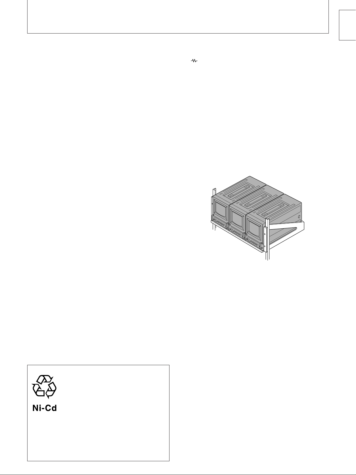
ラックや棚に収納するときは
モニターをラックやモニター棚に収納した時、上下および周
辺の機器によりモニター周辺の通風が妨げられ、動作温度が
室温より上がり、故障や発熱の原因となる可能性がありま
す。このような場合は、モニターの動作条件温度
℃を保つように、上下および周辺機器との隙間を充分にと
り、通気孔の確保や通気ファンの設置、等の配慮をしてくだ
さい。
℃から
0
35
1
2
4
5
5
6
電源コードについて
電源コードを無理に曲げたり、上に重い物を乗せたりしない
でください。コードに傷がついて、火災や電源の原因になり
ます。傷がついたコードは使わないでください。電源コード
を抜くときは、コードを引っ張らずに、必ずプラグを持って
抜いてください。
異物について
内部に液体をこぼしたり、燃えやすいものや、金属類を落と
さないでください。そのまま使用すると火災や感電、故障、
事故の原因となります。
高温でのご使用について
暖房器具の近くや、窓を閉めきった自動車内(特に夏期)など
では、気温が
変形や、故障の原因となります。
℃以上になることがあり、キャビネットの
100
衝撃について
持ち運びの際には衝撃を与えないように、特にブラウン管お
よび前面フィルター(画面)にはご注意ください。
異常や不具合が起きたら
万一、異常や不具合が起きたとき、異物が中に入ったとき
は、すぐにお買い上げ店、またはソニーサービス窓口にご連
絡ください。
これは故障ではありません。
このモニターは、入力信号がない場合は電源を入れてもブラ
ウン管が光りません。
この装置は、第一種情報装置(商工業地域において使用
されるべき装置)で商工業地域での電波障害防止を目的
とした情報処理装置等電波障害自主規制協議会(
基準に適合しております。
したがって、住宅地域またはその隣接した地域で使用す
ると、ラジオ、テレビジョン受信機などに受信障害を与
えることがあります。
取扱説明書に従って正しい取り扱いをしてください。
VCCI
)
主な特長
日本語
カラー方式
4
1
NTSC
、
3.58
PAL、SECAM
、
NTSC
)
の4つのカラー方式
4.43
に対応でき、切り換えは自動です。入力信号に合った方式で
画像を再現します。
ブルーオンリーモード
ブルーオンリーモードにすると、カソードが
個とも青信号
3
で動作し、これが白黒画像として表示されます。色の濃さ
(クロマ)や色相(フェーズ)の調整、
ノイズの監視に便利
VTR
です。
アナログ
ビデオ機器のアナログ
力できます。前面の
/コンポーネント切り換えスイッチで、いずれかの信
RGB
/コンポーネント入力端子
RGB
信号、コンポーネント信号を入
RGB
LINE/RGB
切り換えスイッチと裏面の
号を選びます。
ビーム電流フィードバック回路
この回路の採用により、安定したホワイトバランスが得られ
ます。
型入力端子の自動終端
BNC
( マークの付いているコネクターのみ)
裏面の
型入力端子は、出力端子に何もつないでいない
BNC
ときは、内部で75Ωに終端されています。出力端子にケー
ブルをつなぐと、内部の75Ωが自動的に開放され、入力端
子に入った信号がそのまま出力されます(ループスルー)。
スタンダードの19インチのラックに収納可能
EIA
マウンティングブラケット
汎用ラック(
インチラックにマウントすることができます。マウント
19
JIS C6010
MB-520
一般電子機器用ラック)または
(別売り)を使うと、
方式についてはマウンティングブラケットの取扱説明書をご
覧ください。
JIS
EIA
くし型フィルター
くし型フィルターの採用により、
信号のクロスカラー
NTSC
妨害(文字のまわりの虹)やカラーノイズ(色のにじみ)をなく
し、きめ細かで透明度の高い、しっとりした画像が得られま
す。
2
アンダースキャン
4:3/16:9
切り換えスイッチ
)
画面の垂直方向を圧縮して、16:9の入力信号を正しい縦横
比でモニターするためのスイッチです。アンダースキャン
モードで裏面の切り換えスイッチを16:9にすると縦横比
の映像に変わります。
16:9
このマークはニカド電池のリサイクルマークです。
1
)
NTSC
るように設計された
2
)
アンダースキャン4:3/16:9切り換えスイッチの表示は、シリ
アルナンバー
4.43
は、
PAL、SECAM
の再生信号です。
VTR
2500001
以降の製品に採用されています。
地域で
テープの再生ができ
NTSC
ニカド電池はリサイクルできる貴重な資源です。ニカド電池の交
換および、ご使用済みの製品の廃棄に際しては、ニカド電池を取
り出し、金属部にセロハンテープなどの絶縁テープを貼ってニカ
ド電池リサイクル協力店へご持参ください。
1
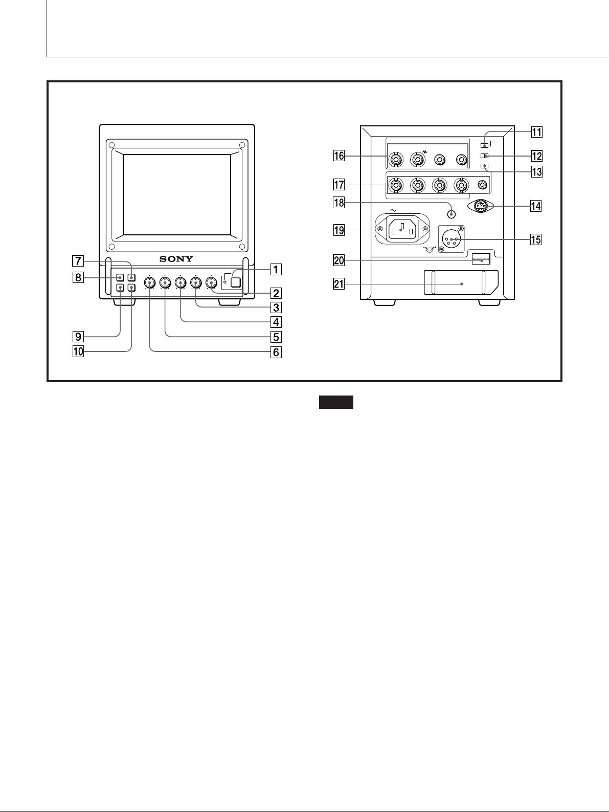
各部の名称と働き
前面 裏面
パワー
1 POWER(電源)スイッチとインジケーター
スイッチを押し込むと電源が入り、インジケーター(緑)が点
灯します。
もう一度押すと、電源が切れます。
インジケーターはバッテリーインジケーターも兼用していま
す。本機に挿入したバッテリーが弱くなったとき、または
DC 12V IN
にはインジケーターが点滅します。
ボリューム
2 VOLUME(音量)調整つまみ
右へ回すと音量が大きくなり、左へ回すと小さくなります。
コントラスト
3 CONTR調整つまみ
右へ回すとコントラストが強くなります。
左へ回すとコントラストが弱くなります。
フェース
4 PHASE(色相)調整つまみ
右へ回すと、肌色が緑がかります。
左へ回すと、肌色が紫がかります。
クロマ
5 CHROMA(色の濃さ)調整つまみ
右へ回すと、色が濃くなります。
左へ回すと、色が薄くなります。
ジャックにつないだ電源の電圧が下がったとき
2
ご注意
•
PHASE、CHROMA
映像の調整はできません。
•
PHASE
きません。
•
PHASE
み有効です。
6 BRIGHT(明るさ)調整つまみ
7 H/VDELAY(水平/垂直ディレイ)ボタン
8 LINE/RGB入力切り換えボタン
9 BLUEONLYボタン
調整つまみはコンポーネント信号の映像の調整はで
調整つまみは、カラー方式が
ブライト
右へ回すと、画面が明るくなります。
左へ回すと、画面が暗くなります。
ディレイ
水平・垂直同期信号を同時にモニターしたいときに押し込み
ます。
水平同期信号は画面の左から約
垂直同期信号は画面のほぼ中央に現れます。
ライン
モニターしたい入力を選びます。
作するとき押します(
ターするときはこのボタンを押さないでおきます(
ブルー オンリー
押し込むと赤と緑の信号がカットされ、青信号のみが白黒画
像として表示されます。色の濃さ(クロマ)や色相(フェーズ)
の調整、
VTR
調整つまみは、アナログ
NTSC
のところに現れます。
1/4
RGB
RGB)。LINE
ノイズの監視が容易に行えます。
端子からの信号をモニ
RGB
である場合にの
端子からの信号で動
信号の
LINE
)。
日本語
アンダー スキャン
!º UNDERSCANボタン
押し込むとアンダースキャンモードになります。画面サイズ
が約
す。
押し込んだ状態で裏面の
換えスイッチを
ります。
!¡ SYNCINT/EXT(内部/外部同期)切り換えスイッチ
シンクインターナルエクスターナル
本機を外部同期で動作させるときは、
ください。
!™ RGB/COMP切り換えスイッチ
RGB
す。前面の
!£ UNDERSCAN4:3/16:9切り換えスイッチ
画面の垂直方向を圧縮して、
比でモニターするためのスイッチです。このスイッチの切り
換えによって、前面パネルの
は下表のように変わります。
UNDERSCAN
ボタン
4:3/16:9
切り換えスイッチ
4:3
16:9
なお、この機能は、シリアルナンバー
縮小され、ラスターの四隅までが画面に表示されま
3%
UNDER SCAN 4:3/16:9
にすると、縦横比16:9の映像に変わ
16:9
(外部同期)にして
EXT
コンポーネント
またはコンポーネント(
LINE/RGB
ボタンは押してください(
R-Y、Y、B-Y
の入力信号を正しい縦横
16:9
)信号を選びま
UNDER SCAN
側にしたとき
側にしたとき
押していない状態
(ø)
の信号をノーマ
4:3
ルスキャンでモニ
ターします。
の信号をノーマ
4:3
ルスキャンでモニ
ターします。
押した状態
4:3
ダースキャンでモニ
ターします。
16:9
ダースキャンでモニ
ターします。(垂直方
向圧縮)
2500001
RGB
ボタンの動作
(Ø)
の信号をアン
の信号をアン
以降の製品
に採用されています。
リモート
!¢ REMOTE端子(8ピンミニ
リモコンを接続することができます。ピン配列については
ページをご覧ください。
!∞ DC12VINジャック(XLR型、4ピン)
ボルト イン
別売りのソニー
アダプター
AC
DIN
)
AC-500
をつなぎます。
切り
)。
ライン
!§ LINE入出力端子
この端子からの信号をモニターするときは、前面の
ボタンを押さないでください(
RGB
VIDEOIN(映像入力)端子(
やカラービデオカメラの映像出力端子と接続します。
VTR
VIDEOOUT(映像出力)端子(
VIDEO IN
VTR
AUDIOIN(音声入力)端子(ピンジャック)
VTR
AUDIOOUT(音声出力)端子(ピンジャック)
AUDIO IN
VTR
!¶ RGB/COMPONENT入力端子
R/R-Y、G/Y、
この端子からの信号をモニターするときは、前面の
RGB
・アナログRGB信号で動作させるとき
ビデオカメラのアナログ
RGB/COMP
・コンポーネント信号で動作させるとき
ソニーのベータカムビデオカメラなどの
ポーネント出力端子につなぎます。
RGB/COMP
ト)にしてください。
SYNC
外部同期信号発生器などからの基準信号を入力します。
SYNC INT/EXT
ください。
!• VHOLD(垂直同期)調整つまみ
画面が上下に分かれたり、流れたりするときに調整します。
つまみを回し、画像の流れが止まったら、他の受像信号に切
り換えて、いずれの信号でも安定するように合わせます。
端子に接続した映像信号のループスルー出力。
や他のモニターの映像入力端子と接続します。
やマイクアンプなどの音声出力端子と接続します。
端子に接続した音声信号のループスルー出力。
や他のモニターの音声入力端子と接続します。
コンポーネント
(
B/B-Y
BNC
ボタンを押しておきます(RGB)。
切り換えスイッチを
切り換えスイッチを
型)
(
BNC
切り換えスイッチを
ホールド
型)
BNC
BNC
型)、
出力端子につなぎます。
RGB
)。
LINE
型)
(ピンジャック)
AUDIO
にしてください。
RGB
Y/R-Y/B-Y
(コンポーネン
COMP
(外部同期)にして
EXT
LINE
LINE
コン
/
/
6
!ª ACINソケット
付属の電源コードをつなぎます。
イジェクト
@º EJECTボタン
このボタンを押し上げると、バッテリーパックを取り出せま
す。
@¡ バッテリー入れ
別売りのバッテリーパック
NP-1A/1B
を挿入します。
3
電源について
屋内で使うには
付属の電源コードを裏面の
電源につないでご利用ください。
ソケットに差し込み、壁の
AC IN
電源コードが
テリーパック(挿入されている場合)や、
クに接続されているACアダプターなどからの電源は自動的
に切れます。
ソケットにつながれているときは、バッ
AC IN
DC 12V IN
ジャッ
電源コードを確実につなぐには
123
裏面の
1
で固定します。
電源コードを差し込み、ACプラグホルダーBを電源コードに取り付けます。
2
AC
3
電源コードをはずすには
プラグホルダーBを左右からはさんで、引きます。
AC
AC IN
プラグホルダーBをはめこみます。
ソケットの2本のねじをはずし、付属のACプラグホルダーAを取り付けて上からねじ
充電式バッテリーパックで使うには
バッテリーパックを取り出すには
EJECT
充電するには
バッテリーパック
1WA
バッテリーパック
使いください。
ボタンを押し上げてください。
NP-1A
バッテリーチャージャーをお使いください。また、
NP-1B
を充電するためには別売りの
を充電するためには
BC-1WB
BC-
をお
4
ご注意
バッテリーパックで使用する場合は、電源コード、ACアダ
プターなどを抜いてください。これらが接続されているとき
は、バッテリーパックが使えません。
日本語
DC 12V IN
本機の
DC 12V IN
とができます。
別売りのソニーACアダプター
ら電源をとることができます。
ジャックを使うには
ジャックに
の直流電流を接続するこ
12V
AC-500
を使って
AC 100V
か
お手入れ
キャビネットや表面のフィルターは柔らかい布でおふきくだ
さい。キャビネットの汚れがひどいときは、水で5〜6倍に
薄めた中性洗剤液に柔らかい布をひたし、かたくしぼってか
ら汚れをふきとります。このあと乾いた布でからぶきしてく
ださい。
シンナーやベンジンなどの薬品類は、表面の仕上げをいため
たり、表示が消えてしまうことがありますので、使用しない
でください。なお、お手入れのときは、必ず電源を切ってく
ださい。
ホコリは大敵
内部にホコリがたまると、故障や事故の原因になることがあ
ります。いつも好調にお使いいただくため、年に一度くらい
は内部の掃除・点検をお買い上げ店または担当セールスマン
にご相談ください。
保証書とアフターサービス
保証書
・この製品には保証書が添付されていますので、お買い上
げの際お受け取りください。
・所定事項の記入および記載内容をお確かめのうえ、大切
に保存してください。
アフターサービス
調子が悪いときはまずチェックを
この説明書をもう一度ご覧になってお調べください。
それでも具合の悪いときはサービスへ
お買い上げ店、または添付の「業務用製品ご相談窓口のご案
内」にあるお近くのソニー業務用製品ご相談窓口にご相談く
ださい。
保証期間中の修理は
保証書の記載内容に基づいて修理させていただきます。詳し
くは保証書をご覧ください。
保証期間経過後の修理は
修理によって機能が維持できる場合は、ご要望により有料修
理をさせていただきます。
5
主な仕様
映像信号系
カラー方式
解像度
周波数特性
同期
NTSC
250
6MHz(−3dB
AFC
3.58
本
時定数
、
PAL、SECAM
)(全入力端子とも)
1.0ms
画像系
ノーマルスキャン
アンダースキャン
直線性
H
直線性
V
コンバージェンス 中心部
ラスターサイズ安定度
有効画面の6%オーバースキャン
CRT
有効画面の3%アンダースキャン
CRT
以下(標準)
7%
以下(標準)
7%
(標準)
(標準)
周辺部
0.50mm
0.60mm
H 1.0%、V 1.5%
高電圧変動率
色温度
3.0%
D65 (PVM-5041Q/6041QM)
D93 (PVM-6041Q)
入力
VIDEO IN BNC型1Vp-p、±6dB
AUDIO IN
R/R-Y、G/Y、B/B-Y BNC
R、G、B
チャンネル
ピンジャック −
型
5dBs、47k
0.7Vp-p、±6dB
チャンネルに負の同期信号がある場
G
合は、内部同期モードで動作する。
0.3Vp-p
R-Y、Y、B-Y
EXT SYNC IN BN C
チャンネル
(
75%
信号のとき)
同期負
0.7Vp-p、±6dB
クロミナンスの標準カラーバー
型 複合同期
4Vp-p、±6dB
、
NTSC4.43
、同期負
Ω以下
、
音声出力レベル
出力レベル
0.5W
その他
消費電力
42W AC
40W DC
電源
動作温度
保存温度 −10〜+
湿度
最大外形寸法 約
質量 約
付属品 電源コード(1)
100V AC、50/60Hz
12V DC
バッテリーパックまたは、ソニー
アダプター
、別売りのソニー
AC-500
0〜35°C
40°C
0〜90%
146×173×352.5mm
(幅/高さ/奥行き)
(バッテリーパックを含まず)
5.5kg
プラグホルダー(1組)
AC
ピンプラグ付コード(1)
8
取扱説明書(1)
保証書(
「業務用製品ご相談窓口のご案内」(1)
)
1
ピン配列
REMOTE
端子(8ピンミニ
DIN
)
NP-1A/1B
AC
を使用
ループスルー出力
VIDEO OUT BNC
入力端子に何もつながれていないとき
は、
AUDIO OUT
REMOTE
入力
REMOTE 8
ピンジャック
ピンミニ
(ピン配列については右段をご覧くだ
さい。)
6
型
Ωで自動的に終端する。
75
DIN
ピン
No.
1
2
3
4
5
6
7
8
リモートコントロールする場合は、希望の機能を持つピンを
各々ピン
本機の仕様および外観は、改良のため予告なく変更すること
がありますが、ご了承ください。
ブルーオンリー
ディレイ
H/V
アース
内部/外部同期
―
アンダースキャン/ノーマルスキャン
RGB/Y、R-Y、B-Y
RGB/LINE
(アース)につないでください。
3
信号

日本語
7
English
WARNING
To prevent fire or shock hazard, do not expose the unit
to rain or moisture.
Dangerously high voltages are present inside the unit. Do
not open the cabinet. Refer servicing to qualified personnel
only.
This symbol is intended to alert the user to
the presence of uninsulated “dangerous
voltage” within the product’s enclosure that
may be of sufficient magnitude to constitute
a risk of electric shock to persons.
This symbol is intended to alert the user to
the presence of important operating and
maintenance (servicing) instructions in the
literature accompanying the appliance.
For the Customers in the USA
This equipment has been tested and found to comply with
the limits for a Class A digital device, pursuant to Part 15 of
the FCC Rules. These limits are designed to provide
reasonable protection against harmful interference when
the equipment is operated in a commercial environment.
This equipment generates, uses, and can radiate radio
frequency energy and, if not installed and used in accordance with the instruction manual, may cause harmful
interference to radio communications. Operation of this
equipment in a residential area is likely to cause harmful
interference in which case the user will be required to
correct the interference at his own expense.
For the customers in Europe
(PVM-6041QM)
This product with the CE marking complies with both the
EMC Directive (89/336/EEC) and the Low Voltage Directive
(73/23/EEC) issued by the Commission of the European
Community.
Compliance with these directives implies conformity to the
following European standards:
• EN60950: Product Safety
• EN55103-1: Electromagnetic Interference (Emission)
• EN55103-2: Electromagnetic Susceptibility (Immunity)
This product is intended for use in the following
Electromagnetic Environment(s):
E1 (residential), E2 (commercial and light industrial), E3
(urban outdoors) and E4 (controlled EMC environment, ex.
TV studio).
Important Safety Instruction
1) Read these instructions.
2) Keep these instructions.
3) Heed all warnings.
4) Follow all instructions.
5) Do not use this apparatus near water.
6) Clean only with dry cloth.
7) Do not block any ventilation openings. Install in accordance with the
manufacturer’s instructions.
8) Do not install near any heat sources such as radiators, heat registers,
stoves, or other apparatus (including amplifiers) that produce heat.
9) Do not defeat the safety purpose of the polarized or grounding-type
plug. A polarized plug has two blades with one wider than the other. A
grounding type plug has two blades and a third grounding prong. The
wide blade or the third prong are provided for your safety. If the
provided plug does not fit into your outlet, consult an electrician for
replacement of the obsolete outlet.
10) Protect the power cord from being walked on or pinched particularly at
plugs, convenience receptacles, and the point where they exit from the
apparatus.
11) Only use attachments/accessories specified by the manufacturer.
12) Use only with the cart, stand, tripod, bracket, or table specified by the
manufacturer, or sold with the apparatus. When a cart is used, use
caution when moving the cart/apparatus combination to avoid injury
from tip-over.
13) Unplug this apparatus during lightning storms or when unused for long
periods of time.
14) Refer all servicing to qualified service personnel. Servicing is required
when the apparatus has been damaged in any way, such as powersupply cord or plug is damaged, liquid has been spilled or objects have
fallen into the apparatus, the apparatus has been exposed to rain or
moisture, does not operate normally, or has been dropped.
You are cautioned that any changes or modifications not
expressly approved in this manual could void your authority
to operate this equipment.
Table of Contents
Features ............................................................................. 1
Location and function of parts and controls ....................... 2
Power sources ................................................................... 4
Specifications ..................................................................... 5
This instruction manual covers PVM-5041Q and
PVM-6041QM.
Features
Four color systems available
The monitor can display NTSC3.58, PAL, SECAM and
NTSC
automatically.
1)
4.43
signals. The appropriate color system is selected
Blue only picture
The picture can be displayed in blue and black only. This
facilitates hue adjustment and the observation of video
noise.
Analog RGB/component input connectors
Analog RGB or component (Y, R-Y, and B-Y) signals from
video equipment can be input through these connectors.
Beam current feedback circuit
The built-in beam current feedback circuit assures stable
white balance.
Comb filter
When NTSC video signals are received, a comb filter
activates to increase the resolution, resulting in fine picture
detail without color spill or color noise.
Under scan 4:3/16:9 selector
The monitor can display the 16:9 signal with the correct
ratio of width and height, compressing the picture vertically.
Selecting 16:9 with the UNDER SCAN 4:3/16:9 selector on
the rear panel in the under scan mode, the ratio of the
picture will change to 16:9.
2)
Automatic termination
(only connector marked )
The VIDEO IN connector is terminated at 75 ohms inside,
when no cable is connected to the loop-through output
connectors. When a cable is connected to an output
connector, the 75-ohm termination is automatically
released.
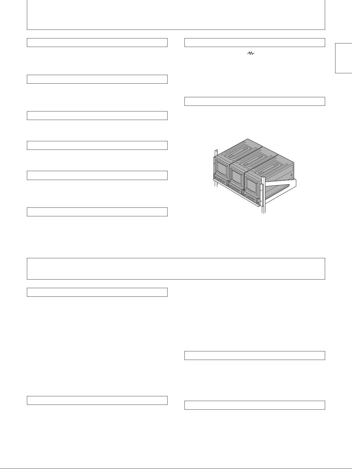
EIA standard 19-inch rack mounting
By using an MB-520 mounting bracket (not supplied), the
monitor can be mounted in an EIA standard 19-inch rack.
For details on mounting, see the instruction manual of the
MB-520.
1) An NTSC4.43 signal is used for playing back NTSC-recorded
video cassettes with a video tape recorder/player especially
designed for use with this system.
2) The UNDER SCAN 4:3/16:9 selector has been adopted since
the serial No. 2500001 product.
English
Precautions
On safety
• Operate the unit on 100 – 240 V AC (for PVM-6041QM),
120 V AC (for PVM-5041Q) or 12 V DC. For the AC
operation, use only the supplied AC power cord or the
AC power adaptor recommended (not supplied). Do not
use any other type. For the battery operation, use only
the NP-1A/1B battery pack (not supplied). Do not use any
other batteries.
• Should any liquid or solid object fall into the cabinet,
unplug the unit and have it checked by qualified
personnel before operating it further.
• Unplug the unit from the wall outlet if it is not to be used
for several days.
• To disconnect the AC power cord, pull it out by the plug.
Never pull the cord itself.
On installation
• Allow adequate air circulation to prevent internal heat
build-up. Do not place the unit on surfaces (rugs,
blankets, etc.) or near materials (curtains, draperies) that
may block the ventilation holes.
• Do not install the unit near heat sources such as
radiators or air ducts, or in a place subject to direct
sunlight, excessive dust, mechanical vibration or shock.
• Keep the unit away from a loudspeaker or motor, as the
picture may be affected.
• If you mount the monitor in a rack or shelf, devices
around the monitor may prevent adequate air circulation,
raising the operating temperature and possibly causing
malfunction or overheating. Take care to leave adequate
clearance around the monitor and not to block the
ventilation holes. Or install a ventilation fan to keep the
operating temperature range between 0°C and 35°C.
On cleaning
Clean the unit with a slightly dampened soft cloth. Use a
mild household detergent. Never use strong solvents such
as thinner or benzine as they might damage the finish of
the cabinet.
As a safety precaution, unplug the unit before cleaning it.
On repacking
Retain the original carton and packing materials for safe
transport of this unit in the future.
If you have any questions about this unit, contact your
authorized Sony dealer.
1
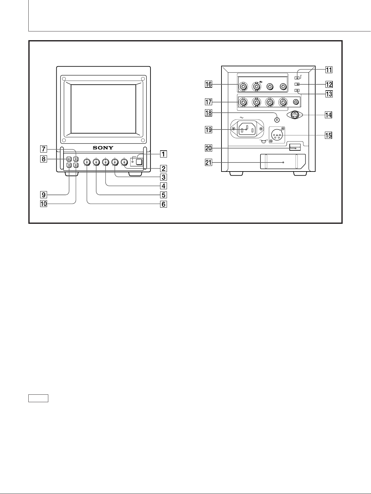
Location and Function of Parts and Controls
Front
1 POWER switch and indicator
Depress to turn the monitor on. The indicator will light
up in green.
The POWER indicator also functions as the battery
indicator. When the internal battery becomes weak or
the power supplied through the DC12V IN jack
decreases, the indicator flashes.
2 VOLUME control
Turn this control clockwise or counterclockwise to obtain
the disired volume.
3 CONTR (contrast) control
Turn clockwise to make the contrast stronger and
counterclockwise to make it weaker.
4 PHASE control
Turn clockwise to make the skin tones greenish and
counterclockwise to make them purplish.
5 CHROMA control
Turn clockwise to make the color intensity stronger and
counterclockwise to make it weaker.
Rear
6 BRIGHT (brightness) control
Turn clockwise for more brightness and
counterclockwise for less.
7 H/V DELAY selector
Depress this button to observe the horizontal and
vertical sync signals at the same time. The horizontal
sync signal is displayed in the left quarter of the screen;
the vertical sync signal is displayed near the center of
the screen.
8 LINE/RGB input selector
Select the program to be monitored. Keep this button
released (LINE) for a signal fed through the LINE
connectors. Depress this button (RGB) for a signal fed
through the RGB/COMPONENT connectors.
9 BLUE ONLY selector
Depress this button to turn off the red and green
signals. A blue signal is displayed as an apparent
monochrome picture on the screen. This facilitates
“chroma” and “phase” control adjustments and the
observation of video noise.
Note
• The PHASE and CHROMA control settings have no
effect on an analog RGB signal.
• The PHASE control has no effect on component signals.
• The PHASE control setting is effective only for the NTSC
system.
2
!º UNDER SCAN selector
Depress this button for underscanning. The display size
is reduced by approximately 3% so that four corners of
the raster are visible.
With this buton depressed, if the UNDER SCAN 4:3/
16:9 selector on the rear panel is set to 16:9, the ratio of
the picture cahnges to 16:9.
 Loading...