

Sony PREMIERPRO SDM-P234 User Manual

TFT LCD Color
Computer Display
SDM-P234
© 2004 Sony Corporation
Owner’s Record
The model and serial numbers are located at the rear of the unit.
Record these numbers in the spaces provided below. Refer to them
whenever you call upon your dealer regarding this product.
Model No.
Serial No.
WARNING
To prevent fire or shock hazard, do not expose the
unit to rain or moisture.
Dangerously high voltages are present inside the
unit. Do not open the cabinet. Refer servicing to
qualified personnel only.
FCC Notice
This equipment has been tested and found to comply with the limits
for a Class B digital device, pursuant to Part 15 of the FCC Rules.
These limits are designed to provide reasonable protection against
harmful interference in a residential installation. This equipment
generates, uses, and can radiate radio frequency energy and, if not
installed and used in accordance with the instructions, may cause
harmful interference to radio communications. However, there is no
guarantee that interference will not occur in a particular installation.
If this equipment does cause harmful interference to radio or
television reception, which can be determined by turning the
equipment off and on, the user is encouraged to try to correct the
interference by one or more of the following measures:
– Reorient or relocate the receiving antenna.
– Increase the separation between the equipment and receiver.
– Connect the equipment into an outlet on a circuit different from
that to which the receiver is connected.
– Consult the dealer or an experienced radio/TV technician for help.
You are cautioned that any changes or modifications not expressly
approved in this manual could void your authority to operate this
equipment.
IMPORTANTE
Para prevenir cualquier mal funcionamiento y evitar daños, por
favor, lea detalladamente este manual de instrucciones antes
de conectar y operar este equipo.
NOTICE
This notice is applicable for USA/Canada only.
If shipped to USA/Canada, install only a UL LISTED/CSA
LABELLED power supply cord meeting the following
specifications:
SPECIFICATIONS
Plug Type Nema-Plug 5-15p
Cord Type SVT or SJT, minimum 3 × 18 AWG
Length Maximum 15 feet
Rating Minimum 7 A, 125 V
NOTICE
Cette notice s’applique aux Etats-Unis et au Canada
uniquement.
Si cet appareil est exporté aux Etats-Unis ou au Canada, utiliser
le cordon d’alimentation portant la mention UL LISTED/CSA
LABELLED et remplissant les conditions suivantes:
SPECIFICATIONS
Type de fiche Fiche Nema 5-15 broches
Cordon Type SVT ou SJT, minimum 3 × 18 AWG
Longueur Maximum 15 pieds
Tension Minimum 7 A, 125 V
As an
ENERGY STAR Partner, Sony
Corporation has determined that this
product meets the
guidelines for energy efficiency.
This monitor complies with the
TCO’99 guidelines.
ENERGY STAR
If you have any questions about this product, you may call;
Sony Customer Information Services Center
1-800-222-7669 or http://www.sony.com/
Declaration of Conformity
Trade Name: SONY
Model: SDM-P234
Responsible Party: Sony Electronics Inc.
Address: 16450 W. Bernardo Dr,
Telephone Number: 858-942-2230
This device complies with part 15 of the FCC rules. Operation is
subject to the following two conditions: (1) This device may not
cause harmful interference, and (2) this device must accept any
interference received, including interference that may cause
undesired operation.
BZ
03
San Diego, CA 92127 U.S.A.
2
Table of Contents
Precautions . . . . . . . . . . . . . . . . . . . . . . . . . . . . . . . . . . . . . . . . . . . 4
Identifying parts and controls . . . . . . . . . . . . . . . . . . . . . . . . . . . . . . 5
Setup . . . . . . . . . . . . . . . . . . . . . . . . . . . . . . . . . . . . . . . . .7
Setup 1: Connect the video signal cables . . . . . . . . . . . . . . . . . . . . 7
Setup 2: Connect the audio cord . . . . . . . . . . . . . . . . . . . . . . . . . . 8
Setup 3: Connect the speakers or headphones . . . . . . . . . . . . . . . 8
Setup 4: Connect the power cord . . . . . . . . . . . . . . . . . . . . . . . . . . 8
Setup 5: Bundle the cords and cables . . . . . . . . . . . . . . . . . . . . . .9
Setup 6: Turn on the monitor and computer . . . . . . . . . . . . . . . . . . 9
Setup 7: Adjust the tilt . . . . . . . . . . . . . . . . . . . . . . . . . . . . . . . . . . 10
Selecting the input signal (INPUT) . . . . . . . . . . . . . . . . . . . . . . . . .11
Customizing Your Monitor . . . . . . . . . . . . . . . . . . . . . . .12
Navigating the menu . . . . . . . . . . . . . . . . . . . . . . . . . . . . . . . . . . . 12
PICTURE ADJUST menu . . . . . . . . . . . . . . . . . . . . . . . . . . . 13
SCREEN menu (analog RGB signal only) . . . . . . . . . . . . . .14
COLOR menu . . . . . . . . . . . . . . . . . . . . . . . . . . . . . . . . . . . .15
GAMMA menu . . . . . . . . . . . . . . . . . . . . . . . . . . . . . . . . . . . .16
ZOOM menu . . . . . . . . . . . . . . . . . . . . . . . . . . . . . . . . . . . . . 16
MENU POSITION menu . . . . . . . . . . . . . . . . . . . . . . . . . . . . 17
INPUT SENSING ON/OFF menu . . . . . . . . . . . . . . . . . . . . . 17
LANGUAGE menu . . . . . . . . . . . . . . . . . . . . . . . . . . . . . . . .17
0 RESET menu . . . . . . . . . . . . . . . . . . . . . . . . . . . . . . . . . . . . 17
MENU LOCK menu . . . . . . . . . . . . . . . . . . . . . . . . . . . . . . . . 18
OPTION menu . . . . . . . . . . . . . . . . . . . . . . . . . . . . . . . . . . . . 18
GB
• Macintosh is a trademark licensed to
Apple Computer, Inc., registered in the
U.S.A. and other countries.
•Windows
Microsoft Corporation in the United
States and other countries.
• IBM PC/AT and VGA are registered
trademarks of IBM Corporation of the
U.S.A.
• VESA and DDC
Video Electronics Standards
Association.
•
ENERGY STAR is a U.S. registered
mark.
• Adobe and Acrobat are trademarks of
Adobe Systems Incorporated.
• All other product names mentioned
herein may be the trademarks or
registered trademarks of their respective
companies.
•Furthermore, “” and “” are not
mentioned in each case in this manual.
is registered trademark of
are trademarks of the
http://www.sony.net/
Technical Features . . . . . . . . . . . . . . . . . . . . . . . . . . . . .19
Power saving function . . . . . . . . . . . . . . . . . . . . . . . . . . . . . . . . . . 19
Reducing the power consumption (ECO mode) . . . . . . . . . . . . . . 19
Automatic brightness adjustment function (light sensor) . . . . . . . .19
Automatic picture quality adjustment function
(analog RGB signal only) . . . . . . . . . . . . . . . . . . . . . . . . . . . . . . . . 20
Troubleshooting . . . . . . . . . . . . . . . . . . . . . . . . . . . . . . .21
On-screen messages . . . . . . . . . . . . . . . . . . . . . . . . . . . . . . . . . . . 21
Trouble symptoms and remedies . . . . . . . . . . . . . . . . . . . . . . . . . 22
Self-diagnosis function . . . . . . . . . . . . . . . . . . . . . . . . . . . . . . . . . .24
Specifications . . . . . . . . . . . . . . . . . . . . . . . . . . . . . . . . .25
3
Precautions
Warning on power connections
Use the supplied power cord. If you use a different power cord, be
sure that it is compatible with your local power supply.
For the customers in the U.S.A.
If you do not use the appropriate cord, this monitor will not
conform to mandatory FCC standards.
For the customers in the UK
If you use the monitor in the UK, be sure to use the appropriate
UK power cord.
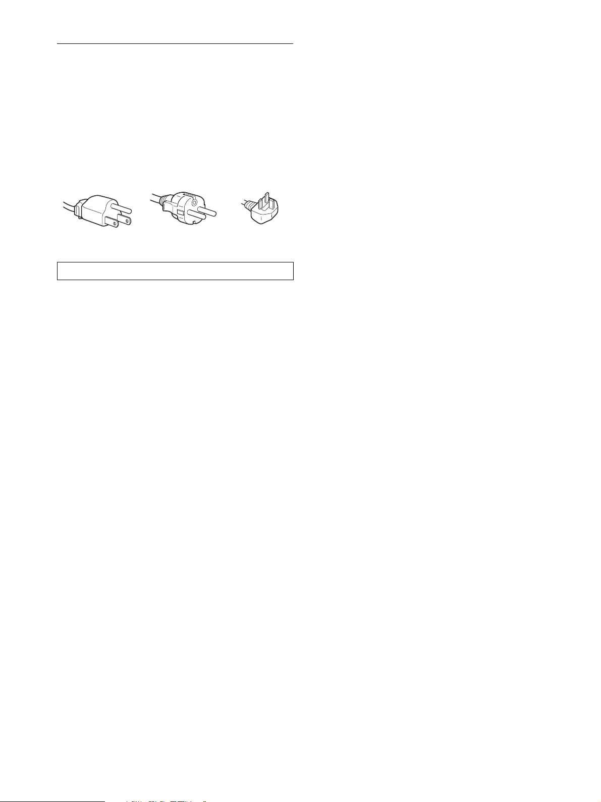
Example of plug types
for 100 to 120 V AC for 200 to 240 V AC for 240 V AC only
The equipment should be installed near an easily accessible outlet.
Installation
Do not install or leave the monitor:
• In places subject to extreme temperatures, for example near a
radiator, heating vent, or in direct sunlight. Subjecting the
monitor to extreme temperatures, such as in an automobile
parked in direct sunlight or near a heating vent, could cause
deformations of the casing or malfunctions.
• In places subject to mechanical vibration or shock.
• Near any equipment that generates a strong magnetic field,
such as a TV or various other household appliances.
• In places subject to inordinate amounts of dust, dirt, or sand, for
example near an open window or an outdoor exit. If setting up
temporarily in an outdoor environment, be sure to take
adequate precautions against airborne dust and dirt. Otherwise
irreparable malfunctions could occur.
Ventilation
The openings are provided for necessary ventilation. To ensure
reliable operation of the set, and to protect it from overheating,
these openings must never be blocked or covered.
Note on the LCD (Liquid Crystal Display)
Please note that the LCD screen is made with high-precision
technology. However, black points or bright points of light (red,
blue, or green) may appear constantly on the LCD screen, and
irregular colored stripes or brightness may appear on the LCD
screen. This is not malfunction.
(Effective dots: more than 99.99%)
Maintenance
• Be sure to unplug the power cord from the power outlet before
cleaning your monitor.
• Clean the LCD screen with a soft cloth. If you use a glass
cleaning liquid, do not use any type of cleaner containing an
anti-static solution or similar additive as this may scratch the
LCD screen’s coating.
• Clean the cabinet, panel, and controls with a soft cloth lightly
moistened with a mild detergent solution. Do not use any type
of abrasive pad, scouring powder, or solvent, such as alcohol or
benzine.
• Do not rub, touch, or tap the surface of the screen with sharp or
abrasive items such as a ballpoint pen or screwdriver. This type
of contact may result in a scratched picture tube.
• Note that material deterioration or LCD screen coating
degradation may occur if the monitor is exposed to volatile
solvents such as insecticide, or if prolonged contact is
maintained with rubber or vinyl materials.
Transportation
• Disconnect all cables from the monitor and hold the LCD
display by the body. Be careful not to scratch the screen when
transporting. If you drop the monitor, you may be injured or the
monitor may be damaged.
• When you transport this monitor for repair or shipment, use the
original carton and packing materials.
Disposal of the monitor
• Do not dispose of this monitor with general
household waste.
• The fluorescent tube used in this monitor contains
mercury. Disposal of this monitor must be carried out
in accordance to the regulations of your local
sanitation authority.
Handling the LCD screen
• Do not leave the LCD screen facing the sun as it can damage
the LCD screen. Take care when you place the monitor by a
window.
• Do not push on or scratch the LCD screen. Do not place a heavy
object on the LCD screen. This may cause the screen to lose
uniformity or cause LCD panel malfunctions.
• If the monitor is used in a cold place, a residual image may
appear on the screen. This is not a malfunction. The screen
returns to normal as the temperature rises to a normal operating
level.
• If a still picture is displayed for a long time, a residual image
may appear for a while. The residual image will eventually
disappear.
• The LCD panel becomes warm during operation. This is not a
malfunction.
4
For customers in the United States
This product contains mercury. Disposal of this product may be
regulated if sold in the United States. For disposal or recycling
information, please contact your local authorities or the
Electronics Industries Alliance (http://www.eiae.org).
Identifying parts and controls
A Sony logo (page 18)
Sony logo illuminates.
See the pages in parentheses for further details.
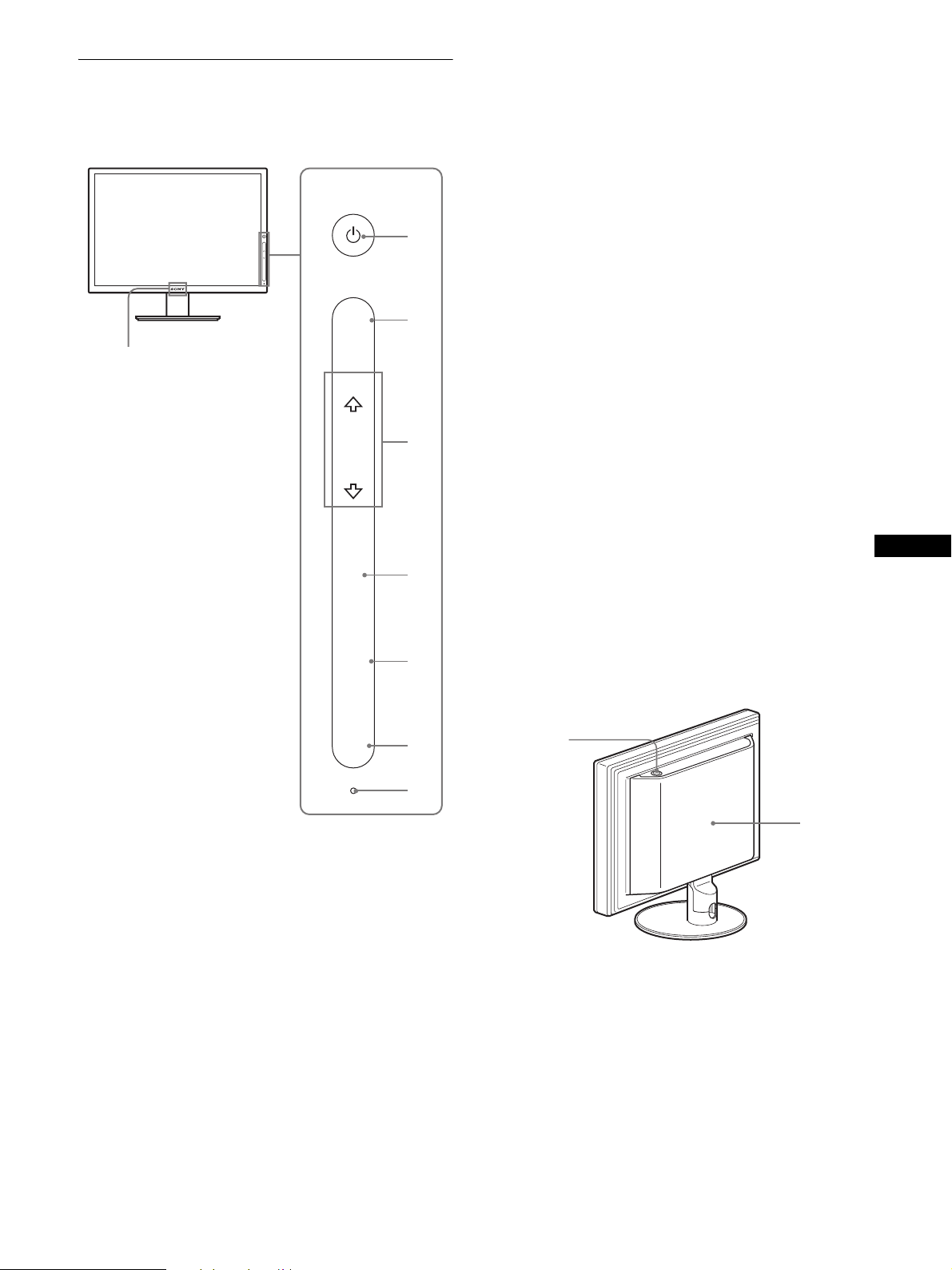
Front of the LCD display
MENU
OK
INPUT
ECO
MENU
1
OK
2
3
4
5
B 1 (Power) (pages 9, 19, 24)
This key turns the monitor on when the key lights up in red.
To turn the monitor off, touch this key again.
If the key does not light up, press the MAIN POWER switch
(9).
C MENU (page 12)
This key turns the menu screen on and off.
D m/M (page 12)
These keys are used to select the menu items and make
adjustments.
E OK (pages 12, 14)
This key activates the selected menu item and adjustments
made using m/M (4).
When the menu screen is not displayed, with this key you can
make automatic adjustment of the picture quality for the
current input signal (one touch sensing function).
F INPUT (page 11)
This key switches the video input signal between INPUT1,
INPUT2 and INPUT3 when multiple computers are
connected to the monitor.
G ECO (page 19)
This key is used to reduce the power consumption.
GB
INPUT
ECO
6
7
8
This display employs a touch sensor key system. You can operate
the display by touching the letters or symbols on the front panel.
Touch sensor keys work only when they are lit. Touch sensor keys
light up when you turn the monitor on, but they turn off if you do
not perform any operations for a while. To light them up again,
touch an area of the touch sensor keys.
Note
Do not press the touch sensor keys too hard. This may cause a
malfunction.
H Light sensor (page 19)
This sensor measures the brightness of the surrounding area.
Be sure not to cover the sensor with papers, etc.
Rear of the display stand
9
0
I MAIN POWER switch (page 9)
This switch turns the monitor’s main power on and off.
J Back cover (page 7)
Slide up this cover when you connect cables or cords.
5
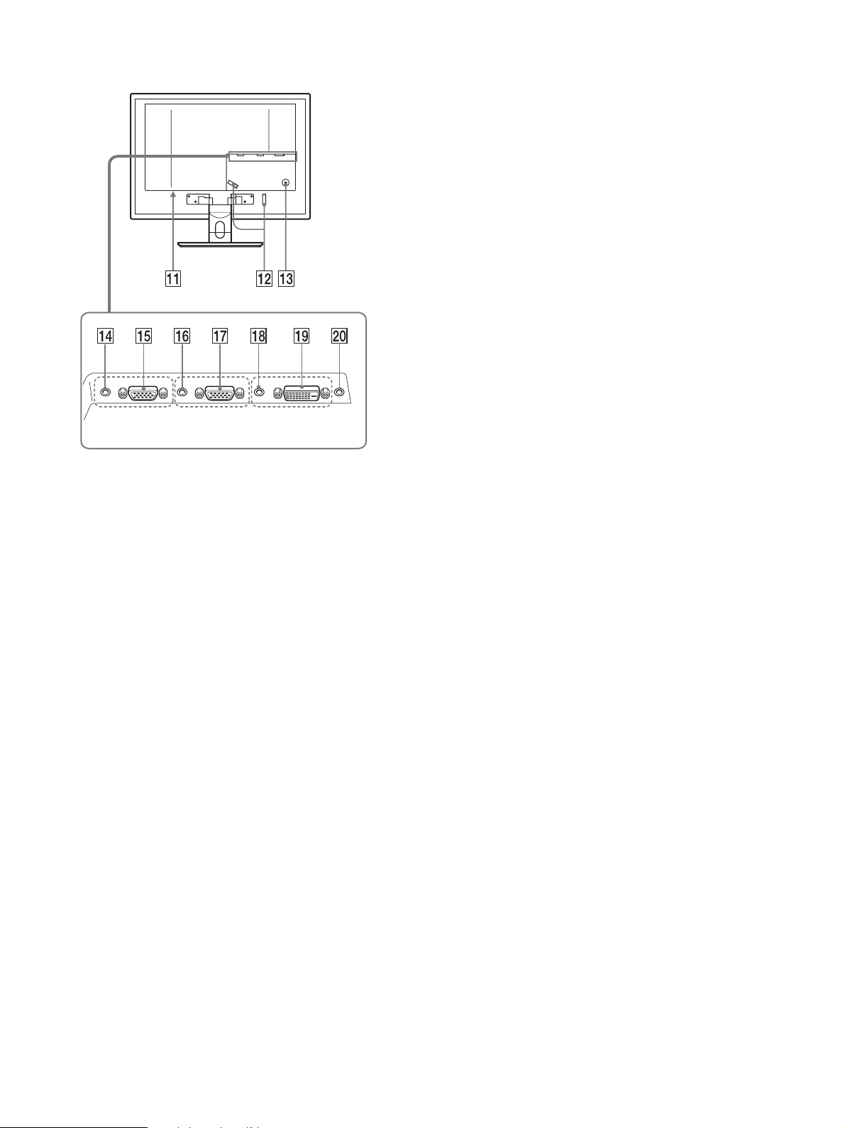
Rear of the LCD display
INPUT 1 INPUT 2 INPUT 3
K AC IN connector (page 8)
This connector connects the power cord (supplied).
L Cable holder (page 9)
This part secures cables and cords to the monitor.
M Security lock hole
The security lock hole should be used with the Kensington
Micro Saver Security System.
Micro Saver Security System is a trademark of Kensigton.
N Audio input jack for INPUT1 (page 8)
This jack inputs audio signals when connected to the audio
output jack of a computer or other audio equipment connected
to INPUT1.
O HD15 input connector (analog RGB) for INPUT1
(page 7)
This connector inputs analog RGB video signals (0.700 Vp-p,
positive) and sync signals.
P Audio input jack for INPUT2 (page 8)
This jack inputs audio signals when connected to the audio
output jack of a computer or other audio equipment connected
to INPUT2.
Q HD15 input connector (analog RGB) for INPUT2
(page 7)
This connector inputs analog RGB video signals (0.700 Vp-p,
positive) and sync signals.
R Audio input jack for INPUT3 (page 8)
This jack inputs audio signals when connected to the audio
output jack of a computer or other audio equipment connected
to INPUT3.
S DVI-D input connector (digital RGB) for INPUT3
(page 7)
This connector inputs digital RGB video signals that comply
with DVI Rev.1.0.
T Audio output jack (page 8)
This jack outputs audio signals to speakers or headphones.
6
Setup
Before using your monitor, check that the following items are
included in your carton:
• LCD display
• Power cord
• HD15-HD15 video signal cable (analog RGB)
• DVI-D video signal cable (digital RGB)
• Audio cord (stereo miniplug)
• CD-ROM (utility software for Windows/Macintosh, Operating
Instructions, etc.)
• Warranty card
• Quick Setup Guide
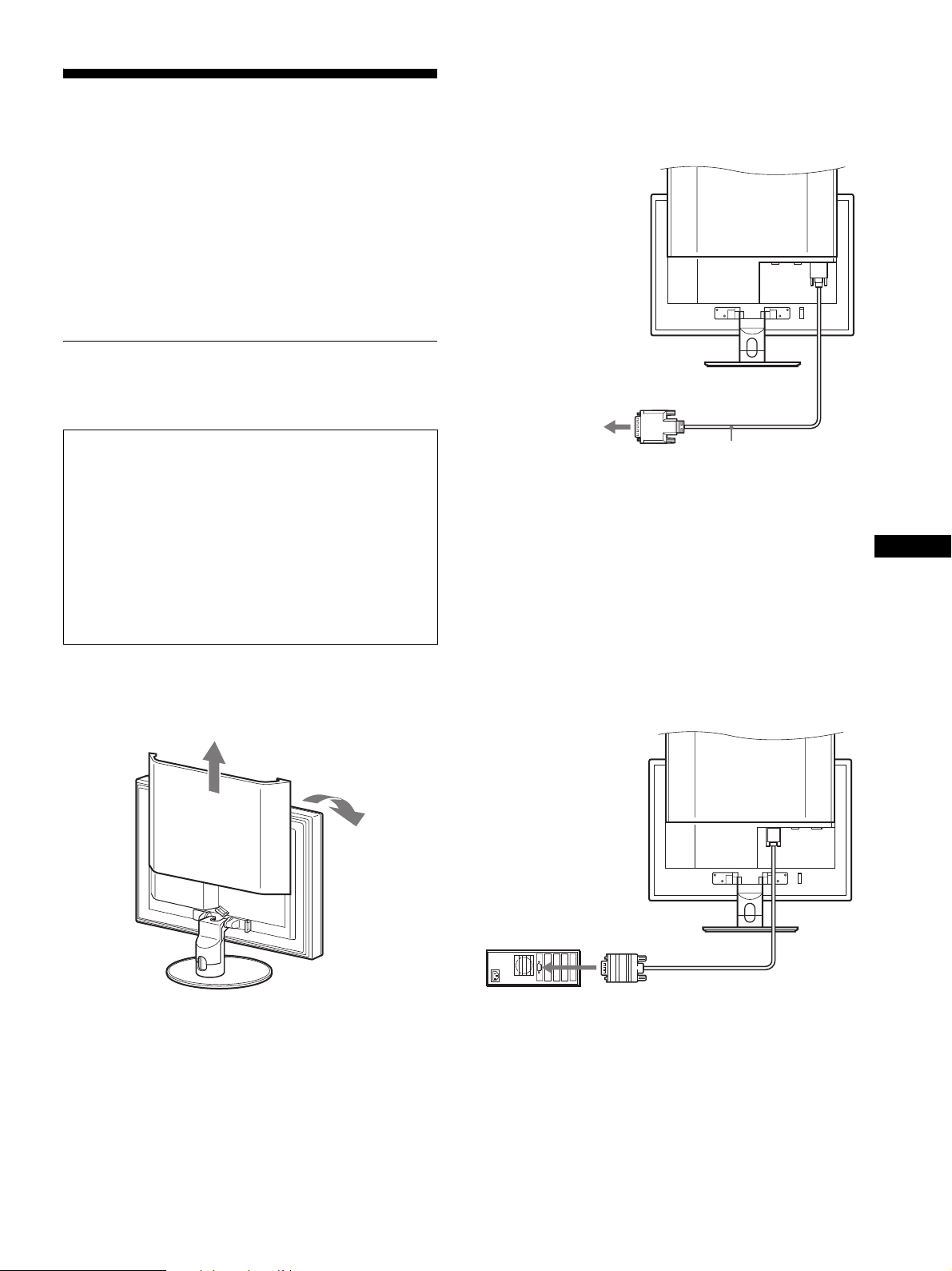
Setup 1:Connect the video signal
Connect a computer equipped with a DVI output
connector (digital RGB)
Using the supplied DVI-D video signal cable (digital RGB), connect the
computer to the monitor’s DVI-D input connector (digital RGB) for
INPUT3.
to the DVI-D input
connector
(digital RGB)
cables
•Turn off the monitor, computer, and any other
equipment before connecting them.
•When connecting the computer to the monitor’s HD15
input connector (analog RGB), refer to “Connect a
computer equipped with an HD15 output connector
(analog RGB).”
Note
• Do not touch the pins of the video signal cable connector as this
might bend the pins.
• Check the alignment of the HD15 connector to avoid bending the
pins of the video signal cable connector.
1 Slide up the back cover.
2 Tilt the display forward.
to the computer’s DVI output
connector (digital RGB)
DVI-D video signal
cable (digital RGB)
(supplied)
Connect a computer equipped with an HD15
output connector (analog RGB)
Using the supplied HD15-HD15 video signal cable (analog RGB),
connect the computer to the monitor’s HD15 input connector (analog
RGB) for INPUT1 or INPUT2.
Connect the computer according to the following illustrations.
x Connecting to an IBM PC/AT or
compatible computer
to the HD15 input
connector
(analog RGB)
GB
to the computer’s HD15 output
connector (analog RGB)
IBM PC/AT or compatible
computer
HD15-HD15 video signal
cable (analog RGB)
(supplied)
7
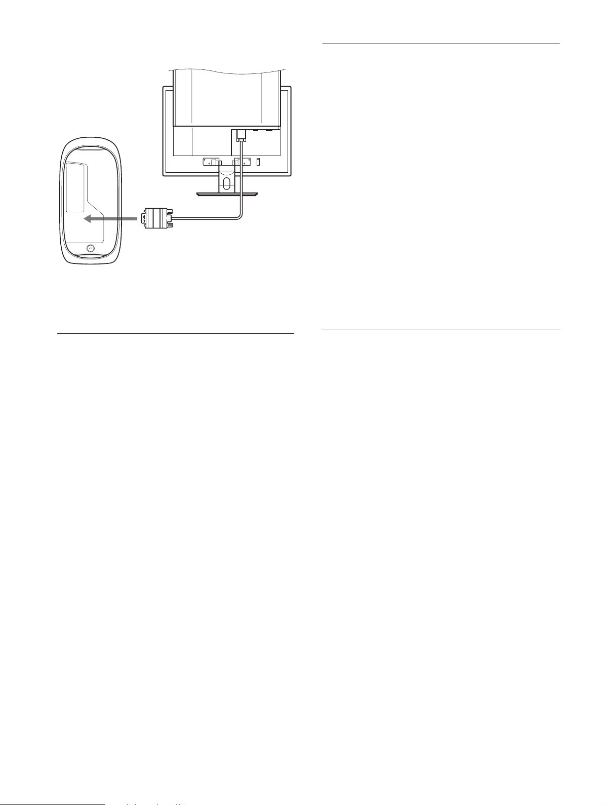
x Connecting to a Macintosh
When connecting a Macintosh computer, use an adapter (not supplied),
if necessary. Connect the adapter to the computer before connecting the
video signal cable.
Setup 3:Connect the speakers or
headphones
Connect the speaker cord or headphone cord securely
to the monitor’s audio output jack. (The speakers and
headphones are not supplied.)
Setup 2:Connect the audio cord
Connect the supplied audio cord to the monitor’s
corresponding audio input jack.
Using the speakers or headphones, you can listen to sound from
your computer or other audio equipment connected to the
monitor’s audio input jacks.
Setup 4:Connect the power cord
1 Connect the supplied power cord securely to the
monitor’s AC IN connector.
2 Connect the other end securely to a power outlet.
8
 Loading...