

Page 1

PROFESSIONAL DISC CAMCORDER
PDW-700
OPERATION MANUAL [English]
1st Edition (Revised 2)
Page 2
WARNING
This label is located
inside the outside
panel of the unit.
Denna etikett finns på
apparatens ovansida.
Denne mærkat sidder
på apparatets øverste
panel.
This Professional Disc Camcorder is
classified as a CLASS 1 LASER PRODUCT.
Laser diode properties
Wavelength: 400 to 410 nm
Emission duration: Continuous
Laser output power: 135 mW (max. of
pulse peak), 65 mW (max. of CW)
Standard: IEC60825-1 (2001)
Egenskaber for laserdiode
Bølgelængde: 400 til 410 nm
Strålingsvarighed: Kontinuerlig
Afgivet lasereffekt: 135 mW (maks
stråletoppunkt), 65 mW (maks ved
kontinuerlig stråling)
Standard: IEC60825-1 (2001)
Tekniska data för laserdiod
Våglängd: 400 till 410 nm
Emissionslängd: Kontinuerlig
Laseruteffekt: 135 mW (max. för
pulstopp), 65 mW (max. för kontinuerlig
våg)
Standard: IEC60825-1 (2001)
Egenskaper for laserdiode
Bølgelengde: 400 til 410 nm
Strålingsvarighet: Uavbrutt
Utgangseffekt for laser: 135 mW (maks av
pulshøyde), 65 mW (maks av CW)
Standard: IEC60825-1 (2001)
Tämä kyltti sijaitsee
laitteen yläpinnalla.
Dette merket er
plassert på oversiden
av produktet.
CAUTION
The use of optical instruments with this
product will increase eye hazard.
Use of controls or adjustments or
performance of procedures other than those
specified herein may result in hazardous
radiation exposure.
VAROITUS!
LAITTEEN KÄYTTÄMINEN MUULLA KUIN
TÄSSÄ KÄYTTÖOHJEESSA MAINITULLA
TAVALLA SAATTAA ALTISTAA
KÄYTTÄJÄN TURVALLISUUSLUOKAN 1
YLITTÄVÄLLE NÄKYMÄTTÖMÄLLE
LASERSÄTEILYLLE.
VARNING
OM APPARATEN ANVÄNDS PÅ ANNAT
SÄTT ÄN I DENNA BRUKSANVISNING
SPECIFICERATS, KAN ANVÄNDAREN
UTSÄTTAS FÖR OSYNLIG
LASERSTRÅLNING, SOM ÖVERSKRIDER
GRÄNSEN FÖR LASERKLASS 1.
For the customers in the U.S.A.
This equipment has been tested and found to
comply with the limits for a Class B digital
device, pursuant to Part 15 of the FCC Rules.
These limits are designed to provide
reasonable protection against harmful
2
Page 3

interference in a residential installation. This
equipment generates, uses, and can radiate
radio frequency energy and, if not installed
and used in accordance with the instructions,
may cause harmful interference to radio
communications. However, there is no
guarantee that interference will not occur in a
particular installation. If this equipment does
cause harmful interference to radio or
television reception, which can be
determined by turning the equipment off and
on, the user is encouraged to try to correct
the interference by one or more of the
following measures:
— Reorient or relocate the receiving
antenna.
— Increase the separation between the
equipment and receiver.
— Connect the equipment into an outlet on a
circuit different from that to which the
receiver is connected.
— Consult the dealer or an experienced
radio/TV technician for help.
You are cautioned that any changes or
modifications not expressly approved in this
manual could void your authority to operate
this equipment.
All interface cables used to connect
peripherals must be shielded in order to
comply with the limits for a digital device
pursuant to Subpart B of Part 15 of FCC
Rules.
If you have any questions about this product,
you may call;
Sony Customer Information Service Center
1-800-222-7669 or http://www.sony.com/
Declaration of Conformity
Trade Name: SONY
Model: PDW-700
Responsible party:
Sony Electronics Inc.
Address: 16530 Via Esprillo,
San Diego, CA 92127
U.S.A.
Telephone Number:
858-942-2230
This device complies with part 15 of the
FCC Rules. Operation is subject to the
following two conditions: (1) this device
may not cause harmful interference, and
(2) this device must accept any
interference received, including
interference that may cause undesired
operation.
For the State of California, USA only
Perchlorate Material - special handling may
apply, See
www.dtsc.ca.gov/hazardouswaste/perchlorate
Perchlorate Material : Lithium battery
contains perchlorate.
For the customers in Europe
This product with the CE marking complies
with the EMC Directive issued by the
Commission of the European Community.
Compliance with this directive implies
conformity to the following European
standards:
• EN55103-1: Electromagnetic Interference
(Emission)
• EN55103-2: Electromagnetic Susceptibility
(Immunity)
This product is intended for use in the
following Electromagnetic Environments: E1
(residential), E2 (commercial and light
industrial), E3 (urban outdoors), E4
(controlled EMC environment, ex. TV studio).
The manufacturer of this product is Sony
Corporation, 1-7-1 Konan, Minato-ku, Tokyo,
Japan.
The Authorized Representative for EMC and
product safety is Sony Deutschland GmbH,
Hedelfinger Strasse 61, 70327 Stuttgart,
Germany. For any service or guarantee
matters please refer to the addresses given
in separate service or guarantee documents.
3
Page 4

For the customers in Taiwan only
4
Page 5

Table of Contents
Foreword .................................................................................................... 11
Before use........................................................................................ 11
Chapter 1 : Overview
Features ...................................................................................................... 12
Locations and Functions of Parts and Controls...................................... 14
Power supply................................................................................... 14
Accessory attachments.................................................................... 15
Operating and connectors section ................................................... 17
HDVF-20A viewfinder (optional)................................................... 30
Status display on the viewfinder screen.......................................... 31
Chapter 2 : Preparations
Preparing a Power Supply ........................................................................ 35
Using a battery pack........................................................................ 35
Using AC power.............................................................................. 36
Attaching the Viewfinder .......................................................................... 36
Attaching the HDVF-20A/C35W ................................................... 36
Adjusting the viewfinder position................................................... 37
Moving the viewfinder shoe up....................................................... 37
Using the BKW-401 Viewfinder Rotation Bracket ........................ 38
Detaching the eyepiece ................................................................... 39
Adjusting the viewfinder focus and screen ..................................... 39
Setting the Area of Use .............................................................................. 40
Setting the Date/Time of the Internal Clock ........................................... 41
Mounting the Lens..................................................................................... 42
Adjusting the Flange Focal Length.......................................................... 43
Preparing the Audio Input System .......................................................... 44
Connecting a microphone to the MIC IN connector....................... 44
Connecting microphones to the AUDIO IN connectors ................. 45
Attaching a UHF portable tuner (for a UHF wireless microphone
system)...................................................................................... 46
Connecting line input audio equipment .......................................... 48
Tripod Mounting ....................................................................................... 49
Table of Contents
5
Page 6

Connecting a Video Light ......................................................................... 50
Using the Shoulder Strap .......................................................................... 50
Adjusting the Shoulder Pad Position....................................................... 51
Connecting the Remote Control Unit ...................................................... 52
Chapter 3 : Adjustments and Settings for Shooting
Setting the Recording Format .................................................................. 54
Setting the system frequency .......................................................... 54
Setting the video recording format.................................................. 55
Adjusting the Black Balance and the White Balance............................. 55
Adjusting the black balance ............................................................ 55
Adjusting the white balance............................................................ 56
Setting the Electronic Shutter................................................................... 60
Shutter modes.................................................................................. 60
Selecting the shutter mode and shutter speed ................................. 61
Changing the Reference Value for Automatic Iris Adjustment............ 63
Adjusting the Audio Level ........................................................................ 65
Manually adjusting the audio levels of the audio inputs from the
AUDIO IN CH1/CH2 connectors............................................. 65
Manually adjusting the audio level of the MIC IN connector ........ 66
Recording audio on channels 3 and 4 ............................................. 66
Setting the Time Data ................................................................................ 68
Setting the timecode........................................................................ 68
Setting the user bits......................................................................... 68
Synchronizing the timecode............................................................ 69
Chapter 4 : Shooting
Table of Contents
6
Handling Discs ........................................................................................... 72
Discs used for recording and playback ........................................... 72
Notes on handling ........................................................................... 72
Write-protecting discs ..................................................................... 72
Loading and unloading a disc ......................................................... 73
Formatting a disc............................................................................. 74
Handling of discs when recording does not end normally (salvage
function).................................................................................... 74
Basic Procedure for Shooting ................................................................... 76
Playing back the recorded clip ........................................................ 78
Deleting the recorded clip............................................................... 79
Page 7

Advanced Operations for Shooting.......................................................... 80
Recording essence marks ................................................................ 80
Setting clip flags with switches....................................................... 80
Setting the thumbnail image at recording time............................... 81
Starting a shoot with a few seconds of pre-stored picture data (Picture
Cache function)......................................................................... 81
Time-lapse video (Interval Rec function) ....................................... 82
To exchange discs while recording (Disc Exchange Cache function)
.................................................................................................. 86
Retaking the most recent clip.......................................................... 87
Assigning user-defined clip titles automatically............................. 87
Assigning user-defined names to clips and clip lists ...................... 90
Recording video from external devices........................................... 93
Chapter 5 : Operations in GUI Screens
Overview..................................................................................................... 95
Switching between GUI screens ..................................................... 95
Information and controls in thumbnail screens............................... 96
Displaying menus.......................................................................... 100
GUI screen operations................................................................... 103
Thumbnail Operations............................................................................ 104
Selecting thumbnails..................................................................... 104
Searching with thumbnails............................................................ 105
Playing the scene you have found................................................. 107
Selecting the information displayed on thumbnails...................... 107
Changing clip index pictures......................................................... 108
Checking clip properties ............................................................... 108
Setting clip flags............................................................................ 111
Locking (write-protecting) clips ................................................... 111
Deleting clips ................................................................................ 112
Scene Selection (Clip List Editing)......................................................... 113
What is scene selection?................................................................ 113
Creating and editing clip lists........................................................ 114
Managing clip lists........................................................................ 119
Disc Operations........................................................................................ 121
Checking disc properties............................................................... 121
Using planning metadata............................................................... 121
Formatting discs............................................................................ 123
Shortcut List............................................................................................. 124
Table of Contents
7
Page 8

Chapter 6 : Menu Displays and Detailed Settings
Menu Organization.................................................................................. 125
TOP menu and top-level menus.................................................... 126
Menu List.................................................................................................. 128
OPERATION menu...................................................................... 128
PAINT menu................................................................................. 139
MAINTENANCE menu................................................................ 145
FILE menu .................................................................................... 157
DIAGNOSIS menu ....................................................................... 161
Menu Operations..................................................................................... 163
Displaying menus.......................................................................... 163
Basic menu operations .................................................................. 163
Using the USER menu (example menu operation) ....................... 166
Editing the USER menu................................................................ 167
Resetting USER menu settings to the standard settings................ 170
Setting the Status Display on the Viewfinder Screen and the LCD
Monitor............................................................................................... 171
Selecting the display items............................................................ 171
Change confirmation/adjustment progress messages.................... 172
Setting the marker display............................................................. 173
Setting the viewfinder ................................................................... 174
Recording shot data superimposed on the color bars.................... 174
Setting the shot ID......................................................................... 175
Displaying the status confirmation screens................................... 176
Adjustments and Settings From Menus ................................................ 177
Setting gain values for the GAIN selector positions..................... 177
Selecting the output signals........................................................... 178
Assigning functions to ASSIGN switches .................................... 178
Setting power saving functions..................................................... 181
Setting the color temperature manually ........................................ 181
Specifying an offset for the auto white balance setting ................ 182
Selecting the lens file .................................................................... 182
Setting the UMID data .................................................................. 183
Chapter 7 : Saving and Loading User Setting Data
Handling the “Memory Stick”................................................................ 185
Saving and Recalling User Files ............................................................. 186
Saving user menu data to the “Memory Stick”............................. 186
Loading saved data from a “Memory Stick”................................. 188
Returning the user file settings to the standard settings................ 189
Table of Contents
8
Page 9

Saving and Loading Scene Files ............................................................. 189
Saving a scene file......................................................................... 189
Loading scene files........................................................................ 191
Returning the scene file settings to the standard settings.............. 192
Jumping to a File-Related Menu Page When Inserting a “Memory Stick”
............................................................................................................. 192
Chapter 8 : File Operations
Overview................................................................................................... 194
Directory structure ........................................................................ 194
File operation restrictions.............................................................. 195
File Operations in File Access Mode (for Windows)............................ 199
Making FAM connections............................................................. 199
Operating on files.......................................................................... 200
Exiting file operations................................................................... 200
File Operations in File Access Mode (for Macintosh) .......................... 201
Making FAM connections............................................................. 201
Operating on files.......................................................................... 202
Exiting file operations................................................................... 202
FTP File Operations................................................................................ 203
Making FTP connections .............................................................. 203
Command list................................................................................ 204
Recording Continuous Timecode With FAM and FTP Connections . 208
Chapter 9 : Maintenance
Testing the Camcorder Before Shooting ............................................... 209
Preparations for testing ................................................................. 209
Testing the camera ........................................................................ 209
Testing the VDR ........................................................................... 211
Maintenance............................................................................................. 213
Cleaning the viewfinder ................................................................ 213
Note about the battery terminal..................................................... 214
Operation Warnings ................................................................................ 215
Appendix
Important Notes on Operation ............................................................... 223
Specifications............................................................................................ 225
Table of Contents
9
Page 10

General.......................................................................................... 225
Video camera section .................................................................... 225
Optical disc drive section.............................................................. 226
Supplied accessories...................................................................... 227
Recommended additional equipment............................................ 227
Chart of Optional Components and Accessories .................................. 229
Using PDZ-1 Proxy Browsing Software ................................................ 230
List of Supported USB Keyboards......................................................... 231
Trademarks and Licenses ....................................................................... 233
MPEG-4 Visual Patent Portfolio License ..................................... 233
MPEG-2 Video Patent Portfolio License...................................... 233
About IJG (Independent JPEG Group) ......................................... 233
Character display software “iType”.............................................. 233
About a “Memory Stick” ........................................................................ 234
Index.......................................................................................................... 236
Table of Contents
10
Page 11

Foreword
Before use
After purchasing this unit, before operating, it is
necessary to set the region of use.
(Unless this setting is made, the unit will not
operate.)
For details of these settings, see “Setting the Area of
Use” on page 40.
Note
Before attaching/removing optional components or
accessories to/from the camcorder, be sure to turn the
power of the camcorder off.
Foreword
11
Page 12

Chapter 1 Overview
Chapter1 Overview
Features
New 2/3-inch full-HD “PowerHAD FX”
CCDs
• IT (Interline Transfer) 2/3-inch progressive
image sensors with 2.2 million pixels, for full
HD resolution (1920 × 1080)
• Newly developed “PowerHAD FX” CCDs,
featuring a signal processing ASIC with 14-bit
A/D converters
These new image sensor technologies enable the
capture of very high-quality images, with F11
(59.94i) and F12 (50i) sensitivity and an SN ratio
1)
of 59 dB.
1) With noise suppression on (off value is 54 dB)
Noise suppression uses proprietary Sony signal
processing technology to suppress noise in highfrequency regions.
Mechanisms for high reliability
A new duct cooling system prevents overheating
inside the unit and on its surfaces, for greater
reliability in high-temperature environments.
Reliability is also enhanced by the drip-proof
design.
Recording can continue even when the unit is
subjected to jarring shocks, because data is stored
in shockproof memory before being recorded to
the media. Reliable recording is ensured by a
recording verification function, similar to the
confidence playback function of tape recorders,
qualifying the unit for use in demanding
broadcast applications.
Multi-format support
The unit supports six system frequencies (1080/
59.94i, 1080/29.97p, 1080/50i, 1080/25p, 720/
1)
, and 720/50p), offering the flexibility
59.94p
needed for worldwide HD recording. The
optional CBKZ-MD01 SD Record and Playback
Software
2)
can be installed to enable recording
and playback of SD signals (both NTSC and
PAL), allowing a stepwise transition from SD to
HD systems.
A multi-format conversion function enables upand down-conversion between SD and HD, and
cross-conversion between 1080 and 720.
Squeeze, edge cropping, and letterbox are
selectable as the aspect pattern in up- and downconversion between SD and HD.
1) When the current recording format is 720/59.94P, you
can shoot in 23.98P mode. However, as soon as it is
shot, the video undergoes 2-3 pulldown and is
recorded as 59.94P.
2) A verification key is required to use the CBKZ -MD01
software after installation. For details, conta ct a Sony
service representative.
Note
It is not possible to combine material recorded in
different system frequencies and recording formats on a
single disc (although 1080/50i and 1080/25P materials
can be combined).
Recording of more than 90 minutes of
high-quality video and audio data
• Signals captured by the full-HD (1920 × 1080)
image sensors are recorded in MPEG HD422
1)
format
• The unit supports recording of four audio
• Dual-layer Professional discs can record about
The generous recording times and the highquality of the recorded video and audio allow this
unit to meet the most stringent requirements of
production teams in a wide range of genres, from
news gathering through digital cinema and
program production.
The unit supports a variety of HD formats,
including formats with 720 lines of resolution.
1) The MPEG-2 422P@HL codec performs 4:2:2
2) Image compression uses the MPEG-2 Long GOP
3) The PDW-HD1500 supports recording of up to eight
for consistently high image quality.
3)
channels
sampled at 24 bits for high quality.
95 minutes of high-quality video and audio
data.
sampling and records at a video bit rate of 50 Mbps.
system.
channels in MPEG HD422 format.
2)
12
Features
Page 13

Format compatibility with earlier models
The unit is capable of recording in the MPEG-2
MP@HL 35/25 Mbps formats used by earlier
XDCAM HD devices. These formats offer longer
recording times than the MPEG-2 422P@HL 50
Mbps format.
The optional CBKZ-MD01 SD Record and
Playback Software
recording and playback in the MPEG IMX 50/40/
30 Mbps and DVCAM 25 Mbps formats.
1) A verification key is required to use th e CBKZ-MD01
software after installation. For details, contact a Sony
service representative.
1)
can be installed to enable
Rich selection of interfaces
• HDSDI and SDSDI output connectors: Allow
free combination of HDSDI and SDSDI signals.
Timecode and other text data can be
superimposed on signals from one of the two
interfaces.
• Composite signal output connector
• Selectable video input connectors: The unit is
designed to support recording in every type of
environment, including reporting by pool
coverage teams. The optional CBK-HD01 HD/
SD SDI Input Board or CBK-SC02 Analog
Composite Input Board can be installed to
enable selection of HD SDI/SD SDI or
composite signals. SD signals can be
upconverted and recorded as HD signals.
• Gen-lock input connector: Enables
synchronized operation of multiple units, with
synchronization possible to either VBS or HDY signals.
• Audio input connectors: Supports AES/EBU
signal input, in addition to microphone input,
+48 V microphone input, and line input.
• Timecode input and output connectors
• Network connector and i.LINK connector:
Enable transfer of MXF-format files. Material
recorded in the field can be transferred to a
computer for immediate cut editing with the
supplied PDZ-1 Proxy Browsing Software.
Features for improved performance
under various shooting conditions
Picture Cache function
The unit can utilize its internal memory to
continuously record the current video input,
allowing recording to commence a certain time (2
to 30 seconds) in advance of the time when the
recording button is pressed, and allowing discs to
be exchanged seamlessly without interrupting the
recording.
Color temperature filters
Color temperature filters are composed of
electronic circuits, allowing smooth and
instantaneous switching – an imp ortant advantage
in ENG (Electron ic News Ga thering) – and linked
operation with ND filters. Dedicated switches are
provided to enable rapid switching between color
temperature filters, and absolute color
temperature settings can be recalled instantly
without being effected by white balance settings.
Noise suppression circuits
New noise suppression circuits offer improved
performance under difficult evening or nighttime
shooting conditions.
Slow shutter function
A maximum of 16 frames can be accumulated
using the slow shutter function. In low light levels
this allows clear and noiseless video to be shot,
and provides a fantasy video effect with ghost
images.
Time lapse function (interval recording)
Using this function slow-moving subjects can be
shot with the movement compressed in time. This
is convenient for many applications, such as
monitoring plant growth, or the progress of a
construction site.
Freeze mix function
This allows a still image from previously
captured video to be aligned with the current
video output from the camera. Thus you can
adjust the camera position to get exactly the same
framing for new shots. For example, this function
makes it easy to frame summer and winter shots
of a landscape scene in exactly the same way.
Digital extender function
This magnifies the center section of the video. It
utilizes electronic processing, which prevents the
decrease in sensitivity (F-drop) that occurs when
the lens extender function is used.
Focus magnification function
This magnifies the center section of the
viewfinder by a factor of about two. It enables
highly precise focus adjustments in HD shooting.
Chapter 1 Overview
Features
13
Page 14
Assignable switches
Frequently used function can be assigned to
Chapter 1 Overview
switches for quick and convenient operation.
Hyper gamma
This enables a wide dynamic range without using
the Knee function, by smoothly compressing the
high-luminance range.
Supports new digital wireless
microphone system
The new digital wireless microphone system
offers high-quality, superior resistance to noise,
and simultaneous multi-channel operation.
Installation of the DWR-S01D Digital Wireless
1)
Receiver
channels.
1) These products are not available in countries where
enables simultaneous reception of two
they are prohibited by radio frequency regulations.
3.5-inch color LCD monitor
The 3.5-inch color LCD monitor displays easyto-read audio meters, menus, disc and battery
capacity indications, and thumbnails of clips
stored on disc.
Inherits unique features of XDCAM series
The unit inherits the workflow features of the
XDCAM series, including thumbnail display and
metadata management, and improves them by
introducing an improved man-machine interface.
Metadata includes new user-settable clip flags
(OK/NG/KEEP) in addition to the existing Rec
Start essence marks. The new metadata types
enable more efficient workflows when clips
recorded on this unit are edited on nonlinear
editing systems.
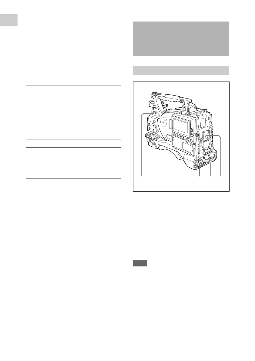
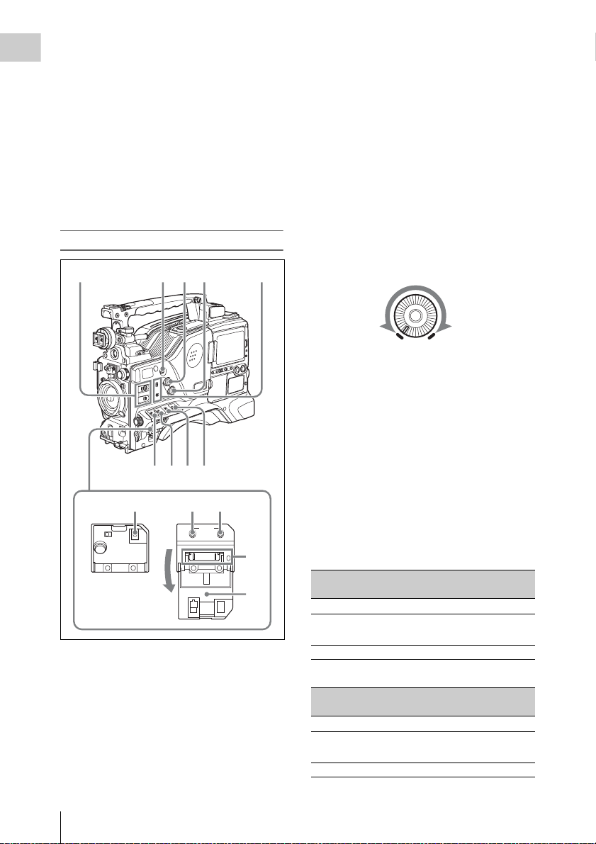
Locations and Functions of Parts and Controls
Power supply
23154
a LIGHT switch
Determines how a video light connected to the
LIGHT connector (see page 16) is turned on and
off.
AUT O: When the POWER switch of the video
light is in the on position, the video light is
turned on automatically while the camcorder
is recording.
MANUAL: You can turn the video light on or off
manually, using its own switch.
Notes
• When this switch is set to AUTO, at the beginning of
the recording, the picture is recorded even though the
lighting may fluctuate until the video light comes on.
If the beginning of the recording is important, you
should set this switch to MANUAL.
• To ensure proper operation of the video light, Sony
recommends the use of the BP-GL95/L80S Battery
Pack with the camcorder.
Locations and Functions of Parts and Controls
14
b POWER switch
Turns the main power supply on and off.
Page 15
c DC IN (DC power input) connector
(XLR type, 4-pin, male)
To operate the camcorder from an AC power
supply, connect an optional DC power cord to this
terminal and then connect the cord to the DC
output terminal of the BC-L70, BC-M150, or
another battery charger.
d DC OUT 12V (DC power output)
connector (4-pin, female)
Supplies power for a WRR-860A/861/862 UHF
Synthesized Diversity Tuner (not supplied)
(maximum 0.5 A).
Do not connect any equipment other than the
UHF synthesized diversity tuner.
e Battery attachment shoe
Attach a BP-GL95/GL65/L60S/L80S Battery
Pack. Alternatively, you can attach an ACDN2B/DN10 AC Adaptor to operate the
camcorder on AC power supply.
For details about how to attach the battery or AC
adaptor, see “Preparing a Power Supply” on page
35. For information about attaching a synthesized
tuner, see “Attaching a UHF portable tuner (for a
UHF wireless microphone system)” on page 46.
Note
For your safety, and to ensure proper operation of the
camcorder, Sony recommends the use of the following
battery packs: BP-GL95, BP-GL65, BP-L60S, and BPL80S.
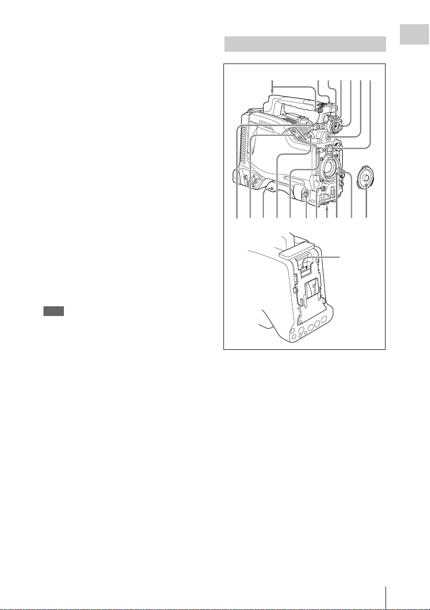
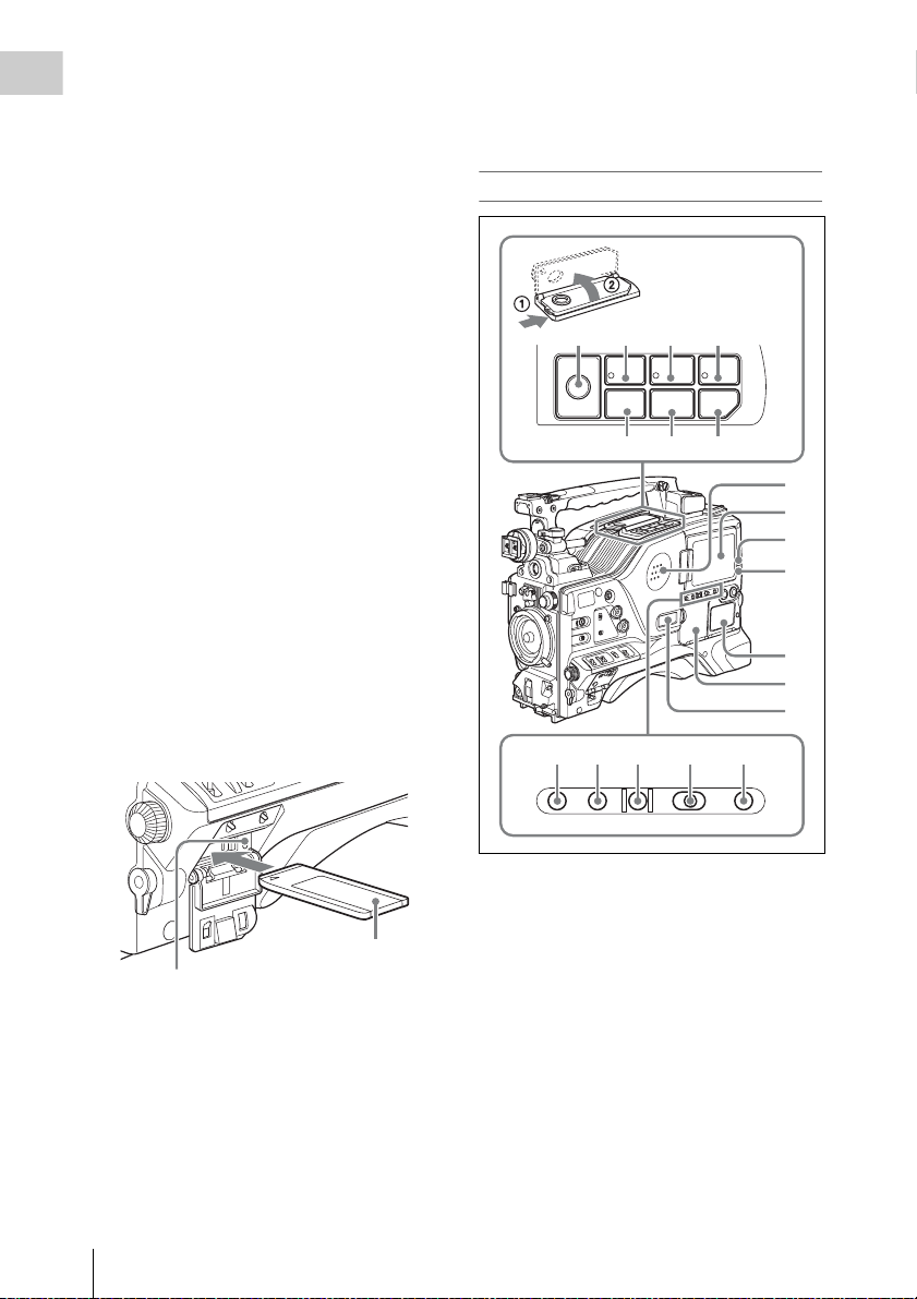
Accessory attachments
5674231
890qaqs qd qgqh qj
a Shoulder strap fitting
Attach the supplied shoulder strap (see page 50).
qf
qk
ql
Chapter 1 Overview
b Light fitting shoe
Attach an optional accessory such as a video light
(see page 50).
c Viewfinder front-to-back positioning
lever
To adjust the viewfinder position in the front-toback direction, loosen this lever and the LOCK
knob. After adjustment, retighten this lever and
the LOCK knob.
d Viewfinder left-to-right positioning ring
Loosen this ring to adjust the left-to-right position
of the viewfinder (see page 37).
e Viewfinder fitting shoe
Attach an optional viewfinder.
Locations and Functions of Parts and Controls
15
Page 16

f VF (viewfinder) connector (20-pin)
Connect an optional viewfinder.
Chapter 1 Overview
Consult a Sony representative for information about
available viewfinders.
g Lens mount securing rubber
After locking the lens in position using the lens
locking lever, fit this rubber over the lower of the
two projections. This fixes the lens mount,
preventing it from coming loose.
h Viewfinder front-to-back positioning
knob (LOCK knob)
Loosen this knob to adjust the front-to-back
position of the viewfinder (see page 37).
i Fitting for optional microphone holder
Fit an optional CAC-12 Microphone Holder (see
page 45).
j Shoulder pad
Raise the shoulder pad fixing lever to adjust the
position in the front-to-rear direction. Adjust the
position for maximum convenience when
operating the unit on your shoulder.
For details of the adjustment, see “Adjusting the
Shoulder Pad Position” on page 51.
k LIGHT (video light) connector (2-pin,
female)
A video light with a maximum power
consumption of 50 W, such as the Anton Bauer
Ultralight 2 or equivalent can be connected (see
page 50).
o Tripod mount
When using the unit on a tripod, attach the tripod
adaptor (optional).
p Lens mount (special bayonet mount)
Attach the lens.
Consult a Sony representative for information about
available lenses.
q Lens locking lever
After inserting the lens in the lens mount, rotate
the lens mount ring with this lever to lock the lens
in position.
After locking the lens, be sure to use the lens
mount securing rubber to prevent the lens from
becoming detached.
r Lens mount cap
Remove by pushing up the lens locking lever.
When no lens is mounted, keep this cap fitted for
protection from dust.
s CA (camera adapter) connector (50-
pin)
Remove the connector cover, and connect the 50pin connector of the HDCA-702 MPEG TS
Adaptor.
Refer to the operation manual of the HDCA-702 for
more information about how to mount it.
l Lens cable clamp
Clamp a lens cable.
m MIC IN (microphone input) (+48 V)
connector (XLR type, 5-pin, female)
Connect a stereo microphone to this connector.
The power (+48 V) is supplied via this connector.
n LENS connector (12-pin)
Connect a lens cable to this connector.
Note
When connecting the lens cable to this connector,
power off this unit first.
Locations and Functions of Parts and Controls
16
Page 17
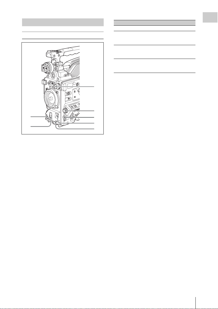
Operating and connectors section
7
Front
3
4
1
2
a REC START (recording start) button
Press to start recording. Press it again to stop
recording. The effect is the same as that of the
REC button on the lens.
b SHUTTER selector
Set to ON to use the electronic shutter. Flick to
SELECT to switch the shutter speed or shutter
mode setting within the range previously set with
the menu. When this switch is operated, the new
setting appears on the setting change/adjustment
progress message display area for about three
seconds.
For details about the shutter speed and shutter mode
settings, see “Setting the Electronic Shutter” on
page 60.
c FILTER selector
Selects from the four neutral density (ND) filters
built into this unit.
5
6
Position number ND filter
1 CLEAR
2
3
4
1
/4 ND (attenuates light to
approximately
1
/16 ND (attenuates light to
approximately
1
/64 ND (attenuates light to
approximately
1
/4)
1
/16)
1
/64)
When this selector is used with the menu item for
filter selection display set to ON (see page 172),
the new setting appears on the viewfinder screen
for about three seconds.
You can change a MAINTENANCE menu
setting so that different white balance settings can
be stored for different FILTER selector positions.
This allows you to automatically obtain optimum
white balance for the current shooting conditions
in linkage with the filter selection.
For details, see “Adjusting the white balance” on
page 56.
d MENU knob
Changes the page selection or a setting within the
menu.
For details about how to use the MENU knob, see
“Menu Operations” on page 163.
e EARPHONE jack (monaural,
minijack)
You can monitor the E-E
1)
sound during
recording and playback sound during playback.
When an alarm is indicated, you can hear the
alarm sound through the earphone. You can use
this with the EARPHONE jack on the rear of the
unit at the same time. Plugging an earphone into
the jack automatically cuts off the built-in
speaker.
1) E-E: Abbreviation of “Electric-to-Electric”. In E-E
mode, video and audio signals input to the camcorder
are output after passing through internal electric
circuits only. This can be used to check input signals.
Chapter 1 Overview
f AUTO W/B BAL (automatic white/
black balance adjustment) switch
Activates the automatic white/black balance
adjustment functions.
WHT: Adjusts the white balance automatically.
If the WHITE BAL switch (see page 19) is
set to A or B, the white balance setting is
Locations and Functions of Parts and Controls
17
Page 18
stored in the corresponding memory. If the
5
2341
Chapter 1 Overview
WHITE BAL switch is set to PRST, the
automatic white balance adjustment function
does not operate.
BLK: Adjusts the black set and black balance
automatically.
g MIC (microphone) LEVEL control
Adjusts the input level of audio channels 1, 2, 3
and 4.
For details, see “Adjusting the Audio Level” on page
65.
Right side (near the front)
b COLOR TEMP. (color temperature)
button
Press to light the button and change the color
temperature for shooting. You can use this as an
ASSIGN (assignable) switch
(see page 178).
c ALARM (alarm tone volume
adjustment) knob
Controls the volume of the warning tone that is
output via the built-in speaker or optional
earphones. When the knob is turned to the
minimum position, no sound can be heard.
However, if the MIN ALARM VOL item on the
AUDIO-1 page of the MAINTENANCE menu is
set to SET, the alarm tone is audible even when
this volume control is at the minimum position.
ALARM
Minimum Maximum
d MONITOR (monitor volume
adjustment) knob
Controls the volume of the sound other than the
warning tone that is output via the built-in speaker
or optional earphones. When the knob is turned to
the minimum position, no sound can be heard.
6789
qa qs0
MENU
CANCEL/PRST
STATUS
ON/
SEL
OFF
OFF
ESCAPEON
a ASSIGN (assignable) 1/2 switches
You can assign the desired functions to these
switches on the ASSIGNABLE SW page of the
OPERATION menu.
Nothing is assigned to these switches when the
camcorder is shipped from the factory (equivalent
to a selection of OFF in the menu).
For details, see “Assigning functions to ASSIGN
switches” on page 178.
Locations and Functions of Parts and Controls
18
qd
qf
e MONITOR (audio monitor selection)
switches
By means of combinations of the two switches,
you can select audio that you want to hear through
the built-in speaker or optional earphones.
Position of down-side switch: CH-1/2
Position of up-side
Audio output
switch
CH-1/CH-3 Channel 1 audio
MIX Channels 1 and 2 mixed
audio (stereo)
a)
CH-2/CH-4 Channel 2 audio
Position of down-side switch: CH-3/4
Position of up-side
Audio output
switch
CH-1/CH-3 Channel 3 audio
MIX Channels 3 and 4 mixed
audio (stereo)
a)
CH-2/CH-4 Channel 4 audio
Page 19

a) By connecting stereo headphones to the EARPHONE
jack on the rear of the unit, you can hear the audio in
stereo. (On the AUDIO-1 page of the
MAINTENANCE menu, HEADPHONE OUT must
be set to STEREO.)
f VDR SAVE/STBY (VDR save/standby)
switch
Switches the status of the power supply to the
VDR while recording is stopped (STOP) or
paused (REC PAUSE).
SAVE: The disc stops rotating and some
functions are disabled. Pow er consumption is
lower than when the camcorder is in STBY
mode. Battery life is extended.
STBY: Recording to the disc starts immediately
when the REC START button is pressed.
Note
An internal operating sound may be recorded at the start
of recording when the VDR SAVE/STB Y switch is set to
SAVE.
g GAIN selector
Switches the gain of the video amplifier to match
the lighting conditi ons during shooting. The gains
corresponding to the L, M, and H settings can be
selected in the menu. (The factory settings are
L=0 dB, M=6 dB, and H=12 dB.)
When this switch is adjusted, the new setting
appears on the setting change/adjustment
progress message display area of the viewfinder
screen for about three seconds.
For details, see “Setting gain values for the GAIN
selector positions” on page 177.
h OUTPUT/DCC (output signal/dynamic
contrast control) switch
Switches the video signal, which is output to the
video disc drive (referred to as “VDR”),
viewfinder, and video monitor from the camera
section, between the following two.
BARS: Outputs the color bar signal.
CAM: Outputs the video signal from the camera.
When this is selected, you can switch DCC
1)
on and off.
1) DCC (Dynamic Contrast Control): Against a very
bright background with the iris opening adjusted to the
subject, objects in the background will be lost in the
glare. The DCC function will suppress the high
intensity and restore much of the lost detail and is
particularly effective in the following cases.
• Shooting people in the shade on a sunny day
• Shooting a subject indoors, against a background
through a window
• Any high contrast scene
i WHITE BAL (white balance memory)
switch
Controls adjustment of the white balance.
PRST: Adjusts the color temperature to the preset
value (the factory default setting: 3200K).
Use this setting when you have no time to
adjust the white balance.
A or B: Recall the white balance adjustment
settings already stored in A or B. Flick the
AUTO W/B BAL switch (see page 17) on th e
WHT side, to automatically adjust the white
balance, and save the adjustment settings in
memory A or memory B.
You can use the AUTO W/B BAL switch
even when ATW
1)
is in use.
B (ATW): When this switch is set to B and
WHITE SWITCH <B> is set to ATW on the
WHITE SETTING page of the
OPERATION menu, ATW is activated.
When this switch is adjusted, the new setting
appears on the setting change/adjustment
progress message display area of the viewfinder
screen for about three seconds.
1) ATW (Auto Tracing White Balance): The white
balance of the picture being shot is adjusted
automatically for varying lighting conditions.
j STATUS ON/SEL/OFF (menu display
on/page selection/display off) switch
To enable this switch, set the MENU ON/OFF
switch to OFF.
Closing the cover automatically sets the MENU
ON/OFF switch to OFF.
ON/SEL: Each time this switch is pushed
upward, a window to confirm the menu
settings and status of the camcorder appears
on the viewfinder screen. The window
consists of four pages, which are switched
each time the switch is pushed upward. Each
page is displayed for about 10 seconds.
OFF: To clear the page immediately after
display, push this switch down to the OFF
position.
You can select the pages to be displayed on the
menu.
For details, see “Displaying the status confirmation
screens” on page 176.
Chapter 1 Overview
Locations and Functions of Parts and Controls
19
Page 20
k MENU ON/OFF switch
To use this switch, open the cover.
Chapter 1 Overview
This switch is used to display the menu on the
viewfinder screen or the test signal screen.
Closing the cover automatically sets this switch to
OFF.
ON: Displays the menu on the viewfinder screen
or the test signal screen.
OFF: Removes the menu from the viewfinder
screen or the test signal screen.
For details about “Memory Stick”, see “Handling
the “Memory Stick”” on page 185.
n Cover
Right side (near the rear)
l CANCEL/PRST (preset)/ESCAPE
switch
To enable this switch, set the MENU ON/OFF
switch to ON.
Closing the cover automatically sets the MENU
ON/OFF switch to OFF.
CANCEL/PRST: Flicking this switch up to this
position displays the message to confirm
whether the previous sett ings are cancelled or
settings are reset to their initial values,
depending on the menu operating condition.
Flicking this switch up to this position again
cancels the previous settings or resets the
settings to their initial values.
ESCAPE: Use this switch when the menu page,
which has a hierarchical structure, is opened.
Each time the switch is flicked to this
position, the page returns to one stage higher
in the hierarchy.
m “Memory Stick” compartment
Label
“Memory Stick” Access indicator
Open the lid of the menu operating section, and
insert a “Memory Stick”, with the notch facing
downward, in the direction shown by the arrow,
so that it clicks into place.
To remove a “Memory Stick”, first press it in to
release the lock, then withdraw.
The “Memory Stick” access indicator lights in
green when a “Memory Stick” is loaded, and
lights in red when the “Memory Stick” is being
accessed for reading or writing.
8 9 q; qa
EJECT
Z
F REV
m.NX
PREV
F FWD
PLAY/PAUSE
M
STOP NEXT
x>
qs qd qf
1
2
3
4
5
6
7
qg qh qj qk ql
BRIGHTDISPLAYRESETHOLDDISP SEL
COUNTER TC U-BITEXPAND CHAPTER RETURN
a Built-in speaker
The speaker can be used to monitor E-E sound
during recording, and playback sound during
playback. The speaker also sounds alarms to
reinforce visual warnings.
If you connect earphones to the EARPHONE
jack, the speaker output is suppressed
automatically.
For details about alarm s, see “Operation Warnings”
on page 215.
b LCD monitor
Displays camera video, VDR-related warnings,
remaining battery capacity, remaining disc
capacity, audio levels, time data, and so on.
Locations and Functions of Parts and Controls
20
Page 21

For details, see “Status Display on the LCD monitor
and monochrome LCD” on page 22.
c WARNING indicator
Lights up or flashes when an abnormality occurs
in the VDR section.
For details about the meaning of the states of the
WARNING indicator, see “Operation Warnings” on
page 215.
d ACCESS indicator
This lights when data is written to or read from
the disc.
e Protection cover of the audio control
section
Open to access the audio control section (see page
26).
approximately four times normal playback speed,
press the F REV button or F FWD button during
playback.
At this time the PLAY indicator and F REV or F
FWD indicator light.
k F FWD (fast forward) button and
indicator
This plays back at high speed in the forward
direction. The indicator lights during high-speed
playback in the forward direction.
l PREV button
This jumps to the first frame of the current clip.
During the jump, the F REV indicator flashes.
If you press this together with the F REV button,
the jump is to the first frame of the first recorded
clip on the disc.
Chapter 1 Overview
f Protection cover of the GUI screen
operations section
Open to access the GUI screen operations section
(see page 26).
g Monochrome LCD
This shows the remaining battery capacity,
remaining disc capacity, time data, and so on.
For details, see “Status Display on the LCD monitor
and monochrome LCD” on page 22.
h EJECT button and indicator
Press this button to insert a disc or eject the disc.
The indicator flashes while the disc is being
ejected.
i F REV (fast reverse) button and
indicator
This plays back at high speed in the reverse
direction. The indicator lights during high-speed
playback in the reverse direction.
j PLAY/PAUSE button and indicator
Press this button to view play back video images
using the viewfinder screen or the LCD monitor.
The indicator lights during playback.
Press this button again during playback to pause,
outputting a still image. At this time the indicator
flashes.
This unit is equipped with an image search
function at approximately four times normal
playback speed, for easy checking of recorded
material. To use the image search function at
m STOP button
Press this button to stop disc playback.
n NEXT button
This jumps to the first frame of the next clip.
During the jump, the F FWD indicator flashes.
If you press this together with the F FWD button,
the jump is to the last frame of the last recorded
clip on the disc.
o DISP SEL (display selection) /EXPAND
(expand function) button
With each press of this button, the display in the
LCD monitor changes as follows.
Display indication Meaning
Video with
superimposed
information (CHAR)
Video without
superimposed
information (MONI)
Status display
(STATUS)
The LCD monitor displays
the same text information
as the viewfinder.
The video only appears.
Counter indications,
warnings, audio levels, and
similar information appear.
No video image appears.
If you press this button when the thumbnail
screen is displayed, the duration of the selected
clip is divided into 12, and the first frame of each
of the divisions is shown in a further thumbnail
display (expand function). Each time you press
this button, the division is repeated (to a
maximum of three times, with 1,728 divisions).
Locations and Functions of Parts and Controls
21
Page 22

Hold down the SHIFT button and press this
button to step back through the division process.
Chapter 1 Overview
For details of the expand function, see page 105.
information for the user such as scene number,
shooting place, etc.
For details, see “Setting the Time Data” on page 68.
p HOLD (display hold)/CHAPTER
(chapter function) button
Pressing this button instantly freezes the time data
displayed in the counter display section. (The
timecode generator continues running.) Pressing
this button again releases the hold.
You can use this button, for example, to
determine the exact time of a particular shot.
For details of the counter display, see page 23.
If you press this button when the clip thumbnail
screen is displayed, those frames on which shot
marks are recorded appear in a list (chapter
function). Press the button once more to return to
the normal thumbnail display.
By displaying thumbnails with shot marks
attached in place of index frames, you can check
the contents of clips more easily and more
quickly. This is also useful for cueing up long
clips.
For details of the chapter function, see page 106
q RESET/RETURN button
Resets the value shown in the time counter
display. According to the settings of the PRESET/
REGEN/CLOCK switch (see page 26) and the FRUN/SET/R-RUN switch (see page 26), this
button resets the display as follows.
Settings of switches To rese t
DISPLAY switch:
COUNTER
DISPLAY switch:
TC
PRESET/REGEN/
CLOCK switch:
PRESET
F-RUN/SET/R-RUN
switch: SET
DISPLAY switch:
U-BIT
PRESET/REGEN/
CLOCK switch:
PRESET
F-RUN/SET/R-RUN
switch: SET
a) Of the timecode bits for every frame recorded on the
disc, those bits which can be used to record useful
Counter to 0:00:00:00
Timecode to 00:00:00:00
User bits data
00
a)
to 00 00 00
This button returns to the previous screen when
pressed during thumbnail display.
For details, see “GUI screen operations” on page
103.
r DISPLAY switch
This cycles the data displayed in the counter
display through the sequence COUNTER, TC,
and U-BIT.
COUNTER: Display the elapsed recording/
playback time (hours, minutes, seconds,
frames).
TC: Display timecode.
U-BIT: Display user bit data.
For details, see “Status Display on the LCD monitor
and monochrome LCD” on page 22.
s BRIGHT (brightness) button
Switches the brightness of the LCD monitor
backlight, and turns the backlight of the
monochrome LCD on and off.
Each press of the button selects the next setting in
the order shown in the following table.
Setting LCD monitor
backlight
H High (select this to view
the LCD monitor
outdoors in the
daytime)
M Brightness between H
and L
L Low (select this to view
the LCD monitor
indoors or outdoors at
night)
OFF Off (the display is also
off)
Monochrome
LCD backlight
Lit
Lit
Lit
Off
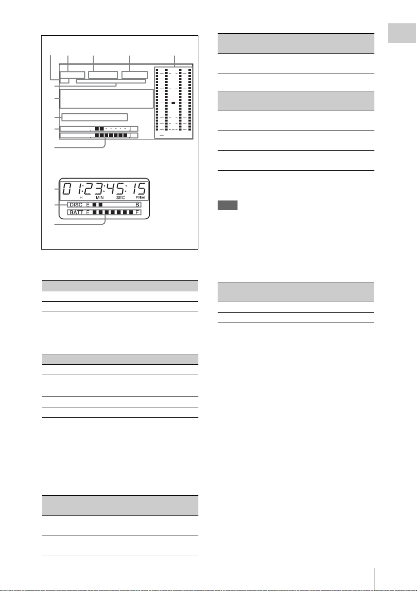
Status Display on the LCD monitor and
monochrome LCD
The following display appears on the LCD
monitor display which is set to STATUS with the
DISP SEL/EXPAND button, and on the
monochrome LCD.
Locations and Functions of Parts and Controls
22
Page 23
422
2134 5
0
50
HD
1080
6
01
7
8
DISC E B
9
BATT E F
59.9i 24bit
PB NDF EXT-LK21HOLD
.....
23 45 15
H
MIN SEC FRM
WARNING:HUMID
0
LCD monitor
Indication Field or frame
rate
29.9P 29.97 frames per
OVER
0
10
.
20
30
40
dB
ST
PEAK
43
If PAL AREA is selected
Indication Field or frame
50i 50 fields per
50P 50 frames per
second
rate
second
Scan mode
Chapter 1 Overview
Progressive
1)
Scan mode
Interlace
Progressive
second
25P 25 frames per
Progressive
second
7
9
Monochrome LCD
a Resolution
Indicates the resolution of HD output video.
Indication Resolution (horizontal × vertical)
1080 1080 lines (1920 × 1080)
720 720 lines (1280 × 720)
b Video format
Indicates the format of video being currently
played back or recorded.
Indication Format Bit rate
HD422 50 MPEG HD422 50 Mbps
HD420 HQ/SP/
a)
LP
MPEG HD420 35/25/18 Mbps
IMX 50/40/30 MPEG IMX 50/40/30 Mbps
DVCAM DVCAM 25 Mbps
a) LP is playback only.
c System frequency
Indicates the system frequency of video being
currently played back or recorded.
If NTSC AREA is selected
Indication Field or frame
1)
Scan mode
rate
59.9i 59.94 fields per
Interlace
second
59.9P 59.94 frames per
Progressive
second
1) Selected by COUNTRY setting on the FORMAT page
of the OPERATION menu (see page 135).
Note
There may be no indication displayed when this unit
cannot identify the system frequency, for example, when
playing back a disc recorded with other equipment.
d Audio format
Indicates the format of audio being currently
played back or recorded.
Indication Quantization bit rate/sampling
frequency
24bit 24 bits/48 kHz
16bit 16 bits/48 kHz
e Audio level indicators
Indicates the audio recording or playback levels
of channels 1 to 4.
f Status display
PB: Appears during playback.
NDF: Appears when non-drop-frame timecode is
selected.
EXT-LK: Appears when the internal timecode
generator is locked to an external signal input
to the TC IN (timecode input) connector.
HOLD: Appears when the internal timecode
generator is stopped.
g Time counter display
Switches displays of time counter, timecode, and
user bits, depending on the position of the
DISPLAY switch.
When the HOLD/CHAPTER button is pressed to
hold the timecode value, the timecode is
displayed in the format shown below. When the
HOLD/CHAPTER button is pressed again to
Locations and Functions of Parts and Controls
23
Page 24

release the hold, the timecode is displayed in the
normal format.
Chapter 1 Overview
Lights when the HOLD/CHAPTER button
is pressed.
h Warning indicator area
Displays warnings when trouble with recording
or moisture condensation occurs.
For details, see “Operation Warnings” on page 215.
Locations and Functions of Parts and Controls
24
Page 25

i Remaining disc capacity indicator
Indication Remaining recording time
DISC E [x x x x x x x] B More than 30 minutes
DISC E [x x x x x x x] B 25 to 30 minutes
DISC E [x x x x x x x] B 20 to 25 minutes
DISC E [x x x x x x x] B 15 to 20 minutes
DISC E [x x x x x x x] B 10 to 15 minutes
DISC E [x x x x x x x] B 5 to 10 minutes
DISC E [x x x x x
DISC E [x x x x x x x] B (flashing) 0 to 2 minutes
DISC E [x x x x x x x] B (flashing) 0 minutes
x x] B 2 to 5 minutes
j Remaining battery capacity indicator
Chapter 1 Overview
Indication Battery voltage
BP-L90A/L60S/L80S
BATT E [x x x x x x x] F 15.5 V or more 17.0 V or more
BATT E [x x x x x x x] F 15.1 to 15.5 V 16.0 to 17.0 V
BATT E [x x x x x x x] F 14.6 to 15.1 V 15.0 to 16.0 V
BATT E [x x x x x x x] F 13.8 to 14.6 V 14.0 to 15.0 V
BATT E [x x x x x x x] F 12.9 to 13.8 V 13.0 to 14.0 V
BATT E [x x x x x x x] F 12.0 to 12.9 V 12.0 to 13.0 V
BATT E [x x x x x
BATT E [x x x x x x x] F 10.8 V or less 11.0 V or less
a) You can change the threshold voltages on the
BATTERY 2 page of the MAINTENANCE menu
(see page 148).
Indication Battery voltage
BATT E [x x x x x x x] F 80 to 100%
BATT E [x x x x x x x] 70%
BATT E [x x x x x x x] 60%
BATT E [x x x x x x x ] 50%
BATT E [x x x x x x x] 40%
BATT E [x x x x x x x] 30%
BATT E [x x x x
BATT E [x x x x x x x] 10%
BATT E [x x x x x x x]0%
x x] F 10.8 to 12.0 V 11.0 to 12.0 V
BP-GL95/GL65/IL75/M100, Anton Bauer Battery
System
x x x] 20%
Other batteries
a)
Locations and Functions of Parts and Controls
25
Page 26

GUI screen operations section and audio control
12345 6
section
Chapter 1 Overview
THUMBNAIL
ESSENCE
MARK
SUB CLIP
DISC MENU
MENU
SET
S.SEL
SHIFT
7 8 9 0 qa qs
a THUMBNAIL indicator
This lights when thumbnails are displayed.
b THUMBNAIL/ESSENCE MARK
button
Press this button to carry out a thumbnail search
or create a clip list (see page 105).
When pressed, the whole-screen display changes
to a thumbnail display. Press once more to return
to the whole-screen display.
For a thumbnail search using essence marks, hold
down the SHIFT button and press this button (see
page 106).
c SET/S.SEL (set/scene selection) button
and arrow buttons
Use these buttons to make timecode and user bit
settings, and for GUI screen operations.
The arrow buttons select items and change values,
and the SET/S.SEL button confirms settings.
Pressing this button with thumbnails displayed
and the SHIFT button held down adds a sub clip
to the current clip list (scene selection).
See page 103 for more informa tion about GUI screen
operations.
See page 113 for more information about scene
selection.
d MENU button
Displays a special menu for operations in GUI
screens (see page 100).
When the whole-screen is displayed, pressing this
button has no effect, and the operation is invalid.
010010
F-RUN
SET
R-RUN
CH-1
PRESET
REGEN
CLOCK
LEVEL
AUTO
MANUAL
AUDIO SELECT
AUDIO IN
FRONT
REAR
WIRELESS
e F-RUN/SET/R-RUN (free run/set/
recording run) switch
Selects the operating mode of the internal
timecode generator. The operating mode is set as
explained below, depending on the position of the
switch.
F-RUN: Timecode keeps advancing, regardless
CH-3
F
R
W
CH-2
CH-4
F
R
W
of the operating state of the VDR. Use this
setting when synchronizing the timecode
with an external timecode.
SET: Sets the timecode or user bits.
R-RUN: Timecode advances only during
recording. Use this setting to have a
consecutive timecode on the disc.
For details, see “Setting the timecode” on page 68
and “Setting the user bits” on page 68.
f AUDIO LEVEL CH-1/CH-2 (audio
channel 1/2 recording level) knobs
Adjusts the audio levels to be recorded on
channels 1 and 2 when the AUDIO SELECT CH1/CH-2 switches are set to MANUAL.
g SUB CLIP indicator
This lights when using a clip list for playback.
h SUB CLIP/DISC MENU button
Press this to play back according to a clip list.
You can play back a particular clip or sequential
clips, or carry out a search of the selected clip list.
To display the Disc Menu which allows you to
carry out operations such as saving, recalling, or
deleting a clip list, hold down the SHIFT button
and press this button.
i SHIFT button
Use this in combination with other buttons.
j PRESET/REGEN (regeneration)/
CLOCK switch
Selects whether to set a new timecode or to utilize
the existing timecode.
PRESET: Records a new timecode.
REGEN: Records timecode continuous with the
existing timecode recorded on the disc.
Regardless of the setting of the F-RUN/SET/
R-RUN switch, the camcorder operates in R-
RUN mode.
CLOCK: Records timecode synchronized to the
internal clock. Regardless of the setting of
the F-RUN/SET/R-RUN switch, the
camcorder operates in F-RUN mode.
Locations and Functions of Parts and Controls
26
Page 27
k AUDIO SELECT CH-1/CH-2 (audio
1
channel 1/2 adjustment method
selection) switches
Select the audio level adjustment method for each
of audio channels 1 and 2.
AUTO : Automatic adjustment
MANUAL: Manual adjustment
Left side and upper section
Chapter 1 Overview
l AUDIO IN CH-1/CH-2/CH-3/CH-4
(audio channel 1/2/3/4 input selection)
switches
AUDIO IN CH-1/CH-2 switches
Select the audio input signals to be recorded on
audio channels 1 and 2.
FRONT: Audio input signals from the
microphone connected to the MIC IN
connector
REAR: Audio input signals from an audio device
connected to the AUDIO IN CH-1/CH-2
connectors
WIRELESS: Audio input signals from the UHF
portable tuner (not supplied) if it is installed
AUDIO IN CH-3/CH-4 switches
Select the audio input signals to be recorded on
audio channels 3 and 4.
F (FRONT): Audio input signals from a
microphone connected to the MIC IN
connector
R (REAR): Audio input signals from an audio
device connected to the AUDIO IN CH-1/
CH-2 connectors
W (WIRELESS): Audio input signals from the
UHF portable tuner (not supplied) if it is
installed
2
345
GENLOCK
SDI IN
(OPTION)
TEST
OUT
OUT
TC IN
IN
TC
67
a ASSIGNABLE 3/4 switches
You can assign the desired functions to these
switches on the ASSIGNABLE page of the
OPERATION menu.
Nothing is assigned to these switches when the
camcorder is shippe d from the factory (equivalent
to a selection of OFF in the menu).
For details, see “Assigning functions to ASSIGN
switches” on page 178.
b Lid of the disc compartment
This opens when the EJECT button on the top
panel is pressed. Press the side of the lid to close.
c SDI IN (OPTION) connector (BNC
type)
This is an input connector for the optional CBKHD01 HD/SD SDI Input Board. When the CBKHD01 is installed, the unit can record HD-SDI or
SD-SDI signals that are input to this connector.
d GENLOCK IN (genlock signal input)
connector (BNC type)
• This connector inputs a reference signal when
the camera is to be genlocked or when timecode
is to be synchronized with external equipment.
Locations and Functions of Parts and Controls
27
Page 28
Use the GENLOCK page of the
MAINTENANCE menu to adjust the genlock
Chapter 1 Overview
H-phase (phase of horizontal sync signal).
• This connector also inputs a return video signal.
You can display the HD-Y (1080i) signal in the
viewfinder screen whi le holding the RE T button
down with RETURN VIDEO set to ON on the
ASSIGNABLE SW page of the OPERATION
menu.
• Input an external video signal. When the
optional CBK-SC02 Analog Composite Input
Board is installed, the unit can record analog
composite video signals that are input to this
connector.
e TC IN (timecode input) connector
(BNC type)
To apply an external lock to the timecode of this
unit, input the reference timecode.
For details of timecode, see “Setting the timecode”
on page 68.
f TEST OUT connector (BNC type)
This connector outputs the video signal for a
video monitor. The output signal can be selected
from composite video, HD-Y, R, G, B, and a
composite video signal like that displayed in the
LCD monitor. To switch output signals, use the
TEST OUT SELECT item on the OUTPUT 1
page of the OPERATION menu.
If the output signal is set to one of R, G, or B, then
this setting changes to HD-Y when the camcorder
is powered off and on again.
Depending on menu settings, menus, timecode,
and shot data can be superimposed on the image
on the monitor. This connector can also be used to
synchronize the timecode of an external VTR
with the timecode of the camcorder.
g TC OUT (timecode output) connector
(BNC type)
To lock the timecode of an external VTR to the
timecode of this unit, connect this connector to
the external VTR’s timecode input connector.
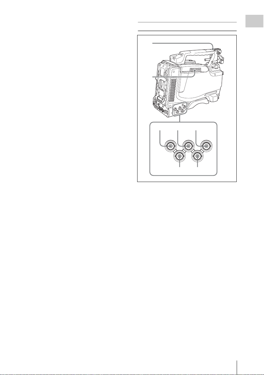
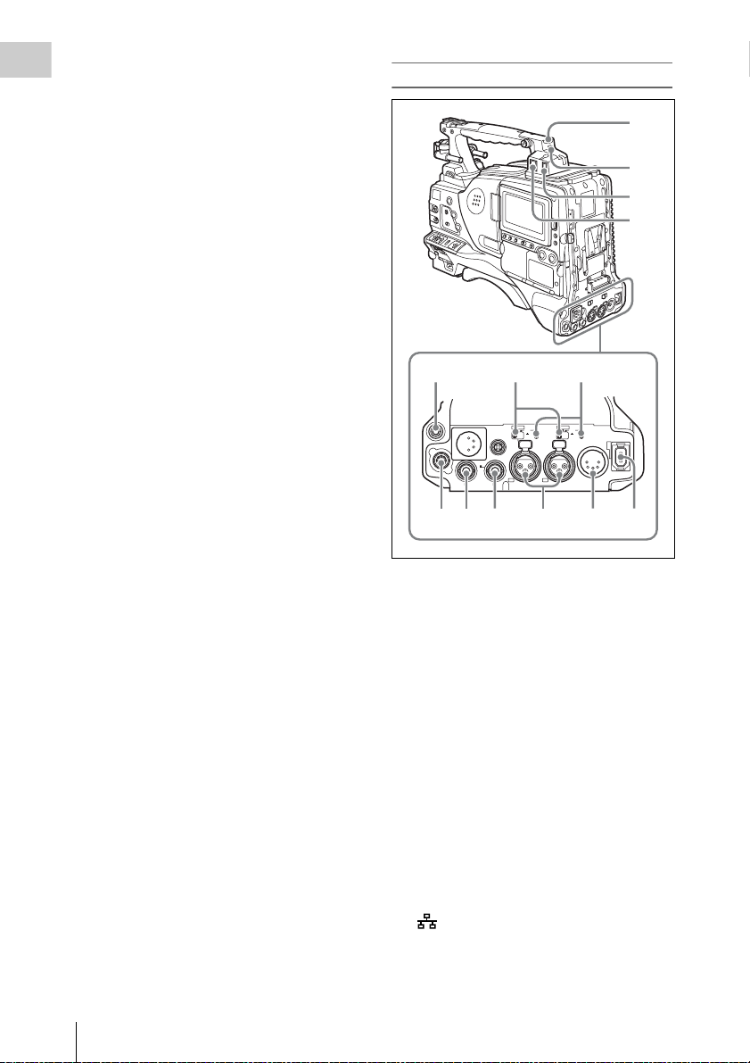
Rear
1
2
3
4
567
AUDIO IN
AES/EBU
AES/EBU
LINE MIC
LINE
MIC
48V
48V
DC OUT
12V
DC
IN
0.5A
SUPER
CH1
1/2
SDI OUT
SDI OUT
89 0 qa qs qd
a TALLY (back tally) indicator (red)
Lights up during recording. It will not light if the
TALLY switch is set to OFF. This indicator also
flashes to indicate warnings (see page 21) in the
same manner as the REC/TALLY indicator in the
viewfinder.
For details, see “Operation Warnings” on page 215.
b TALLY switch
Set to ON to activate the TALLY indicator
function.
c USB connector
This is a USB 2.0 connector.
Connect a Windows USB keyboard or mouse (see
page 110), or a USB flash drive to access
planning metadata stored on the drive (see page
121).
OFF
OFF
AUDIO OUT
CH2
3/4
Locations and Functions of Parts and Controls
28
d (network) connector (RJ-45 type)
This is a 10BASE-T/100BASE-TX connector for
network connection.
Page 29

CAUTION
When you connect the network cable of the unit to
peripheral device, use a shielded-type cable to prevent
malfunction due to radiation noise.
e EARPHONE jack (stereo, minijack)
You can monitor the E-E sound during recording
and playback sound during playback. When an
alarm is indicated, you can hear the alarm sound
through the earphone. You can use this with the
EARPHONE jack on the front of the unit at the
same time. Plugging an earphone into the jack
automatically cuts off the built-in speaker.
You can select monaural or stereo on the AUDIO1 page of the MAINTENANCE menu.
f LINE /AES/EBU / MIC selectors
These select the audio source of the audio input
signals input to the AUDIO IN CH1/CH2
connectors.
LINE: Line input audio equipment
AES/EBU: AES/EBU format audio signal
MIC: Microphone input
Note
When these switches are in the MIC position, and the
+48V/OFF switch is set to +48V, if you inadvertently
connect any audio device other than a microphone to the
AUDIO IN CH1/CH2 connectors, the device may be
damaged.
g +48V/OFF switches
Select either of the following positions for the
microphones to be connected.
+48V: For a microphone to use an external power
supply
OFF: For a microphone to use an internal power
supply
h REMOTE connector (8-pin)
Connect an RM-B150/B750 Remote Control
Unit, which makes it possible to control the
camcorder remotely.
Note
Before connecting/disconnecting the Remote Control
Unit to/from the camcorder, be sure to turn off the
camcorder POWER switch.
i SDI OUT 1 connector (BNC type)
Outputs an HDSDI or SDSDI signal (with
embedded audio). To switch between HDSDI and
SDSDI output, use the SDI OUT 1 SELECT item
on the OUTPUT 1 page of the OPERATION
menu.
j SDI OUT 2 connector (BNC type)
Outputs an HDSDI or SDSDI signal (with
embedded audio). To switch between HDSDI and
SDSDI output, use the SDI OUT 2 SELECT item
on the OUTPUT 1 page of the OPERATION
menu.
Setting menus, timecode, or shot data can be
superimposed on the camera output video
depending on the menu settings, and you can
view them on the monitor screen.
k AUDIO IN CH1/CH2 (audio channel-1
and channel-2 input) connectors (XLR
type, 3-pin, female)
These are audio input connectors for channels 1
and 2 to which you can connect audio equipment
or a microphone.
When the LINE / AES/EBU / MIC selector is set
to AES/EBU, the CH1 connector is used for
channel-1 and -2 inputs, and the CH2 connector,
for channel-3 and -4 inputs.
l AUDIO OUT connector (XLR type, 5-
pin, male)
Outputs the audio signals recorded on audio
channels 1 and 2 or audio channels 3 and 4. The
audio signals are selected by the MONITOR
switch.
m (i.LINK) S400 connector (6-pin,
IEEE1394 compliant)
Use an i.LINK cable (DV cable) to connect the
camcorder to a computer for File Access Mode
file operations.
For details, see “File Operations in File Access
Mode (for Windows)” on page 199).
Note
When you connect the camcorder and other equipment,
such as a hard disk drive, with an i.LINK interface to a
computer with i.LINK connectors, turn off the power of
the computer, the other equipment, and the camcorder
before connecting them using the i.LINK cable (DV
cable). If a bus-powered type
equipment is connected while the computer is powered
on, electric current flows into the camcorder because of
the high voltage caused by the load shift of the computer
power, and this may cause a malfunction.
1) Equipment that can be powered through i.LINK cable
(DV cable)
1)
hard disk drive or similar
Chapter 1 Overview
Locations and Functions of Parts and Controls
29
Page 30
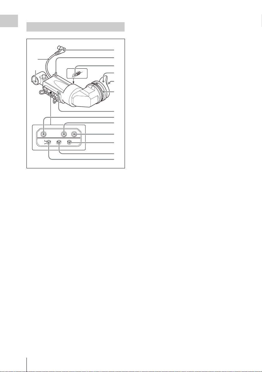
HDVF-20A viewfinder (optional)
q
Chapter 1 Overview
This indica tor also flashes to indi cate warnings, in
the same manner as the camera operator tally
indicator and the REC indicator in the viewfinder.
1
qf
qg
2
3
4
5
6
7
8
9
PEAKING CONTRAST BRIGHT
DISPLAY
ASPECT
TALLY
ZEBRA
HIGH
ON
OFF
OFF
LOW
MOMENT
0
qa
qs
d
a Plug
Connect to the VF connector on the camcorder.
b Stopper
Prevents the viewfinder from coming off the
camcorder when it is slid from side to side.
c Camera operator tally indicator
Lights up while camcorder is recording. This
indicator can be covered when not in use.
This indicator also flashes to indicate warnings, in
the same manner as the tally indicator and the
REC indicator in the viewfinder.
d Eyecup
e Indicators and status display
For details, see “Status display on the viewfinder
screen” on page 31.
f Diopter adjustment ring
Allows for optimal focus adjustment.
g Tally indicator
Lights up while camcorder is recording. Set the
TALLY switch to OFF when not in use. The
brightness can also be adjusted with the TALLY
switch.
h PEAKING control
Turning this control clockwise adjusts the picture
sharpness, and makes focusing easier. This
control has no effect on the output signals of the
camcorder.
i CONTRAST control
Adjusts the contrast of the screen. This control
has no effect on the output signals of the
camcorder.
j BRIGHT control
Adjusts the brightness of the screen. This control
has no effect on the output signals of the
camcorder.
k TALLY switch
Controls the tally indicator located on the front of
the viewfinder.
HIGH: The tally indicator brightness is set to
high.
OFF: The tally indicator is disabled.
LOW: The tally indicator brightness is set to low.
l ZEBRA (zebra pattern) switch
Controls the zebra pattern display on the
viewfinder screen as follows.
ON: A zebra pattern appears and stays.
OFF: The zebra pattern disappears.
MOMENT: A zebra pattern appears and stays for
about five seconds.
m DISPLAY/ASPECT switch
Turns the marker indication on and off, and
switches between 4:3 and 16:9 aspect ratios for
viewfinder screen display.
DISPLAY: When the marker indication is
enabled with the camcorder, the marker
indication on the viewfinder screen turns on
and off every time you push the switch up to
this position.
ASPECT: Each push of the switch down to this
position toggles the mask display on and off.
(Make mask display settings on the
MARKER 1 page of the OPERATION menu
(see page 132).)
Locations and Functions of Parts and Controls
30
Page 31

n Viewfinder cable
1
6
o Microphone holder
Status display on the viewfinder screen
and stays lit when the battery is completely
exhausted.
To prevent interruption during operation, replace
the battery as soon as this indicator starts flashing.
The battery power level at which the indicator starts
flashing can be set on the BATTERY 1 page of the
MAINTENANCE menu. For details, see page 147.
Chapter 1 Overview
Indicators
The following indicators are arranged above and
below the viewfinder screen to show the current
state and adjustments of the camcorder.
TALLY/REC
a TALLY (green tally) indicator
Lights when the camcorder is the following
states.
• Picture Cache mode enabled
• Disc Exchange Cache mode enabled
• Recording with HDSDI REMOTE I/F on the
CAM CONFIG 1 page of the MAINTENANCE
menu set to G-TLY
Flashes when the camcorder is the following
states.
• Set to Auto Interval Rec mode or the
consecutive mode of Manual Interval Rec mod e
(1 flash per second)
• Recording in Auto Interval Rec mode or
recording in the consecutive mode of Manual
Interval Rec mode (4 flashes per second)
• Set to the single-shot mode of Manual Interval
Rec mode, or recording in that mode (2 flashes
per second)
b BATT (battery) indicator
This indicator starts flashing when the battery
connected to the camcorder is nearly exhausted,
BATT
VTR
SAVE
2
3
4
5
c REC (recording, red tally) indicator
Lights up while camcorder is recording.
This indica tor also flashes to indi cate warnings, in
the same manner as the tally indicator and the
camera operator tally indicator.
d Viewfinder screen
e VTR SAVE indicator
This indicator lights when the VDR SAVE/STBY
switch is set to SAVE, putting the VDR into
power save mode.
f ! (warning) indicator
This indicator lights when any of the following
conditions occurs with the corresponding item set
to ON on the ‘!’ LED page of the OPERATION
menu.
• The gain is set to other than 0 dB.
• The SHUTTER selector is set to ON.
• The WHITE BAL switch is set to PRST.
• ATW is enabled.
• The lens extender is used.
• The FILTER selector is set to other than ND:1.
• The reference value of auto iris adjustment is
not the standard value.
Layout of the status display on the
viewfinder screen
The viewfinder screen displays not only the video
picture but also characters and messages
indicating the camcorder settings and operating
status, a center marker, a safety zone marker, etc.
When the menu screen is not displayed and the
DISPLAY of the DISPLAY/ASPECT switch is
set to ON, the items for which an ON setting was
made on the VF DISP 1, VF DISP 2, or VF DISP
3 page of the OPERATION menu or with related
switches are displayed at the top and bottom of
the screen.
The messages that give details of the settings and
adjustment progress and results can also be made
to appear for about three seconds while settings
Locations and Functions of Parts and Controls
31
Page 32

are being changed, during adjustment, and after
90qaqsqdqfqgqhq
w;qlq
wsw
adjustment.
Chapter 1 Overview
For details about the display item selection, see
“Selecting the display items” on page 171.
For details about setting change and adjustment
progress messages, see “Change confirmation/
adjustment progress messages” on page 172.
For details about marker display, see “Setting the
marker display” on page 173.
All items that can be displayed on the viewfinder
screen are shown below.
123 4 5 6 7 8
EX Z W
99 1 2
HD422 50 E0001:004/004 DC IN
13.9
K+
WHITE:NG
LEVEL TOO HIGH EXT
REC2 TCG 01:23:45:15 HDSDI
5600
LOW LIGHT
W:A
1 -
1
2
j
k
a Color temperature
Displays a color temperature calculated from the
gain of R and B, in the range 0.0 K to 99.9 K (in
steps of 0.1 K). The +/– signs may be displayed
depending on the OFFSET WHT setting (see
page 182).
No display: OFFSET WHT is OFF
+: The value of OFFSET WHT is greater than
3200K.
–: The value of OFFSET WHT is less than
3200K.
b Video format
Indicates the format of video being currently
played back or recorded (see page 54).
The video aspect ratio (16:9 or 4:3) can also be
displayed when the recording format is set to
IMX 50, IMX 40, IMX 30, or DVCAM.
c Extender
Displays the extender settings of this unit and the
lens.
EX: The lens extender is on.
08: The lens shrinker is on.
x2D: This unit’s extender function is on.
125
13.4
C
Ex2D: The lens extender and the digital extender
function of this unit are both on.
d Zoom position
Indicates the zoom position of the zoom lens in
the range from 0 to 99.
e Clip information
Displays clip information during playback.
During clip playback and search (when title
display is off): Displays the clip number and
total number of clips.
During clip playback and search (when title
display is on): Displays the title specified in
planning metadata as the clip name,
according to the setting of Planning Clip
V
Name in Clip Info. Area in the Disc Menu
(see page 123).
During clip list playback: Displays the name of
the clip list, the sub clip number , and the total
number of sub clips.
F1.718 35 30dB 1/ 2000
a
f Wireless microphone reception level
When a UHF portable tuner is installed in the
camcorder, “W” appears together with foursegment reception level indicators for each of the
channels (1 or 2 channels) that can be used by the
tuner. The indications are as follows.
Normal use: The number of white segments
indicates the strength of the signal level.
Muted: The number of gray segments indicates
the strength of the signal level.
Reception level over peak: “P” is displayed
instead of the indicators.
1)
Tuner battery is low: The channel number and
indicator of the corresponding channel
1)
flash.
1) DWR-S01D only
g Power source voltage/battery
remaining capacity
When the unit is powered from a battery pack,
indicates the remaining capacity of the power
source voltage. When the unit is powered from a
battery connected to the DC IN connector or AC
adaptor attached to the battery attachment shoe,
indicates the power source voltage.
h External battery
Appears if the power is supplied from an AC
adaptor connected to the DC IN connector.
Locations and Functions of Parts and Controls
32
Page 33

i Controlling external device
3
Appears when HDSDI REMOTE I/F in the CAM
CONFIG 1 page of the MAINTENANCE menu
is set to CHARA, and this unit is controlling
recoding by an external device connected to the
SDI OUT 1/2 connectors (HDSDI output).
1) SDI OUT 1 SELECT or SDI OUT 2 SELECT on the
OUTPUT 1 page of the OPERATION menu must be
set to HDSDI.
1)
j Electric color temperature filter
Appears when the CC 5600K function is set to
ON.
k Filter
Indicates the currently selected filter type (see
page 17).
When the function that switches between
electrical CC filters has been assigned to an
ASSIGN switch (see page 59), and when a
remote control unit has been connected, the
electrical CC filter position (A, B, C, or D)
appears to the right side of the ND filter display
(1 to 4).
l White balance memory
Indicates the currently selected white balance
automatic adjustment memory.
A: Displayed when the WHITE BAL switch is set
to A.
B: Displayed whe n the WHITE BAL switch is set
to B.
P: Displayed when the WHITE BAL switch is set
to PRST or when the preset button on an RMB150 has been pushed.
T: Displayed when ATW is being used.
3200: Displayed when the COLOR TEMP SW
3200K function is set to ON.
4300: Displayed when the COLOR TEMP SW
4300K function is set to ON.
5600: Displayed when the COLOR TEMP SW
5600K function is set to ON.
6300: Displayed when the COLOR TEMP SW
6300K function is set to ON.
o Shutter speed
Indicates the shutter speed or the shutter mode.
However, if the SHUTTER selector (see page 17)
is set to OFF, nothing is displayed.
For details of the displayed shutter speed, see
“Setting the Electronic Shutter” on page 60.
p Operation/alarm message display area
For details, see “Operation/alarm messages” on
page 218.
q Audio level
Indicates the level of audio channel 1 and channel
2. The peak indication of the VDR level meter is
related as follows to the audio level.
1
2
-52 -28 -20 -12 -8(dB)
1 Audio channel 1 level indicator
2 Audio channel 2 level indicator
3 VDR level meter indicator
The segment colors change from gray to white at
or above the AU REF LEVEL set on the AUDIO2 page of the MAINTENANCE menu. This
setting does not affect the relationship between
the number of lit segments and the audio levels.
The example in the above figure shows the colors
when AU REF LEVEL is set to –20 dB.
r Remaining disc capacity
Indicates the remaining recording time (in
minutes) of the disc.
Chapter 1 Overview
m Timecode
Indicates the elapsed recording/playback time,
timecode, user bits or other information selected
by the DISPLAY switch (see page 22).
n Gain value
Indicates the gain value (in dB) of the video
amplifier, as set by the GAIN selector.
Locations and Functions of Parts and Controls
33
Page 34

Examples of remain ing recording time indication
Chapter 1 Overview
Indication Remaining recording
.
.
.
110 < 120 to 110 minutes
100 < 110 to 100 minutes
90 < 100 to 90 minutes
90 - 85 90 to 85 minutes
85 - 80 85 to 80 minutes
.
.
.
20 - 15 20 to 15 minutes
15 - 10 15 to 10 minutes
10 - 5 10 to 5 minutes
5MIN (flash) 5 minutes
4MIN (flash) 4 minutes
3MIN (flash) 3 minutes
2MIN (flash) 2 minutes
1MIN (flash) 1 minutes
0MIN (flash) 0 minutes
time
.
.
.
.
.
.
s Remaining clips display
Displays the remaining number of clips that can
be recorded. The display flashes once per second
when the number of remaining clips is less than
10.
t Iris setting/auto iris override
Indicates the F value (iris setting) of the lens.
Auto iris override is shown by an indicator made
up of two segments each on the upper and lower
sides.
For details, see “Changing the Reference Value for
Automatic Iris Adjustment” on page 63.
u External input status
When the REC VIDEO SOURCE item on the
SOURCE SEL page of the OPERATION menu
has been set to EXT, then “EXT” and the signal
type (HDSDI, SDSDI, or VBS) flashes when a
valid signal is input to this unit.
For details, see “Recording video from external
devices” on page 93.
v Setting change and adjustment
progress message display area
For details, see “Change confirmation/adjustment
progress messages” on page 172.
Locations and Functions of Parts and Controls
34
Page 35

Chapter2 Preparations
Preparing a Power Supply
For safety, use only the Sony battery packs and
AC adaptors listed below.
• BP-GL95/GL65/L60S/L80S Lithium-ion
Battery Pack
• AC power using the AC-DN2B/DN10 AC
adaptor
Using a battery pack
When a BP-GL95/GL65/L60S/L80S Battery
Pack is used, the camcorder will operate
continuously for the time shown below.
Model name Operating time
BP-GL95 Approx. 120 minutes
BP-GL65 Approx. 75 minutes
BP-L60S Approx. 75 minutes
BP-L80S Approx. 100 minutes
Note
The battery pack operating time depends on the
frequency of use of the battery pack, and the ambient
temperature when used.
Before use, charge the battery pack with a charger
suitable for each battery.
For details on the battery charging procedure, refer
to the battery charger operation manual.
Note on using the battery pack
A warm battery pack may not be able to be fully
recharged.
To attach the battery pack
1 Press the battery pack against the back
of the camcorder, aligning the line on
the side of the battery pack with the
matching line on the camcorder.
Chapter 2 Preparations
1
2
1 BP-GL95/GL65/L60S/L80S
2 Align these lines.
2 Slide the battery pack down until its
“LOCK” arrow points at the matching
line on the camcorder.
1
2
1 “LOCK” arrow
2 Matching line on the camcorder
Note
If the battery pack is not attached correctly, the terminal
may be damaged.
To detach the battery pack
Holding the release button in, pull the battery
pack up.
Preparing a Power Supply
35
Page 36

Attaching the Viewfinder
Chapter 2 Preparations
Release button
Notes
• During recording and playback (while the ACCESS
indicator is lit), be careful never to remove the battery
pack.
• Make sure to power the camcorder off before replacing
the battery pack.
Using AC power
When using the AC-DN10 AC adaptor
Mount an AC-DN10 on the camcorder in the
same way as a battery pack, then connect to the
AC power supply.
The AC-DN10 can supply up to 100 W of power.
To an AC outlet
CAUTION
When the viewfinder is attached, do not leave the
camcorder with the eyepiece facing the sun. Direct
sunlight can enter through the eyepiece, be focused in the
viewfinder and cause fire.
Note
The viewfinder is supplied separately.
Attaching the HDVF-20A/C35W
Note
When attaching the viewfinder, make notes of the
following points.
• Be sure to the power off the camcorder before coupling
the viewfinder connector to the camcorder’s VF
connector. If you make this connection when the
camcorder power is on, the viewfinder may not
function properly.
• Couple the viewfinder connector firmly to the
camcorder’s VF connector. If the coupling is loose,
noise may appear on the video or the tally light may not
operate properly.
For more information about the connection of the
viewfinder and camcorder, contact a Sony service
representative.
1 1 Loosen the viewfinder left-to-right
positioning ring, 2 attach the
viewfinder to the viewfinder fitting
shoe, and 3 tighten the viewfinder leftto-right positioning ring.
Attaching the Viewfinder
36
Page 37

Viewfinder left-to-right positioning ring
Stopper
31
2
Viewfinder left-to-right positioning ring
Chapter 2 Preparations
Viewfinder front-to-back positioning knob
2 Couple the viewfinder connector to the
VF connector.
VF connector
Detaching the viewfinder
You can carry out this by following the attaching
procedure in reverse order, but there is an
additional action to take: when detaching the
viewfinder from the fitting shoe, pull up the
stopper.
Adjusting the viewfinder position
To adjust the viewfinder left-right position,
loosen the left-right positioni ng ring, and to adjust
the front-back position, loosen the front-to-back
positioning knob.
Moving the viewfinder shoe up
1 Loosen the front-to-back viewfinder
positioning levers and the front-to-back
viewfinder positioning knobs, and then
pull the viewfinder slide assembly
forward.
2 Using a 2.5 mm diameter hexagonal
wrench, detach the viewfinder slide
assembly and handle front cover.
Attaching the Viewfinder
37
Page 38

Chapter 2 Preparations
Handle front cover
Viewfinder slide assembly
Bolt with
hexagonal hole
Using the BKW-401 Viewfinder Rotation Bracket
By fitting a BKW-401 Viewfinder Rotation
Bracket (not supplied), you can rotate the
viewfinder out of the way so that your right leg
does not hit the viewfinder while you are carrying
the camcorder.
3 Attach the handle front cover with the
bottom edge up.
To attach the viewfinder
at the top
To attach the viewfinder
at the bottom (factory
default)
4 Attach the viewfinder slide assembly,
reversing the steps of the removal
procedure.
1 Carry out steps 1 and 2 of the previous
section “Moving the viewfinder shoe
up” to detach the viewfinder slide
assembly.
2 Attach the BKW-401 with the supplied
bolts.
Bolts supplied
with the BKW-401
3 Adjust the front-to-back position so
that the arm of the BKW-401 does not
touch the handle when it is raised.
Attaching the Viewfinder
38
Page 39

Adjust position so that arm
1
does not touch handle
Detaching the eyepiece
Removing the eyepiece gives a clearer view of the
screen from further away. It is also easy to
remove dust from the viewfinder screen and
mirror when the eyepiece is detached.
1 Turn the eyepiece locking ring fully
counterclockwise, to align the red
marks on the locking ring and the
viewfinder barrel.
To reattaching the eyepiece
1 Align the red marks on the eyepiece
locking ring and the viewfinder barrel.
2 Align the red mark on the end of the
eyepiece end with the red marks on the
eyepiece locking ring and the
viewfinder barrel. Then insert the
eyepiece into the viewfinder barrel.
3 Turn the eyepiece locking ring
clockwise until its “LOCK” arrow
points at the red mark on the viewfinder
barrel.
When the eyecup is worn out, replace it with a
new one.
For details of a replacement eyecup, contact a Sony
service representative.
Adjusting the viewfinder focus and screen
To adjust the viewfinder focus
Turn the diopter adjustment ring until the
viewfinder image is sharpest.
Diopter adjustment ring
Chapter 2 Preparations
1 Locking ring
2 Locking ring match mark
3 Match mark on the viewfinder barrel
2 Detach the eyepiece.
23
Match mark on end of eyepiece
To adjust the viewfinder screen
Adjust the brightness, cont rast, and peaking of the
viewfinder screen with the controls shown below.
Attaching the Viewfinder
39
Page 40

1 2 3
PEAKING CONTRAST BRIGHT
Setting the Area of Use
Chapter 2 Preparations
DISPLAY
ASPECT
MOMENT
OFF
ZEBRA
ON
1 PEAKING control
2 CONTRAST control
3 BRIGHT control
TALLY
HIGH
OFF
LOW
When using the unit for the first time
The area of use is not factory preset. Before using
this unit, you need to set this item. (You cannot
use the unit without setting this item.)
To set the area of use
POWER switch
MENU knob
1 Set the POWER switch to the ON
position.
The screen for setting the area of use appears
in the viewfinder.
FORMAT SETTING
COUNTRY : NOT SELECTED
SYSTEM LINE : 1080
Setting the Area of Use
40
SET FORMAT
AND TURN OFF ONCE.
2 Press the MENU knob.
z on the left of NOT SELECTED changes to
?, and you can now select the area of use.
FORMAT SETTING
COUNTRY :?NOT SELECTED
SYSTEM LINE : 1080
SET FORMAT
AND TURN OFF ONCE.
Page 41

3 Turn the MENU knob to display the
desired area of use.
Setting Area of use
NTSC (J) AREA
NTSC AREA NTSC area (for areas other
PAL A REA
a) The composite signal output from this unit is an
NTSC signal with no black setup. The system
frequency is 59.94i.
b) The composite signal output from this unit is an
NTSC signal with a black setup (7.5 IRE). The
system frequency is 59.94i.
c) The composite signal output from this unit is a
PAL signal. The system frequency is 50i.
NTSC area (Japan)
than Japan)
PAL a r e a
a)
b)
c)
4 Change the SYSTEM LINE (video
resolution) setting as required.
Setting Resolution (horizontal × vertical)
1080 1080 lines (1920 × 1080)
720 720 lines (1280 × 720)
5 Set the POWER switch to OFF, then
once again to ON.
The unit is now ready for use.
Setting the Date/Time of the Internal Clock
You can set or change the date and time of the
internal clock. The date and time set are reflected
in the timecode.
(How to select an item in the menu screen: Turn
the MENU knob to move b to the desired item.)
1 Display the TIME/DATE page of the
DIAGNOSIS menu, and press the
MENU knob.
For details on menu operations, see “Basic
menu operations” on page 163.
D02 TIME/DATE TOP
ADJUST : EXEC
HOUR : 12
MIN : 55
SEC : 58
YEAR : 08
MONTH : 03
DAY : 31
2 Press the MENU knob.
The TIME ADJUST setting window appears.
TIME ADJUST ESC
HOUR : 12
MIN : 55
SEC : 58
YEAR : 08
MONTH : 03
DAY : 31
OK
Chapter 2 Preparations
• HOUR: Sets the hour value.
• MIN: Sets the minutes value.
• SEC: Sets the seconds value.
• YEAR: Sets the year.
• MONTH: Sets the month.
• DAY: Sets the day.
3 Turn the MENU knob to move b to the
item you want to set, and press the
MENU knob.
b on the left of the selected item changes to
z and z on the left of the setting changes to
?.
Setting the Date/Time of the Internal Clock
41
Page 42

4 Turn the MENU knob to display the
desired value, and press the MENU
knob.
z changes to b and ? changes to z.
5 To continue the remaining settings,
repeat steps 3 and 4.
Chapter 2 Preparations
6 When you finish settings, turn the
MENU knob to move b to “OK”, then
press the MENU knob.
The internal clock is set with the date and
time set in steps 3 to 5. The TIME/DATE
page of the DIAGNOSIS menu appears
again. The time set on the TIME ADJUST
setting window is displayed.
To cancel the setting
Before executing step 6, move b to “ESC” at the
top right of the window and press the MENU
knob.
Alternatively, flick the CANCEL/PRST /
ESCAPE switch down to the ESCAPE side.
All settings or changes are discarded and the
TIME/DATE page of the DIAGNOSIS menu
appears.
Mounting the Lens
First power off the cam corder, and then mount the
lens using the following procedure.
For information about using the lens, refer to the
operation manual for the lens.
3
Lens mount
securing rubber
Mounting the Lens
42
5
4
2
1
1 Push the lens locking lever up and
remove the lens mount cap from the
lens mount.
2 Align the center pin on the lens with the
center slot in the lens mount, and insert
the lens into the mount.
3 Holding the lens in place, push the lens
locking lever down to lock the lens.
Caution
If the lens is not firmly locked, it may come off
while the camcorder is being used. This could cause
a serious accident. Make sure the lens is firmly
locked. It is recommended that the lens mount
Page 43

securing rubber be put on the lens locking lever as
illustrated above.
4 Connect the lens cable to the LENS
connector.
5 Secure the lens cable with the cable
clamps.
Adjusting the Flange Focal Length
If the lens does not stay in focus properly as you
zoom from telephoto to wide angle, adjust the
flange focal length (the distance from the plane of
the lens mounting flange to the imaging plane).
Make this adjustment after mounting or changing
the lens.
The position of the controls for adjusting the flange
focal length vary somewhat from lens to lens. Check
the identification of the various controls in the lens
manual.
About 3 m
1 Set the iris to manual.
Chapter 2 Preparations
2 Open the iris. Place the flange focal
length adjustment chart about 3 m (10
ft) away from the camera, lit well
enough to provide a satisfactory video
output level.
3 Loosen the fixing screws on the F.f or
F.B ring (flange focal length adjustment
ring).
4 Use manual or power zoom to set the
lens to telephoto.
5 Point the camera at the chart by turning
the focus ring and focus on it.
6 Set the zoom ring to wide angle.
7 Turn the F.f or F.B ring until the chart
is in focus, being careful not to disturb
the focus ring.
Adjusting the Flange Focal Length
43
Page 44

8 Repeat steps 4 to 7 until the chart stays
in focus all the way from wide angle to
telephoto.
9 Tighten the F.f or F.B ring fixing
screws.
Chapter 2 Preparations
Preparing the Audio Input System
Connecting a microphone to the MIC IN connector
You can attach the ECM-680S stereo microphone
(not supplied) to the microphone holder of the
HDVF-20A viewfinder (not supplied).
1 Loosen the screw and open the
microphone holder clamp.
Microphone holder clamp
1
2
Preparing the Audio Input System
44
2 Place the microphone in the
microphone holder.
1 Place the microphone in the holder so
that “UP” is at the top.
2 Close the microphone holder.
3 Tighten the screw.
1
23
On how to perform this operation, refer to the
operation manual for the microphone.
Page 45

3 Plug the microphone cable into the MIC
IN connector, then set the AUDIO IN
switch for the channel on which you
want to record the audio from this
microphone to FRONT (for CH-1/
CH-2) or F (for CH-3/CH-4).
4 Secure the microphone cable with the
cable clamps.
Connecting microphones to the AUDIO IN connectors
You can connect up to two monaural
microphones to the AUDIO IN CH-1/CH-2
connectors, using a CAC-12 Microphone Holder
(not supplied).
The following is the procedure for attaching an
electret condenser microphone such as the ECM674/678.
On how to attach the CAC-12, refer to the operation
manual for the CAC-12.
1 Attach the electret condenser
microphone.
1 Loosen the ball joint lock lever.
2 Place the microphone in the holder so
that “UP” is at the top.
3 Close the microphone holder.
4 Tighten the screw.
5 Position so that the microphone does
not interfere with the viewfinder and
tighten the ball joint lock lever.
When attaching the ECM-674/678, use the
microphone adaptor supplied with the CAC12 Microphone Holder.
Chapter 2 Preparations
Microphone
2 Connect the microphone cable to the
AUDIO IN CH-1 or CH-2 connector.
3 Set the switches as follows.
Set the LINE/AES/EBU/MIC switch to MIC.
• Set the +48V/OFF switch as indicated
below, depending on the power supply type
of the microphone.
Internal power supply: Set the +48V/OFF
switch to OFF.
External power supply: Set the +48V/
OFF switch to +48V (ON).
• Set the AUDIO IN (CH-1/CH-2/CH-3/CH-
4) switch for the channel to which the
microphone is connected to REAR (for
CH-1/CH-2) or R (for CH-3/CH-4).
Preparing the Audio Input System
45
Page 46

12
Chapter 2 Preparations
43
1 +48V/OFF switch
2 Monaural microphone
3 AUDIO IN CH-1/CH-2 switches
4 To AUDIO IN CH1 or CH2 connector
4 Switch the input level to match the
sensitivity of the microphone used.
Switch the input level by changing the REAR
MIC REF setting on the AUDIO-1 page of the
MAINTENANCE menu (factory default setting
is –60 dB). For details, see page 149.
XLR connection automatic detection function
With the XLR connection automatic detection
function being on, when a cable is connected to
the AUDIO IN CH1 or CH2 connector, the input
from that connector is automatically selected for
audio recording, regardless of the setting of the
AUDIO IN CH-1 or CH-2 switch.
The XLR connection automatic detection
function can be switched on or off on the
AUDIO-1 page of the MAINTENANCE menu,
with the REAR XLR AUTO item.
Notes
• If the input level on this unit is not at an appropriate
setting for the microphone sensitivity, loud sounds
may be distorted, and the signal-to-noise ratio may be
affected.
• In order for the AUDIO IN CH-1 and CH-2 connectors
on the camcorder to be able to provide a phantom 48 V
power supply, female XLR connectors (3-pin) are
fitted. If the microphone cable has a female connector,
use an adaptor.
• When you detach a CAC-12 Microphone Holder once
you have attached to the camcorder, be careful not to
lose the two screws fixing the CAC-12 (in step 1).
After detaching the CAC-12, be sure to put the two
screws back into their original places.
Attaching a UHF portable tuner (for a UHF wireless microphone system)
To use a Sony UHF wireless microphone system,
fit one of the following UHF portable tuners.
• DWR-S01D Digital Wireless Receiver
• WRR-855S UHF Synthesized Tuner Unit
• WRR-860A/861/862 UHF Synthesized
Diversity Tuner
For details of these units, refer to the operation
manuals for them.
To fit the DWR-S01D or WRR-855S
1 Remove the four fixing screws holding
the cover of the portable tuner/receiver
housing slot located in the rear of this
unit, to remove the cover.
2 Insert the DWR-S01D or WRR-855S
into the housing slot, and fasten the four
fixing screws.
DWR-S01D or WRR-855S
3 Set the AUDIO IN switch for the
channel to which you want to input
audio signal to WIRELESS (see page
27).
Notes
• When the XLR connection automatic detection
function is on, even if the AUDIO IN CH-1 or CH-2
switch is set to WIRELESS, the signal input to the
Preparing the Audio Input System
46
Page 47

AUDIO IN CH1 or CH2 connector is automatically
selected when an audio cable is connected to the
AUDIO IN CH1 or CH2 connector. In such a case, set
REAR XLR AUTO to OFF on the AUDIO-1 page of
the MAINTENANCE menu. (The factory default
setting is OFF.)
• When the LINE/AES/EBU/MIC switch is set to LINE
or MIC, the audio signals recorded on audio channels
3 and 4 are not affected by the XLR automatic
detection function. They are determined by the settings
of the AUDIO IN CH-3 and CH-4 switches.
BP-GL65/GL95/L60S/L80S
Adjustment
screws
Mount plate
(supplied with
WRR-862)
Chapter 2 Preparations
To fit the WRR-862 (when using a BPGL65/GL95/L60S/L80S Battery Pack)
1 Attach the WRR tuner fitting (not
supplied; service part number: A-8278057-B) to the back of the camcorder.
1 Use a Phillips type screwdriver to
tighten the four screws placed in the
tuner fitting. For three of these screws,
insert the screwdriver through the
corresponding hole and tighten the
screw.
Note
Make sure that all four screws are fully tightened.
2 Loosen the adjustment screws on the
tuner fitting.
3 Adjust the tuner fitting position for a
BP-GL65/GL95/L60S/L80S Battery
Pack to be attached, and tighten the
adjustment screws to fix its position.
4 Attach the mount plate supplied with
the WRR-862.
About the WRR tuner fitting (service part
number: A-8278-057-B), contact a Sony service
or sales representative.
Phillips type
screwdriver
2 Attach the battery pack.
On how to attach the battery pack, see “To
attach the battery pack” on page 35.
3 Mount the tuner on the WRR tuner
fitting.
WRR-862
4 Connect the tuner power cord to the DC
OUT connector of the camcorder, and
the audio output cable to the AUDIO IN
CH1 or CH2 connector.
5 Set the switches as follows.
• Set the LINE/AES/EBU/MIC switch for
the channel to which the audio output cable
is attached to MIC.
• Set the AUDIO IN (CH-1/CH-2/CH-3/CH-
4) switch for the channel to which the audio
output cable is connected to REAR (for
CH-1/CH-2) or R (for CH-3/CH-4).
If the XLR connection automatic detection
function is on, the input signal for audio
recording is selected automatically, and
therefore this setting is not required.
Preparing the Audio Input System
47
Page 48

Chapter 2 Preparations
21 3
123
1 AUDIO IN CH-1/CH-2 switches
2 To DC OUT connector
3 To AUDIO IN CH1 or CH2 connector
4 LINE/AES/EBU/MIC switch
Connecting line input audio equipment
Connect the audio output connector of the audio
equipment that supplies t he line input signal to the
AUDIO IN CH1 or CH2 connector.
Switch settings
Set the LINE/AES/EBU/MIC switch for the
channel to which the audio signal source is
connected to “LINE”.
Selecting the audio inputs to be recorded
• With the XLR connection automatic detection
function being off (the factory default setting):
A signal must be selec ted for audio recording by
setting the AUDIO IN CH-1 or CH-2 switch to
“REAR” depending on which of the AUDIO IN
CH1 and CH2 conn ectors is used for connecting
the external audio equipment.
• With the XLR connection automatic detection
function being on: When a cable is connected to
the AUDIO IN CH1 or CH2 connector, the
input from that connector is automatically
selected for audio recording, regardless of the
setting of the AUDIO IN CH-1 or CH-2 switch.
The XLR connection automatic detection
function can be switched on or off on the
AUDIO-1 page of the MAINTENANCE menu,
with the REAR XLR AUTO item.
4
4
1 AUDIO IN CH-1/CH-2 switches
2 To AUDIO IN CH1 or CH2 connector
3 Audio equipment
4 LINE/AES/EBU/MIC switch
Preparing the Audio Input System
48
Page 49

Tripod Mounting
1 Attach the VCT-14 tripod adaptor (not
supplied) to the tripod.
Tripod adaptor
Camera mount
2 Mount the camcorder on the tripod
adaptor.
Red button
Lever
Note
The tripod adaptor pin may remain in the engaged
position even after the camcorder is removed. If this
happens, press the red button against the lever a second
time and move the lever as shown above until the pin
returns to the stowed position. If the pin remains in the
engaged position, you will not be able to mount the
camcorder on the tripod adaptor.
Chapter 2 Preparations
Slide the camcorder forward along the
groove in the adaptor until it clicks
To remove the camcorder from the tripod
adaptor
Hold down the red button and pull the lever in the
direction of the arrow.
Tripod Mounting
49
Page 50

Connecting a Video Light
Chapter 2 Preparations
With this camcorder, you can use the Anton
Bauer Ultralight 2 or equivalent video light
(powered by 12 V with maximum power
consumption of 50 W).
• If you connect the video light to the LIGHT
connector on the camcorder and set the LIGHT
switch to AUTO, you can turn the light on and
off automatically as you start and stop the VDR
operation.
• The output of the LIGHT connector on the
camcorder is controlled to 12 V even when the
camcorder is supplied with over 12 V power
(through the DC IN connector or battery pack).
The brightness or color temperature of the light
will not change according to voltage increase.
Notes
• Do not use a video light with power consumption of
over 50 W.
• The brightness or color temperature of the light will
change when the voltage (supplied through the DC IN
connector or from the battery pack) is under 12 V.
To attach the video light
Fit the video light to the accessory fitting shoe on
the camcorder grip, and connect the video light
cable to the LIGHT connector.
Note
The accessory fitting shoe on this unit is of the 1/4-inch
tapped hole type. If you want to replace this with a slidetype shoe, contact a Sony service representative.
Using the Shoulder Strap
To attach the shoulder strap
1 Fit one of the clips to a shoulder strap
fitting.
Pull up the strap to lock the fitting
g
Clip
2 Fit the other clip to the shoulder strap
fitting on the other side of the grip in the
same way as in step 1.
Connecting a Video Light / Using the Shoulder Strap
50
Page 51

To remove the shoulder strap
Press here and pull in the direction
shown by the arrow to release
Adjusting the Shoulder Pad Position
g
You can shift the shoulder pad from its center
position (the factory default setting) backward by
up to 10 mm (3/8 inch) or fo rward by up to 25 mm
(1 inch). This adjustment helps you get the best
balance for shooting with the camcorder on your
shoulder.
1,3
2
Shoulder pad
1 Raise the lever in the center of the
shoulder pad to unlock the shoulder
pad.
2 Slide the shoulder pad backward or
forward until it is in the most
convenient position.
Chapter 2 Preparations
3 Bring down the lever to lock the
shoulder pad in the selected position.
Adjusting the Shoulder Pad Position
51
Page 52

Connecting the Remote Control Unit
Chapter 2 Preparations
Note
Before connecting/disconnecting a remote control unit
to/from the camcorder, be sure to turn the power of the
camcorder off.
Connecting the RM-B150/B750 Remote Control
Unit enables remote control of the principal
camera functions.
Connecting the remote control unit to the
REMOTE connector (8-pin) automatically puts
the camcorder into remote control mode. If you
disconnect the remote control unit, the remote
control mode is cancelled.
1
2
3
1 RM-B150/B750
2 Remote control cable
3 REMOTE connector
Camcorder switch functions when the
remote control unit is connected
The following switches on the camcorder do not
function.
•GAIN selector
•OUTPUT/DCC switch
•WHITE BAL switch
•AUTO W/B BAL switch
• SHUTTER selector
• Button to which the TURBO SWITCH function
has been assigned (ASSIGN 1/3/4 switch,
COLOR TEMP. button, or RET button on the
lens)
• REC START but ton (and the VTR button on the
lens, and the button to which the recording start/
stop function has been assigned (ASSIGN 1/3/4
switch, COLOR TEMP. button, or RET button
on the lens)) (when the RM REC START item
on the CAM CONFIG 2 page of the
MAINTENANCE menu is set to RM)
• Buttons to which the COLOR TEMP SW
3200K/4300K/5600K/ 6300K functions have
been assigned (ASSIGN 1/3/4 switches,
COLOR TEMP. button, and RET button on the
lens)
Paint adjustment when the remote
control unit is connected
The settings of the paint adjustment that were in
effect the last time the remote control unit was
used are recalled.
Function of the recording start/stop
buttons when the remote control unit is
connected
When the remote control unit is connected, you
can make a setting to determine which of the
recording start/stop buttons you will use. This
setting is made using the RM REC START item
on the CAM CONFIG 2 page of the
MAINTENANCE menu.
Relationship between the setting of the RM REC
START item and the function of recording start/
stop buttons
Recording start/
stop button
Camcorder’s REC
START button
Lens VTR button Disabled Enabled Enabled
Button to which
the recording
start/stop function
has been assigned
(camcorder
ASSIGN 1/3/4
switch or COLOR
TEMP. button, or
RET button on
the lens)
Remote control
unit’s VTR button
Settings of RM REC START
RM CAM PARA
Disabled Enabled Enabled
Disabled Enabled Enabled
Enabled Disabled Enabled
Connecting the Remote Control Unit
52
Page 53

When the monitor is connected to the
MONITOR OUT connector of the remote
control unit
The MONITOR connector (BNC type) of the
RM-B150/B750 outputs the same signal as that
from the TEST OUT connector on the camcorder.
Use the black cable supplied with the RM-B150/
B750 to connect the monitor to the MONITOR
connector on the RM-B150/B750.
When the remote control unit is
disconnected from the camcorder
The camcorder settings return to the settings in
effect before the remote control unit was
connected.
Structure of the paint adjustment data
The non-volatile memory of the camcorder used
for storing paint adjustment data consists of two
regions as shown below: one is the “independent
data region” that is used when a remote control
unit is not connected, and the other is the “remote
control data region” that is used when a remote
control unit is connected. Paint adjustment data is
automatically selected and output to the camera
section depending on whether or not a remote
control unit such as the RM-B150 is connected.
Setup menu of the
camcorder
Independent
data region
MASTER BLACK
MASTER GAMMA
KNEE POINT
DETAIL LEVEL
R/B GAIN
R/B BLACK
Non-volatile memory
Hardware of the
camera section
RM-B150 connected
RM-B150 not connected
RM-B150
Remote control
data region
MASTER BLACK
MASTER GAMMA
KNEE POINT
DETAIL LEVEL
R/B GAIN
R/B BLACK
Thus, when a remote control unit is connected to
the camcorder, the effective data region is
switched to the “remote control data region” and
the settings of the paint adjustment that were in
effect the last time the remote control unit was
used are recalled.
The settings of the absolute value rotational
controls
1)
and absolute value switches
2)
are
overwritten by those on the remote control unit
after the remote control unit is connected.
When the remote control unit is disconnected
from the camcorder, the “independent data
region” becomes effective. Thus the camcorder
will return to the settings that were in effect
before the remote control unit was connected.
1) Absolute value rotational controls: The data
corresponding to the angular position of controls is
output. Rotational controls for which the data
corresponding to the amount of their rotation is output
are called relative value controls.
2) Absolute value switches: Like toggle switches or
slide switches (except momentary switches), the
switches (or knobs) whose positions must coincide
with their functions are calle d absolute value switches.
When RM COMMON MEMORY is set to “ON”
on the CAM CONFIG 2 page of the
MAINTENANCE menu, you can use settings of
the paint adjustment data stored in the
independent data region even if you connect the
remote control unit. In this case, the settings
stored in the independent data region will be
renewed when you change the settings on the
remote control unit. Thus, the settings of the paint
data made with the remote control unit can be
retained even if the remote control unit is
removed. However, if the switch position on the
remote control unit differs from the one on the
camcorder, the switch position on the camcorder
takes precedence over that on the remote control
unit.
Also, it is possible to keep the settings that are in
effect before you connect the remote control unit.
In this case, you should set the control knob to the
relative value mode on the remote control unit.
For details, refer to the operation manual supplied
with the remote control unit.
Chapter 2 Preparations
Connecting the Remote Control Unit
53
Page 54

Chapter3
Adjustments and Settings for Shooting
Setting the Recording Format
The recording formats supported by this
Chapter 3 Adjustments and Settings for Shooting
camcorder are as follows.
Video
Recording format Resolution System
frequency
MPEG HD422 50
(Bit rate: 50 Mbps)
MPEG HD420 HQ/
SP
(Bit rate: 35/25
Mbps)
MPEG IMX 50/40/
b)
30
(Bit rate: 50/40/30
Mbps)
b)
DVCAM
(Bit rate: 25 Mbps)
a) 59.94i/29.97P/59.94P: When the area of use is set to
b) When the optional CBKZ-MD01 SD Record and
NTSC (J) AREA/NTSC AREA.
50i/25P/50P: When the area of use is set to PAL
AREA.
Playback Software is installed.
Audio
Recording format Number of channels
24bit/48kHz
16bit/48kHz
a) When the video recording format is set to MPEG
HD422 50.
b) When the video recording format is set to MPEG IMX
50/40/30.
c) When the video recording format is set to MPEG
HD420 HQ/SP or DVCAM.
1080 59.94i/29.97P/
720 59.94P/50P
1080 59.94i/50i
720 59.94P/50P
525 59.94i
625 50i
525 59.94i
625 50i
8 channels
4 channels
8 channels
4 channels
50i/25P
a)
b)
b)
c)
Notes
• It is not possible to combine material recorded in
different system frequencies and recording formats on
a single disc (although 1080/50i and 1080/25P
materials can be combined).
• This unit can record up to four channels of audio. If
you select a format with eight channels of audio,
silence is recorded in channels 5 to 8.
Setting the system frequency
a)
1 Display the FORMAT page of the
OPERATION menu.
024 FORMAT TOP
SYSTEM LINE : 1080
SYSTEM FREQUENCY: 59.9i
REC FORMAT : HD422 50
COUNTRY : NTSC(J)AREA
For details on menu operations, see “Basic
menu operations” on page 163.
2 Select SYSTEM FREQUENCY, and
turn the MENU knob to select the
desired system frequency.
You can select the frequency shown below
depending on the combination of the
COUNTRY and SYSTEM LINE settings.
COUNTRY SYSTEM
NTSC(J)AREA
NTSC AREA
PAL AREA 1080 50i/25P
LINE
1080 59.9i/29.9P
720 59.9P
720 50P
• Change the COUNTRY or SYSTEM LINE
setting as required.
• When SYSTEM LINE is set to 720 and
SYSTEM FREQUENCY is set to 59.9P,
you can set the camera shooting frequency
(SCAN MODE) to either 59.9 Hz or 23.9
Hz. Set SCAN MODE to either as required.
SYSTEM
FREQUENCY
Setting the Recording Format
54
Page 55

Note
When you set SCAN MODE to 23.9P, the video
output signals and video recording signals of this
unit are 59.9 Hz signals after 2-3 pulldown.
Setting the video recording format
1 Display the FORMAT page of the
OPERATION menu.
For details on menu operations, see “Basic
menu operations” on page 163.
2 Select REC FORMAT, and turn the
MENU knob to select the desired
recording format.
As you turn the MENU knob, the recording
format changes as follows: HD422 50 y
HD420 HQ y HD420 SP y IMX 50
y IMX 40
DVCAM
1) When the optional CBKZ-MD01 SD Record and
Playback Software is installed.
To set the aspect ratio (when IMX 50, IMX 40,
IMX 30, or DVCAM is selected)
Select ASPECT RATIO(SD) on the FORMAT
page, and turn the MENU knob to select the
desired aspect ratio.
As you turn the MENU knob, the aspect ratio
changes as follows: 16:9 y 4:3.
024 FORMAT TOP
SYSTEM LINE : 1080
SYSTEM FREQUENCY: 59.9i
REC FORMAT : IMX 50
ASPECT RATIO(SD): 16:9
AU DATA LEN(IMX): 16bit
COUNTRY : NTSC(J)AREA
Note
The unit ignores this setting when it records video from
external devices (see page 93).
To set the audio recording format (when IMX 50,
IMX 40, or IMX 30 is selected)
Select AU DATA LEN(IMX) on the FORMAT
page or AUDIO-2 page of the MAINTENANCE
menu, and turn the MENU knob to select the
desired audio recording format.
As you turn the MENU knob, the audio recording
format changes as follows: 16bit y 24bit.
1)
y IMX 301) y
1)
.
1)
Adjusting the Black Balance and the White Balance
To ensure ex cellent image quali ty when using this
camcorder, conditions may require that both the
black balance and the white balance be adjusted.
Black balance adjustment
The black balance will require adjustment in the
following cases.
• When the camcorder is used for the first time
• When the camcorder has not been used for a
long time
• When the camcorder is used under conditions in
which the surroundin g temperature has changed
greatly
• When the GAIN selector (L/M/H) values have
been changed by using the USER menu
It is not usually necessary to adjust the black
balance when using the camcorder after it has
been off.
White balance adjustment
Always readjust the white balance when the
lighting conditions change.
Viewfinder screen displays
If the black balance or white balance adjustment
is started, messages that report on the progress
and results are displayed on the viewfinder screen
when the VF DISP MODE item is set to “2” or
“3” on the VF DISP 1 page of the USER menu.
Note
Black balance and white balance adjustment values that
are automatically set by the camcorder and the various
settings are stored in the camcorder memory and retained
even when the power is turned off.
Adjusting the black balance
In automatic black balance mode, adjustments are
performed in the following order: black set and
black balance. Manual black balance adjustment
can be selected from the setup menu.
For details of manual black balance adjustment,
refer to the Maintenance Manual.
Chapter 3 Adjustments and Settings for Shooting
Adjusting the Black Balance and the White Balance
55
Page 56

21
1 OUTPUT/DCC switch
Chapter 3 Adjustments and Settings for Shooting
2 AUTO W/B BAL switch
1 Set the OUTPUT/DCC switch to CAM.
2 Flick the AUTO W/B BAL switch to
BLK and release the switch.
The switch returns to the center position, and
the adjustment is executed.
During adjustment, the following message is
displayed on the viewfinder screen.
ABB:EXECUTING
BLACK SET
The messages change in the following
sequence :
BLACK SET
r
BLACK BALANCE
The black balance adjustment ends in a few
seconds with the message “ABB:OK” and
the adjustment value is automatically stored
in memory.
Notes
• During the black balance adjustment, the iris is
automatically closed.
• During the black balance adjustment, the gain
selection circuit is automatically activated so you may
see flickering on the viewfinder screen, but this is not
a fault.
Possible messages are listed below.
Error message Meaning
ABB : NG
IRIS NOT CLOSE
ABB : NG
TIME LIMIT
ABB : NG
R (or G or B) :
OVERFLOW
The lens iris did not close;
adjustment was
impossible.
Adjustment could not be
completed within the
standard number of
attempts.
The difference between the
reference value and the
current value is so great
that it exceeds the range.
Adjustment was
impossible.
If any of the above error messages is displayed,
retry the black balance adjustment.
Keep pushing the AUTO W/B BAL switch to
BLK until “-BLACK SET-” appears after “BLACK BALANCE-” appears. If the error
message occurs again, an internal check is
necessary.
For information about this internal check, refer to
the Maintenance Manual.
Note
If the lens cable is not firmly connected to the LENS
connector, it may not be possible to adjust the lens iris.
If this happens, the black balance will be incorrect.
Black balance memory
Values stored in memory are held until the black
balance is next adjusted.
If a memory error occurs
If the error message “: STORED DATA : NG”
flashes on the viewfinder screen when the
camcorder is turned on, the black balance and
white balance memory contents have been lost.
Adjust the black balance and white balance again.
Contact a Sony representative if this message
continues to appear even after the black balance
and white balance have been adjusted again.
For details, refer to the Maintenance Manual.
If automatic black balance adjustment
cannot be made
If the black balance adjustment cannot be
completed normally, an error message will appear
for about 3 seconds on the viewfinder screen.
Adjusting the Black Balance and the White Balance
56
Adjusting the white balance
1 Set the switches and selectors as shown
in the figure below.
Page 57

2341
1 FILTER selector
2 GAIN selector: Set as low as possible.
3 OUTPUT/DCC switch: CAM
4 WHITE BAL switch: A or B
a)White balance setting values are stored in
memory B only when the WHIT E SWITCH <B>
item is set to “MEM” on the WHITE SETTING
page of the OPERATION menu.
a)
3 Place a white test card under the same
lighting conditions as for the subject to
be shot and zoom up to it.
Alternatively, any white object such as a
cloth or a wall can be used.
The absolute minimum white area is as
follows.
Rectangle centered on the screen. The
lengths of the sides are 70% of the length
and width of the screen.
The white object must be within the
rectangle and have an area of at least 10%
of the screen.
Note
Make sure there are not bright spots in the
rectangle.
Chapter 3 Adjustments and Settings for Shooting
If the setting of the GAIN selector or WHITE
BAL switch is changed, a message reporting
the new setting position appears for about 3
seconds in the setting change and adjustment
progress message display area of the
viewfinder screen.
2 Set the FILTER selector to suit the
lighting conditions as follows.
The possible settings of the FILTER selector
and their corresponding filters to be selected
are listed below.
FILTER selector (inner knob)
setting
1 CLEAR
2
3
4
If the setting of the FILTER selector is
changed, a message reporting the setting
appears for about 3 seconds in the setting
change and adjustment progress message
display area of the viewfinder screen (in
display mode 3).
ND filter
1
/4 ND
1
/16 ND
1
/64 ND
4 Adjust the lens iris.
Manually adjusted lens: set the iris to an
appropriate setting.
Lens with automatic iris: set the automatic/
manual switch on the lens to automatic.
5 Flick the AUTO W/B BAL switch to
WHT and then release the switch.
AUTO W/B BAL switch
The switch returns to the center position, and
the adjustment is executed.
During adjustment, the message “WHITE :
OP” is displayed on the viewfinder screen (in
display mode 2 or 3).
The white balance adjustment ends in about
one second with the message shown in the
Adjusting the Black Balance and the White Balance
57
Page 58

following figure, and the adjustment setting
is automatically stored in the memory (A or
B) that was selected in step 1.
AWB:OK
. K
Approximate color temperature
Chapter 3 Adjustments and Settings for Shooting
of the subject
Note
If the camera has a zoom lens with an a utomatic iris,
the iris may hunt
prevent this, adjust the iris gain knob (indicated as
IG, IS, or S) on the lens.
For details, refer to the lens operation manual.
1) Hunting: Repeated brightening and darkening of
the image, resulting from repeated response to
automatic iris control.
1)
during the adjustment. To
If the automatic white balance adjustment
cannot be made
If the white balance adjustment cannot be
completed normally, an error message will appear
for about 3 seconds on the viewfinder screen.
Possible messages are listed below.
Error message Meaning
WHITE : NG
LOW LEVEL
WHITE : NG
COLOR TEMP
HIGH
WHITE : NG
COLOR TEMP LOW
WHITE : NG
TIME LIMIT
WHITE : NG
POOR WHITE
AREA
WHITE : NG
OVER LEVEL
The white video level is
too low. Either open the
lens iris or increase the
gain.
The color temperature is
too high.
The color temperature is
too low.
Adjustment could not be
completed within the
standard number of
attempts.
The white area could not
be checked.
The white video level is
too high. Either stop down
the lens iris or change the
ND filter.
If any of the above error messages is displayed,
retry the white balance adjustment. If the error
message occurs again, an internal check is
necessary.
For information about this internal check, refer to
the Maintenance Manual.
If you have no time to adjust the white
balance
Set the WHITE BAL switch to PRST.
Adjusting the Black Balance and the White Balance
58
This makes it possible to automatically set the
white balance to 5600 K (factory default value) by
pressing the COLOR TEMP. button.
The color temperature to which the white balance
is set when the COLOR TEMP. button is pressed
can be selected from among 3200K, 4300K,
5600K, and 6300K on the ASSIGNABLE SW
page of the OPERATION menu. You can also
assign color temperatures to the ASSIGN 1/3/4
switches and the RET button on the lens.
For details of automatic white balance adjustment,
see page 56.
To change the color temperature when
the ND filter is switched
You can assign electrical CC (color correction)
filters to ND filters (see page 17). This allows you
Page 59

to change the color temperature automatically
when the ND filter is switched.
1 Display the WHITE FILTER page of
the MAINTENANCE menu.
M15 WHITE FILTER TOP
ND FILTER CTEMP : OFF
ND FLT CTEMP <1>: 3200K
ND FLT CTEMP 2-4: 5600K
ELECTRICAL CC<A>: 3200K
ELECTRICAL CC<B>: 4300K
ELECTRICAL CC<C>: 5600K
ELECTRICAL CC<D>: 6300K
For details on menu operations, see “Basic
menu operations” on page 163
2 Select ND FILTER CTEMP, and turn
the MENU knob to display “ON”.
3 To assign an electrical CC filter to
FILTER selector position number 1,
select “ND FLT CTEMP <1>”. To
assign it to positions 2 to 4, select “ND
FLT CTEMP 2-4”.
4 Turn the MENU knob to display the
desired color temperature.
As you turn the MENU knob, the color
temperature changes as follows: 3200K y
4300K y 5600K y 6300K.
5 Repeat steps 3 and 4 as required.
To switch between electrical CC filters
with an ASSIGN switch
You can assign the function that switches
between electrical CC filters to an ASSIGN
switch. This allows you to switch between color
temperatures (3200K/4300K/5600K/6300K) that
have been assigned to up to four positions (A to
D) with each press of the ASSIGN switch.
Regardless of assignments to ASSIGN switches,
you can also switch between the color
temperatures assigned to each position from a
remote control unit.
1) When the RM-B150/B750, MSU-900/950, or RCP750/751/920/921 is connected.
1)
1 Display the WHITE FILTER page of
the MAINTENANCE menu.
For details on menu operations, see “Basic
menu operations” on page 163.
2 Select the position to which to assign a
CC filter by selecting one of
“ELECTRICAL CC<A>” to
“ELECTRICAL CC <D>”, and then
turn the MENU knob to select the
desired color temperature.
As you turn the MENU knob, the color
temperature changes as follows: 3200K y
4300K y 5600K y 6300K.
To set no color temperature
Select “-----” with ELECTRICAL CC<C> or
<D> selected.
When the ASSIGN switch is pressed, the
setting for that position is not displayed. For
example, if “-----” is set for one position, then
switching between the remaining three
positions is carried out.
3 Repeat step 2 as required.
4 Assign the electrical CC filter switching
function (ELECTRICAL CC) to an
ASSIGN 1/3/4 switch, the COLOR
TEMP button, or the RET button on the
lens (see page 178).
White balance memory
Values stored in memory are held until the white
balance is next adjusted.
There are two sets of white balance memories, A
and B, and adjustments for each of the ND filters
can be automatically stored in the memory
corresponding to the setting (A or B) of the
WHITE BAL switch. The camcorder has four
built-in ND filters, so a total of eight (4 × 2)
adjustments can be stored. However, the memory
contents are not linked to the ND filter settings in
the following cases.
• When the number of memories allocated to
each of A and B is limited to one by setting the
FILTER WHT MEM item on the WHITE
SETTING page of the OPERATION menu to
OFF.
• When the electrical CC filter switching function
has been assigned to an ASSIGN switch, or
when a remote control unit has been connected.
(In these cases, the contents of white balance
memory are linked to electrical CC filter
positions (A to D).)
If the WHITE BAL switch is set to B, and on the
WHITE SETTING page of the OPERATION
Chapter 3 Adjustments and Settings for Shooting
Adjusting the Black Balance and the White Balance
59
Page 60

menu, the WHITE SWITCH <B> item is set to
“ATW”, the ATW function is activated to
automatically adjust the white balance of the
picture being shot for varying lighting conditions.
If a memory error occurs
If the error message “: STORED DATA : NG”
flashes on the viewfinder screen when the
camcorder is turned on, the white balance and
black balance memory contents have been lost.
Adjust the white balance and black balance again.
Contact a Sony representative if this message
continues to appear even after the white balance
Chapter 3 Adjustments and Settings for Shooting
and black balance have been adjusted again.
For details, refer to the Maintenance Manual.
Setting the Electronic Shutter
Shutter modes
The shutter modes that can be used with the
electronic shutter and the shutter speeds that can
be selected are listed below.
Standard mode
Select this mode for shooting fast-moving
subjects with little blurring.
SYSTEM
LINE setting
1080 59.94i
720 59.94P
ECS (Extended Clear Scan) mode
Select this mode for obtaining images with no
horizontal bands of noise when shooting subjects
such as monitor screens.
System
frequency
50i
29.97P
25P
(SCAN
MODE:
59.9P)
59.94P
(SCAN
MODE:
23.9P)
50P
Shutter speed
(unit: seconds)
1
/
, 1/
, 1/
100
125
, 1/
, 1/
, 1/
, 1/
, 1/
, 1/
, 1/
, 1/
125
125
125
1000
1000
500
500
125
1000
1000
1000
, 1/
, 1/
, 1/
, 1/
, 1/
, 1/
, 1/
, 1/
120
100
, 1/
, 1/
, 1/
250
2000
250
2000
, 1/
1000
, 1/
1000
250
2000
250
2000
250
2000
1
/
500
1
/60, 1/
1
/
500
1
/40, 1/60, 1/
1
/
250
1
/
2000
1
/33, 1/50, 1/
1
/
250
1
/
2000
1
/
100
1
/
500
1
/32, 1/48, 1/50, 1/60,
1
/96, 1/
1
/
500
1
/60, 1/
1
/
500
,
,
125
,
125
,
,
,
,
,
,
Setting the Electronic Shutter
60
Page 61

SYSTEM
LINE setting
1080 59.94i 60.00 to 4300
720 59.94P
SLS (slow speed shutter) mode
Select this mode for shooting subjects in low level
lighting conditions.
SYSTEM LINE
setting
1080 2, 3, 4, 5, 6, 7, 8, 16
720 2, 4, 6, 8, 16
Notes
• SLS mode cannot be selected when SCAN
MODE is set to 23.9P.
• Whatever the operating mode of the electronic
shutter, the sensitivity of the CCD decreases
with increasing shutter speed.
• When the automatic iris is used, the iris opens
wider as the shutter speed increases, thus
reducing the depth of field.
• Under artificial light, particularly fluorescent or
mercury lamps, the light intensity may appear to
be constant, but the red, green, and blue
intensities are actually changing in
synchronization with the frequency of the
power supply causing flicker. Using an
electronic shutter under such lighting could
make the flicker even worse. Color flicker is
particularly likely to happen when the power
supply frequency is 60 Hz. However, if the
power frequency is 50 Hz, setting the shutter
speed to 1/100 can reduce this flicker.
• When a bright object is shot in ECS mode in
such a manner that it fills the screen, the upper
edge of the picture may have poor quality
because of an inherent characteristic of CCDs.
Before using ECS mode, check the shooting
conditions.
System
frequency
50i 50.00 to 4700
29.97P 30.00 to 2700
25P 25.00 to 2300
(SCAN
MODE:
59.9P)
59.94P
(SCAN
MODE:
23.9P)
50P 50.00 to 4700
Shutter speed
(unit: Hz)
60.00 to 4300
24.00 to 2200
Shutter speed (unit:
frames)
• The selectable shutter speeds var y depending on
the current system frequency.
Selecting the shutter mode and shutter speed
Switching the shutter mode, and the shutter
speed in standard mode: Repeatedly flick
the SHUTTER selector to the SELECT side
(see the next section).
Switching the shutter speed in ECS mode and
SLS mode: Select ECS mode or SLS mode
with the SHUTTER selector, and then turn
the MENU knob (see page 62).
MENU knob
SHUTTER selector
You can use the SHT ENABLE page of the
OPERATION menu to narrow the range of
choice in advance, or to select in advance whether
or not you use ECS or SLS.
To set the shutter mode and standardmode shutter speed
Once the shutter speed is selected, it is retained
even when the camcorder power is turned off.
1 Follow the procedure described in
“Selecting the display items” on page
171 to set the VF DISPLAY MODE
item to “2” or “3” on the VF DISP 1
page of the USER menu.
2 Flick the SHUTTER selector from ON
to SELECT.
The current shutter setting indication appears
for about 3 seconds in the setting change and
adjustment progress message display area of
the viewfinder screen.
Examples: “: SS : 1/250”, “: ECS : 60.0 Hz”
3 Before the shutter setting indication
disappears, flick the SHUTTER
selector down to SELECT again and
Chapter 3 Adjustments and Settings for Shooting
Setting the Electronic Shutter
61
Page 62

repeat this until the desired mode or
speed appears.
When all modes and speeds are displayed,
the display changes in the following order.
Standard mode (with system frequency: 59.94i)
SLS mode
If you have changed the configuration, only
the selected modes and speeds appear.
Chapter 3 Adjustments and Settings for Shooting
• When the unit is shipped from the factory, it is
configured to display all of the modes and
speeds in “Shutter modes” on page 60, except
SLS mode. You can change this configuration
by selecting only the required modes and
speeds on the SHT ENABLE page of the
OPERATION menu (see page 134).
• Shutter speeds in standard mode can also be
switched to angle display by using SHT DISP
MODE in the CAM CONFIG 2 page of the
MAINTENANCE menu (see page 154).
ECS mode
To set the shutter speed in ECS or SLS
mode
1 Set the shutter speed mode to ECS or
SLS (see the previous item).
2 Turn the MENU knob to select the
desired frequency or number of frames.
When the RM-B150 Remote Control Unit is
connected
You can set the shutter speed of ECS or SLS with
the rotary encoder of the RM-B150.
To change the range of choice of shutter
mode and speed settings
You can reduce the time required to select the
shutter mode and speed by narrowing the choice
of settings in advance. This can be done by using
the SHT ENABLE page of the OPERATION
menu.
Note
The settings selected on the SHT ENABLE page of the
OPERATION menu become invalid when the RM-B150
or another remote control unit is connected to the
camcorder.
1 Display the SHT ENABLE page of the
OPERATION menu, and press the
MENU knob.
For details on menu operations, see “Basic
menu operations” on page 163.
022 SHT ENABLE
SHUTTER ECS : ON
SHUTTER SLS : OFF
SHUTTER 1/100 : ON
SHUTTER 1/125 : ON
SHUTTER 1/250 : ON
SHUTTER 1/500 : ON
SHUTTER 1/1000 : ON
SHUTTER 1/2000 : ON
2 Turn the MENU knob to move b to the
shutter mode or shutter speed you want,
then press the MENU knob.
b on the left of the selected item changes to
z and z on the left of the setting changes to
?.
3 Turn the MENU knob until “ON”
appears, then press the MENU knob.
z on the left of the selected item changes to
b and ? on the left of the setting changes to
z.
To set another mode or speed, return to step
2.
Note that only the shutter speeds set to “ON”
can be selected with the SHUTTER selector.
4 To end the menu operation, set the
MENU ON/OFF switch to OFF or close
the cover of the menu operating section.
The menu disappears from the screen and the
display indicating the current status of the
camcorder appears along the top and bottom
of the screen.
Setting the Electronic Shutter
62
Page 63

Changing the Reference Value for Automatic Iris Adjustment
The reference value for automatic iris adjustment
can be changed to aid the shooting of clear
pictures of back-lit subjects, or to prevent blownout highlights. The reference value for the lens
iris can be set within the following range with
respect to the standard value.
• 0.25 to 1 (increasing by increments of 0.25):
About 0.25 to 1 stop further open
• –0.25 to –1 (decreasing by increments of 0.25):
About 0.25 to 1 stop further close
Also you can set the area where light detection
occurs.
To change the reference value
(How to select an item in the menu screen: Turn
the MENU knob to move b to the desired item.)
1 Display the AUTO IRIS page of the
OPERATION menu, and press the
MENU knob.
For details on menu operations, see “Basic
menu operations” on page 163.
016 AUTO IRIS
2 Check that the b mark is at the IRIS
OVERRIDE position, and then press
the MENU knob.
b on the left of the selected item changes to
z and z on the left of the setting changes to
?.
4 Set the MENU ON/OFF switch to OFF.
The AUTO IRIS page disappears from the
screen.
5 Turn the MENU knob to change the
reference value.
Note
Be sure to confirm that the current shutter mode is
not ECS.
The changed reference value is retained until
the power of the camcorder is turned off.
Even if the reference value is changed, it
reverts to the standard value every time the
power is turned on.
To make the iris more open
Turn the MENU knob counterclockwise as
seen from the front of the camera.
The iris stop indicators as shown in the
following table appear in the upper part to the
left of the F number in the iris indication.
Iris stop Indicator
0.25
0.5
0.75
1
To stop down the iris
Turn the MENU knob clockwise as seen
from the front of the camera.
The iris stop indicators as shown in the
following table appear in the lower part to the
left of the F number in the iris indication.
Iris stop Indicator
–0.25
–0.5
–0.75
–1
Chapter 3 Adjustments and Settings for Shooting
3 Turn the MENU knob until “ON”
appears, then press the MENU knob.
z on the left of the selected item changes to
b and ? on the left of the setting changes to
z.
The IRIS OVERRIDE item is set to “ON”.
Changing the Reference Value for Automatic Iris Adjustment
63
Page 64

Opening the lens iris
Iris opened by 1
stop (two
segments)
Chapter 3 Adjustments and Settings for Shooting
Stopping down the lens iris
When the RM-B150 Remote Control Unit is
connected
The IRIS control knob of the RM-B150 can be
used for lens iris setting. In this case, the indicator
is not displayed.
Iris opened by 0.5
stop (one segment)
Iris stopped down
by 1 stop (two
segments)
Iris stopped down
by 0.5 stop (one
segment)
To set the automatic iris window
1 Follow the procedure of steps 1 and 2
described in the previous item to
display the AUTO IRIS page.
2 Turn the MENU knob to move b to
IRIS WINDOW IND, then press the
MENU knob.
b on the left of IRIS WINDOW IND.
changes to z and z on the left of the setting
changes to ?.
3 Turn the MENU knob until “ON”
appears, then press the MENU knob.
z changes to b and ? changes to z
The currently selected auto iris window
appears on the screen.
If it is not necessary to display the auto iris
window on the screen, set to “OFF”.
4 Turn the MENU knob to move b to
IRIS WINDOW, then press the MENU
knob.
b changes to z and z changes to ?.
5 Turn the MENU knob until the desired
auto iris window appea rs, then press the
MENU knob.
The shaded parts indicate the
area where light detection
z changes to b and ? changes to z.
If you select “VARIABLE”, the following
items become effective and you can set the
window of the desired size. Set each item to
the desired size.
Item Setting
IRIS VAR WIDTH The width of the
window
IRIS VAR HEIGHT The height of the
window
IRIS VAR H POS. The position of the
window in the
horizontal direction
IRIS VAR V POS. The position of the
window in the vertical
direction.
6 Set the MENU ON/OFF switch to OFF.
The menu disappears from the screen and the
display indicating the current status of the
camcorder appears along the top and bottom
of the screen.
To counter problems with very bright
highlights
If the subject is too bright, the iris may close too
much, leaving the overall image dark, or the
highlights may be blown out. In such cases,
setting the highlight clip function on reduces the
luminance range, avoiding problems from the
automatic iris correction.
In the AUTO IRIS page of the USER menu, set
the CLIP HIGH LIGHT item to “ON”.
Changing the Reference Value for Automatic Iris Adjustment
64
Page 65

Adjusting the Audio Level
Setting the AUDIO SELECT CH-1/CH-2
switches to AUTO automatically adjusts the input
levels of the audio signal to be recorded in audio
channels 1 and 2. You can also adjust the audio
level manually.
For audio channels 3 and 4, menu settings allow
you to select automatic adjustment, manual
adjustment, or fixed.
Target audio level for automatic audio level
adjustment
Make adjustment using –20 dB as the target level.
If the audio level meter shows a maximum level
of 0 dB, then it indicates that the input audio level
is excessive.
Excessive
Target input
level
input level
Manually adjusting the audio levels of the audio inputs from the AUDIO IN CH1/CH2 connectors
With the XLR connection automatic detection
function being on, when a cable is connected to
the AUDIO IN CH1 or CH2 connector, the input
from these connectors is automatically selected
for audio recording. In this case, start the
operation from step 2.
You can turn on and off the XLR connection
automatic detection function on the AUDIO-1 page
of the MAINTENANCE menu.
3
CH-3
F
R
W
2
CH-4
F
R
W
1
MIC LEVEL
control
010010
F-RUN
SET
R-RUN
CH-1
PRESET
REGEN
CLOCK
LEVEL
AUTO
MANUAL
AUDIO SELECT
AUDIO IN
FRONT
REAR
WIRELESS
CH-2
1 To adjust the signal input to the AUDIO
IN CH1 or AUDIO IN CH2 connector,
set the AUDIO IN CH-1 or AUDIO IN
CH-2 switch to REAR.
To adjust both input signals, set both
switches to REAR.
2 Set the AUDIO SELECT switch(es)
corresponding to the channel(s) selected
in step 1 to MANUAL.
3 With the LEVEL control(s) for the
channel(s) selected in step 1, adjust so
that the audio level meter shows up to
–20 dB for a normal input volume.
Correspondence between recording level
adjustments and audio level controls
On the AUDIO-3 page of the MAINTENANCE
menu, you can select which audio level control
controls the audio recording level of the input to
each of the AUDIO IN CH1/CH2 connectors. The
correspondence s between the settings of the m enu
items and the controls are as follows.
REAR1/WRR LEVEL: Audio recording level
of channel 1
Setting Control
SIDE1 LEVEL (CH-1) control (on the left)
FRONT MIC LEVEL control
F+S1 LEVEL (CH-1) control linked with
MIC LEVEL control.
Chapter 3 Adjustments and Settings for Shooting
Adjusting the Audio Level
65
Page 66

REAR2/WRR LEVEL: Audio recording level
of channel 2
Setting Control
SIDE2 LEVEL (CH-2) control (on the right)
FRONT MIC LEVEL control
F+S2 LEVEL (CH-2) control linked with
MIC LEVEL control.
Note
When you have operation of the LEVEL (CH-1/CH-2)
controls and MIC LEVEL control linked together, if the
MIC LEVEL control is set to 0, the audio signals on
channels 1 and 2 cannot be recorded. Check the position
Chapter 3 Adjustments and Settings for Shooting
of the MIC LEVEL control before adjusting the LEVEL
(CH-1/CH-2) controls.
Manually adjusting the audio level of the MIC IN connector
Note
If the XLR connection automatic detection mode is on,
when the cables are connected to the AUDIO IN CH1/
CH2 connectors, the camcorder detects the connection to
the AUDIO IN CH1/CH2 connectors. Thus, the AUDIO
IN switches are internally reset to REAR and the audio
signals input to the AUDIO IN CH1/CH2 connectors are
automatically selected.
Before adjusting the audio level of the front microphone,
confirm that no cables are connected to the AUDIO IN
CH1/CH2 connectors. Alternatively, set the REAR XLR
AUTO item to “OFF” on the AUDIO-1 page of the
MAINTENANCE menu.
2 Set the AUDIO SELECT switch(es) for
the desired channel(s) selected in step 1
to MANUAL.
3 Turn the MIC LEVEL control, and
adjust so that the audio level meter
shows up to –20 dB for a normal input
volume.
Correspondence between recording level
adjustments and audio level controls
On the AUDIO-3 page of the MAINTENANCE
menu, you can select which audio level control
controls the audio recording level of the front
microphone input. The correspondences between
the settings of the menu items and the controls are
as follows.
MIC CH1 LEVEL: Audio recording level of
channel 1
Setting Control
SIDE1 LEVEL (CH-1) control (on the left)
FRONT MIC LEVEL control
F+S1 LEVEL (CH-1) control linked with
MIC LEVEL control.
MIC CH2 LEVEL: Audio recording level of
channel 2
Setting Control
SIDE2 LEVEL (CH-2) control (on the
right)
FRONT MIC LEVEL control
F+S2 LEVEL (CH-2) control linked with
MIC LEVEL control.
LEVEL
010010
F-RUN
AUTO
SET
R-RUN
MANUAL
AUDIO SELECT
CH-1
CH-2
AUDIO IN
PRESET
REGEN
CLOCK
FRONT
REAR
WIRELESS
3
1 Set either or both of the AUDIO IN
switch(es) to FRONT.
Adjusting the Audio Level
66
Note
When you have operation of the MIC LEVEL control
and LEVEL (CH-1/CH-2) controls linked toget her, if the
LEVEL (CH-1/CH-2) controls are set to 0, the audio
signals on channels 1 and 2 cannot be recorded. Check
the position of the LEVEL (CH-1/CH-2) controls before
adjusting the MIC LEVEL control.
CH-3
F
R
W
2
CH-4
F
R
W
Recording audio on channels 3 and 4
1
Selecting the recorded audio
You can select the audio recorded on audio
channels 3 and 4 with the AUDIO IN CH-3/CH4 switches, or you can have the selection made
automatically, as follows.
Page 67

To automatically select the same audio as on
channels 1 and 2
On the AUDIO-1 page of the MAINTENANCE
menu, set the AUDIO CH3/4 MODE item to “CH
1/2”.
1
2
page of the MAINTENANCE menu to
FRONT.
The levels of audio channels 3 and 4 can now
be adjusted with the MIC LEVEL control.
To set to a fixed value
In step 2 of the previous procedure “To adjust
manually”, set the menu items to FIX.
3
4
5
6
CH-3 switch
1 F: The audio signal from the front
microphone is recorded.
2 R: The audio signa l input to the AUDIO IN
CH1 connector is recorded.
3 W: The audio signal of the wireless
microphone is recorded.
CH-4 switch
4 F: Same as with the CH3 switch.
5 R: The audio signa l input to the AUDIO IN
CH2 connector is recorded.
6 W: Same as with the CH3 switch.
Note
When the LINE/AES/EBU/MIC swi tch is set to LINE or
MIC, the audio signals recorded on aud io channels 3 and
4 are not affected by the XLR automatic detection
function. They are determined by the settings of the
AUDIO IN CH-3 and CH-4 switches.
Adjusting the audio recording levels
To adjust automatically
Set AU CH34 AGC MODE on the AUDIO-2 page of the
MAINTENANCE menu to STREO or MONO.
To adjust manually
Chapter 3 Adjustments and Settings for Shooting
1 Set AU CH34 AGC MODE on the
AUDIO-2 page of the MAINTENANCE
menu to OFF.
2 Set AUDIO CH3 LEVEL (for audio
channel 3) and AUDIO CH4 LEVEL
(for audio channel 4) on the AUDIO-3
Adjusting the Audio Level
67
Page 68

Setting the Time Data
S
E
N
E
Setting the timecode
The timecode setting range is from 00 : 00 : 00 :
00 to 23 : 59 : 59 : 29 (hours : minutes : seconds :
frames) for the PDW-700.
Chapter 3 Adjustments and Settings for Shooting
1
RESET/RETURN
button
3,5
4
THUMBNAIL
ESSENCE
MARK
SUB CLIP
SET
S.SEL
COUNTER RC U-BITEXPAND CHAPTER
CLIP MENU
SHIFT
BRIGHTDISPLAYRESETHOLDDISP SEL
R-RUN
REGEN
CLOCK
F-RUN
2
1 Set the DISPLAY switch to TC.
2 Set the PRESET/REGEN/CLOCK
switch to PRESET.
SET
PRESET
LEV
010
AUTO
MANUAL
AUDIO SEL
CH-1
AUDIO I
FRONT
REAR
WIRELES
F-RUN: Free run. The timecode generator
keeps running.
R-RUN: Recording run. The timecode
generator runs only while recording.
To set the drop frame mode/non-drop frame
mode
You can select the drop frame (DF) mode or nondrop frame (NDF) mo de on the TIMECODE page
of the MAINTENANCE menu.
To make the timecode consecutive
When the F-RUN/SET/R-RUN switch is set to
R-RUN, recording a number of scenes on the disc
normally produces consecutive timecode.
However, once you r emove the disc and record on
another disc, the timecode will no longer be
consecutive when you use the original disc again
for recording. In this case, to make the timecode
consecutive, set the PRESET/REGEN/CLOCK
switch to REGEN.
Saving the real Time in the Timecode
Setting the PRESET/REGEN/CLOCK switch to
CLOCK saves the real time in the timecode.
When it is necessary to set the actual time, use the
TIME/DATE page of the DIAGNOSIS menu.
For details, see “Setting the Date/Time of the
Internal Clock” on page 41.
Setting the user bits
By setting the user bits (up to 8 hexadecimal
digits), you can record user information such as
the date, time, or scene number on the timecode
track.
3 Set the F-RUN/SET/R-RUN switch to
SET.
The first (leftmost) digit of timecode flashes.
4 Use the up and down arrow buttons to
change values, and use the left and right
arrow buttons to move the flashing
digit. Repeat until all digits are set.
To reset the timecode value to 00 00 00 00
Press the RESET/RETURN button.
5 Set the F-RUN/SET/R-RUN switch to
F-RUN or R-RUN.
Setting the Time Data
68
Page 69

S
E
N
E
1
RESET/RETURN button
BRIGHTDISPLAYRESETHOLDDISP SEL
COUNTER RC U-BITEXPAND CHAPTER
2,4
3
THUMBNAIL
ESSENCE
MARK
SUB CLIP
CLIP MENU
SET
S.SEL
F-RUN
R-RUN
REGEN
SHIFT
CLOCK
1 Set the DISPLAY switch to U-BIT.
2 Set the F-RUN/SET/R-RUN switch to
SET.
The first (leftmost) digit flashes.
3 Use the up and down arrow buttons to
change values, and use the left and right
arrow buttons to move the flashing
digit. Repeat until all digits are set.
To reset the user bit data to 00 00 00 00
Press the RESET/RETURN button.
SET
PRESET
LEV
010
AUTO
MANUAL
AUDIO SEL
CH-1
AUDIO I
FRONT
REAR
WIRELES
generators of other camcorders/VTRs with the
internal generator of this camcorder.
Connections for timecode
synchronization
Connect both the reference video signal and the
external timecode as illustrated below.
Example 1: Synchronizing with an external
timecode
2
1
1 GENLOCK IN
2 TC IN
a) Set GENLOCK to ON on the GENLOCK page of the
MAINTENANCE menu, if GENLOCK is set to OFF.
External timecode
Reference video signal
a)
Chapter 3 Adjustments and Settings for Shooting
4 Set the F-RUN/SET/R-RUN switch to
F-RUN or R-RUN, corresponding to the
desired operating mode for the
timecode generator.
The set user bit data will be recorded for both
LTC and VITC.
To store the user bit setting in memory
The user bit setting (apart from the real time) is
automatically retained in memory even when the
power is turned off.
Synchronizing the timecode
You can synchronize the internal timecode
generator of this camcorder with an external
generator for the regeneration of an external
timecode. You can also synchronize the timecode
Setting the Time Data
69
Page 70

Example 2: Interconnecting a number of
camcorders or timecode synchronization
1
2
Reference camcorder
To lock the timecode to an external
source
3
Chapter 3 Adjustments and Settings for Shooting
4
1
2
3
4
1
2
To another camcorder to be synchronized
1 TEST OUT
2 TC OUT
3 TC IN
4 GENLOCK IN
a) Set GENLOCK to ON on the GENLOCK page of the
MAINTENANCE menu, if GENLOCK is set to OFF.
a)
1
4
3
THUMBNAIL
ESSENCE
MARK
SUB CLIP
SET
S.SEL
BRIGHTDISPLAYRESETHOLDDISP SEL
COUNTER RC U-BITEXPAND CHAPTER
CLIP MENU
F-RUN
R-RUN
REGEN
SHIFT
CLOCK
SET
PRESET
LEVEL
0100
AUTO
MANUAL
AUDIO SELECT
CH-1
AUDIO IN
FRONT
REAR
WIRELESS
2
GENLOCK
SDI IN
(OPTION)
TEST
OUT
TC IN
IN
TC
OUT
5
1 Turn on the POWER switch.
2 Set the PRESET/REGEN/CLOCK
switch to PRESET.
CH-2
Setting the Time Data
70
3 Set the F-RUN/SET/R-RUN switch to
F-RUN.
4 Set the DISPLAY switch to TC.
5 Supply a timecode signal and a
reference video signal complying with
the SMPTE standard and in proper
phase relationship, to the TC IN
connector and to the GENLOCK IN
connector, respectively.
Page 71

This operation synchronizes the internal
timecode generator with the external
timecode. After about 10 seconds, you can
disconnect the external timecode without
losing the synchronization. However, there
will be noise on the recorded image if you
connect or disconnect the timecode signal
during recording.
Notes
• When you finish the above procedure, the internal
timecode is immediately synchronized with the
external timecode and the counter display will show
the value of the external timecode. However, wait for
a few seconds until the sync generator stabilizes before
recording.
• If the frequency of the reference video signal is not the
same as the system frequency of the camcorder, the
camera cannot be correctly genlocked. In such a case,
the internal timecode is not correctly synchronized
with the external timecode.
• When the GENLOCK ON/OFF item is set to OFF on
the GENLOCK page of the MAINTENANCE menu,
the timecode cannot be synchronized with the
reference video signal. In this case, set the GENLOCK
item to ON on the GENLOCK page of the
MAINTENANCE menu.
User bit settings during timecode
synchronization
When the timecode is synchronized, only the time
data is synchronized with the external timecode
value. Therefore, each camcorder can have its
own user bit settings.
You can lock the users bits of this camcorder to
the user bits of external timecode by setting EXTLK UBIT in the TIMECODE page of the
MAINTENANCE menu to EXT.
To release the timecode synchronization
First disconnect the external timecode, then set
the F-RUN/SET/R-RUN switch to R-RUN.
To change the power supply from the battery
pack to an external power supply during
timecode synchronization
To maintain a continuous power supply, connect
the external power supply to the DC IN connector
before removing the battery pack. You may lose
timecode synchronization if you remove the
battery pack first.
Camera synchronization during timecode
synchronization
During timecode synchronization, the camera is
genlocked to the reference video signal input
from the GENLOCK IN connector.
Chapter 3 Adjustments and Settings for Shooting
Setting the Time Data
71
Page 72

Chapter4 Shooting
Handling Discs
Discs used for recording and playback
The following Professional Discs1) can be used
for recording and playback on this unit:
Chapter 4 Shooting
• PFD23A (capacity 23.3 GB)
• PFD50DLA (capacity 50.0 GB)
1) Professional Disc is a trademark of Sony Corporation.
Notes
• It is not possible to use the following discs for
recording or playback on this unit:
-Blu-ray Disc
- Professional Disc for Data
• PFD50DLA discs can be used only by XDCAM
devices with the DL mark (see the following
illustration). They cannot be used by XDCAM devices
without this mark.
• Do not disassemble the cartridge.
• The supplied adhesive labels are recommended
for indexing discs. Apply the label in the correct
position.
Storage
• Do not store discs where they may be subjected
to direct sunlight, or in other places where the
temperature or humidity is high.
• Do not leave cartridges where dust may be able
to gain ingress.
• Store cartridges in their cases.
Care of the discs
• Remove dust and dirt on the outside of a
cartridge using a soft dry cloth.
• If condensation forms, allow ample time to dry
before use.
Write-protecting discs
To protect the content recorded on the disc from
accidental erasure, move the Write Inhibit tab on
the lower surface of the disc in the direction o f the
arrow, as shown in the following figure.
Lower surface of the disc
Write Inhibit tab
DL mark
Notes on handling
Handling
The Professional Disc is housed in a cartridge,
and is designed to allow handling free of risk
from dust or fingerprints. However, if the
cartridge is subjected to a severe shock, for
example by dropping it, this can result in damage
or scratching of the disc. If the disc is scratched,
it may be impossible to record video/audio, or to
play back the content recorded on the disc. The
discs should be handled and stored carefully.
• Do not touch the surface of the disc itself within
the cartridge.
• Deliberately opening the shutter may cause
damage.
Handling Discs
72
E
V
A
S
Slide in the direction of the arrow
Write Inhibit tab settings
SAVE SAVE
Recording enabled Recording disabled
Page 73

You can also write protect-individual clips. For
details, see “Locking (write-protecting) clips” on
page 111.
Loading and unloading a disc
1
To load a disc
1 Turn on the POWER switch.
LCD monitor
POWER switch
Note
If there is condensation inside the VDR section, the
message “HUMID” appears in the status display on
the color LCD . If this happens, wait until the
indicator goes off before going on to step 2.
2 Press the EJECT button.
This opens the lid of the disc compartment.
EJECT button
2
V indication on the outside
The disc is loaded.
Note
To insert the disc correctly, make sure that the
camcorder is in the upright position (the grip
upside, the bottom downside).
To unload a disc
With the power supply on, press the EJECT
button to open the disc compartment lid and eject
the disc, then remove the disc. If you are not
going to insert another disc, close the disc
compartment lid.
To unload a disc when the power supply is off
If the battery is exhausted, it is not possible to
remove the disc by pressing the EJECT button. In
such cases, use the following emergency
procedure to remove the disc manually.
1 Turn off the POWER switch.
2 Carry out the operation shown in the
following figure.
Chapter 4 Shooting
3 1 Insert the disc in the V direction, and
2 close the disc compartment lid
manually.
1 Open this rubber cover.
2 Using a screwdriver or similar
implement, slide the black metal plate
visible inside, in the direction of the
rear of the camcorder.
The disc compartment lid opens. A red
Phillips screw is visible inside the
rubber cap.
3 Use a Phillips screwdriver to turn the
screw counterclockwise (the direction
shown on the rubber cap).
This ejects the disc.
4 Close the rubber cover firmly.
Handling Discs
73
Page 74

Chapter 4 Shooting
You need not return the screw to its original
position after taking out the disc. Turning on the
power makes the disc compartment mechanism
operable again.
Note
Do not touch the disc or try to forcibly remove it until it
has been completely ejected.
Formatting a disc
When using a new disc
An unused disc requires no formatting operation.
The disc is automatically formatted so that it is
ready to use when loaded into this unit.
To format a disc on which material is
recorded
See page 123 for details of formatting a disc.
Note
When a recorded disc is formatted, all the data on the
disc is erased. (Even locked clips (see page 111) are also
erased.)
Handling of discs when recording does not end normally (salvage function)
Recording processing does not end normally if,
for example, the battery pack is removed during
recording, or if the power cord is disconnected
during recording. Because the file system is not
updated, video and audio data recorded in real
time is not recognized as files and clip contents
recorded up to that point are lost.
However, this unit has a salvage function which
can hold losses to the minimum by reconstructing
clips on such discs.
Note that no recorded clip contents are lost when
the POWER switch is set to OFF and when
battery exhaustion is detected, because the unit
does not become powered off until after the end
of recording processing.
Notes
• Do not disconnect the battery pack or power cord until
recording processing has finished and the ACCESS
indicator has gone out.
• This function salvages as much recorded material as
possible after an unforeseen accident, but 100%
restoration cannot be guaranteed.
• Even when this function is used, it is not possible to
recover data from immediately before the interruption
of recording. The amount of data lost is as follows.
- Quick salvage: From 2 to 4 seconds of data before
the interruption of recording.
- Full salvage: From 4 to 6 seconds of data before the
interruption of recording.
(More data may be lost when the unit is subject to
vibrations, when you switch frequently between
recording and paused, and when you use functions
such as Picture Cash.)
Quick salvage
When the unit is powered on again after a
recording interruption due to a power
interruption, with the disc still loaded in the unit,
clips are reconstructed on the basis of backup data
stored in nonvolatile memory and markers
recorded on the disc. Processing time is about 5
seconds.
Full salvage
When recording on an XDCAM device is
interrupted because of a power interruption, and a
disc is manually ejected from that device with the
74
Handling Discs
Page 75

power off, clips are reconstructed on the basis of
markers recorded on the disc when the disc is
loaded in this unit. Therefore, processing takes
longer than for a quick salvage (about 30 seconds,
although it depends on the state of the disc).
Proceed as follows to perform a full salvage.
1 Insert the disc on which recording did
not end normally.
The following salvage message appears.
SALVAGE
TO RECORD ON THE
DISC, IT IS NECESSARY
TO EXECUTE SALVAGE.
SALVAGE OK?
YES NO
2 Turn the MENU knob to move b to
“YES”, and press the MENU knob.
Salvage processing starts, and the message
“EXECUTING” appears.
A results message appears when the
processing finishes.
• If the salvage succeeded, the message
“COMPLETED” appears.
• If the salvage failed, the message
“INCOMPLETED”appears. Clips for
which recording did not end normally are
lost.
To exit without salvaging
Select NO in step 1 to exit without performing
salvage processing.
However, the status of the disc does not change.
Salvage is still required to recover the clips for
which recording did not end normally. The
salvage message will appear again when that disc
is inserted again, or when the camcorder is
powered on again.
Notes
• If salvage processing is not done, sections
which were recorded normally can be played
back, but no new recording can be done on the
disc.
• Full salvage of discs recorded by this camcorder
can be performed with the PDW-HD1500 or
PDW-700. Full salvage cannot be performed
with any other XDCAM device. The following
message may appear when you insert a disc that
was not recorded normally. The “XXXX” in the
message is a code for XDCAM devices that can
salvage the disc. Refer to the table below and
use one of the indicated devices to salvage the
disc.
SALVAGE
DISC CANNOT BE
RECORDED.
FORMAT DISC OR CONTACT
SERVICE TO RUN CLIP
SALVAGE PROGRAM.
(XXXX)
PUSH ESCAPE SWITCH
OR ROTARY ENCODER.
Code (XXXX) Model name
0002 PDW-1500/530/510/R1
PDW-F70/F350/F330
0200 PDW-F75/F355/F335
a)
0300
a) Does not appear on this unit.
PDW-HD1500/700
To cancel the message and return to normal
operation, exchange the disc for a usable disc
and flick the CANCEL/PRST/ESCAPE switch
to the ESCAPE side, or press the MENU knob.
Chapter 4 Shooting
Handling Discs
75
Page 76

Basic Procedure for
162
345
Shooting
This section describes the basic procedures for
shooting and recording.
Before a shooting session, ensure that the
camcorder is functioning properly.
For details, see “Testing the Camcorder Before
Shooting” on page 209.
4 Check that there are no obstructions
such as cables near the disc
compartment lid. Then press the
EJECT button to open the disc
compartment lid.
5 After checking that the disc is not write-
protected (see page 72), load it and close
the disc compartment lid.
Basic procedure for shooting: from
adjusting the black balance and white
balance to stopping recording
Basic procedure for shooting: from power
supply to disc loading
Chapter 4 Shooting
45 1
2
3
1 Attach a fully charged battery pack.
For details, see “ Preparing a Power Supply” on
page 35.
Switch settings
After turning on the power and loading a disc, set
the switches and selectors as shown below and
begin operation.
1 DISPLAY: ON
2 Iris: Automatic
3 Zoom: Automatic
4 OUTPUT/DCC: CAM, DCC: ON
5 F-RUN/SET/R-RUN: F-RUN or R-RUN
(set as needed)
6 AUDIO SELECT CH-1/CH-2: AUTO
2 Set the POWER switch to ON.
3 Press the D ISP SEL/EXPAND button to
switch the LCD monitor to status
display, and check that the following
conditions are met.
• The HUMID indicator is not showing.
If it is, wait until it disappears.
• The battery status indicator shows at least
five segments (x).
If it does not, replace the battery pack with
a fully charged one.
Basic Procedure for Shooting
76
Page 77

Shooting
5,6 4312
1 Flick the AUTO W/B BAL switch to
BLK to adjust the black balance.
For details of black balance adjustment, see
page 55.
2 Select the CC filter and ND filter to
match the lighting conditions, and
adjust the white balance.
For details, see “Adjusting the white balance”
on page 56.
3 Aim the camera at the subject and
adjust the focus and zoom.
4 If necessary, set the electronic shutter
for an appropriate mode and speed.
For details, see “Setti ng the Electronic Shutter”
on page 60.
5 To start recording, press the REC
START button or the VTR button on
the lens.
If the recording start/stop function is
assigned to one of the ASSIGN 1/3/4
switches, COLOR TEMP. button, or RET
button on the lens, you can also use this
switch.
On how to assign functions to the ASSIGN
switches, see page 178.
During recording, the REC indicator lights in
the viewfinder. Perform zooming and focus
control, if necessary.
Note
During recording (while the ACCESS indicator is
lit) do not remove the battery pack. If you do, the
internal processing for recording may not finish
properly, which may cause the last few seconds of
recording to be lost.
For details, see “Handling of discs when
recording does not end normally (salvage
function)” on page 74.
6 To stop recording, press the REC
START button or the VTR button on
the lens again.
The REC indicator in the viewfinder goes
off.
The material recorded from step 5 to step 6 is
saved as a single clip.
To check the last two seconds of the
recording (recording review)
If you press the RET button on the lens while
recording is paused, the last two seconds of
the recording is played back. If you hold
down the RET button, a low-speed reverse
search begins at a position two seconds
before the recording end position. When you
release the RET button, the reverse search
stops and playback in the forward direction
begins. After playback, the camcorder is
ready to start recording again.
By assigning the the same function as that of
the RET button on the lens to the ASSIGN 1/
3/4 switch or COLOR TEMP. button, you
can use the switch in the same way as the lens
RET button.
On how to assign functions to the ASSIGN
switches, see page 178.
7 Repeat steps 5 and 6 as required for
shooting.
Each time you repeat steps 5 and 6, successive
clips are recorded on the disc.
REC
START
Clip 1
REC
STOP
REC
START
Clip 2
REC
STOP
Clip 3
REC
START
REC
STOP
Chapter 4 Shooting
Basic Procedure for Shooting
77
Page 78

Notes
• It is not possible to record a clip shorter than 2 seconds.
If you stop recording within 2 seconds of starting, this
results in a 2-second clip.
If you stop recording and restart within 2 seconds of
the original start, this creates a single continuous clip
from the original start time.
• The maximum num ber of clips that can be recorded on
a single disc is 300. If an attempt is made to record
more than 300 clips, the error message “MAX # Clips”
appears, even if there is free capacity on the disc.
Playback control buttons
During recording, the playback control buttons
(EJECT, F REV, F FWD, NEXT, PREV, PLAY/
PAUSE, STOP) have no effect.
Playing back the recorded clip
Chapter 4 Shooting
Normal playback
By pressing the PLAY/PAUSE button, you can
review any length of recording on the viewfinder
screen in black and white or in color on the LCD
monitor. There are two other ways to review the
recording.
Recording review: You can view the last two
seconds of the recording on the viewfinder
screen in black and white or in color on the
LCD monitor.
Viewing color playback on a video monitor:
You can view the recording in color on a
color video monitor without the need for any
external adaptor.
You can also view palyback video during a fast
forward or reverse search.
For details about the switches and controls used to
select the audio output signal and to adjust the audio
level, see page 18 and page 26.
To freeze a picture during playback
The following operation can also be done from
the RM-B150/B750 Remote Control Unit.
1 Press the PLAY/PAUSE button to start
playback.
2 Press the PLAY/PAUSE button again at
the instant when you want to freeze the
picture.
The playback pauses and a frozen picture
appears.
The timecode of the frozen frame is
displayed in the counter display and the
PLAY/PAUSE indicator now flashes (one
flash/second).
To restart playback
Press the PLAY/PAUSE button once again.
To display camera video in the
viewfinder during playback (Live & Play
function)
During playback, the viewfinder normally
displays the playback video. But you can enable
this function to view live camera video instead.
This is a convenient way to frame the next shot
and adjust the focus and exposure while viewing
recorded video on the LCD monitor or an external
monitor.
(How to select an item in the menu screen: Turn
the MENU knob to move the b mark to the
desired item.)
1 Display the OUTPUT 2 page of the
OPERATION menu.
For details on menu operations, see “Basic
menu operations” on page 163.
2 Select LIVE & PLAY, and then turn the
MENU knob to display “ON”.
The camera video appears in the viewfinder,
even during playback.
You can still check the playback video on the
LCD monitor. Playback signals are output
from the video output connectors.
Disc playback start position
Although this unit uses optical discs, it is
designed to offer the most convenient features of
tape playback by VTRs. One of these is the
playback start position, which works in the same
way as with tape, as described below.
After playback stop
The unit stops at the position where the STOP
button was pressed.
Press the PLAY/PAUSE button to resume
playback at the stop position.
After recording
The unit stops at the position where recording
ended.
Basic Procedure for Shooting
78
Page 79

To play back a clip, press the PREV button to
move to the start frame of any clip, or press the
F REV button to move to any position.
After disc insertion
The unit stops at the position of the disc when it
was most recently ejected.
Press the PLAY/PAUSE button to resume
playback at the most recent position.
The playback position is saved to the disc when
the disc is ejected, which allows playback to start
at that position whenever it is loaded into any
XDCAM player.
Note
The playback position is not recorded to the disc if the
disc is write-protected.
Deteriorating playback conditions
Deteriorating playback may be due to the
following causes.
• Scratches and dust on the disc surface
This includes fingerprints, dust from the air, tar
from cigarette smoke, and so on.
Scratches and soiling which occur before
recording are not a problem because they are
registered in advance as defects, and recording
avoids them. However, scratches and soiling
which occur after recording can lead to
deteriorating playback conditions.
• Aging of disc recording layers
Over several decades, the recording layers of
optical discs can age and cause deteriorating
playback conditions.
• Deteriorating laser diodes performance
The performance of the laser diodes used in
optical heads can worsen with age, leading to
deteriorating playback conditions.
Refer to the Maintenance Manual for an
approximate guide to when it is time to replace
optical heads.
To prevent playback conditions from
deteriorating
Pay attention to the following points when
handling discs.
• Do not open disc cartridges and touch discs
directly with your hands.
• Do not store for long periods in locations which
are dusty or exposed to air circulated by fans.
• Do not store for long periods under high
temperatures or in locations exposed to direct
sunlight.
If playback conditions have deteriorated
Read errors occur when playback conditions
continue to deteriorate.
When a read error occurs, the message “DISC
ERROR!” appears, the video freezes, and the
audio output is suppressed.
If this happens, check the following points.
Whether the disc displays the same playback
condition on other XDCAM devices: If so,
the surface of the disc may be dirty or
scratched, or the performance of the
recording layers on the disc may have
worsened due to age. Do not use discs with
these symptoms.
Whether every disc inserted into an XDCAM
device displays the same playback
conditions: If so, the performance of the
laser diodes may have deteriorated. Check
the total optical output time.
Deleting the recorded clip
For details, see “Deleting clips” on page 112.
Chapter 4 Shooting
Basic Procedure for Shooting
79
Page 80

Advanced Operations for Shooting
Recording essence marks
Shot marks and other essence marks can be
recorded on the disc.
Recording essence marks for scenes containing
important images and sounds enables quick
access to the marked points. This increases
editing efficiency.
To record a shot mark using the RET
button on the lens
Chapter 4 Shooting
To make it possible to record shot marks using the
RET button on the lens, carry out the following
procedure.
(How to select an item in the menu screen: Turn
the MENU knob to move b to the desired item.)
1 Display the ESSENCE MARK page of
the MAINTENANCE menu.
?M11 ESSENCE MARK TOP
RET SHOT MARK 1 : ON
RET SHOT MARK 2 : ON
INDEX PIC. POS : 0SEC
For details on menu operations, see “Basic
menu operations” on page 163.
2 Select the essence mark to be recorded,
and press the MENU knob to display
“ON”.
3 Repeat the step 2, as necessary.
To record shot mark 1/2
When the camcorder is in recording or playback
mode, operate the lens RET button as follows.
Shot mark 1: Press the RET button once.
Shot mark 2: Press the RET button twice in rapid
succession.
“ShotMark1” or “ShotMark2” appears in the
viewfinder screen for about one second near the
timecode display.
If the SHOT MARK 1 or SHOT MARK 2
recording function has been assigned to one of the
ASSIGN 1/3/4 switches and COLOR TEMP.
button, you can also use that switch to record a
SHOT MARK 1 or SHOT MARK 2 essence
mark.
On how to assign functions to the ASSIGN switches,
see page 178.
Setting clip flags with switches
You can set three types of clip flags (OK/NG/
KEEP) during recording, immediately after
recording, or during playback. Setting these flags
in each clip that you record makes it easy for
editors and other colleagues to find and select the
clips they need.
You can use switches on the unit to set these
flags. But before you can do so, you need to
assign the corresponding flag functions to the
ASSIGN 1/3/4 switches, the COLOR TEMP
button, or the RET button on the lens (see page
178).
To set a clip flag
During recording, im mediately after recording, or
during playback (including search and still
picture playback), press the button to which the
flag function has been assigned. Press the button
once at the position where you want to set the
flag.
The specified flag is set, and “*** ClpFlg” (***:
OK, NG, or KEEP) appears near the timecode
display in the viewfinder for about three seconds.
To clear a clip flag
During recording or playback, press the button to
which the flag function has been assigned. Press
the button twice in rapid succession.
The flag is cleared, and “ClpFlg DEL.” appears
for about three seconds.
You can also set and clear clip flags from a GUI
screen. For details, see “Setting clip flags”
(page 111).
Advanced Operations for Shooting
80
Page 81

Setting the thumbnail image at recording time
When you record a clip, you can specify which
frame to use as the clip thumbnail image (see
page 95).
(The factory default setting is to use the first
frame in the clip as the thumbnail.)
For example, if all clips have the same image in
their first frames, you can specify a frame a few
seconds after the start of the clip, so that all
thumbnails will not show the same image.
(How to select an item in the menu screen: Turn
the MENU knob to move b to the desired item.)
1 Display the ESSENCE MARK page of
the MAINTENANCE menu, and press
the MENU knob.
For details on menu operations, see “Basic
menu operations” on page 163.
2 Select INDEX PIC. POS, and press the
MENU knob.
3 Turn the MENU knob to select the
desired time.
lens to start recording. However, the number of
seconds actually recorded from the Picture Cache
may be shorter immediately after the setting of
the VDR SAVE/STBY switch is changed, and in
the special situations explained in the following
notes.
Notes
• Storage of images to memory begins after you select
Picture Cache mode. If you begin recoding
immediately after selecting Picture Cache mode,
images from before the selection will not be recorded.
• During playback, recording review or GUI screen
operations, no data is saved to the Picture Cache
memory. Thus it is not possible to use this function to
rerecord the last few seconds of material from
playback or recording review.
To set the Picture Cache mode/Picture Cache
time
(How to select an item in the menu screen: Turn
the MENU knob to move b to the desired item.)
1 Display the REC FUNCTION page of
the OPERATION menu.
005 REC FUNCTION TOP
CACHE/INTVAL REC: OFF
Chapter 4 Shooting
4 Press the MENU knob.
Starting a shoot with a few seconds of pre-stored picture data (Picture Cache function)
The camcorder has a large capacity internal
memory, in which you can cache the last few
seconds (maximum 30 seconds) of captured
video and audio, so that recording starts from a
point just before you press the REC START
button or the VTR button on the lens.
Setting the Picture Cache mode/Picture
Cache time
To record in Picture Cache mode, you need to
turn on Picture Cache mode and set the picture
data storage time (Picture Cache time) using the
USER menu.
The Picture Cache time determines the number of
seconds recorded from the Picture Cache,
counting back from the time when you press the
REC START button or the VTR button on the
DISC EXCHG CACHE: OFF
For details on menu operations, see “Basic
menu operations” on page 163.
2 Select CACHE REC, and turn the
MENU knob to display CACHE.
3 Select CACHE REC TIME, and turn
the MENU knob to display the desired
Picture Cache time.
As you turn the MENU knob, the Picture
Cache time change s as follows: 0-2s y 2-4s
y 4-6s y 6-8s y 8-10s y 18-20s y
28-30s.
The Picture Cache mode settings once made
continue to be effective until changed.
You can assign the Picture Cache on/off function
to one of the ASSIGN 1/2/3/4 switches, COLOR
TEMP. button, and RET button on the lens.
For details, see “Assigning functions to ASSIGN
switches” on page 178.
Advanced Operations for Shooting
81
Page 82

Notes
• You can do a menu operation to change the Picture
Cache time while the camcorder is in recording mode.
However, the new setting takes effect only after the
recording is finished.
• In Picture Cache mode, the internal timecode generator
operating mode is always F-RUN regardless of the
setting of the F-RUN/SET/R-RUN switch.
Camcorder operations in Picture Cache mode
The recording procedure in Picture Cache mode
is basically the same as that for normal recording.
However, note the following differences.
• When you record in Picture Cache mode, the
picture you are shooting now is recorded to disc
after the picture data stored in memory (equal to
the Picture Cache time) is recorded to disc. For
this reason, disc access may continue for a short
time after you press the REC START button to
Chapter 4 Shooting
stop recording. During this time, the playback
control buttons are disabled, as in recording
mode. Also, if you press the REC START
button or the VTR button on the lens to restart
recording during this time, a separate clip is
recorded.
• When you press the REC START button or the
VTR button on the lens to restart recording
during disc access, the start point of the
recorded clip may be later than the Picture
Cache time, especially when there are a large
number of clips recorded on the disc. In Picture
Cache mode, you should avoid stop and start
recording operations in quick succession.
• The time disc access stops after the REC
START button is pressed equals the Picture
Cache time. However, if you start recording
within the Picture Cache time immediately after
selecting Picture Cache mode, changing the
Picture Cache time or performing playback or
recording review, the picture data for the
duration of the Picture Cache time will not be
stored in memory. Thus, the time disc access
stops after the STOP button is pressed becomes
shorter than the Picture Cache time.
• In Picture Cache mode, you cannot set the FRUN/SET/R-RUN switch to SET to make
timecode settings. To make timecode settings,
first exit Picture Cache mode.
When power is lost during recording in Picture
Cache mode
• If the POWER switch is turned off during
recording in Picture Cache mode, the
camcorder gets powered off after disc access
has continued for a few seconds so that the
picture at the moment when the POWER switch
is turned off is recorded.
• If you remove the batter y, pull out the DC cable,
or cut power to the AC adaptor during recording
in Picture Cache mode, video and audio stored
in memory will be lost without being recorded
to the disc. For this reason, make sure you do
not replace the battery while recording.
Time-lapse video (Interval Rec function)
Using the memory in the camcorder, you can
capture time-lapse video. There are two modes
for this function, which is known as “Interval
Rec”.
Auto Interval Rec mode: In Auto Interval Rec
mode, pictures are automatically shot a frame
(two frames when the recording format is set
to 720p) at a time at the specified interval and
stored in memory. To use this function, you
must set the total time for shooting (TAKE
TOTAL TIME) and the length of time for
recording on the disc (REC TIME).
Manual Interval Rec mode: A specified number
of frames (NUMBER OF FRAME) is
recorded when you press the REC START
button or the lens VTR button.
There are two Manual Interval Rec modes: a
single shot mode in which recording is done
once with each press of the button, and a
consecutive mode in which recording is done
repeatedly at a specified interval after the
button is pressed.
A pre-lighting function is available in Auto
Interval Rec mode and the consecutive mode of
Manual Interval Rec mode. This function
automatically turns on the light before recording
starts, which allows you to record pictures under
stable light and color temperature conditions.
Note
Interval Rec settings cannot be made while this unit is in
the following states.
• The disc exchange cache function is enabled.
• SCAN MODE on the FORMAT page of the
OPERATION menu is set to “23.9P”.
Advanced Operations for Shooting
82
Page 83

Operation limitations during recording
Item Description
(i.LINK)
S400 connector
Time code The internal time code
Audio signals Not recorded.
Playback control
buttons
Menu operations The settings of the Interval Rec-
When the
camcorder power
is switched off
Cannot be used.
generator runs in R-RUN mode
regardless of how the F-RUN/
SET/R-RUN switch is set.
• Auto Interval Rec mode and
the consecutive mode of
Manual Interval Rec mode
The EJECT, F REV, F FWD,
NEXT, PREV, PLAY/PAUSE
and STOP buttons are disabled.
To use these buttons, stop
recording by pressing the REC
START button or the VTR
button on the lens.
• The single shot mode of
Manual Interval Rec mode
The F REV, F FWD, NEXT,
PREV, PLAY/PAUSE, and
STOP buttons are disabled. To
use these buttons, exit the
Interval Rec mode by pressing
the EJECT button.
related items on the REC
FUNCTION page of the
OPERATION menu cannot be
changed. To change the settings,
do either of the following.
• Auto Interval Rec mode and
the consecutive mode of
Manual Interval Rec mode
Stop recording by pressing the
REC START button or the VTR
button on the lens.
• The single shot mode of
Manual Interval Rec mode
Exit the Interval Rec mode by
pressing the EJECT button.
• When you set the POWER
switch to OFF, the camcorder
will switch off by itself after
disc access has continued for a
few seconds to record the
picture data stored in memory.
• If you remove the battery,
unplug the DC cable, or cut
power to the AC adaptor, picture
data stored before recording
stops (a maximum of ten
seconds) may be lost. Take care
when replacing the battery.
Auto Interval Rec mode settings and
shooting
To make settings
1 Display the REC FUNCTION page of
the OPERATION menu.
For details on menu operations, see “Basic
menu operations” on page 163.
2 Select CACHE/INTVAL REC, and
turn the MENU knob to display
“A.INT”.
005 REC FUNCTION TOP
CACHE/INTVAL REC: A.INT
TAKE TOTAL TIME : 5MIN
REC TIME : 5SEC
PRE-LIGHTING : OFF
DISC EXCHG CACHE: OFF
As you turn the MENU knob, the setting
changes as follows: OFF y CACHE y
A.INT y M.INT.
3 Select TAKE TOTAL TIME, and turn
the MENU knob to select the desired
total time for shooting.
As you turn the MENU knob, the setting
changes as follows: 5MIN y 10MIN y
15MIN y 20MIN y 30MIN y 40MIN
y 50MIN y 1H y 2H y 3H y 4H
y 5H y 7H y 10H y 15H y 20H
y 30H y 40H y 50H y 70H y
100H.
Here MIN means minutes (5MIN is 5
minutes) and H means hours (1H is one
hour).
4 Select REC TIME, and turn the MENU
knob to select the desired time to be
recorded on the disc.
As you turn the MENU knob, the setting
changes as follows: 5SEC y 10SEC y
15SEC y 20SEC y 30SEC y 40SEC
y 50SEC y 1MIN ... 85MIN.
Here SEC means seconds (5SEC is 5
seconds) and MIN means minutes (1MIN is
one minute).
You cannot set a REC TIME that is more
than one thirtieth of TAKE TOTAL TIME.
Chapter 4 Shooting
Advanced Operations for Shooting
83
Page 84

The setting value changes within the range
that can be set.
For example: When TAKE TOTAL TIME is
set to 1H, the maximum value of REC TIME
is 2 MIN. (60 minutes divided by 30 gives 2
minutes.)
5 As required, select PRE-LIGHTING,
and turn the MENU knob to select the
lighting on-time before recording starts.
As you turn the MENU knob, the setting
changes as follows: OFF y 2SEC y
5SEC y 10SEC.
Note
Set the LIGHT switch on the camcorder to AUTO
to turn on the light before recording. The light
switch must also be set to ON. With these settings,
Chapter 4 Shooting
the light turns on and off automatically. However,
the light remains on continuously if the off time is 5
seconds or less.
When the LIGHT switch is set to MANUAL and
the light switch is set to ON, the light remains on
continuously. (The light does not turn on and off
automatically.)
When the setting is completed, the message
“AUTO INTERVAL **M**S” appears along the
bottom of the viewfinder screen. “**M**S”
indicates the shooting interval.
For example, the message “AUTO INTERVAL
00M04S” indicates that the shooting interval is
four seconds.
The camcorder exits Auto Interval Rec mode
whenever it is powered off. However, the TAKE
TOTAL TIME, REC TIME, and PRELIGHTING settings are maintained. You do not
need to set them again the next time you use Auto
Interval Rec mode.
To shoot and record
1 After performing the basic procedures
for shooting and recording, following
the instructions in “Basic Procedure for
Shooting” (page 76), secure the
camcorder so that it will not move.
2 Press the REC START button or the
VTR button on the lens.
LIGHTING function, recording starts after
the light is switched on.
The actual recording to disc begins when the
camcorder has saved about ten seconds of
video in memory, so disc access is
intermittent.
While recording in Auto Interval Rec mode,
the TALLY (green tally) indicator in the
viewfinder flashes (4 flashes/second) and the
message “AUTO INTERVAL **M**S”
flashes on the viewfinder screen.
When the camcorder is capturing the picture
in memory, the REC (recording, red tally)
indicator in the viewfinder lights.
After the length of time for recording on the
disc (REC TIME) has elapsed, the camcorder
automatically stops recording.
To interrupt shooting
Press the REC START button or the VTR button
on the lens.
Disc access may occur for recording picture data
already stored in memory.
To continue shooting
Press the REC START button or the VTR button
on the lens again.
To exit Auto Interval Rec mode
Do either of the following.
• Set the POWER switch to OFF.
• Set CACHE/INTVAL REC to OFF on the REC
FUNCTION page of the OPERATION menu.
Time required for shooting and time required for
recording on the disc
Auto Interval Rec mode is effective for shooting
objects that move very slowly. To use this
function, you need to set the total time for
shooting (TAKE TOTAL TIME) and the length
of time for recording on the disc (REC TIME).
The time required for shooting is the time
required to capture the very slowly moving
subject, and the camcorder must be arranged so
that during this time the subject is always in the
frame.
The disc recording time indicates the running
time of the completed recording. The camcorder
calculates the time-lapse interval from these two
times.
The camcorder starts recording in Auto
Interval Rec mode. When you use the PRE-
Advanced Operations for Shooting
84
Page 85

Total time for shooting (TAKE TOTAL TIME)
Shooting interval
Time for recording on the disc
(REC TIME)
Manual Interval Rec mode settings and
shooting
Manual Interval Rec has the following two
modes.
Single shot mode: Each time the REC START
button or VTR button on the lens is pressed,
the camcorder captures to memory a single
shot consisting of the specified number of
video frames.
Consecutive mode: Once the REC START
button or VTR button on the lens is pressed,
the camcorder captures consecutive shots to
memory at the specified interval, with each
shot consisting of the specified number of
video frames.
To make settings
1 Display the REC FUNCTION page of
the OPERATION menu.
For details on menu operations, see “Basic
menu operations” on page 163.
2 Select CACHE/INTVAL REC, and
turn the MENU knob to display
“M.INT”.
005 REC FUNCTION TOP
CACHE/INTVAL REC: M.INT
NUMBER OF FRAME : 1
TRIGGER INTERVAL: M
DISC EXCHG CACHE: OFF
As you turn the MENU knob, the setting
changes as follows: OFF y CACHE y
A.INT y M.INT.
When M. INT appears, the camcorder is in
Manual Interval Rec mode and the TALLY
(green tally) indicator in the viewfinder
flashes.
3 Select NUMBER OF FRAME, and turn
the MENU knob to select the desired
number of frames to be recorded in
each shot.
As you turn the MENU knob, the setting
changes as follows: 1 y 3 y 6 (when
SYSTEM LINE is set to 720 and REC
FORMAT is set to HD422 50 , HD420 HQ, or
HD420 SP: 2 y 6 y 12).
4 Select TRIGGER INTERVAL, and
turn the MENU knob to select the
desired trigger mode or length of
interval.
As you turn the MENU knob, the setting
changes as follows: M y 1SEC y 2SEC
y 3SEC y 4SEC y 5SEC y 6SEC
y 7SEC y 8SEC y 9SEC y 10SEC
y 15SEC y 20SEC y 30SEC y
40SEC y 50SEC y 1MIN y 2MIN y
3MIN y 4MIN y 5MIN y 6MIN y
7MIN y 8MIN y 9MIN y 10MIN y
15MIN y 20MIN y 30MIN y 40MIN
y 50MIN y 1H y 2H y 3H y 4H
y 6H y 12H y 24H.
Here SEC means seconds (5SEC is 5
seconds) and MIN means minutes (1MIN is
one minute).
M: The single shot mo de (recording only one
shot after one operation). In the
viewfinder, the TALLY (green tally)
indicator flashes twice per second.
A setting value other than “M”: The
consecutive mode (recording shots
repeatedly after one operation). In the
viewfinder, the TALLY (green tally)
indicator flashes four times per second.
5 When a setting value other than “M”
(the consecutive mode) is selected in
step 4, select PRE-LIGHTING, and
turn the MENU knob to select the
lighting on-time before recording starts
as required.
As you turn the MENU knob, the setting
changes as follows: OFF y 2SEC y
5SEC y 10SEC.
Note
Set the LIGHT switch on the camcorder to AUTO
to turn on the light before recording. The light
switch must also be set to ON. With these settings,
Chapter 4 Shooting
Advanced Operations for Shooting
85
Page 86

the light turns on and off automatically. However,
the light remains on continuously if the off time is 5
seconds or less.
When the LIGHT switch is set to MANUAL and
the light switch is set to ON, the light remains on
continuously. (The light does not turn on and off
automatically.)
When the setting is completed, the following
message appears along the bottom of the
viewfinder screen.
In single shot mode: MANU INTERVAL *
FRAME
In consecutive mode: MANU INTERVAL *
SEC * FRAME
“* SEC” indicates the length of interval and “*
FRAME” indicates the number of frames.
The camcorder exits Manual Interval Rec mode
Chapter 4 Shooting
whenever it is powered off. However, the
NUMBER OF FRAME, TRIGGER INTERVAL,
and PRE-LIGHTING settings are maintained.
You do not need to set them again the next time
you use Manual Interval Rec mode.
To shoot and record
1 After performing the basic procedures
for shooting and recording, following
the instructions in “Basic Procedure for
Shooting” (page 76), secure the
camcorder so that it will not move.
2 Press the REC START button or the
VTR button on the lens.
The camcorder starts recording in Manual
Interval Rec mode. When you use the PRE-
LIGHTING function, recording starts after
the light is switched on.
While recording in Manual Interval Rec
mode, the TALLY (green tally) indicator in
the viewfinder flashes (2 or 4 flashes/second)
and the message “MANU INTERVAL (*
SEC) * FRAME” flashes on the viewfinder
screen.
To exit Manual Interval Rec mode
Do one of the following.
• In the single shot mode, press the EJECT
button.
• In the consecutive mode, press the REC START
button or the lens VTR button to stop recording.
• Set the POWER switch to OFF.
After the camcorder has exited from Manual
Interval Rec mode, it records picture data stored
in memory to the disc.
To exchange discs while recording (Disc Exchange Cache function)
Even if you run out of free disc capacity while
recording, you can continue recording by using
the Disc Exchange Cache function. This function
enables seamless recording over extended
recording sessions, too long to fit on one disc, by
recording to the unit’s internal memory wh ile you
exchange the disc.
Note
The unit’s internal memory is not unlimited, so the video
and audio may be interrupted if it takes too long to
exchange the disc.
To enable the Disc Exchange Cache
function
1 Display the REC FUNCTION page of
the OPERATION menu.
For details on menu operations, see “Basic
menu operations” on page 163.
2 Select DISC EXCHG CACHE, and
turn the MENU knob to display “ON”.
The TALLY (green tally) indicator lights in
the viewfinder.
To exchange discs with the function
enabled
When the disc exchange cache function is
enabled, the following procedure allows you to
exchange discs while continuing to record.
1 Press the REC START button or the
VTR button on the lens to start
recording.
The REC (recording, red tally) indicator
lights in the viewfinder, and the tally
indicator lights.
2 Press the EJECT button with the unit
still in the recording state.
Advanced Operations for Shooting
86
Page 87

The REC (recording, red tally) indicator in
the viewfinder and the tally indicator flash
(once per second), and the disc is ejected.
If the message “DISC FULL!” appears
You can continue recording, because video
and audio continue to be saved to internal
memory. Press the EJECT button and
continue to step 3.
Note
Do not stop recording before pressing the EJECT
button. If you stop recording, the unit will stop
storing video and audio in internal memory and this
function will not work.
3 Quickly remove the disc, insert a
formatted blank disc, and close the
cover.
When the disc is loaded, the REC (recording,
red tally) indicator in the viewfinder and the
tally indicator change to lit, and recording
continues.
If the REC indicator and tally indicator
begin flashing rapidly during the disc
exchange
If the indicators change to flashing twice per
second, that means that the unit’s internal
memory is almost full. Complete the disc
exchange quickly.
Note
Recording may not start immediately if you insert
an unformatted disc, or a disc that already contains
a large number of clips. As a result, the video and
audio may be interrupted.
Retaking the most recent clip
A retake function is available, making it easy to
erase and retake the most recently recorded clip.
To use the retake function, you need to assign it
to one of the ASSIGN 1/3/4 switches or COLOR
TEMP. button in advance.
For details, see “Assigning functions to ASSIGN
switches” on page 178.
Example: After recording clip 3, you want to
delete it and record a new clip 3 after clip 2.
Clip 1 Clip 2
Clip 3
New clip
To retake the most recent clip
With recording paused or after the end of a
recording review (see page 77), proceed as
follows.
1 Hold down the button to which the
retake function has been assigned.
While the button is held down, the last frame
of the recorded clip and the message “PUSH
RET FOR CLIP DELETE” appears.
2 In this state, press the RET button.
The message “DELETING LAST CLIP”
appears, and the processing for deleting the
last recorded clip begins.
When the deleting has finished, the message
“LAST CLIP WAS DELETED” appears.
Note
If an operation (other than recording review) which is not
a retake operation is carried out after the last clip has
been recorded, the retake function does not work even
when the camcorder is in the recording pause state.
In this case, the message “RE-TAKE NOT
ALLOWED!” appears. When you want to replace the
last clip with a new clip, delete the clip (see page 112).
Once you carry out a retake operation, the last clip is
deleted even if you do not carry out a recording oper ation
afterwards.
Assigning user-defined clip titles automatically
About the automatic title generation
function
By default, clips on each disc are assigned names
in the range C0001.MXF to C9999.MXF. For this
reason, two discs can contain clips with the same
names. The automatic title generation function
allows you to assign titles to all of the clips on
several discs, which facilitates clip management.
For example, if the titles TITLE00001 to
TITLE00020 are assig ned to clips C0001.MXF to
C0020.MXF on disc 1, then the titles
TITLE00021 to TITLE00037 are assigned to
clips C0001.MXF to C0017.MXF on disc 2.
Titles are made up of prefixes, up to 10 characters
in length, and five-digit serial numbers such as
TITLE 00001.
Chapter 4 Shooting
Advanced Operations for Shooting
87
Page 88

C0020.MXF
C0002.MXF
C0001.MXF
TITLE00020
TITLE00020
TITLE00001
Clips recorded on Disc 1
C0017.MXF
C0002.MXF
C0001.MXF
Chapter 4 Shooting
TITLE00022
TITLE00021
Clips recorded on Disc 2
TITLE00037
Setting the title prefix
You can assign title prefixes by choosing from a
prefix list stored in internal memory, or by
entering the prefix directly.
However, to choose from a prefix list, you must
create the list beforehand on a computer and
transfer it to the unit's internal memory with a
“Memory Stick”.
Setting the initial value of the serial number
The initial value of the serial number can be set to
00001 (the default) or to any other number. The
number is automatically incremented by 1 each
time you record a clip. When it reaches 99999, it
returns to 00001 for the next clip.
Note
Duplicate clip titles can be generated depending on the
serial number setting, for example if you reset the serial
number to the original value after recording several clips.
Care should be taken when setting the serial number.
To assign user-defined titles
automatically when clips are recorded
(How to select an item in the menu screen: Turn
the MENU knob to move b to the desired item.)
1 Display the CLIP TITLE page of the
OPERATION menu.
027 CLIP TITLE TOP
TITLE : DSABL
For details on menu operations, see “Basic
menu operations” on page 163.
2 Select “TITLE” and then press the
MENU knob.
3 Turn the MENU knob to display
“ENABL” and then press the MENU
knob.
027 CLIP TITLE TOP
TITLE : ENABL
SELECT PREFIX : EXEC
CLEAR NUMERIC : EXEC
LOAD PREFIX DATA: EXEC
PREFIX : TITLE
NUMERIC : 00001
Clip titles will be generated automatically if
you record in this state.
The title of the next clip to be recorded will
be a combination of the prefix in the PREFIX
field and the serial number in the NUMERIC
field.
To create a list of title prefix strings
Prepare the data beforehand according to the
following rules.
File name
Assign the name “TITLES.TXT” to the file.
Input format
Enter title prefixes one at time, separated by
newline (CRLF) characters.
Prefixes can be up to 10 characters long. A prefix
file can contain up to 20 prefixes.
Allowable characters
• Digits: 0 to 9
• Alphabetic characters: a to z, A to Z
• The following symbols:!, #, $, %, &, ', ( , ), ~, =,
-, ^, @, [, ], {, }, +, ; (semicolon), , (comma), .
(period), _ (underscore)
•Space
Advanced Operations for Shooting
88
Page 89

Title prefix list example
Tennis<CRLF>
Basketball<CRLF>
Skiing_1<CRLF>
Skiing_2<CRLF>
To transfer a title prefix list to the
internal memory of the camcorder
(How to select an item in the menu screen: Turn
the MENU knob to move b to the desired item.)
1 Copy the title prefix file (TITLES.TXT)
to the following folder on the “Memory
Stick”.
\\MSSONY\PRO\XDCAM\GENERAL\VA
L_LIST
Note
This folder is created when you insert a “Memory
Stick” into the camcorder. Do not create this folder
yourself on a computer.
2 Select “SELECT PREFIX” and then
press the MENU knob.
A list of up to 20 title prefixes appears.
P00 TITLE PREFIX ESC
001: Tennis
002: Basketball
003: Skiing_1
004: Skiing_2
005: Athletics
006: Aquatics
007: Cycling
008: Softball
009: Fencing
010: Sailing
Note
When no list of title prefi xes has been transferred to
the internal memory of this unit, only the initial
value “TITLE” appears.
3 Select the desired title prefix from the
list, and then press the MENU knob.
The CLIP TITLE page appears again, and the
selected prefix appears in the PREFIX field.
Chapter 4 Shooting
2 Insert a “Memory Stick” with the title
prefix file (TITLES.TXT) into the
“Memory Stick” slot of the camcorder.
3 On the CLIP TITLE page of the
OPERATION menu (see page 137),
select “LOAD PREFIX DATA” and
then press the MENU knob.
“MEMORY STICK ACCESS” appears, and
the file on the “Memory Stick”
(TITLES.TXT) is transferred to the internal
memory of the unit.
The message “COMPLETE!” appears when
the transfer finishes.
Note
The message “FILE NOT FOUND!” appears if no
list of title prefixes is found.
Check the location where the file is stored on the
“Memory Stick”.
To select a prefix from the title prefix list
(How to select an item in the menu screen: Turn
the MENU knob to move b to the desired item.)
1 Display the CLIP TITLE page of the
OPERATION menu.
For details on menu operations, see “Basic
menu operations” on page 163.
To enter a title prefix directly
(How to select an item in the menu screen: Turn
the MENU knob to move b to the desired item.)
1 Display the CLIP TITLE page on the
OPERATION menu.
For details on menu operations, see “Basic
menu operations” on page 163.
2 Select “PREFIX” and then press the
MENU knob.
A prefix string appears.
027 CLIP TITLE TOP
TITLE : ENABL
SELECT PREFIX : EXEC
CLEAR NUMERIC : EXEC
LOAD PREFIX DATA: EXEC
PREFIX : TITLE
!#$%&'()+,-.0123456789;
=@ABCDEFGHIJKLMNOPQRSTUV
WXYZ[]^_abcdefghijklmnop
qrstuvwxyz{}~
INS DEL RET ESC END
3 Move x onto the character you want to
change, and then press the MENU
knob.
4 Turn the MENU knob to move x onto
the desired character in the list of
selectable characters, and then press
the MENU knob.
Advanced Operations for Shooting
89
Page 90

5 Repeat steps 3 and 4 to enter the
remaining characters.
5 Repeat steps 3 and 4 to enter the
remaining digits.
6 When you have finished entering the
prefix, turn the MENU knob to move x
to “END” and then press the MENU
knob.
The camcorder exits prefix input mode, and
the original CLIP TITLE page appears.
To set the initial value of the clip title
serial number
You can set the initial value of the clip title serial
number to 00001 (default) or to any 5-digit value.
To return the initial value to 00001
(How to select an item in the menu screen: Turn
the MENU knob to move b to the desired item.)
Chapter 4 Shooting
1 Display the CLIP TITLE page on the
OPERATION menu.
For details on menu operations, see “Basic
menu operations” on page 163.
2 Select “CLEAR NUMERIC”and then
press the MENU knob.
The message “CLEAR OK? bYES NO”
appears.
3 Select “YES” and then press the MENU
knob.
The value in the NUMERIC field returns to
00001.
To set the initial value to any number
(How to select an item in the menu screen: Turn
the MENU knob to move b to the desired item.)
1 Display the CLIP TITLE page on the
OPERATION menu.
For details on menu operations, see “Basic
menu operations” on page 163.
2 Select “NUMERIC” and then press the
MENU knob.
3 Move x onto the digit you want to
change, and then press the MENU
knob.
4 Turn the MENU knob to move x onto
the desired digit in the list of selectable
digits, and then press the MENU knob.
6 When you have finished entering the
value, turn the MENU knob to move x
to “END” and then press the MENU
knob.
The camcorder exits numeric input mode,
and the original CLIP TITLE page appears.
To check clip titles
Press the THUMBNAIL button to display the
thumbnail screen, and select the clip whose title
you want to check.
The title of the selected clip appears in the upper
left of the screen.
See “Clip thumbnail screen” (page 96) for more
information about the thumbnail screen.
Notes
• It is not possible to specify 00000 as the initial value.
Even if you enter 00000, the value is reset to 00001
when the camcorder exits numeric input mode.
• The value of the serial number is incremented by 1
every time a title is generated. When the value reaches
99999, the next number restarts from 00001.
• Duplicate clip titles can be generated if you reset the
serial number after recording several clips or the same
is true depending on the value setting. Care should be
taken when setting the serial number.
Assigning user-defined names to clips and clip lists
The following standard format names are
assigned automatically to clips and clip lists that
are created or recorded by XDCAM devices.
Clips: C0001.MXF to C9999.MXF
Clip lists: E0001E01.SMI to E0099E01.SMI
When you record or create clips and clip lists, you
can assign user-defined names instead of the
standard format names. Assigning meaningful
names to clips and clip lists can facilitate file
management.
Limitations
• Letters, numbers and symbols from the Unicode
2.0 character set can be used.
However, the following control characters and
symbols cannot be used.
- Control characters: U+0000 to U+001F,
U+007F
- Symbols: ", *, /, :, <, >, ?, \, |
Advanced Operations for Shooting
90
Page 91

• Depending on the character type, the length of
name (“C*” part) may be limited to 14
characters. (The limit for ASCII characters is 56
characters.)
• All file name extensions are converted
automatically to uppercase.
• Titles are used as user-defined clip names on
this unit. Therefore, the available characters are
limited to those supported by the title function.
• Files generated along with clips and clip lists
are assigned the same names (the “C*” or “E*”
part of the following file names).
- Clips: Metadata files (C*M01.XML), user
metadata file (C*M02.KLV), proxy AV data
files (C*S01.MXF)
- Clip lists: Metadata files (E*M01.XML)
• The following names cannot be assigned.
- Clips: C0000.MXF
- Clip lists: E0000E01.SMI, E0100E01.SMI to
E9999E01.SMI, E0000.SMI, E0100.SMI to
E9999.SMI
• The following names should be avoided.
- Clips: C5000.MXF to C9999.MXF
- Clip lists: E0001.SMI to E0099.SMI
To assign clip names on this unit
The title assigned to a clip is also used as the name
of that clip (or the file name).
C0001.MXF
TITLE00001
When sub item “AUTO NAMING” is set to
“C****”
TITLE00001.MXF
TITLE00001
When sub item “AUTO NAMING” is set to
“TITLE”
(How to select an item in the menu screen: Turn
the MENU knob to move b to the desired item.)
1 Before starting, set TITLE on the CLIP
TITLE page of the OPERATION menu
to ENABL and set a title (see page 88).
For details on menu operations, see “Basic
menu operations” on page 163.
2 Display the FILE NAMING page of the
OPERATION menu.
3 Select NAMING FORM and then press
the MENU knob.
4 Turn the MENU knob to display
“FREE” and then press the MENU
knob.
You can now enter a user-defined name.
028 FILE NAMING TOP
NAMING FORM: FREE
AUTO NAMING: C****
5 Turn the MENU knob to select “AUTO
NAMING” and then press the MENU
knob.
6 Turn the MENU knob to display
“TITLE” and then press the MENU
knob.
The same name will now be given to newly
recorded clips.
Notes
• An FTP client software that supports UTF-8 is
required to use Unicode characters other than ASCII
characters. Command prompt FTP commands do not
support UTF-8.
• When the first letter of the title setting on the CLIP
AUTO TITLING menu is a space or period (.), the clip
name is the title string minus the first letter.
To use clip names and clip list names by FAM
and FTP
Carry out steps 2 to 4 of “To assign clip names on
this unit” (page 91).
It is now possible to write, transfer, and rename
clips and clip lists with user-defined names over
Chapter 4 Shooting
Advanced Operations for Shooting
91
Page 92

file access mode (FAM) connections (see page
199) and FTP connections (see page 203).
Fuji.MXF
User-defined clip names can be used by FAM
and FTP
Sakura.SMI
User-defined clip list names can be used by FAM
Chapter 4 Shooting
and FTP
To set clip names by using planning
metadata
Planning metadata is a file that contains metadata
about the clips to be shot and recorded.
The following two types of clip name strings can
be written in a planning metadata file.
• The ASCII format name that appears in the
viewfinder
• The UTF-8 format name that is actually
registered as the clip name
1) It is also possible to display the UTF-8 format name,
or no name (see page 123).
2) When no UTF-8 format name string is specified, the
ASCII format name string is registered as the actual
clip name.
By loading a file from one of the following
locations into the unit's memory before starting to
shoot, you ca n register the names in the file as clip
names.
To load files, use a GUI screen (see page 121).
1)
2)
File creation rules
File location File name
Professional Disc:
General/Sony/
Planning
a)
directory
USB Flash drive:
General/Sony/
Planning directory
a) The General/Sony/Planning directory is generated
automatically when you format a disc.
• Format that can be used in
the General directory (see
page 198)
• Extension: XML
• ASCII characters (up to
63 characters including
the extension)
• Extension: XML
Clip name string format
In a text editor, modify the two fields in the
<Title> tag that contain the clip name strings (the
shaded fields in the example below).
Enter a name in the first field in ASCII format (up
to 52 characters), and enter another name in the
second field in UTF-8 format (up to 52 bytes).
Clip name string example
version="1.0"spencoding="UTF-8"?>3
<?xml
sp
<PlanningMetadata
xmlns.sony.net/pro/metadata/
planningmetadata"
creationDate="
P0001"
sp
2008-01-20T17:00:00+09:00"
2008-03-28T10:30:00+09:00"
version="1.00">3
false"
sp
<Properties
assignment"
00+09:00"
<Title
="en"> </
xmlns="http://
sp
assignId="
sp
lastUpdate="
sp
load="
sp
propertyId="
sp
update="2008-01-20T09:00:
sp
modifiedBy="Chris">3
sp
usAscii=" "spxml:lang
sp
Typhoon
Typhoon_Strikes_Tokyo
Title>3
</Properties>3
</PlanningMetadata>3
In the above example,
indicates a space and 3
sp
indicates a carriage return.
Notes
• When creating a file, write each line as a single
statement, inserting carriage returns only at the
indicated carriage return locations, and inserting no
unspecified spaces.
• If the UTF-8 format string is longer than 52 characters,
the ASCII format string is used as the clip name string.
Advanced Operations for Shooting
92
Page 93

Setting clip names
1 Load a planning metadata file
containing clip names into the unit’s
memory (see page 121).
2 Carry out steps 2 to 5 of “To assign clip
names on this unit” (page 91).
3 Turn the MENU knob to display
“PLAN”, and then press the MENU
knob.
Each time that you start recording, the unit
automatically creates clip names using the
names specified in the planning metadata
file. An underscore (_) a nd a three-digit serial
number (001 to 999) is appended to each clip
name.
Examples of automatically generated clip
names
• Clip names displayed in the viewfinder:
Typhoon_001, Typhoon_002, ...
• The actually recorded clip names:
Typhoon_Strikes_Tokyo_001,
Typhoon_Strikes_Tokyo_002, ...
1) When display of the ASCII format clip name has
been selected (see page 123).
Notes
• The serial numbers return to 001 on the next
recording operation if you reach number 999.
• Serial numbers are not reset when you power the
unit off or exchange discs (newly generated
numbers are continuous on the old ones).
• If the ASCII format clip name string is longer
than 14 characters, it is displayed in the
viewfinder as the first 8 characters + x
(abbreviated) + the last 4 characters, for a total of
13 characters.
To check clip names
Press the THUMBNAIL button to display the
thumbnail screen, and select the clip whose name
you want to check.
The name of the selected clip appears in the upper
left of the screen.
See “Clip thumbnail screen” (page 96) for more
information.
Note
The item at the upper left of the screen is displayed
according to the following order of priority.
Title > user-defined clip name > standard format clip
1)
name
Therefore, the display of this item changes as follows,
depending on whether or not there is a title.
• When a title has been set as a clip name on this unit,
the title is displayed for clips recorded on this unit.
• The user-defined name or standard format name is
displayed for clips without a title.
To check clip information (name, title,
etc.)
For details, see “Checking clip properties”
(page 108).
Recording video from external devices
You can select between recording of data shot by
the camera and recording of data input from an
external device by using a menu or by using the
ASSIGN 2 switch.
Notes
• If you want to use the ASSIGN 2 switch, you must
assign the video switching function to the ASSIGN 2
switch beforehand (see page 178).
• Switching by the ASSIGN 2 switch takes priority over
switching by the menu. (Switching by menu is not
possible if the function has been assigned to the
ASSIGN 2 switch.)
• Video breakup may occur around the switch if you
switch the input during recording.
• Camera video is recorded if you switch to external
input without inputting an external video signal to the
SDI IN (OPTION) connector or the GENLOCK IN
connector.
• It is not possible to record external input video with a
changed aspect ratio.
To record SDI signals (with the CBKHD01 installed)
When the optional CBK-HD01 HD/SD SDI Input
Board is installed in this unit, you can record HDSDI or SD-SDI signals input to the SDI IN
(OPTION) connector. When an HD recording
format (MPEG HD422 50, or MPEG HD420 HQ/
SP) is selected, SD-SDI signals are upconverted
to HD signals before recording.
Notes
• It is not poss ible to record HD-SDI signals when an SD
recording format (MPEG IMX 50/40/30, or DVCAM)
is selected.
Chapter 4 Shooting
Advanced Operations for Shooting
93
Page 94

• The system frequency and resolution (HD-SDI input
only) of input signals must match the current settings
of this unit. Otherwise the input signals cannot be
recorded.
• Only audio signals embedded in SDI signals are
recorded, regardless of the settings of the AUDIO IN
CH-1/CH-2/CH-3/CH-4 switches.
1 Display the SOURCE SEL page of the
OPERATION menu.
Note
Even if the GENLOCK item on the GENLOCK page of
the MAINTENANCE menu is set to OFF, the unit
automatically genlocks to external video signals that are
input to the GENLOCK IN connector. When
GENLOCK is set to OFF, the genlock is cancelled when
the input of external video signals stops and the unit
switches to camera shooting.
1 Display the SOURCE SEL page of the
OPERATION menu.
2 Select REC VIDEO SOURCE, and turn
the MENU knob to display “EXT”.
Chapter 4 Shooting
For details on menu operations, see “Basic
menu operations” on page 163.
2 Select REC VIDEO SOURCE, and turn
the MENU knob to display “EXT”.
3 Select EXT VIDEO SOURCE, and turn
the MENU knob to select the desired
signal to be recorded.
As you turn the MENU knob, the setting
changes as follows: HDSDI
y VBS
1) HDSDI cannot be selected when an SD recording
2) Does not appear when the optional CBK-SC02
After you complete this setting, you can record
the video signals of external devices by inputting
the SDI signals selected in step 3 to the SDI IN
(OPTION) connector.
2)
.
format is selected.
Analog Composite Input Board is not installed.
Recording analog composite signals
(with the CBK-SC02 installed)
When the optional CBK-SC02 Analog
Composite Input Board is installed in this unit,
you can record analog composite signals input to
the GENLOCK IN connector. When an HD
recording format (MPEG HD422 50, or MPEG
HD420 HQ/SP) is selected, analog composite
signals are upconverted to HD signals before
recording.
1)
y SDSDI
3 Select EXT VIDEO SOURCE, and turn
the MENU knob to display “VBS”.
1) Does not appear when the optional CBK-SC02
Analog Composite Input Board is not installed.
After you complete this setting, you can record
external video signals by inputting analog
composite signals to the GENLOCK IN
connector.
1)
Advanced Operations for Shooting
94
Page 95

Chapter5 Operations in GUI Screens
Overview
You can perform scene searches, play the
searched scenes, and select scenes (edit clip list)
in Graphical User Interface (GUI) screens. The
Switching between GUI screens
The most important GUI screens are:
Clip thumbnail screen: Displays thumbnails of
clips on the disc. “Clip” is displayed as the
title at the upper left of the screen (see
page 96).
Clip list thumbnail screen: Displays thumbnails
of sub clips in a clip list. “Clip List” is
displayed as the title at the upper left of the
screen (see page 96).
There are also two playback screens:
Clip playback screen: Playback screen for
normal video
Clip list playback screen: Playback screen for
clip list video
You will use the THUMBNAIL/ESSENCE
MARK button 1 and the SUB CLIP/DISC
MENU button 2 to switch between these four
screens. Each press of these buttons switches
between the screens as shown in the following
figure. The THUMBNAIL and SUB CLIP
indicators light as follows, according to the type
of screen that is currently displayed.
Notes
• To switch between these four screens, a disc
with recorded clips must be loaded in the unit.
• The GUI screens can display clip name, titles,
and other information in European languages
and Japanese, but they cannot display Chinese.
GUI screens are your gateways to discs and the
data saved on discs.
Chapter 5 Operations in GUI Screens
Overview
95
Page 96

Clip playback screen
a)
1
1
Clip thumbnail screen
Clip:C0006 006/040
TC 00:23:00:25
TC 00:23:40:07
TC 00:24:45:11
TC 00:25:49:23
TC 00:26:22:10
TC 00:27:19:04
TC 00:28:06:09
TC 00:28:22:02
DATE&TIME
TC 00:23:34:18
30 NOV 2005 13:38 DUR 0:00:10:23
TC 00:25:06:14
TC 00:27:51:09
TC 00:23:54:22
TC 00:00:04:14
TC 00:00:35:15
TC 00:01:06:18
28 JUL 2006 19:55
Lit
Unlit
22
TC 00:00:12:04
TC 00:00:46:08
TC 00:01:13:11
Lit
Lit
Unlit
Unlit
THUMBNAIL
ESSENCE
MARK
SUB CLIP
DISC MENU
22
Unlit
Lit
a), b)
THUMBNAIL
ESSENCE
MARK
SUB CLIP
DISC MENU
1
1
Clip list thumbnail screen
Clip List:E0001 002/013
TC 00:00:00:00
TC 00:00:28:08
TC 00:00:59:16
DATE&TIME
Clip list playback screen
Chapter 5 Operations in GUI Screens
a) The playback screens appear when the LCD monitor is switched to display of video with (CHAR) or without
(MONI) superimposed text. Press the DISP SEL/EXPAND button to switch the LCD monitor to these modes (see
page 21).
b) The clip list playback screen appears when a clip list is loaded into the unit’s memory (see page 119).
TOTAL DUR
DISC MENU
b)
ESSENCE
DISC MENU
THUMBNAIL
ESSENCE
MARK
SUB CLIP
TC 00:00:20:13
TC 00:00:53:22
TC 00:01:17:27
00:01:31:16
THUMBNAIL
MARK
SUB CLIP
The other thumbnail screens are:
• Expand thumbnail screen
• Chapter thumbnail screen
• Essence mark thumbnail screen
Overview
96
Information and controls in thumbnail screens
Clip thumbnail screen
This screen displays thumbnails of clips on the
disc in the order that they were recorded. You can
Page 97

use this screen to work with clips – deleting or
1
546
213
locking them, selecting their index pictures,
adding them to clip lists, and so on.
e Clip date and time
Displays the date and time when the selected clip
was shot and recorded.
12 3 4
Clip:C0006 006/040
KP NG OK
TC 00:23:00:25
TC 00:23:40:07
TC 00:24:45:11
TC 00:25:06:14
TC 00:25:49:23
TC 00:26:22:10
TC 00:27:19:04
TC 00:27:51:09
TC 00:28:06:09
TC 00:28:22:02
TC 00:23:34:18
30 NOV 2005 13:38 DUR 0:00:10:23
DATE&TIME
TC 00:23:54:22
56
a Clip name
Displays the name of the selected clip. When the
clip has a title, it is displayed as “TITLE00001”
(see page 87). Clip names can be displayed in
European languages when the area of use (see
page 40) is set to “NTSC AREA” or “PAL
AREA”.
Note
To display the clip title, Settings >Display Title in the
Disc Menu needs to be set to On.
b Selection frame
Indicates that the thumbnail is selected. To select
another thumbnail, move the frame (see
page 104). Multiple selection frames appear
when multiple thumbnails are selected (see
page 104).
c Clip number/total number of clips
Displays the total number of clips on the disc, and
the number of the selected clip.
d Scrollbar
When not all of the thumbnails can be displayed
in the thumbnail display area, the position of the
slider shows the relative position of the currently
displayed clips, and the length of the slider shows
the relative length of currently displayed clips
within all of the clips.
When you have a large number of thumbnails,
you can save time by using the Skip Scroll
function to jump directly to the thumbnail you
want (see page 104).
f Duration
Displays the duration (recording time) of the
selected clip.
1 Thumbnail display items
OK
TC 00:26:22:10
a Index picture
Displays an image to stand for the content of the
clip. The index picture is normally the first frame
of the clip.
b Index picture changed mark
This mark, like the folded-over corner of a page
that you want to remember, appears when the
index picture has been c hanged to any frame other
than the first frame of a clip (see page 108).
Note
When you cue up a clip, the unit always cues up the first
frame, even when the index picture has been changed to
a different frame.
c S mark
This mark appears when shot marks or multiple
Rec Start essence marks have been set in the clip
(see page 80).
The chapter thumbnail screen can be displayed
for clips that show this mark (see page 99).
d Clip flag icon
Displays the corresponding icon when a clip flag
(OK/NG/KP (KEEP)) is set in the clip (see
page 111).
Chapter 5 Operations in GUI Screens
Overview
97
Page 98

e Clip and frame information
234
56
Displays the clip or frame information selected
with the Clip Information item in the Thumbnail
Menu (see page 107). The factory default
selection is the timecode of the first frame or the
timecode of the thumbnail frame.
f Lock icon
This icon appears when the clip is locked
(protected) (see page 111). Clips cannot be
deleted and their clip information cannot be
changed when this mark is displayed.
Clip list thumbnail screen
This screen displays thumbnails of the clips in the
current clip list. You can use this screen to create
and edit clips lists.
1
Clip List:E0001 002/013
TC 00:00:00:00
TC 00:00:04:14
TC 00:00:12:04
TC 00:00:20:13
Chapter 5 Operations in GUI Screens
TC 00:00:28:08
TC 00:00:35:15
TC 00:00:46:08
TC 00:00:53:22
TC 00:00:59:16
TC 00:01:06:18
TC 00:01:13:11
TC 00:01:17:27
DATE&TIME
28 JUL 2006 19:55
5
TOTAL DUR
00:01:31:16
6
a Clip list name
Displays the name of the clip list. When the clip
list has a title, it is displayed as “TITLE00001”
(see page 87). Clip list names can be displayed in
European languages when the area of use (see
page 40) is set to “NTSC AREA” or “PAL
AREA”.
Note
To display the clip list title, Settings >Display Title in the
Disc Menu needs to be set to On.
b Selection frame
See the description in “Clip thum bnail screen” (page
96).
c Sub clip number/number of sub clips
Displays the total number of sub clips in the clip
list, and the number of the selected sub clip.
d Scrollbar
See the description in “Clip thumbnail screen” (page
96).
e Clip list date and time
Displays the date and time when the clip list was
created, or the date and time of its most recent
modification. An asterisk (*) appears after the
date and time of creation when the current clip list
has not been saved to the disc.
Notes
• “New File” appears when no clip list has been loaded
into the unit’s memory, and when a clip list has been
cleared from the unit’s memory.
• A mark appears before the date of creation or
modification when a disc is write inhibited. You can
create clip lists when the disc is write inhibited, but you
cannot save them.
f Total duration
Displays the total duration of all sub clips in the
clip list.
Expand thumbnail screen
This screen displays thumbnails of equally sized
divisions of the selected clip.
1324
Expand Clip 008/024 x 12 001/012
TC 00:01:35:17
TC 00:01:38:00
TC 00:01:36:14
TC 00:01:36:27
TC 00:01:37:11
TC 00:01:37:24
TC 00:01:38:08
TC 00:01:38:22
TC 00:01:39:06
TC 00:01:38:19
TC 00:01:40:02
Ten e DUR 0:00:00:13
CLIP
a Selection frame
See the description in “Clip thumbnail screen” (page
96).
b Clip number/total clips x number of
divisions
Displays the number of the selected clip, the total
number of clips on the disc, and the number of
times that the selected clip has been divided to
display the expansion thumbnails.
TC 00:01:40:16
Overview
98
Page 99

c Thumbnail number/total thumbnails
67
Displays the total number of expanded
thumbnails and the number of the selected
thumbnail.
d Scrollbar
See the description in “Clip thum bnail screen” (page
96).
a Selection frame
See the description in “Clip thumbnail screen” (page
96).
b Clip number/total clips
Displays the total number of clips on the disc and
the number of the clip that contains the displayed
chapters.
e Clip name
Displays the name of the expanded clip. When the
clip has a title, it is displayed as “TITLE00001”
(see page 87). Clip names can be displayed in
European languages when the area of use (see
page 40) is set to “NTSC AREA” or “PAL
AREA”.
Note
To display the clip title, Settings >Display Title in the
Disc Menu needs to be set to On.
f Duration
Displays the time from the selected thumbnail to
the next one.
Chapter thumbnail screen
The sections between essence marks (shot marks
that have been set in clips, and Rec Start essence
marks) are called chapters. The sections between
shot mark and Rec Start essence marks in clips
are called chapters. This screen allows you to
display thumbnails of the chapters in the selected
clip.
Note
Shot marks can be set during recording and playback.
They can be deleted and moved.
Rec Start essence marks are set automatically at the start
of recording. They cannot be deleted or moved.
1425
Chapter of Clip 001/024 001/004
TC 00:23:00:25 TC 00:23:02:00 TC 00:23:04:00
3
c S1/S2/RS marks
The “S1”, “S2”, and “RS” marks on the
thumbnails indicate frames where Shot Mark1,
Shot Mark2, and Rec Start essence marks are set.
d Chapter number/total chapters
Displays the total number of chapters and the
number of the selected chapter.
Note
The total number of chapters is the total number of
chapters in the specified clip only.
e Scrollbar
See the description in “Clip thumbnail screen” (page
96).
f Clip name
Displays the name of the clip that contains the
selected frame. When the clip has a title, it is
displayed as “TITLE00001” (see page 87). Clip
names can be displayed in European languages
when the area of use (see page 40) is set to
“NTSC AREA” or “PAL AREA”.
To display the clip title, Settings >Display Title in
the Disc Menu needs to be set to On.
g Duration
Displays the time from the first frame of the
selected chapter to the first frame of the next
chapter.
Essence mark thumbnail screen
This screen displays thumbnails of the specified
essence mark, found by searching all clips on the
disc.
Chapter 5 Operations in GUI Screens
CLIP C0001 DUR 0:00:01:05
Overview
99
Page 100

12 34
56
Displaying menus
Shot Mark1 001/029
TC 00:23:02:00
TC 00:24:45:25
TC 00:25:07:01
TC 00:26:22:11
TC 00:27:19:25
TC 00:27:51:25
TC 00:28:35:00
TC 00:28:55:02
30 NOV 2006 19:55 "Capping literally years of spe..."
TC 00:29:10:05
a Essence mark name
Displays the name of the essence mark (Shot
Mark1 here).
b Selection frame
See the description in “Clip thum bnail screen” (page
96).
c Essence mark number/total essence
marks
Displays the total number of essence marks and
Chapter 5 Operations in GUI Screens
the number of the selected essence mark.
Note
The total number of essence marks is the total number of
essence marks that have been set in all clips on the disc.
d Scrollbar
See the description in “Clip thum bnail screen” (page
96).
e Clip date and time
Displays the date and time when the clip that
contains the selected thumbnail was recorded or
last modified.
f Clip name
Displays the name of the clip that contains the
selected frame. When the clip has a title, it is
displayed as “TITLE00001” (see page 87). Clip
names can be displayed in European languages
when the area of use (see page 40) is set to
“NTSC AREA” or “PAL AREA”.
To display the clip title, Settings >Di splay Title in
the Disc Menu needs to be set to On.
TC 00:25:40:24
TC 00:28:06:17
TC 00:29:20:03
Thumbnail Menu
The Thumbnail Menu displays menu items that
are valid for the currently displayed thumbnail
screen.
To display the Thumbnail Menu
To display the Thumbnail Menu, press the
MENU button with a thumbnail screen displayed.
To return to the original screen, press the MENU
button again, or press the RESET/RETURN
button.
2 RESET/RETURN button
1 MENU button
BRIGHTDISPLAYRESETHOLDDISP SEL
COUNTER RC U-BITEXPAND CHAPTER
RETURN
THUMBNAIL
ESSENCE
MARK
SUB CLIP
DISC MENU
MENU
SET
S.SEL
F-RUN
R-RUN
REGEN
SHIFT
CLOCK
Thumbnail screen
Clip:"Navigeting sibiling relati..." 018/036
TC 00:29:19:23
TC 00:30:40:13
TC 00:24:34:27
TC 00:29:38:25
TC 01:01:28:25
TC 00:24:46:22
DATE&TIME
30 NOV 2005 14:14 DUR 0:23:22:26
112
Thumbnail Menu
Clip Information
Select Index Picture
Clip Properties
Add Sub Clips
Delete Clip
Lock/Unlock Clip
Set Clip Flag
Skip Scroll
Thumbnail Search
Thumbnail Menu
a) Clip thumbnail screen
b) Thumbnail Menu of the clip thumbnail screen
010010
SET
AUDIO SELECT
CH-1
PRESET
a)
TC 00:29:50:04
TC 00:09:43:14
TC 00:25:42:08
SHIFT+SET
SHIFT+RESET
SHIFT+STOP
b)
LEVEL
AUTO
MANUAL
CH-2
AUDIO IN
FRONT
REAR
WIRELESS
TC 00:30:25:11
TC 00:24:24:29
TC 00:25:49:07
CH-3
F
R
W
CH-4
F
R
W
Overview
100
 Loading...