

Page 1

3-879-701-12(1)
Solid-State Memory
Recorder
Printed on recycled paper.
Sony Corporation
Printed in Japan
Operating Instructions
Before operating the unit, please read this manual thoroughly
and retain it for future reference.
PMW-EX30
© 2008 Sony Corporation
Page 2

WARNING
To reduce the risk of fire or
electric shock, do not
expose this apparatus to
rain or moisture.
To avoid electrical shock,
do not open the cabinet.
Refer servicing to qualified
personnel only.
CAUTION
The apparatus shall not be exposed to
dripping or splashing. No objects filled
with liquids, such as vases, shall be
placed on the apparatus.
Do not install the appliance in a
confined space, such as book case or
built-in cabinet.
WARNING
The supplied AC adaptor has no power
switch.
When installing the unit, incorporate a
readily accessible disconnect device in
the fixed wiring, or connect the power
plug to an easily accessible socketoutlet near the unit. If a fault should
occur during operation of the unit,
operate the disconnect device to switch
the power supply off, or disconnect the
power plug.
Excessive sound pressure from
earphones and headphones can cause
hearing loss.
In order to use this product safely, avoid
prolonged listening at excessive sound
pressure levels.
IMPORTANT
The nameplate is located on the
bottom.
For the customers in the U.S.A.
This equipment has been tested and
found to comply with the limits for a
Class A digital device, pursuant to Part
15 of the FCC Rules. These limits are
designed to provide reasonable
protection against harmful interference
when the equipment is operated in a
commercial environment. This
equipment generates, uses, and can
radiate radio frequency energy and, if
not installed and used in accordance
with the instruction manual, may cause
harmful interference to radio
communications. Operation of this
equipment in a residential area is likely
to cause harmful interference in which
case the user will be required to correct
the interference at his own expense.
You are cautioned that any changes or
modifications not expressly approved in
this manual could void your authority to
operate this equipment.
All interface cables used to connect
peripherals must be shielded in order to
comply with the limits for a digital device
pursuant to Subpart B of Part 15 of FCC
Rules.
For the customers in Europe
This product with the CE marking
complies with both the EMC Directive
and the Low Voltage Directive issued
by the Commission of the European
Community.
Compliance with these directives
implies conformity to the following
European standards:
• EN60065: Product Safety (AC
Adaptor)
• EN55103-1: Electromagnetic
Interference(Emission)
• EN55103-2: Electromagnetic
Susceptibility(Immunity)
This product is intended for use in the
following Electromagnetic
Environments:
2
Page 3
E1 (residential), E2 (commercial and
light industrial), E3 (urban outdoors),
E4 (controlled EMC environment, ex.
TV studio)
The manufacturer of this product is
Sony Corporation, 1-7-1 Konan,
Minato-ku, Tokyo, Japan.
The Authorized Representative for
EMC and product safety is Sony
Deutschland GmbH, Hedelfinger
Strasse 61, 70327 Stuttgart, Germany.
For any service or guarantee matters
please refer to the addresses given in
separate service or guarantee
documents.
For the State of California, USA
only
Perchlorate Material - special
handling may apply, See
www.dtsc.ca.gov/hazardouswaste/
perchlorate
Perchlorate Material : Lithium battery
contains perchlorate.
For the customers in Taiwan
only
AVERTISSEMENT
Afin de réduire les risques
d’incendie ou
d’électrocution, ne pas
exposer cet appareil à la
pluie ou à l’humidité.
Afin d’écarter tout risque
d’électrocution, garder le
coffret fermé. Ne confier
l’entretien de l’appareil
qu’à un personnel qualifié.
ATTENTION
Eviter d’exposer l’appareil à un
égouttement ou à des éclaboussures.
Ne placer aucun objet rempli de liquide,
comme un vase, sur l’appareil.
Ne pas installer l’appareil dans un
endroit confiné, par exemple une
bibliothèque ou un placard encastré.
AVERTISSEMENT
L’adaptateur CA fourni ne possède pas
d’interrupteur d’alimentation.
Lors de l’installation de l’appareil,
incorporer un dispositif de coupure
dans le câblage fixe ou brancher la
fiche d’alimentation dans une prise
murale facilement accessible proche de
l’appareil. En cas de problème lors du
fonctionnement de l’appareil,
enclencher le dispositif de coupure
d’alimentation ou débrancher la fiche
d’alimentation.
Une pression acoustique excessive en
provenance des écouteurs ou du
casque peut provoquer une baisse de
l'acuité auditive.
Pour utiliser ce produit en toute
sécurité, évitez l'écoute prolongée à
des pressions sonores excessives.
3
Page 4

IMPORTANT
La plaque signalétique se situe sous
l’appareil.
Pour les clients en Europe
Ce produit portant la marque CE est
conforme à la fois à la Directive sur la
compatibilité électromagnétique (EMC)
et à la Directive sur les basses tensions
émises par la Commission de la
Communauté Européenne.
La conformité à ces directives implique
la conformité aux normes européennes
suivantes :
• EN60065 : Sécurité des produits
(adaptateur CA)
• EN55103-1 : Interférences
électromagnétiques (émission)
• EN55103-2 : Sensibilité
électromagnétique (immunité)
Ce produit est prévu pour être utilisé
dans les environnements
électromagnétiques suivants :
E1 (résidentiel), E2 (commercial et
industrie légère), E3 (urbain extérieur)
et E4 (environnement EMC contrôlé,
ex. studio de télévision).
Le fabricant de ce produit est Sony
Corporation, 1-7-1 Konan, Minato-ku,
Tokyo, Japon.
Le représentant autorisé pour EMC et
la sécurité des produits est Sony
Deutschland GmbH, Hedelfinger
Strasse 61, 70327 Stuttgart,
Allemagne. Pour toute question
concernant le service ou la garantie,
veuillez consulter les adresses
indiquées dans les documents de
service ou de garantie séparés.
WARNUNG
Um die Gefahr von Bränden
oder elektrischen Schlägen
zu verringern, darf dieses
Gerät nicht Regen oder
Feuchtigkeit ausgesetzt
werden.
Um einen elektrischen
Schlag zu vermeiden, darf
das Gehäuse nicht geöffnet
werden. Überlassen Sie
Wartungsarbeiten stets nur
qualifiziertem
Fachpersonal.
VORSICHT
Das Gerät ist nicht tropf- und
spritzwassergeschützt. Es dürfen keine
mit Flüssigkeiten gefüllten
Gegenstände, z. B. Vasen, darauf
abgestellt werden.
Das Gerät nicht an Orten aufstellen,
z.B. in Bücherregalen oder
Einbauschränken, wo keine
ausreichende Belüftung gewährleistet
ist.
WARNUNG
Das mitgelieferte Netzteil hat keinen
Netzschalter.
Beim Einbau des Geräts ist daher im
Festkabel ein leicht zugänglicher
Unterbrecher einzufügen, oder der
Netzstecker muss mit einer in der Nähe
des Geräts befindlichen, leicht
zugänglichen Wandsteckdose
verbunden werden. Wenn während des
Betriebs eine Funktionsstörung auftritt,
ist der Unterbrecher zu betätigen bzw.
der Netzstecker abzuziehen, damit die
4
Page 5

Stromversorgung zum Gerät
unterbrochen wird.
Zu hoher Schalldruck von Ohrhörern
und Kopfhörern kann Gehörschäden
verursachen.
Um dieses Produkt sicher zu
verwenden, vermeiden Sie längeres
Hören bei sehr hohen
Schalldruckpegeln.
WICHTIG
Das Namensschild befindet sich auf der
Unterseite des Gerätes.
Für Kunden in Europa
Dieses Produkt besitzt die CEKennzeichnung und erfüllt die EMVRichtlinie sowie die
Niederspannungsrichtlinie der EGKommission.
Angewandte Normen:
• EN60065: Sicherheitsbestimmungen
(Netzteil)
• EN55103-1: Elektromagnetische
Verträglichkeit (Störaussendung)
• EN55103-2: Elektromagnetische
Verträglichkeit (Störfestigkeit)
Für die folgenden elektromagnetischen
Umgebungen:
E1 (Wohnbereich), E2 (kommerzieller
und in beschränktem Maße industrieller
Bereich), E3 (Stadtbereich im Freien)
und E4 (kontrollierter EMV-Bereich,
z.B. Fernsehstudio).
Für Kunden in Deutschland
Entsorgungshinweis: Bitte werfen Sie
nur entladene Batterien in die
Sammelboxen beim Handel oder den
Kommunen. Entladen sind Batterien in
der Regel dann, wenn das Gerät
abschaltet und signalisiert „Batterie
leer“ oder nach längerer
Gebrauchsdauer der Batterien „nicht
mehr einwandfrei funktioniert“. Um
sicherzugehen, kleben Sie die
Batteriepole z.B. mit einem
Klebestreifen ab oder geben Sie die
Batterien einzeln in einen Plastikbeutel.
Der Hersteller dieses Produkts ist Sony
Corporation, 1-7-1 Konan, Minato-ku,
Tokyo, Japan.
Der autorisierte Repräsentant für EMV
und Produktsicherheit ist Sony
Deutschland GmbH, Hedelfinger
Strasse 61, 70327 Stuttgart,
Deutschland. Bei jeglichen
Angelegenheiten in Bezug auf
Kundendienst oder Garantie wenden
Sie sich bitte an die in den separaten
Kundendienst- oder
Garantiedokumenten aufgeführten
Anschriften.
5
Page 6

Table of Contents
Chapter 1 Overview
Features .................................................................................10
Using the CD-ROM ..............................................................13
Reading the CD-ROM manuals ......................................13
System requirements for using the applications .............13
Software installation .......................................................14
Names and Functions of Parts..............................................15
Front panel .......................................................................15
Rear panel ........................................................................24
IR remote commander (supplied)....................................26
Chapter 2 Preparations
Starting the Unit ...................................................................28
Connecting the unit to a power source ..........................28
Starting the unit ...............................................................28
Setting the Clock ...................................................................29
Adjusting the LCD Display ..................................................30
Video Format and Input/Output Signals ............................31
Setting the video format ..................................................31
Video format and output signals......................................32
Time Data Handled by This Unit ........................................35
Displaying the time data .................................................35
Handling SxS Memory Cards ..............................................36
About SxS Memory Cards ..............................................36
Inserting/removing an SxS memory card .......................37
Switching between SxS memory cards ...........................38
Formatting an SxS memory card ....................................39
Checking the remaining time available for recording ....39
Restoring an SxS memory card ......................................40
Using the PHU-60K (Optional) ............................................41
Connecting/removing the PHU connection cable ...........41
Formatting the PHU-60K ...............................................41
Checking the remaining time available for recording ....42
Restoring the PHU-60K ..................................................42
Using the IR Remote Commander (Supplied) ...................43
Table of Contents
6
Page 7

Placing the Unit in a Vertical Position ................................44
Superimposed Text Information .........................................45
Turning superimposed text on and off ............................45
Chapter 3 Recording and Playback
Recording ...............................................................................46
Settings for recording .....................................................46
Recording operation ........................................................48
Recording shot marks .....................................................49
Playback .................................................................................50
Settings for playback ......................................................50
Playback operation ..........................................................50
Chapter 4 Clip Operations
Playing Back Clips ................................................................52
Thumbnail screen ............................................................52
Playing back the selected and subsequent clips ..............54
Playing back a clip repeatedly ........................................55
Clip Operations .....................................................................56
Clip Operation menus .....................................................56
Basic operations of the Clip Operation menus ...............56
Displaying the detailed information of a clip ..................57
Adding the OK mark to a clip .........................................58
Copying a clip .................................................................59
Deleting a clip .................................................................59
Displaying the EXPAND CLIP screen ...........................60
Displaying the SHOT MARK screen .............................62
Adding/deleting shot marks ............................................63
Changing the index frame ...............................................64
Dividing a clip ................................................................64
Chapter 5 Setting and Recording Time Data
Recording Timecode and User Bit Data .............................65
Setting the timecode initial value and user bit data (Preset
mode) ..............................................................................65
Recording timecode to continue from previously recorded
timecode (Regen mode) ..................................................66
Synchronizing the internal timecode generator to an
Table of Contents
7
Page 8

external timecode —External synchronization (Ext regen
mode) ..............................................................................66
Chapter 6 Example Connections for Various Applications
Connecting External Video Monitors .................................68
Operating Clips with a Computer .......................................70
Connecting an External Device with the HD SDI Connector
.................................................................................................72
Dubbing clips ..................................................................72
Configuring a live recording system ...............................73
Connecting an External Device with the i.LINK Connector
.................................................................................................75
Dubbing clips ..................................................................75
Recording an input signal from an external device ........76
Nonlinear editing ............................................................77
Chapter 7 Status Display
Showing the Status Display ..................................................79
Audio Status Screen ..............................................................80
Video Status Screen ..............................................................80
Remote/Media Status Screen ...............................................81
Chapter 8 Menu Configuration and Detailed Settings
Overview of the Setup Menus ..............................................82
Setup menu configuration ...............................................82
Setup menu layers ...........................................................82
Basic Menu Operations ........................................................83
Setup Menu List.....................................................................86
AUDIO SET menu ..........................................................86
VIDEO SET menu...........................................................87
LCD SET menu ...............................................................89
TC/UB SET menu............................................................90
OTHERS menu................................................................91
Appendix
Important Notes on Operation ............................................95
Periodic Maintenance ...........................................................96
Digital hours meter .........................................................96
Table of Contents
8
Page 9

Troubleshooting .....................................................................97
Alarm messages ..............................................................99
Error messages ..............................................................100
About i.LINK .....................................................................102
Specifications .......................................................................103
MPEG-2 Video Patent Portfolio License ..........................106
AVC Patent Portfolio License ............................................107
VC-1 Patent Portfolio License ...........................................107
Index .....................................................................................108
Table of Contents
9
Page 10

Chapter 1 Overview
Overview
Features
The PMW-EX30 is a highly compact, highperformance XDCAM EX
recorder that uses SxS
recording media. Like PMW-EX series
camcorders, the PMW-EX30 can record
and play back 1920 ×1080 HD video and
high-quality uncompressed audio.
A New Generation of HD
Recording System
New nonlinear recording media
Using SxS memory cards, the PMW-EX30
offers nonlinear capabilities such as instant
random access and file-based operation.
HD recording using the “MPEG-2
Long GOP” codec
The PMW-EX30 records 1920 × 1080 HD
images using “MPEG-2 Long GOP” codec
compression. This mature “MPEG-2 Long
GOP” codec, which is also adopted in the
XDCAM1) HD and HDV2) 1080i series of
products, enables you to record stunningquality HD video and audio.
Selectable bit rates
The PMW-EX30 offers a choice of bit
rates: either 35 Mbps (HQ mode) or
25 Mbps (SP mode), depending on the
desired picture quality and recording time.
1)
series memory
1)
memory cards as
Chapter
quality HD images for long recording time
of approx. 100 minutes in HQ mode
(35 Mbps VBR) or approx. 140 minutes in
SP mode (25 Mbps CBR) on a single 32-GB
SxS memory card. Equipped with two SxS
memory card slots, the PMW-EX30 makes
transition seamless without any frame loss,
when recording is done across two cards.
Multiple-format recording
The PMW-EX30 offers a wide array of
recording formats for multiple content
creation applications.
• Progressive scanning: 720/50P, 720/
59.94P, 1080/23.98P, 1080/25P, or 1080/
29.97P
• Interlace scanning: 1080/50i or 1080/
59.94i
SxS memory cards can simultaneously hold
multiple files of any of these recording
formats, allowing for flexible use of the
memory cards.
High-quality uncompressed audio
recording
To provide matching audio for HD video,
the PMW-EX30 can record high-quality,
two-channel 16-bit, 48-kHz linear PCM
uncompressed audio.
IT friendly
The file-based recording in MP4 format
allows material to be handled with great
flexibility in an IT-based environment, thus
making it easily available for copying,
transferring, sharing, and archiving.
1
Long recording time
By utilizing an efficient compression
format, the PMW-EX30 records high-
Features
10
Page 11

Immediate start of recording
In recording on flash memory cards, the
PMW-EX30 makes each new recording on
an empty area of the card. This is extremely
convenient, as the user need not worry
about accidentally recording over good
takes or search through the existing
recording for the correct position to start the
next recording.
Instant-access thumbnail display
with “Expand” function
Each time a recording is started and stopped
on the PMW-EX30, the video and audio
signals are recorded as one clip.
On the thumbnail screen, thumbnails are
automatically generated for each clip as a
visual reference, allowing the user to cue up
to a desired scene simply by guiding the
cursor to a thumbnail. For further
convenience, the “Expand” function allows
one selected clip on the thumbnail screen to
be divided into 12 equal time intervals, each
with its own thumbnail identifier. This is
useful if you wish to quickly search for a
particular scene within a lengthy clip.
A variety of functions and
designs for high operability
High-performance downconversion function
When a clip recorded in HD format is
played back on the PMW-EX30, the
reproduced HD signal can be downconverted and output. This capability
allows the unit to be used with an SD
system (comprising, for example, an SD
nonlinear editor, an SD video monitor, and
an SD video recorder). The output display
mode (aspect ratio) can be selected from
among squeeze, letterbox, and edge crop
(side cut).
Variety of Interfaces
• HD SDI: For input/output of HD digital
video, and embedded audio signals and
timecode.
• SD SDI: For output of SD component
digital video, and embedded audio
signals and timecode.
1)
• i.LINK
streams and output of DVCAM streams.
• HDMI: For output of HD and SD digital
video and audio signals.
• COMPONENT: For output of HD and
SD analog component video signals.
• S-VIDEO: For output of SD analog Y/C
signals.
• COMPOSITE: For output of SD analog
composite video signals.
• AUDIO: For input/output of analog
audio signals.
• USB: Allows a computer with the Clip
Browsing Software installed from the
supplied CD-ROM to be used for file
access to the SxS memory card (read/
write) inserted in the unit.
: For input/output of HDV
Repeat playback
You can perform automatic repeat playback
for any clip. Unlike tape, memory cards can
return to the first frame as soon as the last
frame is played, and therefore this function
is ideal for presentations with a need for
looping content.
Front panel design allowing for
VCR-like operation
The front panel design basically follows
that of common VCRs: control buttons such
as PLAY/PAUSE, STOP, and REC, input
selection switches, audio recording level
control knobs, and cursor buttons to handle
thumbnail images and menus are all located
on the front panel. When you operate this
unit, you will feel like you are operating a
familiar VCR.
Chapter 1 Overview
Features
11
Page 12

16:9 color LCD monitor (LCD
display)
The PMW-EX30 is equipped with a 3.5-
Chapter 1 Overview
inch color LCD of 16:9 aspect ratio,
allowing you to easily monitor the video
currently being recorded or played back.
The LCD monitor can also display setup
menu contents, audio level meters, and
various status information superimposed on
the video.
Vertically installable, compact size
body
The half-rack size body width allows the
PMW-EX30 unit to be neatly housed in a
rack by, for example, placing it on top of an
HDV deck or placing the two side by side.
You can also use the supplied supporting
feet to place the unit in a vertical position
near a computer monitor or the like.
1) Sony, XDCAM, XDCAM EX, SxS, i.LINK,
and Remote Commander are trademarks of
Sony Corporation.
2) HDV is a trademark of Sony Corporation and
Victor Company of Japan, Limited.
All other trademarks are the property of their
respective owners.
Asia (except Korea, China, and
Japan)
http://pro.sony.com.hk
Korea
http://bp.sony.co.kr/xdcamex
China
http://pro.sony.com.cn/minisite/
XDCAMEX
Japan
http://www.sony.co.jp/XDCAMEX
XDCAM EX web sites
For information on XDCAM EX, visit the
following web sites:
United States
http://www.sony.com/xdcamex
Canada
http://www.sony.ca/xdcamex
Europe, Middle East, Africa, and
Russia
http://www.sonybiz.net/xdcamex
Latin America
http://www.sonypro-latin.com/xdcamex
Australia
www.sony.com.au/xdcamex
Features
12
Page 13

Using the CDROM
Two CD-ROMs are supplied with the
PMW-EX30.
The CD-ROM labeled “Manuals for SolidState Memory Recorder” contains the pdf
files of the Operating Instructions for the
PMW-EX30 (Japanese, English, French,
German, Italian, Spanish and Chinese).
The CD-ROM labeled “Utility Software for
Solid-State Memory Camcorder and
Recorder” contains the following software.
SxS Device Driver Software
Driver for using SxS memory cards with a
computer having an ExpressCard slot.
Information on installation of the software
is included in the ReadMe (Japanese,
English, French, German, Italian, Spanish,
and Chinese) in PDF format.
Memo
If Adobe Reader is not installed, you can
download it from the following URL:
http://www.adobe.com/
1) Adobe and Adobe Reader are trademarks of
Adobe Systems Incorporated in the United
States and/or other countries.
To read the documents
Do the following:
1 Insert the CD-ROM in your CD-ROM
drive.
A cover page appears automatically in
your browser.
If it does not appear automatically in
the browser, double-click on the
index.htm file on the CD-ROM.
2 Select and click on the manual that you
wish to read.
This opens the PDF file.
Chapter 1 Overview
XDCAM EX Clip Browsing
Software
Application program for operating clips
recorded with XDCAM EX-series models
on a computer.
Information on installation and operations
of the software is included in the User’s
Guide (Japanese, English, French, German,
Italian, Spanish, and Chinese) in PDF
format.
Reading the CD-ROM manuals
Preparations
The following program must be installed on
your computer in order to read the operation
manuals contained on the CD-ROM.
Adobe Reader Version 6.0 or higher
1)
Memo
The files may not be displayed properly,
depending on the version of Adobe Reader.
In such a case, install the latest version you
can download from the URL mentioned in
“Preparations” above.
Note
If you have lost or damaged the CD-ROM,
you can purchase a new one to replace it.
Contact your Sony service representative.
System requirements for using the applications
The following operating conditions are
recommended for using the software
recorded on the CD-ROM:
Using the CD-ROM
13
Page 14

SxS Device Driver Software
Applicable hardware
Chapter 1 Overview
Computer conforming to ExpressCard/34
or ExpressCard/54
Software installation
Do the following to install the software on
the CD-ROM on your computer:
OS
Microsoft Windows XP SP2 or later,
Microsoft Windows Vista, or Mac OS X
v10.4.9 or later
For support information on the driver, refer
to the following URL:
http://www.sony.net/SxS-Support/
XDCAM EX Clip Browsing
Software
OS
Microsoft Windows XP SP3 or later (32-bit
version), Microsoft Windows Vista SP1 or
later (32-bit version), or Mac OS X
v10.4.11 or later/v10.5.1 or later
CPU
Windows: Intel Pentium 4 2.0 GHz or
higher (Intel Core 2 Duo Processor 2.0
GHz or higher is recommended)
Macintosh: Intel Core 2 Duo Processor 2.0
GHz or higher (Intel Core 2 Duo
Processor 2.4 GHz or higher is
recommended)
Memory
1 GB or more (2 GB or more is
recommended)
1 Insert the CD-ROM in your CD-ROM
drive.
A cover page appears automatically in
your browser.
If it does not appear automatically in
the browser, double-click on the
index.htm file on the CD-ROM.
2 Select and click on the software that
you wish to install.
The installer for the software starts up.
Follow the displayed instructions:
For details, refer to the User’s Guide or ReadMe of
the software.
Uninstalling an application
program
Windows computer
Choose “Start”, “Control Panel” then “Add
or Remove Programs” and specify the
program to be deleted.
Macintosh computer
Drop the folder of the software (default:
/Application/XDCAM EX Clip Browser)
into Trash.
• Microsoft, Windows, and Windows
Vista are registered trademarks and/or
trademarks of Microsoft Corporation in
the United States and/or other countries.
• Intel Core and Pentium are trademarks of
Intel Corporation in the United States
and/or other countries.
• Macintosh and Mac OS are trademarks of
Apple Inc. registered in the U.S States
and other countries.
Using the CD-ROM
14
Page 15
Names and Functions of Parts
Front panel
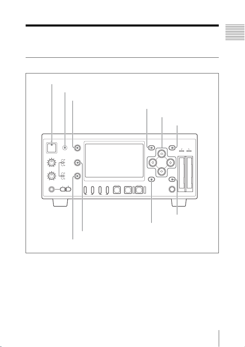
1 Power button and indicator (1)
2 Infrared sensor
3 DISPLAY button
4 MENU button
5 M, m, <, , buttons
Chapter 1 Overview
6 SET button
1
REC LEVEL
CH-1
CH-2
PHONES
DISPLAY
TC/UB
VIDEO INPUT
iLINK
HD SDI
SG
STATUS
AUDIO INPUT
ANALOG
HD SDI
CH-1/2
HD SDI
CH-3/4
PHONE LEVEL
F REV PLAY/PAUSE
9 TC/UB button
0 STATUS button
PREV.NEXT>F FWD
m
TOP END
MENU
THUMBNAIL CANCEL
M
STOPxREC
u
z
SLOT
SELECT
SET
ACCESS
AB
7 CANCEL button
8 THUMBNAIL button
Names and Functions of Parts
15
Page 16
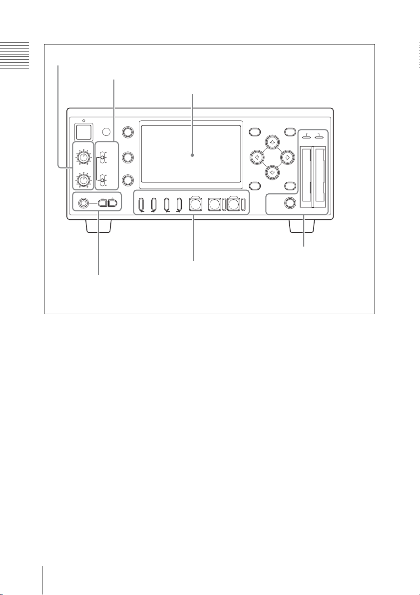
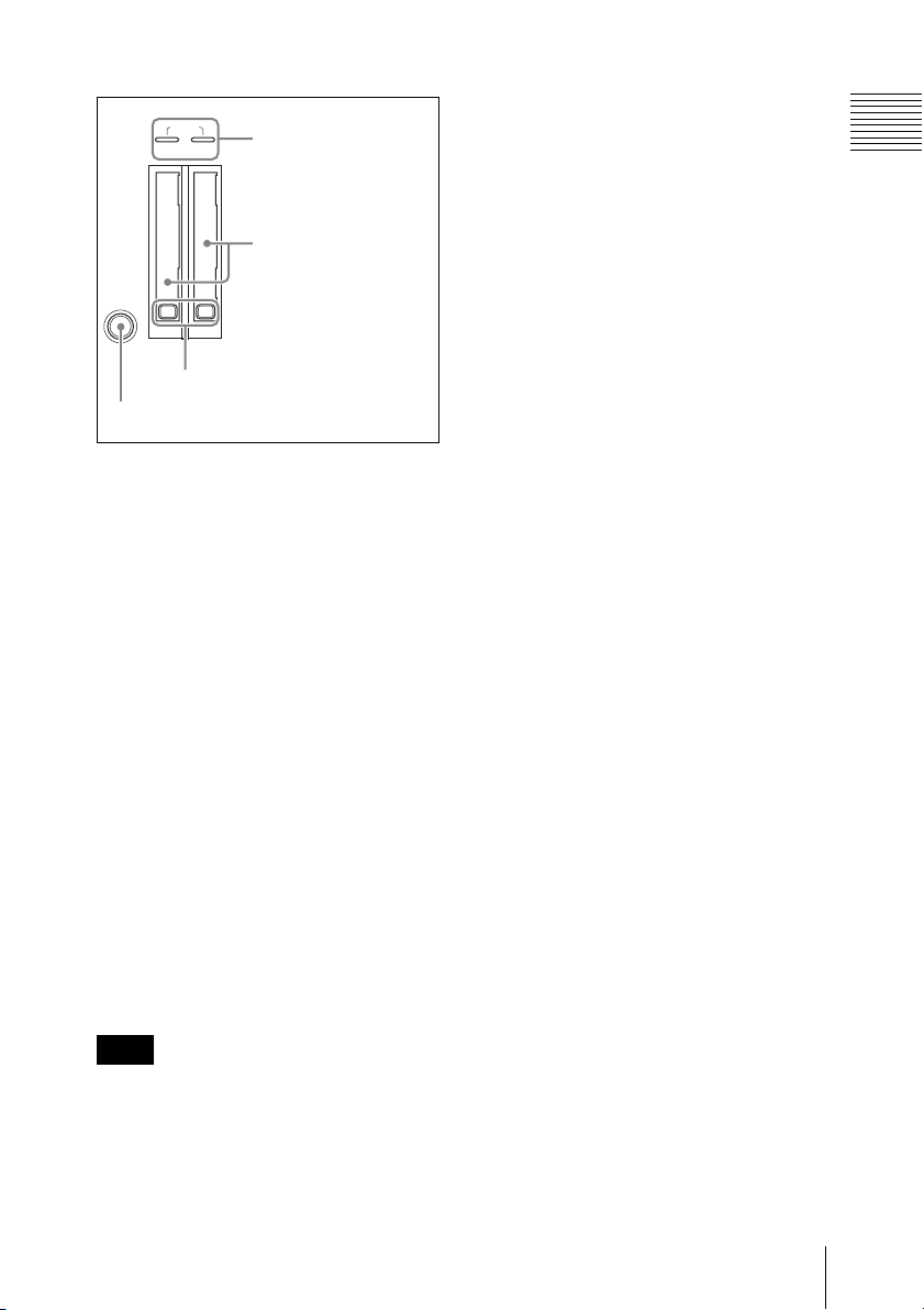
1 Audio input level control section (see page 17)
Chapter 1 Overview
2 Video/audio input selection section (see page 18)
3 LCD display (see page 18)
VIDEO INPUT
iLINK
HD SDI
SG
AUDIO INPUT
ANALOG
HD SDI
CH-1/2
HD SDI
CH-3/4
PHONE LEVEL
DISPLAY
TC/UB
STATUS
PREV.NEXT>F FWD
F REV PLAY/PAUSE
m
TOP END
M
1
REC LEVEL
CH-1
CH-2
PHONES
5 Recording/playback
4 Headphones
connection section
(see page 21)
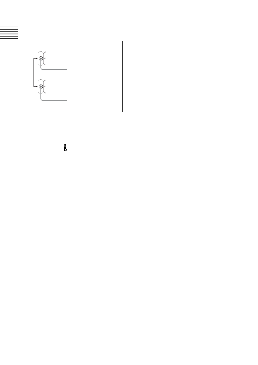
a Power button and indicator (1)
When this unit is connected to an AC power
source via the supplied MPA-AC1 AC
Adaptor (see page 28), the indicator lights
in red. (The unit is in the standby state.)
Pressing the power button with the indicator
lit in red starts the unit. The indicator lights
in green.
Pressing the power button again after the
start-up completes brings the unit into the
standby state (with the indicator lit in red).
To exit the standby state, remove the AC
power source.
b Infrared sensor
This receives signals from the supplied IR
remote commander.
MENU
THUMBNAIL CANCEL
STOPxREC
u
z
SLOT
SELECT
SET
ACCESS
AB
6 Card slot section
(see page 22)
control section (see
page 21)
c DISPLAY button
While recording, E-E, or playback picture is
displayed, pressing this button provides the
LCD display and the external monitor
screen with superimposed text information
including timecode, menu settings, and
alarm messages. Press the button again to
cancel the superimposition.
d MENU button
Press this button to display the menu on the
LCD display and the external monitor
screen. Press it again to exit the menu
display.
On how to use the menu, see Chapter 8 “Menu
Configuration and Detailed Settings” (page 82).
Names and Functions of Parts
16
Page 17
e <, ,, M, m buttons
Use these buttons to move around the menu
items, to select clips in a thumbnail screen,
and also to set the initial timecode value and
user bit data.
They can also be used for normal playback
operations.
f SET button
Press this button to confirm menu and
thumbnail settings, and to execute
operations.
Pressing this button with a still picture
displayed in pause mode calls the Clip
Operation menu.
g CANCEL button
Press this button to cancel menu and
thumbnail settings, and to abort operations.
h THUMBNAIL button
Press this button to display a thumbnail
screen on the LCD display and the external
monitor screen. Pressing the button again
displays only the clips marked OK on the
thumbnail screen. Each press of the button
switches between the thumbnail screen for
all clips and that for OK clips.
On how to use the thumb nail screen, see “Thumbnail
screen” (page 52).
i TC (timecode) /UB (user bit) button
Each press of this button switches the time
data type indicator (see page 19) on the
LCD display and the external monitor
screen.
j STATUS button
Press this button to show the status display
on the LCD display and the external
monitor screen. Press it again to exit the
status display.
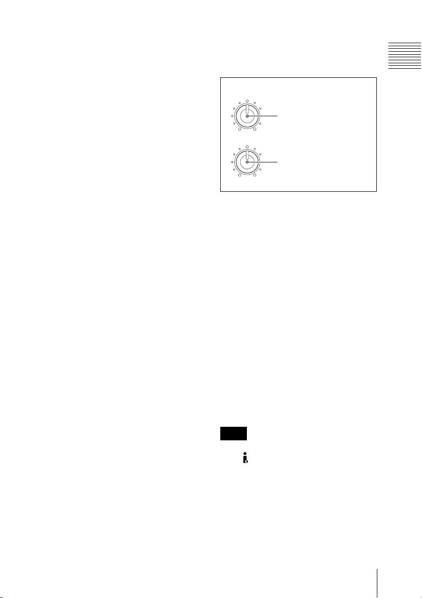
A Audio input level control section
Press this button to show the status screens.
Press it again to exit the status display.
REC LEVEL
CH-1
1 REC LEVEL CH-1
control
CH-2
2 REC LEVEL CH-2
control
a REC LEVEL CH-1 (recording audio
level of channel 1) control
b REC LEVEL CH-2 (recording audio
level of channel 2) control
When “Rec Level” in “Audio Input” of the
AUDIO SET menu is set to “Manual” (see
page 86), use these controls to adjust the
recording level of the two-channel audio
signal input to the HD SDI INPUT
connector or the AUDIO INPUT CH-1 and
CH-2 connectors.
Watching the audio level meters (see page
20) displayed on the LCD display and the
external monitor screen, adjust the level so
that the meter does not indicate higher
values than 0 dB when the audio signal is at
its maximum. When the level exceeds 0 dB,
the “OVER” indicator lights.
Note
When recording HDV-format signals input
to the HDV/DV connector, it is not
possible to adjust the audio recording levels
with these controls.
Chapter 1 Overview
For details on the status screens, see Chapter 7
“Status Display” (page 79).
Names and Functions of Parts
17
Page 18
B Video/audio input selection
section
Chapter 1 Overview
VIDEO INPUT
iLINK
HD SDI
SG
AUDIO INPUT
ANALOG
HD SDI
CH-1/2
HD SDI
CH-3/4
1 VIDEO INPUT switch
2 AUDIO INPUT switch
a VIDEO INPUT switch
Use this switch to select the video signal to
record.
i.LINK: To record HDV-format signals
input to the HDV/DV connector
HD SDI: To record HDSDI signals input to
the HD SDI connector
SG: Internal test signal (100% full color
bar)
b AUDIO INPUT switch
When the VIDEO INPUT switch is set to
HD SDI or SG, use this switch to select the
audio signal to record.
ANALOG: To record analog audio signals
input to the AUDIO INPUT CH-1 and
CH-2 connectors
HD SDI CH-1/2: To record channels 1 and
2 of digital audio signals embedded in
the HDSDI signals input to the HD
SDI INPUT connector
HD SDI CH-3/4: To record channels 3 and
4 of digital audio signals embedded in
the HDSDI signals input to the HD
SDI INPUT connector
Pressing the DISPLAY button to enable
superimposition provides text information
shown in the following figure on recording,
E-E, and playback pictures. Alarm/error
messages and notice/confirmation
messages (shown in 7 and 0) are
displayed, if required, regardless of the
DISPLAY button status.
Those information can be superimposed on
the output signals (see page 45) from the
HDMI, COMPONENT, COMPOSITE, SVIDEO, and HD/SD SDI OUTPUT
connectors so that you can check them on
the external monitor screen.
In Chapter 2 and following of this manual,
both the LCD display of this unit and an
external monitor screen are referred to
collectively as the “monitor screen”.
C LCD display
Displays recording, E-E, and playback
pictures, the menu (see page 82), status
screens (see page 79), and a thumbnail
screen (see page 52).
Names and Functions of Parts
18
Page 19
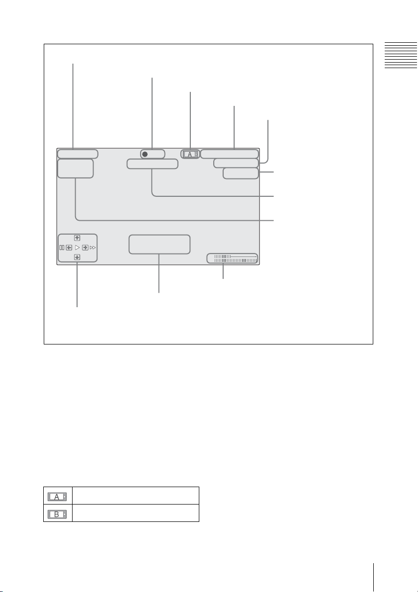
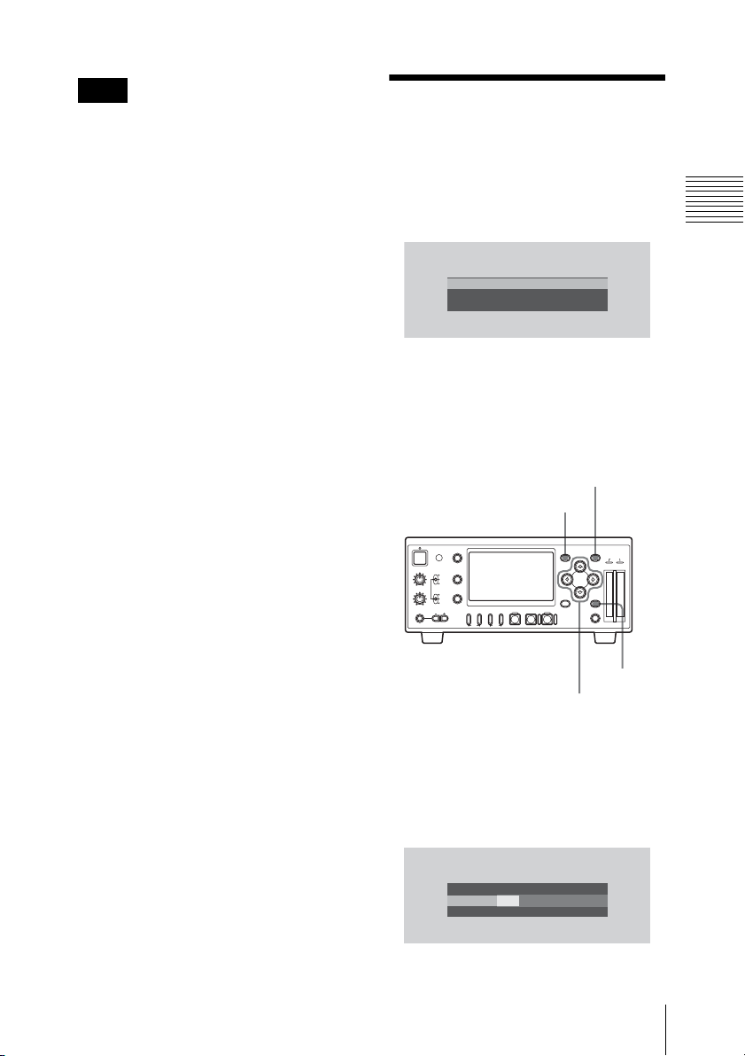
1 DC IN voltage indication
2 Operation mode
3 Media status indication
DC IN12.0V
A: 25min Madia Near full
B: 50min
PRV
Restore Media (B)
Done
NXT
qa Operation guidance area
(during playback)
REC
0 Notice/confirmation message area
4 Time data indication
TCG 00:00:00:00
Q
1080/24P
H
HD-SDI in
CH1
CH2
9 Audio level meters
5 Video format indication
(in recording/E-E mode)
Clip No. and total number
of clips indication (during
playback)
6 Video input signal
indication (in recording/
E-E mode)
7 Alarm/error message
area
8 Media remaining
indication (in
recording/E-E mode)
Chapter 1 Overview
a DC IN voltage indication
Indicates the voltage of the power source
input the DC IN connector.
b Operation mode
Indicates the current operating modes.
c Media status indication
Indicates which card slot is active when
SxS memory cards are installed in both
slots A and B.
Memory card in slot A is active.
Memory card in slot B is active.
d Time data indication
Indicates the time data type indicator and
timecode or user bit.
Each press of the TC/UB button switches
the time data type indicator as follows.
• In recording or E-E mode
TCG: Timecode generated by the timecode
generator
UBG: User bits generated by the timecode
generator
• During playback
TCR: Timecode read by the timecode
reader
UBR: User bits read by the timecode reader
Names and Functions of Parts
19
Page 20
Note
This unit allows setting of timecode and
Chapter 1 Overview
user bit data when an HDSDI signal or the
internal test signal is recorded. When an
HDV signal input to the HDV/DV
connector is recorded, the timecode and
user bit data embedded in the input signal
are recorded as they are. (The
corresponding time data type indicators are
TCR and UBR, respectively.)
e Video format indication (in
recording/E-E mode)/Clip No. and
total number of clips indication
(during playback)
In recording or E-E mode, indicates the
current video format.
The video format consists of bit rate (HQ or
SP), number of effective lines, frame rate,
and scan system (i or P).
During playback, indicates the number of
the clip played back currently and the total
number of clips.
f Video input signal indication (in
recording/E-E mode)
Indicates the input signal selected with the
VIDEO INPUT switch.
g Alarm/error message area
An alarm message is displayed in such a
case that the remaining space on the
memory card is insufficient. An error
message is also displayed in this area.
(Those messages are displayed regardless
of the state of the DISPLAY button.)
h Media remaining indication (in
recording/E-E mode)
Indicates the time remaining for the SxS
memory cards loaded in the card slots.
The available time for recording with the
current video format (recording bit rate) is
calculated according to the remaining space
of each card and indicated in time units of
minutes.
Note
A icon appears if the memory card is
write-protected.
i Audio level meters
Indicates audio peak levels. When the
reference audio signals is output (see page
47), –20 is marked on each meter and –10
dBu signals are output from the AUDIO
OUTPUT CH-1and CH-2 connectos.
j Notice/confirmation message area
Progress messages, completion messages or
messages prompting the next action and
confirmation are displayed regardless of the
DISPLAY button status.
k Operation guidance area (during
playback)
Current functions of the <, ,, M, m
buttons are displayed. Functions assigned
to the PUSH SET button of the IR remote
commander are also displayed when the
remote control function is active.
Guide
marks
M 4-times playback in forward
< 15-times playback in forward
m 4-times playback in reverse
, 15-times playback in reverse
B Normal playback
X Pause
PRV Jump to the top of the
Functions
direction
direction
direction
direction
current clip
Names and Functions of Parts
20
Page 21
Guide
Functions
marks
NXT Jump to the top of the next
clip
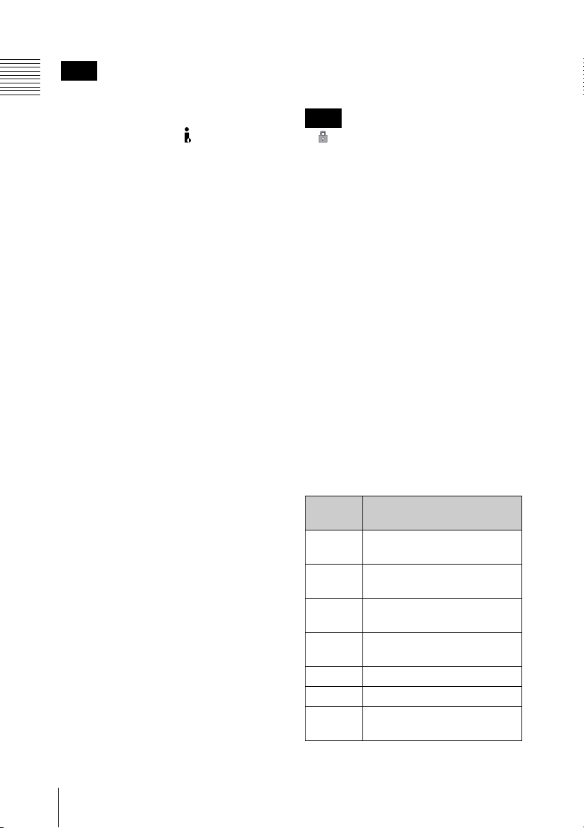
D Headphones connection section
PHONES
1 PHONES
PHONE LEVEL
2 PHONES LEVEL
buttons
jack
a PHONES (headphones) jack (stereo-
mini)
Connect stereo headphones to the jack for
audio monitoring during recording and
playback.
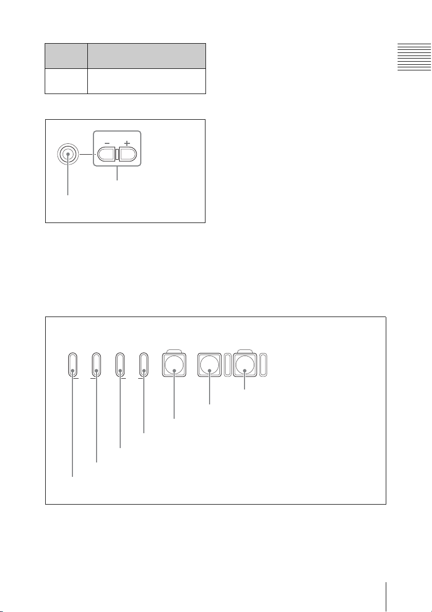
E Recording/playback control section
F REV PLAY/PAUSE
PREV.NEXT>F FWD
m
TOP END
2 PREV button and indicator
1 F REV button and indicator
M
4 F FWD button and indicator
3 NEXT button and indicator
u
5 PLAY/PAUSE button and indicator
STOP
x
6 STOP button
A channel to monitor can be selected by
changing the setting of “Monitor CH” (see
page 87) in the “Audio Set” setting of the
AUDIO SET menu. During playback, also
change the “Output CH” setting (see page
87) as required.
b PHONES LEVEL (headphones
volume) buttons
Adjust the volume of the audio output from
the PHONES jack. Press the + button to
turn up the volume and press the – button to
turn down the volume.
During adjustment, a volume meter appears
on the LCD display and an external monitor
screen. The meter display is displayed for
about three seconds after the adjustment
completes.
REC
z
7 REC button and indicator
Chapter 1 Overview
a F REV (fast reverse) button and
indicator
Use this button for high-speed playback
(with audio muted) in the reverse direction.
Each time you press the button, the
playback speed switches between 4 times
and 15 times normal speed. To return to
Names and Functions of Parts
21
Page 22

normal playback, press the PLAY/PAUSE
button.
Pressing the PREV button and F REV
Chapter 1 Overview
button simultaneously cues up the top of the
first-recorded clip on the memory card
(TOP button function).
During the F REV button is active, the
indicator at the upper of the button is lit.
b PREV (previous clip jump) button
and indicator
When you press the button in normal or
high-speed playback, the top of the current
clip is cued up then playback begins.
When you press the button in fast-reverse
playback or in pause mode, the top of the
current clip is cued up, then the still picture
is displayed.
Repeated pressing of the button cues up the
previous clips one by one.
Pressing the PREV button and F REV
button simultaneously cues up the top of the
first-recorded clip on the memory card
(TOP button function).
During the PREV button is active, the
indicator at the upper of the button is lit.
c NEXT (next clip jump) button and
indicator
When you press the button in normal or
high-speed playback, the top of the next clip
is cued up then playback begins.
When you press the button in fast-reverse
playback or in pause mode, the top of the
next clip is cued up, then the still picture is
displayed.
Repeated pressing of the button cues up the
subsequent clips one by one.
Pressing the F FWD button and NEXT
button simultaneously cues up the top of the
last-recorded clip on the memory card
(END button function).
During the NEXT button is active, the
indicator at the upper of the button is lit.
d F FWD (fast forward) button and
indicator
Use this button for high-speed playback
(with audio muted) in the forward direction.
Each time you press the button, the
playback speed switches between 4 times
and 15 times normal speed. To return to
normal playback, press the PLAY/PAUSE
button.
Pressing the F FWD button and NEXT
button simultaneously cues up the top of the
last-recorded clip on the memory card
(END button function).
During the F FWD button is active, the
indicator at the upper of the button is lit.
e PLAY/PAUSE button and indicator
Each time you press the button toggles
between normal playback and still picture
playback (in pause mode).
The indicator at the upper of the button is lit
during normal playback and blinks in pause
mode.
f STOP button
Press this button to stop the current
playback or recording operation. This unit
enters E-E mode.
g REC (record) button and indicator
Press this button to start recording to the
SxS memory card(s).
The indicator at the upper of the button is lit
during normal recording and blinks when
the video format of the input signal does not
match with the video format set on this unit
or when abnormality in recording is
detected.
F Card slot section
For details on SxS memory cards, see “Handling
SxS Memory Cards” (page 36).
Names and Functions of Parts
22
Page 23
ACCESS
AB
3 EJECT button
4 SLOT SELECT button
1 ACCESS lamps
2 SxS memory card
slots
a ACCESS lamps
When an SxS memory card is inserted into
one of the slot, the ACCESS lamp at the slot
lights in red then changes to green once the
memory card is ready for use. Card slots A
and B are accompanied by the respective
ACCESS lamps to indicate their statuses.
b SxS memory card slots
Insert SxS memory cards into the slots.
c EJECT buttons
Press one of the EJECT button to release the
lock, then pull the button out. Press the
button again to remove the SxS memory
card.
Chapter 1 Overview
d SLOT SELECT (SxS memory card
select) button
When SxS memory cards are loaded in both
card slots A and B, press this button to
select the card you wish to use.
Note
The SLOT SELECT button is disabled
while playback is in progress, that is,
switching is not executed even if you press
the button. On the other hand, the button is
enabled while a thumbnail screen is
displayed.
Names and Functions of Parts
23
Page 24
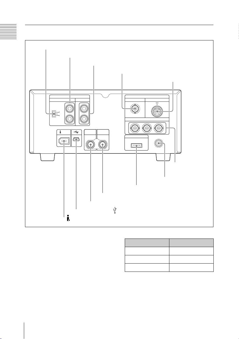
Rear panel
Chapter 1 Overview
1 AUDIO INPUT LEVEL switch
2 AUDIO INPUT CH-1 and CH-2 connectors
3 AUDIO OUTPUT CH-1/3 and CH-2/4 connectors
4 COMPOSITE connector
5 S-VIDEO
connector
6 COMPONENT
connectors
7 DC IN connector
8 HDMI connector
9 HD/SD SDI OUTPUT connector
0 HD SDI INPUT connector
qa USB connector ( )
qs HDV/DV connector
a AUDIO INPUT LEVEL switch
Depending on the connector of the device
connected to the AUDIO INPUT CH-1 and
CH-2 connectors, set the audio input level
as follows.
For an XLR connector: +4 or –2
For a phono jack: –10
The following table shows the relation
between the switch position and maximum
audio level available.
Names and Functions of Parts
24
Position Audio level
–10 +10 dBu
–2 +18 dBu
+4 +24 dBu
Page 25

b AUDIO INPUT CH-1 and CH-2
(channels 1 and 2) connectors (phono
jacks)
Input analog audio signals to the CH-1 and
CH-2 connectors. Set the input level with
the AUDIO INPUT LEVEL switch to –10,
–2, or +4 dBu.
c AUDIO OUTPUT CH-1/3 and CH-2/
4 (channels 1 and 3, channels 2 and 4)
connectors (phono jacks)
Output analog audio signals from the CH-1/
3 and CH-2/4 connectors.
Output channels can be selected by
changing the “Monitor CH” setting (see
page 87) and the “Output CH” setting (see
page 87) of the AUDIO SET menu.
Note
In recording or E-E mode, audio signals of
channels 1 and 2 are output. (Channels 3
and 4 can be selected when 4-channel
material is played back.)
d COMPOSITE connector (BNC type)
Outputs down-converted SD analog
composite video signals.
Setting “CMPST/ S Out Display” (see page
88) of the VIDEO SET menu to “On”
superimposes the same text information as
that displayed on the LCD display on the
output signals from this connector.
e S-VIDEO connector (mini-DIN 4-
pin)
Outputs Y/C separated signals.
Setting “CMPST/ S Out Display” (see page
88) of the VIDEO SET menu to “On”
superimposes the same text information as
that displayed on the LCD display on the
output signals from this connector.
f COMPONENT connectors (BNC
type)
Output HD analog component signals or
down-converted SD analog component
signals from the Y, Pb/B–Y, and Pr/R–Y
connectors. Select the video format of the
output signals with “HDMI/CMPNT/SDI
Out SEL” (see page 87) of the VIDEO SET
menu.
Setting “HDMI/CMPNT/SDI Out DISP”
(see page 88) of the VIDEO SET menu to
“On” superimposes the same text
information as that displayed on the LCD
display on the output signals from this
connector.
Note
The output format is fixed to 480i (576i)
when the “i.LINK I/O Select” setting (see
page 89) of the VIDEO SET menu is
“DVCAM”.
g DC IN (DC power source input)
connector (3-pin, Type 4)
Plugs the DC power cord to connect the
supplied MPA-AC1 AC Adaptor.
h HDMI connector (Type A 19-pin)
Select the video format of the output signals
with “HDMI/CMPNT/SDI Out SEL” (see
page 87) of the VIDEO SET menu.
Setting “HDMI/CMPNT/SDI Out DISP”
(see page 88) of the VIDEO SET menu to
“On” superimposes the same text
information as that displayed on the LCD
display on the output signals from this
connector.
Note
The output format is fixed to 480i (576i)
when the “i.LINK I/O Select” setting (see
page 89) of the VIDEO SET menu is
“DVCAM”.
Chapter 1 Overview
Names and Functions of Parts
25
Page 26

i HD/SD SDI OUTPUT connector
(BNC type)
Outputs HDSDI signals or down-converted
Chapter 1 Overview
SDSDI signals. Audio signals and timecode
are embedded in the SDI signals. Select the
video format of the output signals with
“HDMI/CMPNT/SDI Out SEL” (see page
87) of the VIDEO SET menu.
Setting “HDMI/CMPNT/SDI Out DISP”
(see page 88) of the VIDEO SET menu to
“On” superimposes the same text
information as that displayed on the LCD
display on the output signals from this
connector.
Note
The output format is fixed to 480i (576i)
when the “i.LINK I/O Select” setting (see
page 89) of the VIDEO SET menu is
“DVCAM”.
j HD SDI INPUT connector (BNC
type)
Input HDSDI signals.
Note
When the video format of the input signal
does not match with the video format set on
this unit, recorded and E-E pictures cannot
be displayed. Match the video format of the
input signal with this unit’s video format.
k USB connector ( ) (mini-B/USB 2.0)
Connect a computer to access the data of the
SxS memory card loaded on this unit.
l HDV/DV (HDV or DVCAM input/
output) connector (6-pin, IEEE1394,
S400)
Allows input and output of the HDV-format
digital video and audio and output of downconverted DVCAM signals. Select the
output format with the “i.LINK I/O Select”
setting (see page 89) of the VIDEO SET
menu.
Setting “HDMI/CMPNT/SDI Out DISP”
(see page 88) of the VIDEO SET menu to
“On” superimposes the same text
information as that displayed on the LCD
display on the output signals from this
connector.
Notes
• If the unit is connected to a device
equipped with a 6-pin HDV/DV jack,
when you intend to disconnect or
reconnect the i.LINK cable, turn off the
device and pull out the plug of its power
cord from the AC outlet beforehand. If
you connect or disconnect the i.LINK
cable while the device is connected to the
AC outlet, a high-voltage (8 to 40 V)
current output from the HDV/DV jack of
the device flows into this unit, which may
cause a malfunction to the unit.
• When connecting a device that has a 6pin HDV/DV jack to this unit, first plug
the cable into the 6-pin HDV/DV jack of
the device.
IR remote commander (supplied)
When you use the IR remot e commander, see “Using
the IR Remote Commander (Supplied)” (page 43).
Names and Functions of Parts
26
Page 27
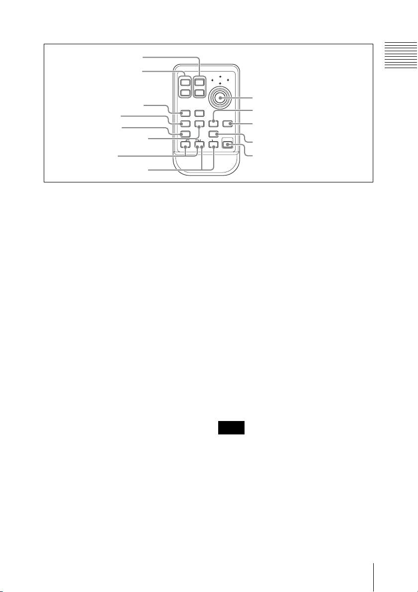
1 ZOOM T/W buttons
2 SHOTMARK1 and 2
buttons
3 THUMBNAIL button
4 PREV button
5 F REV button
6 PLAY/PAUSE button
7 REC buttons
8 REC PAUSE buttons
12T
ZOOM
SHOTMARK
W
SUB CLIP
THUMBNAIL
PREV NEXT
PLAY/PAUSE
.
m
REC
z
Chapter 1 Overview
PUSH SET
9 PUSH SET button
0 NEXT button
STOP
xu
PUSH AFREC PAUSE
qa STOP button
qs F FWD button
>
FFWDFREV
M
X
qd PUSH AF button
a ZOOM T/W buttons
Do not function with this unit.
b SHOTMARK1 and 2 buttons
Press during recording or playback to
record shot mark 1 or shot mark 2.
c THUMBNAIL button
Has the same function with the
THUMBNAIL button (see page 17) on this
unit.
d PREV (previous clip jump) button
Has the same function with the PREV
button (see page 22) on this unit.
e F REV (fast reverse) button
Has the same function with the F REV
button (see page 21) on this unit.
f PLAY/PAUSE button
Has the same function with the PLAY/
PAUSE button (see page 22) on this unit.
g REC (recording) buttons
Press the z button and unmarked button
(safety button) simultaneously to start
recording.
h REC PAUSE (recording pause)
buttons
Press the X button and unmarked button
(safety button) simultaneously to stop
recording.
i PUSH SET (four-way arrow key)
button
Has the same function with the M, m, <,
, buttons (see page 17) and SET button
(see page 17) on this unit.
j NEXT (next clip jump) button
Has the same function with the NEXT
button (see page 22) on this unit.
k STOP button
Press this button to stop playback. The unit
enters E-E mode.
Note
Do not use this button to stop recording.
Use the REC PAUSE buttons to stop
recording.
l F FWD (fast forward) button
Has the same function with the F FWD
button (see page 22) on this unit.
m PUSH AF button
Does not function with this unit.
Names and Functions of Parts
27
Page 28
Preparations
Chapter 2 Preparations
Starting the Unit
When you use this unit for the first time
after purchasing, the initial settings are
required (see page 28).
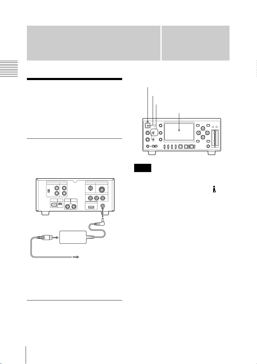
Connecting the unit to a power source
Use the supplied MPA-AC1 AC Adaptor to
connect the unit an AC power source.
DC power cord
(supplied)
MPA-AC1 AC Adaptor (supplied)
To an AC
AC power cord
(supplied)
When this unit is supplied with power, the
power indicator on the front panel lights in
red. (The unit enters the standby state.)
Starting the unit
To start this unit, press the power button
with the power indicator lit in red (when the
unit is in the standby state).
power source
DC IN
Chapter
2
Power indicator
Power button
VIDEO INPUT switch
LCD display
DISPLAY
1
REC LEVEL
CH-1
TC/UB
VIDEO INPUT
iLINK
HD SDI
SG
CH-2
STATUS
AUDIO INPUT
ANALOG
HD SDI
CH-1/2
HD SDI
CH-3/4
PREV.NEXT>F FWD
F REV PLAY/PAUSE
PHONES
PHONE LEVEL
m
TOP END
M
MENU
SET
ACCESS
AB
THUMBNAIL CANCEL
STOPxREC
u
SLOT
SELECT
z
Note
No signal is output from the
COMPONENT, COMPOSITE, S-VIDEO,
HDMI, HD/SD SDI OUTPUT, and HDV/
DV connectors until the start-up completes.
When the start-up of the unit is completed,
the power indicator lights in green.
When the initial setting display
appears on the LCD display
The initial setting display appears on the
LCD display in the following situations.
• When turning on the unit for the first time
• When turning on the unit after the clock
setting is cleared because of exhaustion
of the backup battery while no operation
power was being supplied (no AC power
connection)
For details on the initial settings, see “Setting the
Clock” (page 29).
28
Starting the Unit
Page 29
Note
While the initial setting display is shown,
no other operation except turning the power
off is permitted until you finish the setting
for this display.
When the initial setting display is not
shown or the initial settings are completed,
the LCD display state varies as follows.
With no SxS memory card loaded: The
video selected with the VIDEO INPUT
switch is shown. If the selected video is
not input, a blue or black screen
appears.
With an accessible SxS memory card
loaded: Index frame images of the
clips recorded on the memory card are
shown as thumbnails (thumbnail
screen).
To turn the power off
Press the power button again.
The power indicator on the front panel
lights in red. (The unit enters the standby
state.) To exit the standby state, disconnect
the AC power source (see page 28).
Setting the Clock
When the initial setting display appears on
the LCD display, Set the date and time of
the built-in clock, using this display.
IN ITIAL
SETTING
Time Z
one: UTC +09:00 TOKYO
D
ate/Time: 2008/01/01 00:00:00
Finish
Time Zone
The value shows the time difference from
UTC (Coordinated Universal Time).
Change the setting if needed (see page 28).
To set the time and date
SET button
MENU button
DISPLAY
1
REC LEVEL
CH-1
TC/UB
VIDEO INPUT
iLINK
HD SDI
SG
CH-2
STATUS
AUDIO INPUT
ANALOG
HD SDI
CH-1/2
HD SDI
CH-3/4
PREV.NEXT>F FWD
F REV PLAY/PAUSE
PHONES
PHONE LEVEL
m
TOP END
M
MENU
SET
ACCESS
AB
THUMBNAIL CANCEL
STOPxREC
u
SLOT
SELECT
z
Chapter 2 Preparations
CANCEL
<, ,, M, m buttons
button
1 Press the M or m button to set the
cursor to “Date/Time” then press the
SET button.
The cursor moves to the year-setting
column.
IN ITIAL
SETTING
Time Z
one: UTC +09:00 TOKYO
2008/01/01 00:00:00 SET
D
ate/Time: 2007/01/01 00:00:00 SET
Finish
Setting the Clock
29
Page 30

2 Press the M or m button to set the year
then press the < or , button.
The cursor moves to the month-setting
column.
3 Set the month, day, hour, minute, and
Chapter 2 Preparations
second in sequence in the same
manner.
4 Press the SET button at “SET”.
The cursor moves back to “Date/
Time”.
5 Press the M or m button to move the
cursor to “Finish” then press the SET
button.
The initial setting display disappears,
and the clock setting is completed.
The time zone and date/time settings can be
changed later using “Time Zone” (see page
91) and “Clock Set” (see page 92) of the
OTHERS menu.
Adjusting the LCD Display
You can adjust the display conditions of the
LCD display for the best view in various
situations.
These adjustments of the LCD display have
no effect on pictures being recorded.
To adjust the color density,
contrast, and brightness
These adjustments can be made using the
LCD SET menu.
Press the MENU button to display the menu
icons. Display the select LCD SET menu
with the LCD SET menu icon, and use the
<, ,, M or m button to select “LCD”
from the menu.
LCD SET menu icon
LCD
SET
LCD
00:00
B
Color
C
ont ra st
Br i ght ness
Back Light
:
: 0
:
:
: 0
0
0
0
Adjusting the LCD Display
30
Set the color density, contrast and
brightness of the LCD display with the
corresponding LCD SET menu items:
Color, Contrast, and Brightness.
For details on menu operations, see “Basic Menu
Operations” (page 83).
To adjust the backlight
Use the LCD SET menu.
Select “LCD” from the LCD SET menu and
change the “Back Light” setting.
Page 31

LCD
SET
LCD
00:00
B
Color
C
ont ra st
Br i ght ness
Back Light
:
: 0
:
:
:
0
0
0
0
Video Format and Input/Output Signals
Chapter 2 Preparations
The video format to be used on this unit can
be set with “Video Format” of the OTHERS
menu. When the unit is used for recording,
it is required to input a signal conforming to
the video format set on the unit.
In recording or E-E mode, the type and
format of the output signal vary depending
on the input video format and the “HDMI/
CMPNT/SDI Out SEL” setting of the
VIDEO SET menu. When this unit is used
for playback, the format of the output signal
varies depending on the “HDMI/CMPNT/
SDI Out SEL” setting of the VIDEO SET
menu and the video format in which the clip
was recorded on the SxS memory card.
“Video Format”
setting
NTSC HQ 1080/60i
Input video
format
1080/59.94i
SP 1080/60i
HQ 1080/30P 1080/29.97PsF
HQ 1080/24P 1080/23.98PsF
HQ 720/60P 720/59.94P
PAL HQ 1080/50i
1080/50i
SP 1080/50i
HQ 1080/25P 1080/25PsF
HQ 720/50P 720/50P
Setting the video format
The video format is determined by bit rate
(HQ or SP), number of effective lines,
frame rate, and scan system (i or P).
Set “Video Format” of the OTHERS menu
to a desired video format.
Video Format and Input/Output Signals
31
Page 32

Video format choices
Chapter 2 Preparations
Video format choices vary with the
“Country” setting of the OTHERS menu.
Video format and output signals
When “Country” is set to “NTSC Area”:
HQ 1080/60i, SP 1080/60i, HQ 720/
60P, HQ 1080/24P, HQ 1080/30P
When “Country” is set to “PAL Area”:
HQ 1080/50i, SP 1080/50i, HQ 720/
50P, HQ 1080/25P
Note
It is not possible to change the video format
after recording or playback is started.
“HDMI/CMPNT/SDI Out SEL” of the
VIDEO SET menu allows you to select
whether the digital output signals from the
COMPONENT, HD/SD SDI OUTPUT,
and HDMI connectors are to be HD signals
corresponding to the video format or downconverted SD signals.
Relations between the video format of the
input signal or the clip played back and the
format of the video signals output from the
COMPONENT, HD/SD SDI OUTPUT,
and HDMI connectors are shown in the
tables on page 33 and page 34.
The format of the video signals output from
the HDV/DV connector is shown in the
following tables.
When the “i.LINK I/O Select”
setting of the VIDEO SET menu is
“HDV”
Source video
format
NTSC SP1080/60i 1080/59.94i
PAL SP1080/50i 1080/50i
Output video
format
When the “i.LINK I/O Select”
setting of the VIDEO SET menu is
“DVCAM” (for playback only)
Source video format Output video
format
NTSC HQ1080/60i 480/59.94i
SP1080/60i
SP1080/24P
HQ1080/30P
HQ720/60P
HQ720/30P
PAL HQ1080/50i 576/50i
SP1080/50i
SP1080/25P
HQ1080/25P
HQ720/50P
HQ720/25P
Note
When an HDV-format signal is input to the
HDV/DV connector, note the following
points.
• Set the video format to SP 1080/60i
(when “Country” is set to “NTSC Area”)
or SP 1080/50i (when “Country” is set to
“PAL Area”) on this unit. (It is not
possible to input an HDV-format signal
Video Format and Input/Output Signals
32
Page 33

when any other video format setting is
selected.)
• When a signal containing strong jitters
(such as a computer output) is input to the
HDV/DV connector, output video and
audio from the HD/SD SDI OUTPUT
and HDMI connectors may be noisy, or
In recording/E-E mode
no signal may be output from those
connectors.
• When “HDMI/CMPNT/SDI Out SEL” is
set to “480P (576P)”, no signal is output
from the HD/SD SDI OUTPUT
connector.
Chapter 2 Preparations
“Video Format”
setting
NTSC HQ 1080/60i
SP 1080/60i
HQ 1080/30P 1080/29.97PsF
HQ 1080/24P 1080/
HQ 720/60P 720/59.94P 1080/59.94i
PAL HQ 1080/50i
SP 1080/50i
HQ 1080/25P 1080/25PsF 576/25PsF
HQ 720/50P 720/50P 1080/50i 576/50i
a) “HDMI/CMPNT/SDI Out SEL” is disabled
and the setting value is fixed to 480i (576i)
when the “i.LINK I/O Select” setting of the
VIDEO SET menu is “DVCAM”.
b) 480i when “Country” of the OTHERS menu is
set to “NTSC Area”, or 576i when “Country”
of the OTHERS menu is set to “PAL Area”.
Output video format
“HDMI/CMPNT/SDI Out SEL” setting
1080i/720P 1080i
1080/59.94i 480/59.94i 480/59.94P
23.98PsF
1080/50i 576/50i 576/50P
d)
During playback
Formats indicated in parentheses are the
formats of video output during simplified
playback, that is, playback of PAL-format
recorded clips with this unit set to a NTSC
video format or playback of NTSC-format
recorded clips with this unit set to a PAL
video format. During simplified playback,
HD signals are output only from the
COMPONENT connectors.
a)
480i (576i)b)480P (576P)
1080/59.94i
c) This setting allows no signal to be output from
the HD/SD SDI OUTPUT connector.
d) This format allows no signal to be output from
the HDMI connector.
b) c)
Video Format and Input/Output Signals
33
Page 34

Clip video format Output video format
“HDMI/CMPNT/SDI Out SEL” setting
1080i/720P 1080i
NTSC HQ 1080/60i
Chapter 2 Preparations
SP 1080/60i
SP 1080/24P
1080/59.94i
(1080/49.95i)
HQ 1080/30P 1080/29.97PsF
(1080/49.95i)
HQ 1080/24P 1080/
23.98PsF
(1080/49.95i)
HQ 720/60P
HQ 720/30P
720/59.94P
(720/49.95i)
HQ 720/24P
PAL HQ 1080/50i
SP 1080/50i
1080/50i
(1080/60i)
HQ 1080/25P 1080/25PsF
(1080/60i)
HQ 720/50P 720/50P
(720/60P)
HQ 720/25P 720/25PsF
(720/60P)
a) “HDMI/CMPNT/SDI Out SEL” is disabled
and the setting value is fixed to 480i (576i)
when the “i.LINK I/O Select” setting of the
VIDEO SET menu is “DVCAM”.
b) 480i when “Country” of the OTHERS menu is
set to “NTSC Area”, or 576i when “Country”
of the OTHERS menu is set to “PAL Area”.
c) This setting allows no signal to be output from
the HD/SD SDI OUTPUT connector.
d) This format allows no signal to be output from
the HDMI connector.
1080/59.94i
d)
(1080/49.95i)
1080/59.94i
(1080/49.95i)
1080/50i
(1080/60i)
a)
480i (576i)b)480P (576P)
480/59.94i
(576/49.95i)
576/50i
(480/60i)
480/59.94P
(576/50P)
576/50P
(480/60P)
b) c)
Video Format and Input/Output Signals
34
Page 35

Time Data Handled by This Unit
Using time data allows you to easily check
time information, ensure high precision
editing, and synchronize multiple devices.
This unit allows setting of timecode value
and user bit data when an HDSDI signal or
the internal test signal is recorded.
When an HDV signal input to the HDV/
DV connector is recorded, the timecode and
user bit data embedded in the input signal is
recorded as it is.
In recording or E-E mode and during
playback, timecode or user bit data is
displayed on the monitor screen according
to the TC/UB button state.
Displaying the time data
Press the DISPLAY button to display the
time data on the monitor screen.
DISPLAY button
LCD display
The time data type indicator (see page 19)
is switched between TC and UB each time
you press the TC/UB button.
In recording or E-E mode
TCG: Timecode generated by the timecode
generator
UBG: User bit data generated by the
timecode generator
During playback
TCR: Timecode read by the timecode
reader
UBR: User bit data read by the timecode
reader
Note
When an HDV signal input to the HDV/
DV connector is recorded, TCR or UBR is
displayed the time data type indicator on the
monitor screen because the timecode and
user bit data embedded in the input signal
are recorded as they are.
Chapter 2 Preparations
DISPLAY
1
REC LEVEL
CH-1
TC/UB
VIDEO INPUT
iLINK
HD SDI
SG
CH-2
STATUS
AUDIO INPUT
ANALOG
HD SDI
CH-1/2
HD SDI
CH-3/4
PREV.NEXT>F FWD
F REV PLAY/PAUSE
PHONES
PHONE LEVEL
m
TOP END
M
MENU
SET
ACCESS
AB
THUMBNAIL CANCEL
STOPxREC
u
SLOT
SELECT
z
TC/UB button
To switch the time data
displays between timecode
and user bit data
Press the TC/UB button.
Time Data Handled by This Unit
35
Page 36

Handling SxS Memory Cards
This unit records audio and video on SxS
Chapter 2 Preparations
memory cards (optional) inserted in the
card slots.
About SxS Memory Cards
Usable SxS memory cards
The following Sony-made SxS memory
cards (SxS PRO) are recommended for this
unit:
• SBP-8 (8 GB)
• SBP-16 (16 GB)
• SBP-32 (32 GB)
The above cards comply with the
ExpressCard standard.
• SxS and SxS PRO are trademarks of
Sony Corporation.
• The ExpressCard word mark and logo are
owned by Personal Computer Memory
Card International Association
(PCMCIA) and are licensed to Sony
Corporation. All other trademarks are the
property of their respective owners.
• Do not use or store this media in the
following locations:
- Where recommended operating
conditions are exceeded.
- Inside a closed car in summer; or in
strong sunshine / under direct sunlight /
near a heater, etc.
- Humid or corrosive location
• Verify the correct direction of insertion
before use.
• When storing or carrying this media, put
this media in the carrying case and lock it
firmly.
• We recommend that you make a backup
copy of important data. Sony will not be
liable for any damage or loss of data you
recorded.
• Do not apply a label sheet in places other
than the label space. When applying the
label sheet to this media, do not allow it
to protrude from its proper location.
SxS PRO 8GB
Notes on using SxS memory
cards
• Recorded data may be damaged or lost in
the following situations:
- If the media is removed from the slot or
subjected to vibrations or shocks or if
the equipment is powered off during
read/write of data or formatting.
- If you use in locations subject to static
electricity or electrical noise.
Handling SxS Memory Cards
36
Label space
• SxS memory cards to be used with this
unit must be formatted using the format
function of this unit. If a card is formatted
using other device, it is regarded as of a
different format, requiring repeated
format operation on this unit.
(Formatting or deleting with the function
of the unit does not completely delete
data on this media. When transferring or
disposing of this media, use a
commercial data deleting software or
Page 37

destroy the actual body at you own
responsibility.)
• If the available recording time on a card
is short, clip operation may be restricted.
In such a case, delete unnecessary files by
using a computer or delete unnecessary
clips by operation on this unit.
• Remove or reinsert the case card with the
case opened properly.
Inserting/removing an SxS memory card
DISPLAY
1
REC LEVEL
CH-1
TC/UB
VIDEO INPUT
iLINK
HD SDI
SG
CH-2
STATUS
AUDIO INPUT
ANALOG
HD SDI
CH-1/2
HD SDI
CH-3/4
PREV.NEXT>F FWD
F REV PLAY/PAUSE
PHONES
PHONE LEVEL
m
TOP END
M
ACCESS lamps
STOPxREC
u
z
MENU
THUMBNAIL CANCEL
SLOT
SELECT
SET
ACCESS
AB
Chapter 2 Preparations
For write protection
Setting the write-protect switch of the SxS
memory card to “WP” disables you to
record, edit or delete data.
Write-protect switch
Note
Do not operate the write-protect switch of
an SxS memory card while it is set in the
unit. Temporarily remove the card from the
unit before changing the switch setting.
SLOT SELECT button
Card
slots
EJECT button
To insert an SxS memory card
Insert the SxS memory card into the card
slot.
With the label facing right
The ACCESS lamp lights in red then
changes to green once the memory card is
ready for use.
Status indications by the ACCESS
lamps
Card slots A and B are accompanied by the
respective ACCESS lamps to indicate their
statuses.
Handling SxS Memory Cards
37
Page 38

Lamp Slot statuses
Lights in red Accessing the loaded
Lights in
green
Chapter 2 Preparations
Off • No SxS memory card
SxS memory card
(writing/reading data)
Standby (ready for
recording or playback
using the loaded SxS
memory card)
is loaded.
• The loaded card is
invalid.
• An SxS memory card
is loaded, but another
slot is selected.
To remove an SxS memory
card
1 Press the EJECT button to release the
lock, then pull the button out.
Notes
• Data are not guaranteed if the power is
turned off or a memory card is removed
while the card is being accessed. All data
on the card may be destroyed. Be sure
that the ACCESS lamps are lit in green or
off when you turn off the power or
remove memory cards.
• When you turn on the unit with no valid
memory card loaded, the unit enters E-E
mode and displays the video selected
with the VIDEO INPUT switch.
Switching between SxS memory cards
Press and unlock the button.
2 Press the EJECT button again to
remove the card.
Handling SxS Memory Cards
38
When SxS memory cards are loaded in both
card slots A and B, press the SLOT
SELECT button to select the card you wish
to use.
If a card becomes full during recording,
switching to the other card is automatically
executed.
Note
The SLOT SELECT button is disabled
while playback is in progress, that is,
switching is not executed even if you press
the button. On the other hand, the button is
enabled while a thumbnail screen is
displayed (see page 52).
Page 39

Formatting an SxS memory
T
card
Formatting may be required before using an
SxS memory card with this unit. For an SxS
memory card that is not formatted or that
was formatted with another system, a
message to confirm if formatting is to be
executed is displayed on the LCD display.
Note on formatting
Any SxS memory card formatted with a
device other than this unit cannot be used
with the unit.
To execute formatting
If the message for formatting is displayed,
press the M or m button to select “Execute”
then press the SET button.
Formatting begins, the in-progress message
and status bar (%) are displayed, and the
ACCESS lamp lights in red.
When formatting is completed, the
completion message is displayed for three
seconds.
Recording/playback during
formatting
You can perform recording or playback
using the SxS memory card in the other card
slot while formatting is in progress.
If formatting fails
A write-protected SxS memory card or
memory card that cannot be used with this
unit will not be formatted.
As a warning message is displayed, replace
the card with an appropriate SxS memory
card, as per the instructions in the message.
To format by menu operation
When no formatting message is displayed
on the LCD display, you can execute
formatting using “Format Media” (see page
94) of the OTHERS menu in the same
manner.
Notes
• All the data, including recorded pictures
and setup files, are erased when a
memory card is formatted.
• SxS memory cards to be used with this
unit must be formatted using the format
function of this unit. Any card formatted
with other device must be formatted
again with this unit.
Checking the remaining time available for recording
In recording or E-E mode, you can check
the time remaining for the SxS memory
cards loaded in the card slots on the LCD
display.
DC IN 12.0V
A: 25min
B: 50min
The available time for recording with the
current video format (recording bit rate) is
calculated according to the remaining space
of each card and displayed in time units of
minutes.
The remaining can also be checked in a
meter format on the remote/media status
screen (see page 81).
Note
A icon appears if the memory card is
write-protected.
Replacing an SxS memory
card
• If the available time on two cards in total
becomes less than 5 minutes, a message
“Media Near Full” is displayed, and a
beep sound warns you. Replace the cards
with those with sufficient space.
STBY
STBY
Chapter 2 Preparations
Handling SxS Memory Cards
39
Page 40

• If you continue recording until the total
remaining time reaches zero, the message
changes to “Media Full”, and recording
stops.
Note
Approximately 600 clips can be recorded
Chapter 2 Preparations
on one SxS memory card at maximum.
If the number of recorded clips reaches the
limit, the remaining time indication
becomes “0”, and the message “Media
Full” is displayed.
Restoring an SxS memory card
If an error occurs with data in a memory
card for some reason, the card must be
restored.
If an SxS memory card that needs to be
restored is loaded, a message that prompts
you to execute a restore operation is
displayed on the LCD display.
To restore a card
Press the M or m button to select “Execute”
then press the SET button.
The restore operation begins, the inprogress message and status bar (%) are
displayed, and the ACCESS lamp is lit in
red.
When restoration is completed, the
completion message is displayed for three
seconds.
• In some cases, only parts of clips cannot
be restored. Playback of the restored clips
becomes possible again.
Recording/playback during
restoration
You can perform recording or playback
using the SxS memory card in the other card
slot while restoration is in progress.
If restoration fails
• A write-protected SxS memory card or
one on which an error occurred cannot be
restored. For such a card, a warning
message is displayed. Release the write
protection or replace the card, as per the
instructions in the message.
• An SxS memory card on which an error
occurred may become usable again after
reformatting.
Handling SxS Memory Cards
40
Page 41

Using the PHU60K (Optional)
You can use an optional PHU-60K
Professional Hard Disk Unit with this unit.
The PHU-60K incorporates a 60 GB 1.8inch hard disk, on which up to 200 minutes
of HD video can be recorded in HQ mode.
Note
High-speed playback (see page 51) may not
be properly achieved with the PHU-60K.
On how to use the PHU-60K, refer to the operating
instructions supplied with the PHU-60K.
Connecting/removing the PHU connection cable
Recording/playback can be made using the
PHU-60K in the same manner as with SxS
memory cards by connecting the PHU
connection cable to an SxS memory card
slot.
To connect the PHU
connection cable
Insert the PHU connection cable into the
memory card slot as shown in the following
figure.
Chapter 2 Preparations
Insert so that the cable extends upward.
When the PHU-60K is turned on, the
POWER indicator of the PHU-60K lights in
green.
Subsequently, the ACCESS lamp of this
unit lights in red then changes to green once
the unit is ready for use.
To disconnect the PHU
connection cable
Operate in the same manner as when you
remove an SxS memory card from the slot
(see page 38).
Formatting the PHU-60K
For a PHU-60K that is not formatted or that
was formatted with another system, a
message to confirm if formatting is to be
executed is displayed on the monitor
screen.
To execute formatting
If the message for formatting is displayed,
press the M or m button to select “Execute”
then press the SET button.
Formatting begins, an in-progress message
and status bar (%) are displayed, and the
ACCESS lamp lights in red.
Using the PHU-60K (Optional)
41
Page 42

When formatting is completed, a
completion message is displayed for three
seconds.
message. An LED on the PHU-60K also
indicates the condition of the battery power.
To format by menu operation
When no formatting message is displayed
on the monitor screen, you can execute
Chapter 2 Preparations
formatting using “Format Media” (see page
94) of the OTHERS menu in the same
manner.
Notes
• Formatting for the PHU-60K on this unit
is “Quick Format” with which only the
managerial data are erased. To erase the
recording data completely, connect the
unit to a PC and perform “Full Format”.
• The PHU-60K to be used with this unit
must be formatted using the format
function of the unit. Any PHU-60K
formatted with another device must be
formatted again with this unit.
Checking the remaining time available for recording
The remaining time is displayed in the same
manner as that for the SxS memory card.
For details, see “Checking the remaining time
available for recording” (page 39).
Restoring the PHU-60K
If an error occurs with data on the PHU60K for some reason, the hard disk must be
restored.
If a PHU-60K that needs to be restored is
connected, a message is displayed on the
monitor screen, asking you whether you
want restoration or not.
To restore the hard disk
Press the M or m button to select “Execute”
then press the SET button.
The restoration begins, an in-progress
message and status bar (%) are displayed,
and the ACCESS lamp is lit in red.
When restoration is completed, a
completion message is displayed for three
seconds.
If restoration fails
• A PHU-60K on which an error occurred
may become usable again after
reformatting.
• In some cases, only parts of clips cannot
be restored. Playback of the restored clips
becomes possible again.
Note
When the battery remaining power of the
PHU-60K is not sufficient, recording is
impossible even if there remains a space
available for recording on the hard disk. In
that case, the amount of remaining space is
not counted as length of remaining time.
When the slot to which the PHU-60K is
connected is selected, a decrease in PHU60K’s battery remaining power down to
insufficient level will trigger a warning
Using the PHU-60K (Optional)
42
Page 43

Using the IR
1
Remote
Commander
(Supplied)
Before use
Before you use the supplied IR remote
commander for the first time, pull out the
insulation sheet from the battery holder.
To replace the battery in the
IR remote commander
When the lithium battery’s power falls, the
IR remote commander may not work even
if you press the buttons. The average
lithium battery’s service life is about one
year, but this depends on the pattern of use.
If pressing the remote control buttons
produces absolutely no effect on the unit,
replace the battery then check the operation
again.
Use a commercially available CR2025
lithium battery. Do not use any battery other
than a CR2025.
Chapter 2 Preparations
Insulation sheet
A CR2025 lithium battery is set in the
holder at the factory.
To control this unit from the
IR remote commander
You can use the setup menu to enable and
disable the remote control function. The
factory default setting is enable.
To disable the function
Press the MENU button to display the menu
icons. Use the M, m, < or , button to
display the OTHERS menu ( ), and to
set “IR Remote” to “Off”.
The “IR Remote” setting is maintained after
this unit is turned off.
For details on menu operations, see “Basic Menu
Operations” (page 83).
1 Hold down the lock lever 1, pull out
the battery holder 2, and remove the
battery.
2
2 Place a new battery in the battery
holder with the + symbol facing
upward 1, then push the battery
holder into the IR remote commander
until it clicks 2.
With the + symbol upward
1
2
WARNING
Battery may explode if mistreated.
Do not recharge, disassemble, or dispose of
in fire.
Using the IR Remote Commander (Supplied)
43
Page 44

CAUTION
Danger of explosion if battery is incorrectly
replaced.
Replace only with the same or equivalent
type recommended by the manufacturer.
When you dispose of the battery, you must
obey the law in the relative area or country.
Chapter 2 Preparations
ATTENTION
Il y a danger d’explosion s’il y a
remplacement incorrect de la batterie.
Remplacer uniquement avec une batterie du
même type ou d’un type équivalent
recommandé par le constructeur.
Lorsque vous mettez la batterie au rebut,
vous devez respecter la législation en
vigueur dans le pays ou la région où vous
vous trouvez.
VORSICHT
Explosionsgefahr bei Verwendung falscher
Batterien. Batterien nur durch den vom
Hersteller empfohlenen oder einen
gleichwertigen Typ ersetzen.
Wenn Sie die Batterie entsorgen, müssen
Sie die Gesetze der jeweiligen Region und
des jeweiligen Landes befolgen.
Placing the Unit in a Vertical Position
You can place the unit in a vertical position
by using the supplied pair of supporting
feet.
Supporting feet (supplied)
Placing the Unit in a Vertical Position
44
Page 45

Superimposed Text Information
Signals output from the HDMI,
COMPONENT, COMPOSITE, S-VIDEO,
and HD/SD SDI OUTPUT connectors can
contain superimposed text information,
including timecode, menu settings, and
alarm messages. You can supply an
external video monitor with any of these
signals to view the same text information on
the monitor screen as that displayed on the
LCD display of this unit.
On how to input a si gnal output from each connector
to the external monitor, see “Connecting External
Video Monitors” (page 68)
Turning superimposed text on and off
To set whether to superimpose text
information on the output signals from the
HDMI, COMPONENT and HD/SD SDI
OUTPUT connectors, use “HDMI/
CMPNT/SDI Out DISP” (see page 88) of
the VIDEO SET menu. To set whether to
superimpose text information on the output
signals from the COMPOSITE and SVIDEO connectors, use “CMPST/ S Out
Display” (see page 88) of the VIDEO SET
menu.
On: Superimpose text information.
Off: Do not superinpose text information.
Chapter 2 Preparations
When a DVCAM-format signal is output
from the HDV/DV connector during
playback, “CMPST/ S Out Display” can be
used to superimpose text information on the
signal.
Superimposed Text Information
45
Page 46

Recording and Playback
Recording
Chapter 3 Recording and Playback
This unit allows recording HDSDI signals
input to the HD SDI INPUT connector and
HDV signals input to the HDV/DV
connector on SxS memory cards.
Note
Be sure to set the video format (see page
31) before starting recording.
Settings for recording
Chapter
3
To set the timecode value or user bit
data
For details on setting the timecode value or
user bit data, see Chapter 5 “Setting and
Recording Time Data” (page 65).
2 Use the VIDEO INPUT switch to
select the video signal to record and
use the AUDIO INPUT switch to
select the audio signal.
DISPLAY
TC/UB
STATUS
PREV.NEXT>F FWD
F REV PLAY/PAUSE
m
TOP END
LCD display
M
u
213
1
REC LEVEL
CH-1
VIDEO INPUT
iLINK
HD SDI
SG
CH-2
AUDIO INPUT
ANALOG
HD SDI
CH-1/2
HD SDI
CH-3/4
PHONES
PHONE LEVEL
STATUS button
PHONES jack and
PHONES LEVEL buttons
1 Press the TC/UB button to select
whether to use timecode or user bits.
The time data type indicator (see page
19) is switched between the timecode
and user bits each time you press the
TC/UB button.
Recording
46
STOPxREC
MENU
THUMBNAIL CANCEL
z
SET
ACCESS
AB
SLOT
SELECT
Page 47

Video signal to
record
HDV signals input to
the HDV/DV
connector
HDSDI signals input
to the HD SDI
INPUT connector
Internal test signal
(100% full color bar)
Internal test signal
(100% full color bar)
VIDEO INPUT
switch position
(input signal
indication on the
monitor screen)
i.LINK (i.LINK in) 2-channel digital
HD SDI (HDSDI in) Analog audio
SG (Internal SG)
SG (Internal SG) 1 kHz reference
Audio signal to
record
audio signals
embedded in the
input HDV signals
signals input to the
AUDIO INPUT CH-1
and CH-2
connectors
Channels 1 and 2 of
digital audio signals
embedded in the
input HDSDI signals
Channels 3 and 4 of
digital audio signals
embedded in the
input HDSDI signals
audio signal
AUDIO INPUT
switch position
—
ANALOG
Chapter 3 Recording and Playback
HD SDI CH-1/2
HD SDI CH-3/4
Regardless of the
AUDIO INPUT
switch position, set
“1kHz Tone” in the
“Audio Input” setting
of the AUDIO SET
menu to “On” (see
page 86).
Note
It is not possible to change the input
signal during recording. If the VIDEO
INPUT switch position is changed, the
setting is not enabled until the
recording stops with the STOP button
pressed.
3 When recording audio signals input to
the AUDIO INPUT CH-1 and CH-2
connectors, set the AUDIO INPUT
LEVEL switch as follows.
When audio signals output from an
XLR connector: +4 or –2
When audio signals output from a
phono jack: –10
The following table shows the relation
between the switch position and
maximum audio level available.
Position Audio level
–10 +10 dBu
–2 +18 dBu
+4 +24 dBu
Recording
47
Page 48

4 Check and adjust the audio input level
with the audio level meter on the
monitor screen.
Audio input level is set to the reference
level preset at the factory. When the
VIDEO INPUT switch is set to HD
SDI or SG, manual control of the audio
input level is allowed.
To adjust the audio input level
manually
Chapter 3 Recording and Playback
Set “Rec Level” (see page 86) in
“Audio Input” of the AUDIO SET
menu to “Manual” and use the REC
LEVEL CH-1 and CH-2 controls to
adjust the audio input level of each
channel.
Watching the audio level meters (see
page 20) displayed on the LCD display
and the external monitor screen, adjust
the level so that the meter does not
indicate higher values than 0 dB when
the audio signal is at its maximum.
When the level exceeds 0 dB, the
“OVER” indicator lights.
Note
During recording HDV signals input to
the HDV/DV connector, manual
control of the audio input level is not
allowed.
To check the setting status
Press the STATUS button to show the
status screens (see page 79). You can check
time data settings, video signal settings and
the audio input level.
To monitor video and audio being
recorded
Connect an external video monitor (see
page 68) to the HDMI, COMPONENT,
COMPOSITE, S-VIDEO, HD/SD SDI
OUTPUT, or AUDIO OUTPUT CH-1/3
and CH-2/4 connectors to monitor video
and audio being recorded.
Connect headphones to the PHONES jack
to monitor audio being recorded. Adjust the
volume of the headphones by pressing the
PHONES LEVEL buttons.
Recording operation
DISPLAY button
LCD display
DISPLAY
1
REC LEVEL
CH-1
TC/UB
VIDEO INPUT
iLINK
HD SDI
SG
CH-2
STATUS
AUDIO INPUT
ANALOG
HD SDI
CH-1/2
HD SDI
CH-3/4
PREV.NEXT>F FWD
F REV PLAY/PAUSE
PHONES
PHONE LEVEL
m
TOP END
M
MENU
SET
ACCESS
AB
THUMBNAIL CANCEL
STOPxREC
u
SLOT
SELECT
z
21
STOP button
1 Load valid SxS memory card(s) (see
page 37).
If you load two cards, recording is
continued by automatically switching
to the second card when the first card
becomes full.
For details on memory cards, see “Handling
SxS Memory Cards” (page 36).
If a thumbnail screen (see page 52)
appears on the monitor screen, press
the STOP button to display the E-E
picture.
2 Press the REC button to start
recording.
The REC indicator lights when
recording starts normally.
The indicator blinks if a malfunction
occurs because the video format set on
this unit does not match the input
format, for example.
48
Recording
Page 49

To check the status during recording
Press the DISPLAY button.
For details on each indication displayed, see
3
LCD display” (see page 18).
“
To stop recording
Press the STOP button.
Recording stops and this unit enters E-E
mode.
When you stop recording, video, audio and
subsidiary data from the start to end of the
recording are recorded as a single clip on an
SxS memory card.
For details on clips, see Chapter 4 “Clip
Operations” (page 52).
Recording shot marks
When you record shot marks for important
scenes as subsidiary data, you can access
the marked points easily on a Shot Mark
screen, which only displays scenes with
shot marks only. This increases editing
efficiency.
For the Shot Mark Screen, see “Displaying the
SHOT MARK screen” (page 62).
SHOTMARK 1 button
SHOTMARK 2 button
12T
ZOOM
SHOTMARK
W
SUB CLIP
THUMBNAIL
PLAY/PAUSE
PREV NEXT
.>xu
A shot mark of the type corresponding
to the button you press is recorded.
PUSH SET
STOP
Chapter 3 Recording and Playback
This unit allows you to record two types of
shot marks: shot mark 1 and shot mark 2.
Shot marks can be recorded as needed
during recording or can be added after
recording while checking the playback
pictures (see page 51).
To insert a shot mark during
recording
Use the IR remote commander.
1 Set “IR Remote” (see page 92) of the
OTHERS menu to “On” to activate the
IR remote commander.
2 Start recording and press the
SHOTMARK 1 or 2 button where you
wish to insert a shotmark.
Recording
49
Page 50

Playback
The SxS memory card stores the recording
contents as “clip”. This section explains
operations for playing back the clips in
sequence which they were recorded.
For details on clips, see Chapter 4 “Clip
Operations” (page 52).
the volume of the headphones by pressing
the PHONES LEVEL buttons.
Note
It is not possible to play back audio
recorded in Interval Recording, Frame
Recording, or Slow & Quick Motion
Recording mode on other devices.
Playback operation
Chapter 3 Recording and Playback
Settings for playback
LCD display
TC/UB button
DISPLAY
1
REC LEVEL
CH-1
TC/UB
VIDEO INPUT
iLINK
HD SDI
SG
CH-2
STATUS
AUDIO INPUT
ANALOG
HD SDI
CH-1/2
HD SDI
CH-3/4
F REV PLAY/PAUSE
PHONE LEVEL
m
PREV.NEXT>F FWD
TOP END
M
PHONES
PHONES jack and
PHONES LEVEL buttons
To select the time data
Press the TC/UB button to select whether to
use timecode or user bits. The time data
type indicator (see page 19) is switched
between the timecode (TCR) and user bits
(UBR) each time you press the TC/UB
button.
To monitor video and audio being
played back
Connect an external video monitor (see
page 68) to the HDMI, COMPONENT,
COMPOSITE, S-VIDEO, HD/SD SDI
OUTPUT, or AUDIO OUTPUT CH-1/3
and CH-2/4 connectors to monitor video
and audio being played back.
Connect headphones to the PHONES jack
to monitor audio being played back. Adjust
MENU
THUMBNAIL CANCEL
STOPxREC
u
z
LCD display
DISPLAY button SET button
DISPLAY
1
REC LEVEL
CH-1
TC/UB
VIDEO INPUT
iLINK
HD SDI
SET
ACCESS
AB
SLOT
SELECT
SG
CH-2
STATUS
AUDIO INPUT
ANALOG
HD SDI
CH-1/2
HD SDI
CH-3/4
F REV PLAY/PAUSE
PHONES
PHONE LEVEL
F REV button
m
TOP END
PREV.NEXT>F FWD
M
F FWD button
MENU
SET
ACCESS
AB
THUMBNAIL CANCEL
STOPxREC
u
21
SLOT
SELECT
z
THUMBNAIL
button
STOP button
1 Load the SxS memory card(s) to play
back (see page 37).
For details on memory cards, see “Handling
SxS Memory Cards” (page 36).
If you wish to display the thumbnail
screen (see page 52), press the
THUMBNAIL button.
Switching the SxS memory cards
When two memory cards are loaded,
press the SLOT SELECT button to
switch memory cards.
Note
It is not possible to switch memory
cards during playback.
50
Playback
Page 51

2 Press the PLAY/PAUSE button to start
playback.
The PLAY/PAUSE indicator lights.
To insert a shot mark during
playback
Use the IR remote commander.
To check the status during playback
Press the DISPLAY button.
For details on each indication displayed, see
3
LCD display” (page 18).
“
To enter playback pause mode
Press the PLAY/PAUSE button.
The PLAY/PAUSE indicator blinks in
pause mode.
The playback is restarted by pressing the
button again.
To switch to high-speed playback
This unit allows you to play clips at 4 times
or 15 times normal speed in the forward or
reverse direction. Audio is muffled in highspeed playback.
To play at a high speed in the forward
direction: Press the F FWD button or
, button.
Each time you press the button, the
playback speed switches between 4
times and 15 times normal speed.
To play at a high speed in the reverse
direction: Press the F REV button or
< button.
Each time you press the button, the
playback speed switches between 4
times and 15 times normal speed.
To return to normal playback: Press the
PLAY/PAUSE button.
1 Set “IR Remote” (see page 92) of the
OTHERS menu to “On” to activate the
IR remote commander.
2 Start playback and press the
SHOTMARK 1 or 2 button where you
wish to insert a mark (during playback
or in pause mode).
A shot mark of the type corresponding
to the button you press is recorded.
Notes
• No shot mark can be added if the memory
card is write-protected.
• No shot mark can be added to the first or
last frame of a clip (at which the playback
is in pause mode and the clip number is
incremented).
To display the Clip Operation
menu
Pressing the SET button with a still picture
displayed in pause mode calls the Clip
Operation menu. You can use the Clip
Operation menu to check the detailed clip
information or add shot marks.
For details on Clip Operation menus, see “Clip
Operations” (page 56).
Chapter 3 Recording and Playback
To stop playback
When you press the STOP button, playback
stops and this unit enters E-E mode.
When you press the THUMBNAIL button,
playback stops and the thumbnail screen
appears on the monitor screen.
For details on the thumbnail screen, see “Thumbnail
screen” (page 52).
Playback
51
Page 52

Clip Operations
Playing Back Clips
When this unit is started with an SxS
memory card loaded, or when the
THUMBNAIL button is pressed while this
Chapter 4 Clip Operations
unit is in E-E or playback mode, a
thumbnail screen appears on the monitor
screen to show index frame images of the
clips recorded on the memory card as
thumbnails. (If no clips are recorded on the
memory card, a no-clip message is
displayed.)
You can start playback from the clip
selected on the thumbnail screen.
Thumbnail screen
The recording date and starting time are
displayed below the index frame image of
each clip. (The OK mark symbol is
displayed if the clip is marked.)
Chapter
4
Clip index frame
The first frame is automatically specified as
the index frame of a clip when recorded.
You can change it to another one as
required (see page 64).
Playing Back Clips
52
Page 53

Date and starting
time of recording
Cursor (yellow)
The icon of the currently selected memory card is
highlighted. (If the card is write-protected, a lock icon is
displayed to the left.)
Current clip No./Total number of clips
DC IN 12.0V
OK OK
01/JAN 10 : 53 01/JAN 11 : 53 01/JAN 12 : 53 01/JAN 13 : 53
01
/
JAN 14 : 53 01/JAN 15 : 53 01/JAN 16 : 53 01/JAN 17 : 53
OK OK
01
/
JAN 18 : 53 01/JAN 19 : 53 01/JAN 20 : 53 01/JAN 21 : 53
01 / JAN/ 2008
JPAN0011
Clip name
10:53 S&Q M
(1)
HQ 1080 / 24p
AV independent file icon
OK mark
OK OK
otion 29/24fps
Special recording information
Recording video format
OK mark
Displayed only if the selected clip is
marked OK.
AV independent file icon
Displayed if the selected clip is an AV
independent file. This indicates that the clip
is an AV independent file, such as those
added to the memory card using a
computer. Not all operations and
indications may be available for such clips.
Timecode
The timecode of the index frame is
displayed.
0011 / 0300
TCR
00:00:00:00
00:03:19:23
DUR
Duration of the clip
Timecode
recording frame rate/playback frame
rate is displayed to the right of the
mode name.
Interval Rec (interval recording)
Frame Rec (frame recording)
Displaying only the clips
marked OK on the thumbnail
screen
Press the THUMBNAIL button.
Chapter 4 Clip Operations
Special recording information
If the selected clip was recorded in a special
recording mode, the mode is displayed.
S&Q Motion (slow and quick motion):
For a clip recorded in this mode,
Playing Back Clips
53
Page 54

DISPLAY
1
REC LEVEL
CH-1
TC/UB
VIDEO INPUT
iLINK
HD SDI
SG
CH-2
STATUS
AUDIO INPUT
ANALOG
HD SDI
CH-1/2
HD SDI
CH-3/4
F REV PLAY/PAUSE
PHONE LEVEL
m
TOP END
PREV.NEXT>F FWD
M
PHONES
MENU
SET
ACCESS
AB
THUMBNAIL CANCEL
STOPxREC
u
SLOT
SELECT
z
You can perform playback pause (see page
51), high-speed playback (see page 51) and
shot-mark recording (see page 49).
When playback of the last clip ends, this
unit enters pause (still picture) mode at the
last frame of the last clip. When the STOP
THUMBNAIL button
button is pressed, this unit stops playback
and enters E-E mode.
The thumbnail screen changes such that it
shows only the clips marked OK among the
clips on the current memory card. To return
to the thumbnail screen with all the clips,
press the THUMBNAIL button again.
For operations of the OK mark, see “Adding the OK
mark to a clip” (page 58).
Chapter 4 Clip Operations
Playing back the selected and subsequent clips
<, ,, M, m buttons
1
REC LEVEL
CH-1
VIDEO INPUT
iLINK
HD SDI
SG
CH-2
AUDIO INPUT
ANALOG
HD SDI
CH-1/2
HD SDI
CH-3/4
PHONES
PHONE LEVEL
DISPLAY
TC/UB
STATUS
PREV.NEXT>F FWD
F REV PLAY/PAUSE
M
m
TOP END
PLAY/PAUSE button
F FWD button
NEXT button
PREV button
F REV button
MENU
THUMBNAIL CANCEL
STOPxREC
u
SLOT
SELECT
z
THUMBNAIL button
STOP button
To return to the thumbnail
screen from the still or E-E
picture
Press the THUMBNAIL button.
Notes
• The playback picture may be
momentarily distorted or frozen between
clips. The playback control buttons and
THUMBNAIL button do not function
during this condition.
• When you select a clip on the thumbnail
button and start playback, the playback
SET
ACCESS
AB
picture at the beginning of the clip may
be distorted. To start playback without
distortion, once pause playback after
starting it, press the PREV button to
return to the top of the clip, then restart
playback.
To select the clip
Press the <, ,, M, m buttons to move the
cursor to the thumbnail image of the clip
which you want to select.
To jump to the desired clip
position
Select the clip with which you wish to start
playback and press the PLAY/PAUSE
button.
Playback starts from the beginning of the
selected clip. The clips after the selected
clips are played back in sequence.
Playing Back Clips
54
To return to the top of the current
clip
Press the PREV button.
• When you press the button in normal or
fast-forward playback, the top of the
current clip is cued up, then playback
begins.
Page 55

• When you press the button in fast-reverse
playback or in pause mode, the top of the
current clip is cued up, then the still
picture is displayed.
• Repeated press of the button cues up the
previous clips one by one.
To jump to the top of the next clip
Press the NEXT button.
• When you press the button in normal or
fast-forward playback, the top of the next
clip is cued up then playback begins.
• When you press the button in fast-reverse
playback or in pause mode, the top of the
next clip is cued up, then the still picture
is displayed.
• Repeated pressing of the button cues up
the subsequent clips one by one.
To start playback from the top of
the first clip
Press the PREV button and F REV button
simultaneously. The top of the firstrecorded clip on the memory card is cued
up.
To start playback from the top of
the last clip
Press the F FWD button and NEXT button
simultaneously. The top of the lastrecorded clip on the memory card is cued
up.
Playing back a clip repeatedly
Select “CLIP REPEAT” from the Clip
Operation menu on the thumbnail screen.
This displays the CLIP REPEAT screen.
DC IN 12.0V
A message to confirm the repeat playback
CLIP REPEAT
Repeat clip ?
Execute Cancel
0011/0300
JPAN0011(1)
01/JAN/2008 10:53
HQ 1080/24P
S&Q MOTION 29/24fps
TCR 00:05:00:02
TCR 00:05:00:00 STR
TCR 00:08:19:23 END
DUR 00:03:20:00
CH1/CH2/CH3/CH4
Detailed information of the selected clip is
displayed as in the CLIP INFO screen (see
page 57). At the bottom of the screen, a
message to confirm the repeat playback of
the selected clip appears.
To play back the selected clip
repeatedly
Press the < or , button to select
“Execute”, then press the SET button.
Notes
• During repeat playback, recording/
playback operation buttons other than the
STOP button are disabled.
• When repeat playback is performed, the
last two seconds of video in the clip are
not output as i.LINK HDV signals.
To cancel the repeat playback
Press the STOP button to stop the repeat
playback. This unit enters E-E mode.
When you press the THUMBNAIL button,
the repeat playback stops and the thumbnail
screen appears on the monitor screen.
Chapter 4 Clip Operations
Playing Back Clips
55
Page 56

Clip Operations
You can use Clip Operation menus to
operate the clips or confirm and change the
subsidiary data for clips. Clip Operation
menus can be displayed in the thumbnail
screen (see page 52), the EXPAND CLIP
screen (see page 61), still picture in pause
mode, or the SHOT MARK screen (see
page 62).
Clip Operation menus
For the thumbnail screen (page 57)
Chapter 4 Clip Operations
CANCEL
DISP CLIP INFO
OK MARK DEL
COPY CLIP
DELETE CLIP
SHOT MARK
SHOT MARK1
SHOT MARK2
EXPAND CLIP
CLIP REPEAT
For the still picture in pause mode
(page 57)
CANCEL
DISP CLIP INFO
OK MARK ADD
SHOT MARK1 ADD
SHOT MARK2 ADD
EXPAND CLIP
For the SHOT MARK screen (page
63)
CANCEL
PAUSE
SET INDEX PIC
SHOT MARK1 DEL
SHOT MARK2 DEL
DIVIDE CLIP
Basic operations of the Clip Operation menus
To display a Clip Operation menu
Press the SET button.
The Clip Operation menu for the current
display appears.
For the EXPAND CLIP screen
(page 61)
CANCEL
EXPAND(COARSE)
EXPAND(FINE)
PAUSE
SET INDEX PIC
SHOT MARK1 ADD
SHOT MARK2 ADD
SHOT MARK1 DEL
SHOT MARK2 DEL
DIVIDE CLIP
Clip Operations
56
To select a Clip Operation menu
item
Press the M or m button to select a menu
item, then press the SET button.
Pressing the CANCEL button restores the
previous state.
Selecting “CANCEL” from a Clip
Operation menu turns the Clip Operation
menu off.
Notes
• When the SxS memory card is writeprotected, you cannot copy/delete/divide
clips, change the index frames, and add/
delete the OK and shot marks.
• There may be items that cannot be
selected depending on the status when the
menu is displayed.
Page 57

Clip Operation menu on the
thumbnail screen
Pressing the SET button with the thumbnail
screen (page 52) displayed calls the Clip
Operation menu for the clip at the cursor.
Item Function
DISP CLIP
INFO
OK MARK
ADD
OK MARK
DELETE
COPY CLIP To copy the clip to
DELETE
CLIP
SHOT MARK To display thumbnails
SHOT
MARK1
To display the CLIP
INFO screen for the clip
(see page 57)
To add the OK mark to
the clip (see page 58)
To delete the OK mark
from the clip (see page
59)
another SxS memory
card (see page 59)
To delete the clip (see
page 59)
only of the frames with
shot mark 1 and/or shot
mark 2 recorded (see
page 62)
To display thumbnails
only of the frames with
shot mark 1 recorded
(see page 62)
Item Function
SHOT
MARK2
EXPAND
CLIP
CLIP
REPEAT
To display thumbnails
only of the frames with
shot mark 2 recorded
(see page 62)
To display the EXPAND
CLIP screen (see page
60) for the clip
To perform repeat
playback of a clip (see
page 55)
Clip Operation menu in pause
mode
Pressing the SET button with a still picture
displayed in pause mode calls the Clip
Operation menu for the clip in pause mode.
Item Function
DISP CLIP
INFO
OK MARK
ADD
SHOT
MARK1 ADD
SHOT
MARK2 ADD
EXPAND
CLIP
To display the CLIP
INFO screen for the clip
(see page 57)
To add the OK mark to
the clip (see page 58)
To add shot mark 1 (see
page 63)
To add shot mark 2 (see
page 63)
To display the EXPAND
CLIP screen (see page
60) for the clip
Chapter 4 Clip Operations
Displaying the detailed information of a clip
When you select “DISP CLIP INFO” from
a Clip Operation menu, the CLIP INFO
screen appears.
Clip Operations
57
Page 58

OK
Image of the current clip
Timecode at the recording starting point
Timecode of the displayed frame
Special recording information (see page 53)
Recording format
Date and starting time of recording
Clip name
OK mark (see page 53)
DC IN 12.0V
Chapter 4 Clip Operations
CLIP NEXT CLIP
PREV
Image of the previous clip
Image of the previous clip
Press the PREV or < button to switch to
the CLIP INFO screen of the previous clip.
Image of the next clip
Press the NEXT or , button to switch to
the CLIP INFO screen of the next clip.
CLIP I NFO
JPAN0011
01 / JAN/ 2008 10:53
HQ 1080 / 24p
&Q Motion 29/24fps
S
TCR
TCR
TCR
DUR
CH1/CH2/CH3/CH4
Duration of the clip
Image of the next clip
Timecode at the recording ending point
0011 / 0300
(1)
OK
00:05:00:02
00:05:00:00 STR
00:08:19:23 END
00:03:20:00
Recorded audio channels
marked clips when you press the
THUMBNAIL button.
Clips with the OK mark cannot be deleted
or divided. To delete or divide the clip,
remove the OK mark.
To add the OK mark
Adding the OK mark to a clip
By adding the OK mark to clips, you can
obtain a thumbnail screen of only the
Clip Operations
58
1 Select “OK MARK ADD” from the
Clip Operation menu.
The CLIP INFO screen for the clip
appears and a confirmation message
appears below the index frame.
Page 59

2 Select “Execute”, and press the SET
button.
The OK mark is applied to the selected
clip.
To delete the OK mark
For a clip already marked with OK, the Clip
Operation menu of the thumbnail screen
displays “OK MARK DEL”.
1 Select “OK MARK DEL” from the
Clip Operation menu.
The information screen for the selected
clip appears, and a confirmation
message is displayed below the index
frame image.
2 To delete the OK mark, press the SET
button.
The OK mark is deleted from the
selected clip.
Copying a clip
You can copy a clip selected on the
thumbnail screen to another SxS memory
card.
1 On the thumbnail screen of the current
memory card, select the clip you wish
to copy then press SET button.
The Clip Operation menu of the
thumbnail screen pops up.
2 Select “COPY CLIP” from the Clip
Operation menu.
The information screen of the selected
clip appears, and a confirmation
message is displayed below the index
frame image.
Copying begins.
The clip is copied with the same name
to the destination SxS memory card.
An execution message and an inprogress bar are displayed during
copying.
When copying ends, the thumbnail
screen is restored.
Notes
• If there is another clip having the same
name on the destination SxS memory
card, the clip is copied under a name
adding a single-digit number in
parentheses to the end of the original clip
name.
The parenthetical number is the
minimum value that does not exist in the
destination memory card.
Examples:
ABCD0002(1) if ABCD0002 exists
ABCD0002(2) if ABCD0002(1) exists
ABCD0005(4) if ABCD0005(3) exists
• If parenthetical numbers (1) to (9)
already exist as the result of repeated
copying, copying to that card cannot be
done any more.
• A warning message is displayed if there
is not sufficient space on the destination
SxS memory card. Replace the SxS
memory card with one with sufficient
space.
To cancel copying
Press the CANCEL button.
Copying is canceled and the thumbnail
screen is restored.
Deleting a clip
You can delete a clip selected on the
thumbnail screen from the SxS memory
card.
Chapter 4 Clip Operations
3 To copy, select “Execute” then press
the SET button.
Clip Operations
59
Page 60

1 Select the clip you wish to delete on the
thumbnail screen then press the SET
button.
The Clip Operation menu of the
thumbnail screen pops up.
2 Select “DELETE CLIP” from the Clip
Operation menu.
The information screen for the selected
clip appears, and a confirmation
message is displayed below the index
frame image.
3 To delete, select “Execute” then press
the SET button.
The clip is deleted.
Chapter 4 Clip Operations
The subsequent clips are shifted by one on
the thumbnail screen.
Displaying the EXPAND CLIP screen
The EXPAND CLIP screen permits you to
divide a clip into 12 blocks of equal
duration and show a thumbnail image of the
first frame of each block on the screen.
This helps you to quickly cue up to a
desired scene in a clip of long duration.
You can display the EXPAND CLIP screen
by selecting the clip on the thumbnail
screen or on the still picture of the clip in
pause mode.
2 Select “EXPAND CLIP” from the Clip
Operation menu.
The EXPAND CLIP screen appears
for the clip in pause mode or that you
selected on the thumbnail screen.
On the EXPAND CLIP screen
displayed by using the Clip Operation
menu in pause mode, the clip is
displayed in more divisions.
1 Pause the playback or select a clip on
the thumbnail screen then press the
SET button.
The corresponding Clip Operation
menu pops up.
Clip Operations
60
Page 61

EXPAND CLIP screen
Current frame number
DC IN 12.0V
01:10:20:00 01:10:30:00 01:10:40:00 01:10:50:00
S1 S2
01:11:00:00 01:11:10:00 01:11:20:00 01:11:30:00
01:11:40:00 01:11:50:00 01:12:00:00 01:12:10:00
01 / JAN/ 2008
JPAN0011
(1)
EXPAND CLIP
10:53 S&Q M
HQ 1080 / 24p
Detailed information for the clip is
displayed at the bottom of the screen.
The items other than the following are the
same as those on the normal thumbnail
screen.
Frame information
The following icons show the marking for
the frame at the cursor.
Index frame
Frame with shot mark 1 added
S1
Frame with shot mark 2 added
S2
The same icons may also be displayed
below the thumbnail image of each frame.
If the frame has multiple markings, one of
the icons is displayed, in the priority order
of index frame, shot mark 1, and shot mark
2.
Timecode indication
The timecode of the frame at the cursor is
displayed.
0000123
S2 S1
otion 29/24fps
Frame information
01:10: 20 : 00
TCR
DUR
00:03:19:23
Timecode indication
Clip Operation menu on the
EXPAND CLIP screen
When you select a frame on the EXPAND
CLIP screen and press the SET button, the
Clip Operation menu pops up to allow for
further operations such as increasing the
number of divisions and saving the selected
frame and following frames as a new clip.
Item Function
EXPAND
(COARSE)
EXPAND
(FINE)
PAUSE To set to pause mode at
SET INDEX
PIC
SHOT
MARK1 ADD
To decrease the number
of divisions of the clip
To increase the number
of divisions of the clip
the selected frame
To specify the selected
frame for the index
frame of the clip (see
page 64)
To add shot mark 1 to
the selected frame (see
page 63)
Chapter 4 Clip Operations
Clip Operations
61
Page 62

Item Function
SHOT
MARK2 ADD
To add shot mark 2 to
the selected frame (see
page 63)
SHOT
MARK1 DEL
To delete shot mark 1
from the selected frame
(see page 63)
SHOT
MARK2 DEL
To delete shot mark 2
from the selected frame
(see page 63)
DIVIDE CLIP To divide the clip into
two clips at the selected
frame (see page 64)
frames as the thumbnail images on the
screen.
1 Select a clip on the thumbnail screen.
2 Press the SET button.
The Clip Operation menu pops up.
3 Select “SHOT MARK”, “SHOT
MARK1”, or “SHOT MARK2”.
SHOT MARK: To display
thumbnails only of the frames
marked with shot mark 1 and/or
shot mark 2 recorded
SHOT MARK1: To display
thumbnails only of the frames
Displaying the SHOT
Chapter 4 Clip Operations
MARK screen
When one or more shot marks are recorded
for a single clip, the SHOT MARK screen
marked with shot mark 1
SHOT MARK2: To display
thumbnails only of the frames
marked with shot mark 2
permits you to display only the marked
SHOT MARK screen example (when “SHOT MARK” is selected)
DC IN 12.0V
S1 S2 S2 S1
01:10:20:00 01:10:30:00 01:10:40:00 01:10:50:00
S1 S1
01:11:00:00 01:11:10:00
01 / JAN/ 2008
JPAN0011
The detailed information of the clip is
displayed at the bottom of the screen.
Clip Operations
62
- - -
(1)
SHOT MARK
- - -
- - -
10:53 S&Q M
Frame information (see page 61)
otion 29/24fps
HQ 1080/24p
Timecode indication (see page 61)
- - -
The items other than the following are the
same as those on the EXPAND CLIP
screen.
0031 / 0031
- - -
TCR
DUR
- - -
01:12: 00 : 00
00:03:19:23
Page 63

Clip Operation menu on the
SHOT MARK screen
When you select a frame on the SHOT
MARK screen and press the SET button,
the Clip Operation menu pops up to permit
you further operations.
Item Function
PAUSE To set to pause mode at
SET INDEX
PIC
SHOT
MARK1 DEL
SHOT
MARK2 DEL
DIVIDE CLIP To divide the clip into
the selected frame
To specify the selected
frame for the index
frame of the clip (see
page 64)
To delete the shot mark
1 from the selected
frame (see page 63)
To delete the shot mark
2 from the selected
frame (see page 63)
two clips at the selected
frame (see page 64)
Adding/deleting shot marks
You can add shot marks to the clips after
recording or delete the recorded shot marks.
To add a shot mark in pause
mode
1 Pause the playback at the frame to
which you wish to add a shot mark then
press the SET button.
The Clip Operation menu pops up.
2 Select “SHOT MARK1 ADD” or
“SHOT MARK2 ADD” from the Clip
Operation menu.
A confirmation message is displayed
below the image.
3 Press the SET button.
To cancel the operation
Select “Cancel” and press the SET
button, or press the CANCEL button.
To add a shot mark on the
EXPAND CLIP screen
1 Select the frame to which you wish to
add a shot mark on the EXPAND CLIP
screen then press the SET button.
The Clip Operation menu pops up.
2 Select “SHOT MARK1 ADD” or
“SHOT MARK2 ADD” from the Clip
Operation menu.
The information screen for the selected
frame appears, and a confirmation
message is displayed below the image.
3 Press the SET button.
To cancel the operation
Select “Cancel” and press the SET
button, or press the CANCEL button.
To delete a shot mark
You can delete shot marks on the EXPAND
CLIP screen (see page 61) or on the SHOT
MARK screen (see page 62).
1 Select a frame from which you wish to
delete the shot mark on the EXPAND
CLIP screen or the SHOT MARK
screen then press the SET button.
The Clip Operation menu pops up.
2 Select the “SHOT MARK1 DEL” or
“SHOT MARK2 DEL” from the Clip
Operation menu.
The information screen for the selected
frame appears and a confirmation
message is displayed below the image.
Chapter 4 Clip Operations
Clip Operations
63
Page 64

3 Press the SET button.
To cancel the operation
Select “Cancel” and press the SET
button, or press the CANCEL button.
Changing the index frame
You can change the index frame of a clip to
another frame you selected on the
EXPAND CLIP screen (see page 61) or the
SHOT MARK screen (see page 62).
1 Select a frame to be the index frame on
the EXPAND CLIP screen or the
SHOT MARK screen then press the
SET button.
Chapter 4 Clip Operations
2 Select “SET INDEX PIC” from the
Clip Operation menu.
The information screen of the selected
frame appears and the confirmation
message is displayed below the image.
3 Press the SET button.
To cancel the operation
Select “Cancel” and press the SET
button, or press the CANCEL button.
The information screen for the selected
frame appears, and a confirmation
message is displayed below the image.
3 Press the SET button.
To cancel the operation
Select “Cancel” and press the SET
button, or press the CANCEL button.
The selected and subsequent frames are
divided, creating two clips having different
names.
The first 4 characters of the original clip
name are carried on, continuing to the last
number on the memory card by the second
4 numerics.
Example: If you divide a clip named
ABCD0002 into two clips under the
condition where a new clip will be
named EFGH0100, clip ABCD0100
and clip ABCD0101 are created.
Note
If the remaining space on the memory card
is insufficient for divided clips, a message
informing you of it appears.
Dividing a clip
You can divide a clip into two different
clips at the frame you select on the
EXPAND CLIP screen (see page 61) or the
SHOT MARK screen (see page 62).
1 Select the frame at which the clip is to
be divided on the EXPAND CLIP
screen or the SHOT MARK screen
then press the SET button.
The Clip Operation menu pops up.
2 Select “DIVIDE CLIP” from the Clip
Operation menu.
Clip Operations
64
Page 65

Setting and Recording
Time Data
Recording Timecode and User Bit Data
For timecode recording, there are three
methods, as follows.
Preset mode: Set an initial value, and
generate a timecode internally to this
unit, which is recorded. You can select
either of the following advance modes.
Free Run: Timecode advances
continually.
Rec Run: Timecode advances only
during recording.
Regen (regeneration) mode: Generate a
timecode internally to this unit, to run
consecutively from the timecode
already recorded on the tape, and
record this.
Ext Regen (external regeneration) mode:
Generate a timecode internally to this
unit, synchronized to an external input
timecode, and record this. For the
external timecode input, use the
HDSDI signal embedded timecode
input to the HD SDI INPUT connector.
Note
When recording the HDV signal input to
the HDV/DV connector, the timecode
and user bit data cannot be preset because
they are automatically copied.
Chapter
5
To display the time data
DISPLAY
TC/UB
STATUS
PREV.NEXT>F FWD
F REV PLAY/PAUSE
m
TOP END
LCD display
THUMBNAIL CANCEL
STOPxREC
M
u
z
MENU
SET
ACCESS
AB
SLOT
SELECT
1
REC LEVEL
CH-1
CH-2
PHONES
21
VIDEO INPUT
iLINK
HD SDI
SG
AUDIO INPUT
ANALOG
HD SDI
CH-1/2
HD SDI
CH-3/4
PHONE LEVEL
1 Press the DISPLAY button to display
time data on the monitor screen.
2 Press the TC/UB button to light the
time data type indicator TCG or UBG
in the time data indication.
TCG: To display the timecode value
UBG: To display the user bit data
Setting the timecode initial value and user bit data (Preset mode)
You can set the initial timecode value
before recording the internal timecode
generated by the internal TC (timecode)
generator onto a tape. You can also preset
the user bits to record useful information.
1 Set “Mode” and “Run” in the
“Timecode” setting of the TC/UB SET
menu as follows.
Chapter 5 Setting and Recording Time Data
Recording Timecode and User Bit Data
65
Page 66

Menu item Setting
Mode Preset
Run
Free Run
Run
1) The internal timecode generator begins
to advance at the instant of completion of
the setting.
2) Starting and stopping of the internal
timecode generator advance is linked to
starting and stopping of video and audio
recording.
1)
2)
2 Set “TC Format” of the TC/UB SET
menu to “DF” (drop frame) or “NDF”
(non-drop frame) when the system
frequency is 60i or 60P.
3 Select “Setting” in the “Timecode” or
“User Bit” setting of the TC/UB SET
menu.
The current setting is shown on the
Chapter 5 Setting and Recording Time Data
monitor screen.
TC/UB SET
B
Timecode
B
Users Bit
00:00
TC Format : DF
Mode
Ru n
Setting
Reset
: Preset
: Rec Run
: 00:00:00:00
or Rec
5 Press the SET button.
The new settings are saved in the
memory of the unit.
Note
The new setting may be lost if you power
off the unit during the saving operation.
Wait until the saving operation is completed
before powering the unit off.
Recording timecode to continue from previously recorded timecode (Regen mode)
When the recording format of this unit is set
to be the same as on the SxS memory card,
you can record timecode consecutively
from the timecode already recorded.
To do this, set “Mode” in the “Timecode”
setting of the TC/UB SET menu to
“Regen”. When recording starts, the
timecode on the memory card is read, and
this unit internally generates and records
continuing timecode.
TC/UB SET
B
Timecode
Users Bit
00:00
TC Format DF
Setting: 20:07:12:08
B
:
4 See steps 1 and 2 in “To enter a
character string” (page 85) and enter
the value.
Enter hexadecimal values (0 to 9, A to
F) when setting user bit data.
To set a value of 00:00:00:00
Select “Reset” in the “Timecode”
setting of the TC/UB SET menu and
select “Execute”, then go to step 5.
Recording Timecode and User Bit Data
66
Synchronizing the internal timecode generator to an external timecode —External synchronization (Ext regen mode)
You can synchronize the internal TC
generator to an external timecode
(embedded in the HDSDI signal input to the
HD SDI INPUT connector). Use this
method when synchronizing the timecode
generators of multiple recorders, when
recording the playback timecode of an
external VCR, or when you want to record
without interfering with the timecode
relation of a source image.
Page 67

1 Input an HDSDI signal to the HD SDI
INPUT connector.
2 Set the VIDEO INPUT switch to HD
SDI or SG.
3 Set “Mode” in the “Timecode” setting
of the TC/UB SET menu to “Ext
REGEN”.
Note
If timecode data is not embedded in the
input signal to the HD SDI INPUT
connector, the initial timecode value is that
of the internal timecode.
Chapter 5 Setting and Recording Time Data
Recording Timecode and User Bit Data
67
Page 68

Example Connections
Chapter 6 Example Connections for Various Applications
for Various Applications
Squeeze: To horizontally reduce a 16:9
Connecting External Video Monitors
To connect a video monitor to this unit, you
can use any of the video output connectors:
COMPOSITE, S-VIDEO, COMPONENT,
HDMI, and HD/SD SDI OUTPUT.
Signals output from each connector can
contain superimposed text information,
including timecode, menu settings, and
alarm messages. You can supply an
external video monitor with any of these
signals to view the same text information on
the external video monitor as that displayed
on the LCD display of this unit.
For details, see “Superimposed Text Information”
(page 45).
Note
This unit is equipped with no HDMI input
connector. The HDMI connector can be
used only for output to an external video
monitor.
picture to output a 4:3 picture
Letterbox: To mask the upper and lower
areas of a 4:3 picture to display a 16:9
picture in the center of the screen
Edge Crop: To cut the both sides of a 16:9
picture to output a 4:3 picture
Chapter
6
To select the output mode (aspect
ratio) for SD signal
When using an SD signal down-converted
for output from the COMPONENT, HDMI
and HD/SD SDI OUTPUT connectors, you
can select the output mode in “Down
Converter” (see page 88) of the VIDEO
SET menu.
Connecting External Video Monitors
68
Page 69

SDI input connector
Video monitor
Chapter 6 Example Connections for Various Applications
Audio input connectors
a) e)
AUDIO OUTPUT
CH-1/3, CH-2/4
INPUT
LEVEL (dB)
-10
+4
INPUT
-2
AUDIO
CH-1
CH-2
HDV/DV
RGB/
COMPONENT
a) a) b)
COMPONENT
OUTPUT
CH-1/3
CH-2/4
HD SDI
HD/SD SDI
INPUT
OUTPUT
HD/SD SDI
OUTPUT
d)
VIDEO IN
COMPOSITE
VIDEO OUTPUT
COMPSITE
Y Pb/B-Y Pr/R-Y
S-VIDEO
COMPONENT
HDMI
HDMI
HDMI
Y/C IN
c)
S-VIDEO
DC IN
!
This unit
a) Cable with BNC connectors
b) S-video cable
c) HDMI cable
d) Select the output video format in “HDMI/CMPNT/SDI Out SEL” (see page 87) of
the VIDEO SET menu.
e) Phono plug cable
Connecting External Video Monitors
69
Page 70

Operating Clips
Chapter 6 Example Connections for Various Applications
with a Computer
The clips recorded on SxS memory cards
with this unit can be controlled on a
computer or edited using the optional
nonlinear editing software.
This section shows an example for
connecting this unit and the SBAC-US10
SxS Memory Card USB Reader/Writer
(optional) to a computer using the supplied
USB cable. When memory cards are
inserted in this unit, they are recognized as
two independent extended drives by the
computer.
On how to use the SBAC-US10, refer to the
operating instructions supplied with the SBACUS10.
SxS
memory
card
SxS PRO 8GB
SBAC-US10
a) USB cable (supplied with this unit)
b) USB cable (supplied with the SBAC-US10)
c) With clip managing and editing software
installed
This unit
b)
Computer
Notes
• When connecting the USB cable to the
computer, be careful to check the form
and direction of the USB connector.
• This unit and the SBAC-US10 do not
work on the bus power from the
computer. Supply the operating power
independently.
To check the connection
between this unit and the
computer
1 Turn this unit on.
A message prompting you to confirm
that you wish to enable the USB
connection is displayed on the LCD
display.
Connect USB Now?
Execute
C
ancel
Note
This message will not be displayed
while another confirmation message or
in-progress message (e.g., for
formatting or restoration of an SxS
a)
c)
memory card) is shown on the screen.
It appears when formatting or
restoration is completed.
The message is also not displayed
while the CLIP INFO screen is shown
on the screen. It appears when an
operation on the CLIP INFO screen is
completed or you return to the
thumbnail screen.
2 Select “Execute” and press the SET
button.
The following screen appears.
Operating Clips with a Computer
70
Page 71

3 With Windows, check that the memory
card is displayed as a removable disk
in My Computer.
For Macintosh
Drag the SxS memory card icon on the
desktop to Trash.
If the SxS memory card icon is located on
Finder, click on the eject icon on its side.
Note
Do not select “Card Power Off” from the
SxS memory card icon displayed on the
menu bar.
Chapter 6 Example Connections for Various Applications
With Macintosh, check that a “NO
NAME” or “Untitled” folder was
created on the desktop. (The folder
name can be changed as needed.)
If the result of checking is Yes, then it
indicates that the connections are
correct.
Note
The following operations must be
eliminated when the ACCESS lamp is lit in
red.
• Turning the power off or disconnecting
the power cord
• Removing the SxS memory card
• Disconnecting the USB cable
To remove an SxS memory
card (recognized as extended
drive)
For Windows
1 Click on the icon of “Safely Remove
Hardware” on the task bar of the
computer.
2 Select “Safely remove SxS Memory
Card - Drive (X:)” from the displayed
menu.
3 Check that the Safe To Remove
Hardware message appears then
remove the card.
To use the XDCAM EX Clip
Browsing Software
To copy clips to the local disk of a
computer, the XDCAM EX Clip Browsing
Software must be used.
Install the XDCAM EX Clip Browsing
Software on the supplied CD-ROM to your
computer.
Although the data regarding recorded
materials are stored over multiple files and
folders, you can easily handle the clips
without considering such data and directory
structure by using the XDCAM EX Clip
Browsing Software.
Note
If you operate, e.g. copy the clips on the
SxS memory card by using the Explorer
(Windows) or Finder (Macintosh), the
subsidiary data contained by the clips may
not be maintained. To avoid such a
problem, use the XDCAM EX Clip
Browsing Software.
See “Using the CD-ROM” (page 13) for the
operating requirements, and refer to the User’s
Guide contained in the CD-ROM.
For support information on the XDCAM EX Clip
Browsing Software, visit the web sites shown in
“XDCAM EX Clip Browsing Sof tware” (page 14) or
on the cover page of the supplied CD-ROM.
Operating Clips with a Computer
71
Page 72

To use a nonlinear editing
system
Chapter 6 Example Connections for Various Applications
For a nonlinear editing system, optional
editing software that corresponds to the
recording formats used with this camcorder
is required.
For the nonlinear editing performed via the HDV/
DV connector, see “Nonlinear editing” (page 77).
Store the clips to be edited on the HDD of
your computer in advance, using the
supplied XDCAM EX Clip Browsing
Software.
Some editing software may not operate
properly. Be sure to confirm before use that
it conforms to the recording formats used
with this camcorder.
To use Final Cut Pro of Apple Inc.
It is necessary to convert the clips to files
that can be edited with the Final Cut Pro,
using XDCAM Transfer.
For information on XDCAM Transfer, visit the web
sites shown in “XDCAM EX web sites” (page 12) or
on the cover page of the supplied CD-ROM.
Connecting an External Device with the HD SDI Connector
Dubbing clips
This section shows an example for
connecting this unit and an HDCAM-series
or XDCAM HD-series device such as the
HDW-2000 to perform dubbing clips from
an SxS memory card to a tape.
HDCAM-series VCR
HDSDI INPUT
Connecting an External Device with the HD SDI Connector
72
a)
HD/SD SDI
OUTPUT
HD/SD SDI
OUTPUT
VIDEO OUTPUT
COMPSITE
S-VIDEO
COMPONENT
Y Pb/B-Y Pr/R-Y
HDMI
DC IN
!
This unit
INPUT
LEVEL (dB)
AUDIO
OUTPUT
INPUT
CH-1
CH-1/3
-10
-2
+4
CH-2
CH-2/4
HD SDI
HDV/DV
INPUT
a) Cable with BNC connectors
b) Select “1080i/720P” in “HDMI/CMPNT/
SDI Out SEL” (see page 87) of the VIDEO
SET menu. Set “i.LINK I/O Select” (see
page 89) to an option other than “DVCAM”.
b)
Page 73

To perform dubbing
1 Set the format of video and audio input
signals to HDSDI on the recorder.
For details on the setting, refer to the
operation manual supplied with the recorder.
2 Put the recorder into recording standby
mode.
3 Insert the SxS memory card into this
unit and cue up the clip you want to
dub.
4 Start recording on the recorder.
5 Start playback of the clip on this unit.
6 When dubbing finishes, stop recording
on the recorder and stop playback on
this unit.
Configuring a live recording system
This section shows an example for
connecting this unit and the BRC-Z700W
HD 3CMOS Color Video Camera,
microphones, AWS-G500 Live Contents
Producer to configure a live recording
system.
Chapter 6 Example Connections for Various Applications
On how to connect and use the BRC-Z700W,
microphones and AWS-G500, refer to the operating
instructions supplied with each device.
Connecting an External Device with the HD SDI Connector
73
Page 74

To record live materials on this unit
Perform manual recording using the REC
Chapter 6 Example Connections for Various Applications
button.
For operation method, see “Recording” (page 46).
AUDIO
To distribution system
M
AWS-G500
HDSDI output
connector
(HFBK-HD1)
a)
This unit
b)
AUDIO
HD SDI
HD SDI
HD SDI
AUDIO
microphones
BRC-Z700W
a) Cable with BNC connectors
b) Select the video format matching with the input signal format with “Video Format”
(see page 93) of the OTHERS menu.
c) The HFBK-HD1 HD Interface Board (optional) is required.
d) The BKAW-590 HD Serial Digital Interface Module (optional) is required.
c)
HD SDI
INPUT
d)
Connecting an External Device with the HD SDI Connector
74
Page 75

Connecting an External Device with the i.LINK Connector
Dubbing clips
This section shows an example for
connecting this unit and the HVR-M35
HDV Videocassette Recorder to perform
dubbing clips from an SxS memory card to
a tape.
On how to use the HVR-M35, refer to the Operating
Instructions supplied with the HVR-M35.
Chapter 6 Example Connections for Various Applications
When an HDV-compatible video format is
selected, you can connect an external
device to the HDV/DV connector to
perform dubbing of clips recorded on a SxS
memory card using the external device or to
record playback signals from the external
device on the SxS memory card in this unit.
You can also feed an HDV-format or a
DVCAM-format signal to a nonlinear
editing system connected via the HDV/
DV connector.
Notes
• Use the i.LINK(HDV) connector only for
one-to-one i.LINK connection.
• Playback signals of clips recorded in a
format other than SP 1080/60i (when
“Country” is set to “NTSC Area”) or SP
1080/50i (when “Country” is set to “PAL
Area”) and SP 1080/24P cannot be
output as converted to HDV signals.
• Playback signals of clips recorded in HQ
1080/24P or HQ 720/24P format cannot
be output as converted to DVCAM
signals.
• Use “i.LINK I/O Select”
the VIDEO SET menu to switch the
output format (between HDV and
DVCAM). Be sure to turn off the power
of the connected devices before
switching the output format.
• It is not possible to control the i.LINKconnected device from this unit using
AV/C commands.
(see page 89) of
HVR-M35
b)
HDV/DV
a)
c)
HDV/DV
a) i.LINK cable
b) Select the input format according to the video
format set on this unit.
c) Set “i.LINK I/O Select” (see page 89) of the
VIDEO SET menu to “DVCAM” or “HDV”.
This unit
Connecting an External Device with the i.LINK Connector
75
Page 76

To perform dubbing
1 Set the video format to SP 1080/60i
Chapter 6 Example Connections for Various Applications
(when “Country” is set to “NTSC
Area”) or SP 1080/50i (when
“Country” is set to “PAL Area”) on
this unit.
2 Set “i.LINK I/O Select” (see page 89)
of the VIDEO SET menu to
“DVCAM” or “HDV”.
Note
Be sure to turn off the power of the
connected devices before changing the
“i.LINK I/O Select” setting.
On how to use the HVR-M35, refer to the Operating
Instructions supplied with the HVR-M35.
Notes
• DVCAM signals cannot be recorded on
this unit.
• Be sure to turn off the power of the
connected devices before switching the
output format (between HDV and
DVCAM).
HVR-M35
3 Put the HVR-M35 into recording
standby mode.
4 Insert the SxS memory card into this
unit and cue up the clip you want to
dub.
5 Start recording on the HVR-M35.
6 When dubbing finishes, stop recording
on the HVR-M35 and stop playback on
this unit.
Recording an input signal from an external device
This section shows an example for
connecting this unit and the HVR-M35
HDV Videocassette Recorder to record the
playback picture from the HVR-M35 on an
SxS memory card. When the video format
is set to SP 1080/60i (when “Country” is set
to “NTSC Area”) or SP 1080/50i (when
“Country” is set to “PAL Area”) on this
unit, HDV-format signals can be recorded.
The timecodes superimposed on the i.LINK
input are recorded regardless of the settings
of the unit.
b)
HDV/DV
a)
HDV/DV
This unit
a) i.LINK cable
b) Set “i.LINK I/O Select” (see page 89) of the
VIDEO SET menu to “HDV”.
Connecting an External Device with the i.LINK Connector
76
Page 77

To record a signal input from an
external device
1 Set the video format to SP 1080/60i
(when “Country” is set to “NTSC
Area”) or SP 1080/50i (when
“Country” is set to “PAL Area”) on
this unit.
2 Set “i.LINK I/O Select” (see page 89)
of the VIDEO SET menu to “HDV”.
Note
Be sure to turn off the power of the
connected devices before changing the
“i.LINK I/O Select” setting.
Nonlinear editing
This section shows an example for
connecting a computer with nonlinear
editing software installed via the HDV/
DV connector, to edit clips recorded on an
SxS memory card.
For operations of the nonlinear editing software,
refer to the operation manual of the software.
This unit
Chapter 6 Example Connections for Various Applications
3 Set the VIDEO INPUT switch to
i.LINK.
4 Start playback on the HVR-M35.
5 Start recording on this unit at the
desired position.
6 When dubbing finishes, stop recording
on this unit and stop playback on the
HVR-M35.
Notes
• An error message is displayed when any
of the following cases occurs. If it does
happen, stop the recording.
- The video format of input signal does
not match that specified on this unit.
- A copy-protected stream is being fed
in.
• If the input to this unit stops during
recording, “z REC” flashes on the
monitor screen, indicating that no i.LINK
signal is being recorded on the SxS
memory card.
When an input signal is resumed,
recording is restarted, incrementing the
clip number on the memory card.
c)
HDV/DV
a)
a) i.LINK cable
Computer
b) With nonlinear editing software installed.
c) Set “i.LINK I/O Select” (see page 89) of the
VIDEO SET menu to “HDV” or “DVCAM”.
Notes
• DVCAM signals cannot be recorded on
this unit.
• Be sure to turn off the power of the
connected devices before switching the
output format (between HDV and
DVCAM).
• The HDV/DV connector of this unit is
a 6-pin connector. Check the number of
pins of the i.LINK connector on your
computer and use an appropriate i.LINK
cable.
b)
Connecting an External Device with the i.LINK Connector
77
Page 78

• When making a search through pictures
recorded on the memory card loaded into
this unit from the computer, it may take
Chapter 6 Example Connections for Various Applications
some time until the search display is
reflected on the computer.
• If the current playback clip is short or the
playback starting point is near the end of
the clip, the i.LINK signal may be
interrupted between the clip and the next
clip. When you try to capture such a
signal using the nonlinear editing system,
a malfunction may occur, depending on
the nonlinear editing software in use.
• If you specify a search speed other than 4
or 15 times normal with the nonlinear
editing system, no i.LINK signal is
output. In such a case, the picture on the
LCD monitor may stay frozen.
• High-speed playback picture may not be
displayed on the computer screen,
depending on the nonlinear editing
software in use.
Connecting an External Device with the i.LINK Connector
78
Page 79

Status Display
Chapter
7
Showing the Status Display
This unit provides a status display
switchable through three types of screens,
allowing you to check the various settings
and statuses of the unit.
You can view the status display on the
monitor screen.
For connections of an external video monitor, see
“Connecting External Video Monitors” (page 68).
Available status screens
• Audio status screen (see page 80)
• Video status screen (see page 80)
• Remote/media status screen (see page
81)
Menu button
DISPLAY
1
REC LEVEL
CH-1
TC/UB
VIDEO INPUT
iLINK
HD SDI
SG
CH-2
STATUS
AUDIO INPUT
ANALOG
HD SDI
CH-1/2
HD SDI
CH-3/4
PREV.NEXT>F FWD
F REV PLAY/PAUSE
PHONES
PHONE LEVEL
m
TOP END
M
MENU
SET
ACCESS
AB
THUMBNAIL CANCEL
STOPxREC
u
SLOT
SELECT
z
To switch the status screens
Pressing the M or m button switches the
screens in sequence.
To clear the status display
Press the STATUS button again.
The status display is cleared if you press the
MENU button to show the menu and start or
stop (with the STOP button) playback.
Notes
• When playback starts after the status
display is shown in playback pause
mode, the status display is not cleared
automatically.
• When you show the status display during
recording, it is not cleared automatically
after you stops recording by pressing the
STOP button.
Chapter 7 Status Display
STATUS button
M, m buttons
To show one of the status
display
Press the STATUS button.
Showing the Status Display
79
Page 80

Audio Status
Video Status
Screen
The audio status screen displays
Chapter 7 Status Display
information on audio signals.
AUD IO
C
H-1
CH-2
-40-30-20-
oo
O
utpu t C
H
H
eadphones
CH-1/CH-2/CH-3/CH-4: Audio level
meters
The playback audio levels of channels 1 and
2 or channels 3 and 4 are displayed
according to the “Output CH” setting of the
AUDIO SET menu.
If audio input is fed while this unit is in
recording or E-E mode with the VIDEO
INPUT switch set to HD SDI or SG, the
input audio levels are displayed. In this
case, the channel indications at the left of
the meters are CH-1 and CH-2 regardless of
the “Output CH” setting of the AUDIO SET
menu.
If the VIDEO INPUT switch is set to
i.LINK, the “Output CH” setting of the
AUDIO SET menu is displayed. Set
“Output CH” to “CH-1,CH-2” when
i.LINK input is selected.
In other conditions, the meters do not
function.
Output CH: Output channel setting
The “Output CH” setting of the AUDIO
SET menu is displayed.
Headphones: Headphone output
The output audio channel(s) for the
headphones is/are displayed. The “Monitor
CH” setting of the AUDIO SET menu is
valid as-is.
10 0 OVER
CH-1,CH-2
:
:
CH-1/CH-2
1/3
Screen
The video status screen displays
information on recording and playback of
video signals.
VI DEO 2 /3
V i deo Format
Mode
Rec
HDMI/CMPNT/SD I Out
V i deo O
Down Conver ter
i.LINK O ut
Video Format: Video format setting
Displays the number of effective lines,
frame rate, and scan format set in “Video
Format” of the OTHERS menu.
Rec Mode: Recording bit rate
Displays the bit rate (HQ or SP) set in
“Video Format” of the OTHERS menu.
HDMI/CMPNT/SDI Out: HDMI,
component and SDI output status
Display the number of effective lines, frame
rate, and scan format of the signal being fed
from the HDMI, COMPONENT and HD/
SD SDI OUTPUT connectors according to
the “HDMI/CMPNT/SDI Out SEL” setting
of the VIDEO SET menu.
Video Out: Analog video format
Displays the format (NTSC or PAL) of the
analog composite signal being fed from the
COMPOSITE and S-VIDEO connectors.
Down Converter: Down-converter
setting of the SD output
Displays the “Down Converter” setting
(Squeeze, Letterbox, Edge Crop) of the
VIDEO SET menu.
:
1080/60i
SP
:
: 1080/60i
ut
NTSC
:
: Squeeze
HDV
:
Audio Status Screen / Video Status Screen
80
Page 81

i.LINK Out: HDV/DV output status
Displays the output status of the HDV/
DV connector (HDV, DVCAM, or off)
depending on the “i.LINK I/O Select”
setting of the VIDEO SET menu.
Remote/Media Status Screen
The remote/media status screen displays the
status of the IR remote commander,
remaining space of the media and available
recording time.
REMOTE/MEDIA 3/3
IR REMOTE :On
Battery
HDD A
HDD B
0 50
Media A
Media B
100
%
20min
50min
Protected
IR REMOTE: IR remote
commander status
Displays the status (ON: enabled, OFF:
disabled) of the IR remote commander.
HDD A/HDD B: Battery remaining
of PHU-60K units
Display the remaining power levels of the
batteries of the PHU-60K units connected
via the respective card slots when PHU60K Professional Hard Disk Units are
connected.
Media A/Media B: Remaining
space of the media and available
recording time
The remaining space of the SxS memory
cards in the respective card slots are
indicated on the meters.
At the right of the remaining space meter,
the available time for recording if done at
the current bit rate is displayed, in minutes.
The time indication will be “- - min” if no
SxS memory card or an invalid card is in the
slot.
If the card is write-protected, “Protected” is
shown to the right of the available recording
time indication.
Chapter 7 Status Display
Remote/Media Status Screen
81
Page 82

Menu Configuration and
Detailed Settings
Overview of the Setup Menus
Chapter 8 Menu Configuration and Detailed Settings
This unit allows you to make various
settings for recording and playback with
setup menus on the monitor screen.
For connections of an external video monitor, see
“Connecting External Video Monitors” (page 68).
Setup menu configuration
The following menu icons are displayed
when you press the MENU button, allowing
you to select the corresponding menus.
AUDIO SET menu
For setting the audio-related items (see
page 86).
VIDEO SET menu
For setting the items related to video
outputs (see page 87).
LCD SET menu
For setting the items related to the displays
on the LCD display (see page 89).
00:00
TC/UB SET menu
For setting the items related to timecodes
and user bits (see page 90).
Chapter
Setup menu layers
MENU
AUDIO SET
VIDEO SET
LCD SET
TC/UB SET
OTHERS
Audio Input
Audio Output
HDMI/CMPNT/SDI Out SEL
HDMI/CMPNT/SDI Out DISP
CMPST/ S Out Display
Setup
Down Converter
i.LINK I/O Select
Wide Mode
LCD
Timecode
Users Bit
TC Format
All Reset
Setup Data
Time Zone
Clock Set
Language
Hours Meter
IR Remote
Country
Video Format
Clip
Format Media
8
OTHERS menu
For setting the other items (see page 91).
Overview of the Setup Menus
82
Page 83

Basic Menu Operations
This section describes the basic operations
for setting the setup menu items.
To set the setup menus
1 Press the M or m button to move the
cursor to the icon of the menu you wish
to set.
The selectable menu items are
displayed in the menu item selection
area to the right of the icon.
SET button
MENU button
DISPLAY
1
REC LEVEL
CH-1
TC/UB
VIDEO INPUT
iLINK
HD SDI
SG
CH-2
STATUS
AUDIO INPUT
ANALOG
HD SDI
CH-1/2
HD SDI
CH-3/4
PREV.NEXT>F FWD
F REV PLAY/PAUSE
PHONES
PHONE LEVEL
m
TOP END
M
MENU
SET
ACCESS
AB
THUMBNAIL CANCEL
STOPxREC
SLOT
u
SELECT
z
<, ,, M, m buttons
CANCEL
button
To display the setup menu
Press the MENU button.
The menu icons appear on the monitor
screen.
The cursor is displayed on the icon of the
menu used last, and the corresponding
menu item selection area is displayed to the
right.
Example: When the cursor is
located at (TC/UB SET menu
icon)
Menu icon
00:00
00:00
TC/UB SET
B
Timecode
B
Users Bit
TC Format : DF
2 Press the SET button.
The cursor moves to the menu item
selection area.
You can also move the cursor to the
menu item selection area by pressing
the , button.
TC/UB SET
B
Timecode
B
Users Bit
00:00
TC Format : DF
Menu item selection area
B symbol is displayed to the right
•A
of any item that has subitems.
• The current setting value is
displayed to the right of an item that
has no subitems.
• To return to the previous layer,
select “ ” or press the CANCEL
button.
The menu item selection area can show
seven lines at maximum. When all the
selectable items cannot be displayed at
one time, you can scroll the display up
or down by moving the cursor.
A triangle appears at the upper or
lower right corner of the menu item
selection area to indicate that scrolling
is enabled.
Chapter 8 Menu Configuration and Detailed Settings
Menu item selection area
Basic Menu Operations
83
Page 84

Example: OTHERS menu
Example
OTHERS
All Reset
Setup Data
00:00
Time Zone
Clock Set
Language
Hours Meter
B
UTC +09:00
:
B
English
:
B
V
Displayed when there are more menu
items beneath. (v shown at the top
indicates that there are more menu
items above.)
3 Press the M or m button to move the
Chapter 8 Menu Configuration and Detailed Settings
cursor to the menu item you wish to
set, then press the SET button to
confirm the selection.
The setting area appears to the right of
the menu item selection area, and the
cursor moves to the top of its subitems.
TC/UB SET
B
Mode
Timecode
Users Bit
00:00
TC Format : DF
B
Ru n
Setting
Reset
: Preset
: Rec Run
: 00:00:00:00
Setting area
• The subitems and their
current values are
displayed.
• To return to the previous
layer, select or press
the CANCEL button.
When you select an item without
subitems, that is, an item which is only
to be turned on and off or to be
switched between settings, the choices
are displayed to the right with the
cursor positioned on the currently
selected setting. In this case, proceed
to step 5.
TC/UB SET
B
Timecode
B
Users Bit
00:00
TC Format : DF
NDF
Choices
To return to the previous
layer, press the CANCEL
button.
4 For the item that has subitems, press
the M or m button to move the cursor to
the subitem you wish to set, then press
the SET button to confirm the
selection.
The available values of the selected
subitems are displayed, and the cursor
moves to the current value.
TC/UB SET
B
Mode
Timecode
B
Users Bit
00:00
TC Format : DF
Available value area
To return to the previous
layer, press the CANCEL
button.
• The available value area can show
seven lines at maximum. When all
the selectable values cannot be
displayed at one time, you can scroll
the display up or down by moving
the cursor. A triangle appears at the
upper or lower right corner of the
available value area to indicate that
scrolling is enabled (see the figure in
step 3).
• For items having a wide range of
available values (example: –99 to
+99), the available value area is not
displayed. The current setting is
highlighted instead, indicating that
the setting is ready for change.
Ru n
Setting
Reset
: Preset
: Rec Run
: Free Run 00
Basic Menu Operations
84
Page 85

5 Select the desired value by pressing the
M or m button, then press the SET
button to confirm the setting. To cancel
the setting, press the CANCEL button.
When the SET button is pressed, the
setting is changed and the new setting
is displayed.
When you select “Execute” for an
execution item, the corresponding
function is executed. To return to the
previous layer, press the CANCEL
button.
For an item that requires your
confirmation
When you select an item that you must
confirm before execution in step 3, the
menu display temporarily disappears, and a
confirmation message is displayed.
Following the instructions of message,
specify whether to execute or cancel.
To enter a character string
When you select an item for which a
character string, such as a time value or file
name, is to be specified, the input area for
the character string is highlighted, and
“SET” appears at the right end.
Chapter 8 Menu Configuration and Detailed Settings
1 Select a character using the M or m
button, then press the SET button to
confirm the selection.
The cursor moves to the next position.
To return to the previous position,
press the CANCEL button.
2 Perform setting in the same manner up
to the last position.
The cursor moves to “SET”.
3 Press the SET button.
The setting is completed.
To terminate the menu operation
Press the MENU button.
This returns to the normal screen.
Basic Menu Operations
85
Page 86

Setup Menu List
The functions and available settings of
menus are listed below.
AUDIO SET menu
Menu items Subitems and
Chapter 8 Menu Configuration and Detailed Settings
Audio Input
Setting for audio
inputs
setting values
1KHz Tone
Rec Level
On / Off
Preset / Manual
The default settings set at the factory are
shown in bold face (example: Preset).
Description
Turn the 1-kHz reference tone signal on/off
when the VIDEO INPUT switch is set to SG
in recording or E-E mode.
Select whether to set the audio recording
levels to the preset values or to control them
with the REC LEVEL CH-1 and CH-2 knobs
on the front panel.
Note
This item is disabled (displayed in grey)
when the VIDEO INPUT switch is set to
i.LINK or SG.
86
Setup Menu List
Page 87

Menu items Subitems and
Audio Output
Setting for audio
outputs
setting values
Monitor CH
CH-1 / CH-2
(CH-3 / CH-4)
CH-1+CH-2
(CH-3+CH-4)
CH-1 (CH-3)
CH-2 (CH-4)
Output CH
CH-1,CH-2
CH-3,CH-4
VIDEO SET menu
Description
Select the audio channel(s) to be output to
the headphones or the speaker.
CH-1/CH-2 (CH-3/CH-4): Stereo
CH-1+CH-2 (CH-3+CH-4): Mix
CH-1 (CH-3): CH-1 (CH-3) only
CH-2 (CH-4): CH-2 (CH-4) only
The “Output CH” setting determines which
pair of channels (CH-1 and CH-2 or CH-3
and CH-4) is used.
Select audio channels to be output through
the AUIDO OUTPUT CH-1/3 and CH-2/4
connectors, the headphones, or the HDMI
connector from either channels 1 and 2 or
channels 3 and 4.
Notes
• This item is disabled (displayed in grey)
when this unit is in recording or E-E mode
with the VIDEO INPUT switch set to HD
SDI or SG.
• Set this item to “CH-1,CH-2” when i.LINK
input is selected.
Chapter 8 Menu Configuration and Detailed Settings
Menu items Subitems and
HDMI/CMPNT/SDI
Out SEL
Setting the HDMI/
component/SDI
outputs
The setting value in
parentheses is
displayed when
PAL f o rm a t i s
selected (when
“Country” is set to
“PAL Area”).
setting values
1080i/720P
1080i
480i (576i)
480P (576P)
Description
Select the signals to be output from the
HDMI, COMPONENT and HD/SD SDI
OUTPUT connectors.
1080i/720P: HD signal recorded or played
back
1080i: 1080i signal (or 720P signal
converted to 1080i signal)
480i (576i): Down-converted SD signal
480P (576P): Down-converted SD
progressive signal
Note
This item is disabled (displayed in grey) and
the setting value is fixed to 480i (576i) when
the “i.LINK I/O Select” setting is “DVCAM”.
Setup Menu List
87
Page 88

Menu items Subitems and
HDMI/CMPNT/SDI
Out DISP
Making a setting for
superinposition of
text information on
the HDMI/
component/SDI
outputs
CMPST/ S Out
Display
Making a setting for
Chapter 8 Menu Configuration and Detailed Settings
superinposition of
text information on
the composite/Svideo outputs
Setup
Setting 7.5% setup
for the composite
signal
Down Converter
Selecting the
operation mode of
the down converter
setting values
On / Off Set whether to superimpose the same text
On / Off Set whether to superimpose the same text
On / Off Set whether to add 7.5% black setup to the
Squeeze /
Letterbox / Edge
Crop
Description
information (menus and status indications)
on the output signals from the HDMI,
COMPONENT and HD/SD SDI OUTPUT
connectors as that displayed on the LCD
display.
information (menus and status indications)
on the output signals from the COMPOSITE
and S-VIDEO connectors as that displayed
on the LCD display.
output signal from the COMPOSITE
connector when a format of NTSC is
selected.
Notes
• This item is disabled (displayed in grey)
when a format of PAL is selected.
• The default setting is different among the
sales areas.
United States and Canada: On
Other areas: Off
Set the output mode (aspect) for SD output
from the COMPOSITE, S-VIDEO,
COMPONENT, and HD/SD SDI OUTPUT
connectors.
Squeeze: To horizontally reduce a 16:9
picture to output a 4:3 picture
Letterbox: To mask the upper and lower
areas of a 4:3 picture to display a 16:9
picture in the center of the screen
Edge Crop: To cut the both sides of a 16:9
picture to output a 4:3 picture
88
Note
This item is disabled (displayed in grey)
during recording or playback.
Setup Menu List
Page 89

Menu items Subitems and
i.LINK I/O Select
Setting for input/
output of the
HDV/DV
connector
Wide Mode
Selecting whether
to add screenrelated information
setting values
HDV /DVCAM / Off
On / Off Select “On” to add wide screen-related
LCD SET menu
Description
Disable the input/output of the HDV/DV
connector (Off) or select the format of the
HDV/DV connector input/output (HDV or
DVCAM).
Notes
• Playback signals of clips recorded in HQ
1080/24P or HQ 720/24P format cannot
be output as converted to DVCAM
signals.
• It is impossible to use the DVCAM format
signal for recording or E-E picture display.
information to SD signals output from the
COMPOSITE, S-VIDEO, COMPONENT,
and HDV/DV connectors.
Chapter 8 Menu Configuration and Detailed Settings
Menu items Subitems and
LCD
Making settings for
the LCD display
setting values
Color
–99 to +99 (±0)
Contrast
–99 to +99 (±0)
Brightness
–99 to +99 (±0)
Backlight
–99 to +99 (±0)
Description
Set the color density of pictures on the LCD
display.
Set the contrast of pictures on the LCD
display.
Set the brightness of pictures on the LCD
display.
Set the backlight brightness of the LCD
display.
Setup Menu List
89
Page 90

TC/UB SET menu
Menu items Subitems and
setting values
Timecode
Setting the
timecode
Chapter 8 Menu Configuration and Detailed Settings
Users Bit
Setting the user bits
TC Format
Setting the NTSC
time code format
Mode
Run
Setting Set the timecode to a desired value when
Reset
Setting Set the user bits to a desired value.
DF / NDF Set the NTSC timecode format.
Preset / Regen /
Ext Regen
Rec Run / Free
Run
Execute / Cancel
Description
Set the timecode advance mode.
Preset: To start the timecode from the
specified value
Regen (regeneration): To continue the
timecode from that of the previous clip
Ext Regen (external regeneration): To
synchronize to the SDI embedded
timecode input to the HD SDI INPUT
connector
Set the timecode generator running mode
when the timecode advance mode is set to
“Preset”.
Rec Run: The timecode advances only
during recording mode.
Free Run: The timecode keeps advancing
regardless of the operating mode.
the timecode advance mode is set to
“Preset”. Select “SET” to finish the setting.
Select “Execute” to reset the timecode to
00:00:00:00.
Note
This item is disabled when “Mode” in the
“Timecode” setting is set to “Ext Regen”.
DF: Drop frame
NDF: Non drop frame
90
Note
This item is disabled when “Mode” in the
“Timecode” setting is set to “Ext Regen”.
Setup Menu List
Page 91

OTHERS menu
Menu items Subitems and
setting values
All Reset
Resetting to the
factory status
Setup Data
Storing/recalling all
settings
Time Zone
Setting the time
difference
Execute / Cancel Select “Execute” to reset this unit to the
Store
Execute / Cancel
Recall
Execute / Cancel
UTC –12:00 to UTC
+14:00
(UTC +9.00)
Description
factory status. (The “Date/Time” setting,
“Time Zone” setting and timecode
generated by the timecode generator are
not reset.)
Note
This item is disabled (displayed in grey)
during recording or playback.
Select “Execute” to store all setting values
on the SxS memory card. (The “Date/Time”
setting, “Time Zone” setting and timecode
generated by the timecode generator are
not stored.)
Note
This item is disabled (displayed in grey)
when a write-protected memory card is
loaded or during recording or playback.
Select “Execute” to retrieve the setting
values from the SxS memory card. (The
“Date/Time” setting and “Time Zone” setting
are not retrieved.)
Note
This item is disabled (displayed in grey)
when an unavailable memory card is loaded
or during recording or playback.
Set the time-zone difference from UTC in
steps of 30 minutes.
Chapter 8 Menu Configuration and Detailed Settings
Setup Menu List
91
Page 92

Menu items Subitems and
Clock Set
Setting the built-in
clock
Chapter 8 Menu Configuration and Detailed Settings
Language
Selecting the
language for
messages
Hours Meter
Displaying the
hours meter
IR Remote
Activating/
deactivating the IR
remote commander
Country
Setting the area for
use
setting values
Date / Time Set the current time and date.
12H / 24H Select the display mode of time.
Date Mode
English / Chinese /
Japanese
Hours (Sys) The non-resettable accumulated time of use
Hours (Reset) The resettable accumulated time of use is
Reset
On / Off Set to “Off” to deactivate remote control
NTSC Area / PAL
Area
YYMMDD /
MMDDYY /
DDMMYY
Execute / Cancel
Description
Note
This item is disabled (displayed in grey)
during recording.
12H: 12-hour mode
24H: 24-hour mode
Select the display mode of the date.
YYMMDD: In sequence of year, month, day
MMDDYY: In sequence of month, day, year
DDMMYY: In sequence of day, month, year
English: To display the messages in English
Chinese: To display the messages in
Chinese
Japanese: To display the messages in
Japaneses.
Note
This setting is effective only on messages
for warning and caution. The menus and
status indications do not change.
is displayed
displayed
Select “Execute” to reset the Hours (Reset)
value to 0.
operations from the supplied IR remote
commander.
Select the color system for the area where
you will use the camcorder.
Notes
• This item is disabled (displayed in grey)
during recording or playback.
• The default setting is different among the
sales areas.
United States and Canada: NTSC
Other areas: PAL
92
Setup Menu List
Page 93

Menu items Subitems and
Video Format
Selecting the video
forma t
Clip
Setting for clip
name or deletion
setting values
Country: NTSC
Area
HQ 1080/60i
SP 1080/60i
HQ 1080/30P
HQ 1080/24P
HQ 720/60P
Country: PAL Area
HQ 1080/50i
SP 1080/50i
HQ 1080/25P
HQ 720/50P
Title Prefix
nnn_ (nnn=least
three digits of the
serial number)
Number Set
0001 to 9999
Update
Media (A) /
Media (B)
Description
Select the video format (bit rate, effective
vertical lines, frame rate, and scan system
in combination).
Bit rate: HQ or SP
Effective vertical lines: 1080 or 720
Frame rate: 50, 60, 24, 25, or 30
Scan system: i (interlace) or P (progressive)
Note
The default setting is different among the
sales areas.
United States and Canada: HQ 1080/60i
Other areas: HQ 1080/50i
Set the first 4-alphanumeric part of the clip
names. You can use upper- and lowercase
alphabets, numerics 0 to 9, - (hyphen), and
_ (underscore).
Set the second 4-numeric part of the clip
name.
Update the management file on the
recording media.
Media (A): Update the management file on
the memory card in slot A.
Media (B): Update the management file on
the memory card in slot B.
Chapter 8 Menu Configuration and Detailed Settings
All Clips DEL
Execute / Cancel
Note
“Media (A)” or “Media (B)” (depending on
the slot in use) is disabled (displayed in
grey) when a write-protected memory card
is loaded or during recording or playback.
Select “Execute” to delete all clips on the
active SxS memory card.
Notes
• Clips to which you applied OK mark
cannot be deleted.
• This item is disabled (displayed in grey)
when a write-protected memory card is
loaded, or during recording or playback.
Setup Menu List
93
Page 94

Menu items Subitems and
Clip
Setting for clip
name or deletion
Chapter 8 Menu Configuration and Detailed Settings
Format Media
Formatting SxS
memory cards
setting values
All Clips CPY
AtB / BtA
Media(A)
Media(B)
Execute / Cancel
Execute / Cancel
Description
When two SxS memory cards are used,
copy all the clips stored in a memory card to
the other memory card.
AtB: Copy the clips in the memory card in
slot A to the memory card in slot B.
BtA: Copy the clips in the memory card in
slot B to the memory card in slot A.
Note
Note
This item is disabled (displayed in grey) in
the following cases.
• No memory card is loaded in the copy
destination slot.
• No usable memory card is not loaded in
the copy source slot.
• The unit is in recording/playback mode.
Select “Execute” to format the SxS memory
card in slot A.
Select “Execute” to format the SxS memory
card in slot B.
94
Setup Menu List
Page 95

Appendix
Important Notes on Operation
Do not obstruct ventilation
openings
To prevent the unit from overheating, do
not obstruct ventilation openings, by for
example wrapping the unit in a cloth while
it is in operation.
On operation and storage
locations
Avoid operation or storage in any of the
following places.
• Location subject to extremes of
temperature (operating temperature
range 5°C to 40°C (41°F to 104°F))
• Location subject to direct sunlight for
long periods, or close to heating
appliances (Note that the interior of a car
left in summer with the windows closed
can exceed 50°C (122°F).)
• Damp or dusty places
• Locations where the unit may be exposed
to rain
• Location subject to severe vibrations
• Location near equipment generating
strong electromagnetic emissions
• Location near transmitting stations
generating strong radio waves
Use the supplied stand
Use the supplied stand to place the unit on
its side.
Avoid violent impacts
Dropping the unit, or otherwise imparting a
violent shock to it, is likely to cause it to
malfunction.
On cleaning
If the casing or panel is dirty, wipe it gently
with a soft dry cloth. In the event of extreme
dirt, use a cloth steeped in a neutral
detergent to remove the dirt, then wipe with
a dry cloth. Applying alcohol, thinners,
insecticides, or other volatile solvents may
result in deforming the casing or damaging
the finish.
On repacking and shipping
• Remove the memory cards before
transporting the unit.
• Save the original shipping carton and
packing material; they will come in
handy if you ever have to ship your unit.
For maximum protection, repack your
unit as it was originally packed at the
factory, and take care not to impart
violent shocks in transit.
After use
Press the power button to turn off the
power.
If not to be used for an extended
period of time
Disconnect the unit from the AC power
source (see page 28).
Appendix
Important Notes on Operation
95
Page 96

To prevent electromagnetic
interference from portable
communications devices
The use of portable telephones and other
communications devices near this unit can
result in malfunctions and interference with
audio and video signals.
It is recommended that the portable
communications devices near this unit be
powered off.
About the LCD panels
The LCD panels are manufactured with
extremely high-precision technology that
yields effective pixel rates of 99.99% or
higher. However, very rarely, one or more
pixels may be permanently dark or
Appendix
permanently lit in white, red, blue, or green.
This phenomenon is not a malfunction.
Such pixels have no effect on the recorded
data, and the unit may be used with
confidence even if they are present.
Periodic Maintenance
Digital hours meter
The digital hours meter keeps cumulative
counts of the total operating time. These
counts can be displayed on the monitor
screen. Use them as guidelines for
scheduling maintenance. Consult a Sony
dealer about necessary periodic
maintenance checks.
To display the digital hours
meter
Select “Hours Meter” of the OTHERS
menu.
The cumulative total hours during which
the unit is powered on is displayed in onehour increments.
OTHERS
All Reset
Setup Data
Time Zone
00:00
Clock Set
Language
Hours Meter
IR Remote
B
:
B
:
B
B
UTC +09:00
English
Off
v
Hours (Sys)
V
Hours (Reset)
Reset
: 18 250H
: 560H
Periodic Maintenance
96
Hours (Sys): The non-resettable
accumulated time of use is displayed.
Hours (Reset): The resettable accumulated
time of use is displayed.
To reset the value
Select “Reset”, select “Execute”, and press
the SET button.
Page 97

Troubleshooting
If an alarm message appears on the monitor
screen, or if the unit appears to be
malfunctioning, please check the following
before contacting a Sony dealer.
Recording/playback
Symptoms Cause Remedy
Recording does not
start when you
press the REC
button.
The supplied IR
remote commander
does not work.
Audio recording is
not possible.
The recorded sound
is distorted.
The recorded sound
has a high noise
level.
The REC LEVEL
controls do not
work.
The SxS memory
card is writeprotected.
The SxS memory
card is full.
The SxS memory
card needs
restoration.
The video format of
the input signal
does not match with
the video format set
on this unit.
Remote control
operation is
disabled.
The battery of the IR
remote commander
is exhausted.
The REC LEVEL
controls are set to
the minimum level.
The audio level is
too high.
The audio level is
too low.
The audio recording
levels are set to the
preset values.
Release the write protection (see page
37), or replace the card with a nonprotected SxS memory card.
Replace the card with one having
sufficient space.
Restore the memory card (see page 40).
Set this unit to the same video format as
that of the input signal. (see page 31).
Enable remote control operation (see page
43).
Replace the battery with a new one (see
page 43).
Adjust the audio recording levels with the
REC LEVEL controls (see page 48), and
record again.
Change the AUDIO INPUT LEVEL switch
setting (see page 47), and record again.
Adjust the audio recording levels with the
REC LEVEL controls (see page 48), and
record again.
Set “Rec Level” in “Audio Input” of the
AUDIO SET menu to “Manual” (see page
86).
Appendix
Troubleshooting
97
Page 98

Time data
Symptoms Cause Remedy
Cannot freely set
the initial time data
value.
Regen mode or Ext
regen mode is
selected.
External video monitor
Symptoms Cause Remedy
Data is not
superimposed on
the monitor screen.
The image on the
monitor screen is
Appendix
too bright.
The image on the
monitor screen is
too dark.
The DISPLAY
button is turned off.
Superimposition is
disabled.
The 75 Ω
termination switch
for video input on
the monitor is in the
OFF position, or a
75 Ω terminator is
not fitted to its video
input connector.
In a video signal
loop-through
connection of
multiple video
monitors, 75 Ω
termination switches
for video input on
monitors other than
the loop-end
monitor are in the
ON position.
Set “Mode” in “Timecode” of the TC/UB
SET menu to “Preset” (see page 90).
Turn the DISPLAY button on.
Set “HDMI/CMPNT/SDI Out DISP” or
“CMPST/ S Out Display” of the VIDEO
SET menu to “On” (see page 88).
Set the 75 Ω termination switch to ON or
connect a terminator.
Set the 75 Ω termination switches to OFF
on all monitors other than the loop-end
monitor.
98
Troubleshooting
Page 99

External devices
Symptoms Cause Remedy
The device
connected via
i.LINK interface
does not react as
expected; for
example, no picture
appears on its
screen.
It sometimes takes
time for the
connected device to
recognize the
operation.
The input format
(HDV or DVCAM)
set on the
connected device
does not match with
the output format
set on this unit.
The video format is
not set to SP1080/
60i on this unit.
A clip recorded in
the video format
other than SP1080/
60i and SP1080/
24P is played back.
Wait for about 15 seconds. If the
connected device still does not react, do
the following:
• Check the i.LINK cable, for example, by
replugging it.
• Turn the power off, and connect the
cable again.
• Change the i.LINK cable.
Set the connected device to the same
video format as that on this unit. (see page
31).
Set the video format on this unit to
SP1080/60i (see page 31).
Play back a clip recorded in SP1080/60ior SP1080/24P-format.
Appendix
Alarm messages
When operating this unit, the unit may
sometimes output alarm messages such as
the one shown below to the monitor screen.
Alarm messages Cause and measures
Media Near Full Free space on the SxS memory card has become
insufficient. Replace it with another at the earliest
opportunity.
Media Full No space is left on the SxS memory card. Recording,
clip copying and clip division cannot be performed.
Replace it with another.
Voltage Low The DC IN voltage has become low (stage 1). Check
the power supply.
Insufficient Voltage The DC IN voltage is too low (stage 2). Recording
cannot be performed. Connect other power source.
Troubleshooting
99
Page 100

Alarm messages Cause and measures
Backup Battery End
Please Change.
The remaining power of the backup battery is
insufficient. Replace the battery with a new one.
For replacing the battery, contact a Sony dealer.
Unknown Media(A)
Please Change.
a)
A partitioned memory card or one that contains
recorded clips exceeding the number permitted with
this camcorder is loaded. This card cannot be used
with this camcorder. Remove it and load a compatible
card.
Media Error Media(A)
a)
Needs to be Restored
Media Error
Cannot Record to Media(A)
An error occurred with the memory card. The card
requires restoration. Remove the card, load it again,
and restore it.
Recording cannot be done, as the memory card is
a)
defective. As playback may be possible, it is
recommended to replace it with another card after
copying the clips, as required.
Media Error
Appendix
Cannot Use Media(A)
a)
Neither recording nor playback can be done, as the
memory card is defective. It cannot be operated with
this camcorder. Replace it with another card.
Video Format Mismatch The external signal input via the i.LINK connection
cannot be recorded, as the Video Format setting is
different from the signal format of the external input
signal. Change “Video Format” of the OTHERS menu
to match it to that of the external signal.
Copy Protected Input
Cannot Record
The external signal input via the i.LINK connection
cannot be recorded, as the stream is copy-protected.
Check the input signal.
Media Error
Playback Halted
An error occurred in reading data from the memory
card, and playback cannot be continued. If this
frequently occurs, change the memory card after
copying the clips, as required.
Media(A)
a)
Error
Recording cannot be done, as an error occurred with
the memory card. If this frequently occurs, change the
memory card.
a) (B) for the card in slot B
Error messages
This unit is provided with a self-diagnostic
function that detects internal abnormalities.
When it detects an abnormality, it outputs
an error message to the monitor screen.
100
Troubleshooting
 Loading...