

Page 1
3-878-038-12(1)
Solid-State Memory
Camcorder
PMW-EX3
PMW-EX3
Printed in Japan
Operating Instructions
Before operating the unit, please read this manual thoroughly
and retan it for future reference.
© 2008 Sony Corporation
Page 2

WARNING
To reduce the risk of fire or electric shock,
do not expose this apparatus to rain or
moisture.
To avoid electrical shock, do not open the
cabinet. Refer servicing to qualified
personnel only.
WARNING
When installing the unit, incorporate a readily
accessible disconnect device in the fixed
wiring, or connect the power plug to an easily
accessible socket-outlet near the unit. If a
fault should occur during operation of the
unit, operate the disconnect device to switch
the power supply off, or disconnect the power
plug.
Do not install the appliance in a confined
space, such as book case or built-in cabinet.
IMPORTANT
The nameplate is located on the bottom.
WARNING
Excessive sound pressure from earphones
and headphones can cause hearing loss.
In order to use this product safely, avoid
prolonged listening at excessive sound
pressure levels.
Batteries shall not be exposed to excessive
heat such as sunshine, fire or the like.
For the customers in the U.S.A.
This equipment has been tested and found to
comply with the limits for a Class A digital
device, pursuant to Part 15 of the FCC Rules.
These limits are designed to provide
reasonable protection against harmful
interference when the equipment is operated
in a commercial environment. This
equipment generates, uses, and can radiate
radio frequency energy and, if not installed
and used in accordance with the instruction
manual, may cause harmful interference to
radio communications. Operation of this
equipment in a residential area is likely to
cause harmful interference in which case the
user will be required to correct the
interference at his own expense.
You are cautioned that any changes or
modifications not expressly approved in this
manual could void your authority to operate
this equipment.
All interface cables used to connect
peripherals must be shielded in order to
comply with the limits for a digital device
pursuant to Subpart B of Part 15 of FCC
Rules.
This device complies with Part 15 of the FCC
Rules. Operation is subject to the following
two conditions: (1) this device may not cause
harmful interference, and (2) this device must
accept any interference received, including
interference that may cause undesired
operation.
For the customers in Canada
This Class A digital apparatus complies with
Canadian ICES-003.
For the customers in Europe
This product with the CE marking complies
with both the EMC Directive and the Low
Voltage Directive issued by the Commission
of the European Community.
Compliance with these directives implies
conformity to the following European
standards:
•EN60065 : Product Safety (AC adaptor)
•EN55103-1 : Electromagnetic Interference
(Emission)
•EN55103-2 : Electromagnetic Susceptibility
(Immunity)
This product is intended for use in the
following Electromagnetic Environments:
E1 (residential), E2 (commercial and light
industrial), E3 (urban outdoors), E4
(controlled EMC environment, ex. TV studio)
The manufacturer of this product is Sony
Corporation, 1-7-1 Konan, Minato-ku, Tokyo,
Japan.
The Authorized Representative for EMC and
product safety is Sony Deutschland GmbH,
Hedelfinger Strasse 61, 70327 Stuttgart,
Germany. For any service or guarantee
matters please refer to the addresses given
in separate service or guarantee documents.
For the State of California, USA only
Perchlorate Material - special handling may
apply, See www.dtsc.ca.gov/
hazardouswaste/perchlorate
2
Page 3

Perchlorate Material : Lithium battery
contains perchlorate.
For the customers in the USA and Canada
RECYCLING LITHIUM-ION BATTERIES
Lithium-Ion batteries are recyclable.
You can help preserve our environment by
returning your used rechargeable batteries to
the collection and recycling location nearest
you.
For more information regarding recycling of
rechargeable batteries, call toll free 1-800822-8837, or visit
http://www.rbrc.org/
Caution: Do not handle damaged or leaking
Lithium-Ion batteries.
For the customers in Taiwan only
AVERTISSEMENT
Afin de réduire les risques d’incendie ou
d’électrocution, ne pas exposer cet
appareil à la pluie ou à l’humidité.
Afin d’écarter tout risque d’électrocution,
garder le coffret fermé. Ne confier
l’entretien de l’appareil qu’à un personnel
qualifié.
AVERTISSEMENT
Lors de l’installation de l’appareil, incorporer
un dispositif de coupure dans le câblage fixe
ou brancher la fiche d’alimentation dans une
prise murale facilement accessible proche de
l’appareil. En cas de problème lors du
fonctionnement de l’appareil, enclencher le
dispositif de coupure d’alimentation ou
débrancher la fiche d’alimentation.
Ne pas installer l’appareil dans un endroit
confiné, par exemple une bibliothèque ou un
placard encastré.
IMPORTANT
La plaque signalétique se situe sous
l’appareil.
AVERTISSEMENT
Une pression acoustique excessive en
provenance des écouteurs ou du casque
peut provoquer une baisse de l'acuité
auditive.
Pour utiliser ce produit en toute sécurité,
évitez l'écoute prolongée à des pressions
sonores excessives.
AVERTISSEMENT
N’exposez pas les batteries à une chaleur
excessive, au soleil ou près d’un feu par
exemple.
Pour les clients au Canada
Cet appareil numérique de la classe A est
conforme à la norme NMB-003 du Canada.
Pour les clients en Europe
Ce produit portant la marque CE est
conforme à la fois à la Directive sur la
compatibilité électromagnétique (EMC) et à
la Directive sur les basses tensions émises
par la Commission de la Communauté
Européenne.
La conformité à ces directives implique la
conformité aux normes européennes
suivantes :
• EN60065 : Sécurité des produits
(Adaptateur secteur)
• EN55103-1 : Interférences
électromagnétiques (émission)
• EN55103-2 : Sensibilité électromagnétique
(immunité)
Ce produit est prévu pour être utilisé dans les
environnements électromagnétiques
suivants :
E1 (résidentiel), E2 (commercial et industrie
légère), E3 (urbain extérieur) et E4
(environnement EMC contrôlé, ex. studio de
télévision).
Le fabricant de ce produit est Sony
Corporation, 1-7-1 Konan, Minato-ku, Tokyo,
Japon.
Le représentant autorisé pour EMC et la
sécurité des produits est Sony Deutschland
GmbH, Hedelfinger Strasse 61, 70327
Stuttgart, Allemagne. Pour toute question
concernant le service ou la garantie, veuillez
consulter les adresses indiquées dans les
3
Page 4

documents de service ou de garantie
séparés.
Pour les utilisateurs aux Etats-Unis et au
Canada.
RECYCLAGE DES ACCUMULATEURS AUX
IONS DE LITHIUM
Les accumulateurs aux ions de lithium sont
recyclables.
Vous pouvez contribuer à préserver
l’environnement en rapportant les piles
usées dans un point de collection et
recyclage le plus proche.
Pour plus d’informations sur le recyclage des
accumulateurs, téléphonez le numéro gratuit
1-800-822-8837 (Etats-Unis et Canada
uniquement), ou visitez http://www.rbrc.org/
Avertissment: Ne pas utiliser des
accumulateurs aux ions de lithium qui sont
endommagées ou qui fuient..
WARNUNG
Um die Gefahr von Bränden oder
elektrischen Schlägen zu verringern, darf
dieses Gerät nicht Regen oder
Feuchtigkeit ausgesetzt werden.
Um einen elektrischen Schlag zu
vermeiden, darf das Gehäuse nicht
geöffnet werden. Überlassen Sie
Wartungsarbeiten stets nur qualifiziertem
Fachpersonal.
WICHTIG
Das Namensschild befindet sich auf der
Unterseite d e s Gerätes.
WARNUNG
Zu hoher Schalldruck von Ohrhörern und
Kopfhörern kann Gehörschäden
verursachen.
Um dieses Produkt sicher zu verwenden,
vermeiden Sie längeres Hören bei sehr
hohen Schalldruckpegeln.
WARNUNG
Akkus dürfen keinesfalls übermäßi ger
Wärmeeinwirkung ausgesetzt werden, wie
z.B. Sonneneinstrahlung, Feuer o. ä.
Für Kunden in Europa
Dieses Produkt besitzt die CEKennzeichnung und erfüllt die EMV-
Richtlinie sowie die
Niederspannungsrichtlinie der EGKommission.
Angewandte Normen:
• EN60065 : Sicherheitsbestimmungen
(Netzgerät)
• EN55103-1: Elektromagnetische
Verträglichkeit (Störaussendung)
• EN55103-2: Elektromagnetische
Verträglichkeit (Störfestigkeit)
Für die folgenden elektromagnetischen
Umgebungen:
E1 (Wohnbereich), E2 (kommerzieller und in
beschränktem Maße industrieller Bereich),
E3 (Stadtbereich im Freien) und E4
(kontrollierter EMV-Bereich, z.B.
Fernsehstudio).
WARNUNG
Beim Einbau des Geräts ist daher im
Festkabel ein leicht zugänglicher
Unterbrecher einzufügen, oder der
Netzstecker muss mit einer in der Nähe des
Geräts befindlichen, leicht zugänglichen
Wandsteckdose verbunden werden. Wenn
während des Betriebs eine Funktionsstörung
auftritt, ist der Unterbrecher zu betätigen
bzw. der Netzstecker abzuziehen, damit die
Stromversorgung zum Gerät unterbrochen
wird.
Das Gerät nicht an Orten aufstellen, z.B. in
Bücherregalen oder Einbauschränken, wo
keine ausreichende Belüftung gewährleistet
ist.
4
Der Hersteller dieses Produkts ist Sony
Corporation, 1-7-1 Konan, Minato-ku, Tokyo,
Japan.
Der autorisierte Repräsentant für EMV und
Produktsicherheit ist Sony Deutschland
GmbH, Hedelfinger Strasse 61, 70327
Stuttgart, Deutschland. Bei jeglichen
Angelegenheiten in Bezug auf Kundendienst
oder Garantie wenden Sie sich bitte an die in
den separaten Kundendienst- oder
Garantiedokumenten aufgeführten
Anschriften.
Für Kunden in Deutschland
Entsorgungshinweis: Bitte werfen Sie nur
entladene Batterien in die Sammelboxen
beim Handel oder den Kommunen. Entladen
sind Batterien in der Regel dann, wenn das
Page 5

Gerät abschaltet und signalisiert „Batterie
leer“ oder nach längerer Gebrauchsdauer
der Batterien „nicht mehr einwandfrei
funktioniert“. Um sicherzugehen, kleben Sie
die Batteriepole z.B. mit einem Klebestreifen
ab oder geben Sie die Batterien einzeln in
einen Plastikbeutel.
5
Page 6

Table of Contents
Overview
Preparations
Package Configuration ...........................................................12
Features .................................................................................... 13
Using the CD-ROM ................................................................16
Reading the CD-ROM Manuals ...................................16
System Requirements for Using the Applications ....... 16
Software Installation .............. ... .......................... ......... 17
Parts Identifications ................................................................18
Camcorder .................................................................... 18
Zoom Lens VCL-614B2X (Supplied) .......................... 22
IR Remote Commander (Supplied) .............................. 23
On-Screen Indications ............................................................ 25
Indications in Camera Mode ........................................ 25
Direct Menu Operation ................................................26
Power Supply ............... .... ... .......................... ......................... ..28
Using a Battery Pack ....................................................28
Using AC Power (DC IN Power) .................................29
Turning Power On ........................................................ 30
Turning Power Off ....................................................... 30
Setting the Clock ........................................................ .............31
Adjusting the Viewfinder .......................................................32
Adjusting the Lens ..................................................................35
Adjusting the Flange Focal Length ..............................35
Replacing the Lens ....................................................... 36
Retrieving the Lens File ...............................................38
Adjusting the Grip ..................................................................39
Using the Cheek Pad ...............................................................39
Using the IR Remote Commander ................................... ... ..41
Handling SxS Memory Cards ................................................43
About SxS Memory Cards ........................................... 43
Inserting/Removing an SxS Memory Card .................. 44
Switching Between SxS Memory Cards ......................45
Formatting an SxS Memory Card ................................45
6
Page 7

Recording
Checking the Remaining Time Available for
Recording ............................................................... 46
Restoring an SxS Memory Card .................................. 46
Using the PHU-60K ................................................................47
Connecting/Removing the PHU Connection Ca ble ..... 47
Formatting the PHU-60K .............................................48
Checking the Remaining Time Available for
Recording ............................................................... 48
Restoring the PHU-60K ...............................................49
Basic Operation Procedure ....................................... .... .... ..... 50
Selecting the Video Format ................................ .... ................52
Selectable Formats .......................................................52
Changing the Format .................................................... 53
Switching the ND Filters .............. .... ......................... .............53
Adjusting the White Balance .................................................54
Selecting the Adjustment Mode ...................................54
Executing Auto White Balance ....................................55
Adjusting the Black Balance .................................. ................56
Displaying the Markers and Zebra Patterns ........................56
Displaying the Markers ................................................56
Displaying the Zebra Patterns ...................................... 57
Setting the Gain ............................. .... ......................... .............58
Recording With Fixed Gain ......................................... 58
Recording in AGC Mode .............................................59
Setting the Electronic Shutter ........................................... ..... 59
Shooting in a Fixed Shutter Mode .......................... ... ..59
Shooting in EX Slow Shutter Mode ............................. 61
Shooting in Auto Shutter Mode ...................................61
Adjusting the Iris ....................................................................61
Recording in Auto Iris Mode .......................................61
Adjusting the Iris Manually .........................................62
Adjusting the Zoom ................................................................62
Switching the Zoom Mode ........................................... 62
Operating the Zoom Manually ................. .... ... .............63
Using the Power Zoom .................................................63
Adjusting the Focus ................................................................64
Adjusting in Full MF Mode ................. .... ....................64
Adjusting in MF Mode ............................. ....................65
7
Page 8

Adjusting in AF Mode ......................... .... .... ... .............66
Using Macro Mode ......................................................67
Eliminating Picture Blurring (Steady Shot) .........................67
Reducing Flickers ........................................... ........................68
Setting the Time Data ............................................................. 69
Running Modes of the Timecode .................................69
Setting the Timecode .................................................... 69
Setting the User Bits ................................................ ..... 70
Displaying the Time Data ............................................70
Recording Audio Signals ........................................................71
Using the Built-in Stereo Microphones ........................ 71
Using External Inputs ...................................................71
Using an External Microphone ....................................71
Adjusting the Audio Recording Levels ........................ 72
Monitoring the Audio ...................................................72
Outputting the Color Bars and Reference Tone .................. 73
Recording Shot Marks ............... ... .......................... ... .............74
Rec Review ...............................................................................74
Changing Functions of the Assignable Buttons ...................75
Interval Recording ..................................................................76
Preparatory Settings ........................................ .... .... ..... 76
Performing Interval Recording .................................... 77
Frame Recording ....................................................................78
Preparatory Settings ........................................ .... .... ..... 78
Performing Frame Recording ....................................... 78
Slow & Quick Motion Recording ..........................................79
Preparatory Settings ........................................ .... .... ..... 80
Recording in Slow & Quick Motion Mode ..................80
Freeze Mix: Image Alignment ...............................................81
Shot Transition ................... .... .... ......................... .... ................82
Preparatory Settings ........................................ .... .........83
Recording with a Shot Transition ................................ 84
Fader Function ........................................................................86
Preparatory Settings ........................................ .... .... ..... 86
Starting Recording with a Fade In ............................... 87
Ending Recording with a Fade Out ..............................87
Picture Profiles ........................................................................88
Registering the Customized Settings as a Picture
Profile .....................................................................88
Selecting a Picture Profile ............................................88
Copying the Settings of a Picture Profile .....................89
8
Page 9

Playback
Resetting a Picture Profile ............................................89
Picture Profile Items .....................................................90
Deleting Clips ..........................................................................94
Deleting the Last Recorded Clip .................................. 94
Deleting All Clips ........................................................94
Storing/Retrieving the Setting Data ......................................95
Storing the Setup File ...................................................95
Retrieving the Setup File ..............................................95
Resetting to the Standard Values .................................95
Playing Back Clips ..................................................................96
Thumbnail Screen ........................................................96
Playback ....................................................................... 97
Clip Operations .....................................................................101
Clip Operation Menus ................................................101
Basic Operations of the Clip Operation Menus ......... 102
Displaying the Detailed Information of a Clip ...........103
Adding the OK Mark to a Clip ...................................103
Copying a Clip ...........................................................104
Deleting a Clip ...........................................................104
Displaying the EXPAND CLIP Screen ......................104
Displaying the SHOT MARK Screen ........................105
Adding/Deleting Shot Marks ........ .... ... ......................106
Changing the Index Frame .........................................107
Dividing a Clip ...........................................................107
Status Displays
Showing the Status Screens .......... .... ... ...................... .... .... ...108
CAMERA Status Screen ...................................................... 109
AUDIO Status Screen ...........................................................110
In Camera Mode ................................ ... ......................110
In Media Mode ................... ........................................110
VIDEO Status Screen ...........................................................111
BUTTON/REMOTE Status Screen ....................................111
BATTERY/MEDIA Status Screen ......................................112
Menu Configuration and Detailed Settings
Overview of the Setup Menus ..............................................113
9
Page 10

Basic Menu Operations .................................. .... ..................114
Setup Menu List ....................................................................117
Connecting External Devices
Connecting External Monitors ............................................131
Operating Clips With a Computer ......................................133
Connecting an External Device (i.LINK Connection) ....... 135
About i.LINK .................................................. .... ..................137
External Synchronizatio n ...... ......................... .... ..................138
Operating From the RM-B750/ B15 0 ...... .... .........................140
Setup Menu Configuration .........................................113
Setup Menu Layers ....................... .... ... ......................113
CAMERA SET Menu ............... .......................... ....... 117
AUDIO SET Menu ....................................................121
VIDEO SET Menu .....................................................122
VF SET Menu ............................................................123
TC/UB SET Menu ............................................... ....... 125
LENS Menu ...............................................................125
OTHERS Menu ..........................................................127
Recording the Camcorder Picture on an External
Device .................................................................. 135
Nonlinear Editing ...................... .... .... ... ......................136
Recording External Input Signals ..............................136
Operating the Menus of the Camcorder .....................140
Functions Operable From the RM-B750/B150 (Camera
Mode) ................................................................... 142
Appendixes
10
Important Notes on Operation ............................................144
Formats and Limitations of Outputs ..................................146
Video Formats and Output Formats ...........................146
Limitations of Outputs .............. .... .... ... ......................147
Lens File Operations .............................................................148
Backup Battery .....................................................................149
Troubleshooting .................................................................... 151
Operating Power ................. .... ... .......................... .... ...151
Recording/Playback ...................................................151
External Devices ........................................................152
Error/Warning Indications ..................................................153
Page 11

Error Indications .........................................................153
Warning Indications ...................................................153
MPEG-2 Video Patent Portfolio License ............................155
Specifications ......................................................................... 155
General ....................................................................... 155
Camera Block .............................................................156
Audio Block ...............................................................156
Viewfinder ..................................................................156
Inputs/Outputs ............................................................ 156
Supplied Lens (VCL-614B2X) ..................................157
Optional Accessories ..................................................157
Index ....................................................................................... 159
11
Page 12
Overview
Overview
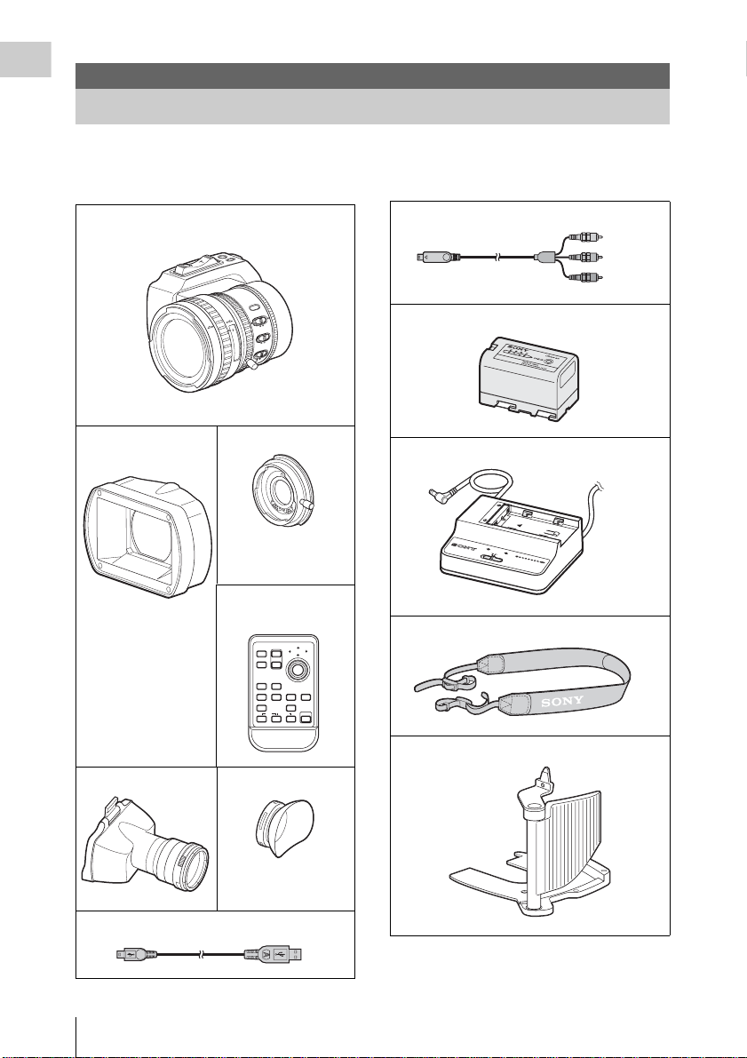
Package Configuration
Make sure you have following ite ms sup plie d w ith your camcorder.
The number in parentheses indicates the number of that item supplied.
VCL-614B2X exclusive standard zoom lens
(1)
STEADY
1.9
SHOT
2.8
4
IRIS
Full
F
M
F
A
5.6
8
O
ft
T
mm
U
A
U
N
A
M
16
O
10
MACR
30
C
5
15
ON
OFF
3
10
FOCUS
2
7
O
T
U
A
It is attached to the camcorder at the factory.
Lens hood with lens
Lens adaptor (1)
cap (1)
For a lens of 2 kg (4 lb 6
oz) or less.
Infrared Remote
It is attached to the
camcorder at the factory.
Commander (1)
PUSH SET
T
1
ZOOM
SHOTMARK
2
W
SUB CLIP
THUMBNAIL
PREV NEXT
PLAY/PAUSE
STOP
.
>
xu
FFWDFREV
m
M
PUSH AFREC PAUSE
REC
z
X
Component video cable (1)
BP-U30 battery pack (1)
B
P-S30
BC-U1 battery charger (1)
DC OUT
CHARGE
0% 80 100
BATTER
BC-U1
Y CHARGER
Shoulder strap (1)
Cheek pad (1)
Eyepiece (1) Eyecup (1)
USB cable (1)
Package Configuration
12
It is attached to the
eyepiece at the factory.
Page 13

Lens mount cap (1)
Lens cap for the supplied lens (1)
Fixing screws for the cheek pad (3)
DC cable clamp an d fixin g s crew (1 each)
Bottom plate (1) and fixing screw s (2)
Lithium battery (CR2032 for backup) (1)
It is mounted in the camcorder at the factory.
Lithium battery (CR2025 for the IR Remote
Commander) (1)
It is mounted in the IR Remote Commander at the
factory.
CD-ROM:
Utility Software for Solid-State Memory
Camcorder and Re corde r (XDCAM EX Cl ip
Browsing Software, SxS Device Driver
Software) (1)
Manuals for Solid-State Memory Camcorder
(Operating Instructions in PDF) (1)
Operating Instructions (This manual) (1)
SxS Device Driver Software End-User
License Agreemen t (1)
Features
The PMW-EX3 is a highly compact and highperformance XDCAM EX
1)
memory cards, as its reco r ding medium.
SxS
The imaging devices us ed in the PMW-EX3
camcorder are three
each with an effective pixel count of 1920 × 1080,
which produce images in full HD resolution.
A New Generation of HD Recording
System
New nonlinear recording media
Using SxS memory cards, the PMW-EX3 offers
nonlinear capabilities such as instant random
access and file-based operation.
HD recording using the “MPEG-2 Long GOP”
codec
The PMW-EX3 records 1920 × 1080 HD images
using “MPEG-2 Long GOP” codec compression.
This mature “MPEG-2 L ong GOP” code c, wh ich
is also adopted in the XDCAM
1080i series of products, enables you to record
stunning-quality HD vi de o and audio with long
recording time by efficiently compressing the
data.
Selectable bit rates
The PMW-EX3 offe rs a choice of b it rat es: ei ther
35 Mbps (HQ mo de) or 25 Mbps (S P mo de),
depending on the desired picture quality and
recording time.
Long recording time
By utilizing an efficient comp ression format, the
PMW-EX3 records high-quality HD images for
long recording time of approx. 100 minutes in HQ
mode (35 Mbps VBR) or approx. 140 minutes in
SP mode (25 Mbps CBR) on a single 32-GB SxS
memory card. Equipped with two SxS memor y
card slots, the PMW-EX3 makes transition
seamless witho ut any f rame lo ss, when recor ding
is done across two cards .
Multiple-format recording
The PMW-EX3 camcorder offers a wide array of
recording formats for multi ple content creation
applications. The scanning mode is switchable
among 1920 × 1080, 1280 × 720, and 1440 ×
1)
camcorder that uses
1
/2-inch type CMOS sensors,
1)
HD and HDV2)
Overview
Features
13
Page 14

1080 resolutions. Frame rate is also selectable
from interlace and progressive (59.94i, 50i,
Overview
29.97P, 25P , an d native 23.98P ). In addition,
59.94P and 50P progressive recording is available
in 1280 × 720 mode. SxS memor y ca rds ca n
simultaneously hold multiple files of any of these
recording formats, allowing for flexible use of the
memory cards.
High-quality uncompressed audio recording
In addition to HD video recording, the PMWEX3 can record and play back high-quality, two channel 16-bit, 48-kHz linear PCM
uncompressed audi o.
IT friendly
The file-based recording in MP4 form at allows
material to be handl ed with g reat flex ibil it y in an
IT-based environment, easily avai la ble for
copying, transferrin g, shari ng, and archiving.
For immediate recording start
In recording on flash memory cards, the XDCAM
EX system makes each new recording on an
empty area of the card. Th is is ex tremely
convenient, as the camera operator need not
worry about accidentally recording over good
takes or search through foota ge for the correct
position to start the next recording.
Instant-access thumbnail display with “Expand”
function
Each time a recording is started and stopped on
the XDCAM EX camcorder, the video and audio
signals are reco rded as one clip.
Furthermore, thumbnails are automatically
generated for each clip as a visual reference,
allowing the op erator to cue-up to a desir ed scen e
simply by gu iding the curs or to a thumbnai l. For
further convenience, the ‘Expand’ function
allows one select ed clip in the Th umbnai l display
to be divided into 12 equal time int er vals, each
with its own thumbnail i dentifier . This is use ful if
you wish to quickly search fo r a parti cu la r sce ne
within a len gthy clip.
Cutting-edge Camera Technologies
1
/2-inch type three “Exmor”1) CMOS sensors
The PMW-EX3 is equipped with three newly
developed
which deliver excellent picture performance with
full HD resolution.
1
/2-inch “Exmor” CMOS Sensors,
Newly developed lens mount
The PMW-EX3 employs a new lens mount (1/2inch EX Mount) of superior optica l
characteris tics in a compact size, which per mits
the supplied standard zoom lens and an optionally
available lens specifically designed for the PMWEX3 to be mounted.
For use of a conventional Sony 1/2-inch Bayonet
Mount lenses, a lens adaptor is provided as a
supplied accessory.
VCL-614B2X high-performance zoom lens
(supplied)
The PMW-EX3 is equipped with a zoom lens
specifically designed for the camcorder, to offer
optimum shooting performance. Independent
rings for zoom, focus, and iris adjust ment give the
user a high level of smooth operational cont rol.
The lens has versatile functions for ea sy and
precise focus adjustments.
• One-push Auto Focus
• MF Assist
• Optical Image Stabilizer (Steady Sho t)
Creative Recording Modes and Settings
23.98P native recording
The PMW-EX3 camcorder, a new member of
Sony’s legendary CineAlta
compact offers native 23.98P re cording
capability.
Slow & Quick Motion function
The PMW-EX3 offers a Slow & Quick Mot i on
function, commonly known as overcranking and
undercranking in film shootin g, wh ic h en ables
you to create unique ‘looks’ or special effects of
slow- and fast-motion images.
Slow Shutter function
The PMW-EX3 offers a Slow Shutter function for
capturing clear images in low-light environments.
This allows the shutter speed to be changed to a
maximum of 64-frame accumulation period.
Selectable gamma curves
The PMW-EX3 provides various types of gamma
identical to those of other CineAlta camcorders.
Interval Recording function
The PMW-EX3 offers an Interval Rec ording
function that in term it tent ly reco rd s signal s at pre determined intervals. This is conven ient for
shooting over long periods of time and also when
creating pic tures with sp ecial effe cts of extrem ely
quick motion.
1)
family, though
14
Features
Page 15

Frame Recording function
Frame Recordi ng is a uni que featu re of th e PMWEX3 camcorder that is especially useful for clayanimation shooting. With this function, images
for pre-determined fra me are recorded each time
the record button is pressed.
Shutter-angle settings
In addition to the electric shutte r spe ed c ont rol s ,
the PMW-EX3 also has a “sh utter angl e” con trol,
which is familiar to cinematographers.
Picture Profile feature
The Picture Profile feature allows the camera
operator to easily call up customized picturetonal settings to suit particular shooting
conditions.
Shot Transition function
The Shot Transition function allows for smooth
automatic scene transitions. The operator can
program start and end setti ngs for zoom, focus,
and white balance into the A and B buttons, and
with a press of the Start button a smooth transition
will take place acco rd ing to the set time.
A variety of functions and designs for
high operability
• Color viewfinder i ncorporated with a 3.5-inc h
color LCD insid e: Flippi ng up the eyepiece, y ou
can also operate the camcorder while direc tly
viewing th e LCD.
• Expanded Focus
• Peaking
• Depth-of-field indicator
• Brightness-level display
• Histogram indicator
• Four assignable buttons
• Zoom and recording start/stop operations
enabled both on the ha ndl e and the grip
• Long operating time with a battery pack
• Wide array of interfaces, including USB and
1)
i.LINK
• ATW (Auto Tracing White Balance)
• Built-in ND filter wheel
• Selectable gain
• High-speed p icture search: ×4, ×15
• Freeze Mix function
• IR Remote Comma nder
• Input/output connectors for external
synchronization
1)
supplied
• Operations from the optional Remote Control
Units: The camcorder can be operated from the
RM-B750/B150 Re mote Control Unit.
1)Sony, XDCAM, XDCAM EX, SxS, i.LINK, Exmor,
CineAlta, and Remote Commander are trademarks of
Sony Corporation.
2)HDV is a trademark of Sony Corporation and Victor
Company of Japan, Limited.
All other trademarks are the property of their respective
owners.
XDCAM EX web sites
For information on XDCAM EX, visit the
following web sites:
United States
http://www.sony.com/xdcamex
Canada
http://www.sony.ca/xdcamex
Europe, Middle East, Africa, and Russia
http://www.sonybiz.net/xdcamex
Latin America
http://www.sonypro-latin.com/xdcamex
Australia
www.sony.com.au/xdcamex
Asia (except Korea, China, and Japan)
http://pro.sony.com.hk
Korea
http://bp.sony.co.kr/xdcamex
China
http://pro.sony.com.cn/minisite/XDCAMEX
Japan
http://www.sony.co.jp/XDCAMEX
Overview
Features
15
Page 16

Overview
Using the CD-ROM
Two CD-ROMs are supplied with the PMWEX3.
The CD-ROM labeled “Manuals for Solid-State
Memory Camcorder” contai ns t he Operating
Instructions for the PMW-EX3 (Ja panese,
English, French, German, Italian, Spanish and
Chinese) in P DF format.
The CD-ROM labelled “Utility Software for
Solid-State Memory Camcorder and Recorder”
contains the following soft w are:
SxS Device Driver Software
Driver for using SxS memory cards with a
computer having an ExpressCard slot.
Information on installation of the software is
included in the ReadMe (Japanese, English,
French, Germa n, Italia n, Spani sh, and Chinese) in
PDF format.
XDCAM EX Clip Browsing Software
Application program for operating clips recorded
with XDCAM EX-series models on a computer.
Information on installation and operations of the
software is included in the User’s Guide
(Japanese, Engl is h , F re n ch, German, Italian,
Spanish, and Chinese) in PDF format.
Reading the CD-ROM Manuals
Preparations
The following program must be installed on your
computer in order to read the operation manuals
contained on the CD-ROM.
Adobe Reader Version 6.0 or higher
Memo
If Adobe Reader is not installed, you can
download it from the following URL:
http://www.adobe.com/
Adobe and Adobe Reader are trademarks of Adobe
Systems Incorporated in the United States and/or other
countries.
To read the documents
Do the following:
1 Insert the CD-ROM in your CD-ROM
drive.
A cover page appears automatically in your
browser.
If it does not appear automatically in the
browser, double-click on the index.htm file
on the CD-ROM.
2 Select and click on the manual that you
wish to read.
This opens th e PDF file.
Memo
The files may not be displayed properly,
depending on the version of Adobe Reader. In
such a case, install the latest version you can
download from the URL ment ioned in
“Preparatio ns” above.
Note
If you have lost or damaged the CD-RO M, you
can purchase a new one to replace it. Contact your
Sony service representative.
System Requirements for Using the Applications
The following operating c onditions are
recommended for using the software recorded on
the CD-ROM:
SxS Device Driver Software
Applicable hardware
Computer conforming to Ex pressCard/34 or
ExpressCard/54
OS
Microsoft Windows XP SP2 or later, Microsoft
Windows Vista, or Mac OS X v10.4. 9 or l at er
For support information on the driver, refer to the
following URL:
http://www.sony.net/SxS-Support/
Using the CD-ROM
16
Page 17

XDCAM EX Clip Browsing Software
OS
Microsoft Windows XP SP3 or later (32-bit
version), Microsoft Windows Vista SP1 or later
(32-bit version), or Mac OS X v10 .4 .11 or la te r/
v10.5.1 or later.
CPU
Windows: Intel Pentium 4 2.0 GHz or higher
(Intel Core 2 Duo Processor 2.0 GHz or
higher is recommended.)
Macintosh: Intel Core 2 Duo Processor 2.0 GHz
or higher (Intel Core 2 Duo Processor 2.4
GHz or higheris recommend ed.)
Memory
1 GB (2 GB or more is recommended.)
• Microsoft, Windows, and Windows Vista are
registered trademarks and/or trademarks of Microsoft
Corporation in the United States and/or other
countries.
• Intel Core and Pentium are trademarks of Intel
Corporation in the United States and/or other
countries.
• Macintosh and Mac OS are trademarks of Apple Inc.
registered in the U.S States and other countries.
Software Installation
Uninstalling an application program
Windows computer
Choose “Start,” “Control Panel” then “ A dd or
Remove Programs” and specify the program to be
deleted.
Macintosh computer
Drop the folder of the software (default:
/Application/XDCAM EX Clip Browser) into
Trash.
Overview
Do the following to install the software on the
CD-ROM on your computer:
1 Insert the CD-ROM in your CD-ROM
drive.
A cover page appears automatically in your
browser.
If it does not appear automa tically in the
browser, double-click on the index.htm file
on the CD-ROM.
2 Select and cl ick on the soft ware that yo u
wish to install.
The installer for the software starts up.
Follow the displayed instructio ns:
For details, refer to the User’s Guide or ReadMe of
the software.
Using the CD-ROM
17
Page 18
Overview
O
EX
UD
IO
S
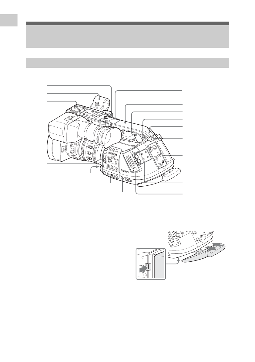
Parts Identifications
Camcorder
1
2
3
16:9 WIDE SCREEN
AF
Full
MF
ft
mm
30
10
5
15
3
10
4
Front lower operation block (page 21)
Side operation panel (page 21)
For functions and usage, see the pages shown in
parentheses.
1. Cable clamp for external microphone
(page 71)
2. External microphone holder (page 71)
3. Front accessory shoe
Attach an optional accessory, such as a video
light.
4. Lens mount lever (page 37)
5. Handle
6. Built-in speaker (page 99)
7. Cable clamp for optional accessories (page
71)
8. Rear accessory shoe
Attach an optional accessory, such as the
PHU-60K Professional Hard Disk Unit (page
47).
9. Rear tally lamp (page 51, page 153)
Operation panel on the
handle(page 20)
R
CANCEL
VOL
F FWD
MONITOR
SEL/SET
L
NEXT
/S J
PLAY/PAUSE
G
THUMNAIL
STOP
F REV
j
REC
PREV
START/STOP
l sL
HOLD
H
F
L
F
O
STEADY
SHOT
81.2
40
IRIS
1.9
25
2.8
MANU
15
AUTO
4
M
ACR
O
10
5.6
8
O
F
F
O
5.8
N
FOCUS
16
C
M
A
N
U
A
U
P
T
U
O
S
H
A
F
A
TR
S
H
A
O
N
T
S
IT
B
IO
N
TC
/U
-B
IT/DU
R
ATIO
LENS INFO
1
ND
FILTER
2
1
-
FRAME
+
GAIN
OFF
WHITE BAL
L
M
A
T
W
H
S
T
A
T
U
S
MENU
SEL/SET
N
BRT DISP
HISTOGRAM
ASSIGN
2
3
SS
ACCE
B
A
FULL AUT
O
BARS/CAM
B
A
P
R
S
T
CANCEL
PICTURE
PROFILE
CAMERAOFF
MEDIA
SDI OUT
V
D
H
T SELECT
IN
SLO
EXT
GENLOCK IN
O
AUT
ANUAL
M
IO
AUD
IN
CH-1
IO
IN
TC IN
AUD
SELECT
EXT
AUDIO
AUTO
LEVEL
ANUAL
M
CH-2
OPEN
PMW-EX3
REMOTE
TC OUT
5
6
7
8
9
Rear connector panel
(page 20)
10
Audio control block
(page 20)
1112
Card slot block
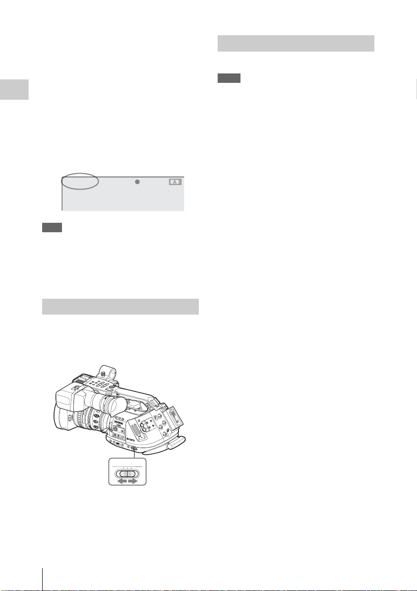
(page 21)
10. Shoulder pad
It can be pulled out as follows:
A
AUT
LEVEL
ANUAL
M
CH-2
OPEN
MEDIA
Push in the knob at the bottom
to unlock.
Hold the knob depressed when
pulling out or pushing in the
pad.
PMW-EX3
REMOTE
REMOTE
TC OUT
11. Power (CAMERA/MEDIA) switch (page
30)
12. PICTURE PROFILE button (page 88)
Parts Identificatio ns
18
Page 19
13
14
OFF
L
15
16
Upper operation
panel (page 21)
17
18
19
20
21
R
E
LE
B
A
A
T
S
T
E
E
R
Y
N
IO
T
A
R
U
/D
D
C
IN
M
O
N
O
ITO
U
T
R
S
VID
E
O
CH-1
AUDIO OUT
CH-2
COMPONENT
OUT
H
l
PREV
j
HOLD
IT
-B
/U
C
T
CH-1
N
IO
B
IT
S
T
N
O
A
H
R
S
T
A
MIC
LINE
STOP
MIC+48V
START/
RELEASE
EXPANDED
FOCUS
REVIEW
REC
LOCK
RELEASE
F REV
sL
STOP
STAR
G
P
LA
/
S
Y
T/STOP
REC
/P
A
NEXT
U
S
J
E
SEL/SET
F FWD
C
A
N
C
E
L
R
A
U
D
IO
IN
CH-2
MIC
LINE
MIC+48V
22
23
24
LOCK
RELEASE
Connectors 18 to 20 have indivial caps, and 21 to 23 are behind a shared cover.
Bottom (page 22)
25
Overview
26
27
T
H
IG
Viewfinder control
R
B
T
S
A
R
T
N
O
C
A
R
B
G
E
IN
Z
K
A
E
P
DISPLAY/BA
OR IMAGE
N
O
MIRR
F
F
O
THUMNAIL
L
MONITOR
VOL
TT INFO
panel (page 22)
28
29
30
31
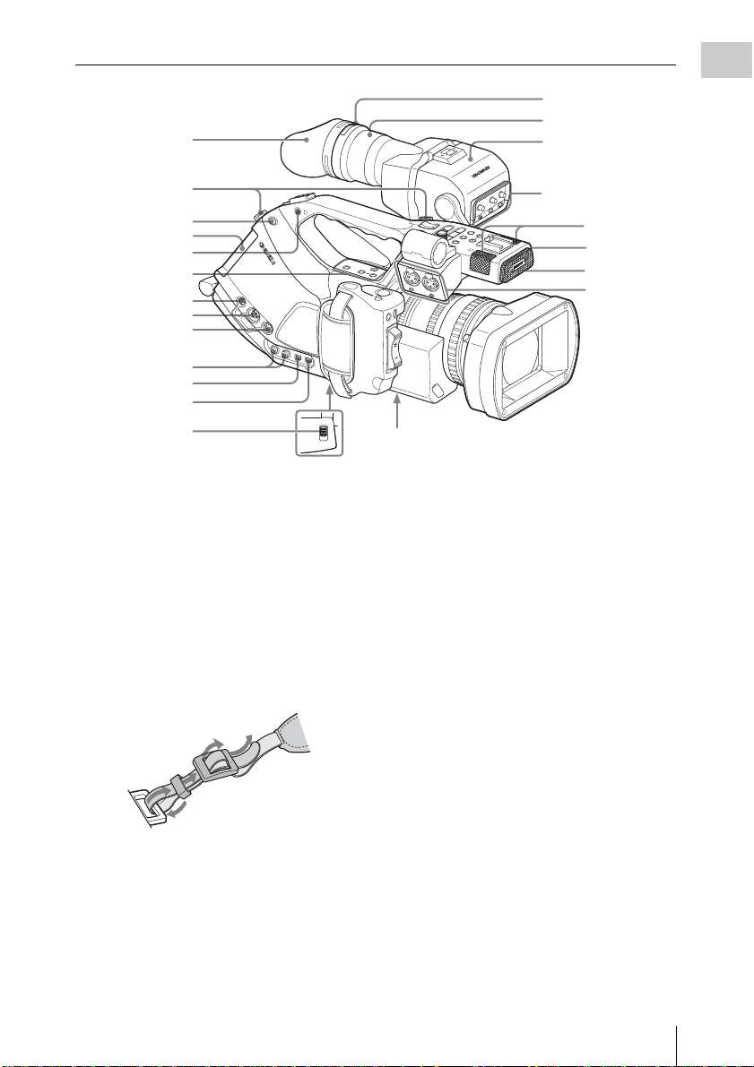
13. Eyecup
The eyecup can be attached in the reversed
direction.
To reattach the eyecup, stretch it a litt le to
attach to the viewfi nder an d fit the rim of the
eyecup into the gro ove of the viewfinder .
14. Hooks for the shoulder strap (left and
right)
Attach the supplied shoulder strap as shown
below.
4
3
2
1
15. BATTERY RELEASE button (page 28)
16. Battery pac k receptacle (page 28)
17. Headphone jack (stereo mini jack) (page
72, page 99)
18. DC IN (DC power input) connector (page
29)
19. MONITOR OUT connector (BNC type)
(page 132)
20. S V ID EO co n n ect or (4-pin) (page 132)
21. AUDIO OUT CH-1/CH-2 connectors
(RCA phono) (page 132)
22. COMPONENT OUT connector (Mini D)
(page 132)
23. USB connector (Mini B) (page 133)
24. Lens mount stopper switch (page 37)
25. Eyepiece focusing knob (page 32)
26. Eyepiece (page 34)
27. Viewfinder (page 32)
28. Built-in microphones (p age 71)
29. REC/TALLY lamp (page 51, page 153)
30. IR remote control receptor
31. AUDIO IN CH-1/CH-2 connec tors (XLR)
and input selection switches (page 71)
Parts Identifications
19
Page 20
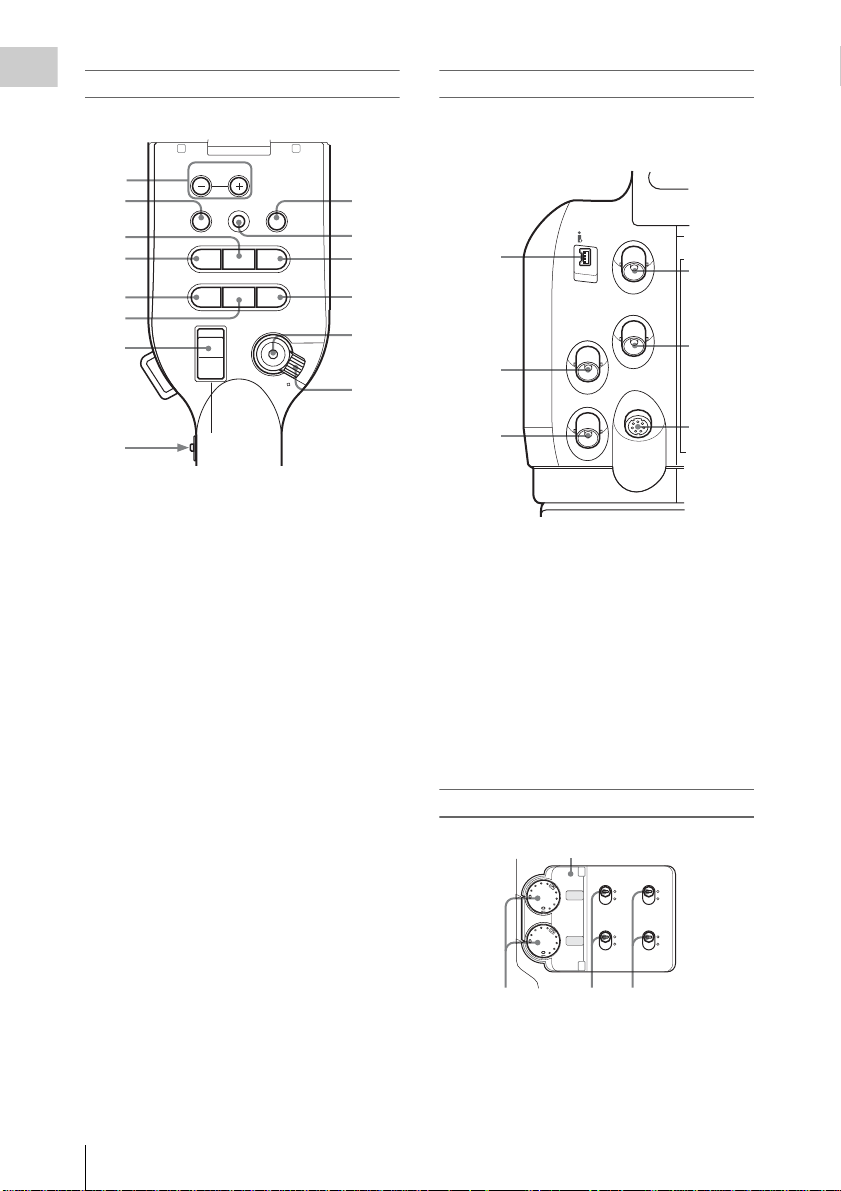
Operation panel on the handle
Overview
CANCEL
F FWD
/SJ
NEXT
REC
START/STOP
R
L
MONITOR
1
2
3
4
5
VOL
THUMBNAIL
SEL/SET
PLAY/PAUSE
F REV
G
j
PREV
STOP
lsL
6
7
HOLD
H
8
OFF
L
1. MONITOR VOL (volume) buttons (page
72, page 99)
2. THUMBNAIL button (page 97)
3. PLAY/PAUSE button (page 97)
4. F REV (fast reverse) button (page 98)
5. PREV (previous) button (page 98)
6. STOP button (page 99)
7. On-handle ZOOM button (page 63)
8. Zoom speed switch (page 63)
9. CANCEL button (page 114)
10. SEL/SET (selection/set) button (Joystick)
(page 114)
It functions accordingly when you move it up
(forward), down (rearwa rd), left, or right, or
you push along the axis.
It is called “the joystick” in the subsequent
operating inst ructions.
11. F FWD (fast forward) button (page 98)
12. NEXT button (page 99)
13. REC START/STOP button (page 51)
14. REC HOLD lever (page 51)
10
11
12
13
14
Rear connector panel
The connectors are l ocated under the respective
caps.
9
SDI OUT
HDV
1
GENLOCK IN
TC IN
2
REMOTE
TC OUT
3
4
5
6
1. i.LINK (HDV) connector (4-pin, S400
conforming to IEEE1394) (p age 135)
2. TC IN (timecode input) connector (BNC
type) (page 138)
3. TC OUT (ti mecode output) connector
(BNC type) (page 139)
4. SDI OUT connector (BNC type) (page 132)
5. GENLOC K IN connector (BNC type)
(page 138)
6. REMOTE connector (8-pin) (page 142)
Audio control block
Cover
AUTO
MANUAL
AUTO
MANUAL
AUDIO
INT
EXT
IN
INT
EXT
CH-1
AUDIO
LEVEL
CH-2
AUDIO
SELECT
123
Parts Identificatio ns
20
1. AUDIO LEVEL CH-1 /CH-2 controls
(page 71)
2. AUDIO SELECT (audio level control
mode selection) switches (page 71)
Page 21
3. AUDIO IN (audio input selection)
switches (page 71)
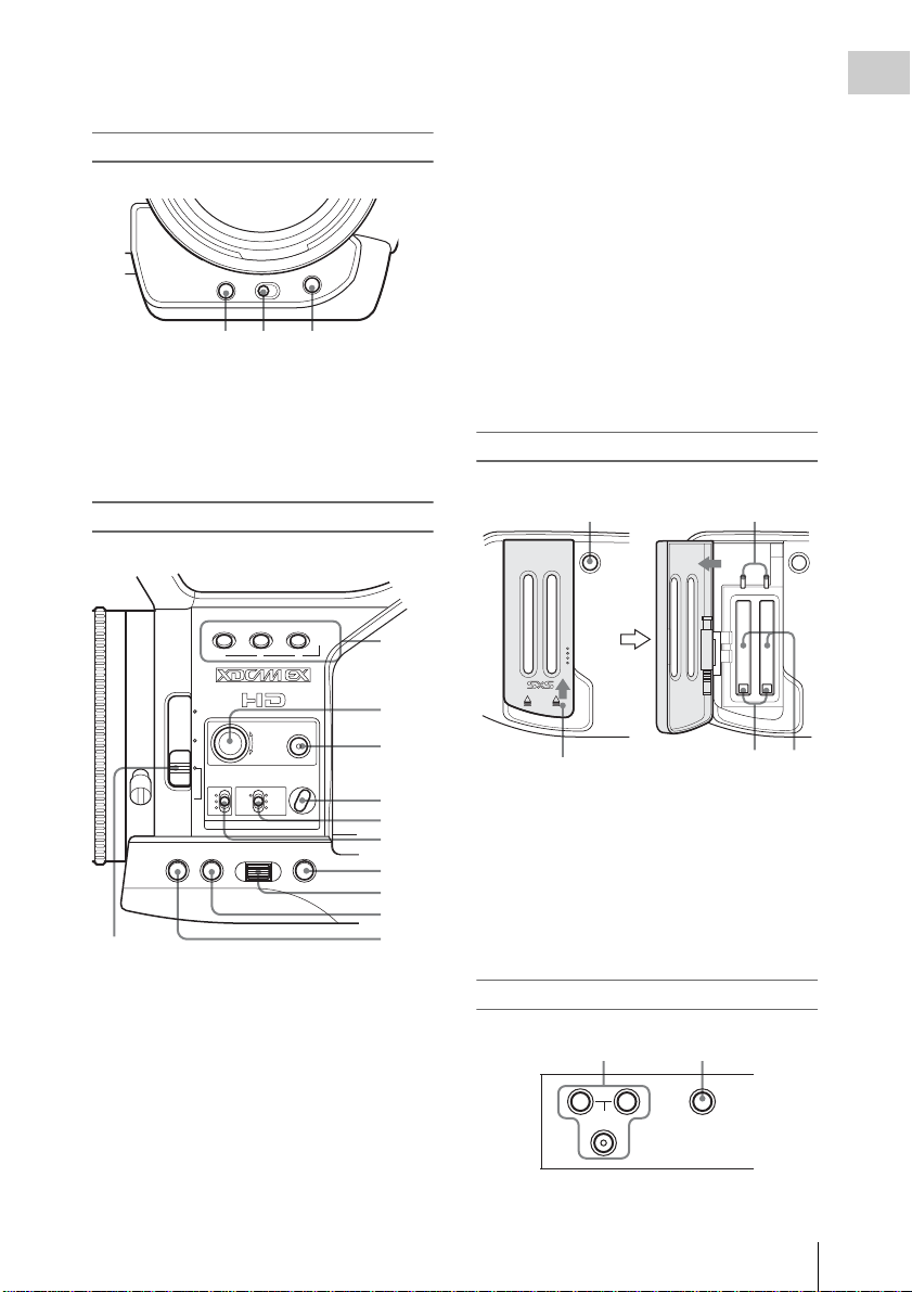
Front lower operation block
WHT BAL
ASSIGN 4
SHUTTER
OFF ON
12 3
1. ASSIGN 4 (assignable 4) button (page 75)
2. SHUTTER switch (page 59)
3. WHT BAL (automatic white balance
adjustment) button (page 54)
5. WHITE BAL (white balance memory)
switch (page 54)
6. GAIN switch ( page 58)
7. CANCEL button (p age 114)
8. SEL/SET (selection/set) dial (Jog dial)
(page 114)
It functions accordingly w he n you turn it up
or down, or you push it horizontally.
It is called “the jog dial” in the subsequent
operating instructions.
9. MENU (menu display ON/OFF) butto n
(page 114)
10. STATUS button (page 108)
11. ND filter select switch ( page 53)
Card slot block
Overview
Side operation panel
LENS INFO BRT DISP HISTOGRAM
123
ND
FILTER
2
-
1
+
WHITE BAL BARS/CAM
GAIN
LATW
OFF
M
H
STATUS MENU SEL/SET CANCEL
FRAME
FULL AUTO
B
A
PRST
ASSIGN
1
2
3
4
5
6
7
8
9
11
10
1. ASSIGN (assignable)1/2/3 buttons (page
75)
2. S&Q (Slow & Quick) Motion dial (page
79)
3. FULL AUTO button and indicator (page
51)
4. BARS/CAM (color bar/camera signal
switching) button (page 73)
12
ACCESS
AB
OPEN
SLOT SELECT
Slide the cover upward
to unlock.
34
1. SLOT SELECT (SxS memory card s elect)
button (page 45)
2. ACCESS lamps (p age 44)
3. EJECT buttons (page 45)
4. SxS memory card slots (page 44)
Upper operation panel
12
A
SHOT
TRANSITION
B
TC/U-BIT/DURATION
Parts Identifications
21
Page 22
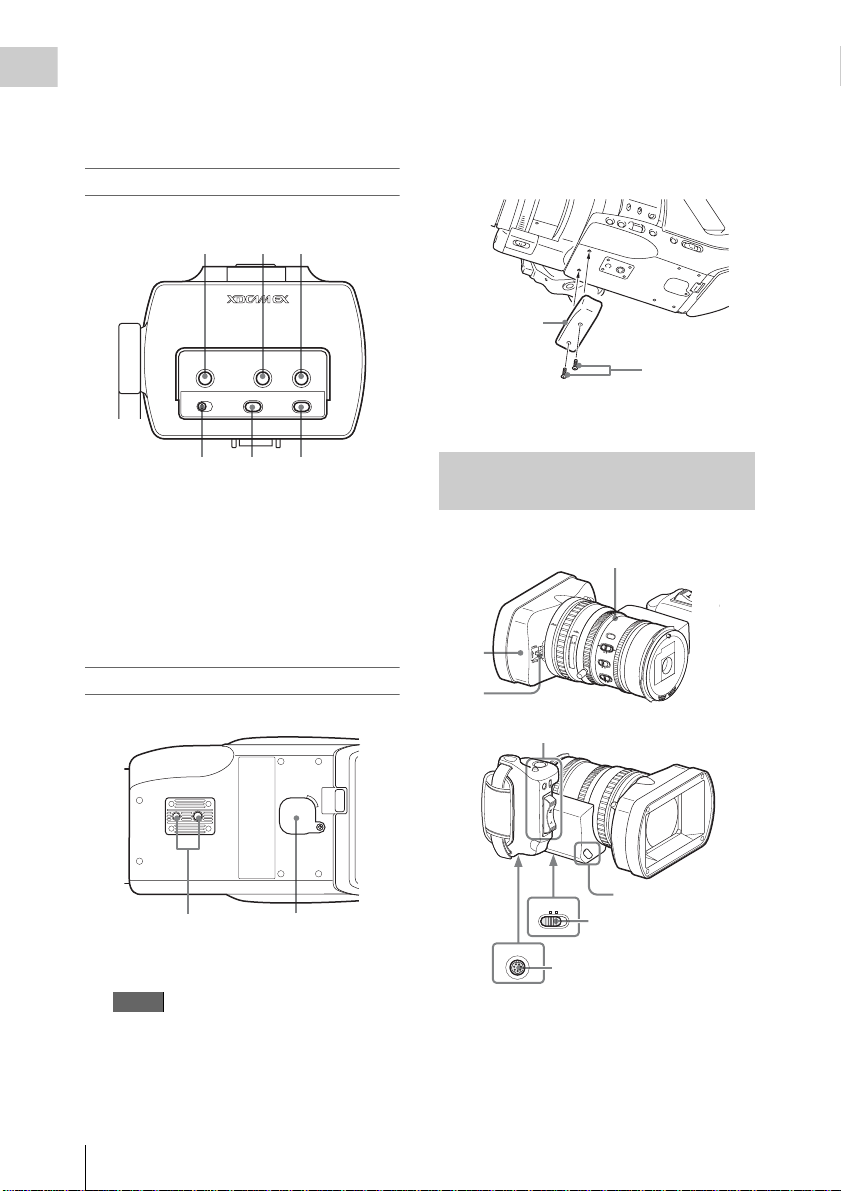
1. SHOT TRANSITION operation block
Overview
(page 82)
2. TC/U-BIT/DURATION (time data
selection) button (page 70, page 98)
Viewfinder control panel
123
When attaching to a tripod
Use the supplied bottom plate to stabilize the
camcorder. Remove two screws from the
bottom of the camcorder and attach the
bottom plate using the two supplied screws
(M2×6).
Bottom plate
PEAKING CONTRAST BRIGHT
MIRROR IMAGE
OFF ON
4
DISPLAY/BATT INFO
ZEBRA
5
6
1. PEAKING control (page 65)
2. CONTRAST control (page 32)
3. BRIGHT control (page 32)
4. MIRROR IMAGE switch (page 33)
5. DISPLAY/BATT INFO button (page 25)
6. ZEBRA button (page 57)
Bottom
12
1. Tripod receptacles
Note
Check that the size of the hole matches the
screw of the tripod. If they do not match , the
camcorder cannot be attached to the tripod
securely.
M2×6 screws
2. Backup batt ery hol der (page 149)
Zoom Lens VCL-614B2X (Supplied)
Lens control block (page 23)
A
F
F
ull
STEADY
M
F
SHOT
81.2
ft
40
mm
IRIS
1.9
25
30
2.8
10
MANU
15
AUT
O
1
2
Controls on the grip
(page 23)
STOP
START/
RELEASE
EXPANDED
FOCUS
REVIEW
REC
ZOOM
MANU SERVO
LENS
REMOTE
4
1. Lens hood
2. Lens cap open/close lever (page 50)
3. ZOOM switch (page 62)
4. LENS REMOTE connector (page 64)
M
A
C
R
5
15
O
10
3
10
O
FF
O
5.8
N
FOCUS
M
ANU
PU
SH AF
3
4
5.6
8
16
C
AUT
O
Cover of the lens
control block (See
“Note” below.)
Parts Identificatio ns
22
Page 23
Note
IL
P
A
EC
ST
L
LOCK
RELEASE
EXPANDED
FOCUS
REC
REVIEW
RELEASE
START/
STOP
The lens is properly adjusted at th e fa ctory. Do
not touch the controls of the len s con trol block.
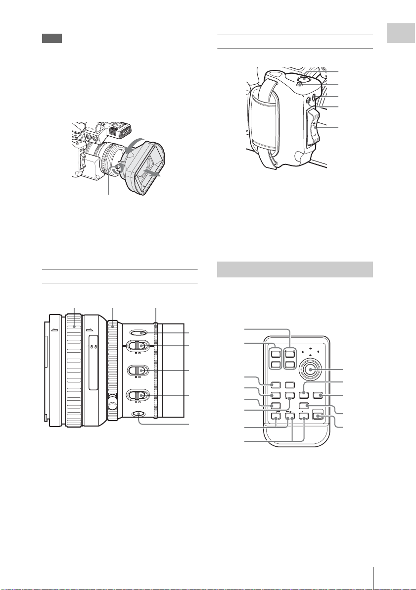
To remove the lens hood
1 Loosen the hood fixing screw, 2 turn the
hood in the direction of the arrow, 3 then pull it
out.
NEXT
U
OP
MONITOR
S
J
E
SEL/SET
F FWD
VOL
C
A
N
C
E
L
R
C
H-1
SITION
T
AUDIO IN
SHO
TRAN
A
CH
-2
M
IC
LIN
E
STOP
M
STAR
IC
+48V
M
IC
T/
LIN
E
M
IC
+48V
RELEASE
EXPANDED
FOCUS
REVIEW
REC
LOCK
RELEASE
2
1
Hood fixing screw
To reattach the hood, align the marks on the
hood with those on the cam co rder, turn it in the
opposite directi on from that when yo u removed it,
then tighten the fixing screw.
Lens control block
12 3
AF
FULL
MF
ft15
310mm5
10 30
15 25 40 81.210
5.8
STEADY
SHOT
IRIS
MANU AUTO
MACRO
OFF ON
FOCUS
MANU AUTO
PUSH AF
1. Focus ring (page 64)
2. Zoom ring (page 62)
3. Iris ring (page 61 )
4. STEADY SHOT button (page 67)
5. IRIS switch (page 61)
6. MACRO switch (page 67)
7. FOCUS switch (page 65)
8. PUSH AF (momentary auto focus) button
(page 66)
3
Controls on the grip
STOP
START/
RELEASE
REVIEW
REC
1
EXPANDED
FOCUS
2
3
Overview
4
5
1. REC STAR T/ STOP button (page 51)
2. RELEASE (grip release) button (page 39)
3. REC REVIEW button (pa ge 74)
4. EXPANDED FOCUS button (page 65)
5. Servo z oom lever (page 63)
IR Remote Commander (Supplied)
The buttons without remark s can be use d in the
same manner as the corresponding buttons on the
camcorder.
4
5
8 5.6 4 2.8 1.916
6
C
7
8
1
2
12T
SHOTMARK
3
4
5
6
THUMBNAIL
PREV NEXT
.
m
z
7
REC
ZOOM
W
SUB CLIP
PLAY/PAUSE
PUSH SET
9
10
STOP
>
xu
FFWDFREV
M
X
11
PUSH AFREC PAUSE
12
13
8
1. ZOOM T/W (telephoto/wide-angle)
button
2. SHOTMARK 1 and 2 buttons (page 74,
page 106)
3. THUM BN AIL button
4. PREV (pre vious clip jump) button
5. F REV (fast reve rse ) button
6. PLAY/PAUSE button
Parts Identifications
23
Page 24

7. REC (record) buttons
Overview
Press the z button together with the unmarked
button (safety button) to start reco rd ing.
8. REC PAUSE buttons
Press the X button together with the unmarked
button (safety button) to pause record i ng.
9. PUSH SET button (four-way arrow key)
It functions the same a s th e SEL /SET button
(joystick) on the camcorder.
10. NEXT button
11. STOP button
12. F FWD (fast forward) button
13. PUSH AF button
Note
The SUB CLIP button does not function with this
camcorder.
When you use the remote commander, see “Using the
IR Remote Commander” on page 41.
Parts Identificatio ns
24
Page 25
On-Screen Indications
9
0
2
3
4
5
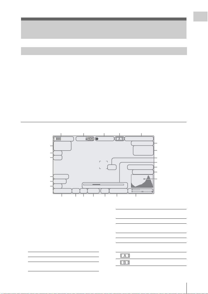
Indications in Camera Mode
Overview
When this unit is in Camera mode (mode for
recording), pressing the DISPLAY/BATT INFO
button displays the statuses and settings of this
unit in the view finder.
When you press the DISPLAY/BATT INFO
button again, the se indications are canceled.
The recordin g statu s indic ation, s uch as “
is always display ed, reg ardless of oper ation of the
DISPLAY/BATT INFO button.
zREC,”
12345
STBY
120min
A: 25min
6
B: 50min
7
Z99
8
EX
9
10
11
.
TLCS
7
On
M
F
∗
ATW 4300K PPOFF ND1
S&Q
1 1.5 2 3 4 5 7 10 15 20 30 oo
++
F1.9
12 13 14 15 16 17 18
Remarks
[M]: The indication of the items named with this
suffix can be independentl y tu rned on/off
with “Display On/Off” of th e VF SET menu
(see page 124).
[A]: The indication of items named with this suf-
fix can be turned on/off using the assignable
buttons to which the correspond ing on/off
functions have been assigned (see page 75).
[D]: The settings of the items named with t his suf-
fix can be changed using the Direct menu on
the screen (see page 26).
REC
TCG 00:00:00:00
Q
1080/24P
H
Q M
otion
S&
29/24fps
2
2
2
2
74% High Light ND2
W
hite Fader
21
2
1
m
CH1
18dB
SHT
:1/2000
CH2
1. Battery remaining/DC IN voltage
indication [M] (page 28)
2. i.LINK status indication
Only when an external device is connected to
the i.LINK connector (page 135), the status
(
zREC or STBY) of the device is displayed.
3. Special recording/operation status
indication
zREC Recording in progress
STBY Standby for recording
zS&Q REC Slow & Quick Motion
recording in progress
S&Q STBY Standby for Slow & Quick
zINT REC Interval Recording in progress
INT STBY Standby for Interval
zFRM REC Frame Recording in progress
FRM STBY Standby for Frame Recording
4. Media status ind ic ation
5. Time data indication [M] (page 70)
Motion recording
Recording
Memory card in slot A is active.
Memory card in slot B is active.
On-Screen Indications
25
Page 26
6. Media remain ing indicatio n [M] (page 46)
STD
Overview
7. Zoom position indication [M] (page 62)
8. Lens extender indication
(available only when a lens extende r is use d)
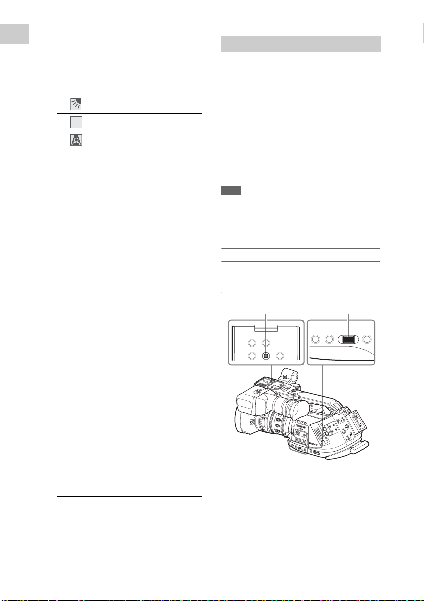
9. TLCS mode indication [M][D] (page 120)
Backlight mode
Standard mode
STD
Spotlight mode
10. Steady Shot indication [M] (page 67)
11. Focus mode indication [M] ( [D] only in MF
mode) (page 64)
(available only when an auto-focus lens is
mounted)
12. White balance mode and color
temperature indications [M][D] (page 54)
13. Picture profile indication [M][D] (page 88)
14. ND filter indication [M] (page 53)
15. Iris position indication [M][D] (page 61)
16. Gain indication [M][D] (page 58)
17. Shutter mode/shutter speed indication
[M][D] (page 59)
18. Audio level meters [M] (page 72)
19. Histogram indication [M][A]
20. Fader indication [M] (page 86)
21. Video level cautioning indication [M]
If the video level is too high or too low, a caution
is generated showing the appropr ia te ND fi lte r
number.
22. Depth-of-Field indication [M][A]
(available only when a serial lens is m ounted)
23. Brightness level indication [M][A]
24. Special recording mode indication [M]
Frame Rec Frame Rec mode
Interval Rec Interval Rec mode
S&Q Motion
xx/xx fps
Slow & Quick Motion mode
EXT-LK Time code external lock (see
page 138)
25. Video Format indication [M] (page 52)
Direct Menu Operation
The settings of th e items named with a suff ix [D]
can be changed using the Direc t menu on the
screen.
Select “All,” “Part,” or “Off” for Direct Menu
using “Direct Menu” (page 129) of the OTHERS
menu.
When the Direct mode is set to “Part,” the
operation is limited depend in g on t h e GA IN,
SHUTTER, or WHITE BAL switch setting.
When the Direct mode is set to “All,” the GAIN,
SHUTTER, and WHITE BAL switches are
disabled.
Note
When the indicator of the FULL AUTO button is
lit, the Direct Menu operation is disa bled for the
functions th at are forcibly set to the autom atic
mode in Full Auto mode (page 51).
To operate the Direct menu
Use the joystick on the handle or the jog dial on
the side operation panel.
Joystick
MONITOR VOL
THUMBNAIL SEL/SET CANCEL
L
16:9 WIDE
SCREEN
ft
m
m
0
0
3
1
5
15
0
3
1
R
CANCEL
VOL
F FWD
MONITOR
E
S
SEL/SET
J
U
A
/P
NEXT
Y
A
L
/S
P
G
THUMNAIL
STOP
F REV
j
REC
T/STOP
PREV
STAR
l s L
HOLD
H
40
IRIS
.9
1
25
L
E
N
S
IN
F
O
B
2.8
M
AN
U
15
AUT
O
4
1
MACR
O
2
ND
.6
10
FILTER
5
8
O
FF
O
5.8
N
2
FOCUS
16
C
1
-
M
A
N
U
A
U
P
T
U
O
S
H
A
F
F
R
A
+
GAIN
O
FF
WHITE BAL
L
M
A
T
W
H
STA
TUS
M
ENU
S
E
L/S
E
T
Jog dial
STATUS MENU SEL/SET CANCEL
F
L
F
O
B
T
C
/U
B
IT
/
D
U
R
A
T
IO
N
SDI OUT
R
T
D
IS
P
H
IS
T
O
G
3
F
U
L
L
A
U
T
O
M
E
B
A
R
S
/C
A
M
B
A
P
R
S
T
CANCEL
HDV
R
A
M
T
C
LE
E
S
T
A
LO
IN
S
S
S
IG
N
T
X
E
GENLOCK IN
O
T
U
A
L
A
U
N
S
A
S
M
E
IO
C
D
C
U
A
A
B
IN
-1
H
C
IO
D
U
A
IN
TC IN
A
T
C
LE
T
E
X
E
S
IO
D
O
U
T
A
L
U
A
E
L
V
A
U
LE
N
A
M
-2
H
C
TC OUT
PMW-EX3
N
E
P
O
P
IC
T
U
R
E
P
R
O
F
IL
C
E
A
M
E
R
A
O
F
F
M
E
D
IA
REMOTE
1 Press the joys ti ck or the jog dial .
If “Direct Menu ” is set to “Al l” or “Part ,” the
cursor is displayed on one of the item s for
which the Direct menu operatio n is
permitted.
Example: TLCS mode indication
On-Screen Indications
26
Page 27

TLCS
0
m
0
7
On
M
F
∗
ATW 4300K PPOFF ND
1 1.5 2 3 4 5 7 10 15 20 30 oo
1 ++F1.9 18dB
SHT
:1/200
2 Tilt the joystic k or rota te t he jo g di al to
set the cursor to the item to be operated
then press the j oystick or the jog dial .
The Direct menu of the selected items
appears.
Example:
Direct menu for TLCS mode selec t ion
Overview
TLCS
TLCS
7
On
M
F
∗
ATW 4300K PPOFF ND
1 1.5 2 3 4 5 7 10 15 20 30 oo
1 ++F1.9 18dB
74% TLCS
SHT
:1/20
3 Tilt the joystic k or rota te t he jo g di al to
select the setti ng the n press th e jo ysti ck
or the jog dia l.
The menu disappears, and the new setting is
displayed.
On-Screen Indications
27
Page 28
Preparations
F
F
T
Power Supply
You can use a battery pack or A C power via an
AC adaptor.
Preparations
If you connect an AC pow e r so urc e, it has a
priority even if a battery pack is mounted.
For safety, use only the Sony battery packs and
AC adaptor listed below:
• BP-U30/U60 Lithium-ion Battery Pack
• BC-U1/U2 Battery Charge r (usa ble as an AC
adaptor)
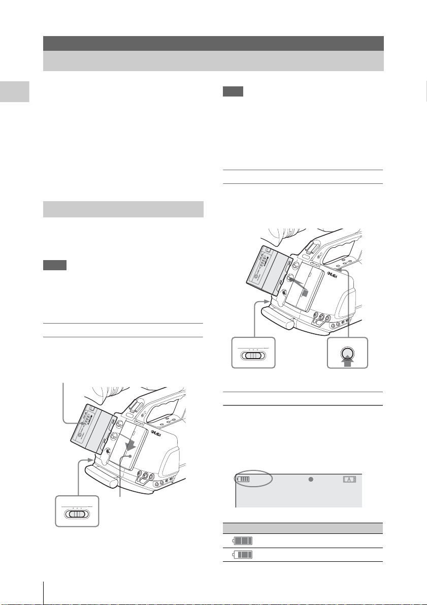
Using a Battery Pack
Mount a BP-U30 or BP-U60 Lithium-ion battery
pack.
One BP-U30 is supp lied with this cam corder.
Notes
• Before use, charge the battery pack with the
supplied BC-U1/U2 Batte ry Charger.
• A warm batter y pack immedia tely aft er use may
not be able to b e fully recharged.
Mounting the battery pack
Fully insert the batter y pac k th en slid e it
downward to lock.
Battery pack
Note
If a battery pack that cannot be used with this
camcorder is mounted, an error message is
appears in the viewfinder. Re place the battery
pack with the BP-U30 or BP-U60, or connect a
power to the DC IN connector after removing the
battery pack.
Removing the battery pack
Hold the BATTERY RELEASE button pressed,
slide the battery pack upward to unlock, then pull
it out.
CAMERA OFF MEDIA
Power switch: OFF
TC IN
REMOTE
TC OUT
SDI OUT
HDV
GENLOCK IN
BATTERY
RELEASE
button
DC IN
T
A
R
A
N
S
S
IT
H
O
IO
T
N
T
C
/U
-B
IT
B
/D
U
R
A
T
IO
N
MONITOR
OUT
S VIDEO
T
N
E
N
O
P
M
T
O
U
C
O
-2
H
C
T
U
O
-1
IO
H
D
C
U
A
BATTERY
RELEASE
Power switch: OFF
Power Supply
28
CAMERA OFF MEDIA
HDV
SDI OUT
GENLOCK IN
TC IN
REMOTE
TC OUT
Battery pack
receptacle
Checking battery charge remaining
T
A
R
A
N
S
S
IT
H
O
IO
T
N
T
C
/U
-B
IT
B
/D
U
R
A
T
IO
N
DC IN
MONITOR
OUT
S VIDEO
T
N
E
N
O
P
M
T
O
U
C
O
-2
H
C
T
U
O
-1
IO
H
D
C
U
A
To check during operation
When recording or playback is in progress on the
battery pack, an icon to show the current battery
charge level and usage time remaining are
displayed in the viewfinder screen.
120min
A: 25min
B: 50min
Z99
STBY
S&Q
REC
Icon Remaining
100% to 91%
90% to 71%
Page 29
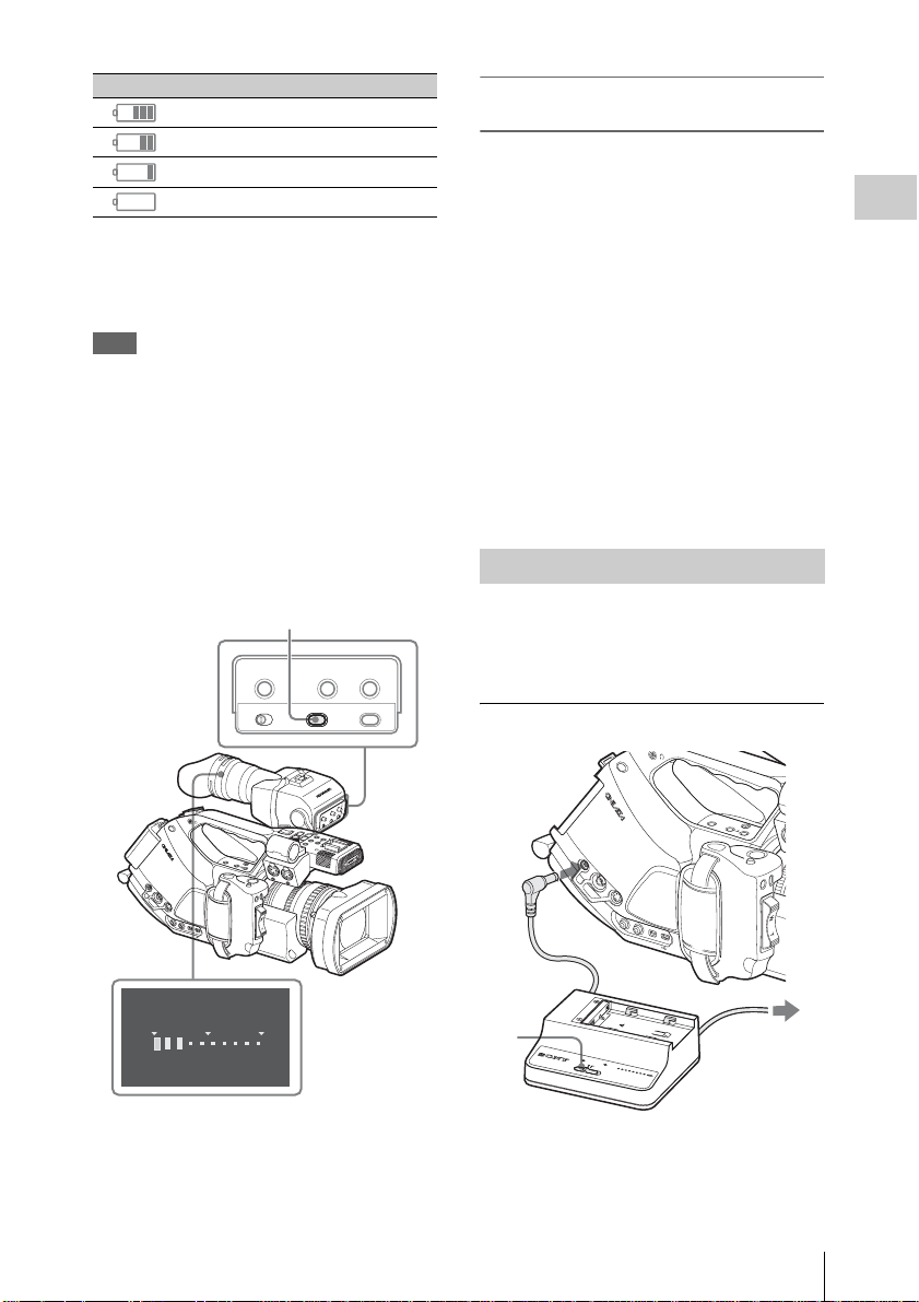
Icon Remaining
H
E
70% to 51%
50% to 31%
30% to 11%
10% to 0%
The camcorder indicates the remaining usage
time in minutes by calc ul ating the available time
with the battery pack if operation is continued at
the current rate of power consumption.
Note
The operating time on a battery pack depends on
the condition (new or old) of the battery pack and
the ambient temperature.
To check in power-off status
Information on the mounted battery pack
(BATTERY INFO) is displayed in the viewfinder
when you hold the DISPLAY/ BA T T IN FO
button pressed even if the camcorder is off.
The BATTERY INFO display goes off after 5
seconds.
DISPLAY/BATT INFO button
PEAKING CONTRAST BRIGHT
MIRROR IMAGE
OFF ON
DISPLAY/BATT INFO
DISPLAY/BATT INFO
ZEBRA
If the battery charge remaining becomes
low
If the battery charge remaining decreases to a
certain level during operation (Low BATT
status), a low-battery message, flashing of the
tally lamps, and a beep sound will warn you.
If the remaining further decreases to a level at
which operation cannot be continued (BATT
Empty status), a battery-empty message appears.
Temporarily set the power switch to OFF and
connect a power source via the DC IN connector
or replace the batter y pack with one that is fully
charged.
To change the message levels
The Low BATT level is set to 10% of full ch arge,
and the BATT Empty level is set to 3% of full
charge at the factory. These settings can be
changed with “B attery Alarm” (page 129) of the
OTHERS menu.
Using AC Power (DC IN Power)
You can connect an AC power source to this
camcorder by using the supp li ed BC-U1 or an
optional BC-U2 Batter y Cha rger for BP-U30/
U60 as an AC adaptor, as show n be low:
Connection exa m ple: BC-U1
Preparations
R
ELEASE
BA
TTER
Y
DC
IN
M
O
N
O
ITO
U
T
R
S VID
EO
C
H
-1
AUDIO OUT
C
H
-2
C
O
M
BATTERY INFO
0%
50%
Rem
aining Time : 20min
OFF
R
E
LE
B
A
A
T
S
T
E
E
R
Y
T
H
IG
R
B
T
S
A
R
T
N
O
C
A
R
B
G
E
IN
Z
K
A
E
P
O
F
IN
T
T
A
/B
Y
A
L
P
IS
D
E
G
A
IM
R
O
R
N
O
IR
M
F
F
O
OFF
L
H
l
PREV
j
F REV
s
THUMNAIL
G
P
L
/S
A
L
Y
/
P
A
U
MONIT
S
J
E
SEL/SET
F FWD
OR
VOL
C
A
N
C
E
L
TC/U-BIT/DURATION
N
O
I
B
T
I
S
T
N
O
A
H
R
S
T
A
O
P
S
E
W
R
C
H
-1
AUDIO IN
C
H
-2
M
IC
L
IN
E
S
M
S
IC
T
T
+
4
A
8
V
M
R
IC
T
L
/
IN
E
M
IC
+
4
8
V
R
E
LE
E
F
X
O
A
P
C
A
U
N
S
D
E
D
R
E
V
R
IE
E
C
1
P
O
N
EN
T
O
U
T
DC IN
DC IN
MONITOR
OUT
S VIDEO
CH-1
AUDIO OUT
CH-2
N
IO
T
A
R
U
COMPONENT
OUT
L
/D
IT
-B
/U
C
T
CH-1
N
IO
B
IT
S
T
N
O
A
H
R
S
T
A
LIN
STOP
START/
RELEASE
EXPANDED
FOCUS
REVIEW
REC
2
100
%
3
DC OUT
CHARGE
0% 80
BATTER
BC-U1
100
Y CHARGER
BC-U1
1 Connect the DC power output cable of
the BC-U1/U2 to the DC IN connector
of the camcorder.
Power Supply
29
Page 30
2 Connect the power cord supplied with
the BC-U1/U2 to the AC input
connector of the BC-U1/U2 then to an
AC power source.
3 Set the mode switch o f the BC-U1 /U2 to
Preparations
the DC OUT position.
For details, refer to the Operating Instructions of the
BC-U1/U2.
When recording or play ba ck is in progress on
power from the DC IN co nne ctor, the input
voltage is displayed in the vi ew fi nder.
DC IN 12.0V
A: 25min
B: 50min
Z99
STBY
S&Q
Note
The battery pack mounte d on the camcorder is not
charged even if you set th e m ode switch of the
BC-U1/U2 to the CHARGE position. To charge
the battery pack, remove it from the camcorder
and mount it on the BC-U1 /U2.
Turning Power On
REC
Turning Power Off
Set the power switch to the OFF position.
Notes
• This camcorder uses a little standby power even
when the power switch is set to OFF. Remove
the battery pack if the camcorder will not be
used for a prolonged period.
• When removing the ba tt ery pack or the DC IN
power, be sure to set the switch to OFF in
advance.
Removing the battery pack and the DC IN
power witho u t first setting th e power switc h to
OFF may cause damage to the camcorder or
SxS memory cards.
This camcorder has Camera mo de for recording
and Media mode for playba ck.
The mode is select ed when yo u turn t he power o n.
R
CANCEL
VOL
F FWD
MONITOR
E
S
SEL/SET
J
U
L
A
/P
NEXT
Y
A
L
/S
P
G
THUMNAIL
STOP
F REV
j
REC
PREV
START/STOP
l s L
HOLD
H
F
L
F
16:9 WIDE SCREEN
ft
m
m
0
0
3
1
5
15
0
3
1
Power switch
O
B
T
C
/U
B
IT
/
D
U
R
A
T
I
O
40
IRIS
1.9
25
2.8
M
ANU
15
AUT
O
4
MACR
O
.6
10
5
8
O
FF
O
5.8
N
FOCUS
16
C
M
A
N
U
A
U
P
T
U
O
S
H
A
F
N
L
E
N
S
IN
F
O
B
R
T
D
IS
P
H
IS
T
O
G
1
2
ND
FILTER
3
2
1
-
F
U
L
L
A
U
T
F
O
R
A
M
E
+
GAIN
O
FF
WHITE BAL
L
B
A
R
S
M
/C
A
A
T
M
W
H
B
A
P
R
S
T
STA
TUS
M
ENU
S
E
L/S
E
T
CANCEL
HDV
R
A
M
T
C
LE
E
S
T
A
LO
IN
S
S
S
IG
N
T
X
E
O
T
U
A
L
A
U
N
S
A
S
M
E
IO
C
D
C
U
A
A
B
IN
-1
H
C
IO
D
U
A
IN
A
T
C
LE
T
E
X
E
S
IO
D
O
U
T
A
L
U
A
E
L
V
A
U
LE
N
A
M
-2
H
C
PMW-EX3
N
E
P
O
P
IC
T
U
R
E
P
R
O
F
IL
C
E
A
M
E
R
A
O
F
F
M
E
D
IA
CAMERA OFF MEDIA
To operate in Camera mode, turn the power on by
setting the p o w er switch to the CAMERA
position.
To operate in Media mode, turn the power on by
setting the p ower switch to the MEDIA po s ition.
Power Supply
30
SDI OUT
GENLOCK IN
TC IN
REMOTE
TC OUT
Page 31

Setting the Clock
SETTING
INITIAL
Time Z
one: UTC +09:00 TOKYO
ate/Time: 2009/01/01 00:00:00 SET
D
2008/01/01 00:00:00 SET
Finish
When you turn the camcorder on for the first time
after purchasing or replacing the backup battery
(page 149), the Initial Settin g display app ears in
the viewfinder.
Set the date and time of the built-in clock , using
this display.
INITIAL
SETTING
Time Z
one: UTC +09:00 TOKYO
ate/Time: 2008/01/01 00:00:00
D
Finish
Time Zone
The value shows the time difference from UTC
(Coordinated Universal Time).
Change the setting i f need ed .
Setting the time and date
Use the joystick on the handle or the jog dial on
the side operation panel for setting.
Joystick Jog dial
F FWD
E
S
J
U
A
/P
NEXT
/S
G
STOP
REC
T/STOP
PREV
STAR
l s L
HOLD
H
F
L
F
O
.9
1
L
E
N
S
IN
F
O
B
R
T
D
IS
2.8
P
H
IS
T
O
4
1
2
ND
.6
FILTER
5
3
8
2
16
C
1
-
F
U
L
L
A
U
T
F
O
R
A
M
E
+
GAIN
O
FF
WHITE BAL
L
B
A
R
S
M
/C
A
A
T
M
W
H
B
A
P
R
S
T
STA
TUS
M
ENU
S
E
L/S
E
T
CANCEL
STATUS MENU SEL/SET CANCEL
B
T
C
/
U
B
I
T
/
D
U
R
A
T
I
O
N
SDI OUT
G
R
A
A
S
HDV
M
T
C
LE
E
S
T
LO
IN
S
S
IG
N
T
X
E
GENLOCK IN
O
T
U
A
L
A
U
N
S
A
S
M
E
IO
C
D
C
U
A
A
B
IN
-1
H
C
IO
D
U
A
IN
TC IN
A
T
C
LE
T
E
X
E
S
IO
D
O
U
T
A
L
U
A
E
L
V
A
U
LE
N
A
M
-2
H
C
REMOTE
TC OUT
PMW-EX3
N
E
P
O
P
IC
T
U
R
E
P
R
O
F
IL
C
E
A
M
E
R
A
O
F
F
M
E
D
IA
MONITOR VOL
THUMBNAIL SEL/SET CANCEL
16:9 WIDE
SCREEN
ft
m
m
0
0
3
1
5
15
0
3
1
R
CANCEL
VOL
MONITOR
SEL/SET
L
Y
A
L
P
THUMNAIL
F REV
j
40
IRIS
25
M
ANU
15
AUT
O
MACR
O
10
O
FF
O
5.8
N
FOCUS
M
A
N
U
A
U
P
T
U
O
S
H
A
F
2 Tilt the joystick or turn the jog dial to
set the year then press the joystick or
dial.
The cursor moves to the month-setting
column.
3 Set the month, day, hour, minute, and
second in sequence in the same manner.
When you press the joystick or the jog dial at
“SET,” the cursor moves back to “Date/
Time.”
4 Move the cursor to “Finish” then press
the joystick or dial.
The Initial Setting display disappears, and the
clock setting is completed.
The camcorder ente rs the operation mode
(Camera mode or M edia mode ) you sel ected wit h
the power switch.
Once after the Initial Setting display disappears,
the time zone and date/time settings can be
changed usi n g “Time Zone” (page 127) and
“Clock Set” (page 127) of the OTHERS menu.
Notes
• If the clock setting is cleared because of
exhaustion of the backup battery while no
operation power was being supplied (no battery
pack and no DC IN connection), the Initial
Setting di spla y will be displ ayed whe n you t urn
the camcorder on at the next opportunity.
• While the Initial Setting display is shown, no
other operation exce pt turning the power off is
permitted until you finish the set ti ng for this
display.
Preparations
1 Tilt the joystick or turn the jog dial to
set the cursor to “Date/Time” then
press the joystick or dia l .
The cursor moves to the year-setting column.
Setting the Clock
31
Page 32

Adjusting the Viewfinder
operator so that the operator can view the image
clearly in the eyepiece.
Eyepiece focusing ring
You can adjust the angle and the display
Preparations
conditions of the viewfinder for best vie w in g in
various shooting situations.
These adjustments of the viewfinder have no
effect on pictures being recorded.
Caution
Do not leave the camcor der with the eyepiece of
the viewfinder facing the sun. Direct sunlight can
enter through the eyepie ce, be focused in the
viewfinder, and cause fire.
Attaching the eyepiece (supplied)
1
FF
O
L
H
LD
O
H
P
O
T
/S
T
C
PEAKING
R
E
A
R
T
S
NEXT
J
STOP
F FWD
CANCEL
VOL
MONITOR
CONTRAST BRIGHT
/S
l s L
E
G
AUS
PREV
PLAY/P
j
F REV
MIRROR IMAGE
SEL/SET
OFF
THUMNAIL
DISPLAY/BA
ON
TT INFO
ZEBRA
IO
T
A
R
U
/D
IT
-B
B
/U
C
T
N
T
IO
O
H
IT
S
S
N
A
R
T
A
P
IS
D
T
R
B
FO
IN
S
N
LE
1 2
1.9
STEADY
SHOT
.8
Clip
16:9 WIDE SCREE
N
AF
Full
STEADY
MF
SHOT
81.2
ft
40
mm
IRIS
9
A
T
S
R
H
A
OT
N
S
IT
B
IO
N
T
C
/
U
B
I
T
/
D
U
R
A
T
I
O
N
You can also attach a commercially available 5 2 mm aperture diopter compensation lens.
Adjusting the contrast and brightness
Use the control knobs on the back panel of the
viewfinder.
BRIGHT control
CONTRAST control
PEAKING CONTRAST BRIGHT
MIRROR IMAGE
DISPLAY/BATT INFO
OFF ON
2
N
M
A
R
G
O
T
IS
H
ASSIGN
3
O
AUT
MANUAL
T SELECT
IO
T
D
C
SLO
U
LE
A
E
-1
S
H
C
IO
L
D
E
U
V
A
-2
LE
S
H
S
B
E
C
C
C
A
A
R
ELEASE
BA
TTER
Y
D
C IN
M
O
NITO
O
U
T
R
S VID
EO
C
H
-1
AUDIO
C
H
-2
OUT
C
O
M
P
O
N
E
N
T
O
U
T
OFF
L
H
TC/U-BIT/DURATION
C
H
-1
N
O
I
B
IT
S
T
N
O
A
AUDIO IN
H
R
S
T
A
C
H
M
IC
L
IN
E
S
M
S
IC
T
T
+
O
4
A
8
P
V
M
R
IC
T
L
/
IN
E
M
R
E
LE
E
F
X
O
A
P
C
S
A
U
E
N
S
D
E
D
R
E
V
R
IE
E
W
C
ZEBRA
T
H
IG
R
B
T
S
A
R
T
N
O
C
A
R
B
G
E
IN
Z
K
A
E
P
O
F
IN
T
T
A
/B
Y
A
L
P
IS
D
E
G
A
IM
R
O
R
N
O
IR
M
F
F
O
l
PREV
j
F REV
s
THUMNAIL
G
P
L
/S
A
L
Y
/P
A
U
MONIT
S
J
E
SEL/SET
F FWD
OR
VOL
C
A
N
C
E
L
R
-2
IC
+
4
8
V
1 Attach the eyepiece by horizontally
sliding it.
2 Flip down the eyepiece and lock it at the
the clip on the bottom.
Adjusting the focus in the viewfinder
The eyepiece focusi n g ( di op ter compensation)
ring enables adjustment to ma tc h th e eyesight of
Adjusting the Viewfinder
32
CONTRAST: For adjusting the brightness
BRIGHT: For adjusting the brightness
When you view the knob from the front,
clockwise rotation increases the level and
counterclockwise rota tion decreases it.
Adjusting the color
These adjustments can be made u sing the VF SET
menu.
Page 33

Press the MENU button to set the camcorder to
Menu mode. Select (VF SET menu) then
“VF” from the menu, and adjust “Color.”
VF
SET
00:00
VF
Peaking
M
arker
Zebra
Display
On/Off
B
B
B
B
B
Color
M
ode
:
Color
:
0
AF
Full
MF
ft
mm
40 81.2
Fixing lever
INT
EXT
O
AUT
IO
D
SLOT SELECT
MANUAL
U
A
IN
INT
EXT
IO
T
STEADY
SHOT
LENS INFOBRT DISP
HISTOGRAM
ND
123
ASSIGN
IRIS
2.8 1.9
D
-1
C
U
H
A
C
LE
S
AUTO
E
S
S
E
MANUAL
IO
C
D
C
U
A
EL
A
V
A B
LE
-2
H
C
Preparations
For details on menu operations, see “B asi c Me nu
Operations” on page 114.
Switching between color and
monochrome modes
For the viewfinder display, color or monochrome
display can be selected.
Select “VF” from the VF SET men u then select
“Mode.”
Select “B&W” if checking the subject and
focusing are easier on the monochrome display.
If you assig n “VF M ode” t o on e of t he a ssign able
buttons (see page 75), you can swi tc h be tween
color and monochrom e by pressing the button.
Adjusting the position (distance from
your eye)
Loosening the fixing lever belo w the handle
(rotating it toward the viewfinder) permits you to
horizontally pull out the support bar and move the
viewfinder forward or rear w ard with the support
bar as the axis.
1 Adjust the h orizontal posit ion.
PEAKINGCONTRAST BRIGHT
MIRROR IMAGE
DISPLAY/BATT INFO
ZEBRA
OFF ON
Fixing lever
Tighten
Loosen
2 Move the view fi nder forward or
rearward for the be st position.
Tighten the fixing lev er after the adjustments .
Note
When you move the viewfinder forward or
rearward, the angle of the viewfinder varies
simultaneously.
Adjust the angle for your best position after
tightening the fixing lever.
Adjusting the angle
You can adjust the angle of the viewfinder.
Note
If the fixing lever below the han d le is lo ose, the
position may vary when you adjust the angle. Be
sure to tighten the lever in advance.
INT
EXT
AUTO
IO
SLOT SELECT
MANUAL
AUD
IN
INT
EXT
Full
STEADY
AF
SHOT
LENS INFOBRT DISP
MF
IRIS
ft
mm
40 81.2
HISTOGRAM
ASSIGN
123
2.8 1.9
ND
Fixing lever
To reverse the image
The viewfinder can be rotated as much as 180
degrees toward the direction fac ing the subject.
To read the displayed menu and messages in this
condition, set the MIRROR IMAGE switch to
ON so that the textual information is converted to
the readable direction.
ACCE
AB
IO
AUD
CH-1
AUTO
SS
SELECT
MANUAL
IO
AUD
LEVEL
CH-2
Adjusting the Viewfinder
33
Page 34

PEAKING CONTRAST BRIGHT
MIRROR
IMAGE switch
MIRROR IMAGE
OFF ON
DISPLAY/BATT INFO
Preparations
R
T
N
O
C
G
IN
K
A
E
P
T
A
/B
Y
A
L
P
IS
D
E
G
A
IM
R
O
R
N
O
IR
M
F
F
O
OFF
L
R
ELE
BA
ASE
TTE
R
Y
DC
IN
M
O
N
O
ITO
UT
R
S VID
EO
C
H
-1
AUDIO OUT
C
H
-2
C
O
M
P
O
N
E
N
T
O
U
T
H
l
PREV
j
F REV
s
THUMNAIL
G
P
L
/S
A
L
Y
/
P
A
U
MONITOR
S
J
E
SEL/SET
F FWD
VOL
C
A
N
C
E
L
TC/U-BIT/DURATION
N
O
I
B
T
I
S
T
N
O
A
H
R
S
T
A
O
P
/
S
E
IE
W
R
C
H
-1
AUDIO IN
C
H
-2
M
IC
L
IN
E
S
M
S
IC
T
T
+
4
A
8
V
M
R
IC
T
L
IN
E
M
IC
+
4
8
V
R
E
LE
E
F
X
O
A
P
C
A
U
N
S
D
E
D
R
E
V
R
E
C
When the camcorder is in Media mode, the
picture is also inverted both vertically and
horizontally. In Camera mode, the picture is
inverted on ly vertically , while it is also inverted
horizontally for Rec Review (page 74).
Opening/detaching the eyepiece (to
directly view the LCD screen)
You can direct ly view the LCD screen inside the
viewfinder by opening the eyepiece.
ZEBRA
T
H
IG
R
B
T
S
A
A
R
B
E
Z
O
F
IN
T
NEXT
J
F FWD
/S
E
AUS
CANCEL
PLAY/P
SEL/SET
VOL
THUMNAIL
MONITOR
FF
O
L
H
LD
O
H
P
O
T
T/S
C
PEAKING
R
E
R
TA
S
STOP
CONTRAST BRIGHT
l s L
G
PREV
j
F REV
MIRROR IMAGE
OFF
DISPLAY/BA
ON
TT INFO
ZEBRA
N
IO
T
A
R
U
/D
IT
-B
B
/U
C
T
N
T
IO
O
H
IT
S
S
N
A
R
T
A
P
IS
D
T
R
B
O
F
IN
S
N
LE
1 2
1.9
STEADY
SHOT
2
O
AUT
MANUAL
T SELECT
IO
T
D
C
SLO
U
LE
A
E
-1
S
H
C
IO
L
D
E
U
V
M
A
R
G
O
T
IS
H
ASSIGN
3
A
-2
LE
S
H
S
B
E
C
C
C
A
A
1
Normally use it in the locked position.
Although you can open it far the r from the lock
position, once return it to the clo sed position to
lock it at the 120-degree position aga in.
To detach
3
CANCEL
VOL
F FWD
SEL/SET
J
MONITOR
NEXT
/S
PLAY/PAUSE
L
G
THUMNAIL
STOP
F REV
s
j
16:9 WIDE SCREEN
16:9 WIDE SCREEN
AF
REC
PREV
START/STOP
l
Full
STEADY
MF
SHOT
81.2
LCD screen
HOLD
H
L
OFF
A
T
S
R
H
A
O
N
T
S
IT
B
IO
N
To open
Push the clip on the bottom to r elease and flip up
the eyepiece.
It locks at the 120-degree posit ion .
Adjusting the Viewfinder
34
4
FF
O
L
H
LD
O
H
P
O
T
T/S
C
PEAKING
R
E
R
TA
S
NEXT
s L
J
STOP
F FWD
CANCEL
VOL
MONITOR
CONTRAST BRIGHT
/S
l
E
G
AUS
PREV
PLAY/P
j
F REV
MIRR
SEL/SET
OR IMAGE
OFF
THUMNAIL
DISPLAY/BA
ON
TT INFO
ZEBRA
N
IO
T
A
R
U
/D
IT
-B
B
/U
C
T
N
T
IO
O
H
IT
S
S
N
A
R
T
A
H
P
IS
D
T
R
B
FO
IN
S
N
LE
1 2
1.9
STEADY
SHOT
.8
2
T SELECT
SLO
M
A
R
G
S
O
T
IS
S
B
E
ASSIGN
C
C
A
A
3
1
1 Push the clip on the bottom to release.
2 Flip up the eyepiece.
AUTO
MANUAL
IO
T
D
C
U
LE
A
E
-1
S
H
C
IO
L
D
E
U
V
A
-2
LE
H
C
Page 35

3 Slide the knob o n the top to the o pposite
side of the eyep iece.
4 Detach the eyepi ece by horizontally
sliding it.
Adjusting the Lens
The supplied VCL-614B2X and the optional
XS8X4AS-XB8 (see page 36) specially designed
for the PMW-EX3 are called “exclusive lenses”
in this manual.
Caution
Do not leave the cam corder with the lens fa cing
the sun. Direct sunlight can enter through the lens,
be focused in the camcorder, and cause fire.
Adjusting the Flange Focal Length
It is necessary to adjust the flange fo cal length
(the distance from t h e l ens flange to the plan e of
the image al ong the opti cal ax is) if the fo cus do es
not match properly from te le photo to wide angle
during zoom operations.
Repeated adjustment is not necessary as long as
the same lens is used.
T
H
IG
R
B
T
S
A
R
T
N
O
C
A
R
B
G
E
IN
Z
K
A
E
P
O
F
IN
T
T
A
/B
Y
A
L
P
IS
D
E
G
A
IM
R
O
R
N
O
IR
M
F
F
O
OFF
L
H
l
PREV
j
F REV
s
THUMNAIL
G
P
L
/S
A
L
Y
/P
A
U
MONIT
S
J
E
SEL/SET
F FWD
OR
VOL
C
A
N
C
E
L
TC/U-BIT/DURATION
N
O
I
B
T
I
S
T
N
O
A
H
R
S
T
A
R
C
H
-1
AUDIO IN
C
H
-2
M
IC
L
IN
E
S
M
S
IC
T
T
+
O
4
A
8
P
V
M
R
IC
T
L
/
IN
E
M
IC
+
4
8
V
R
E
L
E
F
E
X
O
A
P
C
S
A
U
E
N
S
D
E
D
R
E
V
R
IE
E
W
C
D
C IN
M
ON
O
UT
ZOOM switch
MANU SERVO
R
ELEASE
BA
TTER
Y
ITO
R
S VID
EO
C
H
-1
AUD
C
H
-2
IO OUT
C
O
M
P
O
N
E
N
T
O
U
T
ZOOM
Preparations
Focus ring
Zoom ring
IRIS switch
FULL
AF
MF
ft15
15 25 40 81.210
310mm5
10 30
5.8
Adjusting the Lens
MANU AUTO
OFF ON
MANU AUTO
STEADY
SHOT
IRIS
MACRO
8 5.6 4 2.8 1.916
C
FOCUS
PUSH AF
35
Page 36

With the supplied or optional exclusive 1/2-inch
EX Mount lens, the flange focal length c an be
adjusted automatically.
Notes
• If a subject of insufficient contrast is used, or if
the camcorder or subject moves during the
adjustment, adjustment cannot be made
Preparations
properly. Once the adjustment begins, do not
touch the camcorder bo dy or l ens until it ends.
• When the Shutter is in S LS mode, be su re to set
the SLS setting to OFF before starting the
adjustment.
• Be careful that no light source, such as a lamp,
the sun, or a bright window, is in field of view
during flange focal length adjustment.
1 Start the camcorde r i n Came ra mode
by setting the power switch to
CAMERA.
2 Set the IRIS switch to AUTO.
3 Place a high-c ontrast subject, such as a
flange focal length adjustment chart,
about 3 m (10 ft.) away from the
camcorder, and lig h t it w el l en ough to
provide a suffi cient video outp ut level.
LENS
Auto FB ADJ
File
Flare
00:00
S
hading
Execute
B
C
ancel
B
B
6 Move the cursor to “Execute” then
press the joysti ck or the jog dial.
The adjustment begins.
During adjustment
The in-progress message is displaye d.
When the adjustment finished
The completion message is displayed.
If the adjustment fails
Check the conditions of the subject and lighting
then perform the adjustment again.
For details on menu operations, see “Basic M enu
Operations” on page 114.
When a lens other t h an the exclusive le ns es is
used, adjus t the flange focal length man ually.
Replacing the Lens
approx. 3 m
4 Set the ZOOM switch to SERVO
(Power Zoom mode).
5 Press the ME NU button to set the
camcorder to Menu mode, and select
(the LENS menu) then “Auto FB
ADJ” from the menu.
Adjusting the Lens
36
In addition to the supplied VCL-6 14B2X
standard zoom lens, a wide zoom lens exclusively
for the PMW-EX3 is available as an option.
Optional exclusive lens
Fujinon XS8X4AS-XB8: 1/2-inch EX Mount
lens
Using the supplied lens adaptor, a Sony 1/2-inch
Bayonet Mount lens can be mounted.
Note, however, that avai la ble functions, menu
settings and performance may be restricted with
non-exclusive lens.
For non-exclusive but usable lenses, consult your
Sony service representative .
Note
Turn off the camcorder before replacing the lens.
Page 37
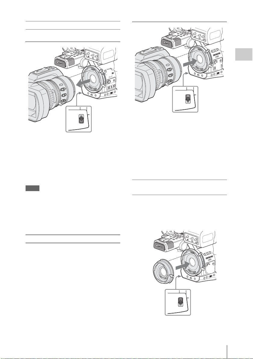
Removing the supplied lens
To remove the supplied lens, proceed as follows:
FF
O
L
H
LD
O
H
P
O
T
T/S
PEAKING CONTRAST BRIGHT
R
EC
R
TA
S
NEXT
STOP
F FWD
/S J
l sL
G
AUSE
PREV
CANCEL
PLAY/P
j
F REV
MIRROR IMAGE
SEL/SET
VOL
OFF ON
THUMNAIL
DISPLAY/BA
MONITOR
W
T
Full
F
M
F
F/M
A
ft
3
1.9
STEADY
SHOT
2.8
4
IRIS
5.6
8
O
T
mm
U
A
U
N
A
M
16
O
10
MACR
30
C
5
15
ON
OFF
3
10
FOCUS
2
7
O
T
U
A
LOCK
RELEASE
TT INFO
ZEBRA
N
IO
T
A
R
U
/D
IT
B
-
B
/U
C
T
N
T
IO
O
H
IT
S
S
N
A
R
T
A
M
A
R
G
O
T
IS
H
N
P
IS
D
T
ASSIG
R
B
O
F
IN
S
N
LE
3
12
2
D
N
R
E
ILT
F
O
T
U
A
L
L
2
U
F
-
E
M
A
R
F
1
+
BARS/CAM
WHITE BAL
GAIN
B
OFF
A
ATW
PAST
L
M
H
CANCEL
ASSIGN 4
SHUTTER
OFF ON
SEL/SET
STATUS MENU
WHT BAL
1
1 Set the lens mount st opper switc h to the
RELEASE position.
2 While holding the lens, turn the lens
mount lever upwar d unt i l it s to ps .
3 Pull the lens forward to remove.
Notes
• When another lens is not immediately attached,
attach the supp lied lens mo unt ca p an d secur e it
by turning the lens mount lever downward.
• When a non-exclusive lens is m ounted for the
first time, it may take about 20 seconds to start
up the camcorder.
Attaching an exclusive lens
To attach the optional 1/2-i nch EX Mount lens,
proceed as follows:
The supplied lens once removed can also be
mounted in the same manner.
F
F
O
L
H
D
L
O
H
P
O
T
/S
T
PEAKINGCONTRAST BRIGHT
EC
AR
R
T
S
NEXT
STOP
F FWD
/S J
l sL
G
AUSE
PREV
CANCEL
PLAY/P
j
F REV
MIRROR IMAGE
SEL/SET
VOL
OFF ON
THUMNAIL
DISPLAY/BA
MONITOR
W
T
Full
F
M
F
F/M
A
ft
mm
30
1
1.9
STEADY
SHOT
2.8
4
IRIS
5.6
8
O
T
U
A
U
N
A
M
16
O
10
MACR
C
5
15
ON
OFF
3
10
FOCUS
2
7
O
T
U
A
LOCK
TT INFO
ZEBRA
N
IO
T
A
R
U
/D
T
I
B
-
U
B
/
C
T
N
T
IO
O
H
IT
S
S
N
A
R
T
A
M
A
R
G
O
T
IS
H
N
P
IS
T D
ASSIG
R
B
FO
S IN
N
LE
3
12
D
N
R
E
ILT
F
O
T
U
A
L
L
2
U
F
-
E
M
A
R
F
1
+
BARS/CAM
WHITE BAL
GAIN
B
OFF
A
ATW
PAST
L
M
H
2
CANCEL
ASSIGN 4
SHUTTER
OFF ON
SEL/SET
STATUS MENU
WHT BAL
3
RELEASE
1 Align the alignment pin of t he lens wit h
the recess at the top of the mount section
of the camcorder and set the lens in
place.
2 Turn the lens mount lever downward.
3 Return the len s mount stop per switch to
the LOCK position.
Attaching a Sony 1/2-inch Bayonet Mount
lens
Use the lens adaptor supplied with the camcorder.
1 Attach the lens adaptor to the
camcorder.
F
F
O
L
H
D
L
O
H
P
O
T
T/S
C
PEAKING CONTRAST BRIGHT
R
E
A
R
T
S
NEXT
STOP
F FWD
/S J
l sL
G
AUSE
PREV
CANCEL
PLAY/P
j
F REV
MIRROR IMAGE
SEL/SET
VOL
OFF ON
THUMNAIL
DISPLAY/BA
Lens adaptor
(supplied)
MONITOR
1
TT INFO
ZEBRA
N
IO
T
A
R
U
/D
IT
-B
B
/U
C
T
N
T
IO
O
H
IT
S
S
N
A
R
T
A
M
A
R
G
O
T
IS
H
P
IS
T D
ASSIGN
R
B
O
F
IN
S
N
LE
3
1 2
D
N
R
FILTE
O
T
U
A
L
L
2
U
F
-
E
M
A
R
F
1
+
BARS/CAM
WHITE BAL
GAIN
B
OFF
A
ATW
T
PAS
L
M
2
H
CANCEL
ASSIGN 4
SHUTTER
OFF ON
SEL/SET
STATUS MENU
WHT BAL
Preparations
LOCK
3
RELEASE
1 Align the alignmen t pi n of the lens
adaptor with the recess at the top of the
Adjusting the Lens
37
Page 38

mount section and set the adaptor in
place.
2 Turn the lens mount le ve r of the
camcorder downward . (Ke ep the lens
mount lever of the lens adaptor in the
upper position.)
Preparations
3 Return the lens stopper s w itch to the
LOCK position.
2 Attach the lens.
LD
O
H
P
O
T
T/S
C
PEAKINGCONTRAST BRIGHT
R
E
A
R
T
S
NEXT
STOP
F FWD
/S J
l sL
G
AUSE
PREV
CANCEL
PLAY/P
j
F REV
MIRROR IMAGE
SEL/SET
VOL
OFF ON
THUMNAIL
MONITOR
ASSIGN 4
OFF ON
1
Sony 1/2-inch Bayonet
Mount lens (optional)
1 Align the alignment pin of the len s wi th
the recess of the adaptor and set the lens
in place.
2 Turn the len s mount lever of the adaptor
downward.
To detach the lens, reverse the above procedure.
When using a non-exclusive lens
You can use the lens file in which you stored the
compensation data for th e lens, using the LENS
menu.
For the storage method, see “Lens File Operations”
on page 148.
When you mount a serial lens
The corresponding file is automatically retrieved.
When you mount a non-serial lens
Retrieve the corresponding lens fi le, usi ng t he
FF
O
L
H
DISPLAY/BA
TT INFO
ZEBRA
N
IO
T
A
R
U
/D
IT
B
-
B
/U
C
T
N
T
IO
O
H
IT
S
S
N
A
R
T
A
M
A
R
G
O
T
IS
H
P
IS
T D
ASSIGN
R
B
FO
IN
S
N
LE
3
12
D
N
R
ILTE
F
U
A
L
L
2
U
F
-
E
M
A
R
F
1
+
BARS/CAM
WHITE BAL
GAIN
B
OFF
A
ATW
PAST
L
M
2
H
CANCEL
SHUTTER
SEL/SET
STATUSMENU
WHT BAL
LENS menu.
1 Press the MENU button to set the
camcorder to Menu mode and select
(the LENS menu).
O
T
2 Select “Recall” from “File” then the
corresponding lens file from the list.
LENS
Auto FB ADJ
File
Flare
00:00
S
hading
B
B
B
Lens
R
ecal l
Store
File ID
No O
Auto
VCL-614B2X
ID
XS
B
User_
B
User_
User_
ffset
User_
Recall:: On
8
X4AS-XB
File
File
File
File
8
1
2
3
4
3 When the confirmation message is
displayed, select “Execute.”
For details on menu operations, see “Basic M enu
Operations” on page 114.
Retrieving the Lens File
By your storing the data (such as com pe nsation
data) specific to the lense s in files, required
adjustments and compensation can be performed
merely by retrieving the appropriate file w hen
changing lenses.
When using an exclusive lens
The optimum compensation data for the two
exclusive lenses are stored in th e c orresponding
lens files at the factory to be automatically
retrieved (with LENS me nu “Auto Recall: On”).
Adjusting the Lens
38
Page 39

Adjusting the Grip
C
/U
R
Using the Cheek Pad
The grip rotates approx. 120 degrees to support a
variety of shooting styles.
Holding the RELEASE button pressed, slowly
rotate the grip.
AUDIO IN
CH-1
MIC
MIC+48V
LINE
MIC
MIC+48V
LINE
RE
LE
REC
REC
REVIEW
REVIEW
FOCUS
RELEASE
ASE
Grip
REC
REVIEW
RELEASE button
T
A
R
A
N
S
S
IT
H
O
IO
T
N
T
B
EXPANDED
EXPANDED
FOCUS
FOCUS
RELEASE
RELEASE
STAR
STAR
T/
T/
STOP
STOP
LOCK
RELEASE
EXPANDED
START/
Click positions are provided at each 15 degrees.
Release the RELEASE button at the desired click
position to lock the grip.
When you operate the camcorder with it on your
right sh oulde r, t he ch eek pad preve nts the co ntr ol
parts on the side panel of the camcorder from
directly hitting your face.
Attaching the cheek pad
To attach the cheek pad, the shoulder pad and the
cable clamp for optional accessories must be once
detached.
1 Remove the shoulder pad.
T
SLOT SELECT
S
S
E
C
C
B
A
A
A
OFF
MEDIA
IN
T
X
E
O
T
U
A
L
A
U
N
A
M
IO
AUD
IN
-1
IO
H
D
T
C
IN
AU
T
X
E
SELECT
O
IO
T
U
D
A
L
U
A
U
L
A
N
E
A
M
V
E
L
-2
H
C
3
X
E
-
W
M
P
N
E
P
O
1
2
Fixing plate Shoulder pad
1 While holding the knob de pre ssed, pull
the shoulder pad outward until it stops.
2 Remove the fixing plate from the bottom
of the camcorder after l oos en ing the
screw.
3 Pull the shoulder pad to remove.
1
3
Preparations
2 Remove the cable cl amp for optional
accessories.
Cable clamp
T
SLOT SELECT
S
S
E
C
C
B
A
A
Adjusting the Grip / Using the Cheek Pad
IN
T
X
E
O
T
U
A
L
A
U
N
A
M
IO
AUD
IN
-1
IO
H
D
T
C
IN
AU
T
X
E
SELECT
O
IO
T
U
D
A
L
U
A
U
L
A
N
E
A
M
V
E
L
-2
H
C
3
X
E
-
W
M
P
39
Page 40

3 Insert the chee k pad from the back of
R
R
R
E
the camcorder and secure it with the
supplied screws.
Align the holes on the bottom of t he mou nt
frame of the chee k pad with those of the
camcorder.
Preparations
Mount frame of
T
SLOT SELECT
S
S
E
C
C
B
A
A
AOFFMEDIA
IN
T
X
E
O
T
U
A
L
A
U
N
A
M
IO
D
AU
IN
-1
IO
H
T
C
IN
AUD
T
T
LEC
X
E
SE
O
IO
T
U
D
A
L
U
A
U
L
A
N
E
A
M
V
E
L
-2
H
C
X
E
-
W
M
P
N
E
P
O
the cheek pad
3
4 Return the shoulder pad to its original
position.
T
SLOT SELECT
S
S
E
C
C
B
A
A
AOFF
MEDIA
IN
T
X
E
O
T
U
A
L
A
U
N
A
M
IO
AUD
IN
-1
IO
H
T
C
IN
AUD
T
T
X
E
SELEC
O
IO
T
U
D
A
L
U
A
U
L
A
N
E
A
M
V
E
L
-2
H
C
3
X
E
-
W
M
P
N
E
P
O
1
3
3
Supplied screw
Cable clamp
T
SLOT SELECT
S
S
E
C
C
B
A
A
A
OFF
MEDIA
IN
T
X
E
O
T
U
A
L
A
U
N
A
M
IO
D
AU
IN
-1
IO
H
D
T
C
IN
AU
T
X
E
SELECT
O
IO
T
U
D
A
L
U
A
U
L
A
N
E
A
M
V
E
L
-2
H
C
3
X
E
-
W
M
P
N
E
P
O
Pole of the
cheek pad
6 While holding the pole upward, flip the
pad toward the side panel of the
camcorder.
SDI OUT
HDV
INT
GENLOCK IN
EXT
O
SLOT SELECT
AL
AUT
ANU
M
AUDIO
IN
INT
TC IN
EXT
CH-1
AUDIO
O
AL
AUT
SELECT
ANU
M
AUDIO
LEVEL
CH-2
OPEN
DIA
PMW-EX3
REMOTE
TC OUT
Cheek pad
2
1 Insert the axis of the shoulder pad in the
hole of the camcorder.
2 Secure the fixing plate to its original
position with the screw.
3 While holding the knob, push in on the
To attach the DC cable clamp
The supplied DC cable clamp can be attach ed to
the frame of th e cheek pad at one of the accessor y
screw holes on the opposite side of the pa d.
The DC power output ca bl e (page 29) of the BCU1/U2 connected to the DC IN connector can be
tied down with the clamp.
shoulder pad.
5 Attach the cable clamp you removed in
step
2.
Align the hole of the cable clamp with those
on the mount f r ame of the cheek p ad (at the
top of the pole) and the ca mcorder then
secure them all together with th e supp lied
screw.
40
(Keep the original screw removed in step
for future use.)
Using the Cheek Pad
2
Page 41

HDV
M
ON
B
SDI OUT
GE
NLOCK IN
TC IN
REMOTE
TC OUT
DC IN
TC/U-BIT/DU
RATION
MONITOR
OUT
S VIDEO
CH-2
CH-1
AUDIO OUT
Accessory screw holes
1
1
2
DC output
cable clamp
1 Insert the cabl e clamp to the frame so
that the rear projection of the ca bl e
clamp fits in the slot on the frame.
Adjust th e po sition of the clamp by
sliding it so that the screw hole of the
clamp aligns w i th t h at of the frame.
2 Secure the clamp, using the supplied
screw.
Using the IR Remote Commander
Before use
Before you use the supplied IR Remo te
Commander for the first time, pull out the
insulation sheet from the batter y hol der.
CO
Insulation sheet
A CR2025 lithium battery is set in the holder at
the factory.
To use the IR Remote Commander
For controlling the camc orde r from the IR
Remote Commander, activate the remote control
function of the camcorder after turning the power
on.
Activating /deactivatin g the remote contr ol
function can be achieved using the Setup menu or
an assignable button.
To activate using the menu
Press the MEN U button to set the camcorde r to
Menu mode, select (the OTHERS menu)
and set “IR Remote” to “On.”
O
THE
RS
:
Button
eter
Alar
B
B
B
B
: O
B
m
English
O
n
n
Off
C
Language
Assign
Tal ly
00:00
H
IR Remote
Battery
lock Set
ours M
Preparations
For details on menu operations, see “Basic M enu
Operations” on page 114.
To activate using an assignable button
Assigning “IR Remote” to one of th e as s ignable
buttons permits you to activate/deactivate the
remote control function by pressing the button.
For the assignable buttons, see“Changing Functions
of the Assignable Buttons” on page 75.
Using the IR Remote Commander
41
Page 42

Note
1
To avoid ma lfunctions, the remote control
function is automati cally deactivated whe n th e
camcorder is turned off. Activate the function
each time when required aft er you turn the
camcorder on.
Preparations
Battery lifetime
When the lithium battery’ s power f al ls, th e I R
Remote Commander may not work even if you
press the buttons. The average lithi um ba tt ery’s
service life is about one year, but this depends on
the pattern of use.
If pressing the remote contr ol bu tt ons produces
absolutely no ef fect on the cam corder, repl ace the
battery then chec k th e operation again.
Replacing the battery in the IR Remote
Commander
Use a commercially available CR2025 lithium
battery. Do not use an y ba tt ery other than a
CR2025.
1 Hold dow n the lock le ver 1, pull out
the battery hold er 2, and remove the
battery.
WARNING
Battery may explode if mistr eated.
Do not recharge, disassemble, or dispose of in
fire.
CAUTION
Danger of ex plosion if bat tery is incorrectly
replaced. Replace only with the sam e or
equivale nt type recommen ded by the
manufacturer.
When you dispose of the battery , yo u must obey
the law in the relative area or country.
ATTENTI ON
Il y a danger d’explosion s’il y a remplacement
incorrect de la batterie. Remplacer uniq uement
avec une batterie du même type ou d’un type
équivalent recommandé par le constructeur.
Lorsque vous mettez la batterie au rebut, vous
devez respecter la législat ion en vigueur dans le
pays ou la région où vous vous tro uve z.
VORSICHT
Explosionsgefah r bei V erwendung falscher
Batterien. Batt erien n ur durch d en vom Her steller
empfohlenen oder ein en gl e ic h wertigen Typ
ersetzen.
Wenn Sie die Batterie ents orge n, müssen Sie die
Gesetze der jeweiligen Region und des jeweiligen
Landes befolgen.
2
2 Place a new battery in the battery
holder with t he + symbol facing up ward
1, then push the battery holder into the
IR Remote Commander until it clicks
2.
With the + symbol upward
2
Using the IR Remote Commander
42
1
Page 43

Handling SxS Memory Cards
This camcorder records au di o and video on SxS
memory cards (optional) inserted in the card slots.
About SxS Memory Cards
Usable SxS memory cards
Use the following Sony-mad e SxS memory cards
(SxS PRO) with this camcorder:
• SBP-8 (8GB)
• SBP-16 (16GB)
• SBP-32 (32GB)
Operations are not guaranteed with memory cards
other than SxS PRO.
These cards comply with the ExpressCard
standard.
• SxS and SxS PRO are trademarks of Sony
Corporation.
• The ExpressCard word mark and logo are owned by
Personal Computer Memory Card International
Association (PCMCIA) and are licensed to Sony
Corporation. All other trademarks are the property of
their respective owners.
Notes on using SxS memory cards
• Recorde d data may be damaged or lost in t he
following situations:
—If you remove this media or turn off the
power while formatti ng, rea ding or writing
data.
—If you use this media in locations subject to
static electricity or electrical noise.
• Do not use or store this media in the following
locations:
—Where recommende d operating conditions
are exceeded.
—Inside a closed car in summer; or in strong
sunshine / under direct sunlight / near a
heater, etc.
—Humid or corrosive location
• Verify the correct dir ec tion of insertion before
use.
• When storing or carrying this medi a , put this
media in the carrying ca se and lock it firmly.
• We recommend that you make a backup copy of
important data. Sony accepts no responsibility
for any damage or loss of data you reco rded.
• Do not apply a label sheet in plac e s other than
the label space. When applying the label sheet
to this media, do not allow it to protrude from its
proper location.
SxS PRO 8GB
Label space
• SxS memory cards to be used with this
camcorder must be formatte d u sin g th e f ormat
function of this camcorder. If a card is formatted
using other device, it is regarded as of a
different format, requirin g re pea ted format
operation on this camcorder.
(Formatting or deleting with the function of the
camcorder does not completely delete data on
this media. When transferring or disposing of
this media, use a commercial data deleting
software or destroy the actual body at you own
responsibility.)
• If the avai lable reco rding time on a card i s short,
clip operati on m ay be re stri ct ed. I n su ch a c ase ,
delete unnecessary files by using a PC.
• Remove or reinsert the case card with the case
opened properly.
For write protection
Setting the write-protect switch of the SxS
memory card to “WP” disables you to record, edit
or delete data.
Preparations
Handling SxS Memory Cards
43
Page 44

Write-protect switch
s
GE
E
A
ON
GE
ON
Preparations
Note
Do not operate the write-protect switch of an SxS
memory card while it is set in the camcorder .
Temporarily remove the card from the camcorder
before changing the swi tc h setting.
TC/U-BIT/DURATION
OGRAM
ASSIGN
2
B
ACCESS
ACCESS
A
A
O
T
SLOT SELEC
B
CH-1
AUDIO
LEVEL
CH-2
M
OPEN
OPEN
PICTURE
L
PROFILE
CAMERA OFF
1
MEDIA
AUTO
MANUAL
AUDIO
SELECT
HDV
IN
EXT
AUDIO
IN
IN
EXT
AUTO
MANUAL
PMW-EX3
SDI OUT
TC IN
Inserting/Removing an SxS Memory Card
The card slots are located behind a cover.
SLOT SELECT button
ACCESS
AB
Cover
R
CANCEL
VOL
F FWD
MONITOR
E
S
SEL/SET
J
U
L
A
/P
NEXT
Y
A
S
L
/
P
L
G
THUMNAIL
STOP
F REV
s
j
REC
T/STOP
PREV
STAR
l
HOLD
H
F
L
F
16:9 WIDE SCREEN
ft
m
m
0
0
3
1
5
15
0
3
1
O
40
IRIS
1.9
25
L
E
N
S
IN
F
O
B
R
T
D
IS
2.8
P
H
IS
M
T
O
ANU
G
R
15
MACR
10
O
FF
5.8
FOCUS
A
AUT
O
4
1
A
O
S
2
ND
.6
FILTER
5
3
8
O
N
2
16
C
1
-
M
A
N
U
F
A
U
U
P
L
T
U
O
L
S
A
H
U
A
F
T
F
O
R
A
M
E
+
GAIN
O
FF
WHITE BAL
L
B
A
R
S
M
/C
A
A
T
M
W
H
B
A
P
R
S
T
STA
TUS
M
EN
U
S
E
L/S
E
T
CANCEL
Inserting an SxS memory card
SLOT SELECT
ACCESS lamp
Card slots
EJECT buttons
B
T
C
/
U
B
IT
/D
U
R
A
T
I
M
S
IG
N
S
S
E
C
C
A
B
A
P
IC
T
U
R
E
P
R
O
F
IL
C
E
A
M
E
R
A
O
F
F
M
E
O
N
SDI OUT
HDV
T
C
LE
E
S
T
LO
IN
S
T
X
E
GENLOCK IN
O
T
U
A
L
A
U
N
A
M
IO
D
U
A
IN
-1
H
C
DIO
U
IN
TC IN
A
T
C
LE
T
E
X
E
S
IO
D
O
U
T
A
L
U
A
E
L
V
A
U
LE
N
A
M
-2
H
C
REMOTE
TC OUT
PMW-EX3
N
E
P
O
D
IA
1 Pull up the cover to release the lock then
open.
2 Insert the SxS memory card into the
slot.
OGRAM
ASSIGN
O
M
L
With the label
facing right
SxS PRO
PICTURE
PROFILE
8
GB
TC/U-BIT/DURATION
ACCESS
A
CAMERA OFF
T
SLOT SELEC
B
CH-1
AUDIO
LEVEL
CH-2
OPEN
MEDIA
AUTO
MANUAL
AUDIO
SELECT
HDV
IN
EXT
AUDIO
IN
IN
EXT
AUTO
MANUAL
PMW-EX3
SDI OUT
The ACCESS lamp lights in red then changes
to green once the memory card is ready for
use.
3 Close the cover .
Status indications by the ACCESS lamps
Card slots A and B are accompanied by the
respective AC CESS lamps to i n dicate their
statuses.
Lamp Slot statuses
Lights in
red
Lights in
green
Accessing the loaded SxS memory card
(writing/reading data)
Standby (ready for recording or
playback using the loaded SxS memory
card)
TC IN
Handling SxS Memory Cards
44
Page 45

Lamp Slot statu ses
GE
ON
GE
ON
Off • No SxS memory card is loaded.
• The loaded card is invalid.
• An SxS memory card is loaded, but
another slot is active.
destroyed. Be sure that the ACCESS lamps are
lit in green or off when you turn off the powe r
or remove memory cards.
• When you turn the camcorder on by setting the
power switch to MEDIA (Media mode), a
display to show that an SxS memory card i s
being confirmed appears in the viewfinder.
Removing an SxS memory card
Preparations
1 Open the cover, onc e press the EJECT
button to release the lock, then pull the
button out.
TC/U-BIT/DURATION
OGRAM
ASSIGN
O
M
PICTURE
L
PROFILE
ACCESS
A
CAMERA OFF
SLOT SELEC
B
OPEN
MEDIA
Press and unlock the button.
T
CH-1
AUDIO
LEVEL
CH-2
AUTO
MANUAL
AUDIO
SELECT
HDV
IN
EXT
AUDIO
IN
IN
EXT
AUTO
MANUAL
PMW-EX3
SDI OUT
TC IN
2 Press the EJECT b ut ton again to
remove the card.
TC/U-BIT/DURATION
OGRAM
ASSIGN
ACCESS
A
O
M
PICTURE
L
PROFILE
CAMERA OFF
T
SLOT SELEC
B
CH-1
AUDIO
LEVEL
CH-2
OPEN
MEDIA
Notes
• Data are not guara nte ed if the power is turned
off or a memory ca rd is r emoved while the ca rd
is being accessed. All data on the card may be
AUTO
MANUAL
AUDIO
SELECT
HDV
IN
EXT
AUDIO
IN
IN
EXT
AUTO
MANUAL
PMW-EX3
SDI OUT
TC IN
The display automatically changes to the
thumbnail screen (page 96 ) when a valid
memory card is inside, but it remains on the
screen if no valid memory card is loaded.
Switching Between SxS Memory Cards
When SxS memory cards are loaded in both card
slots A and B, press the SLOT SELECT button to
select the card you wish to use.
If a card becomes full during recording, switching
to the other card is automatically executed.
Note
The SLOT SELECT button is disabled while
playback is in progress. Switching is not executed
even if you press the button. The button is enabled
on the thumbnail scree n (page 96).
Formatting an SxS Memory Card
Formatting may be required before using an SxS
memory car d w ith this camcorder. For an Sx S
memory car d that is not form atted or that w as
formatted with another system, a message to
confirm if formatt ing is to be executed is
displayed in the viewfinder.
Note on formatting
Any SxS memory card formatte d w ith a device
other than this camcorder cannot be used with the
camcorder.
To execute formatting
If the message for formatting is displayed,
turn the jog dial or tilt th e joystick to sele ct
“Execute” then press the dial or joystick.
Formatting begins.
Handling SxS Memory Cards
45
Page 46

The in-progress message and stat us bar (%) are
T
displayed, and the ACCESS lamp lights in red.
When formatting is completed, the completion
message is displayed for three seconds.
Recording/playback during formatting
You can perform recording or playback using the
SxS memory card in the othe r card slot while
Preparations
formatting is in progress.
If formatting fails
A write-protected SxS memory card or memory
card that cann ot b e us ed wit h this cam cord er wi ll
not be formatted.
As a warning message is displayed, replac e the
card with an appropriate SxS memory card, as per
the instructions in the messa ge .
To format by menu operation
When no formatting messa ge is disp la ye d in the
viewfinder, you can execute formatting using
“Format Media” (page 130 ) of the OTHERS
menu in the same manner.
Notes
• All the data, including recorded pictures and
setup files, are erased when a memo ry card is
formatted.
• SxS memory cards to be used with this
camcorder must be form at te d using the format
function of this camcorder. Any card formatted
with other device must be formatted again with
this camcorder.
Checking the Remaining Time Available for Recording
In Camera mode, you can check the time
remaining for the S xS memory cards load ed in the
card slots in the viewfinder.
120min
A: 25min
B: 50min
Z99
The available time for recording with the current
video format (recording bit rate) is calculated
according to t he remaining space of each card and
displayed in time units of minutes.
The remaining ca n also be checked in a meter
format on the BATTERY/ M EDIA status screen
(page 111).
Handling SxS Memory Cards
46
STBY
STBY
Note
A icon appears if the memory ca rd is writeprotected.
Replacing an SxS memory card
• If the availa b le time on two c ards in total
becomes less than 5 minutes, a messag e “Media
Near Full,” flashing of the tally lamps , and a
beep sound will warn you. Re pla c e th e ca rds
with those with suffi cient space.
• If you continue recording unt il the total
remaining time reaches zero, the message
changes to “Media Full,” and recording stops.
Note
Approximately 600 clips can be recorded on one
SxS memory card at maximum.
If the number of r eco rded clips reaches the limit,
the remaining time indication become s “0 , ” and
the message “Media Full” is displayed .
Restoring an SxS Memory Card
If an error occurs with data in a memory card for
some reason, the card must be restored.
If an SxS memory card that needs to be restore d
is loaded, a message that prompts you to execute
a restore operation is displayed in the viewfinder.
To restore a card
Select “Exec ute” by turning the jog dial or
tilting the joystick then push the dial or
joystick.
The restore operation be gi ns.
During restoration, an in-progre ss message and
status bar (%) are displayed, and the ACCESS
lamp is lit in re d.
When restoration is completed, a completion
message is displayed for three seconds.
If restoration fails
• A write-protected SxS memory card or one on
which an error occurred cannot be restored. For
such a card, a warning message is disp la ye d.
Release the write protecti on or rep lace the car d,
as per the ins tructions in th e m essage.
• An SxS memory card on which an erro r
occurred may becom e usa ble again through
repeated formatting.
Page 47

• In some cases, only parts of clips cannot be
GE
ON
restored. Play back of the re stored clips b ecomes
possible again.
• The following operation may restore an SxS
memory card for which the message “Could not
Restore Some Clips” is repeatedly displayed
each time you try the restoration proc ess:
1 Copy necessary cl ips to anot her SxS memo ry
card, using the co py function (page 104) of
the camcorder or the XDCAM EX Clip
Browsing Software (page 134).
2 Format the problem SxS memory card, using
the format function of this camcorder.
3 Return the necessary clips to the SxS
memory card by copy opera ti on.
Recording/playback during restoration
You can perform recording or playback using the
SxS memory card in the othe r card slot while
restoration is in progres s .
To update the managerial file
If clips cannot be played back, updating the
managerial file on the card may improve the
situation.
For this operation, use “Update Media” of “Clip”
(page 130) of the OTHERS menu.
Using the PHU-60K
You can use an optional PHU-60K Pro fessi ona l
Hard Disk Unit with this camcorder. The PHU60K incorporates a 60GB 1. 8-inch hard disk, on
which up to 200 minutes of HD video ca n be
recorded in HQ mode.
Note
High-speed playback (page 98) may not be
properly achieved wit h the PH U- 60K.
Connecting/Removing the PHU Connection Cable
Recording/playback can be made using the PHU60K in the same manner as with SxS memory
cards by mounting the PHU-60K on the accessory
shoe of the camcorder and connecting the PHU
connection cabl e to an SxS memory card s lot.
For the mounting method, refer to the instructions
supplied with the PHU-60K.
Connecting the PHU connection cable
Preparations
1 Set the power switch of the camcorde r
to the CAMERA positi on.
2 Open the cover of the card slot and plug
the PHU connecti on cable into the slot .
TC/U-BIT/DURATION
OGRAM
ASSIGN
ACCESS
A
O
M
PICTURE
L
PROFILE
CAMERA OFF
T
SLOT SELEC
B
CH-1
AUDIO
LEVEL
CH-2
OPEN
MEDIA
Insert so that the cable extends upward.
Using the PHU-60K
AUTO
MANUAL
AUDIO
SELECT
HDV
IN
EXT
AUDIO
IN
IN
EXT
AUTO
MANUAL
PMW-EX3
SDI OUT
TC IN
47
Page 48

3 Pass the cable through the cable guid e
GE
ATI
SDI OUT
GE
TC IN
HDV
CH-1
AUTO
MANUAL
IN
EXT
AUTO
MANUAL
IN
EXT
AUDIO
LEVEL
SLOT SELEC
T
AUDIO
SELECT
AUDIO
IN
A
B
ACCESS
ASSIGN
A
SHOT
TRANSITION
B
TC/U-BIT/DURA
TION
T
slot above the card slot B and close the
cover.
ON
OGRAM
ASSIGN
Preparations
O
M
PICTURE
L
PROFILE
CAMERA OFF
Pass through the cable guide slot.
ACCESS
A
T
SLOT SELEC
AUTO
B
MEDIA
MANUAL
CH-1
AUDIO
SELECT
AUDIO
LEVEL
CH-2
OPEN
4 Secure the cabl e at the cable clamp.
SS
B
ACCE
A
Cable clamp
HDV
IN
EXT
AUDIO
IN
IN
EXT
AUTO
MANUAL
PMW-EX3
SDI OUT
TC IN
Any PHU-60K formatted with a device other than
this camcorde r ca nnot be used with the
camcorder.
To execute formatting
If the message for formatting is displayed,
turn the jog dial or tilt th e joystick to sele ct
“Execute” then press the dial or joystick.
Formatting begins.
An in-progress message and status bar (%) are
displayed, and the ACCESS lamp lights in red.
When formatting is completed, a completion
message is displayed for three seconds.
To format by menu operation
When no formatting message is displayed in the
viewfinder, you can execute formatting usi ng
“Format Media” (page 130) of the OTHERS
menu in the same manner.
Notes
• Formatting for the PHU-60K on this camcorder
is “Quick Format” with which only the
managerial data are erased. To erase the
recording data completely, connect the unit to a
PC and perform “Full Format.”
• The PHU-60K to be used with this cam corder
must be formatted using the format function of
this camcorder. Any PHU-60K formatted with
another device must be forma tt ed again with
this camcor der.
5 Turn on the PHU -60K.
The POWER indicator of the PHU-60K
lights in green.
Subsequently, the ACCESS lamp of the
camcorder lights in red then changes to green
once the unit is ready for use.
Disconnecting the PHU connection cable
Operate in the same manner as when you remove
an SxS memory card from the slot.
Formatting the PHU-60K
For a PHU-60K that is not formatted or th at was
formatted with another syste m , a message to
confirm if formatting is to be exe cu te d is
displayed in the viewfind er.
Using the PHU-60K
48
Checking the Remaining Time Available for Recording
In Camera mode, the remaining capacity (in
minutes) of the PHU-60K connected via a card
slot is displayed in the viewfinder.
120min
A:
B: 185min
Z99
The available time for recordin g wi th the current
video format (recordin g bit rate) is calculated
according to the remaining space of the hard disk
and displ ayed in time units of minut es.
The remaining capacity can also be checked in a
meter format on the BATTER Y/MEDIA stat u s
screen (page 111).
- - -
min
STBY
STBY
Page 49

Restoring the PHU-60K
If an error occurs with data on the PHU-60K for
some reason, the hard disk must be restored.
If a PHU-60K that needs to be restored is
connected, a message that prompts you to execute
restoration is displayed in the viewfinder.
To restore the hard disk
Select “Execute” b y turning the jog dial or
tilting the joystick then push th e di al or
joystick.
The restoration begins.
During restoration, an in-progress m essage and
status bar (%) are displayed, and the ACCESS
lamp is lit in red.
When restoration is comp leted, a completion
message is displayed for three seconds.
If restoration fails
• A PHU-60K on which an error occurred may
become usable again through repeated
formatting.
• In some cases, only parts of clips cannot be
restored. Play back of the re stored clips b ecomes
possible again.
Preparations
Using the PHU-60K
49
Page 50

Recording
Basic Operation Procedure
The operations described in this se ction assume
that you are using the supplied or optional
exclusive lens. The displays and menu settings
may differ when a non-exclusive lens is used.
Recording
Lens cap OPEN
Viewfinder
4
16:9 WIDE SCREEN
3
AF
R
VOL
MONITOR
SEL/SET
L
THUMNAIL
Full
MF
ft
40
mm
25
30
10
MANU
15
5
15
10
3
10
O
5.8
FULL AUTO
CANCEL
PLAY/PAUSE
F REV
j
STEADY
SHOT
81.2
IRIS
AUTO
M
ACR
O
F
F
O
N
FOCUS
M
A
N
U
A
U
P
T
U
O
S
H
A
F
Preparations
1 Mount a fully charged battery pack .
2 Load SxS memory card(s).
If you load two cards, recording is continued
by automatically switc h ing to the secon d
card when the first card becomes full.
Basic recordin g w ith the exclusive len s can be
performed with the follo wing procedures:
REC START/STOP
7,8
A
T
S
R
H
A
O
N
T
S
ITIO
B
N
TC
ASSIGN
ACCE
A
PICTURE
PROFILE
CAMERA
CAMERA OFF MEDIA
REC REVIEW
9
/U
-BIT/D
U
R
ATIO
N
T SELECT
SLO
SS
B
CH-1
AUD
OPEN
OFF
MEDIA
SDI OUT
V
D
H
IN
EXT
GENLOCK IN
O
AUT
ANUAL
M
IO
AUD
IN
IN
TC IN
AUDIO
EXT
SELECT
IO
O
AUT
LEVEL
ANUAL
M
CH-2
REMOTE
TC OUT
PMW-EX3
Power switch: CAMERA
5
Battery pack
1
Memory card(s)
2
F FWD
NEXT
/S J
G
STOP
OP
REC
T/ST
PREV
STAR
l s L
HOLD
H
F
L
F
O
1.9
LENS INFO
BRT DISP
2.8
4
5.6
8
16
C
HISTOGRAM
1
2
ND
FILTER
3
2
1
-
FULL AUT
FRAME
O
+
GAIN
OFF
WHITE BAL
L
BARS/CAM
M
A
T
W
H
B
A
P
R
S
T
S
T
A
T
U
S
MENU
SEL/SET
CANCEL
6
When using the remote commander, activate the remote
control mode (page 41).
Note
When you hold the camcorder by the grip,
support it from underneath with your left hand.
3 Pull up on the lens cap open/close lever
to open the lens cap built in the lens
hood.
4 Adjust the viewfinder for best viewing.
5 Set the power switch to the CAMERA
position.
The camcorder is turned on and enters
Camera mode.
Basic Operation Procedure
50
Page 51

Recording (Full Auto mode)
be used, it is rec om men de d to set the lever to the
HOLD position to lock the b utton.
6 Press the FULL AUTO button so that
the button indicator lights.
Full Auto mode is turned on, activating the
TLCS (Total Level Contro l Syst em ) (page
120).
Thus Auto Iris, AGC (Auto Gain Control),
Auto Shutter, ATW (Auto Tracing Whi te)
are set to ON, whereby the brightness and
white balance will be automatically adjusted.
When you wish to adjust them manually, turn Full
Auto mode off, and see;
“Adjusting the Iris” on page 61
“Setting the Gain” on page 58
“Setting the Electronic Shut te r” on page 59
“Adjusting the White Balance” on pa ge 54
Note
AF (Auto Focus) is not activated by setting
the camcorder to Full Auto mode.
For information of automatic focus adjustment,
see page 66.
7 Press the REC START/STOP button.
You can start wi th either o f the REC ST ART/
STOP button on the handle or that on the grip
of the lens.
(If you are using the IR Remote Commander, press
the REC button simultaneously with the unmarked
button.)
The front and rear tally lam ps li ght and
recording begins.
8 To stop record ing, press the REC
START/STOP bu tt on again.
(If you are using the IR Remote Commander, press
the REC PAUSE button simultaneously with the
unmarked button.)
REC
START/STOP
HOLD
REC HOLD lever
To unlock the button, return the lever to its
original position.
Checking the last recorded clip (Rec
Review)
9 Press the REC REVIEW button.
The Rec Review function (page 74) is
activated, and the last recorded clip is played
back for the spec if ied time in the viewfinder.
When playback reaches the end of the clip,
the camcorder returns to STBY (re cording
standby) mode.
To delete clips
You can delete the last recorded clip by using the
Last Clip DEL function.
See“Deleting the Last Recorded Clip” on page 94.
Use the All Clips DEL function when you wish to
delete all recorded clips fro m a me mory card.
See“Deleting All Clips” on page 94.
To specify a clip to be de leted, operate the
camcorder in Media mode.
See“Deleting a Clip” on page 104.
Recording
Recording stops and the camcorder enters
STBY (recording standby) mode.
Note
Recording cannot be restarted after you stop
recording until the ACCESS lamp lights in green.
To prevent a switching error
The REC START/STOP but to n on t he handle is
incorporated with the REC HOLD lever. If the
REC START/STOP button on the handle will not
Basic Operation Procedure
51
Page 52

Clip (recording data) and clip name
p
When you stop recording, vide o, audio and
subsidiar y d ata from the sta r t to end of the
recording are re corded as a single clip on an
SxS memory card.
For each clip recorded with this camcorder, a
clip name of 8 characters (the fi rst fo ur
alphanumerics and the second four numerics) is
automatically ge ne rated.
Example: ABCD0001
The first four alphanumerics can be specified as
desired using “Clip” (page 130) of the
Recording
OTHERS menu before you star t rec ording. (It
cannot be changed after recording.)
The second four-digit nu mber is automatically
counted up in sequence.
Notes on Clips
The XDCAM EX-series products employ the
FAT32 File System.
Thus, recorded materials may be segmented in
multiple files depending on the file size. But the
camcorder can play such materials seemlessly.
A long clip can be recorded crossing over two
memory cards in slot A and B.
When you copy clips to a hard disk drive, etc.
using a computer , it is r ecomme nde d to use the
XDCAM EX Clip Browsin g Software on the
supplied CD-ROM.
Note
If copying is done using Explorer (Windows)
or Finder (MAC), the continuity and
relationships of recorded materials may not be
maintained.
L
Selecting the Video Format
You can select various video format s for
recording/playback using “Video Format” (page
130) of the OTHERS menu.
The current format is disp la yed on the screen
when you press the DISPLAY/BATT IN FO
button.
BY
STBY
Selectable Formats
The selectable formats depend on whether
“Country” (page 130) of the OTHERS menu is
set to “NTSC Area” or “PAL Area.”
The video formats set on this camcorder cover the
recording b it rate (HQ/SP), recor ding pic ture si ze
(effective resolution), recording frame rate, and
recording scan system (i/P).
The frame rates are indicated with two-digit
integers, rounding off the frac t ional part.
When you select an HQ format, record ing is made
with the bit ra te of 35 Mbps VBR.
When you select an SP format, recording is made
with the HDV-compatible bit rate of 25 Mbps
CBR.
With “NTSC Area” selected
Format Indication on this
HQ 1920 × 1080
59.94 interlace
SP 1440 × 1080
59.94 interlace
HQ 1920 × 1080
29.97 Progressive
HQ 1920 × 1080
23.98 Progressive
SP 1440 × 1080
23.98 Progressive
HQ 1280 × 720
59.94 Progressive
TCG 00:00:00:00
Q
1080/60i
H
Q M
otion
S&
29/24f
camcorder
HQ 1080/60i
SP 1080/60i
HQ 1080/30P
HQ 1080/24P
SP 1080/24P
HQ 720/60P
s
Selecting the Video Format
52
Page 53

Format Indication on this
0
m
camcorder
HQ 1280 × 720
29.97 Progressive
HQ 1280 × 720
23.98 Progressive
HQ 720/30P
HQ 720/24P
With “PAL Area” selected
Format Indication on this
camcorder
HQ 1920 × 1080
50 interlace
SP 1440 × 1080
50 interlace
HQ 1920 × 1080
25 Progressive
HQ 1280 × 720
50 Progressive
HQ 1280 × 720
25 Progressive
HQ 1080/50i
SP 1080/50i
HQ 1080/25P
HQ 720/50P
HQ 720/25P
Changing the Format
Press the MENU button to set the camcorder to
Menu mode, display the OTHERS me nu with
, and set “Video Format.”
O
THE
RS
Menu
Format
O
ode
B
HQ 1080/60i
1080/60i
SP
:
HQ 1080/30P
:
HQ 1080/24P
:
1080/24P
SP
:
HQ 720/60P
:
B
HQ 720/30P
B
G
enlock
Direc t
i.LINK I/
Tri gger M
00:00
C
ountry
Vi deo
C
lip
For details on menu operations, see “Basic Menu
Operations” on page 114.
Signals from the COMPONENT OUT, SDI
OUT, MONITOR OUT, and S VIDEO
connectors are also output according to the format
selected with this menu.
See “Formats and Limitations of Out puts” on page
146.
Switching the ND Filters
ND filters are available for keeping the aperture
in a proper range.
Set the ND filter switch acco r ding to the
brightness of the subject.
16:9 WIDE SCREEN
AF
Full
MF
81.2
ft
m
40
m
25
0
0
3
1
M
AN
15
MACR
5
15
10
0
3
1
O
FF
5.8
FOCUS
ND
FILTER
2
1
OFF
1
/64ND
2:
1
/8ND
1:
OFF: Clear
The ND filter number is displayed on the screen
when you press the DISPLAY/BATT IN FO
button.
TLCS
.
7
On
M
F
∗
ATW 4300K PPOFF ND
Note
No indication is obtained if the ND filter switch is
set to OFF.
A
STEADY
T
S
R
H
A
O
N
T
S
IT
B
SHOT
IRIS
U
AU
T
O
O
O
N
M
A
N
U
A
U
P
T
U
O
S
H
A
F
IO
N
T
C
/
U
B
I
T
/
D
U
R
A
T
I
O
1.9
2.8
4
.6
5
8
16
C
N
L
E
N
S
IN
F
O
B
R
T
D
IS
P
H
IS
T
O
G
R
A
M
T
C
LE
1
E
S
T
A
LO
S
S
S
IG
2
N
ND
FILTER
3
S
S
E
C
C
A
B
-1
H
2
1
GAIN
O
F
F
L
M
H
STA
TUS
M
ENU
C
A
IO
D
U
A
L
E
V
LE
+
WHITE BAL
A
T
W
S
E
L/S
-2
H
C
F
U
L
L
A
U
T
F
O
R
A
M
E
B
A
R
S/C
A
M
B
A
P
R
S
T
N
E
P
O
E
T
CANCEL
P
IC
T
U
R
E
P
R
O
F
IL
C
E
A
M
E
R
A
O
F
F
M
E
D
IA
ND filter switch
1 1.5 2 3 4 5 7 10 15 20 30 oo
1 ++F1.9 18dB
HDV
IN
T
X
E
O
T
U
A
L
A
U
N
A
M
IO
D
U
A
IN
IO
D
U
IN
A
T
C
LE
E
S
O
T
U
A
L
A
U
N
A
M
PMW-EX3
SHT
SDI OUT
TC IN
T
X
E
:1/200
GENLOCK IN
REMOTE
TC OUT
Recording
Note on recording format in SP 1080/24P mode
When recording in SP 1440 × 1080 mode at 23.98
in Progressive mode (indicated a s SP 1080/ 24P
on this camcor der), pi cture s are rec orded at 59.94
in Interlace mode (indicated as SP 1080/ 60i) by
pull-down processing.
Switching the ND Filters
53
Page 54

Adjusting the White
0
m
Balance
The white balance must be adjusted to suit to the
color temperature of th e li ght source.
You can select the adjustment mode according to
the shooting conditions.
Preset mode
The color temperature is adjusted to the preset
Recording
value (factory setting: 3200 K) in this mode.
Select this mode when there is no time to adjust
the white balance or wh en you wish to fix the
white balance to the condition of you set for a
Picture Profile.
Memory A mode, Memory B mode
• The white balance is adjusted to the value stored
in memory A or memory B.
• Pressing the WHT BAL button executes auto
white balance and stores the adjusted value in
memory A or memory B.
ATW (Auto-Tracing White balance) mode
In this mode, the camco rder automatic ally adjusts
the white balance to the appropriate condition.
When the co lor temperat ur e of the light source
changes, the white balanc e adjustment is
automatically executed.
Five steps of adjustment speed can be sel ec ted
with “ATW Speed” (page 120) of the CAMERA
SET menu.
-
FULL AUTO
FRAME
IS
P
U
L
B
T
CANCEL
H
IS
3
L
A
U
AR
S
/C
A
T
R
T
O
G
R
A
A
S
T
O
AM
S
H
A
O
N
T
S
IT
B
IO
N
M
S
IG
N
P
IC
T
U
R
E
P
R
O
F
IL
E
T
C
/U
B
S
S
E
C
C
A
A
C
A
M
E
R
A
GAIN
L AT W
M
H
IT
/
D
U
R
A
T
IO
N
B
O
F
F
M
E
D
IA
LO
S
N
E
P
O
+
WHITE BAL BARS/CAM
B
A
PRST
SDI OUT
HDV
T
C
LE
E
S
T
IN
T
X
E
GENLOCK IN
O
T
U
A
L
A
U
N
A
M
IO
D
U
A
IN
-1
H
C
IO
D
U
IN
TC IN
A
T
C
LE
T
X
E
SE
IO
D
O
U
T
A
L
U
A
E
L
V
A
U
LE
N
A
M
-2
H
C
PMW-EX3
REMOTE
TC OUT
WHITE BAL switch
16:9 W
IDE SCREEN
AF
Full
STEADY
MF
SHOT
81.2
ft
m
40
m
IRIS
1.9
25
0
0
3
2.8
1
M
AN
U
15
AUT
O
4
MACR
5
15
O
ND
.6
10
FILTER
5
0
3
1
8
O
FF
ON
5.8
2
FOCUS
16
C
1
M
A
N
U
A
U
P
T
U
O
S
H
A
F
O
FF
STA
TUS
L
E
N
S
IN
F
O
B
R
T
D
1
2
-
F
F
R
A
M
E
+
GAIN
WHITE BAL
L
M
A
T
W
H
B
A
P
R
S
M
EN
U
S
E
L/S
ET
B: ATW or Memory B mode
A: Memory A mode
PRST: Preset mode
• Setting the camcorder to Full Auto mode (page
51) forcibly activates ATW mode.
• Assigning the ATW on/off function to an
assignable button permits you to independently
activate/deact ivat e ATW when Full Au to mode
is off.
For details on the assignable buttons, see “Changing
Functions of the Assignable Buttons ” on page 75.
Using the Direct menu
When you press the DISPLAY/BATT INFO
button, the curren t adj ustment mode and color
temperature are displa ye d on the screen.
TLCS
.
7
On
M
F
∗
ATW 4300K PPOFF ND
1 1.5 2 3 4 5 7 10 15 20 30 oo
1 ++F1.9 18dB
SHT
:1/200
Selecting the Adjustment Mode
Using the switch
You can select Preset mode, Memory A mode, or
ATW (Memory B) mode with the WHITE BAL
switch.
To the B posit ion of the WHITE BA L switch,
ATW mode is assigned at the factory. The setting
can be change d w ith “White Switch ” (page 120)
of the CAMERA SET menu to select Memory B
mode.
Adjusting the White Bala nce
54
ATW: A TW m ode
W:A: Memory A mode
W:B: Memory B mode
W:P: Preset mode
When the Direct menu is in All mode, you can
select from among ATW, W:A, W:B, and W : P.
When the Direct menu is in Part mode, you can
switch between ATW and the mode set with the
WHITE BAL switch.
For details on the Direct menu, see “Direct Men u
Operation” on page 26.
Page 55

Executing Auto White Balance
Execute auto w hite-balanc e adjustment according
to the color temperature o f th e light source.
The adjustment value can be stored in memory A
or B.
Note
Auto white-balance adjust ment cannot be
executed in Preset mode.
1 To store the adjustment value in
memory, select Memor y A or Memory
B mode.
2 Select the appropr i ate ND filter
according to th e li ghting condition.
3 Place a white subject under the same
lighting condition and zoom in on it so
that a white area is obtained on the
screen.
A white object (white cloth, a white wall,
etc.) near the subject may be used in place.
Be careful not to have any spots of high
illumination on the screen.
4 Adjust th e lens iris open i n g.
Set it to the proper condition if the manual
iris adjustment mode is selected.
completion message, and the obtained color
temperature is displayed.
• When you execute the adjustment in a memory
mode, the adjusted value is stored in memory
(A or B) selected in s tep 1.
• When you execute th e ad justment in ATW
mode, adjustment in ATW is resumed.
If auto white-balance adjustment fails
An error message is displayed on the screen for
approximately three seconds.
If the error message is displayed, try auto whitebalance adjustm ent again.
If the error message continues to be displayed
after several attempts, consult your Sony service
representative.
Recording
5 Press the WHT BAL button.
Auto white-balance adjustment begins.
OFF
L
H
HOLD
T/STOP
PEAKING
L
REC
T
X
STAR
E
N
s
P
D
O
W
T
S
F
CONTRAST
F
/SJ
l
E
L
S
E
G
V
U
C
E
A
N
R
A
P
Y/P
C
PLA
j
T
BRIGHT
E
V
E
/S
L
R
E
F
M
S
IR
R
IL
O
A
R
L
N
IM
O
M
A
V
U
G
R
E
H
OFFON
T
O
IT
D
N
IS
P
O
L
M
A
Y
/B
A
T
T
IN
F
O
ZEBRA
ASSIGN 4
W
T
AF/M
SHUTTER
OFF ON
Full
F
M
F
m
ft
STEADY
m
0
1
0
3
5
15
3
10
2
7
A
S
S
WHT BAL
A
R
U
/D
IT
B
-
B
/U
C
T
N
T
IO
O
H
IT
S
S
N
A
R
T
A
BRT DISP
LENS INFO
1 2
1.9
SHOT
2.8
ND
FILTER
4
IS
IR
2
5.6
1
8
AUTO
MANU
16
O
R
AC
M
GAIN
C
OFF
L
N
M
O
F
F
O
H
FOCUS
IG
N
MENU
4
S
H
U
O
T
T
TUS
T
U
E
A
R
STA
O
F
F
W
H
T
B
A
L
O
N
During adjustment, an in-progress message is
displayed on the screen. When the adjustment is
completed succe ssfully, the mes sage change s to a
INT
EXT
IO
N
IO
T
D
U
INT
IN
AUTO
A
EXT
MANUAL
IO
T
D
C
SLOT SELECT
U
E
AUTO
L
A
E
-1
MANUAL
S
H
C
IO
L
D
E
U
V
A
E
-2
L
S
HISTOGRAM
H
S
B
N
IG
S
E
C
S
A
C
C
A
A
3
PMW-EX3
O
FULL AUT
-
OPEN
FRAME
+
BARS/CAM
HITE BAL
W
B
MEDIA
A
OFF
ATW
ERA
PAST
CAM
PICTURE
PROFILE
CANCEL
SEL/SET
WHT BAL button
Adjusting the White Balance
55
Page 56

Adjusting the Black
Displaying the Markers
Balance
With this camcorder, the black balance is
automatically adjusted each time the power is
turned on. You can readjust it, using the menu,
when needed.
Use the CAMERA SET men u for the ad j ustmen t.
Press the MENU button to set the camcorder to
Menu mode, display the CAMER A SET menu
Recording
with , and select “Auto BLK Balance” from
the menu.
CAMERA
SET
A
uto BLK B
Setup
Gain
Shutter
00:00
EX Slow S
Transi t ion
Shot
MF A
ssist
For details on menu operations, see “Basic Menu
Operations” on page 114.
Select “Execute” to start the bl ack balance
adjustment.
During adjustment, an in-progress message is
displayed. When the adjustment is completed
successfully, the message changes to a
completion message.
alance
hutter
:
B
B
B
B
Off
Execute
C
ancel
and Zebra Patterns
During recording, various ma rke rs and zebra
patterns can be inserted into the image in the
viewfinder.
This does not affect recording sign al s.
Displaying the Markers
Use “Marker” of th e V F S ET menu.
Press the MEN U button to set the camcorde r to
Menu mode, display the VF SET menu with
, and select “Marker” from the menu.
VF
SET
On/Off
B
B
B
B
B
Setting
Safety
Safety
Center
Aspec t
Aspec t
Zone
Area
Marker
Marker
Select
On
:
On
:
90%
:
: O
On
:
4:3
:
n
B
VF
Peaking
M
arker
00:00
Zebra
Display
Activating the marker indications
• Set “Setting” to “On” then turn the markers on/
off independently.
No marker is displayed when “Setting” is “Off.”
• Assigning the Marker on/off function to one of
the assignable buttons permits you to operate
“Setting: On/Off” by pressing the button.
For the assignable buttons, see “Cha nging
Functions of the Assignable Buttons ” on page 75.
Displaying the safety-zone marker
Set “Safety Zone ” t o “O n” to insert the sa fetyzone marker to the screen.
With “Safety Area” you can select the size of the
safety-zone marker from am ong 80%, 90%,
92.5%, and 95% of the picture area.
Adjusting th e Bl a c k Ba l a nce / Displayin g th e M ar kers and Zebra Pa t t erns
56
Page 57

Example: 95%
STBY
TCG 00:00:00:00 120min
When the aspect marker is on, the safety zone
marker shows the e ffect ive are a within the asp ect
marker.
Displaying the center marker
Set “Center Marker” to “On” to insert the center
marker into the screen area.
STBY
TCG 00:00:00:00 120min
Displaying the aspect marker
Set “Aspect Marker” to “On” to insert the aspect
marker into the screen area.
Select the width of the marker from a mo ng 4:3,
13:9, 14:9, and 15:9 with “Aspect Select.”
Example: 4:3
STBY
TCG 00:00:00:00 120min
Displaying the Zebra Patterns
A zebra pattern (s) can be inse rted to the pi cture in
the viewfinder to check the appropriate
luminance level.
Factory-set zebras
1 (70%) 2 (100%)
Turning the zebra-pattern indication on/
off
Pressing the ZEBRA button turns t he z eb ra
pattern-indication on/off.
ZEBRA button
PEAKING CONTRAST BRIGHT
MIRROR IMAGE
DISPLAY/BATT INFO
ZEBRA
OFF ON
OFF
L
R
ELEA
BA
TTE
SE
R
Y
D
C IN
M
O
N
O
ITO
U
T
R
S VID
EO
C
H
-1
AUDIO OUT
C
H
-2
C
O
M
P
O
N
E
N
T
O
U
T
H
TC/U-BIT/DURATION
C
H
-1
N
O
I
B
T
I
S
T
N
O
A
AUDIO IN
H
R
S
T
A
C
H
M
IC
L
IN
E
S
M
S
IC
T
T
+
O
4
A
8
P
V
M
R
IC
T
L
/
IN
E
M
R
E
LE
E
F
X
O
A
P
C
S
A
U
E
N
S
D
E
D
R
E
V
R
IE
E
W
C
ZEBRA
T
H
IG
R
B
T
S
A
R
T
N
O
C
A
R
B
G
E
IN
Z
K
A
E
P
O
F
IN
T
T
A
/B
Y
A
L
P
IS
D
E
G
A
IM
R
O
R
N
O
IR
M
F
F
O
l
PREV
j
F REV
s
THUMNAIL
G
P
L
/S
A
L
Y
/P
A
U
MONIT
S
J
E
SEL/SET
F FWD
OR
VOL
C
A
N
C
E
L
R
-2
IC
+
4
8
V
Recording
Displaying the guide frame lines
Set “Guide Frame” to “On” to insert the guide
frame lines into the screen area.
STBY
TCG 00:00:00:00 120min
Changing the zebra pattern
Using “Zebra” of the V F SET menu, you can
change the zebra pattern to be displayed.
Press the MEN U button to set the camcorde r to
Menu mode, display the VF SET menu with
, and select “Zeb ra” from the menu.
Displaying the Markers and Zebra Patterns
57
Page 58

VF
SET
On/Off
B
B
B
B
Zebra Select
B
Zebra1
Level
00:00
VF
Peaking
M
arker
Zebra
Display
Zebra Select
Select the zebra pattern(s) to be disp la ye d.
1 (Zebra1): To display a zebra pattern in the area
of ±10% cente ring the video le vel set with
Recording
“Zebra1 Level”
2 (Zebra2): To display a zebra pat tern for the
video level over 100%
Both: To display both Zebra1 and Zebra2
Zebra1 Level
Set the center level of Zebra1 in the range of 50 to
107%. The default setting is 70%.
Setting the Gain
:
1
70
:
You can set the gain of the video amplifi er
according to the brightness of the subje c t.
Select the setting mode required by the shooting
conditions.
Fixed gain mode (manual gain
adjustment)
Select the gain of the video ampl ifi er, using the
switch or a menu operation.
AGC mode (automatic gain control)
The gain of the video amplifier is automatically
adjusted according to the picture brightness.
Recording With Fixed Gain
Selecting the gain with the switch
Select the gain, using the GAIN switch.
Note
When AGC mode is on, the fixed gain cannot be
selected.
Setting the Gain
58
-
FULL AUTO
FRAME
IS
P
U
L
B
T
CANCEL
H
IS
3
L
A
U
A
R
S
/C
A
T
R
T
O
G
R
A
A
S
T
O
A
M
S
H
AN
O
T
S
ITIO
B
N
M
S
IG
N
P
IC
T
U
R
E
P
R
O
F
IL
E
T
C
/
U
B
S
S
E
C
C
A
A
C
A
M
E
R
A
GAIN
L AT W
M
H
I
T
/
D
U
R
A
T
I
O
N
B
O
F
F
M
E
D
IA
LO
S
N
E
P
O
+
WHITE BAL BARS/CAM
B
A
PAS T
SDI OUT
HDV
T
C
LE
E
T S
IN
T
X
E
GENLOCK IN
O
T
U
A
L
A
U
N
A
M
IO
D
U
A
IN
-1
H
C
IO
D
U
IN
TC IN
A
T
C
LE
T
E
X
E
S
IO
D
O
U
T
A
L
U
A
E
L
V
A
U
LE
N
A
M
-2
H
C
PMW-EX3
REMOTE
TC OUT
16:9 WIDE SCREEN
AF
GAIN switch
Full
STEADY
MF
SHOT
81.2
ft
m
40
m
IRIS
1.9
25
0
0
3
2.8
1
M
ANU
15
AUT
O
4
MACR
5
15
O
ND
.6
10
FILTER
5
0
3
1
8
O
FF
O
5.8
N
FOCUS
16
C
M
A
N
U
A
U
P
T
U
O
S
H
A
F
O
FF
STA
TUS
L
E
N
S
IN
F
O
B
R
T
D
1
2
2
1
-
F
F
R
A
M
E
+
GAIN
WHITE BAL
L
M
A
T
W
H
B
A
P
R
S
M
E
NU
S
E
L/S
E
T
The gain value at each of the switch positions are
set at the factory ar e as fo llows:
L: 0 dB
M: 9 dB
H: 18 dB
These values ca n be changed in the range of
–3 dB to +18 dB, us ing th e CAMERA SET menu.
Page 59

To change
0
m
Press the MENU button to set the camcorder to
Menu mode, display the CAMER A SET menu
with , and select “Ga in Se tu p” from the
menu.
C
AMERA SET
A
uto BLK B
alance
hutter
:
B
Low
Mid
High
: 0dB
: 9dB
: 18dB
B
B
B
Off
Setup
Gain
Shutter
00:00
EX Slow S
Transi t ion
Shot
MF A
ssist
For details on menu operations, see “B asi c Me nu
Operations” on page 114.
Selecting gain using the Direct menu
When you press the DISPLAY/BATT INFO
button, the current gain value is displayed on the
screen.
TLCS
.
7
On
M
F
∗
ATW 4300K PPOFF ND
When the Direct menu is in All mode, you can
change the gain in steps of 3 dB with the Direct
menu by operating the joystick or the jog dial .
You can also select AGC mode with the Direct
menu.
When the Direct menu is in Part mode, you can
switch between AGC and the g ain selected wi th
the GAIN switch.
Note
When the camcorder is in Full Auto mo d e (page
51), the Direct menu cannot be selected.
For details on the Direct menu, see “Direct Menu
Operation” on page 26.
1 1.5 2 3 4 5 7 10 15 20 30 oo
1 ++F1.9 18dB
SHT
:1/200
Setting the Electronic Shutter
The electron i c shutter of the camco rder permits
you to change the shutter speed (the accumulation
time per recording frame).
The electron i c shutter can be adjus ted
automatically or manuall y as required.
Fixed Shutter (manual adjustment)
modes
Recording is made with a specified shutter speed
(accumulati o n time).
Standard modes (Speed mode/Angle mode)
These modes may be especially effective when
you wish to record a quick-moving subj ect with
little blurring.
You can select Speed mode or Angle mode. In
Angle mode, you can specify the shutter speed by
setting the shutter angle.
ECS (Extended Clear Scan) mode
Specify the shutter speed by freque ncy. This
mode may be used to shoot the monitor screen
eliminating horizont al bands.
SLS (Slow Shutter) mode
For shooting a subject in low-level lighting
conditions. Specify the shutte r spe ed in the
number of accumulated f ram es.
EX Slow Shutter mode
This is an advanced mode of SLS mode. The
shutter speed is specified in th e num ber of
accumulate d fr ames. Up to 64 f r ames can be
accumulate d in this mode, permitting yo u to
obtain low-noise c lear pict ures in low lig ht levels
or a surreal pictures w ith afterimages.
Recording
Recording in AGC Mode
When you set the camcorder to Full Auto mode
(page 51), AGC mode is forcibly selected.
When Full Auto mode is off, you can
independently turn AGC mode on by setting
“AGC” to “On” with “TLCS” (page 120) of the
CAMERA SET menu or selecting AGC with the
Direct menu.
Auto Shutter mode
The shutter speed is automatically adjusted
according to the picture brig htn ess.
Shooting in a Fixed Shutter Mode
When you set th e SHUTTER sw itch to ON, the
fixed shutter is turned on in the mode and with the
Setting the Electronic Shutter
59
Page 60

shutter speed you specified with “Shutter” of the
CAMERA SET menu.
Note
When Auto Shutter mode is ON, the fixed shutter
cannot be selected.
OFF
L
H
HOLD
T/STOP
PEAKING
L
REC
T
X
STAR
E
N
s
P
D
O
W
T
S
F
CONTRAST
F
/SJ
l
E
L
S
E
G
V
C
E
AU
N
R
/P
A
P
Y
C
PLA
j
T
BRIGHT
E
V
E
/S
L
R
E
F
M
S
IR
L
R
I
O
A
R
L
N
IM
O
M
A
V
U
G
R
E
H
OFFON
T
O
IT
D
N
IS
P
O
L
M
A
Y
/B
A
T
T
IN
F
O
ZEBRA
Recording
ASSIGN 4
W
T
AF/M
SHUTTER
OFF ON
Full
F
M
F
m
ft
m
0
3
STEADY
SHOT
0
1
5
15
3
10
2
7
A
S
S
IG
N
4
WHT BAL
N
O
I
T
A
R
U
D
/
IT
B
-
B
/U
C
T
N
T
IO
O
H
IT
S
S
N
A
R
T
A
S
HISTOGRAM
S
B
N
IG
S
E
S
A
BRT DISP
C
C
LENS INFO
A
A
3
1 2
1.9
2.8
ND
FILTER
4
O
IRIS
2
FULL AUT
5.6
-
E
FRAM
1
8
AUTO
+
MANU
BARS/CAM
16
O
R
AL
AC
M
HITE B
W
GAIN
C
B
OFF
A
OFF
ATW
PAST
L
N
O
F
F
O
FOCUS
S
H
U
O
T
T
T
U
E
A
R
O
FF
O
N
CAMERA
M
PICTURE
FILE
H
PRO
CANCEL
SEL/SET
MENU
TUS
STA
W
H
T
B
A
L
SHUTTER switch
Setting the fixed shutter with the
CAMERA SET menu
The shutter mode and shutter speed can be set
with the CAMERA SET menu.
Press the MENU button to set the camcorder to
Menu mode, display the CAMER A SET menu
with , and select “Shutter.”
CAMERA
SET
A
uto BLK B
alance
Setup
Gain
Shutter
00:00
EX Slow S
hutter
Transi t ion
Shot
MF A
ssist
:
Speed (standard speed) mode
Set “Mode” to “Speed,” and specify the time ([ 1/
setting value ] sec.) with “Shutter Speed.”
The available setting values va ry depending on
the current frame rate.
Frame rate Shutter speed (sec . )
60i, 60P
50i, 50P
24P
1
/
1/
60,
1
/
1000
1
/32, 1/48, 1/50, 1/60, 1/96, 1/
1
/
, 1/
125
, 1/
100
B
B
B
B
250
Off
, 1/
2000
, 1/
120
500
M
ode
Shutter
Shutter
ECS Frequency
Frame
SLS
, 1/
, 1/
125
, 1/
1000
SLOT SELECT
A
-1
H
C
IO
L
D
E
U
V
A
E
L
H
C
OPEN
MEDIA
Speed
Angle
250
100
, 1/
2000
INT
EXT
IO
D
U
INT
IN
AUTO
A
EXT
MANUAL
IO
T
D
C
U
E
AUTO
L
E
MANUAL
S
-2
PMW-EX3
: Speed
: 1/125
: 180
: 60.02
:
, 1/
, 1/
500
Frame rate Shut ter speed (sec.)
25P
30P
1
/33, 1/50, 1/60, 1/
1
/
, 1/
, 1/
500
1000
1
/40, 1/50, 1/60, 1/
1
/
, 1/
, 1/
500
1000
2000
2000
100
100
, 1/
, 1/
120
120
, 1/
, 1/
125
125
, 1/
, 1/
250
250
,
,
Angle (standard angle) mode
Set “Mode” to “Angle,” and specify the shu tter
angle with “Shu tter Angle.”
You can select from among 180, 90, 45, 22.5, and
11.25 degrees.
ECS (Extended Clear Scan) mode
Set “Mode” to “ECS,” and specify the frequency
with “ECS Frequency.”
The availa ble setting values vary de pending on
the current frame rate.
SLS (Slow Shutter) mode
Set “Mode” to “SLS,” and specify the number of
accumulate d f r ames with “SLS F r ame.”
You can select in the range of 2 to 8 frames.
Note
Slow Shutter cannot be used in SP 1080/24P
mode or Slow & Quick Motion mode.
Setting with the Direct menu
When you press the DISPLAY/BATT INFO
button, the current shutter mode and the set value
are displayed.
O
2
1 1.5 2 3 4 5 7 10 15 20 30 oo
ND
1 ++F1.9 18dB
When the Direct menu is in All mode, you can
change the shutter mode and speed with the
Direct menu by operating the j oyst ic k or the jog
dial.
Notes
• When the Direct menu is in Part mode, you
cannot turn the shutter on/off with the Direct
menu if the SHUTTER switch is set to ON.
,
If the SHUTTER switch is s et to OFF, only
switching between Auto Shutter and Shutter
120
,
OFF.
• The Direct menu cann ot be selected when the
camcorder is in Full Auto mode (page 51) or
when the EX Slow Shutter mode is set to “On.”
SHT
:1/2000
m
CH1
CH2
Setting the Electronic Shutter
60
Page 61

For details on the Direct menu, see “Direct Menu
Operation” on page 26.
Shooting in EX Slow Shutter Mode
Adjusting the Iris
Select “EX Slow Shutter” from the CAMERA
SET menu.
CAMERA
SET
A
uto BLK B
alance
hutter
:
B
B
B
Sett i ng
B
Off
m
ber of Fram
Nu
:
Off
es
: 16
Gain
Shutter
00:00
EX Slow S
Shot
MF A
Setup
Transi t ion
ssist
Set “Setting” to “O n, ” and sp ecif y the n umbe r of
accumulated frames with “Num be r of F ra mes.”
You can select from among 16, 32, and 64 frames.
Notes
• EX Slow Shutter cannot be used in SP 1080/24P
mode or Slow & Quick Motion mode.
• The SHUTTER switch has no effect on the EX
Slow Shutter setting.
• The EX Slow Shutter On/Off setting cannot be
changed during recor din g.
• You canno t s et the camcord er to Full Auto
mode (page 51) when the EX Slow Shutter
mode is set to “On.”
Shooting in Auto Shutter Mode
When you set the camcorder to Full Auto mode
(page 51), Aut o Shutter is forcibly selected.
When Full Auto mode is off, you can
independently turn Auto Shutter mode on by
setting “Auto Shutter” to “On” with “TLCS”
(page 120) of the CAMERA SET menu.
Adjust the iris opening accord ing to the
brightness of the subject.
Auto Iris mode
The iris is automa tically adj usted accordi ng to the
brightness of the subject.
Manual Iris mode
Adjust the iris opening using the iris ring or with
a menu operation.
IRIS switch
IRIS
8 5.6 4 2.8 1.916
C
Iris ring
A
T
S
R
H
A
O
N
T
S
IT
B
IO
N
T
C
/
U
B
I
T
/
D
U
R
A
T
I
O
N
L
E
N
S
IN
F
O
B
R
T
D
IS
P
H
IS
T
O
G
R
A
M
1
A
S
S
IG
2
N
3
-
F
U
L
L
A
U
T
F
O
R
A
M
E
+
GAIN
WHITE BAL
B
A
R
S
/C
A
A
T
M
W
B
A
P
R
S
T
U
S
E
L/S
E
T
CANCEL
P
P
SDI OUT
HDV
T
C
LE
E
S
T
LO
IN
S
T
X
E
GENLOCK IN
O
T
U
A
L
A
U
N
S
A
S
M
E
IO
C
D
C
U
A
A
B
IN
-1
H
C
IO
D
U
A
IN
TC IN
A
T
C
LE
T
E
X
E
S
DIO
O
U
T
A
L
U
A
E
L
V
A
U
LE
N
A
M
-2
H
C
REMOTE
TC OUT
PMW-EX3
N
E
P
O
IC
T
U
R
E
R
O
F
IL
C
E
A
M
E
R
A
O
F
F
M
E
D
IA
16:9 WIDE SCREEN
FULL
AF
AF
STEADY
MF
SHOT
ft15
MANU AUTO
MACRO
15 25 40 81.210
OFF ON
310mm5
10 30
FOCUS
5.8
MANU AUTO
PUSH AF
Full
STEADY
MF
SHOT
81.2
ft
m
40
m
IRIS
1.9
25
0
0
3
2.8
1
M
AN
U
15
AUT
O
4
MACR
5
15
O
ND
.6
10
FILTER
5
0
3
1
8
O
FF
O
5.8
N
2
FOCUS
16
C
1
M
A
N
U
A
U
P
T
U
O
S
H
A
F
O
FF
L
M
H
STA
TUS
M
EN
Recording in Auto Iris Mode
When the camcorder is in Full Auto mode (page
51), Auto Iris mode is forcibly turned on.
When Full Auto mode is off, you can turn it on by
setting the IRIS switch to AUTO.
You can sele ct the target level (to make th e
picture brighter or darker) of the Auto Iris control.
(The gain control in AGC mode and the shutter
speed control in Auto Shutte r mode are adjusted
in synchronization.)
To adjust the target level with the Setup menu
Set “Level” of “TL CS” (page 120) of the
CAMERA SET menu.
Recording
Adjusting the Iris
61
Page 62

To adjust the target level with the Direct menu
The target level can also be selected using the
Direct menu.
When you press the DISPLAY/BATT INFO
button, the current settin g is disp la ye d on t he
screen.
1 1.5 2 3 4 5 7 10 15 20 30 oo
ND
1 ++F1.9 18dB
SHT
:1/2000
m
CH1
CH2
You can change the setting with the Direct menu
by operating the joystick or the jog dia l.
Recording
For details on the Direct menu, see “Direct Menu
Operation” on page 26.
Note
Auto Iris motions may be different among lenses.
Adjust the “Speed” setting of “TL CS” (page 120)
on the CAMERA SET menu if needed.
Adjusting the Iris Manually
Set the IRIS switch to MANU to adjust the iris
manually.
Rotate the iris ring for the desired iris opening.
Adjusting the Zoom
You can adjust the zoom in Manual mode or
Power (Servo) mode on the supplied lens.
Manual Zoom mode
Rotate the zoom ring to adjust the zoom.
Power Zoom (Servo) mode
You can adjust the zoom by pressing the power
zoom lever or zoom button on the handle.
The supplied IR Remote Com mander and
optional lens remote controller c an also be used.
The current zoom position is displayed on the
screen in the range of 0 (Wide) to 99 (Tele) when
you press the DISPLAY/BATT INFO but ton .
120min
A: 25min
B: 50min
Z99
The numerical indi cation can be change d to t hat
in a bar by changing the “Zoom Position” setting
of “Display On/Off” (page 124) of the VF SET
menu.
STBY
STBY
Adjusting the Zoom
62
120min
A: 25min
B: 50min
W
T
STBY
STBY
Switching the Zoom Mode
Switching between Manual mode and Servo
mode is performed wit h the ZOOM switch
located on the bottom of the ca mcorder.
Page 63

T
H
IG
R
B
T
S
A
R
T
N
O
C
A
R
B
G
E
IN
Z
K
A
E
P
O
F
IN
T
T
A
/B
Y
A
L
P
IS
D
E
G
A
IM
R
O
R
N
O
IR
M
F
F
O
OFF
L
ZOOM
H
l
PREV
j
F REV
s
THUMNAIL
G
P
L
/S
A
L
Y
/
P
A
U
MONIT
S
J
E
SEL/SET
F FWD
OR
VOL
C
A
N
C
E
L
TC/U-BIT/DURATION
N
O
I
B
T
I
S
T
N
O
A
H
R
S
T
A
P
R
C
H
-1
AUDIO IN
C
H
-2
M
IC
L
IN
E
S
M
S
IC
T
T
+
O
4
A
8
V
M
R
IC
T
L
/
IN
E
M
IC
+
4
8
V
R
E
L
E
F
E
X
O
A
P
C
S
A
U
E
N
S
D
E
D
R
E
V
R
IE
E
W
C
ZOOM switch
RE
LEASE
B
ATTE
R
Y
DC IN
M
O
NITOR
O
UT
S VIDEO
C
H
-1
AUD
C
H
-2
IO OUT
C
O
M
P
O
N
EN
T
O
U
T
MANU SERVO
Operating the Zoom Manually
Setting the ZOOM switch to the MANU position
for Manual Zoom mode activates the zoom ring.
Rotate the zoom ring to adjust the zoom.
Full
AF
MF
IRIS
ft15
10 30
L
E
N
S
IN
F
O
B
R
T
D
IS
1
2
ND
FILTER
2
1
-
F
U
L
F
R
A
M
E
+
GAIN
O
FF
WHITE BAL
L
B
M
A
T
W
H
B
A
P
R
S
T
STA
TUS
M
EN
U
S
E
L/S
E
T
310mm5
Zoom ring
A
T
S
R
A
N
S
P
H
IS
T
O
G
R
A
M
A
S
S
IG
3
L
A
U
T
O
A
R
S
/C
A
M
CANCEL
MANU AUTO
MACRO
8 5.6 4 2.8 1.916
15 25 40 81.210
OFF ON
C
FOCUS
5.8
MANU AUTO
PUSH AF
H
O
T
IT
B
IO
N
T
C
/
U
B
IT
/
D
U
R
A
T
I
O
N
SDI OUT
HDV
T
C
LE
E
S
T
LO
IN
S
N
T
X
E
O
T
U
A
L
A
U
N
S
A
S
M
E
IO
C
D
C
U
A
A
B
IN
-1
H
C
IO
D
U
A
IN
TC IN
A
T
C
LE
T
E
X
E
S
DIO
O
U
T
A
L
U
A
E
L
V
A
U
LE
N
A
M
-2
H
C
PMW-EX3
N
E
P
O
P
IC
T
U
R
E
P
R
O
F
IL
C
E
A
M
E
R
A
O
F
F
M
E
D
IA
ZOOM switch:
MANU
GENLOCK IN
REMOTE
TC OUT
16:9 WIDE SCREEN
MANU SERVO
OPEN
CLOSE
AF
Full
STEADY
MF
SHOT
81.2
ft
m
40
m
IRIS
1.9
25
0
0
3
2.8
1
M
AN
U
15
AU
T
O
4
MACR
5
15
O
.6
10
5
0
3
1
8
O
FF
O
5.8
N
FOCUS
16
C
M
A
N
U
A
U
P
T
U
O
S
H
A
F
ZOOM
Using the Power Zoom
Setting the ZOOM switch to the SERVO position
for Servo mode activates the power zoom.
In Servo mode, the power zoom lever on the grip
and the ZOOM button on the handle are activated.
Zoom speed switch
Power zoom lever
ZOOM button
REC
START/STOP
WT
HOLD
H
L
OFF
T
H
IG
R
B
T
S
A
R
T
N
O
C
A
R
B
G
E
IN
Z
K
A
E
P
O
F
IN
T
T
A
/B
Y
A
L
P
IS
D
E
G
A
IM
R
O
R
N
O
IR
M
F
F
O
OFF
L
D
C IN
ZOOM switch:
SERVO
R
ELE
BATTER
ASE
Y
M
O
NITO
OU
T
R
S VIDEO
C
H-1
AUD
C
H
-2
IO OUT
C
O
M
PO
N
EN
T
O
U
T
TC/U-BIT/DURATION
N
O
I
B
T
I
S
T
N
O
A
H
R
S
T
A
ZOOM
MANU SERVO
H
l
PREV
j
F REV
s
THUMNAIL
G
P
L
/S
A
L
Y
/P
A
U
MONIT
S
J
E
SEL/SET
F FWD
OR
VOL
C
A
N
C
E
L
R
C
H
-1
AUD
IO IN
C
H
-2
M
IC
L
IN
E
S
M
S
IC
T
T
+
O
4
A
8
P
V
M
R
IC
T
L
/
IN
E
M
IC
+
4
8
V
R
E
LE
E
F
X
O
A
P
C
S
A
U
E
N
S
D
E
D
R
E
V
R
IE
E
W
C
To adjust with the power zoom lever on
the grip
Press the W (wide) side for a wider angle or the T
(telephoto) side for a closer angle.
Pressing the lever deeper sets zo om in g faster.
To adjust with the ZOOM button on the
handle
Press the W side for a wider angle or the T side for
a closer angle.
Zooming is ac tivated at the speed selected with
the speed switch.
The zoom speed assignment can be changed with
the CAMERA SET menu.
Speed
switch
H Zoom changes with the speed set by
L Zoom changes with the speed set by
OFF Disabled
ZOOM button operation
“High” of “Zoom Speed” of CAMERA
SET menu. (Default: 70)
“Low” of “Zoom Speed” of CAMERA
SET menu. (Default: 30)
Recording
Adjustin g th e Z o om
63
Page 64

Note
If you set “Zoom Speed (High /Lo w)” of the
CAMERA SET menu to a value between 0 and 9
for a low speed, zooming may not operate
smoothly, depending on the i ndi vidual
characteristics of the lens or operating
environments.
Adjusting the Focus
You can select any of three modes for focus
adjustments on the supplied le ns.
When adjusting with the ZOOM button of
the IR Remote Commander
The zooming speed depends on the “Remote”
setting (default: 50) of “Zoom Speed” o f the
Recording
CAMERA SET menu.
Note
If you set “Zoom Speed (Remote)” of the
CAMERA SET menu to a value between 0 and 9
for a low speed, zooming may not operate
smoothly, depending on the i ndi vidual
characteristics of the lens or operating
environments.
To use the IR Remote Commander, see “Using the I R
Remote Commander” on page 41.
When using a lens remote controller
Zooming can also be controlled from an optional
lens remote controller connected via the LENS
REMOTE connect or.
For operation of the optional lens remote controller,
refer to the operation guide of the le ns remote
controller.
Full MF (Full Manual Focus) mode
Only adjustmen t with the focus ring is effective in
this mode.
You can adjust the fo cus from
length by rotating the ring. Th e ri ng rotates
endlessly in the both direction s .
∞ to the minimum
MF (Manual Focus) mode
In this mode, auto focus ca n b e temporarily
activated by pushing the PUSH AF but to n.
The MF Assist function can be used for
assistance.
AF (Auto Focus) mode
Auto focus functions continuously in this mo de .
The focus ring and the PUSH AF button can also
be used.
Note
The infinity position has some margin to
compensate f o r f ocu s chan ge c au sed by va r iat ion
in ambient temper ature. When shoo ting a n imag e
at infinity in MF or Full MF mode, adjust the
focus while o bserving the image in the
viewfinder.
Adjusting in Full MF Mode
Adjusting the Focus
64
Pull the focus ring rearward (toward the
camcorder body) to set the camcorder to Full MF
mode. Focus can o nl y be adjusted with the f ocus
ring manual ly.
Note
The focus instantly moves to the rang e index
position when you pull the focus ring re arward.
Page 65

16:9 W
IDE SCREEN
AF
Full
MF
ft
m
40
m
25
0
0
3
1
M
15
5
15
10
0
3
1
O
5.8
FULL
AF
MF
ft15
310mm5
10 30
A
STEADY
T
S
R
H
A
O
N
T
S
IT
B
IO
SHOT
81.2
IRIS
AN
U
A
UT
O
MACR
O
FF
ON
FOCUS
M
A
N
U
A
U
P
T
U
O
S
H
A
F
N
T
C
/
U
B
I
T
/D
U
R
A
T
I
O
N
1.9
L
E
N
S
IN
F
O
B
R
T
D
IS
2.8
P
H
IS
T
O
G
R
A
M
4
1
A
S
S
IG
2
N
ND
.6
FILTER
5
3
8
2
16
C
1
-
F
U
L
L
A
U
T
F
O
R
A
M
E
+
GAIN
O
FF
WHITE BAL
L
B
AR
S
M
/C
A
A
T
M
W
H
B
A
P
R
S
T
STA
TUS
M
EN
U
S
E
L/S
ET
CANCEL
P
IC
T
P
R
O
STEADY
SHOT
IRIS
MANU AUTO
MACRO
8 5.6 4 2.8 1.916
15 25 40 81.210
OFF ON
C
FOCUS
5.8
MANU AUTO
PUSH AF
SDI OUT
HDV
T
C
LE
E
S
T
LO
IN
S
T
X
E
GENLOCK IN
O
T
U
A
L
A
U
N
S
A
S
M
E
IO
C
D
C
U
A
A
B
IN
-1
H
C
IO
D
U
A
IN
TC IN
A
T
C
LE
T
E
X
E
S
IO
D
O
U
T
A
L
U
A
E
L
V
A
U
LE
N
A
M
-2
H
C
REMOTE
TC OUT
PMW-EX3
N
E
P
O
U
R
E
F
IL
C
E
A
M
E
R
A
O
F
F
M
E
D
IA
Range index
Focus ring: Rearward
Rotate the focus ring for the best focu s while
observing the picture in the viewfinder.
The range index of the focus ring is effective in
Full MF mode. The distances correspond to the
focus ring positions.
Expanded Focus
When you press the EXPANDED FOCUS
button, the center area of the picture is magnified
in the viewfinder, making the focus adjustment
easier.
Press the EXPANDED FOCUS button again or
leave the focus ring untouched for 5 seconds to
resume the normal angle for re cording.
STOP
START/
RELEASE
REVIEW
REC
FOCUS
EXPANDED
EXPANDED
FOCUS
button
Peaking
When you turn the PEAKING control from its
left-end position, the peaking function is
activated. This function emphasizes the contours
of the images in the viewfinder, making manual
focusing easier.
The emphasis level is increased by turning the
control clockwise.
This function does not affect recording signals.
PEAKING control
PEAKING CONTRAST BRIGHT
MIRROR IMAGE
DISPLAY/BATT INFO
OFF ON
OFF
L
R
ELEA
BA
TTE
SE
R
Y
DC IN
M
O
N
O
ITO
UT
R
S VID
EO
C
H
-1
AUDIO
C
H
-2
OUT
C
O
M
P
O
N
E
N
T
O
U
T
H
TC/U-BIT/DURATION
C
H
-1
N
IO
B
T
I
S
T
N
O
A
AUDIO IN
H
R
S
T
A
C
H
M
IC
L
IN
E
S
M
S
IC
T
T
+
O
4
A
8
P
V
M
R
IC
T
L
/
IN
E
M
R
E
LE
E
F
X
O
A
P
C
S
A
U
E
N
S
D
E
D
R
E
V
R
IE
E
W
C
ZEBRA
T
H
IG
R
B
T
S
A
R
T
N
O
C
A
R
B
G
E
IN
Z
K
A
E
P
O
F
IN
T
T
A
/B
Y
A
L
P
IS
D
E
G
A
IM
R
O
R
N
O
IR
M
F
F
O
l
PREV
j
F REV
s
THUMNAIL
G
P
L
/S
A
L
Y
/P
A
U
MONITOR
S
J
E
SEL/SET
F FWD
VOL
C
A
N
C
E
L
R
-2
IC
+
4
8
V
The color of the contours can be set with
“Peaking” (page 123) of the VF SET menu.
Turning the control back to its left stop position
deactivates the peaking function.
Adjusting in MF Mode
Slide the focus ring forward (toward the lens
hood) and set the FOCUS switch to MANU to set
the camcorder to MF mode. In this mode, you can
activate Auto Focus only when required.
Recording
T
H
IG
R
B
T
S
A
R
T
N
O
C
A
R
B
G
E
IN
Z
K
A
E
P
O
F
IN
T
T
A
/B
Y
A
L
P
IS
D
E
G
A
IM
R
O
R
N
O
IR
M
F
F
O
OFF
L
R
ELEASE
BA
TTER
Y
DC
IN
M
O
N
O
ITO
UT
R
S VIDEO
C
H
-1
AUD
C
H
-2
IO OUT
C
O
M
P
O
N
E
N
T
O
U
T
H
l
PREV
j
F REV
s
THUMNAIL
G
P
L
/S
A
L
Y
/
P
A
U
MONIT
S
J
E
SEL/SET
F FWD
OR
VOL
C
A
N
C
E
L
TC/U-BIT/DURATION
N
O
I
B
T
I
S
T
N
O
A
H
R
S
T
A
O
P
/
S
E
IE
W
R
C
H
-1
AUDIO IN
C
H
-2
M
IC
L
IN
E
S
M
S
IC
T
T
+
4
A
8
V
M
R
IC
T
L
IN
E
M
IC
+
4
8
V
R
E
LE
E
F
X
O
A
P
C
A
U
N
S
D
E
D
R
E
V
R
E
C
Adjusting the Focus
65
Page 66

16:9 WIDE SCREEN
0
m
Recording
AF
Full
MF
ft
m
40
m
25
0
0
3
1
M
15
5
15
10
0
3
1
OFF
5.8
FULL
AF
MF
ft15
310mm5
10 30
A
STEADY
T
S
R
H
A
OT
N
S
ITIO
SHOT
81.2
IRIS
ANU
AUT
O
MACR
O
O
N
FOCUS
M
A
N
U
A
U
P
T
U
O
S
H
A
F
B
N
T
C
/U
B
I
T
/
D
U
R
A
T
I
O
FILTER
O
FF
STA
TUS
MANU AUTO
OFF ON
MANU AUTO
N
L
E
N
S
IN
F
O
B
R
T
D
IS
P
H
IS
T
O
G
R
A
M
T
C
E
L
1
E
S
T
A
LO
S
S
S
IG
2
N
ND
3
O
T
U
A
L
A
U
N
S
A
S
M
E
C
C
A
B
-1
H
C
IO
2
1
-
F
R
+
GAIN
WHITE BAL
L
M
A
T
W
H
M
EN
U
SE
L/S
STEADY
SHOT
IRIS
MACRO
FOCUS
PUSH AF
D
U
A
A
T
C
LE
E
S
IO
D
U
A
L
A
E
V
LE
-2
H
C
F
U
L
L
A
U
T
O
A
M
E
BA
R
S
/C
AM
B
A
P
R
S
T
N
E
P
O
E
T
CANCEL
P
IC
T
U
R
E
P
R
O
F
IL
C
E
A
M
E
R
A
O
F
F
M
E
D
IA
8 5.6 4 2.8 1.916
C
PUSH AF
button
1.9
2.8
4
.6
5
8
16
C
15 25 40 81.210
5.8
FOCUS switch:
Focus ring: Forward
MANU
Adjusting the focus with the focus ring
Rotate the focus ring for the best focu s while
observing the picture in the viewfinder.
The range index of the ring i s i nva li d in M F
mode.
One-Push (Momentary) Auto Focusing
Push the PUSH AF button. Auto focusing
momentarily activates (One-Push Auto
Focusing).
One-Push Auto Focusing is terminated when the
subject comes in focus.
MF Assist function
When you stop rotating the focus ring with the
MF Assist function active, auto focusing starts,
performing fine focus adjustm en t for the subject
in the center of the screen. When the fine
adjustment is complete d, automatic focusin g with
the MF Assist function is terminated.
Activating the MF Assist function using the
CAMERA SET menu
Set “MF Assist” (page 118) of the CAMERA
SET menu to “On.”
Activating the MF Assist function using the Direct
menu
The current focus adjustmen t m ode is disp layed
on the screen when you press the DISPLAY/
BATT INFO button.
TLCS
.
7
On
M
F
∗
ATW 4300K PPOFF ND
SDI OUT
HDV
IN
T
X
E
GENLOCK IN
IO
D
U
A
IN
IN
TC IN
T
X
E
O
T
U
L
A
U
N
A
M
REMOTE
TC OUT
PMW-EX3
In MF mode, you can activate/deactivate the MF
Assist function with the Direct menu by operating
the joystick or the jog dial.
1 1.5 2 3 4 5 7 10 15 20 30 oo
1 ++F1.9 18dB
SHT
:1/200
When the function is active , an ast er isk mark is
displayed to the right of the mode in dication.
Note
The Direct menu cannot be selected in a mode
other than MF mode.
For details on the Direct menu, see “Direct Men u
Operation” on page 26.
Adjusting in AF Mode
Slide the focus ring forward (toward the lens
hood) and set the FOCUS switch to AUTO to set
the camcorder to AF mode. In this mod e, focus is
always adjust ed automatically.
FULL
AF
Focus ring: Forward
The range index of the ring is invalid in AF mode.
Focusing in AF mode
In AF mode the camcorder continuou sly c he cks
changes of images and activates auto focusing
each time it detects a change. The auto focus
adjustment is te rminat ed whe n the su bje ct co mes
into focus, and the camcorder stands by until the
next change is detected.
In AF mode, auto focus ing is also ac tivate d when
you press the PUSH AF button or operate the
focus ring.
STEADY
MF
SHOT
IRIS
ft15
MANU AUTO
MACRO
8 5.6 4 2.8 1.916
15 25 40 81.210
OFF ON
310mm5
10 30
C
FOCUS
5.8
MANU AUTO
PUSH AF
FOCUS switch:
AUTO
Adjusting the Focus
66
Page 67

Using Macro Mode
0
m
When you set the MACRO switch to ON in AF or
MF mode, Macro mode is activate d, pe rmitting
you to adjust the focus in a range that includes the
micro area.
The Macro mode is invalid in Full MF mode.
FULL
AF
STEADY
MF
SHOT
IRIS
ft15
MANU AUTO
MACRO
8 5.6 4 2.8 1.916
15 25 40 81.210
OFF ON
310mm5
10 30
C
FOCUS
5.8
MANU AUTO
PUSH AF
MACRO switch
Eliminating Picture Blurring (Steady Shot)
By activating the Steady Shot func ti on of the
supplied lens, blurring of images due to cam e ra
shaking can be reduced.
Press the STEADY SHOT button on the
lens.
Pressing the button turns the Steady Shot function
ON or OFF.
STEADY SHOT button
FULL
AF
The setting of the Steady Shot function is
displayed in the viewfinder.
TLCS
.
7
On
M
F
∗
ATW 4300K PPOFF ND
STEADY
MF
SHOT
IRIS
ft15
MANU AUTO
MACRO
8 5.6 4 2.8 1.916
15 25 40 81.210
OFF ON
310mm5
10 30
1 1.5 2 3 4 5 7 10 15 20 30 oo
1 ++F1.9 18dB
C
FOCUS
5.8
MANU AUTO
PUSH AF
SHT
:1/200
Recording
Note
If the camcorder is fixed to a tripo d for stable
condition, deactivate the Steady Shot function.
Eliminating Picture Blurring (Steady Shot)
67
Page 68

Reducing Flickers
To reduce flic kers, tr y either of the follo wing two
methods:
Setting the shutter speed according to
the power-supply frequency
Activate the electronic s hutter (page 59) an d s et
Recording
the shutter speed according t o the pow e r supply
frequency.
When the frequency is 50 Hz
Set the shutter speed to
When the frequency is 60 Hz
Set the shutter speed to
Using the Flicker-Reduction function
Set “Mode” of “Flick er Reduce” (page 118) of
the CAMERA SET menu to “Auto” or “On” and
set “Frequency” to the power-supply frequency
(50 Hz or 60 Hz).
Note
If the frame rate selected for recording is close to
the power-supply frequency, flicker may not be
reduced sufficiently even if you activ ate the
Flicker-R eduction functi on. In s uch cases, use the
electronic shutt er .
Recommended settings for flicker reduction
Frequency
Alway set “Frequency” to the power-supply
frequency value appropriate for the shooting area.
Mode
• It is recommended to set “Mode” to “Off” when
shooting outdoors or under ligh ti ng t hat doe s
not cause flicker. (It can be also “Auto,” but the
compensation may not be done properly.)
• It is recommended to set “M ode” to “Auto”
when shooting indoors or under various lighting
that may cause flicker, such as fluorescent,
sodium, or mercury-vapor lamps. (If
continuously shooting under li ghting that may
cause flicker, “Mode” sh oul d be set to “On.”)
1
/50 or 1/
1
/60 or 1/
100
120
seconds.
seconds.
The recommended “M ode ” settings are shown
below.
Flicker
Reduce/
Mode
Auto Recommended Acceptable
On Acceptable Not recommended
Off Not recommended Recommended
Under lighting
that may cause
flicker
Environments
Under lighting
that does not
cause flicker
Reducing Flickers / Reducing Flickers
68
Page 69

Setting the Time Data
Time data, suc h as the timecodes, us er bits, and
the clock time, are recorded with pictures.
The timecode can be locked to an ext ernal timecode
generator. For details, see “Exte rnal
Synchronization” on page 138.
Running Modes of the Timecode
For the timecode, three running modes and Clock
mode can be selected.
Rec Run mode
The timecode advances during recording only.
The continuity of the timecode is maintained
between clips in the sequ ence of recording as long
as the SxS memory card is not changed.
If you remove the memory card and record on
another card, the timecode will not continue when
you return the first card to the slot aga in .
Free Run mode
The timecode keeps advancing regardless of
recording.
Setting the Timecode
Specify the timecode to be recorded with
“Timecode” a nd “TC F ormat” o f the T C/UB SE T
menu.
For details on menu operations, see “Basic M enu
Operations” on page 114.
SET
TC/UB
sers Bit
B
B
M
ode
: Preset
Run :
Setting:
R
eset
Rec Run
00:00:00:00
Timecode
U
TC Format: DF
00:00
Setting the timecode to a desired value
1 Set “Mode” of “Timecode” to “Preset.”
2 Specify the time code value on the
Setting line and select “SET.”
Resetting the timecode
You can reset the timecode to be recorded in
running modes to “00:00: 00: 00. ”
1 Select “Reset” of “Timecode.”
2 Select “Execute.”
Recording
Regen mode
The timecode advances during recording only.
When you insert another memory card, the
camcorder starts next recording so that the
timecode continue s to the last record ed timecode
on the card.
Clock mode
The current clock ti m e is recorded for the
timecode.
Note
In Interval Recording, Frame Recording, Slow &
Quick Motion Reco rdi ng, the timec ode ad vances
in Rec Run mode regardless of the “Run” setting
if you set “Mode” o f “Timecode ” to “Preset” w ith
the TC/UB SET menu.
If you set it to “Clock,” the timecode advances in
Regen mode.
Using the actual time as the timecode
Set “Mode” of “Timecode” to “Clock.”
The time of the built-in clock is recorded as the
timecode.
Switching between DF and NDF of the
timecode
Using “TC Format ” of the TC/UB SET men u, DF
(drop-frame mode) and NDF (non-drop frame
mode) of the timecode can be switc he d.
Note, however, t hat the mode i s fixed either to DF
or NDF regardless of the TC Format setting,
depending on the current frame-rate setting.
Restrictions on the timecode
The timecode setting is restr icte d by the current
video for mat.
Setting the Time Data
69
Page 70

Video
formats
HQ1080/60i
SP 1080/60i
HQ1080/30P
HQ 1080/50i
SP 1080/50i
HQ 1080/25P
HQ 1080/24P
HQ 720/24P
SP 1080/24P
Recording
HQ 720/60P 00 to 29
HQ 720/50P 00 to 24
HQ 720/30P 00 to 29 DF/NDF switchable
HQ 720/25P 00 to 24
Frame
TC Format
setting
00 to 29 DF/NDF switchable
00 to 24 Fixed to NDF
00 to 23
00 to 29
(double count)
(double count)
(Fixed to DF in Clock
mode)
1)
Fixed to NDF
3)
DF/NDF switchable
(Fixed to DF in Clock
mode)
DF/NDF switchable
(Fixed to DF in Clock
mode)
Fixed to NDF
(Fixed to DF in Clock
mode)
Fixed to NDF
1)The frame digits in “Setting” are limited to 00, 04, 08,
12, 16, and 20.
The frame at the beginning of recording is limited to
00, 04, 08, 12, 16, and 20.
As the SDI OUT connector output becomes 60i
because of the 2-3 pull-down process except when
“24P System” of “Genlock” (page 129) is set to
“24PsF” for 1080/24P in Camera mode, the frame
digits of the timecode added to the SDI OUT
connector output are changed to values in the range of
00 to 29.
2)Even in Clock mode, the timecode is gradually
shifted, because it is counted by NDF.
As any output becomes 2-3 pulled-down video except
those from the SDI OUT and COMPONENT OUT
connectors with “24P System” of “Genlock” (page
129) set to “24PsF” for 1080/24P in Camera mode,
there may be a field that has dual timecodes on the
display.
3)With DF, the frame digits can be set as desired in the
range of 00 to 29.
With NDF, the frame at the beginning of recording is
limited to 00, 05, 10, 15, 20, and 25.
Setting the User Bits
SET
TC/UB
sers Bit
B
B
M
ode
: Fix
Setting:
20 07 12 08
Timecode
U
TC Format: DF
00:00
2)
Setting eight digits as desired
1 Set “Mode” of “Users Bit” to “Fix.”
2 Specify the values on the Setting line
and select “SET.”
You can set hexadecimal digits A to F with
the corresponding alphabetics.
Recording the current date as the user
bits
Set “Mode” of “Users Bit” to “Date.”
The current date is displayed on the Setting line.
Displaying the Time Data
In Camera mode, pressing the DISPLAY/BATT
INFO button displays the time data on the screen.
BY
REC
The indication is switched among the timecode,
user bits, and recording dura tion each time you
press the TC/U-BIT/DURATION button.
Display Contents
TCG **:**:**:** Tmecode
CLK **:**:**:** Timecode (Clock mode)
UBG ** ** ** ** User bits
DUR **:**:** Duration from the beginning of
recording
TCG 00:00:00:00
Q
1080/24P
H
You can add a hexadecimal number of 8 digits for
pictures as the user bits.
The user bits can also be set to the c urrent date.
Use “Users Bit” of the TC/UB SET menu.
Setting the Time Data
70
Page 71

Recording Audio Signals
INFO
P
U
E
EW
Using External Inputs
1 Set the AUDIO IN switches CH-1 and
CH-2 to EX T .
Two channels (CH-1/CH-2) of audio can be
recorded (Linear PCM recording) in
synchroni zation with video recording.
You can use the built-in stereo m icrophones
(omni-directional electret condenser
microphones) or 2-channel external audio inputs
to the AUDIO IN connectors by switching with
the AUDIO IN switches.
AUDIO IN
CH-1
MIC
LINE MIC+48V
Built-in stereo
microphones
L
16:9 W
IDE
SCREEN
ft
m
m
0
0
3
1
5
15
0
3
1
CH-1
AUDIO
LEVEL
CH-2
VOL
MONITOR
THUMNAIL
15
10
R
SEL/SET
F REV
40
IRIS
25
M
AN
U
AU
MACR
O
FF
O
5.8
N
FOCUS
M
A
N
U
P
U
AUDIO
SELECT
AUDIO I N
L
CANCE
A
/P
Y
A
L
P
j
T
O
O
A
U
T
O
S
H
A
F
LINE MIC+48V
F FWD
E
S
J
U
NEXT
S
/
L
G
STOP
s
REC
T/STOP
PREV
STAR
l
1.9
2.8
4
ND
.6
FILTER
5
8
16
C
O
F
F
STA
TUS
AUTO
MANUAL
AUTO
MANUAL
2
1
GAIN
L
M
H
M
EN
AUDIO
MIC
HOLD
H
L
E
N
S
IN
F
O
B
1
2
-
F
R
A
M
+
WHITE BAL
A
T
W
U
S
E
L/S
E
T
IN
CH-2
F
L
F
O
B
T
C
/U
B
IT
/
D
U
R
A
T
IO
N
R
T
D
IS
P
H
IS
T
O
G
R
A
M
A
S
S
IG
N
3
S
S
E
C
C
A
B
A
F
U
L
L
A
U
T
O
E
B
A
R
S
/C
A
M
B
A
P
R
S
T
CANCEL
P
IC
T
U
R
E
P
R
O
F
IL
C
E
A
M
E
R
A
O
F
F
M
E
D
IA
INT
EXT
INT
EXT
connectors:
To input external
sources
LINE/MIC/+48V
switches:
To select the type
external source
SDI OUT
HDV
T
C
LE
E
S
T
LO
IN
S
T
X
E
GENLOCK IN
O
T
U
A
L
A
U
N
A
M
IO
D
U
A
IN
-1
H
C
IO
D
U
IN
TC IN
A
T
C
LE
T
E
X
E
S
IO
D
O
U
T
A
L
U
A
E
L
V
A
U
LE
N
A
M
-2
H
C
REMOTE
TC OUT
PMW-EX3
N
E
P
O
2 Connect external audio sources to the
AUDIO IN connectors CH-1 and CH-2.
3 Set the LINE/MIC/+48V switc hes CH-1
and CH-2 to LINE (line level: +4 dBu).
Using an External Microphone
You can use an external microphone for
recording, such as the ECM-673 Electret
Condenser Microphone.
1 Loosen the screw of the microphone
holder and open the cover.
TT
DISPLAY/BA
AGE
OR IM
N
O
MIRR
F
F
OFF
L
H
HOLD
STAR
T/STOP
REC
/
C
T
CH-1
B
T
AUDIO IN
SHO
TRANSITION
A
MIC
LINE
STOP
MIC+48V
STAR
T/
MIC
LINE
RELEASE
EXPANDED
FOCUS
REVI
R
O
l
PREV
j
F REV
s L
THUMNAIL
STOP
G
P
LAY
/S
L
/P
A
NEXT
U
MONITOR
S
J
E
SEL/SET
F FWD
VOL
CANCEL
R
CH-2
MIC+48V
2 Attach a microph one, close the
microphone holder cover for the
original condition to secure, then
connect the microphone cable to either
of the AUDIO IN connectors (CH-1 or
CH-2).
Recording
AUDIO IN switches:
To select the source
AUDIO SELECT switches:
To select the recording level
adjustment mode
AUDIO LEVEL controls:
To adjust th e recording levels
Using the Built-in Stereo Microphones
Set the AUDIO IN switches, both CH-1 and
CH-2, to INT.
Recording Audio Signals
71
Page 72

Recording
INFO
P
E
EW
3
1
OFF
L
H
HOLD
STAR
T/STOP
REC
N
IO
T
A
R
U
/D
IT
-B
/U
C
T
CH-1
N
IO
B
IT
S
T
N
O
A
A
H
R
U
S
T
D
IO
IN
A
MIC
LINE
STOP
START/
RELEASE
EXPANDED
FOCUS
REVI
R
to AUDIO IN
CH-2
MIC+48V
MIC
LINE
MIC+48V
4
sL
NEXT
l
2
PREV
STOP
G
/S
Y
/P
A
U
S
J
E
F FWD
N
C
E
L
TT
DISPLAY/BA
AGE
OR IM
N
O
MIRR
F
F
O
j
F REV
THUMNAIL
P
LA
L
MONITOR
SEL/SET
VOL
C
A
R
External
microphone
1 1.5 2 3 4 5 7 10 15 20 30 oo
ND
1 ++F1.9 18dB
SHT
:1/2000
m
CH1
CH2
Audio recording in special recording
modes
• No audio recording is made in Interval
Recording or Frame Reco rding.
• No audio recording is made in Sl ow & Qu ic k
recording if the recording frame rate is set to a
Cable clamp
value different from t he pl ayback frame rate.
Monitoring the Audio
3 Set the corresponding AUDIO IN
switch (CH-1 or CH-2) to EXT.
4 Set the correspo nding LINE/MIC/+ 48V
switch (CH-1 or CH-2 ) accord ing to the
connected micro phone.
MIC: For a microphone that requires no
power supply
+48V: For a microphone that requires +48V
power supply (such as the ECM-673)
Adjusting the Audio Recording Levels
You can select automatic or manual adjustment
mode independently fo r ea ch c ha nnel.
To adjust the levels automatically (AGC)
When the AUDIO SELECT switches CH-1 and
CH-2 are set to AUTO, the audio recording le vels
are automatically adjusted.
To adjust the levels manually
Set the AUDIO SEL ECT sw itch es CH- 1 and CH 2 to MANUAL, and adjust the audio recording
levels by turning the AUDIO LEVEL controls.
The value is set to 0 dB when t he cont rol is set to
5. Setting to 10 maximizes the level (+12 dB) and
setting to 0 minimizes it (–
∞).
You can monitor the sounds being recorded with
the headphones connec te d to t he h eadphone
connector (stereo mini jack ).
Headphone
connector
MONITOR VOL buttons
MONITOR VOL
MONITOR
THUMNAIL
VOL
SEL/SET
F REV
PLAY/PAUSE
CANCEL
j
PREV
G
F FWD
/S
l
STOP
J
s
NEXT
L
START/STOP
REC
H
L
O
HOLD
F
F
HDV
SDI O
GENLOCK IN
TC IN
REMOTE
TC OUT
T
A
R
A
N
S
S
IT
H
O
IO
T
N
UT
T
C
/U
B
IT
B
/D
U
R
A
T
IO
N
DC IN
LOCK
MONITOR
RELEASE
OUT
S
V
ID
E
O
COMPONENT
OUT
CH-2
UT
IO O
CH-1
AUD
CH-2
IO IN
AUD
CH-1
MIC
MIC+48V
LINE
MIC
MIC+48V
LINE
RELEASE
Note
The built-in speaker is disab le d in Camera mode.
To adjust the audio monitoring volume
Use the MONITOR VOL buttons.
Pressing the + button incre ases th e vo l ume , and
pressing the – bu tton decreases it . To mu ff le the
sound, set it to the minim u m level.
While you adjust the vol um e, the level is
displayed as a bar on the screen.
The input levels are displayed on the screen when
you press the DISPLAY/BATT INFO button.
Recording Audio Signals
72
Page 73

Outputting the Color Bars and Reference Tone
The camcorder can ou tput a color-bar signal in
place of the camera picture.
A 1-kHz reference tone is output with the color
bar signal if “1kHz Tone” of “Audio Input” (page
121) is set to “On” with the AUDIO SET menu.
The color-bar signal is also fed out from the SDI
OUT, COMPONENT OUT, MONITOR OUT
and S VIDEO connectors, and the reference-tone
signal is fed from the AUDIO OUT connectors.
R
CANCEL
VOL
F FWD
MONITOR
E
S
SEL/SET
J
U
L
A
P
/
NEXT
Y
A
L
/S
P
L
G
THUMNAIL
STOP
F REV
s
j
REC
T/STOP
PREV
STAR
l
HOLD
H
F
L
F
25
15
10
5.8
40
IRIS
M
ANU
AU
T
MACR
O
O
FF
O
N
FOCUS
M
A
N
U
A
P
U
S
H
B
A
PAS T
1.9
2.8
O
4
.6
5
8
16
C
U
T
O
A
F
FULL AUTO
O
B
T
C
/
U
B
I
T
/
D
L
E
N
S
IN
F
O
B
R
T
D
IS
P
H
IS
T
O
G
R
A
M
1
A
S
S
IG
2
N
ND
FILTER
3
S
S
E
C
C
A
B
2
A
1
-
F
U
L
L
A
U
T
F
O
R
A
M
E
+
GAIN
O
F
F
WHITE BAL
L
B
A
R
S
M
/C
A
A
T
M
W
H
B
A
P
R
S
T
STA
TUS
M
EN
U
S
E
L/S
E
T
CANCEL
P
IC
T
U
R
E
P
R
O
F
IL
C
E
A
M
E
R
A
O
F
BARS/CAM button
U
R
A
T
I
O
N
SDI OUT
HDV
T
C
LE
E
S
T
LO
IN
S
T
X
E
GENLOCK IN
O
T
U
A
L
A
U
N
A
M
IO
D
U
A
IN
-1
H
C
IO
D
U
IN
TC IN
A
T
C
LE
T
E
X
E
S
IO
D
O
U
T
A
L
U
A
E
L
V
A
U
LE
N
A
M
-2
H
C
REMOTE
TC OUT
PMW-EX3
N
E
P
O
F
M
E
D
IA
16:9 W
IDE
SCREEN
ft
m
m
0
0
3
1
5
15
0
3
1
-
+
WHITE BAL BARS/CAM
GAIN
LATW
M
H
FRAME
• The color bar mode cannot be selected in Slow
& Quick Motion mode and EX Slow Shutter
mode.
Recording
Press the BARS/CAM button.
The camera picture is switched to color bars .
To return to the camera pic ture, press the button
again.
You can select the type of color bars with “Color
Bar Type” (page 118) of the CAMERA SET
menu.
Multi: ARIB multiformat color bars
75%: Vertical stripes of 75% luminance
100%: Vertical stripes of 100% lumina nc e
Notes
• When recording of the camera image is in
progress, it cannot be switched to the color-bar
picture even if you press the BARS/CAM
button. (You ca n sw itch th e colo r-bar p ictur e to
the camera pictur e.)
Outputting the Color Bars and Reference Tone
73
Page 74

Recording Shot Marks
Rec Review
When you record shot marks for important scenes
as subsidiary data, you can acc ess th e marked
points easily on a Shot Mark screen, which only
displays scenes with shot marks only . T his
increases editing efficiency.
For the Shot Mark Screen, see “Dis play ing the
SHOT MARK Screen” on page 105.
Recording
The camcorder permits you to record two types of
shot marks: shot mark 1 and shot mark 2.
Shot marks can be recorded as needed during
recording or can be added after recording while
checking the playback pictures.
Inserting a shot mark during recording
Activate the IR Remote Commander (page 41),
and use the SHOTMARK 1 or 2 button.
SHOTMARK 1 button
SHOTMARK 2 button
Press the SHOTMARK 1 or 2 button where
you wish to insert a mark.
If the Shot Mark1 or Shot Mark2 function is
assigned to an assignable button, you can also use
it instead (page 75).
A shot mark of the type correspon din g to the
button you press is recorded.
For operations to add shot marks after recording,
see “Adding shot marks during play bac k ” on pag e
99 and “Adding/Deleting Shot Marks” on page 106.
12T
ZOOM
SHOTMARK
W
SUB CLIP
THUMBNAIL
PREV NEXT
PLAY/PAUSE
.>xu
PUSH SET
You can review the last recorded clip on the
screen (Rec Review).
Use the REC REVIEW button on the supplied
lens or assign the Rec Review functi on to an
assignable button to use it instead (page 75).
STOP
START/
RELEASE
REVIEW
REC
FOCUS
EXPANDED
REC REVIEW
button
T
H
IG
R
B
T
S
A
R
T
N
O
C
A
R
B
G
E
IN
Z
K
A
E
P
O
F
IN
T
T
A
/B
Y
A
L
P
IS
D
E
G
A
IM
R
O
R
N
O
IR
M
F
F
O
OFF
L
R
ELEAS
BA
TTE
E
R
Y
DC IN
M
O
NITO
O
U
T
R
S VID
EO
C
H
-1
AUD
C
H
-2
IO OUT
C
O
M
P
O
N
E
N
T
O
U
T
STOP
After recording is finished, press the REC
H
l
PREV
j
F REV
s
THUMNAIL
G
P
L
/S
A
L
Y
/
P
A
U
MONIT
S
J
E
SEL/SET
F FWD
OR
VOL
C
A
N
C
E
L
TC/U-BIT/DURATION
N
O
I
B
T
I
S
T
N
O
A
H
R
S
T
A
R
C
H
-1
AUDIO IN
C
H
-2
M
IC
L
IN
E
S
M
S
IC
T
T
+
O
4
A
8
P
V
M
R
IC
T
L
/
IN
E
M
IC
+
4
8
V
R
E
LE
E
F
X
O
A
P
C
S
A
U
E
N
S
D
E
D
R
E
V
R
IE
E
W
C
REVIEW button or the assignab le button t o
which you assigned the Rec Review
function.
Playback of the specified block of the clip begins.
In Rec Review, the last 3 seconds, 10 seconds, or
the entire part of the clip is displayed, depending
on the “Rec Review” se t ti ng (page 119) of the
CAMERA SET menu. It is set to 3 seconds at the
factory.
Rec Review is terminated at the end of the clip,
resuming STBY (recording standby) status.
Notes
• If the duration of the last re corded clip is less
than the time (3 or 10 seconds) specified f or Rec
Review, the clip is pl ay ed back from the
beginning to the end.
• During Rec Review playb ac k, onl y the STOP
button is valid.
When the STOP button is pressed, Rec Review
is canceled, a nd the cam corder r eturns t o STBY
(recording standby) status.
Recording Shot Marks / Rec Revie w
74
Page 75

• If the video format is changed after recording,
Rec Review cannot be pe rform ed.
• The Setup and PICTURE PROFIL E menus
cannot be operated during Rec Review.
Changing Functions of the Assignable Buttons
The camcorder has four assi gnable buttons to
which you can assign various functio ns for
convenience.
ASSIGN 1 to 3 buttons
ASSIGN 4
LENS INFO BRT DISP HISTOGRAM
L
T
X
E
N
s
P
D
O
W
T
S
F
F
/S J
E
L
S
E
G
U
C
A
N
A
Y/P
C
LA
P
j
T
E
V
E
/S
L
R
E
F
S
IL
A
L
N
O
M
V
U
R
H
T
O
IT
N
O
M
W
T
Full
F
M
F
m
AF/M
ft
m
0
3
SHUTTER
OFF ON
123
HOLD
T/STOP
PEAKING
REC
STAR
l
V
E
R
P
M
IR
R
OFF
STEADY
SHOT
MANU
0
1
5
15
3
10
2
7
A
S
S
IG
N
4
WHT BAL
OFF
L
H
CONTRAST
BRIGHT
O
R
IM
A
G
E
D
IS
P
L
A
Y
/B
ON
A
T
T
IN
F
O
ZEBRA
U
/D
IT
B
-
B
/U
C
T
N
T
IO
O
H
IT
S
S
N
A
R
T
A
LENS INFOBRT DISP
1
1.9
2.8
ND
FILTER
4
IRIS
2
5.6
1
8
AUTO
16
O
R
AC
M
C
OFF
N
O
F
F
O
FOCUS
M
S
H
U
O
T
T
TUS
T
U
E
A
R
STA
O
F
F
W
H
T
B
A
L
O
N
ASSIGN
INT
EXT
IO
N
IO
T
A
R
HISTOGRAM
2
GAIN
L
M
H
ENU SEL/SET
D
U
INT
IN
AUTO
A
EXT
MANUAL
IO
T
D
C
SLOT SELECT
U
E
AUTO
L
A
E
-1
MANUAL
S
H
C
IO
L
D
E
U
V
A
E
-2
L
S
H
S
B
N
IG
S
E
C
S
A
C
C
A
A
3
PMW-EX3
O
FULL AUT
-
OPEN
FRAME
+
BARS/CAM
HITE BAL
W
B
EDIA
A
OFFM
ATW
PAST
CAMERA
PICTURE
PROFILE
CANCEL
ASSIGN 4 button
Recording
The following fu nctions are assigned at the
factory:
ASSIGN 1 button (LENS INFO)
Depth-of-field indication on/off
ASSIGN 2 button (BRT DISP)
Brightness-level indication on /off
ASSIGN 3 button (HISTOGRAM)
Histogram indication on/off
ASSIGN 4 button
No function is assigned (Off).
Changing Functions
Use “Assign Button” of the OTH E RS m enu.
For details on menu operations, see “Basic M enu
Operations” on page 114.
1 Select “Assign Butt on” from the
OTHERS menu.
Changing Functions of the Assignable Buttons
75
Page 76
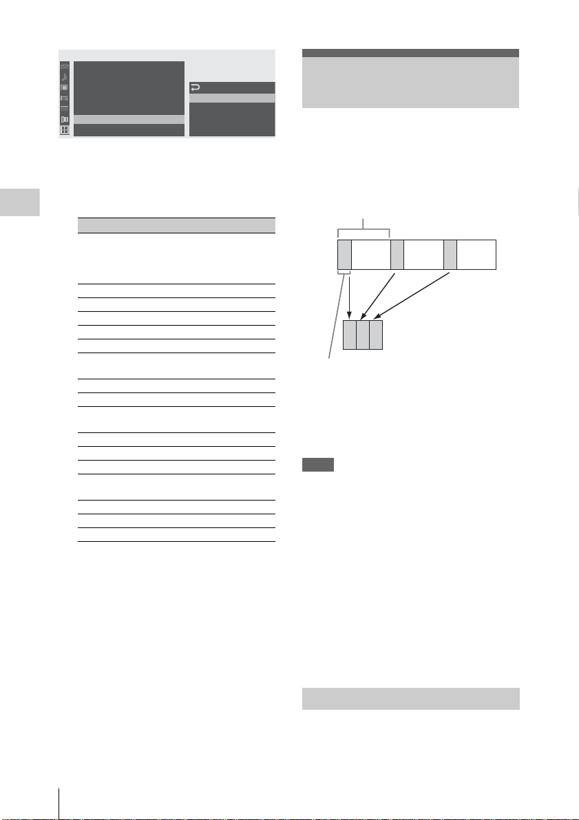
THE
RS
O
All
Reset
Zone
Set
:
:
B
UTC +09:00
B
English
B
B
<1> : Freeze M
:
<2>
:
<3>
:
<4>
Cam
era Data
me
Ti
Clock
00:00
Language
Ass ign Bu tt on
Tally
2 Select the button to which you wish to
assign a function.
3 Select the function to be assigned.
Recording
Function Contents
Marker All marker indications (safety-
Last Clip DEL Las t c lip dele te
ATW ATW function on/off
Rec Review Rec Review start/stop
Rec Recording start/stop
Freeze Mix Freeze Mix start/stop
Expanded
Focus
Spotlight TLCS Spotlight mode on/off
Backlight TLCS Backlight mode on/off
IR Remote IR Remote Commander enable/
Shot Mark1 Shot mark 1 insert
Shot Mark2 Shot mark 2 insert
Fader Fader on/off
VF Mode Viewfinder screen mode (color/
BRT Disp Brightness level indication on/off
Histogram Histogram indication on/off
Lens Info Depth-of-Field indicati on on/off
zone marker, center marker ,
aspect marker, guide frames) on/
off
Expanded Focus function on/off
disable
monochrome) switching
4 Exit the menu.
The assigned functions can be viewed on the
BUTTON/REMOTE status screen (page 111).
Shot M
ark1
Shot M
ark2
Rec Revie
Interval Recording
ix
w
The Interval Recording (time-lapse recording)
function is especially effective for shooting
objects that move very slowl y.
The specified numb er of frames ar e automatica lly
recorded at the specified intervals.
Recording interval (Interval Time)
Number of frames for one recording session
(Number of Frames)
It is recommended to fix the ca mcorder to a tripod
or equivalent and use the IR Remo te Co mmander
to start/stop recording rather than pressing the
REC START/STOP button of the cam c order.
Notes
• Interval Recording cannot be set to “On”
simultaneously with Frame Recording or Slow
& Quick Motion. When you set Inte rval
Recording to “On,” Frame Recording and Slow
& Quick Mot ion are forcib ly set to “Off.”
• No audio recording is executed in Interval
Recording.
• Interval Recording cannot be performed if an
SP video format is selected with “Video
Format” and “i.LINK I/O” is set to “Enable”
with the OTHERS menu.
• Interval Recording cannot be performed if
“Video Format” of the OTHERS menu is set to
SP 1080/24P.
Interval Recording
76
Preparatory Settings
Before starting Interval Recordi ng, make the
necessary settings on the CAMERA SET menu in
advance.
Page 77

For details on menu operations, see “B asi c Me nu
Operations” on page 114.
1 Select “Interval Rec” of the CAMER A
SET menu.
C
AMERA SET
Shot Transi t ion
MF A
ssis t
C
olor Bar
Flicker
00:00
Zoom S
Inter val
me
Fra
:
Type : Multi
Reduce
peed
Rec
Rec
B
Off
B
B
Set t in g
B
Interval
B
Num
ber of Frames
Time
:
Off
: 1sec
: 1
2 Set “Setting” to “On.”
The camcorder ente rs Interval Record in g
mode.
When the special recording mode indication
on the scre en is a ctive, “Inter val Rec” flash es
on the screen.
3 Set the time between recordings with
“Interval Time.”
You can select the time f rom among 1 to10/
15/20/30/40/50 seconds, 1 to 10/15/20/30/
40/50 minutes, and 1 to 4/6/12/24 hour s by
scrolling the display.
4 Set the number of frames to be recorded
at a time with “Number of Frames.”
When “Video Format” (page 130) is set to
“720/60P” or “720/50P,” you can select from
among 2, 6, and 12 frames.
With other settings, you can select from
among 1, 3, 6, and 9 frames.
• The Freeze Mix functio n and Rec Review
function cannot be us ed in Interval Recording
mode.
• The timecode is recorded in Rec Run mode
(page 69) during Interval Recording.
• Some extra frames may be recorded if you stop
recording or s w itch the card slot while
recording is halted in Int erval Recording mode.
Stopping Interval Recording
Press the REC START/STOP button.
Interval Recording stops.
To restart Interval Recording, press the button
again.
Canceling Interval Recording mode
Set “Setting ” of “Interval Rec” of t h e CA M ERA
SET menu to “Off.”
Note
It automatically returns to “Off” when you set the
power switch to OFF, while the “Interval Time”
and “Number of F rame s” s ettin gs are main tain ed.
Recording
5 Exit the menu.
Performing Interval Recording
When the prepara tory sett ings are comp leted, you
can start recording.
Press the REC START/STOP button.
Interval Recording begins.
The flashing “Interval Rec” on the screen is now
steadily lit.
Notes
• You cannot change the “Interval Time” an d
“Number of Frames” settings while Interval
Recording is in progress. To change them,
pause recording.
Interval Recording
77
Page 78

Frame Recording
The camcorder en te rs F r am e Recording
mode.
When the special recording mode indication
on the screen is active, “Frame Re c” flashes
on the screen.
The Frame Recording function is especially
effective for clay an im ation recording.
The specified number of fram es a re recorded
intermittently when you press the REC START/
STOP button.
It is recommended to fix the camcorder to a tripod
or equivalent and use the IR Remote Commander
Recording
to start/stop recording rather than pressing the
REC START/STO P button of the cam corder.
Notes
• Frame Recording cannot be set to “On”
simultaneously with Interval Record ing or Slow
& Quick Motion. When you set Frame
Recording to “On,” Interval Recording and
Slow & Quick M o tion are forcib ly set to “Off.”
• No audio recording is executed in Frame
Recording.
• Frame Recording cannot be performed if an SP
video format is selected with “Video Format”
and “i.LINK I/O” is set to “Enable” with the
OTHERS menu.
• Frame Recording cannot be performed if
“Video Format” o f th e OTHE RS me nu i s s et to
SP 1080/24P.
Preparatory Settings
Before starting F rame Recording, ma ke the
necessary settings on the CAMERA SET menu in
advance.
For details on menu operations, see “B asi c Me nu
Operations” on page 114.
1 Select “Frame Rec” of the CAMERA
SET menu.
AMERA SET
C
MF A
ssis t
:
Type : Multi
Reduce
Rec
Off
B
B
B
B
Sett ing
B
Num
ber of Frames
00:00
C
olor Bar
Flicker
Zoom S
Inter val
me
Fra
S&Q M
otion
peed
Rec
2 Set “Setting” to “On.”
:
: 1
3 Select the “Nu m ber of Frames” valu e
for one recording session.
You can select from among 2, 6, and 12 when
“Video Format” (page 52) is set to 720/60P
or 720/50P.
With other video formats, you ca n sel ec t
from among 1, 3, 6, and 9.
4 Exit the menu.
Performing Frame Recording
When the preparatory settings are completed, you
can start recording.
1 Press the REC START/STOP button.
Recording in Frame Rec mode begins.
The “Frame Rec” indication stops flashing.
When the number of frames you spec ified
with the menu are recorded, the camcorder
automatically enters FRM STBY (Frame Rec
Standby) status.
2 Press the REC START/STOP button
again.
Each time you press the REC START/STOP
button, the camco r der records the specif ied
number of frames then enters FRM STBY
status.
Notes
• Recording cannot be stopped until the specified
number of frames are recorded. If the power
switch is set to OFF during recording, the power
is only shut of f after the specified number of
frames are recorde d.
• The Freeze Mix functio n and Rec Review
function cannot be us ed while recording in
Frame Rec mode is in progress.
• You cannot change the “ N um be r of Frames”
setting while re cording in Frame Rec mode is in
Off
progress. To change it, pause the recording.
• The timecode is recorded in Rec Run mode
(page 69) during Frame Recordin g.
Frame Recording
78
Page 79

• Some extra frames may be recorded if you stop
recording or s wi tch the card slot whi le
recording is paused in Frame Rec mode.
Stopping Frame Recording
Set “Setting” of “Frame Rec” of the
CAMERA SET menu to “Off.”
Recording stops and Frame Rec m ode is
canceled.
Note
It automatically r eturns to “Off” when you set the
power switch to OFF, while the “Number of
Frames” setting is maintained.
Slow & Quick Motion Recording
When an HQ Progressive (P) video format is
selected (page 52), you can set the frame rate for
recording different from that for playback.
By recording at the different frame rate, you can
obtain smoother slow-motion or qu ick-motion
effect when compared with slow-sp eed or fastspeed playback of a ma terial recorded at t he
normal recording speed.
Example
When the video format is HQ 720/24P, recording
with a frame rate between 1 and 23 fps provides a
quick-motion effect in pl a yback, and recording
with the frame rate between 25 and 60 fps
provides a slow-motion effec t in pla yba ck.
Notes
• Slow & Quick Motion cannot be activa ted
simultaneously with Frame Recording or
Interval Recording. When you activate Slow &
Quick Motion, Frame Reco rdi ng and Interval
Recording are forcibly set to “Off.”
• No audio recording is m ade if t he recording
frame rate is set to a value different from the
playback frame rate.
• Slow & Quick Motion recording cannot be
made if “Video Format” of the OTHERS menu
is set to HQ 1080/60i, HQ 1080/50i, SP 1080/
60i, SP 1080/50i, or SP 1080/24P.
• When using a PHU-60K (pa ge 47), set the
camcorder to one of the foll ow i ng conditions.
Slow & Quick Motion recording cannot be done
properly with other conditions.
—NTSC Area
Video format Recording frame rate
HQ 1080/30P 1 to 30 fps
HQ 1080/24P 1 to 24 fps
HQ 720/60P 1 to 60 fps
HQ 720/30P 1 to 30 fps
HQ 720/24P 1 to 24 fps
—P AL Area
Video format Recording frame rate
HQ 1080/25P 1 to 25 fps
HQ 720/50P 1 to 50 fps
HQ 720/25P 1 to 25 fps
Recording
Slow & Quick Motion Recording
79
Page 80

Preparatory Settings
Before starting S low & Quick Motion reco r ding,
make the necessary settings in advance.
R
CANCEL
VOL
F FWD
MONITOR
E
S
SEL/SET
J
U
L
A
/P
NEXT
Y
A
L
/S
P
L
G
THUMNAIL
STOP
F REV
s
j
REC
T/STOP
PREV
STAR
l
HOLD
H
F
L
F
O
B
T
C
/
U
B
I
T
/
D
U
R
A
T
I
O
ND
FILTER
O
FF
STA
TUS
L
E
N
S
IN
1
2
1
+
GAIN
WHITE BAL
L
M
A
T
W
H
M
EN
U
S
F
O
B
R
T
D
IS
P
H
IS
T
O
G
R
A
M
A
S
S
IG
2
N
3
F
U
L
L
A
U
T
F
O
R
A
M
E
BA
R
S
/C
AM
B
A
P
R
S
T
E
L/S
ET
CANCEL
N
T
C
LE
E
S
T
O
L
S
S
S
E
C
C
A
B
-1
H
C
A
IO
D
U
A
V
LE
N
E
P
O
P
IC
T
U
R
E
P
R
O
F
IL
C
E
A
M
E
R
A
O
F
F
M
E
D
IA
-
+
WHITE BAL BARS/CAM
GAIN
LATW
M
H
O
T
U
A
A
M
IO
D
U
A
LE
E
S
L
E
-2
H
C
IN
E
L
A
U
N
IO
D
U
A
IN
T
C
O
T
U
A
A
U
N
A
M
PMW-EX3
FRAME
40
IRIS
1.9
25
2.8
M
ANU
15
AUT
O
4
MACR
O
.6
10
5
8
OFF
ON
5.8
FOCUS
16
C
M
A
N
U
A
U
P
T
U
O
S
H
A
F
Recording
16:9 W
IDE
SCREEN
ft
m
m
0
0
3
1
5
15
0
3
1
S&Q Motion di al
1 Press the S&Q Motion dial for more
than 1 second.
The camcorder ente rs the Slow & Quick
Motion standby status.
The special reco rding mode i ndication on the
screen shows “S&Q Motion” and [Recording
frame rate]/[Playback fra m e ra te] fps
beneath.
BY
S&Q STBY
TCG 00:00:00:00
Q
1080/24P
H
S&
SDI OUT
HDV
T
X
GENLOCK IN
IN
TC IN
T
X
E
L
REMOTE
TC OUT
FULL AUTO
B
A
PAS T
Q M
otion
29/24fps
Setting the recording frame rate with the
Direct menu
When the special reco rdi ng mode indication on
the screen is active, you can change the recording
frame rate wit h th e Direct menu by operating the
joystick or the jog dial.
For details on the Direct menu, see “Direct Men u
Operation” on page 26.
Recording in Slow & Quick Motion Mode
When the preparatory settings are completed, you
can start recording.
Press the REC START/STOP button.
Slow & Quick Motion recording begins.
Notes
• You cannot change the frame rate setting while
Slow & Quick Motion recording is in progress.
To change it, pause the recording.
• The timecode is recorded in Rec Run mode
during Slow & Quick Motion recordi ng (page
69).
Stopping recording
Press the REC START/STOP button.
Slow & Quick Motion recording stops.
Note
When recording at a low-speed frame rate, it may
take time until recording stops after you press the
REC START/STOP button.
2 Set the frame rate for recording by
turning the S&Q Motion dial.
The setting range varies depending on the
current video format.
With a 1080 format: 1 to 30 fps
With a 720 format: 1 to 60 fps
When the RM-B750/B150 Rem ote Contr ol
Unit is connected, “S&Q Motion” of the
CAMERA SE T menu is activated, enabling the
operation fr om the Remote Con tr ol Unit.
For details, see “Operat ing the Slow & Quick
Motion recording from the Remote Control Unit” on
page 141.
Slow & Quick Motion Recording
80
Canceling Slow & Quick Motion mode
Push the S&Q Motion dial.
Note
It automatically returns to “Off” when you set the
power switch to OFF, whil e the frame r ate setting
is maintained.
Page 81

Freeze Mix: Image Alignment
Using the Freeze Mix function, an image (still
picture) of a recorded cli p ca n be temporarily
superimposed on the current ca mera picture,
permitting you to easily align images for next
recording.
• The Freeze Mix function cannot be used if the
recording video format is SP 1080/24P.
• The Freeze Mix display cannot be obtained in
Quick & Slow Motion mode or Slow Shutter
mode.
• You cannot operate the Setup menus an d
PICTURE PROFILE menu in Freeze Mix
status.
To use the Freeze Mix function
Assign the Freeze Mix function to one of the
assignable buttons.
For details, see “Changing Functions of the
Assignable Buttons” on page 75.
Superimposing a Freeze Mix image
1 Stop recording to set the camcorder to
STBY (recording standby) status.
2 Press the REC REVIEW button to
review the re corded imag es, or pre ss the
ASSIGN button to whi ch you assigned
“Freeze Mix.”
3 Press the ASSIGN button to which you
assigned “Fre eze Mix” at the image
with which you want align.
The image where you pressed the ASSIGN button
3 is displayed as a still picture over the
in step
current camera picture.
Canceling Freeze Mix status
You can cancel it with the ASSIGN button to
which you assigned “Freeze Mix” or the REC
START/STOP button.
• When you cancel Freeze Mix status by pressing
the ASSIGN button, the normal camera picture
is restored.
• When you cancel Freeze Mix status by pressing
the REC START/STOP button, norm al
recording begins.
Notes
• If the recorded picture and the current camera
picture differ in video format, the Freeze Mix
display cannot be achieve d.
Recording
Freeze Mix: Image Alignment
81
Page 82

Shot Transition
The Shot Transition function helps yo u to easily
obtain comple x picture effec ts by registering
camera settings or conditions as a “shot ” to be
reproduced in a recording sequence.
Your settings for focus, zoom, iris, ga in , shutte r
speed, white balance, color matrix, an d detail
level can be reg istered in combi nation in one sh ot,
Recording
and you can change the current camera settings to
those of the shot, or the settings reproduced from
one shot to those of another Shot, resu lt in g in a
smooth transition of scenes.
For example, yo u can shift the focus fro m a closer
object to a farther objec t, or change the depth of
field by adjusting the iris. In ad di ti on, you can
develop scenes under different recording
conditions smoothly. If you register th e manual
adjustment function for white balance, the scenes
will develop smoothly between objec ts indoo rs
and those outdoors.
Notes
• Use the exclusive lens for Shot Transition. This
function may not ope rate correctly with a nonexclusive lens.
• Shot transition cannot be activated in
combination with any of the EX Slow Shu tter,
Interval Reco rding, Frame Reco rding, and Slow
& Quick Motion functions.
• If you wish to shift the focus in a shot transiti on,
set the focus adjustment mode to MF or AF (see
page 64). The fo cus will not be s h ifted if Full
MF mode is selected.
• If you wish to shift the zoom in a shot transition,
set the ZOOM switch to SERVO (see page 62).
The zoom will not be shifted with the MANU
setting.
• If you register a focus position in a macro area
with the MACRO switch ON, the focus may not
be shifted to the registered po sit ion if a shot
transition is executed wi th th e MAC RO swit ch
set to OFF.
Shot-transition operation buttons and
indications
For shot-transition oper ations, use the three
TRANSITION operati on buttons on the upper
panel.
A button B button
A
MODE button and
indicator
16:9 W
IDE SCREEN
AF
0
3
15
0
1
A button and B button
You can register a Shot to each of the butt ons.
MODE button and indicator
When you press this button, the camcorder enters
Shot Transition operation mode, and the indicator
of the button lights.
The shot transition operation area is displayed on
the screen.
Each time you press the button, the shot-transition
operation mode cycles among Store, Check,
Execute, and Off (normal Camera mode).
In Execute mode, the shot transition information
area appears.
SHOT
TRANSITION
Full
STEADY
MF
SHOT
81.2
ft
m
40
m
IRIS
25
0
1
M
ANU
15
AU
T
O
MACR
5
O
10
3
O
FF
O
5.8
N
FOCUS
M
A
N
U
A
U
P
T
U
O
S
H
A
F
1.9
2.8
4
.6
5
8
16
C
B
L
E
N
S
IN
F
O
B
R
T
D
1
2
ND
FILTER
2
1
-
F
F
R
A
M
E
+
GAIN
O
FF
WHITE BAL
L
M
A
T
W
H
B
A
P
R
STA
TUS
M
ENU
S
EL/S
E
T
TC/U-BIT/DURATION
A
TR
S
H
A
O
N
T
S
ITIO
B
N
T
C
/U
B
I
T
/
D
U
R
A
T
I
O
N
IS
P
H
IS
T
O
G
R
A
M
A
LO
S
S
S
IG
N
3
S
S
E
C
C
A
B
A
U
L
L
A
U
T
O
B
A
R
S
/C
A
M
S
T
N
E
P
O
CANCEL
P
IC
T
U
R
E
P
R
O
F
IL
C
E
A
M
E
R
A
O
F
F
M
E
D
IA
SDI OUT
HDV
T
C
LE
E
T S
IN
T
X
E
GENLOCK IN
O
T
U
A
L
A
U
N
A
M
IO
D
U
A
IN
-1
H
C
DIO
U
IN
TC IN
A
T
C
LE
T
E
X
E
S
IO
D
O
U
T
A
U
A
EL
L
V
A
U
LE
N
A
M
-2
H
C
REMOTE
TC OUT
PMW-EX3
82
Shot Transition
Page 83

Shot-transition operation area
REC
TCG 00:00:00:00
Shot Transition
Execut e
ShotShot-
S E
12s
0s
Rec Link:Off
A
B
Shot-transition information area
Note
Camera operations are disabled when the shot
transition operati on mode is Check or Execute.
When adjustments are re qui re d, set th e m ode to
Store.
Preparatory Settings
Before you start recording using t he Shot
Transition function, make the necessary settings
with the CAMERA SET menu in advance.
The conditions you set are indicated in the shot
transition information area on the screen when
you set the shot-transition operation mode to
“Execute.”
Shot-transition information area
Progress bar
S E
0s
Rec Link:
Rec Link status
Start timer indication
Transition pattern
12s
Transition time
Off
CAMERA
SET
A
uto BLK B
00:00
Setup
Gain
Shutter
EX Slow S
Transi t ion
Shot
MF A
ssis t
alance
hutter
:
Trans Time
B
Trans
B
Time/Speed
B
Trans
B
Start
Off
Rec
Link
Speed
Curve
Timer
:
:
:
:
:
:
2 Specify the condit io n s for a shot
transition.
Trans Time
After you set “Time/Speed” to “Time,” set
the duration of a transition in the range of 2
to 15 sec in steps of 1 second.
Trans Speed
After you set “Time/Speed” to “Speed,” set
the zoom transition speed (specifying the
time to be taken for the zoom moving from
the TELE end to the WIDE end at a certain
speed).
The setting range is from 1 to 10. The larger
the number you set, the higher spe ed .
Time/Speed
Set whether to specify the duration of a
transition by time or by speed of zoom
transition.
Setting Contents
Time The “Transition Time” setting is valid.
Speed The “Transition Speed” setting is
Trans Curve
Select the transition pattern.
The corresponding icon is displayed in the
shot transition information area.
Setting
and icon
Linear To make the transition linearly.
valid.
Contents
P
2sec
5
Speed
Soft Stop
Off
Off
Recording
Setting procedure
1 Select “Shot Transition” from the
CAMERA SET menu.
T
Shot Transition
83
Page 84

Setting
and icon
Soft Trans To make the transition slowly at
Soft Stop To make the transition slowly near
Recording
P: Parameter level T: Transition of time
Start Timer
Set the time from star t of recordi ng to start of
the shot transition.
The countdown indication is displayed in the
shot-transition information area until the shot
transition is started by the Start Timer.
Rec Link
Set whether to link shot-transition start and
target shot selection to recording start.
The setting status is displayed in the shot
transition information area.
Off: Not to link to recording start
(To use the A or B button to start the
transition and specify the targ et shot)
Shot-A: To start the transition to Shot A in
synchronization with recording start
Shot-B: To start the transition to Shot B in
synchronization with recording start
Contents
the beginning and end but linearly
in between.
P
T
the end.
P
T
3 Exit the men u to finish the se ttings.
Registering a shot
You can register two kinds of shots: A an d B.
1 Press the MODE button to display
“Store” in the shot-transition operation
area.
2 Adjust the camera setting s to ob tain an
image you wish to register.
3 When adjustment is finishe d, press the
Shot A or Shot B button.
The camera setti ngs are registered to t h e pressed
button.
The registered camera settings are maintained
until you register them next.
Checking the registered settings (Shot)
1 Press the MODE button to display
“Check” in the shot-transition
operation area.
2 Press the A or B butt on, wh ich ev er you
assigned to the shot you wish to check.
The selected sh ot ( camer a set ti ngs or co ndi ti ons)
takes effect on the pict ure on the screen.
With this opera tion, you cannot chec k th e
conditions of the transition.
Recording with a Shot Transition
When the preparatory settings are completed, you
can start recording.
Operations differ depending the “Rec Link”
setting.
Making a transition from the current
picture to a registered shot
1 Adjust the ca mer a settings to ob tain an
image with which you wish to star t
recording.
2 Press the MODE button to display
“Execute” in the shot-transition
operation area.
3 Press the REC START/STOP button.
Recording begins.
4 When “Rec Link” is “Off,” press the
button of the ta rget shot (A or B) when
you wish to star t t h e shot transitio n .
The current camera settings are gradually
shifted to those registered to the specified
shot.
84
Shot Transition
Page 85

When “Rec Link” is “Shot-A” or “ShotB,” the camcorder automatical ly per f orms
the shot transition to the camera settings
registered to Shot A or Shot B, respectively.
You need not press the button.
Notes
• You cannot return to the status in step 1 once
after you start the shot transition . If t he st at us
must be resumed, register it as a shot.
• When you perform reco rding on an external
device connected via the i.LINK(HDV)
connector in synchronization with REC
START/STOP operations on this camcorder,
recording start on the ext ern al device and shottransition start may not be synchronized even if
“Rec Link” has been set to “Shot-A” or “ShotB,” depending on the performance of the
external device.
Making a transition from Shot A to Shot B
When “Rec Link” is set to “Off” or “S hot-B,” a
shot transition from Shot A to Shot B is possible.
1 Press the MODE button to display
“Check” in the shot -transition
operation area.
2 Press the A button.
The picture is adjus ted according to the
camera settings registered for Shot A.
3 Press the MODE button to display
“Execute” in the shot-transitio n
operation area.
4 Press the REC START/STOP button.
Recording begins with the ca m era settings
registered for Shot A.
5 When “Rec Link” is “Off,” press the B
button when you wish to start the shot
transition.
When “Rec Link” is “Shot-B,” the
camcorder automatically performs the shot
transition to the camera settings registered
for Shot B. It is not necessary to press the B
button.
Making a transition from Shot B to Shot A
When “Rec Link” is set to “Off” or “Shot-A,” a
shot transition from Shot B to Shot A is possible.
1 Press the MODE button to display
“Check” in the shot-transition
operation area.
2 Press the B button.
The picture is adjusted according to the
camera settings registered f or Shot B.
3 Press the MODE button to display
“Execute” in the shot-transition
operation area.
4 Press the REC START/STOP button.
Recording begins with the camera settings
registered for Shot B.
5 When “Rec Link” is “O ff,” press the A
button when you wish to start the shot
transition.
When “Rec Link” is “Shot-A,” the
camcorder automatically performs the shot
transition to the camera settings re gistered
for Shot A. It is not necessary to press the A
button.
Ending recording
When recording is completed, press the REC
START/STOP button.
To cancel recording while a transition is in
progress
If you press the REC START/STO P butt on
during recording, the recording stops, even when
a shot transition is in progress.
The E-E picture of the settings wh ere the
recording stops is disp l ayed.
Releasing a Shot Transition
Press the MOD E button so tha t the button
indicator goes dark.
The viewfinder sc reen resumes the norm al
condition.
Recording
Shot Transition
85
Page 86

Fader Function
Using the Fader function, you ca n sta rt a
recording by fading in a scene or end a recording
by fading out of a scene.
The fader function can be assigned to an
assignable button.
For function assignment, see “Changi ng Func ti ons
of the Assignable Buttons” on page 75.
Recording
Notes
• The fader function cann ot be used in
combination with the Slow & Quick Motion ,
Interval Recording, Frame Recording, or EX
Slow Shutter function.
• When a clip is recorded usi ng th e fade-in
function, a white or black screen becomes the
index frame on the thumbnail screen (page 96).
Change the index frame for easier
identification.
• When you perform reco rding on an external
device connected via the i.LINK(HDV)
connector in synchronization with REC
START/STOP operations on this camcorder,
recording start/stop on th e external dev ice and
fade-in start/fade-out en d may not be
synchronized, depending on the performance of
the external devi ce.
Preparatory Settings
Specify the condi tions to activate the Fad er
function in advance with the following
procedure:
1 Select “Fader” of the CAMERA SET
menu.
CAMERA
SET
Rec
Rec
:
B
B
Fade In
B
B
2sec
B
B
Fade
Fade
Fade
Fade
Fade
In
In Tim
Out
Out Type
Out Time
Z
oom
Speed
Inter val
me
Fra
S&Q M
oti on
00:00
Review
Rec
Fader
TLCS
2 Specify the f ade-in condi tions.
Type
:
: Black
e
:
:
: Black
:
Off
2sec
Off
2sec
Fade In
Set this to “On” to start recording with fade
in.
(When you operate the function using an
assignable button, it is not necessary to set
“Fade In” to “On” with the menu.)
Fade In Type
Select the initial status of the fade-in.
White: To fade in from a white screen
Black: To fade in from a black screen
Fade In Time
Set the duration (1/2/3/5/10 sec.) of fade-in.
3 Specify the fade-out conditions.
Fade Out
Set this to “On” to end recording with fade
out.
(When you operate the function using an
assignable button, it is not necessary to set
“Fade Out” to “On” with the men u.)
Fade Out Type
Select the final status of the fade-out.
White: To fade out to a white screen
Black: To fade out to a black scr ee n
Fade Out Time
Set the duration (1/2/3/5/10 sec.) of fade-out.
4 Exit the menu.
• If you set “Fade In” to “On ” with th e menu, the
camcorder enters Fade-in standb y sta tus when
you exit the menu.
• When the Fader indication on the screen is
active, the initia l status (“White Fader” or
“Black Fader”) you set wi th “ Fade In Type”
flashes.
74%
1 1.5 2 3 4 5 7 10 15 20 30 oo
ND
1 ++F1.9 18dB
SHT
When using an assignable button
If you assigned the Fader function to an
assignable button, the Fade In/Fade Out On/Off
settings can be made using the butto n.
:1/2000
m
CH1
CH2
W
hite Fader
86
Fader Function
Page 87

For fading in a scene
Press the ASSIGN button to which you assigned
the Fader function in STBY (recordi ng sta ndby)
status.
The fade-in function is turned on.
For fading out
Press the ASSIGN button to which you assigned
the Fader function during recording.
The camcorder enter s in th e fa de-out standby
status.
Note
The Fade In/Fade Out settings automatically
return to “Off” when you turn off the camcorder,
while the Type and Time settings set with the
menu are maintained.
Starting Recording with a Fade In
When the prepara tory sett ings are comp leted, you
can start recording.
Press the REC START/STOP button.
Recording be gins by fad ing in the cam era pictur e.
When the fade-in process you spec if ie d is
completed, the camcorder enters Normal
Recording mode.
The Fade-In Type indication flashes during the
fade-in process and goes off when the process
ends.
Ending Recording with a Fade Out
• If you set “Fade Out” to “On” with the menu,
the camcorder automatically enters Fa d e- out
standby status when it is set to Record ing mode.
• When you press the ASSIGN button to which
you assigned the Fader function after start in g
recording, the camcorder enters fade-out
standby status.
Press the REC START/STOP button to
start fading out of the camera picture.
The fading-out process begins.
When the fading-out proc ess you specified is
completed, recording simultaneously stops.
The Fade-Out Type indication flashes during the
fade-out process and goes off when the process
ends.
Recording
Canceling the Fader function
Set “Fade In” and “Fade Out” to “Off” with the
menu.
Or press the ASSIGN button again.
Fader Function
87
Page 88
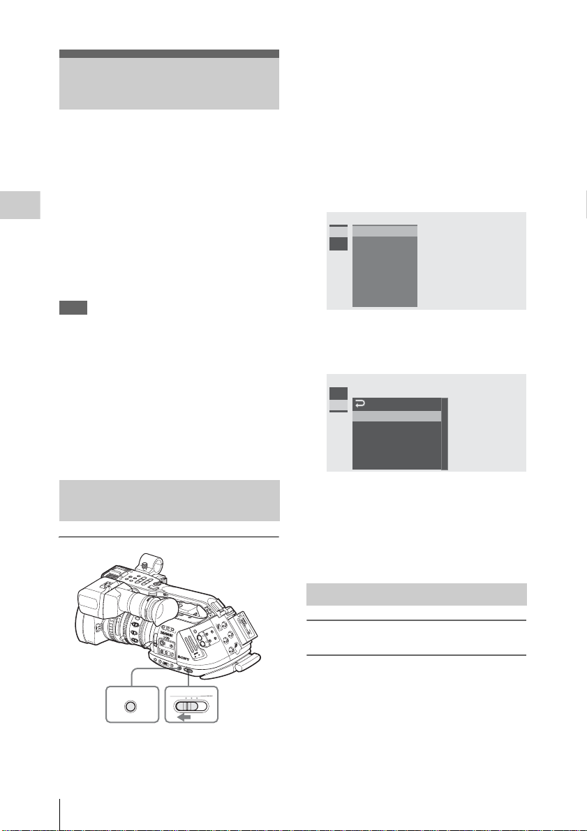
Picture Profiles
You can customize the picture quality, depending
on the conditions or circumstances of recording,
and store them as a picture profile, enab ling the
picture quality to be resumed j ust by your
selecting the picture profi le .
Six different picture profiles (PP1 to PP6) can be
stored in memory.
Recording
The same standard (r eference) valu es are
registered to si x picture profiles at the factory as
those specified for the Picture P rofi le Off sta tu s.
The PICTURE PROFILE menu is av ailable for
picture-profile operati ons.
Note
The picture prof iles can be operated only in
Camera mode. They cannot be operated in Media
mode.
1 Set the power switch to CAMERA to
turn the camcorder on in Camera
mode.
2 Press the PICTURE PROFILE button.
The PICTURE PROFILE menu is displayed.
3 Operating the jog dial or the joystick,
select “SEL” from the PIC TURE
PROFILE menu then select the picture
profile number (PP1 to PP6) to operate.
PICTURE PROFILE
OFF
SEL
SET
STANDARD
PP1:
PP2:
STANDARD
PP3:
STANDARD
PP4:
STANDARD
PP5:
STANDARD
PP6:
STANDARD
4 Operating the jog dial or the joystick,
select “SET” and make the settings of
the picture profile items.
When the RM-B750/B150 Remote Contr ol U ni t
is connecte d , PP6 is automatically selected and
the picture profiles can be adjusted from the RMB750/B150.
For details, see “Operating F rom the RM- B 750/
B150” on page 140.
Registering the Customized Settings as a Picture Profile
R
CANCEL
VOL
F FWD
MONITOR
E
S
SEL/SET
J
U
L
A
/P
NEXT
Y
A
L
/S
P
G
THUMNAIL
STOP
F REV
j
REC
PREV
START/STOP
l s L
HOLD
H
F
L
F
40
IRIS
25
M
AN
U
15
AUT
O
MACR
O
10
O
FF
O
5.8
N
FOCUS
M
A
N
U
A
U
P
T
U
O
S
H
A
F
O
1.9
L
E
N
S
IN
F
O
B
R
T
D
IS
2.8
P
H
IS
4
1
2
ND
.6
FILTER
5
3
8
2
16
C
1
-
F
U
L
L
A
U
F
R
A
M
E
+
GAIN
O
FF
WHITE BAL
L
B
A
R
S
M
/C
A
T
W
H
B
A
P
R
S
T
STA
TUS
M
ENU
S
E
L/S
E
T
CANCEL
CAMERA OFF MEDIA
Power switch:
CAMERA
B
T
C
/
U
B
I
T
/
D
U
R
A
T
I
O
N
SDI OUT
T
O
G
R
A
T
O
A
M
HDV
A
M
T
C
LE
E
S
T
LO
IN
S
S
S
IG
N
T
X
E
GENLOCK IN
O
T
U
A
L
A
U
N
S
A
S
M
E
IO
C
D
C
U
A
A
B
IN
-1
H
C
IO
D
U
A
IN
TC IN
A
T
C
LE
T
E
X
E
S
IO
D
O
U
T
A
L
U
A
E
L
V
A
U
LE
N
A
M
-2
H
C
REMOTE
TC OUT
PMW-EX3
N
E
P
O
P
IC
T
U
R
E
P
R
O
F
IL
C
E
A
M
E
R
A
O
F
F
M
E
D
IA
16:9 WIDE SCREEN
ft
m
m
0
0
3
1
5
15
0
3
1
PICTURE
PROFILE
PICTURE
PROFILE
button
PICTURE PROFILE
PP
1:
SEL
SET
STANDARD
Profile Name
M
atrix
Correction
Color
W
hi t e
Detail
B
B
B
B
B
B
For details on the setting items, see “Pi ct ure
Profile Items” on page 90.
5 When the settings are completed, press
the PICTURE PROFILE button to exit
the menu.
Selecting a Picture Profile
Selecting a Picture Profile using the
PICTURE PROFILE menu
Once you store a picture profile, you can call the
picture qu ality registered in the picture profi le as
follows:
1 Set the power switch to CAMERA to
turn the camcorder on in Camera
mode.
2 Press the PICTURE PROFILE button.
88
Picture Profiles
Page 89

The PICTURE PROFILE menu is displaye d.
0
m
3 Operating th e jog dial or the joystick,
select “SEL” then the desired picture
profile from the list.
Example:
PICTURE PROFILE
OFF
SEL
SET
The camcorder is adju s ted to the picture
quality specified by the selected Profile.
(If you select “OFF,” the camcorder will be
fixed at the standard pictur e quality, and no
picture adjustment is allowed.)
PP1:
PP2:
PP3:
PP4:
PP5:
PP6:
SceneA
SceneB
SceneC
SceneD
SceneE
SceneF
2 Select “Copy” from “SET” of the
PICTURE PROFILE menu.
The picture profile numbers are listed on the
screen.
3 Specify the targ et p ic ture profile.
“Execute” and “C a n ce l” are displayed.
4 Select “Execute.”
Copying begins.
When copying ends, the completion message is
displayed for three seconds, and the original
screen display is restored.
Resetting a Picture Profile
You can reset a selected picture profile to the
factory settings (standard status).
Recording
4 Press the PICTURE PROFILE button
to exit the menu.
Selecting a Picture Profile using the
Direct menu
The picture profile being selected is displayed
when you press the DISPLAY/BATT IN FO
button.
TLCS
.
7
On
M
F
*
ATW 4300K PP1 ND
You can select picture profiles with the Direct
menu by operating the joystick or the jog dial .
For details on the Direct menu, see “Direct Menu
Operation” on page 26.
1 1.5 2 3 4 5 7 10 15 20 30 oo
1 ++F1.9 18dB
SHT
:1/200
Copying the Settings of a Picture Profile
You can copy the settings of a selected picture
profile to another picture profile.
1 Select the source p i ct ure profile by
proceeding from step 1 to 3 of
“Selecting a Picture Profile using the
PICTURE PROFI LE men u” on pa ge 88.
1 Select the picture profile you wish to
reset by proceeding from step 1 to 3 of
“Selecting a Picture Profile using the
PICTURE PROFILE menu” on page 88.
2 Select “Reset” from “SET” of the
PICTURE PROFILE menu.
“Execute” and “C a n ce l” are displayed.
3 Select “Execute.”
Resetting begins.
When resetting ends, the comp letion message is
displayed for three seconds, and the original
screen display is restored.
Picture Profiles
89
Page 90

Picture Profile Items
The values when “Off” is selected at “SEL” of the PICTURE PROFILE menu are shown in bold face
(example:
PICTURE PROFILE SET
Items Subitems and setting values Contents
Profile Name
Changing the picture profile
name
Matrix
Recording
Adjusting the color phase
over the entire area with
matrix operations
Color Correction
Adjusting the color phase in
a specific area
Standard).
Profile name Set the profile name in 8 characters at maximum.
Setting
On / Off
You can use upper- and lowercase alphabetics,
numerics 0 to 9, - (hyphen), _ (underscore) and
space.
Set to “On” to activate the color phase adjustment
function with matrix operations for the entire
picture.
Note
When this function is set to “Off,” Color Correction
is also set to “Off” in synchronization.
Select
Standard /High SAT / FL
Light / Cinema
Level
–99 to +99 (±0)
Phase
–99 to +99 (±0)
R-G, R-B, G-R, G-B, B-R, B-G
–99 to +99 (±0)
Setting
On / Off
Area Detection
Execute/Cancel
Area Indication
On / Off
Target Phase
0 to 359 (130)
1)
2)
Select the built-in preset matrix provided for
convenience.
Adjust the color saturation for the entire picture
area.
Adjust the hue for the entire picture area.
Finely adjust the color phase for the entire picture
area by independently setting each of the factors.
Set to “On” to enable the color phase adjustment
for a specific area. (Simultaneous adjustment of
multiple areas is not allowed. You can adjust it for
one area only.)
Execute to detect the color in the center of the
screen. The area centering around the detected
color of the range specified by “Target Width”
becomes the target area of Color Correction.
Set to “On” to display the Zebra 1 pattern for the
target area of Color Correction.
Manually adjust the center color for the target area
for Color Correctio n .
Note
When Area Detection is executed, this setting is
overwritten by the Area Detection result. Perform
fine adjustment with this item as required.
Target Width
0 to 90 (40)
Level
–99 to +99 (±0)
Phase
–99 to +99 (±0)
Set the width of color phase for the target area for
Color Correction.
Set the saturation for the color in the target area.
Adjust the hue for the color in the target area.
90
Picture Profiles
Page 91

PICTURE PROFILE SET
Items Subitems and setting values Contents
White
Setting the white balance
offset and the color
temperature of the preset
white
Offset White
On / Off
Offset<A>
–99 to +99 (±0)
Offset<B>
–99 to +99 (±0)
Offset<ATW>
–99 to +99 (±0)
Preset White
2100 to 10000 (3200)
Set to “On” to shift the conversion value for auto
white ba lance in M e mory A or B mode and that for
auto tracing white in ATW mode to a lower color
temperature or a higher color temperature.
Adjust the volume of the offset white (shifting
volumes) of the conversion v alu e in Memory A,
Memory B, or ATW mode, respectively.
Adjust the preset color temperature when Preset
white balance mode is selected in steps of 100K.
Notes
• Except when the white balance is in Memory A
or B mode or when ATW is active, you cannot
confirm the result of changing the Offset White
and Offset settings on the screen.
• Except when Preset white balance mode is
selected, you cannot confirm the result of
changing the Preset White settings on the screen.
Detail
Adjusting the details to be
applied to the picture
Setting
On / Off
Level
–99 to +99 (±0)
Frequency
–99 to +99 (±0)
Crispening
–99 to +99 (±0)
H/V Ratio
–99 to +99 (±0)
White Limiter
–99 to +99 (±0)
Black Limiter
–99 to +99 (±0)
V DTL Creation
NAM / Y / G / G+R
Knee APT Level
–99 to +99 (±0)
Set to “On” to apply the details to the video signal.
Adjust the detail level.
Set the center frequency of the details.
Setting the center frequency higher decreases the
details, and setting it lower increases the details.
Adjust the noise-suppression level.
When you set it to a higher level, less noise may be
seen, as fine elements of details are deleted leaving
only high-level elements.
When you set it to a lower level, fine elements are
applied while increasing noise.
Adjust the horizontal-to-vertical ratio of deta il
elements.
A higher value makes the vertical elements
increased with respect to the horizontal elements.
Limit the white details.
Limit the black details.
Select the source signal to generate vertical details
from among NAM (G or R whichever is higher), Y,
G, and G+R.
Adjust the knee aperture level (level of details to be
applied to the sections above the knee point).
Recording
Picture Profiles
91
Page 92

PICTURE PROFILE SET
Items Subitems and setting values Contents
Skin Tone Detail
Adjusting the details to be
applied to the areas of a
specific color phase
Recording
Knee
Adjusting the knee level
Setting
On / Off
Level
–99 to +99 (±0)
Area Detection
Execute/Cancel
Area Indication
On / Off
Saturation
–99 to +99 (±0)
Phase
0 to 359 (130)
Width
0 to 90 (40)
Setting
On / Off
Auto Knee
On / Off
Point
50 to 109 (90)
Slope
–99 to +99 (±0)
Knee SAT Le v e l
0 to 99 (50)
1)
2)
Set to “On” to enable the detail level adjustment for
specific color-phase areas.
The detail level is uniform over the entire picture
with the Off setting.
Adjust the skin-tone detail level.
Execute to detect the color in the center of the
screen. The area centering around the detected
color becomes the target area for Skin Tone Detail
control.
Set to “On” to display the Zebra 1 pattern for the
target area for Skin Tone Detail control.
Adjust the color (saturation) level for Skin Tone
Detail control.
Note
When Area Detection is executed, this setting is
automatically returned to 0.
Adjust the center color-phase value for the target
area for Skin Tone Detail control.
Note
When Area Detection is executed, this setting is
automatically changed to the value equivalent to
that of the detected color.
Adjust the width of the color phase of the target
area for Skin Tone Detail control.
Note
When Area Detection is executed, the Width
setting automatically returns to 40.
Set to “On” to compress the high-luminance area of
the picture.
Note
Knee is fixed and cannot be changed in the
following cases:
• When Gamma is set to CINE1 to 4
• When the electronic shutter is in SLS mode
• When EX Slow Shutter is active
Set to “On” to automatically set the best knee
conditions according to the luminance level of the
picture.
With “Off” the knee conditions can be manually
adjusted independently of the luminance level of
the picture.
Set the knee point when Auto Knee is “Off.”
Set the knee slope (volume of compression) when
Auto Knee is “Off.”
Adjust the knee saturation level for the area over
the knee point.
92
Picture Profiles
Page 93

PICTURE PROFILE SET
Items Subitems and setting values Contents
Gamma
Adjusting the gamma
compensation level and
selecting the gamma curve
Black
Adjusting the black
Black Gamma
Adjusting the black gamma
level
Low Key SAT
Adjusting the low key
saturation
Copy
Copying a picture profile
Reset
Resetting a picture profile
Level
–99 to +99 (±0)
3)
Select
STD1 / STD2 / STD3 / STD4 /
CINE1 / CINE2 / CINE3 /
CINE4
–99 to +99 (±0) Adjust the master black level.
–99 to +99 (±0) Adjust the level of black gamma function that
–99 to +99 (±0) Adjust the level of the low key saturation to
Execute / Cancel Select “Execute” to copy.
Execute / Cancel Select “Execute” to reset.
Adjust the gamma compensation level.
Select the type of reference curve for gamma
compensation.
emphasizes only the dark areas of the picture to
clear the tones or on the contrary de-emphasizes it
to reduce noise.
heighten the colors only in the dark areas of the
picture or pale them to reduce noise.
Recording
1)To execute “Area Detection”
1. Select “Area Detection .”
A square marker that indicates the detection
area appears in the center of the screen, and
“Execute” and “Cancel” are disp layed b elow.
2. Select “Execute.”
Color-phase detection in the marker area is
performed.
When detection successfully ends, a
completion message is displayed. Then the
screen is re s tored, on which the target ar ea
for the Color Correction or Skin Tone Detail
adjustment is changed to the area centering
around the colo r det ected by “Area
Detection,” and the Area Indication (zebra
pattern) appears.
If detection fails, an error message appears,
then the precious screen is restored.
2)The Area Indication setting is common to all picture
profiles PP1 to PP6.
3)Available gamma curves
STD1:This deemphasizes the contrast in dark areas
more than STD2 and emphasizes the contrast in
intermediate areas.
STD2:This deemphasizes the contrast in dark areas
more than STD3.
STD3: Standard (factory setting)
STD4:This emphasizes the contrast in dark areas more
than STD3.
CINE1:This smoothes the contrast in darker areas and
accentuates gradation changes in brighter ar eas,
for a calm and quiet effect.
CINE2:This gives almost the same results as CINE 1.
Select this when you wish to obtain 100% video
signals for editing or other purposes.
CINE3:This emphasizes the contrast between light and
dark more than CINE1 and CINE2, and also
accentuates gradation changes on the black side.
CINE4:This emphasizes the contrast in dark areas more
than CINE3. Contrast in dark areas is weaker
and contrast in bright areas is stronger than STD
curves.
Picture Profiles
93
Page 94

Deleting Clips
In Camera mode, the Last Clip DEL function for
deleting the last recorde d clip and the All Cl ips
DEL function for deleting all c lips from a
memory card are available.
In Media mode, you can specify the clip to be
deleted.
Recording
For clip deletion in Media mode, see “Deleting a
Clip” on page 104.
3 Select “Execute” again.
The last recorded clip is deleted from the
memory card.
For details on menu operations, see “Basic M enu
Operations” on page 114.
Deleting All Clips
Using the Setup menu, you can delete all recorded
clips from the memory card in the selected card
slot.
1 Select “All Clips DEL” from “Clip” of
the OTHERS menu.
Deleting the Last Recorded Clip
Using the assignab le butt on to which you
assigned the Last Clip DEL function or the Setup
menu, the last recorded clip is easily deleted.
To delete using the assignable button
Assign the Last Clip DEL function to one of the
assignable buttons (see page 75) in advance.
1 Press the assignable button to which
you have assigned “L ast Clip DEL.”
The confirmation message is displayed.
2 Operating th e joystick or the jog dial,
select “Execute.”
The last recorded clip is dele ted from the
memory card.
To delete using the Setup menu
1 Select “Last Clip D EL” f rom “Clip” of
the OTHERS menu.
O
THE
RS
Direc t
Menu
Par t
O
ode
Format
mat Media
:
Disable
:
Both
:
NTSC
:
: HQ 1080 / 60i
B
B
Tit l e Pref i x
m
ber S
et
Nu
Update
Clip DEL
Last
All C
lips DEL
: 234_
0001
:
B
Execute
Cancel
Tri gger M
C
00:00
Video
C
For
i.LINK I/
ountry
lip
2 Select “Execute.”
The confirmation message is displayed.
3 Select “Execute” again.
All the clips are deleted from th e memo ry
card.
Note
Clips with the OK mark applied cannot be
deleted.
For details on the OK mark, see “Adding the OK
Mark to a Clip” on page 103.
2 Select “Execute. ”
The confirmation message is displayed.
Deleting Clips
94
Page 95

Storing/Retrieving the Setting Data
You can store all the menu setti ngs (including
picture profiles) as a setup file on an SxS memory
card.
By retrieving the stored setup file, the proper
setup condition can be immediately obtained.
For the setup file operations, use “Camera Data”
of the OTHERS menu.
Note
The Clock Set, Time Zone, Hours Meter (page
128) values are ex cluded.
Storing the Setup File
Only one setup file can be stored on one SxS
memory card.
1 Insert a memory card on which you
wish to store the setup fil e to a card slot .
Check that the corresponding memory card
icon is displayed on the screen. If a memory
card in the other slot is selected, press the
SLOT SELECT button to switch .
2 Select “Camera Data” from th e
OTHERS menu.
O
THE
RS
Zone
Set
Button
:
:
B
B
UTC +09:00
B
English
B
Store
Recall
All
Reset
m
era Data
Ca
Time
00:00
Clock
Language
Assign
3 Select “Store.”
“Cancel” and “Execute” appear to the right.
4 Select “Execute. ”
Writing of data to the memory card begins.
Notes
• If a setup fi le already exists on the memory card
you specified in step
whether to overwrite the file is displayed.
• If there is not sufficient space on the memory
card, an error message is displaye d.
1, a message to confirm
Retrieving the Setup File
When you retrieve the st ore d setup file, the
camcorder settings are changed according to the
file.
1 Insert the memory card on which yo u
stored the setup file int o a ca rd slot.
Check that the corresponding memory card
icon is displayed on the screen. If a memory
card in the other slot is selected, press the
SLOT SELECT button to switch.
2 Select “Camera Data” from the
OTHERS menu.
3 Select “Recall.”
“Cancel” and “Execute” appear t o the right.
4 Select “Execute.”
Reading of data from the memo ry card
begins.
An in-progress message is displayed during data
reading. When the read-out is completed, a
completion message is displayed, indicating that
the camcorder settings have b ee n changed
according to the setup fi le .
Resetting to the Standard Values
The current camcorder settings you made through
various menu and button opera tions can be
collectively returned to the standard statuses
(factory settings) by executing “All Reset” of the
OTHERS menu.
Recording
An in-progress message is displayed during
writing. When writ ing is completed , a complet ion
message is displayed.
Storing/Retrieving the Setting Data
95
Page 96

Playback
Playing Back Clips
Turning the camcorder on with the power switch
set to MEDIA sets it to Media mode, and the clips
recorded on the SxS memor y card are displayed
as thumbnails on the s cr een. (If no clips are
recorded on the card, a no-clip message is
displayed.)
Thumbnail Screen
The index frame images of the clips on the SxS
memory card are displayed as thumbnails.
The recording date and starting time are displayed
Playback
below the index imag e of e ac h cl ip. (The OK
mark symbol is displayed if the clip is marked.)
The icon of the current memory card is highlighted, shading the nonselected one.
(If the card is write-protected, a lock icon is displayed to the left.)
120min
Cursor
(yellow)
OK OK
01/JAN 10 :53 01/JAN 11 :53 01/JAN 12 :53 01/JAN 13 :53
/
JAN 14 :53 01/JAN 15 :53 01/JAN 16 :53 01/JAN 17 :53
01
You can start playback from the clip selected on
the thumbnail screen.
The playback pict ure can be seen in the
viewfinder and external m oni tors.
For connection of external monitors, see
“Connecting External Monitors” on page 131.
Clip index frame
The first frame is automatically specified as the
index frame of a clip when recorded. Yo u can
change it to another one as required (see page
107).
Current clip No./ Total number of clips
0011 / 0300
OK OK
OK OK
/
JAN 18 :53 01/JAN 19 :53 01/JAN 20 :53 01/JAN 21 :53
01
01 / JAN/ 2007
1
JPAN0011
10:53 S&Q M
(1)
2345 6
Data for the clip at the cursor are displayed in 1 to 8.
1. Date and starting time of recording
2. Clip name
3. OK mark
Displayed only if the selected clip is marked OK
(page 103).
4. AV independent file icon
Displayed if the selected clip is an AV
independent
Playing Back Clips
96
file. This indicate s that the clip is
otion 29/24fps
HQ 1080 / 24p
8
00:00:00:00
TCR
DUR
00:03:19:23
an AV independent file, such as those added to
the memory card using a computer. Not all
operations and indications may be available for
such clips.
7
5. Recording video format
6. Duration of the clip
7. Timecode
The timecode of the index frame is displayed.
Page 97

8. Special recording information
If the selected clip was recorded in a spec ial
recording mode (S&Q Motion, Interval Rec, or
Frame Rec), the mode is displayed.
For a clip recorded in S&Q Motion mode,
[recording frame rate/pl ayback frame r ate] fps is
displaye d to the right.
Switching the SxS memory cards
When two memory cards are loaded, press the
SLOT SELECT button to switc h memo r y cards.
Note
In Media mode, card switchin g is enabled only
when the thumbnail scree n is displayed or when
an external input picture is displayed by pressing
the STOP button.
You cannot switch memory cards during
playback.
Continuous playback of ca rds in slot A and B is
not possible.
Displaying only the clips marked OK on
the thumbnail screen
Press the THUMBNAIL button.
MONITOR VOL
THUMBNAIL SEL/SET CANCEL
THUMBNAIL button
R
CANCEL
VOL
F FWD
MONITOR
E
S
SEL/SET
J
U
L
A
/P
NEXT
Y
A
L
/S
P
G
THUMBNAIL
STOP
F REV
j
REC
T/STOP
PREV
STAR
l s L
HOLD
H
F
L
F
16:9 WIDE
SCREEN
ft
m
m
0
0
3
1
5
15
0
3
1
The thumbnail screen changes such that it
contains only the clips marked OK among the
clips on the current memory card. To return to the
thumbnail screen with all the clips, press the
THUMBNAIL button again.
For operations of the OK mark, see “Adding the OK
Mark to a Clip” on page 103.
O
B
T
C
/
U
B
I
T
/
D
U
R
A
T
I
O
40
IRIS
1.9
25
2.8
M
AN
U
15
AUT
O
4
MACR
O
.6
10
5
8
O
FF
O
5.8
N
FOCUS
16
C
M
A
N
U
A
U
P
T
U
O
S
H
A
F
N
L
E
N
S
IN
F
O
B
R
T
D
IS
P
H
IS
T
O
G
R
A
M
1
A
S
S
IG
2
N
ND
FILTER
3
2
1
-
F
U
L
L
A
U
T
F
O
R
A
M
E
+
GAIN
O
FF
WHITE BAL
L
B
A
R
S
M
/C
A
A
T
M
W
H
B
A
P
R
S
T
STA
TUS
M
EN
U
S
E
L/S
E
T
CANCEL
P
IC
P
R
SDI OUT
HDV
T
C
LE
E
S
T
LO
IN
S
T
X
E
GENLOCK IN
O
T
U
A
L
A
U
N
S
A
S
M
E
IO
C
D
C
U
A
A
B
IN
-1
H
C
IO
D
U
A
IN
TC IN
A
T
C
LE
T
E
X
E
S
DIO
O
U
T
A
L
U
A
E
L
V
A
U
LE
N
A
M
-2
H
C
REMOTE
TC OUT
PMW-EX3
N
E
P
O
T
U
R
E
O
F
IL
C
E
A
M
E
R
A
O
F
F
M
E
D
IA
Playback
For playback operations, use the playback control
buttons on the handle.
MONITOR
PLAY/PAUSE
button
F REV button
PREV button
STOP button
16:9 WIDE
SCREEN
ft
m
m
0
0
3
1
5
15
0
3
1
VOL
MONITOR
L
THUMNAIL
R
CANCEL
F FWD
E
S
SEL/SET
J
U
A
/P
Y
A
L
/S
P
G
STOP
F REV
j
PREV
l s L
40
IRIS
25
M
ANU
15
AUT
O
4
MACR
O
.6
10
5
8
O
FF
O
5.8
N
FOCUS
16
C
M
A
N
U
A
U
P
T
U
O
S
H
A
F
VOL
THUMBNAIL
SEL/SET
F REV
PLAY/PAUSE
j
G
/SJ
PREV
STOP
lsL
NEXT
REC
T/STOP
STAR
HOLD
H
F
L
F
O
1.9
L
E
N
S
IN
F
O
B
R
T
D
IS
2.8
P
H
IS
T
O
G
R
A
M
1
A
S
S
IG
2
N
ND
FILTER
3
2
1
-
F
U
L
L
A
U
T
F
O
R
A
M
E
+
GAIN
O
FF
WHITE BAL
L
BA
R
S/C
M
A
A
T
M
W
H
B
A
P
R
S
T
STA
TUS
M
EN
U
S
EL/S
E
T
CANCEL
B
T
C
/
U
S
E
C
C
A
A
P
IC
T
U
R
E
P
R
O
F
IL
C
E
A
M
E
R
A
CANCEL
F FWD
NEXT
B
I
T
/
D
U
R
A
T
I
O
S
B
O
F
F
M
E
N
T
C
LE
E
S
T
LO
S
-1
H
C
D
AU
LE
N
E
P
O
D
IA
Joystick
F FWD button
NEXT button
SDI OUT
HDV
IN
T
X
E
GENLOCK IN
O
T
U
A
L
A
U
N
A
M
IO
D
U
A
IN
IO
D
U
IN
TC IN
A
T
C
LE
T
E
X
E
S
IO
O
T
L
U
A
E
L
V
A
U
N
A
M
-2
H
C
REMOTE
TC OUT
PMW-EX3
• When the IR Remote Commander is enabled,
you can use its playback control buttons instead
(see page 41).
• Functions of the playback control buttons are
occasionally assigned to the joystick (see page
98).
• The jog dial is also valid w hen you move the
cursor on the thumbnail screen or proceed to the
next step of operations.
Playing back the selected and
subsequent clips in sequence
1 Operating the joystick or the jog dial,
move the cursor to the thumb nail image
of the clip with which you wish to start
playback.
2 Press the PLAY/PAUSE button.
Playback starts from the beginning of the
selected clip.
The clips after the selected cl ips are played back
in sequence.
When playbac k of the last clip ends , the
camcorder enters PAUSE (sti l l pi ct ure ) mode at
the last frame of the last clip.
Playback
Playing Back Clips
97
Page 98

Press the THUMBNAIL button to return to the
5
thumbnail screen.
Notes
• The playback picture ma y be momentarily
distorted or fr oze n be tween clip s. The pla ybac k
control buttons and THU MBNAIL button do
not function during this con di ti on.
• When you select a clip on the thumbnail button
and start plaback, the playback pict ur e at the
beginning of the clip may be distorted. To start
playback without distortion, onc e pause
playback after starting it, press the PREV button
to return to the top of the clip, then restart
playback.
Information displayed on the playback
screen
Playback
The following information is superimposed on
the playback picture.
1234
120min B PLAY
PRV
NXT
1. Battery rem a i ni n g /DC IN voltage
2. Playback mode
3. SxS memory card in use
A mark appears if th e memory ca rd is wr iteprotected.
4. Time data
The time data for the playback picture are
displayed. Each time you press th e TC/U- B IT/
DURATION button, the indication is switched
between timecode (TCR) and user-bit (UB)
data.
5. Clip no./total number of clips on the
memory card
6. Joystick operation guidance area
The functions assigned to the joys tic k in the
current condition are displayed.
TCR 00:00:00:00
0011/03 00
CH1
CH2
Display example (Playback m od e):
Function when tilted up (toward the subject)
PRV
Function
when tilted
to the left
Function when tilted down (toward the EVF)
NXT
Function
when tilted
to the right
Guide marks Functions
M 4-times playback in forward
< 15-times playback in forward
m 4-times playback in reverse
, 15-times playback in reverse
PRV Jump to the top of the current
NXT Jump to the top of the next clip
direction
direction
direction
direction
B Normal playback
X Pause
clip
7. Audio levels
The audio levels in recording are dis played.
Pausing the playback
Press the PLAY/PAUSE button.
The playback is restarted by pressing the button
again.
76
Switching to high-speed playback
The camcorder permit s you to play clips at 4
times or 15 times normal speed in the forward or
reverse direction. Audio is muffled in high-speed
playback.
To play at a high speed in the forward direction
Press the F FWD button.
Each time you press the butto n, the pla yback
speed switches between 4 tim es an d 15 ti m es
normal speed.
To play at a high speed in the reverse direction
Press the F REV button.
Each time you press the butto n, the pla yback
speed switches between 4 tim es an d 15 ti m es
normal speed.
To return to normal playback
Press the PLAY/PAUSE button.
Playing Back Clips
98
Page 99

Cueing up
To return to the top of the current clip
Press the PREV button.
• When you press the button in normal or fastforward playback, the top of the current clip is
cued up then playback begins.
• When you press the button in fast-reverse
playback or in Pause mode, the top of the
current clip is cued up, then the still pi cture is
displayed.
• Repeated pressing of th e button cues up the
previous clips one by one.
To start playback from the top of the first clip
Press the PREV button and F REV button
simultaneously. The top of the first-recorded clip
on the memory card is cued up.
To jump to the top of the next clip
Press the NEXT button.
• When you press the button in normal or fastforward playback, th e top of the next clip is
cued up then playback begins.
• When you press the button in fast-reverse
playback or in Pause mode, the top of the next
clip is cued up, then the still picture is displayed.
• Repeated pressing of th e button cues up the
subsequent clips one by one.
To start playback from the top of the last clip
Press the F FWD button and NEXT button
simultaneously. The top of the last-recorded clip
on the memory card is cued up.
Monitoring audio
In Normal playback m ode , you can monitor the
recorded audio signals through the built-in
speaker or conn ected headphones.
Headphone connector
MONITOR VOL
buttons
MONITOR VOL
T
H
IG
R
B
T
S
A
R
T
N
O
C
A
R
B
G
E
IN
Z
K
A
E
P
O
F
IN
T
T
A
/B
Y
A
L
P
IS
D
E
G
A
IM
R
O
R
N
O
IR
M
F
F
O
OFF
L
R
ELEASE
BA
TTE
R
Y
D
C IN
M
O
NITO
O
U
T
R
S VIDEO
C
H
-1
AUDIO OUT
C
H
-2
C
O
M
P
O
N
EN
T
O
U
T
H
l
PREV
j
F REV
s
THUMNAIL
G
P
L
/S
A
L
Y
/
P
A
U
MONIT
S
J
E
SEL/SET
F FWD
OR
VOL
C
A
N
C
E
L
TC/U-BIT/DURATION
N
IO
B
T
I
S
T
N
O
A
H
R
S
T
A
P
E
W
R
C
H
-1
AUDIO IN
C
H
-2
M
IC
L
IN
E
S
M
S
IC
T
T
+
O
4
A
8
V
M
R
IC
T
LIN
/
E
M
IC
+
4
8
V
R
E
L
E
F
E
X
O
A
P
C
S
A
U
N
S
D
E
D
R
E
V
R
IE
E
C
Built-in speaker
With the headphones connected to the headphone
jack, the built-in speaker is turned off.
Press the MONITOR VOL buttons to adjust the
sound volume.
The level bar is displayed during adjustment.
You can select audio channel(s) to be monitored
with “Audio Output” (page 121) of the AUDIO
SET menu.
Adding shot marks during playback
In the same manner as in record ing, you can add
shot marks to the clip during playback.
At the point where yo u w i sh to add a shot
mark, press the “Shot Mark1” or “Shot
Mark2” assigned but t on, or the
SHOTMARK 1 or 2 button on the IR
Remote Commander.
Notes
• No shot mark can be added if the memory card
is write-protected.
• No shot mark can be added to the first or last
frame of a clip.
Playback
Stopping playback
You can stop playback with eit her of the
following operations:
Press the THUMBNAIL button.
Playback mode is canceled, restoring the
thumbnail screen.
Playing Back Clips
99
Page 100

Press the STOP button.
Playback mode is canceled, showing any external
input or a blue screen.
To display the thumbnai l scr ee n, press the
THUMBNAIL button.
Playback
100
Playing Back Clips
 Loading...