

Sony PMC-222-V Service manual
PMC-222V
SERVICE MANUAL
Ver 1.1 2001.10
CD
Section
Tape deck
Section
E Model
Ï
Model Name Using Similar Mechanism CFD-V34L
CD Mechanism Type KSM-213CDM/C2NP
Optical Pick-up Name KSS-213C/Q-RP
Model Name Using Similar Mechanism NEW
Tape Transport Mechanism Type MF-PMC212
SPECIFICATIONS
CD player section
System Compact disk digital audio/video system
Laser diode properties Material : GaAlAs
Wave length:780 nm
Emission duration : Continuous
Laser output : Less than 44.6 µW
(This output is the value measured at a distance of about
200 mm from the objective lens surface on the optical pick-
up block with 7 mm aperture.)
Spindle speed 200r/min (rpm) to 500 r/min (rpm) (CLV)
Number of channels 2
Frequency response 20 – 20,000Hz + 1/–2dB
Wow and flutter Below measurable limit
Color system format NTSC, PAL
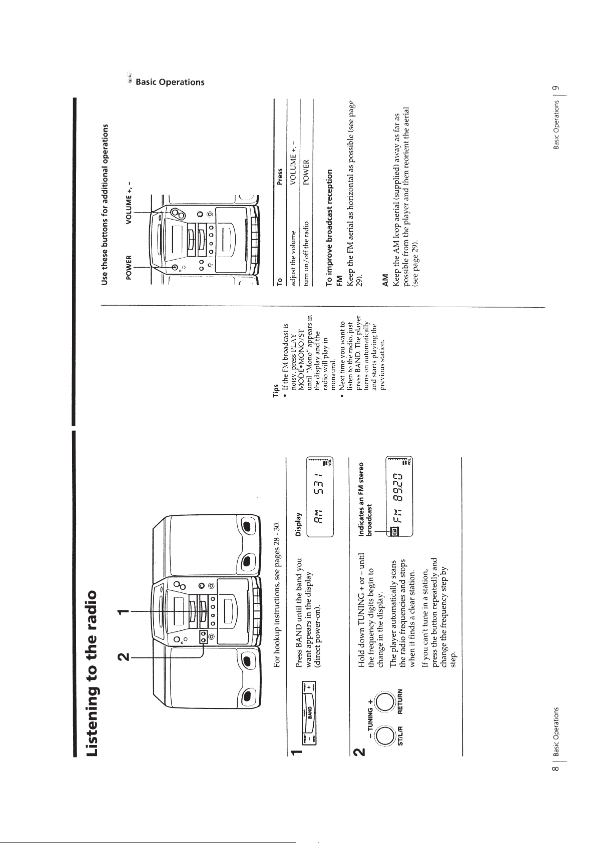
Radio section
Frequency range FM : 87.6 – 108 MHz
AM : 531 – 1,602 kHz
Aerials FM : Wire aerial
AM : External aerial
Cassette-corder section
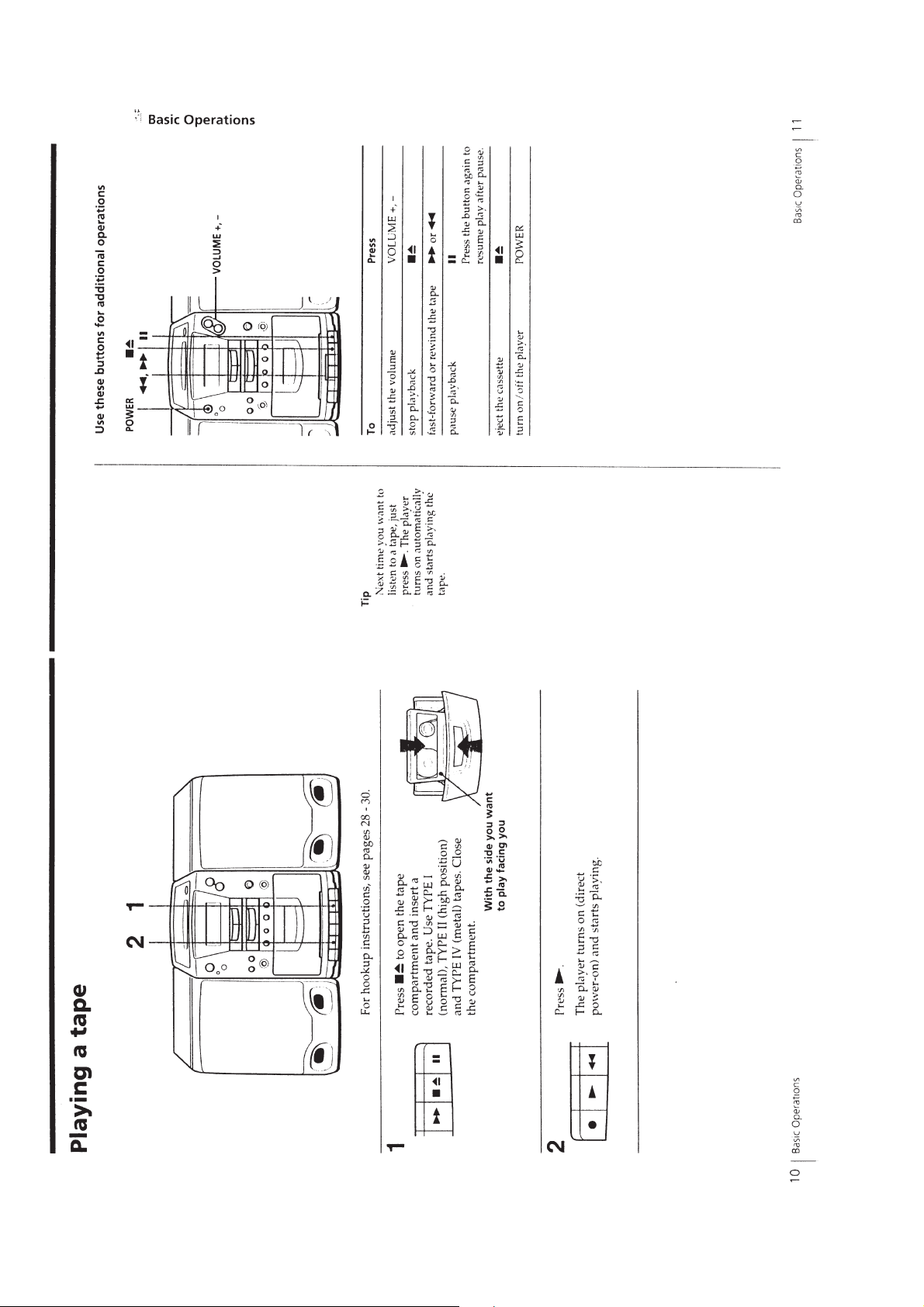
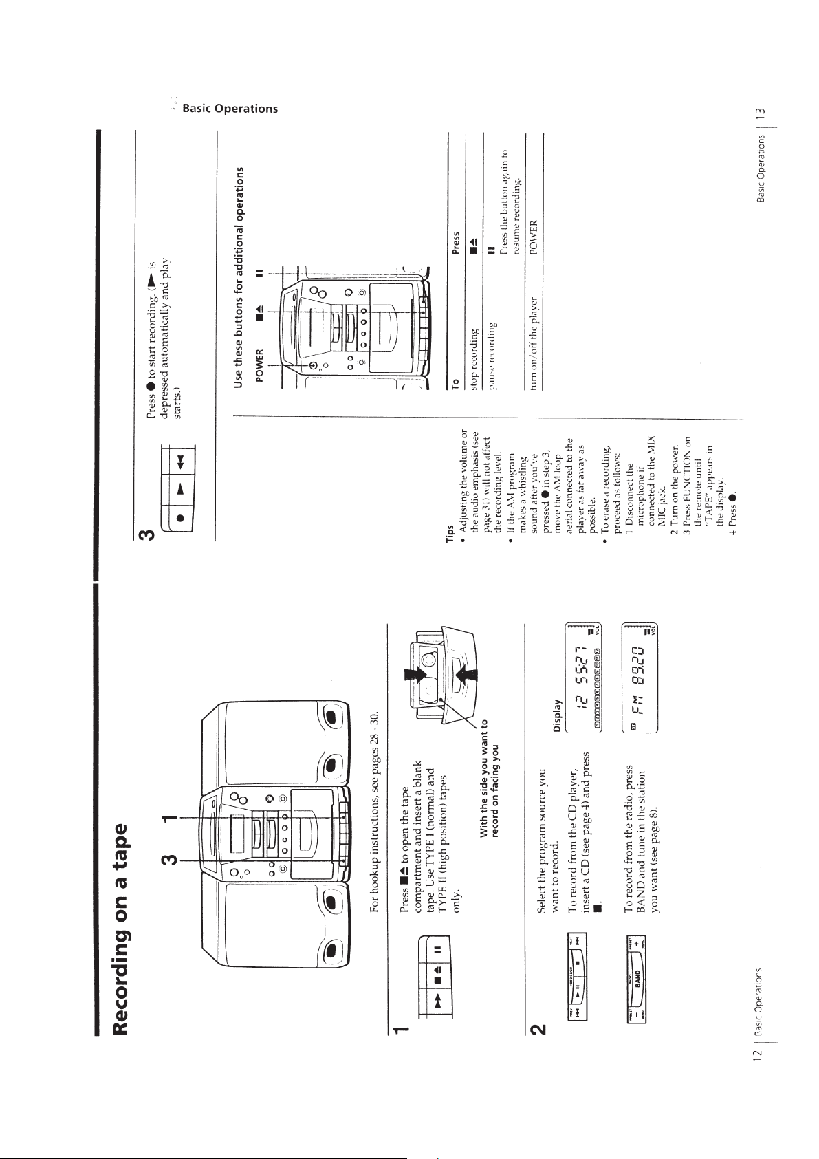
Recording system 4 -track 2 channel stereo
Fast winding time Approx. 120 s (sec.) with Sony cassette C-60
Frequency response TYPE I (normal) : 80 – 14,000 Hz
TYPE II (high position) : 80 – 15,000Hz
General
Speaker Full range : 10 cm (4 in.) dia., 6 Ω, cone type T w eeter :
2cm (4/5 in.) dia.
Inputs Mixing microphone input jack (minijack):
Sensitivity 2.5mV
For 16 – 68 Ω impedance headphones
Outputs Headphones jack (stereo minijack)
Maximum power output 30W + 30W
Power requirements For CD radio cassette-corder
Power consumption AC 55W
Dimensions (incl. projecting parts and controls)
Mass Player: Approx. 4.9 kg (10 lb 13 oz)
Supplied accessories Remote control (1)
Design and specifications are subject to change without notice.
For 16 – 64 Ω impedance headphones
Video output (phono jack)
Output level 1Vp-p at 75Ω
Recommended load impedance over 75Ω
230V AC, 50Hz
For remote control:
3V DC, 2R6 (size AA) batteries
Player: Approx. 160 × 237 × 292.5 mm (w/h/d)
3
(6
/8 × 9 3/8 × 11 5/8 inches)
Speaker: Approx. 150 × 230 × 240 mm (w/h/d)
(6 × 9 1/8 × 8 1/2 inches)
Speaker: Approx. 2.2 kg (4 lb 14 oz)
AM loop aerial (1)
Video cord (1)
9-924-916-12
2001J1600-1
© 2001.10
PERSONAL COMPONENT SYSTEM
Sony Corporation
Home Audio Company
Published by Sony Engineering Corporation
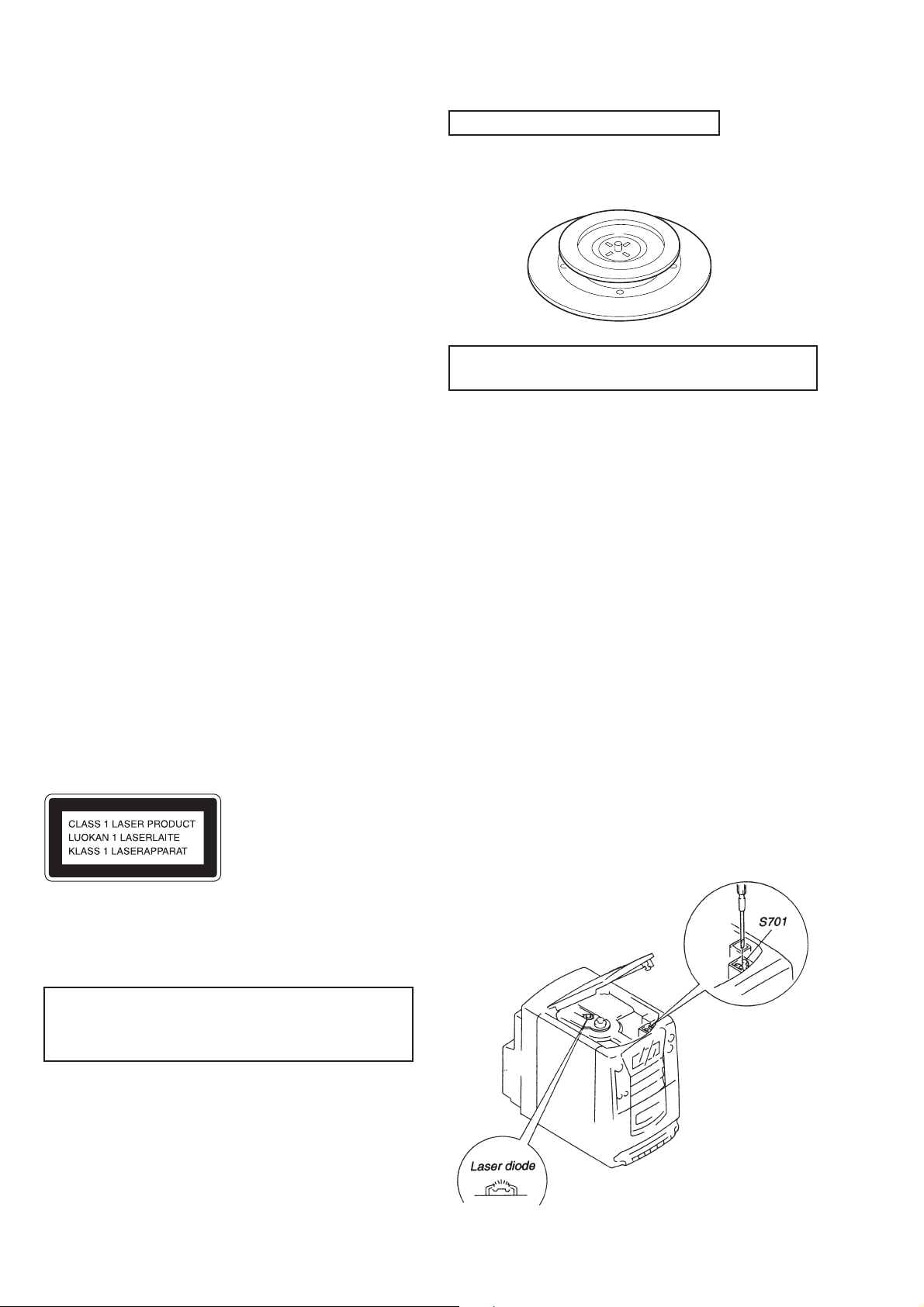
TABLE OF CONTENTS
SERVICING NOTES ······················································· 2
SERVICING NOTES
CHUCK PLATE JIG ON REPAIRING
1. GENERAL ··········································································3
2. DISASSEMBLY
2-1. Front Cabinet Assy ··························································· 19
2-2. CD Block Assy ································································· 19
2-3. Mechanism Deck Block Assy··········································· 20
2-4. Chucking Plate ································································· 20
2-5. CD Door Assy, CD Board, Optical Pick-up Section ········20
3. MECHANICAL ADJUSTMENTS ····························· 21
4. ELECTRICAL ADJUSTMENTS ······························· 21
5. DIAGRAMS
5-1. Block Diagram – CD, Video CD Section – ······················28
5-2. Block Diagram – Tuner, Tape, Amp Section – ·················31
5-3. Circuit Boards Location ··················································· 33
5-4. Printed Wiring Board – CD, System Control Section – ··· 34
5-5. Schematic Diagram – CD, System Control Section – ····· 37
5-6. Schematic Diagram – Tuner, Tape, Amp Section – ··········42
5-7. Printed Wiring Board – Tuner, Tape, Amp Section – ·······47
5-8. Printed Wiring Board – Video CD Section – ···················· 54
5-9. Schematic Diagram – Video CD Section – ······················57
5-10. IC Block Diagrams ···························································60
5-11. IC Pin Function Description ············································· 63
6. EXPLODED VIEWS
6-1. Chassis Section ································································· 68
6-2. Front Cabinet Section ······················································· 69
6-3. CD Block Section ····························································· 70
6-4. Mechanism Deck Section-1 (MF-PMC212) ···················· 71
6-5. Mechanism Deck Section-2 (MF-PMC212) ···················· 72
6-6. Optical Pick-up Section (KSM-213CDM/C2NP) ············73
7. ELECTRICAL PARTS LIST ······································· 74
On repairing CD section, playing a disc without the CD lid, use
Chuck Plate Jig.
• Code number of Chuck Plate Jig : X-4918-255-1
NOTES ON HANDLING THE OPTICAL PICK-UP
BLOCK OR BASE UNIT
The laser diode in the optical pick-up block may suffer electrostatic
breakdown because of the potential difference generated by the
charged electrostatic load, etc., on clothing and the human body.
During repair, pay attention to electrostatic breakdown and also
use the procedure in the printed matter which is included in the
repair parts.
The flexible board is easily damaged and should be handled with
care.
NOTES ON LASER DIODE EMISSION CHECK
The laser beam on this model is concentrated so as to be focused
on the disc reflective surface by the objective lens in the optical
pick-up block. Therefore, when checking the laser diode emission,
observe from more than 30 cm away from the objective lens.
LASER DIODE AND FOCUS SEARCH OPERATION
CHECK
1. Turn POWER switch on with no disc inserted and make
Function switch to CD position.
2. Open the lid for CD.
3. Turn on S701 as following figure.
4. Press the ^ button.
5. Confirm the laser diode emission while observing the objecting
lens. When there is no emission, Auto Power Control circuit or
Optical Pick-up is broken.
Objective lens moves up and down three times for the focus
search.
This appliance is classified as a CLASS 1 LASER product. The
CLASS 1 LASER PRODUCT MARKING is located on the rear
exterior.
The following caution label is located inside the unit.
CAUTION
Use of controls or adjustments or performance of procedures
other than those specified herein may result in hazardous radiation
exposure.
SAFETY-RELATED COMPONENT WARNING!!
COMPONENTS IDENTIFIED BY MARK ! OR DOTTED LINE WITH
MARK ! ON THE SCHEMATIC DIAGRAMS AND IN THE PARTS
LIST ARE CRITICAL TO SAFE OPERATION. REPLACE THESE
COMPONENTS WITH SONY PARTS WHOSE PART NUMBERS
APPEAR AS SHOWN IN THIS MANUAL OR IN SUPPLEMENTS
PUBLISHED BY SONY.
— 2 —
SECTION 1
GENERAL
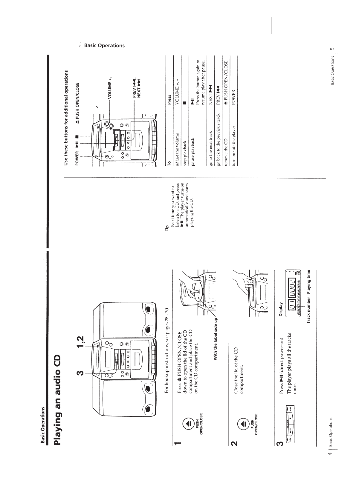
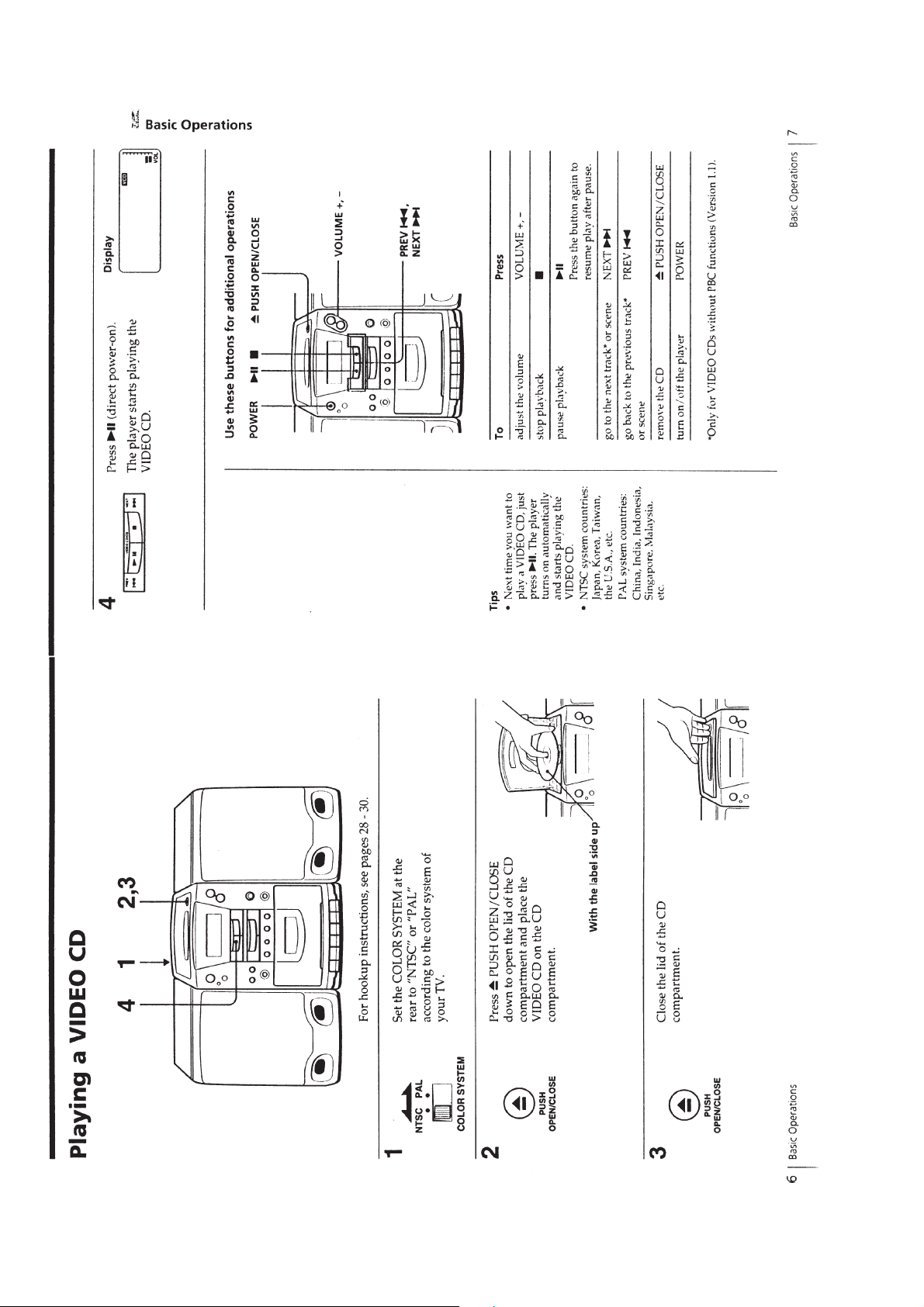
This section is extracted
from instruction manual.
— 3 —
— 4 —
— 5 —
— 6 —
— 7 —
— 8 —
— 9 —
— 10 —
— 11 —
— 12 —
— 13 —
— 14 —
— 15 —
— 16 —
— 17 — — 18 —
 Loading...