

Sony PlayStation 2 SCPH-30001 R, PlayStation 2 SCPH-30003 R, PlayStation 2 SCPH-30004 R, PlayStation 2 SCPH-30002 R Service Manual

Quality Asurance Department
Published in Japan 9. 2001. 9-927-093-01
SCPH-30000 R series
SERVICE MANUAL
for GH013 (31/41) and GH014 MOUNT
1st Edition
SCPH-30001 R
SCPH-30002 R
SCPH-30003 R
SCPH-30004 R
Reproduction Prohibited
— 2 —
SCPH-30000 R series
NOTICE
Copyright by Sony Computer Entertainment Inc. All rights reserved. No reproduced and transferred required except
permission by Sony Computer Entertainment Inc. No commercial use and rental required.
REVISIONS.
This manual compiled by first edition of SCPH-30000 R series design data.
Design and Specification will be subject to changed without notice. The latest versions of service manual, Technical
memo, Technical information should be used together.
SAFETY-RELATED COMPONENT WARNING !!
COMPONENTS IDENTIFIED BY MARK OR DOTTED LINE WITH MARK ON THE SCHEMATIC DIAGRAMS
AND IN THE PARTS LIST ARE CRITICAL TO SAFE OPERATION. REPLACE THESE COMPONENTS WITH SONY
PARTS WHOSE PART NUMBERS APPEAR AS SHOWN IN THIS MANUAL OR IN SUPPLEMENTS PUBLISHED
BY SONY.
ATTENTION AU COMPOSANT AYANT RAPPORT À LA SÉCURITÉ !
LES COMPOSANTS IDENTIFIÉS PAR UNE MARQUE SUR LES DIAGRAMMES SCHÉMATIQUES ET LA LISTE
DES PIÈCES SONT CRITIQUES POUR LA SÉCURITÉ DE FONCTIONNEMENT. NE REMPLACER CES COMPOSANTS QUE PAR DES PIÈCES SONY DONT LES NUMÉROS SONT DONNÉS DANS CE MANUEL OU DANS
LES SUPPLÉMENTS UBLIÉS PAR SONY.
CAUTION
Replace the battery with a Sony CR2032 battery. Use of any other type of battery may present the risk of fire or
explosion. The battery may explode if mistreated. Do not recharge, disassemble, or dispose of in fire.
CAUTION
The use of optical instruments with this product will increase eye Hazard. As the laser beam used in this CD/DVD
player is harmful To eyes, do not attempt to disassemble the cabinet. Refer servicing to qualified personnel only.
WARNING !!
WHEN SERVICING, DO NOT APPROACH THE LASER EXIT WITH THE EYE TOO CLOSELY. IN CASE IT IS
NECESSARY TO CONFIRM LASER BEAM EMISSION, BE SURE TO OBSERVE FROM A DISTANCE OF MORE
THAN 25cm FROM THE SURFACE OF THE OBJECTIVE LENS ON THE OPTICAL PICK-UP BLOCK.
CAUTION
Use of controls or adjustments or performance of procedures other than those specified herein may result in
hazardous radiation exposure.
CAUTION for electric shock
When power is ON, Don’t touch to Power supply block, AC-inlet, Power switch and so on, not to get an electric shock
at repair.
CAUTION for burning
When current is supplied, Some of part surface temperature like EE, GS, Regulater-IC, power supply, Optical device
and so on. These part surface is become high temperature condition. When it repair, Don’t touch them at a time during
it surface is high temperature condition to take prevent against burning. Do repair after it is cooled down enough.
CAUTION
Danger of explosion if battery is incorrectly replaced. Replace only with the same or equivalent type recommended by
the manufacturer. Discard used batteries according to the manufacturer’s instructions.
ADVARSEL!
Lithiumbatteri - Eksplosionsfare ved fejlagtig håndtering. Udskiftning må kun ske med batteri af samme fabrikat og
type. Levér det brugte batteri tilbage til leverandøren.
ADVARSEL
Eksplosjonsfare ved feilaktig skifte av batteri. Benytt samme batteritype eller en tilsvarende type anbefalt av
apparatfabrikanten. Brukte batterier kasseres i henhold til fabrikantens instruksjoner.
VARNING
Explosionsfara vid felaktigt batteribyte. Använt samma batterityp eller en ekvivalent typ som rekommenderas av
apparattillverkaren. Kassera använt batteri enligt fabrikantens instruktion.
VAROITUS
Paristo voi räjähtää, jos se on virheellisesti asennettu. Vaihda paristo ainoastaan valmistajan suosittelemaan tyyppiin.
Hävitä käytetty paristo valmistajan ohjeiden mukaisesti.
SAFETY CHECK-OUT
After correcting the original service problem, perform the following safety checks before releasing the set to the
customer:
1. Check the area of your repair for unsoldered or cold-soldered connections. Check the entire board surface for
solder splashes and bridges.
2. Check the inter board wiring to ensure that no wires are “pinched” or contact high-wattage resistors.
3. Look for unauthorized replacement parts, particularly transistors, that were installed during a previous repair. Point
them out to the customer and recommend their replacement.
4. Look for parts which, though functioning, show obvious signs of deterioration. Point them out of the customer and
recommend their replacement.
5. Check the line cord for cracks and abrasion. Recommend the replacement of any such line cord to the customer.
6. Check the b+ voltage to see it is at the values specified.
7. Check the antenna terminals, metal trim, “metalized” knobs, screws, and all other exposed metal parts for ac
leakage. Check leakage as described below.
LEAKAGE
The AC leakage from any exposed metal part to earth ground and from all exposed metal parts to any exposed metal
part having a Return to chassis, must not exceed 0.5 mA (500 micro-ampers). Leakage current can be measured by
any one of three methods.
1. A commercial leakage tester, such as the SIMPSON 229 or RCA WT-540A. Follow the manufacturers’ instructions
to use these instruments.
2. A battery-operated AC milli-ammeter. The Data Precision 245 digital multi-meter is suitable for this job
3. Measuring the voltage drop across a resistor by means of a VOM or battery-operated ac voltmeter. The “limit”
indication is 0.75V, so analog meters must have an accurate low-voltage scale. The SIMPSON 250 and SANWA
SH-63TRD are examples of a passive VOM that is suitable. Nearly all battery operated digital multi-meters that
have a 2V AC range are suitable.
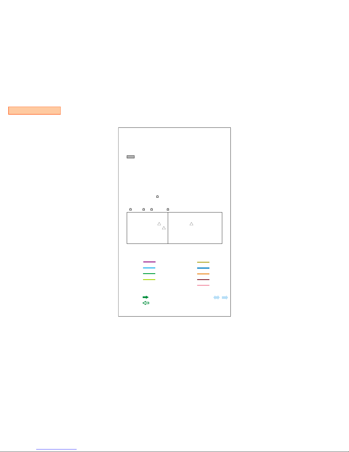
Fig A. Using AC voltmeter to check AC leakage
To Exposed Metal
Parts on Set
1.5 k
Ω
0.15 µF
AC
voltmeter
(0.75V)
Earth Ground
NOTIFICATION for environmental assessment
This model is CR2032 lithium battery onboard inside on the GD MOUNT as Timer backup power. CR2032 life may be
about 5 to 8 years so you have very few need for changing to new one. But if you have necessary to replaced to new
one or disassemble for scrapping, you have to keep your country low, regulation, standard, etc. of environmental
assessment and safty.

— 3 —
Reproduction Prohibited
SCPH-30000 R series
SCPH-30000 R series
GH013(31/41) and GH014 MOUNT
Notice and Revisions 2
1. Specification 4
2. Supplied Accessories and Packing Block 5
3. Instruction Manual Block 6
4. Exploded Views
Overall and Main Block
for SCPH-30001 R 7
for SCPH-30002 R / -30003 R / -30004 R 8
MD Block 9
GH Mount Block and Shield (A) Assy Block 10
Switch Assy Block 11
Power Switch, Fan and Rear Panel Assy Block 12
MD, GB Mount and Plate Assy Block 13
5. Block Diagram 14
6. Printed Wiring Boards and Schematic Diagrams
for GH013(31/41) Mount
This Note is Common for Printed Wiring Boards
and Schematic Diagrams GH013(31/41)-1
GH013(31/41) MOUNT GH013(31/41)-9
Electrical Parts List for GH013(31/41) MOUNT GH013(31/41)-11
Switch MOUNT GH013(31/41)-17
GB MOUNT GH013(31/41)-18
TABLE OF CONTENTS
7. Printed Wiring Boards and Schematic Diagrams
for GH014 Mount
This Note is Common for Printed Wiring Boards
and Schematic Diagrams GH014-1
GH014 MOUNT GH014-9
Electrical Parts List for GH014 MOUNT GH014-11
Switch MOUNT GH014-17
GB MOUNT GH014-18

— 4 —
Reproduction Prohibited
SCPH-30000 R series
SECTION 1
SPECIFICATIONS
General
Power requirements
120 V AC, 60 Hz for SCPH-30001 R
220 -240 V AC, 50/60 Hz
for SCPH-30002 R/-30003 R/-30004 R
Power consumption
79 W for SCPH-30001 R
50 W
for SCPH-30002 R/-30003 R/-30004 R
Dimensions
301 × 78 × 182 mm (w/h/d)
Mass
2.4 kg
Inputs/Outputs on the front
Controller ports (2)
Memory card slots (2)
USB ports (2)
S400 (i-Link) port (1)
Inputs/Outputs on the rear
HDD bay slot (1)
Outputs on the rear
AV Multi out port (1)
RGB, Ycbcr, Y/C, Composite-video,
Audio-L/R, XGA
Digital out port (1)
Optical audio
Supplied accessories
AC power cord (1)
A/V connecting cable (1)
Dualshock2 Analog controller (1)
Euro-AV Connector (1)
for SCPH-30003 R/-30004 R

— 5 —
Reproduction Prohibited
SCPH-30000 R series
SECTION 2
SUPPLIED ACCESSORIES AND PACKING BLOCK
NOTE :
•
•
•
Due to standardization, replacements in
the parts list may be different from the
parts specified in the diagrams or the
components used on the set.
-XX and -X mean standardized parts, so
they may have some difference from the
original one.
RESISTORS
METAL : Metal-film resistor.
F : nonflammable
Unit is .
•
•
•
SEMICONDUCTORS
In each case, u : µ, for example :
uA . .
uPB. .
CAPACITORS
uF : µF
COILS
uH : µH
: µA . .
: µPB. .
uPA . . : µPA . .
uPC . . : µPC . . uPD . . : µPD . .
The components identified by
mark
!
or dotted line with mark.
!
are critical for safety.
Replace only with part number
specified.
SCPH-30003 R ACCESSORIES & PACKING GROUP
****************************************
Ref. Part No. Description
AC 1-751-115-21 CORD, POWER
AC 1-751-115-31 CORD, POWER
AC 1-790-023-21 CODE, POWER
AV 1-792-028-11 AV CABLE (Integrated audio/video)
AV 1-792-028-21 AV CABLE (Integrated audio/video)
AV 1-792-028-31 AV CABLE (Integrated audio/video)
AV 1-792-028-41 AV CABLE (Integrated audio/video)
AV 1-792-238-72 AV CABLE (Integrated audio/video)
AV 1-792-238-82 AV CABLE (Integrated audio/video)
CONT 1-823-069-11 ANALOG CONTROLLER (DUALSHOCK 2)
CONT 1-823-069-21 ANALOG CONTROLLER (DUALSHOCK 2)
CONT 1-823-091-11 ANALOG CONTROLLER (DUALSHOCK 2)
CONV 1-573-291-12 CONNECTOR, CONVERSION
CONV 1-785-004-12 CONNECTOR, CONVERSION
CU 3-064-714-01 CUSHION
PAD 3-065-172-01 PAD, TOGETHER PACKING
SH 3-060-494-01 SHEET, PROTECTION
TA 3-987-483-11 TAPE, BERODDED PREVENTION
CA 3-071-634-11 INDIVIDUAL CARTON
MC 3-071-635-11 MASTER CARTON, 3 SETS
IMB A-6785-340-A MANUAL BLOCK ASSY, INSTRUCTION
*********************************************************
SCPH-30001 R ACCESSORIES & PACKING GROUP
****************************************
Ref. Part No. Description
AC 1-790-108-21 CORD, POWER
AV 1-792-028-11 AV CABLE (Integrated audio/video)
AV 1-792-028-21 AV CABLE (Integrated audio/video)
AV 1-792-028-31 AV CABLE (Integrated audio/video)
AV 1-792-028-41 AV CABLE (Integrated audio/video)
AV 1-792-238-53 AV CABLE (Integrated audio/video)
AV 1-792-238-72 AV CABLE (Integrated audio/video)
CONT 1-823-069-11 ANALOG CONTROLLER (DUALSHOCK 2)
CONT 1-823-069-21 ANALOG CONTROLLER (DUALSHOCK 2)
CONT 1-823-091-11 ANALOG CONTROLLER (DUALSHOCK 2)
CU 3-064-714-01 CUSHION
CU2 3-064-713-01 CUSHION 2
SH 3-065-170-01 SHEET, PROTECTION
TA 3-987-483-11 TAPE, BERODDED PREVENTION
CA 3-071-632-01 INDIVIDUAL, CARTON
MC 3-071-633-01 MASTER CARTON, 3 SETS
IMB A-6785-338-A MANUAL BLOCK ASSY, INSTRUCTION
*********************************************************
SUPPLIED ACCESSORIES and PACKING GROUP PLACE CODE #23
***********************************************************************
SCPH-30002 R ACCESSORIES & PACKING GROUP
****************************************
Ref. Part No. Description
AC 1-555-074-51 CORD, POWER
AV 1-792-028-11 AV CABLE (Integrated audio/video)
AV 1-792-028-21 AV CABLE (Integrated audio/video)
AV 1-792-028-31 AV CABLE (Integrated audio/video)
AV 1-792-028-41 AV CABLE (Integrated audio/video)
AV 1-792-238-72 AV CABLE (Integrated audio/video)
AV 1-792-238-82 AV CABLE (Integrated audio/video)
CONT 1-823-069-11 ANALOG CONTROLLER (DUALSHOCK 2)
CONT 1-823-069-21 ANALOG CONTROLLER (DUALSHOCK 2)
CONT 1-823-091-11 ANALOG CONTROLLER (DUALSHOCK 2)
CU 3-064-714-01 CUSHION
SH 3-060-494-01 SHEET, PROTECTION
CA 3-071-639-01 INDIVIDUAL CARTON
MC 3-071-635-21 MASTER CARTON, 3 SETS
IMB A-6785-341-A MANUAL BLOCK ASSY, INSTRUCTION
*********************************************************
SCPH-30004 R ACCESSORIES & PACKING GROUP
****************************************
Ref. Part No. Description
AC 1-575-131-82 CORD, POWER
AC 1-823-152-11 CORD, POWER
AV 1-792-028-11 AV CABLE (Integrated audio/video)
AV 1-792-028-21 AV CABLE (Integrated audio/video)
AV 1-792-028-31 AV CABLE (Integrated audio/video)
AV 1-792-028-41 AV CABLE (Integrated audio/video)
AV 1-792-238-72 AV CABLE (Integrated audio/video)
AV 1-792-238-82 AV CABLE (Integrated audio/video)
CONT 1-823-069-11 ANALOG CONTROLLER (DUALSHOCK 2)
CONT 1-823-069-21 ANALOG CONTROLLER (DUALSHOCK 2)
CONT 1-823-091-11 ANALOG CONTROLLER (DUALSHOCK 2)
CONV 1-573-291-12 CONNECTOR, CONVERSION
CONV 1-785-004-12 CONNECTOR, CONVERSION
CU 3-064-714-01 CUSHION
PAD 3-065-172-01 PAD, TOGETHER PACKING
SH 3-060-494-01 SHEET, PROTECTION
TA 3-987-483-11 TAPE, BERODDED PREVENTION
CA 3-071-634-01 INDIVIDUAL CARTON
MC 3-071-635-01 MASTER CARTON, 3 SETS
IMB A-6785-339-A MANUAL BLOCK ASSY, INSTRUCTION
*********************************************************

— 6 —
Reproduction Prohibited
SCPH-30000 R series
SECTION 3
INSTRUCTION MANUAL BLOCK
NOTE :
•
•
•
Due to standardization, replacements in
the parts list may be different from the
parts specified in the diagrams or the
components used on the set.
-XX and -X mean standardized parts, so
they may have some difference from the
original one.
RESISTORS
METAL : Metal-film resistor.
F : nonflammable
Unit is .
•
•
•
SEMICONDUCTORS
In each case, u : µ, for example :
uA . .
uPB. .
CAPACITORS
uF : µF
COILS
uH : µH
: µA . .
: µPB. .
uPA . . : µPA . .
uPC . . : µPC . . uPD . . : µPD . .
The components identified by
mark
!
or dotted line with mark.
!
are critical for safety.
Replace only with part number
specified.
A-6785-340-A INSTRUCTION MANUAL BLOCK ASSY
for SCPH-30003 R
********************************************
Ref. Part No. Description
BOR 3-066-159-02 CARD (B), OWNER REGISTRATION
DISK 3-066-725-02 DISK, DEMONSTRATION
IN 3-070-923-11 INSTRUCTION
IM 3-071-581-31 MANUAL, INSTRUCTION
SE 3-987-375-02 SEAL, SEAL
*********************************************************
INSTRUCTION MANUAL BLOCK ASSY PLACE CODE #23
*******************************************************
A-6785-341-A INSTRUCTION MANUAL BLOCK ASSY
for SCPH-30002 R
********************************************
Ref. Part No. Description
AOR 3-066-158-02 CARD (A), OWNER REGISTRATION
DISK 3-066-725-02 DISK, DEMONSTRATION
IN 3-070-923-11 INSTRUCTION
IM 3-071-581-21 MANUAL, INSTRUCTION
SE 3-987-375-02 SEAL, SEAL
*********************************************************
A-6785-339-A INSTRUCTION MANUAL BLOCK ASSY
for SCPH-30004 R
********************************************
Ref. Part No. Description
COR 3-066-160-03 CARD (C), OWNER REGISTRATION
DISK 3-066-725-02 DISK, DEMONSTRATION
IN 3-070-916-11 INSTRUCTION
IM 3-071-581-41 MANUAL, INSTRUCTION
IM 3-071-581-51 MANUAL, INSTRUCTION
SE 3-987-375-02 SEAL, SEAL
*********************************************************
A-6785-338-A INSTRUCTION MANUAL BLOCK ASSY
for SCPH-30001 R
********************************************
Ref. Part No. Description
CI 3-066-021-01 CARD, CUSTOMER INQUIRY
CS 3-066-966-01 CARD, SERVICE NUMBER
IN 3-070-919-11 INSTRUCTION
IM 3-071-581-11 MANUAL, INSTRUCTION
ES 3-060-161-02 SHEET, ESRB
*********************************************************
— 7 —
Reproduction Prohibited
SCPH-30000 R series
The components identified by
mark ! or dotted line with mark.
! are critical for safety.
Replace only with part number
specified.
CAUTION :
Use of controls or adjustments or performance
of procedures other than those specified herein
may result in hazardous radiation exposure.
CAUTION
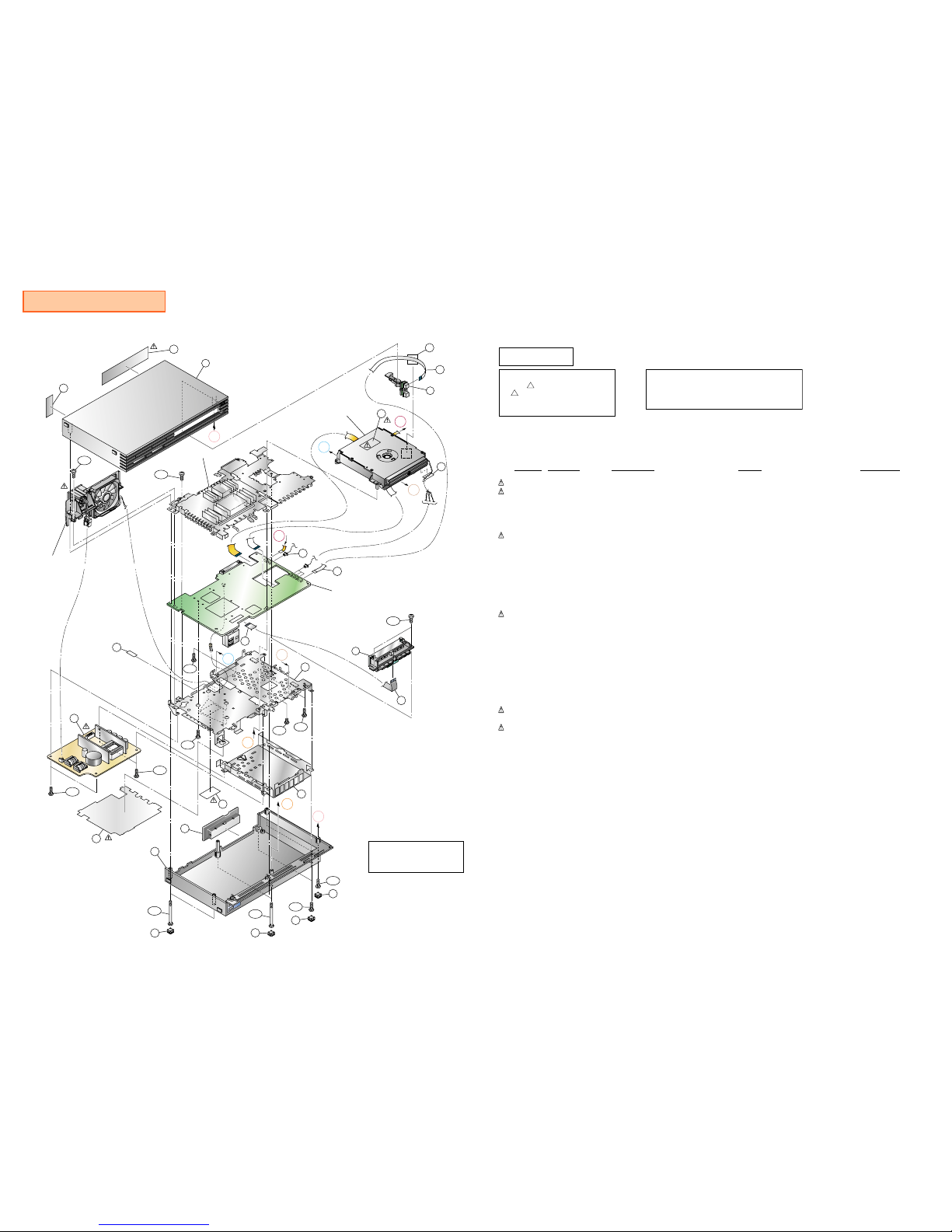
SECTION 4
EXPLODED VIEWS
Overall and Main Block for SCPH-30001 R
CAUTION
Don't lose the insulating sheet
when assemble the console.
103
GH Mount Block
See: 10 page
153
151
E
62
93
76
76
76
75
M354
M354
B265
B265
B265
M225
156
151
152
158
106
A
C
B
D
D
94
112
A
71
60
M360
M360
162
BV312
BV312
BV316
BV316
84
C
B
E
92
152
157
Shield (A) Assy Block
See: 10 page
MD, GB Mount and
Plate Assy Block
See: 13 page
Switch Assy Block
See: 11 page
162
BV312
Power Switch,
Fan and Rear Panel Assy Block
See: 12 page
160
----------------------
OVERALL AND MAIN BLOCK
---------------------Ref-No. Part No. Description Remark Place code
60 1-468-604-11 POWER BLOCK #00
60 1-468-623-11 POWER BLOCK #00
62 1-694-676-21 TERMINAL BOARD (FRONT) #17
62 1-694-729-21 TERMINAL BOARD (FRONT) #17
62 1-694-769-31 TERMINAL BOARD (FRONT) #17
71 3-071-824-01 LABEL, MODEL NUMBER (UC2)
for SCPH-30001 R
#87
75 3-059-626-03 COVER, SCREW #22
76 3-059-627-01 CAP #22
84 3-067-170-01 TAPE (20X20), HARNESS STOPPER #87
92 A-6705-426-A SWITCH BLOCK ASSY #25SW
93 X-3951-706-1 COVER ASSY, LOWER #87
94 X-3951-705-1 COVER ASSY, UPPER #87
103 3-976-231-11 LABEL, CAUTION #87
106 X-3951-316-1 LID ASSY #87
112 3-066-253-01 TAPE, VOID #87
151 1-757-934-11 CABLE, FLEXIBLE FLAT (FFC-011) #12
151 1-757-934-21 CABLE, FLEXIBLE FLAT (FFC-011) #12
152 1-823-341-11 CABLE, FLEXIBLE FLAT (FFC-015) #12
152 1-823-341-21 CABLE, FLEXIBLE FLAT (FFC-015) #12
156 3-068-669-02 SHIELD (B) #16
156 3-068-669-11 SHIELD (B) #16
157 3-068-674-02 SHEET, INSULATING #16
158 3-068-675-02 SHIELD (HDD) #16
160 3-703-692-01 LABEL, CAUTION, BARRIER #16
162 3-069-212-01 TAPE, HARNESS STOPPER #87
B265 3-069-170-01 TAPPING (B2X6.5) #87
BV312 3-325-679-21 SCREW, TAPPING +BV 3X12 #87
BV316 3-070-296-01 TAPPING +BV 3X16 #87
BV316 3-325-679-91 SCREW (2 LOCK), +BV TAPPING #87
M225 3-069-169-01 SCREW (M2X2.5) #87
M354 3-059-622-02 SCREW (M3X54), HEAD TAPPING #87
M360 3-069-168-01 TITE (CZN), M3X6 +BV S #87
— 8 —
Reproduction Prohibited
SCPH-30000 R series
The components identified by
mark ! or dotted line with mark.
! are critical for safety.
Replace only with part number
specified.
CAUTION :
Use of controls or adjustments or performance
of procedures other than those specified herein
may result in hazardous radiation exposure.
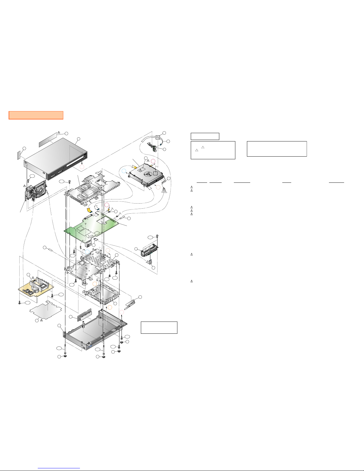
CAUTION
Overall and Main Block for SCPH-30002 R/-30003 R/-30004 R
CAUTION
Don't lose the insulating sheet
when assemble the console.
----------------------
OVERALL AND MAIN BLOCK
---------------------Ref-No. Part No. Description Remark Place code
60 1-468-605-11 POWER BLOCK
Use for GH013(31/41) MOUNT
#00
60 1-468-605-12 POWER BLOCK
Use for GH014 MOUNT
#00
62 1-694-676-21 TERMINAL BOARD (FRONT) #17
62 1-694-729-21 TERMINAL BOARD (FRONT) #17
62 1-694-769-31 TERMINAL BOARD (FRONT) #17
71 3-071-900-01 LABEL, MODEL NUMBER (AU3)
for SCPH-30002 R
#87
71 3-071-899-01 LABEL, MODEL NUMBER (CEK)
for SCPH-30003 R
#87
71 3-071-898-01 LABEL, MODEL NUMBER (CEL)
for SCPH-30004 R
#87
75 3-059-626-03 COVER, SCREW #22
76 3-059-627-01 CAP #22
84 3-067-170-01 TAPE (20X20), HARNESS STOPPER #87
92 A-6705-401-A SWITCH BLOCK ASSY
Use for GH014 MOUNT
#87
92 A-6705-426-A SWITCH BLOCK ASSY
Use for GH013(31/41) MOUNT
#87
93 X-3951-722-1 COVER ASSY, LOWER #87
94 X-3951-721-1 COVER ASSY, UPPER #87
106 X-3951-317-1 LID ASSY #87
112 3-066-498-01 TAPE, VOID #87
135 3-988-711-02 LABEL, LASER CAUTION #87
151 1-757-934-11 CABLE, FLEXIBLE FLAT (FFC-011) #12
151 1-757-934-21 CABLE, FLEXIBLE FLAT (FFC-011) #12
152 1-823-341-11 CABLE, FLEXIBLE FLAT (FFC-015) #12
152 1-823-341-21 CABLE, FLEXIBLE FLAT (FFC-015) #12
156 3-068-669-02 SHIELD (B) #16
156 3-068-669-11 SHIELD (B) #16
157 3-068-674-02 SHEET, INSULATING #16
158 3-068-675-02 SHIELD (HDD) #87
161 3-070-120-01 SHEET, INTERCEPTION
Use for GH014 MOUNT
#87
162 3-069-212-01 TAPE, HARNESS STOPPER #87
B265 3-069-170-01 TAPPING (B2X6.5) #87
BV312 3-325-679-21 SCREW, TAPPING +BV 3X12 #87
BV316 3-070-296-01 TAPPING +BV 3X16 #87
BV316 3-325-679-91 SCREW (2 LOCK), +BV TAPPING #87
M225 3-069-169-01 SCREW (M2X2.5) #87
M354 3-059-622-02 SCREW (M3X54), HEAD TAPPING #87
M360 3-069-168-01 TITE (CZN), M3X6 +BV S #87
135
GH Mount Block
See: 10 page
153
151
E
62
93
76
76
76
75
M354
M354
B265
B265
B265
M225
156
151
152
158
106
A
C
B
D
D
94
112
A
71
60
M360
M360
162
BV312
BV312
BV316
BV316
84
C
B
E
92
152
157
Shield (A) Assy Block
See: 10 page
MD, GB Mount and
Plate Assy Block
See: 13 page
Switch Assy Block
See: 11 page
162
BV312
Power Switch,
Fan and Rear Panel Assy Block
See: 12 page
161

— 9 —
Reproduction Prohibited
SCPH-30000 R series
MD Block
--------
MD BLOCK
-------Ref-No. Part No. Description Remark Place code
2 1-763-700-12 MOTOR, DC (SPINDLE) #10SP
2 8-835-733-02 MOTOR, DC SSC28C/C-NP (SPINDLE) #10SP
3 1-763-639-21 MOTOR, DC #10
5 3-059-845-01 SCREW (B2X6.5), SHAFT RETAINER #10
7 X-3951-637-1 FRAME ASSY, SUB #10
8 3-065-277-01 INSULATOR #10
9 3-065-276-01 SCREW, STEP #10
10 X-3951-606-1 CHASSIS ASSY, MAIN #10
13 3-059-854-02 SHAFT, MAIN #10
14 3-059-855-02 RACK #10
16 3-060-399-01 SCREW, SKEW #10
17 3-060-400-01 TAPPING (B2X6.5) #10
22 3-062-728-01 0 PLATE 3, MAIN M2X3.2 #10
23 8-820-141-29 DEVICE, OPICAL KHS-400B #10OP
26 X-3951-607-2 CHASSIS ASSY, SUB #10
27 X-3951-609-2 BRACKET ASSY, PULLEY #10
28 X-3951-608-2 TRAY ASSY #10TR
30 X-3951-610-4 FRAME ASSY, MAIN #10
31 1-680-370-12 PWB, FLEXIBLE #10
32 3-068-075-02 SCREW (SUB), STEP #10
33 3-065-278-02 CAM, TILT #10
34 3-068-076-01 SPRING (TILT), LEAF #10
35 3-065-282-01 GUIDE (L) #10
36 3-065-283-01 GUIDE (R) #10
37 3-065-557-01 SCREW (M2X6.0) #10
41 3-065-279-02 SCREW, CAM RETAINER #10
14
22
23
13
16
31
41
33
5
17
27
TAP
9
8
9
8
8
32
10
30
7
26
32
8
34
17
28
22
2
22
22
36
37
35
17
3
BOTTOM VIEW
The components identified by
mark ! or dotted line with mark.
! are critical for safety.
Replace only with part number
specified.
CAUTION :
Use of controls or adjustments or performance
of procedures other than those specified herein
may result in hazardous radiation exposure.
CAUTION
— 10 —
Reproduction Prohibited
SCPH-30000 R series
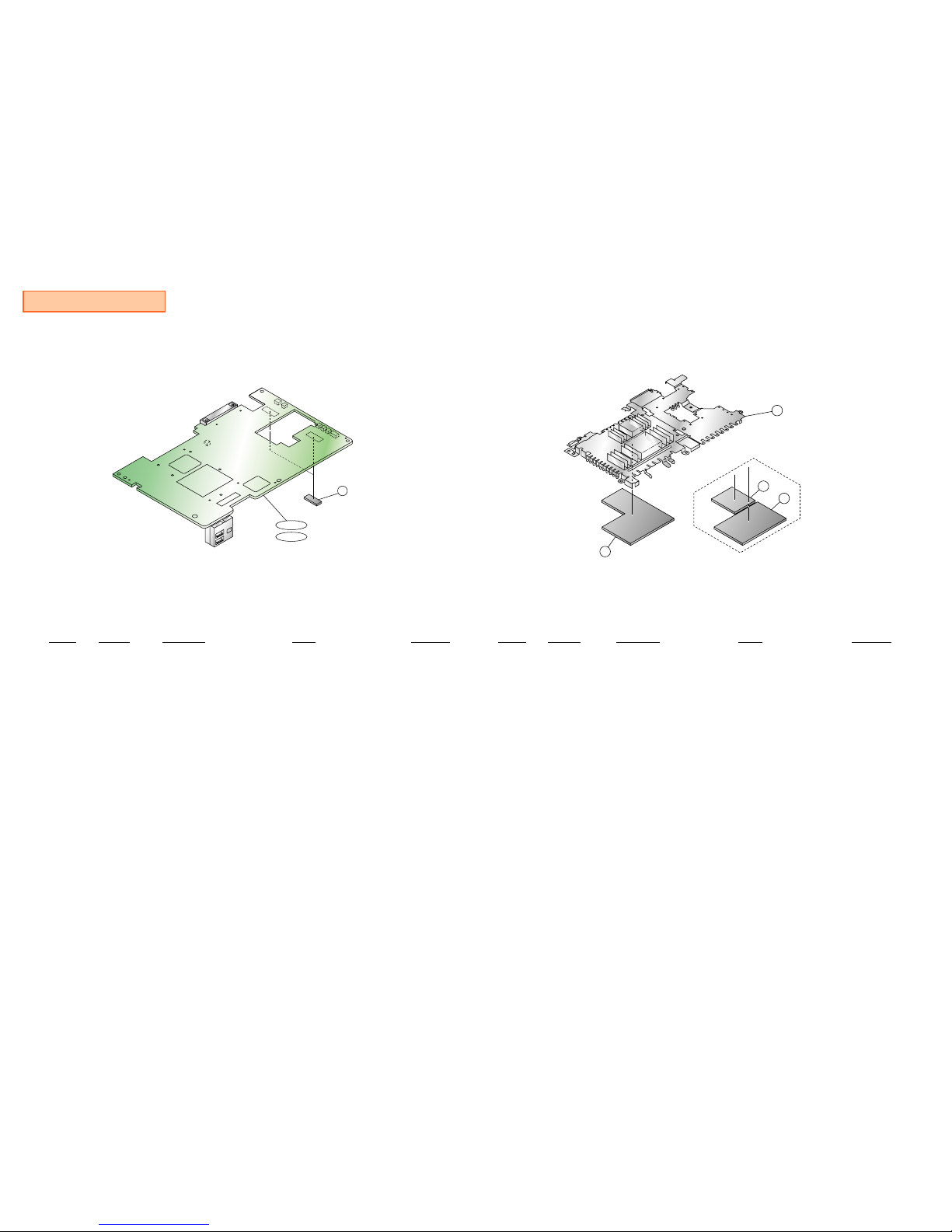
GH Mount Block
87
GH013
GH014
--------------
GH MOUNT BLOCK
-------------Ref-No. Part No. Description Remark Place code
87 3-068-806-01 SHEET (DRIVER), ELECTRIC HEAT #25GH
GH013 A-6714-489-A GH-013(31/41) MOUNT (R64M)
for SCPH-30001 R
#25GH
GH013 A-6714-493-A GH-013(31/41) MOUNT (R64M HV)
for SCPH-30001 R
#25GH
GH013 A-6714-490-A GH-013(31/41) MOUNT (R64M)
for SCPH-30002 R
#25GH
GH013 A-6714-491-A GH-013(31/41) MOUNT (R64M)
for SCPH-30003 R/-30004 R
#25GH
GH014 A-6714-495-A GH-014 MOUNT (R64M)
for SCPH-30003 R/-30004 R
#25GH
Shield (A) Assy Block
---------------------
SHIELD (A) ASSY BLOCK
---------------------
Ref-No. Part No. Description Remark Place code
97 X-3951-707-2 SHIELD (A) ASSY #87
120 3-059-652-01 SHEET (A), ELECTRIC HEAT
for GH013(31/41) MOUNT
#16
143 3-066-277-01 SHEET (P), ELECTRIC HEAT
for GH014 MOUNT
#16
144 3-066-278-01 SHEET (Q), ELECTRIC HEAT
for GH014 MOUNT
#16
97
120
144
143
for GH013(31/41) MOUNT
for GH014 MOUNT
— 11 —
Reproduction Prohibited
SCPH-30000 R series
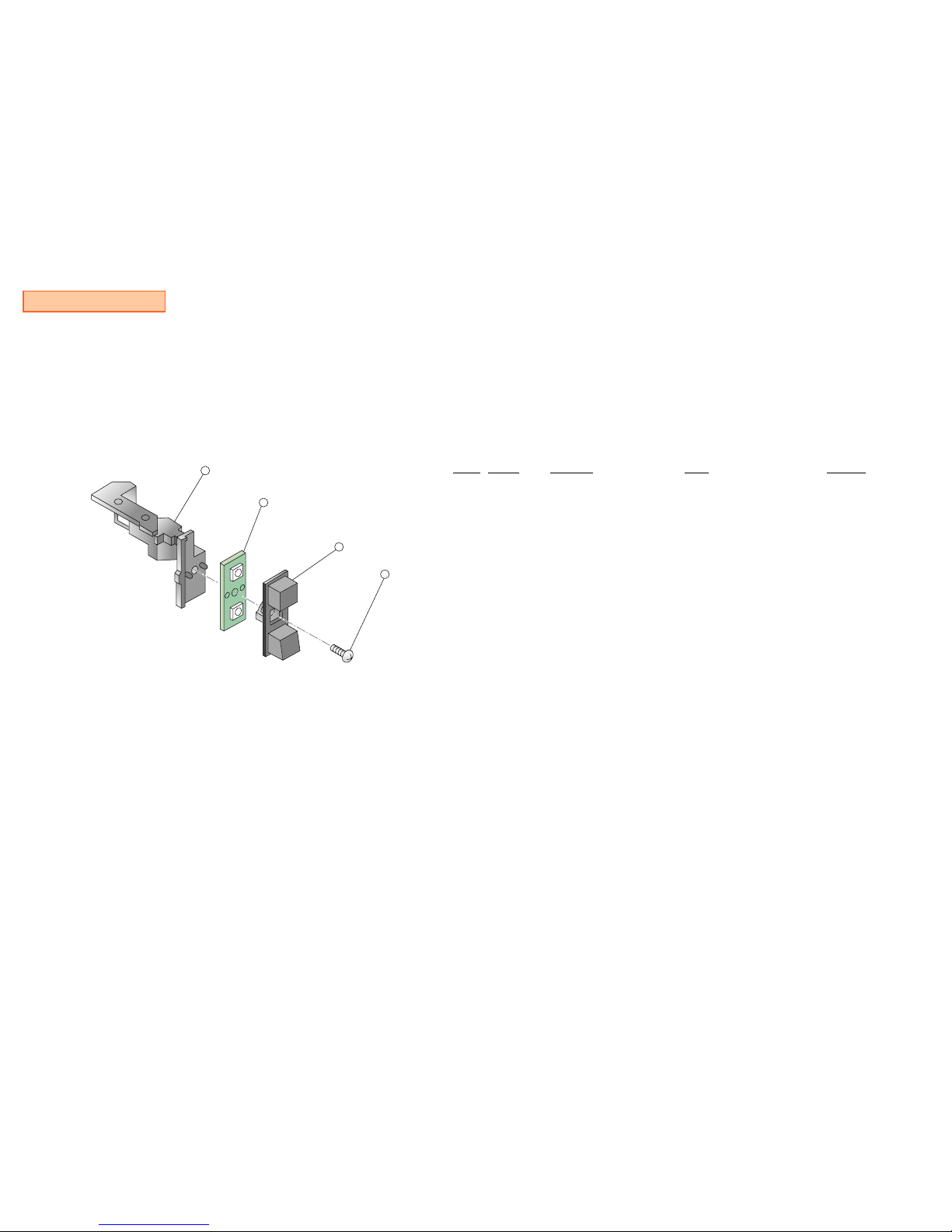
Switch Assy Block
-------------------
SWITCH ASSY BLOCK
-------------------
A-6705-426-A SW-365 SWITCH ASSY BLOCK for GH013(31/41) MOUNT
A-6705-401-A SW-366 SWITCH ASSY BLOCK for GH014 MOUNT
Ref-No. Part No. Description Remark Place code
50 3-059-665-03 BUTTON, SWITCH #25SW
51 3-059-666-05 BRACKET, SWITCH #25SW
51 3-066-494-01 BRACKET, SWITCH #25SW
52 7-685-105-11 TPG +P 2X8, TYPE 2, NON-SLIT #25SW
53 A-6714-472-A SW-365 MOUNT
for GH013(31/41) MOUNT
#25SW
53 A-6712-983-A SW-366 MOUNT
for GH014 MOUNT
#25SW
51
53
50
52
— 12 —
Reproduction Prohibited
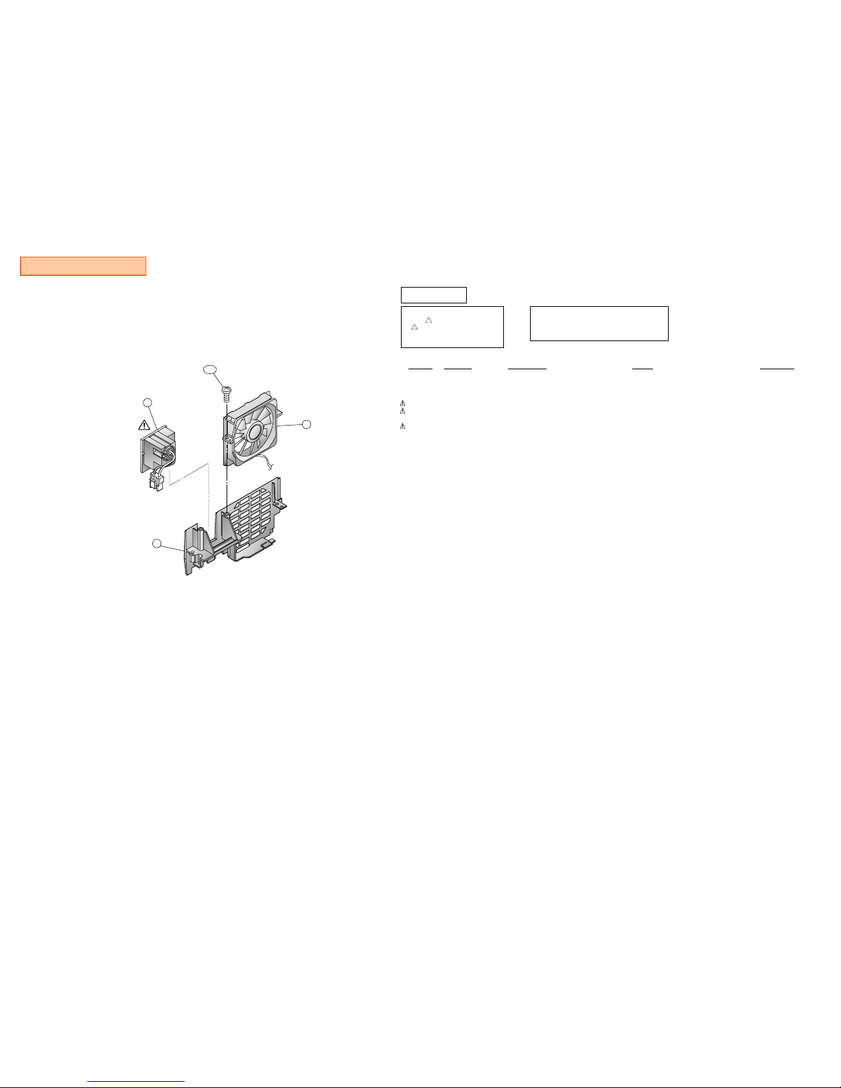
SCPH-30000 R series
Ref-No. Part No. Description Remark Place code
63 1-763-480-23 DC. FAN #74
63 1-763-554-22 FAN, DC #74
63 1-763-756-11 FAN, DC #74
64 1-771-994-31 SWITCH, POWER (WITH AC INLET)
for SCPH-30001 R
#00
64 1-771-995-31 SWITCH, POWER (WITH AC INLET)
for SCPH-30002 R/-30003 R/-30004 R
#00
64 1-786-209-21 SWITCH, POWER (AC INLET)
for SCPH-30002 R/-30003 R/-30004 R
#00
159 3-068-676-02 PANEL, REAR
for SCPH-30001 R
#87
159 3-068-676-12 PANEL, REAR
for SCPH-30002 R/-30003 R/-30004 R
#87
BV312 3-325-679-21 SCREW, TAPPING +BV 3X12 #87
Power Switch, Fan and Rear Panel Assy Block
64
63
159
BV312
The components identified by
mark ! or dotted line with mark.
! are critical for safety.
Replace only with part number
specified.
CAUTION :
Use of controls or adjustments or performance
of procedures other than those specified herein
may result in hazardous radiation exposure.
CAUTION
— 13 —
Reproduction Prohibited
SCPH-30000 R series
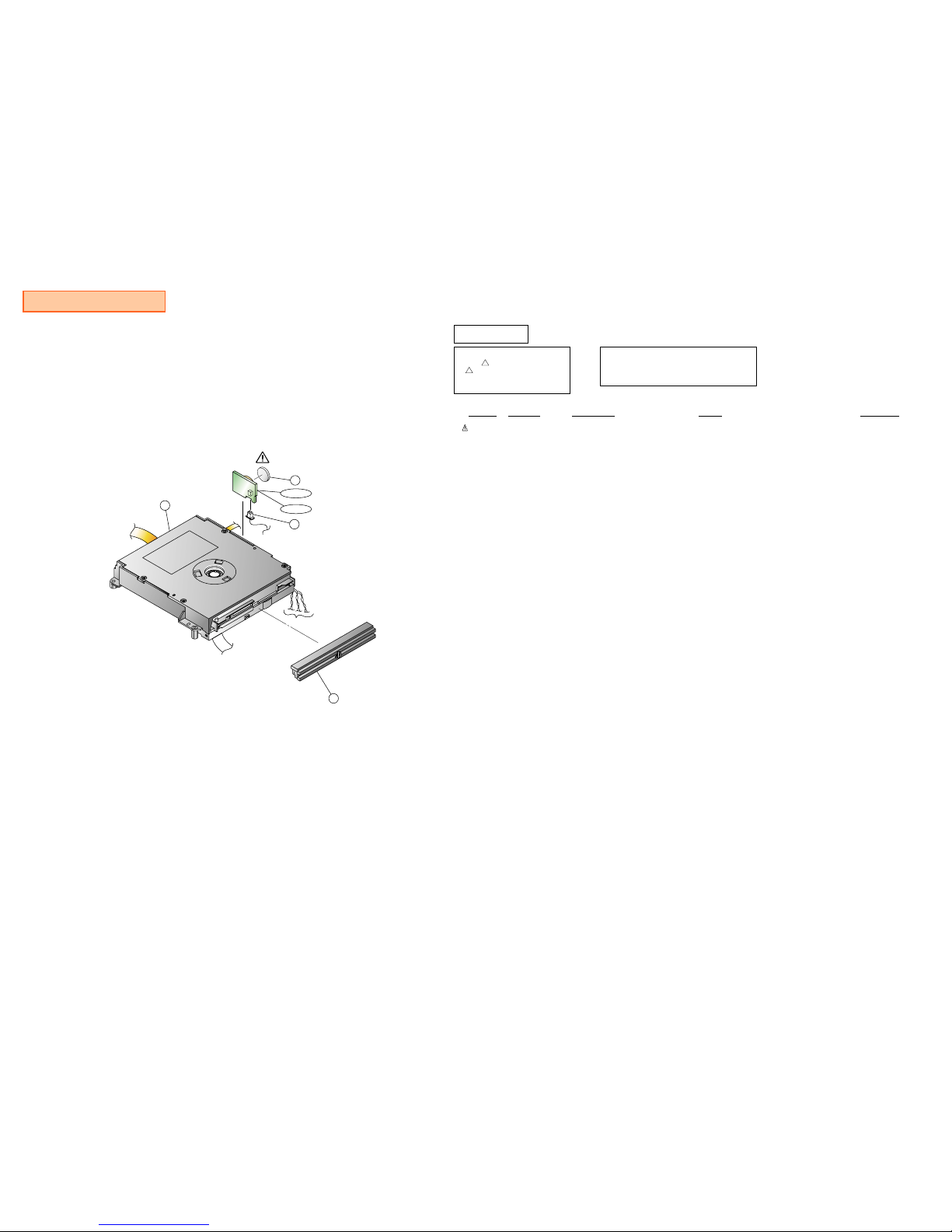
MD, GB Mount and Plate Assy Block
95
61
91
153
GB005
GB006
: Use with GH013(31/41) MOUNT
: Use with GH014 MOUNT
Ref-No. Part No. Description Remark Place code
61 1-528-174-41 BATTERY, LITHIUM (CR2032 TYPE) #25GB
91 A-6705-342-A MD BLOCK ASSY
for SCPH-30002 R/-30003 R/-30004 R
#10
91 A-6705-398-A MD BLOCK ASSY
for SCPH-30001 R
#10
95 X-3951-099-1 PLATE ASSY, ORNAMENTAL #87
153 1-961-160-21 HARNESS (HS-059) #12
GB005 A-6714-473-A GB-005 MOUNT #25GB
Use with GH013(31/41) MOUNT on SCPH-30001 R/-30002 R/-30003 R/-30004 R
GB006 A-6712-984-A GB-006 MOUNT #25GB
Use with GH014 MOUNT on SCPH-30003 R/-30004 R
The components identified by
mark ! or dotted line with mark.
! are critical for safety.
Replace only with part number
specified.
CAUTION :
Use of controls or adjustments or performance
of procedures other than those specified herein
may result in hazardous radiation exposure.
CAUTION
— 14 —
Reproduction Prohibited
SCPH-30000 R series
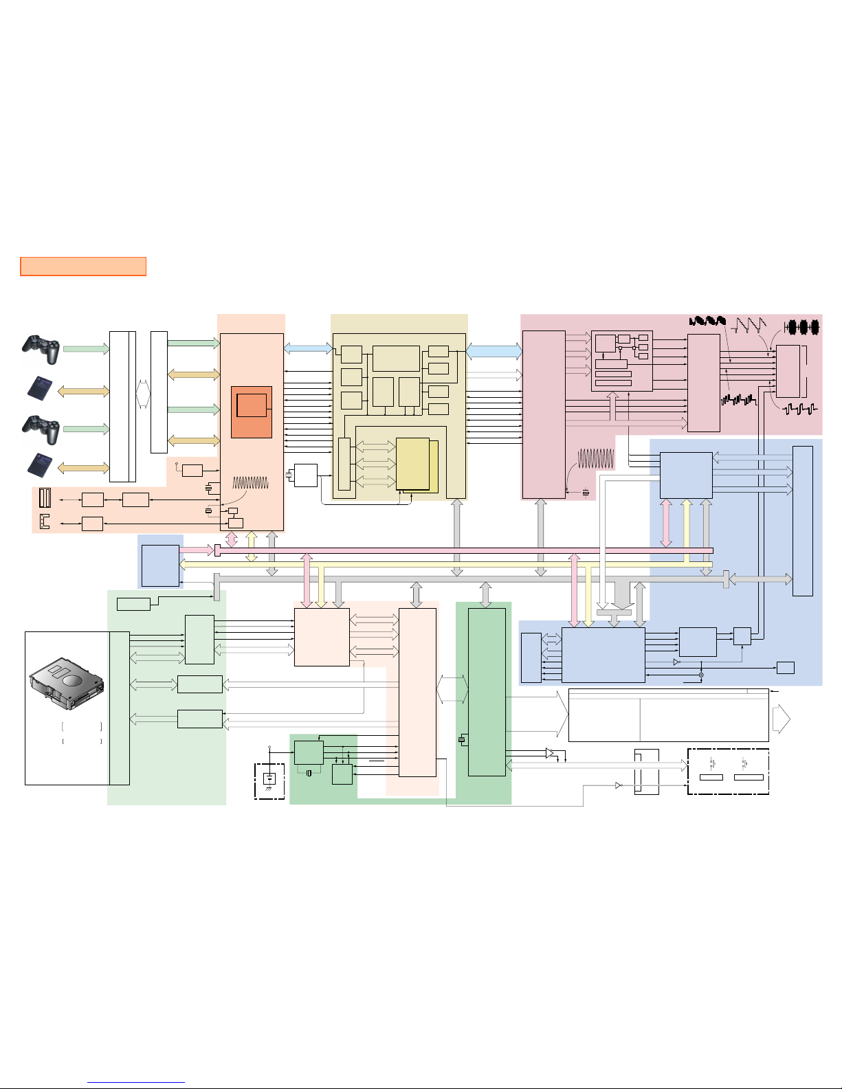
SECTION 5
BLOCK DIAGRAM
RF-AMP+DRIVER
IOP
EE+RDRAM
GS+VIDEO
SPU2+AUDIO+HDD
MECHACON
and DSP
CN108
AUL
AUR
MD BLOCK
CN801-806
PD1
PD2
A-F
/
6
CONTROL BUS
EVER3.3V
BT101
IC801
2
1
5-10
43
42
44
47
FE
TE
CE
RFD0
TS_SI
RF AMP
CONTROL BUS
TIMER
EEP
ROM
IC405
IC406
X402
32.768MHz
EEP-CE
EEP-SCK
EEP-SO
EEP-SI
STEP(–A, –B), TRAY(CNT, DRVF, DRVR)
43-46
3,10,11
DRIVER
H (±), H1 (±)
H2 (±), H3 (±)
A1, 2, 3
STD (±A, ±B)
TD _OFST
LOADING (±)
TRK (±)
FCS (±)
IC802
IC803
SPINDLE CONTROL
FORCUS/TRACKING/
SLIDE/LOADING
16,18
22-23
26
SP_GAINSW/, SP_PS/SPDL/, SP_SB/SP_BR
(FF,FR,TF,TR)DR
(FF,FR,TF,TR) DR
71-73
75,29
61
4
MECHA-CON
PB2
99
53
/POFF_RDY
SYS_SRST
TRAY_REQ
MCON_ACK
SYSTEM
CONTROL
CD/DVD DSP
HDD_SW, SW1.5,
SW1.9/SW2.5
SW5.1/SW3.3,
SW12, FAN_PWM
PWR_SW,/GREEN_ON,OP/CL_SW,/RED_ON
DIG +3.5V/DIG +5V REG (USB DRIVE)
IC409, Q407, 408 (DC-DC CONVERTER)
IC403 : EVER 3.3V REG
IC407 : DIG +1.8V REG
IC411 : DIG +1.8V REG
IC412 : DIG +2.5V REG
IC413 : SER +3.5V REG
IC414 : CON +8V REG
Q409-411, 414 : HDD +5V/+12V REG
DRAM
WE
RAS
CAS
OE
21
22
23
24
17
18
34,35
33
PG5
PG6
PG7
PG4
AN2
48
49
50
47
58
TRAY_LED-ON /BLUE_ON
SPMA0-9
SPMD0-15
SPU2
RST
SYSTEM POWER REGURATOR/FAN DRIVE/USB DRIVE/HDD DRIVE
IC415,Q415 :+8.5V (FAN DRIVE)
Q401,402,404,IC404 :
DIG +1.5V REG
IC408 : DIG +1.8V REG
IC410 : DIG +2.5V REG
SYSTEM
POWER
SUPPLY
POWER SW
OPEN/CLOSE SW
Switch Mount
OPTICAL
DIGTAL OUT
CN501
DIGITAL OUT
Q506
MUTE
AUDIO D/A
CONVERTER
/RST
105
42
47
48
41
40
49
DAD OUT
DABCK OUT
DALRCK OUT
DACCK
SPMUTE
Q505
IC517
IC504
IC502
IC402
IC604
/SSRST,/RST
SLEEP,POFF_REQ,OP_DISC
GSTBY,LCLK,/GRST
SD0-15
SA0-15,24-26
SPUDI,SPUDATI
SPUBCKI,SPULRCKI
PWRUP_EE,/ESTBY,/ERST
SUB ADDRESS BUS
SYSTEM CONTROL BUS
SA0-26
SD0-15
X101
18.432MHz
IC101
CLOCK
GENERATOR
/
DRAMC
PLL
400MHz
PHY
55,57
59,61
TPA/TPAn/TPB/TPBn
/
4
/
2
X301
24.576MHz
179-182
(DATA+,DATA_)X2
/
4X2
CN303 FL301, 302
CN301
IC503, IC505
BOOT ROM
DVD ROM
IC105
SD0-15
17-24,26-33
1-11,15,40-49
SA0-21
/CS1,/CS2
IC605
FE
TE
CE
RFD0
207
205
204
38
LOW POWER
THERMOSTAT
T1;70.6dC
T2;76.7dC
i LINK
/
4
/
4X2
USB PORTX2
MEMORY CARD 2 DATA
(Magic Gate)
CONTROLLER 1 DATA
MEMORY CARD 1 DATA
CONTROLLER 2 DATA
(Magic Gate)
FRONT TERMINAL
CN002
CN001, CN302
MEMORY CARD 2 DATA
CONTROLLER 1 DATA
MEMORY CARD 1 DATA
CONTROLLER 2 DATA
IC303
IOP
/BE0-3
IC306
+2.5V
X302
16.9344MHz
VREF
72
50
51
74
75
IC305
EDO RAM
MD0-31
MA0-9
CAS0-3
WE
44
AD0-31
3-34
394-425
35-38
384-387
/BE0-3
/
4
/RDAC
/WRAC
/RDY
/BREQ
/BGNT
DREQ0
DREQ1
DACK
/SGINT
/SINT
/SRST
39
40
41
42
43
44
45
46
47
48
49
1
2
388
389
383
426
427
393
392
391
429
428
430
431
390
MSCLK
PGCLK
128bit BUS
RQ_A0-7/RQ_B0-7
DQB_A0-7/DQB_B0-7
DQA_A0-7/DQA_B0-7
SIF
DMAC
IPU
EMOTION ENGINE
IC104
CPU
VU0 VU1
GIF
TIMER
SIO
INTC
GD0-63
11-74
1-64
IC202 IC205
GRAPHICS
SYNTHESIZER
ARED
AGEN
ABLU
GA0-6
4-10
71-77
CLKCG
CLKGC
/VLDCG
/VLDGC
/RDYCG
/RDYGC
GRW
/GACK
/GREQ
/GINT
66
65
70
69
68
67
80
78
79
81
75
76
77
78
79
80
81
82
83
84
RGB
to
YCrCB
MATRIX
SYNC_GEN,HD0,1
CONTROL REGISTER
M-Bus Control Module
DAC
DAC
DAC
C
Y
CVBS
DIGITAL DATA
MODE0-2
IC206
ANALOG
VIDEO
ENCODER
DIGITAL VIDEO ENCODER
14
15
16
20
22
24
COUT
YOUT
CVBS-OUT
BOUT/CbOUT/PbOUT
GOUT/YOUT
ROUT/CbOUT/PbOUT
R
G
B
38
40
42
RIN1
GIN1
BIN1
D0-2
AUL
AUR
6
8
7
4
1
2
11
9
CN201
CN504
HDD DATA (CD0-15)
HDD ADDRESS (CA0-25)
CONTROL
HDD
CONTROLLER
60-71,74
76-78
38,40-53
56-59
SCL
SDA
RT
/POFF_RDY
SLEEP
PO_DISC
POFF_REQ
SCL
SDA
/DVRST
12
13
10
IC501
5,6,7
SPCLK
X202
54MHz
X401
4MHz
266
REF.V
GEN.
5
MCD0-7
MCA0-8
CONTROL BUS
1
2
3
4
11
12
15
16
GREEN_ON
RED_ON
Q405
Q601
AV MULTI
OUT
to
HDD
79-88
91-96
97-104,106,107
110-115
RDRAM
(16MB)
4,5
4,5
CTMN
CTM
IC103
IC102
Cr
Cb
Y
Mod.
+ +
HSYNC, VSYNC, CSYNC, PAL/NTSC, CLOCK, RGBYC
220
218
219
SA0-15
SPUDI,SPUDATI
SPUBCKI,SPULRCKI
8
5
11
9
7
30.31
34-36
9
5
1
71,72
68-70
SC
23 5
29,30,31
/
2
/
3
DD+SYSTEM
CONTROL
SUB DATA BUS
SPUDATI/SPUBCKI/SPULRCKI
CD-ROM PlayStation Format
PlayStation2 Format
DC12V IN
CN401
GH-013(31/41)/GH-014
SD0-15
RO0-7
299-306
37-44
GO0-7
291-298
47-54
BO0-7
283-290
55-62
DVD VIDEO
DVD ROM PlayStation2 Format
AUDIO CD
SD0-15
SA1-10
SPU(DI,
DATI,BCKI,
LRCKI)
GB Mount
85,
86,
117,
118
12
13
4
/
4
3
4
6
3
1
3
4
2
4
98
10
7
— GH013(31/41)-1 —
SCPH-30000 R series
SECTION 6
PRINTED WIRING BOARDS AND SCHEMATIC DIAGRAMS for GH013(31/41) MOUNT
THIS NOTE IS COMMON FOR PRINTED WIRING
BOARDS AND SCHEMATIC DIAGRAMS.
Note on Printed Wiring Boards :
¥¥Through hole is omitted.
: Pattern on the side which is seen.
Note on Schematic Diagram :
¥
¥
¥
¥
Use caution when replacing chip parts.
New parts must be attached after removal of chip.
Be careful not to heat the minus side of tantalum capacitor,
because it is damaged by the heat.
All capacitors are in F unless otherwise noted. pF : F 50 WV
or less are not indicated except for electrolytics and tantalums.
All resistors are in and 1/4 W (Chip resistors : 1/10W) unless
otherwise specified.
Chip resistors are 1/8 W or 1/10 W unless otherwise noted.
k : 1000 , M : 1000 k .
Note :
The components
identified by mark
!
or
dotted line with mark
!
are critical for safety.
Replace only with part
number specified.
Note :
Les composants identifies par
une marque
!
sont critiques
pour la securite.
Ne les remplacer que par une
piece portant le nubero specifie.
Unit of voltage is V (volt)
¥
¥
¥
¥
¥
¥
+12V :
+8.0V :
+5.0V :
+3.5V :
IN :
OUT :
¥
¥
¥
¥
¥
¥
+3.3V :
+2.5V :
+1.8V :
VC :
+1.5V :
Main Signal Line : ,
Note on DC Power line :
Reproduction Prohibited
 Loading...