

Sony PEG-S300 Service Manual
PEG-S300
SERVICE MANUAL
Ver 2-2000J
All the supplementary
information are attached
at the end of data files.
“BOARD REPAIR” is internal distribution onl y .
SPECIFICATIONS
Power requirements
AC power adapter (supplied) DC5.7V (dedicated connector)
Battery Lithium ion battery (built-in)
Battery life
15 days* (based on an average of 30 minutes use per day)
Memory
8MB (DRAM)
LCD display mode
× 160 dot (monochrome)
160
External input/output
Interface connector
IrDA (1.2)
Memory Stick slot
Dimensions
Approx. 2
Mass
Approx. 4.27 oz (121g) (supplied stylus included)
Operating temperature
41ºF - 95ºF (5ºC - 35ºC)
* The battery life span varies depending on the temperature and conditions
of use.
Design and specifications are subject to change without notice.
US Model
7
/8 × 4 5/8 × 5/8 inches (70.9 x 114.7 x 15.2 mm) (w/h/d)
9-928-164-11
PERSONAL ENTERTAINMENT
ORGANIZER

Information in this document is subject to change without notice.
Sony and VAIO are trademarks of Sony . Intel logo and Intel Inside
logo are registered trademarks of Intel Corporation. Pentium MMX
is a trademark of Intel Corporation. Microsoft, MS-DOS, W indows,
the W indows 95 and W indows 98 log o are trademarks of Microsoft
Corporation.
All other trademarks are trademarks or registered trademarks of
their respective owners. Other tr ademarks and trade names may be
used in this document to refer to the entitles claiming the marks and
names or their produces. Sony Corporation disclaims any proprietary
interest in trademarks and trade names other than its own.
Caution Markings for Lithium/Ion Battery - The following or similar
texts shall be provided on battery pack of equipment or in both the
operating and the service instructions.
CAUTION: Danger of explosion if battery is incorrectly replaced.
Replace only with the same or equivalent type recommended by
the manufacturer. Discard used batteries according to the
manufacturer’s instructions.
CAUTION: The battery pack used in this de vice may present a f ire
or chemical burn hazard if mistreated. Do not disassemble, heat
above 100°C (212°F) or incinerate.
Dispose of used battery promptly.
Keep away from children.
Service and Inspection Precautions
1. Obey precautionary markings and instructions
Labels and stamps on the cabinet, chassis, and components identify areas
requiring special precautions. Be sure to observe these precautions, as well
as all precautions listed in the operating manual and other associated
documents.
2. Use designated parts only
The set’s components possess important safety characteristics, such as
noncombustibility and the ability to tolerate large voltages. Be sure that
replacement parts possess the same safety characteristics as the originals.
Also remember that the 0 mark, which appears in circuit diagrams and
parts lists, denotes components that have particularly important safety
functions; be extra sure to use only the designated components.
3. Always follow the original design when mounting
parts and routing wires
The original layout includes various safety features, such as inclusion of
insulating materials (tubes and tape) and the mounting of parts above the
printer board. In addition, internal wiring has been routed and clamped so
as to keep it away from hot or high-voltage parts. When mounting parts or
routing wires, therefore, be sure to duplicate the original layout.
4. Inspect after completing service
After servicing, inspect to make sure that all screws, components, and wiring
have been returned to their original condition. Also check the area around
the repair location to ensure that repair work has caused no damage, and
confirm safety.
5. When replacing chip components...
Never reuse components. Also remember that the negati ve side of tantalum
capacitors is easily damaged by heat.
6. When handling flexible print boards...
•The temperature of the soldering-iron tip should be about 270C.
•Do not apply the tip more than three times to the same pattern.
•Handle patterns with care; never apply force.
Caution: Remember that hard disk drives are easily damaged by
vibration. Always handle with care.
Confidential
— 2 —

TABLE OF CONTENTS
1. GENERAL ····································································5
2. DISASSEMBLY
2-1. Upper Cabinet Ass’y ............................................................. 7
2-2. LCD (Liquidcrystal Indicator Module) ................................. 7
2-3. CNX-98 MOUNT, Battery Unit............................................ 8
2-4. MP-23 (C) COMPL. ............................................................. 8
3. EXPLODED VIEW
3-1. Exploded View and Parts List ............................................... 9
3-2. Accessories, Packing Materials and Parts List .................... 10
— 3 —
Confidential
SECTION 1
GENERAL
This section is extracted from
instruction manual (4-649-988-11).
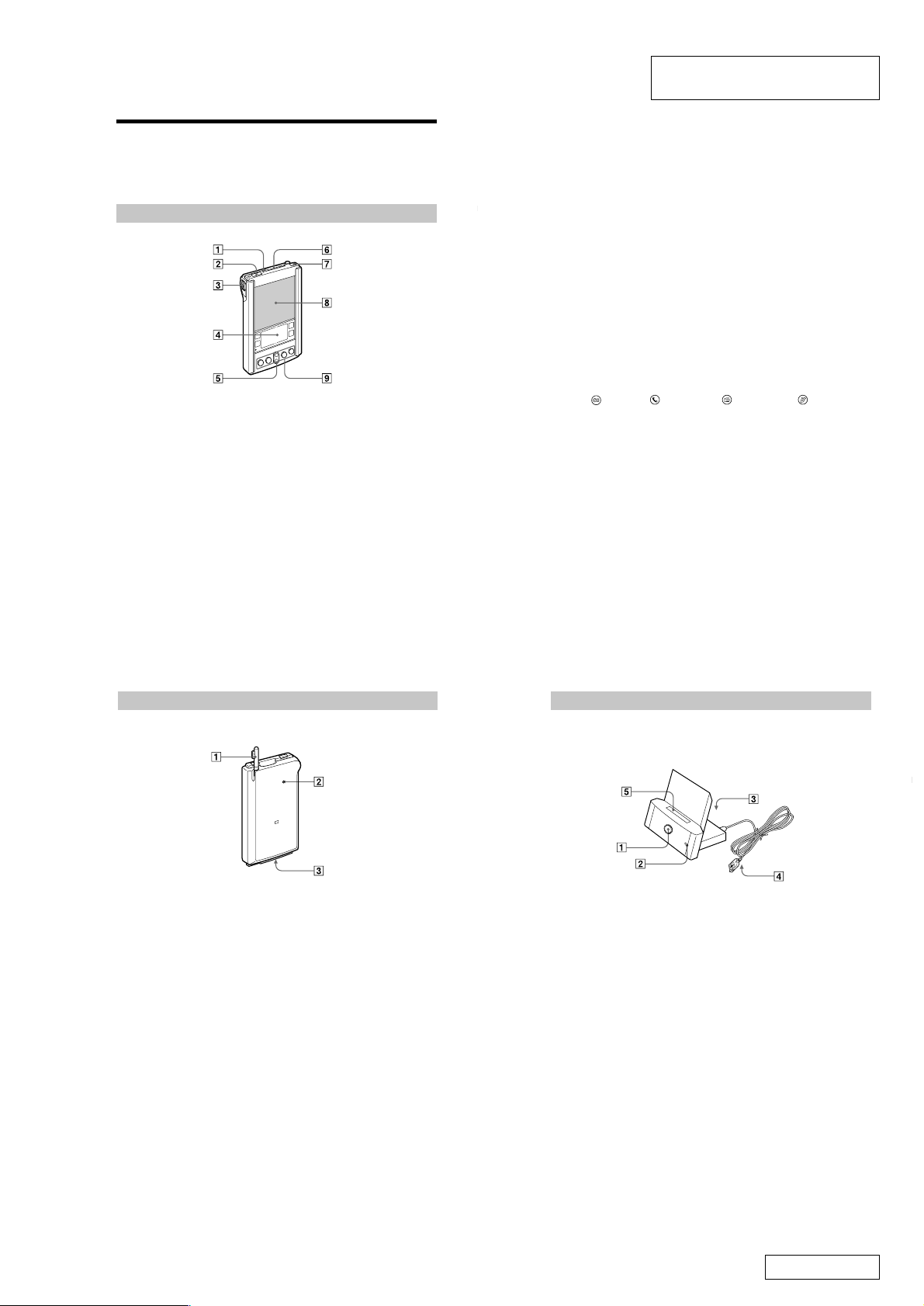
Designation and function of each
component
Front view of Sony handheld
1 Memory Stick Indicator
It lights up while Sony handheld is accessing to Memory Stick media.
2 Infrared Communication Port
Uses infrared technology to transmit data to and receive data from other
Palm OS handhelds, and to perform HotSync operations.
For more information, refer to the Sony handheld Operating Instructions.
3 Jog Dial
Used to select and execute applications or items.
For details, see “Using the Jog Dial control”.
4 Graffiti Writing Area
The area where you write letters and numbers using the Graffiti
See “Using Graffiti writing to enter data” to learn how to write Graffiti
characters.
®
alphabet.
#####
5 Scroll Button
Displays text and other information that extends beyond the area of the
screen. Pressing the lower half of the scroll button scrolls down to view
information below the viewing area, and pressing the upper half of the
button scrolls up to view the information above the viewing area.
6 Memory Stick Slot
Insert Memory Stick media into this slot.
7 Power Button
Used to turn the Sony handheld on or off.
Also, pressing this button for longer than 2 seconds turns the back light on
or off.
8 Screen
Displays the applications and information stored in your Sony handheld. It
is touch-sensitive and responds to the stylus.
9 Application Buttons
Activates the individual applications that correspond to the icons on the
buttons:
Date Book, Address Book, To Do List, and Memo
Pad. See the Sony handheld Operating Instructions for details on
reassigning these buttons to activate any application on your Sony
handheld.
z
If your Sony handheld is turned off, pressing any application button activates the
Sony handheld and opens the corresponding application.
Rear View of Sony handheld
1 Stylus
Used to tap icons and buttons on the screen, or to enter characters.
For details, see “Using the stylus.”
2 Reset Button
Under normal use, you should not have to use this button.
For more information, refer to the Sony handheld Operating Instructions.
3 Interface Connector
Used to connect to the cradle, or AC adapter.
7
8
Cradle
#####
1 HotSync Button
Data in the Sony handheld can be synchronized with the data saved on a
computer.
For more detailed information, see “Exchanging and Updating Data Using
HotSync Operations” in the Sony handheld Operating Instructions.
2 Cradle Indicator
When you connect the AC adapter to the cradle and place the Sony
handheld on the cradle, this indicator lights in green and charging will start.
3 AC adaptor Connector
You can connect an AC adapter.
4 USB Connector
You can connect a USB connector on the computer.
5 Interface Connector
You can connect a Sony handheld.
10
— 5 —
11
Confidential
 Loading...