

Page 1

PROFESSIONAL DISC RECORDER
PDW-V1
OPERATION MANUAL [English]
1st Edition (Revised 1)
Page 2
WARNING
To prevent fire or shock hazard, do not
expose the unit to rain or moisture.
To avoid electrical shock, do not open the
cabinet. Refer servicing to qualified
personnel only.
THIS APPARATUS MUST BE EARTHED.
CAUTION
The apparatus shall not be exposed to dripping or splashing
and no objects filled with liquid, such as vases, shall be placed
on the apparatus.
The unit is not disconnected from the AC power source
(mains) as long as it is connected to the wall outlet, even if the
unit itself has been turned off.
Do not install the appliance in a confined space, such as a
book case or built-in cabinet.
If used in USA, use the UL LISTED power cord specified
below.
DO NOT USE ANY OTHER POWER CORD.
Plug Cap Parallel blade with ground pin
(NEMA 5-15P Configuration)
Cord Type SJT, three 16 or 18 AWG wires
Length Minimum 1.5 m, Less than 2.5 m (8 ft 3 in)
Rating Minimum 10 A, 125 V
Using this unit at a voltage other than 120 V may require the
use of a different line cord or attachment plug, or both. To
reduce the risk of fire or electric shock, refer servicing to
qualified service personnel.
WARNING: THIS WARNING IS APPLICABLE FOR OTHER
COUNTRIES.
1. Use the approved Power Cord (3-core mains lead)/
Appliance Connector/Plug with earthing-contacts that
conforms to the safety regulations of each country if
applicable.
2. Use the Power Cord (3-core mains lead)/Appliance
Connector/Plug conforming to the proper ratings (Voltage,
Ampere).
This apparatus is provided with a main switch on the rear
panel. Install this apparatus so that user can access the main
switch easily.
This symbol is intended to alert the user to
the presence of uninsulated “dangerous
voltage” within the product’s enclosure that
may be of sufficient magnitude to constitute
a risk of electric shock to persons.
This symbol is intended to alert the user to
the presence of important operating and
maintenance (servicing) instructions in the
literature accompanying the appliance.
WARNING: THIS WARNING IS APPLICABLE FOR USA
ONLY.
If you have questions on the use of the above Power Cord/
Appliance Connector/Plug, please consult a qualified service
personnel.
This Professional Disc Recorder is classified as a CLASS 1
LASER PRODUCT.
Laser diode properties
Wavelength: 403 to 410 nm
Emission duration: Continuous
Laser output power: 65 mW (max. of pulse peak), 35 mW
(max. of CW)
Tekniska data för laserdiod
Våglängd: 403 till 410 nm
Emissionslängd: Kontinuerlig
Laseruteffekt: 65 mW (max. för pulstopp), 35 mW (max. för
kontinuerlig våg)
Spesifikasjoner laserdiode
Bølgelengde: 403 til 410 nm
Strålingens varighet: Kontinuerlig
Laserens effekt: 65 mW (maks stråletoppunkt), 35 mW
(maks ved kontinuerlig stråling)
Laserdiodin ominaisuudet
Aallon pituus: 403 - 410 nm
Välityksen kesto: Jatkuva
Laserlähdön teho: 65 mW (sykehuipun maks.), 35 mW
(jatkuvan aallon maks.)
2
Page 3
This label is located on the top panel of the
drive unit.
CAUTION
As the laser beam used in this Professional Disc Recorder is
harmful to the eyes, do not attempt to disassemble the
cabinet. Refer servicing to qualified personnel only.
CAUTION
The use of optical instruments with this product will increase
eye hazard.
CAUTION
Use of controls or adjustments or performance of procedures
other than those specified herein may result in hazardous
radiation exposure.
VAROITUS!
LAITTEEN KÄYTTÄMINEN MUULLA KUIN TÄSSÄ
KÄYTTÖOHJEESSA MAINITULLA TAVALLA SAATTAA
ALTISTAA KÄYTTÄJÄN TURVALLISUUSLUOKAN 1
YLITTÄVÄLLE NÄKYMÄTTÖMÄLLE LASERSÄTEILYLLE.
VARNING
OM APPARATEN ANVÄNDS PÅ ANNAT SÄTT ÄN I DENNA
BRUKSANVISNING SPECIFICERATS, KAN ANVÄNDAREN
UTSÄTTAS FÖR OSYNLIG LASERSTRÅLNING, SOM
ÖVERSKRIDER GRÄNSEN FÖR LASERKLASS 1.
Important Safety Instructions
• Read these instructions.
• Keep these instructions.
• Heed all warnings.
• Follow all instructions.
• Do not use this apparatus near water.
• Clean only with dry cloth.
• Do not block any ventilation openings.
Install in accordance with the manufacturer’s instructions.
• Do not install near any heat sources such as radiators, heat
registers, stoves, or other apparatus (including amplifiers)
that produce heat.
• Do not defeat the safety purpose of the polarized or
grounding-type plug. A polarized plug has two blades with
one wider than the other. A grounding-type plug has two
blades and a third grounding prong. The wide blade or the
third prong are provided for your safety. If the provided plug
dose not fit into your outlet, consult an electrician for
replacement of the obsolete outlet.
• Protect the power cord from being walked on or pinched
particularly at plugs, convenience receptacles, and the point
where they exit from the apparatus.
• Only use attachments/accessories specified by the
manufacturer.
• Use only with the cart, stand, tripod, bracket, or table
specified by the manufacturer, or sold with the apparatus.
When a cart is used, use caution when moving the cart/
apparatus combination to avoid injury from tip-over.
• Unplug this apparatus during lightning storms or when
unused for long periods of time.
• Refer all servicing to qualified service personnel. Servicing
is required when the apparatus has been damaged in any
way, such as power-supply cord or plug is damaged, liquid
has been spilled or objects have fallen into the apparatus,
the apparatus has been exposed to rain or moisture, does
not operate normally, or has been dropped.
For the customers in the USA
This equipment has been tested and found to comply with the
limits for a Class B digital device, pursuant to Part 15 of the
FCC Rules. These limits are designed to provide reasonable
protection against harmful interference in a residential
installation. This equipment generates, uses, and can radiate
radio frequency energy and, if not installed and used in
accordance with the instructions, may cause harmful
interference to radio communications. However, there is no
guarantee that interference will not occur in a particular
installation. If this equipment does cause harmful interference
to radio or television reception, which can be determined by
turning the equipment off and on, the user is encouraged to try
to correct the interference by one or more of the following
measures;
– Reorient or relocate the receiving antenna.
– Increase the separation between the equipment and
receiver.
– Connect the equipment into an outlet on a circuit different
from that to which the receiver is connected.
– Consult the dealer or an experienced radio/TV technician for
help.
3
Page 4

You are cautioned that any changes or modifications not
expressly approved in this manual could void your authority to
operate this equipment.
E1 (residential), E2 (commercial and light industrial), E3
(urban outdoors) and E4 (controlled EMC environment, ex. TV
studio).
The shielded interface cable recommended in this manual
must be used with this equipment in order to comply with the
limits for a digital device pursuant to Subpart B of Part 15 of
FCC Rules.
For the customers in the USA
This product contains mercury. Disposal of this product may
be regulated if sold in the USA. For disposal or recycling
information, please contact your local authorities or the
Electronics Industries Alliance (www.eiae.org http://
www.eiae.org).
For the customers in the USA and Canada
• RECYCLING LITHIUM-ION BATTERIES
Lithium-Ion batteries are recyclable.
You can help preserve our environment
by returning your used rechargeable
batteries to the collection and recycling
location nearest you.
For more information regarding recycling of rechargeable
batteries, call toll free 1-800-822-8837, or visit
http://www.rbrc.org/
Caution: Do not handle damaged or leaking lithium-ion
batteries.
Voor de Klanten in Nederland
• Dit apparaat bevat een vast ingebouwde batterij die niet
vervangen hoeft te worden tijdens de levensduur van het
apparaat.
• Raadpleeg uw leverancier indien de batterij toch vervangen
moet worden.
De batterij mag alleen vervangen worden door vakbekwaam
servicepersoneel.
• Gooi de batterij niet weg maar lever deze in als klein
chemisch afval (KCA).
• Lever het apparaat aan het einde van de levensduur in voor
recycling, de batterij zal dan op correcte wijze verwerkt
worden.
For Customers in Taiwan only
• RECYCLING NICKEL METAL HYDRIDE BATTERIES
Nickel metal hydride batteries are
recyclable.
You can help preserve our environment
by returning your used rechargeable
batteries to the collection and recycling
location nearest you.
For more information regarding recycling of rechargeable
batteries, call toll free1-800-822-8837, or visit
http://www.rbrc.org/
Caution: Do not handle damaged or leaking lithium-ion
batteries.
For the customers in Europe
This product with the CE marking complies with both the EMC
Directive (89/336/EEC) and the Low Voltage Directive (73/23/
EEC) issued by the Commission of the European Community.
Compliance with these directives implies conformity to the
following European standards:
• EN60065: Product Safety
• EN55103-1: Electromagnetic Interference (Emission)
• EN55103-2: Electromagnetic Susceptibility (Immunity)
This product is intended for use in the following
Electromagnetic Environment(s):
4
Page 5
AVERTISSEMENT
Afin d’éviter tout risque d’incendie ou
d’électrocution, ne pas exposer l’appareil à
la pluie ou à l’humidité.
Afin d’écarter tout risque d’électrocution,
garder le coffret fermé. Ne confier
l’entretien de l’appareil qu’à un personnel
qualifié.
CET APPAREIL DOIT ÊTRE RELIÉ À LA
TERRE.
ATTENTION
Eviter d’exposer l’appareil à un égouttement ou à des
éclaboussures et ne placer aucun objet rempli de liquide,
comme un vase, sur l’appareil.
Cet appareil n’est pas déconnecté de la source d’alimentation
secteur tant qu’il est raccordé à la prise murale, même si
l’appareil lui-même a été mis hors tension.
Ne pas installer l’appareil dans un endroit confiné, par
exemple une bibliothèque ou un placard encastré.
Cet appareil possède son interrupteur principal sur le panneau
arrière. Installer l’appareil de façon que l'utilisateur puisse
accéder facilement à l'interrupteur principal.
Avant d’utiliser un câble à fiche modulaire :
Par mesure de sécurité, ne pas raccorder à un connecteur
pour câblage de périphérique qui pourrait avoir une tension
excessive.
Cette étiquette est placée sur le panneau
supérieur de l’unité de commande.
ATTENTION
Comme le rayon laser utilisé dans cet Enregistreur de disques
pour professionnels est dangereux pour les yeux, ne pas
essayer de démonter le coffret. Faire effectuer l’entretien
uniquement par un personnel qualifié.
ATTENTION
L’emploi d’instruments optiques avec ce produit augmentera
les risques pour les yeux.
ATTENTION
L’emploi de commandes ou ajustements ou l’exécution de
procédures autres que celles spécifiées ici peut provoquer
une exposition dangereuse au rayonnement.
Pour les utilisateurs aux Etats-Unis et au Canada.
• RECYCLAGE DES ACCUMULATEURS AUX IONS DE
LITHIUM
Les accumulateurs aux ions de lithium
sont recyclables.
Vous pouvez contribuer à préserver
l’environnement en rapportant les piles
usées dans un point de collection et
recyclage le plus proche.
Cet enregistreur de disques pour professionnels est classé
PRODUIT LASER DE CLASSE 1.
Propriétés de la diode laser
Longueur d’onde : 403 à 410 nm
Durée d’émission : Continue
Puissance de sortie laser : 65 mW (maxi de crête
d’impulsion), 35 mW (maxi d'ondes entretenues)
Pour plus d’informations sur le recyclage des
accumulateurs, téléphonez au numéro gratuit
1-800-822-8837 (Etats-Unis et Canada uniquement), ou
visitez http://www.rbrc.org/
Avertissment : Ne pas utiliser des accumulateurs aux ions
de lithium qui sont endommagés ou qui fuient.
• RECYCLAGE DES ACCUMULATEURS À HYDRURE
MÉTALLIQUE DE NICKEL
Les accumulateurs à hydrure métallique
de nickel sont recyclables.
Vous pouvez contribuer à préserver
l’environnement en rapportant les piles
usées dans un point de collection et
recyclage le plus proche.
5
Page 6

Pour plus d’informations sur le recyclage des
accumulateurs, téléphonez au numéro gratuit
1-800-822-8837 (Etats-Unis et Canada uniquement), ou
visitez http://www.rbrc.org/
Avertissment : Ne pas utiliser des accumulateurs aux ions
de lithium qui sont endommagés ou qui fuient.
WARNUNG
Um Feuergefahr und die Gefahr eines
elektrischen Schlages zu vermeiden, darf
das Gerät weder Regen noch Feuchtigkeit
ausgesetzt werden.
Pour les clients européens
Ce produit portant la marque CE est conforme à la fois à la
Directive sur la compatibilité électromagnétique (EMC) (89/
336/CEE) et à la Directive sur les basses tensions
(73/23/CEE) émises par la Commission de la Communauté
européenne.
La conformité à ces directives implique la conformité aux
normes européennes suivantes :
• EN60065 : Sécurité des produits
• EN55103-1 : Interférences électromagnétiques (émission)
• EN55103-2 : Sensibilité électromagnétique (immunité)
Ce produit est prévu pour être utilisé dans les environnements
électromagnétiques suivants :
E1 (résidentiel), E2 (commercial et industrie légère),
E3 (urbain extérieur) et E4 (environnement EMC contrôlé ex.
studio de télévision).
AVERTISSEMENT :
1. Utilisez un câble d’alimentation (cordon secteur trifilaire),
un connecteur d’appareil ménager et une fiche avec mise à
la terre homologués selon la réglementation de votre pays,
le cas échéant.
2. Utilisez un câble d’alimentation (cordon secteur trifilaire),
un connecteur d’appareil ménager et une fiche dont la
capacité en tension (V) et en intensité électrique (A)
convient à cet appareil.
Pour toute question au sujet de l’utilisation du câble
d’alimentation, du connecteur d’appareil ménager ou de la
fiche mentionnés ci-dessus, consultez un réparateur qualifié.
Um einen elektrischen Schlag zu
vermeiden, darf das Gehäuse nicht
geöffnet werden. Überlassen Sie
Wartungsarbeiten stets nur qualifiziertem
Fachpersonal.
DIESES GERÄT MUSS GEERDET
WERDEN.
ACHTUNG
Das Gerät ist nicht tropf- und spritzwassersicher, daher
dürfen keine mit Flüssigkeiten gefüllten Gegenstände, z. B.
Vasen, darauf abgestellt werden.
Solange das Netzkabel an eine Netzsteckdose
angeschlossen ist, bleibt das Gerät auch im ausgeschalteten
Zustand mit dem Stromnetz verbunden.
Das Gerät nicht an Orten aufstellen, z.B. in Bücherregalen
oder Einbauschränken, wo keine ausreichende Belüftung
gewährleistet ist.
Der Hauptschalter dieses Geräts befindet sich an der
Rückwand. Stellen Sie das Gerät so auf, dass jederzeitiger
Zugriff auf diesen Hauptschalter gewährleistet ist.
Bei Verwendung eines Kabels mit RJ-11-Stecker:
Aus Sicherheitsgründen nicht mit einer Komponente
verbinden, die u.U. eine übermäßig hohe Spannung führt.
Dieser Professional Disc Recorder ist als CLASS 1 LASER
PRODUCT eingestuft.
Eigenschaften der Laserdiode
Wellenlänge: 403 bis 410 nm
Emissionsdauer. Ununterbrochen
Laser-Ausgangsleistung: 65 mW (max. Impulsspitze), 35
mW (max. Dauerstrich)
6
Page 7
Dieser Aufkleber befindet sich oben auf der
Antriebseinheit.
VORSICHT
Die Laserstrahlung im Innern ist augenschädlich. Deshalb den
Professional Disc Recorder nicht öffnen/zerlegen.
Wartungsarbeiten ausschließlich qualifiziertem Fachpersonal
überlassen.
VORSICHT
Der Einsatz von optischen Hilfen verstärkt die Gefahr von
Augenschäden.
VORSICHT
Bei Betätigung von Bedien- und Einstellteilen oder
Ausführung von Bedienvorgängen, die nicht ausdrücklich in
dieser Bedienungsanleitung aufgeführt sind, droht u.U. die
Einwirkung gefährlicher Laserstrahlung.
GEFAHR
Bei geöffnetem Laufwerk und beschädigter oder deaktivierter
Verriegelung tritt ein unsichtbarer Laserstrahl aus.
Direkter Kontark mit dem Laserstrahl ist unbedingt zu
vermeiden.
Für Kunden in Europa
Dieses Produkt besitzt die CE-Kennzeichnung und erfüllt die
EMV-Richtlinie (89/336/EWG) sowie die
Niederspannungsrichtlinie (73/23/EWG) der EG-Kommission.
Angewandte Normen:
• EN60065: Sicherheitsbestimmungen
• EN55103-1: Elektromagnetische Verträglichkeit
(Störaussendung)
• EN55103-2: Elektromagnetische Verträglichkeit
(Störfestigkeit),
für die folgenden elektromagnetischen Umgebungen: E1
(Wohnbereich), E2 (kommerzieller und in beschränktem
Maße industrieller Bereich), E3 (Stadtbereich im Freien) und
E4 (kontrollierter EMV-Bereich, z.B. Fernsehstudio)
1. Für Ihren privat genutzten Videorecorder muß eine
Fernseh-Rundfunk-Genehmigung beantragt werden,
sofern nicht bereits eine Genehmigung für ein
Fernsehgerät desselben Haushaltes vorliegt. Im
geschäftlichen Bereich ist jeder einzelne
Videorecorder anmelde- und gebührenpflichtig.
(Auskunft ggf. bei der GEZ oder den
Rundfunkanstalten.)
2. Im privaten Bereich ist die Aufzeichnung von
urheberrechtlich geschützten Werken auf Bild- und
Tonträger gestattet. Die entsprechenden UrheberVergütungen sind im Kaufpreis des Gerätes
enthalten. Öffentliche Wiedergabe oder Verbreitung
von mitgeschnittenen Fernsehsendungen ist ohne
Erlaubnis nicht zulässig, verpflichtet zu
Schadenersatz und ist gegebenenfalls strafbar.
3. Im Rahmen der Regelung des §47 des
Urheberrechtsgesetzes sind Aufzeichnungen von
Schulfernsehprogrammen gestattet. Mitschnitte von
Schulfunksendungen dürfen jedoch nur für den
Unterricht verwendet werden und sind spätestens am
Ende des laufenden Schuljahres zu löschen.
ACHTUNG:
1. Verwenden Sie ein geprüftes Netzkabel (3-adriges
Stromkabel)/einen geprüften Geräteanschluss/einen
geprüften Stecker mit Schutzkontakten entsprechend den
Sicherheitsvorschriften, die im betreffenden Land gelten.
2. Verwenden Sie ein Netzkabel (3-adriges Stromkabel)/
einen Geräteanschluss/einen Stecker mit den geeigneten
Anschlusswerten (Volt, Ampere).
Wenn Sie Fragen zur Verwendung von Netzkabel/
Geräteanschluss/Stecker haben, wenden Sie sich bitte an
qualifiziertes Kundendienstpersonal.
Zum Netzanschluß dieses Gerätes ist eine geprüfte Leitung zu
verwenden. Es sind die zutreffenden nationalen Errichtungsund/oder Gerätebestimmungen zu beachten.
(Für einen Nennstrom bis 6A)
Es ist eine geprüfte flexible PVC-ummantelte Leitung
entsprechend IEC 60227 (H05VV-F 3G 0.75 mm2 oder
H05VVH2-F 3G 0.75 mm2) zu verwenden.
Andernfalls ist eine flexible Leitung aus systhetischem Gummi
entsprechend IEC 60245 (Bauartkurzzeichen H05RR-F 3G
0.75 mm2) zu verwenden.
7
Page 8
ATTENZIONE
Per evitare il pericolo di incendi o scosse
elettriche, non esporre l’apparecchio alla
pioggia o all’umidità.
Per evitare scosse elettriche, non aprire
l’apparecchio.
Per le riparazioni, rivolgersi solo a
personale qualificato.
QUESTO APPARECCHIO DEVE ESSERE
MESSO A TERRA.
ATTENZIONE
L’apparecchio non deve essere esposto a gocciolamenti o
spruzzi. Non collocare sull’apparecchio oggetti contenenti
liquidi, come ad esempio vasi di fiori.
L’apparecchio non è scollegato dalla fonte di alimentazione
CA (corrente di rete) fintanto che è collegato ad una presa di
corrente, anche se l’apparecchio stesso è stato spento.
Evitate di installare l’apparecchio in uno spazio limitato, tipo in
una libreria o in un mobiletto incassato.
Questo apparecchio è provvisto di interruttore principale
posizionato sul pannello posteriore. Installare l’apparecchio in
modo tale che l’utente possa accedere facilmente
all’interruttore principale.
Quando si usa un cavo a presa modulare
Per sicureazza non collegare ad un connettore per il
collegamento di periferiche, che potrebbe avere una tensione
eccessiva.
Questo registratore di dischi professionale è classificato come
PRODOTTO LASER CLASSE 1.
Proprietà del laser a diodo
Lunghezza d’onda: da 403 a 410 nm
Durata emissione: Continua
Potenza d’emissione del laser: 65 mW (mass. a picco di
impulso), 35 mW (mass. di CW)
Questa etichetta si trova sul pannello
superiore dell’unità di pilotaggio.
CAUTELA
Poiché il raggio laser impiegato in questo registratore di dischi
professionale è dannoso alla vista, non tentare di smontare il
rivestimento. Per la manutenzione rivolgersi esclusivamente a
personale qualificato.
CAUTELA
L’uso di strumenti ottici con questo prodotto aumenta il rischio
per la vista.
CAUTELA
L’uso di comandi o regolazioni o l’esecuzione di procedimenti
diversi da quelli specificati in questo manuale possono
causare esposizione a radiazioni pericolose.
Per i clienti in Europa
Questo prodotto recante il marchio CE è conforme sia alla
direttiva sulla compatibilità elettromagnetica (EMC) (89/336/
CEE) che alla direttiva sulle basse tensioni (73/23/CEE)
emesse dalla Commissione della Comunità Europea.
La conformità a queste direttive implica la conformità alle
seguenti normative europee:
• EN60065: Sicurezza dei prodotti
• EN55103-1: Interferenza elettromagnetica (Emissione)
• EN55103-2: Sensibilità ai disturbi elettromagnetici
(Immunità)
Questo prodotto è destinato all’uso nei seguenti ambienti
elettromagnetici:
E1 (residenziali), E2 (commerciali e industriali leggeri), E3
(esterni urbani) e E4 (ambienti EMC controllati, ad esempio
studi televisivi).
8
Page 9

ATTENZIONE:
1. Utilizzare un cavo di alimentazione (a 3 anime)/
connettore per l’apparecchio/spina con terminali di messa a
terra approvati che siano conformi alle normative sulla
sicurezza in vigore in ogni paese, se applicabili.
2. Utilizzare un cavo di alimentazione (a 3 anime)/
connettore per l’apparecchio/spina confrmi alla rete
elettrica (voltaggio, ampere).
In caso di domande relative all’uso del cavo di alimentazione/
connettore per l’apparecchio/spina di cui sopra, consultare
personale qualificato.
ADVERTENCIA
Para evitar el riesgo de incendios o
electrocución, no exponga la unidad a la
lluvia ni a la humedad.
Para evitar descargas eléctricas, no abra el
aparato. Solicite asistencia técnica
únicamente a personal especializado.
ESTE APARATO DEBE CONECTARSE A
TIERRA.
PRECAUCIÓN
No se debe exponer la unidad a derrames ni goteos, ni se
debe situar cerca objetos llenos de líquido, como por ejemplo
vasos.
La unidad no queda desconectada de la alimentación
eléctrica siempre que esté conectado al tomacorriente incluso
aunque se desconecte el interruptor principal.
No instale el aparato en un lugar estrecho como en una
biblioteca o mueble integrado.
Este aparato tiene el interruptor principal en el panel trasero.
Instale este aparato de tal forma que pueda utilizar fácilmente
el interruptor principal.
Cuando utilice un cable con clavija modular:
Por motivos de seguridad, no conecte a ningún conector para
dispositivos periféricos que puedan utilizar tensión excesiva.
Este grabador de discos profesional está clasificado como
CLASS 1 LASER PRODUCT.
Propiedades del diodo láser
Longitud de onda: 403 a 410 nm
Duración de la emisión: Continua
Potencia de salida láser: 65 mW (máx. de pico de pulso),
35 mW (máx. de onda continua)
9
Page 10

Esta etiqueta se encuentra en el panel
superior de la unidad de mando.
CAUTION
Como el rayo láser utilizado en este grabador de discos
profesional es peligroso para los ojos, no trate de desarmar la
caja. Solicite el servicio sólo al personal cualificado.
CAUTION
El uso de instrumentos ópticos con este producto aumentará
el peligro a los ojos.
ADVERTENCIA:
1. Utilice el cable de alimentación (3 conductores
eléctricos), el conector de dispositivos y el enchufe con
contactos de puesta a tierra aprobados que cumplen con
las normas de seguridad de cada país, si existen.
2. Utilice el cable de alimentación (3 conductores
eléctricos), el conector de dispositivos y el enchufe que
cumplen los valores nominales adecuados (voltaje,
amperios).
Si tiene alguna pregunta acerca del uso del cable de
alimentación, el conector de dispositivos o el enchufe,
póngase en contacto con el personal de servicio cualificado.
CAUTION
La utilización de controles o ajustes, o la realización de
procedimientos no especificados aquí pueden resultar en la
exposición a radiación peligrosa.
Para los clientes de Europa
Este producto cumple con las directivas de compatibilidad
electromagnética (89/336/CEE) y baja tensión (73/23/CEE)
de la Comisión Europea.
El cumplimiento de estas directivas implica la conformidad
con los siguientes estándares europeos:
• EN60065: Seguridad del producto
• EN55103-1: Interferencia electromagnética (Emisión)
• EN55103-2: Susceptibilidad electromagnética (Inmunidad)
Este producto está ha sido diseñado para utilizarse en los
entornos electromagnéticos siguientes:
E1 (zona residencial), E2 (zona comercial e industrial ligera),
E3 (exteriores urbanos), y E4 (entorno con EMC controlada,
p. ej., estudio de televisión).
10
Page 11
11
Page 12

Table of Contents
Before Using the Unit ............................ 14
Setting the Line Mode ..............................14
Chapter 1 Overview
1-1 Features............................................. 16
1-2 Using the CD-ROM Manual .............. 18
1-2-1 CD-ROM System Requirements ..... 18
1-2-2 Preparations ..................................... 18
1-2-3 Reading the CD-ROM Manual........ 18
Chapter 2 Names and Functions of
Parts
2-1 Configuration .................................... 19
2-2 Control Panel..................................... 20
2-3 LCD Panel.......................................... 24
2-4 Connectors........................................ 27
Chapter 3 Preparations
3-1 Connections and Settings................ 29
3-1-1 Connecting an External Monitor .....29
3-1-2 Connections for Using PDZ-1 Proxy
Browsing Software ..........................30
3-1-3 Connecting to a Nonlinear Editing
System.............................................. 32
3-2 Power Preparations .......................... 33
3-2-1 Using AC Power.............................. 33
3-2-2 Using a Battery Pack .......................33
3-3 Setup.................................................. 33
3-4 Setting the Date and Time................ 34
3-5 Superimposed Text Information...... 34
3-6 Handling Discs.................................. 36
3-6-1 Discs Used for Playback.................. 36
3-6-2 Notes on Handling ...........................36
3-6-3 Write-Protecting Discs ....................36
3-6-4 Loading and Unloading a Disc ........37
3-6-5 Formatting a Disc ............................37
3-6-6 To Eject Discs With the Unit Powered
Off .................................................... 38
3-6-7 Using the Salvage Function............. 38
Chapter 4 Playback
4-1 Preparations for Playback................ 39
4-2 Playback Operation .......................... 40
4-3 Thumbnail Search............................. 42
4-3-1 Cuing Up a Desired Clip..................42
4-3-2 Cuing Up a Frame Including an Essence
Mark................................................. 43
4-4 Clip List Playback ............................. 44
4-4-1 Playing Back in Clip List Order ......44
4-4-2 Cuing Up With Sub Clip Thumbnails44
Chapter 5 Scene Selection
5-1 Overview............................................ 45
5-2 Basic Operations .............................. 46
5-2-1 Creating Clip Lists........................... 46
5-2-2 Editing Clip Lists.............................48
5-3 Clip List Operations.......................... 51
5-3-1 Displaying the CLIP Menu.............. 51
5-3-2 Saving the Current Clip List to Disc51
5-3-3 Loading a Clip List From Disc Into the
Current Clip List ..............................52
5-3-4 Deleting Clip Lists From Disc.........52
5-3-5 Clearing the Current Clip List .........53
5-3-6 Setting the Start Timecode of the
Current Clip List ..............................53
5-4 Using PDZ-1 Proxy Browsing Software
54
Chapter 6 File Operations
6-1 Overview............................................ 55
6-1-1 Directory Structure .......................... 55
6-1-2 File Operation Restrictions ..............56
6-2 File Access Mode File Operations... 58
6-3 FTP File Operations.......................... 59
6-3-1 Command List .................................61
Chapter 7 Menus
7-1 Menu System Configuration ............ 66
7-2 Basic Setup Menu............................. 67
7-2-1 Items in the Basic Setup Menu ........67
7-2-2 Basic Menu Operations.................... 69
7-3 Extended Menu ................................. 72
7-3-1 Items in the Extended Menu ............72
7-3-2 Extended Menu Operatoins .............75
7-3-3 Using UMID Data............................ 77
7-4 Maintenance Menu............................ 79
7-4-1 Items in the Maintenance Menu ......79
12
Table of Contents
Page 13

7-4-2 Maintenance Menu Operations........ 81
7-5 System Menu..................................... 84
7-5-1 Items in the System Menu ............... 84
7-5-2 System Menu Operations................. 84
Chapter 8 Maintenance and
Troubleshooting
8-1 Periodic Maintenance....................... 86
8-1-1 Digital Hours Meter......................... 86
8-2 Error Messages................................. 87
8-3 Alarms................................................ 87
8-3-1 Alarm List........................................ 87
8-4 Condensation.................................... 93
Appendixes
Specifications.......................................... 94
Using the Shoulder Belt ......................... 95
Glossary................................................... 96
Index......................................................... 98
Table of Contents
13
Page 14
Before Using the Unit
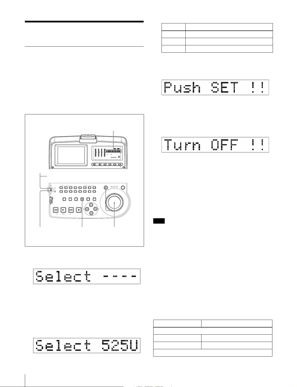
Setting the Line Mode
This unit is shipped with the line mode still unset.
Therefore you need to set the line mode before using the
unit. (The unit cannot be used unless the line mode is set.)
Once it is set, the line mode is retained even when the unit
is powered off.
Setting Line mode
525U 525(U): NTSC (areas outside Japan)
525J 525(J): NTSC (Japan)
625 625: PAL
3 When the desired setting appears, release the
SHUTTLE button.
“Push SET !!” appears.
Setting procedure
Use the following procedure to set the line mode.
Time data display
DATA
DATA
DATA
DATA
OVER
OVER
OVER
OVER
dB
dB
dB
dB
VITC
0
-12
-20
-30
-40
-60
CH-
26
0
0
-12
-12
-20
-20
-30
-30
-40
-40
-60
-60
CH-
37
CH-
48 BATT E F
COUNTERVIUB VITC ALARM
HOURS
MINUTES SECONDS FRAMES
AUDIO 625 IMX 504030
48CH 1624BIT
525
[]
DVCAM
0
-12
-20
-30
-40
-60
CH
- 15
1
AC power switch (rear panel)
MARK1
MARK2
SHUTTLE JOG
L
R
OUT
AUDIO MONITOR
L
CH-2 CH-3 CH-4 CH-5 CH-6 CH-7 CH-8
CH-1
R
ACCESS
SUB
CLIP
THUMBNAIL
NETWORK
LOCAL
REMOTE
CLIP
ESSENCE
MENU
PREV NEXTPLAY STOP
TOP F REV F FWD END
MARK
MENU
SYSTEM
MENU
S.SEL
SET
RESET SHIFT
IN
45 2,3
1 Power the unit on.
“Select ----” appears in the time data display.
2 With the SHUTTLE button held down, rotate the jog
dial.
When you rotate the jog dial in the forward direction,
the “----” part of the display changes in the sequence
525U > 525J > 625. When you rotate it in the reverse
direction, the display changes in the sequence 625 >
525J > 525U.
To redo the selection
Repeat step 2.
4 Press the SET button.
“Turn OFF !!” appears.
5 Power the unit off, and then power it on again.
The selected line mode becomes available for use.
You can change the setting made with this procedure
by using basic menu item 013 “525/625 SYSTEM
SELECT.” See 7-2-2 “Basic Menu Operations” (page
69) for more information about how to make basic
menu settings.
Note
The line mode is not set, or is cleared, in the following
situations. Reset the line mode.
• The unit is powered off before performing step 4 in the
previous procedure.
• The “RESET ALL SETUP” command in the
maintenance menu (see page 79) is executed.
Settings affected by the line mode
The following settings are affected when the line mode is
changed.
• Alarm message language
525(J): Japanese
525(U)/625: English
• The following menu item names, setting values, or initial
setting values
Item No. Item name
Basic menu
002 CHARACTER H-POSITION
003 CHARACTER V-POSITION
Extended menu
14
Before Using the Unit
Page 15

Item No. Item name
601 VITC POSITION SEL-1
602 VITC POSITION SEL-2
628 DF MODE
652 UMID SDI VANC LINE
660 ESSENCE MARK SDI VANC LINE
703 BLANK LINE SELECT
713 VIDEO SETUP REFERENCE
718 SETUP LEVEL/BLACK LEVEL
OUTPUT LEVEL
Before Using the Unit
15
Page 16

Overview
1-1Features
The PDW-V1 Professional Disc Recorder is a compact and
lightweight unit, offered as an affordable solution for
playing back optical discs as well as for audio and video
data file recording through its
S400 (i.LINK
applications, and for desktop viewing by journalists,
producers, and other production staff.
1) i.LINK is a trademark of Sony Corporation.
The features of the PDW-V1 include the following.
Playback of MPEG IMX/DVCAM
The PDW-V1 offers the capability to play back both
MPEG IMX
flexibility to select from these formats according to their
picture-quality needs.
1) MPEG IMX and DVCAM are trademarks of Sony Corporation.
Recording video and audio data as files
Though the PDW-V1 does not have video and audio input
connectors, it is possible to record AV data as files through
its
(network) connector or S400 (i.LINK) connector.
Proxy AV data
The proxy AV data is a low-resolution, MPEG-4 based
version of the full-resolution MPEG IMX/DVCAM
stream. When a full-resolution MPEG IMX/DVCAM file
is transferred, a proxy AV stream file that is time code
synchronized with the full-resolution stream, is also
created automatically on the disc. This proxy AV data,
which is smaller in size, is easier to work with and can be
transferred over common networks at much greater
speeds. The proxy AV data can be transferred at upto 30
times faster than real time.
1)
) connector. It is ideal for field
1)
and DVCAM
(network) connector or
1)
streams. Users have the
Chapter
Thumbnail search operation
Simply press the THUMBNAIL button and the PDW-V1
instantly displays these thumbnails on either its LCD
display or a connected monitor. You can easily cue up the
desired scene by guiding the cursor to the corresponding
thumbnail and confirming your selection with the SET
button.
Scene selection
You can create and play back clip lists of selected clips
from the disc, arranged in any order.
One disc can store up to 99 clip lists.
Clip lists make it simple to perform offline editing in the
field for later use with full-scale nonlinear editing systems
1)
(XPRI
1) XPRI is a trademark of Sony Corporation.
Quick picture search by jog and shuttle
dials
The PDW-V1 has jog and shuttle dials as a conventional
VTR to search picture in a clip. The jog dial is for frameby-frame search at ±1 times normal speed and the shuttle
dial is for high-speed search at up to ±20 times normal
speed.
IT-friendly system
In the Professional Disc, clips are recorded as video and
audio data files
allows material to be viewed directly on a computer linked
to the PDW-V1 via an i.LINK (file access mode, called
FAM below) connection—in the same way that a
computer reads data files on an external drive. The
interfaces include the S400 (i.LINK) connector,
supporting AV/C (Audio/Video Control) and i.LINK
(FAM) protocols, and
(network) connector supports MXF (Material eXchange
Format) file transfer capability to exchange contents with
other equipment supporting MXF.
, etc.).
1)
. This file-based recording system also
(network) connector. The
1
16
1-1 Features
Page 17

1) A clip is created every time recording is stopped.
Supporting digital and analog interfaces
This unit supports the following interfaces.
Digital interfaces
SDI: This allows the unit to output D1 (component) format
digital video and audio signals.
i.LINK: The DVCAM format digital video and audio
signals can be input and output. This unit supports the
AV/C and FAM protocols. Connecting a computer
with the FAM driver installed allows video and audio
data to be transferred at high speeds.
Analog interfaces
Video: The unit can output a composite analog video
signal.
Audio: The unit can output two-channel stereo audio
signals.
DVCAM output from MPEG IMX playback
When the PDW-V1 plays back an MPEG IMX stream, it
outputs a corresponding DVCAM stream at the same time
through its i.LINK (AV/C) port. This is very useful when
carrying out off-line editing with a popular non-linear
editor using DVCAM format.
Compact size, lightweight and batterypowered operation
The PDW-V1 is designed small and light enough to carry
out to the field and it is operable with battery to work
speedily in the field.
Supporting SNMP for service and
maintenance
The PDW-V1 is compatible with Sony remote
maintenance and monitoring software—an SNMPcompliant application that can monitor and log the
hardware’s status in real time via a TCP/IP network. If a
malfunction is detected, this system can immediately
identify the problem, allowing you to take corrective
action.
1) To be supported shortly.
1)
Chapter 1 Overview
Flexible metadata handing
XDCAM
with video and audio data, such as the date and time of
shooting, the cameraman, the recording method, and
comments about the material. This metadata can be used in
applications such as the following.
• The supplied PDZ-1 Proxy Browsing Software can be
used to add titles, comments, and other text data to discs
and clips.
• Computer-readable text files can be recorded on the
Professional Disc, to allow systematic content
management.
• The ability to search metadata for the required audio and
video scenes brings greater efficiency to various stages
of the video production process (editing, archiving, etc.).
1) XDCAM is a trademark of Sony Corporation.
1)
can record various types of metadata together
Color LCD built-in
With the built-in 3.5-inch type color LCD screen, you can
display contents on the disc without an external monitor.
RGB output connector provided
The MONITOR connector outputs analog RGB signals.
You can input the signals to a PC-compatible display or
projector.
1-1 Features
17
Page 18

Note
1-2Using the CD-ROM
Chapter 1 Overview
Manual
The supplied CR-ROM includes versions of the Operation
Manual for the PDW-V1 in English, Japanese, French,
German, Italian, Spanish, and Chinese.
1-2-1 CD-ROM System
Requirements
The following are required to access the supplied CDROM disc.
• Computer: PC with Intel Pentium CPU
-Installed memory: 64 MB or more
-CD-ROM drive: × 8 or faster
• Monitor: Monitor supporting resolution of 800 × 600 or
higher
• Operating system: Microsoft Windows Millennium
Edition, Windows 2000 Service Pack 2 or higher,
Windows XP Professional or Windows XP Home
Edition
If you lose the CD-ROM disc or become unable to read its
content, for example because of a hardware failure, you
can do one of the following.
• You can purchase a new CD-ROM disc to replace one
that has been lost or damaged. Contact your Sony service
representative.
• You can purchase printed versions of the operation
manuals. Contact your Sony service representative.
When ordering, be sure to specify the part number of the
manual you want.
Part No. Models covered
3-796-066-0X PDW-V1
• Intel and Pentium are registered trademarks of Intel Corporation or its
subsidiaries in the United States and other countries.
• Microsoft and Windows are registered trademarks of Microsoft
Corporation in the United States and/or other countries.
• Adobe, Acrobat, and Adobe Reader are trademarks of Adobe Systems
Incorporated in the United States and/or other countries.
When these requirements are not met, access to the CDROM disc may be slow, or not possible at all.
1-2-2 Preparations
One of the following programs must be installed on your
computer in order to use the operation manuals contained
on the CD-ROM disc.
• Adobe Acrobat Reader Version 4.0 or higher
• Adobe Reader Version 6.0 or higher
Note
If Adobe Reader is not installed, you can download it from
the following URL:
http://www.adobe.com/products/acrobat/readstep2.html
1-2-3 Reading the CD-ROM Manual
To read the operation manual contained on the CD-ROM
disc, do the following.
1
Insert the CD-ROM disc in your CD-ROM drive.
A cover page appears automatically in your browser.
If it does not appear automatically in the browser,
double-click the index.htm file on the CD-ROM disc.
2
Select and click the operation manual that you want to
read.
This opens the PDF file of the operation manual.
18
1-2 Using the CD-ROM Manual
Page 19
Names and Functions of
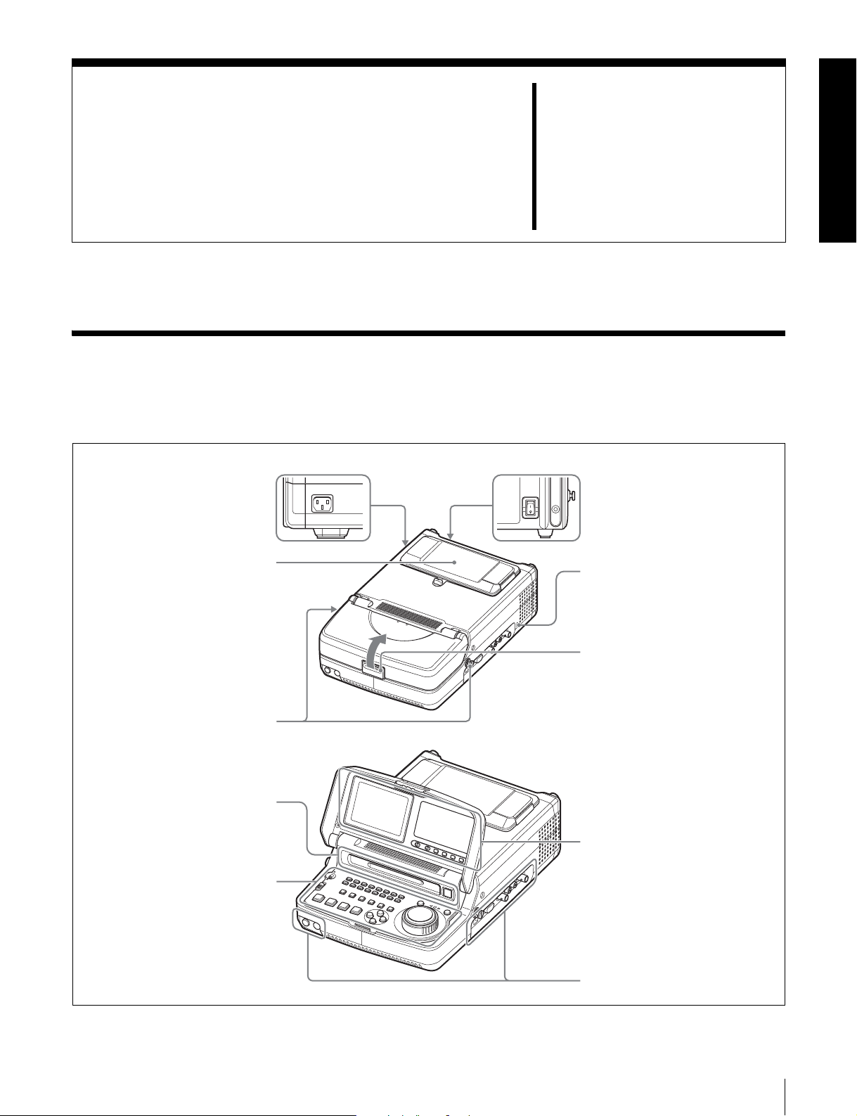
2-1 Configuration
Operation of the PDW-V1 uses the parts shown in the
following figure.
AC power inlet connector (left
side)
Connect to AC power with a power
cord (not supplied, see page 95).
Battery pack shoe (covered)
(see page 33)
Parts
Chapter
AC power switch (rear panel)
Press
power off.
Security slot
You can fit a commercially available
security cable into this slot.
2
" to power on; press a to
a)
Shoulder belt posts
(see page 95)
Disc slot and EJECT button
(see page 37)
Control panel (see page 20)
Press here to raise the cover.
a)For information about how to use
your security cable, refer to the
instructions provided with the
security cable.
LCD panel (see page 24)
Connectors (see page 27)
2-1 Configuration
19
Page 20
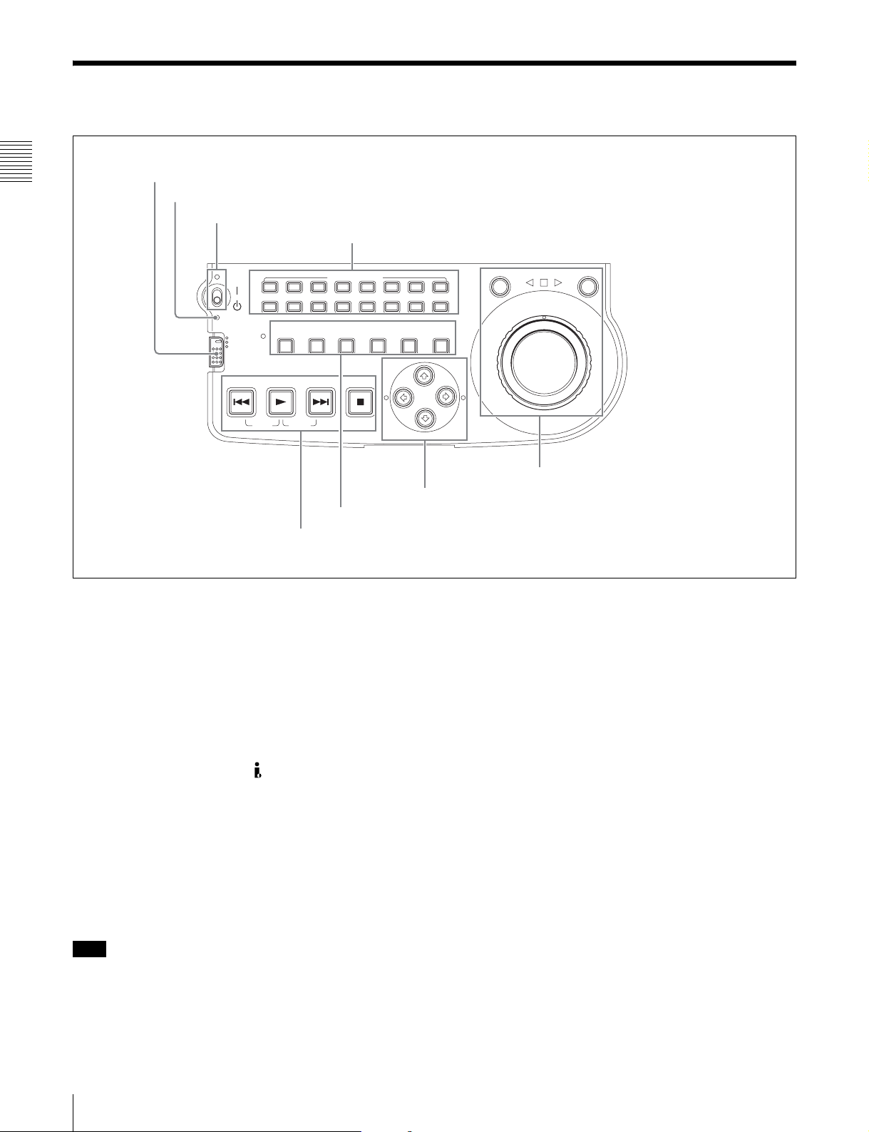
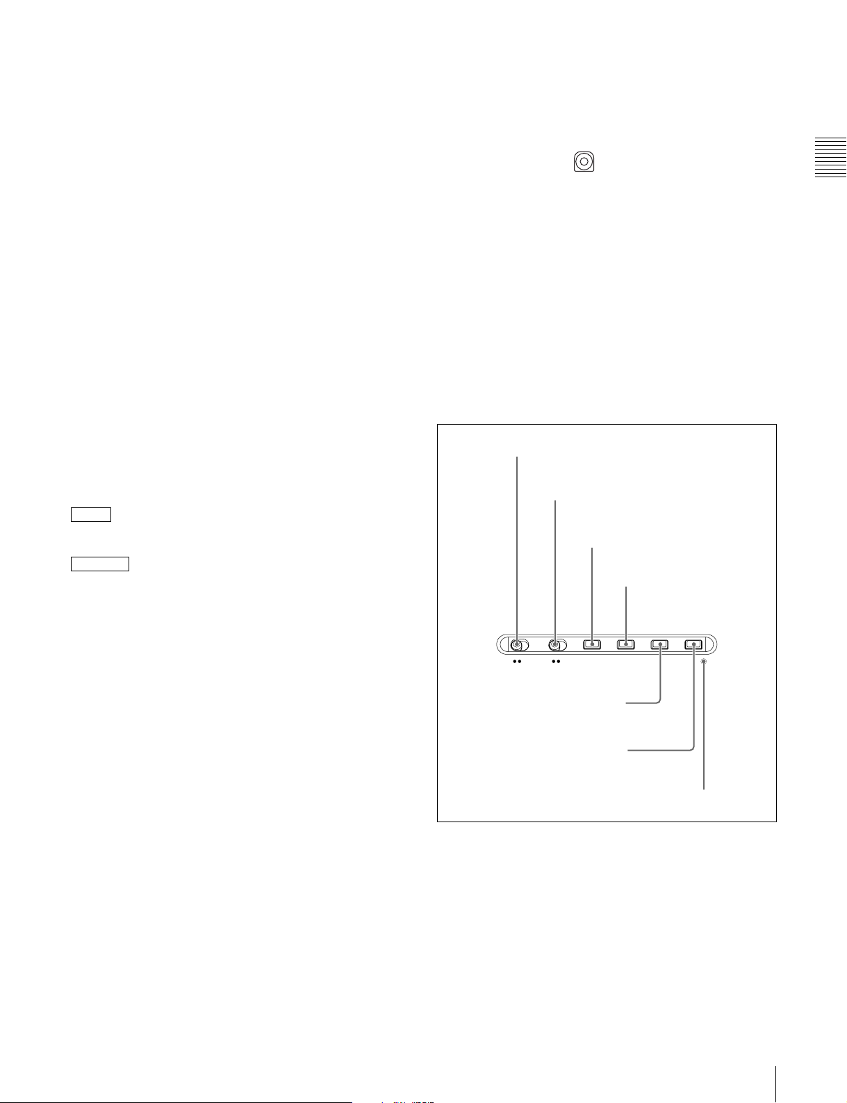
2-2 Control Panel
1 Remote control switch and NETWORK access indicator
Chapter 2 Names and Functions of Parts
2 ACCESS indicator
3 On/standby switch and indicator
4 AUDIO MONITOR buttons
L
CH-1 CH-2 CH-3 CH-4 CH-5 CH-6 CH-7 CH-8
R
ACCESS
SUBCLIP
NETWORK
LOCAL
REMOTE
PREV NEXTPLAY STOP
TOP F REV F FWD END
CLIP
MENU
AUDIO MONITOR
THUMBNAIL
MENU
SYSTEM
ESSENCE
MENU
MARK
3 Operating mode selection/menu setting section (see page 22)
4 Playback controls (see page 22)
SET
S.SEL
RESET SHIFT
IN
a Remote control switch and NETWORK access
indicator
Different positions of the switch allow different operations
as follows.
NETWORK: Enables access to the network. The
indicator lights when an external network device is
being accessed. In this state, operation from the
control panel is not possible.
LOCAL: Enables operation from the control panel.
REMOTE: Enables remote control of the PDW-V1 from
a device connected to the S400 (i.LINK) connector
on the side panel.
b ACCESS indicator
This lights when the disc is accessed and when a file is
opened by a FAM or FTP connections (see page 55).
If the on/standby switch is set to the 1 position while this
indicator is lit, access to the disc is completed before the
unit switches to the standby state.
Note
While the ACCESS indicator is lit, do not turn off the AC
power switch, disconnect the power cord, or remove the
battery. This could lead to a loss of data from the disc.
SHUTTLE JOG
MARK1
OUT
MARK2
1 Jog/shuttle control block (see page 21)
2 Arrow buttons(see page 21)
c On/standby ("/
1) switch and indicator
When the AC power switch on the rear panel is in the "
position, or a battery is loaded, this switches the PDW-V1
between the operating (") and standby (1) states. When
the switch is moved to the " position, the indicator lights.
When the switch is moved to the 1 position, the indicator
goes off.
When operating the PDW-V1 from an AC power supply,
normally leave the AC power switch in the " position, and
switch the PDW-V1 between the operating and standby
states using the on/standby switch.
d AUDIO MONITOR (audio monitor channel
selection) buttons
Each of the L (upper) and R (lower) rows has buttons CH1 to CH-8 corresponding to channels 1 to 8. When a button
is pressed, it lights, and the corresponding audio channel is
output from the PHONES jack and speaker on the front
panel and AUDIO MONITOR OUT L/R connectors on the
side panel.
In each of the L and R rows, if the buttons for more than
one channel are selected simultaneously, the selected
channels are mixed on the audio monitor output.
20
2-2 Control Panel
Page 21
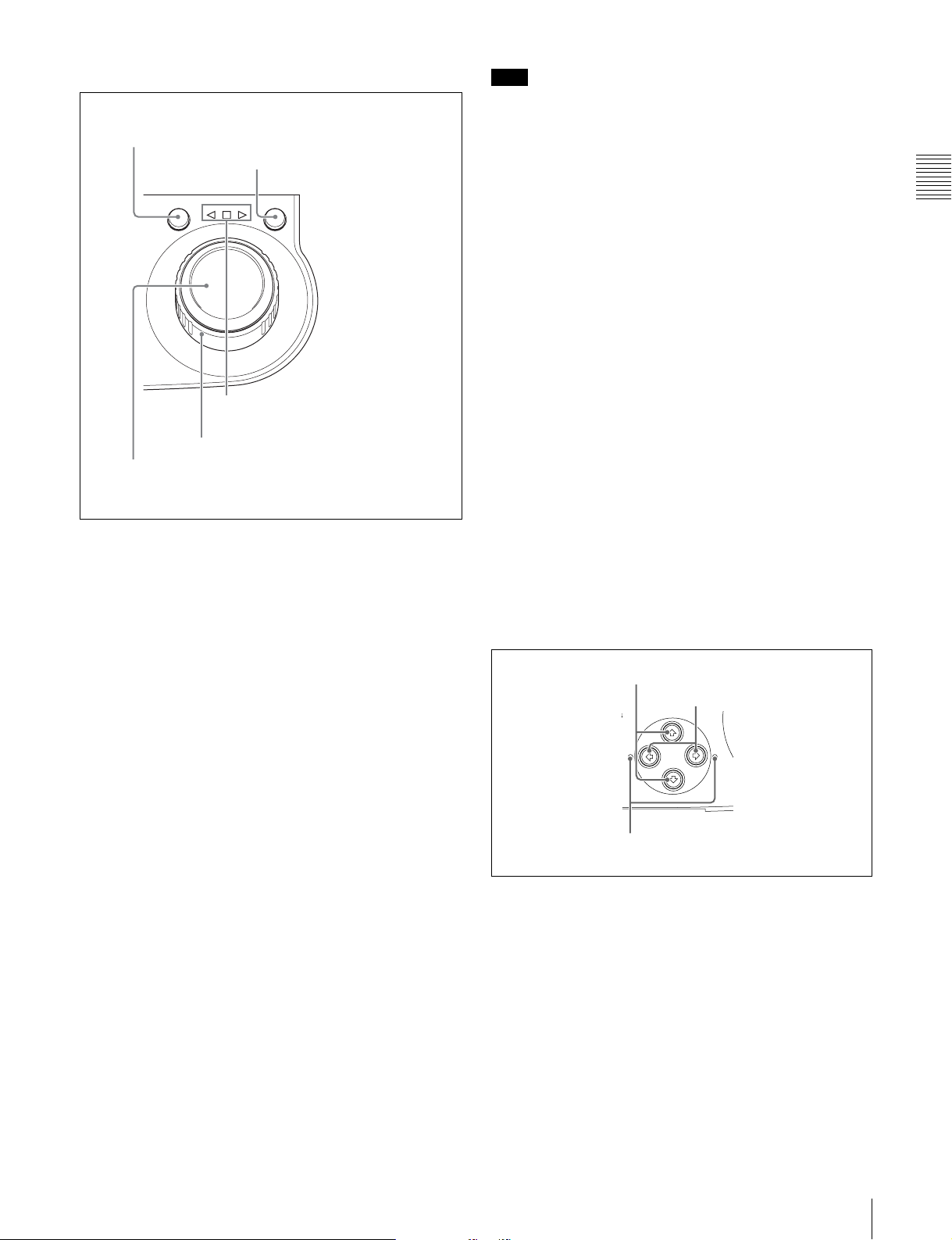
1 Jog/shuttle control block
SHUTTLE JOG
1 SHUTTLE button
2 JOG button
3 Jog/shuttle transport indicators
4 Shuttle dial
5 Jog dial
For details of playback operations with these buttons and
dials, see 4-2 “Playback Operation” on page 40.
a SHUTTLE button
To play back in shuttle mode using the shuttle dial, press
this button, turning it on. Pressing the JOG button or
turning the jog dial switches to jog mode.
b JOG button
To play back in jog mode using the jog dial, press this
button, turning it on. Pressing the SHUTTLE button or
turning the shuttle dial switches to shuttle mode.
Note
When extended menu item 101 “SELECTION FOR
SEARCH DIAL ENABLE” is set to “dial,” after using the
shuttle dial, return it to the center position. If the shuttle
dial is not in the center position, it is possible occasionally
for vibration from other operations to activate the dial, and
start playback in shuttle mode.
e Jog dial
Turn this for playback in jog mode. Turn clockwise for
forward direction playback, and counterclockwise for
reverse direction playback. In jog mode, the playback
speed varies in the range ±1 times normal speed, according
to the rotation rate of the jog dial. There are no detents.
Normally, you press the JOG button before turning the jog
dial, but it is also possible to make a setting to enable jog
mode directly by turning the jog dial (set extended menu
item 101 “SELECTION FOR SEARCH DIAL ENABLE”
to “dial”).
2 Arrow buttons
The four arrow buttons are also used as the MARK1
button, MARK2 button, IN button, and OUT button. The
correspondence with the buttons is as follows.
F button: MARK1 button
f button: MARK2 button
G button: IN button
g button: OUT button
You can use these buttons for thumbnail selection, menu
setting operations, setting IN/OUT points, and so on.
1 F/MARK1 button and f/MARK2 button
G/IN button and g/OUT button
2
MARK1
EL
IN OUT
Chapter 2 Names and Functions of Parts
c Jog/shuttle transport indicators
These show the playback direction in jog or shuttle mode.
b (green): Lights during playback in the reverse direction.
B (green): Lights during playback in the forward direction.
x (red): Lights during still image display.
d Shuttle dial
Turn this for playback in shuttle mode. Turn clockwise for
forward direction playback, and counterclockwise for
reverse direction playback. In shuttle mode, the playback
speed varies in the range ±20 times normal speed,
according to the angular position of the shuttle dial. The
shuttle dial has a detent at the center position, for still
image playback.
Normally, you press the SHUTTLE button before turning
the shuttle dial, but it is also possible to make a setting to
enable shuttle mode directly by turning the shuttle dial (set
extended menu item 101 “SELECTION FOR SEARCH
DIAL ENABLE” to “dial”).
MARK2
3 IN indicator and OUT indicator
a F/MARK1 button and f/MARK2 button
When the THUMBNAIL button is lit, you can use these
for thumbnail selection.
During playback, the F/MARK1 and f/MARK2 buttons
can be pressed with the SET button held down to record a
shot mark 1 or shot mark 2 as an essence mark.
To delete or change essence marks, use the supplied PDZ1 Proxy Browsing Software.
b G/IN button and g/OUT button
When the THUMBNAIL button is lit, you can use these
for thumbnail selection.
2-2 Control Panel
21
Page 22
An In or Out point is set when you press the SET button
SUBCLIP THUMBNAIL
MARK1
MENU
S.SEL
SET
RESET SHIFT
ESSENCE
MARK
CLIP
MENU
SYSTEM
MENU
with the G/IN or g/OUT button held down. The In or Out
point setting is deleted when you press the RESET button
with the G/IN or g/OUT button held down.
c MENU button
Use for setup menu operations. Pressing this displays the
setting of a setup menu item in the time data display. Press
once more to return to the original display.
c IN indicator and OUT indicator
IN indicator: When an IN point can be set, this flashes,
Chapter 2 Names and Functions of Parts
and when the IN point is set it changes to continuously
lit.
If an attempt is made to set the IN point after a
recorded OUT point, this flashes rapidly.
OUT indicator: When an OUT point can be set, this
d SET button
Use for setup menu settings, scene selection (thumbnail)
settings, and so on.
e RESET button
Press to reset the counter. This is also used to cancel setup
menu settings and abandon scene selection (thumbnail).
flashes, and when the OUT point is set it changes to
continuously lit.
If an attempt is made to set the OUT point before a
f SHIFT button
Use to switch the functions of various buttons.
recorded IN point, this flashes rapidly.
4 Playback controls
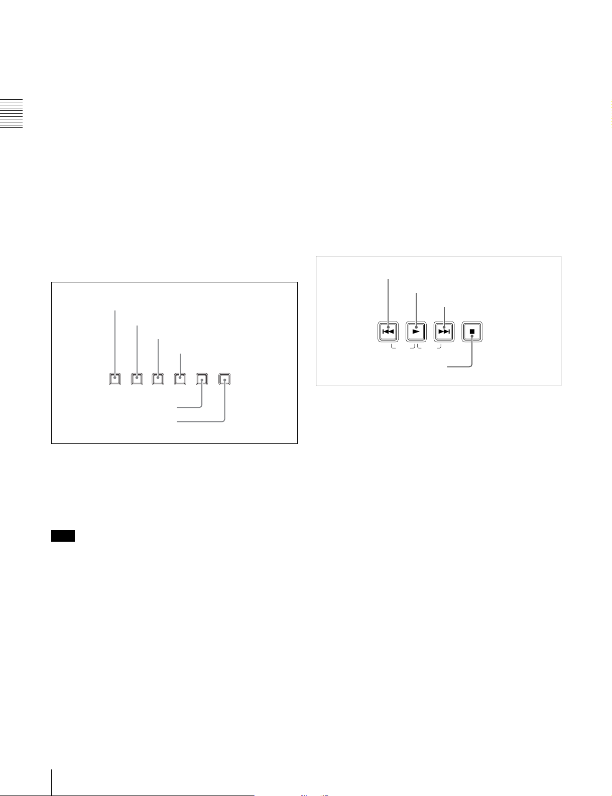
3 Operating mode selection/menu setting
section
1 SUBCLIP button
2 THUMBNAIL button
3 MENU button
4 SET button
1 PREV button
2 PLAY button
3 NEXT button
PREV NEXTPLAY STOP
TOP F REV F FWD END
4 STOP button
5 RESET button
6 SHIFT button
a SUBCLIP button
Press this button, turning it on, to play back following a
clip list. This is also valid for jog and shuttle operations. To
play the clips in the order they are recorded, press this
again, turning it off.
Note
If no clip list is registered, this button does not light when
pressed. The operation is invalid.
b THUMBNAIL button
To carry out a thumbnail search or scene selection, press
this button turning it on. Thumbnail images representing
each clip appear. Press once more to turn the button off,
and return to a whole-screen display.
To display the thumbnails of essence mark frames (frames
with an essence mark attached), hold down the SHIFT
button, and press this button. The essence mark selection
menu appears. Select the desired type of essence mark, and
the corresponding essence mark frames appear in
thumbnails. Press once more, turning the button off, to
return to a whole-screen display.
a PREV (previous) button
Press this, turning it on, to show the first frame of the
current clip. While the first frame of a clip is shown,
pressing this button jumps to the beginning of the previous
clip.
This button is also used together with other buttons for the
following operations.
Reverse direction high-speed search: Hold down the
PLAY button, and press this button. A high-speed
search in the reverse direction is carried out.
Displaying the first frame of the first clip: Hold down
the SHIFT button, and press this button.
b PLAY button
To start playback, press this button, turning it on.
c NEXT button
Press this, turning it on, to show the first frame of the next
clip.
This button is also used together with other buttons for the
following operations.
Forward direction high-speed search: Hold down the
PLAY button, and press this button. A high-speed
search in the forward direction is carried out.
Displaying the last frame of the last clip: Hold down the
SHIFT button, and press this button.
22
2-2 Control Panel
Page 23

d STOP button
To stop playback, press this button, turning it on. The
frame at the stop point appears.
The unit enters standby off mode when you press this
button with the SHIFT button held down. It returns from
standby off mode to the original state when you press this
button again with the SHIFT button held down. (The lit or
unlit status of the STOP button does not change.)
This unit can automatically enter standby mode whenever
a specified time elapses in disc stop mode. For details, see
the description of extended menu item 501 “STILL
TIMER” (page 72).
Chapter 2 Names and Functions of Parts
2-2 Control Panel
23
Page 24
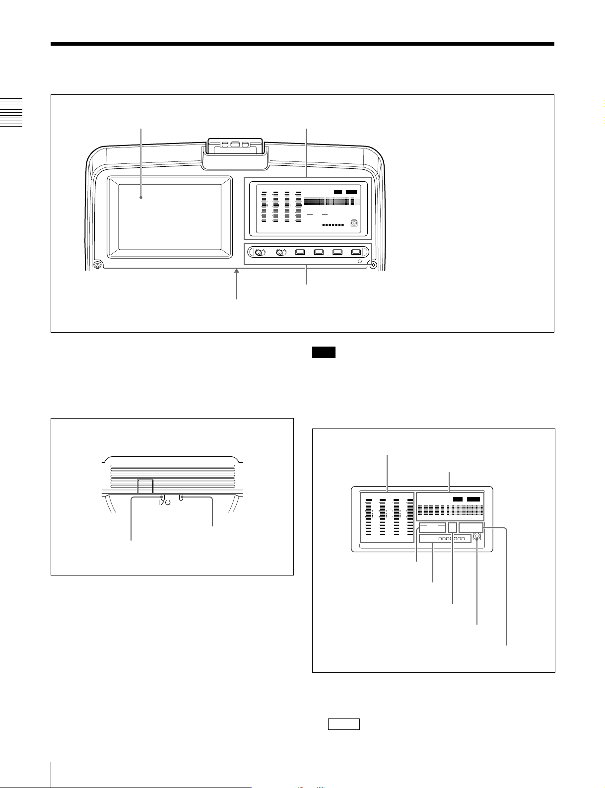
2-3 LCD Panel
1 Image display (color)
1 Status display (monochrome) (see page 24)
Chapter 2 Names and Functions of Parts
DATA
DATA
DATA
OVER
OVER
dB
dB
0
0
-12
-12
-20
-20
-30
-30
-40
-40
-60
-60
CH-
26
CH-
37
DATA
OVER
dB
VITC
COUNTERVIUB VITC ALARM
0
-12
-20
HOURS
MINUTES SECONDS FRAMES
-30
AUDIO 625 IMX 50 4030
-40
48 CH 16 24 BIT
-60
CH-
48 BATT E F
525
DVCAM
[]
OVER
dB
0
-12
-20
-30
-40
-60
CH
- 15
2 Display setting section and WARNING indicator (see page 25)
2 Indicators on the back of the LCD panel
a Image display (color)
In playback and editing operations, this shows the
playback video, clip thumbnail images, and so on.
Note
While the ACCESS indicator is lit, do not turn off the AC
power switch, disconnect the power cord, or remove the
battery. This could lead to a loss of data from the disc.
b Indicators on the back of the LCD panel
There are two indicators, as follows.
1 Status display (monochrome)
ACCESS
ACCESS indicator
"/1 indicator
"/1 (on/standby) indicator: Lights when the on/standby
switch on the control panel is in the on (") position.
ACCESS indicator: Lights when the disc is being
accessed. If the on/standby switch is set to the 1
position while this indicator is lit, access to the disc is
completed before the unit switches to the standby
state.
1 Audio level meters
2 Time data display
DATA
DATA
DATA
OVER
OVER
dB
dB
0
0
-12
-12
-20
-20
-30
-30
-40
-40
-60
-60
26
CH-
37
CH-
DATA
OVER
VITC
HOURS
48 CH 16 24 BIT
48 BATT E F
VITCCOUNTERVIUB ALARM
MINUTES SECONDS FRAMES
AUDIO 625 IMX 50 40 30
525
[]
DVCAM
OVER
dB
dB
0
0
-12
-12
-20
-20
-30
-30
-40
-40
-60
-60
CH
- 15
CH-
3 AUDIO indicators
4 BATT display
5 525/625 indicator
6 Disc loaded mark
7 IMX/DVCAM indicator
a Audio level meters
These show the audio levels for channels 1 to 4 or channels
5 to 8. When the audio level exceeds 0 dB on any channel,
the indicator for that channel lights.
OVER
24
2-3 LCD Panel
Page 25
The DATA indicator lights when non-audio signals are
played back.
b Time data display
Normally, this shows the disc playback time, time code, or
user bit information, as selected by the COUNTER button
in the display setting section and the TC/VITC button.
It is also used for error messages, setup menus, and other
displays.
The following indicators are arranged above the time data
display, in sequence from left to right.
TC/VITC (time code type) indicator: This lights when
TC is selected by the COUNTER button. A time code
appears in the time data display.
When TC is selected by the TC/VITC button, this
appears as “TC,” and when VITC is selected, as
“VITC.”
UB/VIUB (user bit type) indicator: This lights when UB
is selected by the COUNTER button. A user bit value
appears in the time data display.
When TC is selected by the TC/VITC button, this
appears as “UB,” and when VITC is selected, as
“VIUB.”
COUNTER indicator: This lights when COUNTER is
selected by the COUNTER button. The elapsed
playback time (hours, minutes, seconds, frames)
appears in the time data display.
indicator: Regardless of the display on the time
VITC
data display, this lights when VITC is being read
successfully.
ALARM
indicator: This lights when a hardware error is
detected in the PDW-V1, and goes off when the error
is cleared. When this indicator is lit, an error message
appears in the time data display.
c AUDIO indicators
During playback, these show the number of channels
recorded on the disc and the number of quantizing bits.
• Number of channels
4ch: 4 channels
8ch: 8 channels
• Number of quantizing bits
16bit: 16 bits
24bit: 24 bits
d BATT (battery) display
This shows the battery charging state as follows.
xxxxxxx (7 segments lit): Adequately charged. As
the battery discharges, the number of LED segments lit
decreases.
“BATT” flashing: Almost exhausted. Operation of the
PDW-V1 continues.
“BATT” and “E” flashing: Exhausted (charging
required). Operation of the PDW-V1 stops.
e 525/625 (TV system) indicator
This displays the TV system selected in basic menu item
013 “525/625 SYSTEM SELECT.”
525: NTSC, 525 scan lines, field frequency 59.94 Hz
625: PAL, 625 scan lines, field frequency 50 Hz
f Disc loaded mark
This lights while a disc is loaded in the PDW-V1.
It flashes while the disc is being inserted, and while it is
being ejected.
g IMX/DVCAM (playback format) indicator
During playback, this shows the recording format of the
inserted disc.
When a disc is not loaded in the unit, and during FAM and
FTP connections (see page 55), this shows the recording
format set by basic menu item 031 “RECORDING
FORMAT.”
2 Display setting section and WARNING
indicator
1 MONITOR switch
2 LIGHT switch
3 CH1-4/5-8 button
4 TC/VITC button
MONITOR
OFF ON
LIGHT CH1-4/5-8
OFF ON WARNING
5 COUNTER button
6 CHARACTER button
TC/VITC
7 WARNING indicator
a MONITOR switch
Selects whether or not the color monitor display operates.
ON: Operate.
OFF: Do not operate.
The factory default setting is ON.
b LIGHT switch
Selects whether the status monitor backlight is on or off.
ON: On.
OFF: Off.
The factory default setting is ON.
COUNTER
CHARACTER
Chapter 2 Names and Functions of Parts
2-3 LCD Panel
25
Page 26

c CH1-4/5-8 (level display channel selection) button
Selects whether the audio level meters show channels 1 to
4 or channels 5 to 8. Every time you press this button, the
audio level meter channel display changes to reflect the
setting.
The factory default setting is CH1-4.
Chapter 2 Names and Functions of Parts
d TC/VITC (time code display selection) button
When the time data display is set to TC (time code
display), this selects whether to display TC or VITC time
code. The TC or VITC indicator in the time data display
lights to reflect the selection.
The factory default setting is TC.
e COUNTER (time data display selection) button
Switches the data shown in the time data display through
TC, UB, and COUNTER in sequence.
TC: Playback time code read by the internal time code
reader
The selection of TC or VITC is made by the TC/VITC
button.
UB: User bits included in the playback time code
COUNTER: The elapsed playback time (hours, minutes,
seconds, frames). This can be reset by pressing the
RESET button (see page 22).
The corresponding indicator in the time data display lights
to reflect the setting.
The factory default setting is TC.
f CHARACTER button
Selects whether or not to superimpose the time code, menu
settings, alarm messages, or other text information on the
video signals output from the side panel SDI OUT, VIDEO
OUT and MONITOR connectors and also on the unit’s
image display. Every time you press this button, the setting
alternates.
The factory default setting is for superimposing text
information.
g WARNING indicator
This lights when a fault occurs in the PDW-V1.
For details, see 8-2 “Error Messages” (page 87) and 8-3
“Alarms” (page 87).
26
2-3 LCD Panel
Page 27
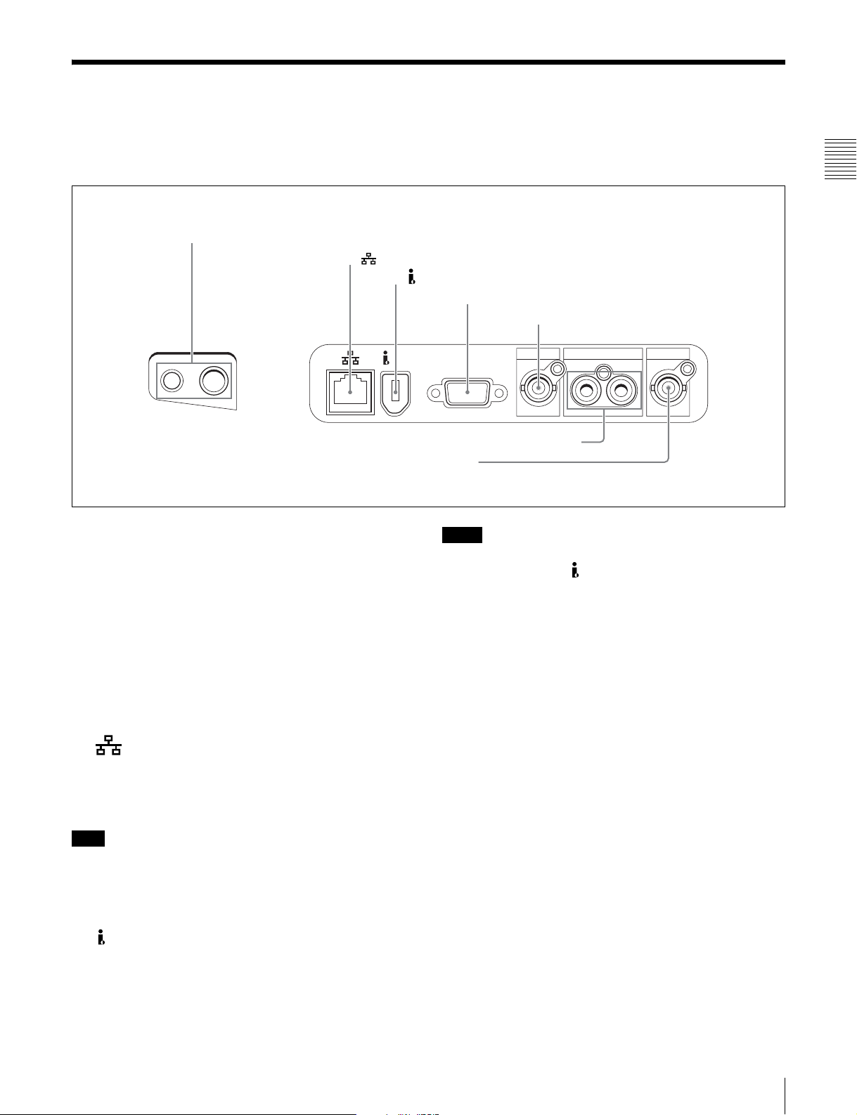
2-4 Connectors
For the locations of the AC power inlet connector on the
left side of the PDW-V1, and the AC power switch on the
rear panel, see the figure on page 19.
1 PHONES jack and LEVEL knob
2 (network) connector
3 S400 (i.LINK) connector
Front Right side
LEVEL PHONES
S400
6 AUDIO MONITOR OUT L/R connectors
7 SDI OUT connector
4 MONITOR connector
5 VIDEO OUT connector
VIDEO OUT
MONITOR
AUDIO MONITOR OUT
LR
SDI OUT
Chapter 2 Names and Functions of Parts
a PHONES jack and LEVEL knob
The jack is a standard stereo jack. Connect stereo
headphones with an impedance of 8 ohms, to monitor the
audio during playback. The channels monitored are
selected by the AUDIO MONITOR buttons.
Non-audio signals are muted.
Adjust the volume with the LEVEL knob. You can also set
this to simultaneously control the output volume from the
AUDIO MONITOR OUT L/R connectors on the side
panel. To do this, in the setup menu, set extended menu
item 114 “AUDIO MONITOR OUTPUT LEVEL” to
“var.”
b (network) connector (RJ-45, 100Base-TX)
To transfer files between an external device and the PDWV1, connect a network cable to this connector and the
external device.
Note
For safety, when connecting external devices to this
connector, do not connect connectors which may have
excessive voltage. Follow the instructions in this manual
when making connections.
c S400 (i.LINK) connector (6-pin, complying with
IEEE1394)
Using the AV/C protocol: Outputs a DVCAM format
digital video/audio signal.
Using FAM protocol: Transfers files to and from
supporting devices.
Notes
• If video or audio signals from an external device
connected with the S400 (i.LINK) connector are not
output, disconnect the i.LINK cable and connect it again,
pushing it straight in.
• When the PDW-V1 is connected to a device with a 6-pin
i.LINK connector by an i.LINK cable, before
unplugging the i.LINK cable, first power off the device
and disconnect the power plug from the outlet. If the
i.LINK cable is unplugged with the device power plug
still connected, a current from an excessive voltage (8 to
40 V) output from the i.LINK connector of the device
flows into the PDW-V1. This may cause a failure of the
PDW-V1.
• When connecting the PDW-V1 to a device with a 6-pin
i.LINK connector, connect to the 6-pin i.LINK
connector of the other device first.
• Except in playback mode (jog and shuttle modes, etc.), if
you are monitoring the audio signal output from this
connector on another device, the audio signal may sound
differently from the audio signal played back on the
PDW-V1.
d MONITOR connector (D-sub 15-pin)
Outputs analog RGB signals. Wnen connecting a PCcompatible display or projector to this connector, set it for
1)
VGA
1) VGA is a registered trademark of International Business Machines
input.
Corporation.
2-4 Connectors
27
Page 28

e VIDEO OUT connector (BNC type)
Outputs an analog composite video signal. The time code,
menu settings, alarm messages, or other text information
can be superimposed on the output video signal. The
setting as to whether or not to superimpose text
information alternates every time you press the
CHARACTER button (see page 26).
Chapter 2 Names and Functions of Parts
f AUDIO MONITOR OUT L/R connectors (pin
jacks)
Output the audio signals for the channels selected with the
AUDIO MONITOR button L and R rows on the control
panel.
Non-audio signals are muted.
g SDI (serial digital interface) OUT connector (BNC
type)
Outputs video/audio signals in D1 format. The time code,
menu settings, alarm messages, or other text information
can be superimposed on the output video signal. The
setting as to whether or not to superimpose text
information alternates every time you press the
CHARACTER button (see page 26).
28
2-4 Connectors
Page 29
Preparations
3-1 Connections and Settings
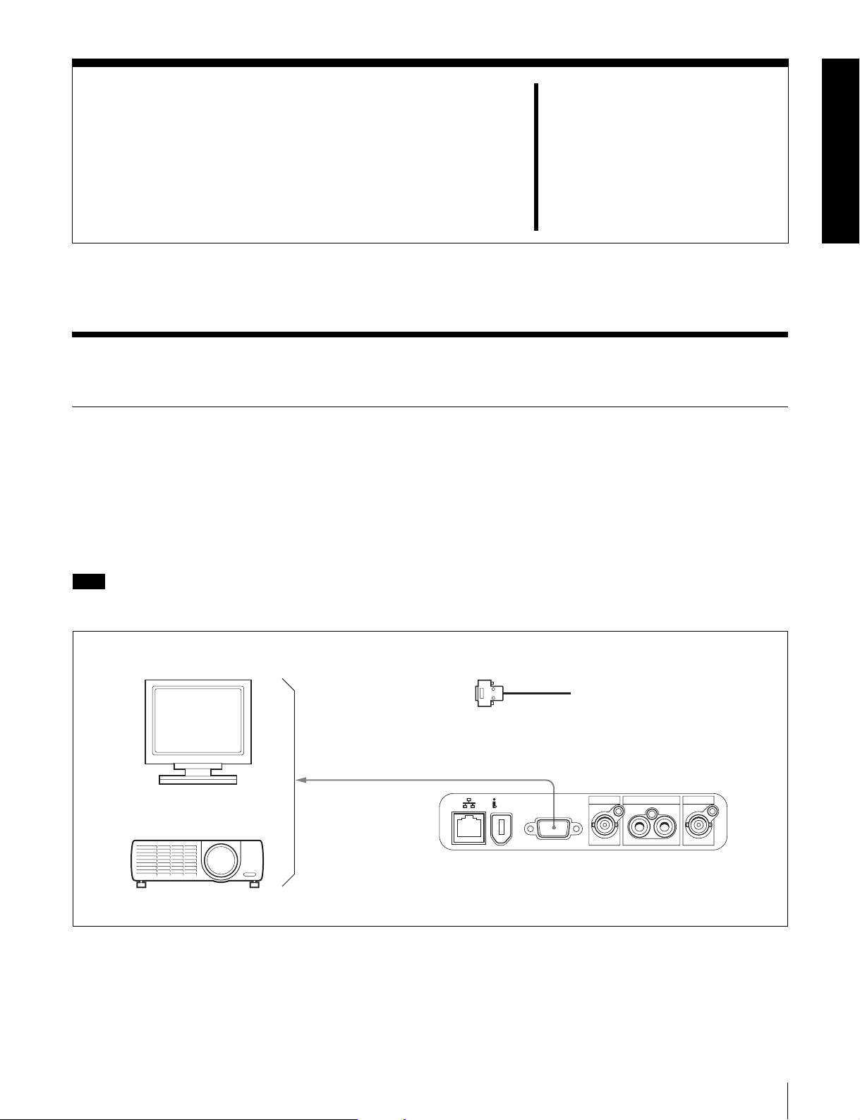
3-1-1 Connecting an External Monitor
Connecting a video monitor to the MONITOR, VIDEO
OUT, or SDI OUT connector of this unit enables you to see
the output video on the monitor screen.
Example connections are shown in the following.
When connecting to the MONITOR connector
Note
Set the PC-compatible display or data projector to which to
connect this unit for VGA input beforehand.
Chapter
3
PC-compatible display
Data projector
RGB input connector
1
1: D-sub 15-pin cable (not supplied)
MONITOR
AUDIO MONITOR OUT
S400
MONITOR
VIDEO OUT
LR
PDW-V1
SDI OUT
3-1 Connections and Settings
29
Page 30
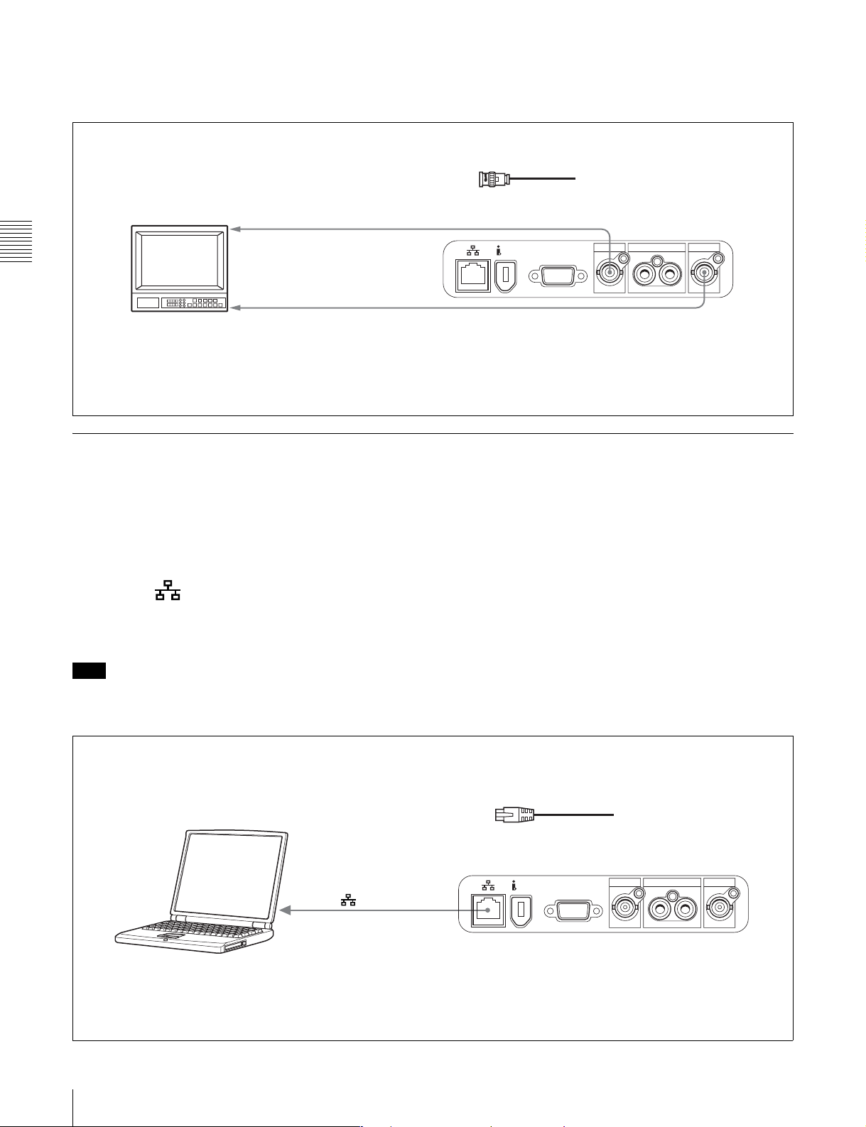
When connecting to the VIDEO OUT or SDI OUT connector
Connect a video monitor as example 1 or 2 shown in the
following figure.
1, 2: 75 Ω coaxial cable (not supplied)
To composite video input connector
1
Chapter 3 Preparations
2
Video monitor
To SDI input connector
To superimpose the time code, menu settings, alarm
messages, or other text information on the video signal,
press the CHARACTER button (see page 26).
S400
VIDEO OUT
MONITOR
AUDIO MONITOR OUT
VIDEO OUT
LR
SDI OUT
PDW-V1
SDI OUT
3-1-2 Connections for Using PDZ-1 Proxy Browsing Software
Using the supplied PDZ-1 Proxy Browsing Software, you
can carry out simple editing with proxy AV data.
For an overview of PDZ-1 and how to install the software,
see 5-4 “Using PDZ-1 Proxy Browsing Software” on page
Using the (network) connector (FTP connection)
The following shows an example of an FTP (File Transfer
Protocol) connection.
54.
For information about how to use the software, refer to the
Help provided in the software.
For details of the network-related settings, see “To
change network settings” (page 82).
Note
To use PDZ-1 requires the PDW-V1 IP address and other
network-related settings to be made beforehand.
Connecting this unit directly to a laptop computer
(network) connector
To network connector
Laptop computer
1
1: Network cable (not supplied)
(Use a crossing cable.)
AUDIO MONITOR OUT
S400
Make sure the remote control switch (see page
20) is set to NETWORK.
MONITOR
VIDEO OUT
LR
PDW-V1
SDI OUT
30
3-1 Connections and Settings
Page 31

Connecting three PDW-V1 units to a laptop computer via a LAN.
(network) connector
Laptop computer
1
To network
LAN
connector
(network) connector
1: Network cable (not supplied)
(Use a straight cable.)
S400
MONITOR
1
S400
MONITOR
1
1
(network) connector
S400
MONITOR
AUDIO MONITOR OUT
VIDEO OUT
LR
AUDIO MONITOR OUT
VIDEO OUT
LR
AUDIO MONITOR OUT
VIDEO OUT
LR
SDI OUT
PDW-V1
SDI OUT
PDW-V1
SDI OUT
PDW-V1
Chapter 3 Preparations
Make sure the remote control switch (see page 20) is set
to NETWORK on each of the three PDW-V1 units.
Using the S400 (i.LINK) connector (FAM connection)
The following shows an example of a FAM (file access
mode) connection.
Note
The PDZ-1 Proxy Browsing Software must be installed in
advance.
The required FAM driver is also installed when you install
the PDZ-1 software.
See 5-4 “Using PDZ-1 Proxy Browsing Software” (page
54) for more information about installing the PDZ-1
software.
Some limitations apply to FAM connections. For details,
see 6-2 “File Access Mode File Operations” (page 58).
3-1 Connections and Settings
31
Page 32

1: i.LINK cable (not supplied)
PDW-V1
AUDIO MONITOR OUT
To i.LINK (IEEE1394)
connector
Chapter 3 Preparations
Laptop computer
1
S400 (i.LINK)
Make sure extended menu item 215 “PC REMOTE” is
set to “ena.”
S400
MONITOR
VIDEO OUT
LR
SDI OUT
3-1-3 Connecting to a Nonlinear Editing System
You can send video/audio signals (AV/C data) from this
unit to a nonlinear editing system connected to the S400
(i.LINK) connector.
The following figure shows an example connection.
Notes
• The S400 (i.LINK) connector of this unit outputs
video/audio signals in DVCAM format. Data recorded in
MPEG IMX format is output after being converted into
DVCAM format.
• The nonlinear editing system to be used being connected
to this unit requires editing software (not supplied)
supporting DVCAM format.
To i.LINK(IEEE1394)
connector
S400 (i.LINK)
• Make the following settings before transferring video/
audio signals (AV/C data) from this unit to a nonlinear
editing system.
Audio mode selection
Use extended menu item 831 “DV OUT AUDIO
MODE” to select either of the following.
2ch: 48 kHz/16 bits/2 channels (Factory default setting)
4ch: 32 kHz/12 bits/4 channels
Audio output channel selection
Select the audio output channels with extended menu
item 828 “SDI/DV AUDIO OUTPUT SELECT.”
For information about how to make extended menu item
settings, see 7-3-2 “Extended Menu Operatoins” on
page 75.
1: i.LINK cable (not supplied)
AUDIO MONITOR OUT
VIDEO OUT
LR
1
S400
MONITOR
PDW-V1
SDI OUT
Laptop computer
(With editing software supporting
DVCAM format installed)
For the method of transferring video/audio signals (AV/C
data) to a nonlinear editing system, refer to the manual
provided with the editing software to be used.
32
3-1 Connections and Settings
Page 33

3-2Power Preparations
3-3Setup
This unit can be powered by a battery pack or AC power.
3-2-1 Using AC Power
Connect an AC power source (100 V to 240 V AC, 50/60
Hz) to the AC power inlet connector on the left side of the
unit with a power cord (not supplied, see page 95).
3-2-2 Using a Battery Pack
Usable battery packs
The battery packs usable with this unit are as follows.
BP-L60S, BP-GL65, BP-GL95, BP-M100
To attach a battery pack
Proceed as follows.
1
Remove the cover of the battery pack shoe.
2
1
The principal setup operations before operating this unit
can be carried out using setup menus.
The setup menus of this unit comprise a basic setup menu
and an extended setup menu. The contents of these menus
are as follows.
Basic setup menu:
• Items relating to the hours meter
• Items relating to operation
• Items relating to menu banks
Extended setup menu:
• Items relating to control panels
• Items relating to the remote control interface
• Items relating to editing operations
• Items relating to preroll
• Items relating to disc protection
• Items relating to the time code reader, metadata, and
UMID
• Items relating to video control
• Items relating to audio control
• Items relating to digital processing
For detailed information about the items, except for the
basic menu items relating to the hours meter, of these
menus and how to use them, see Chapter 7 “Menus.”
For detailed information about menu operations relating
to the hours meter, see 8-1-1 “Digital Hours Meter” (page
86).
Chapter 3 Preparations
2
Fit the battery pack.
To remove the battery pack.
Follow the above procedure in the reverse flow. After the
battery pack is removed, replace the cover of the battery
pack shoe.
This unit allows three different sets of menu settings to be
saved in what are termed “menu banks” numbered 1 to 3.
Saved sets of menu settings can be recalled for use as
required.
For more information about the menu banks, see “Menu
bank operations (menu items B01 to B13)” (page 71).
3-2 Power Preparations / 3-3 Setup
33
Page 34

3-4Setting the Date and
3-5Superimposed Text
Time
When using this unit for the first time, you should set the
date and time as follows.
The time code, menu settings, alarm messages, or other
text information can be superimposed on the video signal
Information
output from the VIDEO OUT connector or SDI OUT
connector. The setting as to whether or not to superimpose
1
text infomration alternates every time you press the
CHARACTER button (see page 26).
MARK1
MARK2
SHUTTLE JOG
OUT
Adjusting the text display
You can adjust the position, size and type of the
superimposed text using basic menu items 002, 003, 005,
009, 011, and 012.
Chapter 3 Preparations
L
R
ACCESS
NETWORK
LOCAL
REMOTE
PREV NEXTPLAY STOP
TOP F REV F FWD END
AUDIO MONITOR
CH-1 CH-2 CH-3 CH-4 CH-5 CH-6 CH-7 CH-8
THUMBNAIL
MENU
SYSTEM
MENU
S.SEL
SET
RESET SHIFT
IN
SUBCLIP
MENU
CLIP
ESSENCE
MARK
For details, see 7-2-2 “Basic Menu Operations” (page
32,34
1
Holding down the SHIFT button, press the MENU
69).
Information displayed
button.
1Type of time data
The system menu appears on the monitor screen.
2Time code reader drop frame
2
Select “DATE/TIME PRESET” using the F button or
mark (for 525-line mode only)
f button, then press the g button.
The date and time setting screen appears on the
Time data
3VITC field mark
monitor, allowing you to set the following items.
• YEAR: Calendar year
• MONTH: Month
• DAY: Day
• TIME: Time
• TIME ZONE: Time zone (Difference from UTC)
TCR 00:04.47.07*
PLAY LOCK
5 Playback
condition mark
3
Set the date, time and time zone.
You can change the setting of the flashing digits.
To change the flashing digits
Use the arrow buttons (G, g).
To increase or decrease the values of the flashing
digits
Use the arrow buttons (F, f) or jog dial.
4
Press the SET button.
The date, time and time zone settings are stored.
To return to the previous menu page
Press the MENU button.
To exit the menu
Press the MENU button twice in succession.
34
3-4 Setting the Date and Time / 3-5 Superimposed Text Information
4Operation mode
a Type of time data
Display Meaning
CNT Counter data
TCR TC reader time code data
UBR TC reader user bits data
IN IN point time data
OUT OUT point time data
DUR Duration between IN point and OUT
point
Page 35

Note
If the time data or user's bits cannot be read correctly, they
will be displayed with an asterisk. For example, “T*R” or
“U*R.”
b Time code reader drop frame mark (for 525-line
mode only)
“.”: Indicates drop frame mode
“:”: Indicates non-drop-frame mode
c VITC field mark
“ ” (blank): Odd fields
“ * ”: Even fields
d Operation mode
Display Operation mode
DISC OUT Disc is not loaded.
LOADING Disc is being loaded.
UNLOADING Disc is being unloaded.
STANDBY OFF Standby off mode
STOP Stop mode
NEXT Cuing up to the first frame of the
next clip.
PREV Cuing up to the first frame of the
current clip.
F.FWD Fast forward search
F.REV Fast reverse search
PLAY Playback mode (servo unlocked)
PLAY LOCK Playback mode (servo locked)
JOG STILL A still picture in jog mode
JOG FWD Jog mode in forward direction
JOG REV Jog mode in reverse direction
SHUTTLE STILL A still picture in shuttle mode
SHUTTLE (Speed) Shuttle mode
TOP 0001/xxxx Cuing up to the first frame of the
first clip.
END xxxx/xxxx Cuing up to the last frame of the
last clip.
PREROLL Cuing up during thumbnail search
e Playback condition mark
One of three channel condition marks is displayed when
the ACCESS indicator is lit. The three channel condition
marks indicate the following three stages.
Display Name Description
Green condition There is no problem with the
playback condition. This unit
and the disc can be used
just as they are. This
corresponds to the “green”
channel condition indicator
of a VTR.
Display Name Description
Yellow condition The playback condition has
deteriorated to some
degree. There are no read
errors, but you should take
the action described in the
next section. This
corresponds to the “yellow”
channel condition indicator
of a VTR.
Red condition The playback condition has
deteriorated. There are no
read errors,
take the action described in
the next section. This
corresponds to the “red”
channel condition indicator
of a VTR.
a) Read errors will occur if the playback condition continues to deteriorate.
If a read error occurs, a “Disc Error!” alarm appears in the time data
display, the picture freezes, and audio is muted.
a)
but you should
To display playback condition marks, set basic menu item
012 “CONDITION DISPLAY ON VIDEO MONITOR”
to “ena,” and set basic menu item 005 “DISPLAY
INFORMATION SELECT” to “T&sta.”
For details about operation, see 7-2-2 “Basic Menu
Operations” (page 69).
Playback condition displays
You can be alerted in advance to deteriorating playback
conditions and to error correction rates which are
approaching their limits.
Deteriorating playback may be due to the following
causes.
• Scratches and dust on the disc surface
This includes fingerprints, dust from the air, tar from
cigarette smoke, and so on.
Scratches and soiling which occur before recording are
not a problem because they are registered in advance as
defects, and recording avoids them. However, scratches
and soiling which occur after recording can lead to
deteriorating playback conditions.
• Aging of disc recording layers
Over several decades, the recording layers of optical
discs can age and cause deteriorating playback
conditions.
You can use this function to check archival discs and
other discs which have been stored for extended periods,
so that you can take action before the deterioration
progresses further.
• Deteriorating laser diodes performance
The performance of the laser diodes used in optical
heads can worsen with age, leading to deteriorating
playback conditions.
You can use the digital clock to check the total optical
output time of optical heads.
Chapter 3 Preparations
3-5 Superimposed Text Information
35
Page 36

For details, see 8-1-1 “Digital Hours Meter” (page 86)
about this setting.
Refer to the Maintenance Manual for an approximate
guide to when it is time to replace optical heads.
3-6Handling Discs
3-6-1 Discs Used for Playback
To prevent playback conditions from
deteriorating
Pay attention to the following points when handling discs.
• Do not open disc cartridges and touch discs directly with
your hands.
• Do not store for long periods in locations which are
Chapter 3 Preparations
dusty or exposed to air circulated by fans.
• Do not store for long periods under high temperatures or
in locations exposed to direct sunlight.
If playback conditions have deteriorated
If a yellow or red playback condition mark appears, check
the following points.
Whether the disc displays the same playback condition
on other XDCAM devices: If so, the surface of the
disc may be dirty or scratched, or the performance of
the recording layers on the disc may have worsened
due to age. Do not use discs with these symptoms.
Whether every disc inserted into an XDCAM device
displays the same playback conditions: If so, the
performance of the laser diodes may have deteriorated.
Check the total optical output time.
This unit uses the following disc for playback: PFD23
Professional Disc
1) Professional Disc is a trademark of Sony Corporation.
Note
It is not possible to use the following discs with this unit:
• Blu-ray Disc
• Professional Disc for Data
1)
(capacity 23.3 GB)
3-6-2 Notes on Handling
Handling
The Professional Disc is housed in a cartridge, and is
designed to allow handling free of risk from dust or
fingerprints. However, if the cartridge is subjected to a
severe shock, for example by dropping it, this can result in
damage or scratching of the disc. If the disc is scratched, it
may be impossible to record video/audio, or to play back
the content recorded on the disc. The discs should be
handled and stored carefully.
• Do not touch the surface of the disc itself within the
cartridge.
• Deliberately opening the shutter may cause damage.
• Do not disassemble the cartridge.
• The supplied adhesive labels are recommended for
indexing discs. Apply the label in the correct position.
Storage
• Do not store discs where they may be subjected to direct
sunlight, or in other places where the temperature or
humidity is high.
• Do not leave cartridges where dust may be able to gain
ingress.
• Store cartridges in their cases.
Care of the discs
• Remove dust and dirt on the outside of a cartridge using
a soft dry cloth.
• If condensation forms, allow ample time to dry before
use.
3-6-3 Write-Protecting Discs
To protect the content recorded on the disc from accidental
erasure, move the write-protect tab on the lower surface of
the disc in the direction of the arrow, as shown in the
following figure.
36
3-6 Handling Discs
Page 37

3-6-5 Formatting a Disc
Lower surface of the disc
Write-protect tab
E
V
A
S
Slide in the direction of the arrow
Write-protect tab settings
SAVE SAVE
Recording enabled Recording disabled
3-6-4 Loading and Unloading a Disc
When the on/standby switch indicator is lit green, you can
load and unload a disc as shown in the following figure.
An unused disc requires no formatting operation. The disc
is automatically formatted when loaded into this unit.
To format a recorded disc, load the disc into the unit, then
do as follows.
Note
When a recorded disc is formatted, all the data on the disc
is erased.
11,6
AUDIO MONITOR
L
CH-1 CH-2 CH-3 CH-4 CH-5 CH-6 CH-7 CH-8
R
ACCESS
NETWORK
LOCAL
REMOTE
THUMBNAIL
MENU
SUBCLIP
CLIP
SYSTEM
ESSENCE
MENU
MENU
PREV NEXTPLAY STOP
TOP F REV F FWD END
MARK
S.SEL
SET
RESET SHIFT
IN
SHUTTLE JOG
MARK1
OUT
MARK2
2,3,45
1
Holding down the SHIFT button, press the MENU
button.
Chapter 3 Preparations
On/standby switch and
indicator
To unload
Press the EJECT button.
To load
Insert a disc face up.
The disc is drawn in.
When a disc is loaded, the disc loaded mark (see page
25) lights. It flashes while the disc is being inserted, and
while it is being ejected.
If message “HUMID!” appears in the time data
display
There is moisture condensation in the unit.
For the steps to take when the message appears, see 8-4
“Condensation” on page 93.
The system menu appears on the monitor screen.
2
Select “DISC MENU” using the F button or f button,
then press the g button.
The menu item “FORMAT” is displayed.
3
Select “FORMAT” using the F button or f button,
then press the g button.
The menu item “QUICK FORMAT” is selected.
4
Press the g button.
The message “QUICK FORMAT OK?” appears.
To return to the previous menu page without
formatting the disc
Press the RESET button.
5
Press the SET button.
Formatting is completed and the message “FORMAT
COMPLETED.” appears.
6
Press the MENU button.
This exits the menu.
3-6 Handling Discs
37
Page 38

3-6-6 To Eject Discs With the Unit
Powered Off
When battery power is low and at other times, it may not
be possible to eject discs by pressing the EJECT button. In
these situations, you can use the following as an
emergency procedure to eject a disc manually.
1
Power the unit off.
Notes
• This function salvages as much recorded material as
possible after an unforeseen accident, but 100%
restoration cannot be guaranteed.
• Even when this function is used, it is not possible to
recover data from immediately before the interruption of
recording. (From 4 to 6 seconds of data before the
interruption of recording are lost.)
Full salvage
2
Insert a Phillips screwdriver into the slit, as shown in
Chapter 3 Preparations
the following illustration, and rotate the red screw in
the counterclockwise direction.
Note
Use a screwdriver that fits into the slit. The width of
the slit is approximately 2.5 mm.
When a disc that was manually ejected from a device
subjected to a recording interruption due to power off is
loaded into this unit, clips are reconstructed on the basis of
markers recorded on the disc. Processing time is about 30
seconds, although it depends on the state of the disc.
Proceed as follows to perform a full salvage.
1
Insert the disc on which recording did not end
normally.
The message “Salvage ?” appears.
2
Do one of the following.
The disc is ejected.
After removing the disc, you do not need to return the
screw to its original position. Normal operation will
resume when the unit is powered on again.
3-6-7 Using the Salvage Function
To salvage
Press the SET button.
Processing begins and the message “Executing.”
appears.
Notes
• If a write protected disc is loaded, the message
“EJECT?” appears. Eject the disc, set the writeprotect tab to the recording enable position, and
insert the disc again.
• This operation cannot be cancelled once it begins.
A message appears to display the results when
processing finishes. If the message reads
“Incomplete!,” the clips that failed were lost.
To exit without salvaging
Press the RESET button.
The state of section where recording was interrupted is
saved, but no salvage processing is done.
Sections which were recorded normally can be played
back, but no new recording can be done on the disc. (A
quick format can be done on the disc, although all of
its contents will be lost.)
When XDCAM recording does not end normally, the file
system is not updated, video and audio data recorded in
real time is not recognized as files, and clip contents
recorded up to that point are lost.
However, this unit has a salvage function which can hold
losses to the minimum by reconstructing clips on such
discs.
38
3-6 Handling Discs
Note
Unless clips are salvaged, the message “Salvage ?”
appears again the next time the disc is inserted or the
unit is powered on.
Page 39

Playback
4-1 Preparations for Playback
Chapter
4
Button/Switch Settings
Before beginning playback, make any necessary button/
switch settings.
AC power switch (rear panel): Press " to power on.
When using a battery pack, fit the battery pack to the battery pack shoe
beforehand. (See page 33.)
AUDIO MONITOR buttons:
Select the audio channel to
monitor. (See page 20.)
On/standby switch: Set
the switch to the "
position, turning the
indicator on. (See page
20.)
For details of the settings of the buttons/switches, see the
pages indicated in parenthesis.
TC/VITC button: Select TC or
VITC to display the time code
recorded on the disk in the
time data display. (See page
26.)
COUNTER button: Select the
data to be displayed in the
time data display. (See page
26.)
Remote control switch
(see page 20): Local
4-1 Preparations for Playback
39
Page 40

4-2Playback Operation
F/MARK1 button and f/MARK2 button
Jog dial
Disc playback start position
Although this unit uses optical discs, it is designed to offer
the most convenient features of tape playback by VTRs.
One of these is the playback start position, which works in
the same way as tape, as described below.
AUDIO MONITOR
L
CH-1 CH-2 CH-3 CH-4 CH-5 CH-6 CH-7 CH-8
R
ACCESS
THUMBNAIL
MENU
SUBCLIP
NETWORK
LOCAL
REMOTE
CLIP
SYSTEM
ESSENCE
MENU
MENU
PREV NEXTPLAY STOP
TOP F REV F FWD END
MARK
S.SEL
SET
RESET SHIFT
IN
SHUTTLE JOG
MARK1
OUT
MARK2
After playback stop
The unit stops at the position where the STOP button was
pressed.
Press the PLAY button to resume playback at the stop
position.
Chapter 4 Playback
After disc insertion
The unit stops at the position of the disc when it was most
recently ejected.
Press the PLAY button to resume playback at the most
recent position.
The playback position is saved to the disc when the disc is
ejected, which allows playback to start at that position
To start playback
Press the PLAY button.
Playback starts.
When two or more clips are recorded on the disc, they are
played back continuously.
PLAY button
PREV button
STOP button
NEXT button
Shuttle dial
whenever it is loaded into any XDCAM player.
Note
This function is not available when the write-protect tab of
Note
No audio is output when non-audio signals are played
back.
the disc is set to the recording disabled position.
To jump to the next or previous clip, then start
This section describes the following types of playback:
• Normal playback
Playback at normal (±1) speed
playback
Use the PREV button, NEXT button, jog dial, or shuttle
dial.
• Playback in jog mode
Variable speed playback, with the speed determined by
the speed of turning the jog dial
• Playback in shuttle mode
Variable speed playback, with the speed determined by
For information about the functions of these buttons, see
“4 Playback controls” on page 22.
For details of the jog and shuttle dials, see “1 Jog/shuttle
control block” on page 21.
the angular position of the shuttle dial
To stop playback
Normal playback
First insert a disc.
Press the STOP button.
If you play back to the end of the last clip
Playback automatically stops.
For details of how to insert a disc, see 3-6-4 “Loading and
Unloading a Disc” on page 37.
If, in this state, you press the PLAY button, the message
“ALARM DISC END.” appears on the monitor.
To carry out playback again, move back to the desired clip
using the PREV button, jog dial or shuttle dial.
40
4-2 Playback Operation
To record an essence mark
While playing back a disc, you can record essence marks
such as shot mark 1 and shot mark 2 in desired frames.
To record a shot mark 1 or shot mark 2, hold down the F/
MARK1 or f/MARK2 button and press the SET button.
Page 41

Note
To erase or change essence marks, use the supplied PDZ1 Proxy Browsing Software.
1
Playback in jog mode
In jog mode, you can control the speed of playback by the
speed of turning the jog dial. The playback speed range is
±1 times normal speed.
To carry out playback in jog mode, do as follows.
1
L
R
ACCESS
NETWORK
LOCAL
REMOTE
PREV NEXTPLAY STOP
TOP F REV F FWD END
AUDIO MONITOR
CH-1 CH-2 CH-3 CH-4 CH-5 CH-6 CH-7 CH-8
THUMBNAIL
MENU
SUBCLIP
CLIP
SYSTEM
ESSENCE
MENU
MENU
MARK
S.SEL
SET
RESET SHIFT
IN
SHUTTLE JOG
MARK1
OUT
MARK2
2,3
1
Press the JOG button, turning it on.
2
Turn the jog dial in the desired direction, at the speed
corresponding to the desired playback speed.
Playback in jog mode starts.
3
To stop playback in jog mode, stop turning the jog dial.
When extended menu item 101 “SELECTION FOR
SEARCH DIAL ENABLE” is set to “dial” (factory default
setting), just turning the jog dial with the JOG button off
starts playback in jog mode.
AUDIO MONITOR
L
CH-1 CH-2 CH-3 CH-4 CH-5 CH-6 CH-7 CH-8
R
ACCESS
NETWORK
LOCAL
REMOTE
THUMBNAIL
MENU
SUBCLIP
CLIP
SYSTEM
ESSENCE
MENU
MENU
PREV NEXTPLAY STOP
TOP F REV F FWD END
MARK
S.SEL
SET
RESET SHIFT
IN
SHUTTLE JOG
MARK1
OUT
MARK2
2,33
1
Press the SHUTTLE button, turning it on.
2
Turn the shuttle dial to the desired angle
corresponding to the desired playback speed.
Playback in shuttle mode starts.
3
To stop playback in shuttle mode, return the shuttle
dial to the center position, or press the STOP button.
When extended menu item 101 “SELECTION FOR
SEARCH DIAL ENABLE” is set to “dial” (factory default
setting), just turning the shuttle dial with the SHUTTLE
button off starts playback in shuttle mode.
To alternate between normal-speed playback and
shuttle mode playback
Set the shuttle dial to the position corresponding to the
desired shuttle playback speed, then switch between
normal-speed playback and shuttle playback by pressing
the PLAY and SHUTTLE buttons alternately.
For intermittent shuttle mode playback, press the STOP
and SHUTTLE buttons alternately.
Chapter 4 Playback
Playback in shuttle mode
In shuttle mode, you can control the speed of playback by
the angular position of the shuttle dial. The range of
playback speed is ±20 times normal speed.
To carry out playback in shuttle mode, do as follows.
4-2 Playback Operation
41
Page 42

4-3Thumbnail Search
Title of currently
selected clip
Sixth clip is selected
from a total of 143 clips.
4-3-1 Cuing Up a Desired Clip
Thumbnail of currently selected clip
(first frame or specified
1)
frame)
To display the thumbnail images of all clips on the disc,
and cue up a desired clip, proceed as follows.
DATA
DATA
DATA
DATA
OVER
OVER
OVER
OVER
dB
dB
dB
dB
VITC
0
-12
-20
-30
-40
-60
CH-
26
0
0
-12
-12
-20
-20
-30
-30
-40
-40
-60
-60
CH-
37
CH-
48 BATT E F
COUNTERVIUB VITC ALARM
HOURS
MINUTES SECONDS FRAMES
AUDIO 625 IMX 504030
48CH 1624BIT
525
[]
DVCAM
0
-12
-20
-30
-40
-60
CH
- 15
Chapter 4 Playback
SUBCLIP button
ACCESS
NETWORK
LOCAL
REMOTE
1
AUDIO MONITOR
L
CH-2 CH-3 CH-4 CH-5 CH-6 CH-7 CH-8
CH-1
R
SUB
CLIP
THUMBNAIL
MENU
CLIP
SYSTEM
ESSENCE
MENU
MENU
PREV NEXTPLAY STOP
TOP F REV F FWD END
MARK
RESET SHIFT
SET
S.SEL
IN
3 2
COUNTER button
SHUTTLE JOG
L
R
MARK1
OUT
MARK2
Recording date and
time of selected clip
Duration of selected clip
or timecode of first frame
1) The thumbnail frame can be specified by setting of a disc recorder.
To switch between duration and timecode display
in the thumbnail display
Press the COUNTER button. Each press of the button
toggles between duration display and timecode
1
With the SUBCLIP button off, press the
THUMBNAIL button, turning it on.
The thumbnails of all clips on the disc appear.
display.
To escape from the thumbnail display to the fullscreen display
Press the THUMBNAIL button, turning it off.
42
4-3 Thumbnail Search
2
Use the arrow buttons or the jog dial to select the
desired clip.
You can select clips with the following operations.
Press the PREV or NEXT button: Move to the
previous or next clip.
Press the PREV or NEXT button with the SHIFT
button held down: Move to the first or last clip.
Press the f or F button with the SHIFT button held
down: Switch to the previous or next page.
3
To cue up the selected clip, press the SET button.
To start playback from the selected clip, press the
PLAY button.
Page 43

4-3-2 Cuing Up a Frame Including an
Essence Mark
Proceed as follows.
RESET button
1
This indicates that the
thumbnail images are the
frames including the essence
mark (SHOTMARK1).
Sixth frame is selected
from a total of 31
SHOTMARK1 frames
L
R
ACCESS
NETWORK
LOCAL
REMOTE
PREV NEXTPLAY STOP
TOP F REV F FWD END
AUDIO MONITOR
CH-1 CH-2 CH-3 CH-4 CH-5 CH-6 CH-7 CH-8
THUMBNAIL
MENU
SUBCLIP
CLIP
SYSTEM
ESSENCE
MENU
MENU
MARK
S.SEL
SET
RESET SHIFT
IN
SHUTTLE JOG
MARK1
OUT
MARK2
2,43,5 45
1
Hold down the SHIFT button, and press the
THUMBNAIL button, turning it on.
The essence mark selection screen appears.
Currently selected
SHOTMARK1 frame
Date and time of recording
of the clip containing the
selected frame
4
Use the arrow buttons or jog dial to select the desired
frame.
You can select frames with the following operations.
Press the PREV or NEXT button: Move to the
previous or next frame.
Press the PREV or NEXT button with the SHIFT
button held down: Move to the first or last frame.
Press the F or f button with the SHIFT button held
down: Switch to the previous or next page.
Chapter 4 Playback
To escape from the essence mark selection screen to
the previous screen
Press the RESET button.
2
Use the arrow buttons to select the desired essence
mark.
You can select essence marks with the following
operations.
Press the PREV or NEXT button: Move to the
previous or next essence mark.
3
Press the SET button.
Thumbnails of the frames including the selected
essence mark appear.
(The example shows the case where SHOT MARK1 is
selected as the essence mark.)
5
Press the SET button to cue up the selected clip.
To start playback from the selected frame, press the
PLAY button.
4-3 Thumbnail Search
43
Page 44

4-4Clip List Playback
Title of current clip list
Sixth frame is selected
from a total of 34 sub clips
You can play back clips in the order of clip lists created
with the scene selection function (see page 45).
Total duration of sub clips in clip list
4-4-1 Playing Back in Clip List Order
Proceed as follows.
1
If the clip list that you want to play exists on the disc,
load it into the current clip list.
About the current clip list, see page 45.
Chapter 4 Playback
For the clip list loading operation, see 5-3-3 “Loading
a Clip List From Disc Into the Current Clip List”
(page 52).
2
Press the SUBCLIP button, turning it on.
3
Press the PLAY button.
Playback begins from the first sub clip in the current
clip list.
Note
Depending on the length of sub clips in the clip list and
their arrangement on the disc, playback may freeze
momentarily between sub clips.
4-4-2 Cuing Up With Sub Clip
Thumbnails
With the desired clip list loaded in the current clip list,
proceed as follows.
1
Press the SUBCLIP button and the THUMBNAIL
button, turning them on.
Currently selected sub clip
Recording date and time of
selected sub clip
To escape from the thumbnail display to the fullscreen display
Press the THUMBNAIL button, turning it off.
2
Use the arrow buttons or the jog dial to select the sub
clip you want to cue up.
You can select sub clips with the following operations.
Press the PREV or NEXT button: Move to the
previous or next sub clip.
Press the PREV or NEXT button with the SHIFT
button held down: Move to the first or last sub
clip.
Press the F or f button with the SHIFT button held
down: Switch to the previous or next page.
Duration of selected sub clip
44
4-4 Clip List Playback
Thumbnails of the first frames in the sub clips appear.
3
To cue up the selected sub clip, press the SET button.
To start playback from the selected sub clip, press the
PLAY button.
Page 45

Scene Selection
Chapter
5
5-1Overview
Clip lists and sub clips
Scene selection is a function which allows you to save,
load, and edit clip lists consisting of clips recorded on disc,
or parts of clips, arranged in any order. Clips or parts of
clips which have been inserted into clip lists are called sub
clips.
Clips recorded on disc
Clip 1
Clip list example
Clip 2
Sub clip 1 Sub clip 2 Sub clip 3
Clip lists on disc and the current clip list
Up to 99 clip lists can be saved on disc. These clip lists can
be loaded, one at a time, into the unit’s memory for
playback and editing. Newly created clip lists are also
saved in the unit’s memory.
This manual refers to the clip list which is currently loaded
into the unit’s memory as the “current clip list.”
Clip 2
Part of clip 4
Clip 3
Part of
clip 3
Clip 4
Unit’s memory
Current clip list
Can be edited (adding and
deleting, rearranging sub
clips)
SAVE mM LOAD
Disc
E0001 (Clip list 1)
E0002 (Clip list 2)
E0003 (Clip list 3)
:
:
E0099 (Clip list 99)
The current clip list is always the target of sub clip creation
and editing.
Notes
• Data in the unit’s memory is lost when a disc is ejected
or the unit is powered off. After creating or editing the
current clip list, be sure to save it to disc.
• The current clip list cannot be saved to disc when the
disc’s write-protect tab is set to the recording disabled
position.
cClip list playback
and thumbnail
display
5-1 Overview
45
Page 46

Chapter 5 Scene Selection
5-2Basic Operations
5-2-1 Creating Clip Lists
You can create a clip list by either of the following two
methods.
• Selecting a desired clip from the thumbnail display, and
including it in the clip list as a sub clip.
• Creating any sub clip from a full-screen display clip, and
including it in the clip list.
Note
Up to 99 clip lists can be handled in the CLIP menu.
Including a clip selected from the
thumbnail display in the clip list
To select the desired clip from the clip thumbnail display
and include it in the clip list, proceed as follows.
2
Use the arrow buttons or the jog dial to select the clip
you want to include in the clip list.
You can select clips with the following operations.
Press the PREV or NEXT button: Move to the
previous or next clip.
Press the PREV or NEXT button with the SHIFT
button held down: Move to the first or last clip.
Press the F or f button with the SHIFT button held
down: Switch to the previous or next page.
3
Hold down the SHIFT button, and press the SET
button.
The scene selection window appears.
AUDIO MONITOR
MENU
SYSTEM
MENU
3
S.SEL
RESET button
L
R
RESET SHIFT
SET
MARK1
IN
MARK2
SHUTTLE JOG
OUT
SUBCLIP button
ACCESS
NETWORK
LOCAL
REMOTE
PREV NEXTPLAY STOP
TOP F REV F FWD END
1
L
CH-1
CH-2 CH-3 CH-4 CH-5 CH-6 CH-7 CH-8
R
SUB
CLIP
THUMBNAIL
CLIP
ESSENCE
MENU
MARK
4 2
1
With the SUBCLIP button off, press the
THUMBNAIL button, turning it on.
The thumbnails of the clips on the disc appear.
To escape from the scene selection window to the
previous screen
Press the RESET button.
4
Press the SET button.
This adds the selected clip to the clip list as a sub clip.
At the same time, this closes the scene selection
window and returns to the original thumbnail display.
5
Repeat steps 2 to 4 until all desired clips have been
added to the clip list.
The scene selection window shows the thumbnails of
the sub clips that have already been included in the clip
list. The cursor within the window indicates the
position in which the next sub clip will be included.
46
5-2 Basic Operations
Page 47

Total duration of the sub clips in the clip list
3
In the same way, find the point you want to be the
OUT point of the sub clip, hold down the g/OUT
button and press the SET button.
This sets the OUT point, and the OUT indicator lights.
When you set IN and OUT points across several
clips
The number of sub clips created equals the number of
clips from the IN point to the OUT point. (See
following figure.)
Clips recorded on disc
Cursor
(Insertion position for the
next sub clip to be included)
Thumbnails of the sub clips already included in the clip list
To move the cursor within the scene selection
window
When the scene selection window appears as you carry
out step 3, use the left and right arrow buttons to move
in the desired direction.
6
When you have added all of the desired clips, save the
current clip list to disc.
For details, see 5-3-2 “Saving the Current Clip List to
Disc” (page 51).
Note
Unless the current clip list has been saved to disc, its
contents will be lost when a disc is ejected or the unit
is powered off. After creating a clip list, be sure to save
it.
Clip 1
IN point OUT point
Sub clip 1
To check the duration
Press the G/IN button and g/OUT button together. The
duration appears on the screen.
To reset the IN point or OUT point, hold down the
G/IN button or the g/OUT button and press the
RESET button.
4
Hold down the SHIFT button, and press the SET
button.
This adds the segment from the IN point to the OUT
point to the end of the clip list as a sub clip.
5
Repeat steps 1 to 4 until all required sub clips have
been created and added to the clip list.
Clip 2
Sub clip 2 Sub clip 3
Clip 3
Chapter 5 Scene Selection
Creating a sub clip from a full-screen
display clip, and including it in the clip list
(Quick scene selection)
To create any sub clip from a full-screen display clip, and
include it in the clip list, proceed as follows.
1
With the SUBCLIP button off, and the clip shown in
the full-screen display, carry out playback and search
to find the point you want to be the IN point of the sub
clip.
2
At the point you want to be the IN point of the sub clip,
hold down the G/IN button and press the SET button.
This sets the IN point, and the IN indicator lights.
To preview a clip list while it is being created
Press the SUBCLIP button, turning it on, and then
press the PLAY button.
Playback begins from the first sub clip.
6
Save the current clip list to disc.
For details, see 5-3-2 “Saving the Current Clip List to
Disc” (page 51).
Note
Unless the current clip list has been saved to disc, its
contents will be lost when a disc is ejected or the unit
is powered off. After creating a clip list, be sure to save
it.
5-2 Basic Operations
47
Page 48

5-2-2 Editing Clip Lists
2
Use the up arrow button to move the cursor to LOAD,
and press the right arrow button.
Chapter 5 Scene Selection
You can carry out the following operations on sub clips
within a clip list.
• Moving sub clips (changing the sequence)
• Trimming sub clips
• Deleting sub clips
For details of how to add sub clips, see the procedure in 52-1 “Creating Clip Lists” (page 46).
SUBCLIP button
THUMBNAIL button
SET button
RESET button
SHIFT button
MARK1
MARK2
SHUTTLE JOG
L
R
OUT
L
R
ACCESS
NETWORK
LOCAL
REMOTE
PREV NEXTPLAY STOP
TOP F REV F FWD END
AUDIO MONITOR
CH-1
CH-2 CH-3 CH-4 CH-5 CH-6 CH-7 CH-8
SUB
CLIP
THUMBNAIL
CLIP
ESSENCE
MENU
MARK
MENU
SYSTEM
MENU
S.SEL
SET
RESET SHIFT
IN
A list of the clip lists on the disc appears.
LOAD
E0001 04/08/08 21:57
E0002 04/08/24 11:15
E0003 04/08/25 15:30
E0004 NEW FILE
E0005 NEW FILE
E0006 NEW FILE
E0007 NEW FILE
E0008 NEW FILE
E0009 NEW FILE
E0010 NEW FILE
3
Use the up and down arrow buttons or the jog dial to
CLIP MENU
select the desired clip list (except for NEW FILE), and
press the right arrow button.
A confirmation message like the one shown below
appears.
LOAD CLIP LIST
Jog dial
g/OUT button
Arrow buttons
G/IN button
NEXT button
PREV button
Loading a clip list to edit from disc
Proceed as follows.
1
With the THUMBNAIL button off, hold down the
SHIFT button, and press the SUBCLIP button.
The CLIP menu appears.
LOAD
SAVE
DELETE
CLEAR
TC PRESET
CLIP MENU
LOAD E0001 OK?
LOAD : SET KEY
TO MENU : MENU KEY
4
Press the SET button.
The selected clip list is loaded into the current clip list.
Moving a sub clip
Proceed as follows.
1
Press the SUBCLIP button, turning it on.
2
Press the THUMBNAIL button, turning it on.
Thumbnails of the sub clips within the current clip list
appear.
48
5-2 Basic Operations
Page 49

To escape from the thumbnail display to the fullscreen display
Press the THUMBNAIL button, turning it off.
3
Use the arrow buttons or jog dial to select the desired
sub clip.
You can select sub clips with the following operations.
Press the PREV or NEXT button: Move to the
previous or next sub clip.
Press the PREV or NEXT button with the SHIFT
button held down: Move to the first or last sub
clip.
Press the F or f button with the SHIFT button held
down: Switch to the previous or next page.
4
Hold down the SHIFT button, and press the SET
button.
The sub clip operation menu appears.
The sub clip movement screen appears. The sub clip
selected in step 3 appears surrounded by a frame.
This shows that third sub clip is moved
to the position of eighth sub clip.
Cursor showing the position to which
the selected sub clip is moved
To escape from the sub clip movement screen to the
previous screen
Press the RESET button.
6
Use the arrow buttons or the jog dial to move the
cursor to the position where you want to move the
selected sub clip.
Note
You can press the THUMBNAIL button to return to
full-screen sub clip display, without moving a sub clip.
Chapter 5 Scene Selection
To return to the thumbnail display without moving
the sub clip
Do either of the following.
• Use the arrow buttons to select EXIT, and press the
SET button.
• Press the RESET button.
5
Use the arrow buttons to select MOVE, and press the
SET button.
7
Press the SET button.
The sub clip thumbnail display appears, and you can
check the new position of the sub clip.
Trimming a sub clip
Proceed as follows.
5-2 Basic Operations
49
Page 50

1
Carry out steps 1 to 4 in the procedure, “Moving a sub
clip” above.
2
Use the arrow buttons to select TRIM, and press the
SET button.
The first frame of the selected sub clip appears in a
full-screen display. In this state, you can carry out
playback and search within the clip including the
selected sub clip.
This carries out the trimming, and the screen returns to
the sub clip thumbnail display.
To cancel the trim operation
Reset the IN point and the OUT point to return to the
state before the sub clip trimming screen was
displayed, then hold down the SHIFT button and press
the SET button.
Chapter 5 Scene Selection
To cancel the trim and escape from the sub clip
trim screen
Hold down the SHIFT button and press the SET
button.
3
Carry out playback and search to find the new location
of the IN point or OUT point of the selected sub clip.
4
At the point where you want to set the new IN point or
OUT point, hold down the G/IN button (when
changing the IN point) or the g/OUT button (when
changing the OUT point), and press the SET button.
Depending on which button you pressed, this sets the
IN point or OUT point, and the IN indicator or OUT
indicator lights.
To change both the IN point and the OUT point,
repeat steps 3 and 4.
To reset the IN point or OUT point, hold down the
G/IN button or the g/OUT button and press the
RESET button.
The IN point and the OUT point return to the state
before the sub clip trimming screen was displayed.
Deleting a sub clip
Proceed as follows.
1
Carry out steps 1 to 4 in the procedure, “Moving a sub
clip” (page 48)
2
Use the arrow buttons to select DELETE, and press the
SET button.
The sub clip deletion screen appears.
5
50
5-2 Basic Operations
To cue up the IN point or OUT point, hold down the
the G/IN button or the g/OUT button and prees the
PREV or NEXT button.
Note
You can press the THUMBNAIL button to return to
full-screen sub clip display, without trimming a sub
clip.
When the new IN and/or OUT points are set, hold
down the SHIFT button and press the SET button.
To cancel the deletion, and escape from the sub clip
deletion screen
Do either of the following.
• Use the left or right arrow button to select CANCEL,
and press the SET button.
• Press the RESET button.
The screen returns to the sub clip thumbnail display.
3
Use the left or right arrow button to select OK, and
press the SET button.
Page 51

This deletes the sub clip, and the screen returns to the
sub clip thumbnail display.
Saving edited clip lists to disc
The operations described above (moving, trimming, and
deleting sub clips) are carried out on the current clip list.
Execute the procedure in 5-3-2 “Saving the Current Clip
List to Disc” (page 51) to save the current clip list to disc
again as a clip list.
Note
Unless the current clip list has been saved to disc, its
contents will be lost when a disc is ejected or the unit is
powered off. After creating a clip list, be sure to save it.
5-3Clip List Operations
5-3-1 Displaying the CLIP Menu
Proceed as follows.
Notes
• The CLIP menu can handle up to 99 clip lists.
• Do this operation in stop mode.
With the THUMBNAIL button off, hold down the SHIFT
button and press the SUBCLIP button.
The CLIP menu appears.
CLIP MENU
LOAD
SAVE
DELETE
CLEAR
TC PRESET
Chapter 5 Scene Selection
Use this menu to carry out the following operations.
• Save the current clip list to disc.
• Load a clip list on disc into the current clip list.
• Delete a clip list from disc.
• Clear the current clip list.
• Set the start timecode of the current clip list.
5-3-2 Saving the Current Clip List to
Disc
Proceed as follows.
1
In the CLIP menu, use the up and down arrow buttons
to move the cursor to SAVE and press the right arrow
button.
A list of clip lists appears.
“NEW FILE” is shown for lists which do not exist on
the disc, having names only.
The date of creation or the title of each clip list is
shown in the list of clip lists. (The date of creation is
always shown for clip lists without titles.)
To switch between the date and the title
Hold down the SHIFT button and press the SET
button.
5-3 Clip List Operations
51
Page 52

SAVE
E0001 04/08/08 21:57
E0002 04/08/24 11:15
E0003 04/08/25 15:30
E0004 NEW FILE
E0005 NEW FILE
E0006 NEW FILE
E0007 NEW FILE
E0008 NEW FILE
E0009 NEW FILE
E0010 NEW FILE
2
Use the up and down arrow buttons or the jog dial to
CLIP MENU
select the desired clip list, and press the right arrow
button.
LOAD
E0001 04/08/08 21:57
E0002 04/08/24 11:15
E0003 04/08/25 15:30
E0004 NEW FILE
E0005 NEW FILE
E0006 NEW FILE
E0007 NEW FILE
E0008 NEW FILE
E0009 NEW FILE
E0010 NEW FILE
2
Use the up and down arrow buttons or the jog dial to
CLIP MENU
select the desired clip list, and press the right arrow
button.
Chapter 5 Scene Selection
A confirmation message like the one shown below
appears.
SAVE CLIP LIST
SAVE E0005 OK?
SAVE : SET KEY
TO MENU : MENU KEY
3
Press the SET button.
The current clip list is saved to disc.
5-3-3 Loading a Clip List From Disc
Into the Current Clip List
Proceed as follows.
1
In the CLIP menu, use the up arrow button to move the
cursor to LOAD and press the right arrow button.
A list of clip lists appears.
The date of creation or the title of each clip list is
shown in the list of clip lists. (The date of creation is
always shown for clip lists without titles.)
A confirmation message like the one shown below
appears.
LOAD CLIP LIST
LOAD E0002 OK?
LOAD : SET KEY
TO MENU : MENU KEY
3
Press the SET button.
The selected clip list is loaded into the current clip list.
If you load a new clip list when the current clip list
is not saved to disc
The following warning message appears.
“CLIP LIST IS NOT SAVED. OVERWRITE CLIP
LIST?”
Press the SET button to overwrite the current clip list,
or the MENU button to return without overwriting it.
4
To check the contents of the loaded clip list, press the
SUBCLIP button and the THUMBNAIL button,
turning them on.
Thumbnails of the sub clips in the clip list appear.
To switch between the date and the title
Hold down the SHIFT button and press the SET
button.
52
5-3 Clip List Operations
5-3-4 Deleting Clip Lists From Disc
Proceed as follows.
Page 53

1
In the CLIP menu, use the up and down arrow buttons
to move the cursor to DELETE and press the right
arrow button.
A list of clip lists appears.
The date of creation or the title of each clip list is
shown in the list of clip lists. (The date of creation is
always shown for clip lists without titles.)
To switch between the date and the title
Hold down the SHIFT button and press the SET
button.
2
Use the up and down arrow buttons or the jog dial to
select the name of the clip list to delete and press the
right arrow button.
A confirmation message like the one shown below
appears.
CLEAR CLIP LIST
CLEAR OK?
CLEAR : SET KEY
TO MENU : MENU KEY
2
Press the SET button.
The current clip list is cleared, leaving it with no clip
list loaded.
DELETE CLIP LIST
DELETE E0001 OK?
DELETE : SET KEY
TO MENU : MENU KEY
3
Press the SET button.
The selected clip list is deleted from the disc.
5-3-5 Clearing the Current Clip List
Proceed as follows to clear the current clip list, leaving it
with no clip list loaded.
1
In the CLIP menu, use the up and down arrow buttons
to move the cursor to CLEAR and press the right arrow
button.
5-3-6 Setting the Start Timecode of
the Current Clip List
The start timecode (LTC) of the current clip list is set to
00:00:00:00 when the unit is powered on and when a disc
is inserted.
You can set the start timecode to any value. Proceed as
follows.
1
In the CLIP menu, use the down arrow button to select
TC PRESET and press the right arrow button.
A screen like the one shown below appears.
CLIP LIST TC PRESET
00:00:00:00
INC/DEC : JOG DIAL
SHIFT : ( )( ) KEY
DATA SAVE : SET KEY
TO MENU : MENU KEY
Chapter 5 Scene Selection
A message like the following appears.
2
Repeat the following operations to set any LTC value.
• Use the left and right arrow buttons to select a digit.
• Rotate the jog dial to set the digit to any value.
3
Press the SET button.
The starting timecode of the current clip list is set to
the specified LTC value. The count starts from that
value when playback starts.
5-3 Clip List Operations
53
Page 54

Chapter 5 Scene Selection
5-4Using PDZ-1 Proxy
Browsing Software
When a computer with the PDZ-1 Proxy Browsing
Software installed is connected to this unit, you can
transfer the proxy AV data and metadata files recorded on
a disc to the computer. On the computer side, PDZ-1
enables you to browse the proxy AV data, add or modify
metadata (titles, comments, essence marks, etc.), or create
a clip list.
The modified metadata and the created clip list can then be
written back to the disc loaded in this unit.
System requirements
The following are required to use PDZ-1.
• Computer: PC with Intel Pentium III CPU, at least 1
GHz
Installed memory: at least 512 MB
• Operating system: Microsoft Windows 2000 Service
Pack 4 or higher, or Microsoft Windows XP
Professional Service Pack 1 or higher
• Web browser: Internet Explorer 6.0 Service Pack 1 or
higher
• DirectX: DirectX 8.1b or higher
To install PDZ-1
Insert the supplied CD-ROM (Proxy Browsing Software
PDZ-1) in the CD-ROM drive of the computer and execute
the Setup.exe file, then follow the installation instructions.
For details, refer to the ReadMe file contained on the CDROM disc.
Notes
• Make sure that the hard disk drive on which the work
folder to store the material transferred from this unit has
adequate free space. The amount of proxy AV data
transferred is about 1.4 GB per disc (when recording in
the DVCAM format).
• To transfer files between the computer and this unit
requires this unit’s IP address and other network-related
settings to be made.
For details of the network-related settings, see “To
change network settings” (page 82).
54
5-4 Using PDZ-1 Proxy Browsing Software
Page 55

File Operations
Chapter
6
6-1Overview
A remote computer can be connected to this unit and used
to operate on recorded data which has been saved in data
files, such as video and audio data files.
There are two ways to connect a remote computer.
• FAM connection
Connect the S400 (i.LINK) connector on this unit to
the i.LINK (IEEE1394) connector on the remote
computer, using an i.LINK cable (see page 58).
• FTP connection
Connect the network connectors on this unit and the
remote computer, using a network cable (see page 59).
6-1-1 Directory Structure
The following figure shows the directory structure of discs
visible to a remote computer.
Note
This structure is not the same as the actual structure
recorded on the disc.
root
a)
INDEX.XML
DISCMETA.XML
Clip
C0001.MXF
C0001M01.XML
C0002.MXF
C0002M01.XML
C0003.MXF
C0003M01.XML
Edit
E0001E01.SMI
E0001M01.XML
a) Root directory
E0002E01.SMI
E0002M01.XML
Sub
C0001S01.MXF
C0002S01.MXF
C0003S01.MXF
General
6-1 Overview
55
Page 56

6-1-2 File Operation Restrictions
This section explains which operations are possible on
files stored in each directory.
When required, the following operation tables distinguish
reading and overwriting from partial reading and
overwriting.
Read: Read data sequentially from the start to the end of
the file.
Partial read: Read only a part of the data in the file.
Overwrite: Overwrite data sequentially from the start to
the end of the file.
Partial overwrite: Overwrite data to a part of the file only.
Root directory
File name Content Operations
Read/
Partial read
INDEX.XML Contains information about all
material on the disc.
DISCMETA.XML Contains the disc ID and disc label. Yes
Other files Files other than the above − No − No −
a) Only files which can be overwritten by XDCAM
Notes
YesNoNoNoNo
• Directories cannot be created in the root directory.
• The directories in the root directory (Clip, Edit, Sub, and
Chapter 6 File Operations
General) cannot be deleted or renamed.
Overwrite/
Partial
overwrite
a)
Ye s
Rename Create Delete
No No No
Clip Directory
File name Content Operations
Read/
Partial read
C*.MXF Clip file created by recording (MXF
file)
*: 0001 to 0300
C*M01.XML Metadata file generated
automatically when C*.MXF file is
created.
*: 0001 to 0300
Other files Files other than the above − No − No −
a) Only files which are 2 seconds or longer in length, in a format matching
the line mode format (525/625) and recording format (IMX50/IMX40/
IMX30/DVCAM and number of audio channels) of the recorded sections
of the disc, and which can be overwritten by XDCAM.
b) Only most recently recorded clip
c) Only files which can be overwritten by XDCAM
d) When a C*.MXF file is created, a C*M01.XML file with the same number
is generated automatically.
e) When a C*.MXF is deleted, the C*M01.XML file with the same number
is also deleted automatically.
Note
Ye s N o N o
Ye s
Directories cannot be created in the Clip directory.
Overwrite/
Partial
overwrite
c)
Ye s
Rename Create Delete
a)
Ye s
No
No
d)
Ye s
No
b)
e)
56
6-1 Overview
Page 57

Edit Directory
File name Content Operations
Read/
Partial read
E*E01.SMI Clip list file
Ye s
*: 0001 to 0099
E*M01.XML Metadata file generated
Ye s
automatically when E*E01.MXF file
is created.
*: 0001 to 0099
Other files Files other than the above − No − No −
Overwrite/
Partial
overwrite
a)
Ye s
a)
Ye s
Rename Create Delete
No
No
Ye s
No
b)
d)
Ye s
No
c)
e)
a) Only files which can be overwritten by XDCAM. Partial overwriting is not
possible.
b) Only files which can be overwritten by XDCAM
c) Only when the write inhibit tab on the disc is set to enable recording.
d) When an E*E01.MXF file is created, an E*M01.XML file with the same
number is generated automatically.
e) When an E*E01.MXF is deleted, the E*M01.XML file with the same
number is also deleted automatically.
Note
Directories cannot be created in the Edit directory.
Sub Directory
File name Content Operations
Read/
Partial read
Overwrite/
Partial
Rename Create Delete
overwrite
C*S01.MXF Proxy AV data (MXF) file generated
automatically when a C*.MXF file is
Ye s N o N o
No
a)
created.
*: 0001 to 0300
Other files Files other than the above − No − No −
a) When a C*.MXF file is created, a C*S01.MXF file with the same number
is generated automatically.
b) When a C*.MXF is deleted, the C*S01.MXF file with the same number is
also deleted automatically.
Note
Directories cannot be created in the Sub directory.
General Directory
File name Content Operations
Read/
Partial read
Any file Yes Yes
Overwrite/
Partial
overwrite
Rename Create Delete
Ye s
a)
Ye s Ye s
No
b)
Chapter 6 File Operations
b)
a) File name up to 63 characters
b) Only when the write inhibit tab on the disc is set to enable recording.
The following directory operations are possible in the
General directory.
• Directory creation (up to 64 levels, including the
General directory)
• Deletion and renaming of directories
Notes
• The maximum number of files which can be created on
a disc, including directories, is 5000.
• The following characters can be used in file names and
directory names.
0 to 9 (digits), a to z (lowercase alphabetic), A to Z
(uppercase alphabetic), @ (at mark), − (minus), _
(underscore), . (period), and ~ (tilde).
6-1 Overview
57
Page 58

6-2File Access Mode File
Operations
File access mode operating environment
Operating system requirements for file operations by file
access mode (called FAM below) are as follows.
• Computer operating system: Microsoft Windows 2000
Service Pack 4 or higher, or Microsoft Windows XP
The remote computer is now able to perform file
operations when a disc is inserted into this unit.
Operation limitations during FAM connections
• Front panel operations are disabled, except for
operations with the EJECT button.
• This unit cannot be controlled from devices connected to
the S400 (i.LINK) connector with the AV/C protocol.
• Signal input to this unit and signal output from this unit
are stopped.
Operating on files
Preparations
Do the following on the remote computer and this unit.
• Install the FAM driver on the remote computer (see the
next section).
• Set extended menu item 215 PC REMOTE to “enable.”
See 7-3-2 “Extended Menu Operatoins” (page 75) for
more information about how to make this setting.
To install the FAM driver
Insert the supplied CD-ROM (PDZ-1 Proxy Browsing
Software) in the CD-ROM drive of the computer and
Chapter 6 File Operations
execute the Setup.exe file, then follow the installation
instructions.
For details, refer to the ReadMe file contained on the CDROM disc.
Making FAM connections
1
If there is a disc loaded in this unit, put the unit into the
following state.
• Playback, search and other disc operations (see page
22): Stopped
• THUMBNAIL button (see page 22): Off
• Disc access by DELETE, FORMAT, and so on in
the System menu (see page 84): Stopped
2
If this unit is connected to a remote computer by FTP,
log out from the FTP session (see page 60).
3
Connect the S400 (i.LINK) connector on this unit to
the i.LINK (IEEE1394) connector on the remote
computer, using an i.LINK cable (see connections
illustration on page 27).
Windows recognizes this unit as a removable disc, and
displays one of the following icons on the remote
computer's task bar:
• Windows 2000:
• Windows XP:
1
Start Explorer.
Check that a drive letter has been assigned to this unit.
(The drive letter will differ depending on the number
of other peripherals connected to the remote
computer.)
2
Use Explorer to perform file operations on the disc
loaded in this unit.
You can operate in the same way that you operate on
local drives and files on network computers.
Notes
• If you power this unit off during an FAM
connection, the data transferred thus far is discarded.
• All file operations are not possible for some types of
files.
For details, see 6-1-2 “File Operation Restrictions”
(page 56).
To eject discs from a remote computer
Right click the icon representing this unit in Explorer, and
select Eject from the menu which appears.
Exiting file operations
Note
Do not disconnect the cable before performing steps 1 to 3.
1
Do one of the following on the or icon
displayed in the remote computer's taskbar.
• Double click.
• Right click, and select one of the following
commands from the menu which appears.
- Windows 2000: Unplug or eject hardware
- Windows XP: Safely Remove Hardware
• Windows 2000: The Unplug or Eject Hardware
dialog appears.
• Windows XP: The Safely Remove Hardware dialog
appears.
58
6-2 File Access Mode File Operations
Page 59

2
Select “Sony XDCAM PDW-V1 IEEE 1394 SBP2
Device” and click Stop.
The Stop a Hardware device dialog appears.
6-3FTP File Operations
3
Select “Sony XDCAM PDW-V1 IEEE 1394 SBP2
Device” and click OK.
• Windows 2000: A confirmation message appears.
• Windows XP: “Sony XDCAM PDW-V1 IEEE
1394 SBP2 Device” is deleted from the Hardware
devices list.
This unit can now resume normal operations. (The
limitations described in “Operation limitations during
FAM connections” (see page 58) no longer apply.)
4
Disconnect the i.LINK cable as required.
Reconnecting
To reconnect after exiting file operations, do one of the
following, depending on whether an i.LINK cable is
connected.
i.LINK cable is not connected: Connect this unit and a
remote computer with an i.LINK cable.
i.LINK cable is connected: Disconnect the i.LINK cable
from either this unit or the remote computer, wait for
at least 10 seconds, and then reconnect the
disconnected cable.
The unit is powered off and an i.LINK cable is
connected: Power the unit on.
File operations between this unit and a remote computer
can be carried out by the File Transfer Protocol (called
FTP below).
Preparations
1
Connect the network connectors of this unit and a
remote computer with a network cable (see
connections illustration on page 30). Or connect this
unit to the network to which the remote computer is
connected (see connections illustration on page 31).
2
Set the IP address and other network setting items for
this unit.
For details, see “To change network settings” (page
82).
If network settings have already been made
Check the IP address of this unit.
For details, see “To check the assigned IP address”
(page 82).
3
Set the remote control switch to NETWORK (see page
20).
Chapter 6 File Operations
To disable FAM connections
Execute one of the procedures described in the previous
section “Reconnecting” to make a FAM connection
between this unit and the remote computer. To disable
FAM connections, set extended menu item 215 “PC
REMOTE” to “disable.”
For more information about how to make this setting, see
7-3-2 “Extended Menu Operatoins” (page 75).
Making FTP connections
FTP connections between this unit and a remote computer
can be made with either of the following.
• The command prompt
•FTP client software
This section explains how to use the command prompt. For
more information about using FTP client software, refer to
the documentation of the FTP client software on your
system.
To log in
If this unit is connected to a remote computer with a FAM
connection, first exit file operations on the FAM
connection (see page 58).
1
Load a disc into this unit and put the unit into the
following state.
• Playback, search and other disc operations (see page
22): Stopped
• THUMBNAIL button (see page 22): Off
• Disc access by DELETE, FORMAT, and so on in
the System menu (see page 84): Stopped
6-3 FTP File Operations
59
Page 60

Note
Login is not possible unless a disc is loaded and the
unit is in the state described above.
2
Start the command prompt.
3
Enter “ftp <SP> <IP address>,” and press the Enter
key. (<SP> refers to a space.)
For example, if the IP address of this unit is set to
“192.168.001.010,” enter “ftp 192.168.1.10.”
Refer to the Windows help for more information about
the FTP command.
If the connection succeeds, you are prompted to enter
a user name.
4
Enter the user name “admin” and press the Enter key.
When the user name is verified, you are prompted to
enter a password.
5
Enter the password and press the Enter key.
The password is set to “pdw-v1” when the unit is
shipped from the factory.
Chapter 6 File Operations
The login is complete when the password is verified.
See 6-3-1 “Command List” (page 61) for the FTP
commands supported by this unit.
If the connection times out
This unit terminates FTP connections if no command
is received within 90 seconds of the last command. If
this occurs, log out (see the next section) and repeat
steps 2 to 4.
Note
If you power this unit off during an FTP connection,
the data transferred thus far is discarded.
To log out
To log out after finishing file operations, enter “QUIT” at
the command prompt and press the Enter key.
60
6-3 FTP File Operations
Page 61

6-3-1 Command List
This unit supports standard FTP commands (see the next
section), and extended FTP commands (see page 65).
Standard commands
The following table shows the standard FTP commands
supported by this unit.
Command name Description Command syntax
USER Send this command to begin the login
process.
PASS After sending the USER command,
send this command to complete the
login process.
QUIT Terminates the FTP connection. If a file
is being transferred, terminates after
completion of the transfer.
PORT Specifies the IP address and port to
which this unit should connect for the
next file transfer (for data transfer from
this unit).
PASV This command requests this unit to
“listen” on a data port (which is not its
default data port). (It puts this unit into
passive mode, waiting for the remote
computer to make a data connection.)
TYPE Specifies the type of data to be
transferred.
In the command syntax column, <SP> means a space,
entered by pressing the space bar, and <CRLF> means a
new line, entered by pressing the Enter key.
USER <SP> <username> <CRLF>
Input example: USER admin
PASS <SP> <password> <CRLF>
Input example: PASS pdw-v1
QUIT <CRLF>
PORT <SP> <h1,h2,h3,h4,p1,p2> <CRLF>
• h1 (most significant byte) to h4 (least significant byte): IP
address
• p1 (most significant byte), p2 (least significant byte): Port
address
Input example: PORT 10,0,0,1,242,48
(IP address: 10.0.0.1, Port number: 62000)
PASV <CRLF>
TYPE <SP> <type-code (options delimited by <SP>)>
<CRLF>
Chapter 6 File Operations
<type-code> can be any of the following. However, for
XDCAM, data is always transferred as “I,” regardless of the
type-code specification.
• A: ASCII
- N: Non-print (default)
- T: Telnet format
- C: ASA Carriage Control
• E: EBCDIC
-N: Non-print
- T: Telnet format
- C: ASA Carriage Control
• I: IMAGE (Binary)
• L: LOCAL BYTE
- SIZE: byte size
Input example: TYPE I
6-3 FTP File Operations
61
Page 62

Command name Description Command syntax
STRU Specifies the data structure. STRU <SP> <structure-code> <CRLF>
<structure-code> can be any of the following. However, for
XDCAM, the structure is always “F,” regardless of the
structure-code specification.
• F: File structure (default)
• R: Record structure
• P: Page structure
Input example: STRU F
MODE Specifies the transfer mode. MODE <SP> <mode-code> <CRLF>
<mode-code> can be any of the following. However, for
XDCAM, the mode is always “S,” regardless of the modecode specification.
• S: Stream mode (default)
• B: Block mode
• C: Compressed mode
Input example: MODE S
LIST Sends a list of files from this unit to the
remote computer.
LIST <SP> <options> <SP> <path-name> <CRLF>
<options> can be any of the following.
• -a: Also display file names that begin with “.”
• -F: Append “/” to directory names.
The following data is transferred, depending on whether
Chapter 6 File Operations
NLST Sends a list of file names from this unit
to the remote computer, with no other
information.
<path-name> specifies a directory or file.
• Directory specified: A list of the files in the specified
directory
• File specified: Information about the specified file
• No specification: A list of the files in the current directory
The wildcard characters “*” (any string) and “?” (any
character) may be used in <path-name>.
Input example 1: LIST -a Clip
Input example 2: LIST Clip/*.MXF
NLST <SP> <options or path-name> <CRLF>
The following options may be specified when no path name
is specified.
• -a: Also display file names that begin with “.”
• -l: Display information other than file name (gives the same
result as the LIST command).
• -F: Append “/” to directory names.
The following data is transferred, depending on whether
<path-name> specifies a directory or file.
• Directory specified: A list of the file names only in the
specified directory
• No specification: A list of the file names only in the current
directory.
RETR Begins transfer of a copy of a file in the
62
6-3 FTP File Operations
specified path on this unit to the current
directory on the remote computer.
The wildcard characters “*” (any string) and “?” (any
character) may be used in <path-name>.
Input example 1: NLST l
Input example 2: NLST Clip/*.MXF
RETR <SP> <path-name> <CRLF>
Input example: RETR Clip/C0001.MXF
Page 63

Command name Description Command syntax
STOR Begins transfer of a copy of a file in the
specified path on the remote computer
to the current directory on this unit.
Depending on the type of file
transferred, the following items are
created.
•C*.MXF file
- C*M01.XML file (metadata)
- C*S01.MXF file (proxy AV data)
- UMID (The UMID of the copy
source file is not saved. However, it
is saved if an immediately
preceding SITE UMMD extended
command has been issued.)
• E*E01.SMI file
- E*M01.XML file (metadata)
*: 0001 to 0300
Notes
• For C*.MXF files, some data, such as
file header metadata, may be
missing.
• Depending on the transfer
destination directory and the file type,
transfer may not be possible.
• No transfer is made if the numbering
rules of the C*.MXF file specified with
the STOR command do not match
those of the XDCAM equipment.
STOR <SP> <path-name> <CRLF>
Input example: STOR Data/E0001E01.SMI
Chapter 6 File Operations
For details, see 6-1-2 “File Operation
Restrictions” (page 56).
RNFR
RNTO
DELE Deletes the specified file on this unit.
Rename a file. Specify the file to be
renamed with the RNFR command,
and specify the new name with the
RNTO command. (Always follow a
RNFR command with a RNTO
command.)
Note
Files in directories other than the
General directory cannot be renamed.
For details, see 6-1-2 “File Operation
Restrictions” (page 56).
Note
Depending on the directory and file
type, deletion may not be possible.
For details, see 6-1-2 “File Operation
Restrictions” (page 56).
RNFR <SP> <path-name (before change)> <CRLF>
RNTO <SP> <path-name (after change)> <CRLF>
Input example: RNFR General/info.txt
RNTO General/clip_info.txt
DELE <SP> <path-name> <CRLF>
Input example: DELE Clip/C0099.MXF
6-3 FTP File Operations
63
Page 64

Command name Description Command syntax
STAT Sends information about properties of
the specified file, or about data transfer
status, from this unit to the remote
computer.
The following property information is
sent, depending on the file type.
• MXF file
-File name
- File type
-CODEC type
-Frame rate
- Number of audio channels
- Duration
• non-MXF file
-File name
ABOR Requests this unit to abort a file
transfer currently in progress.
SYST Displays the system name of this unit. SYST <CRLF>
HELP Displays a list of the commands
supported by this unit, or an
explanation of the specified command.
STAT <SP> <path-name> <CRLF>
The following data is transferred, depending on whether a file
is specified with <path-name>.
• File specified: The properties of the specified file
• No specification: The size of the data transferred thus far
(unit: bytes)
Input example: STAT Clip/C0001.MXF
ABOR <CRLF>
HELP <SP> <command-name> <CRLF>
The following data is transferred, depending on whether a
command name is specified with <command-name>.
• Command name specified: Explanation of the specified
command.
• No specification: Command list
Input example: HELP RETR
Chapter 6 File Operations
NOOP Does nothing except return a response.
(Used to check whether this unit is
running.)
PWD Displays the current directory (“/” if the
directory is the root directory).
CWD Changes the current directory (moves
from the current directory to another
directory).
CDUP Moves one level up in the directory
structure (makes the parent of the
current directory be the current
directory).
MKD Creates a new directory.
Note
Directories can be created only in the
General directory.
For details, see 6-1-2 “File Operation
Restrictions” (page 56).
RMD Deletes a directory.
NOOP <CRLF>
PWD <CRLF>
CWD <SP> <path-name> <CRLF>
Moves to a directory as follows, depending on whether a
directory is specified with <path-name>.
• Directory specified: To the specified directory
• No specification: To the root directory
Input example: CWD General
CDUP <CRLF>
MKD <SP> <path-name> <CRLF>
RMD <SP> <path-name> <CRLF>
64
6-3 FTP File Operations
Note
Directories can be deleted only in the
General directory.
For details, see 6-1-2 “File Operation
Restrictions” (page 56).
Page 65

Extended commands
The following table shows the extended FTP commands
supported by this unit.
Command name Description Command syntax
SITE REPF Sends an MXF file from the specified
path on this unit to the remote
computer. This command allows you to
specify a segment in the body of the
MXF file (composed of video and audio
data), for transfer of the required
segment only.
Note
A segment greater than the file size
cannot be specified.
SITE FSTS Acquires the system status of this unit.
One of the following status codes is
sent.
0: Initial state, or no disc is loaded.
1: File system mount is OK.
3: File system mount is not OK.
SITE MEID Acquires the media ID of the disc
loaded in this unit.
SITE FUNC Acquires the function and version of the
extended commands.
Information is sent in the following
format.
<main function> <SP> <branch
function> <SP> <branch function
version>
For XDCAM, sent in a format like “200
MXF DISK 1” (200 is a response code).
SITE UMMD When C*.MXF file (*: 0001 to 0300) is
sent with the STOR, the copy source
UMID is saved if this command is
invoked immediately before the STOR
command.
In the command syntax column, <SP> means a space,
entered by pressing the space bar, and <CRLF> means a
new line, entered by pressing the Enter key.
SITE REPF <SP> <path-name> <SP> <start-frame> <SP>
<transfer-size> <CRLF>
<start-frame> specifies an offset from the start of the file.
Data is transferred from the video frame at the offset (the first
frame is 0).
<transfer-size> specifies the number of video frames to
transfer (specify 0 to transfer to the end of the file).
Input example: SITE REPF Clip/C0001.MXF 5 150 (Transfer
C0001.MXF. Body data is transferred only from frame 6 to
frame 155.)
SITE FSTS <CRLF>
SITE MEID <CRLF>
SITE FUNC <CRLF>
SITE UMMD <CRLF>
Chapter 6 File Operations
6-3 FTP File Operations
65
Page 66

Menus
Chapter
7
7-1Menu System
Configuration
The settings for this unit use the following menus.
•Setup menu
See the next item.
• Maintenance menu
This provides audio control, and network and setup
menu settings, and also shows version information.
For details, see 7-4 “Maintenance Menu” (page 79).
• System menu
This provides disc formatting, date setting, and similar
operations.
For details, see 7-5 “System Menu” (page 84).
Setup menu
The setup menu system of this unit comprises the basic
setup menu (also referred to simply as “basic menu”) and
extended setup menu (also referred to simply as “extended
menu”).
• Basic menu
This menu is used to make settings relating, for example,
to the following.
- the digital hours meter
- the preroll time
- the text information superimposed on the video output
to the monitor
- the menu banks for retaining menu settings
• Extended menu
This menu is used to make a wide range of settings
relating to the functions of this unit, for example, the
control panel functions, video and audio control, and
digital data processing.
Configuration of the basic setup menu
The basic setup menu comprises the following groups of
items.
Item group Function Refer to
Items
H01 to H15
Items
001 to 099
Items
B01 to B13
Configuration of the extended setup menu
The extended setup menu comprises the following groups
of items.
Item group Function Refer to
Items
100 to 199
Items
200 to 299
Items
300 to 399
Items
400 to 499
Items
500 to 599
Items
600 to 699
Items
700 to 799
Items
800 to 899
Items
900 to 999
Display of the total number of
hours the unit has been
powered on, and other
information collected by the
digital hours meter
Settings relating to the preroll
time, superimposed text
information, switching between
525(U)-line, 525(J)-line and
625-line operation modes, etc.
Settings relating to the menu
banks for saving menu settings
Settings relating to control
panels
Settings relating to the remote
control interface
Settings relating to editing
operations
Settings relating to preroll page 72
Settings relating to disc
protection
Settings relating to the time
code reader, metadata, and
UMID
Settings relating to video
control
Settings relating to audio
control
Settings relating to digital
processing
page 86
page 67
page 69
page 72
page 72
page 72
page 72
page 73
page 73
page 75
page 75
66
7-1 Menu System Configuration
Page 67

7-2 Basic Setup Menu
7-2-1 Items in the Basic Setup Menu
The basic menu items (excluding the items related to the
digital hours meter) are listed in the following table.
Item number Item name Settings
001 PREROLL TIME 0S... 5S
002 CHARACTER H-
POSITION
003 CHARACTER V-POSITION Adjust the vertical screen position (as a hexadecimal value) of the text information
005 DISPLAY INFORMATION
SELECT
006 LOCAL FUNCTION
ENABLE
007 TAPE TIMER DISPLAY Determine whether to display the counter in 12-hour mode or 24-hour mode.
009 CHARACTER TYPE Determine the type of characters such as time code output from the VIDEO OUT
Adjust the horizontal screen position (as a hexadecimal value) of the text
information output from the VIDEO OUT connector and SDI OUT connector for
superimposed display on the monitor.
00... 0A
When setting this item, watch the monitor screen, and adjust to the required state.
output from the VIDEO OUT connector and SDI OUT connector for superimposed
display on the monitor.
00... 2E
When setting this item, watch the monitor screen, and adjust to the required state.
Determine the kind of text information to be output from the VIDEO OUT
connector and SDI OUT connector.
T&sta
T&UB: Time data and user bit data. (When UB is selected with the COUNTER
T&CNT: Time data and counter count. (When COUNTER is selected with the
T&T: Time data and time code (TC or VITC).
T&clp: Time code and clip name
time: Time code (TC or VITC) only.
Determine which recording and playback control buttons on the control panel are
enabled when this unit is controlled from external equipment.
dis: All buttons and switches are disabled.
st&ej
ena: All buttons and switches are enabled.
+ –12H
24H: 24-hour mode
connector and SDI OUT connector for superimposed display on the monitor.
white
black: Black letters on a white background.
W/out: White letters with black outline.
B/out: Black letters with white outline.
...30S: Set the preroll time to between 0 and 30 seconds in steps of 1
second.
A preroll time of at least 5 seconds is recommended when using this unit for
editing.
...2A (525(U)/525(J)-line modes) /00... 09 ...29 (625-line mode): The
hexadecimal value 00 is for the far left of the screen. Increasing the value
moves the position of the characters to the right.
...38 (525(U)/525(J)-line modes)/00... 37 ...43 (625-line mode): The
hexadecimal value 00 is for the top of the screen. Increasing the value lowers
the position of the characters.
: Time data and the units status.
button, the user bit data and time data arranged in that order are displayed.)
COUNTER button, the counter count and time data arranged in that order are
displayed.)
: Only the STOP button and EJECT button are enabled.
: 12-hour mode
: White letters on a black background.
In the Settings column of the table, underlined values
indicate the factory default settings.
Chapter 7 Menus
When setting this item, watch the monitor screen, and adjust to the required state.
7-2 Basic Setup Menu
67
Page 68

Item number Item name Settings
1
011 CHARACTER V-SIZE Determine the vertical size of characters such as time code output from the
VIDEO OUT connector and SDI OUT connector for superimposed display on the
monitor.
×
:Standard size
×2 :2 times standard size
When setting this item, watch the monitor screen, and adjust to the required state.
012 CONDITION DISPLAY ON
VIDEO MONITOR
013 525/625 SYSTEM SELECT Specify whether to enable switching between 525(U)-line, 525(J)-line and 625-line
016 ALARM DISPLAY Select whether or not to display alarm messages.
Select whether to display disc condition marks in the image display and external
monitor output (output from the VIDEO OUT and SDI OUT connectors).
: Do not display (disable).
dis
ena: Display (enable).
modes.
: Do not enable system switching.
off
on: Enable system switching.
For the switching between 525(U)/525(J)/625-line modes, see page 70.
Note
When you switch line modes, all basic menu and extended menu items are set to
the factory defaults for the selected line mode.
off: Do not display alarm messages. (However, certain important alarms are
displayed).
limit: Display only a minimum number of alarm messages.
: Display all alarm messages.
on
For details about alarm message display conditions, see 8-3-1 “Alarm List” (page
87).
017 SUB STATUS DISPLAY
SELECT
Chapter 7 Menus
024 MENU CHARACTER
TYPE
029 STORED OWNERSHIP Specify whether to enable changing UMID ownership information settings
031 RECORDING FORMAT Select the recording format.
032 LCD MONITOR MODE Set the aspect ratio for the image display.
Determine the kind of sub status information to be output from the VIDEO OUT
connector and SDI OUT connector.
: Do not output sub status information.
off
clip: Selected clip number/total number of clips
Note
When the CHARACTER button setting is for no superimposing text information,
sub status information is not displayed when this item is set to “clip name.”
Determine the type of characters in menu text output from the VIDEO OUT
connector and SDI OUT connector for superimposed display on the monitor.
: White letters on a black background.
white
black: Black letters on a white background.
W/out: White letters with black outline.
B/out: Black letters with white outline.
When setting this item, watch the monitor screen, and adjust to the required state.
(COUNTRY, ORGANIZATION and USER).
: Do not enable.
off
on: Enable.
See 7-3-3 “Using UMID Data” (page 77) for more information about UMID.
IMX50: MPEG IMX 50
IMX40: MPEG IMX 40
IMX30: MPEG IMX 30
DVCAM: DVCAM
the aspect ratio of the display screen automatically adjusts to the aspect
auto:
ratio of the input material.
16:9: set the aspect ratio to 16:9.
4:3: set the aspect ratio to 4:3.
68
7-2 Basic Setup Menu
Page 69

Item number Item name Settings
B01 RECALL SETUP BANK-1 Set to “on” to recall menu settings from menu bank 1.
B02 RECALL SETUP BANK-2 Set to “on” to recall menu settings from menu bank 2.
B03 RECALL SETUP BANK-3 Set to “on” to recall menu settings from menu bank 3.
B11 SAVE SETUP BANK-1 Set to “on” to save current menu settings to menu bank 1.
B12 SAVE SETUP BANK-2 Set to “on” to save current menu settings to menu bank 2.
B13 SAVE SETUP BANK-3 Set to “on” to save current menu settings to menu bank 3.
7-2-2 Basic Menu Operations
This section describes the basic menu display and how to
change the settings.
Displaying the menu
Item number (flashing) Setting
MENU button SHUTTLE button
Indications in the status display
MARK1
MARK2
SHUTTLE JOG
L
R
OUT
AUDIO MONITOR
L
CH-1
CH-2 CH-3 CH-4 CH-5 CH-6 CH-7 CH-8
R
ACCESS
SUB
CLIP
THUMBNAIL
NETWORK
LOCAL
REMOTE
CLIP
ESSENCE
MENU
PREV NEXTPLAY STOP
TOP F REV F FWD END
MARK
MENU
SYSTEM
MENU
S.SEL
SET
RESET SHIFT
IN
STOP button
NEXT button
Press the MENU button.
The SHUTTLE button and NEXT button light and the
setting of the currently selected menu item appears in the
image display and status display. (The STOP button also
lights when a menu item with sub-items is selected.)
Cursor indicating the currently selected item
Group name for the currently selected item
HOUR METER
*HO1 : OPE HOURS - 102
H11 : OPE HOURS r- 102
-------
To display the full item name
Hold down the NEXT button.
Item name
Changing the currently displayed menu
item
MARK1
MARK2
SHUTTLE JOG
L
R
OUT
Jog dial
Shuttle dial
AUDIO MONITOR
L
CH-1
CH-2 CH-3 CH-4 CH-5 CH-6 CH-7 CH-8
R
ACCESS
SUB
CLIP
THUMBNAIL
NETWORK
LOCAL
REMOTE
CLIP
ESSENCE
MENU
MARK
PREV NEXTPLAY STOP
TOP F REV F FWD END
MENU
SYSTEM
MENU
S.SEL
SET
RESET SHIFT
IN
Chapter 7 Menus
Indications in the image display
Turn the jog dial or shuttle dial.
Turning the jog dial clockwise increments the item
number, and turning it counterclockwise decrements the
item number. The item number changes at a rate depending
on the jog dial rotation rate.
When you turn the shuttle dial, the item number changes at
a rate depending on the shuttle dial position.
7-2 Basic Setup Menu
69
Page 70

To change the currently displayed sub-item
Hold down the STOP button, and turn the jog dial or
shuttle dial.
The sub-item number changes at a rate depending on the
jog dial rotation rate or on the shuttle dial position.
Sub-item number (flashing while changing)
To abandon making a change
Press the MENU button before pressing the SET
button.
The menu display disappears from the image display
and status display without the new setting value being
saved.
Resetting the menu settings to their
factory default values
To reset the current active menu settings to their factory
default values, do as follows.
123
MARK1
MARK2
SHUTTLE JOG
L
R
OUT
Changing a menu item setting value
To change the setting value of the currently displayed
menu item, do as follows.
AUDIO MONITOR
L
CH-2 CH-3 CH-4 CH-5 CH-6 CH-7 CH-8
CH-1
R
ACCESS
SUB
CLIP
NETWORK
LOCAL
REMOTE
THUMBNAIL
CLIP
ESSENCE
MENU
PREV NEXTPLAY STOP
TOP F REV F FWD END
MARK
MENU
SYSTEM
MENU
S.SEL
SET
RESET SHIFT
IN
12
MARK1
MARK2
SHUTTLE JOG
L
R
OUT
1
Press the MENU button.
The menu appears in the image display and status
display.
2
Press the RESET button.
A message “INITIALIZE ALL ITEMS TO
FACTORY RESET VALUES?” appears in the image
display and a message “Init setup” appears in the status
display.
To abandon operations and return to the setup
menu display
Press the RESET button again.
L
R
ACCESS
NETWORK
LOCAL
REMOTE
PREV NEXTPLAY STOP
TOP F REV F FWD END
AUDIO MONITOR
CH-1
CH-2 CH-3 CH-4 CH-5 CH-6 CH-7 CH-8
SUB
CLIP
CLIP
MENU
THUMBNAIL
ESSENCE
MARK
MENU
SYSTEM
MENU
SET
S.SEL
RESET SHIFT
IN
Chapter 7 Menus
1
Hold down the SHUTTLE button, and turn the jog dial
or shuttle dial.
The setting value changes at a rate depending on the
jog dial rotation rate or on the shuttle dial position.
2
When the desired setting value is displayed, press the
SET button.
This saves the new setting value, and the menu display
disappears from the image display and status display.
70
7-2 Basic Setup Menu
Setting value (flashing while changing)
3
Press the SET button.
The menu settings are reset to their factory default
settings.
Switching between 525(U)-line, 525(J)-line
and 625-line modes (menu item 013)
To switch between 525(U)-line, 525(J)-line and 625-line
operation modes, do as follows.
1
Press the MENU button.
2
Turn the jog dial or shuttle dial to display menu item
013 in the time data display.
Page 71

3
Hold down the SHUTTLE button, and turn the jog dial
or shuttle dial to set menu item 013 to “on.”
4
Press the SET button.
5
Hold down the SHUTTLE button, and turn the jog dial
or shuttle dial to select the line mode 525(U), 525(J) or
625.
Current active
menu settings
Recall
Save
Menu bank 1
6
Press the SET button.
7
Turn the unit off (move the on/standby switch to the 1
position to put the unit in the standby state).
Next time the unit is turned on (when the unit is put in the
operating state by moving the on/standby switch to the @
position), it operates in the new mode.
Menu bank operations (menu items B01 to
B13)
This unit allows menu settings to be saved in what are
termed “menu banks.” Saved sets of menu settings can be
recalled for use as required.
To jump to menu item B01
You can recall any required menu by turning the jog dial
or shuttle dial after pressing the MENU button.
If you press the MENU button first, then the COUNTER
button, you can jump directly to menu item B01 or H01.
The recalled menu item toggles between B01 and H01
every time you press the COUNTER button.
Saving the current active menu settings
Set one of menu items B11 “SAVE SETUP BANK-1” to
B13 “SAVE SETUP BANK-3” to “on,” depending on
which of the menu banks you wish to save in, then press
the SET button.
Recall
Save
Recall
Save
Note
Menu bank 2
Menu bank 3
The following message appears if the line mode of the
menu bank that you are about to recall differs from the
current line mode.
Message in time data display
ITEM-B01
RECALL SETUP BANK-1
Chapter 7 Menus
Recalling settings from a menu bank
Set one of menu items B01 “RECALL SETUP BANK-1”
to B03 “RECALL SETUP BANK-3” to “on,” depending
on which of the menu banks you wish to recall from, then
press the SET button.
System will be changed.
Are you sure you want
to execute?
EXECUTE : SET KEY
ABORT : MENU KEY
Message on image display
Press the SET button to recall the settings and switch to the
line mode saved in the menu bank. When you power the
unit off and then on again, it will use the line mode and
settings of the selected bank.
To cancel the recall, press the MENU button.
7-2 Basic Setup Menu
71
Page 72

7-3 Extended Menu
7-3-1 Items in the Extended Menu
The extended menu contains the following items.
In the Settings column of the table, underlined values
indicate the factory default settings.
Menu items in the 100s, relating to the control panels
Item number Item name Settings
101 SELECTION FOR SEARCH DIAL
ENABLE
114 AUDIO MONITOR OUTPUT LEVEL Select whether or not to control the level of the audio signal output from
Menu items in the 200s, relating to the remote control interface
Item number Item name Settings
215 PC REMOTE Specify whether to enable FAM connections between this unit and
Select how the unit enters the shuttle or jog mode.
: Press the SHUTTLE or JOG button or, except during recording/
dial
editing, turn the jog dial or shuttle dial.
key: Press the SHUTTLE or JOG button.
the AUDIO MONITOR OUT connector with the LEVEL knob for the
PHONES jack.
var: Control.
: Do not control.
fixed
remote computers.
: Disable FAM connections.
dis
ena: Enable FAM connections.
Chapter 7 Menus
Item number Item name Settings
320 DIGITAL AUDIO PB PROCESS ON
EDIT POINT
Item number Item name Settings
401 FUNCTION MODE AFTER CUE-UP Select the state that the unit goes into after a cuing-up operation.
Item number Item name Settings
501 STILL TIMER To protect the disc against shock and vibrations, and to lengthen the life
Menu items in the 300s, relating to editing operations
Select the treatment of audio playback at edit points.
cut: Carry out a cut (possibly resulting in audio discontinuities at the edit
point).
: Fade out and fade in.
fade
Menu items in the 400s, relating to preroll
: Stops (the stop mode).
stop
still: Still playback (in jog and shuttle mode).
Menu items in the 500s, relating to disc protection
of the laser diodes, the unit automatically enters standby off mode
whenever a specified time elapses in a disc stop mode (stop mode or the
still picture mode of search mode). This allows you to set the time after
which the unit exits a disc stop mode and enters standby off mode.
0.5 s to 8 m
minutes.
off: Do not put into standby off mode.
to 30 m: Can be set in the range from 0.5 seconds to 30
72
7-3 Extended Menu
Page 73

Menu items in the 600s, relating to the time code reader, metadata, and UMID
Item number Item name Settings
601 VITC POSITION SEL-1 Select a line into which to insert VITC signals for DVCAM playback
a)
signals.
12H ... 16H ... 20H (in 525(U)/525(J)-line modes)
9H ... 19H
... 22H (in 625-line mode)
Note
You can insert the VITC signal in two places. To insert it in two places, set
both items 601 and 602.
a) In the DVCAM format, VITC is recorded as VAUX (Video Auxiliary) data.
Because VITC is inserted into video signals by the VITC generator only during
playback, the insertion line can be specified only for playback.
602 VITC POSITION SEL-2 Select a line into which to insert VITC signals for DVCAM playback
a)
signals.
12H ... 18H ... 20H (in 525(U)/525(J)-line modes)
9H ... 21H
... 22H (in 625-line mode)
Note
You can insert the VITC signal in two places. To insert it in two places, set
both items 601 and 602.
a) In the DVCAM format, VITC is recorded as VAUX (Video Auxiliary) data.
Because VITC is inserted into video signals by the VITC generator only during
playback, the insertion line can be specified only for playback.
628 DF MODE Select either drop-frame mode or non-drop frame mode for the counter
(when 525(U) or 525(J)-line mode is selected).
: Drop-frame mode
on (df)
off (ndf): Non-drop frame mode
651 UMID SDI OUTPUT Select whether to output UMID in the VANC of the SDI output.
off: Do not output.
: Output.
on
See 7-3-3 “Using UMID Data” (page 77) for more information about
UMID.
652 UMID SDI VANC LINE Select the line in which UMID is output when menu item 651 is set to “on.”
12H, 13H, 15H, 16H, 17H
9H, 10H, 12H, 13H, 14H, 15H, 16H, 17H
, 18H, 19H (525(U)/525(J)-line modes)
, 18H (625-line mode)
See 7-3-3 “Using UMID Data” (page 77) for more information about
UMID.
657 ESSENCE MARK SDI OUTPUT Select whether to output essence marks in the SDI output VANC.
off: Do not output.
: Output.
on
660 ESSENCE MARK SDI VANC LINE When item 657 is set to “on,” select the line to which to output essence
marks.
12H, 13H, 15H, 16H, 17H
9H, 10H, 12H, 13H, 14H, 15H, 16H, 17H
, 18H, 19H (525(U)/525(J)-line modes)
, 18H (625-line mode)
Menu items in the 700s, relating to video control
Item number Item name Settings
703 BLANK LINE SELECT Switch blanking of the video output signal on or off for individual lines in the
Sub-item
0 ALL LINE - - -
vertical blanking interval.
The Y/C signal and odd/even fields are blanked simultaneously.
: Specify the blanking for each line separately.
blnk: Regardless of the setting of other sub-items, blank all lines which
can be specified in this menu item.
thru: Regardless of the setting of other sub-items, switch off blanking for
all lines which can be specified in this menu item.
Chapter 7 Menus
7-3 Extended Menu
73
Page 74

Menu items in the 700s, relating to video control
Item number Item name Settings
In 525(u)-line
mode
In 525(J)-line
mode
In 625-line
mode
705 EDGE SUBCARRIER REDUCER
707 FORCED VERTICAL
12 ... 19 LINE 12 ... LINE 19 Specify blanking for lines 12 to 19.
blnk: Carry out blanking.
thru: Switch off blanking.
20 LINE 20 Specify blanking for line 20.
12 ... 20 LINE 12 ... LINE 20 Specify blanking for lines 12 to 20.
21 LINE 21 Specify blanking for line 21.
9 ... 22 LINE 9, 322 ... LINE
22, 335
23 LINE 23 Specify blanking for line 23.
MODE
INTERPOLATION OFF
: Carry out blanking.
blnk
half: Carry out half-blanking.
thru: Switch off blanking.
: Carry out blanking.
blnk
thru: Switch off blanking.
: Carry out blanking.
blnk
half: Carry out half-blanking.
thru: Switch off blanking.
Specify blanking for lines 9, 322 to 22, 335.
: Carry out blanking.
blnk
thru: Switch off blanking.
: Carry out half-blanking.
half
thru: Switch off blanking.
Select whether to enable the edge subcarrier reducer (ESR).
on: Enable.
: Do not enable.
off
When playing back a composite signal, set this to “on.”
The “Y-add” function is normally switched on automatically during jog or
variable speed playback. This item selects whether or not to force the “Yadd” function off.
: Automatically switch the “Y-add” function on.
auto
off: Force the “Y-add” function off.
Chapter 7 Menus
713 VIDEO SETUP REFERENCE
OUTPUT LEVEL
715 VIDEO GAIN CONTROL Adjust the video output level.
716 CHROMA GAIN CONTROL Adjust the chroma output level.
717 CHROMA PHASE CONTROL Adjust the chroma phase.
718 SETUP LEVEL (525(U)/525(J)-line
modes)/BLACK LEVEL (625-line
mode)
The “Y-add” function is a circuit operation to interpolate the video signal
vertically during jog or variable speed playback for the purpose of reducing
the vertical movement of the playback picture.
Select whether to add the setup (7.5%) to the output analog video signals
(when 525(U) or 525(J)-line mode is selected).
0.0%: Do not add.
7.5%: Add.
The default settings for each line mode are as follows:
525(U)-line mode: 7.5%
525(J)-line mode: 0.0%
–512 to 0
–512 to 0
–128 to 0
Adjust the setup level (black level).
–512 to 0
to 511
to 511
to 127
to 511
74
7-3 Extended Menu
Page 75

Menu items in the 800s, relating to audio control
Item number Item name Settings
802 DIGITAL AUDIO MUTING IN
SHUTTLE MODE
823 NON-AUDIO FLAG PB Control non-audio flags in digital audio output.
Sub-item
1 CH1/CH2 During playback (except E-E mode), set non-audio flags in digital audio
2 CH3/CH4
3 CH5/CH6
4 CH7/CH8
828 SDI/DV AUDIO OUTPUT SELECT Select the audio signals to assign to SDI and i.LINK(AV/C) audio output
Sub-item
1 CH1/CH2 tr1/2
2 CH3/CH4 tr1/2: Tracks 1 and 2 assigned to audio output channels 3 and 4.
831 DV OUT AUDIO MODE
Set the audio muting conditions during shuttle playback.
: Not muted.
off
on: Muted.
output to the following states.
on: Set to on (data is non-audio)
: Set as follows.
auto
•When data is read from disc and confirmed: Follow the data.
•When data from disc is not confirmed: Maintain current state.
channels.
: Tracks 1 and 2 assigned to audio output channels 1 and 2.
tr3/4: Tracks 3 and 4 assigned to audio output channels 1 and 2.
tr5/6: Tracks 5 and 6 assigned to audio output channels 1 and 2.
tr7/8: Tracks 7 and 8 assigned to audio output channels 1 and 2.
: Tracks 3 and 4 assigned to audio output channels 3 and 4.
tr3/4
tr5/6: Tracks 5 and 6 assigned to audio output channels 3 and 4.
tr7/8: Tracks 7 and 8 assigned to audio output channels 3 and 4.
Select the audio mode for S400 (i.LINK) connector (output).
4ch: 12 bit/32 kHz/4ch
: 16 bit/48 kHz/2ch
2ch
Menu items in the 900s, relating to digital process
Item number Item name Settings
920 SD-SDI H-ANC CONTROL Select whether or not to add information to the SDI output.
Sub-item
1 AUDIO 5CH-8CH off: Do not add digital audio data channels 5 to 8.
2 RP188 ATC off: Do not add RP188 time code data.
: Add digital audio data channels 5 to 8.
on
: Add RP188 time code data.
on
7-3-2 Extended Menu Operatoins
The extended menu can be used with the same procedures
as in the basic menu.
However, since with the factory default settings the
extended menu is not displayed, it is first necessary to
enable display of the extended menu.
Enabling display of the extended menu
To enable display of the extended menu, an internal switch
must be set to on, and extended menu display must be
enabled in the maintenance menu. (The internal switch is
set to on when the unit is shipped from the factory. Unless
you have set it to off, there is no need to change the switch
setting.)
Chapter 7 Menus
7-3 Extended Menu
75
Page 76

To set the internal switch to on
1
AUDIO MONITOR
L
CH-1
CH-2 CH-3 CH-4 CH-5 CH-6 CH-7 CH-8
R
ACCESS
SUB
CLIP
NETWORK
LOCAL
REMOTE
THUMBNAIL
CLIP
ESSENCE
MENU
PREV NEXTPLAY STOP
TOP F REV F FWD END
MARK
MENU
SYSTEM
MENU
S.SEL
SET
IN
RESET SHIFT
MARK1
MARK2
DATA
DATA
DATA
OVER
OVER
OVER
dB
dB
dB
0
0
0
-12
-12
-12
-20
-20
-20
-30
-30
-30
-40
-40
-40
-60
-60
-60
CH
- 15
CH-
26
CH-
37
L
R
OUT
DATA
OVER
dB
VITC
COUNTERVIUB VITC ALARM
0
-12
-20
HOURS
MINUTES SECONDS FRAMES
-30
[]
AUDIO 625 IMX 504030
-40
48CH 16 24 BIT
525
DVCAM
-60
CH-
48 BATT E F
SHUTTLE JOG
4,68 3,5,7
21
2
1
Press the MENU button.
The menu appears in the status display.
2
Hold down the COUNTER button, and press the SET
button.
In the status display, first “MAINTE MENU” appears
momentarily, and then the item group name appears.
3
Chapter 7 Menus
S1902, switch 4
1
Using a Phillips screwdriver, remove the bottom
cover.
There are five screws fixing the cover.
Using the J/j buttons, display “Setup” in the status
display.
4
Press the k button.
5
Using the J/j buttons, display “> Extended” in the
status display.
2
Using a sharp implement such as a ball-point pen, set
switch 4 in the S1902 group to the ON position (on the
front side).
3
Replace the bottom cover.
Note
Tighten the screws firmly.
To enable extended menu display in the
maintenance menu
Carry out the following operations.
76
7-3 Extended Menu
6
Press the k button.
The status display shows the current setting (“>>
DISABLE”).
7
Press the j button, to display “>> ENABLE” in the
status display.
Page 77

7-3-3 Using UMID Data
To perform operations from interviewing to editing
effectively and to detect audio-visual materials easily
when reusing them, metadata that provides additional
information is recorded along with audio-visual data. As
one of application of metadata, the UMID (Unique
Material Identifier) is internationally standardized.
What is a UMID?
The UMID (Unique Material Identifier) is a unique
identifier for audio-visual material defined by the
SMPTE330M-2003 standard.
8
Press the SET button.
When you next display the menu and change the item
display, the extended menu will appear after the basic
menu.
The UMID may be used either as the 32-byte Basic UMID
or as the Extended UMID, which includes an additional 32
bytes of Source Pack to make a total 64 bytes.
For details, refer to SMPTE 330M.
Extended UMID (64 bytes)
Basic UMID (32 bytes) Source Pack (32 bytes)
Universal label L Inst. No. Material Number Time/Date
12 bytes 1 3 bytes 16 bytes 8 bytes 12 bytes 4 bytes 4 bytes 4 bytes
Globally unique ID is automatically recorded in clip units.
The Extended UMID is metadata that provides additional
information such as location, time/date, company and so
on.
Material No.
Instance No.
Original material: 00 00 00
Copied material: generation number (1 byte) +
random number (2 bytes)
M
Distinguishing between the
original material and copied
material
ID generated when
recording
Same as the above
Material source ID/detecting
material
Spatial
Co-ordinates
Country Org User
The UMID is applied as follows.
Source Pack
Shooting information (when,
where and who)
Same as the above
M
Metadata pack that identifies
the source of material unit by
defining the when, where
and who of the material unit
with which it is associated.
Chapter 7 Menus
M
7-3 Extended Menu
77
Page 78

Using the Extended UMID
You have to enter a country code, organization code and
user code. Set the country code referring to the ISO-3166
table, and set the organization code and user code
independently.
For details, see “About UMID ownership information”
(page 78).
About UMID ownership information
COUNTRY (country code)
Enter an abbreviated alphanumeric string (4-byte
alphanumeric strings) according to the values defined in
ISO 3166-1.
There are about 240 country codes.
Find your own country code on the following home page.
Functions of UMID data
The UMID data enables the followings:
• Add a globally unique ID to every clip of audio-visual
material. The unique ID is used to detect the material
source and to link it with the original source material.
• Distinguishing between original material and copied
material. 00 is added to the Instance Number for original
material.
• Recording based on the UTC. The UTC is used when
recording the UMID. This enables uniform control of
source material recorded all over the world based on the
universal time code.
• Calculating the date difference among source materials.
The source material is recorded based on the MJD
(Modified Julian Date), which enables easy calculation
of date difference among source materials.
Setting UMID ownership information
Proceed as follows.
1
Set extended menu item 029 “STORED
Chapter 7 Menus
OWNERSHIP” to “on.”
See 7-2-2 “Basic Menu Operations” (page 69) for
more information about how to make this setting.
2
Set the following item.
Item Contents
COUNTRY Country code
ORGANIZATION Organization code
USER User code
To change the currently selected item
Hold down the STOP button, and turn the jog dial.
To select a different digit to be changed
Turn the jog dial.
Refer to ISO-3166-1:
http://www.evertype.com/standards/iso3166/iso3166-1en.html
When the country code is less than 4 bytes, the active part
of the code will occupy the first part of the 4-bytes and the
remainder must be filled with the space character (20h).
Example: In the case of Japan
For Japan, if the country code is JP, it is 2 bytes, if JPN, it
is 3 bytes.
Thus, enter the following:
JP_ _
or
JPN _
where _ represents a space.
ORGANIZATION (organization code)
Enter an abbreviated 4-byte alphanumeric string for the
organization code.
Notes
• Organization codes must be acquired by applying to the
SMPTE registration office.
When no organization code has been acquired, it is
forbidden to enter an arbitrary string. As a rule, the code
“00” must be entered. Freelance operators who do not
belong to an origination should enter “
• There are no problems in recording or playing back
audio-video signals, if ORGANIZATION is not set.
USER (user code)
Enter the 4-byte alphanumeric strings for user
identification.
The user code is registered with each organization locally.
It is usually not centrally registered.
When the country code is less than 4 bytes, enter the
country code from the beginning of the 4 bytes and enter
the space character (20h) in the remaining strings.
This user code is determined by the organization. The
methods used depend on the organization.
∼
.”
3
78
7-3 Extended Menu
To change the value of a digit
Hold down the SHUTTLE button, and turn the jog
dial.
Press the SET button.
Note
User code cannot be entered when no organization code
has been entered.
Page 79

7-4 Maintenance Menu
7-4-1 Items in the Maintenance Menu
The maintenance menu includes the following items.
In the table, the underscored items are the factory default
settings.
AUDIO CONFIG: items relating to audio control
Item Setting
DATA LENGTH When “IMX50,” “IMX40,” or “IMX30” is selected in setup menu item 031, this selects the
NON-AUDIO INPUT Select whether to handle digital audio signals as non-audio signals during recording.
Sub-item
1 tr1/tr2 audio
2 tr3/tr4
3 tr5/tr6
4 tr7/tr8
Item Setting
DHCP Set whether to assign an IP address automatically with the DHCP server.
IP ADDRESS PRESET Set IP address.
SUBNET MASK PRESET Set the subnet mask.
DEFAULT GATEWAY PRESET Set the default gateway.
LINK SPEED Set the communications speed.
DUPLEX Set the communications method.
audio quantization bit count and number of recording channels.
×
8: 16 bits × 8 channels
16
24 × 4: 24 bits × 4 channels
Note
When item 031 is set to “DVCAM,” the setting is automatically fixed at 16 bits × 4 channels.
: Handle as audio signals.
data: Handle as non-audio signals.
NETWORK CONFIG: items relating to network settings
DISABLE
ENABLE: Assign automatically.
192.168.001.010
Note
When DHCP is set to “ENABLE,” it is not possible to set the IP address.
255.255.255.000
Note
When DHCP is set to “ENABLE,” it is not possible to set the subnet mask.
000.000.000.000
Note
When DHCP is set to “ENABLE,” it is not possible to set the default gateway.
AUTO, 10Mbps, 100Mbps
AUTO
Full Duplex: Full duplex
Half Duplex: Half duplex
: Do not assign automatically.
For details about DRIVE MAINTENANCE, ADJUST,
CHECK, BATTERY CONFIG, SERVICE SUPPORT, and
OTHERS, refer to the Maintenance Manual.
Chapter 7 Menus
For details of how to make settings, see “To change
network settings” (page 82).
7-4 Maintenance Menu
79
Page 80

SETUP MAINTENANCE: items relating to the setup menu
Item Setting
EXTENDED MENU Select whether or not to display the extended menu.
DISABLE
ENABLE: Display.
SETUP BANK4 Select the bank to be stored in menu bank 4, or reset menu bank 4.
SAVE MENU DATA Select whether to temporarily back up (save) setup menu settings before operations such as
LOAD MENU DATA Select whether to restore (load) setting that were backed up (saved) with the “SAVE MENU
AUTO BANK RECALL Select whether to recall settings automatically from a menu bank when the system is
RESET ALL SETUP Reset the current menu settings to the factory settings.
Chapter 7 Menus
NO OPERATION
CURRENT: Store the current menu settings in menu bank 4.
BANK1: Store the menu bank 1 settings in menu bank 4.
BANK2: Store the menu bank 2 settings in menu bank 4.
BANK3: Store the menu bank 3 settings in menu bank 4.
RESET BANK4: Reset menu bank 4.
software upgrades.
SET button: Back up (save) the settings.
MENU button: Return to next highest menu level without backing up.
DATA” item.
SET button: Restore (load) the settings.
MENU button: Return to the next highest menu level without restoring.
powered on, and if so which menu bank to recall from.
off
from BANK1: Recall settings from menu bank 1.
from BANK2: Recall settings from menu bank 2.
from BANK3: Recall settings from menu bank 3.
from BANK4: Recall settings from menu bank 4.
SET button: Reset.
MENU button: Return to the next highest menu level without resetting.
Note
The line mode setting is also cleared. If you execute this item, reset the line mode (see page
14).
: Do not display.
: This function is disabled.
: Do not recall settings from a menu bank.
80
7-4 Maintenance Menu
Page 81

7-4-2 Maintenance Menu Operations
This section describes the indications in the maintenance
menu and how to change the settings.
To display a menu item setting
To display the maintenance menu item settings, change the
switch setting within the unit, then carry out the following
operations.
For information about how to change the switch setting
within the unit, see page 76.
DATA
DATA
DATA
DATA
OVER
OVER
OVER
OVER
dB
dB
dB
dB
VITC
0
-12
-20
-30
-40
-60
CH-
26
0
0
-12
-12
-20
-20
-30
-30
-40
-40
-60
-60
CH-
37
CH-
48 BATT E F
COUNTERVIUB VITC ALARM
HOURS
MINUTES SECONDS FRAMES
AUDIO 625 IMX 504030
48CH 16 24 BIT
525
[]
DVCAM
0
-12
-20
-30
-40
-60
CH
- 15
21
MARK1
MARK2
SHUTTLE JOG
L
R
OUT
L
R
ACCESS
NETWORK
LOCAL
REMOTE
PREV NEXTPLAY STOP
TOP F REV F FWD END
AUDIO MONITOR
CH-1
CH-2 CH-3 CH-4 CH-5 CH-6 CH-7 CH-8
SUB
CLIP
THUMBNAIL
CLIP
ESSENCE
MENU
MARK
MENU
SYSTEM
MENU
S.SEL
SET
RESET SHIFT
IN
Flashes to indicate that there is a next level (sub-item/setting).
To return to the item group
Press the K button.
To change the menu item
Use the J/j buttons.
4
Press the k button.
The setting value appears.
To return to the menu item
Press the K button.
When there is a sub-item
Repeat step 3.
3,42,3
1
Press the MENU button.
The menu appears in the status display.
2
Hold down the COUNTER button, and press the SET
button.
In the status display, first “MAINTE MENU” appears
momentarily, and then the item group name appears.
To change the item group
Use the J/j buttons.
3
Press the k button.
To change the setting of a menu item
To change the setting of the currently displayed menu
item, carry out the following operations.
For details of changing settings of network-related items,
see the next item, “To change network settings.”
MARK1
MARK2
SHUTTLE JOG
L
R
OUT
AUDIO MONITOR
L
CH-1
CH-2 CH-3 CH-4 CH-5 CH-6 CH-7 CH-8
R
ACCESS
SUB
CLIP
NETWORK
LOCAL
REMOTE
THUMBNAIL
CLIP
ESSENCE
MENU
PREV NEXTPLAY STOP
TOP F REV F FWD END
MARK
MENU
SYSTEM
MENU
S.SEL
SET
RESET SHIFT
IN
21
1
Using the J/j buttons, display the desired setting.
2
Press the SET button.
Chapter 7 Menus
The item name appears.
This saves the new setting, and the menu disappears
from the status display.
7-4 Maintenance Menu
81
Page 82

To cancel changing a setting
Before pressing the SET button, press the MENU
button.
The menu disappears from the status display, without
saving the new setting.
To change network settings
To change network settings, carry out steps 1 to 3 in the
item, “To display a menu item setting” above, to display
the NETWORK CONFIG menu item, then carry out the
following operations.
For details of the settings, consult your network
administrator.
When the IP address is assigned automatically
Check that the network cable is connected to this unit
before carrying out the operation.
MARK1
MARK2
SHUTTLE JOG
L
R
OUT
L
R
ACCESS
NETWORK
LOCAL
REMOTE
PREV NEXTPLAY STOP
TOP F REV F FWD END
AUDIO MONITOR
CH-1
CH-2 CH-3 CH-4 CH-5 CH-6 CH-7 CH-8
SUB
CLIP
THUMBNAIL
CLIP
ESSENCE
MENU
MARK
MENU
SYSTEM
MENU
S.SEL
SET
RESET SHIFT
IN
4
MARK1
MARK2
SHUTTLE JOG
L
R
OUT
AUDIO MONITOR
L
CH-2 CH-3 CH-4 CH-5 CH-6 CH-7 CH-8
CH-1
R
ACCESS
SUB
CLIP
NETWORK
LOCAL
REMOTE
THUMBNAIL
CLIP
ESSENCE
MENU
PREV NEXTPLAY STOP
TOP F REV F FWD END
MARK
MENU
SYSTEM
MENU
S.SEL
SET
RESET SHIFT
IN
2,313
1
Using the J/j buttons, display “>IP address.”
2
Press the k button.
The IP address appears, and the digit that can be
changed flashes.
24 1,3
Chapter 7 Menus
1
Using the J/j buttons, display “>DHCP.”
2
Press the k button.
Flashes to indicate that the digit can be changed.
3
Set the IP address.
To select a different digit to be changed
Use the K/k buttons.
3
Press the j button, to display “>> ENABLE.”
To change the value of a digit
4
Press the SET button.
Turn the jog dial or shuttle dial.
Turning clockwise increases the value, and turning
To check the assigned IP address
In the NETWORK CONFIG menu, using the J/j
counterclockwise decreases the value.
The J/j buttons can be used.
buttons, display “>IP address,” then press the k
button.
To return to the factory default setting
Press the RESET button.
Note
4
If the IP address cannot be assigned, this is shown as
“000.000.000.000.” In this case, consult the network
administrator.
To set the IP address
First set DHCP to “DISABLE.” (See the previous item,
“When the IP address is assigned automatically.”)
When all digits are set, press the SET button.
This returns to the NETWORK CONFIG menu.
To cancel a setting
Before pressing the SET button, press the MENU
button.
This returns to the NETWORK CONFIG menu,
without saving the new setting.
82
7-4 Maintenance Menu
5
Repeat steps 1 to 4 as required, to set the subnet mask
and default gateway.
Page 83

6
In the NETWORK CONFIG menu, press the SET
button.
7
When the “NOW SAVING...” message vanishes,
power the unit off and then on again with the on/
standby switch.
Setting the communications speed
Set the communications speed (LINK SPEED) and
communications method (DUPLEX) to match the network
environment.
For details of the operation, see “To change the setting of
a menu item” (page 82).
Chapter 7 Menus
7-4 Maintenance Menu
83
Page 84

7-5 System Menu
7-5-1 Items in the System Menu
The system menu includes the following items.
DISC MENU: items relating to disc
Item Setting
STATUS Display disc status or clip status.
Sub-item
1 DISC Display disc status.
2 CLIP Display clip status.
DELETE Delete clips on the disc.
Sub-item
1 LAST CLIP Delete the last clip.
2 ALL CLIP Delete all the clips. (Files in the General directory cannot be deleted.)
FORMAT Select the disc format, and carry out formatting.
Sub-item
1 QUICK FORMAT Quick format (Deletes all data on the disc, including the contents of the General directory.)
Note
Although the PDZ-1 Proxy Browsing Software can write TITLE1 and TITLE2, only TITLE1 is
displayed here.
DATE/TIME PRESET: items relating to date and time setting
Item Setting
Chapter 7 Menus
YEAR Set the year, month, day, time, and time zone.
MONTH
DAY
TIME
TIME ZONE
7-5-2 System Menu Operations
To display disc status and clip status
Insert a disc and proceed as follows.
1
Hold down the SHIFT button and press the MENU
MENU button
SET button
button.
The system menu appears on the image display.
RESET button
SHIFT button
2
Press the J button or j button to select “DISC
MENU,” then press the k button.
MARK1
MARK2
SHUTTLE JOG
L
R
OUT
The DISC MENU page appears.
3
Press the J button or j button to select “STATUS,”
then press the k button.
The “STATUS” menu item appears.
AUDIO MONITOR
L
CH-1
CH-2 CH-3 CH-4 CH-5 CH-6 CH-7 CH-8
R
ACCESS
SUB
CLIP
THUMBNAIL
NETWORK
LOCAL
REMOTE
CLIP
ESSENCE
MENU
PREV NEXTPLAY STOP
TOP F REV F FWD END
MARK
MENU
SYSTEM
MENU
S.SEL
SET
RESET SHIFT
IN
84
7-5 System Menu
Arrow buttons
4
Display the disc status or the status of the current clip.
Page 85

To display the disc status
Press the J button or j button to select “DISC,” then
press the k button.
The status of the loaded disc appears.
3
Delete the last clip or all clips.
To delete the last clip
Press the J button or j button to select “LAST
CLIP,” then press the k button.
DISC STATUS
USER ID:
TITLE :
REMAIN : 029 min
REWRITE : 0002 times
SALVAGE : OK
FILE SYSTEM : OK
TO MENU : MENU KEY
To display the status of the current clip
Press the J button or j button to select “CLIP,” then
press the k button.
The status of the clip at the current position appears.
(When the current clip changes because of playback or
a search, the display switches to the status of the new
clip.)
CLIP STATUS
The number of the clip to be deleted appears.
To cancel the deletion and return to the previous page,
press the MENU button.
To delete all clips
Press the J button or j button to select “ALL CLIP,”
then press the k button.
The message “ALL DELETE OK?” appears.
To cancel the deletion and return to the previous page,
press the RESET button.
To cancel the deletion and exit the menu system, press
the MENU button.
4
Press the SET button.
The last clip is deleted, or all clips are deleted.
To format discs
See 3-6-5 “Formatting a Disc” (page 37).
To set the date and time
NORMAL MODE
CURRENT ID : 0001/0010
TITLE :
RECORD DEVICE: PDW-1500
SERIAL: 10001
DATE : 01/01/02
TIME : 19:54:38
TO MENU : MENU KEY
To return to the previous menu page
Press the MENU button.
To exit the menu system
Press the MENU button twice.
To delete clips
Proceed as follows.
1
Carry out steps 1 and 2 in the previous section “To
display disc status and clip status.”
2
Press the J button or j button to select “DELETE,”
then press the k button.
See 3-4 “Setting the Date and Time” (page 34).
Chapter 7 Menus
The “DELETE” menu item appears.
7-5 System Menu
85
Page 86

Maintenance and
Troubleshooting
8-1Periodic Maintenance
8-1-1 Digital Hours Meter
The digital hours meter can provide six items of
information about the operational history of the unit. The
information can be displayed in the time data display and
also, by text superimposition, on the monitor connected to
the unit. Use the information as a guide in scheduling
periodic maintenance.
For periodic maintenance, consult your Sony dealer.
Display modes of the digital hours meter
H01: OPERATION mode
Displays the total number of hours the unit has been
powered on in units of 1 hour.
H11: OPERATION mode (resettable)
Same as H01 except that the count is resettable.
This can be used as a guide in determining when to replace
parts.
H12: LASER PARAMETER mode (resettable)
This shows the cumulative light output time for the optical
head in units of hours. The count is resettable.
This can be used as a guide in determining when to replace
the optical head.
Chapter
8
This can be used as a guide in determining when to replace
the spindle motor.
H15: LOADING COUNTER mode (resettable)
Display the total number of times disc has been loaded in
the unit. The count is resettable.
To display the hours meter
Press the MENU button, then turn the jog dial or shuttle
dial to display the required item in the time data display
and on the monitor connected to the unit.
Jog dial
MARK1
MARK2
SHUTTLE JOG
L
R
OUT
AUDIO MONITOR
L
CH-1
CH-2 CH-3 CH-4 CH-5 CH-6 CH-7 CH-8
R
ACCESS
SUB
CLIP
NETWORK
LOCAL
REMOTE
CLIP
MENU
PREV NEXTPLAY STOP
TOP F REV F FWD END
MENU button Shuttle dial
THUMBNAIL
ESSENCE
MARK
MENU
SYSTEM
MENU
SET
S.SEL
RESET SHIFT
IN
To exit from the hours meter
Press the MENU button.
To jump to H01
Press the MENU button, then the COUNTER button.
Every time you press the COUNTER button, menu item
H01 or B01 is recalled alternately.
H13: SEEK RUNNING mode (resettable)
This shows the cumulative seek operation time for the
optical head in units of hours. The count is resettable.
This can be used as a guide in determining when to replace
the seek motor.
H14: SPINDLE RUNNING mode (resettable)
This shows the cumulative spindle rotation time, in units of
hours. The count is resettable.
86
8-1 Periodic Maintenance
Page 87

8-2Error Messages
8-3Alarms
Error codes appear in the time data display when an error
(usually a hardware problem) occurs. Error codes and error
messages appear on the image display.
When an error message appears, follow the instructions in
the error message to resolve the problem.
Error code
Error code
Error code in time data display
Error code
ERROR
AN ERROR HAS BEEN
DETECTED. INFORM SERVICE
OF FOLLOWING CODE:
50-010
PRESS EJECT KEY
TO EJECT DISC.
An alarm (warning message) appears in the time data
display when an operation is attempted which is
inappropriate for the settings on this unit or the state of the
disc. The image display shows the alarm message and also
the action to take to resolve the problem.
Alarm in time data display
ALARM
REMOTE MODE IS SELECTED.
SET REMOTE/LOCAL/NETWORK
SWITCH TO LOCAL.
Alarm on image display
Error message on image display
8-3-1 Alarm List
The following tables list the alarms displayed by this unit,
categorized according to the state of the unit when the
alarms occur.
The setting of basic menu item 016 “ALARM DISPLAY”
determines whether or not some of these alarms appear.
The “Display condition” column in the tables shows
whether the alarm is displayed according to or regardless
of the setting of menu item 016.
off: Always display, regardless of the setting.
limit: Display when the setting is “limit” or “on.”
on: Display only when the setting is “on.”
See 7-2-2 “Basic Menu Operations” (page 69) for more
information about how to set menu item 016.
Chapter 8 Maintenance and Troubleshooting
8-2 Error Messages / 8-3 Alarms
87
Page 88

When the unit is powered on
Message in time
data display
MENU Ver.UP off Setup menu settings were reset,
Display
condition
a)
Description Action
Reset the setup menu items.
because this unit was upgraded.
See 7-2-2 “Basic Menu Operations”
(page 69) and 7-3-2 “Extended Menu
Operatoins” (page 75) for information
about making setup menu settings.
Maintenance menu item “SETUP
MAINTENANCE” - “SAVE MENU
DATA/LOAD MENU DATA” (see page
80) can be used to temporarily back up
and restore the current menu settings.
ILL. SETUP! off Setup menu data is invalid, or data
Reset the items in the setup menu.
recalled with the maintenance menu item
“SETUP MAINTENANCE” - “AUTO
BANK RECALL” is invalid.
Exchg batt! off NVRAM battery is exhausted. It is time to exchange the battery on the
board. Contact your Sony service
representative.
LOW BATT! off Battery pack power is low. Exchange with a charged battery pack.
BATT EMPTY! off Battery pack power is exhausted.
See 3-2-2 “Using a Battery Pack” (page
33) for more information about
exchanging battery packs.
Chapter 8 Maintenance and Troubleshooting
a) With respect to setting of basic menu item 016
When a disc is inserted
Message in time
data display
Unknown FS! off The loaded disc was formatted by an
No FS! off The file system cannot be detected. Eject the disc.
ILL. Disc! off An unsupported disc was inserted.
Salvage NG off Recovery of disc contents (salvage)
525/60 Clip limit A disc recorded in NTSC format was
625/50 Clip limit A disc recorded in PAL format was
IMX50 Clip
IMX40 Clip
IMX30 Clip
DVCAM Clip
4CHx/24 Clip
8CHx16 Clip
Display
condition
a)
Description Action
unknown file system.
failed.
inserted when this unit is in 625 line
mode (PAL system).
inserted when this unit is in 525(U) or
525(J) line mode (NTSC system).
limit The recording format of the loaded disc
differs from the format specified with
basic menu item 031 “RECORDING
FORMAT.”
limit The number of channels and quantizing
bits of the loaded disc differ from the
specifications of maintenance menu item
“AUDIO CONFIG” - “DATA LENGTH.”
Eject or format the disc.
See 3-6-5 “Formatting a Disc” (page 37)
for more information about formatting.
See 3-6-7 “Using the Salvage Function”
(page 38).
Use a disc recorded with the PAL
system.
Use a disc recorded with the NTSC
system.
To record on the disc, change the setting
of basic menu item 031.
See 7-2-2 “Basic Menu Operations”
(page 69) about how to change this
setting.
To record on the disc, change the setting
of maintenance menu item “AUDIO
CONFIG” - “DATA LENGTH.”
See 7-4-2 “Maintenance Menu
Operations” (page 81) about how to
change this setting.
88
8-3 Alarms
Page 89

Message in time
data display
Display
condition
a)
Description Action
ILL. Index! off An index file error was detected. Format the disc.
For details, see 3-6-5 “Formatting a Disc”
(page 37).
FORMAT NG! off Automatic format failed. Use another disc.
DISC ERROR! limit A disc error occurred during write back.
Data could not be recorded normally.
This disc cannot be recorded. Exchange
the disc.
DI read err off A disc read error occurred. Try ejecting the disc and inserting it
DRV ADJ err off Adjustment processing failed when a
again, or insert another disc.
disc was inserted.
a) With respect to setting of basic menu item 016
During playback
Message in time
data display
Display
condition
a)
Description Action
525/60 Disc limit An attempt was made to play back a disc
recorded with the NTSC system when
this unit is in 625 line mode (PAL
system).
625/50 Disc limit An attempt was made to play back a disc
recorded with the PAL system when this
unit is in 525(U) or 525(J) line mode
(NTSC system).
No Support! off A disc recorded in an unsupported
recording format was inserted.
Disc Error! off Normal playback is not possible because
of a disc defect.
a) With respect to setting of basic menu item 016
During control panel operations
Message in time
data display
REMOTE! on A button was pressed while the remote
No Disc! on A button was pressed with no disc
REC INHI.! on An attempt was made to record, display
REC INHI.! limit An attempt was made to save the current
REC INHI.! off An attempt was made to delete a clip
REC INHI.! off An attempt was made to format a write-
Display
condition
a)
Description Action
control switch was set to “REMOTE.”
loaded.
an E-E display, record an essence mark,
or add a quick scene selection sub clip.
clip list on a write-protected disc.
from a write-protected disc.
protected disc.
Use a disc recorded with the PAL
system.
Use a disc recorded with the NTSC
system.
Use a disc recorded in the MPEG IMX or
DVCAM format.
Use another disc.
You can check the state of a disc by
checking playback condition marks (see
page 35).
Chapter 8 Maintenance and Troubleshooting
To operate from the control panel, wait
until control by the remote device ends
and then set the remote control switch to
“LOCAL.”
Operate after inserting a disc.
Try the operation again after setting the
write-protect tab to the recording enabled
position.
8-3 Alarms
89
Page 90

Chapter 8 Maintenance and Troubleshooting
Message in time
data display
Display
condition
a)
Description Action
No Clip! limit A playback or search button was pressed
for a disc containing no recorded clips.
No Clip! off An attempt was made to delete a clip
from a disc containing no recorded clips.
Disc Top! limit The PREV button was pressed while
stopped at the top of the disc, or an
attempt was made to perform a highspeed reverse search.
Disc End! limit The NEXT button was pressed while
stopped at the end of the disc, or an
attempt was made to perform a highspeed forward search.
MAX# SB CLP off An attempt was made to add a sub clip
when the number of registered sub clips
had already reached the upper limit
(300) of the specifications of this unit.
CL OVER DUR off An attempt was made to add a sub clip
when the total duration of sub clips in the
clip list had already reached the upper
limit (24 hours) of the specifications of
this unit.
Run Salvage off A recording, E-E display, record an
essence mark, or add a quick scene
selection sub clip was attempted on a
disc which requires clip recovery
(salvage).
No SEL List limit The SUBCLIP button was pressed
without loading a clip list from the disc
into the current clip list.
No SUB Clip limit A button in the playback control section
was pressed when there were no sub
clips in the current clip list.
SB CLP mode limit The SHIFT button and the THUMBNAIL
button were pressed together with the
SUBCLIP button lit.
SUB CLIP NG limit The SHIFT and SET buttons were
pressed together when IN and OUT
points were not set correctly (the OUT
point was set before the IN point, etc.).
No List! off An attempt was made to delete a clip list
with no clip lists saved on the disc.
STOP ONCE! limit The SUBCLIP button was pressed
during playback of a clip list.
STOP ONCE! off An attempt was made to display the
CLIP menu during playback.
No EM Space off Recording of an essence mark failed
because the number of essence marks
recorded on the disc reached the upper
limit of the specifications of this unit.
EM Full! off An attempt was made to add an essence
mark with the number of recorded
essence marks at the upper limit of the
specifications of this unit.
These operations are not possible.
These operations are not possible.
Try the operation again after executing
the salvage function.
For details, see 3-6-7 “Using the Salvage
Function” (page 38).
Try the operation again after loading a
clip list.
For details, see 5-3-3 “Loading a Clip List
From Disc Into the Current Clip List”
(page 52).
Playback is not possible without a sub
clip in the current clip list.
Press the SUBCLIP button, turning it off,
and try the operation again.
Set the IN and OUT points correctly and
try the operation again.
This operation is not possible.
Try the operation again after stopping
playback.
Use the PDZ-1 Proxy Browsing Software
to delete unneeded essence marks.
90
8-3 Alarms
Page 91

Message in time
data display
Display
condition
a)
Formatting! off An attempt was made to display the
Description Action
Wait until the end of the auto format.
DISC MENU page in the system menu
during an auto format.
Disc Damage off An attempt was made to record, display
an E-E picture, record an essence mark,
This disc cannot be recorded. Exchange
the disc.
or add a quick scene selection sub clip
when there was no free sparing area.
Non AV Full off An attempt was made to record, display
an E-E picture, record an essence mark,
Insert a different disc with enough free
capacity.
or add a quick scene selection sub clip
when there was no free Non-Real-Time
space.
a) With respect to setting of basic menu item 016
During reception of commands from an external device connected to the REMOTE connector
Message in time
data display
Display
condition
a)
Description Action
MAX# SB CLP off A command was received to add a sub
clip when the number of registered sub
clips had already reached the upper limit
(300) of the specifications of this unit.
CL OVER DUR off A command was received to add a sub
clip when the total duration of sub clips in
the clip list had already reached the
upper limit (24 hours) of the
specifications of this unit.
Non AV Full off A command was received to record,
display an E-E picture, record an
essence mark, or add a quick scene
selection sub clip when there was no free
Non-Real-Time space.
No Disc! on A recording, playback, search, or other
command was received with no disc
loaded.
No Clip! limit A playback or search command was
received for a disc containing no
recorded clips.
Disc Top! limit A PREV or reverse high-speed search
command was received with the disc
stopped at the top.
Disc End! limit A NEXT or forward high-speed search
command was received with the disc
stopped at the end.
These operations are not possible.
Insert a different disc with enough free
capacity.
Try the operation again after loading a
disc.
Chapter 8 Maintenance and Troubleshooting
These operations are not possible.
a) With respect to setting of basic menu item 016
Alarms relating to sensors and drives
Message in time
data display
HUMID! off Condensation was detected in the unit. See 8-4 “Condensation” (page 93).
Display
condition
a)
Description Action
8-3 Alarms
91
Page 92

Message in time
data display
Display
condition
a)
Description Action
FAN Stopped off The motor of the main unit fan has
stopped.
DR-FAN Stop off The motor of a drive fan has stopped.
High TEMP! off Temperatures have risen within the unit.
High TEMP! off Temperatures have risen within a drive.
a) With respect to setting of basic menu item 016
Contact your Sony service
representative.
Note
The unit will operate, but continued use
in this state will result in rising
temperatures in the unit or drive, with the
risk of fire or damage to the unit.
Chapter 8 Maintenance and Troubleshooting
92
8-3 Alarms
Page 93

8-4Condensation
When this unit is moved from a cold place to a warmer
place, or operated in high humidity, condensation may
form on the optical pickup. This is called condensation,
and if the unit is operated in this state, it may make correct
playback impossible.
Note the following points, to avoid problems with
condensation.
• When moving the unit under conditions in which
condensation is likely, first insert the disc, and close the
lid on the disc slot.
• If when you move the on/standby switch to the ` position
the indication “HUMID” appears in the status display,
do not insert a disc until the indication disappears.
Chapter 8 Maintenance and Troubleshooting
8-4 Condensation
93
Page 94

Specifications
Appendixes
90 (3
5
/8)
General
Power requirements
100 V to 240 V AC, 50/60 Hz
DC (with battery)
Power consumption
45 W
Peak inrush current
(1)Power ON, current probe method:
44 A (240 V), 17 A (100 V)
(2)Hot switching inrush current,
measured in accordance with
European standard EN55103-1: 13 A
(230 V)
Operating temperature
5ºC to 40ºC (41ºF to 104ºF)
Storage temperature
–20ºC to +60ºC (–4ºF to +140ºF)
Operating relative humidity
25% to 90%
Less than 90%
Mass 3.5 kg (7 lb 11 oz)
External dimensions (w/h/d)
210 × 90 × 320 mm
3
(8
/8 × 35/8 × 125/8 inches)
)
8
/
5
320 (12
210 (8 3/8)
Unit: mm (inches)
System
Recording format
Proxy video
MPEG-4
Proxy audio
A-law (8/4 channels, 8 bits, 8 kHz)
1) The MPEG-4 Codec is a product of Ingenient Technologies, Inc.
Playback format
Video MPEG IMX (50/40/30 Mb/s), DVCAM
Proxy video
MPEG-4
Audio
MPEG IMX: 16 bits/48 kHz (8 channels)
DVCAM: 16 bits/48 kHz (4 channels)
Proxy audio
A-law (8/4 channels, 8 bits, 8 kHz)
Recording/Playback time
MPEG IMX
50 Mb/s: 45 min.
1)
(25 Mb/s)
or 24 bits/48 kHz (4 channels)
94
Specifications
Page 95

40 Mb/s: 55 min.
30 Mb/s: 68 min.
DVCAM 85 min.
Search speed
Jog mode
±1times normal speed
Shuttle mode
±20 times normal speed
Video performance
Sampling frequency
Y: 13.5 MHz, R-Y/B-Y: 6.75 MHz
Quantization 10 bits/sample
Output/input connectors
VIDEO OUT BNC ×1 (character out), 1.0 Vp-p, 75 Ω,
sync negative
SDI OUT BNC ×1 (character out)
SDI format, SMPTE 259M (ITU-R
BT656-3), 270 Mb/s
MONITOR D-sub 15-pin ×1, analog RGB
Scanning frequency (525-line mode):
horizontal 31.5 kHz, vertical 60 Hz
Scanning frequency (625-line mode):
horizontal 31.2 kHz, vertical 50 Hz
AUDIO MONITOR OUT
RCA ×2 (L, R), –6 dBu, 47 kΩ,
unbalanced
PHONES Jack ×1, –16 dBu, 8 Ω, unbalanced
S400 (i.LINK)
6-pin, complying with IEEE 1394
(network) 100Base-TX (RJ-45 ×1)
Design and specifications are subject to change without
notice.
Using the Shoulder Belt
The following figures show how to fit the supplied
shoulder belt.
Caution
If you fit the shoulder belt incorrectly, the unit may fall
down and cause body injury. Follow the procedures
described below to fit or remove the shoulder belt.
Press and pull up.
To remove the shoulder belt
While pressing down the indication
PRESS,move the clip downwards to release it.
Accessories supplied
Operation manuals (2)
English version (1)
Japanese version (1)
CD-ROM manual (1)
PDZ-1 Proxy Browsing Software (1)
Shoulder belt (1)
Accessories not supplied
AC power cord
• For the customers in the U.S.A and Canada
Part No. 1-551-812-41 (125 V, 10 A, about 2.4 m)
• For the customers in the United Kingdom
Part No. 1-777-823-12 (250 V, 10 A, about 2.0 m)
• For the customers in European countries other than the
United Kingdom
Part No. 1-551-631-61 (250 V, 10 A, about 2.0 m)
Related products
Battery packs
BP-L60S, BP-GL65, BP-GL95, BP-
M100
Appendixes
Using the Shoulder Belt
95
Page 96

through electric circuits only and
Glossary
AES/EBU
A standard established jointly by the
AES (Audio Engineering Society)
and EBU (European Broadcasting
Union) for serial transmission of
digital audio. Two channels of audio
can be transmitted via a single
connector.
Clip
A recording unit. Clips are created
every time recording starts and stops.
Clip list
A list of locations in the material
recorded on the disc, arranged in any
order. Clips lists can be created with
the scene selection function of this
unit, and with the supplied PDZ-1
Proxy Browsing Software.
Color subcarrier
In a composite video signal, a signal
superimposed upon the picture
(luminance) information for the
purpose of conveying the associated
color information. Color and
saturation information is conveyed
by the phase and amplitude of the
color subcarrier. Also called
subcarrier.
Composite video signal
A video signal in which luminance
and chrominance are combined along
with timing reference “sync”
information to make composite
Appendix
video.
Drop frame mode
SMPTE time code runs at 30 frames/
second, while the NTSC color
television system runs at about 29.97
frames/second. Drop frame mode
adjusts the running of time code to
eliminate the discrepancy between
time code value and actual time by
dropping two frames from the time
code value at the beginning of each
minute except every tenth minute.
E-E mode
Electric-to-Electric mode. When you
operate a VDR in E-E mode, input
video and/or audio signals pass
then come out from the output
connectors, without passing through
electromagnetic conversion circuits
such as recording heads.
Essence mark
A type of metadata that may be set for
a specified frame.
For more efficient searches,
XDCAM equipment records essence
marks as part of Non-RealTime
metadata, and uses them to display
thumbnails.
i.LINK
Another name for the IEEE13941995 standards and their revisions.
XDCAM uses the i.LINK interface to
transfer DV streams by the AV/C
protocol, and to read and write
MPEG IMX and DVCAM data files
by FAM (file access mode).
Metadata
Information about the properties of
video and audio content. XDCAM
records metadata such as UMIDs and
essence marks, and the supplied
PDZ-1 Proxy Browsing Software can
be used to record information such as
titles and comments.
MXF
Material eXchange Format. A file
exchange format developed by the
Pro-MPEG Forum. Equipment from
different manufacturers can
exchange files in this format.
Non-audio
General term for audio signals other
than linear PCM, such as Dolby E
and Dolby Digital (AC-3).
XDCAM can record non-audio as an
input signal.
1) Dolby is a trademark of Dolby Laboratories.
Non-drop-frame mode
A mode of advancing time code
which ignores the difference in frame
values between real time and the time
code. Using this mode produces a
difference of approximately 86
seconds per day between real time
and time code, which causes
problems when editing programs in
units of seconds using the number of
frames as a reference.
1)
Proxy AV data
Low-resolution data with a video
bandwidth of 1.5 Mbps and an audio
bandwidth of 64 kbps per channel.
This unit records proxy AV data
automatically whenever highresolution MPEG IMX or DVCAM
data is recorded.
Reference video signal
A video signal that contains a sync
signal or sync and burst signals, used
as a reference for synchronization of
video equipment.
SDI
Serial Digital Interface. An interface
standardized as SMPTE 259M which
enables the transmission of an
uncompressed digital component
stream.
S/N
Signal-to-Noise ratio. The relation of
the strength of the desired signal to
the accompanying electronic
interference, the noise. If S/N is high,
sounds are reproduced with less noise
and pictures are reproduced clearly
without snow.
SNMP
Simple Network Management
Protocol. XDCAM uses this protocol
to monitor equipment operating
status via network connectors.
Sub clip
One of the sections which make up a
clip list. A sub clip may be part of a
clip or an entire clip.
Thumbnail image
A reduced still picture of video for
display on a GUI screen. XDCAM
creates thumbnail images from proxy
video, and displays them as index
pictures on GUI screens.
Time code
A digitally encoded signal which is
recorded with video data to identify
each frame of the video by hour,
minute, second and frame number.
SMPTE time code is applied to
NTSC system, and EBU time code to
PAL and SECAM systems.
96
Glossary
Page 97

UMID
Unique Material Identifier. A
standard (SMPTE 330M) for video
and audio metadata. The Basic
section of a UMID contains a
globally unique number and a
material number for the identification
of recorded material. An optional
section called the “Source Pack”
contains information such as the time
and location of recording. A UMID
with the Basic section only is called a
Basic UMID. A UMID with the
Source Pack is called an Extended
UMID.
User bits
A total of 32 bits are provided in the
time code which the user can use to
record such information as date, reel
number, or scene number on video
tape. Also called user’s bits.
Glossary
Appendix
97
Page 98

D
Index
A
AC power
inlet connector 19
switch 19, 39
ACCESS indicator 20, 24
Accessories
not supplied 95
supplied 95
ALARM indicator 25
Alarms 87
list 87
Analog interfaces 17
Appendixes 94
specifications 94
using shoulder belt 95
Arrow buttons 21
AUDIO indicators 25
Audio level meters 24
AUDIO MONITOR
buttons 20, 39
OUT L/R connectors 28
AV/C protocol 27
B
Basic setup menu 67
items 67
operations 69
BATT display 25
Battery pack shoe 19
Battery packs 33
C
CD-ROM manual 18
system requirements 18
CH1-4/5-8 button 26
CHARACTER button 26
Clip list 44, 45
creating 46
current clip list 45
Index
editing 48
operations 51
Configuration 19
Connections 29
external monitor 29
for using PDZ-1 30
nonlinear editing system 32
Connectors 19, 27
Control panel 19, 20
COUNTER 26
button 26, 39
indicator 25
Date/time setting 34
Digital
hours meter 86
interfaces 17
Disc loaded mark 25
Discs
formatting 37
handling 36
loading/unloading 37
usable discs 36
write-protecting 36
Display setting section 25
Drop frame mark 35
E
Editing 45
EJECT button 19
Ejecting a disc manually 38
Error messages 87
Essence mark 43
Essence mark recording 40
Extended setup menu 72
items 72
operations 75
External monitor connection 29
F
Features of PDW-V1 16
File access mode (FAM)
file operations 58
File operations 55
directory structure 55
file access mode (FAM) 58
FTP 59
restrictions 56
525/625 indicator 25
Formatting a disc 37
Forward high-speed search 22
FTP
command lists 61
file operations 59
G
Glossary 96
I
i.S400 (i.LINK) connector 27
Image display 24
IMX/DVCAM indicator 25
IN/OUT
button 21
indicator 22
Indicators on back of LCD panel 24
Interfaces 17
J
Jog
dial 21
mode 41
JOG button 21
Jog/shuttle
control block 21
transport indicators 21
L
LCD panel 19, 24
LEVEL knob 27
LIGHT switch 25
Line mode
setting 14
LOCAL 20
M
Maintenance 86
periodic 86
Maintenance menu 79
items 79
operations 81
MARK1/MARK2 button 21
MENU button 22
Menu system
configuration 66
Menus 66
basic setup menu 67
extended setup menu 72
maintenance menu 79
system configuration 66
system menu 84
Metadata 17
MONITOR switch 25
N
Names and functions of parts 19
NETWORK 20
access indicator 20
Network connector 27
NEXT button 22
Nonlinear editing system connection
32
Number of channels 25
O
On/standby
indicator 20, 24
switch 20, 39
Operating mode selection/menu setting
section 22
98
Index
Page 99

Operation mode 35
Overview 16
P
PDZ-1 30, 54
installation 54
system requirements 54
Periodic maintenance 86
PHONES jack 27
Playback 39
clip list 44
condition displays 35
controls 22
jog mode 41
normal speed 40
preparations 39
shuttle mode 41
start position 40
Power
AC power 33
battery packs 33
preparations 33
Preparations 29
PREV button 22
Proxy Browsing Software (See also
"PDZ-1") 30, 54
Proxy data 16
Q
Quick scene selection 47
SNMP 17
Specifications 94
Status display 24
STOP button 23
Sub clip 45
SUBCLIP button 22
Superimposed text information (See
also "Text information") 34
System menu 84
items 84
operations 84
T
TC 26
TC/VITC
button 26, 39
indicator 25
Text information 34
display adjustment 34
information displayed 34
operation mode 35
TC reader drop frame mark 35
time data 34
VITC field mark 35
THUMBNAIL button 22
Thumbnail search 16, 42
Time data
display 25
types 34
Troubleshooting 86
R
Recording
essence mark 40
Related products 95
REMOTE 20
Remote control switch 20, 39
RESET button 22
Reverse high-speed search 22
S
Salvage function 38
Scene selection 45
quick scene selection 47
SDI OUT connector 28
Security slot 19
SET button 22
Setup 33
SHIFT button 22
Shoulder belt 95
posts 19
Shuttle
dial 21
mode 41
SHUTTLE button 21
U
UB 26
UB/VIUB indicator 25
UMID data 77
V
VGA output 17
VIDEO OUT connector 28
VITC
field mark 35
indicator 25
W
WARNING indicator 25, 26
Write-protecting discs 36
Index
Index
99
Page 100

The material contained in this manual consists of information
that is the property of Sony Corporation and is intended solely
for use by the purchasers of the equipment described in this
manual.
Sony Corporation expressly prohibits the duplication of any
portion of this manual or the use thereof for any purpose other
than the operation or maintenance of the equipment described
in this manual without the express written permission of Sony
Corporation.
 Loading...