

Sony PDWHR1,XDS1000,XDSPD1000,XDSPD2000,XDCAM PDBK-202 Operations & Installation Manual
MPEG TS BOARD
PDBK-202
日本語
電気製品は、 安全のための注意事項を守らないと、 火災や人身事故になるこ
とがあります。
• ご使用にあたっては、PDW-HR1 または XDS シリーズ機器に付属のオペレーションマ
ニュアルの「安全のために」をよくお読みください。
• 本機を誤って装着すると、火災・感電やその他の事故により、けがをしたり周辺の物品
に損害を与えたりすることがあります。危険を避けるため、装着はサービストレーニン
グを受けた技術者にご依頼ください。
• このオペレーションアンドインストレーションガイドには、事故を防ぐための重要な注
意事項と製品の取り扱いかたを示してあります。このオペレーションアンドインスト
レーションガイドをよくお読みのうえ、製品を安全にお使いください。お読みになった
あとは、いつでも見られるところに必ず保管してください。
本機を装着する技術者へ
装着のしかたは、本機に付属のインストレーションマニュアルを必ずお読みください。
ご注意
本機を取り付けるときは、必ず PDW-HR1 または XDS シリーズ機器の電源をお切りくだ
さい。
OPERATION AND INSTALLATION GUIDE
Japanese/English/French/German/Italian/Spanish/Chinese
1st Edition (Revised 3)
PDBK-202 (SYM)
4-135-255-04 (1)
Sony Corporation
この説明書は、再生紙を使用しています。
Printed on recycled paper.
4135255040
Printed in Japan
2011.07 32
© 2009

日本語
概要
MPEGTS ボード PDBK-202(以下「本基板」)は、ソニー
プロフェッショナルディスクフィールドステーション
PDW-HR1 または XDS シリーズプロフェッショナルメ
ディアステーションに装着して使用するオプション基板で
す。
本基板の主な特長は以下のとおりです。
本基板を PDW-HR1 に装着すると、HDV
フォーマット互換の MPEGTS
3)
1)
信号(IEEE1394 準拠、
インターレース方式およびプログレッシブ方式)を入力し
て XDCAMプロフェッショナルディスクに記録することが
できます。また、ディスクを再生して HDV1080i フォー
マット互換の MPEGTS 信号(IEEE1394 準拠、インター
レース方式およびプログレッシブ方式)および DVB-ASI
TS 信号を出力することができます。
本基板を XDS シリーズ機器に装着すると、DVB-ASITS 信
号を入力または出力することができます。
ご注意
XDS シリーズ機器は、i.LINK には対応していません。
1080i
2)
• ノンリニア編集機で編集した素材をPDW-HR1のディスク
に書き戻すには、ファンクションメニュー HOME ページ
の F2:PB/EE を「EE」に設定してください。
• PDW-HR1からノンリニア編集機に素材をアップロードす
るときは、ファンクションメニュー HOME ページの
F2:PB/EE を「PB」に設定してください。
ソフトウェアバージョンの確認
PDW-HR1 のソフトウェアバージョンが 2.0 以上、XDS シ
リーズ機器のソフトウェアバージョンが 1.1 以上であるこ
とを確認します。
◆ ソフトウェアバージョンは、メンテナンスメニュー項目 M30:
SOFTWAREVERSION で確認することができます。詳しくは、
装着機器のオペレーションマニュアルの「メンテナンスメ
ニュー」をご覧ください。
本基板と装着機器のソフトウェアバージョンが適合しない
ときは
本基板を装着した直後に装着機器の電源を入れると、エ
ラーコード「ERROR95-119」または「ERROR95-419」が
表示されることがありますが、故障ではありません。
本基板を装着した状態で、装着機器を最新のソフトウェア
パッケージのバージョンにアップデートしてください。
装着機器とともに本基板も自動的に最新バージョンにアッ
プデートされます。
1)HDV および はソニー株式会社と日本ビクター株式
会社の商標です。
2)HDV 1080i:DV テープを用いた HD 記録フォーマット
「HDV 1080i 規格」に準拠した HD 機器。HDV 1080/59.94i、
1080/29.97P および HDV1080/50i、1080/25P に対応。
3)MPEGTS:MPEG-2 トランスポートストリーム。MPEG ビデ
オ、MPEG オーディオ、制御信号などが含まれる。HDV 機器の
標準インターフェース。
取り扱いおよび操作に関する情報について
装着機器のオペレーションマニュアル(日本語)をご覧く
ださい。
PDW-HR1:1stEdition
XDS-1000:1stEdition(Revised1)
XDS-PD1000/PD2000:1stEdition
以下は、本基板を PDW-HR1 または XDS シリーズ機器に
装着した場合の上記マニュアルに対する補足説明です。
PDW-HR1 のみ
ご注意
• 本基板では、DV 信号の記録はできません。
• ビデオフォーマットとして 720P を選択したときは、
i.LINK(TS)は出力されません。
◆ ソフトウェアのアップデートについて詳しくは、ソニーのサー
ビス担当者または営業担当者にお問い合わせください。
概要
2

XDS シリーズ機器の場合
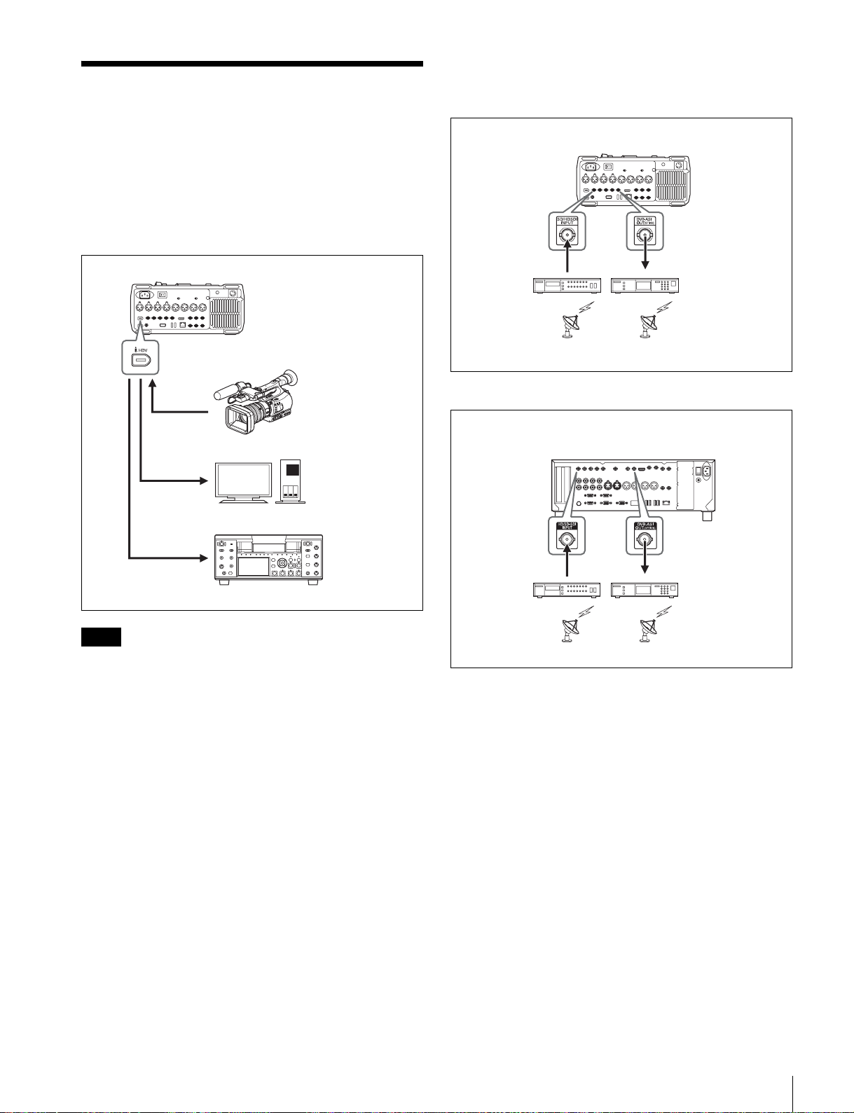
使用例
本基板の使用例を下図に示します。
i.LINKTS 入/出力の使用例(PDW-HR1
のみ)
PDW-HR1(本基板装着)
a)
a)
a)
HDV カムコーダー
HDV 対応ノンリニア
編集システム
HDV レコーダー
XDS シリーズ機器(本基板装着)
a)
レシーバー
配信システム
a)DVB-ASI
a)
モジュレーター
配信システム
DVB-ASITS 信号を入力するには
装着機器の DVB-ASITS 信号入力端子を使用します(前図
参照)。
PDW-HR1:SD/HDSDIINPUT 端子
XDS シリーズ機器:HD/SD-SDIINPUT 端子
入力可能な DVB-ASITS 信号(PDW-HR1 のみ)
MPEG-2 トランスポートストリーム伝送をサポートしてい
る XDCAM のオプション機器(HDCA-702 など)から出力
される DVB-ASITS 信号に限られます。
JP
a)i.LINKTS
ご注意
HDV カムコーダーまたは HDV レコーダーを i.LINK ケー
ブルで接続するときは、あらかじめ i.LINK 入/出力設定を
HDV にしてください。
◆ 詳しくは、HDV カムコーダーまたは HDV レコーダーに付属の
取扱説明書をご覧ください。
DVB-ASI 入/出力の使用例
PDW-HR1 の場合
PDW-HR1(本基板装着)
a)
レシーバー
a)
モジュレーター
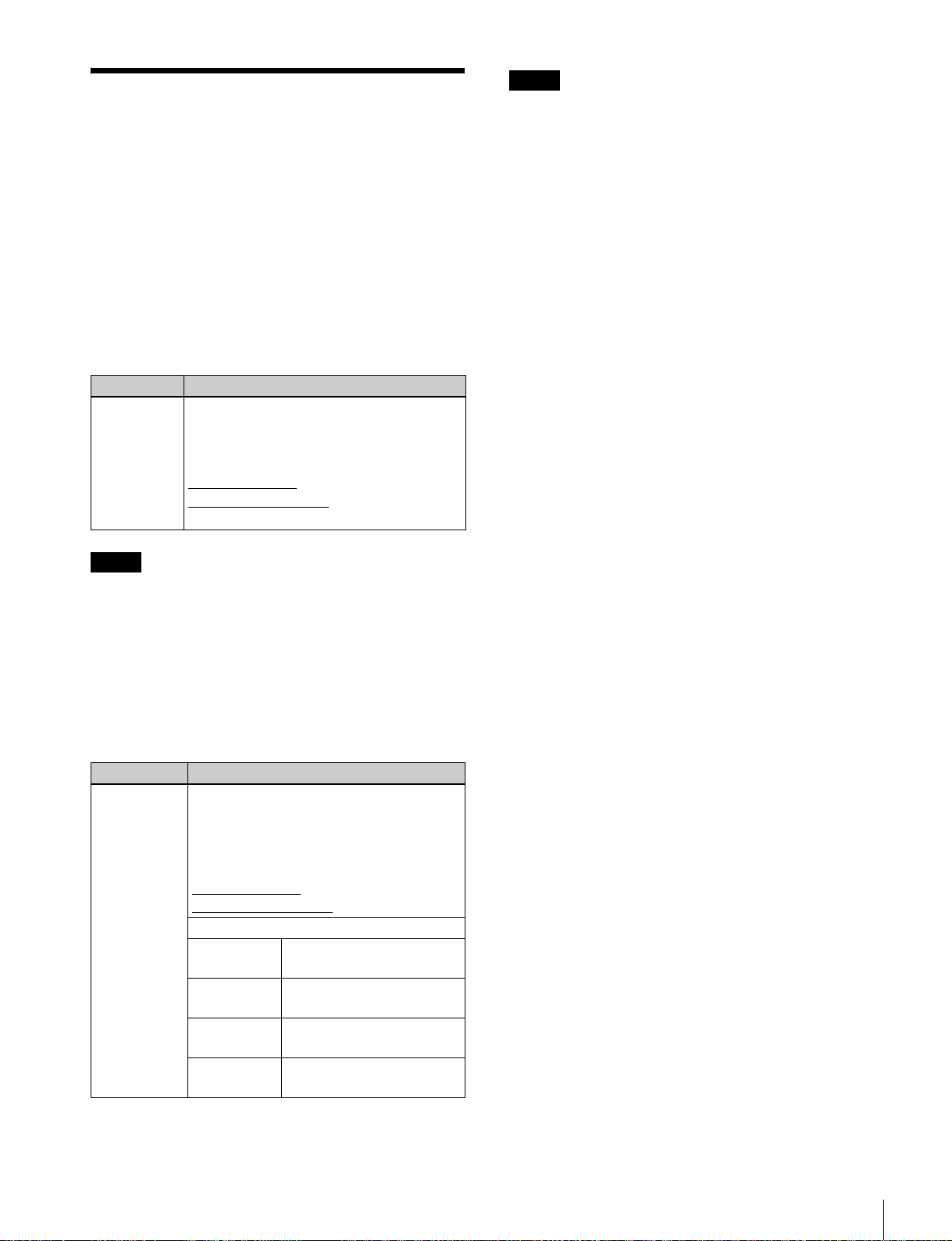
メニュー設定
以下の項目を設定します。
• PDW-HR1 の場合
項目 設定値
ファンクションメニューP1
VIDEO ページの VINPUT
セットアップメニュー項目
926 のサブ項目 TSi.LINK
MODE
セットアップメニュー項目
926 のサブ項目 PROGRAM
NUMBER
DVB-ASI
HDV:PROGRAMNUMBER の設定値
Manual:PROGRAMNUMBER で任
ご注意
720P システムでは、本項目は表示され
ません。
TSi.LINKMODE を「Manual」に設定
して、プログラム番号(1 〜 65535
(FFFFh))を指定する。
• XDS シリーズ機器の場合
項目 設定値
ファンクションメニューP1
INPUT ページの F2:V
INPUT
DVB-ASI
を「00100」(工場出荷時の設定)
にする。
意のプログラム番号を指定できる。
配信システム
a)DVB-ASI
配信システム
使用例
3
項目 設定値
セットアップメニュー項目
926 のサブ項目 I/OMODE
セットアップメニュー項目
926 のサブ項目 TSMODE
セットアップメニュー項目
926 のサブ項目 PROGRAM
NUMBER
DVB-ASI の入出力を設定する。
input[in]:入力モード固定
output[out]:出力モード固定
TS モードを選択する(59.94i/29.97P/
50i/25P モード時のみ)。
HDV:HDV モード
Manual[manu]:エンコードレート
モード
TSMODE を「Manual」に設定して、
プログラム番号(10 進数)を指定する。
• ファンクションメニューP1VIDEO ページの VINPUT を
「DVB-ASI」に設定すると、P2AUDIO ページの A1
INPUT 〜 A4INPUT は自動的に「DVB-ASI」に設定さ
れます。
• セットアップメニュー項目 926 のサブ項目 PROGRAM
NUMBER でプログラム番号を指定することによって、
複数のプログラムが多重された DVB-ASITS 信号から特
定の 1 つのプログラムを選択して受信することができま
す。
DVB-ASITS 信号に重畳されたメタデータ
を利用するには
ご注意
前記のメタデータのうち、エッセンスマーク情報はクリッ
プ名情報よりも優先的に伝送されます。伝送されるエッセ
ンスマーク情報が多すぎると、クリップ名情報の伝送に時
間がかかることがあります。
DVB-ASITS 信号を出力するには
PDW-HR1 の場合は、PDW-HR1 を再生モードにします。
XDS シリーズ機器の場合は、セットアップメニュー項目
926DVB-ASISETTING の I/OMODE で「output」を選択
します。
DVB-ASITS 出力信号にメタデータを重畳
するには
セットアップメニュー項目 926 のサブ項目 META
PACKETOUT を「on」に設定します。
1 倍速再生時、ディスクに記録されているメタデータが映
像・音声データに同期して伝送されます。
静止画・可変速再生時は、タイムコードデータのみが伝送
されます。他のメタデータは伝送されません。
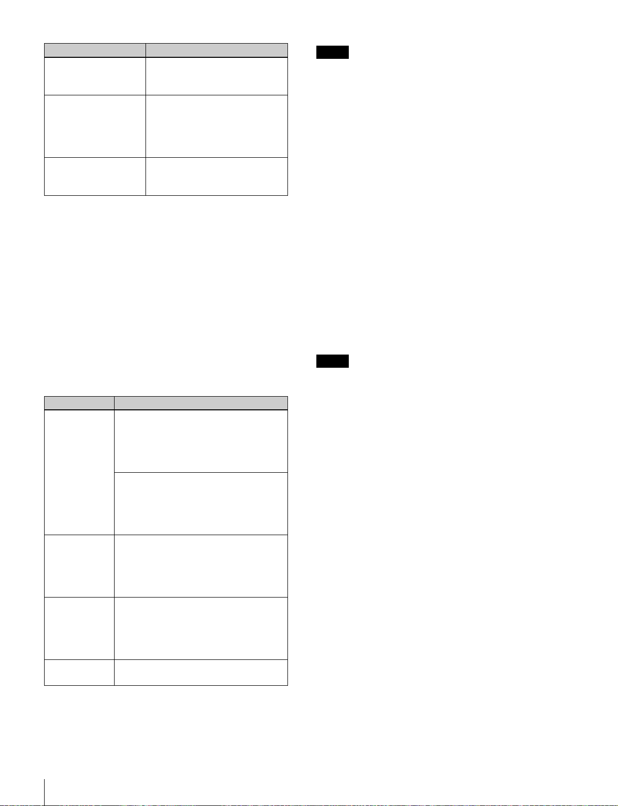
ご注意
メタデータの種類に応じて次表のように設定します。
メタデータの種類 設定
タイムコード/
ユーザービット
エッセンスマーク 特別な設定をすることなく、自動的に記録され
クリップ名
(PDW-HR1 のみ)
UMID 特別な設定をすることなく、自動的に記録され
PDW-HR1 の場合
INT/EXT/SDI スイッチ:EXT または SDI
装着機器の内蔵タイムコードジェネレーターは、
TS 信号に含まれるタイムコードデータに同期し
ます。
XDS シリーズの場合
ファンクションメニュー P4TC ページの TCG
で「EXT」または「SDI」を選択すると、内蔵タ
イムコードジェネレーターは TS 信号に含まれる
タイムコードデータに同期します。
ます。
PDW-HR1 の場合、エッセンスマークが設定され
たフレームを確認するには、チャプターサムネ
イル画面を表示します。
セットアップメニュー項目 036 のサブ項目
AUTONAMING:ext
記録開始時点の TS 信号上のクリップ名が記録さ
れます。記録中に TS 信号上でクリップ名が変更
されても、クリップ名の変更は反映されません。
ます。
PDW-HR1 の場合、セットアップメニュー 926 のサブ項目
TSi.LINKMODE を「HDV」に設定すると、タイムコード
データ以外のメタデータは伝送されません。
XDS シリーズ機器の場合、セットアップメニュー 926 のサ
ブ項目 TSMODE を「HDV」に設定すると、タイムコード
データ以外のメタデータは伝送されません。
使用例
4
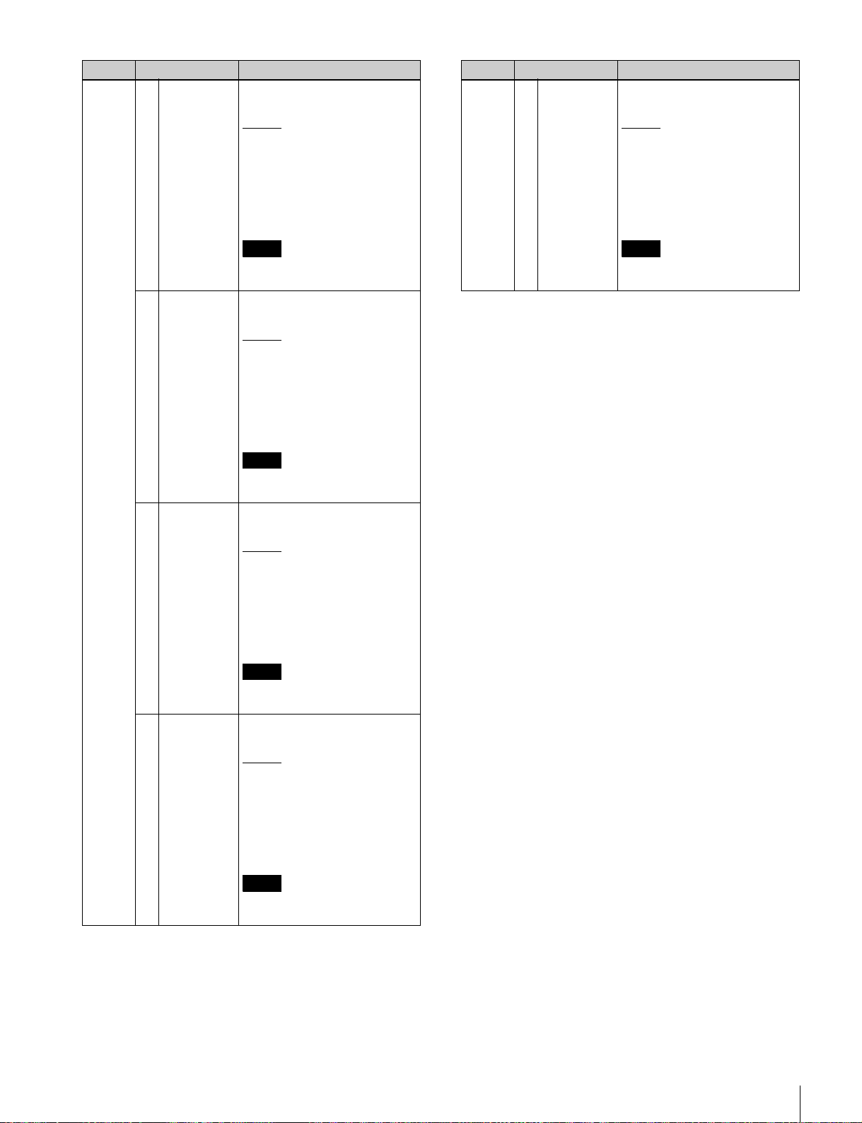
追加されるファンクショ ンメニューの設定内容
PDW-HR1 の場合
本基板を PDW-HR1 に装着すると、以下の表に下線で示す
設定内容が追加されます。
◆ ファンクションメニューの操作方法については、PDW-HR1 の
オペレーションマニュアル「第 3 章 準備」をご覧ください。
P1VIDEO ページ
設定項目 設定内容
F1:VINPUT ビデオ入力信号を選択する。
HDSDI:HDSDI 信号
SDSDI:SDSDI 信号
CMPST:コンポジット信号
:i.LINK 信号
i.LINK
DVB-ASI:DVB-ASI 信号
SG:内部信号発生器からのテスト信号
ご注意
ファンクションメニュー P1VIDEO ページの VINPUT を
「i.LINK」または「DVB-ASI」に設定すると、P2AUDIO
ページの A1INPUT 〜 A4INPUT は自動的に「i.LINK」
または「DVB-ASI」に設定されます。また、ビデオ入力信
号と異なる種類のオーディオ入力信号を設定することはで
きません。
XDS シリーズ機器の場合
本基板を XDS シリーズ機器に装着すると、メンテナンスメ
ニュー M22:OPTIONSETTING の DVB-ASI を「on」に
設定している場合は、ファンクションメニュー P1INPUT
ページと P2INPUT ページに「DVB-ASI」の表示が追加さ
れます。「i.LINK」は表示されません。
◆ XDS シリーズ機器について詳しくは、XDS シリーズ機器に付
属のオペレーションマニュアルの「ファンクションメニューの
基本操作」をご覧ください。
ご注意
•「i.LINK」を選択した場合、PDW-HR1 の E-E モード時の
HDSDI 出力 /SDSDI 出力は保証されません。REC また
は E-E モード時に DVB-ASITS 信号は出力されません。
•「DVB-ASI」を選択した場合、PDW-HR1 の動作モードに
かかわらず、DVB-ASITS 信号および i.LINKTS 信号は
出力されません。
P2AUDIO ページ
設定項目 設定内容
F1:AUINPUT オーディオチャンネル1〜8に割り当てるオー
ディオ入力信号を選択する。
SDI:SDI 信号に重畳されたオーディオ信号
ANALOG1:アナログ 1 のオーディオ信号
SG:内部信号発生器からのテスト信号
:i.LINK 信号
i.LINK
DVB-ASI:DVB-ASI 信号
サブ項目
F1:A1INPUT
(A5INPUT)
F2:A2INPUT
(A6INPUT)
F3:A3INPUT
(A7INPUT)
F4:A4INPUT
(A8INPUT)
チャンネル 1(5)の入力信号
チャンネル 2(6)の入力信号
チャンネル 3(7)の入力信号
チャンネル 4(8)の入力信号
追加されるファンクションメニューの設定内容
5
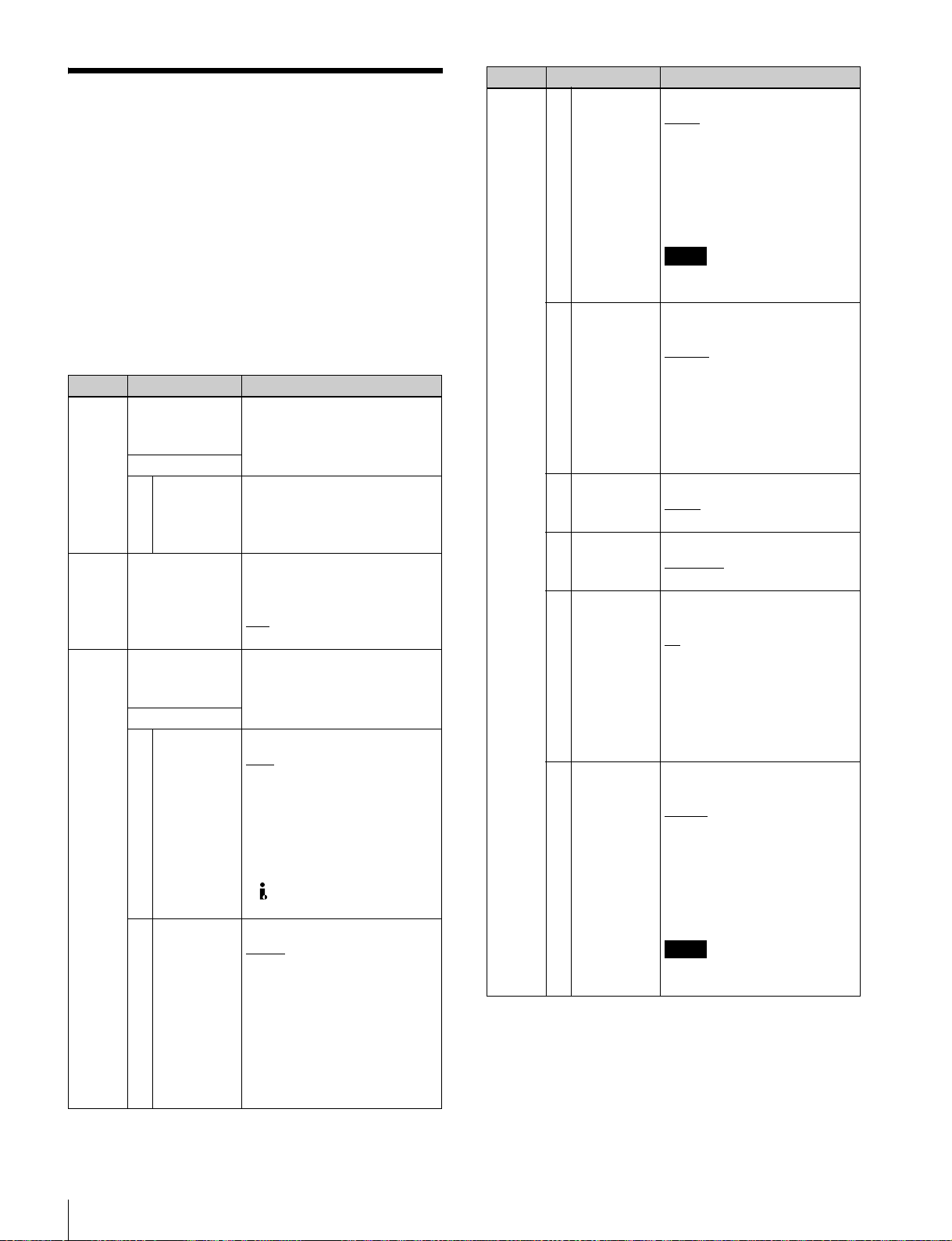
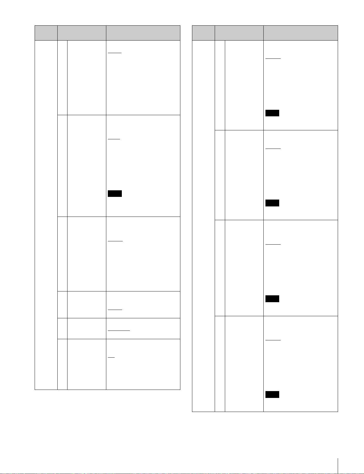
追加されるセットアップ メニュー項目
PDW-HR1 の場合
本基板を PDW-HR1 に装着すると、以下の項目が追加され
ます。(項目 036FILENAMING の場合は、サブ項目
AUTONAMING に設定値「ext」が追加されます。)
下線の設定が、工場出荷時の設定です。
◆ セットアップメニューの操作方法については、PDW-HR1 のオ
ペレーションマニュアル「第 8 章 メニュー」をご覧ください。
項目番号 項目名 設定
036 FILENAMING クリップおよびクリップリストにつ
いて、任意の名前を付けたファイル
の使用を可能にするかどうかを設定
サブ項目
2 AUTO
NAMING
831 TSOUTAUDIO
MODE
926 DVB-ASI
SETTING
サブ項目
1 TSi.LINK
MODE
2ENCRATE
(Mbps)
する。
サブ項目「NAMINGFORM」で
「free」を選択したとき、クリップ名
として何を使用するかを指定する。
ext:DVB-ASI 信号上のクリップ名
DVB-ASITS 信号および i.LINKTS
(HDV)信号のオーディオ出力チャ
ンネル数を設定する。
:2 チャンネル
2ch
4ch:4 チャンネル
DVB-ASI 出力の各種パラメーター
の設定、および DVB-ASI 信号入力
時の受信プログラム番号の指定を行
う。
TSi.LINK モードを選択する。
:HDV モード
HDV
本モードを選択すると「Manual」は
無効になります。
Manual:エンコードレートモード
720P 使用時のご注意
• 本項目は表示されません。
• (i.LINK)HDVTS 端子からは信
号が出力されません。
エンコードレートを設定する。
25.00
:エンコードレートを設定す
る。
---:メニュー項目 926 のサブ項目
TSi.LINKMODE が「HDV」
に設定されている場合。
15.00Mbps 〜 43.25Mbps の範囲から
0.01Mbps 単位または 0.20Mbps 単位
(SHIFT ボタン併用時)で設定でき
ます。
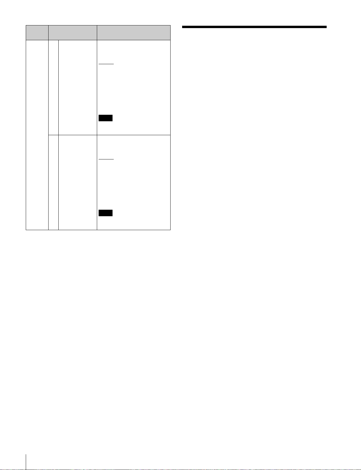
項目番号 項目名 設定
926 3 RESOLUTION 1080i での水平画素数を選択する。
1440
:1440
メニュー項目 926 のサブ項目 TS
i.LINKMODE を「HDV」に設定す
ると、「1440」に固定されます。
1920:1920
エンコードレートが 35.00Mbps 以上
で 1920 を選択できます。
ご注意
720P 使用時に本項目は表示されま
せん。
4 PROGRAM
NUMBER
5OUTPUT
MODE
6PACKET
LENGTH
7META
PACKET
OUT
8 PID(PMT) DVB-ASI 出力時の PMT パケットの
DVB-ASI 入/出力信号のプログラ
ム番号を指定する。
00100
:プログラム番号(1 〜
65535(FFFFh))を設定する。
---:メニュー項目 926 のサブ項目
TSi.LINKMODE が「HDV」
に設定されている場合。
1 単位または 200 単位(SHIFT ボタ
ン併用時)で設定できます。
伝送モードを選択する。
P
ackt:パケットモード
Burst:バーストモード
パケット長を選択する。
Byte:188 バイト
188
204Byte:204 バイト
DVB-ASI 信号のメタデータパケッ
トの出力を設定する。
:メタデータパケットを出力し
off
ない。
on:メタデータパケットを出力す
る。
---:メニュー項目 926 のサブ項目
TSi.LINKMODE が「HDV」
に設定されている場合。
PID 値を変更する。
0081h
:PID 値を設定する。
---:メニュー項目 926 のサブ項目
TSi.LINKMODE が「HDV」
に設定されている場合。
0030h 〜 1FFEh の範囲から 1h 単位
または 20h 単位(SHIFT ボタン併
用時)で設定できます。
ご注意
他の PID 値と同じ値を設定しないで
ください。
追加されるセットアップメニュー項目
6
項目番号 項目名 設定
926 9 PID(PCR) DVB-ASI 出力時の PCR パケットの
PID 値を変更する。
0134h
:PID 値を設定する。
---:メニュー項目 926 のサブ項目
TSi.LINKMODE が「HDV」
に設定されている場合。
0030h 〜 1FFEh の範囲から 1h 単位
または 20h 単位(SHIFT ボタン併
用時)で設定できます。
ご注意
他の PID 値と同じ値を設定しないで
ください。
10 PID(VIDEO) DVB-ASI 出力時の VIDEO パケット
の PID 値を変更する。
:PID 値を設定する。
0810h
---:メニュー項目 926 のサブ項目
TSi.LINKMODE が「HDV」
に設定されている場合。
0030h 〜 1FFEh の範囲から 1h 単位
または 20h 単位(SHIFT ボタン併
用時)で設定できます。
ご注意
他の PID 値と同じ値を設定しないで
ください。
11 PID(AUDIO) DVB-ASI 出力時の AUDIO パケッ
トの PID 値を変更する。
:PID 値を設定する。
0814h
---:メニュー項目 926 のサブ項目
TSi.LINKMODE が「HDV」
に設定されている場合。
0030h 〜 1FFEh の範囲から 1h 単位
または 20h 単位(SHIFT ボタン併
用時)で設定できます。
ご注意
他の PID 値と同じ値を設定しないで
ください。
12 PID(AUX1) DVB-ASI 出力時の AUX1 パケット
の PID 値を変更する。
:PID 値を設定する。
0815h
---:メニュー項目 926 のサブ項目
TSi.LINKMODE が「HDV」
に設定されている場合。
0030h 〜 1FFEh の範囲から 1h 単位
または 20h 単位(SHIFT ボタン併
用時)で設定できます。
ご注意
他の PID 値と同じ値を設定しないで
ください。
項目番号 項目名 設定
926 13 PID(AUX2) DVB-ASI 出力時の AUX2 パケット
の PID 値を変更する。
0811h
:PID 値を設定する。
---:メニュー項目 926 のサブ項目
TSi.LINKMODE が「HDV」
に設定されている場合。
0030h 〜 1FFEh の範囲から 1h 単位
または 20h 単位(SHIFT ボタン併
用時)で設定できます。
ご注意
他の PID 値と同じ値を設定しないで
ください。
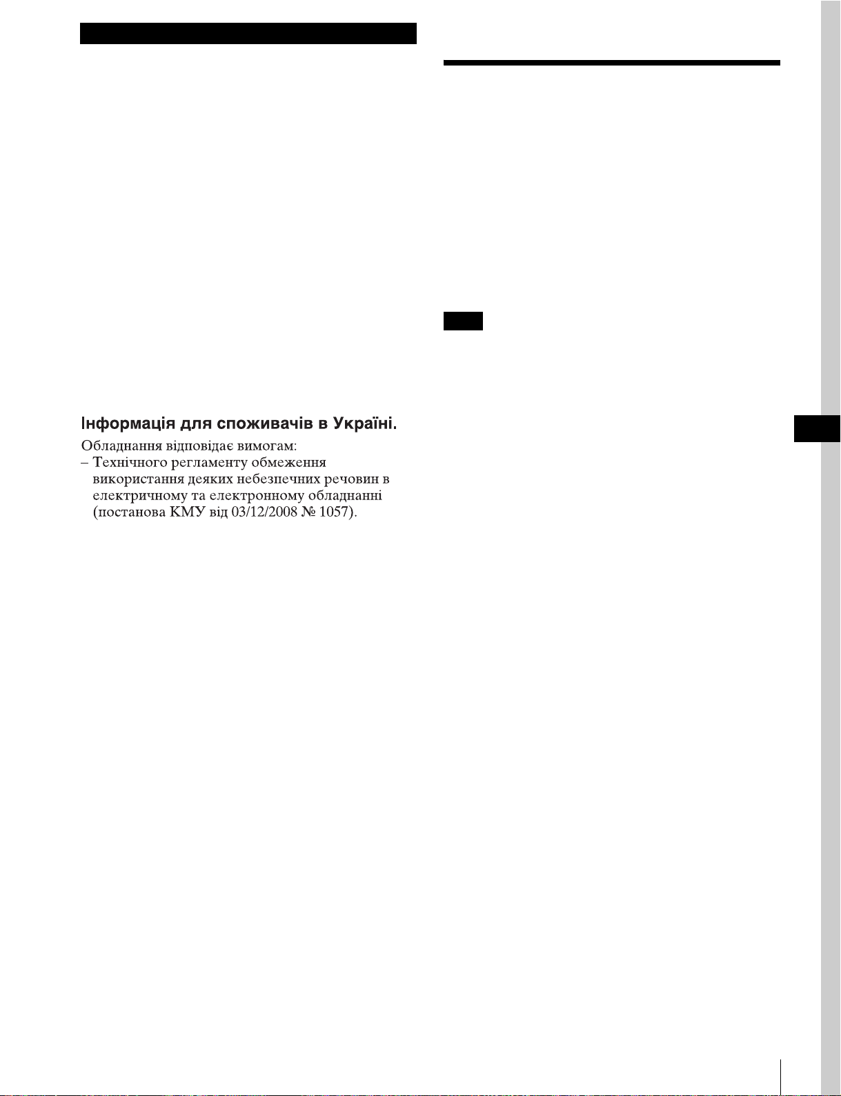
XDS シリーズ機器の場合
本基板を XDS シリーズ機器に装着すると、メニュー項目
831TSOUTAUDIOMODE と、メニュー項目 926DVBASISETTING が追加されます。なお、メニュー項目 036
は追加されません。
◆ XDS シリーズ機器について詳しくは、XDS シリーズ機器に付
属のオペレーションマニュアルの「セットアップメニュー」を
ご覧ください。
追加されるセットアップメニュー項目
7

i.LINK 接続についてのご 注意(PDW-HR1 のみ)
仕様
一般
• i.LINKケーブルを使ってPDW-HR1にコンピューターなど
を接続するときは、端子の向きを確認してください。端
子と i.LINK ケーブルコネクターの向きが逆になっている
状態で無理に押し込むと、端子が破損することがありま
す。また、PDW-HR1 の故障の原因となります。
• i.LINK ケーブルは、先にコンピューターに接続してから
PDW-HR1 に接続してください。先に PDW-HR1 に接続
すると、静電気が発生して PDW-HR1 の故障の原因とな
ります。
• i.LINK端子を持つ機器とPDW-HR1をi.LINKケーブルで接
続し、i.LINK ケーブルを抜き差しするときは、あらかじ
め機器の電源スイッチをオフにし、電源プラグを電源か
ら抜いてください。電源プラグを電源に接続したまま
i.LINK ケーブルを抜き差しすると、機器の i.LINK 端子か
ら出力されている高圧電流が PDW-HR1 に流れ込み、
PDW-HR1 の故障の原因となるおそれがあります。
• 複数の i.LINK 端子を持つ機器(i.LINK インターフェース
カードを搭載したコンピューターなど)を接続する場合、
PDW-HR1 を 1 つの端子に接続した状態で他の端子に後
から外部ハードディスクユニットなどを接続すると、
PDW-HR1 に高圧電流が流れ込み、PDW-HR1 の故障の
原因となるおそれがあります。
コンピューターなどの周辺機器、PDW-HR1、および後か
ら接続する機器の電源スイッチをすべてオフにし、電源
プラグをすべて電源から抜いた状態で、i.LINK ケーブル
を接続してください。
• PDW-HR1 の電源スイッチをオン/オフするときは、あら
かじめ i.LINK 接続している機器の動作を停止してくださ
い。
• PDW-HR1 の電源スイッチをオンにしても MPEGTS信号
の送受信が行われない場合は、PDW-HR1 の電源スイッ
チをいったんオフにして再度オンにしてください。
電源電圧、消費電流
+5.8V、0.1A
+3.3V、0.7A
+2.5V、0.5A
(電源は装着機器から供給)
外形寸法(幅/高さ)
102 × 86mm
質量 約 54g
ストリームフォーマット
ビデオコーデック
DVB-ASI MPEG-2MP@HL
MPEG-2MP@H-14
i.LINK MPEG-2MP@H-14
ビデオ解像度/システム周波数
1440 × 1080 59.94i、50i、29.97P、25P
1920 × 1080 59.94i、50i、29.97P、25P
1280 × 720 59.94P、50P
ビットレート選択範囲
15.00Mbps 〜 43.25Mbps(0.01Mbps ステップ)
オーディオ
MPEG-1Layer2
2 チャンネル、48kHz、384kbps
MPEG-2Layer2
4 チャンネル、48kHz、384kbps
付属品
取り付けネジ(4)
オペレーションアンドインストレーションガイド(1)
インストレーションマニュアル(1)
i.LINK 接続についてのご注意(PDW-HR1 のみ)/仕様
8
仕様および外観は、改良のため予告なく変更することがあ
りますが、ご了承ください。
お使いになる前に、必ず動作確認を行ってください。故
障その他に伴う営業上の機会損失等は保証期間中および
保証期間経過後にかかわらず、補償はいたしかねますの
でご了承ください。
English
Before operating the unit, please read this manual
thoroughly and retain it for future reference.
For the customers in Europe
This product with the CE marking complies with the EMC
Directive issued by the Commission of the European
Community.
Compliance with this directive implies conformity to the
following European standards:
• EN55103-1: Electromagnetic Interference (Emission)
• EN55103-2: Electromagnetic Susceptibility (Immunity)
This product is intended for use in the following
Electromagnetic Environments: E1 (residential), E2
(commercial and light industrial), E3 (urban outdoors), E4
(controlled EMC environment, ex. TV studio).
Precautions
If this unit is installed incorrectly, personal injury or
damage to peripheral items may occur due to fire, shock,
or other accidental circumstances. To avoid such risks,
installation should be performed by trained service
technicians.
To the technician installing the unit
Please refer to the INSTALLATION MANUAL supplied
with this unit for installation instructions.
The manufacturer of this product is Sony Corporation, 17-1 Konan, Minato-ku, Tokyo, Japan.
The Authorized Representative for EMC and product
safety is Sony Deutschland GmbH, Hedelfinger Strasse
61, 70327 Stuttgart, Germany.
Note
Be sure to power off the PDW-HR1 or XDS Series device
before installing this board.
GB
Precautions
9

Overview
The PDBK-202 MPEG TS Board (called “this board” in
the following) is an option board for installation in the
Sony PDW-HR1 Professional Disc Field Station or XDS
Series Professional Media Station.
The principal features of this board are as follows.
Checking software versions
Check to be sure that the software version of the PDWHR1 is 2.0 or higher and that the software version of the
XDS Series device is 1.1 or higher.
You can check the software versions with maintenance
menu item M30: SOFTWARE VERSION. For details, refer
to “Maintenance Menu” in the target device Operation
Manual.
When this board is installed in the PDW-HR1, you can
input MPEG TS
or progressive scan) compatible with the HDV
1)
signals (IEEE 1394 compliant, interlace
2)
1080i 3)
format, and record these signals on XDCAM Professional
Disc.
You can also play back XDCAM Professional Disc and
output MPEG TS signals (IEEE 1394 compliant, interlace
or progressive scan) compatible with the HDV 1080i
format and DVB-ASI TS signals.
Installing this board in an XDS Series device allows DVBASI TS signals to be input to / output from the device.
Note
XDS Series devices do not support i.LINK.
1) MPEG TS: MPEG-2 transport streams containing MPEG video, MPEG
audio, and control information. This is the standard interface for HDV
equipment.
2) HDV and are trademarks of Sony Corporation and Victor
Company of Japan, Limited.
3) HDV 1080i: Refers to devices compliant with the “HDV 1080i Standard”
for recording HD signals on DV tape. Supports HDV 1080/59.94i or 1080/
29.97P and HDV 1080/50i or 1080/25P.
About operating instructions
Refer to the Operation Manual for the device in which you
install this board (called “the target device” in the
following).
PDW-HR1: 1st Edition
XDS-1000: 1st Edition (Revised 1)
XDS-PD1000/PD2000: 1st Edition
If the software versions of this board and the
target device do not match
When you power on the target device immediately after
installing this board, the error code “ERROR 95-119” or
“ERROR 95-419” may appear. This is not a malfunction.
Carry out the procedure for updating the target device to
the latest version of the software package with this board
installed in the device.
This updates both the target device and this board.
For more information about updating the software,
contact your Sony dealer or a Sony service representative.
The following is supplementary information to be added to
the above manual when this board has been installed in the
PDW-HR1 or XDS series device.
When the target device is the PDW-HR1
Notes
• This board cannot record DV signals.
• i.LINK (TS) is not output when the video format is 720P.
• If, after editing material with a nonlinear editor
connected to the PDW-HR1, you want to write the
material back to a PDW-HR1 disc, then set F2: PB/EE
on the HOME page of the function menu to “EE”.
• To upload materials from the PDW-HR1 to a nonlinear
editor, set F2: PB/EE on the HOME page of the function
menu to “PB”.
10
Overview
System Configuration Examples
The following figures show examples of systems.
Examples of i.LINK TS input/output usage
(PDW-HR1 only)
Examples of DVB-ASI input/output usage
When the target device is the PDW-HR1
PDW-HR1 (with this board installed)
PDW-HR1 (with this board
installed)
a) i.LINK TS
Note
a)
a)
a)a)
HDV recorder
HDV camcorder
HDV compatible
nonlinear editing
system
Before connecting an HDV camcorder or an HDV recorder
by an i.LINK cable, set up the camcorder or recorder to
input/output HDV signals via the i.LINK interface.
For details about i.LINK interface settings, refer to the
Operating Instructions for the HDV camcorder or HDV
recorder.
a)
Receiver
Distribution system
a) DVB-ASI
a)
Modulator
Distribution system
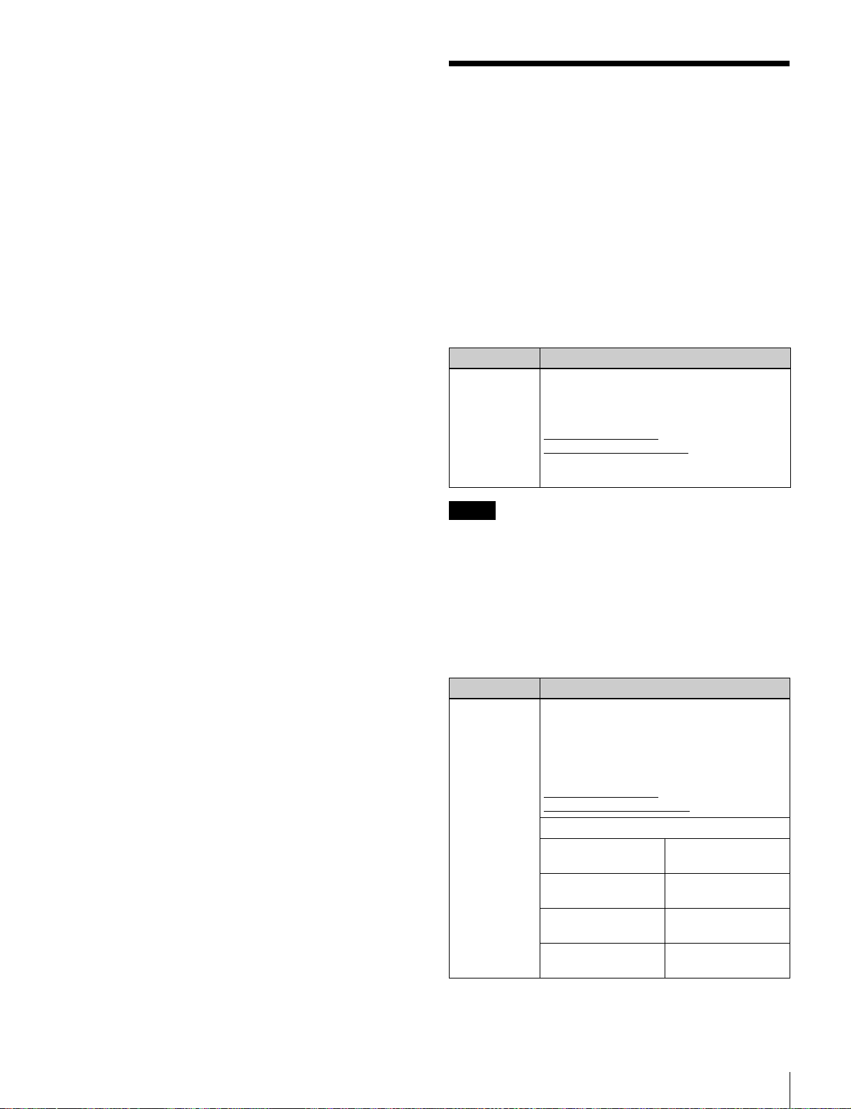
When the target device is an XDS Series device
XDS Series device (with this board
installed)
a)
Receiver
Distribution system
a) DVB-ASI
a)
Modulator
Distribution system
To input DVB-ASI TS signals
Use the DVB-ASI TS signal input connector on the target
device (see the previous figure).
PDW-HR1: SD/HDSDI INPUT connector
XDS Series device: HD/SD-SDI INPUT connector
Supported DVB-ASI TS input signals (PDW-HR1
only)
Support is limited to DVB-ASI TS signals output by
optional XDCAM devices (such as the HDCA-702) that
support MPEG-2 transport stream transmission.
Menu settings
Set the following items.
System Configuration Examples
11

When the target device is the PDW-HR1
Item Setting
V INPUT on the P1
VIDEO page of the
function menu
Sub-item TS i.LINK
MODE of setup menu
item 926
Sub-item PROGRAM
NUMBER of setup
menu item 926
DVB-ASI
HDV: Set PROGRAM NUMBER to
“00100” (factory default
setting).
Manual: You can set PROGRAM
NUMBER to any program
number.
Note
This item does not appear on 720P
systems.
Set TS i.LINK MODE to “Manual”,
and specify a program number (1 to
65535 (FFFFh)).
When the target device is an XDS Series device
Item Setting
F2: V INPUT on the
P1 INPUT page of the
function menu
Sub-item I/O MODE of
setup menu item 926
Sub-item TS MODE of
setup menu item 926
Sub-item PROGRAM
NUMBER of setup
menu item 926
DVB-ASI
Set DVB-ASI input/output.
input [in]: Fixedly input mode
output [out]: Fixedly output mode
Select the TS mode. (59.94i/
29.97P/50i/25P mode only.)
HDV: HDV mode
Manual [manu]: Encoding rate
mode
Set TS MODE to “Manual” and
specify a program number
(decimal).
Metadata type Setting
Timecode/user bits When the target device is the PDW-
HR1
INT/EXT/SDI switch: EXT or SDI
The internal timecode generator of the
target device synchronizes to the
timecode data contained in the TS
signal.
In the case of XDS Series device
When TCG in the TC page of the
function menu is set to “EXT” or “SDI”,
the internal timecode generator
synchronizes to the timecode data
contained in the TS signal.
Essence mark These are recorded automatically,
without any special settings.
In the case of the PDW-HR1, to check
for frames where essence marks are
set, display the chapter thumbnail
screen.
Clip name
(PDW-HR1 only)
UMID This is recorded automatically, without
Note
Sub-item AUTO NAMING of setup
menu item 036: ext
The clip name in TS signals at the
recording start point is recorded. Even
if the clip name in the TS signals is
changed during recording, the change
to the clip name is not reflected.
any special settings.
Among the metadata types listed above, transmission of
essence mark information is given priority over
transmission of clip names. If there is too much essence
mark information to transmit, some time may be required
to transmit clip name information.
• If you set V INPUT on the P1 VIDEO page of the
function menu to “DVB-ASI”, then A1 INPUT to A4
INPUT on the P2 AUDIO page are also set automatically
to “DVB-ASI”.
• Specifying a program number with sub-item
PROGRAM NUMBER of setup menu item 926 makes it
possible to select and receive a specified program from
DVB-ASI TS signals containing multiple multiplexed
programs.
To use metadata multiplexed into DVB-ASI
TS signals
Make the settings shown below, according to the type of
metadata.
To output DVB-ASI TS signals
In the case of the PDW-HR1, put it into playback mode.
In the case of an XDS Series device, set I/O MODE of the
setup menu item 926 DVB-ASI SETTING to “output”.
To multiplex metadata into DVB-ASI TS
output signals
Set sub-item META PACKET OUT of setup menu item
926 to “on”.
During normal speed playback, metadata recorded on the
disc is transmitted at the same time as video and audio
data.
During playback of still images and variable speed
playback, only timecode is transmitted. Other metadata is
not transmitted.
Note
In the case of the PDW-HR1, if the sub-item TS i.LINK
MODE of the setup menu item 926 is set to “HDV”,
metadata other than timecode data is not transmitted.
12
System Configuration Examples
In the case of an XDS Series device, if the sub-item TS
MODE of the setup menu item 926 is set to “HDV”,
metadata other than timecode data is not transmitted.
Additional Function Menu Settings
When the target device is the PDW-HR1
When this board is installed in the PDW-HR1, the
underlined settings in the following tables appear in the
function menu.
For more information about function menu operations,
refer to Chapter 3 “Preparations” in the PDW-HR1
Operation Manual.
P1 VIDEO page
Item Setting
F1: V INPUT Selects the video input signal.
HDSDI: HDSDI signal
SDSDI: SDSDI signal
CMPST: Composite signal
i.LINK signal
i.LINK:
DVB-ASI: DVB-ASI signal
SG: Test signal from internal signal
generator
Notes
• When “i.LINK” is selected, HDSDI output and SDSDI
output in the PDW-HR1’s E-E mode is not guaranteed.
DVB-ASI TS signals are not output in the REC mode or
E-E mode.
• If you select “DVB-ASI”, then DVB-ASI TS signals and
i.LINK TS signals are not output, regardless of the
operating mode of the PDW-HR1.
P2 AUDIO page
Item Setting
F1: AU INPUT Selects the audio input signal to assign to
audio channels 1 to 8.
SDI: Audio signal embedded into SDI signal
ANALOG1: Analog 1 audio signal
SG: Test signal from internal signal
generator
i.LINK signal
i.LINK:
DVB-ASI: DVB-ASI signal
Sub-item
F1: A1 INPUT (A5
INPUT)
F2: A2 INPUT (A6
INPUT)
F3: A3 INPUT (A7
INPUT)
F4: A4 INPUT (A8
INPUT)
Input signal of audio
channel 1 (5)
Input signal of audio
channel 2 (6)
Input signal of audio
channel 3 (7)
Input signal of audio
channel 4 (8)
Additional Function Menu Settings
13

Note
If you set V INPUT on the P1 VIDEO page of the function
menu to “i.LINK” or “DVB-ASI”, then A1 INPUT to A4
INPUT on the P2 AUDIO page are set automatically to
“i.LINK” or “DVB-ASI”. Also, it is not possible to set
audio input signals to a type that differs from the type of
video input signals.
When the target device is an XDS Series
device
When this board is installed in an XDS Series device and
DVB-ASI of the maintenance menu M22: OPTION
SETTING is set to “on”, “DVB-ASI” is added to the P1
INPUT page and P2 INPUT page of the function menu.
“i.LINK” is not displayed.
For more information about the XDS Series device, refer
to “Basic Operations of the Function Menu” in the
Operation Manual supplied with the device.
Additional Setup Menu Items
When the target device is the PDW-HR1
When this board is installed in the PDW-HR1, the menu
items shown in the following table appear in the setup
menu. (The setting “ext” is added to the sub-item AUTO
NAMING of menu item 036 FILE NAMING.)
In the “Settings” column of the table, the factory default
setting is underlined.
For more information about setup menu operations, refer
to Chapter 8 “Menus” in the PDW-HR1 Operation
Manual.
Item
number
036 FILE NAMING Specifies whether to allow
831 TS OUT AUDIO
926 DVB-ASI
Item name Settings
Sub-item
2AUTO
NAMING
MODE
SETTING
1TS i.LINK
MODE
use of clip and clip list files
with user-defined names.
When you select “free” for the
“NAMING FORM” sub-item,
allows you to specify what
you want to use as the clip
name.
ext: Clip name in DVB-ASI
signal
Selects the number of audio
output channels for DVB-ASI
TS and i.LINK TS (HDV)
signals.
: 2 channels
2ch
4ch: 4 channels
Sets the parameters for DVBASI output, and specifies the
number of the program to
receive when DVB-ASI
signals are input.Sub-item
Selects the TS i.LINK mode.
: HDV mode
HDV
When this mode is selected,
the “Manual” setting is
disabled.
Manual: Encoding rate mode
14
Additional Setup Menu Items
When the video format is
720P
• This item does not appear.
• No signals are output from
the (i.LINK) HDV TS
connector.
Item
number
926 2 ENC RATE
Item name Settings
(Mbps)
3 RESOLUTION Selects the number of
4 PROGRAM
NUMBER
5OUTPUT
MODE
6 PACKET
LENGTH
7 META
PACKET OUT
Sets the encoding rate.
: Sets the encoding
25.00
rate.
---: When sub item TS i.LINK
MODE of menu item 926
is set to “HDV”.
You can set this in units of
0.01 Mbps (or 0.20 Mbps
when the SHIFT button is
held down) over the range
from 15.00 Mbps to 43.25
Mbps.
horizontal pixels for the 1080i
format.
: 1440
1440
When sub item TS i.LINK
MODE of menu item 926 is
set to “HDV”, this is fixed as
“1440”.
1920: 1920
The 1920 setting is enabled
when the encoding rate is
35.00 Mbps or higher.
Note
This item does not appear
when the video format is
720P.
Specifies a DVB-ASI input/
output signal program
number.
: Sets the program
00100
number (1 to 65535
(FFFFh)).
---: When sub item TS i.LINK
MODE of menu item 926
is set to “HDV”.
You can set this in units of 1
(or 200 when the SHIFT
button is held down).
Selects the transmission
mode.
: Packet mode
Packt
Burst: Burst mode
Selects the packet length.
188 Byte
204 Byte: 204 bytes
Specifies output of DVB-ASI
signal metadata packets.
off
on: Output metadata packets.
---: When sub item TS i.LINK
: 188 bytes
: Do not output metadata
packets.
MODE of menu item 926
is set to “HDV”.
Item
number
926 8 PID(PMT) Changes the PMT packet PID
Item name Settings
value for DVB-ASI output.
: Set PID value.
0081h
---: When sub item TS i.LINK
MODE of menu item 926
is set to “HDV”.
You can set the value over the
range from 0030h to 1FFEh
in 1h units (or 20h units when
the SHIFT button is held
down).
Note
Do not set the same PID
value as other item.
9 PID(PCR) Changes the PCR packet PID
10 PID(VIDEO) Changes the VIDEO packet
11 PID(AUDIO) Changes the AUDIO packet
value for DVB-ASI output.
: Set PID value.
0134h
---: When sub item TS i.LINK
MODE of menu item 926
is set to “HDV”.
You can set the value over the
range from 0030h to 1FFEh
in 1h units (or 20h units,
when the SHIFT button is
held down).
Note
Do not set the same PID
value as other item.
PID value for DVB-ASI
output.
: Set PID value.
0810h
---: When sub item TS i.LINK
MODE of menu item 926
is set to “HDV”.
You can set the value over the
range from 0030h to 1FFEh
in 1h units (or 20h units,
when the SHIFT button is
held down).
Note
Do not set the same PID
value as other item.
PID value for DVB-ASI
output.
: Set PID value.
0814h
---: When sub item TS i.LINK
MODE of menu item 926
is set to “HDV”.
You can set the value over the
range from 0030h to 1FFEh
in 1h units (or 20h units,
when the SHIFT button is
held down).
Note
Do not set the same PID
value as other item.
Additional Setup Menu Items
15
Item
number
926 12 PID(AUX1) Changes the AUX1 packet
Item name Settings
PID value for DVB-ASI
output.
: Set PID value.
0815h
---: When sub item TS i.LINK
MODE of menu item 926
is set to “HDV”.
You can set the value over the
range from 0030h to 1FFEh
in 1h units (or 20h units,
when the SHIFT button is
held down).
Note
Do not set the same PID
value as other item.
13 PID(AUX2) Changes the AUX2 packet
PID value for DVB-ASI
output.
: Set PID value.
0811h
---: When sub item TS i.LINK
MODE of menu item 926
is set to “HDV”.
You can set the value over the
range from 0030h to 1FFEh
in 1h units (or 20h units,
when the SHIFT button is
held down).
Note
Do not set the same PID
value as other item.
When the target device is an XDS Series
device
When you install this board in the XDS Series device, the
menu item 831 TS OUT AUDIO MODE and menu item
926 DVB-ASI SETTING are added to the setup menu
system of the device. Note that the menu item 036 is not
added.
For more information about the XDS Series device, refer
to “Setup Menu” in the Operation Manual supplied with
the device.
Notes about i.LINK Connections (PDW-HR1 Only)
• Check that connectors are oriented properly before
connecting an i.LINK cable to your computer or to the
PDW-HR1. Trying to force an improperly oriented
connector may damage the connector or the PDW-HR1.
• Connect the i.LINK cable to your computer before
connecting it to the PDW-HR1. The PDW-HR1 may be
damaged by static electricity if you connect the cable to
the PDW-HR1 first.
• Before connecting or disconnecting an i.LINK cable
between the PDW-HR1 and other equipment with an
i.LINK connector, always power both the PDW-HR1
and the connected equipment off and disconnect all
power plugs from their power outlets.
Inserting or removing an i.LINK connector with the
power plugs still connected may cause a damaging surge
of high-voltage power to flow from the equipment’s
i.LINK connector into the PDW-HR1.
• A damaging surge of high-voltage power can still flow
into the PDW-HR1 from the i.LINK connector of
connected equipment even when a separate i.LINK cable
is connected to another i.LINK connector on the
equipment, for example when connecting a hard disk to
a computer with an i.LINK interface card that provided
multiple connectors.
Always power all equipment off and disconnect all
power plugs from their power outlets, both on the PDWHR1 and on the connected computer and its peripherals,
before connecting an i.LINK cable.
• Before turn on or off the power switch of the PDW-HR1,
always stop operation of all devices connected to the
PDW-HR1 over the i.LINK interface.
• If MPEG TS signal transmission is not possible with the
PDW-HR1 powered on, turn off the power switch of the
PDW-HR1 and then turn it on again.
16
Notes about i.LINK Connections (PDW-HR1 Only)

Specifications
General
Power requirements and current consumption
+5.8 V, 0.1 A
+3.3 V, 0.7 A
+2.5 V, 0.5 A
(Power is supplied from the target
device.)
Dimensions (w/h)
102 × 86 mm (4
Mass Approx. 54 g (1.9 oz)
Stream formats
Video codec
DVB-ASI MPEG-2 MP@HL
MPEG-2 MP@H-14
i.LINK MPEG-2 MP@H-14
Video resolution/system frequency
1440 × 1080 59.94i, 50i, 29.97P, 25P
1920 × 1080 59.94i, 50i, 29.97P, 25P
1280 × 720 59.94P, 50P
1
/8 × 31/2 inches)
Bit rate selection range
15.00 Mbps to 43.25 Mbps (in steps of 0.01 Mbps)
Audio
MPEG-1 Layer 2 2 channels, 48 kHz, 384 kbps
MPEG-2 Layer 2 4 channels, 48 kHz, 384 kbps
Accessories supplied
Fitting screws (4)
Operation and Installation Guide (1)
Installation Manual (1)
Design and specifications are subject to change without
notice.
Note
Always verify that the unit is operating properly before
use. SONY WILL NOT BE LIABLE FOR DAMAGES
OF ANY KIND INCLUDING, BUT NOT LIMITED
TO, COMPENSATION OR REIMBURSEMENT ON
ACCOUNT OF THE LOSS OF PRESENT OR
PROSPECTIVE PROFITS DUE TO FAILURE OF
THIS UNIT, EITHER DURING THE WARRANTY
PERIOD OR AFTER EXPIRATION OF THE
WARRANTY, OR FOR ANY OTHER REASON
WHATSOEVER.
Specifications
17

Français
Avant d’utiliser l’appareil, veuillez lire attentivement ce
manuel et le conserver pour future référence.
Pour les clients en Europe
Ce produit portant la marque CE est conforme à la
Directive sur la compatibilité électromagnétique (EMC)
émise par la Commission de la Communauté européenne.
La conformité à cette directive implique la conformité aux
normes européennes suivantes :
• EN55103-1 : Interférences électromagnétiques
(émission)
• EN55103-2 : Sensibilité électromagnétique (immunité)
Ce produit est prévu pour être utilisé dans les
environnements électromagnétiques suivants : E1
(résidentiel), E2 (commercial et industrie légère), E3
(urbain extérieur) et E4 (environnement EMC contrôlé, ex.
studio de télévision).
Précautions
Si cette carte est mal installée, des lésions corporelles ou
des dommages aux périphériques peuvent se produire suite
à un incendie, un choc ou toute autre circonstance à
risques. Pour éviter ce type de situation, l’installation doit
être réalisée par des techniciens qualifiés.
Note au technicien chargé de l’installation
de cette carte
Pour consulter les instructions relatives à l’installation,
reportez-vous au INSTALLATION MANUAL (manuel
d’installation) fourni avec ce produit.
Le fabricant de ce produit est Sony Corporation, 1-7-1
Konan, Minato-ku, Tokyo, Japon.
Le représentant autorisé pour EMC et la sécurité des
produits est Sony Deutschland GmbH, Hedelfinger Strasse
61, 70327 Stuttgart, Allemagne.
Remarque
Assurez-vous de mettre le PDW-HR1 ou le dispositif de la
série XDS hors tension avant d’installer cette carte.
18
Précautions
 Loading...