

Sony PDW-HD1550 Operation Manual

PROFESSIONAL DISC RECORDER
PDW-HD1550
OPERATION MANUAL [English]
1st Edition (Revised 1)

Table of Contents
Chapter 1 Overview
Features............................................................................................6
Features of this unit ............................................................................... 6
System Configurations ...................................................................9
Chapter 2 Names and Functions of Parts
Front Panel .....................................................................................10
Display screen ..................................................................................... 15
Rear Panel ......................................................................................20
Chapter 3 Preparations
Preparing Power Sources .............................................................23
Initial Setup ....................................................................................25
Front Panel Tilt Mechanism..........................................................26
Connections and Settings ............................................................27
Synchronization Reference Signals.............................................33
Setting the System Frequency .....................................................34
Setting the Timecode ....................................................................34
Superimposed Text Information...................................................36
Basic Operations of the Function Menu......................................39
Handling Discs...............................................................................42
Supplying power.................................................................................. 23
Attaching a battery pack...................................................................... 23
Connections for Content Browser and non-Sony nonlinear editors.... 27
Connections for cut editing ................................................................. 28
Using the editing functions of the recorder (controlling through
REMOTE (9P) connector) ......................................................... 31
Connections for pool coverage............................................................ 32
Function menu operations ................................................................... 39
Function menu settings........................................................................ 39
Discs used for recording and playback................................................ 42
Notes on handling................................................................................ 43
Write-protecting discs ......................................................................... 43
2
Table of Contents

Loading and unloading a disc.............................................................. 43
Formatting a disc ................................................................................. 43
Handling Memory Cards ............................................................... 44
About memory cards............................................................................ 44
Handling External Storage............................................................45
Using external storage .........................................................................45
Removing external storage .................................................................. 46
Chapter 4 Recording, Playback and Copy
Recording....................................................................................... 48
Preparations for recording ...................................................................48
Carrying out recording......................................................................... 48
Recording with the HDSDI remote control function........................... 49
Continuing recording while exchanging discs (disc exchange cache
function) ..................................................................................... 50
Handling of discs when recording does not end normally (salvage
functions).................................................................................... 50
Playback.........................................................................................52
Playback operation............................................................................... 53
Playback operations using thumbnails................................................. 55
Copying .......................................................................................... 56
Overview.............................................................................................. 56
Copy operations ...................................................................................56
Chapter 5 Operations on Clip List Screens
Overview......................................................................................... 59
Switching between display screens ..................................................... 59
Information and controls on clip list screens....................................... 60
Clip Menu ............................................................................................ 64
Clip F Menu......................................................................................... 64
Clip Operations.............................................................................. 66
Selecting clips...................................................................................... 66
Searching with thumbnails .................................................................. 66
Playing a clip by thumbnail search...................................................... 67
Setting clip flags .................................................................................. 67
Locking (write-protecting) clips ..........................................................68
Deleting clips ....................................................................................... 68
Copying clips....................................................................................... 69
Setting the index picture frame............................................................ 69
Table of Contents
3

EDL Editing ....................................................................................69
What is EDL editing? .......................................................................... 69
Creating and editing EDLs .................................................................. 70
Disc Operations .............................................................................73
Checking the disc information ............................................................ 73
Formatting (initializing) discs ............................................................. 73
Finalizing discs.................................................................................... 73
Repairing discs .................................................................................... 74
Chapter 6 File Operations
Overview.........................................................................................75
Directory structure............................................................................... 75
FTPS protocol support......................................................................... 75
File operation restrictions.................................................................... 76
FTP File Operations.......................................................................79
Making FTP connections..................................................................... 79
Command list ...................................................................................... 80
CIFS File Operations .....................................................................83
Making CIFS connections ................................................................... 83
Chapter 7 Menus
Appendix
Menu System Configuration .........................................................85
Setup Menu ....................................................................................85
Items in the basic menu ....................................................................... 86
Basic menu operations......................................................................... 89
Menu bank operations (menu items B01 to B13)................................ 91
Items in the extended menu................................................................. 92
Maintenance Menu.......................................................................104
Items in the maintenance menu ......................................................... 104
Maintenance menu operations........................................................... 108
Important Notes on Operation....................................................111
About the LCD panel ........................................................................ 111
Condensation ..................................................................................... 112
Periodic Maintenance..................................................................112
4
Table of Contents

Operating hours meter .......................................................................112
Troubleshooting .......................................................................... 114
Alarms................................................................................................ 114
Error messages................................................................................... 121
Specifications .............................................................................. 122
Using UMID Data.......................................................................... 126
Ancillary Data............................................................................... 128
Ancillary data in HDSDI/SDSDI signals .......................................... 128
Ancillary data in MXF files............................................................... 128
Closed caption data............................................................................ 129
Trademarks and Licenses .......................................................... 130
Trademarks ........................................................................................ 130
MPEG-4 visual patent portfolio license ............................................ 130
MPEG-2 video patent portfolio license ............................................. 130
About IJG (Independent JPEG Group).............................................. 130
Character display software “iType”................................................... 130
Open software licenses ...................................................................... 130
Obtaining GPL/LGPL/GPL V3 licensed software ............................ 131
Index ............................................................................................ 132
Table of Contents
5

Chapter 1 Overview
Overview
Features
Chapter
(CLASS 100) in 1080i (1080 effective scanning lines)
format.
Uncompressed PCM recording of 24-bit 48 kHz audio
enables 8-channel audio recording at high sound quality.
1
The PDW-HD1550 (hereinafter, the “unit”) is a
Professional Disc recorder that supports Full HD (1920 ×
1080) recording on Professional Disc media.
It features enhanced networking and other IT functions,
and is highly compatible with nonlinear editing systems
and network production systems, enabling efficient filebased operation.
The unit can be used as a player for video editing and
program output, and as a recorder for nonlinear editing.
For these applications, the unit can be connected via its
SDI I/O connectors to earlier nonlinear editors, monitors,
and video equipment with SDI interfaces.
It has a compact, lightweight body for easy portability
outdoors, and can be powered from any of three power
sources: AC, DC, or battery
1) BKP-L551 Battery Adaptor is required.
1)
power.
Features of this unit
The principal features of this unit are as follows.
Multiple codecs
MPEG HD422 codec
The MPEG HD422 codec provides video compression
complied with the MPEG-2 422P@HL standard. It enables
HD 4:2:2 (50 Mbps) digital component file recording in
the 1080i (1080 effective scanning lines, interlaced)
format currently in use by many broadcast facilities.
Uncompressed PCM recording of 24-bit 48 kHz audio
enables 8-channel audio recording at high sound quality.
MPEG-4 AVC/H.264 codec
This unit supports the XAVC™ format that complies with
the MPEG-4 AVC/H.264 codec as a recording format and
enables HD 4:2:2 digital component file recording
1)
1) Installation of the optional XDBK-106 is required.
Recording to PFD23 Professional Discs is not supported.
Recording and playback functions
Support for MPEG/XAVC/SD with multiple codecs
In addition to the MPEG HD422 codec and XAVC
MPEG-4 AVC/H.264 codec (CLASS 100), this unit
supports the MPEG HD420 codec, allowing HD operation
across a wide range of recording times and application
objectives.
The unit also supports file recording using the DVCAM
codec, and IMX (30/40/50 Mbps) recording and
playback.
1) Playback only for IMX 40 Mbps.
Support for multiple frame frequencies
This unit can record and play MPEG HD422 format video
at frame frequencies of 1080/59.94i, 50i, 29.97P, 25P,
23.98P or 720/59.94P, 50P.
It can record and play XAVC format video at frame
frequencies of 1080/59.94i, 50i, 29.97P, 25P, 23.98P.
SD up-convert function
The unit can output HD signals while playing Professional
Discs recorded as SD, allowing SD material to be utilized
in an HD environment.
HD down-convert function
The unit is provided with a downconvert function. HD
playback signals can be downconverted to SD signals and
then output as SDSDI or composite signals. This allows
you to use SD nonlinear editors and monitors for editing
and program output.
HDSDI remote recording
HDSDI connections can be made to camcorders with
remote HDSDI support (PDW-700 XDCAM HD422
camcorder, HDW-730/730S/750/790/F900R HDCAM
1)
6
Features

camcorders) to enable recording synchronized to REC and
STOP operations on the camcorder.
1080/720 cross-conversion
This unit supports cross-conversion output. It can output
720 while playing discs recorded as 1080, and output 1080
while playing discs recorded as 720.
Recording of proxy AV data
Proxy AV data is low-resolution data (1.5 Mbps video, 64
kbps per audio channel) recorded using MPEG-4. When
the unit records high-resolution data, proxy AV data is
generated and recorded simultaneously. Because of its
small size, proxy AV data can be transferred over a
network at high speed, and significantly reduces the
storage capacity required for recording. Various
applications can readily take advantage of these
characteristics, such as editing on laptop computers or
managing content on inexpensive, small-scale servers.
High-speed searches with the jog and shuttle
dials
The jog and shuttle dials can be used to find scenes inside
clips, in the same way as the jog and shuttle dials on
conventional VTRs.
In jog and variable modes, frame advance search in field
units is supported at up to –2 to +2 times normal speed. In
shuttle mode, you can perform high-speed searches at up
to ±20 times normal speed. High-speed F.FWD and
F.REV searching is possible at ±50 times normal speed.
Convenient playback and searching
Like previous products in the XDCAM series, this unit
supports a number of convenient search functions,
including, thumbnail searches, essence marks searches,
and expand searches.
Thumbnail searches: The unit creates thumbnails from
the first frame of each generated clip, and displays
them in thumbnail lists on the color LCD or an
external monitor. You can cue up clips very easily
simply by selecting them from thumbnail lists.
Essence mark searches: Essence marks can be added to
any scene during or after recording. A list of frames
with essence marks can be displayed on the color
LCD or an external monitor.
Expand searches: This function allows you to look inside
the clip selected on a thumbnail screen, or inside the
segment from a selected essence mark to the next
essence mark. The selection range is divided into 12
equal blocks, and the first frames of those blocks are
displayed as thumbnails. By checking the thumbnails,
you can easily find the scene you want.
Usability features
AC, DC, and battery1) power support
The unit can be used even where AC power is not
available, for example outdoors or in cars or helicopters.
1) BKP-L551 Battery Adaptor is required.
2) When installing the unit, check that the unit can record and play back
normally before use.
When recording/playing XAVC, use the unit under stable conditions with
no vibration.
Color LCD display
The unit is equipped with a 16:9, 4.3-inch color LCD
which allows you to check the contents of the disc and use
the menu system without connecting an external monitor.
Built-in speakers
The unit features built-in speakers, allowing you to
monitor recorded audio. You can check your clips and
editing results using the color LCD and speakers even
when no monitors or separate speakers are available.
Tiltable front panel
The front panel is tiltable for easy rack-mount and desktop
operation. You can adjust the panel to the angle that makes
the buttons easiest to use.
Cache recording for seamless disc exchanges
When recording is in progress, video and audio data can be
recorded to the unit’s internal memory cache during a disc
exchange (up to about 50 seconds can be cached, including
the time it takes to eject and insert the discs), and then
written back to the newly loaded disc. This allows
seamless recording across extended recording sessions,
including recording of video feeds, with no important
scenes lost while discs are being exchanged.
IT friendly
Equipped with network connector
The unit features a Gigabit Ethernet connector as standard
equipment. Via this connector, you can connect the unit to
computers and networks to enable listing of the video,
audio, and metadata files recorded on the Professional
Disc, and rapid file transfers. Support for FTP commands
makes it easy to carry out network file transfers from
remote locations.
Supports SNMP for maintenance and service
This unit supports Sony’s SNMP-based remote
maintenance and monitoring software. This software
allows you to monitor the status of the hardware via a TCP/
IP network in real time, and to record the results in a status
log.
2)
Chapter 1 Overview
Supports a variety of interfaces
This unit supports the following input/output signals.
• HDSDI video, 8-channel audio input and output
• SDSDI video, 8-channel audio input and output
(the SD/HDSDI INPUT connector doubles as an
SDSDI/HDSDI input connector)
Features
7

• HDMI output
• SD composite output
• Analog audio 4-channel input
• Analog audio 2-channel output
• AES/EBU digital audio 4-channel input and output
•Remote
Chapter 1 Overview
- RS-422A (D-sub 9-pin × 1)
Copying files between USB external
storage and a Professional Disc
The unit is provided with a USB 3.0 interface on the front
panel, allowing you to connect a USB mass storage class
(3 GB to 2 TB) device and use it as external storage. You
can copy clips and clip lists between this external storage
and a disc.
You can also copy clips from SxS memory cards by
connecting the optional SBAC-US20/US30 SxS Memory
Card USB Reader/Writer.
Software Downloads
When the unit is used with a PC connection, download any
device drivers, plug-ins, and application software you
require from the following websites.
Sony Professional products website:
U.S.A. http://pro.sony.com
Canada http://www.sonybiz.ca
Latin America http://sonypro-latin.com
Europe http://www.pro.sony.eu/pro
Middle East, Africa http://sony-psmea.com
Russia http://sony.ru/pro/
Brazil http://sonypro.com.br
Australia http://pro.sony.com.au
New Zealand http://pro.sony.co.nz
Japan http://www.sonybsc.com
Asia Pacific http://pro.sony-asia.com
Korea http://bp.sony.co.kr
China http://pro.sony.com.cn
India http://pro.sony.co.in
Sony Creative Software, software download page:
http://www.sonycreativesoftware.com/download/
software_for_sony_equipment
8
Features
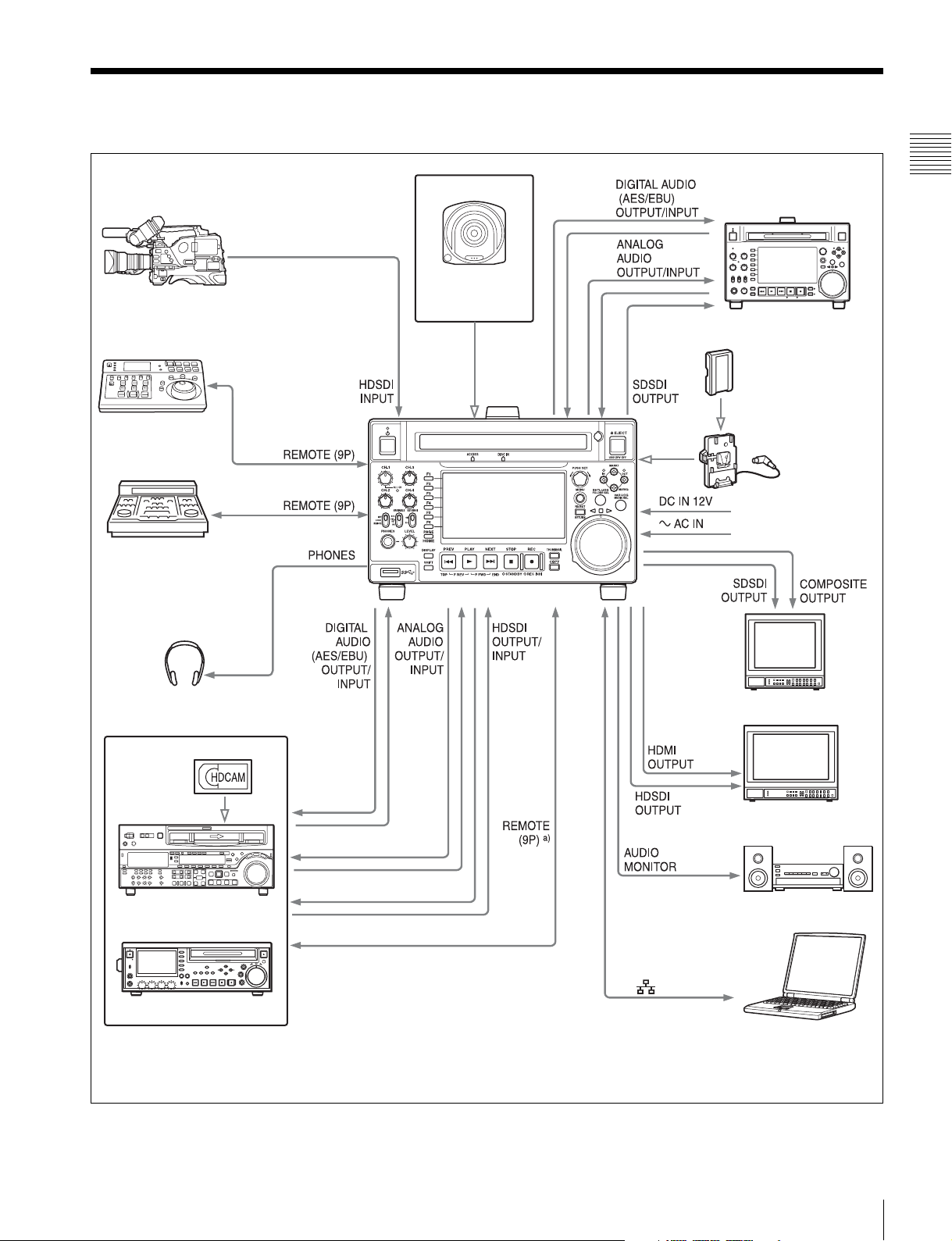
System Configurations
Chapter 1 Overview
PDW-700/PMW-500
RM-280 Editing
Controller
BVE-700
Headphones
Professional Disc
PDW-F1600
BP-L80S Battery Pack
BKP-L551 Battery
Adaptor
DC power source
AC power source
SD video monitor
HDW-2000 series
PDW-F75
a) For HDW-2000 series only.
HD video monitor
Audio monitor
Laptop computer
The unit can function as a player only when performing linear editing.
System Configurations
9
Names and Functions of
Parts
Chapter 2 Names and Functions of Parts
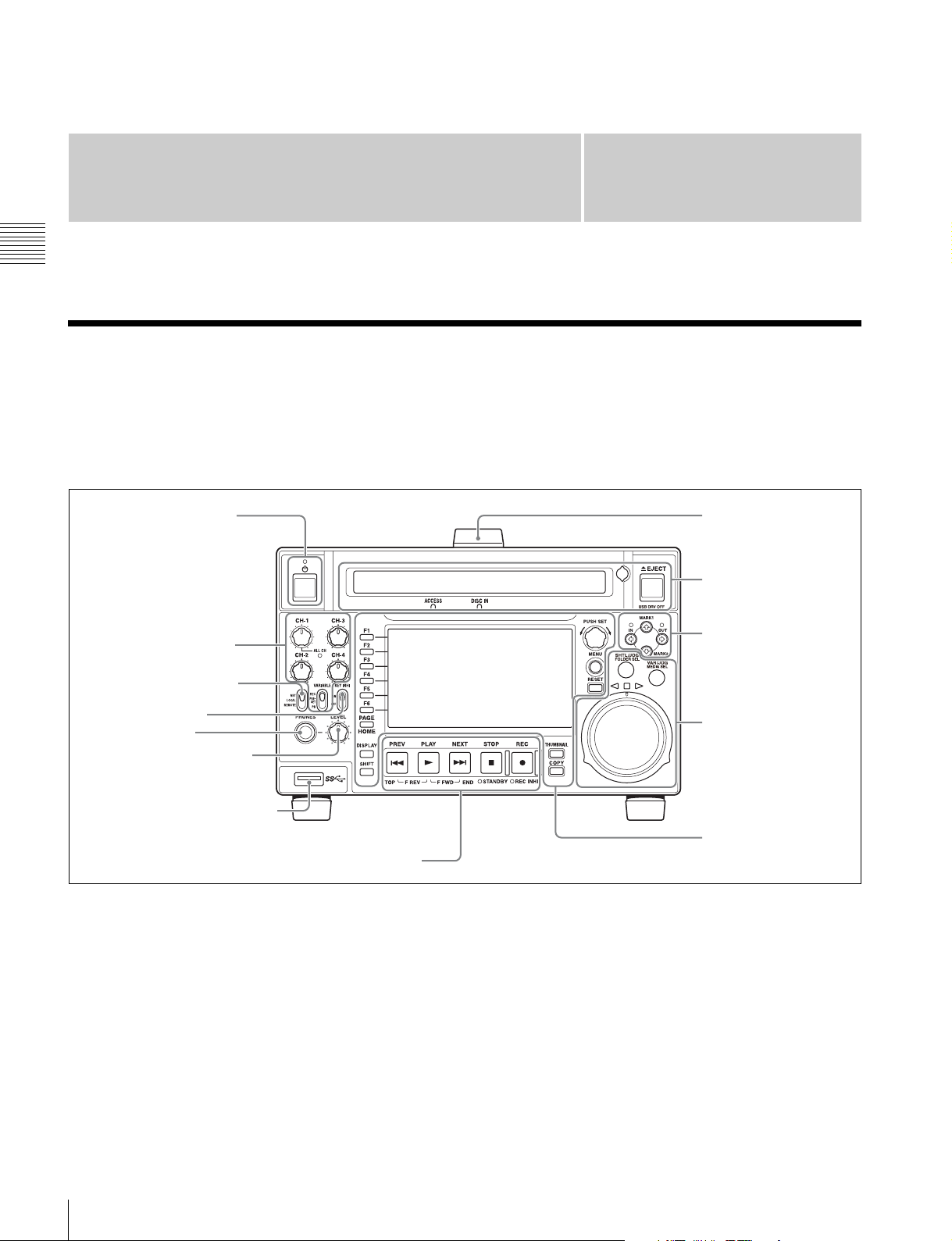
Front Panel
The names and symbols of buttons and knobs on the front
panel are color coded according to function.
White: Function when the button or knob is operated
independently.
1 On/standby button and
indicator
2 Audio level adjustment
section (see page 11)
Chapter
Orange: Function when the button is operated with the
SHIFT button held down.
Blue: Function related to thumbnail operations.
2
Handle
1 Disc control section
(see page 11)
3 Arrow buttons
(see page 12)
2 Remote control switch
3 KEY INHI switch
4 PHONES jack
5 LEVEL adjustment knob
6 Super Speed USB connector
6 Recording and playback control section (see page 14)
a On/standby (1) button and indicator
When the POWER switch on the rear panel is in the @ (on)
position, or when DC power is connected to the DC IN
12V connector on the rear panel, this switches the unit
between the operating state (the indicator is lit green) and
the standby state (the indicator is lit red).
When you press this button with the indicator lit red and
hold it down for a short time (0.25 seconds or longer), the
indicator changes to lit green, and the unit enters the
operating state.
4 Shuttle/jog/variable
control section (see
page 12)
5 Display/menu control
section (see page 13)
When you press this button with the indicator lit green and
hold it down for a longer time (1 second or longer), the
indicator changes to flashing green and then lit red, and the
unit enters the standby state.
When using this unit, normally leave the rear panel
POWER switch in the @ position, and use this button to
switch the unit between the operating state and standby
state.
10
Front Panel
b Remote control switch
REC
NET
REMOTE
LOCAL
VARIABLE KEY INHI
PRESET
ON
OFF
PB
CH-1
ALL CH
CH-2
CH-3
CH-4
Different positions of the switch allow different operations
as follows.
NET: Enables access to the network. When an external
network device is being accessed, operations of the
buttons and dials related to recording and playback
are disabled.
LOCAL: Enables operation from the front panel.
With this unit accessing a network device, setting the
remote control switch to “LOCAL” displays a dialog
asking for your confirmation about network
disconnection. To disconnect, press the PUSH SET
knob. To not disconnect, set the remote control switch
to “NET”.
REMOTE: Enables remote control of this unit from the
following devices:
• Devices connected to the REMOTE (9P) connector
• Devices connected to the SD/HDSDI INPUT
connector with SDI remote control functions
Use setup menu item 214 REMOTE INTERFACE to
select which of the connectors is used for remote
control.
When operating the unit by remote control, you can
use setup menu item 006 LOCAL FUNCTION
ENABLE to enable or disable the buttons and switches
in the recording and playback control section of the
unit.
c KEY INHI switch
This turns key operation inhibit mode on or off.
ON: Turns key operation inhibit mode on.
OFF: Turns key operation inhibit mode off.
d PHONES jack
The jack is a standard stereo jack. Connect stereo
headphones to monitor the audio during recording,
playback, and editing. (Non-audio signals are muted.) The
monitored channel is selected with MONITR L and
MONITR R on the HOME page of the function menu (see
page 39).
e LEVEL (volume) adjustment knob
Adjust the volume of headphones or speakers with the
knob. You can also cause this to simultaneously adjust the
output volume from the AUDIO MONITOR R, L
connectors on the rear panel. To do this, set setup menu
item 114 AUDIO MONITOR OUTPUT LEVEL to
“variable”.
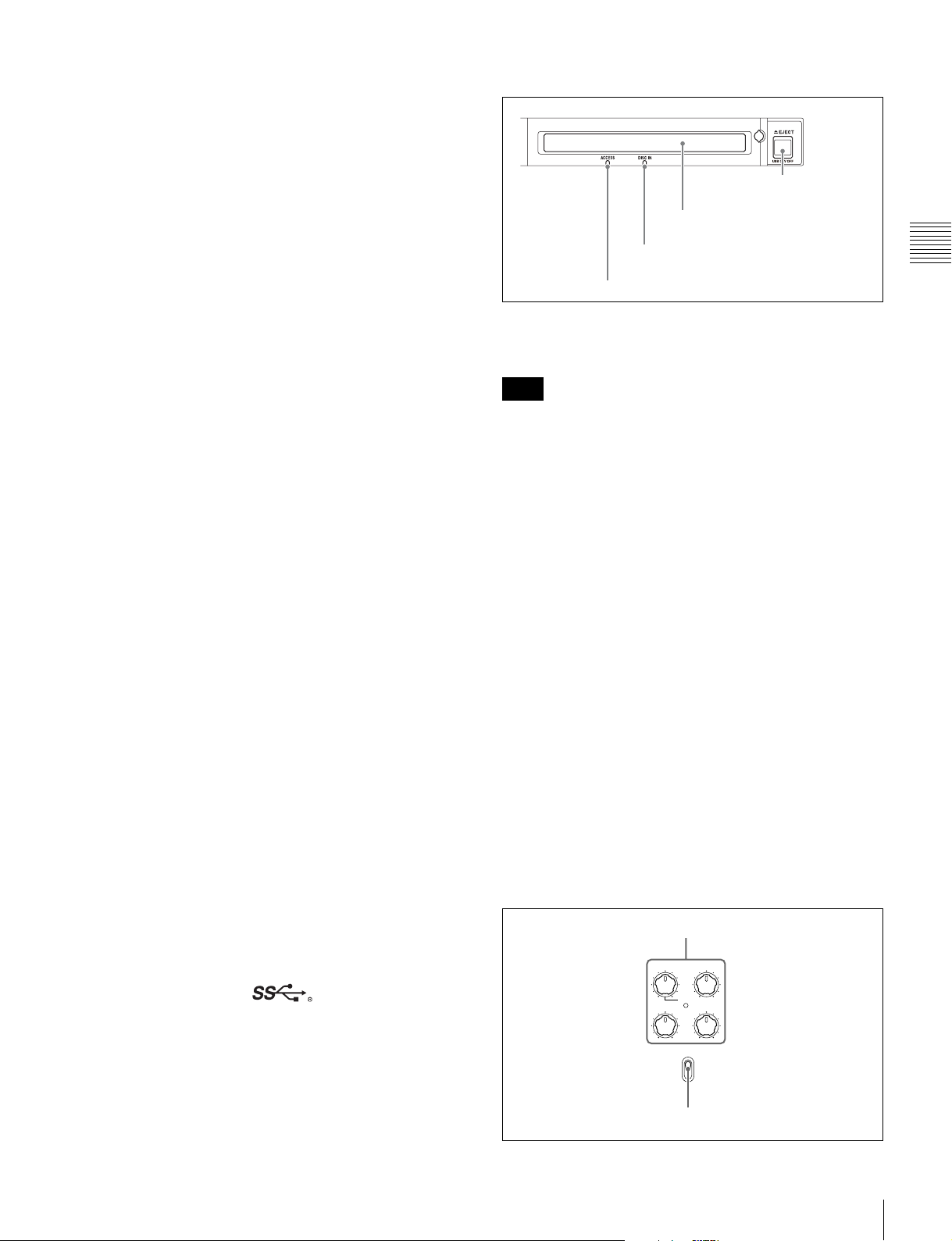
1 Disc control section
4 EJECT/USB DRV OFF
button
3 Disc slot
2 DISC IN indicator
1 ACCESS indicator
a ACCESS indicator
This lights when the Professional Disc is accessed.
Note
While the ACCESS indicator is lit, do not turn off the
POWER switch on the rear panel or disconnect the power
cord.
This could lead to a loss of data from the disc.
b DISC IN indicator
This lights when a Professional Disc is inserted.
c Disc slot
Insert a Professional Disc in this slot.
d EJECT/USB DRV OFF (USB drive off) button
Functions as the EJECT button or the USB DRV OFF
button.
EJECT button: To remove the Professional Disc, press
this button.
USB DRV OFF button: To unmount the USB drive, press
this button.
See “Handling Discs” (page 42) for more information
about disc operations.
See “Handling External Storage” (page 45) for more
information about USB drive operations.
2 Audio level adjustment section
1 CH-1/ALL CH, CH-2 to CH-4 adjustment knobs
Chapter 2 Names and Functions of Parts
f Super Speed USB ( ) connector (USB 3.0)
Connect the USB connector of the external storage device.
2 VARIABLE switch
Front Panel
11

MARK2
MARK1
IN OUT
L/JOG
RETURN
RESET
a CH-1/ALL CH, CH-2 to CH-4 (audio level)
adjustment knobs
Depending on the setting of the VARIABLE switch, these
adjust the input audio or playback audio levels of channels
1 to 4.
You can adjust levels of channels 5 to 8 using the function
menu.
For details, see page 41.
Chapter 2 Names and Functions of Parts
By setting setup menu item 131 AUDIO VOLUME, you
can enable the CH-1/ALL CH adjustment knob to
simultaneously adjust all eight channels. When this
simultaneous adjustment is enabled, the ALL CH indicator
lights.
b VARIABLE (audio level adjustment selector)
switch
This selects whether the input audio level or playback
audio level is adjusted when using the CH-1/ALL CH and
CH-2 to CH-4 adjustment knobs to adjust channels 1 to 4,
and when using the function menu to adjust channels 5 to
8.
REC: Adjust the input audio levels. The playback audio
levels are fixed at their preset values.
PRESET: The audio levels are fixed at their preset values.
PB: Adjust the playback audio levels. The input audio
levels are fixed at their preset values.
3 Arrow buttons
The four arrow buttons can also be used as the MARK1
button, MARK2 button, IN button, and OUT button. The
correspondence with these buttons is as follows.
V button: MARK1 button
v button: MARK2 button
B button: IN button
b button: OUT button
You can use these buttons for thumbnail selection, menu
setting operations, setting IN/OUT points, and so on.
1 V/MARK1 button and v/MARK2 button
2 IN indicator and OUT indicator
3 B/IN button and b/OUT button
a V/MARK1 button and v/MARK2 button
When the clip list screen is shown on the display, you can
use these for thumbnail selection.
During recording or playback, a shot mark 1 or shot mark
2 is recorded as an essence mark when you press the PUSH
SET knob with the V/MARK1 or v/MARK2 button held
down.
You can delete essence marks on the chapter thumbnail
screen (see page 67).
b IN indicator and OUT indicator
Lights or flashes as follows when you set IN and OUT
points in the clip to copy only the part defined by the IN
and OUT points (see page 57).
IN indicator: When an IN point is set, this lights. If an
attempt is made to set the IN point after a recorded
OUT point, this flashes.
OUT indicator: When an OUT point is set, this lights. If
an attempt is made to set the OUT point before a
recorded IN point, this flashes.
c B/IN button and b/OUT button
When the clip list screen is shown on the display, you can
use these for thumbnail selection.
An IN or OUT point is set when you press the PUSH SET
knob with the B/IN or b/OUT button held down. The IN
or OUT point setting is deleted when you press the
RESET/RETURN button with the B/IN or b/OUT button
held down.
4 Shuttle/jog/variable control section
1 SHTL/JOG)/FOLDER SEL button
2 VAR/JOG/MEDIA SEL button
3 Jog/shuttle transport indicators
4 Shuttle dial
5 Jog dial
a SHTL/JOG (shuttle/jog)/FOLDER SEL (folder
select) button
Functions as the SHTL/JOG button or the FOLDER SEL
button.
SHTL/JOG button: Press this button, turning it on, to
perform shuttle or jog playback.
FOLDER SEL button: When a USB drive is connected,
press this button to display a list of the folders on the
USB drive.
b VAR/JOG (variable/jog)/MEDIA SEL (media
select) button
Functions as the VAR/JOG button or the MEDIA SEL
button.
VAR/JOG button: Press this button, turning it on, to
perform variable or jog playback.
MEDIA SEL button: When a USB drive is connected,
press this button to select the target media (disc or
USB drive).
12
Front Panel
c Jog/shuttle transport indicators
These show the playback direction in jog, shuttle, or
variable mode.
d Shuttle dial
Turn this dial for shuttle or variable playback.
e Jog dial
Turn this dial for jog playback.
For details of playback operations in jog, shuttle, or
variable mode, see “Playback operation” (page 53).
For details of USB drive operations with the FOLDER
SEL and MEDIA SEL buttons, see “Handling External
Storage” (page 45).
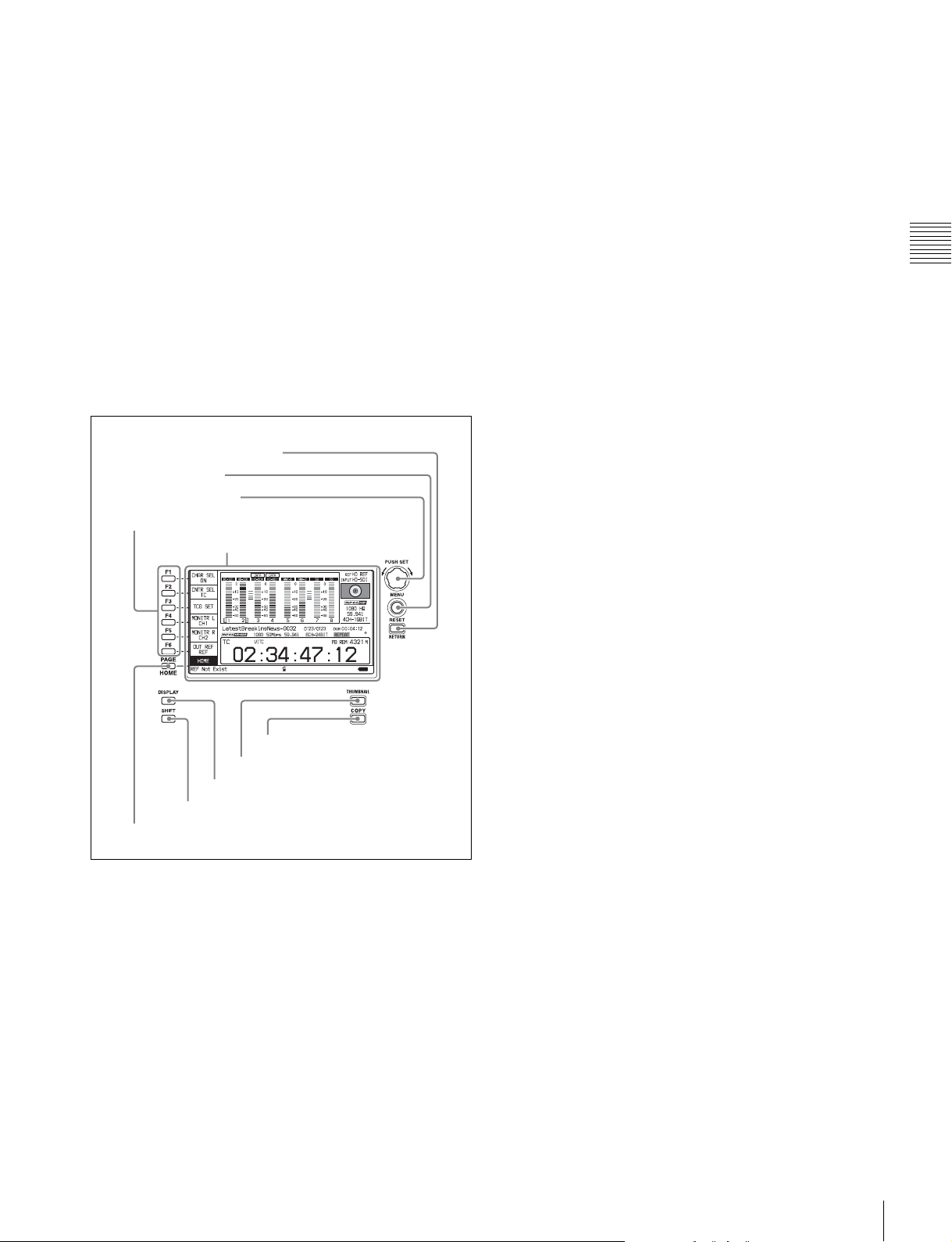
5 Display/menu control section
5 RESET/RETURN button
4 MENU button
3 PUSH SET knob
1 Function buttons (F1 to F6)
2 Display
c PUSH SET knob
Use for setting menu items and for operations using
thumbnails on clip list screens. Turn the knob to select
items, and press it to confirm the selection. This button is
also used to set numerical values, such as timecodes.
See “Clip Operations” (page 66) for more information
about how to use the thumbnail screens.
d MENU button
Displays the setup menu or the clip list screen menu. The
setup menu appears when no clip list screen is visible. The
same information is also superimposed on the display on a
monitor connected to the HDMI OUT connector of the
unit. Press once more to return to the original display.
See “Clip Operations” (page 66) for more information
about how to use the thumbnail screens.
e RESET/RETURN button
Functions as the RESET button or the RETURN button.
RESET button: Resets counters or the setting values of
the timecode generator. This button is also used to
abort or cancel setup menu and thumbnail search
operations.
RETURN button: On setup menu and clip list screens,
returns to the previous procedure.
Chapter 2 Names and Functions of Parts
6 COPY button
7 THUMBNAIL button
8 DISPLAY button
9 SHIFT button
0 PAGE/HOME button
a Function buttons (F1 to F6)
These buttons are enabled when the function menu (see
page 39) is visible. Each press of a button changes the
setting of the corresponding item in the menu.
For convenience, this manual refers to these buttons as
buttons F1 to F6, in order from the top.
b Display
Displays menus, audio level meters, and data, such as time
data or clip information. The DISPLAY button lets you
switch to the video monitor display.
f COPY button
Displays the Clip Copy screen (see page 56) when pressed
while the clip list screen is shown on the display.
g THUMBNAIL button
When this button is pressed when the basic operation
screen or video monitor screen is displayed, a list of clips
or EDLs saved on the currently selected media is
displayed. (That is, the current screen is switched to a clip
list screen.) When pressed again, returns to the basic
operation screen or the video monitor screen.
See “Clip Operations” (page 66) for more information
about how to use the thumbnail screens.
h DISPLAY button
Each press of this button switches the display screen
between the basic operation screen and video monitor
screen (see page 15).
When the clip list screen is shown on the display, this
button switches the display screen between thumbnails
view and details view.
i SHIFT button
Switches between functions for any button with two
functions.
For details, see “Display screen” (page 15).
Front Panel
13
j PAGE/HOME button
When pressed alone, this functions as the PAGE (page
switching) button. When pressed together with the SHIFT
button, functions as the HOME button.
PAGE button: Displays the function menu, if it is not
already visible. (The most recently displayed page of
the function menu appears.)
HOME button: When pressed with the function menu
visible, returns to the HOME page of the function
menu.
Chapter 2 Names and Functions of Parts
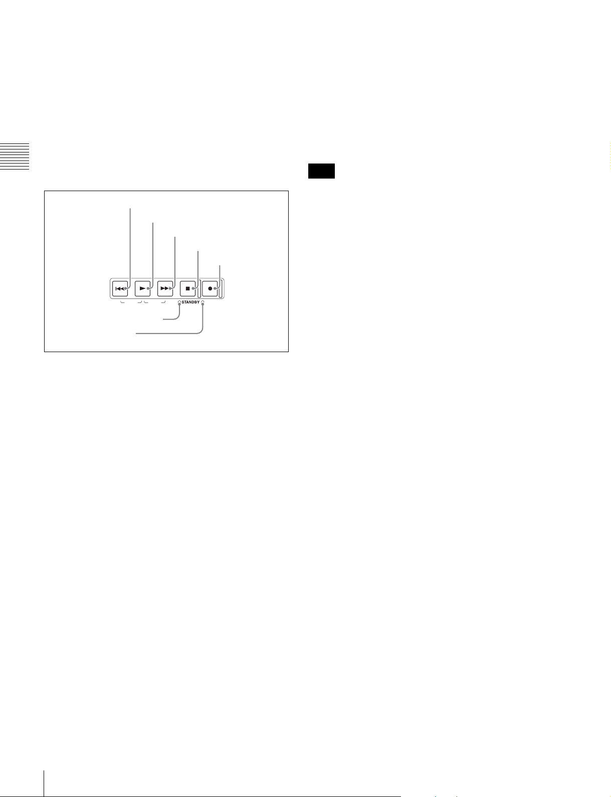
6 Recording and playback control section
1 PREV button
2 PLAY button
3 NEXT button
4 STOP button
5 REC button
PREV PLAY STOPNEXT REC
TOP F REV END
7 STANDBY indicator
6 REC INHI indicator
F FWD
REC INHI
a PREV (previous) button
Press this button, turning it on, to show the first frame of
the current clip. When the first frame of a clip is shown,
pressing this button jumps to the beginning of the previous
1)
clip.
This button is also used together with other buttons
for the following operations.
Reverse direction high-speed search: Hold down the
PLAY button, and press this button. A high-speed
search in the reverse direction is carried out.
Displaying the first frame of the first clip: Hold down
the SHIFT button, and press this button.
1) When setup menu item 153 FIND MODE is set to “clip & rec start mark”,
this button jumps to the frame where the previous Rec Start essence mark
is set and displays the video of that frame.
b PLAY button
To start playback, press this button, turning it on.
When this button is pressed during recording, recording
stops and the unit enters stop mode. If you do not want to
stop recording when this button is pressed, set setup menu
item 145 MODE KEY ENABLE DURING RECORDING
to “stop”.
Displaying the last frame of the last clip: Hold down the
SHIFT button, and press this button.
2) When setup menu item 153 FIND MODE is set to “clip & rec start mark”,
this button jumps to the frame where the next Rec Start essence mark is set
and displays the video of that frame.
d STOP button
To stop recording or playback, press this button, turning it
on. The frame at the stop point is displayed.
Note
This button flashes when setup menu item 105
REFERENCE SYSTEM ALARM is set to “on” and the
correct reference video input signal (as specified by OUT
REF on the HOME page of the function menu) is not being
input.
e REC (record) button
To start recording, hold down this button, and press the
PLAY button. The recording takes place on an unrecorded
part of the disc.
To stop recording, press the STOP button.
To monitor in EE mode
You can press this button when in stop mode to monitor
input signals in EE mode. The button lights when pressed.
Press the STOP button to return to the original video.
You can also press this button during playback and
searches to view EE mode for as long as the button is held
down.
f REC INHI (recording inhibit) indicator
This lights in the following cases.
• When a disc with recording inhibited is loaded.
• When the format of the recorded part of the disc does not
match the system frequency settings of the unit.
g STANDBY indicator
Lights when the unit is put into disc stop mode. After a
certain time passes in a disc stop mode, the unit
automatically enters standby state and the indicator goes
off.
You can specify the time until the unit enters standby state
with setup menu item 501 STILL TIMER.
c NEXT button
Press this button, turning it on, to jump to the next clip, and
show the first frame.
2)
This button is also used together
with other buttons for the following operations.
Forward direction high-speed search: Hold down the
PLAY button, and press this button. A high-speed
search in the forward direction is carried out.
14
Front Panel
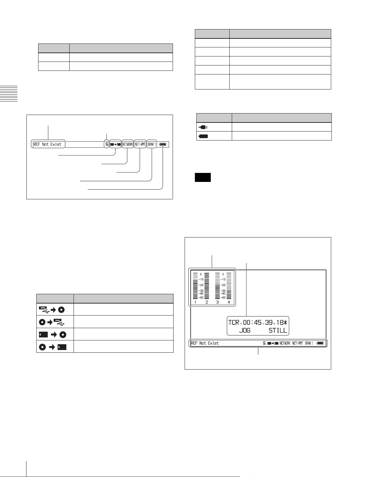
Display screen
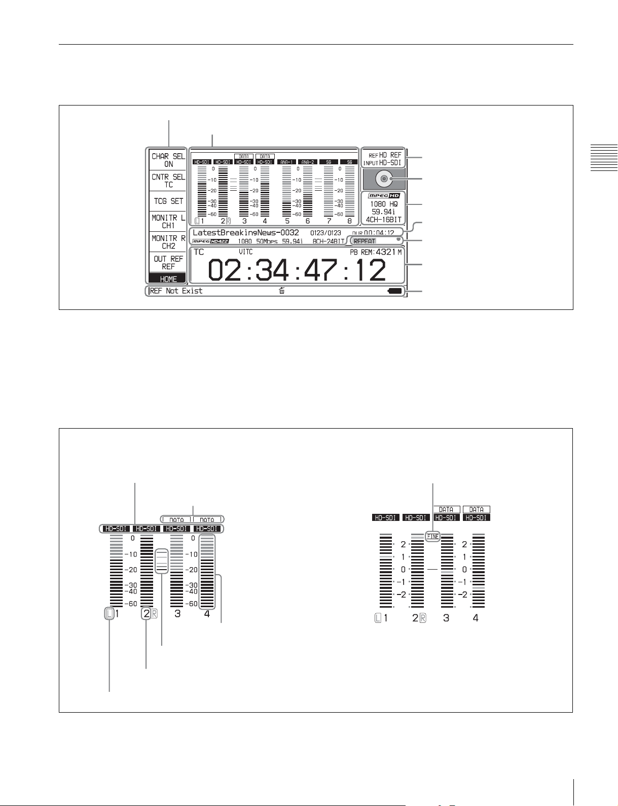
Basic operation screen
1 Function menu
2 Audio input display/audio level meters
3 System information
Chapter 2 Names and Functions of Parts
4 Disc status indicator
5 Recording/playback format
6 Clip information
7 Status indicator
8 Time data display area
9 Status display area
a Function menu
Use the PAGE/HOME button to display this menu, and to
switch between the pages (HOME, P1 to P6) of the menu.
Each page has one to six setting items. Press the
corresponding function button to change a setting.
For details, see “Basic Operations of the Function Menu”
(page 39).
A Input signal indicator
B Data indicator
b Audio input display/audio level meters
Displays information about audio. There are two display
modes for the audio level meter: FULL mode and FINE
mode, which can be switched using AU METER on page
P3 AUDIO of the function menu.
Meter display mode: FINEMeter display mode: FULL
G Meter display mode
E Reference level
D Audio channel
C Monitor channel
F Level bars
Front Panel
15
A Input signal indicator: Displays the audio input
signal.
.
Display Input signal
ANA-1
(MIC-1)
ANA-2
(MIC-2)
ANA-3
Chapter 2 Names and Functions of Parts
ANA-4
HD-SDI HDSDI audio signal (flashes when there is
SD-SDI SDSDI audio signal (flashes when there is no
AES/
EBU
SG Test signal from the internal signal generator
a) When maintenance menu item M374 ANALOG I/O is set to “4ch”
only.
Analog audio signal Channel 1, 3, 5, 7 or
Channel 1, 5
Channel 2, 4, 6, 8 or
Channel 2, 6
Channel 3, 7
Channel 4, 8
no input signal)
input signal)
AES/EBU audio signal (flashes when there is
no input signal)
B Data indicator: Appears when the input signals are
non-audio signals.
C Monitor channel: Displays the audio monitoring
channels set with MONITR L and MONITR R on the
HOME page of the function menu (see page 39).
D Audio channel: Displays the audio channels.
Also indicates preset or variable-speed mode by its
color (see page 12).
White: Preset mode
Green: Variable-speed mode
E Reference level: Displays the reference level for
recording as set with maintenance menu item M370
HEAD ROOM.
For details on setting the reference level, see
maintenance menu item M37 (page 105).
F Level bars: Displays the audio recording or playback
levels of channels 1 to 8. The OVER indicators light
when the audio level exceeds 0 dB.
G Meter display mode: Displays the audio level meter
display mode selected with AU METER on page P3
AUDIO of the function menu (see page 41).
c System information
A Reference signal
B Video input indicator
SD REF: SD-format reference signal
B Video input indicator: Displays the selected video
input signal.
HD-SDI: HDSDI video input
SD-SDI: SDSDI video input
a)
SG: Test video signal from the internal signal
generator
a)
a)
a)
The video signal input is selected with V INPUT on
page P1 INPUT of the function menu (see page 40).
Note
The display blinks when there is no video input signal,
and when the video input signal does not match the
system frequency of this unit.
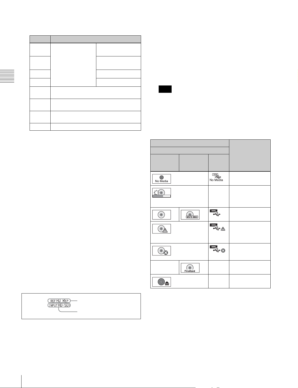
d Disc status indicator
Displays an icon indicating the status of the disc or
external storage.
Icon Status
Professional Disc
PFD23A/
PFD50DLA/
PFD100TLA
— — Finalized
PFD128QLW External
storage
Not loaded
— Mounting
Displays a
mounting progress
bar.
Normal status
Warning level error
has occurred.
(Finalizing is not
possible.)
Error has occurred.
(Restoring is not
possible.)
— Ejecting
The PFD128QLW disc status indicator changes with the
remaining capacity of the recordable resource space (for
writing the disc management data, etc.).
A Reference signal: Displays the type of reference
signal to which this unit is synchronizing.
When there is no display, the unit is synchronizing to
the internal reference signal.
INPUT: Input video
HD REF: HD-format reference signal
16
Front Panel
Icon Status
Yellow bar
Red bar
The available recordable resource space is
running out.
There is no available recordable resource
space on the disc.
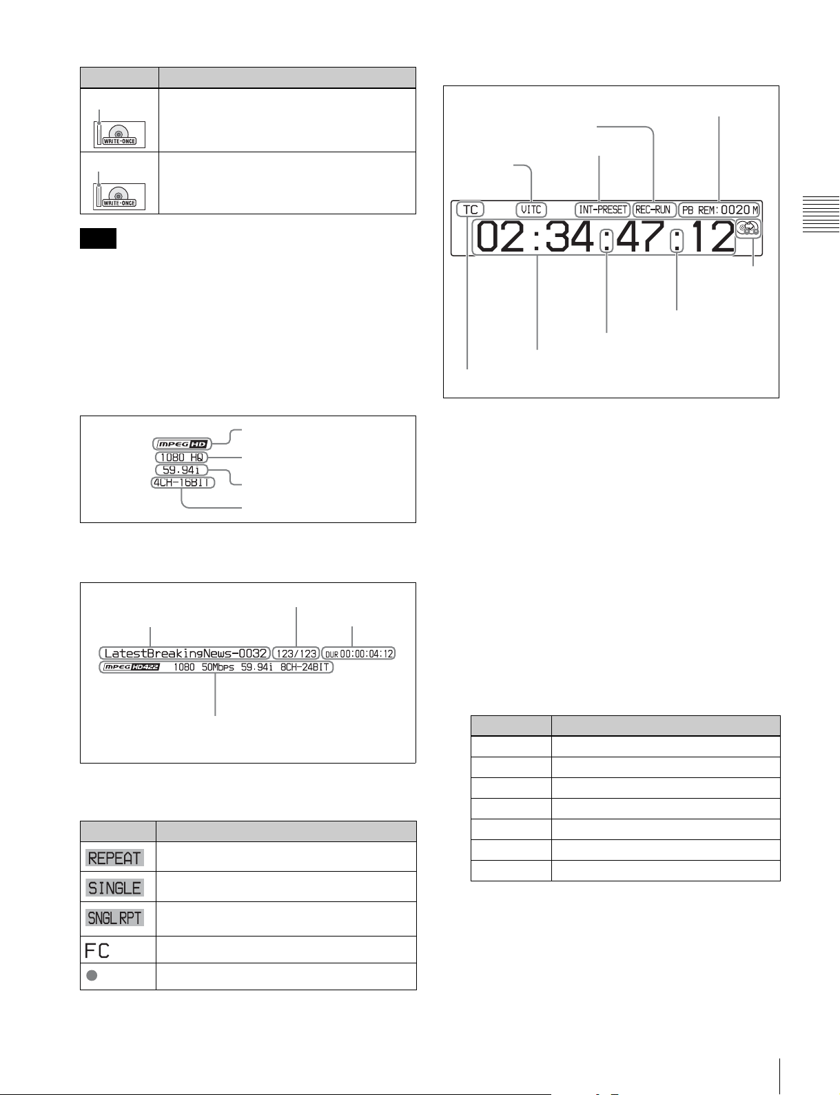
h Time data display area
A Remaining disc capacity for recording or playback
B REC RUN/FREE RUN
C Timecode generator mode
D VITC
Note
The remaining capacity of recordable resource space is not
the same as the remaining recording capacity. When there
is no available recording resource space left on the disc,
file writing may be disabled even with sufficient available
storage remaining.
e Recording/playback format
This displays the recording format during recording and
the playback clip format during playback.
Codec
Video format
System frequency
Audio format
f Clip information
Displays clip information.
Clip number/total number of clips
Clip name
Duration
H Recording
mode
indicator
G DF/NDF
indicator
(TCG)
F Time data
E Time data type
G DF/NDF
indicator
(TCR)
A Remaining disc capacity for recording or
playback: Displays the amount of remaining capacity
for recording or playback on the disc.
B REC RUN/FREE RUN: Displays the timecode run
mode. The run mode is set with RUN MODE on page
P4 TC of the function menu (see page 41).
C Timecode generator mode: Displays the timecode
source and generation method (preset or regenerate).
These are set with TCG and PRST/RGN on page P4
TC of the function menu (see page 41).
D VITC: Lights in the following cases.
• When VITC is read in playback mode. (This has no
relation to the display in the time data display area.)
• When VITC recording is possible.
E Time data type: Displays the type of time data
displayed in the time data display area. The type of
time data is selected with CNTR SEL on the HOME
page of the function menu (see page 39).
Chapter 2 Names and Functions of Parts
Clip format
(Codec, video format, system frequency,
audio format)
g Status indicator
Displays icons indicating the status of this unit.
Icon Description
Currently set to repeat playback mode
Currently set to single clip playback mode
Currently set to single clip playback mode with
repeat playback mode
1080/720 cross-convert output
Recording
Display Type of time data
TC Timecode
COUNTER Elapsed recording/playback time
UB User bits
VITC VITC
VIUB VIUB
TCG Timecode generator value
UBG User bits generator value
F Time data: Normally displays timecode or VITC,
according to the selection made with TCR on page P4
TC of the function menu.
G DF/NDF indicator: Displays the frame count mode
for the internal timecode reader (TCR) and internal
timecode generator (TCG). The frame count mode is
Front Panel
17
set with DF/NDF on page P4 TC of the function menu
(see page 41).
Display Frame count mode
. DF (drop-frame mode)
: NDF (non-drop-frame mode)
H Recording mode indicator: This appears when setup
menu item 150 REC MODE is set to “disc exchange
cache”.
Chapter 2 Names and Functions of Parts
i Status display area
Display Current setup menu settings
BANK1 Same as those in menu bank 1.
BANK2 Same as those in menu bank 2.
BANK3 Same as those in menu bank 3.
DEFAULT Same as the factory default settings.
Nothing
displayed
Different from any of the above.
G Power source indicator: Displays the icon for the
power source being used.
A Error, warning, and alarm messages
B Delete icon
C Copy icon
D Network connection indicator
E Network remote connection indicator
F Menu setting status
G Power source indicator
A Error, warning, and alarm messages: Messages
about operations and the status of the unit appear here.
The seriousness of the message is indicated by the
color, as follows.
Red: Error message (flashing)
Orange: Warning message
White: Alarm message
B Delete icon: Flashes while a clip deletion is being
executed.
C Copy icon: During a clip copy operation, displays an
icon indicating the copy source/copy destination
media.
Icon Power source being used
AC power source
Battery
When the remaining battery power drops below a
certain level, the battery icon starts flashing (this is the
battery near end alarm).
Note
With the battery near end alarm displayed, when the
battery voltage drops below the shutdown voltage set
with setup menu item 033 BATTERY END
VOLTAGE, the unit is automatically shut down.
Video monitor screen
A Audio level meters
B Superimposed information
Icon Copy source/copy destination media
External storage/disc
Disc/external storage
Memory card/disc
Disc/memory card
D Network connection indicator: Lights while data is
being exchanged with a network connected external
device.
E Network remote connection indicator: “NET-
RMT” or “RM-SDI” is displayed during a network
remote control connection to an external device (see
page 49).
F Menu setting status: Displays the current setup menu
settings.
18
Front Panel
C Status display area
A Audio level meters: LEVEL MT on page P3 AUDIO
of the function menu determines whether the meter is
to be displayed and on which side, left or right, in the
display window.
B Superimposed information: Appears when CHAR
SEL on the HOME page of the function menu is set to
“ON”.
C Status display area: Displays messages and icons
about the status of the unit (see page 18).

You can disable the status display area with the
DISPLAY button. However, it is automatically
enabled when:
• Display of error/warning/alarm message becomes
necessary.
• During battery-driven operation, the power source
indicator starts flashing (the battery near end alarm
is given).
Chapter 2 Names and Functions of Parts
Front Panel
19
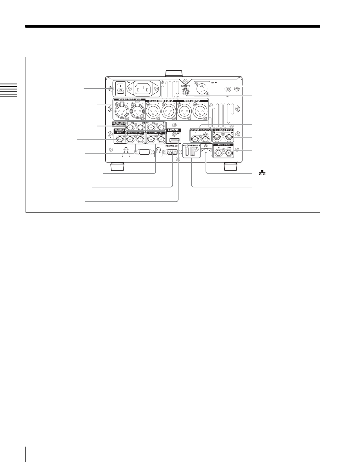
Rear Panel
1 Power supply section
(see page 21)
Chapter 2 Names and Functions of Parts
2 Analog audio signal input/
output section (see page 21)
3 Digital audio signal input/
output section (see page 22)
1 SD/HDSDI INPUT
connector
2
HDSDI OUTPUT 1, 2
(SUPER) connectors
3 SDSDI OUTPUT 1, 2 (SUPER)
connectors
4 REMOTE (9P) connector
5 HDMI OUT connector
a SD/HDSDI INPUT (SDSDI/HDSDI signal input)
connector (BNC type)
This inputs an SDSDI or HDSDI format video/audio
signal.
b HDSDI OUTPUT 1, 2 (SUPER) (HDSDI signal
output 1, 2 (superimpose)) connectors (BNC type)
These output HDSDI format video/audio signals.
You can superimpose timecodes or other information on
the output of the HDSDI OUTPUT 2 (SUPER) connector
using the CHAR SEL setting on the HOME page of the
function menu or the setting for setup menu item 028 HD
CHARACTER. You can always disable the
superimposition of data independently of the setting for
CHAR SEL using the setting for setup menu item 028.
See “Basic Operations of the Function Menu” (page 39)
for more information about the CHAR SEL setting.
See page 88 for more information about the setup menu
item 028 HD CHARACTER.
To treat the input and output signals of these connectors as
non-audio signals, set maintenance menu item M372
NON-AUDIO INPUT.
For details, see maintenance menu item M37 (page 105).
6 DC IN 12V connector
7 REMOTE connector
8 COMPOSITE OUTPUT 1, 2
(SUPER) connectors
9 REF. VIDEO INPUT
connectors
4 Timecode input/output
section (see page 22)
q; (network) connector
qa MAINTENANCE connectors
c SDSDI OUTPUT 1, 2 (SUPER) (SDI signal outputs
1, 2 (superimpose)) connectors (BNC type)
These output SDSDI format video/audio signals.
When the unit is shipped from the factory, audio signal
output is eight channels with no switching, and RP188
timecode output is set to on. You can change these settings
with setup menu item 828 SDI AUDIO OUTPUT
SELECT and setup menu item 920 SD-SDI H-ANC
CONTROL.
The output from the 2 (SUPER) connector can have
timecode and other text information superimposed. To
turn superimposition off, set CHAR SEL on the HOME
page of the function menu to “OFF”.
See “Items in the extended menu” (page 92) for more
information about setup menu settings.
See “Basic Operations of the Function Menu” (page 39)
for more information about the CHAR SEL setting.
d REMOTE (9P) (remote control 9-pin) connector
(D-sub 9-pin)
Connect a controller that supports the RS-422A Sony 9-pin
VTR control protocol.
e HDMI OUT connector
Connects to an HD projector, HD television, or other HD
consumer device, and outputs digital signals (video, audio,
and control signals).
20
Rear Panel
The audio signals of the channels selected with MONITR
ANALOG AUDIO INPUT
ANALOG AUDIO OUTPUT
1212
AUDIO MONITOR
RL
L and MONITR R on the HOME page of the function
menu are output.
You can superimpose timecodes, menu settings, and error
messages on the HDMI output using the CHAR SEL
setting on the HOME page of the function menu.
See “Basic Operations of the Function Menu” (page 39)
for more information about the MONITR L and
MONITR R settings.
f DC IN 12V connector (XLR 4-pin, male)
Connect to a 12 V DC power source.
When using the BKP-L551 Battery Adaptor to mount a
battery pack, connect the power cable of the BKP-L551.
For details, see “Supplying power” (page 23).
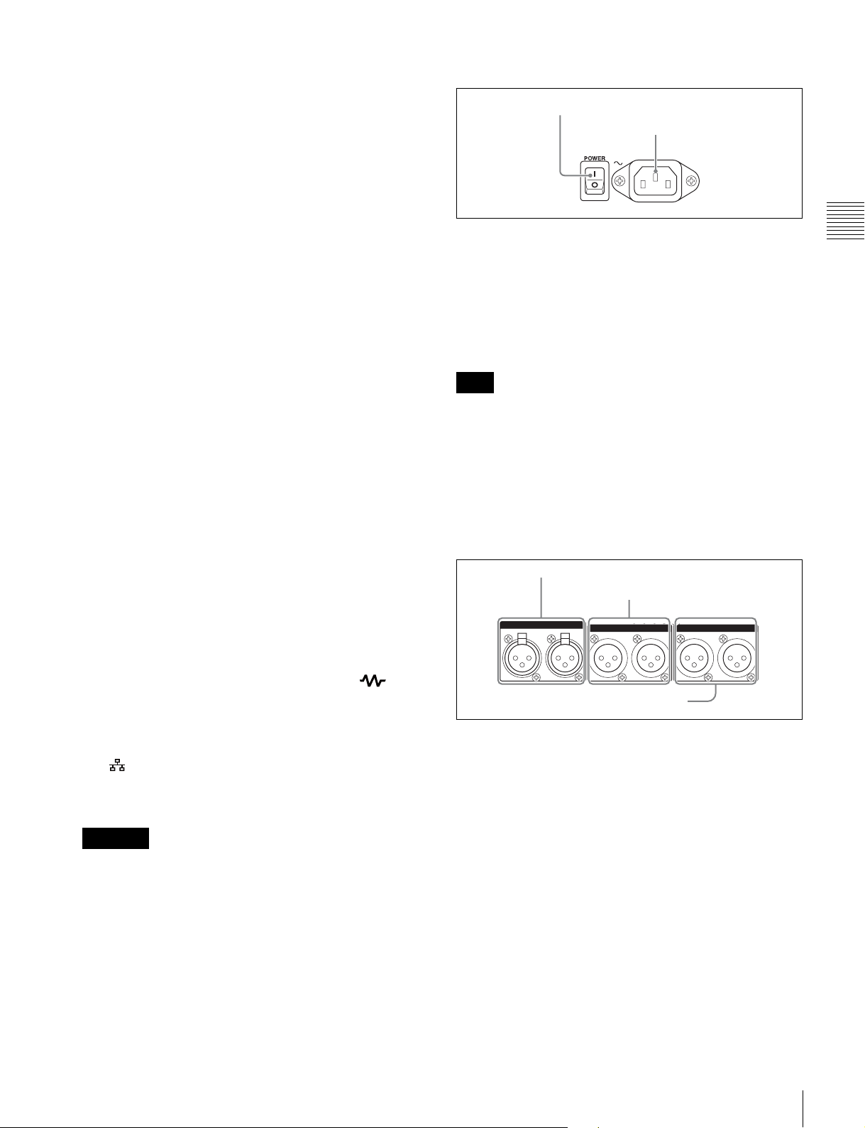
1 Power supply section
1 POWER switch
2 - AC IN connector
a POWER (main power) switch
Press the : side to power on the unit. Press the a side to
power off.
When using the unit, normally leave the POWER switch in
the : (on) position, and use the on/standby button on the
front panel to switch the unit between the operating state
and standby state.
Chapter 2 Names and Functions of Parts
g REMOTE connector (4-pin)
Supplies power to the RM-280 Remote Edit Controller.
h COMPOSITE OUTPUT 1, 2 (SUPER) (analog
composite video output 1, 2 (superimpose))
connectors (BNC type)
These output analog composite video signals. You can
superimpose timecodes on the output of the 2 (SUPER)
connector when CHAR SEL on the HOME page of the
function menu is set to ON.
See “Basic Operations of the Function Menu” (page 39)
for more information about the CHAR SEL setting.
i REF. VIDEO INPUT (reference video signal input)
connectors (BNC type)
The two connectors form a loop-through connection; when
a reference video signal is input to the left connector, the
same signal is input from the right connector ( ) (IN)
to a connected device. When no connection is made to the
right connector, the left connector is automatically
terminated with an impedance of 75 ohms.
j (network) connector (RJ-45 type)
This is a 10BASE-T/100BASE-TX/1000BASE-T
connector for network connection.
CAUTION
• For safety, do not connect the connector for peripheral
device wiring that might have excessive voltage to this
port. Follow the instructions for this port.
• When you connect the network cable of the unit to
peripheral device, use a shielded-type cable to prevent
malfunction due to radiation noise.
k MAINTENANCE connectors
These are High Speed USB (USB2.0) connectors for
maintenance.
Do not use for applications other than maintenance.
Note
Before turning the main power off, always check to be sure
that the unit is in the standby state, and then press the main
power switch to the a side.
b -AC IN connector
Connect to an AC power source using a power cord (not
supplied).
2 Analog audio signal input/output section
1 ANALOG AUDIO INPUT 1, 2 connectors
2 ANALOG AUDIO OUTPUT 1, 2
connectors
3 AUDIO MONITOR R, L connectors
a ANALOG AUDIO INPUT 1, 2 connectors (XLR
3-pin, female)
These input analog audio signals.
With A1 INPUT, A2 INPUT, A3 INPUT, and A4 INPUT
on page P1 INPUT of the function menu (see page 40),
you can assign the input signal on connector 1 to audio
channel 1 or 3, and assign the input signal on connector 2
to audio channel 2 or 4.
With A5 INPUT, A6 INPUT, A7 INPUT, and A8 INPUT
on page P2 INPUT of the function menu (see page 40),
you can assign the input signal on connector 1 to audio
channel 5 or 7, and assign the input signal on connector 2
to audio channel 6 or 8.
You can set the reference input level with maintenance
menu item M373 IN LEVEL. (Factory default setting:
+4dB)
For details, see maintenance menu item M37 (page 105).
Rear Panel
21
Microphone settings
If you have connected a microphone to this unit, you can
set input level, AGC, and limiter values for the
microphone with setup menu items 834, 839, 840, and 841.
Note
See “Basic Operations of the Function Menu” (page 39)
for more information about the MONITR L and
MONITR R settings.
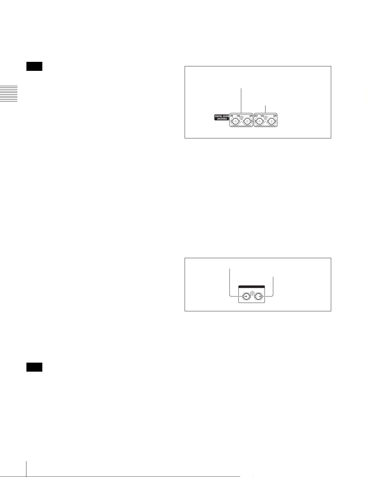
3 Digital audio signal input/output section
An unpleasant sound may be output if you have connected
a microphone to the ANALOG AUDIO INPUT 1 or 2
connector and power the microphone on with the input
level too high. Check the input level setting before
Chapter 2 Names and Functions of Parts
connecting a microphone.
b ANALOG AUDIO OUTPUT 1, 2 connectors (XLR
3-pin, male)
These output analog audio signals.
When the unit is shipped from the factory, connector 1 is
set to audio channel 1, and connector 2 is set to audio
channel 2. You can change these settings with setup menu
item 824 ANALOG LINE OUTPUT SELECT (see
page 100).
You can set the output level with maintenance menu item
M377 OUT LEVEL. (Factory default setting: +4dB)
Non-audio signals are muted.
For details, see maintenance menu item M37 (page 105).
The function of the ANALOG AUDIO OUTPUT 1, 2
connectors can be switched to ANALOG AUDIO INPUT
3, 4 connectors with maintenance menu item M374
ANALOG I/O.
With A1 INPUT, A2 INPUT, A3 INPUT, and A4 INPUT
on page P1 INPUT of the function menu (see page 40),
you can assign the input signal on connector 1 to audio
channel 1, the input signal on connector 2 to audio channel
2, the input signal on connector 3 to audio channel 3, and
the input signal on connector 4 to audio channel 4.
With A5 INPUT, A6 INPUT, A7 INPUT, and A8 INPUT
on page P2 INPUT of the function menu (see page 40),
you can assign the input signal on connector 1 to audio
channel 5, the input signal on connector 2 to audio channel
6, the input signal on connector 3 to audio channel 7, and
the input signal on connector 4 to audio channel 8.
To use ANALOG AUDIO OUTPUT connectors as
ANALOG AUDIO INPUT connectors, XLR male-tofemale adaptors are required.
Note
The ANALOG AUDIO INPUT 3, 4 connectors do not
support microphone connection.
c AUDIO MONITOR R, L connectors (XLR 3-pin,
male)
This outputs an audio signal for monitoring.
The monitored channel is selected with MONITR L and
MONITR R on the HOME page of the function menu.
1 DIGITAL AUDIO (AES/EBU)
IN 1/2, 3/4 connectors
2 DIGITAL AUDIO (AES/EBU)
OUT 1/2, 3/4 connectors
a DIGITAL AUDIO (AES/EBU) IN (digital audio
input) 1/2, 3/4 connectors (BNC type)
These input AES/EBU format digital audio signals.
b DIGITAL AUDIO (AES/EBU) OUT (digital audio
output) 1/2, 3/4 connectors (BNC type)
These output AES/EBU format digital audio signals.
To treat the input and output signals of these connectors as
non-audio signals, set maintenance menu item M372
NON-AUDIO INPUT.
For details, see maintenance menu item M37 (page 105).
4 Timecode input/output section
1 TIME CODE IN connector
2 TIME CODE OUT
connector
TIME CODE
IN OUT
a TIME CODE IN connector (BNC type)
This inputs an SMPTE timecode generated by an external
device.
b TIME CODE OUT connector (BNC type)
This outputs the following timecode, depending on the
operating state of this unit.
During playback: Playback timecode
During recording: The timecode from the internal
timecode generator or the timecode input to the TIME
CODE IN connector
22
Rear Panel

Preparations
Preparing Power Sources
Chapter
Continuous recording time at room temperature
BP-L80S lithium-ion battery pack: Approx. 60 minutes
(MPEG HD422 format)
3
Chapter 3 Preparations
This unit can be powered by AC power, DC power, or a
battery pack.
For safety, use only the Sony battery packs listed below.
Lithium-ion battery pack: BP-L80S
Note
If you load or remove a battery pack incorrectly, it may fall
and cause bodily injury. Follow the procedures described
below to load or remove them.
Supplying power
AC power supply
Connect the AC IN connector to an AC power source using
the specified AC power cord. To supply AC power to the
unit, set the POWER switch on the rear panel to = (on), then
press the on/standby button (1) on the front panel and
hold it down for a short time (0.25 seconds or longer).
DC power supply
Connect the DC IN 12V connector to a DC power source.
To supply DC power to the unit, turn off the POWER
switch on the rear panel, then press the on/standby button
(1) on the front panel and hold it down for a short time
(0.25 seconds or longer). If the POWER switch on the rear
panel is set to = (on), AC power is supplied.
For details on charging battery packs, refer to the
operation manual for the battery charger.
Notes about battery usage
• As long as a battery is connected to the unit, electric
current flows in the unit to keep the CPU in the standby
state, when the unit is not turned on. If the unit is not
used for an extended period, remove the battery.
• Before using the batteries, be sure to charge them fully
with the special battery charger. Refer to the operating
instructions for your battery charger for more
information about how to charge the batteries.
• Batteries may not be completely charged if you charge
them immediately after use when they are still warm.
You should wait until the batteries cool before charging
them.
Attaching a battery pack
Use the BKP-L551 in the following way to attach and
remove the BP-L80S Battery Pack.
For details on attaching the BKP-L551, refer to the
installation manual for the BKP-L551.
WARNING
Batteries shall not be exposed to excessive heat such as
sunshine, fire or the like.
Battery power supply
You can use the BP-L80S Battery Pack with this unit.
To use the battery pack, a BKP-L551 Battery Adaptor and
a dedicated battery charger are also required.
CAUTION
Danger of explosion if battery is incorrectly replaced.
Replace only with the same or equivalent type
recommended by the manufacturer.
When you dispose of the battery, you must obey the law in
the relative area or country.
Preparing Power Sources
23
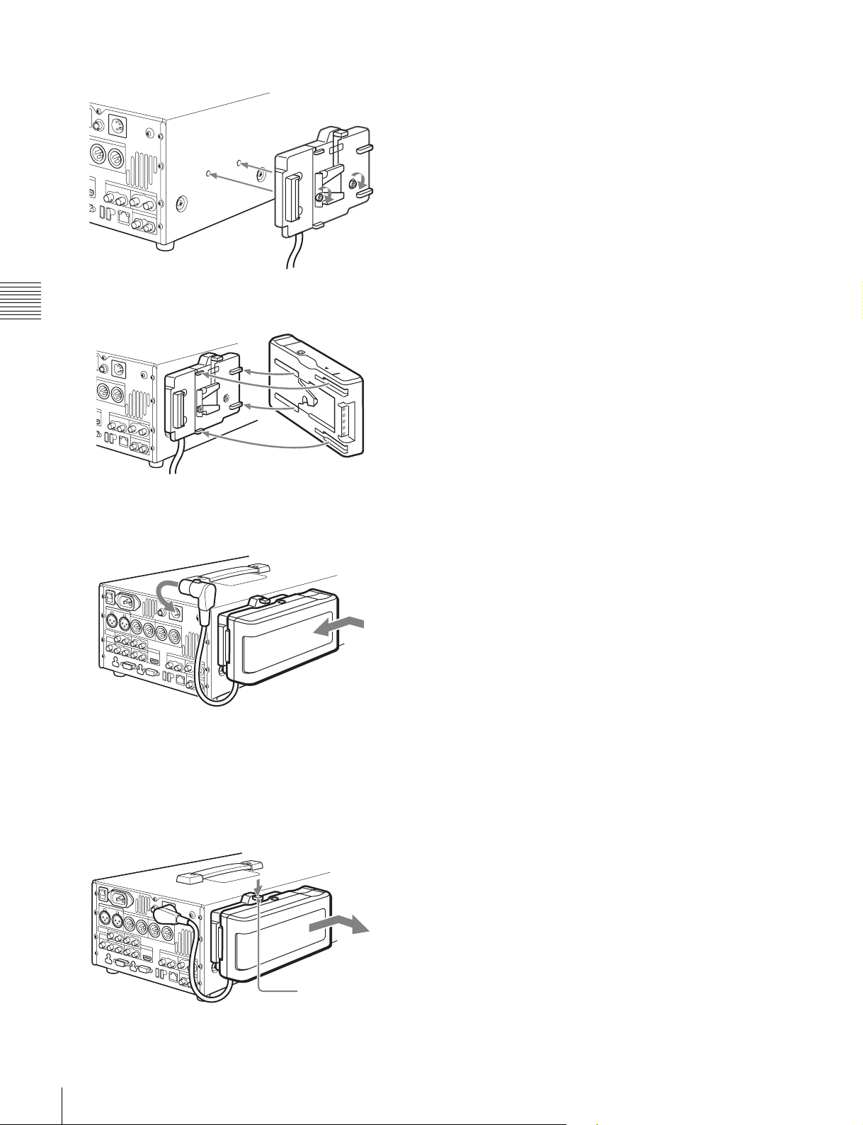
1
Attach the BKP-L551 to the side panel.
BKP-L551
2
Align the grooves on the BP-L80S with the projections
Chapter 3 Preparations
on the BKP-L551.
BP-L80S
Checking the remaining battery power
You can use the LEDs on the side panel of the battery to
check the remaining power of the battery.
When the remaining battery power decreases substantially
and the voltage approaches the set shutdown voltage, the
power source icon starts flashing in the status display area
of the display screen (the battery near end alarm is given).
3
Slide the BP-L80S as shown below so that the
connectors on the BP-L80S and the BKP-L551 are
connected.
4
Connect the DC cable of the BKP-L551 to the DC IN
12V connector.
Removing the battery pack
With the lever pushed in, slide the BP-L80S out as shown
below.
24
Preparing Power Sources
Lever
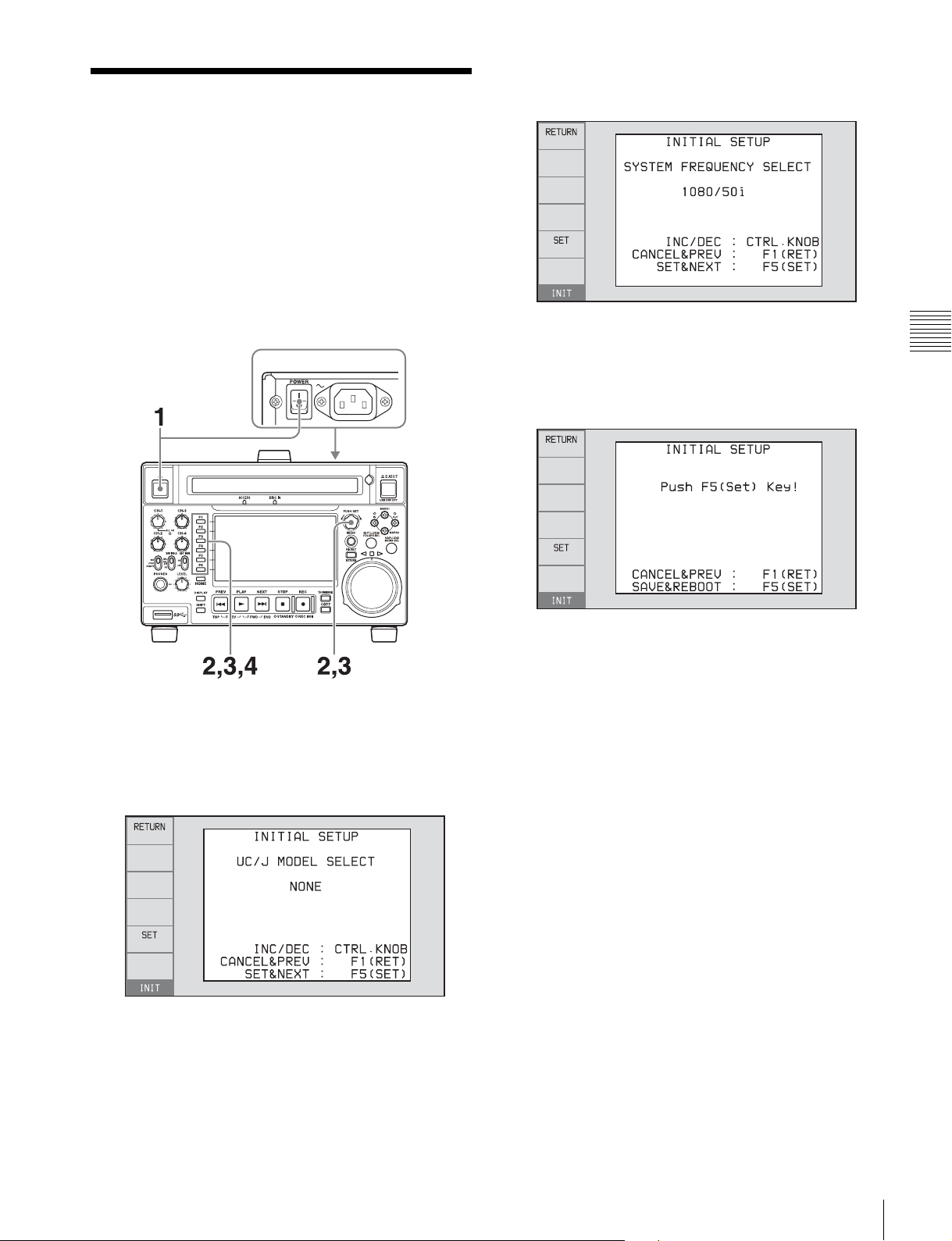
Initial Setup
This unit is shipped with the system frequency, and current
date and time still unset.
Therefore, you need to make initial setup settings before
using the unit. (You cannot use the unit without setting it
up.)
Once the unit has been set up, the settings are retained even
when the unit is powered off.
Use the following procedures.
3
Turn the PUSH SET knob to select the system
frequency.
Display the system frequency that you want to use, and
then press the SET function button (F5).
4
If you want to save the settings made up to this point,
press the SET function button (F5) again.
Chapter 3 Preparations
1
Power the unit on.
The INITIAL SETUP screen appears on the display.
2
Turn the PUSH SET knob to select the area of use.
Display UC (for regions outside Japan) or J (for
Japan), and then press the SET function button (F5).
The system frequency screen appears.
The message “NOW SAVING...” appears, and the
setting screen disappears. Then the unit powers itself
off and on again.
To return to the original screen without saving
settings
Press the RETURN function button (F1).
To set the date and time
Set maintenance menu item M3D DATE/TIME PRESET.
For details, see maintenance menu item M3D (page 106).
Initial Setup
25
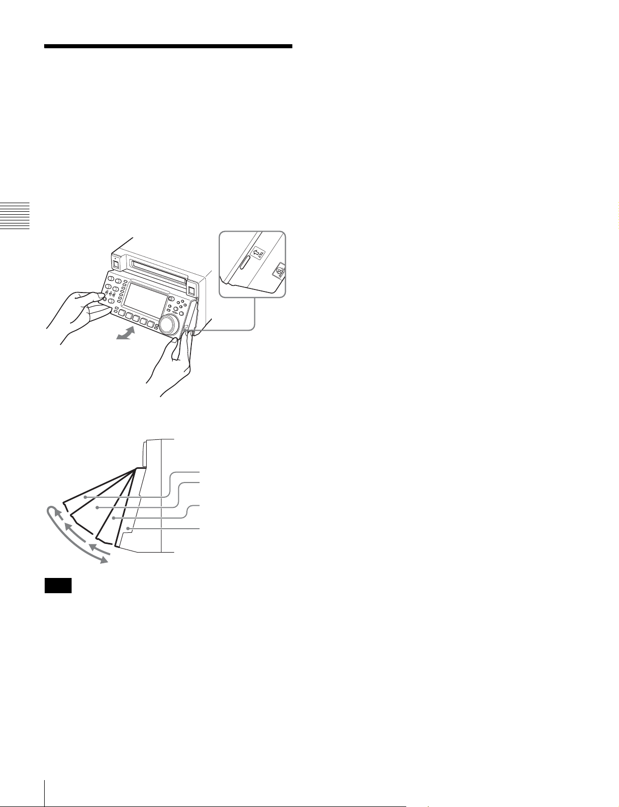
Front Panel Tilt Mechanism
The front panel of this unit has a tilt mechanism that allows
you to pull the front panel out and adjust it to a convenient
angle.
To pull the front panel out
Grasp the holds (small protrusions) on both sides of the
front panel and pull out as indicated by the arrow.
Chapter 3 Preparations
To change the angle of the front panel
To change the angle to position 2 from position 1, pull the
front panel out to position 2.
To change the angle to position 1 from position 2, first
unlock the front panel by pulling it all the way out to the
return position. Then return it to position 0, and pull out
again to position 1.
You can fix the angle of the front panel in position 1 (15
degrees) or position 2 (40 degrees).
Return position
Position 2 (40 degrees)
Position 1 (15 degrees)
Position 0
Note
The angle cannot be fixed if you pull the front panel past
position 2 all the way out to the return position. To fix the
front panel, return it to position 0 and then pull it out to
position 1 or position 2.
To return the front panel to its original
position
Unlock the front panel by pulling it out to the return
position. You can then return it to position 0.
26
Front Panel Tilt Mechanism
Connections and Settings
Note
Production of some of the peripherals and related devices
described in this chapter may have been discontinued.
For advice about choosing devices, please contact your
Sony dealer or a Sony representative.
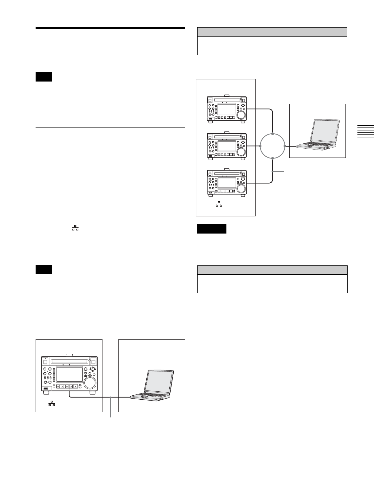
Settings on this unit
Remote control switch: NET (see page 11)
Setup menu item 257 NETWORK ENABLE: network
Connecting three PDW-HD1550 units to a laptop
computer via a LAN
PDW-HD1550
Laptop computer
Connections for Content Browser and non-Sony nonlinear editors
When using Content Browser, you can gain remote access
to this unit from a network connected computer. You can
also access this unit from a nonlinear editor that is not a
Sony product via FTP/CIFS, and use this unit as a material
server.
For an overview and installation of Content Browser,
access the Sony website closest to your area.
Using the (network) connector (FTP
connection)
The following shows an example of an FTP (File Transfer
Protocol) connection.
Note
The PDW-HD1550 IP address and other network-related
settings are required for connection.
For details on network settings, see M5: NETWORK of the
maintenance menu (page 107).
Chapter 3 Preparations
Network cable
(not supplied)
To (network)
connector
CAUTION
When you connect the network cable of the unit to
peripheral device, use a shielded-type cable to prevent
malfunction due to radiation noise.
Settings on all PDW-HD1550 units
Remote control switch: NET (see page 11)
Setup menu item 257 NETWORK ENABLE: network
Connecting a PDW-HD1550 unit directly to a
laptop computer
PDW-HD1550 (this unit)
Laptop computer
To (network) connector
Network cable (not supplied)
Connections and Settings
27

Connections for cut editing
The following figure shows a cut editing system
comprising this unit as a player.
When making the connections, also refer to the manuals
provided with the equipment to be connected.
See page 29 for more information about editing control
unit settings.
HD video monitor
To HDMI input connector
Chapter 3 Preparations
To HDSDI input connector
ANALOG AUDIO INPUT
DIGITAL AUDIO
(AES/EBU)
SD/HDSDI
INPUT
or
12
IN 1/2 3/4 1/2 3/4
OUT
(SUPER)21(SUPER)
21
When using an editing control unit
Using BVE-700/700A
The following figure shows a cut editing system
comprising this unit as a player, an HDW-M2000/M2000P
unit as a recorder, and a BVE-700/700A as an editing
control unit.
a)
REMOTE
ANALOG AUDIO OUTPUT AUDIO MONITOR
12
SDSDI OUTPUTHDSDI OUTPUT
REMOTE (9P)
RL
COMPOSITE OUTPUT REF. VIDEO INPUT
OUT
(
MAINTENANCE
12
(SUPER)
)
12V
PDW-HD1550
(this unit, player)
Reference video signal
IN
TIME CODE
IN OUT
HDW-M2000
(recorder)
To HDSDI
input connector
HD video monitor
a) You can use setup menu item 161 (see page 93) to
set which signal to output from the HDMI OUT
connector: the same signal as the HDSDI
OUTPUT 2 (SUPER) connector output, or the
HDSDI signal and thumbnails view signal by
automatically switching between them.
BVE-700/700A
(editing control unit)
1: 75Ω coaxial cable (not supplied)
2: 9-pin remote control cable (not supplied)
3: HDMI cable (not supplied)
Use of an optional Sony HDMI cable is recommended.
28
Connections and Settings
HDW-M2000 (recorder) settings BVE-700/700A (editing control unit) setting Settings on this unit
REMOTE 1 (9P) button: Lit SYNCHRONIZE menu: OFF Remote control switch:
REMOTE (see page 11)
REF.VIDEO INPUT connector 75 Ω termination
switch: OFF
Audio selection function switching button
Setup menu item 214
REMOTE INTERFACE:
9PIN
INPUT button: HDSDI
Function menu HOME >F1 (VID. IN): SDI
Function menu page 1 >F1 (TCG): INT
Function menu page 1 >F2 (PR/RGN): PRESET
Function menu page 1 >F3 (RUN): FREE
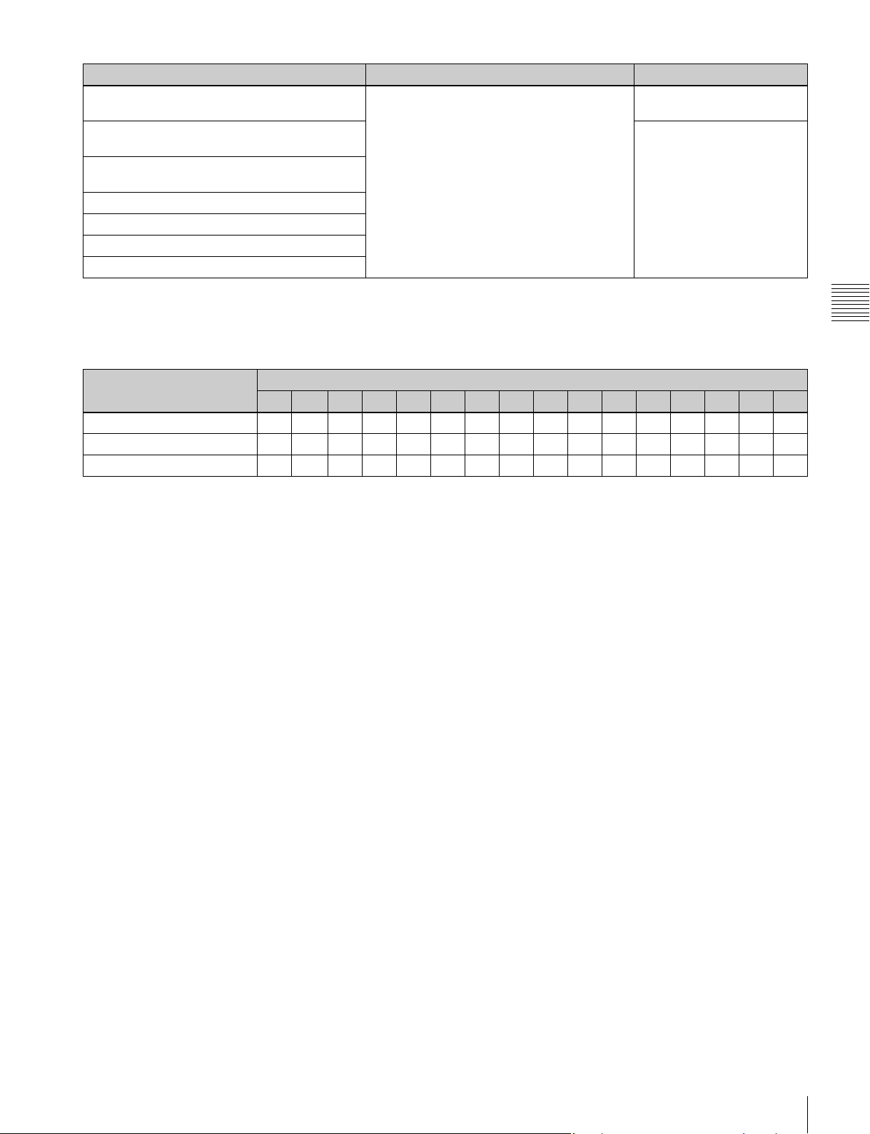
Editing control unit settings
When connecting an editing control unit (BVE-700/700A/
2000) to use with this unit, set VTR constants as follows.
.
System frequency VTR constant
1 2 3 4 5 6 7 8 9 10 11 12 13 14 15 16
59.94i/59.94P/29.97P A0 9C 00 96 07 07 03 80 0A 07 FE 00 80 5A FF 5A
50i/50P/25P A19C007D070703800A07FE00804CFF4B
23.98P A2 9C 00 78 07 07 03 80 0A 07 FE 00 80 48 FF 48
Chapter 3 Preparations
Connections and Settings
29

Using RM-280
The following figure shows a cut editing system
comprising this unit as a player, a PDW-F1600 unit as a
recorder, and an RM-280 as an editing controller.
HD video monitor
To HDMI input connector
a)
or
To HDSDI input connector
TIME CODE
IN OUT
PDW-HD1550
(this unit, player)
Reference video signal
REMOTE
Chapter 3 Preparations
ANALOG AUDIO INPUT
DIGITAL AUDIO
(AES/EBU)
SD/HDSDI
INPUT
PDW-F1600
(recorder)
ANALOG AUDIO OUTPUT AUDIO MONITOR
12
IN 1/2 3/4 1/2 3/4
OUT
SDSDI OUTPUTHDSDI OUTPUT
(SUPER)21(SUPER)
21
12
OUT
REMOTE (9P)
12V
RL
COMPOSITE OUTPUT REF. VIDEO INPUT
IN
12
(SUPER)
(
)
MAINTENANCE
RM-280
(editing
controller)
To HDSDI
input connector
HD video monitor
a) You can use setup menu item 161 (see page 93) to
set which signal to output from the HDMI OUT
connector: the same signal as the HDSDI
OUTPUT 2 (SUPER) connector output, or the
HDSDI signal and thumbnails view signal by
automatically switching between them.
1: 75Ω coaxial cable (not supplied)
2: 9-pin remote control cable (not supplied)
3: HDMI cable (not supplied)
Use of an optional Sony HDMI cable is recommended.
30
Connections and Settings
 Loading...