

Page 1

PROFESSIONAL DISC RECORDER
PDW-HD1500
OPERATION MANUAL [English]
1st Edition (Revised 2)
Page 2
Important Safety Instructions
• Read these instructions.
• Keep these instructions.
• Heed all warnings.
• Follow all instructions.
• Do not use this apparatus near water.
• Clean only with dry cloth.
• Do not block any ventilation openings.
Install in accordance with the manufacturer’s instructions.
• Do not install near any heat sources such as radiators, heat
registers, stoves, or other apparatus (including amplifiers)
that produce heat.
• Do not defeat the safety purpose of the polarized or
grounding-type plug. A polarized plug has two blades with
one wider than the other. A grounding-type plug has two
blades and a third grounding prong. The wide blade or the
third prong are provided for your safety. If the provided plug
dose not fit into your outlet, consult an electrician for
replacement of the obsolete outlet.
• Protect the power cord from being walked on or pinched
particularly at plugs, convenience receptacles, and the point
where they exit from the apparatus.
• Only use attachments/accessories specified by the
manufacturer.
• Use only with the cart, stand, tripod, bracket, or table
specified by the manufacturer, or sold with the apparatus.
When a cart is used, use caution when moving the cart/
apparatus combination to avoid injury from tip-over.
This symbol is intended to alert the user to
the presence of uninsulated “dangerous
voltage” within the product’s enclosure that
may be of sufficient magnitude to constitute
a risk of electric shock to persons.
This symbol is intended to alert the user to
the presence of important operating and
maintenance (servicing) instructions in the
literature accompanying the appliance.
• Unplug this apparatus during lightning storms or when
unused for long periods of time.
• Refer all servicing to qualified service personnel. Servicing
is required when the apparatus has been damaged in any
way, such as power-supply cord or plug is damaged, liquid
has been spilled or objects have fallen into the apparatus,
the apparatus has been exposed to rain or moisture, does
not operate normally, or has been dropped.
WARNING
To reduce the risk of fire or electric shock,
do not expose this apparatus to rain or
moisture.
To avoid electrical shock, do not open the
cabinet. Refer servicing to qualified
personnel only.
THIS APPARATUS MUST BE EARTHED.
CAUTION
The apparatus shall not be exposed to dripping or splashing.
No objects filled with liquids, such as vases, shall be placed on
the apparatus.
The unit is not disconnected from the AC power source
(mains) as long as it is connected to the wall outlet, even if the
unit itself has been turned off.
WARNING: THIS WARNING IS APPLICABLE FOR USA
ONLY.
If used in USA, use the UL LISTED power cord specified
below.
DO NOT USE ANY OTHER POWER CORD.
Plug Cap Parallel blade with ground pin
(NEMA 5-15P Configuration)
Cord Type SJT, three 16 or 18 AWG wires
Length Minimum 1.5 m (4 ft. 11 in.), Less than
2.5 m (8 ft. 3 in.)
Rating Minimum 10 A, 125 V
Using this unit at a voltage other than 120 V may require the
use of a different line cord or attachment plug, or both. To
reduce the risk of fire or electric shock, refer servicing to
qualified service personnel.
WARNING: THIS WARNING IS APPLICABLE FOR OTHER
COUNTRIES.
1. Use the approved Power Cord (3-core mains lead)/
Appliance Connector/Plug with earthing-contacts that
conforms to the safety regulations of each country if
applicable.
2. Use the Power Cord (3-core mains lead)/Appliance
Connector/Plug conforming to the proper ratings (Voltage,
Ampere).
If you have questions on the use of the above Power Cord/
Appliance Connector/Plug, please consult a qualified service
personnel.
2
Page 3
This Professional Disc Recorder is classified as a CLASS 1
LASER PRODUCT.
Laser diode properties
Wave length: 400 to 410 nm
Emission duration: Continuous
Laser output power: 135 mW (max. of pulse peak), 65 mW
(max. of CW)
Standard: IEC60825-1 (2001)
Egenskaber for laserdiode
Bølgelængde: 400 til 410 nm
Strålingsvarighed: Kontinuerlig
Afgivet lasereffekt: 135 mW (maks stråletoppunkt), 65 mW
(maks ved kontinuerlig stråling)
Standard: IEC60825-1 (2001)
Tekniska data för laserdiod
Våglängd: 400 till 410 nm
Emissionslängd: Kontinuerlig
Laseruteffekt: 135 mW (max. för pulstopp), 65 mW (max. för
kontinuerlig våg)
Standard: IEC60825-1 (2001)
Egenskaper for laserdiode
Bølgelengde: 400 til 410 nm
Strålingsvarighet: Uavbrutt
Utgangseffekt for laser: 135 mW (maks av pulshøyde), 65
mW (maks av CW)
Standard: IEC60825-1 (2001)
CAUTION
Use of controls or adjustments or performance of procedures
other than those specified herein may result in hazardous
radiation exposure.
WARNING
Excessive sound pressure from earphones and headphones
can cause hearing loss.
In order to use this product safely, avoid prolonged listening at
excessive sound pressure levels.
VAROITUS!
LAITTEEN KÄYTTÄMINEN MUULLA KUIN TÄSSÄ
KÄYTTÖOHJEESSA MAINITULLA TAVALLA SAATTAA
ALTISTAA KÄYTTÄJÄN TURVALLISUUSLUOKAN 1
YLITTÄVÄLLE NÄKYMÄTTÖMÄLLE LASERSÄTEILYLLE.
VARNING
OM APPARATEN ANVÄNDS PÅ ANNAT SÄTT ÄN I DENNA
BRUKSANVISNING SPECIFICERATS, KAN ANVÄNDAREN
UTSÄTTAS FÖR OSYNLIG LASERSTRÅLNING, SOM
ÖVERSKRIDER GRÄNSEN FÖR LASERKLASS 1.
When installing, the installation space must be secured in
consideration of the ventilation and service operation.
• Do not block the ventilation slots at the left side, right side
and bottom of front side panels, and vents of the fans.
• Leave more than 25 cm of space in the rear of the unit.
• Leave more than 2 cm of space in the left side, right side and
top of the unit.
For the customers in the USA
This equipment has been tested and found to comply with the
limits for a Class A digital device, pursuant to Part 15 of the
FCC Rules. These limits are designed to provide reasonable
protection against harmful interference when the equipment is
operated in a commercial environment. This equipment
generates, uses, and can radiate radio frequency energy and,
if not installed and used in accordance with the instruction
manual, may cause harmful interference to radio
communications. Operation of this equipment in a residential
area is likely to cause harmful interference in which case the
user will be required to correct the interference at his own
expense.
This label is located on the top panel of the drive unit.
Denna etikett finns på ovansidan av driftenheten.
Denne mærkat sidder på drevenhedens øverste panel.
Tämä kyltti sijaitsee ajurilaitteen yläpinnalla.
Dette merket er plassert på oversiden av driverenheten.
CAUTION
The use of optical instruments with this product will increase
eye hazard.
You are cautioned that any changes or modifications not
expressly approved in this manual could void your authority to
operate this equipment.
All interface cables used to connect peripherals must be
shielded in order to comply with the limits for a digital device
pursuant to Subpart B of Part 15 of FCC Rules.
For the customers in Europe
This product with the CE marking complies with both the EMC
Directive and the Low Voltage Directive issued by the
Commission of the European Community.
Compliance with these directives implies conformity to the
following European standards:
• EN60065: Product Safety
• EN55103-1: Electromagnetic Interference (Emission)
• EN55103-2: Electromagnetic Susceptibility (Immunity)
This product is intended for use in the following
Electromagnetic Environment(s):
3
Page 4

E1 (residential), E2 (commercial and light industrial), E3
(urban outdoors) and E4 (controlled EMC environment, ex. TV
studio).
For the customers in Europe
The manufacturer of this product is Sony Corporation, 1-7-1
Konan, Minato-ku, Tokyo, Japan.
The Authorized Representative for EMC and product safety is
Sony Deutschland GmbH, Hedelfinger Strasse 61, 70327
Stuttgart, Germany. For any service or guarantee matters
please refer to the addresses given in separate service or
guarantee documents.
For kundene i Norge
Dette utstyret kan kobles til et IT-strømfordelingssystem.
For the Customers in Taiwan only
4
Page 5

Table of Contents
Chapter 1 Overview
Features............................................................................................ 9
Features of this unit ...............................................................................9
System Configurations ................................................................. 12
Chapter 2 Names and Functions of Parts
Front Panel..................................................................................... 13
Display window...................................................................................18
Rear Panel...................................................................................... 23
Chapter 3 Preparations
Preparing Power Sources............................................................. 26
Initial Setup ....................................................................................27
Front Panel Tilt Mechanism.......................................................... 29
Connections and Settings ............................................................ 30
Synchronization Reference Signals ............................................ 36
Setting System Frequency ........................................................... 37
Setting Timecode........................................................................... 37
Superimposed Text Information .................................................. 39
Basic Operations of the Function Menu...................................... 42
Handling Discs............................................................................... 46
Supplying power.................................................................................. 26
Attaching a battery pack ...................................................................... 26
Connections for using PDZ-1 Proxy Browsing Software.................... 30
Connections for cut editing.................................................................. 31
Using the editing functions of the recorder (controlling through
REMOTE(9P) connector) .......................................................... 34
Connections for pool coverage ............................................................ 35
Function menu operations.................................................................... 42
Function menu settings........................................................................ 42
Discs used for recording and playback................................................ 46
Notes on handling................................................................................46
Write-protecting discs.......................................................................... 47
Table of Contents
5
Page 6

Loading and unloading a disc.............................................................. 47
Formatting a disc ................................................................................. 47
Chapter 4 Recording and Playback
Recording .......................................................................................48
Carrying out recording ........................................................................ 48
To continue recording while exchanging discs (disc exchange cache
function)..................................................................................... 49
Recording with the HDSDI remote control function .......................... 50
Handling of discs when recording does not end normally (salvage
functions) ................................................................................... 51
Playback .........................................................................................52
Playback operation .............................................................................. 53
Playback operations using thumbnails ................................................ 55
Chapter 5 Operations in GUI Screens
Overview.........................................................................................56
Switching between GUI screens.......................................................... 56
Information and controls in thumbnail screens ................................... 57
Displaying menus ................................................................................ 61
GUI screen operations ......................................................................... 63
Thumbnail Operations...................................................................64
Selecting thumbnails ........................................................................... 64
Searching with thumbnails .................................................................. 64
Playing the scene you have found ....................................................... 66
Selecting the information displayed on thumbnails ............................ 67
Changing clip index pictures............................................................... 67
Checking clip properties...................................................................... 68
Setting clip flags.................................................................................. 70
Locking (write-protecting) clips.......................................................... 70
Deleting clips....................................................................................... 71
Scene Selection (Clip List Editing) ..............................................72
What is scene selection?...................................................................... 72
Creating and editing clip lists.............................................................. 73
Managing clip lists .............................................................................. 78
Disc Operations .............................................................................79
Checking disc properties ..................................................................... 79
Using planning metadata ..................................................................... 80
Formatting discs .................................................................................. 81
6
Table of Contents
Page 7

Shortcut List .................................................................................. 82
Chapter 6 File Operations
Overview......................................................................................... 83
Directory structure ...............................................................................83
File operation restrictions .................................................................... 84
Assigning user-defined clip titles ........................................................ 86
Assigning user-defined clip and clip list names .................................. 88
File Operations in File Access Mode (for Windows) ..................89
Making FAM connections ................................................................... 90
Operating on files ................................................................................90
Exiting file operations.......................................................................... 90
File Operations in File Access Mode (for Macintosh) ................ 91
Making FAM connections ................................................................... 91
Operating on files ................................................................................92
Exiting file operations.......................................................................... 92
FTP File Operations....................................................................... 93
Making FTP connections..................................................................... 93
Command list....................................................................................... 94
Recording Continuous Timecode With FAM and FTP
Connections ............................................................................ 98
Chapter 7 Menus
Menu System Configuration.........................................................99
Setup Menu .................................................................................... 99
Items in the basic menu .....................................................................100
Basic menu operations....................................................................... 104
Items in the extended menu ............................................................... 107
Extended menu operations................................................................. 118
Maintenance Menu ...................................................................... 120
Items in the maintenance menu ......................................................... 120
Maintenance menu operations ........................................................... 123
Chapter 8 Planning Metadata
Overview....................................................................................... 126
Manipulating planning metadata ....................................................... 126
To set clip names by using planning metadata ..................................126
Table of Contents
7
Page 8

Appendix
Important Notes on Operation....................................................128
Condensation ..................................................................................... 128
About the LCD panel ........................................................................ 128
Periodic Maintenance..................................................................129
Digital hours meter............................................................................ 129
Troubleshooting ..........................................................................131
Alarms ............................................................................................... 131
Error messages .................................................................................. 140
To eject discs with the unit powered off ........................................... 140
Specifications ..............................................................................140
Using PDZ-1 Proxy Browsing Software.....................................143
Using UMID Data..........................................................................144
Ancillary Data...............................................................................146
Ancillary data in HDSDI signals....................................................... 146
Ancillary data in MXF files............................................................... 146
General MXF metadata ..................................................................... 146
Correspondence Between Setting Items of HKDV-900 and Setup
Menu of This Unit..................................................................147
List of Supported USB Keyboards.............................................148
Trademarks and Licenses...........................................................151
MPEG-4 visual patent portfolio license ............................................ 151
MPEG-2 video patent portfolio license............................................. 151
About IJG (Independent JPEG Group) ............................................. 151
Character display software “iType” .................................................. 151
Glossary .......................................................................................152
8
Table of Contents
Index ............................................................................................154
Page 9

Overview
Features
The PDW-HD1500 is a professional disc recorder
supporting full HD (1920 × 1080 and 1280 × 720)
playback and recording with Professional Disc
When you use this unit in combination with a nonlinear
editing system, the FAM
transfers between the unit and computers over the i.LINK
interface, allowing the unit to be used like an external hard
drive. The unit can be used as a player for video editing and
program output, and as a recorder for nonlinear editing.
For these applications, it can be connected to Sony
nonlinear editors, monitors, and video equipment with
HDSDI interfaces via its standard HDSDI I/O connectors.
It has a compact, lightweight body for easy portability
outdoors, and can be powered from any of three power
sources: AC, DC, or battery
2)
function enables data file
3)
power.
1)
media.
Chapter
Long recording times
PDW-HD1500 supports dual-layer Professional Discs (50
GB). When dual-layer Professional Discs are used, this
unit can record about 95 minutes.
1
Recording and playback functions
Support for multiple SD1) and HD codecs
In addition to the MPEG HD422 codec, this unit supports
the MPEG HD codec.
component files at both 1080i (35/25/18 Mbps
(35/25 Mbps), allowing HD operation across a wide range
of recording times and application objectives. When the
separately sold PDBK-S1500 option is installed, the unit is
also capable of SD (IMX 30/40/50 Mbps or DVCAM
codec) recording and playback.
1) When the separately sold PDBK-S1500 option is installed.
2) MPEG HD is a registered trademark of Sony Corporation.
3) Playback only supported for 18 Mbps.
2)
It can record HD 4:2:0 digital
3)
) and 720P
Chapter 1 Overview
1) Professional Disc is a trademark of Sony Corporation.
2) FAM: File access mode
3) BKP-L551 Battery Adaptor is required.
Features of this unit
The principal features of this unit are as follows.
MPEG HD422
High-quality video and audio recording and
playback
The MPEG HD422 codec provides video compression
compliant with the MPEG-2 422P@HL standard. It
enables HD 4:2:2 (50 Mbps) digital component file
recording in the 1080i (1,080 effective scanning lines,
interlaced) or 720P (720 effective scanning lines,
progressive) format currently in use by many broadcast
facilities.
Uncompressed PCM recording of 24-bit 48 kHz audio
enables 8-channel audio recording at high sound quality.
1) MPEG HD422 is a trademark of Sony Corporation.
1)
codec
Support for multiple frame frequencies
This unit can record and play multiple frame frequencies at
both 1080 (59.94i, 50i, 29.97P, and 25P) and 720 (59.94P
and 50P) (for MPEG HD422).
SD upconvert function
This unit features a standard upconvert function, allowing
SD signals to be input to the SD/HDSDI INPUT connector
and recorded as HD. When the separately sold PDBKS1500 option is installed, the unit can also output HD
signals while playing discs recorded as SD, allowing SD
material to be utilized in an HD environment.
HD downconvert function
The unit is provided with a downconvert function. HD disc
playback signals can be downconverted to SD signals and
then output as SDSDI or composite signals. This allows
you to use SD nonlinear editors and monitors for editing
and program output.
1080/720 cross-conversion
This unit supports cross-conversion output. It can output
720 while playing discs recorded as 1080, and output 1080
while playing discs recorded as 720.
Features
9
Page 10

HDSDI remote recording
HDSDI connections can be made to camcorders with
remote HDSDI support (PDW-700 XDCAM HD422
camcorder, HDW-730/730S/750/790/F900R HDCAM
camcorders) to enable recording synchronized to REC and
STOP operations on the camcorder.
Chapter 1 Overview
1) HDCAM is a trademark of Sony Corporation.
Recording of proxy AV data
Proxy AV data is a low-resolution (1.5 Mbps video, 64
kbps per audio channel), MPEG-4 based version of a full
resolution data stream. Whenever this unit records full
resolution MPEG HD422 data, it simultaneously generates
and records low-resolution proxy AV data. Because of its
small size, proxy AV data can be transferred quickly over
computer networks, easily edited in the field with laptop
computers,
1)
and readily used in a wide variety of
applications, such as content management on small-scale
servers.
1) The supplied PDZ-1 Proxy Browsing Software can be used to create
simple EDLs (Edit Decision Lists).
Usability features
1)
AC, DC, and battery1) power support
The unit can be used even where AC power is not
available, for example outdoors or in cars or helicopters.
1) BKP-L551 Battery Adaptor is required.
Color LCD display
The unit is equipped with a 16:9, 4.3-inch color LCD
which allows you to check the contents of the disc and use
the menu system without connecting an external monitor.
Built-in speakers
The unit features built-in speakers, allowing you to check
recorded audio. You can check your clips and editing
results on the color LCD and speakers even when no
monitors or separate speakers are available.
Tiltable front panel
The front panel is tiltable for easy rack-mount and desktop
operation. You can adjust the panel to the angle that makes
the buttons easiest to use.
High-speed searches with the jog and shuttle
dials
The jog and shuttle dials can be used to find scenes inside
clips, in the same way as the jog and shuttle dials on
conventional VTRs.
In jog and variable modes, you can search in field units at
from –2 to +2 times normal speed. Shuttle mode supports
high-speed searches up to a maximum of ±20 times normal
speed. (F.FWD and F.REV are possible up to 35 times
normal speed.)
Convenient disc-based playback and searching
Like previous products in the XDCAM series, this unit
supports a number of convenient search functions,
including scene selection, thumbnail searches, essence
marks searches, and expand searches.
Scene selection: This function allows you to select clips
from the disc and insert them into playlists. Clips can
be inserted and played back in any order.
Thumbnail searches: The unit creates thumbnails from
the first frame of each generated clip, and displays
them in thumbnail lists on the color LCD or an
external monitor. You can cue up clips very easily by
simply by selecting them from thumbnail lists.
Essence mark searches: Essence marks can be recorded
at any scene during or after recording. Lists of these
marks can be displayed on the color LCD or an
external monitor, allowing you to quickly find scenes
that were marked for later reference.
Expand searches: This function allows you to look inside
the clip selected in a thumbnail screen, or inside the
segment from a selected essence mark to the next
essence mark. The selection range is divided into 12
equal blocks, and the first frames of those blocks are
displayed as thumbnails. By checking the thumbnails,
you can easily find the scene you want.
Cache recording for seamless disc exchanges
About 30 seconds (this duration may differ depending on
the state of a disc) of video and audio data can be recorded
to the unit's internal memory cache during a disc exchange,
and then written back to the newly loaded disc. This allows
seamless recording across extended recording sessions,
including recording of video feeds, with no important
scenes lost while discs are being exchanged.
Cart system support
With its compact body, this unit can replace the SD PDW1500 unit. You can mount this unit in the PDJ-C1080 and
PDJ-A640 XDCAM cart systems.
IT friendly
Computer access to files (file access mode)
Video and audio clip data are recorded as files. The FAM
function enables quick random access by computers to the
video, audio, and metadata files stored on Professional
Discs, with the ability to display thumbnail lists on the
computer screen and perform file-based reads and writes.
Equipped with network connector
The unit features a Gigabit Ethernet connector as standard
equipment. Via this connector, you can connect the unit to
computers and networks to enable listing of the video,
audio, and metadata files recorded on the Professional
Disc, and rapid file transfers. Support for FTP commands
makes it easy to carry out network file transfers from
remote locations.
The unit has two optical pickups for high-speed transfers.
User data recording mode
User data (files other than XDCAM AV files) can be
recorded on Professional Discs as PC data via the i.LINK
10
Features
Page 11

or FTP interface. This allows Professional Discs to be used
as data recording media, with a data storage capacity of
46.4 GB (when dual-layer PFD50DLA discs are used).
Supports a variety of interfaces
This unit supports the following interfaces.
• HDSDI video, 8-channel audio input and output
• SDSDI video, 8-channel audio input and output
(the SD/HDSDI INPUT connector doubles as an SDSDI
input connector)
• SD composite output
• AES/EBU digital audio 4-channel input and output
• Analog audio 2-channel input and output
•Remote
- RS-422A (D-sub 9-pin × 1)
- Video remote (D-sub 9-pin × 1)
TBC control is available from the front panel.
• i.LINK TS (HDV) input and output (when separately
sold PDBK-201 option board is installed)
Chapter 1 Overview
Features
11
Page 12
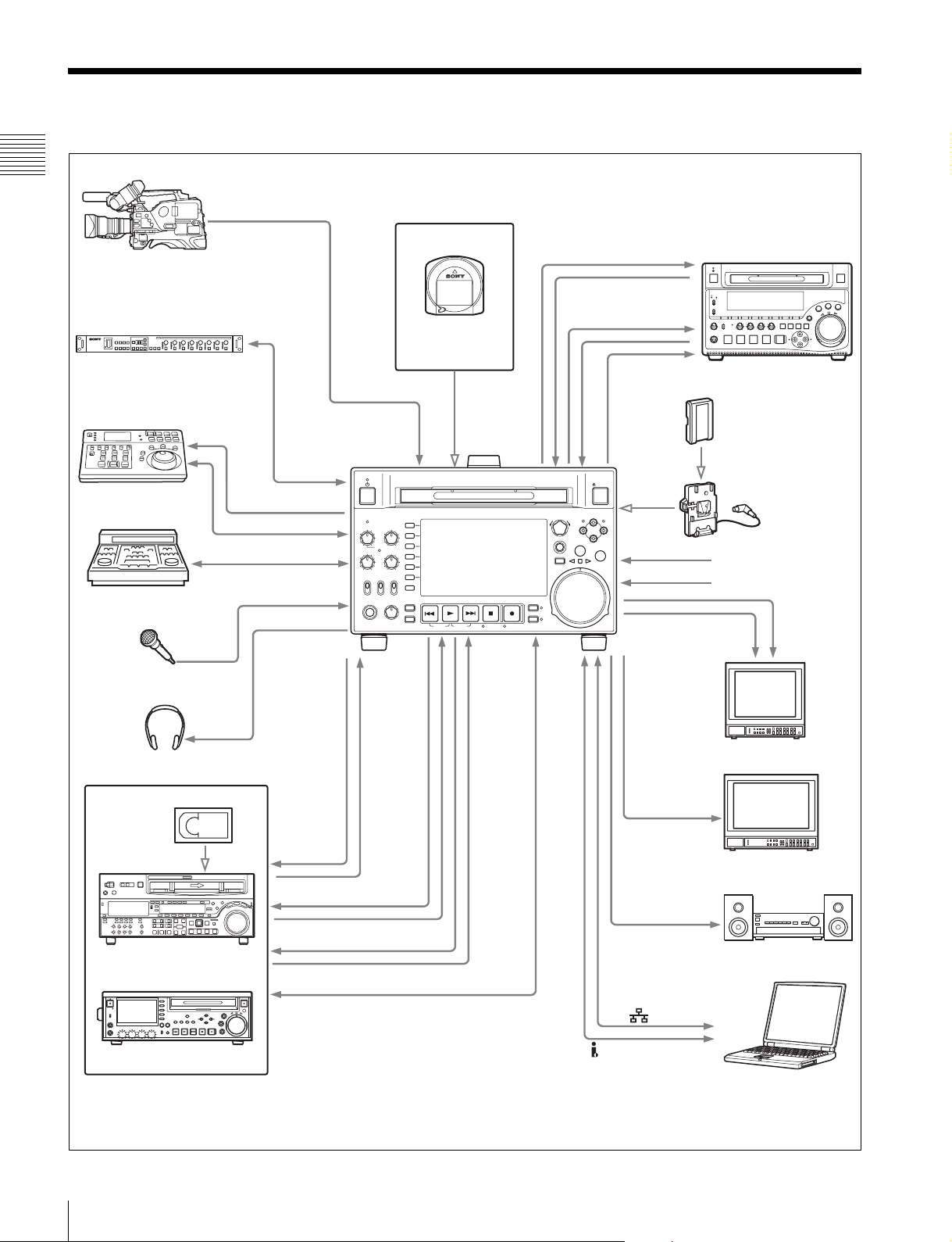
System Configurations
Chapter 1 Overview
PDW-700
HKDV-900
HKDV-900 video control unit
RM-280 editing
controller
BVE-700
Microphone
a)
VIDEO
CONTROL
REMOTE
REMOTE (9P)
REMOTE (9P)
ANALOG AUDIO INPUT
PHONES
DIGITAL
AUDIO
(AES/EBU)
OUT/IN
HDSDI
INPUT
ACCESS
CH-1
ALL CH
CH-2
VARIABLE KEY INHI
REC
NET
PRE-
LOCAL
SET
REMOTE
PB
PHONES LEVEL
ANALOG
OUTPUT/
CH-3
CH-4
ON
OFF
AUDIO
INPUT
Professional Discs
• PFD23A
• PFD50DLA
CHAPTER
EXPAND
PAGE
HOME
PREV NEXTPLAY STOP REC
DISPLAY
SHIFT
TOP F REV F FWD END STANDBY REC INHI
HDSDI
OUTPUT/
INPUT
THUMBNAIL
SUB CLIP
DISC MENU
DIGITAL
AUDIO (AES/EBU)
OUT/IN
MARK1
PUSH SET(S.SEL)
IN OUT
MENU
SHTL/JOG
VAR/JOG
RESET
RETURN
ANALOG
AUDIO
OUTPUT/INPUT
SDSDI
OUTPUT
EJECT
MARK2
DC IN 12V
- AC IN
PDW-1500
Sony BP-L80S/GL95
battery
BKP-L551 battery
adaptor
DC power source
AC power source
SDSDI
OUTPUT
COMPOSITE
OUTPUT
Headphones
HDCAM
HDW-2000 series
PDW-F75
a) If an HKDV-900 is connected, be sure to check that the
version of the HKDV-900 is 2.00 or higher.
b) For HDW-2000 series only.
REMOTE
(9P)
SD video monitor
HDSDI
OUTPUT
HD video monitor
b)
AUDIO
MONITOR
Audio monitor
(i.LINK) S400
Laptop computer
12
System Configurations
Page 13
Names and Functions of
Parts
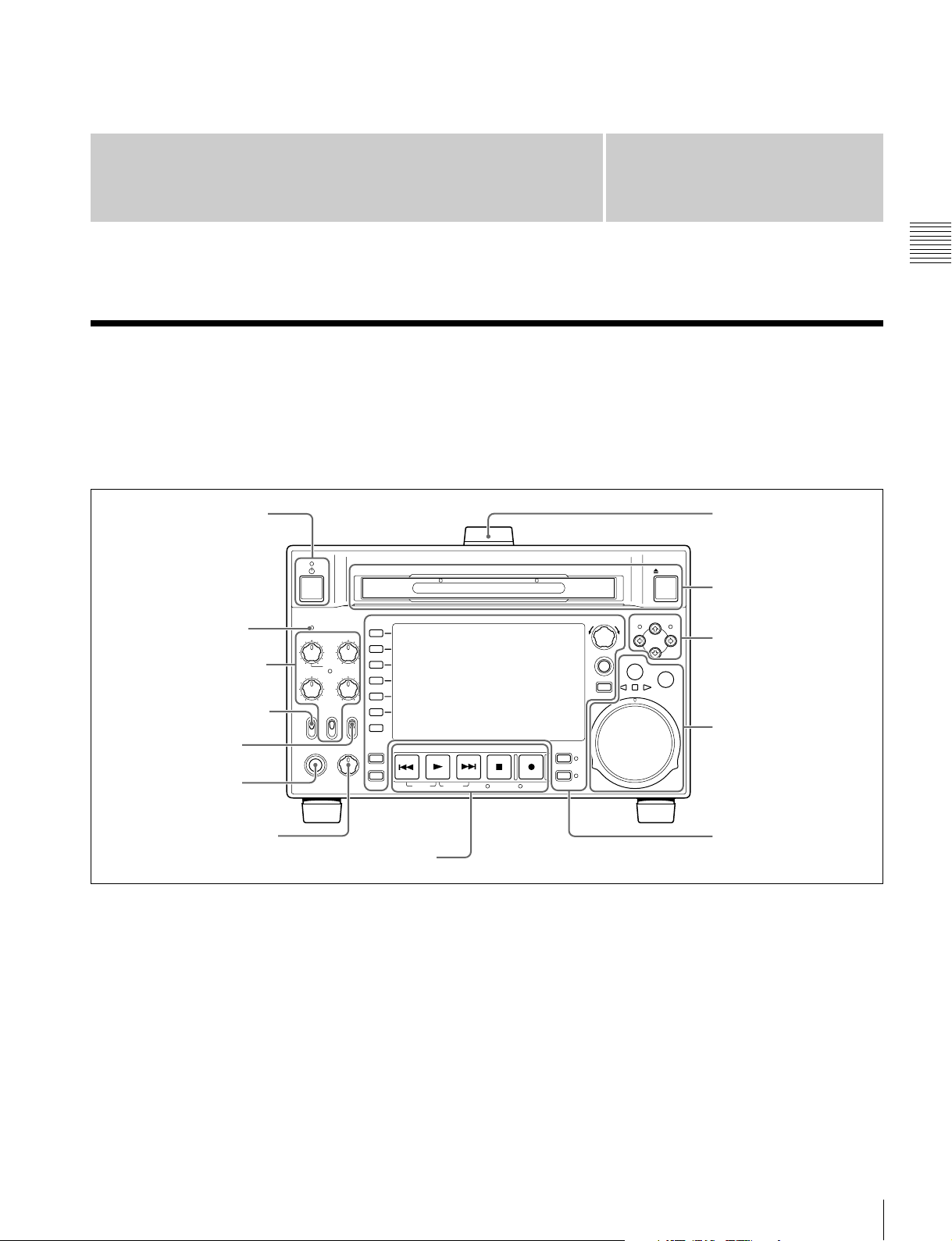
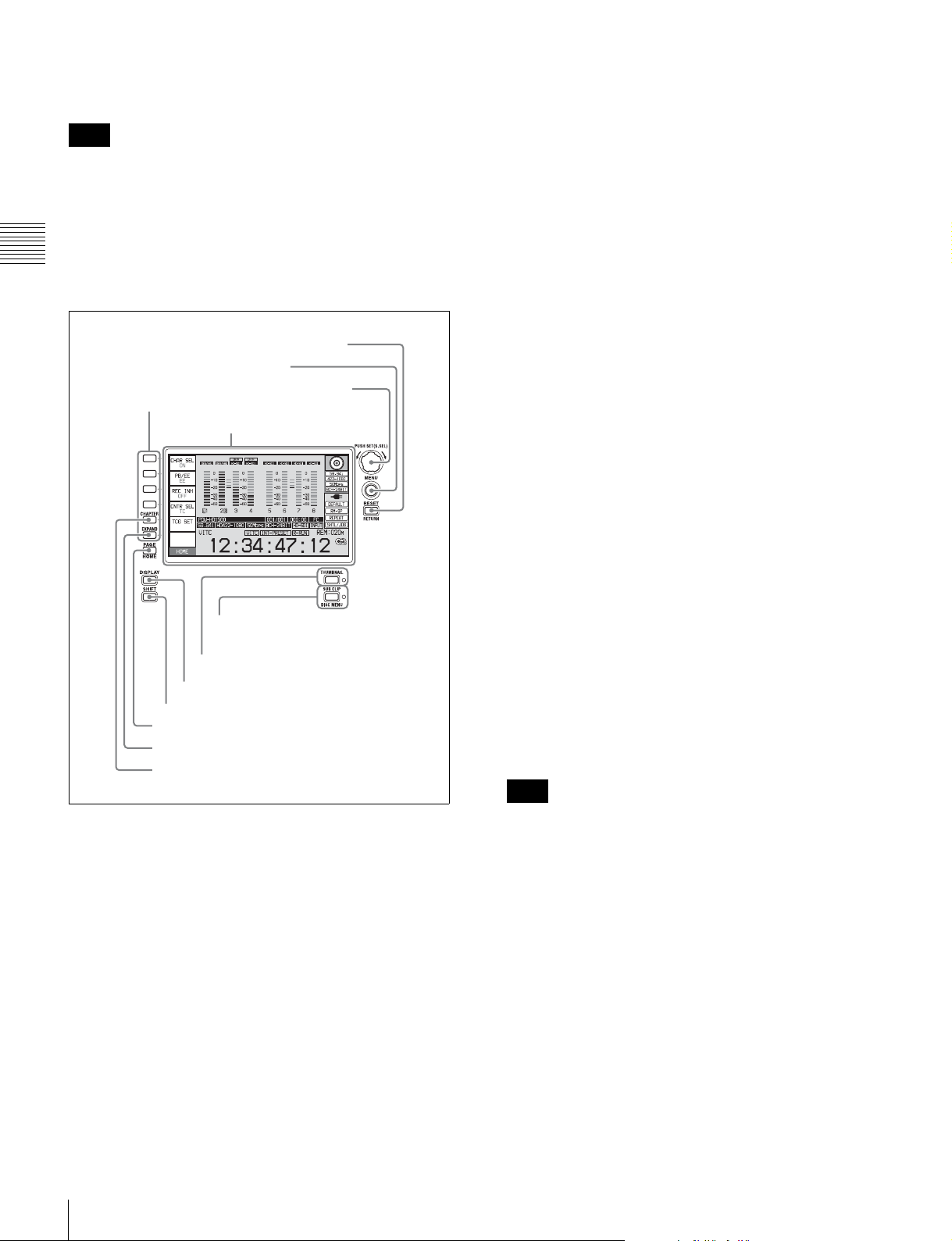
Front Panel
The names and symbols of buttons and knobs on the front
panel are color coded according to function.
White: Function when the button or knob is operated
independently.
1 On/standby button and
indicator
2 ACCESS indicator
1 Audio level adjustment
section (see page 14)
3 Remote control switch
4 KEY INHI switch
5 PHONES jack
ACCESS
CH-1
CH-2
REC
NET
PRE-
LOCAL
SET
REMOTE
PHONES LEVEL
CH-3
ALL CH
CH-4
VARIABLE KEY INHI
ON
OFF
PB
CHAPTER
EXPAND
PAGE
HOME
PREV NEXTPLAY STOP REC
DISPLAY
SHIFT
TOP F REV F FWD END STANDBY REC INHI
Chapter
2
Orange: Function when the button is operated with the
SHIFT button held down.
Blue: Function related to thumbnail operations.
Handle
EJECT
7 Disc slot and EJECT
button
SHTL/JOG
MARK1
IN OUT
MARK2
VAR/JOG
2 Arrow buttons (see
page 14)
3 Shuttle/jog/variable
control section (see
page 15)
PUSH SET(S.SEL)
MENU
RESET
RETURN
THUMBNAIL
SUB CLIP
DISC MENU
Chapter 2 Names and Functions of Parts
6 LEVEL adjustment knob
5 Recording and playback control section (see page 17)
a On/standby (1) button and indicator
When the POWER switch on the rear panel is in the @
position, and when DC power is connected to the DC IN
12V connector on the rear panel, this switches the unit
between the operating state (the indicator is lit green) and
the standby state (the indicator is lit red).
When the indicator is lit red, pressing the button switches
this unit to the operating state, and the indicator lights
continuously green.
When the indicator is lit green, pressing the button
switches the unit to the standby state, and the indicator
4 Display/menu control
section (see page 16)
lights continuously red. If a disc is loaded in the unit, the
indicator flashes before changing to continuously lit red.
When using this unit, normally leave the rear panel
POWER switch in the @ (on) position, and use this button
to switch the unit between the operating state and standby
state.
b ACCESS indicator
This lights when the disc is accessed and when a file is
opened by a FAM or FTP connection (see page 83). If the
on/standby button is pressed while this indicator is lit,
Front Panel
13
Page 14

access to the disc is completed before the unit switches to
REC
NET
REMOTE
LOCAL
VARIABLE KEY INHI
PRESET
ON
OFF
PB
CH-1
ALL CH
CH-2
CH-3
CH-4
the standby state.
Note
While the ACCESS indicator is lit, do not turn off the
POWER switch on the rear panel or disconnect the power
cord. This could lead to a loss of data from the disc.
c Remote control switch
Different positions of the switch allow different operations
Chapter 2 Names and Functions of Parts
as follows.
NET: Enables access to the network. The indicator lights
when an external network device is being accessed. In
this state, operation from the front panel is not
possible.
LOCAL: Enables operation from the front panel.
REMOTE: Enables remote control of this unit from the
following devices:
• Devices connected to the REMOTE(9P) connector
on the rear panel
• Devices connected to the SD/HDSDI INPUT
connector with SDI remote control functions
• Devices connected to the (i.LINK) S400
connector
Use setup menu item 214 REMOTE INTERFACE to
select which of the connectors is used for remote control
(see page 109).
1 Audio level adjustment section
1 CH-1/ALL CH, CH-2 to CH-4 adjustment knobs
2 VARIABLE switch
a CH-1/ALL CH, CH-2 to CH-4 (audio level)
adjustment knobs
Depending on the setting of the VARIABLE switch, these
adjust the input audio or playback audio levels of channels
1 to 4.
You can adjust levels of channels 5 to 8 using the function
menu. See page 44 for details.
By the setting of setup menu item 131 AUDIO VOLUME,
you can enable the CH-1/ALL CH knob to simultaneously
adjust all eight channels. When this simultaneous
adjustment is enabled, the ALL CH indicator lights.
See “Setup Menu” on page 99 for more information about
how to make extended menu settings.
d KEY INHI switch
This turns key operation inhibit mode on or off.
Use setup menu item 118 KEY INHIBIT SWITCH
EFFECTIVE AREA to specify the keys to inhibit.
e PHONES jack
The jack is a standard stereo jack. Connect stereo
headphones to monitor the audio during recording,
playback, and editing. (Non-audio signals are muted.) The
monitored channel is selected with MONITR L and
MONITR R on page P2 AUDIO of the function menu (see
page 43).
f LEVEL (volume) adjustment knob
Adjust the volume of headphones or speakers with the
knob. You can also cause this to simultaneously adjust the
output volume from the AUDIO MONITOR R, L
connectors on the rear panel. To do this, set setup menu
item 114 AUDIO MONITOR OUTPUT LEVEL to “var”.
g Disc slot and EJECT button
Insert a disc in the disc slot. To remove the disc, press the
EJECT button.
b VARIABLE (audio level adjustment selector)
switch
This selects whether input audio levels or playback audio
levels are adjusted by the CH-1/ALL CH and CH-2 to CH4 adjustment knobs for channels 1 to 4, or by the function
menu setting for channels 5 to 8.
REC: Adjust the input audio levels. The playback audio
levels are fixed at their preset values.
PRESET: The audio levels are fixed at their preset values.
PB: Adjust the playback audio levels. The input audio
levels are fixed at their preset values.
2 Arrow buttons
The four arrow buttons are also used as the MARK1
button, MARK2 button, IN button, and OUT button. The
correspondence with these buttons is as follows.
V button: MARK1 button
v button: MARK2 button
B button: IN button
b button: OUT button
You can use these buttons for thumbnail selection, menu
setting operations, setting In/Out points, and so on.
14
Front Panel
Page 15

MARK2
MARK1
IN OUT
L/JOG
1 V/MARK1 button and v/MARK2 button
RETURN
RESET
SHTL/JOG
VAR/JOG
For details of playback operations with these buttons and
dials, see “Playback operation” on page 53.
2 IN indicator and OUT indicator
3 B/IN button and b/OUT button
a V/MARK1 button and v/MARK2 button
When the THUMBNAIL indicator (see page 16) is lit, you
can use these for thumbnail selection.
During recording or playback, a shot mark 1 or shot mark
2 is recorded as an essence mark when you press the PUSH
SET (S.SEL) knob with the V/MARK1 or v/MARK2
button held down.
Use the PDZ-1 Proxy Browsing Software on the supplied
XDCAM Application Software CD-ROM to delete and
modify essence marks.
Essence marks can also be deleted and modified from the
Thumbnail Menu of the chapter thumbnail screen (see
page 59).
b IN indicator and OUT indicator
IN indicator: When an In point is set, this lights. If an
attempt is made to set the In point after a recorded Out
point, this flashes.
OUT indicator: When an Out point is set, this lights. If an
attempt is made to set the Out point before a recorded
In point, this flashes.
c B/IN button and b/OUT button
When the THUMBNAIL indicator (see page 16) is lit, you
can use these for thumbnail selection.
An In or Out point is set when you press the PUSH
SET(S.SEL) knob with the B/IN or b/OUT button held
down. The In or Out point setting is deleted when you
press the RESET/RETURN button with the B/IN or b/
OUT button held down.
3 Shuttle/jog/variable control section
1 SHTL/JOG button
2 VAR/JOG button
3 Jog/shuttle transport indicators
4 Jog dial
5 Shuttle dial
a SHTL/JOG button
Press this button, turning it on, to perform shuttle playback
with the shuttle dial or jog playback with the jog dial.
When pressed during recording, stops recording and
selects shuttle/jog mode. If you do not want to stop
recording when this button is pressed, set extended menu
item 145 MODE KEY ENABLE DURING RECORDING
to “stop”.
b VAR/JOG button
Press this button, turning it on, to perform variable
playback with the shuttle dial or jog playback with the jog
dial.
When pressed during recording, stops recording and
selects variable/jog mode. If you do not want to stop
recording when this button is pressed, set extended menu
item 145 MODE KEY ENABLE DURING RECORDING
to “stop”.
c Jog/shuttle transport indicators
These show the playback direction in jog, shuttle, or
variable speed mode.
b (green): Lights during playback in the reverse direction.
B (green): Lights during playback in the forward
direction.
x (red): Lights during still image display.
d Jog dial
Turn this for playback in jog mode. Turn clockwise for
forward direction playback, and counterclockwise for
reverse direction playback. In jog mode, the playback
speed varies from –1 to +1 times normal speed, according
to the rotation rate of the jog dial. There are no detents.
Normally, you press the SHTL/JOG or VAR/JOG button
before turning the jog dial, but it is also possible to make a
setting to enable jog mode directly by turning the dial (set
setup menu item 101 SELECTION FOR SEARCH DIAL
ENABLE to “dial”).
e Shuttle dial
Turn this for playback in shuttle mode or variable speed
mode. Turn clockwise for forward direction playback, and
counterclockwise for reverse direction playback.
• In shuttle mode, the playback speed varies in the range
±20 times normal speed, according to the angular
position of the shuttle dial.
• In variable speed mode, you can finely adjust the
playback speed from –2 to +2 times normal speed,
according to the angular position of the shuttle dial.
The shuttle dial has a detent at the center position, for still
image playback.
Normally, you press the SHTL/JOG button before turning
the shuttle dial, but it is also possible to make a setting to
enable shuttle mode directly by turning the dial (set setup
Chapter 2 Names and Functions of Parts
Front Panel
15
Page 16
menu item 101 SELECTION FOR SEARCH DIAL
ENABLE to “dial”).
Note
c PUSH SET(S.SEL) knob
Use for menu and GUI screen operations. Turn the knob to
select items, and press it to confirm the selection. This
button is also used to set numerical and timecode values.
When setup menu item 101 SELECTION FOR SEARCH
DIAL ENABLE is set to “dial”, after using the shuttle dial,
return it to the center position. If the shuttle dial is not in
the center position, it is possible occasionally for vibration
from other operations to activate the dial, and start
playback in shuttle mode.
Chapter 2 Names and Functions of Parts
4 Display/menu control section
5 RESET/RETURN button
4 MENU button
3 PUSH SET(S.SEL) knob
1 Function buttons (F1 to F6)
2 Display
6 SUB CLIP/DISC MENU button and
indicator
7 THUMBNAIL button and indicator
8 DISPLAY button
9 SHIFT button
0 PAGE/HOME button
qa EXPAND button
qs CHAPTER button
See “GUI screen operations” (page 63) for more
information about how to use the thumbnail screens.
d MENU button
Displays the setup menu or the GUI screen menu. The
setup menu appears when no GUI screen is visible. The
same information is also superimposed on the display on a
monitor connected to the unit. Press once more to return to
the original display.
See “GUI screen operations” (page 63) for more
information about how to use the thumbnail screens.
e RESET/RETURN button
Functions as the RESET button or the RETURN button.
RESET button: Reset counters or the setting values of the
timecode generator. This button is also used to abort
or cancel setup menu, scene selection, and thumbnail
search operations.
RETURN button: In setup menu and GUI screens,
returns to the previous procedure.
f SUB CLIP/DISC MENU button and indicator
When pressed alone, functions as the SUB CLIP button.
When pressed together with the SHIFT button, functions
as the DISC MENU button.
SUB CLIP button: Press the button, lighting the
indicator, to carry out playback in clip list order (see
page 73). Jog and shuttle operations are supported
during clip list playback. To return to playback in
recording order, press the button again, turning the
indicator off.
Note
a Function buttons (F1 to F6)
These buttons are enabled when the function menu (see
page 42) is visible. Each press of a button changes the
setting of the corresponding item in the menu.
For convenience, this manual refers to these buttons as
buttons F1 to F6, in order from the top.
b Display
Displays menus, audio level meters, and data such as time
data or clip information. The DISPLAY button lets you
switch to the video monitor display.
For details, see “Display window” on page 18.
16
Front Panel
If no clip list is registered, this button does not light
when pressed. The operation is invalid.
DISC MENU button: When pressed together with the
SHIFT button, displays the Disc Menu (see page 79).
Press the button again, turning the indicator off, to
hide the Disc Menu.
See “GUI screen operations” (page 63) for more
information about how to use the thumbnail screens.
g THUMBNAIL button and indicator
To carry out a thumbnail search or create a clip list in the
GUI screen, press this button turning the indicator on.
Thumbnail images representing each clip or sub-clip
appear. Press once more, turning the indicator off, to return
to a whole-screen display.
Page 17
To display the thumbnails of essence mark frames (frames
with an essence mark attached), hold down the SHIFT
button, and press this button. The essence mark selection
menu appears. Select the desired type of essence mark, and
the corresponding essence mark frames appear in
thumbnails. Press once more, turning the indicator off, to
return to a whole-screen display.
This button also becomes a function button (F5) when the
function menu is visible.
See page 65 for more information about the chapter
function.
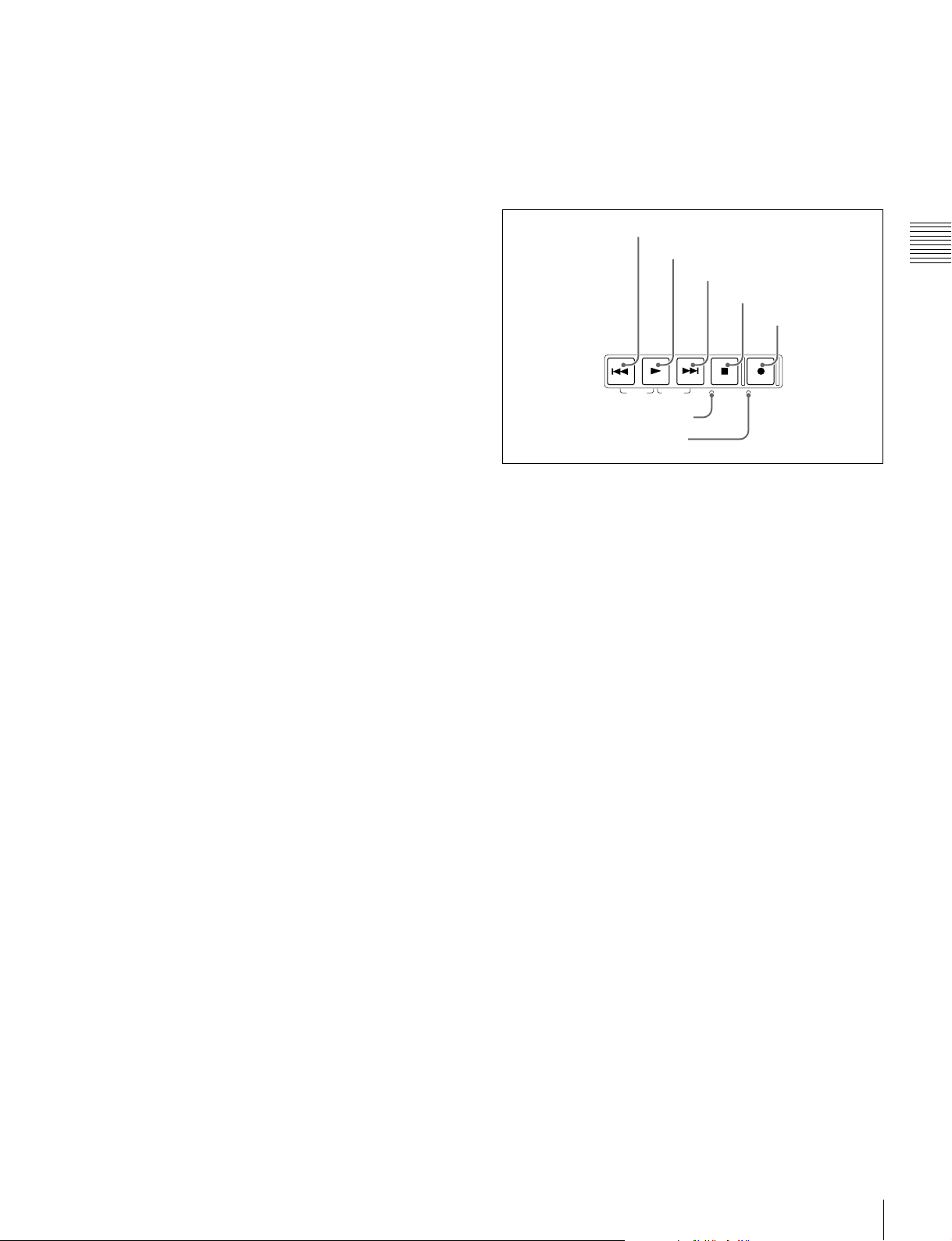
5 Recording and playback control section
See “GUI screen operations” (page 63) for more
information about how to use the thumbnail screens.
h DISPLAY button
Each press of this button switches between the basic
operation display and video monitor display (see page 18).
This button is disabled unless either the basic operation
display or the video monitor display is displayed.
i SHIFT button
Switches between functions for any button with two
functions.
j PAGE/HOME button
When pressed alone functions as the PAGE switching
button. When pressed together with the SHIFT button,
functions as the HOME button.
PAGE button: Displays the function menu, if it is not
already visible. (The most recently displayed page of
the function menu appears.)
HOME button: When pressed with the function menu
visible, returns to the HOME page of the function
menu.
k EXPAND button
When pressed during thumbnail display, divides the
selected clip into 12 blocks and displays a list of
thumbnails of the first frame in each block (expand
function). The division is repeated with each press (up to 3
times, for a total of 1,728 blocks).
When this button is pressed together with the SHIFT
button, the unit returns to the previous division level.
Press the RESET/RETURN button to return to the
thumbnail screen.
This button also becomes a function button (F6) when the
function menu is visible.
See page 64 for more information about the expand
function.
l CHAPTER button
When pressed during thumbnail display, displays a list of
thumbnails of the frames where essence marks are
recorded (chapter function). When this is pressed again,
returns to normal thumbnail display. The chapter function
can be useful when essence mark thumbnails provide more
information about the content of the clip than the index
pictures of the first frames. This can also be used to cue up
long clips.
1 PREV button
2 PLAY button
3 NEXT button
4 STOP button
5 REC button
PREV NEXTPLAY STOP REC
TOP F REV F FWD END STANDBY REC INHI
6 STANDBY indicator
7 REC INHI indicator
a PREV (previous) button
Press this button, turning it on, to show the first frame of
the current clip. While the first frame of a clip is shown,
pressing this button jumps to the beginning of the previous
clip. This button is also used together with other buttons
for the following operations.
Reverse direction high-speed search: Hold down the
PLAY button, and press this button. A high-speed
search in the reverse direction is carried out.
Displaying the first frame of the first clip: Hold down
the SHIFT button, and press this button.
b PLAY button
To start playback, press this button, turning it on.
When pressed during recording, stops recording and enters
stop mode. If you do not want to stop recording when this
button is pressed, set extended menu item 145 MODE
KEY ENABLE DURING RECORDING to “stop”.
c NEXT button
Press this button, turning it on, to jump to the next clip, and
show the first frame. This button is also used together with
other buttons for the following operations.
Forward direction high-speed search: Hold down the
PLAY button, and press this button. A high-speed
search in the forward direction is carried out.
Displaying the last frame of the last clip: Hold down the
SHIFT button, and press this button.
d STOP button
To stop recording or playback, press this button, turning it
on. The frame at the stop point appears.
The unit enters standby off mode when you press this
button with the SHIFT button held down. It returns from
standby off mode to the original state when you press this
Chapter 2 Names and Functions of Parts
Front Panel
17
Page 18
button again with the SHIFT button held down. (The lit or
unlit status of the STOP button does not change.)
Note
This button flashes when setup menu item 105
REFERENCE SYSTEM ALARM is set to “on” and the
correct reference video input signal (as specified by OUT
REF on page P6 REF of the function menu) is not being
input.
Chapter 2 Names and Functions of Parts
This unit can automatically enter standby off mode
whenever a specified time elapses in disc stop mode. For
details, see the description of setup menu item 501 STILL
TIMER (page 109).
e REC (record) button
To start recording, hold down this button, and press the
PLAY button. The recording takes place on an unrecorded
part of the disc.
To stop recording, press the STOP button.
To monitor in E-E mode
You can press this button from stop mode to monitor input
signals in E-E mode. The button lights when pressed. Press
the STOP button to return to the original video.
You can also press this button during playback and
searches. E-E mode playback continues for as long as the
button is held down.
f STANDBY indicator
Lights when the unit is in standby mode (STOP button and,
STANDBY indicator lit).
After a certain time passes in a disc stop mode, the unit
automatically enters standby off mode and the indicator
goes off.
You can specify the time until the unit enters standby off
mode. For details, see the description of setup menu item
501 STILL TIMER (page 109).
g REC INHI (recording inhibit) indicator
This lights in the following cases.
• When a disc with recording inhibited is loaded.
• When REC INH on the HOME page of the function
menu is set to “ON”.
• The format of the recorded part of the disc does not
match the system frequency settings of the unit.
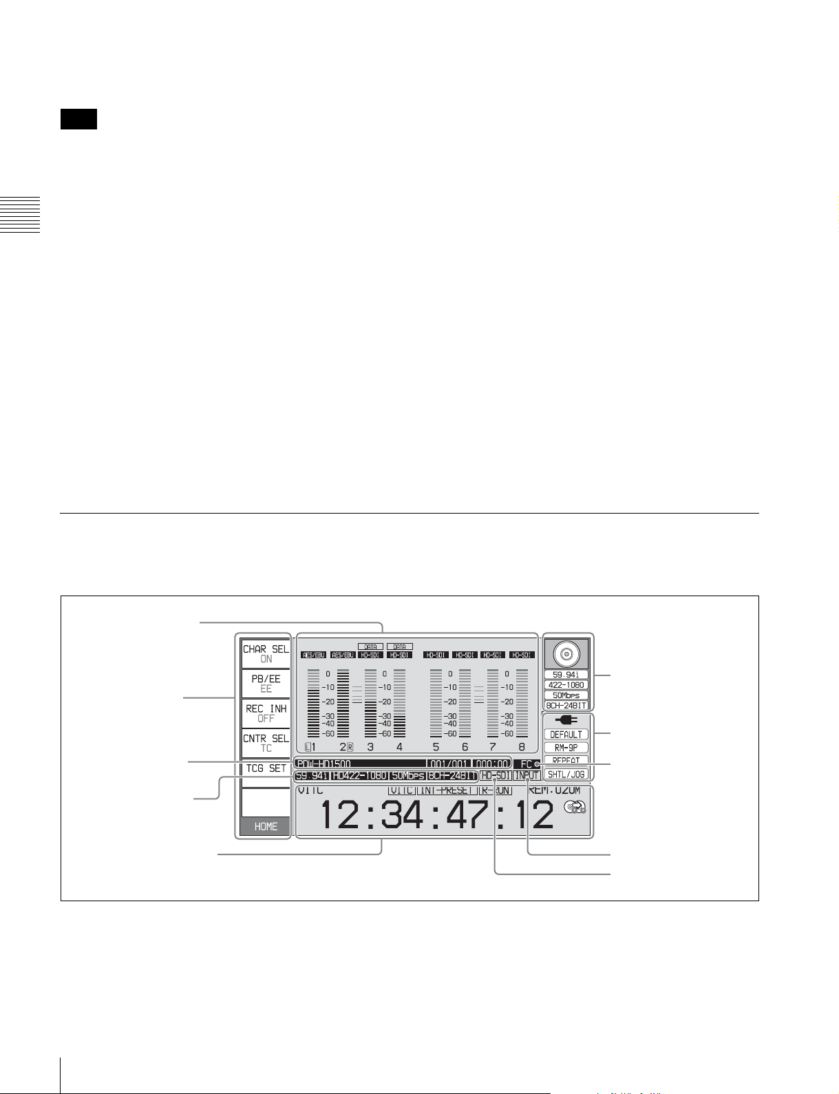
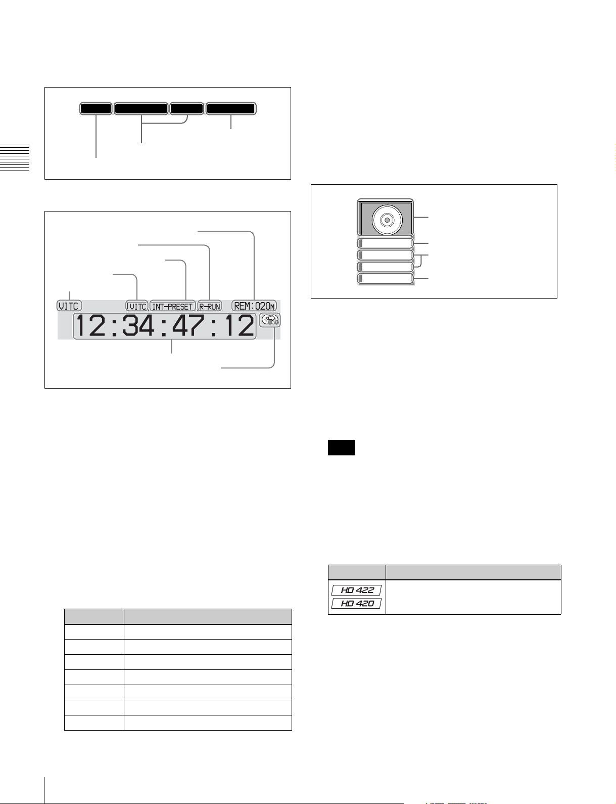
Display window
Basic operation display
1 Audio input display/
Audio level meters
2 Function menu
3 Clip information
4 Recording format
5 Time data display area
a Audio input display/Audio level meters
Displays information about audio. There are two display
modes for the audio level meter: FULL mode and FINE
mode, which can be switched over using AU METER on
page P4 AUDIO of the function menu.
6 Disc information
7 System information
8 Format conversion
9 Reference signal
q; Video input display
18
Front Panel
Page 19
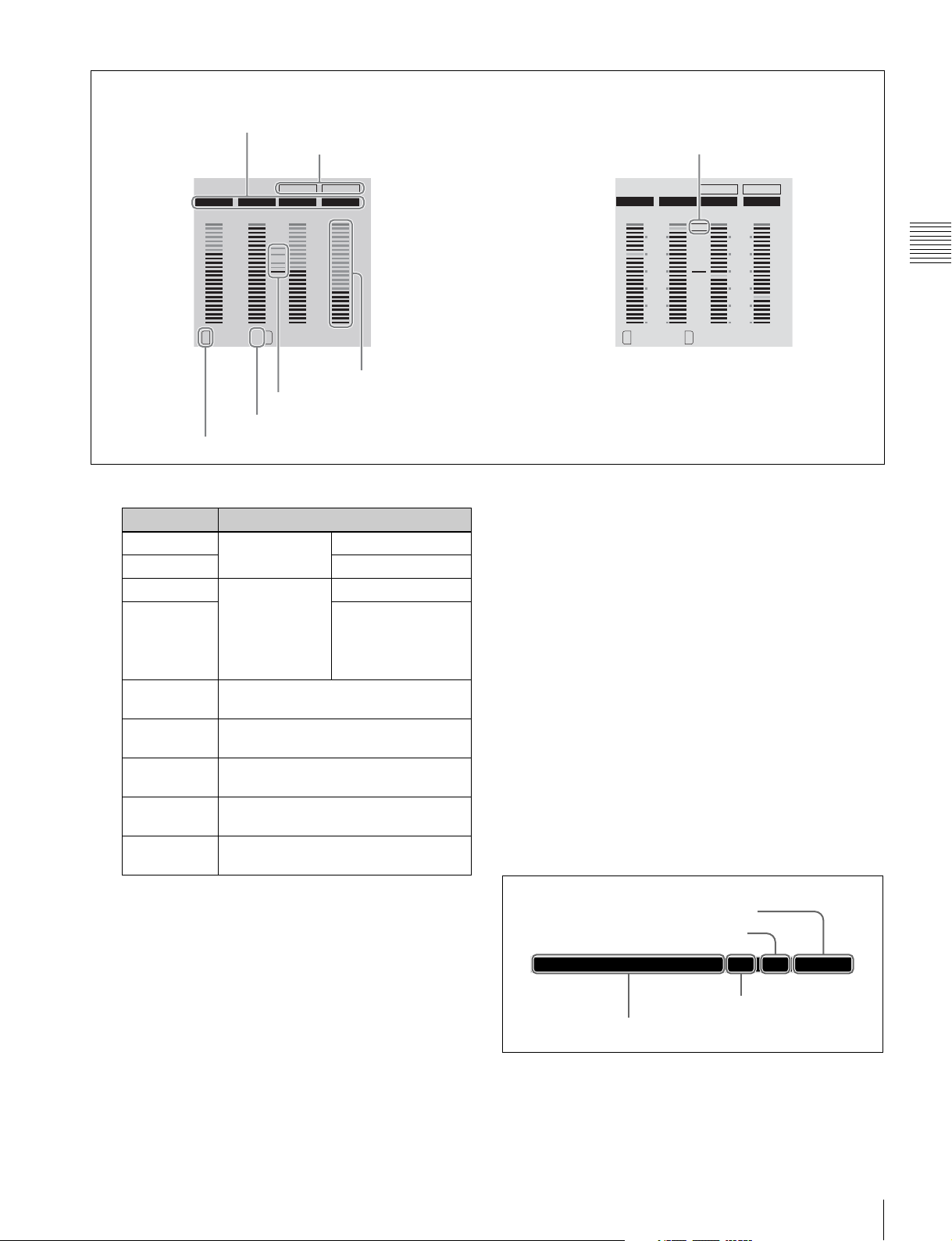
Meter display mode: FULL Meter display mode: FINE
A Input signal display
B Data indication
G Meter display mode
AES/EBU AES/EBU HD-SDI HD-SDI
0
-10
-20
-30
-40
-60
LR
1 2
C Monitor channel
A Input signal display: Displays the audio input signal.
.
DATA DATA
0
-10
-20
-30
-40
-60
3 4
E Reference level
D Audio channel
F Level bar
Display Input signal
ANA-1 Analog audio
ANA-2 Channel 2, 4
signal
MIC-1 Input signal from
MIC-2 Channel 2, 4
the microphone
connected to
Channel 1, 3
Channel 1, 3
ANALOG
AUDIO INPUT
connector
AES/EBU AES/EBU format digital audio signal
(flashes when there is no input signal)
HD-SDI HDSDI audio signal (flashes when
there is no input signal)
SD-SDI SDSDI audio signal (flashes when
there is no input signal)
SG Test signal from the internal signal
generator
No indication Undefined audio signal, or no audio
input
AES/EBU AES/EBU HD-SDI HD-SDI
2
1
0
-1
-2
LR
1 2 3 4
DATA DATA
FINE
2
1
0
-1
-2
F Level bars: Display the audio recording or playback
levels of channels 1 to 8. The OVER indicators light
when the audio level exceeds 0 dB.
G Meter display mode: Displays the audio level meter
display mode selected with AU METER on page P4
AUDIO of the function menu (see page 44).
b Function menu
Use the PAGE/HOME button to display this menu, and to
switch between the pages (HOME, P1 to P7, (P8)
(HOME2)
1)
) of the menu. Each page has three to six
1)
,
setting items. Press the corresponding button to change a
setting.
1) If a menu item is assigned using maintenance menu item M38: F-KEY
CONFIG
For details, see page 42 “Basic Operations of the
Function Menu” in Chapter 3.
c Clip information
Displays clip information.
Chapter 2 Names and Functions of Parts
B Data indication: Appears when the input signals are
non-audio signals.
C Monitor channel: Displays the audio monitoring
channels set with MONITR L and MONITR R on
page P2 AUDIO of the function menu (see page 43).
D Audio channel: Displays the audio channels.
Also indicates preset or variable mode by its color
(see page 14).
White: Preset mode
Green: Variable mode
E Reference level: Displays the reference level for
recording as set in the maintenance menu.
All remaining clips or clip list playback time
Total number of clips recorded on disc
PDW-HD1500 001/001 000:00
Number of current clip
Clip name
Front Panel
19
Page 20
d Recording format
Displays the system frequency and the video and audio
formats.
59.94i HD422-1080 50Mbps
8CH-24BIT
F Time data: Normally displays timecode or VITC,
according to the selection made with TCR on page P5
TC of the function menu.
G Disc exchange cache indication: Appears when setup
menu item 150 DISC EXCHANGE CACHING is set
to “on” (see page 108).
Audio format
Video format
System frequency
Chapter 2 Names and Functions of Parts
e Time data display area
A Remaining disc recording capacity
B Rec Run/Free Run
C Timecode generator mode
D VITC
E Time data type
F Time data
G Disc exchange cache indication
A Remaining disc recording capacity: Displays the
amount of recording capacity remaining on the disc.
B Rec Run/Free Run: Displays the timecode run mode.
The run mode is set with RUN MODE on page P5 TC
of the function menu (see page 45).
C Timecode generator mode: Displays the timecode
source and generation method (preset or regenerate).
These are set with PRST/RGN and TCG on page P5
TC of the function menu (see page 45).
D VITC: Lights in the following cases.
•When VITC is read in playback mode. (This has no
relations to the display in the time data display area.)
•When VITC recording is possible.
E Time data type: Displays the type of time data
displayed in the time data display area. The type of
time data is selected with CNTR SEL on the HOME
page of the function menu (see page 42).
Display Type of time data
TC Timecode
COUNTER Elapsed recording/playback time
UB User bits
VITC VITC
VIUB VIUB
TCG Timecode generator value
UBG User bits generator value
See page 49 for more information about the disc exchange
cache function.
f Disc information
A Disc loaded indication/usable
format
59.94i
422-1080
50Mbps
8CH-24BIT
B System frequency
C Video format
D Audio format
A Disc loaded indication/usable format: When a disc is
loaded in this unit, a disc loaded indication appears.
When no disc is loaded, the usable formats are
displayed.
The background color of the disc loaded mark
indicates one of the following disc states.
Blue: Disc capable of recording and playback.
Yellow: Disc capable of playback only.
Red: Disc incapable of recording and playback.
Note
Even if the background is blue, recording is not
possible in the following cases.
•When a disc with recording inhibited is loaded.
•When REC INH on the HOME page of the function
menu is set to “ON”.
The usable formats displayed when no disc is loaded
in this unit are as follows.
Display Usable format
HD422: HD422
HD420: HD420HQ/HD420SP/HD420LP
a) HD420LP supports playback only.
When the separately sold PDBK-S1500 option is
installed
a)
20
Front Panel
Page 21
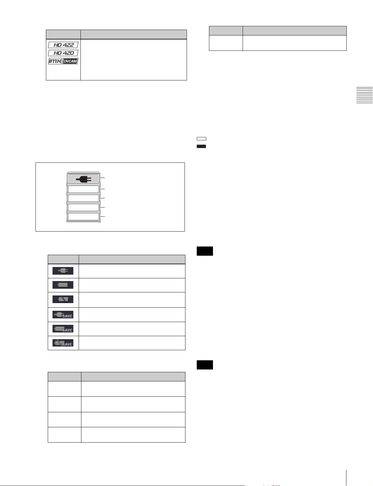
Display Usable format
HD422: HD422
HD420: HD420HQ/HD420SP/HD420LP
IMX: MPEG IMX 50Mbps/40Mbps/
30Mbps
DVCAM: DVCAM
a) HD420LP supports playback only.
a)
B System frequency: Displays the system frequency of
the clips recorded on the disc.
C Video format: Displays the video format and bitrate of
the clips recorded on the disc.
D Audio format: Displays the audio format of the clips
recorded on the disc.
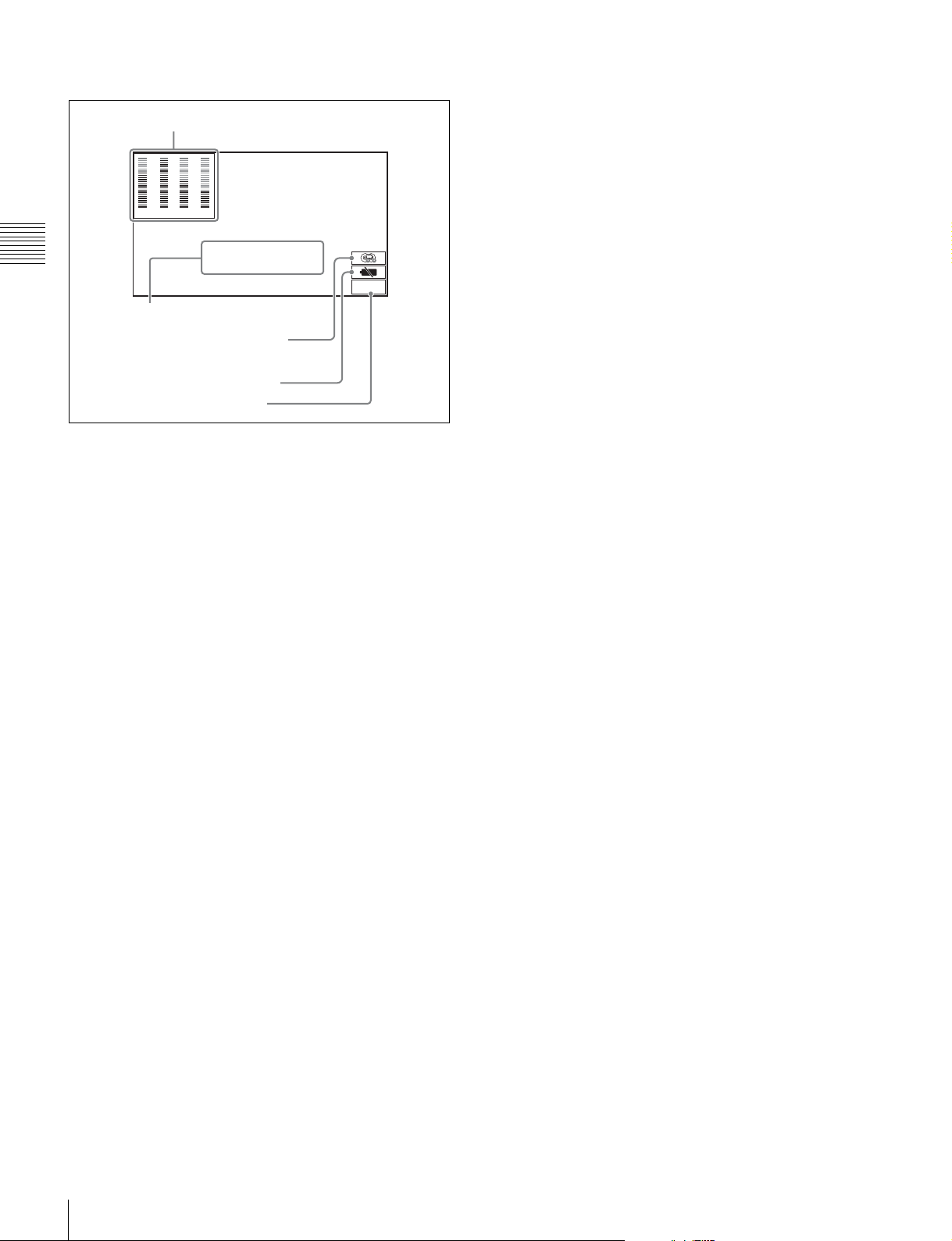
g System information
A Power status
DEFAULT
RM-9P
REPEAT
SHTL/JOG
B Menu setting status
C Remote interface
D Repeat mode
E Jog/shuttle dial mode
A Power status: Displays the status of the power supply
to the unit.
Display Power status
AC power
Battery
Display Description
No display The current menu settings are different
from all of the above.
C Remote interface: When the remote control switch is
set to REMOTE, displays the name of the interface
selected with setup menu item 214 REMOTE
INTERFACE.
D Repeat mode: Appears when setup menu item 142
REPEAT MODE is set to “play”.
E Jog/shuttle dial mode: Appears when the unit is in
shuttle, jog, or variable mode.
h Format conversion
This displays the status of 1080/720 format conversion.
: Format conversion is not being performed.
FC
: Format conversion is being performed.
See page 53 for more information about 1080/720 cross
convert function.
i Reference signal
This displays the type of reference signal to which this unit
is synchronizing.
When there is no display, the unit is synchronizing to the
internal reference signal.
INPUT: Input video
HD REF: HD-format reference signal
SD REF: SD-format reference signal
Note
The HD REF or SD REF display flashes when the video
input signal is not synchronized to the reference signal, and
when the signals are synchronized but their phases do not
match.
Chapter 2 Names and Functions of Parts
Battery almost exhausted: Flashes at 1 Hz
Battery exhausted: Flashes at 4 Hz
AC power (power-saving mode)
Battery (power-saving mode)
Battery (power-saving mode/low)
B Menu setting status: Displays the current setting
status of setup menu.
Display Description
BANK1 The current menu settings are the same
as the settings in menu bank 1.
BANK2 The current menu settings are the same
as the settings in menu bank 2.
BANK3 The current menu settings are the same
as the settings in menu bank 3.
DEFAULT The current menu settings are the same
as the factory defaults.
j Video input display
This displays the currently selected video input signal.
HDSDI: HDSDI video input
SDSDI: SDSDI video input
i.LINK: i.LINK TS (HDV) input
1)
SG: Test video signal from the internal signal generator
1) When the separately sold PDBK-201 option board is installed
Note
The display blinks when there is no video input signal, and
when the video input signal does not match the system
frequency of this unit.
The video signal input is selected with V INPUT on page
P1 VIDEO of the function menu (see page 43).
Front Panel
21
Page 22
Video monitor display
A Audio level meters
0
0
-10
-10
-20
-20
-30
-30
-40
-40
-60
1 2
-60
3 4
Chapter 2 Names and Functions of Parts
B Superimposed information
C Disc exchange cache
D Low battery warning
E Converter display
TCR.00:45.39.18*
JOG STILL
DC-SQ
indication
When you press the DISPLAY button, the display window
changes to the video monitor display.
A Audio level meters: LEVEL MT on page P2 AUDIO
of the function menu decides whether the meter is to
be displayed and on which side, left or right, it is
displayed in the display window.
B Superimposed information: Appears when CHAR
SEL on the HOME page of the function menu is set to
“ON” or “LCD”.
C Disc exchange cache indication: Appears when setup
menu item 150 DISC EXCHANGE CACHING (see
page 108) is set to “on”, and when the disc exchange
cache function is actually operating.
See page 49 for more information about the disc
exchange cache function.
D Low battery warning: Appears and flashes during
operation with a battery pack when the battery power
is almost exhausted.
E Converter display: Displays the current down- or up-
converter mode, depending on the state of the unit.
The current down-converter (DC) mode appears
when HD video is being input and when an HD disc
is being played. The current up-converter (UC) mode
appears when SD video is being input and when an
SD disc is being played.
1)
The current modes are those selected with setup menu
items 930 DOWN CONVERTER MODE (DC) and
950 UP CONVERTER MODE
1) When the separately sold PDBK-S1500 option is installed.
1)
.
DC-EC: Down-converter edge-crop mode
DC-LB: Down-converter letter box mode
DC-SQ: Down-converter squeeze mode
UC-EC: Up-converter edge-crop mode
UC-LB: Up-converter letter box mode
UC-SQ: Up-converter squeeze mode
22
Front Panel
Page 23
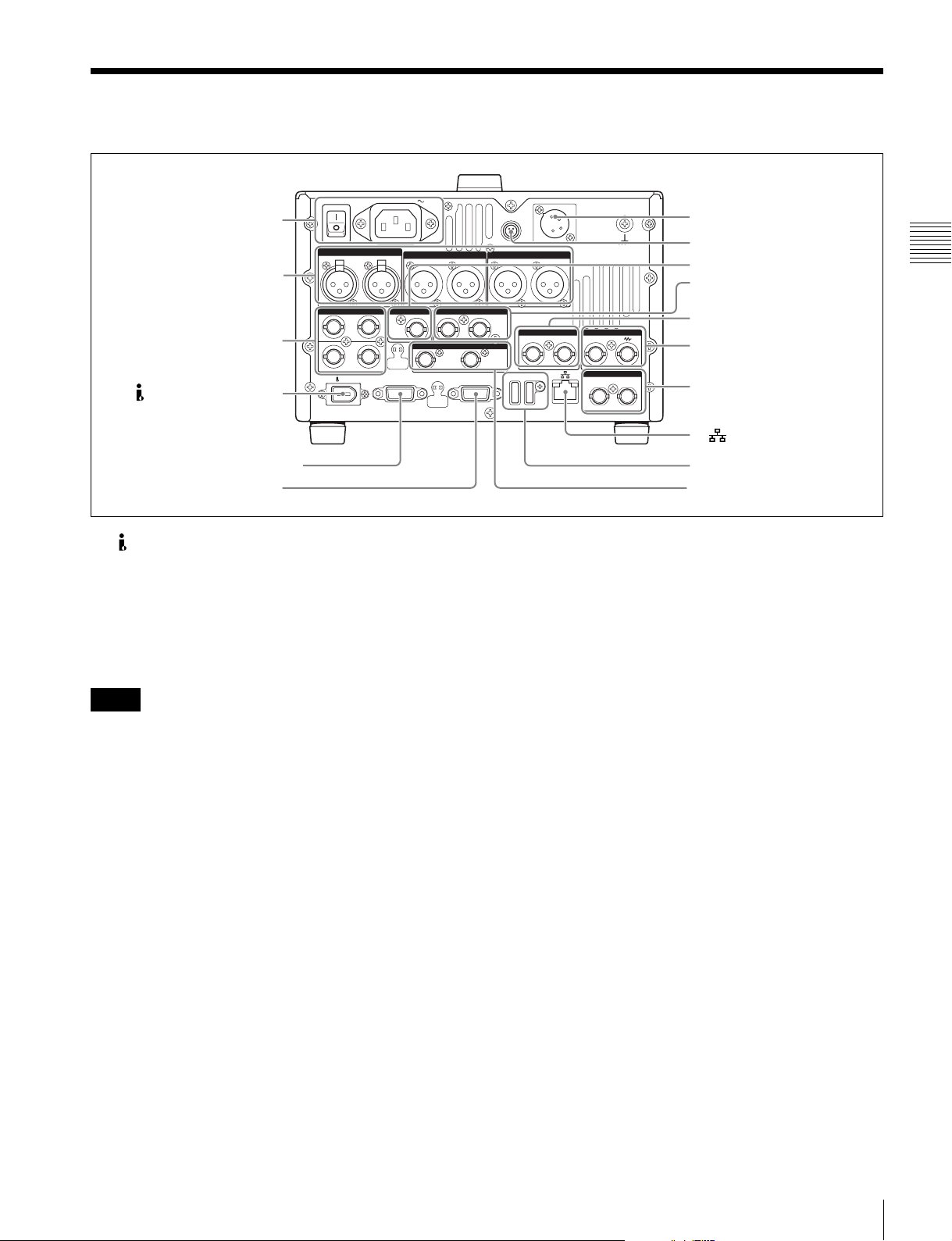
Rear Panel
1 Power supply section (see
page 24)
2 Analog audio signal input/
output section (see
page 24)
3 Digital audio signal input/
output section (see
page 25)
1 (i.LINK) S400 connector
POWER
ANALOG AUDIO INPUT
12
DIGITAL AUDIO (AES/EBU) SD/HDSDI INPUT HDSDI OUTPUT
1/2 3/4IN
OUT
1/2 3/4
VIDEO CONTROL
S400
AC IN
ANALOG AUDIO OUTPUT
12
12
SDSDI OUTPUT
12
REMOTE(9P)
DC IN 12V
REMOTE
AUDIO MONITOR
RL
(SUPER)
COMPOSITE OUTPUTINREF.VIDEO INPUT
12
(SUPER)
MAINTENANCE
(SUPER)
=
4 DC IN 12V connector
5 REMOTE connector
Chapter 2 Names and Functions of Parts
TIME CODE
IN OUT
6 SD/HDSDI INPUT connector
7 HDSDI OUTPUT 1, 2
(SUPER) connector
8 COMPOSITE OUTPUT1, 2
(SUPER) connectors
9 REF.VIDEO INPUT
connectors
4 Timecode input/output
section (see page 25)
0 (network) connector
2 VIDEO CONTROL connector
3 REMOTE(9P) connector
a (i.LINK) S400 connector (6-pin, IEEE1394
compliant)
Connect a computer or other device, using an i.LINK
cable.
When the separately sold PDBK-201 option board is
installed, i.LINK TS (HDV) signals can be input and
output via this connector.
Notes
• When this unit is connected to a device with a 6-pin
i.LINK connector by an i.LINK cable, before
unplugging the i.LINK cable, first power off the device
and disconnect the power plug from the outlet. If the
i.LINK cable is unplugged with the device power plug
still connected, a current from an excessive voltage (8 to
40 V) output from the i.LINK connector of the device
flows into this unit. This may cause a failure of the unit.
• When connecting this unit to a device with a 6-pin
i.LINK connector, connect to the 6-pin i.LINK
connector of the other device first.
b VIDEO CONTROL connector (D-sub-9-pin)
Connect an HKDV-900 video control unit.
See page 147 for correspondence between setting items of
HKDV-900 and setup menu of this unit.
c REMOTE(9P) (remote control 9-pin) connector
(D-sub 9-pin)
To control this unit from a controller or VTR supporting
the RS-422A Sony 9-pin VTR protocol, connect the device
to this connector.
qa MAINTENANCE connectors
qs SDSDI OUTPUT1, 2
(SUPER) connectors
d DC IN 12V connector (XLR 4-pin, male)
Connect to a DC power source of 12 V.
When using the BKP-L551 Battery Adaptor to mount a
battery pack, connect the power cable of the BKP-L551.
For details, see “Supplying power” on page 26.
e REMOTE connector (4-pin)
Supplies power to the RM-280 Editing Controller.
f SD/HDSDI INPUT (SDSDI/HDSDI signal input)
connector (BNC type)
This inputs an SDSDI or HDSDI format video/audio
signal.
g HDSDI OUTPUT 1, 2 (SUPER) (HDSDI signal
output 1, 2 (superimpose)) connectors (BNC type)
These output HDSDI format video/audio signals.
When editing with two PDW-HD1500 units, connect a
cable between these connectors on the player unit and the
SD/HDSDI INPUT connector on the recorder unit.
You can superimpose timecodes, menu settings, error
messages, or other information on the output of the HDSDI
OUTPUT 2 (SUPER) connector with the setting for
CHAR SEL on the HOME page of the function menu or
with the setting for setup menu item 028 HD
CHARACTER. You can always disable to superimpose
the data independent of the setting for CHAR SEL with the
setting for setup menu item 028.
See “Basic Operations of the Function Menu” (page 42)
for more information about the CHAR SEL settings.
Rear Panel
23
Page 24
See page 102 for more information about the setup menu
ANALOG AUDIO INPUT
ANALOG AUDIO OUTPUT
1212
AUDIO MONITOR
RL
item 028 HD CHARACTER.
set CHAR SEL on the HOME page of the function menu
to “OFF”.
To treat the input and output signals of these connectors as
non-audio signals, set the maintenance menu item M37:
AUDIO CONFIG >M372: NON-AUDIO INPUT
(recording) (see page 120) and setup menu item 823 NON-
AUDIO FLAG PB (playback).
h COMPOSITE OUTPUT 1, 2 (SUPER) (analog
Chapter 2 Names and Functions of Parts
composite video output 1, 2 (superimpose))
connectors (BNC type)
Output analog composite video signals. You can
superimpose timecodes, menu settings, or error messages
on the output of the 2 (SUPER) connector when CHAR
SEL on the HOME page of the function menu is set to ON.
See “Basic Operations of the Function Menu” on page 42
for more information about the CHAR SEL setting.
i REF.VIDEO INPUT (reference video signal input)
connectors (BNC type)
The two connectors form a loop-through connection; when
a reference video signal is input to the left connector, the
same signal is input from the right connector ( ) to a
connected device. When no connection is made to the right
connector, the left connector is automatically terminated
with an impedance of 75 ohms.
See “Items in the extended menu” (page 107) for more
information.
See “Basic Operations of the Function Menu” (page 42)
for more information.
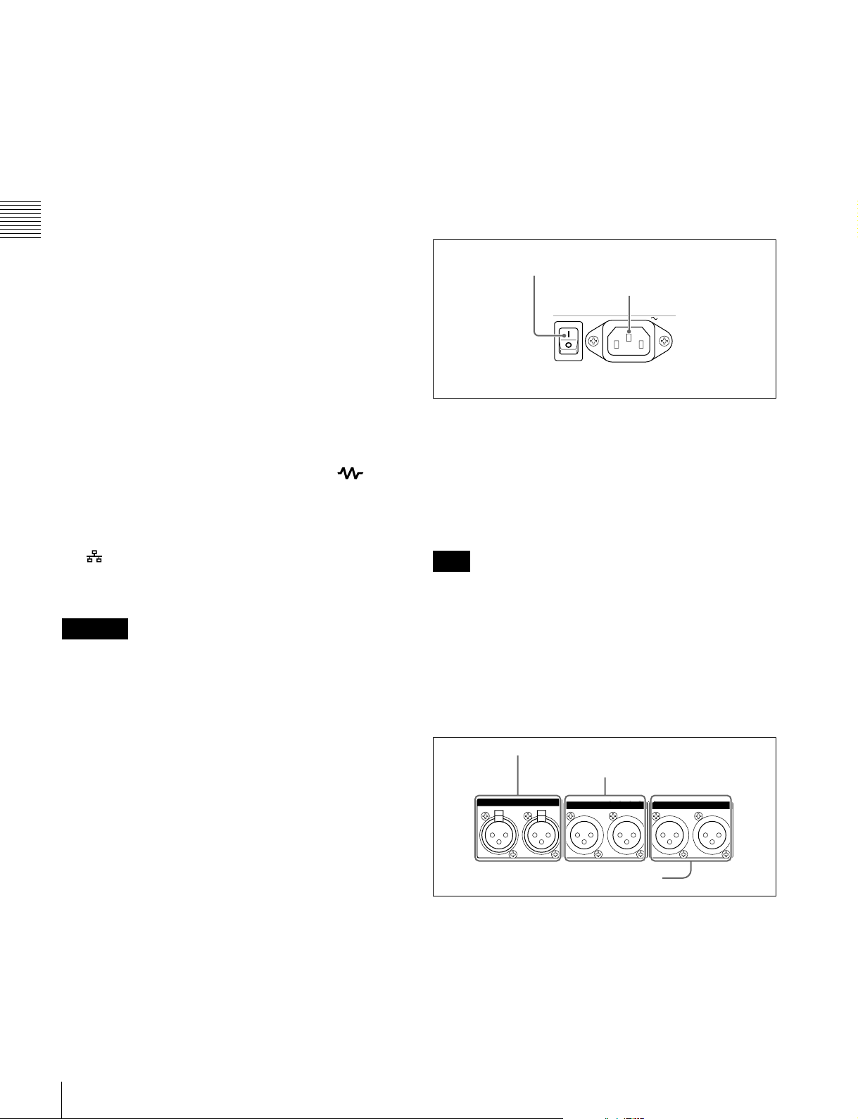
1 Power supply section
1 POWER switch
2 - AC IN connector
POWER
AC IN
a POWER (main power) switch
Press the : side to power on the unit. Press the a side to
power off.
When using the unit, normally leave the POWER switch in
the : (on) position, and use the on/standby button on the
front panel to switch the unit between the operating state
and standby state.
j (network) connector (RJ-45 type)
This is a 10BASE-T/100BASE-TX/1000BASE-T
connector for network connection.
CAUTION
For safety, do not connect the connector for peripheral
device wiring that might have excessive voltage to this
port. Follow the instructions for this port.
k MAINTENANCE connectors
These are the USB connectors for maintenance.
Connect a Windows USB keyboard or mouse (see
page 69), or a USB flash drive to access planning metadata
stored on the drive (see page 80).
l SDSDI OUTPUT 1, 2 (SUPER) (SDI signal outputs
1, 2 (superimpose)) connectors (BNC type)
These output SDSDI format video/audio signals.
When the unit is shipped from the factory, audio signal
output is eight channels with no switching, and RP188
timecode output is set to on. You can change these settings
with setup menu item 828 SDI AUDIO OUTPUT
SELECT and setup menu item 920 SD-SDI H-ANC
CONTROL.
The output from the 2 (SUPER) connector can have
timecode, menu settings, alarm messages, and other text
information superimposed. To turn superimposition off,
Note
Before turning the main power off, always check to be sure
that the unit is in the standby state, and then press the main
power switch to the a side.
b -AC IN connector
Connect to an AC power supply with the power cord (not
supplied).
2 Analog audio signal input/output section
1 ANALOG AUDIO INPUT 1, 2 connectors
2 ANALOG AUDIO OUTPUT 1, 2
connectors
3 AUDIO MONITOR R, L connectors
a ANALOG AUDIO INPUT 1, 2 connectors (XLR 3-
pin, female)
These input analog audio signals.
With A1 INPUT or A2 INPUT on page P2 AUDIO, and
A3 INPUT or A4 INPUT on page P3 AUDIO of the
function menu (see page 44), you can select whether the
signal input to connector 1 is assigned to audio channel 1or
24
Rear Panel
Page 25
3, and whether the signal input to connector 2 is assigned
to audio channel 2 or 4.
You can set the reference input level with the maintenance
menu item M37: AUDIO CONFIG (see page 120).
(Factory default setting: +4 dB)
Microphone settings
If you have connected a microphone to this unit, you can
set input level, AGC, and limiter values for the
microphone with setup menu items 834, 839, 840, and 841
(see page 116).
Note
An unpleasant sound may be output if you have connected
a microphone to the ANALOG AUDIO INPUT 1 or 2
connector and power the microphone on with the input
level too high. Check the input level setting before
connecting a microphone.
b ANALOG AUDIO OUTPUT 1, 2 connectors (XLR
3-pin, male)
These output analog audio signals.
When the unit is shipped from the factory, the 1 connector
is set to audio channel 1, and the 2 connector is set to audio
channel 2. You can change these settings with setup menu
item 824 ANALOG LINE OUTPUT SELECT (see
page 115).
You can set the output level with the maintenance menu
item M37: AUDIO CONFIG (see page 120). (Factory
default setting: +4 dB)
Non-audio signals are muted.
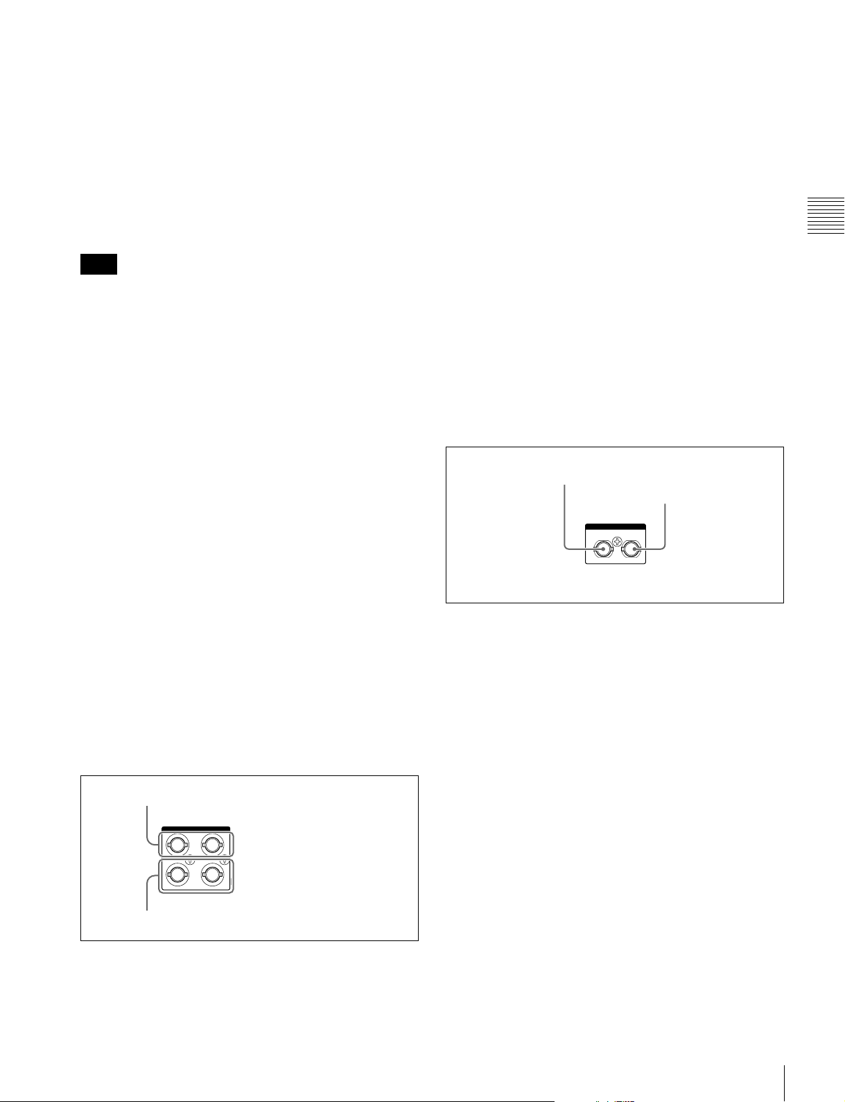
a DIGITAL AUDIO (AES/EBU) IN (digital audio
input) 1/2, 3/4 connectors (BNC type)
These input AES/EBU format digital audio signals. The
left connector (1/2) corresponds to audio channels 1 and 2,
and the right connector (3/4) corresponds to audio
channels 3 and 4.
b DIGITAL AUDIO (AES/EBU) OUT (digital audio
output) 1/2, 3/4 connectors (BNC type)
These output AES/EBU format digital audio signals.
When the unit is shipped from the factory, the 1/2
connector is set to audio channel 1/2, and the 3/4 connector
is set to audio channel 3/4. You can change these settings
with setup menu item 827 AES/EBU AUDIO OUTPUT
SELECT (see page 115).
To treat the input and output signals of these connectors as
non-audio signals, set the maintenance menu item M37:
AUDIO CONFIG >M372: NON-AUDIO INPUT
(recording) (see page 120) and setup menu item 823 NONAUDIO FLAG PB (playback).
4 Timecode input/output section
1 TIME CODE IN connector
2 TIME CODE OUT
connector
TIME CODE
IN OUT
Chapter 2 Names and Functions of Parts
c AUDIO MONITOR R, L connectors (XLR 3-pin,
male)
This outputs an audio signal for monitoring.
The monitored channel is selected with MONITR L and
MONITR R on page P2 AUDIO of the function menu.
See “Basic Operations of the Function Menu” (page 42)
for more information.
3 Digital audio signal input/output section
1 DIGITAL AUDIO (AES/EBU) IN 1/2, 3/4
connectors
DIGITAL AUDIO (AES/EBU)
1/2 3/4IN
OUT
1/2 3/4
2 DIGITAL AUDIO (AES/EBU) OUT 1/2, 3/4
connectors
a TIME CODE IN connector (BNC type)
This inputs an SMPTE timecode generated by an external
device.
b TIME CODE OUT connector (BNC type)
This outputs the following timecode, depending on the
operating state of this unit.
During playback: Playback timecode
During recording: The timecode from the internal
timecode generator or the timecode input to the TIME
CODE IN connector
When setup menu item 611 TC OUTPUT PHASE IN EE
MODE is set to “muting”, no timecode is output.
Rear Panel
25
Page 26
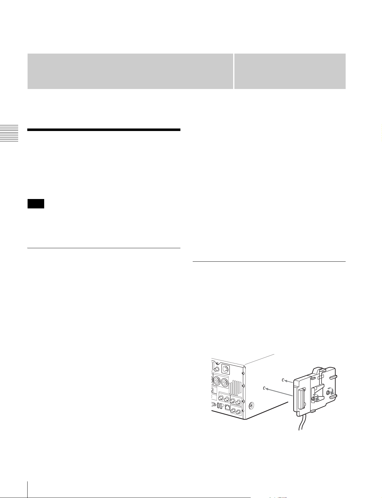
Preparations
Chapter 3 Preparations
Preparing Power Sources
Chapter
Continuous recording time at room temperature
BP-GL95 lithium-ion battery pack: 80 minutes (95
minutes when used in power save mode)
3
This unit can be powered by AC power, DC power, or a
battery pack.
For safety, use only the Sony battery packs listed below.
Lithium-ion battery pack: BP-L80S, BP-GL95
Note
If you load or remove a battery pack incorrectly, it may fall
and cause bodily injury. Follow the procedures described
below to load or remove them.
Supplying power
AC power supply
Connect the AC IN connector to an AC power source using
the specified AC power cord. To supply AC power to the
unit, set the on/standby button on the front panel to ON and
the POWER switch on the rear panel to = (ON).
DC power supply
Connect the DC IN 12V connector to a DC power source.
To supply DC power to the unit, set the on/standby button
on the front panel to ON and the POWER switch on the
rear panel to OFF. If the POWER switch on the rear panel
is set to = (ON), AC power is supplied.
For details on charging battery packs, refer to the
operation manual for the battery charger.
Notes about battery usage
• Before using the batteries, be sure to charge them fully
with the special battery charger. Refer to the operating
instructions for your battery charger for more
information about how to charge the batteries.
• Batteries may not be completely charged if you charge
them immediately after use when they are still warm.
You should wait until the batteries cool before charging
them.
Attaching a battery pack
Attaching and removing of the BP-GL95 Battery Pack is
described below.
The BP-L80S can also be attached and removed in the
same way.
For details on attaching the BKP-L551, refer to the
installation manual for the BKP-L551.
1
Attach the BKP-L551 to the side panel.
Battery power supply
Battery packs that can be used with this unit are as follows.
To use battery pack, a BKP-L551 Battery Adaptor and a
BC-L100 Battery Charger are also required.
• BP-L80S
•BP-GL95
26
Preparing Power Sources
2
Align the grooves on the BP-GL95 with the
projections on the BKP-L551.
BKP-L551
Page 27
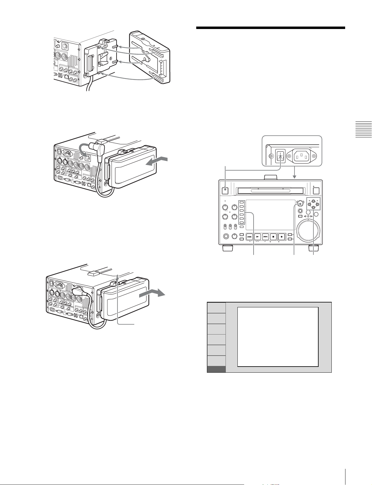
BP-GL95
3
Slide the BP-GL95 as shown below so that the
connectors on the BP-GL95 and the BKP-L551 are
connected.
4
Connect the DC cable of the BKP-L551 to the DC IN
12V connector.
Removing the battery pack
With the lever pushed in, slide the BP-GL95 out as shown
below.
Initial Setup
This unit is shipped with the area of use, system frequency,
recording format, and current date and time still unset.
Therefore, you need to make initial setup settings before
using the unit. (You cannot use the unit without setting it
up.)
Once the unit has been set up, the settings are retained even
when the unit is powered off.
Use the following procedures.
1
ACCESS
CH-1
CH-2
NET
LOCAL
REMOTE
PHONES LEVEL
ALL CH
VARIABLE KEY INHI
REC
PRESET
PB
CH-3
CH-4
CHAPTER
EXPAND
PAGE
ON
OFF
HOME
PREV NEXTPLAY STOP REC
DISPLAY
SHIFT
TOP F REV F FWD END STANDBY REC INHI
POWER
THUMBNAIL
SUB CLIP
DISC MENU
PUSH SET(S.SEL)
MENU
RESET
RETURN
SHTL/JOG
AC IN
MARK1
IN OUT
VAR/JOG
55,6 2,3,4
EJECT
MARK2
Chapter 3 Preparations
Lever
Checking the remaining battery power
You can use the LEDs on the side panel of the battery to
check the remaining power of the battery.
1
Power the unit on.
The INITIAL SETUP screen appears on the display.
RETURN
SET
INC/DEC : CTRL.KNOB
CANCEL&PREV : F1(RET)
SET&NEXT : F5(SET)
INIT
2
Turn the PUSH SET(S.SEL) knob to select the area of
INITIAL SETUP
UC/J MODEL
SELECT
NONE
use.
Display UC (for regions outside Japan) or J (for
Japan), and then press the SET function button (F5).
The system frequency screen appears.
3
Turn the PUSH SET(S.SEL) knob to select the system
frequency.
Initial Setup
27
Page 28
RETURN
SET
INIT
INITIAL SETUP
SYSTEM FREQUENCY
SELECT
1080/50i
INC/DEC : CTRL.KNOB
CANCEL&PREV : F1(RET)
SET&NEXT : F5(SET)
RETURN
SET
INIT
INITIAL SETUP
Push F5(SAVE) Key!!
CANCEL&PREV : F1(RET)
SAVE&REBOOT : F5(SET)
Display the system frequency that you want to use, and
then press the SET function button (F5).
The DATE/TIME PRESET screen appears.
4
Chapter 3 Preparations
In the DATE/TIME PRESET screen, set the current
date and time by setting the following items.
The message “NOW SAVING...” appears again, and
the setting screen disappears. Then the unit powers
itself off and on again.
To return to the original screen without saving
settings
Press the RETURN function button (F1).
RETURN
SET
INIT
DATE/TIME PRESET
YEAR 2008
MONTH 11
DAY 19
TIME 16:49:00
TIME ZONE UTC+00:00
INC/DEC : CTRL.KNOB
SHIFT : (P )(p )KEY
CANCEL&PREV : F1(RET)
SET&NEXT : F5(SET)
Note
The time zone is reset to the factory default when you
execute the maintenance menu item M49: RESET ALL
SETUP. You will need to set it again. The date and time
are not reset.
YEAR: Year
MONTH: Month
DAY: Day
TIME: Time
TIME ZONE: Time zone (as a difference in hours
with respect to Coordinated Universal Time
(UTC))
In the setting screen, you can change the value of the
flashing digit.
Press the B/IN or b/OUT button to make the previous
digit or next digit start flashing.
Press the V/MARK1 or v/MARK2 button (or turn the
PUSH SET(S.SEL) knob) to increment or decrement
the value of the flashing digit.
When you have finished making settings, press the
SET function button (F5).
The date, time, and time zone settings are saved, and
the message “NOW SAVING...” appears.
5
If you want to save the settings made up to this point,
press the SET function button (F5) again.
28
Initial Setup
Page 29
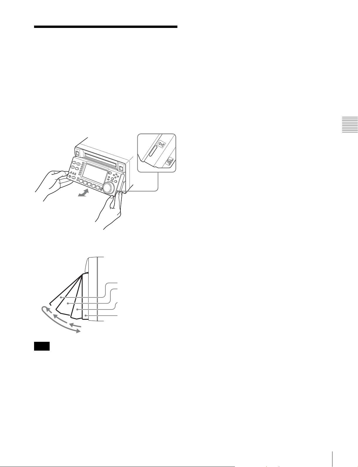
Front Panel Tilt Mechanism
The front panel of this unit has a tilt mechanism that allows
you to pull the front panel out and adjust it to a convenient
angle.
To pull the front panel out
Grasp the holds (small protrusions) on both sides of the
front panel and pull out as indicated by the arrow.
To change the angle of the front panel
To change the angle to position 2 from position 1, pull the
front panel out to position 2.
To change the angle to position 1 from position 2, first
unlock the front panel by pulling it all the way out to the
return position. Then return it to position 0, and pull out
again to position 1.
Chapter 3 Preparations
You can fix the angle of the front panel in position 1 (15
degrees) or position 2 (40 degrees).
Return position
Position 2 (40 degrees)
Position 1 (15 degrees)
Position 0
Note
The angle cannot be fixed if you pull the front panel past
position 2 all the way out to the return position. To fix the
front panel, return it to position 0 and then pull it out to
position 1 or position 2.
To return the front panel to its original
position
Unlock the front panel by pulling it out to the return
position. You can then return it to position 0.
Front Panel Tilt Mechanism
29
Page 30
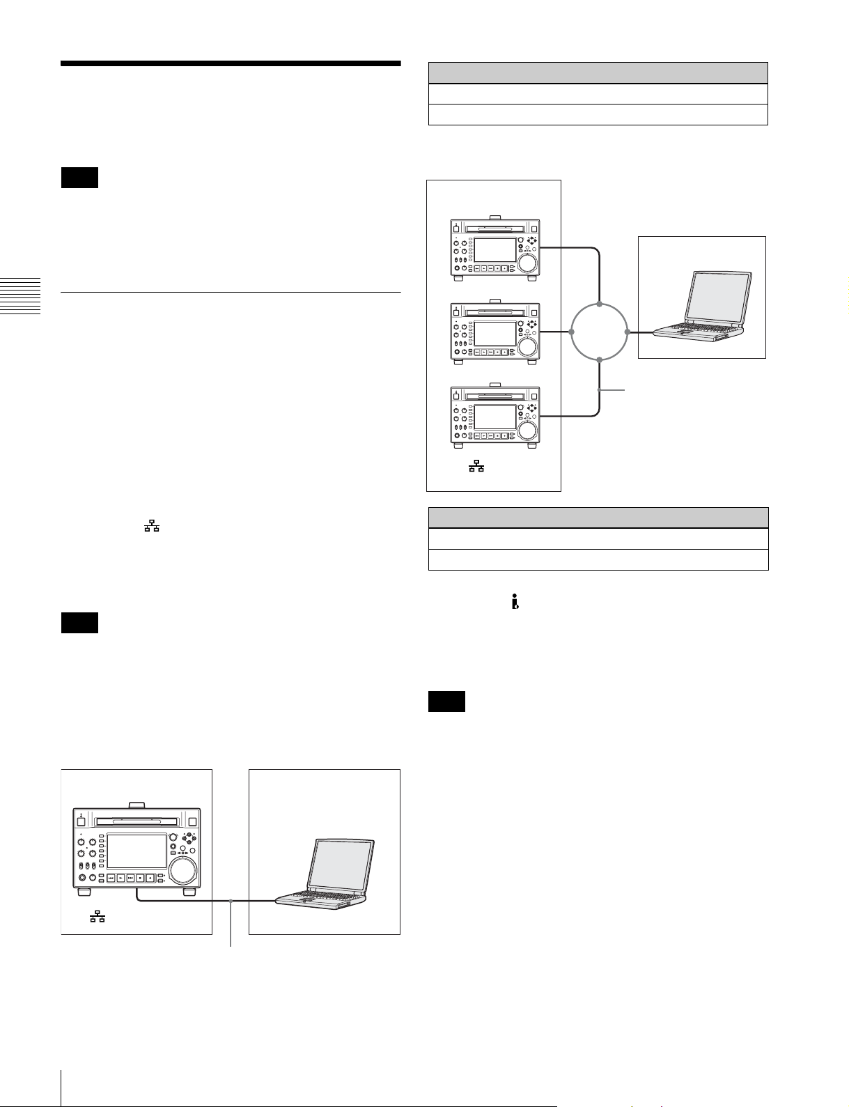
Connections and Settings
Note
Production of some of the peripherals and related devices
described in this chapter has been discontinued.
For advice about choosing devices, please contact your
Sony dealer or a Sony sales representative.
Connections for using PDZ-1 Proxy
Chapter 3 Preparations
Browsing Software
You can use the PDZ-1 Proxy Browsing Software on the
supplied XDCAM Application Software CD-ROM to
carry out simple editing with proxy AV data.
For an overview of PDZ-1 and how to install the software,
see “Using PDZ-1 Proxy Browsing Software” on
page 143. For information about how to use the software,
refer to the Help provided in the software.
Settings on this unit
Remote control switch: NET (see page 14)
Setup menu item 257 NETWORK ENABLE: net
Connecting three PDW-HD1500 units to a laptop
computer via a LAN
PDW-HD1500
Laptop computer
LAN
Network cable
(not supplied)
To (network)
connector
Using the (network) connector (FTP
connection)
The following shows an example of an FTP (File Transfer
Protocol) connection.
Note
To use PDZ-1 requires the PDW-HD1500 IP address and
other network-related settings to be made beforehand.
For details of the network-related settings, see “To change
network settings” (page 124).
Connecting this unit directly to a laptop computer
PDW-HD1500 (this unit)
Laptop computer
To (network) connector
Settings on all PDW-HD1500
Remote control switch: NET (see page 14)
Setup menu item 257 NETWORK ENABLE: net
Using the S400 (i.LINK) connector (FAM
connection)
The following shows an example of a FAM (file access
mode) connection.
Note
The PDZ-1 Proxy Browsing Software must be installed in
advance.
The required FAM driver is also installed when you install
the PDZ-1 software.
See “Using PDZ-1 Proxy Browsing Software” (page 143)
for more information about installing the PDZ-1 software.
Some limitations apply to FAM connections. For details,
see “File Operations in File Access Mode (for Windows)”
(page 89).
30
Connections and Settings
Network cable (not supplied)
Page 31

PDW-HD1500 (this unit)
To S400 connector
i.LINK cable (not supplied)
Use of a shielded cable is recommended.
Laptop computer
Connections for cut editing
The following figure shows a cut editing system
comprising this unit as a player.
When making the connections, also refer to the manuals
provided with the equipment to be connected.
See page 33 for more information about editing control
unit settings.
When using an editing control unit
Using BVE-700/700A
The following figure shows a cut editing system
comprising this unit as a player, an HDW-M2000/M2000P
unit as a recorder, and a BVE-700/700A as an editing
control unit.
Chapter 3 Preparations
Connections and Settings
31
Page 32

HD video monitor
1: 75Ω coaxial cable (not supplied)
To HDSDI input connector
1
POWER
ANALOG AUDIO INPUT
12
AC IN
ANALOG AUDIO OUTPUT
12
HDSDI OUTPUT 2
(SUPER)
=
DC IN 12V
REMOTE
AUDIO MONITOR
RL
2: 9-pin remote control cable (not supplied)
PDW-HD1500
(this unit, player)
REF.VIDEO
DIGITAL AUDIO (AES/EBU) SD/HDSDI INPUT HDSDI OUTPUT
REF.VIDEO
INPUT
1
1/2 3/4IN
OUT
1/2 3/4
S400
Chapter 3 Preparations
HDW-M2000 (recorder)
REF VIDEO
INPUT
75Ω
1
12
SDSDI OUTPUT
HDSDI
OUTPUT1
HDSDI
INPUT
(SUPER)
12
(SUPER)
MAINTENANCE
REMOTE(9P)VIDEO CONTROL
REMOTE(9P)
REF VIDEO
COMPOSITE OUTPUTINREF.VIDEO INPUT
(SUPER)
12
TIME CODE
IN OUT
INPUT
Reference video signal
2
PLAYER-1
INPUT
To HDSDI input
connector
HDSDI
OUTPUT 3
(SUPER)
REMOTE 1-IN(9P)
1
1
REF
VIDEO IN
SDI OUT SDI IN
SWER
REF VIDEO IN
2
MONITOR
VIDEO
VIDEO
OUT
OUT2
OUT1
RECORDER
MIXER
NETWORK
TITLE
RECORDER
PLAYER-3 PLAYER-2 PLAYER-1
PANEL
AUX/
PLAYER-2
PLAYER-3
GPI EDL
PLAYER-1
RECORDER
AC IN
BVE-700/700A
(editing control unit)
HD video monitor
HDW-M2000 (recorder) settings BVE-700/700A (editing control unit)
Settings on this unit
setting
REMOTE 1 (9P) button: Lit SYNCHRONIZE menu:OFF Remote control switch: REMOTE (see
page 14)
REF.VIDEO INPUT connector 75 Ω
termination switch: OFF
Setup menu item 214 REMOTE
INTERFACE: 9PIN
Audio selection function switching button
INPUT button: HDSDI
Function menu HOME >F1 (VID. IN): SDI
Function menu page 1 >F1 (TCG): INT
Function menu page 1 >F2 (PR/RGN):
PRESET
Function menu page 1 >F3 (RUN): FREE
32
Connections and Settings
Page 33

Editing Control Unit Settings
When connecting an editing control unit (BVE-700/700A/
2000/9100) to use with this unit, set VTR constants as
follows.
.
System
frequency
59.94i/
VTR CONSTANT
1 2 3 4 5 6 7 8 9 10 11 12 13 14 15 16
A0 96 00 96 15 15 03 80 0A 07 FE 00 80 5A FF 5A
59.94P/
29.97P
50i/50P/25PA196007D151503800A07FE00804CFF4B
Using RM-280
The following figure shows a cut editing system
comprising this unit as a player, an HDW-M2000/M2000P
unit as a recorder, and an RM-280 as an editing controller.
Chapter 3 Preparations
HD video monitor
HDW-M2000 (recorder)
To HDSDI input
connector
REF.VIDEO
INPUT
1
REF VIDEO
INPUT
75Ω
HDSDI
OUTPUT 3
(SUPER)
To HDSDI input connector
1
POWER
ANALOG AUDIO INPUT
12
DIGITAL AUDIO (AES/EBU) HDSDI OUTPUT
1/2 3/4IN
OUT
1/2 3/4
S400
1
REMOTE 1-IN(9P)
1
AC IN
ANALOG AUDIO OUTPUT
12
SD/HDSDI INPUT
12
SDSDI OUTPUT
HDSDI
OUTPUT1
HDSDI
INPUT
12
REMOTE(9P)VIDEO CONTROL
REF VIDEO
INPUT
HDSDI OUTPUT 2
(SUPER)
=
DC IN 12V
REMOTE
AUDIO MONITOR
RL
(SUPER)
COMPOSITE OUTPUTINREF.VIDEO INPUT
(SUPER)
12
(SUPER)
MAINTENANCE
TIME CODE
IN OUT
REMOTE(9P)
1: 75Ω coaxial cable (not supplied)
2: 9-pin remote control cable (not supplied)
PDW-HD1500 (this unit, player)
REF.VIDEO
INPUT
Reference video signal
1
2
REMOTE(9P)
RECORDER(DEVICE2)
RM-280
)
DC IN
REMOTE (9P
RECORDER (DEVICE 1)PLAYER (DEVICE 2)RS232C
REMOTE(9P)
2
RECORDER(DEVICE1)
REC TALLY
OUTPUT
IN / OUT
(editing
REF
controller)
REF IN/OUT
1
HD video monitor
HDW-M2000 (recorder) settings RM-280 (editing controller) settings Settings on this unit
REMOTE 1 (9P) button: Lit EDITOR/REMOTE CONTROL selector
switch: EDITOR
Remote control switch: REMOTE (see
page 14)
Connections and Settings
33
Page 34

HDW-M2000 (recorder) settings RM-280 (editing controller) settings Settings on this unit
REF.VIDEO INPUT connector 75 Ω
termination switch: OFF
Audio selection function switching button
Setup menu 01 PREROLL: 5s Setup menu item 214 REMOTE
INTERFACE: 9PIN
Setup menu 05 SYNC SEL: ON
INPUT button: HDSDI
Function menu HOME >F1 (VID. IN): SDI Setup menu 06 SYNC VTR:
RECORDER
Function menu page 1 >F1 (TCG): INT Setup menu 09 EDIT DLY: AUTO
Function menu page 1 >F2 (PR/RGN):
Setup menu 10 R ST DLY:AUTO
PRESET
Function menu page 1 >F3 (RUN): FREE Setup menu 11 P ST DLY:AUTO
Using the editing functions of the
Chapter 3 Preparations
recorder (controlling through
REMOTE(9P) connector)
The following figure shows a cut editing system
comprising this unit as a player, and an HDW-M2000/
M2000P unit as a recorder. In this example, video and
audio signals are connected by HDSDI, and control signals
are transferred via the REMOTE(9P) connector.
To HDSDI input connector
HDSDI
OUTPUT2
(SUPER)
POWER
ANALOG AUDIO INPUT
DIGITAL AUDIO (AES/EBU) HDSDI OUTPUT
OUT
S400
12
SD/HDSDI INPUT
1/2 3/4IN
1/2 3/4
ANALOG AUDIO OUTPUT
HDSDI
OUTPUT1
HDW-M2000
(recorder)
1
AC IN
REMOTE
(SUPER)
SDSDI OUTPUT
12
(SUPER)
REMOTE(9P)VIDEO CONTROL
AUDIO MONITOR
MAINTENANCE
12
12
REMOTE(9P)
REF VIDEO
INPUT
75Ω
PDW-HD1500
(this unit, player)
=
DC IN 12V
RL
COMPOSITE OUTPUTINREF.VIDEO INPUT
(SUPER)
12
TIME CODE
IN OUT
1
HD video monitor
REF.VIDEO
INPUT
Reference
video signal
1
REF.VIDEO
INPUT
1
HDSDI
INPUT
34
Connections and Settings
HDSDI
To HDSDI
OUTPUT 3
(SUPER)
REMOTE 1-OUT(9P)
1
input
connector
HD video monitor
1: 75Ω coaxial cable (not supplied)
2: 9-pin remote control cable (not supplied)
2
Page 35

HDW-M2000 (recorder)
setting
REMOTE 1 (9P) button: Lit Remote control switch:
Settings on this unit
REMOTE (see page 14)
Setup menu item 214
REMOTE INTERFACE: 9PIN
For details of HDW-M2000/M2000P settings, refer to the
HDW-M2000/M2000P Operation Manual.
Connections for pool coverage
The following figure shows an example of connections for
pool coverage, with the PDW-700 Professional Disc
Camcorder connected.
Chapter 3 Preparations
PDW-700
To SDI OUT 1 connector
75Ω coaxial cable (not supplied)
PDW-700 (camcorder)
setting
HDSDI REMOTE I/F on
page CAM CONFIG 1 of
the MAINTENANCE menu:
other than OFF
PDW-HD1500 (this unit)
To SD/HDSDI INPUT
connector
Settings on this unit
Remote control switch:
REMOTE (see page 14)
Setup menu item 214
REMOTE INTERFACE: SDI
Connections and Settings
35
Page 36

Synchronization Reference Signals
The synchronization reference signal generator of this unit
synchronizes to a reference signal input to the REF.
VIDEO INPUT connector or to a video input signal.
External synchronization is as follows, depending on the
Input to SD/HDSDI
INPUT connector
Yes Yes Synchronize to the signal input to
Yes No Synchronize to the signal input to the SD/HDSDI INPUT connector
Chapter 3 Preparations
No Yes Synchronize to the signal input to the REF. VIDEO INPUT connector
No No No external synchronization is made
a) Same as when V INPUT on page P1 VIDEO of the function menu is set to
“SG”.
b) FAM and FTP connections always synchronize to the internal
synchronization reference signal, regardless of the setting of OUT REF.
Input to REF. VIDEO
a)
INPUT connector
Setting of OUT REF on page P6 REF
REF INPUT
the REF. VIDEO INPUT connector
setting of OUT REF on page P6 REF of the function menu,
and on the type of the selected input signal. Video output
signals are always synchronized to the internal
synchronization signal.
b)
Synchronize to the signal input to
the SD/HDSDI INPUT connector
36
Synchronization Reference Signals
Page 37

Setting System Frequency
This unit can record and play back video at the system
frequencies of 59.94i, 50i, 29.97P and 25P (1080) or
59.94P and 50P (720).
Selecting the system frequency
1
Set setup menu item 013 SYSTEM FREQUENCY
SELECT MENU to “on” and press the PUSH
SET(S.SEL) knob.
The system frequency selection screen appears.
RETURN
SYSTEM FREQUENCY
SELECT
-
+
SAVE
EXIT
SETUP
2
Turn the PUSH SET(S.SEL) knob to select the system
If the System Frequency
setting is changed,
Turn power off and on
again.
frequency to be used.
1080/59.94i
Setting Timecode
There are the following four ways of recording timecode:
Internal Preset mode: This records the output of the
internal timecode generator, set beforehand to an
initial value. The following run modes can be
selected.
• Free Run: Timecode advances continually.
• Rec Run: Timecode advances only during
recording.
Internal Regen mode: This records the output of the
internal timecode generator, initialized to timecode
following continuously upon the timecode of the last
frame of the last clip on the disc.
External Regen mode: This records the output of the
internal timecode generator, synchronized to an
external timecode generator. As the external input, the
timecode input to any of the following connectors can
be selected.
• TIME CODE IN connector: LTC
• SD/HDSDI INPUT connector: VITC and LTC
• (i.LINK) S400 connector: TC
External Preset mode: This directly records the input of
an external timecode generator. As the external input,
the timecode input to any of the TIME CODE IN
connector can be selected.
Chapter 3 Preparations
RETURN
SYSTEM FREQUENCY
SELECT
-
+
SAVE
EXIT
SETUP
3
Press the PUSH SET(S.SEL) knob or the SAVE
1080/50i
Push F5(SAVE) Key!!
function button (F5).
The message “Turn off/on POWER!!” appears.
4
After pressing the on/standby button to power off the
unit, power it on again.
To record timecode after setting an initial
value (Internal Preset)
Proceed as follows with the function menu. For setting the
timecode, set TCG on page P5 TC of the function menu to
INT and PRST/RGN to PRESET.
Time data display area
Function menu
Function buttons
Setting an initial timecode value
1
Press the CNTR SEL function button on the HOME
page of the function menu, and select TC.
Setting System Frequency / Setting Timecode
37
Page 38

2
Press the TCG SET function button (F5).
The first digit of the time data display starts flashing.
Chapter 3 Preparations
3
Press the T or t function button (F1 or F2) to select
a digit to be set.
The selected digit starts flashing.
4
Use the PUSH SET(S.SEL) knob or – or + function
button (F3 or F4) to set the value for the selected digit.
To set the next-most significant digit (10s place)
Turn the PUSH SET(S.SEL) knob while holding down
the SHIFT button.
Repeat steps 3 and 4 to set all digits that should be set.
To set to 00:00:00:00
Press the RESET/RETURN button.
5
Press the SET function button (F5) .
If RUN MODE on page P5 TC is set to FREE RUN,
the timecode starts running.
To cancel a setting
Press the EXIT function button (F6). Any new settings to
that point are canceled, and the setting operation is
terminated.
Select UB by pressing the CNTR SEL function button (F4)
in step 1 of “Setting an initial timecode value” and carry
out steps 2 to 5. Settings are made in hexadecimal (0-9,
A-F).
You can record ID codes in user bits.
To record timecode that follows
sequentially upon the last recorded
timecode (Internal Regen)
You can record timecode so that it is continuous from one
clip to the next on the disc.
Set TCG on page P5 TC of the function menu to INT, and
PRST/RGN to TC or VITC. When this setting is in force,
the unit reads the timecode of the last frame of the last
recorded clip on the disc before starting to record, and
internally generates timecode that follows upon the
recorded timecode.
The frame count mode (for system frequency 59.94i/
59.94P/29.97P only) is set to the same mode as the last
recorded timecode on the disc (drop-frame or non-dropframe).
To record with the internal timecode
generator synchronized to external
timecode (External Regen)
Use this method to synchronize the timecode generators of
a number of recorders, to record the playback timecode of
external VTRs, or to record while maintaining
synchronization between the source video and timecode.
Use either of the following procedures according to the
type of external timecode.
Synchronizing with timecode input to the TIME
CODE IN connector
1
Connect the timecode output of an external device to
the TIME CODE IN connector, and input a reference
video signal to the REF. VIDEO INPUT connector.
Setting the timecode to the current time
1
Set RUN MODE on page P5 TC to FREE RUN and
DF/NDF to DF (in 59.94i/59.94P/29.97P mode only).
2
Perform steps 1 to 4 of “Setting an initial timecode
value” to set the timecode to a time slightly ahead of
the current time.
3
Press the SET function button (F5) at the instant when
the current time matches the displayed timecode.
Setting user bits
You can record up to 8 hexadecimal digits of information
(date, time, event number, etc.) on the timecode track.
38
Setting Timecode
2
Make the following settings on page P5 TC of the
function menu.
• Set TCG to “EXT”.
• Set PRST/RGN to “TC”.
Synchronizing with embedded LTC input to the
SD/HDSDI INPUT connector
1
Connect an HDSDI signal containing embedded LTC
to the SD/HDSDI INPUT connector, and input a
reference video signal to the REF. VIDEO INPUT
connector.
2
Make the following settings on page P5 TC of the
function menu.
Page 39

• Set TCG to “SDI”.
• Set PRST/RGN to “TC”.
Superimposed Text
Executing either of these procedures starts the internal
timecode generator running in synchronization with the
external timecode generator.
Once the internal timecode generator is synchronized with
the external timecode generator, the internal timecode
generator continues to run even if the external timecode
generator connection is removed.
The timecode advance mode is set automatically to Free
Run. The frame count mode (for system frequency 59.94i/
59.94P/29.97P only) is set to the same mode as the external
timecode signal (drop-frame or non-drop-frame).
To check the synchronization to the external
signal
Press the STOP button to stop this unit, then press the REC
button.
Check that the timecode value shown in the time data
display coincides with the external timecode value.
To record external timecode directly
(External Preset)
When you use this method, the internal timecode generator
advances without being affected by the external timecode.
Information
The video signal output from the COMPOSITE OUTPUT
2 (SUPER) connector, SDSDI OUTPUT 2 (SUPER)
connector, or the HDSDI OUTPUT 2 (SUPER) connector
contains superimposed text information, including
timecode, menu settings, and alarm messages.
Adjusting the text display
You can adjust the position, size and type of the
superimposed text using setup menu items 002, 003, 005,
009, 011, and 012.
For details, see “Items in the basic menu” (page 100).
Information displayed
1 Type of time data
2 Timecode reader drop frame mark
(for 59.94i/59.94P/29.97P mode only)
Chapter 3 Preparations
To directly record timecode input to the TIME
CODE IN connector
Connect the timecode output of an external device to the
TIME CODE IN connector, and make the following
settings on page P5 TC of the function menu.
• Set TCG to “EXT”.
• Set PRST/RGN to “PRESET”.
3 Timecode generator drop
frame mark (for 59.94i/
59.94P/29.97P mode only)
Time data
TCR 00:04.47.07*
PLAY LOCK
5 Operation mode
Note
4 VITC field mark
6 Playback condition
mark/Disc
exchange cache
mark
The display shown above corresponds to the factory
default settings of the unit. You can change the type of
information to be displayed in the lower line of the display
by changing the setting of setup menu item 005 DISPLAY
INFORMATION SELECT.
For details, see “Items in the basic menu” (page 100).
Superimposed Text Information
39
Page 40

a Type of time data
Display Meaning
CNT Counter data
TCR TC reader timecode
UBR TC reader user bits data
TCR. VITC reader timecode
UBR. VITC reader user bits data
TCG TC generator timecode
UBG TC generator user bits data
IN In point time data
OUT Out point time data
DUR Duration between In point and Out point
Chapter 3 Preparations
Note
If the time data or user bits data cannot be read correctly,
they will be displayed with an asterisk. For example,
“T*R”, “U*R”, “T*R.” or “U*R.”.
b Timecode reader drop-frame mark (for 59.94i/
59.94P/29.97P mode only)
“.”: Indicates drop-frame mode.
“:”: Indicates non-drop-frame mode.
c Timecode generator drop-frame mark (for 59.94i/
59.94P/29.97P mode only)
“.”: Indicates drop-frame mode (factory default setting).
“:”: Indicates non-drop-frame mode.
d VITC field mark
“ ” (blank): Fields 1 and 3 (for 59.94i/59.94P/29.97P
mode) or fields 1, 3, 5 and 7 (for 50i/50P/25P mode)
“*”: Fields 2 and 4 (for 59.94i/59.94P/29.97P mode) or
fields 2, 4, 6 and 8 (for 50i/50P/25P mode)
e Operation mode
The field is divided into two blocks as shown below.
• Block A displays the operation mode.
• Block B displays the servo lock status or playback speed.
AB
Display Operation mode
Block A Block B
DISC OUT Disc is not loaded.
LOADING Disc is being loaded.
UNLOADING Disc is being unloaded.
STANDBY OFF Standby off mode
STOP Stop mode
Display Operation mode
Block A Block B
NEXT xxx Cuing up to the first frame of the
next clip.
PREV xxx Cuing up to the first frame of the
F.FWD Fast forward search
F.REV Fast reverse search
PLAY Playback mode (servo unlocked)
PLAY LOCK Playback mode (servo locked)
REC Record mode (servo unlocked)
REC LOCK Record mode (servo locked)
JOG STILL A still picture in jog mode
JOG FWD Jog mode in forward direction
JOG REV Jog mode in reverse direction
SHUTTLE STILL A still picture in shuttle mode
SHUTTLE (Speed) Shuttle mode
VAR STILL A still picture in variable mode
VAR (Speed) Variable speed mode
TOP 0001/xxxx Cuing up to the first frame of the
END xxxx/xxxx Cuing up to the last frame of the
PREROLL Cuing up during thumbnail search
current clip.
first clip.
last clip.
f Playback condition mark/Disc exchange cache
mark
One of three channel condition marks is displayed when
the ACCESS indicator is lit during any mode except
recording. The indication “C” appears here when the disc
exchange cache function is operating.
Display Name Description
Green
condition
Yellow
condition
Red condition The playback condition has
There is no problem with the
playback condition. This unit and
the disc can be used just as they
are. This corresponds to the
“green” channel condition
indicator of a VTR.
The playback condition has
deteriorated to some degree.
There are no read errors, but you
should take the action described
in the next section. This
corresponds to the “yellow”
channel condition indicator of a
VTR.
deteriorated. There are no read
a)
errors,
action described in the next
section. This corresponds to the
“red” channel condition indicator
of a VTR.
but you should take the
40
Superimposed Text Information
Page 41

Display Name Description
CDisc
exchange
cache
a) Read errors will occur if the playback condition continues to deteriorate.
If a read error occurs, a “Disc Error!” alarm appears in the time data
display, the picture freezes, and audio is muted.
This appears during cache
recording.
For details, see page 49.
To display playback condition marks, set setup menu item
012 CONDITION DISPLAY ON VIDEO MONITOR to
“ena”, and set setup menu item 005 DISPLAY
INFORMATION SELECT to “T&sta”.
For details about operation, see “Basic menu operations”
(page 104).
Playback condition displays
You can be alerted in advance to deteriorating playback
conditions and to error correction rates which are
approaching their limits.
Deteriorating playback may be due to the following
causes.
• Scratches and dust on the disc surface
This includes fingerprints, dust from the air, tar from
cigarette smoke, and so on.
Scratches and soiling which occur before recording are
not a problem because they are registered in advance as
defects, and recording avoids them. However, scratches
and soiling which occur after recording can lead to
deteriorating playback conditions.
• Aging of disc recording layers
Over several decades, the recording layers of optical
discs can age and cause deteriorating playback
conditions.
You can use this function to check archival discs and
other discs which have been stored for extended periods,
so that you can take action before the deterioration
progresses further.
• Deteriorating laser diodes performance
The performance of the laser diodes used in optical
heads can worsen with age, leading to deteriorating
playback conditions.
• Do not store for long periods under high temperatures or
in locations exposed to direct sunlight.
If playback conditions have deteriorated
If a yellow or red playback condition mark appears, check
the following points.
Whether the disc displays the same playback condition
on other XDCAM devices: If so, the surface of the
disc may be dirty or scratched, or the performance of
the recording layers on the disc may have worsened
due to age. Do not use discs with these symptoms.
Whether every disc inserted into an XDCAM device
displays the same playback conditions: If so, the
performance of the laser diodes may have
deteriorated. Check the total optical output time.
Chapter 3 Preparations
For details, see “Digital hours meter” (page 129) about
this setting.
Refer to the Maintenance Manual for an approximate
guide to when it is time to replace optical heads.
To prevent playback conditions from
deteriorating
Pay attention to the following points when handling discs.
• Do not open disc cartridges and touch discs directly with
your hands.
• Do not store for long periods in locations which are
dusty or exposed to air circulated by fans.
Superimposed Text Information
41
Page 42

Basic Operations of the Function Menu
The function menu provides access to frequently used
settings, such as input video signal selection and timecode
settings.
Menu settings are stored in nonvolatile memory and are
preserved even after the unit is powered off.
Function menu operations
Chapter 3 Preparations
The function menu appears on the color LCD of this unit.
The following figure shows the buttons (numbered 1 to 6
beginning at the top) used in function menu operations.
Function buttons (1 to 6)
Function menu
button again while the page P2 is displayed switches the
page to P8.
To clear the function menu from the screen
Press the DISPLAY button to switch to the video monitor
display.
To change the setting of a function menu
item
Use the function buttons.
To select the value of the setting item
Press the button to the left of each setting item to change
the value of the item. Keep pressing the button until the
value you want appears.
To set the value of the setting item
• Press the button to the left of each setting item so that the
setting value flashes to enable adjustment of the value
and then turn the PUSH SET(S.SEL) knob to increase or
decrease the value.
• Turning the PUSH SET(S.SEL) knob while holding
down the SHIFT button increases the increment of
adjustment.
• Pressing the button to the left of each setting item while
the setting value is flashing causes the value to stop
flashing and completes the adjustment.
PUSH SET(S.SEL) knob
DISPLAY button
PAGE/HOME button
To display the function menu
The function menu is made up of the HOME page and
pages P1 to P7, (P8)
1)
, (HOME2)
1)
.
If the function menu is not already visible, press the
PAGE/HOME button to display it. (The most recently
accessed function menu page appears.)
1) If a menu item is assigned using maintenance menu item M38: F-KEY
CONFIG
To display a different page
Each press of the PAGE/HOME button displays the next
function menu page in the order: HOME tP1 t P2 t
P3 t P4 t P5 t P6 t P7 t (P8)
1)
t (HOME2)
1)
t HOME…
1) If a menu item is assigned using maintenance menu item M38: F-KEY
CONFIG
• Turning the PUSH SET(S.SEL) knob while holding
down the PAGE/HOME button changes the page
forward or backward.
• Pressing F1 to F6 buttons while holding down the
PAGE/HOME button switches the page directly to pages
P1 to P6. Pressing the F1 button again while the page P1
is displayed switches the page to P7. Pressing the F2
Function menu settings
The following tables list the setting items on each page and
describe their setting values. Underlined values are the
factory defaults.
HOME page
Item Setting
F1: CHAR SEL Turns the display of character
F2: PB/EE Selects the type of video and audio
F3: REC INH Specifies whether to inhibit recording to
information on the color LCD and on an
external monitor on and off.
ON: Character information on
: Character information off
OFF
LCD: Character information on for the
color LCD only
signals to output during fast forward, fast
reverse, stop, and standby.
: Playback signal
PB
EE: E-E signal
the disc.
: Do not inhibit recording.
OFF
ON: Inhibit recording to the disc
according to the setting of setup
menu item 310 REC INHIBIT.
42
Basic Operations of the Function Menu
Page 43

Item Setting
F4: CNTR SEL Selects the type of time data to display in
the time data display area.
: Timecode
TC
COUNTER: Elapsed recording or
playback time
UB: User bits
F5: TCG SET • When CNTR SEL is set to “TC” ,
F6: (Unassigned function button)
a) This is displayed only when TCG on page P5 TC of the function menu is
set to “INT”, and PRST/RGN is set to “PRESET”.
displays a screen where you can set
the initial value of the timecode
generated by the internal timecode
generator
• When CNTR SEL is set to “UB” ,
displays a screen where you can set
timecode user bits
a)
(see page 37).
a)
(see page 38).
P1 VIDEO page
Item Setting
F5: HUE/CHRM
PHS
F6: SETUP/
BLACK
Sets the hue (chroma phase).
PRESET: Set the hue (chroma phase) to
a preset value, regardless of manual
setting.
Manual setting: While the setting value
is flashing, turn the PUSH
SET(S.SEL) knob to adjust the hue
(chroma phase) over the range
±30°.
Sets the HD/SD output black setup level
or black level.
PRESET
value, regardless of the manual
setting.
Manual setting: While the setting value
is flashing, turn the PUSH
SET(S.SEL) knob to set the black
setup level (in 59.94i/59.94P/29.97P
mode) over the range ±30 IRE or the
black level (in 50i/50P/25P mode)
over the range ±210 mV.
: Set the level to the preset
Chapter 3 Preparations
Item Setting
F1: V INPUT Selects the video input signal.
F2: VID. PROC Selects the method used to control the
F3: VIDEO Sets the output level for HD/SD video
F4: CHROMA Sets the output level for HD/SD chroma
: HDSDI signal
HDSDI
SDSDI: SDSDI signal
i.LINK: i.LINK signal (when the
separately sold PDBK-201 option
board is installed)
SG: Test signal from internal signal
generator (Normally this item is not
displayed. It appears when you hold
the button down for 3 seconds.)
internal video signal processor and make
related settings.
LOCAL
MENU: Use the setup menu to change
signals (range –∞ to +3 dB).
PRESET
Manual setting: While the setting value
signals (range –∞ to +3 dB).
PRESET
Manual setting: While the setting value
: Use the function menu to
change settings.
settings.
: Set the video signal output
level to a preset value, regardless of
manual setting.
is flashing, turn the PUSH
SET(S.SEL) knob to adjust the video
signal output level.
: Set the chroma signal output
level to a preset value, regardless of
manual setting.
is flashing, turn the PUSH
SET(S.SEL) knob to adjust the
chroma SETUP signal output level.
P2 AUDIO page
Item Setting
F1: A1 INPUT Selects the audio input signal to assign
F2: A2 INPUT Selects the audio input signal to assign
F3: MONITR L Selects the channel to monitor as the left
F4: MONITR R Selects the channel to monitor as the
to audio channel 1.
: Audio signal embedded into SDI
SDI
signal
ANALOG1: Analog 1 audio signal
AES/EBU1: Signal input to the DIGITAL
AUDIO(AES/EBU) IN 1/2 connectors
SG: Test signal from internal signal
generator (Normally this item is not
displayed. It appears when you hold
the button down for 3 seconds. The
test signal is assigned to audio
channels 1 to 8 simultaneously.)
Press one of the function buttons
corresponding to A1 INPUT to A8
INPUT again to stop output of the
test signal.
i.LINK: i.LINK signal (when the
separately sold PDBK-201 option
board is installed)
to audio channel 2.
: Audio signal embedded into SDI
SDI
signal
ANALOG2: Analog 2 audio signal
AES/EBU2: Signal input to the DIGITAL
AUDIO(AES/EBU) IN 1/2 connectors
monitor channel.
, CH2, CH3, CH4, CH5, CH6, CH7,
CH1
CH8
CH1/2, CH3/4, CH5/6, CH7/8 (MIX)
right monitor channel.
, CH2, CH3, CH4, CH5, CH6, CH7,
CH1
CH8
CH1/2, CH3/4, CH5/6, CH7/8 (MIX)
Basic Operations of the Function Menu
43
Page 44

Item Setting
F5: SPEAKER Enables or disables output from this
unit’s speaker.
: Do not output
OFF
ON: Output
F6: LEVEL MT Specifies the position at which to
superimpose audio level meters in the
video monitor screen (in full-screen
display mode).
: Do not superimpose.
OFF
LEFT: Superimpose the audio level
meters of 2 channels on the left side.
RIGHT: Superimpose the audio level
meters of 2 channels on the right
side.
LEFT(4): Superimpose the audio level
Chapter 3 Preparations
meters of 4 channels on the left side.
RIGHT(4): Superimpose the audio level
meters of 4 channels on the right
side.
LEFT(8): Superimpose the audio level
meters of 8 channels on the left side.
RIGHT(8): Superimpose the audio level
meters of 8 channels on the right
side.
P3 AUDIO page
Item Setting
F1: A3 INPUT Selects the audio input signal to assign
F2: A4 INPUT Selects the audio input signal to assign
F3: A5 INPUT Selects the audio input signal to assign
F4: A6 INPUT Selects the audio input signal to assign
F5: A7 INPUT Selects the audio input signal to assign
to audio channel 3.
: Audio signal embedded into SDI
SDI
signal
ANALOG1: Analog 1 audio signal
AES/EBU3: Signal input to the DIGITAL
AUDIO(AES/EBU) IN 3/4 connectors
to audio channel 4.
: Audio signal embedded into SDI
SDI
signal
ANALOG2: Analog 2 audio signal
AES/EBU4: Signal input to the DIGITAL
AUDIO(AES/EBU) IN 3/4 connectors
to audio channel 5.
: Audio signal embedded into SDI
SDI
signal
ANALOG1: Analog 1 audio signal
AES/EBU1: Signal input to the DIGITAL
AUDIO(AES/EBU) IN 1/2 connectors
to audio channel 6.
: Audio signal embedded into SDI
SDI
signal
ANALOG2: Analog 2 audio signal
AES/EBU2: Signal input to the DIGITAL
AUDIO(AES/EBU) IN 1/2 connectors
to audio channel 7.
: Audio signal embedded into SDI
SDI
signal
ANALOG1: Analog 1 audio signal
AES/EBU3: Signal input to the DIGITAL
AUDIO(AES/EBU) IN 3/4 connectors
Item Setting
F6: A8 INPUT Selects the audio input signal to assign
to audio channel 8.
: Audio signal embedded into SDI
SDI
signal
ANALOG2: Analog 2 audio signal
AES/EBU4: Signal input to the DIGITAL
AUDIO(AES/EBU) IN 3/4 connectors
P4 AUDIO page
Item Setting
F1: A5 VOL
Sets the volume of audio channel 5.
The volume can be adjusted within the
range from –200 to +200 (–∞ to +12 dB)
by turning the PUSH SET(S.SEL) knob.
F2: A6 VOL
Sets the volume of audio channel 6.
The volume can be adjusted within the
range from –200 to +200 (–∞ to +12 dB)
by turning the PUSH SET(S.SEL) knob.
F3: A7 VOL
Sets the volume of audio channel 7.
The volume can be adjusted within the
range from –200 to +200 (–∞ to +12 dB)
by turning the PUSH SET(S.SEL) knob.
F4: A8 VOL
Sets the volume of audio channel 8.
The volume can be adjusted within the
range from –200 to +200 (–∞ to +12 dB)
by turning the PUSH SET(S.SEL) knob.
F5: --- (Unassigned function button)
F6: AU METER Selects the display mode of the audio
level meters.
FULL: Display the range from –60 dB to
0 dB.
FINE: Display a magnified section with
0.25 dB step marks.
a) To enable this setting, the following settings are also required, in the same
way as for volume operations for channels 1 to 4.
- Set the VARIABLE switch of the front panel to “REC” or “PB”.
- Set setup menu item 131 AUDIO VOLUME to “EACH”.
a)
a)
a)
a)
44
Basic Operations of the Function Menu
Page 45

P5 TC page P6 REF page
Item Setting
F1: TCG Selects the timecode signal to which the
F2: PRST/RGN Selects the following for the internal
F3: RUN MODE Selects the timecode run mode.
F4: DF/NDF Selects the drop-frame mode for the
F5: (Unassigned function button)
F6: TCR Selects the type of timecode to display in
internal timecode generator
synchronizes.
: Follow the initial value set from the
INT
control panel or remotely from the
device connected to the
REMOTE(9P) connector, or
synchronize to timecode played
back from the disc.
EXT: Synchronize to external timecode
input to the TIME CODE IN
connector.
SDI: Synchronize to timecode
embedded into HDSDI signal input
to SD/HDSDI INPUT connector.
Note
If you select “EXT” or “SDI” while i.LINK
TS signals are being input, synchronizes
to the timecode data in the TS signals.
timecode generator.
PRESET
TC: Generate timecode synchronized to
VITC: Generate timecode synchronized
FREE RUN: Timecode advances as long
REC RUN
internal timecode generator and the
counter in 59.94i/59.94P/29.97P mode.
DF
NDF: Non-drop-frame mode
the time data display area.
TC
VITC: Display VITC.
: Presets an initial value for the
timecode generated by the internal
timecode generator, as specified
from the control panel or remotely
from the device connected to the
REMOTE(9P) connector. This is
valid when “INT” is selected with the
F1: TCG item on this page. The
operation is the same as “TC” when
anything else is selected.
timecode read by the internal
timecode reader.
to VITC read by the internal
timecode reader.
as the unit is powered on, regardless
of the unit’s operating state.
: Timecode advances only
during recording. When you select
this item, also set F1: TCG on this
page to “INT” and set F2: PRST/
RGN to “PRESET”.
: Drop-frame mode
: Display TC.
Item Setting
F1: OUT REF Selects the reference signal for the
F2: (Unassigned function button)
F3: (Unassigned function button)
F4: (Unassigned function button)
F5: SYNC Sets the sync phase of HD output
F6: FINE Makes fine adjustment to the sync phase
output signals of this unit.
: Use the signal input to the
REF
REF.VIDEO INPUT connector as the
output reference signal.
INPUT: Use the input video signal as the
output reference signal.
signals. While the setting value is
flashing, turn the PUSH SET(S.SEL)
knob to adjust the sync phase of output
signals with respect to the input
reference signal, over the range ±15 µs.
(The display shows –128 to +127.)
of HD output signals. While the setting
value is flashing, turn the PUSH
SET(S.SEL) knob to adjust the sync
phase of output signals with respect to
the input reference signal, over the range
±200 ns. (The display shows 0 to 1023.)
P7 OTHER page
Item Setting
F1: CONV IMP Selects whether to display convert status
on the display during convert operations.
: Do not display.
OFF
ON: Display.
F2: ERR LOG Displays an error log screen.
F3: CLIP FLG Sets a clip flag for the clip being
recorded or played back using the
function button.
If a clip flag is already set for the clip,
“Marked” is displayed in the function
menu item corresponding to one of the
F1 to F3 buttons depending on the type
of flag that has been set.
A clip flag can also be set or deleted
using the GUI screen. See page 70 for
details.
Sub-Item
F1: OK Set an OK flag.
F2: NG Set an NG flag.
F3: KEEP Set a KEEP flag.
F4: –
F5: DELETE Delete the clip flag.
F6: EXIT Exit the clip flag sub-
menu.
Chapter 3 Preparations
Basic Operations of the Function Menu
45
Page 46

Item Setting
F4: PC RMT Enables or disables a FAM connection.
The connection can be cut off while it is
maintained or remade while it is
disabled.
ENABLE: Enable a connection.
DISABLE
Notes
• PC REMOTE under maintenance
menu item M33: FILE I/F CONFIG
must be set to “F-KEY SELECT” in
order to use this function (see
page 120).
• “DISABLE” is always selected when
the unit is powered off and then on
again, regardless of the previous
Chapter 3 Preparations
F5: (Unassigned function button)
F6: (Unassigned function button)
setting.
: Disable a connection.
Handling Discs
Discs used for recording and playback
This unit can record and play back the following
Professional Disc
• PFD23A (capacity 23.3 GB)
• PFD50DLA (capacity 50.0 GB)
1) Professional Disc is a trademark of Sony Corporation.
Notes
• It is not possible to use the following discs for recording
or playback:
-Blu-ray Disc
-Professional Disc for Data
• PFD50DLA discs can be used only by XDCAM devices
with the DL mark (see the following illustration). They
cannot be used by XDCAM devices without this mark.
1)
formats.
DL mark
Notes on handling
Handling
The Professional Disc is housed in a cartridge, and is
designed to allow handling free of risk from dust or
fingerprints. However, if the cartridge is subjected to a
severe shock, for example by dropping it, this can result in
damage or scratching of the disc. If the disc is scratched, it
may be impossible to record video/audio, or to play back
the content recorded on the disc. The discs should be
handled and stored carefully.
• Do not touch the surface of the disc itself within the
cartridge.
• Deliberately opening the shutter may cause damage.
• Do not disassemble the cartridge.
• The supplied adhesive labels are recommended for
indexing discs. Apply the label in the correct position.
Storage
• Do not store discs where they may be subjected to direct
sunlight, or in other places where the temperature or
humidity is high.
• Do not leave cartridges where dust may get inside.
• Store cartridges in their cases.
46
Care of the discs
• Remove dust and dirt on the outside of a cartridge using
a soft dry cloth.
Handling Discs
Page 47

• If condensation forms, allow ample time to dry before
use.
MODE KEY ENABLE DURING RECORDING to
“stop”.
Write-protecting discs
To protect the content recorded on the disc from accidental
erasure, move the Write Inhibit tab on the lower surface of
the disc in the direction of the arrow, as shown in the
following figure.
Lower surface of the disc
Write Inhibit tab settings
SAVE SAVE
Recording enabled
Write Inhibit tab
E
V
A
S
Slide in the direction of the arrow
Recording disabled
Formatting a disc
Unused discs are formatted automatically when they are
loaded into this unit.
To format a recorded disc, use the GUI screen.
For details, see “Formatting discs” (page 81).
Chapter 3 Preparations
You can also write protect individual clips. For details, see
“Locking (write-protecting) clips” (page 70).
Loading and unloading a disc
When the on/standby button and indicator are lit green,
you can load and unload a disc as shown in the following
figure.
On/standby button and indicator
To load
Insert a disc face up.
The disc is drawn in.
When the EJECT button is pressed during recording,
recording stops and the disc is ejected. If you do not want
to eject the disc and stop recording when the EJECT button
is pressed during recording, set extended menu item 145
To unload
Press the EJECT button.
Handling Discs
47
Page 48

Recording and Playback
SD up convert function
Recording
You can input SD signals to the SD/HDSDI INPUT
connector and record them as HD signals.
Chapter
4
This section describes video and audio recording on the
unit.
Chapter 4 Recording and Playback
see page 42 “Basic Operations of the Function Menu” in
Chapter 3 for more information.
see page 99 “Menus” in Chapter 7 for more information
about setup menu operations.
Note
It is not possible to combine material recorded in different
system frequencies and audio recording formats on a
single disc. If you attempt to record material in a system
frequency or audio recording format that differs from that
of existing recorded material on the disc, REC INHI
indicator lights and recording is inhibited.
Make the following settings and adjustments before
starting to record.
Video input signal selection: Select with V INPUT on
page P1 VIDEO of the function menu.
Audio input signal selection: Select with A1 INPUT and
A2 INPUT on page P2 AUDIO, from A3 INPUT to
A8 INPUT on page P3 AUDIO of the function menu.
Timecode and user bits settings: See “Setting Timecode”
(page 37).
Selection of time data to display: Select with CNTR SEL
on HOME page of the function menu.
Selection of audio channels to monitor: Select with
MONITR R and MONITR L on page P2 AUDIO of
the function menu.
Volume adjustment of the monitor audio: Adjust with
the LEVEL knob.
Remote/local setting: Set the remote control switch. If
you set it to REMOTE, also set setup menu item 214
REMOTE INTERFACE (“RM-” and the connector
used appear on the system information of the display)
(see page 109).
User data recording
You can record user data (files other than XDCAM AV
files) on Professional Discs as PC data via the i.LINK or
FTP interface.
This allows Professional Discs to be used as data recording
media, with a data storage capacity of 46.4 GB (when duallayer PFD50DLA discs are used).
Carrying out recording
One recording segment (from the start to the end of
recording) is called a “clip”.
See “Clips” (page 72) for more information about clips.
EJECT
MARK1
THUMBNAIL
SUB CLIP
DISC MENU
PUSH SET(S.SEL)
MENU
RESET
RETURN
SHTL/JOG
IN OUT
VAR/JOG
MARK2
ACCESS
CH-1
CH-2
NET
LOCAL
REMOTE
PHONES LEVEL
ALL CH
VARIABLE KEY INHI
REC
PRESET
PB
CH-3
CH-4
CHAPTER
EXPAND
PAGE
ON
OFF
HOME
PREV NEXTPLAY STOP REC
DISPLAY
SHIFT
TOP F REV F FWD END STANDBY REC INHI
213
1
Insert a disc.
2
Hold down the REC button, and press the PLAY
button.
Recording starts.
48
Recording
Page 49

3
To stop recording, press the STOP button.
If the disc becomes full
Recording stops and the message “ALARM DISC END.”
appears on the monitor.
Notes
• The shortest clip that can be recorded is 2 seconds long.
Even if recording start and stop operations are performed
within 2 seconds, a 2-second clip is recorded.
• The maximum number of clips that can be recorded is
300. If the loaded disc already contains 300 clips,
recording with the REC button is not possible. (The
message “MAX # Clips” appears in the time data display
area.)
• This unit can record video input signals that are not
synchronized to a reference signal. However, in that
case, video breakup and audio noise may occur in E-E
playback.
• During recording, do not turn off the POWER switch on
the rear panel or disconnect the power cord. This could
cause the clip being recorded to be lost.
For details, see “Handling of discs when recording does
not end normally (salvage functions)” (page 51).
If the unit is set up to display superimposed text
information (see page 39), “SHOTMARK1” or
“SHOTMARK2” appears every time you set an essence
mark.
When Shot Mark1 or Shot Mark2 essence marks are set,
you can search for the shot marks by displaying
thumbnails of the frames at those positions (see page 66).
You can also use shot mark positions as edit points during
scene selection operations (see page 72).
You can also set shot marks during playback. See page 54
for the procedure.
To set a clip flag
You can set one of the three types of flag (OK, NG or
KEEP) for the clip while it is being recorded by viewing its
video image and using the function menu (see page 45).
You can also set a clip flag during playback. See page 54
for details.
You can also set a clip flag on the GUI screen. See page 70
for details.
To continue recording while
Chapter 4 Recording and Playback
To adjust the audio recording levels
When carrying out audio recording at a reference
level
Set the VARIABLE switch to PRESET.
The audio signals will be recorded at a preset reference
level.
You can change the reference level and the input levels
with maintenance menu item M37: AUDIO CONFIG.
See page 123 for more information about how to make
maintenance menu settings.
Manually adjusting the audio recording levels
Set the VARIABLE switch to REC and adjust the CH-1/
ALL CH and CH-2 to CH-4 knobs so that the audio level
indications on the audio level meters do not exceed 0 dB
for a maximum volume. Carry out the adjustment in E-E
mode.
See setup menu item 108 AUTO EE SELECT (page 107)
for more information about the signal output settings in EE mode.
To set shot marks
A Shot Mark1 essence mark or Shot Mark2 essence mark
is set if you hold down the V/MARK1 or v/MARK2
button and press the PUSH SET(S.SEL) knob during
recording.
exchanging discs (disc exchange
cache function)
About 30 seconds (this duration may differ depending on
the state of a disc) of video and audio data can be recorded
to the unit's internal memory cache during a disc exchange,
and then written back to the newly loaded disc.
1
Check that setup menu item 150 DISC EXCHANGE
CACHING is set to “on”.
If the disc exchange cache indication is lit in the time
data display area (see page 20) of the basic operation
display, setup menu item 150 DISC EXCHANGE
CACHING is set to “on”.
2
If none of the indications of step 1 appear, set setup
menu item 150 DISC EXCHANGE CACHING to
“on” (see page 108).
This setting can be changed even during recording.
3
Exchange the disc.
When recording on the current disc ends, the disc is
ejected. Until the next disc is inserted, the unit records
to its internal cache memory. Then, after the new disc
is inserted, it copies the data from the cache to the disc
and resumes normal recording.
Recording
49
Page 50

Disc exchange cache indications and their
meanings
Indication Meaning
Right side of icon
flashes once per
second
Left side of icon
flashes twice per
second
Whole icon flashes
four times per
second
Recording to the cache
Remaining memory capacity: Low
Remaining memory capacity:
None (disc full)
Note
The unit (camcorder) that controls this unit must also
support HDSDI remote output.
Settings
Set setup menu item 214 REMOTE INTERFACE to
“SDI”, and set the remote control switch on the front panel
to “REMOTE”.
This unit enters HDSDI remote control mode, in which it
is controlled by command packets received via the SD/
HDSDI INPUT connector.
“C” indications in superimposed text information
and their meanings
Indication Meaning
“C” flashes once
Chapter 4 Recording and Playback
per second
“C” flashes twice
per second
An alarm message
appears instead of
“C”.
Recording to the cache
Remaining memory capacity: Low
Remaining memory capacity:
None (disc full)
To stop disc exchange cache recording
Do any of the following during cache recording.
• Press the STOP button.
• Set setup menu item 150 DISC EXCHANGE
CACHING to “off”.
Notes
• If the disc becomes full while setup menu item 150 DISC
EXCHANGE CACHING is set to “on”, the disc is
ejected and the unit continues to record to its internal
memory (for about 30 seconds depending on the state of
a disc).
• Recording and playback operations by all buttons and
dials other than the STOP button are disabled during
cache recording.
• If the amount of cache data exceeds the capacity of the
unit's internal memory during a disc exchange, an alarm
message appears and the data in cache memory is
overwritten. The internal memory always contains the
latest cache data, so the clip data will be continuous after
the next disc is inserted and recording to the disc
resumes.
Recording with the HDSDI remote control function
This section explains the settings required for recording in
HDSDI remote control mode, and how the unit operates in
this mode.
Note
The following limitations apply in HDSDI remote control
mode.
• Commands received via the REMOTE(9P) connector
are ignored.
• Recording and playback operations on the front panel
are disabled, except for the EJECT button.
Monitor display in HDSDI remote control mode
“RM-SDI” appears in the remote interface display area
(see page 21) of the monitor. This display lights if
command packets are embedded into HDSDI signals, and
flashes if they are not. However, the “RM-SDI” continues
to flash until the time the controlling camcorder is powered
on and the time that the REC button is pressed on the
camcorder.
Recording operation
When a recordable disc is inserted, recording (or stop) is
executed according to the REC (or STOP) command
embedded into the HDSDI signals.
Recording stops automatically when the end of the disc is
reached.
When HDSDI signals are interrupted during
recording
Recording stops if HDSDI signals are interrupted during
recording, for example because the HDSDI cable is
disconnected or the controlling camcorder is powered off.
When HDSDI signal input is restored, the unit resumes
operation according to the embedded REC or STOP
command.
Exchanging discs
Even during recording, it is possible to eject discs by
pressing the EJECT button on the front panel. After a disc
is exchanged, the unit resumes operation according to the
embedded REC or STOP command.
Note
This unit begins recording operation about one second
after the camcorder.
50
Recording
Page 51

Handling of discs when recording does not end normally (salvage functions)
Recording processing does not end normally if, for
example, the POWER switch on the rear panel is turned off
during recording, or if the power cord is disconnected
during recording. Because the file system is not updated,
video and audio data recorded in real time is not
recognized as files and clip contents recorded up to that
point are lost.
However, this unit has salvage functions which can hold
losses to the minimum by reconstructing clips on such
discs. There is a quick salvage function which executes
automatically and a full salvage function which you can
execute as required.
Quick salvage: Clips are reconstructed on the basis of
backup data stored in nonvolatile memory and
markers recorded on the disc. Processing time is about
5 seconds.
Quick salvage executes automatically if the unit is
powered on with a disc still loaded after recording
was interrupted by power off.
Full salvage: Clips are reconstructed on the basis of
markers recorded on the disc. Nonvolatile memory
cannot be used, so processing takes longer than for a
quick salvage (about 30 seconds, although it depends
on the state of the disc).
You are prompted to execute a full salvage whenever
you insert a disc that was removed manually from a
powered off device after interruption of recording by
power off.
end normally. The “XXXX” in the message is a code for
XDCAM devices that can salvage the disc. Refer to the
following table and use one of the indicated devices to
salvage the disc.
Code (XXXX) Model
0002 PDW-1500/530/510/R1
PDW-F70/F350/F330
0200 PDW-F75/F355/F335
a)
0300
a) Does not appear on this unit.
• Even when these functions are used, it is not possible to
recover data from immediately before the interruption of
recording. The amount of data lost is as follows.
Quick salvage: From 2 to 4 seconds of data before the
interruption of recording.
Full salvage: From 4 to 6 seconds of data before the
interruption of recording.
(More data may be lost when the unit is subject to
vibrations, and when you switch frequently between
recording and paused.)
• You are prompted to execute a full salvage every time
you insert a disc that has not been salvaged, or power the
unit on with such as disc loaded.
• No recording is possible on discs containing clips that
have not been salvaged, although it is possible to play
back the normally recorded sections. Recording
becomes possible if you perform a quick format, but this
erases all of the original recorded content.
PDW-HD1500/700
To restore clips with a full salvage
Chapter 4 Recording and Playback
Note that no recorded clip contents are lost when the on/
standby button on the front panel is set to standby during
recording, because the unit does not enter standby mode
until after the end of recording processing.
Notes
• Even after recording finishes, do not set the POWER
switch on the rear panel to off until the ACCESS
indicator has gone out.
• These functions salvage as much recorded material as
possible after an unforeseen accident, but 100%
restoration cannot be guaranteed.
• When recording on the PDW-HD1500 does not end
successfully, you can use another XDCAM system to
perform a full salvage of the disc. As the other system,
use the PDW-700.
• The following alarm message (see page 132) may
appear when you insert a disc:
“DISC CANNOT BE RECORDED. FORMAT DISC
OR CONTACT SERVICE TO RUN CLIP SALVAGE
PROGRAM. (XXXX)”
This message means that recording on that disc did not
1
Insert the disc on which recording did not end
normally.
The message “Salvage ?” appears on the display.
To cancel the clip salvage
Press the RESET/RETURN button.
Notes
• The message “EJECT?” appears when “REC INHI”
is displayed. If the disc is write protected, eject the
disc, set the Write Inhibit tab to enable recording,
and then insert the disc again. If REC INH on
HOME page of the function menu is set to “ON”, set
it to “OFF” (see page 42).
• This operation cannot be cancelled once it begins.
2
Press the PUSH SET(S.SEL) knob.
Processing begins and the message “Executing.”
appears.
When processing finishes, a message appears to
display the results.
Recording
51
Page 52

If the message reads “Incomplete!”, the clips that
failed were lost.
Chapter 4 Recording and Playback
Playback
This section describes playback of video and audio on the
unit.
Before starting playback, make the following settings and
adjustments.
Selection of time data to display: Select with CNTR SEL
on HOME page of the function menu.
Selection of audio channels to monitor: Select with
MONITR L and MONITR R on page P2 AUDIO of
the function menu.
Volume adjustment of the monitor audio: Adjust with
the LEVEL knob.
Remote/local setting: Set the remote control switch. If
you set it to REMOTE, also set setup menu item 214
REMOTE INTERFACE (“RM-” and the connector
used appear on the display) (see page 109).
Disc playback start position
Although this unit uses optical discs, it is designed to offer
the most convenient features of tape playback by VTRs.
One of these is the playback start position, which works in
the same way as tape, as described below.
After playback stop
The unit stops at the position where the STOP button was
pressed.
Press the PLAY button to resume playback at the stop
position.
After recording
The unit stops at the position where recording ended.
To play back a clip, press the PREV button to move to the
start frame of any clip or press the PREV button with the
PLAY button held down to move to any position.
After disc insertion
The unit stops at the position of the disc when it was most
recently ejected.
Press the PLAY button to resume playback at the most
recent position.
The playback position is saved to the disc when the disc is
ejected, which allows playback to start at that position
whenever it is loaded into any XDCAM player.
Note
This function is not available when the Write Inhibit tab of
the disc is set to the recording disabled position, and when
REC INH on HOME page of the function menu is set to
“ON”.
The REC INHI indicator may light when neither of the
above is true if the format of recorded sections on the disc
52
Playback
Page 53

is not the same as the recording settings of this unit. In this
case, the playback position can be saved to the disc.
1080/720 cross convert function
You can output 720 while playing discs recorded as 1080,
and output 1080 while playing discs recorded as 720.
When the system frequency of the loaded disc (59.94i/
59.94P/29.97P or 50i/50P/25P) matches the system
frequency of the unit, but the system line settings (1080 or
720) do not match, then an "FC" mark appears and disc
playback is cross converted automatically. E-E output is
not cross converted.
SD up convert function
By installing the separately sold PDBK-S1500 option, you
can output HD while playing discs recorded as SD.
HD down convert function
You can always output SD while playing discs recorded as
HD.
To specify the frame to use as the
thumbnail image
You can display a list of thumbnails of all clips on a disc,
and use it to check the recorded content (see page 64).
When the unit is shipped from the factory, it is set up to
display the first frame of each clip as the thumbnail. As
required, you can select another frame to display as the
thumbnail.
For example, if there are several seconds of color bars
recorded at the start of the clip, selecting a frame several
seconds after the end of the recording of color bars can
make it easier to identify the clip.
The GUI screen allows you to select thumbnail frames
while viewing the video.
For details, see “Changing clip index pictures” (page 67).
You can also use setup menu item 143 INDEX PICTURE
POSITION to specify a different default frame. You can
specify the initial frame in any of the first few seconds
after the initial frame. The setting range is 0 seconds to 10
seconds.
Playback in shuttle mode: Variable-speed playback, with
the speed determined by the angular position of the
shuttle dial
Playback in variable-speed mode: Variable-speed
playback, with the speed finely determined by the
angular position of the shuttle dial
Normal playback
First insert a disc.
For details of how to insert a disc, see “Loading and
unloading a disc” (page 47).
EJECT
MARK1
THUMBNAIL
SUB CLIP
DISC MENU
PUSH SET(S.SEL)
MENU
RESET
RETURN
SHTL/JOG
IN OUT
VAR/JOG
MARK2
651 2 3 4 7
ACCESS
CH-1
CH-3
ALL CH
CH-2
CH-4
CHAPTER
EXPAND
VARIABLE KEY INHI
REC
PAGE
NET
ON
PRE-
LOCAL
SET
OFF
REMOTE
PB
PHONES LEVEL
HOME
PREV NEXTPLAY STOP REC
DISPLAY
SHIFT
TOP F REV F FWD END STANDBY REC INHI
1 PREV button
2 PLAY button
3 NEXT button
4 STOP button
5 Jog dial
6 Shuttle dial
7 V/MARK1 button and v/MARK2 button
To start playback
Press the PLAY button.
Playback starts.
When two or more clips are recorded on the disc, they are
played back continuously.
Note
No audio is output when non-audio signals are played
back.
To jump to the next or previous clip, then start
playback
Use the PREV button, NEXT button, jog dial, or shuttle
dial.
Chapter 4 Recording and Playback
Playback operation
This section describes the following types of playback:
Normal playback: Playback at normal speed
Playback in jog mode: Variable-speed playback, with the
speed determined by the speed of turning the jog dial
To stop playback
Press the STOP button.
If you play back to the end of the last clip, playback
automatically stops.
If, in this state, you press the PLAY button, the message
“Disc End!” appears on the display.
To carry out playback again, move back to the desired clip
using the PREV button, jog dial or shuttle dial.
Playback
53
Page 54

To set shot marks
While playing back a disc, you can set essence marks such
as Shot Mark1 and Shot Mark2 in desired frames.
To set a Shot Mark1 or Shot Mark2, hold down the V/
MARK1 or v/MARK2 button and press the PUSH
SET(S.SEL) knob.
Use the PDZ-1Proxy Browsing Software on the supplied
XDCAM Application Software CD-ROM to delete and
modify essence marks.
See page 143 for an overview of the PDZ-1 software and
information about how to install it.
You can also delete and modify essence marks from the
Thumbnail Menu of the chapter thumbnail screen (see
page 65).
To set a clip flag
You can set one of the three types of flag (OK, NG or
KEEP) for the clip while it is being played back by
Chapter 4 Recording and Playback
viewing its video image and using the function menu (see
page 45).
Playback in jog mode
In jog mode, you can control the speed of playback by the
speed of turning the jog dial. The playback speed range is
–1 to +1 times normal speed.
To carry out playback in jog mode, proceed as follows.
Playback in shuttle mode
In shuttle mode, you can control the speed of playback by
the angular position of the shuttle dial. The range of
playback speed is ±20 times normal speed.
To carry out playback in shuttle mode, proceed as follows.
EJECT
MARK1
THUMBNAIL
SUB CLIP
DISC MENU
PUSH SET(S.SEL)
MENU
RESET
RETURN
SHTL/JOG
IN OUT
VAR/JOG
MARK2
ACCESS
CH-1
CH-2
NET
LOCAL
REMOTE
PHONES LEVEL
ALL CH
VARIABLE KEY INHI
REC
PRE-
SET
PB
CH-3
CH-4
CHAPTER
EXPAND
PAGE
ON
OFF
HOME
PREV NEXTPLAY STOP REC
DISPLAY
SHIFT
TOP F REV F FWD END STANDBY REC INHI
2,33 1
1
Press the SHTL/JOG button, turning it on.
2
Turn the shuttle dial to the desired angle
corresponding to the desired playback speed.
Playback in shuttle mode starts.
3
To stop playback in shuttle mode, return the shuttle
dial to the center position, or press the STOP button.
EJECT
MARK1
THUMBNAIL
SUB CLIP
DISC MENU
PUSH SET(S.SEL)
MENU
RESET
RETURN
SHTL/JOG
IN OUT
VAR/JOG
MARK2
ACCESS
CH-1
CH-2
NET
LOCAL
REMOTE
PHONES LEVEL
ALL CH
VARIABLE KEY INHI
REC
PRESET
PB
CH-3
CH-4
CHAPTER
EXPAND
PAGE
ON
OFF
HOME
PREV NEXTPLAY STOP REC
DISPLAY
SHIFT
TOP F REV F FWD END STANDBY REC INHI
2,3 11
1
Press the SHTL/JOG button or VAR/JOG button,
turning it on.
2
Turn the jog dial in the desired direction, at the speed
corresponding to the desired playback speed.
Playback in jog mode starts.
3
To stop playback in jog mode, stop turning the jog dial.
When setup menu item 101 SELECTION FOR
SEARCH DIAL ENABLE is set to “dial” (factory
default setting), you can start jog playback by simply
rotating the jog dial, even when the SHTL/JOG and
VAR/JOG buttons are not lit.
When setup menu item 101 SELECTION FOR
SEARCH DIAL ENABLE is set to “dial” (factory
default setting), you can start shuttle playback by
simply rotating the shuttle dial, even when the SHTL/
JOG button is not lit.
To alternate between normal-speed playback and
shuttle mode playback
Set the shuttle dial to the position corresponding to the
desired shuttle playback speed, then switch between
normal-speed playback and shuttle playback by pressing
the PLAY and SHTL/JOG buttons alternately.
Playback in variable-speed mode
In variable-speed mode, you can control the speed of
playback in the range of –2 to +2 times normal speed. (You
can use setup menu item 119 VARIABLE SPEED LIMIT
IN KEY to specify the speed range of variable playback.)
To carry out playback in variable-speed mode, proceed as
follows.
54
Playback
Page 55

EJECT
MARK1
THUMBNAIL
SUB CLIP
DISC MENU
PUSH SET(S.SEL)
MENU
RESET
RETURN
SHTL/JOG
IN OUT
VAR/JOG
MARK2
ACCESS
CH-1
CH-2
NET
LOCAL
REMOTE
PHONES LEVEL
ALL CH
VARIABLE KEY INHI
REC
PRE-
SET
PB
CH-3
CH-4
CHAPTER
EXPAND
PAGE
ON
OFF
HOME
PREV NEXTPLAY STOP REC
DISPLAY
SHIFT
TOP F REV F FWD END STANDBY REC INHI
2,33 1
1
Press the VAR/JOG button, turning it on.
2
Turn the shuttle dial to the desired angle
corresponding to the desired playback speed.
Playback in variable-speed mode starts.
3
To stop playback in variable-speed mode, return the
shuttle dial to the center position, or press the STOP
button.
To alternate between normal-speed playback and
variable-speed mode playback
Set the shuttle dial to the position corresponding to the
desired variable playback speed, then switch between
normal-speed playback and variable-speed mode playback
by pressing the PLAY and VAR/JOG buttons alternately.
Chapter 4 Recording and Playback
Playback operations using thumbnails
Playback operations that you can perform with thumbnails
include searching for clips, displaying clip information,
playing clip lists created with the scene selection function,
and locking and deleting clip. This allows you to check the
actual video as you work.
See “Thumbnail Operations” (page 64) for more
information about thumbnail operations, and “Scene
Selection (Clip List Editing)” (page 72) for more
information about the scene selection function.
Playback
55
Page 56

Operations in GUI
Screens
Overview
You can perform scene searches, play the searched scenes,
and select scenes (edit clip list) in Graphical User Interface
Switching between GUI screens
The most important GUI screens are:
Chapter 5 Operations in GUI Screens
Clip thumbnail screen: displays thumbnails of clips on
the disc. “Clip” is displayed as the title at the upper
left of the screen (see page 57).
Clip list thumbnail screen: displays thumbnails of sub
clips in a clip list. “Clip List” is displayed as the title
at the upper left of the screen (see page 57).
Chapter
(GUI) screens. The GUI screens are your gateways to discs
and the data saved on discs.
5
There are also two playback screens:
Clip playback screen: playback screen for normal video
Clip list playback screen: playback screen for clip list
video
You will use the THUMBNAIL button 1 and the SUB
CLIP/DISC MENU button 2 to switch between these
four screens. Each press of these buttons switches between
the screens as shown in the following figure. The
THUMBNAIL and SUB CLIP/DISC MENU indicators
light as follows, according to the type of screen that is
currently displayed.
Notes
• To switch between these four screens, a disc with
recorded clips must be loaded in the unit.
• The GUI screens can display Japanese and European
languages for clip names and titles, but they cannot
display Chinese.
56
Overview
Page 57

Clip playback screen
1
a)
Clip thumbnail screen
Clip:C0006 006/040
TCR 00 : 23 : 00 . 26
JOG STILL
001/036
THUMBNAIL
1
SUB CLIP
2
DISC MENU
Unlit
Unlit
Clip list playback screen
TCR 00 : 00 : 18 . 01
SHUTTLE STILL
F0008 : 003/005
THUMBNAIL
1
SUB CLIP
2
DISC MENU
Unlit
Lit
22
a) b)
1
1
1
1
TC 00:23:00:25
TC 00:25:49:23
TC 00:28:06:09
1
2
DATE&TIME
THUMBNAIL
SUB CLIP
DISC MENU
TC 00:23:40:07
TC 00:26:22:10
TC 00:28:22:02
30 NOV 2005 13:38
Lit
Unlit
TC 00:24:45:11
TC 00:27:19:04
TC 00:23:34:18
DUR
22
Lit
Lit
b)
TC 00:00:12:04
TC 00:00:46:08
TC 00:01:13:11
TOTAL DUR
Clip list thumbnail screen
Clip List:E0001 002/013
TC 00:00:00:00
TC 00:00:28:08
TC 00:00:59:16
DATE&TIME
28 JUL 2006 19:55
THUMBNAIL
TC 00:00:04:14
TC 00:00:35:15
TC 00:01:06:18
1
SUB CLIP
2
DISC MENU
TC 00:25:06:14
TC 00:27:51:09
TC 00:23:54:22
0:00:10:23
TC 00:00:20:13
TC 00:00:53:22
TC 00:01:17:27
00:01:31:16
Chapter 5 Operations in GUI Screens
a) Playback screens appear when you switch to video monitor display. Use the DISPLAY button to switch from the basic monitor
display to video monitor display (see page 17).
b) The clip list playback screen appears when a clip list is loaded into the unit’s memory (see page 78).
The other thumbnail screens are:
• Expand thumbnail screen
• Chapter thumbnail screen
• Essence mark thumbnail screen
Information and controls in thumbnail screens
Clip thumbnail screen
This screen displays thumbnails of clips on the disc in the
order that they were recorded. You can use this screen to
work with clips – deleting or locking them, selecting their
index pictures, adding them to clip lists, and so on.
12
34
Clip:C0006 006/040
KP NG OK
TC 00:23:00:25
TC 00:25:49:23
TC 00:28:06:09
DATE&TIME
TC 00:23:40:07
TC 00:26:22:10
TC 00:28:22:02
TC 00:24:45:11
TC 00:27:19:04
TC 00:23:34:18
TC 00:25:06:14
TC 00:27:51:09
TC 00:23:54:22
30 NOV 2005 13:38 DUR 0:00:10:23
56
Overview
57
Page 58

a Clip name
213
Displays the name of the selected clip. When the clip has a
title, the title is displayed as “TITLE00001” (see page 86).
When the unit’s area of use (UC/J MODEL SELECT) (see
page 27) is set to “UC”, clip names can be displayed in
European languages.
Note
been changed to any frame other than the first frame of a
clip (see page 67).
Note
When you cue up a clip, the unit always cues up the first
frame, even when the index picture has been changed to a
different frame.
To display the clip title, Settings >Display Title in the Disc
Menu needs to be set to On.
b Selection frame
Indicates that the thumbnail is selected. To select another
thumbnail, move the frame (see page 63). Multiple
selection frames appear when multiple thumbnails are
selected (see page 63).
c Clip number/total number of clips
Displays the total number of clips on the disc, and the
number of the selected clip.
d Scrollbar
When not all of the thumbnails can be displayed in the
thumbnail display area, the position of the slider shows the
Chapter 5 Operations in GUI Screens
relative position of the currently displayed clips, and the
length of the slider shows the relative length of currently
displayed clips within all of the clips.
When you have a large number of thumbnails, you can
save time by using the Skip Scroll function to jump
directly to the thumbnail you want (see page 64).
e Clip date and time
Displays the date and time when the selected clip was shot
and recorded.
f Duration
Displays the duration (recording time) of the selected clip.
c S mark
This mark appears when shot marks or multiple Rec Start
essence marks have been set in the clip (see page 49).
The chapter thumbnail screen can be displayed for clips
that show this mark (see page 59).
d Clip flag icon
Displays the corresponding icon when a clip flag (OK/NG/
KP (KEEP)) is set in the clip.
e Clip and frame information
Displays the clip or frame information selected with the
Clip Information item in the Thumbnail Menu (see
page 67). The factory default selection is the timecode of
the first frame or the timecode of the thumbnail frame.
f Lock icon
This icon appears when the clip is locked (protected) (see
page 70). Clips cannot be deleted and their clip
information cannot be changed when this mark is
displayed.
Clip list thumbnail screen
This screen displays thumbnails of the clips in the current
clip list. You can use this screen to create and edit clips
lists.
12
34
A Thumbnail display items
OK
TC 00:26:22:10
546
a Index picture
Displays an image to stand for the content of the clip. The
index picture is normally the first frame of the clip.
b Index picture changed mark
This mark, like the folded-over corner of a page that you
want to remember, appears when the index picture has
58
Overview
Clip List:E0001 002/013
TC 00:00:00:00
TC 00:00:28:08
TC 00:00:59:16
DATE&TIME
TC 00:00:04:14
TC 00:00:35:15
TC 00:01:06:18
28 JUL 2006 19:55
56
TC 00:00:12:04
TC 00:00:46:08
TC 00:01:13:11
TOTAL DUR
TC 00:00:20:13
TC 00:00:53:22
TC 00:01:17:27
00:01:31:16
a Clip list name
Displays the name of the clip list. When the clip list has a
title, it is displayed as “TITLE00001” (see page 86).
Page 59

When the unit’s area of use (UC/J MODEL SELECT) (see
page 27) is set to “UC”, clip names can be displayed in
European languages.
a Selection frame
See the description in “Clip thumbnail screen” (page 57).
Note
To display the clip title, Settings >Display Title in the Disc
Menu needs to be set to On.
b Selection frame
See the description in “Clip thumbnail screen” (page 57).
c Sub clip number/number of sub clips
Displays the total number of sub clips in the clip list, and
the number of the selected sub clip.
d Scrollbar
See the description in “Clip thumbnail screen” (page 57).
e Clip list date and time
Displays the date and time when the clip list was created,
or the date and time of its most recent modification. An
asterisk (*) appears after the date and time of creation
when the current clip list has not been saved to the disc.
Note
“New File” appears when no clip list has been loaded into
the unit’s memory, and when a clip list has been cleared
from the unit’s memory.
f Total duration
Displays the total duration of all sub clips in the clip list.
Expand thumbnail screen
This screen displays thumbnails of equally sized divisions
of the selected clip.
b Clip number/total clips × number of divisions
Displays the number of the selected clip, the total number
of clips on the disc, and the number of times that the
selected clip has been divided to display the expansion
thumbnails.
c Thumbnail number/total thumbnails
Displays the total number of expanded thumbnails and the
number of the selected thumbnail.
d Scrollbar
See the description in “Clip thumbnail screen” (page 57).
e Clip name
Displays the name of the expanded clip. When the clip has
a title, it is displayed as “TITLE00001” (see page 86).
When the unit’s area of use (UC/J MODEL SELECT) (see
page 27) is set to “UC”, clip names can be displayed in
European languages.
Chapter 5 Operations in GUI Screens
Note
To display the clip title, Settings >Display Title in the Disc
Menu needs to be set to On.
f Duration
Displays the time from the selected thumbnail to the next
one.
Chapter thumbnail screen
The sections between shot mark and Rec Start essence
marks in clips are called chapters. This screen allows you
to display thumbnails of the chapters in the selected clip.
1
Expand Clip 008/024 x 12 001/012
TC 00:01:35:17
TC 00:01:37:11
TC 00:01:39:06
CLIP
24
TC 00:01:38:00
TC 00:01:37:24
TC 00:01:38:19
Te ne DUR 0:00:00:13
56
TC 00:01:36:14
TC 00:01:38:08
TC 00:01:40:02
3
TC 00:01:36:27
TC 00:01:38:22
TC 00:01:40:16
Note
Shot marks can be set during recording and playback. They
can be deleted and moved.
Rec Start essence marks are set automatically at the start of
recording. They cannot be deleted or moved.
Overview
59
Page 60

3142
7
6
Chapter of Clip 001/024 001/003
TC 00:23:00:25 TC 00:23:02:00 TC 00:23:04:00
5
Essence mark thumbnail screen
This screen displays thumbnails of the specified essence
mark, found by searching all clips on the disc.
12
Shot Mark1 001/029
34
CLIP C0001 DUR 0:00:01:05
a Selection frame
See the description in “Clip thumbnail screen” (page 57).
b Clip number/total clips
Displays the total number of clips on the disc and the
number of the clip that contains the displayed chapters.
c S1/S2/RS marks
Chapter 5 Operations in GUI Screens
The “S1”, “S2”, and “RS” marks on the thumbnails
indicate frames where Shot Mark1, Shot Mark2, and Rec
Start essence marks are set.
d Chapter number/total chapters
Displays the total number of chapters and the number of
the selected chapter.
Note
The total number of chapters is the total number of
chapters in the specified clip only.
TC 00:23:02:00
TC 00:26:22:11
TC 00:28:35:00
30 NOV 2006 19:55 "Capping literally years of spe..."
TC 00:24:45:25
TC 00:27:19:25
TC 00:28:55:02
56
TC 00:25:07:01
TC 00:27:51:25
TC 00:29:10:05
TC 00:25:40:24
TC 00:28:06:17
TC 00:29:20:03
a Essence mark name
Displays the name of the essence mark (Shot Mark1 here).
b Selection frame
See the description in “Clip thumbnail screen” (page 57).
c Essence mark number/total essence marks
Displays the total number of essence marks and the
number of the selected essence mark.
Note
The total number of essence marks is the total number of
essence marks that have been set in all clips on the disc.
d Scrollbar
e Scrollbar
See the description in “Clip thumbnail screen” (page 57).
f Clip name
Displays the name of the clip whose chapter is displayed.
When the clip has a title, it is displayed as “TITLE00001”
(see page 86). When the unit’s area of use (UC/J MODEL
SELECT) (see page 27) is set to “UC”, clip names can be
displayed in European languages.
Note
To display the clip title, Settings >Display Title in the Disc
Menu needs to be set to On.
g Duration
Displays the time from the first frame of the selected
chapter to the first frame of the next chapter.
60
Overview
See the description in “Clip thumbnail screen” (page 57).
e Clip date and time
Displays the date and time when the clip that contains the
selected thumbnail was recorded or last modified.
f Clip name
Displays the name of the clip that contains the selected
frame. When the clip has a title, it is displayed as
“TITLE00001” (see page 86). When the unit’s area of use
(UC/J MODEL SELECT) (see page 27) is set to “UC”,
clip names can be displayed in European languages.
Note
To display the clip title, Settings >Display Title in the Disc
Menu needs to be set to On.
Page 61

Displaying menus
Thumbnail Menu
The Thumbnail Menu displays menu items that are valid
for the currently displayed thumbnail screen.
Clip thumbnail screen
Clip:"Navigeting sibiling relati..." 018/036
TC 00:29:19:23
TC 00:29:38:25
TC 00:29:50:04
TC 00:30:25:11
To display the Thumbnail Menu
To display the Thumbnail Menu, press the MENU button
with a thumbnail screen displayed. To return to the original
screen, press the MENU button again, or press the RESET/
RETURN button.
21
EJECT
MARK1
THUMBNAIL
SUB CLIP
DISC MENU
PUSH SET(S.SEL)
MENU
RESET
RETURN
SHTL/JOG
IN OUT
VAR/JOG
MARK2
ACCESS
CH-3
CH-1
ALL CH
CH-2
CH-4
CHAPTER
EXPAND
VARIABLE KEY INHI
REC
PAGE
NET
ON
PRE-
LOCAL
SET
OFF
REMOTE
PB
PHONES LEVEL
HOME
PREV NEXTPLAY STOP REC
DISPLAY
SHIFT
TOP F REV F FWD END STANDBY REC INHI
1 MENU button
2 RESET/RETURN button
TC 00:30:40:13
TC 00:24:34:27
DATE&TIME
TC 01:01:28:25
TC 00:24:46:22
TC 00:09:43:14
TC 00:25:42:08
30 NOV 2005 14:14 DUR 0:23:22:26
1
1 or 2
TC 00:24:24:29
TC 00:25:49:07
Thumbnail Menu
Clip Information
Select Index Picture
Clip Properties
Add Sub Clips
Delete Clip
Lock/Unlock Clip
SHIFT+SET
SHIFT+RESET
SHIFT+STOP
Set Clip Flag
Skip Scroll
Thumbnail Search
Thumbnail Menu of the clip thumbnail screen
Shortcut operations
Shortcut button names are displayed next to the menu
items of commands that have shortcuts (see page 82).
Note
Chapter 5 Operations in GUI Screens
Shortcuts displayed within parentheses should be used
with all menus closed.
Thumbnail Menu submenus
• The Thumbnail Search Menu contains the basic
commands for thumbnail searches.
• The Thumbnail View Menu contains the basic
commands for moving to other menus.
Disc Menu
The Disc Menu allows you to do the following.
Item Operation/Setting
Load Clip List Load clip list into this unit’s memory.
Save Clip List Save a clip list on the disc under its current name, overwriting the old
Save Clip List as… Save a clip list on the disc under a new name.
Delete Clip List Delete a clip list from the disc.
Clear Clip List Clear the current clip list from the unit’s memory.
Load Planning Metadata/Select Drive Select a media disc or drive and load planning metadata into this
Planning Metadata Properties Display the properties of the currently loaded planning metadata.
Clear Planning Metadata Clear the currently loaded planning metadata from the unit’s memory.
contents.
unit’s memory.
Overview
61
Page 62

Item Operation/Setting
Lock or Delete All Clips Sub-Item
Lock All Clips Lock all clips.
Unlock All Clips Unlock all clips.
Delete All Clips Delete all clips.
Disc Properties Display the properties of the currently loaded disc. Or edit the user
disc ID, title, and title 2.
Format Disc Format (initialize) the currently loaded disc.
Settings Sub-Item
SET Key on Thumbnail Selects the behavior of the unit when the PUSH SET(S.SEL) knob is
pressed with one thumbnail selected.
Cue up & Still: Cue up the selected thumbnail.
Cue up & Play: Cue up and play the selected thumbnail.
Sort Clip List by… Selects a method to sort the clip list.
Name (A-Z): Sort in ascending alphabetic order.
Date (Newest First): Sort by date and time of creation, newest clip
list first.
Sort Planning Metadata
by...
Selects a method to sort the planning metadata.
Name (A-Z): Sort in ascending alphabetic order.
Date (Newest First): Sort by date and time of creation, newest
planning metadata first.
Display Title Selects whether to display clip and clip list titles.
On: Display the title, if it has been set. Otherwise display the clip
Chapter 5 Operations in GUI Screens
name or clip list name.
Off: Do not display the title. Always display the clip name or clip list
name.
Planning Clip Name in Clip
Info. Area
Selects whether to display in the video monitor screen the title
contained in a planning metadata file that is loaded into this unit.
Off: Do not display title.
ASCII Clip Name: Display title in ASCII format.
Clip Name: Display title in UTF-8 format.
Disable “Format Disc” Selects whether to disable the Format Disc command.
Disable: Disable the command.
Enable: Enable the command.
Select Mouse Pointer
Speed
Selects the speed of the USB mouse pointer used on the software
keyboard from the following values.
5 Fast/4/3 Middle/2/1 Slow
Select USB Keyboard
Language
Selects a language of the USB keyboard used on the software
keyboard.
To display the Disc Menu
To display the Disc Menu, press the SUB CLIP/DISC
MENU button with the SHIFT button held down in one of
the following screens.
• Clip thumbnail screen
• Clip list thumbnail screen
• Clip playback screen
• Clip list playback screen
To return to the original screen, press the RESET/
RETURN button.
62
Overview
ACCESS
CH-3
CH-1
ALL CH
CH-2
CH-4
CHAPTER
EXPAND
VARIABLE KEY INHI
REC
PAGE
NET
ON
PRE-
LOCAL
SET
OFF
REMOTE
PB
PHONES LEVEL
HOME
PREV NEXTPLAY STOP REC
DISPLAY
SHIFT
TOP F REV F FWD END STANDBY REC INHI
1 SHIFT button
2 SUB CLIP/DISC MENU button
3 RESET/RETURN button
THUMBNAIL
SUB CLIP
DISC MENU
PUSH SET(S.SEL)
21
3
EJECT
MARK1
IN OUT
MENU
MARK2
SHTL/JOG
VAR/JOG
RESET
RETURN
Page 63

Clip li
st thumbnail screen
46 5
Clip List:E0001 002/013
TC 00:00:00:00
TC 00:00:04:14
TC 00:00:12:04
TC 00:00:20:13
• Press the PREV or NEXT button.
• With the SHIFT button held down, press the PREV or
NEXT button (to move to the first or last item).
• With the SHIFT button held down, press the V/MARK1
or v/MARK2 button (to move to the previous or next
page).
TC 00:00:28:08
TC 00:00:59:16
DATE&TIME
TC 00:00:35:15
TC 00:01:06:18
28 JUL 2006 19:55
TC 00:00:46:08
TC 00:01:13:11
TOTAL DUR
1+23
Disc Menu
Load Clip List
Save Clip List
Save Clip List as...
Delete Clip List
Clear Clip List
Load Planning Metadata/Select Drive
Planning Metadata Properties
Clear Planning Metadata
Lock or Delete All Clips
GUI screen operations
TC 00:00:53:22
TC 00:01:17:27
00:01:31:16
EJECT
To select multiple thumbnails
Do one of the following
• Turn the PUSH SET(S.SEL) knob with the SHIFT
button held down.
• With the SHIFT button held down, press the B/IN or b/
OUT button.
To return to the previous screen
Press the RESET/RETURN button.
To move from a menu level to the next
lower or higher menu level
For a menu item displayed together with b or B, you can
move to the next lower or higher menu level by pressing
the B/IN or b/OUT button.
Chapter 5 Operations in GUI Screens
To scroll hidden parts of the string into
view
When a b or B mark is displayed for an item, you can
press the B/IN or b/OUT button to scroll the display by
321
one character for each press.
The V/MARK1 and v/MARK2 buttons scroll the
beginning and end of the string into view.
MARK1
THUMBNAIL
SUB CLIP
DISC MENU
PUSH SET(S.SEL)
MENU
RESET
RETURN
SHTL/JOG
IN OUT
VAR/JOG
MARK2
ACCESS
CH-1
CH-2
NET
LOCAL
REMOTE
PHONES LEVEL
ALL CH
VARIABLE KEY INHI
REC
PRE-
SET
PB
CH-3
CH-4
CHAPTER
EXPAND
PAGE
ON
OFF
HOME
PREV NEXTPLAY STOP REC
DISPLAY
SHIFT
TOP F REV F FWD END STANDBY REC INHI
1 PUSH SET(S.SEL) knob
2 B/IN, b/OUT button
3 V/MARK1, v/MARK2 button
4 Jog and shuttle dials
5 RESET/RETURN button
6 SHIFT button
To select items
Do one of the following to select thumbnails, menu items,
timecode digits, and other items.
• Turn the PUSH SET(S.SEL) knob.
• Turn the jog or shuttle dial.
• Press the V/MARK1, v/MARK2, B/IN or b/OUT
button.
To increment and decrement numbers
Do one of the following.
•Press the V/MARK1 or v/MARK2 button.
• Turn the PUSH SET(S.SEL) knob.
• Turn the jog dial.
To confirm selections
Press the PUSH SET(S.SEL) knob.
Overview
63
Page 64

4
Press the PUSH SET(S.SEL) knob at the new position.
Thumbnail Operations
You can use thumbnail screens to display clip information
and to find, protect, and delete clips. The thumbnails
provide visual confirmation of these and other operations.
Selecting thumbnails
The thumbnail selection frame (see page 58) indicates the
currently selected thumbnail.
To move the thumbnail selection frame
Turn the PUSH SET(S.SEL) knob.
To skip quickly through thumbnails (Skip
Scroll function)
When you have a large number of thumbnails, like in
expand thumbnail screen, you can use the Skip Scroll
function to skip through them quickly.
Chapter 5 Operations in GUI Screens
See page 63 for more information about operations in
thumbnail screens.
The thumbnail at the position indicated in the small
popup window appears in a thumbnail screen like the
following
1) Expand thumbnail screen
1)
.
Expand 007/235
DUR 0:00:00:01
DUR 0:00:00:01
DUR 0:00:00:01
DUR 0:00:00:01
DUR 0:00:00:01
DUR 0:00:00:01
"Seashore" DUR
CLIP
DUR 0:00:00:01
DUR 0:00:00:01
DUR 0:00:00:01
DUR 0:00:00:01
DUR 0:00:00:01
DUR 0:00:00:01
0:00:00:01
To select multiple thumbnails
Move the selection frame to the first thumbnail that you
want to select. Then, with the SHIFT button held down,
turn the PUSH SET(S.SEL) knob.
To cancel the multiple selection, move the selection frame
without the SHIFT button held down.
Clip:"Navigating sibling relati..." 018/036
1
In the screens like clip thumbnail screen or expand
thumbnail screen, display the Thumbnail Menu.
2
Select Skip Scroll, and then press the PUSH
SET(S.SEL) knob.
A small popup window appears on the scrollbar to
indicate the position of the currently selected
thumbnail within the set of all thumbnails.
Expand 007/235
DUR 0:00:00:01
DUR 0:00:00:01
DUR 0:00:00:01
3
Turn the PUSH SET(S.SEL) knob.
DUR 0:00:00:01
DUR 0:00:00:01
DUR 0:00:00:01
"Seashore" DUR
CLIP
DUR 0:00:00:01
DUR 0:00:00:01
DUR 0:00:00:01
DUR 0:00:00:01
Skip Scroll
DUR 0:00:00:01
007/235
DUR 0:00:00:01
0:00:00:01
The current position moves by an amount equal to
of the total number of thumbnails.
1
/10
TC 00:29:19:23
TC 00:30:40:13
TC 00:24:34:27
DATE&TIME
TC 00:29:38:25
TC 01:01:28:25
TC 00:24:46:22
30 NOV 2005 14:14 DUR 0:23:22:26
TC 00:29:50:04
TC 00:09:43:14
TC 00:25:42:08
TC 00:30:25:11
TC 00:24:24:29
TC 00:25:49:07
Searching with thumbnails
By using the thumbnails that appear in the various
thumbnail screens, you can easily cue up and play clips
and sub clips.
Using thumbnails to find clips
The clip thumbnail screen displays thumbnails of all clips
recorded on the disc. You can use this screen to cue up the
selected clip and to carry out playback (see page 66).
See “Selecting thumbnails” (page 64) for more
information.
When you reach a point that is close to the thumbnail
you want, turn the jog dial to move the selection frame
in units of 1 thumbnail.
64
Thumbnail Operations
Using the expand function to find scenes
The expand function allows you to divide a selected clip
into equally sized blocks, and to display thumbnails of the
Page 65

first frame in each block. This is a quick and efficient way
to review the selected clip and search for target scenes.
You can specify 12, 144, or 1728 divisions.
See “To set shot marks” (page 49) for more information.
See page 63 for more information about thumbnail screen
operations.
1
In the clip thumbnail screen, select the thumbnail of a
clip with chapters set.
The “S” mark appears on the thumbnails of clips with
chapters set.
Note
The maximum number of blocks may be other than 1728
when the recorded duration of the clip is short. In this case,
the frame interval of expanded thumbnails is fixed at 1
frame. This allows you to view expanded thumbnails at
equal intervals.
See page 63 for more information about thumbnail screen
operations.
1
In the clip thumbnail screen, select the thumbnail of
the clip that contains the scene you want to find.
2
Press the EXPAND button.
The selected clip is divided into 12 blocks, and a list
appears in the expand thumbnail screen (see page 59)
with the first frame of each block displayed as a
thumbnail.
3
Select the thumbnail that you want to expand further.
4
Repeat steps 2 and 3 up to 2 times, as required.
Note
Thumbnails cannot be further expanded when they already
have the minimum duration (1 frame).
To return to the previous expansion level
Press the EXPAND button with the SHIFT button held
down.
To display the expand thumbnail screen of the
previous or next clip
With the expand thumbnail screen still active, press the
PREV button or the NEXT button.
2
Press the CHAPTER button.
The chapter thumbnail screen (see page 59) appears,
with thumbnails of the frames where chapters are set.
The “S1”, “S2”, and “RS” marks on the thumbnails
indicate frames where Shot Mark1, Shot Mark2, and
Rec Start essence marks are set.
To delete the shot mark at a chapter position
You can delete the shot mark (Shot Mark1 or Shot Mark2)
at the chapter position in the chapter thumbnail screen.
(Rec Satrt cannot be deleted.).
1
In the chapter thumbnail screen, select the thumbnail
for the frame whose shot mark you want to delete.
2
Display the Thumbnail Menu.
3
Select Delete Shot Mark.
A message appears asking if you are sure that you want
to delete the shot mark.
Clip List:E0001 002/013
TC 00:00:00:00
TC 00:00:28:08
TC 00:00:59:16
DATE&TIME
4
Select OK to delete the mark, or Cancel to cancel the
TC 00:00:04:14
Delete Shot Mark
Delete 002?
TC 00:00:35:15
TC 00:01:06:18
28 JUL 2006 19:55
TC 00:00:12:04
TC 00:00:46:08
TC 00:01:13:11
TOTAL DUR
TC 00:00:20:13
OK
TC 00:00:53:22
Cancel
TC 00:01:17:27
00:01:31:16
deletion, and then press the PUSH SET(S.SEL) knob.
Chapter 5 Operations in GUI Screens
Using the chapter function to find scenes
Sections between shot marks and Rec Start are called
chapters.
Rec Start essence marks are set automatically at the start of
recording, but shot marks can be set at any scene during
recording or playback.
The chapter function allows you to display thumbnails of
the chapters in a clip.
To adjust the position of shot marks at chapter
positions
You can use the chapter thumbnail screen to adjust the
position of shot marks (Shot Mark1 and Shot Mark2) at
chapter positions. (The positions of Rec Start essence
marks cannot be adjusted.)
1
In the chapter thumbnail screen, select the thumbnail
of the shot mark whose position you want to adjust.
Thumbnail Operations
65
Page 66

2
Display the Thumbnail Menu.
3
Select Move Shot Mark.
The essence mark thumbnail screen displays a list of
frames where the selected essence mark is set.
The Move Shot Mark screen is displayed.
Move Shot Mark : ShotMark2
00:28:23:14
TCR
0002/0002
Cancel
You can perform playback and searches in this screen.
4
Use the PLAY button or jog dial to display the frame
you want.
5
Select OK, and then press the PUSH SET(S.SEL)
knob.
To display the chapter thumbnail screen of the
Chapter 5 Operations in GUI Screens
previous or next clip with chapters
With the chapter thumbnail screen still active, press the
PREV button or the NEXT button.
The unit searches in the reverse or forward direction for the
next clip with chapters, beginning with the previous or
next clip.
OK
Playing the scene you have found
After finding a clip with one of the methods explained in
the previous section, “Searching with thumbnails” (see
page 64), you can cue up and play the clip that you have
found.
To search for a thumbnail position and cue
it up
See page 63 for more information about GUI screen
operations.
1
Select the thumbnail that you want to cue up.
Clip:C0010 010/041
OK
TC 00:23:00:25
TC 00:25:49:23
TC 00:28:06:09
DATE&TIME
TC 00:23:40:07
TC 00:26:22:10
TC 00:28:22:02
30 NOV 2005 13:40 DUR 0:00:04:14
TC 00:24:45:11
TC 00:27:19:04
TC 00:23:34:18
TC 00:25:06:14
TC 00:27:51:09
TC 00:23:54:22
Using essence marks to find scenes
See page 63 for more information about thumbnail screen
operations.
1
In the clip playback screen or the clip thumbnail
screen, press the THUMBNAIL button with the
SHIFT button held down.
The Select Essence Mark screen appears.
The names of essence marks that are not recorded on
the disc are displayed in gray.
Shot Mark1
Shot Mark2
Rec Start
Cut
Others
2
Select the essence mark that you want, and then press
the PUSH SET(S.SEL) knob.
Select Essence Mark
2
Press the PUSH SET(S.SEL) knob.
To play clips with the PUSH SET(S.SEL) knob
In the Disc Menu, set Settings >SET Key on Thumbnail to
“Cue up & Play”. Playback begins from the selected frame
when you press the PUSH SET(S.SEL) knob, in the same
way as when you press the PLAY button.
To search for a thumbnail position and
play from there
See page 63 for more information about GUI screen
operations.
1
Select the thumbnail that you want to play.
2
Press the PUSH SET(S.SEL) button.
66
Thumbnail Operations
Page 67

Changing clip index pictures
The clip thumbnail screen displays thumbnails as index
pictures for clips. Normally the index picture is the first
frame in a clip, but you can set any frame in the clip as the
index picture.
TCR 00 : 26 : 22 : 10
PLAY
C0010: 010/041
Selecting the information displayed on thumbnails
You can select the information to be displayed at the
bottom of the thumbnails in thumbnail screens.
See page 63 for more information about thumbnail screen
operations.
1
Display the Thumbnail Menu in the clip thumbnail
screen.
2
Select Clip Information.
A window appears in which you can select the
information to display.
Thumbnail Menu
Clip Information
Return to Upper Menu
Date
Time Code
Duration
Sequence Number
Note
You can only change index pictures from the clip
thumbnail screen. The thumbnails shown in the clip list
thumbnail screen, the expand thumbnail screen, and the
chapter thumbnail screen cannot be changed.
To select a clip index picture while viewing the
video
See page 63 for more information about thumbnail screen
operations.
1
In the clip thumbnail screen, select the thumbnail of
the clip whose index picture you want to change.
2
Display the Thumbnail Menu.
3
Select Select Index Picture.
Select Index screen appears.
Select Index:"Navigating sibling relati..."
01:09:16:13
TCR
018/036
OK
Cancel
Chapter 5 Operations in GUI Screens
3
Select the items that you want to display.
Date: Date and time of creation, or date and time of the
more recent modification
Time Code: Timecode of first frame
Duration: Playback time
Sequence Number: Thumbnail sequence number
Return to Upper Menu: Returns to the Thumbnail
Menu
The selected information will appear at the bottom of
the thumbnails when you display a thumbnail screen.
You can play and search with this screen.
4
Select a frame with the PLAY button or the jog dial.
5
Select OK, and then press the PUSH SET(S.SEL)
knob.
To select index pictures by using the expand and
chapter functions
After using the expand function (see page 64) or chapter
function (see page 65) to find a frame, you can set that
frame as the index picture of the clip.
The following example explains how to do so from the
expand thumbnail screen.
See page 63 for more information about thumbnail screen
operations.
Thumbnail Operations
67
Page 68

1
In the expand thumbnail screen, select the thumbnail
to set as the index picture.
2
Display the Thumbnail Menu.
3
Select Set Index Picture.
A message appears asking you to confirm that you
want to set the current frame as the index picture.
Expand 001/012
TC 00:01:35:17
TC 00:01:37:11
TC 00:01:39:06
4
Select OK, and then press the PUSH SET(S.SEL)
TC 00:01:38:00
TC 00:01:37:24
TC 00:01:38:19
Te ne DUR 0:00:00:13
CLIP
Set Index Picture
TC 00:01:36:14
OK
Cancel
TC 00:01:38:08
TC 00:01:40:02
TC 00:01:36:27
TC 00:01:38:22
TC 00:01:40:16
knob.
Clip No.: Clip number/total number of clips
Name: Clip name
Title: Title
Title2: Title 2
1)
1)
TC: Timecode of first frame
DUR: Recording time
Created: Date and time of creation
Modified: Date and time of most recent modification
Rec Device: Name of device that created clip (product
number)
1) When the unit’s area of use (UC/J MODEL SELECT) (see page 27)
is set to “UC”, titles can be displayed in European languages.
To scroll hidden parts of the string into view
When a b or B mark is displayed for an item, you can
press the B/IN or b/OUT button to scroll the display
by one character for each press.
The V/MARK1 and v/MARK2 buttons scroll the
beginning and end of the string into view.
To display the properties of the previous or the
next clip
Press the PREV button or the NEXT button.
Chapter 5 Operations in GUI Screens
After pressing the RESET/RETURN button to return
to the clip thumbnail screen, check to make sure that
the newly selected frame is displayed as the index
picture.
Checking clip properties
You can check clip properties such as the title, timecode,
duration, date and time of creation, and date and time of
the more recent modification.
See page 63 for more information about thumbnail screen
operations.
1
Display the Thumbnail Menu in the clip thumbnail
screen.
2
Select Clip Properties.
The Clip Properties screen appears.
Clip Properties
Clip No.
Name
Title
Title2
TC
DUR
Created
Modified
Rec Device
001/035
TèlèvisionLCD
Capping Literally years of spe...
Rétroprpjecteurs BRAVIA
00:23:00:25
0:00:09:22
30 NOV 2005 13:35±00:00
20 MAY 2006 15:02±00:00
PDW-700(SN-10001)
Horizontal Scroll
OK
To return to the clip thumbnail screen
Press the PUSH SET(S.SEL) knob.
To edit clip information
You can edit the name,1) title, and title 2 of a clip by using
a software keyboard.
1) The “NAMING FORM” sub-item on setup menu item 036 must be set to
“free” (see page 103).
Notes
• The only characters that can be entered are the
alphanumeric characters and symbols that appear on the
software keyboard, and European language characters
displayed on the keyboards illustrated in “List of
Supported USB Keyboards” (page 148). Japanese kanji
cannot be entered.
• Names and titles must be within the specified character
length limits.
• Some symbols cannot be used in clip names. The keys
for those symbols are disabled when you are editing a
clip name.
See page 63 for more information about GUI screen
operations.
1
In the Clip Properties screen, turn the PUSH
SET(S.SEL) knob to select the item you want to edit
(Name, Title
1) Only ASCII characters can be used for Title.
1)
, or Title2).
68
Thumbnail Operations
2
Press PUSH SET(S.SEL) knob.
Page 69

An input screen appears for the selected item.
(An English keyboard appears if the area of use setting
“UC” (for regions outside Japan). A Japanese
keyboard appears if the area of use setting is “J” (for
Japan).)
3
Edit the string in the edit box.
To enter characters
Use the V/MARK1, v/MARK2, B/IN or b/OUT
buttons or turn the PUSH SET(S.SEL) knob to select a
key, and then press the PUSH SET(S.SEL) knob.
Functions of special keys
Key Function
B, b Move the cursor one character forward or
, Move the cursor to Home or End position.
Back
Space
CapsLock Turns the Shift key on permanently (until
F Shift Enables input of capital letters and symbols.
Enter Confirms the edit and enables the OK and
4
Select OK, and then press the PUSH SET(S.SEL)
back.
Deletes the character in front of the cursor.
pressed again), and enables input of capital
letters and symbols.
Turns off after entry of one character.
Cancel buttons.
knob.
You return to the Clip Properties screen, and the
results of the editing are reflected in the clip
information.
To enter text using a USB keyboard or USB
mouse
You can connect a Windows USB keyboard or a Windows
USB mouse
1)
to the MAINTENANCE connector (see
page 24), and use them together with the software
keyboard to enter text.
Connect a Japanese keyboard if you have set the area of
use to “J” (for Japan).
Connect a European language keyboard if you have set the
area of use to “UC” (for regions outside Japan).
1) Some USB keyboards or USB mice may not be used. In this case, the
message "Unknown USB" appears.
To change the keyboard language: Select the desired
language from the following values using Settings
>Select USB Keyboard Language in the Disc Menu.
• English [United Kingdom]
• English [United States]
• French [France]
• German [Germany]
• Italian [Italy]
• Polish (Programmers) [Poland]
• Russian [Russia]
• Spanish [Spain]
See “List of Supported USB Keyboards” (page 148) for
the characters that can be input in each language.
Note
The keyboard language cannot be changed when the area
of use is set to “J” (for Japan).
The keyboard icon on the software keyboard is highlighted
when a USB keyboard has been recognized and enabled
for use with this unit, and the mouse icon is highlighted
and a mouse pointer appears when a USB mouse has been
enabled.
Notes
• Use the proper keyboard for the area of use. Some
characters may not be entered correctly if you use a
keyboard designed for use in another area.
• It is not possible to enter Japanese, even on a Japanese
keyboard.
USB keyboard special functions keys
In addition to the special function keys of the software
keyboard, you can use the following special function keys
on a USB keyboard.
Key
V, v When the cursor is in an edit box:
Delete Deletes the character after the cursor.
Function
Move the cursor to the start or
end.
When “OK” or “Cancel” has the
focus: Moves the focus between
“OK” and “Cancel”.
Chapter 5 Operations in GUI Screens
Thumbnail Operations
69
Page 70

Key
Shift + B, Shift + b Selects the string before or after the
Ctrl + C, X, V, A Ctrl + C: Copies the selected string.
Enter When the cursor is in an edit box:
Esc When the cursor is in an edit box,
Tab Moves the focus between OK and
USB mouse functions
You can use the mouse to move the cursor on the software
keyboard. You can also left click on a key to enter the
character for that key.
To change the speed of the mouse pointer: Select the
desired speed using Settings >Select Mouse Pointer
Speed in the Disc Menu. Select the speed that works
best with the connected mouse.
Chapter 5 Operations in GUI Screens
To exit the software keyboard from a USB
keyboard
Function
cursor.
Ctrl + X: Cuts the selected string.
Ctrl + V: Pastes a copied or cut string.
Ctrl + A: Selects the entire string.
Moves the focus to Cancel.
When OK or Cancel has the focus:
Exits the software keyboard.
moves the focus to Cancel.
Cancel.
3
Select Set Clip Flag.
The clip flag setting screen appears.
Thumbnail Menu
Set Clip Flag
Return to Upper Menu
OK
NG
KP (KEEP)
none
4
Select the clip flag that you want to set (OK/NG/KP
(KEEP)).
A clip flag icon (see page 58) appears for clips that
have clip flags set.
To clear clip flags
Carry out steps 1 to 3, selecting a clip that has a flag set,
and then select “none” in step 4.
You can also use CLIP FLAG on page P7 OTHER of the
function menu to set and clear clip flags (see page 45).
1
With the cursor in an edit box, press the Enter key or
the Esc key to move the focus to Cancel.
2
Do one of the following.
To confirm the edit and then exit the software
keyboard: Press the Tab key to move to OK, and
then press the Enter key.
To discard the edit and then exit the software
keyboard: While Cancel is selected, press the
Enter key.
To continue editing: Press any key except the Enter
key, the Esc key, and the Tab key.
Setting clip flags
You can set three types of clip flags (OK/NG/KP (KEEP))
during recording or playback. Setting these flags in each
clip that you record makes it easy for editors and other
colleagues to find and select the clips that they need.
See page 63 for more information about thumbnail screen
operations.
1
In the clip thumbnail screen, select the thumbnail of
the clip where you want to set a flag.
2
Display the Thumbnail Menu.
Locking (write-protecting) clips
In a clip thumbnail screen, you can lock the selected clips
so that they cannot be deleted or altered.
Locking prevents the following operations on clips.
• Deletion
• Changing the index picture
• Adding and deleting shot marks
• Setting and clearing clip flags
Notes
• Locked clips are deleted along with other clips when a
disc is formatted.
• Clips cannot be locked or unlocked when the write
inhibit tab of the disc is set to the recording disabled
position, or when REC INH in the HOME page of the
function menu is set to ON.
To lock clips
See page 63 for more information about thumbnail screen
operations.
1
In the clip thumbnail screen, select the thumbnails of
the clips that you want to lock.
2
Display the Thumbnail Menu.
3
Select Lock/Unlock Clip.
70
Thumbnail Operations
Page 71

4
Press the PUSH SET(S.SEL) knob.
A lock icon (see page 58) appears on the thumbnail of
the locked clips.
In step 1, you can also perform a shortcut operation by
pressing the STOP button with the SHIFT button held
down.
To lock all clips
2
Select Lock or Delete All Clips, and then select
Unlock All Clips.
A message appears asking you to confirm that you
want to unlock all clips.
3
Select OK to execute the unlock, or Cancel to cancel
it, and then press the PUSH SET(S.SEL) knob.
1
Display the Disc Menu.
2
Select Lock or Delete All Clips, and then select Lock
All Clips.
A message appears asking you to confirm locking all
clips.
3
Select OK to lock all clips or Cancel to cancel it, and
then press the PUSH SET(S.SEL) knob.
To unlock a specific clip
See page 63 for more information about thumbnail screen
operations.
1
In the clip thumbnail screen, select the thumbnail of
the clip that you want to unlock.
2
Display the Thumbnail Menu.
3
Select Lock/Unlock Clip.
A message appears asking you to confirm the
unlocking.
Clip List:E0001 002/013
TC 00:00:00:00
TC 00:00:28:08
TC 00:00:59:16
DATE&TIME
4
Select OK, and then press the PUSH SET(S.SEL)
TC 00:00:04:14
Unlock Clip
C0004
Unlock this Clip?
TC 00:00:35:15
TC 00:01:06:18
28 JUL 2006 19:55
TC 00:00:12:04
TC 00:00:46:08
TC 00:01:13:11
TOTAL DUR
knob.
In step 1, you can also perform a shortcut operation by
pressing the STOP button with the SHIFT button held
down.
TC 00:00:20:13
OK
TC 00:00:53:22
Cancel
TC 00:01:17:27
00:01:31:16
Deleting clips
You can delete clips while checking their contents.
Notes
• Clips cannot be deleted when the write inhibit tab of the
disc is set to the recording disabled position, or when
REC INH in HOME page of the function menu is set to
ON.
• Locked clips cannot be deleted.
• If a deletion target clips is referenced by clip lists on the
disc, all of those clip lists are deleted as well.
• If a deletion target clip is referenced in the current clip
list, only those referencing sub clips are deleted at the
same time as the deletion target clip.
See page 63 for more information about thumbnail screen
operations.
1
In the clip thumbnail screen, select the thumbnail of
the clip that you want to delete.
2
Display the Thumbnail Menu.
3
Select Delete Clip.
A window appears asking you to confirm the deletion.
The window displays thumbnails of four frames from
the target clip (the first frame, two intermediate
frames, and the last frame), along with the name, title,
date of creation, and duration of the clip.
One of the following messages also appears,
depending on whether the clip is referenced in a clip
list.
• When the clip is not referenced in a clip list:
“Delete Clip”
• When the clip is referenced in a clip list: “Delete
Clip & Clip List” (All clip lists that reference the
target clip are deleted along with the clip.)
Chapter 5 Operations in GUI Screens
To unlock all clips
1
Display the Disc Menu.
Thumbnail Operations
71
Page 72

Delete Clip & Clip List 022/036
INDEX
TC 00:25:29:09
Name C0023
Title SCENE-00126
Date 2005 DEC 01 14:55
Dur 0:00:02:05
On Clip List
4
Select OK, and then press the PUSH SET(S.SEL)
MIDDLE1
TC 00:25:30:00
MIDDLE2
TC 00:25:30:22
TC 00:25:31:13
Cancel
knob.
The selected clip is deleted, and you return to the clip
thumbnail screen.
In step 1, you can also perform a shortcut operation by
pressing the RESET/RETURN button with the SHIFT
button held down.
To delete all clips
1
Display the Disc Menu.
Chapter 5 Operations in GUI Screens
2
Select Lock or Delete All Clips, and then select Delete
All Clips.
A message appears asking you to confirm that you
want to delete all clips.
3
Select OK to execute the deletion, or Cancel to cancel
it, and then press the PUSH SET(S.SEL) knob.
Note
END
OK
Scene Selection (Clip List Editing)
What is scene selection?
Scene selection is a function which allows you to select
material (clips) from the material recorded on a disc and
perform cut editing. You can do this by operating on this
unit only.
• Scene selection is a convenient way to perform cut
editing in the field and in other offline situations.
• In scene selection you create a clip list (editing data).
Since the material itself is not affected, you can repeat
this any number of times.
• You can play back the edit list created by scene selection
on this unit.
• In scene selection you can add whole clips or add parts
of a clip. You can add scenes using chapters, change the
playback sequence, and amend or delete In and Out
points. All of these operations can be carried out easily
on this unit.
• Clip lists (editing data) created with the scene selection
function can be used on XPRI and other full-feature
nonlinear editing systems.
Clips
Material recorded with this unit is managed in units called
clips. A clip contains the material from a recording start
point to a recording end point.
Clips have numbers beginning with C, for example C0001.
Locked clips cannot be deleted.
Recording
start point of
clip 2
Clip 1
(C0001)
Recording end
point of clip 2
Clip 2
(C0002)
Clip 3
(C0003)
Clip 4
(C0004)
You can also assign titles to your clips and use the titles to
manage them, instead of the clip numbers. For more
information, “Assigning user-defined clip titles”
(page 86).
Clip lists
You can use the scene selection function to select clips
from the clips saved on a disc and create a cut edit list
called a “clip list”.
Clip lists have numbers beginning with E, for example
E0001. Up to 99 clip lists can be saved on a disc.
72
Scene Selection (Clip List Editing)
Page 73

Sub clips (clips in clip lists)
Clips (or parts of clips) that have been added to a clip list
are called “sub clips”. Sub clips are virtual editing data that
specify ranges in the original clips. You can use them
without modifying the original data.
The following figure illustrates the relation between clips
and sub clips.
Clips on disc
Clip 1
(C0001)
Clip 2 (C0002)
Clip 3
(C0003)
Clip 4
(C0004)
To play a clip list, insert a disc into the unit, load the clip
list that you want to play, and press the PLAY button.
Clips are played according to the data in the clip list.
Creating and editing clip lists
The following table lists the steps in the creation and
editing of clip lists with the scene selection function. To
create a clip list, you always need to carry out the steps
inside the heavy lines. Other steps can be carried out as
required.
Clip list (E0001)
Sub clip 1 Sub clip 2 Sub clip 3
In the above example, the whole of clip 2 has been added
as sub clip 1, and the whole of clip 4 has been added as sub
clip 2.
Sub clip 3 is part of clip 3. Therefore, when clip list E0001
is played back, clip 4 is played after clip 2, and then the
part of clip 3 shown in gray color is played.
Clip list editing (current clip list)
To edit a clip list, you need to load the clip list from the
disc into the unit’s internal memory.
The clip list which is currently loaded into the unit memory
is called the “current clip list”.
The current clip list is always the target of sub clip creation
and editing. Clip list playback also uses the current clip
list.
After creating and editing a clip list, you need to save it to
disc.
Unit memory
Current clip list
Can be edited (adding, deleting, and
reordering sub clips)
SAVE Mm LOAD
Disc
t Clip list playback
and thumbnail
display
1 Add sub clips: Use the Add Sub Clips command to add
the clips you want to use to a clip list. You can add
up to 300 sub clips to one clip list.
This operation can be carried out in the following
thumbnail screens.
• Clip thumbnail screen
• Expand thumbnail screen
• Chapter thumbnail screen
• Clip list thumbnail screen
2 Change the sub clip order: Use the Move Sub Clips
command to change the order of sub clips in a clip
list.
Delete sub clips: Use the Delete Sub Clips command
to delete specified sub clips from a clip list.
Trim sub clips: Use the Trim Sub Clip command to
adjust the In and Out points of a sub clip. This
function can also be used to adjust the overall
duration of the clip list.
Set the start timecode: Use the Set Start Time Code
command to set the timecode at the start of a clip
list.
3 Play the clip list: Use the PLAY button and other
playback controls to play the current clip list and
check its contents.
4 Save the clip list: Use the Save Clip List or Save Clip
List as… command to save the newly created clip
list to the disc.
To reedit clip lists on the disc
Use the Load Clip List command to load the clip lists you
want to edit, and perform the steps 2 to 4 in the previous
section.
You can also delete clip lists on the disc.
For details, see “Managing clip lists” (page 78).
Chapter 5 Operations in GUI Screens
C0001 (Clip 1)
C0002 (Clip 2)
C0003 (Clip 3)
•
•
•
E0001 (Clip list 1)
E0002 (Clip list 2)
E0003 (Clip list 3)
•
•
•
E0099 (Clip list 99)
Clip list playback
Clips and clip lists are saved together on a disc.
Note
Clip lists can be created and edited even when the write
inhibit tab of the disc is set to recording disabled, and when
REC INH on the HOME page of the function menu is set
to ON. However, if you need to save the clip list, set write
inhibit tab and REC INH to enable recording before you
create or edit the clip list.
Scene Selection (Clip List Editing)
73
Page 74

To add sub clips
You can add sub clips to clip lists from with the clip
thumbnail screen or the clip list thumbnail screen.
However, you must use the clip list thumbnail screen to
edit clip lists.
To check the addition results
Move the cursor.
6
Press the RESET/RETURN button.
This returns you to the Clip thumbnail screen.
Adding sub clips from the clip thumbnail screen
The following procedure explains operations in the clip
thumbnail screen. You can proceed in the same way in the
expand thumbnail screen and the chapter thumbnail
screen. Expanded blocks are added as sub clips in the
expand thumbnail screen, and chapters are added as sub
clips in the chapter thumbnail screen.
See page 63 for more information about thumbnail screen
operations.
1
In the clip thumbnail screen, select the clip that you
want to add as a sub clip (multiple selections possible).
2
Display the Thumbnail Menu.
3
Select Add Sub Clips, and then press the PUSH
SET(S.SEL) knob.
Chapter 5 Operations in GUI Screens
The Add Sub Clip screen appears.
The clip(s) selected in step 1 appear in the upper part
of this screen, and the clip list appears in the lower
Scene Selection window. The I cursor in the Scene
Selection window indicates the location where the
currently selected sub clip(s) will be inserted.
7
Repeat steps 1 to 6 as required to add more clips.
8
Save the clip list (see page 77).
In step 1, you can hold down the SHIFT button when you
press the PUSH SET(S.SEL) knob. This is a shortcut that
displays the Add Sub Clip screen immediately. You can
also save the clip list immediately in step 5 by executing
the Save Clip List command in the Disc Menu.
Adding sub clips from the clip list thumbnail
screen
See page 63 for more information about thumbnail screen
operations.
1
Display the Thumbnail Menu.
2
Select Add Sub Clips, and then press the PUSH
SET(S.SEL) knob.
The Clip List (Add) screen appears.
Clip List (Add) 017/035002
Add Sub Clip 017/035002
TC 00:30:25:11
TC 00:24:24:29
Scene Selection
TC 00:30:40:13
TC 00:24:34:27
TC 01:01:28:25
TC 00:24:46:22
TOTAL
TC 00:09:43:14
TC 00:24:56:24
00:13:48:24
To display the total duration after addition of the
selected clip
Press the SHIFT button.
4
In the Scene Selection window, move the I cursor to
the location where you want to insert the clip. (The
existing thumbnails arrange themselves to the left and
right of the I cursor.)
5
Press the PUSH SET(S.SEL) knob.
The selected clip is inserted as a sub clip and a “+”
mark appears on the thumbnail in the Scene Selection
window.
TC 00:30:25:11
TC 00:24:24:29
Scene Selection
3
Select the sub clips that you want to add from the
TC 00:30:40:13
TC 00:24:34:27
TC 01:01:28:25
TC 00:24:46:22
TOTAL
TC 00:09:43:14
TC 00:24:56:24
00:13:48:24
upper part of the screen (the part where 8 thumbnails
are displayed, multiple selections possible).
To select from expanded thumbnails
Press the EXPAND button to display the expand
thumbnail screen.
To select from chapter thumbnails
Press the CHAPTER button to display the chapter
thumbnail screen.
4
Press the PUSH SET(S.SEL) knob.
The thumbnail selection is confirmed, and an I cursor
appears at the bottom of the Clip List (Add) screen (in
the Scene Selection window). The I cursor indicates
74
Scene Selection (Clip List Editing)
Page 75

the location where the currently selected sub clips will
be inserted.
To display the total duration after addition of the
selected clips
Press the SHIFT button.
To delete the In point or Out point
Press the RESET/RETURN button with the B/IN or
b/OUT button held down.
3
With the SHIFT button held down, press the PUSH
SET(S.SEL) knob.
5
In the Scene Selection window, move the I cursor to
the location where you want to insert the clip. (The
existing thumbnails arrange themselves to the left and
right of the I cursor.)
6
Press the PUSH SET(S.SEL) knob.
The sub clips are added at the I cursor position, and
you return to the clip list thumbnail screen.
You can check the results of the addition in that screen.
7
Repeat steps 1 to 6 as required to add more clips.
8
Save the clip list (see page 77).
In step 1, you can also perform a shortcut operation by
pressing the PUSH SET(S.SEL) knob with the SHIFT
button held down.
To add clips from the clip playback screen (quick
insertion)
This method allows you to decide the range to use and add
that range as a sub clip while viewing the video in the clip
playback screen. It does not use GUI screens. You can do
this during recording, playback (including pauses), and
searches.
A sub clip with the range specified in steps 1 and 2 is
added to the end of the clip list.
When you specify a range that spans several clips
Sub clips are generated for each of the clips in the
range.
To check the newly added sub clips
You can check the newly added sub clips by
displaying the clip list thumbnail screen.
4
Repeat steps 1 to 3 as required to add more sub clips.
5
Save the clip list (see page 77).
To reorder sub clips
See page 63 for more information about thumbnail screen
operations.
1
In the clip list thumbnail screen, select the thumbnails
of the sub clips that you want to move (multiple
selections possible).
2
Display the Thumbnail Menu.
Chapter 5 Operations in GUI Screens
1
Find the point that you want to make the start point of
the sub clip, and then press the PUSH SET(S.SEL)
knob with the B/IN button held down.
An In point is set and the IN indicator lights.
2
Find the point that you want to make the end point of
the sub clip, and then press the PUSH SET(S.SEL)
knob with the b/OUT button held down.
An Out point is set and the OUT indicator lights. (This
determines the range of the sub clip to be added.)
To check the timecode of the In point or Out point
Press the B/IN button or the b/OUT button.
To cue up the In point or Out point
Press the PREV button or the NEXT button with the
B/IN button or b/OUT button held down.
To check the duration (time from In point to Out
point)
Press the B/IN and b/OUT buttons at the same time.
3
Select Move Sub Clips, and then press the PUSH
SET(S.SEL) knob.
The Clip List (Move) screen appears.
Clip List (Move)
TC 00:00:00:00
TC 00:04:35:12
TC 00:06:03:03
DATE&TIME
4
Move the I cursor to the point where you want to move
TC 00:00:21:27
TC 00:04:57:10
TC 00:06:25:00
08 AUG 2007 11:50
TC 00:04:06:00
TC 00:05:19:08
TC 00:06:46:27
TOTAL DUR
006
TC 00:04:13:14
TC 00:05:41:05
TC 00:07:08:25
00:13:48:24
001/034
the selected thumbnails.
5
Press the PUSH SET(S.SEL) knob.
The sub clips are moved to the I cursor position.
6
Repeat steps 1 to 5 as required.
Scene Selection (Clip List Editing)
75
Page 76

7
Save the clip list (see page 77).
To adjust the In and Out points of sub clips
(trim)
Proceed as follows to define the range of a scene by
changing the positions of the In and Out points.
To cancel the In point or Out point setting
Display the Thumbnail Menu, select Reset Inpoint or
Reset Outpoint, and then press the PUSH SET(S.SEL)
knob.
The In point or Out point setting returns to the previous
value.
See page 63 for more information about thumbnail screen
operations.
1
In the clip list thumbnail screen, select a thumbnail.
2
Display the Thumbnail Menu.
3
Select Trim Sub Clip, and then press the PUSH
SET(S.SEL) knob.
The Clip List (Trim) screen appears.
Tot a l
00:13:48:24
DUR
00:00:21:27
IN
01:17:33:08
OUT
01:17:55:05
001/034
Cancel
Chapter 5 Operations in GUI Screens
Clip List (Trim)
01:17:33:08 019/035
TCR
Like the clip playback screen, this screen allows you to
play and search all clips on the disc.
CLIP
OK
6
Select OK, and then press the PUSH SET(S.SEL)
knob.
7
Repeat steps 1 to 6 as required.
8
Save the clip list (see page 77).
To delete sub clips
See page 63 for more information about thumbnail screen
operations.
1
Select the clips to delete in the clip list thumbnail
screen (multiple selections possible).
2
Display the Thumbnail Menu.
3
Select Delete Sub Clips, and then press the PUSH
SET(S.SEL) knob.
A message appears asking you to confirm the deletion.
4
Select OK, and then press the PUSH SET(S.SEL)
knob.
To display a list of In and Out point operations that
you can perform
Press the MENU button.
4
When you find the point that you want to make the
start point, select “IN” and then press the PUSH
SET(S.SEL) knob.
The timecode of the new In point appears in the
timecode display, and the Total (total duration) and
DUR (clip duration) displays are updated.
5
When you find the point that you want to make the end
point, select “OUT” and then press the PUSH
SET(S.SEL) knob.
The timecode of the new Out point appears in the
timecode display, and the Total (total duration) and
DUR (clip duration) displays are updated.
To cue up the In point or Out point
Display the Thumbnail Menu, select Cue up Inpoint or
Cue up Outpoint, and then press the PUSH
SET(S.SEL) knob.
5
Repeat steps 1 to 4 as required.
6
Save the clip list (see page 77).
To play the clip list
See page 63 for more information about GUI screen
operations.
To play using GUI screens
1
In the clip list thumbnail screen, select the thumbnail
of the sub clip where you want to start play.
To start play from the start of the clip list
Select the thumbnail of the first sub clip.
2
Press the PUSH SET(S.SEL) knob.
To play using the clip list playback screen
1
Display the clip list playback screen.
76
Scene Selection (Clip List Editing)
Page 77

2
Press the PREV button or the NEXT button to display
the sub clip that you want to play.
To start play from the first sub clip
Press the SHIFT + PREV buttons to move to the start
of the clip list.
3
Press the PUSH SET(S.SEL) knob.
To recall the preset timecode
Select Recall Preset TC in the Thumbnail Menu, and
then press the PUSH SET(S.SEL) knob.
6
Press the PUSH SET(S.SEL) knob.
OK is selected.
7
Press the PUSH SET(S.SEL) knob again.
To change the starting timecode of clip
lists
The timecode of clip lists is continuous timecode,
unrelated to the timecode of the original clips. By default
the timecode (LTC) of the start of the clip list is
00:00:00:00, but it can be set to any value.
See page 63 for more information about thumbnail screen
operations.
1
In the clip list thumbnail screen, display the
Thumbnail Menu.
2
Select Set Start Time Code, and then press the PUSH
SET(S.SEL) knob.
The Set Start Time Code screen appears.
Set Start Time Code
TC 22 : 34 . 56 : 17
Preset TC 00:00:00:00
HMIN SEC FRM
OK
Cancel
8
Save the clip list (see page 77).
To save clip lists
To save under a specified name
See page 63 for more information about thumbnail screen
operations.
1
In the clip list thumbnail screen, display the Disc
Menu.
2
Select Save Clip List as..., and then press the PUSH
SET(S.SEL) knob.
A list of clip lists appears.
Disc Menu
Save Clip List as...
DVD og BI...
E0003
E0004
E0005
E0006
E0007
E0095
E0098
Name & Date/Sorted by Name
08 AUG2007 11:50
03 AUG2007 17:51
03 AUG2007 17:51
03 AUG2007 17:51
03 AUG2007 17:51
03 AUG2007 17:51
18 MAY2006 10:25
13 JUN2006 13:43
Display Select
Chapter 5 Operations in GUI Screens
3
Press the B/IN or b/OUT button to select the digit that
you want to change.
4
Turn the PUSH SET(S.SEL) konb or the jog dial to
change the value of the digit.
5
Repeat steps 3 and 4 as required.
To reset the timecode to 00:00:00:00
Select Reset to Zero in the Thumbnail Menu, and then
press the PUSH SET(S.SEL) knob.
To preset the frequently used timecode
Select Save Preset TC in the Thumbnail Menu, and
then press the PUSH SET(S.SEL) knob.
The timecode set in steps 4 and 5 is saved as a preset
value.
To switch the information displayed for clip lists
Press the b/OUT button.
With each press, the display changes in the order:
“Name & Date” >“Name & Title” >“Name & Sort
Date” >...
To sort clip lists
Select one of the following orders by selecting
Settings >Sort Clip List by... in the Disc Menu.
Name(A-Z): Sort in ascending order by clip list name.
Date(Newest First): Sort by date and time of clip list
creation, newest first.
3
Select the desired clip list name, and then press the
PUSH SET(S.SEL) knob.
To save under the same name
The following procedure saves the current clip list under
its current name (the name that appears in the clip list
thumbnail screen).
Scene Selection (Clip List Editing)
77
Page 78

See page 63 for more information about thumbnail screen
operations.
1
In the clip list thumbnail screen, display the Disc
Menu (see page 62).
2
Select Save Clip List, and then press the PUSH
SET(S.SEL) knob.
To create a new clip list
Select New File and then press the PUSH SET(S.SEL)
knob.
To clear clip lists
The following procedure clears the current clip list from
the unit’s internal memory.
The clip list is saved. However, Save Clip List as... is
executed when the name displayed in the clip list
thumbnail screen is “no name”.
Note
If you press the EJECT button or the on/standby button
before saving a new or edited clip list, a message appears
asking if you want to discard your changes and continue.
Follow the instructions in the message to continue or
cancel the operation.
Managing clip lists
Chapter 5 Operations in GUI Screens
To load clip lists
The following procedure loads a clip list stored on the disc
into the unit’s internal memory as the current clip list.
See page 63 for more information about thumbnail screen
operations.
1
In the clip list thumbnail screen, display the Disc
Menu.
2
Select Load Clip List, and then press the PUSH
SET(S.SEL) knob.
A list of clip lists stored on the disc appears.
See page 63 for more information about thumbnail screen
operations.
1
In the clip list thumbnail screen, display the Disc
Menu.
2
Select Clear Clip List, and then press the PUSH
SET(S.SEL) knob.
A message appears asking you to confirm that you
want to clear the clip list.
3
Select OK, and then press the PUSH SET(S.SEL)
knob.
The current clip list returns to the unnamed state
“(no name)”.
To delete clip lists
The following procedure deletes a clip list from the disc.
See page 63 for more information about thumbnail screen
operations.
1
In the clip list thumbnail screen, display the Disc
Menu.
2
Select Delete Clip List, and then press the PUSH
SET(S.SEL) knob.
A list of clip lists appears.
3
Select the desired clip list, and then press the PUSH
SET(S.SEL) knob.
The name of the clip list selected here appears in the
clip list thumbnail screen. When you execute the Save
Clip List command in the Disc Menu, the clip list will
be saved under that name.
78
Scene Selection (Clip List Editing)
Load Clip List
DVD og BI...
E0003
E0004
E0005
E0006
E0007
E0095
E0098
Disc Menu
Name & Date/Sorted by Name
08 AUG2007 11:50
03 AUG2007 17:51
03 AUG2007 17:51
03 AUG2007 17:51
03 AUG2007 17:51
03 AUG2007 17:51
18 MAY2006 10:25
13 JUN2006 13:43
Display Select
3
Select the clip list that you want to delete, and then
press the PUSH SET(S.SEL) knob.
A message appears asking you to confirm the deletion.
Delete Clip List
E0001
Delete this Clip List?
OK
Cancel
Page 79

4
Select OK, and then press the PUSH SET(S.SEL)
knob.
To sort clip lists
Disc Operations
See page 63 for more information about thumbnail screen
operations.
1
In the clip list thumbnail screen, display the Disc
Menu.
2
Select Settings, and then press the PUSH SET(S.SEL)
knob.
3
Select Sort Clip List by..., and then press the PUSH
SET(S.SEL) knob.
4
Select one of the following sort methods, and then
press the PUSH SET(S.SEL) knob.
Name(A-Z): Sort in ascending order by clip list name.
Date(Newest First): Sort by date and time of clip list
creation, newest first.
Clip lists will be displayed in the specified order the
next time that you carry out an operation such as
loading a clip list.
Checking disc properties
See page 63 for more information about GUI screen
operations.
1
Display the Disc Menu.
2
Select Disc Properties, and then press the PUSH
SET(S.SEL) knob.
The Disc Properties screen appears.
Disc Properties
Disc Properties
User Disc ID
User Disc ID
Title
Title
Title2
Title2
Total DUR
Total DUR
Remain
Remain
Rewrite
Rewrite
User Disc ID: User disc ID
Title: Title
1)
Title2: Title2
12345
12345
One of the memories of sum...
One of the memories of sum...
(none)
(none)
01:23:45:00
01:23:45:00
031min
031min
1234times
1234times
1), 2)
1), 2)
Horizontal Scroll
Horizontal Scroll
Total DUR: Total recording time
Remain: Remaining recording time
Rewrite: Number of times rewritten
OK
OK
Chapter 5 Operations in GUI Screens
1) This can be specified with the PDZ-1 Proxy Browsing Software on
the supplied XDCAM Application Software CD-ROM.
2) When the unit’s area of use (UC/J MODEL SELECT) (see page 27)
is set to “UC”, titles can be displayed in European languages.
To scroll hidden parts of the string into view
When a b or B mark is displayed for an item, you can
press the B/IN or b/OUT button to scroll the display
by one character for each press.
The V/MARK1 and v/MARK2 buttons scroll the
beginning and end of the string into view.
To return to the previous screen
Press the PUSH SET(S.SEL) knob.
To edit disc information
You can edit the user disc ID, title
software keyboard.
1) Only ASCII characters can be used for the title.
See “To edit clip information” (page 68) for more
information about operations.
1)
, and title2 by using a
Disc Operations
79
Page 80

Using planning metadata
Planning metadata is a file that contains metadata about the
clips to be shot and recorded.
To use planning metadata, you will need to save a file in
advance in the specified location of a media, and insert the
media into this unit.
See “To set clip names by using planning metadata”
(page 126) for details.
5
Check the information that appears, and press the
PUSH SET(S.SEL) knob.
To sort planning metadata
You can sort planning metadata by operating in the same
way as in “To sort clip lists” (page 79)). However, in step
3, select Sort Planning Metadata by....
The planning metadata will be displayed in the specified
order the next time you load planning metadata.
To load planning metadata files
See page 63 for more information about GUI screen
operations.
1
Display the Disc Menu.
2
Select Load Planning Metadata/Select Drive, and then
press the PUSH SET(S.SEL) knob.
A media selection screen appears.
Chapter 5 Operations in GUI Screens
Load Planning Metadata/Select Drive
Return to Upper Menu
Professional Disc
USB Flash Drive
3
Select the media where your planning metadata file is
stored, and then press the PUSH SET(S.SEL) knob.
A list of the planning metadata files stored on the
media appears.
Load Planning Metadata/
PM_001_sample
PM_002_sample
PM_003_sample
PM_004_sample
Disc Menu
Disc Menu
Professional Disc
04 AUG 10:39
04 AUG 10:39
04 AUG 10:39
04 AUG 10:39
To check planning metadata properties
You can check the properties of the planning metadata that
is loaded into this unit’s memory, including the date and
time of creation and the clip titles.
See page 63 for more information about GUI screen
operations.
1
Display the Disc Menu.
2
Select Planning Metadata Properties, and then press
the PUSH SET(S.SEL) knob.
The Planning Metadata Properties screen appears.
Planning Metadata Properties
File Name
Assign ID
Created
Modified
Modified by
Title
Title2
Material Gp
LatestNews0034
Projections of world economi...
21 FEB 2008 09:14 +08:00
21 FEB 2008 09:14 +08:00
Guillermo Arduino
Clip#00006
(none)
008
Horizontal Scroll
File Name: Planning metadata file name
Assign ID: Assign ID
Created: Date and time of creation
Modified: Date and time of most recent modification
Modified by: Name of person who modified the file
Title: Title
1)
Title2: Title 2
Material Gp: Material group name
1)This can be set as the clip name (see page 126).
OK
80
Name &Date/ Sorted by Name
4
Select the desired planning metadata file, and then
press the PUSH SET(S.SEL) knob.
The selected planning metadata file is loaded into the
unit’s memory, and the Planning Metadata Properties
screen appears.
Disc Operations
To scroll hidden parts of the string into view
When a b or B mark is displayed for an item, you can
press the B/IN or b/OUT button to scroll the display
by one character for each press.
The V/MARK1 and v/MARK2 buttons scroll the
beginning and end of the string into view.
To return to the previous screen
Press the PUSH SET(S.SEL) knob.
Page 81

To clear planning metadata
A message appears asking you to confirm the format.
See page 63 for more information about GUI screen
operations.
1
Display the Disc Menu.
2
Select Clear Planning Metadata, and then press the
PUSH SET(S.SEL) knob.
A message appears asking if you are sure that you want
to clear the plannning metadata.
3
Select OK, and then press the PUSH SET(S.SEL)
knob.
The planning metadata is cleared from this unit’s
memory.
To switch the title display in the display
window
When planning metadata is loaded into this unit, you can
select the format of the title to display in the display
window.
See page 63 for more information about GUI information.
Format Disc
All Clips, Clip Lists and
Non-AV Data (General Files)
will be Deleted.
Format OK?
OK
Cancel
3
Select OK, and then press the PUSH SET(S.SEL)
knob.
To cancel the format
Select Cancel, and then press the PUSH SET(S.SEL)
knob.
To continue by formatting another disc
Exchange the disc, select OK, and then press the
PUSH SET(S.SEL) knob.
To exit the formatting screen
Press the PUSH SET(S.SEL) knob with Exit selected.
Chapter 5 Operations in GUI Screens
1
Display the Disc Menu.
2
Select Settings, and then press the PUSH SET(S.SEL)
knob.
3
Select Planning Clip Name in Clip Info. Area and then
press the PUSH SET(S.SEL) knob.
See page 19 for more information about the clip
information area.
4
Select one of the following, and then press the PUSH
SET(S.SEL) knob.
Off: Do not display a title.
ASCII Clip Name: Display the ASCII format title
(see page 126)
Clip Name: Display the UTF-8 format title (see
page 126)
Formatting discs
See page 63 for more information about GUI screen
operations.
To disable the Format Disc command
To prevent inadvertent disc formatting, resulting in the
loss of recorded data, you can disable the Format Disc
command.
See page 63 for more information about GUI information.
1
Display the Disc Menu.
2
Select Settings, and then press the PUSH SET(S.SEL)
knob.
3
Select Disable “Format Disc”, and then press the
PUSH SET(S.SEL) knob.
4
Select Disable, and then press the PUSH SET(S.SEL)
knob.
1
Display the Disc Menu.
2
Select Format Disc, and then press the PUSH
SET(S.SEL) knob.
Disc Operations
81
Page 82

Shortcut List
You can access many functions from the buttons, without
displaying a menu (shortcut operations).
Shortcuts are available for the following functions. The
plus sign (+) indicates that one button is held down while
Note
The same shortcut may access different functions,
depending on the screen that is active when it is executed.
another is pressed, for example “SHIFT + RESET/
RETURN”.
Function Operation
Clip List Thumbnail (display the clip list thumbnail screen) SUB CLIP
Expand Thumbnail (display expand thumbnail screen) EXPAND
Chapter Thumbnail (display chapter thumbnail screen) CHAPTER
Essence Mark Thumbnail (display essence mark
thumbnail screen)
Add Sub Clip (add sub clip) SHIFT + PUSH SET(S.SEL) knob
Delete Clip (delete clip) SHIFT + RESET/RETURN
Lock/Unlock Clip (lock or unlock clip) SHIFT + STOP
Set Inpoint (set In point) B/IN + PUSH SET(S.SEL) knob
Set Outpoint (set Out point) b/OUT + PUSH SET(S.SEL) knob
Chapter 5 Operations in GUI Screens
Cue up Inpoint (cue up In point) B/IN + PREV or B/IN + NEXT
Cue up Outpoint (cue up Out point) b/OUT + PREV or b/OUT + NEXT
Reset Inpoint (reset In point) B/IN + RESET/RETURN
Reset Outpoint (reset Out point) b/OUT + RESET/RETURN
Cue up (cue up)
Cue up & Play (cue up and play)
Page Down (switch to next page) SHIFT + v/MARK2
Page Up (switch to previous page) SHIFT + V/MARK1
Go To End (go to the last item) SHIFT + NEXT
Go To Top (go to the first item) SHIFT + PREV
Select Multi Clip (select multiple clips) SHIFT + b/OUT or SHIFT + B/IN
Exit (exit the current thumbnail screen) THUMBNAIL
SHIFT + THUMBNAIL
PUSH SET(S.SEL) knob
b)
PLAY
a)
a) If Settings >SET Key on Thumbnail in the Disc Menu is set to “Cue up &
Play”, then playback starts as soon as cueup is ready.
b) If Settings >SET Key on Thumbnail in the Disc Menu is set to “Cue up &
Play”, then pressing the PUSH SET(S.SEL) knob has the same effect.
82
Shortcut List
Page 83

File Operations
Overview
A remote computer can be connected to this unit and used
to operate on recorded data which has been saved in data
files, such as video and audio data files.
There are two ways to connect a remote computer.
• FAM connection
Connect the (i.LINK) S400 connector on this unit to
the i.LINK (IEEE1394) connector on the remote
computer, using an i.LINK cable (see page 30).
• FTP connection
Connect the network connectors on this unit and the
remote computer, using a network cable (see page 30).
Chapter
6
Chapter 6 File Operations
Directory structure
The following figure shows the directory structure of discs
visible to a remote computer.
Note
This structure is not the same as the actual structure
recorded on the disc.
(Continued)
a) Root directory
b) Only when sub item NAMING FORM of setup menu item 036 is set to
“free”
Overview
83
Page 84

(Continued)
File operation restrictions
This section explains which operations are possible on
files stored in each directory.
When required, the following operation tables distinguish
Write: Write data sequentially from the start to the end of
the file.
Partial write: Write data to a part of the file only.
reading and writing from partial reading and writing.
Read: Read data sequentially from the start to the end of
Chapter 6 File Operations
the file.
Partial read: Read only a part of the data in the file.
Note
Operations other than Read and Partial read are possible
only when the Write Inhibit tab of the disc is set to
recording enabled.
Root directory
File name Content Operations
Read/Partial read Write/Partial write Rename Create Delete
INDEX.XML Contains data for management of the
material on the disc.
ALIAS.XML
DISCMETA.XML Contains metadata to indicate the
MEDIAPRO.XML Contains a list of material on the disc,
SYSPRO.XML Contains information about device
Other files Files other than the above – No – No –
a)
Contains conversion tables for
assigning user-defined names to clips
and clip lists.
disc properties.
basic properties, related information,
and information about access
methods.
system settings and menu settings.
Ye s N o N o N o N o
Ye s N o N o N o N o
Ye s Ye s
Ye s N o N o N o N o
Ye s N o N o N o N o
b)
No No No
a) Only when sub item NAMING FORM of setup menu item 036 is set to
“free”
b) Only files which can be written by XDCAM
84
Overview
Notes
• Directories cannot be created in the root directory.
Page 85

• The directories in the root directory (Clip, Edit, Sub,
UserData, General, and PROAV) cannot be deleted or
renamed.
Clip directory
File name Content Operations
Read/Partial read Write/Partial write Rename Create Delete
Ye s
b) c)
e)
e)
Ye s Yes
f)
No
f)
No
a)
*
C
.MXF
C*M01.XML
C*M02.KLV
a)
Clip file created by recording (MXF
file)
*: 0001 to 9999
a)
Metadata file generated automatically
*
when C
*: 0001 to 9999
.MXF file is created.
User metadata file. This type of file is
generated automatically during recording
Ye s Ye s
Ye s Ye s
Ye s
via an FTP or FAM connection when the
unit recognizes that an MXF file contains
metadata that was generated by a nonXDCAM device.
*: 0001 to 9999
Other files Files other than the above – No – No –
No
Ye s
b)
g)
e)
Ye s
No
Ye s
d)
h)
h)
a) The unit can handle files with user-defined names in the “C*” part.
b) Only files which are 2 seconds or longer in length, in a format matching
the format (system frequency) and recording format (MPEG HD and
number of audio channels) of the recorded sections of the disc, and which
can be overwritten by XDCAM.
c) Overwriting is not possible.
d) Any clip may be selected and deleted.
e) Only files which can be written by XDCAM
f) When the “C*” part of a C*.MXF file name is changed, a C*M01.XML
file and a C*M02.KLV file with the same name in the “C*” part is also
changed automatically.
g) When a C*.MXF file is created, a C*M01.XML file with the same name
in the “C*” part is created automatically.
h) When a C*.MXF file is deleted, a C*M01.XML file and a C*M02.KLV
file with the same name in the “C*” part is also deleted automatically.
Note
Directories cannot be created in the Clip directory.
Edit directory
File name Content Operations
Read/Partial read Write/Partial write Rename Create Delete
*
E
E01.SMI
*
E
M01.XML
a)
a)
Clip list file
*: 0001 to 0099
Metadata file generated automatically
when E*E01.SMI file is created.
Ye s Ye s
Ye s Ye s
b)
b)
Ye s Yes
d)
No
*: 0001 to 0099
Other files Files other than the above – No – No –
a) The “E*” part can be changed to a user-defined name.
b) Only files which can be written by XDCAM. Partial writing is not
possible.
c) Only files which can be written by XDCAM
d) When the “E*” part of an “E*01.SMI” file name is changed, an
E*M01.XML file with the same name in the “E*” part is also changed
automatically.
e) When an E*E01.SMI file is created, an E*M01.XML file with the same
name in the “E*” part is also generated automatically.
f) When an E*E01.SMI file is deleted, an E*M01.XML file with the same
name in the “E*” part is also deleted automatically.
No
c)
e)
Ye s
No
Chapter 6 File Operations
f)
Note
Directories cannot be created in the Edit directory.
Overview
85
Page 86

Sub directory
File name Content Operations
Read/Partial read Write/Partial write Rename Create Delete
*
C
S01.MXF
Other files Files other than the above – No – No –
a)
Proxy AV data (MXF) file generated
automatically when a C*.MXF file is
created.
*: 0001 to 9999
Ye s No N o
b)
No
c)
No
d)
a) The “C*” part can be changed to a user-defined name.
b) When the “C*” part of a C*.MXF file name is changed, a C*S01.MXF file
with the same name in the “C*” part is generated automatically.
c) When a C*.MXF file is created, a C*S01.XML file with the same name in
the “C*” part is generated automatically.
d) When a C*.MXF file is deleted, the C*S01.XML file with the same name
in the “C*” part is also deleted automatically.
Note
Directories cannot be created in the Sub directory.
UserData directory
File name Content Operations
Read/Partial read Write/Partial write Rename Create Delete
Any file Yes Yes
a) UTF-8 file names can be up to 63 bytes in length. (Depending on the
character type, file names (including extension) may be limited to 21
characters.)
The following directory operations are possible in the
UserData directory.
• Directory creation (up to 62 levels, including the
UserData directory)
• Deletion and renaming of directories
Chapter 6 File Operations
General directory
File name Content Operations
Read/Partial read Write/Partial write Rename Create Delete
An y fi le Yes Yes Yes
Ye s
a)
a)
Ye s
Ye s Ye s
Ye s
a) UTF-8 file names can be up to 63 bytes in length. (Depending on the
character type, file names (including extension) may be limited to 21
characters.)
The following directory operations are possible in the
General directory.
• Directory creation (up to 63 levels, including the
General directory)
• Deletion and renaming of directories
Notes
• The maximum number of files that can be created on a
disc is 5,000 for single-layer discs and 6,000 for duallayer discs (both including directories).
• File names and directory names can use letters, numbers,
and symbols from the Unicode 2.0 (UTF-8) character
set.
However, the following control characters and
symbols
1)
cannot be used.
- Control characters: U+0000 to U+001F, U+007F
86
Overview
- Symbols: ", *, /, :, <, >, ?, \, |
1) The following character codes cannot be used by FAM connections.
U+010000, U+020000, U+030000, U+040000, U+050000, U+060000,
U+070000, U+080000, U+090000, U+0A0000, U+0B0000, U+0C0000,
U+0D0000, U+0E0000, U+0F0000, U+100000
PROAV directory
This directory contains individual files recorded on the
disc.
To display the PROAV directory, set maintenance menu
item M33: FILE I/F CONFIG > PROAV DISPLAY to
“ENABLE”.
Assigning user-defined clip titles
By default, clips on each disc are assigned names in the
range C0001.MXF to C9999.MXF. For this reason, two
discs can contain clips with the same names. The
Page 87

automatic title generation function allows you to assign
titles to all of the clips on several discs, which facilitates
clip management. For example, if the titles TITLE00001 to
TITLE00020 are assigned to clips C0001.MXF to
C0020.MXF on disc 1, then the titles TITLE00021 to
TITLE00037 are assigned to clips C0001.MXF to
C0017.MXF on disc 2.
C0020.MXF
C0002.MXF
C0001.MXF
TITLE00020
TITLE00002
TITLE00001
Clips recorded on Disc 1
C0017.MXF
C0002.MXF
C0001.MXF
TITLE00037
TITLE00022
TITLE00021
Clips recorded on Disc 2
Proceed as follows to specify a title and assign it to
recorded clips.
1
Press the MENU button.
2
Turn the PUSH SET(S.SEL) knob to select setup
menu item 035, and press the knob.
3
Turn the PUSH SET(S.SEL) knob to select “on”, and
press the knob.
The clip title naming screen appears.
5
Turn the PUSH SET(S.SEL) knob to select “enable”,
and press the knob.
The automatic title generation function is enabled.
6
Turn the PUSH SET(S.SEL) knob to move the asterisk
(*) on the left of the menu items to the item you want
to select, and press the knob.
PREFIX: A string of up to 10 characters. The
allowable characters are alphanumeric characters,
symbols (! # $ % & ' ( ) + ,- . ; = @ [ ] ^ _ { } ~),
and the space character.
NUMERIC: A five-digit number (00001 to 99999) to
serve as the initial value of the serial number.
7
Turn the PUSH SET(S.SEL) knob to select the
character position to set, and press the knob.
8
Turn the PUSH SET(S.SEL) knob to select the
character to set.
9
Repeat steps 7 and 8 as required.
When you are setting the “NUMERIC” item, you can
press the RESET/RETURN button to return the initial
value of the serial number to 00001 (factory default
setting).
10
Carry out steps 7 to 9 to set the other item.
11
Press the SAVE function (F5) button.
The title is saved.
To check the titles of recorded clips
Press the THUMBNAIL button to display the thumbnail
screen, and select the clip whose title you want to check.
The title of the selected clip appears at the upper left of the
screen.
See “Thumbnail Operations” (page 64) for more
information about the thumbnail screen.
Chapter 6 File Operations
RETURN
SELECT
*TITLE - disable
SAVE
EXIT
SETUP
4
Turn the PUSH SET(S.SEL) knob to move the asterisk
PREFIX - TITLE
NUMERIC - 00001
ITEM-035
CLIP TITLE NAMING
SELECT
(*) on the left of the menu items to “TITLE”, and press
the knob.
The asterisk indicates the selected item.
Notes
• The value of the serial number is incremented by 1 every
time a title is generated. When the value reaches 99999,
the next number restarts from 00001.
• Duplicate clip titles can be generated if you reset the
serial number after recording several clips or the same is
true depending on the value setting. Care should be taken
when setting the serial number.
• The “PREFIX” setting is saved in memory banks, but the
“NUMERIC” setting is not saved (see page 103).
Overview
87
Page 88

Assigning user-defined clip and clip list names
The following standard format names are assigned
automatically to clips and clip lists that are created or
recorded by XDCAM devices.
Clips: C0001.MXF to C9999.MXF
Clip lists: E0001E01.SMI to E0099E01.SMI
This unit can handle clips and clip lists with user-defined
names as well as names in the standard format.
Command prompt FTP commands do not support
UTF-8.
C0001.MXF
TITLE00001
Limitations
• Letters, numbers and symbols from the Unicode 2.0
character set can be used.
However, the following control characters and symbols
cannot be used.
- Control characters: U+0000 to U+001F, U+007F
- Symbols: ", *, /, :, <, >, ?, \, |
• Depending on the character type, the length of userdefined names (the “C*” or “E*E01” part) may be
limited to 14 characters. (The limit for ASCII characters
is 56 characters.)
• All file name extensions are converted automatically to
uppercase.
• Titles are used as user-defined clip names on this unit.
Therefore, the available characters are limited to those
supported by the title function.
• Files generated along with clips and clip lists use the
same names (the “C*” or “E*” part of the following file
Chapter 6 File Operations
names).
- Clips: Metadata files (C*M01.XML), user metadata
files (C*M02.KLV), proxy AV data files
(C*S01.MXF)
- Clip lists: Metadata files (E*M01.XML)
• The following names cannot be assigned.
- Clips: C0000.MXF
- Clip lists: E0000E01.SMI, E0100E01.SMI to
E9999E01.SMI, E0000.SMI, E0100.SMI to
E9999.SMI
• The following names should be avoided.
- Clips: C5000.MXF to C9999.MXF
- Clip lists: E0001.SMI to E0099.SMI
When the “AUTO NAMING” sub item of setup menu
item 036 is set to “C****”
TITLE00001.MXF
TITLE00001
When the “AUTO NAMING” sub item of basic menu item
036 is set to “title”
1
Before you start, set the “TITLE” sub item of setup
menu item 035 CLIP TITLE NAMING SELECT to
“enable”, and set a title (see the previous section).
2
Press the MENU button.
3
Turn the PUSH SET(S.SEL) knob to select setup
menu item 036.
4
Turn the PUSH SET(S.SEL) knob to move the “*” to
the left of the item names to “NAMING FORM”.
The “*” indicates the selected item.
RETURN
SELECT
ITEM-036
FILE NAMING
To assign clip names on this unit
The title assigned to clip becomes its clip name (file
name).
Notes
• When the first letter of the title setting with setup menu
item 035 CLIP TITLE NAMING SELECT is a space or
period (.), the clip name is the title string minus the first
letter.
• An FTP client that supports UTF-8 is required to use
Unicode characters other than ASCII characters.
88
Overview
* NAMING FORM - C****
AUTO NAMING - C****
SAVE
EXIT
SETUP
5
Turn the PUSH SET(S.SEL) knob to select “free”, and
END
press the knob.
You are now able to use clips and clip lists with userdefined names.
Page 89

6
Turn the PUSH SET(S.SEL) knob to move the “*” to
the left of “AUTO NAMING”, and press the knob.
7
Turn the PUSH SET(S.SEL) knob to select “title”, and
press the knob.
8
Press the SAVE function (F5) button.
File Operations in File Access Mode (for Windows)
The same name will now be given to newly recorded
clips.
To use clips and clip lists with user-defined
names over FAM and FTP connections
Carry out steps 2 to 5 of “To assign clip names on this
unit”, and then press the SAVE function (F5) button.
It is now possible to write, transfer, and rename clips and
clip lists with user-defined names over file access mode
(FAM) connections (page 89) and FTP connections
(page 93).
Fuji.MXF
Able to use clips with user-defined names
over FAM and FTP connections
Sakura.SMI
File access mode operating environment
Operating system requirements for file operations by file
access mode (called FAM below) are as follows.
• Computer operating system: Microsoft Windows XP
Professional SP2 or later, or Microsoft Windows Vista
Ultimate/Business (32-bit)
Note
64-bit editions of Windows Vista are not supported.
Preparations
Install the FAM driver on the remote computer (see the
next section).
To install the FAM driver
Insert the supplied CD-ROM (XDCAM Application
Software) into the CD-ROM drive of your computer,
navigate to the FAM Driver directory, and run the installer
in the directory for your operating system, then follow the
installation instructions.
For details, refer to the ReadMe file contained on the CDROM disc.
Chapter 6 File Operations
Able to use clip lists with user-defined names
over FAM and FTP connections
To check clip names
Press the THUMBNAIL button to display the thumbnail
screen, and select the clip whose name you want to check.
The name of the selected clip appears at the upper left of
the screen.
See “Thumbnail Operations” (page 64) for more
information about the thumbnail screen.
Note
The item at the upper left of the screen is displayed
according to the following order of priority.
Title >User-defined clip name >Standard format clip name
Therefore, the display of this item changes as following,
depending on whether there is a title.
- When a title has been set as a clip name on this unit, for
clips recorded on this unit, the title is displayed.
- The user-defined name or standard format name is
displayed for clips without a title.
Note
Use Version 2.10 or higher of the FAM driver. The FAM
driver on the supplied CD-ROM is Version 2.10 or higher.
If a FAM driver is already installed on your computer,
check the version.
To check the version
On Windows XP
Select “ProDisc” from “Add or Remove Programs” in the
control panel, and then click “Click here for support
information”.
On Windows Vista
(1) Open “Programs” >“Programs and Functions” in the
control panel, and then right click the header (where
“Name” and “Supplier” are displayed) and select
“Other...”.
(2) In the Advanced Settings dialog, check “Version” and
click “OK”. The version column appears. Check the
version of “ProDisc”.
File Operations in File Access Mode (for Windows)
89
Page 90

Making FAM connections
1
If there is a disc loaded in this unit, put the unit into the
following state.
• Recording, playback, search and other disc
operations (see page 48): Stopped
• THUMBNAIL button (see page 16): Off
• Disc access by Lock or Delecte All Clips, Format
Disc, and so on in the Disc Menu (see page 62):
Stopped
• Unsaved current clip list: Save or clear
2
If this unit is connected to a remote computer by FTP,
log out from the FTP session (see page 94).
3
Connect the (i.LINK) S400connector on this unit to
the i.LINK (IEEE1394) connector on the remote
computer, using an i.LINK cable (see connections
illustration on page 30).
Windows recognizes this unit as a removable disc, and
displays one of the following icons on the remote
computer’s task bar:
Check that a drive letter has been assigned to this unit.
(The drive letter will differ depending on the number
of other peripherals connected to the remote
computer.)
2
Use Explorer to perform file operations on the disc
loaded in this unit.
You can operate in the same way that you operate on
local drives and files on network computers.
Notes
• If you power this unit off during an FAM
connection, the data transferred thus far is discarded.
• All file operations are not possible for some types of
files.
For details, see “File operation restrictions”
(page 84).
To eject discs from a remote computer
Right click the icon representing this unit in Explorer, and
select “Eject” from the menu which appears.
• Windows XP:
• Windows Vista:
The remote computer is now able to perform file
Chapter 6 File Operations
operations when a disc is inserted into this unit.
Note
You will not be able to log in if you put the unit into
the state described in step 1 after connecting the cable.
To log in, disconnect the cable, put the unit into the
state described in step 1, and connect it again.
When you make your first FAM connection
The Found New Hardware Wizard dialog appears when
you connect this unit to your computer. Select “Install the
software automatically (Recommended)”, and then click
the Next button. Click the Finish button when the software
installation finishes.
Operation limitations during FAM connections
• Front panel operations are disabled, except for
operations with the EJECT button.
• This unit cannot be controlled from devices connected to
the REMOTE(9P) connector (D-sub 9-pin) and
(i.LINK) S400 connector.
• Signal input to this unit and signal output from this unit
are stopped.
Exiting file operations
Note
Do not disconnect the cable before performing steps 1 to 3.
1
Do one of the following on the or icon
displayed in the remote computer’s taskbar.
• Double click.
• Right click, and select the “Safely Remove
Hardware”.
The “Safely Remove Hardware” dialog appears.
2
Select “Sony XDCAM PDW-HD1500 IEEE 1394
SBP2 Device” and click “Stop”.
The “Stop a Hardware device” dialog appears.
3
Select “Sony XDCAM PDW-HD1500 IEEE 1394
SBP2 Device” and click “OK”.
• Windows XP: “Sony XDCAM PDW-HD1500
IEEE 1394 SBP2 Device” is deleted from the
“Hardware devices” list.
• Windows Vista: A message appears to inform you
that you can now safely remove the device from
your computer.
Operating on files
1
Start Explorer.
90
File Operations in File Access Mode (for Windows)
This unit can now resume normal operations. (The
limitations described in “Operation limitations during
FAM connections” no longer apply.)
Page 91

4
Disconnect the i.LINK cable as required.
To reconnect
To reconnect after exiting file operations, do one of the
following, depending on whether an i.LINK cable is
connected.
i.LINK cable is not connected: Connect this unit and a
remote computer with an i.LINK cable.
i.LINK cable is connected: Disconnect the i.LINK cable
from either this unit or the remote computer, wait for
at least 10 seconds, and then reconnect the
disconnected cable.
The unit is powered off and an i.LINK cable is
connected: Power the unit on.
You can enable and disable FAM connection from the
function menu. For details, see page 46.
File Operations in File Access Mode (for Macintosh)
File access mode operating environment
Operating system requirements for file operations by file
access mode are as follows.
• Computer operating system: Mac OS X v10.4.11 or
higher
Preparations
Do the following on the remote computer and this unit.
• Install the FAM driver on the remote computer (see the
next item).
To install the FAM driver
Insert the supplied CD-ROM (XDCAM Application
Software) into the CD-ROM drive of your computer, and
execute the dmg file in FAM Driver >Mac >FAM Driver,
then follow the installation instructions.
For details, refer to the ReadMe file contained on the
CD-ROM disc.
To check the FAM driver version
Connect this unit to your computer with an i.LINK cable,
and then, with a disc loaded, start the system profiler utility
of the application. The version appears to the right of
“prodisk_fs” when you select “Advanced Functions”
under “Software”.
Making FAM connections
1
If there is a disc loaded in this unit, put the unit into the
following state.
• Recording, playback, search and other disc
operations (see page 48): Stopped
• THUMBNAIL button (see page 16): Off
• Disc access by clip deletion, disc formatting, etc.:
Stopped
• MENU button (see page 16): Off
• Unsaved current clip list: Save or clear
Chapter 6 File Operations
2
Connect the (i.LINK) S400 connector on this unit to
the i.LINK (IEEE1394) connector on the remote
computer, using an i.LINK cable (see page 30).
When a disc is inserted into this unit, the remote
computer recognizes this unit as a removable disc. The
following icon appears in the Finder on the remote
File Operations in File Access Mode (for Macintosh)
91
Page 92

computer, indicating that the computer is now able to
perform file operations.
Operation limitations during FAM
connections
• With the exception of the EJECT button, recording
buttons and playback control buttons are disabled.
• Do not use the EJECT button to eject discs. Always eject
discs from the computer.
• Do not disconnect the i.LINK cable during a FAM
connection. Doing so may result in unstable operation.
Always eject any loaded disc before disconnecting the
i.LINK cable.
Operating on files
Note
Do not disconnect the cable before performing steps 1 and
2.
1
Eject the disc by clicking the eject button to the right
of the icon for this unit in the Finder, or by dragging
the icon for this unit from the Finder to the Trash.
2
Disconnect the i.LINK cable as required.
To make a reconnection
To reconnect after exiting file operations, do one of the
following, depending on whether an i.LINK cable is
connected.
i.LINK cable is not connected: Connect this unit and a
remote computer with an i.LINK cable.
i.LINK cable is connected: The unit is mounted
automatically, so you do not need to do anything.
The unit is powered off and an i.LINK cable is
connected: Power the unit on.
Proceed as follows.
1
Start the Finder.
Check to be sure that a drive has been assigned to this
unit.
Chapter 6 File Operations
2
Operate from the Finder on the files on the disc in this
unit.
You can operate in the same way that you operate on
local drives and files on network computers.
Note
• If you power this unit off during a FAM connection, the
data transferred thus far is discarded.
• All file operations are not possible for some types of
files.
For details, see “File operation restrictions” (page 84).
To eject discs from a remote computer
Click the eject button to the right of the icon for this unit in
the Finder, or drag the icon for this unit from the Finder to
the Trash.
You can enable and disable FAM connection from the
function menu. For details, see page 46.
Exiting file operations
Proceed as follows.
92
File Operations in File Access Mode (for Macintosh)
Page 93

FTP File Operations
File operations between this unit and a remote computer
can be carried out by the File Transfer Protocol (called
FTP below).
Preparations
1
Connect the network connectors of this unit and a
remote computer with a network cable (see
connections illustration on page 30). Or connect this
unit to the network to which the remote computer is
connected (see connections illustration on page 30).
2
Set the IP address and other network setting items for
this unit.
For details, see “To change network settings”
(page 124).
If network settings have already been made
Check the IP address of this unit.
For details, see “To check the assigned IP address”
(page 124).
1)
Note
An FTP client that supports UTF-8 is required to use
Unicode characters other than ASCII characters.
Command prompt FTP commands do not support UTF-8.
To log in
If this unit is connected to a remote computer with a FAM
connection, first exit file operations on the FAM
connection (see page 90).
1
Load a disc into this unit and put the unit into the
following state.
• Recording, playback, search and other disc
operations (see page 48): Stopped
• THUMBNAIL button (see page 16): Off
• Disc access by Lock or Delete All Clips, Format
Disc, and so on in the Disc Menu (see page 62):
Stopped
Note
Login is not possible unless a disc is loaded and the
unit is in the state described above.
2
Start the command prompt.
1)This unit is able to acquire an IP address automatically from a DHCP
server. It also supports an Auto-IP function to assign an IP address
automatically when access from this unit to the DHCP server times
out. You can check DHCP settings and the assigned IP address on
page M5:NETWORK of the maintenance menu.
Note
If this unit is directly connected to a computer running
Windows Vista with a network cable, change the
setting as follows:
(1) Open “Network and Sharing Center” >“Manage
network connections” >“Local Area Connection” in
the control panel. (2) In the “Local Area Connection
Properties”, uncheck the “Internet Protocol Version 6
(TCP/IPv6)”, and then click the OK button.
3
Set the remote control switch to “NET” (see page 14).
Making FTP connections
FTP connections between this unit and a remote computer
can be made with either of the following.
• The command prompt
• FTP client software
This section explains how to use the command prompt. For
more information about using FTP client software, refer to
the documentation of the FTP client software on your
system.
3
Enter “ftp <SP> <IP address>”, and press the Enter
key. (<SP> refers to a space.)
For example, if the IP address of this unit is set to
“192.168.001.010”, enter “ftp 192.168.1.10”.
Refer to the Windows help for more information about
the FTP command.
If the connection succeeds, you are prompted to enter
a user name.
4
Enter the user name “admin” and press the Enter key.
When the user name is verified, you are prompted to
enter a password.
5
Enter the password and press the Enter key.
The password is set to “pdw-hd1500” when the unit is
shipped from the factory.
The login is complete when the password is verified.
See page 94 for the FTP protocol commands
supported by this unit.
If the connection times out
This unit terminates FTP connections if no command
is received within 90 seconds of the last command. If
this occurs, log out (see the next section) and repeat
steps 2 to 4.
Chapter 6 File Operations
FTP File Operations
93
Page 94

Note
If you power this unit off during an FTP connection,
the data transferred thus far is discarded.
• p1 (most significant byte), p2 (least significant byte): Port
address
Input example: PORT 10,0,0,1,242,48
(IP address: 10.0.0.1, Port number: 62000)
To log out
To log out after finishing file operations, enter “QUIT” at
the command prompt and press the Enter key.
Command list
The FTP protocol commands supported by this unit
include standard commands (see the next section) and
extended commands (see page 97).
Notes
• To execute FTP commands, you must install application
software such as PDZ-1 on your computer.
• The commands supported by application software vary.
• In the command syntax, <SP> means a space, entered by
pressing the space bar, and <CRLF> means a new line,
entered by pressing the Enter key.
Standard commands
USER
Chapter 6 File Operations
Send this command to begin the login process.
Command syntax: USER <SP> <user name> <CRLF>
Input example: USER admin
PASS
After sending the USER command, send this command to
complete the login process.
Command syntax: PASS <SP> <password> <CRLF>
Input example: PASS pdw-hd1500
PASV
This command requests this unit to “listen” on a data port
(which is not its default data port). (It puts this unit into
passive mode, waiting for the remote computer to make a
data connection.)
Command syntax: PASV <CRLF>
TYPE
Specifies the type of data to be transferred.
Command syntax: TYPE <SP> <type-code (options
delimited by <SP>)> <CRLF>
<type-code> can be any of the following. However, for
XDCAM, data is always transferred as “I”, regardless of
the type-code specification.
•A: ASCII
- N: Non-print
- T: Telnet format
- C: ASA Carriage Control
• E: EBCDIC
- N: Non-print
- T: Telnet format
- C: ASA Carriage Control
• I: IMAGE (Binary) (default)
• L: LOCAL BYTE
- SIZE: byte size
Input example: TYPE I
STRU
Specifies the data structure.
Command syntax: STRU <SP> <structure-code>
<CRLF>
QUIT
Terminates the FTP connection. If a file is being
transferred, terminates after completion of the transfer.
Command syntax: QUIT <CRLF>
PORT
Specifies the IP address and port to which this unit should
connect for the next file transfer (for data transfer from this
unit).
Command syntax: PORT <SP> <h1,h2,h3,h4,p1,p2>
<CRLF>
• h1 (most significant byte) to h4 (least significant byte): IP
address
94
FTP File Operations
<structure-code> can be any of the following. However,
for XDCAM, the structure is always “F”, regardless of the
structure-code specification.
• F: File structure (default)
• R: Record structure
• P: Page structure
Input example: STRU F
MODE
Specifies the transfer mode.
Command syntax: MODE <SP> <mode-code> <CRLF>
Page 95

<mode-code> can be any of the following. However, for
XDCAM, the mode is always “S”, regardless of the modecode specification.
• S: Stream mode (default)
• B: Block mode
• C: Compressed mode
Input example: MODE S
LIST
Sends a list of files from this unit to the remote computer.
Command syntax: LIST <SP> <options> <SP> <path-
name> <CRLF>
<options> can be any of the following.
• -a: Also display file names that begin with “.”
• -F: Append “/” to directory names.
The following data is transferred, depending on whether
<path-name> specifies a directory or file.
• Directory specified: A list of the files in the specified
directory
• File specified: Information about the specified file
• No specification: A list of the files in the current directory
The wildcard characters “*” (any string) and “?” (any
character) may be used in <path-name>.
Input example 1: LIST-a Clip
Input example 2: LIST Clip/*.MXF
NLST
Sends a list of file names from this unit to the remote
computer, with no other information.
Command syntax: NLST <SP> <options or path-name>
<CRLF>
The following options may be specified when no pathname is specified.
• -a: Also display file names that begin with “.”.
• -l: Display information other than file name (gives the same
result as the LIST command).
• -F: Append “/” to directory names.
The following data is transferred, depending on whether
<path-name> specifies a directory or file.
• Directory specified: A list of the file names only in the
specified directory
• No specification: A list of the file names only in the current
directory.
The wildcard characters “*” (any string) and “?” (any
character) may be used in <path-name>.
Input example 1: NLST-l
Input example 2: NLST Clip/*.MXF
RETR
Begins transfer of a copy of a file in the specified path on
this unit to the current directory on the remote computer.
Command syntax: RETR <SP> <path-name> <CRLF>
Input example: RETR Clip/C0001.MXF
STOR
Begins transfer of a copy of a file in the specified path on
the remote computer to the current directory on this unit.
Depending on the type of file transferred, the following
files are created.
•C*.MXF file
-C*M01.XML file (metadata)
-C*M02.KLV file (user metadata)
-C*S01.MXF file (proxy AV data)
•E*E01.SMI file
-E*M01.XML file (metadata)
1) *: 0001 to 9999
2) *: 0001 to 0099
Notes
1)
2)
• For C*.MXF files, the UMID of the copy source file is
not saved. However, it is saved if an immediately
preceding SITE UMMD extended command has been
issued.
• For C*.MXF files, some data, such as file header
metadata, may be missing.
• Depending on the transfer destination directory and the
file type, transfer may not be possible.
For details, see “File operation restrictions” (page 84).
Command syntax: STOR <SP> <path-name> <CRLF>
Input example: STOR Edit/E0001E01.SMI
RNFR
RNTO
Rename a file.
Specify the file to be renamed with the RNFR command,
and specify the new name with the RNTO command.
(Always follow a RNFR command with a RNTO
command.)
For details, see “File operation restrictions” (page 84).
Command syntax: RNFR <SP> <path-name (before
change)> <CRLF>
RNTO <SP> <path-name (after change)> <CRLF>
Input example: RNFR General/info.txt
RNTO General/clip_info.txt
Chapter 6 File Operations
FTP File Operations
95
Page 96

DELE
Deletes the specified file on this unit.
Note
Depending on the directory and file type, deletion may not
be possible.
The following data is transferred, depending on whether a
command name is specified with <command-name>.
• Command name specified: Explanation of the specified
command.
• No specification: Command list
Input example: HELP RETR
For details, see “File operation restrictions” (page 84).
Command syntax: DELE <SP> <path-name> <CRLF>
Input example: DELE Clip/C0099.MXF
STAT
Sends information about properties of the specified file, or
about data transfer status, from this unit to the remote
computer.
The following property information is sent, depending on
the file type.
• MXF file
- File name
- File type
- CODEC type
- Frame rate
- Number of audio channels
- Duration
-UMID
Chapter 6 File Operations
• non-MXF file
- File name
Command syntax: STAT <SP> <path-name> <CRLF>
The following data is transferred, depending on whether a
file is specified with <path-name>.
• File specified: The properties of the specified file
• No specification: The size of the data transferred thus far
(unit: bytes)
Input example: STAT Clip/C0001.MXF
NOOP
Does nothing except return a response. (Used to check
whether this unit is running.)
Command syntax: NOOP <CRLF>
PWD
Displays the current directory (“/” if the directory is the
root directory).
Command syntax: PWD <CRLF>
CWD
Changes the current directory (moves from the current
directory to another directory).
Command syntax: CWD <SP> <path-name> <CRLF>
Moves to a directory as follows, depending on whether a
directory is specified with <path-name>.
• Directory specified: To the specified directory
• No specification: To the root directory
Input example: CWD General
CDUP
Moves one level up in the directory structure (makes the
parent of the current directory be the current directory).
Command syntax: CDUP <CRLF>
MKD
Creates a new directory.
ABOR
Requests this unit to abort a file transfer currently in
progress.
Command syntax: ABOR <CRLF>
SYST
Displays the system name of this unit.
Command syntax: SYST <CRLF>
HELP
Displays a list of the commands supported by this unit, or
an explanation of the specified command.
Command syntax: HELP <SP> <command-name>
<CRLF>
96
FTP File Operations
Note
Directories can be created only in the General directory.
For details, see “File operation restrictions” (page 84).
Command syntax: MKD <SP> <path-name> <CRLF>
RMD
Deletes a directory.
Note
Directories can be deleted only in the General directory.
For details, see “File operation restrictions” (page 84).
Page 97

Command syntax: RMD <SP> <path-name> <CRLF>
Extended commands
The following table shows the extended FTP commands
supported by this unit.
Note
In the Command syntax, <SP> means a space, entered by
pressing the space bar, and <CRLF> means a new line,
entered by pressing the Enter key.
Input example: SITE REPFL “Clip/sakura 0001.MXF” 5 150
(Transfer sakura 0001.MXF. Body data is transferred
only from frame 6 to frame 150.)
SITE FSTS
Acquires the system status of this unit.
One of the following status codes is sent.
• 0: Initial state, or no disc is loaded.
• 1: File system mount is OK.
• 3: File system mount is not OK.
Command syntax: SITE FSTS <CRLF>
SITE REPF
Sends an MXF file from the specified path on this unit to
the remote computer. This command allows you to specify
a segment in the body of the MXF file (composed of video
and audio data), for transfer of the required segment only.
Notes
• A segment greater than the file size cannot be specified.
• This command cannot be used when the path names
contains a space. Use the SITE REPFL command
instead.
Command syntax: SITE REPF <SP> <path-name> <SP>
<start-frame> <SP> <transfer-size> <CRLF>
<start-frame> specifies an offset from the start of the file.
Data is transferred from the video frame at the offset (the
first frame is 0).
<transfer-size> specifies the number of video frames to
transfer (specify 0 to transfer to the end of the file).
Input example: SITE REPF Clip/C0001.MXF 5 150
(Transfer C0001.MXF. Body data is transferred only
from frame 6 to frame 150.)
SITE MEID
Acquires the media ID of the disc loaded in this unit.
Command syntax: SITE MEID <CRLF>
SITE FUNC
Acquires the function and version of the extended
commands.
Information is sent in the following format.
Command syntax: <main function> <SP> <branch
function> <SP> <branch function version>
For XDCAM, sent in a format like “200 MXF DISK 1”
(“200” is a response code).
Command syntax: SITE FUNC <CRLF>
SITE UMMD
When a C*.MXF file is sent with the STOR command, the
copy source UMID is saved if this command is invoked
immediately before the STOR command.
Command syntax: SITE UMMD <CRLF>
Chapter 6 File Operations
SITE REPFL
Sends an MXF file from the specified path on this unit to
the remote computer. This command allows you to specify
a segment in the body of the MXF file (composed of video
and audio data), for transfer of the required segment only.
Note
A segment greater than the file size cannot be specified.
Command syntax: SITE REPFL <SP> “<path-name>”
<SP> <start-frame> <SP> <transfer-size> <CRLF>
<path-name> specifies the path name of the file to transfer.
Enclose the path name in double quotation marks.
<start-frame> specifies an offset from the start of the file.
Data is transferred from the video frame at the offset (the
first frame is 0).
<transfer-size> specifies the number of video frames to
transfer (specify 0 to transfer to the end of the file).
SITE DF
Acquires the amount of free disc space.
Command syntax: SITE DF <CRLF>
SITE CHMOD
Locks and unlocks clips. Also sets permissions for
directories and files in the General directory.
Command syntax: SITE CHMOD <SP> <flag> <SP>
<path-name> <CRLF>
Specify one of the following values in <flag>, according to
the specification in <path-name>.
• When a clip is specified in <path-name>
- 444: Lock.
- 666: Unlock.
• When a directory in the General directory is specified in
<path-name>
- 555: Forbid writing to the directory.
FTP File Operations
97
Page 98

- 777: Allow writing to the directory.
• When a file in the General directory is specified in <pathname>
- 444: Forbid writing to and execution of the file.
- 555: Forbid writing to the file, but allow execution.
- 666: Allow writing to the file, but forbid execution.
- 777: Allow writing to and execution of the file.
Recording Continuous Timecode With FAM and FTP Connections
Input example: SITE CHMOD 444 Clip/C0001.MXF
(Lock clip C0001.MXF)
Chapter 6 File Operations
When you are connected to the unit by FAM or FTP, you
can create new clips with timecode that is continuous with
the timecode of the last frame of the last clip on the disc.
To record continuous timecode, set TCG on page P5 TC of
the function menu to “INT”, and set PRST/RGN to “TC”.
Then proceed as follows.
Note
Continuous timecode cannot be recorded if PRST/RGN on
page P5 TC of the function menu is set to “VITC”.
See “Extended menu operations” (page 118) for more
information.
FAM connection
Write clip files to the unit from the computer or other
device that is connected to this unit.
FTP connection
Use the “STOR” command to transfer clip files from the
computer that is connected to this unit.
If you issue the “SITE UMMD” command immediately
before the “STOR” command, the original timecode of the
transferred file is recorded, regardless of the setting of
TCG on page P5 TC of the function menu.
98
Recording Continuous Timecode With FAM and FTP Connections
Page 99

Menus
Chapter
7
Menu System Configuration
The settings for this unit use the following menus.
Setup menu
The setup menu system of this unit comprises the basic
setup menu and extended setup menu.
Maintenance menu
This provides audio control, and network and setup menu
settings, and also shows version information.
For details, see “Maintenance Menu” (page 120).
Function menu
For details, see “Basic Operations of the Function Menu”
(page 42).
Disc Menu
For details, see “Disc Operations” (page 79).
Setup Menu
The setup menu system of this unit comprises the basic
setup menu and extended setup menu.
• Basic menu
This menu is used to make settings relating, for example,
to the following.
- the digital hours meter
- the preroll time
- the text information superimposed on the video output
to the monitor
- the menu banks for retaining menu settings
• Extended menu
This menu is used to make a wide range of settings
relating to the functions of this unit, for example, the
control panel functions, video and audio control, and
digital data processing.
Configuration of the basic menu
The basic menu comprises the following groups of items.
Item group Function Refer to
Items
H01 to H17
Items
001 to 099
Items
B01 to B20
Display of the total number of
hours the unit has been
powered on, and other
information collected by the
digital hours meter
Settings relating to the preroll
time, superimposed text
information, switching between
59.94i/59.94P/29.97P and 50i/
50P/25P modes, etc.
Settings relating to the menu
banks for saving menu settings
page 129
page 100
page 100
Chapter 7 Menus
Configuration of the extended menu
The extended menu comprises the following groups of
items.
Menu System Configuration / Setup Menu
99
Page 100

Item group Function Refer to
Items
100 to 199
Items
200 to 299
Items
300 to 399
Items
400 to 499
Items
500 to 599
Settings relating to control
panels
Settings relating to the remote
control interface
Settings relating to editing
operations
Settings relating to preroll page 109
Settings relating to disc
protection
page 107
page 108
page 109
page 109
Items in the basic menu
Item group Function Refer to
Items
600 to 650
Items
651 to 699
Items
700 to 799
Items
800 to 899
Items
900 to 999
Settings relating to the
timecode generator
Settings relating to the
metadata and UMID
Settings relating to video
control
Settings relating to audio
control
Settings relating to digital
processing
page 110
page 110
page 112
page 115
page 116
The basic menu items (excluding the items related to the
digital hours meter) are listed in the following table.
connector, or the HDSDI OUTPUT 2 (SUPER)
connector.
• An abbreviated name appears in the time data display
• Item names are the names which appear on the video
monitor screen of this unit and an external monitor,
when the input signals to the monitor are the video
signals output from the COMPOSITE OUTPUT 2
(SUPER) connector, the SDSDI OUTPUT 2 (SUPER)
area when you press the NEXT button.
• The values in the Settings column are the values which
appear in the time data display area. (The values may
appear in a different format on an external monitor. In
this case, the external monitor values are shown in
parentheses.) Underlined values are the factory defaults.
Item number Item name Settings
001 PREROLL TIME 0 s (0 sec)... 5 s (5 sec)
002 CHARACTER H-POSITION Adjust the horizontal screen position (as a hexadecimal value) of the text
Chapter 7 Menus
003 CHARACTER V-POSITION Adjust the vertical screen position (as a hexadecimal value) of the text
and 30 seconds in steps of 1 second.
A preroll time of at least 5 seconds is recommended when using this
unit for editing.
information output from the COMPOSITE OUTPUT 2 (SUPER) connector,
the SDSDI OUTPUT 2 (SUPER) connector, or the HDSDI OUTPUT 2
(SUPER) connector for superimposed display on the monitor.
00... 0C
Set this item by adjusting to the required position while viewing the monitor.
information output from the COMPOSITE OUTPUT 2 (SUPER) connector,
the SDSDI OUTPUT 2 (SUPER) connector, or the HDSDI OUTPUT 2
(SUPER) connector for superimposed display on the monitor.
00... 2A
...28: The hexadecimal value 00 is for the far left of the screen.
Increasing the value moves the position of the characters to the right.
...32: The hexadecimal value 00 is for the top of the screen.
Increasing the value lowers the position of the characters.
... 30 s (30 sec): Set the preroll time to between 0
100
Set this item by adjusting to the required position while viewing the monitor.
Setup Menu
 Loading...