

Sony PDW-HD1200 Operation Manual

PROFESSIONAL DISC RECORDER
PDW-HD1200
OPERATION MANUAL [English]
1st Edition (Revised 1)

Important Safety Instructions
• Read these instructions.
• Keep these instructions.
• Heed all warnings.
• Follow all instructions.
• Do not use this apparatus near water.
• Clean only with dry cloth.
• Do not block any ventilation openings.
Install in accordance with the manufacturer’s instructions.
• Do not install near any heat sources such as radiators, heat
registers, stoves, or other apparatus (including amplifiers)
that produce heat.
• Do not defeat the safety purpose of the polarized or
grounding-type plug. A polarized plug has two blades with
one wider than the other. A grounding-type plug has two
blades and a third grounding prong. The wide blade or the
third prong are provided for your safety. If the provided plug
does not fit into your outlet, consult an electrician for
replacement of the obsolete outlet.
• Protect the power cord from being walked on or pinched
particularly at plugs, convenience receptacles, and the point
where they exit from the apparatus.
• Only use attachments/accessories specified by the
manufacturer.
• Use only with the cart, stand, tripod, bracket, or table
specified by the manufacturer, or sold with the apparatus.
When a cart is used, use caution when moving the cart/
apparatus combination to avoid injury from tip-over.
• Unplug this apparatus during lightning storms or when
unused for long periods of time.
• Refer all servicing to qualified service personnel. Servicing
is required when the apparatus has been damaged in any
way, such as power-supply cord or plug is damaged, liquid
has been spilled or objects have fallen into the apparatus,
the apparatus has been exposed to rain or moisture, does
not operate normally, or has been dropped.
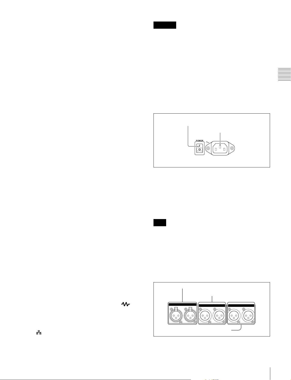
This apparatus is provided with a main switch on the rear
panel.
Install this apparatus so that user can access the main switch
easily.
This symbol is intended to alert the user to
the presence of uninsulated “dangerous
voltage” within the product’s enclosure that
may be of sufficient magnitude to constitute
a risk of electric shock to persons.
This symbol is intended to alert the user to
the presence of important operating and
maintenance (servicing) instructions in the
literature accompanying the appliance.
WARNING: THIS WARNING IS APPLICABLE FOR USA
ONLY.
If used in USA, use the UL LISTED power cord specified
below.
DO NOT USE ANY OTHER POWER CORD.
WARNING
To reduce the risk of fire or electric shock,
do not expose this apparatus to rain or
moisture.
To avoid electrical shock, do not open the
cabinet. Refer servicing to qualified
personnel only.
THIS APPARATUS MUST BE EARTHED.
CAUTION
The apparatus shall not be exposed to dripping or splashing.
No objects filled with liquids, such as vases, shall be placed on
the apparatus.
The unit is not disconnected from the AC power source
(mains) as long as it is connected to the wall outlet, even if the
unit itself has been turned off.
Plug Cap Parallel blade with ground pin
(NEMA 5-15P Configuration)
Cord Type SJT, three 16 or 18 AWG wires
Length Minimum 1.5 m (4 ft 11 in), Less than 2.5 m
(8 ft 3 in)
Rating Minimum 10 A, 125 V
Using this unit at a voltage other than 120 V may require the
use of a different line cord or attachment plug, or both. To
reduce the risk of fire or electric shock, refer servicing to
qualified service personnel.
WARNING: THIS WARNING IS APPLICABLE FOR OTHER
COUNTRIES.
1. Use the approved Power Cord (3-core mains lead) /
Appliance Connector / Plug with earthing-contacts that
conforms to the safety regulations of each country if
applicable.
2. Use the Power Cord (3-core mains lead) / Appliance
Connector / Plug conforming to the proper ratings (Voltage,
Ampere).
If you have questions on the use of the above Power Cord /
Appliance Connector / Plug, please consult a qualified service
personnel.
2
This Professional Disc Recorder is classified as a CLASS 1
LASER PRODUCT.
Tämä Professional Disc Recorder on luokiteltu 1. LUOKAN
LASERTUOTTEEKSI.
Den här Professional Disc Recorder klassificeras som en
LASERPRODUKT AV KLASS 1.
Laser Diode Properties
Wave length: 400 to 410 nm
Emission duration: Continuous
Laser output power: 135 mW (max. of pulse peak), 65 mW
(max. of CW)
Standard: IEC60825-1 (2007)
Egenskaber for laserdiode
Bølgelængde: 400 til 410 nm
Strålingsvarighed: Kontinuerlig
Afgivet lasereffekt: 135 mW (maks stråletoppunkt), 65 mW
(maks ved kontinuerlig stråling)
Standard: IEC60825-1 (2007)
Tekniska data för laserdiod
Våglängd: 400 till 410 nm
Emissionslängd: Kontinuerlig
Laseruteffekt: 135 mW (max. för pulstopp), 65 mW (max. för
kontinuerlig våg)
Standard: IEC60825-1 (2007)
Egenskaper for laserdiode
Bølgelengde: 400 til 410 nm
Strålingsvarighet: Uavbrutt
Utgangseffekt for laser: 135 mW (maks av pulshøyde), 65
mW (maks av CW)
Standard: IEC60825-1 (2007)
This label is located on the top panel of the drive unit.
Denna etikett finns på ovansidan av driftenheten.
Denne mærkat sidder på drevenhedens øverste panel.
Tämä kyltti sijaitsee ajurilaitteen yläpinnalla.
Dette merket er plassert på oversiden av driverenheten.
CAUTION
The use of optical instruments with this product will increase
eye hazard.
CAUTION
Use of controls or adjustments or performance of procedures
other than those specified herein may result in hazardous
radiation exposure.
WARNING
Excessive sound pressure from earphones and headphones
can cause hearing loss.
In order to use this product safely, avoid prolonged listening at
excessive sound pressure levels.
VAROITUS!
LAITTEEN KÄYTTÄMINEN MUULLA KUIN TÄSSÄ
KÄYTTÖOHJEESSA MAINITULLA TAVALLA SAATTAA
ALTISTAA KÄYTTÄJÄN TURVALLISUUSLUOKAN 1
YLITTÄVÄLLE NÄKYMÄTTÖMÄLLE LASERSÄTEILYLLE.
VARNING
OM APPARATEN ANVÄNDS PÅ ANNAT SÄTT ÄN I DENNA
BRUKSANVISNING SPECIFICERATS, KAN ANVÄNDAREN
UTSÄTTAS FÖR OSYNLIG LASERSTRÅLNING, SOM
ÖVERSKRIDER GRÄNSEN FÖR LASERKLASS 1.
When installing the installation space must be secured in
consideration of the ventilation and service operation.
• Do not block the ventilation slots at the left side and right
side panels, and vents of the fans.
• Leave more than 2 cm of space in the left side, right side and
top of the unit.
• Leave more than 25 cm of space in the rear of the unit to
secure the operation area.
When the unit is installed on the desk or the like, leave at least
4 cm of space in the left and right sides. Leaving 40 cm or
more of space above the unit is recommended for service
operation.
WARNING
Batteries shall not be exposed to excessive heat such as
sunshine, fire or the like.
For the customers in the U.S.A.
This equipment has been tested and found to comply with the
limits for a Class A digital device, pursuant to Part 15 of the
FCC Rules. These limits are designed to provide reasonable
protection against harmful interference when the equipment is
operated in a commercial environment. This equipment
generates, uses, and can radiate radio frequency energy and,
if not installed and used in accordance with the instruction
manual, may cause harmful interference to radio
communications. Operation of this equipment in a residential
area is likely to cause harmful interference in which case the
user will be required to correct the interference at his own
expense.
You are cautioned that any changes or modifications not
expressly approved in this manual could void your authority to
operate this equipment.
All interface cables used to connect peripherals must be
shielded in order to comply with the limits for a digital device
pursuant to Subpart B of Part 15 of FCC Rules.
3

This device complies with Part 15 of the FCC Rules. Operation
is subject to the following two conditions: (1) this device may
not cause harmful interference, and (2) this device must
accept any interference received, including interference that
may cause undesired operation.
For the customers in Canada
This Class A digital apparatus complies with Canadian ICES-
003.
For the customers in Europe
This product with the CE marking complies with the EMC
Directive issued by the Commission of the European
Community.
Compliance with this directive implies conformity to the
following European standards:
• EN55103-1: Electromagnetic Interference(Emission)
• EN55103-2: Electromagnetic Susceptibility(Immunity)
This product is intended for use in the following
Electromagnetic Environments: E1 (residential), E2
(commercial and light industrial), E3 (urban outdoors), E4
(controlled EMC environment, ex. TV studio).
The manufacturer of this product is Sony Corporation, 1-7-1
Konan, Minato-ku, Tokyo, 108-0075 Japan.
The Authorized Representative for EMC and product safety is
Sony Deutschland GmbH, Hedelfinger Strasse 61, 70327
Stuttgart, Germany. For any service or guarantee matters
please refer to the addresses given in separate service or
guarantee documents.
For kundene i Norge
Dette utstyret kan kobles til et IT-strømfordelingssystem.
Apparatet må tilkoples jordet stikkontakt
För kunderna i Sverige
Apparaten skall anslutas till jordat uttag
Suomessa asuville asiakkaille
Laite on liitettävä suojamaadoituskoskettimilla varustettuun
pistorasiaan
For the Customers in Taiwan only
4

Table of Contents
Chapter 1 Overview
Features.......................................................................................... 10
Features of this unit ............................................................................. 10
System Configurations ................................................................. 13
Chapter 2 Names and Functions of Parts
Front Panel..................................................................................... 14
Display window................................................................................... 19
Rear Panel...................................................................................... 24
Chapter 3 Preparations
Preparing Power Sources............................................................. 27
Initial Setup ....................................................................................28
Front Panel Tilt Mechanism.......................................................... 30
Connections and Settings ............................................................ 31
Synchronization Reference Signals ............................................ 37
Setting System Frequency ........................................................... 38
Setting Timecode........................................................................... 38
Superimposed Text Information .................................................. 40
Basic Operations of the Function Menu...................................... 43
Handling Discs............................................................................... 47
Supplying power.................................................................................. 27
Attaching a battery pack ...................................................................... 27
Connections for using the supplied application software .................... 31
Connections for cut editing.................................................................. 32
Using the editing functions of the recorder (controlling through
REMOTE(9P) connector) .......................................................... 35
Connections for pool coverage ............................................................ 36
Function menu operations.................................................................... 43
Function menu settings........................................................................ 43
Discs used for recording and playback................................................ 47
Notes on handling................................................................................ 47
Write-protecting discs.......................................................................... 48
Table of Contents
5

Loading and unloading a disc.............................................................. 48
Formatting a disc ................................................................................. 48
Chapter 4 Recording and Playback
Recording .......................................................................................49
Mixed recording of clips in different formats on the same disc.......... 49
Preparations for recording ................................................................... 49
Carrying out recording ........................................................................ 50
Continuing recording while exchanging discs (disc exchange cache
function)..................................................................................... 51
Recording with the HDSDI remote control function .......................... 52
Recording with the Clip Continuous Rec function ............................. 52
Using the Live Logging function ........................................................ 53
Handling of discs when recording does not end normally (salvage
functions) ................................................................................... 53
Playback .........................................................................................55
Playback operation .............................................................................. 56
Playback operations using thumbnails ................................................ 58
Chapter 5 Operations in GUI Screens
Overview.........................................................................................59
Switching between GUI screens.......................................................... 59
Information and controls in thumbnail screens ................................... 60
Displaying menus ................................................................................ 63
GUI screen operations ......................................................................... 66
Thumbnail Operations...................................................................67
Selecting thumbnails ........................................................................... 67
Searching with thumbnails .................................................................. 68
Playing the scene you have found ....................................................... 70
Selecting clips by type (Filter Clips function)..................................... 70
Selecting the information displayed on thumbnails ............................ 72
Changing clip index pictures............................................................... 72
Checking clip properties...................................................................... 73
Setting clip flags.................................................................................. 75
Locking (write-protecting) clips.......................................................... 76
Deleting clips....................................................................................... 76
Scene Selection (Clip List Editing) ..............................................78
What is scene selection?...................................................................... 78
Creating and editing clip lists.............................................................. 79
6
Table of Contents

Managing clip lists............................................................................... 83
Disc Operations............................................................................. 85
Checking disc properties...................................................................... 85
Using planning metadata ..................................................................... 85
Checking user-defined essence marks ................................................. 87
Formatting discs................................................................................... 87
Displaying disc and clip properties in a web browser ......................... 88
Transferring Clips (Direct FTP Function).................................... 90
Preparations for clip transfers.............................................................. 90
Uploading clips.................................................................................... 91
Downloading clips............................................................................... 94
Copying clips directly between XDCAM devices............................... 95
Shortcut List .................................................................................. 96
Chapter 6 File Operations
Overview......................................................................................... 97
Directory structure ............................................................................... 97
File operation restrictions .................................................................... 98
Assigning user-defined clip titles ...................................................... 101
Assigning user-defined clip and clip list names ................................ 102
File Operations in File Access Mode (for Windows) ................ 104
Making FAM connections ................................................................. 104
Operating on files .............................................................................. 105
Exiting file operations........................................................................ 105
File Operations in File Access Mode (for Macintosh) .............. 106
Making FAM connections ................................................................. 106
Operating on files .............................................................................. 106
Exiting file operations........................................................................ 106
FTP File Operations..................................................................... 107
Making FTP connections................................................................... 107
Command list..................................................................................... 108
Recording Continuous Timecode with FAM and FTP
Connections .......................................................................... 113
Chapter 7 Menus
Menu System Configuration....................................................... 114
Setup Menu ..................................................................................114
Items in the basic menu ..................................................................... 115
Basic menu operations....................................................................... 118
Table of Contents
7

Items in the extended menu............................................................... 121
Extended menu operations ................................................................ 134
Maintenance Menu.......................................................................136
Items in the maintenance menu ......................................................... 136
Maintenance menu operations........................................................... 139
Chapter 8 Planning Metadata
Overview.......................................................................................142
Manipulating planning metadata....................................................... 142
Setting clip names by using planning metadata ................................ 142
Setting essence mark names by using planning metadata................. 143
Setting volume labels by using planning metadata ........................... 144
Appendix
Important Notes on Operation....................................................145
Condensation ..................................................................................... 145
About the LCD panel ........................................................................ 145
Periodic Maintenance..................................................................146
Digital hours meter............................................................................ 146
Troubleshooting ..........................................................................147
Alarms ............................................................................................... 147
Error messages .................................................................................. 156
To eject discs with the unit powered off ........................................... 156
Specifications ..............................................................................156
Using UMID Data..........................................................................160
Ancillary Data...............................................................................162
Ancillary data in HDSDI/SDSDI signals .......................................... 162
Ancillary data in MXF files............................................................... 162
General MXF metadata ..................................................................... 162
Closed caption data ........................................................................... 163
List of Supported USB Keyboards.............................................165
Trademarks and Licenses...........................................................168
MPEG-4 visual patent portfolio license ............................................ 168
MPEG-2 video patent portfolio license............................................. 168
About IJG (Independent JPEG Group) ............................................. 168
Character display software “iType” .................................................. 168
About net-snmpd ............................................................................... 168
About libupnp.................................................................................... 171
8
Table of Contents

Glossary .......................................................................................172
Index ............................................................................................ 174
Table of Contents
9

Chapter 1 Overview
Overview
Features
Chapter
Uncompressed PCM recording of 24-bit 48 kHz audio
enables 8-channel audio recording at high sound quality.
1) MPEG HD422 is a trademark of Sony Corporation.
1
The PDW-HD1200 (referred to as “this unit”) is a
professional disc recorder supporting full HD (1920 ×
1080) playback and recording with Professional Disc
media.
When you use this unit in combination with a nonlinear
editing system, the FAM
transfers between the unit and computers over the
i.LINK
external hard drive.
The unit can be used as a player for video editing and
program output, and as a recorder for nonlinear editing.
For these applications, the unit can be connected via its
SDI I/O connectors to earlier nonlinear editors, monitors,
and video equipment with SDI interfaces.
It has a compact, lightweight body for easy portability
outdoors, and can be powered from any of three power
sources: AC, DC, or battery
1) Professional Disc is a trademark of Sony Corporation.
2) FAM: File access mode
3) This unit does not support DV stream output.
4) BKP-L551 Battery Adaptor is required.
3)
interface, allowing the unit to be used like an
2)
function enables data file
4)
power.
1)
Features of this unit
The principal features of this unit are as follows.
MPEG HD422
High-quality video and audio recording and
playback
The MPEG HD422 codec provides video compression
compliant with the MPEG-2 422P@HL standard. It
enables HD 4:2:2 (50 Mbps) digital component file
recording in the 1080i (1,080 effective scanning lines,
interlaced) format currently in use by many broadcast
facilities.
1)
codec
Long recording times
PDW-HD1200 supports dual-layer Professional Discs (50
GB). When dual-layer Professional Discs are used, this
unit can record about 95 minutes.
Recording and playback functions
Support for multiple SD and HD codecs
In addition to the MPEG HD422 codec, this unit supports
the MPEG HD codec.
component files at both 1080i (35/25/18 Mbps
HD operation across a wide range of recording times and
application objectives. The unit is also capable of SD
(IMX 30/40/50 Mbps or DVCAM codec) recording and
playback.
1) MPEG HD is a registered trademark of Sony Corporation.
2) Playback only supported for 18 Mbps.
Support for multiple frame frequencies
This unit can record and play multiple frame frequencies at
1080 (59.94i and 50i). The 29.97P and 25P frame
frequencies can only be played back.
Support for mixed format recording mode
As long as the frame frequency group is the same, clips in
different recording formats can be recorded or written to
the same disc.
The system frequencies supported by this unit are divided
into frame frequency groups, as shown in the following
table.
1) The recording format is regarded as different whenever the system
frequency, video resolution, video codec/bit rate, or number of audio
channels or number of bits does not match.
Frame frequency group System frequency
59.94Hz 59.94i
1)
1)
It can record HD 4:2:0 digital
29.97P
2)
) allowing
10
Features

Frame frequency group System frequency
50Hz 50i
25P
You can record clips with different recording formats, for
example HD422 and HD420SP clips, by putting this unit
into mixed format recording mode.
Note
Continuous playback may not be possible at the transition
point between two clips with different recording formats.
SD upconvert function
The unit can output HD signals while playing discs
recorded as SD, allowing SD material to be utilized in an
HD environment.
HD downconvert function
The unit is provided with a downconvert function. HD disc
playback signals can be downconverted to SD signals and
then output as SDSDI or composite signals. This allows
you to use SD nonlinear editors and monitors for editing
and program output.
HDSDI remote recording
HDSDI connections can be made to camcorders with
remote HDSDI support (PDW-700 XDCAM HD422
camcorder, HDW-730/730S/750/790/F900R HDCAM
1)
camcorders) to enable recording synchronized to REC and
STOP operations on the camcorder.
1) HDCAM is a trademark of Sony Corporation.
Clip Continuous Rec function
Normally, a clip is generated as an independent file every
time recording starts and stops. The Clip Continuous Rec
function allows you to continue recording to the same clip
until the function is stopped or turned off, regardless of
how many times recording starts and stops. This is
convenient if you want to avoid generating a large number
of short clips, or if you want to record without worrying
about the limit on the number of clips (maximum 300).
Note
This function is available only when you are operating
equipment connected to the REMOTE(9P) or SD/HDSDI
INPUT connector. It is not available on the front panel.
Recording of proxy AV data
Proxy AV data is a low-resolution (1.5 Mbps video, 64
kbps per audio channel), MPEG-4 based version of a full
resolution data stream. Whenever this unit records full
resolution MPEG HD422 data, it simultaneously generates
and records low-resolution proxy AV data. Because of its
small size, proxy AV data can be transferred quickly over
computer networks, easily edited in the field with laptop
computers, and readily used in a wide variety of
applications, such as content management on small-scale
servers.
High-speed searches with the jog and shuttle
dials
The jog and shuttle dials can be used to find scenes inside
clips, in the same way as the jog and shuttle dials on
conventional VTRs.
In jog and variable modes, you can search in field units at
from –1 to +1 times normal speed. In shuttle mode, you
can perform high-speed searches at either ±20 times
normal speed or maximum speed (as selected by an
extended menu setting). High-speed F.FWD and F.REV
searching is possible at either ±30 times normal speed or
maximum speed.
Convenient disc-based playback and searching
Like previous products in the XDCAM series, this unit
supports a number of convenient search functions,
including scene selection, thumbnail searches, essence
marks searches, and expand searches.
Scene selection: This function allows you to select clips
from the disc and insert them into playlists. Clips can
be inserted and played back in any order.
Thumbnail searches: The unit creates thumbnails from
the first frame of each generated clip, and displays
them in thumbnail lists on the color LCD or an
external monitor. You can cue up clips very easily by
simply by selecting them from thumbnail lists.
Essence mark searches: Essence marks can be recorded
at any scene during or after recording. Lists of these
marks can be displayed on the color LCD or an
external monitor, allowing you to quickly find scenes
that were marked for later reference.
Expand searches: This function allows you to look inside
the clip selected in a thumbnail screen, or inside the
segment from a selected essence mark to the next
essence mark. The selection range is divided into 12
equal blocks, and the first frames of those blocks are
displayed as thumbnails. By checking the thumbnails,
you can easily find the scene you want.
Filter Clips function
You can select clips of a certain type from among all of the
clips on a disc. For example, you can do the following.
• Select clips in a certain video format from a disc that
contains clips in different video formats.
• Select only clips with NG (bad) clip flags, and delete all
of those clips in one operation.
• Select only clips that were recorded according to
planning metadata, and use the Direct FTP function to
transfer those clips to an external device.
Chapter 1 Overview
Features
11

Usability features
AC, DC, and battery1) power support
The unit can be used even where AC power is not
available, for example outdoors or in cars or helicopters.
Chapter 1 Overview
1) BKP-L551 Battery Adaptor is required.
Color LCD display
The unit is equipped with a 16:9, 4.3-inch color LCD
which allows you to check the contents of the disc and use
the menu system without connecting an external monitor.
Built-in speakers
The unit features built-in speakers, allowing you to check
recorded audio. You can check your clips and editing
results on the color LCD and speakers even when no
monitors or separate speakers are available.
Tiltable front panel
The front panel is tiltable for easy rack-mount and desktop
operation. You can adjust the panel to the angle that makes
the buttons easiest to use.
allows you to monitor the status of the hardware via a TCP/
IP network in real time, and to record the results in a status
log.
User data recording mode
User data (files other than XDCAM AV files) can be
recorded on Professional Discs as PC data via the i.LINK
or FTP interface. This allows Professional Discs to be used
as data recording media, with a data storage capacity of
46.4 GB (when dual-layer PFD50DLA discs are used).
Supports a variety of interfaces
This unit supports the following interfaces.
• HDSDI video, 8-channel audio input and output
• SDSDI video, 8-channel audio input and output
(the SD/HDSDI INPUT connector doubles as an
SDSDI/HDSDI input connector)
• HDMI
1)
output
• SD composite output
• Analog audio 2-channel input and output
•Remote
- RS-422A (D-sub 9-pin × 1)
Cache recording for seamless disc exchanges
About 30 seconds (this duration may differ depending on
the state of a disc) of video and audio data can be recorded
to the unit’s internal memory cache during a disc
exchange, and then written back to the newly loaded disc.
This allows seamless recording across extended recording
sessions, including recording of video feeds, with no
important scenes lost while discs are being exchanged.
IT friendly
Computer access to files (file access mode)
Video and audio clip data are recorded as files. The FAM
function enables quick random access by computers to the
video, audio, and metadata files stored on Professional
Discs, with the ability to display thumbnail lists on the
computer screen and perform file-based reads and writes.
Equipped with network connector
The unit features a Gigabit Ethernet connector as standard
equipment. Via this connector, you can connect the unit to
computers and networks to enable listing of the video,
audio, and metadata files recorded on the Professional
Disc, and rapid file transfers. Support for FTP commands
makes it easy to carry out network file transfers from
remote locations.
1) HDMI, HDMI High-Definition Multimedia Interface, and the HDMI logo
are trademarks or registered trademarks of HDMI Licensing LLC in the
United States and/or other countries.
Software Downloads
When the unit is used with a PC connection, download
device drivers, plug-ins, and application software, where
applicable, from the Sony Professional products web site.
Sony Professional products and solutions site homepage:
U.S.A. http://pro.sony.com
Canada http://www.sonybiz.ca
Latin America http://sonypro-latin.com
Europe, Middle East and Africa
Japan http://www.sonybsc.com
Asia Pacific http://pro.sony-asia.com
Korea http://bp.sony.co.kr
China http://pro.sony.com.cn
http://www.pro.sony.eu
Direct FTP function
You can use this unit as a local FTP host to send and
receive MXF files to and from other XDCAM devices,
without using a computer. This function is available
through simple operations on the GUI screen.
Supports SNMP for maintenance and service
This unit supports Sony’s SNMP-based remote
maintenance and monitoring software. This software
12
Features
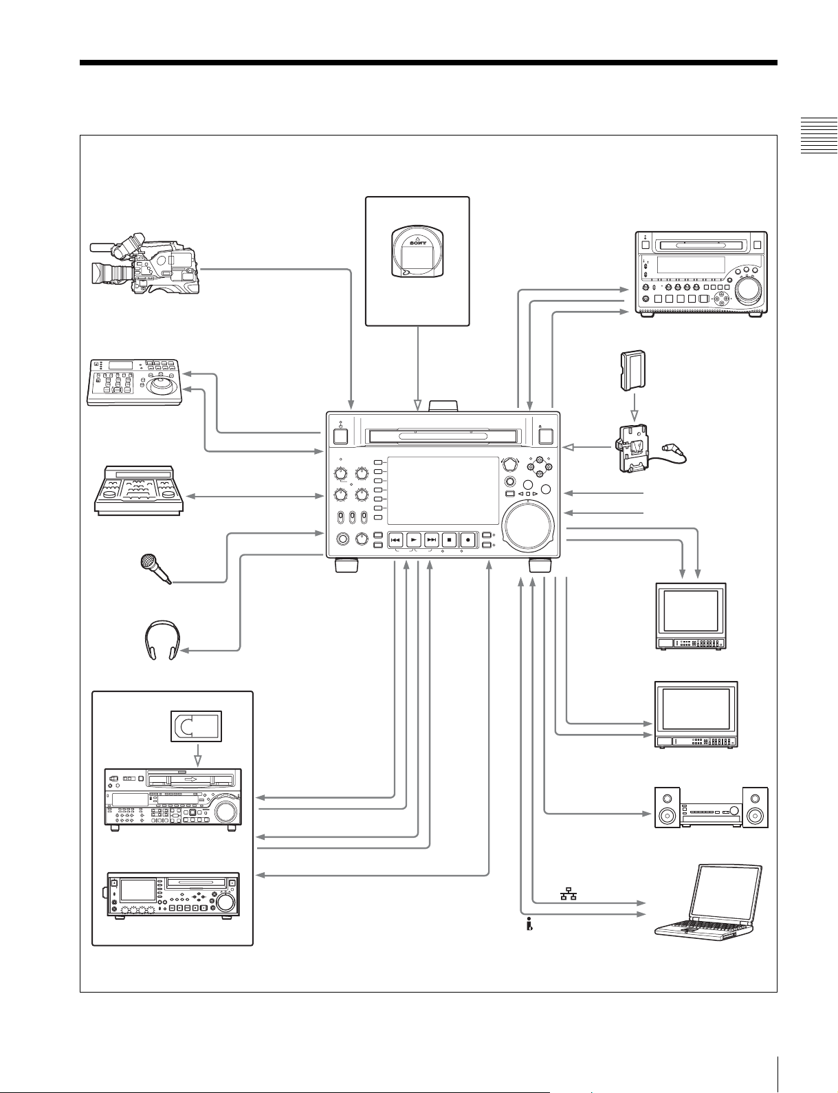
System Configurations
PDW-700
HDSDI
INPUT
RM-280 editing
controller
BVE-700
Microphone
ANALOG AUDIO INPUT
REMOTE
REMOTE (9P)
REMOTE (9P)
PHONES
ACCESS
CH-1
ALL CH
CH-2
VARIABLE KEY INHI
REC
NET
PRE-
LOCAL
SET
REMOTE
PB
PHONES LEVEL
ANALOG
OUTPUT/
CH-3
CH-4
ON
OFF
AUDIO
INPUT
Professional Discs
• PFD23A
• PFD50DLA
CHAPTER
EXPAND
PAGE
HOME
PREV NEXTPLAY STOP REC
DISPLAY
SHIFT
TOP F REV F FWD END STANDBY REC INHI
HDSDI
OUTPUT/
INPUT
THUMBNAIL
SUB CLIP
DISC MENU
PUSH SET(S.SEL)
MENU
RESET
RETURN
ANALOG
AUDIO
OUTPUT/INPUT
SDSDI
OUTPUT
EJECT
MARK1
IN OUT
MARK2
SHTL/JOG
VAR/JOG
DC IN 12V
- AC IN
PDW-1500
Sony BP-L80S/GL95
battery
BKP-L551 battery
adaptor
DC power source
AC power source
SDSDI
OUTPUT
COMPOSITE
OUTPUT
Chapter 1 Overview
Headphones
HDCAM
HDW-2000 series
PDW-F75
a) For HDW-2000 series only.
REMOTE
(9P)
SD video monitor
HDMI
OUTPUT
HDSDI
OUTPUT
a)
HD video monitor
AUDIO
MONITOR
Audio monitor
(i.LINK) S400
Laptop computer
System Configurations
13
Names and Functions of
Parts
Chapter 2 Names and Functions of Parts
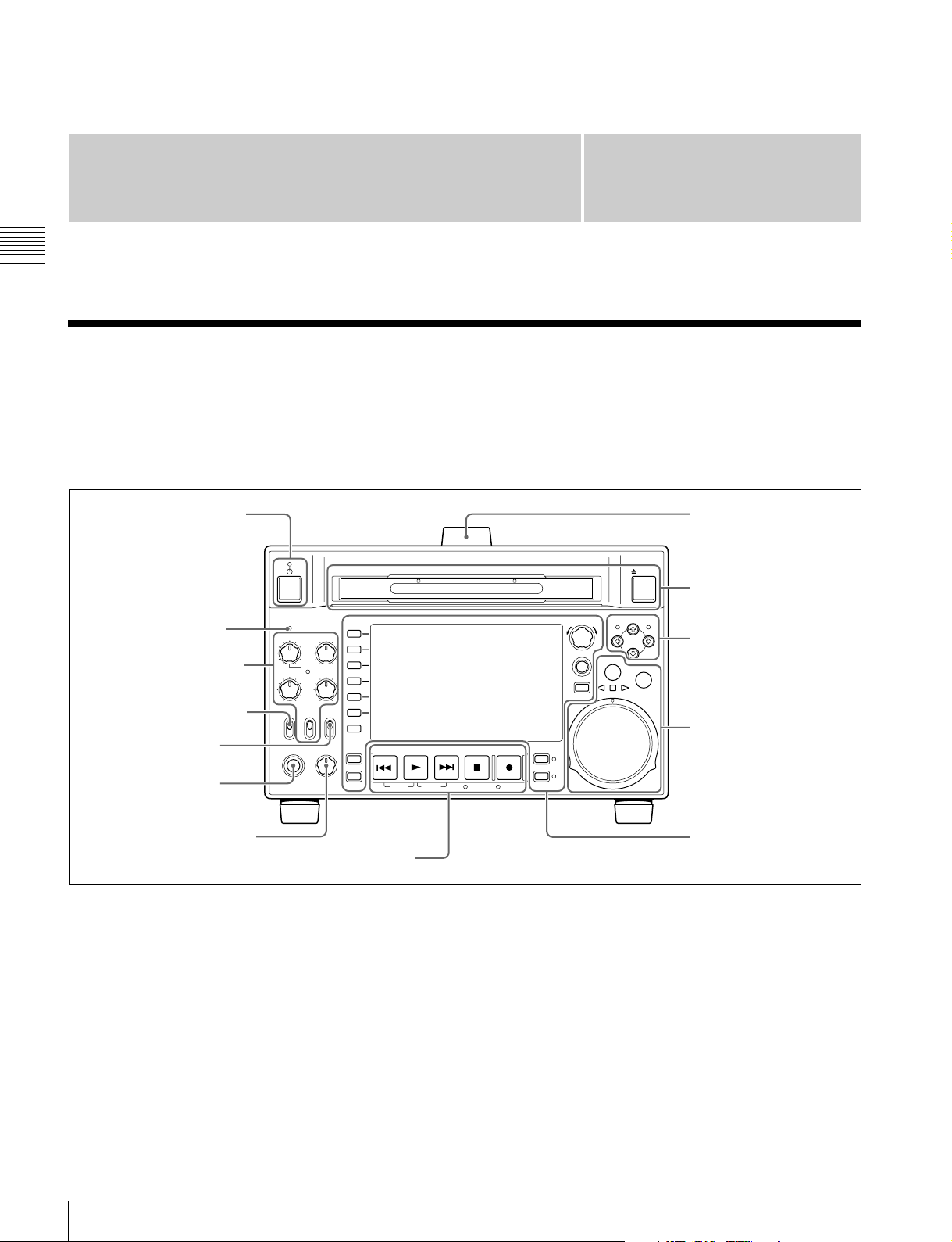
Front Panel
The names and symbols of buttons and knobs on the front
panel are color coded according to function.
White: Function when the button or knob is operated
independently.
1 On/standby button and
indicator
2 ACCESS indicator
1 Audio level adjustment
section (see page 15)
3 Remote control switch
4 KEY INHI switch
5 PHONES jack
ACCESS
CH-1
CH-2
REC
NET
PRE-
LOCAL
SET
REMOTE
PHONES LEVEL
CH-3
ALL CH
CH-4
VARIABLE KEY INHI
ON
OFF
PB
CHAPTER
EXPAND
PAGE
HOME
DISPLAY
SHIFT
TOP F REV F FWD END STANDBY REC INHI
Orange: Function when the button is operated with the
Blue: Function related to thumbnail operations.
PREV NEXTPLAY STOP REC
Chapter
SHIFT button held down.
EJECT
SHTL/JOG
MARK1
IN OUT
MARK2
VAR/JOG
PUSH SET(S.SEL)
MENU
RESET
RETURN
THUMBNAIL
SUB CLIP
DISC MENU
2
Handle
7 Disc slot and EJECT
button
2 Arrow buttons (see
page 15)
3 Shuttle/jog/variable
control section (see
page 16)
6 LEVEL adjustment knob
5 Recording and playback control section (see page 18)
a On/standby (1) button and indicator
When the POWER switch on the rear panel is in the @
position, and when DC power is connected to the DC IN
12V connector on the rear panel, this switches the unit
between the operating state (the indicator is lit green) and
the standby state (the indicator is lit red).
When the indicator is lit red, pressing the button switches
this unit to the operating state, and the indicator lights
continuously green.
When the indicator is lit green, pressing the button
switches the unit to the standby state, and the indicator
14
Front Panel
4 Display/menu control
section (see page 17)
lights continuously red. If a disc is loaded in the unit, the
indicator flashes before changing to continuously lit red.
When using this unit, normally leave the rear panel
POWER switch in the @ (on) position, and use this button
to switch the unit between the operating state and standby
state.
b ACCESS indicator
This lights when the disc is accessed and when a file is
opened by a FAM or FTP connection (see page 97). If the
on/standby button is pressed while this indicator is lit,

access to the disc is completed before the unit switches to
REC
NET
REMOTE
LOCAL
VARIABLE KEY INHI
PRESET
ON
OFF
PB
CH-1
ALL CH
CH-2
CH-3
CH-4
the standby state.
Note
While the ACCESS indicator is lit, do not turn off the
POWER switch on the rear panel or disconnect the power
cord. This could lead to a loss of data from the disc.
c Remote control switch
Different positions of the switch allow different operations
as follows.
NET: Enables access to the network. The indicator lights
when an external network device is being accessed. In
this state, operation from the front panel is not
possible.
LOCAL: Enables operation from the front panel.
REMOTE: Enables remote control of this unit from the
following devices:
• Devices connected to the REMOTE(9P) connector
on the rear panel
• Devices connected to the SD/HDSDI INPUT
connector with SDI remote control functions
Use setup menu item 214 REMOTE INTERFACE to
select which of the connectors is used for remote control
(see page 124).
See “Setup Menu” on page 114 for more information
about how to make extended menu settings.
1 Audio level adjustment section
1 CH-1/ALL CH, CH-2 to CH-4 adjustment knobs
Chapter 2 Names and Functions of Parts
2 VARIABLE switch
a CH-1/ALL CH, CH-2 to CH-4 (audio level)
adjustment knobs
Depending on the setting of the VARIABLE switch, these
adjust the input audio or playback audio levels of channels
1 to 4.
You can adjust levels of channels 5 to 8 using the function
menu. See page 45 for details.
By the setting of setup menu item 131 AUDIO VOLUME,
you can enable the CH-1/ALL CH adjustment knob to
simultaneously adjust all eight channels. When this
simultaneous adjustment is enabled, the ALL CH indicator
lights.
d KEY INHI switch
This turns key operation inhibit mode on or off.
Use setup menu item 118 KEY INHIBIT SWITCH
EFFECTIVE AREA to specify the keys to inhibit.
e PHONES jack
The jack is a standard stereo jack. Connect stereo
headphones to monitor the audio during recording,
playback, and editing. (Non-audio signals are muted.) The
monitored channel is selected with MONITR L and
MONITR R on page P2 AUDIO of the function menu (see
page 44).
f LEVEL (volume) adjustment knob
Adjust the volume of headphones or speakers with the
knob. You can also cause this to simultaneously adjust the
output volume from the AUDIO MONITOR R, L
connectors on the rear panel. To do this, set setup menu
item 114 AUDIO MONITOR OUTPUT LEVEL to “var”.
g Disc slot and EJECT button
Insert a disc in the disc slot. To remove the disc, press the
EJECT button.
b VARIABLE (audio level adjustment selector)
switch
This selects whether input audio levels or playback audio
levels are adjusted by the CH-1/ALL CH and CH-2 to CH4 adjustment knobs for channels 1 to 4, or by the function
menu setting for channels 5 to 8.
REC: Adjust the input audio levels. The playback audio
levels are fixed at their preset values.
PRESET: The audio levels are fixed at their preset values.
PB: Adjust the playback audio levels. The input audio
levels are fixed at their preset values.
2 Arrow buttons
The four arrow buttons are also used as the MARK1
button, MARK2 button, IN button, and OUT button. The
correspondence with these buttons is as follows.
V button: MARK1 button
v button: MARK2 button
B button: IN button
b button: OUT button
You can use these buttons for thumbnail selection, menu
setting operations, setting In/Out points, and so on.
Front Panel
15

MARK2
MARK1
IN OUT
L/JOG
1 V/MARK1 button and v/MARK2 button
RETURN
RESET
SHTL/JOG
VAR/JOG
For details of playback operations with these buttons and
dials, see “Playback operation” on page 56.
2 IN indicator and OUT indicator
3 B/IN button and b/OUT button
Chapter 2 Names and Functions of Parts
a V/MARK1 button and v/MARK2 button
When the THUMBNAIL indicator (see page 17) is lit, you
can use these for thumbnail selection.
During recording or playback, a shot mark 1 or shot mark
2 is recorded as an essence mark when you press the PUSH
SET (S.SEL) knob with the V/MARK1 or v/MARK2
button held down. If you connect a Windows USB
keyboard to the MAINTENANCE connector, you can
record shot marks from Shot Mark0 up to Shot Mark9 by
pressing the 0 to 9 keys on the numeric keypad.
Essence marks can also be deleted and modified from the
Thumbnail Menu of the chapter thumbnail screen (see
page 62).
b IN indicator and OUT indicator
IN indicator: When an In point is set, this lights. If an
attempt is made to set the In point after a recorded Out
point, this flashes.
OUT indicator: When an Out point is set, this lights. If an
attempt is made to set the Out point before a recorded
In point, this flashes.
c B/IN button and b/OUT button
When the THUMBNAIL indicator (see page 17) is lit, you
can use these for thumbnail selection.
An In or Out point is set when you press the PUSH
SET(S.SEL) knob with the B/IN or b/OUT button held
down. The In or Out point setting is deleted when you
press the RESET/RETURN button with the B/IN or b/
OUT button held down.
3 Shuttle/jog/variable control section
1 SHTL/JOG button
2 VAR/JOG button
3 Jog/shuttle transport indicators
4 Jog dial
5 Shuttle dial
a SHTL/JOG button
Press this button, turning it on, to perform shuttle playback
with the shuttle dial or jog playback with the jog dial.
When pressed during recording, stops recording and
selects shuttle/jog mode. If you do not want to stop
recording when this button is pressed, set setup menu item
145 MODE KEY ENABLE DURING RECORDING to
“stop”.
b VAR/JOG button
Press this button, turning it on, to perform variable
playback with the shuttle dial or jog playback with the jog
dial.
When pressed during recording, stops recording and
selects variable/jog mode. If you do not want to stop
recording when this button is pressed, set setup menu item
145 MODE KEY ENABLE DURING RECORDING to
“stop”.
c Jog/shuttle transport indicators
These show the playback direction in jog, shuttle, or
variable speed mode.
b (green): Lights during playback in the reverse direction.
B (green): Lights during playback in the forward
direction.
x (red): Lights during still image display.
d Jog dial
Turn this for playback in jog mode. Turn clockwise for
forward direction playback, and counterclockwise for
reverse direction playback. In jog mode, the playback
speed varies from –1 to +1 times normal speed, according
to the rotation rate of the jog dial. There are no detents.
Normally, you press the SHTL/JOG or VAR/JOG button
before turning the jog dial, but it is also possible to make a
setting to enable jog mode directly by turning the dial (set
setup menu item 101 SELECTION FOR SEARCH DIAL
ENABLE to “dial”).
e Shuttle dial
Turn this for playback in shuttle mode or variable speed
mode. Turn clockwise for forward direction playback, and
counterclockwise for reverse direction playback.
• In shuttle mode, the playback speed varies in the range
of ±20 times normal speed, according to the angular
position of the shuttle dial.
• In variable speed mode, you can finely adjust the
playback speed from –1 to +1 times normal speed,
according to the angular position of the shuttle dial.
The shuttle dial has a detent at the center position, for still
image playback.
Normally, you press the SHTL/JOG button before turning
the shuttle dial, but it is also possible to make a setting to
enable shuttle mode directly by turning the dial (set setup
16
Front Panel

menu item 101 SELECTION FOR SEARCH DIAL
ENABLE to “dial”).
Note
When setup menu item 101 SELECTION FOR SEARCH
DIAL ENABLE is set to “dial”, after using the shuttle dial,
return it to the center position. If the shuttle dial is not in
the center position, it is possible occasionally for vibration
from other operations to activate the dial, and start
playback in shuttle mode.
4 Display/menu control section
5 RESET/RETURN button
4 MENU button
3 PUSH SET(S.SEL) knob
1 Function buttons (F1 to F6)
2 Display
6 SUB CLIP/DISC MENU button and
indicator
7 THUMBNAIL button and indicator
8 DISPLAY button
9 SHIFT button
0 PAGE/HOME button
qa EXPAND button
qs CHAPTER button
a Function buttons (F1 to F6)
These buttons are enabled when the function menu (see
page 43) is visible. Each press of a button changes the
setting of the corresponding item in the menu.
For convenience, this manual refers to these buttons as
buttons F1 to F6, in order from the top.
b Display
Displays menus, audio level meters, and data such as time
data or clip information. The DISPLAY button lets you
switch to the video monitor display.
For details, see “Display window” on page 19.
c PUSH SET(S.SEL) knob
Use for menu and GUI screen operations. Turn the knob to
select items, and press it to confirm the selection. This
button is also used to set numerical and timecode values.
You can also change the playback speed by pressing the
PLAY button and turning this knob during playback (see
page 58).
See “GUI screen operations” (page 66) for more
information about how to use the thumbnail screens.
Chapter 2 Names and Functions of Parts
d MENU button
Displays the setup menu or the GUI screen menu. The
setup menu appears when no GUI screen is visible. The
same information is also superimposed on the display on a
monitor connected to the unit. Press once more to return to
the original display.
See “GUI screen operations” (page 66) for more
information about how to use the thumbnail screens.
e RESET/RETURN button
Functions as the RESET button or the RETURN button.
RESET button: Reset counters or the setting values of the
timecode generator. This button is also used to abort
or cancel setup menu, scene selection, and thumbnail
search operations.
RETURN button: In setup menu and GUI screens,
returns to the previous procedure.
f SUB CLIP/DISC MENU button and indicator
When pressed alone, functions as the SUB CLIP button.
When pressed together with the SHIFT button, functions
as the DISC MENU button.
SUB CLIP button: Press the button, lighting the
indicator, to carry out playback in clip list order (see
page 78). Jog and shuttle operations are supported
during clip list playback. To return to playback in
recording order, press the button again, turning the
indicator off.
Note
If no clip list is registered, this button does not light
when pressed. The operation is invalid.
DISC MENU button: When pressed together with the
SHIFT button, displays the Disc Menu (see page 64).
Press the button again, turning the indicator off, to
hide the Disc Menu.
See “GUI screen operations” (page 66) for more
information about how to use the thumbnail screens.
g THUMBNAIL button and indicator
To carry out a thumbnail search or create a clip list in the
GUI screen, press this button turning the indicator on.
Thumbnail images representing each clip or sub-clip
Front Panel
17
appear. Press once more, turning the indicator off, to return
to a whole-screen display.
To display the thumbnails of essence mark frames (frames
with an essence mark attached), hold down the SHIFT
button, and press this button. The essence mark selection
menu appears. Select the desired type of essence mark, and
the corresponding essence mark frames appear in
thumbnails. Press once more, turning the indicator off, to
return to a whole-screen display.
See “GUI screen operations” (page 66) for more
Chapter 2 Names and Functions of Parts
information about how to use the thumbnail screens.
h DISPLAY button
Each press of this button switches between the basic
operation display and video monitor display (see page 19).
This button is disabled unless either the basic operation
display or the video monitor display is displayed.
pictures of the first frames. This can also be used to cue up
long clips.
This button also becomes a function button (F5) when the
function menu is visible.
See page 68 for more information about the chapter
function.
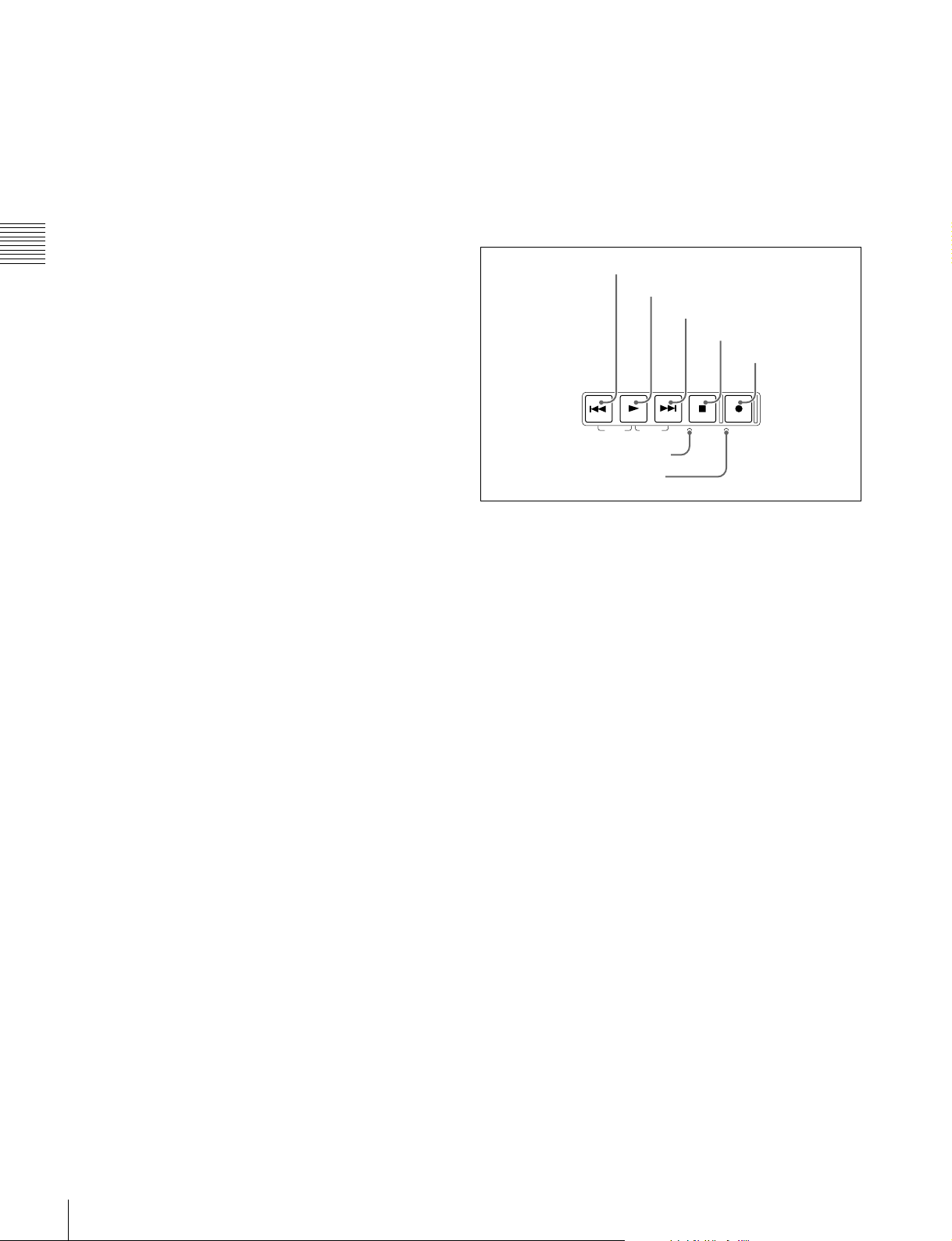
5 Recording and playback control section
1 PREV button
2 PLAY button
3 NEXT button
4 STOP button
5 REC button
PREV NEXTPLAY STOP REC
i SHIFT button
Switches between functions for any button with two
functions.
j PAGE/HOME button
When pressed alone functions as the PAGE (page
switching) button. When pressed together with the SHIFT
button, functions as the HOME button.
PAGE button: Displays the function menu, if it is not
already visible. (The most recently displayed page of
the function menu appears.)
HOME button: When pressed with the function menu
visible, returns to the HOME page of the function
menu.
k EXPAND button
When pressed during thumbnail display, divides the
selected clip into 12 blocks and displays a list of
thumbnails of the first frame in each block (expand
function). The division is repeated with each press (up to 3
times, for a total of 1,728 blocks).
When this button is pressed together with the SHIFT
button, the unit returns to the previous division level.
Press the RESET/RETURN button to return to the
thumbnail screen.
This button also becomes a function button (F6) when the
function menu is visible.
See page 68 for more information about the expand
function.
l CHAPTER button
When pressed during thumbnail display, displays a list of
thumbnails of the frames where essence marks are
recorded (chapter function). When this is pressed again,
returns to normal thumbnail display. The chapter function
can be useful when essence mark thumbnails provide more
information about the content of the clip than the index
TOP F REV F FWD END STANDBY REC INHI
6 STANDBY indicator
7 REC INHI indicator
a PREV (previous) button
Press this button, turning it on, to show the first frame of
the current clip. While the first frame of a clip is shown,
pressing this button jumps to the beginning of the previous
1)
clip.
This button is also used together with other buttons
for the following operations.
Reverse direction high-speed search: Hold down the
PLAY button, and press this button. A high-speed
search in the reverse direction is carried out.
Displaying the first frame of the first clip: Hold down
the SHIFT button, and press this button.
1) When setup menu item 153 FIND MODE is set to “clip & rec start mark”,
this button jumps to the frame where the previous Rec Start essence mark
is set and displays the video of that frame.
b PLAY button
To start playback, press this button, turning it on.
When pressed during recording, stops recording and enters
stop mode. If you do not want to stop recording when this
button is pressed, set setup menu item 145 MODE KEY
ENABLE DURING RECORDING to “stop”.
c NEXT button
Press this button, turning it on, to jump to the next clip, and
show the first frame.
1)
This button is also used together
with other buttons for the following operations.
Forward direction high-speed search: Hold down the
PLAY button, and press this button. A high-speed
search in the forward direction is carried out.
Displaying the last frame of the last clip: Hold down the
SHIFT button, and press this button.
18
Front Panel
1) When setup menu item 153 FIND MODE is set to “clip & rec start mark”,
this button jumps to the frame where the next Rec Start essence mark is set
and displays the video of that frame.
d STOP button
To stop recording or playback, press this button, turning it
on. The frame at the stop point appears.
The unit enters standby off mode when you press this
button with the SHIFT button held down. It returns from
standby off mode to the original state when you press this
button again with the SHIFT button held down. (The lit or
unlit status of the STOP button does not change.)
Note
This button flashes when setup menu item 105
REFERENCE SYSTEM ALARM is set to “on” and the
correct reference video input signal (as specified by OUT
REF on page P6 REF of the function menu) is not being
input.
This unit can automatically enter standby off mode
whenever a specified time elapses in disc stop mode. For
details, see the description of setup menu item 501 STILL
TIMER (page 125).
e REC (record) button
To start recording, hold down this button, and press the
PLAY button. The recording takes place on an unrecorded
part of the disc.
To stop recording, press the STOP button.
To monitor in E-E mode
You can press this button from stop mode to monitor input
signals in E-E mode. The button lights when pressed. Press
the STOP button to return to the original video.
You can also press this button during playback and
searches. E-E mode playback continues for as long as the
button is held down.
f STANDBY indicator
Lights when the unit is in standby mode (STOP button and,
STANDBY indicator lit).
After a certain time passes in a disc stop mode, the unit
automatically enters standby off mode and the indicator
goes off.
You can specify the time until the unit enters standby off
mode. For details, see the description of setup menu item
501 STILL TIMER (page 125).
g REC INHI (recording inhibit) indicator
This lights in the following cases.
• When a disc with recording inhibited is loaded.
• When REC INH on the HOME page of the function
menu is set to “ON”.
• The format of the recorded part of the disc does not
match the system frequency settings of the unit.
Chapter 2 Names and Functions of Parts
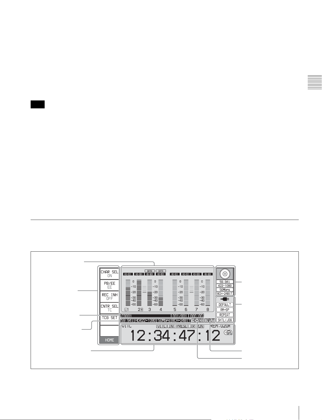
Display window
Basic operation display
1 Audio input display/
Audio level meters
2 Function menu
3 Clip information
4 Recording format
5 Time data display area
6 Disc information
7 System information
8 Reference signal
9 Video input display
Front Panel
19
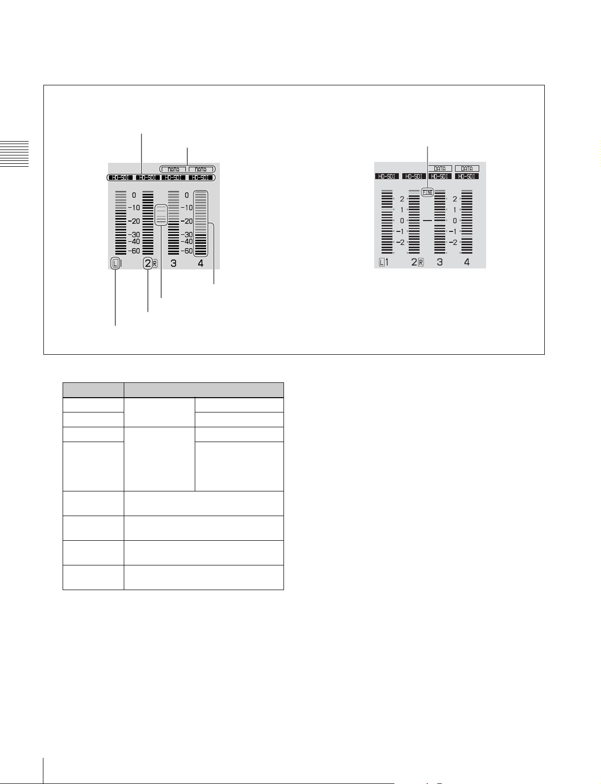
a Audio input display/Audio level meters
Displays information about audio. There are two display
modes for the audio level meter: FULL mode and FINE
Meter display mode: FULL Meter display mode: FINE
A Input signal display
B Data indication
Chapter 2 Names and Functions of Parts
F Level bars
E Reference level
D Audio channel
C Monitor channel
mode, which can be switched over using AU METER on
page P4 AUDIO of the function menu.
G Meter display mode
A Input signal display: Displays the audio input signal.
.
Display Input signal
ANA-1 Analog audio
ANA-2 Channel 2, 4
MIC-1 Input signal from
MIC-2 Channel 2, 4
HD-SDI HDSDI audio signal (flashes when
SD-SDI SDSDI audio signal (flashes when
SG Test signal from the internal signal
No indication Undefined audio signal, or no audio
signal
the microphone
connected to
ANALOG
AUDIO INPUT
connector
there is no input signal)
there is no input signal)
generator
input
Channel 1, 3
Channel 1, 3
B Data indication: Appears when the input signals are
non-audio signals.
C Monitor channel: Displays the audio monitoring
channels set with MONITR L and MONITR R on
page P2 AUDIO of the function menu (see page 44).
D Audio channel: Displays the audio channels.
Also indicates preset or variable mode by its color
(see page 15).
White: Preset mode
Green: Variable mode
E Reference level: Displays the reference level for
recording as set in the maintenance menu.
F Level bars: Display the audio recording or playback
levels of channels 1 to 8. The OVER indicators light
when the audio level exceeds 0 dB.
G Meter display mode: Displays the audio level meter
display mode selected with AU METER on page P4
AUDIO of the function menu (see page 45).
b Function menu
Use the PAGE/HOME button to display this menu, and to
switch between the pages (HOME, P1 to P7, (P8)
(HOME2)
1)
) of the menu. Each page has three to six
1)
,
setting items. Press the corresponding button to change a
setting.
1) If a menu item is assigned using maintenance menu item M38: F-KEY
CONFIG
For details, see page 43 “Basic Operations of the
Function Menu” in Chapter 3.
c Clip information
Displays clip information.
20
Front Panel
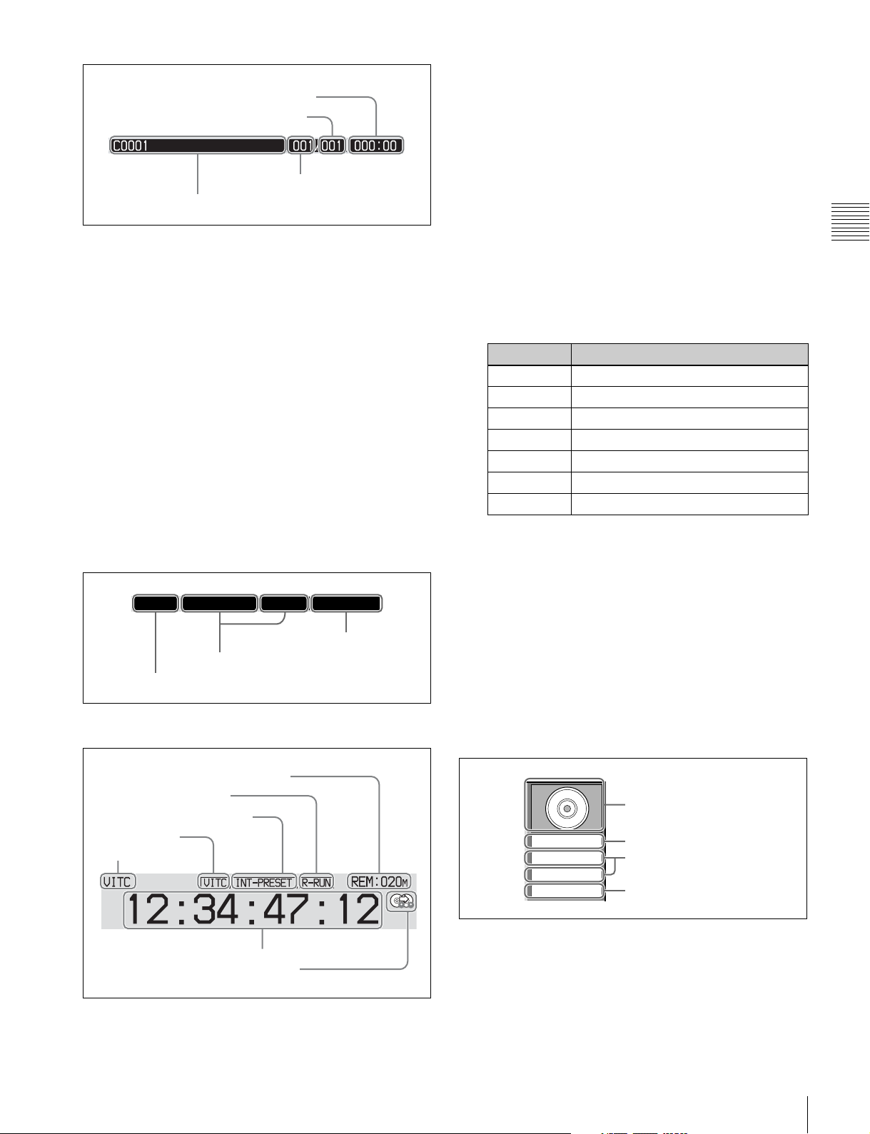
All remaining clips or clip list playback time
Total number of clips recorded on disc
Number of current clip
Clip name
Clip names are displayed according to the setting of
Settings >Display Title in the Disc Menu (see page 65).
However, clip names are always displayed during
playback.
If you are using planning metadata and press the REC
button in stop mode, the name of the clip to be recorded
next appears.
The following characters can be displayed as clip names in
this area.
• Digits: 0 to 9
• Alphabetic characters: a to z, A to Z
• The following symbols: !, ", #, $, %, &, ', (, ), *, +, ,
(comma), -, . (period), /, : (colon), ; (semicolon), <, =, >,
?, @, [, ], ^, _, {, |, }, ~
• Space
d Recording format
Displays the system frequency and the video and audio
formats.
59.94i HD422-1080 50Mbps
Video format
System frequency
8CH-24BIT
Audio format
B REC RUN/FREE RUN: Displays the timecode run
mode. The run mode is set with RUN MODE on page
P5 TC of the function menu (see page 45).
C Timecode generator mode: Displays the timecode
source and generation method (preset or regenerate).
These are set with PRST/RGN and TCG on page P5
TC of the function menu (see page 45).
D VITC: Lights in the following cases.
• When VITC is read in playback mode. (This has no
relations to the display in the time data display
area.)
• When VITC recording is possible.
E Time data type: Displays the type of time data
displayed in the time data display area. The type of
time data is selected with CNTR SEL on the HOME
page of the function menu (see page 43).
Display Type of time data
TC Timecode
COUNTER Elapsed recording/playback time
UB User bits
VITC VITC
VIUB VIUB
TCG Timecode generator value
UBG User bits generator value
F Time data: Normally displays timecode or VITC,
according to the selection made with TCR on page P5
TC of the function menu.
G Recording mode indication: This appears when setup
menu item 150 REC MODE is set to “disc exchange
cache” or “clip continuous rec” (see page 123).
See page 51 for more information about the disc
exchange cache function.
See page 52 for more information about the Clip
Continuous Rec function.
Chapter 2 Names and Functions of Parts
e Time data display area
A Remaining disc recording capacity
B REC RUN/FREE RUN
C Timecode generator mode
D VITC
E Time data type
F Time data
G Recording mode indication
A Remaining disc recording capacity: Displays the
amount of recording capacity remaining on the disc.
f Disc information
A Disc loaded indication/usable
format
59.94i
422-1080
50Mbps
8CH-24BIT
B System frequency
C Video format
D Audio format
A Disc loaded indication/usable format: When a disc is
loaded in this unit, a disc loaded indication appears.
When no disc is loaded, the usable formats are
displayed.
The background color of the disc loaded mark
indicates one of the following disc states.
Front Panel
21
Blue: Disc capable of recording and playback.
Yellow: Disc capable of playback only.
Red: Disc incapable of recording and playback.
Note
Even if the background is blue, recording is not
possible in the following cases.
• When a disc with recording inhibited is loaded.
• When REC INH on the HOME page of the function
Chapter 2 Names and Functions of Parts
menu is set to “ON”.
The usable formats displayed when no disc is loaded
in this unit are as follows.
Display Usable format
HD422: HD422
HD420: HD420HQ/HD420SP/HD420LP
IMX: MPEG IMX 50Mbps/40Mbps/
30Mbps
DVCAM: DVCAM
a) HD420LP supports playback only.
B System frequency: Displays the system frequency of
the clips recorded on the disc.
C Video format: Displays the video format and bitrate of
the clips recorded on the disc.
D Audio format: Displays the audio format of the clips
recorded on the disc.
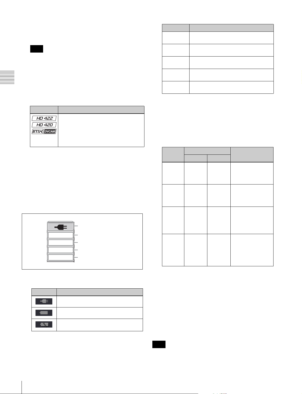
g System information
A Power status
DEFAULT
RM-9P
REPEAT
SHTL/JOG
B Menu setting status
C Remote interface
D Clip playback mode
E Jog/shuttle dial mode
Display Description
BANK1 The current menu settings are the same
as the settings in menu bank 1.
BANK2 The current menu settings are the same
BANK3 The current menu settings are the same
DEFAULT The current menu settings are the same
No display The current menu settings are different
as the settings in menu bank 2.
as the settings in menu bank 3.
as the factory defaults.
from all of the above.
C Remote interface: When the remote control switch is
set to REMOTE, displays the name of the interface
selected with setup menu item 214 REMOTE
INTERFACE.
a)
D Clip playback mode: The clip playback mode appears
as follows, according to the settings of setup menu
items 142 REPEAT MODE and 154 SINGLE CLIP
PLAY MODE.
Display Setup menu setting Description
Item 142 Item 154
REPEAT “play &
VAR fwd”
or “force”
SINGLE off on Single clip playback
SNGL
RPT
No
display
“play &
VAR fwd”
or “force”
off off Continuous
off Repeat playback
mode: Perform
repeat playback of
all clips on the disc.
mode: Play the
currently selected
clip once.
on Single clip repeat
playback mode:
Play the currently
selected clip
repeatedly.
playback mode:
Perform continuous
playback of all clips
on the disc, playing
each clip once.
A Power status: Displays the status of the power supply
to the unit.
Display Power status
AC power
Battery
Battery almost exhausted: Flashes at 1 Hz
Battery exhausted: Flashes at 4 Hz
B Menu setting status: Displays the current setting
status of setup menu.
22
Front Panel
E Jog/shuttle dial mode: Appears when the unit is in
shuttle, jog, or variable mode.
h Reference signal
This displays the type of reference signal to which this unit
is synchronizing.
When there is no display, the unit is synchronizing to the
internal reference signal.
INPUT: Input video
HD REF: HD-format reference signal
SD REF: SD-format reference signal
Note
The HD REF or SD REF display flashes when the video
input signal is not synchronized to the reference signal, and

when the signals are synchronized but their phases do not
match.
i Video input display
This displays the currently selected video input signal.
HDSDI: HDSDI video input
SDSDI: SDSDI video input
SG: Test video signal from the internal signal generator
Note
The display blinks when there is no video input signal, and
when the video input signal does not match the system
frequency of this unit.
The video signal input is selected with V INPUT on page
P1 VIDEO of the function menu (see page 44).
Video monitor display
A Audio level meters
0
0
-10
-10
-20
-20
-30
-30
-40
-40
-60
1 2
-60
3 4
D Low battery warning: Appears and flashes during
operation with a battery pack when the battery power
is almost exhausted.
E Converter display: Displays the current down- or up-
converter mode, depending on the state of the unit.
The current down-converter (DC) mode appears
when HD video is being input and when an HD disc
is being played. The current up-converter (UC) mode
appears when SD video is being input and when an
SD disc is being played.
The current modes are those selected with setup menu
items 930 DOWN CONVERTER MODE (DC) and
950 UP CONVERTER MODE.
DC-EC: Down-converter edge-crop mode
DC-LB: Down-converter letter box mode
DC-SQ: Down-converter squeeze mode
UC-EC: Up-converter edge-crop mode
UC-LB: Up-converter letter box mode
UC-SQ: Up-converter squeeze mode
Chapter 2 Names and Functions of Parts
TCR.00:45.39.18*
JOG STILL
DC-SQ
B Superimposed information
C Recording mode indication
D Low battery warning
E Converter display
When you press the DISPLAY button, the display window
changes to the video monitor display.
A Audio level meters: LEVEL MT on page P2 AUDIO
of the function menu decides whether the meter is to
be displayed and on which side, left or right, it is
displayed in the display window.
B Superimposed information: Appears when CHAR
SEL on the HOME page of the function menu is set to
“ON” or “LCD”.
C Recording mode indication: This appears when setup
menu item 150 REC MODE is set to “disc exchange
cache” or “clip continuous rec” (see page 123).
See page 51 for more information about the disc
exchange cache function.
See page 52 for more information about the Clip
Continuous Rec function.
Front Panel
23

Rear Panel
1 Power supply section (see
page 25)
Chapter 2 Names and Functions of Parts
2 Analog audio signal input/
output section (see
page 25)
1 HDMI OUT connector
2
SD/HDSDI INPUT connector
3 (i.LINK) S400 connector
4 HDSDI OUTPUT 1, 2
(SUPER) connectors
5 SDSDI OUTPUT1, 2 (SUPER) connectors
6 REMOTE(9P) connector
a HDMI OUT connector
Connects to an HD projector, HD television, or other HD
consumer device, and outputs digital signals (video, audio,
and control signals).
The audio signals of the channels selected with MONITR
L and MONITR R in the P2 AUDIO page of the function
menu are output.
See “Basic Operations of the Function Menu” (page 43)
for more information.
b SD/HDSDI INPUT (SDSDI/HDSDI signal input)
connector (BNC type)
This inputs an SDSDI or HDSDI format video/audio
signal.
7 DC IN 12V connector
8 REMOTE connector
9 COMPOSITE OUTPUT1, 2
(SUPER) connectors
0 REF.VIDEO INPUT
connectors
3 Timecode input/output
section (see page 26)
qa (network) connector
qs MAINTENANCE connectors
• When connecting this unit to a device with a 6-pin
i.LINK connector, connect to the 6-pin i.LINK
connector of the other device first.
d HDSDI OUTPUT 1, 2 (SUPER) (HDSDI signal
output 1, 2 (superimpose)) connectors (BNC type)
These output HDSDI format video/audio signals.
You can superimpose timecodes, menu settings, error
messages, or other information on the output of the HDSDI
OUTPUT 2 (SUPER) connector with the setting for
CHAR SEL on the HOME page of the function menu or
with the setting for setup menu item 028 HD
CHARACTER. You can always disable to superimpose
the data independent of the setting for CHAR SEL with the
setting for setup menu item 028.
c
(i.LINK) S400 connector (6-pin, IEEE1394
compliant)
Connect a computer or other device, using an i.LINK
cable.
Notes
• When this unit is connected to a device with a 6-pin
i.LINK connector by an i.LINK cable, before
unplugging the i.LINK cable, first power off the device
and disconnect the power plug from the outlet. If the
i.LINK cable is unplugged with the device power plug
still connected, a current from an excessive voltage (8 to
40 V) output from the i.LINK connector of the device
flows into this unit. This may cause a failure of the unit.
24
Rear Panel
See “Basic Operations of the Function Menu” (page 43)
for more information about the CHAR SEL settings.
See page 117 for more information about the setup menu
item 028 HD CHARACTER.
To treat the input and output signals of these connectors as
non-audio signals, set the maintenance menu item M37:
AUDIO CONFIG >M372: NON-AUDIO INPUT
(recording) (see page 136) and setup menu item 823 NON-
AUDIO FLAG PB (playback).
e SDSDI OUTPUT 1, 2 (SUPER) (SDI signal outputs
1, 2 (superimpose)) connectors (BNC type)
These output SDSDI format video/audio signals.
When the unit is shipped from the factory, audio signal
ANALOG AUDIO INPUT
ANALOG AUDIO OUTPUT
1212
AUDIO MONITOR
RL
output is eight channels with no switching, and RP188
timecode output is set to on. You can change these settings
with setup menu item 828 SDI AUDIO OUTPUT
SELECT and setup menu item 920 SD-SDI H-ANC
CONTROL.
The output from the 2 (SUPER) connector can have
timecode, menu settings, alarm messages, and other text
information superimposed. To turn superimposition off,
set CHAR SEL on the HOME page of the function menu
to “OFF”.
See “Items in the extended menu” (page 121) for more
information.
CAUTION
• For safety, do not connect the connector for peripheral
device wiring that might have excessive voltage to this
port. Follow the instructions for this port.
• When you connect the LAN cable of the unit to
peripheral device, use a shielded-type cable to prevent
malfunction due to radiation noise.
l MAINTENANCE connectors
These are the USB connectors for maintenance.
Connect a Windows USB keyboard or mouse (see
page 74), or a USB flash drive to access planning metadata
stored on the drive (see page 85).
Chapter 2 Names and Functions of Parts
See “Basic Operations of the Function Menu” (page 43)
for more information.
f REMOTE(9P) (remote control 9-pin) connector
(D-sub 9-pin)
To control this unit from a controller or VTR supporting
the RS-422A Sony 9-pin VTR protocol, connect the device
to this connector.
g DC IN 12V connector (XLR 4-pin, male)
Connect to a DC power source of 12 V.
When using the BKP-L551 Battery Adaptor to mount a
battery pack, connect the power cable of the BKP-L551.
For details, see “Supplying power” on page 27.
h REMOTE connector (4-pin)
Supplies power to the RM-280 Editing Controller.
i COMPOSITE OUTPUT 1, 2 (SUPER) (analog
composite video output 1, 2 (superimpose))
connectors (BNC type)
Output analog composite video signals. You can
superimpose timecodes, menu settings, or error messages
on the output of the 2 (SUPER) connector when CHAR
SEL on the HOME page of the function menu is set to ON.
See “Basic Operations of the Function Menu” on page 43
for more information about the CHAR SEL setting.
j REF.VIDEO INPUT (reference video signal input)
connectors (BNC type)
The two connectors form a loop-through connection; when
a reference video signal is input to the left connector, the
same signal is input from the right connector ( ) (IN)
to a connected device. When no connection is made to the
right connector, the left connector is automatically
terminated with an impedance of 75 ohms.
1 Power supply section
1 POWER switch
2 - AC IN connector
a POWER (main power) switch
Press the : side to power on the unit. Press the a side to
power off.
When using the unit, normally leave the POWER switch in
the : (on) position, and use the on/standby button on the
front panel to switch the unit between the operating state
and standby state.
Note
Before turning the main power off, always check to be sure
that the unit is in the standby state, and then press the main
power switch to the a side.
b -AC IN connector
Connect to an AC power supply with the power cord (not
supplied).
2 Analog audio signal input/output section
1 ANALOG AUDIO INPUT 1, 2 connectors
2 ANALOG AUDIO OUTPUT 1, 2
connectors
k (network) connector (RJ-45 type)
This is a 10BASE-T/100BASE-TX/1000BASE-T
connector for network connection.
3 AUDIO MONITOR R, L connectors
Rear Panel
25

a ANALOG AUDIO INPUT 1, 2 connectors (XLR 3-
pin, female)
These input analog audio signals.
With A1 INPUT or A2 INPUT on page P2 AUDIO, and
A3 INPUT or A4 INPUT on page P3 AUDIO of the
function menu (see page 45), you can select whether the
signal input to connector 1 is assigned to audio channel 1or
3, and whether the signal input to connector 2 is assigned
to audio channel 2 or 4.
You can set the reference input level with the maintenance
menu item M37: AUDIO CONFIG (see page 136).
Chapter 2 Names and Functions of Parts
(Factory default setting: +4 dB)
Microphone settings
If you have connected a microphone to this unit, you can
set input level, AGC, and limiter values for the
microphone with setup menu items 834, 839, 840, and 841
(see page 131).
Note
An unpleasant sound may be output if you have connected
a microphone to the ANALOG AUDIO INPUT 1 or 2
connector and power the microphone on with the input
level too high. Check the input level setting before
connecting a microphone.
3 Timecode input/output section
1 TIME CODE IN connector
2 TIME CODE OUT
connector
TIME CODE
IN OUT
a TIME CODE IN connector (BNC type)
This inputs an SMPTE timecode generated by an external
device.
b TIME CODE OUT connector (BNC type)
This outputs the following timecode, depending on the
operating state of this unit.
During playback: Playback timecode
During recording: The timecode from the internal
timecode generator or the timecode input to the TIME
CODE IN connector
When setup menu item 611 TC OUTPUT PHASE IN EE
MODE is set to “muting”, no timecode is output.
b ANALOG AUDIO OUTPUT 1, 2 connectors (XLR
3-pin, male)
These output analog audio signals.
When the unit is shipped from the factory, the 1 connector
is set to audio channel 1, and the 2 connector is set to audio
channel 2. You can change these settings with setup menu
item 824 ANALOG LINE OUTPUT SELECT (see
page 130).
You can set the output level with the maintenance menu
item M37: AUDIO CONFIG (see page 136). (Factory
default setting: +4 dB)
Non-audio signals are muted.
c AUDIO MONITOR R, L connectors (XLR 3-pin,
male)
This outputs an audio signal for monitoring.
The monitored channel is selected with MONITR L and
MONITR R on page P2 AUDIO of the function menu.
See “Basic Operations of the Function Menu” (page 43)
for more information.
26
Rear Panel
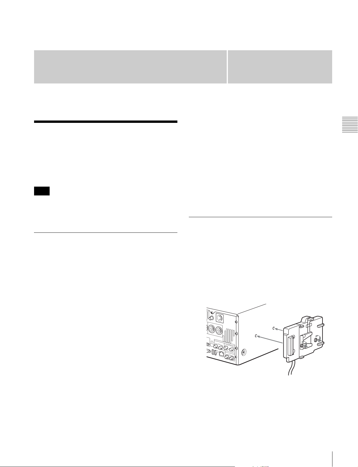
Preparations
Preparing Power Sources
This unit can be powered by AC power, DC power, or a
battery pack.
For safety, use only the Sony battery packs listed below.
Lithium-ion battery pack: BP-L80S, BP-GL95
Note
If you load or remove a battery pack incorrectly, it may fall
and cause bodily injury. Follow the procedures described
below to load or remove them.
Chapter
For details on charging battery packs, refer to the
operation manual for the battery charger.
Notes about battery usage
• Before using the batteries, be sure to charge them fully
with the special battery charger. Refer to the operating
instructions for your battery charger for more
information about how to charge the batteries.
• Batteries may not be completely charged if you charge
them immediately after use when they are still warm.
You should wait until the batteries cool before charging
them.
3
Attaching a battery pack
Chapter 3 Preparations
Supplying power
AC power supply
Connect the AC IN connector to an AC power source using
the specified AC power cord. To supply AC power to the
unit, set the on/standby button on the front panel to ON and
the POWER switch on the rear panel to = (ON).
DC power supply
Connect the DC IN 12V connector to a DC power source.
To supply DC power to the unit, set the on/standby button
on the front panel to ON and the POWER switch on the
rear panel to OFF. If the POWER switch on the rear panel
is set to = (ON), AC power is supplied.
Battery power supply
Battery packs that can be used with this unit are as follows.
To use battery pack, a BKP-L551 Battery Adaptor and a
BC-L100 Battery Charger are also required.
• BP-L80S
•BP-GL95
Attaching and removing of the BP-GL95 Battery Pack is
described below.
The BP-L80S can also be attached and removed in the
same way.
For details on attaching the BKP-L551, refer to the
installation manual for the BKP-L551.
1
Attach the BKP-L551 to the side panel.
BKP-L551
2
Align the grooves on the BP-GL95 with the
projections on the BKP-L551.
Continuous recording time at room temperature
BP-GL95 lithium-ion battery pack: 95 minutes
Preparing Power Sources
27
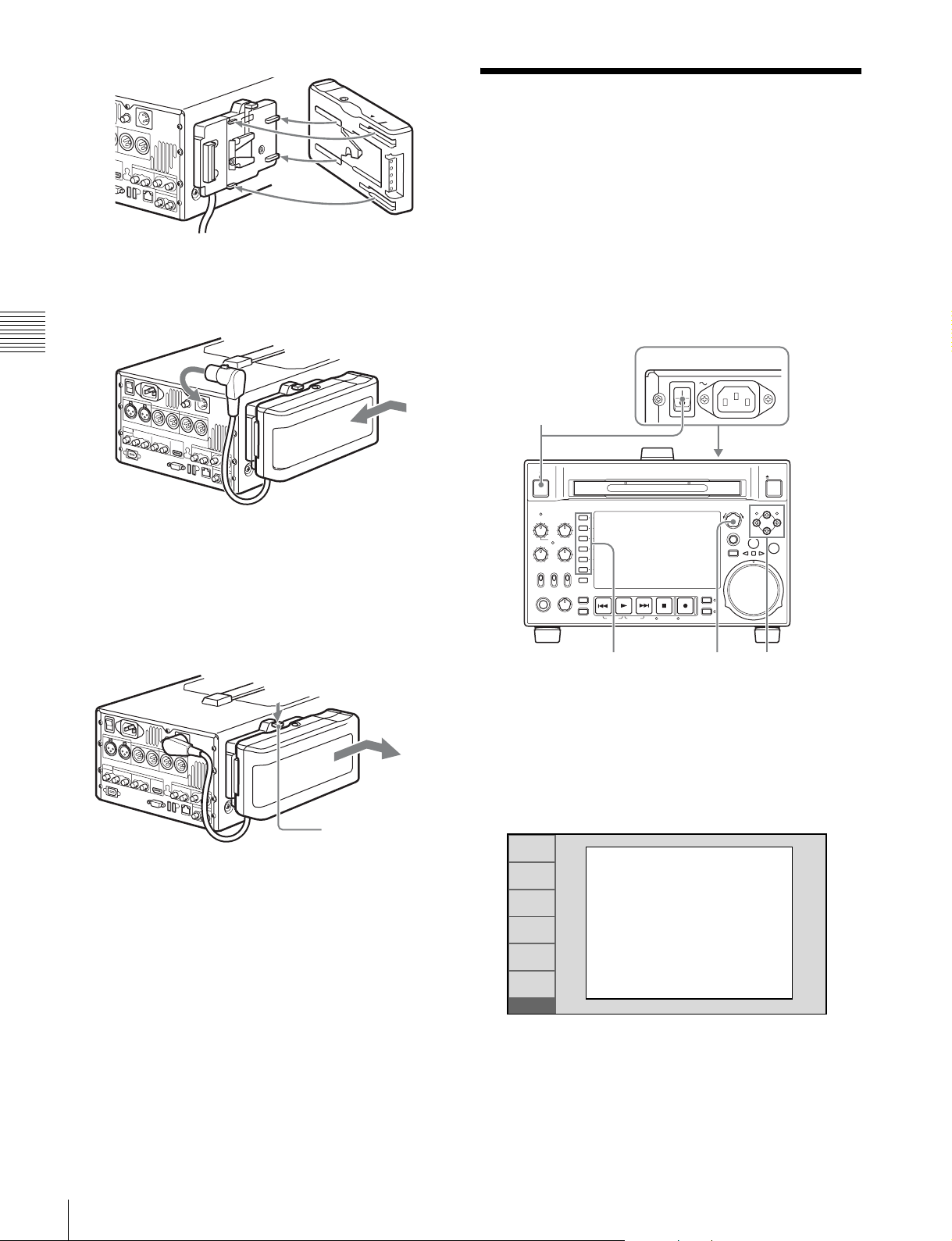
BP-GL95
3
Slide the BP-GL95 as shown below so that the
connectors on the BP-GL95 and the BKP-L551 are
connected.
Chapter 3 Preparations
4
Connect the DC cable of the BKP-L551 to the DC IN
12V connector.
Removing the battery pack
With the lever pushed in, slide the BP-GL95 out as shown
below.
Initial Setup
This unit is shipped with the system frequency, recording
format, and current date and time still unset.
Therefore, you need to make initial setup settings before
using the unit. (You cannot use the unit without setting it
up.)
Once the unit has been set up, the settings are retained even
when the unit is powered off.
Use the following procedures.
POWER
1
EJECT
MARK1
THUMBNAIL
SUB CLIP
DISC MENU
PUSH SET(S.SEL)
MENU
RESET
RETURN
SHTL/JOG
IN OUT
VAR/JOG
55,6 2,3,4
MARK2
ACCESS
CH-1
CH-2
NET
LOCAL
REMOTE
PHONES LEVEL
ALL CH
VARIABLE KEY INHI
REC
PRE-
SET
PB
CH-3
CH-4
CHAPTER
EXPAND
PAGE
ON
OFF
HOME
PREV NEXTPLAY STOP REC
DISPLAY
SHIFT
TOP F REV F FWD END STANDBY REC INHI
Lever
Checking the remaining battery power
You can use the LEDs on the side panel of the battery to
check the remaining power of the battery.
1
Power the unit on.
The INITIAL SETUP screen appears on the display.
2
Turn the PUSH SET(S.SEL) knob to select the system
frequency.
RETURN
SET
INC/DEC : CTRL.KNOB
CANCEL&PREV : F1(RET)
SET&NEXT : F5(SET)
INIT
INITIAL SETUP
SYSTEM FREQUENCY
SELECT
1080/50i
Display the system frequency that you want to use, and
then press the SET function button (F5).
The recording format selection screen appears.
3
Turn the PUSH SET(S.SEL) knob to select the
recording format.
28
Initial Setup
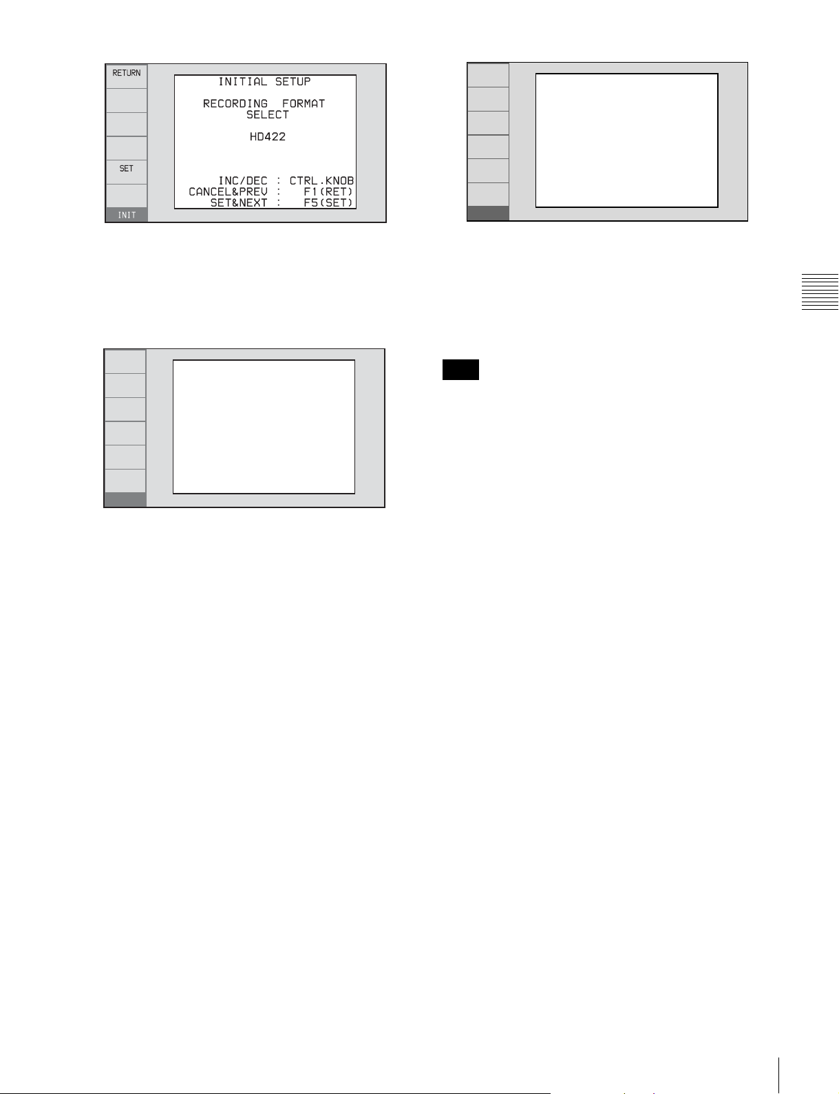
RETURN
INITIAL SETUP
Push F5(SAVE) Key!!
Display the recording format that you want to use, and
then press the SET function button (F5).
The date and time setting screen appears.
4
In the DATE/TIME PRESET screen, set the current
date and time by setting the following items.
RETURN
SET
INIT
DATE/TIME PRESET
YEAR 2008
MONTH 11
DAY 19
TIME 16:49:00
TIME ZONE UTC+00:00
INC/DEC : CTRL.KNOB
SHIFT : (P )(p )KEY
CANCEL&PREV : F1(RET)
SET&NEXT : F5(SET)
YEAR: Year
MONTH: Month
DAY: Day
TIME: Time
TIME ZONE: Time zone (as a difference in hours
with respect to Coordinated Universal Time
(UTC))
SET
CANCEL&PREV : F1(RET)
SAVE&REBOOT : F5(SET)
INIT
The message “NOW SAVING...” appears again, and
the setting screen disappears. Then the unit powers
itself off and on again.
To return to the original screen without saving
settings
Press the RETURN function button (F1).
Note
The time zone is reset to the factory default when you
execute the maintenance menu item M49: RESET ALL
SETUP. You will need to set it again. The date and time
are not reset.
Chapter 3 Preparations
In the setting screen, you can change the value of the
flashing digit.
Press the B/IN or b/OUT button to make the previous
digit or next digit start flashing.
Press the V/MARK1 or v/MARK2 button (or turn the
PUSH SET(S.SEL) knob) to increment or decrement
the value of the flashing digit.
When you have finished making settings, press the
SET function button (F5).
The date, time, and time zone settings are saved, and
the message “NOW SAVING...” appears.
5
If you want to save the settings made up to this point,
press the SET function button (F5) again.
Initial Setup
29
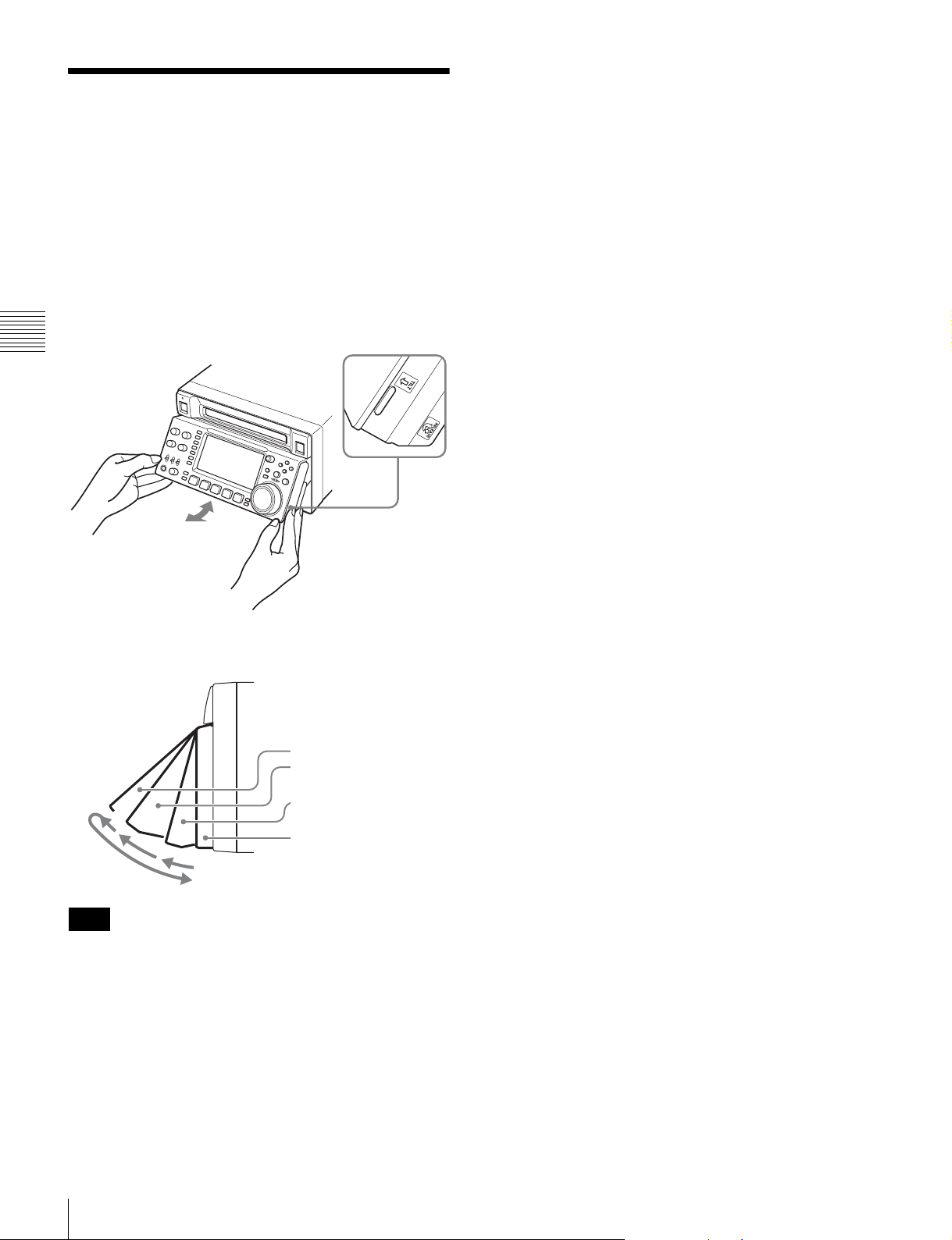
Front Panel Tilt Mechanism
The front panel of this unit has a tilt mechanism that allows
you to pull the front panel out and adjust it to a convenient
angle.
To pull the front panel out
Grasp the holds (small protrusions) on both sides of the
front panel and pull out as indicated by the arrow.
Chapter 3 Preparations
To change the angle of the front panel
To change the angle to position 2 from position 1, pull the
front panel out to position 2.
To change the angle to position 1 from position 2, first
unlock the front panel by pulling it all the way out to the
return position. Then return it to position 0, and pull out
again to position 1.
You can fix the angle of the front panel in position 1 (15
degrees) or position 2 (40 degrees).
Return position
Position 2 (40 degrees)
Position 1 (15 degrees)
Position 0
Note
The angle cannot be fixed if you pull the front panel past
position 2 all the way out to the return position. To fix the
front panel, return it to position 0 and then pull it out to
position 1 or position 2.
To return the front panel to its original
position
Unlock the front panel by pulling it out to the return
position. You can then return it to position 0.
30
Front Panel Tilt Mechanism
 Loading...