

Sony PDW-F330K, PDW-F330L, PDW-F350L User Manual

3-990-971-12(1)
Professional Disc
Camcorder
Operating Instructions
Before operating the unit, please read this manual
thoroughly and retain it for future reference.
PDW-F330L
PDW-F330K
PDW-F350L
© 2006 Sony Corporation
Owner’s Record
The model and serial numbers are located on the top.
Record these numbers in the spaces provided below. Refer
to them whenever you call upon your Sony dealer
regarding this product.
Model No.
Serial No.
WARNING
To reduce the risk of fire or electric shock,
do not expose this apparatus to rain or
moisture.
To avoid electrical shock, do not open the
cabinet. Refer servicing to qualified
personnel only.
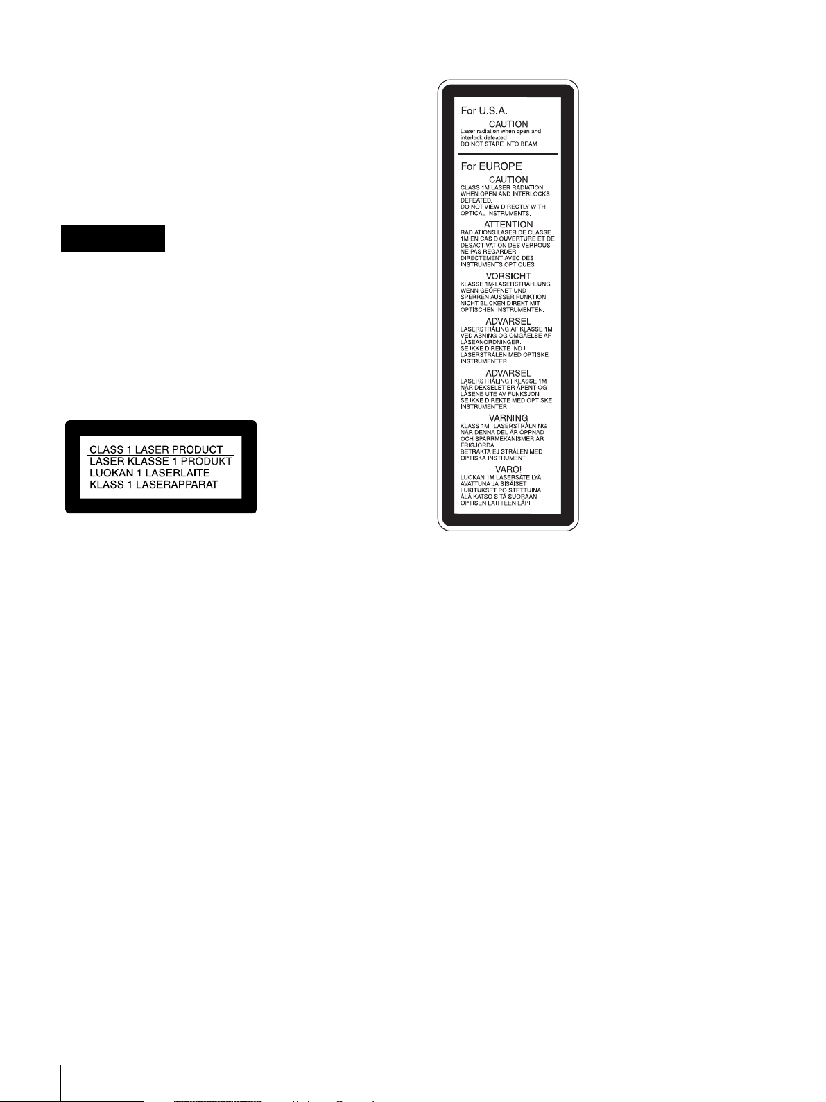
This label is located inside
the outside panel of the unit.
Denna etikett finns på
apparatens ovansida.
Denne mærkat sidder på
apparatets øverste panel.
Tämä kyltti sijaitsee laitteen
yläpinnalla.
Dette merket er plassert på
oversiden av produktet.
This Professional Disc Camcorder is classified as a CLASS 1
LASER PRODUCT.
Laser diode properties
Wavelength: 403 to 410 nm
Emission duration: Continuous
Laser output power: 65 mW (max. of pulse peak), 35 mW
(max. of CW)
Tekniska data för laserdiod
Våglängd: 403 till 410 nm
Emissionslängd: Kontinuerlig
Laseruteffekt: 65 mW (max. för pulstopp), 35 mW (max. för
kontinuerlig våg)
Spesifikasjoner laserdiode
Bølgelengde: 403 til 410 nm
Strålingens varighet: Kontinuerlig
Laserens effekt: 65 mW (maks stråletoppunkt), 35 mW
(maks ved kontinuerlig stråling)
Laserdiodin ominaisuudet
Aallon pituus: 403 - 410 nm
Välityksen kesto: Jatkuva
Laserlähdön teho: 65 mW (sykehuipun maks.), 35 mW
(jatkuvan aallon maks.)
CAUTION
The use of optical instruments with this product will increase
eye hazard.
CAUTION
Use of controls or adjustments or performance of procedures
other than those specified herein may result in hazardous
radiation exposure.
VAROITUS!
LAITTEEN KÄYTTÄMINEN MUULLA KUIN TÄSSÄ
KÄYTTÖOHJEESSA MAINITULLA TAVALLA SAATTAA
ALTISTAA KÄYTTÄJÄN TURVALLISUUSLUOKAN 1
YLITTÄVÄLLE NÄKYMÄTTÖMÄLLE LASERSÄTEILYLLE.
VARNING
OM APPARATEN ANVÄNDS PÅ ANNAT SÄTT ÄN I DENNA
BRUKSANVISNING SPECIFICERATS, KAN ANVÄNDAREN
UTSÄTTAS FÖR OSYNLIG LASERSTRÅLNING, SOM
ÖVERSKRIDER GRÄNSEN FÖR LASERKLASS 1.
For the customers in the U.S.A.
This equipment has been tested and found to comply with the
limits for a Class A digital device, pursuant to Part 15 of the
FCC Rules. These limits are designed to provide reasonable
protection against harmful interference when the equipment is
operated in a commercial environment. This equipment
generates, uses, and can radiate radio frequency energy and,
if not installed and used in accordance with the instruction
manual, may cause harmful interference to radio
communications. Operation of this equipment in a residential
2

area is likely to cause harmful interference in which case the
user will be required to correct the interference at his own
expense.
You are cautioned that any changes or modifications not
expressly approved in this manual could void your authority to
operate this equipment.
All interface cables used to connect peripherals must be
shielded in order to comply with the limits for a digital device
pursuant to Subpart B of Part 15 of FCC Rules.
For the customers in the USA and Canada
RECYCLING LITHIUM-ION BATTERIES
Lithium-Ion batteries are recyclable.
You can help preserve our environment
by returning your used rechargeable
batteries to the collection and recycling
location nearest you.
For more information regarding recycling of rechargeable
batteries, call toll free 1-800-822-8837, or visit
http://www.rbrc.org/
Caution: Do not handle damaged or leaking lithium-ion
batteries.
Voor de Klanten in Nederland
• Gooi de batterij niet weg maar lever deze in als
klein chemisch afval (KCA).
• Dit apparaat bevat een vast ingebouwde
batterij die niet vervangen hoeft te worden
tijdens de levensduur van het apparaat.
• Raadpleeg uw leverancier indien de batterij
toch vervangen moet worden.De batterij mag
alleen vervangen worden door vakbekwaam
servicepersoneel.
• Lever het apparaat aan het einde van de
levensduur in voor recycling, de batterij zal dan
op correcte wijze verwerkt worden.
For the State of California, USA only
Perchlorate Material - special handling may apply, See
www.dtsc.ca.gov/hazardouswaste/perchlorate
Perchlorate Material : Lithium battery contains perchlorate.
For the customers in Europe
This product with the CE marking complies with the EMC
Directive (89/336/EEC) issued by the Commission of the
European Community.
Compliance with this directive implies conformity to the
following European standards:
• EN55103-1: Electromagnetic Interference (Emission)
• EN55103-2: Electromagnetic Susceptibility (Immunity)
This product is intended for use in the following
Electromagnetic Environment(s):
E1 (residential), E2 (commercial and light industrial), E3
(urban outdoors) and E4 (controlled EMC environment, ex. TV
studio).
For the customers in Taiwan only
3

Table of Contents
Foreword .....................................................7
Before Use ....................................................7
Model Distinction Marks Used in This Manual
.............................................................7
Chapter 1 Overview
Product Configurations .............................8
Features ...................................................... 9
Principal Differences Between the PDW-F330
and PDW-F350....................................9
Camera Features ...........................................9
Features of the Optical Disc Drive (VDR) .10
Input/Output Features .................................11
Other Features.............................................12
Location and Function of Parts ..............13
Front............................................................13
Right Side ...................................................15
Status Display on the LCD Monitor ...........17
Left Side and Upper Section.......................22
Rear.............................................................24
VCL-719BXS Auto Focus Lens (Supplied
With the PDW-F330K) .....................27
Viewfinder ..................................................29
Status Display on the Viewfinder Screen ...31
RM-F300 Infrared Remote Commander ....32
Chapter 2 Preparations
Attaching and Replacing the Lithium
Battery ................................................ 35
Preparing a Power Supply....................... 36
Using a Battery Pack ..................................36
Using an AC Adaptor .................................36
Setting the Area of Use and the Frame
Frequency ..........................................37
Using the Unit for the First Time ...............37
Setting the Frame Frequency......................37
Setting the Date and Time of the Internal
Clock................................................... 39
Preparing the Lens................................... 40
Mounting the Lens..................................... 40
Adjusting the Flange Focal Length............ 40
Adjusting the Viewfinder ......................... 42
Detaching the Viewfinder.......................... 42
Adjusting the Viewfinder Position ............ 42
Adjusting the Eyepiece Focus and the Screen
(Brightness, Contrast, and Outline
Emphasis) ......................................... 43
Attaching a 5-inch Electronic Viewfinder. 43
Using the Shoulder Strap ........................ 44
Adjusting the Shoulder Pad Position..... 44
Mounting on a Tripod .............................. 45
Using a Video Light.................................. 45
Preparing the Audio Input System .........46
Using the Supplied Microphone ................ 46
Using an External Microphone.................. 46
Attaching a UHF Synthesized Tuner......... 47
Connecting Line Input Audio Equipment.. 49
Connecting the Remote Control Unit ..... 49
Connecting ............................................... 51
Connecting an External Video Monitor..... 51
Using an i.LINK Connection..................... 51
Connecting Using the HDSDI Connector.. 53
Connections for Using the PDZ-1 ............. 53
Chapter 3 Recording and Playback
Handling Discs ......................................... 54
Discs Used for Recording and Playback ... 54
Notes on Handling ..................................... 54
Write-Protecting Discs............................... 54
Loading and Unloading a Disc .................. 55
Formatting a Disc ...................................... 55
Handling of Discs When Recording Does Not
End Normally (Salvage Function).... 56
Basic Procedure for Shooting ................ 57
Recording – Basic Operations................ 58
Selecting the Recording Format ................ 58
Adjusting the Black Balance/White Balance.
59
Setting the Electronic Shutter .................... 62
Adjusting the Iris ....................................... 64
Adjusting the Audio Level......................... 65
Setting the Time Data ................................ 66
4
Table of Contents

Setting for Special Shooting Cases.............69
Deleting Clips .............................................69
Recording Shot Marks ................................70
Setting the Thumbnail Image at Recording
Time ..................................................70
Recording – Advanced Operations ........71
Time-lapse Video Recording (“Interval
Recording” Function)........................71
Slow & Quick-motion Shooting .................73
Starting a Shoot With a Few Seconds of Pre-
Stored Picture Data (Picture Cache
Function) ...........................................74
Assigning User-Defined Clip Titles
Automatically....................................75
Assigning User-Defined Clip and Clip List
Names................................................77
Viewing Camera Video During Playback
(Live & Play Function) .....................79
Playback.................................................... 80
Normal Playback ........................................80
Checking the Last Two Seconds of the
Recording (a Recording Review
Operation)..........................................81
Checking the Recording on a Color Video
Monitor..............................................81
Thumbnail Search .................................... 82
Searching Using Thumbnails......................82
To switch the information displayed in the
thumbnail screen ...............................83
Changing the Thumbnail Image (Index Frame)
of a Clip.............................................83
Cuing Up a Frame by Searching for an
Essence Mark ....................................84
Searching Using the Chapter Function.......85
Searching Using the Expand Function .......85
Clip List Playback.......................................86
Locking (Write-protecting) Clips ...............87
Deleting Clips .............................................88
Chapter 4 Scene Selection
Overview ...................................................90
Creating Clip Lists.................................... 93
Including Sub Clips in the Current Clip List
...........................................................93
Adding Sub Clips Using the Expand Function
.......................................................... 95
Adding Sub Clips Using the Chapter Function
.......................................................... 96
Editing Clip Lists...................................... 97
Reordering Sub Clips................................. 97
Adjusting Sub Clip In/Out Points (Trimming)
.......................................................... 97
Deleting Sub Clips..................................... 98
Saving the Current Clip List to Disc.......... 98
Setting the Start Timecode for the Current Clip
List.................................................... 99
To Switch the Information Displayed on
Thumbnails....................................... 99
Managing Clip Lists ............................... 100
Loading a Clip List From the Disc as the
Current Clip List............................. 101
Deleting a Clip List From the Disc.......... 101
Sorting the List of Clip Lists ................... 101
Using the PDZ-1 Proxy Browsing Software
.......................................................... 102
Chapter 5 Menu Displays and
Detailed Settings
Menu Organization and Operation ....... 103
TOP Menu ............................................... 110
Menu List................................................. 111
Displaying Menus.................................... 131
Basic Menu Operations............................ 131
Using the USER Menu (Example Menu
Operation)....................................... 132
Editing the USER Menu .......................... 133
Resetting USER Menu Settings to the
Standard Settings............................ 135
Setting the Status Display on the
Viewfinder Screen and the LCD Monitor
.......................................................... 136
Selecting the Display Items ..................... 136
Change Confirmation/Adjustment Progress
Messages ........................................ 137
Setting the Marker Display...................... 137
Setting the Viewfinder Screen Display.... 138
Table of Contents
5

Recording Shot Data Superimposed on the
Color Bars .......................................138
Setting the Shot ID....................................139
Showing the Status Display......................140
Adjustments and Settings from Menus 140
Setting Gain Values for the GAIN Switch
Positions ..........................................140
Selecting the Output Signals.....................140
Setting the Color Temperature Manually .141
Specifying an Offset for the Auto White
Balance Setting................................141
Selecting Gamma Tables ..........................142
Assigning Functions to ASSIGN Switches
.........................................................142
Selecting the Lens File..............................143
Selecting the Aspect Ratio........................143
About the CCD Scan Mode ......................144
Phenomena Specific to CCD Image Sensors
........................................................ 161
Condensation ........................................... 161
Maintenance ........................................... 162
Testing the Camcorder Before Shooting . 162
Maintenance............................................. 164
Operation Warnings...............................165
Troubleshooting .....................................169
Using UMID Data .................................... 171
MPEG-4 License ..................................... 173
About i.LINK .......................................... 173
About a “Memory Stick”........................174
Specifications.........................................176
Chart of Optional Components and
Accessories ..................................... 180
Glossary.................................................. 181
Index........................................................ 184
Chapter 6 Saving and Loading the
User Setting Data
Saving and Loading User Files .............146
Handling the “Memory Stick”..................146
Saving USER Menu Data (User File) to the
“Memory Stick” ..............................147
Loading Saved Data From a “Memory Stick”
.........................................................149
Saving and Loading Scene Files .......... 150
Saving a Scene File...................................150
Loading Scene Files..................................152
Resetting the Settings of the Camcorder to the
Standard Settings.............................153
Chapter 7 File Operation
Overview .................................................155
Directory Structure ...................................155
File Operation Restrictions.......................156
File Access Mode File Operations ........158
Appendix
Important Notes on Operation ..............160
6
Table of Contents

Foreword
Before Use
After purchasing this unit, before operating, it is necessary
to set the region of use and the frame frequency.
(Unless these settings are made, the unit will not operate.)
For details of these settings, see “Setting the Area of Use
and the Frame Frequency” on page 37.
Model Distinction Marks Used in
This Manual
Indications of functions specific to particular
models
This manual describes three models: PDW-F330L, PDWF330K, and PDW-F350L.
These models are divided into the PDW-F330L/F330K
and the PDW-F350L. The following model distinction
marks are used to indicate functions, switches, indications,
etc. that apply only to one or the other.
F330
Specific functions, switches, indications, etc., for the
PDW-F330L/F330K
F350
Specific functions, switches, indications, etc., for the
PDW-F350L
Frame frequency indications for interlaced
signals
In the menus of this unit, the frame frequency of an
interlaced signal is shown as “60I” or “50I”, with a capital
letter, but in this manual these are shown as “60i” and
“50i” with a lower-case letter.
For progressive signals, both menus and manual use a
capital letter (e.g. “30P”, “25P”, “23.98P”).
Foreword
7
Chapter 1 Overview
Overview
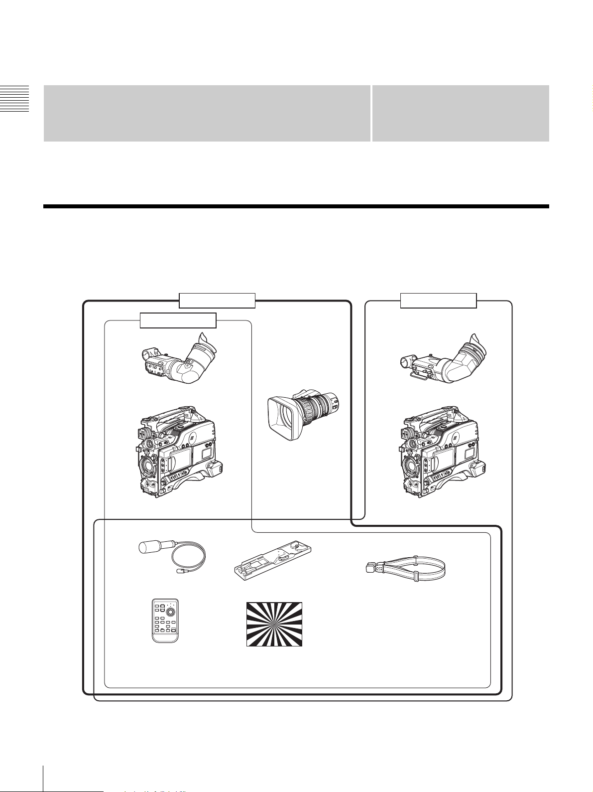
Product Configurations
Chapter
1
The PDW-F330/F350 Professional Disc Camcorder series
includes the models PDW-F330L, PDW-F330K, and
PDW-F350L, with different product configurations. The
PDW-F330K
PDW-F330L
DXF-801/801CE Viewfinder
VCL-719BXS
Auto Focus Lens
PDW-F330 Camcorder
components and accessories supplied of these models are
as shown in the following figure.
PDW-F350L
DXF-20W Viewfinder
PDW-F350 Camcorder
Stereo Microphone VCT-U14 Tripod Adaptor
PUSH SET
T
1
ZOOM
SHOTMARK
2
W
SUB CLIP
THUMBNAIL
PREV NEXT
PLAY/PAUSE
STOP
.
>
xu
FFWDFREV
m
M
PUSH AFREC PAUSE
REC
z
X
RM-F300 Infrared
Remote Commander
a) Use a tripod adaptor with a suffix of “-E” or later on the model name.
For more details, see “Mounting on a Tripod” (page 45).
8
Product Configurations
Test chart for flange focal
length adjustment
a)
Shoulder strap
• Lens mount cap
• PFD23 Professional Disc
• PDZ-1 Proxy Browsing Software
• Operating Instructions
(Japanese version, English
version, and CD-ROM manual)
• Warranty Booklet

Features
1)
The PDW-F330/F350 is an XDCAM
integrating an HD video camera using three HD CCDs of
1
the
/2-inch type with a total effective pixel count of 1.56
million, and a Professional Disc
1)
drive.
This unit provides a range of useful shooting functions for
video production, and allows shooting and recording in
both progressive scan and interlace scan modes with an
HD image having 1080 effective scan lines. Since it also
supports SD
3)
DVCAM recording, it can be used through
a transition from SD to HD production.
The use of Professional Disc adds high reliability to
recording and playback, and the unit also includes many
playback and editing functions exploiting the possibilities
of random access.
1) XDCAM and “Professional Disc” are trademarks of Sony Corporation.
2) HD: High Definition
3) SD: Standard Definition
Principal Differences Between the
HD
2)
camcorder
Camera signal processing for high quality
video
A specially-developed ASIC (application specific
integrated circuit) for signal processing provides the
following functions.
• A 12-bit A/D converter ensures recording of pictures
stable at high quality.
• Both progressive and interlace scan modes are
supported.
• You can select from five HD shooting/recording modes:
23.98P
support of various applications including digital cinema
production, program production, and event video
production.
• For recording and playback in the DVCAM format (SD),
the aspect ratio (16:9/4:3) and standard broadcasting
system (NTSC/PAL) can be freely selected. Further,
when NTSC is selected, video shot at 23.98P can also be
subjected to 2-3 pulldown and recorded. (The recording
format is then 59.94i.)
1) In this system, shown as 23.9P or 23.98P.
2) In this system, shown as 30P.
3) In this system, shown as 60I.
1)
, 25P, 29.97P 2), 50i, and 59.94i 3), for ideal
Chapter 1 Overview
PDW-F330 and PDW-F350
The specifications of the PDW-F330 and PDW-F350
differ in part, as follows.
Item PDW-F330 PDW-F350
Viewfinder 1.5-inch CRT,
Video output
connectors
Audio output
connectors
Timecode input/
output connectors
Slow & quickmotion functions
a) A DXF-20W 2-inch CRT viewfinder (option) with aspect ratio 16:9 can
be installed in the camcorder.
4:3 aspect ratio
(supplied as
standard)
BNC ×3 (analog
component
outputs, HD/SD
switchable)
RCA ×2 XLR, 5-pin
BNC (input/output
switchable)
No Yes
a)
2-inch CRT, aspect
ratio 16:9
(supplied as
standard)
BNC (HDSDI
output)
(balanced output)
BNC ×2
(one for input, the
other for output)
Camera Features
1
/2-inch HD CCD
The use of three interline transfer CCD with an effective
pixel count of approximately 1.56 million (1440 ×1080)
enables high sensitivity, high picture quality, and high
fineness video shooting.
Shooting functions provide various effects
This unit is equipped with many of the functions provided
in a film camera, allowing the operator creative control
through a variety of techniques.
Slow shutter function
A maximum of 64 frames can be accumulated using the
slow shutter function. In low light levels this allows clear
and noiseless video to be shot, and provides a fantasy
video effect with ghost images.
Time lapse function (interval recording)
Using this function slow-moving subjects can be shot with
the movement compressed in time. This is convenient for
many applications, such as monitoring plant growth, or the
progress of a construction site.
1) This function is available when the recording mode is MPEG HD.
Slow & quick-motion functions
F350
1)
The PDW-F350 has slow & quick-motion functions.
These allow the shooting frame rate to be different from
the playback frame rate, allowing the same functions as
overcranking or undercranking with a film camera. Unlike
low-speed or high-speed playback of normally shot video,
this provides a smooth slow-motion effect, or action
speeded up beyond what is actually possible.
1) This function is available when the recording mode is MPEG HD.
1)
Features
9

Shooting functions to cope with different
shooting conditions
• The ATW
automated adjustment of the white balance and intenstity
levels to cope with varying ambient lighting conditions.
Chapter 1 Overview
• By switching among the four levels (including CLEAR)
of neutral density (ND) filter, it is possible to
compensate for lighting conditions, and control the
depth of field.
• When shooting in daylight or other high color
temperature illumination, pressing the 5600K button
instantly switches the color temperature setting to
5600K
• With the GAIN switch, you can adjust the gain of the
video amplifier according to the lighting conditions
when shooting. You can vary the setting in the GAIN
switch positions (H/M/L) to any values in the range –3
dB to +48 dB.
1) Auto Tracing White balance
2) Only when the WHITE BAL switch is in the PRST position
1)
and auto iris functions allow shooting with
2)
.
Saving and recalling settings on a
“Memory Stick”
Using a “Memory Stick”
save menu settings adjusted to particular shooting
conditions, and then recall those settings as required.
1) “Memory Stick” is a trademark of Sony Corporation.
1)
(supplied separately), you can
Features of the Optical Disc Drive
(VDR)
Support for HD/SD recording and playback
formats
For HD video recording format, MPEG-2 MP@HL
compression is used, and the image quality (bit rate) and
recording time
application. Recording in the DVCAM format is also
supported. The audio is recorded as four channels or two
channels
1) The recording mode can be selected from the three modes: HQ (High
Quality), SP (Standard Play) and LP (Long Play).
2) DVCAM recording is available for four channels only.
Proxy AV data recording
The Proxy AV data is low resolution data using MPEG-4
(video 1.5 Mbps, audio 64 kbps per channel). With this
unit, when recording HD or SD high resolution data, low
resolution Proxy AV data is automatically generated at the
same time, and recorded.
Since the Proxy AV data is compact, it can be transferred
to a computer or network at high speed, enormously
reducing the storage capacity required for recording.
1)
can be selected according to the shooting
2)
, uncompressed.
Exploiting this allows a laptop computer to be used for
1)
editing
, allows content management on an inexpensive
and compact server, and makes many other applications
easy to implement.
1) Using the supplied PDZ-1 Proxy Browsing Software, a simple EDL (edit
decision list) can be created.
Saving general-purpose files
The Professional Disc has an area of approximately 500
MB provided for storing general-purpose computer files.
Recording and playback in clip units
A clip is created each time recording is started and
stopped.
• Recording always writes to an empty area of the disc.
Therefore, even if playback is carried out between
shooting sessions, there is no danger of the next shooting
inadvertently overwriting previous material. During
playback, the next they are recorded can always be
started immediately.
• Since unwanted clips can be deleted on this unit
immediately after they are recorded, the disc capacity
can be used effectively.
Convenient playback and search functions
exploiting the disc characteristics
Thumbnail search
Pressing the THUMBNAIL button on this unit displays a
representative image for each clip as a thumbnail on the
LCD (liquid crystal display) monitor, in the viewfinder,
and on the external video monitor.
Selecting a thumbnail with the cursor and pressing the
PLAY/PAUSE button allows any clip to be checked
easily.
Essence mark search
During or after movie recording, an essence mark can be
recorded on any scene. A list of frames with an essence
mark recorded can be displayed on the LCD monitor, in
the viewfinder, and on the external video monitor. Essence
marks can also be added after recording using the supplied
PDZ-1 Proxy Browsing Software.
Expand function
The length of any clip selected in the thumbnail list can be
divided into 12, and the first frames of these 12 divisions
can also displayed in the form of a thumbnail list. With this
function, it is easy to search rapidly for scenes within a
particular clip. This function is called the expand function,
and it can be applied to the same clip up to three times to
display 1728 thumbnails in a list.
10
Features

Scene selection
You can select clips on the disc to create a clip list. The
clips in this list can be played back in any order. A single
disc can hold up to 99 clip lists.
Other signal input/output connectors
HDSDI output connector
F350
Audio recording functions
Audio is recorded as uncompressed data with 16-bit
quantization, and a sampling frequency of 48 kHz.
Depending on shooting requirements and recording time,
either two or four audio channels can be selected. (Only
four channels for DVCAM recording.)
• The unit is equipped with a stereo front microphone.
• There are two AUDIO IN connectors (XLR, 3-pin) on
the rear of the unit, which can be used for line and
microphone input.
• The CA-WR855 Camera Adaptor (supplied separately)
can be used to install the WRR-855 series slot-in type
UHF synthesized tuner (supplied separately) without
using any connecting cable.
• The audio signals to be recorded on the disc can be freely
selected from the audio inputs to the stereo microphone,
AUDIO IN connectors and the UHF synthesized tuner,
and assigned to any desired audio channel.
Input/Output Features
Equipped with an i.LINK connector
The i.LINK connector on this unit supports the following
two functions.
DV stream output (AV/C
stream can be output from the i.LINK connector on
this unit, and recorded on a DV recorder or nonlinear
editor supporting DV. For recording and playback in
MPEG HD format, a down-converted DV stream can
be output.
File access from a computer (FAM
FAM connection between this unit and a computer
allows the video, audio, and metadata information on
the disc to be read and written as files. (The data can
be written and read as normal files on a computer.)
With this function, a nonlinear editing device
connected to this unit can be used for direct HD video
editing or simple Proxy A/V data editing, enabling a
more efficient workflow.
1) Audio/Video Control
2) File Access Mode
1)
mode connection): A DV
2)
connection): An
The audio signals are embedded in the video signal. The
HD video and audio output from this connector can be
recorded on an external HD device.
HD/SD analog component output connector
F330
During HD video recording and playback, either an HD
signal or down-converted SD signal can be output. (The
output signal selection is carried out in a menu.)
Composite video output connector
The 50i/25P video is output as the PAL signal, the 60i/30P
video is output as the NTSC signal, and the 23.98P video
is output as the NTSC signal which has undergone 2-3
pull-down processing.
Timecode input/output connectors
F330
Provided with a single input/output connector (controlled
by a switch).
F350
Provided with one input connector and one output
connector.
GENLOCK connector
The SD or HD reference signal can be input to apply a
genlock to the camera.
Video light connector
There is an interface connector for a maximum 50 W video
light, and a control switch. Depending on the switch
setting, the light can be turned on and off as recording
starts and stops.
Remote control connector
Connect the RM-B150/B750 remote control unit (supplied
separately) or other remote commander, to allow remote
operation of the shooting functions of this unit.
Audio output connectors
F330
Provided with RCA phono jacks, allowing stereo output.
F350
Chapter 1 Overview
Provided with XLR connectors (5-pin, balanced output),
allowing stereo output.
Earphone jack (monaural/stereo)
Audio channels to be monitored can be selected with the
MONITOR switch on the side of the unit. Switch between
monaural and stereo using the menus.
Features
11

Other Features
User-friendly interface functions
ASSIGN (assignable) switches
Chapter 1 Overview
The unit is provided with four ASSIGN switches; two on
the front and the others on the top of the grip. You can
assign various functions to these switches. By assigning
frequently used functions to the switches, you can call up
the desired functions instantly, for example during
shooting operations. The functions that can be assigned are
as follows.
• Lens zoom control (telephoto/wide-angle)
• Easy focus function
• Turbo gain function
• Enabling and disabling the infrared remote commander
function
Infrared remote commander
You can use the supplied infrared remote commander to
carry out the following operations.
• Starting and stopping recording, auto focusing, zoom
control (telephoto/wide-angle)
• Recording essence marks (shot mark 1 and shot mark 2)
• Playback, high-speed playback / reverse high-speed
playback, jump to the next/previous clip
• Thumbnail display and selection, a clip list selection
may be reduced in quality, with jaggies on diagonal
lines, but this is not a malfunction.
Note
To prevent misoperation, the remote commander function
is disabled when this unit is powered on. To use the
infrared remote commander, you must enable the remote
commander function using a menu. If you use the remote
commander frequently, it is recommended that you assign
the function of this menu to one of the ASSIGN switch.
3.5-inch color LCD monitor
The LCD monitor on the side of the unit can be switched
to show the following images and data.
• Status information, including audio level meters for four
channels and timecode
• List of thumbnails of the video recorded on the
Professional Disc
• A playback image of the video recorded on the
Professional Disc
• The camera image
Notes
• The image in the LCD monitor has about 4% cropped
from each of the four edges of the actually captured
video image. For accurate framing, always use the
viewfinder.
• When the area of use is set to “PAL AREA” (frame
frequency 50i or 25P), the image in the LCD monitor
12
Features
Location and Function of Parts
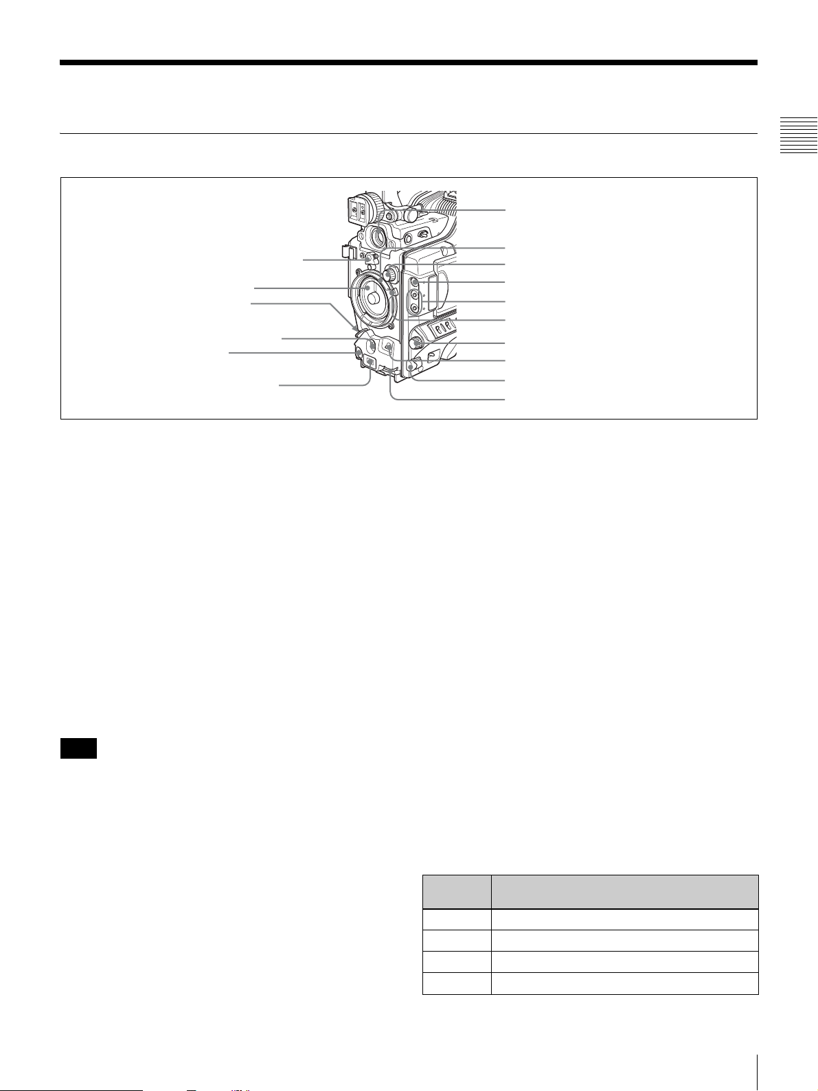
Front
1 Lens mount securing rubber
2 Lens mount cap
3 LENS connector
4 AUTO W/B BAL switch
5 REC button
6 Auto focus ranging
sensor
a Lens mount securing rubber
After locking the lens in position using the lens locking
lever, fit this rubber over the lower of the two projections.
This fixes the lens mount, preventing it from coming loose.
b Lens mount cap
Remove by pushing up the lens locking lever (see page
14). When no lens is mounted, keep this cap fitted for
protection from dust.
c LENS connector (12-pin)
Connect the lens cable mainly for using a
lens. (This connector is not used for a
which is connected by the hot shoe inside the lens mount.)
Consult your Sony dealer when you are using a lens other
than VCL-719BXS (supplied with the PDW-F330K).
Note
2
/3-inch type
1
/2-inch type lens,
Chapter 1 Overview
7 VF connector
8 Lens mount
9 FILTER selector
0 ZEBRA button
qa ASSIGN 1/2 switches
qs Lens locking lever
qd MENU knob
qf SHUTTER switch
qg Remote commander receptor
qh AUDIO LEVEL knob
e REC (recording start) button
Press to start recording. Press it again to stop recording.
The effect is the same as that of the REC button on the
supplied lens. When the REC SWITCH function is
assigned to an ASSIGN switch on the ASSIGNABLE page
of the OPERATION menu, you can use the switch as the
REC button.
f Auto focus ranging sensor
When an VCL-719BXS (supplied with the PDW-F330K)
auto focus lens is mounted, this measures the distance to
the subject, and automatically focuses the lens.
This sensor is provided as an auxiliary function for
improving the automatic focusing speed. Even if this
sensor is blocked, the focusing precision will not be
affected.
g VF (viewfinder) connector (20-pin)
Connect the supplied viewfinder.
When mounting or removing the lens on this unit, power
off this unit first.
d AUTO W/B BAL (automatic white/black balance
adjustment) switch
Activates the automatic white/black balance adjustment
functions.
WHT: Adjusts the white balance automatically. If the
WHITE BAL switch (see page 16) is set to A or B, the
white balance setting is stored in the corresponding
memory. If the WHITE BAL switch is set to PRST,
the automatic white balance adjustment function does
not operate.
BLK: Adjusts the black set and black balance
automatically.
h Lens mount (special bayonet mount)
Attach the lens.
i FILTER selector
Selects from the four neutral density (ND) filters built into
this unit.
Position
number
1 CLEAR
2
3
4
ND filter
1
/4 ND (attenuates light to approximately 1/4)
1
/16 ND (attenuates light to approximately 1/16)
1/
64 ND (attenuates light to approximately
Location and Function of Parts
1
/64)
13

Normally set this to 1 (CLEAR).
For shooting with the lens iris wide open for reduced depth
of field, or when the subject is too brightly lit and the auto
iris function does not operate correctly, select an
appropriate position.
When this selector is used with the menu item for filter
Chapter 1 Overview
selection display set to ON (see page 137), the new setting
appears on the viewfinder screen for about 3 seconds.
You can change a MAINTENANCE menu setting so that
different white balance settings can be stored for different
FILTER selector positions. This allows you to
automatically obtain optimum white balance for the
current shooting conditions in linkage with the filter
selection.
For details, see “To adjust the white balance” (page 60).
j ZEBRA button
Press to display a zebra pattern (diagonal stripes) in the
viewfinder screen.
The zebra pattern is factory set to indicate picture areas
where the video level is approximately 70%. However, on
the VF SETTING page of the OPERATION menu, you
can change the setting so that areas where the video level
is 100% and above are also indicated at the same time. In
addition, you can also change the video level for
displaying the zebra pattern in the range from 30% to
107%.
n SHUTTER switch
Set to ON to use the electronic shutter. Flick to SEL to
switch the shutter speed or shutter mode setting within the
range previously set with the menu. When this switch is
operated, the new setting appears on the setting change/
adjustment progress message display area for about 3
seconds.
For details about the shutter speed and shutter mode
settings, see “Setting the Electronic Shutter” on page 62.
o Remote commander receptor
Press the ASSIGN switch which is assigned to enable/
disable the remote commander function, and then aim the
supplied infrared remote commander at this receptor.
Note
To prevent misoperation, the remote commander function
is disabled when the camcorder is powered on. To use the
infrared remote commander, it is necessary to assign the
remote commander enabling/disabling function to an
ASSIGN switch, and then press the ASSIGN switch to
enable the remote commander. (This function is factory
preset to the ASSIGN 2 switch.)
For details of how to assign a particular function to an
ASSIGN switch, see page 142.
For details, see “Setting the Viewfinder Screen Display”
on page 138.
k ASSIGN 1/2 switches
You can assign the desired functions to each of the
ASSIGN 1 and ASSIGN 2 switches on the ASSIGNABLE
page of the OPERATION menu.
The following functions are factory preset to the switches.
Switch Function
ASSIGN 1 EZ MODE (EZ mode ON/OFF)
ASSIGN 2 IR REMOTE (infrared remote commander
enabled/disabled)
For details, see “Assigning Functions to ASSIGN
Switches” on page 142.
l Lens locking lever
After inserting the lens in the lens mount, rotate the lens
mount ring with this lever to lock the lens in position.
After locking the lens, be sure to use the lens mount
securing rubber to prevent the lens from becoming
detached.
m MENU knob
Changes the page selection or a setting within the menu.
p AUDIO LEVEL knob
Adjusts the input level of audio channels 1and 2.
You can disable this knob by setting the AUDIO CH1
LEVEL and AUDIO CH2 LEVEL items on the AUDIO-1
page of the MAINTENANCE menu. (The knob is factory
preset so that it is enabled.)
For details about how to use the MENU knob, see “Basic
Menu Operations” on page 131.
14
Location and Function of Parts
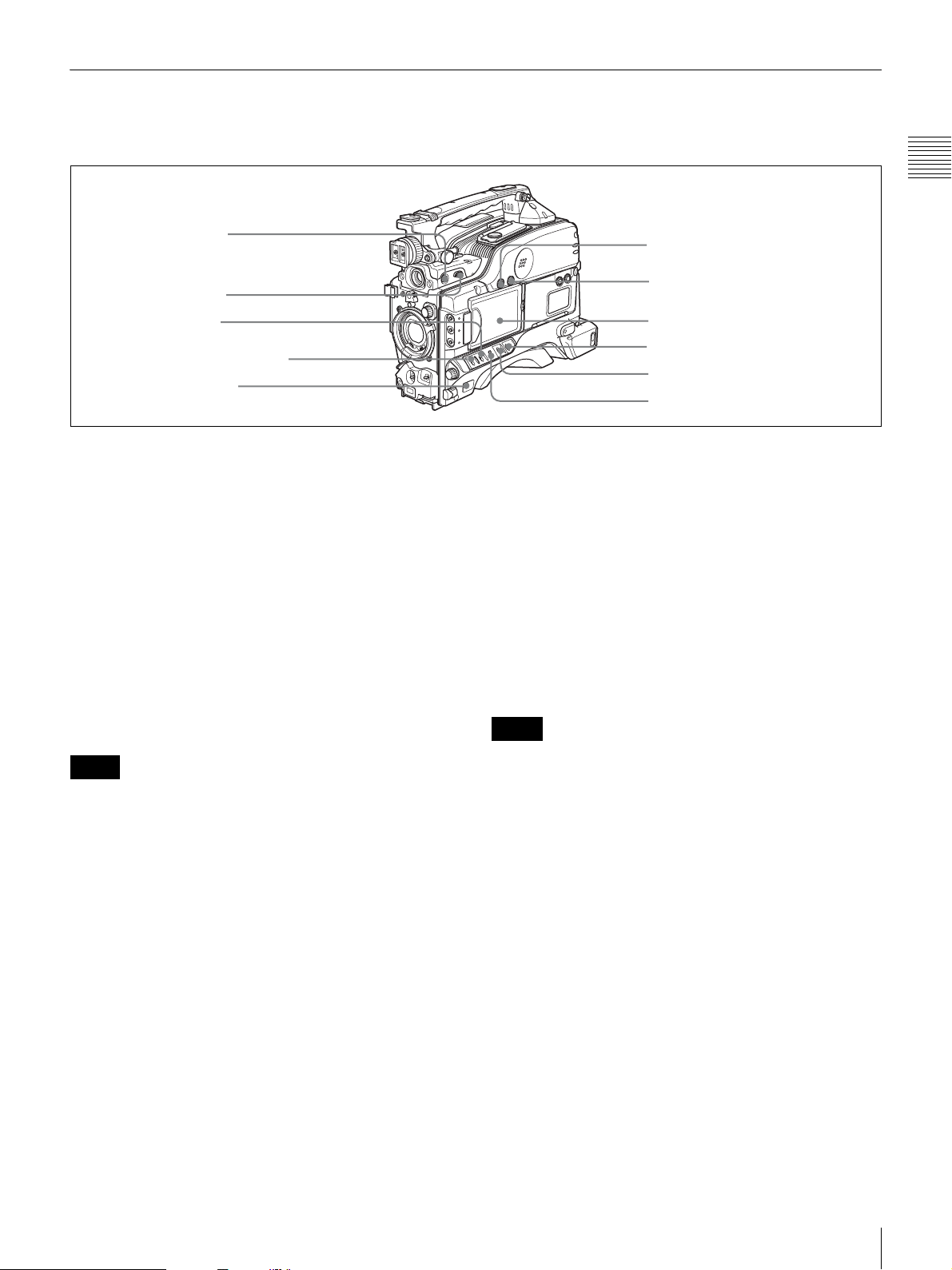
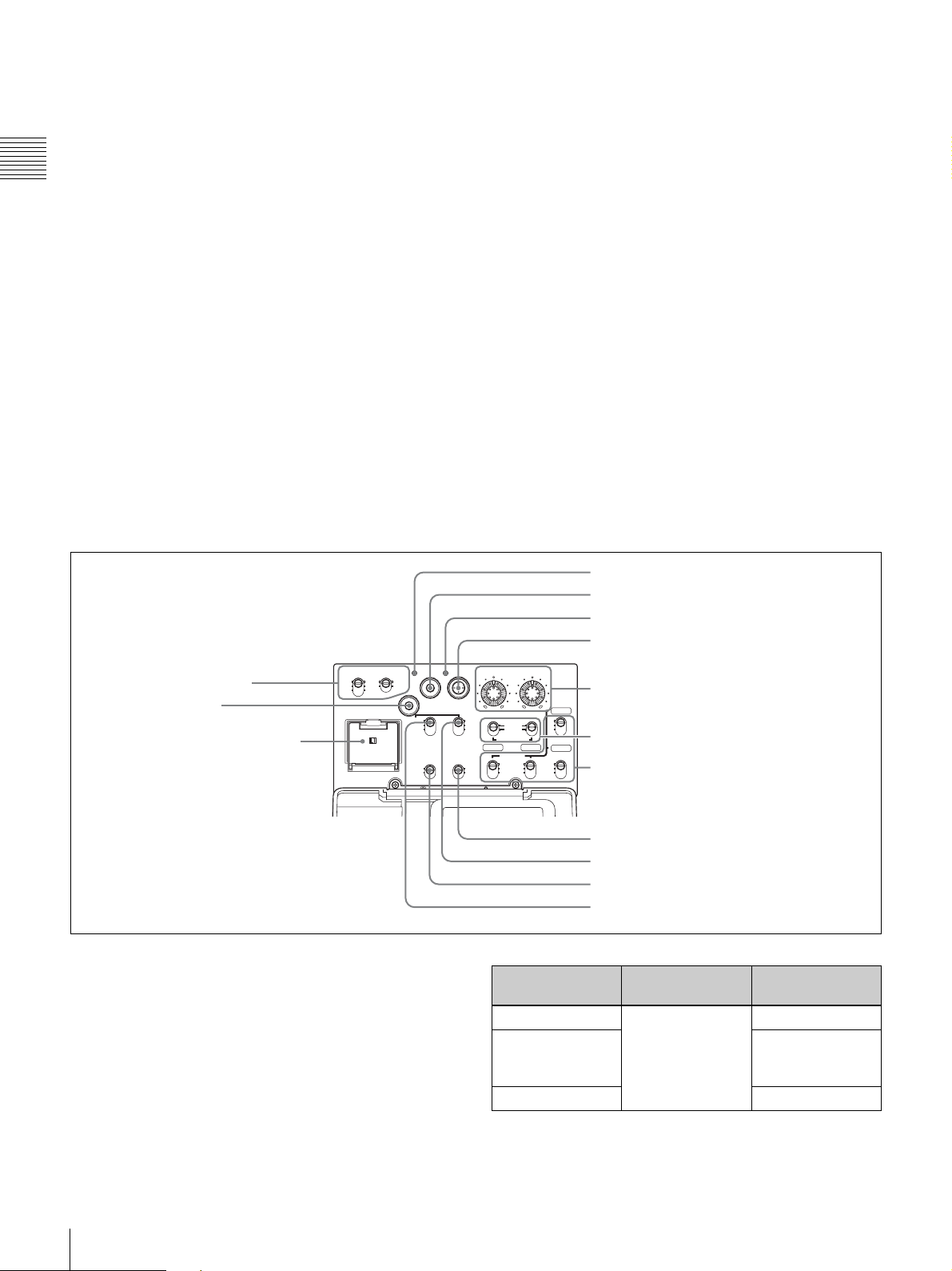
Right Side
Near the front
Chapter 1 Overview
1 5600K button
2 LIGHT switch
3 GAIN switch
4 VDR SAVE/STBY switch
5 POWER switch
a 5600K button
Press to light the button and switch the standard color
temperature for shooting to 5600K. Use this button for
outdoor shooting in daytime or shooting under lighting
with higher temperature. This button is effective only
when the WHITE BAL switch is set to PRST.
b LIGHT switch
Determines how a video light connected to the LIGHT
connector (see page 23) is turned on and off.
AUTO: When the POWER switch of the video light is in
the on position, the video light is turned on
automatically while the camcorder is recording.
MAN: You can turn the video light on or off manually,
using its own switch.
6 MONITOR knob
7 ALARM knob
8 LCD monitor
9 MENU switch
0 WHITE BAL switch
qa OUTPUT/DCC switch
For details, see “Setting Gain Values for the GAIN Switch
Positions” on page 140.
d VDR SAVE/STBY (VDR save/standby) switch
Switches the status of the power supply to the VDR while
recording is paused (REC PAUSE).
SAVE: At the start of recording, an internal operating
sound may be recorded. There is a small delay from
pressing the REC button until recording starts, since
the power consumption is less than in the standby
state.
STBY: When the REC button is pressed, recording starts
immediately.
Notes
Notes
• When this switch is set to AUTO, at the beginning of the
recording, the picture is recorded even though the
lighting may fluctuate until the video light comes on. If
the beginning of the recording is important, you should
set this switch to MAN. However, when using the
interval recording mode, the video light is automatically
turned on immediately before recording starts.
• To ensure proper operation of the video light, Sony
recommends the use of the BP-GL95 Battery Pack with
the camcorder.
c GAIN switch
Switches the gain of the video amplifier to match the
lighting conditions during shooting. The gains
corresponding to the L, M, and H settings can be selected
in the menu. (The factory settings are L = 0 dB, M = 9 dB,
and H = 18 dB.)
When this switch is adjusted, the new setting appears on
the setting change/adjustment progress message display
area of the viewfinder screen for about 3 seconds.
• Even if the switch is on the SAVE side, the unit exits
SAVE (power saving) mode and enters STBY (standby)
mode whenever you exit REC PAUSE mode by carrying
out playback to check the recorded video or by
displaying the thumbnail screen (page 82). To put the
unit into SAVE mode again, put the unit into REC
PAUSE mode again after recording, or power the unit
off and on again.
• An internal operating sound may be recorded at the start
of recording when the VDR SAVE/STBY switch is set
to SAVE.
e POWER switch
Turns the main power supply on and off.
f MONITOR (monitor volume adjustment) knob
Controls the volume of the sound other than the warning
tone that is output via the built-in speaker or optional
earphones. When the knob is turned to the minimum
setting, no sound can be heard.
Location and Function of Parts
15
g ALARM (alarm tone volume adjustment) knob
Controls the volume of the warning tone that is output via
the built-in speaker or optional earphones. When the knob
is turned to the minimum position, no sound can be heard.
ALA RM
Chapter 1 Overview
is activated. When this switch is adjusted, the new
setting appears on the setting change/adjustment
progress message display area of the viewfinder
screen for about 3 seconds. You can assign the ATW
function to an ASSIGN switch on the ASSIGNABLE
page of the OPERATION menu.
Minimum Maximum
h LCD monitor
Displays camera video, VDR-related warnings, remaining
battery capacity, remaining disc space, audio levels, time
data, and so on.
For details, see “Status Display on the LCD Monitor” on
page 17.
i MENU switch
When flicking toward ON, the menu is displayed. When
flicking toward STATUS, the status of the camcorder (of
current settings) is displayed.
For details, see “Displaying Menus” on page 131.
j WHITE BAL (white balance memory) switch
Controls adjustment of the white balance.
PRST: Adjusts the color temperature to the preset value
(the factory default setting: 3200K). Use this setting
when you have no time to adjust the white balance.
A or B: Recall the white balance adjustment settings
already stored in A or B.
Press the AUTO W/B BAL switch (see page 13) on
the WHT side, to automatically adjust the white
balance, and save the adjustment settings in memory
A or memory B. The 5600K button does not function.
You can use the AUTO W/B BAL switch even when
1)
ATW
is in use.
B (ATW): When this switch is set to B and WHITE
SWITCH <B> is set to ATW on the WHITE
SETTING page of the MAINTENANCE menu, ATW
For details about how to assign the function to an ASSIGN
switch, see “Assigning Functions to ASSIGN Switches” on
page 142.
1) ATW (Auto Tracing White Balance): The white balance of the picture
being shot is adjusted automatically for varying lighting conditions.
k OUTPUT/DCC (output signal/dynamic contrast
control) switch
Switches the video signal, which is output to the video disc
drive (referred to as “VDR”), viewfinder, and video
monitor from the camera section, between the following
two.
BARS: Outputs the color bar signal.
CAM: Outputs the video signal from the camera. When
this is selected, you can switch DCC
1) DCC (Dynamic Contrast Control): Against a very bright background
with the iris opening adjusted to the subject, objects in the background will
be lost in the glare. The DCC function will suppress the high intensity and
restore much of the lost detail and is particularly effective in the following
cases.
• Shooting people in the shade on a sunny day
• Shooting a subject indoors, against a background through a window
• Any high contrast scene
OUTPUT: BARS, DCC: OFF
A color bar signal is output and the DCC circuit does not
operate. Use this setting to adjust the video monitor, to
record the color bar signal, etc.
OUTPUT: CAM, DCC: OFF
OUTPUT
DCC
The video signal from the camera is output, and
the DCC circuit does not operate.
CAMBARS
OUTPUT: CAM, DCC: ON
The video signal from the camera is output, and
the DCC circuit operates.
ONOFF
1)
on and off.
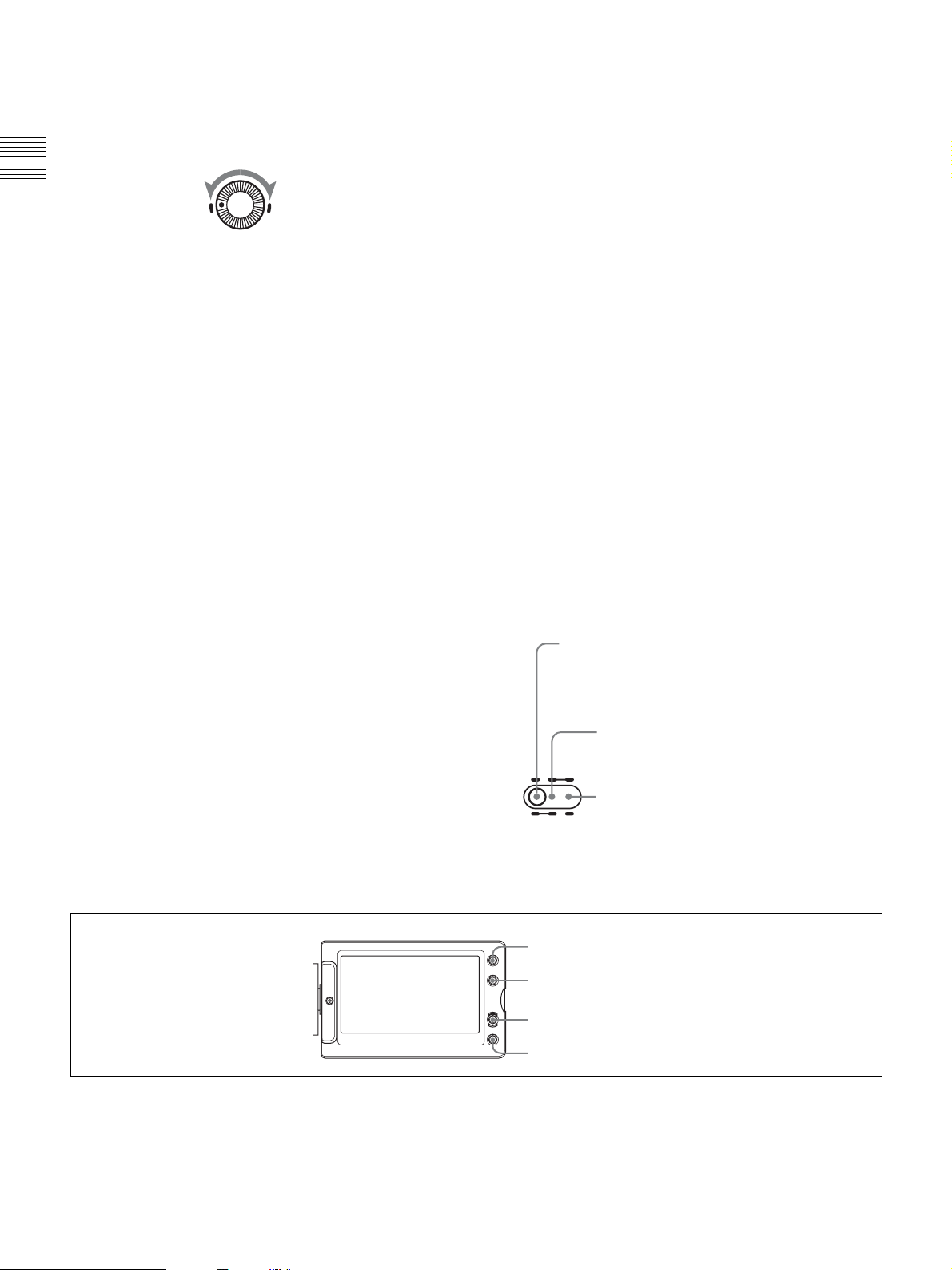
LCD monitor operating buttons
a DISPLAY/EXPAND button
Each time pressing this button, the display in the LCD
monitor changes as follows.
16
Location and Function of Parts
1 DISPLAY/EXPAND button
2 COUNTER/CHAPTER button
3 RESET button
4 BRIGHT button
Display indication Meaning
Video with
superimposed
information
Video without
superimposed
information
Status display Counter indications, warnings, audio
When the MENU switch is flicked
toward STATUS, the principal settings
of this unit appear as on the
viewfinder screen.
The video only appears.
levels, and similar information
appears. No video image appears.
Settings of buttons and
switches
COUNTER/CHAPTER button:
TC
PRESET/REGEN/CLOCK
switch: PRESET
F-RUN/SET/R-RUN switch: SET
COUNTER/CHAPTER button:
U-BIT
PRESET/REGEN/CLOCK
switch: PRESET
F-RUN/SET/R-RUN switch: SET
To reset
Timecode to 00:00:00:00
a)
User bits data
b)
00 00
to 00 00
Chapter 1 Overview
If you press this button when the thumbnail screen is
displayed, the duration of the selected clip is divided into
12, and the first frame of each of the divisions is shown in
a further thumbnail display (expand function). Each time
you press the button, the division is repeated (to a
maximum of three times, with 1728 divisions). Hold down
the SHIFT button and press this button to step back
through the division process.
For details of the expand function, see page 85.
b COUNTER/CHAPTER (counter display toggle/
chapter) button
Each time this button is pressed, the counter display
section changes as follows. This setting is activated only
when the LCD monitor display is set to STATUS with the
DISPLAY/EXPAND button.
COUNTER: Displays the elapsed recording/playback
time.
TC: Displays timecode.
U-BIT: Displays user bits data.
If you press this button when the thumbnail screen is
displayed, those frames on which essence marks are
recorded appear in a list (chapter function). Press the
button once more to return to the normal thumbnail
display.
By displaying thumbnails with essence marks attached in
place of index frames, you can check the contents of clips
more easily and more quickly. This is also useful for
cueing up long clips.
For details of the chapter function, see page 85.
a) Of the timecode bits for every frame recorded on the disc, those bits which
can be used to record useful information for the user such as scene number,
shooting place, etc.
b) Can only be reset when the display is set to STATUS. When it is set to
CHAR, resetting is not possible.
For details, see “Setting the Time Data” on page 66.
If you press this button when thumbnails of frames with
essence marks are displayed using the COUNTER/
CHAPTER button, or when thumbnails of clip divisions
are displayed using the DISPLAY/EXPAND button, then
the display returns to the normal thumbnail display.
d BRIGHT (brightness) button
Sets the backlight brightness. Each time you press this
button, the backlight brightness cycles through the
following four levels:
H: Select this to view the LCD monitor in outdoor
daylight.
M: Brightness level between H and L.
L: Select this to view the LCD monitor indoors or outside
at night.
OFF: Turn the backlight off (you can view video under
normal lighting). Select this in outdoor daylight when
the LCD monitor screen is subjected to direct
sunlight.
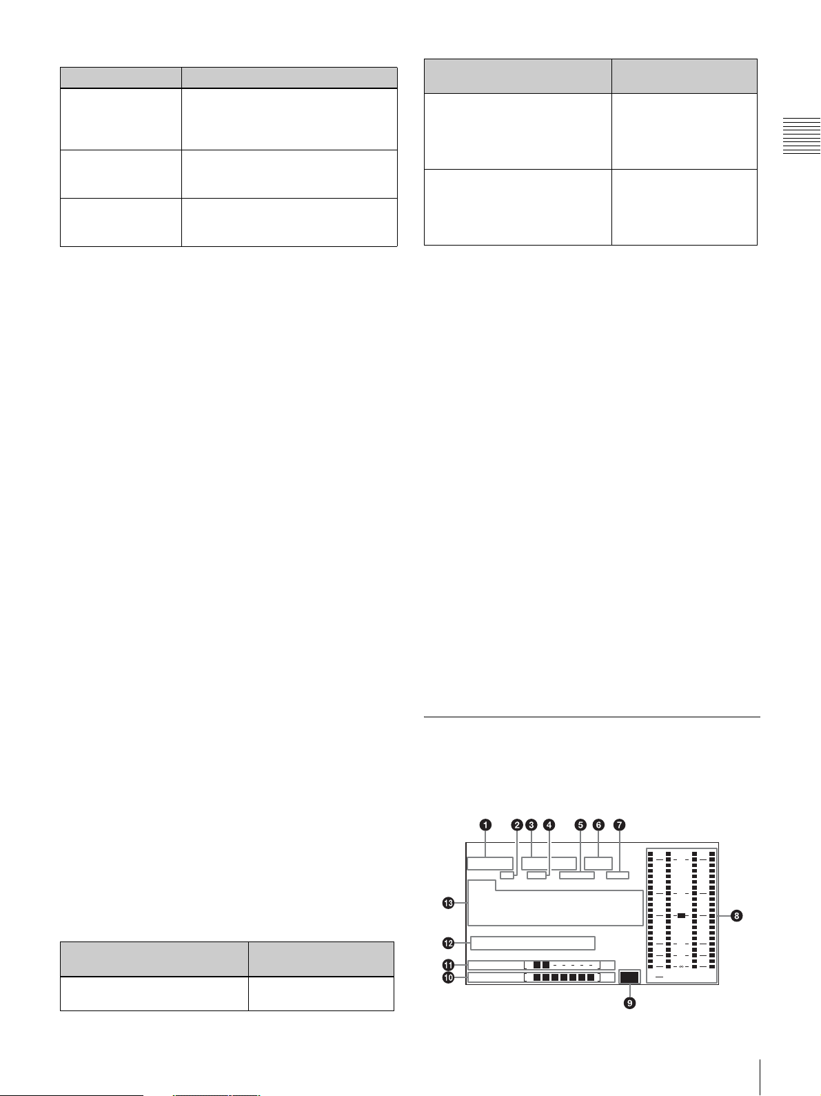
Status Display on the LCD Monitor
The following display appears when the LCD monitor
display is set to STATUS with the DISPLAY/EXPAND
button.
c RESET button
Resets the display of the time data when the LCD monitor
display is set to STATUS or CHAR with the DISPLAY/
EXPAND button. According to the settings of the
PRESET/REGEN/CLOCK switch (see page 22) and the
F-RUN/SET/R-RUN switch (see page 22), this button
resets the display as follows.
Settings of buttons and
switches
COUNTER/CHAPTER button:
COUNTER
To reset
Counter to 0:00:00:00
H D S P
T C G
01 : 23 : 4 5 15:
W A R N I N G : H U M I D
D I S C E B
B A T T E F Li
2 3 . 9 8 P 4 c h
P B N D F EX T - L K21H O L D
H
M I N S E C F R M
Location and Function of Parts
O V E R
0
2
d B
ST
P E U K
43
17
a Video format
Indicates the format of video being currently played back
or recorded.
HD HQ: HQ (high quality) mode in the MPEG HD video
format
HD SP: SP (standard play) mode in the MPEG HD video
Chapter 1 Overview
format
HD LP: LP (long play) mode in the MPEG HD video
format
DVCAM: DVCAM format
b Playback indicator
Appears during playback.
c Camera scan mode indicator
Indicates the camera scan mode of video being currently
played back or recorded.
• If NTSC AREA is selected
1)
60I: 59.94 fields per second, interlace scan mode
30P: 29.97 frames per second, progressive scan mode
23.98P: 23.98 frames per second, progressive scan mode
(converted to 60i at 2-3 pulldown)
• If PAL AREA is selected
1)
50I: 50 fields per second, interlace scan mode
25P: 25 frames per second, progressive scan mode
1) COUNTRY setting on the FORMAT page of the OPERATION menu (see
page 111).
Note
There may be no indication displayed when this unit
cannot identify the camera scan mode, for example, when
playing back a disc recorded with other equipment.
d Non-drop-frame mode indicator
Appears when non-drop-frame timecode is selected.
e External synchronization indicator
Appears when the internal timecode generator is locked to
an external signal input to the TC IN connector
1) For the PDW-F350. For the PDW-F330, the TC connector (IN/OUT
switch set to IN).
f Audio channel display
Shows the audio channel mode during recording or
playback.
2ch: two-channel mode (only when the MPEG HD format
is selected)
4ch: four-channel mode
g Hold indicator
Appears when the internal timecode generator is stopped.
h Audio level indicators
Indicates the audio recording or playback levels of
channels 1 to 4.
1)
i Lithium battery low voltage warning
Appears when the voltage of the internal lithium backup
battery (CR2032) is low. If this indication appears, replace
the lithium battery immediately (see page 36).
j Remaining battery capacity indicator
Indication Battery voltage
BP-L90A/L60S/
L80S
BATT E [ ■■■■■■■ ] F 15.5 V or more 17.0 V or more
BATT E [ ■■■■■■ ] F 15.1 to 15.5 V 16.0 to 17.0 V
BATT E [ ■■■■■ ] F 14.6 to 15.1 V 15.0 to 16.0 V
BATT E [ ■■■■ ] F 13.8 to 14.6 V 14.0 to 15.0 V
BATT E [ ■■■ ] F 12.9 to 13.8 V 13.0 to 14.0 V
BATT E [ ■■ ] F 12.0 to 12.9 V 12.0 to 13.0 V
BATT E [ ■ ] F 10.8 to 12.0 V 11.0 to 12.0 V
BATT E [ ] F 10.8 V or less 11.0 V or less
Indication Battery voltage
BP-GL95/GL65/IL75/
M100, Anton Bauer
Battery System
BATT E [ ■■■■■■■ ] F 80 to 100%
BATT E [ ■■■■■■■ ] 70%
BATT E [ ■■■■■■ ] 60%
BATT E [ ■■■■■ ] 50%
BATT E [ ■■■■ ] 40%
BATT E [ ■■■ ] 30%
BATT E [ ■■ ] 20%
BATT E [ ■ ] 10%
BATT E [ ] 0%
Other
batteries
k Remaining disc capacity indicator
Indication Remaining recording
.
DISC E [ ■■■■■■■ ] B 30 minutes
DISC E [ ■■■■■■ ] B 25 to 30 minutes
DISC E [ ■■■■■ ] B 20 to 25 minutes
DISC E [ ■■■■ ] B 15 to 20 minutes
DISC E [ ■■■ ] B 10 to 15 minutes
DISC E [ ■■ ] B 5 to 10 minutes
DISC E [ ■ ] B 2 to 5 minutes
DISC E [ ■ ] B (flashing) 0 to 2 minutes
DISC E [ ] B (flashing) 0 minutes
time
l Warning indicator area
Displays warnings when trouble with recording or
moisture condensation occurs.
For details, see “Operation Warnings” on page 165.
18
Location and Function of Parts
m Time counter display
Each press of the COUNTER/CHAPTER button cycles
through displays of timecode, user bits, and counter
information. You can display the date or time using the
four-way arrow key on the side control panel.
TCG: Value of timecode generator
TCR: Value of timecode reader
UBG: Value of user bits generator
UBR: Value of user bits reader
Near the rear
CNT: Counter information
CLK: Time by the internal clock
TCG and UBG can be displayed when the disc is stopped
and during recording, and TCR and UBR are displayed
during playback.
CLK appears when the COUNTER/CHAPTER button has
been pressed to display TC, and the PRESET/REGEN/
CLOCK switch is set to CLOCK.
1 WARNING indicator
2 ACCESS indicator
3 Built-in speaker
4 Protection cover of the side control panel
5 EARPHONE jack
Chapter 1 Overview
F REC
EJECT
Z
PLAY/PAUSE
m.NX
PREC
STOP NEXT
x >
a WARNING indicator
Lights up or flashes when an abnormality occurs in the
VDR section.
For details about the meaning of the states of the
WARNING indicator, see “Operation Warnings” on
page 165.
b ACCESS indicator
This lights when data is written to or read from the disc.
c Built-in speaker
The speaker can be used to monitor E-E
1)
sound during
recording, and playback sound during playback. The
speaker also sounds alarms to reinforce visual warnings.
If you connect earphones to the EARPHONE jack, the
speaker output is suppressed automatically.
6 EJECT button and indicator
7 F REV button and indicator
8 PLAY/PAUSE button and indicator
F FWD
M
9 F FWD button and indicator
0 NEXT button
qa STOP button
qs PREV button
1) E-E: Abbreviation of “Electric-to-Electric”. In E-E mode, video and audio
signals input to the camcorder are output after passing through internal
electric circuits only. This can be used to check input signals.
For details about alarms, see “Operation Warnings” on
page 165.
d Protection cover of the side control panel
Open to access the side control panel (see page 20).
e EARPHONE jack
By plugging earphones, you can monitor the E-E sound
during recording and playback sound during playback.
When an alarm is indicated, you can hear the alarm sound
through the earphones. Plugging earphones into the jack
automatically cuts off the sound from the built-in speaker.
You can select monaural or stereo on the AUDIO-2 page
of the MAINTENANCE menu.
Location and Function of Parts
19
f EJECT button and indicator
Press this button to insert a disc or eject the disc. The
indicator flashes while the disc is being ejected.
g F REV (fast reverse) button and indicator
This plays back at high speed in the reverse direction. The
Chapter 1 Overview
indicator lights during high-speed playback in the reverse
direction.
h PLAY/PAUSE button and indicator
Press this button to view play back video images using the
viewfinder screen or a color video monitor. The indicator
lights during playback.
Press this button again during playback to pause,
outputting a still image. At this time the indicator flashes.
This unit is equipped with a color search function at
approximately four times normal playback speed, for easy
checking of recorded material. To use the color search
function at approximately four times normal playback
speed, press the F REV button or F FWD button during
playback.
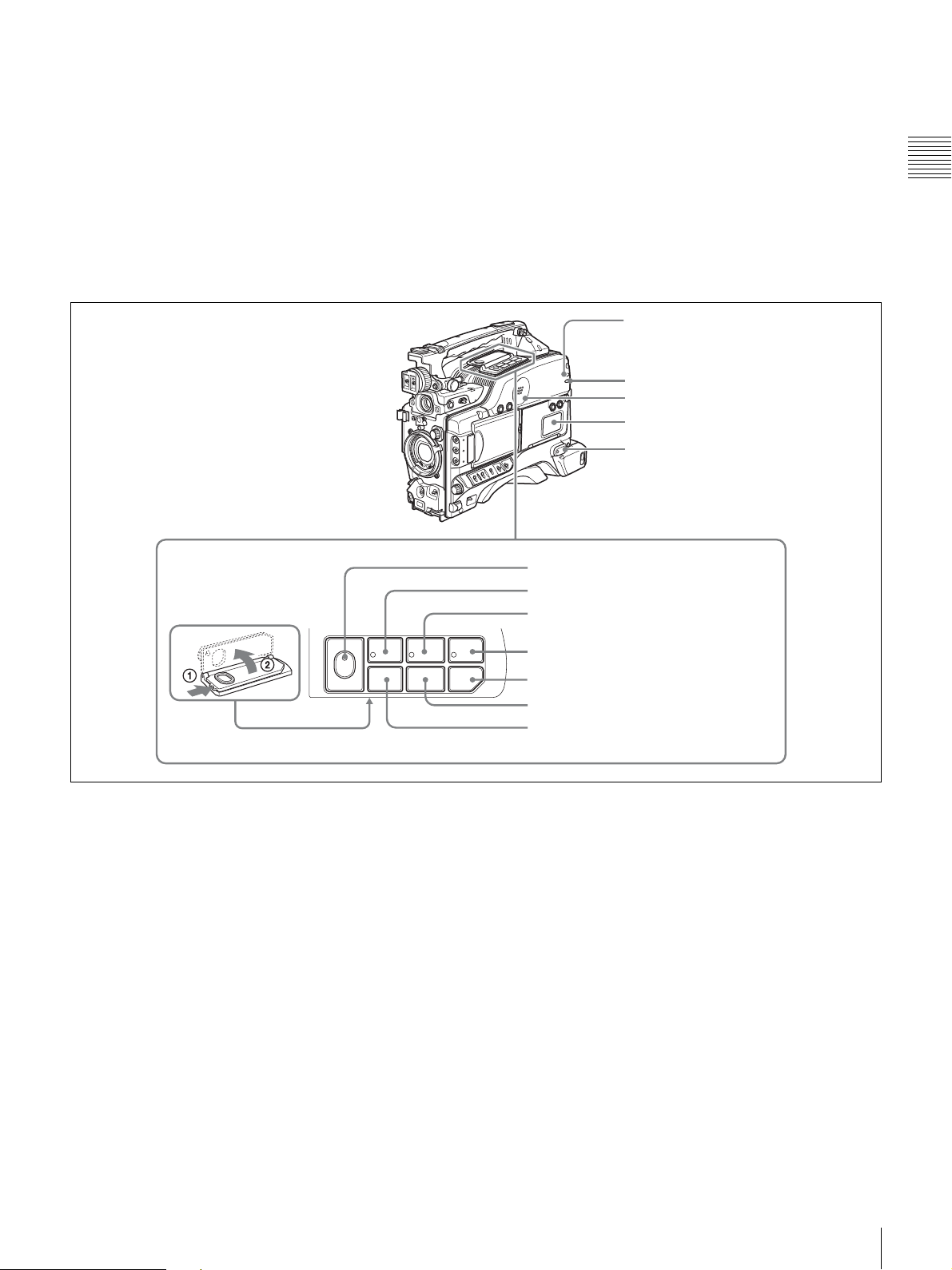
Side control panel (inside the protection cover)
At this time the PLAY indicator and F REV or F FWD
indicator light.
i F FWD (fast forward) button and indicator
This plays back at high speed in the forward direction. The
indicator lights during high-speed playback in the forward
direction.
j NEXT button
This jumps to the start of the next clip, then pauses. During
the jump, the F FWD indicator flashes. If you press this
together with the F FWD button, the jump is to the last
frame of the last recorded clip on the disc.
k STOP button
Press this to stop disc playback.
l PREV (previous) button
This jumps to the start of the current clip, then pauses.
During the jump, the F REV indicator flashes. If you press
this together with the F REV button, the jump is to the start
of the first recorded clip on the disc.
1 MONITOR switches
2 SHIFT button
3 Lithium battery compartment
CH-1
MIX
CH-2
LITHIUM BATT
MONITOR
CH-3
MIX
CH-4
SHIFT
CH-1/2
CH-3/4
PRESET
REGEN
CLOCK
OFF
ON
THUMBNAIL
ESSENCE
MARK
FRONT MIC
LOW CUT
a MONITOR (audio monitor selection) switches
By means of combinations of the two switches, you can
select audio that you want to hear through the built-in
speaker or optional earphones.
SUB CLIP
CLIP MENU
SEL/SET
VIDEO OUT
CHARACTER
F-RUN
SET
R-RUN
ON
OFF
4 THUMBNAIL indicator
5 THUMBNAIL button
6 SUB CLIP indicator
7 SEL/SET button
(four-way arrow key)
AUDIO LEVEL
8 AUDIO LEVEL knobs
0 10 0 10
AUTO
MANUAL
AUDIO SELECT
CH-1
AUDIO IN
FRONT
WIRELESS
REAR
CH-2
CH-3
F
W
R
9 AUDIO SELECT switches
CH-4
F
0 AUDIO IN switches
W
R
qa VIDEO OUT CHARACTER switch
qs F-RUN/SET/R-RUN switch
qd FRONT MIC LOW CUT switch
qf PRESET/REGEN/CLOCK switch
Position of leftside switch
Position of rightside switch
Audio output
CH-1/CH-3 CH-1/2 Channel 1 audio
MIX Channels 1 and 2
mixed audio
(stereo)
a)
CH-2/CH-4 Channel 2 audio
20
Location and Function of Parts

Position of leftside switch
CH-1/CH-3 CH-3/4 Channel 3 audio
MIX Channels 3 and 4
CH-2/CH-4 Channel 4 audio
a) By connecting stereo headphones to the EARPHONE connector you can
hear the audio in stereo. (On the AUDIO-2 page of the MAINTENANCE
menu, HEADPHONE OUT must be set to “STEREO”.)
Position of rightside switch
Audio output
mixed audio
(stereo)
a)
thumbnail with the cursor, press the button centrally to
confirm.
This button is used for scene selection and other
operations.
For details of clip list playback operations, see page 86.
For details of the CLIP menu, see “Managing Clip Lists”
(page 100).
For details of scene selection, see page 90.
Chapter 1 Overview
b SHIFT button
Use this in combination with other buttons.
c Lithium battery compartment
Attach the supplied CR2032 lithium battery.
Details on how to attach the lithium battery, see
“Attaching and Replacing the Lithium Battery” on
page 35.
d THUMBNAIL indicator
This lights when thumbnails are displayed.
e THUMBNAIL button
Press this button to carry out a thumbnail search or create
a clip list.
When pressed, the whole-screen display changes to a
thumbnail display. Press once more to return to the wholescreen display.
For a thumbnail search using essence marks, hold down
the SHIFT button and press this button.
f SUB CLIP indicator
This lights when using a clip list for playback.
g SEL/SET (select/set) button (four-way arrow key)
Sets the timecode and user bits. Push the button towards
left or right so that the digit you want to change flashes.
Pushing the button upward increases the value of the
flashing digit, and pushing it downward decreases the
value.
Hold down the SHIFT button and press upward (in the
direction of the “SUB CLIP” legend) to display the clip
lists (when no clip list is loaded into the current clip list).
When a clip list is loaded, that clip list can be played back.
Hold down the SHIFT button and press upward once more
to exit the display of the clip lists or to exit the clip list
playback state.
Hold down the SHIFT button and press downward (in the
direction of the “CLIP MENU” legend) to display the
CLIP menu. Hold down the SHIFT button and press
downward once more to exit the CLIP menu.
When thumbnails (index frames of clips) are displayed on
the LCD monitor, you can use this button to select a
thumbnail. Push the button in four directions to move the
cursor up, down, left and right. After selecting the desired
h AUDIO LEVEL (CH-1/CH-2) (audio channel 1/2
recording level) knobs
If the audio is input via the AUDIO IN CH-1/CH-2
connectors, adjusts the audio levels of channels 1 and 2
when the AUDIO SELECT (CH-1/CH-2) switches (see
below) are set to MANUAL.
i AUDIO SELECT (CH-1/CH-2) (audio channel 1/2
adjustment method selection) switches
Select the audio level adjustment method for each of audio
channels 1 and 2.
AUTO: Automatic adjustment
MANUAL: Manual adjustment
j AUDIO IN (CH-1/CH-2/CH-3/CH-4) (audio
channel 1/2/3/4 input selection) switches
AUDIO IN CH-1/CH-2 switches
Select the audio input signals to be recorded on audio
channels 1 and 2.
FRONT: Input signals from the microphone connected to
the MIC IN connector
WIRELESS: Audio input signals from the CA-WR855
Camera Adaptor (supplied separately) if a WRR-855
series UHF synthesized tuner (supplied separately) is
installed using the CA-WR855
REAR: Audio input signals from an audio device
connected to the AUDIO IN CH-1/CH-2 connectors
AUDIO IN CH-3/CH-4 switches
Select the audio input signals to be recorded on audio
channels 3 and 4.
F (FRONT): Input signals from a microphone connected
to the MIC IN connector
W (WIRELESS): Audio input signals from the CA-
WR855 camera adaptor (supplied separately) if a
WRR-855 series UHF synthesized tuner (supplied
separately) is installed using the CA-WR855
R (REAR): Audio input signals from an audio device
connected to the AUDIO IN CH-1/CH-2 connectors
(The signal input to the AUDIO IN CH-1 connector is
recorded on channel 3, and the signal input to the
AUDIO IN CH-2 connector on channel 4.)
Location and Function of Parts
21
Note
For audio channels 3 and 4, level adjustment can only be
performed in AUTO (automatic) mode. The audio level of
these channels cannot be adjusted in MANUAL (manual)
mode.
Chapter 1 Overview
R-RUN: Timecode advances only during recording. Use
this setting to have a consecutive timecode on the
disc.
For details, see “To set the timecode” on page 66 and “To
set the user bits” on page 67.
k VIDEO OUT (video output) CHARACTER switch
Selects whether or not (ON/OFF) to superimpose text
information on the VIDEO OUT connector
1) For the PDW-F330, VIDEO OUT connector on the rear panel.
1)
output.
l F-RUN/SET/R-RUN (free run/set/recording run)
switch
Selects the operating mode of the internal timecode
generator. The operating mode is set as explained below,
depending on the position of the switch.
F-RUN: Timecode keeps advancing, regardless of the
operating state of the VDR. Use this setting when
synchronizing the timecode with an external
timecode.
SET: Sets the timecode or user bits.
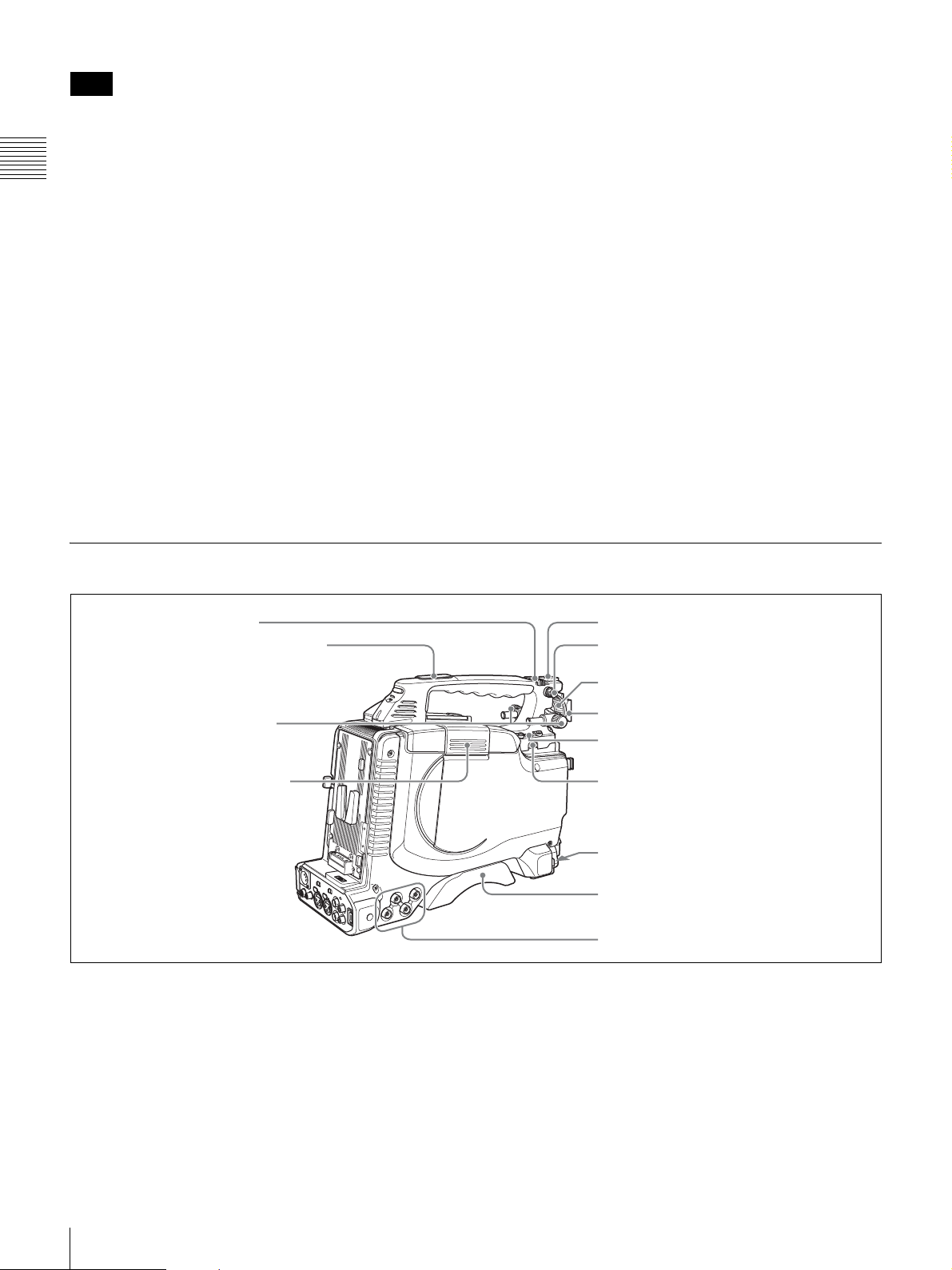
Left Side and Upper Section
1 ASSIGN 3/4 switches
2 Large viewfinder attachment shoe
m FRONT MIC LOW CUT switch
Set to ON to insert a high-pass filter in the microphone
circuit, reducing wind noise. Normally leave the switch in
the OFF position.
n PRESET/REGEN (regeneration)/CLOCK switch
Selects whether to set a new timecode or to utilize the
existing timecode.
PRESET: Records a new timecode.
REGEN: Records timecode continuous with the existing
timecode recorded on the disc. Regardless of the
setting of the F-RUN/SET/R-RUN switch, the
camcorder operates in R-RUN mode.
CLOCK: Records timecode synchronized to the internal
clock. Regardless of the setting of the F-RUN/SET/RRUN switch, the camcorder operates in F-RUN mode.
5 Accessory fitting shoe
6 Shoulder strap fitting
3 Viewfinder front-to-back
positioning knob
4 Lid of the disc compartment
a ASSIGN 3/4 switches
You can assign the desired functions to these switches on
the ASSIGNABLE page of the OPERATION menu.
For details, see “Assigning Functions to ASSIGN
Switches” on page 142.
b Large viewfinder attachment shoe
Use this to mount an optional 5-inch electronic viewfinder
(see page 43).
7 Viewfinder left-to-right positioning ring
8 Viewfinder fitting shoe
9 Fitting for optional microphone holder
0 LIGHT connector
qa MIC IN connector
qs Shoulder pad
1 Video output and timecode connectors
c Viewfinder front-to-back positioning knob
Loosen this knob to adjust the front-to-back position of the
viewfinder (see page 42).
d Lid of the disc compartment
This opens when the EJECT button on the top panel is
pressed. Press the side of the lid to close.
22
Location and Function of Parts
e Accessory fitting shoe
Attach an optional accessory such as a video light (see
page 45).
f Shoulder strap fitting
Attach the supplied shoulder strap (see page 44).
g Viewfinder left-to-right positioning ring
Loosen this ring to adjust the left-to-right position of the
viewfinder (see page 42).
h Viewfinder fitting shoe
Attach the supplied viewfinder.
i Fitting for optional microphone holder
Fit an optional CAC-12 Microphone Holder (see page 46).
j LIGHT (video light) connector (2-pin, female)
A video light with a maximum power consumption of 50
W, such as the Anton Bauer Ultralight 2 or equivalent can
be connected (see page 45).
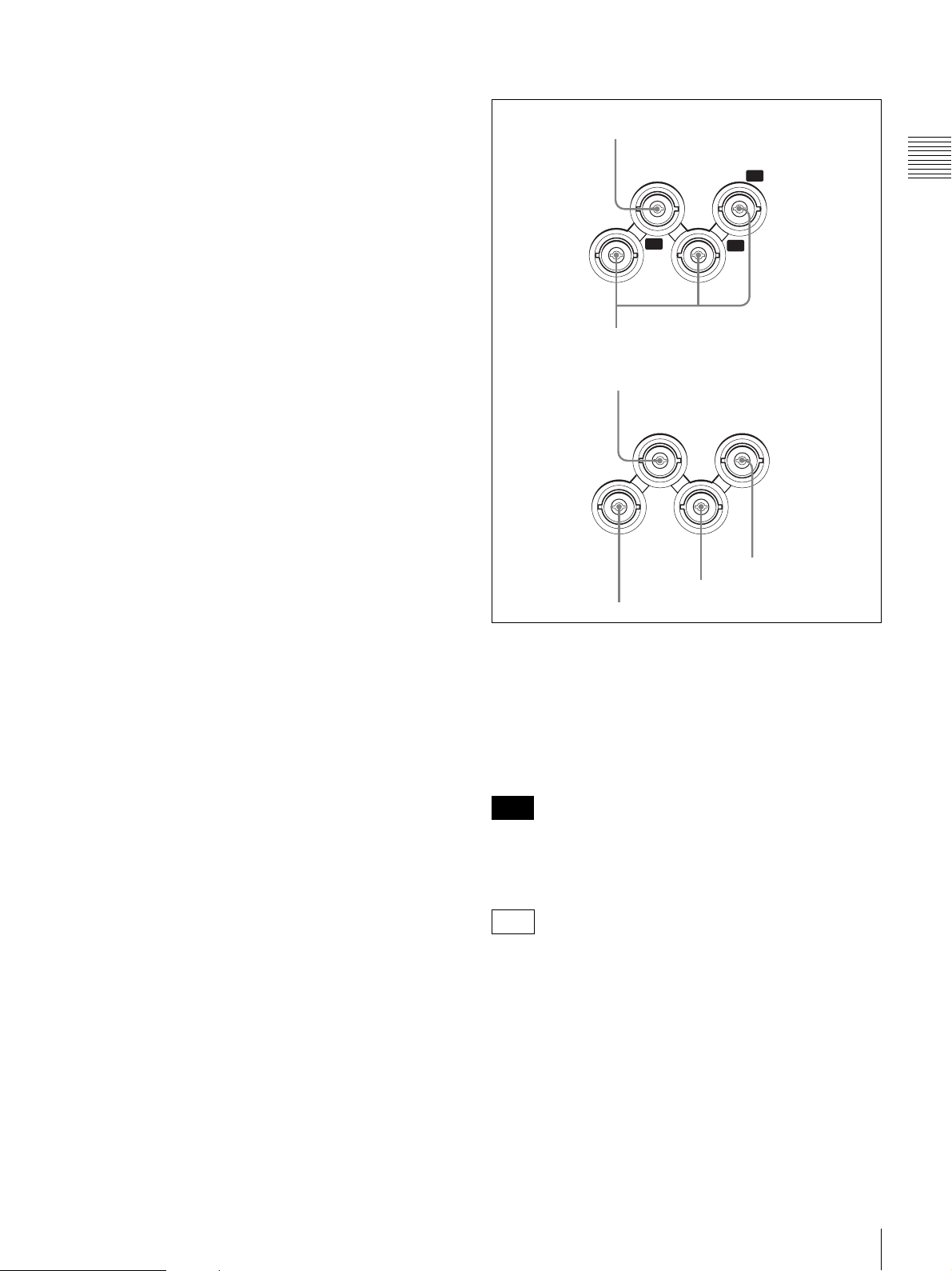
1 Video output and timecode connectors
PDW-F330
1 GENLOCK IN connector
PDW-F350
GENLOCK
IN
Y
VIDEO
OUT
2 VIDEO OUT Y/P
1 GENLOCK IN connector
GENLOCK
IN
P
B
P
R
B/PR connectors
TC IN
Chapter 1 Overview
k MIC IN (microphone input) (+48 V) connector
(XLR type, 5-pin, female)
Connect the supplied stereo microphone to this connector.
The power (+48 V) is supplied via this connector.
l Shoulder pad
Raise the shoulder pad fixing lever to adjust the position in
the front-to-rear direction. Adjust the position for
maximum convenience when operating the unit on your
shoulder.
For details of the adjustment, see “Adjusting the Shoulder
Pad Position” on page 44.
VIDEO
OUT
3 VIDEO OUT connector
TC
OUT
5 TC IN connector
4 TC OUT connector
a GENLOCK IN (genlock signal input) connector
(BNC type)
Input an SD or HD reference signal when applying a
genlock to the camera, or synchronizing timecode to an
external source. Use the GENLOCK page of the
MAINTENANCE menu to carry out phase adjustment of
the horizontal synchronization signal for genlock.
Note
The subcarrier phase cannot be adjusted.
b VIDEO OUT (video output) Y/P
B/PR connectors
(BNC type)
F330
Output component video signals (Y/P
B/PR) for a video
monitor.
Connect a video monitor with component video signal
input connectors to check the video being shot by the
camera. You can also monitor VDR playback video.
You can select HD Y/P
B/PR or SD Y/PB/PR signal output
on the OUTPUT page of the OPERATION menu. For
details, see “Selecting the Output Signals” on page 140.
Location and Function of Parts
23
Note
Even when you are recording or playing back HD 23.98P
signals, 23.98PsF signals are not output from this
connector. The output is 59.94i signals after 2-3 pulldown.
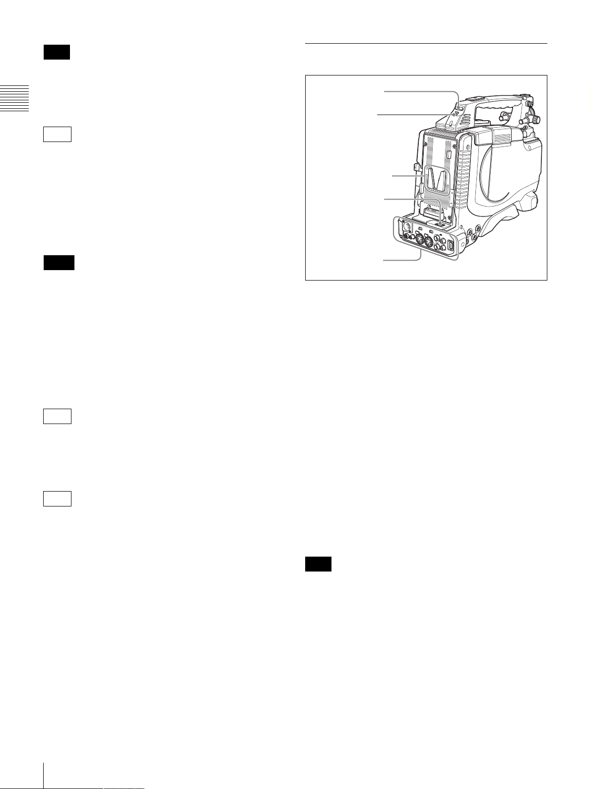
Rear
1 TALLY indicator
Chapter 1 Overview
c VIDEO OUT (video output) connector (BNC type)
F350
Outputs a video signal for a video monitor. The output
signal is composite or HD Y. When the output signal is
composite, setting menus, timecode, or shot data can be
superimposed on the camera output video depending on
the menu settings, and you can view them on the monitor
screen. To lock the timecode of an external device to the
timecode of this unit, connect the genlock signal input
connector of the external device to this connector.
Notes
• The subcarrier phase cannot be adjusted.
• Even when you are recording or playing back HD
23.98P signals, 23.98PsF signals are not output from this
connector. The output is 59.94i signals after 2-3
pulldown.
You can select the composite or HD Y signal output on the
OUTPUT page of the OPERATION menu. For details, see
“Selecting the Output Signals” on page 140.
d TC OUT (timecode output) connector (BNC type)
F350
2 TALLY switch
3 Battery attachment
shoe
4 WRR connector
1 Connector panel
!"##$%&'#$()*
a TALLY (back tally) indicator (red)
Lights up during recording. It will not light if the TALLY
switch (see below) is set to OFF. This indicator also flashes
to indicate warnings (see page 19) in the same manner as
the REC/TALLY indicator in the viewfinder.
For details, see “Operation Warnings” on page 165.
b TALLY switch
Set to ON to activate the TALLY indicator (see above)
function.
To lock the timecode of an external VTR to the timecode
of this unit, connect this connector to the external VTR’s
timecode input connector.
e TC IN (timecode input) connector (BNC type)
F350
To apply an external lock to the timecode of this unit, input
the reference timecode.
For details of timecode, see “To set the timecode” on
page 66.
c Battery attachment shoe
Attach a BP-GL95/GL65/L60S/L80S Battery Pack.
Alternatively, you can attach an AC-DN2B/DN10 AC
Adaptor to operate the camcorder on AC power supply.
For details about how to attach the battery or AC adaptor,
see “Preparing a Power Supply” on page 36. For
information about attaching a synthesized tuner, see
“Attaching a UHF Synthesized Tuner” on page 47.
Note
For your safety, and to ensure proper operation of the
camcorder, Sony recommends the use of the following
battery packs: BP-GL95, BP-GL65, BP-L60S, and BPL80S.
d WRR connector (7-pin)
Connect a CA-WR855 Camera Adaptor with attached
WRR-855 UHF Synthesized Tuner.
For details, see “Attaching a UHF Synthesized Tuner” on
page 47.
24
Location and Function of Parts
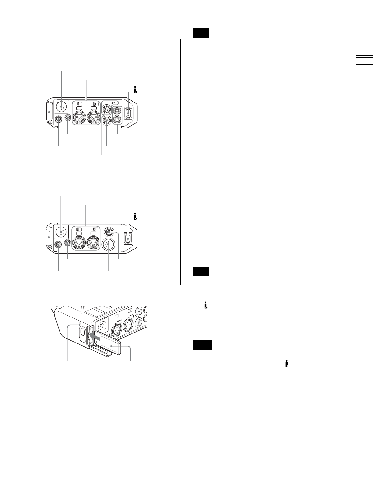
1 Connector panel
Note
PDW-F330
1 ”Memory Stick” slot
2 DC IN connector
3 AUDIO IN CH-1/CH-2 connectors and
input selection switches
6 DC OUT 12V
connector
5 REMOTE
connector
PDW-F350
1 “Memory Stick” slot
2 DC IN connector
3 AUDIO IN CH-1/CH-2 connectors and
input selection switches
6 DC OUT 12V
connector
5 REMOTE
connector
a “Memory Stick” slot
4 DV OUT S400
connector
9 AUDIO OUT CH-1/CH-2
connectors
8 VIDEO OUT connector
7 TC connector and IN/OUT
selector switch
4 DV OUT S400
connector
qa HDSDI OUT connector
0 AUDIO OUT connector
Do not remove a “Memory Stick” while the “Memory
Stick” access indicator is lit. Doing so may cause a loss of
data.
b DC IN (DC power input) connector (XLR type, 4-
pin, male)
To operate the camcorder using an AC power supply,
connect an AC-550 AC Adaptor with the DC output cable
supplied with the adaptor.
c AUDIO IN CH-1/CH-2 (audio input channel 1/2)
connectors (XLR type, 3-pin, female) and input
selection switches
Connect other audio equipment or external microphone.
Set the input selection switches as shown below according
to the microphone or equipment.
LINE (left position): For connecting an external audio
signal source such as a stereo amplifier
MIC (center position): For connecting any microphone
other than 48 V microphone
MIC +48V ON (right position): For connecting a 48 V
microphone
Signals input to the AUDIO IN CH-1 connector can be
recorded on audio channels 1 and 3. Similarly, signals
input to the AUDIO IN CH-2 connector can be recorded on
audio channels 2 and 4.
1) When the AUDIO IN (CH-1/CH-2/CH-3/CH-4) switches on the side
control panel are set to “REAR” or “R”.
Note
1)
If MIC +48V ON is selected for a microphone other than
48 V microphone, the microphone may be damaged.
d (i.LINK) DV OUT S400 connector (6-pin, IEEE
1394 compliant)
Connect to a device supporting the DV format or a
computer, using an i.LINK cable (DV cable).
Chapter 1 Overview
“Memory Stick”
access indicator
“Memory Stick”
Insert a “Memory Stick”. The “Memory Stick” access
indicator lights up when the “Memory Stick” is being
accessed for reading or writing.
For details about how to insert a “Memory Stick”, see “To
insert a “Memory Stick”” on page 146.
For details about the types of “Memory Stick”, see “About
a “Memory Stick”” on page 174.
Notes
• If video and audio signals are not output from the
external device connected to the (i.LINK) DV OUT
S400 connector, disconnect the i.LINK cable (DV cable)
and then reconnect it, making sure that it is firmly seated.
• When you connect the camcorder and other equipment,
such as a hard disk drive, with an i.LINK interface to a
computer with i.LINK connectors, turn off the power of
the computer, the other equipment, and the camcorder
before connecting them using the i.LINK cable (DV
cable). If a bus-powered type
1)
hard disk drive or similar
equipment is connected while the computer is powered
on, electric current flows into the camcorder because of
the high voltage caused by the load shift of the computer
power, and this may cause a malfunction.
Location and Function of Parts
25

1) Equipment that can be powered through i.LINK cable (DV cable)
j AUDIO OUT connector (XLR type, 5-pin, male)
e REMOTE connector (8-pin)
Connect an RM-B150/B750 Remote Control Unit, which
makes it possible to control the camcorder remotely.
Chapter 1 Overview
Note
Before connecting/disconnecting the Remote Control Unit
to/from the camcorder, be sure to turn off the camcorder
POWER switch.
f DC OUT 12V (DC power output) connector (4-pin,
female)
Supplies power for a WRR-861/862 UHF Synthesized
Tuner (optional) (maximum 0.2 A).
Do not connect any equipment other than the UHF
synthesized tuner.
g TC (timecode) connector (BNC type) and IN/OUT
selector switch
F330
• IN/OUT selector switch: IN
To apply an external lock to the timecode, input the
reference timecode.
• IN/OUT selector switch: OUT
To lock the timecode of an external VTR to the timecode
of this unit, connect this connector to the external VTR’s
timecode input connector.
F350
Output the audio signals recorded on audio channels 1 and
2 or audio channels 3 and 4. The audio signals are selected
by the MONITOR switch.
k HDSDI OUT connector (BNC type)
F350
Outputs an HDSDI signal (supporting the embedded audio
function).
Connect a video monitor with an HDSDI signal input
connector to check the video being shot by the camera.
You can also monitor VDR playback video.
Notes
• Even when you are recording or playing back HD
23.98P signals, 23.98PsF signals are not output from this
connector. The output is 59.94i signals after 2-3
pulldown.
• When the video recorded in the DVCAM format is
played back, no signal is output.
h VIDEO OUT connector (BNC type)
F330
Outputs a video signal for a video monitor. When the
output signal is composite, setting menus, timecode, or
shot data can be superimposed on the camera output video
depending on the menu settings, and you can view them on
the monitor screen. To lock the timecode of an external
device to the timecode of this unit, connect the genlock
signal input connector of the external device to this
connector.
Note
The subcarrier phase cannot be adjusted.
i AUDIO OUT CH-1/CH-2 (audio output channel 1/
2) connectors (RCA phono jacks)
F330
Output the audio singnals being recorded or played back.
Connect to a stereo amplifier or video monitor’s audio
input connectors.
26
Location and Function of Parts
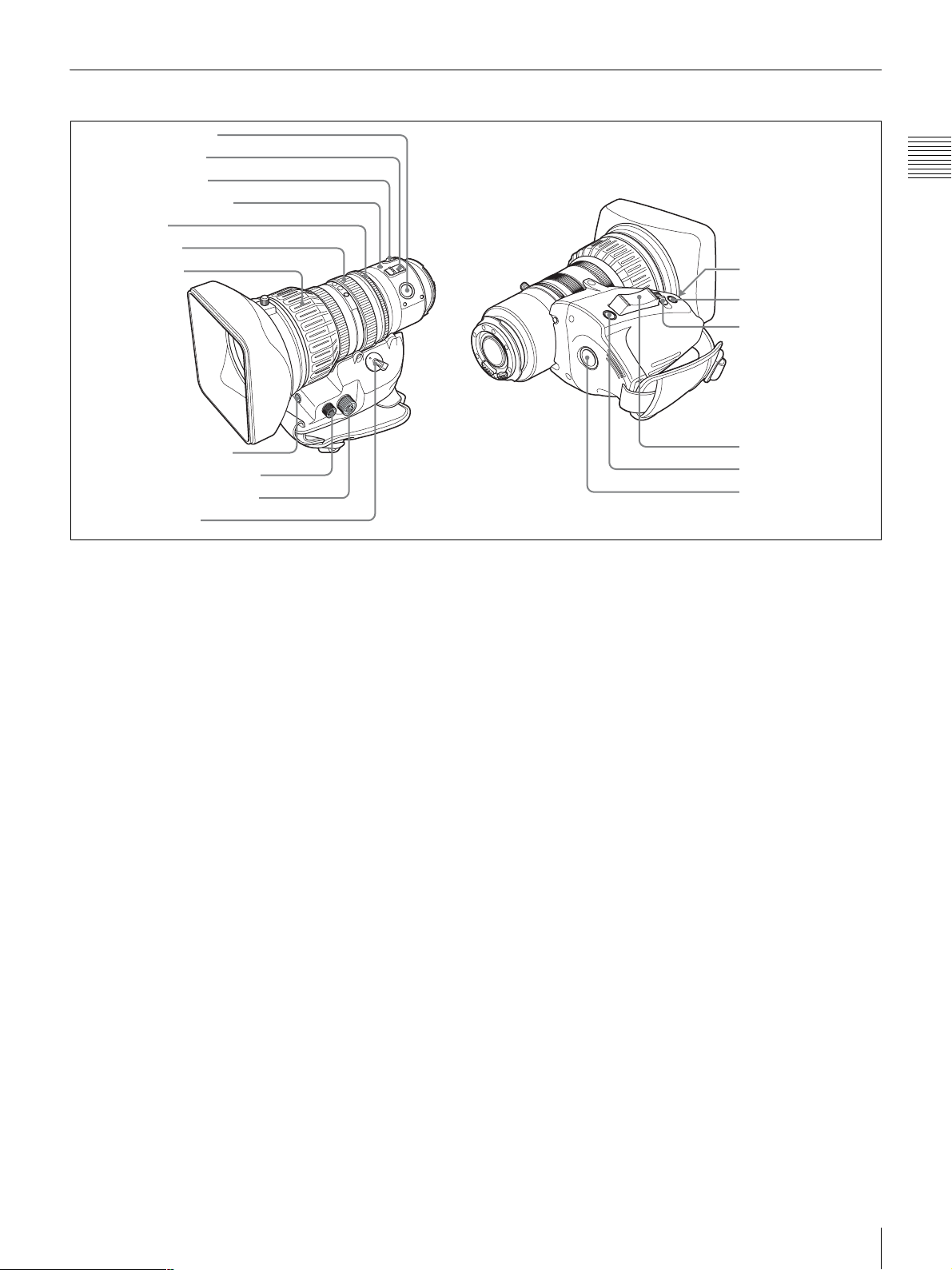
VCL-719BXS Auto Focus Lens (Supplied With the PDW-F330K)
1 PUSH AF button
2 FOCUS switch
3 MACRO switch
4 Auto focus indicator
5 Iris ring
6 Zoom ring
7 Focus ring
Chapter 1 Overview
qs IG control
qd IRIS button
qf IRIS switch
8 Flange focal length
adjustment button
9 Focus control connector
0 Zoom control connector
qa ZOOM switch
a PUSH AF (auto focus) button
When the focus adjustment is in the manual mode, by
pressing this button you can use the auto focus for an
instantaneous adjustment to the subject.
When the button is pressed, the auto focus operates until
the image is in focus, then disengages.
Even when the FOCUS switch is set to A (auto), by
pressing this button, you can restart the auto focus.
b FOCUS switch
Select the method of focusing.
A (auto): The auto focus function is constantly active.
While the auto focus is operating, the auto focus
indicator lights green. Even with the switch in the A
position, you can manually adjust the focus by
operating the focus ring.
M (manual): The manual mode allows focusing
adjustment with the focus ring.
In manual mode, auto focus adjustment is also
possible, by pressing the PUSH AF button.
c MACRO switch
When this switch is in the ON position, the macro mode is
enabled, allowing focusing over the whole range (5 cm
to !) including the macro range (from 5 cm
1)
to 90 cm
1)
from the front of the lens).
This operation is independent of whether the focus
adjustment mode is auto or manual.
In the macro range, the auto focusing speed is lower.
1) At the wide-angle setting
qg Power zoom lever
qh RET button
qj REC button
d Auto focus indicator
This lights green while the auto focus function is
operating.
During flange focal length adjustment, it flashes orange or
green.
If an error occurs, it lights red.
For details of flashing during flange focal length
adjustment, see “Adjusting the Flange Focal Length” on
page 40.
e Iris ring
For manual iris adjustment, set the IRIS switch to the M
(manual) position, then turn this ring.
f Zoom ring
For manual zoom adjustment, set the ZOOM switch to the
MANU. position, then turn this ring.
g Focus ring
Turn this ring to adjust the focus.
This ring can be turned endlessly in both directions. The
faster you turn, the faster the focusing mechanism
operates, to minimize the amount of turning required for
focusing.
h Flange focal length adjustment button
Press this to adjust the flange focal length (the distance
from the lens mounting flange plane to the focusing plane).
For details of flange focal length adjustment, see
“Adjusting the Flange Focal Length” on page 40.
Location and Function of Parts
27

i Focus control connector (6-pin)
Connecting an optional focus servo controller allows
remote control of focusing.
j Zoom control connector (8-pin)
Connecting an optional zoom servo controller allows
Chapter 1 Overview
remote control of zooming.
k ZOOM switch
Select the method of zoom operation.
SERVO: Power zoom. Operate the zoom with the power
zoom lever.
MANU. (manual): Manual zoom. Operate the zoom with
the zoom ring.
l IG (iris gain) control
Remove the rubber cap, and turn the knob inside, to adjust
the gain for auto iris adjustment.
Note
This is set to an appropriate value when the unit is shipped.
It does not normally require any adjustment.
m IRIS button
When the IRIS switch is in the M position for manual
adjustment, press this button for an instantaneous auto
adjustment.
The iris is automatically adjusted while the button is held
down.
“CENTER” to “FULL”, instead of focusing only on the
center portion of the screen, the whole screen image is
used for focusing. In this case, the auto focus area frame
does not appear.
• If there are a number of objects within the screen at close
and far range, the focus may not be on the intended
subject. In this case, with the subject on which you want
to focus in the center of the screen, press the PUSH AF
button.
• After focusing with the PUSH AF button, if you operate
the zoom or adjust the iris, the depth of field may
become shallower, losing crisp focus. In such cases,
press the PUSH AF button once more.
• If you focus at wide-angle then zoom to telephoto, the
subject may no longer be in focus.
• The auto focus function does not operate while using the
slow shutter mode (4F or higher).
Note on zoom speed
Depending on the shooting distance, the zoom speed may
fall as the lens approaches the telephoto end.
p RET (return video) button
Use this to check the video. If you press this while the
internal VDR is pausing recording, the last few seconds
recorded appear in the viewfinder (a recording review
operation).
For details, see “Checking the Last Two Seconds of the
Recording (a Recording Review Operation)” on page 81.
n IRIS switch
Select the method of iris adjustment.
A (auto): Auto mode. The iris is adjusted automatically.
M (manual): Manual mode. Adjust the iris with the iris
ring.
o Power zoom lever
This is enabled when the ZOOM switch is in the SERVO
position. Press the W end for wide-angle and the T end for
telephoto.
Press the lever harder for a faster zoom action.
Notes on auto focus
• When an auto focus lens is mounted, in the auto focus
mode a frame appears in the center of the viewfinder
screen indicating the auto focus area. Place the subject
on which you want to focus within this frame.
• In the following cases, it may be difficult to focus on the
subject. If this does happen, use manual focusing.
- If the subject has no contrast
- If the subject is moving rapidly
- When shooting point light sources, under street
lighting or at night
- When there are very bright objects close to the subject
- When shooting through a glass window
• On the LENS page of the MAINTENANCE menu, by
changing the AF DETECT AREA setting from
Pressing this button (single click) during recording records
a shot mark 1, and double-clicking records a shot mark 2.
For details, see “Recording Shot Marks” on page 70.
q REC (record) button
Use this to start and stop recording. Press once to start
recording, then press once more to stop.
28
Location and Function of Parts
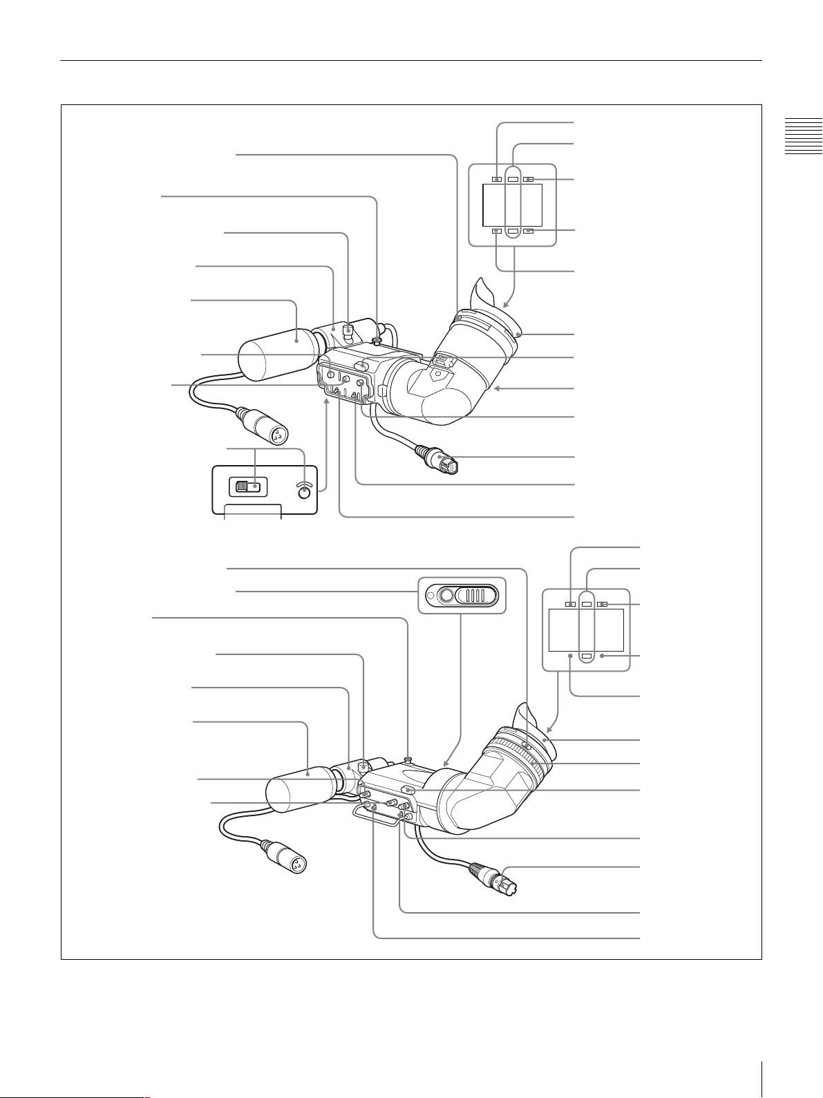
Viewfinder
DXF-801/801CE (supplied with the PDW-F330)
1 Eyepiece focusing knob
3 Stopper
Microphone fixing screw
Microphone holder
Stereo microphone
(packaged with
camcorder)
4 PEAKING control
5
CONTRAST
control
6 LIGHT switch and light
HIGH LOW OFF
LIGHT
DXF-20W (supplied with the PDW-F350)
1 Eyepiece focusing ring
2 Camera person tally light
3 Stopper
TALLY
BATTREC
SHUTTER GAIN UP
7 TALLY indicator
8 REC/TALLY indicators
9 BATT indicator
0 GAIN UP indicator
qa SHUTTER indicator
Eye cup
qd Tally light
qf Eyepiece release catch
qg BRIGHT control
qh Viewfinder connector
qj TALLY switch
qk DISPLAY switch
7 TALLY indicator
8 REC/TALLY
indicators
TALLY
BATTREC
9BATT indicator
Chapter 1 Overview
Microphone fixing screw
Microphone holder
Stereo microphone
(packaged with
camcorder)
4 PEAKING control
5 CONTRAST control
SHUTTER GAIN UP
0 GAIN UP indicator
qa SHUTTER indicator
Eye cup
qs Lock ring
qd Tally light
qg BRIGHT control
qh Viewfinder
connector
qj TALLY switch
qk DISPLAY switch
Location and Function of Parts
29

a Eyepiece focusing knob (DXF-801/801CE)
Eyepiece focusing ring (DXF-20W)
Adjusts the viewfinder focus to match your eyesight (see
page 42).
b Camera person tally light (DXF-20W)
Chapter 1 Overview
F350
l Lock ring (DXF-20W)
F350
If you want to directly view the viewfinder screen, rotate
this ring counterclockwise to align the matching marks (in
orange) on the lock ring and the viewfinder cylinder part to
each other, and then remove the eyepiece.
Lights while the camcorder is recording. To start recording
with your eye off the viewfinder, open the slide window.
This indicator flashes when the remaining battery capacity
or remaining disc capacity is low.
c Stopper
Lift up when detaching the viewfinder (see page 42).
d PEAKING control
Adjusts the outline intensity of the viewfinder image (see
page 42).
e CONTRAST control
Adjusts the contrast of the viewfinder image (see page 42).
f LIGHT switch and light (DXF-801/801CE)
F330
The light lights the lens and the switch controls the light as
follows.
HIGH: Brighter
LOW: Darker
OFF: Turns the light off.
g TALLY (tally) indicator (green)
Flashes when the camcorder is in Interval Rec mode.
Flashing quickens while you are shooting in Interval Rec
mode.
m Tally light
When the TALLY switch (see below) is in the ON
position, this operates in the same way as the REC/TALLY
indicators.
n Eyepiece release catch (DXF-801/801CE)
F330
To view the viewfinder screen directly, press to hinge up
the eyepiece.
o BRIGHT (brightness) control
Adjusts the brightness of the viewfinder image (see page
42).
p Viewfinder connector (20-pin)
Connect to the VF connector (see page 13).
q TALLY switch
Set to the HIGH (high-intensity) or LOW (low-intensity)
to use the tally light.
r DISPLAY switch
Set to ON when you want to display text information on
the viewfinder screen.
For details on Interval Rec mode, see “Time-lapse Video
Recording (“Interval Recording” Function)” on page 71.
h REC/TALLY (recording/tally) indicators (red)
Function as follows.
• Begin flashing when you press the REC button on the
camcorder or on the lens until recording starts, then stay
on continuously during recording.
• Indicate a fault (see page 165).
On the CAM CONFIG page of the MAINTENANCE
menu, you can select that the lower indicator also lights.
i BATT (battery) indicator (red)
Lights up when the remaining battery capacity is low.
j GAIN UP indicator (orange)
Lights up when the gain is 3 dB or more.
k SHUTTER indicator (red)
Lights up when the SHUTTER switch (page 14) is ON.
30
Location and Function of Parts
 Loading...