

Sony PDW-75MD Instructions For Use Manual

3-270-633-13 (1)
Professional Disc
Recorder
Instructions for Use
Before operating the unit, please read this manual
thoroughly and retain it for future reference.
PDW-75MD
© 2007 Sony Corporation
WARNING
To reduce the risk of fire or electric shock,
do not expose this apparatus to rain or
moisture.
To avoid electrical shock, do not open the
cabinet. Refer servicing to qualified
personnel only.
THIS APPARATUS MUST BE EARTHED.
CAUTION
The apparatus shall not be exposed to dripping or splashing.
No objects filled with liquids, such as vases, shall be placed on
the apparatus.
The unit is not disconnected from the AC power source
(mains) as long as it is connected to the wall outlet, even if the
unit itself has been turned off.
When installing the installation space must be secured in
consideration of the ventilation and service operation.
• Do not block the ventilation slots at the left side and right
side panels, and vents of fans.
• Leave a space around the unit for ventilation.
• Leave more than 10 cm of space in the rear of the unit to
secure the operation area.
When the unit is installed on the desk or the like, leave at least
5 cm of space in the left and right sides.
Egenskaper for laserdiode
Bølgelengde: 400 til 410 nm
Strålingsvarighet: Kontinuerlig
Utgangseffekt for laser: 135 mW (maks stråletoppunkt), 65
mW (maks ved kontinuerlig stråling)
Standard: IEC60825-1 (2001)
Laserdiodin ominaisuudet
Aallonpituus: 400 - 410 nm
Säteilyn kesto: jatkuva
Laserin teho: 135 mW (pulssin huipun maks.), 65 mW
(jatkuvan aallon maks.)
Standardi: IEC60825-1 (2001)
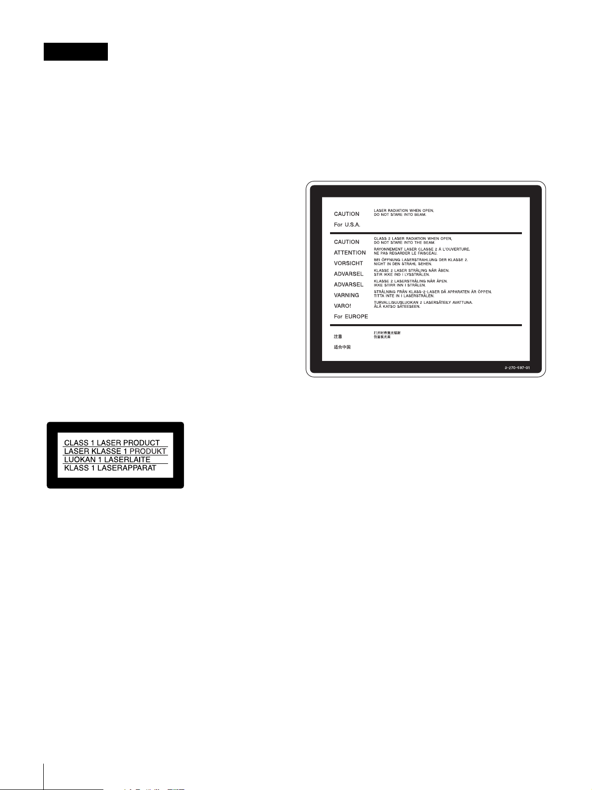
This label is located on the top panel of the drive unit.
Denna etikett finns på ovansidan av driftenheten.
This Professional Disc Recorder is classified as a CLASS 1
LASER PRODUCT.
Laser diode properties
Wave length: 400 to 410 nm
Emission duration: Continuous
Laser output power: 135 mW (max. of pulse peak), 65 mW
(max. of CW)
Standard: IEC60825-1 (2001)
Egenskaber for laserdiode
Bølgelængde: 400 til 410 nm
Strålingsvarighed: Kontinuerlig
Afgivet lasereffekt: 135 mW (maks stråletoppunkt), 65 mW
(maks ved kontinuerlig stråling)
Standard: IEC60825-1 (2001)
Laserdiod - Egenskaper
Våglängd: 400 till 410 nm
Strålningens varaktighet: Kontinuerlig
Lasereffekt: 135 mW (max. för pulstopp), 65 mW (max. för
kontinuerlig våg)
Standard: IEC60825-1 (2001)
Denne mærkat sidder på drevenhedens øverste panel.
Tämä kyltti sijaitsee ajurilaitteen yläpinnalla.
Dette merket er plassert på oversiden av driverenheten.
CAUTION
The use of optical instruments with this product will increase
eye hazard.
Use of controls or adjustments or performance of procedures
other than those specified herein may result in hazardous
radiation exposure.
VAROITUS!
LAITTEEN KÄYTTÄMINEN MUULLA KUIN TÄSSÄ
KÄYTTÖOHJEESSA MAINITULLA TAVALLA SAATTAA
ALTISTAA KÄYTTÄJÄN TURVALLISUUSLUOKAN 1
YLITTÄVÄLLE NÄKYMÄTTÖMÄLLE LASERSÄTEILYLLE.
VARNING
OM APPARATEN ANVÄNDS PÅ ANNAT SÄTT ÄN I DENNA
BRUKSANVISNING SPECIFICERATS, KAN ANVÄNDAREN
UTSÄTTAS FÖR OSYNLIG LASERSTRÅLNING, SOM
ÖVERSKRIDER GRÄNSEN FÖR LASERKLASS 1.
For the customers in the USA
This equipment has been tested and found to comply with the
limits for a Class A digital device, pursuant to Part 15 of the
FCC Rules. These limits are designed to provide reasonable
2
protection against harmful interference when the equipment is
operated in a commercial environment. This equipment
generates, uses, and can radiate radio frequency energy and,
if not installed and used in accordance with the instruction
manual, may cause harmful interference to radio
communications. Operation of this equipment in a residential
area is likely to cause harmful interference in which case the
user will be required to correct the interference at his own
expense.
You are cautioned that any changes or modifications not
expressly approved in this manual could void your authority to
operate this equipment.
All interface cables used to connect peripherals must be
shielded in order to comply with the limits for a digital device
pursuant to Subpart B of Part 15 of FCC Rules.
This device complies with Part 15 of the FCC Rules.
Operation is subject to the following two conditions: (1) this
device may not cause harmful interference, and (2) this device
must accept any interference received, including interference
that may cause undesired operation.
For the State of California, USA only
Perchlorate Material - special handling may apply, See
www.dtsc.ca.gov/hazardouswaste/perchlorate
Perchlorate Material : Lithium battery contains perchlorate.
For the customers in Canada
This Class A digital apparatus complies with Canadian ICES-
003.
Important safeguards/notices for use in the
medical environments
1. All the equipments connected to this unit shall be certified
according to Standard IEC60601-1, IEC60950-1,
IEC60065 or other IEC/ISO Standards applicable to the
equipments.
2. Furthermore all configurations shall comply with the
system standard IEC60601-1-1.
Everybody who connects additional equipment to the
signal input part or signal output part configures a medical
system, and is therefore, responsible that the system
complies with the requirements of the system standard
IEC60601-1-1.
If in doubt, consult the qualified service personnel.
3. The leakage current could increase when connected to
other equipment.
4. For this particular equipment, all accessory equipment
connected as noted above, must be connected to mains
via an additional isolation transformer conforming with the
construction requirements of IEC60601-1 and providing at
least Basic Insulation.
5. This equipment generates, uses, and can radiate radio
frequency energy. If it is not installed and used in
accordance with the instruction manual, it may cause
interference to other equipment. If this unit causes
interference (which can be determined by unplugging the
power cord from the unit), try these measures: Relocate
the unit with respect to the susceptible equipment. Plug
this unit and the susceptible equipment into different
branch circuit.
For the customers in Taiwan only
WARNING
Excessive sound pressure from earphones and headphones
can cause hearing loss.
In order to use this product safely, avoid prolonged listening at
excessive sound pressure levels.
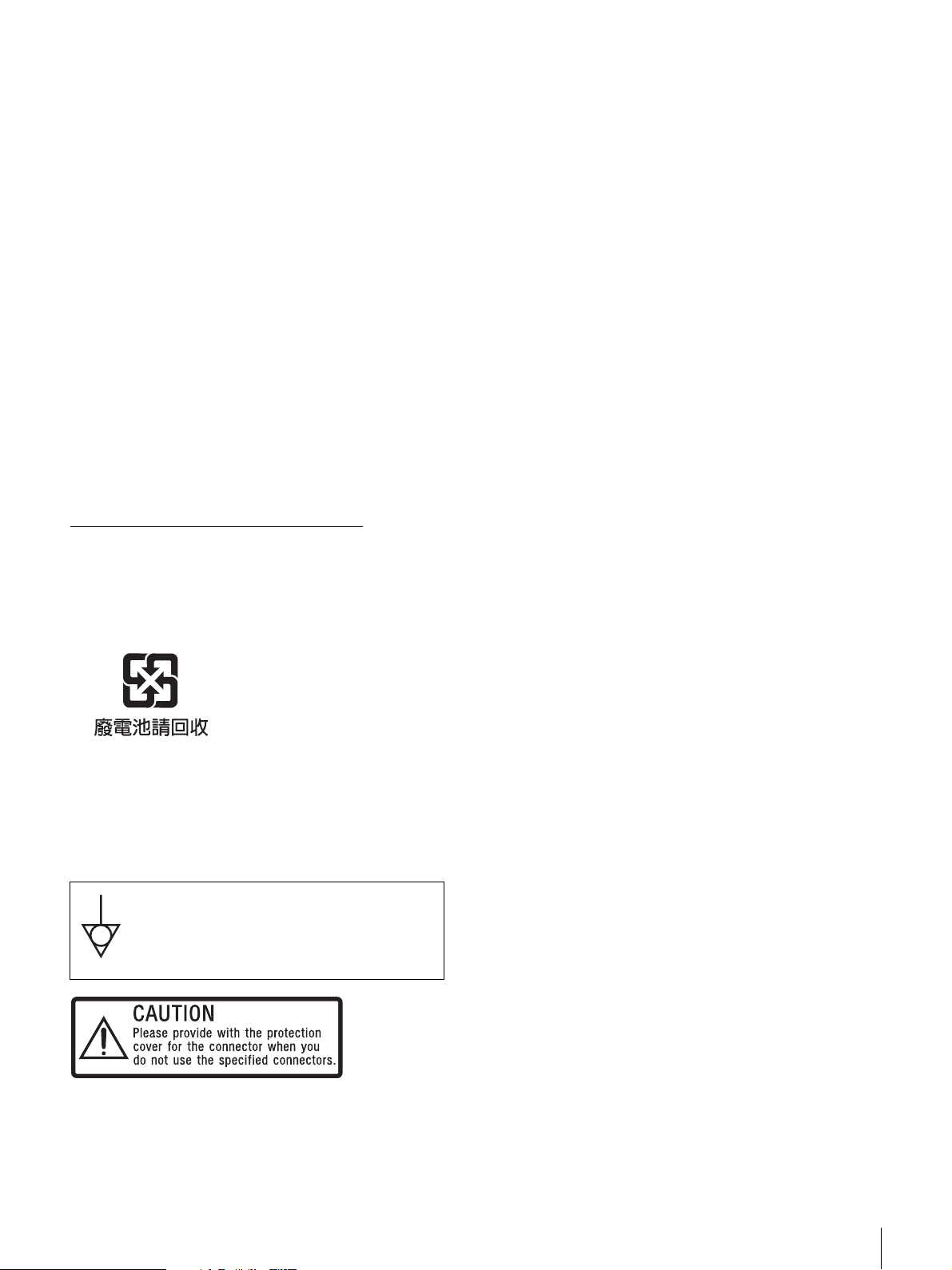
Symbols on the products
This symbol indicates the equipotential terminal
which brings the various parts of a system to
the same potential.
Consult your dealer. (According to standard EN60601-1-2 and
CISPR11, Class B, Group 1)
For kundene i Norge
Dette utstyret kan kobles til et IT-strømfordelingssystem.
This label is located on the top panel of the unit.
See “Removing the Connector Covers” of these instructions
for details about how to attach the connector covers
3
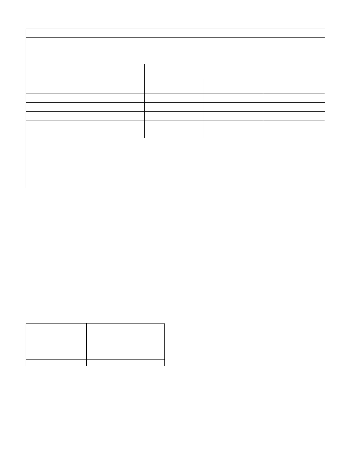
Important EMC notices for use in the medical environments
• The PDW-75MD needs special precautions regarding EMC
and needs to be installed and put into service according to
the EMC information provided in this instructions for use.
• The portable and mobile RF communications equipment
such as cellular phones can affect the PDW-75MD.
List of cables used for EMC tests
Type of cable Specifications
AC mains cable 2.4 m, non-shielded
75-ohm BNC coaxial cable 1.5 m, shielded
XLR 3-pin Cannon cable 5 m, shielded
RCC-5G cable 3.2 m, shielded
Analog RGB cable 2 m, shielded
RCA pin / BNC cable 5 m, shielded
XLR 3-pin / RCA pin cable 5 m, shielded
i.LINK cable 1.5 m, shielded
Warning
The use of accessories and cables other than those specified,
with the exception of replacement parts sold by Sony
Corporation, may result in increased emissions or decreased
immunity of the PDW-75MD.
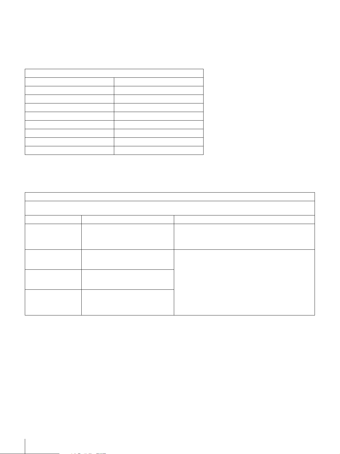
Guidance and manufacturer’s declaration - electromagnetic emissions
The PDW-75MD is intended for use in the electromagnetic environment specified below.
The customer or the user of the PDW-75MD should assure that it is used in such an environment.
Emission test Compliance Electromagnetic environment-guidance
RF emissions
CISPR 11
RF emissions
CISPR 11
Harmonic emissions
IEC 61000-3-2
Voltage fluctuations/
flicker emissions
IEC 61000-3-3
Warning
If the PDW-75MD should be used adjacent to or stacked with
other equipment, it should be observed to verify normal
operation in the configuration in which it will be used.
Group 1
Class B
Class A
Complies
The PDW-75MD uses RF energy only for its internal
function. Therefore, its RF emissions are very low and are
not likely to cause any interference in nearby electronic
equipment.
The PDW-75MD is suitable for use in all establishments,
including domestic establishments and those directly
connected to the public low-voltage power supply network
that supplies buildings used for domestic purposes.
4

Guidance and manufacturer’s declaration - electromagnetic immunity
The PDW-75MD is intended for use in the electromagnetic environment specified below. The customer or the user of the PDW75MD should assure that it is used in such as environment.
Immunity test
Electrostatic
discharge (ESD)
IEC 60601
test level
±6 kV contact
Compliance level Electromagnetic environment - guidance
±6 kV contact
Floors should be wood, concrete or ceramic tile. If floors are
covered with synthetic material, the relative humidity should
be at least 30%.
IEC 61000-4-2
Electrical fast
transient/burst
±8 kV air
±2 kV for power
supply lines
±8 kV air
±2 kV for power
supply lines
Mains power quality should be that of a typical commercial or
hospital environment.
IEC 61000-4-4
Surge
IEC 61000-4-5
Voltage dips, short
interruptions and
voltage variations
on power supply
input lines
IEC 61000-4-11
Power frequency
(50/60Hz) magnetic
field
±1 kV for input/
output lines
±1 kV differential
mode
±2 kV common
mode
< 5% U
(> 95% dip in U
T
for 0.5 cycle
±1 kV for input/
output lines
±1 kV differential
mode
±2 kV common
mode
< 5% U
)
(> 95% dip in U
T
for 0.5 cycle
Mains power quality should be that of a typical commercial or
hospital environment.
T
Mains power quality should be that of a typical commercial or
)
hospital environment. If the user of the PDW-75MD requires
T
continued operation during power mains interruptions, it is
recommended that the PDW-75MD be powered from an
uninterruptible power supply or a battery.
40% UT
(60% dip in U
for 5 cycles
70% U
(30% dip in UT)
T
T
for 25 cycles
< 5% U
(> 95% dip in U
T
for 5 sec
40% UT
)
(60% dip in U
for 5 cycles
70% U
(30% dip in UT)
for 25 cycles
< 5% U
)
(> 95% dip in U
T
for 5 sec
)
T
T
T
)
T
3 A/m 3 A/m Power frequency magnetic fields should be at least
characteristic of a typical location in a typical commercial or
hospital environment.
IEC 61000-4-8
NOTE: U
is the a.c. mains voltage prior to application of the test level.
T
5
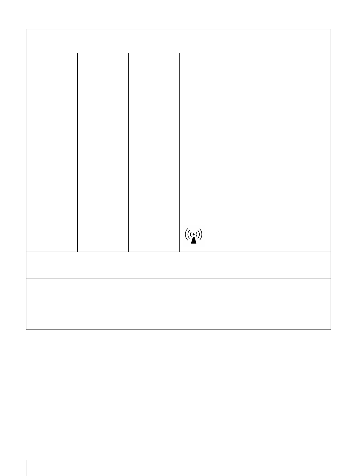
Guidance and manufacturer’s declaration - electromagnetic immunity
The PDW-75MD is intended for use in the electromagnetic environment specified below. The customer or the user of the PDW75MD should assure that it is used in such as environment.
Immunity test
IEC 60601 test
level
Compliance level Electromagnetic environment - guidance
Portable and mobile RF communications equipment should be
used no closer to any part of the PDW-75MD, including cables,
than the recommended separation distance calculated from
the equation appliance to the frequency of the transmitter.
Recommended separation distance
Conducted RF
IEC 61000-4-6
Radiated RF
IEC 61000-4-3
NOTE 1: At 80 MHz and 800 MHz, the higher frequency range applies.
NOTE 2: These guidelines may not apply in all situations. Electromagnetic propagation is affected by absorption and reflection
from structures, objects and people.
a Field strengths from fixed transmitters, such as base stations for radio (cellular/cordless) telephones and land mobile radios,
amateur radio, AM and FM radio broadcast and TV broadcast cannot be predicted theoretically with accuracy. To assess the
electromagnetic environment due to fixed RF transmitters, an electromagnetic site survey should be considered. If the
measured field strength in the location in which the PDW-75MD is used exceeds the applicable RF compliance level above,
the PDW-75MD should be observed to verify normal operation. If abnormal performance is observed, additional measures
may be necessary, such as reorienting or relocating the PDW-75MD.
3 Vrms
150 kHz to 80 MHz
3 V/m
80 MHz to 2.5 GHz
3 Vrms
3 V/m
d = 1.2√P
d = 1.2√P 80 MHz to 800 MHz
d = 2.3√P 800 MHz to 2.5 GHz
Where P is the maximum output power rating of the
transmitter in watts (W) according to the transmitter
manufacturer and d is the recommended separation distance
in meters (m).
Field strengths from fixed RF transmitters, as determined by
an electromagnetic site survey, a should be less than the
compliance level in each frequency range.
Interference may occur in the vicinity of equipment marked
with following symbol:
b
b Over the frequency range 150 kHz to 80 MHz, field strengths should be less than 3 V/m.
6
Recommended separation distances between portable and mobile RF communications equipment and the PDW-75MD
The PDW-75MD is intended for use in an electromagnetic environment in which radiated RF disturbances are controlled. The
customer or the user of the PDW-75MD can help prevent electromagnetic interference by maintaining a minimum distance
between portable and mobile RF communications equipment (transmitters) and the PDW-75MD as recommended below,
according to the maximum output power of the communications equipment.
Separation distance according to frequency of transmitter
Rated maximum output power of transmitter
For transmitters rated a maximum output power not listed above, the recommended separation distance d in meters (m) can be
estimated using the equation applicable to the frequency of the transmitter, where P is the maximum output power rating of the
transmitter in watts (W) according to the transmitter manufacturer.
NOTE 1: At 80 MHz and 800 MHz, the separation distance for the higher frequency range applies.
NOTE 2: These guidelines may not apply in all situations. Electromagnetic propagation is affected by absorption and reflection
from structures, objects and people.
W
0.01 0.12 0.12 0.23
0.1 0.38 0.38 0.73
11.21.22.3
10 3.8 3.8 7.3
100 12 12 23
150 kHz to 80 MHz
d = 1.2√P
80 MHz to 800 MHz
m
d = 1.2√P
800 MHz to 2.5 GHz
d = 2.3√P
WARNING on power connection
Use a proper power cord for your local power supply.
1. Use the approved Power Cord (3-core mains lead) /
Appliance Connector / Plug with earthing-contacts that
conforms to the safety regulations of each country if
applicable.
2. Use the Power Cord (3-core mains lead) / Appliance
Connector / Plug conforming to the proper ratings (Voltage,
Ampere). If you have questions on the use of the above
Power Cord / Appliance Connector / Plug, please consult a
qualified service personnel.
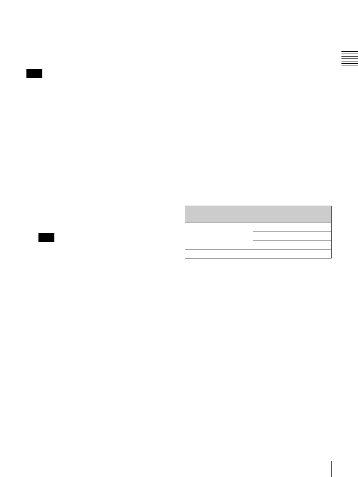
WARNING on power connection for
medical use
Please use the following power supply cord.
With connectors (plug or female) and cord types other than
those indicated in this table, use the power supply cord that is
approved for use in your area.
United States and Canada
Plug Type HOSPITAL GRADE*
Cord Type Min. Type SJT
Maximum Rating for Plug
and Appliance Couplers
Safety Approval UL Listed and CSA
*Note: Grounding reliability can only be achieved when the equipment is
connected to an equivalent receptacle marked ‘Hospital Only’ or
‘Hospital Grade’.
Min. 18 AWG
10A/125V
For the customers in Canada
This unit has been certified according to Standard CSA C22.2
No.601.1.
When the cabinet becomes dirty
Before cleaning the unit, be sure to power the unit off and
disconnect the power plug.
If the body of the unit is dirty, clean it with a soft, dry cloth.
In extreme cases, use a cloth steeped in a little neutral
detergent, then wipe dry. Do not use organic solvents such as
alcohol or thinners, as these may cause discoloration or other
damage to the finish of the unit.
Caution
When you dispose of the unit or accessories, you must obey
the laws in the relative area or country and the regulations in
the relative hospital.
7

Table of Contents
Chapter 1 Overview
Features..........................................................................................11
Names and Functions of Parts .....................................................14
Chapter 2 Preparations
Setting the System Frequency .....................................................26
Removing the Connector Covers.................................................27
Connections and Settings ............................................................28
External Synchronization..............................................................30
Setup...............................................................................................31
Superimposed Text Information...................................................33
Features of This Unit........................................................................... 11
Features of the PDBK-101/102/103/104 Option Boards .................... 12
Front Panel .......................................................................................... 14
Rear Panel............................................................................................ 20
Infrared Remote Commander .............................................................. 23
Connecting an External Monitor ......................................................... 28
Using PDZ-1 over an i.LINK Connection (FAM Connection)........... 29
Setting the Date and Time ................................................................... 31
Adjusting the Brightness of the LCD Panel ........................................ 31
Displaying Supplementary Status Information ................................... 34
Chapter 3 Recording and Playback
Handling Discs...............................................................................36
Discs Used for Recording and Playback ............................................. 36
Notes on Handling............................................................................... 36
Write-Protecting Discs ........................................................................ 36
Loading and Unloading a Disc............................................................ 37
Formatting a Disc ................................................................................ 37
Handling of Discs When Recording Does Not End Normally (Salvage
Functions) .................................................................................. 38
Recording .......................................................................................39
Carrying Out Recording ..................................................................... 39
Recording with the Clip Continuous Rec Function............................. 40
8
Table of Contents

Playback .........................................................................................40
Playback Operation ............................................................................. 40
Searching for Clips with Thumbnails (Thumbnail Search)................. 41
Searching with the Expand Function................................................... 43
Searching for Frames with Essence Marks ......................................... 43
Searching with the Chapter Function .................................................. 44
Clip List Playback ............................................................................... 45
Locking (Write-Protecting) Clips........................................................ 46
Deleting Clips...................................................................................... 47
Assigning Sequence Numbers to Thumbnails..................................... 48
Chapter 4 Scene Selection
Overview.........................................................................................49
Assigning Clip Titles........................................................................... 52
Assigning User-Defined Clip and Clip List Names ............................ 52
Creating Clip Lists .........................................................................54
Including Clips Selected in the Thumbnail Screen in the Clip List .... 54
Quick Scene Selection (Adding Sub Clips during Recording, Playback,
Editing Clip Lists ...........................................................................59
Basic Operations.................................................................................. 59
Reordering Sub Clips .......................................................................... 59
Modifying the In and Out Points of Sub Clips (Trimming)................ 60
Deleting Sub Clips............................................................................... 61
Setting the Start Timecode for the Current Clip List .......................... 61
Previewing the Edited Clip List .......................................................... 61
Saving the Current Clip List to Disc ............................................62
Managing Clip Lists.......................................................................63
Changing Displayed Items of Information on Sub Clips .................... 64
Loading a Clip List from a Disc Into the Current Clip List ................ 64
Deleting Clip Lists from a Disc........................................................... 64
Sorting Clip Lists................................................................................. 64
Using the PDZ-1 Proxy Browsing Software ................................66
or Search) ................................................................................... 57
Chapter 5 File Operations
Overview.........................................................................................67
File Operations in File Access Mode (for Windows) ..................67
Making FAM Connections.................................................................. 67
Operating on Files ............................................................................... 68
Table of Contents
9

Chapter 6 Menus
File Operations in File Access Mode (for Macintosh) ................69
Making FAM Connections.................................................................. 69
Operating on Files ............................................................................... 70
Exiting File Operations ....................................................................... 70
Recording Continuous Timecode over FAM Connections ........ 71
Function Menu ...............................................................................72
Function Menu Operations.................................................................. 72
Function Menu Settings....................................................................... 72
System Menu..................................................................................74
Displaying the Setup and Disc Menus ................................................ 74
Setup Menu.......................................................................................... 75
Setup Menu Items................................................................................ 76
Setup Menu Operations ....................................................................... 81
Disc Menu ........................................................................................... 83
Disc Menu Operations......................................................................... 84
Appendix
Important Notes on Operation......................................................86
Condensation ....................................................................................... 86
Periodic Maintenance....................................................................87
Digital Hours Meter............................................................................. 87
Troubleshooting ............................................................................88
Alarms ................................................................................................. 88
Error Messages .................................................................................... 95
To Eject Discs with the Unit Powered Off.......................................... 95
About i.LINK ..................................................................................96
Specifications ................................................................................97
Using UMID Data..........................................................................100
MPEG-4 Visual Patent Portfolio License ...................................102
MPEG-2 Video Patent Portfolio License....................................102
10
Table of Contents

Overview
Features
The PDW-75MD is a professional disc recorder
supporting HD playback and recording with Professional
1)
Disc
media.
When you use this unit in combination with a nonlinear
editing system, the FAM
transfers between the unit and computers over the i.LINK
interface, allowing the unit to be used like an external hard
drive. The unit can be connected to Sony nonlinear editors,
monitors, and video equipment with HDSDI interfaces via
its standard HDSDI I/O connectors. It incorporates a color
LCD display, allowing you to check video and use the
menu system without connecting an external monitor.
1) Professional Disc is a trademark of Sony Corporation.
2) FAM: File access mode
Features of This Unit
2)
function enables data file
Chapter
Video bitrates and audio channels selectable
according to application
You can select the appropriate video bitrate for your
application from three video bitrate modes: 35 Mbps (HQ:
high quality mode), 25 Mbps (SP: standard mode), and 18
Mbps (LP: long-play mode). You can select 2-channel or
4-channel audio, with the ability to record 120 minutes or
more of audio. If the audio channel modes are the same,
different video bitrates can be mixed on the same disc.
Long recording times
When two-layer Professional Discs are used, this unit can
record about 190 minutes in SP mode and about 185
minutes in DVCAM mode.
Rich selection of recording and playback
functions
Support for multiple frame frequencies
The unit can record and play back four different frame
frequencies: 1080/59.94i (displayed as 60I), 50i (displayed
as 50I), 29.97PsF (displayed as 30P), and 25PsF.
1
Chapter 1 Overview
The principal features of this unit are as follows.
MPEG HD
High-quality video and audio recording and
playback
The MPEG HD codec provides video compression
compliant with the MPEG-2 MP@HL standard. It enables
HD 4:2:0 digital component file recording in the 1080i
(1,080 effective scanning lines, interlaced) format
currently in use by many broadcast facilities.
Uncompressed PCM recording of 16-bit 48 kHz audio
delivers a wide dynamic range with a high signal-to-noise
ratio.
1) MPEG HD is a trademark of Sony Corporation.
1)
codec
DVCAM recording
The optional PDBK-104 SD Input Upconverter Board is
available for input of SDSDI or composite signals, to
enable DVCAM-format recording.
HD downconvert function
The unit is provided with a downconvert function. HD disc
playback signals can be downconverted to SD signals and
then output as SDSDI or composite signals, or output via
the i.LINK (DV) interface. This allows you to shoot and
record masters in an HD environment, and to use SD
nonlinear editors and monitors for editing and program
output.
DVCAM upconvert function
The unit features an upconvert function, with the ability to
upconvert to HD and output HDSDI signals when playing
back DVCAM discs.
Recording of proxy AV data
Proxy AV data is a low-resolution (1.5 Mbps video, 64
kbps per audio channel), MPEG-4 based version of a full-
Features
11

resolution data stream. Whenever this unit records fullresolution MPEG HD data, it simultaneously generates
and records low-resolution proxy AV data. Because of its
small size, proxy AV data can be transferred quickly over
computer networks, easily edited in the field with laptop
computers,
Chapter 1 Overview
applications, such as content management on small-scale
1)
and readily used in a wide variety of
servers.
1) The supplied PDZ-1 Proxy Browsing Software can be used to create
simple EDLs (Edit Decision Lists).
Supports a variety of interfaces
This unit supports the following interfaces.
HDSDI: This enables input and output of HD digital video
and embedded audio signals (4 channels).
SDSDI: This enables output of SD component digital
video and embedded audio signals (4 channels).
AES/EBU: This enables input and output of AES/EBU
serial digital audio signals (4 channels).
i.LINK (AV/C): This enables output of DV-format digital
video and audio signals (4 channels).
Analog video: This enables output of HD analog
component (RGB or YPbPr) and SD composite
signals.
Analog audio: This enables input of 2 channels and output
of 2 channels (1/2 or 3/4) of analog audio.
Convenient disc-based playback and
search functions
Thumbnail searches
An independent clip file is generated whenever recording
starts and stops. The first frame of each clip is used as the
thumbnail for that clip.
You can display a list of thumbnails on the color LCD or
an external monitor, and cue up a desired scene by
selecting the corresponding thumbnail.
1) The Clip Continuous Rec function (see page 40) allows you to record a
single clip even while repeatedly starting and stopping the recording. REC
START essence marks are recorded at recording start points.
Essence mark searches
You can record essence marks at any scene during video
recording, or at the recording stop position. You can
display a list of essence mark scenes on the color LCD or
an external monitor. Essence marks can also be added after
recording with the supplied PDZ-1 Proxy Browsing
Software. Shot marks (SHOT MARK1 and SHOT
MARK2), which are a type of essence mark, can be added
on this unit.
Thumbnail expansion
After selecting a clip in the thumbnail list, you can divide
the clip into 12 parts and show a list of thumbnails for the
first frame in each part. This makes it easy to find the scene
you want within the clip. This expansion can be repeated
up to 3 times (1,728 divisions).
1)
You can also expand the section between a selected
essence mark and the next essence mark.
Scene selection
You can create and play back clip lists of selected clips
from the disc, arranged in any order. One disc can store up
to 99 clip lists.
IT friendly
Computer access to files (file access mode)
Video and audio clip data are recorded as files. The FAM
function enables quick random access by computers to the
video, audio, and metadata
1)
files stored on Professional
Discs, with the ability to display thumbnail lists on the
computer screen and perform file-based reads and writes.
1) XDCAM allows you to record various kinds of information about the
video and audio data, such as the date of shooting, the editor, the recording
format, and comments. This data can be used in the following ways.
• The supplied PDZ-1 Proxy Browsing Software can add titles,
comments, and other text data to discs and clips.
• The ability to search metadata for the required audio and video scenes
brings greater efficiency to various stages of the video production
process (editing, archiving).
Other features
High-speed searches by the jog and shuttle dials
Like conventional VTRs, this unit features jog and shuttle
dials for searching for specific scenes within clips. The
jog/variable mode supports –1 to +2 times normal speed
searching in field units. The shuttle mode enables highspeed searching at up to ±20 times normal speed.
Variety of remote control units
• Infrared remote commander (supplied)
• RS-232C 9-pin remote control
• RS-422A 9-pin remote control
• Minijack 4-pole remote control
• HDSDI remote control
Color LCD display
The unit is equipped with a 16:9, 3.5-inch color LCD
which allows you to check the contents of the disc and use
the menu system without connecting an external monitor.
Features of the PDBK-101/102/103/ 104 Option Boards
The following option boards provide expanded functions
and interfaces for the unit.
Notes
• Contact your Sony service representative for more
information about purchasing and installing option
boards.
12
Features

• Up to two option boards may be installed. Some
combinations are not supported.
• Option slot 1: PDBK-101
• Option slot 2: One of the PDBK-102, PDBK-103, and
PDBK-104 boards
PDBK-101 Network Board (Gigabit
Ethernet)
Installation of this board provides a gigabit Ethernet
connector, which can be used to transfer disc files over
LAN networks and to record MXF (Material eXchange
Format) files from external devices to discs.
It also allows this unit to be controlled remotely by FTP
commands.
PDBK-102 MPEG-TS (Transport Stream)
Input/Output Board
Installation of this board enhances the functionality of the
standard i.LINK connector, allowing it to be used as an
I/O interface for HDV
signals.
HD files recorded on the disc can be converted to TS
signals compatible with the HDV1080i format for transfer
to HDV devices and HDV editors, and TS signals from
HDV devices and HDV editors can be converted to MPEG
HD compatible files for recording by this unit.
1)
1080i
2)
format compatible TS
3)
Chapter 1 Overview
1) HDV and are trademarks of Sony Corporation and Victor
Company of Japan, Limited.
2) HDV1080i: Refers to devices compliant with the “HDV1080i Standard”
for recording HD signals on DV tape. There are 1080 effective lines.
3) TS: MPEG-2 transport streams containing MPEG video, MPEG audio,
and control information. This is the standard interface for HDV
equipment.
PDBK-103 Analog HD Input Board
Installation of this board provides analog HD component
input connectors, to enable recoding of analog HD
component input signals (RGB and YPbPr, Sync) to discs.
PDBK-104 SD Input Upconverter Board
Installation of this board provides SD input connectors to
enable input of SD signals (SDSDI and composite), which
can then be recorded on DVCAM-format discs or
upconverted and recorded on HD-format discs.
Note
This unit cannot record non-standard composite signals,
for example the output of VTRs that are not equipped with
time base correctors.
Features
13
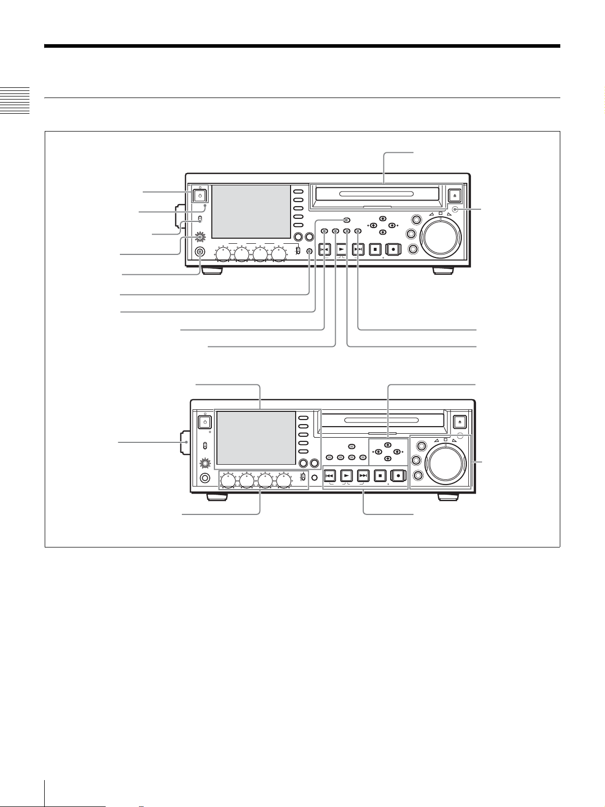
Names and Functions of Parts
Front Panel
Chapter 1 Overview
q; Disc slot and Z EJECT button
1 1 On/standby
switch and indicator
2 ACCESS indicator
3 Remote control switch
ACCESS
NETWORK
REMOTE
LEVEL
PHONES
4 LEVEL knob
5 PHONES jack
6 SHIFT button
7 MENU button
8 SUB CLIP/CLIP MENU button
9 THUMBNAIL/ESSENCE MARK button
1 Display and function menu section
Handle
LOCAL
CH 1 CH 2 CH 3 CH 4
ACCESS
NETWORK
LOCAL
REMOTE
LEVEL
CH 1 CH 2 CH 3 CH 4
PHONES
PAGE DISPLAY
VARIABLE
REC
PRESET
PB
VARIABLE
PRESET
F1
F2
F3
F4
CHAPTER
SUB
EXPAND
F5
CLIP
CLIP
MENU
PREV NEXTPLAY STOP
KEY INHI
SHIFT
TOP
F1
F2
F3
F4
CHAPTER
EXPAND
F5
PAGE DISPLAY
KEY INHI
REC
PB
SHIFT
MENU
THUMB
SET
RESET
NAIL
ESSENCE
MARK
END
F REV F FWD
SUB
THUMB
CLIP
CLIP
ESSENCE
MENU
PREV NEXTPLAY STOP
TOP
F REV F FWD
STANDBY
MENU
SET
RESET
NAIL
MARK
END
STANDBY
EJECT
MARK1
MARK2
VAR
OUTIN
JOG
REC
SHUTTLE
qa Infrared sensor
qs RESET button
qd SET button
3 Arrow buttons
EJECT
MARK1
MARK2
VAR
OUTIN
JOG
REC
SHUTTLE
4 Shuttle/jog/
variable-speed
playback control
block
2 Audio level adjustment section
a 1 On/standby switch and indicator
When the POWER switch (see page 22) on the rear panel
is in the * (on) position, this switches the unit between the
operating state (the indicator is lit green) and the standby
state (the indicator is lit orange).
When the indicator is lit orange, pressing this switch puts
the unit into the operating state. The indicator initially
flashes green and then lights green when the unit enters the
operating state.
When the indicator is lit green, pressing this switch puts
the unit into the standby state. The indicator initially
flashes green, and then lights orange when the unit enters
the standby state.
14
Names and Functions of Parts
5 Recording/playback control block
When using the unit, normally leave the rear panel
POWER switch in the * (on) position, and use this switch
to switch the unit between the operating and standby states.
b ACCESS indicator
This lights blue while a disc is being accessed and while a
file is open by a FAM or FTP connection. If the on/standby
switch is pressed while this indicator is lit, the unit waits
until access to the disc is completed before switching to the
standby state.

Note
Do not turn off the POWER switch on the rear panel or
disconnect the power cord while the ACCESS indicator is
lit. Doing so can result in a loss of data on the disc.
c Remote control switch
Different positions of the switch allow different
operations, as follows.
NETWORK: Enables access to the network. Operation
from the front panel of the unit is disabled during
access to a network device.
LOCAL: Enables operation from the front panel of the
unit.
REMOTE: Enables remote control of this unit from the
following devices.
• Devices connected to external device connectors on
the rear panel
• Devices with HDSDI remote control functions
• The optional remote control panel (not supplied)
Use the setup menu item INTERFACE SELECT
>REMOTE I/F to select which of the connectors is
used for remote control (see page 80).
d LEVEL (audio level adjustment) knob
This adjusts the volume of the audio output from the
PHONES jack. At the same time, it also adjusts the volume
of the output from the AUDIO MONITOR connector on
the rear panel.
e PHONES jack (stereo phone jack)
Connect stereo headphones with an impedance of 8 ohms
to monitor audio during recording, playback, and editing.
The monitored channel is selected by the MONI CH and
MONI SEL items on page P1 of the function menu (see
page 73).
f SHIFT button
When pressed together with a button having two functions,
switches between the functions of the button.
Function button names are displayed in white when the
buttons are pressed alone, and in yellow when they are
pressed together with the SHIFT button.
SUB CLIP button: Press this button, turning it on, to
perform playback of a clip list. A clip list selection
screen appears. To play back the clips in the order
they were recorded, press this button again, turning it
off. The clip list selection screen disappears.
Chapter 1 Overview
Note
This button does not light, and pressing it has no
effect, when no clip lists are registered.
CLIP MENU button: Press this button, turning it on, to
load, save, or delete a clip list. A clip list menu
appears. To erase the clip list screen from the display,
press the button again, turning it off.
For details about clip lists, see Chapter 4 “Scene
Selection” (page 49).
i THUMBNAIL/ESSENCE MARK button
This functions as a THUMBNAIL button when pressed
alone, and as an ESSENCE MARK button when pressed
together with the SHIFT button.
THUMBNAIL button: Press this button, turning it on, to
search for a frame by specifying a thumbnail (see
page 41), and to create a clip list. A thumbnail
selection screen appears on the display. To erase the
selection screen from the display, press the button
again, turning it off.
ESSENCE MARK button: Press this button, turning it
on, to search for a frame by specifying an essence
mark (see page 43), and to record an essence mark.
An essence mark selection list appears. To erase the
selection list from the display, press the button again,
turning it off.
j Disc slot and Z EJECT button
Insert discs into the disc slot. The indicator flashes in
orange, and lights in blue when the disc is completely
loaded.
Press the EJECT button to eject a disc. The indicator
flashes in blue, and goes off when the disc is completely
ejected.
g MENU button
Use this for system menu operations. The system menu
appears in the display when this button is pressed. The
same information is also superimposed on the display of a
monitor connected to the unit.
Press once more to exit the menu.
For more information about the system menu, see Chapter
6 “Menus” (page 72).
h SUB CLIP/CLIP MENU button
This functions as a SUB CLIP button when pressed alone,
and as a CLIP MENU button when pressed together with
the SHIFT button.
k Infrared sensor
This receives signals from the supplied remote
commander.
l RESET button
Press this button to reset counters. This button is also used
to cancel setup menu settings and abandon scene selections
(thumbnail search), and to cancel other operations.
m SET button
Press this button to confirm menu and scene selection
(thumbnail search) settings, and to execute operations.
Names and Functions of Parts
15
For details about scene selection, see Chapter 4 “Scene
Selection” (page 49).
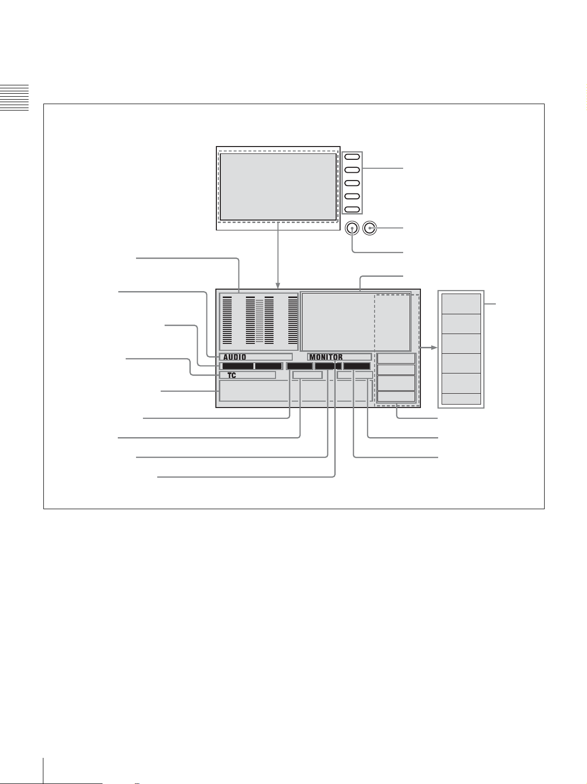
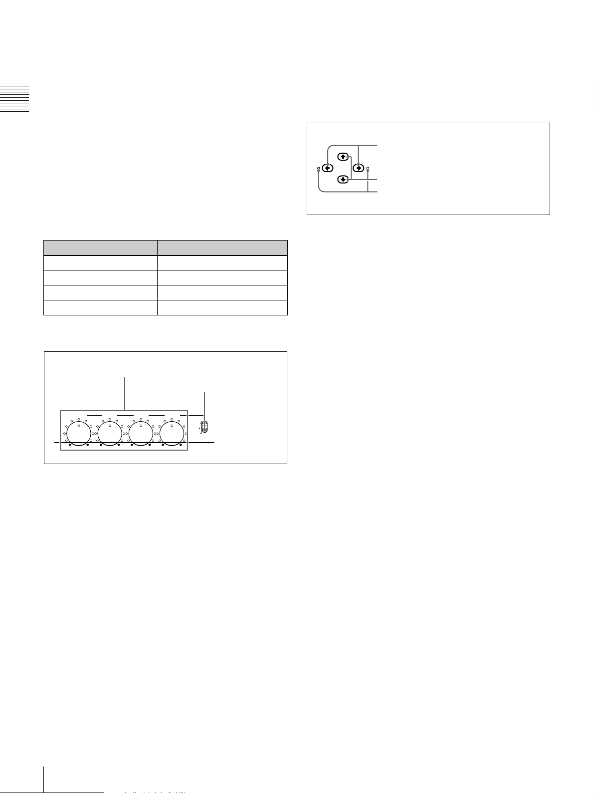
1 Display and function menu section
Chapter 1 Overview
1 Display
F1
F2
F3
F4
F5
PAGE DISPLAY
2 F1 to F5 buttons
3 DISPLAY/KEY INH button
q; Audio level meters
qa Audio format
qs Recording/playback format
qd Time data type
qf Time data display section
qg System line number
qh Clip number
qj System frequency
qk Audio monitor channels
0
-12
-20
-30
-40
-60
1
MPEG HD SP
3
4 CH
16 BIT 3+4
VITC REM:077
00:00.00:00
a Display
Normally this displays the audio level meters, timecode,
monitor pictures, and current settings. It also displays
menus and scene selection (thumbnail search) setting
screens.
b F1 to F5 (Function 1 to Function 5) buttons
These buttons are enabled when the function menu (see
page 72) is visible. Each press of a button changes the
setting of the corresponding item in the menu.
When the SUB CLIP and THUMBNAIL buttons are lit,
the F4 button functions as a CHAPTER button, and the F5
button functions as an EXPAND button.
4 PAGE button
5 Monitor video display section
0
-12
-20
-30
-40
-60
42
1080 60I INPUT
001/034
KEY INH
REC INH
M
REMOTE
RS422A
TCG
EXT
TC MODE
PRESET
RUN MODE
REC RUN
TC/VITC
VITC
DF/NDF
NDF
P2
7 Operation modes
8 Remaining disc capacity
9 Reference signal
c DISPLAY/KEY INH (key operation inhibit mode)
button
This functions as a DISPLAY button when pressed alone,
and as a KEY INH button when pressed together with the
SHIFT button.
DISPLAY button: Each press of this button switches the
monitor video display section between its three
display sizes.
KEY INH button: Each press of this button turns key
operation inhibit mode on or off.
d PAGE button
This displays the function menu, if it is not already visible.
(The most recently accessed page appears.) If the function
menu is visible, this button switches between the function
menu pages (HOME, P1, P2).
6 Function
menu
16
Names and Functions of Parts
e Monitor video display section
This displays monitor video and the system menu.
You can press the DISPLAY button to switch the display
of monitor video between three sizes. The largest size
occupies the full display screen.
Note
Use the largest size to view superimposed information.
f Function menu
Use the PAGE button to display this menu, and to switch
between the pages (HOME, P1, P2) of the menu. Each
page has five setting items, which correspond to the F1 to
F5 buttons. Press the corresponding button to change a
setting.
For details, see page 72 “Function Menu” in Chapter 6.
g Operation modes
This displays the current operation modes.
KEY INH (key operation inhibit mode): Key operation
inhibit mode has been turned on with the KEY INH
button.
REC INH (recording inhibit mode): Recording inhibit
mode has been turned on by setting REC INH on page
P1 of the function menu to “ON” (see page 73), or the
currently loaded disc is write protected.
Note
Recording inhibit mode is also turned on when the
settings of the recorded part of the currently loaded
disc do not match the current settings (number of
recording audio channels, system frequency) of the
unit.
REMOTE/interface name (remote mode): The remote
control switch is set to “REMOTE”. (The interface
name corresponds to the setting of INTERFACE
SELECT >REMOTE I/F in the setup menu (see page
80).)
h Remaining disc capacity
This displays the remaining capacity on the currently
loaded disc.
i Reference signal
This displays the type of reference signal to which this unit
is synchronizing.
When there is no display, the unit is synchronizing to the
internal reference signal.
INPUT: Input video
HD REF: HD-format reference signal
SD REF: SD-format reference signal
j Audio level meters
These display the audio recording levels (during
recording) or audio playback levels (during playback) of
channels 1 to 4. If an audio level exceeds 0 dB, the red
indicator bar at the top lights.
k Audio format
During playback, this displays the number of recording
audio channels on the disc and the number of quantization
bits. During recording, this displays the input signal format
selected with A1 INPUT to A4 INPUT on the HOME page
of the function menu (see page 72). During display of E-
1)
E
video, this displays 2CH/16BIT (two channels, 16 bits)
or 4CH/16BIT (four channels, 16 bits), according to the
setting of AUDIO CONTROL >REC MODE in the setup
menu (see page 80). Always displays 4CH/16BIT when
the DVCAM format is being used.
1) E-E: Abbreviation of Electric to Electric. A mode in which input video and
audio signals are output after passing through electric circuits only.
l Recording/playback format
This displays the following.
During playback: Recording format of the loaded disc.
During recording/E-E screen display/FAM connection:
Signal format Compression method
(video bit rate)
MPEG HD HQ
SP
LP
DVCAM –
a) Selected with OPERATIONAL FUNCTION >REC FORMAT in the
setup menu (see page 77).
a)
m Time data type
This displays the type of the time data that appears in the
time data display section. The time data type is set with
CNTR SEL on page P1 of the function menu (see page 73).
COUNTER: Elapsed recording/playback time
TC/VITC: Timecode
UB/VIUB: User bits
When TC or UB is selected, and VITC is selected under
TC/VITC on page P2 of the function menu (see page 74),
a VITC indicator appears, TC changes to VITC, and UB
changes to VIUB.
n Time data display section
Normally this displays the time data selected with CNTR
SEL on page P1 of the function menu (see page 73).
Messages appear here when an error occurs and when the
unit enters a different mode.
o System line number
This displays 1080, 525, or 625 depending on the signal
format during recording, playback, FAM connection.
Chapter 1 Overview
Names and Functions of Parts
17
p Clip number
This displays the clip number of the clip being monitored.
The clip number in the figure indicates that the first clip
out of 34 clips is selected.
q System frequency
Chapter 1 Overview
This displays the system frequency being used by this unit
(60I, 50I, 30P, or 25P) (see page 26).
r Audio monitor channels
This displays the audio monitor channels, as set with
MONI CH and MONI SEL on page P1 of the function
menu (see page 73).
When you are monitoring channels 1 and 2 (MONI CH is
set to “CH 1/2”), the display changes as follows,
depending on the setting of MONI SEL.
MONI SEL setting Display
MONO L (monaural L) 1 1
MONO R (monaural R) 2 2
STEREO 1 / 2
MIX 1 + 2
m button: MARK2 button
< button: IN button
, button: OUT button
You can use these buttons for menu setting operations,
thumbnail selection, setting or deleting In/Out points, and
so on.
MARK1
MARK2
1 </IN button and ,/OUT button
OUTIN
2 M/MARK1 button and m/MARK2 button
3 IN indicator and OUT indicator
a </IN button and ,/OUT button
When the setup or disc menu is visible, use these buttons
to change menu settings. When the THUMBNAIL button
is lit, you can use these for thumbnail selection.
An In or Out point is set when you press the SET button
with the </IN or ,/OUT button held down. The In or
Out point setting is deleted when you press the RESET
button with the </IN or ,/OUT button held down.
2 Audio level adjustment section
1 CH 1 to CH 4 knobs
2 VARIABLE switch
CH 1
CH 2 CH 3 CH 4
VARIABLE
PRESET
REC
PB
a CH 1 to CH 4 (audio level) knobs
Depending on the setting of the VARIABLE switch, these
adjust the input audio or playback audio levels of CH 1 to
CH 4.
b VARIABLE (audio level adjustment selector)
switch
This selects whether the input audio or the playback audio
has the levels adjusted by the CH 1 to CH 4 knobs.
REC: Adjust the input audio levels. The playback audio
levels are fixed at their preset values.
PRESET: All of the audio levels are fixed at preset values.
PB: Adjust the playback audio levels. The input audio
levels are fixed at their preset values.
3 Arrow buttons
The four arrow buttons are also used as the MARK1
button, MARK2 button, IN button, and OUT button, as
follows.
M button: MARK1 button
b M/MARK1 button and m/MARK2 button
When the setup or disc menu is visible, use these buttons
to change menu settings. When the THUMBNAIL button
is lit, you can use these for thumbnail selection.
During recording and playback, the M/MARK1 or m/
MARK2 button can be pressed with the SET button held
down to record a SHOT MARK1 or SHOT MARK2 as an
essence mark.
To delete or change essence marks, use the supplied PDZ1 Proxy Browsing Software. See “Using PDZ-1 Proxy
Browsing Software” in Chapter 4 (page 66) for more
information about installing the PDZ-1 software. See the
online help of PDZ-1 for more information about using
PDZ-1.
You can delete SHOT MARK1 and SHOT MARK2 in the
CHAPTER screen. For details, see “To delete shot marks
at chapter positions” (page 45).
c IN indicator and OUT indicator
IN indicator: This lights when an In point exists. It flashes
if an attempt is made to set an In point after a recorded
Out point.
OUT indicator: This lights when an Out point exists. It
flashes if an attempt is made to set an Out point before
a recorded In point.
18
Names and Functions of Parts

4 Shuttle/jog/variable-speed playback
control block
The shuttle dial has a detent at the center position, for still
image playback.
4 Jog/shuttle transport indicators
VAR
1 VAR button
JOG
2 JOG button
SHUTTLE
3 SHUTTLE
button
5 Jog dial
6 Shuttle dial
For details about playback operations with these buttons
and dials, see page 40 “Playback” in Chapter 3.
a VAR (variable) button
To play back in variable-speed mode using the shuttle dial,
press this button, turning it on.
b JOG button
To play back in jog mode using the jog dial, press this
button, turning it on.
c SHUTTLE button
To play back in shuttle mode using the shuttle dial, press
this button, turning it on.
d Jog/shuttle transport indicators
These show the playback direction in jog, shuttle, or
variable-speed mode.
b (green): Lights during playback in the reverse direction.
B (green): Lights during playback in the forward
direction.
x (orange): Lights during still image display.
5 Recording/playback control block
1 . PREV/TOP button
2 B PLAY button
3 > NEXT/END button
PREV NEXTPLAY STOP REC
TOP
F REV F FWD
4 x STOP/STANDBY button
5 z REC button
a . PREV (previous)/TOP button
This functions as a PREV button when pressed alone, and
as a TOP button when pressed together with the SHIFT
button.
PREV button: Press this button, turning it on, to jump to
the first frame of the current clip or the previous REC
START essence mark.
frame of the current clip, this button jumps to the first
frame of the previous clip (if it exists).
TOP button: Press this button to jump to the first frame of
the first clip or to the first REC START essence mark
of the first clip.
1)
You can perform a high-speed search in the reverse
direction by pressing the PREV button together with the
PLAY button.
1) The setting of OPERATIONAL FUNCTION >FIND MODE determines
whether the unit jumps to clips or to REC START essence marks.
When you play back clips recorded with the Clip Continuous Rec function
(see page 40), you should set this menu item to “REC START EM”.
END
STANDBY
1)
When pressed at the first
Chapter 1 Overview
e Jog dial
Turn this for playback in jog mode. Turn clockwise for
forward direction playback, and counterclockwise for
reverse direction playback. In jog mode, the playback
speed varies in the range ±1 times normal speed, according
to the rotation rate of the jog dial. The dial has no detents.
f Shuttle dial
Turn this for playback in shuttle mode or variable-speed
mode. Turn clockwise for forward direction playback, and
counterclockwise for reverse direction playback.
• In shuttle mode, the playback speed varies in the range
±20 times normal speed (using MPEG HD/DVCAM),
according to the angular position of the shuttle dial.
• In variable-speed mode, you can finely adjust the
playback speed from –1 to +2 times normal speed,
according to the angular position of the shuttle dial.
b B PLAY button
Press this button, turning it on, to start playback. Press the
STOP button to stop playback.
You can perform a high-speed search in the forward or
reverse direction by pressing this button together with the
NEXT button or PREV button.
c > NEXT/END button
This functions as a NEXT button when pressed alone, and
as an END button when pressed together with the SHIFT
button.
NEXT button: Press this button, turning it on, to jump to
the first frame of the next clip or the next REC
START essence mark.
1)
END button: Press this button to jump to the last frame of
the last clip or to the last REC START essence mark
of the last clip.
1)
Names and Functions of Parts
19

You can perform a high-speed search in the forward
direction by pressing the NEXT button together with the
PLAY button.
1) The setting of OPERATIONAL FUNCTION >FIND MODE determines
whether the unit jumps to clips or to REC START essence marks.
Chapter 1 Overview
When you play back clips recorded with the Clip Continuous Rec function
(see page 40), you should set this menu item to “REC START EM”.
STANDBY button: Press this button to put the unit into
standby-off mode (the STOP button lights, and the
STANDBY indicator goes off). Press it again to
return to the original state (the STOP button lights,
and the STANDBY indicator lights).
This unit enters standby off mode automatically after
a certain length of time passes.
d x STOP/STANDBY button
This functions as a STOP button when pressed alone, and
as a STANDBY button when pressed together with the
SHIFT button.
STOP button: Press this button, turning it on, to stop
recording or playback. The frame at the stop position
is displayed.
Rear Panel
Note
When the unit is shipped from the factory, connector
covers are attached to some of the connectors on the rear
1 Analog video signal
input/output section
2 Analog audio signal
input/output section
3 Digital signal input/
output section
REF VIDEO INPUT
AUDIO INPUT
1/3 2/4
COMPOSITE OUTPUT
HDSDI OUTPUT
12
AUDIO MONITOR
R L IN OUT
AUDIO OUTPUT
1/3 2/4
SDSDI OUTPUTHDSDI INPUT
e z REC (record) button
Press this button together with the PLAY button to start
recording. Recording starts on the unrecorded part of the
disc.
Press the STOP button to stop recording. A clip is created
from the recorded section.
panel. The explanations in this section assume that all
covers have been removed.
For details, see “Removing the Connector Covers” (page
27).
4 Digital audio signal input/output
section
5 Timecode input/output section
MONITOR
DIGITAL
AUDIO
(AES/EBU)
OUTPUT
INPUT
CONTROL
TIME CODE
1/2 3/4
1/2
3/4
RS232C REMOTE(9P)
ANALOG HD INPUT
Y/G P
PB /B
-
AC IN
B /R
SYNS
POWER
6 Power supply
section
S400
20
Names and Functions of Parts
7 External device connection
section
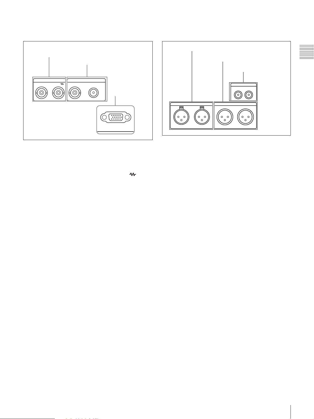
1 Analog video signal input/output
section
1 REF VIDEO INPUT connectors
2 COMPOSITE OUTPUT
connectors
REF VIDEO INPUT COMPOSITE OUTPUT
3 MONITOR
connector
MONITOR
2 Analog audio signal input/output
section
1 AUDIO INPUT 1/3 and 2/4 connectors
2 AUDIO OUTPUT 1/3 and 2/4
connectors
3 AUDIO MONITOR
connectors
AUDIO MONITOR
RL
AUDIO INPUT
1/3 2/4
AUDIO OUTPUT
1/3 2/4
Chapter 1 Overview
a REF VIDEO INPUT (reference video signal input)
connectors (BNC type)
The two connectors form a loop-through connection; when
a reference video signal is input to the left connector, the
same signal is output from the right connector ( ) to a
connected device. When no connection is made to the right
connector, the left connector is automatically terminated
with an impedance of 75 ohms.
b COMPOSITE OUTPUT connectors (phono jack,
BNC type)
These output composite video signals.
When CHAR SEL on page P1 of the function menu is set
to “ON”, and DISPLAY CONTROL >SD CHARA in the
setup menu is set to “COMPOSITE” or “ALL”,
information such as timecode, menu settings, and error
messages is superimposed on the output signals (see page
33).
c MONITOR connector (D-sub 15-pin)
This outputs HD analog video signals. The output signals
can be switched with INTERFACE SELECT >D-SUB
OUTPUT in the setup menu (see page 80).
When CHAR SEL on page P1 of the function menu is set
to “ON”, and DISPLAY CONTROL >HD CHARA in the
setup menu is set to “ALL”, information such as timecode,
menu settings, and error messages is superimposed on the
output signals (see page 33).
a AUDIO INPUT (analog audio signal input) 1/3 and
2/4 connectors (XLR 3-pin, female)
These connectors input two channels of analog audio.
You can use the A1 INPUT to A4 INPUT items on the
HOME page of the function menu (see page 72) to assign
the signals input to connectors 1/3 (ANALOG1) and
connectors 2/4 (ANALOG2) to audio channels 1 to 4.
You can set the reference input levels with the setup menu
item AUDIO CONTROL >LEVEL SELECT (the factory
default settings are INPUT: +4 dB, REF LEVEL:
–20 dB).
b AUDIO OUTPUT (analog audio signal output) 1/3
and 2/4 connectors (XLR 3-pin, male)
These output two channels of analog audio.
For 4-channel audio, you can use the INTERFACE
SELECT >AUDIO OUTPUT item of the setup menu (see
page 80) to select whether to output channels 1 and 2, or
channels 3 and 4 (factory default setting: channels 1 and
2).
You can set the output level with the setup menu item
AUDIO CONTROL >LEVEL SELECT (factory default
setting: +4 dB) (see page 80).
c AUDIO MONITOR connectors (phono jack)
These output audio signals for monitoring.
You can select the channels to monitor with MONI CH and
MONI SEL on page P1 of the function menu (see page 73).
Names and Functions of Parts
21
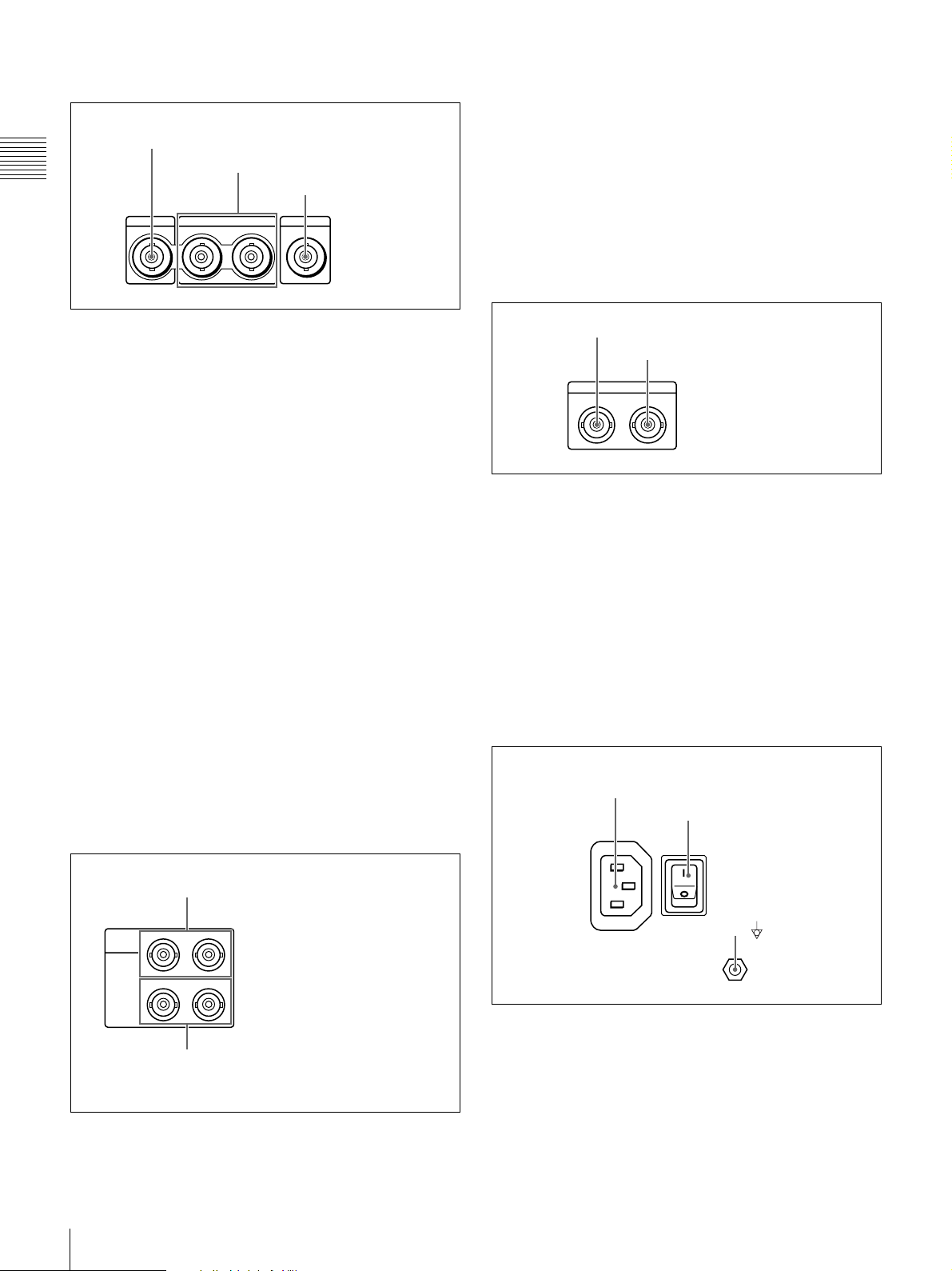
3 Digital signal input/output section
These input AES/EBU format digital audio signals. The
1/2 connector corresponds to audio channels 1 and 2, and
the 3/4 connector corresponds to audio channels 3 and 4.
1 HDSDI INPUT connector
Chapter 1 Overview
HDSDI INPUT
2 HDSDI OUTPUT connectors
3 SDSDI OUTPUT
connector
HDSDI OUTPUT
12
SDSDI OUTPUT
a HDSDI (HD serial digital interface) INPUT
connector (BNC type)
This inputs HD format video and audio signals.
b HDSDI (HD serial digital interface) OUTPUT
connectors (BNC type)
These output HD format video and audio signals.
When CHAR SEL on page P1 of the function menu is set
to “ON”, and DISPLAY CONTROL >HD CHARA in the
setup menu is set to “ALL” (or either “HDSDI2” or “ALL”
for the HDSDI OUTPUT 2 connector), information such
as timecode, menu settings, and error messages is
superimposed on the output signals (see page 33).
c SDSDI OUTPUT connector (BNC type)
This outputs SDSDI signals downconverted from HD
video input signals, or the SDSDI signals being played
back or being recorded.
When CHAR SEL on page P1 of the function menu is set
to “ON”, and DISPLAY CONTROL >SD CHARA in the
setup menu is set to “SDI” or “ALL”, information such as
timecode, menu settings, and error messages is
superimposed on the output signals (see page 33).
b DIGITAL AUDIO (AES/EBU) OUTPUT 1/2 and
3/4 connectors (BNC type)
These output AES/EBU format digital audio signals. The
1/2 connector corresponds to audio channels 1 and 2, and
the 3/4 connector corresponds to audio channels 3 and 4.
5 Timecode input/output section
1 TIME CODE IN connector
2 TIME CODE OUT connector
TIME CODE
IN OUT
a TIME CODE IN connector
Inputs SMPTE timecode generated by an external device.
b TIME CODE OUT connector
Outputs the following timecode, depending on the
operating state of the unit.
During playback: Playback timecode
During recording: The timecode from the internal
timecode generator or the timecode input to the TIME
CODE IN connector.
6 Power supply section
4 Digital audio signal input/output
section
1 DIGITAL AUDIO (AES/EBU) INPUT
1/2 and 3/4 connectors
DIGITAL
1/2 3/4
AUDIO
(AES/EBU)
INPUT
1/2
OUTPUT
a DIGITAL AUDIO (AES/EBU) INPUT 1/2 and 3/4
connectors (BNC type)
22
Names and Functions of Parts
3/4
2 DIGITAL AUDIO (AES/EBU) OUTPUT
1/2 and 3/4 connectors
1 - AC IN connector
2 POWER switch
-AC IN
POWER
3 terminal
a -AC IN (AC power input) connector
Connect to an AC power supply with the power cord (not
supplied).
b POWER (main power) switch
Press the + side to power on the unit. Press the a side to
power off.
When using the unit, normally leave the POWER switch in
the + (on) position, and use the on/standby switch on the
front panel to switch the unit between the operating state
and standby state.
d Remote connector selector switch
Push this switch to the side of the remote control connector
you are using, either the RS232C connector or the
REMOTE (9P) connector.
Note
If you press the on/standby switch on the front panel while
the unit is in the operating state, the unit saves its data and
then enters the standby state (the on/standby indicator
lights orange). Before turning the main power off, always
check to be sure that the unit is in the standby state, and
then push the main power switch to the a side.
c (equipotential ground) terminal
Use to make an equipotential ground connection.
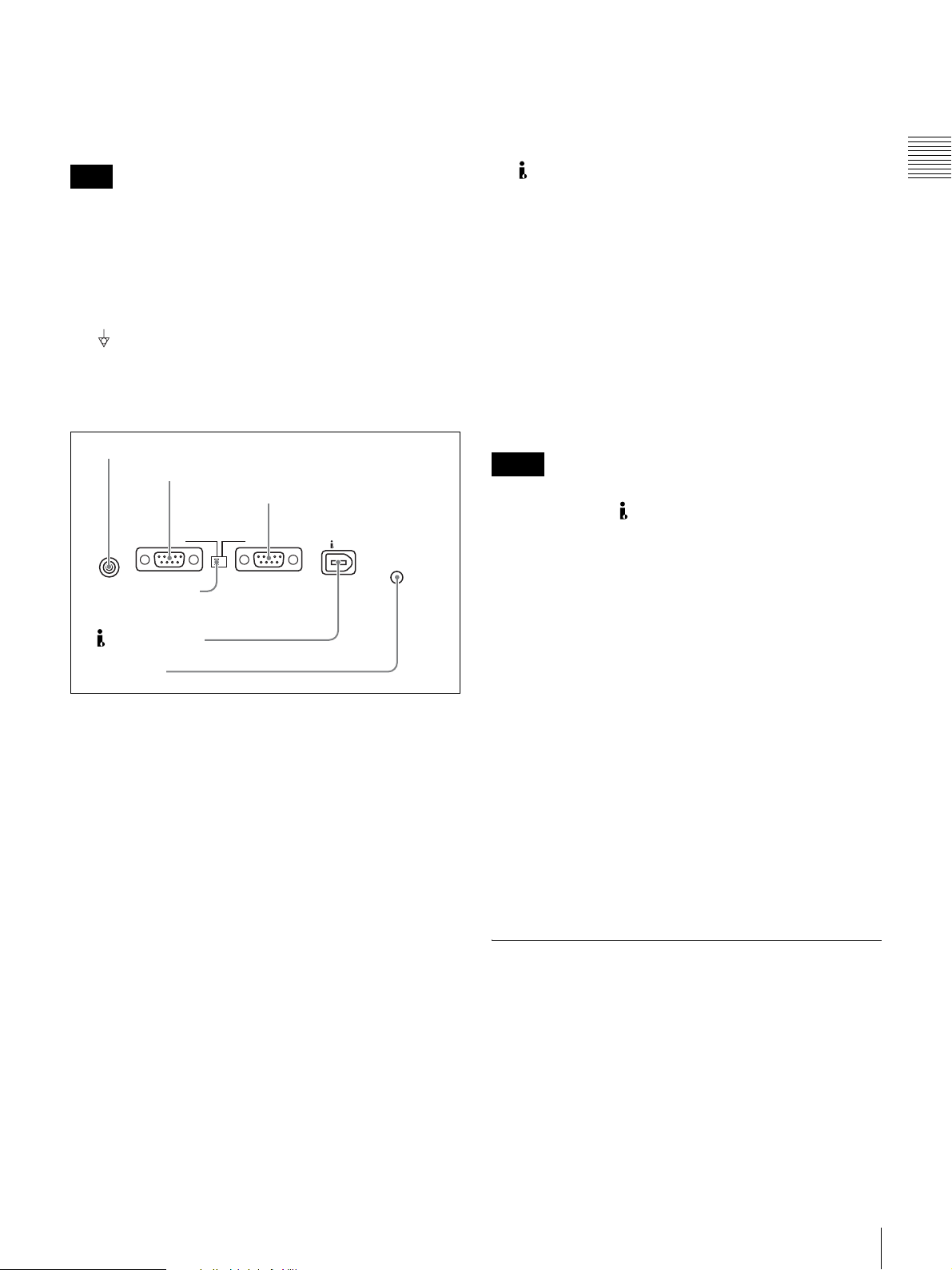
7 External device connection section
1 CONTROL connector
2 RS232C connector
3 REMOTE(9P) connector
CONTROL
4
Remote connector
selector switch
5 S400 connector
6 U terminal
RS232C REMOTE(9P)
a CONTROL connector (minijack 4-pole)
Connect the optional RM-LG2 Remote Control Unit.
b RS232C (serial interface) connector (D-sub 9-pin,
male)
Connect a computer or other device with a serial interface
to control this unit from that device.
When you use this connector, set the remote connector
selector switch to the RS232C side, and set INTERFACE
SELECT >REMOTE I/F in the setup menu to “9PIN/RS232C” (see page 80).
S400
e S400 connector (6-pin, IEEE1394 compliant)
Connect a DV device or computer using an i.LINK cable.
The following connection types are supported. They are
selected by setting INTERFACE SELECT >i.LINK
MODE in the setup menu (see page 80).
AV/C (Audio/Video Control) connection: Output
DVCAM format digital video and audio signals
(i.LINK MODE set to “AV/C”).
Audio output signals are 2ch or 4ch, as selected by
AUDIO CONTROL >DV OUT MODE in the setup
menu (see page 80).
FAM (file access mode) connection: Input and output
files between this unit and a computer (i.LINK
MODE set to “FAM (PC REMOTE)”).
Notes
• If video or audio signals from an external device
connected to the S400 connector fail to be output,
disconnect the i.LINK cable and connect it again,
pushing it straight in.
• Before connecting or disconnecting an i.LINK cable
between this unit and a device with a 6-pin i.LINK
connector, power off the device and disconnect its power
cord from the electrical outlet. If the i.LINK cable is
connected or disconnected with the device’s power plug
still connected, high voltage (8 to 40 V) from the
device’s i.LINK connector can flow into this unit,
possibly damaging the unit.
• When connecting this unit to a device with a 6-pin
i.LINK connector, connect to the 6-pin i.LINK
connector of the other device first.
• Except in playback modes (jog and shuttle modes, etc.),
audio signals output from this connector and monitored
on another device may sound different from the audio
signals played back on this unit.
f U (signal ground) terminal
Connect to the system ground.
Chapter 1 Overview
c REMOTE(9P) (remote control 9-pin) connector
(D-sub 9-pin, RS-422A compliant, female)
To control this unit from a controller or VTR supporting
the RS-422A Sony 9-pin VTR protocol, connect the device
to this connector. When you use this connector, set the
remote connector selector switch to the REMOTE(9P)
side, and set INTERFACE SELECT > REMOTE I/F in the
setup menu to “9PIN/RS-232C” (see page 80).
Infrared Remote Commander
The corresponding functions are executed when you point
the remote commander at the infrared sensor of the main
unit and press the keys and setting pad.
Names and Functions of Parts
23
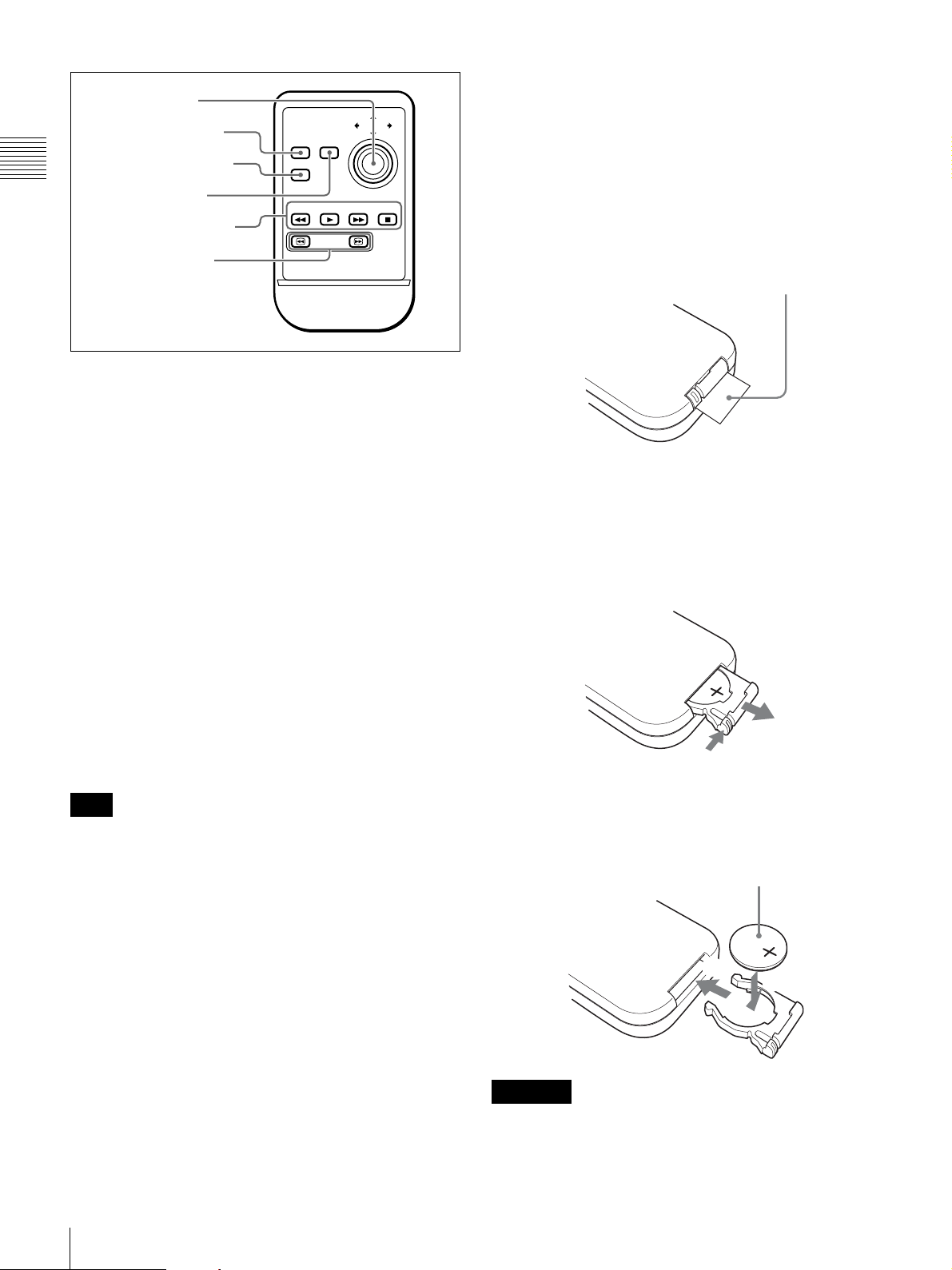
1 Setting pad
1
2 THUMBNAIL key
3 CHARACTER key
Chapter 1 Overview
4 SUB CLIP key
5 Recording/playback
control keys
6 SEARCH keys
THUMBNAIL
CHARACTER
PREV PLAY
PUSH SET
SUB CLIP
NEXT STOP
SEARCH
a Setting pad
Positions on the pad correspond to functions of the main
unit, as follows.
Press the top side: M/MARK1 button
Press the bottom side: m/MARK2 button
Press the left side: </IN button
Press the right side: ,/OUT button
Press the middle: SET button
f SEARCH keys
Press m to perform –5 times normal speed shuttle
playback in the reverse direction.
Press M to perform +5 times normal speed shuttle
playback in the forward direction.
Using the infrared remote commander
Before use
Pull out the insulation sheet.
Insulation sheet
To replace the lithium battery in the remote
commander
The remote commander uses a CR2025 Lithium Battery.
Do not use a battery other than the CR2025.
b THUMBNAIL key
This has the same function as the THUMBNAIL button on
the main unit.
c CHARACTER key
Each press of this key turns the character information
superimposed on the monitor screen on and off, or
switches to the LCD.
d SUB CLIP key
This has the same function as the SUB CLIP button on the
main unit.
Note
Pressing this key has no effect when no clip list is
registered.
e Recording/playback control keys
m PREV (previous) key:Press this to jump to the first
frame of the current clip or the previous REC START
essence mark.
1)
When pressed at the first frame of the
current clip, this button jumps to the first frame of the
previous clip (if it exists).
B PLAY key: Press this to start playback. Press the STOP
key to stop playback.
M NEXT key: Press this to jump to the first frame of the
next clip or to the next REC START essence mark.
1)
x STOP key: Press this to stop recording or playback.
1
Hold down the lock lever 1, and then pull out the
battery holder 2.
2
2
Insert a new battery with the + symbol facing upward
(1), and then push the battery holder until it clicks
(2).
Face the + symbol upward.
2
1
WARNING
1) The setting of OPERATIONAL FUNCTION >FIND MODE determines
whether the unit jumps to clips or to REC START essence marks.
When you play back clips recorded with the Clip Continuous Rec function
(see page 40), you should set this menu item to “REC START EM”.
24
Names and Functions of Parts
Battery may explode if mistreated. Do not recharge,
disassemble or dispose of in fire.

CAUTION
Danger of explosion if battery is incorrectly replaced.
Replace only with the same or equivalent type
recommended by the manufacturer.
When you dispose of the battery, you must obey the law in
the relative area or country.
Battery lifetime
When the lithium battery output falls, even button presses
may not operate. The average lithium battery lifetime is
about one year, but this depends on the pattern of use.
If pressing the remote control buttons produces absolutely
no effect on this unit, replace the battery, then check the
operation again.
Chapter 1 Overview
Names and Functions of Parts
25
Preparations
Chapter 2 Preparations
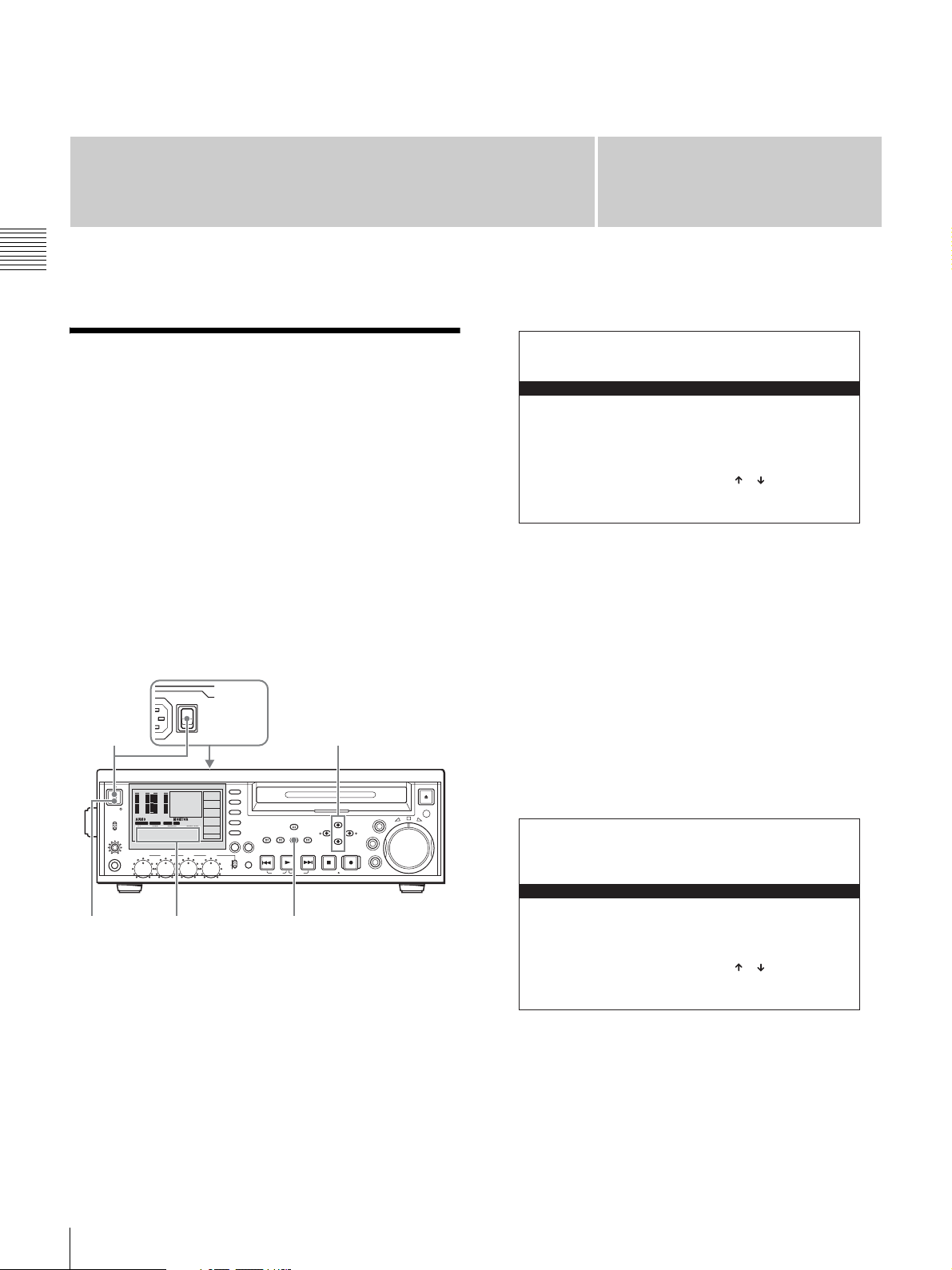
Setting the System Frequency
This unit is shipped with the system frequency still unset.
Therefore, you need to set the system frequency before
using the unit. (The unit cannot be used unless the system
frequency is set.)
Once it is set, the system frequency is retained even when
the unit is powered off.
Chapter
2
SYSTEM SEL
SYSTEM FREQ:
60I
50I
30P
25P
SELECT : ( )( )KEY
DATA SET : SET KEY
2
Press the M/MARK1 button or the m/MARK2 button
to select the system frequency to use.
To set the system frequency
Use the following procedure.
Rear panel
POWER
POWER
1
0
0
-12
-12
-20
-20
-30
-30
-40
ACCESS
NETWORK
REMOTE
LEVEL
PHONES
4
1
Power the unit on.
“SYSTEM SEL” appears in the time data display
section.
-40
-60
-60
1
3
4 CH
16BIT 3+4
MPEG HD SP
1080 60I
LOCAL
VITC REM:077
00:00.00:00
CH 1 CH 2 CH 3 CH 4
Time data display section
switch
2
F1
TCG
EXT
F2
TC MODE
PRESET
RUN MODE
F3
REC RUN
42
TC/VITC
F4
VITC
COOO1
CHAPTER
M
DF/NDF
NDF
P2
VARIABLE
REC
PRESET
F5
PAGE DISPLAY
PB
SUB
THUMB
EXPAND
CLIP
NAIL
CLIP
ESSENCE
MENU
MARK
PREV NEXTPLAY STOP
KEY INHI
SHIFT
TOP
F REV F FWD
MARK1
MENU
SET
RESET
OUTIN
MARK2
REC
END
STANDBY
3
JOG
SHUTTLE
3
Press the SET button.
“NOW SAVING...” appears in the time data display
section, and the modified setting is saved in the unit’s
memory.
“COMPLETE ! !” appears when save processing
finishes.
If you have selected 60I or 30P
EJECT
VAR
When you press the SET button with 60I or 30P
selected in step 2, the following screen appears.
SYSTEM SEL
SYSTEM FREQ : 601
UC/J SELECT : UC
UCP
J
SELECT : ( )( )KEY
DATA SET : SET KEY
Press the M/MARK1 and m/MARK2 buttons to select
“UC” (for areas outside Japan) or “J” (for Japan), then
press the SET button.
26
Setting the System Frequency
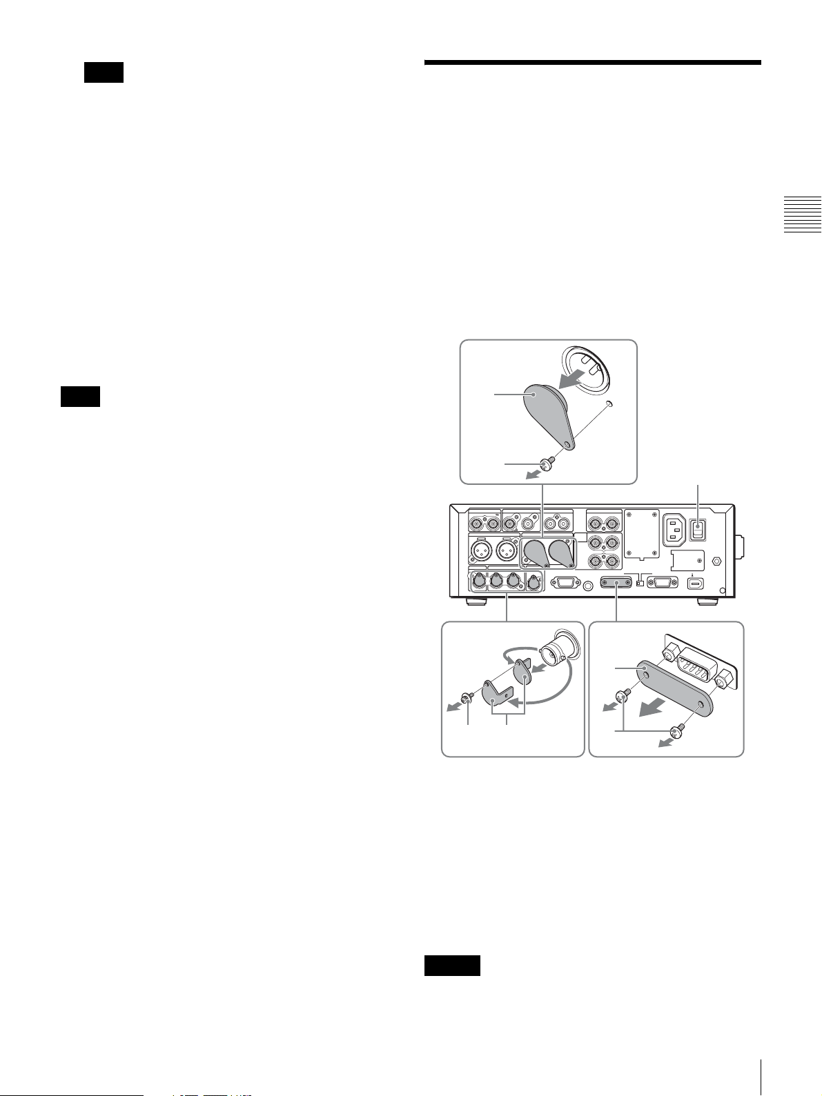
Note
Be sure to carry out step 3 before powering the unit off
(putting it into standby). The new system frequency
setting will not be saved if you power off without
carrying out step 3.
4
Press the on/standby switch to power the unit off (put
it into standby), and then press it again to power the
unit on.
The selected system frequency becomes available for
use.
You can change the system frequency setting by using the
setup menu item OPERATIONAL FUNCTION >SYSTEM
SEL >SYSTEM FREQ.
For details about the setup menu, see page 74 “System
Menu” in Chapter 6.
Removing the Connector Covers
When the unit is shipped from the factory, connector
covers are attached to the following connectors.
• AUDIO OUTPUT 1/3 and 2/4 connectors
• HDSDI INPUT connector
• HDSDI OUTPUT connectors
• SDSDI OUTPUT connector
• RS232C connector
To use one of these connectors, remove the cover as
follows.
Chapter 2 Preparations
Note
When the system frequency is set to 60I or 30P, select
drop-frame mode (DF) or non-drop-frame mode (NDF) on
page P2 of the function menu (see page 74).
3
REF VIDEO INPUT
AUDIO INPUT
1/3 2/4
2
COMPOSITE OUTPUT AUDIO MONITOR
HDSDI OUTPUT
12
R L IN OUT
AUDIO OUTPUT
1/3 2/4
SDSDI OUTPUTHDSDI INPUT
MONITOR
DIGITAL
AUDIO
(AES/EBU)
INPUT
OUTPUT
1/2 3/4
1/2
CONTROL
TIME CODE
ANALOG HD INPUT
Y/G P
PB /B
3/4
RS232C REMOTE(9P)
SYNS
1
-AC IN
POWER
B /R
S400
3
2
3
1
Press the POWER (main power) switch to power the
unit off.
2
2
Remove the screw(s) of the connector cover, using a
screwdriver that matches the grooves of the screw(s).
3
Remove the connector cover.
Save the screw(s) and cover, so that you can reattach
the cover if necessary.
Caution
These connectors are designed to allow direct contact with
conductive circuits. Weak voltage may be present because
Removing the Connector Covers
27

of a failure in this unit. To prevent patients from touching
these connectors accidentally, attach the connector covers
when the connectors are not being used to connect to other
devices.
Chapter 2 Preparations
Connections and Settings
Note
Production of some of the peripherals and related devices
described in this chapter has been discontinued.
For advice about choosing devices, please contact your
Sony dealer or a Sony sales representative.
Connecting an External Monitor
You can connect a video monitor to this unit’s video output
connectors or to the MONITOR connector. The following
figure shows an example using a Sony multi-format LCD
monitor.
You can also superimpose character information such as
timecode and the unit’s operating status on output video.
For details, see “Superimposed Text Information” (page
33).
To view HD video
Connect an HD video monitor using method 1 or 2 in
the following figure.
When you connect a monitor with method 2, set the setup
menu item INTERFACE SELECT >D-SUB OUTPUT to
“YPbPr” (see page 80).
28
Connections and Settings
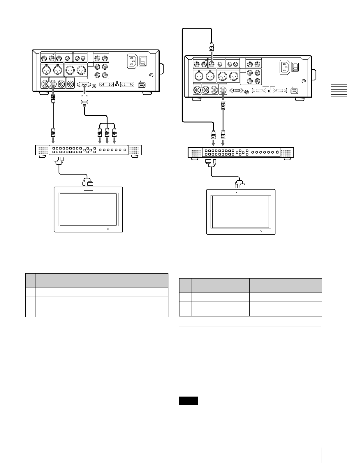
REF VIDEO INPUT
AUDIO INPUT
1/3 2/4
HDSDI OUTPUT
12
1
AUDIO MONITOR
COMPOSITE OUTPUT
R L IN OUT
AUDIO OUTPUT
1/3 2/4
SDSDI OUTPUTHDSDI INPUT
MONITOR
HDSDI
OUTPUT
SDI signal input
connector
a)
TIME CODE
DIGITAL
1/2 3/4
AUDIO
(AES/EBU)
INPUT
1/2
OUTPUT
CONTROL
MONITOR
2
PDW-75MD (this unit)
-AC IN
ANALOG HD INPUT
B /R
Y/G P
PB /B
SYNS
3/4
RS232C REMOTE(9P)
Y/P
B/PR
connectors
AUDIO INPUT
HDSDI OUTPUT
12
COMPOSITE OUTPUT
1/3 2/4
AUDIO MONITOR
R L IN OUT
AUDIO OUTPUT
SDSDI OUTPUTHDSDI INPUT
MONITOR
DIGITAL
AUDIO
(AES/EBU)
INPUT
OUTPUT
CONTROL
1/2 3/4
1/2
PDW-75MD (this unit)
TIME CODE
ANALOG HD INPUT
Y/G P
B /R
PB /B
SYNS
3/4
RS232C REMOTE(9P)
-AC IN
POWER
S400
POWER
S400
COMPOSITE
OUTPUT
REF VIDEO INPUT
1/3 2/4
Chapter 2 Preparations
SDSDI
OUTPUT
2
COMPOSITE
IN connector
1
SDI signal input
connector
a)
MEU-WX2 Multi-Format Engine
LMD-172W/232W Multi-Format LCD Monitor
a) To input HDSDI signals, a BKM-243HS (not supplied) is required.
Connection method and connection cables
Connection method Connection cables (not
1 HDSDI 75Ω coaxial cable
2 Component
B/PR
)
(Y/P
supplied)
D-Sub 15-pin – analog
component cable, phono plug –
stereo miniplug cable
To view SD video
Connect an SD video monitor using method 1 or 2 in the
following figure.
MEU-WX2 Multi-Format Engine
LMD-172W/232W Multi-Format LCD Monitor
a) To input SDSDI signals, a BKM-220D (not supplied) is required.
Connection method and connection cables
Connection method Connection cables (not
supplied)
1 SDSDI 75Ω coaxial cable
2 Composite 75Ω coaxial cable, phono
plug – stereo miniplug cable
Using PDZ-1 over an i.LINK Connection (FAM Connection)
You can use the supplied PDZ-1 Proxy Browsing Software
to do simple editing of proxy AV data. The following
explains how to make an i.LINK connection between this
unit and a computer with PDZ-1 installed, and how to
access this unit by FAM (file access mode).
Notes
• The required FAM driver is installed when you install
the PDZ-1 software.
• Use version 2.01 or higher of the FAM driver.
Connections and Settings
29
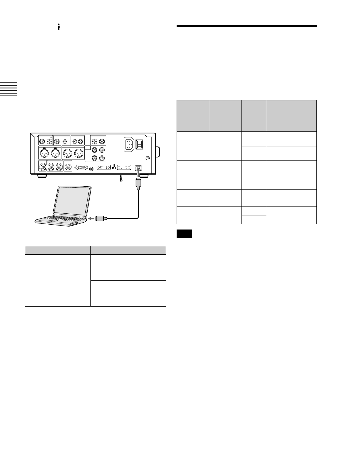
• This unit’s S400 connector has 6 pins. Check the
number of pins on the i.LINK connector of your
notebook computer, and use an appropriate i.LINK
cable.
External Synchronization
See “Using PDZ-1 Proxy Browsing Software” in Chapter
4 (page 66) for more information about installing the
PDZ-1 software. See the online help of PDZ-1 for more
information about using PDZ-1.
Some limitations apply to FAM connections. For details,
Chapter 2 Preparations
see “File Operations in File Access Mode (for Windows)”
in Chapter 5 (page 67).
PDW-75MD (this unit)
REF VIDEO INPUT
AUDIO INPUT
1/3 2/4
HDSDI OUTPUT
12
Laptop computer
COMPOSITE OUTPUT
1/3 2/4
AUDIO MONITOR
R L IN OUT
AUDIO OUTPUT
SDSDI OUTPUTHDSDI INPUT
MONITOR
DIGITAL
AUDIO
(AES/EBU)
INPUT
OUTPUT
CONTROL
1/2 3/4
1/2
TIME CODE
3/4
RS232C REMOTE(9P)
ANALOG HD INPUT
Y/G P
PB /B
-AC IN
B /R
SYNS
S400
i.LINK cable
(not supplied)
i.LINK (IEEE1394) connector
POWER
S400
This unit synchronizes as shown in the following table,
according to the presence or absence of signals input to the
HDSDI INPUT connector, the presence or absence of
signals input to the REF VIDEO INPUT connector, and
the setting of the V INPUT item on the HOME page of the
function menu (see page 72).
Signal
input to
HDSDI
INPUT
connector
Yes Yes HDSDI Synchronize to
Yes No HDSDI Synchronize to
No Yes HDSDI Synchronize to REF
No No HDSDI No external
Note
Signal
input to
REF VIDEO
INPUT
connector
V INPUT
setting
External
synchronization
HDSDI input
SG Synchronize to REF
VIDEO input
HDSDI input
SG No external
synchronization
SG
SG
VIDEO input
synchronization
On the computer On this unit
Install PDZ-1. Set the setup menu item
INTERFACE SELECT
>REMOTE I/F to “i.LINK” (see
page 80).
Set the setup menu item
INTERFACE SELECT >i.LINK
MODE to “FAM(PC REMOTE)”
(see page 80).
There is no external synchronization for file operations by
FAM connection (see page 67).
30
External Synchronization
 Loading...