

Sony PDW-530P, PDW-530, PDW-510P User Manual

PROFESSIONAL DISC CAMCORDER
PDW-510/510P
PDW-530/530P
OPERATION MANUAL [English]
1st Edition (Revised 8)
WARNING
To reduce the risk of fire or electric shock,
do not expose this apparatus to rain or
moisture.
To avoid electrical shock, do not open the
cabinet. Refer servicing to qualified
personnel only.
This Professional Disc Camcorder is classified as a CLASS 1
LASER PRODUCT.
Laser diode properties
Wavelength: 403 to 410 nm
Emission duration: Continuous
Laser output power: 65 mW (max. of pulse peak), 35 mW
(max. of CW)
Tekniska data för laserdiod
Våglängd: 403 till 410 nm
Emissionslängd: Kontinuerlig
Laseruteffekt: 65 mW (max. för pulstopp), 35 mW (max. för
kontinuerlig våg)
Spesifikasjoner laserdiode
Bølgelengde: 403 til 410 nm
Strålingens varighet: Kontinuerlig
Laserens effekt: 65 mW (maks stråletoppunkt), 35 mW
(maks ved kontinuerlig stråling)
Laserdiodin ominaisuudet
Aallon pituus: 403 - 410 nm
Välityksen kesto: Jatkuva
Laserlähdön teho: 65 mW (sykehuipun maks.), 35 mW
(jatkuvan aallon maks.)
This label is located inside
the outside panel of the unit.
Denna etikett finns på
apparatens ovansida.
Denne mærkat sidder på
apparatets øverste panel.
Tämä kyltti sijaitsee laitteen
yläpinnalla.
Dette merket er plassert på
oversiden av produktet.
CAUTION
The use of optical instruments with this product will increase
eye hazard.
CAUTION
Use of controls or adjustments or performance of procedures
other than those specified herein may result in hazardous
radiation exposure.
VAROITUS!
LAITTEEN KÄYTTÄMINEN MUULLA KUIN TÄSSÄ
KÄYTTÖOHJEESSA MAINITULLA TAVALLA SAATTAA
ALTISTAA KÄYTTÄJÄN TURVALLISUUSLUOKAN 1
YLITTÄVÄLLE NÄKYMÄTTÖMÄLLE LASERSÄTEILYLLE.
VARNING
OM APPARATEN ANVÄNDS PÅ ANNAT SÄTT ÄN I DENNA
BRUKSANVISNING SPECIFICERATS, KAN ANVÄNDAREN
UTSÄTTAS FÖR OSYNLIG LASERSTRÅLNING, SOM
ÖVERSKRIDER GRÄNSEN FÖR LASERKLASS 1.
For the customers in the USA
This equipment has been tested and found to comply with the
limits for a Class B digital device, pursuant to Part 15 of the
FCC Rules. These limits are designed to provide reasonable
protection against harmful interference in a residential
installation. This equipment generates, uses, and can radiate
radio frequency energy and, if not installed and used in
accordance with the instructions, may cause harmful
interference to radio communications.
2

However, there is no guarantee that interference will not occur
in a particular installation. If this equipment does cause
harmful interference to radio or television reception, which can
be determined by turning the equipment off and on, the user is
encouraged to try to correct the interference by one or more of
the following measures;
– Reorient or relocate the receiving antenna.
– Increase the separation between the equipment and
receiver.
– Connect the equipment into an outlet on a circuit different
from that to which the receiver is connected.
– Consult the dealer or an experienced radio/TV technician for
help.
You are cautioned that any changes or modifications not
expressly approved in this manual could void your authority to
operate this equipment.
All interface cables used to connect peripherals must be
shielded in order to comply with the limits for a digital device
pursuant to Subpart B of Part 15 of FCC Rules.
For the customers in the USA
Lamp in this product contains mercury. Disposal of these
materials may be regulated due to environmental
considerations. For disposal or recycling information, please
contact your local authorities or the Electronic Industries
Alliance (www.eiae.org).
For the customers in Europe
The manufacturer of this product is Sony Corporation, 1-7-1
Konan, Minato-ku, Tokyo, Japan.
The Authorized Representative for EMC and product safety is
Sony Deutschland GmbH, Hedelfinger Strasse 61, 70327
Stuttgart, Germany. For any service or guarantee matters
please refer to the addresses given in separate service or
guarantee documents.
For the customers in Taiwan only
For the customers in the USA and Canada
RECYCLING LITHIUM-ION BATTERIES
Lithium-Ion batteries are recyclable.
You can help preserve our environment by
returning your used rechargeable batteries to
the collection and recycling location nearest
you.
For more information regarding recycling of rechargeable
batteries, call toll free 1-800-822-8837, or visit
http://www.rbrc.org/
Caution: Do not handle damaged or leaking lithium-ion
batteries.
For the State of California, USA only
Perchlorate Material - special handling may apply, See
www.dtsc.ca.gov/hazardouswaste/perchlorate
Perchlorate Material : Lithium battery contains perchlorate.
For the customers in Europe
This product with the CE marking complies with the EMC
Directive issued by the Commission of the European
Community.
Compliance with this directive implies conformity to the
following European standards:
• EN55103-1: Electromagnetic Interference (Emission)
• EN55103-2: Electromagnetic Susceptibility (Immunity)
This product is intended for use in the following
Electromagnetic Environment(s):
E1 (residential), E2 (commercial and light industrial), E3
(urban outdoors) and E4 (controlled EMC environment, ex. TV
studio).
3

Table of Contents
Chapter 1 Overview
1-1 Features ............................................... 7
1-1-1 Principal Differences Between the
PDW-510/510P and PDW-530/530P.7
1-1-2 Camera Features ................................7
1-1-3 Features of the Optical Disc Drive
(VDR) ................................................8
1-1-4 Inputs and Outputs.............................9
1-1-5 Other Functions ...............................10
1-2 Example of System Configuration .. 11
1-3 Precautions ....................................... 12
1-4 MPEG-4 Visual Patent Portfolio License
........................................................... 12
Chapter 2 Locations and Functions
of Parts and Controls
2-1 Power Supply .................................... 13
2-2 Accessory Attachments................... 15
2-3 Audio Functions................................ 16
2-4 Shooting and Recording/Playback
Functions .......................................... 19
2-5 Output Video Operating Section ..... 26
2-6 Menu Operating Section................... 27
2-7 Time Code System............................ 29
2-8 Warnings and Indications ................ 31
2-9 Warnings and Indications on the LCDs
........................................................... 32
2-9-1 Monochrome LCD........................... 32
2-9-2 Color LCD ....................................... 33
2-10 Indicators in the Viewfinder........... 34
Chapter 3 Recording and Playback
3-1 Handling Discs.................................. 36
3-1-1 Discs Used for Recording and Playback
.........................................................36
3-1-2 Notes on Handling ...........................36
3-1-3 Write-Protecting Discs ....................36
3-1-4 Loading and Unloading a Disc ........ 37
3-1-5 Formatting a Disc ............................38
3-1-6 Handling of Discs When Recording
Does Not End Normally (Salvage
Function).......................................... 38
3-2 Recording .......................................... 40
3-2-1 Basic Procedures.............................. 40
3-2-2 Deleting Clips ..................................42
3-2-3 Recording Essence Marks................42
3-2-4 Starting a Shoot With a Few Seconds of
Pre-Stored Picture Data (Picture Cache
Function).......................................... 44
3-2-5 Time-Lapse Video (Interval Rec
Function).......................................... 46
3-2-6 Retaking the Most Recent Clip........51
3-2-7 Auto Clip List Recoding for Automatic
Inclusion of Recorded Clips in Clip Lists
..........................................................52
3-2-8 Assigning User-Defined Clip Titles
Automatically...................................52
3-2-9 Assigning User-Defined Clip and Clip
List Names .......................................55
3-2-10 Recording in Live Logging Mode .57
3-2-11 Recording Proxy Data to Memory
Cards (With CBK-PC01 Installed) ..58
3-3 Checking Recording and Playback . 61
3-3-1 Normal Playback .............................61
3-3-2 Checking the Last Two Seconds of the
Recording — Recording Review.....62
3-3-3 Checking the Recording on the Color
Video Monitor — Playback in Color62
3-3-4 Thumbnail Search............................ 62
3-3-5 Clip List Playback............................64
3-3-6 Locking and Deleting Clips............. 65
3-4 Recording Video Signals From External
Equipment......................................... 67
3-4-1 Recording a DV Stream From External
Equipment........................................67
3-4-2 Recording Analog Composite Signals
(With the CBK-SC01 Installed)....... 68
3-5 Freezing a Picture During Playback 69
Chapter 4 Scene Selection
4-1 Overview............................................ 70
4-2 Creating Clip Lists ............................ 73
4-2-1 Selecting Clips.................................73
4-2-2 Reordering Sub Clips.......................74
4-2-3 Trimming a Sub Clip ....................... 75
4-2-4 Deleting a Sub Clip..........................76
4-2-5 Previewing the Current Clip List.....77
4-2-6 Saving the Current Clip List to Disc77
4
Table of Contents

4-3 Managing Clip Lists (CLIP Menu) .... 78
4-3-1 Loading a Clip List From Disc Into Unit
Memory............................................ 78
4-3-2 Deleting Clip Lists From a Disc...... 79
4-3-3 Clearing the Current Clip List From the
Unit Memory....................................79
4-3-4 Setting the Start Time Code of the
Current Clip List .............................. 79
4-3-5 Sorting Clip Lists.............................80
4-4 Using the PDZ-1 Proxy Browsing
Software ............................................ 81
Chapter 5 Adjustments and Settings
for Recording
5-1 Setting the Recording Format
(PDW-530/530P Only)....................... 82
5-1-1 Setting the Video Recording Format82
5-1-2 Setting the Audio Recording Format83
5-2 Adjusting the Black Balance and the
White Balance................................... 84
5-2-1 Adjusting the Black Balance ...........84
5-2-2 Adjusting the White Balance........... 85
5-3 Setting the Electronic Shutter ......... 88
5-3-1 Shutter Modes..................................88
5-3-2 Selecting the Shutter Mode and Shutter
Speed................................................ 88
5-4 Changing the Reference Value for
Automatic Iris Adjustment............... 91
5-5 Adjusting the Audio Level................ 93
5-5-1 Manually Adjusting the Audio Levels of
the Audio Inputs From the AUDIO IN
CH1/CH2 Connectors ......................93
5-5-2 Manually Adjusting the Audio Level of
the Front Microphone ......................94
5-5-3 Recording Audio on Channels 3 and 4
.........................................................95
5-6 Setting the Time Data ....................... 96
5-6-1 Setting the Time Code ..................... 96
5-6-2 Saving the Actual Time in the Time
Code .................................................96
5-6-3 Setting the User Bits ........................96
5-6-4 Synchronizing the Time Code ......... 97
5-7 Setting the Thumbnail Image........... 99
Chapter 6 File Operations
6-1 Overview.......................................... 100
6-1-1 Directory Structure ........................100
6-1-2 File Operation Restrictions............ 101
6-2 File Access Mode File Operations. 103
6-2-1 Making FAM connections .............104
6-2-2 Operating on files ..........................104
6-2-3 Exiting file operations....................105
6-2-4 Reconnecting .................................105
6-3 FTP File Operations........................ 106
6-3-1 Making FTP connections...............106
6-3-2 Command List ...............................107
6-4 Recording Continuous Time Code With
FAM and FTP Connections............ 113
Chapter 7 Menu Displays and
Detailed Settings
7-1 Menu Organization and Operation 114
7-1-1 Menu Organization ........................114
7-1-2 Displaying Menus..........................115
7-1-3 Basic Menu Operations..................115
7-1-4 Editing the USER Menu ................117
7-2 Status Display on the Viewfinder
Screen ............................................. 121
7-2-1 Layout of the Status Display on the
Viewfinder Screen .........................121
7-2-2 Selecting the Display Items ...........123
7-2-3 Display Modes and Setting Change
Confirmation/Adjustment Progress
Messages ........................................124
7-2-4 Setting the Marker Display............124
7-2-5 Setting the Viewfinder...................125
7-2-6 Recording Shot Data Superimposed on
the Color Bars ................................126
7-2-7 Setting the Shot ID.........................127
7-2-8 Displaying the Status Confirmation
Windows ........................................128
7-2-9 Confirming the Image of the Return
Video Signal in the Viewfinder .....129
7-3 Adjustments and Settings From Menus
......................................................... 130
7-3-1 Setting Gain Values for the GAIN
Selector Positions...........................130
7-3-2 Selecting the Output Signals..........131
7-3-3 Setting the Color Temperature Manually
........................................................132
7-3-4 Specifying an Offset for the Auto White
Balance Setting ..............................133
7-3-5 Assigning Functions to ASSIGN 1/2/3/4
Switches .........................................133
7-3-6 Setting the Date/Time of the Internal
Clock..............................................135
Table of Contents
5

7-3-7 Selecting the Lens File ..................136
7-3-8 Selecting the Aspect Ratio............. 136
7-3-9 Setting the CCD Scan Mode.......... 138
7-3-10 Using UMID Data ......................139
7-3-11 Making Network Settings............ 141
7-4 Resetting USER Menu Settings to the
Standard Settings........................... 143
Chapter 8 Saving and Loading User
Setting Data
9-5-3 Attaching a UHF Portable Tuner (for a
UHF Wireless Microphone System)162
9-5-4 Connecting Line Input Audio
Equipment......................................164
9-6 Tripod Mounting.............................. 165
9-7 Attaching the Shoulder Strap ........ 166
9-8 Adjusting the Shoulder Pad Position
......................................................... 166
9-9 Connecting the Remote Control Unit
......................................................... 167
8-1 Saving and Loading User Files to and
from a “Memory Stick” .................. 144
8-1-1 Handling the “Memory Stick”....... 144
8-1-2 Saving User Menu Data to the “Memory
Stick” .............................................145
8-1-3 Loading Saved Data From a “Memory
Stick” .............................................147
8-2 Saving and Loading Scene Files ... 148
8-2-1 Saving a Scene File........................ 148
8-2-2 Loading Scene Files.......................151
8-2-3 Resetting the Settings of the Camcorder
to the Standard Settings Saved in the
Reference File ................................152
8-3 Jumping to a File-Related Menu Page
When Inserting a “Memory Stick” 153
Chapter 9 Setting Up the Camcorder
9-1 Power Supply .................................. 154
9-1-1 Using a Battery Pack .....................154
9-1-2 Avoiding Breaks in Operation Due to an
Exhausted Battery ..........................155
9-1-3 Using an AC Adaptor ....................155
9-1-4 Using the Anton Bauer Ultralight
System............................................ 155
9-2 Adjusting the Viewfinder................ 156
9-2-1 Adjusting the Viewfinder Position 156
9-2-2 Adjusting the Viewfinder Focus and
Screen............................................. 156
9-2-3 Detaching the Viewfinder..............157
9-2-4 Moving the Viewfinder Shoe Up... 157
9-2-5 Using the BKW-401 Viewfinder
Rotation Bracket ............................157
9-2-6 Detaching the Eyepiece .................158
9-3 Mounting the Lens .......................... 159
9-4 Adjusting the Flange Focal Length160
9-5 Audio Input System ........................ 160
9-5-1 Using the Supplied Microphone.... 160
9-5-2 Using an External Microphone...... 161
Chapter 10 Maintenance
10-1 Testing the Camcorder Before
Shooting.......................................... 169
10-1-1 Preparations for Testing............... 169
10-1-2 Testing the Camera ......................169
10-1-3 Testing the VDR ..........................170
10-2 Maintenance .................................. 173
10-2-1 Cleaning the Viewfinder..............173
10-2-2 Note About the Battery Terminal 173
10-3 Operation Warnings...................... 174
Appendixes
Specifications........................................ 177
General ....................................................177
Video Camera Section.............................177
Optical Disc Drive Section......................178
Recommended Additional Equipment ....179
Menu List ............................................... 180
OPERATION Menu List.........................180
PAINT Menu List....................................188
MAINTENANCE Menu List ..................193
FILE Menu List.......................................202
DIAGNOSIS Menu List..........................204
About a “Memory Stick”....................... 206
Glossary................................................. 208
Index....................................................... 211
6
Table of Contents

Overview
Chapter
1
1-1 Features
The PDW-510/510P/530/530P is a camcorder for ENG
and EFP
high-definition CCDs of a 16:9 aspect ratio and a
Professional Disc drive are combined integrally. The
camera’s CCDs have approximately 1,000,000 picture
elements (pixels) (the number of effective pixels:
approximately 500,000).
In addition to the well-established high image quality and
vibration resistant, dustproof, and dripproof constructions
of the Betacam SP/SX camcorders, this unit adds a range
of new functionality exploiting the capabilities of optical
discs.
1) ENG: Electronic News Gathering
2) EFP: Electronic Field Production
2)
, in which a color video camera using 2/3-inch
1-1-1 Principal Differences Between
the PDW-510/510P and PDW530/530P
There are the following differences between the PDW510/510P and PDW-530/530P in the specifications of
recording format, internal optical filters, and so on.
PDW-510/510P recording format and internal optical
filters
Recording
format
Optical
filters
DVCAM
compatible
recording
Single integrated filter system for CC (color
correction) and ND (neutral density)
Video
Audio 16 bits, 48 kHz,
Recording
time
25 Mbps
DVCAM
4 channels
85 minutes
1)
format
1)
PDW-530/530P recording format and internal optical
Recording
format
Optical
filters
1) DVCAM is a trademark of Sony Corporation.
2) MPEG IMX is a trademark of Sony Corporation.
3) For analog audio input, the effective bit length is maximum 20 bits.
The following characteristics are common to the PDW510/510P and PDW-530/530P.
DVCAM
compatible
recording
MPEG IMX
compatible
recording
Separate CC filters and ND filters; two filters
can be used simultaneously
filters
Video 25 Mbps
Audio 16 bits, 48 kHz,
Recording
time
Video
Audio
Recording
time
DVCAM format
4 channels
85 minutes
2)
MPEG IMX
(4:2:2 high image
quality video
recording using
MPEG2 intra
frames)
16 bits or 24 bits
48 kHz sampling,
4 channels
50 Mbps: 45 minutes
40 Mbps: 55 minutes
30 Mbps: 68 minutes
format
3)
,
1-1-2 Camera Features
2
/3-inch Power HAD EX CCDs
The three high sensitivity, low smear 2/3-inch Power
1)
HAD
the top of its class for a standard definition camcorder.
• The unit is switchable between a 16:9 aspect ratio wide
EX CCDs provide high image quality which is at
image and 4:3 standard aspect ratio.
1-1 Features
7

• You can select an interlaced scan mode or progressive
scan mode (30 fps (frames
Chapter 1 Overview
510/530, 25 fps for the PDW-510P/530P).
• With the optional CBK-FC01 Pull Down Board
installed, a 24 fps
3)
progressive scan video can be
per second)2) for the PDW-
recorded subjected to pull-down, providing imaging
quality close to that of film. (PDW-510/530 only)
1) Abbreviation of “Power Hole-Accumulated Diode.” “Power HAD” is a
registered trademark of Sony Corporation.
2) More precisely, 29.97 fps
3) More precisely, 23.98 fps
You can also assign any settings to the USER menu, to
create customized menus.
Saving and recalling settings in a “Memory
Stick”
Using an optional “Memory Stick”1), you can save menu
settings for particular shooting conditions, for recall as
required.
1) “Memory Stick” is a trademark of Sony Corporation.
Camera signal processing for high quality
video
• The 12-bit A/D converter provides high image quality,
stability, and reliability.
• The high-performance electronic shutter allows you to
select extended clear scan mode (ECS
vertical resolution mode (EVS
2)
1)
) and high
), to obtain clear, high-
quality video.
1) ECS: Extended Clear Scan
2) EVS: Super Enhanced Vertical Definition System
Shooting functions to cope with different
shooting conditions
• A slow shutter function (up to 1/2 second) is provided as
a standard feature. This allows noiseless shooting under
very poor lighting conditions and a variety of expressive
possibilities, such as shots of flowing streams which are
smoothed out by afterimages.
• You can easily recall sets of adjustment values from
memory, to match the particular lighting conditions.
•The ATW
adjustment in response to changing lighting conditions.
• The TruEye
1)
function provides automatic white balance
TM 2)
process yields distortion-free video,
even with high intensity colors.
• The TURBO GAIN button enables an instantaneous
boost of the video gain to the maximum 48 dB.
1) ATW: Auto Tracing White balance
2) TruEye: “TruEye” is a registered trademark of Sony Corporation.
Freeze mix function
This allows a still image from the previously captured
video to be aligned with the video output from the camera.
Thus you can adjust the camera position to get exactly the
same framing for new shooting.
High-functionality viewfinder
The 2-inch monochrome viewfinder allows accurate
focusing.
The switch settings, automatic black balance and white
balance items, status, warnings and so on appear on the
viewfinder screen.
1-1-3 Features of the Optical Disc
Drive (VDR)
Recording and playback in clip units
Each time you start and stop recording, this creates an
independent clip.
• During recording, material is always written to unused
parts of the disc. Therefore, even when playing back
between shooting sessions, there is no danger of
inadvertently overwriting the previous recording.
• Immediately after recording, you can delete clips you
decide not to keep, allowing efficient use of the available
disc capacity.
• During playback, you can check the recorded video and
audio by viewing thumbnail images of clips on the disc
and jumping instantly to the first frames of other clips.
•The i.LINK
allows you to transfer clip files by connecting a
computer, or by connecting the unit to a network with the
CBK-NC01 Network Adaptor (option).
1) i.LINK is a trademark of Sony Corporation.
Picture cache recording
Video and audio for a maximum of 10 seconds is always
held in memory, so that when you start recording, it is
possible to record from just before the REC START button
was pressed.
1)
(FAM (File Access Mode)) function
Wide range of menu settings
The menus provide the following operations, among
others.
• Status display, message, and marker display settings
• Camera adjustment settings
• Switch function assignment
• “Memory Stick” operations
8
1-1 Features
Time-lapse video (intermittent recording)
function
You can record video intermittently, capturing any number
of frames at any desired time interval.

Proxy AV data
• Proxy AV data is low-resolution data with a video
bandwidth of 1.5 Mbps and an audio bandwidth of 64
Kbps per channel. This unit records proxy AV data on
the Professional Disc whenever MPEG IMX or
DVCAM format data is recorded on the main channel.
• Proxy AV data is much smaller in size than the fullresolution IMX or DVCAM data. It can be transferred
quickly over computer networks, easily edited in the
field with laptop computers, and readily used in a wide
variety of applications, such as content management on
small-scale servers.
Wide range of metadata recording
In addition to video and audio, various types of additional
information can be recorded on the Professional Disc
metadata.
• Essence marks can be added to mark important locations
in the video and audio data.
Essence marks can be added manually at any frame by
pressing the lens RET button or an assignable button.
They can also be added automatically at locations where
there is a sudden change in luminance or audio input
above a specified threshold.
• The supplied logging software can be used to add titles,
comments, and other text data to clips.
• Computer-readable text files can be recorded on the
Professional Disc to enable systematic content
management.
The ability to search metadata for the required audio and
video scenes brings greater efficiency to various stages of
the video production process, such as editing, and
archiving.
1) Professional Disc is a trademark of Sony Corporation.
1)
as
Thumbnail search
Thumbnail images of the clips on the disc can be displayed
on the LCD panel and in the viewfinder by pressing the
THUMBNAIL button. They can also be shown in external
video output.
You can check the content of a clip simply by moving the
cursor to its thumbnail and pressing the play button.
Scene selection
You can create and play back clip lists of selected clips
from the disc, arranged in any order.
One disc can store up to 99 clip lists.
Clip lists make it simple to perform offline editing in the
field for later use with full-scale nonlinear editing systems
1)
(XPRI
1) XPRI is a trademark of Sony Corporation.
, etc.).
High reliability under tough operating
conditions
With resistance to vibration and dust comparable to tape
based camcorders, this unit can be relied on just like a
conventional unit.
1-1-4 Inputs and Outputs
Range of audio inputs and outputs
• A super-cardioid directional monaural microphone with
external power supply is supplied as standard
equipment. By changing the connector (service
component replacement), a stereo microphone can be
fitted.
• The optional slot-in type WRR-855A/855B UHF
Synthesized Tuner Unit can be installed in the unit.
• The two AUDIO IN connectors (XLR type, 3-pin) on the
rear panel of the unit can be switched to line input,
microphone input, or + 48V external power, and also to
AES/EBU digital audio inputs (maximum 24 bits).
• When audio cables are connected to the two AUDIO IN
connectors (XLR type, 3-pin) on the rear panel of the
unit, an automatic detection function forces the
recording of the audio input signals from these
connectors as channels 1 and 2.
• The AUDIO OUT connectors (XLR type, 5-pin) provide
two channels of audio output.
(i.LINK) connector
The i.LINK connector of this unit supports the following
two functions.
Input and output of DV streams (AV/C (Audio/
Video Control) mode)
DV streams can be output from this unit and recorded on
standard DV equipment.
In the same way, the output from external DV devices
(VTRs, nonlinear editors, etc.) can be input to this unit and
recorded on Professional Discs.
DV-compliant nonlinear editors may also be connected.
1) In the case of the PDW-530/530P, DV stream output is also possible when
the unit is set to IMX recording mode. Audio data is recorded after
conversion according to the specifications of this unit.
2) In the case of the PDW-530/530P, this is possible only when the unit is set
to DVCAM recording mode.
Computer access to files (File Access Mode)
Use of application software
series
enables random access to video, audio, and metadata
files on Professional Discs, with the ability to display file
lists and perform file-based reads and writes.
Files can be transferred at high speed, and thumbnail lists
of disc contents can be viewed on computer screens.
1) Such software includes the supplied PDZ-1 Proxy Browsing Software and
the XPRI series.
1)
2)
1)
which supports the XDCAM
Chapter 1 Overview
1-1 Features
9

Remote control connectors
By connecting an optional RM-B150/B750 or similar
Chapter 1 Overview
remote control unit, you can control the shooting functions
of this unit externally.
Function extension interface
• Installing the optional CBK-SD01 SDI Output Board
enables SDI signal output from the VIDEO OUT
connectors.
• By installing the optional CBK-SC01 Analog Composite
Input Board, a composite video signal input to the
GENLOCK connector can be recorded on this unit.
• An extension connector can be attached to the battery
attachment on the rear panel, to allow various camera
adapters to be fitted.
Instant operation assignable switches
Two switches provided on the side panel and on the top of
the grip, respectively, can be assigned to any functions, by
a menu operation.
Furthermore, the TURBO GAIN button can also be used as
an assignable switch.
Alarm function
If a fault is detected on the optical disc drive, or if the disc
or battery capacity is low, notication is provided by
warning indicators and audible alarms.
SMPTE (PDW-510/530)/EBU (PDW-510P/
530P) color bars, and 1 kHz reference
signal output
Network connector (option)
The optional CBK-NC01 Network Adaptor can be
installed on this unit to enable connections to computers
and networks. This makes it possible to transfer files at
high speeds, and to display of lists of the video, audio, and
metadata files stored on Professional Discs. Workflows
can be improved by the ability to use FTP commands to
transfer files to remote locations over networks.
Adjustment of a color monitor or external audio device is
easy. Color bars for an SNG
1) SNG: Satellite News Gathering
1)
uplink are also provided.
Viewfinder height adjustable
In addition to the front to rear and left to right directions,
the viewfinder can be adjusted vertically in two steps.
1-1-5 Other Functions
Usability-oriented design
• There is more space around the rear panel connectors
than on previous models, making cable connections and
switch operations easier.
• The adjustment range of the shoulder pad in the front to
rear direction is increased, making it easier to ensure
proper balance when using the unit.
2.5-inch color LCD panel
The side of the unit has an LCD that can be switched to
show the following images and data.
• Status information, including audio level meters and
time code
• Thumbnails of the video recorded on the Professional
Disc
• A playback image of the video recorded on the
Professional Disc
•The camera image
Monochrome LCD panel
Even when this unit is powered off, the time code,
remaining disc capacity, battery capacity, and other status
information appears on the monochrome LCD. (This
requires either a battery or a DC power supply connected.)
Supports SNMP for maintenance and
service (option)
The SNMP-compliant Sony Remote Maintenance and
Monitoring Software can be used when the optional CBKNC01 Network Adaptor is installed on this unit. Via a
TCP/IP network connection, this software can monitor the
hardware status of this unit in real time and record
monitoring logs. This allows you to analyze the problem
immediately and take the necessary steps whenever a
hardware failure is detected.
10
1-1 Features
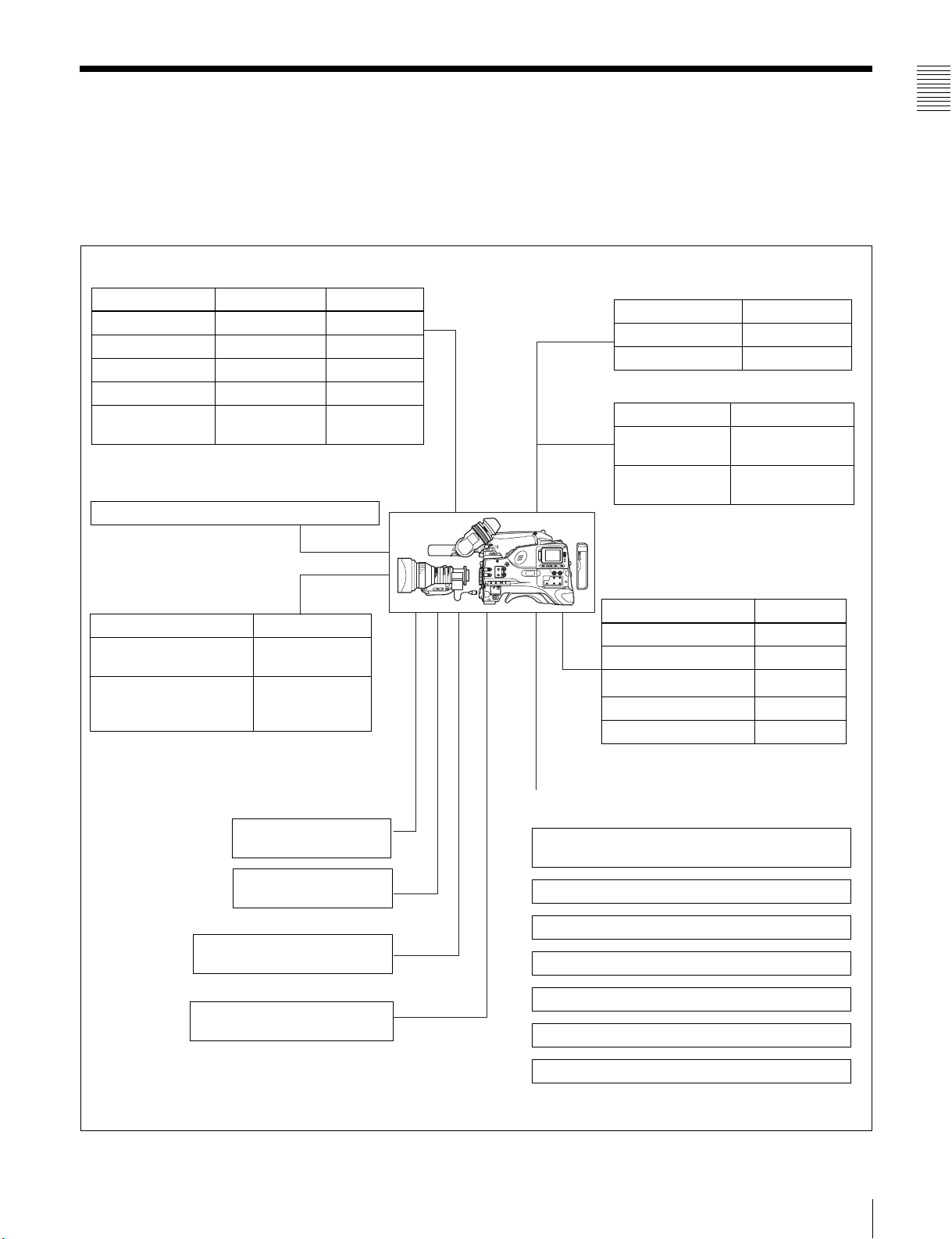
1-2 Example of System Configuration
Chapter 1 Overview
The diagram below shows a typical configuration of the
camcorder for ENG and EFP.
Viewfinder-related equipment
Name / Purpose Magnification Part No.
Fog-proof filter – 1-547-341-11
Lens assembly –2.8 D to +2.0 D A-8262-537-A
Lens assembly –3.6 D to –0.8 D A-8262-538-A
Lens assembly –3.6 D to +0.4 D A-8267-737-A
Lens assembly
(3 × magnification)
Connection through i.LINK interface
Devices with a DV connector
Camera adaptor
Product Model name
Input of audio channels
3/4 and SDI output
CCZ (26-pin) output/
analog composite/SDI
input
–2.4 D to +0.5 D A-8314-798-A
CA-701
CA-702/702P
For more information about the fittings, connections, or
use of additional equipment and accessories, see Chapter
9 as well as the operation manuals for the connected
equipment.
AC power supply
Product Model name
AC Adaptor AC-550/550CE
AC Adaptor AC-DN10
Battery
Product Model name
Battery Charger BC-M150/L500/
Battery Pack
1) BP-L40/M50 cannot be used.
Extension board
Product Model name
SDI Output Board CBK-SD01
Composite Input Board CBK-SC01
Pull Down Board
Network Adaptor CBK-NC01
Memory Card Adaptor CBK-PC01
L70
1)
BP-GL65/GL95/
L60S/L80S
CBK-FC01
2)
“Memory Stick”
(see page 206.)
RM-B150/B750 Remote
Control Unit
Video monitor for color image
check during shooting
XLR 5-pin connector for stereo
microphone (service part)
2) For PDW-510/530 only
Audio signal source
External microphone ECM-670/678 or similar
microphone
CAC-12 Microphone Holder
Audio equipment
WRR-861/862 series UHF Portable Tuner
WRR-855 series UHF Synthesized Tuner Unit
CCXA-53 audio cable
DMX-P01 Portable Digital Mixer
1-2 Example of System Configuration
11

1-3 Precautions
Chapter 1 Overview
1-4 MPEG-4 Visual
Patent Portfolio
Use and Storage
Do not subject the unit to severe shocks
The internal mechanism may be damaged or the body
warped.
After use
Always turn off the power.
Before storing the unit for a long period
Remove the battery pack.
Use and storage locations
Store in a level, ventilated place. Avoid using or storing the
unit in the following places.
• Places subject to temperature extremes
• Very damp places
• Places subject to severe vibration
• Near strong magnetic fields
• In direct sunlight or close to heaters for extended periods
To prevent electromagnetic interference from
portable communications devices
The use of portable telephones and other communications
devices near this unit can result in malfunctions and
interference with audio and video signals.
It is recommended that the portable communications
devices near this unit be powered off.
This product is licensed under the MPEG-4 Visual Patent
Portfolio License. For the personal and non-commercial
use of a consumer for (i) encoding video in compliance
with the MPEG-4 Visual Standard (“MPEG-4 Video”)
and/or (ii) decoding MPEG-4 Video that was encoded by
a consumer engaged in a personal and non-commercial
activity and/or was obtained from a video provider
licensed by MPEG LA to provide MPEG-4 Video.
No license is granted or shall be implied for any other use.
Additional information including that relating to
promotional, internal and commercial uses and licensing
may be obtained from MPEG LA, LLC.
See http://www.mpegla.com
License
Note on laser beams
Laser beams may damage the CCDs. If you shoot a scene
that includes a laser beam, be careful not to let the laser
beam be directed into the lens of the camera.
Use at a high temperature
If the unit is used at a high temperature, white flecks may
appear on the screen.
About the LCD panels
LCD panels are manufactured with extremely highprecision technology that yields effective pixel rates of
99.99% or higher. However, very rarely, one or more
pixels may be permanently dark or permanently lit in
white, red, blue, or green.
This phenomenon is not a malfunction. Such pixels have
no effect on the recorded data, and the unit may be used
with confidence even if they are present.
12
1-3 Precautions / 1-4 MPEG-4 Visual Patent Portfolio License
Locations and Functions
of Parts and Controls
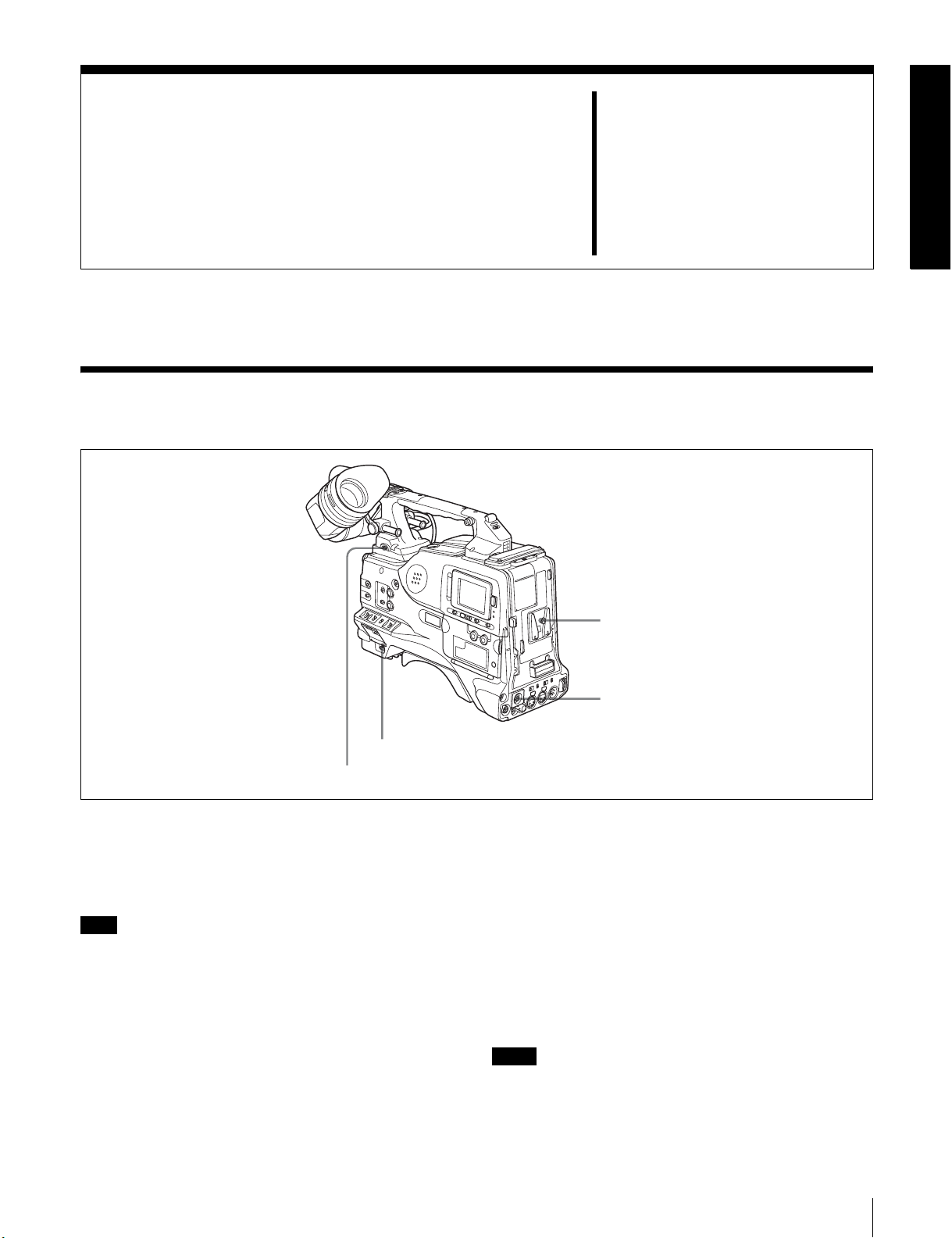
2-1 Power Supply
Chapter
1 Battery attachment
2
3 POWER switch
4 LIGHT switch
a Battery attachment
Attach a BP-GL65/GL95/L60S/L80S battery pack.
Furthermore, by attaching an AC-DN10 AC Adaptor, you
can operate the camcorder from AC power.
Note
For your safety, and to ensure proper operation of the unit,
Sony recommends the use of the following battery packs:
BP-GL65, BP-GL95, BP-L60S, and BP-L80S.
b DC IN connector (XLR type, 4-pin, male)
To operate the camcorder using an AC power supply,
connect an AC-550/550CE AC Adaptor with the DC
output cable supplied with the adaptor.
c POWER switch
This switch turns the main power supply on and off.
2 DC IN connector
d LIGHT switch
This determines how a video light connected to the LIGHT
connector is turned on and off.
AUTO: When the switch on the video light is in the on
position, putting the camcorder in recording mode
turns the video light on automatically. When using the
auto interval recording mode, the video light is
automatically turned on immediately before recording
starts.
MANUAL: You can turn the video light on or off
manually, using its own switch.
Notes
• When AUTO is selected, unevenly lit video is recorded
between the start of recording and the time when the
light comes on. We recommend that you select
MANUAL when the start of a recording is important.
2-1 Power Supply
13

However, the light can be turned on before the start of
recording in auto interval recording mode.
• To ensure proper operation of the video light with the
unit, Sony recommends the use of the following battery
packs: BP-GL65, BP-GL95, BP-L60S, and BP-L80S.
Chapter 2 Locations and Functions of Parts and Controls
14
2-1 Power Supply
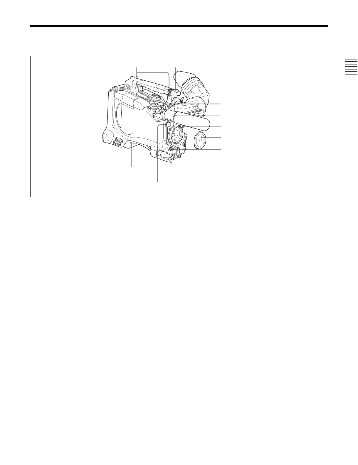
2-2 Accessory Attachments
1 Shoulder strap posts
9 Shoulder pad
Lens cable clamp
a Shoulder strap posts
Attach the supplied shoulder strap to these posts.
For details, see 9-7 “Attaching the Shoulder Strap” on
page 166.
b Light shoe
Attach an optional accessory such as a video light to this
shoe.
2 Light shoe
Chapter 2 Locations and Functions of Parts and Controls
3 LIGHT connector
4 Lens mount
5 Lens locking lever
6 Lens mount cap
7 LENS connector
8 Tripod mount
h Tripod mount
When using the camcorder on a tripod, attach the tripod
adaptor (option).
i Shoulder pad
You can move the shoulder pad forwards or backwards by
raising up the shoulder pad locking lever. Do this to ensure
the best balance when shooting with the camcorder on
your shoulder.
c LIGHT connector (2-pin, female)
Connect the cable of an Anton Bauer Ultralight System
attached to the light shoe. The system operates with lights
powered by 12 V, with a maximum power consumption of
50 W.
d Lens mount (special bayonet mount)
Use this for mounting the lens.
e Lens locking lever
After inserting the lens in the lens mount, rotate the lens
mount ring with this lever to lock the lens in position.
f Lens mount cap
Remove this cap by pushing up the lens locking lever.
When no lens is mounted, keep this cap fitted for
protection from dust.
g LENS connector (12-pin)
Fit the lens cable to this connector. Contact your Sony
representative for more information about the lens you can
use.
For details, see 9-8 “Adjusting the Shoulder Pad
Position” on page 166.
2-2 Accessory Attachments
15
2-3 Audio Functions
8 Built-in speaker
Chapter 2 Locations and Functions of Parts and Controls
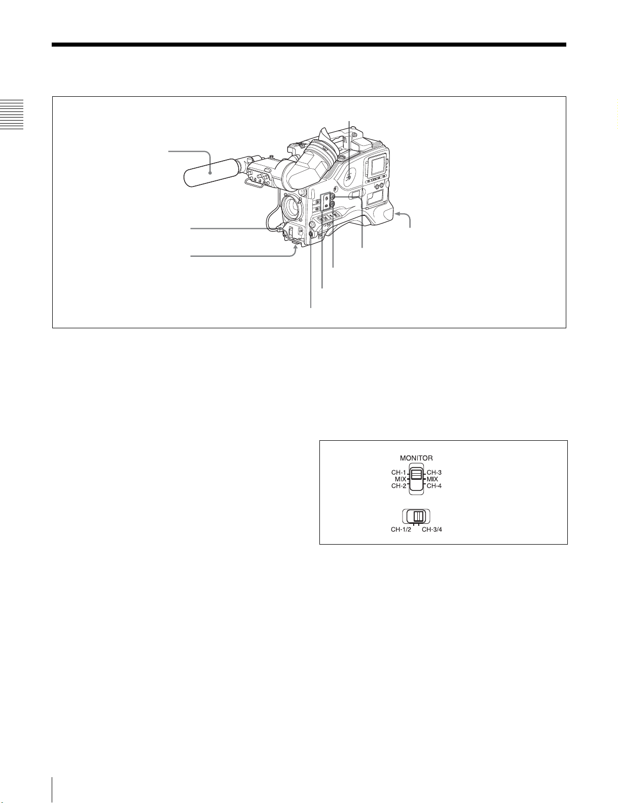
1 Microphone
2 MIC IN connector
3 MIC LEVEL control
Audio functions (1)
a Microphone
This is a super-cardioid directional monaural microphone
with an external power supply (+48 V) system.
b MIC IN (microphone input) connector (XLR type,
3-pin, female)
Connect the supplied microphone to this connector. A
microphone other than the supplied one may also be
connected as long as it can operate with the power (+48 V)
supplied from this connector.
By fitting a 5-pin connector (service part number: A-1053453-A), you can also use a stereo microphone.
c MIC (microphone) LEVEL control
This control adjusts the audio level of the microphone
connected to the MIC IN connector.
d EARPHONE jack (front) (monaural, minijack) /
EARPHONE jack (rear) (monaural/stereo
switchable, minijack)
You can monitor the E-E sound
1)
during recording and
playback sound during playback. Plugging an earphone
into the jack automatically cuts off the built-in speaker.
When an alarm is indicated, you can hear the alarm sound
through the earphone.
You can use the rear EARPHONE jack for stereo output,
by setting the HEADPHONE OUT item in the AUDIO-1
page of the MAINTENANCE menu to “STREO”. You can
also connect a monaural earphone to the front jack and a
monaural/stereo earphone set to the rear jack
simultaneously.
4 EARPHONE jack (rear, stereo)
7 ALARM volume control
6 MONITOR volume control
5 MONITOR switch and CH-1/2 / CH-3/4 switch
4 EARPHONE jack (front, monaural)
1) E-E: Abbreviation of “Electric-to-Electric.” In E-E mode, video and audio
signals input to the camcorder are output after passing through internal
electric circuits only. This can be used to check input signals.
e MONITOR switch and CH-1/2 / CH-3/4 switch
These switches together determine the channel selection
for audio monitor output.
MONITOR switch
CH-1/2 / CH-3/4 switch
MONITOR switch and CH-1/2 / CH-3/4 switch
CH-1/2 / CH-3/4 switch:
This determines the pair of audio channels selected with
the MONITOR switch.
CH-1/2 position: channels 1 and 2
CH-3/4 position: channels 3 and 4
The signals output from the AUDIO OUT connector and
EARPHONE jacks also depend on the setting of this
switch.
MONITOR switch:
This selects the audio monitor channels output to the
monaural earphone or speaker, depending on the setting of
the CH-1/2 / CH-3/4 switch.
16
2-3 Audio Functions
CH-1/2 CH-3/4
switch
position
MONITOR
switch
position
Audio output
CH-1/2 CH-1 Audio channel 1
MIX Mix sound of channels 1 and 2
CH-2 Audio channel 2
CH-3/4 CH-3 Audio channel 3
MIX Mix sound of channels 3 and 4
CH-4 Audio channel 4
f MONITOR volume control
This control adjusts the speaker or earphone volume for
sounds other than the alarm sound. At the minimum
position, no sound can be heard.
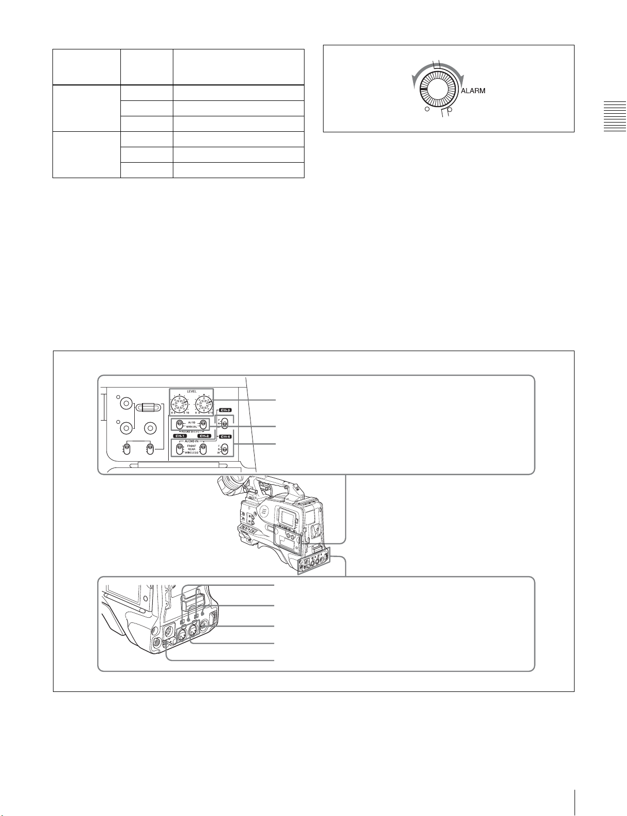
g ALARM volume control
This control adjusts the speaker or earphone alarm volume.
At the minimum position, no sound can be heard.
However, if in the AUDIO-1 page of the
MAINTENANCE menu the MIN ALARM VOL item is
set to “SET”, the alarm tone is audible even when this
volume control is at the minimum position.
Minimum Maximum
ALARM volume control
h Built-in speaker
The speaker can be used to monitor E-E sound during
recording, and playback sound during playback. The
speaker also sounds alarms to reinforce visual warnings.
The output level of the speaker can be lowered by
changing the setting of the SP ATT LEVEL item on the
AUDIO-1 page of the MAINTENANCE menu.
If you connect an earphone to the EARPHONE jack, the
speaker is automatically muted.
See 10-3 “Operation Warnings” on page 174 for
information about alarms.
Chapter 2 Locations and Functions of Parts and Controls
THUMBNAIL
ESSENCE MARK
SUB CLIP
PRESET
REGEN
CLOCK
F-RUN
R-RUN
SEL/SET
S.SEL
SET
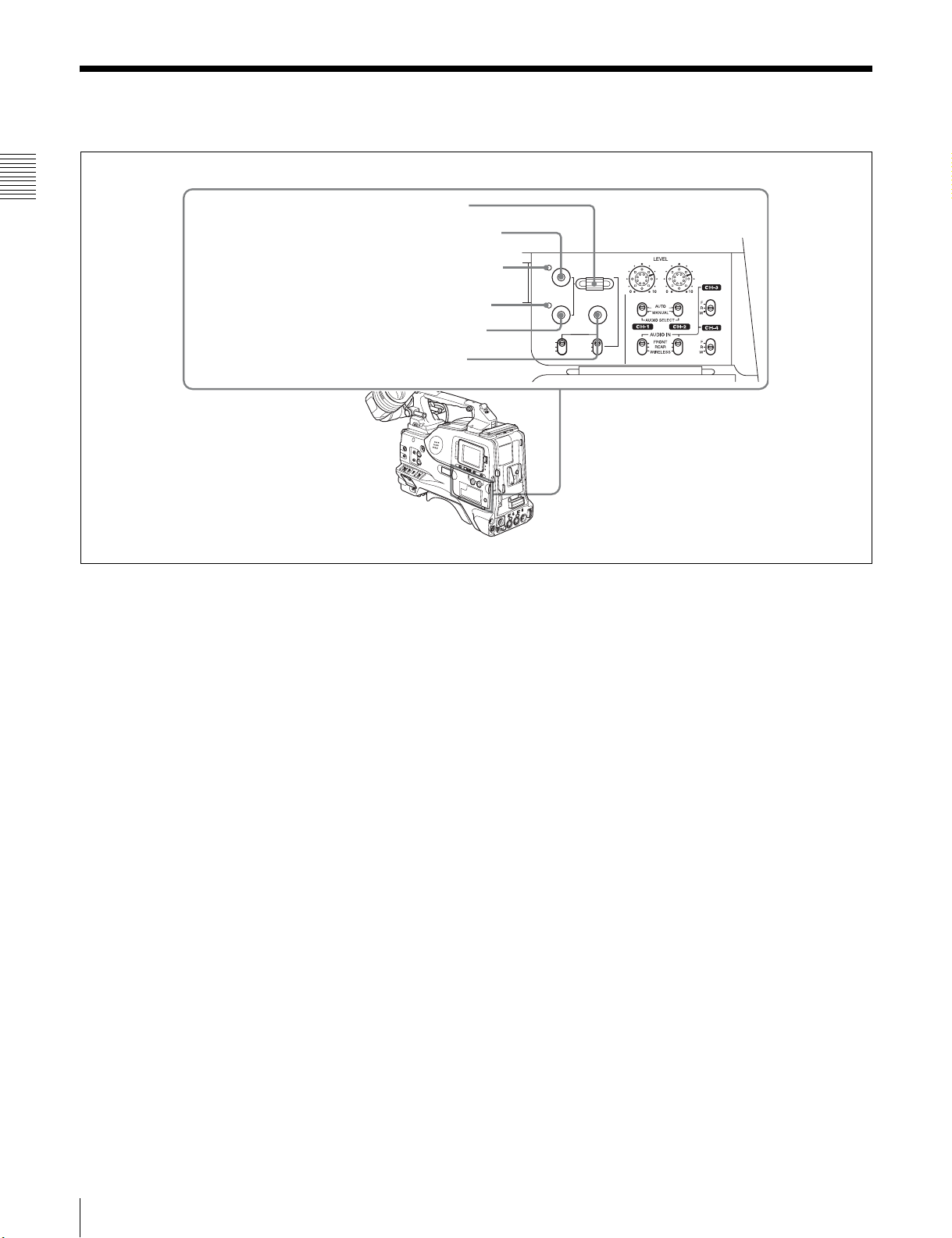
9 LEVEL (CH-1/CH-2) controls
0 AUDIO SELECT CH-1/CH-2 switches
SHIFTCLIP MENU
qa AUDIO IN CH-1/CH-2 / CH-3/CH-4 switches
qs LINE / AES/EBU / MIC selectors
qd +48V/OFF switches
qf AUDIO OUT connector
qg AUDIO IN CH1/CH2 connectors
qh DC OUT 12V connector
i LEVEL (CH-1/CH-2) (audio channel-1 and
channel-2 recording level) controls
Audio functions (2)
These controls adjust the audio levels of channels 1 and 2
when the AUDIO SELECT switches are set to MANUAL.
2-3 Audio Functions
17

j AUDIO SELECT CH-1/CH-2 (audio channel-1
and channel-2 adjustment method selection)
switches
These switches select the audio level adjustment method
for each of audio channels 1 and 2.
AUTO: Select this setting for automatic adjustment.
n AUDIO OUT (audio output) connector (XLR type,
5-pin, male)
This connector outputs the audio signals recorded on audio
channels 1 and 2 or audio channels 3 and 4.
The MONITOR CH-1/2 / CH-3/4 switches allow you to
select the audio signal to be monitored.
MANUAL: Select this setting for manual adjustment.
Chapter 2 Locations and Functions of Parts and Controls
k AUDIO IN CH-1/CH-2 / CH-3/CH-4 (audio input
selection) switches
o AUDIO IN CH1/CH2 (audio channel-1 and
channel-2 input) connectors (XLR type, 3-pin,
female)
These are audio input connectors for channels 1 and 2 to
AUDIO IN CH-1/CH-2 switches
These switches select the audio input signals to be
recorded on audio channels 1 and 2.
FRONT: The input signal source is the microphone
which you can connect audio equipment or a microphone.
When the LINE / AES/EBU / MIC selector is set to AES/
EBU, the CH1 connector is used for channel-1 and -2
inputs, and the CH2 connector, for channel-3 and -4 inputs.
connected to the MIC IN connector.
REAR: The input signal source is the audio equipment
connected to the AUDIO IN CH1/CH2 connectors.
WIRELESS: The input signal source is a WRR-855A/
855B UHF Synthesized Tuner Unit (option).
p DC OUT 12 V (DC power output) connector (4-pin,
female)
This connector supplies power for a WRR-862 UHF
Portable Tuner (option). Do not connect any equipment
other than the UHF portable tuner.
AUDIO IN CH-3/CH-4 switches
These switches select the audio input signals to be
recorded on audio channels 3 and 4.
F (front): The input signal source is the microphone
connected to the MIC IN connector.
R (rear): The input signal source is the audio equipment
connected to the AUDIO IN CH1/CH2 connectors.
W (wireless): The input signal source is a WRR-855A/
855B UHF Synthesized Tuner Unit.
With a CA-701 Camera Adaptor (option) connected to the
camcorder, you can record separate sounds on audio
channels 3 and 4.
l LINE /AES/EBU / MIC selectors
These select the audio source of the audio input signals
input to the AUDIO IN CH1/CH2 connectors.
LINE: Line input audio equipment
AES/EBU: AES/EBU format audio signal
MIC: Microphone input
Note
When these switches are in the MIC position, and the
+48V switch described below is on, if you inadvertently
connect any audio device other than a microphone to the
AUDIO IN CH1/CH2 connectors, the device may be
damaged.
m +48V/OFF switches
Select either of the following positions for the
microphones to be connected.
+48V: For a microphone to use an external power supply
OFF: For a microphone to use an internal power supply
18
2-3 Audio Functions
2-4 Shooting and Recording/Playback Functions
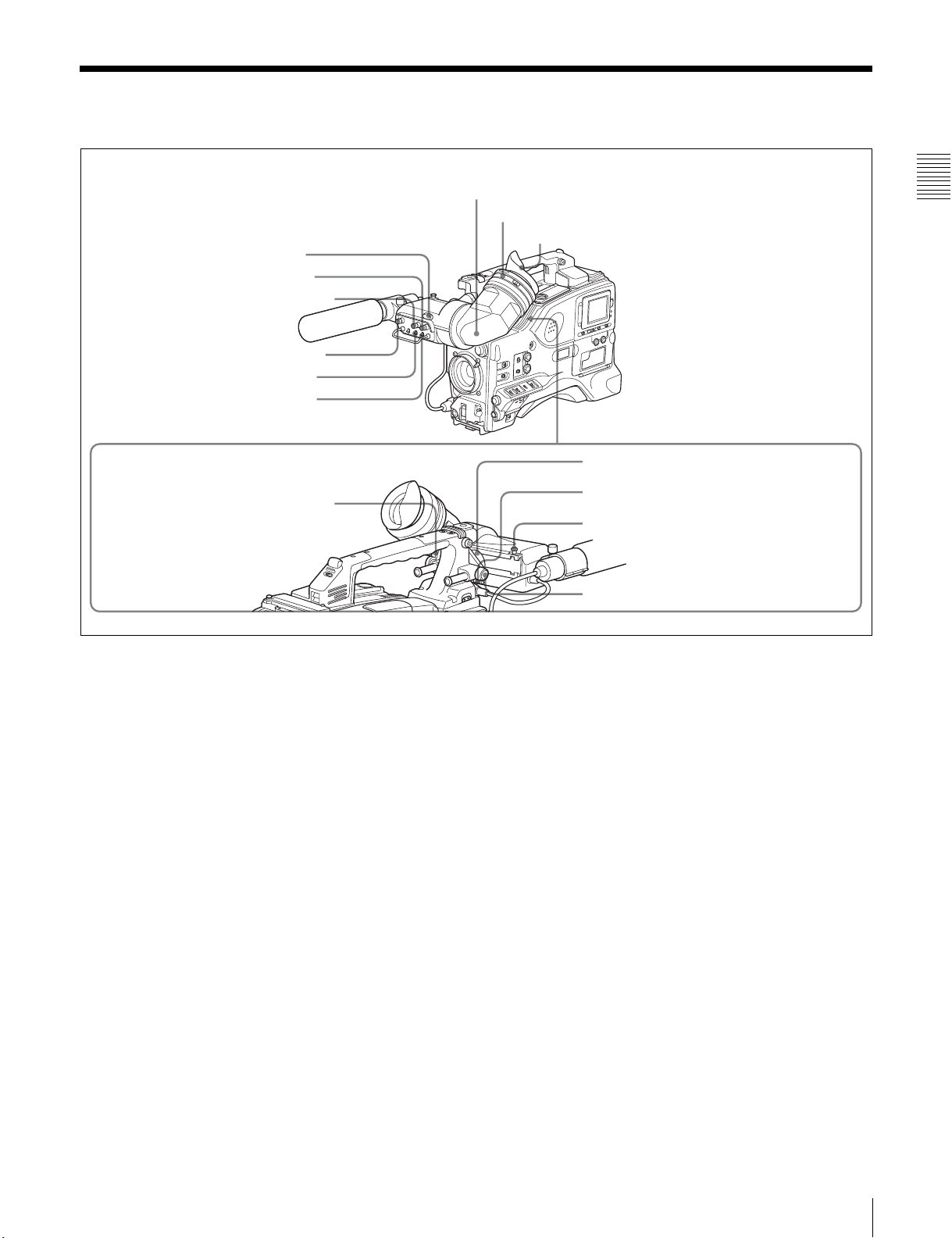
1 Tally indicator
2 BRIGHT control
3 CONTRAST control
4 PEAKING control
5 ZEBRA switch
6 TALLY switch
9 Viewfinder front-rear positioning lever
7 Viewfinder
8 Diopter adjustment ring
Eyecup
Chapter 2 Locations and Functions of Parts and Controls
0 Viewfinder left-right positioning ring
qa Camera operator tally indicator
qs Viewfinder stopper
qd LOCK knob
Shooting and recording/playback functions (1)
a Tally indicator
Setting the TALLY switch to HIGH or LOW enables this
indicator. The indicator lights during recording on the
VDR (video disc recorder). Like the REC indicator in the
viewfinder, it flashes to indicate a problem. You can set the
indicator brightness with the TALLY switch.
b BRIGHT (brightness) control
This control adjusts the picture brightness on the
viewfinder screen. It has no effect on the camera output
signal.
c CONTRAST control
This control adjusts the picture contrast on the viewfinder
screen. It has no effect on the camera output signal.
d PEAKING control
This control adjusts the sharpness of the picture on the
viewfinder screen to make focusing easier. It has no effect
on the camera output signal.
e ZEBRA switch
This switch controls the zebra pattern on the viewfinder
screen.
ON: The zebra pattern
1)
is displayed and stays.
OFF: No zebra pattern is displayed.
MOMENT: The zebra pattern is displayed and stays for 5
to 6 seconds.
The zebra pattern is factory set to indicate picture areas
where the video level is approximately 70%.You can use
the setup menu to change the setting so that areas where
the video level is 100% and above are also displayed at the
same time.
For information about how to change the zebra pattern
setting in the setup menu, see 7-2-5 “Setting the
Viewfinder” on page 125.
1) The zebra pattern aids in manual iris adjustment by indicating areas of the
picture where the video level is approximately 70% and 100% and above.
f TALLY switch
This switch controls the tally indicator, setting its
brightness (HIGH or LOW) or turning it off.
HIGH: The tally indicator brightness is high.
OFF: The tally indicator is disabled.
LOW: The tally indicator brightness is low.
2-4 Shooting and Recording/Playback Functions
19
g Viewfinder
The viewfinder lets you view the image in black and white
j Viewfinder left-right positioning ring
Loosen this ring to move the viewfinder sideways.
while shooting, recording or playing back. It also displays
various warnings and messages related to the settings or
operating conditions of the camcorder, a zebra pattern,
safety zone marker
1) The safety zone marker is a rectangle indicating the effective picture area.
Chapter 2 Locations and Functions of Parts and Controls
2) The center marker indicates the center of the picture with a crosshair.
1)
, and center marker 2).
k Camera operator tally indicator
This indicator lights while the camcorder is recording.
Slide the window open when you shoot with your eye
away from the viewfinder. This indicator flashes when the
battery level is running low or the disc is almost full.
For details, see 7-2-4 “Setting the Marker Display” on
page 124.
h Diopter adjustment ring
Use this ring to adjust the viewfinder image for your
vision.
i Viewfinder front-rear positioning lever
To adjust the viewfinder position in the front-rear
direction, loosen this lever and the LOCK knob. After
adjustment, retighten this lever and the LOCK knob.
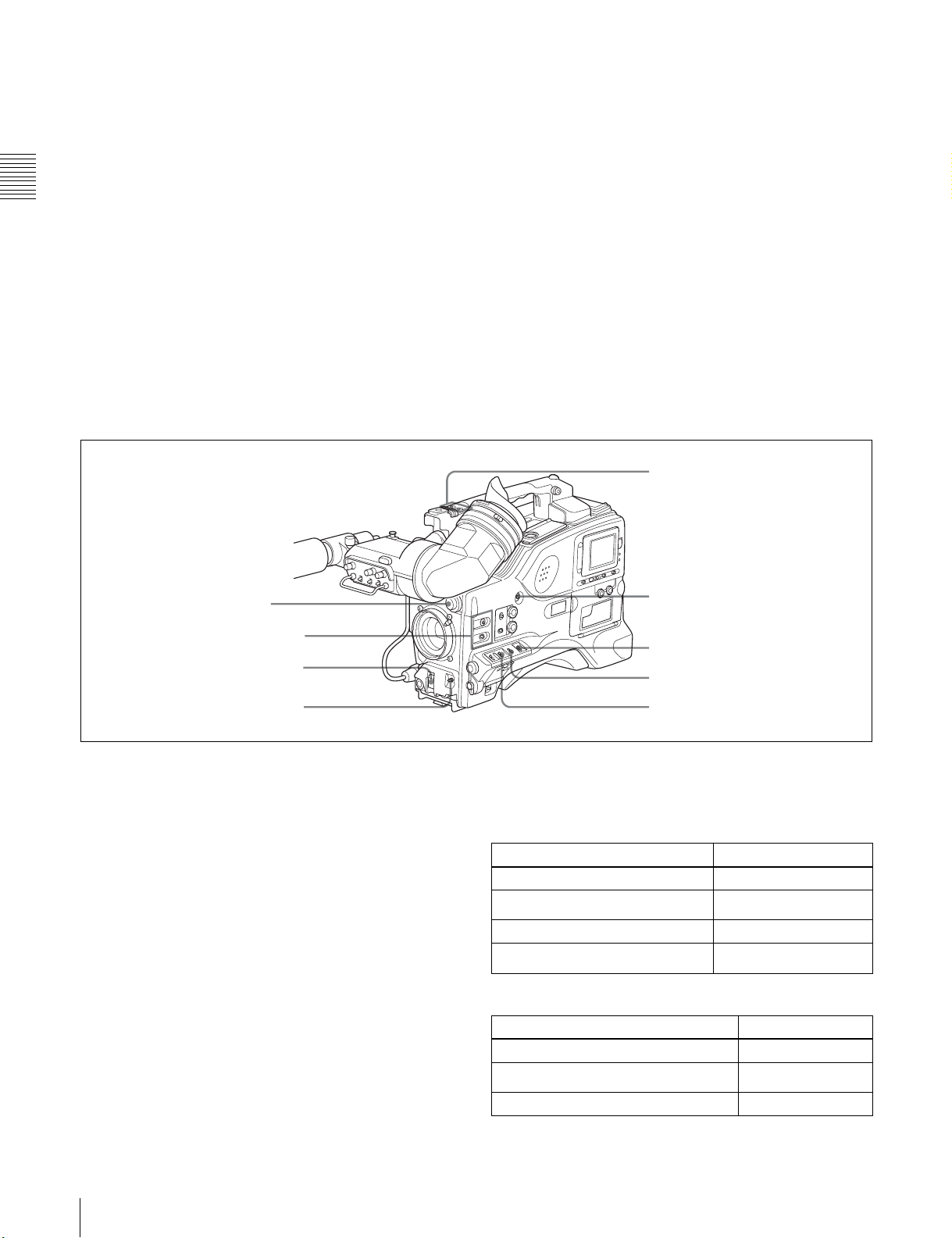
qf FILTER selector
qg ASSIGN. 1/2 switches
qh SHUTTER selector
l Viewfinder stopper
Pull up this stopper to detach the viewfinder from the
camera.
m LOCK knob
To adjust the viewfinder position in the front-rear
direction, loosen this knob and the viewfinder front-rear
positioning lever. After adjustment, retighten this knob
and the viewfinder front-rear positioning lever.
ws ASSIGN 3/4 switches
wa TURBO GAIN button
w; WHITE BAL switch
ql OUTPUT/DCC selector
qj AUTO W/B BAL switch
Shooting and recording/playback functions (2)
n FILTER selector
Use this selector to select the most appropriate filter to
match the light source illuminating the subject.
When this selector is used with the display mode set to 3,
the new setting appears on the viewfinder screen for about
3 seconds. (e.g.: FILTER: 3)
The PDW-510/510P has one switchable filter, and the
PDW-530/530P has two switchable filters.
The relationships between the selector settings and filter
selections as well as examples of filters for different
shooting conditions are as follows.
qk GAIN selector
For the PDW-510/510P
FILTER selector setting and filter selection
FILTER selector setting Filter selection
1 3200 K
2
3 5600 K
4
Examples of shooting conditions and appropriate filters
Shooting condition Filter
Sunrise and sunset; inside studio 1 (3200 K)
Clear skies
Cloudy or raining 3 (5600 K)
5600 K +
5600 K +
1
/8 ND
1
/
ND
64
2 (5600 K +
1
/8 ND)
20
2-4 Shooting and Recording/Playback Functions

Examples of shooting conditions and appropriate filters
Shooting condition Filter
Very bright conditions such as snow, at
high altitudes, or at the seashore
4 (5600 K +
1
/
ND)
64
For the PDW-530/530P
FILTER selector (outer knob) setting and CC filter
selection
FILTER selector (outer knob) setting CC filter selection
A
B 3200 K
C 4300 K
D 6300 K
1) A type of special effect filter. Generates a cross of light on a highlighted
portion.
FILTER selector (inner knob) setting and ND filter
selection
FILTER selector (inner knob) setting ND filter selection
1 Clear
2
3
4
Examples of shooting conditions and appropriate filters
Cross filter
1
/4 ND
1
/16 ND
1
/64 ND
1)
For details about the shutter speed and mode settings, see
5-3 “Setting the Electronic Shutter” on page 88.
q AUTO W/B BAL (automatic white/black balance
adjustment) switch
This switch activates the white balance and black balance
automatic adjustment functions.
WHITE: Automatic adjustment of the white balance. If
the WHITE BAL switch is set to A or B, the white
balance setting is stored in the corresponding memory.
On the PDW-530/530P models with two switchable
filters, the memory stores a separate white balance
setting for each CC filter setting.
BLACK: Automatic adjustment of the black set and black
balance.
r GAIN selector
This selector switches the gain of the video amplifier to
match the lighting conditions during shooting. The gains
corresponding to the L, M, and H settings can be selected
from the setup menu. The factory settings are L = 0 dB, M
= 9 dB, and H = 18 dB.
When this selector is adjusted, the new setting appears on
the setting change/adjustment progress message display
area of the viewfinder screen for about 3 seconds.
For details about setting the gain values, see 7-3-1
“Setting Gain Values for the GAIN Selector Positions” on
page 130.
Chapter 2 Locations and Functions of Parts and Controls
Shooting condition CC filter ND filter
Sunrise and sunset; inside
studio
Clear skies C (4300 K) or
Cloudy or raining D (6300 K) 1 (clear) or 2
Very bright conditions such
as snow, at high altitudes,
or at the seashore
B (3200 K) 1 (clear)
1
/4 ND) or 3
D (6300 K)
C (4300 K) or
D (6300 K)
2 (
1/
(
16 ND)
1
/4 ND)
(
1
/16 ND) or
3 (
1
4 (
/64 ND)
o ASSIGN. 1/2 switches
You can assign the desired functions to each of the
ASSIGN. 1 switch (push button) and ASSIGN. 2 switch
(sliding) on the FUNCTION 1 page of the USER menu.
For details, see 7-3-5 “Assigning Functions to ASSIGN 1/
2/3/4 Switches” on page 133.
p SHUTTER selector
Set this selector to ON to use the electronic shutter. Push it
down to SELECT to switch the shutter speed or mode
setting within the range previously set with the setup
menu.
When this selector is operated, the new setting appears on
the setting change/adjustment progress message display
area for about 3 seconds.
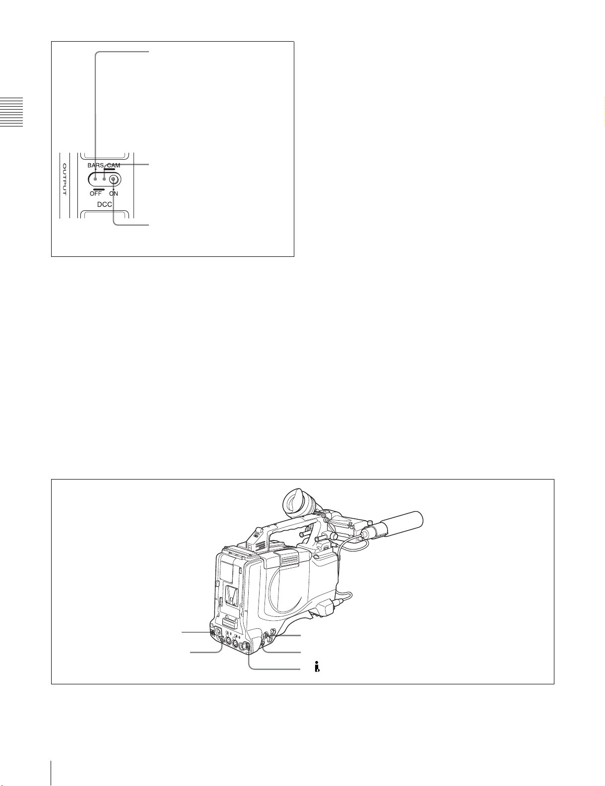
s OUTPUT/DCC (output signal/dynamic contrast
control) selector
This selector switches the video signal that is output to the
VDR, viewfinder, and video monitor, between the
following two.
BARS: Outputs the color bar signal.
CAM: Outputs the video signal from the camera. When
this is selected, you can switch DCC
1)
on and off with
this selector.
1) DCC (Dynamic Contrast Control)
Against a very bright background with the iris opening adjusted to the
subject, objects in the background will be lost in the glare. The DCC
function will suppress the high intensity and restore much of the lost detail
and is particularly effective in the following cases.
• Shooting people in the shade on a sunny day
• Shooting a subject indoors, against a background through a window
• Any high contrast scene
2-4 Shooting and Recording/Playback Functions
21
BARS, DCC OFF
A color bar signal is output and the
DCC circuit does not operate. For
example, use the setting for the
following purposes.
• Adjusting the video monitor
• Recording the color bar signal
Chapter 2 Locations and Functions of Parts and Controls
switch and the FILTER selector.
You can use the AUTO W/B BAL switch even when
1)
ATW
is in use.
B (ATW): When this switch is set to B and on the
FUNCTION 2 page of the OPERATION menu,
“WHITE B CH” is set to “ATW”
1) ATW (Auto Tracing White Balance)
The white balance of the picture being shot is adjusted automatically for
varying lighting conditions.
1)
, ATW is activated.
CAM, DCC OFF
The video signal from the camera is
output, and the DCC circuit does not
operate.
CAM, DCC ON
The video signal from the camera is
output, and the DCC circuit operates.
OUTPUT/DCC selector
t WHITE BAL (white balance memory) switch
This switch controls the white balance setting.
PRST (preset): Adjusts the color temperature
corresponding to the position of the FILTER selector.
Use the PRST setting when you have no time to adjust
the white balance.
A or B: When the AUTO W/B BAL switch is pushed to
WHT, the white balance is automatically adjusted
according to the current position of the FILTER
selector, and the adjusted value is stored in either
memory A or memory B. (There are two memories for
each CC filter, allowing a total of eight adjustments to
be stored.) When this switch is set to A or B, the
camcorder automatically adjusts itself to the stored
value corresponding to the current settings of this
When this switch is adjusted, the new setting appears on
the setting change/adjustment progress message display
area of the viewfinder screen for about 3 seconds.
You can assign the ATW ON/OFF function to the
ASSIGN 1 switch (push button) on the FUNCTION 1 page
of the USER menu.
For details, see 7-3-5 “Assigning Functions to ASSIGN 1/
2/3/4 Switches” on page 133.
u TURBO GAIN button
When shooting under extremely poor lighting conditions,
press the button once to boost the video gain to the value
preset on the GAIN SW page of the USER menu (up to
48 dB). To stop boosting the gain, press the button once
more.
v ASSIGN 3/4 switches
You can assign the desired functions to each of the
ASSIGN 3 switch and ASSIGN 4 switch on the
FUNCTION 1 page of the USER menu.
For details, see 7-3-5 “Assigning Functions to ASSIGN 1/
2/3/4 Switches” on page 133.
wf REMOTE connector
wd VIDEO OUT connector
22
2-4 Shooting and Recording/Playback Functions
wg GENLOCK IN connector
wh TEST OUT connector
wj DV IN/OUT S400 connector
Shooting and recording/playback functions (3)

w VIDEO OUT connector (BNC type)
This connector outputs a composite video signal for a
video monitor. With a video monitor connected to this
connector, you can monitor the picture being shot by the
camera or the picture played back by the VDR. To choose
between the composite video signal output and SDI signal
output, use the menu. When synchronizing the time code
of an external VDR with that of the camcorder, connect
this connector to the GENLOCK IN connector of the
external VDR.
By installing the CBK-SD01 extension board (not
supplied), you can output an SDI signal (supporting
embedded audio and the EDH function) from this
connector.
For details on how to select the output signal, see 7-3-2
“Selecting the Output Signals” on page 131.
x REMOTE connector (8-pin)
Connect the RM-B150/B750 Remote Control Unit, which
makes it possible to control the VDR and camera remotely.
y GENLOCK IN connector (BNC type)
• This connector inputs a reference signal when the
camera is to be genlocked or when time code is to be
synchronized with external equipment. Use the
MAINTENANCE menu to adjust the genlock H-phase
(phase of horizontal sync signal) and the sub-carrier
phase.
wj (i.LINK) DV IN/OUT S400 connector (6-pin,
IEEE1394 compliant)
Connect to a device supporting the DV format or a
computer, using a i.LINK cable.
Notes
• If video and audio signals are not output to an external
device connected to the i.LINK DV IN/OUT S400
connector, try disconnecting the i.LINK cable and then
reconnecting it, making sure that it is firmly seated.
• When you connect this unit to an external device with a
6-pin i.LINK connector, always power this unit off and
disconnect the DC cable from the DC IN connector, or
remove the battery pack, before connecting or
disconnecting the i.LINK cable.
If you connect or disconnect the i.LINK cable while
power is being supplied to this unit, high voltage (8 to 40
V) can flow into this unit from the i.LINK connector of
the connected equipment, possibly damaging this unit.
• When you connect this unit to an external device with a
6-pin i.LINK connector, always connect the 6-pin
i.LINK connector on the external device first.
Chapter 2 Locations and Functions of Parts and Controls
For details, refer to the Maintenance Manual.
• This connector also inputs a return video signal. You can
display the return video signal in the viewfinder screen
while holding the RET button down with “RETURN
VIDEO” set to “ON” on the GENLOCK page of the
OPERATION menu.
• This connector also inputs an external analog composite
video signal.
When the CBK-SC01 extension board is installed, you
can record the external analog composite video signal
input to this connector.
z TEST OUT connector (BNC type)
This connector outputs the video signal for a video
monitor. The output signal can be selected from composite
or RGB. The factory setting is composite, and the setting
returns to composite whenever the unit is powered on.
Depending on internal board and menu settings, menus,
time code, and shot data can be superimposed on the image
on the monitor. Like the VIDEO OUT connector, this
connector can also be used to synchronize the time code of
an external VTR with the time code of the camcorder.
For details on how to select the test output signal, refer to
the Maintenance Manual.
2-4 Shooting and Recording/Playback Functions
23
Chapter 2 Locations and Functions of Parts and Controls
wk REC START button
wl VDR SAVE/STBY connector
e; EJECT button and indicator
ea F REV button and indicator
es PLAY/PAUSE button and indicator
E
S
U
A
/P
Y
LA
P
NEXT
V
E
R
P
Shooting and recording/playback functions (4)
ed F FWD button and indicator
ef NEXT button
eg STOP button
eh PREV button
wk REC START button
Press this button to start recording. Press it again to stop
recording. The effect is exactly the same as that of the VTR
button on the lens.
When the REC SWITCH function is assigned to the
ASSIGN 1, 3 or 4 switch (push button), you can use the
switch as the REC START button.
wl VDR SAVE/STBY (standby) switch
This switch controls the VDR power mode during pauses
in recording.
SAVE: Power saving mode. Although an internal
operating sound is recorded as noise when you start
recording, power consumption in this mode is less than
in standby mode, so that battery life is extended. When
the switch is set to SAVE, the SAVE indicator in the
viewfinder lights.
STBY: Standby mode. Recording starts as soon as you
press the REC START button.
e; EJECT button and indicator
Press this button to eject or load a disc. The indicator
flashes while the disc is being ejected.
ea F REV (fast reverse) button and indicator
Plays back at high speed in the reverse direction. The
indicator lights during high-speed playback in the reverse
direction.
es PLAY/PAUSE button and indicator
Press this to view a playback image using the viewfinder
screen or a color video monitor. The indicator lights during
playback.
During playback, pressing this button pauses the playback,
showing a still image. At this time, the indicator flashes.
This camcorder is capable of color-image search at
approximately four-times normal playback speed, making
it easy to check recorded material. To use the color-image
search, press the F REV button or F FWD button during
playback. When the buttons are pressed, the PLAY
indicator and the F REV or F FWD indicator light.
ed F FWD (fast forward) button and indicator
Plays back at high speed in the forward direction. The
indicator lights during high-speed playback in the forward
direction.
ef NEXT button
This jumps to the beginning of the next clip, and pauses.
During the jump, the F FWD indicator flashes.
Pressing this button together with the F FWD button jumps
to the last frame of the last clip recorded on the disc.
eg STOP button
Press this button to stop disc playback.
24
2-4 Shooting and Recording/Playback Functions

eh PREV button
This jumps to the beginning of the current clip, and pauses.
During the jump, the F REV indicator flashes.Pressing this
button together with the F REV button jumps to the first
frame of the first clip recorded on the disc.
Chapter 2 Locations and Functions of Parts and Controls
2-4 Shooting and Recording/Playback Functions
25
2-5 Output Video Operating Section
Chapter 2 Locations and Functions of Parts and Controls
a SEL/SET (select/set) dial
When thumbnails (each representing a clip) are shown on
the color LCD, you can select a particular thumbnail with
this dial.
Turning the dial upward moves the cursor to the left, and
when it reaches the left edge, to the rightmost position in
the row above. Turning the dial downward moves the
cursor to the right, and when it reaches the right edge, to
the leftmost position in the row below. After selecting the
1 SEL/SET dial
2 THUMBNAIL button
3 Thumbnail indicator
4 Sub clip indicator
5 SUB CLIP button
6 SHIFT button
Output video operating section
e SUB CLIP button
Press this to play back according to a clip list.
You can play back a particular clip or sequential clips, or
carry out a search of the selected clip list.
When no clip list is selected, pressing this button has no
effect, and the operation is invalid.
To carry out operations such as saving, recalling, or
deleting a clip list, hold down the SHIFT button and press
this button.
THUMBNAIL
ESSENCE MARK
SUB CLIP
PRESET
REGEN
REGEN
CLOCK
CLOCK
F-RUN
R-RUN
SEL/SET
S.SEL
SHIFTCLIP MENU
SET
desired thumbnail with the cursor, press the dial in to
confirm.
To carry out a scene selection setting, hold down the
f SHIFT button
Use this in combination with other buttons.
SHIFT button, and press in this dial.
b THUMBNAIL button
To carry out a search using thumbnails, or to create a clip
list, press this button.
Pressing it switches from the whole-screen display to a
thumbnail display. Press once more to return to the wholescreen display.
To search thumbnails by essence marks, hold down the
SHIFT button and press this button.
c Thumbnail indicator
This lights when thumbnails are shown.
d Sub clip indicator
This lights when playing back following a clip list.
26
2-5 Output Video Operating Section
2-6 Menu Operating Section
1 MENU knob
a MENU knob
Use this knob to change the page selection or a setting
within the menu.
Press: If you press this knob when the arrow (b) is placed
at the page title on the menu, the arrow changes to a
question mark (?) and you can change the page by
turning this knob.
When the arrow mark is placed at a position other than
the page title, you can change the setting of the current
item by pressing and turning this knob.
Turn: Turn this knob to change the page or change item
settings.
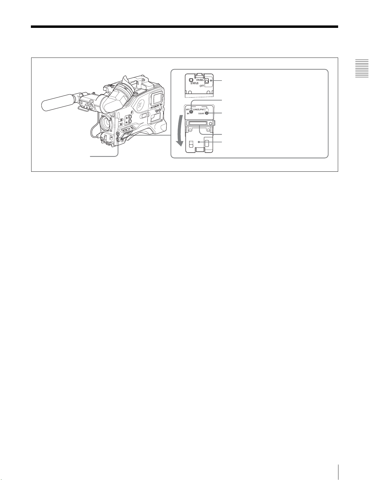
b STATUS ON/SEL / OFF (menu display on/page
selection/display off) switch
To enable this switch, set the MENU ON/OFF switch to
OFF.
Closing the cover automatically sets the MENU ON/OFF
switch to OFF.
ON/SEL: Each time this switch is pushed upward, a
window to confirm the menu settings and status of the
camcorder appears on the viewfinder screen. The
window consists of three pages, which are switched
each time the switch is pushed upward. Each page is
displayed for about 10 seconds.
OFF: To clear the page immediately after display, push
this switch down to the OFF position.
You can select the pages to be displayed on the menu.
2 STATUS ON/SEL / OFF switch
3 MENU ON/OFF switch
MENU
4 CANCEL/PRST / ESCAPE switch
5 “Memory Stick” compartment
Cover
c MENU ON/OFF switch
To use this switch, open the cover.
This switch is used to display the menu on the viewfinder
screen or the test signal screen.
Closing the cover automatically sets this switch to OFF.
ON: Displays the menu on the viewfinder screen or the test
signal screen, at the last accessed page. When the
menu is used for the first time, the first page is
displayed.
OFF: Removes the menu from the viewfinder screen or
the test signal screen.
d CANCEL/PRST (preset) / ESCAPE switch
To enable this switch, set the MENU ON/OFF switch to
ON.
Closing the cover automatically sets the MENU ON/OFF
switch to OFF.
CANCEL/PRST: Pushing this switch up to this position
displays the message to confirm whether the previous
settings are cancelled or settings are reset to their
initial values, depending on the menu operating
condition.
Pushing this switch up to this position again cancels
the previous settings or resets the settings to their
initial values.
ESCAPE: Use this switch when the menu page, which has
a hierarchical structure, is opened. Each time the
switch is pushed to this position, the page returns to
one stage higher in the hierarchy.
Chapter 2 Locations and Functions of Parts and Controls
For details, see 7-2-8 “Displaying the Status Confirmation
Windows” on page 128.
2-6 Menu Operating Section
27

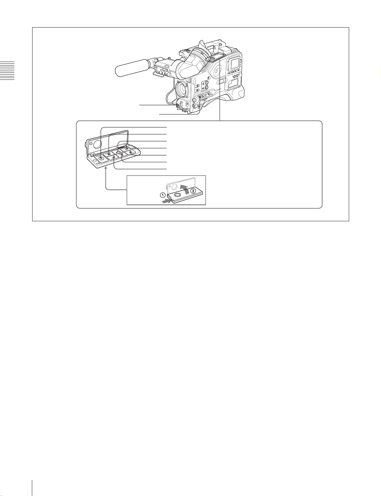
e “Memory Stick” compartment
“Memory Stick”
Access indicator
Chapter 2 Locations and Functions of Parts and Controls
How to insert a “Memory Stick”
Label
“Memory Stick”
Open the lid of the menu operating section, and insert a
“Memory Stick”, with the notch facing downward, in the
direction shown by the arrow, so that it clicks into place.
To remove a “Memory Stick”, first press it in to release the
lock, then withdraw.
The “Memory Stick” access indicator lights when the
“Memory Stick” is being accessed (for reading or writing).
For details about types of “Memory Stick”, see “About a
“Memory Stick”” on page 206.
Notes
• Do not insert/remove a “Memory Stick” while the
“Memory Stick” access indicator is lit or flashing. Doing
so may cause a loss of data.
• This device uses a standard “Memory Stick”, a “Memoy
Stick PRO”, and a “MagicGate Memory Stick” equipped
with MagicGate copyright protection technology.
28
2-6 Menu Operating Section
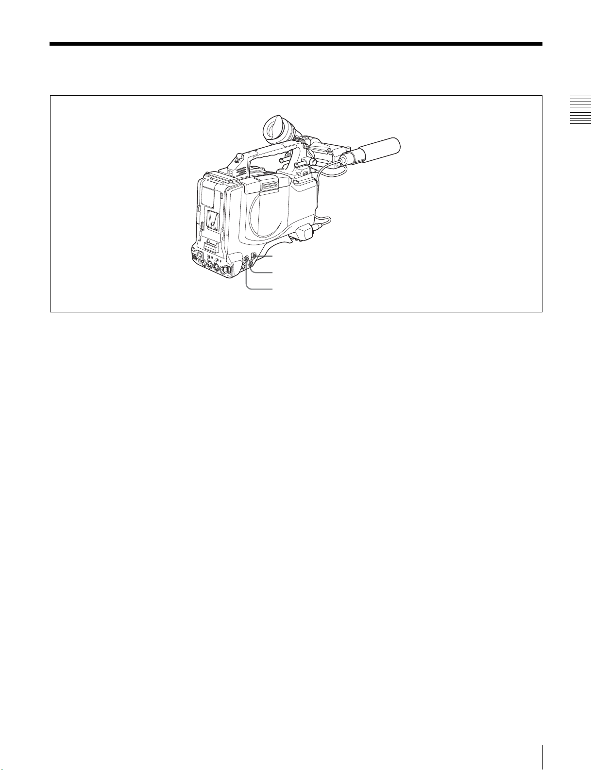
2-7 Time Code System
Time code functions (1)
Chapter 2 Locations and Functions of Parts and Controls
1 TC IN connector
2 TC OUT connector
3 GENLOCK IN connector
a TC IN (time code input) connector (BNC type)
To synchronize the time code of this unit to an external
time code, input the reference time code to this connector.
b TC OUT (time code output) connector (BNC type)
To synchronize the time code of an external VTR to that of
the camcorder, connect this connector to the reference time
code input connector of the external VTR.
c GENLOCK IN connector (BNC type)
• This connector inputs a reference signal when the
camera is to be genlocked or when the time code is to be
synchronized with external equipment. Use the
MAINTENANCE menu to adjust the genlock H-phase
(phase of horizontal sync signal) and the sub-carrier
phase.
For details, refer to the Maintenance Manual.
• This connector also inputs a return video signal.
You can display the return video signal in the viewfinder
screen while holding the RET button down with
“RETURN VIDEO” set to “ON” on the GENLOCK
page of the OPERATION menu.
• This connector also inputs an external analog composite
video signal.
When the CBK-SC01 extension board is installed, you
can record the external analog composite video signal
input to this connector.
For details, see 3-4 “Recording Video Signals From
External Equipment” on page 67.
2-7 Time Code System
29
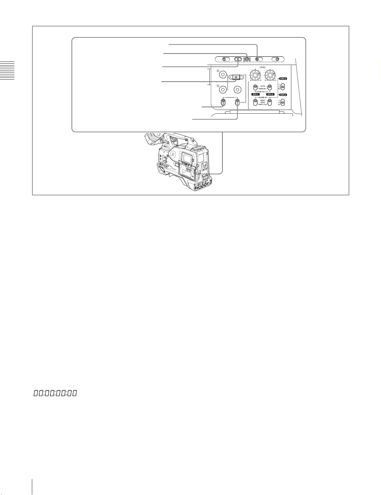
4 DISPLAY switch
5 RESET button
6 HOLD button
Chapter 2 Locations and Functions of Parts and Controls
d DISPLAY switch
This cycles the data displayed in the counter display
7 SEL/SET dial
8 PRESET/REGEN/CLOCK switch
9 F-RUN/SET/R-RUN switch
Time code functions (2)
Turning the dial upward increases the value of the flashing
digit, and turning it downward decreases the value.
THUMBNAIL
ESSENCE MARK
SUB CLIP
PRESET
REGEN
CLOCK
F-RUN
R-RUN
SEL/SET
S.SEL
SHIFTCLIP MENU
SET
through the sequence COUNTER, TC, and U-BIT.
COUNTER: Display the elapsed recording/playback time
(hours, minutes, seconds, frames).
TC: Display time code.
U-BIT: Display user bit data.
h PRESET/REGEN (regeneration)/CLOCK switch
This switch selects whether to set a new time code or to
follow the already recorded time code.
PRESET: Records time code with a preset initial value.
REGEN: Records time code continuous with the existing
For details, see “Time code display” on page 34.
time code recorded on the disc. Regardless of the
setting of the F-RUN/SET/R-RUN switch, the
e RESET button
Pressing this button resets the time data displayed on the
counter display section to “00:00:00:00” or the user bit
data to “00000000.”
camcorder operates in R-RUN mode.
CLOCK: Records time code synchronized to the internal
clock. Regardless of the setting of the F-RUN/SET/RRUN switch, the camcorder operates in F-RUN mode.
f HOLD (display hold) button
Pressing this button instantly freezes the time data
displayed in the counter display section. (The time code
generator continues running.) Pressing this button again
releases the hold. You can use this button, for example, to
determine the exact time of a particular shot.
When the HOLD button is activated, the time data is
displayed in the following format:
For details of the counter display, see 2-9 “Warnings and
Indications on the LCDs” on page 32.
g SEL/SET (select/set) dial
To set a time code, user bit, or real time value, press this
dial so that the digit you want to change flashes.
30
2-7 Time Code System
i F-RUN/SET/R-RUN (free run/set/recording run)
switch
This switch selects the operating mode for the internal time
code generator.
F-RUN: Time code keeps advancing, regardless of the
operating state of the VDR. Use this setting when
aligning the time code with real time or when
synchronizing the time code with an external time
code.
SET: Set the switch to this position to set the time code or
user bits.
R-RUN: The time code value advances only during
recording. Use this setting to have a consecutive time
code on the disc.
For details, see 5-6-3 “Setting the User Bits” on page 96
and 5-6-1 “Setting the Time Code” on page 96.
 Loading...