

Sony PDW-1 Operation Manual

Professional Disc Drive Unit
PDW-D1
OPERATION MANUAL [English]
1st Edition (Revised 4)

English
Important Safety Instructions
• Read these instructions.
• Keep these instructions.
• Heed all warnings.
• Follow all instructions.
• Do not use this apparatus near water.
• Clean only with dry cloth.
• Do not block any ventilation openings.
Install in accordance with the
manufacturer’s instructions.
• Do not install near any heat sources such
as radiators, heat registers, stoves, or
other apparatus (including amplifiers)
that produce heat.
• Do not defeat the safety purpose of the
polarized or grounding-type plug. A
polarized plug has two blades with one
wider than the other. A grounding-type
plug has two blades and a third grounding
prong. The wide blade or the third prong
are provided for your safety. If the
provided plug dose not fit into your
outlet, consult an electrician for
replacement of the obsolete outlet.
• Protect the power cord from being
walked on or pinched particularly at
plugs, convenience receptacles, and the
point where they exit from the apparatus.
• Only use attachments/accessories
specified by the manufacturer.
• Use only with the cart, stand, tripod,
bracket, or table specified by the
manufacturer, or sold with the apparatus.
When a cart is used, use caution when
moving the cart/apparatus combination
to avoid injury from tip-over.
moisture, does not operate normally, or
has been dropped.
WARNING
To prevent fire or shock
hazard, do not expose the
unit to rain or moisture.
To avoid electrical shock, do
not open the cabinet. Refer
servicing to qualified
personnel only.
THIS APPARATUS MUST BE
EARTHED.
IMPORTANT
The name plate is located on the bottom.
(When the unit is oriented vertically.)
CAUTION
The apparatus shall not be exposed to
dripping or splashing. No objects filled with
liquids, such as vases, shall be placed on the
apparatus.
The unit is not disconnected from the AC
power source (mains) as long as it is
connected to the wall outlet, even if the unit
itself has been turned off.
Do not install the appliance in a confined
space, such as a book case or built-in
cabinet.
• Unplug this apparatus during lightning
storms or when unused for long periods
of time.
• Refer all servicing to qualified service
personnel. Servicing is required when the
apparatus has been damaged in any way,
such as power-supply cord or plug is
damaged, liquid has been spilled or
objects have fallen into the apparatus, the
apparatus has been exposed to rain or
2
This apparatus is provided with a main
switch on the rear panel. Install this
apparatus so that user can access the main
switch easily.
This symbol is intended
to alert the user to the
presence of uninsulated
“dangerous voltage”
within the product’s
enclosure that may be of
sufficient magnitude to
constitute a risk of
electric shock to persons.
This symbol is intended
to alert the user to the
presence of important
operating and
maintenance (servicing)
instructions in the
literature accompanying
the appliance.
WARNING: THIS WARNING IS
APPLICABLE FOR USA ONLY.
If used in USA, use the UL LISTED power
cord specified below.
DO NOT USE ANY OTHER POWER
CORD.
WARNING: THIS WARNING IS
APPLICABLE FOR OTHER
COUNTRIES.
1. Use the approved Power Cord (3-core
mains lead)/Appliance Connector/Plug
with earthing-contacts that conforms to
the safety regulations of each country if
applicable.
2. Use the Power Cord (3-core mains lead)/
Appliance Connector/Plug conforming to
the proper ratings (Voltage, Ampere).
If you have questions on the use of the
above Power Cord/Appliance Connector/
Plug, please consult a qualified service
personnel.
When installing the installation space must
be secured in consideration of the
ventilation and service operation.
• Do not block the ventilation slots at the
front and rear panels, and vents of fans.
• Leave a space around the unit for
ventilation.
• Leave more than 10 cm of space in the
rear of the unit to secure the operation
area.
When the unit is installed on the desk or the
like, leave at least 0.5 cm of space on the
front and rear sides.
Leaving 5 cm or more of space above the
unit is recommended for service operation.
Plug Cap Parallel blade with ground pin
(NEMA 5-15P Configuration)
Cord Type SJT, three 16 or 18 AWG
wires
Length Minimum 1.5 m (4 ft. 11 in.),
Less than 2.5 m (8 ft. 3 in.)
Rating Minimum 10 A, 125 V
Using this unit at a voltage other than 120 V
may require the use of a different line cord
or attachment plug, or both. To reduce the
risk of fire or electric shock, refer servicing
to qualified service personnel.
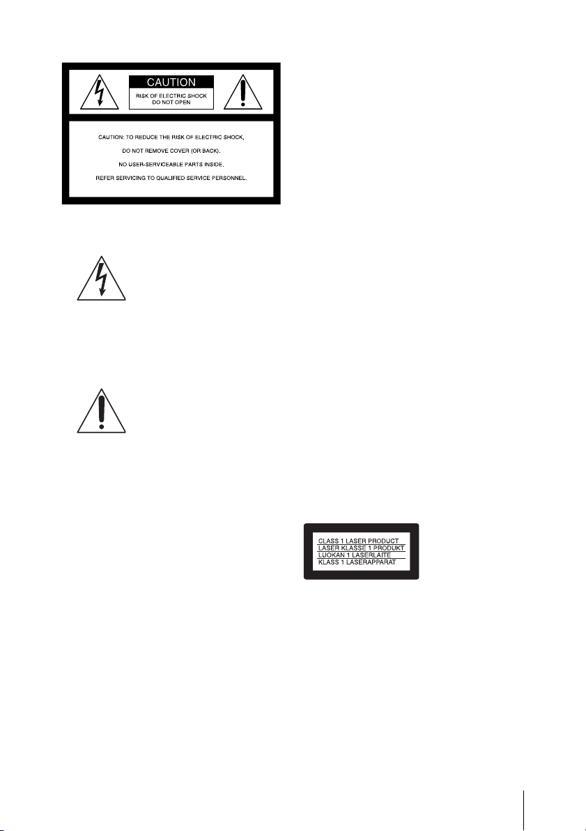
The PDW-D1 is classified as a CLASS 1
LASER PRODUCT.
PDW-D1 on luokiteltu 1. LUOKAN
LASERTUOTTEEKSI.
PDW-D1 klassificeras som en
LASERPRODUKT AV KLASS 1.
3
Laser diode properties
Wavelength: 403 to 410 nm
Emission duration: Continuous
Laser output power: 65 mW (max. of
pulse peak), 35 mW (max. of CW)
Standard: IEC60825-1 (2001)
Tekniska data för laserdiod
Våglängd: 403 till 410 nm
Emissionslängd: Kontinuerlig
Laseruteffekt: 65 mW (max. för
pulstopp), 35 mW (max. för
kontinuerlig våg)
Standard: IEC60825-1 (2001)
Egenskaber for laserdiode
Bølgelængde: 403 til 410 nm
Strålingsvarighed: Kontinuerlig
Afgivet lasereffekt: 65 mW (maks
stråletoppunkt), 35 mW (maks ved
kontinuerlig stråling)
Standard: IEC60825-1 (2001)
Laserdiodin ominaisuudet
Aallonpituus: 403 - 410 nm
Säteilyn kesto: jatkuva
Laserin teho: 65 mW (pulssin huipun
maks.), 35 mW (jatkuvan aallon
maks.)
Standardi: IEC60825-1 (2001)
Tämä kyltti sijaitsee ajurilaitteen
yläpinnalla.
Dette merket er plassert på oversiden av
driverenheten.
CAUTION
The use of optical instruments with this
product will increase eye hazard.
Use of controls or adjustments or
performance of procedures other than those
specified herein may result in hazardous
radiation exposure.
VAROITUS!
LAITTEEN KÄYTTÄMINEN MUULLA
KUIN TÄSSÄ KÄYTTÖOHJEESSA
MAINITULLA TAVALLA SAATTAA
ALTISTAA KÄYTTÄJÄN
TURVALLISUUSLUOKAN 1
YLITTÄVÄLLE NÄKYMÄTTÖMÄLLE
LASERSÄTEILYLLE.
VARNING
OM APPARATEN ANVÄNDS PÅ
ANNAT SÄTT ÄN I DENNA
BRUKSANVISNING SPECIFICERATS,
KAN ANVÄNDAREN UTSÄTTAS FÖR
OSYNLIG LASERSTRÅLNING, SOM
ÖVERSKRIDER GRÄNSEN FÖR
LASERKLASS 1.
This label is located on the top panel of the
drive unit.
Denna etikett finns på ovansidan av
driftenheten.
Denne mærkat sidder på drevenhedens
øverste panel.
4

For the customers in the USA
This equipment has been tested and found
to comply with the limits for a Class B
digital device, pursuant to Part 15 of the
FCC Rules. These limits are designed to
provide reasonable protection against
harmful interference in a residential
installation. This equipment generates,
uses, and can radiate radio frequency
energy and, if not installed and used in
accordance with the instructions, may cause
harmful interference to radio
communications. However, there is no
guarantee that interference will not occur in
a particular installation. If this equipment
does cause harmful interference to radio or
television reception, which can be
determined by turning the equipment off
and on, the user is encouraged to try to
correct the interference by one or more of
the following measures;
– Reorient or relocate the receiving
antenna.
– Increase the separation between the
equipment and receiver.
– Connect the equipment into an outlet on
a circuit different from that to which the
receiver is connected.
– Consult the dealer or an experienced
radio/TV technician for help.
You are cautioned that any changes or
modifications not expressly approved in
this manual could void your authority to
operate this equipment.
All interface cables used to connect
peripherals must be shielded in order to
comply with the limits for a digital device
pursuant to Subpart B of Part 15 of FCC
Rules.
If you have any questions about this product, you
may call;
Sony Customer Information Service Center 1-800222-7669 or http://www.sony.com
Declaration of Conformity
Trade Name : SONY
Model : PDW-D1
Responsible Party : Sony Electronics
Inc.
Address : 16530 Via
Esprillo, San
Diego, CA 92127
U.S.A.
Telephone Number : 858-942-2230
This device complies with Part 15 of the
FCC Rules. Operation is subject to the
following two conditions: (1) this device
may not cause harmful interference, and
(2) this device must accept any
interference received, including
interference that may cause undesired
operation.
For the customers in Europe
This product with the CE marking complies
with both the EMC Directive and the Low
Voltage Directive issued by the
Commission of the European Community.
Compliance with these directives implies
conformity to the following European
standards:
• EN60065: Product Safety
• EN55103-1: Electromagnetic
Interference (Emission)
• EN55103-2: Electromagnetic
Susceptibility (Immunity)
This product is intended for use in the
following Electromagnetic
Environment(s):
E1 (residential), E2 (commercial and light
industrial), E3 (urban outdoors) and E4
(controlled EMC environment, ex. TV
studio).
The manufacturer of this product is Sony
Corporation, 1-7-1 Konan, Minato-ku,
Tokyo, Japan.
The Authorized Representative for EMC
and product safety is Sony Deutschland
GmbH, Hedelfinger Strasse 61, 70327
5

Stuttgart, Germany. For any service or
guarantee matters please refer to the
addresses given in separate service or
guarantee documents.
For the Customers in Taiwan
only
6

Table of Contents
Before Using the Unit ....................................................................9
Setting the Line Mode ..............................................................9
Chapter 1 Overview
1-1 Features ...................................................................................10
1-2 Example of Use ........................................................................12
1-3 System Requirements .............................................................13
1-4 MPEG-4 Visual Patent Portfolio License .............................14
1-5 MPEG-2 Video Patent Portfolio License ..............................15
Chapter 2 Names and Functions of Parts
2-1 Front Panel ..............................................................................16
2-2 Rear Panel ...............................................................................18
Chapter 3 Preparations
3-1 Software Installation ..............................................................19
3-1-1 Windows Installation ....................................................19
3-1-2 Macintosh Installation ...................................................20
3-2 Connections and Settings........................................................21
3-2-1 Connecting to a Nonlinear Editing System (AV/C Connec-
tion) .........................................................................................21
3-2-2 Connecting to a Computer (FAM connection) ..............22
3-3 Power Preparations ................................................................24
3-3-1 Using AC Power ...........................................................24
3-3-2 Using a Battery Pack .....................................................24
3-4 Setting the Date and Time .....................................................25
3-5 Handling Discs ........................................................................26
3-5-1 Discs Used for Recording and Playback .......................26
3-5-2 Notes on Handling .........................................................26
3-5-3 Write-Protecting Discs ..................................................26
3-5-4 Loading and Unloading a Disc ......................................27
3-5-5 Formatting a Disc ..........................................................27
3-5-6 To Eject Discs With the Unit Powered Off ...................27
Table of Contents
7

3-5-7 Handling of Discs When Recording Does Not End
Normally (Salvage Function) ..................................................28
3-5-8 Condensation .................................................................28
3-6 Preparations for Recording and Playback ...........................29
3-6-1 Preparations for Recording ...........................................29
3-6-2 Preparations for Playback .............................................29
Chapter 4 Handling Files
4-1 Overview ..................................................................................31
4-1-1 Directory Structure ........................................................31
4-1-2 File Operation Restrictions ............................................32
4-1-3 Assigning User-Defined Clip Titles ..............................35
4-1-4 Assigning User-Defined Clip and Clip List Names ......36
4-2 Preparations for File Access ..................................................37
4-3 File Access Operations (Windows) .......................................38
Chapter 5 Using the Utility Software
5-1 Starting and Exiting ...............................................................39
5-1-1 Starting ..........................................................................39
5-1-2 Exiting ...........................................................................40
5-2 Names and Functions of Parts................................................41
5-3 Details of Functions ................................................................43
5-3-1 Device Information Menu .............................................43
5-3-2 Setup Menu ...................................................................44
5-3-3 Disc Operation Menu ....................................................51
Appendix
Table of Contents
8
Specifications................................................................................. 53

Before Using the
5 Click the Set button.
“Turn off/on POWER!” appears.
Unit
Setting the Line Mode
This unit is shipped with the line mode still
unset. Therefore you need to set the line
mode before using the unit. (The unit
cannot be used unless the line mode is set.)
Once it is set, the line mode is retained even
when the unit is powered off.
Setting procedure
Use the following procedure to set the line
mode.
1 Power the unit on (see page 17).
2 Start the utility software (see page 39).
In the Line mode box of the Basic
information screen, “----” appears.
For details of installation of the utility
software, see “Utility software” (page 19).
For details of the utility software, see Chapter
5, “Using the Utility Software” (page 39).
6 On a Macintosh computer, click the
“Change Connection” button to switch
to “AVc/Log out.”
7 Exit the utility software (see page 40).
8 Power the unit off, and then power it
on again.
The selected line mode becomes
available for use.
You can change the setting made with this
procedure by using setup menu item “AV
settings” - “525/625 SYSTEM SELECT.” See
5-3-2 “Setup Menu” (page 44) for more
information about how to make setup menu
settings.
Note
The line mode is not set, or is cleared, in the
following situation. Reset the line mode.
• The unit is powered off before
performing step 6 in the previous
procedure.
3 In the tree display, select “Setup” -
“AV settings.”
Menu item “525/625 SYSTEM
SELECT” appears in the operating
screen.
4 Using the V/v buttons or the up and
down arrow keys on the keyboard,
select “525” or “625.”
Setting Line mode
525 525: NTSC
625 625: PAL
Before Using the Unit
9

Chapter 1 Overview
Overview
1-1 Features
The PDW-D1 is a compact and lightweight
disc drive which, connected to a nonlinear
editor, allows recording/playback of video/
audio data. Connected to a computer, it can
also be used to write and read video/audio
data files and general-purpose data files.
In conjunction with a laptop computer it is
ideal for field use, or for building a budget
video production system together with a
nonlinear editor.
The features of the PDW-D1 include the
following.
DVCAM format recording/
playback
By accessing this unit from a computer with
the AV/C (Audio/Video Control) protocol,
you can record or play back a DVCAM
format data stream.
1) DVCAM is a trademark of Sony Corporation.
DVCAM output from MPEG
IMX recorded disc
By playing back a disc recorded in MPEG
1)
format from a computer with the
IMX
AV/C protocol, a signal converted to the
DVCAM format can be output.
1) MPEG IMX is a trademark of Sony
Corporation.
1)
Chapter
Recording video and audio
data as files
You can record video and audio data in
MPEG IMX format or DVCAM format as
files, through the S400 (i.LINK)
connector.
Proxy AV data
The proxy AV data is a low-resolution,
MPEG-4 based version of the fullresolution MPEG IMX/DVCAM stream.
When a full-resolution MPEG IMX/
DVCAM file is transferred, a proxy AV
stream file that is time code synchronized
with the full-resolution stream, is also
created automatically on the disc. This
proxy AV data, which is smaller in size, is
easier to work with and can be transferred at
upto 30 times faster than real time.
IT-friendly system through
i.LINK interface
In the Professional Disc, clips are recorded
as video and audio data files. This filebased recording system also allows material
to be viewed directly on a computer linked
to the PDW-D1 via an i.LINK (file access
mode, called FAM below) connection-in
the same way that a computer reads data
files on an external drive. The interfaces
include the S400 (i.LINK) connector,
supporting AV/C (Audio/Video Control)
and i.LINK (FAM) protocols.
1
10
1-1 Features

Flexible metadata handing
XDCAM
metadata together with video and audio
data, such as the date and time of shooting,
the cameraman, the recording method, and
comments about the material. This
metadata can be used in applications such
as the following.
• The supplied PDZ-1 Proxy Browsing
• Computer-readable text files can be
• The ability to search metadata for the
1) XDCAM is a trademark of Sony Corporation.
1)
can record various types of
Software can be used to add titles,
comments, and other text data to discs
and clips.
recorded on the Professional Disc, to
allow systematic content management.
required audio and video scenes brings
greater efficiency to various stages of the
video production process (editing,
archiving, etc.).
Compact size, lightweight
and batterypowered
operation
The PDW-D1 is designed small and light
enough to carry out to the field and it is
operable with battery to work in the field.
make settings or upgrade the unit by means
of menu operations on the computer.
Chapter 1 Overview
Vertical or horizontal
orientation
The unit is adaptable to different situations.
It can be oriented vertically for use with a
desktop computer, to occupy the minimum
of space, and in the field can be used
horizontally, for stability.
Menu operation from a
computer using the utility
software
By installing the supplied utility software in
a computer connected to this unit, you can
1-1 Features
11
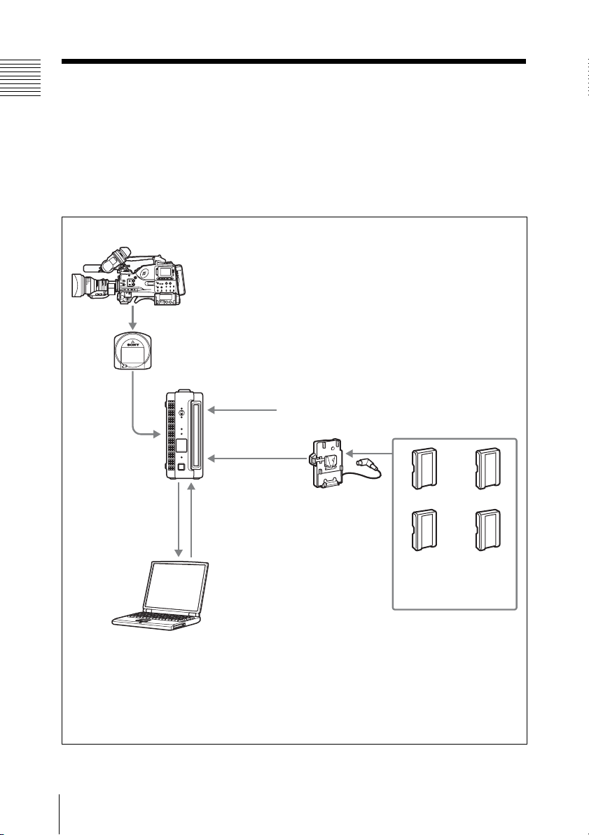
1-2 Example of Use
Chapter 1 Overview
The following figure illustrates a system in which material recorded
with a PDW-510/510P/530/530P camcorder is edited with a
computer connected to this unit.
In general, illustrations in this manual show the unit in the vertical
orientation.
PDW-510/510P/530/530P
Professional Disc
1-2 Example of Use
12
-AC IN
DC IN
PDW-D1
a)
b)
Recording
b)
Writing
c)
Playback
Reading
Laptop computer
a) Operation for DVCAM connection
b) Operation for FAM connection
c) Requires editing software supporting the DVCAM format, or a FAM driver to be installed.
AC power supply
a)
BKP-L551
Battery adaptor
BP-GL65 BP-GL95
BP-L60S BP-L80S
Battery packs

1-3 System
Requirements
Operating the supplied utility software and
PDZ-1 Proxy Browsing Software
(Windows only) requires a computer
system at least meeting the following
requirements.
For details of the PDZ-1 Proxy Browsing Software,
see page 38.
Windows
Item Requirement
Processor Intel Pentium M
Memory 512 MB or more
Free hard
disk space
Monitor • Resolution: 1024 ×
Operating
system
Web browser Internet Explorer 6.0
processor 1 GHz or
higher
• At time of installation:
2 MB or more
100 MB or more
• For proxy AV data:
approx. 1.4 GB per 90
minutes
768 pixels or better
• Color: 16-bit or better
• Microsoft Windows XP
Professional SP2 or
a)
later
• Microsoft Windows XP
Professional SP2 or
later, or Windows
Vista Ultimate/
Business (32bit)
SP1 or later
a)
b)
c)
b)
Item Requirement
Other • Equipped with i.LINK
a) For the utility software
b) For the PDZ-1 Proxy Browsing Software
c) For the Work folder for storing material when
using the PDZ-1 Proxy Browsing Software
connector (IEEE1394
compliant)
• DirectX version 8.1b
or later installed
Macintosh
Item Requirement
Processor PowerPC G4, PowerPC
G5, or Intel Core Duo
processor 867 MHz or
higher
Memory 512 MB or more
Free hard
disk space
Monitor Resolution: 1024 × 768
Operating
system
Other • AGP Quartz Extreme
a) For the utility software
b) For the FAM driver
At time of installation:
20 MB or more
pixels or better
• Mac OS X v10.4.7 or
a)
later
• Mac OS X v10.4.11 or
b)
later
or PCI Express
graphics card
• QuickTime 7.1.3 or
later
• Equipped with
FireWire port
(IEEE1394 compliant)
Chapter 1 Overview
1-3 System Requirements
13

1-4 MPEG-4
Chapter 1 Overview
Visual Patent
Portfolio License
THIS PRODUCT IS LICENSED UNDER
THE MPEG-4 VISUAL PATENT
PORTFOLIO LICENSE FOR THE
PERSONAL AND NON-COMMERCIAL
USE OF A CONSUMER FOR
(i) ENCODING VIDEO IN
COMPLIANCE WITH THE MPEG-4
VISUAL STANDARD (“MPEG-4
VIDEO”)
AND/OR
(ii) DECODING MPEG-4 VIDEO THAT
WAS ENCODED BY A CONSUMER
ENGAGED IN A PERSONAL AND
NON-COMMERCIAL ACTIVITY
AND/OR WAS OBTAINED FROM A
VIDEO PROVIDER LICENSED BY
MPEG LA TO PROVIDE MPEG-4
VIDEO.
Other usage of this product may be required
to obtain license from MPEGLA.
Please contact MPEG LA for any further
information.
MPEG LA, L.L.C., 250 STEELE STREET,
SUITE 300, DENVER, COLORADO
80206, http://www.mpegla.com
NO LICENSE IS GRANTED OR SHALL
BE IMPLIED FOR ANY OTHER USE.
ADDITIONAL INFORMATION
INCLUDING THAT RELATING TO
PROMOTIONAL, INTERNAL AND
COMMERCIAL USES AND LICENSING
MAY BE OBTAINED FROM MPEG LA,
LLC. SEE HTTP://WWW.MPEGLA.COM
MPEG LA is offering licenses for (i)
manufacturing/sales of any storage media
storing MPEG-4 Visual video information
(ii) distribution/broadcasting of MPEG-4
Visual video information in any manner
(such as online video distribution
service,internet broadcasting, TV
broadcasting).
1-4 MPEG-4 Visual Patent Portfolio License
14

1-5 MPEG-2
Video Patent
Portfolio License
ANY USE OF THIS PRODUCT OTHER
THAN CONSUMER PERSONAL USE IN
ANY MANNER THAT COMPLIES
WITH THE MPEG-2 STANDARD FOR
ENCODING VIDEO INFORMATION
FOR PACKAGED MEDIA IS
EXPRESSLY PROHIBITED WITHOUT
A LICENSE UNDER APPLICABLE
PATENTS IN THE MPEG-2 PATENT
PORTFOLIO, WHICH LICENSE IS
AVAILABLE FROM MPEG LA, L.L.C.,
250 STEELE STREET, SUITE 300,
DENVER, COLORADO 80206.
"PACKAGED MEDIA” means any storage
media storing MPEG-2 video information
such as DVD movie which are sold/
distributed to general consumers.
Disc replicators or sellers of the
PACKAGED MEDIA need to obtain
licenses for their own business from MPEG
LA. Please contact MPEG LA for any
further information.
MPEG LA. L.L.C., 250 STEELE STREET,
SUITE 300, DENVER, COLORADO
80206
http://www.mpegla.com
Chapter 1 Overview
1-5 MPEG-2 Video Patent Portfolio License
15
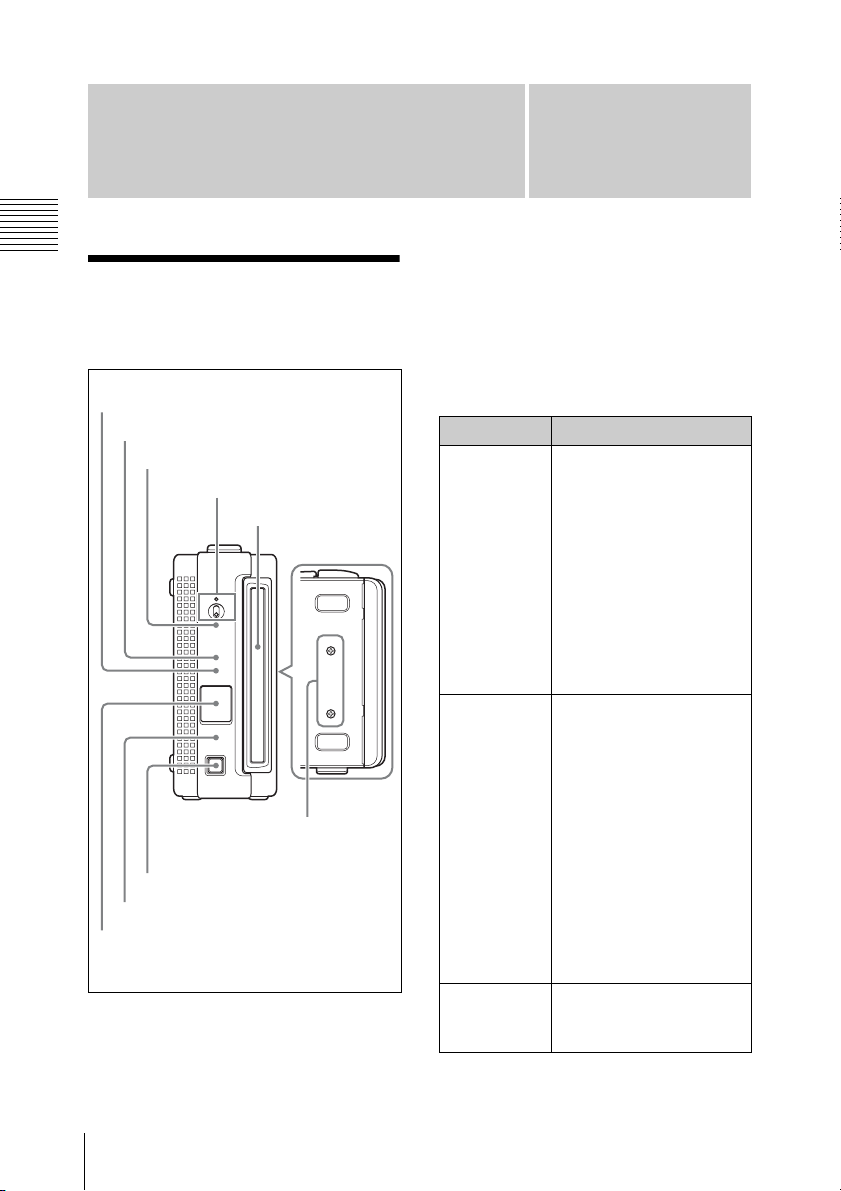
Names and Functions
of Parts
Chapter 2 Names and Functions of Parts
2-1 Front Panel
1
2
3
4
8
?
1
ACCESS
ERROR/ALARM
FILE ACCESS
MODE
DISC IN
Z
EJECT
9
7
6
5
a FILE ACCESS MODE indicator
Lights when a file access mode connection
(FAM connection) is established.
Chapter
During an AV/C (Audio/Video Control)
connection, it is off.
b ERROR/ALARM indicator
If an error occurs in the unit, this indicator
lights or flashes as shown in the following
table.
Indicator Meaning
Lit
continuously
Flashing four
times a
second
Flashing
once a
second
One of the following
alarms has been
generated.
• The battery pack is
exhausted.
• Condensation has
occurred.
• An attempt was made
to write or record when
there is insufficient
remaining disc
capacity.
• An error occurred
(principally a hardware
fault).
• One of the following
alarms has been
generated:
- There was a
- An error occurred
An alarm not listed
above occurred.
2
synchronization
error on the decoder
input signal during
recording.
during writing to
memory.
16
2-1 Front Panel

Note
The indicator may flash or light only for
five seconds depending on the alarm.
You can check alarms generated by this unit, using
the alarm log of the utility software (see page 44).
If the indicator is flashing four times a second, and
it is not possible to check the alarm log, a
malfunction may have occurred. In this case, contact
your Sony service representative.
When the error is eliminated, the indicator
goes off.
c ACCESS indicator
Lights when the disc is being accessed by a
computer. If the ~/1 (on/standby) switch is
set to the 1 position while this indicator is
lit, access to the disc is completed before
the unit switches to the standby state.
Note
While the ACCESS indicator is lit, do not
turn off the AC power switch, disconnect
the power cord, or remove the battery. This
could lead to a loss of data from the disc.
d ~/1 (on/standby) switch and
indicator
When the AC power switch on the rear
panel is in the ~ position, or a battery is
loaded, this switches the PDW-D1 between
the operating (~) and standby (1) states.
When the switch is moved to the ~ position,
the indicator lights. When the switch is
moved to the 1 position, the indicator goes
off.
When operating the PDW-D1 from an AC
power supply, normally leave the AC
power switch in the ~ position, and switch
the PDW-D1 between the operating and
standby states using the ~/1 (on/standby)
switch.
Note
When the DISC IN indicator is lit or
flashing, and the FILE ACCESS MODE
indicator is lit, setting this switch to 1
position has no effect on the power supply.
Eject a disc before carrying out the
operation.
e Manual eject mechanism
When there is no power supply to the unit,
to eject the disc, remove the cover and
rubber cap over this part, then turn the
screw counterclockwise with a Phillips
screwdriver.
For details, see 3-5-6 “To Eject Discs With the Unit
Powered Off” (page 27).
f DISC IN indicator
Lights when a disc is loaded.
It flashes while the disc is being inserted,
and while it is being ejected.
g EJECT button
Ejects a disc (see page 27).
h Disc slot
With the label surface on the right, insert
the disc (see page 27).
i Battery adaptor attachment section
To use a battery pack, remove the Phillips
screws, and fit the optional BKP-L551
battery adaptor.
For details, see “To attach a battery pack” (page
24).
Chapter 2 Names and Functions of Parts
2-1 Front Panel
17
 Loading...