

Sony PCV-RZ26G User Manual

Welcome
Thank you for purchasing your Sony VAIO® computer! Your new computer is a superb blend of high technology and
easy-to-use functionality. The information provided here is designed to help you to become familiar with the hardware and
software applications included with your system.
View the Electronic Flyer, which provides updates and supplemental information about your computer.
View the VAIO® Computer Specifications, which lists your computer's hardware specifications and preinstalled
software information, such as descriptions and contact information.
Page 1

Getting Started
Congratulations on your purchase of the Sony VAIO® computer! Your new, high-performance, multimedia computer combines
state-of-the-art computer functionality with the latest audio, video and information technology features.
Unpacking your Computer
Planning An Ergonomic Work Space
Locating Controls And Ports
Setting Up Your Computer
Turning On your Computer
Registering your Computer
Setting Up your Dial-up Connection
Turning Off your Computer
Page 2
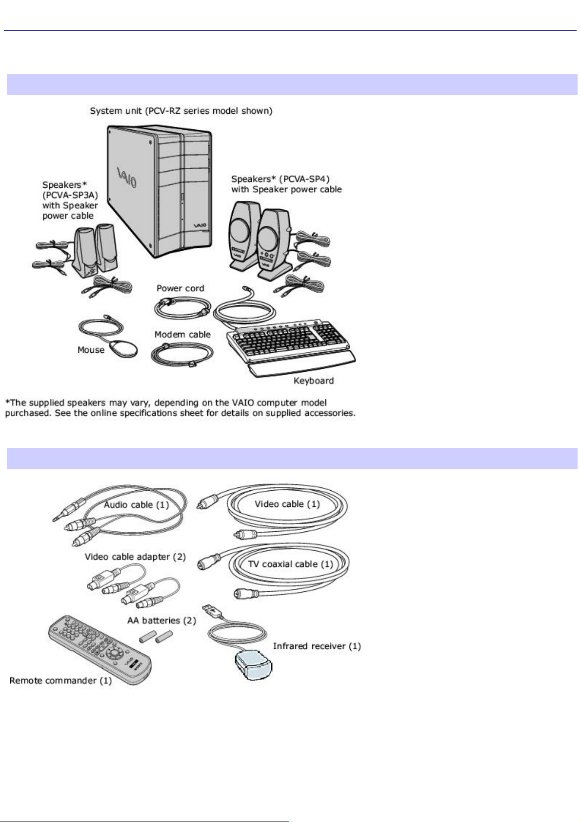
Unpacking your Computer
Your computer may not be supplied with all of the accessories shown, depending on the system configuration you
purchased. For details on the accessories supplied with your computer, see the online Specifications sheet.
Computer and supplied accessories
(See the online specifications sheet for details about supplied accessories.)
Giga Pocket Personal Video Recorder accessories
(For models equipped with Giga Pocket features)
Manuals
VAIO Digital Studio Computer Quick Start—Provides basic information on setting up and registering your
computer. The Quick Start also provides resources for technical support, safety guidelines and owner's information.
Microsoft® Windows® XP guide—Explains how to use the basic features of the latest Windows operating system.
Page 3

Online Documentation
VAIO Digital Studio Computer User Guide—Contains features and specifications of your computer. It also
includes information on the applications included with your system, how to contact software vendors, and solve
common problems.
To access the online User Guide:
1.
Click Start in the Windows taskbar, then click Help and Support.
2.
From the VAIO Help and Support Center menu, click VAIO User Guide.
Giga Pocket Personal Video Recorder—(For models equipped with Giga Pocket) This online guide contains
information on setting up and using the Giga Pocket Personal Video Recorder equipment and software applications.
The Internet Electronic Program Guide (iEPG) service information describes new Sony technology that is used with
the Internet, to locate, record and set up timed recordings of your favorite TV programs.
To access this online information:
1.
Click Start in the Windows taskbar, then click Help and Support.
2.
From the VAIO Help and Support menu, click Giga Pocket.
Creating DVDs—(For models equipped with a DVD±RW drive) This online guide provides information designed to
help you become familiar with your DVD±RW drive and the DVD burning software applications included with your
computer.
To access this online information:
1.
Click Start in the Windows taskbar, then click Help and Support.
2.
From the VAIO Help and Support menu, click Creating DVDs.
Specifications—This online specification sheet describes the hardware and software configuration of your VAIO
computer.
To access this online information:
1.
Click Start in the Windows taskbar, then click Help and Support.
2.
From the VAIO Help and Support menu, click VAIO User Guide.
3.
Click the Welcome link. The Welcome page displays in the right-side frame.
4.
Locate the link in the text, "View the VAIO® Computer Specifications..."
Recovery CDs
System Recovery CD(s) — Restore the software applications that shipped with your computer if they become
corrupted or are erased. The supplied System Recovery CDs can only be used to restore the hard disk of this Sony
computer.
Application Recovery CD(s) — Reinstalls individual software applications or drivers if they become corrupted or are
erased.
Other
Software Library containing the Microsoft software license agreement and Sony end-user license agreement.
Page 4

Planning An Ergonomic Work Space
Before you set up your new computer, find the best location for your new computer and plan your work space. There are
several ergonomic factors to consider when you arrange your work space:
Stable work surface — Use a stable work surface large enough to support the computer and other peripheral
equipment.
Ventilation — Leave at least eight inches of space on the left and back sides of your computer to enable proper
ventilation.
Placement of the keyboard, mouse, and other input devices — Place your keyboard, mouse, and other input
devices so that your arms and hands are in a relaxed, comfortable position. The keyboard should be directly in front
of you. Adjust the level of the keyboard so that your lower arms are parallel to the floor. Keep your wrists in a
relaxed position when you are using the keyboard—not angled up or down. Use the palmrest only briefly, for
resting. While typing, never use the palmrest or rest your hands on the table. Position the mouse at the same level
as the keyboard. Hold the mouse with a relaxed hand, and use your whole arm to move it. Take breaks during
sessions with your computer. Excessive use of the mouse or a joystick may strain muscles or tendons.
Furniture and posture — Sit in a chair with good back support and armrests. Adjust the level of the chair so your
feet are flat on the floor. A footrest may make you more comfortable. Sit with relaxed, upright posture—avoid
slouching forward or leaning far backward.
Viewing angle of the display — Position the display 18 to 26 inches directly in front of you, with the top of the
screen at or a little below eye level. Use the display's tilting feature to find the best position. You can reduce eye
strain and muscle fatigue by placing the display in the proper position.
Lighting — Choose a location where windows and lights do not create glare and reflection on the display. Use
indirect lighting to avoid bright spots on the display. You can also purchase accessories for your display that help
reduce glare. Proper lighting adds to your comfort and work effectiveness.
Page 5

Locating Controls And Ports
This section is intended to familiarize you with the controls, ports and jacks on your computer.Your computer may not be
equipped with all of these hardware features and the location of the controls, ports, and jacks may vary from the
illustrations shown in this section. To view the specific connection capabilities for your system, see the online specifications
sheet.
About the Front Panel (PCV-RZ series model)
About the Back Panel (PCV-RZ series model)
About the Remote Control (For models equipped with Giga Pocket features)
About the Front Panel (PCV-RX series model)
About the Back Panel (PCV-RX series model)
Page 6
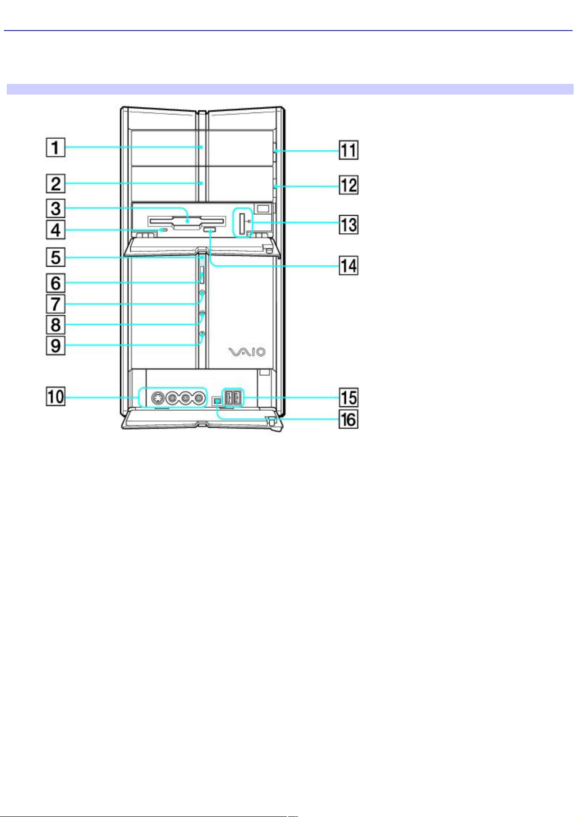
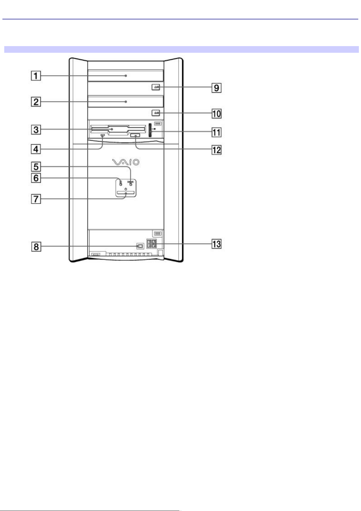
About the Front Panel (PCV-RZ series model)
The front panel of your VAIO Computer enables access to the optical and floppy disk drives. On certain models, the front
panel also provides access to Giga Pocket Personal Video Recorder jacks and ports, a Memory Stick media slot and the
Universal Serial Bus (USB), and i.LINK® ports that enable you to connect compatible peripheral devices.
Front panel (PCV-RZ series model)
1 Optical drive 1
See the online specifications sheet for optical drive information.
2 Optical drive 2
See the online specifications sheet for optical drive information.
3 Floppy disk drive
Reads and writes data from and to a 3.5-inch floppy disk.
4 Floppy disk drive access indicator
Light is green while reading and writing data from and to a floppy disk.
5 Power indicator
Light is blue while the power is on.
6 Power switch
Page 7

Turns the computer on and off.
7 Stand by indicator
Light is red when the computer is placed in Stand by mode.
8 Optical drive access indicator
Light is amber while reading and writing data from and to the optical drives.
9 Hard disk drive access indicator
Light is amber while reading and writing data from and to the hard disk.
10 (For models equipped with Giga Pocket features)
S-video In jack
Connection for an S-video cable (optional).
Video In jack
Connection for a video cable (supplied).
Audio L In jack/Audio R In jack
Connection for an audio cable (supplied).
11 Optical drive 1 eject button
Ejects a disc from Optical drive 1.
12 Optical drive 2 eject button
Ejects a disc from Optical drive 2.
13 Memory Stick media slot and access indicator
Reads and writes data from and to a Memory Stick® media. The access indicator light is amber when reading or writing
data.
14 Floppy disk eject button
Ejects a floppy disk from the floppy disk drive.
15 Universal Serial Bus (USB 2.0) ports (2)
Connections for compatible high/full/low-speed USB devices.
Page 8

16 i.LINK (4-pin) S400 port (IEEE 1394)
Connection for a compatible digital device.
i.LINK is a trademark of Sony used only to designate that a product contains an IEEE 1394 connection. The i.LINK
connection may vary, depending on the software applications, operating system, and compatible i.LINK devices. All products
with an i.LINK connection may not communicate with each other.
Please refer to the documentation that came with your compatible i.LINK device for information on operating conditions and
proper connection. Before connecting compatible i.LINK devices to your system, such as an optical or hard disk drive,
confirm their operating system compatibility and required operating conditions.
Page 9
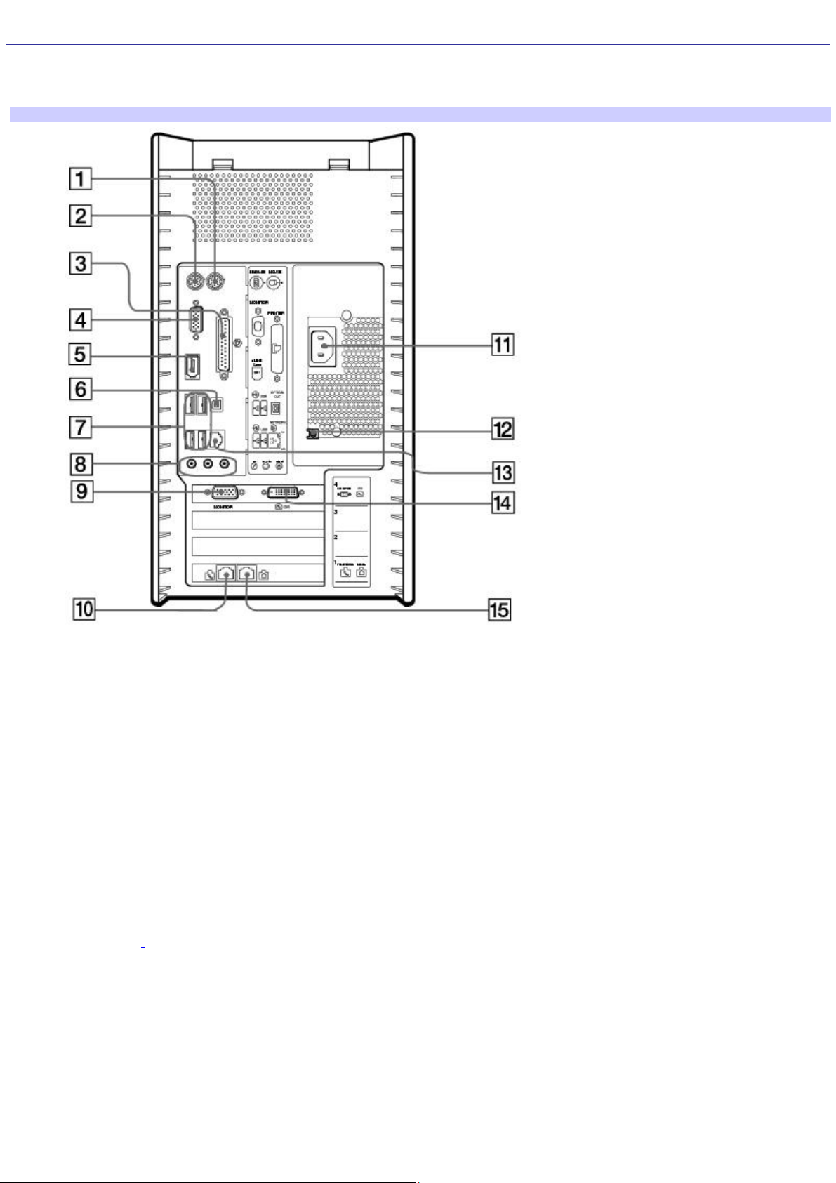
About the Back Panel (PCV-RZ series model)
The back panel of your computer contains the ports for supplied and optional accessories. The icons on the back panel
locate and identify the ports on your computer.
Back panel (PCV-RZ series model)
1 AC Input port
Connection for the supplied power cord.
2 Mouse port
Connection for a PS/2® mouse.
3 Keyboard port
Connection for a PS/2 keyboard.
4 Printer port
Connection for a parallel device, such as a printer or scanner.
5 Monitor port1
Connection for a standard display.
Page 10

6 i.LINK 6-pin S400 port (IEEE 1394)
Connection and power for a compatible digital device such as a Sony Digital Handycam® camcorder.
7 Universal Serial Bus (USB 2.0) ports (4)
Connections for compatible high/full/low-speed USB devices.
8 Microphone jack
Connection for a microphone (optional).
Headphones jack
Connection for the supplied speakers or optional headphones.
Line In jack
Connection for an audio device.
9 Monitor port2
Connection for a standard display.
10 Monitor (DVI) port3
Connection for a DVI monitor.
11 Telephone jack
Connection for a telephone cable (optional) to the computer.
12 Speaker DC Out jack4
Connection for the speaker power cable.
13 S/P DIF optical out port
Connection for a digital audio or optical device.
14 Ethernet port
Connection for a 10BASE-T/100BASE-TX Ethernet.
(The port marked with (Network) is for LAN connections only.)
15 (For models equipped with Giga Pocket features)
Page 11

Audio Out jack
Connection for an audio cable (supplied).
Video/S-video Out jack
Connection for a video cable adapter (supplied) or an S-video cable (optional).
Audio In jack
Connection for an audio cable (supplied).
Video/S-video In jack
Connection for a video cable adapter (supplied) or an S-video cable (optional).
16 (For models equipped with Giga Pocket features)
VHF/UHF port
Connection for a coaxial cable (supplied).
17 Modem line jack
Connection for the modem (supplied) cable to the wall jack.
1
T his monitor port may have a cover, indic ating that it is not available for use. O n s ome models, the monitor port loc ation may be in a different loc ation.
2
O n s ome loc ations, the monitor port location may be in a different loc ation.
3
A DV I monitor port is available on selec ted models only.
4
T he s peaker model supplied with your c omputer may vary, depending on the s ystem purc has ed. See the online specific ation sheet for information on
supplied acc ess ories.
Page 12
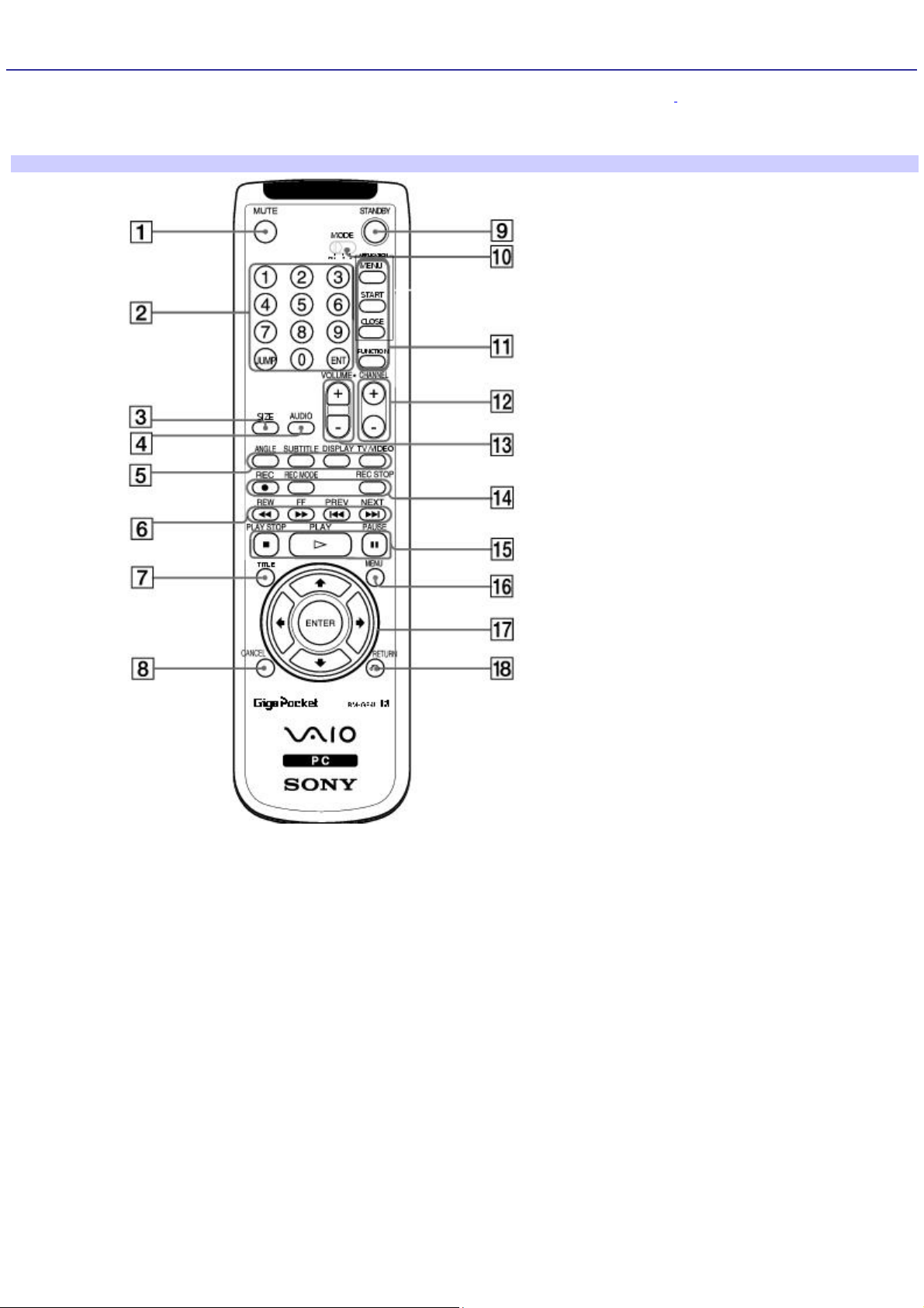
About the Remote Control (For models equipped with Giga Pocket features)
Giga Pocket Personal Video Recorder features are controlled with the remote commander1. The remote commander can
start and stop video recording and playback, select channels, and set viewing preferences. This section describes the basic
functions of your remote commander.
Remote control
1 MUTE button
Press to turn off the sound. Press again to restore the sound.
2 Channel number buttons (1-9)
Press to select specific channels.
(Press the ENT button to activate channel selection.)
JUMP button
Press to return to the previous channel. Press again to return to the current channel.
ENT button
Page 13

Press to activate channel selection. See Channel number buttons.
3 SIZE button
Press to view the current software in full-screen size. Press again to return the view to its original size.
4 AUDIO button
Press to view available sound mode options on the monitor/display.
5 DVD angle button
Press to change the camera angle during DVD playback. See the DVD player software for details. This function is not
available for other software.
DVD Subtitle button
Press to turn on/off subtitles or to change the subtitle language during DVD playback. See the DVD player software for
details. This function is not available for other software.
DISPLAY button
During DVD playback in full screen mode, press to show the settings window.
When using Giga Pocket software, press to display the TV/Recording deck and playback deck screens. Press again to hide
these views.
TV/VIDEO button
Press to change the on-screen image from the TV/Recording deck to external video equipment, such as your VCR.
(Note: You cannot change the input source while recording.)
6 REW and FF buttons
Press to rewind or fast-forward.
PREV and NEXT buttons
Press to move back to the previous screen or forward to the next screen.
7 TITLE button
The function of this button may vary between DVDs. See the DVD player software instructions for details.
8 CANCEL button
When using Giga Pocket software, press to close an error message dialog box. The window returns to its original size when
displayed in full-screen mode.
Page 14

(Note: This function is not available for other software.)
9 STANDBY button
Press to place the system into Stand by mode.
(Note: You can not place the computer into Stand by mode when certain Giga Pocket functions are running.)
10 MODE switch
Set the switch from 1 to 3, to change the remote commander's control between computers. The target computer's remote
commander software determines the assigned number.
(Note: The default setting is 1, if you are using a single computer.)
11 MENU button (upper)
Press to view a shortcut menu of available software applications. Press again to hide this window.
(Note: For Giga Pocket software, the Select Video Capsules window displays.)
START button
Press to start the selected software.
CLOSE button
Press to close the current software.
FUNCTION button
When Giga Pocket software is selected with the Menu button, press to switch from the TV/recording deck to the playback
deck.
When using SonicStage software, press to switch from the music drive (hard disk drive) to the CD.
12 CHANNEL button
Press to change channels automatically (no number input required).
(Note: This function is available for Giga Pocket software only.)
13 VOLUME button
Press to raise or lower the volume.
14 REC button
Page 15

Press to begin recording.
REC MODE button
Press to select the recording mode.
REC STOP button
Press to stop recording.
(Note: These functions are available for Giga Pocket software only.)
15 PLAY STOP button
Press to stop playback.
PLAY button
Press to begin playback.
PAUSE button
,Press to pause playback.
16 MENU button (lower)
Press to display the root menu during DVD playback. Press again to minimize the window. See the DVD player software for
details.
When using Giga Pocket software, press to display Video Capsule listings.
When using SonicStage software, press to display Playlists.
When using VAIO Media software, press to display the main menu.
17 Direction and ENTER buttons
Press a direction arrow to navigate. Press ENTER to select.
18 RETURN button
Press to return to the previous screen.
(Note: This function is not available for Giga Pocket software.)
For more details about the function buttons on your remote commander, see the Giga Pocket Help.
1
T he remote c ommander is s upplied with models that are equipped with Giga P ocket features.
Page 16
About the Front Panel (PCV-RX series model)
The front panel of your VAIO Computer enables access to the optical and floppy disk drives. It also includes access to the
Memory Stick media slot, Universal Serial Bus (USB), and i.LINK® ports to connect compatible peripheral devices.
Front panel (PCV-RX series model)
1 Optical drive 1
See the online specifications sheet for optical drive information.
2 Optical drive 2
See the online specifications sheet for optical drive information.
3 Floppy disk drive
Reads and writes data from and to a 3.5-inch floppy disk.
4 Floppy disk drive access indicator
Light is green while reading and writing data from and to a floppy disk.
5 Optical drive access indicator
Light is amber while reading and writing data from and to the optical drives.
6 Hard disk drive access indicator
Page 17

Light is amber while reading and writing data from and to the hard disk.
7 Power button and power indicator
Turns the computer on/off. The indicator light is blue while the power is on and amber when the computer is in Stand by
mode.
8 i.LINK 4-pin S400 port (IEEE 1394)
Connection for a compatible digital device.
9 Optical drive 1 eject button
Ejects a disc from Optical drive 1.
10 Optical drive 2 eject button
Ejects a disc from Optical drive 2.
11 Memory Stick® media slot
Reads and writes data from and to a Memory Stick media.
12 Floppy disk eject button
Ejects a floppy disk.
13 Universal Serial Bus (USB 2.0) ports (4)
Connections for compatible high/full/low-speed USB devices.
For your convenience, your computer includes USB and i.LINK ports on both the front and back panels. The 4-pin
i.LINK port is located on the front panel and the 6-pin i.LINK port is located on the back.
Page 18
About the Back Panel (PCV-RX series model)
The back panel of your computer contains the ports for supplied and optional accessories. The icons on the back panel
locate and identify the ports and jacks on your computer.
Back panel (PCV-RX series model)
1 Mouse port
Connection for a PS/2® mouse.
2 Keyboard port
Connection for a PS/2 Keyboard.
3 Printer port
Connection for a parallel device, such as a printer or scanner.
4 Monitor port1
Connection for a standard display.
5 i.LINK 6-pin S400 port (IEEE 1394)
Connection for a compatible digital device.
6 S/P DIF optical out port
Page 19

Connection for a digital audio or optical device.
7 Universal Serial Bus (USB 2.0) ports (4)
Connections for compatible high/full/low-speed USB devices.
8 Microphone jack
Connection for a microphone (optional).
Headphones jack
Connection for the supplied speakers or optional headphones.
Line In jack
Connection for an audio device.
9 Monitor port2
Connection for a standard display.
10 Telephone jack
Connection for a telephone cable (optional) to the computer.
11 AC Input port
Connection for the supplied power cord.
12 Speaker DC Out jack3
Connection for the speaker power cable.
13 Ethernet port
Connection for a 10BASE-T/100BASE-TX Ethernet. (The port marked with (Network) is for LAN connections only.)
14 Monitor (DVI) port4
Connection for a DVI monitor.
15 Modem line jack
Connection for the supplied modem cable to the wall jack.
1
T his monitor port may have a cover, indic ating that it is not available for use. O n s ome models, the monitor port loc ation may be in a different loc ation.
Page 20

2
O n s ome loc ations, the monitor port location may be in a different loc ation.
3
T he s peaker model supplied with your c omputer may vary, depending on the s ystem purc has ed. See the online specific ation sheet for information on
supplied acc ess ories.
4
A DV I monitor port is available on selec ted models only.
Page 21

Setting Up Your Computer
Your computer may not be equipped with all of these hardware features and the location of the controls, ports, and jacks
may vary from the illustrations shown in this section. See the online specifications sheet for your system's hardware
configuration.
Connecting a Display (Monitor)
Connecting the Speakers
Connecting the Keyboard and Mouse
Connecting the Power Cords
Turning On your Computer
Page 22
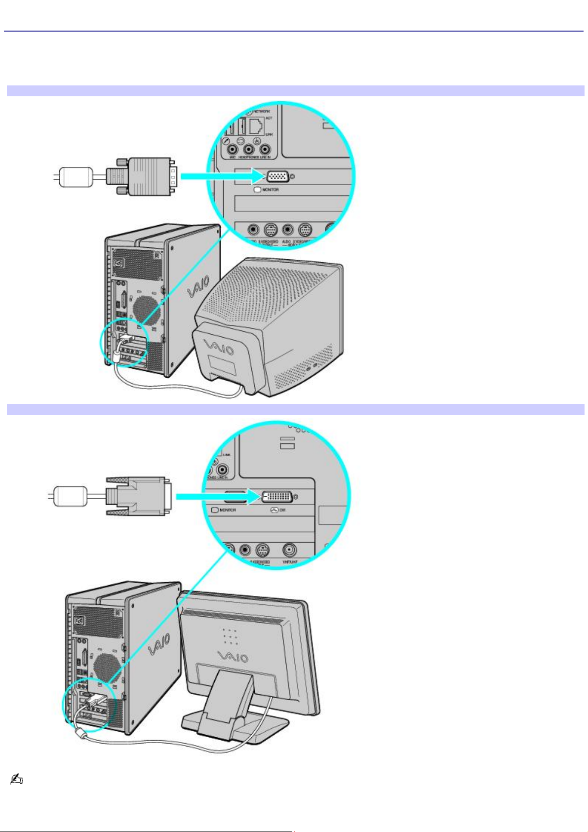
Connecting a Display (Monitor)
1.
Plug the display's cable into the monitor port.
2.
If necessary, plug the display's cable into the rear of the display.
To connect a display (PCV-RZ series model)
To connect a DVI display (PCV-RZ series model)
Install your equipment so that you can easily reach the power outlet in the event of an emergency.
Page 23
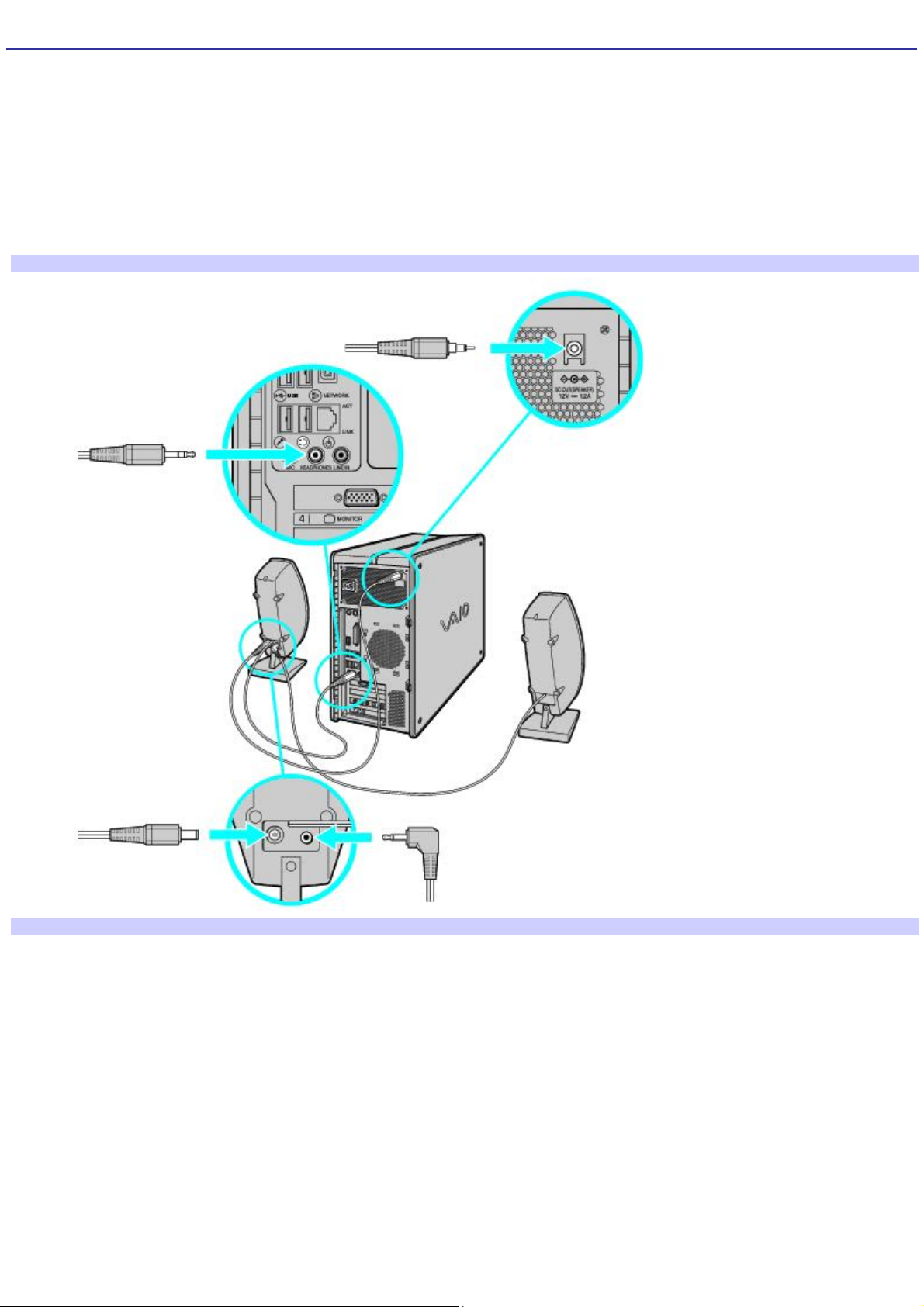
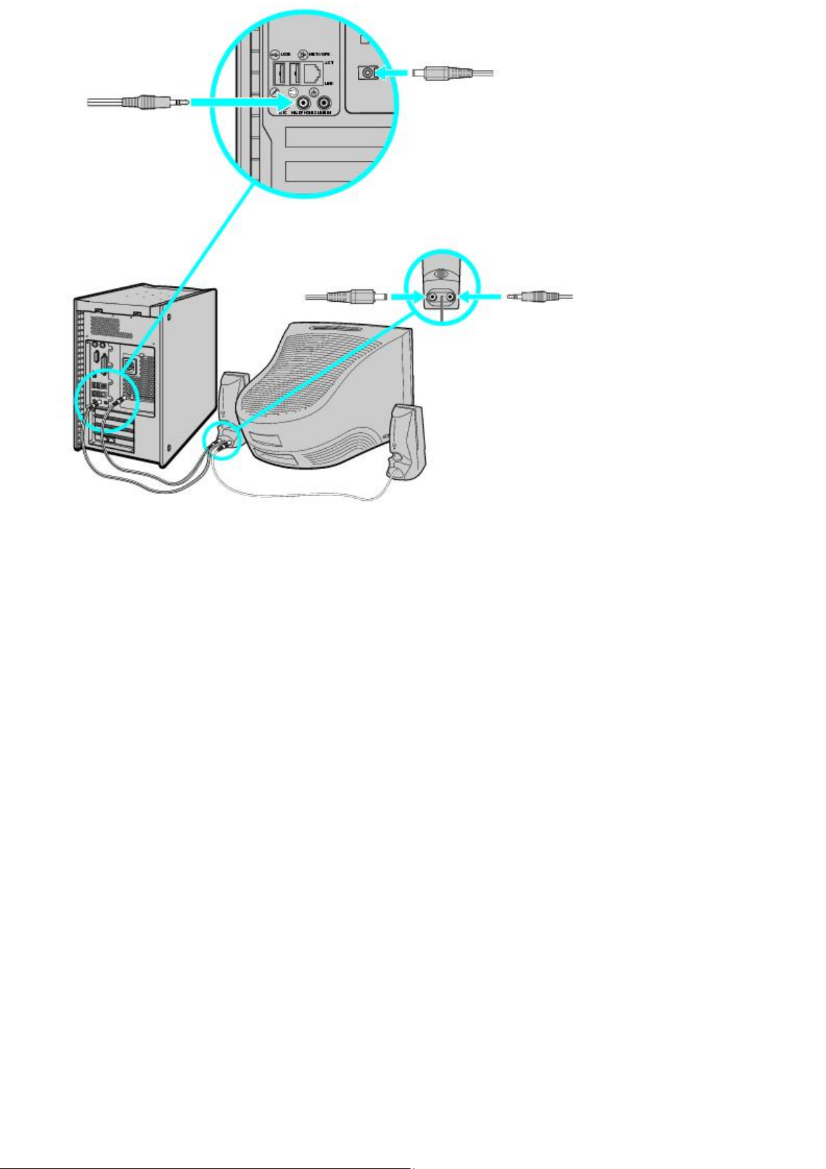
Connecting the Speakers
1.
Plug the cable attached to the back of the left speaker into the L Out jack on the back of the right speaker.
2.
Plug the cable attached to the back of the right speaker into the Headphones jack, located on the back panel of
your computer.
3.
Plug the jack end (yellow) of the speaker power cable into the DC In jack (yellow) on the back of the right
speaker.
4.
Plug the jack end (black) of the speaker power cable into the DC Out jack located on the back panel of your
computer.
To connect the PCVA-SP4 speakers (PCV-RZ series model)
To connect the PCVA-SP3A speakers (PCV-RX series model)
Page 24
Page 25
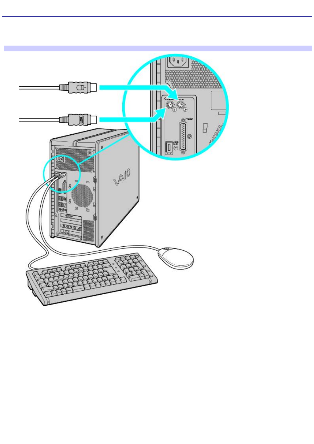
Connecting the Keyboard and Mouse
1.
Plug the keyboard cable into the keyboard port on the back of the computer.
2.
Plug the mouse cable into the mouse port on the back of the computer.
To connect the keyboard and mouse (PCV-RZ series model)
Page 26
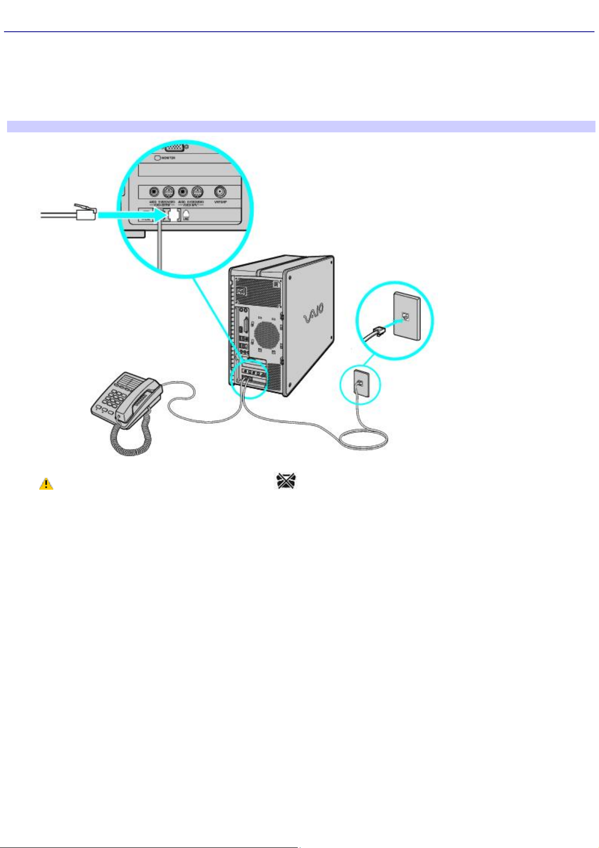
Connecting the Telephone and Modem Cables
1.
Unplug your telephone cable from the wall jack and plug it into the telephone jack located on the back panel of
your computer.
2.
Plug the modem cable (supplied) into the modem line jack, located on the back panel of your computer
3.
Plug the other end of the cable into the wall jack.
To connect the telephone and modem cables (PCV-RZ series m odel)
Your computer has a protective sticker covering the Ethernet port located on the rear panel.
Connect only 10BASE-T and 100BASE-TX cables to the Ethernet port. Using other cables or a telephone cable
may result in an electric current overload that can cause a malfunction, excessive heat, or fire in the Ethernet
port. For help on connecting to a network, see your network administrator.
Page 27
 Loading...