

Page 1

3-875-769-13 (1)
HD Visual
Communication
System
Operating Instructions (Version 2.0)
Before operating the unit, please read this manual thoroughly and retain it for
future reference.
PCS-XG80/XG80S
© 2008 Sony Corporation
Page 2

Owner’s Record
The model and the serial numbers are
located at the bottom. Record the serial
number in the space provided below. Refer
to these numbers whenever you call upon
your Sony dealer regarding this product.
Model No. ______________
Serial No. ______________
WARNING
To reduce a risk of fire or electric
shock, do not expose this product
to rain or moisture.
To avoid electrical shock, do not
open the cabinet. Refer servicing to
qualified personnel only.
IMPORTANT
The nameplate is located on the bottom.
Notice
The PCS-XG80S and the PCS-XG80 are
systems each of which contains Model No.
PCS-XG80S as a main unit. Always refer to
Model No. PCS-XG80S for regulatory
compliance purpose.
WARNING
Use the AC power adapter provided with
this equipment as a power supply source.
Manufacture Type No.
Sony VGP-AC19V15
Any other power sources may result in
hazards such as a fire.
Disconnect device of this equipment is the
mains plug of the AC adapter.
The mains plug on this equipment must be
used to disconnect mains power.
Please ensure that the socket outlet is
installed near the equipment and shall be
easily accessible.
In the event of abnormal operations,
disconnect the mains plug.
NOTICE
Use the power cord set approved by the
appropriate testing organization for the
specific countries where this unit is to be
used.
NOTICE
Each of PCS-XG80S, PCS-RF1 and PCSACXG80 contains an RF (Radio Frequency)
transmitting and receiving module.
Operation is subject to applicable local radio
communication regulations in each country.
This equipment should be installed and
operated with minimum distance 20cm
between the radiator & your body. This
transmitter must not be co-located or
operating in conjunction with any other
antenna or transmitter.
CAUTION for LAN port
For safety reasons, do not connect the LAN
port to any network devices that might have
excessive voltage.
Installing batteries
Two R06 (size AA) batteries are supplied for
Remote Commander.
To avoid risk of explosion, use R06 (size
AA) manganese or alkaline batteries.
CAUTION
Danger of explosion if battery is incorrectly
replaced. Replace only with the same or
equivalent type recommended by the
manufacturer. Dispose of used batteries
according to the manufacturer’s
instructions.
For the customers in the USA
WARNING
This device complies with Part 15 of the
FCC Rules.
Operation is subject to the following two
conditions: (1) This device may not cause
harmful interference, and (2) this device
must accept any interference received,
including interference that may cause
undesired operation.
This equipment has been tested and found to
comply with the limits for a Class A digital
device, pursuant to Part 15 of the FCC
2
Page 3

Rules. These limits are designed to provide
reasonable protection against harmful
interference when the equipment is operated
in a commercial environment. This
equipment generates, uses, and can radiate
radio frequency energy and, if not installed
and used in accordance with the instruction
manual, may cause harmful interference to
radio communications. Operation of this
equipment in a residential area is likely to
cause harmful interference in which case the
user will be required to correct the
interference at his own expense.
You are cautioned that any changes or
modifications not expressly approved in this
manual could void your authority to operate
this equipment.
All interface cables used to connect
peripherals must be shielded in order to
comply with the limits for a digital device
pursuant to Subpart B of Part 15 of FCC
Rules.
FCC Radiation Exposure Statement
(PCS-XG80S/PCS-RF1):
This equipment complies with FCC
radiation exposure limits set forth for an
uncontrolled environment. This equipment
should be installed and operated with
minimum distance 20 cm between the
radiator & your body. This transmitter must
not be co-located or operating in conjunction
with any other antenna or transmitter.
This manual focuses on using ISDN lines
to conduct a videoconference, but it also
covers non-ISDN lines. If you use ISDN
lines, consult your Sony dealer for more
information.
• The ISDN service may not be available
in some areas.
If you dispose the unit, consult your nearest
Sony Service Center. The built-in battery
must be treated as a chemical waste.
For the customers in Canada
This Class A digital apparatus complies with
Canadian ICES-003.
Cet appareil numérique de la classe A est
conforme à la norme NMB-003 du Canada.
IC Interference Statement (PCSXG80S/PCS-RF1)
This device complies with RSS-210 of the
IC Rules. Operation is subject to the
following two conditions:
1. This device may not cause harmful
interference, and
2. This device must accept any interference
received, including interference that may
cause undesired operation.
PCS-XG80S)
(
The term “IC:” before the radio certification
number only signifies that Industry Canada
technical specifications were met.
IC:7424A-ZM100
IC Radiation Exposure Statement:
This equipment complies with IC RSS-102
radiation exposure limits set forth for an
uncontrolled environment.
This equipment should be installed and
operated with minimum distance 20 cm
between the radiator & your body.
For the customers in Europe
The manufacturer of this product is Sony
Corporation, 1-7-1 Konan, Minato-ku,
Tokyo, Japan.
The Authorized Representative for EMC
and product safety is Sony Deutschland
GmbH, Hedelfinger Strasse 61, 70327
Stuttgart, Germany. For any service or
guarantee matters please refer to the
addresses given in separate service or
guarantee documents.
(PCS-XG80S/PCS-RF1)
This equipment conforms to R&TTE
Directive 1999/5/EC. For details, please
access the following URL:
http://www.compliance.sony.de
For the customers in Europe,
Australia and New Zealand
WARNING
This is a Class A product. In a domestic
environment, this product may cause radio
interference in which case the user may be
required to take adequate measures.
In the case that interference should occur,
consult your nearest authorized Sony service
facility.
3
Page 4
This apparatus shall not be used in the
residential area.
For the customers in Taiwan only
For the customers in Europe (PCS-XG80S)
This product is intended to be used in the following countries:
AT BE CY CZ DK EE FI FR DE GR HU
IS IE IT LV LI LT LU MT NL NO PL
PT RO SK SI ES SE CH GB BG
Language Informal DoC
С настоящето Сони Корпорация декларира, че този PCS-XG80S/HD
Bulgarian
Czech
Danish
Dutch
English
Estonian
Visual Communication System о тговаря на основните изисквания и
другите сьответстващи клаузи на Директива 1999/5/EC. Подробности
може да намерите на Интернет страницата : http://
www.compliance.sony.de/
Sony Corporation tímto prohlašuje, že tento PCS-XG80S/HD Visual
Communication System je ve shodě se základními požadavky a dalšími
příslušnými ustanoveními směrnice 1999/5/ES. Podrobnosti lze získat na
následující URL: http://www.compliance.sony.de/
Undertegnede Sony Corporation erklærer herved, at følgende udstyr PCSXG80S/ HD Visual Communication System overholder de væsentlige krav og
øvrige relevante krav i direktiv 1999/5/EF.
For yderligere information gå ind på følgende hjemmeside:
http://www.compliance.sony.de/
Hierbij verklaart Sony Corporation dat het toestel PCS-XG80S/ HD Visual
Communication System in overeenstemming is met de essentiële eisen en de
andere relevante bepalingen van richtlijn 1999/5/EG. Nadere informatie kunt u
vinden op: http://www.compliance.sony.de/
Hereby, Sony Corporation, declares that this PCS-XG80S/ HD Visual
Communication System is in compliance with the essential requirements and
other relevant provisions of Directive 1999/5/EC. For details, please access the
following URL: http://www.compliance.sony.de/
Sony Corporation kinnitab käesolevaga seadme PCS-XG80S/ HD Visual
Communication System vastavust 1999/5/EÜ direktiivi põhinõuetele ja
nimetatud direktiivist tulenevatele teistele asjakohastele sätetele.
Üksikasjalikum info: http://www.compliance.sony.de/.
4
Page 5
Language Informal DoC
p
Ð
Sony Corporation vakuuttaa täten että PCS-XG80S/ HD Visual
Finnish
Communication System tyyppinen laite on direktiivin 1999/5/EY oleellisten
vaatimusten ja sitä koskevien direktiivin muiden ehtojen mukainen. Halutessasi
lisätietoja, käy osoitteessa: http://www.compliance.sony.de/
Par la présente Sony Corporation déclare que l’appareil PCS-XG80S/ HD
Visual Communication System est conforme aux exigences essentielles et aux
French
autres dispositions pertinentes de la directive 1999/5/CE. Pour toute information
complémentaire, veuillez consulter l’URL suivante: http://
www.compliance.sony.de/
Hiermit erklärt Sony Corporation, dass sich das Gerät PCS-XG80S/ HD Visual
Communication System in Übereinstimmung mit den grundlegenden
German
Anforderungen und den übrigen einschlägigen Bestimmungen der Richtlinie
1999/5/EG befindet. Weitere Informationen erhältlich unter: http://
www.compliance.sony.de/
Με την η Sony Corporation δηλώνει τι PCS-XG80S/HD Visual
Greek
Hungarian
Italian
Latvian
Lithuanian
Norwegian
Polish
και τις λ της 1999/5/EK. Για
http://www.compliance.sony.de/
Alulírott, Sony Corporation nyilatkozom, hogy a(z) PCS-XG80S/HD
Visual Communication System megfelel a vonatkozó alapvető
követelményeknek és az 1999/5/EC irányelv egyéb előírá sainak.
További információkat a következő weboldalon találhat: http://
www.com
liance.sony.de/
Con la presente Sony Corporation dichiara che questo PCS-XG80S/ HD Visual
Communication System è conforme ai requisiti essenziali ed alle altre
disposizioni pertinenti stabilite dalla direttiva 1999/5/CE. Per ulteriori dettagli,
si prega di consultare il seguente URL: http://www.compliance.sony.de/
Ar ðo Sony Corporation deklarç, ka PCS-XG80S/HD Visual
Communication System atbilst Direktîvas 1999/5/EK bûtiskajâm prasîbâm
un citiem ar to saistîtajiem noteikumiem. Plaðâka inform âcija ir pieejama:
http://www.compliance.sony.de/
iuo Sony Corporation deklaruoja, kad ðis PCS-XG80S/HD Visual
Communication System atitinka esminius reikalavimus ir kitas 1999/5/EB
Direktyvos nuostatas. Susipaþinti su visu atitikties deklaracijos turiniu Jûs
galite interneto tinklalapyje: http://www.compliance.sony.de/
Sony Corporation erklærer herved at utstyret PCS-XG80S/ HD Visual
Communication System er i samsvar med de grunnleggende krav og øvrige
relevante krav i direktiv 1999/5/EF. For flere detaljer, vennligst se: http://
www.compliance.sony.de/
Niniejszym Sony Corporation oswiadcza, .e PCS-XG80S/ HD Visual
Communication System jest zgodne z zasadniczymi wymaganiami oraz innymi
stosownymi postanowieniami Dyrektywy 1999/5/WE. Szczególowe informacje
znalezc mo.na pod nastepujacym adresem URL: http://
www.compliance.sony.de/
5
Page 6
Language Informal DoC
p
Sony Corporation declara que este PCS-XG80S/ HD Visual Communication
Portuguese
System está conforme os requisitos essenciais e outras disposições da Directiva
1999/5/CE. Para mais informacoes, por favor consulte a seguinte URL: http://
www.compliance.sony.de/
Prin prezenta, Sony Corporation declară că acest PCS-XG80S/HD Visual
Romanian
Communication System respectă cerinţele esenţiale s¸i este în conformitate
cu prevederile Directivei 1995/5/EC. Pentru detalii, vă rugăm accesaţi
următoarea adresă: http://www.compliance.sony.de/
Sony Corporation týmto vyhlasuje, že PCS-XG80S/HD Visual
Slovak
Communication System splňa základné po žiadavky a všetky príslušné
ustanovenia Smernice 1999/5/ES. Podrobnosti získate na nasledovnej
webovej adrese: http://www.compliance.sony.de/
Sony Corporation izjavlja, da je ta PCS-XG80S/HD Visual
Slovenian
Communication System v skladu z bistvenimi zahtevami in ostalimi
relevantnimi določili direktive 1999/5/ES. Za podrobnosti vas napro šamo,
če pogledate na URL: http://www.compliance.sony.de/
Por medio de la presente Sony Corporation declara que el PCS-XG80S/ HD
Visual Communication System cumple con los requisitos esenciales y
Spanish
Swedish
cualesquiera otras disposiciones aplicables o exigibles de la Directiva 1999/5/
CE. Para mayor información, por favor consulte el siguiente URL: http://
www.compliance.sony.de/
Härmed intygar Sony Corporation att denna PCS-XG80S/ HD Visual
Communication System står I ö verensstämmelse med de väsentliga
egenskapskrav och övriga relevanta bestämmelser som framgår av direktiv
1999/5/EG. För ytterligare information gå in på följande hemsida: http://
www.compliance.sony.de/
For the customers in Europe (PCS-RF1)
This product is intended to be used in the following countries:
AT BE CY CZ DK EE FI FR DE GR HU
IS IE IT LV LI LT LU MT NL NO PL
PT RO SK SI ES SE CH GB BG
Language Informal DoC
С настоящето Сони Корпорация декларира, че този PCS-RF1/RF
Bulgarian
Remote Commander о тговаря на основните изисквания и другите
сьответстващи клаузи на Директива 1999/5/EC. Подробности може да
намерите на Интернет страницата : http://www.compliance.sony.de/
Sony Corporation tímto prohlašuje, že tento PCS-RF1/RF Remote
Czech
Commander je ve shodě se základními požadavky a dalšími příslušnými
ustanoveními směrnice 1999/5/ES. Podrobnosti lze získat na následující
URL: htt
://www.compliance.sony.de/
6
Page 7
Language Informal DoC
Undertegnede Sony Corporation erklærer herved, at følgende udstyr PCS-RF1/
RF Remote Commander overholder de væsentlige krav og øvrige relevante krav
Danish
i direktiv 1999/5/EF.
For yderligere information gå ind på følgende hjemmeside:
http://www.compliance.sony.de/
Hierbij verklaart Sony Corporation dat het toestel PCS-RF1/ RF Remote
Dutch
Commander in overeenstemming is met de essentiële eisen en de andere
relevante bepalingen van richtlijn 1999/5/EG. Nadere informatie kunt u vinden
op: http://www.compliance.sony.de/
Hereby, Sony Corporation, declares that this PCS-RF1/ RF Remote
English
Commander is in compliance with the essential requirements and other relevant
provisions of Directive 1999/5/EC. For details, please access the following
URL: http://www.compliance.sony.de/
Sony Corporation kinnitab käesolevaga seadme PCS-RF1/ RF Remote
Estonian
Commander vastavust 1999/5/EÜ direktiivi põhinõuetele ja nimetatud
direktiivist tulenevatele teistele asjakohastele sätetele. Üksikasjalikum info:
http://www.compliance.sony.de/.
Sony Corporation vakuuttaa täten että PCS-RF1/ RF Remote Commander
Finnish
tyyppinen laite on direktiivin 1999/5/EY oleellisten vaatimusten ja sitä
koskevien direktiivin muiden ehtojen mukainen. Halutessasi lisätietoja, käy
osoitteessa: http://www.compliance.sony.de/
Par la présente Sony Corporation déclare que l’appareil PCS-RF1/ RF Remote
French
Commander est conforme aux exigences essentielles et aux autres dispositions
pertinentes de la directive 1999/5/CE. Pour toute information complémentaire,
veuillez consulter l’URL suivante: http://www.compliance.sony.de/
Hiermit erklärt Sony Corporation, dass sich das Gerät PCS-RF1/ RF Remote
German
Commander in Übereinstimmung mit den grundlegenden Anforderungen und
den übrigen einschlägigen Bestimmungen der Richtlinie 1999/5/EG befindet.
Weitere Informationen erhältlich unter: http://www.compliance.sony.de/
Greek
Hungarian
Italian
Latvian
τις
http://www.compliance.sony.de/
Alulírott, Sony Corporation nyilatkozom, hogy a(z) PCS-RF1/RF Remote
Commander megfelel a vonatkozó alapvető követelményeknek
és az 1999/5/EC irányelv egyéb előírá sainak. További információkat a
következő weboldalon találhat: http://www.compliance.sony.de/
Con la presente Sony Corporation dichiara che questo PCS-RF1/ RF Remote
Commander è conforme ai requisiti essenziali ed alle altre disposizioni
pertinenti stabilite dalla direttiva 1999/5/CE. Per ulteriori dettagli, si prega di
consultare il seguente URL: http://www.compliance.sony.de/
Ar ðo Sony Corporation deklarç, ka PCS-RF1/RF Remote Commander
atbilst Direktîvas 1999/5/EK bûtiskajâm prasîbâm un citiem ar to
saistîtajiem noteikumiem. Plaðâka inform âcija ir pieejama:
http://www.compliance.sony.de/
7
Page 8

Language Informal DoC
Ð
iuo Sony Corporation deklaruoja, kad ðis PCS-RF1/RF Remote
Lithuanian
Commander atitinka esminius reikalavimus ir kitas 1999/5/EB Direktyvos
nuostatas. Susipaþinti su visu atitikties deklaracijos turiniu Jûs galite
interneto tinklalapyje: http://www.compliance.sony.de/
Sony Corporation erklærer herved at utstyret PCS-RF1/ RF Remote
Norwegian
Polish
Portuguese
Commander er i samsvar med de grunnleggende krav og øvrige relevante krav i
direktiv 1999/5/EF. For flere detaljer, vennligst se: http://
www.compliance.sony.de/
Niniejszym Sony Corporation oswiadcza, .e PCS-RF1/ RF Remote
Commander jest zgodne z zasadniczymi wymaganiami oraz innymi stosownymi
postanowieniami Dyrektywy 1999/5/WE. Szczególowe informacje znalezc
mo.na pod nastepujacym adresem URL: http://www.compliance.sony.de/
Sony Corporation declara que este PCS-RF1/ RF Remote Commander está
conforme os requisitos essenciais e outras disposições da Directiva 1999/5/CE.
Para mais informacoes, por favor consulte a seguinte URL: http://
www.compliance.sony.de/
Prin prezenta, Sony Corporation declară că acest PCS-RF1/RF Remote
Romanian
Commander respectă cerinţele esenţiale s¸i este în conformitate cu
prevederile Directivei 1995/5/EC. Pentru detalii, vă rugăm accesaţi
următoarea adresă: http://www.compliance.sony.de/
Sony Corporation týmto vyhlasuje, že PCS-RF1/RF Remote Commander
Slovak
splňa základné po žiadavky a všetky príslušné ustanovenia Smernice
1999/5/ES. Podrobnosti získate na nasledovnej webovej adrese:
http://www.compliance.sony.de/
Sony Corporation izjavlja, da je ta PCS-RF1/RF Remote Commander v
Slovenian
skladu z bistvenimi zahtevami in ostalimi relevantnimi določili direktive
1999/5/ES. Za podrobnosti vas napro šamo, če pogledate na URL: http://
www.compliance.sony.de/
Por medio de la presente Sony Corporation declara que el PCS-RF1/ RF
Spanish
Swedish
Remote Commander cumple con los requisitos esenciales y cualesquiera otras
disposiciones aplicables o exigibles de la Directiva 1999/5/CE. Para mayor
información, por favor consulte el siguiente URL: http://
www.compliance.sony.de/
Härmed intygar Sony Corporation att denna PCS-RF1/ RF Remote Commander
står I ö verensstämmelse med de väsentliga egenskapskrav och övriga relevanta
bestämmelser som framgår av direktiv 1999/5/EG. För ytterligare information
gå in på följande hemsida: http://www.compliance.sony.de/
8
Page 9

Precautions
Operating or storage location
Avoid operating or storing the system in the
following locations:
• Extremely hot or cold places
• Humid or dusty places
• Places exposed to strong vibration
• Close to sources of strong magnetism
• Close to sources of powerful
electromagnetic radiation, such as radios
or TV transmitters
• Noisy places
Cleaning
Use a soft, dry cloth to gently wipe the
cabinet and panel when cleaning the unit.
For heavier cleaning, use a cloth lightly
moistened with a mild detergent to remove
the dust, and finish by wiping again with a
dry cloth. Do not use volatile solvents such
as alcohol, benzene, thinners, or insecticides
as they may damage the surface finishes.
Note on laser beams
Laser beams may damage a CMOS image
sensor. You are cautioned that the surface
of a CMOS image sensor should not be
exposed to laser beam radiation in an
environment where a laser beam device is
used.
9
Page 10

Table of Contents
Chapter 1: Installation and Preparation
Using This Manual ................................................................................................. 16
Features .................................................................................................................. 17
System Components .............................................................................................. 19
Basic System Components ............................................................................... 19
Optional Equipment ......................................................................................... 21
System Configuration ............................................................................................ 23
System Configuration via a LAN ..................................................................... 23
System Configuration via an ISDN .................................................................. 24
System Configuration via a SIP ....................................................................... 25
System Configuration Using Two LAN Connections ..................................... 26
System Configuration via a LAN for Multipoint ............................................. 27
System Configuration via an ISDN for Multipoint ......................................... 28
System Configuration via a LAN and ISDN for Multipoint ........................... 29
System Configuration Using the PCSA-A7 Microphones ............................... 30
System Connections ............................................................................................... 31
System Connection via a LAN ......................................................................... 32
System Connection via an ISDN ...................................................................... 33
System Connection via a SIP ........................................................................... 34
Attaching the PCSA-CXG80 HD Camera Unit to a Tripod ............................ 35
Preparing the System ............................................................................................. 36
Inserting Batteries into the Remote Commander ............................................. 36
Programming the Remote Commander to Operate the Camera Unit .............. 37
Turning the System On/Off ................................................................................... 40
Turning On ....................................................................................................... 40
Standby Mode Function ................................................................................... 41
Setting the HD Visual Communication System to Standby Mode .................. 42
Turning Off ...................................................................................................... 42
Adjusting the Volume on the TV Monitor ....................................................... 43
Setting Up the System Immediately after the Installation — Initial Setup Wizard 44
Using the Menus .................................................................................................... 47
Identifying the Home Menu ............................................................................. 47
Operation Using the Menu ............................................................................... 54
Entering Characters Using the Remote Commander ....................................... 57
Entering Characters Using the On-Screen Keyboard ....................................... 58
10
Page 11

Chapter 2: Registration and Setup for System
Administrators
Registering Local Information ............................................................................... 60
Opening the Setup Menu .................................................................................. 60
Line Interface Setup Menu ............................................................................... 64
Dial Setup Menu ............................................................................................... 64
Answer Setup Menu .........................................................................................65
Multipoint Setup Menu .................................................................................... 65
Communication Setup Menu ............................................................................66
Audio Setup Menu ............................................................................................69
Video Setup Menu ............................................................................................ 71
LAN Setup Menu ............................................................................................. 73
QoS Setup Menu .............................................................................................. 75
TOS Setup Menu .............................................................................................. 77
SIP Setup Menu ................................................................................................ 77
ISDN Setup Menu ............................................................................................78
SPID Settings for Customers in the USA and Canada .....................................79
Annotation Setup Menu .................................................................................... 79
Camera Setup Menu .........................................................................................80
General Setup Menu ......................................................................................... 80
Home Menu Setup Menu .................................................................................82
Administrator Setup Menu ...............................................................................83
Encryption Setup Menu .................................................................................... 87
Shared Phone Book Setup Menu ...................................................................... 88
Displaying the Machine Status .............................................................................. 89
Displaying the Machine Status Menu .............................................................. 89
Machine Information ........................................................................................ 91
Peripheral Status ............................................................................................... 91
Communication Mode Status ...........................................................................92
LAN Line Status ............................................................................................... 92
Network Routing Check ................................................................................... 93
Restrictions on the Use of LAN2 ........................................................................... 94
Restrictions on the Use of IPv6 .............................................................................. 94
Setting Up the Network Configurations ................................................................. 95
LAN Connection via DHCP (LAN1/LAN2) ....................................................95
LAN Connection through a Router (LAN1/LAN2) ......................................... 96
LAN Connection through a Gatekeeper (LAN1 Only) .................................... 97
LAN Connection through NAT (LAN1 Only) ................................................. 98
LAN Connection with H.460 Firewall Traversal (LAN1 Only) ...................... 99
LAN Connection Using PPPoE (LAN1/LAN2) ............................................ 101
ISDN Connections .......................................................................................... 102
About the Network Routing Check ...................................................................... 103
11
Page 12

Chapter 3: Basic Connection
Starting a Connection by Calling a Remote Party ............................................... 104
Turning On the Power .................................................................................... 104
Calling a Remote Party by Using the Simple Dial Menu .............................. 105
Calling a Remote Party by Entering Their Address or Number Directly (Direct
Dial) .................................................................................................... 106
Calling a Remote Party Using the One-Touch Dial Buttons ......................... 108
Calling a Remote Party by Selecting Them in the History List ..................... 109
Calling a Remote Party Registered in the Phone Book .................................. 110
Calling a Remote Party Not Registered in the Phone Book ........................... 112
Receiving a Call from a Remote Party ................................................................ 115
Answering a Call from a Remote Party ......................................................... 115
Ending the Connection ......................................................................................... 117
Registering a Remote Party – Phone Book .......................................................... 118
Registering a New Remote Party ................................................................... 118
Editing the Contents of the Phone Book ........................................................ 121
Copying a Registered Paty in the Phone Book .............................................. 122
Deleting the Registered Remote Party ........................................................... 122
Creating a Group in the Phone Book (Group Edit) ........................................ 122
Creating a Private Phone Book ...................................................................... 124
Using the Shared Phone Book ........................................................................ 126
Adjusting the Sound ............................................................................................. 129
Adjusting the Volume of the Received Sound ............................................... 129
Turning Off the Sound Momentarily – Muting Function .............................. 129
Turning Off the Sound on Answering – Mic on Answer Function ................ 130
Synchronizing Audio and Video – Lip Sync Function .................................. 130
Reducing Echo – Echo Canceller ................................................................... 130
Adjusting the Camera .......................................................................................... 132
Adjusting the Camera Angle and Zoom ......................................................... 132
Adjusting the Brightness ................................................................................ 133
Using the Preset Function .............................................................................. 135
Adjusting the Camera in the Detailed Setup Menu ........................................ 138
Selecting the Input Picture and Sound ................................................................. 140
Switching the Displayed Picture between the Local and Remote Pictures .... 140
Selecting the Input Picture ............................................................................. 140
Switching the Sound to Be Sent to the Remote Party .................................... 141
Switching Video and Audio at the Same Time .............................................. 141
Switching the Picture from the Remote System ............................................ 141
Switching the Picture Displayed on the Monitor Screen ..................................... 142
Switching the Video Output Equipment ........................................................ 143
Capturing the Screen ............................................................................................ 144
12
Page 13

Chapter 4: Connection with Optional Equipment
Using a Tools Menu .............................................................................................146
Using the Computer Picture for Presentation ......................................................149
Installing the HD Data Solution Software ...................................................... 149
Connecting a Computer .................................................................................. 150
Making a Presentation .................................................................................... 150
Streaming a Communication ................................................................................ 152
Recording a Visual Communication .................................................................... 154
Using the Annotation Function ............................................................................ 156
Connecting a Pen Tablet ................................................................................. 156
Using the Annotation Function while in Communication ............................. 156
Using Multiple Microphones ............................................................................... 161
Using the PCSA-A7 Microphones ....................................................................... 164
Using a Second Camera ....................................................................................... 167
Recording during a Communication .................................................................... 168
Sending Audio/Video from the External Equipment to a Remote Party ............. 169
Viewing the Picture from the System on a Monitor or Projector ........................ 171
Communicating without the Picture – Voice Meeting .........................................173
Controlling the Remote System with the Tone Signal – DTMF Transmission ... 174
Accessing the Communication System ................................................................175
Using a Web Browser .....................................................................................175
Using Telnet ................................................................................................... 175
Chapter 5: Encrypted Connection
Preparing for an Encrypted Connection via LAN ................................................177
Starting an Encrypted Connection ....................................................................... 179
Chapter 6: Multipoint Connection
Connection Examples of a Multipoint Connection .............................................. 182
Using the LAN Connection (Up to Six Points) ..............................................182
Using the Cascade Connection via LAN (Up to 10 Points) ........................... 183
Using the ISDN Connection ...........................................................................184
Using Both LAN and ISDN ........................................................................... 185
Using the LAN Cascade and ISDN Connection ............................................ 186
Installing the MCU Software ...............................................................................187
Confirming that the Installation of the Software is Complete ........................ 187
Configuring Multipoint ........................................................................................ 188
Setting Up Multipoint .....................................................................................188
13
Page 14

Registering the Remote Parties in the Multipoint Connection List ............... 188
Starting a Multipoint Connection ........................................................................ 192
Calling Remote Parties ................................................................................... 192
Receiving a Call from a Remote Party ........................................................... 196
Using the Display Control ................................................................................... 197
Broadcast Mode ............................................................................................. 197
Broadcast Modes and Displayed Windows .................................................... 199
Switching the Broadcast Mode ...................................................................... 201
Receiving the Broadcast Requested From Another Terminal ........................ 202
Ending the Multipoint Connection ...................................................................... 203
Notes on Secondary Terminals ............................................................................ 204
Multipoint Attributes ........................................................................................... 205
Chapter 7: Web Control Function
Opening the Web Page ........................................................................................ 208
Identifying a User ................................................................................................ 209
Selecting a Menu ................................................................................................. 211
How to Use [Home] Menu ................................................................................... 212
How to Use [Download] Menu ............................................................................ 213
How to Use [Remote Commander] Menu ........................................................... 214
Selecting a Tool ................................................................................................... 215
How to Use [Version Up] Page ........................................................................... 216
How to Use [Streaming] Page ............................................................................. 217
How to Use [Monitor] Page ................................................................................. 218
Appendix
Location and Function of Parts and Controls ...................................................... 219
PCS-XG80S HD Visual Communication System .......................................... 219
PCSA-CXG80 HD Camera Unit (Supplied with PCS-XG80) ...................... 221
PCS-RF1 RF Remote Commander (Supplied) .............................................. 222
PCSA-B384S ISDN Unit (Optional) ............................................................. 223
PCSA-B768S ISDN Unit (Optional) ............................................................. 224
Indicators ............................................................................................................. 225
On-Screen Messages ............................................................................................ 228
Troubleshooting ................................................................................................... 230
Specifications ....................................................................................................... 234
PCS-XG80/XG80S HD Visual Communication System ............................... 234
PCS-RF1 Remote Commander (Supplied with PCS-XG80/XG80S) ............ 235
VGP-AC19V15 AC Adaptor (Supplied with PCS-XG80/XG80S) ............... 235
14
Page 15

PCSA-CXG80 HD Camera Unit (Supplied with PCS-XG80) .......................236
PCS-A1 Microphone (Supplied with PCS-XG80) ......................................... 236
PCSA-A3 Microphone (Optional) .................................................................. 236
PCSA-A7P4 Microphone (Optional) ............................................................. 236
PCSA-B384S ISDN Unit (Optional) .............................................................. 237
PCSA-B768S ISDN Unit (Optional) .............................................................. 237
PCSA-DSG80 HD Data Solution Software (Optional) ..................................237
PCSA-MCG80 HD MCU Software ............................................................... 237
Acceptable RGB Input/Output Signals .......................................................... 239
Acceptable VIDEO IN (YPbPr) Signals ........................................................ 239
Pin Assignments ............................................................................................. 240
Pin Assignments on Optional Board Connectors ........................................... 242
List of Port Numbers Used on the PCS-XG80/XG80S .................................. 243
Meeting Room Layout .........................................................................................244
“Memory Stick” Media ........................................................................................ 245
Phenomena Specific to CMOS Image Sensors .................................................... 246
Glossary ............................................................................................................... 247
Menu Configuration ............................................................................................. 250
“IPELA” and are trademarks of Sony Corporation.
15
Page 16

Chapter 1: Installation and Preparation
Using This Manual
The chapters cover the following contents;
please read the chapters that may be required
for your type of communication.
Chapter 1: Installation and
Preparation
This chapter guides you through the system
configuration and information required to
use your HD Visual Communication System
for the first time. It shows you how to install
and connect your Communication System,
to turn the system on/off and how to access
basic on-screen menus.
Chapter 2: Registration and Setup for
System Administrator
This chapter describes how to register and
set up all the necessary items for system
administrators, using the on-screen menus.
audio data, and encrypted data from a
computer.
Chapter 6: Multipoint Connection
This chapter shows you how to connect your
system to multiple sites. Multipoint
connection requires installation of the
optional PCSA-MCG80 HD MCU software
in your Visual Communication System.
Chapter 7: Web Control Function
This chapter shows you how to control the
PCS-XG80/XG80S or set it up via a Web
browser.
Appendix
The appendix contains descriptions of the
controls and connectors on the components
of the HD Visual Communication System,
troubleshooting list, specifications, and a
glossary.
Chapter 3: Basic Connection
This chapter guides you through the basic
operations and settings for connecting to a
remote party. You will learn how to start
connection to finish it. It is recommended
that this chapter be read by participants in a
communication.
Chapter 4: Connection With Optional
Equipment
This chapter shows advanced
communication using the optional
equipment, and functions such as streaming,
recording, presentation and annotation.
Chapter 5: Encrypted Connection
This chapter shows how to connect to a
remote party using an encrypted video and
16 Using This Manual
Page 17

Features
The PCS-XG80/XG80S HD Visual
Communication System is a communication
system that provides face-to-face
communications with a remote party by
transmitting and receiving images and sound
via LAN (Local Area Network) or ISDN
(Integrated Services Digital Network)
connections.
Supports ITU-T international
standard
The HD Visual Communication System
complies with ITU-T Recommendations
defined by WTSC for easy connection with
remote parties overseas.
ITU: International Telecommunication
Union
WTSC: World Telecommunications
Standardization Committee
High transmission speeds and
high-quality picture capability
The Communication System accepts a LAN
communication bit rate of up to 10 Mbps. It
also allows you to connect to as many as
three ISDN lines and use 6B channels with
the optional PCSA-B384S ISDN Unit, and
as many as six ISDN lines and use 12B
channels with the optional PCSA-B768S
ISDN Unit.
Wide range of video/audio
compression format selectable
The Communication System supports the
H.264, H.263+, H.261 and MPEG4
compression formats. It also supports the
MPEG4 AAC
audio compression formats.
* Supports MPEG4 only for connection using
SIP.
** Supports MPEG4 AAC only for IP and
ISDN connection.
**
, G.722, G.728, and G.711
*
video
Chapter 1: Installation and Preparation
Transmission and reception of
high-definition images enabled
The Communication System supports the
H.264 high-definition video compression
format, enabling transmission and reception
of interlaced video signals with a high
resolution of 1920 × 1080 or 1280 × 720 by
a maximum of 60 frames per second.
Transmission and reception of
wide range of stereo sound
capability
The audio compression format of the
Communication System supports MPEG4
AAC (Advanced Audio Coding) stereo
sound and 22 kHz monaural sound, allowing
high-quality audio transmission and
reception. The built-in echo canceller
supports up to 16 kHz.
Supports data communication
Installing the optional PCSA-DSG80 HD
Data Solution Software into the
Communication System enables
transmission of output data from a computer.
Annotation capability
The annotation function allows you to write
letters or graphics on the screen or point with
a pointer during communication using the
optional pen tablet.
Bright Face feature incorporated in
the HD Camera Unit
The supplied PCSA-CXG80 HD Camera
Unit incorporates the Bright Face feature,
allowing detection of dark and bright
shooting parts of a scene individually to
make a dark scene brighter and a bright
scene clearer.
Up to 100 preset camera settings
Up to 100 settings for camera angle and
zoom can be registered in the preset memory
of the System. You can easily switch the
shooting area only by recalling the preset
position.
17Features
Page 18

RF (Radio Frequency) Remote
Commander adopted
The supplied Remote Commander controls
the Communication System using the radio
frequency of 2.4 GHz. The Remote
Commander can be programmed for pairing
with the System or the Camera Unit to
prevent interference from other Systems and
Camera Units.
On-screen keyboard
The on-screen keyboard displayed on the
monitor screen allows you to input a
number, address, etc. without moving your
eyes away from the screen.
QoS (Quality of Service) function
for optimization of bandwidth and
traffic packet through network
The Communication System includes the
“Packet Resend Request”, “Adaptive Rate
Control”, and “Forward Error Correction”
functions. Depending on the network status,
these functions are used in Hybrid to
guarantee consistent, high-quality
communications.
Compact size
The compact size of the Communication
System allows versatile installation layout.
Echo cancelling microphone
Up to 40 PCSA-A7 echo cancelling
microphones (optional) can be connected to
one port without losing sound quality, using
a cascade connection.
Video and audio recording
Video and audio can be recorded in a
“Memory Stick” and can be watched on a
computer after.
Streaming
You can broadcast streaming video and
audio. This allows people who cannot attend
the communication to watch the proceedings
over the Web using a computer. You can
also select whether to broadcast both video
and audio or audio only.
Supports a connection using SIP
The Communication System allows
connection to a remote party with an IP
phone, etc. using SIP (Session Initiation
Protocol).
Supports encrypted connection
The system allows you to make a strictly
confidential connection using standard
encryption, which complies with the H.233,
H.234 and H.235 standerdized by the ITU-T.
Supports multipoint connection
Installing the optional PCSA-MCG80 HD
MCU software in your Visual
Communication System allows connection
among multiple points via a LAN or/and
ISDN line.
Equipped with an HDMI connector
The HDMI connector allows you to connect
an HDMI display unit to the Communication
System easily.
Equipped with a Memory Stick slot
The Communication System is equipped
with a Memory Stick slot, allowing you to
save still images, create the Private Phone
Book and store the customized settings in a
“Memory Stick”.
18 Features
Page 19
System Components
The PCS-XG80/XG80S HD Visual Communication System is composed of
basic system components for a basic communication, and optional equipment
for an enhanced communication.
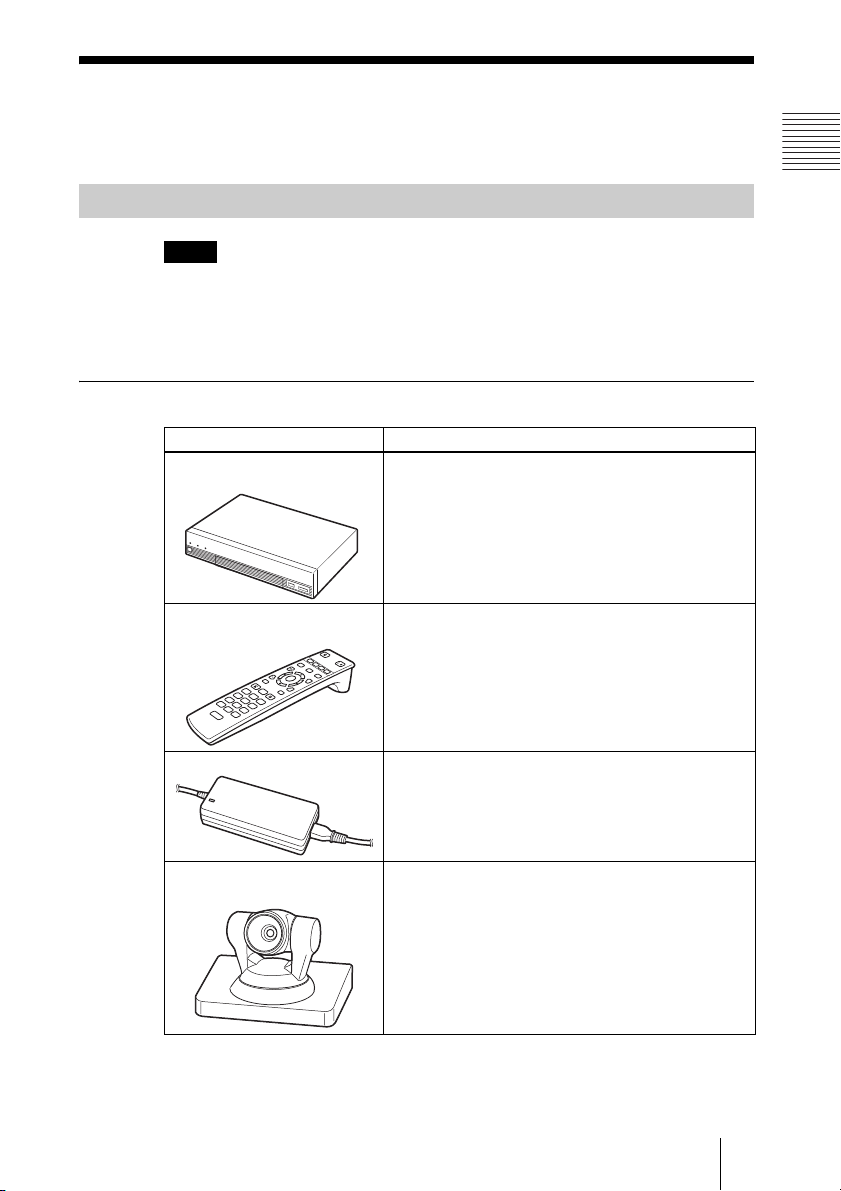
Basic System Components
Note
This manual explains how to operate the system using the PCS-XG80 HD
Visual Communication System Package that contains the
Camera Unit and two PCS-A1 microphones, and the PCS-XG80S HD Visual
Communication System without the Camera Unit and microphones.
Components packaged in the PCS-XG80
Unit Description
PCS-XG80S HD Visual
Communication System
Contains the video codec, audio codec, echo
canceller, network interfaces and system controller.
Chapter 1: Installation and Preparation
PCSA-CXG80 HD
PCS-RF1
Remote Commander
W
F
1
F
2
F
3
T
Used to control the HD Visual Communication
System. Before using, pairing with the
Communication System or HD Camera Unit is
/
F
4
required.
VGP-AC19V15 AC adaptor Supplies power to the Communication System.
PCSA-CXG80
HD Camera Unit
Camera to shoot high-definition images.
19System Components
Page 20
Unit Description
PCS-A1 Microphone Omni-directional microphone that picks up sound
relatively from all directions, allowing participants to
speak from any location. It is recommended to use in
a quiet situation (two pieces supplied).
Components packaged in the PCS-XG80S
Unit Description
PCS-XG80S HD Visual
Communication System
Contains the video codec, audio codec, echo
canceller, network interfaces and system controller.
PCS-RF1
Remote Commander
W
F
1
F
2
F
3
T
Used to control the HD Visual Communication
System. Before using, pairing with the
Communication System or HD Camera Unit is
/
F
4
required.
VGP-AC19V15 AC adaptor Supplies power to the Communication System.
20 System Components
Page 21
Optional Equipment
TV monitor
A TV or projector, etc. is required to monitor the images for the system.
Unit Description
TV, Projector, etc. Used as a monitor and speakers.
When the TV monitor is connected to the HDMI
connector on the Communication System, you can
view the high-definition images.
Optional equipment especially designed for use with the PCS-XG80/XG80S
The following optional devices are used to enhance your videoconference.
Unit Description
PCSA-B384S ISDN Unit Used to connect to an ISDN line. Up to three ISDN
lines; 6B channels usable.
Chapter 1: Installation and Preparation
PCSA-B768S ISDN Unit Used to connect to an ISDN line. Up to six ISDN
PCSA-A3 microphone Unidirectional microphone. It is recommended when
PCSA-A7 microphone Directional microphones that feature high sound
PCSA-DSG80 HD Data
Solution Software
PCSA-MCG80 HD MCU
Software
lines; 12B channels usable.
you want to pick up the voice of a speaker directed
toward the microphone.
quality and a built-in monaural echo canceller.
(Commercially available microphones are 4-piece
set.) Several PCSA-A7 Microphones can be
connected in cascade without reduceing sound
quality. Recommended when many microphones are
required.
Software required for transmission of video and
computer pictures at the same time by connecting a
computer.
Software required for multipoint connection using
LAN or/and ISDN.
21System Components
Page 22

Cable
Use the following cable to connect a device in this system.
Cable Part No. Number
HDMI cable (3 m (9.8 ft)) 1-835-440-1x 1
HDMI cable
22 System Components
Page 23

System Configuration
The PCS-XG80/XG80S HD Visual Communication System has various
system configuration capabilities using the basic components and optional
equipment. This section describes the capabilities and necessary equipment for
some typical configuration examples.
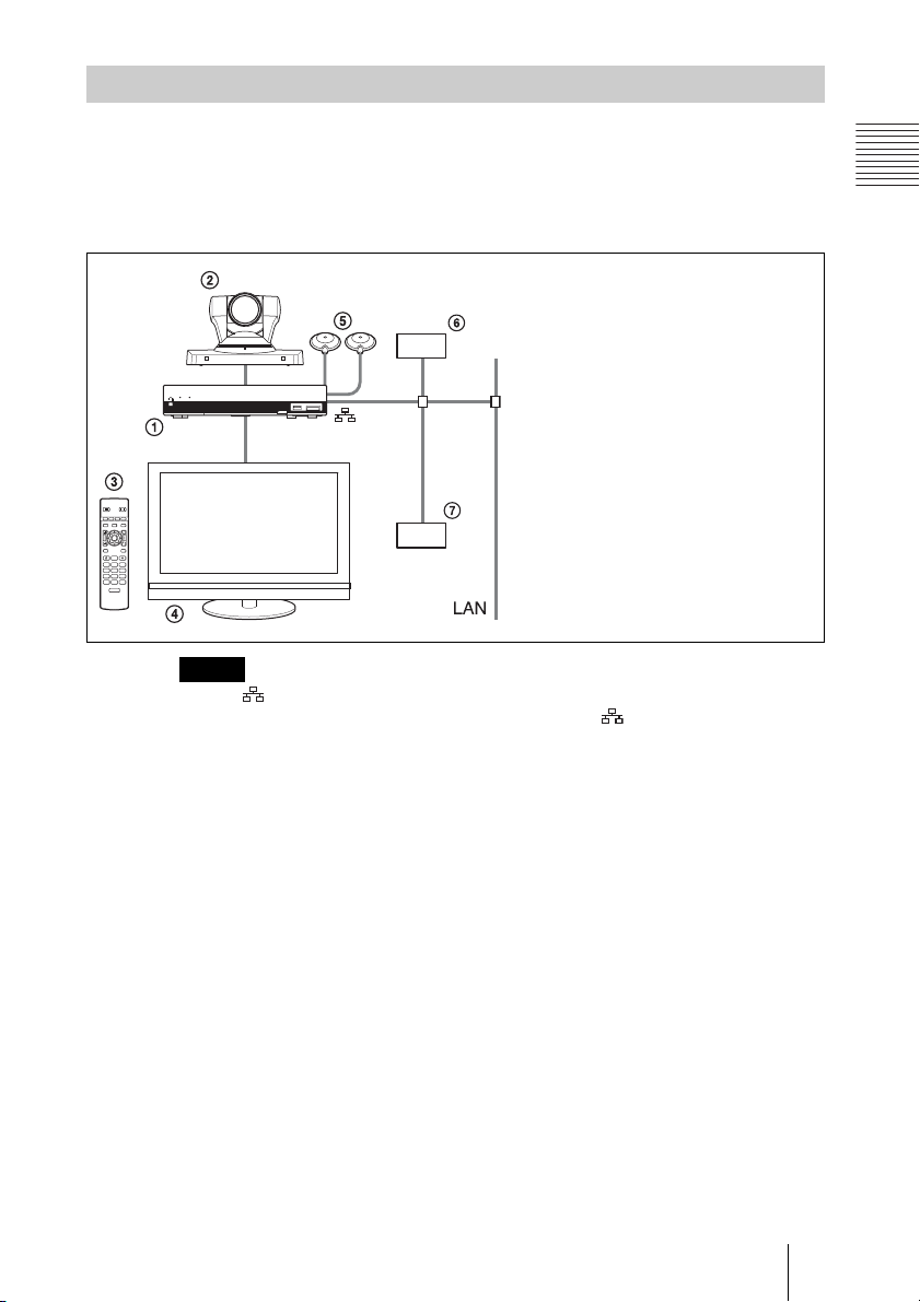
System Configuration via a LAN
This allows you to:
• Have a point-to-point HD visual communication over LAN.
• Pick up sound in stereo by using two microphones connected to the system.
System configuration
POWER/STANDBY
/
Chapter 1: Installation and Preparation
1 PCS-XG80S HD Visual Communication
System
2 PCSA-CXG80 HD Camera Unit
3 PCS-RF1 Remote Commander
4 TV monitor (not supplied)
5 PCS-A1 Microphones
/
T
W
POWER/STANDBY
/
23System Configuration
Page 24
System Configuration via an ISDN
Connection to ISDN is required to use the PCSA-B384S or PCSA-B768S
ISDN Unit especially designed for use with this system.
This allows you to:
• Have a point-to-point HD visual communication over ISDN.
• Pick up sound in stereo by using two microphones connected to the system.
• Hold an HD visual communication with high speeds and highest quality
image transmission by connecting up to three ISDN lines (when using the
PCSA-B384S) or by connecting up to six ISDN lines (when using the PCSAB768S).
System configuration
POWER/STANDBY
/
/
F1 F2 F3 F4
T
W
RF
POWER/STANDBY
/
1 PCS-XG80S HD Visual
Communication System
2 PCSA-CXG80 HD Camera Unit
3 PCS-RF1 Remote Commander
4 TV monitor (not supplied)
5 PCSA-B384S or PCSA-B768S
ISDN Unit (not supplied)
6 PCS-A1 Microphones
This diagram depicts a system
configuration using the PCSA-B768S
ISDN Unit.
About the number of ISDN lines and B (bearer) channels
Up to three ISDN lines (6B channels) with the PCSA-B384S ISDN Unit or up
to six ISDN lines (12B channels) with the PCSA-B768S ISDN Unit can be
connected to one PCS-XG80/XG80S. The more channels you use for a single
communication, the faster speeds and higher-quality picture you can obtain for
your network communication.
Note
When connecting to the ISDN Unit, Use the ports in ascending order.
Yes: 1, 2, 3…
No: 1, 6, 5…
24 System Configuration
Page 25
System Configuration via a SIP
This allows you to:
• Have an HD visual communication with an IP telephone, etc. using SIP.
• Pick up sound in stereo by using two microphones connected to the system.
System configuration
POWER/STANDBY
/
/
T
W
Note
Use the 1 (LAN1) connector on the Communication System when connecting your
system via a SIP. Connection to a SIP server through the 2 (LAN2) connector is not
available.
1
Chapter 1: Installation and Preparation
1 PCS-XG80S HD Visual
Communication System
2 PCSA-CXG80 HD Camera Unit
3 PCS-RF1 Remote Commander
4 TV monitor (not supplied)
5 PCS-A1 Microphones
6 SIP server
7 IP telephone, etc.
25System Configuration
Page 26
System Configuration Using Two LAN Connections
This allows you to:
Connect your system to two networks using the 1 (LAN1) and 2 (LAN2)
connectors. For example, you can use the 1 connector to connect a private
network in your company and 2 connector to connect to an intranet outside
your company.
Note
If your system is connected to a LAN using the 2 connector, some of the intranet/
internet functions of your system, such as SIP server connection, gatekeeper
connection, Telnet access, and Web access, are not available. If your system is
connected to one LAN, use the 1 connector.
For details, see “Restrictions on the Use of LAN2” on page 94.
System configuration
POWER/STANDBY
/
POWER/STANDBY
/
1
2
/
T
W
1 PCS-XG80S HD Visual Communication System
2 PCSA-CXG80 HD Camera Unit
3 PCS-RF1 Remote Commander
4 TV monitor (not supplied)
5 PCS-A1 Microphones
26 System Configuration
Internet
Page 27

System Configuration via a LAN for Multipoint
You need to install the PCSA-MCG80 HD MCU software.
This allows you to:
Have a multipoint HD visual communication among up to 10 sites over LAN.
System configuration
POWER/STANDBY
/
POWER/STANDBY
/
T
W
/
POWER/STANDBY
/
POWER/STANDBY
/
POWER/STANDBY
/
1 PCS-XG80S HD Visual Communication System
2 PCSA-CXG80 HD Camera Unit
3 PCS-RF1 Remote Commander
4 TV monitor (not supplied)
5 PCS-A1 Microphones
6 PCSA-MCG80 HD MCU software (not supplied)
POWER/STANDBY
/
/
T
W
/
/
/
/
Chapter 1: Installation and Preparation
POWER/STANDBY
POWER/STANDBY
POWER/STANDBY
POWER/STANDBY
27System Configuration
Page 28

System Configuration via an ISDN for Multipoint
You need to connect the optional PCSA-B384S or PCSA-B768S ISDN Unit
especially designed for use with this system and to install the optional PCSAMCG80 HD MCU software.
This allows you to:
Have a multipoint HD visual communication among up to six sites over ISDN.
System configuration
POWER/STANDBY
/
POWER/STANDBY
/
POWER/STANDBY
/
/
POWER/STANDBY
/
T
W
POWER/STANDBY
/
POWER/STANDBY
/
This diagram depicts a
system configuration using
the PCSA-B768S ISDN Unit.
1 PCS-XG80S HD Visual Communication System
2 PCSA-CXG80 HD Camera Unit
3 PCS-RF1 Remote Commander
4 TV monitor (not supplied)
5 PCS-A1 Microphones
6 PCSA-MCG80 HD MCU software (not supplied)
7 PCSA-B384S (not supplied) or PCSA-B768S (not supplied) ISDN Unit
28 System Configuration
Page 29
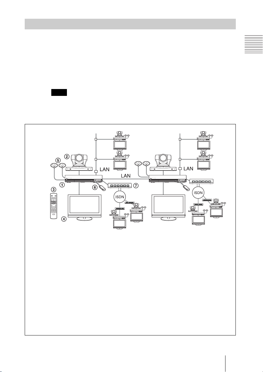
System Configuration via a LAN and ISDN for Multipoint
Installing the PCSA-MCG80 HD MCU software in two HD Visual
Communication Systems enables you to connect to multiple sites up to 10 via
mixed LAN and ISDN lines.
This allows you to:
Have a multipoint HD visual communication among up to 10 sites over LAN
and ISDN.
Note
Be sure to connect two Communication Systems with the HD MCU software installed
over LAN.
System configuration
Chapter 1: Installation and Preparation
POWER/STANDBY
/
POWER/STANDBY
/
POWER/STANDBY
/
/
T
W
POWER/STANDBY
/
POWER/STANDBY
/
POWER/STANDBY
/
POWER/STANDBY
/
This diagram depicts a system
configuration using the PCSAB768S ISDN Unit.
1 PCS-XG80S HD Visual Communication System
2 PCSA-CXG80 HD Camera Unit
3 PCS-RF1 Remote Commander
4 TV monitor (not supplied)
5 PCS-A1 Microphones
6 PCSA-MCG80 HD MCU software (not supplied)
7 PCSA-B384S (not supplied) or PCSA-B768S (not supplied) ISDN Unit
POWER/STANDBY
/
POWER/STANDBY
/
POWER/STANDBY
/
29System Configuration
Page 30
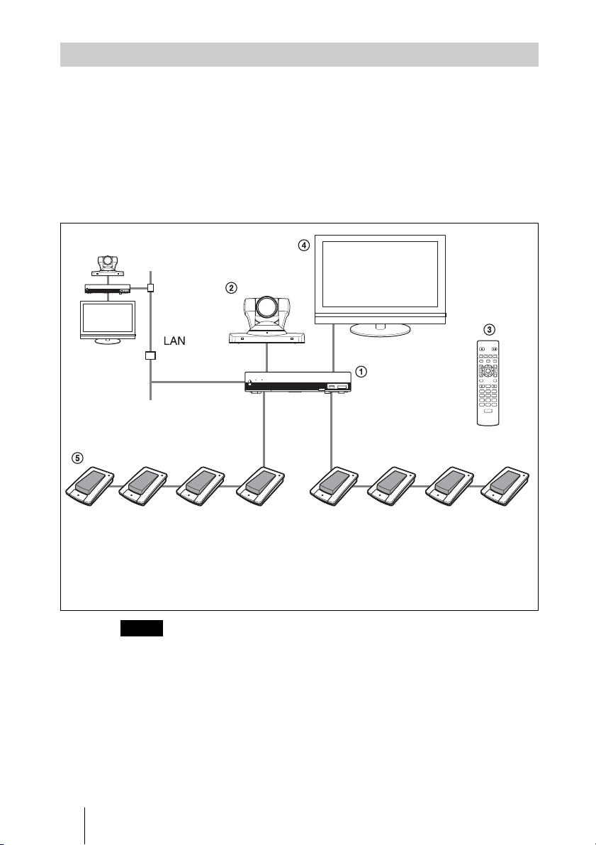
System Configuration Using the PCSA-A7 Microphones
This allows you to:
• Connect up to 40 PCSA-A7 microphones to one microphone connector,
using a cascade connection. As the PCSA-A7 microphones feature high
sound quality and can be connected in cascade without reducing sound
quality, they are available to an HD visual communication with a large
number of participants.
• Connect additional microphones during communication.
System configuration
POWER/STANDBY
/
POWER/STANDBY
/
F1 F2 F3 F4
/
T
W
PCS‑RF1
RF
1 PCS-XG80S HD Visual Communication System
2 PCSA-CXG80 HD Camera Unit
3 PCS-RF1 Remote Commander
4 TV monitor (not supplied)
5 PCSA-A7 microphone (PCSA-A7P4: 4-piece set × 2,
not supplied)
Notes
• Position the microphones about 50 cm (1.6 ft) away from the participants.
• When using speakers, do not place them in front of the microphones.
• The PCSA-A7 microphone is monaural and cannot pick up sound in stereo.
For information about PCSA-A7 microphones, see “Using the PCSA-A7
Microphones” on page 164.
30 System Configuration
Page 31

System Connections
This section describes the typical system connections.
Notes
• Be sure to turn off all the equipment before making any connections.
• Do not connect/disconnect the camera cable, interface cable, or pen tablet with the power
on. Doing so may damage the Camera Unit, Communication System or ISDN Unit.
• For safety, do not connect the 100BASE-TX/10BASE-T connector to a network that
applies excess voltage via the 100BASE-TX/10BASE-T connector.
• Used with the Camera Unit or ISDN Unit for the first time, the Communication
System may automatically upgrade the software of the connected equipment.
Upgrade the software according to the message displayed on the monitor screen. Be
sure not to turn off the Communication System or disconnect the cable during
upgrading. Otherwise, it may cause a malfunction of the system.
Chapter 1: Installation and Preparation
31System Connections
Page 32

System Connection via a LAN
PCSA-CXG80 HD Camera Unit
VISCA OUT
Camera cable (supplied with the
Camera Unit)
to CAMERA
S VIDEO IN RGB IN RGB OUT HDMI OUT
CAMERA
EC-MIC(A7) MIC(A1/A3)
1(R)
2(L)
1
2
RLRLRL
(PLUG IN POWER)
* supplied
** not supplied
TERMINAL
to TERMINAL
to MIC (A1/A3)
1
-
EXT-2REC OUTAUDIO OUTAUDIO 1 IN
to
HDMI
OUT
HDMI
cable*
to
HDMI
IN
PCS-A1 microphone
PCS-XG80S HD Visual
ISDN UNIT
AUX CONTROL
2
1
to
Communication System
DC 19.5V
to DC19.5V
1
VGP-AC19V15
AC adaptor*
UTP cable (category 5, straight)**
TV monitor**
to a wall outlet
Power cord*
to a wall outlet
to LAN
Notes
• Normally, connect the UTP cable to the 1 (LAN1) connector (indicated in green).
If the UTP cable is connected to the 2 (LAN2) connector, some of the functions
of your system may be restricted.
For details, see “Restrictions on the Use of LAN2” on page 94.
• The REC OUT jack is used to make an audio recording of a communication. This is
not used during regular communication.
32 System Connections
Page 33

System Connection via an ISDN
PCSA-CXG80 HD Camera Unit
Camera cable
(supplied with
the Camera
Unit)
to
CAMERA
VISCA OUT
S VIDEO IN RGB IN RGB OUT HDMI OUT
CAMERA
EC-MIC(A7) MIC(A1/A3)
1(R)
2(L)
1
2
RLRLRL
(PLUG IN POWER)
TERMINAL
to TERMINAL
to MIC
(A1/A3)
to
HDMI
OUT
HDMI
cable*
to
HDMI
IN
1
-
EXT-2REC OUTAUDIO OUTAUDIO 1 IN
Interface
cable
(supplied
with ISDN
Unit)
to ISDN UNIT
ISDN UNIT
AUX CONTROL
DC 19.5V
2
1
PCS-A1 Microphone
PCSA-B384S ISDN Unit**
to ISDN 1-3
PCSA-B768S
ISDN Unit**
to ISDN 1-6
to
DC19.5V
ISDN modular cable**
VGP-AC19V15
AC adaptor*
ISDN Unit
to TERMINAL
to ISDN
Power cord*
to a wall outlet
Chapter 1: Installation and Preparation
**
* supplied
** not supplied
Note
The REC OUT jack is used to make an audio recording of a communication. This is not
used during regular conferences.
TV monitor**
to a wall outlet
33System Connections
Page 34

System Connection via a SIP
PCSA-CXG80 HD Camera Unit
VISCA OUT
Camera cable (supplied with
the Camera Unit)
to
CAMERA
S VIDEO IN RGB IN RGB OUT HDMI OUT
CAMERA
EC-MIC(A7) MIC(A1/A3)
1(R)
2(L)
1
2
(PLUG IN POWER)
RLRLRL
to MIC
(A1/A3)
HDMI
TERMINAL
to TERMINAL
1
-
EXT-2REC OUTAUDIO OUTAUDIO 1 IN
to
HDMI
OUT
HDMI
cable*
to
IN
ISDN UNIT
AUX CONTROL
DC 19.5V
2
1
to
1
to DC19.5V
UTP cable (category 5,
straight)**
PCS-A1 microphone
VGP-AC19V15
AC adaptor*
to LAN
connector
to LAN
connector
connector
Power cord*
to a wall outlet
SIP server
to LAN
IP
telephone,
etc.
* supplied
** not supplied
Notes
• Normally, connect the UTP cable to the 1 (LAN1) connector (indicated in green).
If the UTP cable is connected to the 2 (LAN2) connector, some of the functions
of your system may be restricted.
For details, see “Restrictions on the Use of LAN2” on page 94.
• The REC OUT jack is used to make an audio recording of a communication. This is not
used during regular communication.
34 System Connections
TV monitor**
to a wall outlet
Page 35

Attaching the PCSA-CXG80 HD Camera Unit to a Tripod
To attach the Camera Unit to a tripod
Attach a tripod to the screw hole used for attaching a tripod on the bottom of
the Camera Unit.
The tripod must be set up on a flat surface and tightened firmly by hand.
Use a tripod with screws of the following specifications.
4 = 4.5 – 6 mm
4 = 0.18 – 0.24 inches
Chapter 1: Installation and Preparation
35System Connections
Page 36

Preparing the System
Inserting Batteries into the Remote Commander
Most of the operations with the HD Visual Communication System can be
controlled with the supplied Remote Commander.
1 Remove the battery compartment cover.
2 Insert two size AA (R6) batteries (supplied) with correct polarities into the
battery compartment.
3 Replace the cover.
Note
Be sure to insert the batteries E side first. Inserting them forcibly e side first may
damage the insulated film covering the batteries and cause a short circuit.
Battery life
When the batteries are exhausted, the LED indicator does not light if you press
any button and the Remote Commander does not function properly. Replace
both batteries with new ones.
Notes on batteries
To avoid damage from possible battery leakage or corrosion, observe the
following:
• Make sure to insert the batteries with the polarities in the correct direction.
• Do not mix old and new batteries, or different types of batteries.
• Do not attempt to charge the batteries.
• If you do not intend to use the Remote Commander for a long period of time,
remove the batteries.
36 Preparing the System
Page 37

• If battery leakage occurs, clean the battery compartment and replace all the
batteries with new ones.
Programming the Remote Commander to Operate the Camera Unit
The supplied Remote Commander controls the HD Visual Communication
System using the radio frequency of 2.4 GHz. The Remote Commander and
the Communication System are paired to prevent interference from other
Remote Commanders and Systems.
Pairing between the Remote Commander and the Communication System is
programmed at the factory. If the Communication System is installed in
shielded locations, such as under a desk or in a rack, it may not be controlled
by the Remote Commander, depending on the conditions of radio-wave
reception. In this case, pair the PCSA-CXG80 HD Camera Unit with the
Remote Commander.
Note
When performing pairing procedure, be sure to turn off other HD Visual
Communication Systems or HD Camera Units located nearby that are not targets for
pairing. If multiple devices are turned on, the Remote Commander might pair device
other than the target one.
To pair the Camera Unit with the Remote Commander
?/1 (power) indicator
Chapter 1: Installation and Preparation
POWER/STANDBY
VIDEO INPUT CAMERA
ENTER
BACK
SPACE
ABC DEF
GHI JKL MNO
PQRS TU V
0
ON/OFF
MIC
DISCONNECT
/
/
T
W
TOOLS
WXYZ
LED indicator
PRESENTATION
F1 F2 F3 F4
LAYOUT
VOLUME ZOOM
4
RETURN
3
CONNECT
123
456
789
TONE DOT
/
OPEN
1
1 Press the ?/1 (power) switch on the Communication System to turn it on.
The
?/1 (power) indicator on the Communication System flashes. The
indicator lights in green when the Communication System turns on.
2 Set “RF Remote Control Reception” to “Camera” in the General setup
menu.
37Preparing the System
Page 38

Setup
General1
Device SetupGeneral
Terminal Name
Standby Mode
Standby Time
Last Number Registration
Control by Far End
Language
System LED Brightness
Camera LED Brightness
RF Remote Control Reception
On
15minutes
Off
On
English
Dark
Dark
Camera
CancelSave
For details, see “RF Remote Control Reception” on the Device Setup page
of the General setup menu on page 81.
For the procedure on how to operate the menus, see “Opening the Setup
Menu” on page 60.
3 Within three minutes after the power of the Communication System is
turned on, locate the Remote Commander closer to the RF receiver at the
rear of the Camera Unit, and press the RETURN and TOOLS buttons at the
same time.
The Remote Commander and the Camera Unit enter pairing mode, and the
LED indicator on the Remote Commander flashes rapidly.
4 Press the ENTER button on the Remote Commander.
If the LED indicator on the Remote Commander flashes more slowly,
pairing the units has succeeded.
The pairing between the Communication System and the Remote
Commander is disabled.
When pairing has failed
The LED indicator on the Remote Commander continues flashing rapidly. In
this case, press the ENTER button on the Remote Commander again.
To cancel pairing
Press the
Notes
• When the LED indicator does not flash even if you press any button on the Remote
• Once pairing is established between the units, it will not be erased even if the batteries
• Operable distance is 10 m (32.8 ft.). Depending on the circumstances, a longer
?/1 (power) switch on the Communication System.
Commander, the batteries might be exhausted. Replace both batteries with new ones.
are replaced.
operable distance may be possible.
38 Preparing the System
Page 39

To pair the Communication System with the Remote Commander again
Follow the procedure below to release the paring with the Camera Unit, and to
perform pairing with the System again.
1 Turn on the Communication System.
2 Set “RF Remote Control Reception” to “System” on the Device Setup page
of the General setup menu (page 81).
3 Within three minutes after the power is on, locate the Remote Commander
closer to the Communication System, and press the RETURN and TOOLS
buttons at the same time.
The LED indicator flashes rapidly.
4 Press the ENTER button on the Remote Commander.
If the LED indicator flashes more slowly, pairing between the units has
succeeded.
Chapter 1: Installation and Preparation
39Preparing the System
Page 40

Turning the System On/Off
This section describes how to turn on or off the Communication System.
Turning On
1 Turn on the TV monitor.
2 Turn on the power of any other equipment to be used for this connection.
3 Press the ?/1 (power) switch on the Communication System to turn it on.
/
POWER/STANDBY
?/1 (power) switch
?/1 (power) indicator
?/1 (power) indicator on the Communication System flashes. The
The
indicator lights in green when the Communication System turns on.
The Home menu will appear on the monitor screen and the picture shot by
the local camera will also appear in the Home menu.
Home menu
Home
Camera
Connect
AAA Ready to connect.
Ready
5/11/2008 13:00IP:XXX.XXX.XXX.XXX
For details on the Home menu, see“Identifying the Home Menu” on page 47.
40 Turning the System On/Off
Page 41

Notes
• After the power is turned on, the camera moves automatically for trial operation. Be
careful not to catch your finger.
• If you use force to prevent the camera from moving, the camera may stop moving and
the picture may not be displayed. In this case, turn off the System, and turn it on again.
• When you turn on the power of the Communication System for the first time after
installation, the setup wizard will appear after the self-diagnosis is completed. Set up
your system following the wizard.
For setups using the wizard, see “Setting Up the System Immediately after
the Installation — Initial Setup Wizard” on page 44.
• Used with an optional device especially designed for use with this system, such as the
Camera Unit and ISDN Unit, for the first time, the Communication System may
automatically upgrade the software of the connected device. Upgrade the software
according to the message displayed on the monitor screen. Be sure not to turn off the
Communication System or disconnect the cable during upgrading. Otherwise, it may
cause a malfunction of the system. System malfunction may also occur when a system
power-off has been caused by an accidental problem such as a power interruption
during upgrading. If connection of the Camera Unit, ISDN Unit, etc. to the
Communication System is not re-established even after the system power is
recovered, consult a Sony dealer.
• You can check the versions of the Communication System, optional dedicated
equipment connected and the application software installed using the Machine Status
menu.
For details on the Machine Status menu, see page 89.
Standby Mode Function
Chapter 1: Installation and Preparation
To save power, the Communication System will enter standby mode if you do
not operate it for a specified period of time. When the Communication System
is in standby mode, the
?/1 indicator lights in orange.
You can turn on the Communication System with any button on the Remote
Commander if the System is in standby mode.
Once the Communication System receives a call, the standby mode is
automatically released.
41Turning the System On/Off
Page 42

Setting the HD Visual Communication System to Standby Mode
1 Display the Home menu on the monitor screen, then press the @/1 button
on the Remote Commander.
The message “Power off?” appears on the monitor screen.
2 Press the V, v, B or b button on the Remote Commander to select OK, then
press the ENTER button.
You may press the
@/1 button on the Remote Commander.
To cancel setting the system to standby
Select “Cancel” with the V, v, B or b button on the Remote Commander, then
press the ENTER button in step 2 above.
To release the standby mode
Press any button on the Remote Commander.
To specify the standby time
Specify the time that you want the system to remain on before entering into
standby mode (1 to 99 minutes) by setting “Standby Time” of the Device Setup
page of the General setup menu. If you do not want the system to enter the
standby mode, set “Standby Mode” to “Off”.
For the settings, see “Standby Time” and “Standby Mode” in the General
setup menu on page 80.
Turning Off
1 Press the @/1 (power) switch on the Communication System.
2 Press the V, v, B or b button on the Remote Commander to select “Power
The Communication System enters standby mode and the
the Communication System lights in orange.
The message “Power off?” appears on the monitor screen.
off”, and press the ENTER button.
You can power off the system by pressing the
Remote Commander.
The system turns off.
@/1 (power) button on the
@/1 indicator on
3 Turn off the power of other equipment used for the communication.
Notes
• Turn off the power switch on the Communication System when the system will not
be used for an extended period. While the power switch is off, you cannot receive a
call from a remote party.
42 Turning the System On/Off
Page 43

• Be sure to unplug the power cord after the power of the system is turned off
completely.
• If the system is unplugged for about 10 days or longer, the clock setting of the system
may be reset. In this case, re-set the date and time in the Clock Set page of the General
setup menu.
Adjusting the Volume on the TV Monitor
The procedure for volume adjustment during system setup differs from the
procedure during communication.
Adjust the volume on the TV monitor during system setup, and adjust the
volume on the Communication System while in communication.
Volume adjustment during setup
Before adjusting the volume on the TV monitor, set the volume on the
Communication System to the appropriate position.
1 Press the VOLUME +/– buttons on the Remote Commander to set the
volume level on the adjustment bar displayed on the screen to the middle
position.
2 Adjust the volume on the TV monitor so that you can properly hear a
remote party’s speaking.
Chapter 1: Installation and Preparation
Note
Do not activate the TV’s surround sound feature as it may cause the echo canceller of
the Communication System not to function properly and make strange sounds.
Volume adjustment during communication
Press the VOLUME +/– buttons on the Remote Commander to adjust the
volume on the Communication System during communication.
43Turning the System On/Off
Page 44

Setting Up the System Immediately
after the Installation — Initial Setup
Wizard
When you turn on the Communication System for the first time after
installation and the self-diagnosis is completed, the setup wizard appears on
the monitor screen. Register your local system data with the setup wizard using
the Remote Commander.
Notes
• You can change the settings made with the setup wizard later using the setup menus.
• The setup wizard will also be displayed when you install the PCSA-B384S or PCSAB768S ISDN Unit to your system later. Perform the setup again.
Wizard
Home
Back to Tools
Select Language
Set Region and Clock
Select Line I/F
Set up LAN
Set up ISDN
Set up SIP
To select the on-screen language
1 Use the V, v, B or b button on the Remote Commander to select “Select
Language” in the setup wizard, then press the ENTER button.
Wizard Select Language
Select Language
English
2007.11.29 14:21
IP
XXX.XXX.XXX.XXX
Select the on-screen language.
English
5/11/2008 13:00IP:192.168.0.11
5/11/2008 13:00IP:192.168.0.11
CancelSave
44 Setting Up the System Immediately after the Installation — Initial Setup Wizard
Page 45

2 Use the V, v, B or b button on the Remote Commander to select the
language to be used for the on-screen menus and messages.
Select from among English, French, German, Japanese, Spanish, Italian,
Simplified Chinese, Portuguese, Traditional Chinese, Korean, Dutch,
Danish, Swedish, Finnish, Polish, Russian, Arabic, Thai, Turkish,
Norwegian and Welsh.
3 Use the V, v, B or b button on the Remote Commander to select “Save”,
then press the ENTER button.
The setup wizard is restored.
To set the region and clock
1 Use the V, v, B or b button on the Remote Commander to select “Set
Region and Clock” in the setup wizard, then press the ENTER button.
2 Set the region and clock items.
Wizard
Set Region and Clock
Set Region and Clock
Select the region
Select the display pattern
Enter the year
Enter the month
Enter the day
Enter the time
Chapter 1: Installation and Preparation
Year/Month/Day
CancelSave
Select the region: Select the country or region where the system is used.
Select the display pattern: Select the display pattern of year, month and
day.
Enter the year, Enter the month, Enter the day, Enter the time: Enter
the date and time using the number buttons on the Remote
Commander.
For the procedure to enter the numbers using the Remote Commander, see
“Entering Characters Using the Remote Commander” on page 57.
3 Use the V, v, B or b button on the Remote Commander to select “Save”,
then press the ENTER button.
The setup wizard is restored.
To select the line interface
1 Use the V, v, B or b button on the Remote Commander to select “Select
Line I/F” in the seup wizard, then press the ENTER button.
45Setting Up the System Immediately after the Installation — Initial Setup Wizard
Page 46

2 Select the line interface to be used.
Select Line I/F
Wizard
Which is your Line I/F?: Select from among IP, ISDN and SIP.
Which is your primary Line I/F?: If you select two or more interfaces
with “Which is your Line I/F?”, select the interface you most use.
Select from among IP, ISDN and SIP.
3 Use the V, v, B or b button on the Remote Commander to select “Save”,
then press the ENTER button.
The setup wizard appears.
To set up a LAN connection
Select “Set up LAN” in the setup wizard, then set up a LAN connection.
To set up an ISDN line
Select “Set up ISDN” in the setup wizard, then set up an ISDN line connection.
Which is your Line I/F? (Multiple selection available)
Select Line I/F
IP
Which is your primary Line I/F?
IP ISDN SIP
ISDN SIP
CancelSave
To set up a SIP
Select “Set up SIP” in the setup wizard, then set up a SIP connection.
46 Setting Up the System Immediately after the Installation — Initial Setup Wizard
Page 47

Using the Menus
1
234 67
The HD Visual Communication System uses the on-screen menus to make
various adjustments and settings. This section explains how to adjust or set the
items in the menus and gives a brief introduction to the menus.
Identifying the Home Menu
The Home menu is displayed on the monitor screen when the system is
turned on and has not been connected to a remote party. The Home menu
displays the image shot by the local camera, local system name, current date
and time and buttons to open the menus.
You can select the items shown in the Home menu using the Home Menu1 to
Home Menu3 pages in the Home Menu setup menu.
The descriptions of the items displayed in the Home menu are given below
using the default menu and the menu with all items shown, as the examples.
Home menu (default)
Chapter 1: Installation and Preparation
AAA
IP
8
qs
Home
Camera
Connect
qf
Ready
5/11/2008 13:00IP:XXX.XXX.XXX.XXXIP:XXX.XXX.XXX.XXX
Dial
47Using the Menus
Page 48

Home menu (with all items shown)
1
35 674
2
Home
AAA
Ready
5/11/2008 13:00IP:XXX.XXX.XXX.XXX
ql
8
0
qd
9
qa
Camera
Tools
History
Phone Book
Detailed Dial
F2
F1 F3 F4
Room 101
IP
Office EOffice ARoom 201
Dial
qf qg qh qj qk
1 IPELA logo
B Background screen
Image shot by the camera is displayed.
C Local terminal name
The local terminal name set in the menu is displayed.
D IP address of the local system
The IP address of the local system is shown.
By changing the “Number Display” setting (page 82) on the Home Menu1
page of the Home Menu setup menu, you can display the gatekeeper’s user
name and user number, NAT address, etc. instead of the IP address.
E ISDN line number
The ISDN line number of the local system is shown.
F Local system status
The status on the local terminal is shown.
G Date and time
The current date and clock are displayed.
H Camera button
The Camera menu opens when you select the button and press the ENTER
button on the Remote Commander.
The Camera menu is used to adjust the camera angle or brightness, or to
preset the camera adjustments and to move the camera to the preset
position.
48 Using the Menus
Page 49

Camera menu
5/11/2008 13:00
Camera
Previous
Adjustments
Brightness
Preset
Details
For details on the Camera menu, see page 132.
I Tools button
The Tools menu opens when you select the button and press the ENTER
button on the Remote Commander.
The menu is used to carry out presentation, streaming, recording,
annotation, etc. The Machine Status menu or Setup menus can be displayed
using the buttons in the Tools menu.
Tools menu
Chapter 1: Installation and Preparation
Tools
Home
Machine Status
Setup
Presentation
Streaming
Recording
Annotation
Icon display
Reject Answer
Screen Capture
[Suspended]
[Suspended]
[Suspended]
[Suspended]
Execute
Execute
Execute
Execute
On
Off
Execute
For details on the Tools menu, see page 146.
For details on the Machine Status menu, see page 89.
For details on the Setup menu, see page 60.
J History button
The History menu opens when you select the button and press the ENTER
button on the Remote Commander.
The menu is used to check the incoming call and outgoing call histories or
to call a remote party from the history list.
49Using the Menus
Page 50

History menu
History
Home
Phone Book
Detailed Dial
Dial
Answer
Missed Call
IP:192.168.0.11
Dial History1
111.111.111.112 2008/05/01 00:00 (12:34:56)
Dial History2
555-555-555 2008/05/26 00:00 (03:25:45)
Dial History3
17.17.17.17 2008/05/26 00:00 (01:00:17)
Dial History4
18.18.18.18 2008/05/26 00:00 (01:00:18)
Dial History5
19.19.19.19 2008/05/26 00:00 (01:00:19)
Dial History6
20.20.20.20 2008/05/26 00:00 (01:00:20)
Dial History7
66.66.66.66 2008/05/26 00:08 (00:00:00)
Dial History8
88.88.88.88 2008/05/26 00:08 (01:00:06)
5/11/2008 13:00
For details on the History menu, see page 109.
K Phone Book button
The Phone Book menu opens when you select the button and press the
ENTER button on the Remote Commander.
The menu is used to register a remote party to the phone book or to call a
remote party registered in the phone book.
Phone Book menu
Phone Book
Home
New Entry
Group Edit
History
Detailed Dial
Default Group
Group1
Group2
Group3
Group4
Group5
Group6
Group7
Group8
Group9
Office ARoom 102Room 101
ISDN 98-7654-3210IP 255.255.255.255ISDN 01-2345-6789
Office ERoom 202Room 201
ISDN 01-2345-6789IP 123.456.789.012IP 0.0.0.0
For details on the Phone Book menu, see page 118.
L Connect button
The Simple Dial menu opens when you select “Connect” in the Home
menu and press the ENTER button on the Remote Commander.
The Simple Dial menu is used to call a remote party.
50 Using the Menus
Page 51

Simple dial menu
IP:192.168.0.11 5/11/2008 13:00
Previous
Enter Number/Address
Connect
Select from Phone Book
Select from History
For details, see “Calling a Remote Party by Using the Simple Dial Menu”
on page 105.
M Detailed Dial button
The Detailed Dial menu opens when you select the Detailed Dial button
and press the ENTER button on the Remote Commander.
The menu is used to call a remote party by setting the details of the dial
setup options.
Detailed Dial menu
Chapter 1: Installation and Preparation
Detailed Dial
Home
Phone Book
History
Dial to:
Number of Connected Sites
Line I/F
Communication
Bit Rate
Number of Lines
1
IP
1024kbps
1B (64K)
Cancel
For details on the Detailed Dial menu, see page 112.
N Instruction display
The instructions for the operation in the Home menu are displayed.
O Line interface select button
Selecting the button opens the drop-down list of the line interface. Select
the interface to be used, then press the ENTER button.
P Number input box
To call a remote party not registered in the Phone Book, select the box and
enter the party’s IP address, Domain name, ISDN line number, etc.
51Using the Menus
Page 52

Q Dial button
321456
87
To call a remote party whose number or address has been entered in the
number input box, select this button, then press the ENTER button on the
Remote Commander.
R One-touch dial buttons
The submenu is displayed when you select a thumbnail for a remote party
you want to call and press the ENTER button on the Remote Commander.
Using the submenu you can call the remote party.
You can also call the remote parties assigned to the one-touch buttons by
pressing the F1 to F4 buttons on the Remote Commander.
S Display
Home
1 Video input
The selected video input on the local system is displayed.
The displayed video input is shown as the label set in “Custom Input
Label” in the Video setup menu.
2 Audio input
The selected audio input on the local system is displayed.
3 LAN status
The current status of LAN connection is shown. The LAN indicator is
shown in white when LAN is enabled for use and in gray when it is
disabled.
4 ISDN status
The current status of the ISDN unit ports is shown. The port indicator is
shown in white when it is enabled for use and in gray when it is disabled.
5 Indicators
The status indicators indicating that the microphone is off, a “Memory
Stick” is inserted, a pen tablet is connected, etc. are displayed.
6 Audio level meter
The current audio input level is displayed.
52 Using the Menus
Page 53

7 Volume
The volume-level bar is temporarily shown when you adjust the volume of
the Communication System.
8 Warning messages
If system malfunction occurs, a warning, instruction, etc. are displayed.
Chapter 1: Installation and Preparation
53Using the Menus
Page 54

Operation Using the Menu
The basic operation through the menu is explained taking manual brightness
adjustment in the Camera menu as an example.
Buttons used for menu operations
RETURN button
1 Display the Home menu.
PRESENTATION
F1 F2 F3 F4
LAYOUT
VOLUME ZOOM
RETURN
CONNECT
123
GHI JKL MNO
456
PQRS TUV
789
TONE DOT
/
VIDEO INPUT CAMERA
ENTER
TOOLS
BACK
SPACE
DISCONNECT
ABC DEF
WXYZ
0
ON/OFF
MIC
PCS-RF1
RF
V/v/B/b buttons
T
ENTER button
W
Number buttons
DOT button
Home
Camera
Connect
54 Using the Menus
AAA Ready to connect.
Ready
5/11/2008 13:00IP:XXX.XXX.XXX.XXX
Page 55

2 Use the V, v, B or b button on the Remote Commander to select “Camera”,
then press the ENTER button.
The Camera menu appears.
5/11/2008 13:00
Previous
Adjustments
Camera
Brightness
Preset
Details
3 Use the V, v, B or b button on the Remote Commander to select
“Brightness”, then press the ENTER button.
The Brightness menu appears.
5/11/2008 13:00
Adjustments > Brightness
Auto Adjustment
Previous
4 Press the ENTER button on the Remote Commander.
Now you can select the adjustment mode.
Chapter 1: Installation and Preparation
5 Use the V, v, B or b button to select the desired item from the drop-down
list, then press the ENTER button.
5/11/2008 13:00
Adjustments > Brightness
Manual Adjustment
Previous
55Using the Menus
Page 56

6 Use the V, v, B or b button to adjust the brightness of the image.
5/11/2008 13:00
Adjustments > Brightness
Manual Adjustment
Previous
7 Use the V, v, B or b button on the Remote Commander to select
“Previous”, then press the ENTER button after the adjustment is finished.
You can also use the RETURN button on the Remote Commander.
The Brightness menu is restored.
8 Use the V, v, B or b button on the Remote Commander to select
“Previous”, then press the ENTER button. You can also use the RETURN
button on the Remote Commander.
The Camera menu is restored.
When the “Save” button is displayed in the menu
When the setting or adjustment is finished, press the V, v, B or b button on the
Remote Commander to select “Save” and press the ENTER button. The setting
or adjusted value becomes effective.
When the “Cancel” button is displayed in the menu
If you press the V, v, B or b button on the Remote Commander to select
“Cancel” and press the ENTER button, the setting or adjustment is canceled
and the previous one is restored.
56 Using the Menus
Page 57

Entering Characters Using the Remote Commander
This section explains how to enter the letters, numbers or symbols in the text
box in the menu using the Remote Commander.
Chapter 1: Installation and Preparation
PRESENTATION
F1 F2 F3 F4
VIDEO INPUT CAMERA
LAYOUT
VOLUME ZOOM
RETURN
CONNECT
123
GHI JKL MNO
456
PQRS TUV
789
TONE DOT
To enter letters or numbers
ENTER
BACK
SPACE
ABC DEF
0
ON/OFF
MIC
PCS-RF1
RF
/
T
W
TOOLS
DISCONNECT
WXYZ
F1 button
F2 button
b button
BACK SPACE button
Number buttons
DOT button
1 Press the F1 button repeatedly to enable the letters or numbers to be input.
2 Press the number buttons to enter a letter or number you want.
You can enter the letter shown on each button by pressing it repeatedly.
You can enter the number shown on each button by pressing it once.
To enter a symbol
Press the F2 button repeatedly to select the desired symbol. Pressing the 0
button repeatedly also enables you to enter a symbol.
To enter a dot (.) for an IP address
Press the b button or DOT button.
To delete a character
Press the BACK SPACE button. The last entered character is deleted.
57Using the Menus
Page 58

Entering Characters Using the On-Screen Keyboard
This section explains how to enter the letters or numbers in the text box in the
menu using the on-screen keyboard displayed on the monitor screen.
When “Display On-Screen Keyboard” is set to “On” in the Menu Screens page
of the General setup menu (page 81), the on-screen keyboard automatically
appears on the screen if character input is required in the menu.
Note
You can also use the buttons on the Remote Commander even when the on-screen
keyboard is displayed on the screen.
To enter letters or numbers
Num ABC DEF
Alpha
1
GHI JKL
PQRS
TUV
0 Dot
Space
End Cancel
MNO
WXYZ
Back
Space
Symbol
1 Use the V, v, B or b button on the Remote Commander to select “Num”
or “Alpha” on the on-screen keyboard, then press the ENTER button.
Select “Num” to enter numbers, and “Alpha” to enter alphabetic letters.
2 Use the V, v, B or b button on the Remote Commander to select the button
on the on-screen keyboard on which the desired character is indicated, then
press the ENTER button.
When you select a number, the selected number is entered.
When you select an alphabetic letter, a submenu with available letters
appears on the on-screen keyboard. Select the desired letter and press the
ENTER button on the Remote Commander. The selected letter is entered.
ABC
DEF
MNO
TUV
WXYZ
0 Dot
Back
Space
Symbol
Alpha
1
GHI JKL
Previous
A B C
PQRS
abc
Space
58 Using the Menus
End Cancel
Page 59

3 Repeat step 2 to enter all the letters or numbers.
4 After the input is complete, select “End”, then press the ENTER button on
the Remote Commander.
To enter a symbol
1 Select “Symbol” on the on-screen keyboard, then press the ENTER button
on the Remote Commander.
The submenu with available symbols are displayed.
2 Use the V, v, B or b button on the Remote Commander to select the
desired symbol, then press the ENTER button.
The selected symbol is entered.
3 Repeat steps 1 and 2 to enter all the symbols.
4 After the input is complete, select “End”, then press the ENTER button on
the Remote Commander.
To enter a dot (.) for an IP address
Select “b” or “Dot” on the on-screen keyboard, then press the ENTER button
on the Remote Commander.
To enter a space
Select “Space”, then press the ENTER button on the Remote Commander.
To delete a character
To erase the last entered character, select “Back Space”, then press the ENTER
button on the Remote Commander.
To delete all the characters entered
Select “Cancel”, then press the ENTER button on the Remote Commander.
Chapter 1: Installation and Preparation
59Using the Menus
Page 60

Chapter 2: Registration and Setup for System Administrators
This chapter describes the registration and settings to be carried out by the
system administrator.The chapter is intended to be read by the system
administrator.
Registering Local Information
Before connecting, register the required information on the local system using
the Setup menus. This section describes how to display the Setup menus and
gives a introduction to the menus.
Opening the Setup Menu
1 Press the Tools button on the Remote Commander, or use the V, v, B or b
button to select “Tools” in the Home menu, then press the ENTER button.
The Tools menu appears on the monitor screen.
Tools
Home
Machine Status
Setup
60 Registering Local Information
Presentation
Streaming
Recording
Annotation
Icon display
Reject Answer
Screen Capture
[Suspended]
[Suspended]
[Suspended]
[Suspended]
Execute
Execute
Execute
Execute
On
Off
Execute
Page 61

2 Use the V, v, B or b button to select “Setup”, then press the ENTER button
on the Remote Commander.
The Setup menu appears on the monitor screen.
Menus available in a setup menu
There are the prominent types of the setup menus in this system described
below. A setup menu that includes many menus is divided into multiple
pages, from among which you can select the appropriate menu button to
open the menu and set the respective items.
The minimum number of menu butttons is displayed on the screen at the
factory. Pressing the F4 button on the Remote Commander allows you to
display the maximum number of menu buttons. To restore the default
minimum display, press the F4 button again.
Menu buttons
Line I/F
Setup
Home
Back to Tools
For a description of each setup menu, see the page for that menu indicated
below.
Line Interface setup menu (see page 64)
Dial setup menu (see page 64)
Answer setup menu (see page 65)
Multipoint setup menu (see page 65)
Communication setup menu (see page 66)
Audio setup menu (see page 69)
Video setup menu (see page 71)
LAN setup menu (see page 73)
QoS setup menu (see page 75)
TOS setup menu (see page 77)
SIP setup menu (see page 77)
ISDN setup menu (see page 78)
Annotation setup menu (see page 79)
Camera setup menu (see page 80)
General setup menu (see page 80)
Home Menu setup menu (see page 82)
Administrator setup menu (see page 83)
Encryption setup menu (see page 87)
Shared Phone Book setup menu (see page 88)
Line I/F
Dial
Answer
Multipoint
Audio1
Video2
LAN1
LAN2
LAN3
SIP
Line Interface
IP
Primary Line Interface
IP ISDN SIP
Use LAN2 Off
ISDN SIP
Chapter 2: Registration and Setup for System Administrators
61Registering Local Information
Page 62

Note
The Multipoint setup menu is displayed only when the PCSA-MCG80 HD MCU
software is installed in the Communication System.
3 Use the V, v, B or b button on the Remote Commander to select the menu
button you want to set, then press the ENTER or b button.
The selected setup menu appears.
Setting items
Menu button
Setup Dial
Telephone Mode
Dial
More Options Enable
User Name Input
Prefix
Prefix-A
Prefix-B
Prefix-C
LAN Prefix
LAN Prefix
Auto
On
On
Prefix-None
Disable
CancelSave
4 Use the V, v, B or b button on the Remote Commander to select the setting
item, then press the ENTER button.
Setup Dial
Dial
Telephone Mode
Auto
Auto
G.711 µ-law
G.711 A-law
CancelSave
5 Select the desired item from the drop-down list, or enter the characters in
the text box.
For individual items, see pages 64 to 87.
6 After the selection or character input is completed, use the V, v, B or b
button to select “Save”, then press the ENTER button.
The setting is saved, and the Setup menu is restored.
62 Registering Local Information
Page 63

To cancel the setup
Use the V, v, B or b button on the Remote Commander to select “Cancel”,
then press the ENTER button. Or press the RETURN button on the Remote
Commander.
To return to the left column
Press the B button or RETURN button on the Remote Commander.
Chapter 2: Registration and Setup for System Administrators
63Registering Local Information
Page 64

Line Interface Setup Menu
The Line Interface setup menu is used to
select the line interface you use for
connection with a remote party.
Line I/F
Line Interface
Line Interface
Allows you to select the line interface from
among “IP”, “ISDN” and “SIP”. You can
select multiple interfaces.
Primary Line Interface
Allows you to select the line interface you
use most from among IP, SIP and ISDN.
Use LAN2
Allows you to select whether to use the 2
(LAN2) connector on the rear of the
Communication System.
Off: Select when you do not use the 2
(LAN2) connector.
On: Select when you use the 2 (LAN2)
connector.
Note
When “Use LAN2” is set to “On”, some of the
functions using the 2 connector are
restricted. For details, see “Restrictions on the
Use of LAN2” on page 94.
Dial Setup Menu
The Dial setup menu is used to set the
attributes for dialing.
Dial
Telephone Mode
Allows you to select the audio compression
format when conducting a voice meeting.
Auto: Selects an appropriate format
automatically.
G.711µ-law: Selects the format based on the
G.711µ-law standard.
G.711A-law: Selects the format based on
the G.711A-law standard.
Page 1/2
More Options Enable
Allows you to select whether to display the
More Options button in the List Edit menu
of the Phone Book. You can set the detailed
items for dialing in the List Edit menu by
selecting the More Options button.
On: Displays the More Options button.
Off: Does not display the More Options
button.
User Name Input
Allows you to select whether to register user
names in the communications log when
connection is made.
Off: Disables the recording of the user
names.
On: Select when you want to record user
names. Each time dialing takes place,
the user name input menu appears.
Prefix
Select the prefix number (call number
prefixed to a line number).
Prefix-None: Select when you are not using
a prefix number.
Prefix-A: Select when you use the prefix set
in “Prefix-A”.
Prefix-B: Select when you use the prefix set
in “Prefix-B”.
Prefix-C: Select when you use the prefix set
in “Prefix-C”.
Prefix-A
When “Prefix” is set to “Prefix-A”, the line
number prefixed by the prefix (dial number)
registered in this box is dialed.
Prefix-B
When “Prefix” is set to “Prefix-B”, the line
number prefixed by the prefix (dial number)
registered in this box is dialed.
Prefix-C
When “Prefix” is set to “Prefix-C”, the line
number prefixed by the prefix (dial number)
registered in this box is dialed.
Note
Enter “9” when this is required to make an
outgoing call.
64 Registering Local Information
Page 65

Select LAN Prefix
Allows you to select whether to use the LAN
prefix when dialing via a LAN.
Disable: Disables the LAN prefix.
Enable: Enables the LAN prefix.
LAN Prefix
When dialing using the IP connection, the
information entered into this box is added to
the beginning of the IP address. Select
whether to use the LAN prefix in “Select
LAN Prefix”.
Answer Setup Menu
The Answer setup menu is used to set up call
reception.
Answer
Answer
Reject Answer
Allows you to select whether to connect a
remote party’s calling during
communication.
On: Disables the connection of a remote
party.
Off: Enables the connection of a remote
party.
Multipoint Setup Menu
The Multipoint setup menu is used to set up
multipoint connection.
The menu is displayed only when the PCSAMCG80 HD MCU software is installed in
the Communication System.
For the procedure how to install the PCSAMCG80 software, see page 187.
Chapter 2: Registration and Setup for System Administrators
Auto Answer
Allows you to select whether the system
answers calls automatically.
On: Answers calls automatically. When a
call comes in, the line is automatically
connected.
Off: Allows you to answer calls manually.
When a call comes in, the phone rings. If
you select “OK” in the “Answer?”
message, the line is connected.
ISDN MSN
Allows you to select whether you are using
the Multiple Subscriber Number.
Off: Select when you do not use the
Multiple Subscriber Number.
On: Select when you use the Multiple
Subscriber Number.
Mic on Answer
Allows you to select whether to transmit
audio from your site when answering a call
from the remote party.
On: Enables transmission of audio when
answering a call.
Off: Disables transmission of audio when
answering a call.
Multipoint
Multipoint Mode
AUTO: Switches from point-to-point
connection to multipoint connection
automatically.
On: Enables you to make a multipoint
connection at any time.
Broadcast Mode
Allows you to select the broadcast mode.
Split: Displays the picture from the
connected terminals in split windows.
Voice Activate: Detects the terminal where
a speaker has the loudest voice, and
automatically transmits the picture of
this terminal to all other terminals.
Split
Allows you to select the type of split display
used to display local and remote pictures on
a single monitor during a multipoint
connection.
Automatic: When there are two or three
terminals connected, the display is
automatically split into four parts. When
there are four or five terminals
connected, it is split into six parts.
Six-screen Mosaic: The display is split into
six parts regardless of the number of
terminals connected.
Multipoint
65Registering Local Information
Page 66

Note
When there is only one terminal connected, the
display switches to full screen regardless of the
selection of the setting.
Note
The setting items and page numbers in the IP:
Mode page vary according to the setting of
“Individual Settings”.
Communication Setup Menu
The Communication setup menu is used to
set up communications.
Note
The contents of the Communication menu vary
with “Line Interface” setting in the Line I/F
setup menu, or “Individual Settings for
Transmission/Reception” or “Individual
Settings for Point-to-Point/Multipoint” setting
in the Communication setup menu.
The Communication page number after the
Communication2 page also varies according to
the number of setting items.
Communication
The menu is used to set up the
communication mode for the LAN
connection.
Individual Settings for Transmission/
Reception
Allows you to select whether to configure
the LAN settings for transmission and
reception individually.
Off: Select to configure the LAN settings for
transmission and reception commonly.
On: Select to configure the LAN settings for
transmission and reception individually.
Individual Settings for Point-to-Point/
Multipoint
Allows you to select whether to configure
the LAN settings for a point-to-point
connection and multipoint connection
individually.
Off: Select to configure the LAN settings for
both connections commonly.
On: Select to configure the LAN settings for
a point-to-point connection and
multipoint connection individually.
IP
Communication
IP: Mode
Total Bandwidth
Allows you to select the total bandwidth to
be used with this system.
In multipoint connection, the total
bandwidth of all points is displayed.
You can select from among 128Kbps,
384Kbps, 512Kbps, 1Mbps, 2Mbps, 3Mbps,
4Mbps, 5Mbps, 6Mbps, 7Mbps, 8Mbps,
9Mbps, 10Mbps and Other.
Note
In multipoint connection, the actual
Communication Bit Rate for each point is
automatically adjusted so as not to exceed
“Total Bandwidth”.
Communication Bit Rate
Allows you to select the communication bit
rate per point.
When “Individual Settings for
Transmission/Reception” or “Individual
Settings for Point-to-Point/Multipoint” on
the IP page is set to “On”, you can set this
item for transmission and reception, and
point-to-point and multipoint connections
individually.
You can select from among 128Kbps,
384Kbps, 512Kbps, 1Mbps, 2Mbps, 3Mbps,
4Mbps, 5Mbps, 6Mbps, 7Mbps, 8Mbps,
9Mbps, 10Mbps and Other.
Audio Mode
Allows you to select the compression format
of audio to be sent to a remote party. When
“Individual Settings for Transmission/
Reception” or “Individual Settings for Pointto-Point/Multipoint” on the IP page is set to
“On”, you can set this item for transmission
and reception, and point-to-point and
multipoint connections individually.
You can select from among G.711, G.722,
G.728 and MPEG4 (MPEG4 AAC).
66 Registering Local Information
Page 67

Note
When the remote system does not support the
audio mode selected by the local site, the mode
automatically becomes “G.711”.
Far End Camera Control
Allows you to select whether to enable the
control of each other’s cameras from each
other’s site.
When “Individual Settings for Point-toPoint/Multipoint” for IP is set to “On”, you
can set this item individually for point-topoint and multipoint connections.
On: Enables the control of each other’s
cameras. Normally, set to “On”.
Off: Disables the control of each other’s
cameras.
H.239
Allows you to select whether to use the
presentation mode based on the H.239
presentation standard.
On: Enables the presentation mode based on
the H.239 presentation standard.
Off: Disables the presentation mode based
on the H.239 presentation standard.
H.239 Ratio
When H.239 presentation transmissions are
made with the system, the H.239
presentation data shares bandwidth with
camera images that are also being sent. This
setting allows you to select how much of the
total bandwidth to use for H.239
presentation data transmissions.
2/3: Use 2/3 of the total bandwidth for H.239
presentation data transmissions.
1/2: Use 1/2 of the total bandwidth for H.239
presentation data transmissions.
1/3: Use 1/3 of the total bandwidth for H.239
presentation data transmissions.
Screen Size
Allows you to select the screen size of the
picture to be transmitted or received.
When “Individual Settings for
Transmission/Reception” or “Individual
Settings for Point-to-Point/Multipoint” on
the IP page is set to “On”, you can set this
item for transmission and reception, and
point-to-point and multipoint connections
individually.
You can select from among 720, W4CIF,
W432P, WCIF, 4CIF, CIF, QCIF and
AUTO.
Video Mode
Allows you to select the compression format
of pictures to be transmitted or received.
When “Individual Settings for
Transmission/Reception” or “Individual
Settings for Point-to-Point/Multipoint” on
the IP page is set to “On”, you can set this
item for transmission and reception, and
point-to-point and multipoint connections
individually.
You can select from among H.261, H.263+,
and H.264.
Video Frame
Allows you to select the number of video
frames during transmission or reception.
When “Individual Settings for
Transmission/Reception” or “Individual
Settings for Point-to-Point/Multipoint” on
the IP page is set to “On”, you can set this
item for transmission and reception, and
point-to-point and multipoint connections
individually.
15fps: Send CIF format pictures at a
maximum rate of 15 frames per second.
30fps: Send CIF format pictures at a
maximum rate of 30 frames per second.
60fps: Send CIF format pictures at a
maximum rate of 60 frames per second.
AUTO: Switch the number of frames
automatically.
Communication
ISDN
The menu is used to set up the
communication mode for an ISDN
connection.
Individual Settings for Point-to-Point/
Multipoint
Allows you to select whether to configure
the ISDN settings for point-to-point and
multipoint connections individually.
Off: Select to configure the ISDN settings
for both connections commonly.
On: Select to configure the ISDN settings
for point-to-point and multipoint
connections individually.
Chapter 2: Registration and Setup for System Administrators
67Registering Local Information
Page 68

Note
The setting items and page numbers for
“ISDN: Mode” varies according to the setting
of “Individual Settings”.
Communication
ISDN: Mode
ISDN Bandwidth (Dial)
Allows you to select the number of ISDN
lines used for dialing.
When “Individual Settings for Point-toPoint/Multipoint” on the ISDN page is set to
“On”, you can set this item for point-to-point
and multipoint connections individually.
You can select from among 1B (64K), 2B
(128K), 3B (192K), 4B (256K), 5B (320K),
6B (384K), 8B (512K) and 12B (768K).
ISDN Bandwidth (Answer)
Allows you to select the number of ISDN
lines used for answering.
You can select from among 1B (64K), 2B
(128K), 3B (192K), 4B (256K), 5B (320K),
6B (384K), 8B (512K) and 12B (768K).
Audio Mode
Allows you to select the compression format
of audio to be sent to a remote party.
You can select from among G.711, G.722,
G.728 and MPEG4 (MPEG4 AAC).
Note
When the remote system does not support the
audio mode selected by the local site, the mode
automatically becomes “G.711”.
Far End Camera Control
Allows you to select whether to enable the
control of each other’s cameras from each
other’s site.
On: Enables the control of each other’s
cameras. Normally, set to “On”.
Off: Disables the control of each other’s
cameras.
H.239
Allows you to select whether to use the
presentation mode based on the H.239
presentation standard.
On: Enables the presentation mode based on
the H.239 presentation standard.
Off: Disables the presentation mode based
on the H.239 presentation standard.
H.239 Ratio
When H.239 presentation transmissions are
made with the system, the H.239
presentation data shares bandwidth with
camera images that are also being sent. This
setting allows you to select how much of the
total bandwidth to use for H.239
presentation data transmissions.
2/3: Use 2/3 of the total bandwidth for H.239
presentation data transmissions.
1/2: Use 1/2 of the total bandwidth for H.239
presentation data transmissions.
1/3: Use 1/3 of the total bandwidth for H.239
presentation data transmissions.
Restrict
Allows you to select the ISDN transmission
rate.
Auto: Select when connecting a remote
party via a normal ISDN line.
56K: Select when connecting a remote party
located in a region or country where the
ISDN transmission rate is 56 Kbps.
Note
The system is set to connect an ISDN line at the
transmission rate of 64 Kbps by default.
However, some countries, such as the USA,
and some regions may use the ISDN
transmission rate of 64 Kbps and 56 Kbps. You
may not communicate with such countries or
regions at 64 Kbps, so you must therefore set
“Restrict” to “56K” before dialing.
Screen Size
Allows you to select the screen size of the
picture to be transmitted or received.
You can select from among W4CIF,
W432P, WCIF, 4CIF, CIF and AUTO.
Video Mode
Allows you to select the compression format
of pictures to be transmitted or received.
You can select from among H.261, H.263+,
and H.264.
Video Frame
Allows you to select the number of video
frames during transmission or reception.
68 Registering Local Information
Page 69

15fps: Send CIF format pictures at a
maximum rate of 15 frames per second.
30fps: Send CIF format pictures at a
maximum rate of 30 frames per second.
AUTO: Switch the number of frames
automatically.
Communication
SIP: Mode
Communication Bit Rate
Allows you to select the communication bit
rate per point
You can select from among 128Kbps,
384Kbps, 512Kbps, 1Mbps, 2Mbps, 3Mbps,
4Mbps, 5Mbps, 6Mbps, 7Mbps, 8Mbps,
9Mbps, 10Mbps and Other.
Audio Mode
Allows you to select the compression format
of audio to be sent to a remote party.
You can select from among G.728, G.722
and G.711.
Note
When the remote system does not support the
audio mode selected by the local site, the mode
automatically becomes “G.711”.
Far End Camera Control
Allows you to select whether to enable the
control of each other’s cameras from each
other’s site.
On: Enables the control of each other’s
cameras. Normally, set to “On”.
Off: Disables the control of each other’s
cameras.
Screen Size
Allows you to select the screen size of the
picture to be transmitted or received.
You can select from among 720, W4CIF,
W432P, WCIF, 4CIF, CIF, QCIF and
AUTO.
Video Mode
Allows you to select the compression format
of pictures to be transmitted or received.
You can select from among H.261, H.263+,
H.264 and MPEG4.
Video Frame
Allows you to select the number of video
frames during transmission or reception.
15fps: Send CIF format pictures at a
maximum rate of 15 frames per second.
30fps: Send CIF format pictures at a
maximum rate of 30 frames per second.
60fps: Send CIF format pictures at a
maximum rate of 60 frames per second.
AUTO: Switch the number of frames
automatically.
Audio Setup Menu
The Audio setup menu is used to set various
audio items.
Audio1
The level meter indicating the audio input
level is displayed.
Audio Input
Allows you to select the audio input.
MIC: Inputs audio from the microphone.
AUX: Inputs audio from auxiliary external
equipment.
MIC+AUX: Inputs audio from the
microphone and auxiliary external
equipment.
Note
When “Link to Audio Input” is set to “On” in
the Video setup menu, “Audio Input”, “Input
Select (MIC)” and “Input Select (AUX)”
cannot be selected.
Input Select (MIC)/
Input Select (AUX)
Allows you to select the microphone and/or
external equipment from which an audio
signal is input.
The options that can be selected vary with
the Autio Input setting.
When you select “MIC” from “Audio
Input”, you can select one of the following
four options. When you select “AUX”, you
can select “AUDIO 1” or “AUDIO 2”.
When you select “MIC+AUX”, you can
select two options: one microphone input
from “MIC (A1/A3)”, “EC MIC (A7)”,
Basic Setup1
Chapter 2: Registration and Setup for System Administrators
69Registering Local Information
Page 70

“AUDIO 1” or “AUDIO 2”, and one
auxiliary external input from “AUDIO 1” or
“AUDIO 2”.
MIC (A1/A3): Select use of the PCS-A1
microphone (supplied with the PCSXG80) or PCSA-A3 microphone (not
supplied) connected to the MIC (A1/A3)
jacks on the Communication System.
EC-MIC (A7): Select use of the PCSA-A7
echo canceling microphone (not
supplied) connected to the EC-MIC
(A7) jacks on the Communication
System.
AUDIO 1: Select to input the audio of
external equipment connected to the
AUDIO 1 IN jacks on the
Communication System.
AUDIO 2: Select to input the audio of
external equipment connected to the
AUDIO 2 IN jacks on the
Communication System.
Echo Canceller
Allows you to select whether to use the
internal echo canceller.
On: Enables the internal echo canceller.
Off: Disables the internal echo canceller.
Lip Sync
Allows you to select whether to use the
Sync
function.
Lip
Auto: Enables the Lip Sync function.
Off: Disables the Lip Sync function.
Notes
• When “Adaptive Rate Control (ARC)”,
“Packet Resend Request (ARQ)” or
“Forward Error Correction (FEC)” is set to
“On” in the QoS setup menu, you cannot set
“Lip Sync” to “Off”.
• When “Lip Sync” is set to “Off”, you cannot
change the setting for “Adaptive Rate
Control (ARC)”, “Packet Resend Request
(ARQ)” or “Forward Error Correction
(FEC)” in the QoS setup menu.
Recording Mute
When you connect an audio recording
device to the AUDIO 1 IN or AUDIO 2 IN
and REC OUT jacks to record audio, this
function reduces oscillations in sound that
occur due to loop-back within audio
recording device.
Off: Disables the recording mute function.
On: Enables the recording mute function.
Notes
• When “Recording Mute” is set to “On”, only
signals from external equipment are affected.
Signals from the microphones or remote sites
are not affected. Therefore, the Recording
Mute functions only when “Audio Input” is
set to “AUX” or “MIC+AUX.”
• When connecting an audio recording device
to the AUDIO 1 IN or AUDIO 2 IN and REC
OUT jacks, set “Recording Mute” to “On”
and record the sound only from the audio
recording device. If you want to record the
sound on your site as well, also use the
microphone input.
Input Mode
Allows you to select the input audio mode.
Stereo: Inputs audio to the R/L jacks of the
audio input as stereo left and right
sounds.
Monaural: Inputs audio to the R/L jacks of
the audio input as monaural sound.
Output Mode
Allows you to select the output audio mode.
Stereo: Outputs audio from the AUDIO
OUT R/L or HDMI OUT jacks as stereo
left and right sounds.
Monaural: Outputs audio from the AUDIO
OUT R/L or HDMI OUT jacks as
monaural sound.
Audio2
Basic Setup2
AUX Local Monitor Out
Allows you to select whether the audio input
from the AUDIO 1 IN or AUDIO 2 IN jacks
outputs to the audio output jacks on the
Communication System.
On: Enables output from the audio output.
Off: Disables output from the audio output.
Reversed MIC Inputs
Allows you to select whether to transmit the
audio input from the microphone with right
and left reversed. If you select “On”, you can
match the right and left of the camera image
and audio.
70 Registering Local Information
Page 71

Off: Transmits the audio with right and left
not reversed.
On: Transmits the audio with right and left
reversed.
Audio Input Delay Setting
Allows you to set Audio Input Delay to
synchronize the audio with the video input.
Default –100ms: Selects the default delay
minus 100ms.
Default –50ms: Selects the default delay
minus 50ms.
Default: Selects the default delay.
Default + 50ms: Selects the default delay
plus 50ms.
Default + 100ms: Selects the default delay
plus 100ms.
Custom: Uses the Audio Input Delay you
set.
Audio Input Delay
When you set “Audio Input Delay Setting”
to “Custom”, you can set the delay time of
the input audio to match the image and
audio.
Audio Output Delay Setting
Allows you to set Audio Output Delay to
synchronize the audio with the video output.
Default –100ms: Selects the default delay
minus 100ms.
Default –50ms: Selects the default delay
minus 50ms.
Default: Selects the default delay.
Default + 50ms: Selects the default delay
plus 50ms.
Default + 100ms: Selects the default delay
plus 100ms.
Custom: Uses the Audio Output Delay you
set.
Monaural 2ch: The sounds of the remote
and local sites are output from the REC
OUT R and L jacks separately.
Audio3
Beep Sound
Allows you to select whether the system
beeps each time you press a button on the
Remote Commander.
You can select from among “Large”,
“Medium”, “Small” and “Off”.
Sound Effect
Allows you to select whether to output
sounds when the system starts, connection
starts or it is disconnected.
You can select from among “Large”,
“Medium”, “Small” and “Off”.
Dial Tone
Allows you to select whether to output a
ring-back and busy tones when you are
dialing.
You can select from among “Large”,
“Medium”, “Small” and “Off”.
Ringer Tone
Allows you to select whether to output a
ringer tone when you receive a call.
You can select from among “Large”,
“Medium”, “Small” and “Off”.
Sound Effect
Video Setup Menu
The Video setup menu is used to set up video
input/output.
Chapter 2: Registration and Setup for System Administrators
Audio Output Delay
When you set “Audio Output Delay Setting”
to “Custom”, you can set the delay time of
the output audio to match the image and
audio.
REC OUT Mode
Stereo: The mixed sounds of the remote and
local sites are output from the REC OUT
R and L jacks in stereo.
Video1
Video Input
Allows you to select the video input.
Camera: Selects the camera picture from
the camera connected to the CAMERA
connector.
RGB: Selects the video signal from the
external equipment connected to the
RGB IN connector.
Basic Setup
71Registering Local Information
Page 72

YPbPr: Selects the video signal from the
external equipment connected to the
VIDEO IN YPbPr connector.
S-VIDEO: Selects the video signal from the
external equipment connected to the S
VIDEO IN connector.
Presentation Screen
Allows you to select the display pattern of
the presentation screen.
Full Screen: Displays the computer picture,
etc. from the external equipment
connected to the RGB IN connector in
full screen mode.
PandP: Displays the computer picture, etc.
from the external equipment connected
to the RGB IN connector and the
selected input picuture such as a camera
picture in PandP mode.
Side by Side: Displays the computer
picture, etc. from the external equipment
connected to the RGB IN connector and
the selected input picture such as a
camera picture in Side by Side mode.
Monitor Output
Allows you to select the video signal output
from the Communication System.
HDMI: Outputs the video signal to the
external equipment connected to the
HDMI OUT connector.
RGB: Outputs the video signal to the
external equipment connected to the
RGB OUT connector.
HDMI+RGB: Outputs the video signal to
the external equipment connected to the
HDMI OUT and RGB OUT connectors.
Note
If “Monitor Output” is set to “HDMI+RGB”
when no HDMI monitor is connected to the
Communication System, you cannot view the
menus. Before making this setting, be sure to
connect an HDMI monitor.
Frequency
Allows you to select the frequency of 50 Hz
or 60 Hz for video input/output.
RGB Monitor Output Format
Allows you to select the format of the signal
output from the RGB OUT connector.
SXGA: Outputs the SXGA signal.
XGA: Outputs the XGA signal.
WXGA: Outputs the WXGA signal.
Blanking Period
Allows you to select the blackout period that
occurs temporarily when the input picture is
switched when the monitor is connected to
the HDMI OUT connector.
You can select among from Large, Medium
and Small.
Video2
Custom Input
Label
Allows you to set the names of the selected
video inputs using up to 12 characters.
Custom Input Label (Camera)
Selects when “Camera” is selected in
“Video Input”.
Custom Input Label (RGB)
Selects when “RGB” is selected in “Video
Input”.
Custom Input Label (YPbPr)
Selects when “YPbPr” is selected in “Video
Input”.
Custom Input Label (S VIDEO)
Selects when “S VIDEO” is selected in
“Video Input”.
Video3
Link to Mic
Allows you to select whether to link an
audio input to the selected video input.
Link to Audio Input
Allows you to switch the audio input in
conjunction with switching the video input
by linking each video input and a specific
microphone or other audio input.
Off: Switches the video input and the
microphone or other audio input
separately.
On: Links switching of the video input and
the microphone or other audio input.
Note
When “Link to Audio Input” is set to “On”,
“Audio Input”, “Input Select (MIC)” and
72 Registering Local Information
Page 73

“Input Select (AUX)” on the Basic Setup1
page of Audio setup menu cannot be selected.
Video Input
Allows you to select the video input.
Camera: Selects the camera picture from
the camera connected to the CAMERA
connector.
S-VIDEO: Selects the picture from the
external equipment connected to the S
VIDEO IN connector.
RGB: Selects the picture from the external
equipment connected to the RGB IN
connector.
YPbPr: Selects the picture from the external
equipment connected to the YPbPr
jacks.
Audio Input
Allows you to select the audio input which is
linked to the video input selected in “Video
Input” when “Link to Audio Input” is set to
“On”.
MIC: Inputs audio from the microphone.
AUX: Inputs audio from the external
equipment.
MIC+AUX: Inputs audio both from the
microphone and external equipment.
Input Select (MIC)
Input Select (AUX)
Allows you to select the audio input from the
microphone and/or external equipment
when “Link to Audio Input” is set to “On”.
The options that can be selected vary with
the Audio Input setting.
When you select “MIC” from “Audio
Input”, you can select one of the following
four options. When you select “AUX”, you
can select “AUDIO 1” or “AUDIO 2”.
When you select “MIC+AUX”, you can
select two options: one microphone input
from “MIC (A1/A3)”, “EC MIC (A7)”,
“AUDIO 1” or “AUDIO 2”, and one
auxiliary external input from “AUDIO 1” or
“AUDIO 2”.
MIC (A1/A3): Select use of the PCS-A1
microphone (supplied with the PCSXG80) or PCSA-A3 microphone (not
supplied) connected to the MIC (A1/A3)
jacks on the Communication System.
EC-MIC (A7): Select use of the PCSA-A7
echo canceling microphone (not
supplied) connected to the EC-MIC
(A7) jacks on the Communication
System.
AUDIO 1: Select to input the audio of
external equipment connected to the
AUDIO 1 IN jacks on the
Communication System.
AUDIO 2: Select to input the audio of
external equipment connected to the
AUDIO 2 IN jacks on the
Communication System.
LAN Setup Menu
The LAN setup menu is used to set up LAN
connection.
For details about the settings, consult your
network administrator.
Note
The contents of the LAN setup menu vary with
the “Use LAN2” setting in the Line Interface
setup menu, or “Internet Protocol” setting in
the Administrator setup menu.
The LAN page number after the LAN2 page
also varies according to the number of setting
items.
LAN
Host Name
Enter your host name (up to 30 characters).
DHCP Mode
Allows you to select whether the Dynamic
Host Configuration Protocol (DHCP) server
is enabled.
Auto: The IP address, network mask,
gateway address and DNS address are
automatically assigned.
Off: Disables the DHCP server. In this case,
enter an IP address, network mask,
gateway address and DNS address.
IP Address
Enter the IP address.
Network Mask
Enter the network mask.
Basic Setup
Chapter 2: Registration and Setup for System Administrators
73Registering Local Information
Page 74

Gateway Address
Enter the default gateway address.
Primary DNS
Enter a primary DNS address.
Secondary DNS
Enter a secondary DNS address.
LAN Mode
Allows you to select the interface type and
the communication mode of the LAN
connection.
Auto: The interface type and the
communication mode are detected
automatically.
100Mbps Full Duplex: Connects via
100BASE-TX in full duplex mode.
100Mbps Half Duplex: Connects via
100BASE-TX in half duplex mode.
10Mbps Full Duplex: Connects via
10BASE-T in full duplex mode.
10Mbps Half Duplex: Connects via
10BASE-T in half duplex mode.
Prefix Length
Configure the prefix length of the IPv6
address within the range of 0 to 128.
Notes
• The item “Prefix Length” is displayed only
when “DHCP Mode” is set to “On”.
• The setting of “Prefix Length” is common to
both LAN1 and LAN2.
LAN
PPPoE
PPPoE
Allows you to select whether to use PPPoE
for LAN connection.
When using PPPoE, you can use the B
FLET’S* or FLET’S ADSL service without
connecting a router.
Off: Does not use PPPoE.
LAN1: Uses PPPoE for LAN connection
using the 1 (LAN1) connector.
LAN2: Uses PPPoE for LAN connection
using the 2 (LAN2) connector.
Notes
• Operations of PPPoE for LAN connection
are presently verified only for the Japanese
NTT B FLET’S and FLET’S ADSL services.
• The PPPoE registration status appears at the
bottom of the screen for each page.
* “FLET’S” is a trademark of NTT East and
NTT West Corporations in Japan.
User Alias
Enter a user name when you use PPPoE for
LAN connection.
Password
Enter a password when you use PPPoE for
LAN connection.
Fixed IP for PPPoE
Select whether to make a PPPoE connection
using a fixed IP address.
Off: Does not use a fixed IP address for a
PPPoE connection.
On: Uses a fixed IP address for a PPPoE
connection.
Fixed IP Address for PPPoE
Enter an IP address when “Fixed IP for
PPPoE” is set to “On”.
DNS
Allows you to select whether to obtain DNS
server addresses automatically or to specify
them manually when connecting to a LAN
using PPPoE.
Obtain automatically: Assigns DNS server
addresses automatically.
Specify: Allows you to specify DNS server
addresses.
Primary DNS
Enter a primary DNS address.
Secondary DNS
Enter a secondary DNS address.
LAN
NAT Setup
NAT Mode
Allows you to select whether you connect
the system to a local network using Network
Address Translation (NAT), which allows
74 Registering Local Information
Page 75

one IP address to be shared by several
computers on the same LAN.
Auto: Enables or disables the NAT mode by
automatically detecting the use of NAT.
This option is effective only when you
use the UPnP router.
On: Enables NAT mode.
Off: Disables NAT mode.
H.245
Enter the H.245 port number.
RTP/RTCP
Enter the RTP/RTCP port number.
MTU Size
Enter the MTU size.
WAN IP Address
Enter the IP address for the Wide Area
Network (WAN).
LAN
Gatekeeper
Gatekeeper Mode
Allows you to select whether to use the
gatekeeper to control access to a LAN.
Using the gatekeeper allows you to dial
using the user name or user number as well
as dialing using the IP address.
Auto: Automatically detects the gatekeeper
and uses it.
On: Enables the gatekeeper.
Off: Disables the gatekeeper.
Gatekeeper Address
Enter the address of the gatekeeper used
when “Gatekeeper Mode” is set to “On”.
User Alias
Enter the user name (H.323 alias) registered
in the gatekeeper.
User Number
Enter the user number (E.164 number)
registered in the gatekeeper.
H.460
Allows you to select whether to use H.460 to
traverse firewalls and connect to the
terminals on other networks.
On: Enables connection that traverses
H.460 standard firewalls.
Off: Disables connection that traverses
firewalls.
LAN
Used Port
Number, RTP/RTCP Setup
Q.931
Enter the Q.931 port number.
LAN
SNMP
SNMP Mode
Allows you to select whether the Simple
Network Management Protocol (SNMP)
agent is enabled.
On: Enables the SNMP agent.
Off: Disables the SNMP agent.
Trap Destination
Enter the address of the trap destination
SNMP manager.
Community
Enter the community name managed by the
SNMP manager (up to 24 characters). By
default, “public” is entered.
Description
Enter the description of this terminal. By
default, “Videoconference Device” is
entered and can not be changed.
Location
Enter the location where this terminal is
installed (up to 30 characters).
Contact
Enter information about the terminal
administrator (up to 30 characters).
QoS Setup Menu
Specifies the functions for providing
optimum consistent communication.
Notes
• When “Lip Sync” is set to “Off” in the Audio
setup menu, you cannot change the setting
for “Adaptive Rate Control (ARC)”, “Packet
Resend Request (ARQ)” or “Forward Error
Correction (FEC)”.
Chapter 2: Registration and Setup for System Administrators
75Registering Local Information
Page 76

• When “Adaptive Rate Control (ARC)”,
“Packet Resend Request (ARQ)” or
“Forward Error Correction (FEC)” is set to
“On”, you cannot set “Lip Sync” to “Off” in
the Audio setup menu.
QoS1
Basic Setup
Adaptive Rate Control (ARC)
Allows you to select whether to always
optimize the LAN bandwidth.
On: Always optimizes the LAN bandwidth.
Off: Does not optimize the LAN bandwidth.
Auto Bandwidth Detection
Allows you to select whether you use the
Auto Bandwidth Detection feature.
On: Enables the Auto Bandwidth Detection
feature.
Off: Disables the Auto Bandwidth Detection
feature.
TCP Port Number
Enter the fixed TCP port number.
UDP Port Number
Enter the fixed UDP port number.
For details on the port numbers used on the
system, see “List of Port Numbers Used on
the PCS-XG80/XG80S” on page 243.
Packet Resend Request (ARQ)
Allows you to select whether to request
packet to be resent when packet losses occur
during communication.
On: Requests packets to be resent.
Off: Does not request packets to be resent.
ARQ Buffering Time
Set the buffering time used for “Packet
Resend Request”.
You can select from among “300ms”,
“150ms”, “80ms”, “Auto” and “Custom”.
When “Custom” is selected, you can specify
any buffering time.
ARQ Buffering Time
Enter the buffering time (50 ms to 999 ms)
when you select “Custom” in “ARQ
Buffering Time”.
Forward Error Correction (FEC)
Allows you to select whether received
packets are identified with an error
correction mark.
On: Identifies with an error correction mark.
Off: Not identify with an error correction
mark.
FEC Redundancy
Allows you to set redundancy of the packet
used for the Forward Error Correction
(FEC).
You can select from among “8”, “4”, “2” and
“Auto”. When you select “8”, “4” and “2”,
the communication bit rate may be different
from the specified value.
Audio Duplex Transmission
Allows you to select whether to
automatically transmit audio in double when
audio communication is interrupted
depending on a network status.
On: Enables the Audio Duplex
Transmission feature.
Off: Disables the Audio Duplex
Transmission feature.
QoS2
Re-Order/Shaping
Re-Order
Allows you to select whether to correct reorder that may cause packet loss (invalid
order of arrival in the packet). Correcting reorder enables smoother picture and sound.
On: Corrects re-order.
Off: Does not correct re-order.
Re-Order Buffer
Allows you to select re-order buffer.
You can select from among “Auto”, “1”,
“2” and “Custom”.
Re-Order Buffer Rate
Enter the re-order buffer rate. You can enter
the value between 1 and 5.
Shaping
Allows you to select whether to use shaping,
which adjusts the IP packet transfer rate.
On: Uses shaping.
Off: Does not use shaping.
76 Registering Local Information
Page 77

.
TOS Setup Menu
TOS
TOS Data Type
Allows you to select the type of data for
which you configure the TOS (Type of
Service) field.
Video: Configure the TOS field for video
data.
Audio: Configure the TOS field for audio
data.
Data: Configure the TOS field for camera
control signals, etc.
Presentation: Configure the TOS field for
the RGB presentation data.
TOS
Allows you to select how to define the TOS
(Type of Service) field of the data selected in
“TOS Data Type”.
Off: Does not define the TOS field.
IP Precedence: Defines the TOS field as IP
Precedence.
DSCP: Defines the TOS field as the
Differentiated Services Code Point
(DSCP). Enter the value between 0 and
63.
Precedence
Enter the IP Precedence value between 0 and
7.
Low Delay
Allows you to select whether to specify the
Low Delay bit of the TOS field.
On: Specifies the Low Delay bit of the TOS
field.
Off: Does not specify the Low Delay bit of
the TOS field.
High Throughput
Allows you to select whether to specify the
High Throughput bit of the TOS field.
On: Specifies the High Throughput bit of
the TOS field.
Off: Does not specify the High Throughput
bit of the TOS field.
TOS
High Reliability
Allows you to select whether to specify the
High Reliability bit of the TOS field.
On: Specifies the High Reliability bit of the
TOS field.
Off: Does not specify the High Reliability
bit of the TOS field.
Minimum Cost
Allows you to select whether to specify the
Minimum Cost bit of the TOS field.
On: Specifies the Minimum Cost bit of the
TOS field.
Off: Does not specify the Minimum Cost bit
of the TOS field.
DSCP
Enter the DSCP value. This item only
appears when “TOS” is set to “DSCP”.
SIP Setup Menu
The SIP setup menu is used to connect with
an IP phone, etc. using the SIP (Session
Initiation Protocol).
SIP
SIP Server Mode
Allows you to select whether you use a SIP
server or not.
On: Enables use of the SIP server.
Off: Disables use of the SIP server.
Transport Protocol
Allows you to select the protocol to be used
for SIP.
UDP: Uses UDP (User Datagram Protocol).
This is the factory default setting.
TCP: Uses TCP (Transmission Control
Protocol).
Port Number
Enter the port number to be used for SIP.
SIP Domain
Enter the SIP domain name.
Basic Setup
Chapter 2: Registration and Setup for System Administrators
77Registering Local Information
Page 78

Registered User Name
Enter the user name for the terminal to be
registered to the SIP server (up to 39
characters).
Password
Set the password for the terminal to be
registered to the SIP server (up to 39
characters).
SIP Server Address
Enter the address of the SIP server.
SIP Server Port
Enter the port number used for
communication with the SIP server.
ISDN Setup Menu
The ISDN setup menu is used to set up ISDN
lines.
ISDN1
Country/Region
Allows you to select the country or region
where you are using the Communication
System.
Protocol
Allows you to select the protocol of the
ISDN lines to be used. You can select
National ISDN, Japan (NTT), Euro ISDN,
Euro ISDN (France), 5ESS (P-P), or DMS100, depending on the interface that you are
using.
For customers in the USA and Canada, see
“SPID Settings for Customers in the USA
and Canada” on page 79.
ISDN2
Number
Enter the area code and local number in the
text boxes corresponding to the port
numbers on the ISDN unit.
The text boxes correspond to the port
numbers on the ISDN unit in the following
way.
A1: Port 1 on the ISDN unit.
Basic Setup
Telephone
A2: Port 1 on the ISDN unit.
B1: Port 2 on the ISDN unit.
B2: Port 2 on the ISDN unit.
C1: Port 3 on the ISDN unit.
C2: Port 3 on the ISDN unit.
Area Code
Enter the area code of the ISDN line to be
used. Do not enter the first 0 of the area code.
Local Number
Enter the line number (local number) of the
ISDN line to be used.
Notes
• When you select an empty field and then
press the ENTER button of the Remote
Commander, the setting of the previous field
is copied into the selected field.
• When using the PCSA-B768S ISDN Unit,
selecting the ISDN3 button displays the D1
to F2 text boxes. Fill in the D1 to F2 text
boxes according to the lines that you are
using.
ISDN4
Sub Address
The A1 to C2 (or A1 to F2) fields appear.
Sub Address
Enter sub-addresses when registering them.
Sub-addresses can only be composed of
numbers.
ISDN5
SPID
The SPID (Service Profile Identifier) pages
are used only for customers in the USA and
Canada.
For details, see “SPID Settings for
Customers in the USA and Canada” on page
79.
SPID
The A1 to C2 (or A1 to F2) fields appear.
Enter SPID (Service Profile Identifier).
Auto SPID
When you select “Auto SPID”, you can
automatically set up the Area Code and
Local Number on the Telephone Number
page and SPID items.
78 Registering Local Information
Page 79

SPID Settings for Customers in the USA and Canada
If you connect to an ISDN switch type,
configuration of SPID (Service Profile
Identifier) is required.
If “Auto SPID” is not available in your area,
set up SPID manually using the ISDN setup
menu.
1 Open the Basic Setup page of the
ISDN setup menu.
2 Enter the country code in the Country/
Region Code text box depending on
the network switch type you are using.
AT&T 5ESS (National ISDN), NTI
DMS-100 (National ISDN): Enter “1”.
AT&T 5ESS (Point-to-Point Custom
ISDN): Enter “1*12”.
NTI DMS-100 (Custom ISDN): Enter
“1*11”.
3 Open the Telephone Number page to
enter the LDN (Local Directory
Number) in the Local Number text
boxes.
When you use the AT&T 5ESS
(Point-to-Point Custom ISDN)
switch type
Enter the same LDNs in the A1 and
A2 (B1 and B2, C1 and C2, depending
on the number of lines you use) text
boxes.
When you use the NTI DMS-100
(National ISDN) or NTI DMS-100
(Custom ISDN) switch type
Enter the different LDNs in the A1
and A2 (B1 and B2, C1 and C2,
depending on the number of lines you
use) text boxes. These switch types are
given a separate number for each
channel.
When you use the AT&T 5ESS
(National ISDN) switch type
You may enter the same or different
numbers in two channels.
4 Open the SPID page (ID page) to enter
the
SPID.
The SPID is generally comprised of 12
digits, including a 7 digit LDN (Local
Directory Number). Be sure to enter the
different SPID number in each of the
A1 and A2 (B1 and B2, C1 and C2,
depending on the number of lines you
use) text boxes if you have entered the
separate LDNs in the Local Number
text boxes for each channel in step 3.
For the AT&T 5ESS (National
ISDN) switch type
Enter the SPID in the A1 text box
only.
For the NTI DMS-100 (National
ISDN), NTI DMS-100 (Custom
ISDN), AT&T 5ESS (National ISDN)
switch type
Enter the different SPID numbers in
the A1 and A2 text boxes.
For the AT&T 5ESS (Point-to-Point
Custom ISDN) switch type
You do not need to set up the SPID,
then no entry in the A1 and A2 (B1
and B2, C1 and C2, depending on the
number of lines you use) is required.
5 After the settings are completed,
select “Save”, then press the ENTER
button.
Annotation Setup Menu
The Annotation setup menu is used for the
annotation function allowing you to write
letters or graphics on the screen using a pen
tablet.
Annotation
Enable
Allows you to select whether the annotation
function is enabled.
On: Enables the annotation function.
Off: Disables the annotation function.
Annotation
Chapter 2: Registration and Setup for System Administrators
79Registering Local Information
Page 80

Color
Allows you to select the color of the letters
or graphics written on the screen with a pen
tablet.
You can select from among “Black”, “Red”,
“Blue”, “Green”, “Yellow”, “Orange”,
“Purple” and “White”.
Line Density
Allows you to select the density of the line
written on the screen with a pen tablet.
You can select from among “Thick”,
“Medium” and “Narrow”.
Camera Setup Menu
Camera
Fade In
Allows you to select whether to use the fadein function when the camera moves to the
preset position. The picture in the preset
position fades in on a monitor screen.
On: Enables the fade-in function.
Off: Disables the fade-in function.
Second Camera Input
Allows you to select the input connector on
the Communication System to which the
second camera is connected.
RGB: Connects the second camera to the
RGB IN connector.
YPbPr: Connects the second camera to the
VIDEO IN YPbPr jacks.
S-VIDEO: Connects the second camera to
the S VIDEO IN connector.
Image Flip for First Camera
Allows you to select whether to rotate the
camera image 180 degrees when the first
camera is installed on a ceiling.
Flip Vertical: Rotates the image 180
degrees.
Off: Does not rotate the image 180 degrees.
Image Flip for Second Camera
Allows you to select whether to rotate the
camera image 180 degrees when the second
camera is installed on a ceiling.
Flip Vertical: Rotates the image 180
degrees.
Camera
Off: Does not rotate the image 180 degrees.
Note
The “Image Flip” function will be enabled after
system rebooting.
General Setup Menu
General1
Terminal Name
Input the local terminal name transmitted to
a remote party (up to 30 characters).
Standby Mode
Allows you to select whether the
Communication System enters standby
mode if it is idle for a specified period of
time.
On: Allows the System to go on standby.
Off: Does not allow the System to go on
standby.
Standby Time
Specify the time the system must remain idle
before entering the standby mode. This time
can be set between 1 and 99 minutes.
For details on the standby mode, see
“Standby Mode Function” on page 41.
Last Number Registration
Allows you to select whether to register the
remote party in the Phone Book after the
communication ends.
Off: The registration of the remote party
does not take place.
On: If the remote party is not registered in
the Phone Book, the message “Register
this participant in the list?” appears on
the monitor screen wh en communication
ends. When you select “OK”, the List
Edit menu opens.
Control by Far End
When “Far End Camera Control” is set to
“On” in the Communication setup menu,
you can temporarily reject the camera
control command transmitted by the remote
party.
On: Accepts the camera control command.
Device Setup
80 Registering Local Information
Page 81

Off: Rejects the camera control command.
Language
Allows you to select the menu and display
language used by the system. You can select
from the following languages: English,
French, German, Japanese, Spanish, Italian,
Simplified Chinese, Portuguese, Traditional
Chinese, Korean, Dutch, Danish, Swedish,
Finnish, Polish, Russian, Arabic, Thai,
Norwegian, Turkish or Welsh.
System LED Brightness
Allows you to select the LED brightness
level of the Communication System.
You can select from among “Bright”, “Off”
and “Dark”.
Camera LED Brightness
Allows you to select the LED brightness
level of the PCSA-CXG80 HD Camera Unit
connected.
You can select from among “Bright”, “Off”
and “Dark”.
RF Remote Control Reception
Allows you to select the receiver of the RF
signal from the supplied PCS-RF1 Remote
Commander.
System: Receives the RF signal with the
receiver on the Communication System.
Camera: Receives the RF signal with the
receiver on the PCSA-CXG80 HD
Camera Unit.
Secondary NTP Server
Enter the address of the secondary NTP
server from which the clock information is
obtained.
Time Zone
Allows you to select the country or region
where you are using the Communication
System.
Clock Display Pattern
Allows you to select the display pattern of
the clock.
You can select from among “Year/Month/
Day”, “Month/Day/Year”, “Day/Month/
Year”, “Year-Month-Day” and
“Day.Month.Year”.
Date
Enter the current date (year/month/day).
Time
Set the current clock.
Time Update
Selecting “Execute” and pressing the
ENTER button on the Remote Commander
updates the clock setting when “NTP” is set
to “On”.
General3
Allows you to select whether to display the
items in the Tools and Setup menus.
Menu Screens
Chapter 2: Registration and Setup for System Administrators
General2
NTP
Allows you to select whether to obtain clock
information from the server with NTP.
Off: Does not obtain clock information from
the server.
On: Obtains clock information from the
server.
Primary NTP Server
Enter the address of the primary NTP server
from which the clock information is
obtained.
Clock Set
Display Time in Communication
Off: Displays neither the elapsed nor current
time during communication.
Time Display: Displays the elapsed time
during communication.
Current Time: Displays the current time
during communication.
Display Terminal Name
Show temporarily: Displays the connected
terminal names for a brief moment.
Always show: Always displays the
connected terminal names.
Off: Does not display the connected
terminal names.
81Registering Local Information
Page 82

Guide
On: Displays the instruction that guides the
operation.
Off: Does not display the instructions.
Display Indicator
On: Displays the indicators such as
“Memory Stick” and tablet.
Off: Does not display the indicators.
Communication Mode Display
On: Displays the communication mode
when the system is connected to the
remote site.
Off: Does not display the communication
mode when the system is connected to
the remote site.
Display On-Screen Keyboard
On: Displays the on-screen keyboard.
Off: Does not display the on-screen
keyboard.
Home Menu Setup Menu
SIP:Address: Displays the SIP address.
GK:User Alias: Displays the user name
registered in the gatekeeper when you
use the gatekeeper.
GK:User Number: Displays the user
number registered in the gatekeeper
when you use the gatekeeper.
NAT:Address: Displays the NAT address
when you connect the system to a
network using NAT.
IP: Address: Displays the IP address.
No display: Does not display any
identification, such as the IP and user
name, for the system.
Terminal Status
On: Displays the local terminal status in the
Home menu.
Off: Does not display the local terminal
status.
Warning Messages
On: Displays a warning message in the
Home menu when an abnormality
occurs.
Off: Does not display a warning message.
Home Menu1
Allows you to select the items that show or
hide in/from the Home menu.
Note
Some items may not be set during
communication.
Clock Display
On: Allows display of the current time in the
Home menu.
Off: Does not display the current time.
Local Terminal Name
On: Displays the local terminal name in the
Home menu.
Off: Does not display the local terminal
name.
Number Display
Allows you to select the identification of the
local system, such as the IP address and user
name, to be displayed in the Home menu.
SIP:User Name: Displays the user name
registered in the SIP server.
Home Menu1
82 Registering Local Information
Home Menu2
Allows you to select whether to display the
menu buttons in the Home menu.
Connect Button Display
Select the buttons for connection to be
displayed in the Home menu.
Simple: Displays “Connect” for simple
dialing.
Individual: Selects whether to display
“Phone Book”, “History” or “Detailed
Dial” depending on the setting of each
button.
Off: Does not display the buttons for
connection.
Phone Book Button
On: Displays “Phone Book”.
Off: Does not display “Phone Book”.
History Button
On: Displays “History”.
Off: Does not display “History”.
Home Menu2
Page 83

Detailed Dial Button
On: Displays “Detailed Dial”.
Off: Does not display “Detailed Dial”.
Camera Button
On: Displays “Camera”.
Off: Does not display “Camera”.
Tools Button
Off: Does not display “Tools”.
On: Displays “Tools”.
One-Touch Dial
On: Displays the one-touch dial buttons.
Off: Does not display the one-touch dial
buttons.
Direct Dial
Off: Does not display “Dial” and the text
box for direct dialing.
On: Displays “Dial” and the text box for
direct dialing.
Home Menu3
Home Menu3
Allows you to select whether to display the
indicators (status information) in the Home
menu.
Off: Does not display the current status of
LAN connection.
ISDN Status
On: Displays the currently used ISDN unit
port.
Off: Does not display the currently used
ISDN unit port.
Administrator Setup Menu
The Administrator setup menu is used for
the system administrators. If you have set
the password for each menu, you need to
enter it when accessing the setup menus or
Phone Book menus to change the items.
Entering the password is also required to
access the Administrator setup menu.
Administrator1
Administrator Password
Set the system administrator password (up to
8 characters). This allows the system
administrator to modify the Setup and Phone
Book menu items.
Password
Chapter 2: Registration and Setup for System Administrators
Video Input Display
Off: Does not display the current video
input.
On: Displays the current video input.
Audio Input Display
Off: Does not display the current audio
input.
On: Displays the current audio input.
Audio Level Meter
Off: Does not display the current audio input
level.
On: Displays the current audio input level.
Volume
On: Displays the volume meter for a certain
duration when the volume is adjusted.
Off: Does not display the volume meter.
LAN Status
On: Displays the current status of LAN
connection.
Note
Be aware that setting other passwords but
leaving the system administrator password
blank allows for modification and connection
without password input.
Phone Book Modification Password
Set the password used to modify the Phone
Book (up to 8 characters).
Save Settings Password
Set the password used to save settings (up to
8 characters).
Remote Access Password
Set the password to access the system
through a Web browser (up to 8 characters).
Accessing Web browser is also enabled by
entering the administrator or superuser
password.
Streaming Broadcast Password
Set the password used when a remote party
receives streaming video and audio
83Registering Local Information
Page 84

broadcast by the local party (up to 8
characters).
Administrator2
Allows you to select whether to require
“Save Settings Password” when saving each
setting.
Line Interface
Enabled: Requires “Save Settings
Password” when saving the Line
Interface settings.
Disabled: Does not require the password
when saving the Line Interface settings.
Dial
Enabled: Requires “Save Settings
Password” when saving the Dial setup
settings.
Disabled: Does not require the password
when saving the Dial setup settings.
Answer
Enabled: Requires “Save Settings
Password” when saving the Answer
setup settings.
Disabled: Does not require the password
when saving the Answer setup settings.
Multipoint
Enabled: Requires “Save Settings
Password” when saving the Multipoint
settings.
Disabled: Does not require the password
when saving the Multipoint settings.
IP Mode
Enabled: Requires “Save Settings
Password” when saving the IP Mode
settings.
Disabled: Does not require the password
when saving the IP Mode settings.
SIP Mode
Enabled: Requires “Save Settings
Password” when saving the SIP Mode
settings.
Disabled: Does not require the password
when saving the SIP Mode settings.
Setup Password1
ISDN Mode
Enabled: Requires “Save Settings
Password” when saving the ISDN Mode
settings.
Disabled: Does not require the password
when saving the ISDN Mode settings.
Administrator3
Audio
Enabled: Requires “Save Settings
Password” when saving the Audio setup
settings.
Disabled: Does not require the password
when saving the Audio setup settings.
Video
Enabled: Requires “Save Settings
Password” when saving the Video setup
settings.
Disabled: Does not require the password
when saving the Video setup settings.
LAN
Enabled: Requires “Save Settings
Password” when saving the LAN setup
settings.
Disabled: Does not require the password
when saving the LAN setup settings.
QoS
Enabled: Requires “Save Settings
Password” when saving the QoS setup
settings.
Disabled: Does not require the password
when saving the QoS setup settings.
TOS
Enabled: Requires “Save Settings
Password” when saving the TOS setup
settings.
Disabled: Does not require the password
when saving the TOS setup settings.
SIP
Enabled: Requires “Save Settings
Password” when saving the SIP setup
settings.
Disabled: Does not require the password
when saving the SIP setup settings.
Setup Password2
84 Registering Local Information
Page 85

ISDN
Enabled: Requires “Save Settings
Password” when saving the ISDN setup
settings.
Disabled: Does not require the password
when saving the ISDN setup settings.
Administrator4
Setup Password3
General
Enabled: Requires “Save Settings
Password” when saving the General
setup settings.
Disabled: Does not require the password
when saving the General setup settings.
Home Menu
Enabled: Requires “Save Settings
Password” when saving the Home Menu
setup settings.
Disabled: Does not require the password
when saving the Home Menu setup
settings.
Administrator
Enabled: Requires “Save Settings
Password” when saving the
Administrator setup settings.
Disabled: Does not require the password
when saving the Administrator setup
settings.
Annotation
Enabled: Requires “Save Settings
Password” when saving the Annotation
setup settings.
Disabled: Does not require the password
when saving the Annotation setup
settings.
Camera
Enabled: Requires “Save Settings
Password” when saving the Camera
setup settings.
Disabled: Does not require the password
when saving the Camera setup settings.
Encryption
Enabled: Requires “Save Settings
Password” when saving the Encryption
setup settings.
Disabled: Does not require the password
when saving the Encryption setup
settings.
Shared Phone Book
Enabled: Requires “Save Settings
Password” when saving the Shared
Phone Book settings.
Disabled: Does not require the password
when saving the Shared Phone Book
settings.
Administrator5
Streaming/
Recording
Streaming
Select whether to enable the streaming
broadcast.
Enabled: Permits the streaming broadcast.
Disabled: Does not permit the streaming
broadcast of a videoconference.
Recording
Select whether to enable the recording of
video and audio to a “Memory Stick.”
Enabled: Permits the recording.
Disabled: Does not permit the recording.
Video
Select a bit rate for streaming and recording
video.
Off: Disables the streaming and recording of
video.
64Kbps: Streams and records video at
64 Kbps.
128Kbps: Streams and records video at
128 Kbps.
384Kbps: Streams and records video at
384 Kbps.
512Kbps: Streams and records video at
512 Kbps.
Note
When “Off” is selected, only audio can be
streamed and recorded.
Multicast Address
Enter the multicast address for streaming
broadcasts.
Chapter 2: Registration and Setup for System Administrators
85Registering Local Information
Page 86

Audio Port Number
Enter the audio port number for streaming
broadcasts.
Video Port Number
Enter the video port number for streaming
broadcasts.
HOP
Enter a number from 0 to 255 as the HOP for
streaming broadcasts.
Administrator6
Access Permit
Web Monitor
Allows you to permit the monitoring
communication status through a Web
browser (automatic update of JPEG images).
On: Permits monitoring with a Web
browser.
Off: Does not permit monitoring with a Web
browser.
Web Access
Select whether to permit access to the
Communication System via a Web browser.
Enabled: Permits access via a Web browser.
Disabled: Prohibits access via a Web
browser.
Telnet Access
Select whether to permit access to the
Communication System via Telnet.
Enabled: Permits access via Telnet.
Disabled: Prohibits access via Telnet.
SSH Access
Allows you to select whether to permit
access to the Communication System via
SSH (Secure Shell).
Enabled: Permits access via SSH.
Disabled: Prohibits acces via SSH
Administrator7
Other
Use History
Select whether to display the history lists in
order to use for dialing, etc.
On: Displays the history lists.
Off: Does not display the history lists.
Save Setup
Saves the data for each setting to a “Memory
Stick”. The data for each setting saved on the
“Memory Stick” is overwritten.
Note
Phone Book and History data are not saved.
Load Setup
Loads the data for each setting from a
“Memory Stick”. The data for each setting
saved on the System is overwritten.
Note
When saving and loading settings, make sure
that the version of the system from which the
data was originally saved is the same as the
version of the local system. If the versions
differ, the data may not be properly recognized.
AMX Device Discovery
Select whether to export AMX Device
Discovery information onto the network.
Off: Disables this function.
On: Enables this function.
When the AMX system is connected to the
Communication System via serial
connection, AMX Device Discovery
information is output via that serial
connection.
AMX systems are external control devices
that can be used to control the
Communication System. When the AMX
system receives Device Discovery
information from the Communication
System, the System automatically falls
under the control of the AMX system.
HOP
Enter a number from 0 to 255 as the HOP
Display Terminal Name.
1080i Mode
Allows you to select whether to transmit or
receive the picture in 1080i mode.
Transmission and reception of the picture in
1080i mode is available only for connection
via LAN.
You can connect to a remote party in 1080i
mode only by using the button in the Home
menu.
Off: Does not use 1080i video format.
86 Registering Local Information
Page 87

On: Uses 1080i video format. When set to
“On”, the system reboots automatically.
of the local system. If the versions differ, the
data may not be properly recognized.
Notes
• When “1080i” is set to “On”, a remote party
must enable communication in 1080i video
format.
• When “1080i” is set to “On”, presentation
and PinP, PandP and Side by Side displays
are not available.
Auto Restore
Allows you to select whether to
automatically turn on the Communication
System if an power interruption occurs and
is then restored.
On: Enables the Auto Restore function.
Off: Disables the Auto Restore function.
Internet Protocol
IPv4: Uses the internet protocol version 4
(IPv4) that is commonly used.
IPv6: Uses the next-generation internet
protocol version 6 (IPv6).
Notes
• The setting of “Internet Protocol” is common
to both LAN1 and LAN2.
• When “Internet Protocol” is set to “IPv6”,
some of the functions of this system are
restricted.
For details, see “Restrictions on the Use
of IPv6” on page 94.
Clear Phone Book
Allows you to delete a Phone Book on the
system.
Auto Dialing
Allows you to select whether to
automatically dial a specified remote party
in the Private Phone Book created in a
“Memory Stick”, when the “Memory Stick”
is inserted.
On: Enables the Auto Dialing function.
Off: Disables the Auto Dialing function.
For details, see “To dial a specified remote
party in a Private Phone Book
automatically” on page 126.
Create Private Phone Book
Allows you to create an empty folder and
file for a Private Phone Book on a “Memory
Stick” inserted into the system.
Delete Private Phone Book
Allows you to delete the Private Phone Book
on a “Memory Stick” inserted into the
system.
Copy to Private Phone Book
Allows you to copy the entire contents of the
Phone Book to a Private Phone Book on a
“Memory Stick” inserted into the system.
Chapter 2: Registration and Setup for System Administrators
Administrator8
Phone Book
Save Phone Book
Allows you to save the data in the Phone
Book on a “Memory Stick”. The data
already stored on the “Memory Stick” is
overwritten.
Load Phone Book
Allows you to load the data in the Phone
Book from a “Memory Stick.” The data
already stored in the Phone Book is
overwritten.
Note
When loading Phone Book data, make sure that
the version of the system from which the data
was originally saved is the same as the version
Encryption Setup Menu
The Encryption setup menu is used to
connect to a remote party using the
encryption function.
The encryption function allows you to hold
a strictly confidential connection.
For details on an encrypted connection, see
Chapter 5.
Encryption
Encryption
Encryption Mode
Select whether you use the encryption
feature.
Off: Disables use of the encryption feature.
87Registering Local Information
Page 88

Connect Priority: Connects with the
encryption feature to a remote party with
standard encrypted connection enabled.
Connects without the encryption feature
to a remote party with standard
encrypted connection disabled or with
the encryption feature set to off.
Encrypt Priority: Connects only to a
remote party with standard encrypted
connection enabled.
Shared Phone Book Setup Menu
This menu is used to configure the settings
when using the Shared Phone Book located
on the server.
For details on the Shared Phone Book, see
“Using the Shared Phone Book” on page
126.
Shared Phone Book
Shared Phone
Book
SPB Mode
Selects whether to use the server managing
the Shared Phone Book.
On: Enables use of the server managing the
Shared Phone Book.
Off: Disables use of the server managing the
Shared Phone Book.
SPB Server Address
Enter the IP address for the server managing
the Shared Phone Book.
SPB Server Password
Enter the password for the server managing
the Shared Phone Book.
88 Registering Local Information
Page 89

Displaying the Machine Status
The Machine Status menu allows display of the versions, communication
mode, line connection quality, etc. of the Communication System and the
connected equipment.
Displaying the Machine Status Menu
1 Press the TOOLS button on the Remote Commander or use the V, v, B or
b button to select “Tools”, then press the ENTER button.
The Tools menu appears,
Tools
Home
Machine Status
Setup
Presentation
Streaming
Recording
Annotation
Icon display
Reject Answer
Screen Capture
[Suspended]
[Suspended]
[Suspended]
[Suspended]
Execute
Execute
Execute
Execute
On
Off
Execute
2 Use the V, v, B or b button on the Remote Commander to select “Machine
Status”, then press the ENTER button.
The Machine Status menu appears.
Machine Status
Home
Back to Tools
Machine Information
Peripheral Status
Communication Mode Status
LAN Line Status
Network Routing Check
Chapter 2: Registration and Setup for System Administrators
Information screens enabled for display by the Machine Status
menu
Machine Information (see page 91)
Peripheral Status (see page 91)
Communication Mode Status (see page 92)
LAN Line Status (see page 92)
Network Routing Check (see page 103)
89Displaying the Machine Status
Page 90

3 Use the V, v, B or b button on the Remote Commander to select the
information to be displayed, then press the ENTER button.
The selected display appears.
90 Displaying the Machine Status
Page 91

Machine Information
The Machine Information menu shows the
versions of the HD Visual Communication
System and the connected equipment for
exclusive use, installed software versions,
etc.
Machine version
Selecting “Next” in the Machine
Information menu shows the codec version,
etc.
Peripheral Status
Host Version
Displays the software version of the HD
Visual Communication System.
Software Option
Displays the optional software installed.
None: No software is installed.
Presentation: The PCSA-DSG80 HD Data
Solution software is installed.
Multipoint: The PCSA-MCG80 HD MCU
software is installed.
Option I/F
Displays the optional connected equipment.
None: No optional equipment is connected.
ISDN (B768): The PCSA-B768S ISDN
Unit is connected.
ISDN (B384): The PCSA-B384S ISDN
Unit is connected.
Tablet: Pen tablet (Bamboo MTE-450
manufactured by Wacom Co., Ltd.) is
connected.
Host Name
Displays the host name.
IP Address
Displays the IP address for LAN1.
IP Address (LAN2)
Displays the IP address for LAN2.
MAC Address
Displays the MAC address for LAN1.
MAC Address (LAN2)
Displays the MAC address for LAN2.
Video Input
Displays the input video name.
Audio Input (MIC)
Displays microphone input name.
Audio Input (AUX)
Displays the external audio input name.
Video Output
Displays the output video name.
Audio Output
Displays the output audio name.
LAN Mode (LAN1)
Displays the LAN Mode for LAN1.
LAN Mode (LAN2)
Displays the LAN Mode for LAN2.
Gatekeeper
Displays the status of registration to
gatekeeper with the following messages:
Gatekeeper Requested, Gatekeeper
Confirmed, Gatekeeper Reject, Registration
Requested, Registration Confirmed,
Registration Failed, Registration Rejected,
Registration Timeout, Unregistration
Requested and Unregistration Confirmed.
First Camera
Displays the name of the first camera.
Second Camera
Displays the name of the second camera.
Chapter 2: Registration and Setup for System Administrators
Serial Number
Displays the serial number.
91Displaying the Machine Status
Page 92

Communication Mode Status
The Communication Mode Status menu
shows the status of current communication
when communication is in progress, and the
status of previous communications when
communication is not in progress.
The ISDN Line Status, LAN Line Status or
LAN Connection Status will also be
displayed depending on the line interface
used.
Communication Mode Status
The current status will be displayed on one
page for each point connected to the system.
The connected point is shown at the upper
left corner of each page. Selecting “Next” in
the lower part of the page displays the next
page.
The items below are shown both in the
columns for “(Encode)” and “(Decode)”. The
descriptions under “(Encode)” show the
setting status of the local system and those
under “(Decode)” show the status of the
receiving.
Far End Terminal Name
Displays the terminal name of a remote
party.
Remote Address
Displays the address of a remote paty.
Audio Mode
Displays the current audio encoding format.
Video Mode
Displays the current video encoding format.
Note
The audio encoding and video encoding
formats used for communication with a remote
party may differ from the settings in this menu,
depending on the status of the system on the
remote site.
Frame Rate
Displays the maximum frame rate of motion
pictures.
Rate
Displays in real time the number of
connected lines and their transfer rates.
Line I/F
Displays the line interface being used.
Camera Control
Displays whether the unit is ready to operate
both cameras.
H239
Displays whether the unit is ready to use the
H.239 presentation mode.
Check Code
Displays the encryption check code.
LAN Line Status
The LAN line status will be displayed on
one page for each point connected to the
system. The connected point is shown at the
upper left corner of each page. Selecting
“Next” in the lower part of the page displays
the next page.
Bit rate - Encode
Displays by category (audio, video and
H.239 (presentation)) the transfer rates for
sending data.
Bit rate - Decode
Displays by category (audio, video and
H.239 (presentation)) the transfer rates for
receiving data.
Number of lost packets
Displays by category (audio, video and
H.239 (presentation)) the number of packets
lost during transfer on the network.
Number of recovered packets
Displays by category (audio, video and
H.239 (presentation)) the number of lost
packets that were recovered with the
system’s QoS function.
Number of received packets
Displays by category (audio, video and
H.239 (presentation)) the number of packets
received during communication.
92 Displaying the Machine Status
Page 93

Network Routing Check
The Network Routing Check menu is used to
check the network routing, and it shows the
checking results.
You can start the network routing check by
selecting “Start Measurement” in the lower
part of the menu.
For details, see “About the Network Routing
Check” on page 103.
IP address of remote site
Enter the IP address of the remote terminal
you want to check.
Line I/F
LAN1: Select to perform the routing check
for the network connected to the 1
connector.
LAN2: Select to perform the routing check
for the network connected to the 2
connector.
Gateway
Displays the results of check for the default
gateway.
ping
Displays the results of check for
reachability, packet loss, RTT (Round-Trip
Time) and H.323 (H.323 communication
availability).
Chapter 2: Registration and Setup for System Administrators
traceroute
Displays the results of check for HOP
(number of routers passed through to reach
the remote site) and total RTT.
Start Measurement
Select this button to start a network routing
check.
Previous
Select this button to restore the Machine
Status menu.
93Displaying the Machine Status
Page 94

Restrictions on the Use of LAN2
Restrictions on the Use of IPv6
The functions of the system are restricted as
follows when using the 2 (LAN2)
connector on the rear of the system for a
network connection.
Unusable functions with LAN2
• NAT Mode
• Gatekeeper
•SNMP Mode
• SIP Server Mode
•NTP
• Shared Phone Book
• AMX Device Discovery
•H.460
Usable functions with LAN2
•PPPoE
The functions of the system are restricted as
follows when using the Internet Protocol
IPv6.
Unusable functions with IPv6
•SNMP Mode
•NTP
• Shared Phone Book
•TOS
• Network Routing Check
• AMX Device Discovery
• LAN2
94 Restrictions on the Use of LAN2 / Restrictions on the Use of IPv6
Page 95

Setting Up the Network Configurations
This section describes how to set up the network configurations for use with
various networks.
For details on the LAN setup menu, see “LAN Setup Menu” (page 73).
For details on configurations, consult with the system administrator.
LAN Connection via DHCP (LAN1/LAN2)
Configuration example
LAN (A) LAN (B)
/
DHCP Server 1
Set “DHCP Mode” to “Auto” under the Basic Setup page in the LAN setup
menu.
Setup Basic SetupLAN
LAN1
Host Name
DHCP Mode
IP Address
Network Mask
Gateway Address
Primary DNS
Secondary DNS
LAN Mode
Auto
Auto
Chapter 2: Registration and Setup for System Administrators
/
CancelSave
The setting has been configured properly if the IP address appears in the Home
menu.
To connect to a remote party
Select “IP” under “Line I/F”, enter the remote party’s IP address, and dial.
95Setting Up the Network Configurations
Page 96

LAN Connection through a Router (LAN1/LAN2)
Configuration example
LAN (A)
192.100.10.1
/
Router
192.100.10.10
Enter a name in “Host Name” under the Basic Setup page in the LAN setup
menu, and enter the appropriate values for “IP Address”, “Network Mask”,
and “Gateway Address”.
Setup Basic SetupLAN
LAN1
The setting has been configured properly if the correct IP address appears in
the Home menu.
To connect to a remote party
Select “IP” under “Line I/F”, enter the remote party’s IP address, and dial.
Virtual
Private
Network
(VPN)
Host Name
DHCP Mode
IP Address
Network Mask
Gateway Address
Primary DNS
Secondary DNS
LAN Mode
Router
Sony
Off
192.100. 10. 10
255.255.255. 0
192.100. 10. 1
Auto
LAN (B)
192.100.20.1
/
192.100.20.20
CancelSave
96 Setting Up the Network Configurations
Page 97

LAN Connection through a Gatekeeper (LAN1 Only)
Configuration example
LAN (A)
192.100.10.1
/
192.100.10.10
User alias: PCS-A
User number: 100
Gatekeeper
Router Router
192.100.20.20
User alias: PCS-B
User number: 200
LAN (B)
192.100.20.1
/
192.100.10.20
1 Enter a name in “Host Name” under the Basic Setup page in the LAN setup
menu, and enter the appropriate values for “IP Address”, “Network Mask”,
and “Gateway Address”.
Setup Basic SetupLAN
LAN1
Host Name
DHCP Mode
IP Address
Network Mask
Gateway Address
Primary DNS
Secondary DNS
LAN Mode
Sony
Off
192.100. 10. 10
255.255.255. 0
192.100. 10. 1
Auto
CancelSave
2 Set “Gatekeeper Mode” to “On” under the Gatekeeper page of the LAN
setup menu, and enter the appropriate values for “Gatekeeper Address”,
“User Alias”, and “User Number”.
Chapter 2: Registration and Setup for System Administrators
Setup GatekeeperLAN
LAN4
Gatekeeper Mode
Gatekeeper Address
User Alias
User Number
H.460
On
192.100. 10. 20
PCS-A
100
Off
CancelSave
The setting has been configured properly if the correct IP address appears
in the Home menu and “Registration Confirmed” appears on the lower part
of the Gatekeeper page in the LAN setup menu.
97Setting Up the Network Configurations
Page 98

To connect to a remote party
Select “IP” under “Line I/F”, enter the user name or user number set by the
remote party, and dial.
LAN Connection through NAT (LAN1 Only)
Connection using NAT allows one IP address to be shared by several
computers on the same LAN. This section describes how to set up visual
communication in NAT and global IP environments.
Configuration example
192.168.10.1
210.10.10.1
210.20.20.1
Internet
Router Router
/
192.168.10.10
/
210.20.20.2
(Global address)
1 Enter a name in “Host Name” under the Basic Setup page in the LAN setup
menu, and enter the appropriate values for “IP Address”, “Network Mask”,
and “Gateway Address”.
Setup Basic SetupLAN
LAN1
Host Name
DHCP Mode
IP Address
Network Mask
Gateway Address
Primary DNS
Secondary DNS
LAN Mode
Sony
Off
192.100. 10. 10
255.255.255. 0
192.100. 10. 1
Auto
CancelSave
2 Set “NAT Mode” to “On” in the NAT Setup page of the LAN setup menu,
and enter the appropriate IP address in “WAN IP Address”.
98 Setting Up the Network Configurations
Page 99

Setup NAT SetupLAN
LAN3
NAT Mode
WAN IP Address
On
210. 10. 10. 1
5/11/2008 13:00IP:192.168.0.11
Cancel Save
The setting has been configured properly if the correct WAN IP address
appears in the Home menu.
To display the NAT address in the Home menu, you must set “Number
Display” to “NAT:Address” in the Home Menu1 page of the Home Menu
setup menu (page 82).
3 Remote parties must configure the Basic Setup page in the LAN setup
menu in the same way.
Note
Remote parties do not need to configure the settings in the NAT Setup page of the
LAN setup menu as they are not in a NAT environment.
To connect to a remote party
Select “IP” under “Line I/F”, enter the remote party’s IP address, and dial.
Note
When using the terminal in the NAT environment, you can connect to a remote party
(global IP), but for a remote party to connect to you, you must configure your router
settings. For details on router settings, consult with the system administrator.
LAN Connection with H.460 Firewall Traversal (LAN1 Only)
You can use H.460 to traverse firewalls and connect with the terminals on
other networks.
Chapter 2: Registration and Setup for System Administrators
99Setting Up the Network Configurations
Page 100

Configuration example
192.168.10.1
210.20.20.1
Internet
Router Router
LAN ALERT 1LAN ALERT 2
LAN ALERT 1LAN ALERT 2
/
192.168.10.10
OPEN
/
OPEN
Traversal
server
210.20.20.2
(Global address)
1 Enter a name in “Host Name” under the Basic Setup page in the LAN setup
menu, and enter the appropriate values for “IP Address”, “Network Mask”,
and “Gateway Address”.
Setup Basic SetupLAN
LAN1
Host Name
DHCP Mode
IP Address
Network Mask
Gateway Address
Primary DNS
Secondary DNS
LAN Mode
Sony
Off
192.100. 10. 10
255.255.255. 0
192.100. 10. 1
Auto
CancelSave
2 Set “H.460” to “On” under the Gatekeeper page of the LAN setup menu.
Set “Gatekeeper Mode” to “On” and enter the appropriate value for
“Gatekeeper Address”.
Setup GatekeeperLAN
LAN 4
Gatekeeper Mode
Gatekeeper Address
User Alias
User Number
H.460
The setting has been configured properly if the correct IP address appears
in the Home menu and “Registration Confirmed” appears on the lower part
of the Gatekeeper page in the LAN setup menu.
100 Setting Up the Network Configurations
On
192.100. 10. 20
PCS-A
100
On
CancelSave
 Loading...