

Page 1

4-583-039-12 (1)
HD MCU System
Operating Instructions (Version 1.0)
PCS-MCS1
© 2015 Sony Corporation
Page 2

Table of Contents
Precautions................................................4
Chapter 1: Preparation
Features .....................................................5
Operational Flow ........................................... 5
System Components.................................6
Supplied Components.................................... 6
Optional Accessories ..................................... 6
Configuration Examples................................ 6
System Configurations.............................7
LAN Connections.......................................... 7
Internet Connections...................................... 8
Turning the Unit On/Off ............................9
Turning the Unit On ......................................9
Turning the Unit Off...................................... 9
Initial Setup..............................................10
Recommended Operating Environment ......10
Computer Settings ....................................... 10
Initial Setup Wizard..................................... 12
End-User License Agreement...................... 14
Basic Operations.....................................15
User Types...................................................15
Logging into the Unit from a Computer...... 15
Viewing the Web Control Screen................ 16
Chapter 2: Conferences
Starting Conferences..............................18
Conducting Conferences in Web Control
Mode............................................................ 18
Conducting Conferences in Ad Hoc
Mode............................................................ 18
Outgoing Calls.........................................19
Calling via Contact Information Entry ........ 19
Calling via Histories .................................... 19
Calling via the Phonebook........................... 20
Incoming Calls.........................................21
Answer Modes (Manual/Auto).................... 21
Ending Connections............................... 22
Registering Contacts to the
Phonebook .............................................. 22
Registering New Contacts........................... 22
Editing the Phonebook ................................ 23
Deleting Registered Contacts...................... 23
External Access to the Unit ................... 23
Using Telnet ................................................ 23
Using SSH................................................... 23
Picture Displays during Conferences ... 24
Broadcast Modes......................................... 24
[Layout] Screen........................................... 26
Chapter 3: Settings and
Administration
Setting Menus ......................................... 27
Displaying and Configuring Settings.......... 27
Setting Pages and Items .............................. 27
Displaying Device Information ..............34
Displaying Device Information................... 34
[Machine Information] Page ....................... 34
[Peripheral Status] Page .............................. 34
[Communication Mode Status] Page .......... 34
[Network Routing Check] Page .................. 35
[EULA] Page............................................... 35
Restrictions when Using LAN2..............36
Network Configuration Setups ..............37
LAN Connection Using DHCP
(LAN1/LAN2)............................................. 37
LAN Connection Using a Router
(LAN1/LAN2)............................................. 37
LAN Connection Using a Gatekeeper
(LAN1 Only)............................................... 37
LAN Connection Using NAT
(LAN1 Only)............................................... 38
LAN Connection Using H.460 Firewall
Traversal (LAN1 Only)............................... 39
LAN Connection Using PPPoE
(LAN1/LAN2)............................................. 39
Network Routing Checks .......................40
2
Page 3

Chapter 4: Maintenance
Adding Optional Software ......................41
Verifying Proper Installation of Optional
Software....................................................... 41
Verifying the Unit’s Settings ..................42
Saving Configurations to USB Storage
Devices ........................................................42
Viewing or Editing Exported Configuration
Files .............................................................42
Updating the Unit’s Firmware ................43
Updating the Firmware via a USB Storage
Device.......................................................... 43
Updating the Firmware via the Web Control
Screen ..........................................................43
Loading Configurations..........................44
Glossary...................................................54
Menu Configuration................................56
Index.........................................................61
Chapter 5: Encrypted Connections
Preparing for Encrypted
Connections.............................................45
Starting Encrypted Connections ...........46
Appendix
Parts Identification..................................47
Front Panel................................................... 47
Rear Panel.................................................... 47
Troubleshooting ......................................49
Specifications..........................................51
PCS-MCS1 HD MCU System..................... 51
AC Adapter (Supplied)................................ 51
PCSA-MPE1 HD Port Expansion Software
(Optional) .................................................... 52
PCSA-MPE2 HD Port Expansion Software
(Optional) .................................................... 52
PCSA-MSA1 Mobile Access Software
(Optional) .................................................... 52
Pin Assignments .......................................... 53
Ports Used on the PCS-MCS1................53
Other ports ................................................... 53
USB Storage ............................................54
“IPELA” and are trademarks of Sony
Corporation.
3
Page 4

Precautions
Operating or storage location
Avoid operating or storing the system in the following
locations:
• Extremely hot or cold places
• Humid or dusty places
• Places exposed to strong vibration
• Close to sources of strong magnetism
• Close to sources of powerful electromagnetic radiation,
such as radios or TV transmitters
Cleaning
Use a soft, dry cloth to gently wipe the cabinet and panel
when cleaning the unit.
For heavier cleaning, use a cloth lightly moistened with a
mild detergent to remove the dust, and finish by wiping
again with a dry cloth. Do not use volatile solvents such
as alcohol, benzene, thinners, or insecticides as they may
damage the surface finishes.
4
Page 5
Chapter 1: Preparation
Two conference modes
The unit features two conference modes; web control
mode for controlled conferences, and ad hoc mode for
quick conducting of multipoint conferences.
Features
The PCS-MCS1 HD MCU System is a system that allows
audiovisual communication between multiple remote
terminals. Each remote terminal can access the unit to
participate in a multipoint conference.
Convenient system scalability
The unit’s compact size and simplified LAN-connector
interface allows you to expand your system with ease.
Connection of up to 16 points
Standard equipped to allow communication between
4 points, installing the PCSA-MPE1/MPE2 HD Port
Expansion Software (not supplied) allows
communication with up to 16 points.
Connection from mobile terminals
Installing the PCSA-MSA1 Mobile Access Software (not
supplied) allows connection to the unit from a mobile
terminal.
Encrypted connections
The unit allows strictly confidential communications
using standard encryption that complies with the ITU-T
H.235 standard.
Operational Flow
Refer to the relevant chapters as necessary when
operating the unit.
Connection and initial setup (Chapter 1)
Connect the unit and perform initial setup.
Conferences (Chapter 2)
Perform basic operations and configure settings for
standard communications.
Settings (Chapters 3 and 5)
Configure various settings based
on the unit’s operating
environment.
QoS (quality of service) functions for
optimizing communication based on
network traffic
The unit features a packet resend request, adaptive rate
control, and forward error correction functions.
Depending on the network status, these functions are used
in combination to guarantee consistent high-quality
communication.
Display of up to 16 images
Images from all 16 possible points can be displayed
simultaneously on each terminal connected to the unit,
allowing real-time assessment of conditions at each point.
Simultaneous LAN/WAN connection
The dual network function allows simultaneous LAN/
WAN connections where terminals on different networks
can participate in the same conference.
Maintenance (Chapter 4)
Update the unit’s software, add optional
software, and perform other maintenance as
necessary.
5
Page 6

System Components
Supplied Components
PCS-MCS1 HD MCU System
MCU equipped with multipoint connection functions.
AC adapter
Supplies power to the unit.
Configuration Examples
Standard configuration
You can conduct conferences with up to 4 points via a
LAN.
Unit
Power cord (Japan and China only)
Optional Accessories
PCSA-MPE1/MPE2 HD Port Expansion Software
Installing the HD Port Expansion Software on the unit
allows connections with up to 16 points.
• PCSA-MPE1: Increase the maximum number of
connected points from 4 points to 10 points.
• PCSA-MPE2: Increase the maximum number of
connected points from 10 points to 16 points.
Note
You cannot install the PCSA-MPE2 HD Port Expansion
Software without first installing the PCSA-MPE1
software. Always install the PCSA-MPE1 software first.
PCSA-MSA1 Mobile Access Software
Installing this software on the unit allows connection to
the unit from mobile terminals.
Note
The maximum number of mobile terminals that can be
connected varies depending on which HD Port Expansion
Software is installed on the unit.
Standard (HD Port Expansion Software not installed):
4 points
PCSA-MPE1 installed: 10 points
PCSA-MPE2 installed: 16 points
LAN
Videoconferencing terminals
Expanded configuration
By installing the PCSA-MPE1 and PCSA-MPE2 HD Port
Expansion Software, you can connect to up to 16 points.
For details on installing the software, see “Adding
Optional Software” (page 41).
Standard
Unit
PCSA-MPE1
PCSA-MPE2
6
Page 7

Configuration with mobile terminal
support
By installing the PCSA-MSA1 Mobile Access Software,
you can connect from mobile terminals.
For details on installing the software, see “Adding
Optional Software” (page 41).
System Configurations
You can configure a variety of systems by connecting
various combinations of the unit, videoconferencing
terminals, and computers.
LAN
Unit
LAN Connections
Web control mode
Connect the unit, videoconferencing terminals, and
computers located on the LAN via a network hub.
To conduct a conference, log into the unit from a
computer. The user that is logged into the unit holds the
conference control privilege and can control the unit via a
Mobile terminalsVideoconferencing terminals
web browser.
Videoconferencing terminals
Unit
Network hub
Computer
Note
• When connecting the unit to a network, use the LAN1
connector.
• Conferencing in web control mode is not possible when
there is no user logged into the unit from a computer.
7
Page 8

Ad hoc mode
Connect directly to the unit from each videoconferencing
terminal to conduct a conference, without the use of a
computer.
Connecting directly to the provider
(recommended)
As the unit is equipped with a PPPoE function, you can
connect it directly to the provider without the use of a
broadband router.
Unit
Network hub
Videoconferencing terminals
Note
• Connection is only possible when [Ad hoc] is set to
[On] on the [Answer] page of the [Admin] screen and a
user is not logged into the unit from a computer.
• If a user logs into the unit from a computer during a
conference, the conference will switch to web control
mode, and the user that logged in will hold the
conference control privilege.
Internet Connections
In addition to a LAN, connections can include external
terminals connected via the Internet.
Unit
LAN1
Network hub
Videoconferencing
terminals
LAN2
Internet
Computer
Connecting via a broadband router
You can also use a broadband router when connecting to
the Internet.
In such cases, configure the PPPoE and port forwarding
settings on the router.
Note
• The name of the port forwarding function may differ
depending on your router and may be called “port
mapping,” for example. For details, refer to the
operating instructions for your router.
• When connecting a NAT cable to the LAN2 connector
or using a private address for LAN2, configure a private
address of a different class than that of LAN1.
Connecting via the LAN2 connector
When connecting to the Internet, prepare an internet line
dedicated to videoconferencing, and connect it to the
LAN2 connector.
You cannot use a web browser to control the unit from a
computer that is connected via the LAN2 connector.
LAN1 LAN2
Network hub
Videoconferencing
terminals
8
Unit
Computer
Broadband router
Internet
Page 9

Connecting via the LAN1 connector
If an internet line dedicated to videoconferencing is not
available, use the LAN1 connector to connect to the
Internet. However, be aware that this connection method
involves some security risk.
Unit
Turning the Unit On/Off
Turning the Unit On
1
Connect the LAN cable, AC adapter, and power cord
to the real panel of the unit.
LAN1
Broadband router
Videoconferencing
terminals
Computer
Internet
Power button
to 1 (LAN1)
LAN
Note
to DC 12V
AC adapter
Always connect the LAN cable to the LAN1
connector. The LAN2 connector is used for
connecting to the Internet.
2
Press the unit’s power button.
When the POWER indicator on the front panel of the
unit changes from blinking to remaining steadily lit
green, startup is complete.
Power
cord
POWER indicator
Turning the Unit Off
Press the unit’s power button twice in succession. The
POWER indicator will blink orange while the unit is
shutting down and turn off when shutdown is complete.
9
Page 10

Initial Setup
Recommended Operating Environment
OS
Windows 7/Windows 8.1/Windows 10
Web browser
Internet Explorer 11
Computer Settings
Perform initial setup of the unit from a computer’s web
browser.
Be sure to check the connection status and settings on the
computer that will be used for initial setup.
• Connect the computer and unit to the same network via
a wired connection.
• If proxy settings are configured on the computer, check
and configure the [Internet Options] settings.
Note
• Changing the computer’s settings requires an
administrator account.
• If you changed the computer’s settings, return the
settings to their original configurations after
performing initial setup.
Click the Start button, and select [Control Panel] in the
menu that appears.
For Windows 8.1 or Windows 10
Press the X key while holding down the Windows key,
and select [Control Panel] in the menu that appears.
Connecting the computer and unit to the
same network via a wired connection
The following procedure uses Windows 7 as an example.
1
Open the Control Panel, and click [Network and
Sharing Center] > [Local Area Connection].
Note
Opening the Control Panel on the
computer
For Windows 7
[Local Area Connection] does not appear if a LAN
cable is not connected to the computer.
The [Local Area Connection Status] dialog box
appears.
10
Page 11

2
Click [Properties].
The [Local Area Connection Properties] dialog box
appears.
3
Select [Internet Protocol Version 4 (TCP/IPv4)], and
click [Properties].
The [Internet Protocol Version 4 (TCP/IPv4)
Properties] dialog box appears.
Specify “192.168.0.XXX” for the IP address. Enter a
number from 1 to 99 or 101 to 254 for “XXX.”
Specify “255.255.255.0” for the subnet mask.
Checking the [Internet Options] settings
The following procedure uses Windows 7 as an example.
1
Open the [Control Panel], and click [Internet
Options].
The [Internet Properties] dialog box appears.
Note
After performing initial setup for the unit, you must
restore the properties to their original configurations.
Be sure to write down the settings in the [Internet
Protocol Version 4 (TCP/IPv4) Properties] dialog
box.
4
Select [Use the following IP address], specify the IP
address and subnet mask, and then click [OK].
2
Click the [Connections] tab, and click [LAN
settings].
The [Local Area Network (LAN) Settings] dialog
box appears.
3
If the [Use automatic configuration script] and [Use a
proxy server for your LAN] checkboxes are selected,
clear them and click [OK].
11
Page 12
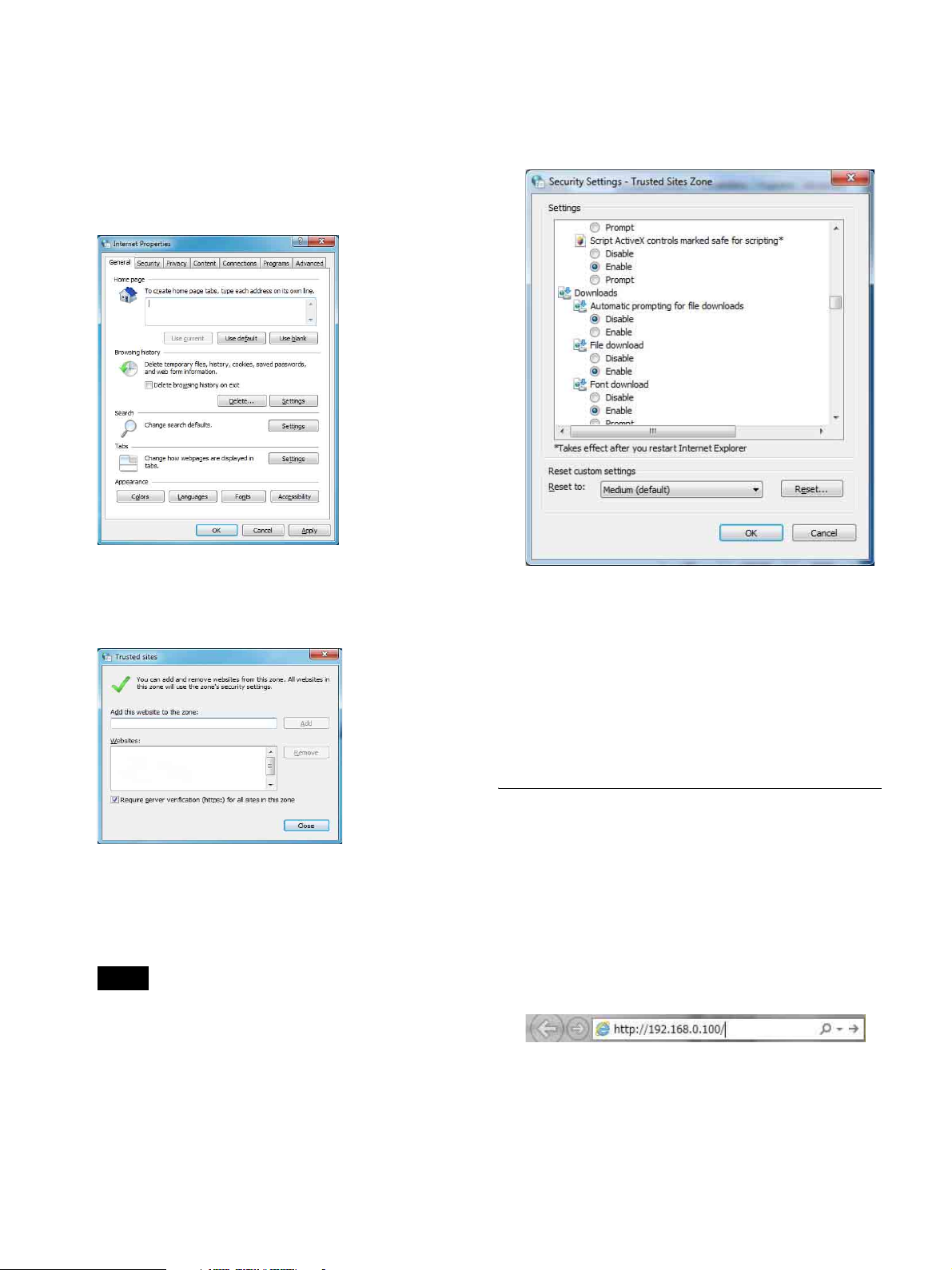
Verifying the JavaScript settings
The following procedure uses Internet Explorer 11 in
Windows 7 as an example.
1
Open the [Control Panel], and click [Internet
Options].
The [Internet Properties] dialog box appears.
5
Click [Custom level] when the [Internet Properties]
dialog box appears again.
The [Security Settings - Trusted Sites Zone] dialog
box appears.
2
Click the [Security] tab, and click [Trusted sites] >
[Sites].
The [Trusted sites] dialog box appears.
3
Clear the [Require server verification (https:) for all
sites in this zone] checkbox, enter “http://
192.168.0.100” for [Add this website to the zone],
and click [Add].
Note
If you change the IP address during initial setup, be
sure to add the new IP address as well.
6
Scroll down the list, set [Active scripting] and [File
download] to [Enable], and click [OK].
If the “Are you sure you want to change the settings
for this zone?” message appears, click [Yes] (or [Yes]
> [Apply]).
7
Click [Close] when the [Internet Properties] dialog
box appears again.
Initial Setup Wizard
Use the initial setup wizard to configure the following.
• Clock settings
• Network settings
• Administrator password
1
Start a web browser on the computer, and enter the
unit’s IP address in the address bar.
The default IP address is “192.168.0.100.”
4
Verify that “http://192.168.0.100” appears under
[Websites], and click [Close].
12
Page 13

2
Enter the user name and password in the dialog box
that appears, and click [OK].
Note
The user name and factory default password are as
follows.
User name: sonypcs
Password: sonypcs
Note
Change the password using the initial setup wizard
described later. The user name cannot be changed.
When accessing the unit from a computer for the first
time, the initial setup wizard appears.
3
Configure the clock settings.
The time zone will be set to Greenwich Mean Time
(GMT). To change the time zone, log into the unit
after initial setup is complete and change the settings.
4
Configure the network settings.
Configure each setting, and click [Next].
[DHCP Mode]
Set this to [On] to use DHCP.
[IP Address]
A static IP address (192.168.0.100) is configured as a
factory default. Change this if necessary.
[Network Mask]
“255.255.255.0” is configured as a factory default.
Configure the network mask according to your
operating environment.
[Gateway Address]
“192.168.0.254” is configured as a factory default.
Configure the gateway address according to your
operating environment.
Note
The date and time configured on the computer
accessing the unit is displayed.
To apply the displayed date and time to the unit, click
[Next].
To configure a different date and time, click [Manual
setting] and change the settings.
If you want to cancel manual settings change after
clicking [Manual setting] and use the computer’s date
and time settings, click [Synchronize with PC].
When [DHCP Mode] is set to [On], the IP address
may change whenever the unit is restarted. As a
result, you will need to determine the IP address each
time to access the unit.
For details on determining the unit’s IP address, see
“Verifying the Unit’s Settings” (page 42).
13
Page 14

5
Configure the administrator password.
This is the password for the administrator account
(user name: sonypcs) for which all unit operations
(settings configuration, call/answer controls, etc.) are
enabled.
After changing the factory default password, click
[Finish and Restart].
Use up to 39 alphanumeric characters and symbols to
register the password.
End-User License Agreement
When you complete initial setup and you log into the unit
for the first time, the end-user license agreement screen
appears.
After agreeing to the terms, the screen will not appear at
subsequent logins.
Note
Hint
The administrator password can be changed later via
the setting menus.
For details on changing the password, see
“[Password] page” (page 33).
The unit will restart. (The process will take about 1
minute.) Verify that the unit’s POWER indicator is lit
orange.
The unit cannot be operated until you agree to the
end-user license agreement terms.
1
Enter the configured IP address in the web browser’s
address bar.
Note
If you set [DHCP Mode] to [On] during initial setup,
the IP address may change whenever the unit is
restarted. As a result, you will need to determine the
IP address each time to access the unit.
For details on determining the unit’s IP address, see
“Verifying the Unit’s Settings” (page 42).
A dialog box appears.
This completes initial setup.
Note
• The configured password will be required at the
next and subsequent logins. Be sure to remember it.
• If you forget the password, contact your Sony
dealer. In such cases, the unit must be initialized, so
all phonebook contacts, histories, and settings data
stored on the unit will be lost.
14
2
Enter the administrator user name and password, and
click [OK].
Enter “sonypcs” for the user name and the password
you configured during initial setup.
The end-user license agreement screen appears.
Page 15
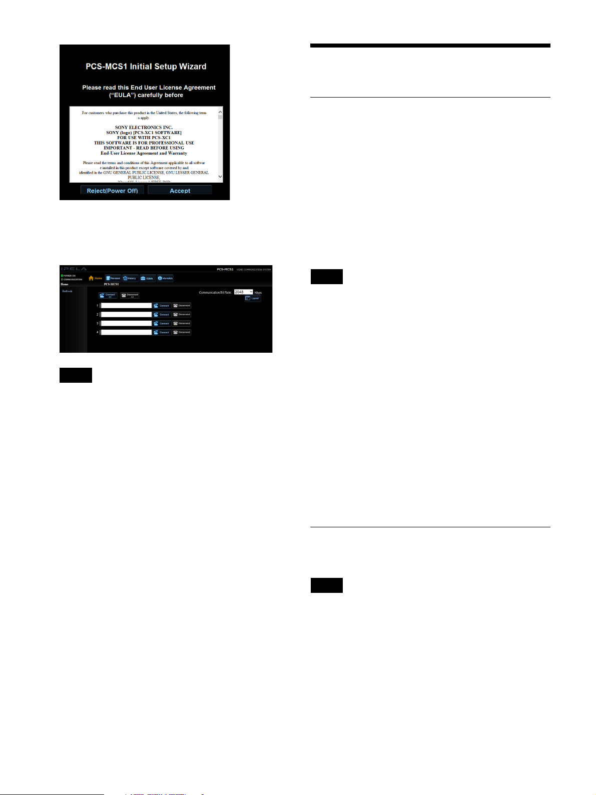
3
Click [Accept].
Login to the unit completes, and the web control
screen appears.
Basic Operations
User Types
User names and passwords are required to log into the
unit from a computer.
There are two types of user names with each possessing
different privileges.
Administrator
The user name for this type is “sonypcs.”
This user can perform all unit operations (settings
configuration, call/answer controls, etc.).
The password is configured via the initial setup wizard.
Hint
The password can be changed via the setting menus after
login.
For details on changing the password, see “[Password]
page” (page 33).
Note
If you do not agree to the end-user license agreement
terms, the unit will turn off.
Web access user
The user name for this type is “pcsuser.”
This user cannot configure settings but can perform
operations during conferences, such as call/answer
controls.
The login password for web access users must be
configured beforehand by the administrator via the
[Admin] screen.
For details on configuring the web access user password,
see “[Password] page” (page 33).
Logging into the Unit from a
Computer
Note
Multiple users cannot log into the unit at the same time. If
another user is already logged in when you perform the
login procedure, a message will appear and login will not
be possible.
15
1
Enter the IP address assigned to the unit in the web
browser’s address bar.
Example: http://xxx.xxx.xxx.xxx/
(“xxx.xxx.xxx.xxx” represents the IPv4 address.)
Page 16
Note
• When a proxy server on an external network
segment is configured, the gateway address
configured in the unit’s LAN settings must also be
specified. Alternatively, you can set your web
browser’s proxy setting to “No Proxy.”
• Depending on your operating environment, access
to the unit from a computer may not be possible. In
such cases, contact your network administrator.
2
Enter the user name and password in the dialog box
that appears, and click [OK].
When login to the unit is complete, you will acquire
the web control privilege, allowing you to control
conferences and configure settings via the web
control screen displayed in the web browser.
Note
• Log in as the administrator (user name: sonypcs)
when logging in for the first time.
• When you complete initial setup and log in for the
first time, the end-user license agreement screen
appears. Click [Accept]. If you do not agree to the
terms, the unit will turn off.
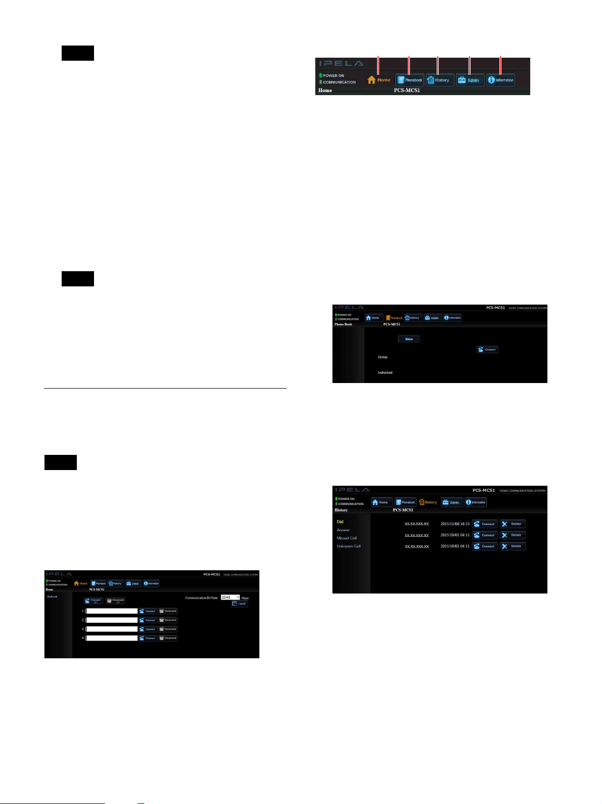
123 45
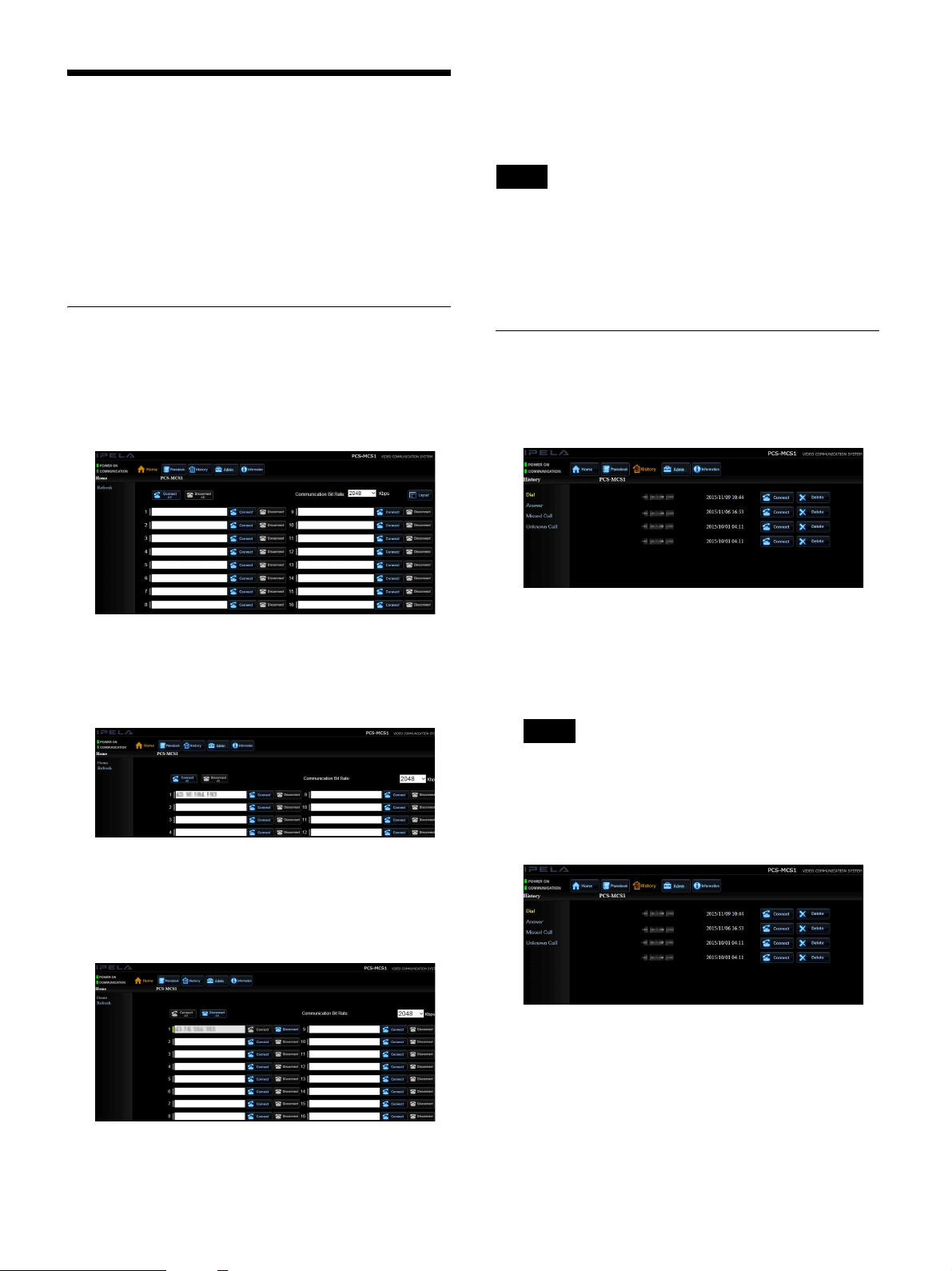
A [Home] button
Click this to display the [Home] screen.
This is the first page that is displayed when you log
into the unit from a computer. You can perform
operations, such as entering an IP address to call a
terminal or disconnecting from a connected terminal,
on this screen.
For details on the contents of the [Home] screen, see
“[Home] screen” (page 17).
B [Phonebook] button
Click this to display the [Phonebook] screen.
You can perform operations, such as calling
registered contacts and adding or editing contacts, on
this screen.
Viewing the Web Control Screen
When you log into the unit from a computer, the web
control screen appears.
Note
• When viewing the web control screen, do not use the F5
keyboard key or the “back” button of your web
browser.
• The web control screen may not be displayed properly
depending on the encoding setting on your web
browser. In such cases, change the encoding setting to
UTF-8 or Shift JIS.
Various control buttons appear in the web control screen,
allowing you to configure the unit’s settings, conduct
conferences, and perform other operations.
For details on the phonebook, see “Registering
Contacts to the Phonebook” (page 22).
C [History] button
Click this to display the [History] screen.
You can view histories of outgoing calls, answered
calls, missed calls, or unknown calls on this screen.
For details on histories, see “Calling via Histories”
(page 19).
D [Admin] button
A settings menu appears at the left side of this screen,
and you can click each item to view or configure the
corresponding settings.
16
Page 17

Note
Note
You cannot click the [Admin] button when logged in
as a web access user (user name: pcsuser). To view or
configure settings, log in as the administrator (user
name: sonypcs).
For details on the [Admin] screen’s settings, see
“Setting Menus” (page 27).
E [Information] button
Click this to display the [Information] screen.
You can view information on the unit and connected
terminals or the communication mode status on this
screen. You can also perform network routing checks.
The number of terminals for which information is
displayed on the [Home] screen is the same as the unit’s
maximum number of connection points. Ordinarily,
information for 4 terminals is displayed, while
information for 10 or 16 terminals is displayed when the
PCSA-MPE1 or PCSA-MPE2 HD Port Expansion
Software is installed, respectively.
A [Connect All] button
Establish connections to all terminals for which you
entered contact information.
B [Disconnect All] button
Disconnect all currently connected terminals.
It changes to [Clear All] in some cases.
For details, see “Ending Connections” (page 22).
C Communication bit rate
Select the communication bandwidth to use per
terminal.
D [Layout] button
Display the [Layout] screen.
The [Layout] screen allows you to configure settings
for the content displayed on each connected
terminal’s monitor during a conference.
For details on the [Layout] screen, see “[Layout]
Screen” (page 26).
For details on the information, see “Displaying
Device Information” (page 34).
[Home] screen
12 3 4
E [Refresh] button
Update the contents displayed in the [Home] screen
to the latest information.
F Terminal number
This is the number assigned to each terminal.
G Communication status bar
This lights green when connection with a terminal is
established.
H Contact entry field
Enter a terminal’s contact information here.
I [Connect] button
Click this to connect to a terminal for which contact
information is entered to the left of the button.
J [Disconnect] button
Disconnect from currently connected terminals
individually.
It changes to [Clear] in some cases.
For details, see “Ending Connections” (page 22).
587906
17
Page 18

Chapter 2: Conferences
Starting Conferences
Note
Do not insert or remove USB storage devices while a
conference is in progress.
Conducting Conferences in Web
Control Mode
Conducting Conferences in Ad Hoc
Mode
Ad hoc mode allows terminals to connect directly to the
unit and conduct conferences without having to log into
the unit from a computer.
Ad hoc conferences can only be conducted when [Ad
hoc] is set to [On] on the [Answer] page of the [Admin]
screen and a user is not logged into the unit from a
computer.
Note
In ad hoc mode, terminals are automatically connected to
the unit when their calls are received, up to the maximum
number of connection points. Be aware that it is less
secure, as anyone can participate in the conference.
1
Log into the unit from a computer to acquire the web
control privilege.
For details on logging into the unit, see “Logging
into the Unit from a Computer” (page 15).
2
On the web control screen, call the other terminals
that will participate in the conference, or answer calls
received from other terminals.
For details on calling other terminals, see “Outgoing
Calls” (page 19).
For details on answering calls, see “Incoming Calls”
(page 21).
When all of the participating terminals are connected,
you can conduct the conference.
Note
• The conference will continue in web control mode
for as long as there are connected terminals, even if
the web browser is accidentally closed or the user
temporarily logs out of the unit. However, when
[Auto Answer] is set to [Off], calls cannot be
received from other terminals when a conference is
already in progress, preventing additional
participants. In such cases, log in again.
• Automatic logout will occur if no operations are
performed for 30 minutes after login.
To conduct an ad hoc conference
Call the unit from your terminal while the unit is turned
on.
The unit will receive and connect calls automatically until
the maximum number of connection points is reached.
To leave an ad hoc conference
The user that wants to leave can disconnect from the unit
via operations from their terminal.
To switch to a web control conference
When a user logs into the unit while an ad hoc conference
is in progress, the conference switches to web control
mode.
For details on logging into the unit, see “Logging into the
Unit from a Computer” (page 15).
Note
After a conference switches to web control mode, the
conference will continue in web control mode for as long
as there are connected terminals, even if the user holding
the web control privilege logs out of the unit.
To add participants during a conference
The user holding the web control privilege can control
calls, even while a conference is in progress.
As long as the maximum number of connection points is
not exceeded, you can add participants by calling or
answering calls on the web control screen.
18
Page 19
Outgoing Calls
To call a terminal from the unit, call the target terminal
from the computer that is logged into the unit.
The following methods are available for calling terminals
from the unit.
• Calling via Contact Information Entry (page 19)
• Calling via Call Histories (page 19)
• Calling via the Phonebook (page 20)
Calling via Contact Information
Entry
1
Click the [Home] button on the web control screen.
To call multiple terminals
Enter the contact information for each of the terminals
you want to call in the web control screen’s entry fields,
and click [Connect All].
Hint
If connection to a terminal failed, you can click the
[Connect] button to the right of its entry field to attempt
connection again. In addition, entering contact
information in empty fields allows you to add participants
to a conference in progress.
Calling via Histories
1
Click the [History] button on the web control screen.
The [Home] screen appears.
2
Select the communication bit rate, enter the contact
information for the terminal you want to call, and
click the [Connect] button to the right of the entry
field.
Calling starts, and the connection results are
displayed when the connection is established.
The communication status bars to the left of the
connected terminals’ entry fields are displayed in
green.
The [History] screen appears.
2
Click [Dial] (outgoing call), [Answer] (answered
call), or [Missed Call] (missed call) on the left side of
the screen.
The selected history appears.
Note
Although [Unknown Call] appears on the left side of
the screen, you cannot call terminals from the
[Unknown Call] page. You can only view the history
of calls rejected by the [Reject Unknown Call]
function.
19
3
Click the [Connect] button to the right of the contact
you want to call.
Calling starts, and the [Home] screen appears when
the connection is established.
The communication status bars to the left of the
connected terminals’ entry fields are displayed in
green.
Page 20

To delete a history entry
Click the [Delete] button to the right of the contact you
want to delete from the history.
Calling via the Phonebook
are going to be connected after selecting the
checkboxes.
“YY” indicates the maximum number of connection
points that the unit can simultaneously connect.
If “XX” exceeds “YY,” you cannot click [OK].
Reduce the number of selected checkboxes.
For details on registering phonebook contacts, see
“Registering Contacts to the Phonebook” (page 22).
1
Click the [Phonebook] button on the web control
screen.
The [Phonebook] screen appears.
2
Checking the contact information in the
phonebook before making a call
Select the checkboxes of the contacts you want to
call, and click the [Confirm] button.
The selected contacts are displayed in a list.
If the selected contacts include groups, all the
contacts from each group will be displayed.
Calling starts, and the [Home] screen appears when
the connection is established.
The communication status bars to the left of the
connected terminals’ entry fields are displayed in
green.
Making a call without checking the contact
information in the phonebook
Select the checkboxes of the contacts you want to
call, and click the [Connect] button.
Step 3 is not required in this case.
3
Check the contact that will be connected, and click
[OK].
Note
Numbers, such as “XX/YY,” are displayed on the left
of [OK].
“XX” indicates the total number of connection points
for which terminals have already been connected and
20
Page 21

Incoming Calls
The operation for answering calls from other terminals
differs depending on whether the manual or auto answer
mode is configured.
Auto answer mode
When a call is received from a terminal in this mode,
connection begins automatically.
This eliminates the need for manual connection
operations but may establish connections while you are
unprepared.
Note
Manual answer mode is configured under factory default
settings.
Answer Modes (Manual/Auto)
Manual answer mode
This mode allows you to decide whether to connect to a
terminal.
When a call is received from a terminal, a confirmation
dialog box and the “Incoming call. Answer?” message
appear.
Click [OK] to establish the connection.
To reject the call, click [Cancel].
Hint
You can view the status of connection after a call is
answered in auto mode in the [Home] screen.
Note
• Answering is not possible while the unit is turned off.
• To view the status of connection when a call was
answered in auto mode while the [Home] screen was
displayed, click the [Refresh] button.
For details on the answer mode setting, see “[Auto
Answer]” (page 28).
If the confirmation dialog box does not appear
The call confirmation dialog box may not appear if the
pop-up blocker setting on your web browser is enabled. In
such cases, configure the setting to allow pop-ups.
The following procedure uses Internet Explorer 11 as an
example.
1
Click [Internet options] in the [Tools] menu.
The [Internet Options] dialog box appears.
2
Display the [Privacy] tab, and click [Settings] under
[Pop-up Blocker].
The [Pop-up Blocker Settings] dialog box appears.
3
Enter “http://xxx.xxx.xxx.xxx” (IP address assigned
to the unit) for [Address of website to allow], and
click [Add].
4
Verify that “http://xxx.xxx.xxx.xxx” (IP address
assigned to the unit) appears under [Allowed sites],
and click [Close].
21
Page 22
Ending Connections
Registering Contacts to
On the [Home] screen, click the [Disconnect] button to
the right of the entry box for the terminal you want to
disconnect.
Connection with the selected terminal ends.
If the contact information of a disconnected terminal
remains in the contact entry field, the [Disconnect] button
changes to [Clear].
To clear the contact information, click [Clear].
To end connections with all terminals
On the [Home] screen, click [Disconnect All].
If any contact information of disconnected terminals
remains in the contact entry fields, the [Disconnect All]
button changes to [Clear All].
To clear all the contact information, click [Clear All].
the Phonebook
Registering a contact to the phonebook allows you to
quickly connect to that contact. Up to 1,000 contacts can
be registered to the unit’s phonebook. Multiple contacts
can also be registered as a group.
Note
Multiple contacts cannot be registered to the phonebook
under the same name.
Registering New Contacts
1
Click the [Phonebook] button on the web control
screen.
The [Phonebook] screen appears.
2
Click [New].
The phonebook registration screen appears.
3
Configure each setting.
[Index]
Enter the name of the contact.
You can enter up to 30 alphanumeric characters and
symbols.
[Number of Connected Sites]
Select the number of contacts to register.
When registering a single contact, select [1]. When
registering multiple contacts as a group, select the
number of contacts.
22
Page 23
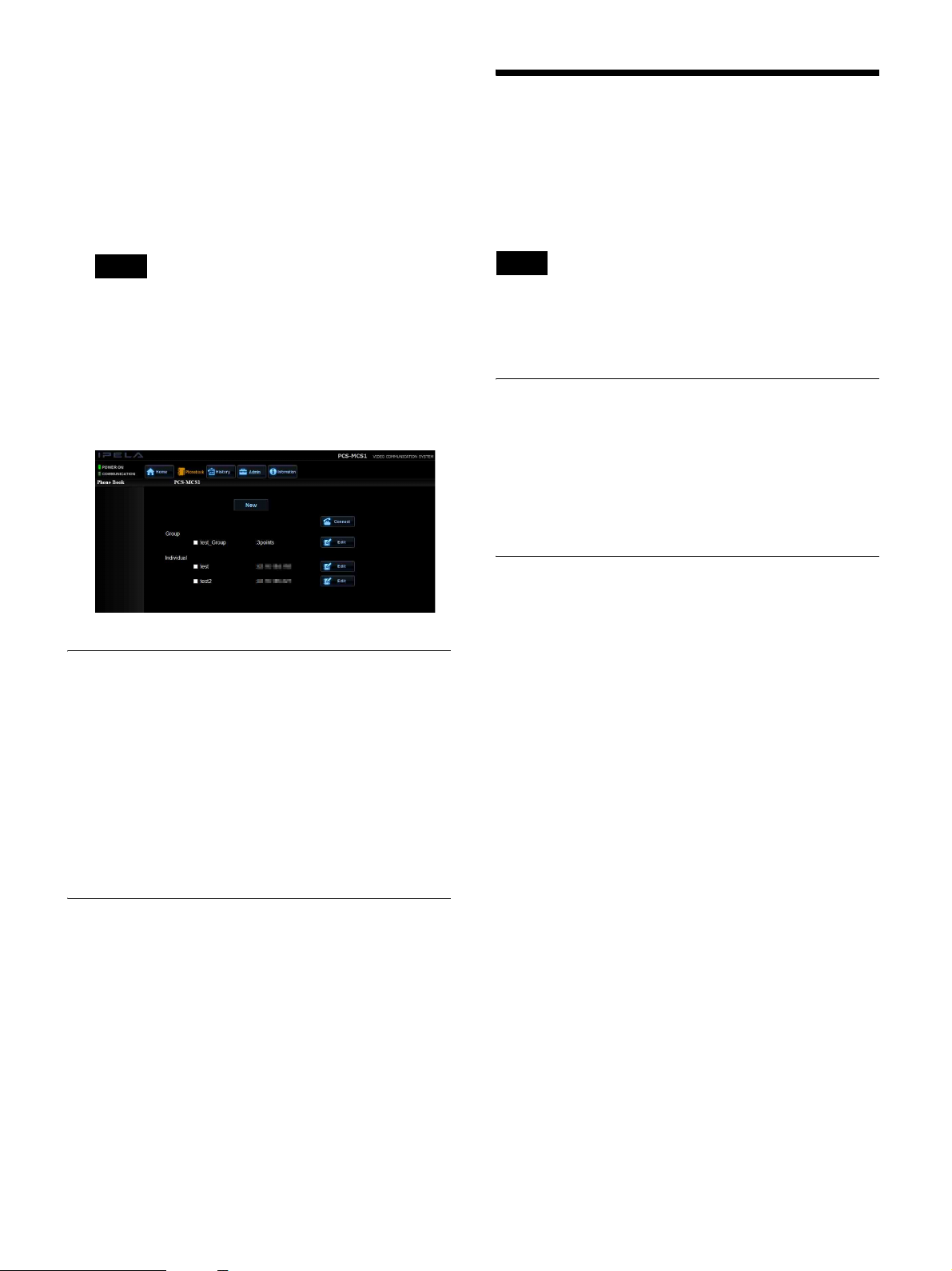
[Dial to]
Enter the IP address of the contact.
The number of entry fields will differ depending on
the [Number of Connected Sites] setting. When
registering a group, enter the IP address of each
contact you want to register in the entry fields.
[Communication Bit Rate]
Enter the communication bit rate per point.
External Access to the Unit
You can use the following methods to access the unit
externally. For details on each method, contact your Sony
dealer.
Note
When selecting multiple phonebooks to make a call,
the lowest communication bit rate is selected.
4
Click [Save].
The [Phonebook] screen appears, and the contacts are
added under [Group] or [Individual] depending on
the information you registered.
Editing the Phonebook
1
On the [Phonebook] screen, click the [Edit] button to
the right of the contact you want to edit.
Note
When allowing external access, unauthorized third parties
on the network may be able to access the unit, depending
on your operating environment.
Using Telnet
You can access, control, and configure settings for the
unit via Telnet.
To access the unit via Telnet, set [Telnet Access] to
[Enabled] on the [Access] page of the [Admin] screen
(page 32).
Using SSH
You can access, control, and configure settings for the
unit via SSH.
To access the unit via SSH, set [SSH Access] to [Enabled]
on the [Access] page of the [Admin] screen (page 32).
The phonebook editing screen appears.
2
Edit each setting, and click [Save].
The edited information is registered, and the
[Phonebook] screen appears again.
Deleting Registered Contacts
1
On the [Phonebook] screen, click the [Delete] button
to the right of the contact you want to delete.
The phonebook editing screen appears.
2
Click [Delete].
The contact is deleted, and the [Phonebook] screen
appears again.
If you clicked [Cancel], the contact is not deleted, and
the [Phonebook] screen appears again.
23
Page 24

Picture Displays during Conferences
Broadcast Modes
When conducting a multipoint conference via the unit, the
content displayed on each connected terminal’s monitor
will vary depending on the unit’s settings.
The “split-screen” and “voice-activate” broadcast modes
are available. When split-screen mode is selected, you
can configure the layout of the split-screen display.
The broadcast mode setting and the layout settings for
when split-screen mode is selected are configured on the
[Multipoint] page of the [Admin] screen or on the
[Layout] screen.
• [Automatic]: Determine the split-screen format based
on the number of connected terminals.
– When 1 terminal is connected: Full-screen display
– When 2 or 3 terminals are connected: 3-window split
– When 4 terminals are connected: 4-window split
– When 5 or 6 terminals are connected: 6-window split
– When 7 to 9 terminals are connected: 9-window split
– When 10 terminals are connected: 10-window split
– When 11 to 13 terminals are connected: 13-window
split
– When 14 to 16 terminals are connected: 16-window
split
The pictures from each participating terminal are
displayed in each window in the order in which they
connected. When the number of connected terminals is
less than the number of split windows, the extra split
windows will be blank.
Hint
For details on the [Layout] screen, see “[Layout]
Screen” (page 26).
Split-screen mode
The pictures from the connected terminals are displayed
on each terminal’s monitor in a split-screen display.
The split-screen format varies depending on the [Split]
setting on the [Multipoint] page of the [Admin] screen.
• [Full window]: Use full-screen display for a single
terminal, regardless of the number of connected
terminals.
• [3 split window]: Split the display into 3 windows,
regardless of the number of connected terminals.
• [4 split window]: Split the display into 4 windows,
regardless of the number of connected terminals.
• [6 split window]: Split the display into 6 windows,
regardless of the number of connected terminals.
• [6 split window + Voice Activate]: Split the display into
6 windows, regardless of the number of connected
terminals. Display the voice-activated terminal in the
large window.
• [9 split window]: Split the display into 9 windows,
regardless of the number of connected terminals.
• [10 split window]: Split the display into 10 windows,
regardless of the number of connected terminals.
• [10 split window + Voice Activate]: Split the display
into 10 windows, regardless of the number of connected
terminals. Display the voice-activated terminal in the
large window on the left or right.
• [13 split window]: Split the display into 13 windows,
regardless of the number of connected terminals.
• [13 split window + Voice Activate]: Split the display
into 13 windows, regardless of the number of connected
terminals. Display the voice-activated terminal in the
large window.
• [16 split window]: Split the display into 16 windows,
regardless of the number of connected terminals.
• When [Split] is set to [Full window], [6 split windows],
[10 split windows], or [13 split windows], you can
specify which terminals are displayed in the large
windows during the conference.
• When [Split] is set to [6 split window + Voice
Activate], [10 split window + Voice Activate], or
[13 split window + Voice Activate], the voice-activated
terminals are displayed in the large windows.
For details, see “Layout settings configured during
conferences” (page 26).
24
Page 25
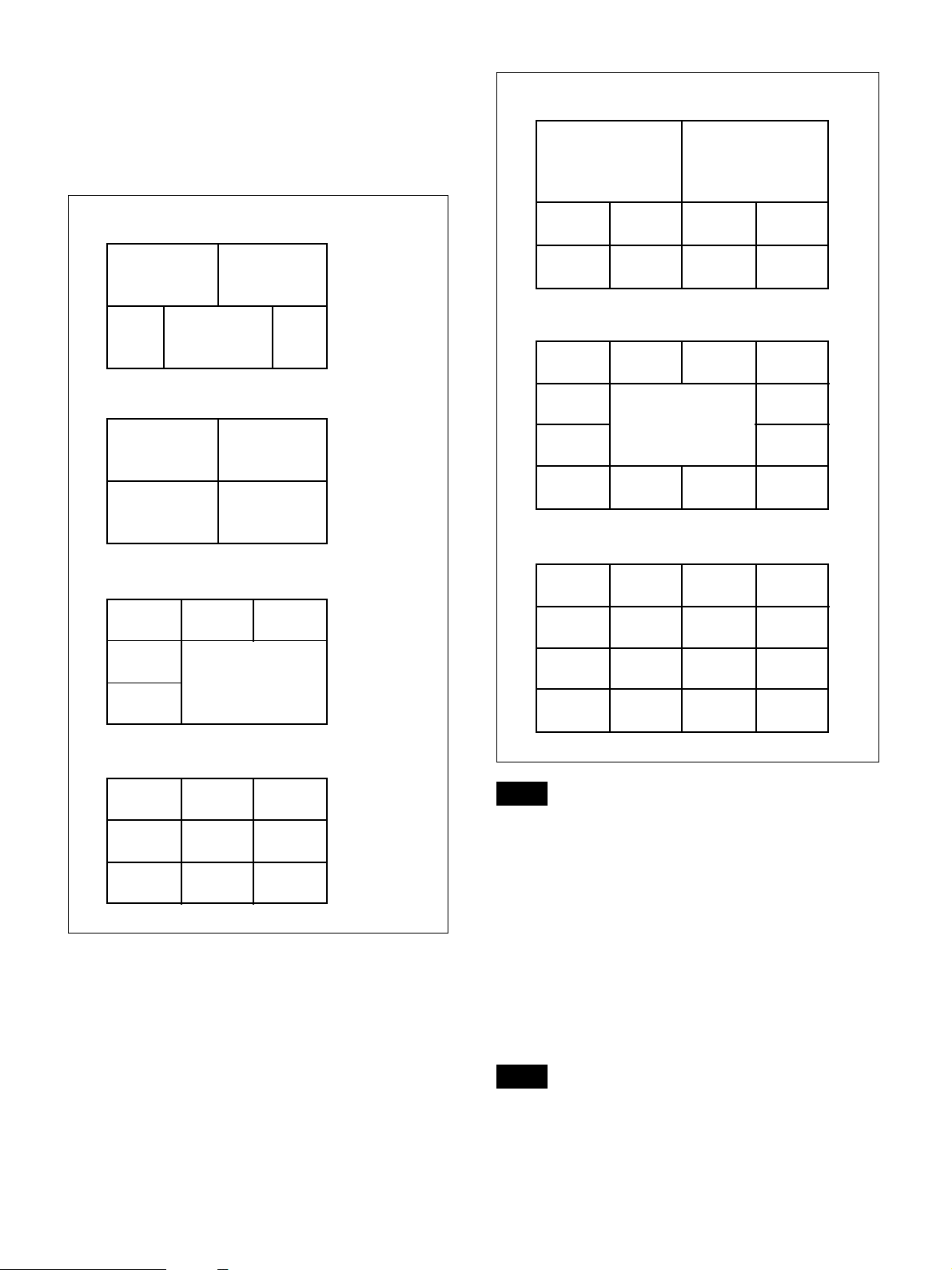
The following are the examples of terminal location
displayed when selecting [Automatic]. The terminal
location is displayed by terminal number. However, it
may be displayed differently when [Split] is set to a
setting other than [Automatic], or the terminals are
connected/disconnected during the conference.
10-window split
Terminal 10 Terminal 9
3-window split
Terminal 1 Terminal 2
Terminal 3
4-window split
Terminal 1 Terminal 2
Terminal 3 Terminal 4
6-window split
Terminal 1
Terminal 4
Terminal 5
Terminal 2 Terminal 3
Terminal 6
Terminal 1
Terminal 5 Terminal 6 Terminal 7
13-window split
Terminal 1 Terminal 4
Terminal 5 Terminal 6
Terminal 7
Terminal 9 Terminal 10 Terminal 11
16-window split
Terminal 1 Terminal 4
Terminal 5 Terminal 8
Terminal 9
Terminal 13 Terminal 14 Terminal 15
Terminal 2 Terminal 3
Terminal 2 Terminal 3
Terminal 13
Terminal 2 Terminal 3
Terminal 6 Terminal 7
Terminal 10 Terminal 11
Terminal 4
Terminal 8
Terminal 8
Terminal 12
Terminal 12
Terminal 16
9-window split
Terminal 1 Terminal 2 Terminal 3
Terminal 4
Terminal 7 Terminal 8 Terminal 9
Terminal 5 Terminal 6
Note
• The cameras of other terminals cannot be controlled in
split-screen mode.
• If a terminal does not support the name display function
or the number of connected terminals exceeds the limit
for its name display function, that terminal’s name will
not be displayed.
Voice-activate mode
The terminal with the loudest audio is detected, and the
picture from that terminal is displayed on each terminal’s
monitor in full screen.
Note
If you want to transmit the images from the voiceactivated terminal in H.264, 1080p (1920 × 1080 pixel)
format, set [Broadcast Mode] to [Voice Activate (1080P)]
on the [Multipoint] page of the [Admin] screen. However,
25
Page 26

when [Voice Activate (1080P)] is configured, connection
to terminals that do not support the H.264 video format
will be disabled.
[Layout] Screen
The [Layout] screen allows you to configure settings for
the content displayed on each connected terminal’s
monitor during a conference.
The settings in the [Layout] screen consist of items that
are configured before conferences and items that are
configured during conferences.
[Select (Full window/6 split/13 split)]
This can be configured when [Split] is set to [Full
window], [6 split windows], or [13 split windows].
The picture displayed in the large window will be fixed at
that of the selected terminal number.
• [Full window]
Picture from selected terminal
displayed
• [6 split windows]
Fixed display
Layout settings configured before
conferences
You can configure the [Broadcast Mode] and [Split]
settings before starting a conference.
The [Broadcast Mode] and [Split] settings are identical to
the corresponding settings on the [Multipoint] page of the
[Admin] screen.
For details on the [Broadcast Mode] and [Split] settings,
see “[Multipoint] page” (page 28).
Note
After a conference ends, the settings configured in the
[Layout] screen are reset, and the values configured on
the [Multipoint] page of the [Admin] screen are applied
again.
Layout settings configured during
conferences
When [Broadcast Mode] is set to [Split Screen] and
[Split] is set to [Full window], [6 split windows], [10 split
windows], or [13 split windows], you can specify which
terminals are displayed in the large windows during the
conference.
When [Split] is set to [6 split window + Voice Activate],
[10 split window + Voice Activate], or [13 split
window + Voice Activate], the voice-activated terminals
are displayed in the large windows.
• [13 split windows]
Fixed display
[Select (10 split: Left)], [Select (10 split: Right)]
These can be configured when [Split] is set to [10 split
windows].
The pictures displayed in the large windows on the left
and right will be fixed at those of the selected terminal
numbers.
Fixed display
(left)
Fixed display
(right)
26
Page 27
Chapter 3: Settings and Administration
Setting Menus
Note
Unit settings cannot be changed while a conference is in
progress.
2
Click the page you want to display from the list on the
left side of the screen.
Displaying and Configuring
Settings
1
Display the unit’s web control screen on a computer,
and click the [Admin] button.
Note
You cannot click the [Admin] button when logged in
as a web access user (user name: pcsuser). To view or
configure settings, log in as the administrator (user
name: sonypcs).
The [Admin] screen appears, and various setting
menus appear on the left side of the screen.
The items for the selected page appear on the right
side of the screen.
3
Click the lists or entry fields for the items you want to
configure, and configure the settings.
4
When you are finished configuring settings, click
[Save].
The configurations are saved.
To cancel configurations
Go to a different page without clicking [Save].
Setting Pages and Items
[Line I/F] page
[Use LAN2]
Select whether to use the 2 (LAN2) connector on the
rear panel of the unit.
Note
For details on the menu configuration and an items
list, see “Menu Configuration” (page 56).
• After setting [Use LAN2] to [On], close the web control
screen, and log in again.
• Some of the unit’s functions will be restricted when
using the 2 (LAN2) connector.
For details, see “Restrictions when Using LAN2”
(page 36).
[Dial] page
[Select LAN Prefix]
Select whether to enable the LAN prefix making calls.
When [Enable] is selected, the prefix entered in the [LAN
Prefix] field will be added before the IP address.
27
Page 28

[Answer] page
[Ad Hoc]
Select whether to accept calls from terminals when a user
is not logged into the unit from a computer and a
conference is not in progress. When [On] is selected,
terminals can connect directly to the unit and conduct
conferences without having to log into the unit from a
computer.
Note
After setting [Ad Hoc] to [On], close the web control
screen. The setting will take about 1 minute to be applied.
[Auto Answer]
Select whether to enable auto answer mode.
[On]: Establish connections automatically when calls are
received.
[Off]: Display the “Incoming call. Answer?” message
when calls are received, and click [OK] to establish
connections.
[Reject Answer]
Select whether to reject calls from other terminals when a
communication is in progress.
[Reject Unknown Call]
Select whether to reject calls from terminals not
registered to the phonebook.
[Off]: Accept calls.
[LAN1]: Reject calls from LAN1.
[LAN2]: Reject calls from LAN2.
[LAN1+LAN2]: Reject calls from both LAN1 and
LAN2.
[Multipoint] page
[Split]
Select the split-screen format that will be used to display
the pictures from connected terminals on each terminal’s
monitor when [Broadcast Mode] is set to [Split Screen].
When [Automatic] is selected, the split-screen format is
determined based on the number of connected terminals.
The format is determined as follows; 3-screen split for 2
or 3 terminals, 4-screen split for 4 terminals, 6-screen
split for 5 or 6 terminals, 9-screen split for 7 to 9
terminals, 10-screen split for 10 terminals, 13-screen split
for 11 to 13 terminals, and 16-screen split for 14 to 16
terminals.
Note
If there is only one other connected terminal, full-screen
display will be used, regardless of this setting.
[Voice Activation Frame]
Select whether to highlight (i.e., frame) the pictures from
terminals for which audio is detected during a conference
on each terminal’s monitor display.
[IP Communication] page
Note
The setting items for the communication mode will vary
depending on the line interface specified on the [Line I/F]
page and the [Individual Settings for Transmission/
Reception] setting on the [IP Communication] page. Only
the setting items that can be configured will be displayed
on the screen.
The number of pages after the [IP Communication Mode]
page will also vary depending on the number of setting
items.
[Broadcast Mode]
Select the broadcast mode.
[Split Screen]: Display the pictures from participating
terminals on each terminal’s monitor in a split-screen
display.
[Voice Activate]: Detect the terminal with the loudest
audio from among the connected terminals, and
display the picture from that terminal on each
terminal’s monitor in full screen.
[Voice Activate (1080P)]: Transmit the images from
the voice-activated terminal in H.264, 1080p (1920 ×
1080 pixel) format.
Note
When [Voice Activate (1080P)] is selected, connection to
terminals that do not support the H.264 video format will
be disabled.
[Individual Settings for Transmission/
Reception]
Select whether to configure settings for transmission and
reception individually.
When [On] is selected, settings can be configured
individually for transmission and reception.
Note
The setting items and number of pages for the [IP
Communication Mode] page will vary depending on this
setting.
[IP Communication Mode] page
[Total Bandwidth]
Enter the total bandwidth used by the system.
You can enter a value between 64 Kbps to 16384 Kbps.
This is the total bit rate of all points in a multipoint
connection.
28
Page 29

Note
In multipoint connections, the actual communication bit
rate for each point is automatically adjusted so as not to
exceed the [Total Bandwidth].
[Screen Size]
Select the image size for transmission and reception.
When [Individual Settings for Transmission/Reception]
is set to [On], this setting can be configured individually
for transmission and reception.
[Communication Bit Rate]
Enter the communication bit rate per point.
You can enter a value between 64 Kbps to 16384 Kbps.
When [Individual Settings for Transmission/Reception]
is set to [On], this setting can be configured individually
for transmission and reception.
[Audio Mode]
Select the audio compression format.
When [Individual Settings for Transmission/Reception]
is set to [On], this setting can be configured individually
for transmission and reception.
You can select multiple formats from among G.711,
G.722, G.728, and MPEG4 (MPEG4 AAC).
Note
If the audio format selected on the unit is not supported on
a terminal, the format will automatically switch to G.711.
[Far End Camera Control]
Select whether to allow connected terminals to control
each other’s camera.
Note
Even if this is set to [On] on the unit, if the function is
disabled on a terminal, remote camera control will not be
possible on that terminal.
[H.239]
The H.239-compatible presentation mode allows
simultaneous transmission of camera images and
presentation data from connected terminals.
Select whether to use the H.239-compatible presentation
mode.
Note
Even if this is set to [On] on the unit, if the function is
disabled on a terminal, presentations will not be possible
on that terminal.
[H.239 Ratio]
When H.239 presentation transmissions are made from a
terminal, the H.239 presentation data shares bandwidth
with camera images that are also being sent. This setting
allows you to select how much of the total bandwidth to
use for H.239 presentation data transmissions.
[Video Mode]
Select the compression format for transmitted and
received video.
When [Individual Settings for Transmission/Reception]
is set to [On], this setting can be configured individually
for transmission and reception.
[Video Frame]
Select the video frame rate (frames per second) for
transmission and reception.
When [Individual Settings for Transmission/Reception]
is set to [On], this setting can be configured individually
for transmission and reception.
[LAN1: Basic] / [LAN2: Basic] page
For details on settings, contact your network
administrator.
Note
The LAN setting items will vary depending on the [Use
LAN2] setting on the [Line I/F] page and [Internet
Protocol] setting on the [Etc] page.
The number of pages after the [LAN2] page will also vary
depending on the number of setting items.
[Host Name]
Enter the host name (up to 30 characters).
[DHCP Mode]
Select whether to use DHCP (Dynamic Host
Configuration Protocol).
[On]: Obtain the IP address, network mask, gateway
address, and DNS address automatically.
[Off]: Disable DHCP. When this is selected, manual
entry of the IP address, network mask, gateway
address, and DNS address is required.
[IP Address]
Enter the IP address.
[Network Mask]
Enter the network mask.
[Gateway Address]
Enter the default gateway address.
[Primary DNS] (LAN1 only)
Enter the primary DNS (Domain Name System) server
address.
[Secondary DNS] (LAN1 only)
Enter the secondary DNS server address
29
Page 30

[LAN Mode]
Select the interface type and communication mode for
LAN connections.
[User Alias]
Enter the user name (H.323 alias) to register to the
gatekeeper.
[LAN: PPPoE] page
[PPPoE]
Select whether to use PPPoE for LAN connections.
[User Alias]
Enter the user name that will be used for PPPoE LAN
connections.
[Password]
Enter the password that will be used for PPPoE LAN
connections.
[Fixed IP for PPPoE]
Select whether to use a fixed IP address for PPPoE
connections.
[Fixed IP Address for PPPoE]
Enter the fixed IP address (when [Fixed IP for PPPoE] is
set to [On]).
[DNS]
Select whether to specify DNS server addresses manually
or obtain them automatically for PPPoE connections.
[Primary DNS]
Enter the primary DNS address.
[Secondary DNS]
Enter the secondary DNS address.
[LAN: NAT] page
[User Number]
Enter the user number (E.164 number) to register to the
gatekeeper.
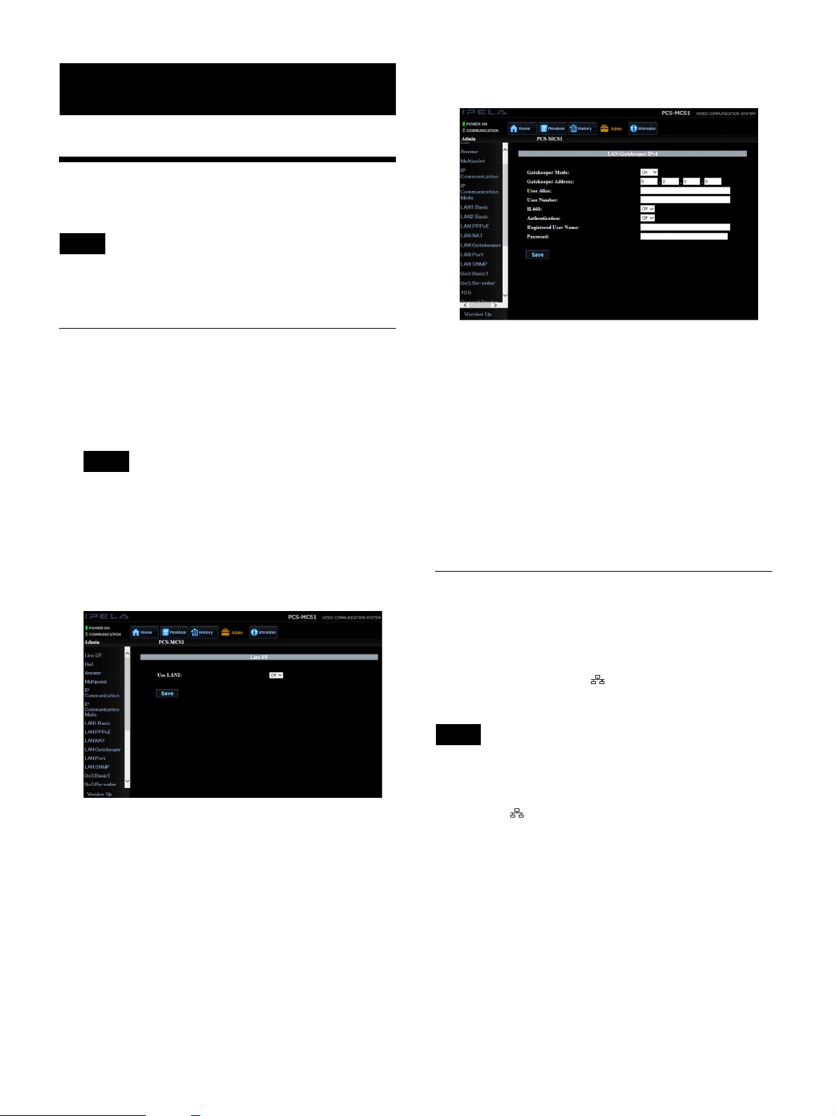
[H.460]
Select whether to use H.460 to traverse firewalls and
connect to the terminals on other networks.
[Authentication]
Select whether to use the gatekeeper’s authentication
function.
Note
When the authentication function is disabled, registration
may not be possible depending on the gatekeeper.
[Registered User Name]
Enter the login name specified by the gatekeeper
administrator when [Authentication] is set to [On].
[Password]
Enter the password name specified by the gatekeeper
administrator when [Authentication] is set to [On].
[LAN: Port] page
[Q.931]
Enter the Q.931 port number.
[H.245]
Enter the H.245 port number.
[NAT Mode]
Select whether to connect the unit to a local network using
NAT (Network Address Translation), which allows one
IP address to be shared by multiple computers on the
same LAN.
When [Auto] is selected, NAT mode is enabled
automatically based on whether the use of NAT is
detected. The [Auto] setting is only effective when a
UPnP router is used.
[WAN IP Address]
Enter the WAN (Wide Area Network) IP address.
[LAN: Gatekeeper] page
[Gatekeeper Mode]
Select whether to use a gatekeeper to control access.
Using the gatekeeper allows you to make calls using user
names and user numbers, in addition to IP addresses.
[Gatekeeper Address]
Enter the address of the gatekeeper to use when
[Gatekeeper Mode] is set to [On].
[RTP/RTCP]
Enter the RTP/RTCP port number.
[MTU Size]
Enter the MTU size.
[LAN: SNMP] page
[SNMP Mode]
Select whether to enable the SNMP (Simple Network
Management Protocol).
[Trap Destination]
Enter the address of the trap destination SNMP manager.
[Community]
Enter the community name managed by the SNMP
manager (up to 24 alphanumeric characters). “public” is
entered by default.
[Description]
“Videoconference Device” is entered by default. This
setting cannot be changed.
30
Page 31

[Location]
Enter the installation location of the unit (up to 30
alphanumeric characters).
[Contact]
Enter information about the unit’s administrator (up to 30
characters).
[QoS: Basic] page
[Adaptive Rate Control]
Select whether to always optimize the LAN bandwidth.
[Re-Order Buffer]
Configure the reordering buffer.
[Re-Order Buffer Rate]
Enter the reordering buffer rate. You can specify a value
from 1 to 5.
[Shaping]
Select whether to use shaping, to adjust the IP packet
transfer rate.
[TOS] page
[Auto Bandwidth Detection]
Select whether to use the auto bandwidth detection
function.
[TCP Port Number]
Enter the fixed TCP port number.
[UDP Port Number]
Enter the fixed UDP port number.
For details on the port numbers used on the unit, “Ports
Used on the PCS-MCS1” (page 53).
[Packet Resend Request]
Select whether to request packets to be resent when
packet losses occur during communication.
[ARQ Buffering Time]
Specify the buffering time used for packet resend
requests.
When [Custom] is selected, you can enter a custom
buffering time.
[ARQ Buffering Time (Custom)]
Enter the custom buffering time (50 to 999 ms) when
[ARQ Buffering] is set to [Custom].
[Forward Error Correction]
Select whether to identify received packets with error
correction codes.
[FEC Redundancy]
Specify the redundancy of the packets used for forward
error correction.
[Audio Duplex Transmission]
Select whether to automatically transmit duplicate audio
when audio interruptions occur due to network
conditions.
[QoS: Re-Order] page
[Re-Order]
Select whether to correct packet reordering (i.e., packets
delivered in the incorrect order) which may result in
packet loss. Correcting reordering results in smoother
picture and sound.
[TOS Data Type]
Select the type of data for which to configure the TOS
(type of service) field.
[Video]: Configure the TOS field for video data.
[Audio]: Configure the TOS field for audio data.
[Data]: Configure the TOS field for camera control
signals, etc.
[Presentation]: Configure the TOS field for DVI-I
presentation data.
[TOS]
Select how to define the TOS field for the type of data
selected in [TOS Data Type].
[Off]: Do not define the TOS field.
[IP Precedence]: Define the TOS field as the IP
Precedence.
[DSCP]: Define the TOS field as the DSCP
(differentiated services code point).
Enter a value from 0 to 63.
[Precedence]
Enter the IP Precedence value (0 to 7).
[Low Delay]
Select whether to specify the low-delay bit of the TOS
field.
[High Throughput]
Select whether to specify the high-throughput bit of the
TOS field.
[High Reliability]
Select whether to specify the reliability bit of the TOS
field.
[Minimum Cost]
Select whether to specify the minimum-cost bit of the
TOS field.
[DSCP]
Enter the DSCP value.
This item only appears when [TOS] is set to [DSCP].
31
Page 32

[General: Device] page
[Terminal Name]
Enter the name of the unit that will be sent to terminals
(up to 30 characters).
[Language]
Select the language used for messages displayed on the
screen. You can select the following languages.
English, Japanese, and Chinese.
Note
To apply the change to the [Language] setting, restart the
unit.
Click [OK] to confirm the change in the setting. To cancel
the change, click [Cancel].
[Telnet Access]
Select whether to allow access to the unit via Telnet.
[SSH Access]
Select whether to allow access to the unit via SSH (Secure
Shell).
[General: Clock] page
[NTP]
Select whether to obtain clock information from a server
using NTP.
[Primary NTP Server]
Enter the address of the primary NTP server from which
to obtain clock information.
[Secondary NTP Server]
Enter the address of the secondary NTP server from
which to obtain clock information.
[Time Zone]
Select the country or region in which the unit is used.
[Clock Display Pattern]
Select the clock display format displayed on the monitor.
[Date]
Enter the current year, month, and day.
[Time]
Enter the current time.
[Time Update]
Click [Execute] when [NTP] is set to [On] to update the
current clock.
[Access] page
Note
Depending on your operating environment, unauthorized
third parties on the network may be able to access the unit.
The following pop-up appears when you set [Telnet
Access] or [SSH Access] to [On].
[Referrer Check]
Select whether to perform a referrer check when the unit
is accessed from the web.
Note
We recommend enabling the referrer check function, as
not doing so involves some security risk.
[Etc] page
[Use History]
Select whether to display call histories from which calling
and other operations can be performed.
[AMX Device Discovery]
Select whether to periodically export AMX Device
Discovery information onto the network.
When the AMX system is connected to the unit via serial
connection, AMX Device Discovery information is
output via the serial interface.
AMX systems are external control devices that can be
used to control the unit. When the AMX system receives
AMX Device Discovery information from the unit, the
unit automatically falls under the control of the AMX
system.
[HOP]
Enter the hop count (0 to 255) of the exported data.
[Auto Restore]
Select whether to turn the unit back on automatically
when power is restored after an outage.
[Internet Protocol]
Only the IPv4 Internet Protocol can be used.
Note
The [Internet Protocol] setting is common to both LAN1
and LAN2.
32
Page 33

[Phonebook] page
Note
[Save Phone Book]
Save the phonebook data to a USB storage device.
Existing phonebook data on the USB storage device will
be overwritten.
[Load Phone Book]
Load the phonebook data from a USB storage device.
Existing phonebook data on the unit will be overwritten.
Note
• The [Save Phone Book] and [Load Phone Book] items
appear only when a USB storage device is inserted in
the USB port on the rear panel.
• When saving and loading phonebook data, make sure
that the version of the PCS-MCS1 from which the data
was originally saved is the same as the version of the
current unit. If the versions differ, the data may not be
properly recognized.
[Clear Phone Book]
Delete the phonebook data on the unit.
[Password] page
The maximum usable bandwidth will be limited to
12 Mbps during encrypted connections.
[Encryption]
Select whether to use the encryption function.
[Off]: Do not use the encryption function.
[Connect Priority]: Connect via an encrypted
connection to terminals that support standard
encrypted connection. If a terminal does not support
standard encrypted connection or its encryption
function is disabled, connection will be established
without encryption.
[Encrypt Priority]: Connect only to terminals that
support standard encrypted connection.
[Software Option] page
Enter the keys of the optional software you want to add in
the [Software Option] entry fields (1 to 8).
For details on adding optional software, see “Adding
Optional Software” (page 41).
[sonypcs] - [Password], [Password
(confirmation)]
Enter a new password when you want to change the
administrator login password.
[pcsuser] - [Password], [Password
(confirmation)]
Enter a new password when you want to change the web
access user login password.
[Maintenance] page
[Day], [Time]
Select the day of the week and time at which the unit is
restarted.
The unit will not be restarted if a conference is in progress
on the specified day and time. In such cases, restart will
be attempted up to 5 times at 30-minute intervals, and the
unit will be restarted if the conference is no longer in
progress.
[Encryption] page
Configure settings for using the encryption function for
connections.
The encryption function allows you to use a highly
confidential connection.
For details on encrypted connections, see Chapter 5.
33
Page 34

Displaying Device Information
You can display various information concerning the unit
and connected devices, such as version information,
communication modes, and line quality, on the
[Information] screen.
Displaying Device Information
Display the unit’s web control screen on a computer, and
click the [Information] button at the top of the screen to
display the [Information] screen.
[MAC Address]
Displays the MAC address of LAN1.
[MAC Address (LAN2)]
Displays the MAC address of LAN2.
[Serial Number]
Displays the serial number.
[Machine Version]
Displays version information for codecs, for example.
[Peripheral Status] Page
[LAN Mode (LAN1)]
Displays the LAN mode of LAN1.
[LAN Mode (LAN2)]
Displays the LAN mode of LAN2.
[Gatekeeper]
Displays the gatekeeper status.
[Gatekeeper Requested], [Gatekeeper Confirmed],
[Gatekeeper Reject], [Registration Requested],
[Registration Confirmed], [Registration Failed],
[Registration Rejected], [Registration Timeout],
[Unregistration Requested], and [Unregistration
Confirmed]
Pages of the [Information] screen
[Machine Information] page (page 34)
[Peripheral Status] page (page 34)
[Communication Mode Status] page (page 34)
[Network Routing Check] page (page 35)
[EULA] page (page 35)
[Machine Information] Page
[Host Version]
Displays the version of the unit’s software.
[Software Option]
Displays the type of optional software installed.
[Host Name]
Displays the host name.
[IP Address]
Displays the IP address of LAN1.
[IP Address (LAN2)]
Displays the IP address of LAN2.
[Communication Mode Status] Page
This page displays the status of the current
communication when communication is in progress, and
the status of previous communications when
communication is not in progress. Depending on the
number of connected terminals, up to 16 pages will be
displayed and you can view information on each terminal
in each page.
For the items with [(Encode)] and [(Decode)] values, the
configuration status of the unit is displayed under
[(Encode)] and the reception status of the unit is displayed
under [(Decode)].
[Far End Terminal Name]
Displays the name of the terminal.
[Remote Address]
Displays the address of the terminal.
[Audio Mode]
Displays the current audio codec format.
[Video Mode]
Displays the current video codec format.
“H.264 HP” is displayed during H.264 High Profile
communication, and “H.264” is displayed during H.264
Baseline Profile communication.
34
Page 35

Note
Depending on the status of the connected system, the
audio and video codec formats used for actual
communication may differ from the formats configured
on the unit.
[Frame Rate]
Displays the video frame rate in real time.
[Rate]
Displays the number of connected lines and their transfer
rates in real time.
[Line I/F]
Displays the line interface being used.
[IP Address of Remote Site]
Enter the IP address of the terminal you want to check.
[Line I/F]
[LAN1]: Perform network routing check for the network
connected to the 1 (LAN1) connector.
[LAN2]: Perform network routing check for the network
connected to the 2 (LAN2) connector.
[Gateway]
Displays the check results for the default gateway.
[ping]
Displays the check results for reachability, packet loss,
RTT (round-trip time), and H.323 communication
availability.
[Far End Camera Control]
Displays whether terminals are able to control each
other’s camera.
[H.239]
Displays whether the H.239 presentations are enabled.
[Check Code]
Displays the encryption check code. This is only
displayed when using encrypted communication.
[Bit rate - Encode]
Displays the transfer rates for sent data by category
(audio, video, H.239 (presentation)).
[Bit rate - Decode]
Displays the transfer rates for received data by category
(audio, video, H.239 (presentation)).
[Number of lost packets]
Displays the number of packets lost during transfer on the
network by category (audio, video, H.239 (presentation)).
[Number of recovered packets]
Displays the number of lost packets that were recovered
with the unit’s QoS function by category (audio, video,
H.239 (presentation)).
[traceroute]
Displays the check results for the hop count (i.e., number
of routers passed through to reach the remote party) and
total RTT.
[Start Measurement]
Click this to start a network routing check.
[EULA] Page
This page allows you to view end-user license agreement
that appears when you first log in after initial setup.
[Number of received packets]
Displays the number of packets received during
communication by category (audio, video, H.239
(presentation)).
[Network Routing Check] Page
This page allows you to perform network routing checks
and displays their results.
Click [Start Measurement] at the bottom of the screen to
start the routing check.
For details, see “Network Routing Checks” (page 40).
35
Page 36

Restrictions when Using LAN2
When using two LAN connections, use the 1 (LAN1)
connector to connect to your private company network
and the 2 (LAN2) connector to connect to the Internet
or locations outside of your company.
The following unit functions are restricted when using the
2 (LAN2) connector.
Note
• When connecting the unit to the Internet or locations
outside of your company, configure the following
settings.
– When using only the 1 (LAN1) connector, set
[Telnet Access] and [SSH Access] to [Disabled] on
the [Access] page (page 32).
– When using both the 1 (LAN1) and 2 (LAN2)
connectors, use the 2 (LAN2) connector to connect
to the Internet or locations outside of your company.
– You cannot use both the 1 (LAN1) and 2
(LAN2) connectors to connect to the Internet or
locations outside your company at the same time.
• The 2 (LAN2) connector cannot be used on its own.
Settings that are common to LAN1 and
LAN2
•Port (TCP, UDP)
•QoS
•TOS
• Auto answer
• Reject answer
Note
• Do not configure the same subnet for LAN1 and LAN2.
• When connecting a NAT cable to the LAN2 connector
or using a private address for LAN2, configure a private
address of a different class than that of LAN1.
Settings that cannot be configured for
LAN2
• NAT
• Gatekeeper
•SNMP
•NTP
• AMX Device Discovery
•H.460
• DNS
• Telnet access, SSH access
Settings that can be configured for either
LAN1 or LAN2
• PPPoE
Settings that are configured individually
for LAN1 or LAN2
• DHCP mode
• IP address
•Network mask
• Gateway address
• LAN mode
36
Page 37
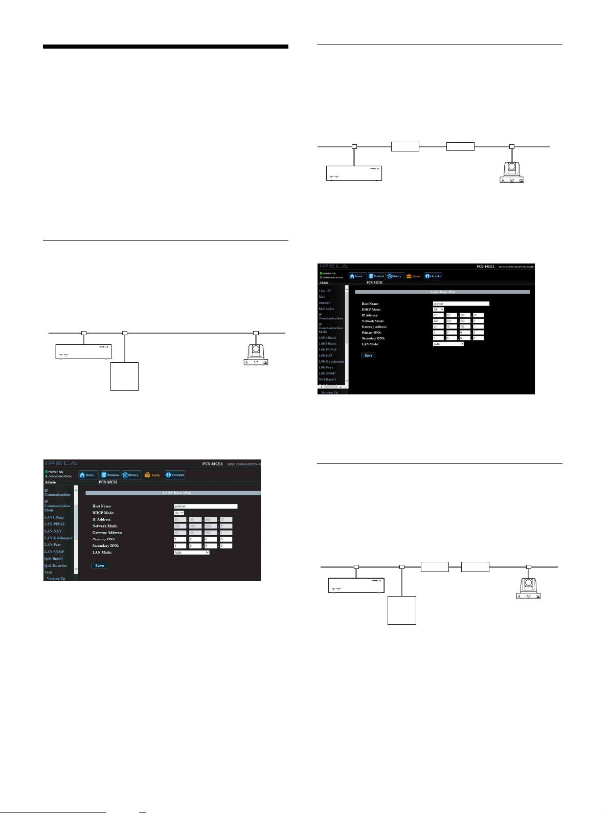
Network Configuration Setups
LAN Connection Using a Router
(LAN1/LAN2)
Configuration example
This section describes how to configure settings for
various network configurations.
For details on LAN settings, see “[LAN1: Basic] /
[LAN2: Basic] page” (page 29).
For details on settings, contact your network
administrator.
LAN Connection Using DHCP
(LAN1/LAN2)
Configuration example
LAN (B)LAN (A)
DHCP server 1
Set [DHCP Mode] to [On] on the [LAN: Basic] page of
the [Admin] screen.
LAN (A)
192.100.10.1
192.100.10.10
Virtual private network
(VPN)
RouterRouter
LAN (B)
192.100.20.1
192.100.20.20
Enter a name in [Host Name] on the [LAN: Basic] page
of the [Admin] screen, and enter the appropriate values
for [IP Address], [Network Mask], and [Gateway
Address].
The settings have been configured properly if the IP
address appears on the [Machine Information] page of the
[Information] screen.
When using DHCP, the IP address may change whenever
the unit is restarted.
To determine the unit’s IP address, save a configuration
file to a USB storage device and verify it on a computer.
For details on determining the unit’s IP address, see
“Verifying the Unit’s Settings” (page 42).
LAN Connection Using a
Gatekeeper (LAN1 Only)
Configuration example
LAN (A)
192.100.10.1
Router
192.100.10.10
User alias: PCS-A
User number: 100
Gatekeeper
192.100.10.20
1
Enter a name in [Host Name] on the [LAN: Basic]
Router
page of the [Admin] screen, and enter the appropriate
values for [IP Address], [Network Mask], and
[Gateway Address].
LAN (B)
192.100.20.1
192.100.20.20
User alias: PCS-B
User number: 200
37
Page 38

Configuration example
2
Set [Gatekeeper Mode] to [On] on the [LAN:
Gatekeeper] page of the [Admin] screen, and enter
the appropriate values for [Gatekeeper Address],
[User Alias], and [User Number]. If [Authentication]
is set to [On], enter the [Registered User Name] and
[Password] specified by the gatekeeper administrator.
192.100.10.1
192.100.10.10
1
Enter a name in [Host Name] on the [LAN: Basic]
page of the [Admin] screen, and enter the appropriate
values for [IP Address], [Network Mask], and
[Gateway Address].
210.10.10.1
Internet
210.20.20.1
RouterRouter
210.20.20.2
(global address)
You can verify the status of registration to the
gatekeeper on the [Peripheral Status] page of the
[Information] screen.
To connect
Enter the [User Alias] or [User Number] configured on
the terminal to which you want to connect, and call.
LAN Connection Using NAT (LAN1
Only)
Connection using NAT allows one IP address to be shared
by multiple computers on the same LAN. This section
describes how to configure settings for visual
communication in NAT and global IP environments.
2
Set [NAT Mode] to [On] on the [LAN: NAT] page of
the [Admin] screen, and enter the appropriate value
for [WAN IP Address].
The settings have been configured properly if the WAN
IP address appears on the [Machine Information] page of
the [Information] screen.
To connect
Enter the IP address of the terminal to which you want to
connect, and call.
Note
Note
When using the unit in a NAT environment, you can
connect to a terminal (global IP) from the unit, but to
connect to the unit from a terminal, router settings must
be configured. For details on router settings, contact your
network administrator.
When using the unit in a NAT environment, you can
connect to a terminal (global IP) from the unit, but to
connect to the unit from a terminal, router settings must
be configured. For details on router settings, contact your
network administrator.
38
Page 39
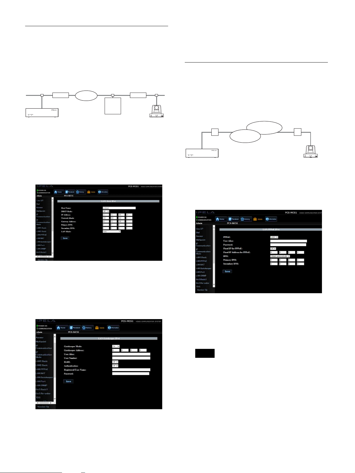
LAN Connection Using H.460
Firewall Traversal (LAN1 Only)
Using H.460 allows you to traverse firewalls and connect
to terminals on other networks.
Configuration example
192.100.10.1 192.200.20.1
Internet
RouterRouter
To connect
Enter the IP address of the terminal to which you want to
connect, and call.
LAN Connection Using PPPoE
(LAN1/LAN2)
Using PPPoE allows you to use your Internet service
provider’s services without using a router.
192.100.10.10
User alias: PCS-A
User number: 100
1
Enter a name in [Host Name] on the [LAN: Basic]
Traversal
server
210.20.20.10
(global address)
192.200.20.10
page of the [Admin] screen, and enter the appropriate
values for [IP Address], [Network Mask], and
[Gateway Address].
2
Set [H.460] to [On] on the [LAN: Gatekeeper] page
of the [Admin] screen. In addition, set [Gatekeeper
Mode] to [On], and enter the appropriate value for
[Gatekeeper Address]. If [Authentication] is set to
[On], enter the [Registered User Name] and
[Password] specified by the gatekeeper administrator.
Configuration example
Internet service
Local IP
ONU
210.10.10.10
1
Set [PPPoE] to [LAN1] or [LAN2] on the [LAN:
network
Internet
Internet service
ONU
211.10.10.10
PPPoE] page of the [Admin] screen, and enter the
information obtained from your provider in [User
Alias] and [Password].
2
If you obtained a fixed IP from your provider, set
[Fixed IP for PPPoE] to [On], and enter the obtained
IP address in [Fixed IP Address for PPPoE].
You can verify the status of registration to the
gatekeeper on the [Peripheral Status] page of the
[Information] screen.
You can verify the network status on the [Network
Routing Check] page of the [Information] screen.
Note
If a fixed DNS server address is specified by your
provider, set [DNS] to [Specify], and enter the
specified addresses in [Primary DNS] and
[Secondary DNS].
To connect
Enter the IP address of the terminal to which you want to
connect, and call.
39
Page 40
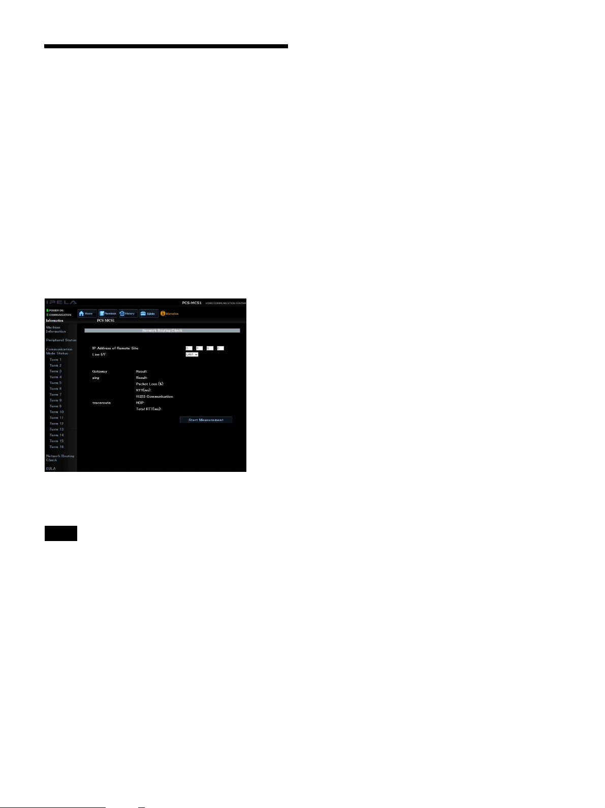
Network Routing Checks
Before connecting to a terminal, you can check the
network routing to ensure smooth communication.
Knowledge of the network is required to perform network
routing checks. For details, contact your network
administrator or Sony dealer.
For inquiries regarding check results, contact your
network administrator or Sony dealer.
To start a network routing check
Configure each setting on the [Network Routing Check]
page of the [Admin] screen.
Click [Start Measurement] to start the network routing
check.
For details on displaying the [Network Routing Check]
page, see “Displaying Device Information” (page 34).
Note
Other functions, including communication, will be
disabled while the network routing check is in progress.
When the routing check is complete, the check results are
displayed on the [Network Routing Check] page.
40
Page 41

Chapter 4: Maintenance
Adding Optional Software
1
Display the [Software Option] page of the [Admin]
screen.
2
Enter the software key of the optional software, and
click [Save Installation].
When the entered key is recognized key as valid, the
unit will restart automatically.
After the unit restarts, the name of the added optional
software will appear under the entry field. In addition,
the entered optional software key will be displayed as
asterisks (*).
Verifying Proper Installation of
Optional Software
Installed software is displayed under [Software Option]
on the [Machine Information] page of the [Information]
screen.
Note
If an invalid key is entered, the entry field will
become empty. Reenter the correct optional software
key.
For details optional software keys, contact your Sony
dealer.
Hint
For details, see “[Machine Information] Page”
(page 34).
• You can register up to eight optional software.
• Optional software installation will be retained, even
after updating the unit’s software version.
Note
Optional software keys cannot be deleted after they
are recognized by the unit.
4141
Page 42

Verifying the Unit’s Settings
Viewing or Editing Exported
Configuration Files
Note
Saving Configurations to USB
Storage Devices
If the unit’s IP address becomes unknown, for example,
you can save a portion of the configurations to a USB
storage device as a text file and verify settings.
The unit’s password cannot be saved. If you forget the
password, contact your Sony dealer. In such cases, the
unit must be initialized, so all phonebook contacts,
histories, and settings data stored on the unit will be lost.
Note
• The name of the file saved to the USB storage device is
“pcsinisetup.txt.” If an identically named file already
exists on the USB storage device, change its name
beforehand.
• Configurations cannot be saved to a USB storage
device under the following conditions.
– The unit is not turned on.
– There is a problem with the hardware.
– A conference is in progress.
– Firmware update for the unit is in progress.
– A USB storage device is not inserted in the USB port
on the rear panel.
1
Turn on the unit, and insert the USB storage device
into the USB port on the rear panel.
2
Press the utility button on the rear panel briefly one
time.
The POWER indicator and NETWORK indicator
rapidly blink green in unison, and the configuration
data is saved to the USB storage device as a text file.
Use WordPad to view or edit configuration files.
Configuration file contents
Setting item Representation of setting item
and sample value in
configuration file
Device name (firmware
version)
IP address (LAN1) :IP_ADDR = xxx.xxx.xxx.xxx
Subnet mask :NETMASK = xxx.xxx.xxx.xxx
Default gateway :GATEWAY = xxx.xxx.xxx.xxx
DHCP setting (on/off)
PPPoE setting
(on/off) 1)
Internet Protocol :IPV4V6 = IPv4
Host name :HOST_NAME = “pcshost”
Date and time :DATETIME = 2015-10-20
Time zone
NTP setting (on/off)
Primary NTP server :NTP_NAME1 = “xxx.xxx.xxx.xxx”
Secondary NTP server :NTP_NAME2 = “”
Terminal name :TERMINAL = “PCS-MCS1”
Communication bit rate
per point
1) “1” represents [On] and “0” represents [Off].
2) The PPPoE setting can be changed from [On] to [Off], but it cannot be
changed from [Off] to [On].
3) When changing the time zone setting, be sure to check the options for
[Time Zone] on the [General: Clock] page of the [Admin] screen, and
enter the exact character string of the option you want to use. However,
when changing the setting to Greenwich Mean Time (GMT), enter “Etc/
GMT.”
2)
3)
#PCS-MCS1 (00.00.0001)
1)
:DHCP = 1
:PPPOE = 0
20:11:28
:TIMEZONE = Asia/Tokyo
1)
:NTP_FLAG = 1
:BITRATE = xxxxx
To edit a configuration file
3
When the indicators switch to remaining steadily lit,
remove the USB storage device.
You can view the configuration file stored on the USB
storage device via a computer, and verify the settings.
You can also edit the contents of the configuration file on
the computer.
For details on loading configuration files, see “Loading
Configurations” (page 44).
1
Open the configuration file using WordPad.
2
Delete the colons (:) in front of the setting items you
want to change, edit the setting values (i.e., the
sections that follow the equals signs (=)), and save the
file.
Hint
When a configuration file is loaded on the unit, only the
settings items with their colons (:) removed will be
loaded.
42
Page 43

Updating the Unit’s Firmware
Updating the Firmware via a USB
Storage Device
Install an update file stored on a USB storage device onto
the unit.
1
Insert the USB storage device into the USB port on
the rear panel while the unit is turned off.
The [Admin] screen appears.
2
Click [Version Up] at the bottom of the menu on the
left side of the [Admin] screen.
2
Turn the unit on.
When then unit turns on, firmware update will start.
The POWER indicator and NETWORK indicator
alternate blinking slowly in orange while firmware
update is in progress.
When update is complete, the POWER indicator
lights green and the NETWORK indicator turns off or
blinks red, and the unit restarts automatically. Do not
turn off the unit until it finishes restarting.
Note
• When updating from a USB storage device, the
version of the update file stored on the device is
recognized by the unit. Update is only performed if
the version of the update file is newer than the
firmware currently installed on the unit. If you want
to install an older version of the firmware onto the
unit, do so from the web control screen.
• If you want to stop updating in the middle of an
update, press the power button once briefly.
Depending on timing, it sometimes cannot be
stopped.
The [Version Up] page appears.
3
Click [Browse], select the update file, and then click
[Upload].
A message appears after the file is uploaded, and
firmware update starts.
The POWER indicator and NETWORK indicator
alternate blinking slowly in orange while firmware
update is in progress.
When update is complete, the POWER indicator
lights green and the NETWORK indicator turns off or
blinks red, and the unit restarts automatically. Do not
turn off the unit until it finishes restarting.
Updating the Firmware via the Web
Control Screen
Install an update file stored on a computer or on the
network onto the unit.
1
Click the [Admin] button on the web control screen.
Note
You cannot click the [Admin] button when logged in
as a web access user (user name: pcsuser). To view or
configure settings, log in as the administrator (user
name: sonypcs).
4343
Page 44

Loading Configurations
You can load a configuration file that was previously
saved to a USB storage device onto the unit to change the
unit’s settings.
You can also edit the contents of the configuration file on
a computer before loading them onto the unit.
For details on saving configuration files to USB storage
devices, see “Saving Configurations to USB Storage
Devices” (page 42).
Note
• When loading configurations, make sure that the
version of the PCS-MCS1 from which the data was
originally saved is the same as the version of the current
unit. If the versions differ, the data may not be properly
recognized.
• The “pcsinisetup.txt” file stored in the USB storage
device’s root directory will be applied when loading
configurations. If the configuration file is stored in a
folder created on the USB storage device or saved
under a different name, the configurations cannot be
loaded.
1
Verify that the configuration file you want to load is
named “pcsinisetup.txt” and located in the root
directory of the USB storage device.
2
Turn on the unit, and insert the USB storage device
into the USB port on the rear panel.
3
Press the utility button on the rear panel for at least 4
seconds.
The configurations are loaded, and the POWER
indicator and NETWORK indicator alternate
blinking rapidly in green.
The unit will restart automatically when loading is
complete, and the unit’s setting configurations will be
overwritten with those stored on the USB storage
device.
Do not turn off the unit until it finishes restarting.
Hint
When a configuration file is loaded on the unit, only
the settings items with their colons (:) removed will
be loaded. Edit the configuration file beforehand, and
delete the colons (:) in front of the setting items you
want to load.
4
Remove the USB storage device after the unit
restarts.
44
Page 45

Chapter 5: Encrypted Connections
Preparing for Encrypted Connections
The unit allows connections with encrypted video and
audio for when a strictly confidential communication is
required. Such connections are called “encrypted
connections.”
The unit supports a standard encryption that complies
with the ITU-T H.235 standard.
Note
• The encryption function is not available in some
countries and regions.
• The maximum usable bandwidth for encrypted
connections is 12 Mbps.
To use an encrypted connection, set [Encryption] to
[Connect Priority] or [Encrypt Priority] on the
[Encryption] page of the [Admin] screen.
[Connect Priority] setting
Connect via an encrypted connection to terminals that
support standard encrypted connection. If a terminal does
not support standard encrypted connection or its
encryption function is disabled, connection will be
established without encryption.
Connect with encryption
Unit: Standard
encrypted connection
available
Terminal: Standard
encrypted connection
available
Connect without encryption
Unit: Standard
encrypted connection
available
Terminal: Standard
encrypted connection
unavailable
[Encrypt Priority] setting
Connect only to terminals that support standard encrypted
connection.
Connect with encryption
Unit: Standard
encrypted connection
available
Do not connect
Unit: Standard
encrypted connection
available
Terminal: Standard
encrypted connection
available
Terminal: Standard
encrypted connection
unavailable
45
Page 46

Starting Encrypted Connections
You can start an encrypted connection by calling a
terminal as you would with a standard connection.
During an encrypted connection, the encryption icon
( ) is displayed on the [Home] screen.
Note
If there is no icon displayed, data transmission and
reception are not encrypted. Confirm that the icon is
displayed before starting a conference.
46
Page 47

Appendix
12345 6 7
8
Status POWER
A problem with
the network
exists.
Indicator
–
NETWORK
Indicator
Remark
Parts Identification
Front Panel
12
A POWER indicator
Indicates the power status.
B NETWORK indicator
Indicates the network connection status.
Indicator statuses
Status POWER
Indicator
The unit is
turned off.
NETWORK
Indicator
Remark
A problem with
the unit’s
hardware
exists.
The unit’s
configurations
are being
saved to a
USB storage
device.
The unit’s
configurations
are being
loaded from a
USB storage
device.
The unit’s
firmware is
being updated.
: Off : Lit : Blinking
Rear Panel
–
Indicators
blink rapidly
in unison.
Indicators
alternate in
blinking
rapidly.
Indicators
alternate in
blinking
slowly.
The unit is
starting up.
The unit is
shutting down.
The unit is
turned on (not
connected to
network).
Initial setup is
not complete.
The IP address
is being
obtained.
The unit is
turned on
(conferencing
is possible).
Conference is
in progress.
The unit
cannot be
operated.
Complete
initial setup.
Indicators
alternate in
blinking
slowly.
A 1 (LAN1) connector (1000BASE-T/
100BASETX/10BASE-T, 8-pin modular)
Connects to a local network.
Under normal circumstances, use this connector for
network connections.
B 2 (LAN2) connector (1000BASE-T/
100BASETX/10BASE-T, 8-pin modular)
Connects to a global network.
When you use this connector for network
connections, some functions, such as login from the
computer, will be restricted.
4747
Page 48

CAUTION
For safety, do not connect the connector for
peripheral device wiring that might have excessive
voltage to the following ports.
: (LAN) 1 connector
: (LAN) 2 connector
Follow the instructions for the above ports.
C MAINTENANCE connector (USB mini-B)
Used for maintenance.
Allows external control and log acquisition.
D (USB) port (Type-A)
Allows you to save settings to a connected USB
storage device, for example.
E Utility button
Allows you to export settings.
F Power button
Turns the unit on/off.
G DC 12V jack
Connects to the supplied AC adapter.
H Kensington security slot
Connects to a Kensington anti-theft security lock.
48
Page 49

Troubleshooting
If the unit does not operate properly, check the following.
Symptom Cause Solution
The unit does not turn on.
(Blinking of the POWER indicator
on the front panel of the unit does
not start.)
The unit cannot be accessed from
a web browser.
The unit does not connect to
videoconferencing terminals.
Configurations cannot be saved
or loaded using a USB storage
device.
Configurations cannot be saved to
a USB storage device.
The supplied AC adapter is not connected
properly.
The power button was not pressed. Press the power button briefly (less than
The LAN cable is not connected properly. Connect the cable properly.
The LAN cable is damaged. Replace the cable.
The IP address you entered is incorrect. Save a configuration file to a USB storage
The IP address and network mask settings
are incorrect.
The wrong number was called. Check the entered number again.
The information registered in the phonebook
is incorrect.
There is a problem on the terminal to which
you want to connect.
The terminal to which you want to connect is
not turned on.
The terminal to which you want to connect is
busy (i.e., communication with another
terminal is in progress).
Answering calls is not permitted on the
terminal to which you want to connect due to
operations being performed on the terminal
(e.g., settings configuration).
Auto answer mode is not enabled on the
terminal to which you want to connect.
The terminal to which you want to connect is
set to reject calls.
There is a problem on the USB storage
device.
A format error occurred on the USB storage
device.
The utility button operation was not
performed properly.
The remaining capacity on the USB storage
device is insufficient.
Connect the supplied AC adapter properly.
1 second) one time to turn on the unit
(page 9).
device, and check the IP address (page 42).
Contact your network administrator, and
configure the correct settings.
See “Registering Contacts to the
Phonebook” (page 22), and register the
information properly.
Try connecting to a different terminal as a
test.
Ask the terminal’s administrator to turn on
the terminal.
Call the terminal again after its current
communication has ended.
Ask the terminal’s administrator to accept
calls on the terminal.
Ask the terminal’s administrator to enable
auto answer mode on the terminal or answer
the call manually.
Ask the terminal’s administrator to change
the call rejection settings.
Use a computer to check whether saving
and loading with the USB storage device is
possible.
Check whether saving and loading is
possible with a different USB storage device.
Reformat the USB storage device.
Note
When you format a USB storage device, all
data stored on the device will be deleted. Be
sure to copy important data to a different
location beforehand.
Insert the USB storage device into the USB
port on the rear panel of the unit, and press
the utility button briefly (less than 1 second)
one time.
Use a different USB storage device.
4949
Page 50

Symptom Cause Solution
Configurations cannot be loaded
from a USB storage device.
The name of the configuration file is
incorrect.
The format of the configuration file’s content
is incorrect.
Check that the name of the file you want to
load is “pcsinisetup.txt.”
Backup the configuration file
(pcsinisetup.txt), save another configuration
file to a USB storage device, and compare
the content of the target configuration file to
that of the new file to check whether it is
formatted correctly (page 44).
The configuration file is not stored in the
correct location on the USB storage device.
Check that the configuration file
(pcsinisetup.txt) is stored in the root
directory of the USB storage device.
The utility button operation was not
performed properly.
Check that the configuration file
(pcsinisetup.txt) is stored in the correct
location, insert the USB storage device into
the USB port on the rear panel of the unit,
and press the utility button for at least 4
seconds.
50
Page 51

Specifications
PCS-MCS1 HD MCU System
This unit complies with ITU-T Recommendation H.323.
Video
Operating bandwidth
64 Kbps to 16 Mbps (standard, LAN connection)
Coding
H.263/H.263+/H.263++/H.264 Baseline Profile/
H.264 High Profile
Picture elements
CIF: 352 pixels × 288 lines
QCIF: 176 pixels × 144 lines
4CIF: 704 pixels × 576 lines
WCIF (W288p): 512 pixels × 288 lines
W432p: 768 pixels × 432 lines
W4CIF: 1024 pixels × 576 lines
720p: 1280 pixels × 720 lines
1080p: 1920 pixels × 1080 lines
Audio
Transfer rate
56 Kbps, 64 Kbps (compliant with G.711 ITU-T
Recommendation)
48 Kbps, 56 Kbps, 64 Kbps (compliant with
G.722 ITU-T Recommendation)
64 Kbps, 96 Kbps (MPEG4 AAC) (LAN connection)
16 Kbps (compliant with G.728 ITU-T
Recommendation)
Network
Interface
LAN (standard), 64 Kbps to 16 Mbps
Supported LAN protocols
HTTP
Tel net
RTP/RTCP
TCP/UDP
SNMP
SSH
General
Power requirement
12 V DC
Current consumption
3 A
Operating temperature
5 °C to 35 °C (41 °F to 95 °F)
Operating humidity
20% to 80% (non-condensing)
Storage temperature
–20 °C to +60 °C (–4 °F to +140 °F)
Storage humidity
20% to 80% (non-condensing)
Dimensions
170 × 46 × 125 mm (6
(excluding protrusions except feet)
Mass
Approx. 0.7 kg (1 lb. 8.7 oz.)
Supplied accessories
AC adapter (1)
Power cord (1) (Japan and China only)
CD-ROM (1)
Before Using this Unit (1)
Quick Reference Guide (1)
B&P warranty booklet (1)
User registration form (1) (Japan only)
3
/4 × 1 13/16 × 5 in.) (W×H×D)
AC Adapter (Supplied)
Power supply
100 V to 240 V AC, 50 Hz/60 Hz, 0.75 A to 0.4 A
Output
12 V DC, 3.0 A
Operating temperature
–5 °C to +45 °C (23 °F to 113 °F)
Operating humidity
25% to 95% RH
Storage temperature
–20 °C to +65 °C (–4 °F to +149 °F)
Storage humidity
5% to 95% RH (non-condensing)
Dimensions
102.5 × 32 × 51.7 mm (4
(W×H×D) (excluding protrusions)
Mass
Approx. 190 g (6.7 oz.)
1
/8 × 1 5/16 × 2 1/8 in.)
Remote control
Remote camera control
H.281 (compliant with ITU-T Recommendation)
5151
Page 52

PCSA-MPE1 HD Port Expansion
Software (Optional)
PCSA-MPE2 HD Port Expansion
Software (Optional)
PCSA-MSA1 Mobile Access
Software (Optional)
Design and specifications are subject to change without
notice.
Sales and distribution of MPEG-4 Visual
encoders/decoders
THIS PRODUCT IS LICENSED UNDER THE
MPEG-4 VISUAL PATENT PORTFOLIO LICENSE
FOR THE PERSONAL AND NON-COMMERCIAL
USE OF A CONSUMER FOR
(i) ENCODING VIDEO IN COMPLIANCE WITH
THE MPEG-4 VISUAL STANDARD (“MPEG-4
VIDEO”)
AND/OR
(ii)DECODING MPEG-4 VIDEO THAT WAS
ENCODED BY A CONSUMER ENGAGED IN A
PERSONAL AND NON-COMMERCIAL
ACTIVITY AND/OR WAS OBTAINED FROM A
VIDEO PROVIDER LICENSED BY MPEG LA
TO PROVIDE MPEG-4 VIDEO.
Notes
• Always make a test recording, and verify that it was
recorded successfully.
SONY WILL NOT BE LIABLE FOR DAMAGES
OF ANY KIND INCLUDING, BUT NOT LIMITED
TO, COMPENSATION OR REIMBURSEMENT
ON ACCOUNT OF FAILURE OF THIS UNIT OR
ITS RECORDING MEDIA, EXTERNAL
STORAGE SYSTEMS OR ANY OTHER MEDIA
OR STORAGE SYSTEMS TO RECORD
CONTENT OF ANY TYPE.
• Always verify that the unit is operating properly
before use. SONY WILL NOT BE LIABLE FOR
DAMAGES OF ANY KIND INCLUDING, BUT
NOT LIMITED TO, COMPENSATION OR
REIMBURSEMENT ON ACCOUNT OF THE
LOSS OF PRESENT OR PROSPECTIVE PROFITS
DUE TO FAILURE OF THIS UNIT, EITHER
DURING THE WARRANTY PERIOD OR AFTER
EXPIRATION OF THE WARRANTY, OR FOR
ANY OTHER REASON WHATSOEVER.
• SONY WILL NOT BE LIABLE FOR CLAIMS OF
ANY KIND MADE BY USERS OF THIS UNIT OR
MADE BY THIRD PARTIES.
• SONY WILL NOT BE LIABLE FOR THE LOSS,
REPAIR, OR REPRODUCTION OF ANY DATA
RECORDED ON THE INTERNAL STORAGE
SYSTEM, RECORDING MEDIA, EXTERNAL
STORAGE SYSTEMS OR ANY OTHER MEDIA
OR STORAGE SYSTEMS.
• SONY WILL NOT BE LIABLE FOR THE
TERMINATION OR DISCONTINUATION OF
ANY SERVICES RELATED TO THIS UNIT
THAT MAY RESULT DUE TO
CIRCUMSTANCES OF ANY KIND.
NO LICENSE IS GRANTED OR SHALL BE
IMPLIED FOR ANY OTHER USE. ADDITIONAL
INFORMATION INCLUDING THAT RELATING
TO PROMOTIONAL, INTERNAL AND
COMMERCIAL USES AND LICENSING MAY BE
OBTAINED FROM MPEG LA, LLC. SEE
HTTP://WWW.MPEGLA.COM
MPEG LA is offering licenses for
(i) manufacturing/sales of any storage media storing
MPEG-4 Visual video information
(ii)distribution/broadcasting of MPEG-4 Visual video
information in any manner (such as online video
distribution service, internet broadcasting, TV
broadcasting).
Other usage of this product may be required to obtain
license from MPEG LA.
Please contact MPEG LA for any further information.
MPEG LA, L.L.C., 250 STEELE STREET, SUITE
300, DENVER, COLORADO 80206, http://
www.mpegla.co
Sales and distribution of MPEG-4 AVC (3-1)
encoders/decoders
THIS PRODUCT IS LICENSED UNDER THE AVC
PATENT PORTFOLIO LICENSE FOR THE
PERSONAL AND NON-COMMERCIAL USE OF A
CONSUMER TO
(i) ENCODE VIDEO IN COMPLIANCE WITH THE
AVC STANDARD (“AVC VIDEO”)
AND/OR
(ii)DECODE AVC VIDEO THAT WAS ENCODED
BY A CONSUMER ENGAGED IN A PERSONAL
AND
52
Page 53

NON-COMMERCIAL ACTIVITY AND/OR WAS
OBTAINED FROM A VIDEO PROVIDER
LICENSED TO PROVIDE AVC VIDEO. NO
LICENSE IS GRANTED OR SHALL BE IMPLIED
FOR ANY OTHER USE. ADDITIONAL
INFORMATION MAY BE OBTAINED FROM
MPEG LA, L.L.C. SEE HTTP://MPEGLA.COM
Pin Assignments
1000BASE-T/100BASE-TX/10BASE-T
connector
18
Modular connector
Pin 10BASE-T/100BASE-TX 1000BASE-T
1TD+ TP0+
2TD– TP0–
3 RD+ TP1+
4– TP2+
5– TP2–
6 RD– TP1–
7– TP3+
8– TP3–
Ports Used on the PCS-MCS1
Function Port number Type
RAS 1719 UDP
Gatekeeper
Discovery
Q.931 (call) 2253-2285 TCP
Q.931 (answer) 1720 TCP
H.245 2253-2285 TCP
Audio RTP 49152-49452 UDP
Audio RTCP 49153-49453 UDP
Video RTP 49154-49454 UDP
Video RTCP 49155-49455 UDP
FECC RTP 49156-49456 UDP
FECC RTCP 49157-49457 UDP
2nd Video RTP 49158-49458 UDP
2nd Video RTCP 49159-49459 UDP
Auto Bandwidth
Detection
Note
The port numbers that can be set for RTCP are 49152 to
65535.
224.0.1.41:1718 UDP Multicast
51234 UDP/TCP
Other ports
Signal Port number Type
Telnet
SSH 22 TCP
Web 80 TCP
DHCP 68 UDP
NTP 123 UDP
SNMP 161 UDP
AMX Device
Discovery
23 TCP
50000 TCP
239.255.250.250:9131 UDP Multicast
5353
Page 54

USB Storage
Glossary
Use USB storage devices that support USB2.0 with this
unit. We recommend using the Sony USM32GR
“POCKET BIT.”
Connection
Connect the device directly to the USB port on the unit.
Access indicator
Off: Standby
Lit: Data transfer in progress
Removal
Always make sure that the POCKET BIT is in standby
mode (i.e., the indicator is off) before removing it.
Usage precautions
• Do not apply excessive force on the POCKET BIT
while it is connected to a device. Damage to the USB
connector may result in malfunction of the POCKET
BIT as well as the connected device.
• Be aware that the surface of this product may become
hot after extended periods of access or use.
• If the connected device is started or restarted while the
POCKET BIT is connected, the POCKET BIT may not
function properly. Remove the POCKET BIT before
performing such operations.
• We recommend creating backups of important data.
SONY WILL NOT BE LIABLE FOR DAMAGES
OF ANY KIND INCLUDING, BUT NOT LIMITED
TO, COMPENSATION OR REIMBURSEMENT
FOR LOSS OF RECORDED DATA ON
ACCOUNT OF FAILURE OF THIS UNIT OR ITS
SOFTWARE.
POCKET BIT is a trademark of Sony Corporation.
ARC
An abbreviation for adaptive rate control, a technology
that automatically lowers the video bit rate during
network congestion.
ARQ
An abbreviation for automatic repeat request, an error
control method in which the receiver requests
retransmission from the transmitter when a packet loss
occurs.
Auto Bandwidth Detection
A function that detects the network bandwidth before
communication. Using this detected value with the QoS
functions allows optimum QoS control from the
beginning of the communication.
Codec
An abbreviation for coder-decoder, an integrated device
or program that includes a coder that converts an analog
audio/video signal to a digital data stream and compresses
it, and a decoder that decompresses the digital signal to its
original analog state.
DHCP
An abbreviation for Dynamic Host Configuration
Protocol, a protocol for managing IP addresses on
networks.
DNS
An abbreviation for Domain Name System, a naming
system utilizing domain names.
FEC
An abbreviation for forward error correction, an error
control method in which the receiver can correct errors
without requesting retransmission from the transmitter.
Frame rate
The number of frames that can be encoded/decoded in
one second.
G.711
An ITU-T audio codec recommendation. This codec
converts a telephone audio bandwidth signal to a digital
signal with a data rate of 64 Kbps. The signal is also
transferred at 56 Kbps in some cases.
G.722
An ITU-T audio codec recommendation. This codec
converts audio with a bandwidth of 7 kHz to a digital
signal with a data rate of 48 Kbps, 56 Kbps, or 64 Kbps.
54
Page 55

G.728
An ITU-T audio codec recommendation. This codec
converts a telephone audio bandwidth signal to a digital
signal with a data rate of 16 Kbps.
QoS
An abbreviation for quality of service which reserves a
bandwidth for specific communications on a network to
guarantee a steady communication speed.
Gatekeeper
A device that controls access to H.323 visual
communication on networks. This allows zone
administration, access and bandwidth restriction, and the
use of aliases and other functions.
H.239
An ITU-T recommendation that supports the dual video
function (presentation mode). This allows simultaneous
reception and transmission of camera images and
computer data.
H.263
A video coding algorithm based on the H.261 standard
that allows communication via a lower bit rate.
H.263+
A video codec based on the H.263 standard that adds
Annex I to T (I, J, K...T) with the purpose of enhancing
picture quality and error tolerance. Normally, this format
is a profile used in combination with some of the Annexes
for H.263/H.263+.
H.264
A video coding algorithm standardized by the ITU-T in
May 2003.
This format achieves high picture quality via lower bit
rates, providing a picture quality equal to that of the
H.263 standard while using about half the bit rate. It has
also been standardized by the ISO as MPEG-4 Part 10,
Advanced Video Coding (AVC).
SNMP
An abbreviation for Simple Network Management
Protocol, a protocol for sharing information between the
management station and managed terminals. This
protocol allows monitoring of Sony communication
systems.
ToS
An abbreviation for type of service, a field in an IP
header. Inclusion of the ToS information allows a
communication device to determine the appropriate
packet transmission priority, etc.
It also allows for the changing of paths based on the type
of service (delay, size, etc.).
H.323
A standard that allows communication via a LAN on
which QoS is not guaranteed.
HD
An abbreviation for high definition that denotes high
resolution and high picture quality for televisions and
other displays. The 1080i, 1080p, and 720p formats
correspond to this standard.
Hop count
The number of routers that are passed through to reach the
remote party.
ITU-T
An abbreviation for the International Telecommunication
Union’s Telecommunication Standardization Sector.
MCU
An abbreviation for multipoint control unit, a device
through which multipoint communication between
connected multipoint terminals is made possible.
5555
Page 56

Menu Configuration
The unit’s menus are configured as follows. For detailed information, see the pages in parentheses. The initial settings of
each item are bolded.
Home Phone Book Phone Book List
(page 16)
New/Edit Index, Number of Connected Sites,
Communication Bit Rate, Dial to:
Connect
(page 22)
History Dial, Answer, Missed Call, Unknown Call
Admin Line I/F A
Dial B
Answer C
Multipoint
IP Communication E
LAN F
QoS G
TOS H
General I
Access J
Etc K
Phonebook L
Password M
Maintenance N
Encryption O
Software Option P
Version Up
information Machine Information
Peripheral Status
Communication Mode Status
Network Routing Check
EULA
Connect All
Disconnect All
Communication Bit Rate
Layout Broadcast Mode Split Screen, Voice Activate, Voice Activate(1080P)
Split Automatic, Full window, 3 split windows,
4 split windows, 6 split windows, 9 split windows,
10 split windows, 13 split windows, 16 split windows
(page 19)
(page 27)
(page 26)
D
Select (Full window/6 split/13 split)
Select (10 split: Left)
Select (10 split: Right)
Connect
Disconnect
56
Page 57

A Line I/F Use LAN2 Off, On
(page 27)
B Dial Select LAN Prefix Disable, Enable
(page 27)
C Answer Ad hoc On, Off
(page 28)
LAN Prefix
Auto Answer On, Off
Reject Answer On, Off
Reject Unknown Call Off, LAN1, LAN2, LAN1+LAN2
D Multipoint Broadcast Mode Split Screen, Voice Activate, Voice Activate (1080P)
(page 28)
Split Automatic, Full window, 3 split windows, 4 split windows,
6 split windows, 9 split windows, 10 split windows,
13 split windows, 16 split windows
Voice Activation Frame On, Off
E
IP Communication IP Communication
(page 28)
Transmission/Reception
Individual Settings for Off, On
IP Communication
Total Bandwidth2) 16384Kbps
Mode1) Communication Bit Rate2) 3) 2048Kbps
Audio Mode
3)
G.711, G.722, G.728,
MPEG4
Far End Camera Control On, Off
H.239 On, Off
H.239 Ratio 2/3, 1/2, 1/3
Screen Size
3)
1080, 720, W4CIF,
W432P, WCIF, 4CIF,
CIF, QCIF, AUTO
Video Mode
Video Frame
3)
H.263+, H.264
3)
15fps, 30fps, AUTO
1) The number of pages available after the [IP Communication Mode] page varies depending on whether [Individual Settings for
Transmission/Reception] is set to [On] or [Off].
2) You can enter a value between 64 Kbps to 16384 Kbps.
3) When [Individual Settings for Transmission/Reception] is set to [On] on the [IP Communication] page, settings can be configured
individually for transmission and reception.
5757
Page 58

F LAN Basic
(page 29)
1)
Host Name
(LAN) DHCP Mode On, Off
IP Address
Network Mask
Gateway Address
Primary DNS
Secondary DNS
LAN Mode Auto, 1000Mbps, 100Mbps Full Duplex,
100Mbps Half Duplex,
10Mbps Full Duplex,
10Mbps Half Duplex
PPPoE PPPoE Off, LAN1, LAN2
(LAN) User Alias
Password
Fixed IP for PPPoE Off, On
Fixed IP Address for PPPoE
DNS Obtain automatically, Specify
Primary DNS
Secondary DNS
NAT NAT Mode Auto, On, Off
(LAN) WAN IP Address
Gatekeeper Gatekeeper Mode Auto, On, Off
(LAN) Gatekeeper Address
User Alias
User Number
H.460 On, Off
Authentication On, Off
Registered User Name
Password
Port Q.931
(LAN)
H.245
RTP/RTCP
MTU Size
SNMP SNMP Mode On, Off
(LAN) Trap Destination
Community
Description
Location
Contact
1) When [Use LAN2] is set to [On] on the [Line I/F] page, the [Basic] pages for LAN1 and LAN2 are displayed, allowing you to
configure the settings.
G
QoS
(page 31)
Basic
Adaptive Rate Control (ARC) On, Off
(QoS1) Auto Bandwidth Detection On, Off
TCP Port Number
UDP Port Number
Packet Resend Request(ARQ) On, Off
ARQ Buffering Time 300ms, 150ms, 80ms, Auto, Custom
ARQ Buffering Time (Custom)
Forward Error Correction(FEC) On, Off, Auto
FEC Redundancy 8, 4, 2, Auto
Audio Duplex Transmission On, Off
Re-Order
Re-Order On, Off
(QoS2) Re-Order Buffer Auto, 1, 2, Custom
Re-Order Buffer Rate
Shaping On, Off
58
Page 59

H TOS TOS Data Type Video, Audio, Data, Presentation
(page 31)
TOS
Off, IP Precedence, DSCP
Precedence
Low Delay
High Throughput
High Reliability
Minimum Cost
On, Off
On, Off
On, Off
On, Off
DSCP
I
General Device Terminal Name
(page 32)
(General1) Language
Japanese
, English, Simplified Chinese
Clock NTP On, Off
(General2) Primary NTP Server
Secondary NTP Server
Time Zone
Clock Display Pattern Year/Month/Day, Month/Day/Year,
Day/Month/Year, Year-Month-Day,
Day.Month.Year
Date
Time
Time Update Execute
J
Access Telnet Access Enabled, Disabled
(page 32)
SSH Access Enabled, Disabled
Referrer Check
K
Etc Use History On, Off
(page 32)
AMX Device Discovery Off, On
HOP
Auto Restore On, Off
Internet Protocol IPv4
L
Phonebook Save Phone Book Execute
(page 33)
Load Phone Book Execute
Clear Phone Book Execute
M
Password sonypcs Password
(page 33)
Password (confirmation)
pcsuser Password
Password (confirmation)
N
Maintenance Day
(page 33)
O
Encryption Encryption Off, Connect Priority, Encrypt Priority
(page 33)
Time
5959
Page 60

P Software Option Software Option 1
(page 33)
Software Option 2
Software Option 3
Software Option 4
Software Option 5
Software Option 6
Software Option 7
Software Option 8
60
Page 61

Index
A
[Access] page 32
[Ad Hoc] 28
Ad hoc mode 8, 18
[Adaptive Rate Control] 31
[Admin] button 16
Administrator 15
[AMX Device Discovery] 32
[Answer] page 28
Answering 21
[ARQ Buffering Time] 31
[ARQ Buffering Time (Custom)] 31
[Audio Duplex Transmission] 31
[Audio Mode] 29, 34
[Authentication] 30
[Auto Answer] 28
Auto answer mode 21
[Auto Bandwidth Detection] 31
[Auto Restore] 32
B
Basic connection methods 18
[Bit rate - Decode] 35
[Bit rate - Encode] 35
Broadcast modes 24, 28
C
Call histories 19
[Check Code] 35
[Clear Phone Book] 33
[Clock Display Pattern] 32
[Communication Bit Rate] 23, 29
[Communication Mode Status] page
34
[Community] 30
[Connect Priority] 45
Connection 21
[Contact] 31
D
[Date] 32
[Day] 33
[Description] 30
Device status 34
Device status menu 34
DHCP 37
[DHCP Mode] 29
[Dial] page 27
[Dial to] 23
[DNS] 30
[DSCP] 31
E
[Encrypt Priority] 45
Encrypted connections 5, 45, 46
[Encryption] 33, 45
[Encryption] page 33
[EULA] page 35
F
[Far End Camera Control] 29, 35
[Far End Terminal Name] 34
[FEC Redundancy] 31
Firewalls 39
[Fixed IP Address for PPPoE] 30
[Fixed IP for PPPoE] 30
[Forward Error Correction] 31
[Frame Rate] 35
G
[Gatekeeper] 34
[Gatekeeper Address] 30
[Gatekeeper Mode] 30
Gatekeepers 37
[Gateway] 35
[Gateway Address] 13, 29
[General: Clock] page 32
[General: Device] page 32
H
[H.239] 29, 35
[H.239 Ratio] 29
[H.245] 30
H.460 39
[H.460] 30
[High Reliability] 31
[High Throughput] 31
[History] button 16
[Home] button 16
[HOP] 32
[Host Name] 29, 34
[Host Version] 34
I
[Index] 22
[Individual Settings for Transmission/
Reception] 28
[Information] button 17
Initial setup wizard 12
[Internet Protocol] 32
[IP Address] 29, 34
[IP Address (LAN2)] 34
[IP Address of Remote Site] 35
[IP Communication Mode] page 28
[IP Communication] page 28
L
[LAN: Gatekeeper] page 30
[LAN: NAT] page 30
[LAN: Port] page 30
[LAN: SNMP] page 30
LAN connection using a gatekeeper
37
LAN connection using a router 37
LAN connection using DHCP 37
LAN connection using H.460 firewall
traversal 39
LAN connection using NAT 38
LAN connection using PPPoE 39
[LAN Mode] 30
[LAN Mode (LAN1)] 34
[LAN Mode (LAN2)] 34
LAN2 36
[Language] 32
[Line I/F] 35
[Line I/F] page 27
Line interface settings 27
[Load Phone Book] 33
[Location] 31
[Low Delay] 31
M
[MAC Address] 34
[MAC Address (LAN2)] 34
[Machine Information] page 34
[Machine Version] 34
[Maintenance] page 33
Manual answer mode 21
Menu configuration 56
Menus 56
[Minimum Cost] 31
[MTU Size] 30
[Multipoint] page 28
N
NAT 38
[NAT Mode] 30
[Network Mask] 13, 29
[Network Routing Check] page 35
Network routing checks 40
[NTP] 32
[Number of Connected Sites] 22
[Number of lost packets] 35
[Number of received packets] 35
[Number of recovered packets] 35
O
Option I/F 34
Optional software 41
61
Page 62

P
[Packet Resend Request] 31
[Password] 30
Password 33
Password (confirmation) 33
[Password] page 33
PCSA-MPE1 6
PCSA-MPE2 6
PCSA-MSA1 6, 7
pcsuser 15, 17, 33
[Peripheral Status] page 34
Phonebook 20, 22, 23
[Phonebook] button 16
[Phonebook] page 33
Picture control 24
Power supply 9
PPPoE 39
[PPPoE] 30
[Precedence] 31
[Primary DNS] 29, 30
[Primary NTP Server] 32
Q
[Q.931] 30
QoS 5
R
[Rate] 35
[Registered User Name] 30
[Reject Answer] 28
[Reject Unknown Call] 28
[Remote Address] 34
[Re-Order] 31
[Re-Order Buffer] 31
[Re-Order Buffer Rate] 31
Restrictions when using LAN2 36
Router 37
[RTP/RTCP] 30
[Start Measurement] 35
System configuration examples 7
T
[TCP Port Number] 31
Telnet 23
[Telnet Access] 32
[Terminal Name] 32
[Time] 32, 33
[Time Update] 32
[Time Zone] 32
[TOS] 31
[TOS Data Type] 31
[TOS] page 31
[Total Bandwidth] 28
[traceroute] 35
[Trap Destination] 30
Traversal servers 39
U
[UDP Port Number] 31
USB storage 54
[Use History] 32
[Use LAN2] 27
[User Alias] 30
[User Number] 30
V
[Video Frame] 29
[Video Mode] 29, 34
[Voice Activation Frame] 28
Voice-activate mode 25
W
[WAN IP Address] 30
Web access user 15
Web control mode 7, 18
Web control screen 16
S
[Save Phone Book] 33
[Screen Size] 29
[Secondary DNS] 29, 30
[Secondary NTP Server] 32
[Select LAN Prefix] 27
[Serial Number] 34
Setting menus 27
[Shaping] 31
[SNMP Mode] 30
[Software Option] 34
[Software Option] page 33
sonypcs 13, 15, 16, 17, 33
[Split] 28
Split-screen mode 24
[SSH Access] 32
62
Page 63

 Loading...