

Page 1

3-863-237-11 (1)
Video
Communication
System
Operating Instructions
Before operating the unit, please read this manual thoroughly and retain it for
future reference.
PCS-G70/G70P
© 2004 Sony Corporation
Page 2

Owner’s Record
The model and the serial numbers are
located at the bottom. Record the serial
number in the space provided below. Refer
to these numbers whenever you call upon
your Sony dealer regarding this product.
Model No. PCS-G70/G70P
Serial No. ______________
WARNING
To prevent fire or shock hazard, do
not expose the unit to rain or
moisture.
To avoid electrical shock, do not
open the cabinet. Refer servicing to
qualified personnel only.
WARNING
This unit has no power switch.
When installing the unit, incorporate a
readily accessible disconnect device in the
fixed wiring, or connect the power cord to
socket-outlet which must be provided near
the unit and easily accessible.
If a fault should occur during operation of
the unit, operate the disconnect device to
switch the power supply off, or disconnect
the power cord.
DISPOSE OF USED BATTERIES
ACCORDING TO THE INSTRUCTIONS.
For the customers in the USA
WARNING
Using this unit at a voltage other than 120 V
may require the use of a different line cord or
attachment plug, or both. To reduce the risk
of fire or electric shock, refer servicing to
qualified service personnel.
This device complies with Part 15 of the
FCC Rules.
Operation is subject to the following two
conditions: (1) This device may not cause
harmful interference, and (2) this device
must accept any interference received,
including interference that may cause
undesired operation.
This equipment has been tested and found to
comply with the limits for a Class A digital
device, pursuant to Part 15 of the FCC
Rules. These limits are designed to provide
reasonable protection against harmful
interference when the equipment is operated
in a commercial environment. This
equipment generates, uses and can radiate
radio frequency energy and, if not installed
and used in accordance with the instruction
manual, may cause harmful interference to
radio communications. Operation of this
equipment in a residential area is likely to
cause harmful interference in which case the
user will be required to correct the
interference at his own expense.
CAUTION for LAN port
For safety reasons, do not connect the LAN
port to any network devices that might have
excessive voltage.
Installing batteries
Two R03 (size AAA) batteries are supplied
for Remote Commander.
To avoid risk of explosion, use R03 (size
AAA) manganese or alkaline batteries.
CAUTION
RISK OF EXPLOSION IF BATTERY IS
REPLACED BY AN INCORRECT TYPE.
2
You are cautioned that any changes or
modifications not expressly approved in this
manual could void your authority to operate
this equipment.
The shielded interface cable recommended
in this manual must be used with this
equipment in order to comply with the limits
for a computing device pursuant to Subpart
B of Part 15 of FCC Rules.
Page 3

This manual focuses on using ISDN lines
to conduct a videoconference, but it also
covers non-ISDN lines. If you use ISDN
lines, consult your Sony dealer for more
information.
• The ISDN service may not be available
in some areas.
Voor de klanten in Nederland
Dit apparaat bevat een vast ingebouwde
batterij die niet vervangen hoeft te worden
tijdens de levensduur van het apparaat.
Raadpleeg uw leverancier indien de batterij
toch vervangen moet worden.
De batterij mag alleen vervangen worden
door vakbekwaam servicepersoneel.
Gooi de batterij niet weg maar lever deze in
als klein chemisch afval (KCA).
Lever het apparaat aan het einde van de
levensduur in voor recycling, de batterij zal
dan op correcte wijze verwerkt worden.
If you dispose the unit, consult your nearest
Sony Service Center. The built-in battery
must be treated as a chemical waste.
For the customers in Canada
This Class A digital apparatus complies with
Canadian ICES-003.
3
Page 4

Table of Contents
Chapter 1: Installation and
Preparation
Using This Manual .............................8
Features .............................................. 9
System Components ........................11
Basic System Components ......... 11
Optional Equipment ................... 12
System Configuration ......................15
System Configuration via a
LAN ................................15
System Configuration via an
ISDN ...............................16
System Configuration via a LAN for
Multipoint Conference .... 17
System Configuration via an ISDN
for Multipoint
Conference ......................18
System Configuration via a LAN
and ISDN for Multipoint
Conference ......................19
System Configuration via a LAN
for Multipoint Data
Conference ......................20
System Configuration via an ISDN
for Multipoint Data
Conference ......................21
System Configuration via a LAN
and ISDN for Multipoint
Data Conference ............. 22
System Connections ......................... 23
System Connection via a
LAN ................................23
System Connection via an
ISDN ...............................24
Preparing the System .......................25
Inserting Batteries into the Remote
Commander .....................25
Turning On/Off the TV Monitor
Together With the
Communication
Terminal ..........................26
Turning the System On/Off .............27
Turning On ................................. 27
4
Standby Mode Function ..............29
Setting the Video Communication
System to Standby
Mode ................................30
Turning Off .................................31
Adjusting the Volume on the TV
Monitor ............................31
Displaying Help ..........................32
Displaying the Versions and
Options ............................32
Setting Up the System for the First Time
— Initial Setup Wizard .....................33
Using the Menus ...............................36
Operation ....................................36
Menu Configuration ....................38
Entering Characters ....................41
Chapter 2: Registration and
Setup for System
Administrators
Registering Local Information .........43
Opening the Setup Menu for the
Administrator ...................43
Dial Setup Menu .........................44
Answer Setup Menu ...................46
Communication Setup Menu ......46
Status Menu ................................49
Audio Setup Menu ......................50
Video Setup Menu ......................52
General Setup Menu ...................53
Administrator Setup Menu .........56
LAN Setup Menu ........................59
ISDN Setup Menu .......................64
SPID Settings for Customers in the
USA and Canada .............65
Information Menu .......................67
Registering a Remote Party – Phone
Book ................................................68
Registering a New Remote
Party .................................68
Page 5

Changing the Contents of the Phone
Book ................................70
Deleting the Registered Remote
Party ................................71
Copying the Setting of the Phone
Book Menu ......................71
Creating a Private Phone
Book ................................71
Chapter 3: Daily
Videoconference
Starting a Conference by Calling a
Remote Party ....................................74
Turning on the Power .................74
Using the Launcher Menu .......... 75
Calling a Remote Party ...............78
Receiving a Call from a Remote
Party ...............................................87
Answering a Call from a Remote
Party ................................87
Ending the Conference ...............89
Adjusting the Sound .........................90
Adjusting the Volume ................90
Turning Off the Sound Momentarily
– Muting Function ........... 90
Turning Off the Sound On
Answering – Mic on Answer
Function ..........................91
Synchronizing Audio and Video
– Lip Sync Function ........ 91
Reducing Echo – Echo
Canceler ..........................91
Adjusting the Camera .......................92
Selecting the Camera to be
Controlled .......................92
Adjusting the Camera Angle and
Zoom ...............................93
Adjusting the Focus and
Brightness .......................95
Presetting the Angle and Zoom
Settings ............................96
Recalling the Preset Angle and
Zoom Setting ................... 98
Selecting the Input Picture and
Sound .............................................100
Switching the Displayed Picture
Between the Local and
Remote Pictures ............ 100
Selecting the Input Picture ....... 100
Switching the Picture Displayed on
the TV Monitor ............. 102
Switching the Sound to Be Sent to
the Remote Party .......... 103
Monitoring the Local Picture as a
Window Picture – PinP Feature .... 104
Conducting a Videoconference Using
the Dual Video Function ............... 105
System Configuration Using 2
Cameras and 3
Monitors ....................... 105
Activating the Dual Video
Function ........................ 107
Chapter 4: Videoconference
With Optional Equipment
Using Still Images Stored on a
“Memory Stick” for a
Videoconference ............................ 108
Displaying a Still Image Stored on a
“Memory Stick” ............ 108
Sending a Still Image Stored on a
“Memory Stick” ............ 111
Formatting a “Memory
Stick” ............................ 112
Sending Motion Pictures as Still
Images ............................................ 113
Sending Still Images Using the Still
Image Menu .................. 113
Sending a Still Image Using the
Communication
Submenu ....................... 114
Sending Motion Pictures Output
from a Document Stand as
Still Images ................... 115
Sending Motion Pictures Input from
an External Camera or Other
Equipment as Still
Images ........................... 116
Receiving Still Images from a Remote
Party ............................................. 117
5
Page 6

Saving Still Images to a “Memory
Stick” .............................................118
Saving Still Images Using the Still
Image Menu ..................118
Saving Still Images Using the
Memory Stick Menu ..... 119
Saving Still Images Using the
Communication
Submenu .......................120
Using a Convenient Menu Available
during Communication — The
Communication Submenu .............. 121
Using Multiple Monitors ...............122
Using Two Monitors–Dual Monitor
Setup .............................122
Using Three Monitors–Triple
Monitor Setup ...............126
Using Multiple Microphones ......... 129
Using the Communication Transducer
(CTE) .............................................131
Recording Audio During a
Conference ..................................... 133
Sending Audio/Video from the External
Equipment to a Remote Party ........ 134
Conducting a Conference Without the
Picture – Voice Meeting ................ 136
Controlling the Remote System With
the Tone Signal – DTMF
Transmission .................................. 137
Conducting a Data Conference Using
NetMeeting – T.120 Data
Conference ..................................... 138
Accessing the Communication
Terminal ......................................... 141
Using a Web Browser ..............141
Using Telnet .............................141
Using Audio/Video Signal from the
Connected Equipment for a
Conference ......................................146
Setting Before Conferencing ....146
Operating the System During a
Conference .....................146
Displaying the Picture on a Projector or
Monitor ...........................................151
Outputting the Signal to One
Monitor ..........................151
Outputting the Signal to the Second
or Third Monitor ............152
Chapter 6: Videoconference
Using a Whiteboard
Connection Example With a
Whiteboard .....................................154
Attaching the mimio Xi on the
Whiteboard .....................................155
Conducting a Videoconference Using a
Whiteboard .....................................156
Chapter 7: Encrypted
Videoconference via LAN
Preparing for an Encrypted
Videoconference via LAN ..............160
Starting an Encrypted Videoconference
via LAN ..........................................161
Chapter 8: Multipoint
Videoconference
Chapter 5: Data Conference
Connection Example Using the Data
Solution Box ..................................143
Connecting the CTE-600
Communication
Transducer ....................145
6
Connection Examples for a Multipoint
Videoconference .............................163
Using the LAN Connection (Up to 6
Points) ............................163
Using the Cascade Connection via
LAN (Up to 10
Points) ............................164
Using the ISDN Connection .....165
Using Both LAN and ISDN ......167
Page 7

Using the LAN and ISDN cascade
connection .....................168
Installing the MCU Software .........169
To check if the installation of the
software is complete .....170
Setting for a Multipoint
Videoconference ............................171
Communication Setup menu ....171
Registering the Remote Parties in
the Multipoint Connection
List ................................173
Starting a Multipoint
Videoconference ............................176
Calling Remote Parties .............176
Receiving a Call from a Remote
Party ..............................180
Using the Display Control ..............181
What is “Broadcast Mode”? ..... 181
Broadcast Modes and Displayed
Windows .......................183
Switching the Broadcast
Mode .............................184
Receiving the Broadcast Requested
From Any Other
Terminal ........................185
Ending the Multipoint
Videoconference ............................186
Notes on Secondary Terminals ......187
Connecting the External MCU ....... 188
Activating the Chair Control ....188
Multipoint Attributes ......................191
Appendix
Location and Function of Parts and
Controls ..........................................193
PCS-PG70/PG70P Communication
Terminal ........................193
PCSA-CG70/CG70P Camera Unit
(Optional) ......................195
PCS-RG70 Remote
Commander ...................196
PCSA-B384S ISDN Unit
(Optional) ......................197
PCSA-PRI ISDN Unit
(Optional) ......................198
PCSA-B768S ISDN Unit
(Optional) ..................... 198
PCSA-DSB1S Data Solution Box
(Optional) ..................... 199
On-screen Messages ...................... 200
Troubleshooting ............................. 207
Specifications ................................ 211
PCS-PG70/PG70P Communication
Terminal ....................... 211
PCSA-CG70/CG70P Camera
Unit ............................... 212
PCS-RG70 Remote
Commander .................. 212
PCS-AC19V6 AC Adaptor ...... 212
PCS-A1 Microphone
(Optional) ..................... 213
PCS-A300 Microphone
(Optional) ..................... 213
PCSA-B384S ISDN Unit
(Optional) ..................... 213
PCSA-B768S ISDN Unit
(Optional) ..................... 213
PCSA-PRI ISDN Unit
(Optional) ..................... 213
PCSA-M0G70 H.320 MCU
Software (Optional) ...... 214
PCSA-M3G70 H.323 MCU
Software (Optional) ...... 214
PCSA-DSB1S Data Solution Box
(Optional) ..................... 214
Acceptable RGB Input/Output
Signals .......................... 215
Pin Assignments ...................... 217
Pin Assignments on Optional Board
Connectors .................... 219
List of Port Numbers Used on the
PCS-PG70/PG70P ........ 220
Videoconferencing Room
Layout ............................................ 222
Camera Range .......................... 222
Glossary ......................................... 224
Menu Configuration ...................... 228
7
Page 8

Chapter 1: Installation and Preparation
Using This Manual
The chapters cover the following contents;
please read the chapters that may be required
for your type of videoconference.
Chapter 1: Installation and
Preparation
This chapter guides you through the system
configuration and information required to
use your Video Communication System for
the first time. It shows you how to install and
connect your Video Communication
System, to turn the system on/off and how to
access basic on-screen menus.
Chapter 2: Registration and Setup for
System Administrator
This chapter describes how to register and
set up all the necessary items for system
administrators, using the on-screen menus.
Chapter 6: Videoconference Using a
Whiteboard
This chapter shows how to use a whiteboard
with the mimio Xi* attached for a
videoconference.
*mimio® is a registered trademark of Virtual
Ink Corporation of the United States.
minio Xi is a trademark of Virtual Ink
Corporation of the United States.
Chapter 7: Encrypted
Videoconference via LAN
This chapter shows how to conduct a
videoconference using an encrypted video
and audio data, and encrypted data from a
computer connected to the Data Solution
Box.
Chapter 8: Multipoint
Videoconference
This chapter shows you how to use the
Video Communication System to hold a
multipoint videoconference.
You need to install MCU software in this
System for a multipoint videoconference.
Appendix
The appendix contains descriptions of the
controls and connectors on the components
of the Video Communication System,
message and troubleshooting lists,
specifications, and a glossary.
Chapter 3: Daily Videoconference
This chapter guides you through the basic
operations and settings to conduct a
videoconference. You will learn how to
conduct a conference from start to finish. It
is recommended that this chapter be read by
participants in the videoconference.
Chapter 4: Videoconference With
Optional Equipment
This chapter shows advanced
videoconferencing using the optional
equipment.
Chapter 5: Data Conference
This chapter shows you how to use the data
from a computer for the conference by using
the optional Data Solution Box.
8 Using This Manual
Page 9

Features
G.728, G723.1, and G.711 audio
compression formats.
The PCS-G70/G70P Video Communication
System is a videoconferencing system that
provides natural, face-to-face
communications with a remote party by
transmitting and receiving images and sound
via LAN (Local Area Network) or ISDN
(Integrated Services Digital Network)
connections.
Supports ITU-T international
videoconferencing standard
The Video Communication System
complies with ITU-T Recommendations
defined by WTSC for easy connection with
remote parties overseas.
ITU: International Telecommunication
Union
WTSC: World Telecommunications
Standardization Committee
Supports data conferences
Use of the optional PCSA-DSB1S Data
Solution Box allows the data from a personal
computer to be incorporated in the
presentation or to be shown on the projector.
High transmission speeds and
high-quality picture capability
The Video Communication System accepts
a LAN bandwidth of up to 4 Mbps. It also
allows you to connect to as many as three
ISDN lines and use 6B channels with the
optional PCSA-B384S ISDN Unit, and as
many as six ISDN lines and use 12B
channels with the optional PCSA-B768S
ISDN Unit. (When you use PRI, you can
connect to one line and use 23B channels
(T1) or 30B channels (E1).)
Wide range of video/audio
compression format selectable
The Video Communication System supports
H.264, H.263 4CIF, H.263, H.261, MPEG4,
interlaced SIF (H.264/H.263) video
compression formats. It also supports
MPEG4 AAC, G.722.1, G.722, G.729,
QoS (Quality of Service) function
for optimization of bandwidth and
traffic packet through network
This system includes the “Packet Resend
Request”, “Adaptive Rate Control”, and
“Forward Error Control” functions.
Depending on the network status, these
functions are used in Hybrid to guarantee
consistent, high-quality communications.
Supports the transmission of two
different video signals (dual video
function)
Using two cameras, you can display the
speaker and the entire conference room
simultaneously, strengthening the sense of
reality of the videoconference.
Easy setup and operation
Help is displayed on the monitor when you
need guidance. The menus used by the
system administrator or those by conference
participants are displayed separately.
Supports multipoint conference
Installing the optional PCSA-M3G70 H.323
MCU software (for LAN) or the
PCSA-M0G70 H.320 MCU software (for
ISDN) allows conduct of a multipoint
conference.
The multipoint conference via LAN and
ISDN connections mixed is also available if
both the PCSA-M3G70 H.323 and
PCSA-M0G70 H.320 MCU software are
installed in a main terminal.
Equipped with a Memory Stick slot
The Communication Terminal is equipped
with a Memory Stick slot, allowing the use
of still images recorded with a digital still
camera and stored in the “Memory Stick”.
9Features
Page 10

Triple monitor system
You can connect three monitors to the
Communication Terminal, which allows
you, for example, to display video from the
remote party, video from your terminal, and
video from a computer or whiteboard
simultaneously.
Supports an encrypted
videoconference (only for LAN
connection)
When you connect to other terminals via
LAN, you can start a videoconference only
with the terminals that enter the preset
password. This feature allows you to hold a
strictly confidential videoconference.
An encrypted conference among multiple
points or with cascade connection is enabled
if all the terminals are connected via LAN.
10 Features
Page 11
System Components
The PCS-G70/G70P Video Communication System is composed of basic
system components for a basic videoconference, and optional equipment for
an enhanced videoconference.
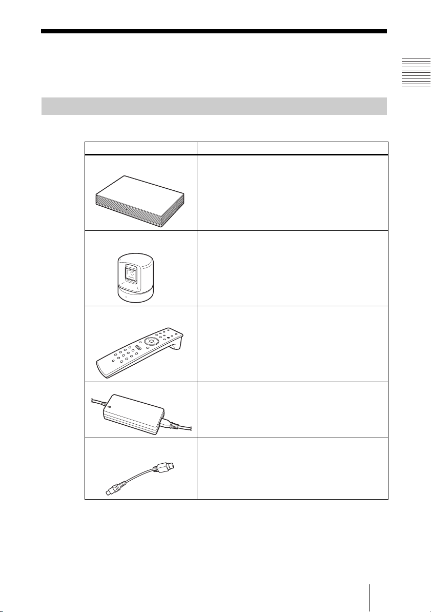
Basic System Components
The PCS-G70/G70P Video Communication System is the basic system of the
PCS-G70/G70P Videoconferencing System. It contains the following components:
Unit Description
PCS-PG70/PG70P
Communication Terminal
Contains the video codec, audio codec, echo
canceler, network interfaces and system controller.
PCSA-CG70/CG70P
Camera Unit
PCS-RG70 Remote
Commander
PCS-AC19V6 AC adaptor Supplies power to the Communication Terminal.
Video Converter Cable
1-757-517-11
Camera to shoot videoconference.
Used to operate the Communication Terminal and
Camera Unit.
Used to send video output from a pin terminal to an
S-video terminal.
11System Components
Page 12
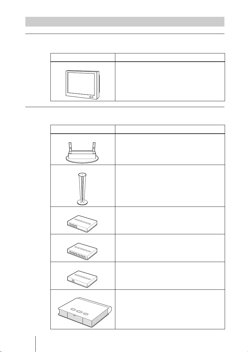
Optional Equipment
TV monitor
A TV or projector, etc. is required to monitor the images for videoconferencing system.
Unit Description
TV, Projector, etc. Used as a monitor and speakers.
Optional equipment especially designed for use with the PCS-G70/G70P
The following optional devices are used to enhance your videoconference.
Unit Description
PCSA-STMG70 Stand This stand can be used to place the Communication
Terminal on end.
PCSA-STCG70 Camera Stand
PCSA-B384S ISDN Unit Used to connect to an ISDN line. Up to three ISDN
PCSA-B768S ISDN Unit Used to connect to an ISDN line. Up to six ISDN
PCSA-PRI ISDN Unit Used to connect to an ISDN line through the PRI line
PCSA-DSB1S Data Solution Box
12 System Components
Stand for the Camera Unit.
lines; 6B channels usable.
lines; 12B channels usable.
interface.
Use of this device allows easy connection with a
computer or projector for a data conference.
Page 13
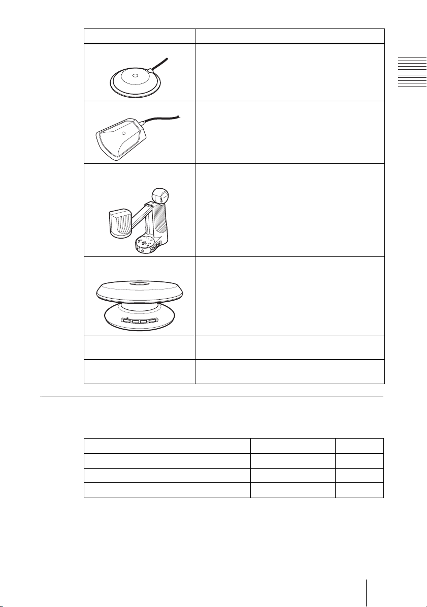
Unit Description
PCS-A1 Microphone Omni-directional microphone that picks up sound
relatively from all directions, allowing participants to
speak from any location. It is recommended to use in
a quiet situation.
PCS-A300 Microphone Unidirectional microphone. It is recommended when
PCS-DS150/DS150P
Document Stand
CTE-600 Communication
Transducer
PCSA-M3G70 H.323 MCU
Software
PCSA-M0G70 H.320 MCU
Software
you want to pick up the voice of a speaker directed
toward the microphone.
Camera for documents.
Allows transmission of pictures to the
Communication Terminal by infrared signals without
connecting a cable.
Integrated microphone/speaker system suitable for
remote communication. The uni-directional
microphones pick up clear voice with minimum
background noise.
Moreover, the omni-directional speaker outputs
sound equally in all directions.
Allows use for a multipoint videoconference over
LAN connection.
Allows use for a multipoint videoconference over
ISDN connection.
Cables
Use the following cables to connect devices in this system.
PCS-G70/G70P Video Communication System
Cable Part No. Number
Camera cable (0.25 m (0.8 ft)) 1-827-376-11 1
S-video cable (1.5 m (4.9 ft)) 1-776-078-42 1
Audio cable (1 m (3.3 ft)) 1-765-258-31 1
13System Components
Page 14

Camera cable
S-video cable
Audio cable
14 System Components
Page 15
System Configuration
The PCS-G70/G70P Video Communication System has various system
configuration capabilities using the basic components and optional equipment.
This section describes eight typical examples.
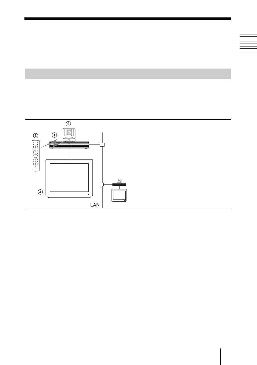
System Configuration via a LAN
This allows you:
• To hold a point-to-point videoconference over LAN.
• To show still images stored on a “Memory Stick”.
System configuration
1 PCS-PG70/PG70P Communication
Terminal
2 PCSA-CG70/CG70P Camera Unit
3 PCS-RG70 Remote Commander
4 TV monitor (not supplied)
15System Configuration
Page 16
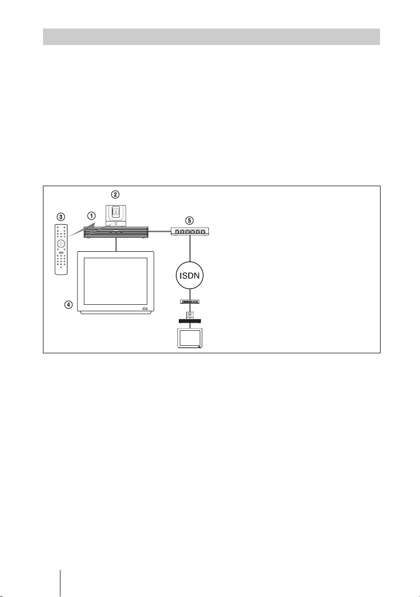
System Configuration via an ISDN
Connection to ISDN is required to use the PCSA-B384S, PCSA-B768S, or
PCSA-PRI ISDN Unit especially designed for use with this system.
This allows you:
• To hold a point-to-point videoconference over ISDN.
• To show still images stored on a “Memory Stick”.
• To hold a videoconference with high speeds and highest quality image
transmission by connecting up to three ISDN lines (when using the PCSAB384S), by connecting up to six ISDN lines (when using the PCSA-B768S)
or by connecting one ISDN line (when using the PCSA-PRI).
System configuration
*
*
1 PCS-PG70/PG70P Communication
Terminal
2 PCSA-CG70/CG70P Camera Unit
3 PCS-RG70 Remote Commander
4 TV monitor (not supplied)
5 PCSA-B384S, PCSA-B768S or PCSA-
PRI ISDN Unit (not supplied)
*
The illustration shows an example using
the PCSA-B768S ISDN Unit.
About the number of ISDN lines and B (bearer) channel
Up to three ISDN lines (6B channels) with the PCSA-B384S ISDN Unit, up to
six ISDN lines (12B channels) with the PCSA-B768S ISDN Unit, or one ISDN
line (23B channels (T1), 30B channels (E1)) with the PCSA-PRI ISDN Unit
can be connected to one PCS-PG70/PG70P. The more channels you use for a
single communication, the faster speeds and higher-quality picture you can
obtain for your network communication.
16 System Configuration
Page 17
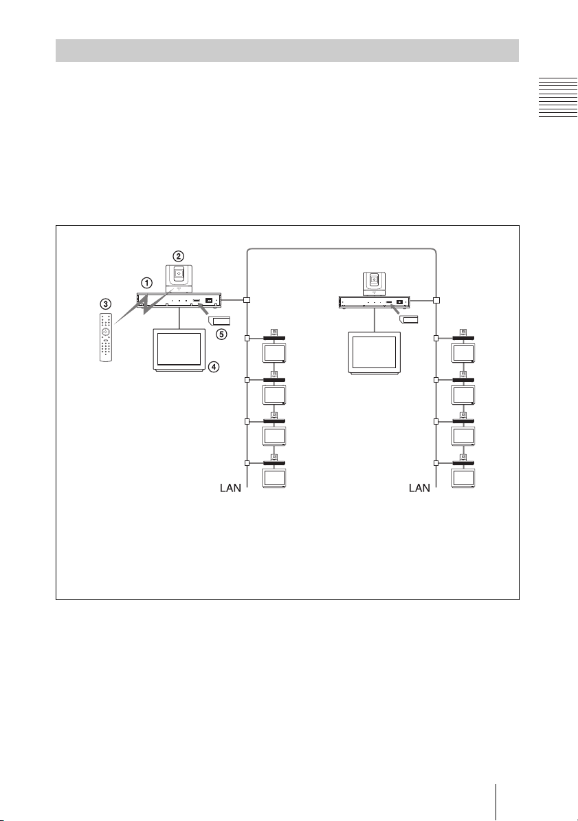
System Configuration via a LAN for Multipoint Conference
You need to install the optional PCSA-M3G70 H.323 MCU software.
This allows you:
• To hold a multipoint videoconference among up to ten sites over LAN.
• To show still images stored on a “Memory Stick”.
• To show the still images on the second TV monitor or projector.
• To pick up a large number of participants’ voices using up to two external
microphones.
System configuration
1 PCS-PG70/PG70P Communication Terminal
2 PCSA-CG70/CG70P Camera Unit
3 PCS-RG70 Remote Commander
4 TV monitor (not supplied)
5 PCSA-M3G70 H.323 MCU software (not supplied)
17System Configuration
Page 18
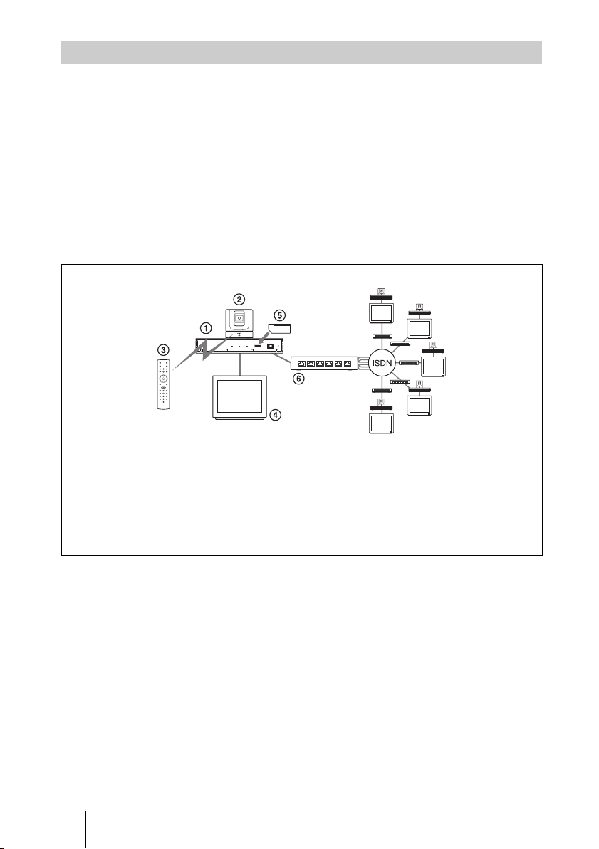
System Configuration via an ISDN for Multipoint Conference
You need to connect the optional PCSA-B384S, PCSA-B768S, or PCSA-PRI
ISDN Unit especially designed for use with this system and to install the
optional PCSA-M0G70 H.320 MCU software.
This allows you:
• To hold a multipoint videoconference among up to six sites over ISDN.
• To show still images stored on a “Memory Stick”.
• To show the still images on the second TV monitor or projector.
• To pick up a large number of participants’ voices using up to two external
microphones.
System configuration
1 PCS-PG70/PG70P Communication Terminal
2 PCSA-CG70/CG70P Camera Unit
3 PCS-RG70 Remote Commander
4 TV monitor (not supplied)
5 PCSA-M0G70 H.320 MCU software (not supplied)
6 PCSA-B384S, PCSA-B768S or PCSA-PRI ISDN Unit
(not supplied)
*
The illustration shows an
example using the PCSA-B768S
ISDN Unit.
18 System Configuration
Page 19
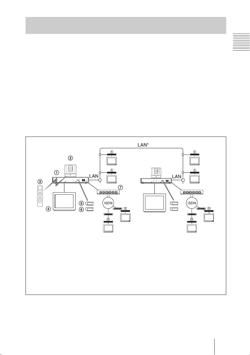
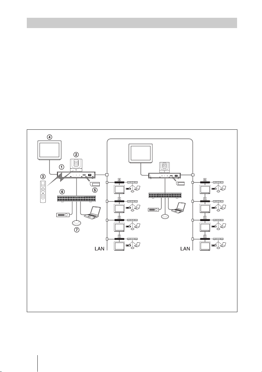
System Configuration via a LAN and ISDN for Multipoint Conference
Installing the optional PCSA-M3G70 H.323 MCU software (for LAN) and
PCSA-M0G70 H.320 MCU software (for ISDN) enables conduct of a
multipoint conference via a LAN and ISDN mixed.
Two Communication Terminals in which MCU software is installed must be
connected via a LAN.
This allows you:
• To hold a multipoint videoconference among up to ten sites over LAN and
ISDN.
• To show still images stored on a “Memory Stick”.
• To show the still images on the second TV monitor or projector.
• To pick up a large number of participants’ voices using up to two external
microphones.
System configuration
1 PCS-PG70/PG70P Communication Terminal
2 PCSA-CG70/CG70P Camera Unit
3 PCS-RG70 Remote Commander
4 TV monitor (not supplied)
5 PCSA-M3G70 H.323 MCU software (not supplied)
6 PCSA-M0G70 H.320 MCU software (not supplied)
7 PCSA-B384S, PCSA-B768S or PCSA-PRI ISDN
Unit (not supplied)
* Be sure to connect two
Communication Terminals,
with the MCU software
installed, via a LAN.
*
The illustration shows an
example using the
PCSA-B768S ISDN Unit.
19System Configuration
Page 20
System Configuration via a LAN for Multipoint Data Conference
You need to connect the optional PCSA-DSB1S Data Solution Box especially
designed to use with this system and to install the optional PCSA-M3G70
H.323 MCU software.
This allows you:
• To hold a multipoint videoconference among up to ten sites over LAN.
• To show still images stored on a “Memory Stick”.
• To use the data from a computer or external equipment.
• To show the data from a computer or still images on the second TV monitor
or projector.
• To pick up a large number of participants’ voices using up to five external
microphones connected to the Data Solution Box.
System configuration
1 PCS-PG70/PG70P Communication Terminal
2 PCSA-CG70/CG70P Camera Unit
3 PCS-RG70 Remote Commander
4 TV monitor (not supplied)
5 PCSA-M3G70 H.323 MCU software (not supplied)
6 PCSA-DSB1S Data Solution Box (not supplied)
7 PCS-A1 Microphone (not supplied)
20 System Configuration
Page 21
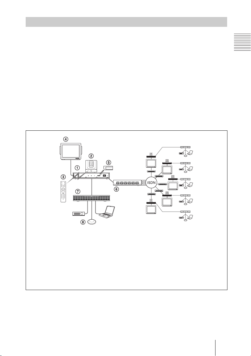
System Configuration via an ISDN for Multipoint Data Conference
You need to connect the optional PCSA-B384S, PCSA-B768S, or PCSA-PRI
ISDN Unit and the PCSA-DSB1S Data Solution Box especially designed for
use with this System and to install the optional PCSA-M0G70 H.320 MCU
software.
This allows you:
• To hold a multipoint videoconference among up to six sites over ISDN.
• To show still images stored on a “Memory Stick”.
• To use the data from a computer or an external equipment.
• To show the data from a computer or still images on the second TV monitor
or projector.
• To pick up a large number of participants’ voices using up to five external
microphones connected to the Data Solution Box.
System configuration
1 PCS-PG70/PG70P Communication Terminal
2 PCSA-CG70/CG70P Camera Unit
3 PCS-RG70 Remote Commander
4 TV monitor (not supplied)
5 PCSA-M0G70 H.320 MCU software (not supplied)
6 PCSA-B384S, PCSA-B768S or PCSA-PRI ISDN Unit (not supplied)
7 PCSA-DSB1S Data Solution Box (not supplied)
8 PCS-A1 Microphone (not supplied)
*
The illustration shows an
example using the PCSA-B768S
ISDN Unit.
21System Configuration
Page 22
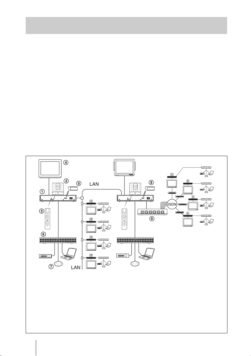
System Configuration via a LAN and ISDN for Multipoint Data Conference
Installing the optional PCSA-M3G70 H.323 MCU software, the PCS-M0G70
H.320 MCU software, and using the optional Data Solution Box PCS-DSB1S
and ISDN Units PCSA-B384S, PCSA-B768S, or PCSA-PRI enables you to
conduct multipoint mixed LAN and ISDN line multipoint data conferences.
Two Communication Terminals where the MCU software is installed must be
connected via a LAN in this configuration.
This allows you:
• To hold a multipoint videoconference among up to six sites over ISDN.
• To show still images stored on a “Memory Stick”.
• To use data from a computer or other such peripheral device in the
videoconference.
• To show still images or computer data on the second monitor or projector
used as the display device.
• To connect up to five external microphones to the Data Solution Box,
allowing you to hear several participants.
System configuration
*
1 PCS-PG70/PG70P Communication Terminal
2 PCSA-CG70/CG70P Camera Unit
3 PCS-RG70 Remote Commander
4 TV monitor (not supplied)
5 PCSA-M3G70 H.323 MCU software (not supplied)
6 PCSA-DSB1S Data Solution Box (not supplied)
7 PCS-A1 Microphone (not supplied)
8 PCSA-M0G70 H.320 MCU software (not supplied)
9 PCSA-B384S, PCSA-B768S or PCSA-PRI ISDN
Unit (not supplied)
22 System Configuration
*
Be sure to connect two
Communication Terminals, with
the MCU software installed, via
a LAN.
*
The illustration shows an
example using the PCSA-B768S
ISDN Unit.
Page 23
System Connections
This section describes the typical system connections.
Notes
• Be sure to turn off all the equipment before making any connections.
• Do not connect/disconnect the camera cable with the power on. Doing so may damage the
Camera Unit or Communication Terminal.
• For safety, do not connect the 100BASE-TX/10BASE-T connector to a network that
applies an excess voltage via the 100BASE-TX/10BASE-T connector.
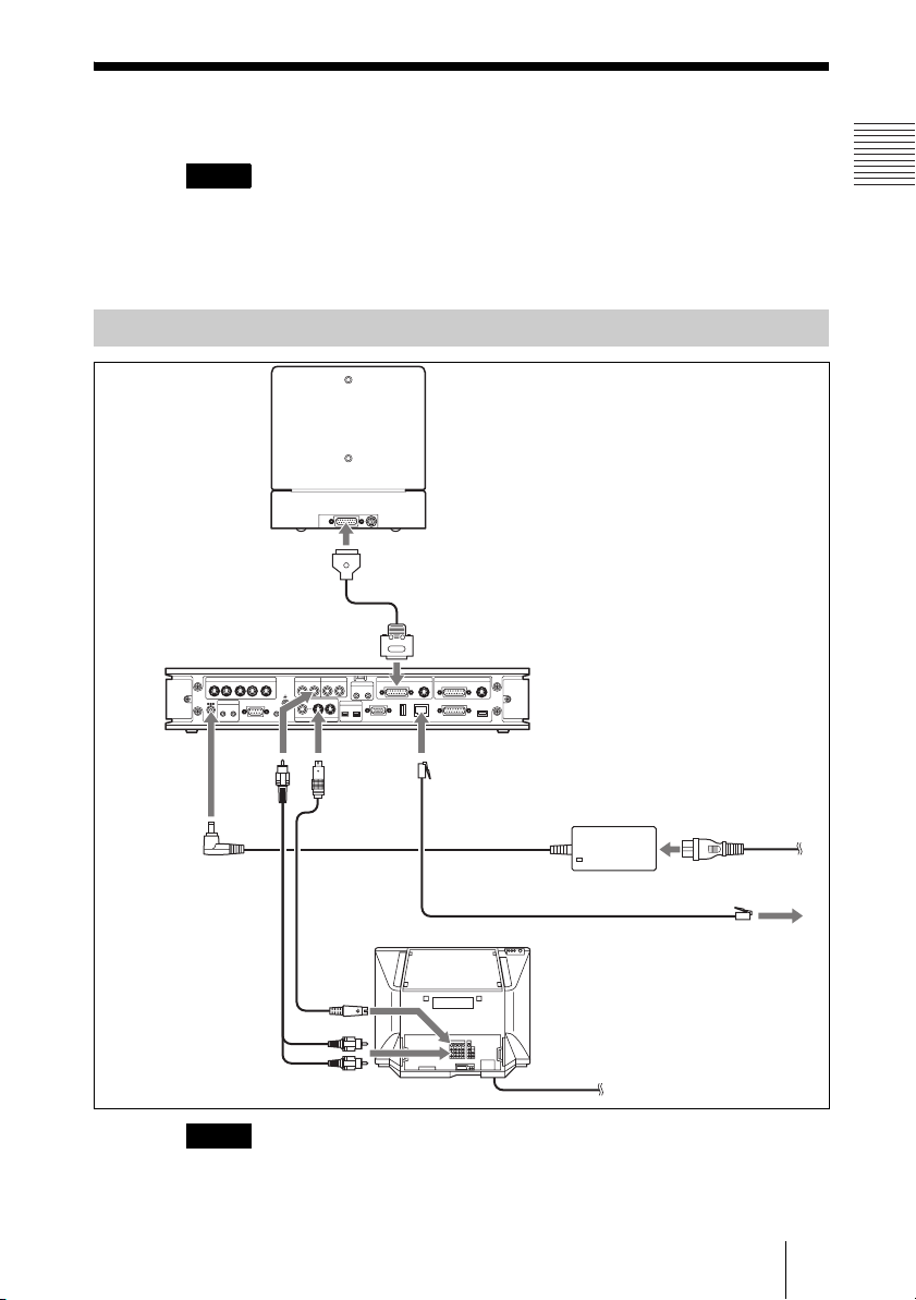
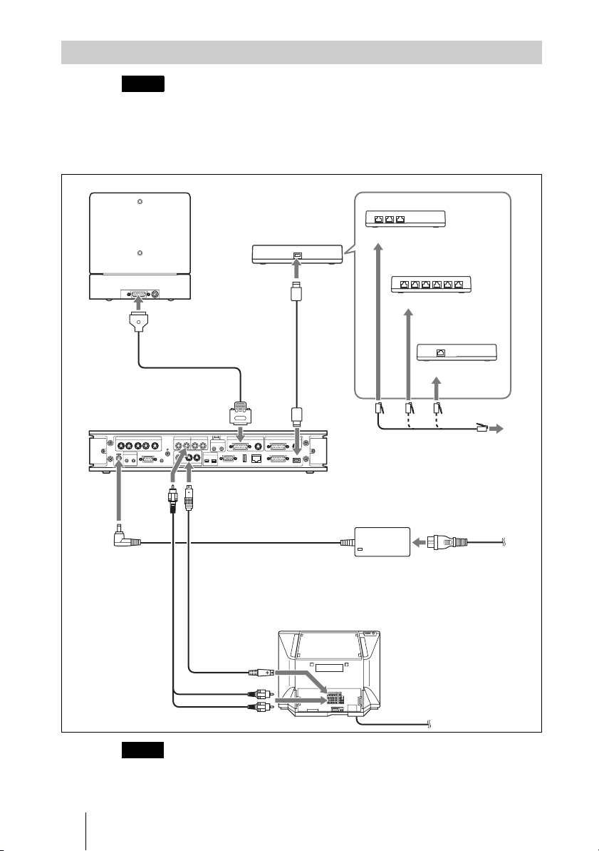
System Connection via a LAN
PCSA-CG70/CG70P Camera Unit
TERMINAL VISCA OUT
to TERMINAL
PCS-PG70/PG70P
Communication
Terminal
to DC19.5V
Audio cable*
* supplied
** not supplied
Notes
• If you are only using one camera, be sure to connect it to the MAIN CAMERA connector.
• The AUDIO OUT (MIXED) jack is used to make an audio recording of a conference.
Camera cable*
to MAIN CAMERA
12 34
DC 19.5V
IR OUT
12
AUDIO
MCU VIDEO OUT
AUX CONTROL
to
OUT
AUDIO OUT AUDIO IN
(MIXED)
AUX
5
12
CTRL-S
AUX
MONITOR
VIDEO OUT
S-video cable*
CAMERA CAMERAAUX IN AUX IN
LINE
MIC
(PLUG IN POWER)
12
RGB OUT DSB
EC-MIC
12
to
VIDEO OUT
MONITOR 1
MAIN SUB
100BASE-TX/
WHITE
10BASE-T
BOARD
ISDN UNIT
to 100BASE-TX/
10BASE-T
UTP cable (category 5, straight)**
to
S-video
input
to audio input
This is not used during regular conferences.
PCS-AC19V6
AC adaptor
TV monitor**
to a wall outlet
Power cord*
to a wall outlet
to LAN
23System Connections
Page 24
System Connection via an ISDN
Notes
• Do not connect/disconnect the camera cable or the interface cable with the power on.
Doing so may damage the Camera Unit, Communication Terminal or ISDN Unit.
• Used with an ISDN Unit for the first time, the Communication Terminal may
automatically upgrade the software of the ISDN Unit. While the upgrading message
is displayed on the monitor screen, be sure not to turn off the Communication
Terminal. Doing so may cause malfunction of the system.
PCSA-CG70/CG70P
Camera Unit
to TERMINAL
TERMINAL VISCA OUT
to TERMINAL
Interface cable (supplied
Camera cable*
PCS-PG70/PG70P
Communication
Terminal
MCU VIDEO OUT
5
12 34
DC 19.5V
IR OUT
AUX CONTROL
12
CTRL-S
to
AUDIO
OUT
to MAIN
CAMERA
AUDIO OUT AUDIO IN
(MIXED)
AUX
LINE
12
AUX
MONITOR
VIDEO OUT
to VIDEO OUT
MONITOR 1
with ISDN UNIT)
MAIN SUB
CAMERA CAMERAAUX IN AUX IN
MIC
(PLUG IN POWER)
12
100BASE-TX/
WHITE
10BASE-T
BOARD
RGB OUT DSB
EC-MIC
12
to ISDN
UNIT
ISDN UNIT
ISDN Unit
**
PCSA-B384S ISDN Unit**
to ISDN 1-3
PCSA-B768S
ISDN Unit**
to ISDN 1-6
PSCA-PRI
ISDN Unit**
to ISDN PRI
ISDN modular cable**
PCS-AC19V6
AC adaptor
Power cord*
to DC19.5V
Audio cable*
* supplied
** not supplied
Notes
• If you are only using one camera, be sure to connect it to the MAIN CAMERA connector.
• The AUDIO OUT (MIXED) jack is used to make an audio recording of a conference.
This is not used during regular conferences.
24 System Connections
S-video
cable*
to audio input
to a wall outlet
TV monitor**
to
S-video
input
to a wall outlet
Page 25
Preparing the System
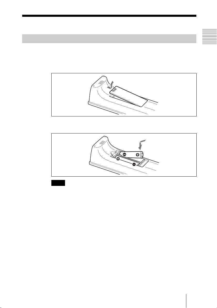
Inserting Batteries into the Remote Commander
Most of the operations with the Video Communication System can be
controlled with the supplied Remote Commander.
1 Remove the battery compartment cover.
2 Insert two size AAA (R03) batteries (supplied) with correct polarities into
the battery compartment.
Note
Be sure to insert the batteries E side first. Inserting them forcibly e side first may
damage the insulated film covering the batteries and cause a short circuit.
3 Replace the cover.
Battery life
When the Remote Commander does not function properly, replace both the
batteries with new ones.
Notes on batteries
To avoid damage from possible battery leakage or corrosion, observe the
following:
• Make sure to insert the batteries with the polarities in the correct direction.
• Do not mix old and new batteries, or different types of batteries.
• Do not attempt to charge the batteries.
• If you do not intend to use the Remote Commander for a long period of time,
remove the batteries.
• If battery leakage occurs, clean the battery compartment and replace all the
batteries with new ones.
25Preparing the System
Page 26
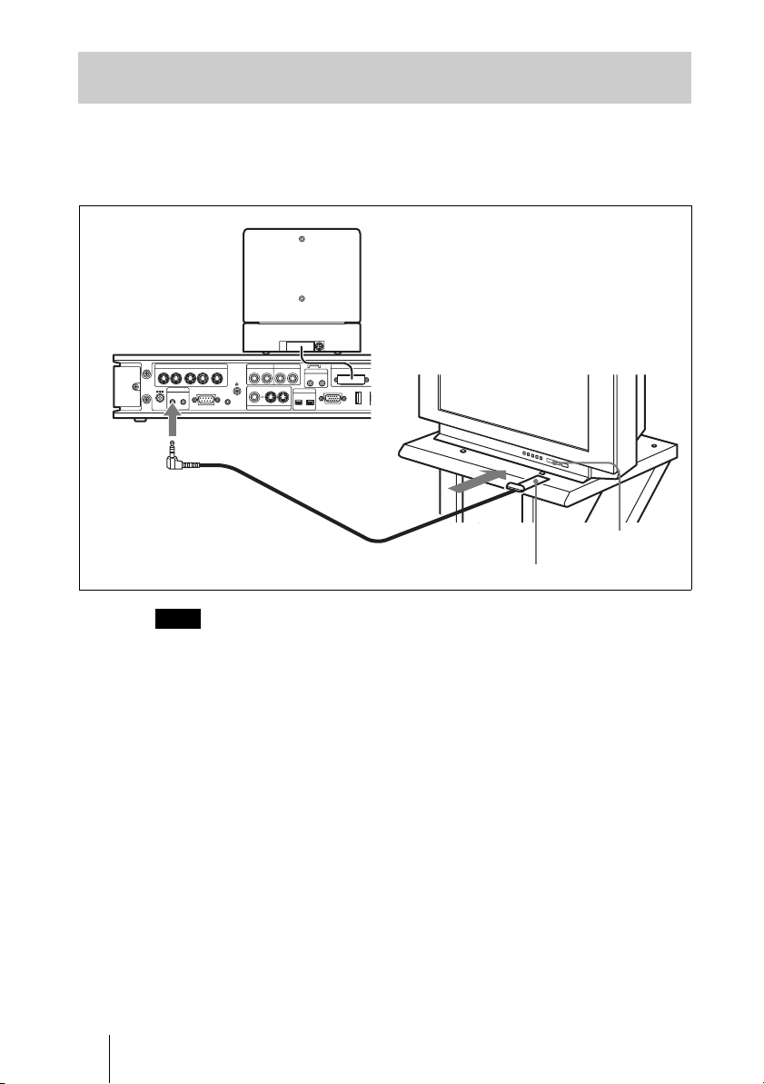
Turning On/Off the TV Monitor Together With the Communication Terminal
If you use a Sony TV, insert the IR repeater under the remote sensor of the TV.
Once you set the IR repeater, the TV will turn on or go to standby together with
the Communication Terminal when you press the
Remote Commander.
@/1 button on the supplied
MCU VIDEO OUT
12 34
DC 19.5V
IR OUT
12
AUX CONTROL
5
CTRL-S
AUDIO OUT AUDIO IN
(MIXED)
12
AUX
VIDEO OUT
TERMINAL VISCA OUT
MAIN
EC-MIC
12
MIC
(PLUG IN POWER)
12
CAMERA
WHITE
BOARD
RGB OUT
AUX
LINE
MONITOR
TV monitor
1
to IR OUT
Remote sensor
IR repeater (supplied)
Note
If the TV monitor is not turned on by pressing the @/1 button on the Remote
Commander, change the “IR Repeater Mode” setting in the General Setup menu.
For details on the “IR Repeater Mode” setting, see “General Setup Menu” on
page 53.
26 Preparing the System
Page 27
Turning the System On/Off
This section describes how to turn on or off the Communication Terminal.
Turning On
1 Turn on the TV monitor.
If the IR repeater is installed in the TV monitor, set the TV monitor to standby
mode. The TV monitor will turn on simultaneously when the Communication
Terminal is turned on.
2 Turn on the power of any other equipment to be used for the
videoconference.
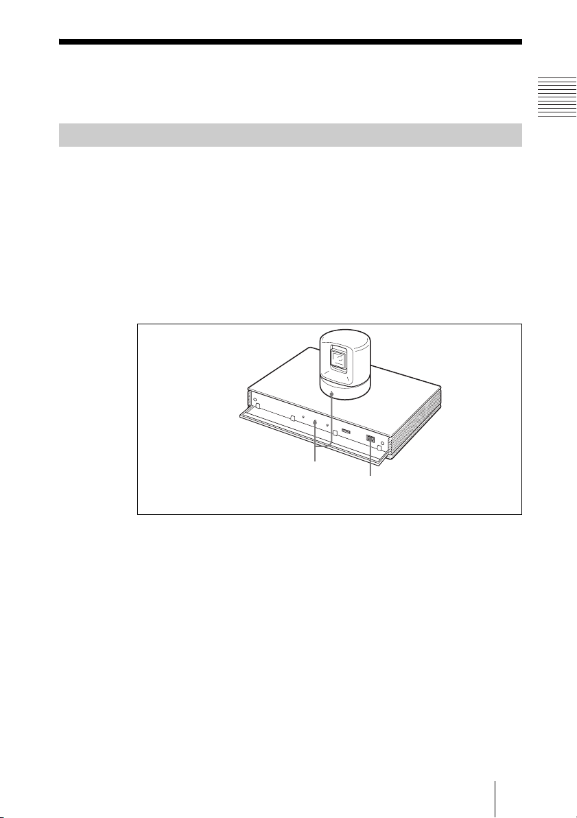
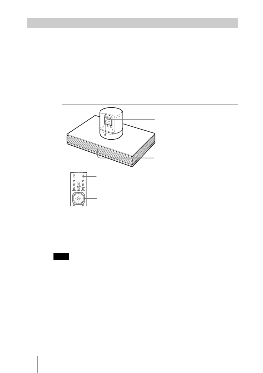
3 Open the front panel of the Communication Terminal, and then slide the
power switch on the right to the on position
(@).
POWER indicators
(Light green.)
The Communication Terminal turns on after a while. Three indicators on the
front of the Communication Terminal and the POWER indicator on the camera
light, then only the POWER indicators on both units remain on in green. The
launcher menu will appear on the monitor screen and the picture shot by the
local camera will also appear in the launcher menu.
Power switch
27Turning the System On/Off
Page 28
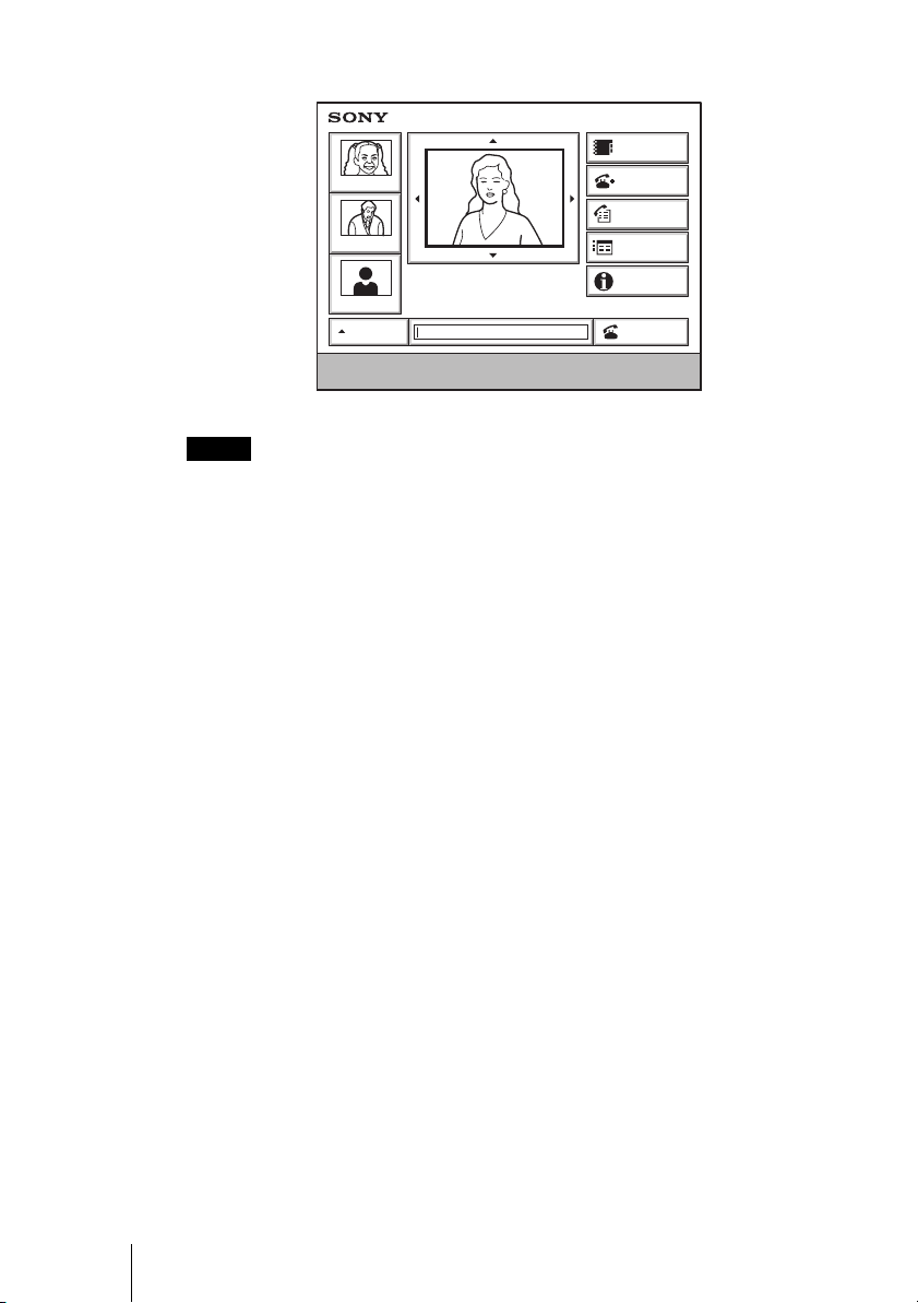
Launcher menu
Phone Book
Tokyo
New York
IP: 012.345.678.678
Paris
AUTO
Enter the remote party number.
ISDN: 012345678956789
Detail Dial
History
Menu
Information
Dial
Notes
• After the power is turned on, the camera moves automatically for trial operation. Be
careful not to catch your finger.
• If you use force to prevent the camera moving, it may not resume moving and not
output a signal to the Communication Terminal. In this case, turn off the terminal, and
turn it on again.
• When you turn on the power of the Communication Terminal for the first time after
installation, the setup wizard will appear after the self-diagnosis is completed. Set up
your system following the wizard.
For setups using the wizard, see “Setting Up the System for the First Time
— Initial Setup Wizard” on page 33.
• Used with an optional device especially designed for use with this system, such as the
Data Solution Box or ISDN Unit, for the first time, the Communication Terminal may
automatically upgrade the software of the connected device. While the upgrading
message is displayed on the monitor screen, be sure not to turn off the Communication
Terminal. Doing so may cause malfunction of the system. System malfunction may
also occur when a system power-off has been caused by an accidental problem such
as a power interruption during upgrading. If connection of the Data Solution Box or
ISDN Unit to the Communication Terminal is not re-established even after the system
power is recovered, consult a Sony dealer.
28 Turning the System On/Off
Page 29

Standby Mode Function
To save power, the Communication Terminal will enter standby mode if you
do not operate it for a specified period of time.
When the Communication Terminal is in standby mode, the POWER indicator
lights in orange. Once the Communication Terminal receives a call, the
standby mode is automatically released.
To release the standby mode
Press the
To specify the standby time
Specify the time that you want the system to remain on before entering into
standby mode (1 to 99 minutes) by selecting “Device Setup” on the General
Setup menu, and then setting “Standby Time”. If you do not want the system
to enter the standby mode, set “Standby Mode” to “Off”.
For the “Standby Time” and “Standby Mode” settings, see “General Setup
Menu” on page 53.
Notes
• The POWER indicator on the camera goes off when the system enters standby mode.
• If you use a Sony TV monitor with the IR repeater installed under the remote sensor,
@/1 button on the Remote Commander.
the TV monitor will enter standby mode together with the Communication Terminal.
29Turning the System On/Off
Page 30
Setting the Video Communication System to Standby Mode
You can turn on the Video Communication System with the @/1 button on the
Remote Commander if it is in standby mode.
1 Display the launcher menu on the monitor screen, then press the @/1 button
on the Remote Commander.
The message “Power off?” appears on the monitor screen.
2 Press the B or b button on the Remote Commander to select OK, and press
the PUSH ENTER button.
You may press the @/1 button on the Remote Commander.
POWER indicator (Not lit.)
POWER indicator (Lights orange.)
@/1 button
B/b buttons and PUSH ENTER
button
The Video Communication System enters standby mode and the POWER
indicator on the Communication Terminal lights in orange. The POWER
indicator on the camera goes out.
If the IR repeater is installed in a Sony TV monitor, it will go into standby
together with the Video Communication System.
Note
When the Communication Terminal and the Camera are separately installed, point the
Remote Commander to the Camera for operations.
To cancel setting the system to standby
Select “Cancel” with the B or b button on the Remote Commander, then press
the PUSH ENTER button in step 2 above.
30 Turning the System On/Off
Page 31
Turning Off
1 Open the front panel of the Communication Terminal, and then slide the
power switch on the right to the off position ({).
2 Turn off the power of other equipment used for the videoconference.
Note
Set the power switch on the Communication Terminal off when the system will not be
used for an extended period. While the power switch is off, you cannot receive a call
from a remote party.
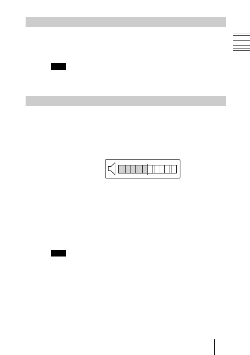
Adjusting the Volume on the TV Monitor
Before adjusting the volume on the TV monitor, set the volume on the
Communication Terminal to the appropriate position.
1 Press the VOLUME +/– buttons on the Remote Commander to set the
volume level on the adjustment bar displayed on the screen to the middle
position.
2 Adjust the volume on the TV monitor so that you can properly hear a
remote party speaking.
To adjust the picture on the TV monitor
Use the controls on the TV monitor to adjust the picture, hue, contrast,
brightness or sharpness.
For details on picture adjustments, refer to the Operating Instructions of the
TV.
Note
Do not activate the TV's surround sound feature as it may cause the echo canceller of
the Communication Terminal not to function properly and make strange sounds.
31Turning the System On/Off
Page 32

Displaying Help
Pressing the HELP button on the Remote Commander displays a balloon help
or a help screen to guide most operations on the monitor screen.
Note
You can hide the balloon help used for entering characters.
Press the MENU button on the Remote Commander to show the menu, and set
“Character Input Help” under “Menu Screens” of the General Setup menu to “Off”. (See
page 53.)
Displaying the Versions and Options
You can check the version of the Communication Terminal, versions of the
connected optional equipment for exclusive use with this system, and the
options installed in the terminal by displaying the Status menu on the monitor
screen.
For details on the Status menu, see “Information Menu” on page 67.
32 Turning the System On/Off
Page 33

Setting Up the System for the First Time — Initial Setup Wizard
When you turn on the Communication
Terminal for the first time after installation
and the self-diagnosis is completed, the
setup wizard appears on the monitor screen.
Register your local system data with the
setup wizard using the Remote Commander.
Notes
• You can change the settings made with the
setup wizard later using the Setup menus.
• The setup wizard will also be displayed when
you install the PCSA-B384S, PCSA-B768S,
or PCSA-PRI ISDN Unit to your system
later. Perform the setup again.
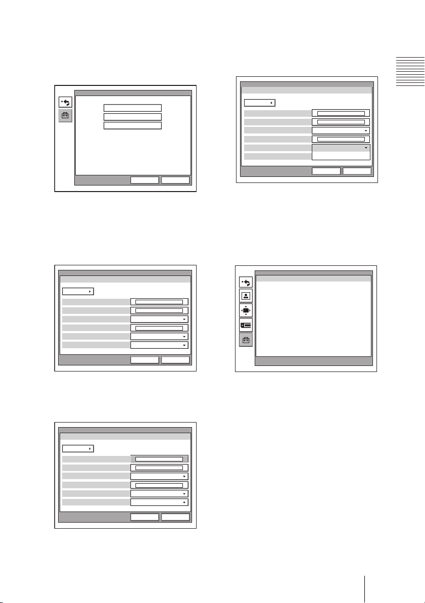
1 Select the language used for the on-
screen menus and messages in the
Language Setup Wizard.
Language: Select one of the following
languages; English, French, German,
Japanese, Spanish, Italian, Simplified
Chinese, or Portuguese.
Language Setup Wizard
Language
2 Use the V, v, B or b button on the
Remote Commander to select “Next”,
then press the PUSH ENTER button.
The Monitor Setup Wizard appears.
3 Select a monitor from which signals
are output.
English
Next Cancel
Note
If you select a monitor from “Monitor
Out”, other monitors than that you selected
display no menus.
Monitor Setup Wizard
Monitors
Connection
Monitor
VIDEO1 VIDEO2 RGB OUT
1
SubMain
NextPrevious Cancel
RGB OUT(DSB)
Sub
Monitors
Select the number of monitors
connected to the system.
1: One monitor connected.
2: Two monitors connected.
3: Three monitors connected.
Connection
Selects the output connector to which
the device to be used is connected.
VIDEO 1: Selects the device connected
to the VIDEO 1 connector.
VIDEO 2: Selects the device connected
to the VIDEO 2 connector.
RGB OUT: Selects the device
connected to the RGB OUT
connector as the main monitor.
RGB OUT (DSB): Selects the device
connected to the RGB OUT
connector on the Data Solution Box.
Monitor
Allows you to define the monitor
connected to the corresponding
connector as the main monitor or the sub
monitor.
Main: Defines the monitor as the main
monitor.
Sub: Defines the monitor as the sub
monitor.
For details, see “Displaying the Picture
on a Projector or Monitor” on page 151.
33Setting Up the System for the First Time — Initial Setup Wizard
Page 34
4 Use the V, v, B or b button on the
Remote Commander to select “Next”,
then press the PUSH ENTER button.
The ISDN Setup Wizard appears when
the PCSA-B384S, PCSA-B768S or
PCSA-PRI ISDN Unit is connected.
When the ISDN Unit is not connected,
the LAN Setup Wizard is displayed.
Proceed to step 11.
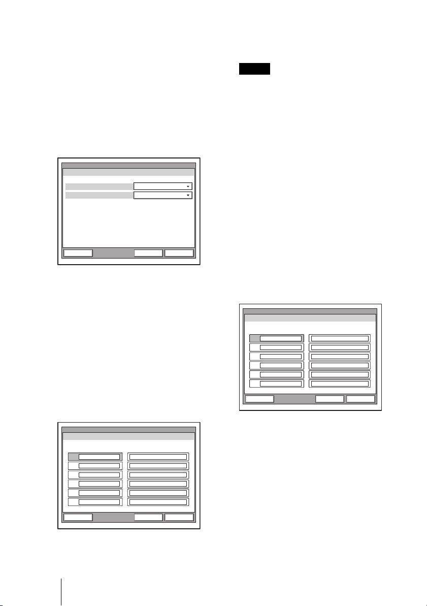
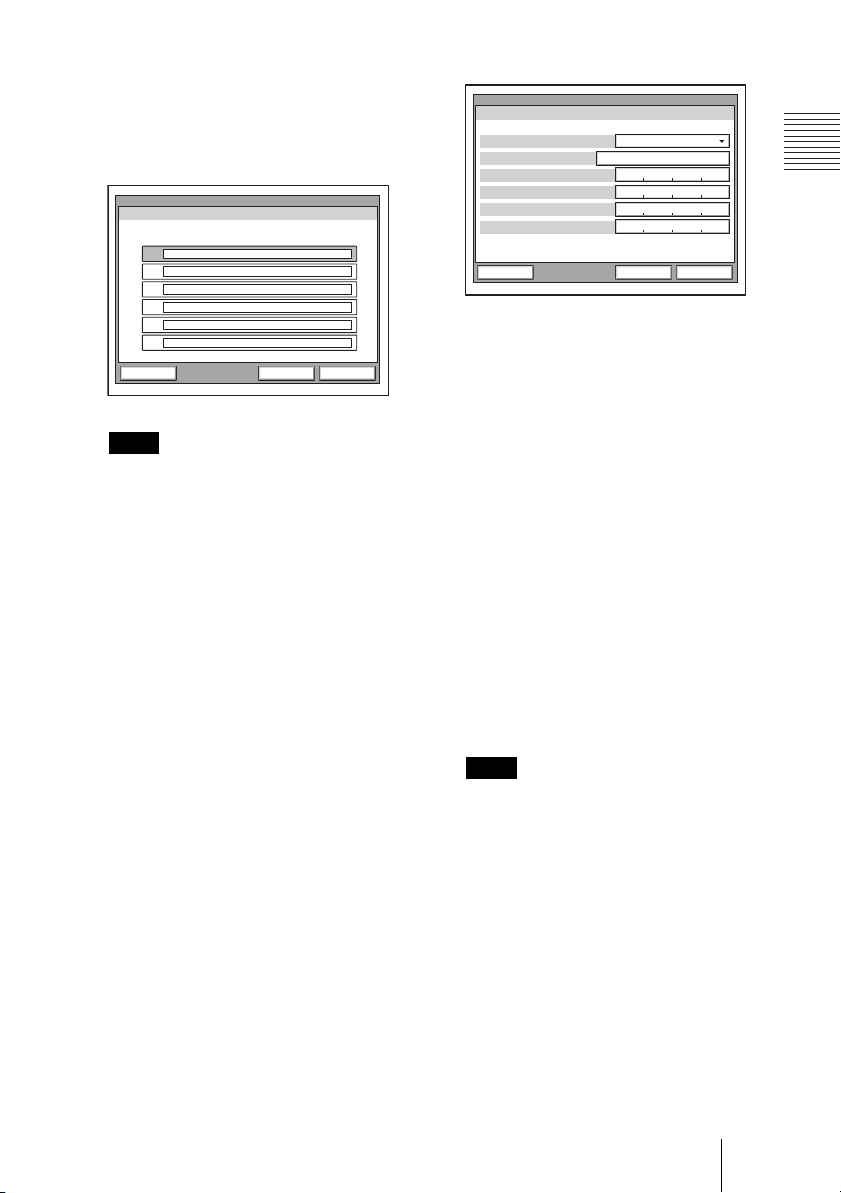
5 Set the following items on the ISDN
line.
ISDN Setup Wizard
USACountry/Region
National ISDNProtocol
NextPrevious Cancel
Country/Region: Select your country
or region.
Protocol: Select the protocol of the
ISDN line you are using.
6 Use the V, v, B or b button to select
“Next”, then press the PUSH ENTER
button.
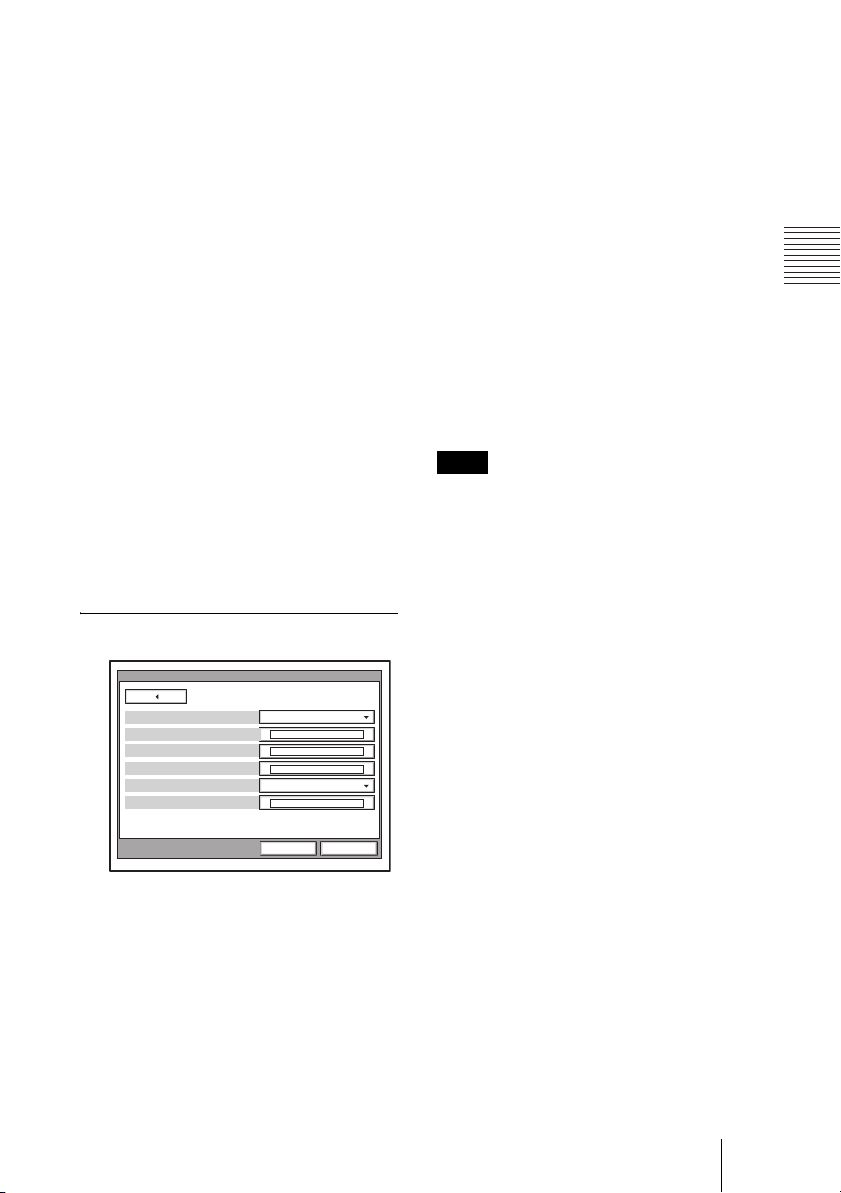
7 Enter the telephone number of the
ISDN used by the system.
When you use one ISDN line, enter the
same number both in the A1 and A2 text
boxes (except for the USA and Canada).
ISDN Setup Wizard
Area Code Local Number
A1
A2
B1
B2
C1
C2
NextPrevious Cancel
Area Code: Enter the area code. Do not
enter the first “0” number.
Local Number: Enter the telephone
number.
Notes
• When you select a blank text box and
press the PUSH ENTER button on the
Remote Commander, the content in the
text box immediately above will be
copied to the selected text box.
• When you use the PCSA-B384S ISDN
unit and connect 2 or 3 ISDN lines,
enter the telephone numbers in the B1
to C2 text boxes in addition to the A1
and A2 boxes.
• When you use the PCSA-B768S and
connect 2 to 6 ISDN lines, enter the
telephone numbers in the B1 to F2 text
boxes in addition to the A1 and A2
boxes. To open the menu with D1 to
F2 text boxes, select “Next”, then
press the PUSH ENTER button.
• When you use the PCSA-PRI, Ch1 to
Ch23 (T1), or Ch1 to Ch30 (E1) are
displayed. Enter the telephone
numbers according to the number of
channels you will use.
ISDN Setup Wizard
Area Code Local Number
Ch1
Ch2
Ch3
Ch4
Ch5
Ch6
NextPrevious Cancel
When you select Auto SPID (only
for customers in the USA and
Canada)
You can automatically set up the Area
Code and Local Number on this page,
and SPID items in the SPID menu.
8 Use the V, v, B or b button to select
“Next”, then press the PUSH ENTER
button.
34 Setting Up the System for the First Time — Initial Setup Wizard
Page 35
9 Enter the sub-addresses.
Only numbers are available for a subaddress.
When you use one ISDN line, enter the
same number both in the A1 and A2 text
boxes (except for the USA and Canada).
ISDN Setup Wizard
Sub Address
A1:
A2:
B1:
B2:
C1:
C2:
NextPrevious Cancel
Note
When you use the PCSA-B384S ISDN
unit and connect 2 or 3 ISDN lines, enter
the sub-addresses in the B1 to C2 text
boxes in addition to the A1 and A2 boxes.
When you use the PCSA-B768S and
connect 2 to 6 ISDN lines, enter the subaddresses in the B1 to F2 text boxes in
addition to the A1 and A2 boxes. To open
the menu with these text boxes, select
“Next”, then press the PUSH ENTER
button.
When you use the PCSA-PRI, Ch1 to Ch23
(T1), or Ch1 to Ch30 (E1) are displayed.
Enter the telephone numbers according to
the number of channels you will use.
10
Use the V, v, B or b button to select
“Next”, then press the PUSH ENTER
button.
The message window for confirmation
appears.
11
Set the following items on the LAN.
LAN Setup Wizard
DHCP Mode
Host Name
IP Address
Network Mask
Gateway Address
DNS Address
Off
NextPrevious Cancel
DHCP Mode
Sets the DHCP (Dynamic Host
Configuration Protocol).
Auto: Automatically assigns your IP
address, network mask, gateway
address and DNS address.
Off: Deactivates DHCP. In this case set
your IP address, network mask,
gateway address and DNS address
manually.
Host Name
Enter your host name.
IP Address
Enter your IP address.
Network Mask
Enter your network mask.
Gateway Address
Enter your default gateway address.
DNS Address
Enter your DNS (Domain Name
System) server address.
Note
When you set “DHCP Mode” to “Auto”,
the assigned IP address is shown in the
launcher menu (page 75) or Information
menu (page 67).
If you do not know how to set up the LAN
configuration, contact your network
administrator.
35Setting Up the System for the First Time — Initial Setup Wizard
Page 36

12
Use the V, v, B or b button to select
“Save”, then press the PUSH ENTER
button.
Save
CancelPrevious
The settings are saved.
To cancel the setting
Press the
V, v, B or b button to select
“Cancel”, then press the PUSH ENTER
button.
To go back to the previous wizard
Press the
V, v, B or b button to select
“Previous”, then press the PUSH ENTER
button.
Using the Menus
The Video Communication System uses the
on-screen menus to make various adjustments
and settings. This section describes how to
adjust or set the items in the menus and gives
a brief introduction of the menus.
For the menu configuration, see page 228.
Operation
The basic operation through the menu is
explained by taking the Setup menu.
1 Press the MENU button on the
Remote Commander, or press the V,
v, B or b button to select “Menu” and
press the PUSH ENTER button in the
launcher menu.
The Setup menu appears.
Setup
36 Using the Menus
Press and hold the [MENU] button to show more
detailed setup menus.
2 Press and hold the MENU button.
The Setup menu for the administrator
appears.
Setup
Dial
Communication
Audio
General
LAN
Information
Answer
Status
Video
Administrator
ISDN
Page 37
3 Use the V, v, B or b button on the
Remote Commander to select the
menu you want to set, then press the
PUSH ENTER button.
The selected setup menu appears.
General
Device Setup
Whiteboard
Menu Screens
Save Cancel
6 Press the V or v button to select the
item you want to set or adjust, then
press the PUSH ENTER button.
The setting items are displayed.
Device Setup
Page: 1/2
Clock Set
Terminal Name
Standby Mode
Standby Time
Last Number Registration
Control by Far End
General
On
On
On
Off
Off
Save Cancel
4 Use the V, v, B or b button on the
Remote Commander to select the
menu you want to set, then press the
PUSH ENTER button.
The selected setup menu appears.
Device Setup
Page: 1/2
Clock Set
Terminal Name
Standby Mode
Standby Time
Last Number Registration
Control by Far End
General
On
On
On
Save Cancel
5 Press the b button, then press the
PUSH ENTER button.
The top item is selected.
Device Setup
Page: 1/2
Clock Set
Terminal Name
Standby Mode
Standby Time
Last Number Registration
Control by Far End
General
On
On
On
Save Cancel
7 Press the V or v button to select the
setting item you want, then press the
PUSH ENTER button.
8 Press the v button to select “Save”,
then press the PUSH ENTER button.
Setup
Press and hold the [MENU] button to show more
detailed setup menus.
The selected setting is saved.
To return to the previous menu
Press the RETURN button on the Remote
Commander.
37Using the Menus
Page 38
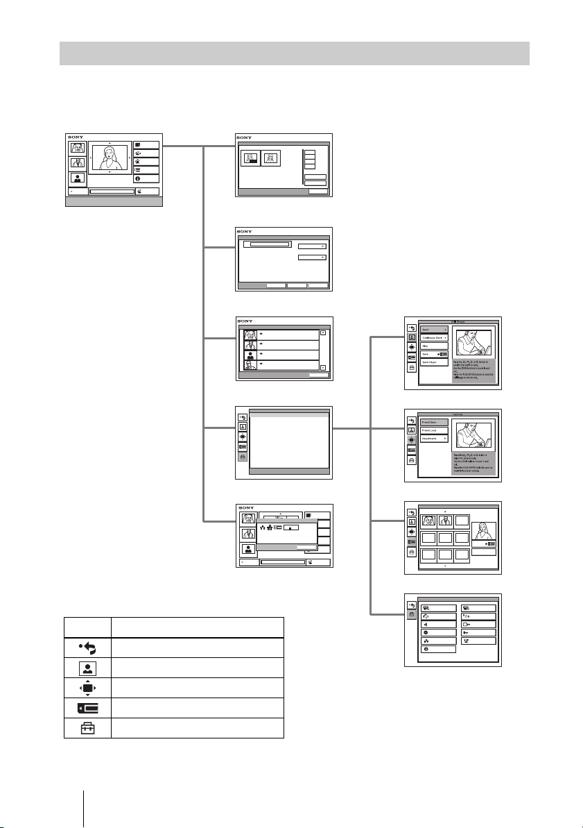
Menu Configuration
The system menus are configured as outlined below.
For details about menu configuration, see “Menu Configuration” on page 228.
Launcher menu Phone Book/Private Phone Book
Tokyo
New York
Paris
AUTO
Enter the remote party number.
IP: 012.345.678.678
ISDN: 012345678956789
Phone Book
Detail Dial
History
Menu
Information
Dial
AUTO
Jane Mary
Detail Dial
IP
Phone Book
Detail Dial
Line I/F
IP
LAN Bandwidth
1024 Kbps
0-9
A-1
J-S
T-Z
Recent
New Entry
Cancel
CancelSaveDial
History
History
Tokyo
LAN 012.345.678.912
New York
LAN 012.345.678.912
Paris
LAN 012.345.678.912
NAKAHATA
LAN 012.345.678.912
Menu
Press and hold the [MENU]button to show more detailed
setup menus.
Information
Information
Tokyo
IP:
012.345.678.912
Object
New York
IP: 012.345.678.678
ISDN: 012345678956789
Paris
AUTO
Selecting the icons shown on the left side of the
launcher menu displays each menu.
Icon Displayed menu
Returns to the previous menu.
Still Image menu
Camera menu
Memory Stick menu
Setup menu
Still Image menu
2004.
04. 04 10:20
2004.
04. 04 10:20
2004.
04. 04 10:20
2004.
04. 04 10:20
Cancel
Setup
Camera menu
Memory Stick menu
Phone Book
Detail Dial
PORT
History
012345678912
ISDN:
Audio: MIC(INT)+AUXVideo:
Menu
OK
OK
Information
Dial
Setup menu
Memory Stick
JPEG JPEG JPEG
JPEG JPEG JPEG
Dial
Communication
Audio
General
LAN
Information
JPEG
Save
Memory Stick Format
Setup
Answer
Status
Video
Administrator
ISDN
38 Using the Menus
Page 39
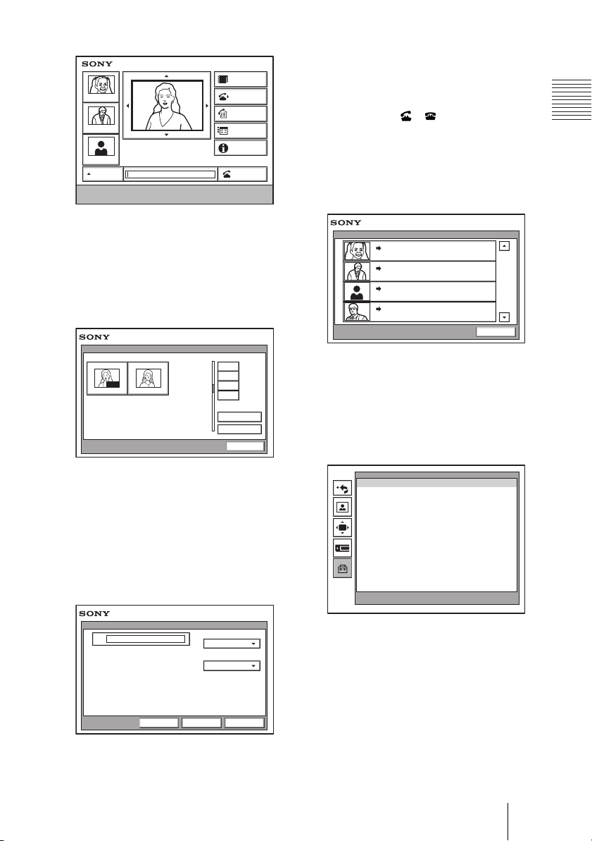
Launcher menu
Phone Book
Tokyo
New York
IP: 012.345.678.678
Paris
AUTO
Enter the remote party number.
ISDN: 012345678956789
Detail Dial
History
Menu
Information
Dial
The launcher menu is displayed when the
Video Communication System is turned on
or while not connected to a remote party.
For details on the launcher menu, see page
75.
Phone Book
Phone Book
0-9
AUTO
Jane Mary
A-1
J-S
T-Z
Recent
New Entry
Cancel
The Phone Book is used to register a remote
party, or to call a registered remote party.
The Phone Book appears when you select
“Phone Book” on the launcher menu.
For details on the Phone Book, see pages 68
to 71 and 84 to 86.
The Detail Dial is used to call a remote party
who is not registered in the Phone Book. The
Detail Dial appears when you select “Detail
Dial” on the launcher menu. The menu also
appears when you press the CONNECT/
DISCONNECT ( / ) button on the
Remote Commander.
For details on the Detail Dial, see pages 79
to 83.
History
History
2004.
Tokyo
LAN 012.345.678.912
New York
LAN 012.345.678.912
Paris
LAN 012.345.678.912
Osaka
LAN 012.345.678.912
04. 04 10:20
2004.
04. 04 10:20
2004.
04. 04 10:20
2004.
04. 04 10:20
Cancel
This menu is used to control the
videoconference history information. The
menu appears when you select “History” on
the launcher menu.
For details on the History, see page 84.
Setup menu
Setup
Press and hold the [MENU] button to show more
detailed setup menus.
Detail Dial
IP
Detail Dial
Line I/F
IP
LAN Bandwidth
1024 Kbps
The menu appears when you select “Menu”
on the launcher menu. The menu also
appears when you press the MENU button
on the Remote Commander.
CancelSaveDial
39Using the Menus
Page 40
Information
Camera menu
012345678912
Phone Book
Detail Dial
History
Menu
OK
OK
Information
Dial
Tokyo
New York
Paris
AUTO
IP:
012.345.678.912
Object
IP: 012.345.678.678
ISDN: 012345678956789
Information
PORT
ISDN:
Audio: MIC(INT)+AUXVideo:
This menu is used to display the current
setting status of the Communication
Terminal. The menu appears when you
select “Information” on the launcher menu.
For details on the Information, see pages 76
to 77.
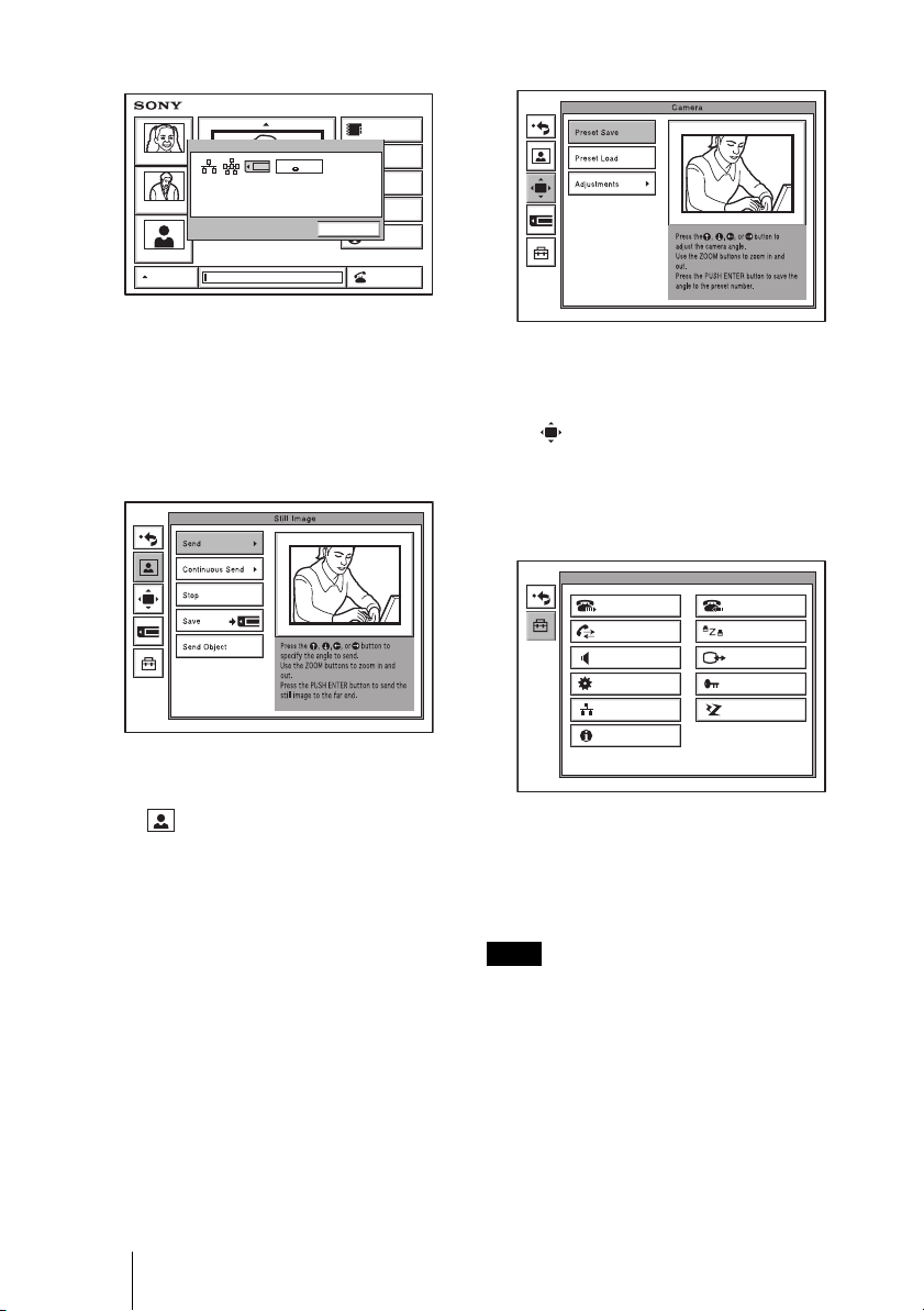
Still Image menu
The Still Image menu is used to control still
images. The menu appears when you select
“Menu” on the launcher menu, and then
select when it appears.
For details on the Still Image menu, see
pages 113 to 120.
The Camera menu is used to adjust the
camera angle or to zoom the displayed
image. The menu appears when you select
“Menu” on the Launcher menu, and then
select when it appears.
For details on the Camera menu, see page
94 to 99.
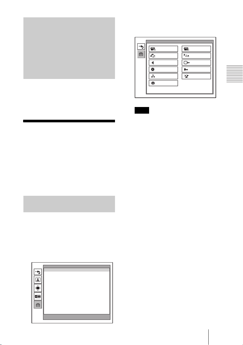
Setup menu (for the administrator)
Setup
Dial
Communication
Audio
General
LAN
Information
Answer
Status
Video
Administrator
ISDN
The Setup menu for the administrator is used
to set various detailed items on the system.
The menu can be displayed by holding down
the MENU button on the Remote
Commander.
40 Using the Menus
Note
You can also display the Setup menu for the
administrator by pressing the numeric button
9 on the Remote Commander twice while
the Setup menu (Initial Setup) or the screen
in communication is displayed.
For details on the Setup menu (for the
administrator), see pages 43 to 67.
Page 41
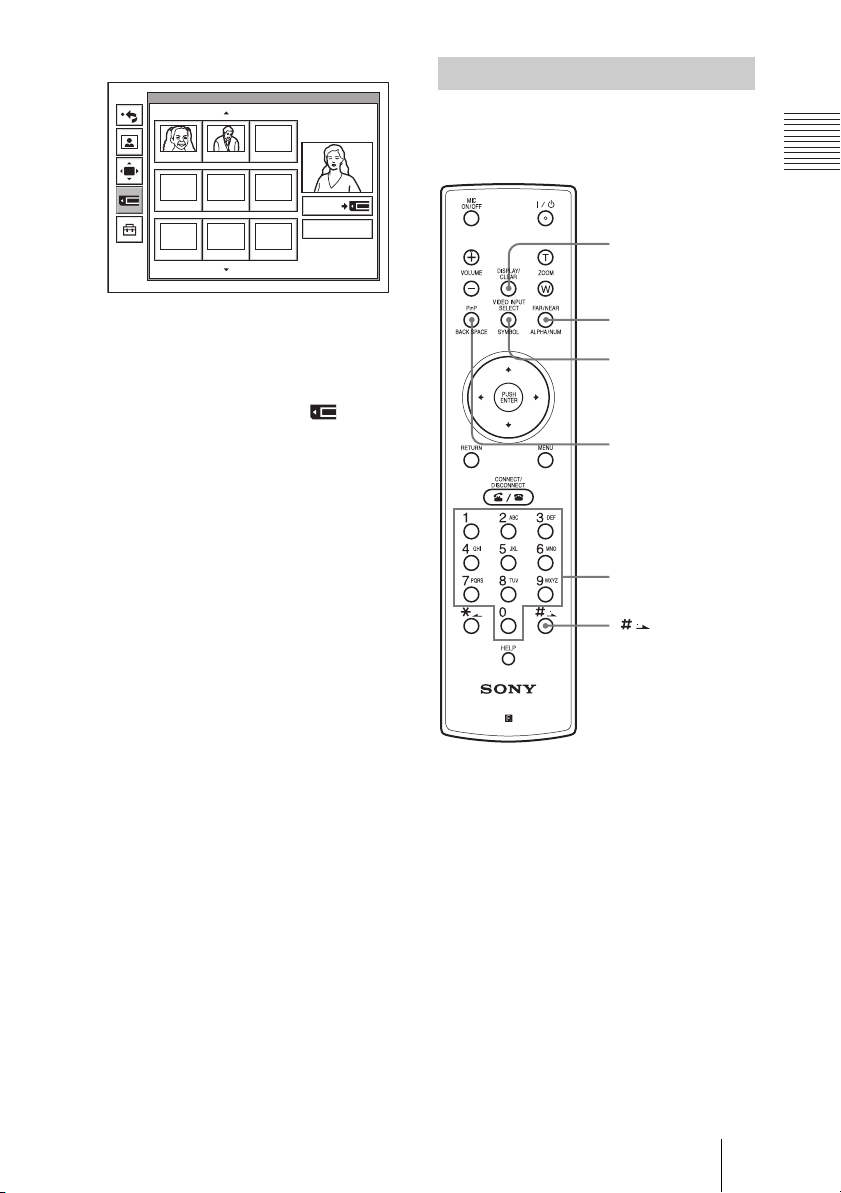
Memory Stick menu
JPEG JPEG JPEG
JPEG JPEG JPEG
Memory Stick
JPEG
Save
Memory Stick Format
Entering Characters
This section explains how to enter the
letters, numbers or symbols on the text box
in the menu using the Remote Commander.
DISPLAY (CLEAR)
button
The Memory Stick menu is used to use
“Memory Sticks”. The menu is not available
if there is no “Memory Stick” inserted in the
Communication Terminal. The menu
appears when you select “Menu” on the
launcher menu, and then select when it
appears.
For details on the Memory Stick menu, see
pages 108 to 112 and pages 118 to 120.
FAR/NEAR
(ALPHA/NUM)
button
VIDEO INPUT
SELECT (SYMBOL)
button
PinP (BACK
SPACE) button
Number buttons
(dot) button
PCS-RG70
To enter letters or numbers
1 Press the FAR/NEAR (ALPHA/
NUM) button repeatedly to enable the
letters or numbers to be input.
2 Press the number buttons repeatedly to
enter the letters or numbers that you
want.
You can enter the letter shown on each
button by pressing it repeatedly.
You can enter the number shown on
each button by pressing it.
41Using the Menus
Page 42

To enter a symbol
Press the VIDEO INPUT SELECT
(SYMBOL) button repeatedly to select the
desired symbol. Pressing the 0 button
repeatedly also enables you to enter a
symbol.
To enter a dot (.) for an IP address
Press the button.
To delete a character
Press the PinP (BACK SPACE) button. The
last entered character is deleted.
To delete all characters in a line
Move the cursor to the line to be deleted,
then press the DISPLAY (CLEAR) button.
Note
When you press the HELP button on the
Remote Commander to show balloon helps or
help screens, you can hide only the balloon
help used for entering characters.
Select “Character Input Help” from the
General Setup menu, then select “Off”. (See
page 53.)
42 Using the Menus
Page 43
Chapter 2:
2 Hold down the MENU button.
The Setup menu for the administrator
appears on the monitor screen.
Registration and
Setup for System
Administrators
This chapter describes the registration and
settings to be carried out by the system
administrator.The chapter is intended to be
read by the system administrator.
Registering Local Information
Before starting a conference, register the
required information on the local terminals
of the system using the Setup menu for
administrator. This section describes how to
display the Setup menus for the
administrator and gives a introduction to the
menus.
Opening the Setup Menu for the Administrator
1 Press the MENU button on the
Remote Commander, or use the V, v,
B or b button to select “MENU” in the
launcher menu, then press the PUSH
ENTER button.
The Setup menu appears on the monitor
screen.
Setup
Setup
Dial
Communication
Audio
General
LAN
Information
Note
You can also display the Setup menu for
the administrator by pressing the numeric
button 9 on the Remote Commander twice
while the Setup menu or the screen in
communication is displayed.
Choosing the following items from the
Setup menu for the administrator opens
the respective menus.
Dial: Dial Setup menu (see page 44)
Answer: Answer Setup menu (see page
46)
Communication: Communication
Setup menu (see page 46)
Status: Status menu (see page 49)
Audio: Audio Setup menu
(see page 50)
Video: Video Setup menu
(see page 52)
General: General Setup menu
(see page 53)
Administrator: Administrator Setup
menu (see page 56)
LAN: LAN Setup menu (see page 59)
ISDN: ISDN Setup menu (see page 64)
Information: Information menu (see
page 67)
Answer
Status
Video
Administrator
ISDN
Press and hold the [MENU] button to show more
detailed setup menus.
3 Use the V, v, B or b button on the
Remote Commander to select the
menu you want to set, then press the
PUSH ENTER button.
43Registering Local Information
Page 44
The selected setup menu appears.
Dial Setup
Page: 1/2
Line I/F
Bonding
Telephone Mode
More Options Enable
User Name Input
IP
Auto
Auto
Off
Off
4 Set the respective items.
Save Cancel
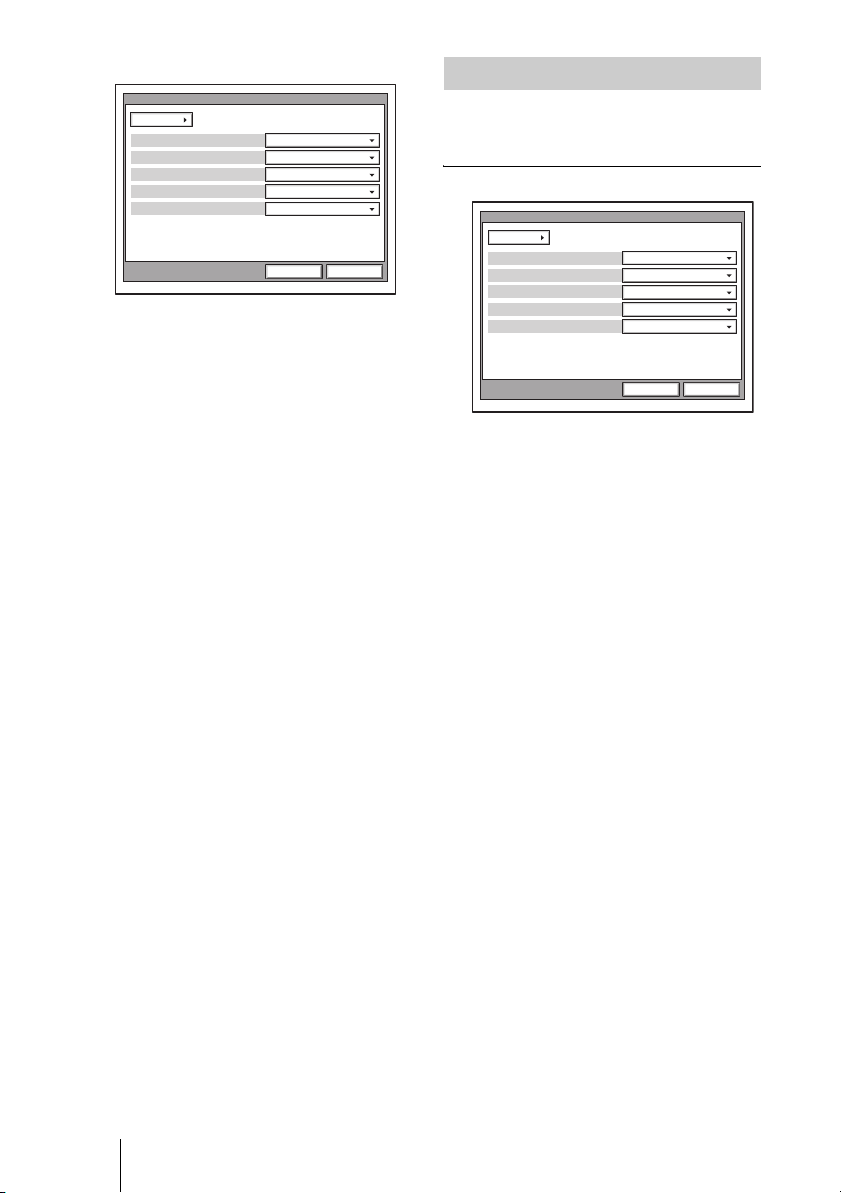
Dial Setup Menu
The Dial Setup menu is used to set the
attributes for dialing.
Page 1/2
Dial Setup
Page: 1/2
Line I/F
Bonding
Telephone Mode
More Options Enable
User Name Input
IP
Auto
Auto
Off
Off
For details on individual items, see the
relevant menu pages.
5 After the setting is completed, use the
V, v, B or b button to select “Save”,
then press the PUSH ENTER button.
The setting is saved, and the Setup menu
(for the administrator) is restored.
To cancel the setup
V, v, B or b button on the Remote
Use the
Commander to select “Cancel”, then press
the PUSH ENTER button. Or press the
RETURN button on the Remote
Commander.
To page up or down the selected
menu
Use the
V, v, B or b button on the Remote
Commander to select the Page box, then
press the b button to advance the page and
the
B button to go back to the previous page.
Save Cancel
Line I/F
Allows you to select the line interface that
you normally use.
IP: Connects a videoconferencing system
via a LAN.
ISDN: Connects a videoconferencing
system via ISDN.
ISDN (Telephone): Connects an audio-only
telephone via ISDN (voice meeting).
Bonding
*
Allows you to select whether you use a
process called bonding to connect multiple
ISDN lines.
Through bonding, the connection of one line
enables you to automatically connect all
other lines.
*
Bonding (Bandwidth on Demand
Interoperability Group) is a registered
trademark of THE BONDING
CONSORTIUM.
Auto: Automatically activates the
connection through bonding if this
feature is available at the remote party.
On: Always connects a remote party
through bonding.
44 Registering Local Information
Telephone Mode
Allows you to select the audio compression
format when conducting a voice meeting.
Auto: Selects an appropriate format
automatically.
Page 45
G.711µ-law: Selects the format based on the
G.711µ-law standard.
G.711A-law: Selects the format based on
the G.711A-law standard.
More Options Enable
Allows you to select whether you can
modify individual dial lists in the Dial Setup
menu.
On: Enables the setting of each dial list.
When you select “More Options
Enable” in the List Edit menu of the
Phone Book, the Dial Setup menu
appears.
Off: Enables the application of settings to all
the dial lists in the Dial Setup menu
simultaneously.
User Name Input
Allows you to select whether to register
users names in the communications log
before communication starts.
On: Select when you want to record user
names. Each time dialing takes place,
the user name input menu appears.
Off: Disables the recording of the user
names.
Page 2/2
Prefix-C: Select when you use the prefix set
in “Prefix-C” on page 2 of the Dial Setup
menu.
Prefix-A
“Prefix” on page 1 of the Dial Setup menu is
set to “Prefix-A”, the line number prefixed
by the prefix (dial number) registered in this
box is dialed.
Prefix-B
“Prefix” on page 1 of the Dial Setup menu is
set to “Prefix-B”, the line number prefixed
by the prefix (dial number) registered in this
box is dialed.
Prefix-C
“Prefix” on page 1 of the Dial Setup menu is
set to “Prefix-C”, the line number prefixed
by the prefix (dial number) registered in this
box is dialed.
Note
Enter “9” when this is required to make an
outgoing call.
Select LAN Prefix
Allows you to select whether to use the LAN
prefix.
Enable: Enable the LAN prefix.
Disable:Disable the LAN prefix.
Dial
Page: 2/2
Prefix
Prefix-A
Prefix-B
Prefix-C
Select LAN Prefix
LAN Prefix
Prefix-None
Enable
Save Cancel
Prefix
Select the prefix number (call number
prefixed to a line number).
Prefix-None: Select when you are not using
a prefix number.
Prefix-A: Select when you use the prefix set
in “Prefix-A” on page 2 of the Dial
Setup menu.
Prefix-B: Select when you use the prefix set
in “Prefix-B” on page 2 of the Dial Setup
menu.
LAN Prefix
When connecting via a LAN, the information
entered into this box is added to the beginning
of the IP address. Select whether to use the
LAN prefix in the Select LAN Prefix option.
45Registering Local Information
Page 46

Answer Setup Menu
Communication Setup Menu
The Answer Setup menu is used to set up
call reception.
Page 1/1
Answer
Page: 1/1
Auto Answer
ISDN MSN
Mic on Answer
Reject Answer
On
Off
On
On
Save Cancel
Auto Answer
Allows you to select whether the system
answers calls automatically.
Auto Answer: Answers calls automatically.
When a call comes in, the line is
automatically connected.
Off: Allows you to answer calls manually.
When a call comes in, the phone rings. If
you select “OK” in the “Respond?”
message, the line is connected.
ISDN MSN
Allows you to select whether you are using
the Multiple Subscriber Number.
On: Select when you use the Multiple
Subscriber Number.
Off: Select when you do not use the
Multiple Subscriber Number.
Mic on Answer
Allows you to select whether to transmit
audio from your site when answering a call
from the remote party.
On: Transmit audio when answering a call.
Off: Do not transmit audio when answering
a call.
Reject Answer
Allows you to select whether to connect a
remote party calling during a multipoint
videoconference.
On:
Disables the connection of a remote party.
Off: Enables the connection of a remote
party.
The Communication Setup menu is used to
set up communications.
Note
Contents of the Communication Setup menu
vary according to the settings configured by
“Individual Settings”, and to whether the
MCU software (see page 169) is installed or
not.
Page 1/3
Communication
Page: 1/3
Individual Settings
Number of Lines
LAN Bandwidth
Off
1B
64Kbps
Save Cancel
Individual Settings
Allows you to select whether to perform
transmission, reception, and multipoint
settings individually.
On: Select to perform transmission, reception,
and multipoint settings individually.
Off: Select to perform all settings
simultaneously.
Number of Lines
Allows you to select the number of ISDN
channels used in bonding calls. If you set
“Individual Settings” to “On” on page 1 of
the Communication Setup menu, you can
perform this setting individually for
transmission, reception, and multipoint
conferencing.
LAN Bandwidth
Allows you to select the bandwidth used
when connected to a LAN. If you set
“Individual Settings” to “On” on page 1 of
the Communication Setup menu, you can
perform this setting individually for
transmission, reception, and multipoint
conferencing.
46 Registering Local Information
Page 47

Page 2/3
Communication
Page: 2/3
Video Mode
Interlace Mode
4CIF Mode
Video Frame
Audio Mode
Restrict
Auto
On
On
Auto
Auto
Auto
Save Cancel
Video Mode
Allows you to select the compression format of
pictures sent to a remote party. If you set
“Individual Settings” to “On” on page 1 of the
Communication Setup menu, you can perform
this setting individually for transmission,
reception, and multipoint conferencing.
Auto: Send pictures matching the format of
the remote site.
H.264: Send pictures based on the H.264
format.
MPEG4: Send pictures based on the
MPEG4 format.
H.263+: Send pictures based on the H.263+
format.
H.261: Send pictures based on the H.261
format (when sending still images using
Annex D).
Auto: Switch the number of frames
automatically.
15fps: Send CIF format pictures at a
maximum rate of 15 frames per second.
30fps: Send CIF format pictures at a
maximum rate of 30 frames per second.
Audio Mode
Allows you to select the compression format
of audio to be sent to a remote party. If you
set “Individual Settings” to “On” on page 1
of the Communication Setup menu, you can
perform this setting individually for
transmission, reception, and multipoint
conferencing.
Auto: Send audio matching the compression
format of the remote site.
MPEG4 Audio: Send audio based on the
MPEG4 AAC format.
G.722.1: Send audio based on the G.722.1
standard.
G.722: Send audio based on the G.722
standard.
G.729: Sends audio based on the G.729
standard.
G.728: Sends audio based on the G.728
standard.
G.723.1: Sends audio based on the G.723.1
standard.
G.711: Sends audio based on the G.711
standard.
Interlace Mode
Allows you to specify whether to use the
interlace SIF format in video mode.
On: Use the interlace SIF format.
Off: Not to use the interlace SIF format.
4CIF Mode
Allows you to specify whether to use the 4CIF
format in video mode.
On: Use the 4CIF format.
Off:Not to use the 4CIF format.
Video Frame
Allows you to select the number of video
frames during transmission. If you set
“Individual Settings” to “On” on page 1 of the
Communication Setup menu, you can perform
this setting individually for transmission,
reception, and multipoint conferencing.
47Registering Local Information
Page 48
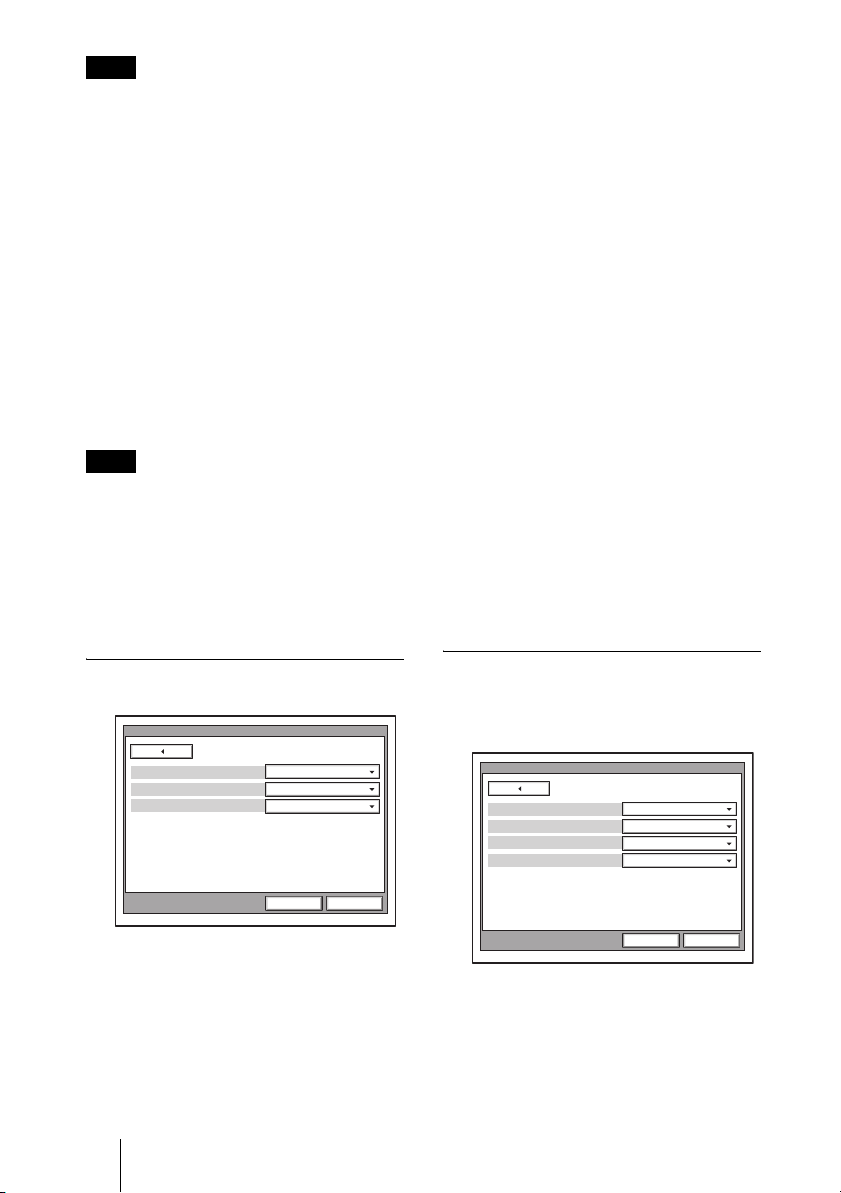
Note
When the remote videoconferencing system
does not support the audio mode selected by
the local site, the mode automatically becomes
“G.711”.
Restrict
Allows you to select the ISDN transmission
rate at dialing. If you set. “Individual
Settings” to “On” on page 1 of the
Communication Setup menu, you can
perform this setting individually for
transmission, reception, and multipoint
conferencing.
Auto: Select when connecting a remote
party via a normal ISDN line.
56K: Select when connecting a remote party
located in a region or country where the
ISDN transmission rate is 56 Kbps.
Note
The system is set to connect an ISDN line at the
transmission rate of 64 Kbps by default.
However, some countries, such as the USA,
and some regions may use the ISDN
transmission rate of 64 Kbps and 56 Kbps. You
may not communicate with such countries or
regions at 64 Kbps, so you must therefore set
“Restrict” to “56K” before dialing.
T.120 Data
Allows you to select whether to perform data
conferences with the T.120 standard using
NetMeeting (only for ISDN connections). If you
set “Individual Settings” to “On” on page 1 of the
Communication Setup menu, you can perform
this setting individually for transmission,
reception, and multipoint conferencing.
On: Enables T.120 data conferences.
Off: Disables T.120 data conferences.
For details about T.120 data conferences,
see “Conducting a Data Conference Using
NetMeeting – T.120 Data Conference” on
page 138.
H.239
Allows you to select whether you can use the
dual video presentation mode based on the
H.239 standard. If you set “Individual
Settings” to “On” on page 1 of the
Communication Setup menu, you can
perform this setting individually for
transmission, reception, and multipoint
conferencing.
On: Enables the dual video presentation
mode based on the H.239 standard.
Off: Disables the dual video presentation
mode based on the H.239 standard.
Page 3/3
Communication
Page: 3/3
Far End Camera Control
T. 120 Data
H 239
On
Off
On
Save Cancel
Far End Camera Control
Allows you to select whether to enable the
control of each other's cameras from each
other's site.
On: Enables the control of each other's
cameras. This is the default setting.
Off: Disables the control of each other's
cameras.
48 Registering Local Information
Page 4/4
This page is only displayed when MCU
software (page 169) is installed.
Communication
Page: 4/4
Multipoint Mode
Split
Sender Screen
Auto
SplitBroadcast Mode
Automatic
Full Screen
Save Cancel
Multipoint Mode
Allows you to select whether to conduct
multipoint videoconferences.
Auto: Switch from two-point
videoconference to multipoint
videoconference automatically.
Page 49
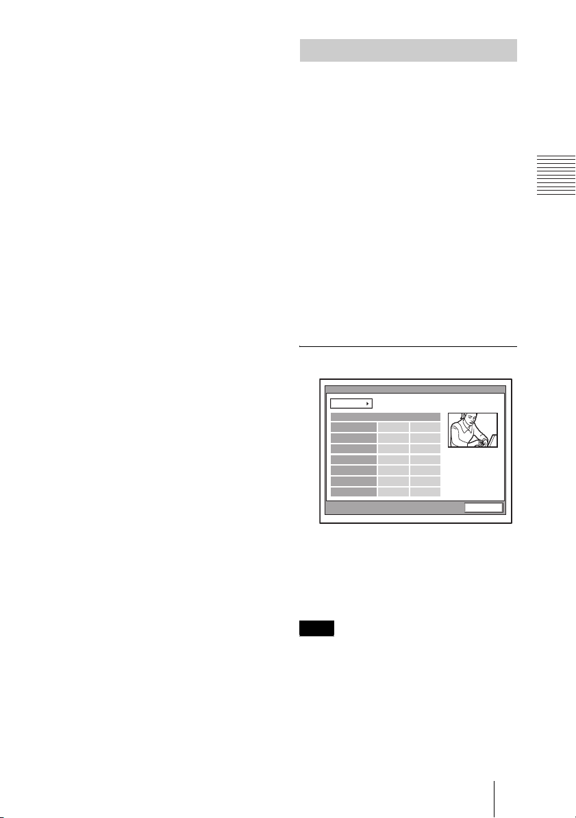
On: Always conducts a multipoint
videoconference.
Broadcast Mode
Allows you to select the broadcast mode.
Split: Displays the video from the connected
terminals in split windows.
Voice Activate: Detects the terminal where
the speaker has the loudest voice, and
sends the video from this terminal to all
other terminals.
Split
Allows you to select the type of split display
used to display local and remote video on a
single monitor during a multipoint
videoconference.
Automatic: When there are up to three
terminals, the display is automatically
split into four. When there are four or
five terminals, the display is
automatically split into six.
Six-screen Mosaic: The display is split into
six, regardless of the number of
terminals.
Sender Screen
Allows you to select the monitor display of
transmitting monitors during multipoint
videoconference.
Full Screen:Display the entire screen.
Automatic: When there are up to three
terminals, the display is automatically
split into four. When there are four or
five terminals, the display is
automatically split into six.
Six-screen Mosaic: The display is split into
six, regardless of the number of
terminals.
Status Menu
The Status menu shows the current status of
communication.
The ISDN Line Status, LAN Line Status or
LAN Connection Status will also be
displayed depending on the line interface
used.
Communication Status
One page for each point connected to the
system will be displayed. The connected
point is shown at the upper right corner of
the page as “Connection A (or B, C....)”.
The terminal’s name of the point is also
displayed at its side.
The items below are shown both in the
columns for “Encode” and “Decode”. The
descriptions under “Encode” show the setting
status of the local system and those under
“Decode” show the status of the receiving.
Page 1/2
Status
Page: 1/2
Audio Mode
Video Mode
Frame Rate
LSD Rate
MLP Rate
HMLP Rate
Audio Mode
Displays the current audio encoding format.
Video Mode
Displays the current video encoding format.
(Encode) (Decode)
G.728 G.728
H.261 CIF H.261 CIF
15fps 15fps
6400
Off
62.4K
Cancel
Note
The audio encoding and video encoding
formats used for communication with a remote
party may differ from the settings in this menu,
depending on the status of videoconferencing
system on the remote site.
Frame Rate
Displays the maximum frame rate of motion
pictures.
49Registering Local Information
Page 50
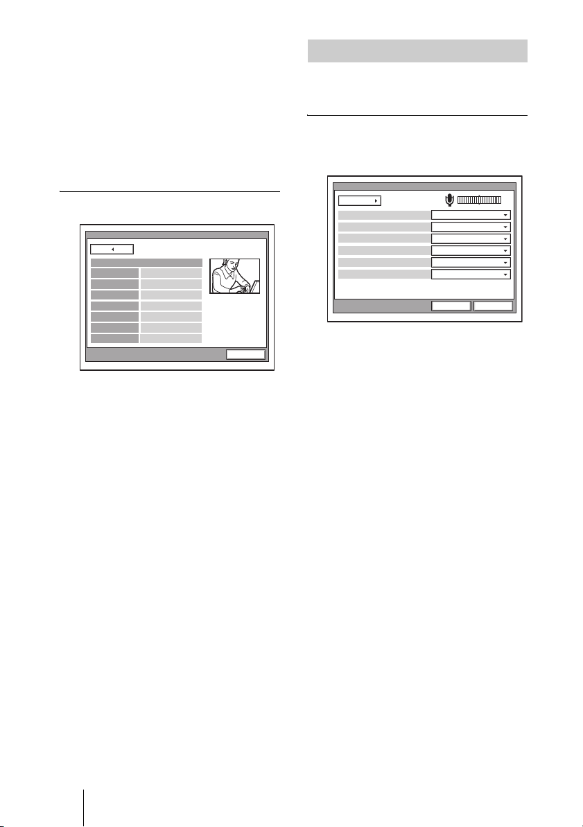
LSD Rate
Displays the LSD (Low Speed Data) rate.
MLP Rate
Displays the MLP (Multi Layer Protocol)
rate.
HMLP Rate
Displays the HMLP (High Speed Multi
Layer Protocol) rate.
Page 2/2
Status
Page: 2/2
Camera Control
Data Control
Line I/F
Rate
DSB
Whiteboard
On
On
BRI
2 x 64K
On
On
Cancel
Camera Control
Displays whether control of each other's
camera is enabled.
Data Control
Displays whether the T.120 data conference
is enabled.
Line I/F
Displays the line interface you are using.
Rate
Displays the number of lines connected and
transmission rate during communication.
DSB
Displays whether the PCSA-DSB1S Data
Solution Box is connected.
Whiteboard
Displays whether the mimio Xi attached to
your whiteboard is enabled.
Audio Setup Menu
The Audio Setup menu is used to set various
audio items.
Page 1/2
The level meter indicating the audio input
level is displayed.
Audio
Page: 1/2
Input Select
CTE
Echo Canceller
Lip Sync
Recording Mute
Input Select
Allows you to select the audio input.
MIC: Inputs audio from the microphone.
AUX: Inputs audio from auxiliary external
equipment.
MIC+AUX: Inputs audio from the
microphone and auxiliary external
equipment.
Mic Select
Allows you to select the microphone to be
used.
MIC: Uses the microphone connected to the
Communication Terminal.
DSB MIC: Uses the microphone connected
to the Data Solution Box.
LINE: Uses the microphone connected to
the AUDIO IN LINE jack.
CTE
Allows you to select the input where the
CTE-600 Communication Transducer is
connected.
Off: Does not use the CTE-600
Communication Transducer.
LINE: Inputs from the AUDIO IN LINE
jack of the Communication Terminal.
DSB AUX IN: Inputs from the AUX IN jack
of the Data Solution box.
MIC
MICMic Select
Off
On
Off
On
Save Cacel
50 Registering Local Information
Page 51
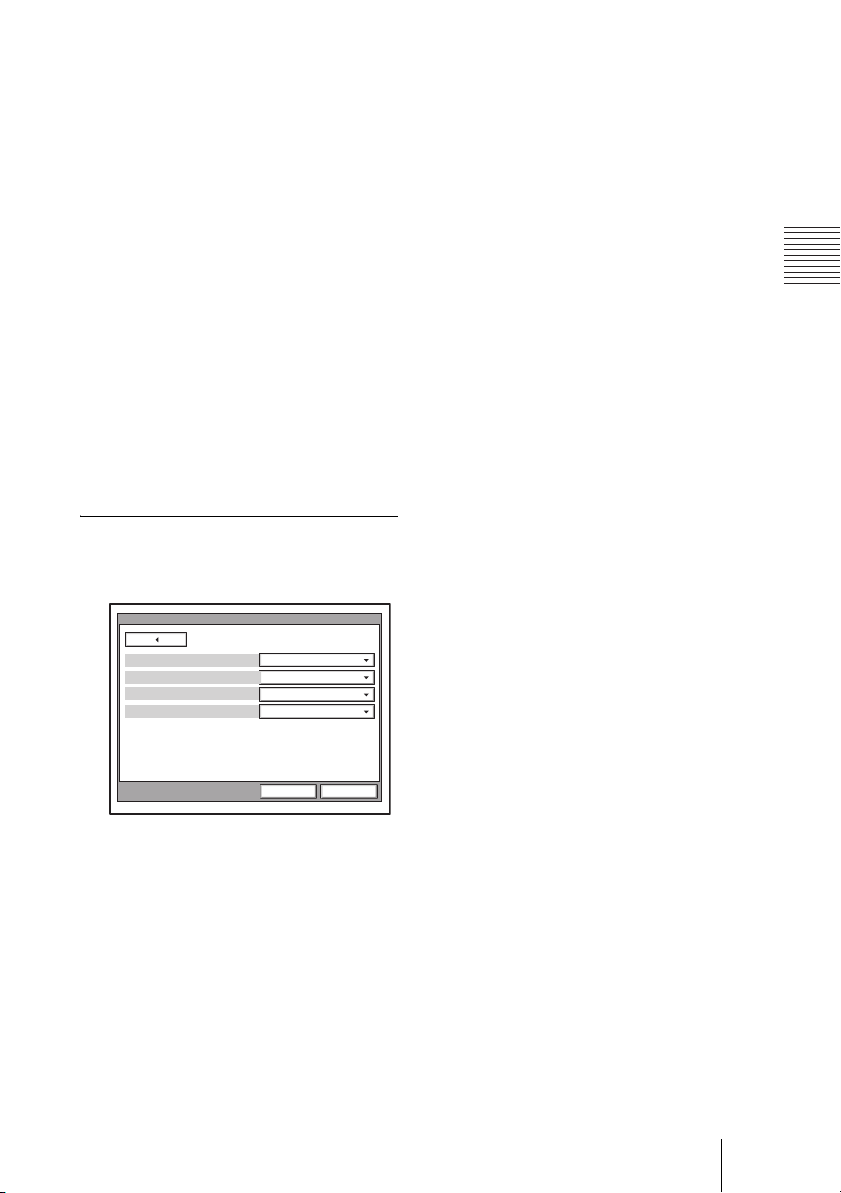
Echo Canceller
Allows you to select whether to use the echo
canceller.
On: Enables the echo canceller.
Off: Disables the echo canceller.
Lip Sync
Allows you to select whether to use the Lip
Sync function.
On: Enables the Lip Sync function.
Off: Disables the Lip Sync function.
Recording Mute
When you connect an audio recording
device to the AUDIO IN AUX and AUDIO
OUT MIXED jacks to record the conference
audio, the recording mute function prevents
echo from affecting remote sites. This is
only available when “Input Select” is set to
“AUX” or “MIC + AUX”.
On: Enables the recording mute function.
Off: Disables the recording mute function.
Page 2/2
The level meter indicating the audio input
level is displayed.
Audio
Page: 2/2
Beep Sound
Dial Tone
Ringer Tone
On
OnSound Effect
On
On
Sound Effect
Allows you to select whether to output
sounds when the system starts, a
videoconference starts or ends.
On: Outputs sounds.
Off: Does not output sounds.
Dial Tone
Allows you to select whether to output a
ring-back and busy tones when you are
dialing.
On: Outputs dial tones.
Off: Does not output dial tones.
Ringer Tone
Allows you to select whether to output a
ringer tone when you receive a call.
On: Outputs the ringer tone.
Off: Does not output the ringer tone.
Save Cacel
Beep Sound
Allows you to select whether the system
beeps each time you press a button on the
Remote Commander.
On: Enables beeping.
Off: Disables beeping.
51Registering Local Information
Page 52
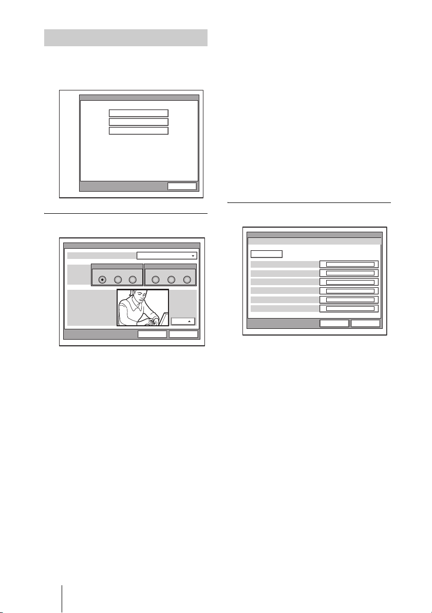
Video Setup Menu
The following menus appear when you
select “Video” on the Setup menu for the
administrator. Select the desired menu.
Video Setup
Input Video
Custom Input Label
Monitor Out
Cancel
Video Input Page 1/1
Dual Video
Connection
Monitor
Dual Video
Allows you to split the display in two.
On: Enables dual video.
Off: Disables dual video.
Split
Allows you to split the display in two.
Off: Does not split the display.
Horizontal: Splits the display horizontally.
Vertical: Splits the display vertically.
MAIN
Allows you to select the video input for
Input 1.
CAMERA: Selects the video signal from
the device connected to the MAIN
CAMERA connector.
IR1: Selects the video signal from the
optional PCS-DS150/DS150P
Document Stand.
Video Setup
MAIN
CAMERA IR1 IR2AUX1 AUX2CAMERA
SUB
Save
Off
Split
Off
Cancel
AUX1: Selects the video signal from the
device connected to the MAIN AUX IN
connector.
SUB
Allows you to select the video input for
Input 2.
CAMERA: Selects the video signal from
the device connected to the SUB
CAMERA connector.
IR2: Selects the video signal from the
optional PCS-DS150/DS150P
Document Stand.
AUX2: Selects the video signal from the
device connected to the SUB AUX IN
connector.
Custom Input Label Page 1/1
Custom Input Label
Page: 1/1
Main Camera
IR1
AUX1
Sub Camera
IR2
AUX2
Video Setup
Save Cacel
Allows you to set the names displayed in the
Video Input Select menu.
Main Camera: Allows you to enter the
name displayed when “Main Camera” is
selected in the Video Input Select
screen.
IR1: Allows you to enter the name displayed
when “IR1” is selected in the Video
Input Select screen.
AUX1: Allows you to enter the name
displayed when “AUX1” is selected in
the Video Input Select screen.
Sub Camera: Allows you to enter the name
displayed when “Secondary camera” is
selected in the Video Input Select
screen.
IR2: Allows you to enter the name displayed
when “IR2” is selected in the Video
Input Select screen.
AUX2: Allows you to enter the name
displayed when “AUX2” is selected in
the Video Input Select screen.
52 Registering Local Information
Page 53
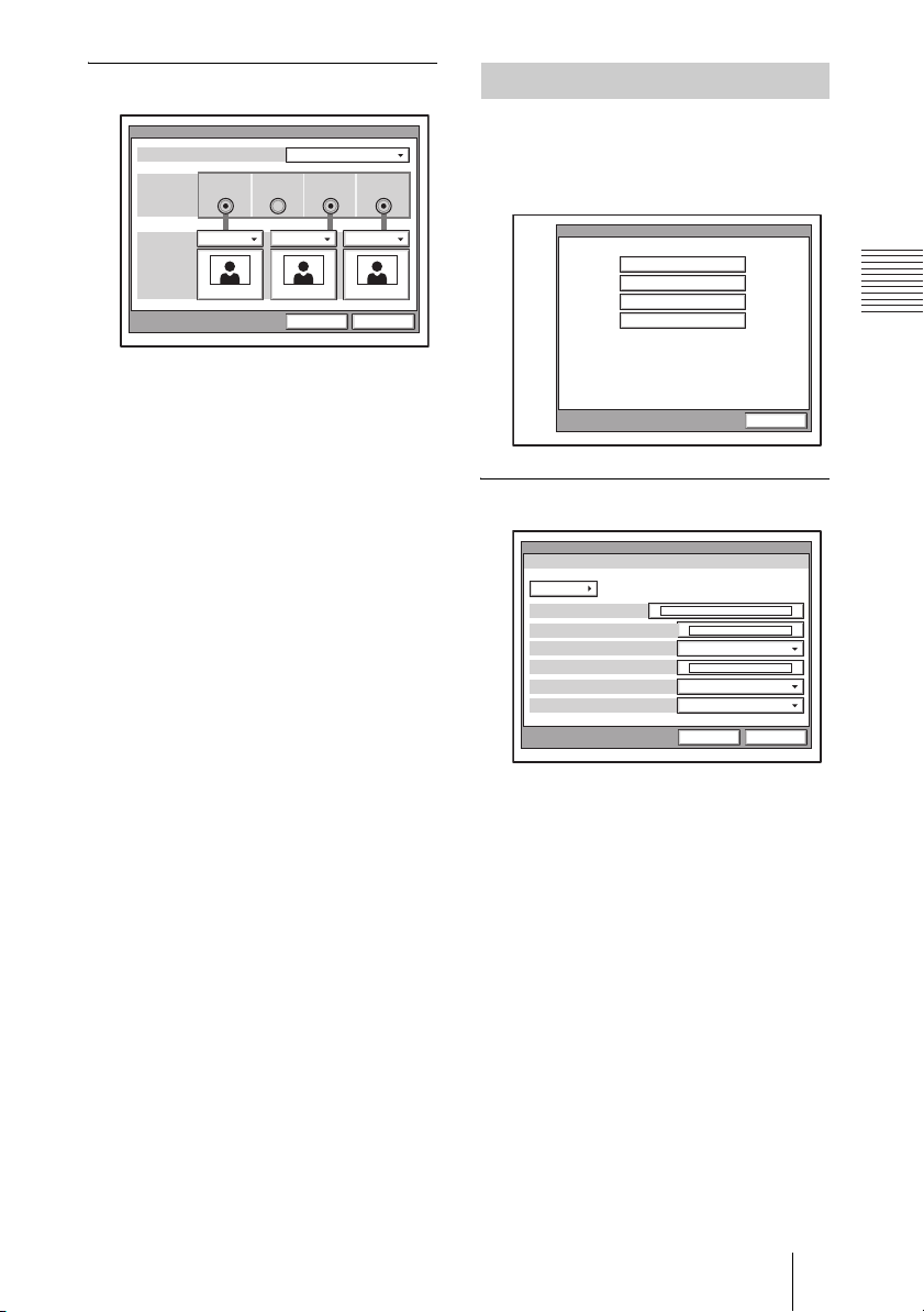
Monitor Out
General Setup Menu
Monitor Out
Monitors
Connection
Monitor
VIDEO1 VIDEO2 RGB OUT
1
SubMain
Save Cancel
RGB OUT(DSB)
Sub
Monitors
Allows you to specify the number of
monitors connected to the system.
1: One monitor connected.
2: Two monitors connected.
3: Three monitors connected.
Connection
Select the connector(s) used to connect the
monitor(s).
VIDEO 1: Select when the monitor is
connected to the VIDEO 1 connector.
VIDEO 2: Select when the monitor is
connected to the VIDEO 2 connector.
RGB OUT: Select when the monitor is
connected to the RGB OUT connector of
the main unit.
RGB OUT (DSB): Select when the monitor
is connected to the RGB OUT connector
of the Data Solution Box.
Monitor
Select whether to use the connected monitor
as the sub- or main monitor.
Main: The connected monitor is used as the
main monitor.
Sub: The connected monitor is used as a
sub-monitor.
The following menus appear when you
select “General” on the Setup menu for
the administrator. Select the desired
menu.
General Setup
Device Setup
Menu Screens
Whiteboard
Launcher
Cancel
Device Setup Page 1/2
Device Setup
Page: 1/2
Clock Set
Terminal Name
Standby Mode
Standby Time
Last Number Registration
Control by Far End
General
MM/DD/YYYY HH:MM:SS
11/30/2003 19:25:53
Off
On
On
Save Cancel
Clock Set
Enter the current date and time.
Terminal Name
Input the terminal name to report when the
system is connected to the remote system.
Standby Mode
Allows you to select whether the
Communication Terminal enters standby
mode if idle for a specified period of time.
On: Allows the system to go on standby.
Off: Does not allow the system to go on
standby.
Standby Time
Specify the time the system must remain idle
before entering the standby mode. This time
can be between 1 and 99 minutes.
53Registering Local Information
Page 54
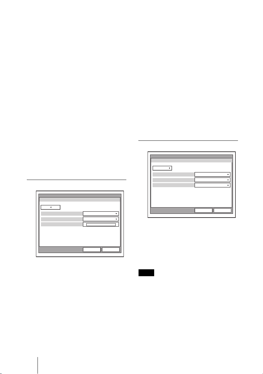
For details on the standby mode, see
“Standby Mode Function” on page 29.
Last Number Registration
Allows you to select whether to register the
remote party in the Phone Book after the
conference is finished.
On: If the remote party is not registered in
the Phone Book, the “Register this
participant in the list?” message appears
on the monitor screen when conference
finishes. When you select “OK”, the List
Edit menu opens.
Off: The message above does not appear and
remote party registration does not take
place.
Control by Far End
When “Far End Camera Control” is set to
“On” in the Communication Setup menu,
you can temporarily reject the camera
control command transmitted by the remote
party.
On: Accepts the camera control command.
Off: Rejects the camera control command.
Device Setup Page 2/2
Device Setup
Page: 2/2
Language
T.120 PC Address
General
English
MODE1IR Repeater Mode
. . .
Save Cancel
Language
Allows you to select the menu and display
language used by the system. You can select
from the following languages: English,
French, German, Japanese, Spanish, Italian,
Simplified Chinese, and Portuguese.
IR Repeater Mode
Allows you to select the Remote Controller
mode of the IR repeater. You should
normally select “MODE 1”.
MODE 1: Select when using mode 1. This
setting does not usually need to be
changed.
MODE 2: Select when using mode 2. Select
this mode when the system does not
operate properly under “MODE 1”.
MODE 3: Select when using mode 3.
MODE 4: Select when using mode 4.
T.120 PC Address
When conducting a data conference based
on the T.120 standard using NetMeeting,
enter the IP address of the computer. (Used
for ISDN connections.)
For details on data conferences based on the
T.120 standard, see “Conducting a Data
Conference Using NetMeeting – T.120 Data
Conference” on page 138.
Menu Screens Page 1/3
Menu Screens
Page: 1/3
Time Display
Character Input Help
General
On
OffDisplay Terminal Name
On
Save Cancel
Time Display
Allows you to select whether you display the
elapsed time on the monitor screen during a
conference.
On: Displays the elapsed time.
Off: Does not display the elapsed time.
Note
During communication, some items that
cannot be modified are also displayed.
Display Terminal Name
Allows you to select whether to display the
connected terminal names on the monitor
screen at the time of disconnection.
Off: Not to display the terminal names.
Show temporarily: Display the terminal
names for a brief moment.
Always show: Display the terminal names.
54 Registering Local Information
Page 55
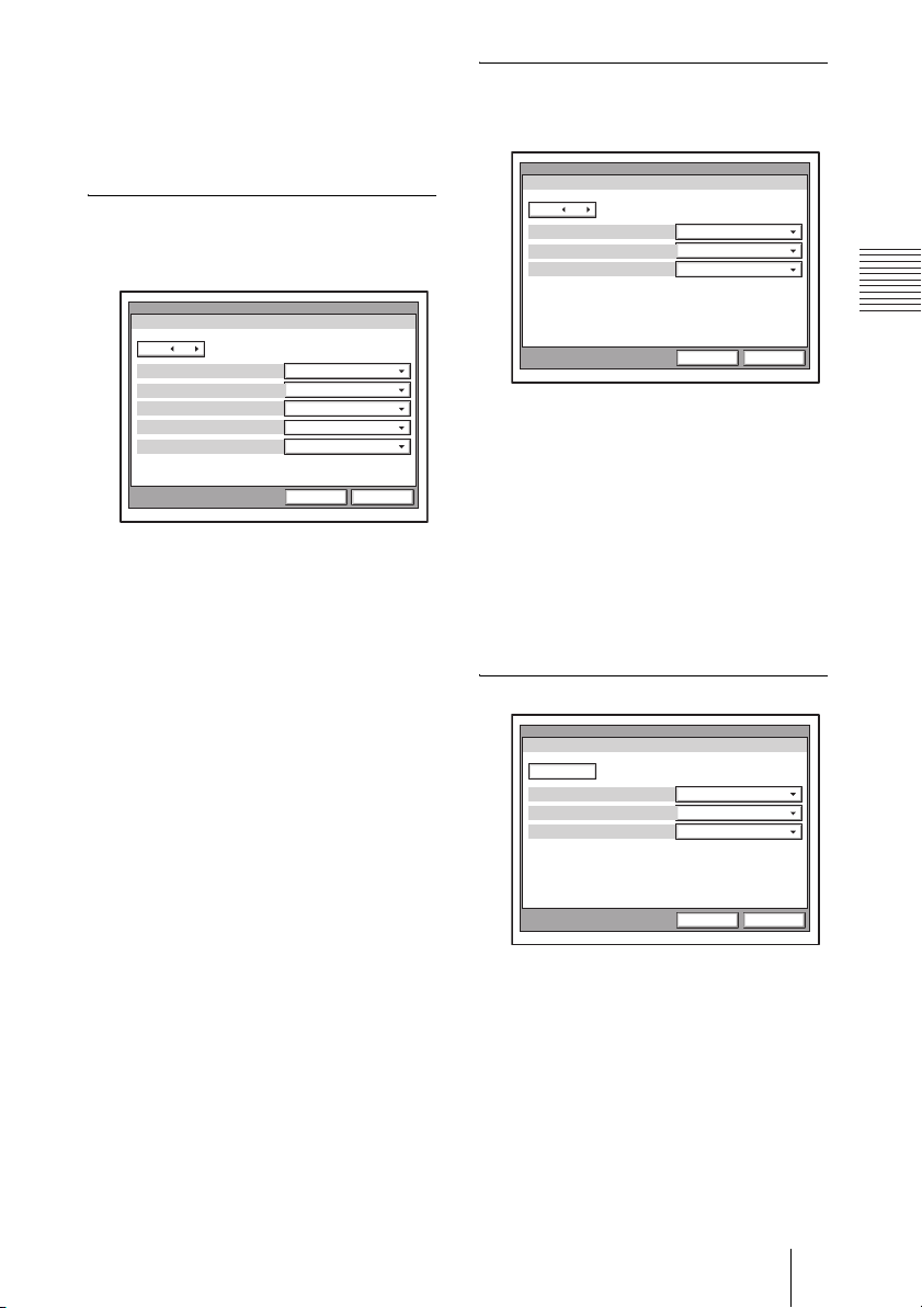
Character Input Help
Allows you to select whether to display help
text when entering characters and numbers.
On: Display help.
Off: Not to display help.
Menu Screens 2/3
Allows you to select whether to display
menus and buttons of the launcher screen.
Menu Screens 3/3
Allows you to select whether to display
menus and buttons of the launcher screen.
Menu Screens
Page: 3/3
Direct Phone Book Button
Guide
General
On
OnDirect Dial
On
Menu Screens
Page: 2/3
Phone Book Button
History Button
Menu Button
Information Button
General
On
OnDetailed Dial Button
On
On
On
Save Cancel
Phone Book Button
On: Display “Phone Book”.
Off: Not to display “Phone Book”.
Detail Dial Button
On: Display “Detail Dial”.
Off: Not to display “Detail Dial”.
History Button
On: Display “History”.
Off: Not to display “History”.
Menu Button
On: Display “Menu”.
Off: Not to display “Menu”.
Information Button
On: Display “Information”.
Off: Not to display “Information”.
Save Cancel
Direct Phone Book Button
On: Display “Direct Phone Book”.
Off: Not to display “Direct Phone Book”.
Direct Dial
On: Display the Direct Dial text box.
Off:
Not to display the Direct Dial text box.
Guide
On: Display the guide.
Off: Not to display the guide.
Whiteboard Page 1/1
Whiteboard
Page: 1/1
Whiteboard Attachment
Whiteboard Size Measurement
General
Vertical
3'0"x4'0"Whiteboard Size
Inches
Save Cancel
Whiteboard Attachment
Allows you to select whether to attach the
optional mimio-Xi vertically or horizontally
on a whiteboard.
Vertical: Attaches the mimio-Xi vertically
on a whiteboard.
Horizontal: Attaches the mimio-Xi
horizontally on a whiteboard.
55Registering Local Information
Page 56
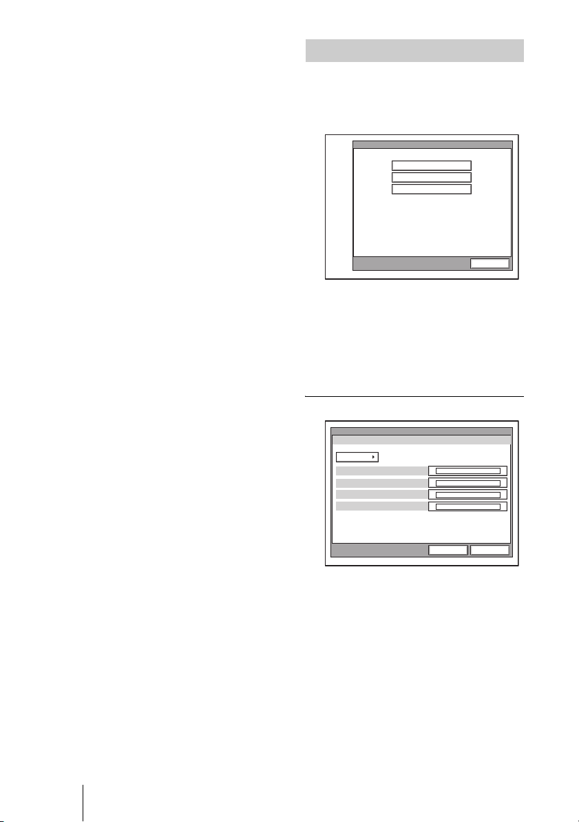
Whiteboard Size
Allows you to select the size (height ×
width) of the whiteboard you are using. The
sizes shown in the menu change according to
“Whiteboard Attachment” setting.
“Vertical” setting: Select from 2'0" × 3'0"
(0.6 × 0.9 m), 3'0" × 4'0" (0.9 × 1.2 m),
4'0" × 6'0" (1.2 × 1.8 m), and 4'0" × 8'0"
(1.2 × 2.4 m).
“Horizontal” setting: Select from 3'0" ×
2'0" (0.9× 0.6 m), 4'0" × 3'0" (1.2 × 0.9
m), 6'0" × 4'0" (1.8 × 1.2 m), and 8'0" ×
4'0" (2.4 × 1.2 m).
Whiteboard Size Measurement
Allows you to select whether to display the
whiteboard size in inches or meters.
Inches: Displays the whiteboard size in
inches.
Meters: Displays the whiteboard size in
meters.
Administrator Setup Menu
The following menus appear when you
select “Administrator” on the Setup menu
for the administrator. Select the desired
menu.
Administrator Setup
Password
Phone Book
Other Settings
Cancel
The Administrator Setup menu is used for
the system administrators. If you have set
the password with this menu, you need to
enter it when accessing the setup menus or
Phone Book menus to change the items.
Entering the password is also required to
access the Administrator Setup menu.
Password Page 1/3
Password
Page: 1/3
Administrator Password
Phone Book Modification Password
Save Settings Password
Remote Access Password
Administrator
56 Registering Local Information
Save Cancel
Administrator Password
Set the system administrator password. This
allows the system administrator to modify
Administrator Setup and Phone Book menu
items.
Phone Book Modification Password
Set the password used to modify the Phone
Book.
Save Settings Password
Set the password used to save settings.
Page 57
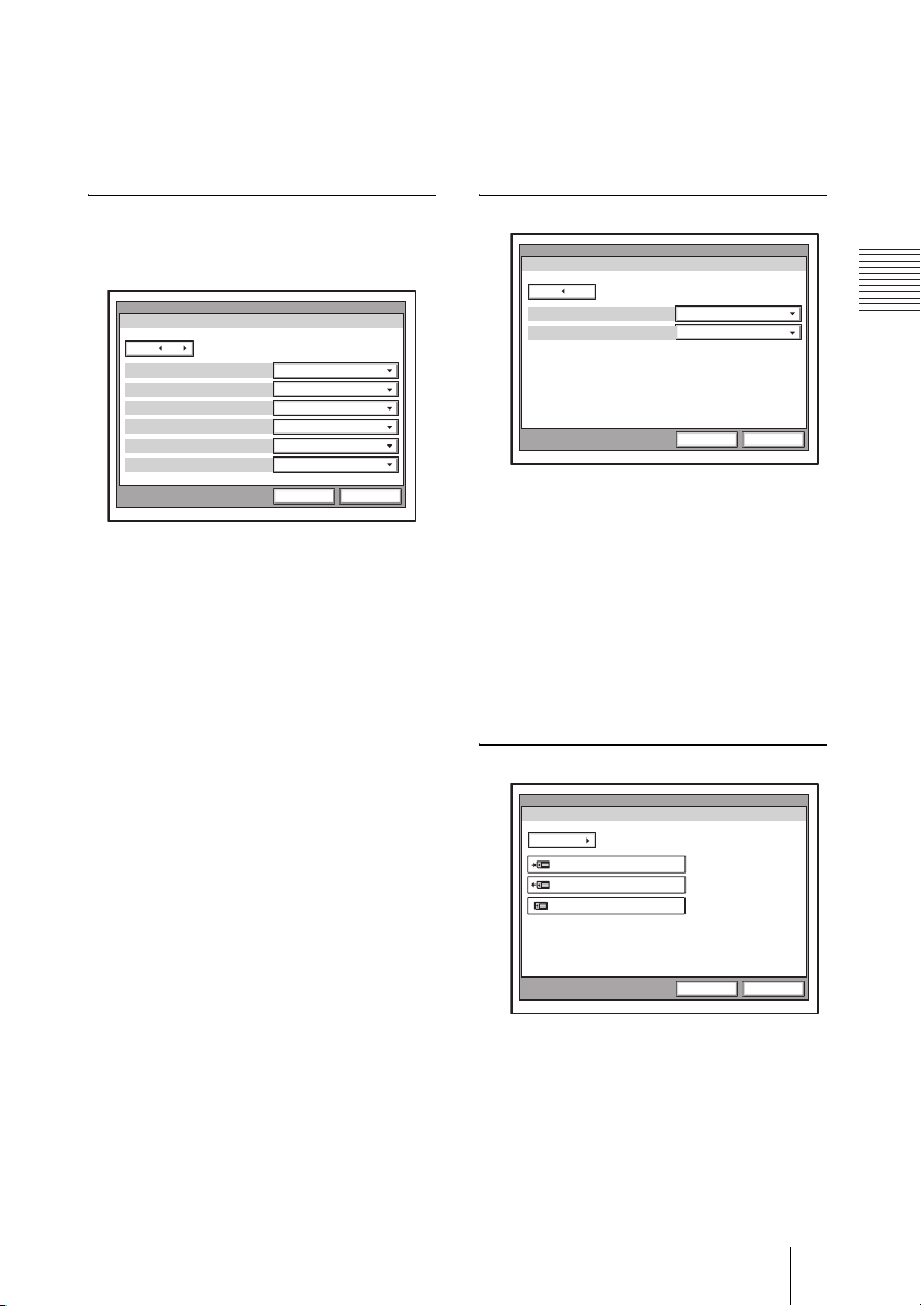
Remote Access Password
Set the password to access the system
through a Web browser. Access from a Web
browser can also be enabled by entering the
administrator password.
General Setup
Enable: Requires the password when saving
the General Setup settings.
Disable: Does not require the password
when saving the General Setup settings.
Password Page 2/3
Specifies whether to require a password
when saving each setting.
Password
Page: 2/3
Dial Setup
Answer Setup
Transmission Mode
Audio Setup
Video Setup
General Setup
Administrator
Enable
Enable
Enable
Enable
Enable
Enable
Save Cancel
Dial Setup
Enable: Requires the password when saving
the Dial Setup settings.
Disable: Does not require the password
when saving the Dial Setup settings.
Answer Setup
Enable: Requires the password when saving
the Answer Setup settings.
Disable: Does not require the password
when saving the Answer Setup settings.
Transmission Mode
Enable: Requires the password when saving
the Communication Setup settings.
Disable: Does not require the password
when saving the Communication Setup
settings.
Password Page 3/3
Password
Page: 3/3
LANSetup
Administrator
Enable
EnableISDN Setup
Save Cancel
LAN Setup
Enable: Requires the password when saving
the LAN Setup settings.
Disable: Does not require the password
when saving the LAN Setup settings.
ISDN Setup
Enable: Requires the password when saving
the ISDN Setup settings.
Disable: Does not require the password
when saving the ISDN Setup settings.
Phone Book Page 1/2
Phone Book
Page: 1/2
Save Phone Book
Load Phone Book
Clear Phone Book
Administrator
Audio Setup
Enable: Requires the password when saving
the Audio Setup settings.
Disable: Does not require the password
when saving the Audio Setup settings.
Video Setup
Enable: Requires the password when saving
the Video Setup settings.
Disable: Does not require the password
when saving the Video Setup settings.
Save Cancel
Save Phone Book
Allows you to save the data in the Phone Book
on a “Memory Stick”. The data already on the
“Memory Stick” is then overwritten.
Load Phone Book
Allows you to load the data in the Phone Book
from a “Memory Stick”. The data already in
the Phone Book is then overwritten.
57Registering Local Information
Page 58
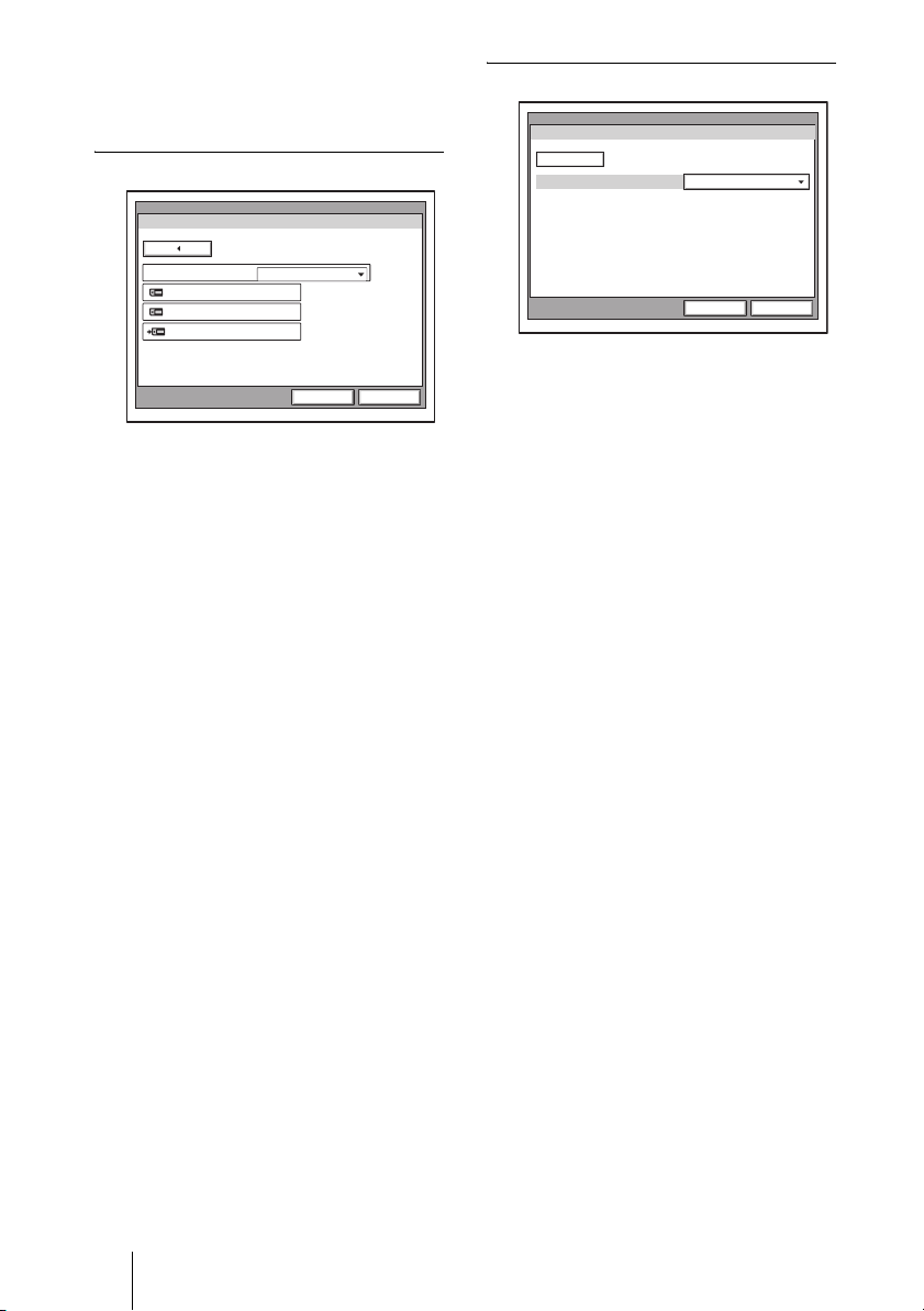
Clear Phone Book
Allows you to delete a Phone book on a
“Memory Stick” inserted into the system.
Private Phone Book Page 2/2
Private Phone Book
Page: 2/2
Auto Dialing
Create Private Phone Book
Delete Private Phone Book
Copy Private Phone Book
Administrator
On
Save Cancel
Auto Dialing
Allows you to automatically contact the
remote parties of the selected Private Phone
Book on a “Memory Stick” when you insert
it into the system.
On: Enables automatic dialing.
Off: Disables automatic dialing.
Create Private Phone Book
Allows you to create an empty folder and
file for a Private Phone Book on a “Memory
Stick” inserted into the system.
Other Settings Page 1/1
Other Settings
Page: 1/1
Web Monitor
Administrator
On
Save Cancel
Web Monitor
Allows you to permit the monitoring
conference status through a Web browser
(automatic update of JPEG images).
On: Permits monitoring with a Web
browser.
Off: Does not permit monitoring with a Web
browser.
Delete Private Phone Book
Allows you to delete the Private Phone Book
on a “Memory Stick” inserted into the
system.
Copy to Private Phone book
Allows you to copy the entire contents of the
Phone Book to a Private Phone Book on a
“Memory Stick” inserted into the system.
58 Registering Local Information
Page 59
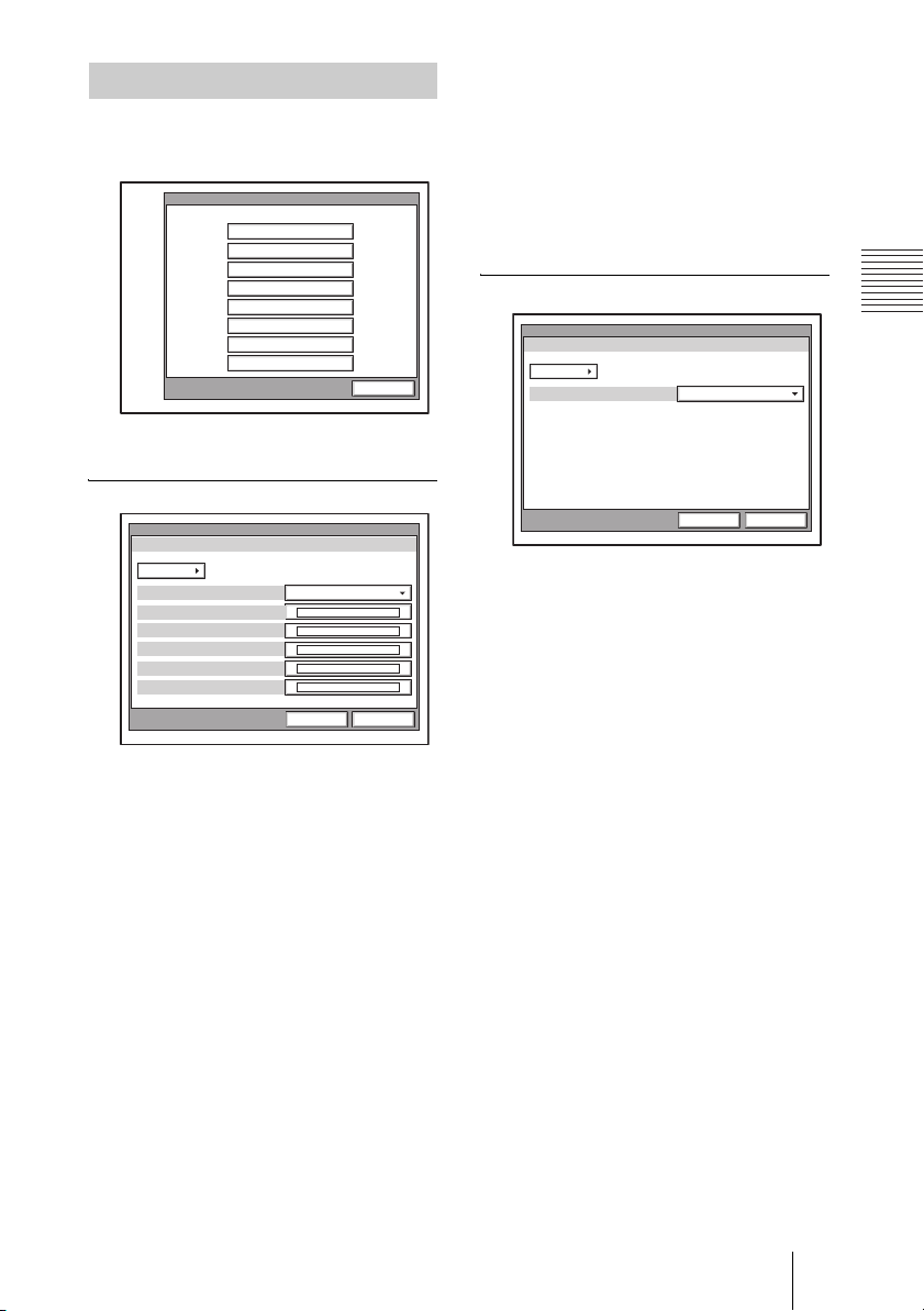
LAN Setup Menu
The following menus appear when you
select “LAN” on the Setup menu for the
administrator. Select the desired menu.
LAN Setup
General
Gatekeeper
SNMP
PPPoE
NAT/Port
QoS
TOS
Encryption via LAN
Cancel
For details about the settings, consult your
network administrator.
General Page 1/2
General
Page: 1/2
DHCP Mode
Host Name
IP Address
Network Mask
Gateway Address
DNS Address
DHCP Mode
Allows you to select whether the Dynamic
Host Configuration Protocol (DHCP) server
is enabled.
Auto: The IP address network mask,
gateway and DNS addresses are
automatically assigned. You should
confirm the assigned IP address in the
launcher menu or the Information menu
after the LAN connection is established.
Off: Disables the DHCP server. In this case,
enter an IP address, network mask,
gateway and DNS addresses.
LAN
Off
. . .
. . .
. . .
. . .
. . .
Save Cancel
Network Mask
Enter the network mask.
Gateway Address
Enter the default gateway address.
DNS Address
Enter the DNS (Domain Name System)
address.
General Page 2/2
General
Page: 2/2
LAN Mode
LAN
Auto Negotiation
Save Cancel
LAN Mode
Allows you to select the interface type and
the communication mode of the LAN
connection.
Auto Negotiation: The interface type and
the communication mode are detected
automatically.
100Mbps Full Duplex: Connects via
100BASE-TX in full duplex mode.
100Mbps Half Duplex: Connects via
100BASE-TX in half duplex mode.
10Mbps Full Duplex: Connects via
10BASE-T in full duplex mode.
10Mbps Half Duplex: Connects via
10BASE-T in half duplex mode.
Host Name
Enter the host name.
IP address
Enter the IP address.
59Registering Local Information
Page 60

Gatekeeper Page 1/1
Gatekeeper
Page: 1/1
Gatekeeper Mode
Gatekeeper Address
User Alias
User Number
LAN
Off
. . .
Save Cancel
On: Enables the SNMP agent.
Off: Disables the SNMP agent.
Trap Destination
Enter the address of the trap destination
SNMP manager.
Community
Enter the community name managed by the
SNMP manager. By default, this is “public”
and this setting does not normally need to be
changed.
Gatekeeper Mode
Allows you to select whether to use the
gatekeeper to control access to a LAN.
Using the gatekeeper allows you to dial
using the user name or user number.
Auto: Automatically detects the gatekeeper
and uses it.
On: Enables the gatekeeper.
Off: Disables the gatekeeper.
Gatekeeper Address
Enter the address of the gatekeeper used
when “Gatekeeper Mode” is set to “On”.
User Alias
Enter the user name (H.323 alias) registered
in the gatekeeper.
User Number
Enter the user number (E.164 number)
registered in the gatekeeper.
SNMP Page 1/1
SNMP
Page: 1/1
SNMP Mode
Trap Destination
Community
Description
Location
Contact
LAN
Off
. . .
Public
Videoconference Device
Save Cancel
Description
Enter the description of this terminal. By
default, this is “Videoconference Device”
and this description does not need to be
changed.
Location
Enter the location where this terminal is
installed.
Contact
Enter information bout the terminal
administrator.
PPPoE Page 1/2
PPPoE
Page: 1/2
PPPoE
PPPoE User Name
PPPoE Password
LAN
Off
Save Cancel
PPPoE
Allows you to select whether to use PPPoE
for LAN connection. When using PPPoE,
you can use the B FLET'S* or FLET'S
ADSL service without connecting a router.
On: Uses PPPoE for LAN connection.
Off: Does not use PPPoE.
SNMP Mode
Allows you to select whether the Simple
Network Management Protocol (SNMP)
agent is enabled.
60 Registering Local Information
Note
Operations of PPPoE for LAN connection are
presently verified only for the Japanese NTT B
FLET'S and FLET'S ADSL services.
Page 61

* “FLET’S” is a trademark of NTT East and
NTT West Corporations in Japan.
PPPoE User Name
Enter a user name when you use PPPoE for
LAN connection.
PPPoE Password
Enter a password when you use PPPoE for
LAN connection.
NAT/Port Page 1/1
NAT/Port
Page: 1/1
NAT Mode
NAT Address
Port Number Used
TCP Port Number
UDP Port Number
LAN
Off
. . .
2253
49152
PPPoE Page 2/2
PPPoE
Page: 2/2
Fixed IP for PPPoE
Fixed IP Address for PPPoE
PPPoE DNS
Primary DNS
Secondary DNS
LAN
Off
. . .
Obtain automatically
. . .
. . .
Save Cancel
Fixed IP for PPPoE
Select whether to make a PPPoE connection
using a fixed IP address.
On: Uses a fixed IP address for a PPPoE
connection.
Off: Does not use a fixed IP address for a
PPPoE connection.
Fixed IP Address for PPPoE
Enter an IP address when “Fixed IP for
PPPoE” is set to “On”.
PPPoE DNS
Allows you to select whether to obtain DNS
server addresses automatically or to specify
them manually when connecting to a LAN
using PPPoE.
Specify Allows you to specify DNS server
addresses.
Obtain automatically: Assigns DNS server
addresses automatically.
Primary DNS
Enter a primary DNS address.
Save Cancel
NAT Mode
Allows you to select whether you connect
the system to a local network using Network
Address Translation (NAT), which allows
one IP address to be shared by several
computers on the same LAN.
On: Enables NAT mode.
Off: Disables NAT mode.
NAT Address
Enter the IP address of a global network to
be used for NAT mode.
Port Number Used
Allows you to select whether to fix the TCP
port and UDP port numbers.
Custom: Uses the port numbers set by the
user.
Default: Uses the default port numbers:
2253 as the TCP port number and 49152
as the UDP port number.
TCP Port Number
When “Port Number Used” is set to
“Custom”, enter the TCP port number.
UDP Port Number
When “Port Number Used” is set to
“Custom”, enter the UDP port number.
For details on the port numbers used,
See “List of Port Numbers Used on the
PCS-PG70/PG70P” on page 220.
Secondary DNS
Enter a secondary DNS address.
61Registering Local Information
Page 62

QoS Page 1/1
QoS
Page: 1/1
Hybrid
Packet Resend Request
Adaptive Rate Control
LAN
On
OnForward Error Correction
On
On
Save Cancel
Type of Service (TOS) Page 1/1
TOS
Page: 1/1
TOS
IP Precedence
Low Delay
High Throughput
High Reliability
Minimum Cost
LAN
Off
Off
Off
Off
Off
Save Cancel
Hybrid
Allows you to select whether to use forward
error correction, send requests to resend
packets, and use adaptive rate control
depending on the network status.
On: Forward Error Correction, Packet
Resend Request, or Adaptive Rate
Control is used automatically depending
on the network status.
Off: The three functions above are not used
automatically depending on the network
status.
Forward Error Correction
Allows you to select whether received
packets containing errors are corrected upon
reception.
On: Corrects packets.
Off: Does not correct packets.
Packet Resend Request
Allows you to select whether to request
packet to be resent when packet losses occur
during communication.
On: Requests packets to be resent.
Off: Does not request packets to be resent.
Adaptive Rate Control
Allows you to select whether to always
optimize the LAN bandwidth.
On: Always optimizes the LAN bandwidth.
Off: Does not optimize the LAN bandwidth.
Note
You can only configure “Adaptive Rate
Control” when “Packet Resend Request” is set
to “Off”. When “Packet Resend Request” is set
to “On”, “Adaptive Rate Control” is also
always set to “On”.
TOS
Allows you to select how to define the Type
of Service (TOS) field.
Off: Does not define the TOS field.
IP Precedence: Defines the TOS field as IP
Precedence.
Diffserve: Defines the TOS field as
Diffserve.
IP Precedence
Enter the IP Precedence value, between 0 and 7.
Low Delay
Allows you to select whether to specify the
Low Delay bit rate of the TOS field.
On: Specifies the Low Delay bit rate of the
TOS field.
Off: Does not specify the Low Delay bit rate
of the TOS field.
High Throughput
Allows you to select whether to specify the
High Throughput bit rate of the TOS field.
On: Specifies the High Throughput bit rate
of the TOS field.
Off: Does not specify the High Throughput
bit rate of the TOS field.
High Reliability
Allows you to select whether to specify the
High Reliability bit rate of the TOS field.
On: Specifies the High Reliability bit rate of
the TOS field.
Off: Does not specify the High Reliability
bit rate of the TOS field.
62 Registering Local Information
Page 63
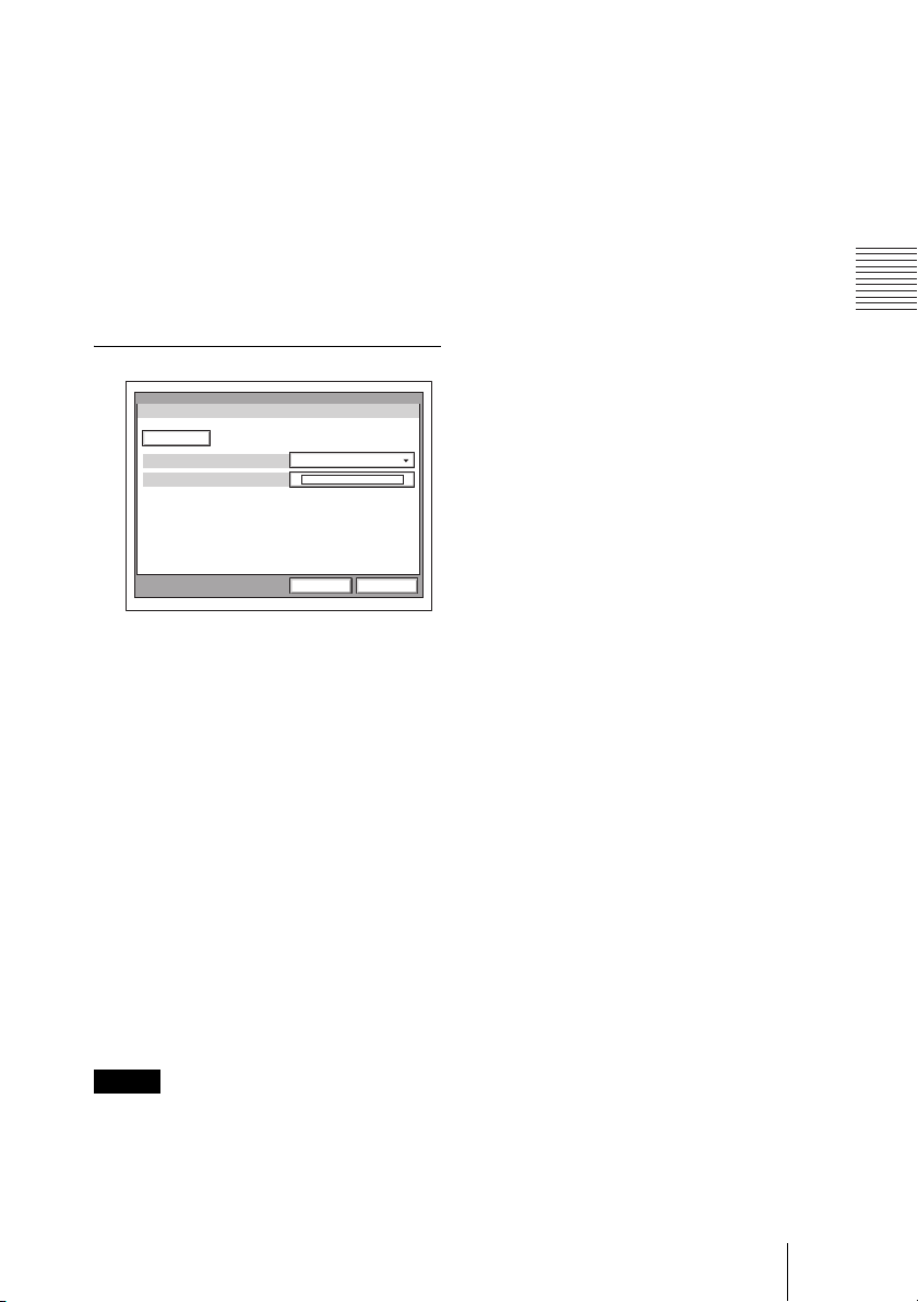
Minimum Cost
Allows you to select whether to specify the
Minimum Cost bit rate of the TOS field.
On: Specifies the Minimum Cost bit rate of
the TOS field.
Off: Does not specify the Minimum Cost bit
rate of the TOS field.
Diffserve
Enter the Diffserve value, between 0 and 64.
This item only appears when “TOS” is set to
“Diffserve”.
Encryption via LAN Page 1/1
Encryption via LAN
Page: 1/1
Encryption via LAN
Encryption Password
LAN
On
Save Cancel
Configure the “Encryption via LAN”
function to conduct encrypted
videoconferences. When you enable this
function, only those terminals who input the
password defined here can connect to the
videoconference, allowing for greater
security.
For details about encrypted
videoconferences, see chapter 7.
different encryption password. You can start
an unencrypted videoconference with a
terminal connected via an ISDN.
• The encryption function is not available
when you connect to other terminals through
cascade LAN and ISDN connections.
Encryption via LAN
Allows you to select whether to use the
encryption feature for videoconferences.
On: Uses the encryption feature.
Off: Does not use the encryption feature.
Encryption Password
Enter the password necessary to start an
encrypted videoconference.
Notes
• When “Encryption via LAN” is set to “On”,
you cannot start a videoconference if your
terminal is not equipped with the encryption
feature, a terminal with “Encryption via
LAN” set to “Off”, or a terminal with a
63Registering Local Information
Page 64
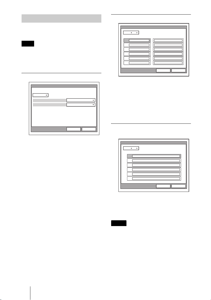
ISDN Setup Menu
The ISDN Setup menu is used to set up
ISDN lines.
Note
The ISDN Setup menu only appears when
the optional PCSA-B384S, PCSA-B768S or
PCSA-PRI ISDN Unit is installed in your
system.
ISDN Page 1/4
ISDN
Page: 1/3
Country/Region
USA
National ISDNProtocol
Japan NTT
ISDN Page 2/4
ISDN
Page: 2/4
Area Code Local Number
A1
A2
B1
B2
C1
C2
Save Cancel
Area Code
Enter the area code of the ISDN line to be
used. Do not enter the first 0 of the area code.
Local Number
Enter the line number (local number) of the
ISDN line to be used.
Save Cancel
Country/Region
Allows you to select the country or region
where you are using the Communication
Terminal. You can select between Europe
(except France), France, Japan, USA, China,
and Other.
Protocol
Allows you to select the protocol of the
ISDN lines to be used. You can select Japan
(NTT), Euro ISDN, Euro ISDN (France),
National ISDN, 5ESS (P-MP), 5ESS (P-P),
or DMS-100, depending on the interface that
you are using.
You can select Japan (NTT), Euro ISDN,
Euro ISDN (France), National ISDN,
5ESS(P-MP), 5ESS(P-P) or DMS-100
depending on the interface you are using.
For customers in the USA and Canada, see
“SPID Settings for Customers in the USA
and Canada” on page 65.
ISDN Page 3/4
The A1 to C2 fields appear.
ISDN
Page: 3/4
Sub Address
A1:
A2:
B1:
B2:
C1:
C2:
Save Cancel
Sub Address
Enter sub-addresses when registering them.
Sub-addresses can only be composed of
numbers.
Notes
• When you select an empty field and then
press the PUSH ENTER button of the
Remote Commander, the setting of the
previous field is copied into the selected
field.
64 Registering Local Information
Page 65
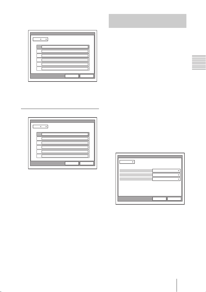
• CH1 to Ch23 (T1), Ch1 to Ch30 (E1) text
boxes appear when using the PCSA-PRI
ISDN Unit.
ISDN
Page: 3/4
Sub Address
Ch1:
Ch2:
Ch3:
Ch4:
Ch5:
Ch6:
Save Cancel
• When using the PCSA-B768S ISDN Unit,
the D1 to F2 text boxes appear on the next
page. Fill in the D1 to F2 text boxes
according to the lines that you are using.
ISDN Page 4/4
ISDN
Page: 4/4
SPID
A1:
A2:
B1:
B2:
C1:
C2:
Save Cancel
SPID
Enter SPID (Service Profile Identifier).
For customers in the USA and Canada, see
see “SPID Settings for Customers in the
USA and Canada” on this page.
SPID Settings for Customers in the USA and Canada
If you connect to an ISDN switch type,
configuration of SPID (Service Profile
Identifier) is required. When you select
“Auto SPID” in the ISDN Setup Wizard
(See page 34), the “Area Code”, “Local
Number” and “SPID” setup items are
automatically set. If “Auto SPID” is not
available in your area, set up SPID manually
using the ISDN Setup menu.
1 Open the ISDN Setup menu.
2 Enter the country code in the Country/
Region Code text box depending on
the network switch type you are using.
AT&T 5ESS (National ISDN), NTI
DMS-100 (National ISDN): Enter “1”.
AT&T 5ESS (Multipoint Custom
ISDN): Enter “1*10”.
AT&T 5ESS (Point-to-Point Custom
ISDN): Enter “1*12”.
NTI DMS-100 (Custom ISDN): Enter
“1*11”.
ISDN
Page: 1/7
Country/Region
Protocol
USA
1Area Code
Nation ISDN
Save Cancel
Auto SPID
This item is used only for customers in the
USA and Canada.
For details, see see “SPID Settings for
Customers in the USA and Canada” on page
65.
3 Open page 2 of the ISDN Setup menu
to enter the LDN (Local Directory
Number) in the Local Number text
boxes.
When you use the AT&T 5ESS
(Multipoint Custom ISDN) or AT&T
5ESS (Point-to-Point Custom ISDN)
switch type
Enter the same LDNs in the A1 and A2
(B1 and B2, C1 and C2, depending on
the number of lines you use) text boxes.
65Registering Local Information
Page 66
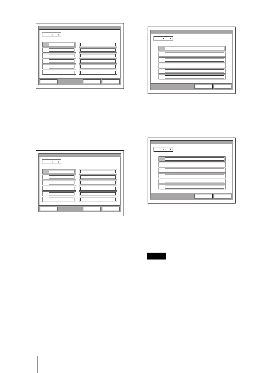
ISDN
Page: 2/7
Area Code Local Number
A1 408
A2
408
B1
B2
C1
C2
9876532
9876532
SaveAuto SPID Cancel
Enter the SPID in the A1 text box only.
ISDN
Page: 6/7
SPID
A1: 019876532001
A2:
B1:
B2:
C1:
C2:
Save Cancel
When you use the NTI DMS-100
(National ISDN) or NTI DMS-100
(Custom ISDN) switch type
Enter the different LDNs in the A1 and
A2 (B1 and B2, C1 and C2, depending
on the number of lines you use) text
boxes. These switch types are given a
separate number for each channel.
ISDN
Page: 2/7
Area Code Local Number
A1 408
A2
B1
B2
C1
C2
408
9876543
9876544
SaveAuto SPID Cancel
When you use the AT&T 5ESS
(National ISDN) switch type
You may enter the same or different
numbers in two channels.
4 Open page 6 (SPID setup menu) to
enter the SPID.
The SPID is generally comprised of 12
digits, including a 7 digit LDN (Local
Directory Number). Be sure to enter the
different SPID number in each of the A1
and A2 (B1 and B2, C1 and C2, depending
on the number of lines you use) text boxes
if you have entered the separate LDNs in
the Local Number text boxes for each
channel in step 3.
For the NTI DMS-100 (National ISDN),
NTI DMS-100 (Custom ISDN), AT&T
5ESS (National ISDN) switch type
Enter the different SPID numbers in the
A1 and A2 text boxes.
ISDN
Page: 6/7
SPID
A1: 019876543001
019876544001
A2:
B1:
B2:
C1:
C2:
Save Cancel
For the AT&T 5ESS (Point-to-Point
Custom ISDN) switch type
You do not need to set up the SPID, then
no entry in the A1 and A2 (B1 and B2,
C1 and C2, depending on the number of
lines you use) is required.
Notes
• If you use the PCSA-B768S ISDN unit
and connect 4-6 ISDN lines, the D1-F2
text boxes are shown in pages 3 and 7 of
the ISDN Setup menu. Fill in the boxes
following steps 3 and 4.
• If you use the PCSA-PRI ISDN unit,
Ch1 to Ch23 (T1), or Ch1 to Ch30 (E1)
are displayed. Enter the telephone
numbers according to the number of
channels you will use.
For the AT&T 5ESS (National ISDN)
and AT&T 5ESS (Multipoint Custom
ISDN) switch type
66 Registering Local Information
5 After the settings are completed,
select “Save”, then press the PUSH
ENTER button.
Page 67
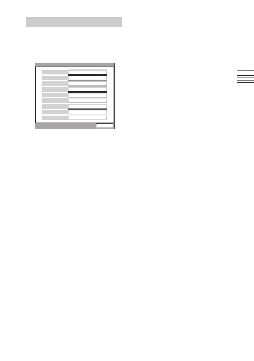
Information Menu
The Information menu shows the versions of
the Communication Terminal and the
connected equipment for exclusive use,
installed software versions, etc.
Information
Version
I/F
Ver X.XX
Ver X.XX
Ver X.XX
Ver X.XX
Multipoint(H.320+H.323)
DSB, ISDN UNIT
PCS-G70
0. 0. 0. 0
00-00-00-00-00-00-00
End
Host Version
ISDN UNIT
USB
Version
DSP
Version
Software Option
Option
Host Name
IP
Address
MAC
Address
Serial Number 12345
Host Version
Displays the software version of the
Communication Terminal.
ISDN UNIT Version
Displays the version of the connected
PCSA-B384S, PCSA-B768S or PCSA-PRI
ISDN Unit.
DSB Version
Displays the version of the connected
PCSA-DSB1S Data Solution Box.
Option I/F
Displays the optional connected equipment.
None: No optional equipment is connected.
ISDN UNIT: The PCSA-B384S, PCSA-
B768S or PCSA-PRI ISDN Unit is
connected.
DSB: The PCSA-DSB1S Data Solution Box
is connected.
Whiteboard: A whiteboard is connected.
Host Name
Displays the host name.
IP Address
Displays the IP address.
MAC Address
Displays the MAC address.
Serial Number
Displays the serial number.
DSP Version
Displays the version of the built-in DSP
(Digital Signal Processor) for audio/video
codec.
Software Option
Displays the optional MCU software
installed.
None: No MCU software is installed.
Multipoint (H.323): The PCSA-M3G70
H.323 MCU software (for LAN) is
installed.
Multipoint (H.320): The PCSA-M0G70
H.320 MCU software (for ISDN) is
installed.
Multipoint (H.320 + H.323): Both the
PCSA-M0G70 and PCSA-M3G70
MCU software are installed.
67Registering Local Information
Page 68
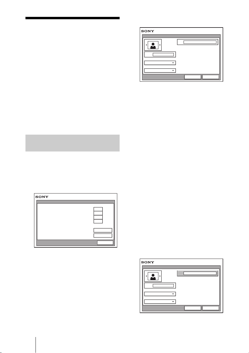
Registering a Remote Party – Phone Book
You can register the telephone number or IP
address of a remote party in the Phone Book,
allowing you to dial the party very easily.
Up to 500 remote parties can be registered in
the Phone Book. You can also store a still
image such as a participant’s portrait in the
index list.
You can also create a Private Phone Book on
a “Memory Stick” separately from the
Phone Book in the Communication
Terminal.
Registering a New Remote Party
1 Use the V, v, B or b button on the
Remote Commander to select “Phone
Book” in the launcher menu, then
press the PUSH ENTER button.
The Phone Book opens.
Phone Book
0-9
A-1
J-S
T-Z
Recent
New Entry
Cancel
2 Use the V, v, B or b button on the
Remote Commander to select “New
Entry”, then press the PUSH ENTER
button.
The List Edit screen appears.
List Edit
IP
Index
Line I/F
IP
LAN Bandwidth
1024 Kbps
Save Cancel
3 Enter the name of a remote party in the
Index text box.
For character input, see “Entering
Characters” on page 41.
4 Select the line interface you are using
to connect to a remote party with
“Line I/F”.
IP: Connects to a videoconferencing
system on the remote site via a LAN.
ISDN: Connects to a videoconferencing
system on the remote site via an ISDN
line.
ISDN (Telephone): Connects to a
phone on the remote site via an ISDN
line for a voice meeting.
Multipoint: Connects to multipoints for
a multipoint videoconference via
LAN and ISDN.
The List Edit menu switches according
to the selected line interface.
5 Set up various items for the line on a
remote site.
When “IP” is selected in step 4
List Edit
IP
Index
Bob
Line I/F
IP
Number of Lines
1024Kbps
Save Cancel
68 Registering a Remote Party – Phone Book
Page 69
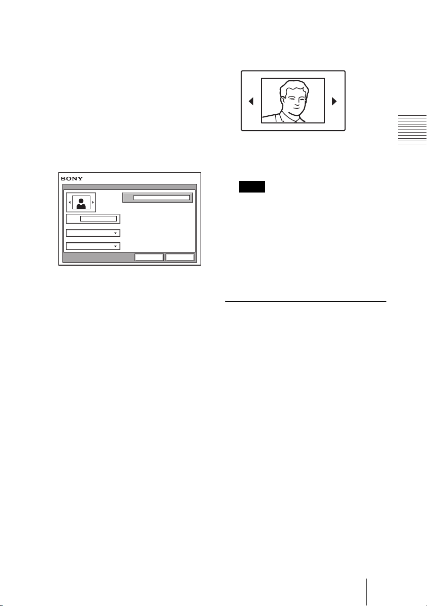
1 Enter the IP address of the remote
party.
Enter the host name and domain
name when using the DNS server
(ex. host.domain). When using the
gatekeeper, enter the user name and
user number registered in the LAN
Setup menu (page 59).
2 Select the LAN bandwidth to be
used.
When “ISDN” or “ISDN
(Telephone)” is selected in step 4
6 Select the icon or a still image stored
on a “Memory Stick” to be registered
in the Phone Book.
Press the B or b button to select the icon
or a still image, then press the PUSH
ENTER button.
List Edit
A1
Index
Bob
Line I/F
ISDN
Number of Lines
6B (384K)
Save Cancel
1 Enter the telephone number of the
remote party in the telephone
number text box beside “A”.
When entering a sub-address,
enter an asterisk (*) between the
telephone number and subaddress. Only numbers are usable
for a sub-address.
When “More Options Enable” is
set to “On” in the Dial Setup menu
page 44), the A1, A2, B1, B2, C1
(
and C2 text boxes appear. Enter
the number of the remote party in
the A1 text box.
2 Select the number of the ISDN
channels to be used for dialing.
Note
You cannot select a still image unless a
“Memory Stick” in which the still image is
stored is inserted.
7 Use the V, v, B or b button to select
“Save”, then press the PUSH ENTER
button.
The settings are registered in the Phone
Book.
To connect to the remote party
without using bonding
If the videoconferencing system of the
remote party is not equipped with the
bonding function, entering one telephone
number does not allow you to connect all the
line numbers used to connect to the remote
party. To connect to the remote party by
entering all the ISDN line numbers used,
you can set the connection without using the
bonding function of this system.
Set “More Options Enable” to “On” in the
Dial Setup menu (page 44), select the More
Options button at the lower part of the List
Edit menu to open the Dial Setup menu, then
set “Bonding” to “Auto”. The A1, A2, B1,
B2, C1 and C2 text boxes appear in the List
Edit menu. Enter all the telephone numbers
for the ISDN lines selected by “Number of
Lines”. Up to 6B-channel connection is
available when using this method.
69Registering a Remote Party – Phone Book
Page 70

Note
When you set “Number of Lines” to “2B”, you
can connect to the remote party by selecting
“ISDN (2B)” from “Line I/F” in the Detail
Dial menu.
To set up more detailed options
When “More Options Enable” is set to “On”
in the Dial Setup menu, the More Options
button is shown at the lower part of the List
Edit menu.
Select the More Options button with the V,
v, B or b
and press the PUSH ENTER button to open
a menu for more detailed dial settings. You
can change the settings of the desired items.
Note
The contents set with the More Options button
have priority over those set in the Detail Dial
Setup menu.
button on the Remote Commander
Changing the Contents of the Phone Book
You can change the telephone number, IP
address, name or setting registered in the
Phone Book.
1 Open the Phone Book menu.
2 Use the V, v, B or b button on the
Remote Commander to select the
remote party to be changed in the
Phone Book menu, then press the
PUSH ENTER button.
The submenu appears.
Dial
Edit
Copy
Delete
Cancel
3 Press the V or v button on the Remote
Commander to select “Edit”, then
press the PUSH ENTER button.
The List Edit menu appears.
70 Registering a Remote Party – Phone Book
4 Change the telephone number, IP
address, name or setting.
5 Use the V, v, B or b button on the
Remote Commander to select “Save”,
then press the PUSH ENTER button.
The correction is completed.
Page 71

Copying the Setting of the Phone Book Menu
Deleting the Registered Remote Party
1 Open the Phone Book menu.
2 Use the V, v, B or b button on the
Remote Commander to select the
remote party to be copied in the Phone
Book menu, then press the PUSH
ENTER button.
The submenu appears.
3 Press the V or v button on the Remote
Commander to select “Copy”, then
press the PUSH ENTER button.
The items for the selected party are
copied, and the file name is followed by
“–2”. You can use the setting after
modifying the necessary items.
Follow the procedure below to delete the
remote party from the Phone Book.
1 Open the Phone Book menu.
2 Use the V, v, B or b button on the
Remote Commander to select the
remote party to be deleted in the
Phone Book menu, then press the
PUSH ENTER button.
The submenu appears.
3 Press the V or v button on the Remote
Commander to select “Delete”, then
press the PUSH ENTER button.
The message “Delete Entry?” appears.
4 Use the V, v, B or b button on the
Remote Commander to select “OK”,
then press the PUSH ENTER button.
The selected party is deleted.
To cancel deleting
Select “Cancel” in step 4, then press the
PUSH ENTER button.
Creating a Private Phone Book
You can create your own Phone Book
(Private Phone Book) on a “Memory Stick”.
Once the Private Phone Book is registered,
inserting the “Memory Stick” into the
Communication Terminal changes the
Phone Book menu to the Private Phone
Book menu. You can also activate the Auto
Dial feature, allowing you to start dialing
automatically to one of the lists simply by
inserting the “Memory Stick”.
To register a new remote party in a
Private Phone Book
1 Insert a “Memory Stick” in which you
want to register a remote party into the
71Registering a Remote Party – Phone Book
Page 72

Memory Stick slot on the
Communication Terminal.
Insert the “Memory Stick” in the
direction of the arrow with the mark
facing upward.
To copy all the contents of the
Phone Book to the Private Phone
Book
Insert the “Memory Stick” in which you
want to store the Private Phone Book into
the Memory Stick slot on the
Communication Terminal, then select
“Copy to Private Phone Book” from the
“Private Phone Book” of the Administrator
Setup menu. All the data registered in the
Phone Book are copied to the inserted
“Memory Stick”.
2 Open “Private Phone Book” of the
Administrator Setup menu.
Private Phone Book
Page: 2/2
Auto Dialing
Create Private Phone Book
Delete Private Phone Book
Copy Private Phone Book
Administrator
On
Save Cancel
For how to open the menu, see “Registering
Local Information” on page 43.
3 Select “Create Private Phone Book”.
An empty folder and file for a Private
Phone Book are created in the “Memory
Stick”.
4 Register a new remote party.
The procedure is the same as that for
registering in the Phone Book. Proceed
with steps 2 to 7 in “Registering a New
Remote Party” on page 68.
To delete the Private Phone Book
from the “Memory Stick”
Insert the “Memory Stick” from which you
want to delete the registered Private Phone
Book into the Memory Stick slot on the
Communication Terminal, then select
“Delete Private Phone Book” from the
“Private Phone Book” of the Administrator
Setup menu. All the data are deleted from
the inserted “Memory Stick”.
To dial a specified list in a Private
Phone Book automatically
If you set “Auto Dial” in the “Private Phone
Book” of the Administrator Setup menu to
“On”, you can automatically dial one of the
lists registered in the Private Phone Book
simply by inserting the “Memory Stick” in
which the Private Phone Book is registered.
1 Open the Private Phone Book.
2 Use the V, v, B or b button on the
Remote Commander to select the
remote party to dial automatically,
then press the PUSH ENTER button.
The procedures for how to change the
contents of the Private Phone Book, how to
delete the registered remote party, or how to
copy the setting of the Private Phone Book
are the same as those for the Phone Book.
Open the Private Phone Book menu and
proceed with the steps described on page 70.
72 Registering a Remote Party – Phone Book
Page 73
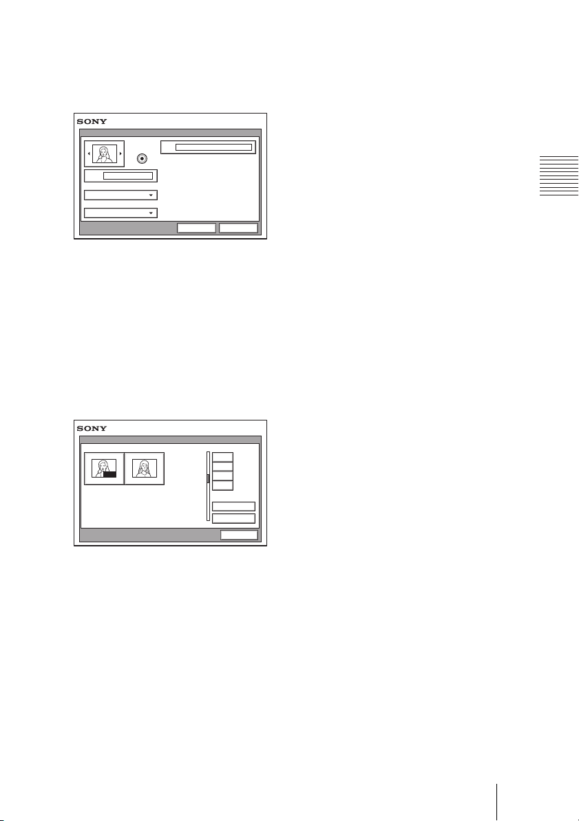
3 Press the V or v button on the Remote
Commander to select “Edit”, then
press the PUSH ENTER button.
The List Edit menu appears.
List Edit
IP 192.168.159.247
Auto Dial
Index
Jane
Line I/F
IP
LAN Bandwidth
1024 Kbps
Save Cancel
4 Use the V, v, B or b button on the
Remote Commander to select “Auto
Dial”, then press the PUSH ENTER
button.
5 Use the V, v, B or b button on the
Remote Commander to select “Save”,
then press the PUSH ENTER button.
The setting is registered and “AUTO”
appears on the registered list.
Phone Book
0-9
AUTO
Jane Mary
A-1
J-S
T-Z
Recent
New Entry
Cancel
73Registering a Remote Party – Phone Book
Page 74

Chapter 3: Daily Videoconference
This chapter describes how to conduct a videoconference from start to finish
after the administrator has completed various registrations and settings for the
system.
The videoconference explained here is a point-to-point conference via a LAN
connection or ISDN connection using the optional PCSA-B384S, PCSAB768S, or PCSA-PRI ISDN Unit.
For use of a “Memory Stick” or optional equipment, see chapter 4. To conduct
a data conference using the optional PCSA-DSB1S Data Solution Box, see
chapter 5. To conduct an encrypted conference via LAN, see chapter 7. To
conduct a multipoint conference, see chapter 8.
Starting a Conference by Calling a Remote Party
You can start a videoconference with a remote party by dialing. Once you have
made a connection to the remote party, you can begin talking just as with a
normal phone call and start a videoconference.
Turning on the Power
1 Turn on the TV monitor.
When the IR repeater is inserted under the remote sensor of the Sony TV, set
the TV to standby mode. When the power of the Communication Terminal is
turned on, the TV monitor will turn on simultaneously.
2 Turn on other equipment you are using for the videoconference.
74 Starting a Conference by Calling a Remote Party
Page 75
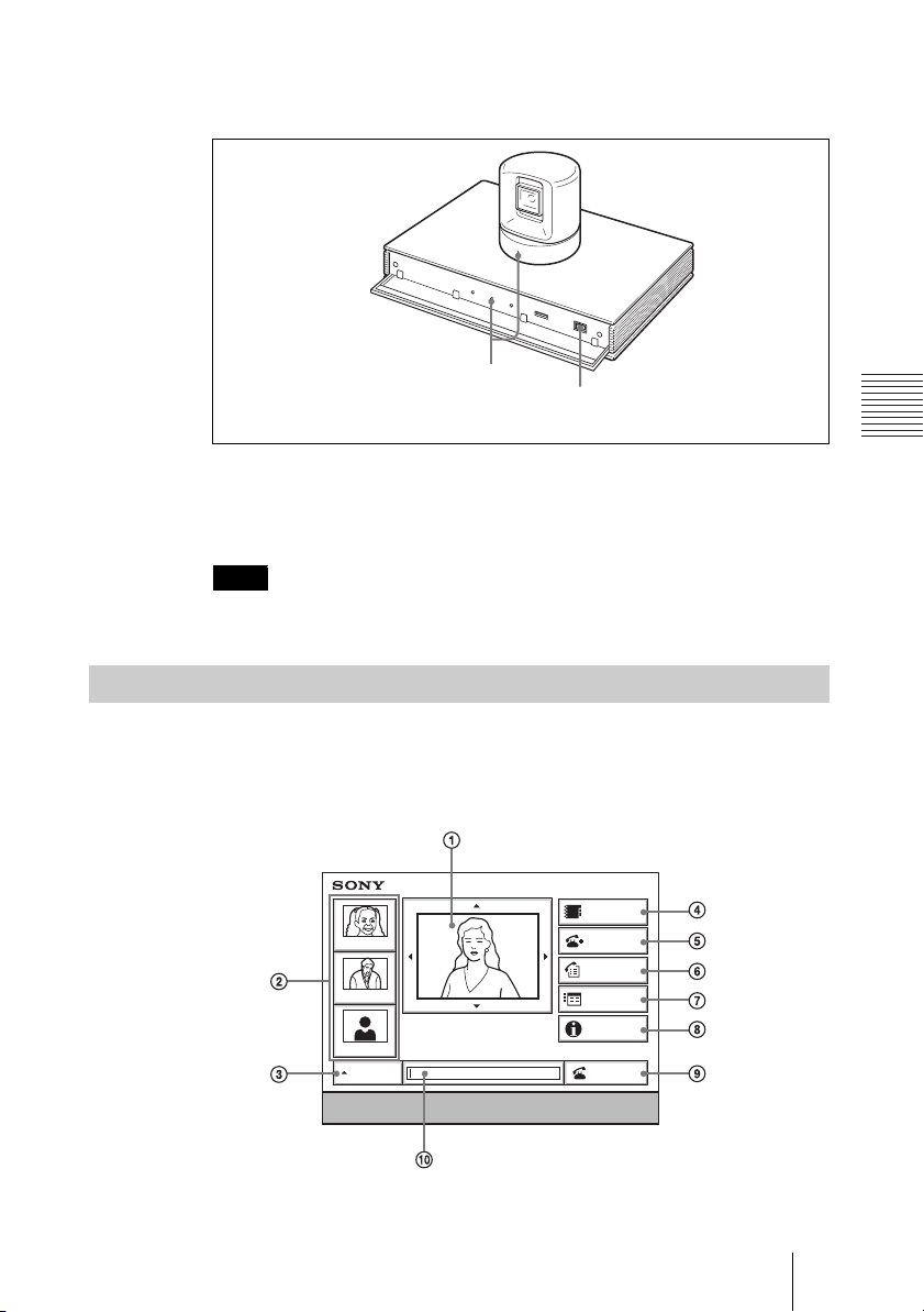
3 Open the front panel of the Communication Terminal, and then slide the
power switch on the right to the on position (
The Communication Terminal turns on after a while.
POWER indicators (Lights green)
Three indicators on the front of the Communication Terminal and the POWER
indicator on the camera light, then only the POWER indicators on both units
remain on in green. The launcher menu will appear on the monitor screen and
the picture shot by the local camera will also appear in the launcher menu.
Note
After the power is turned on, the camera moves automatically for trial operation. Be
careful not to catch your finger.
Using the Launcher Menu
@).
Power switch
The launcher menu is displayed on the monitor screen when the system is
turned on or while it is not connected to a remote party. The launcher menu
displays the image shot by the local camera, local system status and buttons to
open the menus.
Phone Book
Tokyo
New York
IP: 012.345.678.678
Paris
AUTO
Enter the remote party number.
ISDN: 012345678956789
Detail Dial
History
Menu
Information
Dial
75Starting a Conference by Calling a Remote Party
Page 76
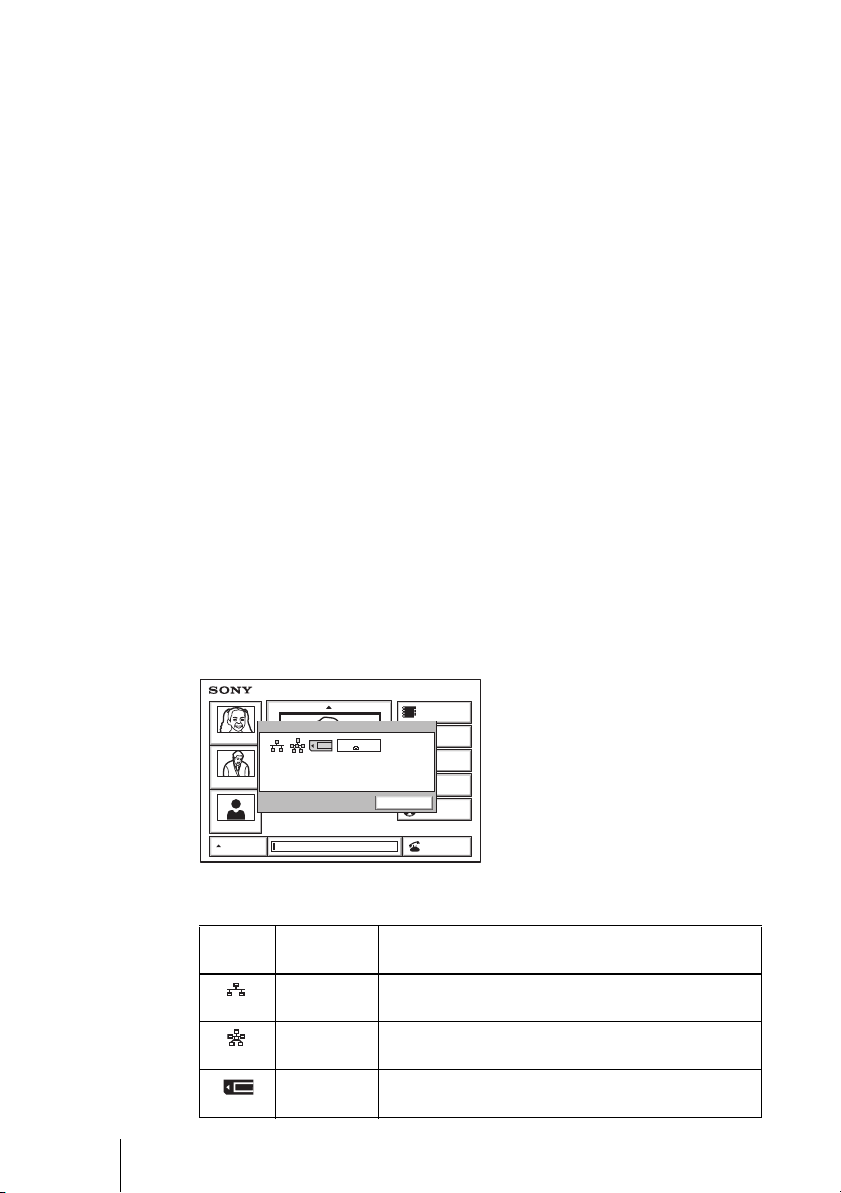
1 Screen
The image shot by the local camera is displayed.
2 Direct Phone Book button
The Direct Phone Book function is selected when you select this button by
pressing the V, v, B or b, and then the PUSH ENTER button of the Remote
Commander. This starts calling the selected remote party.
3 Line I/F
Select this button by pressing the V, v, B or b button, and then the PUSH
ENTER button on the Remote Commander. Items to be set are displayed.
Allows you to select the type of line to be used.
4 Phone Book button
The Phone Book is displayed when you select this button by pressing the V, v,
B or b button and then the PUSH ENTER button on the Remote Commander.
5 Detail Dial button
The Detail Dial appears when you select this button by pressing the V, v, B or
b button, and then the PUSH ENTER button of the Remote Commander.
6 History button
The History appears when you select this button by pressing the V, v, B or b
button, and then the PUSH ENTER button of the Remote Commander.
7 Menu button
You can display the various Setup menus when you select this button by
pressing the V, v, B or b button and then the PUSH ENTER button on the
Remote Commander.
8 Information button
The Information menu appears when you select this button by pressing the V,
v, B or b, and then the PUSH ENTER button of the Remote Commander.
012345678912
Phone Book
Detail Dial
History
Menu
OK
OK
Information
Dial
Tokyo
New York
Paris
AUTO
IP:
012.345.678.912
Object
IP: 012.345.678.678
ISDN: 012345678956789
Information
PORT
ISDN:
Audio: MIC(INT)+AUXVideo:
The following icons or text are displayed in accordance with the system
configuration.
Indicator
Identification Description
(icon)
LAN status The indicator is shown in dark when the LAN is
enabled to use, and in light when it is disabled.
Multipoint
mode
Memory
MCU software for multipoint videoconference is
installed.
“Memory Stick” is inserted.
Stick
76 Starting a Conference by Calling a Remote Party
Page 77
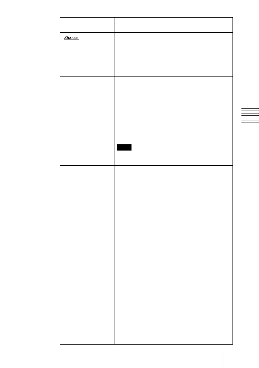
Indicator
(icon)
IP: IP address Shows the IP address of the local system.
ISDN: ISDN
Video: Video input The selected video input on the local system is shown.
Audio: Audio input The selected audio input on the local system is shown.
Identification Description
ISDN status When the optional ISDN Unit is connected, usable
telephone
number
ISDN port is shown.
Shows the ISDN telephone number of the local
system.
Main: Video from the main camera.
Sub: Video from the secondary camera.
IR1: Video from the optional PCS-DS150/DS150P
Document Stand.
IR2: Video from the optional PCS-DS150/DS150P
Document Stand.
AUX1: Video from the device connected to the MAIN
AUX IN connector.
AUX2: Video from the device connected to the SUB
AUX IN connector.
Note
The video inputs are shown as the labels set in the “Custom
Input Label” of the Video Setup menu (page 52).
MIC (EXT): Sound from an external microphone
connected to the Communication Terminal.
MIC (DSB): Sound from an external microphone
connected to the optional PCSA-DSB1S Data
Solution Box.
MIC (AUX): Sound from an external microphone
connected to the AUX IN jack on the optional
PCSA-DSB1S Data Solution Box.
AUX: Sound from external equipment connected to
the AUDIO IN jack on the Communication
Ter min al.
MIC (EXT)+AUX: Mixed sounds from an external
microphone connected to the Communication
Terminal and from external equipment.
MIC (DSB)+AUX: Mixed sounds from an external
microphone connected to the optional PCSADSB1S Data Solution Box and from external
equipment.
MIC (AUX)+AUX: Mixed sounds from an external
microphone connected to the AUX IN jack on the
optional PCSA-DSB1S Data Solution Box and
from external equipment.
CTE (LINE): Sound from the CTE-600
Communication Transducer connected to the
AUDIO IN jack on the Communication Terminal.
CTE (DSB): Sound from the CTE-600
Communication Transducer connected to the
AUX IN jack on the optional PCSA-DSB1S Data
Solution Box.
77Starting a Conference by Calling a Remote Party
Page 78
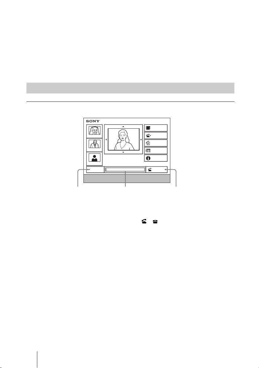
9 Dial button
Select this button by pressing the V, v, B or b button, and then the PUSH
ENTER button on the Remote Commander. This starts calling the remote party
whose dial number is entered in the number input box.
0 Number input box
To call a remote party not registered in the Phone Book, select this box by
pressing the
V, v, B or b button on the Remote Commander, and then enter
the IP address or the ISDN line number.
Calling a Remote Party
To call a remote party by entering their number directly
Phone Book
Tokyo
New York
IP: 012.345.678.678
Paris
AUTO
Enter the remote party number.
Line type Number text box Dial
ISDN: 012345678956789
Detail Dial
History
Menu
Information
Dial
1 Use the V, v, B or b button on the Remote Commander to select “Line I/
” from the launcher menu, then press the PUSH ENTER button. Or press
F
the CONNECT/DISCONNECT ( / ) button on the Remote
Commander.
2 Use the V or v button on the Remote Commander to select the type of line
to be used, then press the PUSH ENTER button.
AUTO: A line for connecting is automatically selected, based on the number
entered in the number text box.
IP: Connects to a videoconferencing system on the remote site via a LAN.
ISDN: Connects to a videoconferencing system on the remote site via an ISDN
line.
TEL: Connects to a phone on the remote site via an ISDN line for a voice
meeting.
3 Press the V, v, B or b button of the Remote Commander to select the
number input field, and then the PUSH ENTER button.
4 Enter the remote party's IP address or line number.
78 Starting a Conference by Calling a Remote Party
Page 79
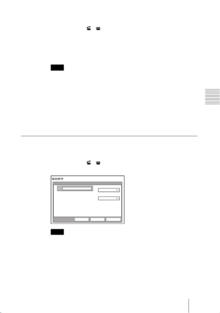
5 Press the V, v, B or b button to select “Dial”, and then press the PUSH
ENTER button of the Remote Commander. Or press the CONNECT/
DISCONNECT ( / ) button on the Remote Commander.
The system begins dialing the IP address ISDN telephone number entered in
step 4. “Dialing” appears on the monitor screen, and the ON LINE indicator
(blue) on the Communication Terminal blinks.
When the system connects to the remote system, the message “Meeting starts!”
appears on the screen, and the ON LINE indicator stops blinking and lights in
blue.
Note
When “More Options Enable” in the Dial Setup menu is set to “On”, a dialog box
appears after step 5.
More Options Enable: The Detail Dial menu is displayed.
Dial: Call the remote party.
Cancel: Cancel a call.
For details about the Detail Dial menu, See “To call a remote party not
registered in the Phone Book“ on this page.
6 Press the V, v, B or b button to select “Dial”, and then press the PUSH
ENTER button of the Remote Commander.
To call a remote party not registered in the Phone Book
1 Use the V, v, B or b button on the Remote Commander to select “Detail
Dial”, then press the PUSH ENTER button, or press the CONNECT/
DISCONNECT ( / ) button on the Remote Commander.
The Detail Dial menu appears on the screen.
Detail Dial
IP
Note
Pressing the number buttons on the Remote Commander opens the Detail Dial
menu, allowing direct entry of the IP address or the ISDN telephone number with
the number buttons.
Line I/F
IP
LAN Bandwidth
1024 Kbps
CancelSaveDial
2 Use the V, v, B or b button to select “Line I/F”, then press the PUSH
ENTER button. The submenu appears. Press the V or v button to select the
line type to be used to connect to the remote party, then press the PUSH
ENTER button.
79Starting a Conference by Calling a Remote Party
Page 80
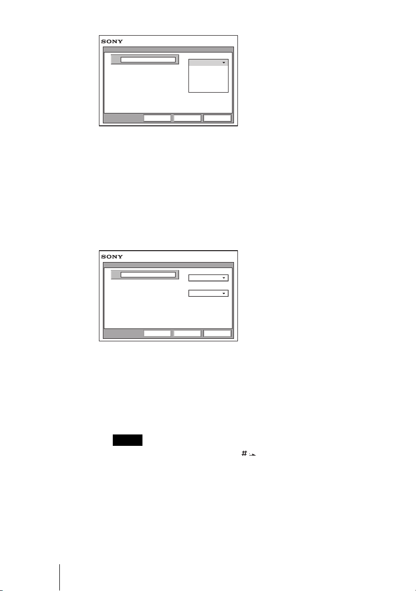
Detail Dial
IP
Line I/F
IP
ISDN
ISDN(2B)
ISDN (Telephone)
Multipoint
CancelSaveDial
IP: Connects to the videoconferencing system of a remote party via a LAN.
ISDN: Connects to the videoconferencing system of a remote party via an
ISDN.
ISDN (2B): Connects to the H.221-format videoconferencing system via 2B
channels of the ISDN connection.
ISDN (Telephone): Connects to the phone of a remote party to conduct a voice
meeting via the ISDN connection.
Multipoint: Connects to the videoconferencing system of a remote party via a
LAN and ISDN.
3 Configure the LAN, or ISDN line.
When using the LAN
Detail Dial
IP
Line I/F
IP
LAN Bandwidth
1024 Kbps
CancelSaveDial
1 Enter the IP address of a remote party to connect in the IP text box.
Use the V, v, B or b button on the Remote Commander to select the IP text
box, then press the PUSH ENTER button. Then enter the IP address with
the number buttons on the Remote Commander. Enter the host name and
domain name when using the DNS server in the IP text box (ex.
host.domain). When using the gatekeeper, enter the user name and user
number registered in the LAN Setup menu (page 60).
Notes
• You can enter a dot (.) with the b or button on the Remote Commander.
• To correct the entered number, press the PinP (BACK SPACE) button on the
Remote Commander. The last entered number is deleted.
• To delete the entered IP address, press the DISPLAY (CLEAR) button on the
Remote Commander.
80 Starting a Conference by Calling a Remote Party
Page 81
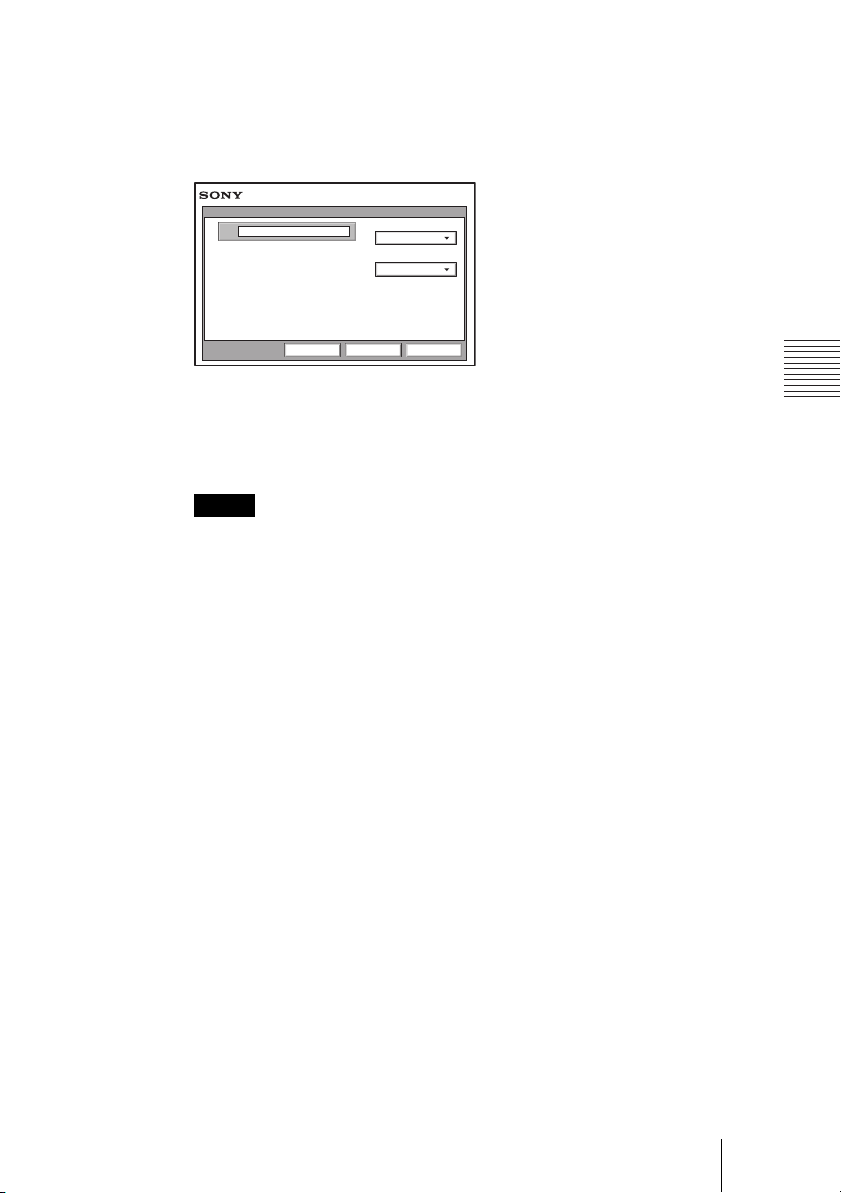
2 Select the LAN bandwidth.
Use the V, v, B or b button to select “LAN Bandwidth”, then press the
PUSH ENTER button. Press the
V or v button to select the bandwidth from
the displayed submenu, then press the PUSH ENTER button.
When using the ISDN
Detail Dial
A
1
Enter the telephone number of a remote party to connect to in the A text box.
Line I/F
ISDN
Number of Lines
6B(384K)
CancelSaveDial
Use the V, v, B or b button on the Remote Commander to select the A text
box, then press the PUSH ENTER button. Then enter the telephone number
with the number buttons on the Remote Commander.
Notes
• Do not enter the prefix number in the telephone number text box, when the prefix
setting is on.
• For details on prefix settings, see “Dial Setup Menu” on page 44.
• Even when you connect multiple ISDN lines (2B or more number of lines),
entering one telephone number of the remote party enables you to connect all the
lines used automatically.
• When you select ISDN (2B (128K)), the A1 and A2 text boxes appear. You can
enter a separate ISDN line number in each text box. When you enter the number
in the A2 text box, pressing the PUSH ENTER button on the Remote Commander
enables copy of the content of the A1 text box to A2.
• To correct the entered number, press the PinP (BACK SPACE) button on the
Remote Commander. The last entered number is deleted.
• To delete the entered ISDN telephone number, press the DISPLAY (CLEAR)
button on the Remote Commander.
2 Select the number of channels connected when setting up a call.
Use the V, v, B or b button on the Remote Commander to select “Number
of Lines”, then press the PUSH ENTER button. Press the V or v button to
select the number of channels to be used when calling a remote party from
the displayed submenu, then press the PUSH ENTER button.
81Starting a Conference by Calling a Remote Party
Page 82

Note
To connect to the remote party by entering all the telephone numbers for the
ISDN lines used
If the videoconferencing system of the remote party is not equipped with the
bonding function, entering one remote party’s telephone number does not allow
automatic connection of multiple ISDN lines used to connect to the remote party.
To connect to the remote party by entering all the telephone numbers, register the
remote party’s telephone numbers for the ISDN lines to be used referring to
“Registering a Remote Party – Phone Book” in chapter 2 (page 68), then connect to
the remote party according to the procedure described in “To call a remote party
registered in the Phone Book” (page 84).
4 Use the V, v, B or b button to select “Dial” in the lower part of the menu,
then press the PUSH ENTER button, or press the CONNECT/
DISCONNECT ( / ) button on the Remote Commander.
The system begins dialing the IP address or ISDN telephone number entered in
step 3. “Dialing” appears on the monitor screen, and the ON LINE indicator
(blue) on the Communication Terminal blinks.
When the system connects to the remote system, the message “Meeting starts!”
appears on the screen, and the ON LINE indicator stops blinking and lights in
blue.
Now you can start a videoconference.
Picture on the local site
Picture on the remote site
Meeting starts!
To cancel dialing before connecting
Press the V, v, B or b button to select “Cancel”, then press the PUSH ENTER
button, or press the CONNECT/DISCONNECT ( / ) button.
To save the entered IP address or ISDN line number in the Phone
Book
Select “Save” with the V, v, B or b button, then press the PUSH ENTER
button on the Remote Commander. The address or number you entered is
saved in the Phone Book and the List Edit menu is displayed.
For details on the List Edit menu, see “Registering a Remote Party – Phone
Book” on page 68.
82 Starting a Conference by Calling a Remote Party
Page 83

Redial function
Once you have input the IP address or ISDN line number using the Detail Dial
menu, it will be entered in the text box of the Detail Dial menu the next time
you open the menu.
Note
The redial function is not available:
• Once you have turned off the power of the system or set it to standby mode.
• When you cancel dialing the entered IP address or ISDN telephone number.
• When you open the Detail Dial menu by pressing the number buttons on the Remote
Commander.
To call a remote party with the Direct Phone Book button in launcher menu
1 Use the V, v, B or b button on the Remote Commander to select “Line I/
” from the launcher menu, then press the PUSH ENTER button. Or press
F
the CONNECT/DISCONNECT ( / ) button on the Remote
Commander.
2 Use the V or v button on the Remote Commander to select the type of line
to be used, then press the PUSH ENTER button.
AUTO: A line for connecting is automatically selected, based on the number
entered in the number text box.
IP: Connects to a videoconferencing system on the remote site via a LAN.
ISDN: Connects to a videoconferencing system on the remote site via an ISDN
line.
TEL: Connects to a phone on the remote site via an ISDN line for a voice
meeting.
3 Press the V, v, B or b button to select the Direct Phone Book of the remote
party that you want to call, and then the PUSH ENTER button of the
Remote Commander.
“Dial” appears.
If “More Options Enable” in the Dial Setup menu is set to “On”, you can select the
“Details” button. When you do, the Detail Dial menu appears.
For details about the Detail Dial menu, see “To call a remote party not
registered in the Phone Book” on page 79.
4 Press the V, v, B or b button to select “Dial”, and then press the PUSH
ENTER button of the Remote Commander.
83Starting a Conference by Calling a Remote Party
Page 84
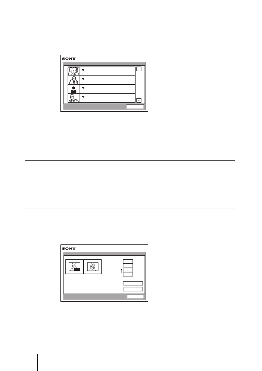
To call a remote party by selecting them in the history list
1 Press the V, v, B or b button to select “History”, and then the PUSH
ENTER button of the Remote Commander.
The History menu appears.
History
2004.
Tokyo
LAN 012.345.678.912
New York
LAN 012.345.678.912
Paris
LAN 012.345.678.912
Osaka
LAN 012.345.678.912
04. 04 10:20
2004.
04. 04 10:20
2004.
04. 04 10:20
2004.
04. 04 10:20
Cancel
2 Press the V or v button to select the desired remote party, and then a
submenu appears.
3 Press the V, v, B or b button to select “Dial”, and then press the PUSH
ENTER button of the Remote Commander.
To set up more detailed options
When “More Options Enable” is set to “On” in the Dial Setup menu, a dialog
box is displayed.
Select the More Options button with the V, v, B or b button on the Remote
Commander and press the PUSH ENTER button to open the Detail Dial menu. You
can change the settings of the desired items.
To call a remote party registered in the Phone Book
1 Use the V, v, B or b button on the Remote Commander to select “Phone
Book” in the launcher menu, then press the PUSH ENTER button.
The Phone Book appears on the monitor screen.
Phone Book
0-9
AUTO
Jane Mary
A-1
J-S
T-Z
Recent
New Entry
Cancel
2 Use the V, v, B or b button on the Remote Commander to select a remote
party from the Phone Book, then press the PUSH ENTER button.
84 Starting a Conference by Calling a Remote Party
Page 85
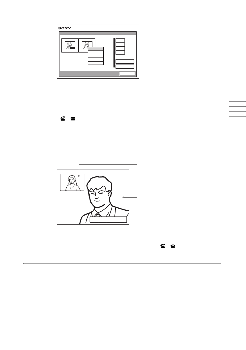
The submenu appears.
Pi
Phone Book
0-9
AUTO
Jane Mary
Dial
Edit
Copy
Delete
Cancel
A-1
J-S
T-Z
Recent
New Entry
Cancel
If the desired remote party does not appear, see “To search for a remote
party in the Phone Book” on page 86.
3 Use the V or v button on the Remote Commander to select “Dial”, then
press the PUSH ENTER button, or press the CONNECT/DISCONNECT
( / ) button on the Remote Commander.
The system begins dialing the party selected in step 2. “Dialing” appears on the
monitor screen, and the ON LINE indicator (blue) on the Communication
Terminal blinks.
When the system connects to the system on the remote site, the message
“Meeting starts!” appears on the screen, and the ON LINE indicator stops
blinking and lights in blue.
Now you can start the videoconference.
cture on the local site
Picture on the remote site
Meeting starts!
To cancel dialing before connecting
Press the V, v, B or b button to select “Cancel”, then press the PUSH ENTER
button, or press the CONNECT/DISCONNECT ( / ) button on the
Remote Commander.
To call a remote party registered in the Private Phone Book
1 Insert a “Memory Stick” in which the Private Phone Book is registered into
the Memory Stick slot on the Communication Terminal.
85Starting a Conference by Calling a Remote Party
Page 86

The Phone Book menu changes to the Private Phone Book menu.
Private Phone Book
0-9
AUTO
Jane Mary
A-1
J-S
T-Z
Recent
New Entry
Cancel
2 Use the V, v, B or b button on the Remote Commander to select a remote
party you want to call from the Private Phone Book, then press the PUSH
ENTER button.
3 Select “Dial” from the submenu and press the PUSH ENTER button, or
press the CONNECT/DISCONNECT ( / ) button on the Remote
Commander.
The system dials the selected remote party.
Note
If the auto dialing feature of the Private Phone Book is activated, the system begins
dialing when the “Memory Stick” is inserted.
To search for a remote party in the Phone Book
The Phone Book displays the list of the six parties at a time.
When you select “Recent”, the Phone Book lists the six names you have most
recently dialed.
Selecting the “0-9”, “A-I”, “J-S” or “T-Z” tab opens the submenu. When you
select the desired number or letter from the corresponding submenu, the Phone
Book lists the six party names which start with the selected number or letter.
Phone Book
0
0-9
1
A-1
AUTO
Jane Mary
J-S
T-Z
Recent
New Entry
Cancel
2
3
4
5
6
7
8
9
Note
You can also search for remote parties by pressing the number buttons on the Remote
Commander instead of the “0-9” tab on the Phone Book. Pressing the number button
lists the six party names which start with the alphabetical letter on the number button of
the Remote Commander.
86 Starting a Conference by Calling a Remote Party
Page 87

Receiving a Call from a Remote Party
Operations for answering a call differ depending on the setting of the answer
mode.
Auto answer mode
The system automatically receives a call from a remote party and you can start
conferencing. Although no operation is necessary to start, the picture on the
local site will be displayed on the remote site screen even if you are not ready
to begin.
Manual answer mode
When there is an incoming call, the Communication Terminal rings. You need
to connect the call manually before starting the conference.
You can start it whenever you are ready.
Notes
• You cannot answer the call unless the power switch on the Communication Terminal
is set to on (
• Make sure that the TV monitor is turned on. If you insert the IR repeater under the
remote sensor on the Sony TV, set the TV to standby mode.
For setting of the answer mode, see “Auto Answer” in the Answer Setup menu
on page 46.
Answering a Call from a Remote Party
@).
To answer a call in auto answer mode
When you receive a call, the Communication Terminal rings and the message
“Incoming Call” appears on the monitor screen. The system is automatically
connected and the picture of the remote party is displayed on the local monitor
screen and the sound is heard. The picture and sound on the local site will be
enabled on the remote site at the same time.
The message “Meeting starts!” appears on the monitor screen.
You are now ready to start a conference.
Meeting starts!
Picture on the local site
Picture on the remote site
87Receiving a Call from a Remote Party
Page 88

Note
See pages 90 to 104 to adjust the sound and picture during the conference.
To receive a call in manual answer mode
When you receive a call, the Communication Terminal rings and the message
“Incoming call. Answer?” appears on the monitor screen.
Press B or b to select “OK”, then press the PUSH ENTER button. The system
is then connected. Once the connection is made, the picture of the remote party
is displayed on the local monitor screen and the sound is heard. The picture and
sound on the local site will be enabled on the remote site at the same time.
The message “Meeting starts!” appears on the monitor screen.
You are now ready to start a conference.
Note
See pages 90 to 104 to adjust the sound and picture during the conference.
When you do not want to answer the call
Press B or b to select “Cancel”, then press the PUSH ENTER button. Ringing
stops.
When the system fails to make an ISDN connection
If the system fails to connect to the remote party, the message “Cannot
complete connection (an ISDN cause code and a message are displayed here)”
appears on the monitor screen.
For details on ISDN cause codes and messages, see “On-screen Messages” on
page 200.
When there is an incoming call during communication over a different line
interface
If you receive a call via an ISDN when you are in communication via a LAN
(or vice versa), the system becomes busy.
To display the elapsed communication time
You can display the elapsed communication time on the monitor screen if
“Time Display” in the General Setup menu is set to “On”.
To turn the indicator off, set “Time Display” in the General Setup menu to
“Off”. You can also turn off the indicator during communication with a remote
party by turning it off in the communication submenu.
For “Time Display” setting, see “General Setup Menu” on page 53.
88 Receiving a Call from a Remote Party
Page 89

Ending the Conference
1 Press the CONNECT/DISCONNECT ( / ) button on the Remote
Commander.
The message “Disconnect?” appears on the monitor screen.
2 Press the B or b button on the Remote Commander to select “OK”, then
press the PUSH ENTER button, or press the CONNECT/DISCONNECT
( / ) button on the Remote Commander again.
The system is disconnected.
Note
The power of the Communication Terminal remains on even if the system is
disconnected.
To cancel disconnection of the system
Select “Cancel” with the B or b button, then press the PUSH ENTER button.
To register the connected remote party in the Phone Book
You can easily register the remote party who has just disconnected.
If you set “Last Number Registration” in the General Setup menu to “On”, the
message “Register this participant in the list?” appears after a conference with
an unregistered remote party is finished. When you select “OK”, the Edit List
menu appears.
Note
If the “Last Number Registration” is set to “Off”, the message does not appear.
For “Last Number Registration” setting, see “Last Number Registration” on
page 54.
89Receiving a Call from a Remote Party
Page 90
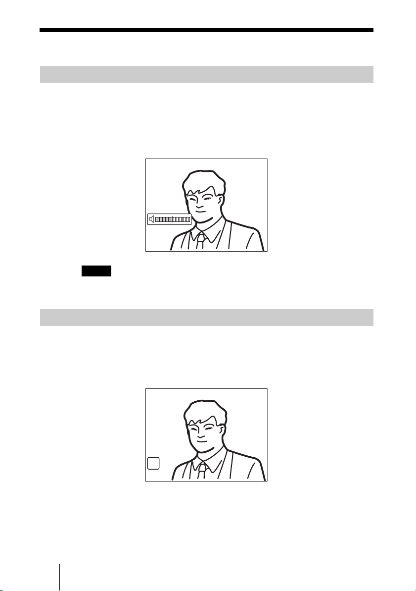
Adjusting the Sound
Adjusting the Volume
You can adjust the volume of the sound to be received from a remote party.
Press the VOLUME + button on the Remote Commander to increase the
volume, VOLUME – button to decrease it. The volume level indicator appears
on the monitor screen. The indicator will automatically disappear if you do not
operate the buttons for a certain time.
Notes
• You need to set the volume of the TV monitor to an appropriate level first.
• If feedback caused by increasing the volume occurs, decrease the volume.
Turning Off the Sound Momentarily – Muting Function
You can momentarily turn off the sound to be sent to the remote party.
Press the MIC ON/OFF button on the Remote Commander.
The sound of the local party is not heard by the remote party. The “MIC OFF”
indicator appears on the monitor screen.
To restore the sound
Press the MIC ON/OFF button again.
The “MIC OFF” indicator disappears and the sound is heard by the remote
party.
90 Adjusting the Sound
MIC
OFF
Page 91

Turning Off the Sound On Answering – Mic on Answer Function
You can turn off the sound to be sent to a remote party when you have
answered a call from the remote party.
If you set “Mic on Answer” to “Off” in the Answer Setup menu, only the
picture on the local party will be sent to the remote party when answering a
call. The “MIC OFF” indicator appears on the monitor screen.
To send the sound to the remote party
Press the MIC ON/OFF button on the Remote Commander.
Synchronizing Audio and Video – Lip Sync Function
During the conference a time lag may occur between the sound and picture to
be sent to the remote party.
When you set “Lip Sync” to “On” in the Audio Setup menu, the system adjusts
to synchronize audio and video. However, this may delay transmission of
audio synchronized with video.
For the Lip Sync setting, see “Audio Setup Menu” on page 50.
Note
To enable the Lip Sync function of the remote party, you have to ask them to do so.
Reducing Echo – Echo Canceler
The Communication Terminal is equipped with the Echo Canceler, allowing
the echo that occurs during audio transmission to be reduced.
Setting “Echo Canceler” to “Internal” in the Audio Setup menu activates the
built-in echo canceler. If you set it to “External”, you can activate the eco
canceler of the equipment connected to the system.
For the “Echo Canceler” setting, see “Audio Setup Menu” on page 50.
91Adjusting the Sound
Page 92
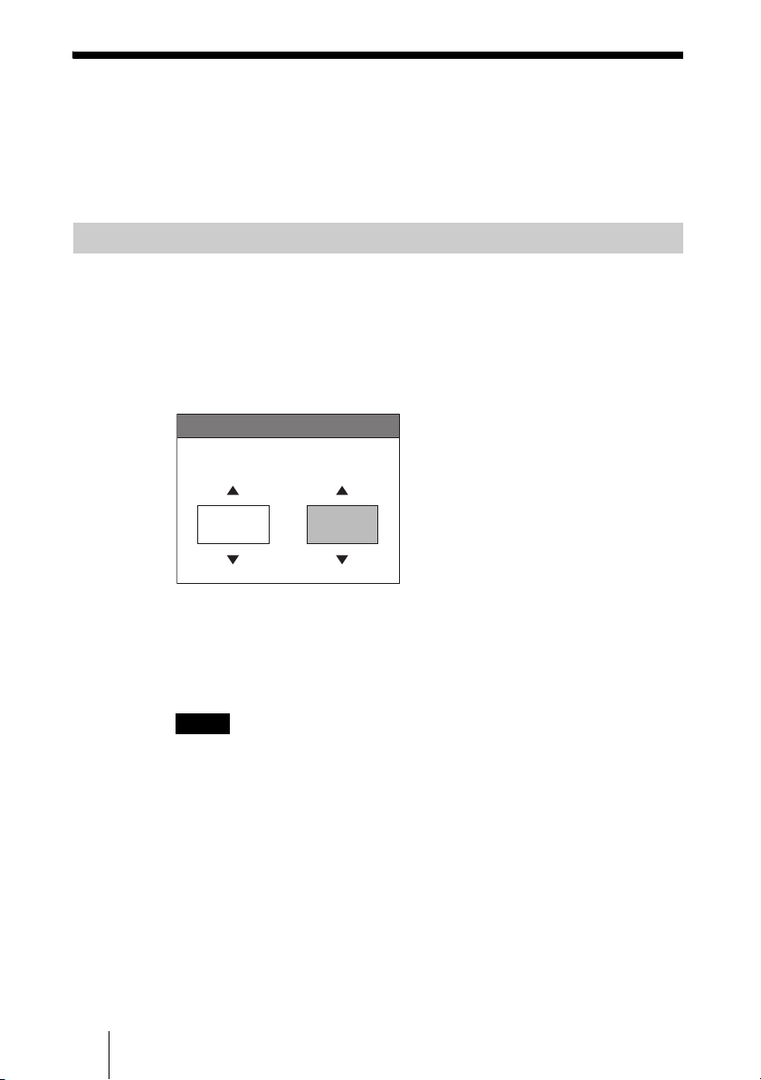
Adjusting the Camera
You can adjust the image shot by the local camera that is sent to the remote
party to obtain the desired angle and size.
During communication you can also control the camera on the remote site to
adjust the image shot by the remote camera.
Selecting the Camera to be Controlled
Before adjustment, choose whether you control the local or remote camera.
1 Press the FAR/NEAR button on the Remote Commander.
The Display Control menu appears.
2 Press the B or b button on the Remote Commander to select “Control”,
then switch between “Far” and “Near” with the V or v button.
Display Control
Display
Far
Control
Near
Camera
3 Press the PUSH ENTER button on the Remote Commander.
When “Far” is selected (the remote camera is selected), the FAR indicator is
displayed.
When “Near” is selected (the local camera is selected), the FAR indicator does
not appear.
Notes
• To control the remote camera, set “Far End Camera Control” to “On” in the
Communication Setup menu. If this setting is not configured properly, you will
not be able to control the remote camera.
• You cannot control the remote camera during a session if the remote control
format of the remote camera is not H.281. If you cannot control the remote
camera, ask the remote party about the remote control format of his camera.
• If the local and remote parties try to control the same camera at the same time, the
camera may not operate correctly.
92 Adjusting the Camera
Page 93
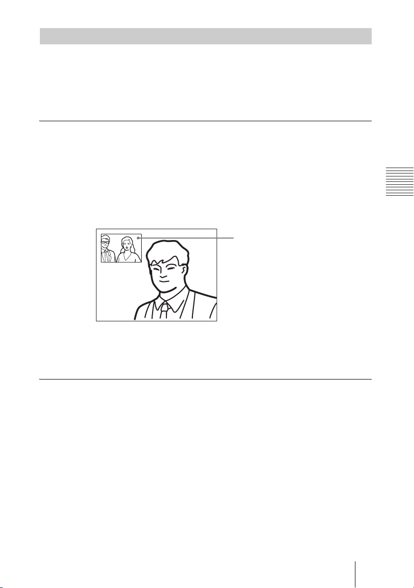
Adjusting the Camera Angle and Zoom
Determine the angle of view and the size of the picture to be displayed on the
monitor screen by adjusting the angle and zoom.
You can make adjustments in the monitor screen during communication and
in the launcher menu when not in communication. You can also make
adjustments using the Camera menu.
To make adjustments during communication
1 Select the camera you want to adjust.
Press the FAR/NEAR button on the Remote Commander to open the Display
Control menu, then select “Far” or “Near” under “Control”.
2 Press the V, v, B or b button to adjust the camera angle.
The picture whose camera angle is adjusted is displayed in the small window
or in full screen.
Adjusted picture
3 Use the ZOOM button to zoom in or out.
Press the ZOOM T (Telephoto) button to zoom in (to enlarge image), and the
ZOOM W (Wide angle) button to zoom out (to obtain wider range of image).
To make adjustments using the launcher menu while not in communication
You can adjust the camera angle and zoom of the picture on the local site only.
1 Use the V, v, B or b button to select the screen (screen frame becomes
yellow), then press the PUSH ENTER button.
93Adjusting the Camera
Page 94
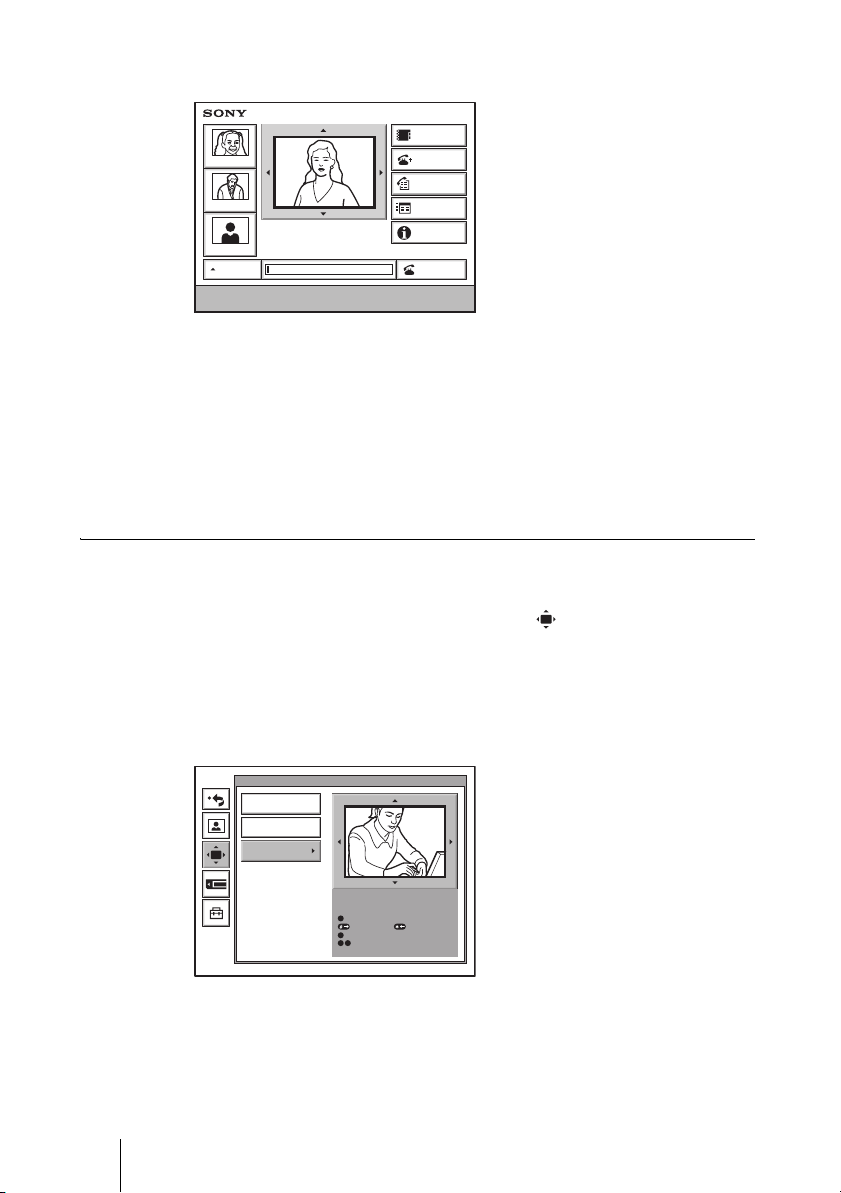
The color of the screen frame changes, then you can adjust the camera angle
and zoom.
Phone Book
Tokyo
New York
Paris
AUTO
Enter the remote party number.
IP: 012.345.678.678
ISDN: 012345678956789
Detail Dial
History
Menu
Information
Dial
2 Press the V, v, B or b button to adjust the camera angle so that the desired
angle of view is obtained.
3 Use the ZOOM button to zoom in or out.
Press the ZOOM T button to zoom in (to enlarge image), and the ZOOM W
button to zoom out (to obtain wider range of image).
4 Press the PUSH ENTER button.
To make adjustments using the Camera menu
1 Press the MENU button on the Remote Commander to display the Setup
menu, then press the V or v button to select (camera) icon.
The Camera menu appears.
2 Use the V, v, B or b button to select “Adjustments”, then press the PUSH
ENTER button.
The color of the screen frame changes, then you can adjust the camera angle
and zoom.
Preset Save
Preset Load
Adjustments
3 While in communication, press the FAR/NEAR button on the Remote
Commander to select the camera to be adjusted.
When the remote camera is selected, the FAR indicator is displayed.
94 Adjusting the Camera
Camera
Use the following Remote Commander
buttons to adjust the camera.
0
: Auto adjustment On.
: Focus+. : Focus–
8
: Backlight On/Off.
9
7
: Brightness.
Page 95
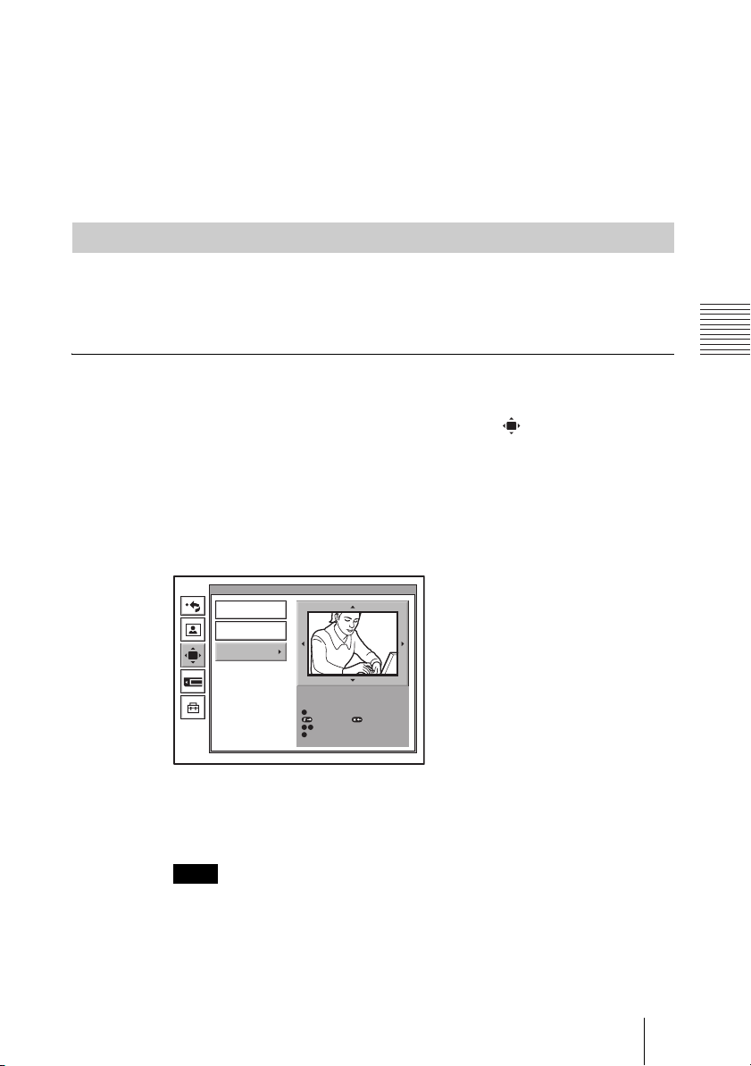
4 Press the V, v, B or b button to adjust the camera angle so that the desired
angle of view is obtained.
5 Use the ZOOM button to zoom in or out.
Press the ZOOM T button to zoom in (to enlarge image), and the ZOOM W
button to zoom out (to obtain wider range of image).
6 Press the PUSH ENTER button.
Adjusting the Focus and Brightness
Normally, the focus and brightness are automatically adjusted to obtain
optimum levels. You can also adjust them manually.
It is recommended that the focus and brightness be adjusted automatically.
To set the system to camera adjustment mode
1 Press the MENU button on the Remote Commander to display the Setup
menu, then press the V or v button to select the (camera) icon.
The Camera menu appears.
2 Use the V, v, B or b button to select “Adjustments”, then press the PUSH
ENTER button.
The color of the screen frame changes, then you can adjust the camera angle
and zoom.
The guidance for operations will be displayed under the screen.
Camera
Preset Save
Preset Load
Adjustments
Use the following Remote Commander
buttons to adjust the camera.
0
: Auto adjustment On.
: Focus
+.
: Focus
9
: Brightness.
7
: Backlight On/Off.
8
–
3 While in communication, press the FAR/NEAR button on the Remote
Commander to select the camera to be adjusted.
When the remote camera is selected, the FAR indicator is displayed.
Note
When the remote camera is selected, only manual focus adjustment is available.
95Adjusting the Camera
Page 96

To display the picture to fill the monitor screen
To display the picture in full screen while the Camera menu is displayed, select
“Adjustments”, then press the PinP button on the Remote Commander. To
cancel the full screen mode, press the RETURN button or PinP button on the
Remote Commander.
To adjust the focus automatically
Press the number button 0 on the Remote Commander.
The “Auto Camera” indicator appears and the focus is automatically adjusted.
To adjust the focus manually
Press the button on the Remote Commander repeatedly to move the focus
point further away from the camera. The “Focus Far” indicator is displayed.
Press the button on the Remote Commander repeatedly to move the focus
point closer to the camera. The “Focus Near” indicator is displayed.
To adjust the brightness
Press the number button 9 on the Remote Commander repeatedly to make the
picture brighter. The “Brightness +” indicator is displayed.
Press the “7” button on the Remote Commander repeatedly to make the picture
darker. The “Brightness –” indicator is displayed.
To shoot the picture with backlight compensation
Use backlight compensation when shooting a subject with bright background.
Each time you press the number button 8, the backlight compensation is
activated or deactivated. When it is activated, the “Backlight On” indicator is
displayed. When it is deactivated, the “Backlight Off” indicator is displayed.
Presetting the Angle and Zoom Settings
Up to six settings for camera angle and zoom can be registered in the preset
memory. Once you have stored the settings, you can easily recall them to move
the camera.
You can preset the settings in the monitor screen while in communication, and
in the launcher menu while not in communication. You can also do so using
the Camera menu.
To preset the setting in the monitor screen while in communication
1 Select the camera whose camera angle and zoom setting you want to
preset.
Press the FAR/NEAR button on the Remote Commander to open the Display
Control menu, then select “Far” or “Near” under “Control”.
96 Adjusting the Camera
Page 97
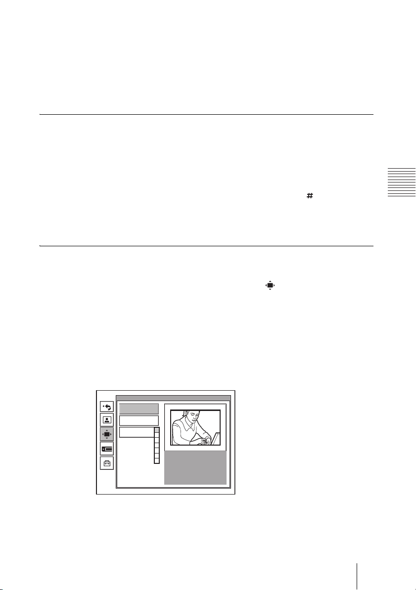
2 Adjust the camera angle and zoom.
Use the V, v, B or b button to adjust the camera angle, and ZOOM button to
adjust the zoom.
3 Hold down one of the number buttons 1 to 6.
The angle and zoom setting is stored in the selected number button, and the
message “Registered to Preset number 1 (to 6).” appears.
To preset the setting in the launcher menu while not in communication
1 Adjust the camera angle and zoom in the launcher menu.
Use the V, v, B or b button to select the screen and press the PUSH ENTER
button, then press the V, v, B or b button to adjust the angle and the ZOOM
buttons to adjust the zoom.
2 Hold down one of the number buttons 1 to 6 or press the button and one
of the 1 to 6 buttons.
The angle and zoom setting is stored in the selected number button, and the
message “Registered to Preset number 1 (to 6).” appears.
To preset the setting using the Camera menu
1 Press the MENU button on the Remote Commander to display the Setup
menu, then press the V or v button to select (camera) icon.
The Camera menu appears.
2 Use the V, v, B or b button on the Remote Commander to select “Preset
Save”, then press the PUSH ENTER button.
3 Select the preset number (1 to 6) with the V or v button, then press the
PUSH ENTER button.
The color of the screen frame changes, then you can adjust the camera angle
and zoom.
Camera
Preset Save
Preset Load
Adjustments
0
1
2
3
4
5
6
4 While in communication, select the camera to be adjusted with the FAR/
NEAR button on the Remote Commander.
The FAR indicator is displayed on the monitor screen when the remote camera
is selected.
97Adjusting the Camera
Page 98

5 Adjust the angle and zoom.
Use the V, v, B or b button to adjust the camera angle, and ZOOM button to
adjust the zoom.
6 Press the PUSH ENTER button.
The setting is registered in the selected preset number.
Recalling the Preset Angle and Zoom Setting
You can move the camera to the preset position by recalling the preset camera
angle and zoom with the monitor screen displayed while in communication.
You can do the same with the launcher menu displayed while not in
communication. Using the Camera menu also enables movement of the
camera to the preset position.
To recall the preset setting in the monitor screen while in communication
1 Select the camera which you want to move to the preset position.
Press the FAR/NEAR button on the Remote Commander to open the Display
Control menu, then select “Far” or “Near” under “Control”.
2 Press one of the number buttons 1 to 6 on the Remote Commander.
The setting of the selected preset number is recalled, and the camera moves to
the preset position. The message “Preset 1 (to 6) selected” appears.
To recall the preset setting in the launcher menu while not in
communication
You can move the local camera to the preset position.
1 Select the screen in the launcher menu, then press the PUSH ENTER
button.
2 Press one of the number buttons 1 to 6 on the Remote Commander.
The setting of the selected preset number is recalled, and the camera moves to
the preset position. The message “Preset 1 (to 6) selected” appears.
To recall the preset setting in the Camera menu
1 Display the Camera menu.
2 Use the V, v, B or b button on the Remote Commander to select “Preset
Load”, then press the PUSH ENTER button.
98 Adjusting the Camera
Page 99

3 Press the V or v button to select the preset number (1-6) you want to recall,
then press the PUSH ENTER button.
Camera
Preset Save
Preset Load
Adjustments
The setting of the preset number is recalled and the camera moves to the
position of that setting.
On backup
The built-in lithium battery enables retention of the memories such as preset
camera adjustments even if the Communication Terminal is turned off.
Notes
• The built-in lithium battery is kept charged as long as the system is operated. If the
system is not used for a long time, the battery is gradually discharged. It will be
completely discharged when you do not use the system for 12 weeks. To retain the
system’s memory, recharge the battery.
• To recharge the battery, connect the camera to the Communication Terminal and
leave both units with the power on for about 48 hours.
0
0
1
1
2
2
3
3
4
4
5
5
6
6
99Adjusting the Camera
Page 100
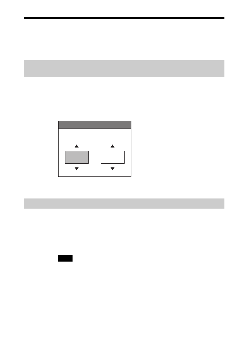
Selecting the Input Picture and Sound
This section describes how to switch the picture displayed on the monitor
screen, and how to switch the input picture and sound.
Switching the Displayed Picture Between the Local and Remote Pictures
1 Press the FAR/NEAR button on the Remote Commander.
The Display Control menu appears.
2 Use the V, v, B or b button on the Remote Commander to select “Near” or
“Far” under “Display”.
Display Control
Display
Far
3 Press the PUSH ENTER button on the Remote Commander.
Selecting the Input Picture
1 Press the VIDEO INPUT SELECT button on the Remote Commander.
The Video Input Select menu appears.
2 Use the V, v, B or b button on the Remote Commander to select the video
input on the local site.
Note
While in communication you can switch the video input of the remote system by
selecting “Far” in the Video Input Select menu.
Control
Near
Camera
100 Selecting the Input Picture and Sound
 Loading...