

Sony PCS-G70, PCS-G70P Operating Instruction

VIDEO COMMUNICATION SYSTEM
PCS-G70
PCS-G70P
SYSTEM INTEGRATION MANUAL
1st Edition

! WARNING
This manual is intended for qualified service personnel only.
To reduce the risk of electric shock, fire or injury, do not perform any servicing other than that
contained in the operating instructions unless you are qualified to do so. Refer all servicing to
qualified service personnel.
! WARNUNG
Die Anleitung ist nur für qualifiziertes Fachpersonal bestimmt.
Alle Wartungsarbeiten dürfen nur von qualifiziertem Fachpersonal ausgeführt werden. Um die
Gefahr eines elektrischen Schlages, Feuergefahr und Verletzungen zu vermeiden, sind bei
Wartungsarbeiten strikt die Angaben in der Anleitung zu befolgen. Andere als die angegeben
Wartungsarbeiten dürfen nur von Personen ausgeführt werden, die eine spezielle Befähigung
dazu besitzen.
! AVERTISSEMENT
Ce manual est destiné uniquement aux personnes compétentes en charge de l’entretien. Afin
de réduire les risques de décharge électrique, d’incendie ou de blessure n’effectuer que les
réparations indiquées dans le mode d’emploi à moins d’être qualifié pour en effectuer d’autres.
Pour toute réparation faire appel à une personne compétente uniquement.
PCS-G70/G70P

Table of Contents
1. Installation
1-1. Caution on Installation ................................................................................ 1-1
1-1-1. Videoconferencing Room Layout .............................................. 1-1
1-1-2. Operating Environment ..............................................................1-3
1-2. Flowchart of Installation ............................................................................. 1-4
1-3. System Connections ....................................................................................1-5
1-3-1. When Used in LAN (100BASE-TX/10BASE-T) ...................... 1-5
(with one Camera and one Monitor) .......................................... 1-5
1-3-2. When Used in ISDN (with one Camera and one Monitor) ........1-6
1-4. Initialization ................................................................................................ 1-7
1-4-1. Inserting Batteries into the Remote Commander ....................... 1-7
1-4-2. Turning On/Off the TV Monitor Together with the
Communication Terminal .......................................................... 1-8
1-4-3. When the Power is First Turned On after Installation ............... 1-9
1-4-4. Adjust the Volume of TV Monitor ........................................... 1-14
1-5. System Setting ........................................................................................... 1-15
1-5-1. Menu Configuration ................................................................. 1-15
1-5-2. System Setting Table ................................................................ 1-16
1-6. Flowchart of Opening Test........................................................................ 1-23
1-6-1. Dialing Procedure of ISDN ......................................................1-24
1-6-2. Answering Procedure of ISDN ................................................ 1-25
1-6-3. Dialing Procedure of LAN ....................................................... 1-26
1-6-4. Answering Procedure of LAN ................................................. 1-27
1-7. Conducting a Videoconference Using the Dual Video Function .............. 1-28
1-7-1. System Configuration Using 2 Cameras and 3 Monitors ......... 1-28
1-7-2. Activating the Dual Video Function ........................................ 1-29
1-8. Connecting Four Camera Units ................................................................. 1-30
PCS-G70/G70P
2. Maintenance
2-1. Confirmation Procedure of Local Terminal Operation Using Self-Loop ... 2-1
2-2. LAN Communication Test Using Ping ....................................................... 2-1
2-3. Failure Analysis .......................................................................................... 2-2
2-4. How to Take Log ........................................................................................ 2-4
2-5. Updating of Software ................................................................................ 2-14
2-5-1. Updating Using Memory Stick ................................................ 2-14
2-6. Service Mode ............................................................................................ 2-15
1

3. Compatibility in LAN Network
3-1. Connection via Hub..................................................................................... 3-1
3-2. Connection via Router................................................................................. 3-3
3-3. Connection via DHCP ................................................................................. 3-5
3-4. Connection via Gatekeeper ......................................................................... 3-7
3-5. Connection via DHCP and Gatekeeper ....................................................... 3-9
3-6. Connection beyond NAT .......................................................................... 3-11
3-7. Connection using PPPoE........................................................................... 3-13
4. Technical Data
4-1. Communication Terminal Port Number Used ............................................ 4-1
4-1-1. Without H.323MCU Option (Default) .......................................4-1
4-1-2. Without H.323MCU Option (Custom: When TCP port
number is set to 3000 and UDP port number is set to 3100) ..... 4-1
4-1-3. With H.323MCU Option (Default) ............................................ 4-2
4-1-4. With H.323MCU Option (Custom: When TCP port number
is set to 3000 and when UDP port number is set to 3100) .........4-2
4-2. Setting of Communication Terminal and HUB .......................................... 4-3
4-3. Audio and Video Input/Output Characteristics of Communication
Terminal ...................................................................................................... 4-4
4-3-1. Audio Input/Output Characteristics of PCS-PG70/PG70P ........ 4-4
4-3-2. Video Input/Output Characteristics of PCS-PG70/PG70P ........ 4-4
4-4. Audio Selection List of PCS-G70/G70P ..................................................... 4-5
4-5. Displayed Window during Multipoint Connection of
PCS-PG70/PG70P ....................................................................................... 4-6
4-5-1. Displayed Picture at Each Point in Voice Activate Mode ......... 4-6
4-5-2. Displayed Picture at Each Point in Broadcast Mode with
Full Screen Mode ....................................................................... 4-7
4-5-3. Displayed Picture at Each Point in Broadcast Mode with
Split Window Mode ................................................................... 4-8
4-6. Display Transition List of PCS-G70/G70P ............................................... 4-11
4-7. Priority Level List of Video and Audio Codec ......................................... 4-16
4-8. Supported Video/Audio Codec ................................................................. 4-17
2
PCS-G70/G70P
Section 1
Installation
1-1. Caution on Installation
1-1-1. Videoconferencing Room Layout
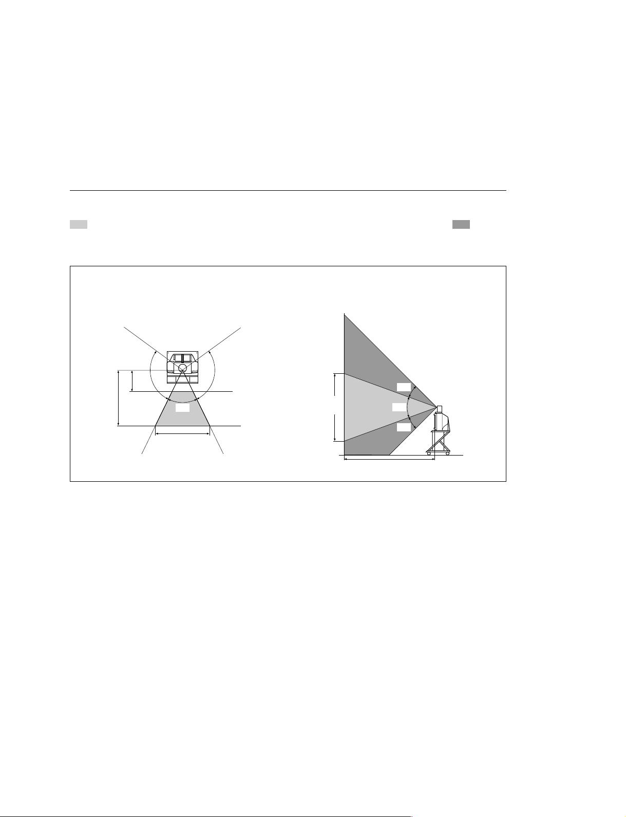
Be sure to position the camera and microphone appropriately in the videoconferencing room.
Shooting range of camera unit
represents the shooting area of the camera unit when the zoom has been extended fully. indicates the shooting area of the camera when the left/right angling function is fully utilized. Use the measurements below as a guide for the layout of the videoconference room.
Top view Side view
(horizontal range at maximum zoom-out) (vertical range at maximum zoom-out)
1.5 m
(4.92 ft)
100d
4 m
(13.12 ft)
65d
5.1 m (16.73 ft)
100d
3.1 m
(8.41 ft)
25d
42d
25d
4 m (13.12 ft)
PCS-G70/G70P
1-1
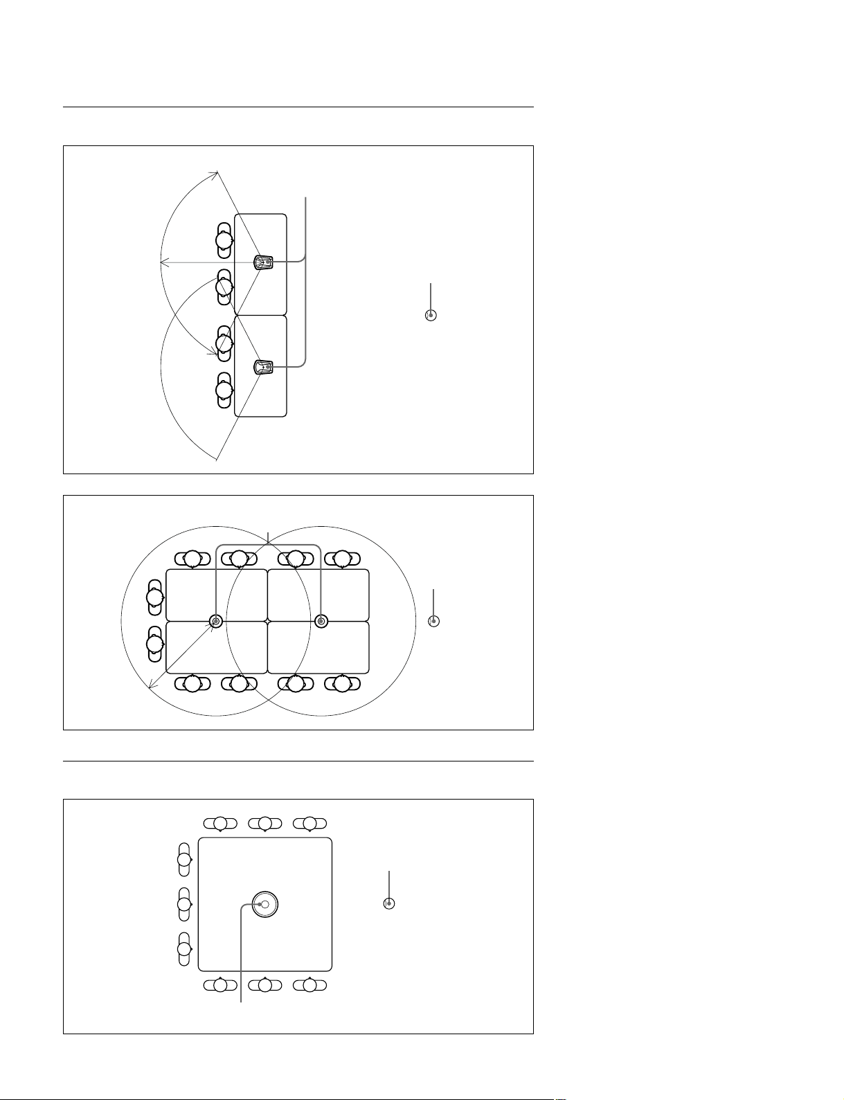
Directional range and layout examples of microphone
Extension microphone (PCS-A300 or PCSA-A3)
PCS-A300 or PCSA-A3
0.5 to 1 m
120d
Extension microphone (PCS-A1)
PCS-A1
Camera unit
Camera unit
0.5 to 1.2 m
Microphone layout example using a communication transducer
Camera unit
1-2
CTE-600
PCS-G70/G70P
1-1-2. Operating Environment
Layout Considerations
. Avoid having large, moving objects, especially people,
behind the participants, as the quality of the picture
transmitted to the remote party will deteriorate.
. Do not seat participants in front of a wall with fine stripe
patterns.
. Choose a room where echo will not occur.
. Do not install the system near noise sources such as air
conditioners or copy machines.
. Avoid placing the system in a room where there are the
speakers used for an in-house broadcasting system.
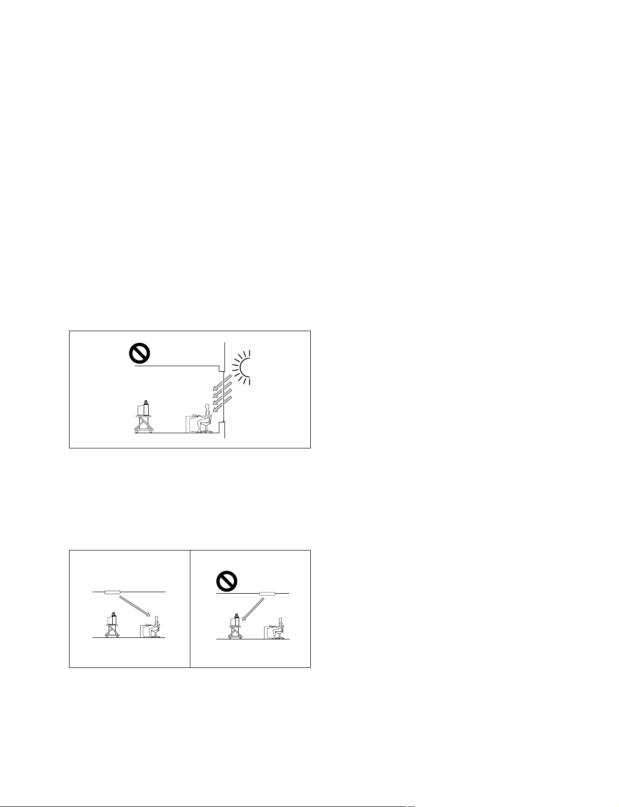
Lighting Considerations
Do not point the camera toward a window where sunlight
comes in as back lighting may decrease the contrast. If it is
necessary, cover the window with a thick curtain.
Adjust room lighting so that it falls on the participants.
Avoid direct light on the TV monitor. Light intensity on
faces should be about 300 lux or more.
If an inverter type or brightness-adjustable type of fluorescent lamp is used, the sensitivity of the remote commander
may deteriorate.
PCS-G70/G70P
1-3
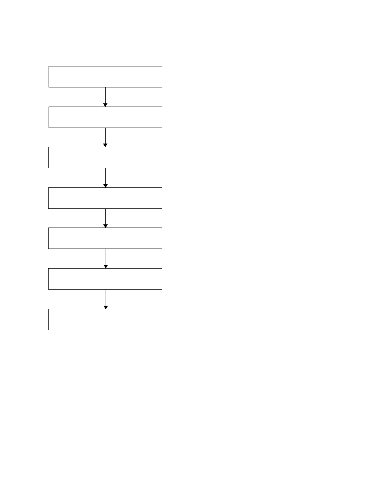
1-2. Flowchart of Installation
Place used
Unpacking
Check of supplied accessories
Power and cable connection, and
preparation
Start the power of the system and
initialize.
<Refer to “1-1. Caution on Installation” on page 1-1.>
<Refer to “1-3. System Connections” on page 1-5.>
<Refer to “1-4. Initialization” on page 1-7.>
Initialize the related block.
End
<Refer to “1-5. System Setting” on page 1-15.>
1-4
PCS-G70/G70P
1-3. System Connections
This section describes the typical system connections.
m
. Be sure to turn off all the equipment before making any connections.
. Do not connect/disconnect the camera cable with the power on. Doing so may damage the camera unit
or communication terminal.
. For safety, do not connect the 100BASE-TX/10BASE-T connector to a network that applies an excess
voltage via the 100BASE-TX/10BASE-T connector.
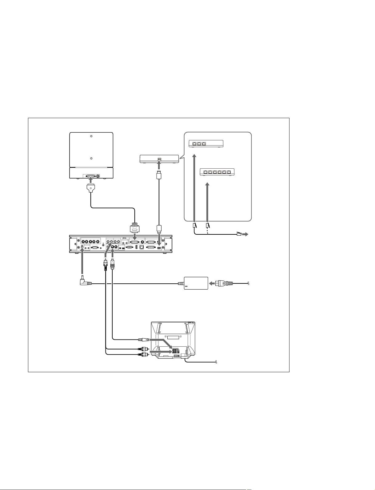
1-3-1. When Used in LAN (100BASE-TX/10BASE-T)
(with one Camera and one Monitor)
PCSA-CG70/CG70P
Camera unit
TERMINAL VISCA OUT
to TERMINAL
Camera cable
*
PCS-PG70/PG70P
Communication terminal
MCU VIDEO OUT
12 34
DC 19.5V
IR OUT
12
AUDIO
OUT
to DC19.5V
Audio cable
*
supplied
**
not supplied
AUDIO OUT AUDIO IN
(MIXED)
5
AUX CONTROL
CTRL-S
AUX
VIDEO OUT
to
S-video cable
*
S-video
to audio input
AUX
LINE
MIC
(PLUG IN POWER)
12
12
EC-MIC
12
MONITOR
to
VIDEO OUT
MONITOR 1
to
input
to MAIN CAMERA
MAIN SUB
CAMERA CAMERAAUX IN AUX IN
100BASE-TX/
WHITE
10BASE-T
BOARD
RGB OUT DSB
to 100BASE-TX/
10BASE-T
*
ISDN UNIT
PCS-AC19V6
AC adaptor
UTP cable (category 5, straight)
TV monitor
**
to a wall outlet
Power cord
to a wall outlet
**
to LAN
*
m
. If the system uses only one camera, be sure to connect it to the MAIN CAMERA connector.
. The AUDIO OUT (MIXED) jack is used to make an audio recording of a conference. This is not used
during regular conferences.
PCS-G70/G70P
1-5
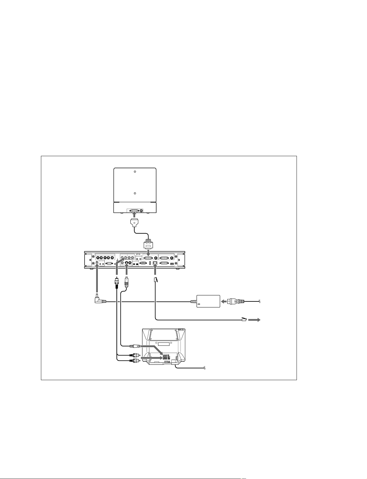
1-3-2. When Used in ISDN (with one Camera and one Monitor)
m
. Do not connect/disconnect the camera cable or the interface cable with the power on. Doing so may
damage the camera unit, communication terminal or ISDN unit.
. Used with an ISDN unit for the first time, the communication terminal may automatically upgrade the
software of the ISDN unit. While the upgrading message is displayed on the monitor screen, be sure not
to turn off the communication terminal. Doing so may cause malfunction of the system.
TERMINAL VISCA OUT
to TERMINAL
Interface cable (supplied
Camera cable
PCS-PG70/PG70P
Communication
terminal
MCU VIDEO OUT
12 34
IR OUT
12
AUX CONTROL
5
CTRL-S
DC 19.5V
to
AUDIO
OUT
to DC19.5V
Audio cable
*
PCSA-CG70/CG70P
Camera unit
to TERMINAL
with ISDN UNIT)
*
to MAIN
CAMERA
AUDIO OUT AUDIO IN
(MIXED)
12
AUX
VIDEO OUT
AUX
MONITOR
LINE
MIC
(PLUG IN POWER)
12
EC-MIC
12
MAIN SUB
CAMERA CAMERAAUX IN AUX IN
WHITE
BOARD
RGB OUT DSB
to VIDEO OUT
MONITOR 1
S-video
*
cable
S-video
100BASE-TX/
10BASE-T
input
to
to ISDN
UNIT
ISDN UNIT
TV monitor
ISDN unit
PCSA-B384S ISDN unit
to ISDN 1-3
PCSA-B768S
ISDN unit
**
to ISDN 1-6
ISDN modular cable
PCS-AC19V6
AC adaptor
to a wall outlet
**
**
**
**
Power cord
*
*
supplied
**
not supplied
to audio input
to a wall outlet
m
. If the system uses only one camera, be sure to connect it to the MAIN CAMERA connector.
. The AUDIO OUT (MIXED) jack is used to make an audio recording of a conference. This is not used
during regular conferences.
. PCS-B384 or PCS-B768 is available for an ISDN unit.
1-6
PCS-G70/G70P
1-4. Initialization
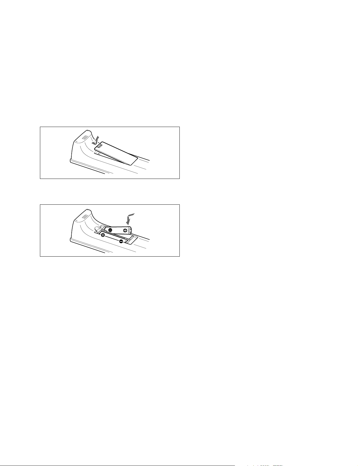
1-4-1. Inserting Batteries into the Remote
Commander
Most of the operations with the video communication
system can be controlled with the supplied remote commander.
1. Remove the battery compartment cover.
2. Insert two size AAA (R03) batteries (supplied) with
correct polarities into the battery compartment.
n
Be sure to insert the batteries _ side first. Inserting them
forcibly + side first may damage the insulated film
covering the batteries and cause a short circuit.
3. Replace the cover.
m
Battery life
When the remote commander does not function properly,
replace both the batteries with new ones.
Notes on batteries
To avoid damage from possible battery leakage or corrosion, observe the following:
. Make sure to insert the batteries with the polarities in the
correct direction.
. Do not mix old and new batteries, or different types of
batteries.
. Do not attempt to charge the batteries.
. If the remote commander is not used for a long period of
time, remove the batteries from it.
. If battery leakage occurs, clean the battery compartment
and replace all the batteries with new ones.
PCS-G70/G70P
1-7
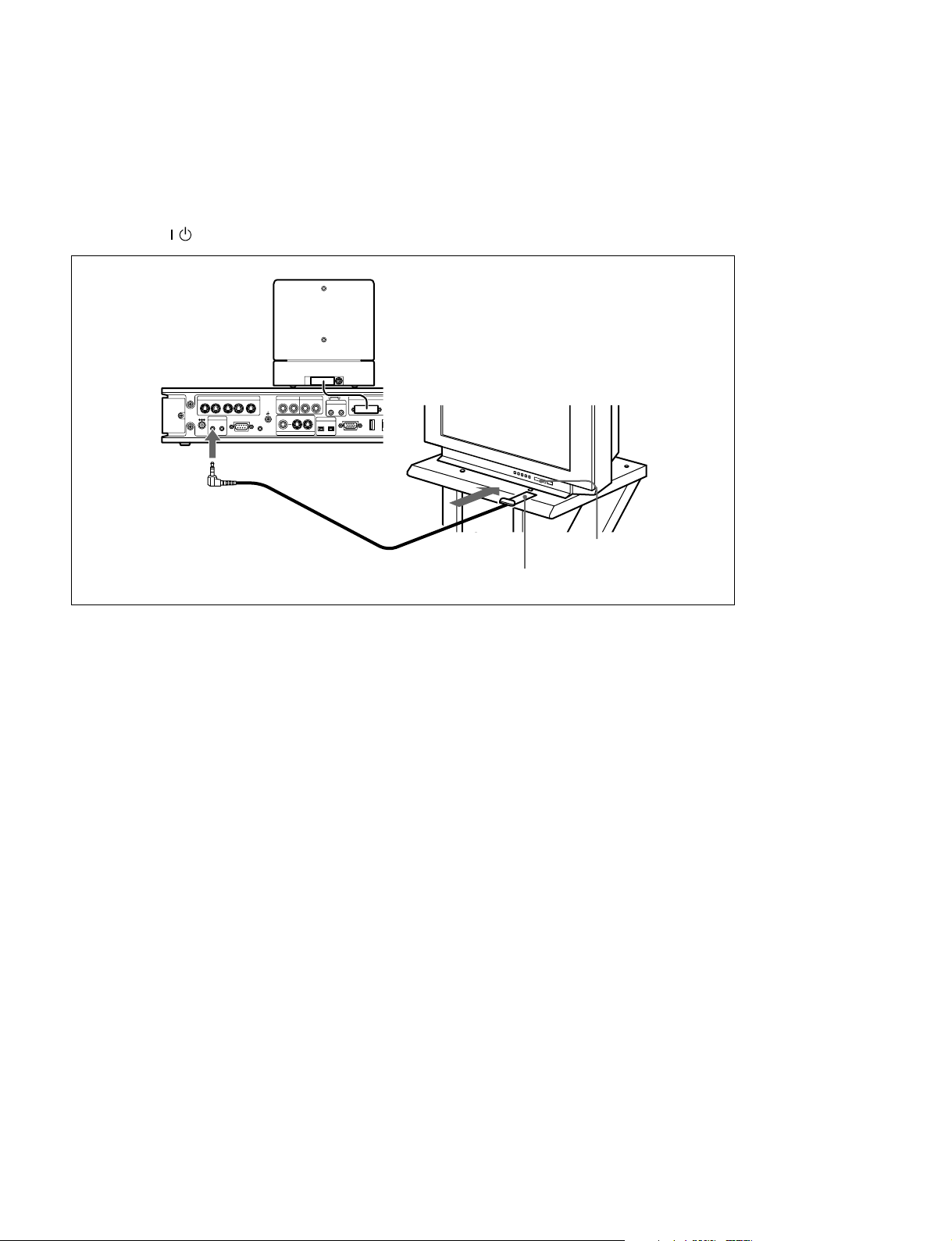
1-4-2. Turning On/Off the TV Monitor Together with the Communication
Terminal
If a Sony TV monitor is used, insert the IR repeater under the remote sensor of the TV monitor. Once the
IR repeater is set, the TV monitor will turn on or go to standby together with the communication terminal
by pressing the
/ button on the supplied remote commander.
TERMINAL VISCA OUT
MCU VIDEO OUT
12 34
DC 19.5V
IR OUT
AUX CONTROL
12
to IR OUT
5
CTRL-S
AUDIO OUT AUDIO IN
(MIXED)
12
AUX
MONITOR
VIDEO OUT
AUX
LINE
EC-MIC
12
MIC
(PLUG IN POWER)
12
MAIN
CAMERA
1
WHITE
BOARD
RGB OUT
Remote sensor
IR repeater (supplied)
1-8
PCS-G70/G70P
1-4-3. When the Power is First Turned On
after Installation
Setting Up the System for the First Time — Initial
Setup Wizard
Turning On
Turn on the communication terminal in the following
procedure.
1. Turn on the TV monitor.
If the IR repeater is installed in the TV monitor, set the
TV monitor to standby mode. The TV monitor will
turn on simultaneously when the communication
terminal is turned on.
2. Turn on the power of any other equipment to be used
for the videoconference.
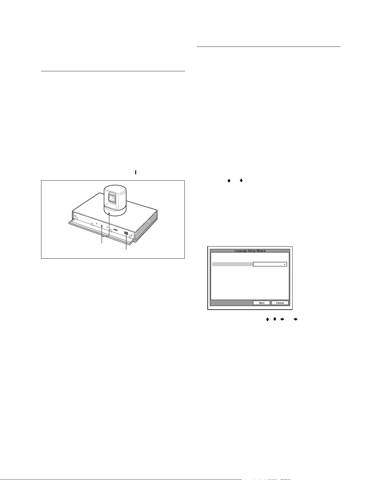
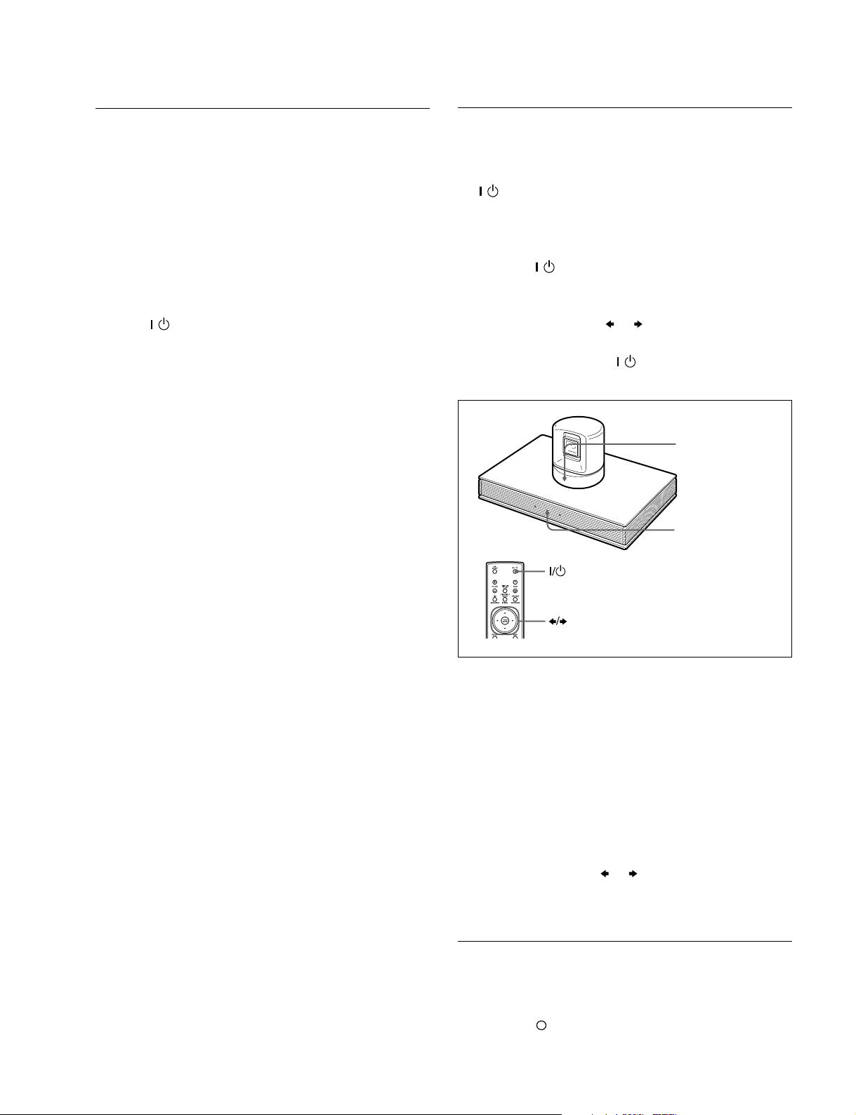
3. Set the power switch on the right side of the communication terminal to the on position ( ).
POWER indicators
(Light green.)
Power switch
When the power is first turned on after installation, the
wizard for initialization is displayed if self-diagnosis is
completed. Register according to the wizard.
The items set according to the wizard can also be later
changed on the menu screen.
m
. The wizard for initialization is also displayed when the
ISDN unit is newly installed after system installation.
Similarly, register according to the wizard in this case.
. When the communication terminal and the camera are
separately installed, point the remote commander to the
camera unit for operations.
1. Use the or button on the remote controller to
select the language displayed in the menus or messages.
Language:
Select one of the desired language from English,
French, German, Japanese, Spanish, Italian, Simplified
Chinese, Portuguese, and Korean*.
* Korean is added by upgrading.
The communication terminal turns on after a while. Three
indicators on the front of the communication terminal and
the POWER indicator on the camera light, then only the
POWER indicators on both units remain on in green.
m
. After the power is turned on, the camera unit moves
automatically for trial operation. Be careful not to catch
your finger.
. If the camera is obstructed forcefully while it is moving,
it may not resume moving or output a signal to the
communication terminal. In this case, turn off the
terminal, and turn it on again.
. A Sony TV monitor may not turn on if the “IR Repeater
Mode” setting does not meet the TV monitor specifications. In this case, turn on the TV monitor manually or
by using its remote controller, perform the setup wizard
of the communication terminal, and then change the “IR
Repeater Mode” setting in the General Setup menu.
Language English
2. Select “Next” using the
, , , or button on the
remote commander, then press the PUSH ENTER
button.
The Monitor Setup Wizard is displayed.
n
The monitor setting wizard is set when two or more
monitors are connected to the system. When only one
monitor television is connected, select “Next” and
proceed to step 5.
PCS-G70/G70P
1-9
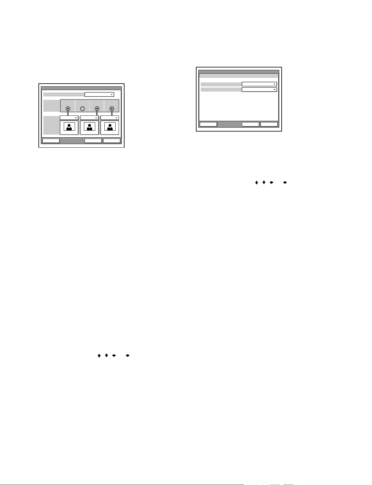
3. Set a monitor that outputs a signal.
n
No menus other than the selected monitor(s) will be
displayed.
Monitor Setup Wizard
Monitors
Connection
VIDEO1 VIDEO2 RGB OUT
3
RGB OUT(DSB)
5. Set the country/region and protocol in which an ISDN
line is used.
ISDN Setup Wizard
USACountry/Region
National ISDNProtocol
SubMain
Monitor
Sub
NextPrevious Cancel
Monitors:
Select the number of monitors connected to the
system.
1: One monitor connected.
2: Two monitors connected.
3: Three monitors connected.
Connection:
Selects the output connector to which the device to be
used is connected.
VIDEO 1: Selects the device connected to
the VIDEO 1 connector.
VIDEO 2: Selects the device connected to
the VIDEO 2 connector.
RGB OUT: Selects the device connected to
the RGB OUT connector as the
main monitor.
RGB OUT (DSB): Selects the device connected to
the RGB OUT connector on the
data solution box.
Monitor:
Define the monitor connected to the corresponding
connector as the main monitor or the sub monitor.
Main: Defines the monitor as the main monitor.
Sub: Defines the monitor as the sub monitor.
4. Select “Next” using the
, , , or button on the
remote commander, then press the PUSH ENTER
button.
The ISDN Setup Wizard is displayed when the ISDN
unit is connected.
When the ISDN unit is not connected, the LAN setting
wizard is displayed. Proceed to step 11.
NextPrevious Cancel
Country/Region:
Select the country or region in which this system is
used.
Protocol:
Select the protocol of the ISDN line used.
6. Select “Next” using the , , , or button on the
remote commander, then press the PUSH ENTER
button.
1-10
PCS-G70/G70P
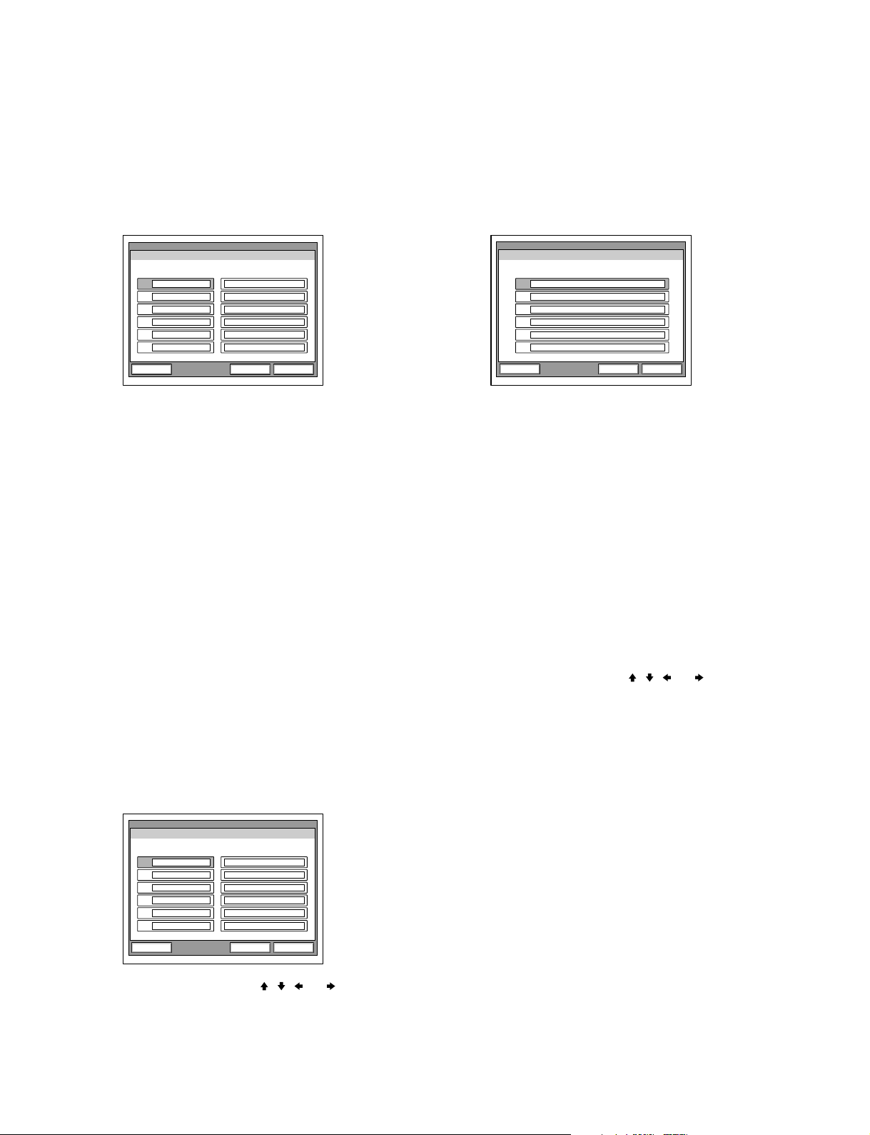
7. Enter the telephone number(s) of the ISDN line used
by the system.
When the ISDN unit PCS-B384/B768 or PCSAB384S/B768S is used, enter the same number in the
text boxes A1 and A2 for one line (except for the
U.S.A. and Canada).
9. Enter the sub-address(es).
Only numeric characters are available for a subaddress.
When the ISDN unit PCS-B384/B768 or PCSAB384S/B768S is used, enter the same number in the
text boxes A1 and A2 for one line.
ISDN Setup Wizard
Area Code Local Number
A1
A2
B1
B2
C1
C2
NextPrevious Cancel
Area Code:
Enter the area code.
Do not enter the first “0” of an area code.
Local Number:
Enter the telephone number.
m
. By pressing the PUSH ENTER button with a blank
text box selected, the content in the text box above
will be copied to the selected text box.
. When the ISDN unit PCS-B384 or PCSA-B384S is
used to connect two or three ISDN lines, enter the
telephone numbers in the text boxes B1 to C2.
. When the ISDN unit PCS-B768 or PCSA-B768S is
used to connect two to six ISDN lines, enter the
telephone numbers in the text boxes B1 to F2. To
open the menu with the text boxes D1 to F2, select
“Next” and press the PUSH ENTER button.
. When the ISDN unit PCSA-PRI is used, Ch1 to
Ch23 (T1), or Ch1 to Ch30 (E1) are displayed. Enter
the telephone numbers according to the number of
channels to be used.
ISDN Setup Wizard
Sub Address
A1:
A2:
B1:
B2:
C1:
C2:
NextPrevious Cancel
m
. When the ISDN unit PCS-B384 or PCSA-B384S is
used to connect two or three ISDN lines, enter subaddresses in the text boxes B1 to C2.
. When the ISDN unit PCS-B768 or PCSA-B768S is
used to connect two to six ISDN lines, enter subaddresses in the text boxes B1 to F2. To open the
menu with the text boxes D1 to F2, select “Next”
and press the PUSH ENTER button.
. When the ISDN unit PCSA-PRI is used, Ch1 to
Ch23 (T1), or Ch1 to Ch30 (E1) are displayed. Enter
the sub-addresses according to the number of
channels to be used.
10. Select “Next” using the
, , , or button on the
remote commander, then press the PUSH ENTER
button.
The LAN Setup Wizard is then displayed.
n
When the LAN is not used, select “Next” and display a
confirmation message. After that, proceed to step 13.
ISDN Setup Wizard
Area Code Local Number
Ch1
Ch2
Ch3
Ch4
Ch5
Ch6
NextPrevious Cancel
8. Select “Next” using the
, , , or button on the
remote commander, then press the PUSH ENTER
button.
PCS-G70/G70P
1-11
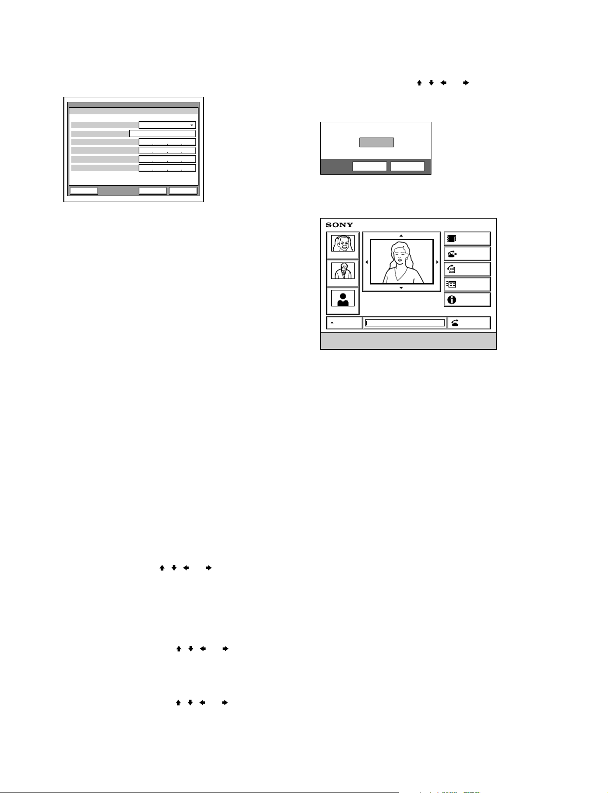
11. Set the following items on LAN.
CancelPrevious
Save
LAN Setup Wizard
DHCP Mode Off
Host Name
IP Address
Network Mask
Gateway Address
DNS Address
13. Select “Save” using the
, , , or button on the
remote commander, then press the PUSH ENTER
button.
NextPrevious Cancel
DHCP Mode:
Sets DHCP (Dynamic Host Configuration Protocol).
AUTO: Automatically assigns an IP address, net-
work mask, gateway address, and DNS
address.
OFF: Deactivates DHCP. In this case set an IP
address, network mask, gateway address,
and DNS address manually.
Host Name:
Enter a host name.
IP Address:
Enter an IP address for the communication terminal.
Network Mask:
Enter a network mask.
Gateway Address:
Enter a default gateway address.
DNS Address:
Enter a DNS (Domain Name System) server address.
m
. If the “DHCP Mode” has been set to “AUTO”, the
automatically assigned IP address can be confirmed
in the launcher menu or information menu.
. If you do not know how to setup the LAN, check
with a network administrator for connectingnetwork.
12. Select “Next” using the , , , or button on the
remote commander, then press the PUSH ENTER
button.
A confirmation message is then displayed.
m
. To stop the setting
Select “Cancel” using the , , , or button on
the remote commander, then press the PUSH
ENTER button.
. To return to the preceding wizard
Select “Return” using the
, , , or button on
the remote commander, then press the PUSH
ENTER button.
The settings are saved, and then the launcher menu
will be displayed.
Phone Book
Tokyo
New York
IP: 012.345.678.678
Paris
AUTO
Enter the remote party number.
ISDN: 012345678956789
Launcher menu
Detail Dial
History
Menu
Information
Dial
n
Used with an optional device especially designed for
use with this system, such as the data solution box or
ISDN unit, for the first time, the communication
terminal may automatically upgrade the software of
the connected device. While the upgrading message is
displayed on the monitor screen, be sure not to turn off
the communication terminal. Doing so may cause
malfunction of the system. System malfunction may
also occur when a system power-off has been caused
by an accidental problem such as a power interruption
during upgrading. If connection of the data solution
box or ISDN unit to the communication terminal is not
re-established even after the system power is recovered, consult a Sony dealer.
1-12
PCS-G70/G70P
Standby Mode Function
button
POWER indicator
(Not lit.)
POWER indicator
(Lights orange.)
buttons and PUSH ENTER button
To save power, the communication terminal will enter
standby mode if it is not operated for a specified period of
time.
When the communication terminal is in standby mode, the
POWER indicator lights in orange.
Once the communication terminal receives a call, the
standby mode is automatically released.
To release the standby mode
Press the
/ button on the remote commander.
To specify the standby time
Specify the time that you want the system to remain on
before entering the standby mode (1 to 99 minutes) using
“Standby Time” in the General Setup menu. To make the
system not enter the standby mode, set “Standby Mode” in
the General Setup menu to “Off”.
m
. The POWER indicator on the camera goes off when the
system enters standby mode.
. If the IR repeater is installed under the remote sensor of
a SONY TV monitor, the TV monitor will enter standby
mode together with the communication terminal.
Setting the Video Communication System to
Standby Mode
The video communication system can be turned on with
the / button on the remote commander when it is in
standby mode.
1. Display the launcher menu on the monitor screen, then
press the / button on the remote commander.
The message “Power off?” appears on the monitor
screen.
2. Select “OK” with the
or button on the remote
commander, then press the PUSH ENTER button.
Alternatively, press the / button on the remote
commander.
PCS-G70/G70P
The video communication system enters standby mode
and the POWER indicator on the communication
terminal lights in orange. The POWER indicator on
the camera unit goes out.
If the IR repeater is installed under the remote sensor
of a Sony TV monitor, the TV monitor will go into
standby together with the video communication
system.
To cancel setting the system to standby
Select “Cancel” with the
or button on the remote
commander, then press the PUSH ENTER button in step 2
above.
Turning Off
1. Open the front panel of the communication terminal,
and then slide the power switch on the right to the off
position (
).
2. Turn off the power of other equipment used for the
videoconference.
1-13

1-4-4. Adjust the Volume of TV Monitor
Before adjusting the volume on the TV monitor, set the
volume on the communication terminal to the appropriate
position.
1. Press the VOLUME +/_ buttons on the remote
commander to set the volume level on the adjustment
bar displayed on the screen to the middle position.
2. Adjust the volume on the TV monitor so that you can
properly hear a remote party speaking.
To adjust the picture on the TV monitor
Use the controls on the TV monitor to adjust the picture,
hue, contrast, brightness, or sharpness.
m
. For details on picture adjustments, refer to the operating
instructions of the TV monitor.
. Do not activate the TV’s surround sound feature as it
may cause the echo canceller of the communication
terminal not to function properly and make strange
sounds.
1-14
PCS-G70/G70P
1-5. System Setting
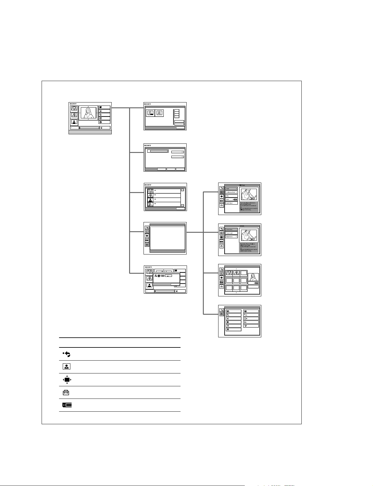
1-5-1. Menu Configuration
Phone Book
Tokyo
New York
Paris
AUTO
Enter the remote party number.
IP: 012.345.678.678
ISDN: 012345678956789
Detail Dial
History
Menu
Information
Dial
Phone Book/Private Phone BookLauncher menu
AUTO
Jane Mary
Detail Dial
IP
Phone Book
Detail Dial
Line I/F
IP
LAN Bandwidth
1024 Kbps
0-9
A-1
J-S
T-Z
Recent
New Entry
Cancel
CancelSaveDial
History
History
2004.
04. 04 10:20
Tokyo
LAN 012.345.678.912
2004.
04. 04 10:20
New York
LAN 012.345.678.912
2004.
04. 04 10:20
Paris
LAN 012.345.678.912
2004.
04. 04 10:20
NAKAHATA
LAN 012.345.678.912
Setup Menu
Setup
Press and hold the [MENU]button to show more detailed
setup menus.
Information
Information
Tokyo
PORT
ISDN:
IP:
012.345.678.912
012345678912
Audio: MIC(INT)+AUXVideo:
Object
New York
IP: 012.345.678.678
ISDN: 012345678956789
Paris
AUTO
Selecting the icons shown on the left side of the
launcher menu displays each menu.
Icon Displayed menu
Returns to the previous menu.
Still Image menu
Cancel
Camera menu
Memory Stick menu
Phone Book
Detail Dial
History
Menu
OK
OK
Information
Dial
Setup menu (for Administrator)
Memory Stick
JPEG JPEG JPEG
JPEG JPEG JPEG
Dial
Communication
Audio
General
LAN
Information
JPEG
Save
Memory Stick Format
Setup
Answer
Status
Video
Administrator
ISDN
PCS-G70/G70P
Still Image menu
Camera menu
Memory Stick menu
Setup menu
1-15

1-5-2. System Setting Table
Menu
Page
Item Description Default
Dial Setup 1/2 Line I/F Select line interface [IP, ISDN, or ISDN (Telephone)] used. IP
Bonding Select bonding mode in which remaining lines can also be Auto
connected by only dialing one line when multiple ISDN lines
are used. Select “On” when connecting a line in the bonding
mode. Select “Auto” when automatically adjusting a line to
remote party.
Telephone Mode Select audio compression system during voice meeting. Auto
More Options Enable Set to “On” when you want to set items in the dial setup Off
menu for each dial list. Set to “Off” when you do not.
User Name Input Set to “On” when recording user name in communication log Off
before communication. Set to “Off” when not recording it.
2/2 Prefix Set prefix number used when connecting using an ISDN line. None
Prefix-A Set ISDN prefix (dial number). Blank
Prefix-B
Prefix-C
Select LAN Prefix Set “Enabled” when using prefix for connection using a LAN Disabled
line. Set “Disabled” when not using it.
LAN Prefix Set LAN prefix (dial number). Blank
Answer Setup 1/1 Auto Answer Select “On” to connect automatically according to a call. On
Select “Off” to confirm connection.
ISDN MSN Select “On” when using multiple subscriber numbers during Off
connection (answering) with an ISDN line. Select “Off” when
not using them.
Mic on Answer Select “On” to enable microphone when answering a call. On
Select “Off” to disable it.
Reject Answer
*1
Select “On” to reject connection when a call is received Off
during conference. Select “Off” to make connection.
Communication
Setup dialing, answering, and for multipoint
1/3 Individual Setting Select “On” to set communication mode individually for Off
*1
. Select “Off” to set it
collectively.
Number of Lines Select the number of ISDN lines used for ISDN 30B
communication from 1B (64 K) up to 30B (1920 K).
LAN Bandwidth Select bandwidth (bit rate) when communicating via a LAN 1024 Kbps
line.
2/3 Video Mode Select video coding format. Auto
Interlace Mode
*2
Select “On” when using interlace SIF mode. Select “Off” On
when not using it.
4CIF Mode
*2
Select “On” when using 4CIF mode. Select “Off” when not On
using it.
Video Frame Select maximum number of video transmission frames (15 Auto
fps or 30 fps).
Audio Mode Select audio coding format. Auto
Restrict Select transmission rate (Auto or 56K) when connecting Auto
using an ISDN line. Two rates (64 Kbps and 56 Kbps) are
used in some countries (USA, etc.) and regions.
*1: Setting is added when H.320 or H.323 MCU Software is installed. (Continued)
*2: In the system version 1.02, these items are automatically set when the Video Mode setting is set to “Auto”.
1-16
PCS-G70/G70P

Menu
Communication
Page
Item Description Default
3/3 Far End Camera Control Select “On” when controlling camera on the remote party. On
Setup Select “Off” when not controlling it.
T.120 Data Select “On” when having data conference conforming to Off
T.120 using NetMeeting. Select “Off” when not having it.
H.239 Select “On” when using dual-video presentation function On
conforming to H.239. Select “Off” when not using it.
4/4*3Multipoint Mode Select “On” when having multipoint videoconference. Select Auto
“Auto” when switching automatically.
Broadcast Mode Select “Split” when displaying video of all connected Split
terminals on the split window. Select “Voice Activate” when
switching video to be distributed by audio detection.
Split Select “Automatic” to switch between 4-split window (for 1 Automatic
to 3 terminals) and 6-split window (for 4 to 6 terminals), or
“Six-screen Mosaic” to always display 6-split window.
Sender Screen Select monitor video displayed on sending terminals during Full Screen
multipoint videoconference.
Status Display current communication status. ISDN line status,
LAN line status, and LAN communication status are also
displayed according to the line interface used.
Audio Setup 1/2 Input Select Select the audio input (MIC, AUX, or MIC + AUX). MIC
Mic Selection Select microphone to be used (MIC, DSB MIC, or LINE). MIC
CTE Select whether to use the communication transducer Off
CTE-600 and select input connector to be connected.
Select “Off” when not using CTE-600. Select “LINE” when
inputting to LINE connector of the communication terminal,
and select “DSB AUX IN” when inputting to AUX IN
connector of the data solution box.
n
When CTE-600 is set to be used, “Input Select”, “Mic
Select”, and “Echo Canceller” are automatically determined
and cannot be changed.
Echo Canceller Select “On” when using an echo canceller. Select “Off” when On
not using it.
Lip Sync Select “On” when using a lip sync function that synchronizes Off
the lip motion and voice of a speaker. Select “Off” when not
using it.
Recording Mute Select “On” when outputting audio signal to AUDIO OUT On
(MIXED) connector. Select “Off” when not outputting it.
2/2 Beep Sound Select “On” to generate beep sound from pressing the On
remote commander button. Select “Off” not to generate.
Sound Effect Select “On” to generate effect sound at system start up and On
conference start/end. Select “Off” not to generate.
Dial Tone Select “On” to generate ring-back tone or busy tone during On
dialing. Select “Off” not to generate.
Ringer Tone Select “On” to generate ringer tone with an incoming call. On
Select “Off” not to generate
*3: Setting is added when H.320 or H.323 MCU Software is installed. (Continued)
PCS-G70/G70P
1-17

Menu
Page
Item 1
Page
Item 2 Description Default
Video Setup 1/1 Video Input 1/1 Dual Video Select “On” when distributing 2-channel moving picture Off
simultaneously from the beginning of conference. Select
“Off” when not distributing it.
n
This function is not available in the system version 1.00 to 1.02.
Split Select “Vertical or “Horizontal” when splitting the screen into Off
two. Select “Off” when not splitting it.
MAIN Select video picture of video input 1. CAMERA
SUB Select video picture of video input 2. Not selected
Custom Input 1/1 Main Camera Enter the name when “Main Camera” is selected on the Blank
Label video input selection window.
Object Enter the name when “Object” is selected on the video input Blank
selection window.
AUX1 Enter the name when “AUX1” is selected on the video input Blank
selection window.
Sub Camera Enter the name when “Sub Camera” is selected on the video Blank
input selection window.
Object Enter the name when “Object” is selected on the video input Blank
selection window.
AUX2 Enter the name when “AUX2” is selected on the video input Blank
selection window.
Monitor Out 1/1 Monitors Select the number of monitors connected to the 1
communication terminal.
Connection Select connectors connecting to the monitors. You can VIDEO1
select them up to the number specified in “Monitors”.
Monitor Select “Main” or “Sub” for connected monitors to be used as. Main
Only one “Main” monitor can be selected. When 1 or 3
monitors are used, VIDEO1 is always “Main” monitor.
General Setup 1/1 Device Setup 1/2 Clock Set Set the current date and time.
Terminal Name
Enter terminal name to be notified to MCU. PCS-G70
Standby Select “On” when using standby mode. Select “Off” when Off
Mode not using it.
Standby Set the time (1 to 99 minutes) required until the unit is put 30
Time into standby mode when standby mode is set to “On”.
Last Number Select “On” when registering the remote user in Phone Book On
Registration after a conference ends. Select “Off” when not registering it.
Control by Select “On” when receiving camera control command from On
Far End the remote party. Select “Off” when not receiving it.
2/2 Language Select language of menu and message displayed on the English
screen.
IR Repeater Select mode to put the monitor into standby state or to turn MODE1
Mode on power when a Sony’s monitor is used. Usually, set to
“MODE 1”.
T.120 PC Enter the IP address of computer used when data Blank
Address conference conforming to T.120 is made using NetMeeting.
Menu Screens
1/3 Time Display Select “On” when displaying elapsed time at upper right of On
the screen during conference. Select “Off” when not
displaying it.
Display
Terminal Name
Select whether to display the connected terminal name on Show
the screen at the time of disconnection. temporarily
Character Select “On” when displaying balloon help appearing when On
Input Help entering alphanumeric characters. Select “Off” when not
displaying it.
1-18
(Continued)
PCS-G70/G70P

Menu
General Setup 1/1
Page
Item 1
Menu Screens
Page
Item 2 Description Default
2/3 Phone Book Select “On” when displaying Phone Book button on the On
Button launcher screen. Select “Off” when not displaying it.
Detailed Dial Select “On” when displaying Detailed Dial button on the On
Button launcher screen. Select “Off” when not displaying them.
Menu Button Select “On” when displaying Menu button on the launcher On
screen. Select “Off” when not displaying it.
Information Select “On” when displaying Information button on the On
Button launcher screen. Select “Off” when not displaying it.
History Select “On” when displaying History button on the launcher On
Button screen. Select “Off” when not displaying it.
3/3 Direct Phone Select “On” when displaying Direct Phone Book button on On
Book Button the launcher screen. Select “Off” when not displaying it.
Direct Dial Select “On” when displaying Direct Dial text box on the On
launcher screen. Select “Off” when not displaying it.
Guide Select “On” when displaying the guide at the bottom of the On
launcher screen. Select “Off” when not displaying it.
Whiteboard 1/1 Whiteboard Select whether to attach Whiteboard “mimio-Xi” vertically or Vertical
Attachment horizontally.
Whiteboard Select the size (height x width) of Whiteboard used. 3'0" x 4'0"
Size
Whiteboard
Measurement
Select whether to show the Whiteboard size in inches or Inches
meters.
Size
Administrator 1/1 Password 1/3 Administrator Set administrator password. Administrator can modify the Blank
Setup Password setup menu (for administrator) and phone book menu.
Phone Book Set password used to modify the phone book. Blank
Modification
Password
Save Settings
Set password used to save various settings. Blank
Password
Remote Set password used to access the system through the Web Blank
Access browser. Access is available with a password for
Password administrator or for superuser.
2/3 Dial Setup Select “Enabled” when password is required to save the dial Enabled
setup settings. Select “Disabled” when it is not required.
Answer Select “Enabled” when password is required to save the Enabled
Setup answer setup settings. Select “Disabled” when it is not
required.
Transmission Select “Enabled” when password is required to save the Enabled
Mode communication setup settings. Select “Disabled” when it is
not required.
Audio Setup Select “Enabled” when password is required to save the Enabled
audio setup settings. Select “Disabled” when it is not required.
Video Setup Select “Enabled” when password is required to save the Enabled
video setup settings. Select “Disabled” when it is not required.
General Select “Enabled” when password is required to save the Enabled
Setup general setup settings. Select “Disabled” when it is not
required.
(Continued)
PCS-G70/G70P
1-19

Menu
Page
Item 1
Page
Item 2 Description Default
Administrator 1/1 Password 3/3 LAN Setup Select “Enabled” when password is required to save the Enabled
Setup LAN setup settings. Select “Disabled” when it is not required.
ISDN Setup Select “Enabled” when password is required to save the Enabled
ISDN setup settings. Select “Disabled” when it is not required.
VCP Setup
*4
Select “Enabled” when password is required to save the Enabled
VCP setup settings. Select “Disabled” when it is not required.
Phone Book 1/2 Save Phone Save phone book data in Memory Stick. Memory Stick must
Book be inserted in the communication terminal. When another
data is already saved in the Memory Stick, it is overwritten.
Load Phone Load phone book data saved in Memory Stick to the
Book communication terminal. Memory Stick must be inserted in
the communication terminal. When phone book data is
already registered in the communication terminal, it is
overwritten.
Clear Phone Delete phone book data registered in the communication
Book terminal.
2/2 Auto Dialing Select whether to automatically dial to a person in the list On
specified by private phone book created in Memory Stick
when Memory Stick is inserted.
Create Private
Phone Book
Delete Private
Phone Book
Copy to Private
Phone Book
Create a new private phone book in Memory Stick. Memory
Stick must be inserted in the communication terminal.
Delete private phone book saved in Memory Stick. Memory
Stick must be inserted in the communication terminal.
Copy phone book list saved in the communication terminal
to Memory Stick as private phone book. Memory Stick must
be inserted in the communication terminal.
Other Settings
1/1 Web Monitor Select “On” when allowing conference monitoring function On
(auto-update of JPEG images) from the Web browser.
Select “Off” when inhibiting it.
LAN Setup 1/1 General 1/2 DHCP Mode Select “Auto” when using DHCP (Dynamic Host Off
Configuration Protocol). Select “Off” when not using it.
When “Auto” is set, IP address, net mask, gateway address,
and DNS address are automatically acquired.
Host Name Enter host name. Blank
IP Address Enter IP address when DHCP mode is set to “Off”. Blank
Network Mask
Enter network mask when DHCP mode is set to “Off”. Blank
Gateway Enter gateway address when DHCP mode is set to “Off”. Blank
Address
DNS Address
Enter DNS (Domain Name System) server address when Blank
DHCP mode is set to “Off”.
2/2 LAN Mode Select interface type and communication mode for LAN Auto
connection. Negotiation
Gatekeeper 1/1 Gatekeeper Select “On” when using a gatekeeper and set to “Off” when Off
Mode not using it. Select “Auto” when automatically searching a
gatekeeper.
Gatekeeper Set IP address of gatekeeper. Blank
Address
User Alias Set user name (H.323 alias) to be registered in a gatekeeper. Blank
User Number Set user number (E.164 number) to be registered in a Blank
gatekeeper.
*4: Setting is added when VCP setup is added by the service command. (Continued)
1-20
PCS-G70/G70P

Menu
Page
Item 1
Page
Item 2 Description Default
LAN Setup 1/1 SNMP 1/1 SNMP Mode Select “On” when enabling service of SNMP (Simple Off
Network Management Protocol) agent. Select “Off” when
disabling it.
Trap Destination
Set IP address of SNMP manager that transmits a trap. Blank
Community Set community name that SNMP manager manages. public
Usually, set to “public”.
Description This is the description of this device. Entered as
“Videoconference Device”. This cannot be changed.
Videoconference
Device
Location Set the place where this unit is installed. Blank
Contact Set information on the administrator of this unit. Blank
PPPoE 1/2 PPPoE Select PPPoE termination On/Off using this unit. Off
PPPoE User Enter PPPoE connection user name (account) acquired Blank
Name from provider.
PPPoE Enter PPPoE connection password acquired from provider.
Password
2/2 Fixed IP for Select “On” when fixed IP address for PPPoE connection is Off
PPPoE acquired from provider. Select “Off” when automatically
acquiring it for each session.
Fixed IP Address
for PPPoE
Enter fixed IP address acquired from provider when “Fixed Blank
IP for PPPoE” is “On”.
PPPoE DNS Select “Obtain automatically” when acquiring IP address of Blank
DNS server from the server during PPPoE connection.
Select “Specify” when fixed IP address exists.
Primary DNS Enter IP address of primary DNS server when “PPPoE DNS” Blank
is “Specify”.
Secondary Enter IP address of secondary DNS server when “PPPoE Blank
DNS DNS” is “Specify”.
NAT/Port 1/1 NAT Mode Select “On” when connecting this unit to local network using Off
NAT (Network Address Translation). Select “Off” when not
connecting it.
NAT Address Set IP address on the global side that NAT uses. Blank
Port Number Select whether to fix TCP port number and UDP port number. Default value
Used Custom: The port number that the user sets is used.
Default: Default port number is used.
TCP port number 2253 and UDP port number 49152 are set.
TCP Port Set TCP port number when “Port Number Used” is “Custom”.2253
Number
UDP Port Set UDP port number when “Port Number Used” is “Custom”. 49152
Number
QoS 1/1 Hybrid Select “On” when automatically switching forward error On
correction function, packet resend request function, and
adaptive rate control function according to network status.
Select “Off” when not switching them.
Forward Error
Correction
Select “On” when correcting data by receiver if error is On
detected in packets received when “Hybrid” is set to “Off”.
Select “Off” when not correcting data.
Packet Select “On” when making a resend request due to packet On
Resend loss when “Hybrid” is set to “Off”. Select “Off” when not
Request making it.
Adaptive Rate
Control
Select “On” when adapting LAN band when “Hybrid”,On
“Forward Error Correction”, and “Packet Resend Request”
are set to “Off”. Select “Off” when not adapting it.
(Continued)
PCS-G70/G70P
1-21

Menu
LAN Setup 1/1 TOS 1/1 TOS Select definition method of TOS (Type of Service) field. Off
ISDN Setup 1/3 Country/Region Select country/region in which this unit is used. Not selected
Machine Display versions of communication terminal and separately
Information available dedicated equipment, as well as optional software
Page
Item 1
Encryption 1/1 Encryption Set whether to encrypt data when connected via LAN. Off
via LAN via LAN
Protocol Select ISDN line protocol to be used. Euro ISDN
2/3 Area Code Enter area code of ISDN line used. Blank
Local Number Enter telephone number (local number) of ISDN line used. Blank
3/3 Sub Address Enter ISDN sub-addresses when registering it. Blank
Page
Item 2 Description Default
IP Enter IP Precedence values (0 to 7) when TOS is set to “IP 0
Proecedence Precedence”.
Low Delay Select “On” when specifying bit rate of Low Delay in TOS Off
field when TOS is set to “IP Precedence”. Select “Off” when
not specifying it.
High Select “On” when specifying bit rate of High Throughput in Off
Throughput TOS field when TOS is set to “IP Precedence”. Select “Off”
when not specifying it.
High Select “On” when specifying bit rate of Reliability in TOS Off
Reliability field when TOS is set to “IP Precedence”. Select “Off” when
not specifying it.
Minimum Select “On” when specifying bit rate of Minimum Cost in Off
Cost TOS field when TOS is set to “IP Precedence”. Select “Off”
when not specifying it.
Diffserve Enter Diffserve value (0 to 64) when TOS is set to 0
Encryption Enter password necessary to start an encrypted Blank
Password videoconference.
“Diffserve”.
n
Do not enter the first “0” of area code.
used.
1-22
PCS-G70/G70P
 Loading...