

Page 1

Video
Communication
System
3-993-428-11 (1)
IPELA VC Link Guide
PCS-G50
© 2006 Sony Corporation
Page 2
Connecting to an external server with the IPELA VC Link
function enables you to use the IPELA VC Link service.
This guide describes the procedures and settings needed to
use the IPELA VC Link service.
Preparing for a
Videoconference With the
IPELA VC Link service is only available in Japan.
For more about the IPELA VC Link service, consult your
Sony dealer.
IPELA VC Link Function
For details on IPELA VC Link settings, see “Details of
IPELA VC Link Setup” (page 4).
1
After entering an extension command with “Function
Extension Command” in Other Settings of the
Administrator Setup menu, select “Save,” then press
the ENTER button on the Remote Commander.
Other Settings
Page:
1/1
Web Monitor
Web Access
Save Setup
Load Setup
Function Extension Command
Administrator Setup
Off
Disabled
Save Cancel
The screen switches to the Setup menu.
Notes
• For details on obtaining the “Function Extension
Command,” consult your Sony dealer.
• If the “SIP Server Mode” setting is set to “On” on the
SIP Setup menu, an error message appears, and
IPELA VC Link does not activate. Set “SIP Server
Mode” to “Off” before entering the “Function
Extension Command” again.
• The SIP Setup menu is displayed when the optional
SIP software has been installed.
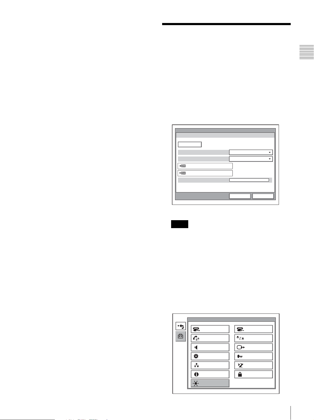
2
With the “IPELA VC Link” is selected, press the
ENTER button.
Setup
Dial
Communication
Audio
General
LAN
Answer
Status
Video
Administrator
ISDN
Information
IPELA VC Link
Preparing for a Videoconference With the IPELA VC Link Function
Encryption
2
Page 3

3
Set “Enable IPELA VC Link” to “On,” and enter an
“IPELA VC Link Number” and “Password.”
Note
For details on acquiring an IPELA VC Link number
and password, consult your Sony dealer.
IPELA VC Link
1/3
Enable IPELA VC Link
IPELA VC Link Number
Password
On
12345678
******
Save Cancel
4
Select “Save,” then press the ENTER button.
The message “The NAT settings, line interface, and
LAN Bandwidth will be changed. Disabling the Web
Access setting is recommended.” appears.
When “Enable IPELA VC Link” is set to “On,” the
“NAT Mode” item on Page 2 of the IPELA VC Link
menu automatically switches to “Auto (UPnP),” and
“Line I/F” and “Number Display” switch to “IPELA
VC Link.” In addition, the “LAN Bandwidth” item on
Page 3 automatically switches to “512 Kbps.”
Note
To select individual “LAN Bandwidth” settings for
transmission, reception, and multipoint conferencing,
set “Individual Settings” on Page 3 to “On.”
IPELA VC Link
2/3
NAT Mode
NAT Address
Port Number
Line I/F
Number Display
Auto (UPnP)
. . .
5060
IPELA VC Link
IPELA VC Link
Save Cancel
Note
The Web Access setting can be changed in Other
Settings of the Administrator Setup menu.
5
The Setup menu (Administrator) appears.
The first time the settings are configured the system
resets and the launcher menu appears.
3
Preparing for a Videoconference With the IPELA VC Link Function
Page 4

Starting a Videoconference With the IPELA VC Link Function
Calling a Remote Party
Starting a Multipoint Videoconference
The procedure is the same as that for a normal
videoconference.
For details, see “Starting a Multipoint Videoconference”
in the Operating Instructions.
For instructions on calling a remote party from the Direct
Phone Book or Phone Book, see “Starting a Conference by
Calling a Remote Party” in the Operating Instructions.
To call a remote party that is not registered
in the Phone Book
The procedure is essentially the same as that for a normal
videoconference.
With “VCLink” selected for “Line I/F,” enter the IPELA
VC Link number of a remote party in the input text box.
Select “Dial,” the press the ENTER button or CONNECT/
DISCONNECT
Commander.
Note
Open the IPELA VC Link menu, and make sure “Enable
IPELA VC Link” is set to “On.”
The system begins dialing the selected remote party and
“Dialing” appears on the display.
When the connection to the remote party is established, the
message “Meeting starts!” appears on the display.
(/) button on the Remote
Details of IPELA VC Link Setup
The displays below show initial settings, before IPELA
VC Link is configured.
Page 1/3
IPELA VC Link
1/3
Enable IPELA VC Link
IPELA VC Link Number
Password
Off
Save Cancel
For details, see “Calling a Remote Party” in the
Operating Instructions.
Receiving a Call From a Remote Party
The procedure is the same as that for a normal
videoconference.
For details, see “Receiving a Call From a Remote Party”
in the Operating Instructions.
Enable IPELA VC Link
Selects whether to use the IPELA VC Link service.
On: Enable IPELA VC Link.
Off: Disable IPELA VC Link.
IPELA VC Link Number
Enter the 8-digit IPELA VC Link number.
Note
This entry field is disabled when “Enable IPELA VC
Link” is set to “Off.”
Password
Enter the password.
Note
This entry field is disabled when “Enable IPELA VC
Link” is set to “Off.”
4
Starting a Videoconference With the IPELA VC Link Function / Details of IPELA VC Link Setup
Page 5

Page 2/3
IPELA VC Link
2/3
NAT Mode
NAT Address
Port Number
Line I/F
Number Display
NAT Mode
Selects whether to use NAT mode.
Auto (UPnP): Enable the UPnP function.
On: Enable NAT mode.
Off: Disable NAT mode.
NAT Address
Enter the IP address of a global network to be used for
NAT mode.
Note
This item can only be set when “NAT Mode” is set to
“On.”
Port Number
Enter the port number to be used for NAT mode.
Note
This item can only be set when “NAT Mode” is set to
“On.”
Line I/F
Selects the line interface to be used normally.
IP: Connects a videoconferencing system via a LAN.
ISDN: Connects a videoconferencing system via ISDN.
ISDN (Telephone): Connects an audio-only telephone
via ISDN (Voice Meeting).
IPELA VC Link: Connects a videoconferencing system
via IPELA VC Link.
Off
. . .
5060
IP
IP:
Save Cancel
No display: Does not display any number identifying the
system.
Page 3/3
Individual Settings
Allows you to select whether to perform transmission,
reception, and multipoint settings individually.
On: Select to perform transmission, reception, and
multipoint settings individually.
Off: Select to perform all settings simultaneously.
LAN Bandwidth
Select the bandwidth to be used for transmission,
reception, and multipoint conferencing.
Available settings are 64 Kbps, 128 Kbps, 256 Kbps,
384 Kbps, 512 Kbps, 768 Kbps, 1024 Kbps, 2 Mbps,
4 Mbps, and “other.”
When “Other” is selected, a bandwidth value between 1
and 4096 Kbps can be entered.
If you set “Individual Settings” to “On”, you can perform
this setting individually for transmission, reception, and
multipoint conferencing.
Number Display
Select the IP address or other number to display in the
launcher menu as identification of your system.
GK:User Alias: Displays the user name registered in the
gatekeeper when you use the gatekeeper.
GK:User Number: Displays the user number registered
in the gatekeeper when you use the gatekeeper.
NAT: Address: Display your NAT address when
connected to a network using NAT.
IP: Display your IP address.
IPELA VC Link: Display your IPELA VC Link number.
5
Details of IPELA VC Link Setup
Page 6

On Screen Messages
Check the following if a message appears on the display when operating the Video Communication System.
Message Response
Router is not supported. (No M-SEARCH
response)
Router is not supported. (Service
unavailable)
Router is not supported. (Failed to obtain
WAN IP address)
Router is not supported. (Port mapping
failed)
Cannot communicate through SIP. (Port
mapping failed)
There are no open ports. Confirm the
router’s port settings.
Authentication error. Check that the
password is correct.
Connection using IPELA VC Link is not
available. Authentication error.(Password)
Authentication error. Check that the ID is
correct.
Connection using IPELA VC Link is not
available. Authentication error.(IPELA VC
Link Number)
Registration Requested. Awaiting response from the server. Wait a few moments.
Connection using IPELA VC Link is not
available. Registration Requested.
The call request has timed out. The server is not responding. Confirm network connection.
Connection using IPELA VC Link is not
available. Registration timeout.
Connection using IPELA VC Link is not
available. Registration Failed.
4xx response received. Server error. Contact the call center.
5xx response received. Server error. Contact the call center.
Connection using IPELA VC Link is not
available. 5xx response received.
6xx response received. Server error. Contact the call center.
Connection using IPELA VC Link is not
available. 6xx response received.
The dialed party does not exist. Check that
the number is correct.
The remote party rejects answering. The remote party has rejected the call. Try calling again later.
Connection using IPELA VC Link is not
available. Canceled by the remote site.
Call not responded. The remote party is not responding. Try calling again later.
Connection using IPELA VC Link is not
available. Line is busy.
The remote party is unable to connect. The remote party is not registered. Try calling again later.
Communication with UPnP is not available.
(Internal error)
A supported router could not be found. Confirm the UPnP settings for the router.
UPnP service could not be found. Confirm the UPnP settings for the router.
Failed to obtain the WAN IP address. Confirm network connection.
Port mapping failed. Confirm the UPnP settings for the router.
Port mapping failed. Confirm the UPnP settings for the router.
Port mapping failed. Confirm the UPnP settings for the router.
Server authentication failed. Confirm the password.
Server authentication failed. Confirm the password.
Server authentication failed. Confirm the VC Link Number.
Server authentication failed. Confirm the VC Link Number.
Awaiting response from the server. Wait a few moments.
The server is not responding. Confirm network connection.
The server is not responding. Confirm network connection.
Server error. Contact the call center.
Server error. Contact the call center.
The remote party dialed does not exist. Confirm the party’s number.
The remote party has canceled the connection.
The remote party’s line is busy. Try calling again later.
UPnP configuration has failed. Confirm network connection.
On Screen Messages
6
Page 7

Page 8

Sony Corporation
Printed in Japan
 Loading...